dependable system development by d-case and …. abstract 2. dependable system development by d-case...
TRANSCRIPT
Dependable System Developmentby D-Case and SysML Collaboration
Demonstration

2
Index
1. Abstract
2. Dependable System Development by D-Case and SysML Collaboration
3. Sample of Applying this Method ~ In-Vehicle System Development Complying with ISO26262 ~
3
Abstract

Scope and Approach
4
Scope
This document shows a method realizing the development of the dependable system.
ApproachThis documents shows an approach which consistently realizes collaboration of D-Case and SysML model from upper process to lower process.
par [パッケージ] Design [PAR_Vehicle]
Break<<Block>>
Values
Operations
breakPowerTargetbreakPower
CC controller<<Block>>
Values
Operations
powerOFF ccBtnccPower
speed
Speed sensor<<Block>>
Values
Operations
speed
Acceleration<<Block>>
Values
Operations
accelPowerTargetaccelPower
Electronic throttle<<Block>>
Values
Operations
pwrthrottleTorque
Throttle actuator<<Block>>
Values
Operations
pwr
CC User I/F<<Block>>
Values
Operations
ccBtn
Acceleration limit :
a < 0.35G.
Acceleration performance :a > 0.080G.
Target speed limit :
50km/h <= vt <= 100km/h.
<<allocate>>
Speed control<<Block>>
Values
Operations
breakPowerTarget
accelPowerTarget
breakTorque
throttleTorque
ccPower
breakPower
accelPower
<<allocate>><<allocate>>
Electronic break<<Block>>
Values
Operations
pwrbreakTorque
Break actuator<<Block>>
Values
Operations
pwr
Vehicle dynamics controller<<Block>>
Values
Operations
pwrspeed
Speed monitor circuit<<Block>>
Values
Operations
powerOFF speed
<<allocate>>CC condition monitor circuit<<Block>>
Values
Operations
ccBtn
speedpowerOFF
pwr =Kp ( Vp - Vt )+ Ki ∫(Vp - Vt ) dt
<<allocate>>
a = (thrust + drag) / mass
<<allocate>>
thrust = pwr / actualSpeed
<<allocate>>
actualSpeed = ∫a dt + v0
<<allocate>>
drag =
-1/2 * Cd * A
* densityOfAir
* actualSpeed̂2
<<allocate>>
Sedan :mass = 1700 kgWagon :mass = 2500 kg
<<allocate>>
Sedan :Cd = 0.44Wagon :Cd = 0.50
<<allocate>>
Sedan :A = 1.8 m̂2Wagon :A = 2.0 m̂2
<<allocate>>
densityOfAir = 1.2 kg/m̂3
<<allocate>>
req [パッケージ] Design [REQ_CC]
CC<<Requirement>>
ID = REQ_01
Vehicle has cruise control features that support a driver.
CC boot (Cruise)<<Requirement>>
ID = REQ_02
If a driver pushes the Cruise button when CC stops, CC should boot.
<<derive>>
CC stop (Cruise)<<Requirement>>
ID = REQ_08
If a driver pushes Cruise button when CCruns, CC should stop.
<<derive>>
Target speed setting (Set)<<Requirement>>
ID = REQ_03
If a driver pushes the Set button when CC boots, CC should set the current speed as a target speed.
<<derive>>
Target speed-down (Decel)<<Requirement>>
ID = REQ_04
If a driver pushes the Decel button when CC boots, the target speed shoulddecrease.
<<derive>>Target speed-up (Accel)
<<Requirement>>
ID = REQ_05
If a driver pushesAccel button when CC boots, the target speed should increase.
<<derive>>
CC pause<<Requirement>>
ID = REQ_06
If a driver puts on the break when CC runs, CC should pause.
<<derive>>
CC resume (Resume)<<Requirement>>
ID = REQ_07
If a driver pushes Resume button when CC pauses, CC should resume with the same setting as before pause.
<<derive>>
Quick response to operation<<Requirement>>
ID = REQ_12
CC responds within 1ms when driver operates.
<<derive>><<derive>> <<derive>><<derive>> <<derive>>
Operability<<Requirement>>
ID = REQ_11
CC can be operated byone-touch.
<<derive>> <<derive>><<derive>>
Speed limit<<Requirement>>
ID = REQ_18
Target speed is restricted from 50 km/h to 100km/h.
<<derive>><<derive>> <<derive>>
Acceleration limit<<Requirement>>
ID = REQ_13
Acceleration is less than 0.35G.
<<derive>> <<derive>>
Continuous duty<<Requirement>>
ID = REQ_15
Continuous duty of CC is carried out for more than 100 hours.
<<derive>>
Priority of driver operation<<Requirement>>
ID = REQ_16
Top priority is given tothe driver operation :accelerator operation, brake operation, and steering operation.
<<derive>> <<derive>>
Config Integrity<<Requirement>>
ID = REQ_17
Configuration data should not be changed unjustly.
<<derive>>
Acceleration performance<<Requirement>>
ID = REQ_14
When the difference of speed and target speed is more than 20km/h, acceleration should be more than 0.080G.
<<derive>><<derive>>
CC stop (PCS)<<Requirement>>
ID = REQ_09
If a stop request is received fromPCS when CC runs, CC should stop.
<<derive>>
Acceleration suppression control<<Requirement>>
ID = REQ_21
Acceleration suppression control is performed so that acceleration is less than threshold.
<<derive>>
<<derive>>
Speed monitor<<Requirement>>
ID = REQ_22
Speed is monitored.
<<derive>>
<<derive>>
CC emergency stop<<Requirement>>
ID = REQ_23
CC urgently stops when trouble is detected.
<<derive>>
CC condition monitor<<Requirement>>
ID = REQ_24
CC condition is monitored.
<<derive>>
uc [パッケージ] Design [UC_CC]
CC
CC stop
Target speedsetting
Targetspeed-down
Target speed-up
CC resume
Speed control<<include>>
<<include>>
<<include>>
<<include>>
CC pause
CC boot
CC condition monitor
<<include>>
<<include>>
<<include>>
<<include>> CC emergency stop
<<include>>
Speed monitor
<<include>>
<<include>>
<<include>>DriverDriver
ThrottleThrottle
PCSPCS
Correspondence Check
Evidence Addition
D-Case SysML
Goal Division
Information Extraction
System Demands
Design Specification

5
Achievement
Guide and Example for D-Case and SysML model collaboration are provided.
Modeling Guide
Example
Target Reader
Modeling Flow of D-Case and SysMLStyle Guide for D-Case NodeCollaboration of D-Case and SysML Model Description
This document assumes the developers as readers who examine developing a dependable system.
This document shows an example of the application of in- vehicle system which complies with ISO26262, the global standard of functional safety for vehicles.

6
Dependable System Development by D-Case and SysML Collaboration

What is Asked for Developing a Dependable System
System Demand System demands should satisfy dependability.
System Demand System demands should satisfy dependability.
Design Specification Design specifications should reflect the demands correctly.
Design Specification Design specifications should reflect the demands correctly.
Requirements DefinitionRequirements Definition
System DesignSystem Design
Development PhaseDevelopment Phase What is AskedWhat is Asked
Verification Result Verification results should account for satisfying dependability.
Verification Result Verification results should account for satisfying dependability.
System VerificationSystem Verification
H/W DevelopmentH/W Development
S/W DevelopmentS/W Development
7
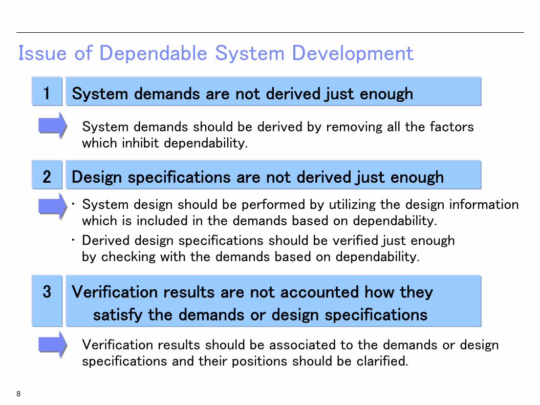
Issue of Dependable System Development
1
System demands should be derived by removing all the factors which inhibit dependability.
3
2
• System design should be performed by utilizing the design information which is included in the demands based on dependability.
• Derived design specifications should be verified just enough by checking with the demands based on dependability.
Verification results should be associated to the demands or design specifications and their positions should be clarified.
System demands are not derived just enough
Verification results are not accounted how they
satisfy the demands or design specifications
Design specifications are not derived just enough
8

par [パッケージ] Design [PAR_Vehicle]
Break<<Block>>
Values
Operations
breakPowerTargetbreakPower
CC controller<<Block>>
Values
Operations
powerOFF ccBtnccPower
speed
Speed sensor<<Block>>
Values
Operations
speed
Acceleration<<Block>>
Values
Operations
accelPowerTargetaccelPower
Electronic throttle<<Block>>
Values
Operations
pwrthrottleTorque
Throttle actuator<<Block>>
Values
Operations
pwr
CC User I/F<<Block>>
Values
Operations
ccBtn
Acceleration limit :
a < 0.35G.
Acceleration performance :a > 0.080G.
Target speed limit :
50km/h <= vt <= 100km/h.
<<allocate>>
Speed control<<Block>>
Values
Operations
breakPowerTarget
accelPowerTarget
breakTorque
throttleTorque
ccPower
breakPower
accelPower
<<allocate>><<allocate>>
Electronic break<<Block>>
Values
Operations
pwrbreakTorque
Break actuator<<Block>>
Values
Operations
pwr
Vehicle dynamics controller<<Block>>
Values
Operations
pwrspeed
Speed monitor circuit<<Block>>
Values
Operations
powerOFF speed
<<allocate>>CC condition monitor circuit<<Block>>
Values
Operations
ccBtn
speedpowerOFF
pwr =Kp ( Vp - Vt )+ Ki ∫(Vp - Vt ) dt
<<allocate>>
a = (thrust + drag) / mass
<<allocate>>
thrust = pwr / actualSpeed
<<allocate>>
actualSpeed = ∫a dt + v0
<<allocate>>
drag =
-1/2 * Cd * A
* densityOfAir
* actualSpeed̂2
<<allocate>>
Sedan :mass = 1700 kgWagon :mass = 2500 kg
<<allocate>>
Sedan :Cd = 0.44Wagon :Cd = 0.50
<<allocate>>
Sedan :A = 1.8 m̂2Wagon :A = 2.0 m̂2
<<allocate>>
densityOfAir = 1.2 kg/m̂3
<<allocate>>
req [パッケージ] Design [REQ_CC]
CC<<Requirement>>
ID = REQ_01
Vehicle has cruise control features that support a driver.
CC boot (Cruise)<<Requirement>>
ID = REQ_02
If a driver pushes the Cruise button when CC stops, CC should boot.
<<derive>>
CC stop (Cruise)<<Requirement>>
ID = REQ_08
If a driver pushes Cruise button when CCruns, CC should stop.
<<derive>>
Target speed setting (Set)<<Requirement>>
ID = REQ_03
If a driver pushes the Set button when CC boots, CC should set the current speed as a target speed.
<<derive>>
Target speed-down (Decel)<<Requirement>>
ID = REQ_04
If a driver pushes the Decel button when CC boots, the target speed shoulddecrease.
<<derive>>Target speed-up (Accel)
<<Requirement>>
ID = REQ_05
If a driver pushesAccel button when CC boots, the target speed should increase.
<<derive>>
CC pause<<Requirement>>
ID = REQ_06
If a driver puts on the break when CC runs, CC should pause.
<<derive>>
CC resume (Resume)<<Requirement>>
ID = REQ_07
If a driver pushes Resume button when CC pauses, CC should resume with the same setting as before pause.
<<derive>>
Quick response to operation<<Requirement>>
ID = REQ_12
CC responds within 1ms when driver operates.
<<derive>><<derive>> <<derive>><<derive>> <<derive>>
Operability<<Requirement>>
ID = REQ_11
CC can be operated byone-touch.
<<derive>> <<derive>><<derive>>
Speed limit<<Requirement>>
ID = REQ_18
Target speed is restricted from 50 km/h to 100km/h.
<<derive>><<derive>> <<derive>>
Acceleration limit<<Requirement>>
ID = REQ_13
Acceleration is less than 0.35G.
<<derive>> <<derive>>
Continuous duty<<Requirement>>
ID = REQ_15
Continuous duty of CC is carried out for more than 100 hours.
<<derive>>
Priority of driver operation<<Requirement>>
ID = REQ_16
Top priority is given tothe driver operation :accelerator operation, brake operation, and steering operation.
<<derive>> <<derive>>
Config Integrity<<Requirement>>
ID = REQ_17
Configuration data should not be changed unjustly.
<<derive>>
Acceleration performance<<Requirement>>
ID = REQ_14
When the difference of speed and target speed is more than 20km/h, acceleration should be more than 0.080G.
<<derive>><<derive>>
CC stop (PCS)<<Requirement>>
ID = REQ_09
If a stop request is received fromPCS when CC runs, CC should stop.
<<derive>>
Acceleration suppression control<<Requirement>>
ID = REQ_21
Acceleration suppression control is performed so that acceleration is less than threshold.
<<derive>>
<<derive>>
Speed monitor<<Requirement>>
ID = REQ_22
Speed is monitored.
<<derive>>
<<derive>>
CC emergency stop<<Requirement>>
ID = REQ_23
CC urgently stops when trouble is detected.
<<derive>>
CC condition monitor<<Requirement>>
ID = REQ_24
CC condition is monitored.
<<derive>>
uc [パッケージ] Design [UC_CC]
CC
CC stop
Target speedsetting
Targetspeed-down
Target speed-up
CC resume
Speed control<<include>>
<<include>>
<<include>>
<<include>>
CC pause
CC boot
CC condition monitor
<<include>>
<<include>>
<<include>>
<<include>> CC emergency stop
<<include>>
Speed monitor
<<include>>
<<include>>
<<include>>DriverDriver
ThrottleThrottle
PCSPCS
Approach by D-CaseD-Case is Utilized to Realize the Dependability of the Target System Consistently from Upper Process to Lower Process
1 System demands should be derived by removing all the factors which inhibit dependability
Goal division by D-Case
2 System design should be performed by utilizing the design information which is included in the demands based on dependability
Information extraction by D-Case
Derived design specifications should be verified just enough by checking with the demands based on dependability
Correspondence check by D-Case
3 Verification results should be associated to the demands or design specifications and their positions should be clarified
Evidence addition to D-Case
Correspondence Check
Evidence Addition
D-Case SysML
Goal Division
Information Extraction
System Demands
Design Specification
9

Approach ~ Goal Division by D-Case
By extracting all the factors which inhibit dependability and marshaling their provisions as system demands.
Provision DefinitionProvision Definition
Cause DefinitionCause Definition
Scene of Threat DefinitionScene of Threat Definition
Threat to Dependability DefinitionThreat to Dependability Definition
Division Pattern of D-CaseDivision Pattern of D-Case
1 Just enough derivation of system demands
10
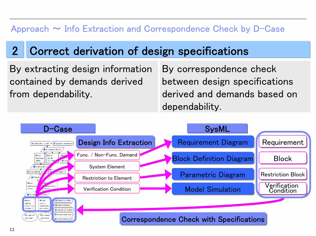
By extracting design information contained by demands derived from dependability.
By correspondence check between design specifications derived and demands based on dependability.
D-Case SysML
Func. / Non-Func. Demand
System Element
Restriction to Element Parametric DiagramParametric Diagram
Block Definition DiagramBlock Definition Diagram
Requirement DiagramRequirement Diagram
Model SimulationModel Simulation
Restriction BlockRestriction Block
BlockBlock
RequirementRequirement
Verification Condition
Verification ConditionVerification Condition
Design Info ExtractionDesign Info Extraction
Correspondence Check with SpecificationsCorrespondence Check with Specifications
Approach ~ Info Extraction and Correspondence Check by D-Case
2 Correct derivation of design specifications
11

By associating verification result to goal as evidence and correspondence check with relate demands or design specifications
D-Case SysML
Model Simulation
Model Simulation
Verification Result
Verification Result
Evidence AdditionEvidence Addition
Approach ~ Evidence Addition to D-Case
3Clarifying relationship of verification results,
demands, and design specifications
12

Outline of Dependable System Development Method
Collaboration of D-Case and SysML Modeling
D-Case SysML
Requirements Identification / Product Planning
Requirements Definition
S/W, H/W Development
System Verification
Requirements Validation
System Design
Use Case DiagramUse Case Diagram
Parametric DiagramParametric Diagram
Block Definition DiagramBlock Definition Diagram
Requirement DiagramRequirement Diagram
Internal Block DiagramInternal Block Diagram
State Machine DiagramState Machine Diagram
Functions & PreconditionFunctions & Precondition
Environment
System Operation Use Case
Func. / Non-Func. Demand
Requirement
System Element
Restriction to Element Verification Result
Verification Condition
Model Simulation Model Simulation
System Function Element
Element
Restriction
2. Correct derivation of design specifications2. Correct derivation of design specifications
3. Clarifying relationship of verification results, demands, and design specifications3. Clarifying relationship of verification results, demands, and design specifications
Just e
nough
derivatio
n o
f system
dem
ands
Just e
nough
derivatio
n o
f system
dem
ands
1.
Guaranty by Verification ResultsGuaranty by Verification Results
Provision DefinitionProvision Definition
Cause DefinitionCause Definition
Scene of Threat DefinitionScene of Threat Definition
Threat to Dependability DefinitionThreat to Dependability Definition
Top Goal DefinitionTop Goal Definition
13

Flow of Dependable System Development Method
D-Case SysML
Requirements DefinitionRequirements Definition
Top Goal DefinitionTop Goal Definition
Threat to Dependability DefinitionThreat to Dependability Definition
Scene of Threat DefinitionScene of Threat Definition
Cause DefinitionCause Definition
System DesignSystem Design
S/W ・ H/W DevelopmentS/W ・ H/W Development
System VerificationSystem Verification
Guaranty by Verification ResultsGuaranty by Verification Results
Provision DefinitionProvision Definition
Dependable System Development by D-Case and SysML Collaboration
14

Flow Detail - Top Goal and Threat to Dependability Definition
D-Case
Top Goal DefinitionTop Goal Definition
Define top goal and precondition on dependability
Define Top Goal in Terms of Dependability, Categorize Threats
Extract characteristics system needs and preconditions for dependability.
Threat to Dependability DefinitionThreat to Dependability Definition
Marshal all threats inhibiting dependability
Decompose top goal to threats by malfunctions, user mistakes, and others.
Example. Safety of In-Vehicle Cruise Control (CC) System
15

CC boot
DriverDriver
Flow Detail - Scene of Threat Definition
D-Case SysML
Scene of Threat DefinitionScene of Threat Definition Use Case DiagramUse Case Diagram Use Case
Verification Condition
Model Simulation Model Simulation
Clarify all the scenes inhibiting dependability
Define System Environment and Operations by Clarifying Scenes of Threat
Reflect
16
Clarify operations causing threatsClarify environment of system
Update use case by operations causing threats
Clarify association between user and operation of system
Update condition of verification scenario by environment of system
Clarify verification condition

Flow Detail - Cause Definition and Provision Definition
Analyze Cause of Threat, Make Provisions
D-Case
Cause DefinitionCause Definition
Cause analysisfor provisionAnalyze cause of threats for each scene
Provision DefinitionProvision Definition
Marshal system demandsfrom provisions for each cause of threat.
Make provision for each cause
17
CC<<Requirement>>
ID = REQ_01
Vehicle has cruise controlfeatures that support a driver.
Acceleration suppression control<<Requirement>>
ID = REQ 21
Acceleration suppression control is performed so that acceleration is less than threshold.
<<derive>>
Target speedsetting
Targetspeed-down
Target speed-up
Speed control
<<include>>
<<include>>
<<include>>
<<include>>
<<include>>
Speed monitor<<include>>
<<include>>
<<include>>
DriverDriver
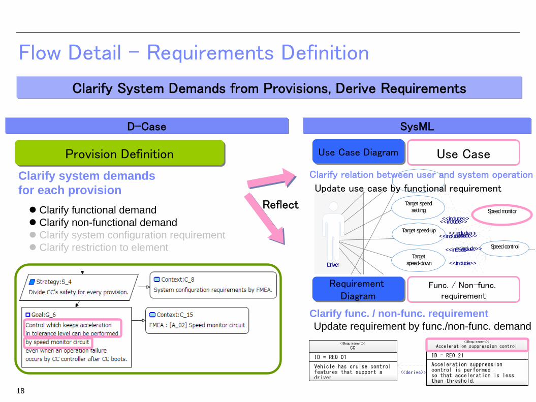
Flow Detail - Requirements Definition
D-Case SysML
Provision DefinitionProvision Definition
Requirement Diagram
Requirement Diagram
Func. / Non-func. requirement
Clarify system demands for each provision
Update requirement by func./non-func. demandClarify func. / non-func. requirement
Clarify System Demands from Provisions, Derive Requirements
Use CaseUse Case DiagramUse Case Diagram
Update use case by functional requirement
Clarify relation between user and system operation
Reflect
18
Clarify functional demand Clarify non-functional demand Clarify system configuration requirement Clarify restriction to element

Acceleration limit :
a < 0.35G.
Speed control<<Block>>
Values
Operations
breakPowerTarget
accelPowerTarget
breakTorque
throttleTorque
ccPower
breakPower
accelPower
<<allocate>>
speed
Flow Detail - System Design
D-Case SysML
Element
Update element by system configuration requirementClarify system architecture
Clarify Design Specifications based on System Demands and Requirements
Block Definition Diagram
Block Definition Diagram
Restriction
Update restriction to elementClarify system precondition and restriction
Parametric Diagram
Parametric Diagram
Reflect
Internal Block Diagram
Internal Block Diagram
19
Provision DefinitionProvision Definition
Clarify system demands for each provision Clarify functional demand Clarify non-functional demand Clarify system configuration requirement Clarify restriction to element
1
Speed monitor circuit<<Block>>
Values
Operations
1

Flow Detail - Guaranty by Verification Result
D-Case
Guaranty of Satisfaction of System Demands
SysML
Add trail by Verification
Guaranty by Verification ResultGuaranty by Verification Result
Associate verification result to goal
Clarification of satisfaction of system demands
0
20
40
60
80
100
120
0 5000 10000 15000 20000sp
eed
(km
/h)
time (ms)
0.28G MAX
20
Verification Result
Model Simulation Model Simulation
Verification result
System verification by executable model

par [パッケージ] Design [PAR_Vehicle]
Break<<Block>>
Values
Operations
breakPowerTargetbreakPower
CC controller<<Block>>
Values
Operations
powerOFF ccBtnccPower
speed
Speed sensor<<Block>>
Values
Operations
speed
Acceleration<<Block>>
Values
Operations
accelPowerTargetaccelPower
Electronic throttle<<Block>>
Values
Operations
pwrthrottleTorque
Throttle actuator<<Block>>
Values
Operations
pwr
CC User I/F<<Block>>
Values
Operations
ccBtn
Acceleration limit :
a < 0.35G.
Acceleration performance :a > 0.080G.
Target speed limit :
50km/h <= vt <= 100km/h.
<<allocate>>
Speed control<<Block>>
Values
Operations
breakPowerTarget
accelPowerTarget
breakTorque
throttleTorque
ccPower
breakPower
accelPower
<<allocate>><<allocate>>
Electronic break<<Block>>
Values
Operations
pwrbreakTorque
Break actuator<<Block>>
Values
Operations
pwr
Vehicle dynamics controller<<Block>>
Values
Operations
pwrspeed
Speed monitor circuit<<Block>>
Values
Operations
powerOFF speed
<<allocate>>CC condition monitor circuit<<Block>>
Values
Operations
ccBtn
speedpowerOFF
pwr =Kp ( Vp - Vt )+ Ki ∫(Vp - Vt ) dt
<<allocate>>
a = (thrust + drag) / mass
<<allocate>>
thrust = pwr / actualSpeed
<<allocate>>
actualSpeed = ∫a dt + v0
<<allocate>>
drag =
-1/2 * Cd * A
* densityOfAir
* actualSpeed̂2
<<allocate>>
Sedan :mass = 1700 kgWagon :mass = 2500 kg
<<allocate>>
Sedan :Cd = 0.44Wagon :Cd = 0.50
<<allocate>>
Sedan :A = 1.8 m̂2Wagon :A = 2.0 m̂2
<<allocate>>
densityOfAir = 1.2 kg/m̂3
<<allocate>>
req [パッケージ] Design [REQ_CC]
CC<<Requirement>>
ID = REQ_01
Vehicle has cruise control features that support a driver.
CC boot (Cruise)<<Requirement>>
ID = REQ_02
If a driver pushes the Cruise button when CC stops, CC should boot.
<<derive>>
CC stop (Cruise)<<Requirement>>
ID = REQ_08
If a driver pushes Cruise button when CCruns, CC should stop.
<<derive>>
Target speed setting (Set)<<Requirement>>
ID = REQ_03
If a driver pushes the Set button when CC boots, CC should set the current speed as a target speed.
<<derive>>
Target speed-down (Decel)<<Requirement>>
ID = REQ_04
If a driver pushes the Decel button when CC boots, the target speed shoulddecrease.
<<derive>>Target speed-up (Accel)
<<Requirement>>
ID = REQ_05
If a driver pushesAccel button when CC boots, the target speed should increase.
<<derive>>
CC pause<<Requirement>>
ID = REQ_06
If a driver puts on the break when CC runs, CC should pause.
<<derive>>
CC resume (Resume)<<Requirement>>
ID = REQ_07
If a driver pushes Resume button when CC pauses, CC should resume with the same setting as before pause.
<<derive>>
Quick response to operation<<Requirement>>
ID = REQ_12
CC responds within 1ms when driver operates.
<<derive>><<derive>> <<derive>><<derive>> <<derive>>
Operability<<Requirement>>
ID = REQ_11
CC can be operated byone-touch.
<<derive>> <<derive>><<derive>>
Speed limit<<Requirement>>
ID = REQ_18
Target speed is restricted from 50 km/h to 100km/h.
<<derive>><<derive>> <<derive>>
Acceleration limit<<Requirement>>
ID = REQ_13
Acceleration is less than 0.35G.
<<derive>> <<derive>>
Continuous duty<<Requirement>>
ID = REQ_15
Continuous duty of CC is carried out for more than 100 hours.
<<derive>>
Priority of driver operation<<Requirement>>
ID = REQ_16
Top priority is given tothe driver operation :accelerator operation, brake operation, and steering operation.
<<derive>> <<derive>>
Config Integrity<<Requirement>>
ID = REQ_17
Configuration data should not be changed unjustly.
<<derive>>
Acceleration performance<<Requirement>>
ID = REQ_14
When the difference of speed and target speed is more than 20km/h, acceleration should be more than 0.080G.
<<derive>><<derive>>
CC stop (PCS)<<Requirement>>
ID = REQ_09
If a stop request is received fromPCS when CC runs, CC should stop.
<<derive>>
Acceleration suppression control<<Requirement>>
ID = REQ_21
Acceleration suppression control is performed so that acceleration is less than threshold.
<<derive>>
<<derive>>
Speed monitor<<Requirement>>
ID = REQ_22
Speed is monitored.
<<derive>>
<<derive>>
CC emergency stop<<Requirement>>
ID = REQ_23
CC urgently stops when trouble is detected.
<<derive>>
CC condition monitor<<Requirement>>
ID = REQ_24
CC condition is monitored.
<<derive>>
uc [パッケージ] Design [UC_CC]
CC
CC stop
Target speedsetting
Targetspeed-down
Target speed-up
CC resume
Speed control<<include>>
<<include>>
<<include>>
<<include>>
CC pause
CC boot
CC condition monitor
<<include>>
<<include>>
<<include>>
<<include>> CC emergency stop
<<include>>
Speed monitor
<<include>>
<<include>>
<<include>>DriverDriver
ThrottleThrottle
PCSPCS
Advantage of applying this method
1. Improvement of Quality by Reflecting Development Intents from Upper Process to Lower Process
2. Modeling from Information on D-Case3. Improvement of Plan by Controlling Development Process by D-Case
D-Case SysMLDevelopment Process
Development Plan
Development Plan
Deve
lopm
ent E
xecutio
nD
eve
lopm
ent E
xecutio
n
Deve
lopm
ent C
ontro
lD
eve
lopm
ent C
ontro
l
Info Extraction to Model
Intension of Design
Intension of Demand
Reflect to Dev. Plan
1
23
21

Requirements DefinitionRequirements Definition
System DesignSystem Design
System VerificationSystem Verification
Clarify Development Intents by D-Case and Reflect to SysML Model
D-Case SysML
Use Case DiagramUse Case Diagram
Parametric DiagramParametric Diagram
Block Definition DiagramBlock Definition Diagram
Requirement DiagramRequirement Diagram
Internal Block DiagramInternal Block Diagram
State Machine DiagramState Machine Diagram
Use Case
Requirement
Verification Result
Verification Condition
Scene of Threat DefinitionScene of Threat Definition
Provision DefinitionProvision Definition
Threat to Dependability DefinitionThreat to Dependability Definition
Guaranty by Verification ResultsGuaranty by Verification Results
Top Goal DefinitionTop Goal Definition
Cause DefinitionCause Definition
Element
Element
Restriction
Model Simulation
Model Simulation
22
Advantage 1. Improvement of Quality by Reflecting Development Intents
Intension Intension of of
DemandDemand
Intension of Intension of DesignDesignEnvironment
System Operation
Func. / Non-Func. Demand
System Element
Restriction to Element
System Function
Acceleration limit :
a < 0.35G.
Speed control<<Block>>
CC boot
Acceleration suppression control<<Requirement>>
ID = REQ_21
Acceleration suppression control is performed so that acceleration is less than threshold.
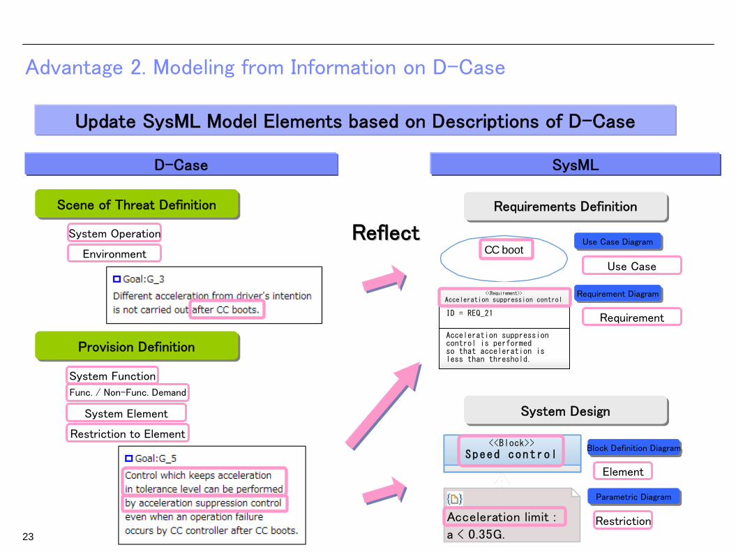
Update SysML Model Elements based on Descriptions of D-Case
D-Case SysML
Use Case DiagramUse Case Diagram
Parametric DiagramParametric Diagram
Block Definition DiagramBlock Definition Diagram
Requirement DiagramRequirement Diagram
Use Case
Requirement
Scene of Threat DefinitionScene of Threat Definition
Provision DefinitionProvision Definition
Element
Restriction23
Advantage 2. Modeling from Information on D-Case
Environment
System Operation
Func. / Non-Func. Demand
System Element
Restriction to Element
System Function
Requirements DefinitionRequirements Definition
System DesignSystem Design
ReflectReflect

D-CaseDevelopment Plan
Development Plan
Development Plan
Deve
lopm
ent E
xecutio
nD
eve
lopm
ent E
xecutio
n
Deve
lopm
ent C
ontro
lD
eve
lopm
ent C
ontro
l
Activities of Development
開発実績
Metrics for Workload Estimation
Advantage 3. Improvement of Plan by Controlling Development Process
Improve Development Plan by Just Enough Provisioning
24
Scene of Threat DefinitionScene of Threat Definition
Provision DefinitionProvision Definition
Threat to Dependability DefinitionThreat to Dependability Definition
Guaranty by Verification ResultsGuaranty by Verification Results
Top Goal DefinitionTop Goal Definition
Cause DefinitionCause Definition
Environment
System Operation
Func. / Non-Func. Demand
System Element
Restriction to Element
System Function
Activity : Contents of Actions
Metrics : Number of Actions
Extract development activities
cyclpaefically
Improve development plan
Extract metrics for workload
estimation
Improve man-hour plan

25
Guide for Supporting this Method
Modeling Guide and Template are Provided
Modeling Flow of D-Case and SysMLStyle Guide for D-Case NodeCollaboration of D-Case and SysML Model Description
Modeling Guide
Template
Pattern of Goal Structure in D-Case and Node NotationStructure of SysML Model
Target of Guide
Derivational Development of System in the Automotive Domain to apply Functional Safety Requirements

26
Sample of Applying this Method
~ In-Vehicle System Development Complying with ISO26262 ~

Correspondence Relation between this Method and ISO26262
This Method Corresponds ISO26262 Safety Lifecycle
Definition of top goal, precondition about safety
Clarification of threats inhibiting safety
Definition of system environment, operations
Definition of system users and operations
Definition of verification condition
Cause analysis for provision
Definition of system demands by provisions
Definition of functional, non-functional requirements
Definition of system architecture
Definition of system restrictions
Top Goal DefinitionTop Goal Definition
Threat to Dependability DefinitionThreat to Dependability Definition
Scene of Threat DefinitionScene of Threat Definition
Cause DefinitionCause Definition
Provision DefinitionProvision Definition
Guaranty by Verification ResultsGuaranty by Verification Results
Demonstration of satisfaction of system demands
Use Case DiagramUse Case Diagram
Requirement DiagramRequirement Diagram
Block Definition DiagramBlock Definition Diagram
Parametric DiagramParametric Diagram
Model SimulationModel Simulation
System verification by executable model
D-Case
3.5 Item definition Item identification 3.5 Item definition Item identification
3.7 Hazard analysis and risk assessment
Hazard identification
3.7 Hazard analysis and risk assessment
Hazard identification
3.8 Functional safety concept Decomposition by
functional safety requirement
3.8 Functional safety concept Decomposition by
functional safety requirement
4.6 Specification of the technical safety requirements
Decomposition by technical safety requirement
4.6 Specification of the technical safety requirements
Decomposition by technical safety requirement
4.7 System design Guaranty by Verification Results
4.7 System design Guaranty by Verification Results
ISO26262 SysML
27
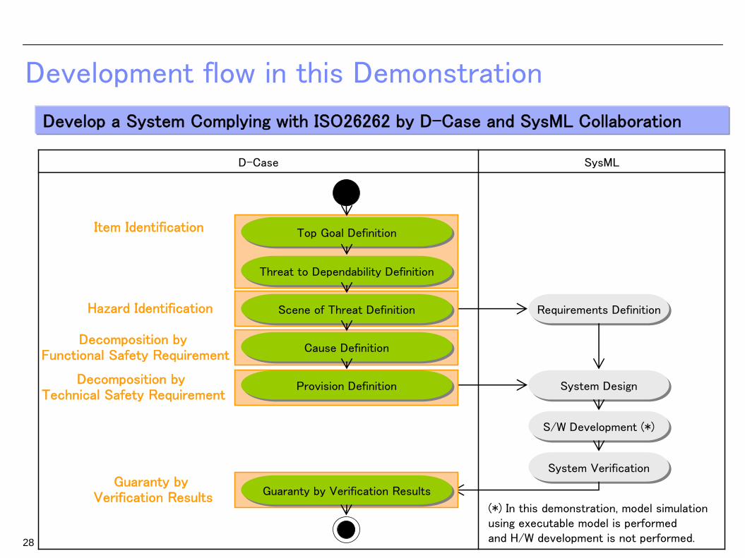
Development flow in this Demonstration
D-Case SysML
Requirements DefinitionRequirements Definition
System DesignSystem Design
S/W Development (*)S/W Development (*)
System VerificationSystem Verification
Develop a System Complying with ISO26262 by D-Case and SysML Collaboration
Item Identification
Hazard Identification
Decomposition by Functional Safety Requirement
Decomposition by Technical Safety Requirement
Guaranty by Verification Results
Top Goal DefinitionTop Goal Definition
Threat to Dependability DefinitionThreat to Dependability Definition
Scene of Threat DefinitionScene of Threat Definition
Cause DefinitionCause Definition
Guaranty by Verification ResultsGuaranty by Verification Results
Provision DefinitionProvision Definition
(*) In this demonstration, model simulation using executable model is performedand H/W development is not performed.28

29
D-Case and SysML Modeling based on ISO26262
Target D-Case SysML
Category D-Case Structure Node Notation Association from D-Case
Association to D-Case
Item Item Definition Goal to Achieve,
Environment and Restriction
- -
Identification of Hazards Environment and Operation of System
Environment and Operation of System
Use Case
Verification condition
Decomposition by Functional Safety Requirements
Detailed Cause to Take Actions
- -
Decomposition by Technical Safety Requirements
System Requirement Functional and non- functional requirement, Functional Block and Restriction
Use Case, requirement, Functional Block and Restriction
Guaranty by Verification Results
Information required to Verification
Condition and Processing of Control
Verification Result
• D-Case Structure based on Safety Lifecycle• SysML Modeling Collaborated with D-Case
Contents of Modeling Guide
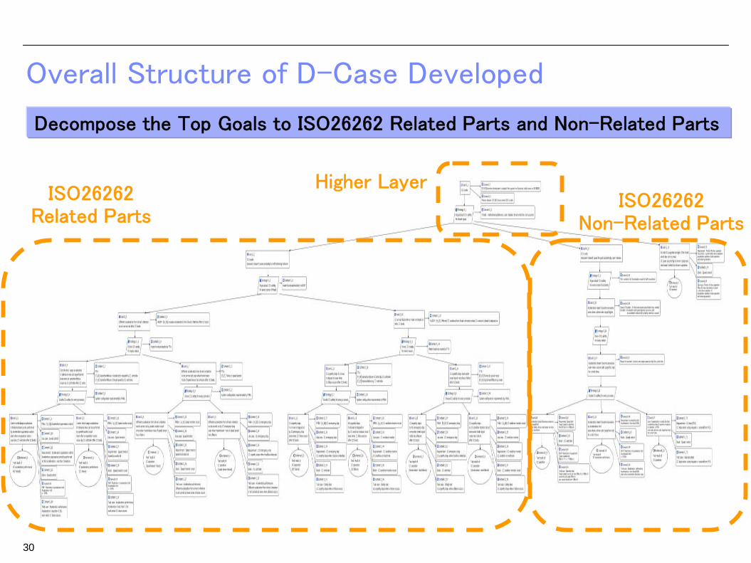
30
Overall Structure of D-Case Developed
Decompose the Top Goals to ISO26262 Related Parts and Non-Related Parts
ISO26262 Related Parts
ISO26262Non-Related Parts
Higher Layer

31
Safety and Reliability Requirements on ISO26262
Absence of unreasonable risk due to hazards caused by malfunctioning behavior of E/E systems
ISO26262
Reduce the risk so that hazards do not arise or result in an accident, even when system has a failure
Safety Requirement
System can continue to operate correctly
Reliability Requirement
Safety and Reliability Required by Functional Safety
Decompose to Safety and Reliability Requirement

32
Demonstration – Target System
Control which keeps acceleration in tolerance level can be performed even when an operation failure occurs by CC controller
Different acceleration from driver's intention is not carried out even when transmission route of speed sensor has a failure
System
Function
Defective
Hazard
Cruise Control System (CC)
Speed control set by driver
System failure or calculation error
Excessive acceleration from driver’s intension
Safety Requirement
Reliability Requirement
Different acceleration from driver’s intension is not carried outFunctional Safety Requirement
PreconditionDerivational development of system to apply functional safety requirements
D-Case SysML
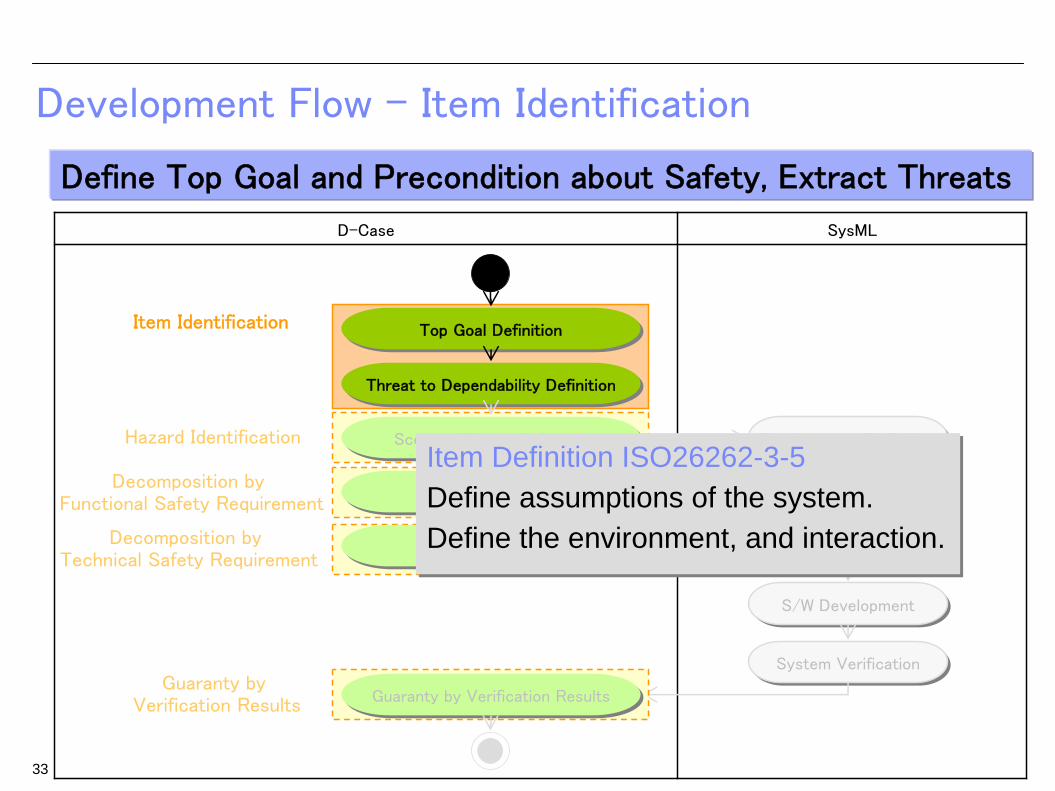
Development Flow – Item Identification
Requirements DefinitionRequirements Definition
System DesignSystem Design
S/W DevelopmentS/W Development
System VerificationSystem Verification
Define Top Goal and Precondition about Safety, Extract Threats
Item Identification
Hazard Identification
Decomposition by Functional Safety Requirement
Decomposition by Technical Safety Requirement
Guaranty by Verification Results
Top Goal DefinitionTop Goal Definition
Threat to Dependability DefinitionThreat to Dependability Definition
Scene of Threat DefinitionScene of Threat Definition
Cause DefinitionCause Definition
Guaranty by Verification ResultsGuaranty by Verification Results
Provision DefinitionProvision Definition
33
Item Definition ISO26262-3-5Define assumptions of the system.Define the environment, and interaction.
Item Definition ISO26262-3-5Define assumptions of the system.Define the environment, and interaction.

34
Top Goal Definition based on Safety
Clarify the precondition of the target systemClarify the precondition of the target system
Function
Cruise Control (CC) system controls speed set by driver.
Precondition
• [CY_01] Derivation development is adopted. Next system has functional safety based on ISO 26262.
• [CY_02] CC is safe.
• [CY_11] CC has 5 buttons on UI:Cruise, Set, Accel, Decel, and Resume.
• [CY_12] Driver controls CC via UI and brake pedal.
• [CY_13] Driver can always set CC in driving the car.
• [CY_21] OS is xx OS.
Cruise Set Accel Decel
UIBrake
Cruise Control(CC) Controller
Cruise Control(CC) Controller
Operation Signal Brake Signal
ThrottleThrottle
Speed Control
Resume
MonitorMonitor
PCSPCS Stop Signal

35
Top Goal:CC is safeTop Goal:CC is safe
(index)
D-CaseD-Case SysMLSysML ISO 26262ISO 26262
Focusing on the safety required to ISO26262,Focusing on the safety required to ISO26262,define the top goal as define the top goal as ““<system> is safe<system> is safe””..
Top Goal of D-Case
Goal in D-Case<System> is <Safe>.
Goal in D-Case<System> is <Safe>.
Top Goal Definition
36
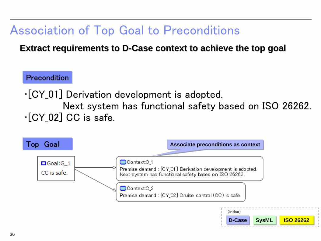
Association of Top Goal to Preconditions
Associate preconditions as contextAssociate preconditions as context
• [CY_01] Derivation development is adopted. Next system has functional safety based on ISO 26262.
• [CY_02] CC is safe.
Precondition
Top Goal
(index)
D-CaseD-Case SysMLSysML ISO 26262ISO 26262
Extract requirements to DExtract requirements to D--Case context to achieve the top goalCase context to achieve the top goal

Categorization of Threats Inhibiting SafetyDecompose top goal based on functional safety for the target sysDecompose top goal based on functional safety for the target systemtem
37
CC is safeCC is safe
It doesn’t cause accidents by malfunctioning behavior It doesn’t cause accidents by malfunctioning behavior
suppress damage of the threat which has not occurred
suppress damage of the threat which has not occurred
It doesn’t cause the past accidents by user mistake It doesn’t cause the past accidents by user mistake
ISO 26262 Related Parts(index)
D-CaseD-Case SysMLSysML ISO 26262ISO 26262
D-Case SysML
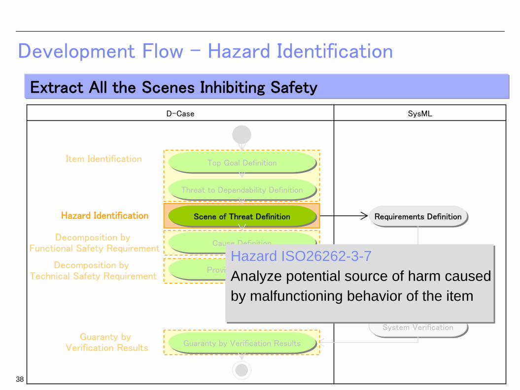
Development Flow – Hazard Identification
Requirements DefinitionRequirements Definition
System DesignSystem Design
S/W DevelopmentS/W Development
System VerificationSystem Verification
Extract All the Scenes Inhibiting Safety
Item Identification
Hazard Identification
Decomposition by Functional Safety Requirement
Decomposition by Technical Safety Requirement
Guaranty by Verification Results
Top Goal DefinitionTop Goal Definition
Threat to Dependability DefinitionThreat to Dependability Definition
Scene of Threat DefinitionScene of Threat Definition
Cause DefinitionCause Definition
Guaranty by Verification ResultsGuaranty by Verification Results
Provision DefinitionProvision Definition
38
Hazard ISO26262-3-7Analyze potential source of harm causedby malfunctioning behavior of the item
Hazard ISO26262-3-7Analyze potential source of harm causedby malfunctioning behavior of the item

Decompose based on the HAZOP result
Decompose based on the HAZOP result
ID Output Guide Word Scene Hazard
H_01 CC Controller More After CC boots Excessive acceleration from driver's intention
H_02 CC Controller No or not Break is stepped on after CC boots Different CC condition from driver's intention
Clarification of Scene of Threat based on HAZOP
Clarify scenes of hazards by HAZOPClarify scenes of hazards by HAZOP
39
Decompose the goal by Decompose the goal by scenes of hazards derived from HAZOPscenes of hazards derived from HAZOP
Associate Associate hazards with hazards with contextscontexts
(index)
D-CaseD-Case SysMLSysML ISO 26262ISO 26262

Requirements Definition – Update Use Case Diagram and Verification Condition
Reflect users and system operations to use case diagram and Reflect users and system operations to use case diagram and verification conditions to test casesverification conditions to test cases
40
uc [パッケージ] Design [UC_CC]
CC
CC stop
Target speedsetting
Targetspeed-down
Target speed-up
CC resume
Speed control<<include>>
<<include>>
<<include>>
<<include>>
CC pause
CC boot
CC condition monitor
<<include>>
<<include>>
<<include>>
<<include>> CC emergency stop
<<include>>
Speed monitor
<<include>>
<<include>>
<<include>>DriverDriver
ThrottleThrottle
PCSPCS
UserUser
OperationOperationUse Case DiagramUse Case Diagram
(index)
D-CaseD-Case SysMLSysML ISO 26262ISO 26262
D-CaseD-Case
Update use case diagram by Update use case diagram by referring description about functionreferring description about function
Extract verification Extract verification conditionsconditions
Verification ConditionVerification Condition
0
20
40
60
80
100
120
0 5000 10000 15000 20000
Time (ms)
spee
d (k
m/h
)
After CC boots, acceleration should changeas a driver intends.

D-Case SysML
Development Flow – Decomposition by Functional Safety Requirement
Requirements DefinitionRequirements Definition
System DesignSystem Design
S/W DevelopmentS/W Development
System VerificationSystem Verification
Analyze Cause for Provision
Item Identification
Hazard Identification
Decomposition by Functional Safety Requirement
Decomposition by Technical Safety Requirement
Guaranty by Verification Results
Top Goal DefinitionTop Goal Definition
Threat to Dependability DefinitionThreat to Dependability Definition
Scene of Threat DefinitionScene of Threat Definition
Cause DefinitionCause Definition
Guaranty by Verification ResultsGuaranty by Verification Results
Provision DefinitionProvision Definition
41
Functional Safety Concept ISO26262-3-8Derive requirements taking into account the preliminary architectural assumptions
Functional Safety Concept ISO26262-3-8Derive requirements taking into account the preliminary architectural assumptions
Safety Goal ISO26262-3-7Extract requirements to avoid hazards basedon the hazard analysis and the risk assessment
Safety Goal ISO26262-3-7Extract requirements to avoid hazards basedon the hazard analysis and the risk assessment

[H_01] Excessive accelerationfrom driver's intention after
CC boots.
Acceleration request isexcessive.
[F_01] Operation failure ofacceleration request by CC
controller.
Target speed directed byoperation UI is excessive.
Value of speed sensor is toosmall.
[F_02] Operation failure oftarget speed by CC controller.
[F_03] Failure of speedsensor.
ID Output Guide Word Scene Hazard
H_01 CC Controller More After CC boots Excessive acceleration from driver's intention
H_02 CC Controller No or not Break is stepped on after CC boots Different CC condition from driver's intention
Clarification of Cause of Threat based on FTA
42
Hazards extracted by HAZOPHazards extracted by HAZOP
Analyze causes of hazards by FTAAnalyze causes of hazards by FTA
Analyze causes of hazards by FTAAnalyze causes of hazards by FTA
Control which keeps acceleration in tolerance level can be performed even when an operation failure occurs by CC controller.
Extract functional safety requirementsExtract functional safety requirements
(index)
D-CaseD-Case SysMLSysML ISO 26262ISO 26262
[H_02] Different CC condition fromdriver's intention when a break is
stepped on after CC boots.
Break signal is not transmitted.[F_04] Operation failure of control
by CC controller.
[F_05] Failure by signal route. [F_06] Signal send failure by break.[F_07] Receive failure by CC
controller.

Clarification of Cause of Threat based on FTADecompose the goal by causes of hazard based on FTADecompose the goal by causes of hazard based on FTA
43
Decompose based on provision of hazards
Decompose based on provision of hazards
Associate causes of hazards with D-Case contexts
Associate causes of hazards with D-Case contexts
(index)
D-CaseD-Case SysMLSysML ISO 26262ISO 26262Control which keeps acceleration in tolerance level can be performed even when an operation failure occurs by CC controller.
Functional safety requirementsFunctional safety requirements

D-Case SysML
Development Flow – Decomposition by Technical Safety Requirement
Requirements DefinitionRequirements Definition
System DesignSystem Design
S/W DevelopmentS/W Development
System VerificationSystem Verification
Refine System Demands based on Provisions for Causes
Item Identification
Hazard Identification
Decomposition by Functional Safety Requirement
Decomposition by Technical Safety Requirement
Guaranty by Verification Results
Top Goal DefinitionTop Goal Definition
Threat to Dependability DefinitionThreat to Dependability Definition
Scene of Threat DefinitionScene of Threat Definition
Cause DefinitionCause Definition
Guaranty by Verification ResultsGuaranty by Verification Results
Provision DefinitionProvision Definition
44
Technical Safety Requirements ISO26262-4-6Specify derived requirement taking into accountthe environment and restrictions
Technical Safety Requirements ISO26262-4-6Specify derived requirement taking into accountthe environment and restrictions

Clarification of Provision based on FMEAClarify system demands just enough using provisions by FMEAClarify system demands just enough using provisions by FMEA
45
Decompose by provisions Decompose by provisions
Investigate provisions by FMEA
Investigate provisions by FMEA
S/W H/WF_01 CC Controller Operation failure (acceler Program bug 6 (M) 1 (L) 5 (M) 30F_02 CC Controller Operation failure (target sProgram bug 3 (L) 1 (L) 1 (L) 3F_03 Speed sensor Abnormal value Breakdown 9 (H) 5 (M) 1 (L) 45F_04 CC Controller Operation failure (control)Program bug 9 (H) 1 (L) 1 (L) 9F_05 Transmission rouAbnormal value Breakdown 9 (H) 5 (M) 1 (L) 45F_06 Brak Operation failure (send) Breaking of wire 9 (H) 1 (L) 1 (L) 9F_07 CC Controller Operation failure (receive Breaking of wire 9 (H) 1 (L) 5 (M) 45
IDProvision
Component Failure mode Factor FrequencyDifficulty ofdetection
Severity ofinfluence
Riskpriority
[A_01] Accelerationsuppression control
[A_03] CCemergency stop
[A_02] Speed monitor circuit
[A_04] CC condition monitorcircuit
Associate the provision with context and clarify correspondence relation with demands
Associate the provision with context and clarify correspondence relation with demands

Requirements Definition – Update Use Case DiagramBasing on system demands, update users and system operations Basing on system demands, update users and system operations to use case diagramto use case diagram
46
uc [パッケージ] Design [UC_CC]
CC
CC stop
Target speedsetting
Targetspeed-down
Target speed-up
CC resume
Speed control<<include>>
<<include>>
<<include>>
<<include>>
CC pause
CC boot
CC condition monitor
<<include>>
<<include>>
<<include>>
<<include>> CC emergency stop
<<include>>
Speed monitor
<<include>>
<<include>>
<<include>>DriverDriver
ThrottleThrottle
PCSPCS
Update ISO26262 Related Parts
UserUser
OperationOperation
Use Case DiagramUse Case Diagram
(index)
D-CaseD-Case SysMLSysML ISO 26262ISO 26262
Update uUpdate use case diagram by referring a se case diagram by referring a technical safety requirement about functiontechnical safety requirement about function
D-CaseD-Case

Requirements Definition – Update Requirement Diagram
Basing on system demands, update requirements to requirement diaBasing on system demands, update requirements to requirement diagramgram
47
req [パッケージ] Design [REQ_CC]
CC<<Requirement>>
ID = REQ_01
Vehicle has cruise control features that support a driver.
CC boot (Cruise)<<Requirement>>
ID = REQ_02
If a driver pushes the Cruise button when CC stops, CC should boot.
<<derive>>
CC stop (Cruise)<<Requirement>>
ID = REQ_08
If a driver pushes Cruise button when CCruns, CC should stop.
<<derive>>
Target speed setting (Set)<<Requirement>>
ID = REQ_03
If a driver pushes the Set button when CC boots, CC should set the current speed as a target speed.
<<derive>>
Target speed-down (Decel)<<Requirement>>
ID = REQ_04
If a driver pushes the Decel button when CC boots, the target speed shoulddecrease.
<<derive>>Target speed-up (Accel)
<<Requirement>>
ID = REQ_05
If a driver pushesAccel button when CC boots, the target speed should increase.
<<derive>>
CC pause<<Requirement>>
ID = REQ_06
If a driver puts on the break when CC runs, CC should pause.
<<derive>>
CC resume (Resume)<<Requirement>>
ID = REQ_07
If a driver pushes Resume button when CC pauses, CC should resume with the same setting as before pause.
<<derive>>
Quick response to operation<<Requirement>>
ID = REQ_12
CC responds within 1ms when driver operates.
<<derive>><<derive>> <<derive>><<derive>> <<derive>>
Operability<<Requirement>>
ID = REQ_11
CC can be operated byone-touch.
<<derive>> <<derive>><<derive>>
Speed limit<<Requirement>>
ID = REQ_18
Target speed is restricted from 50 km/h to 100km/h.
<<derive>><<derive>> <<derive>>
Acceleration limit<<Requirement>>
ID = REQ_13
Acceleration is less than 0.35G.
<<derive>> <<derive>>
Continuous duty<<Requirement>>
ID = REQ_15
Continuous duty of CC is carried out for more than 100 hours.
<<derive>>
Priority of driver operation<<Requirement>>
ID = REQ_16
Top priority is given tothe driver operation :accelerator operation, brake operation, and steering operation.
<<derive>> <<derive>>
Config Integrity<<Requirement>>
ID = REQ_17
Configuration data should not be changed unjustly.
<<derive>>
Acceleration performance<<Requirement>>
ID = REQ_14
When the difference of speed and target speed is more than 20km/h, acceleration should be more than 0.080G.
<<derive>><<derive>>
CC stop (PCS)<<Requirement>>
ID = REQ_09
If a stop request is received fromPCS when CC runs, CC should stop.
<<derive>>
Acceleration suppression control<<Requirement>>
ID = REQ_21
Acceleration suppression control is performed so that acceleration is less than threshold.
<<derive>>
<<derive>>
Speed monitor<<Requirement>>
ID = REQ_22
Speed is monitored.
<<derive>>
<<derive>>
CC emergency stop<<Requirement>>
ID = REQ_23
CC urgently stops when trouble is detected.
<<derive>>
CC condition monitor<<Requirement>>
ID = REQ_24
CC condition is monitored.
<<derive>>
Functional Requirements
Functional Requirements
Non-functional Requirements
Non-functional Requirements
Update ISO26262 Related Parts
D-CaseD-Case
Requirement DiagramRequirement Diagram
Update requirement diagramUpdate requirement diagram related to functional safetyrelated to functional safety

System Design – Update Block Definition DiagramBasing on system demands, uBasing on system demands, update system architecturepdate system architecture
to block definition diagramto block definition diagram
48
bdd [パッケージ] Design[BDD ]
Vehicle<<Block>>
Values
Operations
CC controller<<Block>>
Values
Operations
1
Break<<Block>>
Values
Operations
1
CC User I/F<<Block>>
Values
Operations
1
Speed sensor<<Block>>
Values
Operations
1
Vehicle dynamics controller<<Block>>
Values
Operations
Electronic throttle<<Block>>
Values
Operations
1
Throttle actuator<<Block>>
Values
Operations
1
PCS controller<<Block>>
Values
Operations
1
Front obstacle detection <<Block>>
Values
Operations
1
Speed control<<Block>>
Values
Operations
1
1
CC condition monitor circuit<<Block>>
Values
Operations
1
1
Acceleration<<Block>>
Values
Operations
1
Electronic break<<Block>>
Values
Operations
1
Break actuator<<Block>>
Values
Operations
1
Speed monitor circuit<<Block>>
Values
Operations
1
1
Block Definition DiagramBlock Definition Diagram
Add block extracted by Add block extracted by technical safety technical safety requirementsrequirements
BlockBlockUpdate ISO26262 Related Parts
Functions related to Functional Safety
Functions related to Functional Safety
D-CaseD-Case

System Design – Update Parametric DiagramUpdate Update restrictions, constant value and formularestrictions, constant value and formula to parametric diagramto parametric diagram
49
Acceleration limit :
a < 0.35G.
Acceleration performance :a > 0.080G.
Speed control<<Block>>
Values
Operations
breakPowerTarget
accelPowerTarget
breakTorque
throttleTorque
ccPower
breakPower
accelPower
<<allocate>><<allocate>>
Electronic break<<Block>>
Values
Operations
pwrbreakTorque
Vehicle dynamics controller<<Block>>
Values
Operations
pwrspeed
Speed monitor circuit<<Block>>
Values
Operations
powerOFF speed
<<allocate>>CC condition monitor circuit<<Block>>
Values
Operations
ccBtn
speedpowerOFF
<<allocate>
thrust = pwr / actualSpeed
<<allocate>>
drag =
-1/2 * Cd * A
* densityOfAir
* actualSpeed^
<<allocate>>
Sedan :mass = 1700 kgWagon :mass = 2500 kg
<<allocate>>
Sedan :Cd = 0.44Wagon :Cd = 0.50
<<allocate>>
Sedan :A = 1.8 m 2̂Wagon :A = 2.0 m 2̂
<<allocate>>
densityOfAir = 1.2 kg/m^3
<<allocate>>
Update restriction by safety requirementUpdate restriction by safety requirement
Parametric DiagramParametric Diagram
Update ISO26262 Related Parts
D-CaseD-Case
Safety Requirements
Safety Requirements
Restrictions, Constant Value, Formula, Intentions
Restrictions, Constant Value, Formula, Intentions

System Design – Update Internal Block DiagramUpdate internal structure of blocks to internal block diagramUpdate internal structure of blocks to internal block diagram
50
ibd [Block] Speed monitor circuit [IBD_Speed monitor circuit]
powerOFFspeed powerOFF
<<flow>>
speed
<<flow>>
Read speed1
Attributes
Operations
speed Speed
Judge1
Attributes
Operations
ResultSpeed
Send failure message1
Attributes
Operations
powerOFFResult
Internal Structure InternalInternal
StructureStructure
Internal Block DiagramInternal Block Diagram
Extract system elementExtract system elementby technical safety by technical safety requirementsrequirements from Dfrom D--Case,Case,similar to block definition similar to block definition diagramdiagram
Update ISO26262 Related Parts

Speed control<<Block>>
Values
Operations
1
1
Speed monitor circuit<<Block>>
Values
Operations
1
Acceleration limit :
a < 0.35G.
<<allocate>>Speed monitor circuit
<<Block>>
Values
Operations
powerOFF speed
<<allocate>>
ContextContext
Parametric DiagramParametric Diagram
D-CaseD-Case
ConstraintConstraint
Association by DAssociation by D--Case Case data collaboration data collaboration function on SW function on SW development environment development environment (*1)(*1)
Block Definition DiagramBlock Definition Diagram
BlockBlock
Correspondence Check between System Demands and Design Specifications
Check correspondence of design specifications by associating bloCheck correspondence of design specifications by associating blocks of cks of block definition diagram and restrictions of parametric diagramblock definition diagram and restrictions of parametric diagram
Check correspondence Check correspondence of design specifications of design specifications with goals or contextswith goals or contexts
51(*1)D-Case data collaboration function on SW development environment http://www.dependable-os.net/tech/D-Case-OSLC/index.html

S/W Development
stm [Block] AccController [statechart_0]
init
running
cycle1ms
evAccPowerRequest(this->power) to itsArbitrationController
tm(1)/if (this->isWorking) {
double diffVelocity = (this->targetVelocity - this->velocity) / 3.6; // [m/s]this->sumDVelocity += diffVelocity;this->power += Kp * diffVelocity + Ki * this->sumDVelocity;if(this->power > this->maxPower) this->power = this->maxPower;if(this->power < -this->maxPower) this->power = -this->maxPower;
}else {
this->power = 0.0;}
Off
On
Working
evAccSetBtn/set(this->velocity);
evAccAccelBtn/accel();
evAccDecelBtn/decel();
Unset
evAccSetBtn[valid(this->velocity)]/set(this->velocity);
SleepingevAccBreakPedal
evAccResumeBtn
evAccSetBtn/set(this->velocity);
evAccAccelBtn/accel();
evAccDecelBtn/decel();
evAccCruiseBtn
evAccCruiseBtn
evAccOFF
sensoring
evSpeedChanged/this->velocity = params->velocity;
evPowerOFF
Generate source codes from state machine diagrams defining Generate source codes from state machine diagrams defining dynamical behavior of the systemdynamical behavior of the system
Automatically generate source codes from
state machine diagrams
Automatically generate source codes from
state machine diagrams
52
State Machine DiagramState Machine Diagram

D-Case SysML
Development Flow – Guaranty by Verification Results
Requirements DefinitionRequirements Definition
System DesignSystem Design
S/W DevelopmentS/W Development
System VerificationSystem Verification
Clarify Satisfaction of System Demands
Item Identification
Hazard Identification
Decomposition by Functional Safety Requirement
Decomposition by Technical Safety Requirement
Guaranty by Verification Results
Top Goal DefinitionTop Goal Definition
Threat to Dependability DefinitionThreat to Dependability Definition
Scene of Threat DefinitionScene of Threat Definition
Cause DefinitionCause Definition
Guaranty by Verification ResultsGuaranty by Verification Results
Provision DefinitionProvision Definition
53
Verification ISO26262-4-8D-Case provides the system environment, restriction and criteria. SysML models provide structure and behavior of the component. These are used for verification.
Verification ISO26262-4-8D-Case provides the system environment, restriction and criteria. SysML models provide structure and behavior of the component. These are used for verification.
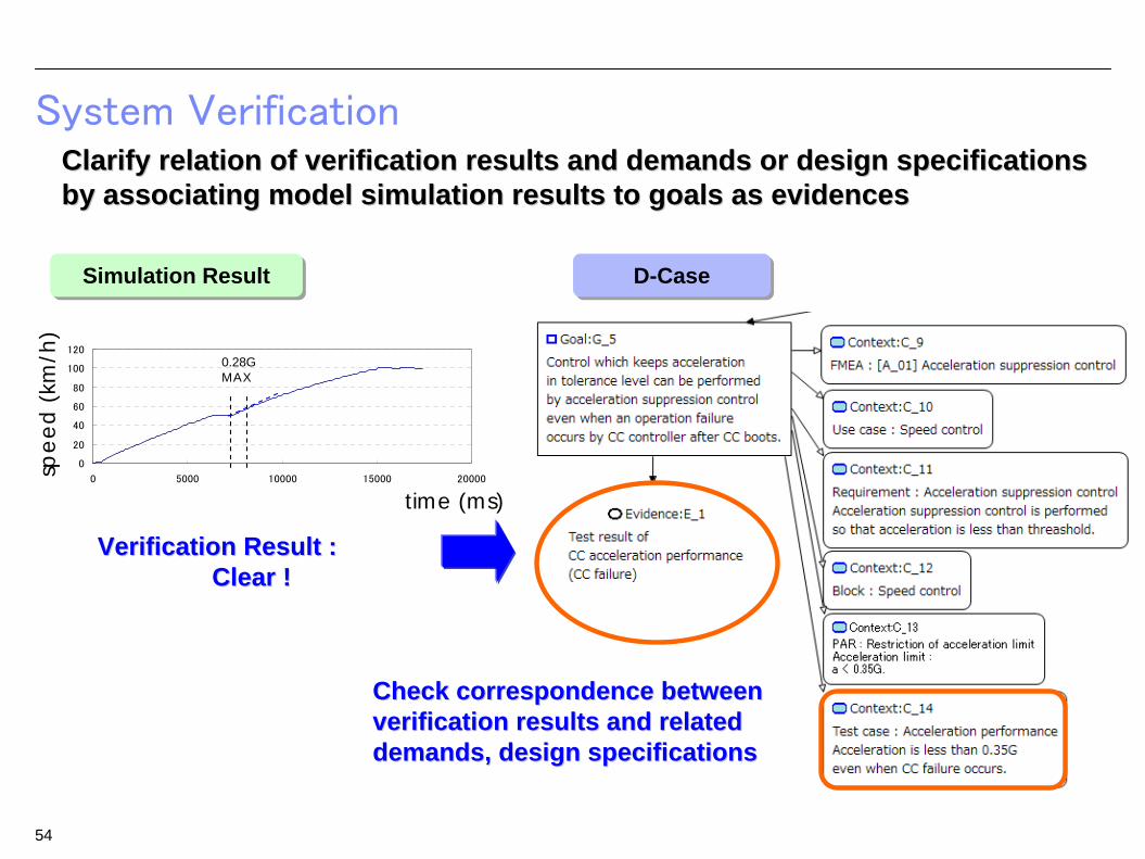
System Verification
0
20
40
60
80
100
120
0 5000 10000 15000 20000
Simulation ResultSimulation Result
Verification Result :Verification Result :Clear !Clear !
spee
d (k
m/h
)
time (ms)
0.28G MAX
D-CaseD-Case
Clarify relation of verification results and demands or design sClarify relation of verification results and demands or design specifications pecifications by associating model simulation results to goals as evidencesby associating model simulation results to goals as evidences
54
Check correspondence between Check correspondence between verification results and related verification results and related demands, design specificationsdemands, design specifications

ConclusionThis Documents Shows the Method and Guide of Developing Dependable System from upper process to lower process by D-Case and SysML Collaboration
55
Development of Dependable System is realized by D-Case and SysML Collaboration Just enough derivation of system demands Correct derivation of design specifications
by D-Case data collaboration function on SW development environment Clarifying relationship of verification results, demands, and design
specifications
Guide
Development of Dependable System
Modeling Flow of D-Case and SysML Style Guide for D-Case Node Collaboration of D-Case and SysML Model Description

END OF PACKAGE
56