dependable low-altitude obstacle avoidance for robotic helicopters operating in rural areas
TRANSCRIPT

Dependable Low-altitude Obstacle Avoidancefor Robotic Helicopters Operating in Rural Areas
• • • • • • • • • • • • • • • • • • • • • • • • • • • • • • • • • • • •
Torsten Merz and Farid KendoulAutonomous Systems Laboratory, CSIRO ICT Centre, 1 Technology Court, Pullenvale, Queensland 4069, Australiae-mail: [email protected], [email protected]
Received 10 July 2012; accepted 15 February 2013
This paper presents a system enabling robotic helicopters to fly safely without user interaction at low altitudeover unknown terrain with static obstacles. The system includes a novel reactive behavior-based methodthat guides rotorcraft reliably to specified locations in sparsely occupied environments. System dependabilityis, among other things, achieved by utilizing proven system components in a component-based design andincorporating safety margins and safety modes. Obstacle and terrain detection is based on a vertically mountedoff-the-shelf two-dimensional LIDAR system. We introduce two flight modes, pirouette descent and wagglecruise, which extend the field of view of the sensor by yawing the aircraft. The two flight modes ensure thatall obstacles above a minimum size are detected in the direction of travel. The proposed system is designedfor robotic helicopters with velocity and yaw control inputs and a navigation system that provides position,velocity, and attitude information. It is cost effective and can be easily implemented on a variety of helicoptersof different sizes. We provide sufficient detail to facilitate the implementation on single-rotor helicopters with arotor diameter of approximately 1.8 m. The system was extensively flight-tested in different real-world scenariosin Queensland, Australia. The tests included flights beyond visual range without a backup pilot. Experimentalresults show that it is feasible to perform dependable autonomous flight using simple but effective methods.C© 2013 Wiley Periodicals, Inc.
1. INTRODUCTION
In airborne remote sensing, flights are conducted at low alti-tude or close to obstacles if sensors must be placed at a shortdistance from objects of interest due to, among other things,limited spatial sensor resolution, limited sensing range, oc-clusion, or atmospheric disturbance. Applications of air-borne remote sensing in rural areas include crop monitoringand inspection of farm infrastructure. In addition to require-ments in remote sensing, operating unmanned aircraft closeto terrain and obstacles decreases the risk of collisions withmanned aircraft, which usually operate at higher altitudeand clear of obstacles.
Low-altitude flights close to obstacles are performedmore easily with rotorcraft than with fixed-wing aircraftdue to their ability to fly at any low speed. Unmanned air-craft are attractive because using manned aircraft is oftenmore expensive and hazardous for such operations. Whilesmaller unmanned rotorcraft such as electric multirotorsare sufficient for some applications, often larger aircraftare required for traveling longer distances and carryingheavier sensors. However, operations of larger unmannedhelicopters are currently constrained by the requirement for
Direct correspondence to: Torsten Merz e-mail: [email protected].
skilled and possibly certified pilots and reliable communi-cation links, especially for operations beyond visual rangein unknown environments.
This paper presents the LAOA (low-altitude obstacleavoidance) system. Its goal is to guide a robotic helicoptersuch that it arrives at a specified location without humaninteraction and without causing damage to the environ-ment or the aircraft. There is no requirement regarding thetrajectory. Safety is an important system requirement as es-pecially larger helicopters may be hazardous. In addition tobeing safe, the system should reliably guide the helicopterto a specified location. Safety and reliability are both at-tributes of dependability. System dependability has beenthe primary requirement of our work. System performancein terms of minimal task execution time or minimal traveldistance has been a secondary requirement. In addition tobeing dependability, we aimed for a cost-effective, genericsystem that can be implemented in a relatively short time.
The LAOA system enables safe autonomous operationsof robotic helicopters in environments with an unknownterrain profile and unknown obstacles under the followingassumptions:
(1) there is no other aircraft operating in the area and ob-stacles are static,
(2) there are no overhead obstacles,
Journal of Field Robotics, 1–33 C© 2013 Wiley Periodicals, Inc.View this article online at wileyonlinelibrary.com • DOI: 10.1002/rob.21455

2 • Journal of Field Robotics—2013
Inspection camera
Flight and navigation computers2D LIDAR system
Figure 1. One of CSIRO’s unmanned helicopters with an inte-grated LAOA system. The helicopter is configured for inspec-tions of vertical structures.
(3) there are no obstacles smaller or thinner than the systemcan detect at the minimum stopping distance, and
(4) the base helicopter system is serviceable and operatedwithin specified weather limitations.
We assume the base helicopter system includes a con-trol and navigation system as specified in this paper. TheLAOA system makes use of the particular flight proper-ties of helicopters. It is designed for a variety of helicoptersof different sizes. We have tested it on a small unmannedsingle-rotor helicopter (Figure 1).
Reactive behavior-based methods have been success-fully applied in many areas of robotics, but their potentialhas not been explored much for robotic helicopters per-forming real-world tasks. Given our task specification, wedecided it was worthwhile investigating. For the obstacleavoidance part, a reactive navigation approach without aglobal planning component was chosen because (1) suffi-ciently accurate and current maps are often not availablefor the mission areas, (2) mapping and planning during theflight does not necessarily increase efficiency of mission ex-ecution in rural areas,1 and (3) a reactive approach helpsto reduce computational resources required for real-timeimplementation. Range information from LIDAR (light de-tection and ranging, also LADAR) is used to create stimulifor the reactive system and for height control during ter-rain following. We decided to utilize LIDAR technology be-cause from our experience with different sensing options, aLIDAR-based approach was likely to give us the best resultsfor terrain and obstacle detection.
1The number of obstacles encountered during remote sensing mis-sions in rural areas is assumed to be relatively low.
Our main contributions are (1) a novel terrain and ob-stacle detection method for helicopters using a single off-the-shelf two-dimensional (2D) LIDAR system and yaw mo-tion of the helicopter to extend its field of view; (2) a novelcomputationally efficient, reactive behavior-based methodfor goal-oriented obstacle and terrain avoidance optimizedfor rotorcraft; (3) details of the implementation on a smallunmanned helicopter and results of extensive flight testing;(4) evidence that it is feasible to conduct autonomous goal-oriented low-altitude flights dependably with simple buteffective methods. The proposed methods are particularlysuitable for approaching vertical structures at low altitude.All experiments were conducted in unstructured unknownoutdoor environments.
The paper is structured as follows: In the next sec-tion we discuss related work. Section 3 provides a systemoverview. The methods for detecting terrain and obstaclesare described in Section 4. Section 5 provides a descriptionof the flight modes of the LAOA system. The strategies forgoal-oriented obstacle avoidance are described in Section 6.Experimental results of the field-tested system are pro-vided in Section 7. Section 8 concludes with a summaryincluding system limitations and future work. Nomencla-ture and technical details about the implemented systemcan be found in the Appendix.
2. RELATED WORK
Developing autonomous rotorcraft systems with onboardterrain-following and obstacle-avoidance capabilities is anactive research area. A variety of approaches to the terrain-following and obstacle-avoidance problems exist, and manypapers have been published. The recent survey (Kendoul,2012) provides a comprehensive survey of rotary-wing un-manned aircraft system (UAS) research, including terrainfollowing and obstacle detection and avoidance. In thissection, we briefly review related work and present ma-jor achievements and remaining challenges in these areas ofresearch.
2.1. Sensing Technologies for Obstacle andTerrain Detection
The sensing technologies commonly used onboard un-manned aircraft are computer vision (passive sensing) andLIDAR (active sensing). Cameras or electro-optics sensorsare a popular approach for environment sensing becausethey are light, passive, compact, and provide rich infor-mation about the aircraft’s self-motion and its surroundingenvironment. Different types of imaging sensors have beenused to address the mapping and obstacle-detection prob-lems. Stereo imaging systems have the advantage of pro-viding depth images and ranges to obstacles and have beenused on rotary-wing UASs for obstacle detection and map-ping (Andert and Adolf, 2009; Byrne et al., 2006; Hrabar,
Journal of Field Robotics DOI 10.1002/rob

Merz & Kendoul: Dependable Low-altitude Obstacle Avoidance for Robotic Helicopters Operating in Rural Areas • 3
2012; Theodore et al., 2006). Monocular vision (single cam-era) has also been used as the main perception sensor indifferent projects (Andert et al., 2010; Montgomery et al.,2006; Sanfourche et al., 2009). Recently, optic flow sensorshave emerged as an alternative sensing technology for ob-stacle detection and avoidance onboard small and mini un-manned aircraft (Beyeler et al., 2009; Ruffier and Frances-chini, 2005; William et al., 2008). Some researchers have alsoinvestigated the use of wide field-of-view imaging systemssuch as fisheye and omnidirectional cameras for obstacle de-tection indoors (Conroy et al., 2009) and outdoors (Hrabarand Sukhatme, 2009). The drawbacks of vision-based ap-proaches are their sensitivity to ambient light and scene tex-ture. Furthermore, the complexity of image-processing al-gorithms makes a real-time implementation on low-powerembedded computers challenging.
LIDAR is a suitable technology for mapping and obsta-cle detection since it directly measures the range by scanninga laser beam in the environment and measuring distancethrough time-of-flight or interference. LIDAR systems out-perform vision systems in terms of accuracy and robustnessto ambient lighting and scene texture. Furthermore, map-ping the environment and detecting obstacles from LIDARrange data is less complex than doing so from intensityimages. Indeed, most successful results and major achieve-ments in obstacle field navigation for unmanned rotorcrafthave been achieved using LIDAR systems (He et al., 2010;Scherer et al., 2008; Shim et al., 2006; Tsenkov et al., 2008).Despite the numerous benefits of LIDAR systems, they suf-fer from some problems. They are generally heavier thancameras and require more power (active sensors), whichmake their integration in smaller aircraft with limited pay-load challenging. LIDAR systems are also sensitive to someenvironmental conditions such as rain and dust, and theycan be blinded by sun. The main drawback of off-the-shelfLIDAR systems is their limited field of view. Indeed, mostcommercially available LIDAR systems only perform linescans. For 3D navigation, these 2D LIDAR systems havebeen mounted on nodding or rotating mechanisms whenused on rotorcraft (Scherer et al., 2012; Takahashi et al.,2008). A few compact 3D LIDAR systems exist but theyare not commercially available, such as the one from Fib-erteck Inc. (Scherer et al., 2008), or they are very expensiveand heavy, such as the Velodyne 3D LIDAR system.
Flash LIDAR cameras or 3D time-of-flight (TOF) cam-eras are a promising emerging 3D sensing technology thatwill certainly increase the perception capabilities of robots.Unlike traditional LIDAR systems that scan a collimatedlaser beam over the scene, Flash LIDAR cameras illumi-nate the entire scene with diffuse laser light and computetime-of-flight for every pixel in an imager, thereby result-ing in a dense 3D depth image. Recently, several companiesstarted offering Flash LIDAR cameras commercially, suchas the SwissRanger SR4000 (510 g) from MESA Imaging AG,Canesta 3D cameras, TigerEye 3D Flash LIDAR (1.6 kg) from
Advanced Scientific Concepts Inc., the Ball Aerospace 5th Gen-eration Flash LIDAR, etc. However, they are either heavyand expensive or small but with very limited range (10 mfor SwissRanger SR4000) and often not suitable in outdoorenvironments.
Radar is the sensor of choice for long-range collisionand obstacle detection in larger aircraft. Radar providesnear-all-weather broad area imagery. However, for integra-tion in smaller unmanned aircraft, most radar systems areless suitable due to their size, weight, and power consump-tion. Moreover, they are quite expensive. There are a fewsmaller radar systems such as the Miniature Radar Altime-ter (MRA) Type 1 from Roke Manor Research Ltd., whichweighs only 400 g and has a range of 700 m. We are not awareof any work by an academic research group on the use ofradar onboard unmanned rotorcraft for obstacle and colli-sion avoidance. In Viquerat et al. (2007), work was reportedusing radar onboard a fixed-wing unmanned aircraft. Theuse of other ranging sensors such as ultrasonic and infraredsensors has been limited to a few indoor flights or grounddetection during autonomous landing.
Since most of these sensing technologies did not meetour requirement of developing a dependable and cost-effective obstacle-avoidance system for an unmanned heli-copter in a relatively short time, we based our system uponan already proven small-sized 2D LIDAR system. For thereasons we discuss in Section 3, we decided to use the mo-tion of the helicopter itself to extend the field of view ofthe LIDAR system for 3D perception rather than using anodding or rotating mechanism.
2.2. Pirouette Descent and Waggle Cruise FlightModes
One of the main contributions of our work is the intro-duction of two special flight modes (pirouette descent andwaggle cruise) for extending the field of view of the 2D LI-DAR system as described in Section 5. We have not founda description of similar flight modes in the literature exceptfor the work presented in Dauer et al. (2011). Indeed, re-searchers from the German Aerospace Center (DLR) haveconsidered the problem of flying a linear path while con-stantly changing the helicopter heading or yaw to aim themission sensor (e.g., camera) on its target. They have pro-posed a quaternion-based approach for attitude commandgeneration and control for a helicopter UAS, and they eval-uated its performance in a hardware-in-the-loop (HIL) sim-ulation environment for an elliptic turn maneuver (similarto the waggle cruise flight mode described in Section 5.7).Although the approach presented in Dauer et al. (2011) re-sults in better tracking accuracy, especially for relativelyhigh forward speeds and high yawing rates, the controlapproach used in our work resulted in satisfactory resultsfor the intended application. This is because of the low for-ward speed of the helicopter which is mainly imposed by
Journal of Field Robotics DOI 10.1002/rob

4 • Journal of Field Robotics—2013
the limited sensing range of the LIDAR system we havebeen using.
2.3. Terrain-following Systems
A closed-loop terrain following system allows aircraft toautomatically maintain a relatively constant altitude aboveground level. This technology is primarily used by mili-tary aircraft during nap-of-the-earth (NOE) flight to takeadvantage of terrain masking and avoid detection by en-emy radar systems. However, terrain following is also auseful capability for civilian UASs. For example, for low-altitude remote sensing flights with fixed focal cameras, itis often required to capture images of objects on the groundwith constant resolution. Furthermore, terrain followingis a useful method for approaching short vertical inspec-tion targets such as farm windpumps at a low but safeheight.
As for obstacle avoidance, terrain following can beachieved with reactive or mapping-based approaches us-ing passive (e.g., vision) or active sensors (e.g., LIDAR).Bio-inspired optic flow methods have been investigated forterrain following and were demonstrated only on small in-door rotorcraft such as quadrotors (Herisse et al., 2010) anda 100 g tethered rotorcraft (Ruffier and Franceschini, 2005).An interesting result on outdoor terrain following the useof optic flow has been reported in Garratt and Chahl (2008).The developed system has been implemented onboard aYamaha RMAX helicopter, and allowed it to maintain 1.27 mclearance from the ground at a speed of 5 m/s, using heightestimates from optic flow and GPS velocities.
The LIDAR-based localization and mapping system,developed by MIT researchers (Bachrach et al., 2009) for au-tonomous indoor navigation of a small quadrotor in GPS-denied environments, included a component related to ter-rain following. Some of the beams of a horizontally mountedHokuyo LIDAR system were deflected down to estimateand control height above the ground plane.
Reactive terrain following provides computationallyefficient ground detection and avoidance capabilities with-out the need for mapping and planning. However, the ap-proach has some limitations. With only limited knowledgeof the terrain profile ahead, sensing limitations of the ob-stacle detection system, and a limited flight envelope, themaximum safe speed of the aircraft is generally lower com-pared to an approach that can make use of maps. The flightpath may also suffer from unnecessary aggressive heightchanges when flying above nonsmooth terrain with largevariation and discontinuities in its profile.
An alternative to reactive terrain following is grounddetection and avoidance through mapping and path plan-ning (Scherer et al., 2008; Tsenkov et al., 2008). These ap-proaches are more general than reactive terrain-followingmethods because they are able to perform terrain followingas well as low-altitude flights without the need to maintain
a constant height above the ground. However, they requireaccurate position estimates relative to the reference frame ofan accurate map, and they are complex and generally com-putationally more expensive than the reactive methods. Weshow that the reactive method we propose performs wellfor the operations we envisage.
2.4. Obstacle-avoidance Systems and Algorithms
A variety of approaches to the obstacle-avoidance prob-lem onboard unmanned rotorcraft exist. They can be classi-fied into two main categories: SMAP-based approaches andSMAP-less techniques (Kendoul, 2012). In the SMAP (simul-taneous mapping and planning) framework, mapping andplanning are jointly performed to build a map of the envi-ronment, which is then used for path planning. SMAP-lessobstacle avoidance strategies are generally reactive withoutthe need for a map or a global path-planning algorithm.
2.4.1. SMAP-less Approaches
SMAP-less techniques aim at performing navigation andobstacle avoidance with reactive methods without mappingand global path planning. Reactive obstacle detection andavoidance algorithms operate in a timely fashion and com-pute one action in every instant based on the current context.They use immediate measurements of the obstacle field totake a reactive response to prevent last-minute collisionsby stopping or swerving the vehicle when an obstacle isknown to be in the trajectory. However, it is often difficultto prove completeness of reactive algorithms for reaching agoal (if a path exists), especially for systems with uncertain-ties in perception and control. Completeness proofs exist forsome algorithms such as the Bug2 algorithm (Choset et al.,2005), which is similar to our second avoidance strategy wedescribe in Section 6.
In the literature, most SMAP-less approaches arevision-based, where obstacles are detected and avoidedusing optic flow (Beyeler et al., 2009; Conroy et al., 2009;Hrabar and Sukhatme, 2009; William et al., 2008; Zuffereyand Floreano, 2006) or a priori knowledge of some character-istics of the obstacle such as color and shape (Andert et al.,2010).
Bio-inspired methods that use optic flow have beenpopular because of their simplicity and the low weightof the required hardware. This is an active research areathat can advance the state of the art in rotary-wing UAS3D navigation. Promising and successful results have al-ready been obtained when using optic flow for obstacleavoidance [Zufferey and Floreano (2006), indoor 30 g fixed-wing UAS; William et al. (2008), indoor MAV; Hrabar andSukhatme (2009), outdoor Bergen helicopter; Beyeler et al.(2009), outdoor fixed-wing UAS; and Conroy et al. (2009),indoor quadrotor]. These methods are very powerful andprovide an interesting alternative for both perception and
Journal of Field Robotics DOI 10.1002/rob

Merz & Kendoul: Dependable Low-altitude Obstacle Avoidance for Robotic Helicopters Operating in Rural Areas • 5
guidance onboard mini UAS with limited payload. How-ever, the problem of robust optic-flow computation in realtime and obstacle detection in natural environments is stilla challenge and an open research area.
Reactive obstacle avoidance based on a priori knowl-edge of some characteristics of the obstacle has been ap-plied in some projects. In Andert et al. (2010), for example,DLR researchers have developed a vision-based obstacle-avoidance system that allows a small helicopter to flythrough gates that are identified by colored flags. This sys-tem was demonstrated in real time using a 12 kg robotichelicopter that crossed autonomously gates of 6 m × 6 mat a speed of 1.5 m/s without collisions. The system pre-sented in Hrabar and Sukhatme (2009) includes a forward-facing stereo camera to detect frontal obstacles. Based ona 3D point cloud, obstacles are detected in the upper halfof the image using some distance threshold and region-growing algorithm. Once the obstacles have been detected,an appropriate evasive control command (turn away, stop)is generated.
LIDAR systems have also been used for reactive obsta-cle avoidance onboard rotary-wing and fixed-wing UASs.Scherer et al. (2008) have developed a reactive obstacleavoidance system or local path planner that is based ona model of obstacle avoidance by humans. Their reac-tive system uses 3D LIDAR data expressed in the aircraft-centric spherical coordinates, and it can be combined witha global path planner. They have demonstrated results ona RMAX helicopter operating at low altitudes and in dif-ferent environments. In a recent work, Johnson et al. (2011)developed and flight-tested two reactive methods for ob-stacle and terrain avoidance to support nap-of-the-earthhelicopter flight. The first method is similar to ours in thesense that it is based on a simple processing of each LI-DAR scan, whereas the second one employs the potentialfield technique. LIDAR-based reactive obstacle avoidancehas been also applied for a small fixed-wing UAS such as theBrigham Young University (BYU) platform (Griffiths et al.,2006).
One of the motivations of our work was to investigatethe potential and effectiveness of using reactive obstacle-avoidance systems for achieving real-world applications innatural unknown environments without the need for map-ping and global path-planning algorithms. SMAP-less tech-niques are attractive because of their simplicity and real-time capabilities. However, reactive methods are prone tobeing incomplete (no path to the goal is found) and ineffi-cient in natural environments. The methods we propose re-liably guide the helicopter to a specified point and employheuristics to cope with inefficiency and the local minimaproblem.
The basic ideas of our work have been presented at theIEEE/RSJ International Conference on Intelligent Robotsand Systems in 2011 (Merz and Kendoul, 2011). In compar-ison to the conference paper, this paper provides a more
detailed description of the system, its underlying methods,and the experiments we conducted. The level of detail is suf-ficient to facilitate the implementation on helicopters similarto the one used for our experiments. Moreover, we provideexperimental results that have not been published in theconference paper.
2.4.2. SMAP-based Approaches
SMAP-based approaches have been proven to be effectiveand efficient for dealing with obstacles in many types of un-known environments. However, there are environments inwhich a reactive method would perform equally well if notbetter as no maps need to be built. Moreover, SMAP-basedapproaches are computationally expensive, especially thosebased on computer vision.
Although many papers have been published on vision-based obstacle avoidance for rotorcraft, very few systemshave been implemented on an actual aircraft, and modestexperimental results have been reported in the literature.In Andert and Adolf (2009), stereo vision has been used tobuild a world representation that combines occupancy gridsand polygonal features. Experimental results on mappingare presented in the paper, but there are no results aboutpath planning and obstacle avoidance. A similar systemwas described in Meier et al. (2012), where stereo visionwas used for mapping and obstacle avoidance onboard asmall quadrotor UAS. Another stereo vision-based systemfor rotorcraft is described in Byrne et al. (2006). It com-bines block-matching stereo (depth image) with image seg-mentation based on graph representation appropriate forobstacle detection. This system was demonstrated in realtime using Georgia Tech’s Yamaha RMAX helicopter. In San-fourche et al. (2009) and Montgomery et al. (2006), monoc-ular stereo vision has been used to map the terrain and toselect a safe landing area for an unmanned helicopter. Fromthe reviewed literature, we found that there are no suc-cessful implementations of vision-based methods onboardrotary-wing UASs for obstacle avoidance using the SMAPframework.
Major significant achievements in 3D navigation andobstacle avoidance by unmanned rotorcraft have been ob-tained using LIDAR systems and a SMAP-based approach.Most successful implementations on rotary-wing UASs areprobably the ones by CMU (Scherer et al., 2008), U.S.army/NASA (Tsenkov et al., 2008; Whalley et al., 2009),Berkeley University (Shim et al., 2006), and MIT (Bachrachet al., 2009). Some experimental results on using LIDAR sys-tems onboard an unmanned helicopter for obstacle avoid-ance were reported in Shim et al. (2006), where the BEARteam developed a 2D obstacle-avoidance algorithm thatcombines local obstacle maps for perception and a hier-archical model predictive controller for path planning andflight control. Equipped with this system, a Yamaha R-50 he-licopter was able to detect 3 m × 3 m canopies (simulating
Journal of Field Robotics DOI 10.1002/rob

6 • Journal of Field Robotics—2013
urban obstacles), to plan its path, and to fly around obstaclesto reach the goal waypoint at a nominal speed of 2 m/s.
In Scherer et al. (2008), researchers from CMU haveaddressed the problem of flying relatively fast at lowaltitudes in cluttered environments relying on onlineLIDAR-based sensing and mapping. Their approach com-bines a slower 3D global path planner that continuouslyreplans the path to the goal based on the perceived envi-ronment with a faster 3D local collision avoidance algo-rithm that ensures that the vehicle stays safe. A custom3D LIDAR system from Fibertek Inc. was integrated intoa Yamaha RMAX helicopter and used as the main percep-tion sensor. The system has been extensively flight-testedin different sites with different obstacles and flight speeds.More than 700 successful obstacle-avoidance runs were per-formed where the helicopter avoided autonomously build-ings, trees, and thin wires.
Other impressive results for rotary-wing UAS SMAP-based obstacle avoidance are reported in Whalley et al.(2009). The U.S. Army/NASA rotorcraft division has de-veloped an Obstacle Field Navigation (OFN) system forrotary-wing UASs low-altitude flights in urban environ-ments. A SICK LIDAR system was mounted on a spinningmechanism and used to generate 3D maps (obstacle prox-imity map and grid height map) of the environment. Two3D path-planning algorithms have been proposed using a2D A* grid-search algorithm on map slices for the first one,and a 3D A* algorithm on a height map (Tsenkov et al.,2008). This OFN system has been implemented on a YamahaRMAX helicopter and demonstrated in a number of realobstacle-avoidance scenarios and environments. More than125 flight tests were conducted at different sites to avoid nat-ural and man-made obstacles at speeds that ranged from 1to 4 m/s.
While previous systems have been developed mainlyfor outdoor navigation and unmanned helicopters, the sys-tem presented in Bachrach et al. (2009) and Bachrach et al.(2011) is designed for mini rotorcraft such as quadrotors fly-ing in indoor GPS-denied environments. The proposed sys-tem is based on stereo vision and the Hokuyu LIDAR systemfor localization and mapping. When this navigation systemwas used with a planning and exploration algorithm, thequadrotor was able to autonomously navigate (motion esti-mation, mapping, and planning) in open lobbies, clutteredenvironments, and office hallway environments. AnotherLIDAR-based mapping system for small multirotor UASsis presented in Scherer et al. (2012). It is based on an off-axisspinning Hokuyu LIDAR system that is used to create a 3Devidence grid of the riverine environment. Experimental re-sults along a 2 km loop of river using a surrogate perceptionpayload on a manned boat are presented.
For a comprehensive literature review of SMAP-basedapproaches and environment mapping for UAS naviga-tion, we refer the motivated reader to the survey papersof Kendoul (2012) and Sanfourche et al. (2012).
2.4.3. Other Approaches
In Zelenka et al. (1996), the authors present results ofsemiautonomous nap-of-the-earth flights of full-sized he-licopters. The research included vision, radar, and LIDAR-based approaches for terrain and obstacle detection anddifferent avoidance methods using information from thedetection system and a terrain database.
In Hrabar (2012), the author combines stereo vision andLIDAR for static obstacle avoidance for unmanned rotor-craft. 3D occupancy maps are generated online using rangedata from a stereo vision system, a 2D LIDAR system, andboth at the same time. A goal-oriented obstacle-avoidancealgorithm is used to check the occupancy map for poten-tial collisions and to search for an escape point when anobstacle is detected along the current flight trajectory. Thesystem has been implemented on one of CSIRO’s unmannedhelicopters. It was tested in a number of flights and scenar-ios with a focus on evaluation and comparison for stereovision and LIDAR-based range sensing for obstacle avoid-ance. However, the avoidance algorithm is prone to the localminima problem and, as the results show, the system is notsuited for safe flights without a backup pilot.
3. SYSTEM OVERVIEW
This section provides an overview of a helicopter sys-tem with an integrated LAOA system. We have used acomponent-based design approach for both software andhardware. Breaking down a complex system in individ-ual components has the advantage that individual com-ponents can be easily designed, tested, and certified. Tomaximize system dependability, we have utilized existingproven components in our design wherever possible.
The three main system components are a base heli-copter system, a 2D LIDAR system, and the LAOA system.The description of base helicopter systems and LIDAR sys-tems is beyond the scope of this paper. Technical specifica-tions of the base system components we have been usingcan be found in Table V of the Appendix. The LAOA sys-tem is designed to be generic. It can be implemented on anyrobotic helicopter with velocity and yaw control inputs (seeSection 5.2) and a navigation system that provides position,velocity, and attitude information. The system requires anumber of parameters that are specific to the aircraft, thesensor and control system, and the environment. Most pa-rameters are determined by geometric considerations. Theparameters we used in the experiments described in Section7 are provided in the Appendix.
Obstacle and terrain detection is based on a 2D LI-DAR system that is rigidly mounted on the helicopter asdescribed in Section 4. There are several reasons why wechose a LIDAR-based approach: (1) LIDAR systems reli-ably detect objects within a suitable range and with suf-ficient resolution, (2) the systems produce very few false
Journal of Field Robotics DOI 10.1002/rob

Merz & Kendoul: Dependable Low-altitude Obstacle Avoidance for Robotic Helicopters Operating in Rural Areas • 7
Obstacle Detection
FunctionsTerrain Following pD
FunctionsObstacle Avoidance
ψ c
hf
df dd,
ψ f g
ψ fp
fNE , ,
h
hminhgnd
Helicopter Navigation System2D LIDAR System
Per
cept
ion
FunctionsFlight Control
Gui
danc
e &
Con
trol
goalPosition
Helicopter Control System
,vcxyz
goalHeight
pfNE
v NED , ψ ,
,
i λ i( )
State Machine
ψ
r ,
pNE ,fwp
φ, θ, ψ
Terrain Detection
φ, θ, ψ
pNE
,
Figure 2. Structure of the LAOA system (see the Appendix fornomenclature). The obstacle-avoidance functions include func-tions for waypoint generation. The terrain-following functionsinclude functions for vertical height change. The flight-controlfunctions include functions for trajectory generation.
positive detections in weather and environments in whichwe typically operate (dust-free and no rain or snowfall),and (3) obstacle and terrain detection based on range datarequires relatively low processing effort. Compared with 3DLIDAR systems, 2D systems are widely commercially avail-able at a reasonable price and require fewer computationalresources.
In our approach, 3D information is obtained by usingthe motion of the helicopter to extend the field of view ofthe LIDAR system. We decided not to utilize a nodding orrotating mechanism for the following reasons: (1) the mech-anisms require extra payload capacity and electric power;(2) it is an additional component that could fail; (3) in mostcases, a mechanism that is specific to a helicopter and a LI-DAR system must be custom-built, and the developmentof a dependable mechanism is time-consuming and expen-sive; (3) especially on smaller aircraft, it is often difficultto find a mounting point for a 3D LIDAR system withoutobstructing the field of view of the sensor.
The structure of the LAOA system is shown inFigure 2. The user inputs to the system are a goal posi-tion (2D position) and a goal height (height above ground).Both are typically provided by a waypoint sequencer thatreads predefined flight plans or plans that are generatedby a global path planner. The cruise speed is a fixed sys-tem parameter that depends on other parameters and is notmeant to be changed by the operator (see Table VI of theAppendix). The system is divided into a perception and a
guidance & control part. The perception part is described inSection 4 and the guidance & control part in Sections 5 and6. The interaction of system components is controlled by astate machine.
State machines are a well-suited formalism for the spec-ification and design of large and complex reactive sys-tems (Harel, 1987). We have utilized the extended-statemachine-based software framework ESM, which also facil-itates a component-based real-time implementation of theproposed methods (Merz et al., 2006). The main differencesbetween the classical finite-state machine formalism andESM is the introduction of hierarchical and concurrent statesand data ports and paths for modeling data flow. The ma-jority of the methods proposed in this paper are describedin state diagrams at a level of detail necessary to understandthe behavior of the helicopter. A brief description of a subsetof the ESM language that is used in this paper can be foundin Table IX of the Appendix.
The LAOA functions are implemented on the existingcomputers of the base helicopter system. The perceptionpart is implemented on the navigation computer and theguidance & control part is implemented on the flight com-puter (see Table V of the Appendix). Both computers run aLinux operating system with a real-time kernel patch andthe ESM run-time environment. The state machines are ex-ecuted at 200 Hz (clock frequency of transition trigger; seeTable IX of the Appendix). All calculations of variables andevents used in the state diagrams in this paper are exe-cuted within 0.5 ms on the specified hardware (assumingsensor readings are available in main memory). The maxi-mum latency for reacting on an (external) event is 5 ms andthe control functions of the LAOA system are executed at100 Hz.
4. OBSTACLE AND TERRAIN DETECTION
Obstacle and terrain detection is based on range measure-ments from a 2D LIDAR system and attitude estimates fromthe navigation system of the helicopter. The LAOA systemis designed for 2D LIDAR systems with a scan range ofapproximately 270◦. A scan rate of approximately 40 Hzand a scan resolution of approximately half a degree aresufficient for operations similar to the ones described inSection 7 with the parameters specified in Table VI of theAppendix.2 The LIDAR system is mounted with the scanplane parallel to the xz-plane of the helicopter body frameand the 90◦ blind section facing backwards (see Figure 3). Inour current implementation, we assume there are no obsta-cles above the helicopter. However, for future applicationsrequiring detection of overhead obstacles, the LIDAR sys-tem is mounted with the scan area symmetrical to the x-axis
2During waggle cruise flight, the spatial scan resolution is approxi-mately 12 cm vertically and 61 cm horizontally at safeObstacleScan-Range distance and at highest yaw rate.
Journal of Field Robotics DOI 10.1002/rob

8 • Journal of Field Robotics—2013
z
Fitted line
xi
Reflection point
!
ri
xB
h min
h gnd
d f
Safe obstacle scan range
detectionWindowSize
dete
ctio
nWin
dow
Siz
e
Figure 3. Illustration of the LIDAR-based terrain and obstacle detection.
of the body frame xB rather than more downward-oriented.A precise alignment with the reference frame of the nav-igation system is not required. Alignment errors of a fewdegrees are tolerated with the parameters specified in TableVI of the Appendix.
LIDAR scans are synchronized with the attitude es-timates from the navigation system. Attitude estimates(φk, θk, ψk) are recorded at the time a sync signal is receivedfrom the LIDAR system (k referring to the kth scan). Thesync signal indicates the completion of a scan. A LIDARscan is processed after the sync signal has been received.
We define a reflection point as a point in the environ-ment where the laser beam of the LIDAR system is reflected.A reflection point is assumed to be part of an obstacle. ALIDAR reading (ri , λi) is a reflection point expressed in po-lar coordinates relative to the x-axis of the body frame (seeFigure 3; i referring to the ith reading with a valid rangevalue). Assuming the helicopter is stationary during a scan,3
reflection points can be expressed in the leveled body frameof the helicopter4 using the recorded attitude estimates. Forobstacle and terrain detection, only the x and z componentsof reflection points are used. A 2D reflection point in theleveled body frame is calculated as follows:(
xi
zi
)=
(cos θk sin θk cos φk
− sin θk cos θk cos φk
) (ri cos λi
ri sin λi
). (1)
We define S as the set of all reflection points (xi, zi)in a scan with a minimum distance from the sensor (ri ≥
3The parameters of the avoidance functions listed in Table VI ofthe Appendix are chosen such that the error introduced by thisassumption is accommodated for.4The leveled body frame is the helicopter-carried NED frame ro-tated by the helicopter yaw angle around the N axis.
minimalLidarRange). Readings with a shorter range are dis-carded as they are likely to be caused by the main rotor orinsects. Apart from that, the detection of an obstacle withinthe specified short minimum distance would be too late toinitiate an avoidance maneuver.
4.1. Obstacles
For obstacle avoidance during forward flight, we only con-sider the closest obstacle in front of the helicopter. The clos-est frontal obstacle is defined as the 2D reflection point withthe minimum x-component in a frontal detection window.The set of 2D reflection points Sf in the detection windowand the horizontal distance df to the closest frontal obstacleare given by
Sf = {(xi, zi) : |zi | ≤ 12 detectionWindowSize, (xi, zi) ∈ S}, (2)
df = min{xi : (xi, zi) ∈ Sf}. (3)
If Sf is empty, df is set to zero.For obstacle avoidance during descents, we also calcu-
late the vertical distance to the closest obstacle below thehelicopter:
Sd = {(xi, zi) : |xi | ≤ farObstacleDistance, (xi, zi) ∈ S}, (4)
dd = min{zi : (xi, zi) ∈ Sd}. (5)
If Sd is empty, dd is set to zero.In our experiments, we did not filter reflection points
for the calculation of df to ensure we detect smallest obsta-cles. The system also detects larger insects or birds. Thismay not be wanted as such animals either avoid the aircraftor they are small enough not to damage it. To make the sys-tem less susceptible to such objects, a temporary filter could
Journal of Field Robotics DOI 10.1002/rob

Merz & Kendoul: Dependable Low-altitude Obstacle Avoidance for Robotic Helicopters Operating in Rural Areas • 9
be applied. However, as the situation rarely occurred in ourexperiments, we did not investigate this option further.
4.2. Terrain
For terrain following, the system requires a height estimaterelative to the ground. We define the height above groundhgnd as the intercept of the least-squares fitted line to 2Dreflection points in a detection window underneath the he-licopter.5 The set of 2D reflection points in the detectionwindow is given by
Sg = {(xi, zi) : |xi | ≤ 12 detectionWindowSize,
|βi | ≤ 12 detectionWindowAngle, (xi, zi) ∈ S}, (6)
where βi = atan2(xi, zi). The detectionWindowAngle condi-tion limits the number of samples used for the line fit. Ifthere are fewer than two samples, no line fitting is per-formed and hgnd is set to zero.
Apart from a height estimate, the line fit also providesan estimate of the slope angle of the terrain. However, wedid not see the need to utilize terrain slope information foroperations at lower cruise speed in a typical rural environ-ment.
In addition to the height above ground, we calculate aminimum height hmin used for detecting terrain discontinu-ities during terrain following. The minimum height is givenby
hmin = min{zj : |zi − zj | ≤ terrainPointVariation,
i �= j, (xi, zi) ∈ Sg, (xj , zj ) ∈ Sg}. (7)
If there are fewer than two elements in Sg, the hmin is set tozero. In Eq. (7), LIDAR readings are filtered by requiring atleast two reflection points at a similar distance. The spatialfilter prevents the terrain-following system from reacting toreadings that are likely to be false-positive detections.
5. FLIGHT MODES
5.1. Mode Switching
The LAOA system utilizes a hybrid control scheme withfive flight modes: hover, climb, pirouette descent, yaw, andwaggle cruise. The mode switching is modeled by a statemachine. The state diagram on the left in Figure 4 showspossible transitions between flight modes. The central flightmode is hover. The hover mode is an atomic state (a statethat does not encapsulate other states), whereas the fournonstationary flight modes (shown as superstates) are flight
5Above sloped terrain, the height value is larger than the distanceof the helicopter to the closest terrain point. This is accommodatedfor by parameters of the terrain-following and avoidance functionslisted in Table VI of the Appendix and the terrain discontinuitybehavior described in Section 5.8.
modes with several nested states. To ensure smooth switch-ing to the hover mode, nonstationary flight modes are onlyexited when the helicopter velocities are low and the atti-tude is normal.
The nonstationary flight modes discussed in this pa-per consist of acceleration, run, deceleration, and stabiliza-tion states as depicted in the state diagram on the right inFigure 4. The events brakeThreshold, velocityReached, closeTo-Target, farFromTarget, and stableHover are sent from a con-current state machine that analyzes the helicopter state inrelation to the reference values of the current flight mode.The lowVelocity event is sent from a concurrent state machinethat monitors the velocity of the helicopter. The queryVelocityevent is used to request an analysis of the current helicoptervelocity. This is necessary as the lowVelocity event could besent while the state machine is not in a state reacting tothe event. A hoverMode event aborts a nonstationary flightmode.
5.2. Controllers
The LAOA system requires an underlying external controlsystem that tracks the longitudinal, lateral, and vertical he-licopter velocity reference vc
xyz = (vcx, v
cy, v
cz) in the leveled
body frame xB of the helicopter (see Section 4) and the yawangle reference ψ c. We assume the controllers are decou-pled and acceleration-limited. The maximum linear and an-gular accelerations are an order of magnitude higher thanthose required for linear and angular velocity changes com-manded by the LAOA system. The superscript ’c’ is used forreferences for the external control system. For other refer-ences, we use the superscripts ’f’ or ’v’ for fixed or variablevalues.
The LAOA system includes three decoupled SISO PIposition controllers Cpx (e), Cpy (e), and Cpz (e) where e is thecontrol error. The position controllers produce the refer-ences for the external velocity controllers. The integral termis usually only required for compensation of steady stateerrors. We determined the gains of the position controllersempirically based on the critical points found through flighttesting.
Height is either defined as height above ground for low-altitude flights or height above takeoff point for flights be-yond safe detection range of the LIDAR system. The heightabove the takeoff point is measured with a barometric al-timeter with the reference pressure set to the pressure atthe takeoff point. The vertical position is regulated inde-pendently of the horizontal position. The terrain-followingbehavior emerges from regulating the height above groundduring cruise flight.
5.3. Hover Mode
The hover mode requires a horizontal position referencepf
NE in the earth-fixed NED frame and a height reference hf.
Journal of Field Robotics DOI 10.1002/rob

10 • Journal of Field Robotics—2013
Figure 4. Flight modes of the LAOA system (left) and typical states of a nonstationary flight mode (right)
Depending on the configuration, the height reference is ei-ther defined as height above ground (negative value) orheight in the earth-fixed NED frame. The correspondingheight estimates are h = −hgnd (see Section 4.2) or, respec-tively, h = pD.
The velocity references for the external controllers arecalculated as follows:
vcx = Cpx(�px), vc
y = Cpy(�py), vcz = Cpz(hf − h),
(8)where �px and �py are components of the position errorvector given by(
�px
�py
)=
(cos ψ sin ψ
− sin ψ cos ψ
) (pf
NE − pNE
), (9)
where pNE is the estimated position of the helicopter in theearth-fixed NED frame.
The yaw angle is fixed and controlled by the externalhelicopter control system (ψ c = ψ f). For yaw angle changes,we use the yaw mode that is described in Section 5.5.
5.4. Climb Mode
The climb mode is used for vertical height changes and re-quires a height reference hf. It is a nonstationary flight modethat consists of the four main states introduced in Section5.1. To reconfigure the control, a reconfigureControl event (seeFigure 4) is sent to a concurrent state machine that modelsthe interaction of the different controllers. The horizontalposition control and the yaw angle control are identical tothe hover mode. The vertical velocity references for the ex-ternal controllers in the acceleration, run, and deceleration
states are
vcz = a(t − t0), vc
z = v, vcz = v − a(t − t0), (10)
where a is a fixed vertical acceleration (negative value),v = −verticalSpeed is a fixed vertical speed, and t0 is the timewhen entering the corresponding state. While being in thestate, the velocity references are calculated and passed tothe controller.
The system transitions from the acceleration to the runstate when reaching the desired vertical velocity. Whenreaching a height that is close to the height reference, thesystem enters the deceleration state. The distance is mainlydetermined by the specified vertical deceleration of the he-licopter. The system leaves the deceleration state when thevelocity is sufficiently low to enable hover control. If suf-ficiently close to the height reference, the system stabilizesthe hover using the desired height as reference for hovercontrol. Otherwise, it uses the current height as referenceand sends an error event. If the system receives a hoverModeevent while it is in climb mode, the helicopter deceleratesand the system transitions to hover mode.
5.5. Yaw Mode
The yaw mode is used for changing the yaw angle of the he-licopter to a desired yaw angle ψ f while the aircraft hovers.The position control is identical to the hover mode. The yawangle change is achieved through an increase or decrease ofthe yaw angle reference ψ c for the external yaw controllerdepending on the direction of rotation. The direction of rota-tion is determined by the smaller angle difference betweenthe start and the desired yaw angle of the two possible rota-tions. The flight mode has nested states similar to the climb
Journal of Field Robotics DOI 10.1002/rob

Merz & Kendoul: Dependable Low-altitude Obstacle Avoidance for Robotic Helicopters Operating in Rural Areas • 11
-10
-5
0
5
10
0 5 10 15 20
wψ
Pirouette scan
Scanned area
Safe obstacle scan range
Top view
corr
idor
Wid
th
Figure 5. Safe scan area of the waggle cruise flight following a pirouette plotted for the parameters specified in Table VI of theAppendix (angles not to scale).
mode. The yaw angle references for the external yaw con-troller in the acceleration, run, and deceleration states are
ψ c = ± 12 α(t − t0)2 + ψ c
0 , ψ c = ±ω(t − t0) + ψ c0 ,
ψ c = ±ω(t − t0) ∓ 12 α(t − t0)2 + ψ c
0 , (11)
where α is a fixed angular acceleration, ω is a fixed angularvelocity, t0 is the time, and ψ c
0 is the yaw angle referencewhen entering the corresponding state.
5.6. Pirouette Descent Mode
The pirouette descent mode in combination with the statemachine described in Section 6.2 enables safe vertical de-scents to desired heights hf close to the ground. The heli-copter descends while rotating about an axis through theposition reference point pf
NE, which is parallel to the z-axisof the leveled body frame. Thus, the field of view of the LI-DAR system is extended from a planar scan to a cylindricalscan. The pirouette is performed by changing the yaw anglereference with constant rate during the descent:
ψ c = ωz(t − t0) + ψ0, (12)
where ωz = pirouetteYawRate is a fixed yaw rate. t0 is thetime and ψ0 is the yaw angle when entering the accelera-tion state. We did not include acceleration and decelerationstates for yaw control in this flight mode for two reasons: (1)the external control system includes an angular accelerationlimiter and (2) accurate yaw angle control is not requiredfor the pirouette descent. While performing pirouettes, theintegral terms of the horizontal position controllers are setto zero.
The flight mode has the same nested states as theclimb mode and thus we use the same state machine(flightModeA). The yaw control is reconfigured by send-ing the event specialMode before entering the superstate (seeFigure 4). The reference velocities are calculated in Eq. (10)with positive values for the vertical acceleration a and ver-tical speed v.
5.7. Waggle Cruise Mode
The LAOA system is waypoint-based and uses horizontalstraight-line paths for flights to waypoints. If waypoints areat different heights, the height change is achieved throughthe climb mode as described earlier. The waggle cruise modecombines a straight-line path-following controller with awaggle motion generator for extending the field of view ofthe LIDAR system. The flight mode requires two references:a 2D waypoint position p
fwpNE and a ground track angle ψgf .
The waggle motion during forward flight extends thefield of view of the LIDAR system from a planar scan to acorridor-shaped scan (see Figures 5 and in Section 4). Theflight mode has nested states similar to the climb mode(see Figure 4). The height reference is fixed. Height is esti-mated based on either distance measurements to the ground(Section 4.2) or barometric pressure.
The only difference between waggle cruise and a sim-ple cruise is the yaw control. Both flight modes use thesame state machine (the simple cruise mode is not shown inFigure 4 as it is not required for the LAOA system). Thedifferent configuration of the yaw control is realized bysending the specialMode event before entering the super-state.
Journal of Field Robotics DOI 10.1002/rob

12 • Journal of Field Robotics—2013
ψe
vv
ψg
y
ψ
North
c
East
wp
yg
xgx
pf
NEwp
f
pNE
Figure 6. Straight-line path following
During simple cruise, the yaw angle reference is fixed.During waggle cruise, the yaw angle reference is given by
ψ c = ψw sin(
2π
Tw(t − t0)
)+ ψ f
g, (13)
where ψw=maxWaggleYawAngle, Tw=wagglePeriodTime, andt0 is the time when entering the state. Similar to the pirouettedescent, there are no acceleration and deceleration statesfor the yaw control during the transition from and to hovermode. The maximum yaw rate and yaw acceleration duringwaggle cruise is determined by ψw and Tw. When choosingthe two parameters, the limitations of the helicopter have tobe taken into account.
The horizontal velocity references vcx and vc
y duringcruise flight are calculated as follows:
vcx = vv
x + Cpx (cx ), (14)
vcy = vv
y + Cpy (cy ), (15)
where vvx and vv
y are the components of the path velocityvector vv and cx and cy the components of the cross-trackerror vector c in the leveled body frame (see Figure 6). Thetwo position controllers Cpx and Cpy are given in Eq. (8).
The cross-track error vector c in the leveled body frameis given by(
cx
cy
)= cyg
( − sin ψe
cos ψe
), where ψe = ψ f
g − ψ (16)
and cyg is the y-component of the cross-track error vector inthe ground track frame given by
cyg = −�pN sin ψg + �pE cos ψg and
×(
�pN
�pE
)= p
fwpNE − pNE. (17)
The velocity vector vv in the leveled body frame is givenby (
vvx
vvy
)= vv
(cos ψe
sin ψe
), (18)
where vv are the desired path speed values that are gen-erated during the acceleration, run, and deceleration statesof the nonstationary flight mode. The path speed valuesare calculated in Eq. (10) with a=horizontalAcceleration andv=waggleCruiseSpeed (fixed values).
The velocity references for the external controllers forthe experiments described in this paper are given by(
vcx
vcy
)=
(cos ψe − sin ψe
sin ψe cos ψe
) (vv
vyg
), (19)
where vyg = Cpy(cyg ). In this method, the velocity referencesare first calculated in the ground track frame and thentransformed into the leveled body frame. Contrary to thismethod, the first method allows us to have different gainsfor x and y position control. This makes sense if the exter-nal velocity controllers behave differently for forward andsideward flight, which is likely to be the case for single-rotorhelicopters.
5.8. Terrain Following
The terrain-following behavior emerges from regulatingthe height above ground during cruise flight. Terrain fol-lowing is activated and deactivated through the eventslowAltitudeFlightOn and lowAltitudeFlightOff, which are sentto the height controller while executing the state machinefor height changes described in Section 6.2. During terrainfollowing, the height controller uses h = −hgnd estimatesfrom the terrain detection module (see Section 4.2).
In the case of detection of a terrain discontinuity causedby a vertical structure or something similar, a special behav-ior is activated: verticalOffset is added to the height observa-tion h if the hmin value is less than discontinuityHeight. Theoffset is removed after the specified decay time verticalOffset-Decay. When during the decay time another discontinuity isdetected, the decay time will start counting again. The maxi-mum vertical velocities commanded by the vertical positioncontroller must be limited to stay within the flight envelopeof the helicopter. In particular, commanding a high descentvelocity must be avoided as it could cause the helicopterto enter the vortex ring state. In our implementation, thevertical velocities are limited to the verticalSpeed value (seeTable VI of the Appendix).
6. LOW-ALTITUDE FLIGHT
We define a low-altitude flight as a flight that is performedbelow typical tree top height in a rural environment. For safeoperations close to terrain and obstacles, the helicopter mustkeep a minimal distance from objects. The minimal distanceis mainly limited by the characteristics of the aircraft’s guid-ance & control system and the error of range measurementswithin the specified environmental conditions. The meth-ods we propose have parameters to adapt the LAOA sys-tem to different helicopter systems and environments. The
Journal of Field Robotics DOI 10.1002/rob

Merz & Kendoul: Dependable Low-altitude Obstacle Avoidance for Robotic Helicopters Operating in Rural Areas • 13
Figure 7. State diagram describing start, finish, and abort of alow-altitude flight. It is concurrent with the flight mode switch-ing state machine (Figure 4). All state machines shown in theremainder of this section are encapsulated in state 2.
parameters of our implementation are provided in Table VIof the Appendix.
The methods described in this section are reactive, andstate machines are used to model the behavior of the he-licopter. The events of the state machines are defined inTable VII and the variables used in the state diagrams arecalculated according to Table VIII. All state machines mod-eling flights at low altitude are encapsulated in the lowAlti-tudeFlight superstate of the top-level state machine for low-altitude flight as depicted in Figure 7. It is assumed the he-licopter is in hover mode before executing and terminatingencapsulated top-level state machines.
We developed two obstacle avoidance strategies: a rel-atively simple strategy that is suitable for many rural ar-eas with isolated obstacles such as single trees, and a morecomplex strategy that reliably guides the helicopter to agoal point in more complex environments. Apart from theassumptions mentioned in the previous sections, we as-sume that the goal point can be reached safely, i.e., thereexists a path with sufficient width. If no such path ex-ists, the helicopter tries to reach the goal point until alow fuel warning is sent, which will abort the low-altitudeflight.
In the following paragraphs, we consider configura-tions of obstacles with gaps smaller than the minimum pathwidth required for the helicopter to pass through as a singleobstacle. Both avoidance strategies ensure a safe distanceto obstacles. The first strategy was developed primarilyfor testing the overall system including obstacle detectionand flight modes. In both strategies, the helicopter performswaggle cruise flights until it detects obstacles. If an obstacleis detected, the helicopter decelerates and switches to thehover mode. Then it scans the environment for obstaclesand calculates and avoidance waypoint.
6.1. Top-level State Machine for Low-altitudeFlight
The state diagram in Figure 7 describes the start, finish, andabort of a low-altitude flight. When entering the state ma-chine, the system checks if the helicopter is in hover mode.It sends a queryHover event to the mode-switching statemachine and waits in state 1 for the hovering event. If themode-switching state machine does not reply after a speci-fied time ( timeout condition), a transition from state 1 tothe final state is made and an error event sent. Otherwise,the system enters the lowAltitudeFlight superstate (state 2).
A low-altitude flight is aborted when any of the eventscausing a transition to state 5 occurs. The events are eithersent from a concurrent state machine that monitors the sys-tem or from state machines encapsulated in state 2. If theflight is aborted, the system goes through a decelerationstate before performing a vertical climb to safeAltitude instate 4. A safe altitude is a height where it is safe to fly with-out obstacle and terrain detection. In the normal case, thelow-altitude flight state 2 is terminated in hover mode anda transition to state 3 is made in which the helicopter climbsdirectly to a safe altitude.
6.2. Height Change
The helicopter must hover at a specified terrain followingheight (heightRef=cruiseHeight) before any of the two avoid-ance strategies mentioned in the previous paragraph canbe applied. Usually, the helicopter is at a different heightabove ground and sometimes the height above ground isunknown. The method described in this section guides thehelicopter safely to the terrain-following height. It may alsobe applied to change the height after the helicopter has ar-rived at the goal point (heightRef=goalHeight). All heightchanges are performed following a vertical flight path.
The state diagram in Figure 8 describes the heightchange method. All descents are performed using the pirou-ette descent mode to make sure that the helicopter does notcollide with any surrounding obstacles. The first pirouetteis flown without height change as initially no assumptionabout free space is made other than that it is safe to ro-tate. For ascents, the helicopter does not fly pirouettes as weassume there are no overhead obstacles. If the helicopteris beyond the sensing range of the LIDAR system, it willperform a pirouette descent until it reaches a safe sensingrange (safeLidarHeight event) to determine the height aboveground. When it reaches the safe sensing range, terrain fol-lowing will be enabled and height control switched to LI-DAR readings (lowAltitudeFlightOn). The final pirouette isalso flown without height change to ensure there is no ob-stacle in any direction of departure.
If during a descent an obstacle is encountered withina specified range, a pirouetteObstacle event is sent froma system monitor. This causes a transition from the
Journal of Field Robotics DOI 10.1002/rob

14 • Journal of Field Robotics—2013
Figure 8. State diagram describing the method for verticalheight changes at low altitude.
lowAltitudeFlight state to the decelerating state in Figure 7and thus aborts the height-change procedure.
6.3. Obstacle-avoidance Strategy 1
The basic idea of strategy 1 is to combine a motion-to-goalbehavior with a motion-to-free-space behavior. The motion-to-goal behavior is the attempted direct flight toward the
goal point. The motion-to-free-space behavior is exhibitedwhen attempting to reach free space by first flying toward anavoidance waypoint (avoidanceWp) and then flying towardan assumed free-space waypoint (freeSpaceWp1) in the direc-tion of the goal point. The helicopter is in free space whenit reaches the free-space waypoint or when it reaches thestart waypoint. The helicopter flies to all waypoints usingthe waggle cruise mode. The strategy is illustrated furtherin an example below.
The three state diagrams in Figure 9 describe Strategy1. The left state diagram in Figure 9 contains the states ofthe top-level state machine. The superstates representingthe two main behaviors of the helicopter are states 3 and4. The transition from the motion-to-goal to motion-to-free-space behavior is made when the helicopter detects a frontalobstacle (farObstacle event).
The waggleCruise state machine is used in several statemachines. It consists of a state for calculating the groundtrack angle, a state for initializing the bearingAngle variableneeded in both strategies, a state for aligning the helicopterwith the ground track, and a state for the actual flight to thespecified waypoint.
The motion-to-free-space behavior is modeled by thefreeSpaceFlight state machine. In strategy 1, the initial avoid-ance direction is predefined (startDirection). However, thedirection will be changed after a specified number of un-successful attempts to avoid the obstacle (state 6). Whenthe direction is changed, the helicopter flies to the last startpoint before flying again toward the goal point. The spec-ified number of attempts constrains the size of an obstaclethat can be avoided.
An obstacle-avoidance flight using strategy 1 is illus-trated in Figure 10. It shows a flight from a start pointdefined by the helicopter’s initial position to a goal point
Figure 9. State diagrams describing obstacle-avoidance strategy 1.
Journal of Field Robotics DOI 10.1002/rob

Merz & Kendoul: Dependable Low-altitude Obstacle Avoidance for Robotic Helicopters Operating in Rural Areas • 15
Start point
avoidanceWpDistance
avoidanceWp Obstacle
Goal point
farObstacleDistance
freeSpaceWp1freeSpaceWpDistance
avoidanceAngle
Figure 10. Illustration of obstacle-avoidance strategy 1(startDirection=-1).
with a predefined avoidance direction to the left. The heli-copter detects an obstacle, flies to the left and toward theobstacle while keeping a safe distance from the obstacle un-til it reaches free space, and eventually it flies to the goalpoint. Flight test results of strategy 1 including flights be-yond visual range are given in Section 7.
The first strategy will not succeed in guiding the heli-copter to a specified goal point in environments that containlarger concave-shaped obstacles. In such environments, thehelicopter could get trapped, a phenomenon often observedin reactive systems. The key parameter defining the admis-sible curvature of the obstacle shape is the distance fromthe point the helicopter detects the first obstacle to the goalpoint. The required minimum path width is mainly deter-mined by the distance condition of the farObstacle event (seeTable VII).
6.4. Obstacle-avoidance Strategy 2
This strategy was developed for rural areas with morecomplex-shaped and larger obstacles. Although still beingreactive and computationally simple, the proposed strat-egy reliably guides the helicopter to a goal point. It suc-ceeds even in environments with concave-shaped obstaclesas long as the boundary length of an obstacle is limited asdefined below. The algorithm of the strategy is similar tothe Bug2 algorithm. Our strategy is designed for the wagglecruise obstacle detection method and considers real-worldconstraints such as safety distances from obstacles, limitedsensing range, limited accelerations, and uncertainties in ob-stacle location, state estimation, and control. Furthermore,it employs heuristics and utilizes assumptions about theenvironment to be more efficient. The Bug2 algorithm is agreedy algorithm that is complete. The algorithm of strategy2 is not complete for the general case. However, for certaincases it is equivalent to Bug2 and it successfully terminatedin all experiments we have conducted.
The state diagrams in Figures 11, 12, and 13 describestrategy 2. The basic idea is the same as in Bug2, i.e., combin-ing a motion-to-goal behavior (state 3 in Figure 11) with a
wall6 following behavior (state 14 in Figure 11). The strategyis illustrated further in an example below. The key differ-ences to Bug2 are the directionScan state (state 11 in Figure 11)for deciding in what direction to circumnavigate an obstacleand different conditions when to abort the wall-followingbehavior.
The state diagram and the pseudo code in Figure 12describe the method for deciding the wall-following direc-tion. The basic idea is to rotate from the left to the rightwhile hovering in front of a detected obstacle and decidingon the direction that offers more free space.
The wall-following method utilizes the obstacle-detection methods and flight modes introduced inSections 4 and 5. The two state diagrams in Figure 13 de-scribe the method. The basic idea is to find a distant point onthe boundary of the obstacle in the wall-following direction,rotate the helicopter to a certain angle relative to that pointaway from the wall, fly a certain distance avoidanceWpDis-tance in that direction, and repeat. To find a distant point onthe boundary, the helicopter first rotates toward the wall7
until the wallCatch event is sent and then rotates away fromthe wall until the wallRelease event is sent. The distant pointis the point on the boundary at which the helicopter is point-ing when the wallRelease event is sent.
The avoidance behavior of the helicopter may dif-fer depending on its yaw angle before commencing arotate-toward-wall behavior. Before the helicopter entersthe corresponding state (state 10 in Figure 13), it rotatesto the startAngle (state 3). The helicopter then either pointsin the direction of the last ground track (startAngle =bearingAngle) or the bearing to the last detected obsta-cle plus or minus an offset angle depending on the cur-rent wall-following direction (startAngle = obstacleBearing +avDirection · offsetAngle). The latter should prevent the heli-copter from missing an obstacle detected during wagglecruise flight while searching for it while hovering. How-ever, the offset angle method has been developed at a laterstage and has not been flight-tested.
The key events that make our avoidance strategy differ-ent from Bug2 are closeToGoal, outside, progress, maxAttempts,and continue. All events abort the wall-following (state 14in Figure 11). The progress and closeToGoal events are similarto the events aborting the wall following in Bug2. Examplesof scenarios in which the key events occur can be found inSection 6.5.
There are some important differences in the conditionsthat must hold to produce the progress event (see Table VII):at least one avoidance waypoint must have been generated,it is sufficient to be close to the line to the goal point, anda minimum progress distance is required. The line to thegoal point is not, as in Bug2, the line through the start point
6Here, a wall is the boundary of an object in a 2D plane.7A rotation toward the wall means rotating clockwise if an obstacleis circumnavigated clockwise and rotating anticlockwise otherwise.
Journal of Field Robotics DOI 10.1002/rob

16 • Journal of Field Robotics—2013
Figure 11. State diagram describing obstacle-avoidance strategy 2 (top-level state machine).
Figure 12. State diagram and pseudocode describing the method for deciding the wall-following direction.
Journal of Field Robotics DOI 10.1002/rob

Merz & Kendoul: Dependable Low-altitude Obstacle Avoidance for Robotic Helicopters Operating in Rural Areas • 17
Figure 13. State diagram describing the wall-following method.
and the goal point (m-line) but rather the line through theprogressWp point and the goal point. The progressWp point isinitially the start point but might be changed to a differentpoint during the flight if the helicopter gets closer to the goalpoint after a specified number of attempts. The minimumprogress is evaluated by comparing the distance from thecurrent position to the goal point with the distance from thepoint at which the wall following started (wallFollowingStartpoint) to the goal point.
Strategy 2 generates a behavior similar to the Bug2 al-gorithm if (1) the geometry of obstacles in an environmentis such that during the execution of the state machine, thewall following will only be aborted by the progress or close-ToGoal events; (2) no height changes occur that change theperceived geometry of obstacles; (3) uncertainties in percep-tion and control are neglected. However, our strategy doesnot check if a goal point is reachable. We assume a pathexists.
Strategy 2 uses the corridorObstacle event for obstacledetection instead of the farObstacle event used in strategy1. The corridorObstacle is sent when obstacles are detectedinside a corridor of a specified length and width, which isaligned with the flight path (see Figure 5 in Section 5.7).
An obstacle-avoidance flight using strategy 2 is illus-trated in Figure 14. The scenario is the same as in Figure 10for strategy 1: a flight from a start point to a goal point withone obstacle in between. In strategy 2, the helicopter detectsthe obstacle, performs a scan to decide for a wall-followingdirection, follows the boundary of the obstacle at a safe dis-tance until it gets close to the original path, aborts the wallfollowing, and eventually flies to the goal point. Flight-testresults using strategy 2 are provided in Section 7.
6.5. Obstacle-avoidance Scenarios
In this section, we illustrate the behavior of the heli-copter for strategy 2 in special scenarios. All scenarios were
Journal of Field Robotics DOI 10.1002/rob

18 • Journal of Field Robotics—2013
Start point
avoidanceAngle
Obstacle
wallReleaseDistance
avoidanceWpDistance
Goal point
corridorWidth
avoidanceWp
corridorLength
progressPathTolerance
Direction scan
Figure 14. Illustration of obstacle-avoidance strategy 2.
encountered during flight tests. The scenarios also demon-strate the application of the events aborting the wall-following behavior. Figure 15 depicts nine different scenar-ios. In the drawings, a line with an arrow represents theapproximate path of the helicopter while exhibiting eithera motion-to-goal or a wall-following behavior. When thehelicopter changes its behavior, a new line is drawn. If thearrow of a line is not filled, it means the complete path isnot shown.
Figure 15(a) illustrates a typical cul-de-sac scenario.This is an example in which strategy 1 would fail. Whenstrategy 2 is applied, the helicopter first flies toward thegoal point, then follows the wall until the progress event issent (i.e., it gets close to the line from the start to the goalpoint). Finally, it flies to the goal point.
Figure 15(b) demonstrates the application of the closeTo-Goal event. The event is sent at point A. The event is similarto the event in Bug2 when a goal point is reached duringwall following. However, the closeToGoal event allows foruncertainty in helicopter position and it makes the strat-egy more efficient. Without the event, the helicopter wouldcontinue following the wall and fly past the goal point.
Figure 15(c) illustrates the situation if the helicopterfollows a wall until the maxAttempts event is sent at pointA. An evaluation of the situation shows that progress hasbeen made during the wall following (wallFollowingProgressevent is sent as the right dotted line is shorter than the leftdotted line), hence the helicopter continues following thewall. Figure 15(d) illustrates the situation if the helicopterfollows a wall until the maxAttempts event is sent at pointA and no progress has been made during wall following.The helicopter then continues flying toward the goal point.When detecting an obstacle at point B, it follows the wall inthe other direction.
Figure 15(e) shows the behavior of the helicopter whenduring wall following the contact to the wall is temporar-
ily lost. This usually happens at sharp convex corners of anobstacle. Losing the contact to the wall means the system en-ters state 5 in Figure 13. In Figure 15(e), the helicopter losescontact at point A, but when flying toward freeSpaceWp2, itdetects the wall again at point B and continues followingthe wall. Figure 15(f) shows the behavior of the helicopterwhen during wall following the contact to the wall is lostand not regained. In this scenario, the contact is lost at pointA and the helicopter reaches freeSpaceWp2 at point B andthe continue event is sent. The wall following is aborted andthe helicopter flies to the goal point.
Figure 15(g) illustrates the case of a false-positive detec-tion at point A. The system fails to detect the obstacle duringthe rotation in state 10 in Figure 13 and transitions to thefinal state instead of state 5 as the wall-following behaviorhas not been exhibited yet. Leaving the wall-following statemeans that the helicopter continues flying to the goal point.
Figure 15 (h) shows the behavior of the helicopter whenreaching the border of the search area. The search area inwhich the helicopter can operate while trying to reach thegoal point is defined as a corridor along the line from thestart point to the goal point. When crossing the border atpoint A, the outside event is sent. The two dashed lines nearpoint A illustrate the hysteresis condition, which is neces-sary to prevent repeatedly sending the outside event. Whencrossing the border, the helicopter stops, turns around, andfollows the wall in the other direction. At point B, theprogress event is not sent, as the distance from the pointat which the helicopter first detected the obstacle to the goalpoint is identical to the distance from point B to the goalpoint and a minimum difference is required to cause theevent.
Figure 15(i) illustrates the case in which the helicopterfollows a wall with a gap that is only detected from one sidewhile circumnavigating an obstacle and the helicopter findsa path through the gap. In this situation, it could happen
Journal of Field Robotics DOI 10.1002/rob

Merz & Kendoul: Dependable Low-altitude Obstacle Avoidance for Robotic Helicopters Operating in Rural Areas • 19
(e) Lost wall contact − obstacle
A
B
A A A
A
(g) False positive
(h) Outside search area
A
(a) Cul−de−sac (b) Close to goal (c) Wall following progress (d) No wall following progress
BB
A B
(i) Inconsistent gap sensing
A
(f) Lost wall contact − no obstacle
Figure 15. Obstacle avoidance scenarios.
that the helicopter would not stop encircling the obstacle asthe progress event is never sent. However, the maxAttemptsevent stops the behavior at point A and the helicopter fliesto the goal point.
6.6. Approaching Vertical Structures
For many inspection tasks it is required to fly toward anapproximately vertical structure and stop at a close butsafe distance to collect frontal images. This can be easilyachieved with components of the LAOA system. We usedthe following method for the structure inspection flightsdescribed in Section 7: The operator defines a target pointand an approach point in the earth-fixed NED frame. Thetarget point is a point of the structure. The line betweenthe approach point and the target point defines the ap-proach path and thus the direction from which the struc-ture should be inspected. Given that the helicopter hoversat the approach point, it is then commanded to fly to thetarget point using the waggleCruise state machine (Figure9). The hoverMode event must be sent once the helicopter
reaches a desired distance to the structure based on the df
value (Section 4.1). The farObstacle event can be used for thefarObstacleDistance condition, or the corridorObstacle eventfor the corridorLength condition (see Table VII). After send-ing the hoverMode event, the helicopter will decelerate andhover.
We assume there is no obstacle between the approachpoint and the target point except for the structure itself.The approach can be performed at any specified height.Height changes are possible either at the approach point orat the point the helicopter stops (inspection point) using theheight-change method described in Section 6.2. However,it should be taken into account that typically for descentsmore free space is required than for ascents because of ahigher control error of the pirouette descent flight mode.Therefore, it is often necessary to descend at the approachpoint. If there is not sufficient space either, a descent mustbe conducted at a third point (descent point). The helicoptercan then be flown to the approach point using strategy 1 or2 as described in Sections 6.3 and 6.4. Once the helicopterhovers at the inspection point, it starts capturing images. At
Journal of Field Robotics DOI 10.1002/rob
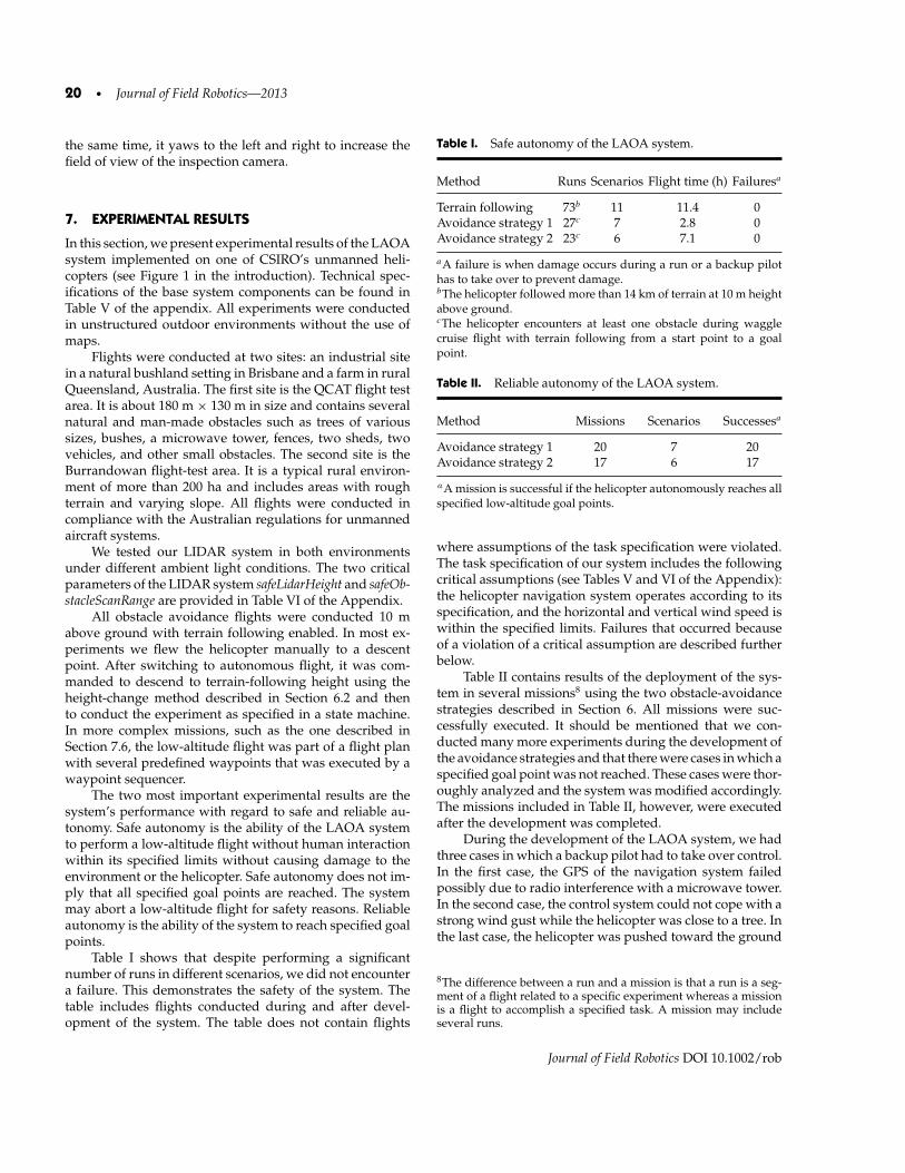
20 • Journal of Field Robotics—2013
the same time, it yaws to the left and right to increase thefield of view of the inspection camera.
7. EXPERIMENTAL RESULTS
In this section, we present experimental results of the LAOAsystem implemented on one of CSIRO’s unmanned heli-copters (see Figure 1 in the introduction). Technical spec-ifications of the base system components can be found inTable V of the appendix. All experiments were conductedin unstructured outdoor environments without the use ofmaps.
Flights were conducted at two sites: an industrial sitein a natural bushland setting in Brisbane and a farm in ruralQueensland, Australia. The first site is the QCAT flight testarea. It is about 180 m × 130 m in size and contains severalnatural and man-made obstacles such as trees of varioussizes, bushes, a microwave tower, fences, two sheds, twovehicles, and other small obstacles. The second site is theBurrandowan flight-test area. It is a typical rural environ-ment of more than 200 ha and includes areas with roughterrain and varying slope. All flights were conducted incompliance with the Australian regulations for unmannedaircraft systems.
We tested our LIDAR system in both environmentsunder different ambient light conditions. The two criticalparameters of the LIDAR system safeLidarHeight and safeOb-stacleScanRange are provided in Table VI of the Appendix.
All obstacle avoidance flights were conducted 10 mabove ground with terrain following enabled. In most ex-periments we flew the helicopter manually to a descentpoint. After switching to autonomous flight, it was com-manded to descend to terrain-following height using theheight-change method described in Section 6.2 and thento conduct the experiment as specified in a state machine.In more complex missions, such as the one described inSection 7.6, the low-altitude flight was part of a flight planwith several predefined waypoints that was executed by awaypoint sequencer.
The two most important experimental results are thesystem’s performance with regard to safe and reliable au-tonomy. Safe autonomy is the ability of the LAOA systemto perform a low-altitude flight without human interactionwithin its specified limits without causing damage to theenvironment or the helicopter. Safe autonomy does not im-ply that all specified goal points are reached. The systemmay abort a low-altitude flight for safety reasons. Reliableautonomy is the ability of the system to reach specified goalpoints.
Table I shows that despite performing a significantnumber of runs in different scenarios, we did not encountera failure. This demonstrates the safety of the system. Thetable includes flights conducted during and after devel-opment of the system. The table does not contain flights
Table I. Safe autonomy of the LAOA system.
Method Runs Scenarios Flight time (h) Failuresa
Terrain following 73b 11 11.4 0Avoidance strategy 1 27c 7 2.8 0Avoidance strategy 2 23c 6 7.1 0
aA failure is when damage occurs during a run or a backup pilothas to take over to prevent damage.bThe helicopter followed more than 14 km of terrain at 10 m heightabove ground.cThe helicopter encounters at least one obstacle during wagglecruise flight with terrain following from a start point to a goalpoint.
Table II. Reliable autonomy of the LAOA system.
Method Missions Scenarios Successesa
Avoidance strategy 1 20 7 20Avoidance strategy 2 17 6 17
aA mission is successful if the helicopter autonomously reaches allspecified low-altitude goal points.
where assumptions of the task specification were violated.The task specification of our system includes the followingcritical assumptions (see Tables V and VI of the Appendix):the helicopter navigation system operates according to itsspecification, and the horizontal and vertical wind speed iswithin the specified limits. Failures that occurred becauseof a violation of a critical assumption are described furtherbelow.
Table II contains results of the deployment of the sys-tem in several missions8 using the two obstacle-avoidancestrategies described in Section 6. All missions were suc-cessfully executed. It should be mentioned that we con-ducted many more experiments during the development ofthe avoidance strategies and that there were cases in which aspecified goal point was not reached. These cases were thor-oughly analyzed and the system was modified accordingly.The missions included in Table II, however, were executedafter the development was completed.
During the development of the LAOA system, we hadthree cases in which a backup pilot had to take over control.In the first case, the GPS of the navigation system failedpossibly due to radio interference with a microwave tower.In the second case, the control system could not cope with astrong wind gust while the helicopter was close to a tree. Inthe last case, the helicopter was pushed toward the ground
8The difference between a run and a mission is that a run is a seg-ment of a flight related to a specific experiment whereas a missionis a flight to accomplish a specified task. A mission may includeseveral runs.
Journal of Field Robotics DOI 10.1002/rob

Merz & Kendoul: Dependable Low-altitude Obstacle Avoidance for Robotic Helicopters Operating in Rural Areas • 21
Table III. Empirical control errorsa of flight modes during low-altitude flight.b
Mode h95 (m) p95 (m) ψ95 (deg) v95/ME (m/s)
hover 0.8 1.8 9waggle cruise 0.8 1.6c 0.7/0.1pirouette descent 4.5 0.4/0.0climb 2.4 0.3/0.0yaw 1.0 2.9
ax95 = 95th percentile of absolute error, xME = mean error,h = height error, p = horizontal position error, ψ = yaw error,v = horizontal/vertical velocity error.b10 m height above ground; 4–7 m/s wind speed at ground stationlocation.ccross-track error.
by a strong downdraft. In all three cases, a critical designassumption was violated. The risk of failure during a BVRflight was decreased by increasing the safety distance toobstacles and by avoiding flights in potentially bad weatherand areas with GPS problems.
7.1. Control Errors
The parameters of the terrain following and avoidance func-tions listed in Table VI of the Appendix depend, amongothers, on the control errors. Table III shows control errorsfor the different flight modes used in the LAOA system.The errors were estimated empirically from flight data ofthe CSIRO helicopter. The errors depend much on the un-derlying external control system. When estimating controlerrors empirically, it is important to collect flight data inrepresentative environmental conditions.
Figure 16 shows the tracking performance for the yawangle during pirouette descent and waggle cruise flight.Accurate yaw angle tracking is not important for obsta-cle detection as long as the specified scan area is covered.We conducted some longer pirouette descents to see if wewould encounter problems because of the sustained rota-tion of the helicopter. We tested pirouette descents witha height change of more than 30 m without noticing anyproblems.
7.2. Terrain Following
Terrain following is a key functionality of the LAOA system.Hence, we conducted many experiments to investigate if thesimple method we propose is adequate. The flights wereconducted with and without waggle motion. We did notnotice a deterioration in performance with waggle motion.Terrain following was flight-tested for cruise speeds up to2 m/s and down to 5 m height above ground in hilly terrain.However, due to the frontal sensing range limitation of ourLIDAR system, we limited the cruise speed for obstacle-avoidance flights to 1 m/s. The height error in Table III forthe waggle cruise mode with terrain following is estimatedfrom flights with 1 m/s cruise speed.
Figure 17 shows the path of two terrain-followingflights conducted at the QCAT site: a flight around the com-pound (descent point to end point) without waggle motionwith 2 m/s cruise speed at 5 m height above ground and aflight across the compound (point 1 to point 2) with wagglemotion at 1 m/s cruise speed at 10 m height above ground.
In the first flight, the helicopter was commanded to flyto a series of waypoints, defining an obstacle-free flight pathof about 450 m around the compound. The correspondingaltitude plot is shown in Figure 18. The plot contains threedifferent heights: The height above takeoff point (−pD) isestimated based on barometric pressure. The height aboveground is the hgnd value (it does not show terrain disconti-nuities as it is the intercept of the line fit described in Sec-tion 4.2). The terrain height is estimated by subtracting theheight above ground from the height above takeoff point.The helicopter was manually flown to the descent point ata height of approximately 22 m above takeoff point. At thatheight, no LIDAR-based height estimates were available.After switching to autonomous flight, the height-changestate machine (Figure 8) was used to perform a descent to theterrain-following height. The height control was changedfrom pressure-based height to LIDAR-based height and theterrain following was enabled when the lowAltitudeFlightOnevent was sent.
For the waypoint flight, we used a waypoint sequencerthat utilized the simple cruise mode (see Section 5.7). Dur-ing 370 s of terrain following, the helicopter maintained thespecified clearance from the ground with approximately1 m error in height regulation. Figure 19 shows the slope
Figure 16. Yaw angle tracking during pirouette descent (left) and waggle cruise flight (right).
Journal of Field Robotics DOI 10.1002/rob
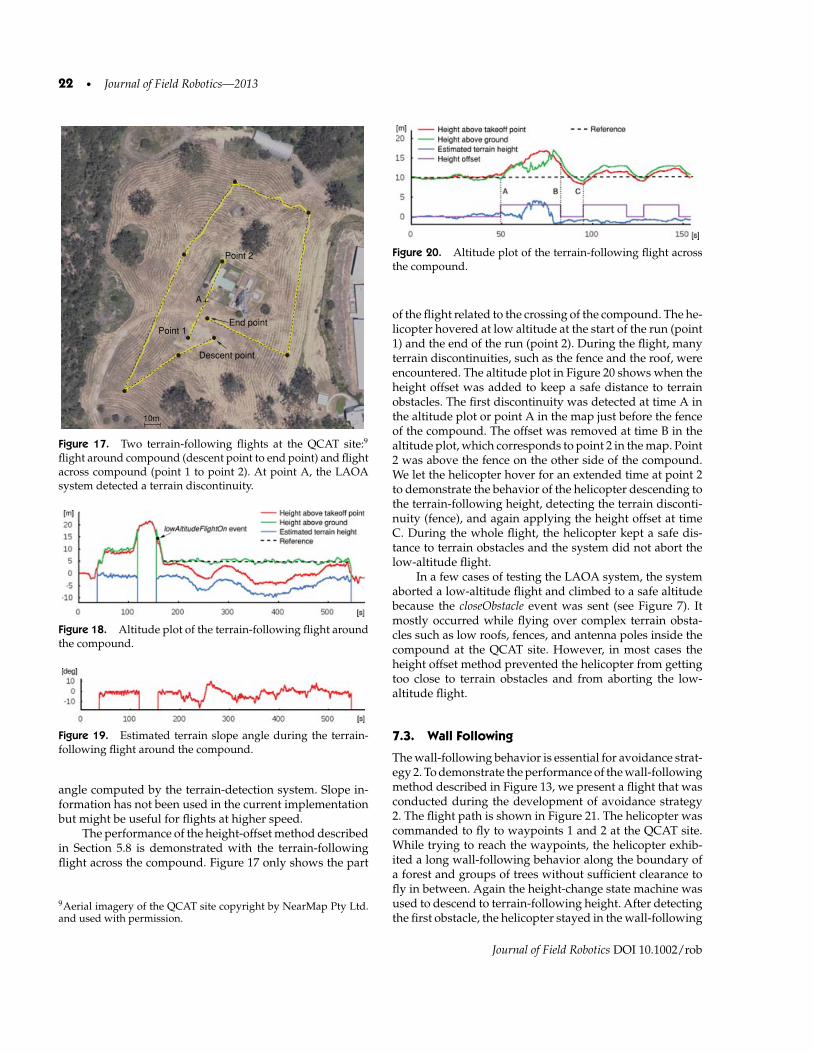
22 • Journal of Field Robotics—2013
10m
Point 2
Descent point
A
Point 1End point
Figure 17. Two terrain-following flights at the QCAT site:9
flight around compound (descent point to end point) and flightacross compound (point 1 to point 2). At point A, the LAOAsystem detected a terrain discontinuity.
Figure 18. Altitude plot of the terrain-following flight aroundthe compound.
Figure 19. Estimated terrain slope angle during the terrain-following flight around the compound.
angle computed by the terrain-detection system. Slope in-formation has not been used in the current implementationbut might be useful for flights at higher speed.
The performance of the height-offset method describedin Section 5.8 is demonstrated with the terrain-followingflight across the compound. Figure 17 only shows the part
9Aerial imagery of the QCAT site copyright by NearMap Pty Ltd.and used with permission.
Figure 20. Altitude plot of the terrain-following flight acrossthe compound.
of the flight related to the crossing of the compound. The he-licopter hovered at low altitude at the start of the run (point1) and the end of the run (point 2). During the flight, manyterrain discontinuities, such as the fence and the roof, wereencountered. The altitude plot in Figure 20 shows when theheight offset was added to keep a safe distance to terrainobstacles. The first discontinuity was detected at time A inthe altitude plot or point A in the map just before the fenceof the compound. The offset was removed at time B in thealtitude plot, which corresponds to point 2 in the map. Point2 was above the fence on the other side of the compound.We let the helicopter hover for an extended time at point 2to demonstrate the behavior of the helicopter descending tothe terrain-following height, detecting the terrain disconti-nuity (fence), and again applying the height offset at timeC. During the whole flight, the helicopter kept a safe dis-tance to terrain obstacles and the system did not abort thelow-altitude flight.
In a few cases of testing the LAOA system, the systemaborted a low-altitude flight and climbed to a safe altitudebecause the closeObstacle event was sent (see Figure 7). Itmostly occurred while flying over complex terrain obsta-cles such as low roofs, fences, and antenna poles inside thecompound at the QCAT site. However, in most cases theheight offset method prevented the helicopter from gettingtoo close to terrain obstacles and from aborting the low-altitude flight.
7.3. Wall Following
The wall-following behavior is essential for avoidance strat-egy 2. To demonstrate the performance of the wall-followingmethod described in Figure 13, we present a flight that wasconducted during the development of avoidance strategy2. The flight path is shown in Figure 21. The helicopter wascommanded to fly to waypoints 1 and 2 at the QCAT site.While trying to reach the waypoints, the helicopter exhib-ited a long wall-following behavior along the boundary ofa forest and groups of trees without sufficient clearance tofly in between. Again the height-change state machine wasused to descend to terrain-following height. After detectingthe first obstacle, the helicopter stayed in the wall-following
Journal of Field Robotics DOI 10.1002/rob

Merz & Kendoul: Dependable Low-altitude Obstacle Avoidance for Robotic Helicopters Operating in Rural Areas • 23
Figure 21. Wall following flight at the QCAT site.
state 14 of the state machine of strategy 2 (Figure 11) for mostof the flight.
Apart from the flight path, Figure 21 also showsthe obstacle points that correspond to the distances df ofthe closest frontal obstacles (Section 4.1). As can be seenin the figure, the helicopter keeps a safe distance from ob-stacles during wall following. With the parameters used inour experiments (see Table VI of the Appendix), the flighttime per generated avoidance waypoint is approximately1 min and the distance between two avoidance waypointsis approximately 12 m.
7.4. Avoidance Strategy 1
Avoidance strategy 1 is quick to implement and usefulfor testing obstacle detection and flight modes. However,strategy 2 outperforms strategy 1 in finding a path in com-plex scenarios. Hence, we will only present results of twoobstacle-avoidance flights using strategy 1. The flights areinteresting as they were part of two complex infrastructureinspection missions that were executed beyond visual rangewithout a backup pilot at the Burrandowan site. The com-plete missions are described in Section 7.6; here we focus onthe obstacle-avoidance part. The paths of the two obstacle-avoidance flights are shown in the top left corners ofFigures 23(a) and 23(b).
In both missions, the helicopter performed a pirouettedescent at the descent point (start point) and was com-manded to fly to an approach point (goal point). Between
the two points was a big tree. In the first mission, the pre-defined avoidance direction was to the right, in the secondmission it was to the left. During the first low-altitude flight,the LAOA system generated five waypoints to avoid the bigtree. During the second low-altitude flight, more waypointswere generated as the initial avoidance direction was to theleft and there was no safe path to circumnavigate the treeclockwise. The helicopter returned to the descent point af-ter several attempts, changed the avoidance direction, andsucceeded to circumnavigate the tree anticlockwise as it didin the first flight.
The implementation of strategy 1 used for the twoflights was slightly different from the final version: the he-licopter did not stop at freeSpaceWp1 points and there wasan implementation fault in the processing of short LIDARrange measurements when the helicopter was in obstacle-free space. The latter caused the generation of one unneces-sary avoidance waypoint during the first flight before pro-ceeding to the approach point [Figure 23(a)]. The problemhas since been fixed. The switching to the hover mode atfreeSpaceWp1 points was introduced after simplifying a statemachine in the current implementation.
7.5. Avoidance Strategy 2
We put significant effort into the development and testing ofavoidance strategy 2. Since completing the development, wehave not encountered a situation in which the LAOA systemhas not reached a goal point. In the following, we present sixmissions executed after completing the development. Theflight paths are shown in Figure 22.
A typical avoidance flight with a single obstacle in theflight path is shown in Figure 22(a). When detecting thetree between the start and the goal point, the LAOA systemdecided to fly to the left using the method described inFigure 12 in Section 6. From the helicopter’s perspective, thegap between the compound on the right and the tree was notbig enough and it detected more free space on the left. Thesystem circumnavigated the tree clockwise by generatingfive avoidance waypoints before the wall following wasaborted by the closeToGoal event.
Figure 22(b) shows a simple inspection mission. Thetask was to take aerial photos of a ground object with a digi-tal camera mounted underneath the helicopter. The groundobject was defined by its position in the earth-fixed NEDframe (inspection point). The mission was started at high al-titude and included a pirouette descent at the descent point.The helicopter then had to fly from the descent point (startpoint) to the inspection point (first goal point) and returnto the descent point (second goal point). As in the previousscenario, the helicopter circumnavigated the tree clockwise,however on the return flight it found a path between thesheds in the compound and the tree. The wall followingon the return flight was aborted by the progress event. Theheight variation of the obstacles inside the compound was
Journal of Field Robotics DOI 10.1002/rob

24 • Journal of Field Robotics—2013
Figure 22. Six LAOA missions flown within visual range at the QCAT site using strategy 2: (a) tree avoidance, (b) inspection ofa ground object, (c) inspection of microwave tower, (d) inspection of microwave tower with different start point, (e) inspection ofseveral ground objects, (f) inspection with unreachable inspection point.
Journal of Field Robotics DOI 10.1002/rob
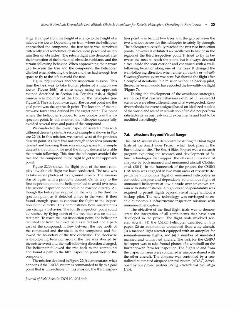
Merz & Kendoul: Dependable Low-altitude Obstacle Avoidance for Robotic Helicopters Operating in Rural Areas • 25
large. It ranged from the height of a fence to the height of amicrowave tower. Depending on from where the helicopterapproached the compound, the free space was perceiveddifferently and sometimes obstacles were perceived as ter-rain (terrain obstacles). The return flight also demonstratesthe interaction of the horizontal obstacle avoidance and theterrain-following behavior. When approaching the narrowgap between the tree and the compound, the helicopterclimbed when detecting the fence and then had enough freespace to fly to the left to avoid the tree.
Figure 22(c) shows another inspection mission. Thistime the task was to take frontal photos of a microwavetower [Figure 26(b)] at close range using the approachmethod described in Section 6.6. For this task, a digitalcamera was mounted at the front of the helicopter (seeFigure 1). The start point was again the descent point and thegoal point was the approach point. The location of the mi-crowave tower was defined by the target point. The pointwhere the helicopter stopped to take photos was the in-spection point. In this mission, the helicopter successfullyavoided several trees and parts of the compound.
We conducted the tower inspection several times withdifferent descent points. A second example is shown in Fig-ure 22(d). In this mission, we started west of the previousdescent point. As there was not enough space for a pirouettedescent and knowing there was enough space for a simpledescent (no rotation), we used the simple descent to enablethe terrain following. This time the helicopter avoided thetree and the compound to the right to get to the approachpoint.
Figure 22(e) shows the flight path of the most com-plex low-altitude flight we have conducted. The task wasto take aerial photos of five ground objects. The missionstarted again with a pirouette descent. On its way to thefirst inspection point, the helicopter had to avoid two trees.The second inspection point could be reached directly. Al-though the helicopter stopped on the way to the third in-spection point as it detected a tree in the west, it thenfound enough space to continue the flight to the inspec-tion point directly. This demonstrates how uncertaintiescan change a behavior. The fourth inspection point couldbe reached by flying north of the tree that was on the di-rect path. To reach the last inspection point, the helicopterdeviated far from the direct path as it did not find a patheast of the compound. It flew between the tree north ofthe compound and the sheds in the compound and fol-lowed the boundary of the tree clockwise. The clockwisewall-following behavior around the tree was aborted bythe outside event and the wall-following direction changed.The helicopter followed the tree back to the compoundand found a path to the fifth inspection point west of thecompound.
The mission depicted in Figure 22(f) demonstrates whathappens if the LAOA system is commanded to fly to a goalpoint that is unreachable. In this mission, the third inspec-
tion point was behind two trees and the gap between thetwo was too narrow for the helicopter to safely fly through.The helicopter successfully reached the first two inspectionpoints, however it exhibited an oscillatory behavior in theregion of the third inspection point. It tried to fly in be-tween the trees to reach the point, but it always detecteda tree inside the scan corridor and continued with a wall-following behavior along one of the trees. It changed thewall-following direction when either an outside or noWall-FollowingProgress event was sent. We aborted the flight aftera couple of iterations. In a mission without a backup pilot,the lowFuel event would have aborted the low-altitude flight(Figure 7).
During the development of the avoidance strategies,we noticed that reactive behaviors exhibited in real-worldscenarios were often different from what we expected. Reac-tive methods that were designed based on idealized modelsof the world and tested in simulation often did not performsatisfactorily in our real-world experiments and had to bemodified accordingly.
7.6. Missions Beyond Visual Range
The LAOA system was demonstrated during the final flighttrials of the Smart Skies Project, which took place at theBurrandowan site. The Smart Skies Project was a researchprogram exploring the research and development of fu-ture technologies that support the efficient utilization ofairspace by both manned and unmanned aircraft Clothieret al. (2011). In the framework of the project, the CSIROUAS team was engaged in two main areas of research: de-pendable autonomous flight of unmanned helicopters incontrolled airspace and dependable autonomous flight ofunmanned helicopters at low altitude over unknown ter-rain with static obstacles. A high level of dependability wasrequired to permit flights beyond visual range without abackup pilot. The new technology was envisaged to en-able autonomous infrastructure inspection missions withunmanned helicopters.
The objective of the final flight trials was to demon-strate the integration of all components that have beendeveloped in the project. The flight trials involved sev-eral aircraft: (1) the CSIRO helicopter described in thispaper, (2) an autonomous unmanned fixed-wing aircraft,(3) a manned light aircraft equipped with an autopilot forsemiautonomous flights, and (4) a number of simulatedmanned and unmanned aircraft. The task for the CSIROhelicopter was to take frontal photos of a windmill on theBurrandowan farm for inspection. The flights to and fromthe inspection area were conducted in airspace shared withthe other aircraft. The airspace was controlled by a cen-tralized automated airspace control system (ADAC) devel-oped by our project partner Boeing Research and TechnologyUSA.
Journal of Field Robotics DOI 10.1002/rob

26 • Journal of Field Robotics—2013
10m
100m
ADAC flight plan
Detected obstacle pointsTarget point
Mission end point
(windmill)
Inspection point
BVR transition point
Ground station
Descent point
Mission start point
Original flight plan
Descent point
Original flight path
Approach point
Inspection area
Target point
a
10m
100m
Detected obstacle pointsTarget point(windmill)
Inspection point
BVR transition point
Ground station
Inspection area
Target point
Descent point
Mission start point
Original flight path
Descent point
Mission end point
Approach point
b
Figure 23. The two windmill inspection missions flown beyond visual range at the Burrandowan site (satellite imagery of theBurrandowan site copyright by Google Inc.) using strategy 1: (a) initial avoidance direction to the right, (b) initial avoidancedirection to the left.
Figure 24. Altitude plot of the windmill inspection flight shown in Figure 23(b).
Figure 25. The CSIRO helicopter approaching the windmill at the Burrandowan site. The helicopter successfully avoids the bigtree in the left image, which is in between the descent point and the windmill (see also Figure 23).
We executed the inspection mission twice, as shownin Figures 23(a) and 23(b). The windmill (target point) waslocated at about 1.4 km from the takeoff point. The inspec-tion missions started at the mission start point and finishedat the mission end point. The missions were executed be-yond visual range of the operator at the ground station
location and without a backup pilot. The operator couldterminate a flight but there were no means to fly the aircraftthrough the ground station. The flights to and from the in-spection area [zoomed-in area in Figures 23(a) and 23(b)]were conducted at high altitude without static obstacles fol-lowing a predefined flight plan. Flights at high altitude were
Journal of Field Robotics DOI 10.1002/rob

Merz & Kendoul: Dependable Low-altitude Obstacle Avoidance for Robotic Helicopters Operating in Rural Areas • 27
Figure 26. Inspection photos taken by the helicopter from approximately 10 m: (a) windmill at the Burrandowan site; (b) microwavetower at the QCAT site.
conducted with 5 m/s ground speed and without wag-gle motion. Other aircraft were avoided by following in-structions the helicopter received during the flight from theairspace control system. Once the helicopter descended intothe inspection area at the descent point, flights were con-ducted at low altitude without other air traffic.
In the first mission, the helicopter flew to the approachpoint at low altitude as described in Section 7.4 and ap-proached the windmill using the method explained in Sec-tion 6.6. At the inspection point, it took photos of the wind-mill and climbed to a safe altitude. During the return flightin controlled airspace, the helicopter was instructed by theautomated airspace control system to deviate from the orig-inal flight plan to the west to avoid an aircraft (ADACflight plan). In the second mission,10 no flight plan changeswere required during the flights to and from the inspectionarea. The low-altitude flight, however, was more challeng-ing than in the first mission as the predefined avoidancedirection was to the left. This made the helicopter initiallyfly into an area without a safe path to the windmill, as de-scribed in Section 7.4.
The altitude plot of the second flight is shown inFigure 24. The different heights were already explainedin Section 7.2. The plot depicts the three stages of theinspection mission: the flight to the inspection area, thelow-altitude flight, and the return flight. The heights instages 1 and 3 were predefined in the flight plan relativeto the takeoff point. The two sudden height changes duringthe low-altitude flight were caused by terrain discontinu-ities (Section 5.8).
Figure 25 contains photos of the helicopter taken byan observer while approaching the windmill. The observer
10A video showing the arrival of the helicopter in the inspectionarea, the pirouette descent, waggle cruise flight, the approach of thewindmill, and the departure is available at http://www.cat.csiro.au/ict/download/SmartSkies/bvr_inspection_flight_short.mov
was in radio contact with the operator at the ground station.To meet regulatory requirements, the helicopter was alsoequipped with a flight-termination system that preventedthe aircraft from leaving a specified mission area in case ofa fatal system failure. Flight termination could have beeninitiated by a system monitor or the operator. The designof the flight-termination system is beyond the scope of thispaper.
One of the inspection photos of the windmill takenby the helicopter is shown in Figure 26(a). Figure 26(b)contains an inspection photo taken during the microwavetower inspection flights described in Section 7.5. Both pho-tos were taken at an approximate distance of 10 m to theinspection object.
8. CONCLUSION
We presented a dependable autonomous system and the un-derlying methods enabling goal-oriented flights of robotichelicopters at low altitude over unknown terrain with staticobstacles. The proposed LAOA system includes a novelLIDAR-based terrain- and obstacle-detection method and anovel reactive behavior-based avoidance strategy. We pro-vided a detailed description of the system facilitating animplementation for a small unmanned helicopter. All meth-ods were extensively flight-tested in representative outdoorenvironments. The focus of our work has been on de-pendability, computational efficiency, and easy implemen-tation using off-the-shelf hardware components. We chosea component-based design approach including extended-state machines for modeling robotic behavior. The statemachine-based design simplified in particular the develop-ment and analysis of different avoidance strategies. More-over, the state machine-based design makes it easy to extendthe proposed strategies.
We have shown that obstacles can be reliably de-tected by analyzing readings of a 2D LIDAR system while
Journal of Field Robotics DOI 10.1002/rob

28 • Journal of Field Robotics—2013
flying pirouettes during vertical descents and wagglingthe helicopter in yaw during forward flight. We have alsoshown that it is feasible to use a reactive behavior-based ap-proach for goal-oriented obstacle avoidance. We decoupledthe terrain-avoidance problem from the frontal obstacle-avoidance problem by combining a terrain-following ap-proach with a reactive navigation avoidance strategy fora 2D environment. We put significant effort into the de-velopment of an avoidance strategy that considers real-world constraints and that is optimized for robotic heli-copters operating in rural areas. The LAOA system canalso safely reach locations in more confined spaces as itis not much limited by dynamic constraints and is ca-pable of detecting obstacles in front of and below thehelicopter.
The system and methods were thoroughly evaluatedduring many low-altitude flights in unstructured, outdoorenvironments without the use of maps. The helicopter per-formed many close-range inspection flights. Among others,it flew multiple times to a microwave tower at the QCAT siteand a windmill at the Burrandowan site. Two windmill in-spection flights were conducted beyond visual range with-out a backup pilot. In total, the helicopter followed morethan 14 km of terrain at 10 m above ground, avoided 50 ob-stacles with no failure, and succeeded in reaching 37 reach-able locations. The total flight time was more than 11 h. Theexperimental results demonstrate the safety and reliabil-ity of the proposed system allowing low-risk autonomousflight.
However, our approach has some limitations. It is lesssuitable for environments with complex obstacle config-urations that are typically found in urban areas. Here, amapping-based approach is likely to be more efficient. Inenvironments for which the system was designed, however,mapping is often not beneficial as locations are rarely revis-ited and the sensing range of LIDAR systems is typicallyshort compared to the mission area. Another limitation ofour approach is that obstacles are predominantly avoidedfrom the side as height changes are only performed throughterrain following during low-altitude flight. Locations thatare surrounded by obstacles that cannot be avoided throughheight change are unreachable. Furthermore, steep terrain isrecognized as a frontal obstacle and the system tries to avoidit from the side. This may result in inefficient behavior. Fi-nally, we have not fully investigated what kind of obstaclesour system cannot detect. It mainly depends on the per-formance of the 2D LIDAR system and the chosen systemparameters. What we can say is that the implemented sys-tem detected all obstacles in the experiments we conductedin relevant environments. Most obstacles were larger ob-jects such as trees and sheds, but the system also detectedsmaller objects such as fences and antenna poles. Our sys-tem has not been specifically configured for the detection ofsmall or thin obstacles such as power lines.
Future work could address these limitations. In addi-tion to improving the reactive system by including the notyet flight-tested offset angle method and additional behav-iors for height changes, adding a mapping component tothe system would significantly improve its efficiency. Hav-ing a LIDAR system with longer range and a more accuratenavigation and control system would increase cruise speedand enable flights closer to obstacles. Furthermore, a suit-able11 3D LIDAR system would make the pirouette descentand waggle cruise flight modes obsolete. The LAOA sys-tem has not yet been validated on helicopters of a differentclass. A procedure for determining system parameters fromcharacteristics of the aircraft, the sensor and control system,and the environment would facilitate the adaption of thesystem.
ACKNOWLEDGMENTS
This research was part of the Smart Skies Project and wassupported, in part, by the Queensland State GovernmentSmart State Funding Scheme. The authors gratefully ac-knowledge the contribution of the Smart Skies partnersBoeing Research & Technology (BR&T), Boeing Research& Technology Australia (BR&TA), Queensland Universityof Technology (QUT), and all CSIRO UAS team members. Inparticular, we would like to thank Bilal Arain and LennonCork for the work on the control system of the CSIROunmanned helicopter and Brett Wood for the technicalsupport.
APPENDIX
Tables IV–IX present additional information.
11According to our requirements, a suitable 3 D LIDAR system isdependable, lightweight, low power, easy to install, cost effective,and has a comparable resolution and field of view (when inte-grated).
Journal of Field Robotics DOI 10.1002/rob

Merz & Kendoul: Dependable Low-altitude Obstacle Avoidance for Robotic Helicopters Operating in Rural Areas • 29
Table IV. Nomenclature.
Variable name Symbol Descriptiona
dd vertical distance to obstacle below helicopterdf horizontal distance to obstacle in front of helicopterdo distance from helicopter to line through start point and goal pointdp distance from helicopter to line through progressWp point and goal pointh height observation for control
heightRef hf fixed height referencehgnd helicopter height above groundhmin helicopter height above highest point below helicopterθ, φ helicopter pitch and roll anglespD helicopter height in the earth-fixed NED frame
goalPosition pgoalNE goal point
positionRef pfNE fixed position reference
wp pfwp
NE fixed target waypoint for waggle cruise modepNE helicopter position
(ri , λi ) LIDAR readings in polar coordinatesvNED helicopter velocity vectorvcxyz velocity references for external controllersψc yaw angle reference for external controllerψ f fixed yaw angle reference
groundTrackAngleRef ψ fg fixed ground track angle reference
helicopterYawAngle ψ true heading of the helicopter
aTrue north is used for the earth-fixed NED frame. All points pNE = (pN, pE) are described by their horizontal position in the earth-fixedNED frame. For simplicity reasons, we do not distinguish between points and their coordinate vectors.
Table V. Technical specifications of base system components.
Helicopter Vario Benzin Trainer (modified)12.3 kg maximum takeoff weight1.78 m rotor diameter23 cm3 two-stroke gasoline engine60 min endurance
Avionics L1 C/A GPS receiver (2.5 m CEP), MEMS-based AHRS, high-resolution barometric pressure sensorHokuyo UTM-30LX 2D LIDAR system (270◦ field of view, 30 m detection range, 25 ms scan time)Vortex86DX 800 MHz navigation computer producing helicopter state estimates at 100 HzVia Mark 800 MHz flight computer running the external velocity and yaw control at 100 Hz
Journal of Field Robotics DOI 10.1002/rob

30 • Journal of Field Robotics—2013
Table VI. Parameters of the LAOA system used in the flight tests.
Strategy 1 Strategy 2
avoidanceAngle 90◦ 60◦
avoidanceWpDistance 12 m 12 mclearanceAngle – 60◦
closeObstacleDistance 5 m 5 mcloseToGoalDistance – 20 mcorridorLength – 12 mcorridorWidth – 20 mcruiseHeight 10 m 10 mdetectionWindowAngle 90◦ 90◦
detectionWindowSize 10 m 10 mdiscontinuityHeight 8 m 8 mfarObstacleDistance 15 m 15 mfreeSpaceDistance – 20 mfreeSpaceWpDistance – 12 mheightClearance (7 m) (7 m)maxAttempts 4 10maxHorizontalWind 10 m/s 10 m/smaxPathDistance – 50 mmaxVerticalWind 2 m/s 2 m/smaxWallAngle – 120◦
maxWaggleYawAngle 45◦ 45◦
minimalLidarRange 1.5 m 1.5 mminPathProgressDistance – 20 mminWallFollowingProgressDistance – 10 moffsetAngle – (20◦)outsideHysteresis – 20 mpirouetteYawRate 45◦/s 45◦/sprogressPathTolerance – 5 msafeAltitude 55 m 55 msafeLidarHeight 15 m 15 msafeObstacleScanRange 14 m 14 mscanAngle – 120◦
terrainPointVariation 1 m 1 mverticalOffset 3 m 3 mverticalOffsetDecay 16 s 16 sverticalSpeed 1 m/s 1 m/swaggleCruiseSpeed 1 m/s 1 m/swagglePeriodTime 4 s 4 swallCatchDistance – 15 mwallReleaseDistance – 15 m
Journal of Field Robotics DOI 10.1002/rob

Merz & Kendoul: Dependable Low-altitude Obstacle Avoidance for Robotic Helicopters Operating in Rural Areas • 31
Table VII. Condition-based eventsa used in state diagrams.
Event (↔ opposite event) Condition
clearOfWall wrap(ψ − bearingAngle) ≥ avDirection · clearanceAngle wherewrap(α) = atan2(sin α, cos α)
climb (↔descend) hgnd ≤ heightRefcloseObstacle [(df < closeObstacleDistance) ∧ (df �= 0)] ∨ [(hmin < closeObstacleDistance) ∧ (hmin �= 0)]closeToGoal (|pgoal
NE − pNE| < closeToGoalDistance) ∧ (closeT oGoalF lag = 0)corridorObstacle waggle cruise mode enabled ∧ (df �= 0)
∧[df cos(ψ − ψg) < corridorLength
] ∧ [|df sin(ψ − ψg)| < 12 corridorWidth
]directionKnown (↔directionUnknown) avDirection �= 0farObstacle waggle cruise mode enabled ∧ (df < farObstacleDistance) ∧ (df �= 0)firstAttempt (↔notFirstAttempt) attempts = 1maxAttempts (↔moreAttempts) attempts>maxAttemptsnoLidarHeight (hgnd = 0) ∧ terrain following switched onoutside [(do < (maxPathDistance − outsideHysteresis) since last outside event] ∨ (no previous
outside event) ∧ (do > maxPathDistance)outsideFlightArea helicopter is between flight area and no fly zonesafeLidarHeight (↔noSafeLidarHeight) (hgnd < safeLidarHeight) ∧ (hgnd �= 0)pirouetteObstacle ([(df < farObstacleDistance ∧ (df �= 0)] ∨ [(dd < heightClearanceb) ∧ (dd �= 0)])∧ pirouette
descent mode or yaw mode enabled when in height change stateprogress (initProgressFlag = 0) ∧ (dp ≤ progressPathTolerance) ∧ [|pgoal
NE − pNE| < (|pgoalNE − last pNE
with initProgressFlag= 1| − minPathProgressDistance)]wallCatch df < wallCatchDistance ∧ (df �= 0)wallFollowingProgress |pgoal
NE − pNE| <
(↔noWallFollowingProgress) (|pgoalNE − wallFollowingStart| − minWallFollowingProgressDistance)
wallRelease df ≥ wallReleaseDistance ∨ (df = 0)
aA condition-based event is sent when a condition starts to hold or when a condition holds at the time a corresponding query event isreceived.bThe heightClearance condition was introduced after we finished our experiments as we realized there are some rare cases in which thesafety distance to obstacles and terrain during a height change could be less than specified.
Table VIII. Calculation of variables used in state diagrams.
avDirection ={
1 if wrap(ψgoal − lef tObstacleAngle) > wrap(rightObstacleAngle − ψgoal)−1 else
where wrap(α) = atan2(sin α, cos α)
avoidanceWp =(
pfE + avoidanceWpDistance · sin ψa
pfN + avoidanceWpDistance · cos ψa
)where ψa = bearingAngle + avDirection · avoidanceAngle
freeSpaceWp1 =(
pfE + freeSpaceWpDistance · sin ψgoal
pfN + freeSpaceWpDistance · cos ψgoal
)
freeSpaceWp2 =(
pfE + freeSpaceWpDistance · sin ψ
pfN + freeSpaceWpDistance · cos ψ
)leftScanAngle = ψgoal − 1
2 scanAngle
rightScanAngle = ψgoal + 12 scanAngle
ψ fg = atan2(pfwp E − pf
E, pfwp N − pfN)
ψgoal = atan2(pgoalE − pf
E , pgoalN − pf
N)
Journal of Field Robotics DOI 10.1002/rob

32 • Journal of Field Robotics—2013
Table IX. ESM state machine language.a
↑ triggers transition when a clock signal is received.../↑event, ... event sent during a state transitionb
∗ triggers transition if at the time a clock signal is received at least one nested state of the current superstateis a final state or all statements of the current atomic state have been processed
superstate encapsulating nested states of container containerName
container containerName with two orthogonal regions (two concurrent states)
region encapsulating a flat state machine (no concurrent states)
aThe ESM language is similar to Harel’s state charts (Harel, 1987) and the UML state machine language. The table contains only elementsthat are specific to the ESM language and necessary for the understanding of state diagrams used in this paper.bIn this paper, state diagrams only contain events that are necessary for the understanding of a method and events are not filtered atcontainer boundaries.
REFERENCES
Andert, F., & Adolf, F. (2009). Online world modeling andpath planning for an unmanned helicopter. AutonomousRobots, 27(3), 147–164.
Andert, F., Adolf, F.-M., Goormann, L., & Dittrich, J. (2010). Au-tonomous vision-based helicopter flights through obstaclegates. Journal of Intelligent and Robotic Systems, 57(1-4),259–280.
Bachrach, A., He, R., Prentice, S., & Roy, N. (2011). RANGE- robust autonomous navigation in GPS-denied environ-ments. Journal of Field Robotics, 28(5), 644–666.
Bachrach, A., He, R., & Roy, N. (2009). Autonomous flight inunknown indoor environments. International Journal ofMicro Air Vehicles, 1(4), 217–228.
Beyeler, A., Zufferey, J.-C., & Floreano, D. (2009). Vision-basedcontrol of near-obstacle flight. Autonomous Robots, 27(3),201–219.
Byrne, J., Cosgrove, M., & Mehra, R. (2006). Stereo based obsta-cle detection for an unmanned air vehicle. In Proceedingsof the IEEE International Conference on Robotics and Au-tomation (ICRA) (pp. 2830–2835), Orlando, FL.
Choset, H., Lynch, K., Hutchinson, S., Kantor, G., Burgard,W., Kavraki, L., & Thrun, S. (2005). Principles of RobotMotion: Theory, Algorithms, and Implementations. Cam-bridge, MA: MIT Press.
Clothier, R., Baumeister, R., Brunig, M., Duggan, A., & Wilson,M. (2011). The Smart Skies project. IEEE Aerospace andElectronic Systems Magazine, 26(6), 14–23.
Conroy, J., Gremillion, G., Ranganathan, B., & Humbert, J.(2009). Implementation of wide-field integration of opticflow for autonomous quadrotor navigation. AutonomousRobots, 27(3), 189–198.
Dauer, J., Lorenz, S., & Dittrich, J. (2011). Advanced attitudecommand generation for a helicopter UAV in the contextof a feedback free reference system. In AHS InternationalSpecialists Meeting on Unmanned Rotorcraft (pp. 1–12),Tempe, AZ.
Garratt, M., & Chahl, J. (2008). Vision-based terrain followingfor an unmanned rotorcraft. Journal of Field Robotics, 25(4-5), 284–301.
Griffiths, S., Saunders, J., Curtis, A., Barber, B., McLain, T., &Beard, R. (2006). Maximizing miniature aerial vehicles—Obstacle and terrain avoidance for MAVs. IEEE Roboticsand Automation Magazine, 13(3), 34–43.
Harel, D. (1987). Statecharts: A visual formalism for complexsystems. Science of Computer Programming, 8(3), 231–274.
He, R., Bachrach, A., & Roy, N. (2010). Efficient planning un-der uncertainty for a target-tracking micro aerial vehicle.In Proceedings of the IEEE International Conference onRobotics and Automation (ICRA) (pp. 1–8), Anchorage,AK.
Herisse, B., Hamel, T., Mahony, R., & Russotto, F. (2010). Aterrain-following control approach for a VTOL unmannedaerial vehicle using average optical flow. AutonomousRobots, 29(3-4), 381–399.
Hrabar, S. (2012). An evaluation of stereo and laser-based rangesensing for rotorcraft unmanned aerial vehicle obstacleavoidance. Journal of Field Robotics, 29(2), 215–239.
Hrabar, S., & Sukhatme, G. (2009). Vision-based navigationthrough urban canyons. Journal of Field Robotics, 26(5),431–452.
Johnson, E. N., Mooney, J. G., Ong, C., Hartman, J., & Sa-hasrabudhe, V. (2011). Flight testing of nap of-the-earthunmanned helicopter systems. In Proceedings of the 67thAnnual Forum of the American Helicopter Society (pp.1–13), Virginia Beach, VA.
Kendoul, F. (2012). A survey of advances in guidance, naviga-tion and control of unmanned rotorcraft systems. Journalof Field Robotics, 29(2), 315–378.
Meier, L., Tanskanen, P., Heng, L., Lee, G. H., Fraundorfer, F.,& Pollefeys, M. (2012). PIXHAWK: A micro aerial vehi-cle design for autonomous flight using onboard computervision. Autonomous Robots, 33(1-2), 21–39.
Journal of Field Robotics DOI 10.1002/rob

Merz & Kendoul: Dependable Low-altitude Obstacle Avoidance for Robotic Helicopters Operating in Rural Areas • 33
Merz, T., & Kendoul, F. (2011). Beyond visual range obsta-cle avoidance and infrastructure inspection by an au-tonomous helicopter. In IEEE/RSJ International Confer-ence on Intelligent Robots and Systems (IROS) (pp. 4953–4960), San Francisco, CA.
Merz, T., Rudol, P., & Wzorek, M. (2006). Control system frame-work for autonomous robots based on extended state ma-chines. In IARIA International Conference on Autonomicand Autonomous Systems (ICAS) (pp. 1–8), Silicon Valley,CA.
Montgomery, J., Johnson, A., Roumeliotis, S., & Matthies, L.(2006). The jet propulsion laboratory autonomous he-licopter testbed: A platform for planetary explorationtechnology research and development. Journal of FieldRobotics, 23(3/4), 245–267.
Ruffier, F., & Franceschini, N. (2005). Optic flow regulation:The key to aircraft automatic guidance. Robotics and Au-tonomous Systems, 50(4), 177–194.
Sanfourche, M., Besnerais, G. L., Fabiani, P., Piquereau, A., &Whalley, M. (2009). Comparison of terrain characterizationmethods for autonomous UAVs. In Proceedings of the 65thAnnual Forum of the American Helicopter Society (pp. 1–14), Grapevine, TX.
Sanfourche, M., Delaune, J., Besnerais, G. L., de Plinval, H.,Israel, J., Cornic, P., Treil, A., Watanabe, Y., & Plyer, A.(2012). Perception for UAV: Vision-based navigation andenvironment modeling. Journal Aerospace Lab, 4, 1–19.
Scherer, S., Rehder, J., Achar, S., Cover, H., Chambers, A.,Nuske, S., & Singh, S. (2012). River mapping from a fly-ing robot: State estimation, river detection, and obstaclemapping. Autonomous Robots, 33(1-2), 189–214.
Scherer, S., Singh, S., Chamberlain, L., & Elgersma, M. (2008).Flying fast and low among obstacles: Methodology andexperiments. International Journal of Robotics Research,27(5), 549–574.
Shim, D., Chung, H., & Sastry, S. (2006). Conflict-free naviga-tion in unknown urban environments. IEEE Robotics andAutomation Magazine, 13(3), 27–33.
Takahashi, M., Schulein, G., & Whalley, M. (2008). Flight con-trol law design and development for an autonomous ro-torcraft. In Proceedings of the 64th Annual Forum of theAmerican Helicopter Society (pp. 1652–1671), Montreal,Canada.
Theodore, C., Rowley, D., Hubbard, D., Ansar, A., Matthies,L., Goldberg, S., & Whalley, M. (2006). Flight trials of arotorcraft unmanned aerial vehicle landing autonomouslyat unprepared sites. In Proceedings of the 62nd AnnualForum of the American Helicopter Society (pp. 1–15),Phoenix, AZ.
Tsenkov, P., Howlett, J., Whalley, M., Schulein, G., Takahashi,M., Rhinehart, M., & Mettler, B. (2008). A system for3D autonomous rotorcraft navigation in urban environ-ments. In Proceedings of the AIAA Guidance, Navigation,and Control Conference and Exhibit (pp. 1–23), Honolulu,HI.
Viquerat, A., Blackhall, L., Reid, A., Sukkarieh, S., & Brooker, G.(2007). Reactive collision avoidance for unmanned aerialvehicles using Doppler radar. In Proceedings of the Inter-national Conference on Field and Service Robotics (FSR)(pp. 245–254, Chamonix, France.
Whalley, M., Takahashi, M., Tsenkov, P., & Schulein, G. (2009).Field-testing of a helicopter UAV obstacle field naviga-tion and landing system. In Proceedings of the 65th An-nual Forum of the American Helicopter Society (pp. 1–8),Grapevine, TX.
William, B., Green, E., & Oh, P. (2008). Optic-flow-based colli-sion avoidance. IEEE Robotics and Automation Magazine,15(1), 96–103.
Zelenka, R., Smith, P., Coppenbarger, R., Njaka, C., & Sridhar,B. (1996). Results from the NASA automated nap-of-the-earth program. In Proceedings of the 52nd Annual Forumof the American Helicopter Society (pp. 107–115), Wash-ington, D.C.
Zufferey, J.-C., & Floreano, D. (2006). Fly-inspired visual steer-ing of an ultralight indoor aircraft. IEEE Transactions OnRobotics, 22(1), 137–146.
Journal of Field Robotics DOI 10.1002/rob