department of veterans affairs william s. middleton
TRANSCRIPT

00 01 10-1
DEPARTMENT OF VETERANS AFFAIRS WILLIAM S. MIDDLETON
MEMORIAL VETERANS HOSPITAL – MADISON, WI
CONSOLIDATE ICU PROJECT 8A/8B VA Project No. 607-394
KS Project No. 211033.00
TABLE OF CONTENTS Section 00 01 10
DIVISION 00 - SPECIAL SECTIONS DATE
00 01 15 List of Drawing Sheets 09-11 00 01 20.16 Equipment List Schedule DIVISION 01 - GENERAL REQUIREMENTS 01 00 00 General Requirements 06-11 01 33 23 Shop Drawings, Product Data, and Samples 11-08 01 42 19 Reference Standards 09-11 01 45 29 Testing Laboratory Services 05-09M 01 57 19 Temporary Environmental Controls 01-11 01 58 16 Temporary Interior Signage 08-11 01 74 19 Construction Waste Management 09-10 01 91 00 General Commissioning Requirements 05-11 DIVISION 02 – EXISTING CONDITIONS 02 41 19 Selective Demolition for Remodeling 02 82 11 Traditional Asbestos Abatement 07-11 02 82 13.13 Glovebag Asbestos Abatement 07-11 02 82 13.19 Asbestos Floor Tile and Mastic Abatement 07-11 DIVISION 03 – CONCRETE 03 30 00 Cast-in-Place Concrete 03-11 03 45 00 Precast Architectural Concrete 09-11 DIVISION 04 – MASONRY 04 05 13 Masonry Mortaring 09-11 04 05 16 Masonry Grouting 09-11 04 20 00 Unit Masonry 09-11 DIVISION 05 – METALS 05 12 00 Structural Steel Framing 07-11 05 31 00 Steel Decking 11-08M 05 40 00 Cold-Formed Metal Framing 07-11 05 50 00 Metal Fabrications 09-11 05 51 00 Metal Stairs 09-11 DIVISION 06 – WOOD,PLASTICS AND COMPOSITES

00 01 10-2
06 10 00 Rough Carpentry 09-11 06 20 00 Finish Carpentry DIVISION 07 - THERMAL AND MOISTURE PROTECTION 07 18 13 Pedestrian Traffic Coatings 09-11 07 21 13 Thermal Insulation 03-09M 07 22 00 Roof and Deck Insulation 10-10 07 40 00 Roofing and Siding Panels 10-11 07 53 23 Ethylene-Propylene-Diene-Monomer Roofing 10-11 07 60 00 Flashing and Sheet Metal 10-10 07 81 00 Applied Fireproofing 12-08M 07 84 00 Firestopping 10-11 07 92 00 Joint Sealants 02-11 07 95 13 Expansion Joint Cover Assemblies 10-11 DIVISION 08 - OPENINGS 08 11 13 Hollow Metal Doors and Frames 02-09 08 14 00 Interior Wood Doors 01-10 08 31 13 Access Doors and Frames 10-07M 08 44 13 Glazed Aluminum Curtain Walls 10-11 08 51 13 Aluminum Windows (Double-Glazed) 08 71 00 Door Hardware 09-11 08 71 13 Automatic Door Operators 12-09 08 80 00 Glazing 12-10 08 88 16 Vision Control Glass 08 90 00 Louvers and Vents 10-11 DIVISION 09 – FINISHES 09 06 00 Schedule for Finishes 10-11 09 22 16 Non-Structural Metal Framing 07-10 09 29 00 Gypsum Board 02-12 09 30 13 Ceramic/Porcelain Tiling 03-09 09 51 00 Acoustical Ceilings 10-10 09 65 13 Resilient Base and Accessories 10-11 09 65 16 Resilient Sheet Flooring 07-10 09 65 19 Resilient Tile Flooring 03-11 09 68 00 Carpeting 10-11 09 72 16 Vinyl-Coated Fabric Wall Coverings 11-11 09 91 00 Painting 04-09 09 94 19 MultiColor Interior Finishing 04-10 DIVISION 10 – SPECIALTIES 10 11 13 Chalkboards and Markerboards 10-11 10 14 00 Signage 06-08M 10 21 13 Toilet Compartments 11-07 10 21 23 Cubicle Curtain Tracks 11-11 10 25 13 Patient Bed Service Walls 11-11 10 26 00 Wall and Door Protection 01-11 10 28 00 Toilet, Bath, and Laundry Accessories 11-11 10 30 00 Fireplaces
00 01 10-3
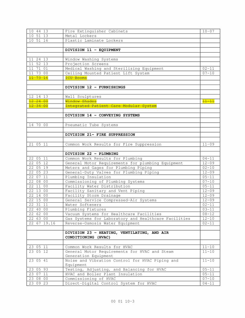
10 44 13 Fire Extinguisher Cabinets 10-07 10 51 13 Metal Lockers 10 51 16 Plastic Laminate Lockers DIVISION 11 - EQUIPMENT 11 24 13 Window Washing Systems 11 52 13 Projection Screens 11 71 01 Medical Washing and Sterilizing Equipment 02-11 11 73 00 Ceiling Mounted Patient Lift System 07-10 11 73 16 ICU Booms DIVISION 12 – FURNISHINGS 12 14 13 Wall Sculptures 12 24 00 Window Shades 11-11 12 34 00 Integrated Patient Care Modular System
DIVISION 14 – CONVEYING SYSTEMS
14 70 00 Pneumatic Tube Systems DIVISION 21- FIRE SUPPRESSION
21 05 11 Common Work Results for Fire Suppression 11-09 DIVISION 22 – PLUMBING 22 05 11 Common Work Results for Plumbing 04-11 22 05 12 General Motor Requirements for plumbing Equipment 12-09 22 05 19 Meters and Gages for Plumbing Piping 02-10 22 05 23 General-Duty Valves for Plumbing Piping 12-09 22 07 11 Plumbing Insulation 05-11 22 08 00 Commissioning of Plumbing Systems 07-10 22 11 00 Facility Water Distribution 05-11 22 13 00 Facility Sanitary and Vent Piping 12-09 22 14 00 Facility Storm Drainage 12-09 22 15 00 General Service Compressed-Air Systems 12-09 22 31 11 Water Softeners 02-11 22 40 00 Plumbing Fixtures 03-11 22 62 00 Vacuum Systems for Healthcare Facilities 08-12 22 63 00 Gas Systems for Laboratory and Healthcare Facilities 12-10 22 67 19.16 Reverse-Osmosis Water Equipment 02-11 DIVISION 23 – HEATING, VENTILATING, AND AIR
CONDITIONING (HVAC)
23 05 11 Common Work Results for HVAC 11-10 23 05 12 General Motor Requirements for HVAC and Steam
Generation Equipment 11-10
23 05 41 Noise and Vibration Control for HVAC Piping and Equipment
11-10
23 05 93 Testing, Adjusting, and Balancing for HVAC 05-11 23 07 11 HVAC and Boiler Plant Insulation 05-11 23 08 00 Commissioning of HVAC 07-10 23 09 23 Direct-Digital Control System for HVAC 04-11

00 01 10-4
23 21 13 Hydronic Piping 03-10 23 22 13 Steam and Condensate Heating Piping 03-10 23 23 00 Refrigerant Piping 23 31 00 HVAC Ducts and Casings 04-11 23 34 00 HVAC Fans 11-09 23 36 00 Air Terminal Units 03-10 23 37 00 Air Outlets and Inlets 11-09 23 40 00 HVAC Air Cleaning Devices 05-11 23 73 00 Indoor Central-Station Air-Handling Units 04-11 23 82 00 Convection Heating and Cooling Units 04-11 23 82 16 Air Coils 04-11 DIVISION 26 – ELECTRICAL 26 05 03 Electrical Equipment Mounting Requirements 02-13 26 05 11 Requirements for Electrical Installations 09-10 26 05 12 Suggested Sequence of Installation 26 05 21 Low-Voltage Electrical Power Conductors and Cables (600
Volts and Below) 09-10
26 05 26 Grounding and Bonding for Electrical Systems 09-10 26 05 33 Raceway and Boxes for Electrical Systems 09-10 26 05 71 Electrical System Protective Device Study 09-10 26 08 00 Commissioning of Electrical Systems 07-10 26 09 23 Lighting Controls 09-10 26 22 00 Low-Voltage Transformers 12-12 26 24 16 Panelboards 09-10 26 27 26 Wiring Devices 04-09 26 29 11 Motor Starters 09-10 26 29 21 Disconnect Switches 09-10 26 36 23 Automatic Transfer Switches 09-10 26 41 00 Facility Lightning Protection 04-09 26 43 13 Transient-Voltage Surge Suppression 04-09 26 51 00 Interior Lighting 04-09 26 56 00 Exterior Lighting 09-10 DIVISION 27 – COMMUNICATIONS 27 05 11 Requirements for Communications Installations 11-09 27 05 26 Grounding and Bonding for Communications Systems 10-06 27 05 33 Raceways and Boxes for Communications Systems 12-05 27 08 00 Commissioning of Communications Systems 07-10 27 10 00 Structured Cabling 12-05 27 15 00 Communications Horizontal Cabling 10-06 27 41 31 Master Antenna Television Equipment and Systems 08-09 27 51 16 Public Address and Mass Notification Systems 01-10 27 51 23 Intercommunications and Program Systems 02-09 27 52 23 Nurse Call and Code Blue Systems 01-10 27 52 41 Miscellaneous Medical Systems 01-02 DIVISION 28 – ELECTRONIC SAFETY AND SECURITY 28 05 11 Requirements for Electronic Safety and Security
Installations 04-11
28 05 13 Conductors and Cables for Electronic Safety and Security
12-05

00 01 10-5
28 05 26 Grounding and Bonding for Electronic Safety and Security
10-06
28 05 33 Raceways and Boxes for Electronic Safety and Security 12-05 28 08 00 Commissioning of Electronic Safety and Security Systems 07-10 28 13 16 Access Control System and Database Management 11-09 28 31 00 Fire Detection and Alarm 09-05

MEDICAL EQUIPMENT INVENTORY & SPECIFICATION Project: William S. Middleton Memorial Veterans Hospital - Consolidate ICUs - 8A/8B Project No. 211033.00MOUNTING KEY: 12/3/2012
C = CEILING D = DESKTOP ST = STORAGE ADDN 2; 7/22/13CAB = CABINET F = FLOOR UCT = UNDER COUNTERCT = COUNTERTOP P = PORTABLE W = WALL
INSTALLED ELECTRIC BY
NEW ROOM
NO EQUIPMENT NAMEMANUFACTURER &
MODEL# SIZE (W x D x H) OW
NER
CO
NTR
OW
NER
CO
NTR
WA
TTS
VO
LTA
GE
CW
HW
DRA
IN
NOTES
Surgery Support & Public Spaces (A & D Wings)
B8062 Family Waiting & NourishmentB8060 112 N 1 Refrigerator - Undercounter Follett 24w x 25.5d x 31.5h X X UCT 115V ADA
127 N 1 Coffee Maker Bunn or similar X X CT X XN 7 Cafe Chair X X FN 3 Table - Café X X FN 4 Settee X X FN 9 Lounge Chair X X FN 1 Table X X FN 2 Side Chair X X F
B8058 Greeter1 Computer Workstation X X D1 Task Chair X X F
A8001 Imaging Support1 Computer Workstation X X D Owner to confirm equipment specifications1 Digitizer X X D Owner to confirm equipment specifications1 Portable X-Ray X X F Owner to confirm equipment specifications1 Computer Workstation X X D1 Task Chair X X F
A8002 ConsultN 1 Computer X X WN 2 Lounge Chair X X FN 1 Settee X X FN 1 Table X X FN 6 Side Chair X X F
A8003 ICU Equipment StorageR 1 Stretcher X X F currently in SICU corridorR 1 Stretcher X X F currently in SICU corridorR 1 Oxygen Tank Cart - Full Tanks 18w x 27d x 40h X X FR 1 EZ Way Patient standing lift X X F currently in SICU corridorR 1 Wheelchair X X F currently in SICU corridorR 1 Wheelchair X X F currently in SICU corridor
MO
UN
TIN
G REQ'MTS REQ'MTS
ITEM
NO
PLUMBING
NEW
/REU
SE
SUPPLIEDBY
QU
AN
TIT
Y
Page 1 O:\2011\211033\211033.00\Doc\Equipment\000120.16_Schedule Eq - Addn2

MEDICAL EQUIPMENT INVENTORY & SPECIFICATION Project: William S. Middleton Memorial Veterans Hospital - Consolidate ICUs - 8A/8B Project No. 211033.00MOUNTING KEY: 12/3/2012
C = CEILING D = DESKTOP ST = STORAGE ADDN 2; 7/22/13CAB = CABINET F = FLOOR UCT = UNDER COUNTERCT = COUNTERTOP P = PORTABLE W = WALL
INSTALLED ELECTRIC BY
NEW ROOM
NO EQUIPMENT NAMEMANUFACTURER &
MODEL# SIZE (W x D x H) OW
NER
CO
NTR
OW
NER
CO
NTR
WA
TTS
VO
LTA
GE
CW
HW
DRA
IN
NOTES MO
UN
TIN
G REQ'MTS REQ'MTS
ITEM
NO
PLUMBING
NEW
/REU
SE
SUPPLIEDBY
QU
AN
TIT
Y
A8011 ConferenceN 1 LCD Monitor - 50" X X WN 2 Workstation, Computer X X DN 2 Task Chair X X FN 14 Stacking Chair X X FN 12 Conference Chair X X FN 4 Conference Table X X FN 1 Smartboard SMART X X WN 1 Projector, Multimedia/Data X X C
N 1 Video Teleconferencing System X X
A8015 HousekeepingN 1 Janitor Cart X X FN 1 Mop Bucket X X FN 1 Shelf w/ mop holders Bobrick 36" L X X WN 1 Chemical Dispenser (wall mtd) X X W
121 N 1 Shelving Unit Metro 48w x 24d x 72h X X F
A8017 OR Vendor OfficeN 2 Computer Workstation X X DN 2 Task Chair X XN 2 Folding Guest Chair X X wall hung w/ hookN 2 Wall Hook X X W
121 N 3 Shelving Unit Metro 48w x 18d x 72h X X F170 N 1 Equipment Cart 24w x 36d x 36h X X F
A8019 Staff Toilets - Men'sN 2 Soiled Linen Hamper X X F
A8021 VestibuleN 1 Personal Protection Supply Cart X X F Owner to confirm equipment specifications
161 N 2 Scrub Valet - Dispenser X X F Owner to confirm equipment specifications
A8027 Staff Lockers - Men's162 N 1 Scrub Valet - Return X X F Owner to confirm equipment specifications
Video conferencing unit consisting of a camera, microphone, video/audio compression components and a component cart.
Page 2 O:\2011\211033\211033.00\Doc\Equipment\000120.16_Schedule Eq - Addn2

MEDICAL EQUIPMENT INVENTORY & SPECIFICATION Project: William S. Middleton Memorial Veterans Hospital - Consolidate ICUs - 8A/8B Project No. 211033.00MOUNTING KEY: 12/3/2012
C = CEILING D = DESKTOP ST = STORAGE ADDN 2; 7/22/13CAB = CABINET F = FLOOR UCT = UNDER COUNTERCT = COUNTERTOP P = PORTABLE W = WALL
INSTALLED ELECTRIC BY
NEW ROOM
NO EQUIPMENT NAMEMANUFACTURER &
MODEL# SIZE (W x D x H) OW
NER
CO
NTR
OW
NER
CO
NTR
WA
TTS
VO
LTA
GE
CW
HW
DRA
IN
NOTES MO
UN
TIN
G REQ'MTS REQ'MTS
ITEM
NO
PLUMBING
NEW
/REU
SE
SUPPLIEDBY
QU
AN
TIT
Y
A8026 VestibuleN 1 Personal Protection Supply Cart X X F Owner to confirm equipment specifications
161 N 2 Scrub Valet - Dispenser X X F Owner to confirm equipment specifications
A8030 Staff Lockers - Women's162 N 1 Scrub Valet - Return X X F Owner to confirm equipment specifications
A8036 Staff Toilets - Women'sN 2 Soiled Linen Hamper X X F
A8029 Sterile Supply/Cart Assembly6 Case Cart 42w x 29d x ?h X X F
120 N 13 Shelving Unit (solid shelves) Metro 48w x 24d x 72h X X F120 N 6 Shelving Unit (solid shelves) Metro 48w x 18d x 72h X X F107 N 10 Top Track Shelving Units Metro 48w x 24d x 72h X X F solid shelves
2 Task Chair - High X X F2 Task Chair - High X X F1 Pedestal File X X F1 Printer X X D
164 1 PPE cabinet - SSTL X X F Owner to confirm equipment specifications118 N 1 Pass Thru Window Assembly Steris 36w x 36h x 5d X X W
A8035 Sterilizers
106 N 2 Steam Sterilizer
Steris 400 Ster. Prevac
see cut sheets
X XF
208VSingle hinged door model, Contractor to provide utility rough-ins and final hook-up for Owner installation of equipment
Page 3 O:\2011\211033\211033.00\Doc\Equipment\000120.16_Schedule Eq - Addn2

MEDICAL EQUIPMENT INVENTORY & SPECIFICATION Project: William S. Middleton Memorial Veterans Hospital - Consolidate ICUs - 8A/8B Project No. 211033.00MOUNTING KEY: 12/3/2012
C = CEILING D = DESKTOP ST = STORAGE ADDN 2; 7/22/13CAB = CABINET F = FLOOR UCT = UNDER COUNTERCT = COUNTERTOP P = PORTABLE W = WALL
INSTALLED ELECTRIC BY
NEW ROOM
NO EQUIPMENT NAMEMANUFACTURER &
MODEL# SIZE (W x D x H) OW
NER
CO
NTR
OW
NER
CO
NTR
WA
TTS
VO
LTA
GE
CW
HW
DRA
IN
NOTES MO
UN
TIN
G REQ'MTS REQ'MTS
ITEM
NO
PLUMBING
NEW
/REU
SE
SUPPLIEDBY
QU
AN
TIT
Y
A8037 Prep/Pack105 N 4 Assembly Workstation TBJ SPD X X F X height adjustable, shallow drawer
N 4 Task Chair - High X X FN 3 Workstation, Computer X X D ceiling hung
Cart, Mobile X X F167 R 2 Heat Sealer X X CT Owner to confirm equipment specifications
Loading Cart X X F Owner to confirm equipment specificationsR 1 Printer X X DR 1 Label Printer X X D
166 N 5 Incubator X X CT Emergency powerN 2 Lateral File X X F
1 Linen Cart X X F1 Supply Cart X X F flat, SSTL shelves
N 1 Computer X X DN 1 Workstation TBJ SPD X X F height adjustable, upper shelf, SSTLN 1 PPE cabinet - SSTL X X F solid shelves
120 N 2 Shelving Unit (solid shelves) Metro 48w x 24d x 72h X X F115 N 3 Instrument Storage Cabinet Pedigo 47w x 18d x 72h X X F
A8042 Anesthesia TrainingN 10 Stackable Chair X X FN 1 Task Chair - High X X FR 2 Stretcher X X FR 2 Mannequin X X F
A8046 OR Equipment Storage120 N 3 Shelving Unit (solid shelves) Metro 48w x 24d x 72h X X F
A8052 Anesthesia Storage121 N 4 Shelving Unit Metro 48w x 24d x 72h X X F
A8041 HousekeepingN 1 Janitor Cart X X FN 1 Mop Bucket X X FN 1 Shelf w/ mop holders Bobrick 36" L X X WN 1 Chemical Dispenser (wall mtd) X X W
121 N 1 Shelving Unit Metro 48w x 24d x 72h X X F
Page 4 O:\2011\211033\211033.00\Doc\Equipment\000120.16_Schedule Eq - Addn2

MEDICAL EQUIPMENT INVENTORY & SPECIFICATION Project: William S. Middleton Memorial Veterans Hospital - Consolidate ICUs - 8A/8B Project No. 211033.00MOUNTING KEY: 12/3/2012
C = CEILING D = DESKTOP ST = STORAGE ADDN 2; 7/22/13CAB = CABINET F = FLOOR UCT = UNDER COUNTERCT = COUNTERTOP P = PORTABLE W = WALL
INSTALLED ELECTRIC BY
NEW ROOM
NO EQUIPMENT NAMEMANUFACTURER &
MODEL# SIZE (W x D x H) OW
NER
CO
NTR
OW
NER
CO
NTR
WA
TTS
VO
LTA
GE
CW
HW
DRA
IN
NOTES MO
UN
TIN
G REQ'MTS REQ'MTS
ITEM
NO
PLUMBING
NEW
/REU
SE
SUPPLIEDBY
QU
AN
TIT
Y
D8013 Clean Instrument Holding1 Equipment Cart (SSTL) 42w x 29d x 36h X X F
120 N 3 Shelving Unit (solid shelves) Metro 48w x 24d x 72h X X F
D8015 Decontamination
102 N 2 Washer-Disinfector
Steris Reliance HamoVision
see cut sheets X X F480 V
Steam, Contractor to provide utility rough-ins and final hook-up for Owner installation of equipment
108 N 1 Washer Detergent Steris Prolystica see cut sheets X X X F on shelf104 N 2 3 Bay Sink (height adjustable) TBJ SPD see cut sheets X X F X109 N 2 Chemical Dosing System Steris Acu Sinq see cut sheets X X X W
103 N 3 Ultrasonic Cleaner
Steris Caviwave Pro 17W
see cut sheets
X XF
208V20 gallon tank, Contractor to provide utility rough-ins and final hook-up for Owner installation of equipment
122 N 1 Shelving Unit Metro 60w x 24d x 72h X X F solid bottom shelfN 2 Loading Cart X X FN 1 Waste Can - 44 gallon X X FN 2 Sorting Table (SSTL) X X F shallow drawerN 2 Workstation, Computer C ceiling hung
113 N 1 Cidex station X X CT on cart113 N 1 Cidex tube X X W
R 1 Metal cabinet w/ glass doors existing 36w x 24d x 72h X X F relocate from exist SPD on ground floorN 1 Linen Hamper X X F
110 R 2 Portable Suction UnitOhio Medical Care-E-
Vac 38w x 6h x 8d CT
110/ 240
on shelf above triple bay sink
R 2 Olympus Leak Tester 4w x 6h x 6d X X X CT on shelf above triple bay sink118 N 1 Pass Thru Window Assembly Steris 36w x 36h x 5d X X W
D8019 Decon Ante RoomN 1 Linen Hamper X X F
D8023 Cart Washer
101 N 1 Cart Washer-DisinfectorBelimed Cart Washer
see cut sheets
X XF
480 VCS750S Steam or Equal, Contractor to provide utility rough-ins and final hook-up for Owner installation of equipment
D8025 Clean Cart Holding
Page 5 O:\2011\211033\211033.00\Doc\Equipment\000120.16_Schedule Eq - Addn2

MEDICAL EQUIPMENT INVENTORY & SPECIFICATION Project: William S. Middleton Memorial Veterans Hospital - Consolidate ICUs - 8A/8B Project No. 211033.00MOUNTING KEY: 12/3/2012
C = CEILING D = DESKTOP ST = STORAGE ADDN 2; 7/22/13CAB = CABINET F = FLOOR UCT = UNDER COUNTERCT = COUNTERTOP P = PORTABLE W = WALL
INSTALLED ELECTRIC BY
NEW ROOM
NO EQUIPMENT NAMEMANUFACTURER &
MODEL# SIZE (W x D x H) OW
NER
CO
NTR
OW
NER
CO
NTR
WA
TTS
VO
LTA
GE
CW
HW
DRA
IN
NOTES MO
UN
TIN
G REQ'MTS REQ'MTS
ITEM
NO
PLUMBING
NEW
/REU
SE
SUPPLIEDBY
QU
AN
TIT
Y
D8030 Storage
Page 6 O:\2011\211033\211033.00\Doc\Equipment\000120.16_Schedule Eq - Addn2

MEDICAL EQUIPMENT INVENTORY & SPECIFICATION Project: William S. Middleton Memorial Veterans Hospital - Consolidate ICUs - 8A/8B Project No. 211033.00MOUNTING KEY: 12/3/2012
C = CEILING D = DESKTOP ST = STORAGE ADDN 2; 7/22/13CAB = CABINET F = FLOOR UCT = UNDER COUNTERCT = COUNTERTOP P = PORTABLE W = WALL
INSTALLED ELECTRIC BY
NEW ROOM
NO EQUIPMENT NAMEMANUFACTURER &
MODEL# SIZE (W x D x H) OW
NER
CO
NTR
OW
NER
CO
NTR
WA
TTS
VO
LTA
GE
CW
HW
DRA
IN
NOTES
Intensive Care Unit 1 (B Wing West)
B8032 ICU Patient RoomB8034 1 Patient Bed X X F Owner to confirm equipment specificationsB8038 N 1 Prefabricated Headwall Unit Compass or equal X X W see interior elevationsB8044 N 1 Prefabricated Footwall Unit Compass or equal X X W see interior elevations
1 Physiological Monitor Philips X X W mtd on headwall w/ arm1 Sphygmomanometer X X W mtd on headwall1 Thermometer X X W mtd on headwall1 Pulse Oximeter X X W mtd on headwall
N 1 Sharps X X X WN 1 Glove Dispenser X X X W
N 1
System Clock X X W
mtd on footwall, Contractor to provide utility rough-ins and final hook-up for Owner installation of equipment
N 1 Soiled Linen Hamper X X FN 1 Television - 42" X X WN 1 Wall Bracket for TV X X W
N 1Markerboard X X X W
Marker Board is also noted as Patient Information on drawings. Corian shelf below board is Contractor Furnish and Contractor
N 1 Flashlight - Rechargeable X X WN 1 Overbed Table X X FN 1 Patient Recliner X X FN 1 Sleeper Settee or Recliner (family) X X FN 1 Guest Chair (folding) X X W mtd on wall bracketN 1 Wall Bracket for guest chair X X X WN 1 Task Chair - High (no casters) X X FN 1 Charting Computer X XN 1 Mobile computer cart X X F for charting computer
119R 1
Patient Lift Arjo Maxi Sky 600 X X C
Owner to confirm equipment specifications, Owner installation includes tracks and associated structural supports.
117 N 1 Veteran Server Systec or equal 15w x 24d x 72h X X Owner to confirm equipment specifications
ITEM
NO
.
SUPPLIED
MO
UN
TIN
G
PLUMBING
NEW
/REU
SE BY REQ'MTS REQ'MTS
QU
AN
TIT
Y
Page 7 O:\2011\211033\211033.00\Doc\Equipment\000120.16_Schedule Eq - Addn2

MEDICAL EQUIPMENT INVENTORY & SPECIFICATION Project: William S. Middleton Memorial Veterans Hospital - Consolidate ICUs - 8A/8B Project No. 211033.00MOUNTING KEY: 12/3/2012
C = CEILING D = DESKTOP ST = STORAGE ADDN 2; 7/22/13CAB = CABINET F = FLOOR UCT = UNDER COUNTERCT = COUNTERTOP P = PORTABLE W = WALL
INSTALLED ELECTRIC BY
NEW ROOM
NO EQUIPMENT NAMEMANUFACTURER &
MODEL# SIZE (W x D x H) OW
NER
CO
NTR
OW
NER
CO
NTR
WA
TTS
VO
LTA
GE
CW
HW
DRA
IN
NOTES ITEM
NO
.
SUPPLIED
MO
UN
TIN
G
PLUMBING
NEW
/REU
SE BY REQ'MTS REQ'MTS
QU
AN
TIT
Y
B8040 ICU Bariatric Patient Room1 Patient Bed X X F Owner to confirm equipment specifications
N 1 Prefabricated Headwall Unit Compass or equal X X W see interior elevationsN 1 Prefabricated Footwall Unit Compass or equal X X W see interior elevations
1 Physiological Monitor Philips X X W mtd on headwall w/ arm1 Sphygmomanometer X X W mtd on headwall1 Thermometer X X W mtd on headwall1 Pulse Oximeter X X W mtd on headwall
N 1 Sharps X X X WN 1 Glove Dispenser X X X W
N 1
System Clock X X W
mtd on footwall, Contractor to provide utility rough-ins and final hook-up for Owner installation of equipment
N 1 Soiled Linen Hamper X X FN 1 Television - 42" X X WN 1 Wall Bracket for TV X X W
N 1Markerboard X X X W
Marker Board is also noted as Patient Information on drawings. Corian shelf below board is Contractor Furnish and Contractor
N 1 Flashlight - Rechargeable X X WN 1 Overbed Table X X FN 1 Patient Recliner X X FN 1 Sleeper Settee or Recliner (family) X X FN 1 Guest Chair (folding) X X W mtd on wall bracketN 1 Wall Bracket for guest chair X X X WN 1 Task Chair - High (no casters) X X FN 1 Charting Computer X XN 1 Mobile computer cart X X F for charting computer
119N 1
Patient Lift Arjo Maxi Sky 1000 X X C
Owner to confirm equipment specifications, Owner installation includes tracks and associated structural supports.
117 N 1 Veteran Server Systec or equal 15w x 24d x 72h X Owner to confirm equipment specifications
Page 8 O:\2011\211033\211033.00\Doc\Equipment\000120.16_Schedule Eq - Addn2

MEDICAL EQUIPMENT INVENTORY & SPECIFICATION Project: William S. Middleton Memorial Veterans Hospital - Consolidate ICUs - 8A/8B Project No. 211033.00MOUNTING KEY: 12/3/2012
C = CEILING D = DESKTOP ST = STORAGE ADDN 2; 7/22/13CAB = CABINET F = FLOOR UCT = UNDER COUNTERCT = COUNTERTOP P = PORTABLE W = WALL
INSTALLED ELECTRIC BY
NEW ROOM
NO EQUIPMENT NAMEMANUFACTURER &
MODEL# SIZE (W x D x H) OW
NER
CO
NTR
OW
NER
CO
NTR
WA
TTS
VO
LTA
GE
CW
HW
DRA
IN
NOTES ITEM
NO
.
SUPPLIED
MO
UN
TIN
G
PLUMBING
NEW
/REU
SE BY REQ'MTS REQ'MTS
QU
AN
TIT
Y
B8026 ICU Patient Room - Negative IsolationB8028 1 Patient Bed X X F Owner to confirm equipment specificationsB8046 N 1 Prefabricated Headwall Unit Compass or equal X X W see interior elevations
N 1 Prefabricated Footwall Unit Compass or equal X X W see interior elevations1 Physiological Monitor Philips X X W mtd on headwall w/ arm1 Sphygmomanometer X X W mtd on headwall1 Thermometer X X W mtd on headwall1 Pulse Oximeter X X W mtd on headwall
N 1 Sharps X X X WN 1 Glove Dispenser X X X W
N 1
System Clock X X W
mtd on footwall, Contractor to provide utility rough-ins and final hook-up for Owner installation of equipment
N 1 Soiled Linen Hamper X X FN 1 Television - 42" X X WN 1 Wall Bracket for TV X X W
N 1Markerboard X X X W
Marker Board is also noted as Patient Information on drawings. Corian shelf below board is Contractor Furnish and Contractor
N 1 Flashlight - Rechargeable X X WN 1 Overbed Table X X FN 1 Patient Recliner X X FN 1 Sleeper Settee or Recliner (family) X X FN 1 Guest Chair (folding) X X W mtd on wall bracketN 1 Wall Bracket for guest chair X X X WN 1 Task Chair - High (no casters) X X FN 1 Charting Computer X XN 1 Mobile computer cart X X F for charting computer
119N 1
Patient Lift Arjo Maxi Sky 1000 X X C
Owner to confirm equipment specifications, Owner installation includes tracks and associated structural supports.
117 N 1 Veteran Server Systec or equal 15w x 24d x 72h X Owner to confirm equipment specifications
B8030 Charting - DecentralizedB8042 N 2 Computer Workstation X X DB8048 N 2 Task Chair - High (w/ casters) X X F
B8036 Charting - DecentralizedN 1 Computer Workstation X X D
Page 9 O:\2011\211033\211033.00\Doc\Equipment\000120.16_Schedule Eq - Addn2

MEDICAL EQUIPMENT INVENTORY & SPECIFICATION Project: William S. Middleton Memorial Veterans Hospital - Consolidate ICUs - 8A/8B Project No. 211033.00MOUNTING KEY: 12/3/2012
C = CEILING D = DESKTOP ST = STORAGE ADDN 2; 7/22/13CAB = CABINET F = FLOOR UCT = UNDER COUNTERCT = COUNTERTOP P = PORTABLE W = WALL
INSTALLED ELECTRIC BY
NEW ROOM
NO EQUIPMENT NAMEMANUFACTURER &
MODEL# SIZE (W x D x H) OW
NER
CO
NTR
OW
NER
CO
NTR
WA
TTS
VO
LTA
GE
CW
HW
DRA
IN
NOTES ITEM
NO
.
SUPPLIED
MO
UN
TIN
G
PLUMBING
NEW
/REU
SE BY REQ'MTS REQ'MTS
QU
AN
TIT
Y
N 1 Task Chair - High (w/ casters) X X F
B8037 Family RoomN Lounge Chair X X FN Settee X X F
Page 10 O:\2011\211033\211033.00\Doc\Equipment\000120.16_Schedule Eq - Addn2

MEDICAL EQUIPMENT INVENTORY & SPECIFICATION Project: William S. Middleton Memorial Veterans Hospital - Consolidate ICUs - 8A/8B Project No. 211033.00MOUNTING KEY: 12/3/2012
C = CEILING D = DESKTOP ST = STORAGE ADDN 2; 7/22/13CAB = CABINET F = FLOOR UCT = UNDER COUNTERCT = COUNTERTOP P = PORTABLE W = WALL
INSTALLED ELECTRIC BY
NEW ROOM
NO EQUIPMENT NAMEMANUFACTURER &
MODEL# SIZE (W x D x H) OW
NER
CO
NTR
OW
NER
CO
NTR
WA
TTS
VO
LTA
GE
CW
HW
DRA
IN
NOTES ITEM
NO
.
SUPPLIED
MO
UN
TIN
G
PLUMBING
NEW
/REU
SE BY REQ'MTS REQ'MTS
QU
AN
TIT
Y
B8033 Soiled UtilityR 1 Trash Can - 44 gallon X X FN 1 Sharps (wall) X X WN 1 Gloves X X WR 2 Soiled Linen Hamper X X FR 2 Red bag waste can X X FR 2 Sharps containers X X F
B8041 Nourishment125 N 1 Refrigerator/Freezer 24w x 24d x 33h X X F126 R 1 Microwave 21w x 24d x 12h X X CT114 N 1 Ice Maker Follett 21w x 24d x 47h X X CT 115V Air cooled116 N 1 Water Filter Follett 16w x 4d x 20h X X W127 N 1 Coffee Maker Bunn or similar X X CT
B8043 Nurse Station132 R 1 Crash Cart w/ Defib (beige) 28w x 22d x 38h X X F currently in CCU corridor131 R 1 ECG 18w x 40h x 28d X X F currently in CCU corridor133 R 1 Anesthesia Cart 24w x 24d x 44h X X F currently in CCU corridor
R 1 Patient Information Board 36w x 30h X X X WR 1 Central Monitor Station X X DR 1 Central Monitor printer 6w x 9d x 5h X X DR 1 Patient Order Monitor 10w x 11h x 5d X X DR 1 Intellivue Printer 12w x 12d x 12h X X DR 1 HP Laser Jet Printer 16w x 17d x 16h X X DR 2 Lateral File 20d x 36w X X F
N 1 ClockX X W
Contractor to provide utility rough-ins and final hook-up for Owner installation of equipment
R 2 Paper Recycling Bin X X FN 1 OR Code Blue X X WR 14 Computer Workstation X X UCTN 14 Task Chair X X FN 10 Pedestal Files X X FR 1 Patient Order Monitor 10w x 11h x 5d X X DR 2 Monitor - Unit Clerk X X DR 1 Scanner - small 24w x 12d x 12h X X D
135 R 1 Copier 41w x 26d x 46h X X FSystems Furniture X X F see plan
Page 11 O:\2011\211033\211033.00\Doc\Equipment\000120.16_Schedule Eq - Addn2

MEDICAL EQUIPMENT INVENTORY & SPECIFICATION Project: William S. Middleton Memorial Veterans Hospital - Consolidate ICUs - 8A/8B Project No. 211033.00MOUNTING KEY: 12/3/2012
C = CEILING D = DESKTOP ST = STORAGE ADDN 2; 7/22/13CAB = CABINET F = FLOOR UCT = UNDER COUNTERCT = COUNTERTOP P = PORTABLE W = WALL
INSTALLED ELECTRIC BY
NEW ROOM
NO EQUIPMENT NAMEMANUFACTURER &
MODEL# SIZE (W x D x H) OW
NER
CO
NTR
OW
NER
CO
NTR
WA
TTS
VO
LTA
GE
CW
HW
DRA
IN
NOTES ITEM
NO
.
SUPPLIED
MO
UN
TIN
G
PLUMBING
NEW
/REU
SE BY REQ'MTS REQ'MTS
QU
AN
TIT
Y
B8053 Alcove - Med Prep152 R 1 Medication Dispenser Med Select 19w x 20d x 38h X X F152 R 1 Medication Dispenser w/ Monitor Med Select 19W x 28D x 70H X X F Monitor on left
B8055 Med Prep121 R 1 Shelving Unit Metro 48w x 24d x 72h X X F111 N 1 Refrigerator Follett 24w x 26d x 35h X X UCT
N 1 Hook Strip 36w X X WN 2 Sharps X X WN 1 Gloves X X WR 2 Recycling Bin X X FR 1 Computer Workstation X X CT
B8057 Clean Utility123 R 1 Shelving Unit Metro 60w x 24d x 72h X X F121 R 4 Shelving Unit Metro 48w x 24d x 72h X X F151 R 2 Small supply cart 38w x 22d x 36h X X F
R 1 Hazardous Waste X X F
B8059 Equipment Room124 R 1 Blanket Warmer 30w x 27d x 36h X X F142 R 1 Cortrak Monitor 18w x 18d x 60h X X F currently in CCU corridor143 R 1 Wireless Monitor 18w x 18d x 60h X X F currently in CCU corridor144 R 2 Bladderscan 21w x 21d x 36h X X F145 R 1 Bronch Tower 24w x 26d x 72h X X F currently in CCU corridor146 R 1 Ultrasound 21w x 24 d x 60h X X F currently in CCU corridor149 R 1 Maxi Move Patient Lift Arjo X X F123 N 1 Shelving Unit Metro 60w x 18d x 72h X X F130 R 1 I-Med Consent COW 26w x 30d x 54h X X F currently in CCU corridor150 R 1 Crash Cart (red) 34w x 26d x 48h X X F
R 1 IV Pole w/ Pumps X X X WN 1 Hooks for transfer boards
B8061 Clean Linen123 N 1 Shelving Unit Metro 60w x 24d x 72h X X F121 N 1 Shelving Unit Metro 48w x 24d x 72h X X F147 R 1 Comfort Cleanse Warmer (white) 28w x 14d x 18h X X CT148 R 1 Comfort Cleanse Warmer (black) 28w x 15d x 20h CT
Page 12 O:\2011\211033\211033.00\Doc\Equipment\000120.16_Schedule Eq - Addn2

MEDICAL EQUIPMENT INVENTORY & SPECIFICATION Project: William S. Middleton Memorial Veterans Hospital - Consolidate ICUs - 8A/8B Project No. 211033.00MOUNTING KEY: 12/3/2012
C = CEILING D = DESKTOP ST = STORAGE ADDN 2; 7/22/13CAB = CABINET F = FLOOR UCT = UNDER COUNTERCT = COUNTERTOP P = PORTABLE W = WALL
INSTALLED ELECTRIC BY
NEW ROOM
NO EQUIPMENT NAMEMANUFACTURER &
MODEL# SIZE (W x D x H) OW
NER
CO
NTR
OW
NER
CO
NTR
WA
TTS
VO
LTA
GE
CW
HW
DRA
IN
NOTES ITEM
NO
.
SUPPLIED
MO
UN
TIN
G
PLUMBING
NEW
/REU
SE BY REQ'MTS REQ'MTS
QU
AN
TIT
Y
B8054 Respiratory Therapy Storage141 R 1 RT Supply Shelving Unit 36w x 24d x 72h X X F123 R 1 Shelving Unit Metro 60w x 24d x 72h X X F currently in CCU
R 1 Oxygen Tank Cart - Full Tanks 18w x 27d x 40h X X F currently in CCUR 1 Oxygen Tank Cart - Empty Tanks 12w x 18d x 36h X X F currently in SICU
137 R 1 Ventilator 24w x 31d x 53h X X F currently in SICU137 R 1 Ventilator 24w x 31d x 53h X X F currently in SICU138 R 1 PICC Cart 32w x 28d x 38h X X F currently in SICU139 R 1 Neuro Cart 32w x 22d x 37h X X F140 R 1 Hemodynamic Cart 32w x 22d x 37h X X F136 R 2 Ventilator 23w x 26d x 68h X X F
R 1 Oxygen Tank Cart - Empty Tanks 12w x 18d x 36h X X FR 1 Non-invasive Vent CPAP
B8056 ICU Equipment StorageR 1 Portable Scale 24w x 60h x 30d X X FR 2 Stretcher X X FR 1 Stretcher Stryker Zoom 87w x 32d X X FR 1 Stretchair 29w x 48d X X FR 1 Stretchair 29w x 48d X X FR 1 Dr Peaslee Monitor 28w x 28d x 60h X X F
Page 13 O:\2011\211033\211033.00\Doc\Equipment\000120.16_Schedule Eq - Addn2

MEDICAL EQUIPMENT INVENTORY & SPECIFICATION Project: William S. Middleton Memorial Veterans Hospital - Consolidate ICUs - 8A/8B Project No. 211033.00MOUNTING KEY: 12/3/2012
C = CEILING D = DESKTOP ST = STORAGE ADDN 2; 7/22/13CAB = CABINET F = FLOOR UCT = UNDER COUNTERCT = COUNTERTOP P = PORTABLE W = WALL
INSTALLED ELECTRIC BY
NEW ROOM
NOEQUIPMENT NAME ANUFACTURER & MODE SIZE (W x D x H) O
WN
ER
CO
NTR
OW
NER
CO
NTR
WA
TTS
VO
LTA
GE
CW
HW
DRA
IN
NOTES
Intensive Care Unit 2 (B Wing East)
B8002 ICU Protective Environment Room w/ BoomB8004 1 Patient Bed X X F Owner to confirm equipment specifications
169 N 1 Equipment Boom - 2 Arms Trumpf (design basis) X X X C Owner to confirm equipment specificationsN 1 Prefabricated Footwall Unit Compass or equal X X W
1 Physiological Monitor Philips X X Boom1 Sphygmomanometer X X Boom1 Thermometer X X Boom1 Pulse Oximeter X X Boom currently in SICU corridor
N 1 Sharps X X X WN 1 Glove Dispenser X X X W
N 1
System Clock X X W
Contractor to provide utility rough-ins and final hook-up for Owner installation of equipment
N 1 Soiled Linen Hamper X X FN 1 Television - 42" X X WN 1 Wall Bracket for TV X X W
N 1Markerboard X X X W
Marker Board is also noted as Patient Information on drawings. Corian shelf below board is Contractor Furnish and Contractor Installed.
N 1 Flashlight - Rechargeable X X WN 1 Overbed Table X X FN 1 Patient Recliner X X FN 1 Sleeper Settee or Recliner (family) X X F see planN 1 Guest Chair (folding) X X WN 1 Wall Bracket for guest chair X X X WN 1 Task Chair - High (no casters) X X FN 1 Charting Computer X X Boom
117 N 1 Veteran Server Systec or equal 15w x 24d x 72h X X Owner to confirm equipment specifications
ITEM
NO
.
SUPPLIED
MO
UN
TIN
G
PLUMBING
NEW
/REU
SE
BY REQ'MTS REQ'MTS
QU
AN
TIT
Y
Page 14 O:\2011\211033\211033.00\Doc\Equipment\000120.16_Schedule Eq - Addn2

MEDICAL EQUIPMENT INVENTORY & SPECIFICATION Project: William S. Middleton Memorial Veterans Hospital - Consolidate ICUs - 8A/8B Project No. 211033.00MOUNTING KEY: 12/3/2012
C = CEILING D = DESKTOP ST = STORAGE ADDN 2; 7/22/13CAB = CABINET F = FLOOR UCT = UNDER COUNTERCT = COUNTERTOP P = PORTABLE W = WALL
INSTALLED ELECTRIC BY
NEW ROOM
NOEQUIPMENT NAME ANUFACTURER & MODE SIZE (W x D x H) O
WN
ER
CO
NTR
OW
NER
CO
NTR
WA
TTS
VO
LTA
GE
CW
HW
DRA
IN
NOTES ITEM
NO
.
SUPPLIED
MO
UN
TIN
G
PLUMBING
NEW
/REU
SE
BY REQ'MTS REQ'MTS
QU
AN
TIT
Y
B8008 ICU Bariatric Protective Environment Patient Room1 Patient Bed X X F Owner to confirm equipment specifications
N 1 Prefabricated Headwall Unit Compass or equal X X W see interior elevationsN 1 Prefabricated Footwall Unit Compass or equal X X W see interior elevations
1 Physiological Monitor Philips X X W mtd on headwall w/ arm1 Sphygmomanometer X X W mtd on headwall1 Thermometer X X W mtd on headwall1 Pulse Oximeter X X W mtd on headwall
N 1 Sharps X X X WN 1 Glove Dispenser X X X W
N 1
System Clock X X W
mtd on footwall, Contractor to provide utility rough-ins and final hook-up for Owner installation of equipment
N 1 Soiled Linen Hamper X X FN 1 Television - 42" X X WN 1 Wall Bracket for TV X X W
N 1Markerboard X X X W
Marker Board is also noted as Patient Information on drawings. Corian shelf below board is Contractor Furnish and Contractor Installed.
N 1 Flashlight - Rechargeable X X WN 1 Overbed Table X X FN 1 Patient Recliner X X FN 1 Sleeper Settee or Recliner (family) X X FN 1 Guest Chair (folding) X X W mtd on wall bracketN 1 Wall Bracket for guest chair X X X WN 1 Task Chair - High (no casters) X X FN 1 Charting Computer X XN 1 Mobile computer cart X X F for charting computer
119N 1
Patient LiftArjo Maxi Sky 1000
X X C
Owner to confirm equipment specifications, Owner installation includes tracks and associated structural supports.
117 N 1 Veteran Server Systec or equal 15w x 24d x 72h X X Owner to confirm equipment specifications
Page 15 O:\2011\211033\211033.00\Doc\Equipment\000120.16_Schedule Eq - Addn2

MEDICAL EQUIPMENT INVENTORY & SPECIFICATION Project: William S. Middleton Memorial Veterans Hospital - Consolidate ICUs - 8A/8B Project No. 211033.00MOUNTING KEY: 12/3/2012
C = CEILING D = DESKTOP ST = STORAGE ADDN 2; 7/22/13CAB = CABINET F = FLOOR UCT = UNDER COUNTERCT = COUNTERTOP P = PORTABLE W = WALL
INSTALLED ELECTRIC BY
NEW ROOM
NOEQUIPMENT NAME ANUFACTURER & MODE SIZE (W x D x H) O
WN
ER
CO
NTR
OW
NER
CO
NTR
WA
TTS
VO
LTA
GE
CW
HW
DRA
IN
NOTES ITEM
NO
.
SUPPLIED
MO
UN
TIN
G
PLUMBING
NEW
/REU
SE
BY REQ'MTS REQ'MTS
QU
AN
TIT
Y
B8010 ICU Patient Room - Protective EnvironmentB8014 1 Patient Bed X X F Owner to confirm equipment specificationsB8016 N 1 Prefabricated Headwall Unit Compass or equal X X WB8020 N 1 Prefabricated Footwall Unit Compass or equal X X W
1 Physiological Monitor Philips X X W1 Sphygmomanometer X X W1 Thermometer X X W1 Pulse Oximeter X X W currently in SICU corridor
N 1 Sharps X X X WN 1 Glove Dispenser X X X W
N 1
System Clock X X W
mtd on footwall, Contractor to provide utility rough-ins and final hook-up for Owner installation of equipment
N 1 Soiled Linen Hamper X X FN 1 Television - 42" X X WN 1 Wall Bracket for TV X X W
N 1Markerboard X X X W
Marker Board is also noted as Patient Information on drawings. Corian shelf below board is Contractor Furnish and Contractor Installed.
N 1 Flashlight - Rechargeable X X WN 1 Overbed Table X X FN 1 Patient Recliner X X FN 1 Sleeper Settee or Recliner (family) X X F see planN 1 Guest Chair (folding) X X WN 1 Wall Bracket for guest chair X X X WN 1 Task Chair - High (no casters) X X FN 1 Charting Computer X XN 1 Mobile computer cart X X F
119R 1
Patient LiftArjo Maxi Sky 600
X X C
Owner to confirm equipment specifications, Owner installation includes tracks and associated structural supports.
117 N 1 Veteran Server Systec or equal 15w x 24d x 72h X X Owner to confirm equipment specifications
Page 16 O:\2011\211033\211033.00\Doc\Equipment\000120.16_Schedule Eq - Addn2

MEDICAL EQUIPMENT INVENTORY & SPECIFICATION Project: William S. Middleton Memorial Veterans Hospital - Consolidate ICUs - 8A/8B Project No. 211033.00MOUNTING KEY: 12/3/2012
C = CEILING D = DESKTOP ST = STORAGE ADDN 2; 7/22/13CAB = CABINET F = FLOOR UCT = UNDER COUNTERCT = COUNTERTOP P = PORTABLE W = WALL
INSTALLED ELECTRIC BY
NEW ROOM
NOEQUIPMENT NAME ANUFACTURER & MODE SIZE (W x D x H) O
WN
ER
CO
NTR
OW
NER
CO
NTR
WA
TTS
VO
LTA
GE
CW
HW
DRA
IN
NOTES ITEM
NO
.
SUPPLIED
MO
UN
TIN
G
PLUMBING
NEW
/REU
SE
BY REQ'MTS REQ'MTS
QU
AN
TIT
Y
B8022 ICU Patient Room1 Patient Bed X X Owner to confirm equipment specifications
N 1 Prefabricated Headwall Unit Compass or equal X X see interior elevationsN 1 Prefabricated Footwall Unit Compass or equal X X see interior elevations
1 Physiological Monitor Philips X X W mtd on headwall w/ arm1 Sphygmomanometer X X W mtd on headwall1 Thermometer X X W mtd on headwall1 Pulse Oximeter X X W mtd on headwall
N 1 Sharps X X X WN 1 Glove Dispenser X X X W
N 1
System Clock X X W
mtd on footwall, Contractor to provide utility rough-ins and final hook-up for Owner installation of equipment
N 1 Soiled Linen Hamper X XN 1 Television - 42" X X WN 1 Wall Bracket for TV X X W
N 1Markerboard X X X W
Marker Board is also noted as Patient Information on drawings. Corian shelf below board is Contractor Furnish and Contractor Installed.
N 1 Flashlight - Rechargeable X XN 1 Overbed Table X XN 1 Patient Recliner XN 1 Sleeper Settee or Recliner (family) XN 1 Guest Chair (folding) X X mtd on wall bracketN 1 Wall Bracket for guest chair X X X WN 1 Charting Computer X XN 1 Mobile computer cart X X for charting computer
119N 1
Patient LiftArjo Maxi Sky 1000
X X C
Owner to confirm equipment specifications, Owner installation includes tracks and associated structural supports.
117 N 1 Veteran Server Systec or equal 15w x 24d x 72h X X F Owner to confirm equipment specifications
B8006 Charting - DecentralizedB8012 N 2 Computer Workstation X X DB8018 N 2 Task Chair - High X X F see plan
B8024
Page 17 O:\2011\211033\211033.00\Doc\Equipment\000120.16_Schedule Eq - Addn2

MEDICAL EQUIPMENT INVENTORY & SPECIFICATION Project: William S. Middleton Memorial Veterans Hospital - Consolidate ICUs - 8A/8B Project No. 211033.00MOUNTING KEY: 12/3/2012
C = CEILING D = DESKTOP ST = STORAGE ADDN 2; 7/22/13CAB = CABINET F = FLOOR UCT = UNDER COUNTERCT = COUNTERTOP P = PORTABLE W = WALL
INSTALLED ELECTRIC BY
NEW ROOM
NOEQUIPMENT NAME ANUFACTURER & MODE SIZE (W x D x H) O
WN
ER
CO
NTR
OW
NER
CO
NTR
WA
TTS
VO
LTA
GE
CW
HW
DRA
IN
NOTES ITEM
NO
.
SUPPLIED
MO
UN
TIN
G
PLUMBING
NEW
/REU
SE
BY REQ'MTS REQ'MTS
QU
AN
TIT
Y
B8001 Staff Lounge 125 N 2 Refrigerator full size, 19-21 CF X X F126 N 2 Microwave X X CT127 N 1 Coffee Maker Bunn or similar X X CT X X134 N 1 Toaster Oven X CT
N Table X X FN Stacking Chair X X FN 80 Mailslots X X F See interior elevationsN 20 Box Lockers X X F See interior elevationsN 1 Computer Workstation X X DN 1 Pedestal File X X F
B8005 Family RoomLounge Chair X X FSettee X X F
B8009 Nourishment125 N 1 Refrigerator X X F126 N 1 Microwave 21w x 24d x 12h X X CT114 N 1 Ice Maker Follett 21w x 24d x 47h X X CT 115 Air cooled116 N 1 Water Filter Follett 16w x 4d x 20h X X W127 N 1 Coffee Maker Bunn or similar X X CT X X
Page 18 O:\2011\211033\211033.00\Doc\Equipment\000120.16_Schedule Eq - Addn2

MEDICAL EQUIPMENT INVENTORY & SPECIFICATION Project: William S. Middleton Memorial Veterans Hospital - Consolidate ICUs - 8A/8B Project No. 211033.00MOUNTING KEY: 12/3/2012
C = CEILING D = DESKTOP ST = STORAGE ADDN 2; 7/22/13CAB = CABINET F = FLOOR UCT = UNDER COUNTERCT = COUNTERTOP P = PORTABLE W = WALL
INSTALLED ELECTRIC BY
NEW ROOM
NOEQUIPMENT NAME ANUFACTURER & MODE SIZE (W x D x H) O
WN
ER
CO
NTR
OW
NER
CO
NTR
WA
TTS
VO
LTA
GE
CW
HW
DRA
IN
NOTES ITEM
NO
.
SUPPLIED
MO
UN
TIN
G
PLUMBING
NEW
/REU
SE
BY REQ'MTS REQ'MTS
QU
AN
TIT
Y
B8013 Nurse Station132 R 1 Crash Cart w/ Defib (beige) 28w x 22d x 38h X X F one power connection or 2?133 R 1 Anesthesia Cart 24w x 24d x 44h X X F131 N 1 ECG 18w x 40h x 28d X X F
R 1 Supply Cart 24w x 22d x 37h X X FR 1 Printer X X DR 1 Central Monitor Station X X DR 1 Central Monitor printer 6w x 9d x 5h X X DN 1 Patient Information Board (Markerboard) X X WN 1 OR Code Blue X X X X WR 15 Computer Workstations X X DN 16 Task Chair X X FN 6 Pedestal File X X FN 1 Lateral File X X F
N 1 ClockX X W
Contractor to provide utility rough-ins and final hook-up for Owner installation of equipment
R 1 Patient Order Monitor 10w x 11h x 5d X X DR 1 Scanner - small 24w x 12d x 12h X X DR 2 Monitors - Unit Clerk X X D
135 R 1 Copier 41w x 26d x 46h X X FSystems Furniture X X F
B8019 Alcove - Med Prep152 R 1 Medication Dispenser Med Select 19w x 20d x 38h X X F152 R 1 Medication Dispenser w/ Monitor Med Select 19w X 28d X 70h X X F Monitor on right
B8021 Med Prep121 R 1 Shelving Unit Metro 48w x 24d x 72h X X F
R 1 Label Holder 16w x 4d x 35h X X W111 N 1 Refrigerator Follett 24w x 26d x 34h X X CT
N 1 Hook Strip 36w X WR 2 Recycling Bin X FN 2 Sharps X X WN 1 Glove Dispenser X X WR 1 Computer Workstation X X CT
Page 19 O:\2011\211033\211033.00\Doc\Equipment\000120.16_Schedule Eq - Addn2

MEDICAL EQUIPMENT INVENTORY & SPECIFICATION Project: William S. Middleton Memorial Veterans Hospital - Consolidate ICUs - 8A/8B Project No. 211033.00MOUNTING KEY: 12/3/2012
C = CEILING D = DESKTOP ST = STORAGE ADDN 2; 7/22/13CAB = CABINET F = FLOOR UCT = UNDER COUNTERCT = COUNTERTOP P = PORTABLE W = WALL
INSTALLED ELECTRIC BY
NEW ROOM
NOEQUIPMENT NAME ANUFACTURER & MODE SIZE (W x D x H) O
WN
ER
CO
NTR
OW
NER
CO
NTR
WA
TTS
VO
LTA
GE
CW
HW
DRA
IN
NOTES ITEM
NO
.
SUPPLIED
MO
UN
TIN
G
PLUMBING
NEW
/REU
SE
BY REQ'MTS REQ'MTS
QU
AN
TIT
Y
B8023 Clean Utility123 R 1 Shelving Unit Metro 60w x 24d x 72h X X F121 R 4 Shelving Unit Metro 48w x 24d x 72h X X F151 R 1 Small supply cart (gray) 38w x 22d x 36h X X F
N 1 Markerboard/Tackboard X X W
B8025 Equipment Room129 R 1 Warming Cabinet 28w x 25d x 72h X X F130 R 1 I-Med Consent COW 26w x 30d x 54h X X F153 R 2 Isolation Supply Cart 28w x 20d x 64h X X F154 R 1 Ultrasound 24w x 24 d x 60h X X F155 R 1 Bair Hugger 14w x 16d x 24h X X F156 R 1 Cortrak Monitor 18w x 18d x 60h X X F157 R 1 Bladderscan 21w x 21d x 36h X X F158 R 1 Scale 26w x 28d x 50h X X F159 R 1 Vital Signs Monitor on cart 20w x 28d x 36h X X F160 R 1 Crash Cart (red) 34w x 26d x 48h X X F149 R 1 Maxi Move standing patient lift Arjo X X F
R 1 IV Pole w/ Pumps X X FR 1 IV Pole w/ Pumps X X F
B8027 Clean Linen120 N 1 Shelving Unit (solid shelves) Metro 48w x 24d x 72h X X F122 N 1 Shelving Unit (solid shelves) Metro 48w x 24d x 72h X X F128 R 1 Comfort Cleanse Warmer (white) 28w x 14d x 18h X X CT
B8029 Conference/ReportN 1 LCD Monitor - 50" X X WN 1 Workstation, Computer X X DN Stacking Chair X X FN Conference Chair X X FN Conference Table X X FN 1 Projector X X CN 1 Smart Board X X W
Page 20 O:\2011\211033\211033.00\Doc\Equipment\000120.16_Schedule Eq - Addn2

Copyright ©2012 Kahler Slater, Inc. All rights reserved.
WM. S. MIDDLETON MEMORIAL VA HOSPITAL - CONSOLIDATE ICU, 8A/8BVA Project No. 607-394Project No. 211033.00
Abbreviation Material Spec Section Abbreviation Material Spec Section Abbreviation Material Spec SectionACT Acoustical Ceiling Tile 095100 PL Plastic Laminate 062000
BG Bumper Guard 102600 RB Rubber Wall Base 096513
CG Corner Guard 102600 RF Rubber Flooring 096516
CPT Carpet 096800 RS Roller Shade 122400
CT Curtain Track 102123 RT Resilient Tile 096519
DG Decorative Glazing 088000 RWP Rigid Wall Protection 102600
ETR Existing to Remain SC Sealed Concrete
EXP Exposed SS Solid Surface Material 062000
GT Grout 093013 SST Stainless Steel
Room Finish ScheduleAbbreviations
GWB Gypsum Wall Board 092900 STR Stair Tread / Riser 096519
HR Handrail 102600 SV Sheet Vinyl 096516
MT Mosaic Tile 093013 TFP Tackable Fabric Panel 062000
PA Paint 099100 TS Transition Strip
PC Privacy Curtain 102123 WC Wall Covering 097216
PCT Porcelain Ceramic Tile 093013 WD Wood 062000
PCTB Porcelain Tile Base 093013
Addendum 1May 24, 2013
O:\2011\211033\211033.00\Doc\Interiors\Room Finish Schedule & Key\090600 RFS 090600 - 1 of 26

Room Finish ScheduleCopyright ©2012 Kahler Slater, Inc. All rights reserved. Material KeyWM. S. MIDDLETON MEMORIAL VA HOSPITAL - CONSOLIDATE ICU, 8A/8BVA Project No. 607-394Project No. 211033.00
Spec Section Key Code Product Description - Design Basis Spec Section Key Code Product Description - Or Equal
PL-1 Item: Casework Laminate - Design Basis PL-1 Item: Casework Laminate - Or EqualMaterial: Plastic Laminate Material:Manufacturer: Formica Manufacturer:Pattern: Pattern:Color: 6208 - Glamour Cherry Color:Description: Matte Finish Description:
TFP-1 Item: Tackable Fabric Panel - Design Basis TFP-1 Item: Tackable Fabric Panel - Or EqualMaterial: Olefin Material:Manufacturer: DL Couch - Source One Manufacturer:Pattern: Jet Set Pattern:Color: TPJ-10 Color:Description: 54"W Description:
SS-1 Item: Solid Surface Sills & Countertops - SS-1 Item: Solid Surface Sills & Countertops -Design Basis Or Equal
Material: Solid Surface Material:
062000 Finish Carpentry 062000 Finish Carpentry
Manufacturer: DuPont Manufacturer:Pattern: Corian Pattern:Color: Raffia Color:Description: 1/2" Thick Description:
SS-2 Item: Solid Surface - Design Basis SS-2 Item: Solid Surface - Design BasisMaterial: Solid Surface Material:Manufacturer: DuPont Manufacturer:Pattern: Corian Pattern:Color: Bone Color:Description: 1/2" Thick Description:
WD-1 Item: Wood Detailing - Design Basis WD-1 Item: Wood Detailing - Or EqualMaterial: Cherry Material:Manufacturer: Manufacturer:Pattern: Rotary Cut Pattern:Color: Color:Description: Stain to Match Architect's Sample. Description:
Basis: Marshfield Door Systems, Species: Cherry, Stain: Autumn 32-95
Addendum 1May 24, 2013
O:\2011\211033\211033.00\Doc\Interiors\Room Finish Schedule & Key\090600 RFS 090600 - 2 of 26

Room Finish ScheduleCopyright ©2012 Kahler Slater, Inc. All rights reserved. Material KeyWM. S. MIDDLETON MEMORIAL VA HOSPITAL - CONSOLIDATE ICU, 8A/8BVA Project No. 607-394Project No. 211033.00
Spec Section Key Code Product Description - Design Basis Spec Section Key Code Product Description - Or Equal
DG-1 Item: Decorative Glazing at Family Waiting - DG-1 Item: Decorative Glazing at Family Waiting -Design Basis Or Equal
Material: Kiln-Cast Glass Material:Manufacturer: Meltdown Glass Manufacturer:Pattern: MD 204 Strata Pattern:Color: Color:Description: 3/8" Thick, Tempered Description:
Pattern Direction to Run Vertically
PCT-1 Item: Floor & Wall Tile - Design Basis PCT-1 Item: Floor & Wall Tile -Or EqualMaterial: Porcelain Material:Manufacturer: StonePeak Manufacturer:Pattern: Limestone Pattern:Color: USH1224001AC - Active Ivory Color:Description: 12"x24", Vertical Grid Installation Description:
Grout: (Hydroment) - Epoxy
088000 Glazing
093013 Ceramic/ Porcelain Tiling
088000 Glazing
093013 Ceramic/ Porcelain Tiling
( y ) p y
PCT-2 Item: Floor Tile - Design Basis PCT-2 Item: Floor Tile - Or EqualMaterial: Porcelain Material:Manufacturer: StonePeak Manufacturer:Pattern: Limestone Pattern:Color: USH1212003 - Walnut Color:Description: 12"x12", Standard Grid Installation Description:
Grout: (Hydroment) - Epoxy
PCT-3 Item: Mosaic Wall Tile - Design Basis PCT-3 Item: Mosaic Wall Tile - Or EqualMaterial: Porcelain Material:Manufacturer: StonePeak Manufacturer:Pattern: New Mosaics - Design 4 Pattern:Color: USH124D401 - Ivory Color:Description: Approx. 12"x24" Description:
Grout: (Hydroment) - Epoxy
Addendum 1May 24, 2013
O:\2011\211033\211033.00\Doc\Interiors\Room Finish Schedule & Key\090600 RFS 090600 - 3 of 26

Room Finish ScheduleCopyright ©2012 Kahler Slater, Inc. All rights reserved. Material KeyWM. S. MIDDLETON MEMORIAL VA HOSPITAL - CONSOLIDATE ICU, 8A/8BVA Project No. 607-394Project No. 211033.00
Spec Section Key Code Product Description - Design Basis Spec Section Key Code Product Description - Or EqualPCT-4 Item: Mosaic Wall Tile - Design Basis PCT-4 Item: Mosaic Wall Tile - Or Equal
Material: Porcelain Material:Manufacturer: StonePeak Manufacturer:Pattern: New Mosaics - Design 1 Pattern:Color: USH412D101 - Limestone Color:Description: 4"x12" Description:
Grout: (Hydroment) - Epoxy
PCT-5 Item: Wall Tile - Design Basis PCT-5 Item: Wall Tile - Or EqualMaterial: Porcelain Material:Manufacturer: StonePeak Manufacturer:Pattern: Limestone Pattern:Color: USH1212001AC - Active Ivory Color:Description: 12"x12", Standard Grid Installation Description:
Grout: (Hydroment) - Epoxy
ACT-1 Item: Ceiling Tile - General Use - ACT-1 Item: Ceiling Tile - General Use - Design Basis Or Equal
Material: Mineral Fiber Material:M f t A t M f t
095100 Acoustical Ceilings 095100 Acoustical Ceilings
Manufacturer: Armstrong Manufacturer:Pattern: Ultima #1911 Pattern:Color: White Color:Description: 24"x24"x3/4", 15/16" Beveled Tegular Description:
ACT-2 Item: Ceiling Tile - Scrubbable - ACT-2 Item: Ceiling Tile - Scrubbable - Design Basis Or Equal
Material: Mineral Fiber Material:Manufacturer: Armstrong Manufacturer:Pattern: Healthzone Ultima #1937 Pattern:Color: White Color:Description: 24"x24"x3/4", 15/16" Beveled Tegular Description:
ACT-3 Item: Ceiling Tile - Scrubbabl, Clipped - ACT-3 Item: Ceiling Tile - Scrubbabl, Clipped -Design Basis Or Equal
Material: Mineral Fiber Material:Manufacturer: Armstrong Manufacturer:Pattern: Healthzone Ultima #1937 Pattern:Color: White Color:Description: 24"x24"x3/4", 15/16"Beveled Tegular Description:
System to be clipped/gasketed per spec.
Addendum 1May 24, 2013
O:\2011\211033\211033.00\Doc\Interiors\Room Finish Schedule & Key\090600 RFS 090600 - 4 of 26

Room Finish ScheduleCopyright ©2012 Kahler Slater, Inc. All rights reserved. Material KeyWM. S. MIDDLETON MEMORIAL VA HOSPITAL - CONSOLIDATE ICU, 8A/8BVA Project No. 607-394Project No. 211033.00
Spec Section Key Code Product Description - Design Basis Spec Section Key Code Product Description - Or Equal
RB-1 Item: Resilient Wall Base for Carpet - RB-1 Item: Resilient Wall Base for Carpet -Design Basis Or Equal
Material: Rubber (TDC) Material:Manufacturer: Johnsonite Manufacturer:Pattern: Tightlock for Carpet Pattern:Color: 80 - Fawn Color:Description: 6 1/4"H Description:
RB-2 Item: Resilient Wall Base for Resilient RB-2 Item: Resilient Wall Base for Resilient Flooring - Design Basis Flooring - Or Equal
Material: Rubber (TDCR) Material:Manufacturer: Johnsonite Manufacturer:Pattern: Tightlock for Resilient Flooring Pattern:Color: 80 - Fawn Color:Description: 6 1/4"H Description:
RF 1 Item: Non Directional Sheet Flooring RF 1 Item: Non Directional Sheet Flooring
096513 Resilient Base and Accessories
096516 Resilient Sheet Flooring
096513 Resilient Base and Accessories
096516 Resilient Sheet FlooringRF-1 Item: Non-Directional Sheet Flooring - RF-1 Item: Non-Directional Sheet Flooring -
Design Basis Or EqualMaterial: Nora Vulcanized Rubber Compound 913 Material:Manufacturer: Nora Manufacturer:Pattern: Noraplan, Environcare Pattern:Color: 2968 - Sweet Olive Color:Description: 3.0mm Thick, 4'W Description:
RF-2 Item: Non-Directional Sheet Flooring - RF-2 Item: Non-Directional Sheet Flooring -Design Basis Or Equal
Material: Nora Vulcanized Rubber Compound 913 Material:Manufacturer: Nora Manufacturer:Pattern: Noraplan, Environcare Pattern:Color: 2787 - Driftwood Color:Description: 3.0mm Thick, 4'W Description:
Addendum 1May 24, 2013
O:\2011\211033\211033.00\Doc\Interiors\Room Finish Schedule & Key\090600 RFS 090600 - 5 of 26

Room Finish ScheduleCopyright ©2012 Kahler Slater, Inc. All rights reserved. Material KeyWM. S. MIDDLETON MEMORIAL VA HOSPITAL - CONSOLIDATE ICU, 8A/8BVA Project No. 607-394Project No. 211033.00
Spec Section Key Code Product Description - Design Basis Spec Section Key Code Product Description - Or EqualRF-3 Item: Non-Directional Sheet Flooring - RF-3 Item: Non-Directional Sheet Flooring -
Design Basis Or EqualMaterial: Nora Vulcanized Rubber Compound 913 Material:Manufacturer: Nora Manufacturer:Pattern: Noraplan, Environcare Pattern:Color: 2967 - Moor Grass Color:Description: 3.0mm Thick, 4'W Description:
RF-4 Item: Non-Directional Sheet Flooring - RF-4 Item: Non-Directional Sheet Flooring -Design Basis Or Equal
Material: Nora Vulcanized Rubber Compound 913 Material:Manufacturer: Nora Manufacturer:Pattern: Noraplan, Environcare Pattern:Color: 2949 - Sage Color:Description: 3.0mm Thick, 4'W Description:
SV-1 Item: Wood-look Sheet Flooring - SV-1 Item: Wood-look Sheet Flooring -Design Basis Design Basis
Material: Vinyl Material:M f t T k fl M f tManufacturer: Teknoflor Manufacturer:Pattern: Pattern:Color: 73801 - Honey Oak Color:Description: 2.3 mm, 6' W Description:
SV-2 Item: Non-Directional Sheet Flooring - SV-2 Item: Non-Directional Sheet Flooring -Design Basis Or Equal
Material: Vinyl Material:Manufacturer: Teknoflor Manufacturer:Pattern: Moonscapes/ Granite II Pattern:Color: 8604 - Bianco Romano Color:Description: 2.3 mm, 6' W Description:
Addendum 1May 24, 2013
O:\2011\211033\211033.00\Doc\Interiors\Room Finish Schedule & Key\090600 RFS 090600 - 6 of 26

Room Finish ScheduleCopyright ©2012 Kahler Slater, Inc. All rights reserved. Material KeyWM. S. MIDDLETON MEMORIAL VA HOSPITAL - CONSOLIDATE ICU, 8A/8BVA Project No. 607-394Project No. 211033.00
Spec Section Key Code Product Description - Design Basis Spec Section Key Code Product Description - Or EqualSV-3 Item: Wood-look Sheet Flooring - SV-3 Item: Wood-look Sheet Flooring -
Design Basis Or EqualMaterial: Vinyl Material:Manufacturer: Teknoflor Manufacturer:Pattern: Pattern:Color: 52301 - Devon Pecan (LP) Color:Description: 2.3 mm, 6' W Description:
RT-1 Item: Rubber Tile at Stair Landings - RT-1 Item: Rubber Tile at Stair Landings -Design Basis Or Equal
Material: Rubber Material:Manufacturer: Nora Manufacturer:Pattern: Norament-Grano (Art. 1880) Pattern:Color: 4896 - Ammonite Color:Description: 3.5mm, 39.5"x39.5", Hammered Text. Description:
STR-1 Item: Integrated Stair Tread & Riser - STR-1 Item: Integrated Stair Tread & Riser -Design Basis Or Equal
M t i l R bb M t i l
096519 Resilient Tile Flooring 096519 Resilient Tile Flooring
Material: Rubber Material:Manufacturer: Nora Manufacturer:Pattern: Norament Grano Stairtreads Pattern:Color: Twilight Color:Description: 4'W & 6'W as required Description:
(To Match Existing.)
CPT-1 Item: Carpet Tile - Design Basis CPT-1 Item: Carpet Tile - Design BasisMaterial: Post-Consumer Content Type 6,6 Nylon Material:Manufacturer: Interface Flor Manufacturer:Pattern: 12349 - Praire Grass Glas Bac RE Tile Pattern:Color: 9312 - Savanna Color:Description: 19.69" x 19.69", Ashlar Installation Description:
096800 Carpeting 096800 Carpeting
Addendum 1May 24, 2013
O:\2011\211033\211033.00\Doc\Interiors\Room Finish Schedule & Key\090600 RFS 090600 - 7 of 26

Room Finish ScheduleCopyright ©2012 Kahler Slater, Inc. All rights reserved. Material KeyWM. S. MIDDLETON MEMORIAL VA HOSPITAL - CONSOLIDATE ICU, 8A/8BVA Project No. 607-394Project No. 211033.00
Spec Section Key Code Product Description - Design Basis Spec Section Key Code Product Description - Or EqualCPT-2 Item: Carpet Tile - Design Basis CPT-2 Item: Carpet Tile - Or Equal
Material: Post-Consumer Content Type 6,6 Nylon Material:Manufacturer: Interface Flor Manufacturer:Pattern: 12348 - Farmland Glas Bac RE Tile Pattern:Color: 9295 - Savanna Color:Description: 19.69" x 19.69", Ashlar Installation Description:
WC-1 Item: Wall-Covering at Main Elevators - WC-1 Item: Wall-Covering at Main Elevators -Design Basis Or Equal
Material: Vinyl (w/ Clean Vinyl Technology) Material:Manufacturer: Len-Tex Corporation Manufacturer:Pattern: Allegria Pattern:Color: 3385-AL Nocturne Color:Description: 54"W, Contact: Diane Lovegren, Description:
(800) 621-4006
WC-2 Item: Wall-Covering in Family Waiting - WC-2 Item: Wall-Covering in Family Waiting -Design Basis Or Equal
M t i l Vi l /RE B ki M t i l
097216 Vinyl Coated Fabric Wall-Coverings 097216 Vinyl Coated Fabric Wall-Coverings
Material: Vinyl w/REcore Backing Material:Manufacturer: MDC Bolta Contract Manufacturer:Pattern: Golden Sedge Pattern:Color: BB-GO-14 Shenandoah Brush Color:
Description: 54"W, Contact: Diane Lovegren, Description:(800) 621-4006
WC-3 Item: Wall-Covering in Conference/ Consult- WC-3 Item: Wall-Covering in Conference/ Consult-Design Basis Or Equal
Material: Vinyl w/REcore Backing Material:Manufacturer: MDC Bolta Contract Manufacturer:Pattern: Golden Sedge Pattern:Color: BB-GO-20 Viridian Frond Color:Description: 54"W, Contact: Diane Lovegren, Description:
(800) 621-4006
Addendum 1May 24, 2013
O:\2011\211033\211033.00\Doc\Interiors\Room Finish Schedule & Key\090600 RFS 090600 - 8 of 26

Room Finish ScheduleCopyright ©2012 Kahler Slater, Inc. All rights reserved. Material KeyWM. S. MIDDLETON MEMORIAL VA HOSPITAL - CONSOLIDATE ICU, 8A/8BVA Project No. 607-394Project No. 211033.00
Spec Section Key Code Product Description - Design Basis Spec Section Key Code Product Description - Or Equal
PA-1 Item: Paint - Design Basis PA-1 Item: Paint - Or EqualMaterial: Material:Manufacturer: Sherwin Williams Manufacturer:Pattern: Pattern:Color: SW 6147 - Panda White Color:Description: LRV 77% Description:
PA-2 Item: Paint at Door Frames - Design Basis PA-2 Item: Paint at Door Frames - Or EqualMaterial: Material:Manufacturer: Sherwin Williams Manufacturer:Pattern: Pattern:Color: SW 7531 - Canvas Tan Color:Description: LRV 64%, Sheen: Semi-Gloss Description:
PA-3 Item: Epoxy Paint at Walls - Design Basis PA-3 Item: Epoxy Paint at Walls - Or EqualMaterial: Material:Manufacturer: Sherwin Williams Manufacturer:P tt P tt
099100 Painting 099100 Painting
Pattern: Pattern:Color: SW 6164 - Svelte Sage Color:Description: LRV 42% Description:
PA-4 Item: Paint - Design Basis PA-4 Item: Paint - Or EqualMaterial: Material:Manufacturer: Sherwin Williams Manufacturer:Pattern: Pattern:Color: SW 6206 - Oyster Bay Color:Description: LRV 43% Description:
PA-5 Item: Paint - Design Basis PA-5 Item: Paint - Or EqualMaterial: Material:Manufacturer: Sherwin Williams Manufacturer:Pattern: Pattern:Color: SW 0012 - Empire Gold Color:Description: LRV 39% Description:
Addendum 1May 24, 2013
O:\2011\211033\211033.00\Doc\Interiors\Room Finish Schedule & Key\090600 RFS 090600 - 9 of 26

Room Finish ScheduleCopyright ©2012 Kahler Slater, Inc. All rights reserved. Material KeyWM. S. MIDDLETON MEMORIAL VA HOSPITAL - CONSOLIDATE ICU, 8A/8BVA Project No. 607-394Project No. 211033.00
Spec Section Key Code Product Description - Design Basis Spec Section Key Code Product Description - Or EqualPA-6 Item: Paint - Design Basis PA-6 Item: Paint - Or Equal
Material: Material:Manufacturer: Sherwin Williams Manufacturer:Pattern: Pattern:Color: SW 6129 - Restrained Gold Color:Description: LRV 48% Description:
PA-7 Item: Epoxy Coating at Floor - Design Basis PA-7 Item: Epoxy Coating at Floor - Or EqualMaterial: Material:Manufacturer: Tnemec Company, Inc. Manufacturer:Pattern: Pattern:Color: 14BL - Cadet Blue Color:Description: Multi-step system, see spec. Description:
PA-8 Item: Epoxy Coating at Walls - Design Basis PA-8 Item: Epoxy Coating at Walls - Or EqualMaterial: Material:Manufacturer: Sherwin Williams Manufacturer:Pattern: Pattern:Color: SW 6147 - Panda White Color:
LRV % E f M i C lDescription: LRV 77%, Epoxy for Moisture Control Description:
PA-9 Item: Paint in Stairwells - Design Basis PA-9 Item: Paint in Stairwells - Or EqualMaterial: Material:Manufacturer: Multispec Manufacturer:
Pattern: Fine Fleck Pattern:Color: MS90-9871 Color:Description: (To Match Existing.) Description:
PA-10 Item: Paint at Handrails in Stairwells - PA-10 Item: Paint at Handrails in Stairwells -Design Basis Or Equal
Material: Material:Manufacturer: Manufacturer:Pattern: Pattern:Color: Color:Description: (To Match Existing.) Description:
*Extended lead time. See Gen. Note F.
CT-1 Item: Curtain Track System - Design Basis CT-1 Item: Curtain Track System - Or Equal102123 Cubicle Curtain Tracks 102123 Cubicle Curtain Tracks
Addendum 1May 24, 2013
O:\2011\211033\211033.00\Doc\Interiors\Room Finish Schedule & Key\090600 RFS 090600 - 10 of 26

Room Finish ScheduleCopyright ©2012 Kahler Slater, Inc. All rights reserved. Material KeyWM. S. MIDDLETON MEMORIAL VA HOSPITAL - CONSOLIDATE ICU, 8A/8BVA Project No. 607-394Project No. 211033.00
Spec Section Key Code Product Description - Design Basis Spec Section Key Code Product Description - Or EqualManufacturer: On the Right Track Systems, Inc. Manufacturer:Description: To be used wherever PC-1 is specified. Description:
PC-1 Item: Privacy Curtain - Design Basis PC-1 Item: Privacy Curtain - Or EqualMaterial: Trevira CS Polyester Material:Manufacturer: Architex Manufacturer:Pattern: Remede. Rx 8001 Pattern:Color: Emerald Sea Color:Description: 72"W, Repeat: 81"V Description:
w/ BioAm (Anti-Microbial Finish)*See. Gen. Note O.
BG-1 Item: Bumper Guard - Design Basis BG-1 Item: Bumper Guard - Or EqualMaterial: PETG+ Biopolymer Blend (PVC Free) Material:Manufacturer: InPro Corporation Manufacturer:Pattern: EnviroGT G2-1800 Silhouette Pattern:Color: 0154 - Clam Shell Color:Description: 8"H Description:
*E t d d l d ti S G N t H
102600 Wall and Door Protection 102600 Wall and Door Protection
*Extended lead time. See Gen. Note H.
BG-2 Item: Bumper Guard - Design Basis BG-2 Item: Bumper Guard - Or EqualMaterial: PETG+ Biopolymer Blend (PVC Free) Material:Manufacturer: InPro Corporation Manufacturer:Pattern: EnviroGT G2-1800 Silhouette Pattern:Color: 0353 - Sprout Color:Description: 8"H Description:
*Extended lead time. See Gen. Note H.
Addendum 1May 24, 2013
O:\2011\211033\211033.00\Doc\Interiors\Room Finish Schedule & Key\090600 RFS 090600 - 11 of 26
Room Finish ScheduleCopyright ©2012 Kahler Slater, Inc. All rights reserved. Material KeyWM. S. MIDDLETON MEMORIAL VA HOSPITAL - CONSOLIDATE ICU, 8A/8BVA Project No. 607-394Project No. 211033.00
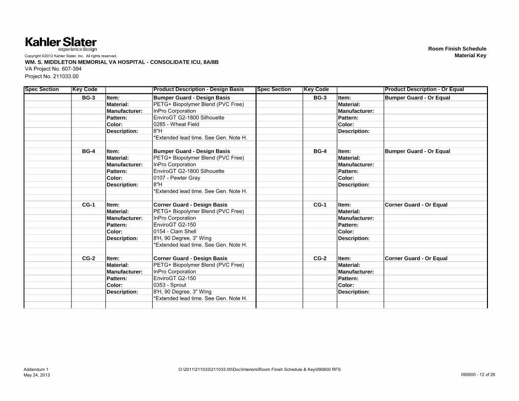
Spec Section Key Code Product Description - Design Basis Spec Section Key Code Product Description - Or EqualBG-3 Item: Bumper Guard - Design Basis BG-3 Item: Bumper Guard - Or Equal
Material: PETG+ Biopolymer Blend (PVC Free) Material:Manufacturer: InPro Corporation Manufacturer:Pattern: EnviroGT G2-1800 Silhouette Pattern:Color: 0285 - Wheat Field Color:Description: 8"H Description:
*Extended lead time. See Gen. Note H.
BG-4 Item: Bumper Guard - Design Basis BG-4 Item: Bumper Guard - Or EqualMaterial: PETG+ Biopolymer Blend (PVC Free) Material:Manufacturer: InPro Corporation Manufacturer:Pattern: EnviroGT G2-1800 Silhouette Pattern:Color: 0107 - Pewter Gray Color:Description: 8"H Description:
*Extended lead time. See Gen. Note H.
CG-1 Item: Corner Guard - Design Basis CG-1 Item: Corner Guard - Or EqualMaterial: PETG+ Biopolymer Blend (PVC Free) Material:Manufacturer: InPro Corporation Manufacturer:P tt E i GT G2 150 P ttPattern: EnviroGT G2-150 Pattern:Color: 0154 - Clam Shell Color:Description: 8'H, 90 Degree, 3" Wing Description:
*Extended lead time. See Gen. Note H.
CG-2 Item: Corner Guard - Design Basis CG-2 Item: Corner Guard - Or EqualMaterial: PETG+ Biopolymer Blend (PVC Free) Material:Manufacturer: InPro Corporation Manufacturer:Pattern: EnviroGT G2-150 Pattern:Color: 0353 - Sprout Color:Description: 8'H, 90 Degree, 3" Wing Description:
*Extended lead time. See Gen. Note H.
Addendum 1May 24, 2013
O:\2011\211033\211033.00\Doc\Interiors\Room Finish Schedule & Key\090600 RFS 090600 - 12 of 26

Room Finish ScheduleCopyright ©2012 Kahler Slater, Inc. All rights reserved. Material KeyWM. S. MIDDLETON MEMORIAL VA HOSPITAL - CONSOLIDATE ICU, 8A/8BVA Project No. 607-394Project No. 211033.00
Spec Section Key Code Product Description - Design Basis Spec Section Key Code Product Description - Or EqualCG-3 Item: Corner Guard - Design Basis CG-3 Item: Corner Guard - Or Equal
Material: PETG+ Biopolymer Blend (PVC Free) Material:Manufacturer: InPro Corporation Manufacturer:Pattern: EnviroGT G2-130 Pattern:Color: 0353 - Sprout Color:Description: 8'H, 135 Degree, 3" Wing Description:
*Extended lead time. See Gen. Note H.
CG-4 Item: Corner Guard - Design Basis CG-4 Item: Corner Guard - Or EqualMaterial: Stainless Steel Material:Manufacturer: InPro Corporation Manufacturer:Pattern: Model 180 Surface Mount Pattern:Color: No. 4 Satin Finish Color:Description: 8'H, 3 1/2"Wing, 1/8" Radius Description:
CG-5 Item: Corner Guard - Design Basis CG-5 Item: Corner Guard - Or EqualMaterial: Stainless Steel Material:Manufacturer: InPro Corporation Manufacturer:P tt M d l 181 S f M t P ttPattern: Model 181 Surface Mount Pattern:Color: No. 4 Satin Finish Color:Description: 8'H, 1 1/2"Wing, 1/8" Radius Description:
CG-6 Item: Corner Guard - Design Basis CG-6 Item: Corner Guard - Or EqualMaterial: PETG+ Biopolymer Blend (PVC Free) Material:Manufacturer: InPro Corporation Manufacturer:Pattern: EnviroGT G2-150 Pattern:Color: 0107 - Pewter Gray Color:Description: 8'H, 90 Degree, 3" Wing Description:
*Extended lead time. See Gen. Note H.
Addendum 1May 24, 2013
O:\2011\211033\211033.00\Doc\Interiors\Room Finish Schedule & Key\090600 RFS 090600 - 13 of 26

Room Finish ScheduleCopyright ©2012 Kahler Slater, Inc. All rights reserved. Material KeyWM. S. MIDDLETON MEMORIAL VA HOSPITAL - CONSOLIDATE ICU, 8A/8BVA Project No. 607-394Project No. 211033.00
Spec Section Key Code Product Description - Design Basis Spec Section Key Code Product Description - Or EqualCG-7 Item: Corner Guard - Design Basis CG-7 Item: Corner Guard - Or Equal
Material: PETG+ Biopolymer Blend (PVC Free) Material:Manufacturer: InPro Corporation Manufacturer:Pattern: EnviroGT G2-160 Pattern:Color: 0353 - Sprout Color:Description: 8'H, 90 Degree, 2" Wing Description:
*Extended lead time. See Gen. Note H.
HR-1 Item: Handrail - Design Basis HR-1 Item: Handrail - Or EqualMaterial: Vinyl Material:Manufacturer: InPro Corporation Manufacturer:Pattern: 2000W Handrail Pattern:Color: 0535 - Honey Nut Color:Description: With Stainless Steel Mounting Brackets Description:
RWP-1 Item: Wall Protection - Design Basis RWP-1 Item: Wall Protection - Or EqualMaterial: PETG Biopolymer Blend (PVC Free) Material:Manufacturer: InPro Corporation Manufacturer:Pattern: EnviroGT G2 Series Sheet Pattern:C l 0154 Cl Sh ll C lColor: 0154 - Clam Shell Color:Description: 4'x8' Sheet, 0.060" Thick Description:
*Extended lead time. See Gen. Note H.
RWP-2 Item: Wall Protection - Design Basis RWP-2 Item: Wall Protection - Or EqualMaterial: PETG Biopolymer Blend (PVC Free) Material:Manufacturer: InPro Corporation Manufacturer:Pattern: EnviroGT G2 Series Sheet Pattern:Color: 0353 - Sprout Color:Description: 4'x8' Sheet, 0.060" Thick Description:
*Extended lead time. See Gen. Note H.
Addendum 1May 24, 2013
O:\2011\211033\211033.00\Doc\Interiors\Room Finish Schedule & Key\090600 RFS 090600 - 14 of 26

Room Finish ScheduleCopyright ©2012 Kahler Slater, Inc. All rights reserved. Material KeyWM. S. MIDDLETON MEMORIAL VA HOSPITAL - CONSOLIDATE ICU, 8A/8BVA Project No. 607-394Project No. 211033.00
Spec Section Key Code Product Description - Design Basis Spec Section Key Code Product Description - Or EqualRWP-3 Item: Wall Protection - Design Basis RWP-3 Item: Wall Protection - Or Equal
Material: PETG Biopolymer Blend (PVC Free) Material:Manufacturer: InPro Corporation Manufacturer:Pattern: EnviroGT G2 Series Sheet Pattern:Color: 0285 - Wheat Field Color:Description: 4'x8' Sheet, 0.060" Thick Description:
*Extended lead time. See Gen. Note H.
RWP-4 Item: Door Protection - Design Basis RWP-4 Item: Door Protection - Or EqualMaterial: Vinyl Material:Manufacturer: InPro Corporation Manufacturer:Pattern: Rigid Vinyl Sheet - Woodland 1 Pattern:Color: 0535 - Honey Nut Color:Description: 4'x8' Sheet, 0.060" Thick Description:
RS-1 Item: Roller Shade - Design Basis RS-1 Item: Roller Shade - Or EqualManufacturer: RollEase Manufacturer:P tt R S i G l G d Cl t h P tt
122400 Window Shades 122400 Window Shades
Pattern: R Series Galaxy Geared Clutches Pattern:w/Phifer Sheerweave 4100
Color: Q12 Pebblestone, 10% Openness Color:Description: Stainless steel ball chain loops and Description:
commercial hold-down.
RS-2 Item: Roller Shade - Outer Shade (Blackout)- RS-2 Item: Roller Shade - Outer Shade (Blackout)-Design Basis Or Equal
Manufacturer: RollEase Manufacturer:Pattern: R Series Galaxy Geared Clutches Pattern:
w/Butler Panta-Flex Matte FR Color: 934 Fawn Color:Description: Stainless steel ball chain loops and Description:
commercial hold-down.
Addendum 1May 24, 2013
O:\2011\211033\211033.00\Doc\Interiors\Room Finish Schedule & Key\090600 RFS 090600 - 15 of 26

Copyright ©2012 Kahler Slater, Inc. All rights reserved.
WM. S. MIDDLETON MEMORIAL VA HOSPITAL - CONSOLIDATE ICU, 8A/8BVA Project No. 607-394Project No. 211033.00
NotesGeneral Notes
A Room Finish Schedule to be read in combination with Room Finish Schedule Material Key, Finish Plans, Elevations and Details.B See sheet series AS-200 for Reflected Ceiling Plans denoting ceiling heights and ceiling material locations.C See sheet seies AS-310 for wall protection types and locations including bumper guards (BG), corner guards (CG), handrails (HR) and rigid wall protection (RWP).
Listed items' locations are not included in the Room Finish Schedule.D Standard paint sheen to be Eggshell, u.n.o.E All hollow metal door frames to be PA-2, semi-gloss finish, u.n.o.F All metal handrails in stairwells to be PT-10, shop-finished powdercoating.G All GWB at ceilings and soffits to be painted PA-1, u.n.o.H All corner guards and wall protection products (IPC, G-Series) have extended lead times of 20 business days; schedule procurement accordingly. I All rigid wall protection (RWP) to run 4'-0" above scheduled base to maintain standard product size, u.n.o.J Provide appropriate transition strips between all dissimilar flooring materials, including sheet ruber to sheet vinyl transitions. Color to match RB-1, u.n.o.K All solid surface countertops to have 1 1/2" built-up eased edge, u.n.o.L All window sills to be solid surface, SS-1, u.n.o.M All PCT on walls in toilet rooms to be full-height to ceiling, u.n.o.N Provide RS-1 at all exterior glazing.O PC-1 has 81" vertical pattern repeat. Curtain panels to be fabricated with top of pattern repeat (lightest portion) at attached mesh. Trim from bottom
Room Finish ScheduleGeneral and Key Notes
of pattern repeat as necessary to achieve desired curtain panel length.P Provide 2"x2" mosaic PCT to coordinate with specified floor tile when needed to slope to floor drains. Confirm any areas larger than 24"x24" with Architect.
*Hatching or shading in Room Finish Schedule or Material Key indicates a revision. If an existing item is changed, it will be either struck through "xxxx"in the Material Key or appear in brackets "[xxxx]" in the Room Finish Schedule along with any revised information.
Addendum 1May 24, 2013
O:\2011\211033\211033.00\Doc\Interiors\Room Finish Schedule & Key\090600 RFS 090600 - 16 of 26

Copyright ©2012 Kahler Slater, Inc. All rights reserved.
WM. S. MIDDLETON MEMORIAL VA HOSPITAL - CONSOLIDATE ICU, 8A/8BVA Project No. 607-394Project No. 211033.00
Notes
Room Finish ScheduleGeneral and Key Notes
Key Notes1 Resilient sheet flooring to be flash-coved to 6"AFF.2 Schulter Systems coved transition to be used at all transitions between wall and floor tile, including any inside and outside corners with associated accessories.3 Privacy Curtain PC-1 to be used with track system CT-1.4 PCT-4 to be used between 6'-0" and 6'-4"AFF.5 All face tiles of headwall & footwall system to match Herman Miller Durawrap, Aged Cherry-HX, u.n.o. Sink, worksurface and associated face tiles above
each to be SS-2.6 All existing finishes to remain.7 Patient display shelf at footwall to be SS-2. 8 Provide both RS-1 and RS-2 at exterior glazing.9 Wall and ceiling finishes as noted. All other surfaces, patch to match existing as required by owner.10 TFP-1 to be included above worksurface.11 AT-3 specified as the patient room could be switched to negative air pressure in the event of a surge.
Addendum 1May 24, 2013
O:\2011\211033\211033.00\Doc\Interiors\Room Finish Schedule & Key\090600 RFS 090600 - 17 of 26

Copyright © 2012 Kahler Slater, Inc. All rights reserved.
Project No.
Room Finish Schedule
VA Project No. 607-394
C:\Users\4345ad\Documents\VA-ICU Consolidation_4345ad.rvt RFS-1
211033.00
WM. S. MIDDLETON MEMORIAL VETERAN'S HOSPITAL CONSOLIDATE ICUs, 8A/8B
ADDENDUM 1MAY 24, 2013
Room No. Room Name Floor BaseWall Cabinetry
Ceiling Notes RevisionsNorth East South West Top Base Wall
A8054 STAIR 9 RT-1/ STR-1 RB-2 PA-9 PA-9 PA-9 PA-9 - - - GWBEB1-08 STAIR 1 - - - - PA-9 PA-9 - - - ACT-1/
GWB9
EB2-08 STAIR 2 - - PA-9 - - - - - - GWB 9EB3-08 STAIR 3 RT-1/ STR-1 RB-2 PA-9 PA-9 PA-9 PA-9 - - - ACT-1EB3-09 STAIR 3 RT-1/ STR-1 RB-2 PA-9 PA-9 PA-9 PA-9 - - - ACT-1ED7-08 STAIR 7 - - - - - - - - - - 6ED8-08 STAIR 8 RT-1/ STR-1 PA-9 PA-9 PA-9 PA-9 - - - ACT-1
090600 - 18 of 26

Copyright © 2012 Kahler Slater, Inc. All rights reserved.
Project No.
Room Finish Schedule
VA Project No. 607-394
C:\Users\4345ad\Documents\VA-ICU Consolidation_4345ad.rvt RFS-3
211033.00
WM. S. MIDDLETON MEMORIAL VETERAN'S HOSPITAL CONSOLIDATE ICUs, 8A/8B
ADDENDUM 1MAY 24, 2013
Room No. Room Name Floor BaseWall Cabinetry
Ceiling Notes RevisionsNorth East South West Top Base Wall
A8001 IMAGING ALCOVE SV-2 SV-2 PA-3 PA-3 PA-3 PA-3 SS-1 - - ACT-2 1A8002 CONSULT CPT-1 RB-1 PA-1 WC-3 PA-1 PA-1 - - - ACT-1/
GWBA8003 ICU EQUIP SV-2 SV-2 PA-1 PA-1 PA-1 PA-1 - - - ACT-2 1A8004 RN MGR CPT-2 RB-1 PA-1 PA-1 PA-1 PA-1 - - - ACT-1A8005 PUBLIC / STAFF TLT -
FEMALEPCT-2 PCT-1 PCT-1,4 PCT-1,4 PCT-1,4 PCT-1,4 SS-1 PL-1 - GWB 2, 4
A8006 RN MGR CPT-2 RB-1 PA-1 PA-1 PA-1 PA-1 - - - ACT-1A8007 PUBLIC / STAFF TLT - MALE PCT-2 PCT-1 PCT-1,4 PCT-1,4 PCT-1,4 PCT-1,4 SS-1 PL-1 - GWB 2, 4A8008 PHARMACIST CPT-2 RB-1 PA-1 PA-1 PA-1 PA-1 - - - ACT-1A8010 INTENS. OFFICE CPT-2 RB-1 PA-1 PA-1 PA-1 PA-1 - - - ACT-1A8011 CONFERENCE CPT-1 RB-1 WC-3 PA-1 PA-1 PA-1 - - ACT-1/
GWBA8012 CLINICAL SPECIALIST CPT-2 RB-1 PA-1 PA-1 PA-1 PA-1 - - - ACT-1A8013 ELEC SC RB-2 PA-1 PA-1 PA-1 PA-1 - - - EXPA8014 ANESTH. MD/RN OFFICE CPT-2 RB-1 PA-1 PA-1 PA-1 PA-1 - - - ACT-1A8015 HSKP PCT-2 PCT-1 PCT-1 PCT-1 PCT-1 PCT-1 - PL-1 SST GWB 2A8016 ANESTHESIA ADMIN CPT-2 RB-1 PA-1 PA-1 PA-1 PA-1 - - - ACT-1A8017 OR VENDOR OFFICE SV-1,2 SV-2 PA-1 PA-1 PA-1 PA-1 - - ACT-1 1, 10A8018 CHIEF ANESTH. OFFICE CPT-2 RB-1 PA-1 PA-1 PA-1 PA-1 - - - ACT-1A8019 MEN'S TOILETS PCT-2 PCT-1 PCT-1,4 PCT-1,4 PCT-1,4 PCT-1,4 SS-1 PL-1 - GWB 2, 4
090600 - 19 0F 26

Copyright © 2012 Kahler Slater, Inc. All rights reserved.
Project No.
Room Finish Schedule
VA Project No. 607-394
C:\Users\4345ad\Documents\VA-ICU Consolidation_4345ad.rvt RFS-4
211033.00
WM. S. MIDDLETON MEMORIAL VETERAN'S HOSPITAL CONSOLIDATE ICUs, 8A/8B
ADDENDUM 1MAY 24, 2013
Room No. Room Name Floor BaseWall Cabinetry
Ceiling Notes RevisionsNorth East South West Top Base Wall
A8020 ANESTH. MD OFFICE CPT-2 RB-1 PA-1 PA-1 PA-1 PA-1 - - - ACT-1A8021 VESTIBULE SV-2 SV-2 PA-1 PA-1 PA-1 PA-1 - - - ACT-1 1A8022 ANESTH. MD OFFICE CPT-2 RB-1 PA-1 PA-1 PA-1 PA-1 - - - ACT-1A8024 ANESTH. MD OFFICE CPT-2 RB-1 PA-1 PA-1 PA-1 PA-1 - - - ACT-1A8026 VESTIBULE SV-2 SV-2 PA-1 PA-1 PA-1 PA-1 - - - ACT-1 1A8027 MEN'S LOCKERS SV-1,2 SV-2 PA-1 PA-1 PA-1 PA-1 SST - - ACT-1 1A8028 CORRIDOR SV-1,2 SV-2 PA-3 - PA-3 PA-3 - - - ACT-1 1A8028A UTILITY CLOSET SV-2 RB-2 PA-1 PA-1 PA-1 PA-1 - - - EXPA8029 STERILE SUPPLY/ CLEAN
STORAGE/ CART ASSEMBLYRF-1,2,3,4 RF-2 PA-6 PA-6 PA-6 PA-6 SST - SST GWB 1
A8030 WOMEN'S LOCKERS SV-1,2 SV-2 PA-1 PA-1 PA-1 PA-1 SST - - ACT-1 1A8035 STERILIZERS PA-7 RB-2 PA-8 PA-8 PA-8 PA-8 - - - EXPA8036 WOMEN'S TOILETS PCT-2 PCT-1 PCT-1,4 PCT-1,4 PCT-1,4 PCT-1,4 SS-1 PL-1 - GWB 2, 4A8037 PREP/ PACK RF-1,2,3,4 RF-2 PA-6 PA-6 PA-6 PA-6 SST - SST GWB 1A8041 HSKP PCT-2 PCT-1 PCT-1 PCT-1 PCT-1 PCT-1 - PL-1 SST GWB 2A8042 ANESTHESIA TRAINING RF-1,2 RF-2 PA-1 PA-1 PA-1 PA-1 SS-1 PL-1 PL-1 ACT-1 1A8044 CORRIDOR RF-1,2 RF-2 PA-3 PA-3 PA-3 - - - - ACT-1/
GWB1
A8046 OR EQUIP. STORAGE RF-2 RF-2 PA-1 PA-1 PA-1 PA-1 - - - ACT-2 1A8048 EDU/ CNL CPT-2 RB-1 PA-1 PA-1 PA-1 PA-1 - - - ACT-1A8050 OR SERV. COORD. CPT-2 RB-1 PA-1 PA-1 PA-1 PA-1 - - - ACT-1 10A8052 ANESTH STORAGE RF-2 RF-2 PA-1 PA-1 PA-1 PA-1 - - - ACT-2 1
090600 - 20. of 26

Copyright © 2012 Kahler Slater, Inc. All rights reserved.
Project No.
Room Finish Schedule
VA Project No. 607-394
C:\Users\4345ad\Documents\VA-ICU Consolidation_4345ad.rvt RFS-5
211033.00
WM. S. MIDDLETON MEMORIAL VETERAN'S HOSPITAL CONSOLIDATE ICUs, 8A/8B
ADDENDUM 1MAY 24, 2013
Room No. Room Name Floor BaseWall Cabinetry
Ceiling Notes RevisionsNorth East South West Top Base Wall
B8001 STAFF LOUNGE SV-1,2 SV-2 PA-4 PA-1 PA-1 PA-4 SS-1 PL-1 PL-1 ACT-1 1B8002 PROT. ENVIRON. PATIENT
ROOMSV-1,2 SV-2 PA-1/ PCT-5 PA-1/ PCT-5 PA-1 PA-4 SS-2 PL-1 - ACT-3/
GWB1, 3, 5, 7, 8
B8004 PROT. ENVIRON. PATIENTROOM
SV-1,2 SV-2 PA-1/ PCT-5 PA-4 PA-1 PA-1/ PCT-5 SS-2 PL-1 - ACT-3/GWB
1, 3, 5, 7, 8
B8005 FAMILY ROOM CPT-2 RB-1 PA-5 WC-2 PA-5 PA-5 - - - ACT-1B8006 CHARTING SV-2 SV-2 PA-3 PA-3 - PA-3 SS-1 - - GWB 1B8007 VISITOR/STAFF TOILET PCT-2 PCT-1 PCT-1,4 PCT-1,4 PCT-1,4 PCT-1,4 - - - GWB 2, 4B8008 BARIATRIC PROT. ENVIRON.
PATIENT ROOMSV-1,2 SV-2 PA-1/ PCT-5 PA-1/ PCT-5 PA-1 PA-4 SS-2 PL-1 - ACT-3/
GWB1, 3, 5, 7, 8
B8009 NOURISHMENT SV-1,2 SV-2 PA-1 PA-1 PA-1 PA-1 SS-1 PL-1 PL-1 ACT-2 1B8010 PROT. ENVIRON. PATIENT
ROOMSV-1,2 SV-2 PA-1/ PCT-5 PA-4 PA-1 PA-1/ PCT-5 SS-2 PL-1 - ACT-3/
GWB1, 3, 5, 7, 8
B8012 CHARTING SV-2 SV-2 PA-3 PA-3 - PA-3 SS-1 - - GWB 1B8013 NURSE STATION SV-1,2,3 SV-2 - PA-3 PA-3 PA-3 - - - ACT-1/
GWB1
B8014 PROT. ENVIRON. PATIENTROOM
SV-1,2 SV-2 PA-1/ PCT-5 PA-1/ PCT-5 PA-1 PA-4 SS-2 PL-1 - ACT-3/GWB
1, 3, 5, 7, 8
B8016 PROT. ENVIRON. PATIENTROOM
SV-1,2 SV-2 PA-1/ PCT-5 PA-4 PA-1 PA-1/ PCT-5 SS-2 PL-1 - ACT-3/GWB
1, 3, 5, 7, 8
B8018 CHARTING SV-2 SV-2 PA-3 PA-3 - PA-3 SS-1 - - GWB 1B8019 MED PREP ALCOVE SV-2 SV-2 PA-3 PA-3 PA-1 PA-1 - - - ACT-2 1B8020 PROT. ENVIRON. PATIENT
ROOMSV-1,2 SV-2 PA-1/ PCT-5 PA-1/ PCT-5 PA-1 PA-4 SS-2 PL-1 - ACT-3/
GWB1, 3, 5, 7, 8
090600 - 21 of 26

Copyright © 2012 Kahler Slater, Inc. All rights reserved.
Project No.
Room Finish Schedule
VA Project No. 607-394
C:\Users\4345ad\Documents\VA-ICU Consolidation_4345ad.rvt RFS-6
211033.00
WM. S. MIDDLETON MEMORIAL VETERAN'S HOSPITAL CONSOLIDATE ICUs, 8A/8B
ADDENDUM 1MAY 24, 2013
Room No. Room Name Floor BaseWall Cabinetry
Ceiling Notes RevisionsNorth East South West Top Base Wall
B8021 MED PREP SV-2 SV-2 PA-1 PA-1 PA-1 PA-1 SS-1 PL-1 PL-1 ACT-2 1B8022 PATIENT ROOM SV-1,2 SV-2 PA-1/ PCT-5 PA-4 PA-1 PA-1/ PCT-5 SS-2 PL-1 - ACT-3/
GWB1, 3, 5, 7, 8,11
B8023 CLEAN UTILITY SV-2 SV-2 PA-1 PA-1 PA-1 PA-1 - - - ACT-2 1B8024 CHARTING SV-2 SV-2 PA-3 PA-3 - PA-3 SS-1 - - GWB 1B8025 EQUIPMENT SV-2 SV-2 PA-1 PA-1 PA-1 PA-1 - - - ACT-2 1B8026 NEG. ISOLATION PATIENT
ROOMSV-1,2 SV-2 PA-1/ PCT-5 PA-1/ PCT-5 PA-1 PA-4 SS-2 PL-1 - ACT-3/
GWB1, 3, 5, 7, 8
B8027 CLEAN LINEN SV-2 SV-2 PA-1 PA-1 PA-1 PA-1 - - - ACT-2 1B8028 NEG. ISOLATION PATIENT
ROOMSV-1,2 SV-2 PA-1/ PCT-5 PA-4 PA-1 PA-1/ PCT-5 SS-2 PL-1 - ACT-3/
GWB1, 3, 5, 7, 8
B8029 CONFERENCE/ REPORT CPT-2 RB-1 WC-3 PA-1 PA-1 PA-1 SS-1 - - ACT-1B8030 CHARTING SV-2 SV-2 PA-3 PA-3 - PA-3 SS-1 - - GWB 1B8032 PATIENT ROOM SV-1,2 SV-2 PA-1/ PCT-5 PA-1/ PCT-5 PA-1 PA-4 SS-2 PL-1 - ACT-2/
GWB1, 3, 5, 7, 8
B8033 SOILED UTILITY SV-2 SV-2 PCT-1 PCT-1 PCT-1 PCT-1 SS-1 - PL-1 GWB 1B8034 PATIENT ROOM SV-1,2 SV-2 PA-1/ PCT-5 PA-4 PA-1 PA-1/ PCT-5 SS-2 PL-1 - ACT-2/
GWB1, 3, 5, 7, 8
B8035 ELEC. SC RB-2 PA-1 PA-1 PA-1 PA-1 - - - EXPB8036 CHARTING SV-2 SV-2 PA-3 PA-3 - PA-3 SS-1 - - GWB 1B8037 FAMILY ROOM CPT-2 RB-1 PA-5 PA-5 PA-5 WC-2 - - - ACT-1B8038 PATIENT ROOM SV-1,2 SV-2 PA-1/ PCT-5 PA-1/ PCT-5 PA-1 PA-4 SS-2 PL-1 - ACT-2/
GWB1, 3, 5, 7, 8
B8039 VISITOR/STAFF TOILET PCT-2 PCT-1 PCT-1,4 PCT-1,4 PCT-1,4 PCT-1,4 - - - GWB 2, 4B8040 BARIATRIC PATIENT ROOM SV-1,2 SV-2 PA-1/ PCT-5 PA-4 PA-1 PA-1/ PCT-5 SS-2 PL-1 - ACT-2/
GWB1, 3, 5, 7, 8
090600 - 22 of 26

Copyright © 2012 Kahler Slater, Inc. All rights reserved.
Project No.
Room Finish Schedule
VA Project No. 607-394
C:\Users\4345ad\Documents\VA-ICU Consolidation_4345ad.rvt RFS-7
211033.00
WM. S. MIDDLETON MEMORIAL VETERAN'S HOSPITAL CONSOLIDATE ICUs, 8A/8B
ADDENDUM 1MAY 24, 2013
Room No. Room Name Floor BaseWall Cabinetry
Ceiling Notes RevisionsNorth East South West Top Base Wall
B8041 NOURISHMENT SV-1,2 SV-2 PA-1 PA-1 PA-1 PA-1 SS-1 PL-1 PL-1 ACT-2 1B8042 CHARTING SV-2 SV-2 PA-3 PA-3 - PA-3 SS-1 - - GWB 1B8043 NURSE STATION SV-1,2,3 SV-2 - PA-3 PA-3 PA-3 - - - ACT-1/
GWB1
B8044 PATIENT ROOM SV-1,2 SV-2 PA-1/ PCT-5 PA-1/ PCT-5 PA-1 PA-4 SS-2 PL-1 - ACT-2/GWB
1, 3, 5, 7, 8
B8046 NEG. ISOLATION PATIENTROOM
SV-1,2 SV-2 PA-1/ PCT-5 PA-4 PA-1 PA-1/ PCT-5 SS-2 PL-1 - ACT-3/GWB
1, 3, 5, 7, 8
B8048 CHARTING SV-2 SV-2 PA-3 PA-3 - PA-3 SS-1 - - GWB 1B8050 CORRIDOR SV-1,2,3 SV-2 PA-3 PA-3 PA-3 PA-3 SS-1 PL-1 - ACT-1/
GWB1
B8052 CORRIDOR SV-1,2,3 SV-2 PA-3 PA-3 PA-3 PA-3 SS-1 PL-1 - ACT-1/GWB
1
B8053 MED PREP ALCOVE SV-2 SV-2 PA-3 PA-3 PA-1 PA-1 - - - ACT-2 1B8054 RT/ IABP STORAGE SV-2 SV-2 PA-1 PA-1 PA-1 PA-1 - - - ACT-2 1B8055 MED PREP SV-2 SV-2 PA-1 PA-1 PA-1 PA-1 SS-1 PL-1 PL-1 ACT-2 1B8056 ICU EQUIP. STORAGE SV-2 SV-2 PA-1 PA-1 PA-1 PA-1 - - - ACT-2 1B8057 CLEAN UTILITY SV-2 SV-2 PA-1 PA-1 PA-1 PA-1 - - - ACT-2 1B8058 GREETER CPT-1/ SV-3 RB-1,2 WC-2 WC-2 - - - - - ACT-1/
GWBB8059 EQUIPMENT SV-2 SV-2 PA-1 PA-1 PA-1 PA-1 - - - ACT-2 1B8060 FAMILY WAITING CPT-1 RB-1 PA-5 PCT-3/ WC-2 WC-2/ PA-5 PCT-3/WC-2 - - - ACT-1/
GWB
090600 - 23 of 26

Copyright © 2012 Kahler Slater, Inc. All rights reserved.
Project No.
Room Finish Schedule
VA Project No. 607-394
C:\Users\4345ad\Documents\VA-ICU Consolidation_4345ad.rvt RFS-8
211033.00
WM. S. MIDDLETON MEMORIAL VETERAN'S HOSPITAL CONSOLIDATE ICUs, 8A/8B
ADDENDUM 1MAY 24, 2013
Room No. Room Name Floor BaseWall Cabinetry
Ceiling Notes RevisionsNorth East South West Top Base Wall
B8061 CLEAN LINEN SV-2 SV-2 PA-1 PA-1 PA-1 PA-1 - - - ACT-2 1B8062 LOCKERS/ NOURISH SV-1 RB-2 PA-5 - WC-2 PCT-3 SS-1 PL-1 - ACT-1/
GWBB8063 HSKP - - - - - - - - - - 6B8064 DUMBWAITER SV-2 SV-2 PA-1 PA-1 PA-1 PA-1 - - - ACT-1 1B8065 MECHANICAL - - - - - - - - - - 6B8066 ELEVATOR LOBBY SV-1,2,3 SV-2 WC-2/ PA-3 WC-1/ PA-3 PA-3 - - - ACT-1/
GWB1
B8067 MED GAS STORAGE - - - - - - - - - - 6B8069 CORRIDOR SV-1,2 SV-2 - WC-1/ PA-3 PA-3 PA-3 - - - ACT-1/
GWB1
B8071 MECHANICAL - - - - - - - - - - 6B8073 DATA SC RB-2 PA-1 PA-1 PA-1 PA-1 - - - EXP
090600 - 24 of 26

Copyright © 2012 Kahler Slater, Inc. All rights reserved.
Project No.
Room Finish Schedule
VA Project No. 607-394
C:\Users\4345ad\Documents\VA-ICU Consolidation_4345ad.rvt RFS-9
211033.00
WM. S. MIDDLETON MEMORIAL VETERAN'S HOSPITAL CONSOLIDATE ICUs, 8A/8B
ADDENDUM 1MAY 24, 2013
Room No. Room Name Floor BaseWall Cabinetry
Ceiling Notes RevisionsNorth East South West Top Base Wall
D8013 CLEAN INST HOLDING RF-2 RF-2 PA-1 PA-1 PA-1 PA-1 SST - - ACT-3 1D8015 DECONTAMINATION RF-1,2,3,4 RF-2 PA-6 PA-6 PA-6 PA-6 - - SST GWB 1D8016 MECHANICAL EXP EXP EXP PA-8 PA-8 PA-8 - - - EXPD8016A MANIFOLD EXP EXP PA-8 PA-8 PA-8 PA-8 - - - EXP 1D8019 ANTEROOM RF-2 RF-2 PA-1 PA-1 PA-1 PA-1 - PL-1 - GWB 1D8020 CORRIDOR RF-1,2 RF-2 PA-3 PA-3 PA-3 PA-3 - - - ACT-1 1D8021 TOILET/ SHOWER PCT-2 PCT-1 PCT-1 PCT-1 PCT-1 PCT-1 - - - GWB 2D8023 CART WASHER PA-7 RB-2 PA-8 PA-8 PA-8 PA-8 - - - EXPD8025 CLEAN CART HOLDING RF-2 RF-2 PA-1 PA-1 PA-1 PA-1 - - - GWB 1D8028 CORRIDOR RF-1,2 RF-2 PA-3 PA-3 PA-3 PA-3 - - - ACT-1 1D8030 STORAGE RF-2 RB-2 EXP PA-1 PA-1 PA-1 - - - EXPD8035 MECH PA-7 RB-2 PA-8 PA-8 PA-8 PA-8 - - - EXPED8201 MECHANICAL - - - - - - - - - - 6ED8202 MECHANICAL - - - - - - - - - - 6ED8203A TELEPHONE - - - - - - - - - - 6ED8203B ELEC - - - - - - - - - - 6ED8205 CORRIDOR RF-1,2 RF-1 PA-3 PA-3 PA-3 PA-3 - - - ACT-1 1ED8208 - - - - - - - - - - 6ED8209 CLEAN CART LIFT/ STAGING - - - - - - - - - - 6
090600 - 25 of 26
1 ADDENDUM 1 - 05/24/2013

Copyright © 2012 Kahler Slater, Inc. All rights reserved.
Project No.
Room Finish Schedule
VA Project No. 607-394
C:\Users\4345ad\Documents\VA-ICU Consolidation_4345ad.rvt RFS-10
211033.00
WM. S. MIDDLETON MEMORIAL VETERAN'S HOSPITAL CONSOLIDATE ICUs, 8A/8B
ADDENDUM 1MAY 24, 2013
Room No. Room Name Floor BaseWall Cabinetry
Ceiling Notes RevisionsNorth East South West Top Base Wall
A9002 PENTHOUSE - - - - - - - - - - 6A9010 VESTIBULE PA-7 RB-2 PA-1 PA-1 PA-1 PA-1 - - - ACT-1A9020 PENTHOUSE - WEST PA-7 - - - - - - - - EXPB9030 PENTHOUSE - EAST PA-7 - - - - - - - - EXP
090600 - 26 of 26

09-11
23 09 23 - 1
SECTION 23 09 23
DIRECT-DIGITAL CONTROL SYSTEM FOR HVAC
PART 1 - GENERAL
1.1 DESCRIPTION
A. Provide (a) direct-digital control system(s) as ind icated on the
project documents, point list, interoperability tab les, drawings, and as
described in these specifications. Include a comple te and working
direct-digital control system. Include all engineer ing, programming,
controls and installation materials, installation l abor, commissioning
and start-up, training, final project documentation and warranty. Work
related to this section shall be the responsibility of the Systems
Integrator and the Controls Contractor.
B. The responsibilities of the Control System Integrat or shall be
comprised of Network Area Controller’s (NAC) connec ted to the
telecommunication network as well as networking sof tware and work
associated with integration of new control panels t o the NAC’ s. System
will be integrated into the existing Virtual Server provided by the VA
IT Department. Tridium Niagra AX network platform h as been sole sourced
for implementation.
C. Controls contractor shall be responsible for the re maining scope of the
work as outlined in the specifications and on the d rawings.
1. The direct-digital control system(s) shall be nativ e BACnet. All
controllers, devices and components shall be listed by BACnet Testing
Laboratories. All controller, devices and component s shall be
accessible using a Web browser interface and shall communicate
exclusively using the ASHRAE Standard 135 BACnet co mmunications
protocol without the use of gateways, unless otherw ise allowed by
this Section of the technical specifications, speci fically shown on
the design drawings and specifically requested othe rwise by the VA.
2. The work administered by this Section of the techni cal
specifications shall include all labor, materials, special tools,
equipment, enclosures, power supplies, software, so ftware licenses,
project specific software configurations and databa se entries,
interfaces, wiring, tubing, installation, labeling, engineering,
calibration, documentation, submittals, testing, ve rification,
training services, permits and licenses, transporta tion, shipping,
handling, administration, supervision, management, insurance,
warranty, specified services and items required for complete and
fully functional Controls Systems.

09-11
23 09 23 - 2
3. The control systems shall be designed such that eac h mechanical
system shall operate under stand-alone mode. The co ntractor
administered by this Section of the technical speci fications shall
provide controllers for each mechanical system. In the event of a
network communication failure, or the loss of any o ther controller,
the control system shall continue to operate indepe ndently. Failure
of the ECC shall have no effect on the field contro llers, including
those involved with global strategies.
4. The control system shall accommodate:
a. 1 Engineering Control Center(s) and the control sys tem shall
accommodate
b. 5 web-based Users simultaneously, and the access to the system
should be limited with security privileges as speci fied by the
VA.
D. Some products are furnished but not installed by th e contractor
administered by this Section of the technical speci fications. The
contractor administered by this Section of the tech nical specifications
shall formally coordinate in writing and receive fr om other contractors
formal acknowledgements in writing prior to submiss ion the installation
of the products. These products could include the f ollowing:
1. Control valves.
2. Flow switches.
3. Flow meters.
4. Sensor wells and sockets in piping.
E. Some products are installed but not furnished by th e contractor
administered by this Section of the technical speci fications. The
contractor administered by this Section of the tech nical specifications
shall formally coordinate in writing and receive fr om other contractors
formal acknowledgements in writing prior to submiss ion the procurement of
the products. These products could include the foll owing:
1. Factory-furnished accessory thermostats and sensors furnished with
unitary equipment.
F. Leave existing direct-digital control system intact and in place. Provide
a new ASHRAE Standard 135 BACnet-compliant ECC in t he same room as the
existing system’s ECC, and provide a new standalone BACnet-compliant
control system serving the work in this project. No interoperability is
required.

09-11
23 09 23 - 3
G. This campus will be standardized on standard ASHRAE Standard 135,
BACnet/IP Control System supported by a preselected controls service
company. This entity is referred to as the “Control System Integrator” in
this Section of the technical specifications. The C ontrol System
integrator is responsible for ECC system graphics a nd expansion. It also
prescribes control system-specific commissioning/ v erification procedures
to the Control Contractor administered by this Sect ion of the technical
specification. It lastly provides limited assistanc e to the Control
Contractor administered by this Section of the tech nical specification in
its commissioning/verification work.
H. The General Contractor of this project shall direct ly hire the Control
System Integrator in a contract separate from the c ontract procuring the
controls contractor administered by this Section of the technical
specifications.
I. The Control Contractor administered by this Section of the technical
specifications shall coordinate all work with the C ontrol System
Integrator. The contractor administered by this Sec tion of the technical
specifications shall integrate the ASHRAE Standard 135, BACnet/IP control
network(s) with the Control System Integrator’s are a control through an
Ethernet connection provided by the Control System Integrator.
J. The Control Contractor administered by this Section of the technical
specifications shall provide a peer-to-peer network ed, stand-alone,
distributed control system. This direct digital con trol (DDC) system
shall include one portable operator terminal - lapt op, one digital
display unit, microprocessor-based controllers, ins trumentation, end
control devices, wiring, piping, software, and rela ted systems. This
contractor is responsible for all device mounting a nd wiring.
Responsibility Table:
Item/Task Control
Contractor Control System
Integrator VA
ECC expansion X ECC programming X Devices, controllers, control panels and equipment
X
Point addressing: all hardware and software points including setpoint, calculated point, data point (analog/ binary), and reset schedule point
X
Point mapping X Network Programming X ECC Graphics X Controller programming and sequences
X

09-11
23 09 23 - 4
Item/Task Control
Contractor Control System
Integrator VA
Integrity of LAN communications
X
Electrical wiring X Operator system training X X LAN connections to devices X LAN connections to ECC X IP addresses X Overall system verification X Controller and LAN system verification
X X
K. The direct-digital control system shall start and s top equipment, move
(position) damper actuators and valve actuators, an d vary speed of
equipment to execute the mission of the control sys tem. Use electricity
as the motive force for all damper and valve actuat ors.
1.2 RELATED WORK
A. Section 23 21 13, Hydronic Piping.
B. Section 23 22 13, Steam and Condensate Heating Pipi ng.
C. Section 23 31 00, HVAC Ducts and Casings.
D. Section 23 36 00, Air Terminal Units.
E. Section 23 73 00, Indoor Central-Station Air-Handli ng Units.
F. Section 26 05 11, Requirements for Electrical Insta llations.
G. Section 26 05 21, Low-Voltage Electrical Power Cond uctors and Cables (600
Volts and Below).
H. Section 26 05 26, Grounding and Bonding for Electri cal Systems.
I. Section 26 05 33, Raceway and Boxes for Electrical Systems.
J. Section 26 27 26, Wiring Devices.
K. Section 28 31 00, Fire Detection and Alarm.
1.3 DEFINITION
A. Algorithm: A logical procedure for solving a recurr ent mathematical
problem; A prescribed set of well-defined rules or processes for the
solution of a problem in a finite number of steps.
B. ARCNET: ANSI/ATA 878.1 - Attached Resource Computer Network. ARCNET
is a deterministic LAN technology; meaning it's pos sible to determine the
maximum delay before a device is able to transmit a message.
C. Analog: A continuously varying signal value (e.g., temperature,
current, velocity etc.

09-11
23 09 23 - 5
D. BACnet: A Data Communication Protocol for Building Automation and
Control Networks , ANSI/ASHRAE Standard 135. This c ommunications
protocol allows diverse building automation devices to communicate
data over and services over a network.
E. BACnet/IP: Annex J of Standard 135. It defines and allows for using a
reserved UDP socket to transmit BACnet messages ove r IP networks. A
BACnet/IP network is a collection of one or more IP sub-networks that
share the same BACnet network number.
F. BACnet Internetwork: Two or more BACnet networks co nnected with
routers. The two networks may sue different LAN tec hnologies.
G. BACnet Network: One or more BACnet segments that ha ve the same
network address and are interconnected by bridges a t the physical and
data link layers.
H. BACnet Segment: One or more physical segments of BA Cnet devices on a
BACnet network, connected at the physical layer by repeaters.
I. BACnet Broadcast Management Device (BBMD) : A commu nications device
which broadcasts BACnet messages to all BACnet/IP d evices and other
BBMDs connected to the same BACnet/IP network.
J. BACnet Interoperability Building Blocks (BIBBs) : B ACnet
Interoperability Building Blocks (BIBBs) are collec tions of one or
more BACnet services. These are prescribed in terms of an "A" and a
"B" device. Both of these devices are nodes on a BA Cnet internetwork.
K. BACnet Testing Laboratories (BTL) : The organizatio n responsible for
testing products for compliance with the BACnet sta ndard, operated
under the direction of BACnet International.
L. Baud: It is a signal change in a communication link . One signal
change can represent one or more bits of informatio n depending on
type of transmission scheme. Simple peripheral comm unication is
normally one bit per Baud. (e.g., Baud rate = 78,00 0 Baud/sec is
78,000 bits/sec, if one signal change = 1 bit).
M. Binary: A two-state system where a high signal leve l represents an
"ON" condition and an "OFF" condition is represente d by a low signal
level.
N. BMP or bmp: Suffix, computerized image file, used a fter the period in
a DOS-based computer file to show that the file is an image stored as
a series of pixels.
O. Bus Topology: A network topology that physically in terconnects
workstations and network devices in parallel on a n etwork segment.

09-11
23 09 23 - 6
P. Control Unit (CU) : Generic term for any controllin g unit, stand-
alone, microprocessor based, digital controller res iding on secondary
LAN or Primary LAN, used for local controls or glob al controls
Q. Deadband: A temperature range over which no heating or cooling is
supplied, i.e., 22-25 degrees C (72-78 degrees F), as opposed to a
single point change over or overlap).
R. Device: a control system component that contains a BACnet Device
Object and uses BACnet to communicate with other de vices.
S. Device Object: Every BACnet device requires one Dev ice Object, whose
properties represent the network visible properties of that device.
Every Device Object requires a unique Object Identi fier number on the
BACnet internetwork. This number is often referred to as the device
instance.
T. Device Profile: A specific group of services descri bing BACnet
capabilities of a device, as defined in ASHRAE Stan dard 135-2008,
Annex L. Standard device profiles include BACnet Op erator
Workstations (BOWS), BACnet Building Controllers (B -BC), BACnet
Advanced Application Controllers (B-AAC), BACnet Ap plication Specific
Controllers (B-ASC), BACnet Smart Actuator (B-SA), and BACnet Smart
Sensor (B-SS) . Each device used in new constructio n is required to
have a PICS statement listing which service and BIB Bs are supported
by the device.
U. Diagnostic Program: A software test program, which is used to detect
and report system or peripheral malfunctions and fa ilures. Generally,
this system is performed at the initial startup of the system.
V. Direct Digital Control (DDC) : Microprocessor based control including
Analog/Digital conversion and program logic. A cont rol loop or
subsystem in which digital and analog information i s received and
processed by a microprocessor, and digital control signals are
generated based on control algorithms and transmitt ed to field
devices in order to achieve a set of predefined con ditions.
W. Distributed Control System: A system in which the p rocessing of
system data is decentralized and control decisions can and are made
at the subsystem level. System operational programs and information
are provided to the remote subsystems and status is reported back to
the Engineering Control Center. Upon the loss of co mmunication with
the Engineering Control center, the subsystems shal l be capable of
operating in a stand-alone mode using the last best available data.

09-11
23 09 23 - 7
X. Download: The electronic transfer of programs and d ata files from a
central computer or operation workstation with seco ndary memory
devices to remote computers in a network (distribut ed) system.
Y. DXF: An AutoCAD 2-D graphics file format. Many CAD systems import and
export the DXF format for graphics interchange.
Z. Electrical Control: A control circuit that operates on line or low
voltage and uses a mechanical means, such as a temp erature sensitive
bimetal or bellows, to perform control functions, s uch as actuating a
switch or positioning a potentiometer.
AA. Electronic Control: A control circuit that operates on low voltage
and uses a solid-state components to amplify input signals and
perform control functions, such as operating a rela y or providing an
output signal to position an actuator.
BB. Engineering Control Center (ECC) : The centralized control point for
the intelligent control network. The ECC comprises of personal
computer and connected devices to form a single wor kstation.
CC. Ethernet: A trademark for a system for exchanging m essages between
computers on a local area network using coaxial, fi ber optic, or
twisted-pair cables.
DD. Firmware: Firmware is software programmed into read only memory (ROM)
chips. Software may not be changed without physical ly altering the
chip.
EE. Gateway: Communication hardware connecting two or m ore different
protocols. It translates one protocol into equivale nt concepts for
the other protocol. In BACnet applications, a gatew ay has BACnet on
one side and non-BACnet (usually proprietary) proto cols on the other
side.
FF. GIF: Abbreviation of Graphic interchange format.
GG. Graphic Program (GP) : Program used to produce imag es of air handler
systems, fans, chillers, pumps, and building spaces . These images can
be animated and/or color-coded to indicate operatio n of the
equipment.
HH. Graphic Sequence of Operation: It is a graphical re presentation of
the sequence of operation, showing all inputs and o utput logical
blocks.
II. I/O Unit: The section of a digital control system t hrough which
information is received and transmitted. I/O refers to analog input
(AI), digital input (DI), analog output (AO) and di gital output (DO).

09-11
23 09 23 - 8
Analog signals are continuous and represent tempera ture, pressure,
flow rate etc, whereas digital signals convert elec tronic signals to
digital pulses (values), represent motor status, fi lter status, on-
off equipment etc.
JJ. I/P: a method for conveying and routing packets of information over
LAN paths. User Datagram Protocol (UDP) conveys inf ormation to
“sockets” without confirmation of receipt. Transmis sion Control
Protocol (TCP) establishes "sessions", which have e nd-to-end
confirmation and guaranteed sequence of delivery.
KK. JPEG: A standardized image compression mechanism st ands for Joint
Photographic Experts Group, the original name of th e committee that
wrote the standard.
LL. Local Area Network (LAN) : A communication bus that interconnects
operator workstation and digital controllers for pe er-to-peer
communications, sharing resources and exchanging in formation.
MM. Network Repeater: A device that receives data packe t from one network
and rebroadcasts to another network. No routing inf ormation is added
to the protocol.
NN. MS/TP: Master-slave/token-passing (ISO/IEC 8802, Pa rt 3). It is not
an acceptable LAN option for VA health-care facilit ies. It uses
twisted- pair wiring for relatively low speed and l ow cost
communication.
OO. Native BACnet Device: A device that uses BACnet as its primary method
of communication with other BACnet devices without intermediary
gateways. A system that uses native BACnet devices at all levels is a
native BACnet system.
PP. Network Number: A site-specific number assigned to each network
segment to identify for routing. This network numbe r must be unique
throughout the BACnet internetwork.
QQ. Object: The concept of organizing BACnet informatio n into standard
components with various associated properties. Exam ples include
analog input objects and binary output objects.
RR. Object Identifier: An object property used to ident ify the object,
including object type and instance. Object Identifi ers must be unique
within a device.
SS. Object Properties: Attributes of an object. Example s include present
value and high limit properties of an analog input object. Properties
are defined in ASHRAE 135; some are optional and so me are required.
Objects are controlled by reading from and writing to object

09-11
23 09 23 - 9
properties.
TT. Operating system (OS) : Software, which controls th e execution of
computer application programs.
UU. PCX: File type for an image file. When photographs are scanned onto a
personal computer they can be saved as PCX files an d viewed or
changed by a special application program as Photo S hop.
VV. Peripheral: Different components that make the cont rol system
function as one unit. Peripherals include monitor, printer, and I/O
unit.
WW. Peer-to-Peer: A networking architecture that treats all network
stations as equal partners- any device can initiate and respond to
communication with other devices.
XX. PICS: Protocol Implementation Conformance Statement , describing the
BACnet capabilities of a device. All BACnet devices have published
PICS.
YY. PID: Proportional, integral, and derivative control , used to control
modulating equipment to maintain a setpoint.
ZZ. Repeater: A network component that connects two or more physical
segments at the physical layer.
AAA. Router: A component that joins together two or more networks using
different LAN technologies. Examples include joinin g a BACnet
Ethernet LAN to a BACnet MS/TP LAN.
BBB. Sensors: Devices measuring state points or flows, w hich are then
transmitted back to the DDC system.
CCC. Thermostats: Devices measuring temperatures, which are used in
control of standalone or unitary systems and equipm ent not attached
to the DDC system.
1.4 QUALITY ASSURANCE
A. Criteria:
1. Single Source Responsibility of subcontractor: The Contractor shall
obtain hardware and software supplied under this Se ction and
delegate the responsibility to a single source cont rols installation
subcontractor. The controls subcontractor shall be responsible for
the complete design, installation, and commissionin g of the system.
The controls subcontractor shall be in the business of design,
installation and service of such building automatio n control systems
similar in size and complexity.
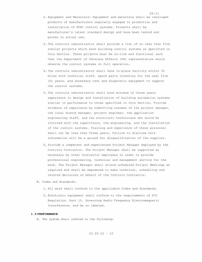
09-11
23 09 23 - 10
2. Equipment and Materials: Equipment and materials sh all be cataloged
products of manufacturers regularly engaged in prod uction and
installation of HVAC control systems. Products shal l be
manufacturer’s latest standard design and have been tested and
proven in actual use.
3. The controls subcontractor shall provide a list of no less than five
similar projects which have building control system s as specified in
this Section. These projects must be on-line and fu nctional such
that the Department of Veterans Affairs (VA) repres entative would
observe the control systems in full operation.
4. The controls subcontractor shall have in-place faci lity within 50
miles with technical staff, spare parts inventory f or the next five
(5) years, and necessary test and diagnostic equipm ent to support
the control systems.
5. The controls subcontractor shall have minimum of th ree years
experience in design and installation of building a utomation systems
similar in performance to those specified in this S ection. Provide
evidence of experience by submitting resumes of the project manager,
the local branch manager, project engineer, the app lication
engineering staff, and the electronic technicians w ho would be
involved with the supervision, the engineering, and the installation
of the control systems. Training and experience of these personnel
shall not be less than three years. Failure to disc lose this
information will be a ground for disqualification o f the supplier.
6. Provide a competent and experienced Project Manager employed by the
Controls Contractor. The Project Manager shall be s upported as
necessary by other Contractor employees in order to provide
professional engineering, technical and management service for the
work. The Project Manager shall attend scheduled Pr oject Meetings as
required and shall be empowered to make technical, scheduling and
related decisions on behalf of the Controls Contrac tor.
B. Codes and Standards:
1. All work shall conform to the applicable Codes and Standards.
2. Electronic equipment shall conform to the requireme nts of FCC
Regulation, Part 15, Governing Radio Frequency Elec tromagnetic
Interference, and be so labeled.
1.5 PERFORMANCE
A. The system shall conform to the following:

09-11
23 09 23 - 11
1. Graphic Display: The system shall display up to fou r (4) graphics on
a single screen with a minimum of twenty (20) dynam ic points per
graphic. All current data shall be displayed within ten (10) seconds
of the request.
2. Graphic Refresh: The system shall update all dynami c points with
current data within eight (8) seconds. Data refresh shall be
automatic, without operator intervention.
3. Object Command: The maximum time between the comman d of a binary
object by the operator and the reaction by the devi ce shall be two
(2) seconds. Analog objects shall start to adjust w ithin two (2)
seconds.
4. Object Scan: All changes of state and change of ana log values shall
be transmitted over the high-speed network such tha t any data used
or displayed at a controller or work-station will b e current, within
the prior six (6) seconds.
5. Alarm Response Time: The maximum time from when an object goes into
alarm to when it is annunciated at the workstation shall not exceed
(10) seconds.
6. Program Execution Frequency: Custom and standard ap plications shall
be capable of running as often as once every (5) se conds. The
Contractor shall be responsible for selecting execu tion times
consistent with the mechanical process under contro l.
7. Multiple Alarm Annunciations: All workstations on t he network shall
receive alarms within five (5) seconds of each othe r.
8. Performance: Programmable Controllers shall be able to execute DDC
PID control loops at a selectable frequency from at least once every
one (1) second. The controller shall scan and updat e the process
value and output generated by this calculation at t his same
frequency.
9. Reporting Accuracy: Listed below are minimum accept able reporting
end-to-end accuracies for all values reported by th e specified
system:
Measured Variable Reported Accuracy
Ducted air temperature ±0.5 C [±
Outdoor air temperature ±1.0 C [±
Dew Point ±1.5 C [±
Water temperature ±0.5 C [±

09-11
23 09 23 - 12
Measured Variable Reported Accuracy
Relative humidity ±2% RH
Air flow (measuring stations) ±5% of reading
Air pressure(ducts) ±25Pa [±0.1"w.c.]
Note 1: for both absolute and differential pressure
10. Control stability and accuracy: Control sequences s hall maintain
measured variable at setpoint within the following tolerances:
Controlled Variable Control Accuracy Range of Medium
Air Pressure ±50 Pa (±0.2 in. w.g.) 0–1.5 kPa (0–6 in. w.g.)
Airflow ±10% of full scale
Duct Temperature ±1.5 °C (±3 °F)
Humidity ±5% RH
11. Extent of direct digital control: control design sh all allow for at
least the points indicated on the points lists on t he drawings.
1.6 WARRANTY
A. Labor and materials for control systems shall be wa rranted for a period as
specified under Warranty in FAR clause 52.246-21.
B. Control system failures during the warranty period shall be adjusted,
repaired, or replaced at no cost or reduction in se rvice to the owner. The
system includes all computer equipment, transmissio n equipment, and all
sensors and control devices.
C. The on-line support service shall allow the Control s supplier to dial out
over telephone lines to or connect via (through pas sword-limited access)
VPN through the internet monitor and control the fa cility’s building
automation system. This remote connection to the fa cility shall be within
two (2) hours of the time that the problem is repor ted. This coverage
shall be extended to include normal business hours, after business hours,
weekend and holidays. If the problem cannot be reso lved with on-line
support services, the Controls supplier shall dispa tch the qualified
personnel to the job site to resolve the problem wi thin 24 hours after the
problem is reported.
D. Controls and Instrumentation subcontractor shall be responsible for
temporary operations and maintenance of the control systems during the
construction period until final commissioning, trai ning of facility
operators and acceptance of the project by VA.
1.7 SUBMITTALS
A. Submit shop drawings in accordance with Section 01 33 23, SHOP DRAWINGS,
PRODUCT DATA, AND SAMPLES.

09-11
23 09 23 - 13
B. Manufacturer’s literature and data for all componen ts including the
following:
1. A wiring diagram for each type of input device and output device
including DDC controllers, modems, repeaters, etc. Diagram shall
show how the device is wired and powered, showing t ypical
connections at the digital controllers and each pow er supply, as
well as the device itself. Show for all field conne cted devices,
including but not limited to, control relays, motor starters,
electric or electronic actuators, and temperature p ressure, flow and
humidity sensors and transmitters.
2. A diagram of each terminal strip, including digital controller
terminal strips, terminal strip location, terminati on numbers and
the associated point names.
3. Control dampers and control valves schedule, includ ing the size and
pressure drop.
4. Catalog cut sheets of all equipment used. This incl udes, but is not
limited to software (by manufacturer and by third p arties), DDC
controllers, panels, peripherals, airflow measuring stations and
associated components, and auxiliary control device s such as
sensors, actuators, and control dampers. When manuf acturer’s cut
sheets apply to a product series rather than a spec ific product, the
data specifically applicable to the project shall b e highlighted.
Each submitted piece of literature and drawings sho uld clearly
reference the specification and/or drawings that it supposed to
represent.
5. Sequence of operations for each HVAC system and the associated
control diagrams. Equipment and control labels shal l correspond to
those shown on the drawings.
6. Color prints of proposed graphics with a list of po ints for display.
7. Furnish a BACnet Protocol Implementation Conformanc e Statement
(PICS) for each BACnet-compliant device.
8. Schematic wiring diagrams for all control, communic ation and power
wiring. Provide a schematic drawing of the central system
installation. Label all cables and ports with compu ter
manufacturers’ model numbers and functions. Show al l interface
wiring to the control system.
9. An instrumentation list for each controlled system. Each element of
the controlled system shall be listed in table form at. The table
shall show element name, type of device, manufactur er, model number,

09-11
23 09 23 - 14
and product data sheet number.
10. Riser diagrams of wiring between central control un it and all
control panels.
11. Scaled plan drawings showing routing of LAN and loc ations of
control panels, controllers, routers, gateways, ECC , and larger
controlled devices.
12. Construction details for all installed conduit, cab ling, raceway,
cabinets, and similar. Construction details of all penetrations and
their protection.
13. Quantities of submitted items may be reviewed but a re the
responsibility of the contractor administered by th is Section of the
technical specifications.
C. Product Certificates: Compliance with Article, QUAL ITY ASSURANCE.
D. Licenses: Provide licenses for all software residin g on and used by the
Controls Systems and transfer these licenses to the Owner prior to
completion.
E. As Built Control Drawings:
1. Furnish three (3) copies of as-built drawings for e ach control
system. The documents shall be submitted for approv al prior to final
completion.
2. Furnish one (1) stick set of applicable control sys tem prints for
each mechanical system for wall mounting. The docum ents shall be
submitted for approval prior to final completion.
3. Furnish one (1) CD-ROM in CAD DWG and/or .DXF forma t for the
drawings noted in subparagraphs above.
F. Operation and Maintenance (O/M) Manuals):
1. Submit in accordance with Article, INSTRUCTIONS, in Specification
Section 01 00 00, GENERAL REQUIREMENTS.
2. Include the following documentation:
a. General description and specifications for all comp onents,
including logging on/off, alarm handling, producing trend
reports, overriding computer control, and changing set points and
other variables.

09-11
23 09 23 - 15
b. Detailed illustrations of all the control systems s pecified for
ease of maintenance and repair/replacement procedur es, and
complete calibration procedures.
c. One copy of the final version of all software provi ded including
operating systems, programming language, operator w orkstation
software, and graphics software.
d. Complete troubleshooting procedures and guidelines for all
systems.
e. Complete operating instructions for all systems.
f. Recommended preventive maintenance procedures for a ll system
components including a schedule of tasks for inspec tion, cleaning
and calibration. Provide a list of recommended spar e parts needed
to minimize downtime.
g. Training Manuals: Submit the course outline and tra ining material
to the Owner for approval three (3) weeks prior to the training
to VA facility personnel. These persons will be res ponsible for
maintaining and the operation of the control system s, including
programming. The Owner reserves the right to modify any or all of
the course outline and training material.
h. Licenses, guaranty, and other pertaining documents for all
equipment and systems.
G. Submit Performance Report to Resident Engineer prio r to final inspection.
1.8 INSTRUCTIONS
A. Instructions to VA operations personnel: Perform in accordance with
Article, INSTRUCTIONS, in Specification Section 01 00 00, GENERAL
REQUIREMENTS, and as noted below.
1. First Phase shall be completed by Controls Contract or: Formal
instructions to the VA facilities personnel for a t otal of 16 hours,
given in multiple training sessions (each no longer than four hours
in length), conducted sometime between the complete d installation
and prior to the performance test period of the con trol system, at a
time mutually agreeable to the Contractor and the V A.
2. Second Phase shall be completed by Control System I ntegrator: This
phase of training shall comprise of on the job trai ning during
start-up, checkout period, and performance test per iod. VA
facilities personnel will work with the Contractor’ s installation
and test personnel on a daily basis during start-up and checkout
period. During the performance test period, control s subcontractor

09-11
23 09 23 - 16
will provide 16 hours of instructions, given in mul tiple training
sessions (each no longer than four hours in length) , to the VA
facilities personnel.
B. The O/M Manuals shall contain approved submittals a s outlined in Article
1.7, SUBMITTALS. The Controls subcontractor will re view the manual
contents with VA facilities personnel during second phase of training.
C. Training shall be given by direct employees of the subcontractor.
1.9 PROJECT CONDITIONS (ENVIRONMENTAL CONDITIONS OF OPERATION)
A. The ECC and peripheral devices and system support e quipment shall be
designed to operate in ambient condition of 20 to 3 5 C (65 to 90 F) at a
relative humidity of 20 to 80% non-condensing.
B. The CUs used outdoors shall be mounted in NEMA 4 wa terproof enclosures,
and shall be rated for operation at –40 to 65 C (-4 0 to 150 F).
C. All electronic equipment shall operate properly wit h power fluctuations of
plus 10 percent to minus 15 percent of nominal supp ly voltage.
D. Sensors and controlling devices shall be designed t o operate in the
environment, which they are sensing or controlling.
1.10 APPLICABLE PUBLICATIONS
A. The publications listed below form a part of this s pecification to the
extent referenced. The publications are referenced in the text by the
basic designation only.
B. American Society of Heating, Refrigerating, and Air -Conditioning Engineers
(ASHRAE):
Standard 135-10 ............. BACNET Building Autom ation and Control Networks
C. American Society of Mechanical Engineers (ASME):
B16.18-01 .................. Cast Copper Alloy Sold er Joint Pressure Fittings.
B16.22-01 ................... Wrought Copper and Co pper Alloy Solder Joint Pressure Fittings.
D. American Society of Testing Materials (ASTM):
B32-08 ..................... Standard Specification for Solder Metal B88-09 ...................... Standard Specificatio ns for Seamless Copper
Water Tube B88M-09 .................... Standard Specification for Seamless Copper
Water Tube (Metric) B280-08 ................. Standard Specification fo r Seamless Copper Tube
for Air-Conditioning and Refrigeration Field Service
D2737-03 ................ Standard Specification fo r Polyethylene (PE) Plastic Tubing

09-11
23 09 23 - 17
E. Federal Communication Commission (FCC):
Rules and Regulations Title 47 Chapter 1-2001 Part 15: Radio Frequency Devices.
F. Institute of Electrical and Electronic Engineers (I EEE):
802 .3-11 .......................Information Techno logy-Telecommunications and Information Exchange between Systems-Local and Metropolitan Area Networks- Specific Requirements-Part 3: Carrier Sense Multiple Access with Collision Detection (CSMA/CD) Access method and Physical Layer Specifications
G. National Fire Protection Association (NFPA):
70-11 ....................... National Electric Cod e 90A-09 ...................... Standard for Installa tion of Air-Conditioning
and Ventilation Systems
H. Underwriter Laboratories Inc (UL):
94-10 ......................... Tests for Flammabil ity of Plastic Materials for Parts and Devices and Appliances
294-10 ...................... Access Control System Units 486A/486B-10 ............. Wire Connectors
555S-11 .................... Standard for Smoke Dam pers 916-10 ..................... Energy Management Equi pment 1076-10 ..................... Proprietary Burglar A larm Units and Systems
PART 2 - PRODUCTS
2.1 MATERIALS
A. Use new products that the manufacturer is currently manufacturing
and that have been installed in a minimum of 25 ins tallations. Spare
parts shall be available for at least five years af ter completion of
this contract.
2.2 CONTROLS SYSTEM ARCHITECTURE
A. General
1. The Controls Systems shall consist of multiple Node s and associated
equipment connected by industry standard digital an d communication
network arrangements.
2. The building controllers and principal communicatio ns network
equipment shall be standard products of recognized major
manufacturers available through normal PC and compu ter vendor
channels – not "Clones" assembled by a third-party subcontractor.
3. The networks shall, at minimum, comprise, as necess ary, the
following:
a. Network computer processing, data storage and BACne t-compliant
communication equipment including Servers and digit al data

09-11
23 09 23 - 18
processors.
b. BACnet-compliant routers, bridges, switches, hubs, modems,
gateways, interfaces and similar communication equi pment.
c. Active processing BACnet-compliant building control lers connected
to other BACNet-compliant controllers together with their power
supplies and associated equipment.
d. Addressable elements, sensors, transducers and end devices.
e. Third-party equipment interfaces and gateways as de scribed and
required by the Contract Documents.
f. Other components required for a complete and workin g Control
Systems as specified.
B. The Specifications for the individual elements and component
subsystems shall be minimum requirements and shall be augmented as
necessary by the Contractor to achieve both complia nce with all
applicable codes, standards and to meet all require ments of the
Contract Documents.
C. Network Architecture
1. The Controls communication network shall utilize BA Cnet
communications protocol operating over a standard E thernet LAN and
operate at a minimum speed of 100 Mb/sec.
2. The networks shall utilize only copper and optical fiber
communication media as appropriate and shall comply with applicable
codes, ordinances and regulations
3. All necessary telephone lines, ISDN lines and inter net Service
Provider services and connections will be provided by the VA.
D. Third Party Interfaces:
1. The Controls Contractor administered by this Sectio n of the
technical specifications shall include necessary ha rdware,
equipment, software and programming to allow data c ommunications
between the controls system interface and building systems supplied
by the Control System Integrator.
2. Other manufacturers and contractors supplying other associated
systems and equipment shall provide their necessary hardware,
software and start-up at their cost and shall coope rate fully with
the contractor administered by this Section of the technical
specifications in a timely manner and at their cost to ensure
complete functional integration.

09-11
23 09 23 - 19
E. Servers:
1. Existing VA servers shall be utilized with the VA p roviding a
virtual server for the building automation system i nterface
software. VA shall provide data storage server(s) t o archive
historical data including trends, alarm and event h istories and
transaction logs. Control Systems Integrator shall coordinate with
VA to access size of storage requirements.
2. Equip these server(s) with sole source Tridium Niag ra AX network
integration platform.
3. Access to all information on the data storage serve r(s) shall be
through the same browser functionality used to acce ss individual
nodes. When logged onto a server the operator will be able to also
interact with any other controller on the control s ystem as required
for the functional operation of the controls system s.
4. These server(s) shall be utilized for controls syst ems application
configuration, for archiving, reporting and trendin g of data, for
operator transaction archiving and reporting, for n etwork
information management, for alarm annunciation, for operator
interface tasks, for controls application managemen t and similar.
These server(s) shall utilize IT industry standard data base
platforms which utilize a database declarative lang uage designed for
managing data in relational database management sys tems (RDBMS) such
as SQL.
2.3 COMMUNICATION
A. Control products, communication media, connectors, repeaters, hubs,
and routers shall comprise a BACnet internetwork. C ontroller and
operator interface communication shall conform to A NSI/ASHRAE
Standard 135-2008, BACnet.
1. The Data link / physical layer protocol (for commun ication)
acceptable to the VA throughout its facilities is E thernet (ISO
8802-3) and BACnet/IP.
2. The MS/TP data link / physical layer protocol is no t acceptable to
the VA in any new BACnet network or sub-network in its healthcare or
lab facilities.
B. Each controller shall have a communication port for connection to an
operator interface.
C. Internetwork operator interface and value passing s hall be
transparent to internetwork architecture.

09-11
23 09 23 - 20
1. An operator interface connected to a controller sha ll allow the
operator to interface with each internetwork contro ller as if
directly connected. Controller information such as data, status,
reports, system software, and custom programs shall be viewable and
editable from each internetwork controller.
2. Inputs, outputs, and control variables used to inte grate control
strategies across multiple controllers shall be rea dable by each
controller on the internetwork. Program and test al l cross-
controller links required to execute specified cont rol system
operation. An authorized operator shall be able to edit cross-
controller links by typing a standard object addres s.
D. System shall be expandable to accommodate the campu s mechanical
system components.
E. ECCs and Controllers with real-time clocks shall us e the BACnet Time
Synchronization service. The system shall automatic ally synchronize
system clocks daily from an operator-designated dev ice via the
internetwork. The system shall automatically adjust for daylight
savings and standard time as applicable.
2.4 ENGINEERING CONTROL CENTER (ECC)
A. The ECC shall reside on a high-speed network with c ontrollers as
shown on system drawings. The ECC and each standard browser
connected to server shall be able to access all sys tem information
Re-use existing VA Workstation.
B. ECC and controllers shall communicate using BACnet protocol. ECC and
control network backbone shall communicate using IS O 8802-3
(Ethernet) Data Link/Physical layer protocol and BA Cnet/IP
addressing as specified in ASHRAE/ANSI 135-2008, BA Cnet Annex J.
C. ECC Software:
1. Provide for automatic system database save and rest ore on the ECC’ s
hard disk a copy of the current database of each Co ntroller. This
database shall be updated whenever a change is made in any system
panel. In the event of a database loss in a buildin g management
panel, the ECC shall automatically restore the data base for that
panel. This capability may be disabled by the opera tor.
2. Provide for manual database save and restore. An op erator with
proper clearance shall be able to save the database from any system
panel. The operator also shall be able to clear a p anel database and
manually initiate a download of a specified databas e to any panel in

09-11
23 09 23 - 21
the system.
3. Provide a method of configuring the system. This sh all allow for
future system changes or additions by users with pr oper clearance.
4. Operating System. Furnish a concurrent multi-taskin g operating
system. The operating system also shall support the use of other
common software applications. Acceptable operating systems are
Windows XP, Windows System 7, Linux, and UNIX.
5. System Graphics. The operator workstation software shall be
graphically oriented. The system shall allow displa y of up to 10
graphic screens at once for comparison and monitori ng of system
status. Provide a method for the operator to easily move between
graphic displays and change the size and location o f graphic
displays on the screen. The system graphics shall b e able to be
modified while on-line. An operator with the proper password level
shall be able to add, delete, or change dynamic obj ects on a
graphic. Dynamic objects shall include analog and b inary values,
dynamic text, static text, and animation files. Gra phics shall have
the ability to show animation by shifting image fil es based on the
status of the object.
6. Custom Graphics. Custom graphic files shall be crea ted with the use
of a graphics generation package furnished with the system. The
graphics generation package shall be a graphically based system that
uses the mouse to create and modify graphics that a re saved in
industry standard formats such as PCX, TIFF, and GE M. The graphics
generation package also shall provide the capabilit y of capturing or
converting graphics from other programs such as Des igner or AutoCAD.
7. Graphics Library. Furnish a complete library of sta ndard HVAC
equipment graphics such as chillers, boilers, air h andlers,
terminals, fan coils, and unit ventilators. This li brary also shall
include standard symbols for other equipment includ ing fans, pumps,
coils, valves, piping, dampers, and ductwork. The l ibrary shall be
furnished in a file format compatible with the grap hics generation
package program.
8. The Controls Systems Operator Interfaces shall be u ser friendly,
readily understood and shall make maximum use of co lors, graphics,
icons, embedded images, animation, text based infor mation and data
visualization techniques to enhance and simplify th e use and
understanding of the displays by authorized users a t the ECC. The
operating system shall be Windows XP or better, and shall support
the third party software.

09-11
23 09 23 - 22
9. Provide graphical user software, which shall minimi ze the use of
keyboard through the use of the mouse and "point an d click" approach
to menu selection.
10. The software shall provide a multi-tasking type env ironment that
will allow the user to run several applications sim ultaneously. The
mouse or Alt-Tab keys shall be used to quickly sele ct and switch
between multiple applications. The operator shall b e able
automatically export data to and work in Microsoft Word, Excel, and
other Windows based software programs, while concur rently on-line
system alarms and monitoring information.
11. On-Line Help. Provide a context-sensitive, on-line help system to
assist the operator in operating and editing the sy stem. On-line
help shall be available for all applications and sh all provide the
relevant data for that particular screen. Additiona l help
information shall be available through the use of h ypertext.
12. User access shall be protected by a flexible and Ow ner re-definable
software-based password access protection. Password protection
shall be multi-level and partition able to accommod ate the varied
access requirements of the different user groups to which
individual users may be assigned. Provide the means to define
unique access privileges for each individual author ized user.
Provide the means to on-line manage password access control under
the control of a project specific Master Password. Provide an audit
trail of all user activity on the Controls Systems including all
actions and changes.
13. The system shall be completely field-programmable f rom the common
operator’s keyboard thus allowing hard disk storage of all data
automatically. All programs for the CUs shall be ab le to be
downloaded from the hard disk. The software shall p rovide the
following functionality as a minimum:
a. Point database editing, storage and downloading of controller
databases.
b. Scheduling and override of building environmental c ontrol
systems.
c. Collection and analysis of historical data.
d. Alarm reporting, routing, messaging, and acknowledg ement.
e. Definition and construction of dynamic color graphi c displays.
f. Real-time graphical viewing and control of environm ent.

09-11
23 09 23 - 23
g. Scheduling trend reports.
h. Program editing.
i. Operating activity log and system security.
j. Transfer data to third party software.
14. Provide functionality such that using the least amo unt of steps to
initiate the desired event may perform any of the f ollowing
simultaneously:
a. Dynamic color graphics and graphic control.
b. Alarm management.
c. Event scheduling.
d. Dynamic trend definition and presentation.
e. Program and database editing.
f. Each operator shall be required to log on to the sy stem with a
user name and password to view, edit or delete the data. System
security shall be selectable for each operator, and the password
shall be able to restrict the operator’s access for viewing and
changing the system programs. Each operator shall a utomatically
be logged off the system if no keyboard or mouse ac tivity is
detected for a selected time.
15. Graphic Displays:
a. The workstation shall allow the operator to access various system
schematics and floor plans via a graphical penetrat ion scheme,
menu selection, or text based commands. Graphic sof tware shall
permit the importing of AutoCAD or scanned pictures in the
industry standard format (such as PCX, BMP, GIF, an d JPEG) for
use in the system.
b. System Graphics shall be project specific and schem atically
correct for each system. (ie: coils, fans, dampers located per
equipment supplied with project.) Standard system g raphics that
do not match equipment or system configurations are not
acceptable. Operator shall have capability to manua lly operate
the entire system from each graphic screen at the E CC. Each
system graphic shall include a button/tab to a disp lay of the
applicable sequence of operation.
c. Dynamic temperature values, humidity values, flow r ates, and
status indication shall be shown in their locations and shall
automatically update to represent current condition s without

09-11
23 09 23 - 24
operator intervention and without pre-defined scree n refresh
values.
d. Color shall be used to indicate status and change i n status of
the equipment. The state colors shall be user defin able.
e. A clipart library of HVAC equipment, such as chille rs, boilers,
air handling units, fans, terminal units, pumps, co ils, standard
ductwork, piping, valves and laboratory symbols sha ll be provided
in the system. The operator shall have the ability to add custom
symbols to the clipart library.
f. A dynamic display of the site-specific architecture showing
status of the controllers, the ECC and network shal l be provided.
g. The windowing environment of the workstation shall allow the user
to simultaneously view several applications at a ti me to analyze
total building operation or to allow the display of graphic
associated with an alarm to be viewed without inter rupting work
in progress. The graphic system software shall also have the
capability to split screen, half portion of the scr een with
graphical representation and the other half with se quence of
operation of the same HVAC system.
16. Trend reports shall be generated on demand or pre-d efined schedule
and directed to monitor display, printers or disk. As a minimum,
the system shall allow the operator to easily obtai n the following
types of reports:
a. A general list of all selected points in the networ k.
b. List of all points in the alarm.
c. List of all points in the override status.
d. List of all disabled points.
e. List of all points currently locked out.
f. List of user accounts and password access levels.
g. List of weekly schedules.
h. List of holiday programming.
i. List of limits and dead bands.
j. Custom reports.
k. System diagnostic reports, including, list of digit al controllers
on the network.
l. List of programs.

09-11
23 09 23 - 25
17. Scheduling and Override:
a. Provide override access through menu selection from the graphical
interface and through a function key.
b. Provide a calendar type format for time-of-day sche duling and
overrides of building control systems. Schedules re side in the
ECC. The digital controllers shall ensure equipment time
scheduling when the ECC is off-line. The ECC shall not be
required to execute time scheduling. Provide the fo llowing
spreadsheet graphics as a minimum:
1) Weekly schedules.
2) Zone schedules, minimum of 100 zones.
3) Scheduling up to 365 days in advance.
4) Scheduled reports to print at workstation.
18. Collection and Analysis of Historical Data:
a. Provide trending capabilities that will allow the o perator to
monitor and store records of system activity over a n extended
period of time. Points may be trended automatically on time
based intervals or change of value, both of which s hall be user
definable. The trend interval could be five (5) min utes to 120
hours. Trend data may be stored on hard disk for fu ture
diagnostic and reporting. Additionally trend data m ay be
archived to network drives or removable disk media for off-site
retrieval.
b. Reports may be customized to include individual poi nts or
predefined groups of at least six points. Provide a dditional
functionality to allow pre-defined groups of up to 250 trended
points to be easily accessible by other industry st andard word
processing and spreadsheet packages. The reports sh all be time
and date stamped and shall contain a report title a nd the name of
the facility.
c. System shall have the set up to generate spreadshee t reports to
track energy usage and cost based on weekly or mont hly interval,
equipment run times, equipment efficiency, and/or b uilding
environmental conditions.
d. Provide additional functionality that will allow th e operator to
view real time trend data on trend graph displays. A minimum of
20 points may be graphed regardless of whether they have been
predefined for trending. In addition, the user may pause the
graph and take snapshots of the screens to be store d on the
workstation disk for future reference and trend ana lysis. Exact

09-11
23 09 23 - 26
point values may be viewed and the graph may be pri nted. Operator
shall be able to command points directly on the tre nd plot by
double clicking on the point.
19. Alarm Management:
a. Alarm routing shall allow the operator to send alar m notification
to selected printers or operator workstation based on time of
day, alarm severity, or point type.
b. Alarm notification shall be provided via two alarm icons, to
distinguish between routine, maintenance type alarm s and critical
alarms. The critical alarms shall display on the sc reen at the
time of its occurrence, while others shall display by clicking on
their icon.
c. Alarm display shall list the alarms with highest pr iority at the
top of the display. The alarm display shall provide selector
buttons for display of the associated point graphic and message
in English language. The operator shall be able to sort out the
alarms.
d. Alarm messages shall be customized for each point t o display
detailed instructions to the operator regarding act ions to take
in the event of an alarm.
e. An operator with proper security level access may a cknowledge and
clear the alarm. All that have not been cleared sha ll be archived
at workstation disk.
20. Remote Communications: The system shall have the a bility to dial
out in the event of an alarm. Receivers shall inclu de operator
workstations, e-mail addresses, and alpha-numeric p agers. The
alarm message shall include the name of the calling location, the
device that generated the alarm, and the alarm mess age itself.
21. System Configuration:
a. Network control strategies shall not be restricted to a single
digital controller, but shall be able to include da ta from all
other network devices to allow the development of g lobal control
strategies.
b. Provide automatic backup and restore of all digital controller
databases on the workstation hard disk. In addition to all backup
data, all databases shall be performed while the wo rkstation is
on-line without disturbing other system operations.
2.5 DOT (NOT USED)

09-11
23 09 23 - 27
2.6 BACnet PROTOCOL ANALYZER (NOT USED)
2.7 NETWORK AND DEVICE NAMING CONVENTION
A. Network Numbers
1. BACnet network numbers shall be based on a "facilit y code, network"
concept. The "facility code" is the VAMC’ s or VA c ampus’ assigned
numeric value assigned to a specific facility or bu ilding. The
"network" typically corresponds to a "floor" or oth er logical
configuration within the building. BACnet allows 65 535 network
numbers per BACnet internet work.
2. The network numbers are thus formed as follows: "Ne t #" = "FFFNN"
where:
a. FFF = Facility code (see below)
b. NN = 00-99 This allows up to 100 networks per faci lity or
building
B. Device Instances
1. BACnet allows 4194305 unique device instances per B ACnet internet
work. Using Agency's unique device instances are fo rmed as follows:
"Dev #" = "FFFNNDD" where
a. FFF and N are as above and
b. DD = 00-99, this allows up to 100 devices per netwo rk.
2. Note Special cases, where the network architecture of limiting
device numbering to DD causes excessive subnet work s. The device
number can be expanded to DDD and the network numbe r N can become a
single digit. In NO case shall the network number N and the device
number D exceed 4 digits.
3. Facility code assignments:
4. 000-400 Building/facility number
5. Note that some facilities have a facility code with an alphabetic
suffix to denote wings, related structures, etc. Th e suffix will
beignored. Network numbers for facility codes above 400 will be
assigned in the range 000-399.
C. Device Names
1. Name the control devices based on facility name, lo cation within a
facility, the system or systems that the device mon itors and/or
controls, or the area served. The intent of the dev ice naming is to
be easily recognized. Names can be up to 254 charac ters in length,
without embedded spaces. Provide the shortest descr iptive, but

09-11
23 09 23 - 28
unambiguous, name. For example, in building #123 pr efix the number
with a “B” followed by the building number, if ther e is only one
chilled water pump "CHWP-1", a valid name would be "B123.CHWP.
1.STARTSTOP". If there are two pumps designated "CH WP-1", one in a
basement mechanical room (Room 0001) and one in a p enthouse
mechanical room (Room PH01), the names could be "B1 23.R0001.CHWP.1.
STARTSTOP" or "B123.RPH01.CHWP.1.STARTSTOP". In the case of unitary
controllers, for example a VAV box controller, a na me might be
"B123.R101.VAV". These names should be used for the value of the
"Object_Name" property of the BACnet Device objects of the
controllers involved so that the BACnet name and th e EMCS name are
the same.
2.8 BACNET DEVICES
A. All BACnet Devices – controllers, gateways, routers , actuators and
sensors shall conform to BACnet Device Profiles and shall be BACnet
Testing Laboratories (BTL) -Listed as conforming to those Device
Profiles. Protocol Implementation Conformance State ments (PICSs),
describing the BACnet capabilities of the Devices s hall be published
and available of the Devices through links in the B TL website.
1. BACnet Building Controllers, historically referred to as NACs, shall
conform to the BACnet B-BC Device Profile, and shal l be BTL-Listed
as conforming to the B-BC Device Profile. The Devic e’s PICS shall be
submitted.
2. BACnet Advanced Application Controllers shall confo rm to the BACnet
B-AAC Device Profile, and shall be BTL-Listed as co nforming to the
B-AAC Device Profile. The Device’s PICS shall be su bmitted.
3. BACnet Application Specific Controllers shall confo rm to the BACnet
B-ASC Device Profile, and shall be BTL-Listed as co nforming to the
B-ASC Device Profile. The Device’s PICS shall be su bmitted.
4. BACnet Smart Actuators shall conform to the BACnet B-SA Device
Profile, and shall be BTL-Listed as conforming to t he B-SA Device
Profile. The Device’s PICS shall be submitted.
5. BACnet Smart Sensors shall conform to the BACnet B- SS Device
Profile, and shall be BTL-Listed as conforming to t he B-SS Device
Profile. The Device’s PICS shall be submitted.
6. BACnet routers and gateways shall conform to the BA Cnet B-OTH Device
Profile, and shall be BTL-Listed as conforming to t he B-OTH Device
Profile. The Device’s PICS shall be submitted.

09-11
23 09 23 - 29
2.9 CONTROLLERS
A. General. Provide an adequate number of BTL-Listed B -BC building
controllers and an adequate number of BTL-Listed B- AAC advanced
application controllers to achieve the performance specified in the
Part 1 Article on “System Performance.” Each of the se controllers
shall meet the following requirements.
1. The controller shall have sufficient memory to supp ort its operating
system, database, and programming requirements.
2. The building controller shall share data with the E CC and the other
networked building controllers. The advanced applic ation controller
shall share data with its building controller and t he other
networked advanced application controllers.
3. The operating system of the controller shall manage the input and
output communication signals to allow distributed c ontrollers to
share real and virtual object information and allow for central
monitoring and alarms.
4. Controllers that perform scheduling shall have a re al-time clock.
5. The controller shall continually check the status o f its processor
and memory circuits. If an abnormal operation is de tected, the
controller shall: assume a predetermined failure mo de, and generate
an alarm notification.
6. The controller shall communicate with other BACnet devices on the
internetwork using the BACnet Read (Execute and Ini tiate) and Write
(Execute and Initiate) Property services.
7. Communication.
a. Each controller shall reside on a BACnet network us ing the ISO
8802-3 (Ethernet) Data Link/Physical layer protocol for its
communications. Each building controller also shall perform
BACnet routing if connected to a network of custom application
and application specific controllers.
b. The controller shall provide a service communicatio n port using
BACnet Data Link/Physical layer protocol for connec tion to a
portable operator’s terminal.
8. Keypad. A local keypad and display shall be provide d for each
controller. The keypad shall be provided for interr ogating and
editing data. Provide a system security password sh all be available
to prevent unauthorized use of the keypad and displ ay.

09-11
23 09 23 - 30
9. Serviceability. Provide diagnostic LEDs for power, communication,
and processor. All wiring connections shall be made to field-
removable, modular terminal strips or to a terminat ion card
connected by a ribbon cable.
10. Memory. The controller shall maintain all BIOS and programming
information in the event of a power loss for at lea st 72 hours.
11. The controller shall be able to operate at 90% to 1 10% of nominal
voltage rating and shall perform an orderly shutdow n below 80%
nominal voltage. Controller operation shall be prot ected against
electrical noise of 5 to 120 Hz and from keyed radi os up to 5 W at
1 m (3 ft).
B. Provide BTL-Listed B-ASC application specific contr ollers for each
piece of equipment for which they are constructed. Application
specific controllers shall communicate with other B ACnet devices on
the internetwork using the BACnet Read (Execute) Pr operty service.
1. Each B-ASC shall be capable of stand-alone operatio n and shall
continue to provide control functions without being connected to the
network.
2. Each B-ASC will contain sufficient I/O capacity to control the
target system.
3. Communication.
a. Each controller shall reside on a BACnet network us ing the ISO
8802-3 (Ethernet) Data Link/Physical layer protocol for its
communications. Each building controller also shall perform
BACnet routing if connected to a network of custom application
and application specific controllers.
b. Each controller shall have a BACnet Data Link/Physi cal layer
compatible connection for a laptop computer or a po rtable
operator’s tool. This connection shall be extended to a space
temperature sensor port where shown.
4. Serviceability. Provide diagnostic LEDs for power, communication,
and processor. All wiring connections shall be made to field-
removable, modular terminal strips or to a terminat ion card
connected by a ribbon cable.
5. Memory. The application specific controller shall u se nonvolatile
memory and maintain all BIOS and programming inform ation in the
event of a power loss.

09-11
23 09 23 - 31
6. Immunity to power and noise. Controllers shall be a ble to operate
at 90% to 110% of nominal voltage rating and shall perform an
orderly shutdown below 80%. Operation shall be prot ected against
electrical noise of 5-120 Hz and from keyed radios up to 5 W at 1
m (3 ft).
7. Transformer. Power supply for the ASC must be rated at a minimum
of 125% of ASC power consumption and shall be of th e fused or
current limiting type.
C. Direct Digital Controller Software
1. The software programs specified in this section sha ll be
commercially available, concurrent, multi-tasking o perating system
and support the use of software application that op erates under DOS
or Microsoft Windows.
2. All points shall be identified by up to 30-characte r point name and
16-character point descriptor. The same names shall be used at the
ECC.
3. All control functions shall execute within the stan d-alone control
units via DDC algorithms. The VA shall be able to c ustomize control
strategies and sequences of operations defining the appropriate
control loop algorithms and choosing the optimum lo op parameters.
4. All controllers shall be capable of being programme d to utilize
stored default values for assured fail-safe operati on of critical
processes. Default values shall be invoked upon sen sor failure or,
if the primary value is normally provided by the ce ntral or another
CU, or by loss of bus communication. Individual app lication software
packages shall be structured to assume a fail-safe condition upon
loss of input sensors. Loss of an input sensor shal l result in
output of a sensor-failed message at the ECC. Each ACU and RCU shall
have capability for local readouts of all functions . The UCUs shall
be read remotely.
5. All DDC control loops shall be able to utilize any of the following
control modes:
a. Two position (on-off, slow-fast) control.
b. Proportional control.
c. Proportional plus integral (PI) control.
d. Proportional plus integral plus derivative (PID) co ntrol. All PID
programs shall automatically invoke integral wind u p prevention
routines whenever the controlled unit is off, under manual

09-11
23 09 23 - 32
control of an automation system or time initiated p rogram.e.
Automatic tuning of control loops.
6. System Security: Operator access shall be secured u sing individual
password and operator’s name. Passwords shall restr ict the operator to
the level of object, applications, and system funct ions assigned to
him. A minimum of six (6) levels of security for op erator access
shall be provided.
7. Application Software: The controllers shall provide the following
programs as a minimum for the purpose of optimizing energy
consumption while maintaining comfortable environme nt for occupants.
All application software shall reside and run in th e system digital
controllers. Editing of the application shall occur at the ECC or
via a portable operator’s terminal, when it is nece ssary, to access
directly the programmable unit.
a. Economizer: An economizer program shall be provided for VAV
systems. This program shall control the position of air handler
relief, return, and outdoors dampers. If the outdoo r air dry bulb
temperature and humidity fall below changeover set point the
energy control center will modulate the dampers to provide 100
percent outdoor air. The operator shall be able to override the
economizer cycle and return to minimum outdoor air operation at
any time.
b. Night Setback/Morning Warm up Control: The system s hall provide
the ability to automatically adjust set points for this mode of
operation.
c. Optimum Start/Stop (OSS): Optimum start/stop progra m shall
automatically be coordinated with event scheduling. The OSS
program shall start HVAC equipment at the latest po ssible time
that will allow the equipment to achieve the desire d zone
condition by the time of occupancy, and it shall al so shut down
HVAC equipment at the earliest possible time before the end of
the occupancy period and still maintain desired com fort
conditions. The OSS program shall consider both out side weather
conditions and inside zone conditions. The program shall
automatically assign longer lead times for weekend and holiday
shutdowns. The program shall poll all zones served by the
associated AHU and shall select the warmest and coo lest zones.
These shall be used in the start time calculation. It shall be
possible to assign occupancy start times on a per a ir handler
unit basis. The program shall meet the local code r equirements
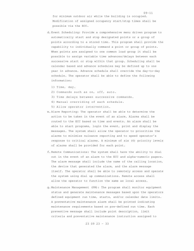
09-11
23 09 23 - 33
for minimum outdoor air while the building is occup ied.
Modification of assigned occupancy start/stop times shall be
possible via the ECC.
d. Event Scheduling: Provide a comprehensive menu driv en program to
automatically start and stop designated points or a group of
points according to a stored time. This program sha ll provide the
capability to individually command a point or group of points.
When points are assigned to one common load group i t shall be
possible to assign variable time advances/delays be tween each
successive start or stop within that group. Schedul ing shall be
calendar based and advance schedules may be defined up to one
year in advance. Advance schedule shall override th e day-to-day
schedule. The operator shall be able to define the following
information:
1) Time, day.
2) Commands such as on, off, auto.
3) Time delays between successive commands.
4) Manual overriding of each schedule.
5) Allow operator intervention.
e. Alarm Reporting: The operator shall be able to dete rmine the
action to be taken in the event of an alarm. Alarms shall be
routed to the ECC based on time and events. An alar m shall be
able to start programs, login the event, print and display the
messages. The system shall allow the operator to pr ioritize the
alarms to minimize nuisance reporting and to speed operator’s
response to critical alarms. A minimum of six (6) p riority levels
of alarms shall be provided for each point.
f. Remote Communications: The system shall have the ab ility to dial
out in the event of an alarm to the ECC and alpha-n umeric pagers.
The alarm message shall include the name of the cal ling location,
the device that generated the alarm, and the alarm message
itself. The operator shall be able to remotely acce ss and operate
the system using dial up communications. Remote acc ess shall
allow the operator to function the same as local ac cess.
g. Maintenance Management (PM): The program shall moni tor equipment
status and generate maintenance messages based upon the operators
defined equipment run time, starts, and/or calendar date limits.
A preventative maintenance alarm shall be printed i ndicating
maintenance requirements based on pre-defined run t ime. Each
preventive message shall include point description, limit
criteria and preventative maintenance instruction a ssigned to

09-11
23 09 23 - 34
that limit. A minimum of 480-character PM shall be provided for
each component of units such as air handling units.
2.10 SPECIAL CONTROLERS (NOT USED)
2.11 SENSORS (AIR, PRESSURE, WATER AND STEAM)
A. Sensors’ measurements shall be read back to the DDC system, and
shall be visible by the ECC.
B. Temperature and Humidity Sensors shall be electroni c, vibration and
corrosion resistant for wall, immersion, and/or duc t mounting.
Provide all remote sensors as required for the syst ems.
1. Temperature Sensors: thermistor type for terminal u nits and
Resistance Temperature Device (RTD) with an integra l transmitter
type for all other sensors.
a. Duct sensors shall be rigid or averaging type as sh own on
drawings. Averaging sensor shall be a minimum of 1 linear ft of
sensing element for each sq ft of cooling coil face area.
b. Immersion sensors shall be provided with a separabl e well made of
stainless steel, bronze or monel material. Pressure rating of
well is to be consistent with the system pressure i n which it is
to be installed.
c. Outdoor air temperature sensors shall have watertig ht inlet
fittings and be shielded from direct sunlight.
d. Wire: Twisted, shielded-pair cable.
e. Output Signal: 4-20 ma.
2. Humidity Sensors: Bulk polymer sensing element type .
a. Duct and room sensors shall have a sensing range of 20 to 80
percent with accuracy of ± 2 to 5 percent RH, inclu ding
hysteresis, linearity, and repeatability.
b. Outdoor humidity sensors shall be furnished with el ement guard
and mounting plate and have a sensing range of 0 to 100 percent
RH.
c. 4-20 ma continuous output signal.
C. Static Pressure Sensors: Non-directional, temperatu re compensated.
1. 4-20 ma output signal.
2. 0 to 5 inches wg for duct static pressure range.
3. 0 to 0.25 inch wg for Building static pressure rang e.

09-11
23 09 23 - 35
D. Flow switches:
1. Shall be either paddle or differential pressure typ e.
a. Paddle-type switches (liquid service only) shall be UL Listed,
SPDT snap-acting, adjustable sensitivity with NEMA 4 enclosure.
b. Differential pressure type switches (air or water s ervice) shall
be UL listed, SPDT snap acting, NEMA 4 enclosure, w ith scale
range and differential suitable for specified appli cation.
E. Current Switches: Current operated switches shall b e self powered,
solid state with adjustable trip current as well as status, power,
and relay command status LED indication. The switch es shall be
selected to match the current of the application an d output
requirements of the DDC systems.
F. Room Differential Pressure Sensor and Monitor: The differential
pressure in negative and positive isolation rooms s hall be
monitored. One sensor per room shall measure and di splay pressure
differential through a sampling tube installed in t he wall
separating the room from the adjacent space, and di splay the value
on its associated monitor. Audible and visual alarm s able to be
silenced shall alert users of conditions outside se tting tolerances.
The sensor shall meet the following as a minimum:
1. Operating range: -0.25 to +0.25 inches of water col umn.
2. Resolution: 5 percent of reading.
3. Accuracy: +/- 10 percent of reading +/- 0.005 inche s of water
column.
4. Analog output: 0-10 VDC or 4-20 ma.
5. Housing: Molded plastic with flush mounted color to uch screen
password protected.
6. Model Manufacturer: TSI Pressura model RPM 20.
2.12 CONTROL CABLES
A. General:
1. Ground cable shields, drain conductors, and equipme nt to eliminate
shock hazard and to minimize ground loops, common-m ode returns,
noise pickup, cross talk, and other impairments. Co mply with
Sections 27 05 26 and 26 05 26.
2. Cable conductors to provide protection against indu ction in
circuits. Crosstalk attenuation within the System s hall be in excess

09-11
23 09 23 - 36
of -80 dB throughout the frequency ranges specified .
3. Minimize the radiation of RF noise generated by the System equipment
so as not to interfere with any audio, video, data, computer main
distribution frame (MDF), telephone customer servic e unit (CSU), and
electronic private branch exchange (EPBX) equipment the System may
service.
4. The as-installed drawings shall identify each cable as labeled, used
cable, and bad cable pairs.
5. Label system’s cables on each end. Test and certify cables in
writing to the VA before conducting proof-of-perfor mance testing.
Minimum cable test requirements are for impedance c ompliance,
inductance, capacitance, signal level compliance, o pens, shorts,
cross talk, noise, and distortion, and split pairs on all cables in
the frequency ranges used. Make available all cable installation and
test records at demonstration to the VA. All change s (used pair,
failed pair, etc.) shall be posted in these records as the change
occurs.

09-11
23 09 23 - 37
6. Power wiring shall not be run in conduit with commu nications trunk
wiring or signal or control wiring operating at 100 volts or less.
B. Analogue control cabling shall be not less than No. 18 AWG solid,
with thermoplastic insulated conductors as specifie d in Section 26
05 21.
C. Copper digital communication cable between the ECC and the B-BC and
BAAC controllers shall be 100BASE-TX Ethernet, Cate gory 5e or 6, not
less than minimum 24 American Wire Gauge (AWG) soli d, Shielded
Twisted Pair (STP) or Unshielded Twisted Pair (UTP) , with
thermoplastic insulated conductors, enclosed in a t hermoplastic
outer jacket, as specified in Section 27 15 00.
1. Other types of media commonly used within IEEE Std 802.3 LANs (e.g.,
10Base-T and 10Base-2) shall be used only in cases to interconnect
with existing media.
D. Optical digital communication fiber, if used, shall be Multimode or
Singlemode fiber, 62.5/125 micron for multimode or 10/125 micron for
singlemode micron with SC or ST connectors as speci fied in TIA-568-
C.1. Terminations, patch panels, and other hardware shall be
compatible with the specified fiber and shall be as specified in
Section 27 15 00. Fiber-optic cable shall be suitab le for use with
the 100Base-FX or the 100Base-SX standard (as appli cable) as defined
in IEEE Std 802.3.
2.13 FINAL CONTROL ELEMENTS AND OPERATORS
A. Fail Safe Operation: Control valves and dampers sha ll provide "fail
safe" operation in either the normally open or norm ally closed
position as required for freeze, moisture, and smok e or fire
protection.
B. Spring Ranges: Range as required for system sequenc ing and to
provide tight shut-off.
C. Power Operated Control Dampers (other than VAV Boxe s): Factory
fabricated, balanced type dampers. All modulating d ampers shall be
opposed blade type and gasketed. Blades for two-pos ition, duct-
mounted dampers shall be parallel, airfoil (streaml ined) type for
minimum noise generation and pressure drop.
1. Leakage: maximum leakage in closed position shall n ot exceed 7 L/S
(15 CFMs) differential pressure for outside air and exhaust dampers
and 200 L/S/ square meter (40 CFM/sq. ft.) at 50 mm (2 inches)
differential pressure for other dampers.

09-11
23 09 23 - 38
2. Frame shall be galvanized steel channel with seals as required to
meet leakage criteria.
3. Blades shall be galvanized steel or aluminum, 200 m m (8 inch)
maximum width, with edges sealed as required.
4. Bearing shall be nylon, bronze sleeve or ball type.
5. Hardware shall be zinc-plated steel. Connected rods and linkage
shall be non-slip. Working parts of joints shall be brass, bronze,
nylon or stainless steel.
6. Maximum air velocity and pressure drop through free area the
dampers:
a. Smoke damper in air handling unit: 305 meter per mi nute (1000
fpm).
b. Duct mounted damper: 600 meter per minute (2000 fpm ).
c. Maximum static pressure loss: 50 Pascal (0.20 inche s water gage).
D. Control Valves:
1. Valves shall be rated for a minimum of 150 percent of system
operating pressure at the valve location but not le ss than 900 kPa
(125 psig).
2. Valves 50 mm (2 inches) and smaller shall be bronze body with
threaded or flare connections.
3. Valves 60 mm (2 1/2 inches) and larger shall be bro nze or iron body
with flanged connections.
4. Brass or bronze seats except for valves controlling media above 100
degrees C (210 degrees F), which shall have stainle ss steel seats.
5. Flow characteristics:
a. Three way modulating valves shall be globe pattern. Position
versus flow relation shall be linear relation for s team or equal
percentage for water flow control.
b. Two-way modulating valves shall be globe pattern. P osition versus
flow relation shall be linear for steam and equal p ercentage for
water flow control.
c. Two-way 2-position valves shall be ball, gate or bu tterfly type.
6. Maximum pressure drop:
a. Two position steam control: 20 percent of inlet gau ge pressure.

09-11
23 09 23 - 39
b. Modulating Steam Control: 80 percent of inlet gauge pressure
(acoustic velocity limitation).
c. Modulating water flow control, greater of 3 meters (10 feet) of
water or the pressure drop through the apparatus.
7. Two position water valves shall be line size.
E. Damper and Valve Operators and Relays:
1. Electric operator shall provide full modulating con trol of dampers
and valves. A linkage and pushrod shall be furnishe d for mounting
the actuator on the damper frame internally in the duct or
externally in the duct or externally on the duct wa ll, or shall be
furnished with a direct-coupled design. Metal parts shall be
aluminum, mill finish galvanized steel, or zinc pla ted steel or
stainless steel. Provide actuator heads which allow for electrical
conduit attachment. The motors shall have sufficien t closure torque
to allow for complete closure of valve or damper un der pressure.
Provide multiple motors as required to achieve suff icient close-off
torque.
a. Minimum valve close-off pressure shall be equal to the system
pump’s dead-head pressure, minimum 50 psig for valv es smaller
than 4 inches.
2. Electronic damper operators: Metal parts shall be a luminum, mill
finish galvanized steel, or zinc plated steel or st ainless steel.
Provide actuator heads which allow for electrical c onduit
attachment. The motors shall have sufficient closur e torque to allow
for complete closure of valve or damper under press ure. Provide
multiple motors as required to achieve sufficient c lose-off torque.
3. See drawings for required control operation.
2.14 AIR FLOW CONTROL
A. Airflow and static pressure shall be controlled via digital
controllers with inputs from airflow control measur ing stations and
static pressure inputs as specified. Controller out puts shall be
analog or pulse width modulating output signals. Th e controllers
shall include the capability to control via simple proportional (P)
control, proportional plus integral (PI), proportio nal plus integral
plus derivative (PID), and on-off. The airflow cont rol programs
shall be factory-tested programs that are documente d in the
literature of the control manufacturer.
B. Air Flow Measuring Station -- Electronic Thermal Ty pe:

09-11
23 09 23 - 40
1. Air Flow Sensor Probe:
a. Each air flow sensor shall contain two individual t hermal sensing
elements. One element shall determine the velocity of the air
stream while the other element shall compensate for changes in
temperature. Each thermal flow sensor and its assoc iated control
circuit and signal conditioning circuit shall be fa ctory
calibrated and be interchangeable to allow replacem ent of a
sensor without recalibration of the entire flow sta tion. The
sensor in the array shall be located at the center of equal area
segment of the duct and the number of sensors shall be adequate
to accommodate the expected velocity profile and va riation in
flow and temperature. The airflow station shall be of the
insertion type in which sensor support structures a re inserted
from the outside of the ducts to make up the comple te electronic
velocity array.
b. Thermal flow sensor shall be constructed of hermeti cally sealed
thermistors or nickel chromium or reference grade p latinum wire,
wound over an epoxy, stainless steel or ceramic man drel and
coated with a material suitable for the conditions to be
encountered. Each dual sensor shall be mounted in a n extruded
aluminum alloy strut.
2. Air Flow Sensor Grid Array:
a. Each sensor grid shall consist of a lattice network of
temperature sensors and linear integral controllers (ICs)
situated inside an aluminum casing suitable for mou nting in a
duct. Each sensor shall be mounted within a strut f acing
downstream of the airflow and located so that it is protected on
the upstream side. All wiring shall be encased (out of the air
stream) to protect against mechanical damage.
b. The casing shall be made of welded aluminum of suff icient
strength to prevent structural bending and bowing. Steel or iron
composite shall not be acceptable in the casing mat erial.
c. Pressure drop through the flow station shall not ex ceed 4 Pascal
(0.015" W.G.) at 1,000 meter per minute (3,000 FPM) .
C. Static Pressure Measuring Station: shall consist of one or more
static pressure sensors and transmitters along with relays or
auxiliary devices as required for a complete functi onal system. The
span of the transmitter shall not exceed two times the design static
pressure at the point of measurement. The output of the transmitter

09-11
23 09 23 - 41
shall be true representation of the input pressure with plus or
minus 25 Pascal (0.1 inch) W.G. of the true input p ressure:
1. Static pressure sensors shall have the same require ments as Airflow
Measuring Devices except that total pressure sensor s are optional,
and only multiple static pressure sensors positione d on an equal
area basis connected to a network of headers are re quired.
2. For systems with multiple major trunk supply ducts, furnish a static
pressure transmitter for each trunk duct. The trans mitter signal
representing the lowest static pressure shall be se lected and this
shall be the input signal to the controller.
3. The controller shall receive the static pressure tr ansmitter signal
and CU shall provide a control output signal to the supply fan
capacity control device. The control mode shall be proportional plus
integral (PI) (automatic reset) and where required shall also
include derivative mode.
4. In systems with multiple static pressure transmitte rs, provide a
switch located near the fan discharge to prevent ex cessive pressure
during abnormal operating conditions. High-limit sw itches shall be
manually-reset.
D. Constant Volume Control Systems shall consist of an air flow
measuring station along with such relays and auxili ary devices as
required to produce a complete functional system. T he transmitter
shall receive its air flow signal and static pressu re signal from
the flow measuring station and shall have a span no t exceeding three
times the design flow rate. The CU shall receive th e transmitter
signal and shall provide an output to the fan volum e control device
to maintain a constant flow rate. The CU shall prov ide proportional
plus integral (PI) (automatic reset) control mode a nd where required
also inverse derivative mode. Overall system accura cy shall be plus
or minus the equivalent of 2 Pascal (0.008 inch) ve locity pressure
as measured by the flow station.
E. Airflow Synchronization:
1. Systems shall consist of an air flow measuring stat ion for each
supply and return duct, the CU and such relays, as required to
provide a complete functional system that will main tain a constant
flow rate difference between supply and return air to an accuracy of
±10%. In systems where there is no suitable locatio n for a flow
measuring station that will sense total supply or r eturn flow,
provide multiple flow stations with a differential pressure
transmitter for each station. Signals from the mult iple transmitters

09-11
23 09 23 - 42
shall be added through the CU such that the resulta nt signal is a
true representation of total flow.
2. The total flow signals from supply and return air s hall be the input
signals to the CU. This CU shall track the return a ir fan capacity
in proportion to the supply air flow under all cond itions.
PART 3 - EXECUTION
3.1 INSTALLATION
A. General:
1. Examine project plans for control devices and equip ment locations;
and report any discrepancies, conflicts, or omissio ns to Resident
Engineer for resolution before proceeding for insta llation.
2. Install equipment, piping, wiring /conduit parallel to or at right
angles to building lines.
3. Install all equipment and piping in readily accessi ble locations. Do
not run tubing and conduit concealed under insulati on or inside
ducts.
4. Mount control devices, tubing and conduit located o n ducts and
apparatus with external insulation on standoff supp ort to avoid
interference with insulation.
5. Provide sufficient slack and flexible connections t o allow for
vibration of piping and equipment.
6. Run tubing and wire connecting devices on or in con trol cabinets
parallel with the sides of the cabinet neatly racke d to permit
tracing.
7. Install equipment level and plum.
B. Electrical Wiring Installation:
1. All wiring cabling shall be installed in conduits. Install conduits
and wiring in accordance with Specification Section 26 05 33,
RACEWAY AND BOXES FOR ELECTRICAL SYSTEMS. Conduits carrying control
wiring and cabling shall be dedicated to the contro l wiring and
cabling: these conduits shall not carry power wirin g. Provide
plastic end sleeves at all conduit terminations to protect wiring
from burrs.
2. Install analog signal and communication cables in c onduit and in
accordance with Specification Section 26 05 21. Ins tall digital
communication cables in conduit and in accordance w ith Specification
Section 27 15 00, Communications Horizontal Cabling .

09-11
23 09 23 - 43
3. Install conduit and wiring between operator worksta tion(s), digital
controllers, electrical panels, indicating devices, instrumentation,
miscellaneous alarm points, thermostats, and relays as shown on the
drawings or as required under this section.
4. Install all electrical work required for a fully fu nctional system
and not shown on electrical plans or required by el ectrical
specifications. Where low voltage (less than 50 vol t) power is
required, provide suitable Class B transformers.
5. Install all system components in accordance with lo cal Building Code
and National Electric Code.
a. Splices: Splices in shielded and coaxial cables sha ll consist of
terminations and the use of shielded cable couplers . Terminations
shall be in accessible locations. Cables shall be h arnessed with
cable ties.
b. Equipment: Fit all equipment contained in cabinets or panels with
service loops, each loop being at least 300 mm (12 inches) long.
Equipment for fiber optics system shall be rack mou nted, as
applicable, in ventilated, self-supporting, code ga uge steel
enclosure. Cables shall be supported for minimum sa g.
c. Cable Runs: Keep cable runs as short as possible. A llow extra
length for connecting to the terminal board. Do not bend flexible
coaxial cables in a radius less than ten times the cable outside
diameter.
d. Use vinyl tape, sleeves, or grommets to protect cab les from
vibration at points where they pass around sharp co rners, through
walls, panel cabinets, etc.
6. Conceal cables, except in mechanical rooms and area s where other
conduits and piping are exposed.
7. Permanently label or code each point of all field t erminal strips to
show the instrument or item served. Color-coded cab le with cable
diagrams may be used to accomplish cable identifica tion.
8. Grounding: ground electrical systems per manufactur er’s written
requirements for proper and safe operation.
C. Install Sensors and Controls:
1. Temperature Sensors:
a. Install all sensors and instrumentation according t o
manufacturer’s written instructions. Temperature se nsor locations
shall be readily accessible, permitting quick repla cement and

09-11
23 09 23 - 44
servicing of them without special skills and tools.
b. Calibrate sensors to accuracy specified, if not fac tory
calibrated.
c. Use of sensors shall be limited to its duty, e.g., duct sensor
shall not be used in lieu of room sensor.
d. Install room sensors permanently supported on wall frame. They
shall be mounted at 1.5 meter (5.0 feet) above the finished
floor.
e. Mount sensors rigidly and adequately for the enviro nment within
which the sensor operates. Separate extended-bulb s ensors form
contact with metal casings and coils using insulate d standoffs.
f. Sensors used in mixing plenum, and hot and cold dec ks shall be of
the averaging of type. Averaging sensors shall be i nstalled in a
serpentine manner horizontally across duct. Each be nd shall be
supported with a capillary clip.
g. All pipe mounted temperature sensors shall be insta lled in wells.
h. All wires attached to sensors shall be air sealed i n their
conduits or in the wall to stop air transmitted fro m other areas
affecting sensor reading.
i. Permanently mark terminal blocks for identification . Protect all
circuits to avoid interruption of service due to sh ort-circuiting
or other conditions. Line-protect all wiring that c omes from
external sources to the site from lightning and sta tic
electricity.
2. Pressure Sensors:
a. Install duct static pressure sensor tips facing dir ectly
downstream of airflow.
b. Install high-pressure side of the differential swit ch between the
pump discharge and the check valve.
c. Install snubbers and isolation valves on steam pres sure sensing
devices.
3. Actuators:
a. Mount and link damper and valve actuators according to
manufacturer’s written instructions.
b. Check operation of damper/actuator combination to c onfirm that
actuator modulates damper smoothly throughout strok e to both open
and closed position.

09-11
23 09 23 - 45
c. Check operation of valve/actuator combination to co nfirm that
actuator modulates valve smoothly in both open and closed
position.
4. Flow Switches:
a. Install flow switch according to manufacturer’s wri tten
instructions.
b. Mount flow switch a minimum of 5 pipe diameters up stream and 5
pipe diameters downstream or 600 mm (2 feet) whiche ver is
greater, from fittings and other obstructions.
c. Assure correct flow direction and alignment.
d. Mount in horizontal piping-flow switch on top of th e pipe.
D. Installation of network:
1. Ethernet:
a. The network shall employ Ethernet LAN architecture, as defined by
IEEE 802.3. The Network Interface shall be fully In ternet
Protocol (IP) compliant allowing connection to curr ently
installed IEEE 802.3, Compliant Ethernet Networks.
b. The network shall directly support connectivity to a variety of
cabling types. As a minimum provide the following c onnectivity:
100 Base TX (Category 5e cabling) for the communica tions between
the ECC and the B-BC and the B-AAC controllers.
2. Third party interfaces: Contractor shall integrate real-time data
from building systems by other trades and databases originating from
other manufacturers as specified and required to ma ke the system
work as one system.
E. Installation of digital controllers and programming :
1. Provide a separate digital control panel for each m ajor piece of
equipment, such as air handling unit, chiller, pump ing unit etc.
Points used for control loop reset such as outdoor air, outdoor
humidity, or space temperature could be located on any of the remote
control units.
2. Provide sufficient internal memory for the specifie d control
sequences and trend logging. There shall be a minim um of 25 percent
of available memory free for future use.
3. System point names shall be modular in design, perm itting easy
operator interface without the use of a written poi nt index.

09-11
23 09 23 - 46
4. Provide software programming for the applications i ntended for the
systems specified, and adhere to the strategy algor ithms provided.
5. Provide graphics for each piece of equipment and fl oor plan in the
building. This includes each chiller, cooling tower , air handling
unit, fan, terminal unit, boiler, pumping unit etc. These graphics
shall show all points dynamically as specified in t he point list.
3.2 SYSTEM VALIDATION AND DEMONSTRATION
A. As part of final system acceptance, a system demons tration is
required (see below). Prior to start of this demons tration, the
contractor is to perform a complete validation of a ll aspects of the
controls and instrumentation system.
B. Validation
1. Prepare and submit for approval a validation test p lan including
test procedures for the performance verification te sts. Test Plan
shall address all specified functions of the ECC an d all specified
sequences of operation. Explain in detail actions a nd expected
results used to demonstrate compliance with the req uirements of this
specification. Explain the method for simulating th e necessary
conditions of operation used to demonstrate perform ance of the
system. Test plan shall include a test check list t o be used by the
Installer’s agent to check and initial that each te st has been
successfully completed. Deliver test plan documenta tion for the
performance verification tests to the owner’s repre sentative 30 days
prior to start of performance verification tests. P rovide draft copy
of operation and maintenance manual with performanc e verification
test.
2. After approval of the validation test plan, install er shall carry
out all tests and procedures therein. Installer sha ll completely
check out, calibrate, and test all connected hardwa re and software
to insure that system performs in accordance with a pproved
specifications and sequences of operation submitted . Installer shall
complete and submit Test Check List.
C. Demonstration
1. System operation and calibration to be demonstrated by the installer
in the presence of the Architect or VA's representa tive on random
samples of equipment as dictated by the Architect o r VA’ s
representative. Should random sampling indicate imp roper
commissioning, the owner reserves the right to subs equently witness
complete calibration of the system at no addition c ost to the VA.

09-11
23 09 23 - 47
2. Demonstrate to authorities that all required safeti es and life
safety functions are fully functional and complete.
3. Make accessible, personnel to provide necessary adj ustments and
corrections to systems as directed by balancing age ncy.
4. The following witnessed demonstrations of field con trol equipment
shall be included:
a. Observe HVAC systems in shut down condition. Check dampers and
valves for normal position.
b. Test application software for its ability to commun icate with
digital controllers, operator workstation, and uplo ading and
downloading of control programs.
c. Demonstrate the software ability to edit the contro l program off-
line.
d. Demonstrate reporting of alarm conditions for each alarm and
ensure that these alarms are received at the assign ed location,
including operator workstations.
e. Demonstrate ability of software program to function for the
intended applications-trend reports, change in stat us etc.
f. Demonstrate via graphed trends to show the sequence of operation
is executed in correct manner, and that the HVAC sy stems operate
properly through the complete sequence of operation , e.g.,
seasonal change, occupied/unoccupied mode, and warm -up condition.
g. Demonstrate hardware interlocks and safeties functi ons, and that
the control systems perform the correct sequence of operation
after power loss and resumption of power loss.
h. Prepare and deliver to the VA graphed trends of all control loops
to demonstrate that each control loop is stable and the set
points are maintained.
i. Demonstrate that each control loop responds to set point
adjustment and stabilizes within one (1) minute. Co ntrol loop
trend data shall be instantaneous and the time betw een data
points shall not be greater than one (1) minute.
5. Witnessed demonstration of ECC functions shall cons ist of:
a. Running each specified report.
b. Display and demonstrate each data entry to show sit e specific
customizing capability. Demonstrate parameter chang es.
c. Step through penetration tree, display all graphics , demonstrate

09-11
23 09 23 - 48
dynamic update, and direct access to graphics.
d. Execute digital and analog commands in graphic mode .
e. Demonstrate DDC loop precision and stability via tr end logs of
inputs and outputs (6 loops minimum).
f. Demonstrate EMS performance via trend logs and comm and trace.
g. Demonstrate scan, update, and alarm responsiveness.
h. Demonstrate spreadsheet/curve plot software, and it s integration
with database.
i. Demonstrate on-line user guide, and help function a nd mail
facility.
j. Demonstrate digital system configuration graphics w ith
interactive upline and downline load, and demonstra te specified
diagnostics.
k. Demonstrate multitasking by showing dynamic curve p lot, and
graphic construction operating simultaneously via s plit screen.
l. Demonstrate class programming with point options of beep
duration, beep rate, alarm archiving, and color ban ding.
- - - E N D - - -

04-11
23 73 00 - 1
SECTION 23 73 00 INDOOR CENTRAL-STATION AIR-HANDLING UNITS
PART 1 - GENERAL
1.1 DESCRIPTION
A. Air handling units including integral components specified herein.
B. Definitions: Air Handling Unit (AHU): A factory fabricated and tested
assembly of modular sections consisting of multiple plenum fans with
direct-drive, coils, filters, and other necessary e quipment to perform
one or more of the following functions of circulati ng, cleaning,
heating, cooling, humidifying, dehumidifying, and m ixing of air. Design
capacities of units shall be as scheduled on the dr awings.
1.2 RELATED WORK
A. General mechanical requirements and items, which are common to more than
one section of Division 23: Section 23 05 11, COMMO N WORK RESULTS FOR
HVAC AND STEAM GENERATION.
B. Sound and vibration requirements: Section 23 05 41, NOISE AND VIBRATION
CONTROL FOR HVAC PIPING AND EQUIPMENT.
C. Piping and duct insulation: Section 23 07 11, HV AC, PLUMBING, AND BOILER
PLANT INSULATION.
D. Piping and valves: Section 23 21 13 / 23 22 13, HYDRONIC PIPING / STEAM
AND CONDENSATE HEATING PIPING.
E. Heating and cooling coils and pressure requireme nts: Section 23 82 16,
AIR COILS.
F. Return and exhaust fans: Section 23 34 00, HVAC FANS.
G. Requirements for flexible duct connectors, sound attenuators and sound
absorbing duct lining, and air leakage: Section 23 31 00, HVAC DUCTS and
CASINGS.
H. Air filters and filters' efficiency: Section 23 40 00, HVAC AIR CLEANING
DEVICES.
I. HVAC controls: Section 23 09 23, DIRECT-DIGITAL CONTROL SYSTEM FOR HVAC.
J. Testing, adjusting and balancing of air and wate r flows: Section 23 05
93, TESTING, ADJUSTING, AND BALANCING FOR HVAC.
K. Types of motors: Section 23 05 12, GENERAL MOTOR REQUIREMENTS FOR HVAC
AND STEAM GENERATION EQUIPMENT.
L. Types of motor starters: Section 26 29 11, LOW-V OLTAGE MOTOR STARTERS.
M. General Commissioning: Section 01 91 00, GENERAL COMMISSIONING
REQUIREMENTS
N. HVAC Commissioning: Section 23 08 00, COMMISSION ING OF HVAC SYSTEMS

04-11
23 73 00 - 2
1.3 QUALITY ASSURANCE
A. Refer to Article, Quality Assurance, in Section 23 05 11, COMMON WORK
RESULTS FOR HVAC AND STEAM GENERATION.
B. Air Handling Units Certification
2. Air Handling Units with Plenum Fans:
b. Air handling Units with Multiple Fans in an Arra y shall be tested
and rated in accordance with AHRI 430 and AHRI 260.
C. Heating, Cooling, and Air Handling Capacity and Performance Standards:
AHRI 430, AHRI 410, ASHRAE 51, and AMCA 210.
D. Performance Criteria:
1. The fan BHP shall include all system effects for all fans and v-belt
drive losses for housed centrifugal fans.
2. The fan motor shall be selected within the rated nameplate capacity,
without relying upon NEMA Standard Service Factor.
3. Select the fan operating point as follows:
b. Air Foil, Backward Inclined, or Tubular Fans Inc luding Plenum
Fans: At or near the peak static efficiency but at an appropriate
distance from the stall line.
4. Operating Limits: AMCA 99 and Manufacturer’s Rec ommendations.
E. Units shall be factory-fabricated, assembled, an d tested by a
manufacturer, in business of manufacturing similar air-handling units
for at least five (5) years.
1.4. SUBMITTALS:
A. The contractor shall, in accordance with Section 01 33 23, SHOP
DRAWINGS, PRODUCT DATA, AND SAMPLES, furnish a comp lete submission for
all air handling units covered in the project. The submission shall
include all information listed below. Partial and i ncomplete submissions
shall be rejected without reviews.
B. Manufacturer's Literature and Data:
1. Submittals for AHUs shall include fans, drives, motors, coils,
humidifiers, mixing box with outside/return air dam pers, filter
housings, blender sections, and all other related a ccessories. The
contractor shall provide custom drawings showing to tal air handling
unit assembly including dimensions, operating weigh t, access
sections, flexible connections, door swings, contro ls penetrations,
electrical disconnect, lights, duplex receptacles, switches, wiring,
utility connection points, unit support system, vib ration isolators,
drain pan, pressure drops through each component (f ilter, coil etc).
2. Submittal drawings of section or component only will not be
acceptable. Contractor shall also submit performanc e data including
performance test results, charts, curves or certifi ed computer

04-11
23 73 00 - 3
selection data; data sheets; fabrication and insula tion details. If
the unit cannot be shipped in one piece, the contra ctor shall
indicate the number of pieces that each unit will h ave to be broken
into to meet shipping and job site rigging requirem ents. This data
shall be submitted in hard copies and in electronic version
compatible to AutoCAD version used by the VA at the time of
submission.
3. Submit sound power levels in each octave band fo r the inlet and
discharge of the fan and at entrance and discharge of AHUs at
scheduled conditions. In absence of sound power ratings refer to
Section 23 05 41, NOISE AND VIBRATION CONTROL FOR H VAC PIPING AND
EQUIPMENT.
4. Provide fan curves showing Liters/Second (cubic feet per minute),
static pressure, efficiency, and horsepower for des ign point of
operation and at maximum design Liters/Second (cubi c feet per
minute).
5. Submit total fan static pressure, external stati c pressure, for AHU
including total, inlet and discharge pressures, and itemized
specified internal losses and unspecified internal losses. Refer to
air handling unit schedule on drawings.
C. Maintenance and operating manuals in accordance with Section 01 00 00,
GENERAL REQUIREMENTS. Include instructions for lubr ication, filter
replacement, motor and drive replacement, spare par t lists, and wiring
diagrams.
D. Submit written test procedures two weeks prior t o factory testing.
Submit written results of factory tests for approva l prior to shipping.
E. Submit shipping information that clearly indicat es how the units will be
shipped in compliance with the descriptions below.
1. Units shall be shipped in one (1) piece where po ssible and in shrink
wrapping to protect the unit from dirt, moisture an d/or road salt.
2. If not shipped in one (1) piece, provide manufac turer approved
shipping splits where required for installation or to meet shipping
and/or job site rigging requirements in modular sec tions. Indicate
clearly that the shipping splits shown in the submi ttals have been
verified to accommodate the construction constraint s for rigging as
required to complete installation and removal of an y section for
replacement through available access without advers ely affecting
other sections.
3. If shipping splits are provided, each component shall be individually
shrink wrapped to protect the unit and all necessar y hardware (e.g.

04-11
23 73 00 - 4
bolts, gaskets etc.) will be included to assemble u nit on site (see
section 2.1.A4).
4. Lifting lugs will be provided to facilitate rigg ing on shipping
splits and joining of segments. If the unit cannot be shipped in one
piece, the contractor shall indicate the number of pieces that each
unit will have to be broken into to meet shipping a nd job site
rigging requirements.
1.5 APPLICABLE PUBLICATIONS
A. The publications listed below form a part of thi s specification to the
extent referenced. The publications are referenced in the text by the
basic designation only.
B. Air-Conditioning, Heating, and Refrigeration Ins titute (AHRI)/(ARI):
410-01..................Standard for Forced-Circula tion Air-Heating and
Air-Cooling Coils
430-09..................Central Station Air Handlin g Units
C. Air Movement and Control Association Internation al, Inc. (AMCA):
210-07..................Laboratory Methods of Testi ng Fans for Rating
D. American Society of Heating, Refrigerating and A ir-conditioning
Engineers, Inc. (ASHRAE):
170-2008................Ventilation of Health Care Facilities
E. American Society for Testing and Materials (ASTM ):
ASTM B117-07a...........Standard Practice for Opera ting Salt Spray (Fog)
Apparatus
ASTM D1654-08...........Standard Test Method for Ev aluation of Painted
or Coated Specimens Subjected to Corrosive
Environments
ASTM D1735-08...........Standard Practice for Testi ng Water Resistance
of Coatings Using Water Fog Apparatus
ASTM D3359-08...........Standard Test Methods for M easuring Adhesion by
Tape Test
F. Military Specifications (Mil. Spec.):
MIL-P-21035B-2003.......Paint, High Zinc Dust Conte nt, Galvanizing
Repair (Metric)
G. National Fire Protection Association (NFPA):
NFPA 90A................Standard for Installation o f Air Conditioning
and Ventilating Systems, 2009
H. Energy Policy Act of 2005 (P.L.109-58)
PART 2 - PRODUCTS
2.1 AIR HANDLING UNITS
A. General:

04-11
23 73 00 - 5
1. AHUs shall be fabricated from insulated, solid d ouble-wall galvanized
steel without any perforations in draw-through conf iguration. Casing
shall be fabricated as specified in section 2.1.C.2 . Galvanizing
shall be hot dipped conforming to ASTM A525 and sha ll provide a
minimum of 0.275 kg of zinc per square meter (0.90 oz. of zinc per
square foot) (G90). Aluminum constructed units, sub ject to VA
approval, may be used in place of galvanized steel. The unit
manufacturer shall provide published documentation confirming that
the structural rigidity of aluminum air-handling un its is equal or
greater than the specified galvanized steel.
2. The contractor and the AHU manufacturer shall be responsible for
ensuring that the unit will not exceed the allocate d space shown on
the drawings, including required clearances for ser vice and future
overhaul or removal of unit components. All structu ral, piping,
wiring, and ductwork alterations of units, which ar e dimensionally
different than those specified, shall be the respon sibility of the
contractor at no additional cost to the government.
3. AHUs shall be fully assembled by the manufacture r in the factory in
accordance with the arrangement shown on the drawin gs. The unit shall
be assembled into the largest sections possible sub ject to shipping
and rigging restrictions. The correct fit of all co mponents and
casing sections shall be verified in the factory fo r all units prior
to shipment. All units shall be fully assembled, te sted, and then
split to accommodate shipment and job site rigging. On units not
shipped fully assembled, the manufacturer shall tag each section and
include air flow direction to facilitate assembly a t the job site.
Lifting lugs or shipping skids shall be provided fo r each section to
allow for field rigging and final placement of unit .
4. The AHU manufacturer shall provide the necessary gasketing, caulking,
and all screws, nuts, and bolts required for assemb ly. The
manufacturer shall provide a factory-trained and qu alified local
representative at the job site to supervise the ass embly and to
assure that the units are assembled to meet manufac turer's
recommendations and requirements noted on the drawi ngs. Provide
documentation to the Contracting Officer that the l ocal
representative has provided services of similar mag nitude and
complexity on jobs of comparable size. If a local representative
cannot be provided, the manufacturer shall provide a factory
representative.
5. Gaskets: All door and casing and panel gaskets a nd gaskets between
air handling unit components, if joined in the fiel d, shall be high

04-11
23 73 00 - 6
quality which seal air tight and retain their struc tural integrity
and sealing capability after repeated assembly and disassembly of
bolted panels and opening and closing of hinged com ponents. Bolted
sections may use a more permanent gasketing method provided they are
not disassembled.
6. Structural Rigidity: Provide structural reinforc ement when required
by span or loading so that the deflection of the as sembled structure
shall not exceed 1/200 of the span based on a diffe rential static
pressure of 1991 PA (8 inch WG) or higher.
B. Base:
1. Provide a heavy duty steel base for supporting a ll major AHU
components. Bases shall be constructed of wide-flan ge steel I-beams,
channels, or minimum 200 mm (8 inch) high 3.5 mm (1 0 Gauge) steel
base rails. Welded or bolted cross members shall be provided as
required for lateral stability. Contractor shall pr ovide supplemental
steel supports as required to obtain proper operati on heights for
cooling coil condensate drain trap and steam coil c ondensate return
trap as shown on drawings.
2. AHUs shall be completely self supporting for ins tallation on concrete
housekeeping pad, steel support pedestals, or suspe nded as shown on
drawings.
3. The AHU bases not constructed of galvanized stee l shall be cleaned,
primed with a rust inhibiting primer, and finished with rust
inhibiting exterior enamel.
C. Casing (including wall, floor and roof):
1. General: AHU casing shall be constructed as soli d double wall,
galvanized steel insulated panels without any perfo rations, integral
of or attached to a structural frame. The thicknes s of insulation,
mode of application and thermal breaks shall be suc h that there is no
visible condensation on the exterior panels of the AHU located in the
non-conditioned spaces.
2. Casing Construction:
Table 2.1.C.2
Outer Panel 0.8 mm (22 Gage) Minimum
Inner Panel 0.8 mm (22 Gage) Minimum
Insulation
Thickness
Density
Foam
50 mm (2 inch) Minimum
48 kg/m 3 (3.0 lb/ft 3) Minimum
Total R Value 2.3 m 2.K/W (13.0 ft 2. OF.hr/Btu)
Minimum

04-11
23 73 00 - 7
3. Casing Construction (Contractor’s Option):
Table 2.1.C.3
Outer Panel 1.3 mm (18 Gage) Minimum
Inner Panel 1.0 mm (20 Gage) Minimum
Insulation
Thickness
Density
Fiberglass
50 mm (2 inch) Minimum
24 kg/m 3 (1.5 lb/ft 3) Minimum
Total R Value 1.4 m 2.K/W (8.0 ft 2. OF.hr/Btu)
Minimum
4. Blank-Off: Provide blank-offs as required to pre vent air bypass
between the AHU sections, around coils, and filters .
5. Casing panels shall be secured to the support st ructure with
stainless steel or zinc-chromate plated screws and gaskets installed
around the panel perimeter. Panels shall be complet ely removable to
allow removal of fan, coils, and other internal com ponents for future
maintenance, repair, or modifications. Welded exter ior panels are not
acceptable.
6. Access Doors: Provide in each access section and where shown on
drawings. Show single-sided and double-sided access doors with door
swings on the floor plans. Doors shall be a minimu m of 50 mm (2
inch) thick with same double wall construction as t he unit casing.
Doors shall be a minimum of 600 mm (24 inches) wide , unless shown of
different size on drawings, and shall be the full c asing height up to
a maximum of 1850 mm (6 feet). Doors shall be gasketed, hinged, and
latched to provide an airtight seal. The access doo rs for fan
sections, mixing box, humidifier and coil sections shall include a
minimum 150 mm x 150 mm (6 inch x 6 inch) double th ickness window,
with air space between the glass panes tightly seal ed, reinforced
glass or Plexiglas window in a gasketed frame.
a. Hinges: Manufacturers standard, designed for doo r size, weight and
pressure classifications. Hinges shall hold door co mpletely rigid
with minimum 45 kg (100 lb) weight hung on latch si de of door.
b. Latches: Non-corrosive alloy construction, with operating levers
for positive cam action, operable from either insid e or outside.
Doors that do not open against unit operating press ure shall allow
the door to ajar and then require approximately 0.7 85 radian (45
degrees) further movement of the handle for complet e opening.

04-11
23 73 00 - 8
Latch shall be capable of restraining explosive ope ning of door
with a force not less than 1991 Pa (8 inch WG).
c. Gaskets: Neoprene, continuous around door, posit ioned for direct
compression with no sliding action between the door and gasket.
Secure with high quality mastic to eliminate possib ility of gasket
slipping or coming loose.
7. Provide sealed sleeves, metal or plastic escutch eons or grommets for
penetrations through casing for power and temperatu re control wiring
and pneumatic tubing. Coordinate with electrical an d temperature
control subcontractors for number and location of p enetrations.
Coordinate lights, switches, and duplex receptacles and disconnect
switch location and mounting. All penetrations and equipment mounting
may be provided in the factory or in the field. All field
penetrations shall be performed neatly by drilling or saw cutting. No
cutting by torches will be allowed. Neatly seal all openings
airtight.
D. Floor:
1. Unit floor shall be level without offset space o r gap and designed to
support a minimum of 488 kg/square meter (100 lbs p er square foot)
distributed load without permanent deformation or c rushing of
internal insulation. Provide adequate structural ba se members beneath
floor in service access sections to support typical service foot
traffic and to prevent damage to unit floor or inte rnal insulation.
Unit floors in casing sections, which may contain w ater or
condensate, shall be watertight with drain pan.
2. Where indicated, furnish and install floor drain s, flush with the
floor, with nonferrous grate cover and stub through floor for
external connection.
E. Condensate Drain Pan: Drain pan shall be designe d to extend entire
length of cooling coils including headers and retur n bends. Depth of
drain pan shall be at least 43 mm (1.7 inches) and shall handle all
condensate without overflowing. Drain pan shall be double-wall, double
sloping type, and fabricated from stainless (304) w ith at least 50 mm (2
inch) thick insulation sandwiched between the inner and outer surfaces.
Drain pan shall be continuous metal or welded water tight. No mastic
sealing of joints exposed to water will be permitte d. Drain pan shall be
placed on top of casing floor or integrated into ca sing floor assembly.
Drain pan shall be pitched in all directions to dra in line.
1. An intermediate, stainless-steel (304) condensat e drip pan with
copper downspouts shall be provided on stacked cool ing coils. Use of
intermediate condensate drain channel on upper casi ng of lower coil

04-11
23 73 00 - 9
is permissible provided it is readily cleanable. De sign of
intermediate condensate drain shall prevent upper c oil condensate
from flowing across face of lower coil.
2. Drain pan shall be piped to the exterior of the unit. Drain pan shall
be readily cleanable.
3. Installation, including frame, shall be designed and sealed to
prevent blow-by.
F. Plenum Fans –Multiple Fans in an Array: 1. General: Fans shall be Class II (minimum) constr uction with single
inlet, aluminum wheel and stamped air-foil aluminum bladed. The fan
wheel shall be mounted on the directly-driven motor shaft in AMCA
Arrangement 4. Fans shall be dynamically balanced and internally
isolated to minimize the vibrations. Provide a ste el inlet cone for
each wheel to match with the fan inlet. Locate fan in the air stream
to assure proper flow. The fan performance shall b e rated in
accordance with AMCA 210 or ASHRAE 51.
2. Allowable vibration tolerances for fan shall not exceed a self-
excited vibration maximum velocity of 0.005 m/s (0 .20 inch per
second) RMS, filter in, when measured with a vibrat ion meter on
bearing caps of machine in vertical, horizontal and axial directions
or measured at equipment mounting feet if bearings are concealed.
After field installation, compliance to this requir ement shall be
demonstrated with field test in accordance with Sec tion 23 05 41,
NOISE AND VIBRATION CONTROL FOR HVAC PIPING AND EQU IPMENT and Section
23 05 93, TESTING, ADJUSTING, AND BALANCING FOR HVA C. Following fan
assembly, the complete fan assembly balance shall b e tested using an
electronic balance analyzer with a tunable filter a nd stroboscope.
Vibration measurements shall be taken on each motor bearing housing
in the vertical, horizontal, and axial planes (5 to tal measurements,
2 each motor bearing and 1 axial).
3. The plenum fans shall be driven by variable spee d drives with at
least one back-up drive as shown in the design docu ments. Use of a
drive with bypass is not permitted.
4. Multiple fans shall be installed in a pre-engine ered structural frame
to facilitate fan stacking. All fans shall modulat e in unison, above
or below the synchronous speed within the limits sp ecified by the
manufacturer, by a common control sequence. Stagin g of the fans is
not permitted. Redundancy requirement shall be met by all operating
fans in an array and without the provision of an id le standby fan.
5. Fan Accessories

04-11
23 73 00 - 10
a. Fan Isolation: Provide a manual blank off plate to isolate the fan
not in operation due to failure.
b. Fan Airflow Measurement: Provide an airflow meas uring device
integral to the fan to measure air volume within +/ - 5 percent
accuracy. The probing device shall not be placed i n the airflow
path to stay clear of turbulence and avoid loss of performance.
G. Fan Motor, Drive, and Mounting Assembly (Plenum Fans):
Fan Motor and Drive: Motors shall be premium energ y efficient type, as
mandated by the Energy Policy Act of 2005, with eff iciencies as shown in
the Specifications Section 23 05 12 (General Motor Requirements For HVAC
and Steam Equipment), on drawings and suitable for use in variable
frequency drive applications. Refer to Section 23 05 11, COMMON WORK
RESULTS FOR HVAC AND STEAM GENERATION, for addition al motor and drive
specifications. Refer to Specification Section 26 2 9 11, LOW-VOLTAGE
MOTOR STARTERS
H. Mixing Boxes: Mixing box shall consist of casing and outdoor air and
return air dampers in opposed blade arrangement wit h damper linkage for
automatic operation. Coordinate damper operator wit h Section 23 09 23,
DIRECT-DIGITAL CONTROL SYSTEM FOR HVAC. Dampers sha ll be of ultra-low
leak design with metal compressible bronze jamb sea ls and extruded vinyl
edge seals on all blades. Blades shall rotate on st ainless steel sleeve
bearings or bronze bushings. Leakage rate shall not exceed 1.6 cubic
meters/min/square meter (5 CFM per square foot) at 250 Pa (1 inch WG)
and 2.8 cubic meters/min/square meter (9 CFM per sq uare foot) at 995 Pa
(4 inch WG) Electronic operators shall be furnished and mounted in an
accessible and easily serviceable location by the a ir handling unit
manufacturer at the factory. Damper operators shall be of same
manufacturer as controls furnished under Section 23 09 23, DIRECT-
DIGITAL CONTROL SYSTEM FOR HVAC.M. Blenders: Constr uction of the
blender section shall be of welded aluminum 2 mm (0 .081 inch) thick
framing and turbulators. The mixer shall have no m oving parts and shall
contain a primary set of directional changing vanes , a secondary set of
turbulator vanes, and a cone design for mixing of a ir streams. Certify
blender performance to achieve no more than a 5°F v ariation across the
cross section of the AHU measured 12 inches downstr eam of the blender
over a face velocity range of 1-4 m/s (200-800 FPM) .
I. Filter Section: Refer to Section 23 40 00, HVAC AIR CLEANING DEVICES,
for filter requirements.
1. Filters including one complete set for temporary use at site shall be
provided independent of the AHU. The AHU manufactur er shall install
filter housings and racks in filter section compati ble with filters

04-11
23 73 00 - 11
furnished. The AHU manufacturer shall be responsibl e for furnishing
temporary filters (pre-filters and after-filters, a s shown on
drawings) required for AHU testing.
2. Factory-fabricated filter section shall be of th e same construction
and finish as the AHU casing including filter racks and hinged double
wall access doors. Filter housings shall be constru cted in accordance
with side service housing requirements in Section 2 3 40 00, HVAC AIR
CLEANING DEVICES.
J. Coils: Coils shall be mounted on hot dipped galv anized steel supports to
assure proper anchoring of coil and future maintena nce. Coils shall be
face or side removable for future replacement thru the access doors or
removable panels. Each coil shall be removable with out disturbing
adjacent coil. Cooling coils shall be designed and installed to insure
no condensate carry over. Provide factory installed extended supply,
return, drain, and vent piping connections. Copper fins are also
required for all duct-mounted and terminal reheat c oils.
1. Integral Face and Bypass Steam Coils: Provide in tegral face and
bypass dampers in vertical or horizontal orientatio n. Electric
damper operators shall be furnished and mounted by the AHU
manufacturer at the factory. Damper operators shall be of same
manufacturer as controls furnished under Section 23 09 23, DIRECT-
DIGITAL CONTROL SYSTEM FOR HVAC.
K. Humidifier: When included in design, coordinate the humidification
requirements with section 23 22 13 Steam and Conden sate Heating Piping.
Provide air-handling unit-mounted humidification se ction with stainless
steel drain pan of adequate length to allow complet e absorption of water
vapor. Provide stainless steel dispersion panel or distributors as
indicated, with stainless steel supports and hardwa re.
L. Electrical and Lighting: Wiring and equipment sp ecifications shall
conform to Division 26, ELECTRICAL.
1. Vapor-proof lights using cast aluminum base styl e with glass globe
and cast aluminum guard shall be installed in acces s sections for
fan, mixing box, humidifier and any section over 30 0 mm (12 inch)
wide. A switch shall control the lights in each com partment with
pilot light mounted outside the respective compartm ent access door.
Wiring between switches and lights shall be factory installed. All
wiring shall run in neatly installed electrical con duits and
terminate in a junction box for field connection to the building
system. Provide single point 115 volt - one phase c onnection at
junction box.
2. Install compatible 100 watt bulb in each light f ixture.

04-11
23 73 00 - 12
3. Provide a convenience duplex receptacle next to the light switch.
4. Disconnect switch and power wiring: Provide fact ory or field mounted
disconnect switch. Coordinate with Division 26, ELE CTRICAL.
PART 3 – EXECUTION
3.1 INSTALLATION
A. Install air handling unit in conformance with AR I 435.
B. Assemble air handling unit components following manufacturer's instruc-
tions for handling, testing and operation. Repair d amaged galvanized
areas with paint in accordance with Military Spec. DOD-P-21035. Repair
painted units by touch up of all scratches with fin ish paint material.
Vacuum the interior of air handling units clean pri or to operation.
C. Leakage and test requirements for air handling u nits shall be the same
as specified for ductwork in Specification Section 23 31 00, HVAC DUCTS
AND CASINGS except leakage shall not exceed Leakage Class (C L) 12 listed
in SMACNA HVAC Air Duct Leakage Test Manual when te sted at 1.5 times the
design static pressure. Repair casing air leaks tha t can be heard or
felt during normal operation and to meet test requi rements.
D. Perform field mechanical (vibration) balancing i n accordance with
Section 23 05 41, NOISE AND VIBRATION CONTROL FOR H VAC PIPING AND
EQUIPMENT.
E. Seal and/or fill all openings between the casing and AHU components and
utility connections to prevent air leakage or bypas s.
3.2 STARTUP SERVICES
A. The air handling unit shall not be operated for any purpose, temporary
or permanent, until ductwork is clean, filters are in place, bearings
are lubricated and fan has been test run under obse rvation.
B. After the air handling unit is installed and tes ted, provide startup and
operating instructions to VA personnel.
C. An authorized factory representative should star t up, test and certify
the final installation and application specific cal ibration of control
components. Items to be verified include fan perfo rmance over entire
operating range, noise and vibration testing, verif ication of proper
alignment, overall inspection of the installation, Owner/Operator
training, etc.
3.3 COMMISSIONING
A. Provide commissioning documentation in accordanc e with the requirements
of Section 23 08 00 – COMMISSIONING OF HVAC SYSTEMS for all inspection,
start up, and contractor testing required above and required by the
System Readiness Checklist provided by the Commissi oning Agent.

04-11
23 73 00 - 13
B. Components provided under this section of the sp ecification will be
tested as part of a larger system. Refer to Section 23 08 00 –
COMMISSIONING OF HVAC SYSTEMS and related sections for contractor
responsibilities for system commissioning.
- - - E N D - - -