department of electronic engineering basic electronic engineering transients analysis
Post on 22-Dec-2015
219 views
TRANSCRIPT

Department of Electronic EngineeringBASIC ELECTRONIC ENGINEERING
Transients Analysis
Department of Electronic EngineeringBASIC ELECTRONIC ENGINEERING
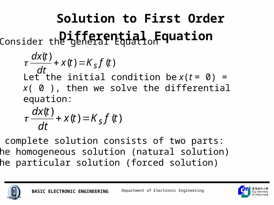
Solution to First Order Differential Equation
)()()(
tfKtxdt
tdxs
Consider the general Equation
Let the initial condition be x(t = 0) = x( 0 ), then we solve the differential equation:
)()()(
tfKtxdt
tdxs
The complete solution consists of two parts: • the homogeneous solution (natural solution)• the particular solution (forced solution)
Department of Electronic EngineeringBASIC ELECTRONIC ENGINEERING
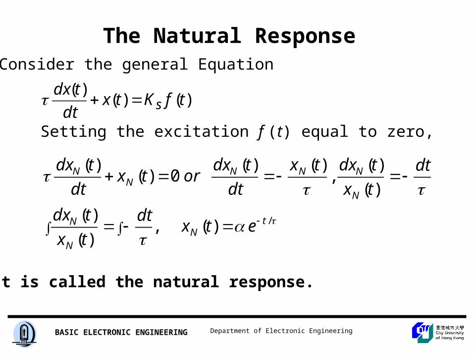
The Natural Response
/)(,)(
)(
)(
)(,
)()(0)(
)(
tN
N
N
N
NNNN
N
etxdt
tx
tdx
dt
tx
tdxtx
dt
tdxortx
dt
tdx
Consider the general Equation
Setting the excitation f (t) equal to zero,
)()()(
tfKtxdt
tdxs
It is called the natural response.
Department of Electronic EngineeringBASIC ELECTRONIC ENGINEERING
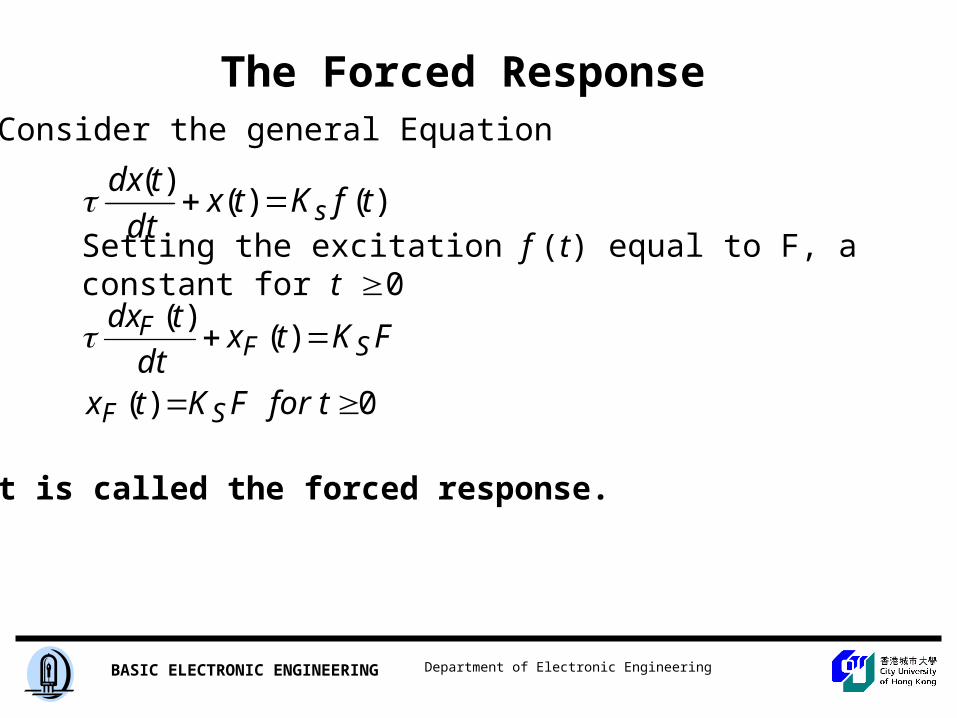
The Forced Response
0)(
)()(
tforFKtx
FKtxdt
tdx
SF
SFF
Consider the general Equation
Setting the excitation f (t) equal to F, a constant for t 0
)()()(
tfKtxdt
tdxs
It is called the forced response.
Department of Electronic EngineeringBASIC ELECTRONIC ENGINEERING
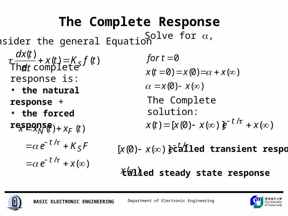
The Complete Response
)(
)()(
/
/
xe
FKe
txtxx
tS
tFN
Consider the general Equation
The complete response is: • the natural response + • the forced response
)()()(
tfKtxdt
tdxs
Solve for ,
)()0(
)()0()0(
0
xx
xxtx
tfor
The Complete solution:
)()]()0([)( / xexxtx t
/)]()0([ texx called transient response
)(x called steady state response

Department of Electronic EngineeringBASIC ELECTRONIC ENGINEERING
WHAT IS TRANSIENT RESPONSE
Figure 5.1

Department of Electronic EngineeringBASIC ELECTRONIC ENGINEERING
Figure
5.2, 5.3
Circuit with switched DC excitation
A general model of the transient analysis problem
Department of Electronic EngineeringBASIC ELECTRONIC ENGINEERING
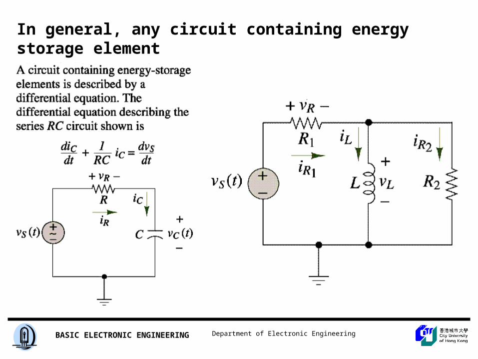
In general, any circuit containing energy storage element
Figure 5.5, 5.6

Department of Electronic EngineeringBASIC ELECTRONIC ENGINEERING
Figure 5.9, 5.10
(a) Circuit at t = 0(b) Same circuit a long time after the switch is closed
The capacitor acts as open circuit for the steady state condition(a long time after the switch is closed).
Department of Electronic EngineeringBASIC ELECTRONIC ENGINEERING
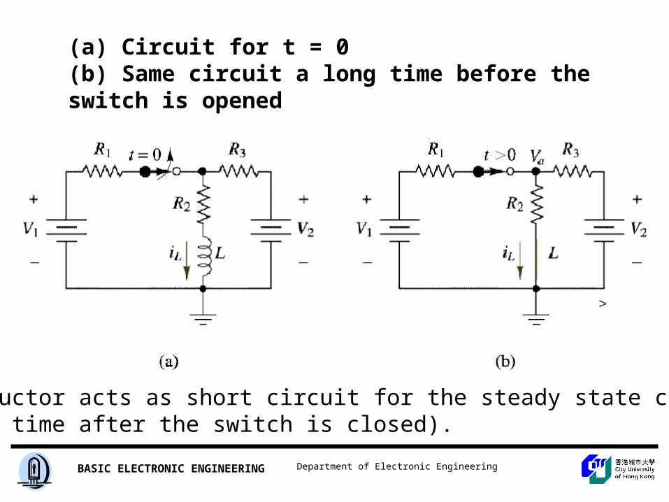
(a) Circuit for t = 0(b) Same circuit a long time before the switch is opened
The inductor acts as short circuit for the steady state condition(a long time after the switch is closed).

Department of Electronic EngineeringBASIC ELECTRONIC ENGINEERING
Why there is a transient response?
• The voltage across a capacitor cannot be changed instantaneously.
)0()0( CC VV
• The current across an inductor cannot be changed instantaneously.
)0()0( LL II

Department of Electronic EngineeringBASIC ELECTRONIC ENGINEERING
Figure 5.12, 5.13
5-6
Example

Department of Electronic EngineeringBASIC ELECTRONIC ENGINEERING
Transients Analysis1. Solve first-order RC or RL circuits.
2. Understand the concepts of transient response and steady-state response.
3. Relate the transient response of first-order
circuits to the time constant.

Department of Electronic EngineeringBASIC ELECTRONIC ENGINEERING
TransientsThe solution of the differential equation represents are response of the circuit. It is called natural response.
The response must eventually die out, and therefore referred to as transient response. (source free response)

Department of Electronic EngineeringBASIC ELECTRONIC ENGINEERING
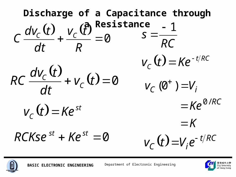
Discharge of a Capacitance through a Resistance
ic iR 0,0 RC iii
0
R
tv
dt
tdvC CC
Solving the above equation with the initial conditionVc(0) = Vi
Department of Electronic EngineeringBASIC ELECTRONIC ENGINEERING
Discharge of a Capacitance through a Resistance
0
R
tv
dt
tdvC CC
0 tvdt
tdvRC C
C
stC Ketv
0 stst KeRCKse
RCs
1
RCtC Ketv
K
Ke
VvRC
iC
/0
)0(
RCtiC eVtv
Department of Electronic EngineeringBASIC ELECTRONIC ENGINEERING
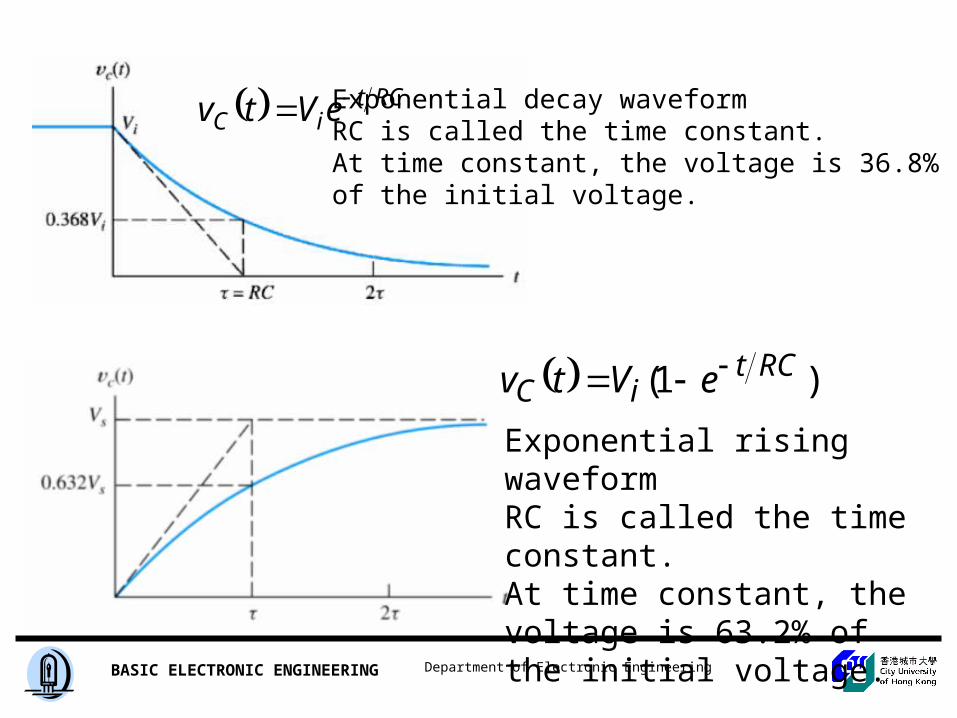
RCtiC eVtv Exponential decay waveform
RC is called the time constant.At time constant, the voltage is 36.8%of the initial voltage.
)1( RCtiC eVtv
Exponential rising waveformRC is called the time constant.At time constant, the voltage is 63.2% of the initial voltage.
Department of Electronic EngineeringBASIC ELECTRONIC ENGINEERING
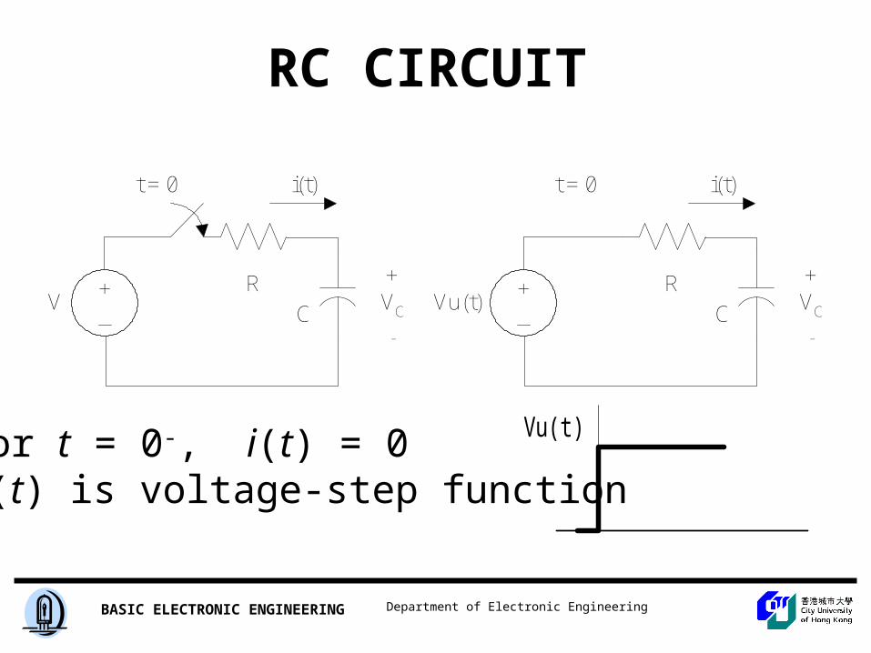
RC CIRCUIT
for t = 0-, i(t) = 0u(t) is voltage-step function
Vu(t)
RC
+VC
-
i(t)t = 0
+_
VR
C
+VC
-
i(t)t = 0
+_
Vu(t)

Department of Electronic EngineeringBASIC ELECTRONIC ENGINEERING
RC CIRCUIT
Vu(t)
0)(,
,)(
tforVtuvVvdt
dvRC
dt
dvCi
R
vtvui
ii
CC
CC
CR
CR
Solving the differential equation

Department of Electronic EngineeringBASIC ELECTRONIC ENGINEERING
Complete Response
Complete response = natural response + forced response• Natural response (source free response) is
due to the initial condition• Forced response is the due to the external
excitation.

Department of Electronic EngineeringBASIC ELECTRONIC ENGINEERING
Figure 5.17, 5.18
5-8
a). Complete, transient and steady state response
b). Complete, natural, and forced responses of the circuit

Department of Electronic EngineeringBASIC ELECTRONIC ENGINEERING
Circuit Analysis for RC Circuit
Vs+
Vc-
+ VR -
R
C
iR
iC
sRC
CC
RsR
CR
vRC
vRCdt
dvdt
dvCi
R
vvi
ii
11
,
Apply KCL
vs is the source applied.

Department of Electronic EngineeringBASIC ELECTRONIC ENGINEERING
Solution to First Order Differential Equation
)()()(
tfKtxdt
tdxs
Consider the general Equation
Let the initial condition be x(t = 0) = x( 0 ), then we solve the differential equation:
)()()(
tfKtxdt
tdxs
The complete solution consits of two parts: • the homogeneous solution (natural solution)• the particular solution (forced solution)

Department of Electronic EngineeringBASIC ELECTRONIC ENGINEERING
The Natural Response
/)(
)()(0)(
)(
tN
NNN
N
etx
tx
dt
tdxortx
dt
tdx
Consider the general Equation
Setting the excitation f (t) equal to zero,
)()()(
tfKtxdt
tdxs
It is called the natural response.

Department of Electronic EngineeringBASIC ELECTRONIC ENGINEERING
The Forced Response
0)(
)()(
tforFKtx
FKtxdt
tdx
SF
SFF
Consider the general Equation
Setting the excitation f (t) equal to F, a constant for t 0
)()()(
tfKtxdt
tdxs
It is called the forced response.

Department of Electronic EngineeringBASIC ELECTRONIC ENGINEERING
The Complete Response
)(
)()(
/
/
xe
FKe
txtxx
tS
tFN
Consider the general Equation
The complete response is: • the natural response + • the forced response
)()()(
tfKtxdt
tdxs
Solve for ,
)()0(
)()0()0(
0
xx
xxtx
tfor
The Complete solution:
)()]()0([)( / xexxtx t
/)]()0([ texx called transient response
)(x called steady state response
Department of Electronic EngineeringBASIC ELECTRONIC ENGINEERING
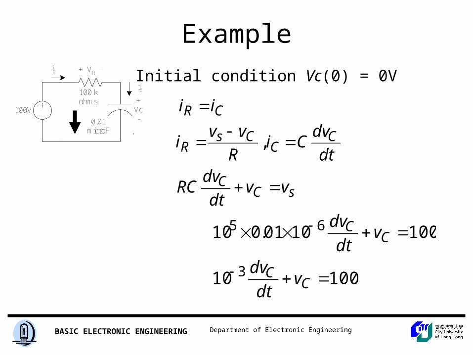
Example
+Vc-
+ VR -
100 kohms
0.01microF
iR
iC
100V
Initial condition Vc(0) = 0V
sCC
CC
CsR
CR
vvdt
dvRC
dt
dvCi
R
vvi
ii
,
10010
1001001.010
3
65
CC
CC
vdt
dv
vdt
dv
Department of Electronic EngineeringBASIC ELECTRONIC ENGINEERING
Example+
Vc-
+ VR -
100 kohms
0.01microF
iR
iC
100V
Initial condition Vc(0) = 0V
and
3
3
10
10
100100
100
1000,0)0(
100
t
c
c
t
c
ev
A
AvAs
Aev)()(
)(tfKtx
dt
tdxs
)(
)()(
/
/
xe
FKe
txtxx
tS
tFN
10010 3 C
C vdt
dv
Department of Electronic EngineeringBASIC ELECTRONIC ENGINEERING
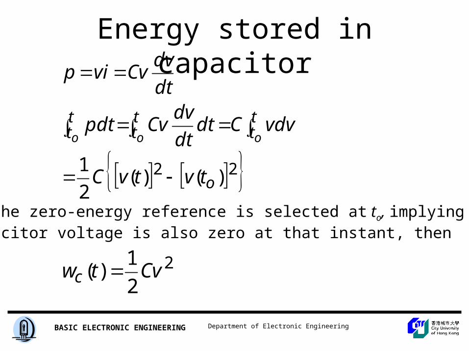
Energy stored in capacitor
22 )()(2
1o
tt
tt
tt
tvtvC
vdvCdtdt
dvCvpdt
dt
dvCvvip
ooo
If the zero-energy reference is selected at to, implying that thecapacitor voltage is also zero at that instant, then
2
2
1)( Cvtwc

Department of Electronic EngineeringBASIC ELECTRONIC ENGINEERING
R C
Power dissipation in the resistor is:
pR = V2/R = (Vo2 /R) e -2 t /RC
2
0/22
0/22
0
2
1
|)2
1(
o
RCto
RCto
RR
CV
eRC
RV
R
dteVdtpW
RC CIRCUIT
Total energy turned into heat in the resistor

Department of Electronic EngineeringBASIC ELECTRONIC ENGINEERING
RL CIRCUITS
LR-
VR
+
+VL
-
i(t)
Initial condition i(t = 0) = Io
equationaldifferentitheSolving
idt
di
R
Ldt
diLRivv LR
0
0

Department of Electronic EngineeringBASIC ELECTRONIC ENGINEERING
RL CIRCUITS
LR-
V R
+
+V L
-
i(t)
Initial condition i(t = 0) = Io LRt
o
o
to
iI
t
o
ti
I
eIti
tL
RIi
tL
Ri
dtL
R
i
didt
L
R
i
di
iL
R
dt
di
o
o
/
)(
)(
lnln
||ln
,
0

Department of Electronic EngineeringBASIC ELECTRONIC ENGINEERING
RL CIRCUIT
LR-
V R
+
+V L
-
i(t)
Power dissipation in the resistor is:
pR = i2R = Io2e-2Rt/LR
Total energy turned into heat in the resistor
2
0/22
0
/22
0
2
1
|)2
(
o
LRto
LRtoRR
LI
eR
LRI
dteRIdtpW
It is expected as the energy stored in the inductor is 2
2
1oLI

Department of Electronic EngineeringBASIC ELECTRONIC ENGINEERING
RL CIRCUIT Vu(t)
RL
+V L
-
i(t)
+_
Vu(t)
ktRiVR
L
sidesbothgIntegratin
dtRiV
Ldi
Vdt
diLRi
)ln(
,
0,
]ln)[ln(
ln,0)0(
/
/
tforeR
V
R
Vi
oreV
RiV
tVRiVR
L
VR
Lkthusi
LRt
LRt
where L/R is the time constant
Department of Electronic EngineeringBASIC ELECTRONIC ENGINEERING
DC STEADY STATEThe steps in determining the forced response for RL or RC circuits with dc sources are:
1. Replace capacitances with open circuits.
2. Replace inductances with short circuits.
3. Solve the remaining circuit.