department of defense - university of queenslandergonomics.uq.edu.au/public/pdf/milhbk759c.pdf ·...
TRANSCRIPT

METRIC
MIL-HDBK-759C31 July 1995SUPERSEDINGMIL-HDBK-759B30 OCTOBER 1991
DEPARTMENT OF DEFENSE
HANDBOOK FOR
HUMAN ENGINEERING DESIGN GUIDELINES
This handbook is for guidance only. Do not cite thisdocument as a requirement.
AMSC N/A AREA HFACDISTRIBUTION STATEMENT A. Approved for public release; distribution is unlimited.

MIL-HDBK-759C
ii
FOREWORD
1. This handbook is approved for use by all Departments and Agencies of the Departmentof Defense.
2. This handbook is for guidance only. This handbook cannot be cited as a requirement. Ifit is, the contractor does not have to comply.
3. This document provides basic guidelines and data on human engineering design formilitary systems, equipment, and facilities. This handbook has been designed to supplementMIL-STD-1472D. To cue the MIL-STD-1472D user to such supplementary information, thishandbook has been formatted to follow the same paragraph numbering, down to the thirdindenture level, as in MIL-STD-1472D, e.g., paragraph 5.4.5 of both MIL-STD-1472D andthis handbook deal with miniature controls. Some paragraphs, necessarily, do not contain anyinformation, but are reserved to accommodate new information that may become available.Additional paragraphs are added to accommodate information that does not appropriately fitelsewhere.
4. Beneficial comments (recommendations, additions, or deletions) and any pertinent datawhich may be of use in improving this document should be addressed to: Commander, U.S.Army Missile Command, ATTN: AMSMI-RD-SE-TD-ST, Redstone Arsenal, Alabama35898-5270, by using the Standardization Document Improvement Proposal (DD Form 1426)appearing at the end of this document or by letter.

MIL-HDBK-759C
CONTENTS
PARAGRAPH PAGE
iii
1. SCOPE .....................................................................................................................1 1.1 Scope.....................................................................................................................1 1.2 Applicability..........................................................................................................1 1.2.1 Application.........................................................................................................1 1.2.2 Selection of hardware, materials, or processes...................................................1 1.2.3 Gender considerations ........................................................................................1 1.2.4 Force limits ........................................................................................................1 1.2.5 Manufacturing tolerances ...................................................................................1
2. APPLICABLE DOCUMENTS................................................................................3 2.1 General ..................................................................................................................3 2.2 Government documents.........................................................................................3 2.2.1 Specifications, standards, and handbooks ..........................................................3 2.2.2 Other documents, drawings, and publications....................................................5 2.3 Non-government publications ...............................................................................5 2.4 Order of precedence ..............................................................................................6
3. DEFINITIONS.........................................................................................................7 3.1 Battle-short switch ................................................................................................7 3.2 Inch-pound equivalents, abbreviations, and prefixes............................................ 7 3.3 Primary controls ....................................................................................................7
4. GENERAL GUIDELINES.......................................................................................9
5. DETAILED GUIDELINES ...................................................................................11 5.1 Control-display integration..................................................................................11 5.1.1 General criteria.................................................................................................11 5.1.2 Position relationships. ......................................................................................12 5.1.3 Movement relationships ...................................................................................15 5.1.4 Control-display movement ratio.......................................................................15
5.2 Visual displays .....................................................................................................195.2.1 General ..............................................................................................................195.2.2 Transilluminated displays..................................................................................205.2.3 Scale indicators .................................................................................................235.2.4 Cathode ray tube (CRT) displays ......................................................................345.2.5 Large-screen displays ........................................................................................455.2.6 Other displays....................................................................................................45
5.3 Audio displays......................................................................................................545.3.1 General ..............................................................................................................545.3.2 Audio signals.....................................................................................................55

MIL-HDBK-759C
CONTENTS
PARAGRAPH PAGE
iv
5.3.3 Characteristics of audio warning signals ...........................................................575.3.4 Signal characteristics in relation to operational conditions and objectives........585.3.5 Verbal warning signals ......................................................................................585.3.6 Controls for audio warning devices...................................................................585.3.7 Speech transmission equipment.........................................................................585.3.8 Speech reception equipment..............................................................................585.3.9 Operator comfort and convenience....................................................................585.3.10 Operating controls for voice communication equipment...................................585.3.11 Speaker side tone...............................................................................................585.3.12 Speech intelligibility..........................................................................................585.3.13 Communications................................................................................................58
5.4 Controls ................................................................................................................635.4.1 General criteria..................................................................................................635.4.2 Rotary controls ..................................................................................................715.4.3 Linear controls...................................................................................................865.4.4 High-force controls..........................................................................................1135.4.5 Miniature controls ...........................................................................................1135.4.6 Touch-screen controls for displays..................................................................1135.4.7 Quickened and predictor controllers................................................................1135.4.8 Integral, handle-mounted controls ...................................................................113
5.5 Labeling..............................................................................................................1215.5.1 General ............................................................................................................1215.5.2 Orientation and location ..................................................................................1215.5.3 Contents...........................................................................................................1235.5.4 Qualities ..........................................................................................................1235.5.5 Label characteristics........................................................................................1245.5.6 Equipment labeling..........................................................................................1285.5.7 Labeling for identification...............................................................................130
5.6 Anthropometry ...................................................................................................1335.6.1 General ............................................................................................................1335.6.2 Anthropometric data........................................................................................1335.6.3 Use of data.......................................................................................................1355.6.4 Special populations..........................................................................................1365.6.5 Body movement ..............................................................................................1365.6.6 Human strength and handling capacity............................................................136
5.7 Workspace design...............................................................................................1435.7.1 General ............................................................................................................1435.7.2 Standing operations .........................................................................................143

MIL-HDBK-759C
CONTENTS
PARAGRAPH PAGE
v
5.7.3 Seated operations.............................................................................................1445.7.4 Common working positions.............................................................................1505.7.5 Standard console design ..................................................................................1505.7.6 Special-purpose console design.......................................................................1555.7.7 Stairs, ladders, and ramps................................................................................1555.7.8 Ingress and egress............................................................................................1635.7.9 Surface colors ..................................................................................................165
5.8 Environment .......................................................................................................1675.8.1 Heating, ventilating, and air conditioning .......................................................1675.8.2 Illuminance......................................................................................................1725.8.3 Acoustical noise ..............................................................................................1765.8.4 Vibration..........................................................................................................178
5.9 Design for maintainer.........................................................................................1795.9.1 General ............................................................................................................1795.9.2 Mounting of items within units .......................................................................1875.9.3 Adjustment controls ........................................................................................1915.9.4 Accessibility ....................................................................................................1925.9.5 Lubrication ......................................................................................................1985.9.6 Case and cover mounting ................................................................................1985.9.7 Cases ...............................................................................................................2005.9.8 Covers .............................................................................................................2015.9.9 Access openings and covers ............................................................................2025.9.10 Fasteners..........................................................................................................2025.9.11 Unit design for efficient handling....................................................................2075.9.12 Mounting and packaging .................................................................................2095.9.13 Conductors.......................................................................................................2205.9.14 Connectors.......................................................................................................2315.9.15 Test points .......................................................................................................2445.9.16 Test equipment ................................................................................................2515.9.17 Failure indications and fuse requirements ......................................................2605.9.18 Printed circuit boards.......................................................................................2625.9.19 Ignition equipment...........................................................................................2625.9.20 Batteries...........................................................................................................2635.9.21 Climate effects.................................................................................................264
5.10 Design for remote handling ..............................................................................2685.10.1 Characteristics of equipment to be handled remotely....................................2685.10.2 Feedback........................................................................................................2685.10.3 Manipulators..................................................................................................2685.10.4 Viewing equipment .......................................................................................268
MIL-HDBK-759C
CONTENTS
PARAGRAPH PAGE
vi
5.10.5 Illumination ...................................................................................................268
5.11 Small systems and equipment ..........................................................................2705.11.1 Portability and load-carrying .........................................................................2705.11.2 Tracking ........................................................................................................2705.11.3 Optical instruments and related equipment ...................................................270
5.12 Ground and shipboard vehicles ........................................................................2725.12.1 General ..........................................................................................................2725.12.2 Seating...........................................................................................................2725.12.3 Controls .........................................................................................................2725.12.4 Operating instructions ...................................................................................2725.12.5 Visibility........................................................................................................2725.12.6 Heating and ventilation..................................................................................2735.12.7 Trailers, vans, and intervehicular connections...............................................2745.12.8 Cranes, material handling and construction equipment .................................2755.12.9 Automotive subsystems.................................................................................278
5.13 Hazards and safety ..........................................................................................2885.13.1 General ..........................................................................................................2885.13.2 Safety labels and placards .............................................................................2885.13.3 Pipe-, hose-, and tube-line identification.......................................................2885.13.4 General workspace hazards ...........................................................................2885.13.5 General equipment-related hazards ...............................................................2885.13.6 Platforms .......................................................................................................2915.13.7 Electrical, mechanical, fluid, toxic, and radiation hazards ............................2915.13.8 Trainers..........................................................................................................3095.13.9 Stealth and covert operations.........................................................................309
5.14 Aerospace vehicle compartments .....................................................................3115.14.1 General ..........................................................................................................3115.14.2 Crewstations and passenger compartments ...................................................3115.14.3 Personnel ingress and egress .........................................................................3115.14.4 Emergency evacuation...................................................................................311
5.15 User-computer interface ...................................................................................3135.15.1 General ..........................................................................................................3135.15.2 Data entry ......................................................................................................3135.15.3 Data display...................................................................................................3135.15.4 Interactive control..........................................................................................3135.15.5 Feedback........................................................................................................3135.15.6 Prompts..........................................................................................................313

MIL-HDBK-759C
CONTENTS
PARAGRAPH PAGE
vii
5.15.7 Defaults .........................................................................................................3135.15.8 Error management and data protection..........................................................3135.15.9 System response time ....................................................................................3135.15.10 Other requirements ........................................................................................3135.15.11 Data and message transmission .....................................................................313
5.16 Visual Display Terminals .................................................................................315
5.17 Weapons systems .............................................................................................3175.17.1 Ammunition...................................................................................................3175.17.2 Armament......................................................................................................319
6. NOTES............................................................................................................327

MIL-HDBK-759C
CONTENTS
FIGURE PAGE
viii
1. Control-display relationship .........................................................................................16 2. Scale graduation, pointer position and scale numbering alternatives ...........................26 3. Fixed-scale azimuth dials .............................................................................................27 4. Examples of shape- and color-coding ..........................................................................28 5. Zero position and pointer movement for circular dial displays ....................................30 6. Aligned pointers for rapid check-reading.....................................................................31 7. Relative position of scale marks, numerals and pointers on arc and straight-line
scales ............................................................................................................................32 8. Selection of dot and segmented matrix characters .......................................................47 9. Digit light counter arrays..............................................................................................49 10. Drum-type counter design ...........................................................................................52 11. Rotating knob separation.............................................................................................76 12. Keylock mounting criteria...........................................................................................77 13. Keylock switch criteria................................................................................................79 14. Thumbwheel orientation and movement .....................................................................80 15. Set screws for control knobs........................................................................................82 16. Recommended knob shapes ........................................................................................83 17. Easily recognizable knob shapes .................................................................................83 18. Proper mounting of rapidly operated crank .................................................................85 19. Multi-function keyset format examples.......................................................................96 20. Menu selector types and format examples ..................................................................97 21. Toggle switch orientation for ON..............................................................................103 22. Location and position of labels .................................................................................122 23. Close proximity character height criteria ..................................................................126 24. Extended distance character height criteria...............................................................127 25. Label-size hierarchy ..................................................................................................129 26. Range of human motion ............................................................................................138 27. Standing workspace dimensions................................................................................145 28. Seated workspace dimensions ...................................................................................147 29. Swing-away seat for short-term operations ...............................................................149 30. Mobile workspace dimensions ..................................................................................151 31. Seated optimum manual control space ......................................................................154 32. Guardrail and handrail dimensions............................................................................158 33. Step-ladder dimensions .............................................................................................160 34. Rung-ladder and ladder-cage dimensions..................................................................160 35. Ramp dimensions ......................................................................................................161 36. Walkway and passageway dimensions......................................................................164 37. Door dimensions .......................................................................................................165 38. Windchill chart..........................................................................................................171 39. Workspace reflectance values ...................................................................................177 40. Hinged units ..............................................................................................................187 41. Component placement...............................................................................................188

MIL-HDBK-759C
CONTENTS
FIGURE PAGE
ix
42. Tube socket orientation .............................................................................................188 43. Access opening dimensions.......................................................................................195 44. Covers and accesses ..................................................................................................197 45. Cover and case design examples ...............................................................................199 46. Fastener examples .....................................................................................................204 47. Use of spring clamps .................................................................................................214 48. Pull-out, roll-out, and slide-out drawers....................................................................218 49. Fold-out construction for electronic chassis ..............................................................219 50. Hinged assemblies.....................................................................................................219 51. Use of maintenance stands ........................................................................................220 52. Routing cables...........................................................................................................221 53. Cable connections .....................................................................................................221 54. Cable bends ...............................................................................................................221 55. Methods for recoiling service loops ..........................................................................223 56. Cable winder .............................................................................................................223 57. Cable inspection ........................................................................................................228 58. Preformed cables .......................................................................................................228 59. Quick-disconnect cable connections .........................................................................232 60. Coding of connectors.................................................................................................236 61. Identifying plugs and receptacles to prevent mismatching........................................237 62. Alignment guides and guide pins ..............................................................................239 63. Equipment removal ...................................................................................................239 64. Use of side-alignment brackets .................................................................................240 65. Types of AN connectors............................................................................................241 66. Alternate methods for grouping test points ...............................................................248 67. Test points on replaceable units ................................................................................249 68. Hand-held testers.......................................................................................................258 69. Performance decrement at different ambient temperatures .......................................265 70. Visible seals ..............................................................................................................276 71. Connectors for fluid lines ..........................................................................................278 72. Burn criteria for human skin .....................................................................................289 73. Door interlock switch ................................................................................................293 74. Automatic shorting bars ............................................................................................295 75. Grounding methods ...................................................................................................295 76. Cabinet grounding system.........................................................................................296 77. Correct instrument-type fuse holder wiring...............................................................297 78. Effects of incline on center of gravity location of equipment ...................................299 79. Retainers for floor mounted vertical ammunition and missile ready racks ...............319 80. Dimensions guidance for rifles and machine guns ....................................................325

MIL-HDBK-759C
CONTENTS
TABLE PAGE
x
1. Inch-pound equivalents, abbreviations, and prefixes......................................................8 2. Scale of markings.........................................................................................................25 3. Character sizes for mechanical counters (mm).............................................................50 4. Control selection criteria ..............................................................................................64 5. Recommended manual controls ...................................................................................65 6. Conventional control movement stereotypes ...............................................................67 7. Knob detent placement.................................................................................................72 8. Rotary selector controls................................................................................................73 9. Representative push button switch applications...........................................................87 10. Push button switches ...................................................................................................88 11. Nominal keyboard characteristics ...............................................................................93 12. Toggle switches...........................................................................................................98 13. Levers........................................................................................................................105 14. Two-axis controllers for display system applications................................................111 15. Foot-operated controls...............................................................................................114 16. Grip switches.............................................................................................................117 17. A bivariate frequency table .......................................................................................134 18. Range of human motion ............................................................................................137 19. Standing workspace dimensions................................................................................144 20. Seated workspace dimensions ...................................................................................148 21. Mobile workspace dimensions ..................................................................................152 22. Illumination criteria for representative tasks .............................................................157 23. Equivalent chill temperature .....................................................................................173 24. Brightness ratios........................................................................................................175 25. Equipment units design checklist ..............................................................................189 26. Equipment units access checklist ..............................................................................203 27. Electrical cable coding ..............................................................................................224 28. Hydraulic and pneumatic coding...............................................................................225 29. Cable checklist ..........................................................................................................242 30. Connector checklist ...................................................................................................243 31. Test points checklist ..................................................................................................250 32. Weight and dimension limits of portable test equipment ..........................................257 33. Test equipment checklist...........................................................................................259 34. General comparison of fuses and circuit breakers .....................................................261 35. Shock current intensities and their probable effects ..................................................292 36. Constants for predicting COHb blood content ..........................................................303 37. Noxious exhaust products of engine fuels .................................................................304 38. Safety checklist .........................................................................................................307

MIL-HDBK-759C
xi
This Page Intentionally Left Blank

MIL-HDBK-759C
1
1. SCOPE
1.1 Scope. This handbook provides human engineering design guidelines and referencedata for design of military systems, equipment, and facilities. (Programmatic and technique-oriented guidelines may be found in DOD-HDBK-763 and MIL-HDBK-761.)
1.2 Applicability.
1.2.1 Application. The function- and commodity-oriented design guidelines and practicesprovided by this handbook apply to military systems, equipment, and facilities. They may beapplied during any phase of acquisition, as appropriate, where design influence, design, ordesign evaluation is involved. (A comprehensive treatment of human engineering design ofuser-computer interaction is provided by MIL-HDBK-761.)
1.2.2 Selection of hardware, materials, or processes. Nothing in this handbook should beconstrued as limiting the selection of hardware, materials, or processes to items that may bedescribed herein.
1.2.3 Gender considerations. Military systems, equipment, and facilities are designed foroperation, maintenance, and control by both male and female personnel. Accordingly andunless stated otherwise, the design guidelines, preferred practices, and data herein apply todesign of systems, equipment, and facilities for use by both men and women.
1.2.4 Force limits. If an item will be used by an already established military occupationthat specifies physical qualification requirements, any discrepancy between the forceguidelines in this handbook and the qualification requirements should be resolved in favor ofthe latter. In this event, the least stringent physical qualification requirement of all specialtieswhich may operate, maintain, transport, supply, move, lift, or otherwise manipulate the itemin the manner being considered should be selected as a maximum design force limit. If suchphysical qualification requirements do not cover the task addressed by the criteria herein, thecriteria herein should be applied.
1.2.5 Manufacturing tolerances. When manufacturing tolerances are not perceptible to theuser, the guidelines and preferred practices herein should not be interpreted in a mannerpreventing the use of components whose dimensions are within a normal manufacturing upperor lower limit tolerance of the dimensions specified herein.

MIL-HDBK-759C
2
This page intentionally left blank

MIL-HDBK-759C
3
2. APPLICABLE DOCUMENTS
2.1 General. The documents listed below are not necessarily all of the documentsreferenced herein, but are the ones that are needed in order to fully understand the informationprovided by this handbook.
2.2 Government documents.
2.2.1 Specifications, standards, and handbooks. The following specifications, standards,and handbooks form a part of this document to the extent specified herein. Unless otherwisespecified, the issues of these documents are those listed in the latest issue of the Departmentof Defense Index of Specifications and Standards (DoDISS) and supplement thereto.
SPECIFICATIONS
DEPARTMENT OF DEFENSE
MIL-P-514 Plate, Identification, Instruction and Marking, Blank
MIL-C-3702 Cable, Power, Electrical, Ignition, High-Tension
MIL-L-3976 Light, Marker, Clearance, Service and Blackout
MIL-B-8584 Brake Systems, Wheel, Aircraft, Design of
MIL-F-8785 Flying Qualities of Piloted Airplanes
MIL-C-13486 Cable, Special Purpose, Electrical. Low-Tension, Heavy-dutyMultiple Conductors
MIL-F-15160 Fuses, Instrument, Power and Telephone
MIL-M-18012 Markings for Aircrew Station Displays, Design andConfiguration of
STANDARDS
FEDERAL
FED-STD-376 Preferred Metric Units for General Use by the FederalGovernment
FED-STD-595 Colors (Requirements for Individual Color Chips)

MIL-HDBK-759C
4
DEPARTMENT OF DEFENSE
MIL-STD-188 Common Long Haul and Tactical Communication SystemTechnical Standards
MIL-STD-195 Marking of Connections for Electrical Assemblies
MIL-STD-203 Aircrew Station Controls and Displays: Location, Arrangementand Actuation of, for Fixed Wing Aircraft
MIL-STD-250 Aircrew Station Controls and Displays for Rotary Wing Aircraft
MIL-STD-454 Standard General Requirements for Electronic Equipment
MIL-STD-681 Identification Coding and Application of Hookup and Lead Wire
MIL-STD-685 Identification of Cable Used for Transmission of Telephone,Telegraph and Teletype Signals
MIL-STD-686 Cable and Cord, Electrical, Identification Marking and ColorCoding of
MIL-STD-1472 Human Engineering Design Criteria for Military Systems,Equipment and Facilities
MIL-STD-1473 Standard General Requirements for Color and Marking of ArmyMateriel
MIL-STD-1474 Noise Limits for Military Materiel
MIL-STD-1908 Definitions of Human Factors Terms
HANDBOOKS
MIL-HDBK-761 Human Engineering Guidelines for Management InformationSystems
DOD-HDBK-763 Human Engineering Procedures Guide
(Unless otherwise indicated, copies of the above specifications, standards, and handbooksare available from the Standardization Documents Order Desk, 700 Robbins Avenue, Building4D, Philadelphia, PA 19111-5094.)

MIL-HDBK-759C
5
2.2.2 Other documents, drawings, and publications. The following other governmentdocuments, drawings and publications form a part of this document to the extent specifiedherein.
PUBLICATIONS
ARMY
FM 31-71 Northern Operations
NRDEC TR 84-034 Anthropometry of the Clothed U.S. Army Ground Troop andCombat Vehicle Crewmen; Natick Research, Developmentand Engineering Center
NAVY
NAEC TR 2100-07B A Family of Manikins for Workstation Design; Naval AirEngineering Center
PMTC TP 75-49 Computerized Accommodated Percentage Evaluation(CAPE) Model for Cockpit Analysis and Other ExclusionStudies; Pacific Missile Test Center
NATIONAL AERONAUTICS AND SPACE ADMINISTRATION (NASA)
NASA Ref. Pub. 1024 Anthropometric Source Book, Volume 1: Anthropometry forDesigners
FEDERAL
29 CFR 1910 Occupational Safety and Health Standards
FMVSS-101 Federal Motor Vehicle Safety Standards
(Copies of other government documents, drawings, and publications required by contractorsin connection with specific procurement functions should be obtained from the acquiringactivity or as directed by the contracting officer.)
2.3 Non-government publications. The following document(s) form a part of thisdocument to the extent specified herein. Unless otherwise specified, the issues of thedocuments which are DoD adopted are those listed in the latest issue of the DoDISS andsupplement thereto.

MIL-HDBK-759C
6
AMERICAN SOCIETY FOR TESTING AND MATERIALS
ASTM E 380 Standard Practice for the Use of the International System of Units(SI)(The Modernized Metric System)
(Application for copies should be addressed to the American Society for Testing andMaterials, 1916 Race Street, Philadelphia, PA 19103-1187)
INTERNATIONAL STANDARDIZATION ORGANIZATION (ISO)
ISO 2631-1 Guide to the Evaluation of Human Exposure to Whole BodyVibration, Part 1: General Requirements
(Application for copies should be addressed to the American National Standards Institute,Inc., 11 West 42nd Street, New York, NY 10036.)
SOCIETY OF AUTOMOTIVE ENGINEERS (SAE)
SAE TP-810217 An Alternative to Percentile Model
(Application for copies should be addressed to the Society of Automotive Engineers, 400Commonwealth Drive, Warrendale, PA 15096-0001.)
(Non-government standards and other publications are normally available from theorganizations that prepare or distribute the documents. These documents also may beavailable in or through libraries or other informational services.)
2.4 Order of precedence. In the event of a conflict between the text of this document andthe references cited herein, the text of this document takes precedence. Nothing in thisdocument, however, supersedes applicable laws and regulations unless a specific exemptionhas been obtained.

MIL-HDBK-759C
7
3. DEFINITIONS
NOTE: Terms not appearing below are defined in accordance with MIL-STD-1908.
3.1 Battle-short switch. A switch used on high-priority equipment designed to bypass orshort circuit interlock switches or devices during emergency conditions.
3.2 Inch-pound equivalents, abbreviations, and prefixes. Inch-pound units, metric units,and multipliers to convert from metric units to inch-pound units are presented in Table 1.
3.3 Primary controls. The most important and frequently used devices designed to controlequipment and systems.

MIL-HDBK-759C
8
TABLE 1. Inch-pound equivalents, abbreviations, and prefixes
EQUIVALENTS
TO CONVERT FROM TO MULTIPLY BY
candela per square meter (cd/m2) footlambert (fL) 0.291 864
kilogram (kg) pound (lb) avoirdupois 2.204 623
kilopascals (KPa) pound force/inch2 (lbf/in2) 0.145 038
lux (lx) footcandle (fc) 0.092 903
meter (m)
meter (m)
foot (ft)
inch (in. or ")
3.280 840
39.370 079
meter2 (m2)
meter2 (m2)
foot2 (ft2)
inch2 (in2)
10.763 910
1550.003 120
meter3 (m3) foot3 (ft3) 35.314 662
meter3 (m3) inch3 (in3) 61203.745 303
millimeter (mm) inch (in. or ") 0.039 370
millimeter2 (mm2) inch2 (in2) 0.001 550
newton (N) pound force (lbf) 0.224 809
newton (N) ounce force (ozf) 3.596 942
newton meter (N.m) pound-inch (lbf-in) 8.850 748
newton meter (N.m) ounce-inch (ozf-in) 141.611 929
radian (rad) degree (angle)(deg) 57.295 788
radian (rad) minute (angle)(min) 3437.746 873
PREFIXES TEMPERATURE CONVERSION
Nano n 10-9 Micro µ 10-6 Milli m 10-3 Centi c 10-2
Kilo k 103 Mega M 106
oC = 5/9 (oF - 32)
oF = 9/5 oC + 32

MIL-HDBK-759C
9
4. GENERAL GUIDELINES
The design of systems, equipment, and facilities should conform to the capabilities andlimitations of the fully-equipped individual to operate, maintain, supply, and transport themateriel in its operational environment consistent with tactical criteria and logisticcapabilities. Accordingly, design-induced workload, accuracy, time constraints, mentalprocessing, and communications requirements should not exceed operator, maintainer, orcontroller capabilities. Design should also foster effective procedures, work patterns, andpersonnel safety and health, and minimize factors which degrade human performance. Designalso should minimize personnel and training requirements within the limits of time, cost, andperformance trade-offs.

MIL-HDBK-759C
10
This page intentionally left blank

MIL-HDBK-759C
11
5. DETAILED GUIDELINES
5.1 Control-display integration.
5.1.1 General criteria.
5.1.1.1 Relationship. Control-display relationships should be functionally effective andrequire a minimum of decoding or mental involvement on the part of the operator. Thisshould include relationships between a control and specific display hardware (meters,instruments, and labeled control escutcheon plates), and/or external devices or visual elementsthat are used as visual references while operating particular controls. A control should not beused in any application in which its movement is likely to be ambiguously interpreted, such aswhen the manipulation required is opposite to that anticipated or expected by the typicaloperator.
5.1.1.2 Organization. Controls and displays should be organized in a manner that willminimize operator effort, confusion, and error, by means of functional grouping, sequentialarrangement, accessibility to the nominal user's limb or hand, and/or nominal viewing axis ofthe operator.
5.1.1.3 Feedback. Control-display systems should be designed to provide feedback oncontrol input and system state as rapidly as possible. Feedback should be considered at thethree levels listed below:
a. Control Actuation.
(1) Discrete state selectors. Controls of this type (toggle switches, push buttonswitches, and rotary selectors) should provide positive indication of controlactuation to the operator under all operational conditions. Control displacementsufficient to be unambiguously recognized may provide adequate feedback at thislevel for most functions.
(2) Continuous adjustment controls. Controllers such as continuous adjustmentknobs, cranks, and joysticks should provide feedback as to where the control ispositioned with respect to its entire range of variability. Ordinarily, this is bymeans of visual indication via the control's moving pointer against a fixed scale.
b. Transient system response. Feedback at this level is used to provide an indication ofsystem response to the control input between the time of control actuation and that ofarriving at system steady-state condition in response to that input. When the transientresponse is short (less than two seconds duration), feedback at this level is sufficient(there is one clear visual or auditory indication that the system is in the process ofresponding). However, for especially critical functions, transient system responseshould be indicated by one of the feedback arrangements listed below.

MIL-HDBK-759C
12
(1) Direct positive feedback from the mechanism being driven via, for example, astrong auditory signal directly from a drive motor, or direct visual indication ofthe orientation of the driven unit.
(2) Redundant positive feedback from two different points in the system (a meterindication and a pilot light, which sense the system's transient state).
(3) Both positive and negative feedback, so that one or the other will always beactivated, whether or not the system responds to the control input, such as whenthe positive feedback indicates the system is in the process of responding when itshould; the negative feedback indicates that the system is not responding when itshould; and/or one or the other of the indications would always be present duringthe transient period.
c. System steady-state. Feedback should be provided to indicate completion of thesystem's response to the control input and current system operating state. Usually asingle positive feedback indication at this level is sufficient. (The onset of theindication signals completion of the response and the continuing indication constantlyinforms of system state.) Where the original control input is by some type of discretestate selector, a discrete state indicator for feedback is sufficient. Where the originalcontrol input was by a continuous adjustment control, an analog or digital indication ofsystem state is usually required to indicate that the system has responded fully to thecontrol input. Exceptions to this may be allowed where provision is made toautomatically compare the completed system response with the magnitude of thecontrol input and to indicate that the system has responded within satisfactorytolerance. For critical functions, a warning indication should be provided to signal atall times following the system transient response when the system state mismatchesthe ordered state as set by the input control(s).
5.1.2 Position relationships. Controls should normally be placed beneath or to the right ofa related display except when:
a. the display would be obscured by the operator's hand,
b. panel space limitations require use of an array of displays that would be selectivelyoperated by means of a "ganged" control device, wherein separate knobs would beassociated with individual displays within the array, or
c. the control operation would be inefficient or awkward if the control were placed nextto the display, or vice versa. Typical applications include such relationships assteering wheel, joystick or foot-operated controls relative to displays on an instrumentpanel.
5.1.2.1 General arrangement. Arrangement of controls and displays at workstations shouldbe in accordance with those arrangement factors most likely to ensure effective operator

MIL-HDBK-759C
13
performance. Care should be exercised to obtain the best balance of these factors when theymay be in conflict or may vary in significance with the mode of operation at the workstation.
5.1.2.2 Operator orientation. Controls and displays associated with a given control ormonitoring task(s) should be located and positioned with reference to a specified operatorposition(s), including criteria for visual monitoring beyond the immediate control-displayinterface, and should not impose difficult mobility problems for the operator (sitting orstanding in an awkward position, frequent extreme reaching and body or head turning criteria,or constant changes in body position in order to accommodate to various control manipulationor visual monitoring tasks).
5.1.2.3 Simultaneous access. Where two operators must use the same control or display(when monitoring system status), the criteria listed below should be applied.
a. If the controls and displays have high priority, duplicate sets should be providedwhenever there is adequate space. Otherwise, controls and displays should be centeredbetween the operators.
b. If secondary controls and displays should be shared, they should be centered betweenthe operators if equally important to each. If the controls or displays are moreimportant to one operator than to the other, they should be placed nearer the operatorhaving the principal criteria for using them.
c. If the primary or secondary controls must be operated with the user's preferred hand(keyboards, keysenders), duplicate controls should be provided. Such controls shouldnot be centered between the operators.
d. If direction-of-movement relationships are important, controls and displays should belocated so that both operators face in the same direction.
5.1.2.4 Functional grouping.
5.1.2.4.1 Functional group arrangement. Controls and displays should be groupedfunctionally when they are identical in function, used together in a specific task, and related toone equipment or system component. Once grouped, they should be spatially organized sothat the relationship between them is apparent to the operator and all displays used togethershould be placed at the same viewing distance. In addition, controls and displays should begrouped by function when there is no definite sequence of function.
5.1.2.4.2 Sequence. The principles listed below should be applied to displays which areobserved in sequence.
a. When displays are arranged horizontally, they should be viewed from left to right.
b. When displays are arranged vertically, they should be viewed from top to bottom.

MIL-HDBK-759C
14
c. Displays should be grouped, arranged, and located as close together as possible,provided the layout does not make it difficult to interpret individual displays.
When the operator uses several controls in sequence with the same hand, the controls shouldbe arranged in horizontal rows, from left to right, in order of operation. If horizontal rows areimpractical, the controls should be arranged in vertical rows, from top to bottom, in order ofoperation.
5.1.2.4.3 Consistency. Similar control-display functions should be consistent from oneoperator workstation to another when it is likely that the same operator may be called upon tochange workstations. Examples are listed below.
a. Left-right arrangements. When a group of control-display elements normally have aleft-to-right and/or numbered relationship to other equipment components (aircraftengines numbered from left to right), the operator control-display arrangement shouldremain the same with respect to the operator's orientation within the workstation(facing forward, right, left, or aft).
b. Related but separated control-display arrays. When an array of controls on one panelcorresponds to displays mounted on another panel because of special space limitations,the control and display arrays should be similarly arranged. That is, the leftmostcontrol of a horizontal array should correspond to the leftmost display mounted on theother panel, or a topmost control of a vertical array should correspond to the topmostdisplay on the other panel. Two horizontal panels should not be mounted so that theyface each other and thus create the opportunity to confuse the left-to-rightrelationships.
c. Vertical vs horizontal control-display arrangements. When displays are arranged in arow or column the associated controls should be similarly arranged and spaced (seeFigure 1), except as follows:
(1) Fewer rows of controls than displays. Controls affecting the top row of displaysshould be positioned at the far left; controls affecting a second row of displaysshould be placed immediately to the right of these, with an appropriate spacebetween the two control arrays.
(2) Vertical vs horizontal association. If a horizontal row of displays should berelated to a vertical row of controls or vice versa, the farthest left item in thehorizontal array should correspond to the top item in the vertical array.Exceptions often lead to errors in spite of the recommended spatial associations;therefore, they should be avoided whenever possible.

MIL-HDBK-759C
15
(3) Multiple display vs single control. When the manipulation of one controlrequires reading of several displays, the control should be centered as near aspossible below the display group.
(4) Multiple display vs ganged control. When up to three displays are to beindividually affected by a three-layer, ganged rotary control switch, the switchshould be centered below a horizontal display group, or to the right of a verticaldisplay group. The knob-display associations should be as follows: top knob -right or upper display, middle knob - middle display, bottom knob - left or lowerdisplay.
5.1.3 Movement relationships. Reserved.
5.1.4 Control-display movement ratio.
5.1.4.1 Complexity and precision.
5.1.4.1.1 Coarse vs fine setting. The amount of control and/or display movement should becompatible with the operator's inherent capacity to discriminate visual and tactile inputs fromdisplayed elements and/or control movement feedback. For coarse setting tasks, controlmovement should be less than display movement; for fine setting tasks, control movementshould be greater than display movement. When a task may include criteria for both coarseand fine setting, the control-display movement ratio should be chosen to minimize the time tomake control settings. At operator stations where some tasks require only coarse settings, butothers require fine settings, the operator should be provided with two selectable ratios, normaland fine.

MIL-HDBK-759C
FIGURE 1. Control-display relationship.
16

MIL-HDBK-759C
17
5.1.4.1.2 Hand vs foot controls. Foot controls should be used only for coarse adjustmentsor settings. Hand- or arm-operated controls may be used for both coarse and fine adjustment.The more precision required, the less arm movement should be involved in control operation.
5.1.4.2 Counters. The counter-setting criteria listed below should apply:
a. Multi-digit, mechanical drum counters. One revolution of a knob should equalapproximately 50 counts (right-hand drum rotates five times).
b. Multi-digit electronically-displayed counters. A momentary switch-type controlshould be used. Both slow and fast speed (slew) operation should be provided so theoperator can either slew through the digits rapidly (about two digits per second for thecell being read) or step through, one digit at a time. In the latter case, the systemshould preclude the operator advancing more than one character in the event thecontrol is not released. However, a system in which both forward and reverse displaychanges can be made is preferred so that the operator can back up one or two digitsrather than having to cycle through the series to obtain the desired setting.
c. Single-digit electronically-displayed counters. A momentary-contact step advancemay be sufficient unless frequent setting is required in which case a two-speed switchshould be provided as for the multi-digit counter.
5.1.4.3 Foot-operated controls. Foot-operated controls should not be used to adjust a visualdisplay directly (other than indirect display of vehicle changes in direction or acceleration). Ifa directly-coupled display adjustment is to be made by foot-operated control movements, itshould be only for gross, relatively slow, settings. Foot-operated controls, when used tocontrol the direction of vehicle movement (as in small submersibles) should be instrumentedto indicate the direction and magnitude of control surface actuation as well as the heading ofthe vehicle.

MIL-HDBK-759C
18
This Page Intentionally Left Blank.

MIL-HDBK-759C
19
5.2 Visual displays.
5.2.1 General. Designing any equipment component that people operate to obtaininformation about equipment status always has priority and requires a thorough knowledge ofthe kind, amount, and accuracy of information the operator will require. Almost all of theoperator's decisions and actions depend on the information which is presented. All visualdisplays should conform to these general guidelines:
a. Display only the information that is essential for adequate job performance.
b. Display information only as accurately as the operator's decisions and control actionsrequire.
c. Present information in such a way that any failure or malfunction in the display or itscircuitry will be obvious immediately.
d. Present data in the most direct, simple, understandable, and usable form possible.
e. Arrange displays so the operator can locate and identify them easily, withoutunnecessary searching.
f. Group displays functionally or sequentially so the operator can use them more easily.
g. Make sure that all displays are properly illuminated, coded, and labeled (includingsymbols) by their functions.
h. The maximum viewing distance to displays located close to their associated controlsshould not exceed 635 mm. Otherwise, there is no maximum limit other than thatimposed by legibility limitations, which should be compensated for by proper design.
i. With the exception of CRT and collimated displays, the minimum viewing distanceshould never be less than 330 mm and preferably not less than 510 mm.
j. The display should be illuminated with white light when dark adaptation is notessential. Red illumination should be used when dark adaptation is required. Othercolors may be necessary when night vision goggle compatibility is required.
k. A failure in the display should not cause associated equipment to fail.
5.2.1.1 Alerting or warning displays. Reserved.
5.2.1.2 Display illumination and light distribution.
5.2.1.2.1 Display illumination. The full range of operational conditions should be takeninto account in designing display illumination. A display which should be operable under

MIL-HDBK-759C
20
conditions varying from night blackout conditions to full daylight should incorporate thenecessary illumination features to allow proper use under all these widely varying conditions.A display which will always be used in a controlled lighting environment, such as a commandand control center, may need to satisfy illumination criteria only for the ambient conditions ofthat task environment.
5.2.1.2.2 Light distribution. Reserved.
5.2.1.3 Information.
5.2.1.3.1 Redundancy. Redundancy of information appears in systems by presenting thesame information in two or more different places, at two or more different times, or under twoor more different encoding techniques. Redundancy may be constructively used to facilitatepattern recognition, enhance detectability, provide backup capability, speed up informationretrieval, and increase reliability in information processing. Redundancy should be avoided,however, if it simply increases the volume of information which should be displayed andprocessed without obvious constructive purpose.
5.2.1.3.2 Display failure clarity. A suitable technique, such as one or more of thefollowing, should be used to indicate to the operator that the display itself or the associateddisplay circuitry has failed.
a. the display illumination is extinguished,
b. the display sweep stops scanning, or
c. a failure indicator is energized.
5.2.1.4 Location and arrangement. Reserved.
5.2.1.5 Coding. Reserved.
5.2.2 Transilluminated displays.
5.2.2.1 General.
5.2.2.1.1 Equipment response. Generally, equipment state rather than control position orcondition should be displayed, considering the following:
a. equipment state should always be continually displayed,
b. control actuation should be transiently displayed, and

MIL-HDBK-759C
21
c. control setting should be continuously displayed if it can be at variance with equipmentstate. An in-transit condition should remain ON until the system state is consistent with thecontrol state (except for in-transit durations shorter than the operator's response time).
5.2.2.1.2 Master warning, caution, and advisory lights. Master warning, caution, and/oradvisory lights should be set apart from the lights which show the status of the subsystemcomponents when used to indicate the condition of an entire subsystem, except as required formaintenance-only displays.
5.2.2.1.3 Display luminance and visibility.
5.2.2.1.3.1 Luminance. The luminance (brightness) of transilluminated displays should becompatible with the expected range of ambient illuminances associated with missionoperation and/or servicing and maintenance of the system and equipment. The followingfactors should be considered in determining luminance levels:
a. Within-display contrast, such as contrast between light ON vs OFF modes; two-levelcontrast if display requires a dormant luminance to read an identifying label plus an activeluminance increase to indicate functioning mode.
b. Display-surround contrast, such as contrast between the illuminated indicator and itsimmediate panel surface, in which case effects of ambient reflection on either the display orsurround should be compensated for by such means as increased display luminance, surroundsurface modification, or use of filters or shields.
c. Operator visual-adaptation criteria, such as display luminance, should be compatiblewith the operator's criteria to detect low-level signals or targets in the external visualenvironment, and/or perceive faint signals on a CRT or read red-lighted instruments providedfor night operation.
d. Conspicuity and attention-demand criteria, such as luminances, should provide therequired alerting to ensure that the operator will not miss a critical warning, caution, oradvisory message.
e. Distraction, such as luminance levels, should not dazzle or otherwise distract theoperator in a manner that could be detrimental to safe, efficient system operation.
5.2.2.1.3.2 Luminance level. When a two-level indicator is used, the difference betweenthe dormant and illuminated brightness should be approximately 1:2, considering always thefactors noted above.
5.2.2.2 Legend lights.
5.2.2.2.1 Use. The number of legend lights should be kept to a minimum, as needed toprovide required information feedback. A legend light should be used to provide qualitative

MIL-HDBK-759C
22
information; it should not give a command. If a command should be given, the legend shouldclearly and unambiguously indicate that this is the case.
5.2.2.2.2 Design. The legend face should be essentially in the plane of the panel whichhouses it (not recessed) and should have large enough front areas to accommodate theanticipated legends without requiring unreasonable abbreviation. The possibility of losing orinterchanging legends should be minimized by such techniques as captive legends. Thereshould be a border around each legend not less than the width of the letter "H" of the selectedfont.
5.2.2.2.3 Visual contrast. Optimum visual contrast should be provided between the legendlettering and its background. The face of the light should not have trademarks, companynames or other similar markings unrelated to the information displayed.
5.2.2.2.4 Illumination. A legend light should illuminate immediately upon the occurrenceof the event described by its legend; it should go out when that event terminates. Thereshould not be light leakage around the illuminated light.
5.2.2.2.5 Redundancy. Lamps should have redundant filaments or dual bulbs; that is, whenone filament or bulb fails, the second remains illuminated. The decreased intensity of thelight indicates the need for lamp replacement.
5.2.2.2.6 Malfunctions. Legend-light indications for isolating malfunctions should beprovided only down to the point dictated by the system maintenance philosophy. They shouldoperate in a fail-safe fashion. Failure of a legend light or its indicator circuit should notinfluence or cause failure of its monitored circuits and equipment.
5.2.2.3 Simple indicator lights.
5.2.2.3.1 Use. Simple, non-legend light displays may be used when design considerationsmake legend light displays impractical, such as the following:
a. Small pilot lights preclude legend or symbol imprint on display surface.
b. Small equipment indicator, such as light to indicate radio is in AM vs FM mode.
c. Vehicular panel indicators, such as "high beam" headlight mode, or left or right "turn-signal indication."
d. External vehicle identification or mode lights, such as rear caution, stop, backup, orturn lights; vehicle perimeter warning and blackout lights; and aircraft position lights,navigation lights, and anti-collision lights.
e. Ground-based beacons, airport runway, taxiway, obstacle warning, and roadway signallights.

MIL-HDBK-759C
23
f. Marinecraft position, navigation, and signaling lights.
5.2.2.3.2 International conventions and standards. International conventions and standardsfor aircraft, highway vehicles, and marinecraft should be followed in design, location, andluminance characteristics of all military systems utilizing public roadways; airways; ornavigable streams, rivers, and sea-lanes.
5.2.2.3.3 Brightness. Simple light displays used on operator control panels should besufficiently bright for the operator to easily differentiate between an ON and OFF condition.The indicator also should be designed and/or otherwise positioned or shielded so that brightambient light will not cause the indicator to appear lighted when it is not, and/or so that thelighted indicator will not reflect on other critical viewing surfaces and thus diminish viewingeffectiveness of a display or window. Light indicators should not be so bright as to create"dazzle" and/or destroy operator dark adaptation where required.
5.2.2.4 Transilluminated panel assemblies. Integrally-lighted subpanels should bedesigned so that all panel markings are equally visible throughout the range of panel lightlevel adjustment, and brightness variation among separate subpanels on the same lightingcircuit should not exceed 1:7.
5.2.3 Scale indicators.
5.2.3.1 General.
5.2.3.1.1 Applications. Scale indicators should be used in preference to digital readoutswhen the data displayed are of qualitative as well as quantitative value, or of qualitative valueonly. Scale indicators should not be used when the primary purpose is readout of precisequantitative information.
5.2.3.1.2 Preferred. The preferred type of scale indicator for most applications has amoving pointer and a fixed scale. With a moving-pointer, fixed-scale indicator, both the scaleprogression and control movement are compatible with operator expectancies. Therefore, thistype of scale can be used effectively whenever a scale indicator is required. The other majortype of scale indicator has a fixed pointer and a moving scale. Because there is alwayscompromise to one or another human engineering principle in the use of this design, its useshould be limited to:
a. where multiple scales can be lined up and read in a row or column, and/or
b. where speed and accuracy of setting is not critical.
5.2.3.1.3 Scale markings and numbering. No more than three sizes of marks should beused on any scale.

MIL-HDBK-759C
24
5.2.3.1.3.1 Graduations. The scales which require three sizes include those which havevalues in multiples of 10 but are graduated in five- and ten-degree intervals. The number ofgraduation marks between numbered marks (not to exceed nine) are presented in Table 2, andillustrations of various graduated scales are provided in Figure 2.
5.2.3.1.3.2 Intermediate marks. Intermediate marks ordinarily should not be numbered.
5.2.3.1.3.3 Numerals. On fixed scales, numerals should be vertically oriented; on rotatingscales, numerals should be radially oriented and positioned so as to be upright when readagainst the pointer. Bearing dials should have numerals (and major graduation marks) ateither 10 or 30 degrees, as shown in Figure 3.
5.2.3.1.3.4 Major marks. Scales should start and end on a major graduation mark, even ifthis puts either or both ends beyond the usable range of the scale.
5.2.3.1.4 Pointers.
5.2.3.1.4.1 General. For best legibility, indicators with scales should have pointers that arerelatively wide at the pivot, tapering gradually to a fine tip, arrowhead, or teardrop that is thesame width as the smallest graduation mark.
5.2.3.1.4.2 Dial faces. If the display is used for making a setting, such as tuning in adesired wavelength, it is usually advisable to cover the unused portion of the dial face. Theopen window should be large enough to show at least one numbered graduation on each sideof any setting. If the display is one used in tracking, such as a heading indicator, the wholedial face should be exposed.

MIL-HDBK-759C
TABLE 2. Scale of markings.
Minimum scale dimensions for low illumination (1-3.4 cd/m2)
25

MIL-HDBK-759C
Fixed-scale, moving-pointer preferred;three-level marking, numbered at eachmajor mark. Pointer adjacent tograduation marks to preclude obscurationof either marks or numbers.
For short, finite scale, every 5thgraduation is marked; using onlytwo-level marking.
When scale crowding makes pointer-mark association difficult, scalemay be graduated in units of two,with two-level scale marking andnumbering at each major marking.
When dial face is deeply inset withininstrument case and visibili ty ofnumbers is more important than scalepointer-mark association, pointer maybe located inside the graduations alongwith numbers at major markings. Pointerwidth should be narrowed at point inwhich it passes numbers.
Moving scale against an index-mark or pointermay be used when scale length precludes thefixed-scale format (graduation markswould be too close together) . Open windowconfiguration helps operator focus ons igni f icant sca le area .
When open window configurationis or ien ted in ver t ica l pos i t ion ,numbers should appear upright aseach number passes the index markor pointer. Total scale exposureis desirable when operator needsto refer to other portions of thescale .
FIGURE 2. Scale graduation, pointer position and scale numberingalternatives.
26

MIL-HDBK-759C
S m a l l e r S c a l e I n c r e m e n t s(where greater precis ionis required)
L a r g e r S c a l e I n c r e m e n t s(where less precis ion isr e q u i r e d )
NOTE: The above genera l sca le marking concepts a lsoapply to displays in which measure is in roils.
FIGURE 3. Fixed-scale azimuth dials.

MIL-HDBK-759C
5.2.3.1.4.3 Tip configuration. With reciprocal (double-ended) pointers, it should be easy todistinguish the end that indicates the reading. In edgewise indicators, such as rectangularmeters with straight scales, only the tip of the pointer may be visible. If so, it should bedistinctive and obvious.
5.2.3.1.4.4 Pointers per shaft. There should not be more than two pointers on a singleshaft.
5.2.3.1.5 Shape coding. Operating zones may be shape coded when the indicator must beviewed in very low-light-level work environments (0.07-0.7 cd/m2) or where the illuminantcolor will cause difficulty in discrimination of colors (see Figure 4).
FIGURE 4. Examples of shape- and color-coding.
28

MIL-HDBK-759C
29
5.2.3.2 Moving-pointer, fixed-scale indicators.
5.2.3.2.1 Zero position and direction of movement. The position of the zero value on anumbered scale and the relative pointer movement should conform to criteria in Figure 5.
5.2.3.2.2 Aligned pointers for check-reading. When a stable value exists for givenoperating conditions in a group of circular-scale indicators, they should be arranged either inrows so that all pointers line up horizontally on the 9 o'clock position under normal operatingconditions or in columns so that all pointers line up vertically in the 12 o'clock position undernormal operating conditions. If a matrix of indicators is needed, preference should be given tothe 9 o'clock position (see Figure 6).
5.2.3.2.3 Curved (arc), horizontal straight, and vertical straight scales.
5.2.3.2.3.1 Zero position and direction of movement. The position of the zero value oncurved or straight scales should conform to criteria in Figure 7.
5.2.3.2.3.2 Relative position of scale marks and numbers. The numbers should be locatedon the side of the graduation marks opposite the pointer. The graduation marks should bealigned on the side of the pointer and stepped on the side of the numbers. The relativeposition of pointers, scales and numerals should conform to criteria in Figure 7.
5.2.3.3 Fixed-pointer, moving-scale indicators.
5.2.3.3.1 Setting. At least two number values should appear within the window at all timesunless the scale is finite and the dial cannot be rotated continuously through successiverotations in the same direction. If the display will be used for tracking (as in the case of adirectional indicator), the entire face of the dial should be exposed.
5.2.3.3.2 Circular scales. There are ambiguities in associating moving circular scales withcontrol movements; thus fixed-pointer, moving-scale indicators are not recommended.Moving circular scales necessarily violate one of the following principles of humanengineering:
a. Scale numbers should increase in a clockwise direction. Values on moving circularscales should therefore increase with counterclockwise rotation of the dial face.

MIL-HDBK-759C
When a dial scale is of finitelength, it should be numbered sothat value increase is clockwise.The zero starting point shouldbe approximately at the 7 o’clockpos i t ion . There should be anobvious “break” between the two endsof the scale of at least 10° of arc.
When multirevolution pointermovement is involved, the zeroreference should be at the top ofthe dial and there should be nobreak between scale ends. Nomore than two pointers should beused except for special cases,such as a clock (with second hand).
Azimuth dial scales should be laidout with the zero (or north) referenceat the top of the dial, and scalevalues should increase clockwise.At least every 30° reference shouldbe numbered.
Positive-negative dial formatsshould be laid out with the zero(or “null” position) located at the9 or 12 o’clock positions. Scalevalues should increase right orleft, or up or down as appropriateto provide positive-negative pointermovement relationships.
FIGURE 5. Zero position and pointer movement for circular dial displays.
30

MIL-HDBK-759C
FIGURE 6. Aligned pointers for rapid check-reading.
31

MIL-HDBK-759C
Numerals should be located outsidescale marks, and pointers shouldride against the inner scale annulusjust short of the markings. Thezero reference should be to theleft so that increasing numbers andpointer motion is clockwise.
Zero reference (null) for arc scaleformats should be centered on thescale, with Positive value increaseto the right-or upward; negativeincrease to the left or downward.A “mirror image” of the verticalformat is also acceptable.
Relative location of numerals, scale, and pointeron “straight-line” display formats should be asshown. Pointer should not cover either thescale marks or the numerals. The pointer shouldeminate from the right side of the vertical formatand from the bottom of the horizontal format.
FIGURE 7. Relative position of scale marks, numerals and pointers on arc and straight-linescales.
32

MIL-HDBK-759C
33
b. The direction of movement of the associated control should be compatible with thedirection of movement of the dial. (Clockwise movement of the control should resultin clockwise movement of the dial.)
c. Clockwise movement of a control should result in an increase.
If Principle b is compromised, such as when counterclockwise movement of the dial occurs,operators err in the initial direction of turn. If Principle c is compromised, a standard controlmovement-system relationship is violated. The following practices are recommended fordesigning circular moving scales to minimize the effects of incompatibilities:
a. The numbers should increase clockwise around the face for controls without dial facemasks. Therefore, the dial face moves counterclockwise to increase the readings.
b. If the associated control has no direct effect on the performance of the equipment(tuning in radio stations), the scale should rotate counterclockwise (increase) when theassociated knob or crank is turned counterclockwise.
c. If the associated control has a direct effect on the performance of the equipment (speedor direction), the scale should rotate counterclockwise (increase) with a clockwise,upward or rightward movement of the associated control.
5.2.3.3.3 Straight scales moving vertically and horizontally. Straight scales that movevertically and horizontally exhibit the same direction-of-motion ambiguities as circularmoving scales. The numbers should be printed so they increase from bottom to top, or fromleft or right on the scale plate itself. The scale should increase (move downward or to the left)when the associated knob or crank is moved clockwise, or when the associated lever is movedupward or to the right.
5.2.3.3.4 Accepted deviations. It is acceptable to deviate from the previously listed scale-design principles when other considerations have prime importance. Certain uniqueapplications of scales may require other design features and compromises. For example, anazimuth indicator with the numerical progression of 30, 60, 90, is less satisfactory than thosepreviously recommended. However, this arrangement represents a compromise between thebest numbering progression and a manageable size of dial. Where the azimuth indicator is asmall dial, the numbered cardinal points (north, east, south, west), serve as anchoring points ininterpreting this indication and a progression by 30s is a good solution. Where the dial can bemade large enough, the major intervals should be marked by 10s.
5.2.3.3.5 Non-linear scales. Non-linear scales condense a large range into a relativelysmaller space, yet permit sensitive readings at certain critical ranges of the scale. When errortolerances are a constant percentage of the indication, a logarithmic scale is very suitable.However, logarithmic scales should show enough numbered graduation marks to preventoperators from reading the scale as if it were linear.

MIL-HDBK-759C
34
5.2.3.4 Composite scalar and pictorial displays. Color contrast should be used to aid theoperator in differentiating among various elements of the combined or composite display,such as dark "land" vs light "sky."
5.2.3.5 Head-up display.
5.2.3.5.1 Use. The head-up display may be considered with the approval of the acquiringactivity. The head-up display concept should not be used for ground-borne or sea-bornevehicles or other operator control-display installations without express approval of theacquiring activity.
5.2.3.5.2 Display and external viewing interference. Markings projected on the windshieldshould be designed and illuminated in a manner that will not create confusion with externalvisual details required by the pilot for safe flight. Brightness control should be provided theoperator, with sufficient latitude to set the brightness appropriately for the expected visualenvironment variations.
5.2.4 Cathode ray tube (CRT) displays.
5.2.4.1 Use. Cathode ray tubes may be used for a wide variety of display purposes such aspresentation of sensor data from radar and electronic-warfare systems, computer-generateddata such as processed sensory data, target tracks, computer graphics, and status data. CRTsalso may be used to show simulated exercises, aircraft system status, caution and warningindications, and presentation of television pictures. A CRT also may be employed formultiple uses in which case it should at least minimally satisfy the criteria for each use.
5.2.4.2 Screen luminance.
5.2.4.2.1 Operating range. The luminance used should be compatible with the CRTsoperating characteristics and life expectancy. For example, the CRT should not be drivenbeyond its normal value in order to gain greater screen luminance since this could result inburning of the screen or in reduced life.
5.2.4.2.2 Operator visual capabilities and task criteria. Luminance of the faintestinformation displayed for operator response should be well above the operator's thresholdconsidering target size and presentation rate, clutter, phosphor color, and ambient illuminationconditions.
5.2.4.3 Ambient illuminance. CRTs which must be viewed under daylight conditions suchas in an aircraft cockpit should utilize one or more appropriate means, such as the following,to bring viewing conditions within an acceptable range:
a. a deep shield or hood to reduce the amount of incident light,
b. scan conversion for continuous presentation at high luminance levels,

MIL-HDBK-759C
35
c. a high-output burn-resistant phosphor compatible with the higher ambient light levels,
d. a circularly-polarized filter for cancellation of light reflected off the face plate,
e. negative image polarity to present dark traces on a light background,
f. a filter and phosphor combination which will minimize screen fluorescence, and
g. a fiber-optic or mesh-type filter which tends to reject incident light and pass screen-emitted light.
5.2.4.4 Reflected glare. Reflection and glare off CRT face plates and cover plates shouldbe minimized by one or more appropriate techniques such as:
a. shielding the CRT,
b. positioning light sources so they do not reflect off the CRT face plate into theoperator's eyes,
c. use of a circularly-polarized filter for cancellation of light reflected in off the CRT faceplate,
d. use of a cross-polarized lighting system (a polarizing filter over the CRT rotated 90°with respect to polarizing filters over the light sources),
e. use of a controlled ambient light system which delivers light only to the necessarywork areas and baffles it from the CRT,
f. use of a selective spectrum lighting system wherein the spectral output of the CRT issubstantially outside the spectrum of the ambient illumination, and
g. application of an anti-reflective coating on the CRT face plate and non-bonded filtersurfaces to reduce the proportion of reflected light.
5.2.4.5 Color. Color is inherently a good coding dimension, but it should be utilized onlywhen any loss of CRT resolution resulting from the use of color is acceptable; color codes arecompatible with color stereotypes and conventional usage; and all users will be able toperceive the code. (Because there are some color vision deficient personnel (about 8% malepopulation, rare in female population) in the armed forces, it cannot be assumed that anyrandom operator will be able to differentiate the color codes reliably. Use of some other coderedundantly along with the color code is the best way to ensure that the codes will bedifferentiable by all personnel. Thus, if friendly and hostile tracks are to be differentiated bycolor, they should also be differentiable by some other means such as shape coding.)

MIL-HDBK-759C
36
5.2.4.6 Persistence. Transient signals of very short duration such as those derived fromradar and active sonar systems should be displayed with sufficient persistence for the operatorto perform whatever operations are needed with respect to the signals. Persistence beyondsignal duration on the display may be accomplished through use of persistent phosphors,periodic repainting (refreshing) of the image from processor memory, or utilization of scanconverters or direct view storage tubes as appropriate to the application. With rotating sweepindicators, the persistence should be at least such as to display even faint signals abovethreshold for a period equal to one-quarter of a sweep rotation. Short to medium persistenceis adequate for scan rates such as those used for television. Because some of the personnel inthe armed forces may have flicker frequency induced seizures, operators of such devicesshould be screened carefully.
5.2.4.7 Dynamic range. A dynamic range of at least 7 dB should be provided for detectionof targets on a plan-type indicator, and 20 dB or more is desirable for detection on an A-scanpresentation or other deflection display. A dynamic range of at least 7 dB should be providedfor TV images, and applications where fine-grain detail is important, such as high-resolutionreconnaissance sensors, should provide the maximum attainable with the state-of-the-art.
5.2.4.8 Jitter. Erratic movement of sweep traces on CRT displays should be diminished tothe point where it is not detectable by the operator.
5.2.4.9 Flicker. The refresh (repaint) rate of signals or data displayed on a CRT should notbe between the rates of 7 Hz and 28 Hz except in applications requiring sensor scanning atthese rates and as otherwise noted. Rates between 1 and 7 Hz should be utilized only when itis desired to capitalize on the conspicuity value of such rates, such as for warning signals or inthe rare circumstances when flash rate coding might be utilized. Refresh rates for data whichare to be perceived as continuously presented should be adjusted upward from 28 Hz asnecessary to reduce flicker to a non-detectable level over entire range of display luminance.
5.2.4.10 Spot size and resolution. The spot size on a CRT should be compatible with thesignal characteristics and type of scan to be utilized. For radar the spot size preferably shouldbe smaller than the minimum size of a returned pulse as presented on the slowest sweep(longest range scale) in order to avoid loss of resolving power inherent in the radar system.For most CRT display applications spot diameter at all parts of the screen should subtend nomore than one minute of arc from the normal viewing position. Alphanumeric charactersshould be scaled to subtend at least 15 minutes of arc; other complex shapes should subtend atleast 20 minutes of arc.
5.2.4.11 Hand-capacitance effects. For applications where the operator's hand normallycomes close to the screen, such as in plotting on the face plate or in using a light pencil fordata pickoff, aluminized backing of the screen should be utilized so as to minimize the effectof hand capacitance which tends to add uncontrolled deflection to the CRT beam.
5.2.4.12 Burning of screen. The display design should minimize the likelihood of burningof long persistence phosphor screens, since it cannot be assumed that burn-damaged CRTs

MIL-HDBK-759C
37
will always be properly replaced under operational conditions, and the presence of burnedareas seriously degrades display legibility. Anti-burn techniques include use of aluminizedbackings and protective circuits for automatic intensity reduction whenever the beam remainsstationary.
5.2.4.13 Distortion. Sweep non-linearity with raster on plan-type scans should be less than2 percent. CRTs displaying only alphanumeric or graphics should show no obvious distortionin any column or row of characters, and the character aspect ratio should appear to be constantat all parts of the screen.
5.2.4.14 Screen shape. CRT display surfaces used exclusively for data presentation ofcomputer graphics should be rectangular in shape. CRT displays used exclusively for TVimage presentation should also be rectangular and should normally follow the standardpractice of having a 3:4 aspect ratio (height to width). Those CRTs used exclusively for polarplots of sensor data should be round. The preferred display surface shape for A-scanpresentations is rectangular. CRTs used simultaneously or sequentially for two or moredifferent display functions may have round, square, or rectangular display surfaces as best fitthe combined purposes.
5.2.4.15 Useful screen diameter. The diameter of direct-viewing console-mounted CRTsshould normally be within the limits listed below:
a. For detection of signals from sensor systems: 215 mm + 40 mm.
b. For both detection and tracking: 300 mm + 50 mm.
c. Tactical or situation displays: at least 380 mm, maximum 760 mm.
d. Alphanumeric displays: size by considering the largest format which will be requiredand the recommended character size.
e. TV: minimum 120 mm, maximum 600 mm.
f. Single character display: 20 mm minimum.
g. Display of single pulse or short sweep segment for qualitative monitoring only:20 mm minimum.
Smaller CRTs than those listed for detection, detection and tracking, and situation displaymay be used where there are severe space constraints such as in aircraft or submarines orhand-held units.
5.2.4.16 Viewer protection. A transparent safety screen which may be integral with theCRT face plate should be provided to prevent implosion injury. Protection as needed shouldalso be provided against low-intensity X-radiation as prescribed by current regulations.

MIL-HDBK-759C
38
5.2.4.17 "Housekeeping" controls. The number of "housekeeping" controls (focus,intensity, and centering) to be used by the operator for adjustment of the CRT should be keptto a minimum. Such controls which are to be used by the operator (as opposed to amaintenance technician) should be finger-operated and available from the front panel butrecessed and preferably covered when not in use. It should be noted that CRT displays usedfor different functions may require adjustments for the various parameters.
5.2.4.18 Display composition features. Convenient controls should be provided forstructuring the display format and content in accordance with user criteria. Display capabilityshould be provided to present both the current settings of all controls relating to displaycomposition, and the total range of settings available.
5.2.4.19 Viewing angle. CRT screens should be perpendicular to the operator's line ofsight (have a 90° viewing angle at screen center) whenever feasible and no part of any screenincluding secondary CRTs should offer a viewing angle of less than 45° from the operator'snormal position.
5.2.4.20 Special criteria for TV displays.
5.2.4.20.1 Resolution. Resolution should be 400 lines or greater, both horizontally andvertically, except for low-resolution applications where line spacing need not be closer thanneeded to subtend one minute of arc from the normal viewing position.
5.2.4.20.2 Frame rate and interlacing. Except for slow-scan systems for reproduction ofstatic images, the frame rate for sampling of video material should be a minimum of 30 Hz.There should be two display scans (fields) per frame period (or a minimum of 60 Hz) with thelines of the second scan in the frame period interlaced with the lines of the first scan.
5.2.4.20.3 Phosphors. The phosphors for TV screens should have short or mediumpersistence and high output.
5.2.4.20.4 Distortion. Spot diameter should not vary by more than a ratio of 3:2 at any twopoints on the screen. Distortion should not be sufficient to cause obvious non-linearityanywhere on the screen when viewing alphanumeric formats or picture images.
5.2.4.20.5 Gray scale. There should be a minimum of at least five distinguishable grayscale levels. When the criteria include interpretation of handwriting, resolution of fine detail,or complex image interpretation, up to eight gray scale levels should be provided.
5.2.4.21 Special criteria for sensor displays.
5.2.4.21.1 Types of scans. The type of scan selected should be appropriate to the operator'stask in utilizing the sensor data. Commonly used scan types should be selected in preferenceto novel or experimental scan types except as approved by the acquiring activity.

MIL-HDBK-759C
39
5.2.4.21.2 Display scale sizes and range ring values. Display scale should be selected onthe basis of the following criteria:
a. If rings are to be used, the display scales selected should be compatible with use of aconstant number of range rings regardless of scale, as follows:
3 Range Rings 4 Range Rings 5 Range Rings
Any decimalmultiples of:
Any decimalmultiples of:
Any decimalmultiples of:
15 unit scale 4 unit scale 5 unit scale
30 unit scale 8 unit scale 10 unit scale
60 unit scale 20 unit scale 25 unit scale
Display systems capable of presenting alphanumerics should present range ring valueson the CRT.
b. Appropriate scale limits considering sensor characteristics such as maximum range,range resolution, bearing resolution, and maximum range of detection. For example,the display scales for use with a shipboard surface search radar having a minimumrange of 200 m and a maximum range of 60 km might be as follows:
(1) Minimum: 2 km (not more than 10 times the minimum range value, to capitalizeon range determination at close-in ranges as in station keeping).
(2) Maximum: 75 km (accommodates maximum range of the radar and is a goodscale for estimation and interpolation).
c. Area and scaling limits suggested by representative operational situations includingwarfare operations, search patterns, maneuvers, and flight operations. For example, anair traffic control center which may have a number of missions involving close-inaircraft operations at ranges from 15 to 30 km should have a 30 km display scale formonitoring and control of aircraft on such missions.
5.2.4.21.3 Offset. Provision for offsetting display center should be made if it is expectedthat operators may find it advantageous to sometimes confine their attention to an expandedportion of the display which would not be centered on the sensory location. The preferredway of offsetting is through positioning a CRT marker that centers the new display with atwo-coordinate controller and activates it with an entry switch. If the amount of offset issufficient to displace the original display center off the scope, then a simple means ofrecapturing the original center should be provided.

MIL-HDBK-759C
40
5.2.4.21.4 Resolution, signal size, and viewing distance. In general, the display shouldpresent sensor signals with sufficient display resolution to match the resolution of the system.(A precision radar needs a high-resolution display but a mosaic of infrared detectors cansuffice with a much lower display resolution.) The signal size should be sufficient to providea subtended visual angle for the target of at least 12 minutes of arc for the normal position ofthe viewer. When the target is of complex shape and recognition is required, it should subtendno less than 20 minutes of visual angle and at least 10 lines or resolution elements (25 minutesin presence of heavy noise or clutter).
5.2.4.21.5 Reference and boundary marks. Provision may be made for range rings, gridmarks, azimuth markings, map outlines, operational boundaries, and velocity vectors asappropriate for the intended operational situation. When such aids are provided, they shouldbe selected as needed, parallax-free, and controllable in intensity. There should be no morethan five range rings on a plan-type indicator.
5.2.4.21.6 Operator loading. In planning the number of detection and tracking displayswhich may be needed in a system, the following criteria should be considered:
a. Detection performance decreases as the amount of target activity increases. Detectiondisplays should not require monitoring of more than four concurrent and independentdetection situations by an unaided operator.
b. In a computer-based system relying upon operator updating of target positions,individual displays should not require tracking of more than six independent air targetsor more than 15 independent surface targets. Systems which will be employed insituations where there may be groups of targets moving with common velocities shouldbe capable of presenting computer-aided tracking aids such as raid-forming gateswhich treat the entire group as a single target for tracking purposes.
c. Systems performing automatic detection and tracking should provide sufficient displaycapability to accommodate an appropriate level of operator monitoring for manualbackup in case of computer failure.
5.2.4.21.7 Automatic sequencing. Computer-aided display systems may provide priority-ordered automatic sequencing to facilitate manual track position updating or other recurrentmanual operations. With automatic sequencing, each time a position update is entered by theoperator, a marker on the display steps to the position of the next track needing updating.
5.2.4.21.8 Data readout. Computer-aided display systems should provide convenientoperator-oriented facilities for readout of selected information on demand. In tactical datasystems this may involve use of a two-coordinate controller to designate specific tracks on theCRT for readout, and an auxiliary display presenting formatted information held by thecomputer concerning the designated track.

MIL-HDBK-759C
41
5.2.4.21.9 Handover. Computer-aided display systems should provide convenient meansfor transferring responsibilities between operators (handover of targets on the basis of sectortransit or operator overload).
5.2.4.21.10 Display gates. Computer-aided systems may provide display gates controllablein size and position by the operator to designate areas within which signal return is blankedout (censored) or identified as calling for special processing.
5.2.4.22 Special criteria for computer-generated displays.
5.2.4.22.1 Display of processed sensor data.
5.2.4.22.1.1 Quantized data. Systems which process and quantize sensor data beforepresenting it to an operator for detection should provide a minimum signal size on the displayof 12 minutes of visual angle for the viewer's normal position; display coding to maximize theopportunity to discriminate signals from noise; and operator control to electronically markpoints to be monitored, correlated, entered, or dropped.
5.2.4.22.1.2 Time-integrated data. Systems which accumulate processed data and presentall or part of that history in integrated fashion on current scans should provide controls foradjusting the amount of data history to be displayed, means to differentiate the most recentdata from the older data, and operator control to electronically mark points to be entered ordropped.
5.2.4.22.1.3 Time-compressed data. Systems which accumulate processed data and presentall or part of that history in accelerated sequential playback should provide controls foradjusting the amount of data history to be displayed, adjusting playback rate between thelimits of 12 and 30 frames per second, and electronically marking points to be entered ordropped. (For most applications, the minimum number of scans to be displayed in a sequenceshould be six.)
5.2.4.22.2 Alphanumeric characters.
5.2.4.22.2.1 Character generation. Provided they meet the legibility guidelines, charactersmay be generated by any of the commonly used techniques including the following:
a. Stroke generation, in which the character is drawn by deflecting the CRT beamthrough a series of connected line segments.
b. Lissajous generation, in which the beam is deflected through a sequence of segmentsof lissajous figures.
c. Facsimile generation, in which character shapes are stored in analog form as a maskwithin the CRT and are used to shape the electron beam.

MIL-HDBK-759C
42
d. Dot matrix generation in which an electronically stored dot matrix memory is used tointensity-modulate the beam as it scans the character space.
5.2.4.22.2.2 Legibility criteria. CRT-presented characters should be designed to avoidlook-alike pairs which might be confused with one another (B and 8, 5 and S, 0 and D.)Characters should generally conform to the legibility criteria when:
a. Stroke width on CRTs for single-operator use may be determined by the normal widthof a stroke on the CRT rather than by a fixed ratio of stroke width to height.
b. Minimum character height on raster scans should be seven raster lines.
5.2.4.22.3 Symbols and symbol modifiers. Symbols and their modifiers which arepresented on CRTs should meet the following criteria.
a. Except for dots; small circles; and keyboard generated symbols such as the dash,quotation marks, and commas, minimum height of symbols should at least equal theminimum height for characters. Minimum symbol height on raster scans should be atleast seven raster lines.
b. Color coding of symbols should be used only redundantly with some other codingtechnique. (For example, if shape coding is utilized to differentiate between hostile andfriendly tracks, color coding may also be used to enhance the difference, but colorcoding should not be used as the sole means of differentiation.)
c. Selection of a symbol set and modifiers should be based on the following criteria:
(1) Symbols and modifiers should reflect the interrelationships among the data in theset. For example, if a target represented by a circle, an engaged target should bepresented as a modified circle (a circle with a bar across it) rather than as acompletely different symbol (a triangle).
(2) Clear differentiation should be maintained between basic symbol types, betweenmodified symbol types, and between modified and unmodified symbols.
(3) No more than five variations (three preferred) in a single dimension (hue forcolor coding) should be utilized in any set of symbols which must bediscriminated from one another on an absolute basis (without side by sidecomparison).
5.2.4.22.4 Refresh rates. Except for time-compressed data and warning or alerting signals,all data on CRTs should be displayed at refresh rates of at least 28 Hz or greater as needed toprevent noticeable flicker.

MIL-HDBK-759C
43
5.2.4.22.5 Display-composition features. Convenient controls should be provided to allowthe operator to select the categories of information which are needed for independent displayand to determine how the selected information should be displayed (normal symbology, dotsonly, intensified, blinking, if this type of selective control over presentation mode is neededby the operator for task performance). Controls should be on an alternate action basis so thatone switch action adds the category and the alternate action removes it (as opposed to twoindependent controls, one to add and the other to remove.) Positive indication should beprovided at all times for the state of the display-composition switches. (The operator needs tobe able to conveniently read out at any point in time precisely how the display has beenstructured.)
5.2.4.22.6 Operator-computer interaction. The opportunity for constructive use ofoperator-computer interaction should be considered for the following situations (asapplicable):
a. Generation of trial solutions to tactical problems.
b. Generation of free-drawn graphics.
c. Solution of relative motion problems.
d. Construction of formatted messages.
e. Editing of messages.
5.2.4.22.7 Data readout. Computer-generated display systems should provide convenientoperator-oriented means for readout of selected information on demand. In tactical datasystems this may involve use of a two-coordinate controller to designate specific tracks forreadout, a keyboard for entry of instructions to the computer, sophisticated computeralgorithms for processing information per operator request, and displays for presentingformatted information in response to track oriented or other information requests.
5.2.4.22.8 Handover. Computer-generated display systems should provide convenientmeans for transferring responsibilities between operators (complete handover of responsibilityas in shutting down a console, or handover of individual targets on the basis of sector transit,engagement status, or operator overload).
5.2.4.22.9 Interdisplay pointing. Incorporation of interdisplay pointing should beconsidered to allow each operator to position a display marker and drive one or more slavedmarkers on other displays as selected, to facilitate communication regarding areas of interest.
5.2.4.22.10 Composition and editing of messages. When the computer is used to assist theoperator in composing and/or editing CRT-displayed messages the following features shouldbe provided:

MIL-HDBK-759C
44
a. a cursor on the display (a line beneath a character) to identify where the operator is inthe sequence,
b. controls as needed to allow rapid positioning of the cursor,
c. selection capability for standard message formats, and
d. automatic composition of those parts of standard formats for which the computer hasthe data.
5.2.4.22.11 Automation of functions.
5.2.4.22.11.1 Criteria for automation. Automated systems should be used to:
a. prevent operator saturation as in the detection and tracking of large numbers of targetsin a surveillance system,
b. detect events (targets, signals) when the frequency of occurrence is very low and theunaided operator cannot maintain the required vigilance over the long period of timebetween events, and
c. replace manual functions wherever the capabilities of the automated system are clearlysuperior to those of a purely manual system.
5.2.4.22.11.2 Data filtering for monitoring automated functions. Displays used exclusivelyfor monitoring automated functions should operate on a discrepancy or "management byexception" basis wherein only those data which deviate from expectation according to systemmode and operational conditions are displayed. (This includes data on processor function aswell as operational data.)
5.2.4.22.11.3 Data presentation for manual backup. In systems where manual backup maybe required in case of computer failure, the backup display should not operate strictly on adiscrepancy basis but rather should present sufficient data to keep the operator advised of thecurrent state of processing and to provide all the baseline data which would be needed toinitiate manual operation at any point in time.
5.2.4.22.11.4 Timely data processing and display. Automated systems should be designedto:
a. respond to operator information requests and control inputs in a timely manner,
b. impose minimal burden on the operator for routine aspects of data management, and
c. present routine information to the operator on a time-phased basis related to the tasksequence but present urgent information on an interrupt basis using alerting techniques.

MIL-HDBK-759C
45
5.2.5 Large-screen displays.
5.2.5.1 Use. Large-screen displays may be used when:
a. groups of operators frequently refer to the same information and are required tointeract as a team, based on the same information,
b. one or more members of a team of operators have to move about, yet require frequentreferral to information required to make decisions, but which they cannot carry withthem, or do not have displayed at their assigned position(s),
c. there are space or other constraints that preclude the use of individual displays for eachteam member to call up commonly-used information, or
d. it may be desirable to have general information available to persons who must notinterrupt ongoing group operations by looking over the shoulder(s) of individualoperator(s) to see their individual displays.
5.2.5.2 Angle of view. All critical display observers should be able to view the display asperpendicularly as possible, and in no case at an angle of less than 40° from the plane of thescreen.
5.2.6 Other displays.
5.2.6.1 General.
5.2.6.1.1 Application. Where applicable, other display concepts, devices and/or techniquesshould be considered, including the following:
a. digit light arrays to monitor "countdown" operations,
b. drum-type, mechanical counters to display discrete numerical values, but non-trendinformation,
c. character readout devices (stacked edge-lit, back-projected, gas-discharge tube, CRT,plasma, liquid crystal display (LCD), light-emitting diode (LED)) that present alternatecharacters (numericals, letters, or numerals and letters) within the same viewingenvelope, which may be used in conjunction with, or in lieu of a or b above,
d. mechanical flags incorporated within an instrument to indicate that the instrument is ina go vs no-go condition,
e. plotters and recorders to provide visual record of continuous graphic data,

MIL-HDBK-759C
46
f. printers for producing hard copy records from manual or computer input, and
g. optical projection systems to present static and/or dynamic information for largescreen, group viewing, projection of guidance information on a vehicle windscreen(head-up display), and for display of composite situation information.
5.2.6.1.2 Character-generating devices.
5.2.6.1.2.1 General. In making a selection from among the several types of readoutdevices, consideration should be given to the limitations of each device in terms of availablebrightness, colors, and reading speed and accuracy. For example, the character legibility ofsome indicators is better than others.
a. Devices that produce continuous-line characters provide the opportunity to maximizekey legibility parameters, such as height-to-width ratio, stroke width, luminancecontrast, and color.
b. Devices that produce characters by means of dot or line segment patterns are limited interms of the above legibility parameters. Dot patterns are more readable (see Figure8).

MIL-HDBK-759C
5 x 7 DOT MATRIX MAYBE USEDFOR BOTH LETTERS ANDNUMERALS, AS WELL AS OTHERSYMBOLS. A 7 X 9 IS PREFERREDWHEN ACCURACY IS OFPARTICULAR IMPORTANCE FORALPHANUMERIC DATA SETS.
7-SEGMENT BAR-TYPE MATRIX ISACCEPTABLE FOR NUMERALS,BUT CANNOT PROVIDE A FULLALPHABET OF LETTERS.
ITALIC OR SLOPING MATRIX ISACCEPTABLE AS LONG AS THESLOPE DOES NOT EXCEED 11°.
FIGURE 8. Selection of dot and segmented matrix characters.
47

MIL-HDBK-759C
48
c. Depending on the state-of-the-art for a given device, some devices may be too large ortoo small for the particular application, such as panel space limits or viewing distancelimits.
5.2.6.1.2.2 Alphanumeric character format. Characters and symbols should appear uprightor slope slightly (up to 11°) to the right. Legibility and readability of unusual formats shouldbe equivalent to that of standard Gothic capital letters and numerals.
5.2.6.1.2.3 Contrast direction. Character generation techniques should be chosen to best fitthe operating environment.
a. Light symbols on a dark background should be used when work area illumination islow (less than about 3.4 cd/m2).
b. Either a light or dark background should be chosen for intermediate illuminationlevels.
c. Dark symbols on a light background is preferred when ambient light conditions arehigh (more than about 3400 cd/m2).
5.2.6.1.2.4 Indicator spacing. Devices which are subject to glare problems (stacked edge-lit, gas-discharge tubes) should be designed to minimize intersurface reflections, halo effectsaround glow wires or engravings, and "hot spots" from lamp sources. When the particulardisplay may be affected by external (ambient) light reflections, filters and/or anti-reflectioncoatings should be provided.
5.2.6.1.2.5 Lamp replacement. Devices which depend upon incandescent lamp sourcesshould be packaged for ease of lamp replacement.
5.2.6.1.2.6 Intensity Control. Digital readout devices that may be used under dim-out orblackout operating conditions should be selected on the basis that operator-controlleddimming will be provided.
5.2.6.1.3 Digit light arrays.
5.2.6.1.3.1 Arrangement. Digit light arrays used for other than countdown purposes,should be arranged in normal single line format with increasing numbers from left to right orfrom top to bottom. The sequence for countdown operation should be reversed so that thenumbers decrease from left to right or from top to bottom (see Figure 9).

MIL-HDBK-759C
FIGURE 9. Digit light counter arrays.
49

MIL-HDBK-759C
50
5.2.6.1.3.2 Spacing. Lights should be spaced as follows:
a. Minimum = one half the diameter of the indicator light.
b. Maximum = equal to the diameter of the indicator light.
5.2.6.1.3.3 Color and contrast. Black numbers on a white background should be used(unless specific approval for a reversed contrast or colors is given by the acquiring activity).Adjacent panel surface should appear darker than the lighted indicator (a minimum contrast of50 percent), and the surface should have a dull or matte finish.
5.2.6.2 Counters.
5.2.6.2.1 General.
5.2.6.2.1.1 Spacing. Large horizontal spacing between number drums should be avoided.
5.2.6.2.1.2 Snap action. If the operator must read numbers consecutively, numbers shouldnot change faster than twice a second. Odometers and hour meters are exceptions to this rule.
5.2.6.2.1.3 Illumination. Table 3 shows the character sizes that should be used for countersviewed from various distances and under different illumination levels.
TABLE 3. Character sizes for mechanical counters (mm).
Viewing Stroke Minimum SeparationDistance Height Width Width Between Numerals
Normal Illumination (above 3.4 cd/m2)
710 3.80 3.80 0.94 0.64 910 4.80 4.80 1.20 0.81 1525 7.90 7.90 1.30 1.30
Low Illumination (0.1 to 3.4 cd/m2)
710 5.60 5.60 0.94 0.94 910 7.10 7.10 1.20 1.20 1525 13.00 13.00 2.10 2.10
NOTE: For reading distances closer than 710 mm, characters should be at least 3 mm high.

MIL-HDBK-759C
51
5.2.6.2.1.4 Numbers. Numbers on counters should read horizontally, from left to right,rather than vertically.
5.2.6.2.1.5 Color. When only a small area of the counter drum is visible around eachnumber, the counter frame should be the same color as the drum.
5.2.6.2.2 Drum-type mechanical counters. Mechanical, drum-type counters shouldconform to criteria in Figure 10.
5.2.6.3 Printers.
5.2.6.3.1 Application. Printers should not be excessively noisy if they will be located in anarea normally occupied by personnel for more than a few minutes or where critical direct ortelephone conversations are required.
5.2.6.3.2 Features. Printers should have the features shown below:
a. A paper advance control should be provided where necessary so the operator can readthe most recently printed line.
b. A cutting edge should be provided to remove printed material rapidly and evenly.
c. There should be an indication of the paper supply remaining.
d. There should be some provision for taking up finished copy.
e. Paper retainers should be provided to reduce paper vibration.
5.2.6.3.3 Lettering. Lettering should be black on white paper to provide maximumcontrast.
5.2.6.3.4 Paper. Hard-finish matte paper should be used to avoid smudged copy and glare.If record research is required, accordion-fold paper should be used.
5.2.6.3.5 Control, replenishment, and service. Provision should be made for loading paper,ribbon, or ink without extensive disassembly or using special tools. Instructions for reloadingshould appear on an instruction plate attached to the printer. In addition, storage should beprovided for supplies such as ribbons, spare paper, and ink.

MIL-HDBK-759C
a. Counter drums should be numbered so that aclockwise rotation of drums and/or reset controlproduce increasing numerical values. Numeralsshould “snap” into position so that the entirenumeral appears within the viewing window.Number height: width proportions should bewithin the range of 5:3 to 1:1, (1:1 is thepreferred ratio) except for number ‘1’.
b. Spacing between adjacent numerals shouldnot exceed 1/4 width of wide numerals; 1/2width of narrow numerals when severalnumbers are to be read as a total value.
c. Counter drums should be mounted as closeto the front panel surface as practical and theedges of the viewing window should be beveledto provide at least 45° off-angle view of thedisplay.
d. When numbers on right drums need not beread accurately, these may move in acontinuous motion--in which case at least twoof the numbers should be visible.
e. Decimal points may be inserted within theviewing window or placed on the panel whenthe position remains constant. Commas shouldnot be used unless more than four numbersappear in the window.
f. If left-hand numbers are seldom used, ablanking system should be provided rather thanpresenting several preceding zeros (the blankingdevice only exposes left-hand drums whennumerical value is displayed.
FIGURE 10. Drum-type counter design.
52

MIL-HDBK-759C
53
5.2.6.4 Plotters and recorders. Reserved.
5.2.6.5 Flags.
5.2.6.5.1 Application. Flags should be used to display qualitative, non-emergencyconditions.
5.2.6.5.2 Mounting. Where practicable the flag, when in the no-go position, should extendinto the display area (and preferably obscure some displayed element) far enough to ensurethat the operator will take note of the condition indicated by the flag (display or instrumentinoperative).
5.2.6.6 Large-screen optical projection displays. Reserved.
5.2.6.7 Light-emitting diodes (LEDs).
5.2.6.7.1 Application. LEDs may be used in matrix displays in natural-emission colors,provided color-coding is not required. Red LEDs should be used in transilluminated displaysin crew stations exposed to ambient illumination of direct sunlight. LEDs used inalphanumeric displays and green and yellow LEDs should not be used without approval of theacquiring activity.
5.2.6.7.2 Intensity control. The dimming of LEDs should be compatible with the dimmingof incandescent lamps.
5.2.6.8 Dot matrix and segmented displays. Reserved.
5.2.6.9 Electroluminescent displays. Reserved.

MIL-HDBK-759C
54
5.3 Audio displays.
5.3.1 General. Speech input is received through microphones for processing andtransmission through voice communication systems or for entry to speech recognitionsystems. Audio displays are used not only to present voice communication from anothersource but also to present sonically-derived sensor data, synthetic speech, alerting and cueingsignals, and other acoustically-coded information. Unlike vision, which can be interrupted byeyelid closure, auditory input is constant. The perception of visual and auditory stimuli isinfluenced by the ability of the human brain to integrate this input. Vision integrates spatialcontrast border, brightness, and color information while audition integrates sound pattern,dynamics, and frequency information. Visual and auditory integration times vary and dependupon several stimulus parameters but are normally short. These differences and othersdiscussed in this section should be considered in planning and designing systems utilizingspeech or other acoustic signals.
5.3.1.1 Use.
5.3.1.1.1 Voice Communication. Voice communication should be considered for systemsin the situations listed below.
a. The message content or format cannot be predicted in advance.
b. Considerable and/or rapid interaction between operators will be required as wherethere must be joint solution of a war problem, or where it is necessary to "break into"concurrent information transmission.
c. The voice signal itself offers assurance of essential psychological support nototherwise available.
d. Users cannot conveniently look at a visual display to obtain information.
5.3.1.1.2 Individual speaker recognition. Automatic speaker recognition techniques maybe employed in systems to positively identify an originator to an addressee or to restrictcommunication access to specific individuals (to limit access to a data bank). If individualspeaker recognition is used for security purposes (to deny access to classified material byunauthorized personnel), it should be used in combination with some other control method inorder to attain sufficient reliability.
5.3.1.1.3 Speech recognition for information retrieval and computer control. Automaticspeech recognition systems which are used to recognize the spoken words but not theindividual speaker provide an alternate to keysetting techniques for information retrieval andcomputer control. However, because of the possible misapplication of automatic speechrecognition, such techniques should be considered for use only when:

MIL-HDBK-759C
55
a. the vocabulary needed at each phase of operation is comparatively small, (vocabularycriteria can be considerably reduced by using syntax control which limits the necessaryvocabulary search to the words which are plausible at that particular point in the entrysequence),
b. error rates would be comparable to or more favorable than those with other types ofcontrol input such as keysets,
c. speed of entry would be equal to or faster than conventional entry techniques,
d. convenient means of error detection and correction are provided,
e. convenient means are provided to inhibit the system except when speech input isintended, and
f. performance will be satisfactory even under stress conditions.
5.3.1.1.4 Audio displays. Audio displays are necessary when amplified signals are used invoice communication. They should also be considered under the conditions listed below.
a. The information that is to be processed is short, simple, and transitory, requiring animmediate or time-based response.
b. The visual display is restricted by: overburdening; ambient light variability orlimitation; operator mobility; degradation of vision by reason of vibration, high-gforces, or hypoxia; other environmental considerations; or anticipated operatorinattention.
c. The critical nature of transmission response makes supplementary or redundanttransmission desirable.
d. It is desirable to capture the operator's attention for advisory, cueing, alerting, orwarning purposes.
e. Custom or usage has created anticipation of an audio display.
f. An auditory presentation is desirable to reinforce a visual presentation.
5.3.1.1.5 Sensor applications. Audio displays for sensor systems such as sonar andelectronic countermeasures should be made compatible with the criteria stated herein.Deviations should require approval of acquiring activity.
5.3.2 Audio signals.

MIL-HDBK-759C
56
5.3.2.1 Warning signals. Warning signals should be used to alert personnel of immediateaction required in hazardous or emergency situations. These signals should alert personneland transmit identifying or action signals. These functions may be accommodated by either atwo-element or single-element signal as appropriate to the situation in consideration of thetotal acoustic signal environment. Ordinarily, if a small set of warning signals is used, thesingle-element signal would be preferred since this would provide the shortest reaction time.Warning signals should consist of distinctive complex sounds of exceptional attention-gettingvalue and be presented at a level of at least 20 dB (on the A-weighted scale) above the noiseenvironment. Examples of warning signals include fire alarms, collision alarms, and transitbells on cranes.
5.3.2.2 Caution signals. Caution signals should be used to capture the attention ofpersonnel so as to direct them to potentially destructive conditions requiring immediateawareness. (There is not immediate threat to life or major property damage, but there may beincipient threat to either, or there may be a possible threat to major system malfunction orabort.) They may provide either one or two functions. A single-function caution signalconsists of an alert only and should be accompanied by a visually-presented messageidentifying the specific nature of the caution situation. Two-function caution signals whichprovide both the alerting and identification functions should be used where the total number ofcaution signals is small. Caution signals should consist of distinctive complex sounds at least20 dB on the A-weighted scale above the noise environment. They should persistintermittently until restoration of normal conditions or manual shut off. Upon termination,they should be automatically reset to respond to the next initiating condition. A volumecontrol may be incorporated provided full volume is automatically restored upon initiation ofthe next caution signal.
5.3.2.3 Alerting signals.
5.3.2.3.1 General. Alerting signals should be provided whenever there is a requirement forimmediate response to a situation outside of the operator's normal task sequence, such aswhen there is incoming traffic on an unattended circuit, or some system function needsattention on an irregular basis, or there may be a minor component failure. Alerting signalsshould be of a spectral composition and character more demanding of attention than eitheradvisory or cueing signals. They may be momentary or continuous in nature as appropriate,but if momentary they should be repeated periodically until either proper action is taken or thesignal is turned off. Similarly, continuously-presented alerting signals should persist untilinitiation of proper action or signal turn-off. After the signal is terminated, it should beautomatically reset to respond to the next initiating condition. As a general rule, alertingsignals should exceed the noise level in the critical band for all major signal components by atleast 20 dB.
5.3.2.3.2 Differentiation from routine signals. Alerting signals intended to bring theoperator's attention to a malfunction or failure should be differentiated from routine signalssuch as bells, buzzers, and normal operation noises.

MIL-HDBK-759C
57
5.3.2.4 Advisory signals. Audio signals may be provided to transmit information of anadvisory nature which does not require specific operator response or acknowledgment. Inquiet areas, advisory signals should be presented at a level of 50 to 70 dB on the A-weightedscale. Where there is a noise background, they should be at least 20 dB above the noise levelin the critical band centered on each major component frequency of the advisory signal.
5.3.2.5 Cueing signals. Audio cueing signals should be provided for pacing operatoractions in situations requiring timely execution of task elements but where: (1) operatorattention may be diverted from the task at hand, or (2) the operator depends on the cueingsignal to know when to perform the task. Cueing signals may be used in combination withvisually-presented messages providing specific task element instructions. Cueing signalsshould be short, tonal, and non-annoying but distinctive in character, and, as a general rule,should exceed the noise level in the critical band by at least 20 dB. Consideration should begiven to instrumenting the cueing signal system so as to generate a repetition of the signal ifthe operator fails to perform the desired action.
5.3.2.6 Prioritization. When there could be a possibility of simultaneous presentation ofautomatically initiated messages, a message priority system should be provided, such that themost critical message overrides for initial presentation any messages occurring lower on thepriority list. Following initial presentation of the top priority message, other messages shouldbe presented in the priority order, except that no caution messages should be presented untilall warning messages are terminated.
5.3.3 Characteristics of audio warning signals.
5.3.3.1 Warning recognition time. Warning signals should be sufficiently distinctive sothat they can be unambiguously recognized as warning signals within 0.5 seconds ofinitiation. Single-element signals should, in addition, convey full meaning of the signalwithin that initial 0.5 second period. In the worst case, two-element signals should conveyfull meaning of the signal within 2.5 seconds of initiation.
5.3.3.2 Control of warning signals. Warning signals may be either manually orautomatically initiated, whichever is more appropriate to the circumstances. Manuallyinitiated signals should also be manually terminated. Automatically initiated signals shouldpersist until either automatically or manually terminated. Automatic termination should notbe on a time basis but rather on either initiation of action to restore normal conditions or uponrestoration of normal conditions. Provision for manual termination should always beprovided. Automatic reset for the next initiating condition should be provided for all signalswhich can be automatically initiated. Local area volume control (with volume reductionlimited to ensure signal audibility) may be incorporated provided full volume is automaticallyrestored upon initiation of the next warning signal.
5.3.3.3 Compatibility with existing signal codes. Warning signal characteristics andmeanings selected for a system or facility should be compatible with signals alreadyestablished for the particular warning situation.

MIL-HDBK-759C
58
5.3.3.4 Compatibility with other critical signals. No warning signal should be of such acharacter as to preclude hearing any other warning signal or reception of vital voicecommunication.
5.3.4 Signal characteristics in relation to operational conditions and objectives. Reserved.
5.3.5 Verbal warning signals. Reserved.
5.3.6 Controls for audio warning devices. Reserved.
5.3.7 Speech transmission equipment. Reserved.
5.3.8 Speech reception equipment. Reserved.
5.3.9 Operator comfort and convenience. Materials selected should be impervious tobiological organisms such as molds and fungi and should not deteriorate from humidity orperspiration.
5.3.10 Operating controls for voice communication equipment. For situations in whichoperators using microphones and/or headsets also have both hands occupied most of the time,consideration should be given to providing hands-free operation of microphone and headsetswitching through use of foot switches, voice-actuated switches, or remotely controlledswitches as appropriate to the circuits in use. If there may be any requirement to operate themicrophone and/or headset switching from a standing position, then hand-operated switchesshould also be provided.
5.3.11 Speaker side tone. If headsets are used, feedback of the speaker's own voice (sidetone) should be provided via the earphones.
5.3.12 Speech intelligibility. Reserved.
5.3.13 Communications.
5.3.13.1 General. Voice communication is the most common method of requesting andproviding information. In military systems, information may be transmitted by using radio ortelephone or from operator to operator. Electrically transmitted speech depends, to a greatextent, on the characteristics of the microphone, transmission equipment, and the receptionequipment; however, both direct and electrically transmitted communications have certainlimitations in common. One of the limitations is the acoustical environment of both thespeaker and listener, and this factor is of great importance in determining communicationeffectiveness. Communication equipment should be located to ensure the maximumintelligibility in the area served. In most cases, this will require a receiver and headset, i.e.,earphones housed in earcups. The earphones will provide the audio signal close to the ear and

MIL-HDBK-759C
59
the earcups will provide a passive attenuation of environmental noise. The combination ofearphones and earcups increase the signal-to-noise ratio of the audio signal.
5.3.13.1.1 Masking of speech by noise. Most of the energy required for near-perfectspeech intelligibility is contained in the range of 200-6,100 Hz. This range may be narrowedto 250-4,000 Hz without significant loss in intelligibility. Consonants contain energy mainlyat frequencies above 1,500 Hz, whereas vowels contain lower-frequency energy.Unfortunately, the consonants, which convey most of the information in English speech,contain very little energy. Thus, they are more subject to interference (masking) from noisethan are vowels. Vowels contain more energy but transmit less information. Since maskingof the audio signal is mainly the result of low frequency noise, the use of active noisereduction (ANR) should be used to phase cancel low frequency noise. This is especiallyimportant in extremely noisy background environments when passive attenuation is normallyused to reduce background noise.
5.3.13.1.2 Power. The communication system should be capable of power output at least15 dB louder than the anticipated ambient noise. The user should have a gain control foradjusting the output level. Output sound pressure level should not exceed 105 dB peak voicelevel at the ear, but where appropriate, average level may be increased by using compressionor automatic volume control.
5.3.13.1.3 Audible signals. When two or more items of communication equipment withaudible signals (telephone, radio, and intercom) are in the same area, each should have adistinct signal or 3D audio technology should be used.
5.3.13.2 Telephones. A telephone should be used when messages are from one person toanother person, ambient noise is too high (more than 75 dBA, or exceeding NC-55) for aloudspeaker system, and security of communication is a requirement. If the operator is in afixed position with hands free, a handset should be used; if the operator's task requires usingboth hands, a headset should be used; and if the operator must be mobile within a limited area,a headset and extension cord should be used.
5.3.13.3 Loudspeakers (announcing system or intercom). An announcing system orintercom may be used when:
a. the ambient noise level is low,
b. it is desirable to transmit to several stations simultaneously,
c. it is desirable for several persons within a space to receive simultaneously, and
d. the listener must move about within a space, and a headset would be an impediment.
5.3.13.4 Receiver and headset. The receiver and headset should have a frequency responseof + 3 dB between 250 and 6,000 Hz to maximize intelligibility.

MIL-HDBK-759C
60
5.3.13.4.1 Warning signals. Auditory warning signals should be presented through theoperator's headset as well as to the work area when ambient noise level will exceed 85 dBA orwhen the operator will ordinarily wear earphones covering both ears during normal equipmentoperation.
5.3.13.4.2 Headset jacks. Headset jacks or connectors should be placed so the headset cordwill not obstruct the work area or interfere with the operator's normal functions. If listenerswear headsets while working in high ambient noise (85 dBA or above), headsets should coverboth ears, and their attenuation qualities should be capable of reducing the ambient noise levelto less than 85 dBA.
5.3.13.5 Talkers. Supervisory personnel may sometimes be required to maintaincommunications on (or monitor) more than one circuit at a time. These personnel should beassisted by the use of 3D audio technology to help clarify multiple source audio input signalsor a talker who can monitor and repeat messages on the major or the more important circuit,as assigned. The talker's duties are passing on outgoing messages and repeating incomingones. The supervisor or equipment operator should have a talker if they receive messagessimultaneously on different channels, receive so many messages on a single channel that theydistract from another task(s), or move often enough, or far enough, that it becomes impracticalto use extension cords. The use of multi-channel wireless FM receivers should be consideredas a replacement to hard wire extension cords.
5.3.13.6 Radio sets.
5.3.13.6.1 Location. The radio set should be located where normal system operations andcrew activities are not likely to damage it. Such locations should also minimize interferencewith the crew's normal range of movement and eliminate hazards to them. However, radiocontrol panels should be readily visible and accessible to operators. The operator should alsobe able to reach control panel(s) to change frequency without having to open doors or removecovers. When protective devices such as fuses and circuit breakers are located inside theequipment, there should be a visible status indicator where the operator can see it.
5.3.13.6.2 Safety. All external metal parts which operators ordinarily touch should be atground potential. There should be a provision for discharging high-voltage circuits andcapacitors to 30 volts within two seconds before maintenance personnel work on them. Inaddition, if components in a high-voltage circuit have exposed terminals, they should beprotected so that operating and maintenance personnel cannot short circuit, ground, or contactthem accidentally.
5.3.13.7 Radio antenna. Locations for radio antennas should be selected to minimize thepossibility of radio frequency hazards to personnel. Antennas and waveguides should be atground potential, except for the radio frequency energy meant to be radiated.

MIL-HDBK-759C
61
5.3.13.8 Control box. Control box locations should be chosen so that operators have easyaccess to controls. The boxes themselves should not interfere with the operator's normalmovements or present any hazard to them. It is important that the boxes not be placed wherethey are likely to be used as footrests or steps. Any cables connected to headsets ormicrophones should be clear of rotating or moving linkages. Boxes should be within easyreach of standard connecting cables (760 mm) from the crewman's nominal working area. Ifwarning lights are mounted on the control box, they should be located within the responsiblecrewman's field of vision.
5.3.13.9 Audio accessories. Stowage hooks should be provided in each crew member'snormal working area for storing audio accessories such as microphones, headsets, handsets,and cords when not in use. However, these hooks should be located where they will neitherobstruct the operator's normal movements nor be likely to cause injury when equipment isremoved from stowed positions.
5.3.13.10 Cable routing. All interconnecting cables should be routed neatly (clamped atapproximately 300 mm intervals) to eliminate droop and unnecessary loops so that personnelare not apt to use them as handholds or steps. If this is not feasible, cables should be coveredby protective guards.
5.3.13.11 Telephone or radio communications. Design of military integrated telephone orradio communication systems, either of a switched or point-to-point nature, should be inaccordance with the applicable requirements of MIL-STD-188.

MIL-HDBK-759C
62
This Page Intentionally Left Blank.

MIL-HDBK-759C
63
5.4 Controls.
5.4.1 General criteria.
5.4.1.1 Selection. Criteria in Table 4 should be used in determining the type of control tobe used on operator control panels. In addition, the following paragraphs should be consultedbefore deciding on specific control application. Table 5 shows recommended controls.
5.4.1.1.1 Basic factors in selection. Basic factors in selection include:
a. the control's function, purpose, and importance to the system; the nature of thecontrolled object; the type of change to be made, as well as its extent, direction, andrate of change,
b. the task's criteria (precision, speed, range, and force required to use the control) andhow the system is affected by sacrificing one to improve another,
c. the information the operator needs, including criteria for locating and identifying thecontrol, determining its setting, and sensing any change in its setting,
d. the amount and location of space where the control can be placed, and
e. the importance of locating the control in a certain position for proper grouping orproper association with other controls and displays.
5.4.1.1.2 Compatibility with users. The type of control selected and the location of themotion envelopes should assure that suitably-clothed and suitably-equipped user personnelwith applicable 5th through 95th percentile body dimensions and 5th percentile strength canoperate them.
5.4.1.1.3 Functional efficiency. Since more operators are right-handed than left-handed, ahigher portion of operators will be more accurate, faster, and be able to apply more force withthe right hand or foot than with the left. Accordingly, equipment should generally be designedfor right-handed operation.
a. Hand manipulation is more precise than foot manipulation.
b. More force usually can be applied by the foot and leg than by the hand and arm.


MIL-HDBK-759C
65
TABLE 5. Recommended manual controls.
CONTROL FUNCTION CONTROL TYPE
Small actuation force required:
2 Discrete positions Keylock Push button Toggle switch Legend switch Slide switch
3 Discrete positions Rotary selector switch Toggle switch Push button
4 to 24 Discrete positions Rotary selector switch
Continuous setting (linear and less than 360°) Continuous rotary knob Joystick or lever
Continuous slewing and fine adjustment Crank Continuous rotary knob
Large actuation force required:
2 Discrete positions Foot push button Hand push button Detent lever
3 to 24 Discrete positions Detent lever Rotary selector switch
Continuous setting (linear and less than 360°) Handwheel Joystick or lever Crank Two-axis grip handle
Continuous setting (more than 360°) Crank Handwheel Valve Two-axis grip handle

MIL-HDBK-759C
66
c. Where right-hand manipulations could create difficulties for a left-handed operator, thecontrol should be selected and located to minimize degradation for both left- and right-handed operators.
d. Manipulatory characteristics of candidate control devices should be compatible withoperator biomechanical characteristics and limitations. For example, naturalmusculoskeletal motions, excursions, precision, and strength factors should beconsidered in choosing the particular control device and locating it with respect to theoperator.
5.4.1.1.4 Environmental and physical constraints. The considerations listed below shouldbe considered in the selection, design, and placement of controls.
a. Mobility constraints of special clothing (gloves or mittens), connections, electricalleads, and/or special restraint systems (seat belts).
b. Degrading effects of expected environments such as acceleration or deceleration,vibration, ambient light, extreme cold, or extreme heat.
c. Operator support and/or anchoring, for example, in order to apply required force tomaintain a given control contact for the required duration and/or to have sufficientstability to perform a precise manipulation.
5.4.1.1.5 Standard practice. Unless demonstrable improvement in operator performance isshown by alternate concepts, standard practice relative to certain control-function utilizationshould be followed. Examples include the following:
a. primary vehicle steering by a steering wheel,
b. three-dimensional vehicle steering or attitude control by a joystick or a combinationjoystick wheel and rudder pedals,
c. primary vehicular braking by foot pedal(s),
d. primary automotive acceleration by foot pedal,
e. aircraft throttle control by manually-operated levers,
f. automotive transmission gear position selection by a ever,
g. continuous adjustment, panel control functions by rotary controls,
h. discrete multi-position selection panel control functions by rotary selector switches,push buttons, or mechanically detented levers,

MIL-HDBK-759C
67
i. multi-axis, console-type tracking function control by joystick, track ball and/or handcranks,
j. manual valve control by rotary knobs or T-handles (valves should have the wordVALVE in their labels), and
k. simple two-position, panel control functions by push button, toggle, rocker, or slideswitches.
5.4.1.2 Direction of movement.
5.4.1.2.1 Stereotypes. Where most users expect to find standard stereotyped relationshipsbetween controls and displays, these expectancies should be followed to take advantage ofprevious learning, maximize transfer of training, and minimize error (see Table 6).
TABLE 6. Conventional control movement stereotypes.
Direction of Movement Function
Up, right, forward, clockwise, pull (push- pull type switch) On
Down, left, rearward, counterclockwise, push Off
Clockwise, right Right
Counterclockwise, left Left
Up, back Raise
Down, forward Lower
Up, rearward, pull Retract
Down, forward, push Extend
Forward, up, right, clockwise Increase
Rearward, down, left, counterclockwise Decrease
Counterclockwise Open valve
Clockwise Close valve

MIL-HDBK-759C
68
5.4.1.2.3 Control-display motion. The following combination motion relationships shouldbe observed:
a. In general, a right, clockwise, forward or upward control motion should result inclockwise, right, or upward motion of the moving element of an associated display(instrument pointer), except for certain aircraft control-display combinations ("fly-to"principle for joystick and aircraft direction and attitude displays) and valve-displaycombinations (counterclockwise valve rotation results in a clockwise or upper pointermotion on a pressure gauge).
b. Although not preferred, when a numerical scale used on a rotary control skirt is to beset against a fixed-index marker, the clockwise rotation of the knob should result inincreasing scale values (the scale should be designed so that values increase in acounterclockwise direction around the knob skirt).
5.4.1.2.4 Control-device motion. When a control affects the movement of some appendeddevice which is directly observable by the operator (window, windshield wiper, remotely-controlled object such as a crane boom and tackle or hook), the motion of the control and thecontrolled object should be similar.
5.4.1.2.5 Control-vehicle motion relationships. The control-vehicle motion relationshipslisted below should be observed:
a. Ground vehicles. Standard vehicle control convention should be observed with respectto automotive and similar vehicles:
(1) Clockwise motion of the steering wheel results in a right turn;
(2) Forward movement of the accelerator results in increase in speed;
(3) Forward movement of service or parking brake pedals results in slowing and/orstopping of vehicle;
(4) Rearward (pull) motions of a hand brake result in slowing or stopping of vehicle;and
(5) Upward motion of column-mounted turn-signal lever results in activation of rightturn-signal light.
When a rotary knob is used on the end of column-mounted levers, forward rotation ofthe knob as viewed from above should produce an increasing function for either side ofthe steering wheel. However, the concept of clockwise for increase does not hold forthe left-hand knob.

MIL-HDBK-759C
69
b. Aircraft, spacecraft, and submersibles. A forward movement of any lever controlnormally should result in an increase in aircraft performance (addition of engine poweror trimming for increased speed). Exceptions include the joystick (which moves aft toraise the nose of the aircraft; to the right for a right turn or right roll). For all aircraftcontrol conventions refer to MIL-STD-203 and MIL-STD-250.
c. Tracked vehicle steering. Because of independent drive systems typically used intracked vehicles, steering control (lever) movements should follow the convention offorward lever movements to drive the associated track. A combination of right controllever forward with left control lever aft should produce a left turn and vice versa.
d. Marinecraft steering. Clockwise movement of a wheel should result in a right turn ofthe vessel. A right movement of a tiller control should result in a left turn of a smallboat.
5.4.1.2.6 Proportional controls. It is permissible to make control action disproportionatelyrapid where settings are not critical or disproportionately slow where personnel should makefine adjustments. With proportional controls, including engine throttles, the action of thedevice that is controlled should parallel the force and movement applied to the control.
5.4.1.3 Arrangement and grouping. Reserved.
5.4.1.4 Coding.
5.4.1.4.1 Methods and requirements. Many methods of coding are available. The choiceof coding should be based on factors such as:
a. types of coding already being used,
b. kinds of information to be used,
c. nature of the tasks to be performed, and the conditions under which they will beperformed,
d. number of coding steps or categories available (the number of different knob shapesavailable, and how many of those shapes users can discriminate easily),
e. need for redundant or combination coding, and
f. standardizing coding methods.
Any coding method that is selected should be used consistently and with consistent meaningthroughout the system. Consideration should be given to consistency of coding used within asystem compared to coding used in other systems which the operator may be employing(either separately from, or in conjunction with, the system being designed). The method

MIL-HDBK-759C
70
should allow controls to be identified easily by sight or touch and discriminated from eachother by color, size, shape, and location.
5.4.1.4.2 Location coding. When operators cannot see controls, but should operate themby blind positioning, the most effective coding method is by location. Operators discriminatelocations more accurately when controls are in front of them. Controls in the forward areashould be spaced about 150 to 200 mm apart. When controls are beside (or behind) theoperator, they should be 300 to 400 mm apart, for easy recognition without confusion.
5.4.1.4.3 Size coding.
5.4.1.4.3.1 Discrimination of sizes. When size coding knobs with diameters between13 mm and 100 mm, each knob's diameter should be at least 20% larger than the next smallerone.
5.4.1.4.3.2 Similar functions. Code sizes should be consistent when controls have similarfunctions on different items of equipment.
5.4.1.4.3.3 Sub-coding. Size-coded knobs may also be sub-coded by shapes. Within theacceptable size range, users can recognize shapes regardless of size.
5.4.1.4.4 Shape coding.
5.4.1.4.4.1 Similar functions. Controls with similar purposes or functions should have thesame shape.
5.4.1.4.4.2 Dimensions. When operators must distinguish controls by touch alone, theshape of the control should be free of sharp edges or corners and at least:
a. Height: 13.0 mm or larger.
b. Width: 13.0 mm or larger.
c. Depth: 6.5 mm or larger.
5.4.1.4.5 Color coding.
5.4.1.4.5.1 Emergency controls. All emergency controls should be coded red. To givethese emergency controls the visual emphasis they demand, only a bare minimum of other,less important controls should be color coded. Colors used to code critical controls shouldcontrast sharply with those used for non-critical controls.
5.4.1.4.5.2 Ambient lighting and color-coding exclusion. Color coding requiresunrestricted vision, as well as reasonably bright, whitish ambient light for colors to be easily

MIL-HDBK-759C
71
discriminable from each other. This type of coding should not be used when visibility isrestricted or obstructed, the illumination is dim, or under colored light.
5.4.1.5 Labeling of controls. Controls should have labels (on panel or control) that identifywhat they control and show how to operate the control. Some equipment manufacturers aredeveloping uniform symbols for use with controls. Uniform symbols, which have beenstandardized and accepted, may be used in lieu of labels.
5.4.2 Rotary controls.
5.4.2.1. Discrete rotary controls.
5.4.2.1.1 Rotary selector switches.
5.4.2.1.1.1 Shape. Bar or bar and pointer-shaped knobs should be used with rotary selectorswitches so that an operator can tell which way the knob is pointing, and can quickly identifya selector function from a continuously-adjustable control function. A white reference lineshould be inscribed on the face of the knob, running from approximately the midpoint of theknob to the pointing edge. The pointing end of the knob should also be tapered so that thepointing end is easily differentiated from the non-pointing end, and also so that the referencemark can be "followed" (visually) to a point adjacent to a reference mark or numeral on theinterfacing panel. Contrast between the reference mark and its knob background should be atleast 50%. When an application requires the operator to judge pointer position without benefitof visual reference, the sides of the knob (except for the tapered end) should be parallel. Ifadditional shape coding is required, the code should be applied as an extra cap. The shapecode should not interfere with the general shape objectives noted above.
5.4.2.1.1.2 Positive detents. Rotary selector switches should have mechanical detents sothat the switch knob cannot be positioned between nominal switch positions. Table 7 showsknob detent placement parameters.
5.4.2.1.1.3 Number of switch positions. Stops should be provided at the beginning and endof the range of control positions if the switch is not required to be operated beyond the endpositions or specified limits.
5.4.2.1.1.4 Dimensions, resistance, displacement, and separation. Knob dimensions,switch displacement, and control separation should conform to criteria in Table 8 and Figure11.

MIL-HDBK-759C
72
TABLE 7. Knob detent placement.
Recommended StartingPosition (Degrees)
TotalNo. of
Settings
Left-HandOperation
Right-HandOperation
Either HandRecommended
AngularDisplacement
(Degrees)
RecommendedRadius for
13 mmSeparation
(mm)
3 15 265 320 40 20
4 350 255 300 40 20
5 325 245 285 35 20
6 305 235 205 35 20
7 285 225 255 35 20
8 265 215 240 35 20
9 250 210 230 30 20
10 230 200 215 30 25
11 215 195 205 30 25
12 0, 90or 180
180, 270or 360
0 or 180 30 25


MIL-HDBK-759C
Nominal separation between moving-pointer knobs requires only that there isadequate physical separation betweenthe knob skirts to prevent knobmovement interference when the zeroor referencing index is at the 12 o’clockposition.
Separation between moving-pointerknobs that have the referencing index atthe 3 or 9 o’clock position should besufficient to ensure that there is notvisual confusion regarding knob towhich the index mark refers. Minimumshould be about twice the nominalcharacter width.
Separation between moving-pointer,fixed-scale configurations should bebased on clear visual separation ofadjacent scale characters. Theminimum should be at least fourcharacter widths. However, if the knoblength extends the full width of the skirtand the handle is not tapered at thepointing end, there should be at least a25 mm separation between knobs whenthey are end-to-end.
Separation between small, detentedknob configurations should be at least25 mm unless there are adjacent panelreferencing marks or characters, inwhich case separation minimumsshould be established on the basis of(c)above, or the 25 mm criteria whicheveris greater.
FIGURE 11. Rotating knob separation.
76
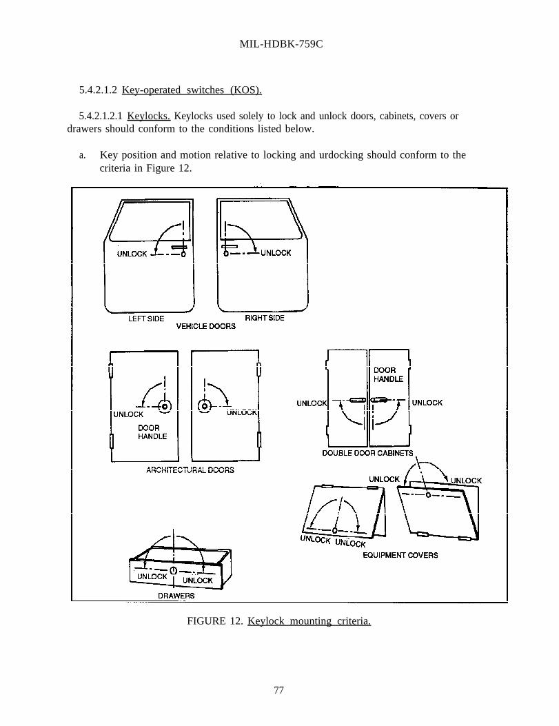
MIL-HDBK-759C
5.4.2.1.2 Key-operated switches (KOS).
5.4.2.1.2.1 Keylocks. Keylocks used solely to lock and unlock doors, cabinets, covers ordrawers should conform to the conditions listed below.
a. Key position and motion relative to locking and urdocking should conform to thecriteria in Figure 12.
FIGURE 12. Keylock mounting criteria.
77

MIL-HDBK-759C
78
b. Reversible key designs should be used. It is preferable to have keys that will operatethe lock with either side "up." If key designs are used that have teeth only on one side,the lock should be oriented so that the "flat" edge of the key will be on the bottom toenter a vertical (lock) slot, and to the right to enter a horizontal (lock) slot.
c. Lock systems used for vehicle exterior doors should be designed so that the operatorcannot inadvertently lock himself out of the vehicle.
d. Keylocks exposed to external weather conditions should be weatherproof. Theyshould not become inoperable because of dirt accumulation nor freeze because ofmoisture collection and freezing temperatures.
e. When several keylock systems are required on the same vehicle or equipment, and alllocks must be accessible to the operator, a single key and identical locks should beused. On the other hand, when access to certain closures must be limited to peopleother than the operator, different keylock assemblies should be used so that theoperator's key will not unlock these special locks.
5.4.2.1.2.2 Keylock switches. Keylock switches which are used not only to providesecurity (by removing the key), but also to provide ON-OFF functions, should conform to theconditions listed below.
a. Key should be removable only in the security position.
b. Key position and motion relative to locking, unlocking, and ignition should conform tocriteria in Figure 13.
c. Keylock switches that will be used externally should be weatherproofed to preventfailures resulting from dirt and freezing.
d. An auditory signal should be provided for vehicle ignition keylock systems to advisethe operator that the key has been left in the ignition lock after the engine has beenshut off.

MIL-HDBK-759C
N O T E S : 1 . Switchlocks should generally be oriented so that the pivotal off keyposition is vertical and/or forward (horizontal panel).
2. Key displacement between functional positions should beat least 30°.Mechanical detents should preclude positioning the key in betweendesignated positions.
3. When only two functional positions occur (on-off), displacement betweenthe two positions should be 90°.
4. Total displacement of multi-position keylock switches should not exceed120°.
FIGURE 13. Keylock switch criteria.
5.4.2.1.3 Discrete thumbwheel controls.
5.4.2.1.3.1 Application. Mechanically-demented thumbwheel controls may be used as analternative rotary selector device when the application will benefit from the compactness ofsuch devices, and appropriate visual and/or audio feedback is provided. Numericthumbwheels should be oriented and move as indicated in Figure 14.
79
MIL-HDBK-759C
81
5.4.2.1.3.2 Dimensions, separation, and resistance. Control resistance should be elastic,building up and then decreasing as each detent is approached so that the control snaps intoposition without stopping between adjacent detents.
5.4.2.1.3.3 Labeling and visibility. Marking and labeling of thumbwheel controls shouldconform to criteria herein with respect to visibility of markings and design of numerals.
5.4.2.1.3.4 Color Coding. Thumbwheel controls may be coded by means of color and/orcontrast (dark vs light surfaces). Examples are reversing the colors of the least significantdigit wheel as on a typical odometer, and where used as an input device, the thumbwheelswitch OFF or NORMAL positions may be color coded to permit a visual check that the digitshave been reset to their normal value.
5.4.2.1.4 Continuous Adjustment Thumbwheel Controls.
5.4.2.1.4.1 Use. Continuously-adjustable thumbwheel controls may be used as an alternateto rotary knobs when the application will benefit from the compactness of the thumbwheeldevice.
5.4.2.1.4.2 Orientation and movement. Thumbwheels should be oriented and move in thedirections specified in Figure 14.
5.4.2.1.4.3 Thumbwheel serrations. The rim of the thumbwheel should be serrated to aidthe operator in manipulating the control.
5.4.2.1.4.4 Labeling and visibility. Marking and labeling of continuously-adjustablethumbwheel controls should conform to criteria herein with respect to visibility of markingsand legibility of label alphanumerics.
5.4.2.2 Continuous-adjustment rotary controls.
5.4.2.2.1 Knobs.
5.4.2.2.1.1 Use. If the adjustment requires reference to a scale, the scale should be placedon a panel and an index line should be inscribed on the pointer (moving-pointer fixed-scaleformat). If the range of knob movement involves more than 360° rotation, scales should notbe used, except for directional input devices (azimuth setting).
5.4.2.2.1.2 Direction of movement. Turning a knob clockwise should produce an increase.
5.4.2.2.1.3 Knobs mounted with set screws. Control knobs should be mounted with largeset screws which are accessible enough to be tightened or loosened with a standard-sizescrewdriver. Selection of a switch, with regard to location of the set screw (Figure 15), is afunction of access to the set screw in the installed position. If control resistance is substantial

MIL-HDBK-759C
(selector switches with several contact discs), minimize the possibility of knobs slipping ontheir shafts by using knobs with two set screws, spaced about 90° apart.
FIGURE 15. Set screws for control knobs.
5.4.2.2.1.4 Knob style.
5.4.2.2.1.4.1 Shapes. Knobs which perform the same function should have the same shape.The shape should be determined by the knob’s function and use. Representative knob shapesare shown in Figure 16.
5.4.2.2.1.4.2 Open-window, skirted knobs. Special knob designs consisting of a bar-typeknob and open-window skirt may be used for applications in which visual confusion maybereduced by exposing only one number of a scale at a time (see Table 8).
5.4.2.2.1.5 Tactile (touch) recognition. For knobs that must be recognized by touch alone,use easily recognizable knob shapes (see Figure 17). Some sets of knobs have been speciallydeveloped and validated experimentally for tactile recognition.
8 2

MIL-HDBK-759C
FIGURE 16. Recommended knob shapes.
FIGURE 17. Easily recognizable knob shapes.
5.4.2.2.1.4.6 Knob rims. All rotary adjustment knobs should have rims with suitablesurfaces for secure grasp. Very small knobs should have knurled surfaces to providemaximum torquing capability. Intermediate and larger sizes of knobs should have serratedrims, except that knobs used where high torque is required should have rim indentation ratherthan serration for firmer grasp. Larger knobs should utilize rim indentation to aid gripping for
83

MIL-HDBK-759C
84
application of higher torques. The design should ensure that the operator will not injure ahand if the shaft sticks.
5.4.2.2.1.4.7 Twist grip controls. Handle-like rotary controls may be used for specialapplications (motorcycle accelerator control).
5.4.2.2.1.4.8 Knob mounting. Rotary selector knob attachment should preclude thepossibility of the knob slipping on the shaft, and/or the knob being replaced with the pointingend opposite from its correct position.
5.4.2.2.1.4.9 Contact hazard. When knobs are used in vehicles and are located where theycould be contacted during the sudden deceleration of a crash, frontal surface area should belarge, and all edges should be rounded in order to minimize the potential injuries associatedwith small, sharp, knob designs.
5.4.2.2.2 Ganged control knobs. Reserved.
5.4.2.2.3 Continuous-adjustment thumbwheel controls. Reserved.
5.4.2.2.4 Cranks.
5.4.2.2.4.1 Positioning. Cranks which must be turned rapidly should be mounted so theirturning axes are between 60° and 90° from the body's frontal plane (Figure 18). For standingoperators, they should be between 900 and 1200 mm above the floor.
5.4.2.2.4.2 Handles. Handles should be used to maximize the area of contact with thehand. They should turn about their shafts freely. The outside edge of the crank handlesshould clear any obstruction by at least 75 mm.
5.4.2.2.4.3 Simultaneously-operated hand cranks.
5.4.2.2.4.3.1 Application. Simultaneously-operated hand cranks should be used inpreference to other two-axis controllers where extreme precision is required in setting crosshairs or reticules as in map readouts or optical sighting mechanisms. This type of control mayalso be used in other applications requiring X and Y control provided there is no criteria forrapid or frequent operation.

MIL-HDBK-759C
5.4.2.2.4.3.2 Dynamic characteristics. The dynamic characteristics of simultaneously-operated hand cranks should be the same as those for single cranks. The gear ratio anddynamic characteristics of the cranks should be such as to allow precise placement of thefollower (cross hairs) without overshooting or undershooting and successive correctivemovements.
FIGURE 18. Proper mounting of rapidly operated crank.
5.4.2.2.5 Handwheels, two-hand operated.
5.4.2.2.5.1 Position. Handwheels (including steering wheels) should be selected in termsof size and expected usage to provide operator use convenience based upon whether theoperator is seated or standing to operate the wheel. For seated operation, the wheel shouldnormally be centered on the operator’s centerline and sloped so that both of the operator’s armsand hands have approximately equal access to the wheel. In addition, wheels operated fromthe seated position should be sized and positioned for convenient ingress or egress as well asover-the-wheel viewing, where applicable.
5.4.2.2.5.2 Wheel hub delethalization. Steering wheel hubs should be recessed andprovided with a broad pad to minimize the possibility of driver impalement during a crash.Consideration should also be given to use of a collapsible steering column for rapidly-movingvehicles. Such steering wheels should be structurally resistant to major rim or spokedistortion considering the loads that could be created by the driver’s body being thrust into thewheel during a crash.
85

MIL-HDBK-759C
86
5.4.3 Linear controls.
5.4.3.1 Discrete linear controls.
5.4.3.1.1 Push button, finger- or hand-operated.
5.4.3.1.1.1 Use. Push button controls should be used primarily for simple switchingbetween two conditions, selection of alternate ON-OFF functions from an array of relatedconditions or subsystem functions, release of a locking system such as on a parking brake, orentry of a discrete control order. Push buttons should not be used indiscriminately merely tomake all panel controls look alike, or where another type of switch could be used to savepanel space (toggle switch). Push button-type controls may be used for any of the followingkinds of operations singly or in combination (see Table 9).
5.4.3.1.1.2 Shape. Push button cap surfaces should, in general, be flat, but with roundededges. However, for proper finger-centering, which should be ensured, the cap surface maybe concave. General cap shapes may be round, square, or rectangular as long as they provideadequate finger, thumb or hand contact area, and are compatible with identification or legendcriteria.
5.4.3.1.1.3 Channel or cover guard. Primary methods for minimizing inadvertent switchactuation should conform to criteria in Table 10.
5.4.3.1.1.4 Momentary contact. Momentary contact controls should be used for single"push-HOLD and release-OFF" functions. The push button should be one of the followingtypes: (1) non-illuminated, (2) continuously ON switchcap light or legend, or (3) momentaryON switchcap light.
5.4.3.1.1.5 Alternate action. Alternate action for a single function may be implementedeither in a two-button format or as a single button. With the single-button type, a first presssets the switch to the ON state and a second press sets it to OFF. Feedback to indicate the ONstate should be provided either by switchcap lamp or legend or by a closely associated lamp orlegend. With the two-button type, the buttons are mechanically interlocked so that one buttonis always depressed and the other button is in the up position. Although the depressed buttonprovides feedback on switch state, additional feedback by means of switchcap lamp or closelyassociated lamp or legend should normally be provided.
5.4.3.1.1.6 Stepping action. Successive presses of the switch cycle it through three or morestates. Switch state feedback may be provided by selective illumination of integral orassociated legends.

MIL-HDBK-759C
87
TABLE 9. Representative push button switch applications.


MIL-HDBK-759C
91
5.4.3.1.1.7 Combination. Sets of related switching functions of the above types may becombined as an assembly. These may be independent, interlocked or a combination of both,may be momentary or latching or a combination of both; and may be non-illuminated, or haveswitchcap lights or legends. Feedback as to active switch states should always be provided.Interlocking and latching functions may be either mechanical or electrical.
5.4.3.1.1.8 Push button identification and legends. Although push buttons may beidentifiable by means of panel labels and/or symbols, labels placed on the push button face(where size and other use factors are compatible) are preferred. Criteria for labels, symbolsand legends should be followed. Legends normally should be legible with or without internalillumination, but legends may be invisible during any distinct modes in which the button isnever used. A lamp test capability and/or dual lamp reliability should be provided, except forswitches using light-emitting diodes (LEDs) in place of incandescent lamps. No more thanthree lines of lettering should normally be used on a legend plate. Lamps within incandescentlegend switches should be replaceable from the front of the panel, by hand, and the legend orcover should be keyed to prevent possibility of interchanging legend covers.
5.4.3.1.2 Foot-operated switches. Foot-operated switches should be located so the operatorhas some normal heel resting position on the floor or a floor board. Avoid placing a footswitch beneath or behind other pedals wherein it might be possible for the operator's foot tobecome momentarily entangled or trapped during the transfer between the switch and a pedal.
5.4.3.1.3 Keyboards, keypads, keysets, and menu selectors.
5.4.3.1.3.1 Use.
a. Alphanumeric keyboards with standard typewriter key configurations should be usedfor applications where a general-purpose entry criteria cannot be satisfied by numericentries alone, by smaller keysets with either dedicated or programmable keys, or bymenu selection techniques.
b. Keypads (decimal entry keysets) should be used for applications requiring frequententry of decimal digits, whether data or numeric codes.
c. Keysets with each key dedicated to a specific switching function should be usedwhenever the number of switching functions is manageable and need not change withtime or operational condition.
d. Multi-function (programmable) keysets offering means of changing the switchingfunction of individual keys should be utilized whenever switching criteria varysubstantially for different phases or modes of operation and the total number offunctions to be switched cannot be conveniently handled by dedicated keys.
e. Menu selection techniques which provide for display and selection of switchable stateson a CRT may be used as an alternate to the multi-function keyset.

MIL-HDBK-759C
92
5.4.3.1.3.2 Keyboards.
5.4.3.1.3.2.1 Mounting. The keyboard should be mounted so that it is directly in front ofthe operator when it is in use. The first row of keys should be between 230 mm and 300 mmabove the seat level and the tiers of keys should slope upward toward the back at an anglebetween 10° and 30° from the horizontal with 17° preferred (see Table 11).
5.4.3.1.3.2.2 Function control. Convenient means of switching keyboard function andindicating keyboard state should be provided to enable composing and posting message textprior to its release, editing posted data or text material, and directly entering data orinstructions to a computer.
5.4.3.1.3.3 Keypads.
5.4.3.1.3.3.1 Mounting. Keypads may be mounted wherever they are convenientlyavailable for use. Keypads requiring frequent use should be mounted in a preferred locationfor controls such as a desk top and should be sloped as indicated for keyboards.
5.4.3.1.3.3.2 Actuating force. The actuating force required for keypads should fall in therange of 0.25 N to 3.9 N. (This actuating force range does not apply to touch-activatedkeypads.) The larger actuating forces should be used where the user wears gloves or mittens,or is subjected to substantial vibration or acceleration.
5.4.3.1.3.3.3 Function control. Switches for control functions should be provided to allowclearing either the last posted digit only or all posted digits.

MIL-HDBK-759C
TABLE 11. Nominal keyboard characteristics.
5.4.3.1.3.4 Dedicated keysets.
93

MIL-HDBK-759C
94
5.4.3.1.3.4.1 Configuration. A dedicated keyset consists in essence of two or more pushbutton sets which are grouped together because of some commonality of purpose and whichutilize some common control and/or display functions. As best fits the purpose, key actionmay be momentary contact or latching, and key tops may (1) be opaque, (2) contain anindicating lamp, (3) provide a continuously illuminated label, (4) provide an illuminated labelwhen activated, or (5) provide both (3) and (4). The functions and physical configuration ofthe push buttons in the keyset should be appropriate to the switching functions it must handleand to the operator's task.
5.4.3.1.3.4.2 Mounting. Dedicated keysets may be mounted wherever they areconveniently available for use.
5.4.3.1.3.4.3 Actuating force. The actuating force required for dedicated keysets shouldfall in the range of 0.25 N to 11.3 N. The larger actuating forces should be used only withlarge-size illuminated switchcaps which are 25 mm wide or larger as may be needed toaccommodate switchcap labeling. The preferred actuating force for push buttons which canbe mounted on 20 mm centers is about 2.8 N.
5.4.3.1.3.4.4 Feedback. Feedback should be provided to inform the operator whether ornot the pressed key was, in fact, actuated; the intended key selection was the one which wasmade; the system is in the process of responding to the actuated key; and the system hascompleted its response to the actuated key.
5.4.3.1.3.4.5 Function control. Switches for control functions governing operation of thekeyset should be provided as needed for the particular application.
5.4.3.1.3.5 Multi-function (programmable) keysets.
5.4.3.1.3.5.1 Special criteria. Multi-function keysets require instrumentation foraccommodating switching at two levels: a gross function, or mode level and a detailed, oritem level within each mode.
5.4.3.1.3.5.2 Function (or mode) selection. The amount of selection capability should bedependent upon the number of different sets of switching functions to be used alternatively.The mechanization of the function selectors should ordinarily be by rotary selector or byinterlocked push buttons with latching actuation. The complete range of choices as well asthe current mode indication should be visible to the operator at all times, except in thoseinstances where function selectors are implemented by entry of coded switching instructionsusing a general-purpose keyboard. (Mode switching also may be implemented for initiationby the computer, in which case manual switching capability can be correspondingly reduced.)
5.4.3.1.3.5.3 Switching for item selection. The amount of selection capability should bedependent upon the number of switching actions which must be independently controllable.Item selection should be provided by push buttons of the appropriate types (latching ormomentary; interlocked or independent) for the specific switching functions.

MIL-HDBK-759C
95
5.4.3.1.3.5.4 Item labeling and feedback. Item labels applicable to each mode should bedisplayed on or adjacent to the item selector switches, and labels which are inapplicable to theselected mode should not be visible. Appropriate feedback should be provided to indicate thecurrent state of each item selector switch. When switching to a new mode, feedback shouldbe provided as to the current state of each switchable function. In addition, feedback may beneeded to indicate which switches can or cannot be utilized in the current mode (byextinguishing labels for switching functions which are inapplicable).
5.4.3.1.3.5.5 Configuration. The physical configuration of the keyset should be appropriateto the switching functions it should handle and to the operator's task. A sample configurationis shown in Figure 19.
5.4.3.1.3.5.6 Mounting. Multi-function keysets may be mounted wherever they areconveniently available for use.
5.4.3.1.3.5.7 Actuating force. The actuating force for the push buttons in multi-functionkeysets should fall in the range of 0.25 N to 11.3 N. The larger actuating forces should beused only with large-size illuminated switchcaps 25 mm wide or larger which may be neededto accommodate switchcap labeling. The preferred actuating force is about 2.8 N.
5.4.3.1.3.6 Menu selectors.
5.4.3.1.3.6.1 Special criteria. Menu selectors require control at three levels: (1) function-level switching to select which one out of the set of menu listings is presented on the display,(2) a control for selection of a particular item from the menu, and (3) a control for entry oractivation of the selected menu item. Menu-item selection may implemented by means of acursor controlled by push buttons, a light pencil, or a grid and stylus-type device. The entryinstruction itself should be implemented as a separate momentary-contact switch.
5.4.3.1.3.6.2 Configuration. The physical configuration of menu selector controls anddisplays should be appropriate to the switching functions it should handle and to the operator'stask. Two sample configurations are shown in Figure 20.
5.4.3.1.3.6.3 Dimensions, displacement, and separation. The push button switches shouldconform to dimensional criteria for legend switches.
5.4.3.1.3.6.4 Mounting. The cursor control (thumbwheel, keypad) should be mountedbeneath the menu listing. The ENTER button should be close to and preferably to the right ofthe cursor control. The function (mode) selectors should be mounted conveniently near thecursor control.
5.4.3.1.4 Toggle switch controls.
5.4.3.1.4.1 Use. The application and design criteria for toggle switches is given in Table 12.
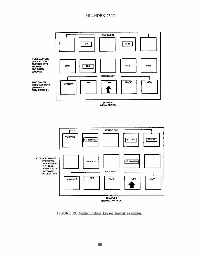
MIL-HDBK-759C
FIGURE 19. Multi-function keyset format examples.
96

MIL-HDBK-759C
FIGURE 20. Menu selector types and format examples.
97


MIL-HDBK-759C
102
5.4.3.1.4.2 Orientation. When toggle switches are located on panels that slope as in wrap-around or stacked workplace arrangements, switch orientation and movement should conformto criteria in Figure 21.
5.4.3.1.5 Legend switches.
5.4.3.1.5.1 Use. Legend switches are particularly well-suited to the conditions listedbelow:
a. To display qualitative information on an important system status which requires theoperator's attention.
b. To reduce demands for the operator to interpret information.
c. When functional grouping or a matrix of control switches and indicators is required butspace is very limited.
5.4.3.1.5.2 Characteristics. The following characteristics apply to legend switches:
a. Legend switches should be located within a 30° cone (total included angle) along theoperator's normal line of sight.
b. For positive feedback that the switch has operated, legend switches should have adetent or a click.
c. Legend switch lamps should be replaceable from the front of the panel.
d. Legends should be legible with or without internal illumination.
e. If legend switches do not have duplicate bulbs, dual filament, or equivalent reliability,the legend switch circuit should permit a positive test of the lamp.
5.4.3.1.6 Rocker switches. Reserved.
5.4.3.1.7 Slide switch controls. Reserved.
5.4.3.1.8 Discrete push-pull controls. Rotate to the right for activation or increasingfunction in the case of combination pull-rotary switches. An exception should be permitted inthe case of certain contemporary automotive switches (combination headlight, parking light,and panel-dome light switch).
5.4.3.1.9 Printed circuit (PC) switch controls. Reserved.

MIL-HDBK-759C
104
5.4.3.2 Continuous-adjustment linear controls.
5.4.3.2.1 Levers.
5.4.3.2.1.1 Use. Lever-type controls may be used, when large forces or displacements areinvolved, as an alternate control for electrical switching when it may be more cost-effective toprovide direct mechanical linkage between the control and controlled element, or when multi-dimensional, mechanical or electro-mechanical, multi-stage control modes (gear shift) arerequired. Lever-type controls should not be used where very precise electrical outputs arerequired (in lieu of a precision electrical adjustment, where a rotary controller is moreappropriate). Levers should be considered for the general classes of control listed below:
a. braking (mechanical);
b. mode selection (environmental system);
c. gear selection (vehicle or machine transmission);
d. gross, continuous adjustment (temperature, audio volume, throttle); or
e. steering (joystick, track vehicle)
5.4.3.2.1.2 Coding. Color and/or shape coding may be used when it is important for theoperator to quickly identify and/or differentiate among critical controls or several controls thatmay be grouped in proximity to each other. Special control coding criteria already establishedshould be followed. When shape-codes are used, they should be designed so that they do notinterfere with the basic criteria for ease of manipulation, and should be free of sharp cornersthat could result in operator injury in the event of violent contact by the operator.
5.4.3.2.1.3 Labeling Where appropriate, lever handles should be marked and/or labeled forease of positioning and identification.
5.4.3.2.1.4 Resistance. The resistance incorporated in levers should be within the limitsindicated in Table 13 (measured as linear force applied to a point on the lever handle). Forjoystick controls, elastic resistance which increases with displacement may be used toimprove "stick feel".
5.4.3.2.1.5 Location, position, direction, and range of movement. The location, positionrelative to the operator, and direction and range of lever movement should be compatible withoperator reach, mobility, natural movements, and strength capabilities. In addition, directionof motion criteria should be preserved. When high forces are required of the operator, the

MIL-HDBK-759C
Generally avoid the area aft ofthe operator’s eye reference, butwhen used treat as though operatori s fac ing to the r ight .
FIGURE 21. Toggle switch orientation for ON.
103


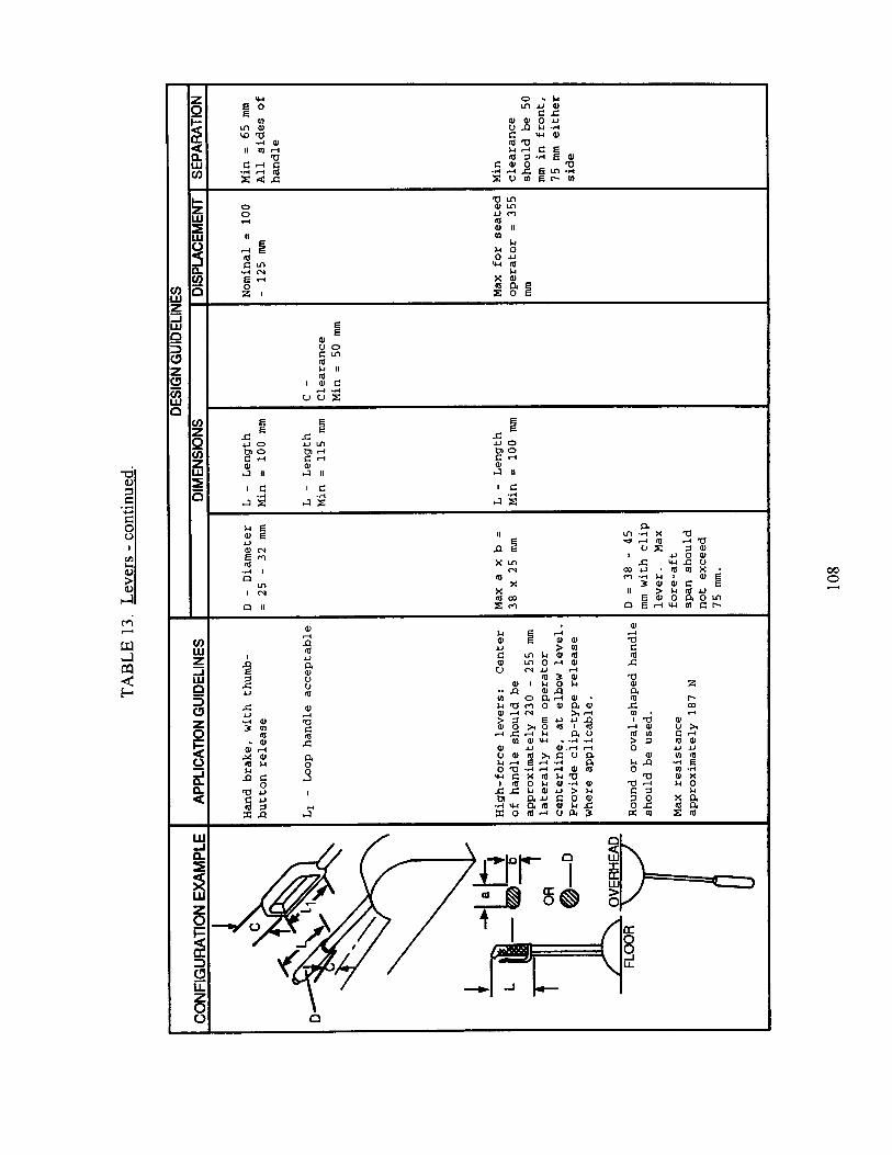


MIL-HDBK-759C
110
lever handle should be located between waist and shoulder levels, and the force shouldnormally be applied in a pulling direction.
5.4.3.2.1.6 Detents. When levers are used as "selector" controllers, mechanical detentsshould be provided (in addition to panel labels or markings) to provide tactile feedbackindicating that the lever is positively positioned at designated settings. Detents and panelmarkings should coincide precisely.
5.4.3.2.1.7 Non-slip handles. Surfaces of lever handles should provide sufficient friction(by means of the specific material used, and/or addition of serrations or knurling) to reducethe probability of the operator's hand or fingers slipping while operating the lever.
5.4.3.2.2 Displacement (isotonic) joysticks.
5.4.3.2.2.1 Hand-operated displacement joysticks.
5.4.3.2.2.1.1 Dynamic characteristics. Recessed mounting or pencil attachments may beused to provide greater precision of control. One or more switches actuated by either thumbor finger pressure may be integrally mounted.
5.4.3.2.2.1.2 Refresh rate. When used for generation of free-drawn graphics, the refreshrate for the follower on the CRT should be sufficiently high to ensure the appearance of acontinuous track. Delay between contact movement and the confirming display responseshould be minimized and should not exceed 0.1 second.
5.4.3.2.2.2 Finger-operated displacement joysticks. Reserved.
5.4.3.2.2.3 Thumbtip- or fingertip-operated displacement joysticks. Reserved.
5.4.3.2.3 Isometric joysticks (two-axis controllers). Display systems requiring a singleoperator to make control movements along two orthogonal coordinate axes simultaneouslyshould utilize one of the following types of controllers: simultaneously-operated hand cranks,ball control, joystick, grid and stylus devices, pantographs, or free-moving XY controller(mouse). Selection should be made on the basis of matching controller characteristics withsystem criteria (see Table 14).
5.4.3.2.4 Ball controls. (Also known as track balls, ball trackers, joyballs, or rolling balls).Reserved.
5.4.3.2.5 Gird-and-stylus devices. Reserved.


MIL-HDBK-759C
112
5.4.3.2.6 Free-moving XY controllers (mouses). Reserved.
5.4.3.2.7 Light pen. Reserved.
5.4.3.2.8 Pedals.
5.4.3.2.8.1 Play. Pedal control systems should be designed to minimize excess play’(movement that does not activate the control system).
5.4.3.2.8.2 Adjustment. Sufficient control and/or seat adjustment capabilities should beprovided to accommodate the leg reach capabilities of the total range of expected operators(5th percentile female to 95th percentile male). Consideration should also be given tocombined vertical and horizontal adjustment effect on reach. For seated operatorconfigurations where external vision is critical and corresponding control panel constraintsmay be present, the pedal-seat-vision interactions should be considered to provide the best-fitamong eye reference, seat and pedal adjustment position, and adjustment range.
5.4.3.2.8.3 Automotive-related foot controls.
5.4.3.2.8.3.1 Arrangement. Assemblies of foot-operated controls should conform toindustry practice with respect to arrangement.
a. Manual transmission: The clutch should be positioned for left-foot operation; servicebrake and accelerator for right-foot operation. Headlight dimmer function may beprovided as a left or right hand- or foot-operated floor switch or column-mounted stalk(lever).
b. Automatic transmission: The above arrangement should be followed except that theservice brake should be accessible for either right- or left-foot operation (in which casethe brake pedal should be laterally elongated sufficiently to make it convenient foroperation by either foot).
5.4.3.2.8.3.2 Pedal, geometric relationships. Clutch, service brake, and accelerator pedalsshould be arranged so that the primary contact point of each pedal (height and distance fromthe floor, heel-reference point) is approximately the same, to make it convenient for theoperator to shift his foot from the accelerator to the service brake pedal without having to liftthe foot an excessive amount. The pedal contact point should be based on a point on theaccelerator pedal that matches an "all-of-the-foot" position when the operator's heel restsnormally on the floor, and the accelerator pedal is in the "un-depressed" position. Lateralpedal positions should be arranged and spaced so that the total array is approximately centeredon the operator's centerline (so the operator is not required to sit in a skewed position in orderto operate certain pedals). For maximum, long-duration comfort, the accelerator pedal shouldbe not more than about 300 mm right of the operator's centerline.
MIL-HDBK-759C
113
5.4.3.2.8.3.3 Lateral pedal array limits. Lateral spacing of individual pedals shouldconform to criteria in Table 15. However, the overall array should not exceed 760 mm asmeasured between the outermost pedal centerlines.
5.4.4 High-force controls. Reserved.
5.4.5 Miniature controls. Reserved.
5.4.6 Touch-screen controls for displays. Reserved.
5.4.7 Quickened and predictor controllers. Complex tracking functions may require use ofquickened or predictor approaches to control-display implementation. These approachesshould be utilized only with the approval of the acquiring activity.
5.4.8 Integral, handle-mounted controls.
5.4.8.1 Use. Handle-mounted, auxiliary controls may be integrated into the handles ofprimary controllers such as joysticks, or equipment such as cameras and power tools, whensuch integration enhances the simplicity and/or efficiency and safety of system operation.
5.4.8.2 Number of controls. The number of controls integrated into a handle should notexceed three (a trigger, plus two thumb-operated switches in a joystick handle) unlessspecified by the procurement specification or upon specific approval by the acquiring activity.
5.4.8.3 Inadvertent input. The type of auxiliary switch, its motion characteristics andlocation should be such that movement of the auxiliary switch will cause minimal probabilitythat the primary control or equipment operation and/or positioning is inadvertently disturbed.
5.4.8.4 Thumb switches.
5.4.8.4.1 Types. Push buttons, slide, or rotary thumb switches may be used as appropriatefor any of the following switch modes:
a. Push button: ON-OFF (communication).
b. Two-dimensional toggle: two-axis, spring-centering (aircraft trim).
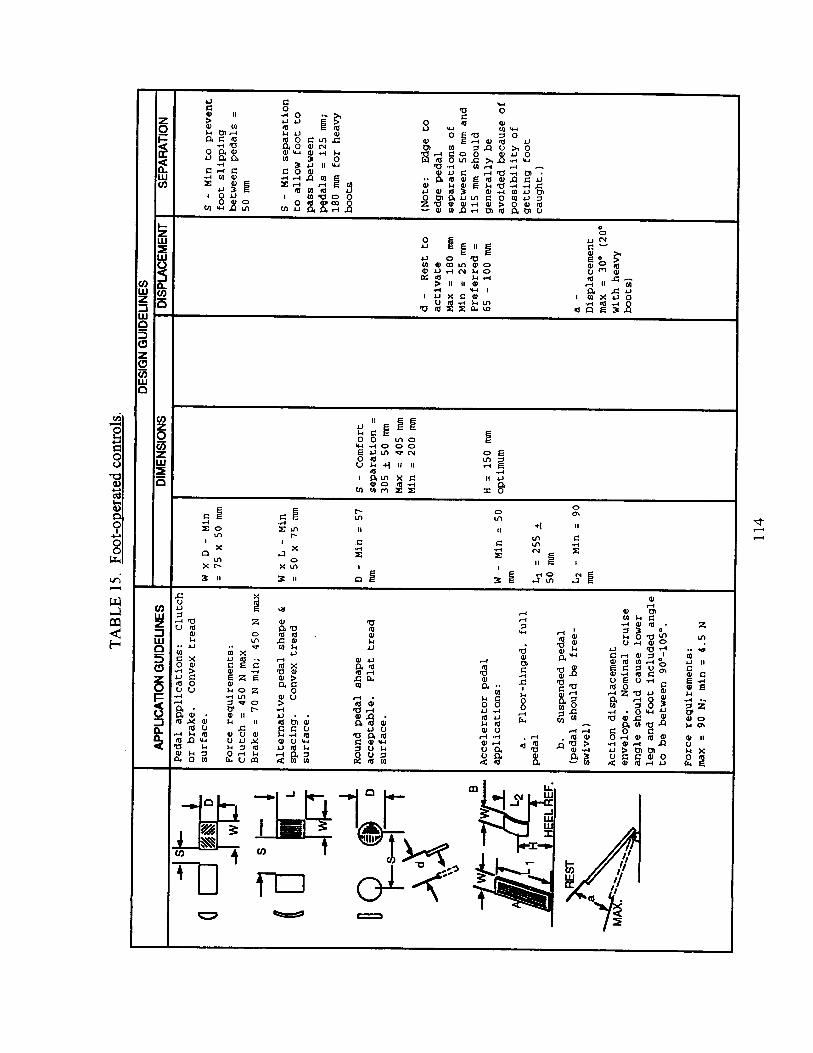


MIL-HDBK-759C
116
c. Slide switch: single-axis ON-OFF, momentary ON plus ON-HOLD (safety switch forhand-held power tool).
d. Rotary thumbwheel: rotary selector (maximum of three positions), continuousadjustment (audio volume).
Other auxiliary thumb-operated control applications should be subject to the approval of theacquiring activity.
5.4.8.4.2 Location and operation. Thumb switches should be positioned and operate in afashion that is compatible with comfortable and natural thumb articulation limits, consideringthe total range of hand sizes for the expected user population, and constraints imposed bywearing of gloves.
5.4.8.4.3 Resistance. Resistance should not exceed limits for push buttons, slides, orthumbwheels as specified in other sections of this handbook.
5.4.8.4.4 Dimensions and displacement. Dimensions and displacement of handle-mounted,auxiliary thumb switches should conform to criteria in Table 16.
5.4.8.5 Index finger-operated switches and triggers.
5.4.8.5.1 Use. Index finger-operated, auxiliary, handle-mounted controls should be usedfor typical "trigger" operations (weapon firing, camera film operation, and power tool motoractivation). Since the operator typically expects to use the index finger for these types offunctions, other index finger operations should not be implemented without express approvalof the acquiring activity. Similarly, "trigger" functions should not be implemented in the formof non-index finger operation (thumb or palm).
5.4.8.5.2 Location and operation. Trigger controls should be located and operate in amanner that is compatible with the inherent limitations for using the basic control handle.(The operator should not be required to shift his hand from the normal hand-grip position inorder to actuate the trigger.) If the trigger should be operated simultaneously while holdinganother auxiliary switch (safety), location and operation of both controls should be such thatthe operator can comfortably and naturally activate both controls without inadvertentlydisturbing the primary handle positioning or aiming. Special consideration should be given torestrictions which may be imposed by wearing of gloves (reach and mobility).
5.4.8.5.3 Resistance. Trigger-pull characteristics, including resistance level and profile,should be as specified by the acquiring activity. Unless otherwise directed by the acquiringactivity, trigger response should be "even" throughout the trigger pull, i.e., breakout vs steady-state should be approximately equal with no apparent "build-up" prior to final contact with themechanical stop.


MIL-HDBK-759C
119
5.4.8.5.4 Safety. Inadvertent trigger operation should be minimized through proper use oftrigger guards, safety latches, or other means to prevent inadvertent operation during non-operating modes (storing or carrying) and inadvertent operation during primary firing oroperating modes (trigger activation before the operator is prepared).
5.4.8.5.5 Dimensions, displacement, and clearance. Trigger dimensions, displacement, andclearance limits should conform to criteria in Table 16.
5.4.8.6 Grip-actuated switches.
5.4.8.6.1 Use. Handle-mounted grip switches should be used only for discrete ON-OFFenabling functions with respect to a trigger mechanism, or control outputs from a joystick.
5.4.8.6.2 Dimensions, displacement, and resistance. The grip-actuated switch should becompatible with the natural placement and contour of the operator's palm, as it conforms tothe handle during use of the primary handle manipulation (for moving a joystick andpositioning a tool or camera). The switch tab should be approximately 7.5 mm long by 9.5mm wide and have rounded edges. Switch displacement should be between 3 mm and 6 mm.Resistance should not exceed 22.5 N nor be less than 3 N.

MIL-HDBK-759C
120
This Page Intentionally Left Blank.

MIL-HDBK-759C
121
5.5 Labeling.
5.5.1 General. Labels should conform to these principles:
a. A label should give the user the information needed to perform the task.
b. Labels should be located consistently on all equipment.
c. Labels should use familiar words; overly technical or difficult words should beavoided.
d. Labels should be brief but unambiguous; punctuation should be omitted.
e. Words should be printed so they read horizontally, not vertically.
f. Labeling should be supplemented where necessary with other coding procedures (suchas color and shape).
g. Labels should be placed where they can be seen easily, not where other units in theassembly will cover or obscure them.
h. Labels should be made large enough that the operators can read them easily at normaldistance.
i. Generally, capital letters should be used; however, if the label has several long lines,upper- and lower-case letters should be used.
j. Bold-faced letters should be used only for short words or phrases that requireemphasis.
k. Labels should be placed on, or very near, the item they identify; any confusion withother items and labels should be eliminated.
l. Labeling should be etched or embossed into the surface for durability, rather thanstamped, stenciled, or printed. Decals are acceptable, but less desirable.
5.5.2 Orientation and location. Labels should be located so as not to obscure otherinformation needed by the operator, and should be placed where a control or operator's normalhand or arm position will not obscure the label (see Figure 22).

MIL-HDBK-759C
Locate labels consistentlyabove or below a controlor display on a given panel(Above is preferred exceptwhen the panel is locatedabove the observer’s eyelevel ) .
Locate label so that acontrol handle will notobscure the label.
Do not place labelon a control thatcould rotate thelabel to an upside-down position.
Do not place placards near thefloor or other positions thatpreclude the observer fromgetting his or her eyes in aposition adequate for readingthe placard.
FIGURE 22. Location and position of labels.
122

MIL-HDBK-759C
123
5.5.3 Contents. Reserved.
5.5.4 Qualities.
5.5.4.1 Brevity. Special markings and symbols (pictorials and arrows) should beconsidered when they unambiguously convey meaning in a more direct manner than words.
5.5.4.2 Understandability. Extended instructional or procedural information for placardsand signs should be concise but understandable to the intended user.
a. Omit words that are unnecessary to convey the meaning of the message.
b. Place each procedural step on a separate line and include numbers, dots, or othertechniques to emphasize the beginning of each step.
c. Use acronyms sparingly and only when they are familiar to the intended user.
d. Avoid use of instructions that require reference to another, perhaps unavailableresource. However, such reference may be used for placards that pertain only to adepot maintenance situation and where resource materials are typically available.
5.5.4.3 Visibility and legibility. The following factors should be taken into consideration:
a. contrast between the lettering and its immediate background;
b. height, width, stroke width, spacing and style of letters and numerals, and/or size ofdetail for other abstract or pictorial symbols;
c. method of application (etching, engraving, decal, silk screen);
d. relative legibility of alternate words; and
e. specular reflection.
5.5.4.4 Consistency. When function and application are identical, words or abbreviationsused should be identical. Conversely, the same words should not be used to identify two ormore controls or displays when these are not functionally identical.
5.5.4.5 Label background. Placards or signs that include their own independentbackground should provide maximum contrast between lettering and immediate background.Shiny metallic backgrounds should not be used for operational labels, placards, signs, ormarkings.
5.5.4.6 Access. Labels should be placed on the outside of equipment covers to identifycontrol, display, or other functions located within a covered compartment. Labels attached to

MIL-HDBK-759C
124
lines or cables for the purpose of identification should be positioned so the label is visible andproperly oriented with respect to the nominal viewing position of the field technician ratherthan the factory assembler. Both ends of a cable or line should be labeled, and the connectorelements also should contain appropriate, matching labels.
5.5.4.7 Label surface. Whenever practicable, labels, legends, placards or signs should beplaced on a flat surface. If a label must be placed on a curved surface, lettering or symbolsshould be completely visible to an observer from the nominal vantage point. When thecurvature of the surface is such that the lettering becomes too small to be read, another modeof labeling, such as an attached tag, should be used.
5.5.5 Label characteristics.
5.5.5.1 Style. Letters and numerals should be of a simple style without serifs except asmay be necessary to distinguish between characters which would otherwise be confused.
5.5.5.2 Character stroke width. When characters are used on a light background, the strokewidth should be approximately 1/6 the height of the character. When light characters are usedon a dark background, the stroke width should be 1/7 to 1/8 the height of the character. Theseratios should apply regardless of how high characters are made for distance viewing.However, for certain applications, characters with different stroke widths may be used on thesame sign for emphasis. In this case, the thinnest character stroke should be no less than 1/8nor the thickest character stroke greater than 1/5 of the respective character heights.
5.5.5.3 Stroke continuity. Continuous stroke characters should be used where applicableand practical for all equipment labels, legends, placards, and signs. Stencil characters may beused for shipping containers. Stencil characters should not have stroke breaks greater than 1/2the character stroke width.
5.5.5.4 Character spacing. The minimum space between characters within a word shouldbe one stroke width. However, character spacing should be adjusted to provide an appearanceof open area balance within single words. An example is adjacent vertical strokes betweenadjoining characters compared to adjacent characters in which vertical components are farapart. In such cases, it is recommended that the space between adjacent vertical strokes beslightly wider than between vertical-horizontal or horizontal-horizontal strokes.
5.5.5.5 Word spacing. The preferred space between words is the width of one character(except for "I" or "1"). Minimum spacing between words should be 1/2 the width of onecharacter.
5.5.5.6 Character height. Character height for labels, legends, and signs should bedetermined on the basis of criteria in Figures 23 and 24. For marking of aircrew stationdisplays, refer to MIL-M-18012.

MIL-HDBK-759C
125
5.5.5.7 Confusion between "I", "1" and "L" and between "0" and "O". When a label,legend, placard, or sign contains characters which might be confused, they should be madedistinguishably different.
a. The lower case letter "L" should have a tab at the lower end extending to the right.
b. The numeral "1" should have a tab at the upper end extending to the left.
c. The numeral "0" should appear narrower than the letter "O" of a given font.
5.5.5.8 Pictorials. Pictorial symbols may be used in place of word labels and/or in additionto a word label when the pictorial provides quicker operator response. They should becompletely unambiguous in the expected visual operating environments and should not beused on a control that may rotate and thus position the symbol so that it may be confusing.Pictorials for automotive equipment should conform to criteria in Federal Motor VehicleSafety Standard (FMVSS) 101. Other pictorials should be subject to approval by theacquiring activity.
5.5.5.9 Borders. There should be sufficient clear space between characters and words usedfor labeling or signing to prevent the label from appearing crowded or difficult to read. Theminimum clearance around a character or word should be 1/2 character height or more.Clearance around a character, or word, or set of words should not make the label appear "lost"within a large expanse of background. No performance limits have been established formaximum clearance around a label.

MIL-HDBK-759C
A. For displays where the position of the numerals may vary and the illumination is between 1.0and 3.4 cd/m2.
B. For displays where the position of the numerals is fixed and the illumination is 1.0-3.4 cd/m2,or where position of the numerals may vary and the illumination exceeds 3.4 cd/m2.
c . For displays where the position of the numerals is fixed and the illumination is above 3.4 cd/m2
NOTE: Minimum space between characters, 1 stroke width; between words, 6 stroke widths.
FIGURE 23. Close proximity character height criteria.
126

MIL-HDBK-759C
Minimum letter height for 3 meter viewing distance= 7.6 mm. Letter height for longerviewing distances may be computed as follows:
Viewing distance (m) x (7.6) mmDesired character height (mm) = 3 m
FIGURE 24. Extended distance character height criteria.
127

MIL-HDBK-759C
128
5.5.6 Equipment labeling.
5.5.6.1 Cabinets. When several equipment cabinets are located in a single work area, eachcabinet should be labeled to aid the operators and other personnel in quickly identifying whatis located in each equipment cabinet. Such identification labels should be located in aconspicuous position considering the typical observation points from which each piece ofequipment must be identifiable. Primary cabinet labels should be located in as consistent amanner as practicable so that observers do not have to hunt for the label. The size of thematerial on each label should be consistent with viewing distance criteria.
5.5.6.2 Panels. Where applicable, each panel within a given equipment or console shouldbe labeled if the panel must be identified from others. When a given panel integrates aspecific operating function as distinct from another panel, a general system or subsystemidentification label should be provided.
5.5.6.3 Subfunctions. When subfunction areas on a single panel must be easily and quicklydifferentiated from other areas on the panel, the subfunction area should have a labelapproximately centered above the subfunction area. When the shape of the componentswithin the subfunction area is not uniform, consideration should be given to surrounding thearea with a suitable border to define the limits of the subfunction area.
5.5.6.4 Cabinet, panel, subfunction, and component label differentiation. Labels foridentifying a prime equipment cabinet vs panels, subfunctions on a panel, and individual panelcomponents should be capable of being differentiated in terms of the label size (letter height).The size encoding should progress according to the priority listing indicated below:
a. Largest label size for the prime equipment.
b. Next largest label for individual panels.
c. Next largest label for subfunction areas within a panel.
d. Smallest label for individual components, such as displays or controls.
Label sizes should be compatible with expected viewing distances; however, to providediscriminable differences among label sizes, each label character height should be at least25% less than, or greater than, the next function label (see Figure 25).

MIL-HDBK-759C
FIGURE 25. Label-size hierarchy.
129

MIL-HDBK-759C
130
5.5.7 Labeling for identification.
5.5.7.1 Assemblies. Label assemblies with clearly visible, readable, and meaningful namesor signs. Assembly labels should:
a. specify the overall system of which the assembly is a part,
b. include the assembly's popular name and function, and
c. include a stock number for requisition purposes.
The gross identifying label on an assembly should be located:
a. where adjacent assemblies will not obscure it,
b. on the flattest, most uncluttered surface available,
c. on a main chassis of the assembly, and
d. where it will not be removed accidentally, obstructed, or damaged in handling.
5.5.7.2 Instruction plate. Instruction-plate decal specifications can be found in MIL-P-514.Instructions should be as brief as clarity allows and placed where the operator can see themeasily. They should read from left to right and listed in a step-by-step format rather than in acontinuous paragraph.
5.5.7.2.1 Diagrams. Diagrams containing only the information the operator needs shouldbe used where possible. Orient such diagrams so they relate logically to the objects to whichthey pertain. Locate them in conspicuous places on or near controls.
5.5.7.2.2 Color. Instructions should be printed in white letters on a black background. Theblack color should be 37038, FED-STD-595, or an approved equivalent.
5.5.7.2.3 Lettering. Information-plate lettering should be 12- to 14-point-size, with titles in24-point letters.
5.5.7.2.4 Caution plate and decals. Caution plates or decals should be printed in yellowletters on a black background. The black color should be 37038, FED-STD-595; the yellowcolor should be 23538 or 23655, FED-STD-595.
5.5.7.3 Lift points. Mark lift and hoist points clearly indicating weight and stresslimitations. Label lift or hoist joints at the point of lift, not on removeable parts of the bodymember that may be separated from the lift point.

MIL-HDBK-759C
131
5.5.7.4 Safety and hazards. Wherever possible, equipment should be designed so it doesnot present hazards to personnel or equipment. If hazards are unavoidable, warning signsshould be displayed prominently. These safety labels should be brief and uncluttered andgenerally be no more than two or three words.
5.5.7.5 Hazard signing and marking. Appropriate signing and marking of all potentialhazards to personnel should be provided. The following signing and marking should beconsidered.
a. Fixed physical obstructions (low overheads, open hatches or manholes, posts, andguardrails).
b. Moving hazards (conveyor belts, chains, gears, loaders, cranes, and booms).
c. Equipment contact hazards (high-voltage and high-temperature).
d. Radiation hazards (electromagnetic and nuclear).
e. Laser beams.
f. Toxic contaminants (substances and gases).
g. Flash or high intensity light.
h. Requirement for safety glasses.
i. High noise or blast.
j. Criteria for hard hats.
k. Explosives.
l. High-pressure containers and hoses.
m. Slipping and falling hazards.
n. Other (fire, first aid and rescue).

MIL-HDBK-759C
132
This Page Intentionally Left Blank.

MIL-HDBK-759C
133
5.6 Anthropometry.
5.6.1 General. In design work, human engineering, or any other application ofanthropometric data, measurements of a single body dimension are seldom used alone.Usually, two or more measurements should be considered together. Stature and chestcircumference, as well as waist circumference, are utilized in the sizing of many items ofclothing, while neck circumference and sleeve length are needed for shirts, and waistcircumference and crotch height are required for trousers. Similarly, in human engineeringapplications, sitting height and functional reach, for example, are used in the design ofvehicles and aircraft, while hip breadth, sitting and popliteal height are required for the designof seating.
5.6.2 Anthropometric data.
5.6.2.1 Highly-correlated measurements. In general, height measurements (waist height,crotch height, sitting height) and the lengths of the arms or legs are highly correlated withstature. Circumference measurements or body girths are more likely correlated with weight.Breadth measurements tend to be more highly correlated with weight than with stature.
5.6.2.2 Relationship between measurements. The degree of relationship may be expressedby a correlation coefficient or "r" value. The "r" value describes the degree to which twovariables vary together (positive correlation) or vary inversely (negative correlation). Thecorrelation coefficient, "r", has a range of values from +1.0 (perfect positive correlation)through -1.0 (perfect negative correlation).
5.6.2.3 Bivariate tables. The variability of two body measurements and theirinterrelationship with each other may be shown graphically in a bivariate table. The bivariatetable shows the ranges of two measurements and the numbers or frequencies of individualswho have the various possible combinations of values of the two measurements. The valuesindicating the ranges of the two measurements represent the midpoints of the intervals inthose ranges. The frequencies or numbers of individuals may be given as actual numbers ormay be expressed as percentages of the sample. While the relationship between twomeasurements is summarized by the coefficient of correlation, or "r" value, the extent ordegree of correlation may also be estimated from the appearance or general shape of thebivariate distribution. A bivariate table, which shows a fairly well-defined band sloping fromthe lower left to upper right indicates a high degree of correlation that would normally beconfirmed by a comparatively high coefficient of correlation (0.7 and higher). If this slope isabsent, and the distribution is oval in shape, that means the correlation coefficient is low, andthat the two variables are not changing in a similar fashion. See Table 17 for a bivariatefrequency table for waist circumference and crotch height.
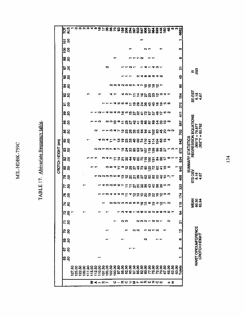

MIL-HDBK-759C
135
5.6.2.4 Regression analysis. The coefficient of correlation is a measure of the relationshipbetween variables. Given values of one variable, it is possible to predict the value of anothervariable. The predictive relationship between two variables can be shown in terms of a "lineof best fit," or in terms of the mathematical definition of this line, called a "regression line."The application of regression analysis is useful for predicting measurements and relationshipsbetween measurements when an actual sample is not available.
5.6.3 Use of data.
5.6.3.1 Interrelationships. The anthropometric data represent values for individual bodymeasurements. These are values for each independent measurement and, as such, give noindication of the interrelationships or correlations among the various body measurements.
5.6.3.2 Multiple dimensions. Extreme caution should be used when two or moredimensions are simultaneously used as criteria for design. Percentile values are not additivebetween different dimensions (see "An Alternative to Percentile Model," Society ofAutomotive Engineers (SAE) Technical Paper No. 810217). For example, it is incorrect toassume that the combination of the 5th percentile values will describe the dimensions of a"5th percentile man." In practice, the 5th to 95th percentile values of some dimensions willhave to be exceeded in order to accommodate the same range in another key dimension.Therefore, percentile values are inadequate for designs where two or more dimensions areused simultaneously as design parameters. Instead, appropriate multivariate data andtechniques should be used (see: "Computerized Accommodated Percentage Evaluation(CAPE) Model for Cockpit Analysis and Other Exclusion Studies," Pacific Missile TestCenter (PMTC), TP 75-49; and "A Family of Manikins for Workstation Design," Naval AirEngineering Center (NAEC) TR 2100-07B).
5.6.3.3 Variability of relationships. The relationships or correlations between bodymeasurements are highly variable. Certain dimensions may not always have the sameinfluence on other dimensions.
5.6.3.4 Clothing. Examples of the changes in anthropometric values imposed by differentclothing ensembles and more specific may be found in "Anthropometry of the Clothed U.S.Army Ground Troop and Combat Vehicle Crewmen," Natick Research, Development andEngineering Center (NRDEC) TR 84-034.
5.6.3.5 Posture. Different cockpits and crewstations often require their operators to assumedifferent postures, which may change as the operator fatigues. Because anthropometric dataare derived from measurements taken in standard anthropometric postures, suitableallowances should be made for postural variation. Further information may be obtained fromthe appropriate service agency responsible for anthropometry.
5.6.3.6 Slump factor. Seated eye-height measurements may be reduced as much as 65 mmwhen personnel sit in a relaxed or slumped position. This slump factor should be consideredwhen selecting the range of movement for adjustable seats, as well as in locating displays,

MIL-HDBK-759C
136
optics, and vision ports. The slump factor is not a valid reason for lowering ceilings to savespace.
5.6.3.7 Human subjects. Once the equipment or workspace design has progressed from thedrawing board to a full scale mockup, the use of persons closely resembling variouspercentiles in conjunction with the mockup is a valuable design practice.
5.6.3.8 Information sources. Data on arm and leg reach, center-of-mass and joint centersfor body segments and the inertial properties of the human body are sometimes of interest toequipment and workspace designers. Data are available in various publications. An exampleof a convenient and informative source of data is NASA-STD-3000, "Man-SystemsIntegration Standards."
5.6.4 Special populations. Reserved.
5.6.5 Body movement.
5.6.5.1 Range of motion. Table 18 gives the ranges, in angular degrees, for all voluntarymovements the joints of the body can make, as illustrated in Figure 26. The designer shouldremember that these are maximum values; since they were measured with nude personnel,they do not reflect the restrictions clothing would impose. The lower limit should be usedwhen personnel must operate or maintain a component; the upper limit should be used indesigning for freedom of movement.
5.6.5.2 Whole body. All operating positions should allow enough space to move the trunkof the body. When large forces (more than 13.6 kg) or large control displacements (more than380 mm in a fore-aft direction) are required, the operator should have enough space to movehis entire body.
5.6.6 Human strength and handling capacity.
5.6.6.1 Exerted forces. The maximum amount of force or resistance designed into acontrol should be determined by the greatest amount of force that can be exerted by theweakest person likely to operate the control. The maximum force that can be applied willdepend on such factors as the type of control, the body member used to operate it, the positionof this body member during control operations, the general position of the body, and whetheror not support is provided by backrests.

MIL-HDBK-759C
137
TABLE 18. Range of human motion.1
Body Member Movement Lower Limit(degrees)
Average(degrees)
Upper Limit(degrees)
A. Wrist 1. Flexion 78 90 1022. Extension 86 99 1123. Adduction 18 27 364. Abduction 40 47 54
B. Forearm 1. Supination 91 113 1352. Pronation 53 77 101
C. Elbow 1. Flexion 132 142 152
D. Shoulder 1. Lateral Rotation 21 34 472. Medial Rotation 75 97 1193. Extension 47 61 754. Flexion 176 188 1905. Adduction 39 48 576. Abduction 117 134 151
E. Hip 1. Flexion 100 113 1262. Adduction 19 31 433. Abduction 41 53 654. Medial Rotation (prone) 29 39 495. Lateral Rotation (prone) 24 34 446. Lateral Rotation (sitting) 21 30 397. Medial Rotation (sitting) 22 31 40
F. Knee Flexion 1. Prone 115 125 1352. Standing 100 113 1263. Kneeling 150 159 168
______________________1These values are based on the nude body. The ranges are larger than they would be for clothed personnel.

MIL-HDBK-759C
FIGURE 26. Range of human motion.
138

MIL-HDBK-759C
139
TABLE 18. Range of human motion - continued.1
Body Member Movement Lower Limit(degrees)
Average(degrees)
Upper Limit(degrees)
G. Foot Rotation
1. Medial2. Lateral
23 31
35 43
47 55
H. Ankle 1. Extension 26 38 502. Flexion 28 35 423. Adduction 15 24 334. Abduction 16 23 30
I. Grip Angle 95 102 109
J. Neck 1. Dorsal (back) 44 61 88 Flexion 2. Ventral
(forward) 48 60 723. Right 34 41 484. Left 34 41 48
K. Neck 1. Right 65 79 93 Rotation 2. Left 65 79 93
_______________________1These values are based on the nude body. The ranges are larger than they would be forclothed personnel.
Flexion: Bending or decreasing the angle between parts of the body.Extension: Straightening or increasing the angle between parts of the body.Adduction: Moving toward the midline of the body.Abduction: Moving away from the midline of the body.Medial Rotation: Turning toward the midplane of the body.Lateral Rotation: Turning away from the midplane of the body.Pronation: Rotation of the palm of the hand downward.Supination: Rotation of the palm of the hand upward.

MIL-HDBK-759C
FIGURE 26. Range of human motion - continued.
140

MIL-HDBK-759C
141
5.6.6.2 Lifting.
5.6.6.2.1 Comparative strength. Much research, currently investigating the maximumlifting characteristics of males and females, has produced little insight into the relativestrength of women to men. The U.S. Army Research Institute of Environmental Medicine(ARIEM) has been collecting data in this area. ARIEM suggests the following strengthrelationship:
a. For upper extremities, women's strength is 56.5% of men.
b. For lower extremities, women's strength is 64.2% of men.
c. For trunk extremities, women's strength is 66.0% of men.
These numbers (based on sample size N = 1500) may serve as a preliminary design guidelineuntil more up-to-date information may be available.
5.6.6.2.2 One person lift. Whenever possible, equipment should be designed so one personcan lift it. Some lifting tasks may require two persons, but this is not normally desirable.
5.6.6.2.3 Other application limits. Design should also take into consideration conditionswhen the object might be very difficult to handle (slippery), workspace might be less thanoptimal, or the object must be positioned or handled delicately.

MIL-HDBK-759C
142
This Page Intentionally Left Blank

MIL-HDBK-759C
5.7 Workspace design.
5.7.1 General. This section of the handbook has been prepared to consolidate informationabout the dimensional aspects of workspaces. Anthropometric data necessary for the planningand design of functional workspaces are presented. This information addresses designconcerns pertaining to general types of seating access, and to standing, stationary and mobileworkspaces, including the crewstations of combat vehicles. The key to proper workspacelayout is to first give consideration to the accommodation of the operator(s) and his tasks, andthen to the dimensioning of the overall workspace. Thus, insofar as it is consistent with theoperational mission, the workspace should be laid out with the person as the primaryconsideration. The reverse, designing the workspace and then adding the person, is usuallyineflicient and most often not cost effective.
5.7.2 Standing operations.
5.7.2.1 General. Whenever possible, workspace should be designed so operators can doroutine, frequent, or short-term jobs while standing. A standing operator’s workstation is notas limited to strict dimensional constraints as a seated operator’s workstation because thestanding operator can face in any direction and move from one position to another. If they arenot free to do so and must remain in one position, the workspace should be designed so theoperator can sit or take a sit-stand position.
5.7.2.2. Advantages. Some of the advantages of the standing position include those listedbelow:
a.
b.
c.
d.
Operator’s arms can apply more muscular force and make larger movements such aswhen operating a large lever.
Operators can move to see and use components in areas that would be inaccessible toseated users.
Operators can change positions, to reduce fatigue and boredom; many standing taskscan be done in either a sitting or a standing position.
Standing saves space; the operators can use flat working surfaces, without knee room.
5.7.2.3 Work surface. A horizontal, or nearly horizontal, work surface which servesprimarily as a work or writing surface, or as a support for the operator’s convenience items,should be 915 ± 15 mm above the floor, unless the surface is being used for locating certaintypes of controls (joystick, track ball, and keyboards) which should be 1.02 to 1.07 m abovethe floor. Care should be taken, when combining a horizontal workspace and a control panel,to ensure that the operators will have adequate workspace (minimum of 250 mm deep) andthat they will be able to reach the control panel (maximum of 400 mm deep).
143

MIL-HDBK-759C
5.7.2.4 Equipment placement. Any equipment that standing operators view or adjust onlyoccasionally may be placed anywhere around them as long as it is at the proper height. Thisprinciple does not apply if the operator’s attention must be concentrated in one particulardirection most of the time.
5.7.2.5 Dimensions. Recommended dimensions for standing workspace are given inTable 19 and Figure 27.
5.7.3 Seated operations.
5.7.3.1 Advantages. Some advantages of having operators work while seated include thoselisted below:
a. The operator can use more than one pedal control simultaneously.
b. The operator can exert greater force on foot controls.
c. Sitting reduces fatigue.
d. Operators have greater stability and better equilibrium when the equipment is vibratingor moving.
TABLE 19. Standing workspace dimensions,
Work Benches
Standard Type: A.1 Height: 0.91 m above floorB.1 Width: 0.99 m
Podium Type: A.2 Height: 1.04 m above floorB.2 Width: 0.91 m
Work Clearances (mm)
c . Passing body depthD. Standing spaceE. Foot spaceF. Overhead clearanceG. Maximum overhead reachH. Maximum depth of reachI. Walking space widthJ. Passing body width
Minimum
330760
100Xl001855
305510
Preferred
380910
2030685585380810
Arctic
380
1930635585380810
I
144


MIL-HDBK-759C
5.7.3.2 Seating. The main objective of seat design is stabilizing the operator’s body so thatthe operator can work efficiently (see Figure 28 and Table 20).
5.7.3.3 Cushioning. Chairs should be cushioned whenever operators must remain seatedfor more than an hour or more than 20% of the time. Uncushioned stools or benches areadequate for intermittent sitting, but they should conform to applicable criteria for seats.Good seat cushions should:
a.
b.
c.
d.
e.
f.
g.
h.
have flat, firm shape, but with enough softness to deform,
have resilient material under the cushion to absorb shocks,
support body weight, primarily around the two bony points of the pelvis,
tilt backward 5° to 7°, so the seat (rather than the user’s muscles) supports the back,
be shaped to follow the inward curve of the lower back, and provide adequate supportfor it, to relieve strain on the back muscles,
avoid applying pressure under the thighs,
use perforated or ventilated material, to prevent “hotness” or “sweatiness,” and
allow the sitter to shift positions. (Larger backrests are better, because more supportarea gives greater opportunity for changing positions.)
5.7.3.4 Armrests. Seats usually should have armrests so the elbows can help support someof the upper-body weight. These rests should be undercut to allow space for the hips andthighs. Where a console or panel has a tracking control, the armrest should support theoperator’s arm so he is in the same plane as the control. These rests should be removable,since they sometimes interfere with tasks the operator must perform.
5.7.3.5 Footrests. Whenever the operators must work for extended periods in seats higherthan 460 mm or with work surfaces higher than 760 mm, footrests should be provided.
5.7.3.6 Temporary seats. If there is not enough space to include a permanent seat, considera temporary “swing-away” seat (see Figure 29).
146

MIL-HDBK-759C
FIGURE 28. Seated workspace dimensions.
147

MIL-HDBK-759C
TABLE 20. Seated workspace dimensions.
Fixed Adjustment 1
(mm) (mm)Chair
Armrests: A. Length 255B. Width 50C. Height 215D. Separation 460
Seat: E. Width 405F. Height 460 ±5OG. Depth 405
Backrest: H. Space 150 ±50I. Height 380J. Width 405
Footrests: L. From center 180M. Width 150N. Length 255
Workspace Minimum Preferred
O. Kneehole depth 460P. Kneehold width 510Q. Kneehole height
(standard office) 635R. Desk to wall 810S. Armrest to wall 610T. Lateral work clearance
(1) Shoulders 585(2) Elbows 635(3) Best overall l m
U. Height of work surface 735 760V. Width of work surface
(1) Elbow rest alone 100 200(2) Writing surface 305 405(3) Desk work area 910
1Adjustment range. Adjustability is preferred for these dimensions.
148

MIL-HDBK-759C
FIGURE 29. Swing-away seat for short-term operations.
149

MIL-HDBK-759C
5.7.3.7 Mobile workspace. Because of space limitations, personnel sometimes have toperform tasks where they can neither sit nor stand. These cases should be minimized as muchas possible. If personnel must work in or pass through such limited spaces, minimumnecessary clearances are given in Figure 30 and Table 21.
5.7.4 Common working positions. Reserved.
5.7.5 Standard console design. The effectiveness with which the operator performs taskswill depend upon: designing the contours and slopes of the console or instrument panel tominimize parallax in viewing displays, locating controls so they can be easily manipulated,and providing adequate space and supports for the operator.
5.7.5.1 Display surfaces. The various surfaces on consoles or instrument panels can beclassified in terms of primary and secondary display and control areas. Each of these has itsown guidelines.
5.7.5.1.1 Primary display surface. The primary visual surface on consoles or instrumentpanels should be reserved for displays which are used frequently or are critical to successfuloperation. Special cases, where controls and displays are combined, or control and displaycompatibility is important (even though the displays are of secondary importance), maywarrant placing them on this surface.
5.7.5.1.2 Secondart display surface. The secondary display surfaces are located above orto the side of the primary display surfaces. These surfaces should be used for displays whichare used infrequently during operations (set-up, adjustment, or operationally non-criticalfunctions).
5.7.5.1.3 Design principles. The designer should use the principles listed below in layingout displays on the console or instrument panel.
a.
b.
c.
d.
Frequently monitored displays should be within the operator’s preferred viewing area.
Indicators that are used for long, uninterrupted periods should be in the preferredposition.
The preferred distance to displays is 635 mm.
The viewing distance to displays should not be less than 250-300 mm for short viewingperiods, and preferably not less than 400 mm.
150

MIL-HDBK-759C
FIGURE 30. Mobile workspace dimensions.
151

MIL-HDBK-759C
TABLE 21. Mobile workspace dimensions.
Dimensions (mm)Arctic
Minimum Preferred ClothedA. Two men passing abreast 1.06 m 1.37 m 1.53 mB. Two men passing facing 760 910 910
Catwalk Dimensions
C. Height 1.60 m 1.86 m 1.91 mD. Shoulder width 560 610 810E. Walking width 305 380 380F. Vertical entry hatch
Square 450 560 810Round 560 610
G. Horizontal entry hatchShoulder width 535 610 810Height 380 510 610
H. Crawl through pipeRound or square 635 760 810
Supine workspace
I. Height 510 610 660J. Length 1.86 m 1.91 m 1.98 m
Squatting workspace
K. Height 1.22 m 1.29 mL. Width 685 910
Optimum display area 685 1.09 moptimum control area 485 865
Stooping workspace
M. Width 660 1.02 m 1.12 mOptimum display area 810 1.22 mOptimum control area 610 990
Kneeling workspace
N. Width 1.06 m 1.22 m 1.27 mO. HeightP. Optimum work point
1.42 m 1.50 m685
Optimum display area 510 890Optimum control area 510 890
Kneeling crawl space
Q. Height 785 910 965R. Length 1.50 m 1.76 m
Prone work or crawl space
S. Height 430 510 610T. Length 2.86 m
152

MIL-HDBK-759C
e. Displays requiring accurate readout should be located closer to the operator’s line ofsight than displays requiring only gross monitoring.
f. Displays should be mounted perpendicular to the line of sight. Angular deviation fromthe line of sight up to 45° may be acceptable, provided accurate instrument reading isnot essential and parallax is not too great.
g. All instruments and legends should be readable from the operator’s normal headposition, allowing for normal head rotation and for restrictions imposed by helmets orother head gear.
h. All displays necessary to support an operator activity or sequence of activities shouldbe grouped together.
i. Infrequently used displays can be in the periphery (maximum viewing angle) of thevisual field.
5.7.5.2 Control surfaces.
5.7.5.2.1 General. In general, the control area is below the area where displays aremounted; displays which are closely associated with controls can be mounted on thesesurfaces. The optimum manual space is that in which hand-operated controls can bemanipulated with the greatest speed and accuracy (Figure 3 1). This space is reserved forcontrols which must be operated frequently or are critical to operations placing controls in theoptimum space permitting rapid and accurate identification, reaching and operation, andlocation of visual displays near the controls.
5.7.5.2.2 Design guides. The designer should use the principles listed below in arrangingcontrols on the console.
a.
b.
c.
d.
e.
Primary controls should be located between shoulder level and waist height.
Controls should be located so that simultaneous operation of two controls will notnecessitate crossing or interchanging hands.
When controls are operated frequently, they should be located to the left front or rightfront of the operator.
Frequently used controls should be grouped together, unless there are overridingreasons for separating them.
Frequently used controls should be located for right-hand operation.
153

MIL-HDBK-759C
FIGURE 31. Seated optimum manual control space.
154

f.
g.
h.
i.
j.
k.
l.
m.
n.
o.
MIL-HDBK-759C
Frequently used controls should be within a radius of 400 mm from the normalworking position.
Occasionally used controls should be within a radius of 500 mm.
Infrequently used controls should be within a radius of 700 mm.
Controls should be located where the user can see them to check their positions,regardless of the viewing angle.
All controls should be within the maximum reach of the seated operator (seeFigure 31).
Controls requiring fine adjustments should be located closer to the operator’s line ofsight than controls requiring gross positioning.
When the operator must manipulate controls while monitoring a display, the controlsshould be placed close to, and directly below, that display.
Controls that are used infrequently should be placed to one side to prevent inadvertentactivation.
Occasionally used controls may be mounted behind hinged doors or recessed into thepanel to reduce distraction and prevent inadvertent operation. If, because of spaceconstraints, controls must be placed where operators locate them without seeing them,designers should consider these error tendencies:
(1) When controls are above shoulder level, operators tend to reach too low.
(2) When controls are on either side of the operator, the operator tends to reach toofar to the rear.
(3) When controls are placed below shoulder level, operators tend to reach too high.
Groups of controls should be arranged so these error tendencies will not cause injury,damage equipment, or allow incorrect operation.
When controls need to be placed where operators cannot see them, shape codingshould be considered in their design to aid the operator in detecting the correct controlby touch.
5.7.6 Special-purpose console design. Reserved.
5.7.7 Stairs, ladders, and ramps.
155

MIL-HDBK-759C
5.7.7.1 General criteria. Stairs, ladders and ramps should be:
a.
b.
c.
d.
e.
f.
g.
h.
i.
provided wherever operators or maintenance personnel must change elevation abruptlyby more than 305 mm,
selected to give the fastest, most efficient access to (and between) workplaces andareas,
constructed of materials which are lightweight, nonconductive, splinterproof,waterproof, humidity resistant, and resistant to chemical action,
strengthened to withstand the combined weight of the heaviest combination ofpersonnel and equipment that is apt to be on them at any one time,
provided with non-skid material on surfaces where personnel may step, walk, or stand,
unencumbered by obstructions, edges, notches, or burrs that might injure personnel ordamage hoses and cables,
adequately lighted (see Table 22),
adequately marked to warn users against any dangers involved in using them(unavoidable low overhead and possible shock hazard),
designed to be carried, handled, and positioned by one person wherever possible (butnever more than two persons), and
used for safe, easy passage over low objects (pipes, lines, and ridges).
5.7.7.1.1 Layout and design. The layout and design of stairs, ladders, and ramps shouldmake use of the considerations listed below:
a. Limited amounts of space and clearance available.
b. Expected environmental conditions, and especially whether the structure may get wetor be covered with ice or snow.
c. The type, direction, and frequency of traffic over the structure.
d. The relative efficiency of alternate traffic plans and patterns.
156

MIL-HDBK-759C
TABLE 22. Illumination criteria for representative tasks.
Illumination Level(lux)
Task Recommended Minimum Light SourcePerceiving small details with low Generalcontrast for prolonged times or where 1615 1075 services plusspeed and accuracy are essential supplementary(examples: repairing small components,inspecting dark materials, layoutdrafting).Perceiving small details with fair contrast Generalwhere speed and accuracy are not so 1075 540 services and/oressential (examples: handwriting, supplementaryelectronic assembly).Prolonged reading, desk or bench work, Generalgeneral office and laboratory work 755 540 services and/or(examples: assembly work, filing supplementaryrecords).Occasional reading, recreation, reading Generalsigns where visual tasks are not 540 325 services and/orprolonged (example: reading a bulletin supplementaryboard).Perceiving large objects with good Generalcontrast (example: locating objects in 215 110 servicesbulk supply warehouse).Passing through walkways, handling Generallarge objects (example: loading from a 215 110 servicesplatform).
e. Loads or other equipment users must carry.
f. The configuration and weight of other equipment that may have to move over thestructure.
5.7.7.1.2 Guardrails and handrails.
5.7.7.1.2.1 General. Guardrails and handrails should meet the criteria of Figure 32.
157

MIL-HDBK-759C
FIGURE 32. Guardrail and handrail dimensions.
5.7.7.1.2.2 Uses. Guardrails and handrails should be used to:
a. keep personnel from falling off raised work places,
b. keep personnel from falling through floor openings or manholes,
c. keep personnel within safe bounds when passing through hazardous areas,
d. help personnel climb inclines and stairs, and
e. help personnel stabilize themselves when working in moving vehicles or around highwinds, fog, ice, or other hazards.
5.7.7.2 Stairs.
5.7.7.2.1 General. Long flights of stairs should be avoided. there should be at least onelanding for each story (2.44 to 3.66 m of elevation), and landings, are recommended every 10to 12 treads. Where practical, treads should be open, without the vertical risers to connectthem. However, metal screens or kick plates should be fastened to the underside whereneeded to prevent injuries or avoid damaging equipment.
5.7.7.2.2 Risers. Riser height, or the distance between steps or stairs, should be uniform(between 125 and 200 mm). The distance between steps and landings, if different from theuniform riser height, should also be between 125 and 200m.
158

MIL-HDBK-759C
5.7.7.2.3 Load carrying. When people carry loads weighing more than 9 kg, or wherestairs are more than two stories high, use deep treads (300 mm) and low risers (125 mm).
5.7.7.3 Ladders.
5.7.7.3.1 Rung ladders. Rung ladders are acceptable for occasional traffic, but they shouldnot be used for frequent passage. They are comparatively unsafe, difficult to climb, anddifficult from which to accomplish work. Loads cannot be carried up rung ladders safelyunless they are strapped to personnel. As fixed ladders are preferable because they are morestable, pose fewer clearance problems, and can be protected with guardrails, safety beltrigging, and other safety features. Portable ladders should be avoided; when used at all, theyshould be restricted to emergency functions, infrequent maintenance tasks, or tacticalsituations where fixed ladders are impractical. For rung ladder dimensions, see Figure 34.
5.7.7.3.2 Handrails. When ladder steps (rungs) also serve as handrails, they should haveround rungs. However, level steps, 75-100 mm deep, are also acceptable if there are handrailson both sides of the ladder.
5.7.7.3.3 Moving parts. Two-section extension ladders should assemble with permanentlycaptive hardware such as hinges and locks rather than blots and nuts. Folding ladders shouldhave catches and locking mechanisms that are simple, easy to release, and easy to maintain bythe suitably-clothed and suitably-equipped users with applicable 5th to 95th percentile bodydimensions.
5.7.7.3.4 Safety devices. Both fixed and portable ladders should have safety devicesappropriate for their length, use, and operating conditions. For example, long ladders used inadverse weather or under emergency conditions should have carrier rails and safety belts;ladders erected against poles should have pole-lashing devices. In addition, moveable laddersshould have secure feet which are not apt to slip. Secure ladder feet include rubber-cleated,pivoted feet for temperatures above freezing and steel cleats for use in ice and snow.
159

MIL-HDBK-759C
A. Spread: 290 mm per meterlength of front sectionplus 160 mm per length ofback section
B. Tread depth: Min. 75 mm;bes t 75 - 100 mm
C. Step spacing: min. 230 mm;bes t 280 - 300 mm
D. Min. width between top ofs i d e r a i l s :
Metal ladders: 300 mmWood ladders: 290 mm
E. Width at bottom: Add 90 mmper meter of length
F. Length of ladder: Maximumof 6 m
A.
B.
c .
D.
E.F.
G.
H.
I .
FIGURE 33. Stepladder dimensions.
Height of cage from base ofladder: 2.1 m
Flare at bottom of cage:810 mm
Depth of cage from center ofladder: 710 mm
Max. distance between cageribs : 460 mm
Width of cage: 680 mmRung diameter: See fixed
laddersRung spacing: See fixed
laddersMaximum ladder length:
Single ladders: 9.1 mTwo-section metal ladders:
14.6 mTwo-section wood ladders:
18.3 mMin. width between siderails:
Metal ladders: 300 mmWood ladders up to 3 m long:
290 mm
(Add 6 mm for each additional610 mm in length.)
FIGURE 34. Rung-ladder and ladder-cage dimensions.
160

MIL-HDBK-759C
5.7.7.3.5 Weights. Where one person must lift ladders and store them by hand, ladderweights should be limited as shown below, depending on how high above ground level theladder must be lifted:
Lift Distance Weight(Meters) (Kilograms)
1.52 11.3
1.83 9.0
5.7.7.4 Ramps.
5.7.7.4.1 General. Ramps make it possible for personnel to roll stock from one level toanother. However, in situations where personnel must push or pull stock up ramps, the rampsshould be elevated carefully to the into consideration human strength and safety. Ramps orinclines should be used for slopes under 20°. For slopes between 7° and 20°, consider usingcombination ramps and stairways. (See Figure 35.)
Minimum Maximum
A. Angle of rise: - - - - - 20°B. Height of handrails: 960 mm 1.1 mC. Width: Determined by function and usage;
particularly size of rolling stock and loads .D. Diameter of handrail: 25 mm 75mmE. Clearance around handrail: 50 mm - - - - - -
FIGURE 35. Ramp dimensions.
161

MIL-HDBK-759C
5.7.7.4.2 Pedestrian traffic. When pedestrian traffic uses ramps, handrails should beprovided. There also should be traverse strips of non-skid material, at least 50 mm wide and150 mm apart, over the entire length of the ramp. From the standpoints of space and speed,stairways carry pedestrian traffic more efficiently than ramps do.
5.7.7.5 Personnel platforms and work areas. Reserved.
5.7.7.6 Elevators, inclinators, and hydraulic-operated work platforms.
5.7.7.6.1 General. Platforms should be used where personnel must be raised to withinoptimal (or at least tolerable) working distance of equipment. Platforms should be designedwith the considerations listed below.
a. Measure at least 610 mm wide and 910 mm long.
b. Leave both of the user’s hands free for work.
c. Provide continuous work surface around the work area or between related parts of it.
d. Hold one or two persons (but no more).
e. Have sufficient strength to hold the heaviest combination of personnel and equipmentthat it will ever be required to support, plus a safety allowance. (In calculating thisload, assume each person weighs 113.4 kg.)
f. Conform closely to the equipment surface it adjoins:
(1)
(2)
(3)
5.7.7.6.2
Average conformation should be within 50 mm.
Gaps greater than 150 mm should be avoided.
Contact plates, cushions, bumpers, or pads should be used as necessary to protectequipment surfaces.
Portable platforms. Portable platforms should be constructed of lightweightmaterial and be fully collapsible. Any platform on wheels should have brakes and wheellocks.
5,7.7.6.3 Equipment on Platforms. When users must carry equipment onto a platform,access stairs should not be steeper than 35°. Provisions should be incorporated in the platformto support test equipment at convenient working levels.
5.7.7.6.4 Handrails and toeboards. Platforms should have handrails and toeboards aroundthe outer edges. Screening and latticework may also be used (see Figure 32).
162

MIL-HDBK-759C
5.7.8 Ingress and egress,
5.7.8.1 Routine. Enclosed work areas should have conventional entrances and exits forroutine access to permit unrestricted flow for all anticipated traffic. They should be located sopersonnel who are entering or leaving will not operate controls accidentally or block access tocontrols.
5.7.8.2 Non-routine. Designers should consider providing auxiliary entrances as well asany needed emergency exits. Emergency exits should allow enough space for rapid exit of alloccupants, including any who must carry essential equipment or wear bulky protectiveclothing, without danger of injuring personnel or damaging the equipment they carry.
5.7.8.3 Walkways and Passageways.
5.7.8.3.1 General. Corridor widths should be designed with consideration for peak trafficload expected, direction of traffic flow, and number and size of entrances and exits in the area.To allow people to move without restriction, the minimum widths given in Figure 36 shouldbe observed.
5.7.8.3.2 Clearance. Adequate clearance for personnel wearing bulky protective clothingand carrying equipment should be allowed. A person can move through a corridor 510 mmwide with some difficulty; however, a one-person or one-direction corridor should be a least760 mm wide.
5.7.8.3.3 Floors. Corridors should have non-side floors.
5.7.8.4 Doors.
5.7.8.4.1 General. Door dimensions should be as shown in Figure 37. Sills should usuallybe omitted, unless they are necessary for weather protection or ventilation control.
5.7.8.4.2 Sliding doors. Sliding doors are recommended when large vehicles or largepieces of equipment must be moved into (or out of) compartments. Separate hinged doorsshould be inserted into sliding doors for personnel use.
5.7.8.5 Escape hatches.
5.7.8.5.1 General. Escape hatches should be designed so they can be opened with onemotion of the hand or foot. If personnel must use a handle or push button to open the hatch,its operating force should be less than 220 N. If emergency hatches must be placed overhead,they should weigh 22.6 kg or less and they should open by force of gravity. All personnel,except the weakest 5% of the population, should be able to release and open these hatches.
163

MIL-HDBK-759C
FIGURE 36. Walkway and passageway dimensions.
164
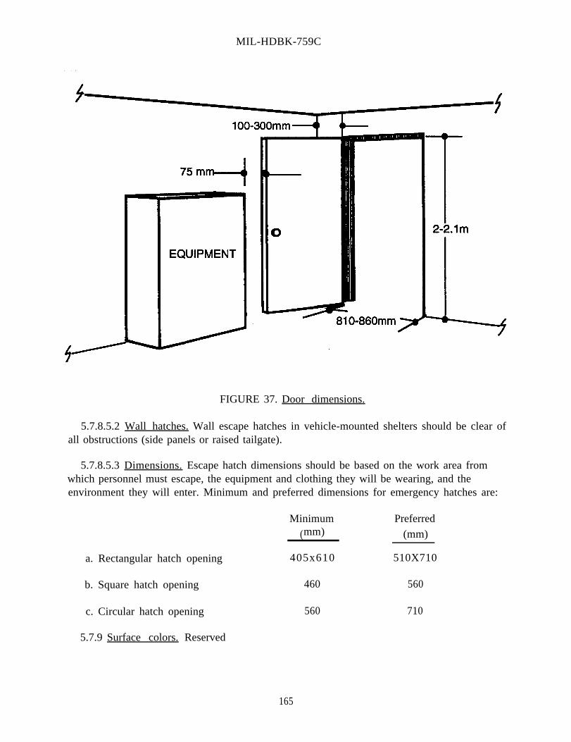
MIL-HDBK-759C
FIGURE 37. Door dimensions.
5.7.8.5.2 Wall hatches. Wall escape hatches in vehicle-mounted shelters should be clear ofall obstructions (side panels or raised tailgate).
5.7.8.5.3 Dimensions. Escape hatch dimensions should be based on the work area fromwhich personnel must escape, the equipment and clothing they will be wearing, and theenvironment they will enter. Minimum and preferred dimensions for emergency hatches are:
Minimum Preferred
(mm) (mm)
a. Rectangular hatch opening
b. Square hatch opening
c. Circular hatch opening
5.7.9 Surface colors. Reserved
405x610 510X710
460 560
560 710
165

MIL-HDBK-759C
This Page Intentionally Left Blank.
166

MIL-HDBK-759C
5.8 Environment.
5.8.1 Heating, ventilating, and air conditioning.
5.8.1.1 Heating.
5.8.1.1.1 Mobile personnel enclosures (shop vans, shelters). Heating should be providedwithin mobile personnel enclosures utilized for detail work or occupied during prolongedperiods of time to maintain interior dry bulb temperature above 10° C.
5.8.1.1.2 Permanent and semi-permanent Personnel enclosures (shops, offices]. Heatingshould be provided within permanent and semi-permanent personnel enclosures utilized fordetail work or occupied for prolonged periods of time to maintain interior dry bulbtemperature of 18° C. The heating system should have provisions for regulating (shutters,louvers, fan-speed controls, fuel-proof carburetor) the amount of heat it delivers and bedesigned such that hot-air discharge is not directed on personnel.
5.8.1.1.3 Vehicle design thermal considerations. Power-train and subsystem components,which are heated to a high temperature when the vehicle is in operation, is one source of heat.Solar radiation, which is distributed over the surfaces exposed to the sun, is another source ofheat. The rate of solar radiation varies throughout the day, reaching a maximum ofapproximately 945 watts/m2 per hour on a horizontal surface.
5.8.1.2 Ventilating. Reserved.
5.8.1.3 Air conditioning. Reserved.
5.8.1.4 Environmental factors. There are three major categories of environmental factorswhich affect equipment design.
a. Environmental factors that design can control (illumination, ventilation rate, andtemperature).
b. Environmental factors that design cannot control (amount of solar radiation, dust, mud,and rain).
c. Environmental factors that are a function of design (noxious substances, vibration, andnoise).
5.8.1.4.1 Environmental extremes. To maximize the effectiveness of the weapons system,the designer should consider the environmental extremes to which the system will besubjected and the effect on performance. Military materiel should be capable of sustainedoperations within the climatic extremes specified in the materiel requirements documents.When deviations from the stated tolerable conditions are necessary, consequences should beconsidered in design to prevent adverse effects such as:
167

MIL-HDBK-759C
a.
b.
c.
d.
criteria for protective clothing or devices which affect the mobility, reach workspace,or access size, for efficient and effective operation and maintenance;
reduced human performance;
borderline conditions which, though they have little or no direct effect on equipment,may seriously impair the ability of the operator or technician to perform effectively;and
conditions which contribute to longer maintenance time or increased maintenanceerrors, oversights, and erroneous decisions, and which are detrimental to systemavailability and performance.
The above adverse effects can sometimes be minimized through the use of alternatives suchas:
a. rotation of personnel at their workstations,
b. decreased workloads,
c. increased workspace allotments,
d. individual protective measures or supplemental equipment,
e. personnel selection and training, and
f. acclimation of operating personnel.
5.8.1.4.2 Hot environment.
5.8.1.4.2.1 Heat stress factors. Five basic factors that determine the degree of heat stressexerted by the environment are air temperature, humidity, air movement, heat radiation anddirect conduction from objects.
5.8.1.4.2.2 Effective-temperature ranges. The effective-temperature ranges are flexiblebecause they vary according to the amount of work activity. Dry bulb temperature should bedecreased by 1.7° C for each 29 watts per hour increase in metabolic rate above the resting117 watts per hour level, with relative humidity kept at or below 60% to allow sufficientevaporation to avoid perspiring. In general, the ranges should be extended upwards for tasksrequiring minimal physical effort and downward for tasks requiring continuous muscularexertion.
a. An effective temperature of 29.5° C should be considered the maximum limit forreliable human performance.
168

MIL-HDBK-759C
b. Minimum temperature requirements are dependent upon the tasks to be performed inspecific applications. Heating should be provided within personnel enclosures used fordetailed work or occupied during extended periods of time if the dry bulb temperaturedrops below 10° C.
c. Prolonged exposure of an ungloved person to effective temperatures below 13.00 Coften results in “stiffening” of fingers, which degrades performance in tasks requiringmanual dexterity.
d. A person wearing arctic clothing should not be exposed, while sitting quietly, totemperatures higher than 15.5° C; a temperature of 1.5-7.0° C is optimal.
e. In providing for heating and cooling of enclosed areas, it is important that thetemperature of the enclosed area be held relatively uniform. The temperature of the airat floor level and at head level should not differ significantly (by more than 5.5.0 C).
f. Relative humidity above 30% and below 70% is considered adequate if the optimumtemperature range for physical comfort is maintained.
g. Side walls of the compartment should be kept at equal temperatures in so far aspossible; however, temperature differences of 11° C or less do not significantlydegrade comfort.
5.8.1.4.2.3 Measurement methods. Conventional methods for measuring environmentalstress include the ordinary dry bulb thermometer, wet bulb thermometer, and black globethermometer. However, dry bulb temperature does not include the effects of humidity, airmovement, or radiation. Wet bulb is a better index since it includes humidity as well as airtemperature but is not a good index of heat stress imposed by radiation. Radiant heat canmost easily be determined by the black globe thermometer.
5.8.1.4.2.4 Wet bulb globe temperature. The Wet Bulb Globe Temperature (WBGT) indexis more applicable than the effective-temperature index in the range beyond the comfort anddiscomfort zones of heat stress. WBGT incorporates, as a major element, the evaporativecooling available to a natural wet bulb thermometer (one with a wettable wick, exposed toambient air motion and extending into a water reservoir) under whatever air motion exists inthe environment; this contrasts with the conventional, psychometric wet bulb thermometer,where air is moved across the wetted bulb either by a fan or by “slinging” the thermometer atthe end of a handle. Because of this difference, the natural (non-psychometric) wet bulbtemperature is a better representation of the actual evaporative cooling available to a sweatingperson. The WBGT index is calculated as:
WBGT = 0.7TWBnp + 0.2Tg + 0.lTA
169

MIL-HDBK-759C
where Tg, representing the radiant heat, is the temperature at the interior center of a 15.2 cm,black globe and TA is a non-psychometric, but shaded, dry bulb (air) temperature. In theabsence of a radiant heat source (solar, engine, furnace), a modified Wet-Dry (WD85) indexshould be used where:
W D85 = 0.85 TWBnp + 0.15TA
Use of a psychometric rather than shaded dry bulb for TA makes little difference in eitherWBGT or WD; however, use of the psychometric wet bulb for TWBnp can result in seriousdiscrepancy, unless wind velocity approaches or exceeds 3 m/s or ambient relative humidityapproaches 100%. Note that regulations for control of heat illness reference WBGT, whileprovisions for comfort and performance decrements typically reference effective temperature.
5.8.1.4.3 Cold environment.
5.8.1.4.3.1 Windchill. The windchill scale has been derived from the rate of freezingwater influenced by ambient temperature and wind. Figure 38 depicts the relationshipbetween temperature and wind for various windchill values.
5.8.1.4.3.2 Human reaction to windchill. A qualitative description of human reaction towindchill values top exposed skin includes:
Windchill HumanValue Reaction
100 warm200 Pleasant800 Cold
1000 Very Cold1200 Bitterly Cold1400 Exposed Flesh Freezes
The above reaction should not be taken to indicate that freezing of exposed flesh does notoccur below a windchill value of 1400. In fact, during the Korean campaigns, significantnumbers of cold injury occurred at windchill values between 900 and 1000. The discrepancypresumably occurs because the freezing of flesh at dry condition temperatures (about the 1400windchill level) differs from the freezing of flesh at wet condition temperatures (possibly aslow a windchill value as 800). As a rule of thumb, if personnel are exposed to a windchillindex (WI) of 1200 or above while operating equipment, they should be protected. Windchillindices this large are common even in temperate climates.
170

MIL-HDBK-759C
In outdoor cold weather, the wind velocity has a profound, sometimes decisive, effect on thehazard to men who are exposed. The windchill concept dramatizes this by providing a means ofquantitative comparison of various combinations of temperature and wind speed. Note forexample that -45° C with an air movement of 0.045 m/s has the same windchill value, andtherefore is predicated to produce same sensation on exposed skin as -8° C with a wind ofonly 0.45 m/s or -10° C with a wind of 2.2 m/s. The windchill index does not account forphysiological adaptation or adjustments. It is based on field measurements of the rate ofcooling of a container of water by Paul Siple during World War II.
FIGURE 38. Windchill chart.
171

MIL-HDBK-759C
5.8.1.4.3.3 Wind and windchill. The WI relates the amount of heat actually lost by aperson to the wind velocity and temperature. In evaluating a windchill hazard, designersshould consider air movement at personnel positions. Table 23 gives the cooling power ofwind expressed as “Equivalent Chill Temperature.” Frostbite can occur even in relativelywarm temperatures if wind penetrates the layer of insulating air around the body to exposebody tissue.
5.8.1.5 Thermal tolerance and comfort zones.
5.8.1.5.1 Optimum temperatures. The optimum temperatures for personnel variesaccording to the nature of the tasks, the conditions under which the tasks are performed, andthe clothing personnel are wearing. The optimum range of effective temperature foraccomplishing light work while dressed appropriately for the season or climate is 21 -27° Cin a warm climate, or during summer, and 18-24° C in a colder climate, or during winter.
5.8.1.5.2 Limited thermal tolerance zones. Physically fit troops acclimate to work in theheat most rapidly (3 to 4 days of 100 minutes of physical work in the heat each day) and stayacclimated (for 3 or more weeks after cessation of work in the heat). Less fit, unacclimatedindividuals may not initially be able to complete a full 100 minutes of work in the heat andwill have to be brought to this level over a period of 6 to 8 days. Unacclimated troops shouldnot be required to perform hard physical work for more than two hours at WBGTs above 25°C while fully-acclimated troops can workup to 8 to 12 hours a day at WBGTs in the 27° Crange. In these cases, water intake should be maximized by command, if necessary. At theselevels of WBGT, troops will lose one quart of sweat per hours. This represents a dehydration(loss of body fluids) amounting to about 1.5% per hour and a 5 to 6% level of dehydration isincompatible with sustained, unimpaired performance of hard physical work. While a 10 Clower threshold WBGT maybe appropriate for women in general, a very fit acclimatedfemale may experience no more difficulty with heat exposure than a male of average militaryfitness. Emphasis on physical fitness and acclimatization to heat will be a more effectiveapproach than emphasis on intrinsic differences in heat tolerance between men and women.
5.8.2 Illuminance.
5.8.2.1 General. Criteria for appropriate illumination cannot be satisfied merely b yproviding a sufficient amount of light to perform tasks or providing emergency lighting(approximately 32 lux) to enable personnel to operate important controls or to find the exitfrom the system. The following should be considered.
172


MIL-HDBK-759C
a.
b.
c.
d.
e.
f.
The brightness contrast between each visual task object and its background.
Glare from work surfaces and light sources.
The level of illumination required for the most difficult tasks.
The color composition of the illumination source and the equipment surfaces.
Time and accuracy required in task performance.
Possible variations in operating conditions (such as outdoor panel blackout operationor outdoor panel visibility under bright sunlight) which may affect the lighting system,the task criteria, or the personnel.
5.8.2.2 Illumination levels and distribution. The examples of illumination levels areexpressed in Table 22.
5.8.2.3 Lighting fixtures. Factors which should be considered in selecting the number andlocation of fixtures are accessibility of lights, convenient operation of switches and othercontrols, and the absence of glare from the fixture itself or indirectly in the form of reflectionfrom windows or other reflecting surfaces.
5.8.2.4 Brightness ratios. The brightness ratios between lightest and darkest areas and/orbetween task and surroundings should meet the criteria presented in Table 24.
5.8.2.5 Glare.
5.8.2.5.1 General. One of the most serious illumination problems is glare or dazzle fromsurfaces. Relatively bright light shining into the observer’s eyes as the observer tries toobserve a relatively dim visual field or reflected glare from work surfaces is common cause ofreduced performance in visual tasks. Glare not only reduces visibility for objects in the fieldof view, but causes visual discomfort.
5.8.2.5.2 Direct glare. Direct glare arises from a light source within the visual work field.Direct glare should be controlled by avoiding placing bright light sources within 60° of thecenter of the visual field. Since most visual work is at or below the eye’s horizontal position,placing luminaries high above the work area minimizes direct glare. Using indirect lightingand more relatively dim light sources, rather than a few very bright ones as well as usingpolarized light, shields, hoods, or visors to block the glare in confined areas will also reduceglare.
174

MIL-HDBK-759C
TABLE 24, Brightness ratios.
Environmental Classification*Comparison A B c
Between tasks and adjacent 3:1 3:1 5:1darker surroundings
Between tasks and adjacent 1:3 1:3 1:5lighter surroundings
Between tasks and more remote 10:1 20:1 ***
darker surfaces
Between tasks and more remote 1:10 1:20 ***
lighter surfaces
Between luminaries and adjacent 20:1 *** ***
surfaces
Between the immediate work area 40:1 *** ***
and the rest of the environment
*A Interior areas where reflection off entire space can be controlled for optimum visualconditions.
B Areas where reflection off immediate work area can be controlled, but there is only limitedcontrol over remote surroundings.
C Areas (indoor and outdoor) where it is impractical to control reflection and difficult to alterenvironmental conditions.
*** Brightness ratio control not practical
5.8.2.5.3 Reflected glare. Reflected glare refers to reflections from shiny surfaces in thevisual field. Reflected glare should be controlled by using surfaces that diffuse incident light,rather than reflecting it specularly and arranging direct-light sources so their angle ofincidence to the visual work area is not the same as the operator’s viewing angle.
5.8.2.5.4 Eyeglasses. These glare-control methods assume the operator is using unaidedvision. Eyeglasses reflect glare into the eyes if a bright light behind the viewer is between 300
above and 45° below the line of sight, or if it is within 20° left or right of the line of sight.
5.8.2.6 Reflectance.
175

MIL-HDBK-759C
5.8.2.6.1 General. Large surface areas should be covered with non-saturated colors such astints, pastels, and warm grays that are non-glossy. Some non-critical small areas such as doorframes and molding may be glossy if ease of cleaning is essential.
5.8.2.6.2 Surface reflectance values. Generally recommended surface reflectance valuesfor work places such as power stations, control rooms, offices and maintenance areas areindicated in Figure 39.
5.8.2.7 Dark adaptation.
5.8.2.7.1 General. Dark adaptation is the process by which the eyes become moresensitive in dim light. The eyes adapt almost completely in about 30 minutes, but the timerequired for dark adaptation depends on the color, duration of exposure and intensity of theprevious light.
5.8.2.7.2 Ambient light. Ambient light is generally incompatible with dark adaptation. Ifit is dimmed enough so that it does not interfere with dark adaptation, it will not be brightenough by which to work. Where both ambient light and dark adaptation are required, theconflict should be resolved by evaluating the priorities of the operator’s tasks. (If night visionis more important than reading maps, use red lighting.) Minimum interference with darkadaptation is produced by brief exposure of the lowest intensity possible. Colors often appeardifferent under different types of illumination, so unless a display will always be used underambient light, do not use color coding.
5.8.2.7.3 Red light. Low-brightness and red light is used to do visual work and forinstrument and display marking (between 0.07 cd/m2) where maintaining maximum darkadaptation is required. This red light is obtained by passing white light through a filter thattransmits only wavelengths longer than 620 millimicrons (red). A filter with a higher cutoffwould maintain dark adaptation more effectively, but would waste too much of the availablelight energy.
5.8.2.7.4 Additional aids. The additional aids to night vision listed below should beincorporated.
a. Lettering that must be read at low light intensities should be block-type white letterson a black background.
b. All controls (knobs, switches) should be painted white.
c. Instrument panels should be designed and located for both day and night use.
d. Maps designed for use under red illumination should be used.
5.8.3 Acoustical noise. Reserved.
176


MIL-HDBK-759C
5.8.4 Vibration.
5.8.4.1 Whole-body vibration. Facilities and facility equipment should be designed tocontrol the transmission of whole body vibration to levels which will prevent safe operationand maintenance (see ISO 2631-1). In the case of multi-directional vibration, each directionis to be evaluated independently with respect to the limits presented. Performance isadversely affected to the degree that vibration can, at high levels, cause critical body damage.Vibration can also make dials, letters, and sight retitles difficult to read and makes controls,tools, or other objects difficult to manipulate. The human physical condition is affect byvibration because it contributes to increased fatigue, nervousness, and irritability that can leadto oversights and errors in judgment.
5.8.4.2 Equipment vibration. Vibration can be reduced and controlled by isolatingequipment from vibration sources by shock mountings and fluid couplings, providing properbalance of rotating elements of equipment and providing damping materials or cushionedseats for standing or seated personnel.
178

MIL-HDBK-759C
179
5.9 Design for maintainer.
5.9.1 General.
5.9.1.1 Standardization. The following standardization practices should befollowed in design of equipment.
a. Standardize types and sizes of bearings where practical.
b. Standardize knob set screws so that a standard diameter and thread are used fora given shaft diameter.
c. Standardize tolerances on similar parts for interchangeability.
d. Standardize the method of pinning gears; set screws should be used wherekeyways or splines are used.
5.9.1.2 Special tools.
5.9.1.2.1 General. Determining tool design is dependent upon maintenanceoperations and characteristics of the equipment. Neglecting tool design untilequipment design and procedures are final may result in the need for special tools or anunnecessarily wide variety of standard tools. Definition of tool requirements early inequipment design and development, before procedures and designs are final, will resultin tools compatible with the equipment on which they will be used and with the job tobe performed. Tools should be designed for simplicity, practicality, and universalityand should be evaluated for adequacy during developmental testing of the system. Therequirement for special tools should be minimized or eliminated. This requirementshould be considered mandatory on the part of the design engineer. Consideration oftool design early in equipment development will result in fewer special tools anddevices. Special tools should be used only when standard tools cannot be used orwhen necessary to facilitate maintenance tasks, reduce time, or improve accuracy.Special tools already in the supply system should be investigated for adequacy inunique situations. Necessary special tools should be made available when theequipment requiring their use is completed.
5.9.1.2.2 Considerations. These areas should be considered in design anddistribution of tools.
a. If possible, require only those tools normally found in the maintenancetechnician's tool kit.
b. Minimize the variety and number of sizes of tools required.
C. A comprehensive list of tools needed for all maintenance tasks shouldaccompany each equipment system. This should include all special tools

MIL-HDBK-759C
180
necessary to perform the authorized work, together with the equipment itemsrequiring their use.
d. Equipment should be designed to minimize the need for torque wrenches. Thedesign activity should review each special requirement in an attempt to makedesign changes to eliminate the need for torque wrenches.
e. If torque wrenches or guns are used for factory assembly and are necessaryequipment, provide maintenance personnel with similar tools.
f. Specify tools which are compatible with the design of the equipment on whichthey will be used as well as with the job to be performed.
g. Provide for the use of speed or power tools such as ratchets, speedscrewdrivers, or power wrenches when demanded by torque requirements orspace limitations.
h. Enable the technician to assemble a tool for many different uses by providingmaintenance personnel with socket wrenches and accessories (breaker bars,extensions, and joints).
i. Positive snap-locking action should be used for connecting sockets to thevarious components of a socket set. They should be designed so they can beeasily connected and disconnected.
j. Tool handles should have adequate gripping surfaces. Tools used wheredropping could result in maintenance delay or possible tool loss should beprovided with thongs sufficiently long to enable the user to place a loop overhis wrist.
k. The use of heat- or cold-resistant handles on tools which are to be used inextreme climates should be specified. Metal handles are undesirable for use incold climates.
l. In evaluating the finish to be applied to tools, the designer should consider thattools with a dull finish prevent reflected glare in areas of high illumination.However, dull-finished tools are often overlooked when closing assemblies,causing loss of tools and possible damage to the equipment. The designershould therefore consider the advantages and disadvantages of the type of finishin relation to the potential application of the tool.
5.9.1.2.3 Mechanical equipment. The design of mechanical equipment shouldconsider the ideas listed below.
a. Interchangeable fastening devices should be used, and the number of types andsizes of bolts, nuts, and screws should be kept to a minimum. Wherepracticable, lock washers should be attached to the bolts and screws.

MIL-HDBK-759C
181
b. Fast-acting fastening devices should be used for covers and cover plates that areof the captive type and do not require special tools.
c. Corrosion-resistant, sealed bearings should be used in all fire control materiel,except where the sleeve type has a logical application.
d. Wherever possible, self-aligning bearings should be used instead of ball capsand sockets in worm gear mechanisms.
e. Securing bearings by staking should be avoided; stakes have a tendency tobreak when in use for prolonged periods of time.
f. Dual doweling should be eliminated. Instead, eccentric dowels, dowels withstopscrews, with slots, with edge-locating shoulders, and with keys should beused.
g. Where possible, the use of split pins should be avoided; taper pins are moredesirable.
h. Split clamp couplings should be used instead of pinned sleeves to facilitate thereplacement of parts and adjustments.
i. Ferrous parts that are susceptible to corrosion and are used internally ininstruments should be appropriately plated. Phosphate finishes (especiallywhere not oiled) do not provide sufficient protection.
j. Oil-impregnated bearings should be used where practical.
k. Related subassemblies should be grouped together as much as possible.
l. A manual means for the engagement, disengagement and locking of elevatingand traversing mechanisms should be provided to facilitate maintenance.
m. In high-speed applications, it should be specified that mating gears be ofmaterials having dissimilar wear characteristics.
n. Backlash and torque lash should be minimized. The effects of backlash andlost motion should be taken into consideration in the selection or design ofmovable parts.
o. The same type socket should be used on all socket set screws.
p. Screws, studs, and nuts made of non-ferrous material should be used wherepracticable.

MIL-HDBK-759C
182
q. Using dowel pins for the final positioning of mounts on support surfacesprovided on the weapon should be avoided; fixed locating points present aproblem when mounts are interchanged. Consider key and keyway, eccentricand keyway, or single dowel pins for the final positioning of mounts.
5.9.1.2.4 Safety.
a. Adequate insulation should be provided on tool handles or other parts of thetools which the technician is likely to touch while performing maintenance onelectrical or electronic equipment near voltages in excess of 30 volts.
b. Spark resistant tools should be provided if they are to be used in areas wherefire or explosion hazards exist.
c. Storage for tools should be provided so they cannot fall and cause personnelinjury or equipment damage.
d. Sharp corners and edges should be eliminated on tool chests.
e. Casters or a sufficient number of properly sized and located handles should beprovided to facilitate lifting if tool chests are too large to be handled easily byone person. Handle location should ensure that the chest will remain balancedwhen lifted.
5.9.1.2.4.1 Safety features. The safety features listed below should be considered.
a. Doors or hinged covers should be designed so they are rounded at the cornersand provide slip hinges and stops to hold them open.
b. In mounting fire control components, access to both sides of the equipmentshould be provided, and sufficient hand room should be provided for thetechnicians to remove and replace parts.
c. Personnel should be protected from moving mechanical parts by the use ofguards, safety covers, and warning plates.
d. Covers or boots for exposed couplings and universal joints should be provided.

MIL-HDBK-759C
183
5.9.1.3 Maintainability.
5.9.1.3.1 General. Materiel readiness emphasizes the complementary attributes ofreliability and maintainability. Reliability is best expressed as the probability themateriel will perform its intended function, for example, remain ready withoutrequiring unplanned maintenance. Maintainability is the ease of keeping the materielin, or restoring it to, readiness and availability. Maintainability depends onaccessibility of parts, internal and external configuration, use, and repair environment,as well as the time, tools, and training skills required for maintenance. The objectivesof improving maintainability are to make materiel more available to perform itsfunction and mission and to reduce the cost of operational support during the materiel'sservice life.
5.9.1.3.2 Maintainability in the design schedule. To avoid costly maintenance, orredesign, maintainability should be designed into the materiel during the initialdevelopment stage. Therefore, it is imperative to schedule for maintainability. Firstplan, then design, and finally, test the design to ensure maintainability.
5.9.1.3.2.1 Planning for maintainability. In planning for maintainability, designersshould consider the points listed below.
a. Determine the size of required access openings, work surfaces, and workspaceso that components are accessible to maintenance personnel.
b. Study operational materiel similar to that to be designed. List the maintenancefeatures built into it and, from its maintenance history and experience, identifyadditional maintenance features that should have been incorporated to improvemaintainability.
c. Determine how components should be arranged and located to provide rapidaccess to those components with the lower reliability that will probably requiremaintenance most frequently, or whose failure would critically degrade the enditem's performance.
d. Identify tools and test equipment already in the operational system that can bemade available for maintenance of the materiel being designed.
e. Determine what type, number, and organization of manuals the maintenancepersonnel will need to maintain the materiel properly, effectively, and safely.
5.9.1.3.2.2 Designing for maintainability. Wherever practical, the designers shouldconsider and incorporate the following features into design and development projects.
a. Simplification of operator and maintenance functions.
b. Use of modular or unit packaging or throw-away components and techniques.

MIL-HDBK-759C
184
c. Use of self-lubricating principles.
d. Use of sealed and lubricated components and assemblies.
e. Use of built-in testing and calibration features for major components.
f. Use of self-adjusting mechanisms.
g. Use of gear-driven accessories to eliminate belts and pulleys.
h. Minimize number and complexity of maintenance tasks.
i. Maximize design simplicity.
j. Design for quick recognition of malfunctions or marginal performance.
k. Design for quick identification of the replaceable defective components,assemblies, and parts.
l. Design to eliminate torque specifications at organizational or aviation unitmaintenance level and minimize need for all other torque specifications.
m. Design to minimize skills and training requirements of maintenance personnel.
n. Design to minimize the types and number of tools and test equipment (bothstandard and special) required to perform maintenance.
o. Design for accessibility to all systems, equipment, and components requiringmaintenance, inspection, removal, and replacement.
p. Design for maximum safety and protection for personnel and equipment.
q. Design equipment to permit maintenance from above and outside in contrast torequiring access for maintenance from underneath.
r. Design of items should facilitate manual handling required during maintenanceand comply with established manual force criteria.
s. Design equipment to facilitate assembly and disassembly.
5.9.1.3.2.3 Testing the design. Development and production models should betested for maintainability under operational conditions. These tests should usemaintenance personnel with the same amount of training as those assigned to actualmaintenance, and use the procedures, tools, test equipment, and manuals thatmaintenance personnel will use.

MIL-HDBK-759C
185
5.9.1.3.3 Manuals. Complete and current maintenance manuals should be issuedwith the materiel as it is released for use.
5.9.1.4 Stowage.
5.9.1.4.1 General. The following statements are applicable to stowing equipment.
a. Stowed items should be secured by straps, brackets or other restraining devicesto provide for cross-country operation.
b. All stowage locations should be designed to drain adequately when the vehicleis on level ground. Drain holes should be arranged so that they will not beblocked by normal stowage.
c. Items which are flammable or subject to damage by leakage of lubricants, fuels,or water should be stowed in a manner to protect them from engines,generators, and exhaust components.
d. To prevent its loss, peculiar equipment should be designed to be properlysecured when installed or stowed.
e. Items of mission-critical nature should be stowed in a manner to permit rapidaccess by crew members.
f. Consider all environments in which the crew will operate when locating anddesigning stowage space for items worn by crew members.
5.9.1.4.2 Identification. A stowage plan should be provided identifying the stoweditems and their locations. Also, stowed items should be permanently labeled for easeof identification.
5.9.1.4.3 Interference. Stowed items should not interfere with system functions,operations, or established personnel movement (entrance, exit, or escape) routes.
5.9.1.4.4 Removal and replacement. Stowed items should be capable of beingremoved and replaced without having to remove or replace other stowed items orcomponents of the system.
5.9.1.4.5 Retaining devices. Items should be capable of being stowed and removedunder all environmental conditions. The retaining devices should be simple, capableof quick removal and replacement, and need no tools. Retaining devices should beattached to either the stowage space or the stowed item to prevent loss.
5.9.1.4.6 Utilization of stowage space. The accessibility and locations of stowedequipment should be determined by the functional utilization of each item. Items usedby a particular crew member should be stowed in a convenient, accessible locationwithin the functional area of the crew member's station.

MIL-HDBK-759C
186
5.9.1.4.6.1 Unused space. Unused space should be utilized to provide suitablestowage for items.
5.9.1.4.6.2 Individual items. When operating equipment, stowage should beavailable for doffed personal items such as individual weapons, small armsammunition, rations, and helmets if donning of other special gear is required.
5.9.1.5 Stowage areas and boxes: doors and covers.
a. Unless access covers or doors are intended to be removable, they should bedesigned so they can be retained open.
b. Instructions about contents in a box should be located so they can be read whenthe door is open.
c. Required access should be provided to the rear of sliding, rotating or hingedunits so they open or rotate their full distance freely and remain "open" bythemselves.
d. Openings of covers or doors should be designed to be obvious or have openinginstructions affixed to the outside.
e. When a cover or door is in place, but not secured, it should be visually obvious.
f. Sharp edges and corners on doors, covers, and other exposed surfaces should berounded.
g. To simplify reinstalling removable inspection access doors, they should beinterchangeable or of the size and shape which will make their proper positionobvious.
h. Obstructions (material or structural members) should never block covers ordoors so they cannot be opened or removed, or restrict the required accessthrough the cover or door opening.
i. If covers are hinged, space equal to the sweep volume of the cover should beallowed so the body frame and brackets will not obstruct its opening.
j. Items should be capable of being stowed and unstowed by the 5th through 95thpercentile user while wearing cold-weather gear and gloves without having toassume a strenuous or difficult position.

MIL-HDBK-759C
5.9.2 Mounting of items within units.
5.9.2.1 General. Units should be located so no other equipment has to be removedto gain access to them. All components should be laid out so they are accessible withthe emphasis for easy access placed on items that require frequent inspection andmaintenance. Components maintained by the same technician should be groupedtogether so that only a minimum of moving from position to position is necessaryduring system checking. Components that require frequent visual inspection, checkpoints, adjustment points, cable-end connectors, and labels should be located inpositions that can be seen easily. All components should be located to minimize thepossibility of equipment damage or personnel injury.
5.9.2.2 Stacking avoidance. Units should not be stacked. If stacking is necessarybecause of space limitations, place the unit requiring the least frequent access in theback or on the bottom.
5.9.2.3 Hinge-mounted units. Small hinge-mounted units, which require access tothe back, should be free to open their full distance and remain open without being held(see Figure 40).
5.9.2.4 Frames and structural members. Frames and structural members should notinterfere with maintenance and operational personnel reaching components they haveto maintain, inspect, or operate (see Figure 41).
5.9.2.5 Tubes. Tubes should be replaceable without interference from resistors,capacitors, or wiring and without removing assemblies or subassemblies. Miniaturetube sockets should be oriented with gaps facing in one direction to facilitate replacingtubes (see Figure 42). When tubes are replaced through narrow openings, an externalindication of the position for pin insertion should be provided.
5.9.2.6 Fuses. Fuses should be located so they can be seen and replaced withouttools or removing other parts or subassemblies.
FIGURE 40. Hinged units.
187

MIL-HDBK-759C
FIGURE 41. Component placement.
FIGURE 42. Tube socket orientation.
5.9.2.7 Equipment units design checklist. The following checklist (Table 25)summarizes some of the important features to be considered in the design of equipmentunits. The checklist contains several items which were not discussed separately in thetext. These items are included here because their necessity in design is so obvious thatthey might otherwise be inadvertently overlooked. In using the checklist, if the answerto any question is NO, the design should be restudied to ascertain the need forcorrection.
188

MIL-HDBK-759C
189
TABLE 25. Equipment units design checklist.
1. Are plug-in components used where feasible?
2. Is wrong installation of unit prevented by virtue of size, shape or configuration?
3. Are modules and mounting plates labeled?
4. Are guides used for module installation?
5. Are means provided for pulling out drawers and slide-out racks without breaking electrical connections when internal in-service adjustments are required?
6. Are units and assemblies mounted so that replacing one does not require removal of others?
7. Are parts mounted on a single plane, not stacked one on another?
8. Are parts mounted on one side of a surface with associated wiring on the other side?
9. Are easily damaged components mounted or guarded so they will be protected?
10. Are all replaceable parts accessible by fold-out construction or other special techniques when necessary?
11. When fold-out construction is employed, are parts and wiring positioned to prevent damage by opening and closing?
12. Are braces provided to hold hinged assemblies in the "out" position while being worked on?
13. Are parts which retain heat or electrical potential after the equipment is turned off located so that the technician is not likely to touch them while replacing commonly malfunctioning parts?
14. When screwdriver adjustments must be made by touch, are screws mounted vertically so that the screwdriver will not fall out of the slot?
15. When necessary, are internal displays illuminated?
16. Are internal controls (switches, adjustment screws) located away from

MIL-HDBK-759C
190
TABLE 25. Equipment units design checklist - continued.
dangerous voltages?
17. Are screwdriver guides provided on adjustments which are located near high voltages?
18. Are parts located so that other large parts (such as indicators and magnetron tubes), that are difficult to remove, do not block access to them?
19. Are parts, assemblies, and components placed so there is sufficient space to use test probes, soldering irons, and other tools without difficulty?
20. Are parts, assemblies, and components placed so that structural members of units do not prevent access to them?
21. Are all throwaway items made accessible without removal of other items?
22. Are units designed so that it is unnecessary to remove an assembly from a major component to troubleshoot that assembly?
23. Is equipment laid out so the technician will not have to retrace movements during checking routines?
24. Are all miniature tube sockets oriented with the gaps facing one direction?
25. When tubes must be replaced through small access openings, is there an external indication of the position for pin insertion?
26. Are all fuses located so they can be seen and replaced without removal of any other items?
27. Are fuse assemblies designed and placed so that tools are not required to replace fuses?
28. Are removable units removable along a straight or moderately curved line?

MIL-HDBK-759C
191
5.9.3 Adjustment controls.
5.9.3.1 Protection from fluids. Components should be placed in positions where oiland other fluids are not likely to fall on them.
5.9.3.2 High-temperature guards. High-temperature parts should be guarded orlocated so personnel will not contact them during operation or maintenance. Heat-producing equipment should be arranged and shielded so discomfort to personnel isavoided.
5.9.3.3 Enclosure of high-current devices. High-current switching devices shouldbe enclosed to protect personnel. Components that retain electrical potential after theequipment is turned off should be equipped with bleeder networks. Internal controlsshould not be located close to dangerous voltages.

MIL-HDBK-759C
192
5.9.4 Accessibility.
5.9.4.1 General. Accessibility is defined as the relative ease with which anassembly component can be reached for inspection, service, repair, or replacement. Itis a fundamental requirement for maintainability and should be designed into theequipment because adding access provisions for maintenance purposes after theequipment is built is inefficient, costly, and often inadequate. If it can be reachedquickly, requiring the use of only a few simple steps, an item is accessible; if itrequires many tools, special tools, many or difficult operations, it is inaccessible, eventhough it is possible to eventually reach it. The disassembly or removal of parts thatare in the way of easy access to a part needing maintenance is highly undesirable,especially in field conditions. Adequate space is usually not available for laying outparts as they are removed. This increases the possibility that they will be lost,damaged, or contaminated, and further malfunctions will be introduced into thesystem.
5.9.4.2 Psychological aspects. The more difficult or involved a maintenance task is,the more readily an operator or mechanic will put it off in preference to lessdemanding tasks. Periodic maintenance activities, such as checks, adjustments, orgeneral troubleshooting may be unduly postponed or neglected entirely. Thus,inaccessibility is a human engineering problem as well as a problem for the designengineer.
5.9.4.3 Environment. The environment in which maintenance tasks will beperformed should also be considered by the designer when determining the size ofaccess openings. Access for a gloved or mittened hand is considerably larger than fora bare hand. Wearing gloves or mittens seriously limits the dexterity and skill withwhich technicians can perform their duties. Certain simple tasks may be impossible toperform while wearing arctic mittens. Wearing cold-weather clothing createsproblems such as persons becoming less agile. Their bodies may become wedged innarrow hatches, or their feet may stumble on steps, ladders, and small, closely-spacedpedals. Their hands may be unable to operate intricate hand controls with deftness andprecision.
5.9.4.4 Equipment. Equipment design for accessibility should include the followingconsiderations.
a. Provide access openings for instrument adjustment.
b. Provide external access to internal adjusting devices.
c. Locate high-mortality parts near access openings.
d. Make lubrication points easily accessible and clearly marked.
e. Make mounting bolts easily accessible.

MIL-HDBK-759C
193
f. Avoid through bolts having nuts that are inaccessible except through extensivedisassembly of adjacent parts.
g. Socket-head screws should not be used where relative inaccessibility wouldrequire special or modified hexagonal wrenches.
5.9.4.5 Workspace.
5.9.4.5.1 General. The system criteria should be based on the following minimumconsiderations for the 5th to 95th percentile maintenance population wearing cold-weather clothing.
a. Points where operation and maintenance may be required.
b. Space, clearance, access and movement criteria needed for personnel usingequipment to perform the functions of operation and maintenance.
c. Criteria for access or passage to the workstation, as well as the size and weightof equipment carried and used at the workstation.
5.9.4.5.2 Other features. The workspace should allow personnel to change theirbody positions if the task requires kneeling, crawling, or crouching for a prolongedperiod of time. Consideration should also be given to providing protection against anypotential hazards which might exist while personnel are performing their tasks.Auxiliary hooks, holders, lights, outlets, non-skid treads, expanded metal flooring, orabrasive coating on surfaces used for walking, climbing, or footholds should beprovided at the workstation to assist personnel in performing their jobs, as appropriate.Top surfaces of equipment should be reinforced and provided with non-skid surfaceswhenever they are used as work platforms. (Use 113.6 kg per person to calculateanticipated load.)
5.9.4.6 General-access criteria.
5.9.4.6.1 Design. Where possible and feasible, design for accessibility by usingmodular design, and equipping major units and assemblies (particularly engines andturbines) with removable housings so they can be inspected completely. Anyreplaceable item should be designed so that it can be removed after opening only oneaccess (unless the accesses are latched or hinged doors). Accesses should be designedso that they are located, covered, and fastened so it will not be necessary to removecomponents or wires to reach an item requiring maintenance. These openings shouldbe directly in line with the equipment to be serviced or maintained.
5.9.4.6.2 Visual inspection. Items requiring visual inspection (hydraulic reservoirs,gauges) should be located so personnel can see them without removing panels or othercomponents, particularly if hazards can be encountered inside the equipment.

MIL-HDBK-759C
194
5.9.4.6.3 Sharp edges. Accesses having sharp edges or protrusions that could injurepersonnel or damage hoses should be lined with internal fillets or other suitableprotection prior to access for maintenance.
5.9.4.7 Access. Access should be provided to all points, items, units, andcomponents which require testing, servicing, adjusting, removing, replacing, andrepairing. The type, size, shape, and location of accesses (see Figures 43-44) shouldbe based on a thorough understanding of the considerations listed below.
a. Operational location, setting, and environment of the unit.
b. Frequency of use.
c. Maintenance tasks performed through the access and the intricacy of the tasks.
d. Time required to perform maintenance functions.
e. Types of tools and accessories required.
f. Workspace required.
g. Type of clothing likely to be worn by personnel.
h. Necessary access reach.
i. Visual requirements and the intricacy of the tasks.
j. Packaging of items and elements behind the access.
k. Mounting of items, units, and elements behind the access.
l. Hazards in using the access.
m. Size, shape, weight, and clearance requirements for logical combinations ofhuman appendages, tools, and units that will enter the access.

MIL-HDBK-759C
FIGURE 43. Access opening dimensions.
195

MIL-HDBK-759C
* Or sufficient to clear part if part is larger than 125 mm.FIGURE 43. Access opening dimensions - continued.
196

MIL-HDBK-759C
BEST-NO COVER(USE WHENEVER POSSIBLE)
PERMANENT GLASS OR PLASTICCOVER (USE WHERE ONLY VISUALINSPECTION IS REQUIRED).
HINGED OR SLIDING COVER(USE WHERE PHYSICAL ACCESSIS REQUIRED AND WHERE DIRTAND MOISTURE COULD BE APROBLEM).
CAPTIVE QUICK-OPENING FASTENERS(USE WHEN SPACE PREVENTS USE OFHINGED COVER).
SCREWED-DOWN COVER(USE ONLY WHEN STRESS ORPRESSURIZATION REQUIRESMINIMUM NUMBER OF SCREWS).
FIGURE 44. Covers and accesses.
197

MIL-HDBK-759C
198
5.9.5 Lubrication. Reserved.
5.9.6 Case and cover mounting.
5.9.6.1 Covers, cases, and shields.
5.9.6.1.1 General. Covers, cases, and shields should be provided as necessary todivide enclosures into sections which are cleaned by different methods and to keeppersonnel from touching dangerous electrical or mechanical parts. They also protectdelicate or sensitive equipment so it will not be damaged by movements of personnel,shifting cargo, loose objects, or installing and maintaining nearby assemblies.
5.9.6.1.2 Design for maintenance. Covers, cases, and shields should also bedesigned for fast, easy maintenance (Figure 45). Their maintenance characteristicsdepend largely on how they are fastened; the size, weight, and ease of handling; andwhether handles or provisions for tool grips are provided. Other characteristics includethe workspace and clearance around them and how often they must be opened orremoved.
5.9.6.2 Characteristics.
a. They should be lightweight if possible, but whatever size is necessary for thedegree of enclosure and the accessibility required.
b. They should be openable, removable, and transportable by one hand, by oneperson, or by two persons, in that order of preference.
c. Handles or tool grips should be provided if it is heavy, difficult to open, ordifficult to handle.
d. Enough clearance should be provided around enclosed components to preventdamage and to avoid requiring extremely fine or careful positioning andhandling.
e. They should be designed and located so bulkheads, brackets, or other units donot interfere with using them, and so they will not interfere with othermaintenance operations when they are open.
5.9.6.3 Shape. Any appropriate shape for the degree of enclosure, accessibility, andclearances required may be used. It should be made obvious how the item must bepositioned or mounted, and how enclosed delicate components are oriented in order toprevent damage during removal. Indentations or settling areas on top surfaces shouldbe avoided to prevent rust and corrosion and keep dirt and grease from accumulating.

MIL-HDBK-759C
FIGURE 45. Cover and case design examples.
5.9.6.4 Location and mounts. Covers, cases, and shields should be designed,located, and mounted so that they can be removed and replaced if they are damagedand irregular extensions and accessories can be removed readily. They should becapable of being opened or removed as necessary without taking the equipment apartor removing auxiliary equipment. Props, retainers, or other supports should be located
199

MIL-HDBK-759C
200
or mounted where required so the equipment will not be unbalanced when opened.When open, they should not obscure or interfere with controls, displays, test points, orconnections used in working inside the access or enclosure. They also should haveadequate stops and retainers to keep them from swinging against, or being dropped on,fragile equipment or on personnel, and have locking devices or retaining bars to holdthem open if they might otherwise fall shut and cause damage, injury, orinconvenience. (This is particularly necessary when used in high winds.) If feasible,stowage provisions should be provided if the covers, cases, or shields are removable.
5.9.6.5 Fasteners. Fasteners for covers, cases, and shields should be selected,applied, and mounted so that they satisfy the preferences, criteria, and standardizationaspects. Hinges, latches, and catches should be used wherever possible to reducehandling and stowing of covers and cases. It should be obvious when a cover is not inplace or is not securely fastened. Where possible, spring-loaded fasteners should beused so they can stand out or the cover itself stays ajar when it is not secure.
5.9.6.6 Labels and markings. Labels and markings on covers and cases should:
a. present instructions on how to open, remove, and position them, unless thedesign itself makes operation obvious;
b. clearly indicate the functions of units behind the enclosure or the functionswhich are performed through the access (such as "Battery," "Fuel Pump," or"Oil Here");
c. warn about any dangers or hazards involved in removing the cover or case, orworking within the enclosure;
d. indicate how units or service equipment should be oriented or connected to gothrough the opening (unless this is already obvious); and
e. present instructions so they will be visible and properly oriented to amaintenance technician when the cover, door, or case is open.
5.9.7 Cases. Cases should be selected, designed, and mounted so that cases lift offof units, rather than units lifting out of cases, particularly when subassemblies areheavy (see Figure 45). They should be somewhat larger than the items they cover, soitems inside can be removed and replaced easily without damaging wires or othercomponents. They should have guidepins and tracks, as necessary, to help align thecase, prevent it from cocking or binding, and to protect delicate or sensitivecomponents from damage when the case is moved. Access to frequently usedadjustment, test, and service points should be available so the case need not beremoved for routine maintenance. All aspects and portions of the equipment that aresignificant for maintenance should be fully exposed when the case is removed. Rubberstripping or other sealing material should be selected and mounted so personnel willnot damage it when the case is moved.

MIL-HDBK-759C
201
5.9.8 Covers. Covers are listed here in order of preference.
5.9.8.1 Hinged doors, hoods and caps. Hinged doors, hoods, and caps allow fastestand easiest access, with relatively few fasteners, and the cover is supported so thetechnician does not have to handle it. However, these covers do require swingingspace, which may interfere with other operations or components. Where swinging oropening space is limited, double-hinged split doors should be used. Hinges should beplaced at the bottom of the door, or a prop, catch, or latch should be provided to holdthe door open, particularly if the door must be opened in high winds. When hingeddoors are adjacent, they should open in the opposite directions to maximizeaccessibility. Hinged caps should be used over service or test points so they will notinterfere with inserting or attaching service or test equipment. Stops or retainersshould be used as necessary to keep doors from swinging into adjacent controls orfragile components, and so they will not spring their hinges.
5.9.8.2 Sliding doors and caps. Sliding doors or caps are particularly useful whereswinging space is limited. Small sliding caps are useful for small accesses that do notrequire a tight seal. When using sliding doors and caps, they should lock positively, bedesigned so they will not jam or stick, and be easy to use. Personnel should be able touse them without tools. Opening or closing them should not interfere with, damage, ormake potentially harmful contact with wires or other equipment items.
5.9.8.3 Removable doors, plates, and caps. Removable doors, plates, or capsrequire little space for opening and, once removed, do not interfere with workspace.However, handling them takes time and effort. When using removable covers, tongue-and-slot or similar catches should be used wherever possible for small plates, doors,and caps, to minimize the number of fasteners required. If small plates and caps arelikely to be misplaced or damaged, secure them with retainer chains (see 5.9.10.6.12).If a removable plate must be attached in a certain way, it should be designed so itcannot be attached improperly. For example, use an asymmetric shape, locatemounting holes asymmetrically, or code both plate and structure with labels that willalign when the plate is properly installed.
5.9.8.4 Removable panels or sections. Removable panels or sections give access towhole sides of equipment. They discourage non-maintenance personnel from openingthe access. They do not require "swinging space," but they are easily damaged andawkward to handle. They may also interfere with maintenance. When used, panelsthat must be removed for maintenance should be held with a minimum of combination-head, captive fasteners. Spring-loaded, quarter-turn fasteners are particularlyrecommended, and it should be apparent when fasteners have been released. Panelsand sections should be designed so one person can carry them and install or removethem with common hand tools, and should have handles to facilitate removal,handling, and replacement. It should not be necessary to disconnect wires orcomponents from a panel before removing it. If such items are attached to the panel, itshould be hinged so they need not be removed.

MIL-HDBK-759C
202
5.9.9 Access openings and covers. The following checklist (Table 26) summarizessome of the important features to be considered in the design of equipment units. Thechecklist contains several items which were not discussed separately in the text. Theseitems are included here because their necessity in the design is so obvious that theymight otherwise be inadvertently overlooked. In using the checklist, if the answer toany question is NO, the design should be restudied to ascertain the need for correction.
5.9.10 Fasteners.
5.9.10.1 General. The design, selection, or application of fasteners should considerthe workspace, tool clearance, and wrenching space needed around the fastener, andthe types of tools required to operate the fastener, depending on the type of fastener,application, and location. How often the tool will be used and the time available fortasks involving operation of the fasteners are other considerations. The fasteners alsowill have to be used by personnel who may be wearing arctic gloves or mittens.
5.9.10.2 Selection. Fasteners are available in a wide variety of types and sizes, andnew types are always appearing on the market. Before selecting fasteners, review thevarieties available. They should be standardized wherever possible to reduce spareparts and minimize the danger that personnel will damage them by using the wrongtool or fastener. Fasteners should be selected for durability, easy operation, speed, andeasy replacement.
5.9.10.3 Minimize fasteners and required tools. Minimize the number of types andsizes of fasteners within the system by using only a few basic types and sizes whichare readily distinguishable from each other (see Figure 46) and using the same typeand size of fastener consistently for a given application. For example, all mountingbolts should be the same for a given type of item. Another way to minimize thenumber and types of sizes is by making certain that screws, bolts, and nuts withdifferent threads also have clearly different physical sizes so they will not beinterchanged, by avoiding fasteners that require special tools, and by selectingfasteners that can be operated by hand or by common hand tools.

MIL-HDBK-759C
203
TABLE 26. Equipment units access checklist.
1. Are clearance holes for mounting screws in cover plates and shields oversize to obviate need for perfect alignment?
2. Are cases designed to be lifted off units rather than units lifted out of cases?
3. Are cases made larger than units they cover to preclude damage to wires and components?
4. Are guides or tracks provided to prevent cases cocking to one side?
5. If the method of opening a cover is not obvious, is an instruction plate attached to the outside of the cover?
6. When covers are not in place and secure, are means provided to make it obvious?
7. Are no more than six fasteners used to secure the case?
8. Are the same type fasteners used for all covers and cases on a given piece of equipment?
9. Is ventilation-hole screening of small enough mesh provided to prevent entry of probes or conductors that could inadvertently contact high voltages?
10. When the sealing edges of a case must be slid over sealing material (such as rubber stripping), does the sealing material adhere tightly enough to prevent it from buckling or tearing?

MIL-HDBK-759C
FIGURE 46. Fastener examples.
204

MIL-HDBK-759C
205
5.9.10.4 One-hand or one-tool operation. Nuts and bolts, particularly those whichare operated frequently or which are not very accessible, should be mounted so theycan be operated with one hand or one tool and recesses should be provided to holdeither the nut or the bolt. Either the nut or the bolt should be attached semi-permanently, and they should not interfere with each other or with other componentsduring release. Nuts and bolts should not be hazards to personnel, wires, or hoses andshould have adequate hand or tool clearance for easy operation. It should beconsidered that it may take two hands or power tools to manipulate, breakaway, orremove stuck fasteners. Fasteners that are normally operated by hand should bedurable enough that they can be turned with a wrench.
5.9.10.5 Other considerations. Consider how stripped, worn, or damaged fastenerscan be replaced. Fasteners (studs) which are an integral part of the housing should beavoided. Fastener mounting holes or other tolerances should be large enough to allow"starting" fasteners without perfect alignment. Attach hinges, catches, latches, locks,and other quick-disconnect devices with small bolts or screws, not with rivets.
5.9.10.6 Types of fasteners (in order of preference).
5.9.10.6.1 Quick-connect and quick-disconnect devices. These devices are fast andeasy to use, do not require tools, may be operated with one hand, and are very good forsecuring plug-in components, small components, and covers. However, their holdingpower is low, and they cannot be used where a smooth surface is required. The factorslisted below should be considered in selecting quick-connect and quick-disconnectfasteners.
a. These fasteners should be used wherever possible when components must bedismantled or removed frequently.
b. These fasteners should fasten and release easily, without requiring tools.
c. They should fasten or unfasten with a single motion of the hand.
d. It should be obvious when they are not correctly engaged.
e. When there are many of these fasteners, prevent misconnections by giving thefemale section a color or shape code, location, or size so it will be attached onlyto the correct male section.
5.9.10.6.2 Latches and catches. These items are very fast and easy to use, do notrequire tools, and have good holding power; they are especially good for large units,panels, covers, and cases. They cannot be used where a smooth surface is required.The factors listed below should be considered in selecting latches and catches.
a. Long-latch catches should be used to minimize inadvertent releasing of thelatch.

MIL-HDBK-759C
206
b. Catches should be spring-loaded so they lock on contact rather than requiringpositive locking.
c. If the latch has a handle, the latch release should be located on, or near, thehandle so it can be operated with one hand.
d. Latches and catches should be evaluated for snap down and release forces thatcould be hazardous to handle during operation.
5.9.10.6.3 Captive fasteners. Captive fasteners are slower and more difficult to use,depending upon type, and usually require using common hand tools, but they stay inplace, saving time that would otherwise be wasted handling and looking for bolts andscrews, and can be operated with one hand. The factors listed below should beconsidered in selecting captive fasteners.
a. Captive fasteners should be used when "lost" screws, bolts, or nuts might causea malfunction or excessive maintenance time.
b. Fasteners should be used which can be operated by hand or with a commonhand tool and which can be replaced easily if they are damaged.
c. Captive fasteners of the quarter-turn type should be self-locking and spring-loaded.
5.9.10.6.4 Regular screws. Round, square, or flat-head screws take longer to useand are subject to loss, damage, stripping, and misapplication. Square-head screws aregenerally preferable to round or flat ones; they provide better tool contact, havesturdier slots, and can be removed with wrenches. If personnel must drive screwsblindly, provide a guide in the assembly to help keep the screwdriver positionedproperly. Screw heads should have deep slots that will resist damage, and should beused only when personnel can use screwdrivers in a "straight-in" fashion. Personnelshould not be required to use offset screwdrivers.
5.9.10.6.5 Bolts and nuts. Bolts are usually slow and difficult to use. Personnelmust have access to both ends of the bolt, use both hands, and often use two tools.Also, starting nuts require precise movements. There are many loose parts to handleand lose such as nuts and washers. Design considerations should include keeping boltsas short as possible, so they will not snag personnel or equipment. Coarse threads arepreferable to fine threads for low torques and reduce the possibility of cross-threading.Left-hand threads should be avoided unless system requirements demand them. Ifused, both bolts and nuts should be identified by clearly marking, or shape or colorcoding. Wing nuts (preferably) or knurled nuts should be used for low-torqueapplications, because they do not require tools.
5.9.10.6.6 Combination-head bolts and screws. Combination-head bolts and screwsare preferable to other screws or bolts because they can be operated with either a

MIL-HDBK-759C
207
wrench or a screwdriver, and there is less danger of damaged slots and stuck fasteners.In general, slotted hexagon heads are preferable to slotted knurled heads.
5.9.10.6.7 Internal-wrenching screws and bolts. Internal-wrenching screws andbolts (socket heads) allow higher torque, better tool grip, and less wrenching space, butrequire special tools, are easily damaged, and are difficult to remove if damaged. Theyalso become filled with ice and frozen mud. The number of different sizes should belimited to minimize the number of special tools; one size is preferred. Fasteners withdeep slots should be selected to reduce the danger of damaged fasteners.
5.9.10.6.8 Rivets. Rivets are very hard and time-consuming to remove. Theyshould not be used on any part which may require removal.
5.9.10.6.9 Cotter key. Keys and pins should fit snugly, but they should not have tobe driven in or out. Cotter keys should have large heads for easy removal.
5.9.10.6.10 Safety wire. Use safety wire only where self-locking fasteners cannotwithstand the expected vibration or stress. Attach safety wire so it is easy to removeand replace.
5.9.10.6.11 Retainer ring. Rings which become difficult to remove and replacewhen they are worn should be avoided. Rings which hold with a positive snap actionshould be used when possible.
5.9.10.6.12 Retainer chains. Retainer chains should be used to:
a. keep hatches or doors from opening too far and springing their hinges,
b. turn doors or covers into useful shelves for the technician,
c. prevent small covers, plates, or caps from being misplaced,
d. secure small, special tools where they will be used,
e. secure objects which might otherwise fall and injure personnel, and
f. secure removable pins to prevent loss.
The selection of retainer chains for use in design should consider link, sash, or woven-mesh chains. Bead-link chain should be avoided because it breaks more easily thanother types. Chains should be attached with screws or bolts; attach them strongly andpositively, but so they can be disconnected easily when required. Eyelets should beprovided at both ends of the chain for attaching to the fasteners and chains should notbe longer than their function requires.
5.9.11 Unit design for efficient handling.

MIL-HDBK-759C
208
5.9.11.1 General. Handling equipment includes ground support equipment used forhandling, lifting, and positioning tasks required during system maintenance.
5.9.11.2 Handling equipment.
5.9.11.2.1 Jacks.
5.9.11.2.1.1 General. Jacks should be designed so they can be transported, handled,and stored easily. Small jacks, that one person must lift and carry, should not weighmore than 18 kg.
5.9.11.2.1.2 Handles. Jack handles should be designed so they can be removed orfolded when the jack is not in use.
5.9.11.2.1.3 Labels. Jacks should be labeled to indicate the direction to turn thejack handle for raising and lowering, and the load they are designed to carry.
5.9.11.2.1.4 Hydraulic jacks. On hydraulic jacks, there should be mechanicalsafety-locking devices to keep the load from falling if the hydraulic system fails. Onlynon-flammable hydraulic fluid should be used in jacks.
5.9.11.2.1.5 Jacking points. Jacking points should be conspicuously labeled onequipment.
5.9.11.2.2 Cranes.
5.9.11.2.2.1 Crane booms. Sections of crane booms should have hook eyes at theircenter of gravity for easier assembly and disassembly. Where feasible, the boomlength should be adjustable to make the equipment more versatile.
5.9.11.2.2.2 Boom indicators and controls. The main boom angle-indicator displayshould be easily visible to the operator and coded to alert the operator when there isdanger of exceeding the maximum load angle. Load capacity, in kg, should beindicated on the equipment and audible warning devices should be provided when loadis exceeded. Boom controls should have labels indicating their functions and directionof motion and be placed in the most accessible area for the 5th through 95th percentileoperator when wearing cold weather clothing. These controls should be spring-loadedso they return to the stop position when released. Latches on control levers should notcause delay in operation.
5.9.11.2.2.3 Hooks. Crane hooks should have handles so operators can hold orguide hooks during lifting, without danger or injury. The hook mouths should havesafety-closure locking devices that are easy to open or close.
5.9.11.2.2.4 Other considerations.

MIL-HDBK-759C
209
a. The crane operator's station should be located where the operator will have thebest view of the load, the ground, and other equipment in the vicinity.
b. Retainers or locks used to keep booms in place during transport should beidentified clearly and unambiguously.
c. Fail-safe load holding devices should be provided to reduce dropping objects.
d. Cranes that rotate on a turntable should be provided with a mechanical safe.
e. Foot-operated controls and brake pedals that require locking should lock byfoot action only. Pedals should rise from a depressed position in a backward aswell as vertical movement.
5.9.11.2.3 Hoists.
5.9.11.2.3.1 General. Hoists should have an automatic cutoff of power to stoplifting when a bind occurs. Moving parts, such as belts, chains, and gears should becovered to prevent personnel from accidently coming in contact with them.
5.9.11.2.3.2 Control box. The hoist control box should be lightweight and designedto be hand-held so the operator may reach the "up" and "down" control while holdingthe box securely and comfortably. Where a push button control is used, it should bespring-loaded to the "off" position and recessed. The "up" and "down" hoist controlsshould be clearly labeled, preferably on the control.
5.9.11.3 Handles and grasp areas.
5.9.11.3.1 General. Hand-shaped handles should be used when items must becarried frequently or for long periods, to prevent undue side pressure on the fingers.Recessed, concealed, or folding handles may be used to conserve space, but theyshould be accessible without tools and remain securely folded when not in use.Handles, lugs, and other handling gear (casters, push bars) should be permanent partsof the equipment case, and hoist lugs (lifting-eyes) should be provided on allequipment weighing more than 68 kg. "LIFT HERE" should be marked adjacent toeach lug, and a minimum of 100 mm space should be allowed around the lifting eyesfor convenient use.
5.9.11.3.2 Location. The primary consideration in the design and location ofhandles should be to allow the device to be easily handled and carried. Somesecondary considerations are to guard against accidental operation of controls toprotect delicate parts of instrument faces, to serve as locking devices to securecomponents in place, to serve as protective supports or stands so they can be used asmaintenance stands when items are inverted, and to allow the device to be easilyhandled and carried.
5.9.12 Mounting and packaging.

MIL-HDBK-759C
210
5.9.12.1 General. Assemblies, modules, and parts should be packaged and mountedin accordance with the principles listed below.
a. Adequate tool access and wrenching space is provided around fasteners.
b. Adequate space is provided for use of test probes and other service or testequipment.
c. Components to be serviced or repaired in position are at the most favorableworking level (between hip and shoulder level).
d. Maintenance required on a given unit or component can be performed with theunit or component in place, where possible, and without disconnection,disassembly, or removal of other items.
e. All replaceable items, particularly disposable modules, are removable withoutremoval or disassembly of other items or units; by opening a minimum numberof covers, cases, and panels, without hindrance from structural members orother parts; and along a straight or slightly curved line, rather than through anangle or more devious course.
f. All heavy, large, or awkward units are located so they may be slid out or pulledout rather than lifted out, do not prevent access to other removable items, andare mounted on sliding drawers and racks wherever practicable.
g. When it is necessary to place one unit behind or under another, the unitrequiring the most frequent maintenance is most accessible.
h. All chassis are completely removable from the enclosure with minimum effortand disassembly.
i. Structural members of items, chassis, or enclosures do not prevent access toremovable items, their connectors, or fasteners.
j. Removal and replacement require minimum tools and equipment, and onlycommon hand tools where practicable.
k. Rapid and easy removal and replacement can be accomplished by one person,two persons, or handling equipment, in that order of preference.
l. Irregular, fragile, or awkward extensions, such as cables and hoses are easilyremovable before the unit is handled. (Such protrusions are easily damaged bypersonnel and make handling difficult.)
m. Handling and carrying can be done efficiently by one person:

MIL-HDBK-759C
211
(1) Removable items should weigh less than 16.8 kg.
(2) Difficult to reach items should weigh less than 11.3 kg.
n. Items over 16.8 kg are designed for two-person handling.
o. Hoist lugs are provided for assemblies over 40.8 kg.
5.9.12.1.1 Arrangement. The majority of parts, items, and assemblies can belocated and packaged in a variety of ways and places. The final arrangement should bebased on the following factors for ease of maintenance and training.
a. Accessibility preferences.
b. Standardization considerations.
c. Reliability figures and factors, as a basis for access requirements.
d. Operating stress, vibration, and temperature.
e. Criteria for built-in test and malfunction circuits or indicators. The peculiarcharacteristics of each item or module should be chosen with particularreference to:
(1) item size, weight, and clearance requirements;
(2) item fragility or sensitivity and resultant protection needs;
(3) item servicing, adjustment, or repair needs and procedures; and
(4) tool access and clearance criteria for each item fastener, connector, test, orservice point.
f. Specific factors such as critical lead length, weight balance, and heatdissipation, which may hinder personnel in carrying out their tasks.
5.9.12.1.2 Safety. Items should be located, packaged, mounted, and shielded so thataccess to them, adjacent items, or associated fasteners can be achieved without dangerto personnel from electrical charge, heat, sharp edges, points, moving parts, chemicalcontamination, or other hazards. Design, packaging, and mounting should beaccording to the considerations listed below.
a. For personnel protection, commonly worked on parts, fasteners, service, or testpoints should not be located near exposed terminals or moving parts.
b. Guards or shields should be provided to prevent personnel from coming intocontact with dangerous moving parts or potential injury.

MIL-HDBK-759C
212
c. Ventilation holes in equipment should be located and made small enough toprevent insertion of fingers and tools into hazardous areas.
d. Tool guides should be provided to allow safe manipulation of points adjacent tohigh voltages or other hazards.
e. Capacitors, exhaust pipes, or other parts which retain heat or electrical potentialafter the equipment is turned off, should be located or shielded so personnelcannot contact them accidentally.
5.9.12.1.3 Facilitation of maintenance operations. The layout and packaging ofcomponents, subassemblies, or assemblies should maximally facilitate the required orexpected maintenance operations.
a. Place-to-place movement of the technician during servicing, checkout, ortroubleshooting should be minimized.
b. The need for the technician to retrace movements or steps during servicing,checkout, or troubleshooting should be minimized.
c. The number of component or item inputs and outputs should be kept to aminimum.
d. The equipment should be packaged so the technician has the option of replacingan individual item of a group, or the whole group, in accordance with themaintenance philosophy.
e. New fastener or bracket assemblies should be provided on spare componentswhere the old ones are likely to be lost or damaged.
f. Undue sequential assembly that requires sequential disassembly to accomplishmaintenance should be avoided.
g. Sliding racks, or hinged assemblies, should be used to allow maximumaccessibility.
h. Organization should be according to maintenance specialties so thatmaintenance performed by one specialist does not require removal or handlingof equipment maintained by another specialist, particularly where suchequipment is of a critical nature or its maintenance requires highly specializedskills.
5.9.12.1.4 Other considerations.
a. Adjustment and alignment devices should be mounted so they cannot beinadvertently actuated by the technician.

MIL-HDBK-759C
213
b. Mountings of components, modules, and parts should be designed to preventtheir being inadvertently reversed, mismated, or misaligned during installationor replacement.
c. While components of the same form, function, and value should be completelyinterchangeable throughout the system, components of the same or similarform, but of different functional properties, should be readily identifiable,distinguishable, and not physically interchangeable.
d. Hinged bars are useful for tying down and permitting access to a number ofsmall components at one time.
5.9.12.2 Removal.
5.9.12.2.1 Mounting. Parts, subassemblies, and assemblies should be mounted sothat only interconnecting wire and structural members are permanently attached tounits; all other fixtures should be removable for ease of maintenance. Fixtures whichare built into the chassis should be either strong enough to withstand usage bypersonnel over the life of the system or are removable. Mounting should becompatible with the size and weight of the part to prevent lead breakage or similardamage from fatigue under personnel handling stress.
5.9.12.2.2 Pins, caps, and covers. Small removable pins, caps, and covers should beattached to prevent loss or damage. Vital, fragile, sensitive, or easily damagedcomponents should be located, arranged, and shielded so they will not be used forhandholds, footholds or rests, or damaged by flying particles, loose objects, ormovement of personnel or tools during maintenance.
5.9.12.2.3 Spring clamps. Use spring clamps to mount tubing, pipes, or wiringwhich may require frequent removal and replacement (see Figure 47). For overheadmounting, use a spring clamp similar to that used for floor mounting, but provide ahinged locking latch over the open side of the clamp to prevent accidents.
5.9.12.2.4 Straps and brackets. Straps and brackets should be thick or roundedenough so that they have no sharp edges. They also should be twist or push-to-lockmounting type for small components; such brackets should be designed so lockingstuds are visible when the component is in place and locking screws or dimples areprovided, as necessary, to ensure security of the mount. Straps and brackets should beused as necessary for tying down large components and supporting items mounted onthe underside of assemblies. They also should be used instead of cantilever bracketsfor mounting parts and as necessary to prevent the mounted item from sliding orjumping out of position. "U" straps should be used to "tie down" components, not tosecure or support them.

MIL-HDBK-759C
FIGURE 47. Use of spring clamps.
5.9.12.3 Alignment.
5.9.12.3.1 Guides and guide pins.
5.9.12.3.1.1 General. Supports, guides, and guide pins should be provided asnecessary to assist handling, aligning, and positioning units. Their design shouldprevent mismating or misalignment during installation or replacement.
5.9.12.3.1.2 Bottom-mounted aligning pins. Bottom-mounted aligning pins shouldbe used for components which are light enough to be lifted and positioned easily suchas those weighing less than 9 kg.
5.9.12.3.1.3 Side-aligning devices. Side-aligning devices or brackets should beused for heavy components so the components can be slid rather than lifted into andout of place.
5.9.12.3.2 Shock mounts. Shock mounts should be used, as necessary, to eliminatevibrational fluctuations in displays and markings which will cause error in operatorreading as well as to protect fragile or vibration-sensitive components and instruments.Shock mounts also control sources of high or dangerous noise and vibration foreffective human performance.
5.9.12.4 Coding.
5.9.12.4.1 Coding, marking, and labeling. The rapidity, accuracy, and ease ofmaintenance, particularly troubleshooting, are proportional to the amount of color
214

MIL-HDBK-759C
215
coding, marking, and labeling employed. These are the most direct links between thedesigner and the technician and should be used as fully as possible to explain thearrangement, function of, and relationship among items. There are no hard and fastrules for coding and labeling as a function or part of packaging; the effectiveness ofsuch efforts depends largely on the care and ingenuity of the designer. Codes andlabels used on and within equipment packages should be:
a. in accordance with the principles for coding and labeling,
b. in keeping with test and service-point coding and labeling,
c. consistently and unambiguously used throughout the system,
d. of such a nature as to be easily read and interpreted,
e. durable enough to withstand expected wear and environmental conditions, and
f. coordinated and compatible with codes and labels on related test and serviceequipment, other coding and labeling within the system, and related job aids,instructions, handbooks and manuals.
5.9.12.4.2 Identification. For identification purposes, codes and labels should beprovided on, and within, the packaging arrangement as necessary to:
a. outline and identify functional groups of equipment,
b. identify each item or part by name or common symbol,
c. identify each test or service-point, and the sequence in which it is used,
d. identify the value and tolerance of parts such as resistors (directly rather than incolor code where possible),
e. indicate the direction of current or fluid flow, to aid systematic elimination ofpossibilities when troubleshooting without cross-reference to schematics,
f. indicate "maintenance highways" to guide the technician through routineprocesses,
g. indicate the weight of units over 16.8 kg,
h. point out warning and caution areas,
i. present an outline procedure not made obvious by design and to supplywhatever information is necessary for troubleshooting and maintenance, and

MIL-HDBK-759C
216
j. allow the presentation or recording of historic data where practical, particularlyto display periodic readings at test points, to allow development of trends wherethese are fundamental to maintenance decisions, and permit recording ofreplacement dates, or other data necessary to replenishment criteria orpreventive maintenance.

MIL-HDBK-759C
217
5.9.12.5 Rollout racks, slides, or hinges.
5.9.12.5.1 General. Pull-out, roll-out, or slide-out drawers, shelves, racks or otherhinged or sliding assemblies (see Figure 48) should be provided as necessary andwherever practicable to optimize workspace, tool clearance, and accessibility, andreduce the need for the technician to handle fragile or sensitive items. This would alsofacilitate the handling and/or positioning of heavy or awkward items as well asmaintenance of items which are frequently moved from the installed position forchecking, servicing, or repair. Pull-out or slide-out racks and drawers should bedesigned in the manner listed below.
a. A minimum number of operations are required to open or release them.
b. They operate with a force less than 178 N.
c. A smooth-operating bearing assembly facilitates operations, as needed.
d. They lock automatically in both servicing and operating positions.
e. Handles are provided, as necessary, to facilitate operation and handling.
f. Assemblies may be opened without breaking internal connections which arenecessary for required maintenance.
g. Extension cables or hoses are provided, as necessary, to allow completelyremovable assemblies to be checked in a convenient location.
h. Guards and shields are provided, as necessary, to prevent damage to fragile orsensitive parts when the assembly is moved.
5.9.12.5.2 Retaining devices. Rests, limit stops, guards, and/or retaining devicesshould be provided as part of the basic chassis. These devices should prevent theassembly from being dropped, prevent heavy assemblies from tipping the equipment,and allow complete and convenient removal of the assembly. These devices alsoshould allow the assembly to open its full distance and remain open without beingheld.

MIL-HDBK-759C
FIGURE 48. Pull-out, roll-out, and slide-out drawers.
5.9.12.5.3 Internal connectors. Where internal connection is not required duringmaintenance, connectors to a drawer or shelf may be attached to the assembly itself, sothat closing the assembly effects connection. This requires that the connector parts bemounted on the assembly and rear wall and locks be provided to ensure that connectorsremain engaged. Guides should be provided to ensure proper orientation of theassembly prior to pin engagement. If necessary, insulation should be provided toensure safety.
5.9.12.6 Fold-out construction. Fold-out construction should be used forsubassemblies whenever feasible (see Figure 49); the parts and wiring should bepositioned to prevent damage to them when the assembly is opened or closed.
218
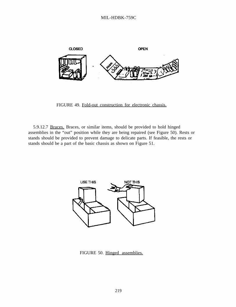
MIL-HDBK-759C
FIGURE 49. Fold-out construction for electronic chassis.
5.9.12.7 Braces. Braces, or similar items, should be provided to hold hingedassemblies in the “out” position while they are being repaired (see Figure 50). Rests orstands should be provided to prevent damage to delicate parts. If feasible, the rests orstands should be a part of the basic chassis as shown on Figure 51.
FIGURE 50. Hinged assemblies.
219

MIL-HDBK-759C
FIGURE 51. Use of maintenance stands.
5.9.12.8 Blind mounting. Where blind mounting is required, the inaccessible side should besecured with mounts which allow exceptionally easy mating and do not require access to frictionlugs or tongue-and-groove fittings.
5.9.13 Conductors.
5.9.13.1 General. Lines and cables should be selected, designed, marked, bound, routed, andinstalled so the following operations can be performed quickly.
a. Troubleshooting, testing, checking, and isolating malfunctions.
b. Tracing, removing, repairing, and replacing cables.
c. Removing and replacing other items and components.
d. Connecting and disconnecting.
5.9.13.1.1 Design recommendations.
a.
b.
c.
d.
Route cables so that they are not pinched by doors, lids and slides, are not walked on or usedfor handholds (see Figure 52), and are accessible to the technician, by not being underfloorboards, behind panels or components that are difficult to remove, or routed throughcongested areas, and need not be bent or unbent sharply when connected or disconnected(see Figures 53 and 54).
Design cables or lines which must be routed through walls or bulkheads for easy installationand removal without the necessity for cutting or compromising the integrity of the system.
Cable routing should avoid close contact with tubes, transformers, or rectifiers so that theywill not be damaged by overheating.
Provide guards or other protection for easily damaged conductors such as waveguides, high-frequency cables, or insulated high-voltage cables.
220

MIL-HDBK-759C
FIGURE 53. Cable connections.
FIGURE 52. Routing cables.
FIGURE 54. Cable bends.
221

MIL-HDBK-759C
222
e. Protect electrical wiring from contact with fluids such as grease, oil, fuel, hydraulic fluid,water, or cleaning solvents. These may damage insulation and result in injury to personnel.
f. Provide a means for keeping cables and lines off the ground. While permanent lines shouldnever be on the ground, keeping them clear is especially important in areas where ice andsnow may cover the lines for long periods, making them inaccessible for maintenance.
g. Where cable connections are maintained between stationary equipment and sliding chassis orhinged doors, provide service loops to permit movement, such as pulling out a drawer formaintenance without breaking the electrical connection. The service loop should have areturn feature to prevent interference when removable chassis are replaced in the cabinet.Figure 55 shows two methods of recoiling the cable.
h. Provide storage space for long electrical cables which are a part of ground power, service,and test equipment. Often a storage compartment is present, but no easy means is providedfor coiling the wire into a shape and size which will permit storage. A simple means is acable winder, a device around which the cable may be wrapped (see Figure 56). Use acircular spool as a cable winder to prevent bending radii of less than six times the diameterof the cable.
i. Precautions should be taken to protect the insulation at the ends of cables from moisture.Moisture-proof jacketing, which will withstand the required temperature range andmechanical abuse, should be used.
j. Provide protective covers for the cable to prevent damage to connectors during periods ofnon-use. Provisions should be made to secure the protective cover to the cable to avoidmisplacement.
5.9.13.1.2 Compatibility. Lines and cables should be compatible with interfacing connectors,fasteners, accesses, and environmental extremes to which they will be subjected.
5.9.13.2 Coding. Conductors should be coded and labeled so each conductor can be identifiedthroughout the length of each cable or harness, wherever tracing is required, and so codes andlabels correspond to connector designations, test point designations, and connector functions.

MIL-HDBK-759C
FIGURE 55. Methods for recoiling FIGURE 56. Cable winder.service loops.
5.9.13.2.1 Wires. Wires may be color coded by (in order of preference) solid-color insulation,solid-color insulation with colored-stripe tracer, or colored braid insulation with woven tracer.Every wire in a cable should be color coded over its entire length. There are 21 discriminablydifferent patterns of solid colors and solids with striped tracers (see Table 27).For more than 21 wires, see MIL-STD-686. If a wire’s color may become obscured, wires may becoded with numbered metal tags.
5.9.13.2.1.1 Number coding. Where wires are coded with numbers, the numbers should berepeated at least every 50 mm over the wire’s entire length.
5.9.13.2.1.2 Specific wire coding information.
5.9.13.2.1.2.1 Hook-up wire. Coding for hook-up wire is prescribed by MIL-STD-681.
5.9.13.2.1.2.2 Telephone, teletype, and telegraph wires. Coding for telephone, teletype, andtelegraph wire is prescribed by MIL-STD-685.
5.9.13.2.1.2.3 High- and low-tension power cables. Coding for high-tension power cables isprescribed by MIL-C-3702; coding for low-tension power cables is prescribed by MIL-C-13486.
223

MIL-HDBK-759C
224
TABLE 27. Electrical cable coding.
Number of Basic Instructions Conductor Color Tracer
1. Find the number of the 1 Black None conductor to be color 2 White None coded. 3 Red None
4 Green None2. The colors at the right 5 Orange None of the number are the 6 Blue None appropriate combination 7 White Black for that conductor. 8 Red Black For example, if a cable 9 Green Black consists of 12 10 Orange Black conductors, the twelfth 11 Blue Black color combination would 12 Black White be black with white 13 Red White tracer. The eighth 14 Green White color combination would 15 Blue White be red with black 16 Black Red tracer. The fifth 17 White Red color combination would 18 Orange Red be orange without 19 Blue Red tracer, and so on. 20 Red Green
21 Orange Green
NOTE: If a cable has concentrically laid conductors, the first combination or color applies to thecenter conductor. If a cable contains various sizes of conductors, the first color applies to the largest,continuing in order of conductor size.
5.9.13.2.2 Hydraulic and pneumatic conductors. Hydraulic and pneumatic conductors shouldeither be color coded (see Table 28) or coded by metal tags. Metal tags should be used whereadverse conditions (such as grease or mud) could obscure colors; otherwise, color coding shouldbe used.
5.9.13.3 Cable clamps. Clamps or plates that mount lines and cables should be spaced notmore than 610 mm apart so personnel can install or remove one with each hand with or withoutcommon hand tools, and have heat-insulating liners so they do not become hot enough thatpersonnel could be burned. They should be the quick-release hinged or spring type if cables areremoved frequently. Hinged clamps are preferable, because they support the weight of the lineduring maintenance, freeing the technician's hands for other tasks. For overhead mounting, aspring clamp should be used with a hinged-locking latch over the clamp's open side to preventaccidents.
5.9.13.4 Length. The length of cables should be the same for each installation of a given typeof electronic equipment if the circuit might be affected by differences in the length of the cable.

MIL-HDBK-759C
225
(Even if a unit can be adjusted to compensate for differences in the length of the cable, usingdifferent lengths of cable means that an adjustment made on the bench might be out of tolerancewhen the unit is installed.)
TABLE 28. Hydraulic and pneumatic coding.
Function Color Definition of Function
Intensified pressure
Black Pressure in excess of supply pressure induced by abooster orintensifier.
Supply pressure
Red Pressure of the power-actuating fluid.
Charging Intermittent Pump-inlet pressure, higher than pressure Red atmospheric pressure.
Reduced pressure
Intermittent Red Auxiliary pressure lower than supply pressure.
Metered flow Yellow Fluid at a controlled flow rate (other than pumpdelivery).
Exhaust Blue Return of the power-actuating fluid to reservoir.
Intake Green Subatmospheric pressure, usually on the intakeside of the pump.
Drain Green Return of leakage of control-actuating fluid toreservoir.
Inactive Blank Fluid within the circuit but not serving a functionalpurpose during the phase being represented.
5.9.13.4.1 Extension cables. Use extension cables to:
a. increase efficiency and make maintenance easier,
b. test assemblies or components without removing them,
c. check each functioning unit in a convenient place,
d. allow parking support equipment or setting it in a convenient place, and

MIL-HDBK-759C
226
e. serve as many related functions as possible, avoiding the possibility of misuse ormisconnection.
5.9.13.4.2 Handling and storage. There should be adequate provision for handling and storingextension cables and cables used with ground power, service, and test equipment. Adequate,covered space should be provided for storing lines and cables in support equipment. Suitableracks, hooks, or cable winders should be available and conveniently accessible in the storage spaceto hold lines and cables. Reels or reel carts should be used for handling large, heavy, or very longlines and cables. Automatic or power tensioning or rewinding reels should be used where possibleto make handling easier. Wheeled or mobile supports also should be used for extra-large lines andcables that must be moved frequently.
5.9.13.5 Cable routing.
5.9.13.5.1 General. Interconnecting communication cables should be routed to minimize thepossibility of their use as handholds or steps. A protective guard should be placed over the cableswhere the possibility of such use exists.
5.9.13.5.2 Maintenance. Cable routing should facilitate ease of maintenance by ensuring thateach unit can be checked in a convenient place (extension cables should be provided whennecessary). Units in drawers and slide-out racks should be able to be pulled out to be worked onwithout breaking electrical connections. Connectors should be reached easily for replacement orrepair, and units that are difficult to connect where they are mounted should be capable of beingmoved to a more convenient position for connecting and disconnecting.
5.9.13.5.3 Mounting. Lines and cables should be routed and mounted so that they fulfill theconditions listed below.
a. They should be accessible without disassembling or removing other equipment.
b. Points of connection, mounting, splicing, or testing should be especially accessible.
c. They can be removed and replaced completely if they are damaged.
d. There are accesses and clearances for removing and replacing them.
e. Personnel will not use them for handholds or footsteps and will not step or walk on them.
f. Moving and rotating parts will not snag them, and so they do not interfere with normaloperations.
g. Cables routed through metal partitions should be protected by use of insulating grommets.
h. Foreign objects, such as flying stones, will not damage them.

MIL-HDBK-759C
227
i. Cables routed in areas where potential risks for degradation are high (passageways; acrosswalkways; or exposure to adverse conditions such as oil, blasts, and heat) should be protectedby conduit.
5.9.13.5.4 Layout and routing. The layout and routing of wires should be made as simple andlogical as possible by combining wires into cables (preferable) or into harnesses, minimizing thenumber of wires, harnesses, and cables, and grouping conductors into cables, and within cables orharnesses, by their functions and relationships to replaceable items. Electrical wires, harnesses,and cables should be mounted so there is adequate accessibility through raceways, conduits, andjunction boxes. Electrical wires and cables should be mounted over, rather than under, pipes orfluid containers.
5.9.13.5.5 Leads.
5.9.13.5.5.1 Length. Leads should not be longer than necessary, but their lengths should alloweasy connection and disconnection with enough slack to back wires away from attachment pointsso units can be removed easily. They should be long enough to allow slack so terminal fittings canbe replaced at least twice, and preferably three times (if electrical considerations permit). Leadsalso should be long enough to permit units which are difficult to handle when mounted to bemoved to a more convenient position for connection or disconnection.
5.9.13.5.5.2 Mounting. Leads should be mounted so they are separated far enough to clear thetechnician's hand or any tool required for checking or connecting them, and oriented, wherepossible, so they will not be connected incorrectly or crossed.
5.9.13.5.6 Junction boxes. Cables should fan out in junction boxes for easy inspection,especially if there are no other test points in the circuits (Figure 57). Each terminal in the junctionbox should be clearly labeled and easy to reach with test probes.

MIL-HDBK-759C
FIGURE 57. Cable inspection.
5.9.13.5.7 Harnesses. Cable harnesses should be designed so they can be built in a shop orfactory and installed as a package.
5.9.13.5.8 Preformed cables. Use preformed cables when possible (see Figure 58). Theypermit flexible, more efficient assembly methods and minimize the chances of making wiringerrors. They also permit testing and coding of the entire cable before installation. Once the cableis placed in position on the chassis, the leads can be connected without the usual interference andconfusion caused by stray wires.
FIGURE 58. Preformed cables.
5.9.13.6 Cable Protection.
5.9.13.6.1 Plastic covering. Consider using clear plastic covering to insulate leads on cables sothat breaks in internal wiring can readily be seen. Neoprene-covered, rather than aluminum-sheathed cable, should be used in areas where intense vibration or corrosive substances may causefailures. These coverings should remain flexible at low temperatures.
228

MIL-HDBK-759C
229
5.9.13.6.2 Wires. When polyvinyl wire is used, care should be taken so there will be no coldflow of the insulation resulting from tightness of the lacing or mounting. High-temperature wireshould be used when wires are routed near ducts carrying pressures over 3.5 x 10⁵ Pascals and/ortemperatures above 200° C. Wires and coverings also should remain flexible at the lowtemperatures encountered in cold regions. Color code or number code insulated wire and cable inaccordance with MIL-STD-195 and MIL-STD-681.
5.9.13.6.3 Metallic shielding. Metallic shielding, unprotected by outer insulation, should besecured to prevent the shielding from contacting exposed terminals or conductors.
5.9.13.7 Fluid and gas lines.
5.9.13.7.1 Personnel and equipment protection. Lines should be kept from spraying or drainingfluid on personnel or equipment when they are disconnected by locating connections away fromwork areas and sensitive components, shielding sensitive components where required, andproviding drains and bleed fittings so lines can be drained, or depressurized, before they aredisconnected. Cutoff valves should be provided at appropriate locations in the system to permitisolation or drainage of the system for maintenance or emergency purposes.
5.9.13.7.2 Mounting and installation. Lines should be mounted and installed so that rigid lineswith fittings do not have to be backed-off before they can be disconnected. Flexible tubing, ratherthan rigid lines, should be used where feasible because it allows easier handling, can be backed-offeasily, and is easier to thread through equipment when it must be replaced. Flexible hose, ratherthan pipes or tubing, should be used when there is only limited space for removing, replacing, orhandling lines. It can be backed-off or pushed aside for access to other components. Fuel linesshould not be routed above electrical cables or above hot pipes or areas.
5.9.13.7.3 Prevention of mismating. To avoid the possibility of mismating connectors duringservice or maintenance, standardize fittings so lines which differ in content cannot beinterchanged. Lines should be coded by arrangement, size, shape, and color as necessary, andcolored bands should be used to identify all lines that carry fluids.
5.9.13.7.4 Fluid and gas connectors. Connectors for pipes, tubing, hoses, and similarconnectors should be located and installed so that it is unnecessary to jack the equipment up todrain it, fill it, or perform other maintenance involving the connectors, and so that the techniciancan perform leakage tests easily and without danger. Tests should be planned so the technician'shead is not in areas of extreme noise, vibration, or other danger while the equipment is running.
5.9.13.7.5 Gaskets and seals. Gaskets and seals should be selected and installed so that theycan be replaced easily without removing other connector parts or disassembling other equipment.Part of a gasket or seal should be visible after it is installed as a check on failure to replace sealsafter disassembly. There should be job instructions giving the expected life of seals and gasketsand recommending when they should be changed.

MIL-HDBK-759C
230
5.9.13.7.6 Drainage problems. Prevent drainage problems by:
a. designing lines so they can be emptied completely when necessary,
b. making bends horizontal, rather than vertical, to avoid fluid traps,
c. avoiding low points or dips in lines that make them difficult to drain,
d. providing special drains at low points where necessary, and
e. providing cutoff valves at appropriate points in the system to permit isolation or drainage ofparticular lines for maintenance or emergency purposes.
5.9.13.7.7 Supports. Adequate supports should be provided for lines from external service ortest equipment, or where extensions will be attached for other purposes. These supports shouldwithstand not only the initial pressure through the line and the weight of its external extensions,but the rigors of handling and repeated connection and disconnection as well.
5.9.13.8 Wiring and cables.
5.9.13.8.1 General. Standardized connectors should be provided. Bonding points should beaccessible and their securing screws should have vibration-proof washers.
5.9.13.8.2 Safety precautions. The following general safety precautions should be adhered toduring selection, routing, and maintenance of wires and cables.
a. Test points should be provided for checking components when their terminals are notaccessible.
b. Electrical shielding should be easy to remove.
c. All ground return connections should be brought to a common, grounded, bus bar.
d. All wiring should be positioned away from sharp corners.
e. Wiring passing through unprotected holes in metal parts should be protected by grommets.
f. All electrical cables should be oil-proof, unless their location provides adequate protectionagainst contact with oil.
g. Exposed cables should be protected from mechanical damage. (Consider the use of armoredcables in such installations.)
h. Long unsupported lengths of cable or wire should be avoided.
i. Cables may be run inside frame members, providing they are accessible and not exposed toheat or oil.

MIL-HDBK-759C
231
j. Electrical cables should be color-coded or tagged for ease of identification.
k. Electrical cables should be of the quick-disconnect type wherever possible (see Figure 59).
l. Wires and coverings should remain flexible at the low temperatures encountered in coldregions.
5.9.14 Connectors.
5.9.14.1 General.
5.9.14.1.1 Compatibility. Connectors should be compatible with lines and cables, fasteners,mounting, environmental extremes and maintenance routines to which they will be subjected.
5.9.14.1.2 Selection and design. Connectors should be selected, designed, and mounted forfast, easy maintenance operations, and easy removal and replacement of components and units.Connector design should also allow the most rapid set-up test and service of equipment andminimize danger to personnel and equipment contents, from pressures, contents, voltages, or linesduring the release of connectors. Use of tools to perform connect or disconnect operations is notdesirable from a human factors viewpoint; therefore, connectors should be easily connected anddisconnected by hand where possible.

MIL-HDBK-759C
Time required for removal of cables Recommend that wiring harnesseswas approximately 2 hours. Removal be equipped with quick-disconnectof 10 or 15 individual bolt-on fittings. Pin and socket typeconnections and drawing harnesses quick-disconnect fittings can beout of boxes and through conduit separated in no more than 3 minuteswill result in higher mortality for all three cables.rate on wiring and unnecessarydowntime.
FIGURE 59. Quick-disconnect cable connections,
5.9.14.1.3 Accessibility. Connectors should be accessible without disassembly or removal ofother equipment or items. In proportion to how often they are operated, connectors used duringpreoperating checks should be the most accessible.
5.9.14.1.4 Location. Connectors should be located so that personnel can see and reach themeasily to connect or disconnect them safely. Access to perform the function should be madeavailable. Fluid connector leakage or accidental spillage should be controlled as necessary toprevent damage to equipment.
5.9.14.1.5 Protection from damage. Connectors should be designed and located so they willnot be damaged by moving personnel, shifting objects, opening doors, excessive tightening ormanhandling during operation, shorts, arcing from foreign objects, erroneous connection, orhandling after disconnection. Protect connectors by recessing receptacles; by recessing delicateparts such as pins and keys within the connector so they are not exposed to harmful contact; andby providing protective caps, inserts, covers, cases, and shields as necessary.
5.9.14.1.6 Mismating and cross-connections. Connectors should be selected, designed, andinstalled so they cannot be mismated or cross-connected. The following means should beconsidered.
a. Different sizes or types of connectors should be used.
b. Cables should be arranged so their lengths correspond to the distances from the connector tothe correct point of attachment.
232

MIL-HDBK-759C
233
c. Wires should be arranged or separation blocks or other mounts should be provided, so thesequence of leads is obvious.
d. Connectors should be polarized or different sizes of prongs and prong receptacles should beused so lines with different voltages cannot be mismatched. If different size prongs on prongreceptacles are used, the difference should be obvious enough to preclude attempts to mateand potentially damage connectors.
e. Different, mutually incompatible and irreversible arrangement of guide pins, keys, or prongsshould be used.
f. Connectors and receptacles should be color-coded or labeled so mismating is unlikely.
5.9.14.2 Classification (in order of preference).
5.9.14.2.1 Plug-in connectors. Plug-in connectors are the fastest and easiest to use, but theyhave low holding power; therefore plug-in connectors should not be used when accidental pulls onthe cable may disconnect them. Plug-in connectors should be used for cables that are connectedand disconnected frequently.
5.9.14.2.2 Quick-disconnect devices. Quick-disconnect devices have a variety of forms,including any type of connector that can be released by snap action, twisting up to a full turn,triggering a latch or spring device, or removing an external pin. Use quick-disconnect devices toconnect items which must be disconnected or replaced frequently and items which must bereplaced within critical readiness times.
5.9.14.2.3 Threaded connectors. Threaded connectors provide very secure connections,particularly when locked into place by set screws, retainers, or safety wires. They usually takelonger to operate, depending on the number of turns and the types of tools they require. Threadedconnectors should use the fewest turns that will satisfy holding requirements, be operable by handif used for electrical connections, require only common hand tools, and minimize the danger ofaccidentally loosening other connectors while working on one.
5.9.14.3 Identification. Connectors and associated parts and wiring should be coded andidentified to key them to references in the job instructions and identify replaceable items and partsfor reordering. Coding will expedite and facilitate maintenance and troubleshooting procedures,indicate the sequence routine or test procedures, and provide adequate warnings or cautions aboutusing connectors.
5.9.14.3.1 Labeling. Label or code connectors and receptacles to ensure that:
a. each plug is clearly identified with its receptacle,
b. each wire is clearly identified with its terminal post or pin,
c. test points are clearly identified by a unique mark or symbol,

MIL-HDBK-759C
234
d. non-interchangeable connectors are clearly distinguishable, and
e. the manner of connection or disconnection is obvious.
Plugs and receptacles should have painted strips, arrows, or other indications to show howconnector interfaces should be aligned for proper connection. Terminal strips and circuit boardsshould be permanently marked to identify individual terminals and facilitate their replacement,and power receptacles for primary, secondary, or utility systems should be clearly labeled toprevent personnel injury or equipment damage.
5.9.14.3.2 Location. Labels or codes on connectors and associated items should be located sothat they are optimally visible during maintenance and are visible whether the connector isconnected or disconnected. It should be possible to identify connectors without disconnectingthem, and their positions should be consistent in relation to associated pins, terminals, andreceptacles.
5.9.14.3.3 Order of preference. The location of labels or codes is, in order of preference, first,directly on the connector and receptacle; second, on plates permanently attached to the connectorand receptacle; and third, on tabs or tapes attached to the connector. On receptacles, labels andcodes should be placed on the surface or panel immediately adjacent to the receptacle and onrecessed receptacles, on or near the access opening.
5.9.14.4 Aligning pins and keyways. Alignment keys or pins should be designed and locatedwithin the plug so that they extend beyond electrical pins to protect the pins from damage if theconnector is misaligned and should be arranged asymmetrically to prevent incorrect pluginsertions. All alignment pins for a given plug or series of plugs should be oriented in the samedirection. If this conflicts with precautions against mismating, pin orientations should differconsistently and systematically for the technician's convenience.
5.9.14.5 Coding. Coding connector receptacles and plugs is an important aid that helpsoperators associate input and output lines connecting different items of equipment. Some codingshould be provided to associate each connector with its mate.
5.9.14.5.1 Color coding.
5.9.14.5.1.1 General.
a. All colors used for coding should be readily discriminable from each other under operationallighting.
b. Colored areas should be protected, in so far as possible, to keep the color from wearing off,fading, or disappearing.
c. Permanently applied colors are preferable to adhesive tapes or bent-on tapes.
d. If many connectors must be coded and there are not enough easily discriminable colors,matching patterns of colors and/or stripes should be used.

MIL-HDBK-759C
235
e. Colors used to code connectors should be consistent and have the same meaning throughoutthe system.
5.9.14.5.1.2 Two color-coding methods. Either of two color-coding methods may be used forelectrical connectors. Apply the same coding color to the face of the receptacle and the base ofthe plug or apply the same coding color to an area around the receptacle, and a band around theplug.
5.9.14.5.2 Shape codes. Connectors may be coded by using various shapes of matching plugsand receptacles (see Figure 60). Different shapes of alignment pins also may be used todifferentiate connectors and to prevent mismating.
5.9.14.5.3 Pin configurations. Still another coding method is using connectors with differentnumbers and configurations of pins (see Figure 61) or unique keyway slots so that it is physicallyimpossible to mismate connectors without breaking them. However, to prevent such damage,designers should select and code connectors so it is obvious which pairs do, or do not, match.Users should not be tempted nor encouraged to make mistakes. When a plug and a receptaclelook generally similar but do not mate, use additional coding to differentiate them.
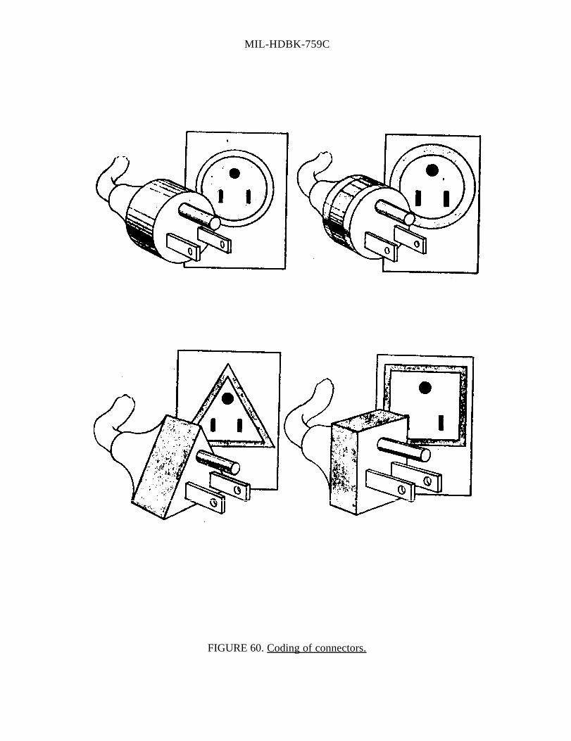
MIL-HDBK-759C
FIGURE 60. Coding of connectors.

MIL-HDBK-759C
FIGURE 61. Identifying plugs and receptacles to prevent mismatching.
237

MIL-HDBK-759C
238
5.9.14.6 Electrical connectors. Electrical plugs should be designed, installed, and mounted so thatit is impossible to insert a plug into a wrong receptacle or into the correct receptacle the wrongway. Wherever possible, plugs should have multiple contacts to reduce the number of plugs and,consequently, the number of maintenance operations. Connectors should "plug-in" or secure withno more than one complete turn, especially with auxiliary or test equipment. Wiring should berouted through the plugs and receptacles so disconnection does not expose "hot" leads. Examplesof "hot" contacts are socket contacts and female connectors. Receptacles should be "hot" andplugs should be "cold" when disconnected. Plugs should be self-locking or use safety catchesrather than requiring safety wiring; plugs should have low insertion forces to minimize thepossibility of damaging contact surfaces.
5.9.14.7 Electronic modules.
5.9.14.7.1 General. There are two primary reasons for designing electronic equipment withrelatively small, removable or replaceable units. Constructing electronic equipment with easilyremovable assemblies, subassemblies, and components permits the division of maintenanceresponsibility. This design permits rapid corrective maintenance at the user level. Whenequipment is built with removable units, it is easier to work on malfunctioning parts.
5.9.14.7.2 Design recommendations.
a. Replaceable components should be designed so they cannot be installed in the wrong way.Also, if two parts are physically interchangeable, they should be functionallyinterchangeable. Designs, mockups, and manufacturing processes should be continuallyreviewed to identify and correct, or compensate for, all potential sources of such errors.
b. Tapered alignment pins, quick-disconnect fasteners, and other similar devices should be ableto facilitate removal and replacement of components.
c. Mounting brackets and surfaces should be designed so that mounting bolts and fasteners canbe placed on a surface adjacent to the technician's workspace. Guides and guide pins shouldbe provided for alignment of units on mountings (see Figure 62).
d. Where possible, units should be designed so they are removable along a straight, or slightlycurved line, rather than through an angle (see Figure 63).

MIL-HDBK-759C
FIGURE 62. Alignment guides and guide pins.
FIGURE 63. Equipment removal.
239

MIL-HDBK-759C
e. Mounting brackets should be designed so that the component can be installed only in thecorrect position. Where space permits, side-alignment brackets which permit installation inonly one position should be provided (see Figure 64).
FIGURE 64. Use of side-alignment brackets.
f.
g.
h.
i.
j.
k.
1.
Bottom-mounted aligning pins should be used for components which are light enough to belifted easily. Such aligning pins are not desirable for heavy components because theyrequire a lifting process for aligning the component. Side-aligning devices, similar to theone shown in Figure 64, are more desirable for heavy components because the componentcan be slid into place.
Symmetrical components should be coded, labeled, or keyed to indicate the properorientation for mounting or installation.
Opening more than one access panel to remove any single unit should not be required.
Components should be positioned so that the technician does not have to reach too far forheavy units.
For components that are heavy or relatively inaccessible, slide-out racks should be provided.When using roll-out mounting racks, limit stops should be provided to prevent dropping thecomponents.
Units should be designed for easy connection to each other and to the housing in which theyare installed.
Electronic and electrical units should be designed with plug-in rather than solder connections.
m. When using AN connectors, the quick-disconnect type (see Figure 65) should be specified.
240

MIL-HDBK-759C
n.
o.
p.
q.
r .
s.
t.
FIGURE 65. Types of AN connectors.
Incorrect assembly should be made difficult by using different sizes, or completely differenttypes of connectors. Where incorrect assembly is possible, use coding techniques such asdifferent color, size, and shape.
Connectors requiring no tools (or only common hand tools) and with only a fraction of a turnor quick-snap action should be used.
Mounting bolts, screws, and fasteners that can be easily removed and replaced withminimum chance for error should be provided. Use captive bolts and nuts to preventdropping small items into the equipment.
Small removable parts such as pins, caps, and covers should be attached to the main body ofthe equipment by small chains or other suitable means to prevent their loss. Because someretainers tend to break apart, especially when kinked, care should be exercised in theselection of suitable retainers to ensure that they meet performance requirements.
Lock washers or other restraining measures should be used to prevent bolts and nuts fromvibrating loose. Safety wire is not generally recommended, but if it must be used, a simplemeans of attaching it should be provided.
The weight of components should be kept under 13.6 kg where possible.
Adequate handles on all units weighing more than 4.5 kg should be provided. Handlesshould be provided for units weighing less than 4.5 kg if they might otherwise be difficult tograsp, remove, or hold.
5.9.14.8 Cabling and connectors checklist. Checklists summarizing the importantmaintainability design features relating to cables (Table 29) and connectors (Table 30) arepresented below. These checklists contain items which were not discussed separately in the text.These items are included here because their necessity in the design is so obvious that they mightotherwise be inadvertently overlooked. In using the checklist, if the answer to any question is NO,the design should be restudied to ascertain the need for correction.
241

MIL-HDBK-759C
242
TABLE 29. Cable checklist.
1. Are cables long enough that each functioning unit can be checked in a convenient place?
2. Can units which are difficult to connect when installed, be moved to convenient positions forconnecting and disconnecting?
3. Are cable harnesses designed for fabrication in a shop as a unit?
4. Are all cables color coded and are both ends tagged? Can the selected colors bedistinguished?
5. Are cables and lines directly accessible to the technician wherever possible (not underfloorboards or behind panels which are difficult to remove)?
6. Are cables routed so they need not be bent or unbent sharply when being connected ordisconnected?
7. Are cables routed so they cannot be pinched by closing doors or lids or so they will not bestepped on or used as handholds by maintenance personnel?
8. Are cables or lines attached to units which can be partially removed (chassis on slide racks)and attached so units can be replaced conveniently without damaging the cable or interferingwith securing the unit?
9. Is a 75 mm minimum clearance provided wherever possible between control cables andwiring? Has the designer anticipated potential chafing hazards and provided physical meansto prevent chafing?
10. Is electrical wiring routed away from all lines that carry flammable fluids or oxygen?
11. Is care taken in design of cable conduits to prevent collection of water or debris which couldinterfere with operation of a control system (freezing or short circuiting)?
12. Is the necessity for removing connectors or splicing lines avoided?
13. Is direct routing through congested areas avoided wherever possible?
14. Are cable entrances on the fronts of cabinets avoided where it is apparent they could be"bumped" by passing equipment or personnel?
15. Are cables flexible in severe cold temperatures?

MIL-HDBK-759C
243
TABLE 30. Connector checklist.
1. Are adjacent solder connections far enough apart so work on one connection does not compromisethe integrity of adjacent connections?
2. Are connector plugs designed so that pins cannot be damaged (aligning pins extended beyondelectrical pins)?
3. Are self-locking safety catches rather than safety wire provided on connector plugs?
4. Are connectors designed so that it is physically impossible to reverse connections or terminals inthe same or adjacent circuits?
5. Is the use of special adapters avoided since these are often lost?
6. Are electrical connectors protected from possible shorting through contact with external objects?Are adequate covers provided on electrical connectors to prevent foreign matter from shorting outthe connector or causing damage to the connector threads and pins? Are provisions made tosecure the cover to the connector to avoid misplacement during periods of non-use?
7. Are separate ground connections provided for each voltage regulator so that a single groundingfailure does not cause failure of several other systems?
8. Are quick-disconnect devices used wherever possible to save time and minimize human error(fractional-turn, quick-snap action, and press fit)?
9. Are unkeyed symmetrical arrangements of aligning pins on connectors avoided?
10. Are electrical terminals plainly marked +(plus) or -(minus), since the marked caps may be lost?
11. Do markings on plugs, connectors, and receptacles show proper position of keys for aligning pinsfor proper insertion position?
12. Is the use of identical fittings avoided by staggering location, varying lengths, size or shape, orby shape, symbol, or color coding?
13. On cable-connected removable units, will plug and receptacle disconnect before cable breaks?
14. Are connectors located for easy accessibility for replacement or repair?
15. Are U-lugs (spade) used in lieu of O-lugs (ring) where frequent removals are anticipated?
16. Are auxiliary-equipment connectors used that do not require tools for their operation?

MIL-HDBK-759C
244
TABLE 30. Connector checklist - continued.
17. If tools must be used to operate connectors, are only standard tools required?
18. Do connectors used to connect test equipment to a test point require not more than one fullturn?
19. Can wires be unsoldered and removed without damaging plugs?
5.9.15 Test points.
5.9.15.1 General. In order to make testing and servicing as simple as possible, therecommendations of this section should be considered by the designer.
5.9.15.1.1 Arrangement of test points. Test points should be arranged on a panel or othersurfaces according to the criteria listed, in order of priority.
a. The type of test equipment used at each point.
b. The type of connector used and the clearances it requires.
c. The function to which each point is related.
d. The test routines in which each point will be used.
e. The order in which each will be used.
5.9.15.1.2 Design considerations. In order for the operator to best use the test and servicepoints on equipment, the following criteria are recommended for consideration by the designer.These test and service points should be provided, designed, and located:
a. According to the frequency and time requirements of use.
b. So that there will be a minimum of disassembly or removal of other equipment or items.
c. On surfaces or behind accesses which may be easily reached or readily operated when theequipment is fully assembled and installed.
d. To be clearly distinguishable from each other (where necessary use color coding andlabeling).
e. So that test points and their associated labels and controls face the technician.

MIL-HDBK-759C
245
f. So that adequate clearance is provided between connectors, probes, and controls for easygrasping and manipulation. Minimum clearances recommended are 19 mm when onlyfinger control is required, and 75 mm when the gloved hand must be used.
g. So they offer positive indication, by calibration, labeling or other features, of the direction,degree, and effect of the adjustment.
h. With guards and shields to protect personnel and test or service equipment, particularly ifthe equipment must be serviced while operating.
i. At a central panel or location, or at a series of functionally autonomous panels andlocations.
j. To avoid locating a single test or service point in an isolated position; such points are mostlikely to be overlooked or neglected.
k. With lead tubes, wires, or extended fittings to bring hard-to-reach test and service points toan accessible area.
l. To overcome accessibility deficiencies resulting from critical lead lengths and similarconstraints.
m. With windows to internal items requiring frequent visual inspections, such as gauges andindicators.
n. With tool guides and other design features to facilitate operation of test or service pointswhich require blind operation.
o. Within easy functional reach or seeing distance of related or corresponding controls,displays, fittings, and switches.
p. Away from dangerous electrical, mechanical, or other hazards. A hand's width (115 mm)separation should be provided from the nearest hazard along with guards and shields, asnecessary to prevent injury.
q. So they are not concealed or obstructed by the hull, turret, brackets, or other items.
5.9.15.1.3 Other considerations. The following topics represent areas not covered in the aboveparagraphs but are still important design considerations.
a. Templates or overlays should be provided where they will expedite the use of different testprocedures which use the same set of test points.
b. The maximum use of color codes, guidelines, symbols, and labels should be made tofacilitate following logical test routines among the test points.

MIL-HDBK-759C
246
c. Distinctively different connectors or fittings should be provided for each type of test orservice equipment, probe, grease, or oil to minimize the likelihood of error or misuse.
d. Requirements for separate funnels, strainers, adaptors and other accessories should beavoided. Where practical, these should be built into the equipment or service equipment,so they need not be handled separately.
e. Test points should be combined, where feasible, into clusters for multi-prongedconnectors, particularly where similar clusters occur frequently.
f. Lubrication points should be provided to avoid disassembly of equipment; but if suchpoints are not feasible, easy access should be provided for direct lubrication.
5.9.15.2 Adjustment.
5.9.15.2.1 General. Where adjustment controls are associated with test and service points, theyshould be designed and positioned as listed below.
a. They are located on a single panel or face of the equipment, or on a minimum number offunctionally independent panels.
b. They are capable of being quickly returned to the original settings, to minimizerealignment time if they are inadvertently moved.
c. Adjustments are independent of each other whenever possible.
d. Those that require sequential adjustment are located in the proper sequence and marked asnecessary to designate the order of adjustment.
e. Adjustment procedures are clear and straightforward and do not require conversion ortransformation of related test values.
f. Knobs are used in preference to screwdriver adjustments; the latter are generallyunsatisfactory from the standpoint of easy manipulation and the requirement for tools.
5.9.15.2.2 Adjustments to avoid. The following types of adjustment are to be avoided, exceptwhere their use will considerably simplify the design or use of the equipment.
a. Extremely sensitive adjustments.
b. "System adjustments," such as where components cannot be replaced without recalibratingthe whole system.
c. Harmonizing or "mop-up" adjustments, such as those that require "A" or "B" to bereadjusted after A, B, and C have been adjusted in sequence.
MIL-HDBK-759C
247
5.9.15.3 Troubleshooting. The following arrangements are intended to help the designerevaluate the adequacy of the test point arrangement.
a. A built-in test unit, built in as part of the installation, is most desirable for efficientmaintenance and troubleshooting. For example, if voltages and wave shapes must bechecked, the test unit might consist of a meter, an oscilloscope, and a rotary switch forselecting circuits, as shown in Figure 66A. The meter and oscilloscope should have fixed,preset circuits so that the meter always reads center scale and the oscilloscope needs noadjustment. Either an in-tolerance meter reading or an in-tolerance waveform on theoscilloscope should be coded for each position of the rotary switch. If more test points areneeded than can be handled by a single switch, multiple switches could be used.
b. A partially built-in test unit is sometimes preferred because some oscilloscopes are large,heavy, and expensive. It might not be practical to design a test unit such as thatrecommended in above for each major component of a system. An acceptablecompromise is to mount a center-reading meter on each major component that can bechecked by meter and then provide a set of test jacks as an outlet for signals requiring anoscilloscope, as shown in Figure 66B. The selector switch and circuits for thisarrangement should be designed as before.
c. A portable test unit may be required if neither of the two previous arrangements ispracticable because of space or weight limitations. An integrated portable test unitresembling the built-in unit can be designed, as shown in Figure 66C. A single multi-prong contact, on the end of a cable, can be used to attach the test unit.

MIL-HDBK-759C
248
METER
OSCILLOSCOPE
SELECTOR SWITCH
OSCILLOSCOPE
METER
SELECTORSWITCH
A. Built-In Test Unit B. Partially Built-In Test Unit
TEST UNIT
TEST PANEL
C. Portable Test Unit D. Built-In Test Panel
FIGURE 66. Alternate methods for grouping test points.
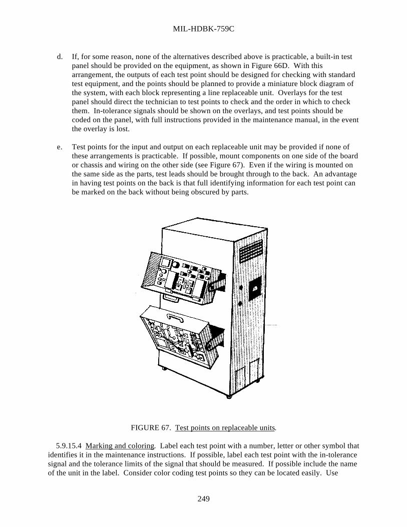
MIL-HDBK-759C
249
d. If, for some reason, none of the alternatives described above is practicable, a built-in testpanel should be provided on the equipment, as shown in Figure 66D. With thisarrangement, the outputs of each test point should be designed for checking with standardtest equipment, and the points should be planned to provide a miniature block diagram ofthe system, with each block representing a line replaceable unit. Overlays for the testpanel should direct the technician to test points to check and the order in which to checkthem. In-tolerance signals should be shown on the overlays, and test points should becoded on the panel, with full instructions provided in the maintenance manual, in the eventthe overlay is lost.
e. Test points for the input and output on each replaceable unit may be provided if none ofthese arrangements is practicable. If possible, mount components on one side of the boardor chassis and wiring on the other side (see Figure 67). Even if the wiring is mounted onthe same side as the parts, test leads should be brought through to the back. An advantagein having test points on the back is that full identifying information for each test point canbe marked on the back without being obscured by parts.
FIGURE 67. Test points on replaceable units.
5.9.15.4 Marking and coloring. Label each test point with a number, letter or other symbol thatidentifies it in the maintenance instructions. If possible, label each test point with the in-tolerancesignal and the tolerance limits of the signal that should be measured. If possible include the nameof the unit in the label. Consider color coding test points so they can be located easily. Use

MIL-HDBK-759C
250
phosphorescent or chemoluminescent markings on test points, selector switches and meters thatmight have to be read in very low ambient illumination.
5.9.15.5 Test points checklist. The following checklist (Table 31) summarizes some of theimportant features pertaining to the design of test points. The checklist contains several itemswhich were not discussed separately in the text. These items are included here because theirnecessity in the design is so obvious that they might otherwise be inadvertently overlooked. Inusing the checklist, if the answer to any question is NO, the design should be restudied to ascertainthe need for correction.
TABLE 31. Test points checklist.
1. Are test points located on the front panel wherever possible?
2. Is accessibility of external test points assured under conditions of use?
3. Are test points grouped for accessibility and convenient sequential arrangement of testing?
4. Is each test point labeled with name or symbol appropriate to that point?
5. Is each test point labeled with the in-tolerance signal or limits which should be measured?
6. Are test points labeled with the designation of what output is available?
7. Are all test points color coded with distinctive colors?
8. Are test points provided in accordance with the system test plan?
9. Do test-lead connectors require no more than a fraction of a turn to connect?
10. Are test points located close to controls and displays with which they are associated?
11. Is the test point used in an adjustment procedure associated with only one adjustmentcontrol?
12. Are means provided for an unambiguous signal indication at a test point when the associatedcontrol has been moved?

MIL-HDBK-759C
251
TABLE 31. Test points checklist - continued.
13. Are test points located so the technician operating the associated controls can read thesignals on the display?
14. Are test points provided for a direct check of all replaceable parts?
15. Are fan-out cables in junction boxes used for checking if standard test points are notprovided?
16. Are test points planned for compatibility with the maintenance skill levels and not randomlylocated?
17. Are test points coded or cross-referenced with the associated units to indicate the location offaulty circuits?
18. Are test points provided to reduce the number of steps required (split-half isolation oftrouble, automatic self-check sequencing, minimizing of step retracing or multipleconcurrent tests)?
19. Are test points located so as to reduce hunting time (near main access openings, in groups,properly labeled, near primary surface to be observed from working position)?
20. Are test points which requiring test-probe retention designed so that the technician will nothave to hold the probe?
21. Are built-in test features provided wherever standard portable test equipment cannot beused?
22. Can the technician gain access to routine check points without removing the unit or moduleor removing a cover from the cabinet?
23. Are test points adequately protected, illuminated, and accessible?
24. Are routine test points available to the technician without removing the chassis from thecabinet?
5.9.16 Test equipment.
5.9.16.1 General. Regardless of the engineering sophistication of the testing device, unless thetechnician recognizes it as being useful, reliable, and operable, the technician will avoid using it,and the design will be, for all practicable purposes, wasted. To design for usability, the designershould consider the statements listed below.

MIL-HDBK-759C
252
a. Technicians are trained to use complex devices, but they occasionally forget what theylearn.
b. Technicians avoid using devices they do not understand or find difficult to operate.
c. Supervisors hesitate to let technicians use expensive, complex equipment when theoperation of the equipment is not simple or self-evident.
d. When test equipment is overly complex and difficult to operate, the technician:
(1) must spend considerable time and effort learning to operate it,
(2) tends to make errors in usage,
(3) can learn to operate only a small number of devices well, and
(4) finds that habits developed with one device interfere with learning to use or operateanother device.
e. Military testers, which are drab, unattractive and apparently rugged, actually get roughertreatment than those which look fragile or have eye appeal. Therefore, testers should bedesigned to look no tougher than they are, and to compensate for the rough treatment theyare likely to receive.
5.9.16.1.1 Common complaints about available test devices. The following list providescommon complaints about available test devices or reasons for not using them. Each of thesereasons is a result of inadequate consideration of the user during design and should be avoided inthe design of new devices.
a. The device was too clumsy, heavy, or awkward to carry to the job.
b. There were an unnecessarily large number of different test devices.
c. Procedures and displays were inconsistent from device to device.
d. There was confusion as to the accuracy, operation, or purpose of the device.
e. The device was inaccurate, unreliable, or too often out-of-tolerance.
f. Calibration was too difficult and kept the device out of use too often.
g. The device was not compatible with the tested equipment. For example, connectors weretoo loose or too hard to reach, leads were not long enough, or workspace was too small touse the device.
5.9.16.1.2 Operation and maintenance.

MIL-HDBK-759C
253
a. Equipment should be made simple to operate and provide self-checking calibrationfeatures.
b. Test equipment should be designed for one-person operation.
c. A simple method to calibrate test equipment should be provided. Equipment should beequipped with a go/no-go indicator or simple check to determine whether the tester ismalfunctioning or needs calibration.
d. A warm-up indicator should be provided if applicable. Required warm-up time should beindicated clearly near the warm-up switch if no visual signal is provided. Warm-upprocedures should be explicit.
e. A simple check should be incorporated into the tester for testing the accuracy of theresults.
f. Conversion tables should be provided when needed.
g. Attached instructions that clearly indicate the purpose of the tester and special caution forits use should be provided.
h. Set-up procedures should be provided on an instruction card attached to the equipment.
i. Tests necessitating quantitative readings and adjustments by operating personnel should beavoided. Information should be furnished by qualitative, positive signaling devices, suchas color-coded signals and zero-center meters, or similar means of indication.
j. Equipment should be designed either to prevent the operator from making errors or to warnthe operator of errors.
k. Components or equipment should be clearly labeled as to whether it is to be used withalternating or direct current.
l. Circuit breakers should be provided on all testers to safeguard against damage if the wrongswitch or jack position is used.
m. Fail-safe features should be incorporated into the equipment to minimize the danger tooperator and/or equipment should failure occur.
n. Regularly stocked standard components and units should be specified.
o. If components are physically interchangeable, they also should be functionallyinterchangeable.
p. Test equipment should be designed to be as rugged as the conditions of its use; that is,equipment to be used in the field should be more rugged than that built for laboratory use.

MIL-HDBK-759C
254
q. Controls, dials, and adjustments should be designed to prevent misalignment caused byvibration, service use, or accidental contact.
r. Safeguards against equipment damage from inadvertent human error should be provided.
s. Equipment should be provided with devices to ensure that it is turned off when testing iscompleted.
t. Power switches should be provided to shut off automatically when the tester lid is closed.
u. A device to indicate that power is on should be included on the tester panel.
v. Controls should be designed to prevent equipment damage if it is operated at the wrongtime or in the wrong manner.
w. Delicate components should be located where they will not be damaged while the unit isbeing operated.
5.9.16.1.3 Maintenance environment. To best utilize an individual with respect to testequipment, the maintenance environment in which testing is to be done should be considered,particularly with regard to:
a. the environmental extremes to be withstood by the human operating the device,
b. maintenance procedures and policies the users will have to follow,
c. symbols and codes commonly employed by, or familiar to, the user,
d. methods of information presentation, data collection, or maintenance feedback by, orfamiliar to, the user,
e. purposes for which the tester will be employed, in terms of what the technician should dowith the information obtained from the tester,
f. tasks involved in using the tester, from maintenance task assignment to return of the testerto storage, and
g. the manner of transporting the tester from storage to place of application, including howfar it must be transported, and by what means as well as the clothing or otherencumbrances the technician will be wearing.
5.9.16.2 Instructions. To facilitate understanding and increase operator efficiency, instructionsshould be provided in the manner described below.
a. On the face of the tester, in the lid, or in a special compartment.
b. In a step-by-step fashion, numbered, or lettered in serial order.

MIL-HDBK-759C
255
c. In easy view while the device is being operated.
d. As complete and detailed as required, but strictly job oriented.
e. In simple language, avoiding uncommon terms or symbols.
f. Large enough to be clearly and easily read in poor light.
g. Emphasize critical material by larger type or color coding.
h. Have a distinguishable title where more than one instruction list is required (color codingshould be considered also).
i. As a reminder that the device must be calibrated, especially if calibration is required beforeeach use or change in use.
j. As a reminder to ensure that the test equipment will be turned off when testing iscompleted.
5.9.16.3 Displays. Whenever more than one scale must be in the technician's view, eachshould be clearly differentiated from the other by labeling and color coding to their respectivecontrol positions. Exact values should be presented on test equipment displays rather thanindications which require multiplication or other transformation of display values.
5.9.16.4 Switches. Selector switches should be used on test equipment instead of a number ofplug-in connections. Devices, such as circuit breakers and fuses, should be employed to safeguardagainst damage if the wrong switch or jack position is used.
5.9.16.5 Portable test equipment.
a. Portable test equipment may be necessary when the number, or complexity, of functions tobe tested would make hand-held testers too heavy or bulky.
b. Portable test equipment may be necessary when a number of pieces of equipment must betested and are physically separated.
c. Portable test equipment may be necessary when the equipment to be tested will not belocated at a permanent testing installation.
d. Portable test equipment should be of medium size and weight and be approximately cubicin shape.
e. Rectangular or square shapes are recommended for easy storage. If possible, theirdimensions should fit relay racks for transportation in shop vans in the field.

MIL-HDBK-759C
256
f. Storage space for test equipment instructions should be provided on, or within, the testequipment.
g. Stands or casters should be provided for devices weighing more than 13.6 kg.
h. Wheels, casters, or hoist-lifting should be provided for devices weighing more than 40.8kg.
i. Hooks or other devices should be provided on the tester, or on the prime equipment, toattach the tester to the equipment during the test.
j. An adjustable harness or sling should be provided to facilitate carrying test equipment.
k. If the test equipment has a removable cover, handles or grips should be provided on thesides of the test equipment for carrying it when the cover is not attached.
l. Portable test equipment should have rounded corners and edges for safety.
m. Hinged, permanently attached covers are recommended. If the test equipment must have aremovable cover, it should be labeled with the same identification as the test equipment.
n. Tester connectors should be clearly labeled with the type of electrical source that should beused.
o. Panel lighting should be provided so the tester can be used under conditions of low or highillumination.
p. Stands should be provided, on which the test equipment can be placed, while being used.
q. The weight and dimensions of portable test equipment should not exceed those listed inTable 32.

MIL-HDBK-759C
257
TABLE 32. Weight and dimension limits of portable test equipment.
Operability Portability Hand-Held One
Person Two Persons
Dimensions Optimum Maximum Maximum Maximum
Weight (kg) 1.4 2.3 11.3 40.8Height (mm) 50 100 460 485Length (mm) 200 255 460Width (mm) 100 125 255
5.9.16.6 Hand-held testers.
a. Hand-held testers should be used for making measurements at fairly inaccessible locations.
b. Hand-held testers should be small, lightweight, and conveniently shaped.
c. Hand-held testers should not weigh more than 2.3 kg and should be capable of being heldand operated with the same hand (Figure 68).
d. The hand-held tester should have a grip on the underside through which the hand can beinserted (see Figure 68). This grip will reduce the probability of dropping the tester andwill eliminate the necessity of holding the tester with both hands.
e. The underside of the tester should be serrated or ridged to prevent it from slipping out ofthe operator's hand.
f. The tester should be equipped with a string or strap so the operator can place it around hisneck when it is not in use; the tester can then stand free and leave both hands free for othertasks. A means should also be provided to clip or attach the tester to the operator's body orclothing to prevent the tester from swinging into other equipment or interfering withaccomplishment of other tasks when not in use.
g. Hand-held testers should be as functionally simple as possible.
h. The tester should be self-powered and not require attachment to an electrical outlet.

MIL-HDBK-759C
FIGURE 68. Hand-held testers.
i. The indicator on the tester should be of the simple go/no-go type with a light to indicateout-of-tolerance conditions. If a meter is necessary, tolerance zones should be colorcoded.
5.9.16.7 Console-type testers.
a. Modular design should be used to the greatest extent possible; and off-the-shelf unitsshould be specified whenever they are available.
b. Equipment should be designed so that consoles can be converted from one function toanother by replacing modules.
5.9.16.8 Test equipment checklist. A summary of some of the important test equipment designrecommendations is presented below (Table 33). The checklist contains several items which werenot discussed separately in the text. These items are included here because their necessity in thedesign is so obvious that they might otherwise be inadvertently overlooked. In using the checklist,if the answer to any question is NO, the design should be restudied to ascertain the need forcorrection.
2 5 8

MIL-HDBK-759C
259
TABLE 33. Test equipment checklist.
1. Are the instructions for using the test equipment in a step-by-step format?
2. Is there a signal which shows when the test equipment is warmed up?
3. If it is not feasible to present such a signal, is the warm-up time required clearly indicated near thepower switch?
4. Is a simple check provided to indicate when the test equipment is out of calibration or is otherwise notfunctioning?
5. Is an appropriate indication of test equipment performance provided so the technician does not attemptto measure with a faulty standard or instrument out of calibration?
6. Do test equipment displays, which require transformation of values, have conversion tables attached tothe equipment with the transform factor by each individual switch position or display scale?
7. Is adequate support provided for test equipment which must be taken into the work area?
8. Are built-in test features provided wherever standard portable test equipment cannot be used?
9. Does portable test equipment weigh under 11.3 kg if it is to be carried by one person?
10. Do plugs, jacks, and binding posts used for testing test equipment appear on the outer casing ofequipment, so it is unnecessary to remove the case? If internal repair requires removal of the case, areduplicate jacks and plugs provided on the chassis so "jury-rig" connections to the case areunnecessary?
11. Are a display light, automatic power switches, or printed warnings provided to ensure that testequipment is turned off when testing is completed?
12. Is storage for cables and test leads (within test instrument case lid) designed so the loose cablescannot interfere with closure of the case?
13. Are the purposes of the test equipment and special cautions displayed in a conspicuous place on theouter surface of the test equipment?
14. Are units which are not self-checking designed to be checked in the operating condition, without theaid of special rigs and harnesses, wherever possible?
15. Are selector switches provided in lieu of a number of plug-in connectors?

MIL-HDBK-759C
260
5.9.17 Failure indications and fuse requirements.
5.9.17.1 Fuses and circuit breakers.
a. Fuses or circuit breakers should be provided so that each unit of a system is separatelyfused and adequately protected from harmful variations or transient voltages.
b. When fuses are used, they should conform to MIL-F-15160.
c. Fuses should be located on the front panel of the unit where they can be seen and replacedwithout removing other parts. Fuses should not be located inside the equipment.
d. Fuses should be grouped in a minimum number of central, readily accessible locations, andshould be replaceable by the equipment operator whenever possible, without the use oftools.
e. Fuses should be provided which safeguard the circuit if the wrong switch or jack positionis used and overload indicators should be provided on each major component.
f. Spare fuses should be provided and located near the fuse holder, and labels adjacent to thefuse holder should provide both fuse value and function. (If space is limited, provide fusevalue rather than fuse function.)
g. Fuse holder cups or caps should be the quick-disconnect rather than the screw-in type; theyshould be knurled and large enough to be removed easily by hand.
h. To protect the fuse and fuse holder against corrosion, whenever practicable, the fuse(including the contact surfaces) and the interior of the fuse holder should be coated with asilicone electrical lubricating compound. The exterior of the fuse holder, except contactsurfaces, should be coated with fungicidal varnish. If possible, sealed fuses should beused.
i. Fuse installations should be designed so that only the "cold" terminal of the fuse can betouched by personnel.
j. When selecting fuses or circuit breakers, consider the suitability of each to perform aparticular function (see Table 34). There are two types of circuit breakers, thermal air andmagnetic air. Thermal-air circuit breakers are used primarily for overcurrent circuitprotection. They are best adapted to DC circuits up to 250 volts, and to AC circuits up to600 volts in capacities up to 600 amperes. Magnetic-air circuit breakers may be used toprovide protection in event of overcurrent, undercurrent, reverse current, low voltage, andreverse phase.
k. Fuse ratings should be indicated adjacent to the fuse in whole numbers, common fractionssuch as 1/2, or whole numbers and common fractions such as 2 1/2.

MIL-HDBK-759C
261
TABLE 34. General comparison of fuses and circuit breakers.
Circuit Breaker Function Fuse Thermal Air Magnetic Air
Instantaneous action X X
Time delay features X X X
Resetting X X
Adjustable tripping range for otherthan maximum setting X
Automatic resetting X
Remote control resetting andtripping X
Overcurrent protection X X X
Low current, reverse current,reverse phase, and low voltageprotection
X
5.9.17.2 Relays.
5.9.17.2.1 General. If possible, circuits should be designed to avoid the use of relays. Whenrelays are required, they should be the largest size practical and be made of the highest grade ofarc-resistant material. The circuits should include a positive feedback loop through a set of relaycontacts to ensure proper operation of the relay. The feedback loop may be part of the circuitfunction or a separate circuit used for troubleshooting.
5.9.17.2.2 Mercury-type. Mercury-type relays should be used whenever possible, but the angleof tilt should be kept in mind. Since liquid automatically seeks the lowest level, contact will bebroken should the relay tilt more than 30° from the vertical. This limitation rules out manyairborne applications.
5.9.17.2.3 Vacuum- and gas-filled. To avoid oxidation of relay contacts, glass enclosedvacuum- or gas-filled relays should be used. If the circuit is extremely critical, consider "out-gassing" of materials after periods of storage even though a vacuum initially prevailed.

MIL-HDBK-759C
262
5.9.17.3 Moist environments. Hermetically-sealed relays should be used for applications inmoist or salty environments because natural organic insulators, such as paper or cotton, cancontribute to the corrosion of windings in the presence of moisture or high direct currentpotentials. Synthetic insulating materials should be used to reduce these effects.
5.9.17.4 Power transients. Relay operation can cause transients in the power supply if largecurrents are applied, or interrupted by the relay. If operation at minimum current is not possible,decoupling networks and filters may be necessary.
5.9.17.5 Time delays increase relay lifespan. The time delay between the application of coilcurrent and the closing of contacts will increase with the life of the relay as spring membersfatigue. If close timing is important, external circuits, copper slugs in the relay core, or airdashpots should be used to control the delay.
5.9.17.6 Shock and vibration. The effects of shock and vibration can be decreased by usingrelays with contacts that are mounted on short, thick supports. Wiping, or follow-throughcontacts, such as those used in a stepping relay, should be used when the relay will be subjected toshock and vibration. Relays should be used in the energized position, if possible, as the holdingforce is greater, and there is less danger of inadvertent opening. Adequate current should besupplied to the coil to obtain the strongest armature attraction.
5.9.18 Printed circuit boards. Reserved.
5.9.19 Ignition equipment. Ignition equipment for internal combustion engines should bedesigned to have the following maintainability characteristics:
a. Spark plugs should be of the highest quality and reflect the most advanced technology inthe state-of-the-art. Materials selected should provide maximum life, ease of adjustment,and maintenance. Self-cleaning types should be used wherever possible.
b. Distributors should be located to permit rapid and easy access to all maintenance points,close line of sight inspection, and rapid total removal and assembly. Flywheels used fortiming should be clearly and adequately marked by engraving or deep stamping, and beprovided with an accurate rigid pointer.
c. Ignition points should be designed and located for rapid removal, adjustment, andassembly.
d. Ignition timing advance mechanisms should be rapidly and easily replaceable and capableof inspection.
5.9.19.1 Dynamotors. Dynamotors should be designed to allow for the use of commutatordressing and burnishing stones and should be mounted so they do not have to be removed to dressand burnish the commutator.

MIL-HDBK-759C
263
5.9.19.2 Slip rings. Slip rings should be protected from the entrance of dust and moisture andshould be self-cleaning and accessible for servicing. These assemblies should be provided withextra slip rings, where practicable, for emergency repairs.
5.9.20 Batteries.
5.9.20.1 General.
a. Batteries should be installed in locations away from sources of heat and be protected insuch a manner as to ensure satisfactory functioning within the maximum and minimumoperating ambient-air temperature limits.
b. Battery holders should be rugged and have easily operated clamping devices, not requiringthe use of tools, to hold the battery firmly in position against all vibrations, motions, andshocks (such as from gunfire).
c. One person should be capable of rapidly and easily removing batteries for servicing andreplacement without removing other items of equipment, and without using special tools.
d. Complete freedom of access should be provided for replenishing the electrolyte and testingthe specific gravity and voltage. Loose filler caps should be avoided whenever possible.
e. Dust caps should be provided so battery terminals cannot contact metal surfaces duringhandling, removal, or replacement.
f. Battery supports, hold-downs, and areas around the installation, which could possibly beaffected by dripping or seepage of acids, should be protected with acid-proof paints orcoatings. Battery cases should be drained overboard with acid-proof piping, whenrequired.
g. Batteries should be located in well ventilated areas and have facilities to prevent freezing,when necessary.
h. Batteries should not be charged in a poorly ventilated compartment where explosivemixtures of hydrogen and air may result.
i. Batteries should have special filler caps and palladium catalysts to reconvert hydrogen andoxygen into water, thus reducing noxious fumes in the battery area.
j. To prevent gas explosions, only electrical fixtures approved for hazardous locations shouldbe used in battery compartments.
k. Quick-disconnects should be provided on battery leads for power-off maintenance oremergencies.
l. Labeling should be provided as necessary to identify the battery type, voltage, polarity, andsafe rate of charge. An example is the rate which will preclude production of dangerous

MIL-HDBK-759C
264
concentrations of hydrogen gas and excessive heat. All related terminals, connectors,contacts, and leads that are part of the battery circuit should be identified. When practical,a block or pictorial wiring diagram of the battery circuit should also be provided.
m. Batteries with "dry" electrolytes should be installed according to the preceding criteriawhen they apply, except that certain types of dry batteries may be installed in sealedcontainers without ventilation. Dry electrolytic batteries should be mounted in housingswhich will keep them dry from water, moisture, and contaminants. "Plug-in" designsinstalled without tools or loose parts should be used wherever possible.
5.9.20.2 Shelf life of dry batteries. To increase the shelf life of dry batteries, they should beencapsulated in plastic films or in watertight metal cases. Batteries should be stored in coolplaces.
5.9.21 Climate effects.
5.9.21.1 General. Successful maintainability design should consider the effect of the workingenvironment on human performance. Consideration should be given to adverse as well as normalenvironmental factors of temperature, humidity, illumination, and dust, which could affect theability of personnel to perform as required.
5.9.21.2 Temperature extremes. Although the effects of temperature on human performanceare not completely quantified, it is known that certain temperature extremes are detrimental towork efficiency. As the temperature increases above the comfort zone, mental processes slowdown, motor responses are slower, and the likelihood of error increases. As the temperaturedecreases below the comfort zone, physical fatigue and stiffening of the extremities begin.
5.9.21.3 Heat. Heat is probably the most important factor in reducing the operationalefficiency of personnel. The design recommendations listed below should be considered.
a. Where possible, provide air conditioning if temperatures exceed 29.5° C. In any event,adequate ventilation should be provided in equipment trailers or other locations wherepersonnel are performing monitoring, servicing, or other maintenance tasks.
b. When maintenance technicians must work for periods of time inside equipment which isexposed to the sun, air conditioning should be provided in the enclosure or a large volumeof air in compliance with established ventilation criteria should be provided.
c. Where feasible, appropriate heat reflector and absorbent surfaces on equipment whichmust be maintained should be employed while personnel and equipment are exposed to thesun.
d. Where frequent maintenance, such as checking or adjusting a component, is impossible ordelayed because of excessively high temperatures, the equipment should be redesigned sothe component is in a cooler area. If this is impossible, provision should be made to coolthe component to permit the required maintenance.

MIL-HDBK-759C
5.9.21.4 Cold and windchill.
5.9.21.4.1 Cold. Maintenance personnel on duty in cold regions are physically andpsychologically disadvantaged. It has been found that personal discomfort increases rapidly as thetemperature drops below -12° C. Performance of organizational maintenance is expected withoutshelter in the field down to -29° C or equivalent windchill (see FM 31-71, Northern Operations).Maintenance in cold regions is unique. Those measures that are normally within the capabilitiesof the trained operator of equipment in temperate zones necessarily revert to the maintenanceperson located at the organizational or aviation unit maintenance (AVUM) level in the polar zone.Also, a considerable number of the tasks that a maintenance person would normally perform revertto direct support or aviation intermediate maintenance (AVIM) unless adequate shelter isprovided. Without shelter and heat, most adjustments are impossible. With cold-weather mittensor anti-contact gloves, even the simple task of removing or inserting screws becomes extremelydifficult.
5.9.21.4.1.1 Temperature effect on Performance. When workers are properly dressed, they canperform down to between 0° C and -18° C for 30 minutes without interference from the cold (seeFigure 69). The figure also indicates that the decrement in performance, below temperatures of-18°C, rapidly increases as the temperature decreases.
FIGURE 69. Performance decrement at different ambient temperatures.
5.9.21.4.1.2 Desire features. The following features should also be considered by the designer.
a. Maintenance should be able to be performed without shelter at the organizational levelwhen the temperature is as low as -29° C or an equivalent windchill factor exists.
b. In cold environments, heated working areas for maintenance personnel above theorganizational level should be provided. For organizational maintenance activities, theequipment should be designed (use quick-disconnect servicing equipment) to require aminimum sustained working time. Procedures should be clear and specific.
265
MIL-HDBK-759C
266
c. Equipment should be dried if it is to be returned to out-of-door arctic temperatures aftershop maintenance. Moisture which has condensed on such equipment will cause it tofreeze with possible resultant damage and subsequent increased maintenance.
d. The following should be considered in design of maintenance accessibility for winterizedequipment.
(1) Winterization equipment, such as preheaters, should be positioned where they do notinterfere with accessibility to perform maintenance tasks.
(2) In locating access doors and panels, consider the effects of rain, snow, and iceformation.
(3) Where feasible, workspace access openings should be provided to accommodatepersonnel wearing cold-weather clothing.
(4) Drains should be provided that can be adequately accessed by personnel wearingcold-weather clothing to drain liquids to prevent freeze damage.
e. In areas where technicians may suffer freezing if bare hands are used when maintainingequipment such as liquid oxygen lines, sufficient access and internal workspace should beprovided to permit them to wear the appropriate protective gloves.
5.9.21.4.2 Windchill. No general index, such as effective temperature, is available forexpressing all of the factors involved in cold exposure, but the windchill index is a scalecommonly used to express the severity of cold environments. This index is an empiricalexpression of the total cooling power of the environment, and although it is not based on humancooling, it has become a practical guide to the severity of temperature-wind combinations. Awindchill chart is shown in Figure 38. It is a usable guide to the severity of exposure conditionsfor personnel who are appropriately dressed and not wearing heated garments.

MIL-HDBK-759C
267
This Page Intentionally Left Blank

MIL-HDBK-759C
268
5.10 Design for remote handling.
5.10.1 Characteristics of equipment to be handled remotely. Reserved.
5.10.2 Feedback. Reserved.
5.10.3 Manipulators. Reserved.
5.10.4 Viewing equipment. Reserved.
5.10.5 Illumination. Reserved.

MIL-HDBK-759C
269
This Page Intentionally Left Blank

MIL-HDBK-759C
270
5.11 Small systems and equipment.
5.11.1 Portability and load-carrying. Reserved.
5.11.2 Tracking. Reserved.
5.11.3 Optical instruments and related equipment. Reserved.

MIL-HDBK-759C
271
This Page Intentionally Left Blank

MIL-HDBK-759C
272
5.12 Ground and shipboard vehicles.
5.12.1 General. Reserved.
5.12.2 Seating. Reserved.
5.12.3 Controls. Reserved.
5.12.4 Operating instructions. Reserved.
5.12.5 Visibility.
5.12.5.1 Night operation (blackout driving light system).
5.12.5.1.1 Master switch. The blackout master switch should be designed so that it cannot beswitched into the normal (bright or dim) modes by accident. In order to change the blackoutswitch to the normal modes, the operator should have to perform some preliminary action (such aspushing a release button) so that activating the bright lights becomes a deliberate act. This isnecessary to prevent enemy detection of military vehicles under blackout conditions.
5.12.5.1.2 Location of light source. If only one blackout light source is provided, it should bemounted on the left-hand side of the vehicle, as far forward and aimed as near the driver's line ofsight as practicable.
5.12.5.1.3 Beam criteria. On a level road, the blackout beam should be 9 m wide at a point 6 min front of the vehicle (decreasing in intensity from 6 m to a point 30.5 m in front of the vehicle)with the top of the beam directed at least one degree below the horizontal.
5.12.5.1.4 Marker lights. Blackout marker lights should follow MIL-L-3976.
5.12.5.1.5 Concealment. Reflectors should be concealed (taped) during blackout conditions toprevent detection by enemy forces.
5.12.5.2 Visual field. The visual field restriction should not be less than 20 degrees of subtendswith one eye.
5.12.5.3 Ground view.
5.12.5.3.1 Lighting systems. The lighting system found in military vehicles and equipmentusually consists of:
a. headlights to illuminate the road ahead of the vehicle or equipment,
b. parking and side lights to indicate the location of the vehicle or equipment,
c. tail lights to indicate the rear of the vehicle or equipment,

MIL-HDBK-759C
273
d. instrument panel lights to illuminate the instruments, and
e. exterior lights, such as spot lights, signal lights, blackout lights, stop and, in some cases,backup lights.
5.12.5.3.2 Headlights. Design of headlights should allow the driver the choice of either upper(bright) or lower (dim) distribution of light, illuminate at least 150 m of roadway in front of thevehicle or equipment under clear atmospheric conditions when the upper headlight beam is in use,and be designed so that the regular (bright or dim) headlights cannot be turned on when theblackout system is on.
5.12.5.3.3 Reflectors. Side and rear reflectors should be mounted between 0.6 and 1.5 m abovethe ground. When reflectors are used on vehicles or equipment which have extending pods, arms,or other devices, the reflector should remain visible when they are extended or in the stowedposition.
5.12.5.4 Mirrors. Where two exterior rear-vision mirrors are provided, they should be locatedso that the driver has rear view capability along both sides of the vehicle. Mirrors should bebraced and clamped so that vibration will not blur the view. If the mirror structure is to be used asa handhold for entering the vehicle, or for maintenance operations, it should be securely braced toprevent misalignment of the rearward view. Use of rear-vision mirrors in combat vehicles shouldbe avoided. However, when such vision to the rear is required and no alternative means areavailable, mirrors should be guarded from tree limbs and flying debris to the maximum extentpossible without negating their function.
5.12.5.5 Windshields and windows.
5.12.5.5.1 Windshields. The critical visual area extends to, and often beyond, the vehicle's leftcorner post. It is better to use a narrow corner post (not over 50 mm wide) than to use awraparound windshield, which may distort important visual areas. Door posts, windshield wipermotors, and other devices should not obstruct vision. Interior surfaces should not reflect glare intothe driver's eyes or onto the windshield.
5.12.5.5.2 Windows.
5.12.5.5.2.1 General. In addition to the windshield area, closed-cab vehicles should have atleast one easily opened and closed glass or curtained aperture on each side of the driver'scompartment. When possible, there should be a rear window so that the driver can see out overthe cargo bed.
5.12.5.5.2.2 Buses. Every bus that seats eight or more passengers, should have provisions forpassengers to escape through the windows. Each push-out or other type of escape window shouldbe clearly identified, by prominent, legible instructions, which include the simple steps to open theescape exit.
5.12.6 Heating and ventilation.

MIL-HDBK-759C
274
5.12.6.1 Heating.
5.12.6.1.1 Exhausts. Any heater that uses oil, gas, liquified petroleum gas, or any othercombustible fuel for its operation, should discharge its exhaust products outside of the vehicle.
5.12.6.1.2 Location. Heaters should be located or protected so that personnel cannot touchparts that are hot enough to cause burns (46° C). The heater air inlet should be positioned so itcannot ingest either engine or heater exhaust gases.
5.12.6.1.3 Mounting. Van heaters should be fastened securely so they will stay in place duringnormal use or in case the vehicle overturns. They should be designed so that they will not comeapart, exposing parts (exhaust stacks, pipes or conduits) if the vehicle overturns. It should bepossible to replace ignitors, resistors, and other "high-mortality" items without having to removethe heater from the vehicle. Cab heater controls should be accessible to the operator and assistantoperator.
5.12.6.2 Ventilation. Reserved.
5.12.7 Trailers, vans, and intervehicular connections.
5.12.7.1 Trailers. Reserved.
5.12.7.2 Vans. Reserved.
5.12.7.3 Ladders for trailers and vans.
5.12.7.3.1 General. Ladders should be used whenever personnel have to change elevationabruptly (more than 400 mm) during operation or maintenance of the vehicle. Surfaces uponwhich personnel step or walk should be non-skid (expanded metal) and be of sufficient length andwidth to accommodate arctic boots. Ladders should lock in place during use and have noobstructions, edges, notches or burrs which could injure personnel or damage hoses or cables.Markings should be provided indicating any dangers associated with their use. Wherever possible,ladders should be capable of being carried, handled, and positioned by one person, but shouldnever require more than two.
5.12.7.3.2 Design considerations. The designer should take into consideration spatiallimitations and clearances, weather conditions affecting a ladder's use (rain, ice, snow) and trafficflow. When operational vans will remain in one place for an extended period of time, stair laddersshould be used.
5.12.7.3.3 Selection. Ladder selection should be based on the required structural strength ofthe ladder relative to the required slope of the ladder. Ladders should be designed to support theweight of a 95th percentile man dressed in arctic clothing plus the weight of any additionalequipment that he may be wearing or carrying (approximately 113 kg). If one person must lift andstow a ladder manually, the ladder's weight and lift distance from ground level should not exceed11.3 kg for 1.52 m, or 9 kg for 1.83 m.

MIL-HDBK-759C
275
5.12.8 Cranes, material handling and construction equipment.
5.12.8.1 General. Reserved.
5.12.8.2 Hydraulics. Hydraulic systems are used in tractor and earth-moving equipment.Power pumps and positive-displacement motors are common on industrial, construction, and othertypes of engineering equipment. Hydraulic systems are used to provide power for braking and forother applications in which an intermittent high amplitude impulse of power is needed. Theadvantage of the hydraulic system is that effective power may be stored by a small pump over along duty cycle and expended in a short duty cycle impulse of high power. Use non-flammablefluid only for safety.
5.12.8.2.1 Standardization.
a. Connectors in hydraulic systems should be of standard design and able to be handled withstandard tools.
b. Standardize, where practical, valves and cylinders, hose assemblies, couplings, fittings,and filters.
c. Standard hardware should be used for mounting hydraulic components.
d. Ensure that all connectors are standardized by content of lines, and that the number ofdifferent sizes are held to a minimum. If there is danger of mismating connectors foradjacent lines carrying different fluids, specify physically incompatible connectors for thetwo lines.
5.12.8.2.2 Identification.
a. Color coding should be used for hydraulic lines and valves at each end of the line.
b. Permanent identification, instruction markings, periodic inspection dates, and drainschedules should be provided.
c. Inlets, outlets, and connecting lines in hydraulic systems should be identified at least every460 mm, and at both ends, to facilitate maintenance.
5.12.8.2.3 Drain cocks. All drain cocks should be readily accessible and hand operable withoutspillage on gloves by the full range of user personnel wearing arctic and/or chemical protectivegarments. Drain cock handles should be in-line with the corresponding pipe when ON andperpendicular to the pipe when OFF. On vehicular equipment vertical drain cocks should beoperable only by upward movement of the handle. On horizontal lines, the handle should be ontop or bottom of the line or should be operable only by upward movement if on the side of theline. Drain cocks with high draining rates should be fitted to all air receivers and oil reservoirs.
5.12.8.2.4 Seals. Seals should be used which are externally visible after they are installed.Costly accidents result when seals are left out during assembly or repair (see Figure 70). They

MIL-HDBK-759C
should not protrude or extrude beyond the coupling since protruding seals are chipped andshredded by vibration or contact, and the damage spreads internally to destroy sealing power anddeposit pieces in the line. For low-temperature operation, special low-temperature materialsshould be used. Specify couplings which utilize permanent seals rather than those which shouldbe removed and replaced when the seal wears out.
FIGURE 70. Visible seals.
5.12.8.2.5 Design considerations. Hydraulic systems design should make use of the followingconsiderations.
a.
b.
c.
d.
e.
f.
g.
h.
All lines should be secured and free from accidental damage.
Mechanical stops should be provided for valve handles to prevent the valves from openingbecause of vibration.
Positive locking A-end pumps should be provided when in the traveling position.
Self-sealing couplings should be provided on complex hydraulic and pneumatic systems tosimplify identification.
Hydraulic pumps, valves, and lines, as well as other parts of hydraulic systems should bedesigned in accordance with the standards laid down in such references as the Society ofAutomotive Engineers (SAE) Handbook.
The use of armor-covered flexible hose should be considered for hydraulic lines tofacilitate replacement in the field from bulk stock.
Aircraft-type safety fittings with built-in check valves should be used in hydraulic lines tolimit fluid loss in the event of a line rupture.
Automatic bleeding of hydraulic systems should be utilized whenever possible.
276

MIL-HDBK-759C
277
i. Relief valves should be used in hydraulic lines to prevent their bursting and injuringpersonnel.
j. Quick-release fastening devices should be used on connections that require frequentdisconnection. Self-sealing features should be provided to prevent leakage of fluid whendisconnect is made.
k. Shock-proof pressure gauges should be used on all mobile equipment.
l. Gauges should be selected that have an external pointer adjustment for ease of adjustmentand calibration.
m. Meters, gauges and control valves should be placed in a centralized position.
n. Valves with integral limit switches should be used where practicable.
o. Permanent or cartridge-type filters should be used.
p. In case of electrical failure, a means for manually operating hydraulic systems should beprovided.
q. The connector recommendations shown in Figure 71 should be used.
r. To prevent fluid spraying or draining on the technician or nearby objects when fluid linesare disconnected during maintenance, the following design recommendations should beused.
(1) Provide line drains to ground or container at low level access points.
(2) Reposition line disconnects from sensitive components or shield the component.
(3) Provide a high visibility warning light at disconnect areas which are especiallycritical.

MIL-HDBK-759C
FIGURE 71. Connectors for fluid lines.
5.12.9 Automotive subsystems.
5.12.9.1 Batteries.
5.12.9.1.1 Battery compartments. Batteries should be located away from sources of heat andbe environmentally protected to ensure satisfactory functioning within all ambient temperatureranges. Adequate compartment space should be provided around the batteries for the placement ofinsulation or heating pads when winterizing the equipment.
5.12.9.1.2 Holders. Battery holders should be rugged and have easily operated (without tools)clamping devices to firmly hold the battery in position against all vibration, vehicle motions, andgunfire shocks.
5.12.9.1.3 Mounting racks. Under-the-hood mounting racks for batteries should be placedwithin the 5th percentile reach, with the hood open. If such access is not feasible, corrosionresistant roll-out racks (or similar devices) should be provided.
5.12.9.1.4 Ventilation. Batteries should be located in well ventilated areas (particularly whenbeing charged) since they may emit hazardous concentrations of toxic or explosive gas andthreaten the health and safety of personnel in the area. In areas where batteries are stored, it is
278
MIL-HDBK-759C
279
recommended that appropriate warning signs be posted which read "NO SMOKING", "DANGER,NOXIOUS FUMES AREA," or "NO OPEN FLAME."
5.12.9.1.5 Partitions. Whenever both the battery and the fuel tank are under the driver's seat,they should be partitioned from each other and both compartments should have separate covers,ventilation, and drainage to the outside.
5.12.9.1.6 Receptacles. When a slave receptacle is required, it should be installed on theexterior of the vehicle (or equipment) as near as possible to the battery enclosure. It should beaccessible from ground level to all personnel. It should also be located away from areas wherefuel or other explosive vapors are present.
5.12.9.1.7 Battery servicing. Battery access covers should be fastened with quick-releasefasteners and insulated on the inside of the cover to prevent cable shorting if accidentallyloosened. It should be readily apparent if the access cover is either loose or secure. If the cover ishinged, there should be enough clearance to open the cover.
5.12.9.1.8 Access. Complete freedom of access for replenishing the electrolyte, seeing into thefiller opening, and testing the specific gravity and voltage should be provided. Use of loose fillercaps should be avoided whenever possible.
5.12.9.1.9 Maintenance. Batteries and their compartments should be designed so they can becleaned and serviced without removing any other components. Batteries should be capable ofrapid and easy removal by one person for servicing or replacement without removing other itemsof equipment or without requiring special tools.
5.12.9.1.10 Battery acid. Battery supports, hold-downs, and areas around the installation whichcould possibly be affected by dripping or seepage of acids should be protected with acid-proofpaints or coatings. Battery cases should be drained overboard with acid-proof piping whenrequired.
5.12.9.1.11 Cables. Wherever the starter cable passes through a metal part, it should beinsulated with a acid-proof and waterproof bushing to prevent grounding.
5.12.9.1.12 Battery terminals. Dust caps should be provided so that terminals cannot contactmetal surfaces during handling, removal or replacement.
5.12.9.2 Brakes.
5.12.9.2.1 Use. There should be two independent means available to the operator for applyingvehicle brakes. One such means should be an auxiliary parking brake. If the two brake systemsare not completely independent, the design of the system should be such as not to degrade onebraking system should the other system fail.
5.12.9.2.1.1 Air brakes. The design of air or vacuum braking systems for any surface vehicleshould provide full braking capability with or without the engine operating.

MIL-HDBK-759C
280
5.12.9.2.1.2 Towed vehicles. Every vehicle used to tow another vehicle with full air brakesshould have a means of activating the towed vehicle's brakes.
5.12.9.2.2 Parking brakes. Manual parking brake controls for trailers should be located so thatan operator can reach them easily after positioning or parking the trailer. The controls should notbe located on the side of the vehicle normally exposed to road traffic.
5.12.9.2.3 Brake warning.
5.12.9.2.3.1 Air brakes. Vehicles with compressed air brakes should have warning signals thatoperate continuously as long as pressure is below a fixed threshold level (not less than one-half thecut-out pressure of the compressor governor). These warnings should be designed so they areaudible or visible to the operator. In addition, each vehicle should have a pressure gauge whichindicates the braking pressure.
5.12.9.2.3.2 Vacuum brakes. Vehicles with vacuum brakes should have an audible or visiblewarning signal which gives a continuous warning as long as the vacuum in the supply reservoir isless than 200 mm of mercury. In addition, each vehicle should have a vacuum gauge indicatingthe braking vacuum.
5.12.9.2.4 Brake maintenance. All parts of the brake assembly, drums, discs, shoes, cylinders,support plates, and housing mechanisms should be quickly and easily removable, renewable, andrepairable. Appropriate inspection ports, protected by a window or removable cover, should beprovided to permit examination of brake linings. Brake system components requiringmaintenance action should be both visible and accessible to maintenance personnel.
5.12.9.2.4.1 Accessibility. Rapid accessibility should be provided for such operations asfilling, bleeding, and adjusting the brakes. All connections for air, vacuum, or non-flammablehydraulic fluid braking systems should be accessible to the operator. The air reservoir drains,master cylinder, and other such components should be easily accessible for servicing. Braketubing and hoses should be mounted so that fittings are accessible with ordinary hand tools.
5.12.9.2.4.2 Glad hands. Where service and emergency air brake components are installed onthe front or rear of equipment, the glad hands should be rigidly mounted with service glad hand onthe curb side and emergency glad hand on the road side. Each glad hand should be equipped withpermanent and clear identification tags. A spring-type, metal dust cover should be installed oneach glad hand to prevent contaminants from entering the opening. Color coding, when specified,should be blue for service and red for emergency.
5.12.9.2.4.3 Check valves. Every air or vacuum reservoir should have a check valve so thatleakage from the air or vacuum supply lines will not deplete the reservoir. Means should beprovided to determine that the check valve is in working order.
5.12.9.2.5 Brake adjustment.

MIL-HDBK-759C
281
5.12.9.2.5.1 Special tools. Brakes should be adjustable without using special tools (includingwheel pullers) or removal of any part. Adjustments required to tighten brakes should be clearlymarked as to proper rotation or action when operation is not obvious.
5.12.9.2.5.2 Self-adjusting brakes. Self-adjusting brakes are both a desirable and acceptabledesign feature provided that brake adjustment cannot be changed inadvertently and that actualbrake system data prove the self-adjustment system to be effective.
5.12.9.3 Clutches.
5.12.9.3.1 Split line. Whenever possible split-line clutch element design or other appropriatemethods should be used so that clutch linings, plates, or discs can be rapidly removed and replacedwithout removing other power-train components such as the engine and associated gear box.
5.12.9.3.2 Thrust bearings. Thrust bearings should be replaceable by use of split-line design orother appropriate method without removal of any major part of the equipment.
5.12.9.3.3 Dry type. Dry type clutch design should provide generous positive slingers,designed to prevent oil leakage from coming in contact with the surface of the clutch.
5.12.9.3.4 Other features. Well-guarded drain holes and baffles should be provided to preventany oil from collecting on the clutch face. Any clutch adjustment devices which are providedshould include a feature for indicating the amount of clutch lining remaining following eachadjustment.
5.12.9.4 Fuel system.
5.12.9.4.1 General. The following should be included in the fuel system design.
a. The capacity of the fuel tank should be clearly marked on the tank.
b. Tactical and combat vehicles' fuel tanks that hold 190 liters or more should be able toaccept fuel at 190 liters per minute. Tanks that hold less than 190 liters should accept fuelfast enough to be filled in one minute.
c. The fuel tank drain plug should be located so that the fuel tank can be drained completely.Personnel should be able to remove the drain plug with on-equipment material (OEM).
d. Fuel filters that are accessible and easy to clean should be provided.
e. The replacement of fuel feed pumps should be accomplished as simply as any otherroadside repair. If this is not possible, an alternate fuel supply system should beconsidered.
f. The fuel system should be constructed so gravity or siphoning cannot feed fuel directly tothe carburetor or injector.

MIL-HDBK-759C
282
g. The operator should be able to remove the air intake pipe on the carburetor easily.
5.12.9.4.2 Safety. Safety features of tanks for liquid fuels are listed below.
a. As a precaution, in case of collision, the vehicle's fuel tank should not be forward of thefront axle.
b. The fuel tank and fuel filler pipe should not be inside or over parts of the vehicle that carrythe crew or passengers.
c. The tank, its intake pipe, or its supports should not project beyond the vehicle's overallwidth. Ideally, these components should be located slightly inward of the overall width.
d. The tank should be designed so that if the vehicle turns over, fuel will not spill out fasterthan 30 ml per minute.
e. When fuel is forced from the tank with pressure devices, there should be a safeguard(excess-flow valve) to stop the flow of fuel if the fuel feed line breaks.
f. Every fuel tank should have a non-spill air vent. It may be mounted separately, orcombined with the filler cap, and should be above water during vehicle swimmingoperations.
g. The nozzle opening in the fuel fill pipe should be located to minimize the likelihood ofspilling fuel on the exhaust system, the battery, or inside the vehicle. It should never bemore than 1.2 m above the ground or the base of the work platform used for refueling.
5.12.9.5 Engine.
5.12.9.5.1 Accessibility. Engine designs should provide easy access for maintenance.
5.12.9.5.1.1 Engine accessories. Fuel and coolant pumps, starter motors, generators, filters,and other engine accessories should be accessible without removing the engine from the vehicle.It should be possible to replace any engine accessory without removing more than one otherengine accessory. Fuel and oil filters should be located where they can be cleaned and replacedwithout disassembling the engine from the chassis and without first removing engine accessoriessuch as starters, generators, pumps, or manifolds.
5.12.9.5.1.2 Filters and belts. Air cleaners should be located where they are easy to remove,service, and install using OEM tools and equipment. Crankcase sumps should be easy to remove.Fan belts and other drives that require adjustment should be designed to be handled while wearingarctic mittens and so located to provide easy, safe access away from heat sources such as hotmanifolds.
5.12.9.5.1.3 Spark plugs. Spark plugs should be accessible. They should be removeable withOEM tools and equipment. Ignition system wiring should be mounted and routed so vehiclevibration or personnel movements cannot break connections accidentally.

MIL-HDBK-759C
283
5.12.9.5.1.4 Engine timing marks. Engine timing marks should be easily visible and shouldhave a visible reference point on the engine, so that the timing can be checked when the engine isinstalled in the vehicle.
5.12.9.5.2 Drains. Engines that use diesel or multi-fuels should be designed so that it is easy todrain the primary fuel filter daily. Drains should be located to direct their flow onto the ground,rather than on equipment. Removing oil-drain plugs should allow the pan to drain completely ifthe vehicle is on a level surface.
5.12.9.5.3 Throttles. Engines used as electric or pneumatic power sources and vehicularengines on radio-carrying vehicles should have a tachometer and throttles which can be locked atselected part throttle positions. Vehicles should be equipped with overspeed governors which aretamper-proof.
5.12.9.5.4 Air restriction gauge. If an air restriction gauge is required, it should be placedwhere it is visible to the operator of the vehicle.
5.12.9.6 Radiators.
5.12.9.6.1 General. The radiator filler neck should be large enough to accept existing fillernozzles. It should be positioned so that the operator can see the fluid level inside the radiator.There should be an accessible drain in the radiator's lower tank to drain it completely onto theground or into a suitable container without splashing on vehicle parts. A guard should be providedto protect the radiator during travel through brush and during actions. It should be possible toremove the radiator without removing the engine.
5.12.9.6.2 Tubes and hoses. Radiator coolant tubing and hoses should be designed,constructed, and installed to ensure continued functioning in all environments. They should besufficiently long and flexible to accommodate all normal motions of the parts to which they areattached without damage. They should be secure from chafing, kinking, or other damage. Theyshould be mounted with airplane-type clamps which are accessible to the operator.
5.12.9.7 Exhaust systems.
5.12.9.7.1 Location. The exhaust system should be located or protected so that personnel willnot come into contact with hot surfaces. The design should keep fumes from entering crew andother personnel compartments. Exhaust gases should be deflected away from tires, roadways, andthe ground so as not to damage vehicle components, disturb roadway dust or cause brush or grassfires. In addition, the exhaust system should not be capable of being clogged or its functiondegraded when the vehicle is either operating on a muddy surface or engaged in swimmingoperations.
5.12.9.7.2 Drains. Gravity draining of the exhaust system should be provided so that it willdrain completely when the vehicle is on level ground.

MIL-HDBK-759C
284
5.12.9.7.3 Mounting. The exhaust system should be mounted to the chassis securely, yetloosely enough so that flexing between components will not cause damage. No part of the exhaustsystem should cause burning, charring, or other damage to the vehicles electrical wiring, the fuelsupply, or any other equipment.
5.12.9.7.4 Mufflers. The exhaust system should include mufflers (silencers) to limit the noiseto which any occupant is exposed to the levels specified in MIL-STD-1474.
5.12.9.8 Drains and vents.
5.12.9.8.1 General. Drain valves should be accessible, dependable, and have simple operatingmechanisms. Drains that purge pneumatic-system reservoirs should be readily accessible andshould drain the tanks completely. Drains and vents should be located where crew members canclear and check them easily. They should be easy to identify and to close and check beforefording or swimming operations. Instruction plates, giving drain and vent locations andprocedures for operating them, should be provided. Vehicles that swim should be equipped withbilge pumps.
5.12.9.8.2 Design. Vents should be designed so that mud, ice, or other foreign matter will notclog them. Drain plugs and valves should be designed to resist seizing in either the open or closedposition. All drain plugs should be the same size. If drain plugs cannot be designed to be thesame size, the number of different sizes should be minimized.
5.12.9.8.3 Fluids. Drains should be designed so as to empty lubricants and hydraulic fluidscompletely onto the ground or into a suitable container. Fluids should drain to the outside of thevehicle, without falling on obstructions or splashing onto vehicle components.
5.12.9.8.4 Mounting. Regardless of whether they are open or closed, drains in the vehicleshould remain flush to the surface in which they are mounted so they do not interfere with theloading, stowage, or unloading of cargo.
5.12.9.9 Filling, draining, and checking procedures.
5.12.9.9.1 Dipsticks. Items such as the engine, transmission, and hydraulic reservoir sumpsshould be equipped with dipsticks to determine fluid levels. Dipsticks should be etched,sandblasted, knurled, or phosphate-coated to facilitate determination of the fluid level. Otheritems such as gear cases, differentials, and reservoirs which contain oil should be equipped witheither dipsticks, check plugs, or sight glasses, as appropriate. Each pump enclosure should befastened within the housing.
5.12.9.9.2 Drainage. Removal of drain plugs should result in complete drainage of the fluidfrom each sump or enclosure. When equipment or a vehicle is in a level position, drainage of allfluids, including engine coolant, should be onto the ground, or into a suitable container withoutdamage to any part of the equipment. Integral tubes, hoses, or troughs may be utilized to carrythese fluids from the drains.

MIL-HDBK-759C
285
5.12.9.9.3 Accessibility. Access to filling ports, fluid-level checking means, and drain plugsand valves of all sumps, enclosures, reservoirs, and radiators should be provided without removalor adjustment of components or parts other than access covers.
5.12.9.10 Chassis.
5.12.9.10.1 General. Cabs and bodies should be easy to remove. Heavy cabs should beprovided with lifting points, which are properly marked (LIFT HERE). The skirting plates, trackguards, and mud flaps should be easy to remove and be capable of preventing rocks and otherdebris from being thrown against the crew, passengers, or other personnel in the immediatevicinity. Suspension units and final drives should be removable under field conditions.Replacement parts should be bolted, not riveted or welded, to the frame.
5.12.9.10.2 Alignment. Standard devices for checking chassis alignment should be provided ataccessible positions and should be suitably marked. The installation and adjustment of tracksshould not require the use of special jacks or tensioners to pull out slack in the track.
5.12.9.10.3 Bumpers. Bumpers should be of standard proportions, located at standard heightwithin the vehicle class, and be rugged and sufficiently strong for towing with the vehicle loaded.Appropriate towing attachments should be provided on the bumper.
5.12.9.10.4 Accessibility. Hoods and other access panels which must be opened for dailychecks should be accessible and operable by a single 5th percentile operator.
5.12.9.10.5 Canvas and accessories. The cab of a vehicle should be designed so that onemember of the crew can convert it from open to closed configuration and vice versa in 10 minutesor less. Tarpaulins, end curtains, and bows also should be designed so that two crew members canremove or install them in 10 minutes or less. These times do not apply to heavy padded arcticcabs and enclosures. One crew member should be able to gain access to the cargo compartmentwithin three minutes, from front or rear, with the tarpaulin and curtains in place. Pins and otherretaining devices should be designed so two crew members, wearing triggerfinger mittens, canremove and replace them.
5.12.9.10.5.1 Cargo vehicles. When cargo vehicles are used for troop transport or workspace,there should be between 1.5 and 1.9 m of clearance between the tarpaulins and bows covering thebed and cargo floor. Tarpaulin bows and ropes should be easy to unfasten. Bows should bedesigned so that personnel wearing gloves can remove them from sockets under wet, muddy, orfreezing conditions. Tarpaulin and cab-top bow sockets should have adequate drain apertures.Cab-tops, tarpaulins, and curtains should be protected from chafing and flapping. Tarpaulins andend curtains should be fire resistant. There should be a provision for rolling up the sides of cargoarea tarpaulins to ventilate the area occupied by personnel.
5.12.9.10.5.2 Other features. Pins and other retaining devices should have the maximumworking clearances that still assure they will be retained properly. Chains should be used withretaining pins and other similar devices to prevent loss of these items. There should be space tostow stakes and bows on the vehicle. Vehicles that transport troops, should have safety straps atthe rear of the vehicle.

MIL-HDBK-759C
286
5.12.9.11 Intravehicular coupling device.
5.12.9.11.1 General. Coupling devices should be long enough so that they do not restrict thetowing vehicles' maneuverability during towing operations. Coupling devices should be designedto preclude mismating and damage under normal use. Suitable measures should be employed toprotect intravehicular couplings from accidental disconnection, kinking, entanglement, dragging,abrasion, or pinching during operation.
5.12.9.11.2 Air and hydraulic brakes. Vehicles with air-over-hydraulic brakes or air brakes,should have provisions at the front and rear for connecting to another vehicle's brake system andcontrolling it during towing operations.
5.12.9.12 Tires.
5.12.9.12.1 Spare tires.
5.12.9.12.1.1 General. The spare tire and the tools for servicing it should be readily accessible.A 5th percentile woman in size and strength should be able to jack up the vehicle, remove thespare tire, remove the damaged tire, install the spare tire, tighten the nuts to the required torque tosecure the spare, and stow and secure the damaged tire using OEM. Equipment for stowing andremoving the spare tires should be simple to operate and safe to use. It should be possible toremove and replace the spare tire with the vehicle fully loaded.
5.12.9.12.1.2 No spare tire criteria. When there is no spare tire, the vehicle should have a"limp home" device (to temporarily take on the function of the damaged tire) that will permit it tocontinue traveling for 80 km after the failure.
5.12.9.12.2 Air-over-hydraulic brake systems. Vehicles with air-over-hydraulic brake systemsshould have a pneumatic outlet and pressure gauge for adjusting tire pressures. The air hose forthis outlet should be long enough to reach all the tires, including the spare, from the aircompressor on the same vehicle or another vehicle. It should be possible to inflate and check thespare tire with a standard air gauge without removing the spare from its mount.
5.12.9.12.3 Dual-wheels. Dual-wheel tires should be designed so both outer and inner tires canbe inflated and checked. Valves should be located so tires can be inflated and checked when theyare interchanged.

MIL-HDBK-759C
287
This Page Intentionally Left Blank

MIL-HDBK-759C
288
5.13 Hazards and safety.
5.13.1 General. Reserved.
5.13.2 Safety labels and placards. Reserved.
5.13.3 Pipe-, hose-, and tube-line identification. Reserved.
5.13.4 General workspace hazards.
5.13.4.1 Stairs. Reserved.
5.13.4.2 Thermal contact hazards. Measures should be taken to guard against inadvertent skincontact with surfaces of different temperatures. Surfaces that personnel touch (gearshift levers,steering wheels, dash controls, seats, side panels, and compartment walls) should have low heatconductivity. If personnel can touch metal surfaces that may get as hot as 49° C, specialprecautions are indicated such as shielding; insulating; relocating components; or adding warningdecals, signs, or labels. Figure 72 shows the burn criteria for human skin. For temperatures at orbelow 0° C, pain and/or tissue damage (freezing) can occur.
5.13.5 General equipment-related hazards.
5.13.5.1 General. In evaluating equipment's safety characteristics, some of the areas whichshould be reviewed are:
a. failure modes and hazardous effects,
b. electrical and electronic safety factors,
c. mechanical safety factors, including hydraulics and pneumatics,
d. toxicity, and
e. radiation.
5.13.5.2 Human behavior principles. There are principles concerning human behavior that canhelp designers design safeequipment. The principles below are based on how people actually use equipment in the field andon what actually does happen to that equipment. These principles give a partial answer to whypeople make errors, misuse equipment, and do other unsafe things. Armed with such knowledgeof why people err, the designer can avoid many rather subtle temptations that give usersopportunities to take chances. Relevant behavior principles include:

MIL-HDBK-759C
FIGURE 72. Burn criteria for human skin.
If the equipment provided is insufficient or inadequate, users will modify it, or improvise,so they can get the job done.
Procedures should be definite and comprehensive.
c. People often feel that “it can’t happen here.” They assume that, if someone gets hurt (ordamages equipment) by disregarding instructions, it will be someone else in some otherplace. Because people feel safer than they are, procedures should be as nearly foolproof aspossible. Since procedures are shaped by the equipment, equipment should be designed toencourage safe usage.
d. Once a safety problem has arisen, taking corrective action does not necessarily eliminate it.The correction may not be sufficient, or may not be appropriate, or may even fail to attackthe cause of the problem. Corrective actions should always be verified to determine if theproblem has been solved.
289

MIL-HDBK-759C
290
e. Not all safety problems can be anticipated from studying concepts and blueprints.Thorough safety analysis requires realistic tests using mockups and prototypes.
f. Equipment not designed to operate in accordance with user expectancies and stereotypeswill eventually lead to mistakes.
g. Warning notes have a limited, supplementary value in making mishaps less probable.However, many users may not have read them, may not remember them, or may not evenknow where to find them. Warning notes do not prevent safety problems.
h. Accidents seem so unreal to some people that they do not appreciate how carelessperformance can cause accidents. Before these individuals take their assignment seriously,and do it thoroughly and carefully, they must actually see equipment damaged or peopleinjured.
i. Equipment should be designed so it is inherently safe to use, rather than relying on specialsafety training to prevent accidents. Not all users get such training, even when it is"required."
j. Equipment users do not visualize the consequences of unsafe acts. These people onlyrealize a practice is dangerous after they have seen someone get hurt.
k. Certain individuals seemingly prefer to work under hazardous conditions, as if theirbravery makes the job more important.
l. Instructions, like warning notes, are not enough to ensure operators will work safely.
m. Designers should consider the possibility for errors, listing the possible mistakes theoperator can make, and their consequences.
n. Some accidents occur because technicians cannot identify parts correctly. Designersshould provide complete, legible, understandable identification of parts in order to avoidpersonnel injuries and equipment damage.
o. Many designs require compromises, but every effort should be made to minimizeconditions which could lead to accidents. If undesirable conditions are tolerated withoutmaking an effort to improve them, they often seem to multiply and interact to produceserious safety problems.
p. Equipment should be designed so it can be used safely. If the procedures for safeoperation seem needlessly difficult or burdensome, people tend to avoid doing what seemsunnecessary. Ideally, equipment should be designed so it is easier to use it safely then touse it unsafely.
q. Designers should anticipate that operators do make mistakes and assure that these mistakesare not likely to injure personnel or damage the equipment. For example, users should be

MIL-HDBK-759C
291
given at least some on-the-job training with operational equipment; these partially trainedpersonnel should be expected to make errors.
r. The designer should understand all of the criteria the equipment must satisfy;comprehending these requirements can assure that the equipment will meet them.
s. The operator's care in using and maintaining items tends to be related to their complexityand cost. People are most careful with complicated, expensive items. Conversely,individuals tend to neglect simple, inexpensive items because they seem relativelyunimportant.
t. Since workers often neglect their own safety, each supervisor should take responsibility forcertain areas concerning personnel and equipment safety, and particularly for unwise short-cuts and variations from the prescribed procedures.
u. Abbreviated checklists tend to cause mistakes. Checklists may be useful if the personnelare well trained. However, less knowledgeable technicians may not go beyond thechecklist when working in unfamiliar areas. Rather than refer to the detailed jobprocedures, they tend to experiment or fill in the gaps by guessing.
v. The equipment's reputation among users can be very important because it may affect theway they use it and service it. Even rumors that equipment is difficult or hazardous to usecan compound and magnify the basic difficulty.
w. Ease of use or maintenance affects equipment reliability. If items are difficult to maintain,technicians will probably not keep them in good operating condition. If equipment isdifficult to use, operators will substitute other equipment when they can.
x. Equipment is particularly susceptible to misuse if crew members must communicate witheach other to use it. People seldom realize communications are inadequate until they makemistakes.
5.13.6 Platforms.
5.13.6.1 Locks. Adjustable stands and platforms should have foolproof self-locking devicesthat keep them from collapsing accidentally. Where stands have high centers of gravity and mightoverturn, they should have anchors or outriggers to stabilize them. To prevent overloading,weight-sharing equipment such as stands, hoists, lifts, and jacks should be marked to show weightcapacity.
5.13.6.2 Handrails, safety bars, and chains. Reserved.
5.13.7 Electrical, mechanical, fluid, toxic, and radiation hazards.
5.13.7.1 Electrical hazards. The primary reference in designing electrical equipment is MIL-STD-454. The principal electrical hazard is shock. The effects of electric shock depend on thebody's resistance, the current path through the body, the duration of the shock, the amount of

MIL-HDBK-759C
292
current and voltage, the frequency of an alternating current, and the individual's physicalcondition. The most critical determinant of injuries is the amount of current conducted throughthe body. Besides the obvious risk of burns and injuries to the nervous system, electric shock canproduce involuntary muscular reactions that injure people and can damage equipment.
5.13.7.1.1 Hazards. All electrical systems of 30 volts or more are potential shock hazards.Research reveals that most shock deaths result from contacts with electrical systems ranging from70 to 500 volts. Under extraordinary circumstances, even lower voltages can cause injury. Shockcauses many severe injuries by evoking muscular spasms and reflexes that propel the body againstnearby objects. Table 35 summarizes typical effects of various levels of electrical current.
5.13.7.1.2 Power lines. While safety guidelines often concentrate on high-voltage apparatus,power line hazards also deserve close attention. Personnel who touch, short circuit, or ground theincoming power line can receive severe shocks and serious burns. Both ends of the power lineand all branches should be fused. Otherwise, a transformer or motor failure could ground theprimary supply line.
TABLE 35. Shock current intensities and their probable effects.
CURRENT (milliamperes) EFFECTS
AC (60 Hz) DC
0 - 1 0 - 4 Perception 1 - 4 4 - 15 Surprise 4 - 21 15 - 80 Reflex Action 21 - 40 80 - 160 Muscular Inhibition 41 - 100 160 - 300 Respiratory Block Over 100 Over 300 Usually Fatal
5.13.7.1.3 Prevention. Personnel should be protected from electrical shock by suitableinterlocks, grounding, and enclosures or other protective devices. The main method of alertingpersonnel to potential shock hazards is through effective visual and audible warnings.
5.13.7.1.3.1 Color. Equipment designed for safety, protective, or emergency functions shouldbe colored in conformance with MIL-STD-1473.
5.13.7.1.3.2 Danger markings. Caution markings should warn personnel about hazardousvoltages, and the safety precautions they should take to avoid shock.
5.13.7.1.3.3 Danger signs. Danger signs are necessary, but because they do not actuallyprevent users from being hurt, signs should always be supplemented by physical barriers or otherpositive protection where feasible. Signs, reading "DANGER--HIGH VOLTAGE" or "DANGER(insert maximum voltage) VOLTS," should be displayed prominently on safety covers, accessdoors, and inside equipment where hazardous voltages are exposed. These signs should bedurable, easy to read, and located where dust and foreign matter will not eventually obscure

MIL-HDBK-759C
wording. Markings on electrical equipment should conform to requirements in Article 510 of theNational Electrical Code.
5.13.7.1.3.4 Warning signals. Warning signals such as lights, bells, horns, or other devicesshould be used to alert personnel of danger. These signals should be located where the peoplewho must take corrective action can perceive them most easily. Multiple redundant warningsignals, lights, and bells may be required if ambient noise could mask the audible alarm, orpersonnel might not be looking at a warning light.
5.13.7.1.4 Safety switches. The two basic types of safety switches for preventing electricshock are interlocks and main-power switches.
5.13.7.1.4.1. Interlocks. An interlock is a switch that automatically turns power off when theequipment’s access door, cover, or lid is open. These switches are ordinarily wired into the “hot”lead to the power supply and operate whenever an access cover is opened, thus breaking the circuitwhenever personnel enter the enclosure. Every door or cover that provides access to high-voltagepotentials should have an interlock. Selection of the type of interlock switch to be used should bebased on reliability. The type shown in Figure 73 has proven most satisfactory.
FIGURE 73. Door interlock switch.
5.13.7.1.4.1.1 Maintenance. The use of interlocks assures that power is off duringmaintenance. If maintenance personnel must open the equipment and work on it while the poweris on, there should be some provision for bypassing interlocks. Such bypass switches should belocated inside the equipment in a position where closing the access door or cover automaticallyrestores interlock protection. Wherever these bypass switches are used, there should also be awarning signal to show personnel that there is danger because the interlock has been bypassed.These warnings should include a flashing red light as well as an appropriate warning plate ordecal.
293

MIL-HDBK-759C
294
5.13.7.1.4.1.2 Battle-short switch. Wherever complicated interlocks are used on high priorityequipment, there should be a battle-short switch (or terminals for connecting one) which bypassesall interlocks. The circuit consists of a single switch, wired in parallel with the interlock system.Closing the battle-short switch thus short circuits all of the interlock switches, turning power onregardless of whether interlocks have been opened. Whether mounted on the equipment panel orremotely, battle-short switches are for emergency use only, and they should be so marked. Theyshould have adequate protection against accidental operation such as seals which must be brokenbefore the switch can be operated. In addition, switches should also have appropriate warningdevices to alert personnel that interlocks have been bypassed.
5.13.7.1.4.2 Main power switch. Each item of equipment should have a clearly labeled main-power switch that turns off all power to the item by opening all leads from the main-power serviceconnection. Main-power switches should be safeguarded to prevent heavy arcing. Fuses andconductive metal parts should be isolated from each other with barriers. The switch box shouldalso be designed so the box cannot be opened when the switch is turned on. Such switches areavailable as standard, commercial equipment.
5.13.7.1.4.3 Discharging devices (bleeders). Because high-quality filter capacitors can storelethal charges for relatively long periods of time, all medium- and high-voltage power suppliesshould have devices that discharge them when they are turned off. Bleeders should beincorporated in all power supplies where the product of resistance (in ohms) and capacitance (infarads) is three seconds or more. Since no one discharging method meets the criteria for alldevices, the examples listed below are presented as guidelines.
a. DC power supplies may be discharged very satisfactorily by permanently connecting ableeder resistor across the output terminals. This bleeder serves to improve the supply'sregulation, and to discharge the filter capacitors when the supply is turned off. Althoughbleeder current is an additional load on the power supply, the supply should be designed toaccommodate this extra load. The bleeder resistance should be the lowest value that doesnot load the power supply excessively so it can discharge the capacitors quickly afterpower is turned off. An adequate bleeder should discharge the capacitors fully in oneminute or less.
b. Some circuits with large, high-voltage capacitors (high-voltage radar equipment) cannotuse bleeder resistors so other methods should be used to discharge the capacitors beforedoing maintenance. Often capacitors are discharged with a shorting or grounding rod thathas a well-insulated handle. It is a better engineering practice to discharge capacitorsgradually, rather than shorting them, and high-power resistors are often used in place of agrounding rod; several thousand ohms of resistance is a typical value.
c. Interlocks should remove power before automatic shorting bars (see Figure 74), operatedby mechanical releases or electrical solenoids, can discharge the power supply quicklywhen covers or access doors are opened. These bars should operate automaticallywhenever the enclosure is opened; they should function quickly, with high reliability.

MIL-HDBK-759C
*Should be spring-loaded to ensure operation in all equipment positions
FIGURE 74. Automatic shorting bars.
5.13.7.1.5 Ground potential. All enclosures, exposed parts, and the chassis should be kept atground potential by the same common ground system.
5.13.7.1.5.1 Grounding techniques. Various grounding techniques are used to protectpersonnel from dangerous voltages in equipment. A terminal spot welded to the chassis provides areliable ground connection. Where welding is not feasible, as with an aluminum chassis, theground terminal should be fastened down by a machine bolt, lock washer, and nut (see Figure 75).Ground lugs should not be stacked on bolts with any material subject to coldflow. The machinebolts used to mount ground lugs should be large enough that eventual relaxation will not loosenthe ground connection. A lock washer should always be used to keep the ground tight. Any non-conductive finish on the chassis should be removed before bolting down the ground lug. Groundlugs should not be attached with rivets because rivets do not give reliable electrical connections.
FIGURE 75. Grounding methods.

MIL-HDBK-759C
5.13.7.1.5.2 Common ground. The common ground of each chassis should connect to athrough-bolt mounted on the enclosure and clearly marked “ENCLOSURE GROUND.” Anexternal safety ground strap should, in turn, be connected to this through-bolt. The externalground strap should be a suitably plated flexible copper strap with a current-carrying capacity atleast twice as large as the equipment requires (see Figure 76).
FIGURE 76. Cabinet grounding system.
5.13.7.1.5.3 Panel-mounted components. Panel-mounted components, especially meters andtest jacks, are occasionally used to monitor current in power lines. Such items should beconnected into the grounded side of the power line rather than into the ungrounded side; thisprecaution limits current flow if the component should short to the grounded chassis.
5.13.7.1.5.4 Non-grounded lines. Some power-supply lines are not grounded as a means ofreducing interference. These lines should be bypassed through capacitors to ground; however, thetotal current to ground, including any leakage through the capacitor, should be not greater thanfive milliamperes.
296

MIL-HDBK-759C
5.13.7.1.6 Electronic equipment.
5.13.7.1.6.1 Test equipment. Electronic test equipment (signal generators, amplifiers, andoscilloscopes) which is plug connected should have an integral ground prong to ensure automaticground connection. These ground leads provide safe grounding because if a fault in the instrumentputs a dangerous voltage on the metal housing, it is bypassed without endangering the operator.
5.13.7.1.6.2 Fusing. Circuits should be fused so that other parts of the circuit will not bedamaged if a fuse is removed or if it ruptures. All leads from the primary power lines should beprotected by fuses. Fuses should be connected between the main-power switch and the load.
5.13.7.1.6.3 Fusing techniques. Branch-line holders should be designed so that, when correctlywired, fuses can be changed without risk of accidental shock. Where feasible, both of the fuse-holder contacts should be recessed so users cannot touch them. At least one of the fuse-holdercontacts should be recessed where personnel cannot touch it, and that contact should be connectedto the supply line; the accessible contact, if there is one, should be connected to the load. Figure77 shows how an instrument-type fuse holder should be wired to keep users from touching thehigh-potential contact.
5.13.7.2 Mechanical hazards.
FIGURE 77. Correct instrument-type fuse holder wiring.
5.13.7.2.1 Guards. Equipment should have shields and guards to keep users from accidentallytouching rotating or oscillating parts such as gears, couplings, levers, cams, latches, or largesolenoids. Moving parts should be enclosed, shielded, or guarded. High-temperature parts shouldbe located (or guarded) so users will not normally touch them. If such protection is not feasible,there should be prominent warning signs. Wherever possible, a guard should be designed so userscan inspect parts without having to remove it. Especially if a part’s failure can cause a hazardouscondition, guards should not interfere with inspecting that part.
297

MIL-HDBK-759C
298
5.13.7.2.2 Protrusions. All edges and corners should be rounded, having as large a roundingradius as practical. This prevents injuries from sharp or pointed edges. This rounding isespecially important with front and side edges, and with door corners. Designers should avoid thinedges. Units should be designed so users can carry them without risk of cutting their hands onsharp edges. To minimize protrusions from equipment surfaces, flat-head screws should be usedwhere possible; otherwise, pan-head screws should be used. To reduce the risk of skin abrasion,all exposed surfaces should be machined smooth, covered, or coated. In areas where users mustmake rapid movements, small projecting components should be avoided or covered. If smallprojecting parts (such as toggle switches or small knobs) must be mounted on a front panel,recessed mountings should be considered.
5.13.7.2.3 Ventilation. There should be enough ventilation to keep parts and materials fromgetting so hot that they will be damaged or their useful life will be shortened. Exposed parts of theequipment should never, under any condition of operation, get hot enough to endanger personnel.Hot components may be cooled with forced air. Any air-exhaust openings should be locatedwhere personnel are not exposed to direct drafts.
5.13.7.2.4 Perforations. Some housings, cabinets, and covers should be perforated to allow aircirculation. Many small perforations are better than a few large ones; perforations should be nolarger than 13 mm in diameter. Any component which rotates, oscillates, or carries high voltageshould be spaced back from perforations so personnel cannot touch it accidentally.
5.13.7.2.5 Instability. Equipment should be designed for maximum stability. Particularattention should be given to portable equipment such as maintenance stands, tables, benches,platforms, and ladders. Walkways, catwalks, and any surfaces used for climbing should have non-skid metallic materials, expanded metal flooring, or abrasive surfaces. Ladders and steps shouldbe designed so they can be de-iced with hot water or steam. There should be hand grips onplatforms, walkways, stairs, and around floor openings. Hand grips should ordinarily be fixed, butsometimes hand grips should fold or telescope so they are concealed or flush with the surfaceexcept when being used. Folding grips should remain securely folded when not in use, but usersshould not need tools to open them for use.
5.13.7.2.6 Center of gravity. Equipment should be designed to maximize safety and stabilitywhen it is moved on inclines, such as cargo ramps, or lifted by cranes for shipping. The center ofgravity and jacking points should be suitably marked to show their locations (see Figure 78).Users should be aware that ramps and inclines change the way weight is distributed among thewheels; the lower wheels bear weight. With heavier equipment, this may mean that weight isconcentrated enough to exceed allowable ramp loads. Shifting the center of gravity also increasesthe risk that equipment will overturn.

MIL-HDBK-759C
FIGURE 78. Effects of incline on center of gravity location of equipment.
5.13 .7.2.7 Implosion and explosion.
5.13.7.2.7.1 Implosion. CRTs pose a special hazard because minor physical damage(accidental nicks or scratches) may trigger later implosions. Therefore, the face of CRTs shouldalways be shielded by shatter-proof glass attached to the panel. The terminal end of CRTs shouldbe located within the equipment housing whenever possible. If the terminal end must extendoutside the equipment housing, it should have a sturdy cover to protect the tube. This covershould be anchored to the main housing structure firmly enough to withstand shipping and roughhandling so that external pressures will not be transmitted to the tube and its wiring. There shouldalso be signs inside the equipment warning maintenance personnel that the neck of the tube isfragile and must be handled with caution.
5.13.7.2.7.2 Explosion. Equipment that may be operated, maintained, or stored in an explosiveatmosphere should be designed to eliminate the possibility of an explosion. All electricalequipment that will be used near flammable gases or vapors should be explosion-proof. Risk ofexplosion should be minimized by isolating hazardous substances from heat sources and by usingspark arrestors, vents, drains, and other safety techniques as appropriate.
5.13.7.3 Fluid hazards.
5.13 .7.3.1 Connectors. Reserved.
5.13 .7.3.2 Fluid- and fuel-servicing equipment.
5.13.7.3.2.1 Fire. All reasonable precautions should be taken to minimize fire hazards. Inparticular, if capacitors, inductors, or motors are potential fire hazards, they should have non-combustible enclosures with a minimum of openings. Materials that can produce toxic fumesshould not be used because equipment must often be installed in confined spaces. Designersshould also avoid materials that, under adverse operating conditions, might liberate combustiblematerials. Equipment should be designed so it will not emit flammable gases during storage oroperation; if any such gases are unavoidably emitted during operation, there should be automaticcutoffs and suitable warnings. Equipment should not produce undesirable or dangerous smoke
299

MIL-HDBK-759C
300
and fumes. Finished equipment should be checked carefully to verify that protective features areactually effective.
5.13.7.3.2.2 Fire extinguishers. Where fire hazards are known to exist, or may be created bythe equipment, there should be portable, hand-operated fire extinguishers. These fireextinguishers should be located so they are immediately and easily accessible. They should beselected for suitability to the class of fires most likely to occur in the area.
a. Class A. Fires of ordinary combustible materials (wood, paper, and rags) which can beextinguished with water or aqueous solutions.
b. Class B. Fires involving flammable liquids (gasoline and other fuels, solvents, greases,and similar substances) which can be extinguished by diluting, eliminating air, orblanketing.
c. Class C. Fires in electrical equipment (motors, transformers, and switches) which shouldbe extinguished by a material that does not conduct electricity.

MIL-HDBK-759C
301
5.13.7.4 Toxic hazards.
5.13.7.4.1 General. Enclosed vehicle crew compartments are particularly susceptible toaccumulations of noxious substances which result primarily from engine and heater exhaust andthe firing of weapons from within the vehicle. From the practical standpoint of controlling healthhazards, the critical contaminants are carbon monoxide, ammonia, nitrogen oxides, sulphurdioxide, and aldehydes (methane). In sufficient concentrations, the substances may incapacitatepersonnel or reduce substantially their performance through eye irritation, nausea, reduced mentalalertness, and even unconsciousness. However, little is known relative to their interaction which isthe primary reason given for the general tendency (in regulatory standards) to reduce allowableexposures for any one toxic element below its experimentally defined toxic influence level. Othercontaminants may also create health hazards, particularly when design changes are introduced ornew fuels or propellants are used.
5.13.7.4.2 Carbon monoxide. Carbon monoxide (CO) is particularly dangerous in that it isodorless, colorless, and tasteless and is not ordinarily detectable by the human senses. Its effectsare cumulative. Doses which may be tolerable by individuals for brief periods may prove to bedangerous to them when repeated often over several hours. CO combines with the blood to formcarboxyhemoglobin (COHb). CO accumulates rapidly in the blood; however, the human body isextremely slow in reducing the COHb level in the blood, which may account for its toxic action.Ammonia is a pulmonary irritant and asphyxiant; nitrogen dioxide is both a pulmonary irritant andedemogenic agent.
5.13.7.4.3 Nitrogen oxides. Nitrogen oxides are also dangerous because they producerelatively little discomfort, yet even low concentrations can produce grave damage in the lowerrespiratory tract. Thus, exposed personnel may experience little irritation while breathingconcentrations of nitrogen oxides which will, 12 to 24 hours later, prove fatal.
5.13.7.4.4 Concentrations. The presence of either carbon monoxide or ammonia in excessiveconcentration has been known to reduce the effectiveness of personnel and has even causedcollapse and unconsciousness in battle. It is obvious that concentrations of such toxic agentsshould not be permitted to build up beyond tolerable limits in personnel compartments. Thecurrent occupational health standard as established by the Occupational Safety and HealthAdministration (OSHA) as a time-weighted average (TWA) for CO is 50 parts per million (PPM);for ammonia (NH3) is 50 PPM; and for nitrogen dioxide (NO2) is 5.0 PPM. The NO2 is a ceilingvalue, which should not be exceeded at any time. Regulations governing personnel exposure tothe noxious substances listed above are stated in terms of TWA and ceilings found in Title 29Code of Federal Regulations (CFR), Labor, Part 1910, OSHA Standards, and also in the FederalRegister for recently promulgated revisions. The American Conference of GovernmentalIndustrial Hygienists (ACGIH) also publishes a list of TWA values and short term exposure limits(STEL) from which many of the OSHA standards are taken. ACGIH values are established withconsideration to the latest in scientific information. OSHA values require congressional approvalwhich may cause a delay in their implementation. In the interim, discrepancies arising betweenOSHA and ACGIH TWA values should generally be settled by taking the more stringent of valuesfor purposes of safety. The current ACGIH TWA value for NH3 is 25 PPM, as compared to theOSHA TWA for NH3 of 50 PPM. The current ACGIH TWA value for carbon monoxide is 25

MIL-HDBK-759C
302
ppm and for nitrogen dioxide is 3 ppm as compared to OSHA 50 ppm and 5 ppm respectively.The lower values should be used.
5.13.7.4.5 Evaluation of carbon monoxide toxic hazard. Present procedure governingevaluation of the toxic hazard in enclosed vehicles involves the determination of allowableexposure based upon a TWA of successive exposures over an 8-hour interval using the values (forall toxic elements) listed in the above noted CFR. Because it neglects to account for the COactually inhaled by the exposed crew member, and it uses limit exposure values which may beinapplicable to the military population, that evaluative procedure is unrealistic. Some findingsprovide the assurance that non-smoking, healthy personnel will not experience any significanteffects on mental acuity or physical ability which are attributable to CO exposures providingCOHb levels up to 10% nor is their health impaired by such exposures. However, otherexperimental evidence suggests that visual acuity may degrade at or below COHb levels ofapproximately 5%. Because of both the uncertainties evident in the research findings and thecritical nature of certain crew tasks involving visual perception (night flight operations), bothsystems design objective for all systems and the performance limit for aviation systems isspecified to be a COHb level of not greater than 5% in MIL-STD-1472. The maximum acceptableCO exposure for personnel operating or maintaining equipment or systems other than aviationsystems should be limited to values which will result in COHb blood levels not greater than 10%.The prediction of COHb blood content is determined by the following empirical equation:
(1 ppm CO) % COHbt = % COHbo (e exp (-t/A)) + 218 (1-e exp (-t/A)) x (B + 1403)
where % COHbt is the predicted carboxyhemoglobin in the exposed individual; % COHbo is theamount of COHb usually found in non-smoking adults; t is the exposure duration in minutes; andppm CO is the carbon monoxide exposure in parts per million of contaminated atmosphere; A andB are constants which are obtained from Table 36 and depend on the estimated physical activitylevel of the individual during the exposure. This equation accounts for the minute respiratoryvolume of contaminated atmosphere actually inhaled by an exposed individual whose level ofphysical activity is either estimated or specified. The equation also accounts for the elimination ofCO by the body. It should be noted that the equation is applicable equally to short-duration high-level exposures as well as low-level exposures of long duration. It should be emphasized that theexposure magnitude, frequency and duration is unlimited provided the criterion specified by MIL-STD-1472 is met.

MIL-HDBK-759C
303
TABLE 36. Constants for predicting COHb blood content.
Work Effort Scale
Work Effort Description A Value B Value
1 Sedentary 425 806
2 241 1421
3 Light Work 175 1958
4 134 2553
5 Heavy Work 109 3144
5.13.7.4.6 Weapon combustion products. The gases produced when weapons are firedtypically contain carbon monoxide (approximately one-third of the volume of fumes produced),oxides of nitrogen, and ammonia. Carbon monoxide concentrations can cause loss of mentalalertness and even disorientation and collapse. Ammonia fumes are highly irritating and, even insmall concentrations, produces eye watering.
5.13.7.4.7 Exhaust combustion products.
5.13.7.4.7.1 Composition. The composition of combat system exhaust gases varies withoperating conditions. For example, concentrations of noxious substances are highest when startingand idling the engine in cold weather. In addition, exhaust composition depends on the loadingconditions of the engine, the ambient temperature in which the engine is operating, and the type offuel.
5.13.7.4.7.2 Exhaust products. The exhaust products of carbon monoxide and carbon dioxideoccur no matter which fuel is used. In addition, when multi-fuel engines are using gasoline, theexhaust products include oxides of nitrogen, formaldehyde and acrolein. The exhaust products ofengines operated on CITE, JP4, or kerosene, include aldehydes, water, hydrogen, and free carbon.When diesel fuel is used, the exhaust products include aldehydes, traces of nitrous oxides, sulphurcompounds, oxygen, nitrogen, and methane. When multi-fuel engines are operated on CITE anddiesel fuels, the exhaust products contain aldehydes which can cause eye irritation and nauseaamong personnel. Conjunctivitis and nausea resulting in temporary disability have occurredamong personnel exposed to these exhaust products. These temporary disabilities are common invehicles in convoy, transportation of troops, and other situations where personnel are subjected tothe exhaust stream of multi-fuel engines. Table 37 shows some of the noxious exhaust products ofengine fuels.

MIL-HDBK-759C
304
TABLE 37. Noxious exhaust products of engine fuels.
Exhaust Products
Fuel CO CO2 N2O4 SO2
CITE X XJP4 X XKerosene X XDiesel Fuel X X X XGasoline X X X X
5.13.7.4.7.3 Ventilation. Careful consideration should be given in designing vehiclecompartments to provide sufficient ventilation to maintain these products below an irritating andnauseating level, and the direction and dispersion of these products (the exhaust of multi-fuelengines) should minimize exhaust concentrations. For maximum allowable concentrations ofgases, vapors, fumes, and dusts, the more stringent of the OSHA or ACGIH recommendationshould be used.
5.13.7.4.8 Chemical warfare agents. In the event of employment of chemical warfare (CW)agents by an enemy, the first consideration should be the adequate protection of forces, andsecond, the maintenance of the ability to continue operations. There are basically three ways toprovide protection against CW agents:
a. Individual protection, generally consisting of a protective mask, protective clothing, andperhaps a decontamination kit.
b. Collective protection (operator or crew station), wherein each operator or crew memberwears a protective mask connected to a centrally located gas particulate filter. Theoperator may or may not require protective clothing.
c. Collective protection (overpressure), wherein the collective protection system provides anoverpressure in the entire personnel occupied compartment. Protective masks and clothingare not required to be worn.
Selection of the best method to provide protection against CW agents should be based upon theoperational considerations, cost effectiveness, and the requirements documentation.
5.13.7.4.8.1 General. For ground troops, required to be in the environment during theaccomplishment of their duties, the protective ensemble is the only feasible way to accomplish therequired protection. However, in other situations, a choice can be made between crew or operatorstation collective protection and overpressure collective protection.

MIL-HDBK-759C
305
5.13.7.4.8.2 Overpressure collective protection system. Whereas all three methods will protectpersonnel, the overpressure collective protection system has distinct advantages over the other twofor interior environments. Primarily, the advantage lies in the fact that the overpressure systemeliminates the requirement for masks and protective clothing. This eliminates the encumbrance ofthis equipment and any compatibility problem with equipment to be operated (keyboards,switchboards, telephones, and optical equipment). Additionally, there is no problem of mask hoseinterference, or reduction of mobility. The advantage of the overpressure system is that the dangerof interior compartment contamination is minimized, therefore minimizing the requirement todecontaminate the compartment and its contents. This aspect should not be considered lightly inview of the fact that (1) effective decontamination of electronic or optical equipment will bedifficult if not impossible in the field, and (2) because of the intimate contact of the personnel withinstruments and controls, as well as other interior surfaces of the compartment, contamination ofthe interior cannot be tolerated.
5.13.7.4.8.3 Protective ensemble. Wearing the protective ensemble (mask, hood, overgarment,and gloves) poses some serious problems in functional efficiency degradation. The overallensemble imposes the problem of heat stress as body temperatures rise. This problem is directlyrelated to the amount of exercise or physical activity of the wearer. Heat stress associated with theprotective ensemble may be a particular problem in hot environments where vehicle interiors maybe expected to reach extreme levels. An associated problem is the loss of visual field and of visualacuity. This is particularly true if there is an operational requirement for use of optical equipmentwherein mask-instrument compatibility may well pose a problem. Another associated problem isthat of mask lens fogging with attendant loss of vision. The protective gloves reduce tactility, thusthe ability to perform rapid, accurate finger tasks, particularly in restricted spaces such askeyboards or control panels. The effect of degradation effected by the bulk of the protectiveensemble should be evaluated as a function of the operator's tasks; in some cases this may notnecessarily be a major consideration.
5.13.7.4.8.4 Testing. Human engineers should assure that appropriate sub-tests are conductedthroughout the development and operational testing of new materiel which will be required to beoperated by troops in a CW environment. These tests should have as their objective thequantification and qualification of performance by the operator(s) under toxic-free versus toxicenvironments. The data thus generated will be useful in evaluating criteria for changes in designand task completion times. They will have the further advantage of providing data to the trainer inthe preparation of programs of instruction for the users in operation and maintenance.
5.13.7.5 Radiation. Potential hazards arising from nuclear, microwave, radio frequency, X, andlaser radiation should be evaluated by specialized personnel trained in investigating andcontrolling such hazards.
5.13.7.5.1 General. Radiation problems are becoming increasingly important as new uses forradioactive materials and methods for handling them are developed. Radiation is extremelydangerous and its health hazards are well known. Protective devices, permissible dosages anddosage rates change as new data accumulate.
5.13.7.5.2 Microwave radiation. Reserved.

MIL-HDBK-759C
306
5.13.7.5.3 Nuclear radiation. To find the maximum nuclear radiation to which personnel maybe exposed, designers should refer to Part 20, Title 10, Code of Federal Regulations.
5.13.7.6 Dust.
5.13.7.6.1 Dust concentration. The dust concentrations to which vehicle personnel are exposedvary widely from imperceptible levels to dense clouds which may reduce visibility to almost zero.
5.13.7.6.2 Ventilation system. The ventilation system intake should be located in an areawhere concentration of dust is minimal when the vehicle is moving. Filters should be capable ofremoving dust particles above five microns in diameter. Dust skirts are of great value in reducingthe dust raised around a vehicle and should be provided.
5.13.7.6.3 Personnel protection. Dust causes temporary eye and throat irritation and at timesdegrades performance and interferes with operations. Goggles and throw-away dust maskrespirators should be provided for use where needed.
5.13.7.7 Mud and water. Mud and water are analogous to dust in that the same aspects ofdesign affect them. As with dust, it may be impractical to eliminate them as problems affectingcomfort, but vehicle design should minimize the problem.
5.13.7.8 Safety checklist. The checklist below (Table 38) summarizes the general areasdesigners should consider in protecting personnel and equipment. Several items are included here,although not discussed previously, because they seem so obvious that they tend to be overlooked.A NO answer to any question in the checklist means the equipment should be reevaluated toimprove its safety characteristics.

MIL-HDBK-759C
307
TABLE 38. Safety checklist.
1. Do all moving parts of machinery and transmission equipment have mechanical guards?
2. Are edges of components and access openings either grounded or protected by rubber, fiber, orplastic?
3. Are there portable, hand-operated fire extinguishers near places where fires might occur?
4. Are fire extinguishers the correct type?
5. Are fire extinguishers located so they are readily accessible yet where fires will not block access tothem?
6. In vehicles, is the correct type of fire extinguisher mounted on the vehicle at the driver's position?
7. Are audible signals distinctively recognizable and unlikely to be masked by other noises?
8. Are fault-warning systems designed to detect weak or failing parts before an emergency occurs?
9. Are the most critical warning lights grouped together within the operator's normal field of view andseparated from other, less important lights?
10. Is the brightness of warning lights compatible with expected ambient illumination levels?(Personnel may not see dim lights in bright sunlight, but bright lights may interfere with darkadaptation.) Are dimmer controls used where necessary?
11. If operators must monitor a display continuously, but may not always be able to watch it, are theresupplementary audible warnings?

MIL-HDBK-759C
308
TABLE 38. Safety checklist - continued.
12. Are covers over fuses transparent so personnel can check them without opening the cover orwindow?
13. Are indicators color-coded to show normal operating range and danger range?
14. Are warning circuits designed so they actually sense hazardous conditions rather than merelydisplaying the control settings?
15. Are go/no-go or fail-safe circuits used wherever possible to assure that failures will not producehazards and that operators know when a failure has occurred?
16. Are discharging (bleeder) devices provided for high-energy capacitors which personnel may touchduring maintenance?
17. Are any exposed dangerous voltages kept separated from internal controls such as switches andadjustment screws?
18. Are components and live wires that can store dangerous voltages, even when the equipment is off,located where a technician is not likely to touch them accidentally?
19. Are adjustment screws and commonly replaced parts located away from high-voltage or hot parts?
20. Are covers, structural members, and similar electrically neutral parts of electrical systems eithergrounded or protected so personnel and tools cannot touch them?
21. Are vehicle electrical systems designed to prevent sparking (or other conditions) that could ignite orexplode combustible materials?
22. When tools and equipment are used in an explosive atmosphere, are they non-sparking andexplosion-safe?
23. Are jacking and hoisting points identified clearly, conspicuously, and unambiguously?
24. Are all liquid, gas, and steam pipelines clearly labeled or coded to identify them and warn of anyspecific hazards to personnel or equipment?
25. Do hatches have a positive lock for the open position which is simple to operate yet can withstandall the rigorous requirements of a tactical vehicle in a combat situation?
26. Are struts and latches provided to keep hinged and sliding components from shifting and thuspossibly injuring personnel during maintenance?
27. Do drawers and fold-out assemblies have limit stops that keep them from coming out too far,coming loose, or falling?

MIL-HDBK-759C
309
TABLE 38. Safety checklist - continued.
28. Are conspicuous warning notices mounted near high-voltage or very hot equipment?
29. When switches or controls initiate hazardous operations (such as ignition or crane moving), are they interlocked so a related or locking control must be released first?
30. Are safety interlocks used wherever necessary?
31. Are components located and mounted so maintainers have easy access to them without danger from electrical charges, heat, sharp edges and points, moving parts, and chemical contamination?
32. Are mechanical components with heavy springs designed so the springs cannot come loose and injure personnel or damage components?
33. Are warning plates provided where mechanical assemblies, linkages, or springs are under constant strain or load?
34. When equipment uses internal combustion engines, are the exhausts routed properly to keep carbon monoxide from accumulating in the cab?
35. Are exhausts for vans or trailers designed so gases are directed away from the enclosure or compartment?
36. Are exhaust pipes of internal combustion engines pointed upward to reduce the danger of igniting flammable liquids which may collect on the ground or floor?
37. When equipment may expose personnel to dangerous gases, are warning devices provided to signal when a dangerous concentration is approached?
38. Are vehicles and their components made of materials which will not produce hazards under severe operating conditions? (Some materials, e.g., cadmium and polytetrafluorethylene, emit toxic gases at extremely high temperatures; others may emit substances which are combustible or corrosive.)
39. Are vehicle warning lights provided to alert the driver to fire or excessive heat in areas that they cannot see?
5.13.8 Trainers. Reserved.
5.13.9 Stealth and covert operations. Reserved.

MIL-HDBK-759C
310
This Page Intentionally Left Blank.

MIL-HDBK-759C
311
5.14 Aerospace vehicle compartments.
5.14.1 General. Reserved.
5.14.2 Crewstations and passenger compartments. Reserved.
5.14.3 Personnel ingress and egress. Reserved.
5.14.4 Emergency evacuation. Reserved.

MIL-HDBK-759C
312
This Page Intentionally Left Blank.

MIL-HDBK-759C
313
5.15 User-computer interface.
5.15.1 General. Reserved.
5.15.2 Data entry. Reserved.
5.15.3 Data display. Reserved.
5.15.4 Interactive control. Reserved.
5.15.5 Feedback. Reserved.
5.15.6 Prompts. Reserved.
5.15.7 Defaults. Reserved.
5.15.8 Error management and data protection. Reserved.
5.15.9 System response time. Reserved.
5.15.10 Other requirements. Reserved.
5.15.11 Data and message transmission. Reserved.

MIL-HDBK-759C
314
This Page Intentionally Left Blank.

MIL-HDBK-759C
315
5.16 Visual display terminals. Reserved.

MIL-HDBK-759C
316
This Page Intentionally Left Blank.
MIL-HDBK-759C
317
5.17 Weapons systems.
5.17.1 Ammunition.
5.17.1.1 Projectile storage. The term "projectile" in this section is intended to meana complete round. The ready rack should be designed so that several different types ofammunition can be stowed and removed without shifting other rounds and to minimizeinterference with the work area. Means should be provided to prevent stowedprojectiles from dropping or impacting each other when the vehicle is moving or whenthe gun is fired. The design should provide for easy stowage and removal ofammunition by hoist or manual means. This should be an easy operation from the rear,side, or front sections of the rack. However, vehicle layout and ammunition rackdesign will determine the requirement for accessibility from the side or horizontalstowage.
5.17.1.2 Handling. Particular attention should be devoted to stowing ammunitionwhen manual handling is required so that the gun may be loaded safely, rapidly andeffectively. For example, if the rounds are stowed horizontally and parallel to theramming trough, the individual loading the weapon may be required to turn around(180°) to place the projectile(s) into the trough. In such cases, the projectiles should bestowed with their noses pointing away from the breech so that both loader andprojectile are oriented correctly when positioning the rounds in the ramming trough.
5.17.1.3 Projectile transfer. Unobstructed workspace should be provided fortransferring the projectiles from outside the vehicle to the ready rack and from theready rack to the breech. Provisions should also be made for disposing of empty shellcases in vehicles using fixed and semi-fixed ammunition.
5.17.1.4 Ammunition hoist. Where an ammunition hoist is used, the projectilesshould be prevented from swinging about, thereby endangering personnel or damagingequipment. The ammunition hoist design should include a clamp to prevent accidentalrelease of projectiles, provisions for manual operation of the hoist in case of powerfailure, and the capability of being stowed without interference with either theramming trough or breech lock mechanism.
5.17.1.5 Ammunition stowage racks. Ammunition stowage racks, whether loadedor empty, should not impede escape from the crew compartment, obstruct access tocontrols, obscure displays, or interfere with the footing of crew members and should belocated so personnel can remove and replace ammunition from the stowage rackwithout striking any protrusions.
5.17.1.5.1 Ready racks. Where ready racks are located to the rear of the gunbreech, sufficient distance should be provided between the rack and the breech toaccommodate the longest round anticipated for use plus the thickness of the 95thpercentile gloved hand, and an additional 50 mm channel.

MIL-HDBK-759C
318
5.17.1.5.2 Floor and hull. Floor and hull stowage tube-type ammunition racksshould be spring-loaded so that stowed rounds will travel 50 mm out of the rack whenthe latching mechanism is released. Where spring-loading in not feasible, the end ofthe tube should be recessed to facilitate gripping by hand.
5.17.1.5.3 Upright mounts. Upright-mounted ammunition weighing over 18.1 kgshould have a floor retainer which has sufficient clearance to allow removal by the95th percentile gloved hand (see Figure 79).
5.17.1.5.4 Latching mechanisms. Ammunition rack latching mechanisms should beof a quick-release design which requires no more than 53 N to operate, and be free ofsharp edges or protrusions which can snag clothing or injure personnel during entrance,exit, and movement within the vehicle. They should remain in the open position orfold out of the way by gravity when unlatched to allow the removal and replacement ofammunition in stowage racks. It should be apparent to personnel when theammunition rack latching mechanisms are in the locked position but not secured.They should have a cushioning material to minimize transmission of undesireddynamic effects to secured rounds. The mechanism should not allow distortion,bursting or rupturing of the round or cartridge case and should prevent damage to theinternal components of the missile or rounds.
5.17.1.6 Fuzes. The surface of hand-manipulated fuze controls should be a materialwhich will maximize, the grip the operator can maintain on the fuze. However, thetexture of the surface finish should not interfere with the aerodynamic performance ofthe round.
5.17.1.6.1 Detents. Fixed detents should be used for each position on a fuze so thatthe moving component of the control will snap into place in the selection of each fuze.Sufficient resistance should be built into the setting to prevent the inadvertent changeof settings.
5.17.1.6.2 Pointers. Markings and pointers should contrast maximally with theirbackgrounds and should correspond in color, if possible. The pointer tip and indexshould not be separated by more than 1.5 mm.
5.17.1.6.3 Multi-position selectors. The multi-position selectors should bedesigned to resist changes of operator settings which may result from the rotationalforce imparted by the round either during firing or while in flight. Designing theselector mechanism so that linear acceleration will lock the selector in place willprevent such accidental changes in setting.

MIL-HDBK-759C
FIGURE 79. Retainers for floor mounted vertical ammunition andmissile ready racks.
5.17.2 Armament.
5.17.2.1 Primary armament. Main armament loading procedures should bereversible for efficient and safe round removal. In addition, provision should be madeto minimize vibrations of the gunner’s sight from the shock of loading main armament.
319

MIL-HDBK-759C
320
5.17.2.1.1 Breech design. A breech weighing over 22.5 kg should not beconsidered manually removable. For manual breech operation, the operating forceshould not exceed 130 N for one-handed operation and 220 N for two-handedoperations. The controls for power operated breeches should be located away from thebreech to protect personnel when the breech is in operation. Stored mechanical energyin the breech block which, if released, could injure the hand, should be protected byinterlock from accidental actuation. The main armament recoil mechanism should becapable of being exercised by crew personnel without damage to the system or dangerof injury to personnel.
5.17.2.1.2 Maintenance. Main armament machined surfaces should be protectedfrom the environment to minimize maintenance requirements. Crew maintenance ofthe main armament should not require special tools. In addition, the main armamentchamber should be capable of being cleaned by suitably-clothed and suitably-equippedpersonnel with applicable body dimensions between the 5th and 95th percentile.Servicing polished machine surfaces should not require removing the gun tube. Thebreech design should provide drains where necessary to preclude trapping cleaningfluids.
5.17.2.1.3 Expended rounds. Casing ejection should not endanger personnel orequipment. Space should be provided to store expended casings within the fightingcompartment of a means should be incorporated into the design to allow disposal ofthese casings by another method.
5.17.2.1.4 Boresighting. Boresighting should be capable of being accomplished bythe naked eye and without use of tools from within the fighting compartment andwithout disassembly in order to achieve the specified convergence with the line ofsight or to be parallel with the line of sight. Quadrants and other devices mounted onthe main armament should be accessible to the gunner throughout the maximum andminimum elevation and depression.
5.17.2.1.5 Electrical components. The potential of electrical power componentsshould be capable of being de-energized at the primary power source. Shieldingshould be provided to prevent accidental contact with other wires and electromagneticpulse. A disconnect capability should be provided at the powered component andpower source.
5.17.2.2 Secondary armament.
5.17.2.2.1 Removal and replacement. The secondary weapon should be capable ofbeing mounted on the vehicle by crew members from a natural working position withthe weapon fully assembled. This armament should be capable of being removed orreplaced without the use of tools. The number of turns required for installing orremoving threaded fastening devices should be the minimum for proper componentfunctioning.

MIL-HDBK-759C
321
5.17.2.2.2 Retaining devices. All secondary armament retaining devices (pins orbolts) should be captive or attached to their mounts by a chain or similar captivedevice. All retaining pins should be provided with L-shaped handles to expedite theirremoval under conditions or binding or corrosion. In addition, clamps or similarweapon retaining devices should be hinged to clamps or similar weapon retainingdevices should be hinged to swing away from the mount and should be the quick-disconnect type.
5.17.2.2.3 Ground mount operation. The secondary armament should be capable ofbeing removed and put into the ground mount while hot. The pintle should be capableof remaining attached to the weapon, be designed to position itself by gravity, andshould not need to be held by hand when positioned into the ground mount.
5.17.2.2.4 Sights. For ground mount operation sights, the rear sight notch shouldbe 3 mm or wider and the front sight should be wide enough to fill the notch whentaking sight pictures.
5.17.2.2.5 Assembly and disassembly. The secondary armament should bedesigned in such a manner that barrels are not capable of incorrect assembly and arecapable of being changed from the inside of the fighting compartment withoutaffecting the boresight. The design should include spring-loaded retainers, releases,and detents capable of being released by the use of the finger only. The driving rodand spring, or similar kinetic-energy mechanical assemblies, should have a positiverelease or lock and not be hazardous if accidentally released during servicing. Afterservicing, the weapon should be capable of being dry-fired without damage to ancillaryparts.
5.17.2.2.6 Solenoids. Solenoids should be capable of activating the firingmechanism of the weapon both manually and electrically. When checked electrically,the solenoid should produce an audible click or visual signal to indicate that it isfunctioning. Solenoids should be adjustable or an adjustment should be provided inthe linkage, limiting or compensating for tolerance build-up or have sufficient plungerand armature travel to eliminate the need for adjustment.
5.17.2.2.7 Solenoid removal and replacement. Removing and replacing solenoidsshould not require extensive assembly or disassembly of the weapon. In general,wiring and connectors should be easily removable and mounted such that they will notbe caught in turret rings or gun breeches. Wiring should be protected against abradingthrough abuse or striking a surface when personnel are removing, replacing, orservicing the weapon. To guard against misconnection, the solenoid should have anelectrical connector designed to eliminate reverse polarity.
5.17.2.2.8 Operation. A weapon should be capable of being loaded without beingcocked, but where this is not possible, a positive lock should be provided on the firing

MIL-HDBK-759C
322
mechanism. The weapon should be capable of being loaded by a 5th and 95thpercentile hand in both the vehicle and the ground mount. It is desirable to have aweapon that does not require headspace or timing, but where these are required, asimple go/no-go system should be used to determine correct headspace and timing. Anon-destructive feedback is desirable to indicate whether the headspace or timing iscorrect.
5.17.2.2.8.1 Charging. The weapon should be capable of being charged bysuitably-clothed and suitably-equipped user personnel with applicable bodydimensions between the 5th and 95th percentile. For ground mount weapons, chargingmay take place while in the prone position. Where wires or chains are used to chargethe weapon, the action of charging should be a non-directional reaction to an appliedforce. Straight back pull to charge should not be required. Charging resistance shouldnot exceed 340 N•m breakaway or 80 N•m sustained.
5.17.2.2.8.2 Expended rounds. Expended brass and links should be caught by aspent brass container or be ejected outside the fighting compartment. The trajectoryand path of the ejected casings should be such that ejection will not injure a crewmember, interfere with crew operations, or affect other equipment. The weapon designshould permit removing jammed cases simply and quickly by suitably-clothed andsuitably-equipped user personnel with applicable body dimensions between the 5th and95th percentile without disassembly the weapon and without endangering the hand. Ifa tool is required, it is desirable to have it mounted to, or be captive to, the weapon onwhich is to be used.
5.17.2.2.8.3 Ammunition chutes. Flexible ammunition-chute openings should belarge enough to allow the ammunition to be guided through the chute by a 5th to 95thpercentile hand and should be free of sharp edges which could cut the hands ofpersonnel during loading operation.
5.17.2.2.8.4 General. Rate selectors, safeties, or triggers should be clearlyidentified to indicate their position and should be of sufficient size and resistance toaccommodate a 5th and 95th percentile arctic-clothed hand. Detents should beprovided for each position on rate selectors or safeties.
5.17.2.3 Small arms.
5.17.2.3.1 General. In this section the term "user" refers to the rifleman or gunner,as appropriate.
a. Weapons should be designed so suitably-clothed and suitably-equipped userpersonnel, with applicable body dimensions between the 5th and 95thpercentiles, can perform all required tasks (both field operations andmaintenance) easily and efficiently in daylight and at night, and in either thestanding or prone position.

MIL-HDBK-759C
323
b. When the user must reassemble parts under field conditions, their matingsurfaces should be beveled to simplify assembly.
c. Surfaces of the weapon or its attachments that normally contact the user's bodyor clothing during firing or maneuvering should be smooth, without sharpedges or discontinuities.
d. Any part of the weapon or attachments that contacts the user's skin shouldhave thermal insulation.
e. Weapon design should minimize projections that could impede movementthrough dense vegetation. Unavoidable projections (such as the front sightpost) should be angled toward the back of the weapon rather thanperpendicular to its barrel.
f. A weapon's controls or latches should be designed and located so they will notbe operated unintentionally during fire or maneuver.
g. Weapons should be designed so users will not damage them by operatingcontrols in the wrong sequence or by using full hand force.
h. Weapons should be designed so parts cannot be assembled improperly.
i. Weapon controls should be sufficiently sturdy and durable to prevent damagefrom normal handling in the field.
j. Whenever the user is likely to remove retaining pons during field operations ormaintenance, captive hardware should be used to prevent pin loss.
k. A weapon's safety should be located so the user can change from SAFE toFIRE (and vice versa) quickly, without moving either hand from its normalfiring position.
l. Weapon controls should have distinctive shapes and locations to simplify theiridentification and use during stressful situations.
m. Safety should be designed into weapons by assuring that no part of theweapon:
(1) could endanger the user's face during firing if the head is held in theproper eye-sight position, and
(2) encourages the users to fire their weapon in an unorthodox way thatmight cause injuries.

MIL-HDBK-759C
324
5.17.2.3.2 Rifles and machine guns.
a. Figure 80 shows an acceptable range of dimensions for rifles and machineguns.
b. The charging handle should not interfere with the bolt during firing.
c. Magazines should be designed so that:
(1) they can only be loaded correctly (not with cartridges facing the wrongway);
(2) they can be held with one hand, and have a non-slip finish on surfaces theuser will hold during all handling operations;
(3) loading requires only inserting the magazine and charging the weapon(but no additional human tasks); and
(4) a particular loading pattern is not required, however, where this isunavoidable, a magazine loading diagram should be provided.
d. When a bipod is used, it should be designed so that:
(1) the user wearing arctic mittens can extend or retract the bipod easily andquickly;
(2) recoil and stresses of field maneuvering will not disturb the bipod'sextended or retracted setting;
(3) with bipod retracted, the user should be able to grasp the foregrip withoutobstruction, in either the prone or standing assault position. In addition,the bipod should accommodate uneven terrain without cant; and
(4) when attached to the weapon, but retracted, the bipod should to tanglewith vegetation.
e. The rear sight should be designed so that:
(1) all component parts are positively retained;
(2) the rear aperture and other parts remain secure during the stresses ofcarrying and firing;


MIL-HDBK-759C
326
(3) windage and elevation controls have detents to prevent disturbing ofsettings as a result of combat stresses of carrying and firing;
(4) the design should allow the user wearing arctic mittens to set windageand elevation controls quickly, easily, and precisely, without tools;
(5) windage and elevation controls can be clearly differentiated to minimizeconfusion;
(6) windage and elevation control settings are immediately obvious, indaylight, when the user is in any normal firing position; and
(7) the user, when in a normal firing position, is able to verify setting quicklywithout moving the body or the weapon, manipulating any sightcomponent, counting, or requiring visual or auditory cues.
f. Weapons should eject expended cases into the first quadrant (forward and to theright).

MIL-HDBK-759C
327
6. NOTES
6.1 Intended use. This handbook is intended to provide non-binding humanengineering guidelines, preferred practices, and reference data for design of militarymateriel, both in-house and contracted, during any phase of acquisition, as appropriate,to facilitate achievement of objectives stated in human engineering policy documents.The handbook also serves to provide expanded, supplementary, and relevant humanengineering information that may be too detailed, lengthy, or service-oriented forinclusion in military standards, such as MIL-STD-1472.
6.2 Subject term (key word) listing.
ArmamentAnthropometryCommunicationsConsolesControlsControl-display integrationDisplaysEnvironmentErgonomicsHazardsHuman engineeringLabelingMaintainabilitySafetyUser-computer interfaceVehiclesWorkspace
6.3 Changes from previous issue. Marginal notations are not used in this revisionto identify changes with respect to the previous issue due to the extensiveness of thechanges.

MIL-HDBK-759C
328
This Page Intentionally Left Blank.

MIL-HDBK-759C
INDEX
329
PARAGRAPH PAGEA
Access ........................................................................... 5.9.4.6 193Covers ....................................................................... Figure 44 197Design criteria........................................................... 5.9.4.6.1 193Openings ................................................................... Figure 43 195Visual inspection....................................................... 5.9.4.6.2 193
Accessibility .................................................................. 5.9.4 192Environment.............................................................. 5.9.4.3 192Equipment ................................................................. 5.9.4.4 192Workspace................................................................. 5.9.4.5 193
Acoustical noise (reserved) ........................................... 5.8.3 176Advisory signals ............................................................ 5.3.2.4 57Air conditioning (reserved) ........................................... 5.8.1.3 167Alerting signals ............................................................. 5.3.2.3 56Aligning pins ................................................................. 5.9.14.4 234Alphanumeric characters
Character-generating devices .................................... 5.2.6.1.2.2 48CRT........................................................................... 5.2.4.22.2 41
Ammunition .................................................................. 5.17.1 317Ammunition hoist ..................................................... 5.17.1.4 317Ammunition storage racks ........................................ 5.17.1.5 317Fuzes ......................................................................... 5.17.1.6 318Projectile handling .................................................... 5.17.1.2 317Projectile storage....................................................... 5.17.1.1 317Projectile transfer ...................................................... 5.17.1.3 317
Anthropometric dataClothing .................................................................... 5.6.3.4 135Multiple dimensions.................................................. 5.6.3.2 135Posture ...................................................................... 5.6.3.5 135Slump factor.............................................................. 5.6.3.6 135
Anthropometry .............................................................. 5.6 133Anthropometric data ................................................. 5.6.2 133Bivariate tables ......................................................... 5.6.2.3 133Body movements....................................................... 5.6.5 136Human strength and handling capacity ..................... 5.6.6 136Relationship between measurements ........................ 5.6.2.2 133
Armament, primary ....................................................... 5.17.2.1 319Boresighting.............................................................. 5.17.2.1.4 320Breech design............................................................ 5.17.2.1.1 320Electrical components ............................................... 5.17.2.1.5 320Expended rounds....................................................... 5.17.2.1.3 320

MIL-HDBK-759C
INDEX
330
PARAGRAPH PAGE
Armament, secondary.................................................... 5.17.2.2 320Ammunition chutes ................................................... 5.17.2.2.8.3 322Charging.................................................................... 5.17.2.2.8.1 322Ground mount operation ........................................... 5.17.2.2.3 321Expended rounds....................................................... 5.17.2.2.8.2 322Removal and replacement ......................................... 5.17.2.2.1 320Retaining devices ...................................................... 5.17.2.2.2 321Sights ........................................................................ 5.17.2.2.4 321Solenoids................................................................... 5.17.2.2.6 321
Audio displays............................................................... 5.3 54Audio signals
Advisory signals........................................................ 5.3.2.4 57Alerting signals ......................................................... 5.3.2.3 56Caution signals.......................................................... 5.3.2.2 56Warning signals......................................................... 5.3.2.1 56
Automotive subsystems................................................. 5.12.9 278Batteries .................................................................... 5.12.9.1 278Brakes ....................................................................... 5.12.9.2 279Chassis ...................................................................... 5.12.9.10 285Clutches .................................................................... 5.12.9.3 281Drains and vents........................................................ 5.12.9.8 284Engine ....................................................................... 5.12.9.5 282Exhaust system.......................................................... 5.12.9.7 283Filling, draining, and checking procedures ............... 5.12.9.9 284Fuel system ............................................................... 5.12.9.4 281Intravehicular coupling devices ................................ 5.12.9.11 286Radiators ................................................................... 5.12.9.6 283Tires .......................................................................... 5.12.9.12 286
B
Ball controls (reserved) ................................................. 5.4.3.2.4 110Batteries......................................................................... 5.9.20 263Batteries, automotive..................................................... 5.12.9.1 278
Acid........................................................................... 5.12.9.1.10 279Cables........................................................................ 5.12.9.1.11 279Maintenance.............................................................. 5.12.9.1.9 279Mounting racks ......................................................... 5.12.9.1.3 278Servicing ................................................................... 5.12.9.1.7 279Slave receptacles....................................................... 5.12.9.1.6 279Terminals .................................................................. 5.12.9.1.12 279Ventilation ................................................................ 5.12.9.1.4 278

MIL-HDBK-759C
INDEX
331
PARAGRAPH PAGE
Battle-short switch (definition)...................................... 3.1 7Blackout driving lighting system................................... 5.12.5.1 272Body movements........................................................... 5.6.5 136
Range of motion........................................................ 5.6.5.1 136Table 18 137Figure 26 138
Whole body............................................................... 5.6.5.2 137Bolts .............................................................................. 5.9.10.6.5 202Braces............................................................................ 5.9.12.7 219Brackets......................................................................... 5.9.12.2.4 213Brakes............................................................................ 5.12.9.2 279
Adjustment................................................................ 5.12.9.2.5 280Air brakes.................................................................. 5.12.9.2.1.1 279Maintenance.............................................................. 5.12.9.2.4 280Parking brakes........................................................... 5.12.9.2.2 280Warnings ................................................................... 5.12.9.2.3 280
Burn criteria for human skin.......................................... Figure 72 289
C
Cable routing ................................................................. 5.9.13.5 226Layout ....................................................................... 5.9.13.5.4 227Maintenance.............................................................. 5.9.13.5.2 226Mounting................................................................... 5.9.13.5.3 226
CablesCable clamps............................................................. 5.9.13.3 224Checklist ................................................................... 5.9.14.8 241
Table 29 242Extension cables........................................................ 5.9.13.4.1 225Handling and storage................................................. 5.9.13.4.2 226Harnesses .................................................................. 5.9.13.5.7 228Junction boxes........................................................... 5.9.13.5.6 227Leads......................................................................... 5.9.13.5.5 227Length ....................................................................... 5.9.13.4 224Preformed cables....................................................... 5.9.13.5.8 228Protection .................................................................. 5.9.13.6 228Routing...................................................................... 5.9.13.5 226Safety precautions ..................................................... 5.9.13.8.2 230
Captive fasteners ........................................................... 5.9.10.6.3 202Carbon monoxide .......................................................... 5.13.7.4.2 301
Evaluation of ............................................................. 5.13.7.4.5 302Case and cover mounting .............................................. 5.9.6 198
MIL-HDBK-759C
INDEX
332
PARAGRAPH PAGE
Characteristics........................................................... 5.9.6.2 198Fasteners ................................................................... 5.9.6.5 200Labels and markings ................................................. 5.9.6.6 200Location .................................................................... 5.9.6.4 199Shape......................................................................... 5.9.6.3 198
Cases ............................................................................. 5.9.7 200Catches .......................................................................... 5.9.10.6.2 205Cathode ray tube............................................................ 5.2.4 34
Color ......................................................................... 5.2.4.5 35Computer-generated displays.................................... 5.2.4.22 41Distortion .................................................................. 5.2.4.13 37Flicker ....................................................................... 5.2.4.9 36Glare.......................................................................... 5.2.4.4 35Jitter .......................................................................... 5.2.4.8 36Luminance................................................................. 5.2.4.2 34Persistence ................................................................ 5.2.4.6 36Screen, burning of ..................................................... 5.2.4.12 36Screen shape.............................................................. 5.2.4.14 37Sensor displays.......................................................... 5.2.4.21 38Spot size and resolution ............................................ 5.2.4.10 36TV displays ............................................................... 5.2.4.20 38Viewing angle ........................................................... 5.2.4.19 38
Caution signals .............................................................. 5.3.2.2 56Center of gravity............................................................ 5.13.7.2.6 298Character-generating devices ........................................ 5.2.6.1.2 46
Alphanumeric characters........................................... 5.2.6.1.2.2 48Contrast ..................................................................... 5.2.6.1.2.3 48Indicator spacing ....................................................... 5.2.6.1.2.4 48
Chassis........................................................................... 5.12.9.10 285Alignment ................................................................. 5.12.9.10.2 285Bumpers .................................................................... 5.12.9.10.3 285Canvas and accessories ............................................. 5.12.9.10.5 285Cargo vehicles........................................................... 5.12.9.10.5.1 285
ChecklistsCable ......................................................................... 5.9.14.8 241
Table 29 242Connector.................................................................. 5.9.14.8 241
Table 30 243Equipment units access ............................................. 5.9.9 202
Table 26 205Equipment units design ............................................. 5.9.2.7 188
Table 25 189

MIL-HDBK-759C
INDEX
333
PARAGRAPH PAGE
Test equipment.......................................................... 5.9.16.8 258Table 33 259
Test points................................................................. 5.9.15.5 250Table 31 250
Safety ........................................................................ 5.13.7.8 306Table 38 307
Chemical warfare agents ............................................... 5.13.7.4.8 304Overpressure collective protection............................ 5.13.7.4.8.2 305Protective ensemble .................................................. 5.13.7.4.8.3 305
Circuit breakers ............................................................. 5.9.17.1 260Clutches......................................................................... 5.12.9.3 281Coding of conductors .................................................... 5.9.13.2 222
Electrical cable coding .............................................. Table 27 224Hydraulic and pneumatic conductors ........................ 5.9.13.2.2 224Wires......................................................................... 5.9.13.2.1 223
Coding of connectors..................................................... 5.9.14.5 234Color ......................................................................... 5.9.14.5.1 234Pin configurations ..................................................... 5.9.14.5.3 235Shape......................................................................... 5.9.14.5.2 235
Coding of controls ......................................................... 5.4.1.4 69Color ......................................................................... 5.4.1.4.5 70Location .................................................................... 5.4.1.4.2 70Shape......................................................................... 5.4.1.4.4 70Size ........................................................................... 5.4.1.4.3 70
Cold environment .......................................................... 5.8.1.4.3 170Maintenance effects .................................................. 5.9.21.4.1 265Windchill .................................................................. 5.8.1.4.3.1 170
Color (CRT) .................................................................. 5.2.4.5 35Communications............................................................ 5.3.13 58
Control box ............................................................... 5.3.13.8 61Loudspeakers ............................................................ 5.3.13.3 59Masking of speech by noise ...................................... 5.3.13.1.1 59Power ........................................................................ 5.3.13.1.2 59Radio antenna............................................................ 5.3.13.6 60Radio sets .................................................................. 5.3.13.7 60Receiver and headset................................................. 5.3.13.4 59Talkers ...................................................................... 5.3.13.5 60Telephones ................................................................ 5.3.13.2 59
Computer-generated displays ........................................ 5.2.4.22 41Alphanumeric characters........................................... 5.2.4.22.2 41Legibility................................................................... 5.2.4.22.2.2 42Symbols and modifiers.............................................. 5.2.4.22.3 42

MIL-HDBK-759C
INDEX
334
PARAGRAPH PAGE
Conductors .................................................................... 5.9.13 220Coding....................................................................... 5.9.13.2 222Design guidelines...................................................... 5.9.13.1.1 220
Connectors..................................................................... 5.9.14 231Accessibility.............................................................. 5.9.14.1.3 232Aligning pins and keyways ....................................... 5.9.14.4 234Checklist ................................................................... 5.9.14.8 241
Table 30 243Electrical ................................................................... 5.9.14.6 238Labeling .................................................................... 5.9.14.3.1 233Mismating ................................................................. 5.9.14.1.6 232Protection from damage ............................................ 5.9.14.1.5 232Selection.................................................................... 5.9.14.1.2 231Types of .................................................................... 5.9.14.2 233
Console design .............................................................. 5.7.5 150Control surfaces ........................................................ 5.7.5.2 153Control surface design guidelines ............................. 5.7.5.2.2 153Display surface design principles.............................. 5.7.5.1.3 150Display surfaces ........................................................ 5.7.5.1 150Optimum control space ............................................. Figure 31 154
Control-display integrationControl actuation....................................................... 5.1.1.3 11Control-display relationship...................................... Figure 1 16General relationships................................................. 5.1.1.1 11Operator orientation .................................................. 5.1.2.2 13Movement relationships (reserved) ........................... 5.1.3 15Position relationships ................................................ 5.1.2 12Simultaneous access.................................................. 5.1.2.3 13
Controls ......................................................................... 5.4 63Coding of controls..................................................... 5.4.1.4 69Control-device motion .............................................. 5.4.1.2.4 68Control-display motion ............................................. 5.4.1.2.3 68Control-vehicle motion ............................................. 5.4.1.2.5 68Direction of movement ............................................. 5.4.1.2 67High-force (reserved) ................................................ 5.4.4 113Handle-mounted........................................................ 5.4.8 113Linear ........................................................................ 5.4.3 86Manual ...................................................................... Table 5 85Miniature (reserved).................................................. 5.4.5 113Quickened and predictor controllers ......................... 5.4.7 113Rotary........................................................................ 5.4.2 72

MIL-HDBK-759C
INDEX
335
PARAGRAPH PAGE
Selection of ............................................................... 5.4.1.1 63Table 4 64
Standard practice....................................................... 5.4.1.1.5 66Touch-screen (reserved)............................................ 5.4.6 113
Continuous adjustment rotary controls .......................... 5.4.2.2 81Cranks ....................................................................... 5.4.2.2.4 84Ganged control knobs ............................................... 5.4.2.2.2 84Handwheels............................................................... 5.4.2.2.5 85Knobs ........................................................................ 5.4.2.2.1 81
Continuous adjustment thumbwheel controls................ 5.4.2.1.4 81Cotter key ...................................................................... 5.9.10.6.9 207Counters ........................................................................ 5.2.6.2 50
Character size............................................................ Table 3 50Drum-type ................................................................. Figure 10 52Setting criteria........................................................... 5.1.4.2 17
Course vs fine setting .................................................... 5.1.4.1.1 15Covers ........................................................................... 5.9.8 201
Hinged doors ............................................................. 5.9.8.1 201Removable doors....................................................... 5.9.8.3 201Removable panels ..................................................... 5.9.8.4 201Sliding doors ............................................................. 5.9.8.2 201
Cranes............................................................................ 5.9.11.2.2 208Boom indicators and controls.................................... 5.9.11.2.2.2 208Booms ....................................................................... 5.9.11.2.2.1 208Hooks ........................................................................ 5.9.11.2.2.3 208
Cranks ........................................................................... 5.4.2.2.4 84
D
Dark adaptation ............................................................. 5.8.2.7 176Ambient light ............................................................ 5.8.2.7.2 176Red light.................................................................... 5.8.2.7.3 176
Digit light arrays............................................................ 5.2.6.1.3 48Dipsticks........................................................................ 5.12.9.9.1 284Direction of movement (controls) ................................. 5.4.1.2 67Discrete thumbwheel switches ...................................... 5.4.2.1.3 79
Orientation and movement........................................ Figure 14 80Displays
Cathode ray tube ....................................................... 5.2.4 34Head-up displays....................................................... 5.2.3.5 34Illumination............................................................... 5.2.1.2.1 19Information ............................................................... 5.2.1.3 20

MIL-HDBK-759C
INDEX
336
PARAGRAPH PAGE
Large-screen displays................................................ 5.2.5 45Scale indicators ......................................................... 5.2.3 23Transilluminated ....................................................... 5.2.2 20
Distortion....................................................................... 5.2.4.13 37Doors ............................................................................. 5.7.8.4 163
Dimensions ............................................................... Figure 37 165Sliding doors ............................................................. 5.7.8.4.2 163
Dot matrix displays (reserved) ...................................... 5.2.6.8 53Drain cocks.................................................................... 5.12.8.2.3 275Drains and vents ............................................................ 5.12.9.8 284
Drains, engine ........................................................... 5.12.9.5.2 283Fluids ........................................................................ 5.12.9.8.3 284Mounting................................................................... 5.12.9.8.4 284
Dust ............................................................................... 5.13.7.6 306Dynamotors ................................................................... 5.9.19.1 263
E
Effective-temperature ranges......................................... 5.8.1.4.2.2 168Electrical cable coding .................................................. Table 27 224Electrical hazards .......................................................... 5.13.7.1 292
Effects of electrical current ....................................... Table 35 292Grounding techniques ............................................... 5.13.7.1.5.1 295Power lines................................................................ 5.13.7.1.2 292Prevention ................................................................. 5.13.7.1.3 292Safety switches.......................................................... 5.13.7.1.4 293
Electroluminescent displays (reserved) ......................... 5.2.6.9 53Electronic modules ........................................................ 5.9.14.7 238Engine ........................................................................... 5.12.9.5 282
Accessories ............................................................... 5.12.9.5.1.1 282Drains........................................................................ 5.12.9.5.2 283Filters and belts ......................................................... 5.12.9.5.1.2 282Spark plugs................................................................ 5.12.9.5.1.3 283Throttles .................................................................... 5.12.9.5.3 283Timing marks ............................................................ 5.12.9.5.1.4 283
Environmental factors ................................................... 5.8.1.4 167Cold environment...................................................... 5.8.1.4.3 170Effect on human performance ................................... 5.9.21 264Hot environment ....................................................... 5.8.1.4.2 168Thermal tolerance ..................................................... 5.8.1.5 172

MIL-HDBK-759C
INDEX
337
PARAGRAPH PAGE
Equipment labeling........................................................ 5.5.6 127Cabinets .................................................................... 5.5.6.1 128Panels ........................................................................ 5.5.6.2 128Subfunctions.............................................................. 5.5.6.3 128
Equipment units access checklist .................................. 5.9.9 202Table 26 205
Equipment units design checklist .................................. 5.9.2.7 188Table 25 189
Escape hatches............................................................... 5.7.8.5 163Design criteria........................................................... 5.7.8.5.1 163Dimensions ............................................................... 5.7.8.5.3 165Wall hatches.............................................................. 5.7.8.5.2 165
Exhaust combustion products ........................................ 5.13.7.4.7 303Noxious products of engine fuels.............................. Table 37 304
Exhaust systems ............................................................ 5.12.9.7 283Mounting................................................................... 5.12.9.7.3 284Mufflers .................................................................... 5.12.9.7.4 284
Explosion....................................................................... 5.13.7.2.7.2 299Extension cables ............................................................ 5.9.13.4.1 225
F
Fasteners........................................................................ 5.9.10 202Captive ...................................................................... 5.9.10.6.3 206Examples of .............................................................. Figure 46 204Types of .................................................................... 5.9.10.6 205
Flags .............................................................................. 5.2.6.5 53Flicker ........................................................................... 5.2.4.9 36Fluid and gas lines......................................................... 5.9.13.7 229
Connectors ................................................................ 5.9.13.7.4 229Drainage.................................................................... 5.9.13.7.6 230Gaskets and seals ...................................................... 5.9.13.7.5 229Mounting and installation ......................................... 5.9.13.7.2 229Mismating ................................................................. 5.9.13.7.3 229
Filling, draining, and checking procedures.................... 5.12.9.9 284Accessibility.............................................................. 5.12.9.9.3 285Dipsticks ................................................................... 5.12.9.9.1 284Drainage.................................................................... 5.12.9.9.2 284
Filters and belts ............................................................. 5.12.9.5.1.2 282Fire extinguishers .......................................................... 5.13.7.3.2.2 300Fold-out construction..................................................... 5.9.12.6 218Foot-operated controls................................................... 5.1.4.3 17

MIL-HDBK-759C
INDEX
338
PARAGRAPH PAGE
Foot-operated switches.................................................. 5.4.3.1.2 91Free-moving XY controllers (reserved)......................... 5.4.3.2.6 112Fuel system.................................................................... 5.12.9.4 281Functional grouping....................................................... 5.1.2.4 13Fuses.............................................................................. 5.9.2.6 187
5.9.19.1 263Fusing techniques...................................................... 5.13.7.1.6.3 297
Fuzes ............................................................................. 5.17.1.6 318
G
Gas lines ........................................................................ 5.9.13.7 229Connectors ................................................................ 5.9.13.7.4 229Gaskets and seals ...................................................... 5.9.13.7.5 229Mounting and installation ......................................... 5.9.13.7.2 229Mismating ................................................................. 5.9.13.7.3 229
Gaskets .......................................................................... 5.9.13.7.5 229Glad hands..................................................................... 5.12.9.2.4.2 280Glare.............................................................................. 5.8.2.5 174
CRT........................................................................... 5.2.4.4 35Direct ........................................................................ 5.8.2.5.2 174Reflected ................................................................... 5.8.2.5.3 175
Grid-and-stylus devices (reserved) ................................ 5.4.3.2.5 110Grounding techniques.................................................... 5.13.7.1.5.1 295
Common ground........................................................ 5.13.7.1.5.2 296Non-grounded lines................................................... 5.13.7.1.5.4 296
Guards ........................................................................... 5.13.7.2.1 297Guardrails ...................................................................... 5.7.7.1.2 157Guides and guide pins ................................................... 5.9.12.3.1 214
H
Hand vs foot controls..................................................... 5.1.4.1.2 17Hand-held testers........................................................... 5.9.16.6 257Handling equipment ...................................................... 5.9.11.2 208
Cranes ....................................................................... 5.9.11.2.2 208Hoists ........................................................................ 5.9.11.2.3 213Jacks.......................................................................... 5.9.11.2.1 208
Handle-mounted controls .............................................. 5.4.8 113Design guidelines...................................................... Table 16 117Finger-operated switches and triggers....................... 5.4.8.5 116Grip-actuated switches.............................................. 5.4.8.6 119

MIL-HDBK-759C
INDEX
339
PARAGRAPH PAGE
Number of controls ................................................... 5.4.8.2 113Thumb switches ........................................................ 5.4.8.4 113
Handrails ....................................................................... 5.7.7.1.2 157Handwheels ................................................................... 5.4.2.2.5 85Harnesses, cable ............................................................ 5.9.13.5.7 233Hazards
Electrical ................................................................... 5.13.7.1 292Fire ............................................................................ 5.13.7.3.2.1 299Mechanical................................................................ 5.13.7.2 297Radiation................................................................... 5.13.7.5 305Thermal contact ........................................................ 5.13.4.2 288Toxic ......................................................................... 5.13.7.4 301
Head-up displays ........................................................... 5.2.3.5 34Headlights...................................................................... 5.12.5.3.2 278Headset .......................................................................... 5.3.13.4 59Heaters, vehicle
Exhaust...................................................................... 5.12.6.1.1 279Location .................................................................... 5.12.6.1.2 279Mounting................................................................... 5.12.6.1.3 279
Heating .......................................................................... 5.8.1.1 167Mobile personnel enclosures..................................... 5.8.1.1.1 167Permanent personnel enclosures ............................... 5.8.1.1.2 167Vehicle thermal design considerations...................... 5.8.1.1.3 167
High-force controls (reserved)....................................... 5.4.4 113Hinge-mounted units ..................................................... 5.9.2.3 189Hoists............................................................................. 5.9.11.2.3 209Hot environment............................................................ 5.8.1.4.2 168
Effective-temperature ranges .................................... 5.8.1.4.2.2 168Maintenance effects .................................................. 5.9.21.3 264Wet bulb globe temperature ...................................... 5.8.1.4.2.4 169
Human behavior principles............................................ 5.13.5.2 288Human strength and handling capacity.......................... 5.6.6 136
Exerted force............................................................. 5.6.6.1 136Lifting capacity ......................................................... 5.6.6.2 141
Hydraulic and pneumatic conductors ............................ 5.9.13.2.2 224Hydraulic and pneumatic coding............................... Table 28 225
Hydraulic systems ......................................................... 5.12.8.2 275Design considerations ............................................... 5.12.8.2.5 276Drain cocks ............................................................... 5.12.8.2.3 275Seals .......................................................................... 5.12.8.2.4 276

MIL-HDBK-759C
INDEX
340
PARAGRAPH PAGEI
Identification labeling.................................................... 5.5.7 130Assemblies ................................................................ 5.5.7.1 130Hazard signing and marking ..................................... 5.5.7.4 131Instruction plates ....................................................... 5.5.7.2 130Lift points.................................................................. 5.5.7.3 130
Ignition equipment ........................................................ 5.9.19 262Dynamotors............................................................... 5.9.19.1 263Slip rings ................................................................... 5.9.19.2 263
Illuminance.................................................................... 5.8.2 172Brightness ratios........................................................ 5.8.2.4 174
Table 24 175Dark adaptation ......................................................... 5.8.2.7 176Glare.......................................................................... 5.8.2.5 174Reflectances .............................................................. 5.8.2.6 175
Implosion....................................................................... 5.13.7.2.7.1 299Inch-pound equivalents (definition)............................... 3.2 7
Table 1 8Instruction plates ........................................................... 5.5.7.2 130
Color ......................................................................... 5.5.7.2.2 130Diagrams................................................................... 5.5.7.2.1 130Lettering.................................................................... 5.5.7.2.3 130
Intravehicular coupling devices..................................... 5.12.9.11 286
J
Jacks .............................................................................. 5.9.11.2.1 208Handles ..................................................................... 5.9.11.2.1.2 208Hydraulic................................................................... 5.9.11.2.1.4 208Labels........................................................................ 5.9.11.2.1.3 208
Jitter............................................................................... 5.2.8.4Joysticks
Isometric ................................................................... 5.4.3.2.3 110Isotonic...................................................................... 5.4.3.2.2 110
Junction boxes ............................................................... 5.9.13.5.6 227

MIL-HDBK-759C
INDEX
341
PARAGRAPH PAGEK
Keyboards...................................................................... 5.4.3.1.3.2 92Characteristics........................................................... Table 11 93
Keypads......................................................................... 5.4.3.1.3.3 92Keysets .......................................................................... 5.4.3.1.3.4 94
Actuating force.......................................................... 5.4.3.1.3.4.3 94Multi-function (programmable) ................................ 5.4.3.1.3.5 94
Key-operated switches................................................... 5.4.2.1.2 77Keylocks ................................................................... 5.4.2.1.2.1 77
Knobs ............................................................................ 5.4.2.2.1 81Shape......................................................................... 5.4.2.2.1.4.1 82
Figure 16 117Tactile recognition......................................................... 5.4.2.2.1.5 82
L
Label characteristics ...................................................... 5.5.5 124Borders...................................................................... 5.5.5.9 125Character height ........................................................ 5.5.5.6 124Character spacing...................................................... 5.5.5.4 124Pictorials ................................................................... 5.5.5.8 125Stroke width .............................................................. 5.5.5.2 124Style .......................................................................... 5.5.5.1 124Word spacing ............................................................ 5.5.5.5 124
LabelsCases and covers ....................................................... 5.9.6.6 200Connectors ................................................................ 5.9.14.3.1 233Jacks.......................................................................... 5.9.11.2.1.3 208
Labeling......................................................................... 5.5 121Access ....................................................................... 5.5.4.6 123Consistency ............................................................... 5.5.4.4 123Equipment ................................................................. 5.5.6 127Hierarchy................................................................... Figure 25 129Legibility................................................................... 5.5.4.3 123Identification ............................................................. 5.5.7 130Orientation ................................................................ 5.5.2 121
Figure 22 122Surface ...................................................................... 5.5.4.7 124Understandability ...................................................... 5.5.4.2 123
Ladders .......................................................................... 5.7.7.3 159Dimensions ............................................................... Figure 33 160
Figure 34 160

MIL-HDBK-759C
INDEX
342
PARAGRAPH PAGE
Rung ladders ............................................................. 5.7.7.3.1 159Safety devices ........................................................... 5.7.7.3.4 159Trailers and vans ....................................................... 5.12.7.3 273Weight....................................................................... 5.7.7.3.5 161
Large-screen displays .................................................... 5.2.5 45Latches .......................................................................... 5.9.10.6.2 205Leads, cable................................................................... 5.9.13.5.5 227Legend switches ............................................................ 5.4.3.1.5 102Legibility (computer displays)....................................... 5.2.4.22.2.2 42Levers............................................................................ 5.4.3.2.1 104
Application................................................................ 5.4.3.2.1.1 104Design guidelines...................................................... Table 13 105
Lifting capacity ............................................................. 5.6.6.2 141Comparative strength ................................................ 5.6.6.2.1 141One person lift........................................................... 5.6.6.2.2 141
Light pen (reserved) ...................................................... 5.4.3.2.7 112Light-emitting diodes .................................................... 5.2.6.7 53Lighting systems, vehicle .............................................. 5.12.5.3.1 272
Night operation ......................................................... 5.12.5.1 272Linear controls............................................................... 5.4.3 86
Ball controls (reserved) ............................................. 5.4.3.2.4 110Free-moving XY controllers (reserved) .................... 5.4.3.2.6 112Foot-operated switches.............................................. 5.4.3.1.2 91Grid-and-stylus devices (reserved)............................ 5.4.3.2.5 110Joysticks, isometric ................................................... 5.4.3.2.3 110Joysticks, isotonic ..................................................... 5.4.3.2.2 110Keyboards, keypads, and keysets .............................. 5.4.3.1.3 91Legend switches........................................................ 5.4.3.1.5 102Levers........................................................................ 5.4.3.2.1 104Light pen (reserved) .................................................. 5.4.3.2.7 112Mouses (reserved) ..................................................... 5.4.3.2.6 112Pedals ........................................................................ 5.4.3.2.8 112Printed circuit switch controls (reserved).................. 5.4.3.1.9 102Push buttons .............................................................. 5.4.3.1.1 86Push-pull controls ..................................................... 5.4.3.1.8 102Rocker switches (reserved) ....................................... 5.4.3.1.6 102Slide switch controls (reserved) ................................ 5.4.3.1.7 102Toggle switch............................................................ 5.4.3.1.4 95
Loudspeakers................................................................. 5.3.13.3 59Lubrication (reserved) ................................................... 5.9.5 198

MIL-HDBK-759C
INDEX
343
PARAGRAPH PAGEM
Machine guns ................................................................ 5.17.2.3.2 324Maintainability .............................................................. 5.9.1.3 183Mechanical equipment .................................................. 5.9.1.2.3 180Mechanical hazards ....................................................... 5.13.7.2 299
Center of gravity ....................................................... 5.13.7.2.6 298Explosion .................................................................. 5.13.7.2.7.2 299Guards ....................................................................... 5.13.7.2.1 297Implosion .................................................................. 5.13.7.2.7.1 299Perforations ............................................................... 5.13.7.2.4 298Protrusions ................................................................ 5.13.7.2.2 298
Menu selectors............................................................... 5.4.3.1.3.6 95Miniature controls (reserved) ........................................ 5.4.5 113Mirrors........................................................................... 5.12.5.4 273Mobile workspace ......................................................... 5.7.3.7 150
Workspace dimensions.............................................. Figure 30 151Table 21 152
Mounting and packaging ............................................... 5.9.12 209Arrangement of parts................................................. 5.9.12.1.1 211Design principles....................................................... 5.9.12.1 210Removal .................................................................... 5.9.12.2 213Safety ........................................................................ 5.9.12.1.2 211
Mounting of items ......................................................... 5.9.2 187Blind mounting ......................................................... 5.9.12.8 220Braces........................................................................ 5.9.12.7 219Fold-out construction ................................................ 5.9.12.6 218Fuses ......................................................................... 5.9.2.6 187Guides and guide pins ............................................... 5.9.12.3.1 214Hinge-mounted units................................................. 5.9.2.3 187Rollout racks ............................................................. 5.9.12.5 217Shock mounts............................................................ 5.9.12.3.2 214Tubes......................................................................... 5.9.2.5 187
Mouses (reserved) ......................................................... 5.4.3.2.6 112Mud ............................................................................... 5.13.7.7 306Mufflers......................................................................... 5.12.9.7.4 284
N
Nitrogen oxides ............................................................. 5.13.7.4.3 301Noise, acoustical (reserved)........................................... 5.8.3 176Nuts ............................................................................... 5.9.10.6.5 206

MIL-HDBK-759C
INDEX
344
PARAGRAPH PAGEO
P
Passageways .................................................................. 5.7.8.3.1 163Clearance .................................................................. 5.7.8.3.2 163Dimensions ............................................................... Figure 36 164
Pedals ............................................................................ 5.4.3.2.8 112Adjustment................................................................ 5.4.3.2.8.2 112Automotive-related ................................................... 5.4.3.2.8.3 112Spacing...................................................................... Table 15 114
Persistence..................................................................... 5.2.4.6 36Pin configurations.......................................................... 5.9.14.5.3 235Platforms ....................................................................... 5.13.6 291Plotters and recorders (reserved) ................................... 5.2.6.4 53Plug-in connectors ......................................................... 5.9.14.2.1 233Portable test equipment ................................................. 5.9.16.5 255
Weights and dimensions ........................................... Table 32 257Power lines .................................................................... 5.13.7.1.2 292Preformed cables ........................................................... 5.9.13.5.8 228Primary controls (definition) ......................................... 3.3 7Printed circuit boards (reserved).................................... 5.9.18 262Printed circuit switch controls (reserved) ...................... 5.4.3.1.9 102Printers .......................................................................... 5.2.6.3 51Protection of cables ....................................................... 5.9.13.6 228
Metallic shielding...................................................... 5.9.13.6.3 229Plastic covering......................................................... 5.9.13.6.1 228Wires......................................................................... 5.9.13.6.2 229
Push buttons .................................................................. 5.4.3.1.1 86Alternate action......................................................... 5.4.3.1.1.5 86Applications .............................................................. 5.4.3.1.1.1 86
Table 9 87Design guidelines...................................................... Table 10 88Momentary contact ................................................... 5.4.3.1.1.4 86Shape......................................................................... 5.4.3.1.1.2 86
Push-pull controls.......................................................... 5.4.3.1.8 102
Q
Quick-connect and quick-disconnect devices................ 5.9.10.6.1 205Quick-disconnect connectors......................................... 5.9.14.2.2 233Quickened and predictor controllers.............................. 5.4.7 113

MIL-HDBK-759C
INDEX
345
PARAGRAPH PAGER
Radiation hazards .......................................................... 5.13.7.5 305Microwave radiation (reserved) ................................ 5.13.7.5.2 305Nuclear radiation....................................................... 5.13.7.5.3 306
Radiators ....................................................................... 5.12.9.6 283Radio antenna................................................................ 5.3.13.7 60Radio sets ...................................................................... 5.3.13.6 60Ramps............................................................................ 5.7.7.4 161
Design guidelines...................................................... 5.7.7.4.1 161Dimensions ............................................................... Figure 35 161Pedestrian traffic ....................................................... 5.7.7.4.2 162
Range of motion ............................................................ 5.6.5.1 136Table 18 137Figure 26 138
Receivers ....................................................................... 5.3.13.4 59Reflectors ...................................................................... 5.12.5.3.3 273Relays............................................................................ 5.9.17.2 261Resolution (CRT) .......................................................... 5.2.4.10 36Retainer chains .............................................................. 5.9.10.6.12 207Retainer ring.................................................................. 5.9.10.6.11 207Rifles ............................................................................. 5.17.2.3.2 324Rivets............................................................................. 5.9.10.6.8 207Rocker switches (reserved)............................................ 5.4.3.1.6 102Rollout racks ................................................................. 5.9.12.5 217
Retaining devices ...................................................... 5.9.12.5.2 217Rotary controls .............................................................. 5.4.2 71
Continuous adjustment rotary controls...................... 5.4.2.2 81Continuous adjustment thumbwheel controls ........... 5.4.2.1.4 81Discrete thumbwheel controls................................... 5.4.2.1.3 79Key-operated switches .............................................. 5.4.2.1.2 77Rotary selector switches............................................ 5.4.2.1.1 71
Rotary selector switches................................................ 5.4.2.1.1 71Detent placement ...................................................... Table 7 72Design guidelines...................................................... Table 8 73Knob separation ........................................................ Figure 11 76Shape......................................................................... 5.4.2.1.1.1 71
Routing of cables........................................................... 5.9.13.5 226Layout ....................................................................... 5.9.13.5.4 227Maintenance.............................................................. 5.9.13.5.2 226Mounting................................................................... 5.9.13.5.3 226

MIL-HDBK-759C
INDEX
346
PARAGRAPH PAGES
Safety checklist ............................................................. 5.13.7.8 306Table 38 307
Safety switches.............................................................. 5.13.7.1.4 293Discharging devices .................................................. 5.13.7.1.4.3 294Interlocks................................................................... 5.13.7.1.4.1 293Main power switch.................................................... 5.13.7.1.4.2 294
Safety wire..................................................................... 5.9.10.6.10 207Scale indicators ............................................................. 5.2.3 23
Fixed-pointer, moving-scale indicators..................... 5.2.3.3 29Fixed-scale azimuth dials.......................................... Figure 3 27Markings and numbering .......................................... 5.2.3.1.3 23Moving-pointer, fixed-scale indicators ..................... 5.2.3.2 29Pointers ..................................................................... 5.2.3.1.4 24Scale graduations ...................................................... Figure 2 26Scale markings .......................................................... Table 2 25Shape coding examples ............................................. Figure 4 28
Screen shape (CRT)....................................................... 5.2.4.14 37Screws ........................................................................... 5.9.10.6.4 206Seals .............................................................................. 5.9.13.7.5 229
5.12.8.2.4 276Seated workspace design............................................... 5.7.3 144
Armrests.................................................................... 5.7.3.4 146Cushioning ................................................................ 5.7.3.3 146Footrests.................................................................... 5.7.3.5 146Seating ...................................................................... 5.7.3.2 146Temporary seats ........................................................ 5.7.3.6 146Workspace dimensions.............................................. Figure 28 147
Table 20 148Sensor displays .............................................................. 5.2.4.21 38Shock mounts ................................................................ 5.9.12.3.2 214Slide switch controls (reserved) .................................... 5.4.3.1.7 102Slip rings ....................................................................... 5.9.19.2 263Small arms..................................................................... 5.17.2.3 322
Rifles and machine guns ........................................... 5.17.2.3.2 324Spark plugs .................................................................... 5.12.9.5.1.3 283Speaker recognition....................................................... 5.3.1.1.2 54Special tools .................................................................. 5.9.1.2 179Speech intelligibility (reserved) .................................... 5.3.12 58Speech reception equipment.......................................... 5.3.8 58Speech recognition ........................................................ 5.3.1.1.3 54Speech transmission equipment (reserved).................... 5.3.7 58

MIL-HDBK-759C
INDEX
347
PARAGRAPH PAGE
Spring clamps................................................................ 5.9.12.2.3 214Stairs.............................................................................. 5.7.7.2 158
Load carrying ............................................................ 5.7.7.2.3 159Risers ........................................................................ 5.7.7.2.2 158
Stairs, ladders, and ramps.............................................. 5.7.7 155Design criteria........................................................... 5.7.7.1 156Guardrails and handrails ........................................... 5.7.7.1.2 157Ladders...................................................................... 5.7.7.3 159Layout ....................................................................... 5.7.7.1.1 156Ramps ....................................................................... 5.7.7.4 161Stairs ......................................................................... 5.7.7.2 158
Standing workspace design ........................................... 5.7.2 143Console design .......................................................... 5.7.5 150Equipment placement................................................ 5.7.2.4 144Work surface ............................................................. 5.7.2.3 143Workspace dimensions.............................................. 5.7.2.5 144
Table 19 144Figure 27 145
Stowage, equipment ...................................................... 5.9.1.4 185Areas and boxes ........................................................ 5.9.1.5 186Removal and replacement ......................................... 5.9.1.4.4 185Retaining devices ...................................................... 5.9.1.4.5 185
Straps............................................................................. 5.9.12.2.4 213Symbols and modifiers .................................................. 5.2.4.22.3 42
T
Talkers........................................................................... 5.3.13.5 60Telephones .................................................................... 5.3.13.2 59Test equipment .............................................................. 5.9.16 251
Checklist ................................................................... 5.9.16.8 258Table 33 259
Common complaints ................................................. 5.9.16.1.1 252Displays .................................................................... 5.9.16.3 255Hand-held testers....................................................... 5.9.16.6 257Instructions................................................................ 5.9.16.2 254Operation and maintenance....................................... 5.9.16.1.2 253Portable ..................................................................... 5.9.16.5 255Switches .................................................................... 5.9.16.4 255
Test points ..................................................................... 5.9.15 244Adjustments .............................................................. 5.9.15.2 246

MIL-HDBK-759C
INDEX
348
PARAGRAPH PAGE
Checklist ................................................................... 5.9.15.5 250Table 31 250
Design considerations ............................................... 5.9.15.1.2 244Marking..................................................................... 5.9.15.4 249Troubleshooting ........................................................ 5.9.15.3 247
Thermal contact hazards................................................ 5.13.4.2 288Burn criteria for human skin ..................................... Figure 72 289
Thermal tolerance.......................................................... 5.8.1.5 172Limited thermal tolerance zones ............................... 5.8.1.5.2 172Optimum temperatures.............................................. 5.8.1.5.1 172
Threaded connectors...................................................... 5.9.14.2.3 233Throttles ........................................................................ 5.12.9.5.3 283Tires............................................................................... 5.12.9.12 286
Dual wheels............................................................... 5.12.9.12.3 286Spare tires ................................................................. 5.12.9.12.1 286
Toggle switch controls .................................................. 5.4.3.1.4 95Design guidelines...................................................... Table 12 98Orientation ................................................................ Figure 21 103
Touch-screen controls (reserved) .................................. 5.4.6 113Toxic hazards ................................................................ 5.13.7.4 301
Carbon monoxide...................................................... 5.13.7.4.2 301Chemical warfare agents ........................................... 5.13.7.4.8 304Concentrations .......................................................... 5.13.7.4.4 301Exhaust combustion products.................................... 5.13.7.4.7 303Nitrogen oxides ......................................................... 5.13.7.4.3 301Weapon combustion products ................................... 5.13.7.4.6 303
Trainers (reserved) ........................................................ 5.13.8 309Transilluminated displays.............................................. 5.2.2 20
Legend lights............................................................. 5.2.2.2 21Luminance................................................................. 5.2.2.1.3 21Panel assemblies ....................................................... 5.2.2.4 23Simple indicator lights .............................................. 5.2.2.3 22
TV displays ................................................................... 5.2.4.20 38
U
User-computer interface (reserved) ............................... 5.15 313

MIL-HDBK-759C
INDEX
349
PARAGRAPH PAGEV
Ventilating (reserved).................................................... 5.8.1.2 167Vibration........................................................................ 5.8.4 178
Equipment ................................................................. 5.8.4.2 178Whole-body............................................................... 5.8.4.1 178
Viewing angle (CRT) .................................................... 5.2.4.19 38Visual display terminals (reserved) ............................... 5.16 315Visual displays .............................................................. 5.2 19
W
Walkways ...................................................................... 5.7.8.3 163Clearance .................................................................. 5.7.8.3.2 163Dimensions ............................................................... Figure 36 164
Warning signals............................................................. 5.3.2.1 56Characteristics of ...................................................... 5.3.3 57Control of .................................................................. 5.3.3.2 57
Weapon combustion products........................................ 5.13.7.4.6 303Weapon systems ............................................................ 5.17 317
Ammunition .............................................................. 5.17.1 317Primary armament..................................................... 5.17.2.1 319Secondary armament................................................. 5.17.2.2 320Small arms ................................................................ 5.17.2.3 322
Wet bulb globe temperature (definition) ....................... 3.4 75.8.1.4.2.4 169
Windchill....................................................................... 5.8.1.4.3.1 170Maintenance effects .................................................. 5.9.21.4.2 266Equivalent chill temperature ..................................... Table 23 173Human reaction ......................................................... 5.8.1.4.3.2 170Wind and windchill ................................................... 5.8.1.4.3.3 172Windchill chart.......................................................... Figure 38 171
Windows........................................................................ 5.12.5.5.2 273Windshields................................................................... 5.12.5.5.1 273Wires ............................................................................. 5.9.13.2.1 223
Electrical cable coding .............................................. Table 27 224High- and low-tension power cables ......................... 5.9.13.2.1.2.3 223Hook-wire ................................................................. 5.9.13.2.1.2.1 223Number coding.......................................................... 5.9.13.2.1.1 223Safety precautions ..................................................... 5.9.13.8.2 230Telephone, teletype, and telegraph wires .................. 5.9.13.2.1.2.2 223

MIL-HDBK-759C
INDEX
350
PARAGRAPH PAGE
Workspace design.......................................................... 5.7 143Mobile workspace ..................................................... 5.7.3.7 150Seated operations ...................................................... 5.7.3 144Standing operations................................................... 5.7.2 143
X
Y
Z

MIL-HDBK-769C
351
CONCLUDING MATERIAL
Custodians Preparing Activity:Army - MI Army - MINavy - ASAir Force 11 (Project HFAC-A025)
Review ActivitiesArmy - AL, AM, AR, AT, AV, CR, EA, ER, GL, ME
MD, PT, SC, TE, TMNavy - EC, MC, OS, PE, SH, TD, YDAir Force - 13, 19DoD - HS, IQ, WS
Civilian AgenciesNASA - MSFCDOT - FAA