department of civil engineering senior design project … fall... · department of civil...
TRANSCRIPT

1 | P a g e
Department of Civil Engineering
Senior Design Project
Fall 2013
Final Report
The University of Toledo Ottawa River Restoration
Submitted To: Patrick Lawrence, Ph.D,
Professor and Chair, Department of Geography and Planning
Chair, UT Presidents Commission on the River
Douglas Collins
Director, Grounds and Off-Site Facilities
Submitted By: Kyle Bucher
Joseph Hanely
Benjamin Hodges
Benjamin Wetherill
Mark Wolf
Faculty Advisor: Cyndee Gruden, Ph.D, P.E.

2 | P a g e
Table of Contents
Executive Summary…………………………………………………………………………....….3
Problem Statement……………………………………………………………………………......5
Constraints……...……………………………………………………………………………...…7
Outfall Proposed Alternatives……………………………………………………………...….….8
Outfall #1………………………………………………………………….……………....8
Outfall#2…………………………………………………………………………………11
Outfall#3…………………………………………………………………………………14
Ourfall#4………………………………………………………………………………....17
Ourfall#5……………………………………………………………………………...….19
Channel Erosion Alternatives……………………………………………………………...…….20
Bridge Erosion……………………………………………………………………...……………30
East Ramp Pedestrian Bridge………………………………………………………........30
Carlson Pedestrian Bridge……………………………………………………………….32
Bridge Erosion Alternatives…………………………………………………….….....…35
Conclusion……………………………………………………………………………………….39
Contacts…………………………………………………………….….…………………...……41
Statement of Qualifications…………………………………………….………………………..42
Appendix A – Design Calculations………………………………………………………………53
Appendix B – Conceptual and CAD Drawings……………………………………………..…...73

3 | P a g e
Fall Semester 2013
Team Members:
Kyle Bucher
Joseph Hanely
Benjamin Hodges
Benjamin Wetherill
Mark Wolf
Faculty Mentor:
Cyndee L. Gruden, Ph.D, P.E.
Associate Professor
(419) 530-8128
Consulting Mentor:
Patrick L. Lawrence, Ph.D
Chair, UT Presidents Commission on the River
(419) 530-4128
Consulting Mentor:
Douglas Collins
Director, Grounds and Off-Site Facilities
(419) 530-1018
For copies of this final report go to
http://www.eng.utoledo.edu/civil/classes/c3210.html#
4750
or call 419.530.8120.
University of Toledo
Department of Civil Engineering
2801 W. Bancroft Street
Toledo, Ohio 43606
Mail Stop #307
University of Toledo Ottawa
River Restoration
Problem Statement The recent Ottawa River restoration
work on main campus of the University of
Toledo has revealed erosion issues near five
storm water outfalls along the North side of
the river. The current Chair of the UT
President’s Commission on the River has
requested a plan for repairing these five
outfalls as well as for increased access to the
river. Erosion issues under the numerous
bridges that cross the Ottawa River have
also be considered.
Objectives
To provide a plan to repair the
outfalls that have been damaged by
erosion and weathering.
To prepare a design for the outfalls
that is aesthetically pleasing.
To promote functionality and
longevity of the outfalls.
To reduce the possibility of erosion
in the future near outfalls and under
bridges.
To provide additional access points
to the river through piers and/or
overlooks.
To create access points and platforms
which are appealing to the
faculty/staff and student body.
To address safety concerns that arise
with the design process.
Department of Civil Engineering
Senior Project
Executive Summary Report

4 | P a g e
Solution Approach
The designs presented in this project
address outfall and erosion issues along the
Ottawa River and underneath two pedestrian
bridges. The outfalls and bridges were
analyzed independently to examine their
individual problems. From there, cost
effective and innovative solutions were
presented to resolve the outfall and bridge
erosion issues. Lastly, two overlooks near
two of the outfalls were conceptually
designed to add additional access points to
the river.
Schedule and Person Loading
Approximately 800 hours total has
been spent on the design of this
project
160 hours per person (5 member
team) – approximately 10 hours per
week per member
Constraints
Available space between the existing
road and the outfalls limited design
options
Elevation differences between the
outfalls and the edge of the river
The design cannot negatively impact
the flow of the river
Cost of the project
Existing infrastructure (above and
below ground)
Environmental footprint
Innovation
Aesthetics
Economics
No budget was provided for this
project. We have prioritized by identifying
major concerns first, followed by additional
design alternatives. A material cost analysis
has been determined for each of the
alternatives selected.
Implementation Potential
The recent construction that has
occurred in the Ottawa River has exposed
the need for these issues to be addressed.
The probability that this project will actually
take place is very likely. This is especially
true with the interest of making the river
more attractive to the University.
Deliverables
Current site condition pictures
showing damage and erosion issues
Conceptual drawings for proposed
overlooks with location map
showing proposed locations
Visuals of alternative designs
Maps showing location of each
outfall
Cost analysis of the each location
covered in the project including a
total material cost estimate for
project
Final comprehensive report
Conclusions and Recommendations
In addressing the issues at the outfall
channels and two pedestrian bridges, it was
determined that cost effective, innovative
and effective protection methods are the best
solution to eradicate erosion issues. In order
to correct the problems with the current
headwalls, it was concluded that they would
either have to be replaced or repaired.

5 | P a g e
Problem Statement
The section of the Ottawa River that runs through the University of Toledo is a main
focal point for the campus community. In 1960, the 3700 foot long section of the river that runs
through campus was diked and straightened. As a result, much of the natural habitats of native
fish and other species were destroyed (Gamble, 2013). It is in the best interest of the University
of Toledo to showcase the beauty of the Ottawa River and plan projects that will improve the
river as a whole. In order to do this, the UT President’s Commission on the River was formed in
2005 by President Dan Johnson. The objective of the Commission is to involve students, faculty,
staff, and the community in the development and implementation of projects related to the
improvement of the Ottawa River. One project that the Commission has successfully
implemented is the use of a rain garden to treat storm water runoff. The University also secured a
grant from the EPA to perform several in-stream modifications to improve the habitat for native
wildlife. In order to do this, a series of logs, large rocks, and hydraulic structures were
strategically placed into the river. Also, many non-native plant species were removed and
replaced with native trees and vegetation. This project was completed in August of 2013
(Lawrence, 2013).
In the process of restoring the river and removing the plants, many of the existing storm
water outfalls on the North side of the river were exposed. It was realized that many of these
outfalls had been damaged over the years due to erosion and weathering. There are five outfalls
in particular that specifically need to be addressed. The problems range from erosion around the
back side of the headwalls to damaged pipes and splash pads at the entrance to the river.
Another main issue associated with the river is the erosion that is taking place under
several of the existing bridges. Under the bridges, very little vegetation can grow due to the lack
of light. Since a root base is not present under the bridges, the soil is very susceptible to erosion
from the river and water that drains down next to the bridge abutments. The objective is to
provide slope protection that will increase longevity and protect the bridges from damage caused
by erosion, while maintaining an aesthetically appealing appearance.
Figure 1 shows the project location on the University’s campus along the Ottawa River.
Figure 2 identifies the outfall and bridge locations associated with the project, which are
contained within 3 reaches of the Ottawa River on campus. Reach 1 and 2 are not depicted in
Figure 1 since they are outside the scope of this project. Reach 1 is located from Secor Road to
the West Rocket Drive Traffic Bridge. Reach 2 is located from the West Rocket Drive Traffic
Bridge to the Center for Performing Arts Pedestrian Bridge. Reach 3 is located from the Center
for Performing Arts Pedestrian Bridge to the Carlson Library Pedestrian Bridge. Reach 4 is
located from the Carlson Library Pedestrian Bridge to the David Root Bridge. Finally, Reach 5 is
located from the David Root Bridge to the East Ramp Pedestrian Bridge.
Many people view the Ottawa River as a dirty waterway due to its past history of
contamination (Gamble, 2013). It is in the best interest of the University to increase the ease of
access to the river so that this negative misconception can be changed for the better by improving
its popularity. In order to achieve this, two overlooks have been designed on the Ottawa River.

6 | P a g e
Figure 1- Project Location on University of Toledo’s Campus
Figure 2-Reach Identification and Project Layout

7 | P a g e
Constraints
There are several constraints that must be considered in completing this project. The first
of these issues is that there are currently no funds earmarked for this project. The money for this
project will hopefully be allocated by the University or acquired through grant applications after
the design stages have been completed. Space has also be a relevant constraint because many of
the outfalls are very close to the existing infrastructure - both above and below ground. In
particular, Towerview Boulevard is very close to two of the outfalls in question. Elevation
differences between the outfalls and the edge of the river also played a factor in the decision of
what channel protection to utilize. Environmental factors must also be taken into account. The
ideas involved with this project must have a minimal impact on the plant life surrounding the
outfalls, bridges, and pier locations, while effort is put forth to include innovative designs.
Furthermore, the alterations made to the river must not change or interrupt the flow pattern of the
river so that erosion is not created in other locations on the river bank or that the elevation of the
river changes. Native plants should be used if there is any planting involved with the final
design. A low-profile headwall design would be ideal for this project so that the changes are
aesthetically pleasing. Finally, the piers/overlooks must complement the current architecture of
the campus, while being sure that safety is maintained with their implementation.

8 | P a g e
Outfall #1
Outfall #1 is located in Reach 3 on the North side of the Ottawa River, between the
pedestrian bridges by the Center for Performing Arts and the Carlson Library, just off the access
path. There is no vegetation where this outfall is located. There is little damage to the headwall
itself, but soil has eroded from underneath the headwall structure on its western side. Also, the
splash pad has broken off on the westernmost side of the outfall. The erosion has caused some of
the toe of the headwall to break away (Figure 3). Outfall #1 has steep banks that lack stability
resulting in the erosion. The outfall does not have a very lengthy channel run. There is rip-rap at
the base of the outfall, but there is little protection of the banks around the outfall. Dimensions of
the current headwall are 67” tall, 82” wide, and 36” deep. This outfall utilizes a 14” diameter
pipe.
Figure 3 – Outfall #1 Channel
Alternatives to Outfall #1
Repair Headwall
At Outfall #1, a proposed alternative and recommended solution is to repair the headwall
of the structure. To repair the erosion from the structure, first the broken splash pad should be
removed from the outfall. Some of the loose soil and any obstructions should be removed from
around the area where the erosion concern is an issue. Next, rip rap should be placed and
compacted to shore up the headwall structure. A new concrete splash pad should be poured at the

9 | P a g e
base of the headwall structure. This is a very cost effective way to ensure erosion protection from
around the outfall structure. The new splash pad dimensions would be 82” wide, 24” deep, and
6” thick. The total volume of concrete needed would be 0.253 cubic yards.
Remove and Replace Headwall
Another proposed alternative is to remove and replace the entire headwall structure at
Outfall #1. This option eliminates the damaged areas to the headwall. Many headwalls are
precast concrete structures, so they can be purchased at reasonable cost. The pipe associated with
this headwall is 14” in diameter. The cost of the new precast headwall needed for this size of
pipe is $495.00 as priced from Oldcastle Precast Headwalls. Figure 4 depicts the new headwall.
Figure 4 – Sample Replacement Headwall
Overlook Addition
An overlook, in the form of a pier, constructed over Outfall #1 will provide an area where
students can enjoy the Ottawa River. This overlook will be a platform where people can sit and
enjoy the view or catch fish. The overlook will cover the outfall, which will make the area more
aesthetically pleasing. The pier will be 12’ deep by 18’ wide with a total area of 216 square feet.
Composite wood will be used in the construction of the overlook, making it an affordable,
durable, and long lasting platform. Figure 5 shows a sample conceptual design of the proposed
overlook. The overlook will have a concrete walkway connecting it to the access road that runs
along the North bank of the river. The platform will have a ramp to provide easy access to all
individuals. Railing will be constructed around the platform to provide fall protection. Along the

10 | P a g e
railing on the side of the overlook, benches will be made to offer a place to sit. The deck of the
overlook will be placed on support columns in the front, while additional columns will support
the back section. The platform will be elevated to accommodate the flood levels of the river. The
design dead weight for the pier will be 25 pounds per square foot (psf). The design live load will
be 20 psf for the snow load and 100 psf calculated from the capacity of people that the pier can
hold. The factored design ultimate load was calculated to be 222 psf. In speaking with a local
contractor, Gary Dahl, it is estimated that a desk of this size and weight bearing capacity will
cost anywhere from $10,000-12,000. This cost includes all estimated materials and labor. Picture
1 in Appendix B shows a more site specific layout of this proposed overlook.
Figure 5- Sample Composite Deck for Overlook

11 | P a g e
Outfall #2
Outfall #2 is located on the North side of the Ottawa River in Reach 4, near the Carlson
Library. When walking across the small pedestrian bridge to the Carlson Library the outfall can
be observed on the right hand side. The headwall of the outfall is sized at 48” tall, 134” wide,
and 12” deep. The headwall currently sits approximately five feet from the dry weather water
level. The current pipe coming from the outfall is a 24” corrugated steel pipe. The outfall
consists of a steep slope with extreme erosion issues (Figure 6). There is also a short channel that
funnels the water into the river.
Figure 6 – Outfall #2 Erosion
The concrete headwall seems to be in working condition. It is serving its purpose of holding
back the earth around it. The corrugated metal pipe has been damaged, presumably from recent
construction work performed during the river restoration (Figure 6). The channel consists of
eroded soil on the banks with various sizes of rocks in the middle of the channel to help dissipate
the flow with the large elevation difference between the outfall and the water level.
The existing erosion issues are due to the steep slope around the outfall. Removal of
vegetation around the outfall also has increased the erosion concerns. The channel is in need of
reconstruction due to the dangerous erosion issues and the absence of efficient bank stabilization.
More details on channel alternatives will be addressed in a separate section of the scope.

12 | P a g e
Alternatives to Headwall at Outfall #2
Repair Headwall
A proposed alternative to address this headwall is to modify the damaged section of pipe. To
do this, the damaged section of the pipe that extends out of the headwall should be cut off. The
pipe will then be flush with the headwall. This approach will keep the headwall as is, without a
need to replace or move the headwall. A replacement alternative was not implemented since the
headwall is in relevantly good condition.
Overlook Addition
A key element when considering the outfalls is to make them aesthetically pleasing. To
achieve this, an overlook that is placed over top of the outfall is proposed. The location of the
overlook will be from the existing sidewalk that runs East and West along the river to the
concrete headwall of the outfall. The clear opening that currently exists behind the outfall will be
a good location for this overlook (Figure 7). It will provide an additional access point for the
campus community to enjoy the river. The overlook will be 12’ deep by 20’ wide with a total
area of 240 square feet. Concrete will be used as the main material for this overlook to tie into
the existing sidewalk. Concrete will allow for the superior strength and longevity of the
overlook. The overlook will be designed to cantilever out into the river. Railings will be built
around the overlook for safety. Seating in the form of picnic tables will be implemented into the
overlook. The design dead weight for the pier due to the weight of the concrete is 150 pounds per
square foot (psf). The design live load will be 20 psf for the snow load and 100 psf calculated
from the capacity of people that the pier can hold. The factored design ultimate load was
calculated to be 372 psf. The entire overlook will tie into the existing outdoor study area along
the East side of Carlson Library known as the Student Garden Plaza. A conceptual idea for a
possible overlook design is shown in Figure 8. Picture 2 and 3 in Appendix B shows a more site
specific layout of this proposed overlook. Due to the complex design and uncertainties associated
with this overlook, it is difficult to provide an accurate estimate of a price for this overlook.
Rather, we provided a conceptual design.
Figure 7 – Proposed Location for Overlook at Outfall #2

13 | P a g e
Figure 8 – Concrete Overlook Concept

14 | P a g e
Outfall #3
Outfall #3 is located on the North side of the Ottawa River in Reach 4, near the Health and
Human Services Building (Figure 9). It is observable when driving East on North Towerview
Boulevard to the right on the bank of the river. The headwall of the outfall is sized at 134” tall,
80” wide, and 12” deep. The headwall currently sits approximately 25 feet from the dry weather
water level. The headwall also is located approximately eight feet from North Towerview Blvd.
The current pipe coming from the outfall is a 21” concrete pipe. The bank around the outfall
consists of a moderate slope with hazardous erosion issues on each side of the outfall.
The concrete pipe in the headwall has no damage and has accessible flow into the channel.
The channel consists of a small path worn into the soil from the small flow of water. The
concrete headwall is in relatively good shape. The headwall extends out of the ground
significantly due to erosion caused by the removal of the various trees and bushes that were
originally around the outfall (Figure 9). The massive headwall is no longer needed due to the
erosion issues. The headwall is also currently leaning forward. There is no form of channel
stabilization to restrict the flow path of the water.
The existing erosion issues are the most significant on outfall #3. Removal of vegetation
around the outfall increased the erosion concerns. The channel is in need of reconstruction due to
the erosion issues and the absence of efficient bank stabilization.
Alternatives to Headwall at Outfall #3
Repair Headwall
One of the proposed alternatives for correcting this headwall is to modify the headwall so
that it is less noticeable. Since a headwall of this size is no longer needed, a portion of the
headwall can be cut off to eliminate the unappealing site. The bottom portion of the headwall
that is still in the ground will serve its purpose for the outfall. To deal with the significant erosion
issues, the bank around the outfall will need to be backfilled. The backfilled material will level
out the erosion issues allowing bank stabilization and erosion methods to be installed. The
average cost associated with concrete wall sawing of this nature is $35.00/linear foot. At this
rate, the total cutting cost for this headwall (80” wide) is $233.33.

15 | P a g e
Figure 9 – Erosion around Headwall #3
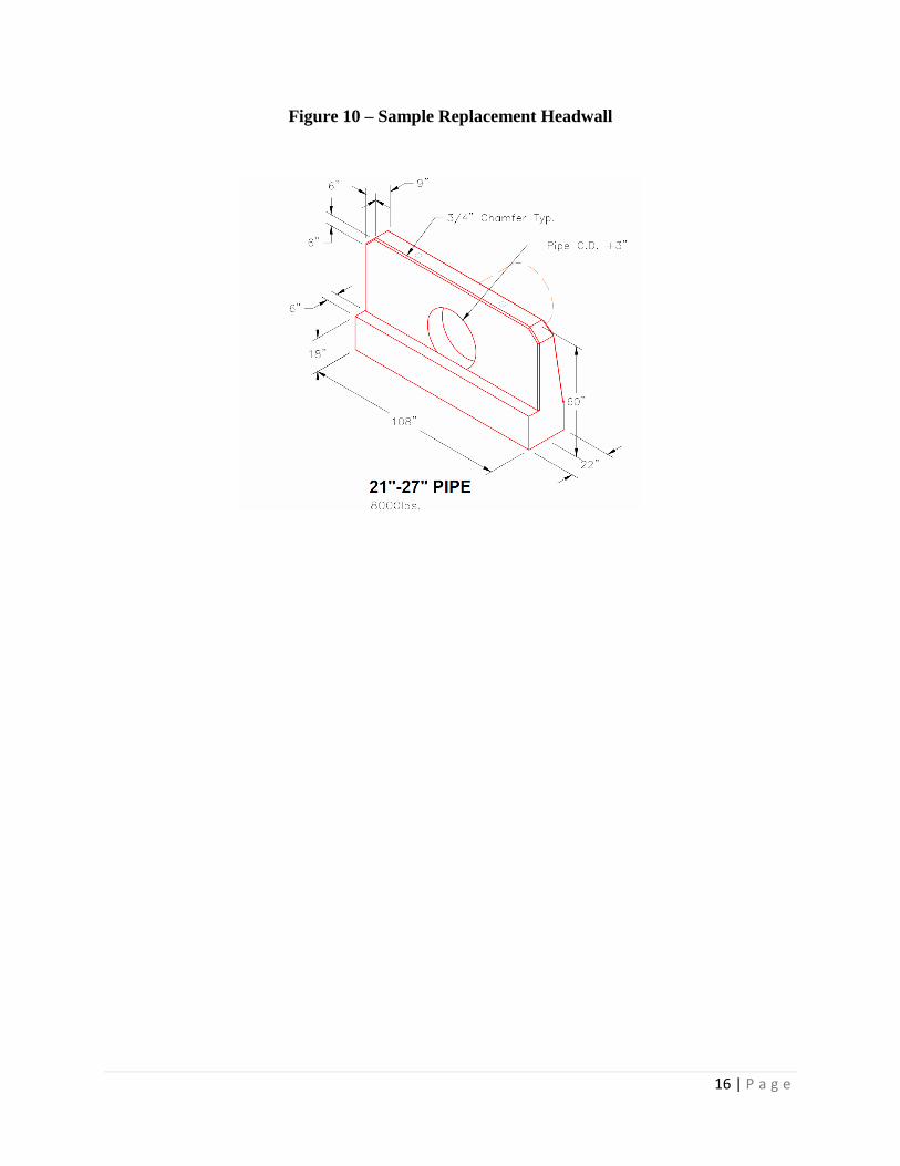
Remove and Replace Headwall
Another proposed alternative to address the enormous, unappealing headwall is by
removing and replacing it with a new one. This will allow for more opportunity to deal with the
erosion issues. A smaller, more appropriately sized headwall could then be installed for the
outfall, while incorporating the existing concrete pipe in the headwall itself. A new headwall
would also eliminate the forward lean of the existing headwall. Though this lean is minimal, the
headwall could continue to settle; therefore, amplifying the lean. The pipe associated with this
headwall is 21” in diameter. The cost of the new precast headwall needed for this size of pipe is
$605.00 as priced from Oldcastle Precast Headwalls. Figure 10 depicts the new headwall.
16 | P a g e
Figure 10 – Sample Replacement Headwall

17 | P a g e
Outfall #4
Outfall #4 is located in Reach 5 on the North side of the Ottawa River, South of the
Health and Human Services Building. This outfall sits 8 feet south of the curb along North
Towerview Boulevard. Outfall #4 is in poor condition. Inside the headwall, the pipe had settled,
disconnecting itself from the headwall. As a result, the pipe no longer lines up with the headwalls
outlet as shown in Figure 11. Soil on the top side of the headwall has, overtime washed out due
to the separated pipe carrying the earth away and exposed the back side of the headwall. There is
severe erosion along the side of the headwall as well, due to poor bank stabilization as seen in
Figure 12. Outfall #4 does have a long channel, compared to other outfalls, that has a relatively
flat slope as it approaches the main flow area of the river. The channel could also use protection
from erosion, since the channel walls have little vegetation to control the erosion. The current
headwall is a U-shaped structure with the dimensions of 70” tall, 60” wide and 35” deep. The
pipe inside the structure has a 12” diameter
Figure 11 – Settled Pipe Inside Headwall #4
Figure 12- Erosion around Outfall #4

18 | P a g e
Alternatives to Headwall at Outfall #4
Remove and Replace Headwall
A proposed alternative for Outfall #4 is to remove and replace the existing headwall.
Currently, water exiting the pipe cannot flow freely from the outfall. The 12” pipe inside the
headwall will need to be replaced. A section of guardrail from North Towerview Boulevard may
need to be removed to access the damaged pipe. Soil will have to be excavated from the outfall
to the location where there is a non-damaged section of existing pipe. A new headwall and pipe
could then be installed. The replacement of the headwall is the only way to properly remediate
the problems at this outfall. The pipe associated with this headwall is 12” in diameter. The cost
of the new precast headwall needed for this size of pipe is $495.00 as priced from Oldcastle
Precast Headwalls. Figure 13 depicts the new headwall.
Figure 13 – Sample Replacement Headwall

19 | P a g e
Outfall #5
Outfall #5 is located in Reach 5. This outfall has a 21” pipe and a 37.5” tall headwall.
The headwall and splash pad to the outfall are in good shape, but there are erosion issues due to
poor bank stability in the channel. This head wall also contains a flap gate which prevents the
river water to backflow into the pipe. Soil on each side of the headwall is loose and is eroding
into the channel as shown in Figure 14. Outfall #5 has a relatively long flow channel that will
also require erosion protection. Figure 15 shows the channel at Outfall #5. The eroding issues
with this outfall are simple to correct.
Alternatives to Headwall at Outfall #5
The existing headwall at Outfall #5 is still in very good condition. There are no
noticeable issues that would justify any repairs or the replacement for this headwall. The only
concerns for this outfall reside in the channel erosion.
Figure 14 – Outfall #5
Figure 15 – Channel at Outfall#5
20 | P a g e
Channel Erosion Alternatives
Rock Check Dams
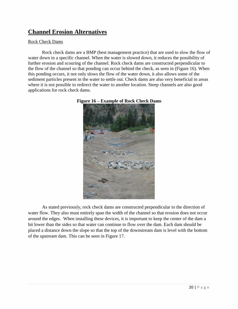
Rock check dams are a BMP (best management practice) that are used to slow the flow of
water down in a specific channel. When the water is slowed down, it reduces the possibility of
further erosion and scouring of the channel. Rock check dams are constructed perpendicular to
the flow of the channel so that ponding can occur behind the check, as seen in (Figure 16). When
this ponding occurs, it not only slows the flow of the water down, it also allows some of the
sediment particles present in the water to settle out. Check dams are also very beneficial in areas
where it is not possible to redirect the water to another location. Steep channels are also good
applications for rock check dams.
Figure 16 – Example of Rock Check Dams
As stated previously, rock check dams are constructed perpendicular to the direction of
water flow. They also must entirely span the width of the channel so that erosion does not occur
around the edges. When installing these devices, it is important to keep the center of the dam a
bit lower than the sides so that water can continue to flow over the dam. Each dam should be
placed a distance down the slope so that the top of the downstream dam is level with the bottom
of the upstream dam. This can be seen in Figure 17.

21 | P a g e
Figure 17 – Downstream Spacing
Maintenance of these rock check dams can vary depending on how much loose material
is washed downstream. If the depth of the sediment in the ponds reaches about half of the
original ponding depth it is necessary to physically remove the sediment so that the rock check
dams can still serve their intended purpose. It is also necessary to check the integrity of the dams
after high capacity flows to make sure that they are still intact.
The best location for these rock check dams to be used would be Outfall #3 and Outfall
#4. The reason for this is that these outfalls have a relatively long channel, as compared to the
other outfalls, extending from the headwall to the edge of the river. The channels for Outfalls #3
and #4 can be seen in Figure 18 and Figure 19 respectively. This would provide enough room for
check dams to be installed for each outfall so that there is no further erosion of the existing bank
due to these storm water outlets. Picture 4 in Appendix B shows how rock check dams could be
implemented in these channels.

22 | P a g e
Figure 18 – Outfall #3 Channel
Figure 19- Outfall #4 Channel

23 | P a g e
The size of the rip rap for each channel is based on the discharge velocity of the pipe
feeding the channel. These discharge velocities were calculated from Manning’s equation for full
pipe flow. Once the velocity was known, the size and type of the rip rap was chosen, based on a
reference chart taken from the Ohio Department of Transportation’s Location and Design
Manual. For both channel #3 and #4 it was determined that Type C rip rap would be appropriate
to use. In Type C rip rap, 85% of the material, by weight, is larger than a 6 inch square opening
and at least 50% of the material, by weight, is larger than a 12 inch square opening. In order to
calculate the volume of rip rap needed, standard cross sections were taken from the Urban
Drainage and Flood Control District’s Urban Storm Drainage Criteria Manual. Table 1 shows
the volume and price per ton of Type C rip rap. The price of Type C rip rap is $18 per ton as
obtained from Hanson Aggregates. It can be seen from the table that for the channel of Outfall
#3, the material price would be $164.59, and for the channel of Outfall #4, the material price
would be $214.72. Channel #3 only has enough elevation difference between the headwall and
the edge of the river for one check dam to be put into place, but Channel #4 will have enough
elevation difference for two.
Table 1 – Rock Check Dam Pricing
A-Jacks
A new and innovative erosion control method is the concept of concrete objects known as
A-Jacks. The A-Jack units are high-stability concrete armor units that interlock into a flexible,
permeable matrix. They are designed to dissipate energy and resist the forces of flowing water,
while preventing scour and erosion. The units are installed either randomly or in a uniform
pattern and the voids formed within the matrix provide about 40% open space. The voids created
actually provide habitat for aquatic life when used as a reef, revetment, or soil support system in
river applications. Biologists believe the A-Jacks create partly submerged structures where fish
and wildlife can hide, while also diverting the stream to protect vegetation and banks from
erosion. The voids also may be backfilled with suitable soils and planted with vegetation above
the normal base flow. Contractors can install the units by hand, reducing construction time
(Figure 20). A-Jack units are typically configured in three rows stacked in a two-and-one
configuration, two aligned A-Jacks comprise a first and second row near the waterline, and a
third row is staggered relative to the other two rows (Figure 21) (Armortec, 1999).
The A-Jack approach can be used to address the erosion issues around the
outfalls, along with the erosion issues in the channels. A main benefit for the A-Jack approach is
that they can be used in areas where there are short channel lengths, unlike rock check dams. For
these reasons, the A-Jacks could be used as channel protection in Outfall #1, Outfall #2, and
Channel Rip-Rap Check Dam Rip-Rap Total Total Price/Ton Geo-textile Geo-textile Price Total Price
Channel (yd^3) (yd^3) (yd^3) (Tons) ($/Ton) (Price/sq ft) ($) ($)
#3 3.70 0.89 4.59 8.03 18.00 0.20 20.00 164.59
#4 4.30 1.78 6.08 10.64 18.00 0.20 23.20 214.72
Total = 379.31
Rock Check Dam/ Channel Rip Rap Alternative

24 | P a g e
Outfall #5. Figures 22, 23, and 24 depict these outfall channels. Picture 5 in Appendix B shows
how A-Jacks could be implemented in these smaller channels.
Figure 20 – Installation of A-Jacks Figure 21 – A-Jacks along Channel
Figure 22 – Outfall #1 Channel

25 | P a g e
Figure 23- Outfall #2 Channel
Figure 24 – Outfall #5 Channel

26 | P a g e
The size of the A-Jack Concrete Units for each channel is based on various parameters of
the Ottawa River. These parameters consist of the 100-year design discharge, channel bottom
width, channel side slope, and required factor of safety. Using these factors the actual shear
stress and actual velocity could be determined. The recommended shear stress and recommended
velocity based on the bed slope were then obtained from the charts provided from the A-Jacks
Concrete Armor Units Design Manual of Ayres Associates. Comparing the actual and
recommended values a factor of safety was calculated. The AJ-24 Concrete Unit was chosen
since the calculated factor of safety exceeded the required factor of safety. Two A-Jack Concrete
Units linked together can cover a length or width of three feet. Depending on the length and the
width of the channel the quantity of A-Jack units could be calculated. Table 2 shows the quantity
and price per A-Jack. It can be seem from the table that for channel of Outfall #1, the material
price would be $4290.00, for the channel of Outfall #2, the material price would be $4590.00,
and for the channel of Outfall #5, the material price would be $3780.00.
Table 2 – A-Jack Pricing
Articulating Concrete Block Mats
Articulating Concrete Block mats provide practical erosion control to outfall channels.
An interlocking matrix of concrete blocks make up these block mats. Galvanized steel, stainless
steel, or polyester revetment cable run through the blocks, connecting them in a mat that can be
simply laid down in sections. Since the blocks are placed in mats, they are flexible making it an
excellent choice for lining channel bottoms.
The blocks can be designed for specific hydraulic situations. Blocks of different sizes and
shapes will give channel protection at different flows. There are blocks that are tapered to slow
down and dissipate high flow rates. These are also beneficial in channels where there are great
hydraulic jumps.
There is an option for open-celled and close-celled blocks. Close-celled blocks are
standard plate blocks that offer no void spaces in their design (Figure 25). Open-celled blocks
provide void spaces in the blocks that allow for vegetation to grow through (Figure 26).
Therefore, open-celled blocks are a form of erosion protection that has a low impact on plant life.
Length Width Rows Total Price/A-Jack Total Price
Channel (ft) (ft) (A-Jacks) ($/A-Jack) ($)
#1 13.00 9.00 11.00 143.00 30.00 4290.00
#2 15.00 6.00 13.00 153.00 30.00 4590.00
#5 20.00 6.00 9.00 126.00 30.00 3780.00
Total = 12660.00
A-Jack Concrete Units Alternative

27 | P a g e
Figure 25 – Close-celled Block Figure 26 – Open-celled Block
The installation of articulating concrete block mats does not require any more than
conventional construction equipment and is simple to place. First, geotextile fabric will be placed
on the prepared channel (Figure 27). The concrete block mats are available in various
configurations; therefore, they will come from the factory ready to be placed (Figure 28 & 29).
Moving the mats will require a spreader bar to be placed on a crane. At least two rows of blocks
will need to be buried to offer an acceptable anchor to hold the block mats in place (Figure 30).
Figure 27 – Channel Preparation Figure 28 – Mat Rigging
Figure 29 – Mat Placement Figure 30 – Backfilled
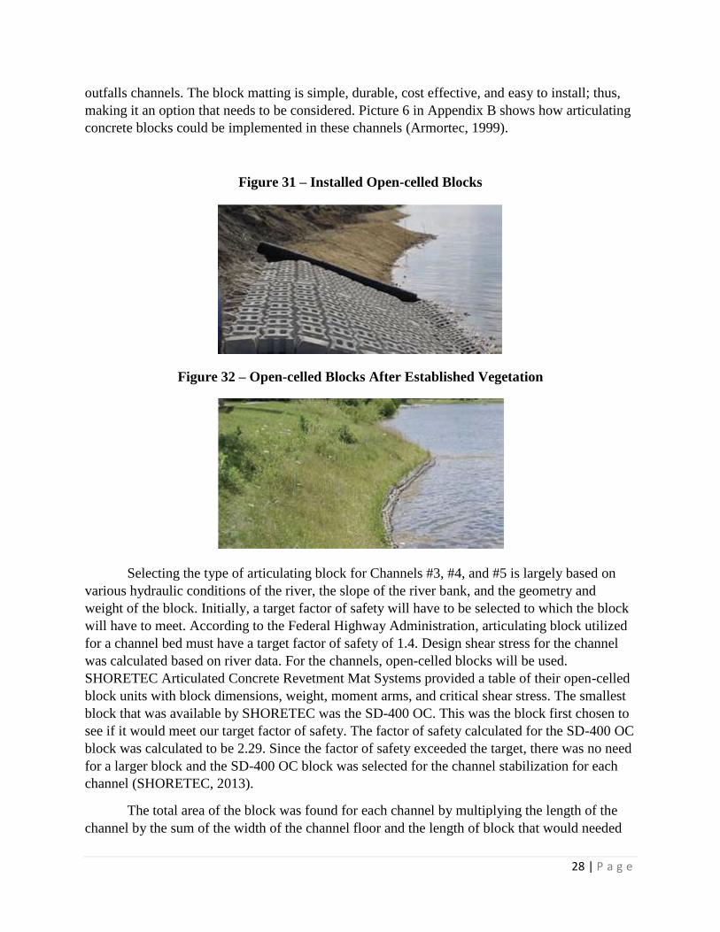
Articulating concrete blocks are a proven and effective way to stabilize channels and
prevent erosion. It is an excellent alternative that is visually appealing with the use of open-
celled blocks. Figure 31 shows the blocks after installation before they are back filled. Figure 32
shows the blocks after being back filled and with established plant life on top of them. This
alternative will work well where there are outfall channels with longer runs; so, Outfall #3, #4,
and #5 will benefit from this option. Refer back to Figures 18, 19, and 24, respectively, for these
28 | P a g e
outfalls channels. The block matting is simple, durable, cost effective, and easy to install; thus,
making it an option that needs to be considered. Picture 6 in Appendix B shows how articulating
concrete blocks could be implemented in these channels (Armortec, 1999).
Figure 31 – Installed Open-celled Blocks
Figure 32 – Open-celled Blocks After Established Vegetation
Selecting the type of articulating block for Channels #3, #4, and #5 is largely based on
various hydraulic conditions of the river, the slope of the river bank, and the geometry and
weight of the block. Initially, a target factor of safety will have to be selected to which the block
will have to meet. According to the Federal Highway Administration, articulating block utilized
for a channel bed must have a target factor of safety of 1.4. Design shear stress for the channel
was calculated based on river data. For the channels, open-celled blocks will be used.
SHORETEC Articulated Concrete Revetment Mat Systems provided a table of their open-celled
block units with block dimensions, weight, moment arms, and critical shear stress. The smallest
block that was available by SHORETEC was the SD-400 OC. This was the block first chosen to
see if it would meet our target factor of safety. The factor of safety calculated for the SD-400 OC
block was calculated to be 2.29. Since the factor of safety exceeded the target, there was no need
for a larger block and the SD-400 OC block was selected for the channel stabilization for each
channel (SHORETEC, 2013).
The total area of the block was found for each channel by multiplying the length of the
channel by the sum of the width of the channel floor and the length of block that would needed
29 | P a g e
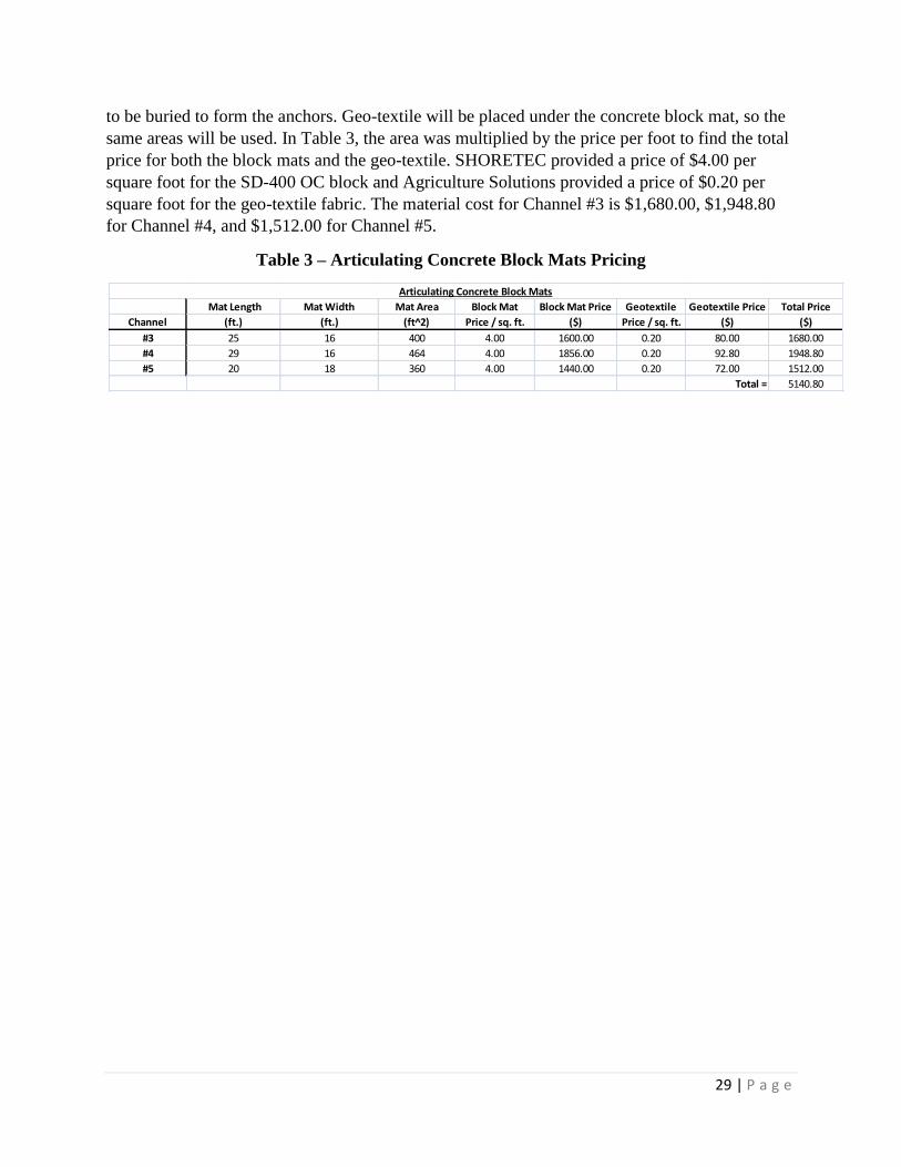
to be buried to form the anchors. Geo-textile will be placed under the concrete block mat, so the
same areas will be used. In Table 3, the area was multiplied by the price per foot to find the total
price for both the block mats and the geo-textile. SHORETEC provided a price of $4.00 per
square foot for the SD-400 OC block and Agriculture Solutions provided a price of $0.20 per
square foot for the geo-textile fabric. The material cost for Channel #3 is $1,680.00, $1,948.80
for Channel #4, and $1,512.00 for Channel #5.
Table 3 – Articulating Concrete Block Mats Pricing
Mat Length Mat Width Mat Area Block Mat Block Mat Price Geotextile Geotextile Price Total Price
Channel (ft.) (ft.) (ft^2) Price / sq. ft. ($) Price / sq. ft. ($) ($)
#3 25 16 400 4.00 1600.00 0.20 80.00 1680.00
#4 29 16 464 4.00 1856.00 0.20 92.80 1948.80
#5 20 18 360 4.00 1440.00 0.20 72.00 1512.00
Total = 5140.80
Articulating Concrete Block Mats

30 | P a g e
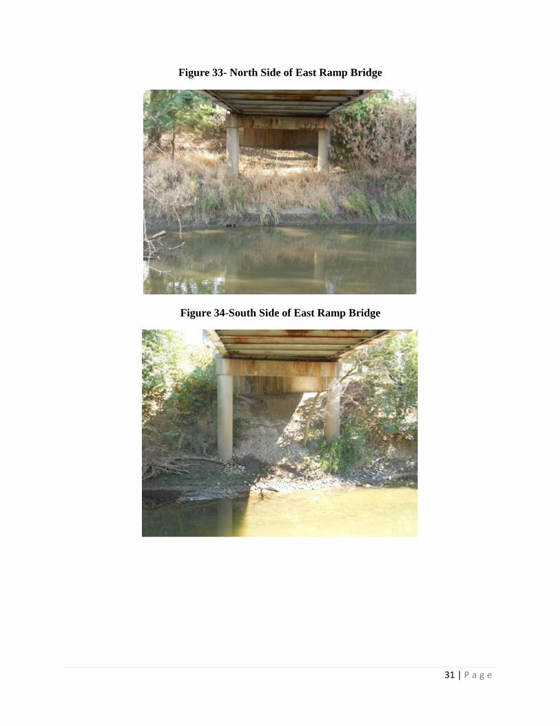
Bridge Erosion
East Ramp Pedestrian Bridge
The East Ramp Pedestrian Bridge spanning the Ottawa River, located by Savage Hall,
has moderate erosion occurring around the abutments and piers. The banks on each side of the
bridge have plentiful vegetation which creates stabilization and serves as natural erosion control.
There is little concern with bank stabilization and erosion at these locations. However, directly
under the bridge there is little to no vegetation. As a result of this, the river has cut steep banks
into the center portions of the river and higher up on the banks. The steeper the banks become,
the faster the erosion will occur. With steeper banks there will be less bank stabilization as well.
As these banks erode, they will begin to encroach upon the bridge piers. Additionally, these steep
banks could break off exposing much more of the bridge's piers; especially at times with high
water flows and high velocities. If the erosion reaches the piers it could cause stability and
structural problems for the bridge. Since this bridge already has structural issues which is an area
of concern, a problem at the piers could noticeably affect the bridge's structural integrity.
The erosion at the East Ramp Bridge has been neglected for years. The main areas of
focus are to control the erosion just below the abutments and around the piers. This is a concern
for both the North and South side of the bridge. Since the piers extend into the river, they are
typically surrounded with water during and after wet weather events. The need to control the
erosion around the piers is more critical since the erosion is already threatening the bridge's
structural integrity. As the water flow under the bridge gets parted by the piers, the water
velocities around the piers increases. This means that the area around the piers will erode away
faster than other parts of the river like the banks, river bottom, and even the area around the
bridge abutments.
The stabilization of the bank beneath this bridge has two areas of concern. The first area
of concern is mainly on the North side of the river. The location of the river at lower flows has
eroded the river side just before the piers. This has left a ledge that could shear off of the bank
and fall into the river. As erosion around the piers continues, this threat will grow because it will
weaken the back side of the ledge; therefore, increasing the possibility of it shearing. If this
occurs, it will greatly expose the piers and promote further erosion and decreased bank
stabilization. The second area of concern is around the bridge abutments on both the North and
South side. In this area, there is no vegetation to serve as natural bank stabilization, there is only
soil. As erosion occurs in this unprotected area, it weakens the banks. It is clear that something
needs done to prevent erosion and increase bank stabilization under this bridge. For this, several
alternatives have been determined. The erosion and bank stabilization issues for the East Ramp
Bridge on the North and South side of the river can be seen in Figure 33 and Figure 34,
respectively.
31 | P a g e
Figure 33- North Side of East Ramp Bridge
Figure 34-South Side of East Ramp Bridge
32 | P a g e
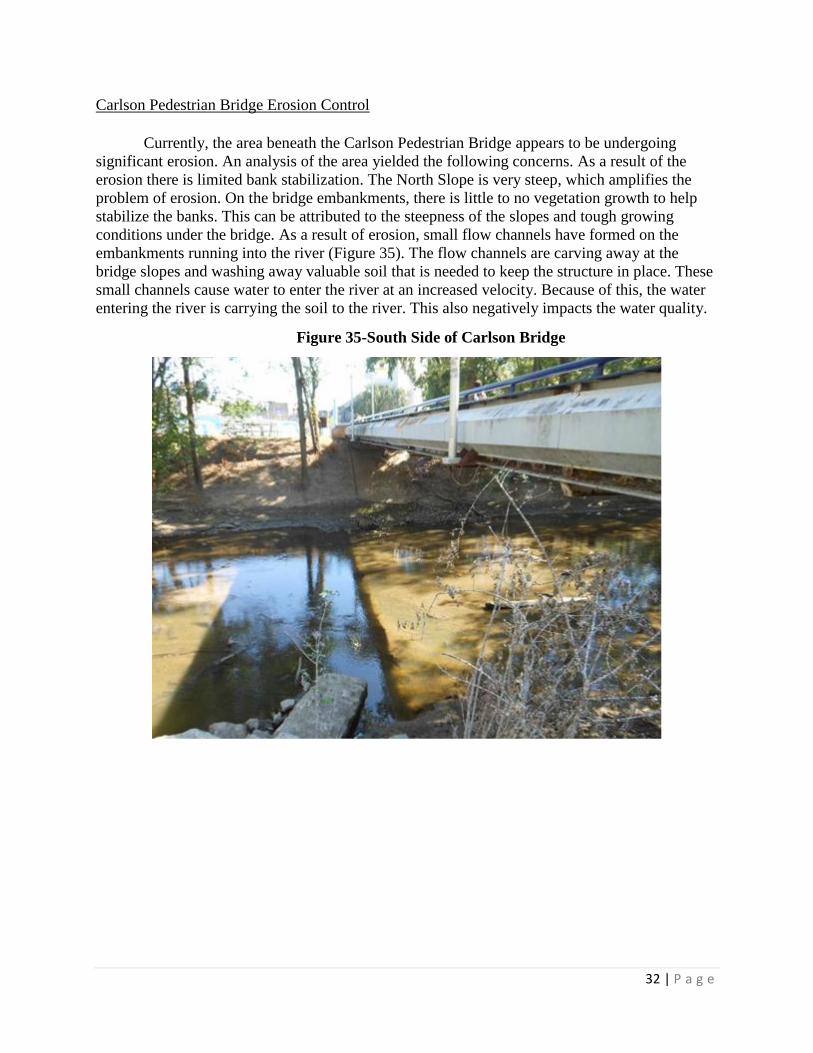
Carlson Pedestrian Bridge Erosion Control
Currently, the area beneath the Carlson Pedestrian Bridge appears to be undergoing
significant erosion. An analysis of the area yielded the following concerns. As a result of the
erosion there is limited bank stabilization. The North Slope is very steep, which amplifies the
problem of erosion. On the bridge embankments, there is little to no vegetation growth to help
stabilize the banks. This can be attributed to the steepness of the slopes and tough growing
conditions under the bridge. As a result of erosion, small flow channels have formed on the
embankments running into the river (Figure 35). The flow channels are carving away at the
bridge slopes and washing away valuable soil that is needed to keep the structure in place. These
small channels cause water to enter the river at an increased velocity. Because of this, the water
entering the river is carrying the soil to the river. This also negatively impacts the water quality.
Figure 35-South Side of Carlson Bridge

33 | P a g e
The erosion under the Carlson pedestrian bridge is very significant. In the past and during
previous construction, it appears that there has been a minimal effort made towards reducing the
amount of erosion that takes place under the bridge. In addition, the erosion appears to have been
occurring for a considerable amount of time since water has etched out a few significant
pathways. The etching of these pathways is a process that takes years to accomplish. There are
also many smaller, erosion formed flow channels in the soil that can be seen on both the North
and South side of the bridge (Figure 36).
Figure 36-North Side of Carlson Bridge
Bank stabilization is the process of holding the soil of a bank in place so it does not wash
away or slide. Bank stabilization is a very important aspect to any bank, especially on banks that
serve as structural support. In the case of the Carlson pedestrian bridge, bank stabilization is very
important. Due to the lack of stabilization under the bridge, much erosion has occurred over the
years (Figure 37). The implementation of erosion control alternatives can be used to help
stabilize steep bank slopes such as the North side of this bridge (Figure 36). Because the erosion
that has occurred under the Carlson Pedestrian Bridge is determined to be repairable and
preventable, it is a great candidate for a bank restoration.

34 | P a g e
Figure 37-North Abutment of Carlson Bridge

35 | P a g e
Bridge Erosion Alternatives
Rip Rap
The first alternative that was determined was the use of rip rap for the erosion control and
bank stabilization. This is a commonly used alternative that is easy to install and is usually very
cost effective. Rip rap is an assortment of larger sized rocks which are placed in a layer on a
bank or slope to help limit the erosion. Figure 38 depicts an example of what the use of rip rap
can look like. The rock size needs to be determined based on the water velocity of the river, such
that the rocks will not be swept away with the water’s current. Rip rap essentially puts weight on
the soil and banks to hold it into place. Rip rap can also help to stabilize the bank not just by
limiting erosion but also by helping to hold the side slopes in place just by the added material. It
also slows down water runoff, again limiting erosion. Rip rap can look aesthetically pleasing to
most people if it is used correctly. This alternative could be used at both the Carlson Pedestrian
Bridge as well as the East Ramp Pedestrian Bridge. Picture 7 in Appendix B shows a visual
representation of rip rap used under these bridges.
Figure 38- Application of Rip Rap
The size of the rip rap for underneath each bridge is based on the discharge velocity and
depth of flow of the Ottawa River. The discharge velocity and depth of flow were obtained from
the HEC-RAS model provided by Dr. Patrick Lawrence, Chair of the UT President’s
Commission of the River. Using the design guideline for rip rap from the U.S. Department of
Transportation, the d50 size of riprap was obtained. For both bridges it was determined that Type
C rip rap would be appropriate to use. This rip rap can be used on a bank up to a 1 to 1.5 slope
which will work for all applications on this project. In Type C rip rap, 85% of the material, by
weight, is larger than a 6 inch square opening and at least 50% of the material, by weight, is
larger than a 12 inch square opening, as stated previously. In order to calculate the volume of rip
rap needed, the areas underneath each side of the bridges were used. Table 4 shows the volume

36 | P a g e
and price per ton of Type C rip rap. It can be seen from the table that for the East Ramp
Pedestrian Bridge, the material price (including geo-textile fabric) would be $852.12, and for the
Carlson Pedestrian Bridge, the material price would be $655.48.
Table 4 – Rip Rap Pricing
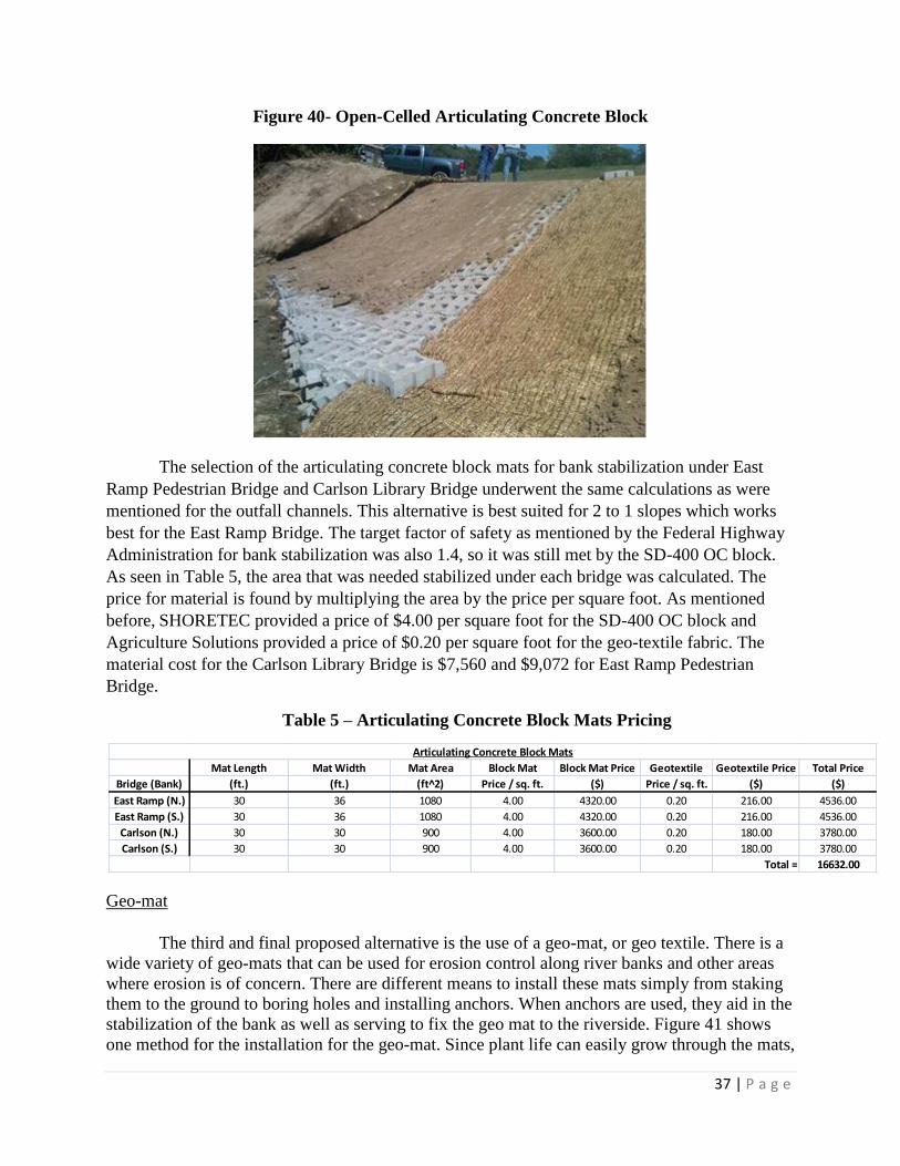
Articulating Concrete Blocks
The use of articulating concrete blocks have proven to be a very reliable and effective
way to reduce erosion around structures such as bridge abutments and piers. This alternative will
also positively impact bank stabilization when used in the correct application. There is an
assortment of these blocks that vary in size, geometry, weight, etc. The differences in the blocks
will allow the best result for each unique application. Some of the blocks are close-celled, like
those seen in Figure 39. Other articulating blocks are open-celled to allow plant life to grow
through. This style block can be seen in Figure 40. The additional plant life growth will add
additional bank stabilization and erosion control. The use of these will be aesthetically pleasing
and can promote the growth of native species. This alternative could successfully be applied at
either of the two bridge locations. Picture 8 in Appendix B shows a visual representation of
articulating concrete blocks used under these bridges.
Figure 39- Close-Celled Articulating Concrete Block
Under Bridge Rip-Rap Geotextile Geotextile Price Total Price/Ton Total Price
Bridge (yd^3) (Price/sq ft) ($) (Tons) ($/Ton) ($)
East Ramp Pedestrian Bridge 22.10 0.20 155.97 38.68 18.00 852.12
Carlson Pedestrian Bridge 17.00 0.20 119.98 29.75 18.00 655.48
Total = 1507.60
Under Bridge Rip Rap Alternative
37 | P a g e
Figure 40- Open-Celled Articulating Concrete Block
The selection of the articulating concrete block mats for bank stabilization under East
Ramp Pedestrian Bridge and Carlson Library Bridge underwent the same calculations as were
mentioned for the outfall channels. This alternative is best suited for 2 to 1 slopes which works
best for the East Ramp Bridge. The target factor of safety as mentioned by the Federal Highway
Administration for bank stabilization was also 1.4, so it was still met by the SD-400 OC block.
As seen in Table 5, the area that was needed stabilized under each bridge was calculated. The
price for material is found by multiplying the area by the price per square foot. As mentioned
before, SHORETEC provided a price of $4.00 per square foot for the SD-400 OC block and
Agriculture Solutions provided a price of $0.20 per square foot for the geo-textile fabric. The
material cost for the Carlson Library Bridge is $7,560 and $9,072 for East Ramp Pedestrian
Bridge.
Table 5 – Articulating Concrete Block Mats Pricing
Geo-mat
The third and final proposed alternative is the use of a geo-mat, or geo textile. There is a
wide variety of geo-mats that can be used for erosion control along river banks and other areas
where erosion is of concern. There are different means to install these mats simply from staking
them to the ground to boring holes and installing anchors. When anchors are used, they aid in the
stabilization of the bank as well as serving to fix the geo mat to the riverside. Figure 41 shows
one method for the installation for the geo-mat. Since plant life can easily grow through the mats,
Mat Length Mat Width Mat Area Block Mat Block Mat Price Geotextile Geotextile Price Total Price
Bridge (Bank) (ft.) (ft.) (ft^2) Price / sq. ft. ($) Price / sq. ft. ($) ($)
East Ramp (N.) 30 36 1080 4.00 4320.00 0.20 216.00 4536.00
East Ramp (S.) 30 36 1080 4.00 4320.00 0.20 216.00 4536.00
Carlson (N.) 30 30 900 4.00 3600.00 0.20 180.00 3780.00
Carlson (S.) 30 30 900 4.00 3600.00 0.20 180.00 3780.00
Total = 16632.00
Articulating Concrete Block Mats

38 | P a g e
the added vegetation will allow further erosion control and bank stabilization. This alternative
could be used for the East Ramp Pedestrian Bridge and the Carlson Library Pedestrian Bridge.
Picture 9 in Appendix B shows a visual representation of geo-matting used under these bridges.
Figure 41- Installation of Geo-Mat
The selection of the type of geo-matting for use under the East Ramp Pedestrian Bridge
and Carlson Library Pedestrian Bridge was based on the slope of the bank and the lowest angle
of repose for the infill material. Using those factors, the EGA 30 geo-mat with 6 inch cells was
chosen from the recommendation table from Geo Products, LLC. The next factor in the design
was anchoring the geo-mat. A net sliding factor was determined to ensure that there was enough
friction to hold the geo-mat on the bank. Anchoring methods include toeing the mat using an
anchor trench and staking the mat to the bank. Tendons will connect to each anchoring point and
increase stability.
Table 6 displays the number of geo-mat panels that will cover the area under each bridge
to stabilize the bank. Price calculation is determined by multiplying the mat area by the price per
foot. The cost of the tendons and stakes used to hold the geo-mat in place were also determined.
Geo Products provided a price of $168.02 for each panel, $125 per coil of tendon, and $0.80 per
stake. There is also the cost of #57 stone used to fill the cells in the Geo-mat. The volume of
stone was calculated from the geo-mat volume and converted into tonnage as seen in Table 7.
Hanson Aggregate provided the price of $11.50 per ton for #57 stone. The material cost for the
geo-mat and stone for Carlson Library Bridge is $2,571.87, and $3,152.34 for East Ramp
Pedestrian Bridge.

39 | P a g e
Table 6 – Geo-mat Pricing
Table 7 - #57 Stone for Geo-mat Pricing
Conclusion
For this project, our recommended solutions were based largely on price, and innovation,
while being sure to keep negative environmental impact to a minimum. Available space at each
outfall was also a limiting factor. For Outfall #1, it is recommended that the splash pad of the
headwall be replaced, and that A-Jacks be installed in the channel and on the banks on both side
of the headwall. This would result in a material price of $4315.30 for Outfall #1. For Outfall #2,
it is proposed that the damaged end of the corrugated metal pipe be cut off flush with the surface
of the headwall and that A-Jacks be placed in the channel and on both sides of the headwall. This
would result in a material price of $4590.00. The recommended solution for Outfall #3 would be
to cut the upper portion of the headwall down and to install a rock check dam in the channel.
This would result in a material price of $397.92. Outfall #4 would benefit the most by replacing
the headwall, and installing two rock check dams in the channel. This would result in a material
price of $709.72. Since the headwall of Outfall #5 is in good condition, the only work necessary
would be to install articulating concrete blocks in the channel. This would result in a material
price of $1512.00 for the articulating concrete blocks.
In order to address the erosion issues under the Carlson Pedestrian Bridge and the East
Ramp Pedestrian Bridge, the geo-mat is the recommended solution. Although, this is not the
most cost effective solution, it is very innovative when compared to rip rap and articulating
concrete blocks. Plants are also able to grow in the geo-matting, making this alternative even
more attractive when compared to rip rap. According to plant expert, Tim Walters, a possible
seed that could be planted under these bridges would be Virginia wild-rye. Violet or wild ginger
could also be planted as plugs. These species tend to be able to grow in shade and are able to
survive high flow events on the river. The estimated material price for the geo-matting under the
Carlson Pedestrian Bridge is $2571.87. The estimated material price for the geo-matting under
the East Ramp Pedestrian Bridge is $3152.34. With all of the recommended solutions taken into
account (including outfalls and bridges), the estimated total material cost is $17249.15. Cost
summary for the project can be seen in Table 7. This price does not include the cost of labor or
Number of Panels Price/ Panel cost Tendon Cost Total Number Price/ Stake Cost Total Price
Bridge (27.4' x 8.4') Panels ($) ($) of Stakes Stake ($) ($)
East Ramp 10 168.02 1680.20 250.00 300 0.80 240.00 2170.20
Carlson 8 168.02 1344.16 250.00 240 0.80 192.00 1786.16
Total = 3956.36
Geo-mat / Geo-grid
Panel Area Stone Depth Stone Volume Number of Total Volume Total Tons Price / Ton Total Price
Channel (yd^2) (yd) (yd^3) Panels (yd^3) ($) ($)
East Ramp 25.57 0.17 4.27 10.00 42.70 85.4 11.50 982.14
Carlson 25.57 0.17 4.27 8.00 34.16 68.3 11.50 785.71
Total = 1767.86
#57 Stone for Geo-mat

40 | P a g e
equipment. Refer to Appendix B which contains CAD drawings for specific dimensions for
check dams, A-Jacks, articulating concrete block, geo-mat, and headwalls (Drawings 1-6).
Table 7 – Project Cost Summary
Outfall Recommended Repair Recommended Channel Protection Cost
#1 Repair Splash Pad A-Jacks $4,315.30
#2 Cut Off Damaged Pipe A-Jacks $4,590.00
#3 Cut Down Headwall One Rock Check Dam $397.92
#4 Replace Headwall Two Rock Check Dams $709.72
#5 No Headwall Modification Articulating Concrete Block $1,512.00
Total Outfall Cost = $11,524.94
Bridge Recommended Erosion Control Cost
Carlson Pedestrian Geo-mat $3,152.35
Savage Pedestrian Geo-mat $2,571.87
Total Bridge Cost = $5,724.22
Total Project Cost = $17,249.16
Project Cost Summary

41 | P a g e
Contacts
Patrick Lawrence Ph D. – Client
(419) 530-4128 [email protected]
Douglas Collins – Secondary Client
(419) 530-1018 [email protected]
Cyndee Gruden Ph D., P.E. – Professor
(734) 417-1359 [email protected]
Xiaozhong Zhang – Program Database Analyst
(419) 503-1458 [email protected]
Mike Kovacs – Safety and Health
(319) 530-3605 [email protected]
Group Members
Kyle Bucher (419) 654-9335 [email protected]
Joseph Hanely (419) 699-2713 [email protected]
Benjamin Hodges (419) 260-7593 [email protected]
Benjamin Wetherill (419) 767-0849 [email protected]
Mark Wolf (419) 279-7462 [email protected]

42 | P a g e
Statement of Qualifications
Biographies and Resumes
Kyle Bucher is a senior at The University of Toledo
currently pursuing a degree in Civil Engineering.
He has completed four co-op rotations with two
different companies. His first term was with The
City of Sylvania Utilities Department. Kyle
obtained valuable field experience by inspecting
sewer installations, performing repairs on sewer
systems, and maintaining waterways and
watersheds. His final three co-op rotations were
with the alloy metal manufacturing company,
Materion. Here he worked in the Facilities
Engineering Department where he provided
engineering assistance plant wide. Kyle also
managed equipment installation, building repair,
and steel structure construction projects with his
time there. Upon graduation, Kyle plans to take a
full time position with Materion as Civil Facilities
Engineer.
Joseph Hanely is a senior at The University of
Toledo with an anticipated degree in Civil
Engineering. During Joseph’s time in the Civil
Engineering program, he has completed 3 co-op
terms with The Village of Dundee, Michigan, a
local municipality. Joseph gained experience
ranging from skills of water, storm, and sewer
systems, along with surveying, AutoCAD, to name
a few. He was involved in surveying, estimating,
inspecting projects, and design work. Joseph plans
to find a full time position in Civil Engineering after
graduation this December.

43 | P a g e
Benjamin Hodges is a senior in his final semester at
The University of Toledo in the Civil Engineering
program. Benjamin has completed five co-op terms
with the E.S. Wagner Company, working in heavy
highway construction on road reconstruction project
and the I-475 rehabilitation project. He has gained
a wide variety of experience and skills from his
time as a laborer working on various crews, site
layout using GPS, grade checking for roadway
undercuts, quantity tracking during the project, and
field supervision of small crews. After his
anticipated graduation in December 2013, Benjamin
plans on taking a full time position with the E.S.
Wagner Company.
Benjamin Wetherill is a senior at the University of
Toledo where he is in his final semester in the Civil
Engineering program. Ben has completed three co-
op terms with Ulliman Schutte Construction, a
wastewater and water supply construction firm with
headquarters in Dayton, OH. During his co-op
terms, Ben had the opportunity to work in Virginia,
Maryland, and Washington D.C. Ben gained
experience working as an Assistant Project
Engineer during his first co-op where he obtained
submittal material along with priced, purchased, and
distributed project materials. During his second co-
op as a Project Estimator, Ben was able to gain
experience in the take-off and estimating side of the
construction process. In Ben’s third and final co-op
as an Assistant Project Engineer he gained a lot
more responsibility and preformed small portions of
the project on his own in conjunction with the
Project Manger. Planning to graduate in December
of 2013, Ben plans to acquire a position as a Project
Engineer for a construction company in Ohio or
nearby state.

44 | P a g e
Mark Wolf is a senior in the Civil Engineering
program at the University of Toledo. While
pursuing his degree in Civil Engineering, Mark has
completed four co-op experiences. The first two co-
op positions that Mark held were for the City of
Perrysburg Engineering Department. During his
time at the City of Perrysburg, Mark was able to
utilize GPS equipment to locate items for the water
division, and upload the data. Mark’s next two co-
op experiences were with the Geo. Gradel
Company. While working for the Geo. Gradel
Company, Mark gained experience assisting in the
management of projects, recording revenue for their
scrap program, preparing bid take-off, and
estimating. After his graduation in December 2013,
Mark’s goal is to securing a position in Civil
Engineering.

45 | P a g e
KYLE D. BUCHER
4855 Keener Rd. Monclova, OH 43542
(419) 654-9335 [email protected]
OBJECTIVE To secure a position in Civil Engineering where my knowledge, mechanical and structural
aptitude, and commitment to safety can effectively contribute to the successful operation
of the company.
EDUCATION
August 2009-Present
The University of Toledo, Toledo, Ohio
Bachelor of Science, Civil Engineering
Anticipated Graduation Date: December 2013
COMPUTER SKILLS
EXPERIENCE
August 2012 - Present
January 2012 - May 2012
May 2011- August 2011
May 2010- August 2010
Microsoft Office Suite
Microsoft Access
AutoCAD 2012
Materion, Elmore, Ohio
Civil Engineering Co-op
Managed capital projects
Restructured document filing database
Designed steel structures
Provided engineering assistance
City of Sylvania Utilities, Sylvania, Ohio
Civil Engineering Co-op
Inspected sewer and water line replacement projects
Inspected sewer lines for problems and repairs
Repaired storm sewer lines
City of Sylvania Parks and Forestry, Sylvania, Ohio
General Temporary Laborer
Operated landscape and other equipment
Performed equipment maintenance and repair
Maintained parks and cemetery
Assisted with composting operations
ADDITIONAL TRAINING Leadership Initiatives - Project Management Fundamentals Course
Trane - Air to Air Energy Recovery Seminar
Safe Start - Unit 1 Training
REFERENCES Available upon request

46 | P a g e
JOSEPH M. HANELY
1653 Short Rd. Curtice, OH 43412
(419) 699-2713 [email protected]
OBJECTIVE To secure a full time position in the field of Civil Engineering to utilize my skills and
experience in the work field.
EDUCATION August 2009 –
Present
The University of Toledo, Toledo, Ohio
Bachelor of Science, Civil Engineering
Expected Graduation Date: December 2013
EXPERIENCE August 2013 - Present
May 2010 - May
2013
Summer of
May 2009 - July 2013
E.S. Wagner Company
Oregon, Ohio
Shop Mechanic
General Labor
Vehicle and Machinery Maintenance
General Shop Projects
Village of Dundee, Michigan
Dundee, Michigan
Co-op
Aided in Village Engineering Operations
Oversaw New Construction Projects
General Office Work
Xanterra Parks and Resorts (Maumee Bay State
Park)
Oregon, Ohio
Maintenance Department and Banquet Server
Maintained Property
Ensure Customer Service
Maintained Equipment
August 2008 - May
2010
Gordon Food Services,
Oregon, Ohio
Sales Associate
Stock Shelves
Help Maximize Sales
Customer Service
COMPUTER
SKILLS Microsoft Office Suite
Microsoft Internet Explorer
AutoCAD
HONORS &
AWARDS Dean's List
Scholarship Awards
National Honors Society High School Graduate
REFERENCES Available upon request.

47 | P a g e
BENJAMIN EDWARD HODGES
8970 Cedar Point Rd. Oregon, OH 43616
(419) 836-8957 [email protected]
OBJECTIVE To secure a full time position in the Civil Engineering field that will complement my academic
endeavors with hands-on experience.
EDUCATION
August 2009-Present
The University of Toledo, Toledo, Ohio
Bachelor of Science, Civil Engineering
Anticipated Graduation Date: December 2013
Grade Point Average: 3.997
COMPUTER SKILLS
EXPERIENCE
June 2009-Present
Microsoft Office Suite
AutoCAD 2009
E.S. Wagner Company, Oregon, OH
Project Engineer Co-op/ Equipment Distribution Personnel
Administer parts, materials, equipment, etc. to construction sites
Perform engine/ mechanic work
Prepare equipment and material orders for field job sites
Organize construction materials
Repair various tools used in the field
Obtain inventory of various supplies
Maintain a clean work environment
Manage work force, enter quantities and employee/ equipment time
Detail the interior and exterior of semi-trucks and pick-up trucks
Utilize a global positioning system to check grade, install storm sewers, and survey roadway
pavement layout
Reconcile payment quantities with project owner
HONORS &
AWARDS
University of Toledo Rocket Scholar Award
National Honor Society
SPECIAL SKILLS
& INTERESTS
Take tremendous pride in my work
Excellent ability to learn new skills quickly
Possess a very logical thought process
Display a great organizational ability
REFERENCES Available upon request

48 | P a g e
BENJAMIN J. WETHERILL
16394 County Road 10 Forrest, OH 45843
(419) 767-0849 [email protected]
OBJECTIVE To obtain a position as a Civil Engineer encompassing a hands-on
capacity that will enhance and enrich my Civil Engineering knowledge
and assist in achieving my PE license.
EDUCATION The University of Toledo, Toledo, Ohio
August 2009 – Present Bachelor of Science, Civil Engineering
Anticipated Graduation Date: Dec. 2013
Grade Point Average: 3.72
Business Minor
COMPUTER SKILLS Microsoft Office Suite and AutoCAD
ICE: MC^2 Estimating Computer Software and Digitizing
EXPERIENCE
January 2013 – May 2013 Ulliman Schutte Construction, Dayton, Ohio
Co-op Engineer for project in Lorton, VA
Head coordinator for all below ground yard piping
Lead Engineer/Designer for change orders and as-built projects
Preformed start-up and testing for mechanical components
May 2012 – August 2012 Ulliman Schutte Construction, Dayton, Ohio
Co-op Estimator/Engineer for estimating office in Rockville, MD
Performed takeoff and estimated architectural section of all bids
Configured prices from venders and organized bid proposals
August 2011 – December 2011 Ulliman Schutte Construction, Dayton, Ohio
Co-op Engineer for project in Lorton, VA
Obtained submittal material and secured purchase orders
Priced, purchased, and organized deliveries for project materials
Coordinated distribution and implementation of job components
August 2008 – May 2009 Marathon Petroleum Company, Findlay, Ohio
Engineering Explorers (In conjunction with Ohio Northern University)
Job Shadowed Lucas R. DeGarmo, Project Engineer I
HONORS & AWARDS Rocket Scholar Award
MOSSER Construction: Robert H. Moyer Scholarship
Central Ohio Associated General Contractors Scholarship
William D. Squires Scholarship
Golden Key International Honour Society
LEVIS Leadership Scholarship
Engineering Department Dean’s List Recognition
COLLEGIATE ACTIVITIES UT LEVIS Leadership Program and Rocket 2 Rocket Peer Mentorship
Civil Engineering Department Mentorship Program for Freshman
ASCE – American Society of Civil Engineers
UTSPE – University of Toledo Society of Professional Engineers
Office – Secretary and Survey Committee
Intramural Sports
REFERENCES: Available upon request

49 | P a g e
MARK K. WOLF
7740 Corduroy Rd. Oregon, OH 43616
(419) 836-2402 [email protected]
OBJECTIVE To obtain a career in the field of Civil Engineering that will allow me to grow
professionally and utilize my knowledge and skills.
EDUCATION
August 2009-Present
The University of Toledo, Toledo, Ohio
Bachelor of Science, Civil Engineering
Anticipated Graduation Date: May 2013
EXPERIENCE
Wolf Farms, Oregon, Ohio
May 2006-
Present
Cultivated farm land to prepare for planting.
Participated in the operation of planting and harvesting of the grain crop.
Transported grain to the elevator.
Provided help in the repairing of equipment.
Assisted with water drainage and tiling of farm land.
Maumee Bay State Park Nature Center, Oregon, Ohio
June-August 2008
May-August 2011
January-May 2012
August-December 2012
May-August 2013
Volunteered at the Nature Center, which involved various maintenance duties.
Controlled invasive plant species.
City of Perrysburg Engineering Division, Perrysburg, Ohio
Utilized hand-held GPS units to mark locations of curb boxes, pull boxes, etc.
Repaired any broken curb boxes.
Uploaded data from GPS and sent it out to be post processed.
Organized and recorded plans.
Checked Sight distances at intersections.
Geo. Gradel Company, Toledo, Ohio
Worked on site, and assisted in management of projects.
Calculated and recorded revenues from scrap management projects.
Dissected project plans and prepared bid take-offs.
HONORS & AWARDS Rocket Gold Scholarship
Dr. & Mrs. Riza Scholarship
H. Peter Carstensen Scholarship
Top 10% while attending Clay High School
National Honor Society member
ACTIVITIES
Participated in the football program at Clay High School
4-H involvement in the Livestock Unlimited 4-H Club, where I served as vice
president.
REFERENCES Available upon request

50 | P a g e
References
"2010 California Residential Code." California Building Standards Commission. California
Building Standards Commission, n.d. Web. 31 Oct 2013.
<https://law.resource.org/pub/us/code/bsc.ca.gov/gov.ca.bsc.2010.02.5.html>.
"Aggregate Summary." Aggregate Industries. N.p.. Web. 31 Oct 2013. <http://www.aggregate-
us.com/_aius/regions/ma/_assets/_pdfs/aggregate/millville.pdf>.
Armortec. "A-Jacks Concrete Armor Units Design Manual." N.p., Aug. 1999. Web. 17 Sept.
2013. <http://www.a-
jacks.com/River/DesignInfo/Channel_Lining_and_Pier_scour_Design_Manual.pdf>.
"Beyond Riprap | Articles | Erosion Control." Beyond Riprap | Articles | Erosion Control. N.p.,
n.d. Web. 17 Sept. 2013.
<http://www.erosioncontrol.com/EC/Articles/Beyond_Riprap_15450.aspx>.
"Caltrans Storm Water Quality Handbooks." Check Dam. N.p., 1 Mar. 2003. Web. 17 Sept.
2013. <http://www.dot.ca.gov/hq/construc/stormwater/SC-04.pdf>.
"Chapter 8: Structural Measures for Erosion and Sediment Control." Erosion Control Class
Material. Robert Pitt. N.p., n.d. Web. 17 Sept. 2013.
<http://rpitt.eng.ua.edu/Class/Erosioncontrol/Module8/MainECM8.html>.
"Check Dam Rock Good." Check Dam Rock Good. N.p., n.d. Web. 17 Sept. 2013.
<http://www.coloradodot.info/programs/environmental/water-quality/assets/check-dam-
rock-good.jpg/image_view_fullscreen>.
"Check Dams." Urban Storm Drainage Criteria Manual Volume 3. Urban Drainage and Flood
Control District, n.d. Web. 31 Oct. 2013. <http://www.udfcd.org/downloads/pdf/
critmanual/Volume%203%20PDFs/chapter%207%20fact%20sheets/EC-
12%20Check%20Dam.pdf>.
"Construction Best Management Practices." Check Dam. N.p., n.d. Web. 17 Sept. 2013.
<http://www.clermontstorm.net/checkdam.pdf>.
"Construction News." UK Construction News. N.p., n.d. Web. 26 Sept. 2013.
<http://www.theconstructionindex.co.uk/news/view/kijlstra-precast-units-speed-
kingsnorth-development>.
"Decks Over a River." Green Life in Social. N.p., n.d. Web. 26 Sept. 2013.
http://www.bing.com/images/search?q=decks+over+a+river&qs=n&form=QBIR&pq=de
cks+over+a+river&sc=1-18&sp=1&sk=#view=detail&id=B0C30B3298B4C5878A276
3F03FE391368FB66110&selectedIndex=197

51 | P a g e
"Design and Installation Guidelines for Erosion Control." EnviroGrid. 2013.
<http://geoproducts.org/editoruploads/documents/Erosion Control 0811s.pdf>.
"Design Guideline 8 Articulating Concrete Block Systems - HEC 23 - Bridge Scour and Stream
Instability Countermeasures - Hydraulics - Engineering - FHWA." Design Guideline 8
Articulating Concrete Block Systems - HEC 23 - Bridge Scour and Stream Instability
Countermeasures - Hydraulics – Engineering - FHWA. N.p., n.d. Web. 14 Nov. 2013.
http://www.fhwa.dot.gov/engineering/hydraulics/pubs/09112/page08.cfm
"Engineered Hard Armor Solutions." Contech Engineered Solutions. N.p., n.d. Web. 17 Sep
2013. <http://www.conteches.com/Products/Erosion-Control/Hard-
Armor/ArmorFlex.asp&xgt;.
Gamble, Danielle. "Ottawa River Project: Restoring a UT Icon." The Independent Collegian.
N.p., n.d. Web. 17 Sept. 2013. <http://www.independentcollegian.com/news/ottawa-
river-project-restoring-a-ut-icon-1.2830941?pagereq=1>.
"Geo Products EnviroGrid Cellular Confinement Systems." Geo Products. N.p., n.d. Web. 31
Oct 2013. <http://geoproducts.org/>.
"Headwalls ." Oldcastle Precast. N.p., n.d. Web. 31 Oct. 2013.
<http://www.oldcastleprecast.com/plants/Lexington/products/water/conveyance/Pages/he
adwalls.aspx>.
"Hydrology and Hydraulics: Analysis of Existing and Proposed Conceptual Design
Alternatives." University of Toledo RAP Project. 2011.
Iowa DNR. (2006). How to control streambank erosion. Retrieved from
http://www.ctre.iastate.edu/erosion/manuals/streambank_erosion.pdf
International erosion control systems. (2013). Retrieved from
http://designerlabeled.com/iecs/portfolio-items/headwall-outfall-1/
Lawrence, Patrick. "The River Runs Through It: Planning for the Ottawa River." University of
Toledo. N.p., n.d. Web. 24 Sept. 2013. <http://www.eeescience.utoledo.edu/faculty/
gottgens/vita/Lawrence%20et%20al.%20FINAL.pdf>
"Location and Design Manuals, Volume 1 Roadway Design." Ohio Department of
Transportation. N.p., n.d. Web. 31 Oct. 2013. <http://www.dot.state.oh.us/Divisions/
Engineering/Roadway/DesignStandards/roadway/Pages/locationanddesignmanuals.aspx>
"Lowes Decking Design." Deck Design Planner. Lowes, n.d. Web. 26 Sept. 2013.
http://lowestools.diyonline.com/servlet/GIB_Base/lowes_minireportstatuspage.html?stor
eid=1659&projectName=Ottawa+River+2&projectID=426260946
Propex geotextile systems. (2012). Retrieved from http://www.geotextile.com/

52 | P a g e
"Riprap." Michigan.gov. N.p., n.d. Web. 31 Oct 2013.
<http://www.michigan.gov/documents/deq/deq-wb-nps-rip_250895_7.pdf>.
"Roswell River Landing." Talk of the Town Atlanta. N.p., n.d. Web. 26 Sept. 2013.
http://www.talkofthetownatlanta.com/wp-content/uploads/roswell-river-landing.jpg
"SHORETEC® Articulated Concrete Revetment Mat Systems." SHORETEC® Articulated
Concrete Revetment Mat Systems. N.p., n.d. Web. 14 Nov. 2013. http://shoretec.com/
Sowa, Tom. "Concrete Dolos Help Prevent Riverbank Erosion and Restore Fish habitat."
Spokesman.com. The Spokesman Review, 23 Aug. 2013. Web. 17 Sept. 2013.
<http://www.spokesman.com/stories/2013/aug/23/concrete-dolos-help-prevent-riverbank-
erosion-and/>.
Stormwater outfall rehabilitation . (2010). Retrieved from
http://www.terraerosion.com/CityofEdmonton-Outfall101.htm
"Strata Systems." Strata. N.p., n.d. Web. 31 Oct 2013. <http://www.geogrid.com/>.
Sutkowski, A. (2009). D2 land and water resource, erosion control solutions. Retrieved from
http://www.d2lwr.com/?p=1048
"The University of Toledo." - Commission on the River. N.p., n.d. Web. 24 Sept. 2013.
<http://www.utoledo.edu/commissions/river/index.html>
United States Department of Transportation. "Design Guideline 4 Riprap Revetment." Design
Guideline 4 Riprap Revetment - HEC 23 - Bridge Scour and Stream Instability
Countermeasures - Hydraulics - Engineering - FHWA. Federal Highway Administration,
21 Sept. 2011. Web. 14 Nov. 2013.
<http://www.fhwa.dot.gov/engineering/hydraulics/pubs/09112/page04.cfm>.

53 | P a g e
Appendix A-Design Calculations

54 | P a g e
Channel Flow and Velocity Calculations
Outfall #1
⁄
⁄
⁄
⁄
⁄
⁄
⁄
Outfall #2
⁄
⁄
⁄
⁄
⁄
⁄

55 | P a g e
⁄
Outfall #3
⁄
⁄
⁄
⁄
⁄
⁄
⁄
Outfall #4
⁄
⁄
⁄
⁄
⁄
⁄

56 | P a g e
⁄
Outfall #5
⁄
⁄
⁄
⁄
⁄
⁄
⁄

57 | P a g e
Channel Alternative Design Calculations
Rip Rap/Check Dam Volume Calculations:
Channel #3: (Outlet velocity = 9.316 ft/s, From ODOT – Type C Rip-Rap)
Channel Rip Rap: (1 ft thick, 25 ft long, 4 ft wide)
Check Dam: (4 ft wide)
Channel #4: (Outlet velocity = 6.405 ft/s, From ODOT – Type C Rip-Rap)
Channel Rip Rap: (1 ft thick, 29 ft long, 4 ft wide)
Check Dams: (4 ft wide, 2 dams)

58 | P a g e
ODOT Chart Used to Size Rip-Rap

59 | P a g e
A-Jacks Design Calculations:
River Details:
100-year Design Discharge:
Bed Slope:
Channel Bottom Width:
Channel Side Slope:
Required Factor of Safety:
Manning’s Coefficient:
Step 1
The determination of hydraulic conditions will be straightforward, since the roughness of the A-
Jacks along the banks will not appreciably affect the flow conditions of the soft-bottom channel.
The solution procedure will evaluate the AJ-24 armor units and determine their factor of safety
under the given conditions.
a.
b.
c. Calculate
Step 2
Determine velocity and bed shear stress:
a.
[ ]
b.
c.
Step3
Determine the limiting values of shear stress and velocity for AJ-24 armor units on the channel
bed from Figures 2.9 and 2.10 at a bed slope of 0.012 ft/ft (1.2%):
Multiply the limiting values of shear stress and velocity for the bed by the side slope correction
fact from Figures 2.11 with a 2H:1V slope:

60 | P a g e
Step 4
Determine the safety factors associated with shear stress and velocity:
Conclude that safety factors for both shear and velocity criteria exceed the required value of 1.5
for this particular application, using A-Jacks AJ-24 armor units.
Step 5
Summarize Results for the A-Jacks AJ-24 system:
100-year discharge, Q 4235
Bed slope, percent 1.2
Bottom width, b 57
Side Slope Z 2H:1V
Manning’s Coeff., n 0.068
Depth, y 8.55
Velocity, V 6.68
Shear Stress 6.45
Safety Factor (shear stress) 3.06
Safety Factor (velocity) 2.35

61 | P a g e

62 | P a g e
Figure 2.9

63 | P a g e
Figure 2.10

64 | P a g e
Figure 2.11

65 | P a g e
Articulating Concrete Block:
River Details:
100 year design discharge: Q = 4,235
⁄
Max Depth: y = 8.55 ft.
Slope of Energy Grade Line: ⁄
Maximum Velocity: ⁄
Bend Coefficient:
Target Factor of Safety for Channel Bed or Bank
Design Shear Stress
⁄
Calculate the Factor of Safety Parameters
The following table displays the given block cell information by SHORETEC Articulated
Concrete Revetment Mat Systems. The block cell information will be utilized through various
parameters for calculating the factor of safety for that block.
Open
Cell Unit
Block
Thickness
(in.)
Block
Width
(in.)
Block
Length
(in.)
Weight
(lbs.)
Moment Arms (lb/ )
SD-400
OC
4.00 15.50 17.40 57 2 11.65 3.2 11.65 32
Additional Lift & Drag on a Protruding Block
(
)(
)(
⁄ )
⁄

66 | P a g e
Stability Number for a Block on a Horizontal Surface
Angle between Side Slope Projection of Submerged block Weight and the Vertical
(
)
(
)
Projection of Submerged Block Weight into Plane of Subgrade
√
√
Angle between Block Motion and the Vertical
(
(
)√
(
)
)
(
(
)
√
(
)
)
Angle between Drag Force and Block Motion

67 | P a g e
Stability Number on a Sloped Surface
( ⁄
⁄ )
( ⁄
⁄ )
0.197
Submerged Block Weight
(
)
(
)
Factor of Safety
( )
√ (
)
(
)
√ (
)
The factor of safety for the SD-400 OC block meets the target factor of safety.

68 | P a g e
Bridge Erosion Alternatives Design Calculations
Rip-Rap Design Calculations:
√ (
)
√ (
)
( )
[
√ ( ) ]
*
√ +
= 0.474 ft = 5.68in

69 | P a g e
Side Slope Correction Factor 0.871
Bank Angle, Degrees 26.6
Local Depth of Flow, ft 8.55
Safety Factor 1.5
Stability Coefficient 0.3
Velocity Distribution Coefficient 1
Blanket Thickness Coefficient 1
Design Velocity, ft/sec 8
Specific Gravity of RipRap 2.65
Acceleration Due to Gravity 32.2
d30, ft 0.395
d50, ft 0.474
d50, in 5.68
Articulating Concrete Block Calculations:
The articulating concrete block mat calculations for the bridge erosion control are the
same as the articulating concrete block mat calculations for the channel protection. This is
because both are based on the flow of the river, not the channels.
Geo-mat Design Calculations:
Use EGA30 with 6 inch cells from design guide to allow for aggregate and soil backfill.
Provided information for EGA30:
0.15m (0.5') Cell Height
0.32m (1.05') Cell Width
0.29m (0.95') Cell Length
8.35m (27.4') Panel Length
2.56m (8.4') Panel Width
8 Cells per Width
Variable Key:
NSF = Net Sliding Force
H = Height of Cell
L = Length of Slope
ϒ = Unit Weight of Fill
S = Snow Load
W = Slope Inclination (Horizontal to Vertical)
φ = Lowest Angle of Internal Friction of Soil
FS = Factor of Safety

70 | P a g e
Side Calculations / Needed Values:
⁄ ⁄
⁄ ⁄
⁄ ⁄
⁄ ⁄
Net Sliding Force:
[ ] [ ]
[ ] [ ]
Anchor Trench Dimensions:
⁄
⁄
Mat Staking:
Optional for NSF of 4.94 kN/m3
Recommend 1 stake per yd2
Tendons:
⁄
Staples:
4 Staple per adjoining cell for 6" cell height

71 | P a g e
Outlook Loading Design Calculations
Outlook at Outfall #1:
Conceptual Design of a Composite Wood Deck with simply supported piers.
Deck Specifications:
18 feet wide by 12 feet deep (of the bank edge towards the river) and will land roughly 16 feet
over the edge of the river.
Calculations:
Using and assumed 20psf for snow load in NW Ohio (California Residential Code, 2010), and an
assumed 10psf (Bergman 2013) for the Dead Weight of the materials in constructing the
structure:
Area:
Estimated Live Load:
Factored Load Calculation:
( )
Design Outlook Loading: 222psf
Outlook near Outfall #2:
Conceptual Design of a Cantilever Concrete Deck
Deck Specifications:
20 feet wide by 12 feet deep (of the bank edge towards the river) and will land roughly 16 feet
over the edge of the river.
Calculations:
Using and assumed 20psf for snow load in NW Ohio (California Residential Code, 2010), an
assumed 150psf for the Dead Weight of Concrete, and a slab thickness of 1 foot:
Area:

72 | P a g e
Estimated Live Load:
Estimated Dead Load:
Factored Load Calculation:
( )
Design Outlook Loading: 372psf

73 | P a g e
Appendix B – Conceptual and CAD Drawings

Page | 73
Appendix B - Conceptual and CAD Drawings

Page | 74
Picture 1 - Composite Deck Overlook at Outfall #1

Page | 75
Picture 2 - Concrete Overlook at Outfall #2 View of Student Plaza

Page | 76
Picture 3 - Concrete Overlook at Outfall #2 View of River

Page | 77
Picture 4 - Rock Check Dam Channel Protection

Page | 78
Picture 5 - A-Jack Channel Protection

Page | 79
Picture 6 - Articulating Concrete Block Channel Protection

Page | 80
Picture 7 - Rip Rap Bridge Erosion Alternative

Page | 81
Picture 8 - Articulating Concrete Block Bridge Erosion Alternative

Page | 82
Picture 9 - Geomat Bridge Erosion Alternative
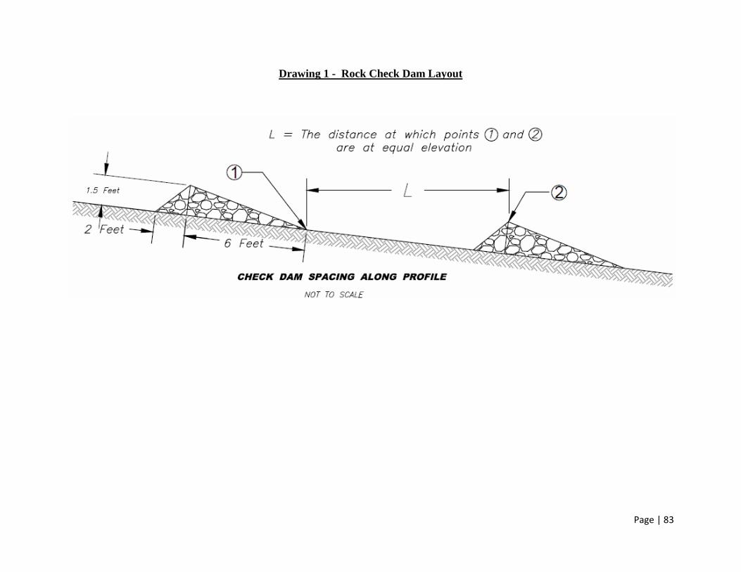
Page | 83
Drawing 1 - Rock Check Dam Layout

Page | 84
Drawing 2 - A-Jack Specifications

Page | 85
Drawing 3 - Articulating Concrete Block Specifications

Page | 86
Drawing 4 - Geomat Layout Specifications
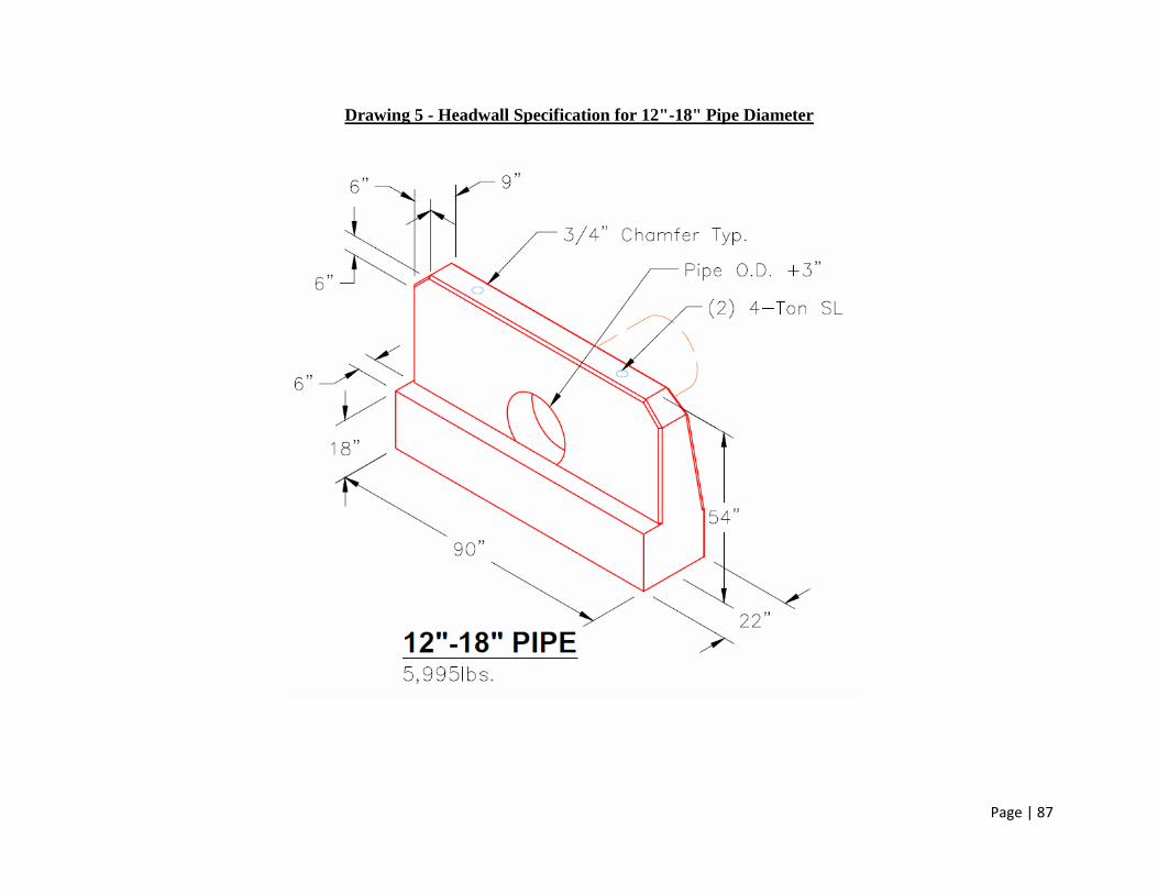
Page | 87
Drawing 5 - Headwall Specification for 12"-18" Pipe Diameter

Page | 88
Drawing 6 - Headwall Specification for 21"-27" Pipe Diameter