dental implants resistance: computational analysis · dental implants resistance: computational...
TRANSCRIPT

1
Dental Implants Resistance: Computational Analysis
Soraia Isabel Correia Ribeiro
Instituto Superior Técnico, Lisbon
October 2016
Abstract
The overall goal of the present work is to analyse several dental implant abutment systems, produced by Osteotech. In order to proceed with such analysis, the ISO 14801 Dentistry – Implants – Dynamic fatigue test for endosseous dental implants standard [1] is considered. This standard refers the procedures to perform static and fatigue analysis to the implant itself. Since the purpose of this work is to analyse dental implant abutment systems and not the implants themselves, [1] is adjusted according to it.
The study is performed through several three-dimensional models containing an implant replica, an abutment and its components for a fixed prosthesis. Stress analyses of two scenarios were performed in ABAQUS®: a pre-load situation, corresponding to the implant insertion, and a masticatory situation, corresponding to the implant usage.
The results obtained from this work allowed to isolate a component as the worst case: the bolt MUTIPA from the angulated abutment model. It was also verified that the bolt preload is responsible for most of the stress accumulated in the system and that bolts can fail during tightening if the torque applied is higher than the recommended one. The agreement of the results presented in this work and reported by Osteotech show that the simplifications made are reasonable and that the work developed is a solid base to validate and further develop the models for commercial use and proceed with an analysis on the critical component. Keywords: Dental Implants, Abutment, Bolt Load, Finite Element Method.
1. Introduction
Edentulism can lead to a continued bone loss
of the jaw, a decrease of the soft tissue and, as result, a decrease in facial height that causes several facial and aesthetic changes. All this factors reveal teeth play an important role, not only for the consumption digestion of food, but also as an important role on the appearance and integration on society, as well as in speech and communication [2, 3]. Nowadays one of the dentistry’s goals is to give back to the patient the normal contour, function, comfort, aesthetics, speech and health. This may be achieved by restoring a single tooth or replacing several teeth to full function. It was from this need that dental prosthesis emerged. Implant dentistry allows an improvement on patient’s comfort and masticatory ability, maintain the health integrity of the dental arches and, in many instances, elevate the patient’s self-image, regardless of the disease [3, 4].
For both completely and partially edentulous patients there are the options of a removable or a fixed restoration, most of them requiring dental
implants as fixation points. Fixed dental implants have in their structure a component that stablishes the connection between the prosthesis crown and the implant, usually through a screw, called abutment. The clinical use of removable abutments was first recorded on the beginning of 1980 and allowed better handling of temporary restoration and wider prosthetic options, especially for single tooth restoration [5, 6]. Besides the advantages associated to dental implants, prostheses are different from natural teeth and can also present complications, especially on the screws, and may require certain procedures to avoid damage of its components [7]. There are a few critical factors that affect the screw-joint stability, such as an adequate preload, a precise fit of the mating implant components and the anti-rotational characteristics of the implant-abutment interface. The importance of the preload remains on the ability to hold together the components and it is achieved with the application of the correct torque to the implant screw. If screw loosening occurs, metal fatigue may
2
result in screw fracture, being the abutment screw the component that fails more often [8]. Throughout the years the dental implant systems have evolved and it is possible nowadays to restore teeth with success however, a few problems still remain and before considering each application it is important to analyse the implants’ conditions of insertion and use, in order to expand their lifetime as well as the patient comfort.
There is no specific set of rules to dental implant design and, since computational models have evolved and allow the study of complex mechanical systems, the finite element method (FEM) has been introduced not only in the design process but also in the optimization and validation of such components [9]. FEM analysis can provide accurate results and this type of simulation results in a precise calculation of stresses, strains and contact forces. The overall goal of the present work is to analyse several dental implant abutment systems, produced by Osteotech. In order to proceed with such analysis, the ISO 14801 Dentistry – Implants – Dynamic fatigue test for endosseous dental implants standard [1] is considered.
The study is performed through several three-dimensional models containing an implant replica, an abutment and its components for a fixed prosthesis. The Finite Element Method (FEM) is used to analyse a two scenarios: a pre-load situation, corresponding to the implant insertion, and a masticatory situation, corresponding to the implant usage. It is expected that the model is able to reproduce qualitatively and quantitatively the behaviour on both situations, in order to verify the safety of the different abutments under use. Furthermore, this work aims at improving and validating several models for commercial use, providing information on the behaviour of these components. It is also expected to identify the system and the component that has the most severe stress level, in order to isolate this component as the worst case.
2. Materials
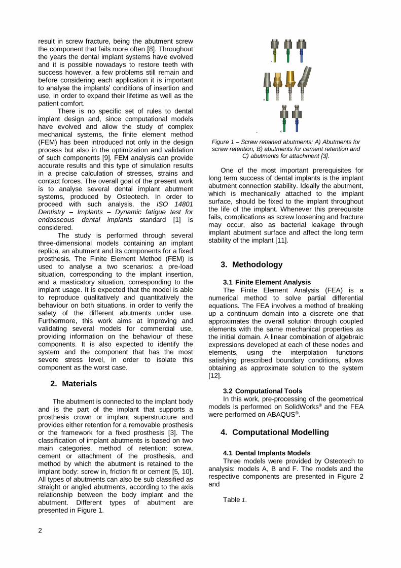
The abutment is connected to the implant body and is the part of the implant that supports a prosthesis crown or implant superstructure and provides either retention for a removable prosthesis or the framework for a fixed prosthesis [3]. The classification of implant abutments is based on two main categories, method of retention: screw, cement or attachment of the prosthesis, and method by which the abutment is retained to the implant body: screw in, friction fit or cement [5, 10]. All types of abutments can also be sub classified as straight or angled abutments, according to the axis relationship between the body implant and the abutment. Different types of abutment are presented in Figure 1.
.
Figure 1 – Screw retained abutments: A) Abutments for screw retention, B) abutments for cement retention and
C) abutments for attachment [3].
One of the most important prerequisites for long term success of dental implants is the implant abutment connection stability. Ideally the abutment, which is mechanically attached to the implant surface, should be fixed to the implant throughout the life of the implant. Whenever this prerequisite fails, complications as screw loosening and fracture may occur, also as bacterial leakage through implant abutment surface and affect the long term stability of the implant [11].
3. Methodology
3.1 Finite Element Analysis The Finite Element Analysis (FEA) is a
numerical method to solve partial differential equations. The FEA involves a method of breaking up a continuum domain into a discrete one that approximates the overall solution through coupled elements with the same mechanical properties as the initial domain. A linear combination of algebraic expressions developed at each of these nodes and elements, using the interpolation functions satisfying prescribed boundary conditions, allows obtaining as approximate solution to the system [12].
3.2 Computational Tools In this work, pre-processing of the geometrical
models is performed on SolidWorks® and the FEA were performed on ABAQUS®.
4. Computational Modelling
4.1 Dental Implants Models Three models were provided by Osteotech to
analysis: models A, B and F. The models and the respective components are presented in Figure 2 and
Table 1.

3
Assembly A Assembly B Assembly F
Figure 2 - Dental implants models.
Table 1 - Models and their components.
Assembly A Assembly B Assembly F
Interface MUTIRTG Interface MUTIRTG Interface
RPBACCSX
Bolt MUTIPA Bolt MUTIPA Bolt RPTIPA
Bolt PRRPTIPA10 Angulated platform PA30RPTIBA40G
Implant replica RPTIBA
Platform PRRPTIBA10G
Bolt PARPTIPAG
Implant replica RPTIBA
Implant replica RPTIBA
4.2 Geometrical Model The 3D models of the several dental implant
systems were conceded by Osteotech in format .SLDPRT from SolidWorks® and were adjusted considering a posterior finite elements analysis as well as the standard ISO 14801:2007 [1].
4.2.1 Bolt Geometry
The threaded area of the bolts would increase the complexity of the system by not only creating the need to model the spiral threads and its fillets, but also to assuming friction interactions between the threaded surfaces in the FEA. So as to simplify the analysis, all threaded areas were modelled as plain cylinders.
The diameters of the connections were adjusted to their resistant diameter, in order to avoid overlapping between the parts. The basic terminology for threaded fasteners is presented in
Figure 3. According to this terminology, defines the pitch. , and denote the major, minor and
pitch diameters of a bolt thread [13].
Figure 3 - Terminology of bolts threads [13].
Tensile tests of threaded rods have shown the equivalence between the tensile strength determined in the mean diameter, which is the mean diameter between the pitch and the minor diameters, on both thread and unthread rods. This
diameter is called tensile-area diameter, [13].
(1)
The tensile-area diameter is calculated for all the bolts presented in the assemblies, with 1.4 and 2.0 millimetres diameter.
Table 2 - Screw diameters.
Nominal diameter
1,4 0,3 1,03 1,21 1,12
2 0,4 1,51 1,74 1,62
4.2.2 Boundary Conditions
According to the ISO 14801 [1] the implant is to be clamped 3 millimetres below the bone level. The bone level corresponds to the top surface of the replica implant, immediately before the external hexahedral connection. An auxiliary plane is created to define the clamped area, below which the boundary condition is defined as fully fixed.
4.2.3 Loading Geometry
In order to apply the load and proceed with the simulation comparatively to a real test situation, no lateral constraints should occur and the loading centre should be well defined, such that
the moment arm can be measured. Both schematics of test set-up for an implant system with no pre-angled and pre-angled connecting parts, according to the standard, are represented in Figure 4 and Figure 5.
Legend:
1. Loading device;
2. Bone level;
3. Connecting part;
4. Hemispherical loading member;
5. Dental implant body;
6. Specimen holder.
Figure 4 - Schematic of test set-up for systems with no pre-angled connecting parts [1].

4
Legend:
1. Loading device;
2. Bone level; 3. Connecting part; 4. Hemispherical
loading member; 5. Dental implant
body;
6. Specimen holder.
Figure 5 - Schematic of test set-up for systems with pre-angled connecting parts. [1]
Clamping on dental implants, with pre-angled connecting parts, will be modelled so that
the distance from the centre
to the clamping plane results in a moment arm
that can be calculated as . The loading
centre can also be defined by from the bone level.
Dental implants with pre-angled connecting parts, shall be clamped such that the angle with the
loading direction of the testing machine is
greater than the angle between the implant axis and the angle of the angled portion on the connecting part, α. As mentioned before, the
loading centre shall be at a distance
from the clamping plan or
from the same point to the bone level.
Both systems presented a distance so there was the need to reduce the height of both interfaces (MUTIRTG). The final designs are illustrated in Figure 6.
a) b)
Figure 6 – Final geometry: a) System A and b) System B.
Assembly F will have later on a pillar welded to his structure, around the interface RPBACCSX. Since this component is essential to the analysis, a structure is created in ABAQUS®
with a height of to represent this component. A tube is created with the outer and inner diameters
of the interface and placed around the interface, overlapping components. Afterwards, a new component was created removing the material of the interface of the tube. Assembly F with and without the tube, as well as the tube itself, are presented in Figure 7.
a) b)
Figure 7 - a) Assembly F. Without tube (Left). With tube (Right). b) Tube.
As for the load surface, the force is applied through a deformation-resistant loading member with a hemispherical contact surface for load transfer. This member is attached to or placed over the free end of the connecting part such that
the centre of the hemisphere shall be on the central longitudinal axis of the dental implant [1]. A hemispherical loading member was designed as a semi-sphere and attached to the plain surface on the top of the interfaces, as depicted in Figure 8.
a) b) c)
Figure 8 – Assembly with loading geometry: a) system A, b) system B and c) system F.
4.3 Finite Element Modelling
4.3.1 Material properties
All components from models A and B are built from the titanium alloy Al-6Ti-4V ELI while model F has two different materials, titanium alloy Al-6Ti-4V ELI and low carbon Co-28Cr-6Mo alloy. The properties of both materials are defined in and were collected from data provided by Osteotech and from RTI – Titanium Alloy Guide [14].
Table 53 and were collected from data provided by Osteotech and from RTI – Titanium Alloy Guide [14].

5
Table 53 - Material properties.
Al-6Ti-4V
ELI Co-28Cr-
6Mo
Young Modulus – (GPa) 114 210
Poisson’s Ratio - 0.34 0.29
Yield Strength (MPa) 950 1027 Ultimate Stress Strength
(MPa) 1046 1517
Elongation (%) 18 34
4.3.2 Interactions between the Parts
To simulate the different surface interactions amongst components, a type of contact interaction and two types of kinematic constraints are used, Surface-to-Surface Contact, Tie and Coupling. The contact between parts is defined with several contact pairs, using Surface-to-Surface Contact, an automated contact algorithm provided by ABAQUS®. A kinematic constraint, that ensures a rigid bond between the surfaces, is used to define the surface interactions of the bolt joints, namely a surface-to-surface tie constraint. This is a reasonable approach assuming that the fixation between threaded connections is successful.
4.3.3 Loading and Boundary
Conditions
Every bolted connection has a pretension associated to it, which is the clamping force that exists in the connection after it has been properly tightened, allowing the clamped system parts to remain together independently of other external loads. To ensure that the preload needed is developed when the parts are assembled, a torque method is applied [15, 16]. The values of the torque applied during the tightening of the bolted connections are given by Osteotech and are discriminated in Table 4.
Table 4 - Torque applied in bolted connections.
Bolt Torque (N.cm)
MUTIPA 15
PRRPTIPA10 32
PARPTIPAG 20 RPTIPA 32
Equation (4.1) gives the relation between bolt torque and bolt tension [13].
(4.1)
In which is the tightening torque, is the torque
coefficient, is the nominal diameter in is the preload in Newton. According to Shigley [13], for a
friction coefficient of , shall be assumed as 0.2, independently from the bolt size and the coarse of the thread. The preloads are determined using Equation (4.1). The preload
values are shown in Table 5. It is applied on the
system using the “bolt load” option available on ABAQUS® on the first step of the analysis.
Table 5 - Preload values.
Bolt
MUTIPA 1.4 536
PRRPTIPA10 2 800
PARPTIPAG 2 500
RPTIPA 2 800
The applied masticatory load value is of
200N. It was defined based on the data provided by Ferrario et al. [17], Reina et al. [18] and Dean et al. [19]. For system A and F, the load was subjected to an angle of 10º while for system B the load was subjected to an angle of 40º, 30º from the original angle of the system plus the 10º specified by the standard. The load was applied on the reference point RP previously created on the top surface of the abutment. This way, due to the coupling interaction of the RP with the semi-sphere surface, the standard’s instructions on this parameter are fulfilled [1].
The assembly is fixed in a rigid clamping device and at a distance of 3.0mm ± 0.5mm from the bone level [1]. The boundary conditions as well as the loads applied are shown in Figure 9.
a) b)
c)
Figure 9 - Loads and boundary conditions: a) system A, b) system B and c) system F.
6
4.3.4 Mesh Generation
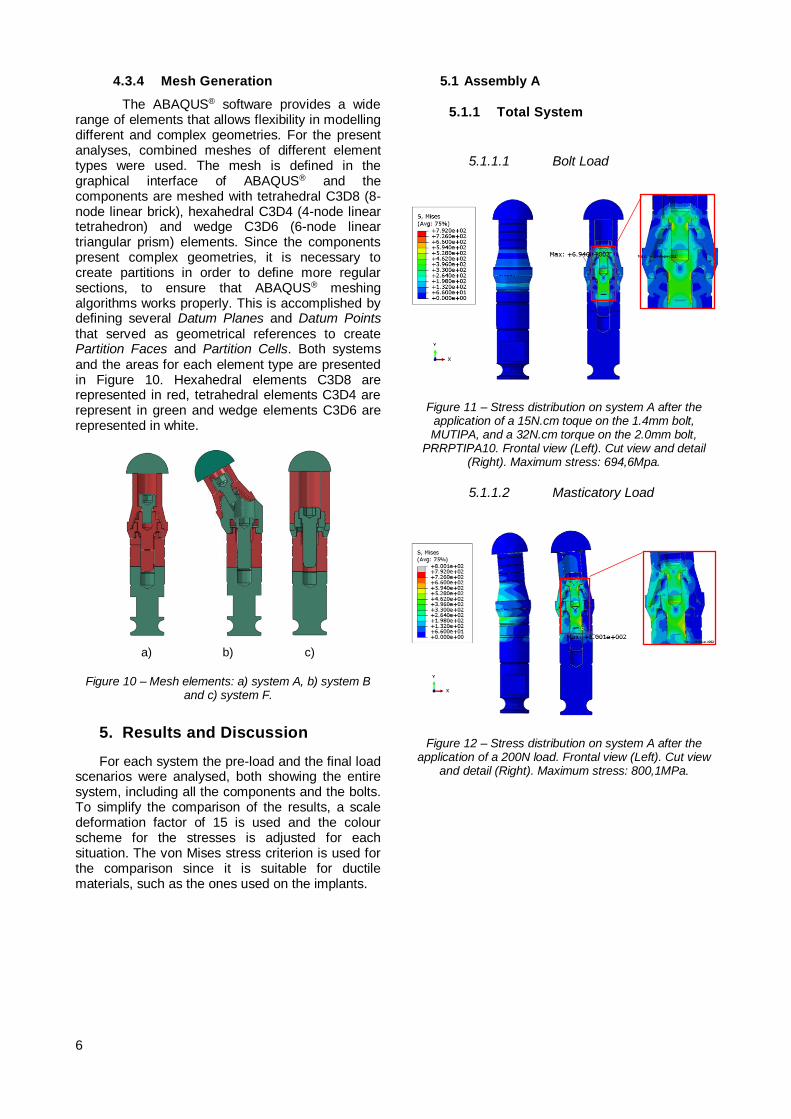
The ABAQUS® software provides a wide range of elements that allows flexibility in modelling different and complex geometries. For the present analyses, combined meshes of different element types were used. The mesh is defined in the graphical interface of ABAQUS® and the components are meshed with tetrahedral C3D8 (8-node linear brick), hexahedral C3D4 (4-node linear tetrahedron) and wedge C3D6 (6-node linear triangular prism) elements. Since the components present complex geometries, it is necessary to create partitions in order to define more regular sections, to ensure that ABAQUS® meshing algorithms works properly. This is accomplished by defining several Datum Planes and Datum Points that served as geometrical references to create Partition Faces and Partition Cells. Both systems and the areas for each element type are presented in Figure 10. Hexahedral elements C3D8 are represented in red, tetrahedral elements C3D4 are represent in green and wedge elements C3D6 are represented in white.
a) b) c)
Figure 10 – Mesh elements: a) system A, b) system B and c) system F.
5. Results and Discussion
For each system the pre-load and the final load scenarios were analysed, both showing the entire system, including all the components and the bolts. To simplify the comparison of the results, a scale deformation factor of 15 is used and the colour scheme for the stresses is adjusted for each situation. The von Mises stress criterion is used for the comparison since it is suitable for ductile materials, such as the ones used on the implants.
5.1 Assembly A
5.1.1 Total System
5.1.1.1 Bolt Load
Figure 11 – Stress distribution on system A after the application of a 15N.cm toque on the 1.4mm bolt, MUTIPA, and a 32N.cm torque on the 2.0mm bolt,
PRRPTIPA10. Frontal view (Left). Cut view and detail (Right). Maximum stress: 694,6Mpa.
5.1.1.2 Masticatory Load
Figure 12 – Stress distribution on system A after the application of a 200N load. Frontal view (Left). Cut view
and detail (Right). Maximum stress: 800,1MPa.

7
5.1.2 Bolts MUTIPA and PRRPTIPA:
Bolt and Masticatory Load
Figure 13 – (Left) Stress distribution on bolts after the 15N.cm torque is applied to the MUTIPA bolt and the 32N.cm torque is applied to the PRRPTIPA bolt. Front view and cut view. Maximum stress: 694,6MPa. (Right)
Stress distribution on bolts MUTIPA and PRRPTIPA after 200N load application. Front view and cut view.
Maximum stress: 800,1MPa.
Initially the bolt load generates a stress that starts on the bolts’ shank and then is propagated to the adjacent components. The highest stress concentration is verified on the bolts, essentially on the areas where the diameter changes. During the application of the masticatory load, due to the load direction, the stress is redistributed to the compression area, being the highest stress value verified on the bolt PRRPTIPA10, 800,1MPa. Table 6 presents a summary of the highest stress values in all the components after the bolt load step and the load step.
Table 6 - Assembly A components’ highest stress after bolt load and load steps.
Bolt Load Masticatory
Load
Component Highest Stress
Value (MPa) Highest Stress
Value (MPa)
Interface
MUTIRTG 589,5 769,3
Bolt MUTIPA 662,4 686,6
Bolt PRRPTIPA10 694,6 800,1
Platform PRRPTIBA10G
321,8 572,9
Implant Replica RPTIBA
232,8 584,2
Hemispherical Part 0,1 25,9
5.2 Assembly B
5.2.1 Total System
5.2.1.1 Bolt Load
Figure 14 – Stress on assembly B after the application of a 15N.cm torque on the 1.4mm bolt, MUTIPA, and a
20N.cm torque on the 2.0mm bolt, PARPTIPAG. Frontal view (Left). Cut view (Right). Maximum stress: 888,0MPa.
5.2.1.2 Masticatory Load
Figure 15 – Stress on assembly B after the application of a 200N load. Frontal view (Left). Cut view and detail
(Right). Maximum stress: 907,4MPa.

8
5.2.2 Bolt MUTIPA: Bolt and
Masticatory Load
Figure 16 – (Left) Stress on bolt MUTIPA after the 15N.cm torque is applied to the MUTIPA bolt and the
20N.cm torque is applied to the PRRPTIPAG bolt. Front view and cut view. Maximum stress: 888,0MPa. (Right). Stress on bolt MUTIPA after the 200N load application. Front view and cut view Maximum stress: 907,4MPa.
When the bolt load is applied, the stress is distributed mainly on the bolts’ shank and also to the adjacent components to the bolts. After loading the system with the 200N load, the stress is distributed not only on bolt shank but also on the adjacent components. The bolt MUTIPA is the one that has the highest stress value of all system, either after the bolt load and the masticatory load. After the bolt load step, the highest stress is verified exactly on the same area for both situations.
Table 7 - Assembly B components’ stress after
bolt load and load steps.
Bolt Load Masticatory
Load
Component
Highest
Stress Value (MPa)
Highest
Stress Value (MPa)
Interface MUTIRTG 723,3 750,9
Bolt MUTIPA 888 917,1
Angulated platform PA30RPTIBA40G
564,3 640,4
Bolt PARPTIPAG 579,6 578,4
Implant Replica RPTIBA
183,3 373,5
Hemispherical Part 5,2 28,2
5.3 Assembly F
5.3.1 Total System
5.3.1.1 Bolt Load
Figure 17 – Stress distribution on assembly F after the application of a 32N.cm toque on the 2.0mm bolt,
RPTIPA. Front view (Left side). Cut view (Right side). Maximum stress: 790,1MPa.
5.3.1.2 Masticatory Load
Figure 18 - Stress distribution on assembly F after the application of a 200N load. Front view (Left). Cut view
(Right). Maximum stress: 808,1MPa.
5.3.2 Bolt RPTIPA: Bolt and
Masticatory Load
9
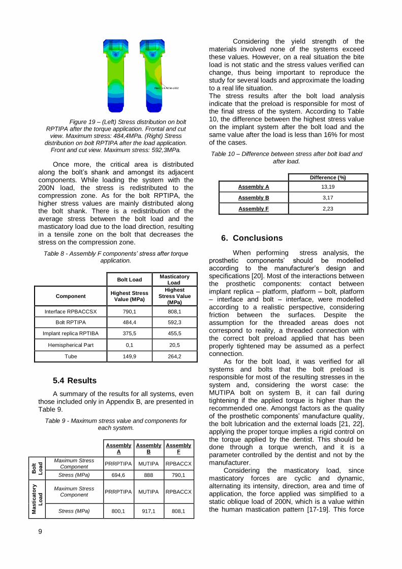
Figure 19 – (Left) Stress distribution on bolt RPTIPA after the torque application. Frontal and cut
view. Maximum stress: 484,4MPa. (Right) Stress distribution on bolt RPTIPA after the load application.
Front and cut view. Maximum stress: 592,3MPa.
Once more, the critical area is distributed along the bolt’s shank and amongst its adjacent components. While loading the system with the 200N load, the stress is redistributed to the compression zone. As for the bolt RPTIPA, the higher stress values are mainly distributed along the bolt shank. There is a redistribution of the average stress between the bolt load and the masticatory load due to the load direction, resulting in a tensile zone on the bolt that decreases the stress on the compression zone.
Table 8 - Assembly F components’ stress after torque application.
Bolt Load
Masticatory Load
Component Highest Stress
Value (MPa)
Highest
Stress Value (MPa)
Interface RPBACCSX 790,1 808,1
Bolt RPTIPA 484,4 592,3
Implant replica RPTIBA 375,5 455,5
Hemispherical Part 0,1 20,5
Tube 149,9 264,2
5.4 Results
A summary of the results for all systems, even those included only in Appendix B, are presented in Table 9.
Table 9 - Maximum stress value and components for each system.
Assembly
A Assembly
B Assembly
F
Bo
lt
Lo
ad
Maximum Stress Component
PRRPTIPA MUTIPA RPBACCX
Stress (MPa) 694,6 888 790,1
Masti
cato
ry
Lo
ad
Maximum Stress Component
PRRPTIPA MUTIPA RPBACCX
Stress (MPa) 800,1 917,1 808,1
Considering the yield strength of the materials involved none of the systems exceed these values. However, on a real situation the bite load is not static and the stress values verified can change, thus being important to reproduce the study for several loads and approximate the loading to a real life situation. The stress results after the bolt load analysis indicate that the preload is responsible for most of the final stress of the system. According to Table 10, the difference between the highest stress value on the implant system after the bolt load and the same value after the load is less than 16% for most of the cases.
Table 10 – Difference between stress after bolt load and
after load.
Difference (%)
Assembly A 13,19
Assembly B 3,17
Assembly F 2,23
6. Conclusions
When performing stress analysis, the prosthetic components’ should be modelled according to the manufacturer’s design and specifications [20]. Most of the interactions between the prosthetic components: contact between implant replica – platform, platform – bolt, platform – interface and bolt – interface, were modelled according to a realistic perspective, considering friction between the surfaces. Despite the assumption for the threaded areas does not correspond to reality, a threaded connection with the correct bolt preload applied that has been properly tightened may be assumed as a perfect connection.
As for the bolt load, it was verified for all systems and bolts that the bolt preload is responsible for most of the resulting stresses in the system and, considering the worst case: the MUTIPA bolt on system B, it can fail during tightening if the applied torque is higher than the recommended one. Amongst factors as the quality of the prosthetic components’ manufacture quality, the bolt lubrication and the external loads [21, 22], applying the proper torque implies a rigid control on the torque applied by the dentist. This should be done through a torque wrench, and it is a parameter controlled by the dentist and not by the manufacturer.
Considering the masticatory load, since masticatory forces are cyclic and dynamic, alternating its intensity, direction, area and time of application, the force applied was simplified to a static oblique load of 200N, which is a value within the human mastication pattern [17-19]. This force

10
can sometimes unload the prosthetic bolts by distributing the stress on the prosthetic system.
According to Osteotech, the worst case should be the MUTIPA bolt. This critical component fails most of the times during the tightening, in the transition area between the bolt shank and the bolt head. Despite the limitations described above, the analyses results show that the assembly B, with the MUTIPA bolt, was indeed the worst case, presenting a stress concentration area with stress values relatively close to the yielding strength exactly in the same zone mentioned by Osteotech. The agreement of the results presented in this work and reported by Osteotech show that the simplifications made are reasonable and that the work developed is a solid base to further develop the models and proceed with an analysis on the critical component, including a fatigue analysis, as described in [1]
7. References 1. Standard, I., ISO 14801 Dentistry –
Implants – Dynamic fatigue test for endosseous dental implants 2007.
2. Petersen, P.M.a.P.E., Diet, nutrition and the prevention of dental diseases. Public Health Nutrition, 2004. 7: p. 201-226.
3. Misch, C.E., Dental Implant Prosthetics. 2014: Elsevier Health Sciences.
4. Shillingburg, H.T. and D.A. Sather, Fundamentals of Fixed Prosthodontics. 2012: Quintessence Pub.
5. Nsarin Sadaqah, A.A.-W., Elham Abu Alhija, Implant Abutment Types: A Literature Review - Part 1. The Journal of Implant & dvanced Clinical Dentistry, January 2010. Vol. 2(No. 3).
6. Scacchi, M., B.R. Merz, and A.R. Schär, The development of the ITI® Dental Implant System. Clinical oral implants research, 2000. 11(s1): p. 22-32.
7. Koutsonikos, A., Implants: success and failure--a literature review. Annals of the Royal Australasian College of Dental Surgeons, 1998. 14: p. 75-80.
8. Schwarz, M.S., Mechanical complications of dental implants. Clinical Oral Implants Research, 2000. 11(s1): p. 156-158.
9. Duse, D.-M. and A. Pasa, Dental implants mechanical properties: FEA vs. physical
testing. Annals of DAAAM & Proceedings, 2011: p. 1059-1061.
10. Finger, I. and L. Guerra, Integral implant-prosthodontic considerations. Dental clinics of North America, 1989. 33(4): p. 793-819.
11. Bozkaya, D. and S. Müftü, Mechanics of the taper integrated screwed-in (TIS) abutments used in dental implants. Journal of Biomechanics, 2005. 38(1): p. 87-97.
12. Lotti, R.S., et al., Aplicabilidade científica do método dos elementos finitos. Rev Dent Press Ortodon Ortop Facial, 2006. 11(2): p. 35-43.
13. Shigley, J.E., Shigley's mechanical engineering design. 2011: Tata McGraw-Hill Education.
14. Company, R., RTI - Titanium Alloy Guide R.I. Metals, Editor. Jan/2000.
15. Lang, L.A., et al., Finite element analysis to determine implant preload. The Journal of prosthetic dentistry, 2003. 90(6): p. 539-546.
16. Patterson, E.A. and R. Johns, Theoretical analysis of the fatigue life of fixture screws in osseointegrated dental implants. The International journal of oral & maxillofacial implants, 1991. 7(1): p. 26-33.
17. Ferrario, V., et al., Single tooth bite forces in healthy young adults. Journal of oral rehabilitation, 2004. 31(1): p. 18-22.
18. Reina, J., et al., Numerical estimation of bone density and elastic constants distribution in a human mandible. Journal of Biomechanics, 2007. 40(4): p. 828-836.
19. Dean, J.S., et al., A preliminary study of maximum voluntary bite force and jaw muscle efficiency in pre-orthognathic surgery patients. Journal of oral and maxillofacial surgery, 1992. 50(12): p. 1284-1288.
20. Natali, A.N., P.G. Pavan, and A.L. Ruggero, Analysis of bone–implant interaction phenomena by using a numerical approach. Clinical oral implants research, 2006. 17(1): p. 67-74.
21. Bickford, J., An introduction to the design and behavior of bolted joints, Revised and expanded. Vol. 97. 1995: CRC press.
22. Wang, R.-F., et al., The dynamic natures of implant loading. The Journal of prosthetic dentistry, 2009. 101(6): p. 359-371.