demonstrating cost effective technologies
TRANSCRIPT

Demonstrating Cost Effective Technologies
(A Case Study of Bawana Industrial Workers Housing Project)
Building Materials & Technology Promotion CouncilMinistry of Housing and Urban Poverty Alleviation
Government of India.
Demonstrating Cost Effective Technologies
(A Case Study of Bawana Industrial Workers Housing Project)
A publication of
Building Materials & Technology Promotion CouncilMinistry of Housing and Urban Poverty Alleviation, Government of India.
Core-5A , 1st Floor, India Habitat Centre, Lodhi Road, New Delhi 110 003 (India)

Prepared by
Promod Adlakha with the support from Adlakha Associates team.Adlakha Associates Pvt. Ltd.Architectural ConsultantsF-70, 1st Floor, Bhagat Singh MarketNear Gole Market, Connaught PlaceNew Delhi 110 001 (India)E-mail: [email protected]; Website: adlakhaassociates.com
A publication of
Building Materials and Technology Promotion Council (BMTPC)Ministry of Housing and Urban Poverty Alleviation, Government of India.Core-5A , 1st Floor, India Habitat Centre, Lodhi Road, New Delhi 110 003 (India).Tel: +91-11-2463 6705; 2463 8096, Fax: +91-11-2464 2849E-mail: [email protected]; Website: www.bmtpc.org
DisclaimerThe views expressed in this document are those of the authors. They do not necessarily represent those of the BMTPC, Ministry of Housing and Urban Poverty Alleviation, Government of India.

Foreword
Building Materials & Technology Promotion Council since its inception in 1990 has
been toiling hard to implement cost effective, energy efficient & eco-friendly building materials & technologies at gross root level. There have been number of success sto-
ries, however, the single largest project executed in India using these technologies has been by Delhi State Infrastructure & Industrial Development Corporation (DSIIDC) for
industrial workers. Later the same concept was repeated for EWS housing projects by DSIIDC. These projects have been documented by Shri Promod Adlakha, Consultant &
Architect, under one of the BMTPC’s sponsored study so as to bring the entire gamut of
these technologies right from implementation to cost-economics to construction man-
agement & quality control for the engineers & architects who are willing to adopt them
for ensuing projects.
The technologies used are simple & rudimentary i.e. load bearing construction using
modular bricks with cement-flyash blended mortar for structural framing, precast RC planks & joist for roofing & flooring. Also, ferrocement staircase treader–riser units, precast ferrocement sunshades, kitchen platform & precast ferrocement water tanks
are used as an alternate to common conventional systems. It has been shown that
there is overall saving of more than 20% over conventional construction in civil works.
The single stack system for plumbing & sanitation has been used as a digression from
the conventional dual stack system giving overall saving of more than 30% in plumb-
ing services. There is also considerable saving of cement & steel which are energy
intensive materials and based on natural resources which are finite in nature. Through this real time project, it has also been shown that there is considerable saving in time
of construction. The publication presents all the details including cost analysis. It is also
equally important to draw a strict QC/QA plan while implementing any new/alternate
construction methodology/system. The entire chapter is devoted on these aspects in
the publication. In light of Housing for All Mission launched by Govt. of India, it is hoped
that this document will become a reference document for professionals and go a long
way in BMTPC’s mission to mainstream alternate materials & technologies.
The BMTPC’s team of Shri Sharad Gupta and Shri Dalip Kumar also deserve a special
mention for bringing the document to presentable form in time-bound manner.
It is high time for architects & engineers to bring innovations in clichéd conventional
building construction.
Dr. Shailesh Kr. Agrawal
Executive DirectorBMTPC


PreFACe
This document describes the Architectural and Structural methodologies adopted
keeping in mind the cultural, social & economic needs of the urban poor. Optimiz-
ing on cost with respect to housing blocks and layout, use of appropriate cost ef-
fective alternative materials & technologies were incorporated in the project with
technical support of Building Materials & Technology Promotion Council (BMTPC)
and Central Building Research Institute (CBRI).
This document shall play an important role to economize the cost of construction
without affecting functional behavior and ensuring reliable and durable “Built Envi-
ronment”.
This document shall be useful to all planners, Architects, Engineers, Administra-
tors, Builders & Developers, Housing Boards, Development Authorities, Teaching
& Training Institutes and Professionals of Government Departments.
Promod Adlakha
Adlakha Associates Pvt. Ltd.


Contents
S.No. Description Page No.
1. Introduction 1
2. Economics 37
3. The Construction 50
4. Construction Management and Quality Control 72
5. Drawings 90
6. Snapshots of the Project 119
7. Conclusions 129


1
Building Materials & Technology Promotion Council
Chapter 1 : INTRODUCTION
1.1 Preamble
In order to decongest the City of Delhi, it was decided to shift the industries from Delhi’s non-confirming areas to the outskirts. DSIIDC was entrusted with this gigantic task of shifting about 28,000 industrial units. For the purpose, 1865 acres of land was acquired, in North West Delhi at Bawana and surrounding areas.
Bawana Industrial Estate, the largest Industrial Relocation Scheme in Asia, was expected to benefit a work-force of about 2,50,000 persons. The Industrial Estate was also to provide; whole-sale market, raw material market, workshops, warehouses, godowns, offices etc.
Fig. 1.1: Location of Bawana in Map of Delhi & proposed Metro Connectivity

2
Demonstrating Cost Effective Technologies – A Case Study of Bawana Industrial Workers Housing Project
1.2 Rajiv Gandhi Housing Project
Bawana Industrial Estate was also required to provide proper living accommodation for the workers. Ac-cordingly, DSIIDC launched a housing scheme for Industrial Workers at Bawana Industrial Estate. The DSI-IDC took upon the responsibility of providing accommodation to industrial workers catering to the relocated industries in this new industrial township. In order to achieve this it has played a leading role in the planning and implementation of this project.
This scheme was meant primarily for providing shelter for poor industrial workers near to their work place so that they were not required to travel long distances. The project was to facilitate economic upliftment of the workers and to reduce time consumed to travel from place of living to place of work and vice – versa so that they have adequate time for relaxing, socializing and looking after their families.
The Making of “Bawana Housing Project” - A Case Study About Bawana & Chronology of the Project
ADLAKHA ASSOCIATES PVT. LTD. BMTPC DSIIDC 8
2.2 – Rajiv Gandhi Housing Project Bawana Industrial Estate was also required to provide proper living accommodation for the workers. Accordingly, DSIIDC launched a housing scheme for Industrial Workers at Bawana Industrial Estate. The DSIIDC took upon the responsibility of providing accommodation to industrial workers catering to the relocated industries in this new industrial township. In order to achieve this it has played a leading role in the planning and implementation of this project.
This scheme was meant primarily for providing shelter for poor industrial workers near to their work place so that they were not required to travel long distances. The project was to facilitate economic upliftment of the workers and to reduce time consumed to travel from place of living
UER
Fig. 2 – Layout Plan of Bawana Industrial Complex (showing Residential Pocket)
Poothkhurd (Bawana-III)
Fig.1.2: Layout Plan of Bawana Industrial Complex (Showing Residential Pocket)
3
Building Materials & Technology Promotion Council
Part of “The Rajiv Gandhi Housing Project” at Bawana has been implemented and dedicated to the people on 19th November, 2006 by the then Hon’ble Chief Minister of Delhi. The project is a good example of effec-tive use of time tested materials along with the use of alternative technologies.
1.3 Project Philosophy and Realization
The Housing Project at Bawana has been evolved on the philosophy of providing a dream home for the poor within the affordable costs without compromising on the quality and creating a living environment con-genial to their lifestyle and culture. The aspect of affordability was of prime consideration.
The objectives of the philosophy behind the project had to be achieved while keeping in mind the follow-ing:-
Low Income Housing Norms• Planning and Design Concept• Built Environment• Efficient Infrastructure Development• Appropriate Specifications• Optimum Structural Design• Cost Effective Construction Techniques• Fast Track Construction• Efficient Construction Management and Quality Control• Aesthetic• Functionality• Social-acceptance• Environmental issues• Sense of togetherness (neighborhood concept)• Thus the overall concept of the project was evolved.•
1.4 Low Income Housing Norms
Since the houses in the project primarily belong to the low income segment, the norms on low income hous-ing as contained in the National Building Code of India have been kept in mind while finalizing the design of the houses. The NBC norms are as under :
In case of one room house, the size of multi-purpose room including space for cooking shall not be less • than 12.5 sqm with a minimum width of 2.5 m.In case of a two roomed house, the size of 2nd room shall not be less than 6.5 sqm with a minimum • width of 2.1m, provided the total area of both the rooms is not less than 15.5 sqm. In the case of in-cremental housing to be developed as a future two room house, the bigger room shall always be the first room.The minimum size of independent W.C. shall be 0.9 x 1.0 m.• The minimum size of independent bath shall be 1.2 x 1.0 m.• The minimum size of combined bath & W.C. shall be 1.80 x 1.0 m.• The size of a cooking alcove serving as cooking space shall not be less than 2.4 sqm with min. width • of 1.2 m. The size of individual kitchen provided in a two roomed house shall not be less than 3.3 sqm with min. width of 1.5 m.Minimum height of habitable room 2.6 m, kitchen 2.6 m, Bath/W.C. 2.1 m.• Minimum width of staircase upto 4 storeyed constructions should be 1 m, risers a maximum of 20 cm • and tread a minimum of 25 cm. The minimum clear head room shall be 2.1 m.•

4
Demonstrating Cost Effective Technologies – A Case Study of Bawana Industrial Workers Housing Project
Beside NBC norms the living habits of the occupants, climatic considerations of Delhi, affordability levels of the class have been taken into account.
1.5 Planning and Design Concepts
1.5.1 Design ConsiderationsThe prime objective of the project as defined already was to create an integrated human habitat suited to the lifestyle and cultural background of the workers. This was to be achieved efficiently to match the afford-ability of the users. The unit size, type of housing, level of infrastructure etc. to be provided were areas of concern to achieve scalability vis-a-vis affordability and marketability.
Depending on the land cost, land development cost, affordable density, conducive to the overall goal of affordable housing, the desirable design considerations were compiled at dwelling level, cluster level and the sector level. The basic considerations were to reflect economic planning. Self-financing approach was adopted to ensure viability of the project. The development is built at a high density of 300 dwelling units per hectare. The built form reflects the local characteristics and aspirations of the people.
All basic community and institutional facilities and services including basic social services like education, health, recreational areas, essential infrastructure and amenities like water supply, sewerage, storm water drainage, roads, electricity and activities like commercial and other services establishments have been taken care of in the project.
The project has been designed on the basis of a ‘creative’ form:
The Urban form for maintaining the traditional living pattern of the inhabitants.• The Design is Socio-culturally sensitive with a strong sense of interaction and unity & identity.• The design is adaptable to local life-styles and space requirements• Fostering social interaction and inter-relationship by grouping of the inhabitants.• The design respects the existing social hierarchies and resultant morphologies in terms of layout, ac-• cessibility, proximity and interrelationship.
Providing amenities like community halls, kiosks, schools, women welfare centre, dispensary, tot lots, cycle tracks which serve not only as a functional public node, but also reflect the identity of the inhabitants and their aspirations.
1.5.2: Planning ConceptsThe site is broadly divided into 11 Sectors so that the construction sequence is well managed and phased out with the required infrastructure. Each sector works as an independent “Block of Units”. The water supply and sewerage systems have been designed, so that the residents can be allotted the dwelling units in ‘phase’ and that they can move into a cluster even while construction is going on for other clusters. This has helped in easy and ef-ficient implementation of the project.
The development of the project was conceptualized with a focus that Pocket/Sector ‘A’ shall have only Type II houses in G+3 (Fig.1.3) and that Pocket/Sector ‘B’ shall have only Type I houses in G+2 (Fig.1.4). Fig. 1.3: Pocket A

5
Building Materials & Technology Promotion Council
The cluster were planned in a grid pattern with hierarchy of Roads along all sides of a cluster tangential to the front road (MP-7) and parallel to the sides of triangular plot.
Fig. 1.5 shows a typical cluster with blocks of G+3 in Pocket/Sector A.
Fig. 1.4: Pocket B
Fig. 1.5: Layout Grid Plan

6
Demonstrating Cost Effective Technologies – A Case Study of Bawana Industrial Workers Housing Project
On the advice of Delhi Urban Art Commission, the entire layout as well as the ‘block’ dwelling unit plan were modified on the following lines:
The separate sectors/pockets for Type I and Type II defeat the purpose of social living.i. The large complex should create variation in skyline. Intermixing of both Type I (G+2) and Type II (G+3) ii. would create an interesting skyline.
Fig. 1.6: Shows the proposed skyline
Fig. 1.7: Shows the skyline as per modified plan
Fig. 1.8
The parks were small and scattered like tot lots, which eventually would invite the residents to en-iii. croach upon.
7
Building Materials & Technology Promotion Council
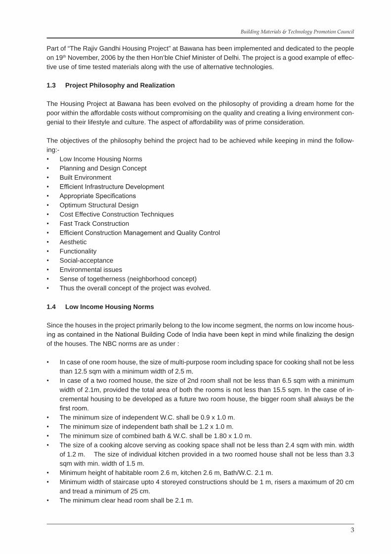
The modified layout plan was worked out on the similar pattern of road network but with intermixing of Type I (G+2) and Type II (G+3) blocks. As per Delhi Master Plan – 2001 the maximum density allowed is 300 DU/hectare. This could be efficiently planned as a low-rise high density concept with walkable structures. This also prompted to use load bearing concept instead of a framed structure. The modified layout plan is shown as Fig. 1.9. A modified cluster plan is shown as Fig. 1.10. The cluster has a bigger green court / Park with blocks around the court in a “swastik” pattern.
Fig. 1.9 Fig. 1.10
Fig. 1.11 Fig. 1.12
It was further modified with a cluster comprising of combination of twin blocks (Fig. 1.11) and Fig. 1.12 shows a typical cluster.
The layout plan was further modified by merging the small parks with the central large park (Fig. 1.13), thereby creating a wind flow across the cluster (Fig. 1.14). Thus the central green provide a cooling effect in the harsh weather of Delhi.

8
Demonstrating Cost Effective Technologies – A Case Study of Bawana Industrial Workers Housing Project
1.5.3 Planning at Sector (Pocket) Level
To maintain contact with land and greenery.• To reflect the local characteristics in the built form.• To encourage interactions and integration amongst the various social groups.• To segregate pedestrian and vehicular movements.• To optimize land use, roads and other infrastructure.• To provide a sense of security.• To provide daily need facilities within easy reach.• To provide well-ordered hierarchy open spaces for various activities.• To provide defined entry points and discourage through vehicular traffic.• To suit self-financing approach. •
Fig. 1.13
Fig. 1.14

9
Building Materials & Technology Promotion Council
1.5.4 Planning at Cluster Level
The design considerations at the cluster level include :To promote person to person contact through cluster of human scale.• To provide an individual character to each cluster.• To create a functional and pleasing street environment.• To provide spaces for social & religious activities.• To provide basic essential amenities and utilities to every cluster.•
The cluster is the form of a group which helps in fostering a sense of community, a concept similar to the ‘Mohallas’ found in traditional towns. The open green square & pathways “Streets” promote person-to-per-son contact. This is also achieved by giving a sense of boundary and a sense of identity to each cluster. The built form of cluster is in relation to the human scale. The cluster boundaries have been defined by access roads, around the clusters. The small green squares and pedestrian walkways around, not only provide ac-cess to various infrastructure to each house but also become focal points for social brotherhood. The green squares act as safe play areas for children and provide for social and domestic get together.
1.5.5 Planning at Dwelling Level
For the house design, a range of options/designs were evolved. The Architectural planning of dwelling units was done with the following parameters :
To make the dwellings sensitive to the life styles and daily needs of the people.• To give the dwelling a rich and unique identity.• To integrate the spaces within and outside the dwellings.• To maintain privacy within and from outside.• To consider light, ventilation, climate control.• To study efficiency of dwelling units w.r.t. internal circulation.• To use appropriate materials and construction Technologies.• To make the dwellings simple and economical.• To propose economic planning of services, structure and substructure.•
1.6 Built Environment
Built environment are of two types, viz. measurable & non-measurable. Measurable functions are neces-sary from the considerations of economy whereas non-measurable functions are important from the con-siderations of aesthetics, quality of life etc.
The concept of Built Environment involves issues relating to anthropometrics, ecology and environment spaces, building and plumbing services, sustainable development, construction management and econo-my.
While designing this “Rajiv Gandhi Housing Project” efforts were made to keep above cited parameter in mind for creating an efficient Built Environment in the project. It was observed that a low–rise built form would be more suitable. In case of low rise development the habitants are more in touch with the Mother Earth and the Mother Nature, which provides a sense of comfort.
Protection of outdoor spaces by mutual shading of external walls, shelter from the winds during hot summer and cold seasons, shelter from the dust and reduction of surfaces exposed to solar radiation are some of the other important aspects which have been given considerations for the Built Environment.

10
Demonstrating Cost Effective Technologies – A Case Study of Bawana Industrial Workers Housing Project
1.7 Compliance to Standards and Specifications
Following Standards were followed for Design & Execution :-MCD Byelaws• DDA Byelaws• BIS Codes• CPWD Specifications• BMTPC Specifications• CBRI Technical Notes• IRC Standards• HUDCO Technical Services• IBC Publications• National Building Code• National Electrical Code•
1.8 Orientation
Delhi climate requires an orientation of the longer sides of building to-wards North – South as this ensures less radiation on built form during summer months. Although it is not possible to meet the desired objec-tive for all in a cluster form, yet most of the houses have the desired orientation. Wherever, possible care was taken that most of the houses had the opening facing the prevailing breeze, so as to utilize its cooling effect.
1.8.1 Courtyard Living Concept
The problem associated with the low cost housing schemes is that the low cost housing projects lack qual-ity and variety of open spaces. The bias of economics in planning such schemes typically ignore the social as-pects and needs while designing.
The problem has been addressed in this project tech-nically by providing blocks in cluster court concepts whereby the “organized” open spaces have been formed to create intimate family links like an enclosed form and expression of a public square.
The courtyard type of built form is very suitable, as the open courtyards are excellent thermal regulators. De-ciduous trees & plants provide shade in summer and allow the low sun in winters.
Fig. 1.15: Wind Flow Diagram
Fig. 1.16: Courtyard Concept Image
Fig. 1.17

11
Building Materials & Technology Promotion Council
1.8.2: Public squares spreaded with large trees located in the centre or at a corner of the squares are a common feature for meeting of the habitants. The space beneath such shady trees is used as an outdoor meeting place, work place and porches.
1.8.3: Similar meeting places have been created around the trees planted along the periphery of the settlement and in other green spaces.
1.8.4 Automobile traffic in low income housing settle-ments is limited. This does not mean, however, that there is no vehicular traffic in the area but its conglomeration may be different. There are smaller vehicles in lower in-come housing than the conventional housing. The smaller vehicles include bicycles, mopeds, motor rickshaws, auto-rickshaws. It is a mindset of people to park the vehicles closer to the house, than in specified parking spaces.
1.8.5 The layout is done such that these specified spaces are closest to each block of houses. Parking spaces have been created in each cluster and the access ways between the blocks are wide to accommo-date such vehicles, wherever required.
Fig. 1.18
Fig. 1.20
Fig. 1.21 – Pathway Fig. 1.22 – Parking lot
Fig. 1.19: Sit Outs

12
Demonstrating Cost Effective Technologies – A Case Study of Bawana Industrial Workers Housing Project
1.8.6 In informal settlement, streets are generally narrower than functionally required. In this project, the pathways are 2.5 to 4m wide. The vehicular access streets/roads are 9m wide (Right of way) and thus houses set-backs are minimum 9m across the road.
1.9 The Neighbourhood
The neighbourhood, commonly defined as community living & its coherence found in villages as the social pattern of living in the countryside, is of fundamental importance to this scheme in order to provide a feeling of togetherness.
The Universal needs of a family life are basically same; where in basic instincts of a human being govern the needs with some variations as a result of social, climatic and geographical effects. The neighbourhood system if available is applicable and acceptable in both urban and rural areas equally.
The framework of a model community is a distinct identity classified under the following :-
Residential Environment• Elementary Schooling• Small parks and play grounds• Local Shops / Kiosks• Facility Centres•
1.9.1 Under the term ‘residential environment’ is included the quality of architecture, the layout of roads, and pathways/streets, the plantation along ends of corner blocks, the arrangement and setbacks of build-ings and their linkage to the meeting places. The commercial links to the dwelling places – all the elements, put together create an environment and constitute a worth living characteristic atmosphere.
1.9.2 Small Shops / Kiosks have been planned in addition to formal markets / shopping areas. These kiosks by the nature of their commerce are exclusively oriented to local needs, and their intimate proxim-ity to the home and along main roads around cluster corners in open spaces. Without the organized small shops, the houses at ground floor, facing the roads normally become commercial centre and as such are not desirable. (Fig. 1.24 & 1.25)
Fig. 1.23: Showing Pathway & Road

13
Building Materials & Technology Promotion Council
1.10 Distribution of Open Spaces
At the cluster level as well as at Sector/Pocket level, the open spaces have been organized in a linear fash-ion so as to lend continuity. The pedestrian pathways along the open spaces short circuit the formal road pattern. The green area divided into each cluster has been linked with clusters through small green areas. The pattern and distribution of open spaces has been linked with location of various facilities, amenities and the road network, so as to evolve a compact network for the colony.
Informal day to day shopping through kiosks has been provided along the green spaces to form public squares. Thus the land has been put to optimum use without loss of spaciousness. Due to the location of social facilities in open spaces, there are better chances of these spaces being used, maintained and self-policed against illegal encroachment.
Fig. 1.24: Temporary unauthorized structure for shops (Undesirable)
Fig. 1.25: Shop opened in houses (Undesirable)
Fig. 1.26

14
Demonstrating Cost Effective Technologies – A Case Study of Bawana Industrial Workers Housing Project
1.11 Social Facilities and Amenities
The facilities and amenities provided in the colony are given in table below. Each sector / pocket has been organized to incorporate the required facilities and amenities so as to sustain a viable community. The ame-nities include primary schools, kiosks, community centre, facility centre, petrol pump, rickshaw stand, infor-mal weekly market, Elect. Substations, mother dairy booth, crèche, library, dispensary, essential shops.
Community activities have also been combined with open spaces, thus promoting multiple use. The bound-aries have also been demarcated for social facilities.
1.12 Landscape Design
1.12.1 In most conventional housing projects, landscaping is considered as a frill. In Bawana Housing Project, Landscaping and tree planting has been considered as integral part of the planning process. The trees have a strong significance in low-income areas as various social, domestic and work activities are performed beneath trees. Trees become focal points. They modulate spaces and enhance the quality of living environment. The plantation of trees, grass and shrubs has been done for unbuilt open areas in squares. Plantation of hardy plants has been emphasized.
Another important aspect of the tree plantation exercise was to carry out at an early stage of land develop-ment, so that by the time, the township is ready for occupation, the vegetation would reach a stage of ma-turity and could serve its purpose. This step had been taken up right at the beginning to create a habitable environment.
1.12.2 Plant Selection
Plants are an important component of landscape. Following factors have been kept in mind while deciding the nature of plants to be put in the project :
Ecology• Botany• Horticulture• Aesthetics• Growth & survival• Environmental function• Maintenance•
Emphasis has been laid on branching and flowering pattern at corners of the lawns.1.
Trees have been planted along the boundary wall with tree guards in exposed brick and Kota stone in 2. order to enable these spaces to be utilized for sitting under the shade.
Being low rise structure, emphasis has been made for using medium size trees.3.
Situated in an industrial area and along the 40m road, vegetation buffers have been provided along the 4. boundary wall which acts as pollution sinks, as the leaves absorb pollutants.
Small green areas / small parks have pipe railing in orange colour provide the protection from misuse 5. of the park.
The multi coloured Concrete Park railings add to the aesthetics besides providing privacy protection 6. & identity.

15
Building Materials & Technology Promotion Council
1.12.3 Construction details, specification and methods used for the landscape elements include.
Paved areas as ‘soft’ areas for pedestrian use with interlocking pavers, which are porous and • minimize the heat island effect.Edges, kerbs, bumper stops, ramps, steps, planters, railings and other protection devices.• Boundary wall, fencing and retaining walls.• Tree gratings with exposed brick & kota stone finish as street furniture.• Low level park boundaries with kota stone top finish as street furniture.• Structures in landscapes such as gate houses, kiosks.• Site utilities such as saucer drains, storm water drains, manholes, catch basins, outdoor lighting fix-• tures, electrical feeder pillars, all provide aesthetics merged with parks.Outdoor signage.• Provision for handicapped wheel chair access and movement.•
Photo 1: A few landscaped features
Photo 2

16
Demonstrating Cost Effective Technologies – A Case Study of Bawana Industrial Workers Housing Project
1.13 Land use Pattern
The land use pattern has been evolved in a manner to achieve a net density of 300 D.U./Ha., the o t h e r details are as follows : Pocket A, B & C
Total Plot area (Pocket A,B,C) = 1,50,000 sqm (15 Ha)• = 37 Acres (approx.)
G.F. coverage achieved = 29.91%• Area under Roads & Parking = 27%• Area under Pathways of soft areas = 10%• Area under green tot-lots/parks = 20%• Total FAR achieved = 105•
Community FacilitiesPrimary School = 4 Nos. • Kiosks = 21 Nos.• Community Centre / Facility Centre = 4 Nos.• Local Shopping cum Facility Centre = 1 Nos.• Women’s, Welfare Centre = 1 Nos.• Security Check posts = 5 Nos.• Rickshaw Stand = 1 No.• Informal market = 1 No. •
Table 1
CategoryPlinth Area
(sqm)Carpet Area
(sqm)No. of
StoreyesNo. of DUs No. of blocks
Type I 31.60 24.47 G + 2 1500 125Type II 37.73 27.61 G + 3 1664 104Type III 39.96 28.92 G + 3 1184 74
Total 4348 303
Fig. 1.27: A Typical Cluster

17
Building Materials & Technology Promotion Council
The ground coverage has been limited to 30% and low rise (3 & 4 storeyed) structures have been provided so as to have desired open areas. The organised green areas e.g. Parks and Tot lots are about 20% be-sides the other green patches which further accounts for approximately 5%.
Fig. 1.28: Layout Plan
1.14 Traffic Planning, Road Network and Blocks Articulation
The blocks have been planned to give better and equal relationship of green space, parking and approach. The blocks offer privacy, natural light and ventilation to all the flats. From the point of view of articulation of the build ing blocks and open spaces, relationship of fenestration’s, road pattern, and parking layout have been provided in such a manner that central green area merges with the parks, improves the environment and livability of the inhabitants of the complex.
While designing an appropriate circulation network, the various elements of the habitation have been taken into account. The grid pattern has been principally adopted. Through traffic has been excluded. The system of road network follows a clear hierarchy in terms of width. The street pattern within the cluster has clear identity to the streets which has created a functionally sympathetic and aesthetically pleasing street envi-ronment. Forming cluster around green squares also helped in providing economic infrastructure and easy access from the streets. The strips of land 1.5m wide on either side of the road earmarks a transition zones from where the housing activity starts.
The road network has three hierarchies :Access road 40m wide• Internal Roads 9m wide• Pathways 3.5m wide•
There are no dead ends, thus facilitating smooth vehicular traffic.
The access to each Sector/Pocket has been controlled by limited entry points, which enhances the domain of the neighborhood. The central open space of each cluster is free from vehicular movement or parking areas, whereby this open space can be effectively used as community activity space too, for small children

18
Demonstrating Cost Effective Technologies – A Case Study of Bawana Industrial Workers Housing Project
to play, while their parents can keep a watch overlooking them. The green tot lots spaces can be used for family functions also.
Another concept in the road network is the secondary linkage with pathways in each cluster. These pedes-trian pathways cut through the access roads and join the other clusters pathways. Properly landscaped public spaces are located around these pathways. Continuous pedestrian flow with centralized green link-age is an important feature of the project. At nodal points, that is intersection of roads, ‘kiosks’ have been planned in each cluster.
Fig. 1.29: Road Section (Pathways for pedestrians along road)
Fig. 1.30: Two clusters together
The colony belonging to Economically Weaker Sections of population shall have low vehicle ownership. The development has pedestrian pathways which is amply justified ensuring its intense use. Between the pocket A and B an eighteen metre wide “Cycle Track” has been provided extending through Industrial Es-tate.
The metalled road width has been reduced to 6m while keeping minimum setbacks of 9m between two blocks. The road width is sufficient to cater to the volume and type of vehicular traffic including the emer-gency vehicles such as Fire tenders, Ambulances, Sanitation Vehicles, etc. The parking areas shall be used by LTVs and have been paved with using precast low density paver blocks, laid on a sand cushion; thus allowing the percolation through the joints between the pavers legitimately thought as soft areas.

19
Building Materials & Technology Promotion Council
The paved areas that are used for movement of vehicles, pedestrians and wheel chair users in outdoor environment have been designed to facilitate easy accessibility, with well drained surface and good visual views.
The berms have been provided on all roads along the drains which adequately control drainage within the road, prevent moisture from entering the subgrade and separate the road from the pedestrian area. They also provide lateral support for the roads & pavement.
Pathways have been separated from the road by mean of using concrete segregated from black top roads, which provides both physical & visual separation. Pedestrian pathways are adequate for light vehicular use emergency.
1.15 Services Network
The linear layout of Road network the services such as sewerage, drainage, water supply, pathways pro-vide economical solution.
Fig. 1.31: Services Network

20
Demonstrating Cost Effective Technologies – A Case Study of Bawana Industrial Workers Housing Project
1.16 External Lighting
Landscape lighting has been provided by pro-1. viding pole mounted light fixtures in a mast of 13.5m ht. within the park. Masts have been preferred as the bollards are prone to vandal-ism and damage. Street lights fixtures have also been provided on the main Electrical poles instead of a separate street light pole for economy and also that it takes into consid-eration energy saving, safety aspect, lighting pollution and illumination level required.The small hanging transformers on poles rather added to the features.2. The poles have been provided along the boundary walls or on the edges of the side walk with clear 3. width of 1.5 m for circulation path.
1.17 Provisions for differently abled People
All pathways provide easy access, approach 1. and safety to the wheel chair users.Entry to all parks is user friendly.2. The kerb stones & drains along the roads pro-3. vide physical barrier.The junctions of roads & pathways have been 4. rounded for safety.The entry to blocks are wide enough (4.5m 5. setbacks) that in case of emergency ambu-lance can be approached at entry point of each block.High masts lights in parks surrounded by the blocks provide adequate illumination, for safety.6. The top finish of manholes and inspection chambers covers are in alignment or flushed with the 7. pavement, so that they facilitate easy and unobstructed movement for handicapped persons.Different texture finishes & change in levels in different colours provide visual aid to handicapped 8. for accessibility.The change in level at entry in the stair well within the block has been provided with a ramp instead 9. of steps.
1.18 Space Visualization and Blocking
Each block has 4 dwelling units on one floor served through one common stair case. Thus three storeyed blocks have 12 dwelling units in one block and four storeyed blocks have 16 dwelling units in one block.
Blocks have been in combination of two, three and four blocks in a row. These blocks have been articulated to form a cluster. By adjusting the block lengths in a cluster it had been possible to adjust the pedestrian permeability of the grid resulting in an openness at all ends of the clusters. Plantation along the perimeter of central open area has resulted in enclosed open space which is used as common garden and playground insulated from traffic.
The buildings clearly define the passage from the public space of street and side walk into the shared space of landscaped courtyards (parks). These courtyards are bounded by the units they serve and most of them have views into the outdoor space. This ensures that the children can play within sight and at calling dis-
Photo 3: Electrical Poles & High Mast Towers
Photo 4: Ramps

21
Building Materials & Technology Promotion Council
tance of home. These courtyards (parks) are human scaled with a height to width ratio of about 1:1 to 1:2 and its bound-aries are fenced, yet have easy access giving simultaneous effect of openness and privacy.
The post occupancy evaluation and related studies of many such neighborhood schemes in various countries indicate how effective shared outdoor space can be as a significant component of the landscape wherein it is bounded by the dwellings it serves and is clearly not a public park.
The public park of about one hectare area has been centrally placed between Pocket A & B for older children to play their usual games of football, hockey, cricket etc.
1.19 Grouped Squares
Each cluster resembles a square. The visual impact of a group of squares may be compared with the effect of a cycle of murals. In both instances, each “sub block” the individual “square” (Cluster) and the single “block represent an entity per so, aesthetically self-sufficient and yet part of a comprehensive higher order – individuation and uni-ty”.
In analogue on a more limited scale would be the relationship of successive rooms inside a “palace” the first room preparing for the second, the second for the third, and so on so forth; each room meaningful as a link in a chain beyond its own architectural significance. Similarly, individual ‘squares’ (Cluster) have been fused organically and aesthetically into one comprehensive whole.
The mental aesthetic effect of whole has been further enhanced due to successive images of changing heights (3 storeyed & 4 storeyed blocks)
Photo 5: Space Visualization
Fig. 1.32: Park between Pocket A & B
Photo 6
Photo 7: Three & Four Storeyed blocks successive image

22
Demonstrating Cost Effective Technologies – A Case Study of Bawana Industrial Workers Housing Project
1.20 Dwelling Units
Design Requirement for Dwelling Units
In general the low cost housing as a standard dwelling unit comprise of a multipurpose room with a cook-ing corner and a toilet. Such dwelling units are very small due to economic reasons and do not take into account the socio-economics characteristics of the occupants.
The stereo type housing along a common corridor (such as chawls in Mumbai) have been common in sight, but such housing lacks in individual identity, privacy and vitality and are abandoned by the users after oc-cupation.
In this project, as the dwelling units envisaged were of smaller area, there was a need for sharing of spaces for different activities at the dwelling unit level. To cater to the various work activities, outdoor space in the form of verandah had to be provided. The main design criteria of the dwelling units were to ensure maxi-mum utilization of the space and to minimize circulation areas, with as much light and natural ventilation. The planned dwelling units give an owner pride of owning it. There are two type of houses Type I (Fig. 1.34) and Type II (Fig. 1.36). Type I comprise of a living room, a multipurpose room, W.C., Bath, Balcony.
The Type II houses comprise of a living room with verandah, Bed room, Kitchen, Toilet.
The initial concept for Type II houses had a combined toilet (Bath + WC) (Fig. 1.33). However, in the final stages, the toilet was converted into separate Bath and W.C. (Fig. 1.36)
Fig. 1.33: Initial concept of Dwelling Unit plan in G+3 (35.96 sqm) – Type II with combined Toilet

23
Building Materials & Technology Promotion Council
Fig. 1.34: Shows the Dwelling Unit plan in G+2 (31.73 Sqm) – Type I
Fig.1.35: Front Elevation-Type I

24
Demonstrating Cost Effective Technologies – A Case Study of Bawana Industrial Workers Housing Project
Fig. 1.36: Shows the Dwelling Unit plan in G+3 (Type-II)
Fig.1.37: Front Elevation-Type II
The Scheme was further extended to Pocket ‘C’ wherein a new unit comprising of 39.96 sqm area in G+3 blocks are developed.

25
Building Materials & Technology Promotion Council
Fig. 1.38: Shows the Typical Floor Plan (Type III)
Fig. 1.39: Front Elevation – Type III

26
Demonstrating Cost Effective Technologies – A Case Study of Bawana Industrial Workers Housing Project
Fig. 1.40
1.21 Aesthetics (Bricks as Natural Material)
Building according to artistic principle is reflected in a more or less ornate portal like an entrance stairs hall found to be in ancient architectural traditional buildings.
The importance of bricks as natural building material is in use of bricks as “State of Art and technology”.
The Architectural character is reflected in laying of courses of ‘natural Red Clay Bricks’ combined with ‘Fly-ash bricks’ as voids. Brick as the dominant material has been used in a disciplined manner to achieve the desired effect.
1.22 Building Blocks
The design of the building blocks cover following parameters for efficient performance: Orientation aspect• Space Efficiency• Grouping• Privacy – usual & acoustical• Circulation• Sanitation• Economy• Elegancy•

27
Building Materials & Technology Promotion Council
1.23 Other Features
Certain aesthetic considerations have been incorporated into the design of the dwelling unit, these in-cludes:
Treatment of interior floor spaces.• Colour for walls, ceilings. • Natural lighting and ventilation.• Exterior & interior finish for walls – different materials, colour, texture and visual effect.•
1.24 Efficient Structural System
The building is designed on the principles of ‘box’ consisting of wall panel and floor diaphragms. While individual characteristics of the panels are duly considered during casting, transportation and erection, the properties of the box made out of these individual panels are considered for transferring bending moments and shear forces due to earthquake and wind.
The “Ductility provisions” have been provided in the form of :Vertical reinforcement at corner and tee junctions of walls, at jambs around openings, wherever 1. requiredGrade beam at piles cut off level1. Plinth band at plinth level1. Lintel band at Door/window lintel level (i.e. 2.1 m ht.)1. Roof band at all load bearing and peripheral walls.1.
Besides economical these structures have higher lateral stiffness than framed structure.
Design Concept(Through the lens)
Aesthetics Aesthetics Openness & the Parks with railings
Openness & the totlots Road Street lights & transformers on poles

28
Demonstrating Cost Effective Technologies – A Case Study of Bawana Industrial Workers Housing Project
Design Concept(Through the lens)
(Earthquake Resistance Measures)
Sit outs along boundary Inter Locking Pavers pathways High mast towers in Parks
Saucer drains Drains along Roads Parking Spaces
Plinth Band & Vertical reinforcement
Lintel band (for earthquake resistance)
Vertical reinforcement from Grade beam
Plinth Band and Vertical reinforcement at L Junction
Plinth Band and Vertical reinforcement at T Junction
Roof Band on load bearing walls (also shows precast planks and
reinforcement in haunches)

29
Building Materials & Technology Promotion Council
1.25 Use of Cost Effective Innovative Technologies
200 mm thick load bearing wall in Super Structure• Modular bricks with Cement + Flyash blended mortar• Precast Reinforced Concrete planks and joist for roofing and flooring• Ferrocement staircase treader – riser units• Precast ferrocement sunshades, kitchen platform• Precast ferrocement water tanks•
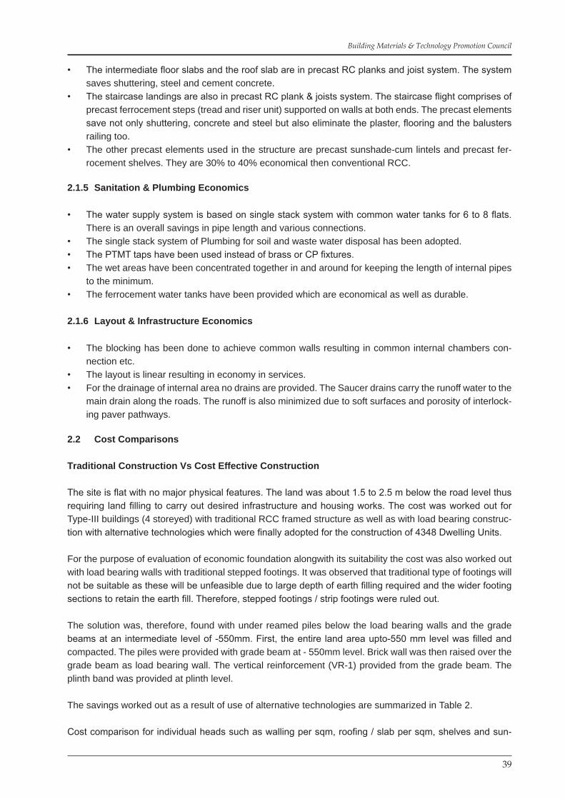
Mechanised ModularBricks / Walls
Mechanised Modular Flyash Bricks Modular Flyash bricks
Design Concept(Through the lens)
(Use of Cost Effective Innovative Technologies)
Lintel-cum-Sunshade Erection of Lintel-cum-precast Sunshade placed over window openings
Precast Planks casting
Ferrocement cooking platform
Casting of Staircase Steps(riser & tread units)
Ferrocement Water TanksErection of precast step

30
Demonstrating Cost Effective Technologies – A Case Study of Bawana Industrial Workers Housing Project
1.26 Structural Design
1.26.1 Typical Structural Design of Plank
(1) Plank (1500 x 300 x 60) For Intermediate Floors Load on Plank : (a) Dead Load : Self : 1.500x.300x.06x25000 = 675N Floor : 1.50x0.30x.04x24000 = 432N Total = 1107N Factor Load 1.50x1107 = 1660.5N (b) Live Load : 1.50x0.30x1500 = 675N Factor load 1.5x675 = 1012.5N
(2) Planks For Terrace Slab : Load on plank (a) Dead Load (self) 1.5x0.30x0.06x25000 = 675N Brick coba (b) (Average 100mm Thick) 1.5x0.30x0.10x20000 = 900N Total = 1575N Factor load 1.5 x 1575 = 2365.50N (c) Live Load 1.5x0.30x750 = 337.50N Factor Load 1.5x337.50 = 506.25N BM. Due to D/L 2365.50 x 1.50 / 8 = 443.5NM BM Due to L/L 506.25 x 1.50 / 10 = 75.95NM Total BM = (443.50 + 75.95) = 519.45NM Hence d = 519.45x10³ /0.138 x 20 x300 = 25.05mm Add cover + 15.00mm Total 40.05mm Provide 60mm overall depth Calculation for transvers reinforcement in plank As required in IS 456 the minimum transverse reinforcement should not be less than 0.15% of Cross sectional Area : 0.15x 1/100 x 1500x60 = 135mm2 Number of bars
Assuming 6 mm dia = 135/28.26 = 4.78 nos., Say 5 nos.Hence spacing = 1500/5 =300mmProvide 6 mm dia bars @ 200 mm c/cMain Reinforcement in PlankRatio : m/bd2 = 519.45x10³/300x452 =0.855Ref : SP 16 Table 2 (for fe 250)Percentage of Reinforcement = 0.412%Total reinforcementRequired – 300x60x0.412/100 = 74.16 mm2
Provide 6 mm dia mild steel bars: No of bars = 74.16 / 28.26 = 2.62 nos.Hence provide 3 nos. of 6 mm dia bars (main bars)Distribution bars.Ref: IS:13990:1994 (Clause 5.2.2)Provide 6 mm dia M.S. bars @ 200 mm c/cAs transverses reinforcement which is more than 0.15% of the sectional area of

31
Building Materials & Technology Promotion Council
the concrete as recommended in Code IS:456.Check for deflection as per IS456Ref: IS 456 Fig 3 P/57 for mild steelModification factor against Percentage of steel ie:=100x28.26x3/300x60 = 0.471%M. factor = 1.9Hence allowable L/D =1500/45 = 33.33<38Hence safe:Check of ShearPercentage of tension steel = 0.471%Shear strength of Concrete against percentage of Steel(Ref: IS 456 Table 17-P/128) = 0.30N/mm2(Ref: IS456 Clause 47.2.1.1)K= 1.3 For section less than 10mmTc = KxTc = 1.3x0.3 = 0.39N/mm2SHEAR FORCE (Actual)Tv= Vu/bd =(51.90/2)10/300x60 = 0.02N/mm2Which less than 0.39N/mm2Hence Safe :
Note: In above design plank for maximum size has been taken for calculation purpose. Therefore it is recommended to use any size of Plank less than the length 1.50m with similar reinforcement and depth.
1.26.2 Design of Typical Joist
Joist (2.90x0.15x0.21)(Assuming that the partially precast joist with plan partially launched and filled inside with flange reinforce-ment shall be acting monolithically and will form a T-beam effect in transferring the Loads)To calculate effective width of flange Ref: IS456 clause 22.1.2 Bf = Lo/6+bw+6Df = (0.7x2.9)/6+0.15+6x0.06 =0.84 [considering as a balance section with tension reinforcement only] If Df/d >0.20 = 60/185 = 0.32>0.2 Xm = 0.48 x180 = 86.40 Therefore MR = .36 6ckbw xm (d-0.42xm)+0.446 6ck (bf-bw) yf (d-05yf) Where = (0.15x m +0.65Df)> Df =0.36x20x150x86.4 (180-0.42x86.4)+0.446x20(840-150)60(180-0.50x60) =(0.36x20x150x86.4x143.71)+0.446x3800x60x150 =(13409867.52) + (55393200) = 68803067.52Nmm Or 68803.067Nm (2) (i) Joist (2.90X0.15X0.21) (For Intermediate Floors) (Assuming Rectangular Section) Clearspan = 2.70m +Bearing = 0.20m Effective Span = 2.90m

32
Demonstrating Cost Effective Technologies – A Case Study of Bawana Industrial Workers Housing Project
Load on Joist (a) Dead load Self 2.90x0.15x0.21x25000x1.50 = 2283.75N DL from floor and flooring (Ref) = 166/30x290 = 16047.00N Factored Total DL = 18330.75N (b) Live Load (Ref ib) Factored 1012.5/30 x290 = 9787.50N BM Due to DL = 18330.75/8 x2.90 = 6644.90Nm BM Due to LL = 9787.50/10 x2.90 = 2838.40Nm Total BM = 9483.30Nm
Joist for Terrace Floor (2.90x0.15x0.21) Effective span: 2.90m Load on Joist (i) Dead load Self-factored 1.5x2.90x0.15x0.21x25000 = 2283.75N Roof + Terracing 2365.50/30x30 = 22866.50N Total = 25150.25N (ii) Live Load 506.3/30x2.90 = 4894.20N Factored BM due to D/L 25150.25x2.90/8 = 9116.96 Nm BM due to L/L 4894.20x2.90/10 = 1419.31 Nm Total = 10536.27 Nm Hence effective depth d = 10536.27 x103/0.138 x20 x150 = 159.44 Add cover = 25.00 Total = 184.44 mm Provide 210 mm overall depth
ReinforcementRatio m/bd2 = 10536.27x103/150x1852 = 2.05(Ref. SP16 Table 2 for fe 415)Percentage of Reinforcement = 0.658: Area of Steel = 0.658x150x210/100 = 207.27mm2
Provide 2 No. 10 mm dia bars + 1 No. 8 mm dia bars = 207.30 mm2
Check for DeflectionModification factor againstPercentage of Steel from fig 3 of IS456 P/57 (for Tor steel) = 1.08Hence allowable L/d = 20x1.08 = 21.6Actual Provide L/d = 2900/180 = 16.11<21.6 Hence SafeCheck for ShearPercentage of tension Steel = 0.658%Shear strength of concrete against percentage of steel(Ref IS 456 Table 17-P/128)Te = 0.33 N/mm2
Ref. IS 456 Clause 47.2.1.1 for kK = 1.17

33
Building Materials & Technology Promotion Council
Tc = k x Tc = 0.33x1.17 = 0.386 N/mm2
Actual Tv = Vu/bd = 15005.85/150x210 = 0.47mm2
Which is > than 0.386 N/ mm2
The balance shear will be taken by the stirrups Although the Design Calculation is done for the complete rectangular Section of Joist, considering Simply supported rectangular Section.Obviously the designed Section will be over safe when behaving as flanged Section.
1.27 Design of Typical Wall
To calculate actual stresses at Bottom most course of the masonry. A critically Loaded central wall of maxi-mum length has been considered for calculation purpose (Ref drg)
(i) Load from terrace per m2 including live load = 2515.025+489.42/1.5x2.90 =689.87 kg/m2
(ii) Load from intermediate floors including live load = 1833.075+978.75/1.5x2.90=646.31 kg/m2
Area of Slab (Trapezium) = 4.50 + 1.80 ÷ 2 x 1.35 x 2 = 6.30 ÷ 2 x 2.70 = 8.50m2
Total Load ‘A’ From Terrace = 689.87 x 8.50 = 5863.90 kg Total Load ‘B’ From Intermediate floors = 2 x 646.31 x 8.50 = 10987.30 kg Self Load of Masonry ‘C’ = 3 x 3 x 4.5 x 2000 x 0.2 = 16200.00 kg Gross Load = A+B+C = 5863.90 + 10987.30 + 16200.00 = 33051.20 kg Actual fb = 33051.20 ÷ 4.5 x 200 x 1000 = 0.367 N/mm2
Permissible Shear Stress(i) SR Due to Ht Actual Ht = 2.94 + 0.40 = 3.34m Effective Ht (Ref IS 1905 Table 4 P/11) = 0.75 x Ht = 0.75 x 3.34 = 2.505m S.R. = 2.505 ÷ 0.20 = 12.525(ii) S.R Due to Length of wall Actual length of biggest panel on plan = 4.70m Effective length (Ref IS 1905 Table 5 P/12) = 0.80 x4.70 = 3.76m S.R. = 3.76/0.20 = 18.80 Adopting minimum S.R. Permissible stress = Fb = (basic compressible stress in masonry from Table 8-1905-P/16) = 0.94 Ks = (Stress reduction factor) = 0.84 1905 Table 9 P/16 Ka = (Area reduction factor) = (0.70 + 1.5 A) = (0.70 + 1.50 x 0.2) = 1 Kp = (Shape modification factor 1905 Table 10 P/17) = 1 Permissible Stress = 0.94 x 0.84 x 1x 1 = 0.79 N/mm2 > 0.367 N/mm2
Hence Safe.
1.28 Provisions for Earthquake Resistance
As per National Building Code Part 6 (Structural Design – Section IV Masonry)
Clause 4.2.22 specifies requirements for stability of 4 storied load bearing buildings.The height to width ratio of the block is 1:1 < 2 hence safe.i.

34
Demonstrating Cost Effective Technologies – A Case Study of Bawana Industrial Workers Housing Project
All load bearing walls are 200mm thick. All these walls act as stiffening walls and are continuous.ii. The floor and roof slab are anchored to the walls with roof band.iii. As per table 2, none of the stiffening wall has length of more than 6miv. Crosswalls are jointed by toothing.v.
Code recommends that load bearing masonry walls should not be more than 15m total height. • The prescribed height for this project is 12m. Code recommends that the load bearing walls must be straight and symmetrical in plan, so that • torsional shears are minimized. The Architectural plan satisfy the recommendation.Code recommends (SP:22 clause 3.4.1) symmetrical structure with respect to mass and rigidity, so • that centre of mass and C.G. of the building coincide with each other, to avoid eccentricity.The plan is almost symmetrical. The structure has more or less equal stiffness in both directions; • therefore satisfies the codal recommendation.Building category :- The building is in seismic zone IV and has importance factor of 1.0.• Mortar strength required is 1:6 C.M. hence sufficient.• The wall panels are of 200mm and the storey height is less than 3.5m (the bending check as a plate • or as vertical strip is not required).Openings in bearing walls :- Max. openings required is 37%. • All load bearing walls satisfy this requirement except the following : •
Wall between living room and balcony • Wall between bedroom and bath/WC. Therefore Vertical reinforcement shall be required in these • two walls. (As per drawing VR2 of 12mm dia provided)
Plinth band provided with 2-8mm dia bars • Lintel band provided with 2-8mm dia bars • Roof band provided with 2-8mm dia bars •
Note :-The span of walls is less than 6m; therefore 2-8mm dia bars are sufficient. • Stirrups 6mm dia @150c/c• Vertical reinforcement :- The vertical reinforcement required at L&T junctions and in two walls as men-• tioned above.
The vertical reinforcement required is as below:- Ground floor 12mm dia First floor 12mm dia Second floor 10mm dia Third floor 10mm dia
1.29 Energy Efficiency, Eco-friendly & Green Building Concepts
Appropriate use of building materials and techniques, rationalized Architectural design, standardized pre-cast on site production, simplicity in execution, speed of construction, efficient layout, efficient structural system optimizing the performance of building system, eco-friendliness and minimum maintenance are the key to “Affordable sustainable Housing” created by DSIIDC.
Various new technologies are being imported from European Countries in the garb of quality fast track hous-ing. Incidentally, all these technologies are highly mechanized and are suitable only in developed countries where the man power is very costly. It requires a heavy capital investment to establish such production unit (like a full-fledged industry) in terms of land, plant & machinery, infrastructure. The cost of establishment, training, depreciation, technology transfer put together, increases the cost of construction by 20%.

35
Building Materials & Technology Promotion Council
DSIIDC has adopted indigenously developed and field tried technologies which are highly economical and sustainable.
Aim of sustainable Housing
Identification of Technologies to reduce cost of construction so as to make housing affordable• Fast-track construction technology to reduce time period of construction• Use of local materials & technologies• Use of waste products & technologies reducing the embodied energy• Conservation of resource materials• Durability• Minimum maintenance•
The basic principles of sustainable design or ‘green design’ as it is popularly known are been aimed at :-
Maximum resource conservation• Efficient utilization of non-renewable resources adopting efficient system • Use of eco-friendly building materials & intermediate modes of construction• Maximize use of local manpower, and renewed resources• Waste water management•
1.29.1 Low Energy Materials & Technologies
The aim for sustainability lies in adopting materials & technologies that reduce the cost and time of con-struction, and that cover environmental protection and energy conservation.
No heavy equipment or sophisticated T&P required• : Saves energy & fuelLess consumption of cement, Steel & aggregate• : Saves energyNo shuttering• : Saves forestFlyash mixed in C.M• : Saves cement & energyFlyash Bricks• : Utilisation of waste productPerforated bricks• : Provides better insulation & saves fuelCeiling & walls, finish in white• : Improve day lightNo external paint or plaster• : Less maintenanceControlled quality concrete due to precasting• : Less maintenanceFerrocement elements• : Requires less maintenanceLess weight of structure• : Safer in EQ
1.29.2 Savings in Embodied Energy
No shuttering used• - Saves wood & steel30% reduction in consumption of cement• - Saves embodied energy60% reduction in steel reinforcement (less than 1 kg/sqft. • in comparison to 3.5 kg/sqft)
- Saves embodied energy
Perforated Bricks • - Saves fuel
36
Demonstrating Cost Effective Technologies – A Case Study of Bawana Industrial Workers Housing Project
1.29.3 Seismic Resistance
The houses have been designed as per IS : 4326 with
Load bearing walls concept with box behavior which has lateral stiffness much higher than framed • structure.Vertical reinforcement at T & L junctions.• Vertical reinforcement around openings.• Plinth band, lintel band & roof band.• Grade beam over under reamed piles foundations provided for Bawana site which behaves better • under liquefaction effect.Building Form – Rectangular, therefore more stable.• Building configuration is symmetrical w.r.t. mass and rigidity.• Structure is light due to 15% less thickness of walls, 30% reduction in concrete slab and use of ferroce-• ment thin elements.
1.29.4 Water Conservation (Saving in Water Consumption)
During construction:- due to lesser volume of masonry, less volume of concrete, due to no ceiling plas-1. ter, due to no external plaster.The precast slab panels, stairs, sunshades, shelves etc. are cured with spray of water. There is no free 2. flow of water, thus conservation of water during construction.The precast elements are covered with thick cloth / gunny bags and then water sprayed on them. This 3. avoids water rebound and ensures sustained and complete curing conserving water. The surface area exposed during curing of stacked planks is 1/5th, thus less evaporation conserving the water for cur-ing.Water ponding is done in sunken portion of WC/ Bath and then ponding used for curing. This conserve 4. water (to avoid water flowing away)The mechanised bricks have high compressive strength and low water absorption –thus saves water.5. Ferrocement elements also being thin elements – consume less water.6. Hardy plants species used which require less water Acacia Arabica, Ficus Bengalenois (Baryan) Ficus 7. Religiosa (Pelpal) poly athia Litigifolia (Ashok) cedar in Horticulture Development.Soft permeable pathways to reduce run off rain water8. Ground water recharging through Rain Water Harvesting wells.9.

37
Building Materials & Technology Promotion Council
Chapter 2 : ECONOMICS
2.1 Approach to Economics
The cost effectiveness has been worked out in all aspects of built environment without sacrificing aesthet-ics, maintenance, safety and durability.
2.1.1 Economics of Resource Management
Resource efficiency features adopted in this project include :-
Community parks, cluster parks, courtyard tot lots• Cluster courts as well-lit source of light and ventilation• Energy optimization• Water conservation : for gardening untreated low bore well water• Perforated – high – strength bricks (machine made)• Flyash Bricks – (Utilisation of Industrialised Waste)• Blended cement – flyash mortar• Precast thin elements• Minimum use of steel• Practically no shuttering• No external finish required – natural finish•
Climatic and atmospheric actions such as rain, temperature variations, humidity, abrasion from dust and wind, chemical reactions, pollution, the drying & fading effects of sunrays, account for the deterioration of the facades. Instead of the expensive paints and cladding in elevation crystalisation with a colour less water soluble silicon paint on exposed surfaces and use of quality natural materials has made it possible to achieve the desired results.
2.1.2 Use of Appropriate Technologies
2.1.2.1 Conventional
Conventional construction is the type of construction which is done by adopting traditional specifications using traditional plant and machinery commonly used and popularly known as cast-in-situ RCC framed construction.
Conventional construction has some drawbacks like; high cost of construction inferior quality and longer construction schedule. Workers attitude of carelessness and negligence sometimes due to over confidence results into poor workmanship resulting in high maintenance cost. Conventional construction consumes more cement and steel. These materials consume high energy for their production. Higher use of high en-ergy materials is not eco-friendly.
2.1.2.2 Hi-tech construction
The Hi-tech construction such as slip form construction, large panel industrialised prefabrication construc-tion is high cost construction and is more suitable for metro and mega cities with large volume projects and requires.
High Skilled workers•

38
Demonstrating Cost Effective Technologies – A Case Study of Bawana Industrial Workers Housing Project
High Investment in plant, Machinery and land• Assembly Line of works to offset idle period of heavy plant & equipment• High cost of erection and transportation•
2.1.2.3 Intermediate Technology
This construction technology is a combination of partial prefabrication at site of work requiring only small equipments, which are portable and available at very small investment and partial conventional practices. This has many positive features such as :
Partially Precast• Use of skilled & non-skilled workers• Generates employment• Cost effective• Time saving• Low life cycle cost•
This can be termed as Best practices adopted and has been successfully adopted on this project. Various features of the Technologies adopted are detailed in the subsequent paras.
2.1.3 Architectural Economics
The unit plan the block house form / typology is almost square thus the unit has minimum perimeter of • wall length.There are minimum offsets, thus reducing length of walls.• The two faces of each dwelling unit has common walls without affecting the light and ventilation.• The plan is functional and efficient. The total circulation area including the staircase is only 2.50 sqm • per dwelling unit.Four dwelling units have been planned on one floor around one staircase.• The wet areas have been placed around one core to achieve economy in plumbing and vertical • stacks.The door/window openings have been minimal and rightly located to achieve load bearing behavior of • the structure.With the use of 200mm thick walls instead of 230mm thick there is a reduction of plinth area by about • 5% thereby saving in cost.Adoption of modular coordination has resulted in reduction in wastages.•
2.1.4 Structural Economics
Load bearing concept has been adopted instead of RCC framed structure with bricks as filler walls. A • load bearing structure up to 4 Storeys is highly economical.With the high strength bricks, 200mm thick wall satisfy the structural requirements for G+3, structure. • The mechanized bricks also reduce the thickness of plaster required. The brick wall on external fa-cades are kept exposed without plaster, thus further saving in cost.The overall slab thickness using precast RC planks is only 60mm. A normal cast-in-situ slab for this • type of structure requires 100mm thickness thus the dead load of slab is reduced by about 30% to 40%. Reduction in dead load means reduction in overall quantities of steel and concrete (in conven-tional design the dead load is more than 3 times the live load).For the four storeyed blocks, virtually the dead load of the structure is equivalent of a three storeyed • structure. The cumulative reduced dead load of the slab and walling both, account for saving in founda-tions to an extent of 20%.
39
Building Materials & Technology Promotion Council
The intermediate floor slabs and the roof slab are in precast RC planks and joist system. The system • saves shuttering, steel and cement concrete.The staircase landings are also in precast RC plank & joists system. The staircase flight comprises of • precast ferrocement steps (tread and riser unit) supported on walls at both ends. The precast elements save not only shuttering, concrete and steel but also eliminate the plaster, flooring and the balusters railing too.The other precast elements used in the structure are precast sunshade-cum lintels and precast fer-• rocement shelves. They are 30% to 40% economical then conventional RCC.
2.1.5 Sanitation & Plumbing Economics
The water supply system is based on single stack system with common water tanks for 6 to 8 flats. • There is an overall savings in pipe length and various connections.The single stack system of Plumbing for soil and waste water disposal has been adopted.• The PTMT taps have been used instead of brass or CP fixtures.• The wet areas have been concentrated together in and around for keeping the length of internal pipes • to the minimum.The ferrocement water tanks have been provided which are economical as well as durable.•
2.1.6 Layout & Infrastructure Economics
The blocking has been done to achieve common walls resulting in common internal chambers con-• nection etc.The layout is linear resulting in economy in services.• For the drainage of internal area no drains are provided. The Saucer drains carry the runoff water to the • main drain along the roads. The runoff is also minimized due to soft surfaces and porosity of interlock-ing paver pathways.
2.2 Cost Comparisons
Traditional Construction Vs Cost Effective Construction
The site is flat with no major physical features. The land was about 1.5 to 2.5 m below the road level thus requiring land filling to carry out desired infrastructure and housing works. The cost was worked out for Type-III buildings (4 storeyed) with traditional RCC framed structure as well as with load bearing construc-tion with alternative technologies which were finally adopted for the construction of 4348 Dwelling Units.
For the purpose of evaluation of economic foundation alongwith its suitability the cost was also worked out with load bearing walls with traditional stepped footings. It was observed that traditional type of footings will not be suitable as these will be unfeasible due to large depth of earth filling required and the wider footing sections to retain the earth fill. Therefore, stepped footings / strip footings were ruled out.
The solution was, therefore, found with under reamed piles below the load bearing walls and the grade beams at an intermediate level of -550mm. First, the entire land area upto-550 mm level was filled and compacted. The piles were provided with grade beam at - 550mm level. Brick wall was then raised over the grade beam as load bearing wall. The vertical reinforcement (VR-1) provided from the grade beam. The plinth band was provided at plinth level.
The savings worked out as a result of use of alternative technologies are summarized in Table 2.
Cost comparison for individual heads such as walling per sqm, roofing / slab per sqm, shelves and sun-

40
Demonstrating Cost Effective Technologies – A Case Study of Bawana Industrial Workers Housing Project
shades has also been summarized in Table 3.
The cost comparison of the dwelling units are tabled in subsequent pages of the chapter.
The cost comparison of such elements such as foundations, superstructure, slab etc. were also worked out and are tabled for Construction of 1184 Type III houses (39.74 sqm) at Bawana.
Rates adopted for the estimates are from DSR – 2002.• Cost Index of 34.34% on both estimates as prevalent at the time has been added.• Rates of Non-schedule items analysed on the basis of DSR – 2002.•
Table 2 Cost Comparison Civil Work
Conventional Cost Effective Technologies
Building cost with conventional specification Building cost (for 1 block of 16 DU)
For 1 block of 16 units 24,85,384.00 Civil work 19,29,023.00Add 34.34% Cost Index 8,53,481.00 Add 34.34% Cost Index 6,62,427.00Total 33,38,865.00 Total 25,91,450.00Cost per DU (33,38,865.00 ÷16) 2,08,679.00 Cost per DU (25,91,450.00 ÷16) 1,61,966.00
P.A. 39.74 sqmCost per sqm 5,251.10 Cost per sqm 4,075.63
Saving in cost = 2,08,679.00 – 1,61,966.00 = 46,713.00 = 22.38%
Table 3Cost Comparison of different items Conventional Vs Alternative
Comparison of various Alternate Technologies vs Conventional Technologies
S.No. Item of Work Conventional Alternative Savings1. Slab Cast-in-situ 100mm thick solid slab
Rs. 580.27 per sqm
Precast RC Planks & Joists
Rs. 419.82 per sqm
27.65%
2. Walling System 230 mm thick FPC bricks with
15mm plaster stone grit plaster
Rs. 594.63 per sqm
200 mm thick perforated
modular bricks Rs. 489.82 per sqm
17.62%
3. Door / window /
chaukhats
Second class teak wood chaukhat
(75x60 mm) Rs. 213.50 per m
T–iron/angle iron 40x4x6mm
Rs. 96.43 per m
54.83%
4. Door / Shutters
opening size
900x2100mm
Teak wood (2nd Class) frame + 35
mm thick Flush door shutter Rs.
2443.35 per shutter
T-iron frame + 35 mm thick flush door shutter Rs. 2052.71 per Shutter
15.98%
5. Kitchen Shelf Cast in-situ R.C. shelf 75mm thick
CC 1:1½:3 Rs. 425.00 per sqm
Precast ferrocement shelf in CM 1:½
- 25 mm thick per sqm Rs.213.00 per
sqm
49.88%
6. Sun Shades Cast in-situ R.C. Sun Shades
1:1½:3
Rs. 444.15 per sqm
Precast RCC sunshade 60 mm thick Rs.
354.50 per sqm
20%
7. Stairs Cast in situ slab in RCC 1:1½:3 in
waist slab and brick masonry steps
Rs. 2394.32 each (single flight with 10 steps)
Precast ferrocement steps 25 mm thick
in cm 1:1½ Rs. 1558.00 each (Single
flight with 10 steps)
34.95%
8. Flooring 40mm thick CC 1:2:4 flooring finished with a floating coat of neat cement over a base course
of 100mm thick in CC 1:5:10 (1
cement : 5 fine sand : 10 graded stone aggregate)
Rs. 234.25 per sqm
25mm thick CC 1:2:4 flooring finished with a floating coat of neat cement over a base course of 75mm thick in
CC 1:5:10 (1 cement: 5 fine sand: 10 graded brick aggregate)
Rs. 164.08 Per sqm
29.95%

41
Building Materials & Technology Promotion Council
A single essential element “the staircase” plays important role in small size of dwelling units, as its propor-tionate cost per dwelling units is predominant.
A unique method of precast Ferrocement stair case has brought in saving of more than 34% in cost of stair case as given in Table 4.
Table 4
Cast in situ waist slab in RCC 1:1½:3 and mason-ry steps for stairs (Single, flight with 10 step) Rs. 2394.32
Precast ferrocement steps using cm 1:1½ (1 cement : 1½ fine sand) (Single flight 10 steps)Rs. 1557.50
Percentage Savings = 34.95%
The plumbing services constitute about 10 to 15% of cost of civil work. Considerable saving has been achieved by adopting single stack system as observed in Table 5.
Table 5Cost Comparison
Conventional Vs Cost Effective of Plumbing / Sanitation
Conventional (Dual Stack System) Cost Effective (Single Stack System)
SW Pipes (soil waste pipes) Soil waste pipe100 mm = 125.60 m @ 271.15 34056.00 100 mm = 70 m @ 271.15 18981.0075 mm = 48 m @ 230.05 m 11042.00 75 mm = 23 m @ 230.05 5291.00M.S. Holder Bat Clamp M.S. Holder Bat Clamps 100 mm = 48 nos. @ 44.35 each 2129.00 100 mm = 20 @ 44.35 each 887.0075 mm = 20 nos. @ 43.25 each 865.00 75 mm = 8 @ 43.25 each 346.00Bend (with access door) Bend (with access door)100 mm = 8 nos. @ 157.35 1259.00 100 mm = 4 @ 157.35 629.0075 mm = 4 nos. @ 121.00 484.00 75 mm = 4 @ 121.00 484.00Plain Band Plain Band 100 mm = 8 nos. @ 120.70 966.00 100 mm = 4 @ 120.70 483.0075 mm = 4 nos. @ 101.00 404.00 75 mm = 4 @ 101.00 404.00Plain Junction Plain Junction 100x100x100 mm = 4 @ 195.15 781.00 100x100x100 mm = 12 @ 195.15 2342.00
75x75x75 mm = 3 @ 137.65 413.00Junction with access door Unequal Junction100x100x100mm = 16 no @ 225.15 3602.00 100x100x75 = 12 @ 195.15 2342.0075x75x75 mm = 8 no @ 164.30 1314.00Terminal guard Terminal guard100 mm = 4 no @ 108.45 each 434.00 100 mm = 4 nos. @ 108.45 each 434.00
100 mm collar = 8 @ 96.25 each 770.00Lead caulked joints Lead caulked joints100 mm = 130 nos. @ 78.45 each 10198.00 100 mm = 96 nos. @ 78.45 each 10042.0075 mm = 43 nos. @ 66.55 each 2862.00 75 mm = 44 @ 66.55 each 2928.00Stay Clamps Stay Clamps 4 nos. @ 30.70 each 123.00 4 nos. @ 30.70 123.00Floor Traps Floor Traps100x100 mm = 32 @ 285.40 each 9133.00 100x100 mm = 16 @ 285.40 4566.00Painting of SCI pipe Painting of SCI pipe 100 mm = 125.60 @ 12.65 m 1589.00 100 mm = 70 m @ 12.65 m 886.0075 mm = 48 @ 9.65 m 463.00 75 mm = 23 m @ 9.65 m 222.00Total 81704.00 Total 52573.00
Saving due to Single Stack System = Rs. 81704 – 52573 = Rs. 29131 = 35.65%
It is a universal fact that cost of construction goes on increasing with time and delays in construction adds on to the already tight budget. The Alternative technologies adopted also save time period of construction. The major component of time period is consumed in intermediate and roof slab. Casting of slab requires about 20 days schedule of centering / shuttering, reinforcement, casting, de-shuttering and the ceiling plas-

42
Demonstrating Cost Effective Technologies – A Case Study of Bawana Industrial Workers Housing Project
ter. The table 5 gives the Economics of time period of construction which is almost 60% of the conventional period.
Table 6Affordability in Technology
Comparison Chart – Time SavingS. No. Description Conventional Cost effective Proposal1. Foundation 6 days 6 days2. Superstructure: Casting of column, beams, slabs includ-
ing shuttering, placing reinforcement, casting and removal of form work (each Floor)
16 days 6 days (precast slab)
3. Raising Brick wall (each floor) 3 days 3 days4. Internal plastering (each floor) 2 days 1 day (no ceiling plaster)5. External plastering (each floor) 3 days No Ext. plaster6. Flooring (each floor) 1 day 1 day7. Plumbing & Elec.(each Floor) 4 days 4 days
One Block 122 days 71 days
Economics of man power
During the rainy days, the labour force is made idle. The precast technology adopted reduces such idle periods and allows the workers to carry out the routine work.
Economics of capital investment / plant & machinery
Largely said, the precast technology in India is costly due to high degree of mechanisation. The Indigenous-ly developed and time tested technology “The RC plank and joist system” and various other precast ele-ments such as stair case steps, sunshades, lintels, water tanks do not involve any high capital investment. No manufacturing industry required. Since, all the precasting is done at the site itself, no capital investment required for Land, Building and Machinery. There is no component of foreign elements like patent fee / technology transfer fee. Also that these are not monopolised technologies. Everyone is free to use.
The table below (Table 7) gives the cost element of the precast plant & machinery required for RC Planks and joists stair case sunshades, shelves. The lifting and transporting equipments such as cranes, loaders are not mentioned, as these are common equipments adopted on all large construction sites.
Table 7Affordability in Technology
Capital Investment of Mechanization(For 20 Lacs Sqft built-up area for roofing) (Time period: 27 months)
RC planks Casting machines 7 Nos. @ 85000 = 5.60 lacsTwin moulds 14 Nos. @ 20000 = 2.80 lacsPellets 700 Nos. @ 1000 = 8.00 lacsMS Channels for Joists 70 Nos. @ 2500 = 1.75 lacsMS Angles for Steps, Sunshades, Shelves = 0.50 lacs
= 18.65 lacsCost per Sqft = Rs. 0.93 say Rs. 1.0 per SqftOpen platform (20000 sqft) & Temporary Shed (10000 sqft) = 10.00 lacsTotal = 28.65 lacsTotal cost per Sqft = Rs. 1.43 per Sqft (say Rs. 1.50 per Sqft)
Economics of Overheads and Maintenance
The technology for cost reduction can succeed only, if it saves cost, improves quality, saves time, saves overheads both during construction and during operation.

43
Building Materials & Technology Promotion Council
The design and technology of this project also saves the overheads and the maintenance. The savings in overheads which in terms of quantification can be 2 to 3% based on the experience because of reduction in construction time.
Cost Comparison of Building Elements
Thus due to the technologies adopted a saving about 20% is achieved over conventional cost over all for the same Architectural plans.
Various cost comparative tables referred above are given as under.
Table 8Conventional RCC Slab vs Precast RC Planks
Cost with Conventional Specifications Cost Effective SpecificationsCast in situ 100 mm thick R.C. slab in C.C. 1 : 1 ½ : 3. Details for 1 sqm
Precast R.C. Planks and Joists System of Roofing using C.C. 1 : 1½ : 3Details of cost for a room size 2900 x 4700 (c/c) 2.90 x 4.70 = 13.63 sqm
1. C.C. 1:1½ :3 = 0.10 Cum@ 2324.20(DSR 02, Item 5.3)C.C. (1:2:4) = 2120.65add difference for usingC.C.;: 1½ : 3 = 203.552351.35 – 2174.80= 203.55 _______ 2324.20
232.42 C.C 1 : 1½ : 3 for joists2 x 2.90 x 0.15 x 0.15= 0.1305 cum @ 3208.00 per cum = 418.64 (A)(DSR 02, Item 5.22)In CC 1:2:4) = 3004.45Add for usingCC 1:1½:3 = 203.55 3208.00CC 1:1½:3 in planks i/c cast in situ conc.2.90 x 4.70 x 0.06= 0.82 cum @ 4192.45 per cum = 3437.81 (B)(DSR 02: item 5.23)In CC 1:2:4 = 3988.90add for using 1:1 ½: 3 = 203.55 4192.45Steel reinforcement In joists12mm dia = 2 x 3 x 2.85= 17.10m @ 0.89 kg/m = 15.22 kg6 mm dia 150 mm c/c = 2 x 20 x 0.45(175 + 175 + 100)= 18.0m @ 0.22 kg/m = 3.96 kgSteel in planks (6mm dia)3 x 1.50 = 4.50 m9 x 0.25 = 2.25 m 6.75 m @ 0.22 kg/m = 1.49 kg1.49 kg x 30 = 44.70 kgNegative reinforcement 6mm dia 2x2x2.85 = 11.4030x4x0.72 = 86.40 97.80 m @ 0.22 kg/m=21.51kg85.39 kg @ 21.85 kg = 1865.77 (C)For 13.63 sqm (A+B+C) = 5722.22For 1 sqm = 419.82
2. Steel reinforcement = 9 kg @ 21.85/kg(Taking average steel Reinforcement for slab @ 90kg/cum of R.C.C.(DSR 02, Item 5.29.7)
196.65
3. Centering shuttering for slab = 1 sqm @ 111.20 per sqm(DSR 02, Item 5.14.3)
111.20
4. Ceiling plaster 1 sqm @ 40.00 per sqm(DSR 02, Item 13.24.1)
40.00
Rs.580.27 Per sqm

44
Demonstrating Cost Effective Technologies – A Case Study of Bawana Industrial Workers Housing Project
Table 9Walling Comparison of 230 mm thick wall using FPS bricks,
15 mm thick plaster 1:6 inside, stone grit plaster on external surfaceVs
200 mm thick brick wall using perforated modular brick,12 mm thick plaster 1:6 inside and exposed brick work outside
Detail for 1 sqm of Wall AreaCost with Conventional Specifications Cost Effective Specifications230 mm thick FPS bricks 200 mm thick modular perforated bricks
(exposed)1 Brick work 0.23 cum @ 1545.15 per cum
(DSR Item 6.1.10+6.3)355.38 1 Brick work 0.20 cum @ 1851.15
(DSR Item 6.43C) upto Plinth level370.23
2 15 mm plaster 1 sqm @ 51.00 /sqm in Cm 1:6 (DSR Item 13.9.4)
51.00 2 Extra for super structure 0.20 cum @ 262.45 (DSR Item 6.45)
52.49
3 Stone grit plaster 1 sqm @169.25 per sqm (DSR Item 13.112)
169.25 3 12 mm plaster 1 sqm @ 44.00 per sqm (DSR Item 13.8.4)
44.00
4 Forming of groove 2 m @ 9.50/m (Av) (DSR Item 13.116)
19.00 4 Silicon Treatment on exposed surface for water proofing
23.10
Total 594.63 Total 489.82
Percentage saving = 594.63 – 489.82 = 104.81 ÷ 594.63 x 100 = 17.62%
Other benefits apart from cost.Plinth area gets reduced.• Saving in foundation as dead load of walls for foundations get reduced.• Better insulation due to perforations• Green building concept• Less maintenance• Indian heritage character•
Table 10Cost Comparison
RCC Shelves vs Precast Ferrocement Shelves
Cost with Conventional Specifications Cost Effective SpecificationsRCC Shelves (Cast-in-situ) – 75mm thickDetails of cost for 1 shelfSize 1.50 x 0.70 = 1.05 sqmConcrete 1 : 1.5 : 3= 0.08 cum @ 2324.20 cum = 185.94 1.05 x 0.075 = 0.08 cumShuttering 1.40 x 0.60= 0.84 sqm @ 111.20 sqm = 93.41Finishing= 0.94 sqm @ 13.30 sqm = 12.501.40 x 0.60 = 0.841.40 x 0.075 = 0.10 0.94 sqm Steel reinforcement0.80 cum x 90= 7.20 kg @ 21.45 kg = 154.44For 1.05 sqm = 446.29Rate per sqm = 425.00
Precast Ferrocement shelves – 25mm thick using cement mortar (1:1.5) (1 cement 1.5 fine sand) i/c 2 layers of chicken mesh 24gauge 12.5mm and 1 layer of WWF 12gauge – 25x75mm spacing sandwiched in chicken mesh.Detail for 1 sqmCement mortar 1:1 ½0.027 cum @ 2701.60 per cum = 72.94Rate of cement mortar 1:2 = 2103.60(DSR 02 2106, P -74)Add for using 1:1 ½ mixCement 0.23 tonne @ 2600.01(0.91 – 0.68) = 598.00 tonne 2701.60 /cum2 layers of chicken mesh = 66.002.20 sqm @ 30.00 per sqm(i/c wastage) (code 1220 p326)Welded fabric 1.50 kg @ 24.70 per kg = 37.05 A(5.29.5 DSR 02)

45
Building Materials & Technology Promotion Council
Cost with Conventional Specifications Cost Effective SpecificationsLabour for laying:Mason 0.006 @ 130.00 each= 0.78Beldar 0.054 @ 93.00 each= 5.02 = 7.98(2.75 – 0.75 = 2.0 per cum x 0.027 = 0.054)Bhishti 0.022 @ 99.40 each = 2.18 7.98(0.9 – 0.07 = 0.83 per cum x 0.027 = 0.022)Cement mortar 1.70 units@ 1.66 each = 2.82Sundries in carriage etc, hoisting,fixing etc. 5.20 units @ 1.66 each = 8.63 195.42Add 1% water charges on allexcepts ‘A’ i.e. on 158.37 = 1.58 197.00Add 10% C.P and OH on allexcept ‘A’ on 159.95 = 16.00 213.00 Per sqm(0475 cum) 0.68 tonne cement is in 1 cum of cement mortar 1:2(0.63 cum) 0.91 tonne cement is in 1 cum of cement mortar 1:1½
Table 11Cost Analysis Precast Staircase vs RCC Stairs
Cost with Conventional Specifications Cost Effective Specifications
Waist slab =√6.25 + 3.70= √9.95= 3.15 = 3.15x1.10x0.10= 0.346cumR.C.C. 1 : 1 ½ : 3 = 0.346 cum@ 2324.20/cum = 804.17Shuttering [email protected]/sqm = 335.16Reinforcement 90 x 0.346 = 31.14 kg @ 21.85 = 680.41(5.29.7)Brick work in steps 10 x ½ x 0.25 x 0.175 x 1.0= 0.22 cum @ 1545.15 per cum = 339.93
Precast ferrocement staircase steps: (25 mm) (Cost of one flight)Detail for 1m x 0.45 = 0.45 sqm0.45 sqm @ 213.00 per sqm = 95.85Extra labour for L-shape etc.Mason – I, 0.011 no @ 130.00 each = 1.43Mason – II,0.011 no @ 110.00 each = 1.21Beldar0.045 no @ 93.00 each = 4.18Mortar for fixing etc.2 units @ 1.66 = 3.32 Extra = 10.14 = 10.14

46
Demonstrating Cost Effective Technologies – A Case Study of Bawana Industrial Workers Housing Project
Cost with Conventional Specifications Cost Effective SpecificationsPlastering on step 10x1.0x0.45 sqm= 4.50 sqm (It 6.1.10 + 6.3)10 x ½ x 0.25 x 0.20 = 0.25 sqm 4.75 sqm @ 49.40 per sqm(15 mm in cm 1:4) = 234.65DSR 02, Item 13.8.2(for 1 flight having 10 steps) ---------- 2394.32
Steel reinforcement2 x 0.95 = 1.90 @ 0.22 kg/m = 9.18= 0.42 kg @ 21.85 (DSR – 5.22)Angle iron nozing25 x 25 x 5mm1.00m @ 1.80 kg/m= 1.80kg @ 21.95/kg = 39.51(10.1 DSR 02) ----------- 154.68Add W.C. on 10.14 @ 1% = 0.10Add CP+OH on 10.24 @ 10% = 1.02For 0.45 =155.80Per sqm =346.22For 1 flight10 steps x 0.45 sqm= 4.50 sqm @ 346.22 per sqm = 1558.00
Table 12RCC (Cast in situ) Sun Shades Vs Precast RC Sun Shades
Cost with Conventional Specifications Cost Effective Specifications
R.C.C. Sunshades (Cast-in-situ)Details of cost for 1 SunshadeSize = 1m x 0.60 x 0.075 = 0.045 cumConcrete 1 : 1.5 : 3= 0.045 cum @ 2324.20 cum = 104.59Shuttering0.53 sqm @ 111.20 per sqm = 58.94Finishing1.21 sqm @ 13.30 per sqm = 16.090.53 x 2 = 1.062 x 0.075 = 0.15 1.21 sqmSteel Reinforcement= 4.05 kg @ 21.45 per kg = 86.870.045 x 90 = 4.05 kg ----------For 0.60 sqm = 266.49Rate per sqm = 444.15
Precast RCC Sun ShadesSize 1 m x 0.60 x 0.06
= 0.036 cum @ Rs. 4192.45 per cum = 150.93Steel Reinforcement= 2.88 kg @ Rs.21.45 per Kg = 61.77For 0.60 sqm = 212.70Rate per sqm = 354.50
Savings = 444.15 – 354.50 = 89.65 (20%)

47
Building Materials & Technology Promotion Council
Table 13Foundations & Plinth
Using Conventional Technologies Using Cost Effective - Technologies
1(1.1)(1.2)(1.3)
Earth work cutting / filling in-cluding supply of good earth
24779.00 1(1.1)(1.2)(1.3)
Earth work cutting / filling 18514.00
2(1.4)
Sand filling under floors 1945.00 2(1.4)
Sand filling under floors 2125.00
3(2.1)(2.2)(2.5)
PCC in foundations and under floors
36519.00 3(2.1a)(2.2a)(2.4)
PCC in foundations and un-der floors
19480.00
4(3.1)(3.4a)
(3.4b)
(3.4c)(3.5)
RCC in foundation & PlinthRCC upto P.L. 92457.00Centering shutteringfor Col. footing 7604.00Plinth BeamShuttering 7533.00Col. Shuttering 4248.00Steel reinforcement(Partially) 95463.00 207305.00
207305.00 4
(3.1a)(3.1b)(3.3)
(3.4a)(3.5)(3.6)(3.9)
RCC in foundation & PlinthRCC (1:1.5:3) 4254.00RCC (M25) 20531.00PB centeringshuttering 12418.00PB Shuttering 4633.00Steel 17502.00Piles - Steel 47527.00Pile 161912.00 268777.00
268777.00
5(4.1)
Brick work in foundation and plinth
144071.00 5(4.1)
Brick work in foundation and plinth
54012.00
414619.00 362908.00
Saving = 414619.00 – 362908.00 = Rs. 51711.00 = 12.47%
Table 14Superstructure
Cost of One Block (16 DU)
Using Conventional Technologies Using Cost Effective - Technologies
1 RCC in Superstructure(110.74 – 58.43 – 2.18)= 50.13
1 RCC in Superstructure
(3.2) RCC frame 116512.00 (3.2a) RCC (VR) 26359.00
(3.3) Structure 47781.00 (3.3) RCC bands 33979.00
(3.4) Columns 41625.00 (3.4a) Shuttering 18530.00
(3.5) Beams 181705.00 (3.5) Steel reinforcement 24500.00
2(4.2 to (4.5)
Brick work in Superstructure
447457.00 2(4.2 to (4.9)
Brick work in Superstruc-ture
563658.00
835080.00 667026.00
Saving = 835080.00 – 667026.00 = 168054.00 (20.12%)

48
Demonstrating Cost Effective Technologies – A Case Study of Bawana Industrial Workers Housing Project
Table 15Overall Savings
With Conventional Specification With Cost Effective Technologies
Civil Work 2485384.00 Civil Work 1929027.00Internal Services Internal Services
Sanitary Water Supply • (Dual Stack System)
171425.00
Sanitary Water Supply • (Single Stack System)
132468.00Internal Electrical• 224116.00 Internal Electrical• 224116.00
Total 2880925.00 Total 2285611.00Add 34.34% Cost Index on Civil & Sanitary items on Rs.2656809.00
912348.00
Add 34.34% Cost Index on Civil & Sanitary items on Rs.2061495.00
707918.00Total 3793273.00 Total 2993529.00Cost per dwelling unit 237080.00 Cost per dwelling unit 187096.00 Savings Achieved per block = 799745.00 21.08%
Savings for 1 block = Rs. 7,99,745.00
Savings for 1184 D.U. (74 blocks) = 74 x 7,99,745.00 = 5,91,81,130.00 Say = Rs. 591.81 Lakh
Table 16Foundation
Cost of One Block for Civil Works (4 Storeyed) 16 Flats
With Conventional Specification With Cost Effective Technologies
1.1 Earth work in excavation in foundation trenches or drains
16979.00
1.1 Earth work in excavation in foun-dation trenches or drains
1522.001.2 Filling available excavated
earth 5986.001.2 Filling available excavated
earth 4496.002.1(a)
Providing and laying in position cement concrete (1:4:8)
21401.00
2.1 (a)
Providing and laying in position cement concrete (1:6:10) using Flyash 5435.00
2.5 Extra for providing and mixing water proofing compound in plinth beam 1511.00
2.4 Extra for providing and mixing water proofing material in Plinth band 310.00
3.1 Providing and laying in position specified grade of reinforced cement concrete excluding the cost of centering shuttering and reinforcement in RCC 1:1½:3 92457.00
3.1 (a)
Providing and laying in position specified grade of reinforced cement concrete excluding the cost of centering shuttering and reinforcement in RCC 1:1½:3 4254.00
(b) Providing and laying in position machine batched M25 concrete
20531.003.4 (a)
Centering shuttering in Lintels, beams, plinth beams, girders, bressumers and cantilevers. (Partial 35.29 sqm @ 87.95) 7501.00
3.4 (a)
Centering and shuttering includ-ing strutting, propping etc. (Par-tial 21.32 @ 87.95) for plinth band etc. 1875.00
(b) Column footings 7604.00 3.5 (a)
Thermo Mechanically treated bars (Partial 3921.15 kg @ 21.85 per kg) 85677.00
3.5 (b)
Reinforcement for R.C.C work (Partial 161 kg + 6.93 @ 21.85)
18655.00
3.6 Structural steel work in single
section for piles 47527.00

49
Building Materials & Technology Promotion Council
With Conventional Specification With Cost Effective Technologies
3.9 (a)
Boring, providing and installing cast in situ under ream piles with single bulb. 161912.00
4.1 Brick work with FPS bricks in Foundation & plinth cement mortar 1:6 144071.00
4.1 Brick work with FPS bricks of class designation
54012.00Total 383187.00 Total 320529.00Add Cost Index @ 34.34% 131586.00 Add Cost Index @ 34.34% 110070.00Total 514773.00 Total 430599.00Foundation Cost per DU 32173.00 Foundation Cost per DU 26912.00
Savings for 1 block = 84174.00 (16.35%)
Saving for 1184 D.U. (74 blocks) = 74 x 84174.00 = Rs. 6228876.00 Say= Rs. 62.29 Lakh
4.3 Specifications
Table 17
With Conventional Specification With Cost Effective Technologies
RCC framed structure in R.C.C 1:1.5:3• Load bearing structure with machine made modular • bricksRC bands at P.L/L.L/R.L in CC 1:1.5:3• Vertical reinforcements at corners and junctions•
Independent column footings• Under reamed Piles footings•
Filler walls using FPS CD - 75 bricks• Non load bearing walls using Fal-G bricks•
Cast in situ R.C Slab in RC 1:1.5:3 for roofing• Precast R.C planks and joists using C.C 1:1.5:3 for • intermediate floors / roofs
Cast in situ R.C stairs in CC 1:1.5:3• Precast ferrocement steps for stairs•
T- iron frames for doors / windows• T- iron frames for doors / windows•
Flush door shutters• Flush door shutters•
40 mm thick P.C.C 1:2:4 flooring • 25 mm thick P.C.C. 1:2:4 Flooring •
Kota stone on R.C.C Cooking shelf• Kota stone on Ferrocement cooking shelf•
12 mm cement plaster in cm 1:6 on inner walls• 12 mm cement plaster in cement plaster in cm 1:6 • on inner walls
6 mm thick ceiling plaster in cm 1:3• No ceiling plaster•
Washed stone grit plaster on exterior face of walls.• Exposed brick work with a coat of silicon treatment•
Brick coba for terracing• Brick coba for terracing•

50
Demonstrating Cost Effective Technologies – A Case Study of Bawana Industrial Workers Housing Project
Chapter 3 : THE CONSTRUCTION3.1 Phasing of Development
The site is broadly divided into 11 Sectors so that the construction sequence is well managed and phased out with the required infrastructure. Each cluster works as an independent Block of units. The water supply and sewerage system have been designed in a manner that the residents can be allotted the dwelling units in ‘phases’ and that they can move into a cluster even while construction is going on for other clusters. This has helped in easy and efficient implementation of the project.
3.2 Analysis of Alternative Technologies
All technique were put to value analysis in group discussions consisting of officers from clients, consultants, BMTPC and CBRI. Value analysis of every technique was undertaken.
It is a general practice to adopt cast-in-situ slabs for floors and roofs. By adopting this construction an average of 25% of the cost of building is spent on floor/roof item only. Research and development works in the country have shown that partial precast systems of floor/roofs are best suited for the country. These systems are convenient to adopt in the field, speedier and economical in construction.
A number of such partially precast systems for roofing currently available were explored. These include the precast R.C. channel units, R.C. cored units, R.C. waffle shells, R.C. Planks and joists system, brick panel system etc. After a careful consideration of the different types of partially precast systems, it was decided to adopt precast planks and joists system for roof/floor.
Value analysis was also carried out for items like RC stair case, RC shelves and RCC sunshades, ferroce-ment steps, shelves and ferrocement water tanks.
Based on this exercise, it was finally decided to adopt following innovative techniques in the project :-Foundationi.
Under reamed piles for foundations• Super structureii.
Single brick thick load bearing wall using combination of modular Fal G & mechanised modular • perforated bricksPrecast ferrocement steps for stairs• Precast ferrocement shelves for kitchen• Precast R.C. sunshades• Use of Flyash with cement mortars•
Roofingiii. Precast RC Planks and Joists•
3.3 New Technologies Adopted in the Project
Innovative & cost effective Technologies
Load bearing EQ resistant structure• Modular walls (200 mm instead of 230 mm)• High strength mechanized perforated bricks• High strength Flyash (Fal-G) Modular bricks (manufactured at site)• Precast R.C. Planks and Joists System for intermediate Floors and Roofs• Precast ferrocement stairs steps•

51
Building Materials & Technology Promotion Council
Precast ferrocement shelves & platform• Precast lintels• Precast sunshades• Flyash for Land filling• Single stack system of plumbing• PTMT eco friendly taps & fittings• Saucer drainage system• Use of waste brick bats• Centralised High mast towers instead of lights on poles•
3.4 Under-Reamed Pile Foundation
In areas with soil having low bearing capacity and filled up soil areas, it is a conventional practice to provide spread footing foundations. Research and development work has shown that a unique solution for provid-ing foundations in such areas is by way of Under-reamed piles.
Under-reamed piles are bored, in situ concrete piles with one or more bulbs formed by enlarging the bases of the bore-holes by means of an under-reaming tool. By increasing the numbering under reams or bulb load carrying capacities of the pile can be considerably increased.
The principle involved is to anchor the building by means of these piles at a depth where the soil has a nearby stable mois-ture content during the various seasons round the year and as such does not suffer any appreciable seasonal movement. In order to avoid inconvenience in construction as well for easy handling of construction equipment the dimensions of the piles have been standardized. The diameter of the pile ranges be-tween 200 mm to 450 mm and depth of the pile preferably kept upto 8.50 m. the diameter of the under-reamed bulb is gener-ally 2.50 times the diameter of the pile.
Arising from the additional bearing capacity and anchorage derived from the bulbs, these piles provide safe and economical foundations in soils of poor capacity overlying firm strata.
In this project single under-reamed piles of 8.5 m length have been provided having a diameter of 250 mm. The reinforcement has been decided on the basis of the load coming on each pile. Typically the reinforce-ment consists of 3 bars of 10 mm dia. These piles are located at each corner and T – junctions in the block and throughout the length of the load bearing wall.
Alternatively, in this project the reinforcement bars were replaced by single-angle iron section equivalent to the steel reinforcement.
The construction process involved the identification of the corners and T-junctions, layout on ground, bor-ing for the pile including the under-ream, inserting the reinforcement cage in the bore hole and concreting through tremie. The concreting is done to the top level of grade beam. The top 200 mm is dismantled be-cause of impurities & sludge mixed up, before laying the grade beam.
Photo 8: Pile Casting through a Tremie

52
Demonstrating Cost Effective Technologies – A Case Study of Bawana Industrial Workers Housing Project
Augur Boring in Progress
In the project a total of 13000 under-reamed piles have been provided and it has been possible to achieve an economy of 10% in foundations as compared with the isolated and step footings. By adopting these piles it has also been possible to achieve speed in construction.
3.5 Walling
In one of the simplest subdivisions one can consider walls to beLoad bearing, and • Non load bearing•
Walls built of masonry or in-situ cast walls can either be load bearing or non-load bearing. In load bearing construction, the weight of floors and walls of upper storeys are carried by the walls and transferred evenly to the foundation. The non-load bearing walls are part of RC framed construction where in loads are trans-ferred through beams and columns.
Masonry walls are done by use of bricks or blocks (may be called as the masonry unit) which are usually held together with the help of mortar. Use of clay bricks and stone for masonry walls have been known since ancient times. In recent years, new materials like hollow or solid concrete blocks, hollow clay blocks, light weight blocks have emerged as the other alternatives for masonry walls.
Photo 9: Reinforcement Cage in Under-ream Borehole
Photo 10 Photo 11
Casting of Under-reamed Piles in Progress

53
Building Materials & Technology Promotion Council
3.5.1 Masonry Bonding
Bonding of bricks / blocks for masonry walls using conventional bricks in, English bond and Flemish bond are well known. English bond, however, is the most commonly used for construction in India.
3.5.2 Load Carrying capacity of the Masonry
Based on the masonry strength required to resist gravity loads masonry unit strength and mortar strength combination gives the basic compressive stress required. For example IS 1905 code gives a table to choose basic compressive strength of masonry based on a combination of mortar strength and brick strength.
Table 18Basic Compressive Stresses for Masonry (After 28 Days)
S. No.
Mortar Type
Basic Compressive Stresses in N/mm2 Corresponding to Masonry Units of which Height to Width Ratio does not exceed 0.75 and Crushing Strength in N/mm2 is not less than
3.5 5.0 7.5 10 12.5 15 17.5 20 25 30 35 40
(1) (2) (3) (4) (5) (6) (7) (8) (9) (10) (11) (12) (13) (14)
1 H1 0.35 0.50 0.75 1.00 1.16 1.31 1.45 1.59 1.91 2.21 2.50 3.05
2 H2 0.35 0.50 0.74 0.96 1.09 1.19 1.30 1.41 1.62 1.85 2.10 2.50
3 M1 0.35 0.50 0.74 0.96 1.06 1.13 1.20 1.27 1.47 1.69 1.90 2.20
4 M2 0.35 0.44 0.59 0.81 0.94 1.03 1.10 1.17 1.34 1.51 1.65 1.90
5 M3 0.25 0.41 0.56 0.75 0.87 0.95 1.02 1.10 1.25 1.41 1.55 1.78
6 L1 0.25 0.36 0.53 0.67 0.76 0.83 0.90 0.97 1.11 1.26 1.40 1.06
7 L2 0.25 0.31 0.42 0.53 0.58 0.61 0.65 0.69 0.73 0.78 0.85 0.95
3.5.3 Single Brick thick load bearing walls in multi storeyed buildings
3.5.3.1 Earlier the design of load bearing brick wall was made on empirical methods based on long es-tablished experience of Architects/Engineers, for example, wall thickness for a four storeyed building as per empirical method is to be 18”, 13.5”, 9” and 9” for ground, first, second and third storeyes respectively. While through rationalized design method by using better quality bricks, improved methods of construction, single thickness brick wall can be adopted for all the four storeys resulting in economy in cost and consump-tion of materials. The thickness of masonry walls depends on
The strength of bricks and mortars used.• Unsupported height or length of the walls• Eccentricity in vertical loading• Location and dimension of the opening• Location of longitudinal and cross walls. To achieve best efficiency the imposed load is distributed • uniformly and eccentricity of loading is kept to a minimum.
3.5.3.2 The IS code of practice for structural safety of buildings : Masonry walls (IS : 1905-1969) is referred in the design of masonry walls. The basic stress in the brick work depends upon the crushing strength of the bricks used and the mortar adopted in the construction of the wall. The basic stresses for brick work are given in Table II of the code. The permissible compressive stresses which can be allowed on the brick walls are to be reduced by a stress factor depending on the slenderness ratio and the equivalent eccentricity of loading given in table III of the code.
3.5.3.3 The slenderness ratio of a wall is an important factor governing the permissible stress. For a wall the slenderness ratio is obtained by dividing the effective height by the effective thickness or the effective length by the effective thickness, whichever is less. For a column the slenderness ratio is the effective height divided by the corresponding lateral dimension. The effective thickness is the actual dimension of the brick plus the specified thickness of the masonry. The effective heights and lengths of masonry walls
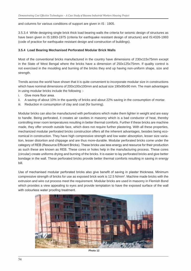
54
Demonstrating Cost Effective Technologies – A Case Study of Bawana Industrial Workers Housing Project
and columns for various conditions of support are given in IS : 1905.
3.5.3.4 While designing single brick thick load bearing walls the criteria for seismic design of structures as have been given in IS:1893-1975 (criteria for earthquake resistant design of structure) and IS:4326-1993 (code of practice for earthquake resistant design and construction of buildings).
3.5.4 Load Bearing Mechanised Perforated Modular Brick Walls
Most of the conventional bricks manufactured in the country have dimensions of 230x115x75mm except in the State of West Bengal where the bricks have a dimension of 250x125x75mm. If quality control is not exercised in the moulding and burning of the bricks they end up having non-uniform shape, size and strength.
Trends across the world have shown that it is quite convenient to incorporate modular size in constructions which have nominal dimensions of 200x100x100mm and actual size 190x90x90 mm. The main advantages in using modular bricks include the following :-
Give more floor area.i. A saving of about 10% in the quantity of bricks and about 22% saving in the consumption of mortar.ii. Reduction in consumption of clay and coal (for burning).iii.
Modular bricks can also be manufactured with perforations which make them lighter in weight and are easy to handle. Being perforated, it creates air cavities in masonry which is a bad conductor of heat, thereby controlling inner room temperatures resulting in better thermal comforts. Further if these bricks are machine made, they offer smooth outside face, which does not require further plastering. With all these properties, mechanized modular perforated bricks construction offers all the inherent advantages, besides being eco-nomical in construction. They have high compressive strength and low water absorption, lesser size varia-tion, lesser distortion and chippage and are thus more-durable. Modular perforated bricks come under the category of REB (Resource Efficient Bricks). These bricks use less energy and resource for their production as such these are known as REB. These cores or holes help in the manufacturing process. These cores (circular) create uniforms drying and burning of the bricks. It is easier to lay perforated bricks and give better bondage in the wall. These perforated bricks provide better thermal comforts resulting in saving in energy bill.
Use of mechanised modular perforated bricks also give benefit of saving in plaster thickness. Minimum compressive strength of bricks for use as exposed brick work is 12.5 N/mm2. Machine made bricks with the extrusion and wire cut process meet the requirement. Modular bricks are used in masonry in Flemish Bond which provides a view appealing to eyes and provide temptation to have the exposed surface of the wall with colourless water proofing treatment.
Photo 12

55
Building Materials & Technology Promotion Council
3.5.5 Flyash (Fal G) Bricks Masonry
Flyash is a finely grounded residue resulting from the combustion of pulverized bituminous coal or sub bituminous coal (Lignite) in ther-mal power plants. It is generally grey, abrasive, acidic, refractory in nature and posses pozzolanic properties as fuel. Fal-G is a cementi-tious material which has a composition of flyash 70%, lime 15% and calcinated gypsum 15%. With this technology mechanised bricks are being manufactured using 60% sand, 28% flyash, 6% lime & 6% calculated gypsum. The lime content can be varied to achieve higher strength of bricks.
3.5.5.1 A compressive strength of 50 to 60 kg. per sqcm. is expected to be achieved from these bricks. For higher strengths composition of 50% flyash, 10 to 12% lime, 30% coarse sand, 5% gypsum and 2 to 5% cement is adopted. Cement not only provides early strength but also reduces breakage of corners / edges during handing.
3.5.5.2 The method of manufacture of these bricks is very simple and does not require elaborate arrangements. Flyash, Kankar lime and Gypsum are powdered and mixed in the desired proportion volu-metrically in dry state. A measured quantity of water is then added and mixing is done in pan mixture to form a stiff paste. The paste is poured into the steel moulds with hydraulic press. The bricks are then cured in air for about a fortnight. The bricks gain the final strength in longer period due to slow reac-tion of lime and active flyash. Random samples are tested for compressive strength before being used for construction.
3.5.5.3 These bricks can be manufactured in modular size which would enable saving in the quantity of bricks and mortar. These bricks do not require to be burnt in a kiln.
3.6 Roofing / Intermediate Slabs
By the use of precast roofing/flooring elements, the expenditure involved on this item can be reduced and a considerable amount of speed in construction is achieved. The planning of the building is done in a manner that spans are maintained to a particular module (100 mm). By doing so precast units of only one size will be required in construction which would result in preparing one size of mould only. Buildings planned on cross wall system are well suited for adoption of precast units.
The moulds for precasting are manufactured with steel. Steel moulds can be used for a large number of castings and are economical in the longer run. The precast units are designed by common methods of a structural design, adopting elastic theory or ultimate load theory. Ordinary mild steel are used as reinforce-ment. The M.S. provide better ductility.
Casting of the units is to be done with great care. Honeycombing etc. should be completely eliminated by using vibration. The units are to be properly cured before they are used in the building. Handling methods require particular attention during transportation & placement to avoid breakage and damage to the finished surface.
All openings are pre-planned and provided for in the moulds so that chipping or breaking of the precast units is completely avoided. Fan hooks, electrical conduits etc. are embedded in the in-situ concrete.
Photo 13
Photo 12
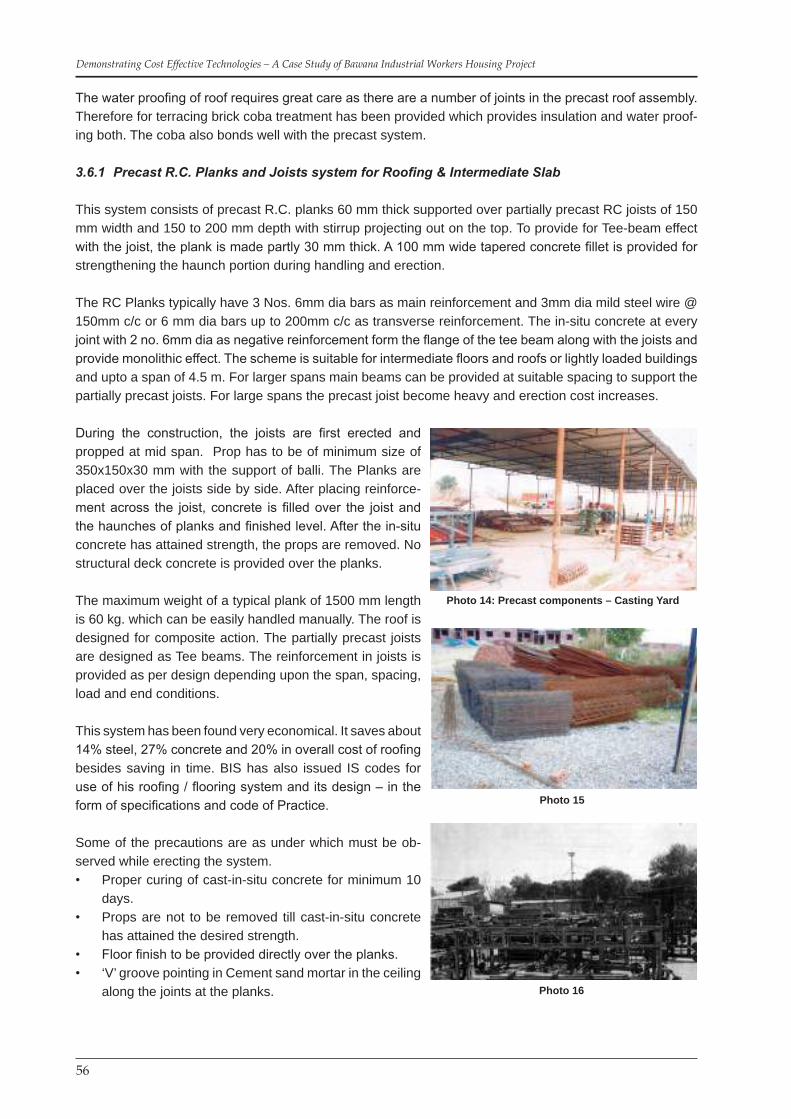
56
Demonstrating Cost Effective Technologies – A Case Study of Bawana Industrial Workers Housing Project
The water proofing of roof requires great care as there are a number of joints in the precast roof assembly. Therefore for terracing brick coba treatment has been provided which provides insulation and water proof-ing both. The coba also bonds well with the precast system.
3.6.1 PrecastR.C.PlanksandJoistssystemforRoofing&IntermediateSlab
This system consists of precast R.C. planks 60 mm thick supported over partially precast RC joists of 150 mm width and 150 to 200 mm depth with stirrup projecting out on the top. To provide for Tee-beam effect with the joist, the plank is made partly 30 mm thick. A 100 mm wide tapered concrete fillet is provided for strengthening the haunch portion during handling and erection.
The RC Planks typically have 3 Nos. 6mm dia bars as main reinforcement and 3mm dia mild steel wire @ 150mm c/c or 6 mm dia bars up to 200mm c/c as transverse reinforcement. The in-situ concrete at every joint with 2 no. 6mm dia as negative reinforcement form the flange of the tee beam along with the joists and provide monolithic effect. The scheme is suitable for intermediate floors and roofs or lightly loaded buildings and upto a span of 4.5 m. For larger spans main beams can be provided at suitable spacing to support the partially precast joists. For large spans the precast joist become heavy and erection cost increases.
During the construction, the joists are first erected and propped at mid span. Prop has to be of minimum size of 350x150x30 mm with the support of balli. The Planks are placed over the joists side by side. After placing reinforce-ment across the joist, concrete is filled over the joist and the haunches of planks and finished level. After the in-situ concrete has attained strength, the props are removed. No structural deck concrete is provided over the planks.
The maximum weight of a typical plank of 1500 mm length is 60 kg. which can be easily handled manually. The roof is designed for composite action. The partially precast joists are designed as Tee beams. The reinforcement in joists is provided as per design depending upon the span, spacing, load and end conditions.
This system has been found very economical. It saves about 14% steel, 27% concrete and 20% in overall cost of roofing besides saving in time. BIS has also issued IS codes for use of his roofing / flooring system and its design – in the form of specifications and code of Practice.
Some of the precautions are as under which must be ob-served while erecting the system.
Proper curing of cast-in-situ concrete for minimum 10 • days.Props are not to be removed till cast-in-situ concrete • has attained the desired strength.Floor finish to be provided directly over the planks.• ‘V’ groove pointing in Cement sand mortar in the ceiling • along the joints at the planks.
Photo 14: Precast components – Casting Yard
Photo 15
Photo 16

57
Building Materials & Technology Promotion Council
3.6.2 Performance of RC Planks & Joists (Source : CBRI)
Fire ResistanceFire resistance of RC plank slab with 3 cm concrete floor finish in respect of fire rating criteria is 1 hour and 45 minutes (while for 10 cm RC slab it is 2 hours).
Rain PenetrationPonding tests over RC plank scheme were carried out and it was found that there was no seepage of water through the joints when all the suggested precautions, specially of filling of joints and laying a mortar layer over them before concreting in the haunches was followed.
Impact Load TestThe plank assembly without any floor finish over it have been tested under impact load by dropping a well tied gunny bag load of 40 kg. from a height of 1.2m. No sign of distress in the roof assembly has been observed.
Thermal PerformanceThe thermal transmittance (U) value of 6cm thick RC plank with 7.5 cm average thick mud phaska and 6 cm tiles above is 2.189 K.Cal/Hr/M2/C
3.6.3 Validation of Technology – Precast RC Planks and Joist System
Time Tested Technology Important CodesIS : 13990 : 1994 Precast reinforced planks & joist & flooring specifications.IS : 13994 : 1994 SpecificationsCBRI Building Research Note (4) 1982 & 1987 Precast RC planks flooring/Roofing schemeIS : 4326 : 1993 Code of practice for EQ resistance design & Construction of
buildings improvisedNBC : 2005 (part 6) clause 6.3.1, 7.3.1.1 Part 6 section 7B
Prefabrication system accepted standards
Approved Technology by CBRI, BIS (IS:13994, IS:13990), IIT Delhi and as per NBC-2005
3.6.4 Economy
The quantities of cement, steel, labour and overall cost for a room of 3.5m x 3.5m have been calculated and compared with conventional RCC slab. The savings are as under :
Reinforcement : 14%Cement : 27%Coarse Aggregate : 27%Fine Aggregate : 25%Overall Cost : 21%
Since the scheme uses precast components, shuttering is eliminated and propping is required only for pre-cast joists. Because of precast components quality can be controlled and the components being of moder-ate size and weight, no heavy mechanical handling and erection is required. Because of prefabrication, the construction time of roof can be reduced by about 40% as compared to the conventional insitu RCC slab.
3.7 Thin Precast R.C.C. Lintel cum Sunshade
The lintels are designed on the basis of the assumption that the load from a triangular portion of the ma-sonry above, acts on the lintel. Bending moment of WL/8 where W is the load coming on the lintel and L is

58
Demonstrating Cost Effective Technologies – A Case Study of Bawana Industrial Workers Housing Project
the span of the lintel assumed for the design purpose. A thickness of 15 cm is required by this method.
Thin precast R.C.C. lintels are designed taking into account the composite action of the lintel with brick work. It is applicable only when the load on the composite lintel is uniformly distributed. The thickness of the lintel is kept equal to the thickness of brick itself having a bearing of 200 mm on either supports. The sunshade is casted along with the lintel. The projected reinforcement of lintel beam is lapped with cast – in – situ lintel band reinforcement for continuity.
Use of precast lintels speeds up the construction of walls besides eliminating shuttering and centering. Adoption of thin precast lintels and sunshades results in upto 50 percent saving in material and cost.
Photo 17: Vibrating Table for twin mould Photo 18: Wheels of the machine
Photo 19: The Machine with mould Photo 20: Machine placed over casting Table
Sequence of Casting Erection, Placement of Precast Elements(RC Planks, Joists, Sunshade cum Lintels)

59
Building Materials & Technology Promotion Council
Photo 21: Pellets stack ready for precasting Photo 22: Binding Planks Reinforcement
Photo 23: Stack of reinforcement cage for different size of planks
Photo 24: Placing twin plank reinforcement
Photo 25: Placing mould over reinforcement cage Photo 26: Tightening the mould clamps
Photo 27: Pouring of concrete in mould Photo 28: Finishing the planks
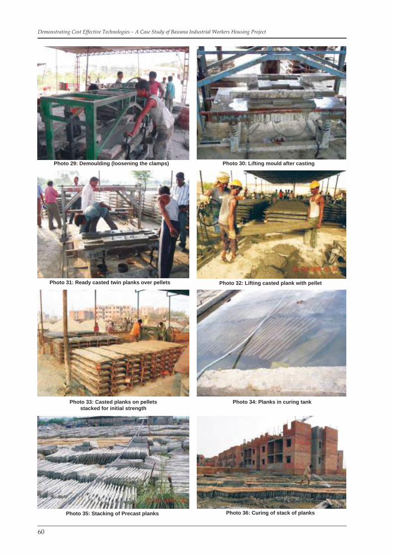
60
Demonstrating Cost Effective Technologies – A Case Study of Bawana Industrial Workers Housing Project
Photo 29: Demoulding (loosening the clamps) Photo 30: Lifting mould after casting
Photo 31: Ready casted twin planks over pellets Photo 32: Lifting casted plank with pellet
Photo 33: Casted planks on pellets stacked for initial strength
Photo 34: Planks in curing tank
Photo 35: Stacking of Precast planks Photo 36: Curing of stack of planks

61
Building Materials & Technology Promotion Council
Photo 37: RC joists being precasted Photo 38: Precasted joists under covered shed
Photo 39: Precasted joists stacked Photo 40: Precasting of joists with eges laying machine
Photo 41: Manual lifting joists Photo 42: Precast joists loading on trolley
Photo 43: Precast joist loaded on trolley Photo 44: Transporting planks through Tractor – trolley from casting yard

62
Demonstrating Cost Effective Technologies – A Case Study of Bawana Industrial Workers Housing Project
Photo 45: Lifting of planks mechanically Photo 46: Lifting & placing of planks mechanically
Photo 47: Planks placed over joists & walls Photo 48: The rows of planks with havneh reinforcement
Photo 49: Portable concrete plant Photo 50: Filling cast-in-situ concrete in haunches perforated brick walls with vertical reinforcement visible
Photo 51: The slab after cast-in-situ concrete filled up haunches. The flyash brick serves as shuttering
and cornice band
Photo 52: The sunk slabs and vertical reinforcement projecting out

63
Building Materials & Technology Promotion Council
Photo 53: Ceiling view after placement of joists Photo 54: Form work and reinforcement of precast sunshade cum lintel
Photo 55: Precasted sunshade cum lintel Photo 56: Curing of Sunshades
Photo 57: Precast sunshades stacked for curing & lifting Photo 58: Loading of precast sunshades on trolley
Photo 59: Precast sunshades placed over window opening Photo 60: Precast Sunshade Reinforcement lap with lintel band

64
Demonstrating Cost Effective Technologies – A Case Study of Bawana Industrial Workers Housing Project
3.8 Ferrocement
3.8.1 Ferrocement is a special form of reinforced concrete. It is a composite material consisting of ce-ment sand mortar (matrix) reinforced with layers of small diameter wire meshes. It differs from conventional reinforced concrete primarily by the manner in which the reinforcement is arranged within the brittle matrix. Since its behavior is quite different from that of conventional reinforced concrete in performance, strength and potential applications, it is classed as a separate material. Usually steel bars are also used in addition to wire mesh, to form a steel skeleton, which helps in retaining the required shape of the ferrocement com-ponents once the cement mortar hardens. The wire mesh reinforcement is uniformly distributed across the thickness of the element. This helps in achieving improved mechanical properties viz. fracture, tensile and flexural strength, fatigue and impact resistance. In addition, it also eliminates the use of formwork particu-larly for complicated shapes. Ferrocement is used as thin structural components where strength and rigidity are developed through form. Cement is ideally suited for prefabricated construction and in particular for housing applications. The success of ferrocement in various terrestrial applications can be attributed to:
Ready availability of material locallyi. Need of low level technology for its productionii. Better utilization of available human resources andiii. Architectural flexibilityiv.
3.8.2 Ferrocement can be considered as a material with many paradoxes. This is because it possesses a degree of toughness, ductility, strength, crack resistance and durability considerably greater than other forms of reinforced concrete. It has been possible to achieve these improved properties in structural com-ponents having a thickness of 25mm. Normally improvements in properties of material are associated with sophistication in manufacturing processes with increased demand for quality control. This is not so in case of ferrocement, as these improved properties, can be achieved with almost primitive techniques without any advanced technology.
3.8.3 Materials
The materials used for ferrocement are cement, sand, wire mesh and steel bars. The properties of these materials are discussed below :-
3.8.3.1 CementOrdinary Portland cement of grade 43 that is commercially available in the market is satisfactory for fer-rocement construction.
3.8.3.2 SandWell-graded Natural River sand with particle size less than 4.75 mm having fineness modulus between 2.5 – 3.0 is suited for ferrocement construction. The cover to reinforcing mesh is small and cannot be ex-ceeded. Hence to prevent corrosion of steel reinforcement grading of sand for mortar mixes become very important to get workable cement mortar with low water cement ratio. The water used for preparing cement sand mortar is potable and relatively free from organic compounds. The proportion of cement sand mix generally varies from 1:1½ to 1:3 and water cement ratio varies from 0.35 to 0.55.
3.8.3.3 Wire MeshOne of the important constitute of ferrocement is wire mesh reinforcement. These generally consist of thin galvanized wires. Properties of ferrocement depend on the type, quantity, orientation and strength proper-ties of the mesh reinforcement. Different types of mesh reinforcement are available in the market, which are suitable of ferrocement construction.
Hexagonal wire mesh also commonly known as chicken wire mesh is fabricated from drawn wires of diam-

65
Building Materials & Technology Promotion Council
eter varying from 22-26 gauge and woven into hexagonal patterns with mesh opening varying from 10mm to 25mm. this is the cheapest, easiest to handle and most commonly used in ferrocement construction.
Woven wire mesh is fabricated by simply weaving the galvanized wires into desired grid sizes without weld-ing them at the intersections. The grids are generally square, the mesh wires are not perfectly straight and some amount of waviness exists.
Welded wire mesh is fabricated in rectangular or square pattern by perpendicular intersecting wires (gener-ally 2 – 3 mm diameter) made of low to medium tensile strength steel (which are much stiffer than hexago-nal or woven wire mesh) and welded together at the intersections.
Expanded metal mesh, which is sometimes used in ferrocement construction, is formed by slitting thin gauge sheets and expanding them in a direction perpendicular to the slits to produce diamond shape open-ings. This mesh has inherent advantages like good mechanical bond and ease of placing.
3.8.4 Skeletal Steel
As the name implies this is generally used for making framework of the structural component upon which layers of wire mesh reinforcement are laid and also serve as spacer to wire mesh. The steel rods are pro-vided in both longitudinal and transverse directions. When they are provided for non-structural purpose, they are spaced as widely as possible and when provided for carrying external loads, their spacing is gov-erned by design considerations. In general, mild steel roads or galvanized iron wires of diameters varying from 2 mm to 6 mm are used. Sometimes for structural purpose high yield strength deformed bars are also employed.
3.8.5 Admixtures
Admixtures are additives, which are introduced in the cement sand mortar mix to modify some of the prop-erties of the mortar in its fresh and hardened states. These materials may be chemical admixtures in which case they are added in quantities no larger than 5% by weight of cement or other materials in which case they are added in excess of 5% of weight of cement and referred as additives. Different types of admixtures are used to improve/modify properties of mortar.
3.8.6 Construction Methods
Ferrocement construction does not require skilled labour nor heavy capital investment on equipment to produce them. There are four major steps in ferrocement construction, viz. placing of reinforcement, mixing of mortar, placing mortar and curing. As the reinforcement content in ferrocement is very high (up to 8% by volume) and is uniformly distributed throughout the thickness of the element, the essential requirement is that the continuous mesh reinforcement has to be completely impregnated and covered with cement mor-tar. Basically to achieve this goal one may either force the cement mortar into the pre-existing skeletal steel framework or alternatively force layers of mesh reinforcement into a bed of mortar. A number of techniques are being used for placing the mortar into the framework of mesh. Among these are hand plastering of mortar from one side against a mould or from both sides.
3.8.7 Mechanical Properties
Ferrocement derives its unique properties due to the subdivision and distribution of the reinforcement which can be described with the two parameters namely volume fraction of reinforcement defined as volume of reinforcement per unit volume of ferrocement and specific surface of reinforcement defined as surface area of reinforcement per unit volume of ferrocement. Within the elastic range ferrocement can be considered as a homogeneous material and its elastic properties can be obtained from the elastic properties and volume

66
Demonstrating Cost Effective Technologies – A Case Study of Bawana Industrial Workers Housing Project
fractions of its constituents.
The advantages of Ferrocement elements include :-
High strength to weight ratio compared to reinforced concrete• High crack resistance and impermeability to water• Lightweight elements due to relatively small volume of material required • Ease in maintenance and repair• Easy provision of accessories, conduit holes etc.•
In keeping with the advantages of ferrocement it was decided to use ferrocement elements in construction in place of the conventional RCC construction. These included ferrocement shelves, ferrocement steps in stairs and ferrocement water tanks.
3.8.8 Ferrocement Shelves
Conventionally, cooking platforms are provided in 50 mm thick cast-in-situ RCC slabs. In this project, precast ferro-cement cooking shelves have been used which are easi-er to cast, easier to handle and light weight besides being economical. The cooking platform provided has 25mm thickness having one layer of welded mesh 25x75mm of 2 mm dia and two layers of chicken mesh 24 gauge, em-bedded in cement mortar. Besides reduction of dead load it has resulted in an economy of about 35%.
3.8.9 Ferrocement Staircase Steps
Stair case is an essential part of any building as it provides access to different floors in the structure. Con-ventionally, staircases are constructed in Reinforced Cement Concrete, having a waist slab, treads and risers, hand rails etc. The per square metre load on account of the staircase is higher than the residential portion of the building. Similarly, the cost of stair case is always more than the built up area of rest of the building, due to treads and risers railing, baluster etc.
An economical method of providing a staircase is to eliminate the waist slab and use precast steps (tread & riser unit). In the Bawana project, precast ferrocement elements, combining the tread and riser have been used which have been supported on walls. These elements which are 25 mm thick do not require any plas-tering, or flooring and railing. The use of these elements has led to a saving of 40% to 50%.
Photo 61: Casting of precast ferrocement shelves
Photo 62: Preparing Mesh Photo 63: Mould ready for casting

67
Building Materials & Technology Promotion Council
Photo 66: Mesh placed on battery of moulds Photo 67: Laying mortar and finishing
Photo 68: Giving finishing touch to precast steps Photo 69: Stacking of precast steps
Photo 70: Precast steps placed in first flight Photo 71: Precast steps placed in first & second flight
Photo 64: Laying first layer of mortar Photo 65: Mesh placed on mould

68
Demonstrating Cost Effective Technologies – A Case Study of Bawana Industrial Workers Housing Project
Photo 72: Precast landing Photo 73: View showing precast sunshade, landing
3.8.10 Ferrocement Water Tanks
In the present day scarcity of water and limited water supply during the day, it has become essential to have a provision to store water for use. There are a number of options available to store water viz. brick masonry tanks, RCC water tanks, PVC tanks etc.
Photo 74: Ferrocement Water Tank Photo 75: Ferrocement Water Tanks
In this project ferrocement tanks of 1200 litres & 1600 litres have been provided which have a dia of 1.5m. For these tanks, the base and the cylindrical container have been casted separately. The wall thickness is 25mm. Two layers of chicken mesh along with GI wire in helical shape have been provided in the walls.
3.9 Earthquake Resistance Features
Grade Beam • Vertical Corner Reinforcement • Plinth band • Lintel band • Roof band•
Photo 76: Grade Beam & Vertical Reinforcement (for Earthquake Resistance)

69
Building Materials & Technology Promotion Council
Photo 77: Plinth band & Vertical Reinforcement (for Earthquake Resistance)
Photo 78: Photograph of lintel band
Photo 79: Photograph of roof band

70
Demonstrating Cost Effective Technologies – A Case Study of Bawana Industrial Workers Housing Project
3.10 Partial Replacement of Cement by Flyash
Flyash is a fine residue obtained from thermal power stations using ground or powdered coal as boiler fuel. It can be utilized in various forms as building material. The thermal power stations in the country throw large quantities of flyash which goes as waste but which can be effectively used as partial replacement of cement.
Investigations carried out in research laboratories have shown that replacement of cement (OPC) by flyash up to 20% by weight in concrete and mortars does not adversely affect the strength of the resultant mix. The flyash should however conform to the following chemical and physical requirements (IS : 3812 – Part II – 1966)
It should however be seen that the mixing should be done thoroughly and the proportions of the materials should be carefully controlled to obtain the requisite strength. Moreover as the density of flyash ranges from 750 to 850 kg/m3 it is preferable to check the weight / volume ratio at intervals on site to ensure proper mix control when batching is done by volume.
The use of flyash partially replacing cement improves plasticity making the mix more easily workable. Denser concrete/mortar is obtained thereby making it more impermeable. Besides this the surface finish of concrete is also improved and the segregation and bleeding in lean concrete is also reduced. Instead prescribed M2 mix of 1 cement : 6 coarse sand, mortar mix of 1:1:6 (1 Cement : 1 Flyash : 6 coarse sand) has been used, resulting in saving of cement without affecting the required strength.
3.11 Services
Single Stack System of PlumbingIn the conventional system of drainage for buildings two separate pipes are provided. One for the soil which takes discharge from the water closet, urinals etc. and the other for the discharge from the baths, sinks and wash basins etc. Besides, a vent pipe is also fitted with both the pipes to prevent breakage of seal of the traps of different appliances. The single stack system of plumbing which replaces the above system is es-sentially a one pipe system in which the wastes from kitchen, bath etc. and soil from toilets is carried out of the building in a single stack. The ventilation is also completely omitted and the service stack itself serves the purpose of a ventilation pipe. It embodies the merits of both the conventional two pipe system and the
Photo 80: Vertical Reinforcement L - Junction Photo 81: Vertical Reinforcement T - Junction

71
Building Materials & Technology Promotion Council
modern one pipe system.
In the single stack system of plumbing the loss of seal due to self siphonage, induced siphonage and back pressure should be avoided. The shape of appliances, slope, diameter and length of the branch pipes re-quires careful designing. Deep seal traps have been used to keep intact the water seal.
The use of the above system effects saving in quantity of pipes and fittings and also gives a cost saving of up to 30% in plumbing work.
Single stack water supply system For water supply system also, the single stack plumbing has been adopted.
3.12 Tendering System
After finalizing the new innovative techniques and other specifications to be adopted in conjunction with the architectural planning and design of the dwelling unit, the detailed working drawings were prepared with all minute details like design of pile foundations, size of piles, pile – reinforcement, details of earthquake strengthening measures needed as per codal requirements, size and sections of planks and joists, require-ment of steel as per designs, thickness, size of ferrocement elements to be adopted etc.
This exercise was carried out in order to avoid any future cost escalations. As a result of group discussions it was decided that lump – sum tendering system should be adopted for the scheme. Lump sum tendering system requires all detailed drawings for each item of work so as not to leave any scope for cost variations during construction stage.
In order to assess the real capabilities of the contractors and their potential to undertake this unique self-contained composite project the bids were invited in two parts separately containing technical and financial bids.
M/s Era Construction (I) Ltd. Were found technically eligible and competitive in financial bid and as such DSIIDC and consultants found them suitable for award of work.
The adoption of theory of Modular – Coordination weighed in favour of Lump-sum tendering and it has resulted in saving in construction time, less wastages of materials & labour, easy supervision, uniform and simplified measurement practices. This also helped in close coordination at all stages of building process like designing, component production and monitoring of construction.
Prebid meetings, where representatives of various contracting firms were present, were also represented by officers of BMTPC and CBRI.
CBRI and BMTPC Scientists were there to answer any technical queries or doubts regarding proposed technologies in-order to quash any fears in the minds of bidders. Technical presentation and interactive discussions between consultants, Bidders, Promoters and Executors resulted in confidence-building.

72
Demonstrating Cost Effective Technologies – A Case Study of Bawana Industrial Workers Housing Project
Chapter 4 : CONSTRUCTION MANAGEMENT AND QUALITY CONTROL
4.1 Supervision and Control
Proper supervision and management control was ensured through the Engineering Staff of DSIIDC and project management team of the consultants. Periodical visit by the officials from CBRI and BMTPC, helped in proper planning and implementation of project in the field. Design and detailing of the precast elements with the help of BMTPC and CBRI officers have played a vital role in execution of the project.
4.2 Quality Assurance
Quality assurance functions involved.
Drawing up contract clauses / specifications, laying down the detailed requirement of materials, pro-• cesses, standards including tests to be conducted and laying down acceptance criteria.Exercising checks and tests during the construction phase in order to ascertain that the work done • conforms to the standards and specifications laid down.
In this project in order to achieve proper quality assurances, the tender documents were prepared in clear terms, proper specifications formulated, construction practices and processes to be followed were laid down properly. Various standards to be followed were clearly indicated as per CPWD Specifications.
A well-defined coordination between Clients, Consultants and Contractors was needed and in this project all concerned thrived to achieve it.
In order to achieve timely targets and better quality control it was decided to set-up a casting yard at the site of work for the production of precast RC and ferrocement elements and productions unit for manufacturing of Fal G bricks. This resulted in better quality control on the produce, timely delivery of the elements as per scheduled requirement for which proper delivery / demand schedule was maintained.
For proper quality analysis and quality control, a laboratory with field testing facilities was setup. Periodical tests were conducted at the construction site as well as through approved Laboratories.
4.3 Various tests to be conducted for materials during construction are given in Table 19.
Table 19 (Format)
S. No.
Item Test Required Test ConductedIn house External Lab
1. Stone Agg. 10.20 & 40 mm2. Coarse Sand
a) Sieve Analysisb) Silt Content / Bulkage
3. FPS Bricka) Dimensional testb) Water absorptionc) Compressive strength
4. Modular Bricksa) Dimensional testb) Water absorption

73
Building Materials & Technology Promotion Council
S. No.
Item Test Required Test ConductedIn house External Lab
c) Compressive strength5. Fly Ash Bricks
a) Dimensional testb) Water absorptionc) Compressive strength
6. Reinforcement Steela) 6 mmb) 8 mmc) 10 mmd) 12 mm
7. Structural Steela) MS Angle 40 x 40 x 5b) MS Angle 40 x 40 x 6
8. Cement9. Tiles10. Door Shutter11. Water Proofing Compound12. Lead13. Enamel Paint14. Wooden Primer 15. Steel Primer16. Water17. Rebound Hammer Test18. Cube Test19. Slump Test
4.4 Some of the Mandatory Tests to be Conducted for Important Materials are given in Table 20.
Table 20
Material Test Relevant IS CodeCement Fine ness IS:4031, IS:269, IS:1489 & IS:455
Soundness IS:4031, IS:269, IS:1489 & IS:455Setting time (initial & final) IS:4031, IS:269, IS:1489 & IS:455Compressive strength IS:4031, IS:269, IS:1489 & IS:455Consistency IS:4031, IS:269, IS:1489 & IS:455
Sand Organic impurities IS:2386, IS:383, IS:456Silt content IS:2386, IS:383, IS:456Particle size distribution IS:2386, IS:383, IS:456Bulking of sand IS:2386, IS:383, IS:456
Coarse aggregate % of soft or deleterious material IS:2386, IS:456, IS:383Particle size distribution IS:2386, IS:456, IS:383Estimation of organic impunities IS:2386, IS:456, IS:383Surface moisture IS:2386, IS:456, IS:383Determination of 10% fine IS:2386, IS:456, IS:383Specific gravity IS:2386, IS:456, IS:383Bulk density IS:2386, IS:456, IS:383Agg. Crushing strength IS:2386, IS:456, IS:383Agg. Impact value IS:2386, IS:456, IS:383
Fly Ash Chemical properties IS:3812Physical properties IS:3812

74
Demonstrating Cost Effective Technologies – A Case Study of Bawana Industrial Workers Housing Project
Material Test Relevant IS CodeWater pH Value IS:3025, IS:456
Limit of acidity IS:3025, IS:456Limit of alkalinity IS:3025, IS:456% of solids IS:3025, IS:456Chlorides IS:3025, IS:456Suspended matters IS:3025, IS:456Sulphates IS:3025, IS:456Inorganic solids IS:3025, IS:456Organic solids IS:3025, IS:456
Concrete Compacting factor IS:1199Weight, cement and air contentCube test IS:516, IS:1199, IS:456
Steel for RCC Tensile strength IS:1608Retest IS:1786Rebound test IS:1786Nominal mass IS:1786Bend test IS:1599Elongation test IS:1786Proof stress IS:1786
Brick work Dimension IS:3495, IS:1077Compressive strength IS:3495, IS:1077Water absorption IS:3495, IS:1077Efflorescence IS:3495, IS:1077
White glazed tiles Water absorption IS:777Crazing test IS:777Impact test IS:777Chemical resistant test IS:777
Wood Flush door Timber : Moisture contentEnd Immersion test IS:2202Knife test IS:2202Adhesion test IS:2202
4.5 The tables 21 to 30 show the methodology as sample test.
Table 21Format for Water Test Report (Sample)
(Without Admixture / With Required Admixture)
Sample : Water collected
S. No. Tests Results IS Limit Protocol
a) Volume of 0.02 N H2SO4 required to neutralize 100 ml sample using mixed indicator (ml)
25.0 ml Max IS : 456
b) Volume of 0.02 N, NaOH required to neutralize 100 ml sample using phenolphthalein (ml)
5 ml Max IS:456
c) PH value Not less than 6
IS:3025 Pt-11-1983, Reaff-1996
Test conducted on _________ (date) at site laboratory of ____________________ in presence of the following persons :-
(Representative of agency) (Representative of Contractors)

75
Building Materials & Technology Promotion Council
Table 22Format for Sample Test of Cubes for Compressive Strength
Project : Agency : _ _ _ _ _ _ _ _ _ _ _ _ (Contractor)Client : ___________________
S. No
Date of Sample
Item of work and loca-tion
Mix Date of test-ing
No. of days
Com-pressive strength obtained for individual cubes Kg/Cm2
Average strength Kg/Cm2
(B)
Differ-ences (Max. – Min.)(A)
% of (A) over (B)
Accept-ability
Remarks
Signature of Contractor’s Authorised Signature of ClientRepresentative
Table 23Format for Sample Test of Bricks for Water Absorption
Name of Project : Name of Agency : _ _ _ _ _ _ _ _ _ _ _ _ (Contractor)Name of Client : _______________Class of Designation : 125Brand of Brick : Mechanised Modular perforated Brick
S. No.
Date of taking Sample
Identi-fication mark
Wt. of dry brick (gms) 19-04-2005
Wt. of brick af-ter immersing 24 hrs. water (gms)
Date of test-ing
Percent-age water absorbed in indi-vidual brick
Average percent-age water absorbed
Accept-ability
Remarks
1 I
6.63% Max 20%Satisfac-tory
2 II
3 III
4 IV
5 V
Signature of Contractor’s Authorised Signature of ClientRepresentative

76
Demonstrating Cost Effective Technologies – A Case Study of Bawana Industrial Workers Housing Project
Table 24Format for Sample Test of Bricks for Water Absorption
Name of Project : Name of Agency : _ _ _ _ _ _ _ _ _ _ _ _ (Contractor)Name of Client : __________________Class of Designation : 75Brand of Brick : Non-Modular Brick (FPS)
(Example)
S. No.
Date of taking Sample
Identi-fication mark
Wt. of dry brick (gms) 19-04-2005
Wt. of brick after im-mersing 24 hrs. water (gms)
Date of test-ing
Percentage water absorbed in individual brick
Aver-age per-cent-age water ab-sorbed
Accept-ability
Remarks
1 I
Max 20%
Satisfac-tory
2 II
3 III
4 IV
5 V
Signature of Contractor’s Authorised Signature of ClientRepresentative
Table 25Format for Test of Bricks for Water Absorption
Name of Project : Name of Agency : _ _ _ _ _ _ _ _ _ _ _ _ (Contractor)Name of Client : __________________Class of Designation : 100Brand of Brick : Fly Ash Brick
(Example)
S. No.
Date of taking Sample
Identi-fication mark
Wt. of dry brick (gms)
Wt. of brick after immers-ing 24 hrs. water (gms)
Date of testing
% water absorbed in individual brick
Average % water absorbed
Accept-ability
Remarks
1 A.T.
Max 20%Satisfac-tory
2 A.T.
3 A.T.
4 A.T.
5 A.T.
Signature of Contractor’s Authorised Signature of ClientRepresentative

77
Building Materials & Technology Promotion Council
Table 26Test of Bricks for Dimensions (Format)
Name of Project : Name of Agency : _ _ _ _ _ _ _ _ _ _ _ _ (Contractor)Name of Client : ___________________Designation of Brick : 125 (Mechanised Modular perforated Brick)
S.No. Brick Brand Date of Testing Dimension obtained for 20 Bricks (cm)
Acceptability (cm) Remarks
1. L = 380 372 – 388 Satisfactory
W = 180 176 – 184 Satisfactory
H = 180 176 – 184 Satisfactory
Signature of Contractor’s Authorised Signature of ClientRepresentative
Table 27Format for Test of Bricks for Compressive Strength
Name of Project : Name of Agency : Name of Client : Class of Designation : 125 (Mechanised Modular perforated Bricks)
(Example)
S . No.
Date of tak-ing sample
Identifica-tion mark
Date of testing
Dial Gauge Reading(KN)
Compressive strength obtained for individual bricks Kg/Cm2
Size of bricks
Average strength Kg/cm2
(B)
Remarks
1 I 19 x 9
Required 125 kg/cm2
2 II 19 x 9
3 III 19 x 9
4 IV 19 x 9
5 V 19 x 9

78
Demonstrating Cost Effective Technologies – A Case Study of Bawana Industrial Workers Housing Project
Table 28Format for Test for Sand
Name of Project : Name of Agency : _ _ _ _ _ _ _ _ _ _ _ _ (Contractor)Name of Client :
Silt Content of SandDate of testing : Limit
Volume of saturated sand and silt = 92 ml1. Volume of silt = 5.4 ml2. Percentage silt content after 3 hours = 5.86% 8%3.
Bulking of SandDate of testing :
Volume of moist sand = 150 ml1. Volume of saturated sand = 128 ml2. Percentage bulking of sand = 17.18% Bulkage range 15% to 30% 3.
depending upon moisture content ranging between 2% to 5%.
Signature of Contractor’s Authorised Signature of ClientRepresentative
Table 29Format for Gradation Test for Sand
Name of Project : Name of Agency : _ _ _ _ _ _ _ _ _ _ _ _ (Contractor)Name of Client : Sample : Coarse SandDate :
S.No. Sieve Size(mm)
Wt. Retained Gms. Cumulative Wt. Re-tained Gms.
Percentage Retained
Percentage Passing
Limit Zone–II
1 10 mm 100 100
2 4.75 mm 93.90 90-100
3 2.36 mm 80.45 75-100
4 1.18 mm 63.45 55-90
5 600 micron 43.05 35-59
6 300 micron 24.05 8-30
7 150 micron 10 0-10
8 PAN
Sample taken 2000 gm.
Signature of Contractor’s Authorised Signature of ClientRepresentative

79
Building Materials & Technology Promotion Council
Table 30Format for Gradation Test for Aggregate
Name of Project : Name of Agency : _ _ _ _ _ _ _ _ _ _ _ _ (Contractor)Name of Client : Sample : 20 mm AggregateDate :
S.No. Sieve Size(mm)
Wt. Retained Gms.
Cumulative Wt. Retained Gms.
Percentage Retained
Percentage passing
Limit
1 40 0 0 0 100 100
2 20 660 660 13.20 86.80 86.100
3 10 3950 4610 92.20 7.80 0-20
4 4.75 279 4889 97.78 2.22 0-5
5 PAN 111 5000
Sample taken 5000 gm.
Signature of Contractor’s Authorised Signature of ClientRepresentative____________________________________________________________________________________
4.6 Tests for Structure Elements
As Structural elements were produced at site workshop under strict controls, the quality of final product was assured.
4.6.1 Field Load Tests for alternative technologies adopted
RC planks deflection test• RC planks & joist assembly load test• Ferrocement steps load test• Rebound hammer non-destructive test• Under reamed piles load test • Sonic integrity test for piles.•
Photo 82: Brick Compression Test Photo 83: Sieve Analysis

80
Demonstrating Cost Effective Technologies – A Case Study of Bawana Industrial Workers Housing Project
4.6.2 Testing of precast RC Planks & Joists as per IS 13990:1994 (Precast Reinforced Concrete Planks and Joists for roofing and flooring specification)
R.C. PLANKS
General
The planks are to be tested after 28 days of laying of in-situ concrete in haunches. The haunch • concrete shall be cured for 14 days.The selected plank shall be simply supported with a bearing of 40mm / 50 mm over a brick wall • finished level and smooth with cement mortar 1.4
Deflection Test
The maximum allowable deflection in millimeters is 40 x L2/d, where ‘L’ is the effective length of the plank in metres and D is the total thickness of the plank in millimeters.
In case of DSIIDC project at Bawana the maximum length of a plank is 1.50 metres and the total thickness is 60mm. Therefore effective loaded length is 1.50-2x0.040= 1.42m
Load Calculations
Panel length = 1500mmDimensions of the panel = 1500x30x60mmLoaded area of the plank = 1.42 x 0.30 = 0.426 sqm, say 0.43 sqmSuperimposed Dead Load of the floor finish & Cushion = 0.43 x 150 = 64.5 kg, say 65 kgSuperimposed Live Load (as per I.S. code for low income housing = 0.43 x 150 = 65 kgSuperimposed Test live load = (1.25 x LL) = 1.25x65 = 81.25, say 82.00Maximum allowable deflection in this case is 40 x (1.42)2/60 = 1.344, say 1.35 mm
Testing of Planks
a) Allowable Deflection and Deflection Recovery Test
The stages of testing are as under :
Explanatory Example(Sample)
PE-1 (Plank Size) = 1480 mm x 300 mmBearing = 40 mmClear Span = 1400 mm
• Imposed Dead Load (for Flooring) 40mm flooring = 100 kg/m2
• Imposed Live Load = 200 kg/m2
• Design Live Load for Testing (1.25 x 200) = 250 kg/m2
• Total Load for Testing = 350 kg/m2
• Loaded Area of Plank (1.40m x 0.30m) = 0.42 m2

81
Building Materials & Technology Promotion Council
Step - 1Initial Dead Load to be applied as UDL = 0.42 m2 x 100 = 42.0 kgReading on Dial Gauge to be recorded = + 0 Say (X) Step - 2Further Load as UDL = 0.42 m2 x 250 = 105.00 kg Step - 3Retain the Load for 24 HoursRecord Second Reading on Dial Gauge after completion of 24 hours = Say (Y)
Step - 4Check Deflection = Y – X mm
Permissible Deflection < 40 L2 (L = in m) D (D = in mm) < 40 x 1.4 x 1.4 60 < 1.307 mm
(if the deflection observed is < 1.307 mm it is safe and no further test required)
Failure Load Test
The RC Plank which has passed the deflection recovery test shall be tested further to ‘Failure Load Test’.The loading of the plank shall continue till the plank fails. If no failure occurs by crushing or breaking of the unit, the load causing a deflection of 1 in 60 of the clear span of the unit shall be considered as the failure load.
Table 31Deflection Recovery test of Reinforced concrete Precast Planks
(As per IS : 13990-1994)(Sample)
S. No. Load (kg) Dial Gauge (mm) Date Time
1. 62.50 1 14-09-2005 9:15 am
2. 140.62 1.1 14-09-2005 9:20 am
3. 140.62 1.23 15-09-2005 9:30 am
4. 62.50 1.01 15-09-2005 9:35 am
5. 62.50 1.01 15-09-2005 11:20 am
Size of Plank : 1.490m x 0.30m x 0.06mDead Load : 62.50 kgTotal Load applied : 140.62 kg
Deflection was found within permissible limit.

82
Demonstrating Cost Effective Technologies – A Case Study of Bawana Industrial Workers Housing Project
4.6.3 The entire slab comprising of precast planks, joists and in-situ haunches were also tested for deflec-tion
Photo 84: Shows RC Planks Deflection Testand RC Planks Failure Load Test
Photo 85: Precast Plank Load Test for Failure
Photo 86 Photo 87
Precast Slab Assembly Load Test (Deflection of entire slab)
Table 32Location : Pocket-_____, Block-_____, Cluster-_____, Flat-_____
Sample Load Test for First Floor Slab (Bed Room)
Room Size 2.98 x 2.41 = 7.18 sqmLive Load = 150 Kg/sqm Test Load 150 x 1.25 = 187.50 Kg/sqmTotal Design Load 7.18 x 187.50 = 1347 KgAverage Wt. of Single Brick = 2.99 Kg
No. of Bricks Required 1347 ÷ 2.99 = 450 Nos. of Bricks
Date Time Load in Kg
Dial Gauge Read-ing initial +0 (mm)
Deflection(mm)
Remarks Max deflection as per IS:13990 Cal-culations
26-12-2005 01:10 PM 1346 0.16 0-16 Immediate loadingAfter 24 hours of load-ing
1.70 mm
27-12-2005 02:10 PM 1346 0.27 0-27
Note : As per IS : 1994, if the deflection is less than the permissible deflection. No further recovery test is required.Result : The deflection after 24 hours of loading comes out to much less than the permissible limit. Hence the perfor-
mance of assembly is satisfactory.

83
Building Materials & Technology Promotion Council
4.6.4 The piles were also tested by loading the piles with sand bags and the settlement checked.
4.6.5 For safety check, even non-destructive tests were carried out for under reamed piles. The Sonic-Integrity Test (SIT) for piles foundation included pulse velocity test.
Photo 88: Loading in progress for Pile Test Photo 89: For settlement installed below the load platform
Photo 90: Non Destructive Pile Integrated Test Photo 91: Non Destructive Pile Integrated Test
4.7 Time and Site Management
The fundamental requirement of any good construction is to ensure quality, speed and overall economy.
4.7.1 The precast RC plank system of roofing requires remarkably short completion period compared to conventional system of cast-in-situ concrete.
The roofing elements and other structural elements such as sunshades, lintels, stairs steps are produced in a site workshop, while simultaneously the site preparation and foundations are under way. The precast elements are transported from workshop to the erection site. The construction time, with the technologies adopted is almost 30 to 40% less than conventional system, because the use of these technologies require almost no centering or shuttering etc. at job sites. These technologies make the construction free from com-mon problems associated with cast-in-situ work that makes other activities difficult.
The precast system allows other activities such as conduiting, plumbing, Door and Window frames, simulta-neously. Plastering and other wall finishes follow immediately after laying of slab. Due to precasting, ceiling plaster is not required.

84
Demonstrating Cost Effective Technologies – A Case Study of Bawana Industrial Workers Housing Project
The monitoring of time management at site was done in a planned manner so as to check the progress from time to time. PERT chart / Bar chart were developed to watch the progress of the work.
A long term success of a project depends upon the quality of construction and the workmanship involved during the implementation process. The construction quality is to a great extent dependent on the quality of material used and the routine and mandatory tests carried out from time to time. These become essential as materials are procured from different sources having variable engineering properties.
The formats of Tests have been dealt in earlier paras of this chapter.
For proper management, the number and types of precast elements and other materials were worked out.
4.7.2 Different sizes of Precast R.C. Elements
The sizes of planks and joists were limited to four and three respectively. In fact the use of principles of Modular – coordination for architectural design helped in restricting the sizes of precast elements like planks, joists, lintels, sunshades to two or three only which helped in saving in construction time and reduc-ing the wastages. Adoption of modular coordination for architectural planning is a helpful tool in adoption of Precast technologies. Table 15 given below give details of the sizes of the elements used in the project whereas table 16 and 17 quantify the Precast Elements. These figures are just to indicate the size of the project.
Table 33Sizes of Planks & Joists
Description SizesType – I & II Type – III
PlanksPE 1 1490 x 300 1492 x 300PE 2 930 x 300 1280 x 300PE 3 1140 x 300 1230 x 300PE 4 830 x 300 1080 x 300PE 5 ------ 870 x 314JoistsJE 1 2930 x 150 x 150 2900 x 150 x 150JE 2 2610 x 150 x 150 2400 x 150 x 100JE 3 2330 x 150 x 100 1700 x 150 x 100JE 4 2260 x 150 x 100 ------
Table 34Quantity of Various Precast Elements
S.No. Description of Item Unit Quantity
(For One Block)
Total Quantity
(For Whole Project)Type I Type II Type III
P Planks P1 PE1 Nos. 345 981 720 198429 P2 PE2 Nos. 14 165 160 30750 P3 PE3 Nos. 368 30 144 59776 P4 PE4 Nos. 139 26 180 33399P5 PE5 Nos. --- --- 21 1554 J Joists J1 JE1 Nos. 36 64 64 15892 J2 JE2 Nos. 0 16 16 2848 J3 JE3 Nos. 36 16 16 7348 J4 JE4 Nos. 12 16 16 4348S Sunshades, lintels, etc. S1 W1 Nos. 12 16 16 4348

85
Building Materials & Technology Promotion Council
S.No. Description of Item Unit Quantity
(For One Block)
Total Quantity
(For Whole Project)Type I Type II Type III
S2 W2 Nos. 0 16 16 2848 LB Lintel Beams Nos. 24 48 48 11544PB1 Plinth beam of length 2200 &
2800 mm
Nos. 4 6 6 1568
PB2 Plinth beam of length less than
2200 mm
Nos. 4 8 8 1924
FerrocementFC1 Stair’s Step Sqm 13.43 20.15 20.15 5266FC2 Kitchen Platform Sqm 12.60 11.20 11.20 3569FC3 Bed Block Nos. 168.00 224.00 224 60872FC Water Tank Lit 2400.00 3200.00 3200 869600
Note :-Type I = 125 blocks of 12 DUs eachType II = 104 blocks of 16 DUs eachType III = 74 blocks of 16 DUs each
Table 35Total Number of Precast Elements (for 3164 + 1184) houses
Precast Elements Total Required (Nos.)RC Planks 323908RC Joists 30436Lintel Beam 11544Sunshades 7196Plinth Beam (for partition walls) 3492Stair Case Steps 11476Kitchen Working Platform 4348Water Tanks 606Bed Block 60872Total Precast Elements 456278
4.7.3 Estimation of Concrete & steel reinforcement for precast elements. The quantities worked out providemonitoring,qualitycontrol,managementandcheckforwastage,pilferage,efficiency(Table 18 to 22)
Table 36Reinforcement Steel in individual Precast Elements
(Sample Type I)S. No. Description Dia. No. Length Total Length wt/m Wt.
Precast Planks :1 PE 1 (1490 x 304.3) 6 3 1.460 4.380 0.222 0.972 11 0.274 3.014 0.222 0.669 1.6412 PE 2 (930 x 304.3) 6 3 0.900 2.700 0.222 0.599 7 0.274 1.918 0.222 0.426 1.0253 PE 3 (1140 x 304.3) 6 3 1.110 3.330 0.222 0.739 9 0.274 2.466 0.222 0.547 1.2874 PE 4 (830 x 304.3) 6 3 0.800 2.400 0.222 0.533 7 0.274 1.918 0.222 0.426 0.959
Precast Joists :1 JE 1 (2930 x 150 x 210) 6 21 0.570 11.970 0.222 2.657 8 1 2.890 2.890 0.395 1.142 10 2 2.890 5.780 0.617 3.566 7.365

86
Demonstrating Cost Effective Technologies – A Case Study of Bawana Industrial Workers Housing Project
S. No. Description Dia. No. Length Total Length wt/m Wt.2 JE 2 (2610 x 150 x 160) 6 18 0.475 8.550 0.222 1.898 8 1 2.570 2.570 0.395 1.015 10 2 2.570 5.140 0.617 3.171 8 1 1.300 1.300 0.395 0.514 6.5983 JE 3 (2330 x 150 x 160) 6 17 0.475 8.075 0.222 1.793 8 1 2.290 2.290 0.395 0.905 10 2 2.290 4.580 0.617 2.826 5.5234 JE 4 (2260 x 150 x 160) 6 17 0.475 8.075 0.222 1.793 8 1 2.220 2.220 0.395 0.877 10 2 2.220 4.440 0.617 2.739 5.409
Precast Sunshade :1 Sunshade W1 6 14 1.14 15.96 0.222 3.54 8 5 2.3 11.5 0.395 4.54 6 5 1.27 6.35 0.222 1.41 9.502 Sunshade W2 6 9 0.84 7.56 0.222 1.68 8 5 1.85 9.25 0.395 3.65 6 3 0.72 2.16 0.222 0.48 5.81
Precast LintelLintel (1150 x 100) Length=1.150 + 2 x 40 x 0.008 = 1.79 Wt. of 8 mm bar = 1.79 x 0.395 = 0.71 kg Wt. of 6 mm bar = 1.79 x 0.222 = 0.40 kg Total Wt. = 1.11 kg
Lintel (1300 x 100) Length = 1.300 + 2 x 40 x 0.008 = 1.94 Wt. of 8 mm bar = 1.94 x 0.395 = 0.77 kg Wt. of 6 mm bar = 1.94 x 0.222 = 0.43 kg Total Wt. = 1.20 kg
Table 37Reinforcement Steel for Precast Element (Sample Type I)
Unit Qty. per Steel per Unit (kg) Steel per Block (kg)6 mm 8 mm 10 mm 6 mm 8 mm 10 mm
PlanksPE1 Nos. 345 1.64 566.31 0 0PE2 Nos. 14 1.03 14.35 0 0PE3 Nos. 368 1.29 473.51 0 0PE4 Nos. 139 0.96 133.24 0 0Joists JE1 Nos. 36 2.66 1.14 3.57 95.66 41.0958 128.38536JE2 Nos. 0 1.90 1.53 3.17 0.00 0 0JE3 Nos. 36 1.79 0.90 2.83 64.54 32.5638 101.73096JE4 Nos. 12 1.79 0.88 2.74 21.51 10.5228 32.87376Sunshades W1 Nos. 12 4.95 4.54 59.43 54.51 0W2 Nos. 0 2.16 3.65 0.00 0 0Lintel Beams Nos. 24 0.42 0.74 9.96 17.76 0PB >2200 & 2800 mm Nos. 2 2.58 3.90 6.10 5.16 7.8052 12.19192PB <2200 mm Nos. 2 1.05 1.85 2.11 3.6972 0Total 1445.79 167.95 275.18

87
Building Materials & Technology Promotion Council
Table 38Concrete in Precast Elements (Sample Type I)
S. No. Description Length
(m)
Breadth
(m)
Height
(m)
Qty.
(cum)Precast Planks
1 PE 1 (1490 x 304.3) 1.490 0.304 0.030 0.014 0.890 0.234 0.030 0.006 0.300 0.100 0.030 0.001 0.021
2 PE 2 (930 x 304.3) 0.930 0.304 0.030 0.008 0.330 0.234 0.030 0.002 0.300 0.100 0.030 0.001 0.012
3 PE 3 (1140 x 304.3) 1.140 0.304 0.030 0.010 0.540 0.234 0.030 0.004 0.300 0.100 0.030 0.001 0.015
4 PE 4 (830 x 304.3) 0.830 0.304 0.030 0.008 0.230 0.234 0.030 0.002 0.300 0.100 0.030 0.001
0.010Precast Joists
1 JE 1 (2930 x 150 x 210) 2.930 0.150 0.150 0.0662 JE 2 (2610 x 150 x 160) 2.610 0.150 0.100 0.0393 JE 3 (2330 x 150 x 160) 2.330 0.150 0.100 0.0354 JE 4 (2260 x 150 x 160) 2.260 0.150 0.100 0.034
Precast Sunshade1 Sunshade W1 1.500 0.180 0.100 0.027 1.300 0.600 0.050 0.039 1.300 0.600 0.025 0.020 0.086
2 Sunshade W2 1.050 0.180 0.100 0.019 0.750 0.300 0.050 0.011 0.750 0.300 0.025 0.006
0.036Precast Lintel
1 Lintel (1150 x 100) 1.150 0.090 0.100 0.0102 Lintel (1300 x 100) 1.300 0.090 0.100 0.012
Table 39Concrete in Precast Elements per block (Type I)
Description of Item Unit Qty. per block Concrete per unit Total Concrete of one block
Planks :
PE1 Nos. 345 0.021 7.154
PE2 Nos. 14 0.012 0.164
PE3 Nos. 368 0.015 5.552
PE4 Nos. 139 0.010 1.402
Sunshades 0.000
W1 Nos. 12 0.086 1.026
W2 Nos. 0 0.036 0.000
Bed block Nos. 168 0.002 0.403
Total 15.701

88
Demonstrating Cost Effective Technologies – A Case Study of Bawana Industrial Workers Housing Project
Description of Item Unit Qty. per block Concrete per unit Total Concrete of one block
Joists :
JE1 Nos. 36 0.066 2.373
JE2 Nos. 0 0.039 0.000
JE3 Nos. 36 0.035 1.258
JE4 Nos. 12 0.034 0.407
Lintel Beams Nos. 24 0.011 0.265
PB 2200 & 2800 mm Nos. 4 0.056 0.225
PB 2200 mm Nos. 4 0.018 0.072
Total 4.600
Table 40Estimated Material Data for 3164 Houses (Type I & II) Pocket A & B
Flyash Brick• 30 Lacs
Mechanised perforated modular clay brick• 195 Lacs
Conventional FPS Brick • 50 Lacs
Cement • 3.20 Lacs bags
Reinforcement steel • 1135 MT
Coarse Sand • 17,200 cum
Fine Sand• 28,400 cum
Water Proof Silicon Paint• 1.26 lac sqm
No. of under Reamed Piles• 13000
Precast Elements•
- RC Planks 2,33,300
- RC Joists 22,150
- Sunshades 4,828
- Stairs Steps 8,430
- Kitchen Platforms 3,164
- Water Tank 458
Electric Conduit• 1,79,200 metre
Wires & Cables• 6,94,700 metre
Main Water Line• 4,393 metre
Sewer line• 3,362 metre
Drain• 7,030 metre

89
Building Materials & Technology Promotion Council
4.8 Time management
Daily & Weekly programme schedule for precasting and other works at site had been monitored.
Table 41Weekly Sample Work Schedule for Structure
October November December
Blo
ck
Floo
r
Flat
Wee
kly
Tota
l
Blo
ck
Floo
r
Flat
Wee
kly
Tota
l
Blo
ck
Floo
r
Flat
Wee
kly
Tota
l
1-Oct 0 1-Nov
32
1-Dec 12/2/I(3) GF 12
282-Oct
32
2-Nov 11/5/I FF 8 2-Dec 11/9/II FF 8
3-Oct 10/6/I(4) 2F 16 3-Nov 3-Dec 9/1/II 2F 8
4-Oct 4-Nov 11/7/I(4) FF 16 4-Dec
24
5-Oct 10/8/I 2F 8 5-Nov 11/8/II GF 8 5-Dec 11/2/II 2F 8
6-Oct 6-Nov
36
6-Dec
7-Oct 10/1/II 2F 8 7-Nov 12/1/I(3) FF 12 7-Dec 11/3/II 2F 8
8-Oct 8-Nov 8-Dec
9-Oct
32
9-Nov 11/2/II GF 8 9-Dec 11/6/II 2F 8
10-Oct 10/4/II 2F 8 10-Nov 11/3/II GF 8 10-Dec
11-Oct 11-Nov 11-Dec
28
12-Oct 11/1/I(4) FF 16 12-Nov 11/6/II GF 8 12-Dec 11/8/II 2F 8
13-Oct 13-Nov
40
13-Dec 12/2/II FF 12
14-Oct 11/4/I GF 8 14-Nov 11/4/I 2F 8 14-Dec
15-Oct 15-Nov 15-Dec 11/9/II 2F 8
16-Oct
36
16-Nov 11/5/I 2F 8 16-Dec
17-Oct 11/5/I GF 8 17-Nov 11/9/II GF 8 17-Dec
18-Oct 18-Nov 18-Dec
32
19-Oct 11/7/I(4) GF 16 19-Nov 11/7/I(4) 2F 16 19-Dec 11/2/II 3F 8
20-Oct 20-Nov
36
20-Dec
21-Oct 12/1/I(3) GF 12 21-Nov 12/1/I(3) 2F 12 21-Dec 11/3/II 3F 8
22-Oct 22-Nov 22-Dec
23-Oct
32
23-Nov 11/8/II FF 8 23-Dec 11/6/II 3F 8
24-Oct 10/1/II 3F 8 24-Nov 11/2/II FF 8 24-Dec 9/1/II 3F 8
25-Oct 25-Nov 25-Dec
28
26-Oct 10/4/II 3F 8 26-Nov 11/3/II FF 8 26-Dec
27-Oct 27-Nov
8
27-Dec 12/2/I(3) 2F 12
28-Oct 11/1/I(4) 2F 16 28-Nov 11/6/II FF 8 28-Dec
29-Oct 29-Nov 29-Dec 11/8/II 3F 8
30-Oct
8
30-Nov 30-Dec 11/9/II 3F 8
31-Oct 11/4/I FF 8 31-Dec
140 152 140
696 848 988

90
Demonstrating Cost Effective Technologies – A Case Study of Bawana Industrial Workers Housing Project
Chapter 5 : DRAWINGSList of Drawings :
Master Layout (3164 + 1184) = 4348 houses5.1 Layout Pocket A & B (3164 DU)5.2 Ground Floor Cluster Plan Type I5.3 Ground Floor Cluster Plan Type II5.4 Ground Floor Cluster Plan Type III5.5 Front Elevation Cluster Type I5.6 Front Elevation Cluster Type II5.7 Front Elevation Cluster Type III5.8 Rear Elevation Cluster Type I5.9 Rear Elevation Cluster Type II5.10 Side Elevation Cluster Type I5.11 Side Elevation Cluster Type II5.12 Side Elevation Cluster Type III5.13 Pile Foundation plan Type II5.14 Grade Beam Plan Type III5.15 Plinth Band Detail Type I5.16 Plinth Band Detail Type II5.17 Plinth Band Detail Type III5.18 Plinth Band Plan Type I5.19 Plinth Band Plan Type II5.20 Plinth Band Plan Type III5.21 Lintel Band Detail Type I5.22 Lintel Band Detail Type II5.23 Lintel Band Plan Type I5.24 Lintel Band Plan Type II5.25 Precast Assembly Plan Type I5.26 Precast Assembly Plan Type II5.27 Precast Roof Elements Part Details5.28 Vertical Reinforcement Detail for Earthquake Type III5.29 Vertical Reinforcement Plan for Earthquake Type III5.30 Ferrocement Kitchen Shelves, Step5.31 Ferrocement Water Tank Detail5.32 Architecture Kitchen Detail Type I5.33 Architecture Kitchen Detail Type II5.34 Sanitation & Water Supply System Type I5.35 Sanitation & Water Supply System Type II5.36 Electrical Plan Type II5.37 Precast Lintel & Sunshade Detail5.38 Sewerage5.39 Drainage5.40 Water supply5.41
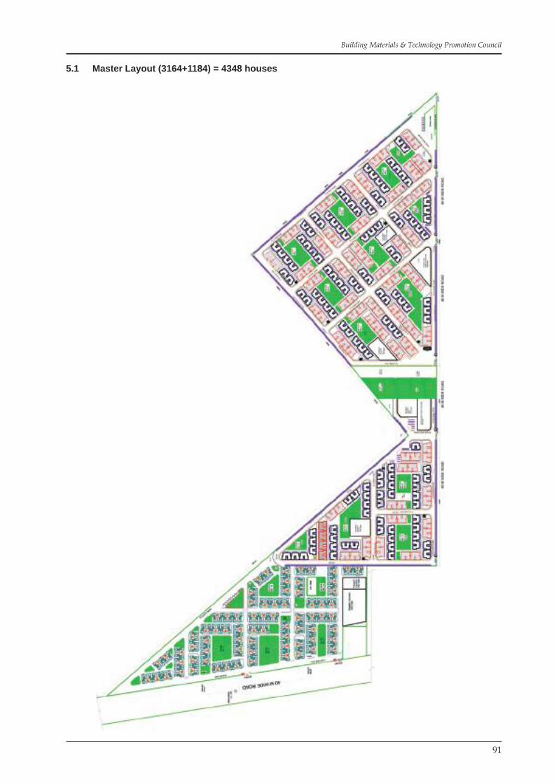
91
Building Materials & Technology Promotion Council
5.1 Master Layout (3164+1184) = 4348 houses

92
Demonstrating Cost Effective Technologies – A Case Study of Bawana Industrial Workers Housing Project
5.2 Layout Pocket A & B (3164 DU)

93
Building Materials & Technology Promotion Council
5.3 Ground Floor Cluster Plan Type I
8.4 Ground Floor Cluster Plan Type II

94
Demonstrating Cost Effective Technologies – A Case Study of Bawana Industrial Workers Housing Project
5.5 Ground Floor Cluster Plan Type III
5.6 Front Elevation Cluster Type I

95
Building Materials & Technology Promotion Council
5.7 Front Elevation Cluster Type II
5.8 Front Elevation Cluster Type III

96
Demonstrating Cost Effective Technologies – A Case Study of Bawana Industrial Workers Housing Project
5.9 Rear Elevation Cluster Type I
5.10 Rear Elevation Cluster Type II

97
Building Materials & Technology Promotion Council
5.11 Side Elevation Cluster Type I
5.12 Side Elevation Cluster Type II

98
Demonstrating Cost Effective Technologies – A Case Study of Bawana Industrial Workers Housing Project
5.13 Side Elevation Cluster Type III

99
Building Materials & Technology Promotion Council
5.14 Pile Foundation Plan Type II

100
Demonstrating Cost Effective Technologies – A Case Study of Bawana Industrial Workers Housing Project
5.15 Grade Beam Plan Type III

101
Building Materials & Technology Promotion Council
5.16 Plinth Band Detail Type I

102
Demonstrating Cost Effective Technologies – A Case Study of Bawana Industrial Workers Housing Project
5.17 Plinth Band Detail Type II
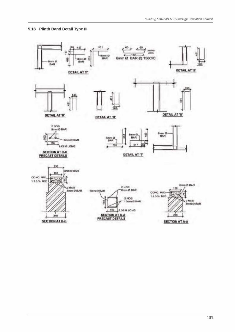
103
Building Materials & Technology Promotion Council
5.18 Plinth Band Detail Type III

104
Demonstrating Cost Effective Technologies – A Case Study of Bawana Industrial Workers Housing Project
5.19 Plinth Band Plan Type I
5.20 Plinth Band Plan Type II

105
Building Materials & Technology Promotion Council
5.21 Plinth Band Plan Type III
5.22 Lintel Band Detail Type I

106
Demonstrating Cost Effective Technologies – A Case Study of Bawana Industrial Workers Housing Project
5.23 Lintel Band Detail Type II
5.24 Lintel Band Plan Type I

107
Building Materials & Technology Promotion Council
5.25 Lintel Band Plan Type II
5.26 Precast Assembly Plan Type I

108
Demonstrating Cost Effective Technologies – A Case Study of Bawana Industrial Workers Housing Project
5.27 Precast Assembly Plan Type II
5.28 Precast roof Elements Part Details

109
Building Materials & Technology Promotion Council
5.29 Vertical Reinforcement Detail for Earthquake Type III
5.30 Vertical Reinforcement Plan for Earthquake Type III

110
Demonstrating Cost Effective Technologies – A Case Study of Bawana Industrial Workers Housing Project
5.31 Ferrocement Kitchen Shelves, Step
5.32 Ferrocement Water Tank Detail

111
Building Materials & Technology Promotion Council
5.33 Architecture Kitchen Detail Type I
5.34 Architecture Kitchen Detail Type II

112
Demonstrating Cost Effective Technologies – A Case Study of Bawana Industrial Workers Housing Project
5.35 Sanitation & Water Supply System Type I

113
Building Materials & Technology Promotion Council
5.36 Sanitation & Water Supply System Type II

114
Demonstrating Cost Effective Technologies – A Case Study of Bawana Industrial Workers Housing Project
5.37 Electrical Plan Type II

115
Building Materials & Technology Promotion Council
5.38 Precast Lintel & Sunshade Detail

116
Demonstrating Cost Effective Technologies – A Case Study of Bawana Industrial Workers Housing Project
5.39 Sewerage

117
Building Materials & Technology Promotion Council
5.40 Drainage

118
Demonstrating Cost Effective Technologies – A Case Study of Bawana Industrial Workers Housing Project
5.41 Water Supply
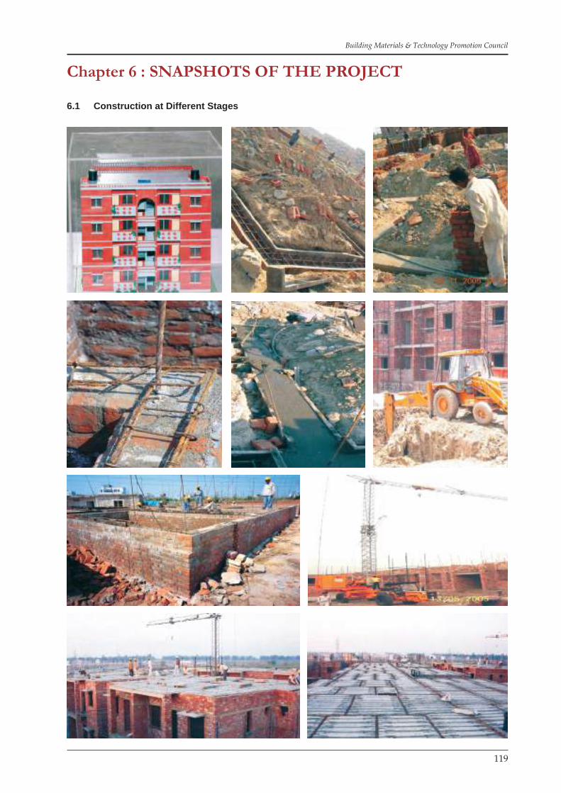
119
Building Materials & Technology Promotion Council
Chapter 6 : SNAPSHOTS OF THE PROJECT
6.1 Construction at Different Stages

120
Demonstrating Cost Effective Technologies – A Case Study of Bawana Industrial Workers Housing Project
Construction at Different Stages

121
Building Materials & Technology Promotion Council
Construction at Different Stages
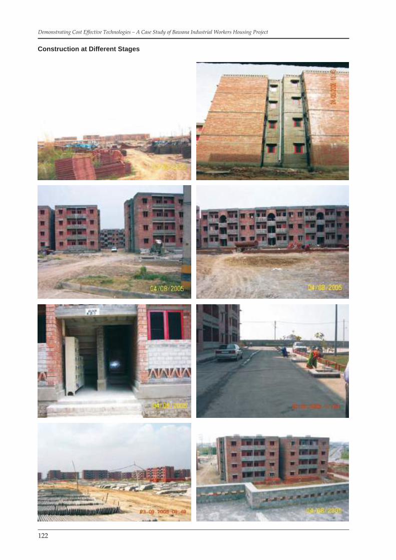
122
Demonstrating Cost Effective Technologies – A Case Study of Bawana Industrial Workers Housing Project
Construction at Different Stages

123
Building Materials & Technology Promotion Council
Construction at Different Stages

124
Demonstrating Cost Effective Technologies – A Case Study of Bawana Industrial Workers Housing Project
Construction at Different Stages

125
Building Materials & Technology Promotion Council
6.2 Views of Completed Buildings

126
Demonstrating Cost Effective Technologies – A Case Study of Bawana Industrial Workers Housing Project

127
Building Materials & Technology Promotion Council

128
Demonstrating Cost Effective Technologies – A Case Study of Bawana Industrial Workers Housing Project
6.3 Interior Views

129
Building Materials & Technology Promotion Council
Chapter 7 : CONCLUSIONS
The project was result of team work of DSIIDC, M/s Adlakha Associates Pvt. Ltd., BMTPC, CBRI and Era Construction (I) Ltd. Through this document it is shown that the technologies adopted here are eco-friendly, time saving, environmental friendly. The cost-effectiveness of the technologies is established as follows:
Saving in consumption of cement (High energy based material)• Saving in consumption of steel (High energy based material)• Saving in centering shuttering material (High energy based material in case of steel shuttering and • eco-friendly material in case of wooden shuttering)Standardization and repetitive use of Precast elements (Reduction in wastage of materials)• Construction management (saving in construction time)• Saving in consumption of power (emphasis on well oriented layouts and improved thermal conductivity • because of use of perforated bricks)Consumption of waste by product ‘Fly-ash’ (Helps in protection of environment)• On site production of Flyash bricks and precast RCC elements (Reduction in wastages / breakages • and better quality control)Precast technology provide better quality•
Tables given below show the savings in consumption of cement, steel and shuttering.
Table 42Cement Consumption (1 Block – 16 DU)
Conventional Specifications Cost Effective Specifications
Cement = 3012.40 Bags Cement = 2024.84 Bags
Savings = 3012.40 – 2024.84 = 987.56 bags = 32.78%
Table 43Steel Consumption (1 Block – 16 DU)
Conventional Specifications Cost Effective SpecificationsTMT Bars = 18745.80 Kg MS = 3125.00 Kg
TMT = 2578.61 KgSteel for piles(Single Section)
= 2165.22 Kg
7868.83 Kg
Savings = 18745.80 – 7868.83 = 10876.97 Kg = 58%
Table 44Centering Shuttering (1 Block – 16 DU)
Conventional Specifications Cost Effective Specifications(a) Lintels, beams = 628.93 sqm Bands at Plinth level,
lintel level and roof level, encasing of vertical bars = 263.37 sqm
(b) Column footings = 124.45 sqm(c) Columns = 337.80 sqm(d) Slabs = 584.36 sqm(e) Stairs = 18.94 sqm
1694.48 sqm
Saving in shuttering area = 1694.48 – 263.37 = 1431.11 sqm (savings is almost 85%)“Recron” fibres have been used during the midway of this project in the thin precast elements RC planks

130
Demonstrating Cost Effective Technologies – A Case Study of Bawana Industrial Workers Housing Project
and the ferrocement steps. The results show that it improves the strength and enhances durability.
An improvement in the technology has made subsequently, with the experience gained. The ‘hooks’ in the RC planks have been added which allow the distribution bar through and keep the planks intact during cast-ing as well as provide extra safety.
The DSIIDC obtained the ISO Certificate for Rajiv Gandhi Housing Project. The First ISO Certified Low Cost Housing Project, which itself is the testimony to the professionalism and the management of the proj-ect at its best possible.
Above stated benefits are perhaps enough to encourage the multiple use of these technologies in the con-struction industry. There are few other projects by DSIIDC where these technologies are being repeated:
Construction of 5568 houses for slum rehabilitation at Baprola• Construction of 1652 Dwelling units for Urban Poor and Industrial Workers at Narela-II• Construction of 1272 Dwelling Units at Bhorgarh• Construction of 1892 Dwelling Units at Narela-I•
The document would serve as a guiding Case Study for the construction industry who are willing to adopt cost effective technologies in their future projects.

131
Building Materials & Technology Promotion Council
Annexure - I
Table 45Cement Consumption with Conventional Specifications (1 Block – 16 DU) 39.74 sqm
S. No.
DSR 2002 Description Unit Qty. Co-efficient
CementQty. in qtl.
1 4.5.9 CC 1:4:8 cum 16.16 1.70 27.47
2 4.5.11 CC 1:5:10 cum 56.10 1.30 72.93
3 5.1.2 RCC 1:1.5:3 cum 43.69 4.00 174.76
4 5.2.2 RCC 1:1.5:3 cum 25.72 4.00 102.88
5 5.3 (modified) RCC 1:1.5:3 cum 110.74 4.00 442.96
6 6.1.14 Brick work 1:6 cum 104.06 0.625 65.04
7 6.1.14 + 6.2A.2 Brick work 1:6 cum 277.84 0.625 173.65
8 6.15 Brick work 1:3 in ARCHES cum 0.24 1.28 0.31
9 5.25.2 Cement Jalli 40mm (fixing only) 100 sqm 5.76 1.64 0.09
10 6.12.2 Half Brick work 1:4 100 sqm 24.5 10.64 2.61
11 11.3.2 CC Floor 1:2:4, 40 mm thick sqm 516.66 0.17 87.83
12 11.6.1 Skirting Cement plaster 1:3 neat cement 18 mm
sqm 61.04 0.14 8.55
13 11.26 Kota stone sqm 13.93 0.1491 2.08
14 11.19 Ceramic Glazed tiles sqm 144.32 0.0942 13.59
15 13.2 12 mm Cement Plaster 1:6 100 sqm 3694.98 3.60 133.02
16 13.19 6 mm Cement Plaster 1:3 100 sqm 537.64 3.67 19.73
17 13.47 Grit Wash 100 sqm 671.93 17.472 117.40
18 22.5 Water proofing sqm 79.36 0.0123 0.98
19 10.13 T-iron Door frame fixing 100 kg 2200.79 0.11 2.42
20 22.7 Brick Bat Coba sqm 148.56 0.387 57.49
21 AR Coping 25 mm thick 1:2:4 sqm 5.18 0.08 0.41
Cement in Quintal 1506.20
Cement in Bags 3012.40

132
Demonstrating Cost Effective Technologies – A Case Study of Bawana Industrial Workers Housing Project
Annexure – II
Table 46Cement Consumption with Cost Effective Specifications (1 Block – 16 DU)
S. No.
DSR 2002 Description Unit Qty. Co-effi-cient
CementQty. in qtl.
1 250 mm dia pile M25 m 721.05 0.19 137.00
2 4.1.4 CC 1:6:10 cum 46.73 1.30 60.75
3 5.1.2 RCC 1:1.5:3 cum 2.01 4.00 8.04
4 5.42.1 RCC 1:1.5:3 cum 8.67 4.10 35.55
5 5.2.2 RCC 1:1.5:3 cum 11.21 4.00 44.84
6 5.3 (modified) RCC 1:1.5:3 cum 26.715 4.00 106.86
7 5.22 (modified) RCC 1:1.5:3 cum 7.07 4.00 28.28
8 AR RCC 1:1.5:3 cum 26.17 4.00 104.68
9 6.1.14 Brick work 1:6 cum 38.95 0.625 24.34
10 6.1.14 + 6.2A.2 Brick work 1:6 cum 61.12 0.625 38.20
11 6.48.3 Brick work 1:6 cum 48.26 0.625 30.16
12 6.44 c Brick work 1:6 cum 151.54 0.625 94.71
13 6.12.2 Half Brick Work 1:4 100 sqm 132.12 10.64 14.06
14 6.22 Brick band 10cm / 7.0 cm thick x 5cm
100 m 197.60 0.38 0.75
15 6.15 Brick work 1:3 in ARCHES cum 0.24 1.28 0.31
16 5.25.2 Cement Jalli 40 mm (fixing only)
100 sqm 5.76 1.64 0.09
17 11.3.2 CC floor 1:2:4, 25 mm thick sqm 516.66 0.122 63.03
18 11.6.1 Skirting Cement plaster 1:3 neat cement 18 mm
sqm 61.04 0.14 8.55
19 11.26 Kota Stone sqm 13.93 0.1491 2.08
20 11.19 Ceramic Glazed Tiles sqm 144.32 0.0942 13.59
21 13.2 12 mm Cement Plaster 1:6 100 sqm 3512.70 3.60 126.46
22 22.5 Water Proofing sqm 79.36 0.0123 0.98
23 10.13 T-iron Door Frame Fixing 100 kg 2200.79 0.11 2.42
24 22.7 Brick Bat coba Av 120mm thick sqm 148.56 0.387 57.49
25 AR Ferrocement shelves 25mm thick
sqm 13.02 0.23 2.99
26 AR Ferrocement stair case 25mm thick
sqm 25.20 0.23 5.80
27 AR Coping 25 mm thick 1:2:4 sqm 5.18 0.08 0.41
Cement in Quintal 1012.42
Cement in Bags 2024.84
