dell™ powervault™ md32xxi/md36xxi deployment …„¢ powervault™ md32xxi/md36xxi deployment...
TRANSCRIPT

Dell™ PowerVault™ MD32xxi/MD36xxi Deployment Guide for VMware ESX4.1 Server A Dell Technical White Paper
Version 1.4
PowerVault MD32xxi and MD36xxi Storage Arrays
www.dell.com/MD32xxi
Dell™ PowerVault™ MD32xxi/MD36xxi Deployment Guide for VMware ESX4.1 Server
ii
THIS WHITE PAPER IS FOR INFORMATIONAL PURPOSES ONLY, AND MAY CONTAIN TYPOGRAPHICAL ERRORS AND TECHNICAL INACCURACIES. THE CONTENT IS PROVIDED AS IS, WITHOUT EXPRESS OR IMPLIED WARRANTIES OF ANY KIND.
© 2011 Dell Inc. All rights reserved. Reproduction of this material in any manner whatsoever without the express written permission of Dell Inc. is strictly forbidden. For more information, contact Dell.
Dell, the DELL logo, and the DELL badge, and PowerVault are trademarks of Dell Inc. Other trademarks and trade names may be used in this document to refer to either the entities claiming the marks and names or their products. Dell Inc. disclaims any proprietary interest in trademarks and trade names other than its own.
March 2011
Dell™ PowerVault™ MD32xxi/MD36xxi Deployment Guide for VMware ESX4.1 Server
iii
Contents Terminology/Glossary .................................................................................................... 5
Introduction ................................................................................................................ 6
New Features in vSphere4 Software iSCSI Initiator ............................................................ 6
Supported Hardware and Software ..................................................................................... 7
Hardware Requirements............................................................................................ 7
Supported Operating Systems for the MD32xxi Array ......................................................... 7
Architectural Setup ....................................................................................................... 7
Considerations When Using iSCSI Software or Hardware Initiators for ESX4.1............................ 8
Establishing Sessions to a SAN in ESX4.1 .................................................................. 8
Configure iSCSI Storage on ESX4.1 Server ............................................................................. 9
Step 1: Configure the vSwitch & Enable Jumbo Frame Support ............................................ 9
Step 2: Add iSCSI VMkernel Ports ............................................................................... 10
Configuration Guidelines ................................................................................... 10
Step 3: Assign Network Adapters ............................................................................... 12
Using vCLI ..................................................................................................... 12
Using the VCenter GUI ...................................................................................... 13
Step 4: Associate VMkernel Ports to Physical Adapters ..................................................... 15
Using vCLI ..................................................................................................... 15
Using the vCenter GUI ...................................................................................... 16
Step 5: Enable the VMware iSCSI Software Initiator ........................................................ 18
Using vCLI ..................................................................................................... 18
Using the vCenter GUI ...................................................................................... 18
Step 6: Binding VMkernel Ports to iSCSI Software Initiator ................................................ 20
Step 7: Connect to PowerVault MD32XXi Storage ............................................................ 23
Step 8: PowerVault MD32xxi Storage Setup and Configuration............................................ 26
Add a New ESX Host ......................................................................................... 26
Name the Host ............................................................................................... 27
Select Host Port Identifiers ................................................................................ 28
Enter a Host Port Alias ..................................................................................... 29
Enter a Host Group Name .................................................................................. 33
Define Mappings for LUNs .................................................................................. 36
Step 9: Perform Rescan so VMware Sees the Virtual Disk .................................................. 40
Step 10: Create VMFS Datastores ............................................................................... 42
Step 11: Configuring the VMware Path Selection Policy .................................................... 50
Dell™ PowerVault™ MD32xxi/MD36xxi Deployment Guide for VMware ESX4.1 Server
iv
Contact Information .................................................................................................... 52
Appendix A ................................................................................................................ 53
Adding an MD36xxi Into the ESX Rule Set ..................................................................... 53
Steps for Using the iSCSI Offload Functions of a NIC ........................................................ 53
Considerations Involving Subnet Configuration .............................................................. 53
Changing the Pathing Policy ............................................................................... 54
Using the MD Configuration Utility (MDCU) ................................................................... 54
Considerations Involving Volume Not On Preferred Path ................................................... 54

Dell™ PowerVault™ MD32xxi/MD36xxi Deployment Guide for VMware ESX4.1 Server
5
Terminology/Glossary
VD == virtual disk
VM == virtual machine
NIC == network interface card
MPIO == Multi-Path I/O
SAN == Storage Area Network
RDM == Raw Device Map
DVS == Distributed Virtual Switch
HA == high availability
DRS == Distributed Resource Scheduler
MRU == Most Recently Used
IQN == iSCSI Qualified Name

Dell™ PowerVault™ MD32xxi/MD36xxi Deployment Guide for VMware ESX4.1 Server
6
Introduction This whitepaper goes into depth with configuration examples for connecting to a Dell™ PowerVault™ iSCSI SAN utilizing the software iSCSI initiator inside the VMware ESX4.1 Server. This process is also documented in VMware’s iSCSI SAN Configuration Guide which can be found on VMware’s website. Additionally, Appendix A gives details regarding configuring hardware initiators from within VMware ESX4.1 Server.
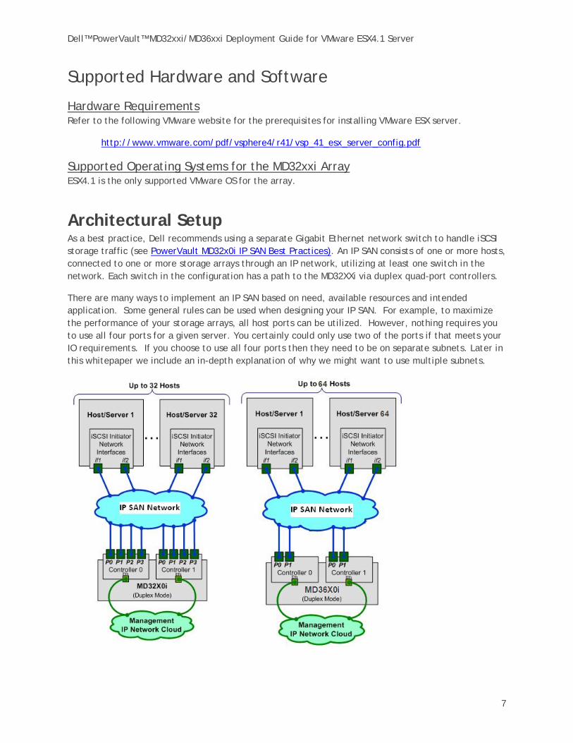
The Dell PowerVault MD32xxi & MD36xxi iSCSI SAN storage solution consists of either a standard or high availability configuration. The standard (simplex) configuration has a single controller with four 1GbE ports. It can be deployed to support up to 32 hosts non-redundantly. The high availability (duplex) configuration has dual controllers with four 1GbE ports per controller for a total of eight 1GbE ports. The dual controller option can also connect up to 32 fully redundant hosts
Provisioning of MD32xxi storage in a VMware ESX4.1 environment is a multi-step process starting with establishing the iSCSI session, definition of the server topology for host access, and finally allocating storage to the individual virtual machines (VMs).
New Features in vSphere4 Software iSCSI Initiator VMware vSphere4 offers many new and advanced enhancements over the iSCSI software initiator in conjunction with iSCSI SAN connectivity. Many of these new features require advanced configuration in order to work properly. Administrators who are familiar with ESX 3.5 iSCSI SAN configuration may find that their current configuration steps are not sufficient to enable all of the advanced features offered in vSphere4.
VMware vSphere4 ESX4.1 has new support for various new advanced capabilities that were not found in ESX 3.5:
iSCSI Software Initiator – For ESX4.1, the iSCSI software initiator was re-written from the ground up for better performance and functionality.
Jumbo Frames – With ESX 4.1 and vSphere4, Jumbo Frames can be enabled on the iSCSI software initiator. Jumbo Frame support allows for larger packets to be transferred between the ESX4.1 servers and the SAN for increased efficiency and performance. Jumbo Frame Support can be enabled via the vCLI.
MPIO – With ESX4.1 and vSphere4, customers can benefit from Multi-Path I/O from the ESX4.1 server and the SAN. This allows for multiple connections to be used to allow for greater bandwidth. This is especially important for the PowerVault SAN as each PowerVault member has multiple connections and now ESX4.1 can take full advantage of these connections.
Third Party MPIO Support – With ESX4.1 and vSphere4, VMware has provided an architecture that enables PowerVault platforms to provide new and advanced intelligent integration.
Dell™ PowerVault™ MD32xxi/MD36xxi Deployment Guide for VMware ESX4.1 Server
7
Supported Hardware and Software
Hardware Requirements Refer to the following VMware website for the prerequisites for installing VMware ESX server.
http://www.vmware.com/pdf/vsphere4/r41/vsp_41_esx_server_config.pdf
Supported Operating Systems for the MD32xxi Array ESX4.1 is the only supported VMware OS for the array.
Architectural Setup As a best practice, Dell recommends using a separate Gigabit Ethernet network switch to handle iSCSI storage traffic (see PowerVault MD32x0i IP SAN Best Practices). An IP SAN consists of one or more hosts, connected to one or more storage arrays through an IP network, utilizing at least one switch in the network. Each switch in the configuration has a path to the MD32XXi via duplex quad-port controllers.
There are many ways to implement an IP SAN based on need, available resources and intended application. Some general rules can be used when designing your IP SAN. For example, to maximize the performance of your storage arrays, all host ports can be utilized. However, nothing requires you to use all four ports for a given server. You certainly could only use two of the ports if that meets your IO requirements. If you choose to use all four ports then they need to be on separate subnets. Later in this whitepaper we include an in-depth explanation of why we might want to use multiple subnets.

Dell™ PowerVault™ MD32xxi/MD36xxi Deployment Guide for VMware ESX4.1 Server
8
Considerations When Using iSCSI Software or Hardware Initiators for ESX4.1 Taking advantage of all of these new features requires some new steps to be taken by ESX administrators. Configuration is done via either GUI or vCLI inside ESX4.1 vCenter. The remainder of this whitepaper focuses on installation and configuration of an iSCSI software initiator connection to a PowerVault Series SAN. Each of these commands can be found inside the VMWARE ISCSI SAN
CONFIGURATION GUIDE and where names and IP Addresses are used, they will be different for each environment. This serves as an example and demonstration of how to configure a new vSphere4 ESX4.1 server correctly and connect it to the PowerVault SAN. The screenshots displayed in this whitepaper are for reference only and may vary from site-specific implementations.
Establishing Sessions to a SAN in ESX4.1 Before continuing the examples, we first must discuss how VMware ESX4.1 establishes its connection to the SAN utilizing the new vSphere4 iSCSI Software Adapter.
With previous versions of ESX, sessions were established using a single NIC path and any additional NICs were there for failover only. With the improvements to vSphere4 and MPIO, administrators can now take advantage of multiple paths to the SAN for greater bandwidth and performance. This does require some additional configuration which is discussed in detail in this whitepaper.
VMware uses VMkernel ports as the session initiators. Each VMkernel is bound to a physical adapter. Depending on the environment this can create a single session to an array or up to 8 sessions (ESX4.1 maximum number of connections per volume). For a normal deployment, it is acceptable to use a one-to-one (1:1) ratio of VMkernels to physical network cards. This means if there are 3 physical NICs, you would establish 1 VMkernel per physical NIC and associate a separate NIC with each VMkernel port.
This scheme can be expanded depending on the number of NICs you have in the system. As the environment grows, you can establish multiple sessions to the SAN by oversubscribing VMkernel ports to actual physical NICs. This establishes multiple sessions to an array but still utilizes the same physical NICs as the means to get to the storage. However, VMWare reports issues with oversubscribing VMkernel ports. Consequently we recommend maintaining 1:1 port binding.
Once these sessions to the SAN are initiated, the VMware NMP will take care of load balancing and spreading the I/O across all available paths.
Dell™ PowerVault™ MD32xxi/MD36xxi Deployment Guide for VMware ESX4.1 Server
9
The following assumptions are made for these examples:
• ESX4.1 Server is installed • Latest Dell PowerVault MD32xxi firmware is installed • More than one Network Interface Card (NIC) is set aside for iSCSI traffic • No Distributed Virtual Switch (DVS) for iSCSI traffic • The MD32xxi IP address on the host ports will have already been configured (see
PowerVault MD32x0i IP SAN Best Practices) • The network topology is connected and both the ESX server and MD32xxi are powered
on • The environment will be using multiple NICs and attaching to a Dell PowerVault SAN
utilizing Native Multipathing (NMP) from VMware
Configuring iSCSI Storage on ESX4.1 Server Note that not every environment requires all of the steps detailed in this example.
• Users connecting their vSphere4 environment using just iSCSI HBAs or users wishing to only assign a single iSCSI NIC with no Jumbo Frame support will not follow these steps and instead configure their environment as normal.
• Users who wish to only enable Jumbo Frame support for their environment will want to follow steps 1 and 2 but only create a single VMkernel port through the vCenter GUI after that.
• Users wishing to only enable Jumbo Frame support for the iSCSI connection need to follow steps 1 and steps 2 with the following changes:
o Step 1: Configure vSwitch and Enable Jumbo Frames – No changes to the instructions
o Step 2: Add iSCSI VMkernel Ports – Instead of assigning multiple VMkernel Ports, administrators will only assign a single VMkernel Port
Once these two steps are done, the rest of the configuration can be accomplished in the vCenter GUI by attaching NICs, assigning storage and then connecting to the storage.
Step 1: Configure the vSwitch & Enable Jumbo Frame Support This step will create a new vSwitch and enable Jumbo Frame support for this switch. Currently there is no option to enable Jumbo Frames on a vSwitch from the VMware vCenter GUI so these commands must be run via vCLI. Be sure to check the environment to make sure that Jumbo Frames are supported at the networking layer before enabling them on the ESX host.
First, connect to the ESX server/vCenter using VI Client.
Next, use the following command to create a new vSwitch called vSwitch2:
esxcfg-vswitch –a vSwitch2
Finally, enable Jumbo Frames on the vSwitch:
esxcfg-vswitch –m 9000 vSwitch2

Dell™ PowerVault™ MD32xxi/MD36xxi Deployment Guide for VMware ESX4.1 Server
10
To verify that the switch was configured properly run the following command:
esxcfg-vswitch –l
Your output will look similar to this:
Switch Name Num Ports Used Ports Configured Ports MTU Uplinks vSwitch2 64 1 64 9000
In this example, note the new vSwitch2 with the MTU of 9000 confirming that the switch was created correctly. You can also see it displayed in the GUI of vCenter.
NOTE: Throughout these procedures some of the verification can be done either via command line or seen in the vCenter GUI. In other cases only the command line method can be used. The polling rate of vCenter is not instant so changes will not show up immediately after they are typed.
Step 2: Add iSCSI VMkernel Ports This next step will assign VMkernel Ports to the new vSwitch2. It will also configure Jumbo Frame support as well as assign the IP Addresses. Administrators familiar with iSCSI connectivity in ESX3.5 will find that it is no longer required to configure a Service Console port for the iSCSI connection.
Another thing to notice is that because the Service Console is not needed, the iSCSI switch environment can be on a different subnet than the public environment or existing service console. Each VMkernel Port will need its own IP Address and they must all be on the same subnet as the PowerVault IP Address. Nothing requires you to use all four ports for a given server but if you are going to use Round Robin (RR) then using all four ports is recommended. If you choose to use all four ports then they need to be on separate subnets and if you need to use vLans you’ll need separate vLans for RR to work correctly. You certainly can only use two of the ports if that meets the IO requirements.
Configuration Guidelines Some suggested configurations are based on the number of NICs that will be used for iSCSI traffic. Every environment will differ depending on the number of hosts, and the number of volumes.
In a default configuration, assign one VMkernel port for each physical NIC in the system. For example, if there are 3 NICs, assign 3 VMkernel Ports. This is referred to in VMware’s iSCSI SAN Configuration Guide as 1:1 port binding. VMware vCenter has a maximum of 8 connections to a single volume. In this whitepaper we choose 3 connections in the 1:1 scenario. This provides scalability and performance as the SAN environment grows without having to make changes on each ESX host.
If fewer connections are desired follow the above sample configurations to obtain the number of VMkernel Ports that match the environment and the number of paths you need.
Always keep the entire virtual datacenter in mind when deciding on path and volume count. View the Release Notes of the PowerVault Firmware for the current connection limits for the Dell PowerVault.
Dell™ PowerVault™ MD32xxi/MD36xxi Deployment Guide for VMware ESX4.1 Server
11
All of these configurations are done for the vSwitch itself. This means that once VSwitch is configured, the ESX4.1 host will create multiple connections to the PowerVault SAN. Thereafter there only need to be changes made if more NICs are being added or if more or less paths are needed.
NOTE: Host profiles do not keep information on Jumbo Frames or Port Bindings.
For the rest of this example the configuration steps and commands will be given for the 1:1 binding.
Using VCLI The following command will add a new iSCSI VMkernel Port named iSCSI1 on the vSwitch created in the previous step.
esxcfg-vswitch –A iSCSI1 vSwitch2
This next command will configure the IP Address and Subnet Mask and enable Jumbo Frame support for the new VMkernel Port named iSCSI1
esxcfg-vmknic –a –i 10.10.6.206 –n 255.255.255.0 –m 9000 iSCSI1
For our example with a 1:1 relationship with 3 NICs we need to create two more VMkernel Ports named iSCSI2 and iSCSI3.
esxcfg-vswitch –A iSCSI2 vSwitch2
esxcfg-vmknic –a –i 10.10.7.207 –n 255.255.255.0 –m 9000 iSCSI2
esxcfg-vswitch –A iSCSI3 vSwitch2
esxcfg-vmknic –a –i 10.10.8.208 –n 255.255.255.0 –m 9000 iSCSI3
To verify the configuration enter the following command:
esxcfg-vswitch –l
The output will look similar to this:
Switch Name Num Ports Used Ports Configured Ports MTU Uplinks vSwitch2 64 7 64 9000 PortGroup Name VLAN ID Used Ports Uplinks iSCSI3 0 1 iSCSI2 0 1 iSCSI1 0 1
This will show the VMkernel ports that are assigned to the vSwitch. To verify the IP addresses enter the following command:
esxcfg-vmknic –l
The output will look similar to the graphic below.
You can also verify the IP Addresses via the vCenter GUI. In vCenter, on the ESX Host, navigate to Configuration -> Networking.

Dell™ PowerVault™ MD32xxi/MD36xxi Deployment Guide for VMware ESX4.1 Server
12
Step 3: Assign Network Adapters The next step in the process is to assign the network adapters (NICs) that will be attached to the iSCSI network and used for iSCSI traffic. These will be attached to vSwitch2 that we created earlier. This can be done two ways, in the vCenter GUI or by vCLI.
Using vCLI To list all of the adapters in the system run the following command:
esxcfg-nics –l
The output will look similar to this:
Name PCI Driver Link Speed Duplex MAC Address MTU vmnic0 03:00.00 bnx2 Up 1000Mbps Full 00:21:9b:8b:4b:b0 1500
Next., assign the NICs that are physically connected to the SAN infrastructure and to the vSwitch. The following command assumes that we are assigning vmnic1, vmnic2, and vmnic3 to the vSwitch.
esxcfg-vswitch –L vmnic1 vSwitch2 esxcfg-vswitch –L vmnic2 vSwitch2 esxcfg-vswitch –L vmnic3 vSwitch2
Once again, to verify the configuration, type the following command to list the vSwitch information:
esxcfg-vswitch –l
Your output should look similar to the following. Note the new vmnics that were assigned to the vSwitch under uplinks.
Switch Name Num Ports Used Ports Configured Ports MTU Uplinks vSwitch2 64 9 64 9000 PortGroup Name VLAN ID Used Ports Uplinks
iSCSI3 0 1 vmnic1,vmnic2,vmnic3 iSCSI2 0 1 vmnic1,vmnic2,vmnic3 iSCSI1 0 1 vmnic1,vmnic2,vmnic3
Dell™ PowerVault™ MD32xxi/MD36xxi Deployment Guide for VMware ESX4.1 Server
13
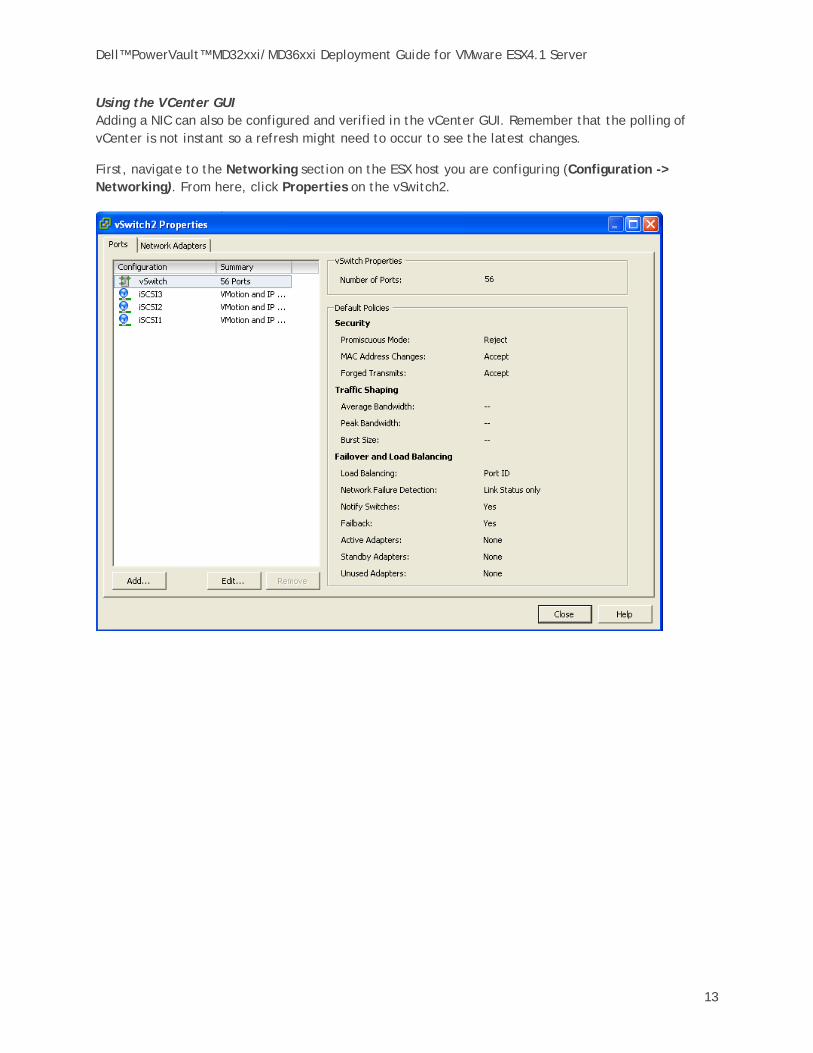
Using the VCenter GUI Adding a NIC can also be configured and verified in the vCenter GUI. Remember that the polling of vCenter is not instant so a refresh might need to occur to see the latest changes.
First, navigate to the Networking section on the ESX host you are configuring (Configuration -> Networking). From here, click Properties on the vSwitch2.

Dell™ PowerVault™ MD32xxi/MD36xxi Deployment Guide for VMware ESX4.1 Server
14
Click the Network Adapters tab, then click Add. This will open up the Add Adapter Wizard. From here select the vmnics that you want to add to the vSwitch. In our example they will be vmnic1, vmnic2 and vmnic3.
Click Next after you have selected the chosen adapters. For now, keep the defaults listed in the Failover Order screen and click Next.
Review the adapters listed and click Finish completing the process. These adapters will now show up in the GUI under the Network Adapters tab.

Dell™ PowerVault™ MD32xxi/MD36xxi Deployment Guide for VMware ESX4.1 Server
15
Step 4: Associate VMkernel Ports to Physical Adapters This step creates the individual path bindings for each VMkernel to a NIC. This is required in order to take advantage of features such as Most Recently Used (MRU) and Round Robin (RR) multipathing policies or 3rd party MPIO plug-ins currently available from Dell.
In this example, we have 3 VMkernel ports and 3 NICs. This means that each NIC will have 1 VMkernel port assigned to it. Again, each environment will differ and these numbers can change based on the number of NICs and the number of paths assigned.
This process can be done either via vCLI or through the vCenter GUI.
Using vCLI By default, all the vmnics are assigned to each VMkernel port. We need to remove all but one vmnic from each VMkernel port so that each VMkernel port has only one uplink.
Before running these commands the switch information looks like the following:
Switch Name Num Ports Used Ports Configured Ports MTU Uplinks vSwitch2 64 9 64 9000 PortGroup Name VLAN ID Used Ports Uplinks
iSCSI3 0 1 vmnic1,vmnic2,vmnic3 iSCSI2 0 1 vmnic1,vmnic2,vmnic3 iSCSI1 0 1 vmnic1,vmnic2,vmnic3
You can see that there are three vmnics in each uplink for each VMkernel Port. This is what we need to change so that only a single vmnic is in each uplink and that we manually load balance them across all available VMkernel Ports.
To accomplish this process via vCLI first note the vmnic number of the first NIC you want to remove and type the following command:
esxcfg-vswitch –p iSCSI1 –N vmnic3 vSwitch2
This removes vmnic3 from VMkernel port iSCSI1 so that now vmnic1 and vmnic2 are left on iSCSI1. We then need to remove vmnic2 so that only vmnic1 is associated with the iSCSI1. To do this type the following command:
esxcfg-vswitch –p iSCSI1 –N vmnic2 vSwitch2
Now that we have just one vmnic associated with one VMkernel port we need to repeat these steps to remove the excess NICs from the other ports.
esxcfg-vswitch –p iSCSI2 –N vmnic1 vSwitch2 esxcfg-vswitch –p iSCSI2 –N vmnic3 vSwitch2 esxcfg-vswitch –p iSCSI3 –N vmnic1 vSwitch2 esxcfg-vswitch –p iSCSI3 –N vmnic2 vSwitch2
To verify that this was done correctly type the following command:
esxcfg-vswitch –l
Dell™ PowerVault™ MD32xxi/MD36xxi Deployment Guide for VMware ESX4.1 Server
16
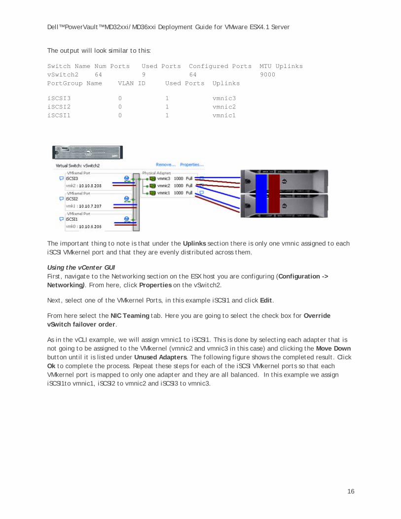
The output will look similar to this:
Switch Name Num Ports Used Ports Configured Ports MTU Uplinks vSwitch2 64 9 64 9000 PortGroup Name VLAN ID Used Ports Uplinks
iSCSI3 0 1 vmnic3 iSCSI2 0 1 vmnic2 iSCSI1 0 1 vmnic1
The important thing to note is that under the Uplinks section there is only one vmnic assigned to each iSCSI VMkernel port and that they are evenly distributed across them.
Using the vCenter GUI First, navigate to the Networking section on the ESX host you are configuring (Configuration -> Networking). From here, click Properties on the vSwitch2.
Next, select one of the VMkernel Ports, in this example iSCSI1 and click Edit.
From here select the NIC Teaming tab. Here you are going to select the check box for Override vSwitch failover order.
As in the vCLI example, we will assign vmnic1 to iSCSI1. This is done by selecting each adapter that is not going to be assigned to the VMkernel (vmnic2 and vmnic3 in this case) and clicking the Move Down button until it is listed under Unused Adapters. The following figure shows the completed result. Click Ok to complete the process. Repeat these steps for each of the iSCSI VMkernel ports so that each VMkernel port is mapped to only one adapter and they are all balanced. In this example we assign iSCSI1to vmnic1, iSCSI2 to vmnic2 and iSCSI3 to vmnic3.

Dell™ PowerVault™ MD32xxi/MD36xxi Deployment Guide for VMware ESX4.1 Server
17
Dell™ PowerVault™ MD32xxi/MD36xxi Deployment Guide for VMware ESX4.1 Server
18
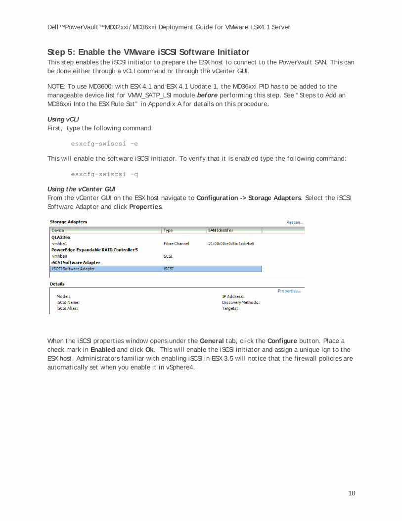
Step 5: Enable the VMware iSCSI Software Initiator This step enables the iSCSI initiator to prepare the ESX host to connect to the PowerVault SAN. This can be done either through a vCLI command or through the vCenter GUI.
NOTE: To use MD3600i with ESX 4.1 and ESX 4.1 Update 1, the MD36xxi PID has to be added to the manageable device list for VMW_SATP_LSI module before performing this step. See “Steps to Add an MD36xxi Into the ESX Rule Set” in Appendix A for details on this procedure.
Using vCLI First, type the following command:
esxcfg-swiscsi –e
This will enable the software iSCSI initiator. To verify that it is enabled type the following command:
esxcfg-swiscsi –q
Using the vCenter GUI From the vCenter GUI on the ESX host navigate to Configuration -> Storage Adapters. Select the iSCSI Software Adapter and click Properties.
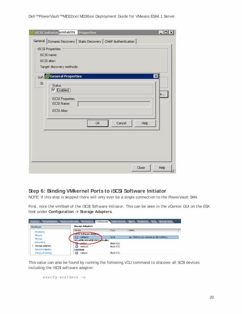
When the iSCSI properties window opens under the General tab, click the Configure button. Place a check mark in Enabled and click Ok. This will enable the iSCSI initiator and assign a unique iqn to the ESX host. Administrators familiar with enabling iSCSI in ESX 3.5 will notice that the firewall policies are automatically set when you enable it in vSphere4.

Dell™ PowerVault™ MD32xxi/MD36xxi Deployment Guide for VMware ESX4.1 Server
19
Dell™ PowerVault™ MD32xxi/MD36xxi Deployment Guide for VMware ESX4.1 Server
20
Step 6: Binding VMkernel Ports to iSCSI Software Initiator NOTE: If this step is skipped there will only ever be a single connection to the PowerVault SAN.
First, note the vmhba# of the iSCSI Software Initiator. This can be seen in the vCenter GUI on the ESX host under Configuration -> Storage Adapters.
This value can also be found by running the following vCLI command to discover all SCSI devices including the iSCSI software adapter:
esxcfg-scsidevs –a

Dell™ PowerVault™ MD32xxi/MD36xxi Deployment Guide for VMware ESX4.1 Server
21
The output will look something like the following:
vmhba0 mptsas link-n/a sas.5001ec90e0ba7c00 (1:0.0) LSI Logic / Symbios Logic LSI1068E vmhba1 ata_piix link-n/a ide.vmhba1 (0:31.1) Intel Corporation 631xESB/632xESB IDE Controller vmhba32 ata_piix link-n/a ide.vmhba32 (0:31.1) Intel Corporation 631xESB/632xESB IDE Controller vmhba33 iscsi_vmk link-n/a iscsi.vmhba33 () Software iSCSI
In this example, we can determine that the vmhba# for the iSCSI Software Initiator is vmhba33. This will be used in the next step. This value will differ on various systems based on the devices installed.
The next piece of information to gather is the vmk# of each of the VMkernel ports. Again, this can be done via the GUI or vCLI.
From the vCenter GUI navigate to Configuration -> Networking. From the vSwitch that was created earlier under each VMkernel port, the vmk# will be listed.
NOTE: vMotion ports and other VMkernels will utilize the same numbers based on the order they are created. They may not start with vmk0.
In this example we see that iSCSI1 is vmk0, iSCSI2 is vmk1, and iSCSI3 is vmk2.
We can also see this in the vCLI by using the following command:
esxcfg-vmknic –l
Dell™ PowerVault™ MD32xxi/MD36xxi Deployment Guide for VMware ESX4.1 Server
22
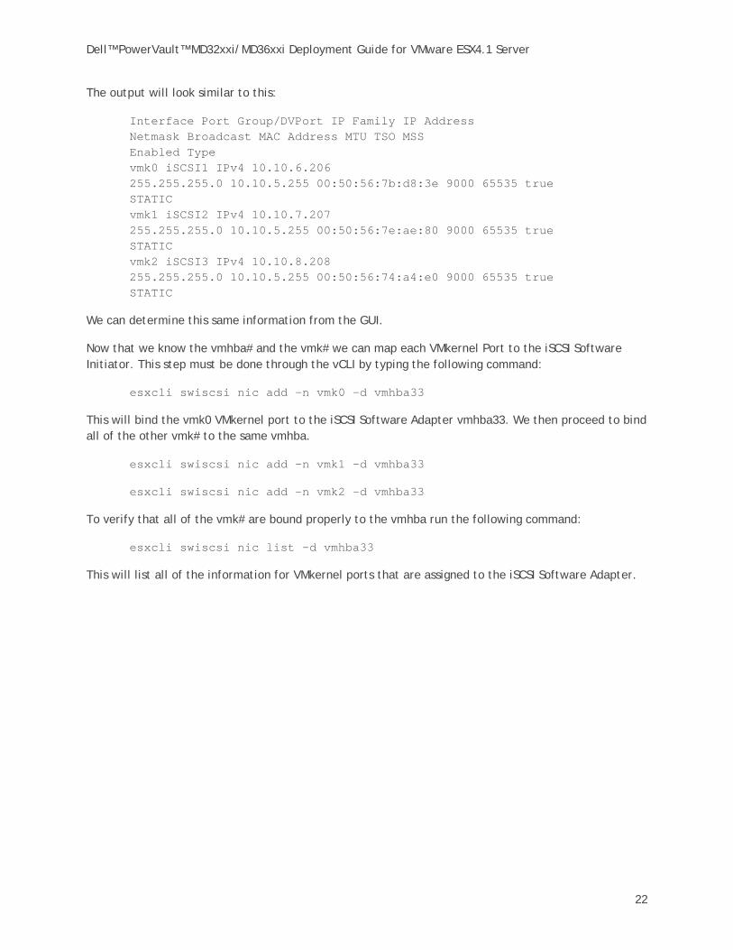
The output will look similar to this:
Interface Port Group/DVPort IP Family IP Address Netmask Broadcast MAC Address MTU TSO MSS Enabled Type vmk0 iSCSI1 IPv4 10.10.6.206 255.255.255.0 10.10.5.255 00:50:56:7b:d8:3e 9000 65535 true STATIC vmk1 iSCSI2 IPv4 10.10.7.207 255.255.255.0 10.10.5.255 00:50:56:7e:ae:80 9000 65535 true STATIC vmk2 iSCSI3 IPv4 10.10.8.208 255.255.255.0 10.10.5.255 00:50:56:74:a4:e0 9000 65535 true STATIC
We can determine this same information from the GUI.
Now that we know the vmhba# and the vmk# we can map each VMkernel Port to the iSCSI Software Initiator. This step must be done through the vCLI by typing the following command:
esxcli swiscsi nic add –n vmk0 –d vmhba33
This will bind the vmk0 VMkernel port to the iSCSI Software Adapter vmhba33. We then proceed to bind all of the other vmk# to the same vmhba.
esxcli swiscsi nic add –n vmk1 –d vmhba33
esxcli swiscsi nic add –n vmk2 –d vmhba33
To verify that all of the vmk# are bound properly to the vmhba run the following command:
esxcli swiscsi nic list –d vmhba33
This will list all of the information for VMkernel ports that are assigned to the iSCSI Software Adapter.

Dell™ PowerVault™ MD32xxi/MD36xxi Deployment Guide for VMware ESX4.1 Server
23
Step 7: Connect to PowerVault MD32XXi Storage Now that the advanced configuration for the vSphere4 iSCSI Software Initiator has been completed, the next stage is to connect to the Dell PowerVault SAN. More information for complete administration of the Dell PowerVault SAN can be found in the PowerVault User’s Guide. In this example we will attach the iSCSI Software Initiator to the SAN. We will skip configuring CHAP but both one way and bi-directional CHAP is supported by the PowerVault SAN.
First, navigate in the vCenter GUI to Configuration -> Storage Adapters. You should now see your iSCSI Target name listed.
Click on the iSCSI Software Adapter and click Properties. In the iSCSI Server box type an IP Address for one of the iSCSI host ports of the PowerVault SAN and click OK. There may be a slight delay before the process completes.

Dell™ PowerVault™ MD32xxi/MD36xxi Deployment Guide for VMware ESX4.1 Server
24
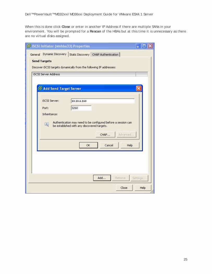
Click the Dynamic Discovery tab, then click Add.
Dell™ PowerVault™ MD32xxi/MD36xxi Deployment Guide for VMware ESX4.1 Server
25
When this is done click Close or enter in another IP Address if there are multiple SANs in your environment. You will be prompted for a Rescan of the HBAs but at this time it is unnecessary as there are no virtual disks assigned.
Dell™ PowerVault™ MD32xxi/MD36xxi Deployment Guide for VMware ESX4.1 Server
26
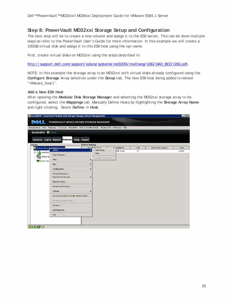
Step 8: PowerVault MD32xxi Storage Setup and Configuration The next step will be to create a new volume and assign it to the ESX server. This can be done multiple ways so refer to the PowerVault User’s Guide for more information. In this example we will create a 100GB virtual disk and assign it to this ESX host using the iqn name.
First, create virtual disks on MD32xxi using the steps described in:
http://support.dell.com/support/edocs/systems/md3200i/multlang/GSG/DAO_BCC/GSG.pdf.
NOTE: in this example the storage array is an MD32xxi with virtual disks already configured using the Configure Storage Array selection under the Setup tab. The new ESX host being added is named “VMware_host1”.
Add a New ESX Host After opening the Modular Disk Storage Manager and selecting the MD32xxi storage array to be configured, select the Mappings tab. Manually Define Hosts by highlighting the Storage Array Name and right-clicking. Select Define -> Host.
Dell™ PowerVault™ MD32xxi/MD36xxi Deployment Guide for VMware ESX4.1 Server
27
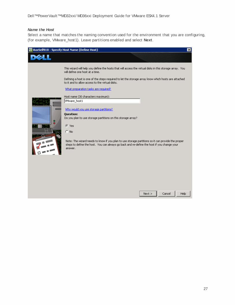
Name the Host Select a name that matches the naming convention used for the environment that you are configuring, (for example, VMware_host1). Leave partitions enabled and select Next.

Dell™ PowerVault™ MD32xxi/MD36xxi Deployment Guide for VMware ESX4.1 Server
28
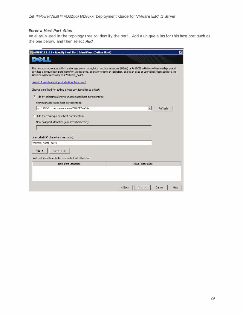
Select Host Port Identifiers Using the pull down, select the host port identifier. In this example, because the iSCSI session has already been established the iqn is already in the list.
NOTE: You can also add the iqn manually. To find the iSCSI Initiator Name from the vCenter GUI go to Configuration -> Storage Adapters, and then click on the iSCSI Software Adapter. You can then copy the iqn value and paste it into the Add by creating a host port identifier field.
Dell™ PowerVault™ MD32xxi/MD36xxi Deployment Guide for VMware ESX4.1 Server
29
Enter a Host Port Alias An alias is used in the topology tree to identify the port. Add a unique alias for this host port such as the one below, and then select Add

Dell™ PowerVault™ MD32xxi/MD36xxi Deployment Guide for VMware ESX4.1 Server
30
The completed host port screen will be similar to the one below. Select Next to continue.

Dell™ PowerVault™ MD32xxi/MD36xxi Deployment Guide for VMware ESX4.1 Server
31
Select VMware as the host type.

Dell™ PowerVault™ MD32xxi/MD36xxi Deployment Guide for VMware ESX4.1 Server
32
If you intend to use advanced VMware features such as VMotion then this host will share access with other ESX servers and you will have to create a Host Group. We will create a host group for this example.
Dell™ PowerVault™ MD32xxi/MD36xxi Deployment Guide for VMware ESX4.1 Server
33
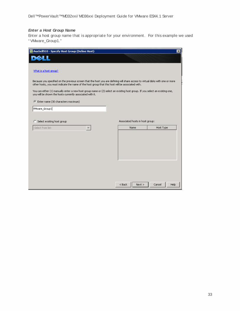
Enter a Host Group Name Enter a host group name that is appropriate for your environment. For this example we used “VMware_Group1.”

Dell™ PowerVault™ MD32xxi/MD36xxi Deployment Guide for VMware ESX4.1 Server
34
Review the Host Definition. If all of the information is correct for your environment select Finish.
Dell™ PowerVault™ MD32xxi/MD36xxi Deployment Guide for VMware ESX4.1 Server
35
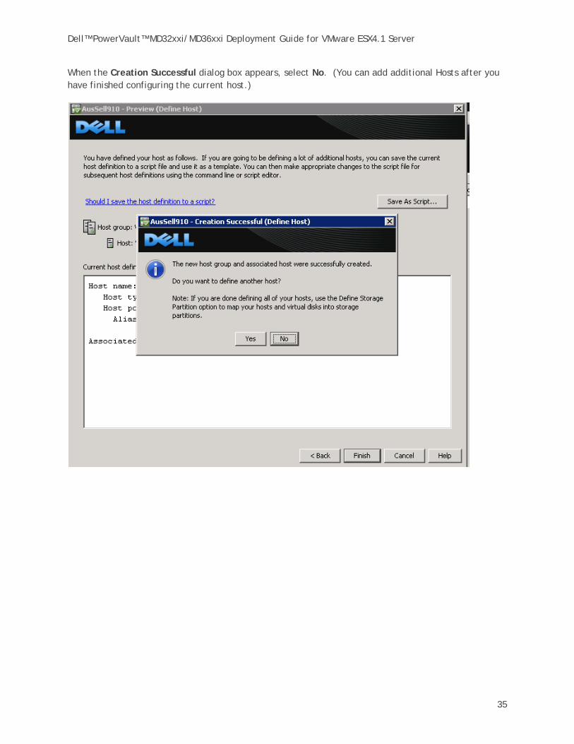
When the Creation Successful dialog box appears, select No. (You can add additional Hosts after you have finished configuring the current host.)
Dell™ PowerVault™ MD32xxi/MD36xxi Deployment Guide for VMware ESX4.1 Server
36
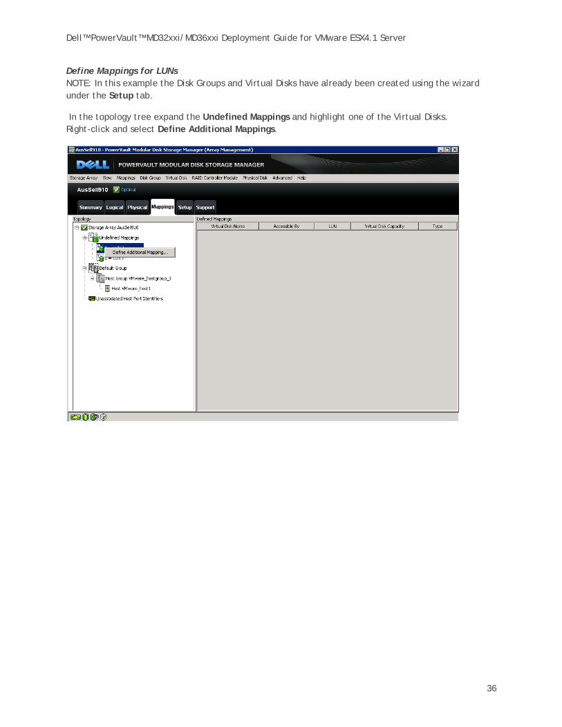
Define Mappings for LUNs NOTE: In this example the Disk Groups and Virtual Disks have already been created using the wizard under the Setup tab.
In the topology tree expand the Undefined Mappings and highlight one of the Virtual Disks. Right-click and select Define Additional Mappings.

Dell™ PowerVault™ MD32xxi/MD36xxi Deployment Guide for VMware ESX4.1 Server
37
NOTE: Remember that the virtual disk is assigned to the host group and not the host. For this example we selected the host group that was defined in the previous steps.

Dell™ PowerVault™ MD32xxi/MD36xxi Deployment Guide for VMware ESX4.1 Server
38
Assign the other virtual disk to the same host group.

Dell™ PowerVault™ MD32xxi/MD36xxi Deployment Guide for VMware ESX4.1 Server
39
After the virtual disks are assigned, notice that the host group and its associated hosts are no longer under the default group in the topology. This completes the configuration.
Dell™ PowerVault™ MD32xxi/MD36xxi Deployment Guide for VMware ESX4.1 Server
40
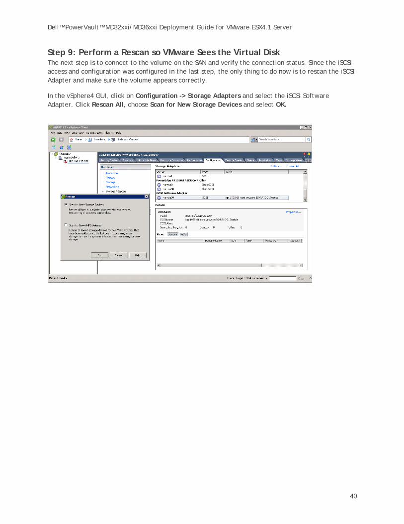
Step 9: Perform a Rescan so VMware Sees the Virtual Disk The next step is to connect to the volume on the SAN and verify the connection status. Since the iSCSI access and configuration was configured in the last step, the only thing to do now is to rescan the iSCSI Adapter and make sure the volume appears correctly.
In the vSphere4 GUI, click on Configuration -> Storage Adapters and select the iSCSI Software Adapter. Click Rescan All, choose Scan for New Storage Devices and select OK.

Dell™ PowerVault™ MD32xxi/MD36xxi Deployment Guide for VMware ESX4.1 Server
41
If everything has been configured properly, under Devices there will be new PowerVault iSCSI Disks with the correct LUNs, similar to what’s shown below.
If the device information is correct select the Path tab and verify that there are active and standby paths for each device (LUN).
Repeat this step for each additional new Dell iSCSI disk that is created.

Dell™ PowerVault™ MD32xxi/MD36xxi Deployment Guide for VMware ESX4.1 Server
42
Step 10: Create VMFS Datastores Now that the iSCSI Software adapter is set up and configured and the Dell iSCSI disks are visible to the adapter, they can also be formatted as VMFS Datastores.
Creating a datastore from the MD32xxi LUNS is the same as creating a datastore with any local disk. Begin by selecting Storage under Hardware and then select Add Storage.

Dell™ PowerVault™ MD32xxi/MD36xxi Deployment Guide for VMware ESX4.1 Server
43
Because an iSCSI disk is considered a local SCSI disk, select Disk/LUN as the storage type.

Dell™ PowerVault™ MD32xxi/MD36xxi Deployment Guide for VMware ESX4.1 Server
44
Next, select one of the LUNS from the MD32xxi to create a Datastore from.

Dell™ PowerVault™ MD32xxi/MD36xxi Deployment Guide for VMware ESX4.1 Server
45
This screen displays the information about the disk layout. Select Next to create a VMFS partition.

Dell™ PowerVault™ MD32xxi/MD36xxi Deployment Guide for VMware ESX4.1 Server
46
Enter a datastore name and select Next.
Dell™ PowerVault™ MD32xxi/MD36xxi Deployment Guide for VMware ESX4.1 Server
47
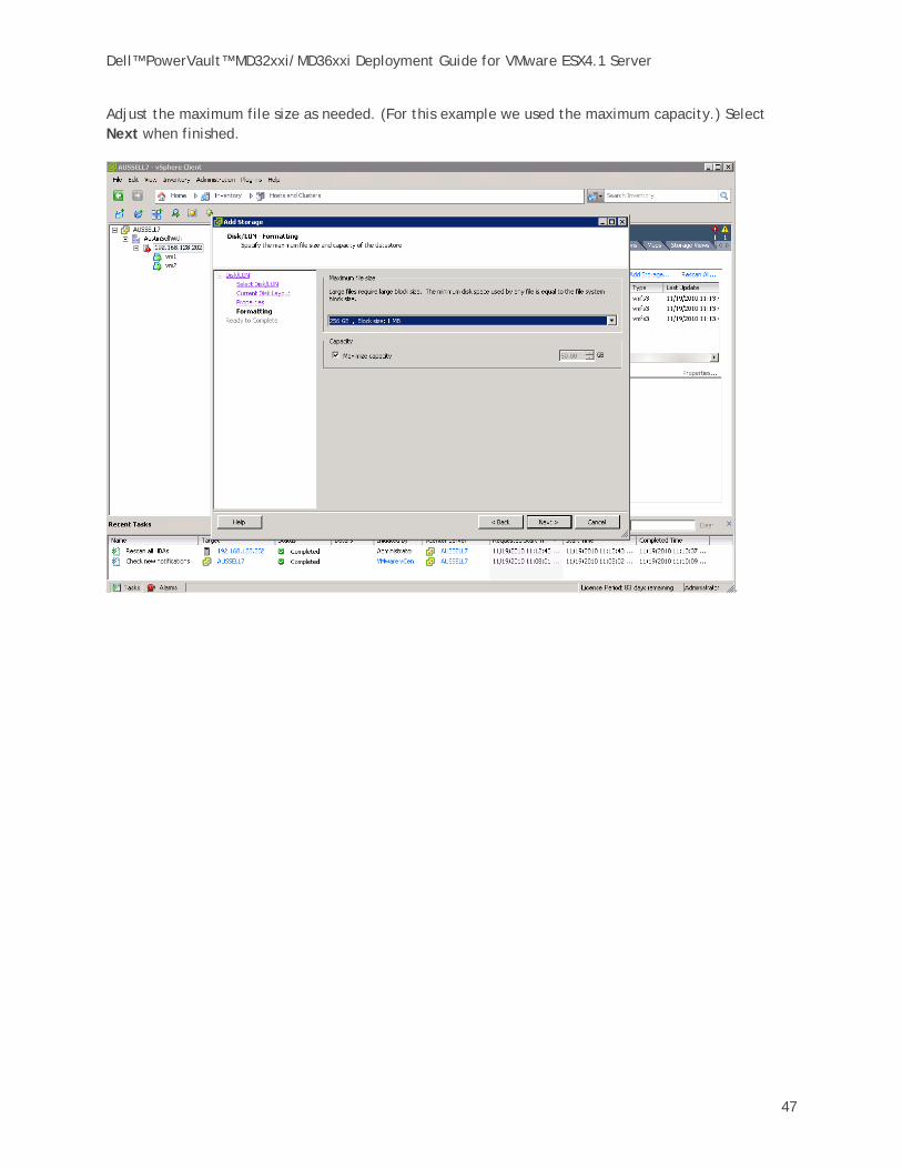
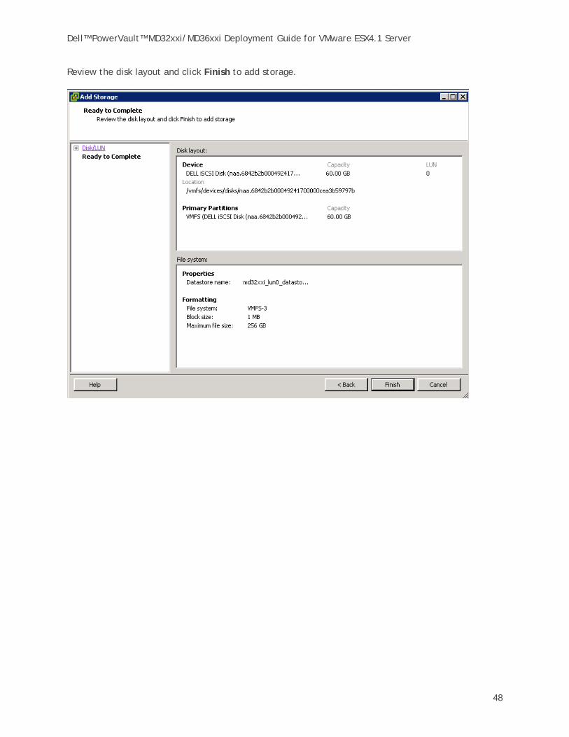
Adjust the maximum file size as needed. (For this example we used the maximum capacity.) Select Next when finished.
Dell™ PowerVault™ MD32xxi/MD36xxi Deployment Guide for VMware ESX4.1 Server
48
Review the disk layout and click Finish to add storage.

Dell™ PowerVault™ MD32xxi/MD36xxi Deployment Guide for VMware ESX4.1 Server
49
The new storage is completed and ready to use with VMs.

Dell™ PowerVault™ MD32xxi/MD36xxi Deployment Guide for VMware ESX4.1 Server
50
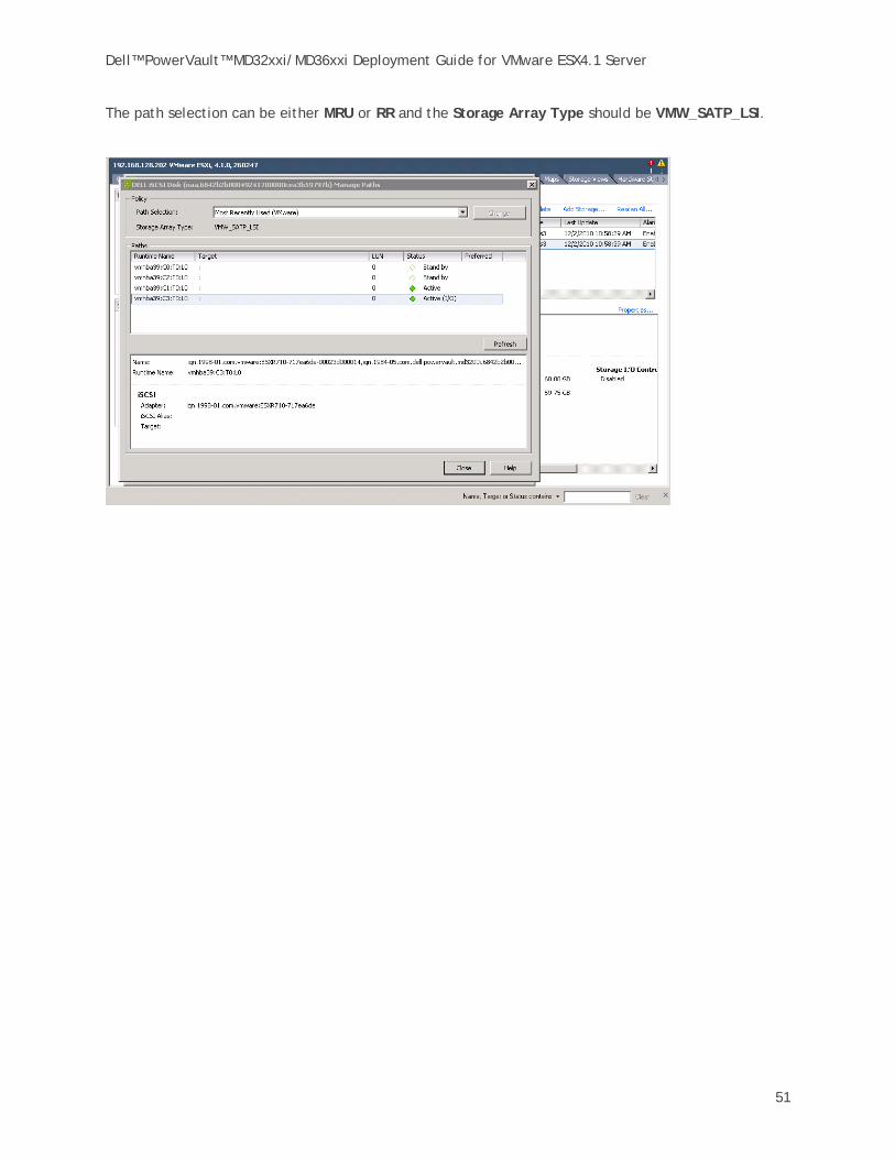
Step 11: Configuring the VMware Path Selection Policy By configuring the iSCSI Software Initiator the way we have, we can take advantage of several multipathing policies, such as Most Recently Used (MRU) and Round Robin(RR). This allows for greater and better bandwidth utilization than in previous versions of ESX.
To verify the Path Selection Policy on a datastore, select the volume from the vCenter GUI, then select Configure -> Storage. Highlight the datastore and select Properties.
From the properties window select Manage Paths.
Dell™ PowerVault™ MD32xxi/MD36xxi Deployment Guide for VMware ESX4.1 Server
51
The path selection can be either MRU or RR and the Storage Array Type should be VMW_SATP_LSI.

Dell™ PowerVault™ MD32xxi/MD36xxi Deployment Guide for VMware ESX4.1 Server
52
Contact Information Dell Support information:
HTTP://SUPPORT.DELL.COM/SUPPORT/TOPICS/GLOBAL.ASPX/SUPPORT/PRODUCT_SUPPORT/PRODUCT_SUPPORT_CENTRAL?C=US&CS=555&L=EN&S=BIZReferences
VMware vSphere 4.1 documentation:
http://www.vmware.com/support/pubs/vs_pages/vsp_pubs_esxi41_e_vc41.html
Dell/VMware alliance home page:
http://www.dell.com/vmware

Dell™ PowerVault™ MD32xxi/MD36xxi Deployment Guide for VMware ESX4.1 Server
53
Appendix A
Adding an MD36xxi to the ESX Rule Set To use MD3600i with ESX 4.1 and ESX 4.1 Update 1, the MD36xxi PID has to be added to the manageable device list for the VMW_SATP_LSI module. Otherwise, the guest host will not be able to see the mapped volumes and perform I/O's.
Consequently, the following procedure needs to be run before mapping virtual disks to ESX guest OS’s. The setup of an MD36xxi vs an MD32xxi is identical through Step 4 of the procedure in this document. At Step 5, prior to enabling the iSCSI initiator to prepare the ESX host to connect to the PowerVault SAN, on the ESX host you need to run
#/*example to add MD 3600i VID/PID (following the MD3200i format)*/ #esxcli nmp satp addrule -V DELL -M MD36xxi -s VMW_SATP_LSI
This command adds MD36xxi devices into the device list for VMW_SATP_LSI module. After running this command, proceed with Step 5: Enable the VMware iSCSI Software Initiator.
Steps for Using the iSCSI Offload Functions of a NIC Lower CPU utilization and potentially lower power consumption justify offload adapters (hardware initiators). With hardware-based iSCSI storage, you use a specialized third-party adapter capable of accessing iSCSI storage over TCP/IP(a.k.a. iSCSI Offload, ISOE adapters). This iSCSI initiator handles all iSCSI and network processing and management for your ESX/ESXi system.
The list of hardware initiators supported on the MD32xxi can be found here. You must install and configure the hardware iSCSI adapter for your host to be able to access the iSCSI storage device. For installation information, see either Broadcom or Emulex documentation.
With respect to Broadcom NICs, this site from VMWare identifies ‘Functionality Caveats’ which include:
• Broadcom Hardware iSCSI does not support Jumbo Frames or IPv6. • Dependent hardware iSCSI does not support iSCSI access to the same LUN when a host
uses dependent and independent hardware iSCSI adapters simultaneously. This site gives further information regarding dependent & independent adapters. Note that Dell support in this regard extends only to dependent adapters.
Considerations Involving Subnet Configuration Subnets should be allocated by the number of array ports per controller. With the MD32xxi you only get an active path to multiple ports on the same controller if they are on different subnets/vLANs. Since the MD3220i has 4 ports per controller you achieve your best throughput with 4 subnets.
On an MD32xxi, each disk group is owned by a controller and the LUNs are assigned out of those disk groups. Only one controller at a time has access to the LUNs. The alternate controller has access to those LUNs but only as a failover alternate path. This LUN/controller relationship is reported by the MD32xxi to VMware which then dictates the paths (and the "optimal" condition of the MD32xxi).
On the MD32xxi, setup each port on a different subnet with one disk group per controller, each disk group with 4 LUNS (one LUN per port).

Dell™ PowerVault™ MD32xxi/MD36xxi Deployment Guide for VMware ESX4.1 Server
54
Regardless of the pathing method in VMware, you will only have one active port on each controller of the array if you do not create additional subnets. Without additional subnets this will cause a bottle-neck at the controller since pathing is at the disk group level rather than the LUN level for the MD3xxxi. Configuring RR to the same LUN across both controllers is not recommended.
Changing the Pathing Policy Use the following ESXi CLI commands to switch the pathing policy. They must be run for each device. (Note that this can also be accomplished via the GUI.)
esxcli nmp device setpolicy --device < device name > --psp VMW_PSP_MRU
esxcli nmp device setpolicy --device < device name > --psp VMW_PSP_RR
esxcli nmp device list
Improving Performance The number of servers and physical NICs as well as the I/O access characteristics will affect how you configure the MD32xxi. Performance depends on many variables. For example, if you have lots of random data going to one LUN and lots of sequential data on another LUN, you might want them to be on separate disk groups as all that random movement could inhibit performance of the sequential data. However, if all the data is sequential, you might get better performance keeping both the LUNs on a large disk group and take advantage of spindles, so a lot depends on the nature of your data.
A performance tuning guide that talks about various variables that you can try and how each might impact performance is available here.
Using the MD Configuration Utility (MDCU) This utility provides a wizard for configuring ports on an MD3xxxi. A user would employ this on a guest OS under an established VM.
Considerations Involving Volume Not On Preferred Path Virtual Disk Not On Preferred Path(VNOP) condition is the result of a Virtual Disk (LUN) being assigned to the alternate controller from its original assignment when first created.
This situation can arise as a combination of default settings for Virtual Disk creation in the MD32xxi and the creation of active iSCSI sessions between the host and the MD32xxi for iSCSI access. In this case, insufficient active paths have been defined to allow multipath access preferred by the MD32xxi storage array for performance and redundancy features.
The difference between the current path and MD32xxi preferred path can be a configuration issue, and in most cases is not a functional path or hardware failure. There are corrective actions possible to resolve the reported Virtual Disk Not On Preferred Path fault condition without replacement of any hardware.