dell emc sc series storage: synchronous replication and live … · 2020-02-18 · executive...
TRANSCRIPT

CML1064
Technical White Paper
Dell EMC SC Series: Synchronous Replication and Live Volume
Abstract This document provides descriptions and use cases for the Dell EMC SC Series
data protection and mobility features of synchronous replication and Live
Volume.
February 2020

Revisions
2 Dell EMC SC Series: Synchronous Replication and Live Volume | CML1064
Revisions
Date Description
May 2014 Merged synchronous replication and Live Volume documents; updated for Enterprise Manager 2014 R2 and SCOS 6.5
July 2014 vSphere HA PDL update
November 2015 Updated for SCOS 6.7
July 2016 Updated for SCOS 7.1 and DSM 2016 R2
October 2016 Minor updates
February 2017 Updated guidance on MPIO settings for Windows Server and Hyper-V
July 2017 Minor updates
December 2017 Minor updates to section 3.4.1
April 2018 Updated for SCOS 7.3 and DSM 2018
July 2019 Consistent snapshot and Live Volume updates
September 2019 Updated link
February 2020 Minor updates for vSphere 6.7
Acknowledgments
Authors: Jason Boche, Marty Glaser, Mike Matthews, Dan Tan, Mark Tomczik, and Henry Wong
The information in this publication is provided “as is.” Dell Inc. makes no representations or warranties of any kind with respect to the information in this
publication, and specifically disclaims implied warranties of merchantability or fitness for a particular purpose.
Use, copying, and distribution of any software described in this publication requires an applicable software license.
Copyright © 2014–2020 Dell Inc. or its subsidiaries. All Rights Reserved. Dell Technologies, Dell, EMC, Dell EMC and other trademarks are trademarks
of Dell Inc. or its subsidiaries. Other trademarks may be trademarks of their respective owners. [2/12/2020] [Technical White Paper] [CML1064]

Table of contents
3 Dell EMC SC Series: Synchronous Replication and Live Volume | CML1064
Table of contents
Revisions............................................................................................................................................................................. 2
Acknowledgments ............................................................................................................................................................... 2
Table of contents ................................................................................................................................................................ 3
Executive summary ............................................................................................................................................................. 6
1 Introduction to synchronous replication ........................................................................................................................ 7
1.1 Features of SC Series synchronous replication ................................................................................................. 7
1.2 Synchronous replication requirements ............................................................................................................... 8
2 Data replication primer ................................................................................................................................................. 9
2.1 Replication methods ........................................................................................................................................... 9
3 Synchronous replication features ............................................................................................................................... 13
3.1 Modes of operation ........................................................................................................................................... 13
3.2 Minimal recopy .................................................................................................................................................. 15
3.3 Asynchronous replication capabilities .............................................................................................................. 15
3.4 Multiple replication topologies .......................................................................................................................... 16
3.5 Live Volume ...................................................................................................................................................... 18
3.6 Dell Storage Manager recommendations ......................................................................................................... 19
3.7 Dell Storage Manager DR recovery .................................................................................................................. 19
3.8 Support for VMware vSphere Site Recovery Manager .................................................................................... 19
4 Synchronous replication use cases ............................................................................................................................ 20
4.1 Overview ........................................................................................................................................................... 20
4.2 High consistency ............................................................................................................................................... 20
4.3 High availability ................................................................................................................................................. 22
4.4 Remote database replicas ................................................................................................................................ 25
4.5 Disaster recovery .............................................................................................................................................. 26
5 Live Volume overview ................................................................................................................................................ 34
5.1 Reference architecture ..................................................................................................................................... 34
5.2 Proxy data access ............................................................................................................................................ 36
5.3 Live Volume ALUA............................................................................................................................................ 37
5.4 Live Volume connectivity requirements ............................................................................................................ 40
5.5 Replication and Live Volume attributes ............................................................................................................ 42
6 Data Progression and Live Volume ............................................................................................................................ 46
6.1 Primary and secondary Live Volume ................................................................................................................ 46
7 Live Volume and MPIO .............................................................................................................................................. 47
7.1 MPIO policies for Live Volume ......................................................................................................................... 47
Table of contents
4 Dell EMC SC Series: Synchronous Replication and Live Volume | CML1064
8 VMware vSphere and Live Volume ............................................................................................................................ 49
8.1 Path Selection Policies (PSP) .......................................................................................................................... 49
8.2 Round Robin with Live Volume ALUA .............................................................................................................. 49
8.3 Fixed ................................................................................................................................................................. 52
8.4 Single-site MPIO configuration ......................................................................................................................... 52
8.5 Multi-site MPIO configuration ........................................................................................................................... 53
8.6 VMware vMotion and Live Volume ................................................................................................................... 54
8.7 vSphere Metro Storage Cluster ........................................................................................................................ 54
8.8 Live Volume automatic failover ......................................................................................................................... 55
8.9 vMSC storage presentation .............................................................................................................................. 55
8.10 Tiebreaker service ............................................................................................................................................ 58
8.11 Common automatic failover scenarios ............................................................................................................. 58
8.12 Detailed failure scenarios ................................................................................................................................. 61
8.13 Live Volume automatic restore ......................................................................................................................... 63
8.14 VMware DRS/HA and Live Volume .................................................................................................................. 64
8.15 vSphere Metro Storage Cluster and Live Volume Requirements .................................................................... 67
8.16 VMware and Live Volume managed replication ............................................................................................... 68
9 Live Volume support for Microsoft Windows/Hyper-V ................................................................................................ 70
9.1 MPIO ................................................................................................................................................................. 70
9.2 Round Robin ..................................................................................................................................................... 70
9.3 Round Robin with Subset (ALUA) .................................................................................................................... 71
9.4 Windows Server support limitations with Live Volume ALUA .......................................................................... 72
9.5 Failover Only ..................................................................................................................................................... 73
9.6 Uniform server mappings with Live Volume and Round Robin ........................................................................ 74
9.7 Hyper-V and Live Volume ................................................................................................................................. 75
9.8 SCVMM/SCCM and Performance and Resource Optimization (PRO) ............................................................ 76
9.9 Live Volume and Cluster Shared Volumes ....................................................................................................... 76
9.10 Live Volume automatic failover for Microsoft .................................................................................................... 77
9.11 Live Volume with SQL Server ........................................................................................................................... 82
10 Live Volume with Linux/UNIX ..................................................................................................................................... 83
10.1 Live Volume and Synchronous Replication ...................................................................................................... 83
10.2 Live Volume managed replication .................................................................................................................... 83
10.3 Live Volume automatic failover ......................................................................................................................... 84
10.4 Live Volume and Linux MPIO ........................................................................................................................... 84
10.5 Live Volume with ALUA .................................................................................................................................... 86
10.6 Identify parent SC Series arrays for Linux storage paths ................................................................................. 90

Table of contents
5 Dell EMC SC Series: Synchronous Replication and Live Volume | CML1064
10.7 Use cases ......................................................................................................................................................... 93
11 Live Volume use cases .............................................................................................................................................. 99
11.1 Zero-downtime SAN maintenance and data migration..................................................................................... 99
11.2 Storage migration for virtual machine migration ............................................................................................. 100
11.3 Disaster avoidance and disaster recovery ..................................................................................................... 101
11.4 On-demand load distribution .......................................................................................................................... 102
11.5 Cloud computing ............................................................................................................................................. 102
11.6 Replay Manager and Live Volume ................................................................................................................. 103
A Technical support and additional resources ............................................................................................................. 104
A.1 Related resources .......................................................................................................................................... 104

Executive summary
6 Dell EMC SC Series: Synchronous Replication and Live Volume | CML1064
Executive summary
Preventing the loss of data or transactions requires a reliable method of continuous data protection. In the
event of a disaster or unplanned outage, applications and services must be made available at an alternate
site as quickly as possible. A variety of data mobility methods, including asynchronous replication, can
accomplish the task of providing offsite replicas. Synchronous replication sets itself apart from the other
methods by guaranteeing transactional consistency between the protected site and the recovery site.
While remote replicas have traditionally provided a data protection strategy for disaster recovery, the disaster
itself and the execution of a disaster recovery (DR) plan involves a period of downtime for organizations.
Replicas along with storage virtualization can provide other types of data mobility that fit a broader range of
proactive high availability use cases without an outage.
This guide focuses on two of the main data protection and mobility features available with Dell EMC™ SC
Series storage: synchronous replication and Live Volume. In this paper, each feature is discussed and use
cases are highlighted where these technologies fit independently or together.

Introduction to synchronous replication
7 Dell EMC SC Series: Synchronous Replication and Live Volume | CML1064
1 Introduction to synchronous replication While SC Series storage supports both asynchronous and synchronous replication, this document focuses
primarily on synchronous replication.
By definition, synchronous replication ensures data is written and committed to both the replication source
and destination volumes in real time. The data is essentially written to both locations simultaneously. In the
event that the data cannot be written to either of the locations, the write I/O will not be committed to either
location, ensuring transactional consistency, and a write I/O failure will be issued to the storage host and
application where the write request originated. The benefit synchronous replication provides is guaranteed
consistency between replication sites resulting in zero data loss in a recovery scenario.
Dell Technologies advises customers to understand the types of replication available, their applications, and
their business processes before designing and implementing a data protection and availability strategy.
1.1 Features of SC Series synchronous replication Mode migration: Existing replications may be migrated to an alternate type without rebuilding the replication
or reseeding data.
Live Volume support: Live Volumes may leverage any available type of replication offered with SC Series
storage including both modes of synchronous (high consistency or high availability) and asynchronous.
Live Volume managed replication: Live Volume allows an additional synchronous or asynchronous
replication to a third SC Series array that can be DR activated using Dell™ Storage Manager (DSM).
Preserve Live Volume (manual failover): In the event an unplanned outage occurs impacting availability of
a primary Live Volume, the secondary Live Volume can be promoted to the primary Live Volume role
manually using DSM.
Live Volume automatic failover: In the event an unplanned outage occurs impacting availability of a primary
Live Volume, the secondary Live Volume can be promoted to the primary Live Volume role automatically.
Live Volume automatic restore: After Live Volume automatic failover has occurred, Live Volume pairs may
be automatically repaired after the impacted site becomes available.

Introduction to synchronous replication
8 Dell EMC SC Series: Synchronous Replication and Live Volume | CML1064
1.2 Synchronous replication requirements Replicating volumes between SC Series systems requires a combination of software, licensing, storage, and
fabric infrastructure. The following sections itemize each requirement.
1.2.1 Dell Storage Manager Dell™ Storage Manager (DSM) 2018 or newer is required to leverage all available replication and Live
Volume features.
1.2.2 Storage Center OS Dell Storage Center OS (SCOS) 7.3 or newer is required to leverage all available replication and Live Volume
features.
1.2.3 Licensing Replication licensing, which includes synchronous replication and asynchronous replication, is required for
each SC Series array participating in volume replication. Additionally, a Live Volume license for each array is
required for all Live Volume features. With Dell EMC SC All-Flash storage arrays such as the SC5020F and
SC7020F, the replication and Live Volume licensing are included.
1.2.4 Supported replication transport SC Series systems support array-based replication using either Fibre Channel (FC) or iSCSI connectivity. A
dedicated network is not required but a method of isolation for performance or security should be provided.
Synchronous replication typically requires more bandwidth and less latency than asynchronous replication
due to sensitivity of applications and end users where the impacts of high latency will be felt.

Data replication primer
9 Dell EMC SC Series: Synchronous Replication and Live Volume | CML1064
2 Data replication primer Data replication is one of many options that exist to provide data protection and availability. The practice of
replication evolved out of a necessity to address a number of matters such as substantial data growth,
shrinking backup windows, more resilient and efficient disaster recovery solutions, high availability, mobility,
globalization, cloud, and regulatory requirements. The common requirement is to maintain multiple copies of
data and make them highly available and easily accessible. Traditional backup methods satisfied early data
protection requirements, but this feasibility diminished as data sets and other availability constraints grew.
Vanishing backup windows, ecommerce, and exponential growth of transactions brought about the need for
continuous data protection (CDP). Replicas are typically used to provide disaster recovery or high availability
for applications and data, to minimize or eliminate loss of transactions, to provide application and data locality,
or to provide a disposable data set that can be internally developed or tested. At a higher level, data
protection translates to guarding the reputation of an organization by protecting end-user data.
2.1 Replication methods There are a number of replication approaches, but two methods stand out as highly recognized today:
asynchronous and synchronous. SC Series arrays support a flexible variety of replication methods that fall in
the category of asynchronous or synchronous.
2.1.1 Synchronous Synchronous replication guarantees data consistency (zero data loss) between the replication source and
destination. This is achieved by ensuring write I/O commitments at the replication source and destination
before a successful write acknowledgement is sent back to the storage host and the requesting application. If
the write I/O cannot be committed at the source or destination, the write will not be committed at either
location to ensure consistency. Furthermore, a write failure is sent back to the storage host and its
application. Application error handling will then determine the next appropriate step for the pending
transaction. By itself, synchronous replication provides CDP. Coupled with hardware redundancy, application
clustering, and failover resiliency, continuous availability for applications and data can be achieved.
Because of the method used in synchronous replication to ensure data consistency, any issues impacting the
source or destination storage, or the replication link in-between, will adversely impact applications in terms of
latency (slowness) and availability. This applies to Live Volumes built on top of synchronous replications as
well. For this reason, appropriate performance sizing is paramount for the source and destination storage, as
well as the replication bandwidth and any other upstream infrastructure that the storage is dependent on.

Data replication primer
10 Dell EMC SC Series: Synchronous Replication and Live Volume | CML1064
Figure 1 demonstrates the write I/O pattern sequence with synchronous replication:
1. The application or server sends a write request to the source volume.
2. The write I/O is mirrored to the destination volume.
3. The mirrored write I/O is committed to the destination volume.
4. The write commit at the destination is acknowledged back to the source.
5. The write I/O is committed to the source volume.
6. Finally, the write acknowledgement is sent to the application or server.
The process is repeated for each write I/O requested by the application or server.
Synchronous replication write I/O sequence
2.1.2 Asynchronous Asynchronous replication accomplishes the same data protection goal in that data is replicated from source
storage to destination storage. However, the manner and frequency that the data is replicated differs from
synchronous replication. Instead of committing a write at both replication source and destination
simultaneously, the write is committed only at the source and an acknowledgement is then sent to the storage
host and application. The accumulation of committed writes at the source volume are replicated to the
destination volume in one batch at scheduled intervals and committed to the destination volume.
Aside from replicating the active snapshot (semi-synchronous replication is discussed in section 2.1.3),
Asynchronous replication in SC Series storage is tied to the source volume replication schedule. When a
snapshot is created on the source volume, and that volume is configured for asynchronous replication, the
new snapshot is replicated to the destination volume. Snapshots on a volume may be created automatically
according to a schedule or manually created from a variety of integration tools. Regardless, all snapshots
occur on a per-volume basis. As a result, volumes may adhere to their own independent replication schedule,
or they may share a replication schedule with other volumes leveraging the same snapshot profile. This type
of replication is also referred to as a point-in-time replication, which is a type of asynchronous replication that
specifically leverages volume snapshots. Because asynchronously replicated transactions are not required to
wait for write committals at the replica destination volume, the replication link and/or destination storage will
not contribute to application or transaction latency at the source volume.

Data replication primer
11 Dell EMC SC Series: Synchronous Replication and Live Volume | CML1064
Figure 2 demonstrates the write I/O pattern sequence with respect to asynchronous replication.
1. The application or server sends a write request to the source volume.
2. The write I/O is committed to the source volume.
3. Finally, the write acknowledgement is sent to the application or server.
The process is repeated for each write I/O requested by the application or server.
4. Periodically, a batch of write I/Os that have already been committed to the source volume are
transferred to the destination volume.
5. The write I/Os are committed to the destination volume.
6. A batch acknowledgement is sent to the source.
Asynchronous replication write I/O sequence
2.1.3 Semi-synchronous With SC Series storage, semi-synchronous replication behaves like synchronous replication in that application
transactions are immediately sent to the replication destination storage (assuming that the replication link and
destination storage have the bandwidth to support the current rate of change). The difference is that the write
I/O is committed at the source volume and an acknowledgement is sent to the storage host and application
without a guarantee that the write I/O was committed at the destination storage. Semi-synchronous replication
is configured in Dell Storage Manager by creating asynchronous replication between two volumes and
checking the box for Replicate Active Snapshot. A snapshot is an SC Series storage term that describes
frozen data. The Active Snapshot refers to newly written or updated data that has not yet been frozen in a
snapshot. Semi-synchronous offers a synchronous-like recovery point objective (RPO) without application
latency, but the RPO and loss of data in an unplanned outage scenario cannot be guaranteed.

Data replication primer
12 Dell EMC SC Series: Synchronous Replication and Live Volume | CML1064
Figure 3 demonstrates the write I/O pattern sequence with semi-synchronous replication.
1. The application or server sends a write request to the source volume.
2. The write I/O is committed to the source volume.
3. The write acknowledgement is sent to the application or server.
The process is repeated for each write I/O requested by the application or server.
For each write I/O that completes that process, there is an independent and parallel process:
a. The write request is sent to the destination.
b. The write I/O is committed to the destination.
c. The write acknowledgement of the mirror copy is sent to the source array.
The commits at the source and destination volumes are not guaranteed to be in lockstep with each other.
Semi-synchronous replication write I/O sequence

Synchronous replication features
13 Dell EMC SC Series: Synchronous Replication and Live Volume | CML1064
3 Synchronous replication features SC Series storage supports a wide variety of replication features. Each feature is outlined in the following
sections.
3.1 Modes of operation A number of evolutionary improvements have been made to enhance synchronous replication with SC Series
arrays. Among these improvements are choice in replication mode on a per-volume basis. Synchronous
replication can be configured in one of two modes: high consistency or high availability.
3.1.1 Legacy Synchronous replications created prior to SCOS 6.3 are identified as legacy after upgrading to SCOS 6.3 and
newer. Legacy synchronous replications cannot be created in SCOS 6.3 or newer and do not possess the
newer synchronous replication features currently available. To upgrade a legacy synchronous replication to
synchronous high consistency or synchronous high availability replication, a legacy synchronous replication
must be deleted and recreated after both source and destination SC Series arrays have SCOS 6.3 or newer
installed. Deleting and recreating a synchronous replication will result in data inconsistency between the
replication source and destination volumes until 100% of the initial and journaled replication is completed.
3.1.2 High consistency Synchronous high consistency mode rigidly follows the storage industry specification of synchronous
replication outlined earlier and shown in Figure 1. The mechanisms involved with this method of replication
will guarantee data consistency between the replication source and destination volumes unless an
administrator pauses the replication for maintenance or other reasons. Latency can impact applications at the
source volume if the replication link or replication destination volume is unable to absorb the amount of data
being replicated or the rate of change. Furthermore, if write transaction data cannot be committed to the
destination volume, the write will not be committed on the source volume and in effect, a transaction involving
a write fails. An accumulation of write failures will likely result in an application failure or outage when a
tolerance threshold is crossed. For these reasons, application latency and high availability are important
points to consider in a storage design proposing synchronous replication in high consistency mode.

Synchronous replication features
14 Dell EMC SC Series: Synchronous Replication and Live Volume | CML1064
3.1.3 High availability Synchronous high availability mode bends the rules of synchronous replication by relaxing the requirements
associated with high consistency mode. While the replication link and the replica destination storage are able
to absorb the write throughput, high availability mode performs like high consistency mode (described in
section 3.1.2 and illustrated in Figure 1). Data is consistently committed at both source and destination
volumes and excess latency in the replication link or destination volume will be observed as application
latency at the source volume.
The difference between high consistency and high availability mode is that data availability will not be
sacrificed for data consistency. What this means is that if the replication link or the destination storage either
becomes unavailable or exceeds a latency threshold, the SC Series array will automatically remove the dual
write committal requirement at the destination volume. This allows application write transactions at the source
volume to continue, with no downstream latency impacts, instead of write I/O being halted or slowed, which is
the case with high consistency mode and legacy synchronous replication. This relaxed state is referred to as
being out of date. If and when an SC Series array enters the out-of-date state, inconsistent write I/O will be
journaled at the source volume. When the destination volume becomes available within a tolerable latency
threshold, journaled I/O at the source volume is flushed to the destination volume where it will be committed.
During this process, incoming application writes continue to be written to the journal. After all journaled data is
committed to the destination volume, the source and destination will be in sync and the data on both volumes
will be consistent. When the source and destination volumes are in sync, downstream latency will return
within the application at the source volume. Similar to the high consistency mode, application latency and
data consistency are important points to consider in a design that incorporates synchronous replication in high
availability mode.
High availability mode synchronous replication in an out-of-date state
3.1.4 Mode migration In SCOS 6.5 or newer, replications may be migrated from one mode to another without manually having to
destroy the replication and destination replica volumes, and then rebuild. This includes migrations such as
asynchronous to synchronous high consistency, synchronous high consistency to synchronous high
availability, or synchronous high availability to asynchronous. Leveraging the mode migration feature can
save significant time and replication bandwidth. It also reduces the data availability risk exposure associated

Synchronous replication features
15 Dell EMC SC Series: Synchronous Replication and Live Volume | CML1064
with the time taken to destroy and rebuild a replica volume. Lastly, this method preserves predefined DR
settings in Dell Storage Manager that are tied to restore points and replica volumes. For all of these reasons,
individually or combined, it is recommended to take full advantage of this feature.
Note: This feature is compatible with all replication modes except legacy synchronous replication.
3.2 Minimal recopy As discussed in section 3.1.3, synchronous replications configured in high availability mode allow write
access to the source volume if the destination volume becomes unavailable or falls behind. While out of date,
a journalizing mechanism shown in Figure 4 tracks the write I/O that makes the source and destination
volumes inconsistent. Prior to SCOS 6.3 with legacy replication, journaling was not performed and if the
destination volume became unavailable and then later available, all data on the source volume needed to be
re-replicated to the destination to get back in sync. However, with the minimal recopy feature, only the
changed data contained in the journal is replicated to the destination volume in order to bring the source and
destination volumes back in sync. This dramatically reduces the recovery time and data inconsistency risk
exposure as well as the replication link bandwidth consumed to recover. Minimal recopy is also employed in
high consistency mode should the destination volume become unavailable during initial synchronization or an
administrator invoked a pause operation on the replication.
Flushing journaled writes to the destination volume to regain volume consistency
3.3 Asynchronous replication capabilities Synchronous replication has seen numerous improvements over time and includes key features that were
previously associated only with asynchronous replication.
3.3.1 Snapshots and consistency groups The most notable asynchronous feature is the replication of SC Series snapshots. In the past, only the active
snapshot data was replicated from source to destination. With snapshots automatically replicated to the
destination site, customers have more flexibility in recovery options with many historical restore points to
choose from. By virtue of having snapshot functionality, synchronous replication can be integrated with

Synchronous replication features
16 Dell EMC SC Series: Synchronous Replication and Live Volume | CML1064
consistency groups and Replay-Manager-created snapshots across volumes to enable snapshot interval
consistency across replicated volumes. In high consistency mode, snapshot consistency will be guaranteed.
In high availability mode, snapshot consistency is highly likely.
Note: Consistent snapshots may be created for asynchronous and synchronous replications. However,
consistent snapshots are not supported with Live Volumes.
3.3.2 Pause Synchronous replications configured in either high consistency or high availability modes can be paused
without impacting availability of applications relying on the replication source volume. Pausing replication can
facilitate multiple purposes. For example, it can be used to relieve replication link bandwidth utilization. In
designs where replication bandwidth is shared, other processes can temporarily be given burstable priority.
Pausing may also be preferred in anticipation of a scheduled replication link or fabric outage.
3.4 Multiple replication topologies Dell extends synchronous replication support beyond just a pair of SC Series volumes residing in the same or
different sites. A choice of two topologies or a hybrid combination of both is available.
3.4.1 Mixed topology The mixed topology, also known as 1-to-N (N=2 as of SCOS 6.5), allows a source volume to be replicated to
two destination volumes where one replication is synchronous or asynchronous and the additional replications
are asynchronous. The maximum number of additional replications is set by the value of N. This topology is
useful when data must be protected in multiple locations. If data recovery becomes necessary, a flexible
choice of locations is available for recovery.
Mixed topology
If the volume replication source becomes unavailable, volume replication stops.
The source volume of a replication becomes unavailable and replication stops

Synchronous replication features
17 Dell EMC SC Series: Synchronous Replication and Live Volume | CML1064
For recovery purposes, the replica can be activated and mapped by Dell Storage Manager to a storage host
(for instance, at a disaster recovery site).
Furthermore, in a mixed topology, a replica volume may be configured to replicate to another one of the
replicas (asynchronous or synchronous) without having to reseed a majority of the data both volumes would
already have before the original source volume became unavailable. This may be useful where two or more
disaster recovery sites exist.
After DR activation, a replica volume can be replicated to another replica with efficiency
3.4.2 Cascade topology The cascade topology allows asynchronous replications to be chained to synchronous or asynchronous
replication destination volumes. This topology is useful in providing immediate reprotection for a recovery site.
Similar to the mixed topology, it provides a flexible choice of locations for data recovery or business
continuation practices. It could also be used as a means of providing replicas of data in the same data center
or a remote site. Copies of Microsoft® SQL Server® or Oracle® databases for parallel test, development, or QA
environments are popular examples of this.
Cascade topology
3.4.3 Hybrid topology A hybrid topology can also be created by combining mixed and cascade topology types. This configuration is
adaptable to virtually any replica or data protection needs a business may require.

Synchronous replication features
18 Dell EMC SC Series: Synchronous Replication and Live Volume | CML1064
Hybrid topology
3.5 Live Volume The Live Volume feature, which is discussed in detail later in this document, is built on replication. In versions
of SCOS prior to 6.5, Live Volume was supported only with asynchronous replication. With SCOS 6.5 and
newer, Live Volume is designed to work in conjunction with asynchronous and synchronous replication types.
In addition, Live Volume supports many of the current synchronous replication features such as modes of
operation and mode migration.
3.5.1 Preserve Live Volume In SCOS 6.5 or newer, recovering data from a secondary Live Volume, when the primary Live Volume is
unavailable, is faster, easier, and more flexible. Secondary Live Volumes may be promoted to the primary
Live Volume role that preserves volume identity and storage host mappings. Alternatively, data on a
secondary Live Volume may be recovered by creating a new a View Volume and then mapping that View
Volume to one or more storage hosts.
3.5.2 Live Volume automatic failover SCOS 6.7 introduced automatic failover for Live Volumes. Depending on the nature of the unplanned outage,
the recovery process is similar to the Preserve Live Volume feature except that it is completely automated
and occurs within a matter of seconds, and at scale.
3.5.3 Live Volume automatic restore When an unplanned outage occurs, Live Volume automatic failover provides high availability for configured
volumes. However, at this point, volume availability is at risk should a second unplanned event impact the
remaining system. If the original outage is minimal in scope and the site can be brought back online, the Live
Volume automatic restore feature repairs the Live Volume back to a redundant state with no administrator
intervention required. Note that a Live Volume role swap does not occur as part of this process meaning a
Secondary Live Volume which was recovered as a Primary Live Volume during automatic failover will remain
a Primary Live Volume after the automatic restore.
3.5.4 Live Volume managed replication A Live Volume managed replication is an additional replication and replica volume that uses the primary Live
Volume as its replication source. The Live Volume managed replication may be synchronous or
asynchronous depending on the Live Volume configuration. To maintain data integrity and consistency, when
a Live Volume swap role or failover occurs, the Live Volume managed replication persistently follows the
primary Live Volume as its source of replication.

Synchronous replication features
19 Dell EMC SC Series: Synchronous Replication and Live Volume | CML1064
Live Volume managed replication before and after swap role or failover
3.6 Dell Storage Manager recommendations Dell Storage Manager periodically checks the status of replication and records the progress of completeness.
In the event of a failure at the source site, DSM provides a safe recommendation on the use of the destination
replica. When using high consistency synchronous replication, data between source and destination must be
consistent for DSM to advise it is safe to use the destination replica for recovery.
When using high availability synchronous replication (or high consistency with the ability to pause replication),
the data between source and destination volumes may or may not be consistent depending on whether the
replication was in sync or out of date at the time of the failure. If at the time of failure replication was in sync,
DSM will advise that the destination replica volume is data consistent and safe to use for recovery.
Conversely, if the synchronous replication was out of date, this means journaled transactions at the source
volume likely have not been replicated to the destination and the destination replica is not data consistent and
not recommend for use. At this point, the data recovery options would be to use a data consistent snapshot
as the recovery point or continue with using the inconsistent replica. In either case, the most recent
transactions will have been lost at the destination but recovering from a snapshot will provide a precise point
in time as the recovery point.
3.7 Dell Storage Manager DR recovery Synchronous replication volumes are supported in the scope of the DSM predefined disaster recovery and
DR activation features. Those that have used this feature with asynchronously replicated volumes in the past
can extend the same disaster recovery test and execution processes to synchronously replicated volumes.
DSM and its core functionality is freely available to SC Series customers, making it an attractive and
affordable tool for improving recovery time objectives. Note that DR settings cannot be predefined for Live
Volumes, nor can Live Volume restore points be test activated.
3.8 Support for VMware vSphere Site Recovery Manager Standard asynchronous or synchronous (either mode) replication types can be leveraged by VMware®
vSphere® Site Recovery Manager (SRM) protection groups, recovery plans, and reprotection.
SRM version 6.1 support for stretched storage with Live Volume was added in DSM 2016 R1. Supported
deployment configurations are outlined in the document, Dell EMC SC Series Best Practices with VMware
Site Recovery Manager. For more information on use cases and integrating stretched storage with SRM,
please see the Site Recovery Manager Administration documentation provided by VMware.

Synchronous replication use cases
20 Dell EMC SC Series: Synchronous Replication and Live Volume | CML1064
4 Synchronous replication use cases Replicating data can be a valuable and useful tool, but replication by itself serves no purpose without tying it
to a use case to meet business goals. The following sections highlight sample use cases for synchronous
replication.
4.1 Overview Array-based replication is typically used to provide upper tier application high availability or disaster recovery,
a data protection process to enable image or file-level backup and recovery, or a development tool to
generate copies of data in near or remote locations for application development or testing purposes. For
many business use cases, asynchronous replication provides a good balance of meeting recovery point
objective (RPO) and recovery time objective (RTO) service level agreements without a cost-prohibitive
infrastructure such as dark fibre, additional networking hardware, or additional storage. This is why
asynchronous replication is often used between data centers where longer distances are involved.
However, there are an increasing number of designs where a strong emphasis is placed on the prevention of
data loss. Regardless of where the need originates, the method of replication that satisfies zero transaction
loss is synchronous. The next few sections highlight examples of synchronous replication with a focus on high
consistency for zero data loss or high availability for relaxed data consistency requirements.
4.2 High consistency The primary need for synchronous replication is preventing data loss or guaranteeing data consistency
between the source and destination replica volume. Synchronous replication provides the same data
protection benefits for both proactive and reactive use cases. Refer to section 3 for more detail on
synchronous high consistency replication operational characteristics.
4.2.1 VMware and Hyper-V When virtualized, server workloads in the data center are encapsulated into a small set of files that represent
the virtual BIOS, virtual hardware resources, and the virtual disks that provide read and write access to data.
The I/O profile is dependent on the virtual machine role and the applications and services running within it.
Virtual machines work particularly well with replication because their compute resources are portable and
hardware independent by nature. Their inherent mobility, combined with storage replication, allows them to
easily migrate from one site to another, with comparatively little effort required to bring them online at the
destination site. Virtual machines may be relocated for load balancing or disaster avoidance/recovery
purposes. Whatever the reason for relocation, high consistency synchronous replication will ensure that the
contents of the virtual machine at the source and destination match. In the event the vSphere or Microsoft®
Hyper-V® virtual machine needs to be migrated to a host or cluster of hosts at the destination site, data
consistency of the virtual machine being brought up at the destination site is guaranteed. Disaster recovery is
covered in more detail in section 4.5.
Note that Dell Storage Manager DR plans cannot be predefined with Live Volumes. Predefined DR plans are
supported with regular (asynchronous or synchronous) volume replications or with a managed (cascaded or
hybrid) asynchronous replication from a Live Volume.

Synchronous replication use cases
21 Dell EMC SC Series: Synchronous Replication and Live Volume | CML1064
High consistency synchronous with consolidated vSphere or Hyper-V sites
A replication link or destination volume issue in St. Paul results in a VM outage in Minneapolis
4.2.2 Microsoft SQL Server and Oracle Database/Oracle RAC Database servers and clusters in critical environments are often designed to provide highly available, large
throughput, and low latency access to data for application tier servers and sometimes directly to application
developers or end users. Database servers differ from virtual machines in that protection of the database
volumes is paramount while protection of the operating system is not required for data recovery. However,
booting from SAN and replicating that SAN volume to a remote site with compatible hardware can drastically
improve RTO. Similar to virtual environments, the critical data may be spread across multiple volumes. When
designing for performance, application, or instance isolation, this is often the case. Unless the replication is
paused, consistency between volumes is guaranteed in high consistency mode because the write order at the
destination will mirror the write order at the source, otherwise the write will not happen in either location (see
Figure 15). This is the fundamental premise of high consistency mode detailed in section 3.1.2.
High consistency synchronous with databases

Synchronous replication use cases
22 Dell EMC SC Series: Synchronous Replication and Live Volume | CML1064
A replication link or destination volume issue in St. Paul results in database outage in Minneapolis
To summarize, there are high consistency use cases that can be integrated with virtualization as well as
database platforms. The key benefit being provided is data consistency and zero transaction loss. Keep in
mind that the infrastructure supporting synchronous replication between sites must perform sufficiently. In the
case of high consistency, the supporting infrastructure must be highly redundant and immune to outages for
slowness or an outage of the replication link or the destination site is reflected equally at the source site
where the end user applications are running.
An important factor when considering the type of replication to be implemented is that the infrastructure
required to keep two sites well connected, particularly at greater distances, often comes at a premium.
Stakeholders may be skeptical about implementing a design where a failure at the secondary site or a failure
of the connection between sites can have such a large impact on application availability and favor
asynchronous replication over synchronous replication. However, with the high availability synchronous
replication offered with SC series storage, customers have additional flexibility compared to legacy
synchronous replication.
4.3 High availability Many organizations prefer asynchronous replication for its cost effectiveness and its significant reduction in
risk of an application outage, should the destination storage become unavailable. The high availability
synchronous replication mode in SC Series arrays provide data consistency throughout normal uptime
periods. However, if unexpected circumstances arise resulting in a degradation or outage of the replication
link or destination storage, latency or loss of production application connectivity at the replication source is not
at risk. While this deviates slightly from the industry-recognized definition of synchronous replication, it adds
flexibility that is not found in high consistency synchronous by blending desirable features of both
synchronous and asynchronous replication. In addition, SC Series storage automatically adapts to shifting
destination replica availability. Refer to section 3 for more detail on high availability synchronous replication
operational characteristics.
4.3.1 VMware and Hyper-V Encapsulated virtual machines are replicated in a data consistent manner as they are when using high
consistency mode replication. The difference of behavior comes into play if the replication link (or the
destination replica volume) becomes burdened with excess latency or is unavailable. Instead of failing writes
from the hypervisor, the writes are committed and journaled at the source volume, allowing applications to
continue functioning but at the expense of a temporary lack of data consistency while the destination volume
is unavailable.
In the following examples, note that using high availability mode in place of high consistency mode does not
automatically allow the design to be stretched over further distances without consideration to application
latency. High availability mode is still a form of synchronous replication and should not be confused with

Synchronous replication use cases
23 Dell EMC SC Series: Synchronous Replication and Live Volume | CML1064
asynchronous replication. Adding significant distance between sites generally results in latency increases
which will still be observed in the applications at the source side for as long as the high availability replication
is in sync.
Finally, if virtual machines are deployed in a configuration that spans multiple volumes, consider using Replay
Manager or consistency groups. Replay Manager is covered in section 11.6.
High availability synchronous with consolidated vSphere or Hyper-V sites
A replication link or destination volume issue in St. Paul results in no VM outage in Minneapolis
Note: Consistent snapshots may be created for asynchronous and synchronous replications. However,
Consistent snapshots are not supported with Live Volumes.
4.3.2 Microsoft SQL Server and Oracle Database/Oracle RAC As discussed in section 4.3.1, the behavioral delta between high availability and high consistency modes is
minimal until extreme latency or an outage impacts the destination volume availability. If high availability
synchronous replication falls into an out-of-date state, write I/O at the source volume is journaled and the
destination volume becomes inconsistent. In terms of recovery, this may or may not be acceptable. A feature
in Dell Storage Manager advises customers on whether or not the active snapshot on the destination volume
is safe to recover from at a data consistency level. In the event that DSM detects the data is not consistent,
the recommendation is to revert to the most recent consistent snapshot associated with the destination
volume (another new feature in synchronous replication: replication of snapshots).
For storage hosts with data confined to a single volume, special considerations are not necessary. However,
if the host has application data spread across multiple volumes (for example, a VM with multiple virtual
machine disk files, or a database server with instance or performance isolation of data, logs, and other files)
then it becomes critical to ensure snapshot consistency for the replicated data that will be used as a restore
point. Ensuring all volumes of a dataset are quiesced and then snapped at precisely 8:00, for example,
provides a data consistent restore point across volumes supporting the dataset. This snapshot consistency is

Synchronous replication use cases
24 Dell EMC SC Series: Synchronous Replication and Live Volume | CML1064
accomplished with Replay Manager (especially recommended for Microsoft products through VSS integration)
or by containerizing volumes by use of consistency groups.
To create consistency across snapshots using consistency groups, a snapshot profile is created with a
snapshot Creation Method of Consistent (Figure 18). This profile is then applied to all volumes containing the
dataset. For virtual machines, the volumes would contain the virtual disks representing the c: drive, d: drive,
or Linux mount points such as / or /tmp. For Microsoft SQL Server database servers, the volumes may
represent system databases, application databases, transaction logs, and tempdb. For Oracle databases, the
dataset must contain all volumes containing any part of the database (data, index, data dictionary, temporary
files, control files, online redo logs, and optionally offline redo logs). For Oracle RAC, OCR files or voting disks
can be added to the dataset. For either database platform, separate volumes for hot dumps, archived redo
logs, or boot from SAN may exist but typically would not need to be included in a consistency group with the
key database files.
Creating a consistency group in Dell Storage Manager
Note: Consistent snapshots may be created for asynchronous and synchronous replications. However,
consistent snapshots are not supported with Live Volumes.
Another method of capturing consistency in snapshots across volumes (and perhaps more useful for
customers with Microsoft Windows, SQL Server, Exchange, Hyper-V, or VMware vSphere) would be to use
Replay Manager. Replay Manager has the underlying storage integration and VSS awareness required to
create application consistent snapshots, across volumes if necessary, which can then be replicated
synchronously (either mode) or asynchronously.

Synchronous replication use cases
25 Dell EMC SC Series: Synchronous Replication and Live Volume | CML1064
Once data is frozen with consistency across volumes using Replay Manager or consistency groups, those
snapshots will be replicated to the destination volume where they can serve as historical restore points for
high availability mode recovery, disaster recovery, or remote replicas which will be discussed in the coming
sections.
High availability synchronous with databases
A replication link or destination volume issue in St. Paul results in no database outage in Minneapolis
4.4 Remote database replicas One practice commonly found in organizations with Microsoft SQL Server or Oracle database technologies is
to create copies of databases. There are several reasons to clone databases, and most of them stem from
the common principle of minimal or no disruption to the production database, and thus to the application and
end users. To identify a few examples, at least one separate copy of a database is maintained for application
developers to develop and test code against. A separate database copy is maintained for DBA staff to test
index changes, queries, and for troubleshooting areas such as performance. A copy of the production
database may be maintained for I/O intensive queries or reporting. SC Series storage snapshots and View
Volumes are a natural tactical fit for fulfilling database replica needs locally on the same SC Series array.
However, if the replica is to be stored on a different array, whether or not it is in the same building or
geographic region, replication or portable volume must be used to seed the data remotely, and replication
should be used to refresh the data as needed. For the purposes of developer or DBA testing, asynchronous
replication may be timely enough. However, for reporting purposes, synchronous replication will ensure the
data is up to date when the reporting database is refreshed using the replicated volumes. The choice of
providing zero data loss through high consistency mode or a more flexible high availability mode should be
decided ahead of time with the impacts of each mode well understood.
SC Series snapshots, as well as asynchronous and synchronous replication, are natively space and
bandwidth efficient on storage and replication links respectively. Only the changed data is frozen in a
snapshot and replicated to remote SC Series arrays. In the following figure, notice the use of high availability

Synchronous replication use cases
26 Dell EMC SC Series: Synchronous Replication and Live Volume | CML1064
synchronous replication within the Minneapolis data center. Although the two arrays are well connected, the
risk of internal reporting database inconsistency does not warrant a production outage for the organization.
Database replicas distributed in a mixed topology
4.5 Disaster recovery With data footprints growing exponentially, backup and maintenance windows shrinking along with the cost of
storage, and the impact of downtime gnawing on the conscience of businesses, migrating to online storage-
based data protection strategies is trending for a variety of organizations. Legacy processes which dumped
data to tape were once cost effective and acceptable, but the convergence of key decision-making factors has
prompted a shift from yesterday’s nearline storage to the more affordable and efficient online storage of
today. Data replication within or between sites is the ubiquitous backbone for much more scalable data
protection strategies. With replication in place as the data mover, an assortment of vendor and platform
provided tools and methods can be coupled to replication to form a manual or electronically documented and
reliable recovery process. The SC Series support for multiple replication topologies really comes into play in
the disaster recovery conversation because it adds a lot of flexibility for customers wanting to provide data
protection for multiple or distributed site architectures. Before getting into platform-specific examples, two
fundamental disaster recovery metrics need to be understood as they will be referenced throughout business
continuation planning discussions.
Recovery point objective (RPO): This is the acceptable amount of data loss measured by time or the
previous point in time at which data is recovered from. An RPO is negotiated with business units and
predefined in a disaster recovery plan. In terms of replication, the keys to achieving an RPO target are
choosing the appropriate replication type, making sure replication is current (as opposed to out of date or
behind), and knowing the tools and processes required to recovery from a given restore point.
Recovery time objective (RTO): This is the elapsed recovery time allowed to bring up a working production
environment. Just like RPO, RTO is negotiated with business units and predefined in a disaster recovery plan
and may also be included in a service level agreement (SLA). The keys to achieving targeted RTO may vary
from data center to data center but they all revolve around process efficiency and automation tools wherever
possible. Replication is a quintessential contributor to meeting RTO, especially at large scale.

Synchronous replication use cases
27 Dell EMC SC Series: Synchronous Replication and Live Volume | CML1064
By leveraging replication, aggressive RPOs and RTOs can be targeted. Data footprint and rate of change
growth may be continuous, but feasible RPO and RTO goals do not linearly diminish as long as the replication
infrastructure (this includes network, fabric, and storage) can scale to support the amount of data being
replicated and the rate of change.
4.5.1 Hyper-V and VMware As discussed in previous sections, replicating the file objects that form the construct of a virtual machine takes
advantage of the intrinsic encapsulation and portability attributes of a VM. Along with hardware
independence, these attributes essentially mean the VM can be moved to any location where a supported
hypervisor exists, and a VM or group of VMs are quickly and easily registered and powered on depending on
the hypervisor and the automation tools used to perform the cutover. Compare this to legacy methods of
disaster recovery in which physical or virtual servers are built from the ground up at the recovery site,
applications needed to be installed and configured, and then large amounts of data needed to be restored
from tape. Instead, at the time a disaster is declared, virtual machines and their configured applications are
essentially ready to be added to the hypervisor’s inventory and powered on. Virtualization and replication
shave off massive amounts of recovery time, which helps achieve targeted RTO. When the VMs are powered
on, their application data payload from the most recently completed replication is already present, meeting the
RPO component of the DR plan.
Virtualization and replication combined meet aggressive RTOs and RPOs
4.5.2 Microsoft SQL Server and Oracle Database/Oracle RAC Aside from infrastructure servers such as Microsoft Active Directory®, LDAP, DNS, WINS, and DHCP,
database servers are among the first assets to be recovered. Typically, databases are classified as tier 1
infrastructure (tier 1 assets included in a DR plan receive first recovery priority) and database servers are the
first tier that must be brought online in a multi-tier application architecture. The next online is the application
tier servers, and then the application front end (on either client desktops or a load-balanced web portal).
RTO is a paramount metric to meet in testing and executing a live business continuation plan. In a DR plan,
all steps are predefined and executed in order according to the plan; some steps may be carried out in
parallel. Successfully recovered database servers are a required dependency beginning early in the DR plan.
This includes bringing up application and web servers that have a critical tie to the database server. The more
databases a shared database server hosts, the broader the impact because the number of dependent
application and front-end tiers fan out.
Industry analysis reflects data growing at alarming rates across many verticals. Providing performance and
capacity is not a challenge with current technology, but protecting the data is. Data growth drives changes in
Synchronous replication use cases
28 Dell EMC SC Series: Synchronous Replication and Live Volume | CML1064
technology and strategy so that SLAs, RTOs, and RPOs can still be maintained even though they were
defined when data was a fraction of the size it is today. Restoring 10 TB of data from tape is probably not
going to satisfy a 24-hour RTO. Data growth on tapes means that there is a growing number of sequential-
access, long-seek time tapes for restoration. This diminishes the chances of meeting RTO, and increases the
chances that one bad tape will cause data recovery to fail. Data replication is a major player in meeting RTO.
Intra-volume consistency is extremely important in a distributed virtual machine disk or database volume
architecture. Comparing the synchronous replication modes, high consistency guarantees data consistency
between sites across all high consistency replicated volumes. Unfortunately, this is at the cost of destination
site latency, or worse, downtime of the production application if the destination volume becomes unavailable
or exceeds latency thresholds.
Outside of use cases that require the textbook definition of synchronous replication, high availability mode (or
asynchronous) may be a lot more attractive for DR purposes. This mode offers data consistency in the proper
conditions, as well as some allowance for latency while in sync. However, consistency is not guaranteed if
production application uptime is jeopardized should the destination volume become unavailable.
Because consistency cannot be guaranteed in high availability mode, it is important to implement VSS-
integrated Replay Manager snapshots or consistency groups with high availability synchronous replication
where a multiple volume relationship exists (this is commonly found in both SQL Server and Oracle
environments). While this will not guarantee active snapshot consistency across volumes, the next set of
frozen snapshots that have been replicated to the remote array should be consistent across volumes.
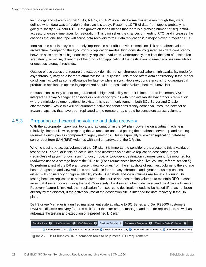
4.5.3 Preparing and executing volume and data recovery With the appropriate hypervisor, tools, and automation in the DR plan, powering on a virtual machine is
relatively simple. Likewise, preparing the volumes for use and getting the database servers up and running
requires a quick process compared to legacy methods. This is especially true when replicating database
server boot from SAN (BFS) volumes with similar hardware at the DR site.
When choosing to access volumes at the DR site, it is important to consider the purpose. Is this a validation
test of the DR plan, or is this an actual declared disaster? As an active replication destination target
(regardless of asynchronous, synchronous, mode, or topology), destination volumes cannot be mounted for
read/write use to a storage host at the DR site. (For circumstances involving Live Volume, refer to section 5).
To perform a test of the DR plan, present view volumes from the snapshots of each test volume to the storage
hosts. Snapshots and view volumes are available for both asynchronous and synchronous replications in
either high consistency or high availability mode. Snapshots and view volumes are beneficial during DR
testing because replication continues between the source and destination volumes to maintain RPO in case
an actual disaster occurs during the test. Conversely, if a disaster is being declared and the Activate Disaster
Recovery feature is invoked, then replication from source to destination needs to be halted (if it has not been
already by the disaster) if the active volume at the destination site is intended for data recovery in the DR
plan.
Dell Storage Manager is a unified management suite available to SC Series and Dell FS8600 customers.
DSM has disaster recovery features built into it that can create, manage, and monitor replications, as well as
automate the testing and execution of a predefined DR plan.
DSM bundles DR automation tools to help meet RTO requirements

Synchronous replication use cases
29 Dell EMC SC Series: Synchronous Replication and Live Volume | CML1064
For virtualization and database use cases alike, DSM is used to create asynchronous or synchronous
replications. These replications predefine the destination volumes that will be presented to storage hosts for
disaster recovery.
Note: Destination replica volumes are for DR purposes only and should not be used actively in a Microsoft or
VMware vSphere Metro Storage Cluster design.
In most cases, predefined destination volumes are data volumes. Where physical hosts are involved, boot
from SAN volumes can also be included in the pre-defined DR plan to quickly and effortlessly recover
physical hosts and applications as opposed to rebuilding and installing applications from scratch. Rebuilding
takes significant time, is error prone, and may require subject matter expert knowledge of platforms,
applications, and the business depending on how well detailed the build process is in the DR plan. Confusion
or errors during test or DR execution lead to high visibility failure. Detailed and current DR documentation
provides clarity at the DR site. Process inconsistency and errors are mitigated by automation or closely
following DR documentation. With these points in mind, the benefit of automating a DR plan with DSM (or a
similar tool) is clear. From the moment a disaster is declared by the business, the RTO is in jeopardy;
automation of tasks saves time and provides process consistency.
Predefining a DR plan in Dell Storage Manager
Once the volumes are prepared and presented manually or automatically by DSM or API scripting, the
process of data recovery continues. For SQL Server and Oracle database servers, databases are attached
and various scripts are run to prepare the database server and applications for production use (such as to
resync login accounts). For VMware vSphere and Hyper-V hosts, VM datastores are now visible to the hosts
and VMs need to be added to the inventory so that they can be allocated as compute and storage resources
by the hypervisor and then powered on.
In Hyper-V 2008 R2, the configuration file for each virtual machine must be generated with the correct number
of processors, memory, network card, and attached virtual machine disk files. This is a process that is
documented or scripted prior to the DR event. Hyper-V 2012/R2 and newer includes a virtual machine import
wizard that is able to import the existing virtual machine configuration located on replicated Dell storage,
rather than generating a new configuration for each VM from scratch. Once the VMs are added to inventory in
Hyper-V 2008 R2 or Hyper-V 2012/R2 and newer, they can be powered on. All versions of VMware vSphere
have the same capability as Hyper-V 2012/R2 and newer in that once datastores are presented to the
vSphere hosts, the datastores can be browsed and the virtual machine configuration file that is located in
each VM folder can be added to inventory and then powered on. A manual DR process, especially in an

Synchronous replication use cases
30 Dell EMC SC Series: Synchronous Replication and Live Volume | CML1064
environment with hundreds or thousands of virtual machines, quickly eats into RTO. The automation of
discovering and adding virtual machines to inventory is covered in the next section.
VMware vSphere Site Recovery Manager is a disaster recovery and planned migration tool for virtual
machines. It bolts onto an existing vSphere environment and leverages Dell Technologies™ certified storage
and array-based replication. Both synchronous and asynchronous replication are supported as well as each
of their native features. Stretched storage with SRM 6.1 is also supported by Live Volume in specific
configurations. With this support, customers can strive for RPOs that are more aggressive and maintain
compatibility with third party automation tools, like SRM, to maintain RTOs in large VMware virtualized
environments.
For vSphere environments, SRM invokes the commands necessary for tasks (such as managing replication,
creating snapshots, creating view volumes, and presenting and removing volumes from vSphere hosts) to be
performed at the storage layer without removing DSM from the architecture. The storage-related commands
from SRM flow to the Storage Replication Adapter (SRA) and then to the DSM server. For this reason, a DSM
Data Collector needs to remain available at the recovery site for the automation to be carried out. Outside of
SRM, in a heterogeneous data center, DSM or API scripting would be needed to carry out the DR automation
for Hyper-V or physical hosts.
Beyond the scope of storage, SRM automates other processes of DR testing, DR recovery, and planned
migrations, making it a major contributor to meeting RTO goals. SRM takes care of important, time-
consuming tasks such as adding virtual machines to inventory at the DR site, modifying TCP/IP address
configurations, VM dependency, power-on order, and reprotection of virtual machines.

Synchronous replication use cases
31 Dell EMC SC Series: Synchronous Replication and Live Volume | CML1064
VMware vSphere Site Recovery Manager and SC Series active/active architecture
The DSM server must be available to perform DR testing or an actual DR cutover for an automated DR
solution involving SC Series storage replication. This means making sure that at least one DSM server
resides at the recovery site so that it can be engaged when needed for DR plan execution. The DSM server
labeled as a physical server in Figure 22 also represents a virtualization candidate if it is already powered on
and not required to automate the recovery of the vSphere infrastructure where it resides.

Synchronous replication use cases
32 Dell EMC SC Series: Synchronous Replication and Live Volume | CML1064
4.5.4 Topologies and modes Replication of data between or within data centers is the fastest, most efficient, and automated method for
moving large amounts of data in order to provide replica data, data protection, and business continuation in
the event of a disaster. This section provides examples of the different topologies and modes available with
synchronous replication in addition to appropriate uses of asynchronous replication.
DR within a campus, standard topology, Fibre Channel replication
Metro DR site, standard topology, Fibre Channel replication
Metro and remote DR sites, mixed topology (1-to-N), Fibre Channel and iSCSI replication

Synchronous replication use cases
33 Dell EMC SC Series: Synchronous Replication and Live Volume | CML1064
Intra campus and metro DR sites, cascade topology, Fibre Channel and iSCSI replication
Intra-campus, metro, and remote DR sites; hybrid topology; Fibre Channel and iSCSI replication
The examples in Figure 26 through Figure 30 serve to represent physical hosts or virtual machines. Some
notable details in the examples are:
• A 1U DSM server is racked at each recovery site to facilitate DR testing and cutover automation
through DSM, VMware Site Recovery Manager, or both. The DSM shown is for logical representation
only. DSM may be a virtual machine.
• SC Series storage supports Fibre Channel and iSCSI-based replication.
• SC Series storage supports asynchronous replication as well as multiple modes of synchronous
replication.
• Either mode of synchronous replication latency will impact production applications relying on the
replication source volume. The infrastructure design should be sized for adequate replication
bandwidth, controllers, and storage at the recovery site to efficiently absorb throughput.
• The examples provide adequate hardware and data center redundancy at the recovery site when
implementing high consistency synchronous replication. Aside from a pause operation, unavailability
of a destination replica volume leads to unavailability of the source volume and will result in a
production application outage.

Live Volume overview
34 Dell EMC SC Series: Synchronous Replication and Live Volume | CML1064
5 Live Volume overview Live Volume is a high availability and data mobility feature for SC Series storage that builds on the Dell Fluid
Data™ architecture. It enables non-disruptive data access, data migration, and stretched volumes between
SC Series arrays. It also provides the storage architecture and automatic failover required for VMware
vSphere Metro Storage Cluster certification (vMSC) with SCOS 6.7 and newer. SCOS 7.1 extended Live
Volume automatic failover (LV-AFO) support to Microsoft Server 2012/Hyper-V 2012 and newer clusters.
5.1 Reference architecture
Live Volume migration
Live Volume is a software-defined high availability solution that is integrated into the SC Series controllers. It
is designed to operate in a production environment that allows storage hosts and applications to remain
operational during planned volume migration or data movement regardless of the geographical distance
between arrays. The automatic failover and restore features available for vSphere Metro Storage Cluster
integration with SCOS 6.7 and newer, and for Microsoft environments with SCOS 7.1 and newer, provides
high availability for applications and services during planned or unplanned events in the data center.
Live Volume increases operational efficiency, eliminates the need for planned storage outages, and enables
planned migrations as well as disaster avoidance and disaster recovery. The Live Volume feature provides
powerful options:
• Allows storage to follow mobile virtual machines and applications in virtualized environments within a
data center, campus, or across larger distances
• Supports automatic or manual mechanisms to migrate virtual machine storage as virtual machines
are migrated within or across hypervisor clusters
• Zero application downtime occurs for planned maintenance outages
• Enables all data to be moved non-disruptively between arrays to achieve full planned or unplanned
site shutdown without downtime
• Provides on-demand load balancing; Live Volume enables data to be relocated as desired to
distribute workload between arrays
• Stretches Microsoft clustered volumes between geographically disperse locations
• Allows VMware vSphere and Microsoft Clusters to see the same disk signature on the volume
between data centers and allows the volume to be clustered across arrays

Live Volume overview
35 Dell EMC SC Series: Synchronous Replication and Live Volume | CML1064
• Supports asynchronous or synchronous replication and included features such as:
- Snapshots
- High consistency and high availability modes
- Mode migration
- DR activation for Live Volume managed replications
• Supports an additional asynchronous or synchronous Live Volume replication to a third array created
and dynamically managed by Live Volume
• Provides automatic or manual Live Volume failover and restore in the event of an unplanned outage
at a primary Live Volume site
• Includes VMware vSphere Metro Storage Cluster (vMSC) certification with SCOS 6.7 and newer
Live Volume is designed to fit into existing physical and virtual environments without disruption or significant
changes to existing configurations or workflow. Physical and virtual servers see a consistent, unchanging
virtual volume. Volume presentation is consistent and transparent before, during, and after migration. The
Live Volume role swap process can be managed automatically or manually and is fully integrated into the
array and Dell Storage Manager. Live Volume operates asynchronously or synchronously and is designed for
application high availability during planned migration, resource balancing, disaster avoidance, and disaster
recovery use cases.
A Live Volume can be created between two SC Series arrays residing in the same data center or between
two well-connected data centers with Fibre Channel or iSCSI replication connectivity.
Using DSM, a Live Volume and an optional Live Volume managed replication can be created from a new
volume, an existing volume, or an existing replication. For more information on creating a Live Volume, see
the appropriate Dell Storage Manager User Guide provided with the DSM software.

Live Volume overview
36 Dell EMC SC Series: Synchronous Replication and Live Volume | CML1064
Creating a replica as a Live Volume
5.2 Proxy data access An SC Series Live Volume is comprised of a pair of replication enabled volumes: a primary Live Volume and
a secondary Live Volume. A Live Volume can be accessed through either array supporting the Live Volume
replication. However, the primary Live Volume role can only be active on one of the available arrays. All read
and write activity for a Live Volume is serviced by the array hosting the primary Live Volume. If a server is
accessing the Live Volume through uniform or non-uniform paths to the secondary Live Volume array, the I/O
is passed through the Fibre Channel or iSCSI replication link to the primary Live Volume system.

Live Volume overview
37 Dell EMC SC Series: Synchronous Replication and Live Volume | CML1064
In Figure 33, a mapped server is accessing a Live Volume by proxy access through the secondary Live
Volume system to the primary Live Volume system. This type of proxy data access requires the replication
link between the two arrays to have enough bandwidth and minimum latency to support the I/O operations
and latency requirements of the application data access.
Proxy data access through the Secondary Live Volume
5.3 Live Volume ALUA The Live Volume Asymmetric Logical Unit Access (ALUA) feature was added in SCOS 7.3 and DSM 2018
following the T10 SCSI-3 specification SPC-3 for Microsoft Windows, Hyper-V, and vSphere operating
systems. The feature is enabled on a per-Live-Volume basis and allows the advertisement of MPIO paths to
the primary Live Volume as optimal and MPIO paths to the secondary Live Volume as non-optimal. When
used in conjunction with an ALUA-supporting Round Robin path selection policy (PSP), optimal paths will be
used for read and write I/O when available while non-optimal paths will be reserved for use in the event no
optimal paths are available. If a Live Volume role wwap or Automatic Failover occurs, the SC Series array will
report the ALUA path state changes to the storage host upon request. The feature effectively allows a Round
Robin PSP to be used with Live Volume in either uniform or non-uniform storage presentations. The Round
Robin PSP is easy to deploy, requires minimal administrative effort and documentation, and yields a good
balance of storage port, fabric, and controller utilization.

Live Volume overview
38 Dell EMC SC Series: Synchronous Replication and Live Volume | CML1064
Uniform Live Volume with ALUA and Round Robin PSP
ALUA can be enabled on Live Volumes when both SC Series arrays are running SCOS 7.3 or newer. For new
Live Volumes, select the Live Volume option to enable Report Non-optimized Paths.
Select Report Non-optimized Paths for the secondary Live Volume

Live Volume overview
39 Dell EMC SC Series: Synchronous Replication and Live Volume | CML1064
For pre-existing Live Volumes, once both SC Series arrays are upgraded to SCOS 7.3, a banner will be
displayed allowing these Live Volumes to upgraded to support ALUA capability.
Banner in DSM 2018 showing Live Volumes can be upgraded for ALUA capability
Dell Storage Manager 2018 provides guidance through the upgrade process. All Live Volumes can be
upgraded, or just a partial subset of Live Volumes can be upgraded if not all storage host operating system
types meet the requirements.
Microsoft Windows, Hyper-V, or vSphere Live Volumes can be upgraded for ALUA capability
The next task in the wizard provides an option to unmap and remap the secondary Live Volume mappings to
the storage host. Depending on the operating system of the storage host, resetting the secondary Live
Volume mappings, or alternatively rebooting the storage host, may be necessary to cleanly pick up the ALUA
state changes on the Live Volume. This is a flexible option available to the administrator performing the
upgrade. Be aware of the impact of either operation. Testing revealed that vSphere hosts require a reboot.
The default action in the workflow is to not reset the secondary server mappings.
Reset the secondary Live Volume mappings or reboot the storage host as necessary

Live Volume overview
40 Dell EMC SC Series: Synchronous Replication and Live Volume | CML1064
After the Live Volume is upgraded for ALUA capability, the last step is to choose whether or not to Report
Non-optimized Paths. The default action is to report non-optimized paths. However, if the storage host
operating system does not support ALUA but there is a desire to upgrade the Live Volume for ALUA support,
this option allows leaving the ALUA feature disabled from the viewpoint of the storage host operating system.
Report Non-optimized Paths option
Live Volumes which were upgraded for ALUA capability or created in SCOS 7.3 and natively have ALUA
capability cannot be downgraded or have their ALUA capability removed. However, the ALUA feature can be
disabled at any time by editing the Live Volume and unchecking the Report Non-Optimized Paths option.
5.4 Live Volume connectivity requirements Live Volume connectivity requirements vary depending on intended use. For example, there are different
requirements for using Live Volume to migrate a workload depending on whether or not the virtual machines
are powered on during the migration.
From the Live Volume perspective and outside of automatic failover with vSphere Metro Storage Cluster or
Microsoft Server/Hyper-V clusters, there are no firm restrictions on bandwidth or latency. However, to proxy
data access from one SC Series array to another requires the Live Volume arrays to be connected through a
high-bandwidth, low-latency replication link. Some operating systems and applications require disk latency
under 10 ms for optimal performance. However, performance impact may not be effectively realized until disk
latency reaches 25 ms or greater. Some applications are more latency sensitive. This means that if average
latency in the primary data center to the storage is 5 ms for the volume and the connection between the two
data centers averages 30 ms of latency, the storage latency writing data to the primary Live Volume from the
secondary Live Volume proxy across the link is probably going to be 35 ms or greater. While this may be
tolerable for some applications, it may not be tolerable for others.
If the Live Volume proxy communication or synchronous replication is utilized, it is strongly recommended to
leverage site-to-site replication connectivity which offers consistent bandwidth and the least amount of
latency. The amount of bandwidth required for the connectivity is highly dependent on the amount of changed
data that requires replication, as well as the amount of other traffic on the same wire. If a site is not planning
to proxy data access between arrays with asynchronous replication, then latency is not as much of a concern.

Live Volume overview
41 Dell EMC SC Series: Synchronous Replication and Live Volume | CML1064
It is recommended to use dedicated VLANs or fabrics to isolate IP-based storage traffic from other types of
general-purpose LAN traffic, especially when spanning data centers. While this is not a requirement for Live
Volume, it is a general best practice for IP-based storage.
For hypervisor virtualization products such as VMware vSphere, Microsoft Hyper-V, and Citrix® XenServer®, a
site must have at least a 1 GB connection with 10 ms or less latency between servers to support VMware
vMotion® Metro or live migration activities. Standard vMotion requires 5 ms or less latency between the
source and destination host.
5.4.1 High bandwidth, low latency For an inter-data-center, campus environment (or within a 60-mile radius as an example), high-speed fiber
connectivity is possible. While inter-data-center and campus environments may be able to run fiber speeds of
up to 16 Gb using Multi-mode fiber connectivity, single-mode fiber connectivity of up to 1 Gb using dark fibre
can assist with connecting data centers together that may be up to 60 miles apart as an example. Minimal
latency is especially key when implementing Live Volume on top of synchronous replication (in either mode).
This type of connectivity is highly recommended for live migrating virtual machine workloads between arrays
and required for synchronous Live Volume with automatic failover used in vSphere Metro Storage Cluster
configurations or Microsoft Windows Server/Hyper-V clusters.
5.4.2 Low bandwidth, high latency If a site is planning on using Live Volume on a low-bandwidth, high-latency replication link, it is recommended
to control swap role activities manually by shutting down the application running at site A, perform a Live
Volume swap role, and then bring the application up at the remote site. This scenario prevents any storage
proxy traffic from going across the link, as well as providing a pause in replication I/O for the link allowing the
replication to catch up so that a Live Volume swap role can occur as quickly as possible. Manual swap role
activities can be controlled by deselecting the Automatically Swap Roles option on the Live Volume
configuration. If the replication connection has characteristics of high latency, asynchronous replication is
recommended for Live Volume so that applications are not adversely impacted by replication latency. Note
that Live Volume automatic failover supports synchronous replication in high availability mode only.

Live Volume overview
42 Dell EMC SC Series: Synchronous Replication and Live Volume | CML1064
5.5 Replication and Live Volume attributes Once a Live Volume is created, additional attributes can be viewed and modified by editing the replication
properties of the Live Volume. To modify the Live Volume settings, select Replication & Live Volumes from
Dell Storage Manager, and select Live Volumes as depicted in Figure 40.
Live Volume settings
5.5.1 Replication Live Volume is built on standard SC Series storage replicated volumes in which each replicated volume can
individually be configured as asynchronous, synchronous high availability, or synchronous high consistency.
Note that Live Volume automatic failover requires synchronous high availability mode. More information about
these attributes can be found throughout this document and in the Dell Storage Manager Administrator’s
Guide.
Type: This refers to asynchronous or synchronous replication.
Sync Mode: If the replication type is synchronous, Sync Mode describes the mode of synchronous replication
that may be either high consistency or high availability. Sync Mode is not displayed for asynchronous Live
Volumes.

Live Volume overview
43 Dell EMC SC Series: Synchronous Replication and Live Volume | CML1064
Sync Status: If the replication type is synchronous, Sync Status describes the current state of the
synchronous replication as Current or Out Of Date. When Sync Status is Current, synchronous replication is
in sync. This means that both the source and destination volumes are consistent and the cumulative latency
to the secondary Live Volume will be observed at the primary Live Volume application. An out-of-date status
indicates that the data on the source and destination volumes is not consistent. Changed or inconsistent data
is tracked in a journal where the primary Live Volume resides until the two volumes are once again Current.
Sync Status is not displayed for asynchronous Live Volumes.
Deduplication: The Deduplication feature replicates only the changed portions of the snapshot history on the
source volume, rather than all data captured in each snapshot. While this is a more processor-intensive
activity, it may reduce the amount of replication traffic and bandwidth required. If sufficient bandwidth is
present on the connection, Dell Storage recommends disabling Deduplication for Live Volumes in order to
preserve controller CPU time for other processes.
Replicate Active Snapshot: It is recommended that Replicate Active Snapshot is enabled for asynchronous
Live Volumes. This ensures that data is replicated in real time as quickly as possible which decreases the
amount of time required to perform a Live Volume Swap role. For Live Volumes configured with either mode
of synchronous replication, the Active Snapshot is effectively replicated in real time providing the replication is
in sync (HA mode) and not paused by an administrator (HA and HC modes).
Replicate Storage to Lower Tier: The Replicate Storage to Lowest Tier feature is automatically enabled for
a new Live Volume. Disable this option to replicate data to tier 1 on the destination array. Many users perform
the initial Live Volume replication to the lowest tier, and then deselect this option once the initial replication
completes. This strategy aids in preserving tier 1 storage capacity, which is useful when using SSD or 15K
drives. For more information on Data Progression with Live Volume, see the section, Data Progression and
Live Volume.
QoS Nodes: A pair of QoS Nodes depicts the desired egress traffic shaping to be applied when replicating
from the primary to the secondary Live Volume. Although labeled a secondary QoS Node, it does not provide
ingress traffic shaping. Instead, it provides egress traffic shaping after a role swap occurs and it becomes the
primary Live Volume. QoS Nodes apply to replication traffic only. The Live Volume proxy traffic between the
arrays is not governed by QoS Nodes. If the link between the Live Volume storage controllers is shared by
other traffic, it may be necessary to throttle the replication traffic using QoS Nodes to prevent it from flooding
the replication link. However, throttling synchronous replication traffic will produce latency for applications
which are dependent on the Live Volume. For this reason, replication links and QoS Nodes should be sized
appropriately taking into account the amount of data per Live Volume, rate of change, application latency
requirements, and any other applications or services that may be sharing the replication link. This is
especially important when using synchronous replication. Note that vSphere Metro Storage Cluster latency
between sites should not exceed 10 ms.
For instance, if a 20 Gbps replication link exists between data centers that is shared by all intra-data-center
traffic, a replication QoS could be set at 10 Gbps and thereby limits the amount of bandwidth used by
replication traffic to half of the pipe capacity. This allows the other non-Live-Volume replication traffic to
receive a reasonable share of the replication pipe, but could cause application latency if synchronous
replication traffic exceeds 1,000 MBps.

Live Volume overview
44 Dell EMC SC Series: Synchronous Replication and Live Volume | CML1064
Editing a Live Volume with QoS nodes
As a best practice, common QoS Nodes should not be shared between a single SC Series source and
multiple SC Series destinations, particularly where Live Volume managed replications are in use. For
instance, if volume A is replicating to volume B synchronously to support a Live Volume and volume A is also
replicating to volume C asynchronously to support a Live Volume managed replication, an independent QoS
Node should be created and used for each of these replications.
5.5.2 Live Volume A Live Volume provides additional attributes that control the behavior of the Live Volume and are listed as
follows:
Swap Roles Automatically: When Swap Roles Automatically is selected, the primary Live Volume will be
automatically swapped to the array serving the most I/O load to that Live Volume as long as it meets the
conditions for a swap. The Live Volume logic gathers I/O samples to determine the primary access to the Live
Volume (from either servers accessing it directly on the primary Live Volume array, or servers accessing from
a secondary Live Volume array). Samples are taken every 30 seconds and automated role-swap decisions

Live Volume overview
45 Dell EMC SC Series: Synchronous Replication and Live Volume | CML1064
are based on the last ten samples (five minutes total). This occurs continuously on the primary Live Volume
array (it does not start once the 30-minute delay timer expires).
The autoswap design is meant to make intelligent decisions on the autoswap movement of Live Volume
primary systems while preventing role swap movement from occurring rapidly back and forth between arrays.
Min Amount Before Swap: This attribute is the amount of data accessed from a secondary system. If there
is light, infrequent access to a Live Volume from a secondary array, consider if this makes sense to move the
primary to that system. If so, set this value to a very small value. The criteria for this aspect are defined by the
Min Amount Before Swap attribute for the Live Volume. The value specifies an amount equal to the read/write
access divided by the second-per-sample value. If a sample shows that the secondary array access exceeds
this value, this sample/aspect has been satisfied.
Min Secondary Percent Before Swap: This is the percentage of total access of a Live Volume from the
secondary array on a per-sample basis. The criteria for this aspect are defined by the Min Secondary Percent
for Swap attribute for the Live Volume. If a sample shows the secondary array accessed the Live Volume
more than the defined setting for this aspect, this sample/aspect has been satisfied. The default setting for
this option is 60%. The SC Series array takes samples every 30 seconds and keeps the most recent ten
samples (five minutes total) for analysis. This means that the secondary Live Volume has to have more I/O
than the primary system for six out of ten samples (60%).
Min Time As Primary Before Swap: Each Live Volume has a TimeAsPrimary timer (default setting of 30
minutes) that will prohibit an autoswap from occurring after a role swap has completed. This means that
following a role swap of a Live Volume (either auto or user specified), the SC Series array waits the specified
amount of time before analyzing data for autoswap conditions to be met again. The purpose of this is to
prevent thrashing of autoswap in environments where the primary access point could be dynamic or where a
Live Volume is shared by applications that can be running on servers both at the primary and secondary sites.
Failover Automatically: This indicates whether or not the Live Volume is configured to automatically fail over
and remain available if there is an unplanned outage of the primary Live Volume.
ALUA Optimized: This specifies whether the Live Volume is capable of supporting ALUA Non-Optimized
path reporting. All new Live Volumes created between SC Series arrays running SCOS 7.3 or newer will
automatically be ALUA Optimized. Live Volumes created on SC Series arrays with SCOS 7.2 or earlier can
be updated to be ALUA Optimized once both arrays are running SCOS 7.3 or newer. Live Volumes running
on SCOS 7.2 or earlier will not be ALUA Optimized. Live Volumes which are not ALUA Optimized will report
an Optimal path status for all paths to both the primary and secondary Live Volume.
Report Non-Optimized Paths: This indicates whether or not the Live Volume is configured to report Non-
Optimized paths to the secondary Live Volume (enabled by default). This feature is used in conjunction with
uniform storage presentation and a Round Robin path selection policy where optimal MPIO paths will be
preferred over non-optimal paths for I/O when both types are available. Live Volumes must be ALUA
Optimized and the box must be checked in the Live Volume settings in order to report Non-Optimized paths to
the secondary Live Volume.

Data Progression and Live Volume
46 Dell EMC SC Series: Synchronous Replication and Live Volume | CML1064
6 Data Progression and Live Volume Data Progression lifecycles are storage profiles that are managed independently on each SC Series array
configured with Live Volume. If a Live Volume is not replicated to the lowest tier on the destination array, data
ingestion follows the volume-based storage profile. The Data Progression lifecycle on the destination array
then moves data based on the destination storage profile. If a Live Volume is replicated to the lowest tier on
the destination array, data ingestion occurs in the lowest tier of storage. The Data Progression lifecycle on the
destination array then moves data based on the destination storage profile.
6.1 Primary and secondary Live Volume If a primary Live Volume is located on volume A and is not being replicated to the lowest tier on the
destination volume B, the data will progress down on the destination array to the next tier or RAID level every
12 days. This is because the data on the destination array is never actually being read. All reads take place
on the primary Live Volume array.
For instance, if an array has two tiers of storage and the storage profiles write data at RAID 10 on tier 1,
snapshot data at tier 1 is at RAID 5, and tier 3 is at RAID 5. The blocks of data that were written during the
day will progress from tier 1, RAID 10 to tier 1, RAID 5 on the first night.
If a primary Live Volume is frequently swapped between the Live Volume arrays, then the Data Progression
pattern will be determined by how often the data is accessed on both systems.

Live Volume and MPIO
47 Dell EMC SC Series: Synchronous Replication and Live Volume | CML1064
7 Live Volume and MPIO By using Live Volume with a storage host that has access to both SC Series arrays in a Live Volume
configuration, multiple paths can be presented to the server across the arrays. All read and write I/O
ultimately flows to the primary Live Volume. Read and write I/O sent down paths to the primary Live Volume
are handled directly. Read and write I/O sent down paths to the secondary Live Volume are proxied to the
primary Live Volume via replication ports. Acknowledgements and read payloads are then sent back over the
replication ports, through the secondary Live Volume, and back down the originating path to the storage host.
ALUA requires special consideration to understand and optimize I/O paths for the Live Volume.
Note: Live Volume ALUA support was added in SCOS 7.3 for VMware vSphere and Microsoft Windows
operating systems only.
7.1 MPIO policies for Live Volume For Live Volume arrays where a server has volume access through both the primary and secondary Live
Volume controllers (uniform storage presentation), it may be desirable to configure the MPIO policy to prevent
primary data access through the secondary Live Volume array. Instead, these paths would be reserved for
use as failover paths. Examples of these types of MPIO policies are Failover Only or Fixed. Use cases
include asynchronous replication link slowness or a QoS node that adds too much latency to proxied traffic.
A Round Robin MPIO policy may also be used with Live Volume. There may be slight deviations based on the
storage host, but in general, with the ALUA support added in SCOS 7.3, Round Robin utilizes all available
optimal paths to a device. MPIO paths leading to the primary Live Volume are advertised by the SC Series
array as optimal. In the event optimal paths are not available, Round Robin will then utilize non-optimal paths
that are available. MPIO paths leading to the secondary Live Volume are advertised by the SC Series array
as non-optimal.
Standalone servers or clustered servers accessing shared storage may use uniform storage presentation.
Uniform storage presentation provides host to Live Volume storage paths through both arrays. With the Live
Volume ALUA feature enabled, a Round Robin path selection policy can quickly and easily be configured with
uniform storage presentation. With the ALUA intelligence built into both the storage host and the arrays,
optimal MPIO paths will be used for I/O and the storage fabric will be both well utilized and well balanced.
For non-vSphere or Microsoft storage hosts in a uniform Live Volume configuration, all MPIO paths will be
reported as optimal. When using a Round Robin path selection policy, half of the I/O will go through the
primary Live Volume and the other half with be proxied through the replication link through the secondary Live
Volume. This may or may not be a good design choice. Also, the automatic role swap feature will not be able
to make an accurate determination of where the primary Live Volume should be, and the feature will be
ineffective if enabled.
Clustered servers accessing shared storage may also use non-uniform storage presentation. Non-uniform
means that each cluster node will access a Live Volume through one array or the other, but not both. Non-
uniform typically applies to a stretched cluster configuration where each node in the cluster accesses the Live
Volume through paths that are local in fabric proximity only. Each cluster node would have read/write access
to either the primary or the secondary Live Volume, but not both simultaneously. For the cluster nodes which
have access to the primary Live Volume, their front-end I/O will remain local in proximity. For the cluster
nodes which have access to the secondary Live Volume, their front-end I/O will be proxied to the primary Live
Volume through the replication link. Implementing Round Robin with non-uniform presentation is typically
preferred to provide automated port and fabric balancing, but fixed paths may also be used. Automatic role

Live Volume and MPIO
48 Dell EMC SC Series: Synchronous Replication and Live Volume | CML1064
swap would be preferred with non-uniform storage presentation so that a role swap will automatically follow
the vMotion of virtual machines between sites.
Regardless of storage presentation, MPIO path selection, and role swap policies, synchronous replication
latency between arrays will impact applications. Additional information on configuring Live Volume MPIO can
be found in each of the application-specific sections of this document, such as VMware vSphere (section 8),
Microsoft Windows/Hyper-V (section 9), and Linux/Unix (section 10).

VMware vSphere and Live Volume
49 Dell EMC SC Series: Synchronous Replication and Live Volume | CML1064
8 VMware vSphere and Live Volume When vSphere and Live Volume combine, they can provide VMware-certified, large-scale application and
service mobility, high availability, planned maintenance, resource balancing, disaster avoidance, and disaster
recovery options for virtual environments.
8.1 Path Selection Policies (PSP) vSphere ships with three MPIO path selection policies (PSP): Fixed, Round Robin, and Most Recently
Used (MRU is not tested and should not be used with SC Series storage). The best path selection policy to
choose with Live Volume depends on uniform or non-uniform storage presentation, available ALUA support,
replication type, latency between sites or arrays, and customer preference. Round Robin is largely the easiest
PSP to configure and provides both optimal I/O performance and balance of the storage fabric in uniform
storage presentations with ALUA support or non-uniform storage presentation with or without ALUA support.
8.2 Round Robin with Live Volume ALUA Figure 42 depicts a Round Robin policy with a uniformly presented Live Volume between two SC Series
arrays with the ALUA feature (introduced in SCOS 7.3). Read and write I/O will follow the Round Robin policy,
taking optimal paths directly to the primary Live Volume, shown as Active (I/O), in a uniform Live Volume
storage presentation. Non-optimal paths lead to the secondary Live Volume and will be reserved for use in
the event all optimal paths to the primary Live Volume become unavailable. In the event of a Live Volume role
swap, the non-optimal paths reported by the SC Series array become optimal, and the optimal paths become
non-optimal.
Round Robin policy

VMware vSphere and Live Volume
50 Dell EMC SC Series: Synchronous Replication and Live Volume | CML1064
Note: ALUA information used by the Round Robin PSP for a device can also be viewed using esxcli as
shown in the following example. TPG_state identifies the active/optimal and active/non-optimal ALUA state
for each target port group. Working Paths identifies each active/optimal path for Round Robin as derived
from the target port groups.
[root@s1212:~] esxcli storage nmp device list -d
naa.6000d31000ed1f000000000000000015
naa.6000d31000ed1f000000000000000015
Device Display Name: COMPELNT Fibre Channel Disk
(naa.6000d31000ed1f000000000000000015)
Storage Array Type: VMW_SATP_ALUA
Storage Array Type Device Config: {implicit_support=on; explicit_support=off;
explicit_allow=on; alua_followover=on; action_OnRetryErrors=off;
{TPG_id=61480,TPG_state=ANO}{TPG_id=61731,TPG_state=AO}{TPG_id=61735,TPG_state=A
O}{TPG_id=61732,TPG_state=AO}{TPG_id=61475,TPG_state=ANO}{TPG_id=61736,TPG_state
=AO}{TPG_id=61479,TPG_state=ANO}{TPG_id=61476,TPG_state=ANO}}
Path Selection Policy: VMW_PSP_RR
Path Selection Policy Device Config:
{policy=rr,iops=1000,bytes=10485760,useANO=0; lastPathIndex=6:
NumIOsPending=0,numBytesPending=0}
Path Selection Policy Device Custom Config:
Working Paths: vmhba3:C0:T15:L1, vmhba2:C0:T15:L1, vmhba3:C0:T14:L1,
vmhba2:C0:T14:L1
Is USB: false
If a Live Volume role swap occurs, the SC Series array is designed to report the ALUA path state changes to
the vSphere host using the following process (according to the T10 SCSI-3 specification SPC-3):
1. A Live Volume role swap occurs between optimal and non-optimal paths.
2. The vSphere hosts send Round Robin I/O to what is now the secondary Live Volume through non-
optimal paths.
3. The SC Series array fails the I/O with a Unit Attention Check Condition.
4. The vSphere host requests Report Target Port Groups.
5. The SC Series array responds with new ALUA state changes.
6. vSphere begins Round Robin I/O over new optimal paths.
Note: The Unit Attention Check Condition can be observed in /var/log/vmkernel.log in the following
example. For more information, see the VMware KB article, Interpreting SCSI sense codes in VMware ESXi
and ESX (289902).
2018-02-28T16:59:02.589Z cpu18:66287)NMP: nmp_ThrottleLogForDevice:3617: Cmd
0x28 (0x439500e6bdc0, 111979) to dev "naa.6000d31000ed1f000000000000000015" on
path "vmhba3:C0:T15:L1" Failed: H:0x0 D:0x2 P:0x0 Valid sense data: 0x6 0x2a
0x6. Act:FAILOVER
During extensive testing, it was discovered that vSphere did not consistently or reliably begin using the new
optimal primary Live Volume paths immediately after a role swap as designed. Instead, up to five minutes
elapsed before vSphere recognized the ALUA path state change. This means that vSphere may continue to
follow the Round Robin policy over the non-optimal paths to the secondary Live Volume for up to five minutes.
Dell Technologies is working with VMware to understand this behavior.

VMware vSphere and Live Volume
51 Dell EMC SC Series: Synchronous Replication and Live Volume | CML1064
For customers concerned about this behavior occurring in their environments, there are two workarounds:
• After the Live Volume role swap, perform a vSphere storage rescan.
• Reduce the vSphere host advanced setting Disk.PathEvalTime from the default of 300 seconds
down to an acceptable automatic storage rescan interval. This would need to be performed on each
vSphere host the Live Volume is mapped to.
Example: Reducing the Disk.PathEvalTime setting to 30 seconds on a vSphere host

VMware vSphere and Live Volume
52 Dell EMC SC Series: Synchronous Replication and Live Volume | CML1064
8.3 Fixed The Fixed PSP may be desirable when a preferred path on the storage fabric should be used. The Fixed PSP
may also be useful in a uniform Live Volume storage presentation, if the ALUA feature (added in SCOS 7.3) is
not yet available, in order to avoid sending read and write I/O down a non-optimal path to the secondary Live
Volume. As shown in Figure 44, the MPIO policy on the vSphere host should be set to Fixed with the
preferred path leading to the primary Live Volume. Using the Fixed PSP generally requires more
administrative effort to implement, maintain, and document.
Fixed policy
8.4 Single-site MPIO configuration In a single-site or uniform configuration, vSphere hosts may be zoned to both arrays. If a Live Volume is
mapped over both arrays to the vSphere hosts, the volume can participate in an MPIO configuration involving
both arrays. In a Live Volume configuration, the optimal I/O path is through the primary Live Volume. In this
scenario, using the vSphere Round Robin MPIO policy in conjunction with the Live Volume ALUA feature
ensures I/O traffic goes through the primary Live Volume array. This is a preferred configuration because it
requires minimal administrative effort and yields a well-balanced fabric.
Alternatively, the vSphere Fixed MPIO policy with preferred path can be used to ensure front-end I/O traffic is
going through the primary Live Volume array. In the event a Live Volume role swap occurs, the preferred path
will need to be updated on each vSphere host to point to an optimal primary Live Volume path. This is where
additional administrative effort is involved to maintain a well-balanced fabric.

VMware vSphere and Live Volume
53 Dell EMC SC Series: Synchronous Replication and Live Volume | CML1064
As depicted in Figure 45, a Live Volume replication exists between SC Series A and SC Series B. Two
vSphere hosts are mapped to the Live Volume on each array. The Primary Live Volume is located on SC
Series A, and the Fixed preferred path (Figure 44) on each vSphere host is configured to use a path to SC
Series A as the preferred path.
Uniform Live Volume replication
If planned downtime will impact SC Series A, the preferred path for the vSphere hosts could be configured for
SC Series B. When the Live Volume is configured for automatic role swap, this change in preferred paths will
trigger the Live Volume to swap roles making SC Series B the Primary Live Volume controller, allowing SC
Series A to be taken offline without a disruption to virtual machines on that Live Volume.
8.5 Multi-site MPIO configuration In a multi-site or non-uniform stretched cluster configuration, each vSphere host is zoned and mapped only to
its local corresponding array (see Figure 46).
Non-uniform multi-site MPIO configuration

VMware vSphere and Live Volume
54 Dell EMC SC Series: Synchronous Replication and Live Volume | CML1064
In this configuration, the MPIO policy for the primary Live Volume can be configured as either Round Robin
(preferred) or Fixed. Enabling Live Volume automatic role swap would be optimal in this configuration where
vMotion is used to migrate virtual machines between sites (for example, from Site A to Site B). After the
vMotion occurs, read and write I/O stemming from VMware Host B to the secondary Live Volume is proxied to
the Primary Live Volume controller through the asynchronous or synchronous replication link(s) between the
arrays. Automatic role swap allows SC Series storage to optimize the I/O after vMotion so that all or the
majority is flowing through the primary Live Volume.
Multiple sites and stretched clusters may also be configured with uniform storage presentation. For more
information on vMSC storage presentation, see section 8.9.
8.6 VMware vMotion and Live Volume In a non-uniform storage presentation model, one method of controlling the location of the primary Live
Volume is to use vMotion and configure Live Volume automatic role swap (see Figure 46). vSphere Host A is
mapped to SC Series A and vSphere Host B is mapped to SC Series B. When a virtual machine running on a
Live Volume is migrated from Host A to Host B, Live Volume with automatic role swap observes that the
storage access has shifted from SC Series A to SC Series B. The SC Series array automatically swaps the
Secondary Live Volume to become the Primary Live Volume. Once this occurs, the virtual machine disk I/O
traverses a local path to the Primary Live Volume on SC Series B (using the Fixed or Round Robin MPIO
policy) instead of going through the Secondary Live Volume proxy across the replication link. The result
evades an inevitably higher cost in terms of increased latency. For stretched clusters or data centers,
consider the vMotion and Metro vMotion latency requirements between hosts. vMotion requires a round-trip
latency of 5 ms or less between hosts on the vMotion network. vSphere Metro Storage Cluster boosts the
allowable round-trip latency from 5 ms to 10 ms on the vMotion network between sites.
8.7 vSphere Metro Storage Cluster vSphere Metro Storage Cluster (vMSC) is a specific VMware-certified design and is an implementation of
vSphere, compute, storage, and network infrastructure. The design is typically a stretched cluster
configuration over varying distances to provide high availability for virtualized workloads. This is achieved
through continuous availability of compute and storage resources provided by a combination of hardware
redundancy and automatic failover capabilities built into the vSphere hypervisor and the SC Series Live
Volume architecture. With the configuration of the Live Volume automatic failover feature, and by meeting
other solution requirements, SC Series storage is certified by VMware in supporting vSphere Metro Storage
Cluster in uniform, non-uniform, Fibre Channel, and iSCSI designs.

VMware vSphere and Live Volume
55 Dell EMC SC Series: Synchronous Replication and Live Volume | CML1064
8.8 Live Volume automatic failover Configuring Live Volume for synchronous high availability replication and automatic failover (Figure 47) is a
key requirement for vMetro Storage Cluster deployments. Live Volume and replication may be configured on
a per-volume basis using the SC Series vSphere web client plug-in or DSM. The Failover Automatically
feature for Live Volume is configured using DSM. Live Volume automatic failover is supported with VMware
vSphere 5.5 or newer VMFS datastores and virtual mode RDMs, with support for physical mode RDMs added
with the release of SCOS 7.1.
Live Volume configured with Synchronous, High Availability, and Failover Automatically enabled
8.9 vMSC storage presentation vSphere Metro Storage Cluster supports uniform or non-uniform storage presentation and fabric designs.
Within the vMSC entity, one presentation model should be implemented consistently for all vSphere hosts in
the stretched cluster. Mixing storage presentation models within a stretched cluster is not recommended. It
may work but it has not been formally or thoroughly tested.

VMware vSphere and Live Volume
56 Dell EMC SC Series: Synchronous Replication and Live Volume | CML1064
8.9.1 vMSC uniform storage presentation Uniform presentation (Figure 48) tends to be a more common design, which provides host-to-Live-Volume
storage paths through both arrays. This means that half of the I/O will go through the primary Live Volume
and the other half with be proxied through the replication link through the secondary Live Volume. Uniform
presentation helps provide a better level of uptime for virtual machines if Live Volume automatic failover
occurs because of an unplanned storage or fabric outage. Automatic role swap may or may not disabled
when using the Round Robin PSP in conjunction with uniform storage presentation.
© VMware, Inc.
Tiebreakersite
vSphere Stretched Cluster
Site 1 Site 2
Synchronous HighAvailability replication
Live VolumeVMFS datastores or RDM
TCP/IPTCP/IP
Primary Secondary
Fibre Channelor iSCSI
Fibre Channelor iSCSI
Fibre Channelor iSCSI
SC Series array
SC Series array
High Availability
PrimarySecondary
Uniform
vMSC uniform storage presentation

VMware vSphere and Live Volume
57 Dell EMC SC Series: Synchronous Replication and Live Volume | CML1064
8.9.2 vMSC non-uniform storage presentation Non-uniform means that each vSphere Metro Storage Cluster host will access a Live Volume through one
array or the other, but not both. Each cluster node has read/write access to either the primary or the
secondary Live Volume, but not both simultaneously. For the cluster nodes with access to the primary Live
Volume, their front-end I/O remains local in proximity. For the cluster nodes with access to the secondary Live
Volume, their front-end I/O is proxied to the primary Live Volume using the replication link. Implementing
Round Robin with non-uniform presentation is typically preferred to provide automated port and fabric balance
but fixed paths may also be used. Automatic role swap would be preferred with non-uniform storage
presentation so that a role swap will automatically follow the vMotion of virtual machines between sites.
© VMware, Inc.
Tiebreakersite
vSphere Stretched Cluster
Site 1 Site 2
Live VolumeVMFS datastores or RDM
TCP/IPTCP/IP
Fibre Channelor iSCSI
Fibre Channelor iSCSI
Fibre Channelor iSCSI
SC Series array
SC Series array
High Availability
Primary Secondary
PrimarySecondary
Non-uniform
Synchronous HighAvailability replication
vMSC non-uniform storage presentation

VMware vSphere and Live Volume
58 Dell EMC SC Series: Synchronous Replication and Live Volume | CML1064
8.10 Tiebreaker service A tiebreaker service is built into the Dell Storage Manager Data Collector as well as the Remote Data
Collector, and acts as a quorum to facilitate Live Volume automatic failover. It also plays an important role in
preventing split-brain conditions should a network or fabric partition between arrays occur. The tiebreaker
should be located at a site physically independent of arrays participating in a Metro Cluster. This may be in a
customer-owned data center or public cloud. Although tiebreaker availability is not required for Live Volume
I/O during healthy operating conditions, the tiebreaker service is required to act on unplanned Live Volume
component outages (typically, the result is automatic failover but this is not always the case) and network
latency to the tiebreaker from each array must not exceed 200 ms RTT.
8.11 Common automatic failover scenarios The following sections outline failure scenarios and the resulting Live Volume automatic failover behavior.
These are scenarios commonly asked about by customers, not necessarily scenarios that are likely to
commonly occur.
8.11.1 Primary Live Volume array failure If an unplanned event impacts an SC Series array that is hosting a primary Live Volume, Live Volume
availability is automatically failed over to the surviving array.
Primary Live Volume failure

VMware vSphere and Live Volume
59 Dell EMC SC Series: Synchronous Replication and Live Volume | CML1064
8.11.2 Secondary Live Volume array failure If an unplanned event impacts an SC Series array hosting a secondary Live Volume, the primary Live Volume
remains available on the surviving array.
Secondary Live Volume failure
8.11.3 Replication network partition If an unplanned event impacts the replication link between SC Series arrays, the primary Live Volume will
continue to remain available serving I/O and no automatic failover will occur. The secondary Live Volume will
be unable to proxy I/O requests to the primary Live Volume while the replication link is down.
Replication link failure

VMware vSphere and Live Volume
60 Dell EMC SC Series: Synchronous Replication and Live Volume | CML1064
8.11.4 SC Series back-end outage If an unplanned event impacts primary Live Volume back-end SC Series components (such as the loss of
several drives or a drive shelf), the primary Live Volume will automatically fail over to the surviving array. Both
arrays will continue to service I/O requests from the primary Live Volume locally and remotely through the
replication link.
Primary back-end failure
8.11.5 Tiebreaker failure If an unplanned event impacts the availability of the tiebreaker service on the DSM server, both SC Series
arrays will continue to service I/O requests but no automatic failover can occur during this time.
Tiebreaker failure
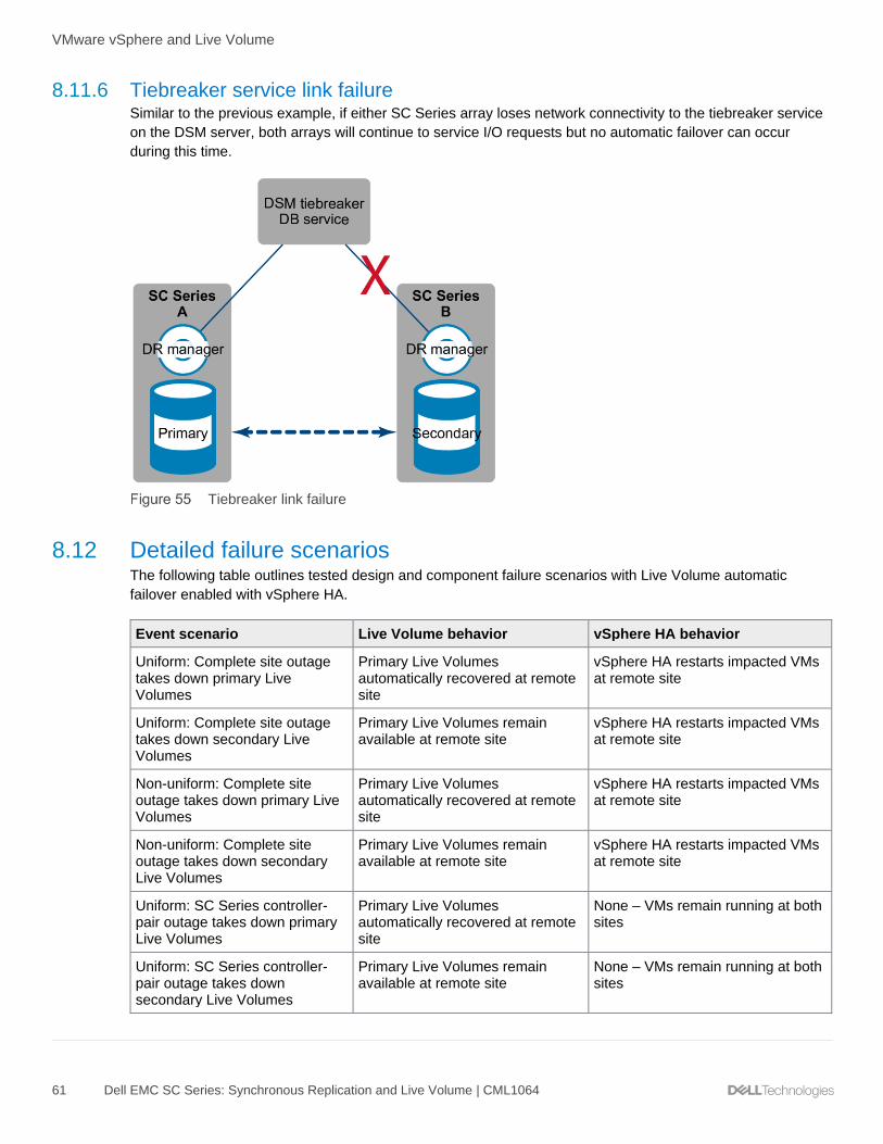
VMware vSphere and Live Volume
61 Dell EMC SC Series: Synchronous Replication and Live Volume | CML1064
8.11.6 Tiebreaker service link failure Similar to the previous example, if either SC Series array loses network connectivity to the tiebreaker service
on the DSM server, both arrays will continue to service I/O requests but no automatic failover can occur
during this time.
Tiebreaker link failure
8.12 Detailed failure scenarios The following table outlines tested design and component failure scenarios with Live Volume automatic
failover enabled with vSphere HA.
Event scenario Live Volume behavior vSphere HA behavior
Uniform: Complete site outage takes down primary Live Volumes
Primary Live Volumes automatically recovered at remote site
vSphere HA restarts impacted VMs at remote site
Uniform: Complete site outage takes down secondary Live Volumes
Primary Live Volumes remain available at remote site
vSphere HA restarts impacted VMs at remote site
Non-uniform: Complete site outage takes down primary Live Volumes
Primary Live Volumes automatically recovered at remote site
vSphere HA restarts impacted VMs at remote site
Non-uniform: Complete site outage takes down secondary Live Volumes
Primary Live Volumes remain available at remote site
vSphere HA restarts impacted VMs at remote site
Uniform: SC Series controller-pair outage takes down primary Live Volumes
Primary Live Volumes automatically recovered at remote site
None – VMs remain running at both sites
Uniform: SC Series controller-pair outage takes down secondary Live Volumes
Primary Live Volumes remain available at remote site
None – VMs remain running at both sites

VMware vSphere and Live Volume
62 Dell EMC SC Series: Synchronous Replication and Live Volume | CML1064
Event scenario Live Volume behavior vSphere HA behavior
Non-uniform: SC Series controller-pair outage takes down primary Live Volumes
Primary Live Volumes automatically recovered at remote site
vSphere HA restarts impacted VMs at remote site
Non-uniform: SC Series controller-pair outage takes down secondary Live Volumes
Primary Live Volumes remain available at remote site
vSphere HA restarts impacted VMs at remote site
Uniform: SC Series back-end outage (such as loss of drive enclosure or multiple drives) takes down primary Live Volumes
Primary Live Volumes automatically recovered at remote site
SC Series continues to provide Live Volume access from both arrays
None – VMs remain running at both sites
Uniform: SC Series back-end outage (such as loss of drive enclosure or multiple drives) takes down secondary Live Volumes
Primary Live Volumes remain available at remote site
SC Series continues to provide Live Volume access from both arrays
None – VMs remain running at both sites
Non-uniform: SC Series-back end outage (such as loss of drive enclosure or multiple drives) takes down primary Live Volumes
Primary Live Volumes automatically recovered at remote site
SC Series continues to provide Live Volume access from both arrays
None – VMs remain running at both sites
Non-uniform: SC Series back-end outage (such as loss of drive enclosure or multiple drives) takes down secondary Live Volumes
Primary Live Volumes remain available at remote site
SC Series continues to provide Live Volume access from both arrays
None – VMs remain running at both sites
Uniform: Replication link failure between sites
No automatic failover
Primary Live Volumes remain available
Secondary Live Volumes go offline
None – VMs remain running at both sites
Non-uniform: Replication link failure between sites
No auto failover
Primary Live Volumes remain available
Secondary Live Volumes go offline
VMs which were running on primary Live Volumes: None – VMs remain running
VMs which were running on secondary Live Volumes: vSphere HA restarts VMs at remote site

VMware vSphere and Live Volume
63 Dell EMC SC Series: Synchronous Replication and Live Volume | CML1064
Event scenario Live Volume behavior vSphere HA behavior
Tiebreaker service failure No automatic failover
Primary Live Volumes remain available
Secondary Live Volumes remain available
None – VMs remain running at both sites
Tiebreaker service network isolated from either or both array sites
No auto failover
Primary Live Volumes remain available
Secondary Live Volumes remain available
None – VMs remain running at both sites
8.13 Live Volume automatic restore Live Volumes configured for automatic failover are also be configured for automatic restore by default (Figure
56). If Live Volume Automatic Failover has occurred and the impacted array and data center infrastructure is
subsequently recovered and brought back online, the Restore Automatically feature will repair Live Volumes
by replicating changed data back to the impacted site (leveraging the built-in minimal recopy feature) and then
bring the failed Live Volume back online as a secondary. The Restore Automatically feature is configured on a
per-Live-Volume basis through Dell Storage Manager and it is recommended to leave this enabled for the
purposes of automation, consistency, efficiency, and high availability of consistent data.

VMware vSphere and Live Volume
64 Dell EMC SC Series: Synchronous Replication and Live Volume | CML1064
Live Volume configured with Restore Automatically enabled
8.14 VMware DRS/HA and Live Volume VMware Distributed Resource Scheduler (DRS) is a cluster-centric configuration that uses VMware vSphere
vMotion® to automatically move virtual-machine compute resources to other nodes in a cluster. This is
performed without local, metro, or stretched-site awareness. In addition, vSphere is unaware of storage
virtualization that occurs in Live Volume. When Live Volume is configured with a vSphere stretched cluster, it
is a best practice to keep virtual machines running at the same site as their primary Live Volumes.
Additionally, it is recommended to keep virtual machines that share a common Live Volume datastore
together at the same site. This ensures that compute and storage resources remain local to the vSphere host
running the virtual machine(s). If DRS is activated on a vSphere cluster with nodes in each site, DRS could
automatically move some of the virtual machines running on a Live Volume datastore to a host that resides in
the other data center.
In vSphere 4.1 and later, DRS host groups and VM groups can be used to benefit a vSphere Metro Storage
Cluster environment.

VMware vSphere and Live Volume
65 Dell EMC SC Series: Synchronous Replication and Live Volume | CML1064
• VM groups: Virtual machines that share a common Live Volume datastore can be placed into VM
groups. Movement of virtual machines and management of their respective Live Volume datastore,
can then be performed at a containerized-group level rather than at an individual virtual-machine
level.
• Host groups: Hosts that share a common site can be placed into host groups. Once the host groups
are configured, they can represent locality for the primary Live Volume.
VM groups can be assigned to host groups using the DRS Groups Manager. This will ensure all virtual
machines that share a common Live Volume datastore are consistently running from the same datastore. The
virtual machines can be vMotioned as a group from one site to another. After a polling threshold is met, SC
Series storage can perform an automatic role swap of the primary Live Volume datastore to the site where the
VMs were migrated. The infrastructure can also be designed with separate DRS-enabled clusters existing at
both sites, keeping automatic migration of virtual machines within the respective site where the primary Live
Volume resides. In the event of a Live Volume role swap, all virtual machines associated with the Live Volume
can be vMotioned from the site A cluster to the site B cluster.
vSphere High Availability (HA) is also a cluster-centric configuration. In the event of a host or storage failure,
HA will attempt to restart virtual machines on a host candidate within the same cluster that may be local or
stretched in a vMSC deployment. In a non-uniform storage configuration, if an outage impacts primary Live
Volume availability and Live Volume automatic failover occurs, vSphere HA can be configured to restart
impacted virtual machines on the surviving array.
Live Volume data access in a non-uniform vSphere environment

VMware vSphere and Live Volume
66 Dell EMC SC Series: Synchronous Replication and Live Volume | CML1064
The following vSphere advanced tuning should be configured for non-uniform stretched cluster configurations.
This tuning allows HA to power off and migrate virtual machines during storage-related availability events
after the primary Live Volume becomes available again using the Preserve Live Volume or Live Volume
Failover Automatically feature.
Note: The Live Volume Failover Automatically feature is only supported with vSphere 5.5 and newer.
Set one of the following, depending on the vSphere version:
• vSphere 5.0u1+/5.1: Disk.terminateVMOnPDLDefault = True (/etc/vmware/settings file on each host)
or
• vSphere 5.5+: VMkernel.Boot.terminateVMOnPDL = yes (advanced setting on each host, reboot
required)
And set one of the following, depending on the vSphere version:
• vSphere 5.5: Disk.AutoremoveOnPDL = 0 (VMware-recommended non-default advanced setting on
each host)
or
• vSphere 6.0+: Disk.AutoremoveOnPDL = 1 (VMware-recommended default advanced setting on
each host)
And set the following, regardless of the vSphere version:
• vSphere 5.0u1+: das.maskCleanShutdownEnabled = True (Cluster advanced options)
Configuring HA to restart VMs impacted by a non-uniform storage outage was improved in vSphere 6. In
addition to supporting HA restart for Permanent Device Loss (PDL) events, HA restart can also react to All-
Paths-Down (APD) events. The tuning becomes easier and more intuitive using the Web Client or HTML5
client in newer versions of vSphere.
1. It is recommended to configure VM Component Protection for PDL and APD events. For PDL events,
select Power off and restart VMs. For APD events, VMware recommends selecting Power off and
restart VMs (conservative). For the advanced APD settings, refer to VMware documentation or the
VMware vSphere Metro Storage Cluster Recommended Practices available on the VMware
Documentation site.

VMware vSphere and Live Volume
67 Dell EMC SC Series: Synchronous Replication and Live Volume | CML1064
Configuring vSphere HA for PDL and APD conditions
The Disk.AutoremoveOnPDL advanced setting is not configurable in VMCP and should remain at its default
value of 1 for each vSphere 6 host in the cluster. For more information on the Disk.AutoremoveOnPDL
feature, refer to VMware KB article 2059622, PDL AutoRemove feature in vSphere 5.5 and vSphere 6.0.
In a non-uniform configuration, if an outage impacts primary Live Volume availability and Live Volume
automatic failover cannot occur, vSphere HA will not be able to immediately restart impacted virtual
machines.
If the VMware virtual infrastructure is version 4.0 or earlier, vSphere Metro Storage Cluster is not supported
and other steps should be taken to prevent virtual machines from unexpectedly running from the secondary
Live Volume. An individual VM or group of VMs may be associated with a DRS rule that keeps them together
but this does not guarantee they will stay over a period of time on the same host or group of hosts where the
primary Live Volume is located. As a last resort, DRS can be configured for manual mode or disabled when
using Live Volume in a multi-site configuration that will prevent the automatic migration of VMs to Secondary
Live Volume hosts in the same cluster.
VMware vSphere monitors SCSI sense codes sent by an array to determine if a device is in a PDL state.
These SCSI sense codes are outlined in VMware KB article 2004684, Permanent Device Loss (PDL) and All-
Paths-Down (APD) in vSphere 5.x and 6.x. SC Series storage supports two SCSI sense codes (see Table 1)
which will be sent to vSphere hosts when a PDL condition is met.
SCSI sense codes
SCSI sense code Description
H:0x0 D:0x2 P:0x0 Valid sense data: 0x4 0x3e 0x1 LOGICAL UNIT FAILURE
H:0x0 D:0x2 P:0x0 Valid sense data: 0x5 0x25 0x0 LOGICAL UNIT NOT SUPPORTED
8.15 vSphere Metro Storage Cluster and Live Volume Requirements A vSphere Metro Storage Cluster (vMSC) design with Live Volume requires the following:
• Dell SCOS 6.7 or newer with both SC Series arrays having the same firmware version
• Dell Storage Manager 2015 R2 or newer with tiebreaker service located at a site physically
independent of SC Series arrays

VMware vSphere and Live Volume
68 Dell EMC SC Series: Synchronous Replication and Live Volume | CML1064
• VMware vSphere 5.5 or newer
• SC Series best practices with VMware vSphere followed and configured
• Uniform or non-uniform storage presentation of volumes to vSphere hosts
• Fixed or Round Robin path selection policy (PSP)
• Live Volume with automatic failover with VMFS datastores or virtual mode raw device mappings
(RDMs), with support for physical mode RDMs (added with SCOS 7.1)
• Live Volumes enabled to fail over automatically
• Fibre Channel or iSCSI synchronous high availability replication between SC Series arrays
• Maximum supported latency for synchronous high availability replication of 10 ms RTT
• Maximum supported latency of vSphere management network of 10 ms RTT
• Maximum supported latency from array to tiebreaker of 200 ms RTT
• Redundant vMotion network supporting a minimum throughput of 250 Mbps
8.16 VMware and Live Volume managed replication Live Volume fulfills the needs of high availability use cases between two SC Series arrays in a local or
stretched configuration. A third array can be added to the design to host a Live Volume managed replication.
A managed replication is a replica of the primary Live Volume and may be either synchronous or
asynchronous, depending on the type of replication used between the Live Volume pair. When Live Volume is
configured to provide high availability intra site, the managed replication provides an additional level of data
protection and recovery in the event of an unplanned outage impacting both Live Volume arrays. Live Volume
managed replication and automatic failover are supported together. If an automatic failover occurs, the
managed replication will follow the primary Live Volume which was automatically failed over.
Synchronous Live Volume with asynchronous Live Volume managed replication
Although managed replications are controlled by Live Volume, they fundamentally work the same way as
standard synchronous or asynchronous volume replication. This includes the recovery options available with
view volumes and DR activation.
Asynchronous Live Volume with synchronous Live Volume managed replication

VMware vSphere and Live Volume
69 Dell EMC SC Series: Synchronous Replication and Live Volume | CML1064
One differentiator between standard replication and Live Volume managed replication is that the source
volume of a managed replication is dynamic and changes as Live Volume role swaps occur. The easiest way
to think of this is to understand that the managed replication source is always the primary Live Volume.
Because the primary Live Volume role can shift manually or automatically between arrays, the flow of
replicated data will also seamlessly and automatically follow this pattern. The reason for this is that the
primary Live Volume is the volume where write I/O is first committed. Therefore, and especially in an
asynchronous Live Volume configuration, in the event of an unplanned outage or disaster that disables both
Live Volumes, data should be recovered from the most transaction consistent volume to minimize loss of
data. For synchronous Live Volumes, transaction inconsistency is less of an issue because both primary and
secondary Live Volumes should have a sync status of current and not out of date unless the synchronous
replication was paused or became out of date due to excess latency in high availability mode. Disaster
recovery at a remote site is a good use case for the Live Volume managed replication feature. However, Live
Volume managed replications are not explicitly supported with vSphere Site Recovery Manager. LUN
presentation and data recovery on a managed replication can be handled automatically by DSM, but before
virtual machines can be powered on, they must be registered into vSphere inventory, which may require a
manual DR-documentation or scripted process.
Non-uniform Live Volume pair with managed replication at a third site
Live Volume support for Microsoft Windows/Hyper-V
70 Dell EMC SC Series: Synchronous Replication and Live Volume | CML1064
9 Live Volume support for Microsoft Windows/Hyper-V This section details aspects of the Live Volume feature set that are specific to Microsoft environments, such
as best practices for MPIO settings and Live Volume automatic failover (LV-AFO), including ALUA support
with SCOS 7.3. It is recommended to review the prior general sections of this document before proceeding in
this section. In addition, review the VMware sections because Live Volume and MPIO behavior are very
similar in both environments.
9.1 MPIO Microsoft Windows or Hyper-V servers running 2008/R2 and newer versions on SC Series arrays can use the
in-box Microsoft MPIO device specific module (DSM). The DSM comes with different MPIO policy options.
The following policies are supported with Live Volume:
For SCOS 7.2 and prior:
• Round Robin (no ALUA support; all paths reported as optimized)
• Failover Only
For SCOS 7.3 and newer:
• Round Robin
• Failover Only
• Round Robin with Subset, Live Volume ALUA support (see limitations described in sections 9.3 and
9.4)
Note: For more information about Windows Server and MPIO policies, settings, and best practices, review
the Dell EMC SC Series Storage and Microsoft Multipath I/O best practices guide.
9.2 Round Robin The Round Robin policy spreads the read and write I/O evenly over all available data paths to a data volume
without any consideration for latency or bandwidth for individual data paths. All available data paths are
treated as optimal. Typically, this unintelligent yet simple approach is an ideal configuration in the following
scenarios:
• If using non-uniform server mappings (where a host is presented with multiple data paths only to the
SC Series array that is local to it)
• When the workload is local to the SC Series array that hosts the primary Live Volume(s)
• If bandwidth and latency performance are the same for all the available data paths
Round Robin also works well with uniform server mappings in the following cases:
• When both primary and secondary Live Volumes are accessible by high-bandwidth low-latency
primary and secondary data paths.
• If the slight latency penalty caused by proxied data over secondary data paths does not negatively
impact the workload.
In many cases, using non-uniform server mappings with Round Robin provides the best overall design while
minimizing complexity, and it provides a good design baseline.

Live Volume support for Microsoft Windows/Hyper-V
71 Dell EMC SC Series: Synchronous Replication and Live Volume | CML1064
9.3 Round Robin with Subset (ALUA) Round Robin with Subset (ALUA) is supported when a Live Volume is configured to report non-optimized
paths to server hosts. This ability is available with SCOS 7.3 and newer, along with DSM 2018 R1 and newer.
ALUA support is enabled by default when configuring a new Live Volume with SCOS 7.3.
Report Non-optimized Paths to a host server
A Windows server will detect the presence of non-optimal paths when this feature is enabled on a Live
Volume. In the MPIO settings, the MPIO policy indicates Round Robin With Subset. In this example (with
uniform server mappings), half of the paths are listed as Active/Optimized (paths to the primary Live Volume),
and the other half are listed as Active/Unoptimized (paths to the secondary Live Volume). There are four of
each kind of path, eight paths total. Figure 63 shows three paths; the other paths can be viewed by scrolling.
Active Optimized and Unoptimized paths

Live Volume support for Microsoft Windows/Hyper-V
72 Dell EMC SC Series: Synchronous Replication and Live Volume | CML1064
9.4 Windows Server support limitations with Live Volume ALUA Live Volume ALUA support with SCOS 7.3 and DSM 2018 R1 has use case limitations to be aware of.
In the process of developing this feature, it was found that the Microsoft implementation of MPIO incorrectly
utilizes non-optimal paths when a stretch cluster node is configured to use non-uniform server mappings to a
secondary Live Volume. In cases where no optimal paths are available, the Windows host will use a single
available non-optimal path, instead of using Round Robin to spread the I/O over all available non-optimal
paths. While a host configured to use only non-optimal paths to a secondary Live Volume (with non-uniform
server mappings) is a legitimate use-case scenario by design with Live Volume ALUA, it is not a typical
configuration encountered in the SAN industry, and this issue was not immediately apparent.
To address this limitation, install the March 2018 monthly cumulative update for Windows Server 2016.
Microsoft does not plan to extend this fix to Windows Server operating systems prior to Windows Server
2016.
Customers should consider their design and decide whether to implement Live Volume ALUA support for their
Windows Server hosts when using non-uniform server mappings with Live Volume. The following details the
support for Windows Server:
• Windows Server 2016 with the March 2018 cumulative update and newer fully supports Live Volume
ALUA.
• Windows Server 2012 R2 and prior: When using non-uniform server mappings for stretch cluster
nodes, the recommendation is to uncheck the Report Non-Optimal Paths option, and the host
server will detect and utilize all available paths as active-optimized.

Live Volume support for Microsoft Windows/Hyper-V
73 Dell EMC SC Series: Synchronous Replication and Live Volume | CML1064
9.5 Failover Only With this MPIO policy, a primary data path is configured as active/optimized, and all other paths are set to
standby. This policy is an option when using uniform server mappings and secondary data paths to the
secondary Live Volume have limited bandwidth or higher latency that would negatively affect the workload,
and the Windows Server operating system does not fully support Live Volume ALUA. Where supported,
Round Robin with Subset typically is a better choice than Failover Only from a design and maintenance
overhead standpoint.
Failover Only MPIO policy properties

Live Volume support for Microsoft Windows/Hyper-V
74 Dell EMC SC Series: Synchronous Replication and Live Volume | CML1064
9.6 Uniform server mappings with Live Volume and Round Robin In Figure 65, a Round Robin Live Volume MPIO configuration is depicted. In this scenario, the server has two
adapters and is mapped to both SC Series arrays that host the primary and secondary Live Volume pair. This
configuration is referred to as uniform server mapping since the server is mapped to both SC Series arrays.
Since all four paths are included in an MPIO Round Robin policy, about half of the storage traffic has to
traverse the proxy link between the two SC Series arrays. In cases where the two SC Series arrays are well
connected (for example, if they reside within the same data center), the slight latency penalty incurred for
proxied data may be negligible for the workload, and this design would perform well. However, this
configuration would be sub-optimal if there were significant latency or bandwidth limitations for the secondary
paths, in which case, Round Robin with Subset or Failover Only would be a better choice.
Round Robin with uniform server mappings also prevents a Live Volume from automatically swapping roles
(when the Swap Roles Automatically feature is enabled on a Live Volume) because about 50% of the traffic
will always be going through each array and therefore the thresholds that trigger a role swap will not be
exceeded.
The decision to use uniform or non-uniform server mappings in conjunction with MPIO Round Robin, Round
Robin with Subset (with non-optimal paths reported to the host server), or Failover Only is a function of
environmental variables that are unique to each customer. Because there are so many different configuration
possibilities, administrators have great flexibility to tailor a solution that is best for their environment.
Uniform server mapping with MPIO

Live Volume support for Microsoft Windows/Hyper-V
75 Dell EMC SC Series: Synchronous Replication and Live Volume | CML1064
9.7 Hyper-V and Live Volume The full Live Volume feature set works well with Microsoft Hyper-V in both clustered and non-clustered
environments. These Live Volume features include support for synchronous and asynchronous replication,
load balancing, disaster avoidance, managed replication, pre-defined DR plans, and other features covered in
this document.
Note: Live Volume automatic failover (LV-AFO) supports host and guest clusters running Windows Server
2012 or newer, or Hyper-V 2012 or newer. More on LV-AFO is covered in section 9.9.
9.7.1 VM live migration and Live Volume automatic role swap With clustered Hyper-V servers running Windows Server 2008 R2 and newer, live migration of virtual
machines to another node can trigger a Live Volume automatic role swap. In order for automatic role swap to
work (using a two-node Hyper-V cluster as an example), each node is mapped only to the SC Series array
that is local to it. Therefore, when a VM workload is live migrated to the second node, the I/O will follow, and
for a brief time, the I/O be proxied over secondary data paths until the auto role swap thresholds are
exceeded. As noted previously, the Live Volume automatic role swap feature will not work when using MPIO
Round Robin (all paths optimal) because the minimum I/O thresholds that trigger a role swap will not be
exceeded.
9.7.2 Single-site configuration In a single-site configuration, multiple Hyper-V servers can be mapped to both SC Series arrays for uniform
server mappings. If latency and bandwidth are not a concern over secondary data paths, Round Robin is
typically the best (and simplest) MPIO policy choice. If latency and bandwidth are a concern to non-optimal
paths, configure the Live Volume to report non-optimized paths (SCOS 7.3 and newer) and leverage Live
Volume ALUA if the OS fully supports Live Volume ALUA. This is the default setting for new Live Volumes
configured with SCOS 7.3. Failover Only can also be used to limit I/O to a preferred optimized data path, but
is typically more complicated to set up and maintain than Round Robin.
9.7.3 Multi-site configuration In a multi-site stretch-cluster configuration, typically the individual Hyper-V hosts are mapped only to the SC
Series array at that particular site, for a non-uniform mapping configuration. In this scenario, the best MPIO
policy would typically be Round Robin for each Hyper-V host if the host does not fully support Live Volume
ALUA (unpatched versions of Windows Server 2016 and prior). If the host OS fully supports Live Volume
ALUA (Windows Server 2016 with the March 2018 cumulative update applied and newer), Round Robin with
Subset is a better choice (with Report Non-optimized paths enabled for each Live Volume).

Live Volume support for Microsoft Windows/Hyper-V
76 Dell EMC SC Series: Synchronous Replication and Live Volume | CML1064
If Live Volume automatic role swap is enabled, the VM placement and workload determines which array will
own the primary Live Volume, since the Live Volume will follow the workload, based on the auto-swap
thresholds. The scenario in Figure 66 depicts a virtual machine that is live migrated from Host A to Host B.
The secondary SC Series array will proxy I/O to the primary array for short time and then automatically swap
the primary Live Volume role from the primary array to the secondary array.
Non-uniform server access and Live Volume role swap
9.8 SCVMM/SCCM and Performance and Resource Optimization (PRO) Microsoft System Center Virtual Machine Manager (SCVMM) with System Center Configuration Manager is
capable of providing intelligent placement as well as automatic migrations of virtual machines from highly
utilized nodes to lower utilized nodes, depending on the action setting of Automatic or Manual. If using Live
Volume in a multi-site Hyper-V cluster with Performance and Resource Optimization (PRO) where there are
latency and bandwidth limitations for secondary data paths, use the Manual action for virtual machine
placement.
In a multi-site Live Volume Hyper-V cluster, the virtual machines will typically be kept running on nodes within
the same site as their respective primary Live Volume(s). If PRO is activated on a Hyper-V cluster with nodes
in each site, it could automatically migrate some of the virtual machines running on Cluster Shared Volumes
(CSVs) that are also Live Volumes to a node that resides in the other data center, thereby splitting the I/O
between data centers.
9.9 Live Volume and Cluster Shared Volumes The Hyper-V Cluster Shared Volume (CSV) feature allows administrators to place multiple virtual machines
on the volume in a way that VMs on different nodes can all have read and write access to the same volume
concurrently. CSVs also have a resiliency feature called network redirection that by design makes Hyper-V
cluster data access more fault tolerant. If the CSV is owned by a node in the cluster that has access to the
volume, it can redirect data access to that volume through the network to another node that has lost access to
that volume.

Live Volume support for Microsoft Windows/Hyper-V
77 Dell EMC SC Series: Synchronous Replication and Live Volume | CML1064
One of the best practices with CSVs is utilizing the ability to control which node is the CSV owner. Set the
CSV to be owned by a cluster node that is in the primary site and mapped directly to the SC Series array. In
this way, if the CSV goes into Network Redirected mode, the CSV owner is in the same site and downtime
can be eliminated or reduced.
Figure 67 depicts a multi-site Hyper-V cluster with Live Volume. In this figure, the SC Series storage at Site B
is offline. CSV network redirection can take over and proxy all the data traffic through the CSV owner on Host
A.
CSV resiliency with Live Volume and Network Redirection
If a failure happens that takes down SC Series B, Hyper-V can redirect access to the volume over the network
using CSV Network Redirected access.
9.10 Live Volume automatic failover for Microsoft Live Volume automatic failover (LV-AFO) is a feature enhancement that first became available with SCOS 6.7
and was supported initially in VMware environments only. See section 8 for more information on VMware
support for LV-AFO.
With the release of SCOS 7.1 and Dell Storage Manager 2016 R2, support for LV-AFO was extended to
Microsoft Window Server cluster and Hyper-V cluster environments in addition to VMware. LV-AFO functions
essentially the same with Microsoft or VMware hosts, regarding triggers that cause a Live Volume to
automatically fail over given a DR situation (see section 8.12). The main difference is that VMware offers
some additional resiliencies with VM and workload recovery given a disaster.
To learn more about how LV-AFO works with Microsoft, including a deep dive into LV-AFO functionality and a
lab demo, see the three-part video series, Live Volume with Auto Failover Support for Microsoft.

Live Volume support for Microsoft Windows/Hyper-V
78 Dell EMC SC Series: Synchronous Replication and Live Volume | CML1064
9.10.1 SC Series requirements for LV-AFO for Microsoft The SC Series storage requirements to support LV-AFO for Microsoft are as follows:
• A pair of SC Series arrays that support Live Volume (SCv2000 Series is not supported)
- Similarly configured SC Series arrays are recommended to ensure uniform performance
- Dissimilar SC Series arrays are supported but performance will be no greater that the lower
performing of the two SC Series arrays
• Replication and Live Volume feature licenses applied to both SC Series arrays
• SCOS 7.1 or newer on both SC Series arrays; both SC Series arrays should be running matching
SCOS versions
• At least 1 Gbps of available bandwidth between the SC Series arrays for replication and proxied data
(iSCSI or FC)
• No more than 5 to 10 ms of latency between the SC Series arrays and the host servers (higher
latencies may be tolerable for some workloads but generally anything over 10 ms will start to be
noticeable)
• An instance of the Dell Storage Manager at a third site to act as a tiebreaker/quorum witness for LV-
AFO
- DSM version 2016 R2 or newer is required to support LV-AFO for Microsoft; DSM 2018 or newer
is required to support Live Volume ALUA.
- DSM can be configured as a physical host or as a VM.
- DSM supports running from a cloud-based service if the customer does not have third site.
- This DSM instance should be dedicated to a tiebreaker/quorum witness role (run other DSM
instances at the primary or secondary site for day-to-day management, monitoring, and
reporting).
- No more than 200 ms of round-trip latency is required between the DSM tiebreaker and each SC
Series array.
9.10.2 Microsoft requirements for LV-AFO
Note: The LV-AFO feature requires Windows Server 2012 or newer.
The Microsoft requirements to support LV-AFO for Microsoft are as follows:
• Physical server clusters running Windows Server 2012 and newer
• Physical Hyper-V clusters running Windows Hyper-V 2012 or newer
- Uniform or non-uniform host mappings to SC Series storage mappings are supported.
- Fibre Channel or iSCSI transports are supported.
- It is a best practice to avoid presenting Fibre Channel and iSCSI paths concurrently to the same
volume (mixed transports) because it can result in unpredictable behavior with Microsoft
clustering in some LV-AFO failure scenarios.
• Guest VM clusters running Windows Server 2012 and newer, that use the following methods for
guest VM clustering:
- Shared virtual hard disks with VHDX format (host servers require Hyper-V 2012 R2 in this case)
- In-guest iSCSI (guest VMs running on either Hyper-V or VMware hosts are supported)
- Physical raw device mappings (pRDMs) on VMware 5.5 or 6.0 hosts

Live Volume support for Microsoft Windows/Hyper-V
79 Dell EMC SC Series: Synchronous Replication and Live Volume | CML1064
Note: Each customer needs to make an informed choice about how they configure the quorum witness for a
clustered environment that utilizes LV-AFO. The risk of an outage due to a temporary loss of quorum due to a
less resilient design might be permissible in some cases, such as for test or development environments.
• Quorum witness: With Windows/Hyper-V clusters (physical or virtual), administrators can choose
between a SAN-based quorum disk witness or a file share witness to serve as a tiebreaker. This is
particularly important when there are equal numbers of nodes at each site, given a stretch cluster with
LV-AFO. Configuring a quorum witness with Windows Server 2012 R2 Hyper-V and newer is
recommended, regardless of the number of cluster nodes.
- The optimal quorum configuration for LV-AFO is a file share witness that is located at a third site
to ensure that the surviving node(s) at either site A or site B (given a complete site failure at either
location) always have continuous, uninterrupted access to the quorum. This is true for both
physical node clusters and guest VM clusters.
- If a third site is not available for a file share witness, then the next best configuration is to use a
SAN-based quorum disk that is also a Live Volume, configured for LV-AFO, so it can
automatically fail over given a DR situation.
However, this may not prevent loss of quorum given a complete site failure if the site that goes
down hosts the quorum disk (as a primary LV), and it also hosts the node that owns the quorum
disk. Given a complete site failure, if the quorum disk is configured for LV-AFO, it will fail over to
the other site and become available as a primary LV to a surviving node. However, with a
complete site failure, the combination of a surviving node needing to take ownership of the
quorum disk, concurrent with the short pause in I/O to the quorum disk (20 to 30 seconds) while
LV-AFO completes, may result in a failure of a surviving node to take ownership of the quorum
disk. If this occurs, workloads dependent on cluster resources at the surviving site may go offline
if the surviving nodes require a tiebreaker to achieve quorum, as would be the case if there are
an equal number of cluster nodes at each site. To avoid this scenario, configure a file share
witness at a third location.
- Configuring a file share witness that is local to either site A or site B given a stretch cluster
configuration with LV-AFO should be avoided. If the site that hosts the file share witness suffers a
site outage, access to the file share witness by the surviving nodes at the surviving site will fail. If
the file share witness is unavailable to the surviving nodes as a tiebreaker, and its vote is needed
to maintain quorum, then cluster resources will go offline.
Note: There are two additional methods of guest VM clustering that have not been tested with LV-AFO:
Windows Server guest VM clusters on Hyper-V that use pass-through disks, or virtual Fibre Channel disks as
cluster disks. While they may work, they are not supported configurations with LV-AFO.

Live Volume support for Microsoft Windows/Hyper-V
80 Dell EMC SC Series: Synchronous Replication and Live Volume | CML1064
9.10.3 Enabling LV-AFO for a Live Volume To enable LV-AFO, edit the settings for a Live Volume. Under Replication Attributes, make sure the Type is
set to Synchronous and Sync Mode is set to High Availability. Once the correct sync mode is set, the
Failover Automatically and Restore Automatically options become available at the bottom of the configuration
screen. Check the box to enable Failover Automatically, and this will by default enable Restore
Automatically as well. It is recommended to leave the Restore Automatically option enabled. This will
minimize the amount of time a Live Volume is vulnerable to failure after an automatic failover occurs and the
primary site comes back online. This will ensure that the Live Volume achieves a protected state as quickly as
possible (fully synchronized) allowing automatic failback to occur, given another DR event that affects the
secondary location.
Enable Failover Automatically and Restore Automatically for a Live Volume

Live Volume support for Microsoft Windows/Hyper-V
81 Dell EMC SC Series: Synchronous Replication and Live Volume | CML1064
9.10.4 DR failure scenarios Refer to section 8 for a list of DR events and how LV-AFO will function to protect the environment. The DR
events that will cause a Live Volume to automatically fail over are platform agnostic; LV-AFO itself works the
same given VMware or Windows Server/Hyper-V hosts or clusters. However, the steps necessary to recover
VMs and workloads given a DR situation will be different based on the following:
• The nature, scope, and duration of the disaster
• The platform (VMware or Microsoft)
• The type of server mappings (uniform or non-uniform)
• Configuration of the workload.
In general, VMware (when configured) may offer more HA resiliency with its ability to automatically move and
recover VMs and workloads at another location given a disaster.
9.10.5 Best practices for DSM tiebreaker placement with LV-AFO One commonly asked question is about the placement of the Dell Storage Manager tiebreaker role, and if it
needs to be installed at third site. The simple answer is, yes. From a best-practices standpoint, particularly for
production workloads, it is critical to place the DSM tiebreaker at a third location to prevent site bias, which is
explained in this section.
While nothing will prevent a customer from co-locating the DSM tiebreaker role at the same site as the
primary or secondary Live Volume, cutting corners with this design puts the customer at an elevated risk of an
unintended outage due to loss of LV-AFO quorum. To avoid confusion, the reference to LV-AFO quorum is
separate, in addition to the Windows Server/Hyper-V quorum, as discussed in section 9.10.2.
For example, if the DSM tiebreaker is co-located at the same site as the secondary Live Volume, and this site
suffers an outage so that the primary Live Volume loses connectivity to both the secondary Live Volume and
DSM tiebreaker, the primary Live Volume will also go offline due to loss of quorum. The result is that there will
be a complete outage for any workloads that use this Live Volume. This is by design. When the primary Live
Volume loses connectivity to both the DSM tiebreaker and the secondary Live Volume concurrently
(assuming the Live Volume pair is in sync at the time), the primary Live Volume has to assume that by
becoming completely isolated (loss of quorum), that the DSM tiebreaker and secondary Live Volume are still
online, and that the DSM tiebreaker is now promoting the secondary Live Volume to primary status.
Placing the DSM tiebreaker at the primary site with the primary Live Volume will help prevent an unintended
loss of quorum, but only as long as the primary Live Volume stays at that site. If the primary Live Volume ever
fails over (for any reason, manually or automatically) to the other site, then the customer is again vulnerable
to an unintended loss of quorum and an outage due to site bias. To work around this, the customer could
install another instance of DSM at the secondary site to manually seize the local tiebreaker role for that
particular Live Volume if it ever fails over to that site, but this is not a very practical situation from an
administration standpoint.
If the customer does not have a third site of their own for the DSM tiebreaker role, then a cloud service can be
used. DSM can be installed on a physical host or a VM, as long as the OS is supported.
Each customer will need to make an informed choice about DSM tiebreaker placement. The risk of an outage
due to unintended loss of quorum might be permissible in some cases, such as for test or development
environments.

Live Volume support for Microsoft Windows/Hyper-V
82 Dell EMC SC Series: Synchronous Replication and Live Volume | CML1064
9.11 Live Volume with SQL Server While SQL Server database files can be stored on Live Volumes, it is important to understand how a primary
volume failure can impact database availability. If a database cannot be recovered after a primary volume
failure, from either a frozen snapshot or the active snapshot on the secondary volume, a restore from backup
will be required. Recovering from backup can greatly increase the time it takes to recover from a failure of the
primary volume. If Live Volume is used across multiple sites, it is important to ensure that current database
backups are always available at the secondary site.
Replay Manager cannot be used to protect SQL Server data stored on Live Volumes. Snapshots on a Live
Volume will always be crash consistent. Unfortunately, database recovery from crash-consistent snapshots is
not always successful, especially when database files are spread across multiple volumes. While generally
not a best practice, placing all files for a given database on the same volume will increase the odds of a
successful recovery from crash-consistent snapshots.
As long as the primary and secondary volumes are synchronized, database recovery should be reliable from
the active snapshot on the secondary volume, if the primary volume fails. Since asynchronous Live Volume
does not keep the primary and secondary volumes synchronized, synchronous Live Volume should be used
for SQL Server database files. If synchronous Live Volume is used in high availability mode, the secondary
volume may not always be in sync with the primary. A successful recovery from the active snapshot on the
secondary volume may not be possible if it is out of sync. Synchronous Live Volume in high consistency
mode provides the best protection.
Live Volume with automatic failover can be used to create a multi-site failover cluster instance of SQL Server.
As long as the sites are synchronized, SQL Server will automatically bring the instance online at the
secondary site if the primary site were to fail. If Live Volume is set up in a uniform configuration, it is possible
for SQL Server to be running in one site and the primary volume in another. Using Live Volume in a non-
uniform configuration, where each node of the cluster only has volume mappings to the local array and with
automatic role swap enabled, will help ensure that SQL Server and the primary volume are running at the
same site. Since Live Volume with automatic failover uses synchronous replication in high availability mode,
the secondary volume is not guaranteed to always be in sync with the primary. If a failure occurs while the
secondary is out of sync, manual intervention will be required to recover the SQL Server instance.
If automatic failover is not needed, regular replication may be a better choice to protect SQL Server data.
Replication alone offers recovery times comparable to Live Volume without losing the protection benefits of
application-consistent snapshots provided by Replay Manager, reducing the risk of having to recover from
backup in the event of a failure. The entire recovery can be scripted using Microsoft PowerShell®, reducing
recovery time and minimizing mistakes.

Live Volume with Linux/UNIX
83 Dell EMC SC Series: Synchronous Replication and Live Volume | CML1064
10 Live Volume with Linux/UNIX Synchronous replication is a feature of SC Series that allows two copies of data to be maintained on separate
SC Series arrays using one or multiple replication relationships. These two arrays can be in the same
location, or can be geographically dispersed and connected by a WAN. Synchronous replication functionality
is subdivided into two user-configurable operating modes, high consistency and high availability; these two
modes are discussed in further detail in section 3.1. Additionally, the synchronous replication mode can be
changed "on demand" depending on the needs of the customer.
Note: The serial number of the replicated volume on the destination SC Series array is unique, and different
from that of the source volume.
When Live Volume is coupled with synchronous replication, it allows customers to deploy and manage
identical data integrity guaranteed copies of data to a secondary SC Series array at an alternate location. The
use of Live Volume creates value in this scenario, by masking the serial number of the replicated volume on
the destination SC Series array and making the serial number appear identical to that of the source volume.
The ability to maintain an identical serial number volume (or volumes) on the destination SC Series array
simplifies and expedites the ability to recover from this volume (or volumes) into the destination application
stack.
10.1 Live Volume and Synchronous Replication The use of Live Volume in conjunction with synchronous replication in Red Hat® Enterprise Linux®
deployments offers customers the ability to safely and resiliently manage, back up, and recover their
business-critical data across both single- and multi-site deployments.
The remainder of this section discusses some of these use cases along with certain technical considerations
in these scenarios, respectively.
10.2 Live Volume managed replication Live Volume managed replication (LVMR) is the ability of SC Series arrays to replicate and manage a third
copy of data. It is always attached to the primary SC Series array in a Live Volume scenario. If the SC Series
roles are swapped, the LVMR volume will always follow the array that assumes the primary role. The mode of
replication used for the LVMR volume is described in Table 2, which shows there is a maximum of one
synchronous replication pair in any scenario.
Live Volume replication modes
Live Volume at Site A Replication mode of Live Volume to site B
Replication mode of LVMR to site C
Live Volume
Synchronous Asynchronous
Asynchronous Synchronous
Asynchronous Asynchronous
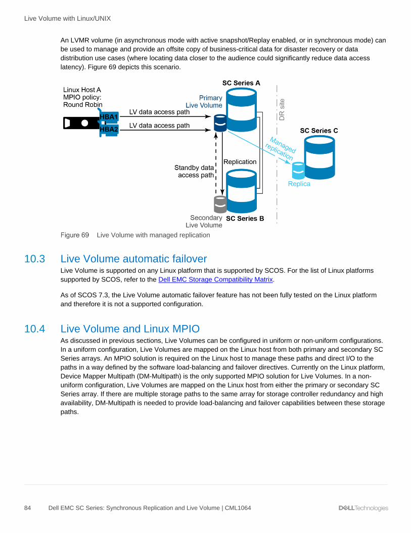
Live Volume with Linux/UNIX
84 Dell EMC SC Series: Synchronous Replication and Live Volume | CML1064
An LVMR volume (in asynchronous mode with active snapshot/Replay enabled, or in synchronous mode) can
be used to manage and provide an offsite copy of business-critical data for disaster recovery or data
distribution use cases (where locating data closer to the audience could significantly reduce data access
latency). Figure 69 depicts this scenario.
Live Volume with managed replication
10.3 Live Volume automatic failover Live Volume is supported on any Linux platform that is supported by SCOS. For the list of Linux platforms
supported by SCOS, refer to the Dell EMC Storage Compatibility Matrix.
As of SCOS 7.3, the Live Volume automatic failover feature has not been fully tested on the Linux platform
and therefore it is not a supported configuration.
10.4 Live Volume and Linux MPIO As discussed in previous sections, Live Volumes can be configured in uniform or non-uniform configurations.
In a uniform configuration, Live Volumes are mapped on the Linux host from both primary and secondary SC
Series arrays. An MPIO solution is required on the Linux host to manage these paths and direct I/O to the
paths in a way defined by the software load-balancing and failover directives. Currently on the Linux platform,
Device Mapper Multipath (DM-Multipath) is the only supported MPIO solution for Live Volumes. In a non-
uniform configuration, Live Volumes are mapped on the Linux host from either the primary or secondary SC
Series array. If there are multiple storage paths to the same array for storage controller redundancy and high
availability, DM-Multipath is needed to provide load-balancing and failover capabilities between these storage
paths.

Live Volume with Linux/UNIX
85 Dell EMC SC Series: Synchronous Replication and Live Volume | CML1064
10.4.1 DM-Multipath configuration DM-Multipath comes with built-in default settings for SC Series arrays. These default settings are not reflected
in the /etc/multipath.conf file. To display these settings, execute multipathd -k"show config" and look for the
device section for "COMPELNT".
It is recommended to examine the settings closely especially when Live Volumes are involved because the
built-in default settings might not be appropriate. The following sample configuration demonstrates a version
of the multipath configuration:
defaults {
find_multipaths yes
user_friendly_names yes
polling_interval 5
}
devices {
device {
vendor "COMPELNT"
product "Compellent Vol"
path_grouping_policy "multibus"
path_checker "tur"
features "0"
hardware_handler "0"
prio "const"
failback immediate
rr_weight "uniform"
no_path_retry "24"
fast_io_fail_tmo 5
dev_loss_tmo infinity
path_selector "round-robin 0"
}
}
This configuration is designed with the following assumptions:
• The storage arrays are fully redundant and are protected for complete outage.
• Storage paths are expected to be highly available within an SC Series array and across remote
arrays.
• In the event of path failovers, I/O is queued and retried for up to 24 times. Each retry interval is 5
seconds. Therefore, it tolerates a maximum of 2 minutes (24 x 5 seconds) of path unavailability
before it stops retrying. This timeout needs to be long enough to cover the controller failover within an
SC Series array and the Live Volume swap role between the primary and secondary array. Adjust this
value if necessary to adapt to your environment.
• It is recommended to explicitly include the COMPELNT device settings in /etc/multipath.conf file
even though the built-in defaults might cover it. Several reasons for this recommendation are:
- It prevents an unexpected change of behavior due to unannounced changes on these default
settings in future releases of DM-Multipath.
- It overrides the defaults and allows finer control on COMPELNT-specific settings, such as
no_path_retry, path_grouping_policy and prio.

Live Volume with Linux/UNIX
86 Dell EMC SC Series: Synchronous Replication and Live Volume | CML1064
• While device path_selector policies service-time and round-robin are supported by DM-Multipath,
Dell Technologies has performed extensive testing with round-robin policy only. See Figure 65.
• In a uniform configuration where primary and secondary paths are mapped to the Linux host, these
paths are grouped into a single group and the round-robin policy spreads I/O to these paths with
equal weight even though the secondary paths might have higher latency. This is because I/O issued
to the secondary paths is proxied through the replication link to the primary SC Series array as
described in section 5.2. Hence, the overall application performance would be limited by the slowest
paths.
10.5 Live Volume with ALUA SCOS 7.3 enhances Live Volume with the introduction of the ALUA capability. ALUA-optimized Live Volumes
report the preferred storage access paths to the host by indicating which paths are optimized and non-
optimized. In a uniform configuration, paths from the primary Live Volume are seen as optimized, while paths
from the secondary Live Volume are seen as non-optimized. With proper configuration in the host's MPIO
software, the host can direct I/O only to the optimized storage paths, improving the overall I/O latency and
performance by avoiding sending I/O through the slower paths.
Note: As of SCOS 7.3, the ALUA optimization feature has not been fully tested on the Linux platform.
Therefore, it is not recommended to enable the feature.
10.5.1 Disable ALUA prioritization in DM-Multipath configuration For reasons mentioned in the previous section, DM-Multipath ALUA settings should be avoided as of SCOS
7.3. Therefore, do not set prio alua for COMPELNT devices in the /etc/multipath.conf file. Rather, use prio
const in the COMPELNT device stanza as shown in 10.4.1.

Live Volume with Linux/UNIX
87 Dell EMC SC Series: Synchronous Replication and Live Volume | CML1064
10.5.2 Existing Live Volumes created before SCOS 7.3 For existing Live Volumes created before SCOS 7.3, ensure that these volumes have an ALUA Optimized
status of No in DSM and are excluded from being upgraded to ALUA-optimized.
After SCOS is upgraded to 7.3, DSM displays a banner in the Live Volume tab indicating that there are
existing Live Volumes that can be optimized for ALUA. Select any Live Volume on the list to see the existing
ALUA Optimized status. See Figure 70.
Live Volume ALUA optimization banner and ALUA optimization status
Live Volumes created before SCOS 7.3 do not automatically become ALUA optimized. The storage
administrator must click the Update to ALUA Optimized link to initiate the optimization process. The link
opens a pop-up window that shows all Live Volumes that are eligible for optimization. See Figure 71. To
ensure Linux Live Volumes do not get ALUA optimized, unselect them from the list.
Note: By default, all eligible Live Volumes are selected. It is important to make sure the Linux Live Volumes
are unselected from the list. These Live Volumes will remain on the list and need to be unselected the next
time the storage administrator optimizes other Live Volumes.

Live Volume with Linux/UNIX
88 Dell EMC SC Series: Synchronous Replication and Live Volume | CML1064
Unselect Linux Live Volumes from the update list
In the event that Linux Live Volumes created before SCOS 7.3 are optimized, the Linux hosts might
experience temporary I/O interruption during the optimization process. The length of the interruption varies
depending on the host's DM-Multipath configuration. Internal testing showed this can range from a few
seconds to a couple minutes.
10.5.3 Disable reporting ALUA optimization As discussed in section 10.5, it is not recommended to optimize Live Volumes for ALUA on the Linux
platform. Once a Live Volume is optimized for ALUA, it cannot be undone. However, the ALUA-optimized Live
Volume can be set to behave like a non-optimized Live Volume.
The Report Non-optimized Paths setting can be found under the Edit Live Volume Settings screen (Figure
72). By unchecking this option, SCOS stops reporting the non-optimized ALUA status of the storage path to
the Linux host. As a result, all paths on the Linux host appear as active and optimized, regardless of the
primary and secondary SC Series arrays. This is the same behavior on a system with SCOS prior to 7.3.
Disabling the Report Non-optimized Paths option does not interrupt host I/O, and therefore it is safe to
execute at any time.

Live Volume with Linux/UNIX
89 Dell EMC SC Series: Synchronous Replication and Live Volume | CML1064
Disable ALUA status reporting
10.5.4 Creating new Live Volumes on SCOS 7.3 All new Live Volumes created on SCOS 7.3 are ALUA-optimized. If the Live Volumes are intended for the
Linux platform, ensure the Report Non-optimized Paths setting is unchecked during the creation of the Live
Volume, or follow section 10.5.3 to update the setting after the Live Volume is created.
Because the Live Volumes are created as already ALUA-optimized on the SC Series array, even though it is
not reporting the non-optimized status, these Live Volumes would not show up in the Update to ALUA
optimized list (Figure 71).

Live Volume with Linux/UNIX
90 Dell EMC SC Series: Synchronous Replication and Live Volume | CML1064
10.6 Identify parent SC Series arrays for Linux storage paths This section provides information on how to correlate the Linux device paths to the SC Series arrays. The
following exercise demonstrates the process to show the Fibre Channel ports on the SC Series arrays
associated with each Linux device paths. The same process also applies to iSCSI transport. The information
might be helpful for troubleshooting path failures or performance related issues.
a) Show the paths information with multipath command. Note the H:C:T (Host adapter, Controller,
Target) and the sd devices information. In this example, a Live Volume has eight storage paths.
# multipath -ll mpatha
mpatha (36000d31000ed1f0000000000000000b6) dm-2 COMPELNT,Compellent Vol
size=100G features='1 queue_if_no_path' hwhandler='0' wp=rw
`-+- policy='round-robin 0' prio=1 status=enabled
|- 0:0:0:1 sdb 8:16 active ready running
|- 7:0:0:1 sde 8:64 active ready running
|- 0:0:15:1 sdh 8:112 active ready running
|- 7:0:15:1 sdi 8:128 active ready running
|- 0:0:3:1 sdc 8:32 active ready running
|- 7:0:3:1 sdf 8:80 active ready running
|- 0:0:4:1 sdd 8:48 active ready running
`- 7:0:4:1 sdg 8:96 active ready running
b) Execute the lsscsi command to show the transport information. Note the transport column (third field)
contains the SC Series target port number.
# lsscsi --transport
[0:0:0:1] disk fc:0x5000d31000ed1f220x1b0b02 /dev/sdb
[0:0:3:1] disk fc:0x5000d31000ed21210x1b1201 /dev/sdc
[0:0:4:1] disk fc:0x5000d31000ed21220x1b1301 /dev/sdd
[0:0:15:1] disk fc:0x5000d31000ed1f210x1b0a02 /dev/sdh
[1:0:0:0] disk sata: /dev/sda
[5:0:0:0] cd/dvd sata: /dev/sr0
[7:0:0:1] disk fc:0x5000d31000ed1f260x1c0b02 /dev/sde
[7:0:3:1] disk fc:0x5000d31000ed21250x1c1201 /dev/sdf
[7:0:4:1] disk fc:0x5000d31000ed21260x1c1301 /dev/sdg
[7:0:15:1] disk fc:0x5000d31000ed1f250x1c0a02 /dev/sdi

Live Volume with Linux/UNIX
91 Dell EMC SC Series: Synchronous Replication and Live Volume | CML1064
c) In DSM, navigate to the Fibre Channel fault domain tabs. If the array is configured in Virtual Port
mode, go to the Virtual Ports screen. In this example, the Virtual Ports information for both primary
and secondary SC Series arrays are examined.

Live Volume with Linux/UNIX
92 Dell EMC SC Series: Synchronous Replication and Live Volume | CML1064

Live Volume with Linux/UNIX
93 Dell EMC SC Series: Synchronous Replication and Live Volume | CML1064
d) The following relationships can be established after analyzing the information from steps a, b, and c.
Linux multipath device mpatha consists of eight storage paths that span across SC 22 and SC 23.
DM-Multipath device
Linux host storage paths
SC Series ports
mpatha
sdb → SC22, Top Controller, Slot 1, Port 2
sde → SC22, Top Controller, Slot 1, Port 4
sdh → SC22, Top Controller, Slot 1, Port 1
sdi → SC22, Top Controller, Slot 1, Port 3
sdc → SC23, Top Controller, Slot 1, Port 1
sdf → SC23, Top Controller, Slot 1, Port 3
sdd → SC23, Top Controller, Slot 1, Port 2
sdg → SC23, Top Controller, Slot 1, Port 4
10.7 Use cases This section discusses various use cases of Live Volume and synchronous replication with Linux, and
highlights technical considerations that should be considered. These use cases are examples and starting
points for consideration. They are not a complete list of scenarios in which Live Volume and synchronous
replication can be adapted. The scenarios discussed can apply to both single- and multi-site deployments by
varying and either scaling the transport mechanisms (LAN, MAN, WAN) connecting site A to site B, or site A
to site C.
10.7.1 Single-site In this single-site scenario, the Linux hosts and SC Series arrays are geographically located within the same
site boundaries though different buildings or labs if necessary. Figure 73 depicts this scenario.
Live Volume in a single-site use case

Live Volume with Linux/UNIX
94 Dell EMC SC Series: Synchronous Replication and Live Volume | CML1064
A volume (or multiple volumes) is first created and mapped to a Linux host. The volumes are scanned,
identified and brought into multipath awareness as shown in the following example.
[root@tssrv216 ~]# multipath -ll
vol_02 (36000d31000fba6000000000000000015) dm-4 COMPELNT,Compellent Vol
size=10G features='1 queue_if_no_path' hwhandler='0' wp=rw
`-+- policy='round-robin 0' prio=1 status=active
|- 0:0:0:2 sdd 8:48 active ready running
|- 1:0:0:2 sde 8:64 active ready running
|- 0:0:2:2 sdh 8:112 active ready running
|- 1:0:2:2 sdi 8:128 active ready running
vol_01 (36000d31000fba6000000000000000014) dm-5 COMPELNT,Compellent Vol
size=10G features='1 queue_if_no_path' hwhandler='0' wp=rw
`-+- policy='round-robin 0' prio=1 status=active
|- 0:0:7:1 sdj 8:144 active ready running
|- 1:0:10:1 sdk 8:160 active ready running
|- 0:0:9:1 sdl 8:176 active ready running
|- 1:0:12:1 sdm 8:192 active ready running
vol_00 (36000d31000fba6000000000000000013) dm-3 COMPELNT,Compellent Vol
size=10G features='1 queue_if_no_path' hwhandler='0' wp=rw
`-+- policy='round-robin 0' prio=1 status=active
|- 1:0:0:1 sdc 8:32 active ready running
|- 0:0:0:1 sdb 8:16 active ready running
|- 0:0:2:1 sdf 8:80 active ready running
|- 1:0:2:1 sdg 8:96 active ready running
These volumes are then converted into Live Volumes and synchronously (either HA or HC modes) replicated
to the alternate array. The volumes on the alternate array are then mapped back to the same Linux host. The
volumes are once again scanned, identified, and brought into multipath awareness as shown in the following.
Each volume is now represented by four additional paths, these paths are the mappings from the alternate
array.
[root@tssrv216 ~]# multipath -ll
vol_02 (36000d31000fba6000000000000000015) dm-4 COMPELNT,Compellent Vol
size=10G features='1 queue_if_no_path' hwhandler='0' wp=rw
`-+- policy='round-robin 0' prio=1 status=active
|- 0:0:0:2 sdd 8:48 active ready running
|- 1:0:0:2 sde 8:64 active ready running
|- 0:0:2:2 sdh 8:112 active ready running
|- 1:0:2:2 sdi 8:128 active ready running
|- 0:0:5:2 sdo 8:224 active ready running
|- 0:0:8:2 sdq 65:0 active ready running
|- 1:0:4:2 sdu 65:64 active ready running
`- 1:0:8:2 sdw 65:96 active ready running
vol_01 (36000d31000fba6000000000000000014) dm-5 COMPELNT,Compellent Vol
size=10G features='1 queue_if_no_path' hwhandler='0' wp=rw
`-+- policy='round-robin 0' prio=1 status=active
|- 0:0:7:1 sdj 8:144 active ready running
|- 1:0:10:1 sdk 8:160 active ready running
|- 0:0:9:1 sdl 8:176 active ready running

Live Volume with Linux/UNIX
95 Dell EMC SC Series: Synchronous Replication and Live Volume | CML1064
|- 1:0:12:1 sdm 8:192 active ready running
|- 0:0:5:1 sdn 8:208 active ready running
|- 0:0:8:1 sdp 8:240 active ready running
|- 1:0:4:1 sdt 65:48 active ready running
`- 1:0:8:1 sdv 65:80 active ready running
vol_00 (36000d31000fba6000000000000000013) dm-3 COMPELNT,Compellent Vol
size=10G features='1 queue_if_no_path' hwhandler='0' wp=rw
`-+- policy='round-robin 0' prio=1 status=active
|- 1:0:0:1 sdc 8:32 active ready running
|- 0:0:0:1 sdb 8:16 active ready running
|- 0:0:2:1 sdf 8:80 active ready running
|- 1:0:2:1 sdg 8:96 active ready running
|- 0:0:11:1 sdr 65:16 active ready running
|- 0:0:13:1 sds 65:32 active ready running
|- 1:0:11:1 sdx 65:112 active ready running
`- 1:0:13:1 sdy 65:128 active ready running
It should be noted that even though these additional paths are shown as active and will be actively used for
I/O requests (Round Robin), any I/O requests sent to these paths will be proxied through the replication link to
the primary array for commits. The use of these paths would thus introduce unintended latency to any
applications that may be latency-adverse; at this time, path priority definitions and grouping (for example, all
paths are prio=1 by default and used in equal fashion) are not configurable between Linux hosts and SC
Series arrays. Therefore, it is not recommended to use this approach for any critical production use cases.
That being said, this scenario can still apply in certain use cases. In situations where a maintenance event
requires SC Series arrays to be powered down, the volumes on the primary array can be Live Volume
replicated to an alternate array in a different building or lab. The roles of the arrays can then be swapped,
making the alternate array adopt the primary array role (and the paths from them). The latent paths (from the
formerly primary array) can then be removed from multipath for the duration of these maintenance events
while maintaining uptime and zero disruption to any and all functions and applications that may reside on the
Linux hosts. Upon completion of these maintenance events, the volumes and roles of the arrays can then be
swapped back or left in place to the discretion of the business requirements.

Live Volume with Linux/UNIX
96 Dell EMC SC Series: Synchronous Replication and Live Volume | CML1064
10.7.2 Multi-site In this multi-site scenario, the Linux hosts and SC Series arrays are geographically dispersed within a
metropolitan (or multi-state) region; sites may be connected with MAN or WAN technologies. Figure 74
depicts this scenario. It should be noted that this scenario can also be scaled down and applied towards
single-site deployments as well.
Live Volume in a multi-site use case
The Live Volumes are synchronously (in either HA or HC modes) replicated across SC Series arrays. In this
scenario, the alternate array volumes are mapped to a secondary Linux host instead. It should be noted that
the volumes mapped to the secondary Linux host are not shared volumes and do not possess shared I/O
management and locking mechanisms. These secondary volumes would need to be remounted to reflect any
data changes that were written to the primary volumes. For this reason, the integrity of data across both
primary and secondary volumes is guaranteed (in either HA or HC modes) as long as the replication link is in
a known good state.
The secondary Linux host can be used in various ways including, but not limited to, the following use cases:
• These volumes can be used to present a consistent read-only copy of this data to a remotely located
site; this can apply not only for data distribution reasons, but to also manage and minimize any data
access latency concerns.
• The consistency of these volumes (and the integrity of the data that it guarantees) also lends itself
towards database replication use. Databases (and applications) can be brought online at the
remotely-located site, in either read-only mode or used in a disaster recovery after the roles of the SC
Series arrays are swapped (the secondary array becomes the primary array).
• These volumes can also be used to complement virtualization technologies such as Red Hat
Enterprise Virtualization (RHEV) to allow for the replication of virtual machine workgroups from one
site or hypervisor to another site or hypervisor. RHEV hosts its virtual machines on a storage domain
that in turn is correlated through a one-to-many relationship to one or multiple backing SC Series
volumes. These volumes are enabled with Live Volume or are synchronously replicated to an
alternate site or secondary array. At the alternate site, these storage volumes can then be used to

Live Volume with Linux/UNIX
97 Dell EMC SC Series: Synchronous Replication and Live Volume | CML1064
reconstruct or import the storage domain into the alternate data center object, and from which object,
reconstruct the virtual machine workgroup.
The following technical and performance considerations should be taken when exploring these use cases.
/etc/multipath.conf: This keeps the contents of /etc/multipath.conf file consistent across all hosts sharing
these Live Volumes; this file contains the definitions of volume WWIDs and their respective aliases and will
ensure that volumes are identified across the different hosts as the same device, and contain the same data
to maintain application integrity.
/etc/fstab: Use the /etc/fstab file in conjunction with /etc/multipath.conf to ensure that volumes are accurately
mounted to their respective and proper mount points in the filesystem. Use the multipath device aliases (if
defined) or default multipath device naming (mpathX) in /etc/fstab to maintain this consistency.
/etc/ntp.conf: Always use the /etc/ntp.conf file to maintain a certain degree of time-based integrity across all
infrastructure. The use of /etc/ntp.conf file becomes even more critical when attempting to maintain data
integrity across multiple cluster nodes/sites dispersed across larger geographic deployments (MAN, WAN).
Cluster configurations: In addition to the considerations mentioned above, take into account cluster-specific
configuration files as well and the best practices of their respective vendors. The discussion of cluster-specific
configuration remains outside the scope of this paper. The list of enterprise-class clustering technologies
include but is not limited to Red Hat Cluster Suite, IBM® PowerHA®, Oracle® Solaris Cluster, Oracle RAC, HP-
UX ServiceGuard, and Symantec™ Veritas™ Cluster Server to name a few.
Performance considerations: It should be noted that the dual commit nature of synchronous replication (I/O
writes must be committed to the secondary SC Series volume before it is committed to the primary volume)
may introduce latency to the applications generating these write requests. The use of synchronous replication
guarantees the consistency and integrity of the data at both SC Series sites when the acknowledgment is
received by the requesting application. The use of synchronous replication should be made upon the detailed
and thorough analysis and understanding of the applications and its I/O needs.
The following demonstration has a small dataset (40 MB) that is written to a primary Live Volume and is
synchronously replicated to an alternate array. The filesystem is formatted as ext4 and mounted (@ /vol_00)
with the discard and sync (the sync option disables filesystem buffer caching) flags.
[tssrv216:/root]# cd /etc; time tar cvf - . | (cd /vol_00; tar xvf -)
[snip]
real 0m24.147s
user 0m0.122s
sys 0m1.421s
In this next demonstration, the synchronously replicated Live Volume at the alternate site is mounted to the
secondary Linux host and writes are applied to the secondary Linux host. This demonstrates additional
latency as all write I/O requests are proxied through the secondary SC Series array to the primary array for
processing.
[tssrv217:/root]# cd /etc; time tar cvf - . | (cd /vol_00; tar xvf -)
[snip]
real 0m30.864s
user 0m0.111s
sys 0m1.422s

Live Volume with Linux/UNIX
98 Dell EMC SC Series: Synchronous Replication and Live Volume | CML1064
In this final demonstration, the replication link is quickly changed from synchronous replication to
asynchronous replication and write I/O requests are applied to the primary Live Volume. Note the reduction in
time required to commit these writes compared to the previous use of synchronous replication.
[tssrv216:/root]# cd /etc; time tar cvf - . | (cd /vol_00; tar xvf -)
[snip]
real 0m18.266s
user 0m0.104s
sys 0m1.328s
10.7.3 Multi-site with LVMR In this alternate multi-site scenario, the Linux hosts and SC Series arrays are geographically dispersed within
a metro (or multi-state) region. Sites may be connected through MAN or WAN technologies. Additionally, a
third site has been included using the LVMR feature of SC Series storage. Figure 75 depicts this scenario. It
should be noted that this scenario can also be scaled down and applied towards single-site deployments as
well.
Live Volume in multi-site use case with LVMR
The third site and data in this scenario is replicated asynchronously. One of its uses may include the remotely
located disaster recovery copy of business-critical data. It should be noted that the LVMR copy is always
associated or paired with the primary SC Series array. If the primary and secondary array roles are swapped,
the LVMR copy automatically transfers and associates or pairs itself with the array that assumes the primary
role. Additionally, this asynchronously replicated copy (unlike a synchronously replicated) is current if the
replication link has sufficient bandwidth and the Replicate Active Snapshot (Replay) feature is enabled, or
current as of the last captured snapshot if the feature is disabled. Consequently, discussions should also be
conducted around acceptable RPO and RTO thresholds and maintaining agreeable SLAs with all business
entities involved.
The technical considerations discussed in the section 10.7.2 should be kept in consideration when setting up
this use case.

Live Volume use cases
99 Dell EMC SC Series: Synchronous Replication and Live Volume | CML1064
11 Live Volume use cases This section exhibits additional examples of how Live Volume can be used in a variety of environments. Live
Volume is not limited to these use cases.
11.1 Zero-downtime SAN maintenance and data migration With Live Volume, maintenance activities can be performed without downtime on an SC Series array. This
includes tasks such as taking an array offline to move its location, perform service-affecting enclosure or disk
firmware updates, and migrate the volume to a new SAN.
The requirements for this operation include:
• MPIO installed and appropriately configured on the host computers
• Server(s) properly zoned into both SC Series arrays
• Server(s) configured on both arrays
• At least a 1 Gb low-latency replication link between arrays
Summary: In advance of a planned outage, Live Volume can non-disruptively migrate volumes from one SC
Series array to another, enabling continuous operation for all applications — even after one array has
completely powered down.
Operation: In an on-demand, operator-driven process, Live Volume can transparently move volumes from
one SC Series array to another. The applications operate continuously. This enables several options for
improved system operation:
• Redefine remote site as primary for all volumes on local site
• Shut down local site
• Reverse process after planned outage is completed
Maintaining availability of applications and services during scheduled maintenance

Live Volume use cases
100 Dell EMC SC Series: Synchronous Replication and Live Volume | CML1064
Applications remain continuously available on SC2 while SC1 undergoes maintenance
11.2 Storage migration for virtual machine migration As VMware, Hyper-V, or XenServer virtual machines are migrated from data center to data center, Live
Volume can automatically migrate the related volumes to optimize performance and minimize I/O network
overhead.
Live Volume continuously monitors for changes in I/O traffic for each volume and non-disruptively moves the
primary storage to the optimal SC Series array for optimum efficiency. This involves the following:
• Migrate the virtual machine using the server virtualization software.
• Live Volume will track the changes in I/O traffic mapping and will perform a primary/secondary swap
after a fixed amount of time and data have been transferred.
Storage follows the application (server virtualization)

Live Volume use cases
101 Dell EMC SC Series: Synchronous Replication and Live Volume | CML1064
The requirements for this operation include the following:
• Server(s) properly zoned into both SC Series arrays
• Server(s) configured on both arrays
• Stretched Layer 2 networking between source and destination sites or hypervisors
• 1 Gbps or better low-latency iSCSI or Fibre Channel connectivity between the arrays to support
asynchronous or synchronous Live Volume replication
11.3 Disaster avoidance and disaster recovery In anticipation of an outage (for instance, an approaching hurricane) or after an unplanned outage has
occurred, Live Volume migrates data and applications to recovery systems. Live Volume used in this manner
can prevent data loss and application downtime.
Operation: Live Volume can transparently move volumes from one SC Series array to another. The
applications operate continuously. This enables several options for improved system operation:
• Redefine remote site as primary for all volumes on local site
• Shut down applications on local site
• Restart or recover applications on remote site
• Move applications seamlessly back to their original locations using Live Volume
Disaster avoidance and disaster recovery

Live Volume use cases
102 Dell EMC SC Series: Synchronous Replication and Live Volume | CML1064
11.4 On-demand load distribution In this use case, Live Volume transparently distributes the workload, balances storage utilization, or balances
I/O traffic between two SC Series arrays.
Configuration: SC Series arrays must be connected using high-bandwidth and low-latency connections,
especially when synchronous replication is used with Live Volume.
Operation: In an on-demand, operator-driven process, Live Volume can transparently move volumes from
one SC Series array to another. The applications operate continuously. This enables several options for
improved system operation:
• Distribution of I/O workload
• Distribution of storage
• Distribution of front-end Ioad traffic
• Reallocation of workload to match capabilities of heterogeneous systems
On-demand local distribution
11.5 Cloud computing In this use case, Live Volume transparently distributes the workload, balances storage utilization, or balances
I/O traffic between multiple SC Series arrays within a data center, enabling continuous flexibility to meet
changes in workload and to provide a higher-level system up time.
Configuration: Live Volumes can be created between any two SC Series arrays in a data center. Each array
can have many Live Volumes, each potentially connecting to a different array.

Live Volume use cases
103 Dell EMC SC Series: Synchronous Replication and Live Volume | CML1064
Operation: In an on-demand, operator-driven process, Live Volume can transparently move volumes from
one SC Series array to another. The applications operate continuously. This enables several options for
improved system operation:
• Distribution of I/O workload
• Distribution of storage
• Distribution of front-end Ioad traffic
• Reallocation of workload to match capabilities of heterogeneous systems
Cloud computing
11.6 Replay Manager and Live Volume Replay Manager and Live Volume are mutually exclusive features that cannot be used together. If storage
hosts are split between data centers in a stretched cluster configuration using Live Volume, then Replay
Manager cannot be used to create application-consistent snapshots.

Technical support and additional resources
104 Dell EMC SC Series: Synchronous Replication and Live Volume | CML1064
A Technical support and additional resources
Dell.com/support is focused on meeting customer needs with proven services and support.
Storage solutions technical documents and videos provide expertise that helps to ensure customer success
on Dell EMC storage platforms.
A.1 Related resources
• Dell EMC SC Series Best Practices with VMware vSphere 5.x-6.x
• Dell EMC SC Series Best Practices with VMware Site Recovery Manager
• High Availability and Disaster Recovery with VMware vSphere Solutions Guide
• Dell SC Series Storage and Microsoft Hyper-V
• Dell EMC SC Series Storage and Microsoft Multipath I/O
• Dell EMC SC Series with Red Hat Enterprise Linux 6x
• Dell EMC SC Series with Red Hat Enterprise Linux 7x
• Red Hat Enterprise Linux 6 DM Multipath Configuration and Administration
• Red Hat Enterprise Linux 7 DM Multipath Configuration and Administration
• VMware vSphere 6.0 Metro Storage Cluster Recommended Practices
• Live Volume with Auto Failover Support for Microsoft (three-part video series)
• Dell EMC Storage Compatibility Matrix