dell emc ready architecture for vmware vcloud …...2 dell emc ready architecture for vmware vcloud...
TRANSCRIPT
Dell Customer Communication - Confidential
Dell EMC Ready Architecture for VMware vCloud
NFV 3.0 vCloud Director 9.5
Architecture and Manual Deployment Guide
Dell Engineering August 2019
2 Dell EMC Ready Architecture for VMware vCloud NFV 3.0 vCloud Director 9.5
Dell Customer Communication - Confidential
Revisions
Date Description
August 2019 Initial release
The information in this publication is provided “as is.” Dell Inc. makes no representations or warranties of any kind with respect to the information in this
publication, and specifically disclaims implied warranties of merchantability or fitness for a particular purpose.
Use, copying, and distribution of any software described in this publication requires an applicable software license.
© 2019 Dell Inc. or its subsidiaries. All Rights Reserved. Dell, EMC, Dell EMC, and other trademarks are trademarks of Dell Inc. or its subsidiaries. Other
trademarks may be trademarks of their respective owners.
Dell believes that the information in this document is accurate as of its publication date. The information is subject to change without notice.
3 Dell EMC Ready Architecture for VMware vCloud NFV 3.0 vCloud Director 9.5
Dell Customer Communication - Confidential
Table of contents
Dell EMC Ready Architecture for VMware vCloud NFV 3.0 vCloud Director 9.5 .............................................................. 1
Revisions ............................................................................................................................................................................ 2
Overview ............................................................................................................................................................................ 9
Intended audience .............................................................................................................................................................. 9
Acronyms and definitions ................................................................................................................................................. 10
1 Deployment architecture for vCloud NFV .................................................................................................................. 11
1.1 Architecture design .......................................................................................................................................... 11
1.2 Solution bundle network topology .................................................................................................................... 12
1.2.1 Solution bundle physical network design and topology ................................................................................... 12
1.2.2 Solution bundle virtual network design and topology ...................................................................................... 16
1.3 Three-pod configuration ................................................................................................................................... 18
1.3.1 Management pod ............................................................................................................................................. 18
1.3.2 Edge pod .......................................................................................................................................................... 19
1.3.3 Resource pod................................................................................................................................................... 20
2 Solution hardware ...................................................................................................................................................... 21
2.1 Hardware installation and configuration .......................................................................................................... 21
2.1.1 Unpack and install equipment .......................................................................................................................... 21
2.1.2 Power on equipment ........................................................................................................................................ 21
2.1.3 Tested BIOS and firmware .............................................................................................................................. 22
2.1.4 Supported configuration ................................................................................................................................... 23
2.1.5 List of components ........................................................................................................................................... 23
2.2 Network connectivity and port mapping ........................................................................................................... 24
2.2.1 Verify network connectivity to server ports ...................................................................................................... 24
2.2.2 VDS DvPort group mapping with VLAN ID and related ESXi VMNIC ............................................................. 25
3 Manual deployment ................................................................................................................................................... 28
3.1 Solution prerequisites ...................................................................................................................................... 28
3.1.1 Deployment server ........................................................................................................................................... 28
3.1.2 Create standard vSwitch on deployment server .............................................................................................. 31
3.1.3 Create port group on deployment server ......................................................................................................... 32
3.1.4 Create datastore on deployment server .......................................................................................................... 33
3.1.5 Connectivity overview for deployment VM and server .................................................................................... 33
3.1.6 Deployment VM ............................................................................................................................................... 33
4 ESXi installation and configuration ............................................................................................................................ 41

4 Dell EMC Ready Architecture for VMware vCloud NFV 3.0 vCloud Director 9.5
Dell Customer Communication - Confidential
4.1 Install ESXi on Dell EMC PowerEdge R640, R740, and R740xd servers using iDRAC9 ............................... 41
5 Auxiliary components ................................................................................................................................................ 44
5.1 Prerequisites for auxiliary components ............................................................................................................ 44
5.1.2 NTP server configuration ................................................................................................................................. 45
5.1.3 Synchronize ESXi clocks with NTP ................................................................................................................. 47
5.1.4 Microsoft Windows Server 2012 installation for AD DNS ................................................................................ 48
5.1.5 Active Directory and DNS installation .............................................................................................................. 49
5.1.6 Create DNS Reverse Lookup Zone ................................................................................................................. 53
5.1.7 Enable Remote Desktop connection ............................................................................................................... 54
5.1.8 Add Windows VM license ................................................................................................................................ 55
5.1.9 Add self-signed certificate to Windows Active Directory.................................................................................. 55
5.1.10 Configure NTP client in AD VM ................................................................................................................. 58
6 VMware vCenter Server deployment and configuration ............................................................................................ 59
6.1 VMware vCenter Server Appliance deployment .............................................................................................. 59
6.2 Stage 1: Deploy ISO file for Management vCenter Server Appliance with embedded PSC ........................... 59
6.3 Stage 2: Set up Management vCenter Server Appliance with embedded PSC .............................................. 60
6.3.1 Change vSAN default storage policy for management vCSA ......................................................................... 62
6.4 Stage 1: Deploy ISO file for Resource vCenter Server Appliance .................................................................. 62
6.5 Stage 2: Set up resource vCenter Server Appliance with embedded PSC ..................................................... 63
6.5.1 Change VMware vSAN default storage policy for resource vCSA .................................................................. 64
6.6 Add AD authentication for vCenter Server ...................................................................................................... 64
6.7 Assign license to vCSA .................................................................................................................................... 65
6.8 Create data center and cluster on resource vCenter ...................................................................................... 66
6.9 Add hosts to vCenter cluster ............................................................................................................................ 66
6.10 Enable VMware enhanced vMotion compatibility ............................................................................................ 67
6.10.1 Enable VMware EVC for management cluster ......................................................................................... 68
6.10.2 Enable VMware EVC for resource and edge cluster ................................................................................ 68
7 Configure Virtual Network .......................................................................................................................................... 69
7.1 VDS creation and configuration for management pod .................................................................................... 69
7.1.1 Create VDS for management pod ................................................................................................................... 69
7.1.2 VDS configuration settings for management VDS ........................................................................................... 70
7.1.3 Create LAG for management pod ................................................................................................................... 70
7.2 Create distributed port group for management pod......................................................................................... 71
7.3 Add host to VDS on management pod ............................................................................................................ 72

5 Dell EMC Ready Architecture for VMware vCloud NFV 3.0 vCloud Director 9.5
Dell Customer Communication - Confidential
7.3.1 vSwitch to VDS Migration on management pod .............................................................................................. 73
7.3.2 Add hosts to VM_Network_VDS ...................................................................................................................... 76
7.4 Create VDS for resource and edge pods ........................................................................................................ 77
7.4.1 VDS configuration settings for resource VDS .................................................................................................. 78
7.4.2 Create LAG for resource and edge pods ......................................................................................................... 79
7.5 Create distributed port group for resource and edge VDS .............................................................................. 79
7.6 Add hosts to VDS on edge pod ....................................................................................................................... 81
7.6.1 Add hosts to Edge_Infra_Network_VDS ......................................................................................................... 81
7.6.2 Add hosts to Edge_VM_Network_VDS ........................................................................................................... 83
7.7 Add hosts to VDS on resource pod ................................................................................................................. 83
7.7.1 Add hosts to Res_Infra_Network_VDS ........................................................................................................... 83
8 Configure VMware vSAN clusters ............................................................................................................................. 86
8.1 Configure vSAN on resource and edge cluster ............................................................................................... 86
8.2 Assign vSAN license key to cluster ................................................................................................................. 86
8.2.1 Add a new vSAN license ................................................................................................................................. 87
8.2.2 Assign vSAN license using an existing license ............................................................................................... 87
8.3 Update vSAN HCL database manually ........................................................................................................... 87
8.4 Enable vSAN performance service .................................................................................................................. 88
9 Configure VMware vCenter High Availability ............................................................................................................. 89
9.1 Management cluster VCSA-HA configuration ................................................................................................. 89
9.1.1 Configure Management vCenter HA ............................................................................................................... 89
9.2 Resource cluster VCSA-HA configuration ....................................................................................................... 91
9.2.1 Configure Resource vCenter HA ..................................................................................................................... 91
10 NSX-T deployment and configuration ....................................................................................................................... 98
10.1 Install NSX-T Manager Virtual Appliance ........................................................................................................ 98
10.2 Add license key .............................................................................................................................................. 100
10.3 Add Compute Manager for management and resource VCSA ..................................................................... 100
10.4 Installation of NSX-T controller and cluster from NSX-T Manager ................................................................ 101
10.4.1 NSX-T controllers and cluster deployment validation ............................................................................. 103
10.5 Configure NSX-T Manager ............................................................................................................................ 104
10.5.1 Prepare Edge and Resource ESXi hosts as fabric node from NSX-T Manager ..................................... 104
10.5.2 Create Transport Zones .......................................................................................................................... 105
10.5.3 Create uplink profiles............................................................................................................................... 106
10.5.4 Create IP pool for tunnel endpoints ......................................................................................................... 109
10.5.5 Create host transport nodes .................................................................................................................... 109

6 Dell EMC Ready Architecture for VMware vCloud NFV 3.0 vCloud Director 9.5
Dell Customer Communication - Confidential
10.6 Installation of NSX-T Edge ............................................................................................................................ 111
10.6.1 Create edge transport nodes .................................................................................................................. 113
10.6.2 Create edge cluster ................................................................................................................................. 116
10.7 Create logical switches .................................................................................................................................. 117
10.8 Create and configure Tier-1 router ................................................................................................................ 119
10.8.1 Create Router port on Tier-1 Router ....................................................................................................... 120
10.8.2 Configure Route Advertisement on Tier-1 Router ................................................................................... 121
10.9 Create and configure NSX-Tier-0 router ........................................................................................................ 121
10.9.1 Connect Tier-1 router to NSX-Tier-0 router............................................................................................. 122
10.9.2 Create Logical Router port on Tier-0 router ............................................................................................ 123
10.9.3 Redistribution on Tier-0 router ................................................................................................................ 124
10.9.4 Configure BGP on NSX-Tier-0 router ...................................................................................................... 124
10.10 Create and configure VCD-Tier1 router ......................................................................................................... 127
10.10.1 Create logical router port on VCD tier-1 router ....................................................................................... 128
10.10.2 Create and configure the Load Balancer ................................................................................................ 129
11 Configure vCloud Director ....................................................................................................................................... 135
11.1 Configure a PostgreSQL database ................................................................................................................ 135
11.2 Installation of NFS server .............................................................................................................................. 138
11.3 Installation and configuration of vCloud Director ........................................................................................... 138
11.3.1 Installation of vCD Cell 1 ......................................................................................................................... 138
11.3.2 Installation of vCD Cell 2 ......................................................................................................................... 143
11.4 Creating a session token for vCD .................................................................................................................. 146
11.5 Register a VIM server .................................................................................................................................... 147
11.6 Update VIM server ......................................................................................................................................... 149
11.7 Retrieve the list of available resource pool .................................................................................................... 150
11.8 Register NSX-T Manager to vCloud Director ................................................................................................ 151
11.9 Retrieve VIM server details ............................................................................................................................ 153
11.10 Retrieve NSX-T Manager instance details .................................................................................................... 154
11.11 Create a provider VDC .................................................................................................................................. 155
11.12 Create an organization VDC .......................................................................................................................... 157
11.12.1 Add Resource to organization VDC ........................................................................................................ 159
12 VMware vRealize Log Insight deployment and configuration ................................................................................. 162
12.1 Deploy the vRealize Log Insight virtual appliance ......................................................................................... 162
12.2 Configure the root SSH password for vRLI virtual appliance ........................................................................ 163

7 Dell EMC Ready Architecture for VMware vCloud NFV 3.0 vCloud Director 9.5
Dell Customer Communication - Confidential
12.3 Master node configuration ............................................................................................................................. 164
12.4 Worker node configuration ............................................................................................................................. 164
12.5 Enable Integrated Load Balancer .................................................................................................................. 165
12.6 Integrate vRLI with AD ................................................................................................................................... 165
12.7 Integrate vRLI with VMware vCenter ............................................................................................................. 166
12.8 Configure vRLI to send notifications to vRealize Operations Manager ......................................................... 166
12.9 Add Log Insight content packs ....................................................................................................................... 167
12.9.1 Offline update for content pack ............................................................................................................... 167
12.9.2 Online update for content pack ............................................................................................................... 167
12.10 vRLI integration with vCD .............................................................................................................................. 168
13 VMware vRealize Operations Manager deployment and configuration .................................................................. 170
13.1 Deployment prerequisites for vRealize Operations Manager ........................................................................ 170
13.2 Deploy vRealize Operations Manager ........................................................................................................... 170
13.3 Configuration of vRealize Operations Manager ............................................................................................. 171
13.4 Add data nodes to scale out vRealize Operations Manager ......................................................................... 171
13.5 Add master replica node ................................................................................................................................ 172
13.6 Enable High Availability for clusters .............................................................................................................. 172
13.6.1 Start cluster ............................................................................................................................................. 173
13.7 Product license .............................................................................................................................................. 173
13.8 vROps integration with other components ..................................................................................................... 173
13.8.1 Integrate vROps with VMware vCenter ................................................................................................... 173
13.8.2 vROps integration with AD ...................................................................................................................... 176
13.8.3 vROps integration with VRLI ................................................................................................................... 177
13.8.4 vROps integration with NSX-T ................................................................................................................ 177
13.8.5 vROps integration with vSAN .................................................................................................................. 178
13.8.6 vROps integration with vCD .................................................................................................................... 179
14 Set up anti-affinity rules ........................................................................................................................................... 181
14.1 Create an anti-affinity rule .............................................................................................................................. 182
14.2 Enable vSphere DRS ..................................................................................................................................... 182
14.3 Enabling vSphere availability ......................................................................................................................... 182
15 Forwarding logs to vRLI ........................................................................................................................................... 184
15.1 Forwarding vROps log to vRLI ....................................................................................................................... 184
15.2 Forwarding vSAN logs to vRLI ....................................................................................................................... 185
15.3 Forwarding logs from vCD to vRLI ................................................................................................................ 186
15.4 Configure syslog server for NSX-T ................................................................................................................ 186

8 Dell EMC Ready Architecture for VMware vCloud NFV 3.0 vCloud Director 9.5
Dell Customer Communication - Confidential
15.5 Log Message IDs ........................................................................................................................................... 187
A Reference documentation ....................................................................................................................................... 190

9 Dell EMC Ready Architecture for VMware vCloud NFV 3.0 vCloud Director 9.5
Dell Customer Communication - Confidential
Overview
The Dell EMC Ready Solution bundle is designed to consolidate and deliver the networking components that
support a fully virtualized infrastructure. The components include virtual servers, storage, and or other networks.
It uses standard IT virtualization technologies that run on high-volume service, switch, and storage hardware to
virtualize network functions.
The Dell EMC Ready Architecture for VMware vCloud NFV 3.0 vCloud Director 9.5 Architecture and Software
Deployment Guide provides a detailed set of instructions for the manual deployment of the VMware vCloud NFV
3.0 with VMware vCloud Director 9.5 platform. This guide also provides information about the hardware and
software that is recommended for the deployment of the Dell EMC Ready Architecture for VMware NFV 3.0
platform.
The scope of this document is limited to a Greenfield deployment.
Servers:
• Dell EMC PowerEdge R640 or Dell EMC PowerEdge R740 server with the Dell EMC PowerEdge
HBA330 disk controller based on vSAN Ready Node
• Dell EMC PowerEdge R740xd server with the Dell EMC PowerEdge HBA330 disk controller based
on vSAN Ready Node
Networking:
• One Dell EMC Networking S4048T-ON switch as Top of Rack (ToR) switch
• Two Dell EMC Networking Z9264F-ON, S5248-ON, S5232-ON, or S6010-ON switches as leaf
switches
This guide consists of three sections:
• Deployment architecture
• Hardware installation and configuration
• Manual deployment
Intended audience
The information in this guide is intended for use by system administrators who are responsible for the
installation, configuration, and maintenance of Dell EMC 14G technology along with the suite of VMware
applications.
10 Dell EMC Ready Architecture for VMware vCloud NFV 3.0 vCloud Director 9.5
Dell Customer Communication - Confidential
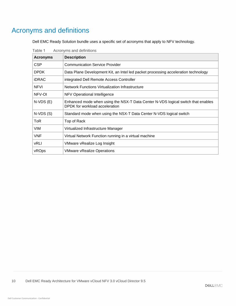
Acronyms and definitions
Dell EMC Ready Solution bundle uses a specific set of acronyms that apply to NFV technology.
Acronyms and definitions
Acronyms Description
CSP Communication Service Provider
DPDK Data Plane Development Kit, an Intel led packet processing acceleration technology
iDRAC integrated Dell Remote Access Controller
NFVI Network Functions Virtualization Infrastructure
NFV-OI NFV Operational Intelligence
N-VDS (E) Enhanced mode when using the NSX-T Data Center N-VDS logical switch that enables DPDK for workload acceleration
N-VDS (S) Standard mode when using the NSX-T Data Center N-VDS logical switch
ToR Top of Rack
VIM Virtualized Infrastructure Manager
VNF Virtual Network Function running in a virtual machine
vRLI VMware vRealize Log Insight
vROps VMware vRealize Operations

11 Dell EMC Ready Architecture for VMware vCloud NFV 3.0 vCloud Director 9.5
Dell Customer Communication - Confidential
1 Deployment architecture for vCloud NFV This section provides a reference architecture for the design and creation of a Greenfield Network Function
Virtualization (NFV) environment using VMware vCloud Director (VCD) with VMware NSX-T and Dell EMC
PowerEdge Servers.
This deployment uses the three-pod architecture design as per VMware vCloud NFV 3.0 Reference Architecture
Guide to deploy Dell EMC vCloud NFV 3.0 with VCD. By design, the management, resource, and edge pods
include a vSphere cluster. You can scale up the clusters by adding ESXi hosts to the clusters.
For more information see:
• Architecture design
• Solution bundle network topology
• Three-pod configuration
1.1 Architecture design Figure 1 displays the three-pod architecture diagram that is used to deploy the Dell EMC Ready Solution vCloud
NFV 3.0.
Architecture design
For more information, see the following sections:
• Management pod
• Edge pod
• Resource pod
12 Dell EMC Ready Architecture for VMware vCloud NFV 3.0 vCloud Director 9.5
Dell Customer Communication - Confidential
1.2 Solution bundle network topology This section provides the network information physical network design and virtual network topology design and
topology that is used in this deployment. For more information, see:
• Solution bundle physical network design and topology
• Solution bundle virtual network design and topology
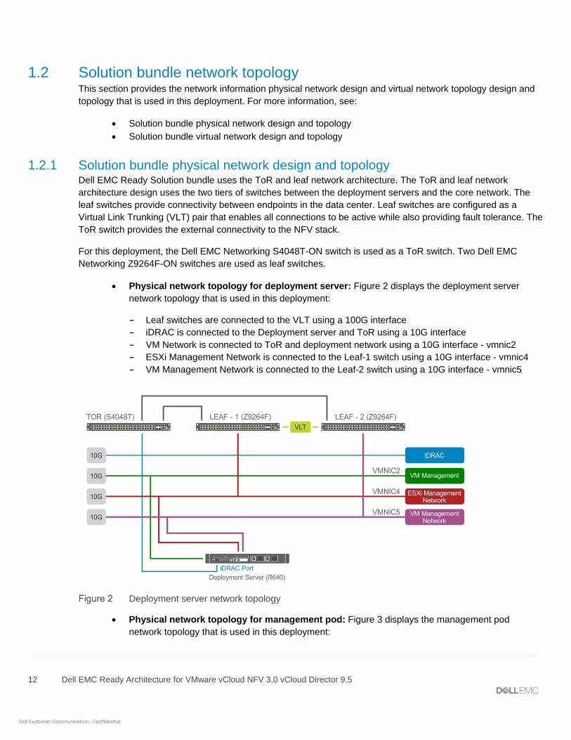
1.2.1 Solution bundle physical network design and topology Dell EMC Ready Solution bundle uses the ToR and leaf network architecture. The ToR and leaf network
architecture design uses the two tiers of switches between the deployment servers and the core network. The
leaf switches provide connectivity between endpoints in the data center. Leaf switches are configured as a
Virtual Link Trunking (VLT) pair that enables all connections to be active while also providing fault tolerance. The
ToR switch provides the external connectivity to the NFV stack.
For this deployment, the Dell EMC Networking S4048T-ON switch is used as a ToR switch. Two Dell EMC
Networking Z9264F-ON switches are used as leaf switches.
• Physical network topology for deployment server: Figure 2 displays the deployment server
network topology that is used in this deployment:
- Leaf switches are connected to the VLT using a 100G interface
- iDRAC is connected to the Deployment server and ToR using a 10G interface
- VM Network is connected to ToR and deployment network using a 10G interface - vmnic2
- ESXi Management Network is connected to the Leaf-1 switch using a 10G interface - vmnic4
- VM Management Network is connected to the Leaf-2 switch using a 10G interface - vmnic5
Deployment server network topology
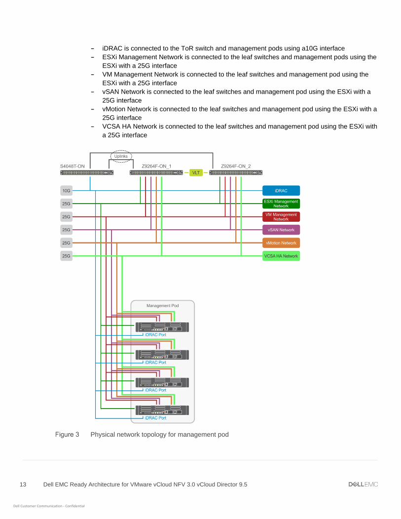
• Physical network topology for management pod: Figure 3 displays the management pod
network topology that is used in this deployment:
13 Dell EMC Ready Architecture for VMware vCloud NFV 3.0 vCloud Director 9.5
Dell Customer Communication - Confidential
- iDRAC is connected to the ToR switch and management pods using a10G interface
- ESXi Management Network is connected to the leaf switches and management pods using the
ESXi with a 25G interface
- VM Management Network is connected to the leaf switches and management pod using the
ESXi with a 25G interface
- vSAN Network is connected to the leaf switches and management pod using the ESXi with a
25G interface
- vMotion Network is connected to the leaf switches and management pod using the ESXi with a
25G interface
- VCSA HA Network is connected to the leaf switches and management pod using the ESXi with
a 25G interface
Physical network topology for management pod

14 Dell EMC Ready Architecture for VMware vCloud NFV 3.0 vCloud Director 9.5
Dell Customer Communication - Confidential
• Physical network topology for edge pod: Figure 4 displays the edge pod physical network
topology that is used for this deployment:
- iDRAC is connected to the ToR switch and Edge pod using a 10G interface
- ESXi Management Network is connected to the leaf switches and Edge pod ESXi using a 25G
interface
- VM Management Network is connected to the leaf switches and Edge pod ESXi using a 25G
interface
- vSAN Network is connected to the leaf switches and edge pod ESXi using a 25G interface
- vMotion Network is connected to the leaf switches and edge pod ESXi' using a 25G interface
- Overlay Network is connected to the leaf switches and edge pod ESXi using a 25G interface
- External Network is connected to the leaf switches and edge pod ESXi using a 25G interface
Physical network topology for edge pod
• Physical network topology for resource pod: Figure 5 displays the resource pod physical
network topology that is used in this deployment:

15 Dell EMC Ready Architecture for VMware vCloud NFV 3.0 vCloud Director 9.5
Dell Customer Communication - Confidential
- iDRAC is connected to the ToR switch and resource pod using a 10G interface
- ESXi Management Network is connected to the leaf switches and resource pod ESXi using a
25G interface
- VM Management Network is connected to the leaf switches and resource pod ESXi using a 25G
interface
- vSAN Network is connected to the leaf switches and resource pod ESXi using a 25G interface
- vMotion Network is connected to the leaf switches and resource pod ESXi using a 25G interface
- Overlay Network is connected to the leaf switches and resource pod ESXi using a 25G interface
- External Network is connected to the leaf switches and resource pod ESXi using a 25G
interface
- N-VDS (Enhanced mode) Network is connected to the leaf switches and resource pod ESXi
using a 25G interface
- N-VDS (Standard mode) Network is connected to the leaf switches and resource pod ESXi
using a 25G interface
Physical network topology for resource pod

16 Dell EMC Ready Architecture for VMware vCloud NFV 3.0 vCloud Director 9.5
Dell Customer Communication - Confidential
1.2.2 Solution bundle virtual network design and topology The vCloud NFV platform consist of two networks:
• Infrastructure network
• Virtual Machine (VM) network
Infrastructure networks are host-level networks used to connect hypervisors with the physical networks. Each
ESXi host has multiple port groups that are configured on each infrastructure network.
The VMware vSphere Distributed Switch (VDS) is configured on the hosts in each pod. This configuration
provides a similar network configuration across the multiple hosts. One VDS is used to manage infrastructure
network and another is used to manage VM networks. Also, N-VDS is used to manage the traffic between:
• Components that are running on transport node
• Internal components and physical network
The ESXi hypervisor uses the infrastructure network for Edge overlay, vMotion, and vSAN traffic. The VMs use
the VM network to communicate with each other. In this configuration, two distribution switches are used to
create a separation. One switch is used for the infrastructure network where the second switch is used for VM
network.
Each distribution switch has a separate uplink connection for physical data center network that separates uplink
traffic from other network traffic. The uplinks are mapped with a pair of physical NICs on each ESXi host for best
performance and resiliency.
NSX-T creates the VLAN-backed logical switches which provide the connectivity to VNF components and VMs.
On the ESXi hosts, physical NICs act as uplinks to connect the host virtual switches to the physical switch.
The following infrastructure networks are used in the pods:
• ESXi management network – network for ESXi host management traffic
• vMotion network – network for VMware vSphere vMotion traffic
• vSAN network – network for vSAN shared storage traffic
• Virtual network topology of management Pod: Management pod networking consists of the
infrastructure and VM networks as described previously

17 Dell EMC Ready Architecture for VMware vCloud NFV 3.0 vCloud Director 9.5
Dell Customer Communication - Confidential
Management Pod virtual network topology
• Virtual network topology of edge pod: The virtual network of the edge pod depends on the
network topology that is required for VNF workloads. In general, the edge pod has the infrastructure
networks, networks for management, and networks for the workloads.
Edge Pod virtual network topology
• Virtual Network topology for Resource pod: The resource pod virtual network depends on the
network topology that is required to deploy tenants as a specific tenant has a certain set of
networking requirement.

18 Dell EMC Ready Architecture for VMware vCloud NFV 3.0 vCloud Director 9.5
Dell Customer Communication - Confidential
Virtual network topology for resource pod
1.3 Three-pod configuration In this deployment, a pod is used to streamline the NFV environment operations and other roles. This
deployment architecture illustrates a three-pod configuration where three vSphere clusters are deployed to
create the following clusters within the pods:
• Management pod
• Edge pod
• Resource pod
Clusters are the vSphere objects that are used to access the virtual domain resources and manage the resource
allocation.
During the initial deployment, Dell EMC recommends:
• Minimum of four servers that consist of either Dell EMC PowerEdge R640 or R740 servers in the
management pod
• Minimum of four servers that consist of Dell EMC PowerEdge R740xd servers in the edge pod
• Minimum of four servers that consist of Dell EMC PowerEdge R740xd servers in the resource pod
Note: A maximum of 64 server can be added to each pod to scale up the deployment.
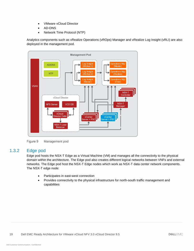
1.3.1 Management pod The management pod hosts and manages all NFV management components:
• vCenter Server Appliance
• NSX-T Manager
• NSX-Controller
19 Dell EMC Ready Architecture for VMware vCloud NFV 3.0 vCloud Director 9.5
Dell Customer Communication - Confidential
• VMware vCloud Director
• AD-DNS
• Network Time Protocol (NTP)
Analytics components such as vRealize Operations (vROps) Manager and vRealize Log Insight (vRLI) are also
deployed in the management pod.
Management pod
1.3.2 Edge pod Edge pod hosts the NSX-T Edge as a Virtual Machine (VM) and manages all the connectivity to the physical
domain within the architecture. The Edge pod also creates different logical networks between VNFs and external
networks. The Edge pod host the NSX-T Edge nodes which work as NSX-T data center network components.
The NSX-T edge node:
• Participates in east-west connection
• Provides connectivity to the physical infrastructure for north-south traffic management and
capabilities

20 Dell EMC Ready Architecture for VMware vCloud NFV 3.0 vCloud Director 9.5
Dell Customer Communication - Confidential
Edge pod
1.3.3 Resource pod The resource pod provides the virtualized runtime environment, namely compute, network, and storage
environments, to fulfill workloads.
Resource pod

21 Dell EMC Ready Architecture for VMware vCloud NFV 3.0 vCloud Director 9.5
Dell Customer Communication - Confidential
2 Solution hardware
2.1 Hardware installation and configuration The servers, storage, and other networking component are required to install and configure to deploy Dell EMC
Ready Solution bundle.
The following server solution support is used in this deployment:
• Dell EMC PowerEdge R640 or R740 servers
• Dell EMC PowerEdge R740xd servers
This configuration uses the following switches:
• Dell EMC Networking S4048-ON with one switch used to serve as a ToR
• A pair of Dell EMC Networking Z9264F-ON, S5248-ON, S5232-ON, or S6010-ON as leaf switches
This deployment also uses the iDRAC9 to improve the overall availability of Dell systems.
2.1.1 Unpack and install equipment After performing all standard industry safety precautions, proceed with the following steps:
1. Unpack and install the racks.
2. Unpack and install the server hardware.
3. Unpack and install the switch hardware.
4. Unpack and install the network cabling.
5. Connect each individual machine to both power bus installations.
6. Apply power to the racks.
Note: The Dell EMC EDT team usually performs these steps.
2.1.2 Power on equipment
Note: The Dell EMC EDT team usually performs these steps.
To test the installation of the equipment, perform the following steps:
1. Power on each server node individually.
2. Wait for the internal system diagnostic procedures to complete.
3. Power up the network switches.
4. Wait for the internal system diagnostic procedures to complete on each of the switches.
22 Dell EMC Ready Architecture for VMware vCloud NFV 3.0 vCloud Director 9.5
Dell Customer Communication - Confidential
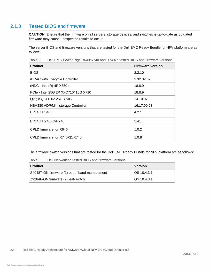
2.1.3 Tested BIOS and firmware
CAUTION: Ensure that the firmware on all servers, storage devices, and switches is up-to-date as outdated
firmware may cause unexpected results to occur.
The server BIOS and firmware versions that are tested for the Dell EMC Ready Bundle for NFV platform are as
follows:
Dell EMC PowerEdge R640/R740 and R740xd tested BIOS and firmware versions
Product Firmware version
BIOS 2.2.10
iDRAC with Lifecycle Controller 3.32.32.32
rNDC - Intel(R) 4P X550-t 18.8.9
PCIe - Intel 25G 2P XXC710/ 10G X710 18.8.9
Qlogic QL41262 25GB NIC 14.10.07
HBA330 ADP/Mini storage Controller 16.17.00.03
BP14G R640 4.27
BP14G R740XD/R740 2.41
CPLD firmware for R640 1.0.2
CPLD firmware for R740XD/R740 1.0.8
The firmware switch versions that are tested for the Dell EMC Ready Bundle for NFV platform are as follows:
Dell Networking tested BIOS and firmware versions
Product Version
S4048T-ON firmware (1) out of band management OS 10.4.3.1
Z9264F-ON firmware (2) leaf-switch OS 10.4.3.1

23 Dell EMC Ready Architecture for VMware vCloud NFV 3.0 vCloud Director 9.5
Dell Customer Communication - Confidential
2.1.4 Supported configuration The Table 4 provides the list of VMware component and their supported version that is used and verified for this
deployment.
VMware vCloud NFV product inventory list
Product Version
ESXi 6.7 U1
VMware vCenter Server 6.7 U1
VMware NSX–T 2.3.0
VMware vSAN 6.7 U1
VMware vRealize Log Insight 4.7
VMware vRealize Operations Manager 7.0
VMware vCloud Director 9.5.0.3
2.1.5 List of components Various software’s are used to create the NFVI environment. Table 5 displays the list of components and their
instances that are deployed in this deployment.
NFVI Components
Product Instances (Count)
ESXi 12 nodes
AD-DNS 1 VM
NTP 1 VM
VMware vCenter Server 6 VM
VMware vSAN NA
VMware NSX–T Manager 1 VM
VMware NSX–T Controller 3 VM
VMware NSX–T Edge 4 VM
VMware vRealize Log Insight 3 VM
VMware vRealize Operations Manager 3 VM
VMware vCloud Director 4 VM
24 Dell EMC Ready Architecture for VMware vCloud NFV 3.0 vCloud Director 9.5
Dell Customer Communication - Confidential
2.2 Network connectivity and port mapping
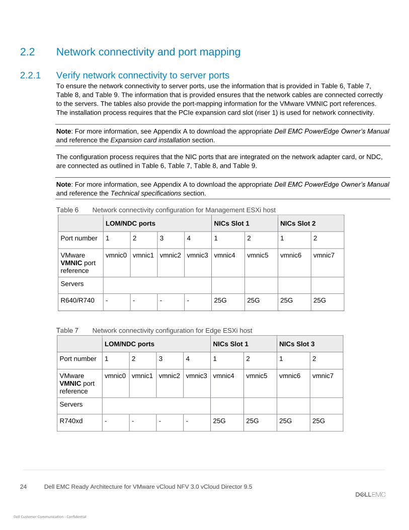
2.2.1 Verify network connectivity to server ports To ensure the network connectivity to server ports, use the information that is provided in Table 6, Table 7,
Table 8, and Table 9. The information that is provided ensures that the network cables are connected correctly
to the servers. The tables also provide the port-mapping information for the VMware VMNIC port references.
The installation process requires that the PCIe expansion card slot (riser 1) is used for network connectivity.
Note: For more information, see Appendix A to download the appropriate Dell EMC PowerEdge Owner’s Manual
and reference the Expansion card installation section.
The configuration process requires that the NIC ports that are integrated on the network adapter card, or NDC,
are connected as outlined in Table 6, Table 7, Table 8, and Table 9.
Note: For more information, see Appendix A to download the appropriate Dell EMC PowerEdge Owner’s Manual
and reference the Technical specifications section.
Network connectivity configuration for Management ESXi host
LOM/NDC ports NICs Slot 1 NICs Slot 2
Port number 1 2 3 4 1 2 1 2
VMware VMNIC port reference
vmnic0 vmnic1 vmnic2 vmnic3 vmnic4 vmnic5 vmnic6 vmnic7
Servers
R640/R740 - - - - 25G 25G 25G 25G
Network connectivity configuration for Edge ESXi host
LOM/NDC ports NICs Slot 1 NICs Slot 3
Port number 1 2 3 4 1 2 1 2
VMware VMNIC port reference
vmnic0 vmnic1 vmnic2 vmnic3 vmnic4 vmnic5 vmnic6 vmnic7
Servers
R740xd - - - - 25G 25G 25G 25G

25 Dell EMC Ready Architecture for VMware vCloud NFV 3.0 vCloud Director 9.5
Dell Customer Communication - Confidential
Network connectivity configuration table of Resource ESXi host
LOM/NDC ports NICs Slot 1 NICs Slot 3 NICs Slot 4
Port number 1 2 3 4 1 2 1 2 1 2
VMware VMNIC port reference
vmnic0 vmnic1 vmnic2 vmnic3 vmnic4 vmnic5 vmnic6 vmnic7 Vmnic8 Vmnic9
Servers
R740xd - - - - 25G 25G 25G 25G 25G 25G
Network connectivity configuration table of Deployment Server
LOM/NDC ports NIC Slot 1
Port number 1 2 3 4 1 2
VMware VMNIC port reference
vmnic0 vmnic1 vmnic2 vmnic3 vmnic4 vmnic5
Servers
R640/R740 - - 10G - 10G 10G
2.2.2 VDS DvPort group mapping with VLAN ID and related ESXi VMNIC The mapping list provides details about all VSS, VDS, VDS DvPort groups, VLAN ID, and ESXi VMNICs. These
details are created and configured under management and resource pod networking.
Table 10, Table 11, Table 12, and Table 13 show the VDS-DvPort group/VSS port group mappings with VLAN
ID and corresponding VMNIC present on ESXi, which are assigned as uplinks to the VDS/VSS.
For example, the VDS named Infrastructure Management VDS with the DvPort Group ESXi_Mgmt_Network is
configured with VLAN ID 100 and uses a pair of VMNIC which is vmnic4 and vmnic6 as uplinks for the VDS.

26 Dell EMC Ready Architecture for VMware vCloud NFV 3.0 vCloud Director 9.5
Dell Customer Communication - Confidential
Management POD
VDS type VDS name Port groups VLAN ID Uplink NICs Switch
VDS (Infrastructure)
Infrastructure Management VDS
ESXi_Mgmt_Network 100 vmnic4 vmnic6
Leaf1+Leaf2
vSAN_Network 300
vMotion_Network 200
Virtual Machine Network (VDS)
Management Network VDS
VM_Mgmt_Network 20 vmnic5 vmnic7
Leaf1+Leaf2
VCSA_HA_Network 30
Resource POD
VDS Type VDS Name Port groups VLAN ID Uplink NICs Switch
VDS (Infrastructure)
Infrastructure Management VDS
ESXi_Mgmt_Network 100 vmnic4 vmnic6
Leaf1+Leaf2
VM_Mgmt_Network 20
vSAN_Network 200
vMotion_Network 300
VDS (Virtual Machine Network)
N-VDS(S) Overlay_Network 70 vmnic5 vmnic7
Leaf1+Leaf2
VDS (Virtual Machine Network)
N-VDS(Enhanced Data Path)
Vlan_DPDK_Network 40 vmnic8 vmnic9
Leaf1+Leaf2
Edge POD
VDS Type VDS Name Port groups VLAN ID Uplink NICs Switch
VDS (Infrastructure)
Infrastructure Management VDS
ESXi_Mgmt_Network_Edge 100 vmnic4 vmnic6
Leaf1+Leaf2
VM_Mgmt_Network_Edge 20
vSAN_Network_Edge 200
vMotion_Network_Edge 300
VDS (Virtual Machine Network)
Edge VDS Overlay_Network VLAN 0-4094
vmnic5 vmnic7
Leaf1+Leaf2
External_Network

27 Dell EMC Ready Architecture for VMware vCloud NFV 3.0 vCloud Director 9.5
Dell Customer Communication - Confidential
Deployment Server
VSS name Port groups VLAN ID Uplink NICs Switch
vSwitch0 VM Network 0 vmnic2 ToR
vSwitch1 PG-100-ESXI 100 vmnic4 Leaf
PG-20-VM-Mgmt 20 vmnic5 Leaf
28 Dell EMC Ready Architecture for VMware vCloud NFV 3.0 vCloud Director 9.5
Dell Customer Communication - Confidential
3 Manual deployment
3.1 Solution prerequisites The following requirements must be satisfied before beginning with a Dell EMC VMware vCloud NFV 3.0
Platform manual deployment:
Note: All compute nodes must have identical hard drive, RAM, and NIC configurations.
• All the required hardware must be installed and configured as per the Hardware installation and
configuration
• Powered after the hardware once they are configured as per the Hardware installation and
configuration section
• Internet access, including but not limited to, deployment server
• Deployment server used to deploy the solution should hold the required VMware Software
Appliance files
3.1.1 Deployment server Refer the Solution bundle physical network design and topology section for the deployment server physical
network topology that is used in this deployment:
Note: ESXi 6.7 U1 or above must be installed on a bare-metal deployment server.
3.1.1.1 ESXi installation on deployment server Prerequisite:
• iDRAC should be configured and accessible
• ESXi 6.7 U1 ISO file on local machine
• ToR switch should be configured
To install ESXi on deployment server:
1. Log in to iDRAC 9 web GUI.
2. From the Dashboard window, click Launch Virtual Console within the Virtual Console section. The
iDRAC Virtual Console window displays.
3. On the navigation bar, click Connect Virtual Media.
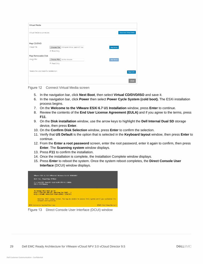
4. From the Virtual Media window, in the Map CD/DVD section, click Choose File and select the ESXi
image file from your local machine, and click Map Device then click Close.
29 Dell EMC Ready Architecture for VMware vCloud NFV 3.0 vCloud Director 9.5
Dell Customer Communication - Confidential
Connect Virtual Media screen
5. In the navigation bar, click Next Boot, then select Virtual CD/DVD/ISO and save it.
6. In the navigation bar, click Power then select Power Cycle System (cold boot). The ESXi installation
process begins.
7. On the Welcome to the VMware ESXi 6.7 U1 Installation window, press Enter to continue.
8. Review the contents of the End User License Agreement (EULA) and if you agree to the terms, press
F11.
9. On the Disk installation window, use the arrow keys to highlight the Dell Internal Dual SD storage
device, then press Enter.
10. On the Confirm Disk Selection window, press Enter to confirm the selection.
11. Verify that US Default is the option that is selected in the Keyboard layout window, then press Enter to
continue.
12. From the Enter a root password screen, enter the root password, enter it again to confirm, then press
Enter. The Scanning system window displays.
13. Press F11 to confirm the installation.
14. Once the installation is complete, the Installation Complete window displays.
15. Press Enter to reboot the system. Once the system reboot completes, the Direct Console User
Interface (DCUI) window displays.
Direct Console User Interface (DCUI) window
30 Dell EMC Ready Architecture for VMware vCloud NFV 3.0 vCloud Director 9.5
Dell Customer Communication - Confidential
3.1.1.2 Customize ESXi The System Customization window enables users to customize various ESXi system settings such as:
• Passwords
• Management configuration
• Restart options
• Keyboard settings
• Troubleshooting options
• System reset configurations
Follow the following steps to access the System Customization window:
1. From the DCUI window, press F2.
2. Provide the required user credentials in the fields provided then press Enter.
3. On the System Customization window, use the arrows to select the option to customize, then press
Enter.
3.1.1.3 Management network configuration To configure the management network, perform the following steps:
1. On the System Customization window, use the keyboard arrow keys to select Configure Management
Network, then press Enter.
2. To update the network adapters, use the keyboard arrow keys to select the Network Adapter option,
then press Enter.
3.1.1.4 Change IPv4 configuration Perform the following steps to configure the static IPv4 address:
1. On the System Customization window, select Configure Management Network > IPv4 Configuration,
then press the Enter key.
2. Select Set static IPv4 and network configuration, and enter the required IPv4 address, subnet mask,
and default gateway.
3. Press Enter to save the changes made.
Note: The IPv4 addresses used in the example are for demonstration purposes only.
3.1.1.5 Change DNS configuration To change the DNS configuration:
1. On the Configure Management Network window, use keyboard arrow keys to select DNS
Configuration then press Enter.
2. From the DNS Configuration window, use keyboard arrow keys to select Use the following DNS
server addresses and hostname: option.
3. In the fields provided, enter the required Primary DNS Server, Alternate DNS Server IP, and
Hostname information in the fields provided, then press Enter.
4. Add the domain name in the Suffixes field then press Enter to save the settings.

31 Dell EMC Ready Architecture for VMware vCloud NFV 3.0 vCloud Director 9.5
Dell Customer Communication - Confidential
5. Press Enter to restart the management network.
6. Once the network restarts, select the Test Management Network and press Enter. This test pings the
configured default gateway, primary and alternate DNS servers, and resolve the configured hostname.
3.1.1.6 Troubleshooting options To troubleshoot ESXi issues:
1. Use the keyboard to select the Troubleshooting Options then press Enter.
2. From the options provided, use the arrow to select the wanted troubleshooting option, then press Enter.
3.1.2 Create standard vSwitch on deployment server By default, vSwitch0 is available on the deployment server. The user must create the following virtual switches
on the deployment server:
vSwitch details
vSwitch name Uplink MTU (bytes) Link discovery Security
vSwitch0 vmnic2 1500 Bytes Listen/CDP For Promiscuous mode and Forged transmits, enable the Reject radio button
vSwitch1 vmnic4, vmnic5
9000 Bytes Listen/CDP For Promiscuous mode and Forged transmits, enable the Accept radio button
To create a standard vSwitch on the deployment server:
1. In the Web Browser, browse the deployment server IP address, then log in into it using the necessary
credentials.
2. From the navigation pane, click Networking.
3. On the Virtual switches tab, select Add standard virtual switch. The Add standard virtual switch
window displays.
4. In the vSwitch Name field, enter the vSwitch name.
5. Use the vSwitch details in Table 14 and select the MTU, Uplink, Mode, Protocol, and Security details
options, then click Add.
6. Once the vSwitch1 is created, edit the vSwitch1.
7. In the NIC Teaming section, locate the Load balancing drop-down list and select Route based on IP
hash.
32 Dell EMC Ready Architecture for VMware vCloud NFV 3.0 vCloud Director 9.5
Dell Customer Communication - Confidential
Edit standard virtual switch
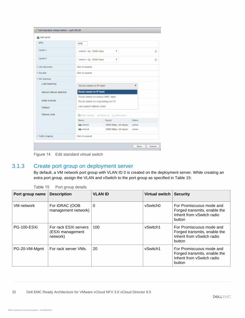
3.1.3 Create port group on deployment server By default, a VM network port group with VLAN ID 0 is created on the deployment server. While creating an
extra port group, assign the VLAN and vSwitch to the port group as specified in Table 15:
Port group details
Port group name Description VLAN ID Virtual switch Security
VM network For iDRAC (OOB management network)
0 vSwitch0 For Promiscuous mode and Forged transmits, enable the Inherit from vSwitch radio button
PG-100-ESXi For rack ESXi servers (ESXi management network)
100 vSwitch1 For Promiscuous mode and Forged transmits, enable the Inherit from vSwitch radio button
PG-20-VM-Mgmt For rack server VMs. 20 vSwitch1 For Promiscuous mode and Forged transmits, enable the Inherit from vSwitch radio button
33 Dell EMC Ready Architecture for VMware vCloud NFV 3.0 vCloud Director 9.5
Dell Customer Communication - Confidential
To create a port group on deployment server:
1. Log in to the deployment server web GUI.
2. From the navigation panel, click Networking.
3. On the Port groups tab, then select Add port group. The Add port group window displays.
4. Use the information in Table 15 to update the required information in the Add port group window, then
click Add.
5. Repeat the steps in this section to create more port groups on the deployment server as specified in
Table 15.
3.1.4 Create datastore on deployment server To create the datastore on ESXi deployment server:
1. Log in into ESXi host using vSphere web client.
2. From the Home window, click Storage > New datastore.
3. On the Select Creation Type window, select Create new VMFS datastore then click Next.
4. In the Name field, enter the name of the datastore, select a non-SSD device, and then click Next.
5. From the Select partitioning options window, select how you would like to partition the device, then
click Next.
6. Review the options selected from the Ready to complete window and if no changes are required, click
Finish.
3.1.5 Connectivity overview for deployment VM and server To deploy the CentOS VM on a deployment server, the VM network must be configured within the network
mapping for management purposes.
After the VM is deployed, perform the following steps:
1. From Edit settings, add a Stamp adapter to access the VMs.
2. Add an ESXi management adapter to access the ESXi server from the deployment server.
3. From the console of that VM, assign the static IP addresses to the deployment server for each adapter
that is connected to it.
4. Once the IP address is assigned, open the command console and ping the gateway. If the ping is
successful, go to deploy NFV components.
Note: Once the deployment VM and server connectivity are established, install Google Chrome on the access
rack servers.
3.1.6 Deployment VM In this document, a deployment VM is used to deploy the solution which can be a virtual machine or a physical
server. The deployment VM contains the licenses for VMware software OVA, ISO, and other required licenses
necessary for the deployment.
Note: To deploy the VM, ensure that the Dell 14G servers and network are accessible.
34 Dell EMC Ready Architecture for VMware vCloud NFV 3.0 vCloud Director 9.5
Dell Customer Communication - Confidential
The CentOS deployment VM is used in this guide as a base operating system platform for the deployment of the
NFV Infrastructure (NFVI). The deployment VM performs all the steps involving installation, configuration, and
verification of the VMware software stack.
Note: Before initiating the deployment, ensure that all of the necessary software firmware is copied or
downloaded in the Deployment VM.
This document provides the steps necessary to install the following applications:
• VMware-VMvisor-Installer-6.7.0.update01-10302608.x86_64-DellEMC_Customized
• Centos7.6 ISO for NTP
• Windows Server 2012R2 ISO for AD DNS
• VMware-VCSA-all-6.7U1
• VMware-vRealize-Log-Insight-4.7
• vRealize-Operations-Manager-Appliance-7.0
• NSX-T Manager 2.3
• VMware-vCloud-Director-9.5
3.1.6.1 Creating Deployment VM using CentOS Prerequisites:
• ESXi Server 6.7U1
• ISO file for CentOS 7.6 or above
• Three network adapters are used:
- vnic1: For management network
- vnic2: For stamp-related network
- vnic3: For management ESXi network
• Ensure that available disk storage is not less than 150 GB.
3.1.6.2 Installation of CentOS To install the CentOS:
1. Open the ESXi hosts in the browser, in the navigation pane, right-click the host, then select
Create/Register VM.
2. On the Select Creation type window, click create a new Virtual Machine, then click Next to continue.
3. On the Select a name and guest OS window:
- Enter the VM name in the Name field.
- From the Compatibility drop-down list, select ESXi 6.7 virtual machine.
- From the Guest OS family drop-down list, select the operating system family as Linux.
- From the Guest OS version drop-down list, select the operating system version as CentOS 7
(64-bit)
- Click Next to continue.
4. On the Select storage window, select the datastore, then click Next to continue.
5. On the Customize settings window:

35 Dell EMC Ready Architecture for VMware vCloud NFV 3.0 vCloud Director 9.5
Dell Customer Communication - Confidential
- Select the CPU to 8.
- Expand the CPU then select the Virtual Sockets to 2 and Check Socket to 4.
- Select the Memory to 16 GB.
- Select the Hard Disk1 to 150 GB.
- Expand the hard disk then select the Disk Provisioning to Thin Provisioned.
- Select the SCSI controller 0 to LSI Logic Parallel.
- Select the VM network in the Network Adapter 1 field.
- Click CD/DVD DRIVE 1, select ISO file from the uploaded on the datastore.
- Click Next to continue.
Customize settings window
6. Review the setting selection and click Finish.
7. Power on the Virtual Machine then click Install CentOS 7, or you can wait for 60 seconds for the
automatic boot to begin the CentOS installation.
The installation process begins and the Welcome to CENTOS 7 window open.
8. Select the wanted language, then click Continue.
9. On the Installation Summary window, select the SOFTWARE SELECTION, then select the GNOME
Desktop radio button in base environment then click Done.
10. On the Installation Summary window, click Installation Destination.
11. On the Installation Destination window, select Automatically configure partitioning radio button in
the other storage options and then click Done.
12. On the Installation summary window, click Begin Installation.
Note: Once the installation is complete, the user is required to set the root password.
13. Set the root password, then click Finish Configuration, and click Reboot.
14. Once system reboots, review the license agreement and if you agree to the terms, click Accept.

36 Dell EMC Ready Architecture for VMware vCloud NFV 3.0 vCloud Director 9.5
Dell Customer Communication - Confidential
15. On Privacy window, click Next to continue.
16. On the Time Zone window, select the appropriate time zone and then click Next to continue.
17. On the Online Account window, click Skip to continue.
18. On the About You window, enter the full name and the username in the fields provided and then click
Next to continue.
19. On the Password window, enter a password and confirm, click Next to continue.
20. On Ready to go window, click Start using CentOS Linux.
3.1.6.3 IP configuration of deployment VM Perform the following steps to configure the IP address:
1. Open the CentOS VM, then go to Settings > Network.
2. On the Network window, click the Gear icon.
3. On the IPv4 tab, select the Manual radio button.
4. In the Addresses section, enter the IP address, Netmask IP, andIP, Gateway IP for deployment VM in
the fields provided.
5. Click Apply. Once the IP is assigned, restart the network.
3.1.6.4 Enable connect automatically in Network settings To enable connect automatically in Network settings:
1. From Settings, go to to Network, and click the Gear icon.
2. In the Details tab, check the Connect Automatically box, and click Apply.
Details tab

37 Dell EMC Ready Architecture for VMware vCloud NFV 3.0 vCloud Director 9.5
Dell Customer Communication - Confidential
3.1.6.5 NTP settings on deployment VM Prerequisites:
• Deployment VM must have Internet connectivity
To configure NTP settings on deployment VM:
3. On the CentOS VM, open the terminal.
4. Run the following command to replace the chrony with NTPD:
# yum remove chrony
5. Run the following command to disable the firewall:
# systemctl stop firewalld
6. Run the following command and install NTP service:
# yum install ntp
7. Run the following command to check the NTPD status:
# systemctl status ntpd.
a. Run the following command and if NTPD is running, stop it first and then enable ntpd in next step:
# systemctl stop ntpd.service
b. Run the following command to restart and enable ntpd service:
# systemctl restart ntpd
# systemctl enable ntpd
3.1.6.6 Setting up the time zone to UTC Prerequisites:
• Deployment VM must have Internet connectivity.
To set time zone to UTC on CentOS:
1. On the deployment VM, open the terminal.
2. Run the following command to check the present time zone:
# ls -l /etc/localtime
3. Run the following command and search the time zone that you want to set:
# timedatectl list-timezones | grep UTC
This command displays the list of available time zone.sIf the UTC time zone is present, the grep UTC
command displays.

38 Dell EMC Ready Architecture for VMware vCloud NFV 3.0 vCloud Director 9.5
Dell Customer Communication - Confidential
Time zones
4. Once you verify that the UTC time zone is present, set the time zone using the following command:
# timedatectl set-timezone UTC.
5. Once the setup is completed, verify the time zone by running following command:
# ls –l /etc/localtime
Setup time zone
3.1.6.7 Disable DHCP script from adding entries to resolv.conf To stop DHCP to update DNS entries while on boot, edit the file and add the line dns=none in the [main]
section. This command stops the DHCP script so that you can update the DNS entries in the resolv.conf.
Disable DHCP
3.1.6.8 Disable auto mount on CentOS By default, the auto mount option is enabled on the CentOS. This option must be disabled during the
development process to avoid multiple mounts of ISO files.
To disable the auto mount on the CentOS:
1. On the CentOS VM, open the terminal.
2. Create a file /etc/dconf/db/local.d/00-media-automount with following content:
[org/gnome/desktop/media-handling]
automount=false
automount-open=false
3. Run the following command to check the file:
# cat /etc/dconf/db/local.d/00-media-automount
The output must be:
[org/gnome/desktop/media-handling]
automount=false
automount-open=false

39 Dell EMC Ready Architecture for VMware vCloud NFV 3.0 vCloud Director 9.5
Dell Customer Communication - Confidential
4. Once the file is created, run the following command to save the changes: # dconf update
3.1.6.9 Installation of Google Chrome and related settings Prerequisites:
• Deployment VM must have Internet connectivity
To install Google Chrome:
1. On the CentOS VM, open the terminal.
2. Enable Google YUM repository:
a. Create a file and name it: /etc/yum.repos.d/google-chrome.repo then add the following lines of code:
[google-chrome]
name=google-chrome
baseurl=http://dl.google.com/linux/chrome/rpm/stable/$basearch
enabled=1
gpgcheck=1
gpgkey=https://dl-ssl.google.com/linux/linux_signing_key.pub
3. Use the following comment to install Google Chrome: # yum install google-chrome-
stable.x86_64
Proceed on all prompts asked while installing.
4. Edit the file /usr/bin/google-chrome and append --no-sandbox -test-type to end of last code line
as shown below:
CLI for Google Chrome
This avoids the need to open google-chrome using command line and opens it directly while disabling
pop-ups.
5. Run the following command to remove the login pop-up: rm ~/.local/share/keyrings/* then
restart Chrome browser.
6. Once the Chrome installed successfully, delete the file google-chrome.repo using command:
# rm /etc/yum.repos.d/google-chrome.repo
3.1.6.10 Installation of OVF tool Prerequisites:
• Deployment VM must have Internet connectivity
To download and install the VMware OVF tool:

40 Dell EMC Ready Architecture for VMware vCloud NFV 3.0 vCloud Director 9.5
Dell Customer Communication - Confidential
1. Download the OVF Tool from following URL:
https://my.vmware.com/group/vmware/details?downloadGroup=OVFTOOL430&productId=742#
Note: You can also download the OVF Tool version 4.3 from the VMware site using VMware credentials. Locate
the corresponding Linux 64 bit setup file and download it.
The file is downloaded as VMware-ovftool-4.3.0-7948156-lin.x86_64.bundle
2. Go to the folder in which OVF tool is downloaded and open it.
3. On the CentOS VM, open the terminal.
4. Change permissions of the downloaded file: chmod +x VMware-ovftool-4.3.0-7948156-
lin.x86_64.bundle
5. To install OVF Tool, run the following command: # ./VMware-ovftool-4.3.0-7948156-
lin.x86_64.bundle
6. Review and accept the license agreement then click Next, and then click Install.
7. Click Finish to complete installation.
3.1.6.11 Add network adapters To Add the network adapter:
1. Right-click on the deployment VM and select Edit Setting. The Edit setting dialog box displays.
2. Click Add network adapter and add two network adapters:
- For ESXi management, select PG-100-ESXi
- For VM Management, select PG-20-VM-Mgmt
3. Assign the appropriate IP address to the corresponding VM NICs.
4. Click Save.
Edit setting window
41 Dell EMC Ready Architecture for VMware vCloud NFV 3.0 vCloud Director 9.5
Dell Customer Communication - Confidential
4 ESXi installation and configuration To create an NFV infrastructure, install ESXi on the Dell EMC PowerEdge R640/R740 and R740xd servers
based on vSAN Ready Node.
4.1 Install ESXi on Dell EMC PowerEdge R640, R740, and R740xd
servers using iDRAC9 Prerequisites:
• Verify that the minimum required hardware firmware versions on the servers are as in Table 2
• ESXi Installer 6.7 U1 or later ISO file
• iDRAC with at least 16 GB SD Card enabled
See the ESXi installation on deployment server section to install the ESXi on Dell EMC PowerEdge R640/R740
and R720xd servers.
Once the ESXi is installed on the Dell EMC PowerEdge R640, R740 and R720xd servers, see the Customize
ESXi and its subsection to configure the ESXi password, update management network configuration, and
change IPv4 and DNS configuration.
Refer the following section to:
• To add VLAN ID on ESXI Management Network, see Set VLAN ID for ESXi management network
• Assign licenses to ESXi, see Assign license to ESXi
• To create SSH policies, see Set SSH policy
• For help in creating firewall rules, see Set Firewall Rules
• To install the DPDK drivers, see Installing the DPDK drivers
4.1.1.1 Set VLAN ID for ESXi management network You can set VLAN ID for the ESXi management network. Perform the following steps to set the VLAN ID for the
ESXi management network:
1. On the System Customization window, select Configure Management Network then select VLAN,
and press Enter.
2. In the field provided, enter the configured VLAN ID and press Enter to save the change.
4.1.1.2 Assign license to ESXi To assign license to an ESXi:
1. From a browser, open ESXi and click Manage, then select Licensing.
2. In the License key field, enter the required license key and click Check license.
3. Click Assign license then click Close.
4.1.1.3 Set SSH policy To set SSH policy for ESXi:
1. Navigate to your ESXi server’s embedded host client using the IP address or domain name.
42 Dell EMC Ready Architecture for VMware vCloud NFV 3.0 vCloud Director 9.5
Dell Customer Communication - Confidential
2. From the left navigation bar, select Manage to access the settings for your host.
3. Select the Services tab then select the TSM-SSH service (SSH).
4. Right-click on a service or click the Actions menu item to set the Policy to Start and stop with host.
4.1.1.4 Set Firewall Rules To set the firewall rules:
1. SSH to the ESXi Host with valid credentials.
2. Run the following command to disable the firewall rule:
esxcli network firewall set --enabled false
3. Run the following command to get the status:
esxcli network firewall get
4.1.1.5 Installing the DPDK drivers On the Resource pod, install the required firmware for Intel NIC Cards (25G 2P XXC740/10G X710) on each
ESXi hosts to use N-VDS Enhanced mode.
Note: Qlogic drivers do not support the N-VDS Enhanced mode feature.
Prerequisites:
• Download the updated NIC driver from the VMware Compatibility Guide in either VIB or offline
bundle format
• Resource ESXi hosts should be in maintenance mode
To install the firmware:
1. Copy the downloaded VIB or offline bundle file to /tmp/directory in the ESXi Server.
2. Run the following command using SSH terminal:
• If you are using VIB file to install driver:
esxcli software vib install -v {VIBFILE path}
• If you are using offline bundle to install the driver:
esxcli software vib install -d {OFFLINE_BUNDLE path}
Note: Enter the complete path of VIB or offline bundle path of ESXi server in place of {VIBFILE path} and
{OFFLINE_BUNDLE path}. For example, esxcli software vib install -v
/tmp/VMware_bootbank_net-driver.1.1.0-1vmw.0.0.372183.vib
The driver installation begins.
3. Once the driver installation is completed, reboot the host.
4. Check which VMware installation bundle (VIB) versions are installed on the resource pod hosts.

43 Dell EMC Ready Architecture for VMware vCloud NFV 3.0 vCloud Director 9.5
Dell Customer Communication - Confidential
Installed DPDK Drivers
Note: Repeat the steps provided in the ESXi installation and configuration section to install and configure the
remaining ESXi servers.
44 Dell EMC Ready Architecture for VMware vCloud NFV 3.0 vCloud Director 9.5
Dell Customer Communication - Confidential
5 Auxiliary components In order to operate successfully, the auxiliary components are required to install on Dell EMC ready solution
bundle. Network Time Protocol (NTP) and Active Directory (AD) or Domain Name System (DNS) serve as the
auxiliary components:
• AD: It provides a centralized authentication source for management components
• DNS: It provides forward and reverse lookup services to all platform components
• NTP: It provides a time synchronization source to all components
Deploy the virtual machines of AD-DNS and NTP on the first management ESXi server.
5.1 Prerequisites for auxiliary components To install and configure the auxiliary components, you are required to create a datastore, a standard vSwitch,
and a port group. Refer the following section to create it:
• Create datastore on first management ESXi server
• Create standard vSwitch on first management ESXi server
• Create port group on first management ESXi server
5.1.1.1 Create datastore on first management ESXi server To create the datastore on the first management ESXi server:
1. Open the ESXi in your browser, and login with valid credentials.
2. From the Home window, click Storage, then click New datastore.
3. On Select Creation Type window, select Create new VMFS datastore then click Next.
4. In the Name field, enter the datastore name, select a non-SSD disk device, and then click Next.
5. From the Select partitioning options window, select how you would like to partition the device, then
click Next.
6. Review the options selected from the Ready to complete window and if no changes are required, click
Finish.
5.1.1.2 Create standard vSwitch on first management ESXi server By default, vSwitch0 exists on the first ESXi server. Using the settings in Table 16, you can create more virtual
switches.
vSwitch details
vSwitch name Uplink MTU (bytes) Link discovery Security
vSwitch1 Vmnic5 9000 Bytes Listen/CDP • For Promiscuous mode and Forged transmits, enable the Reject radio button.
• For MAC address changes, enable Accept radio button.
45 Dell EMC Ready Architecture for VMware vCloud NFV 3.0 vCloud Director 9.5
Dell Customer Communication - Confidential
To create a standard vSwitch on the first management ESXi server:
1. Log in into first management ESXi server.
2. From the navigation panel, click Networking.
3. Click the Virtual switches tab, then select Add standard virtual switch. The Add standard virtual
switch window displays.
4. Use the Table 16 to update the required information in Add standard virtual switch window, then click
Add to create vSwitch.
5.1.1.3 Create port group on first management ESXi server By default, the VM network port group, VLAN ID 0, exists on the ESXi server. To add more port groups, you
must create them and assign the VLAN and vSwitch information to the port group.
Port group details
Port group name Description VLAN ID Virtual switch Security
Appliance_Network For rack ESXi servers (VM management network)
20 vSwitch1 For Promiscuous mode and Forged transmits, enable the Inherit from vSwitch radio button
To create a port group on the first management ESXi server:
1. Log in into first management ESXi server.
2. From the navigation panel, click Networking.
3. On the Port groups tab, then select Add port group. The Add port group window displays.
4. Use the Table 17 to update the required information in Add port group window, then click Add.
5.1.2 NTP server configuration Prerequisite:
• Linux CentOS 7.6 VM is running and is configured for network use
Note: The Linux VM acts as the NTP server.
To configure the NTP server, perform the following steps:
1. Install the NTP daemon that is provided by default, within the CentOS repository.
2. Run the following command: # yum install ntp
Note: The # yum install ntp command runs if an Internet connection is available
3. Enter the # timedatectl set-timezone UTC command to set the time zone to UTC.
Note: Set the NTP client and NTP server to have the same time zone.

46 Dell EMC Ready Architecture for VMware vCloud NFV 3.0 vCloud Director 9.5
Dell Customer Communication - Confidential
4. After setting the time zone, verify that the system and hardware clocks are synchronized. If the clocks
are not synchronized, enter the following command:
[root@localhost -]# date
Wed Jul 25 15:25:44 UTC 2018
[root@localhost -]# hwclock
Wednesday 26 July 2018 03:25:54 PM UTC -0.646933 seconds
[root@localhost -]# hwclock -–systohc
[root@localhost -]# hwclock
Wednesday 26 July 2018 03:37:39 PM UTC -0.771275 seconds
[root@localhost -]# date
Wed Jul 25 15:27:45 UTC 2018
Note: The #date command shows the system clock. The #hwclock command shows the hardware clock. The
#hwclock --systohc command synchronizes the hardware and system clocks.
5. Enter the following command within the /etc/ntp.conf file to enable clients from your network to
synchronize the time with this server:
restrict ::1
# Hosts on local network are less restricted.
restrict 192.168.20.0 netmask 255.255.255.0 nomodify notrap
# Use public servers from the pool.ntp.org project.
# Please consider joining the pool (http://www.pool.ntp.org/join.html).
#server 0.centos.pool.ntp.org iburst
#server 1.centos.pool.ntp.org iburst
#server 2.centos.pool.ntp.org iburst
#server 3.centos.pool.ntp.org iburst
server 127.127.1.0
Note: The restrict 192.168.20.0 netmask 255.255.255.0 nomodify notrap command allows for
restricted access to the network. The IP range sees the actual network address in the production environment.
Multiple IP ranges can be added.
6. Enter the following IP command for the NTP server configuration: 127.127.1.0
Note: The 127.127.1.0 server line in the ntp.conf file configures itself as an NTP server.
7. Enter the following commands to add firewall rules:
# firewall-cmd --add-service=ntp --permanent
# firewall-cmd –-reload
8. Activate the NTPD service by entering the following commands:
# systemctl restart ntpd
# systemctl enable ntpd
# systemctl status ntpd

47 Dell EMC Ready Architecture for VMware vCloud NFV 3.0 vCloud Director 9.5
Dell Customer Communication - Confidential
Note: Whenever you are restarting the VMs above services are required to run again.
9. Enter the following command to ensure that NTP is running properly: # ntpq –p
Confirmation of NTP status
5.1.3 Synchronize ESXi clocks with NTP Before you install vCenter Server or deploy the vCenter Server Appliance, ensure that all of the machines on the
vSphere network have their clocks that are synchronized.
To synchronize the ESXi clocks with NTP:
1. Connect to the ESXi host using URL.
2. Select Manage and go to System > Time & Date > Edit Settings.
3. In the Edit time configuration window, select Use Network Time Protocol (Enable NTP client).
Edit time configuration window
4. In the Add NTP Server field, enter the IP address or fully qualified domain name of one or more NTP
servers to synchronize.
5. Set the startup policy and service status as Start and stop with host then click OK.
6. To save the changes and service, again select the Time and date, click Actions, select NTP service
and click Start.

48 Dell EMC Ready Architecture for VMware vCloud NFV 3.0 vCloud Director 9.5
Dell Customer Communication - Confidential
Time and date start action
5.1.3.1 Synchronize VM clock using NTP If the system running Microsoft Windows is not part of a domain controller, synchronize the Microsoft Windows
machine time with the NTP server.
To synchronize the VM clocks using NTP:
1. From the task bar, right-click the time that is listed and select Change date and time settings.
2. From the Date and Time window, select the Internet Time tab, then click Change Settings.
3. Within the Internet Time Settings window, click to place a check in the Synchronize with an Internet
time server option.
4. Enter your NTP server IP or FQDN in the Server field that is provided, and then click Update Now.
5. Click OK to save the changes.
5.1.4 Microsoft Windows Server 2012 installation for AD DNS Microsoft Windows Server 2012 uses AD, DNS, and NTP auxiliary services. This section describes the steps
that are used to install Microsoft Windows Server 2012.
Note: The server using AD, DNS, and NTP auxiliary services is deployed on the ESXi datastore and not on the
vSAN datastore. Dell EMC recommends the creation of a datastore on the ESXi server, specifically for AD, DNS,
and NTP and that is part of the management cluster. Use the ESXi datastores for deployment of the AD, DNS,
and NTP server.
When the cluster is in place, migration of the AD, DNS, and NTP server, and the VM from the ESXi datastore to
the vSAN datastore is necessary. Once the AD, DNS, and NTP server VM is migrated, remove the ESXi
datastore.
Prerequisites:
• Minimum 1.4 GHz 64-bit processor
• Minimum 4 GB memory
• 40 GB or greater of disk space
• ESXi datastore
To install Microsoft Windows Server 2012, follow the below steps:
1. Create a VM and select the ISO of Windows Server 2012 R2 to deploy AD, DNS, and NTP services.
Note: Setup of the necessary files may take several minutes.

49 Dell EMC Ready Architecture for VMware vCloud NFV 3.0 vCloud Director 9.5
Dell Customer Communication - Confidential
2. On the Start window, click Next to continue.
3. When prompted, select the required language, time, and keyboard selections, then click Next.
4. Click Install now. The Setup is starting window displays until the application loads completely.
5. On the Select the operating system window, select Windows Server 2012 R2 Standard Evaluation
with GUI and click Next.
6. Review the License terms and if you agree, check the I accept the license terms box, then click Next.
7. On the Windows Setup Installation Type Selection window, select Custom: Install Windows only
(advanced). The Where do you want to install Windows? screen displays.
8. Verify the location of the drive or partition, then click Next. After the setup is complete, Microsoft
Windows Server 2012 restarts.
9. From the Settings window, enter the desired administrator password, reenter the password to confirm it,
then click Finish. The setup process begins to finalize the settings.
Note: This process may take several minutes to complete.
10. After the setup is complete, log in with the Administrator credentials. After successful login, the Server
Manager displays.
5.1.4.1 Network configuration for Microsoft Windows Server and VMware tool installation To configure the network for Microsoft Windows Server 2012, perform the following steps:
1. From the Network and Sharing Center, click right-click the desired Ethernet then select Properties.
2. On the Internet Protocol Version 4 (TCP/IPv4) window, configure the IP address for the AD/DNS
server and then click OK.
5.1.4.2 Install VMware tools 1. From the Windows VM, locate the installed ESXi and right-click the VM preview and select Guest OS
> Install VMware Tools.
2. From the Windows VM console (UI), locate the drive.
3. Double-click the VMware Tools installation drive.
4. Select the Typical setup type, then click Install.
5.1.5 Active Directory and DNS installation
5.1.5.1 Update Windows VM computer name Before creating the AD DNS server, change the Windows VM computer name. To assign a human-readable
name to the Windows VM, perform the following steps:
1. On the Server Manager window, click Local Server in the left-navigation pane. The Properties window
displays.
2. On the Properties window, right-click the Computer Name field and select System properties. The
System Properties window displays.
3. From the System Properties window, select the Computer Name tab, click the Change button. The
Computer Name/Domain Changes window displays.
4. On the Change Name and Domain Changes window, locate the Computer Name field and enter a
computer name for the ADDNS server. For example, Figure 25 uses ADDNSServer as the new
computer name. Click OK to save the name change. The System restart message displays.

50 Dell EMC Ready Architecture for VMware vCloud NFV 3.0 vCloud Director 9.5
Dell Customer Communication - Confidential
5. Click Restart Now. The virtual machine restarts.
5.1.5.2 Primary Active Directory and DNS installation To install the primary AD and DNS:
1. On the Server Manager dashboard, click Add roles and features.
2. Review the information that is provided in the Before you Begin window, then click Next to continue.
3. Select Role-based or feature-based installation option then click Next.
4. On the Server Selection window, select the server role to install from the options that are provided and
click Next.
5. In the Server Roles window, select the Active Directory Domain Services option.
Server Roles selection window
6. From the Add Roles and Features Wizard, select the Add Features button.
7. Click the DNS Server listing.
8. From the Add features that are required for DNS Server window, click the Add Features button.
DNS Server required features window
9. Click Next.

51 Dell EMC Ready Architecture for VMware vCloud NFV 3.0 vCloud Director 9.5
Dell Customer Communication - Confidential
10. On the Features window, review the options that are selected, making sure to keep the default
selections then click Next.
11. Review the information within the DNS Server window, then click Next.
12. Review the information provided within the AD DS window, then click Next.
13. From the Confirm installation selections window, carefully review each of the selections that are made
then click Install.
Confirm installation selections window
14. Once the installation is complete, click Close to exit the wizard.
15. Reboot the server to complete the installation.
16. Once the server reboots, access the Server Manager and from the Dashboard, click the task flag,
which is located in the navigation bar.
17. From the options provided, click the Promote this server to a domain controller hyperlink.
Server Manager Dashboard task flag advisory
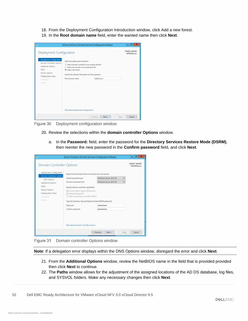
52 Dell EMC Ready Architecture for VMware vCloud NFV 3.0 vCloud Director 9.5
Dell Customer Communication - Confidential
18. From the Deployment Configuration Introduction window, click Add a new forest.
19. In the Root domain name field, enter the wanted name then click Next.
Deployment configuration window
20. Review the selections within the domain controller Options window.
a. In the Password: field, enter the password for the Directory Services Restore Mode (DSRM),
then reenter the new password in the Confirm password field, and click Next.
Domain controller Options window
Note: If a delegation error displays within the DNS Options window, disregard the error and click Next.
21. From the Additional Options window, review the NetBIOS name in the field that is provided provided
then click Next to continue.
22. The Paths window allows for the adjustment of the assigned locations of the AD DS database, log files,
and SYSVOL folders. Make any necessary changes then click Next.

53 Dell EMC Ready Architecture for VMware vCloud NFV 3.0 vCloud Director 9.5
Dell Customer Communication - Confidential
23. From the Review Options window, review the selections that are made and click Next to continue.
A system check begins that verifies the compatibility of the system with the options selected. When
complete, review the results of the prerequisites check.
Note: A successful prerequisites check displays a green check at the top of the window. Any critical errors that
are found must be addressed before the option to begin the installation is provided.
24. Click Install to start the installation process. Once the installation process is complete, the server
automatically reboots.
25. After the server reboots, log in to the server using domain administrator credentials.
5.1.6 Create DNS Reverse Lookup Zone The Reverse Lookup Zone is not created by default if the DNS server is newly configured. The steps provided in
this section to help with the creation of the Reverse Lookup Zone for the IPv4 address range. In this deployment,
two DNS reverse lookup zones are created: one for VM Management Network and another for ESXi
Management Network.
To create a DNS Reverse Lookup Zone for VM Management Network:
1. From the Server Manager Dashboard, click Tools in the top navigation panel, then DNS.
2. From the DNS Manager window, right-click the Reverse Lookup Zone in the left-navigation panel, then
click New Zone.
3. On the Welcome to New Zone Wizard window, click Next.
4. In the Zone Type window, select the zone to create then click Next.
Zone Type selection window
5. From the Active Directory Zone Replication Scope window, select how the DNS data is replicated,
then click Next.
6. In the Reverse Lookup Zone Name window, select IPv4 Reverse Lookup Zone and click Next.
7. Verify that the Network ID option is selected and enter the Network ID in the field provided, then click
Next.
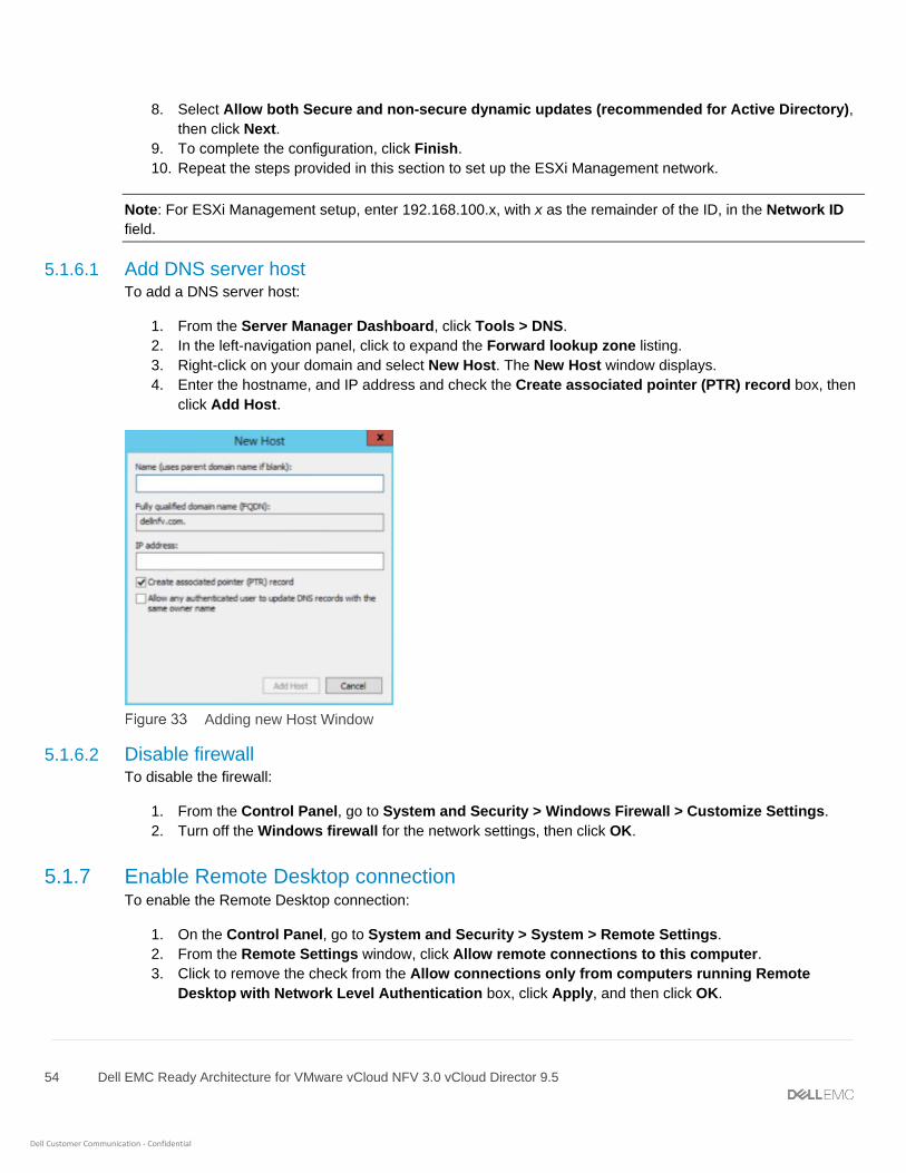
54 Dell EMC Ready Architecture for VMware vCloud NFV 3.0 vCloud Director 9.5
Dell Customer Communication - Confidential
8. Select Allow both Secure and non-secure dynamic updates (recommended for Active Directory),
then click Next.
9. To complete the configuration, click Finish.
10. Repeat the steps provided in this section to set up the ESXi Management network.
Note: For ESXi Management setup, enter 192.168.100.x, with x as the remainder of the ID, in the Network ID
field.
5.1.6.1 Add DNS server host To add a DNS server host:
1. From the Server Manager Dashboard, click Tools > DNS.
2. In the left-navigation panel, click to expand the Forward lookup zone listing.
3. Right-click on your domain and select New Host. The New Host window displays.
4. Enter the hostname, and IP address and check the Create associated pointer (PTR) record box, then
click Add Host.
Adding new Host Window
5.1.6.2 Disable firewall To disable the firewall:
1. From the Control Panel, go to System and Security > Windows Firewall > Customize Settings.
2. Turn off the Windows firewall for the network settings, then click OK.
5.1.7 Enable Remote Desktop connection To enable the Remote Desktop connection:
1. On the Control Panel, go to System and Security > System > Remote Settings.
2. From the Remote Settings window, click Allow remote connections to this computer.
3. Click to remove the check from the Allow connections only from computers running Remote
Desktop with Network Level Authentication box, click Apply, and then click OK.

55 Dell EMC Ready Architecture for VMware vCloud NFV 3.0 vCloud Director 9.5
Dell Customer Communication - Confidential
5.1.8 Add Windows VM license To add a Windows VM license:
1. Open the PowerShell and enter the following command: DISM /Online /Set-
Edition:ServerStandard /ProductKey:<enter product key here> /AcceptEula
Note: Enter the product key after the ProductKey: command.
2. After entering the license key, press Enter. The prompt to reboot the system displays.
3. Press the Y key on the keyboard to reboot the system and apply the license.
5.1.9 Add self-signed certificate to Windows Active Directory Prerequisites:
• WinSCP installed on a Microsoft Windows VM to copy files from Windows to Linux
• Optionally, you can install PuTTY to run commands from a Microsoft Widows VM.
To add a self-signed certificate in AD, perform the following steps:
1. On a Linux machine with open-SSL installed, enter the following command to generate the ca.key file:
$ openssl genrsa -des3 -out ca.key 4096
2. When prompted, enter the desired password.
3. On the Linux machine, enter the following command to generate the ca.crt file:
$ openssl req -new -x509 -days 3650 -key ca.key -out ca.crt
4. Using WinSCP or a similar tool, copy the ca.crt file to the Active Directory Windows VM from the
Linux machine.
5. From the Windows Active Directory VM, go to Manage Computer Certificates by searching for it
using the Windows search function.
6. Once the location is found, import the copied certificate.
Manage computer certificates window

56 Dell EMC Ready Architecture for VMware vCloud NFV 3.0 vCloud Director 9.5
Dell Customer Communication - Confidential
7. Right-click the Trusted Root Certification Authority listing within the Logical Store Name section,
select All Tasks, then select Import.
8. On the Welcome to the Certificate Import Wizard window, click Next to continue.
9. Click on Browse button and select the ca.crt file and then click Next.
10. Verify that the Certificate store listed is correct, then click Next.
11. Click on Finish button to Import the certificate. The Import was successful message displays.
12. Click OK.
13. Verify that the imported certificate displays in the Trusted Root Certification Authority section.
Trusted Root Certification Authority window
14. From the Windows AD VM, create a request.inf file.
15. Copy and paste the following text into the file:
[Version]
Signature="$Windows NT$"
[NewRequest]
Subject = "CN=ACTIVE_DIRECTORY_FQDN"
KeySpec = 1
KeyLength = 1024
Exportable = TRUE
MachineKeySet = TRUE
SMIME = FALSE
PrivateKeyArchive = FALSE
UserProtected = FALSE
UseExistingKeySet = FALSE
ProviderName = "Microsoft RSA SChannel Cryptographic Provider"
ProviderType = 12
RequestType = PKCS10
KeyUsage = 0xa0
[EnhancedKeyUsageExtension]

57 Dell EMC Ready Architecture for VMware vCloud NFV 3.0 vCloud Director 9.5
Dell Customer Communication - Confidential
OID = 1.3.6.1.5.5.7.3.1 ; Server Authentication
16. Replace the ACTIVE_DIRECTORY_FQDN text in quotes, with the FQDN of the Windows AD VM, and
save the changes.
Example of request.ini file
17. Open the PowerShell and ‘cd’ to the directory where the request.inf file is saved.
18. Run the following command: certreq -new request.inf client.csr
19. The client.csr file is created.
20. Using WinScp or a similar tool, copy the client.csr file to the Linux system.
21. Create a v3ext.txt file on the Linux system.
22. Paste the following text into the v3ext.txt file:
keyUsage=digitalSignature,keyEncipherment
extendedKeyUsage=serverAuth
subjectKeyIdentifier=hash
23. Using PuTTY or by pasting it directly, enter the following command within the Linux system:
$ openssl x509 -req -days 3650 -in client.csr -CA ca.crt -CAkey ca.key -
extfile v3ext.txt -set_serial 01 -out client.crt
24. When prompted, enter the password for the ca.key. The client.crt file is created on the Linux system.
25. Use WinSCP to copy the client.crt file to the Windows AD VM.
26. Run the following command in the Windows AD VM PowerShell, within in the same directory as the
client.crt file: certreq -accept client.crt
27. In the Windows AD VM, create a file that is named ldap-renewservercert.txt.
28. Paste the following text within the file:
dn:
changetype: modify
add: renewServerCertificate
renewServerCertificate: 1
–
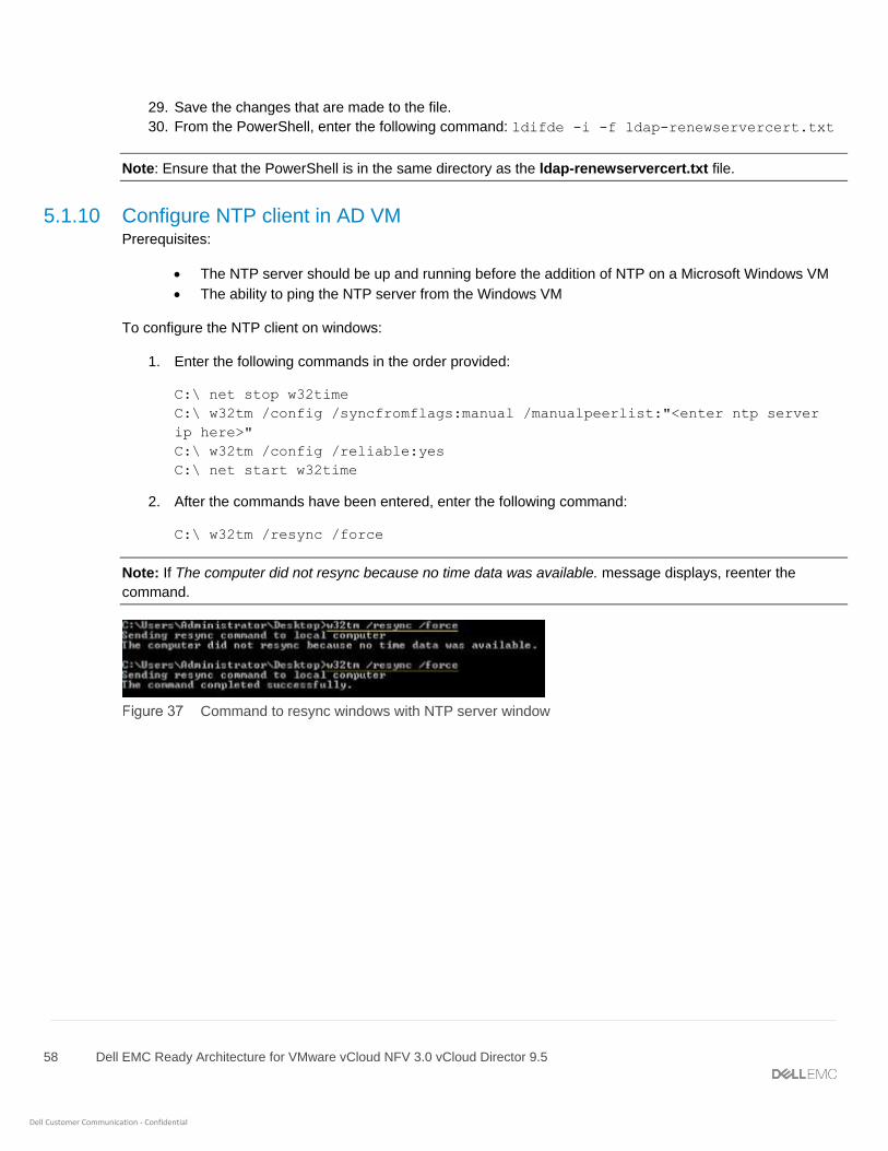
58 Dell EMC Ready Architecture for VMware vCloud NFV 3.0 vCloud Director 9.5
Dell Customer Communication - Confidential
29. Save the changes that are made to the file.
30. From the PowerShell, enter the following command: ldifde -i -f ldap-renewservercert.txt
Note: Ensure that the PowerShell is in the same directory as the ldap-renewservercert.txt file.
5.1.10 Configure NTP client in AD VM Prerequisites:
• The NTP server should be up and running before the addition of NTP on a Microsoft Windows VM
• The ability to ping the NTP server from the Windows VM
To configure the NTP client on windows:
1. Enter the following commands in the order provided:
C:\ net stop w32time
C:\ w32tm /config /syncfromflags:manual /manualpeerlist:"<enter ntp server
ip here>"
C:\ w32tm /config /reliable:yes
C:\ net start w32time
2. After the commands have been entered, enter the following command:
C:\ w32tm /resync /force
Note: If The computer did not resync because no time data was available. message displays, reenter the
command.
Command to resync windows with NTP server window
59 Dell EMC Ready Architecture for VMware vCloud NFV 3.0 vCloud Director 9.5
Dell Customer Communication - Confidential
6 VMware vCenter Server deployment and configuration In the VMware vCloud NFV 3.0 architecture, two instances of the VMware vCenter Server Appliance (VCSA)
with embedded PSC are deployed. One VCSA instance manages the management cluster, while the second
instance manages the resource cluster and edge cluster. Management pod hosts both of these instances. Each
VCSA instance required to configure in HA mode and consist of active, passive, and witness vCenter Server
instance.
6.1 VMware vCenter Server Appliance deployment In the vCloud NFV 3.0 architecture, the deployment of the VCSA is done in two stages. The first deployment is
for the VCSA instance that manages the management cluster, and the second VCSA deployment manages the
Edge and resource cluster.
Prerequisites:
• ESXi 6.7 U1 is configured and running
• AD, DNS, and NTP are running
• Manual creation of forward and reverse lookup entries for all VCSA instances on the DNS server
before deployment
6.2 Stage 1: Deploy ISO file for Management vCenter Server Appliance
with embedded PSC Stage 1 of the deployment process involves the deployment of the ISO file in the VCSA installer, as a vCenter
Server Appliance with an embedded PSC. To deploy the ISO file:
1. Mount the VMware-VCSA-all-6.7.x ISO on Windows/Linux VM Deployment server.
2. Go to the path where VCSA installer is mounted and go to the vcsa-ui-installer directory, then to the
subdirectory for your operating system, and run the installer executable file.
• For Microsoft Windows, go to the win32 subdirectory, and run the installer.exe file.
• For Linux, go to the lin64 subdirectory, and run the installer file.
3. From the vCenter Server Appliance 6.7 Installation window, click Install.
4. On the Introduction window, review the installation overview and click Next.
5. Review the information provided within the End User License Agreement (EULA) and if you agree to the
terms check the I accept the terms of the license agreement box and, click Next.
6. On the Select deployment type window, select vCenter Server with an Embedded Platform Services
Controller in the Embedded Platform Services Controller section, and click Next.
7. Within the Appliance deployment target window, enter the ESXi host, HTTPS port, user name, and
password in the fields that are provided, then click Next.
8. When prompted, review the contents of the Certificate Warning, then click Yes to accept the certificate.
9. On the Set up appliance VM window, enter the VM name and set the root password in the fields
provided, then click Next.
Note: The appliance name can contain upper and lower-case letters, however special characters such as %, \,
or / are not permitted. The appliance name must not exceed 80 characters in length.

60 Dell EMC Ready Architecture for VMware vCloud NFV 3.0 vCloud Director 9.5
Dell Customer Communication - Confidential
10. From the Select deployment size window, use the drop-down from the Deployment size and Storage
size sections to select the sizes necessary for the vCenter Server Appliance for your vSphere inventory,
then click Next.
11. From the Select datastore window, select Install on new vSAN cluster containing the target host
option, then enter the Datacenter and Cluster Name and click Next.
12. On the Claim disks for vSAN window, click all the disks and check the Enable Thin Disk Mode box
then click Next.
13. In the Configure Network Settings window, enter the appropriate network settings details, then click
Next.
Note: Dell EMC recommends the use of an FQDN. However, if an IP address is used instead, use a static IP
address allocation for the appliance as IP addresses allocated by DHCP may change.
14. From the Ready to complete stage 1 window, review the deployment settings for the vCenter Server
Appliance and click Finish.
The deployment process starts.
Stage 1 status window
15. Once the deployment is complete, click Continue to proceed with the stage 2 deployment process.
Stage 1 completion and continuation window
6.3 Stage 2: Set up Management vCenter Server Appliance with
embedded PSC Once the stage 1 deployment is complete, you are redirected to stage 2 of the deployment process to set up and
start the services of the newly deployed vCenter Server Appliance with an embedded Platform Services
Controller.
1. Review the information within the Introduction to stage 2 page, then click Next.
2. From the Appliance configuration screen:

61 Dell EMC Ready Architecture for VMware vCloud NFV 3.0 vCloud Director 9.5
Dell Customer Communication - Confidential
a. Locate the Time synchronization mode drop-down list and select Synchronize time with NTP
servers.
b. In the NTP Servers field, enter the NTP server IP address.
c. From the SSH access drop-down list, select Enabled, then click Next.
Note: From this window, the option to enable remote SSH access to the appliance, is provided.
3. In the SSO configuration window, enter the vCenter Single Sign-On domain name and
administrator password in the fields that are provided, then click Next.
4. Optionally, you can select to participate in the Customer Experience Improvement Program by
selecting the Join the VMware Customer Experience Improvement Program (CEIP) box, then click
Next.
Note: The Customer Experience Improvement Program (CEIP) provides VMware with information that enables
VMware to improve its products and services and to fix problems. By choosing to participate in CEIP, you agree
that VMware may collect technical information about your use of VMware products and services regularly. This
option is enabled by default.
5. From the Ready to complete page, review the configuration settings for the vCenter Server Appliance,
click Finish, and then click OK. Stage 2 of the deployment process and set up of the appliance is
complete.
Ready to complete window
6. Optionally, once the initial setup is complete, open the browser and go to to the following URL:
https://<vcenter_server_appliance_fqdn>:443 or from the Appliance Getting Started Page option click
the https://<vcenter_server_appliance_fqdn>:443 link to access the vCenter Server Appliance Getting
Started page. Otherwise, click Close to exit the wizard.
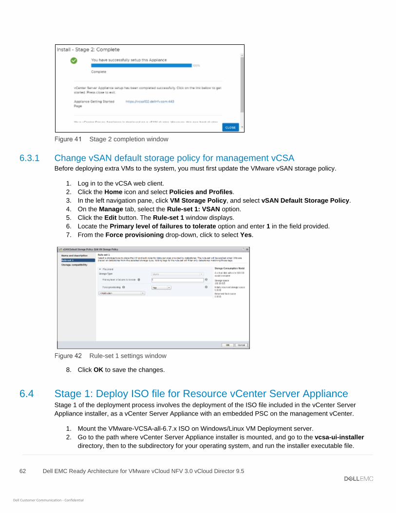
62 Dell EMC Ready Architecture for VMware vCloud NFV 3.0 vCloud Director 9.5
Dell Customer Communication - Confidential
Stage 2 completion window
6.3.1 Change vSAN default storage policy for management vCSA Before deploying extra VMs to the system, you must first update the VMware vSAN storage policy.
1. Log in to the vCSA web client.
2. Click the Home icon and select Policies and Profiles.
3. In the left navigation pane, click VM Storage Policy, and select vSAN Default Storage Policy.
4. On the Manage tab, select the Rule-set 1: VSAN option.
5. Click the Edit button. The Rule-set 1 window displays.
6. Locate the Primary level of failures to tolerate option and enter 1 in the field provided.
7. From the Force provisioning drop-down, click to select Yes.
Rule-set 1 settings window
8. Click OK to save the changes.
6.4 Stage 1: Deploy ISO file for Resource vCenter Server Appliance Stage 1 of the deployment process involves the deployment of the ISO file included in the vCenter Server
Appliance installer, as a vCenter Server Appliance with an embedded PSC on the management vCenter.
1. Mount the VMware-VCSA-all-6.7.x ISO on Windows/Linux VM Deployment server.
2. Go to the path where vCenter Server Appliance installer is mounted, and go to the vcsa-ui-installer
directory, then to the subdirectory for your operating system, and run the installer executable file.
63 Dell EMC Ready Architecture for VMware vCloud NFV 3.0 vCloud Director 9.5
Dell Customer Communication - Confidential
• For Microsoft Windows, go to the win32 subdirectory, and run the installer.exe file.
• For Linux, go to the lin64 subdirectory, and run the installer file.
3. From the vCenter Server Appliance 6.7 Installation window, click Install.
4. On the Introduction window, review the installation overview then click Next.
5. Review the information provided within the End User License Agreement (EULA) and if you agree to
the terms check the I accept the terms of the license agreement box and, click Next.
6. On the Select deployment type window, select vCenter Server with an Embedded Platform
Services Controller in the Embedded Platform Services Controller section, and click Next.
7. On the Appliance deployment target window, enter vCenter Server name, HTTPS port, User name,
and Password in the fields provided, then click Next. The Certificate Warning window display.
8. Review the contents of the Certificate Warning, if agreed then click Yes to accept the certificate.
9. On the Select folder window, select the ManagementDatacenter option and then click Next.
10. On the Select compute resource window, go to require ESXi to deploy, then click Next.
11. On the Set up appliance VM window, enter the VM name and set the root password in the fields
provided, then click Next.
Note: The appliance name can contain upper and lower case letters, however special characters such as %, \,
or / are not permitted. The appliance name must not exceed 80 characters in length.
12. On the Select deployment size window, select the Deployment size and Storage size, then click
Next.
13. From the Select datastore window, select the vsanDatastore, and check the Enable Thin Disk Mode
box, then click Next.
14. On the Configure Network Settings window, enter the appropriate network settings details, then click
Next.
Note: Dell EMC recommends the use of a FQDN. If an IP address is used, the use of static IP address allocation
for the appliance is recommended, as the IP addresses allocated by DHCP may change.
15. On the Ready to complete stage 1 window, review the deployment settings for the VCSA and click
Finish. The deployment process starts.
16. Once the Stage 1 deployment is complete, click Continue to proceed with the stage 2 deployment
process.
6.5 Stage 2: Set up resource vCenter Server Appliance with embedded
PSC Once the Stage 1 deployment is complete, you are redirected to stage 2 of the deployment process to set up
and start the services of the newly deployed VCSA with an embedded Platform Services Controller.
1. Review the information within the Introduction to stage 2 page, then click Next
2. On the Appliance configuration window:
a. From the Time synchronization mode drop-down list, select Synchronize time with NTP
servers.
b. In the NTP Servers field, enter the NTP server IP address

64 Dell EMC Ready Architecture for VMware vCloud NFV 3.0 vCloud Director 9.5
Dell Customer Communication - Confidential
c. From the SSH access drop-down list, select Enabled, then click Next.
Note: From this window, the option to enable remote SSH access to the appliance, is provided.
3. On the SSO configuration window, enter the vCenter Single Sign-On domain name, user name, and
administrator password, then click Next.
4. On the Ready to complete window, review the configuration settings, and click Finish, then click OK.
Stage 2 of the deployment process and set up of the appliance is complete.
5. Optionally, once the initial setup is complete, open the browser and go to the following URL:
https://<vcenter_server_appliance_fqdn>:443 or from the appliance Getting Started page option and
click the https://<vcenter_server_appliance_fqdn>:443 link to access the vCenter Server Appliance
Getting Started page. Otherwise, click Close to exit the wizard.
6.5.1 Change VMware vSAN default storage policy for resource vCSA Prior to deploying more VMs to the system, you must first update the VMware vSAN storage policy.
1. Log in to the VCSA web client.
2. Click the Home icon and select Policies and Profiles.
3. In the left navigation pane, click VM Storage Policy, and select vSAN Default Storage Policy.
4. On the Manage tab, select the Rule-set 1: VSAN option.
5. Click the Edit button. The Rule-set 1 window displays.
6. Locate the Primary level of failures to tolerate option and enter 1 in the field provided.
7. From the Force provisioning drop-down, click to select Yes.
8. Click OK to save the changes.
6.6 Add AD authentication for vCenter Server Prerequisites:
• Deployment of the Management VCSA must be complete
• Deployment of the Resource VCSA must be complete
To add AD authentication:
1. Open the VCSA web client and log in as single sign-on administrator.
Note: You can access the vCSA web client by going to the following URL: <https://VCSA_FQDN_OR_IP>
Note: Use the password that was set during the installation process.
2. From the Homescreen, click Administration > System Configuration, then select the appropriate
VCSA and select the Manage tab.
3. On the Manage window, locate the Active Directory section and click the Join button.
4. In the fields provide, enter Domain name, user name, and password, then click OK.
Note: The Organizational unit information is optional.
5. Reboot the node to apply the changes. Once the node reboots, log in to the VMware vCenter Server.

65 Dell EMC Ready Architecture for VMware vCloud NFV 3.0 vCloud Director 9.5
Dell Customer Communication - Confidential
6. Navigate to Home > Administration > System Configuration, then select the appropriate VCSA then
select the Manage tab
7. Locate the Active Directory section and confirm that the domain is listed in the Domain field.
Active Directory window
8. Navigate to: Home icon and select Administration >Single Sign-On > Configuration.
9. On the Configuration window, click the Identity Sources tab, and then click the Add (+) icon to add an
identity source. The Add Identity source window displays.
10. On the Add identity source window, select the Active Directory (Integrated Windows
Authentication) source type from the options listed.
Note: The underlying system must be a member of the Active Directory domain.
11. Enter the domain name in the field provided then click Next.
12. Review the domain name and then click Finish.
The identity source displays in the Identity Sources tab.
Identity Sources tab with new identity listed
Note: Repeat the steps in this section for resource vCenter server.
6.7 Assign license to vCSA To assign licenses to VCSA:
1. Log in to the vCenter through vSphere Web Client.
2. Click the Home icon and select Administration.
3. From the left navigation pane, click Licenses.
4. Click the Add (+) icon and in the field that is provided, enter the license key, then Next.
5. Add a name for the license in the field that is provided and click Next.
The license displays in the Licenses tab and is added to vCenter.

66 Dell EMC Ready Architecture for VMware vCloud NFV 3.0 vCloud Director 9.5
Dell Customer Communication - Confidential
Listing of licenses within Licenses tab
6. Click the Assets tab, then the Solutions tab.
7. Select the vCenter Server from the Solutions list.
8. From the All Actions drop-down menu, select Assign license.
9. Select the license that you want to apply and then click OK to assign the license.
6.8 Create data center and cluster on resource vCenter After the installation of the management and resource vCenter, create the data center, resource cluster, and
edge cluster to enable vSAN, DRS, and vSphere HA.
Note: The management data center and cluster are created while the management vCSA is deployed.
1. Log in to the VMware vCenter Server Web Client using the required credentials.
2. From the left-navigation panel, right-click the desired vCenter server.
3. Click New Datacenter from the options provided.
4. Within the Datacenter name field, enter the name for the new data center, then click OK.
5. To create resource cluster, right-click the newly created data center and select New cluster.
6. Enter a name for the new cluster in the Name field, then click OK.
7. To create the Edge cluster, repeat the steps from step 5 to step 6.
6.9 Add hosts to vCenter cluster When adding hosts to the vCenter cluster, a minimum four hosts must be added to the management, resource,
and edge clusters. Once the clusters are created, add the hosts to the cluster.
1. To add a host to the vCenter cluster, right-click the cluster and select Add host. The Add Host window
displays.
2. Enter the name or IP address of the host and click Next.
3. On the Connection settings window, enter the required host user name and password for the
connection, and click Next. The Security Alert window displays.
4. On the Security Alert window, click Yes to replace the host certificate with a new certificate that is
signed by the VMware Certificate Server.
5. On the Host Summary window, review the information, and click Next to continue.
6. From the Assign license window, click to select the license that is listed, then click Next.
7. Within the Lockdown mode window, select the Disabled option and click Next.
8. Review the selected configurations within the Ready to complete window and if no other changes are
required, click Finish.

67 Dell EMC Ready Architecture for VMware vCloud NFV 3.0 vCloud Director 9.5
Dell Customer Communication - Confidential
Note: Repeat the steps within this section to add more ESXi hosts to the vCenter Cluster. Each cluster must
have minimum four hosts added to it.
Ensure that all the hosts are added to the management, edge, and resource cluster:
Sample Edge and resource cluster listing
6.10 Enable VMware enhanced vMotion compatibility To improve CPU compatibility between hosts that have varying CPU feature sets, you can hide some host CPU
features from the virtual machine by placing the host in an Enhanced vMotion Compatibility (EVC) cluster. Hosts
in an EVC cluster and hosts that you add to an existing EVC cluster must meet EVC requirements.
Prerequisites:
• Power off all virtual machines in the cluster that are running on hosts with a feature set greater than
the EVC mode that you intend to enable
• All hosts in the cluster must meeting the following requirements:
Requirements Description
ESXi version ESXi 6.7 U1
vCenter Server The host must be connected to a vCenter Server system.
CPUs A single vendor, either AMD or Intel.

68 Dell EMC Ready Architecture for VMware vCloud NFV 3.0 vCloud Director 9.5
Dell Customer Communication - Confidential
Advanced CPU features enabled Enable these CPU features in the BIOS if they are available:
• Hardware virtualization support (AMD-V or Intel VT)
• AMD No eXecute(NX)
• Intel eXecute Disable (XD)
6.10.1 Enable VMware EVC for management cluster To enable VMware EVC for management cluster:
1. Select the Management Cluster in the vSphere Web Client.
2. On the Configure tab go to VMware EVC and click Edit.
3. Select the Enable EVC for Intel Hosts radio button from the Select EVC Mode option and from the
VMware EVC Mode drop-down list select appropriate processor for the hosts to add to the cluster, then
click OK.
6.10.2 Enable VMware EVC for resource and edge cluster To enable VMware EVC for resource and edge cluster:
1. Go to the Resource Cluster in the VMware vSphere Web Client.
2. Click the Configure tab.
3. From the Services tab, go to VMware EVC and click Edit.
4. Select the Enable EVC for Intel Hosts radio button from the Select EVC Mode option and from the
VMware EVC Mode drop-down list select appropriate processor for the hosts to add to the cluster, then
click OK.
5. Repeat the steps provided in this section, on the edge cluster to enable EVC for the edge cluster.

69 Dell EMC Ready Architecture for VMware vCloud NFV 3.0 vCloud Director 9.5
Dell Customer Communication - Confidential
7 Configure Virtual Network Figure 6, Figure 7, and Figure 8 displays the underlying virtual distributed switch, or VDS, for the management
edge, and resource clusters. Different VLAN IDs can be used in the physical environment.
7.1 VDS creation and configuration for management pod Refer the following sections to create and configure VDS on Management pod:
• Create VDS for management pod
• VDS configuration settings for management VDS
• Create LAG for management pod
• Create distributed port group for management pod
• Add host to VDS on management pod
7.1.1 Create VDS for management pod The Table 18 displays the VDS configuration settings that are used for VDS in the management cluster.
VDS-management settings
Distributed switch name Version Number of uplinks
Network I/O control
Discovery protocol type/operation
MTU (bytes)
Infra_Network_VDS 6.6.0 2 Enabled CDP/Both 9000 Bytes
VM_Network_VDS 6.6.0 2 Enabled CDP/Both 9000 Bytes
To create and configure the virtual distributed switch for the management pod, perform the following steps:
1. In the VMware vSphere Web Client, select Home/Networking to switch to Networking View.
2. Right-click the ManagementDatacenter and select Distributed switch > New Distributed Switch.
3. In the New Distributed Switch window, see Table 18 and enter the switch name, then click Next.
4. On the Select version window, select Distributed switch: 6.6.0 and click Next.
5. From the Edit settings window, see Table 18 and select the number of required uplinks.
Note: The number of uplinks that are used depends on the number of physical NICs associated to the VDS.
6. Verify that the Network I/O Control option is set to Enabled.
7. From the Default port group drop-down, verify that the Create a default port group box is not
checked, and click Next.
8. Review the selected settings in the Ready to complete window, and if no changes are required, click
Finish.
Note: Using the information provided within Table 18, create the VM_Network_VDS distributed switch.
Once all the distributed switches are created, the Networking tab displays something like:

70 Dell EMC Ready Architecture for VMware vCloud NFV 3.0 vCloud Director 9.5
Dell Customer Communication - Confidential
VMware vSphere Web Client Networking tab
7.1.2 VDS configuration settings for management VDS 1. Once the distributed switches are created, select each distributed switch and click the Configure tab,
Properties, then click Edit.
2. From the Advanced tab, set MTU to 9000 bytes.
3. Locate the Discovery protocol section, from the Type drop-down list select Cisco Discovery
Protocol.
4. Use the drop-down arrow of Operation field, select Both, then click OK.
7.1.3 Create LAG for management pod The Table 19 displays the LAG configuration settings that are used for VDS in the Management cluster.
VDS-LAG settings
Distributed Switch Name Number of Ports Mode Load balancing mode
Infra_Network_VDS MgmtLag1 2 Active Source and destination IP address and TCP/UDP port
VM_Network_VDS MgmtLag1 2 Active Source and destination IP address and TCP/UDP port
To create and configure the LAG on virtual distributed switch for the management pod, perform the following
steps:
1. From the left navigation panel, click to select the Infra_Network_VDS then click the Configure tab.
2. From the Settings section, select LACP, click Add (+) to create the Migrating network traffic to LAGs.
3. Use Table 19 to enter Lag name, Number of ports, mode, and Load balancing mode. Click OK.

71 Dell EMC Ready Architecture for VMware vCloud NFV 3.0 vCloud Director 9.5
Dell Customer Communication - Confidential
New Link Aggregation Group
Note: Using the information provided within Table 19, create the LAG on VM_Network_VDS distributed
switches.
7.2 Create distributed port group for management pod The information in this section assists with the creation of more distributed port groups for the distributed switch.
The port group settings that are used for VDS-management cluster are shown in Table 20.
VDS-Management port group settings
Port group VLAN type
VLAN ID
Teaming and failover settings
Load balancing
Network failure detection
Notify switches
Failback Active uplinks
ESXi_Mgmt_Network (under Infra_Network_VDS)
VLAN 100 Route based on IP hash
Link status only
Yes Yes MgmtLag1
vSAN_Network (under Infra_Mgmt_VDS)
VLAN 300 Route based on IP hash
Link status only
Yes Yes MgmtLag1
vMotion_Network (under Infra_Network_VDS)
VLAN 200 Route based on IP hash
Link status only
Yes Yes MgmtLag1
VM_Mgmt_Network (under VM_Network_VDS)
VLAN 20 Route based on IP hash
Link status only
Yes Yes MgmtLag1
VCSA_HA_Network (under VM_Network_VDS)
VLAN 30 Route based on IP hash
Link status only
Yes Yes MgmtLag1

72 Dell EMC Ready Architecture for VMware vCloud NFV 3.0 vCloud Director 9.5
Dell Customer Communication - Confidential
To create a port group on the management pod:
1. Right-click on the newly created distributed switch and select Distributed Port Group, and then New
Distributed port group.
2. In the New Distributed Port Group window, see Table 20 and enter the port group name in the fields
provided, then click Next.
3. On the Configure settings page, set the general properties of the new port group as follows:
- Port binding: Static binding
- Port allocation: Elastic
- Number of ports: 8
- Network resource pool: (default)
- VLAN type: VLAN
- VLAN ID: See Table 20 to add VLAN ID
4. Check the Customize default policies configuration box, then click Next.
5. On the Security and Traffic Shaping windows, click Next as defaults settings are used.
6. On the Teaming and failover window, see Table 20 and select the Load balancing, Network failure
detection, Notify switches, Failback, and Active uplinks options, then click Next.
7. Use default setting in Monitoring, Miscellaneous, and Edit additional settings window and click Next.
8. Review the selected settings in the Ready to complete window, and if no changes are required, click
Finish.
The distributed port group is created display under the VDS:
VMware vSphere Web Client window
Note: Repeat the steps in this section to create more port groups as described in Table 20.
7.3 Add host to VDS on management pod Add hosts to each VDS switch created for management pod that is created in the VDS creation and
configuration section.

73 Dell EMC Ready Architecture for VMware vCloud NFV 3.0 vCloud Director 9.5
Dell Customer Communication - Confidential
7.3.1 vSwitch to VDS Migration on management pod vSwitch is migrated to VDS for both management and resource PODs. The VSS to VDS migration for both
PODs follows similar steps. Virtual machines residing on individual PODs are migrated to the VDS during this
operation.
Note: The migration process must be performed on the management pod first, then the resource pod.
7.3.1.1 Add hosts to Infra_Network_VDS 1. Right-click Distributed switch Infra_Network_VDS and select Add and Manage Hosts.
2. On the Add and Manage Hosts window, select the Add hosts radio button then click Next.
3. On the Select hosts window, click the (+) New hosts icon.
4. Select all of the hosts for the management cluster, then click OK.
5. Check the Configure identical network settings on multiple hosts (template mode) box then click
Next.
6. From the Select a template host window, select the network configuration host to apply to the other
hosts, then clicks Next.
7. On the Select network adapter tasks window, check the Manage physical adapter (template mode)
box to associate the necessary uplinks to the DVS, and check the Manage VMKernel adapters
(template mode) box then click Next.
8. On the Manage Physical network and adapters (template mode) window, add physical network
adapters to the distributed switch:
a. Select vmnic4, then click the Assign uplink icon and assign it to Mgmtlag1-0.
b. Select vmnic6, then click the Assign uplink icon and assign it to Mgmtlag1-1.
c. After assigning the uplink on the template host, click Apply to all to apply the physical network
adapter assignments on the switch for all the hosts, and click Next.
9. On the Manage VMkernel network adapters (template mode) window:
a. Select vmk0 and click the Assign port group icon.
b. Select the destination port group, for example, Esxi_Mgmt_Network to migrate the VMkernel
adapters from the source port group, then click OK.
c. Click New adapter to create network adapters for vSAN port group:
i. On the Select target device window click the Browse button and select the vSAN_Network
then click OK, then click Next.
ii. On the Port properties window, specify the VMKernel port settings:
> Network label: vSAN_Network
> IP settings: IPv4
> TCP/IP stack: Default
> Enabled services: vSAN
iii. Click Next.
iv. On the IPv4 settings window, click the Use static IPv4 settings option and enter the IPv4
address as 192.168.2.10 and Subnet mask IP in the provided fields, then click Next.
v. On Ready to complete window, review the settings and selections then click Finish to create
network adapter.
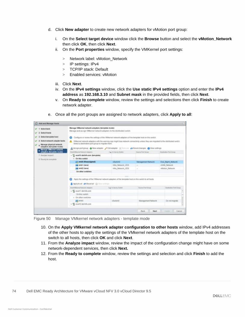
74 Dell EMC Ready Architecture for VMware vCloud NFV 3.0 vCloud Director 9.5
Dell Customer Communication - Confidential
d. Click New adapter to create new network adapters for vMotion port group:
i. On the Select target device window click the Browse button and select the vMotion_Network
then click OK, then click Next.
ii. On the Port properties window, specify the VMKernel port settings:
> Network label: vMotion_Network
> IP settings: IPv4
> TCP/IP stack: Default
> Enabled services: vMotion
iii. Click Next.
iv. On the IPv4 settings window, click the Use static IPv4 settings option and enter the IPv4
address as 192.168.3.10 and Subnet mask in the provided fields, then click Next.
v. On Ready to complete window, review the settings and selections then click Finish to create
network adapter.
e. Once all the port groups are assigned to network adapters, click Apply to all:
Manage VMkernel network adapters - template mode
10. On the Apply VMkernel network adapter configuration to other hosts window, add IPv4 addresses
of the other hosts to apply the settings of the VMkernel network adapters of the template host on the
switch to all hosts, then click OK and click Next.
11. From the Analyze impact window, review the impact of the configuration change might have on some
network-dependent services, then click Next.
12. From the Ready to complete window, review the settings and selection and click Finish to add the
host.

75 Dell EMC Ready Architecture for VMware vCloud NFV 3.0 vCloud Director 9.5
Dell Customer Communication - Confidential
Ready to complete window
7.3.1.2 Configure vSAN on management cluster To migrate the VM to VDS, configure the vSAN first. Perform the following steps to configure the vSAN on
management cluster:
1. Open the VMware vSphere Web Client for the management cluster.
2. On the ManagementCluster, select the Configure tab.
3. In the left navigation panel, click Disk Management under vSAN, then click the Claim disks icon in
Disk Groups.
Disk management window
4. In Claim Disk for vSAN use window, ensure that the Capacity tier is claimed for HDD, and that the
Cache tier has Flash selected, then click OK.
Claim disks window

76 Dell EMC Ready Architecture for VMware vCloud NFV 3.0 vCloud Director 9.5
Dell Customer Communication - Confidential
5. From the Configure tab, verify that the disk groups are created on each ESXi and the vSAN Datastore
is created.
7.3.2 Add hosts to VM_Network_VDS Prerequisites:
• All ESXI hosts have an extra uplink to the management network
To add hosts to the VM_Network_VDS:
1. Right-click on the VM_Network_VDS distributed switch and select Add and Manage Hosts.
2. On the Add and Manage Hosts window, select the Add hosts radio button then click Next.
3. On the Select hosts window, click the (+) New hosts icon. On the displayed window select all of the
management cluster hosts, then click OK.
Note: Do not select the hosts that are associated with any VM.
4. Check the Configure identical network settings on multiple hosts (template mode) box then click
Next.
5. On the Select a template host window, select the network configuration host to apply to the other
hosts, then clicks Next.
6. On the Select network adapter tasks window, check the Manage physical adapter (template mode)
box to associate the necessary uplinks to the DVS, and check the Manage VMKernel adapters
(template mode) box then click Next.
7. On the Manage Physical network and adapters (template mode) window, add physical network
adapters to the distributed switch
a. Select vmnic5, then click the Assign uplink icon and assign it to Mgmtlag1-0.
b. Select vmnic7, then click the Assign uplink icon and assign it to Mgmtlag1-1.
c. After assigning the uplink on the template host, click Apply to all to apply the physical network
adapter assignments on this switch for all the hosts, and click Next.
8. Review the information that is provided in the Manage VMkernel network adapter (template mode)
window, then click Next.
9. From the Analyze impact window, review the impact of the configuration change might have on some
network-dependent services, then click Next.
10. From the Ready to complete window, review the settings and selection and click Finish to add the
host.
7.3.2.1 Migrate AD-DNS VM To migrate the AD-DNS VM to a specific host or cluster and to a specific datastore:
1. Open the VMware vCenter Server Virtual Appliance.
2. From the datastore, right-click the AD-DNS VM and select Migrate.
3. On the Select the migration type window, select the Change both compute resource and storage
radio button then click Next.
4. On the Select a compute resource window, select the compute resource added to the
VM_Network_VDS for VM migration, then click Next.

77 Dell EMC Ready Architecture for VMware vCloud NFV 3.0 vCloud Director 9.5
Dell Customer Communication - Confidential
5. On the Select storage window, select vSAN Default Storage Policy from the VM storage policy drop-
down, then select vsanDatastore from the datastore listing, and click Next.
6. On the Select networks window, select the destination network, such as VM_Mgmt_Network, from the
drop-down list, and click Next.
7. On the Select vMotion priority window options, ensure that Schedule vMotion with high priority
radio button is selected, then click Next.
8. From the Ready to complete window, review the selections that are made then click Finish to complete
the operation.
7.3.2.2 Migrate NTP VM Follow the steps described in Migrate AD-DNS VM to migrate NTP VM deployed on the Management cluster.
7.3.2.3 Migrate Management VCSA active VM To migrate the management VCSA active VMs to a specific host or cluster:
1. Open the VMware vCenter Server Virtual Appliance.
2. From the datastore, right-click the management VCSA active VM and select Migrate.
3. On the Select the migration type window, select the Change compute resource only radio button then
click Next.
4. On the Select a compute resource window, select the compute resource for VM migration, then click
Next.
5. On the Select networks window, select the destination network from the drop-down list, and click Next.
6. On the Select vMotion priority window options, make sure that Schedule vMotion with high priority radio
button is selected, then click Next.
7. From the Ready to complete window, review the chosen selections then click Finish to complete the
operation.
7.3.2.4 Migrate Resource VCSA active VM Follow the steps described in Migrate Management VCSA active VM to migrate resource VCSA active VM
deployed on the Management cluster.
Note: Once the VMs are migrated from the ESXi host to VDS, it is required to add the remaining ESXi host to
VDS. Follow the steps that are described in Add hosts to VM_Network_VDS to add the host.
7.4 Create VDS for resource and edge pods In the resource cluster, create a VDS for Infrastructure network and for VM networks. Table 21 displays the VDS
information and the recommended settings that are required for this deployment.
VDS-Resource settings
VDS name Version Number of uplinks
Network I/O control
Discovery Protocol Type/Operation
MTU (Bytes)
Edge_Infra_Network_VDS 6.6.0 2 Enabled CDP/Both 9000 Bytes
Edge_VM_Network_VDS 6.6.0 2 Enabled CDP/Both 9000 Bytes
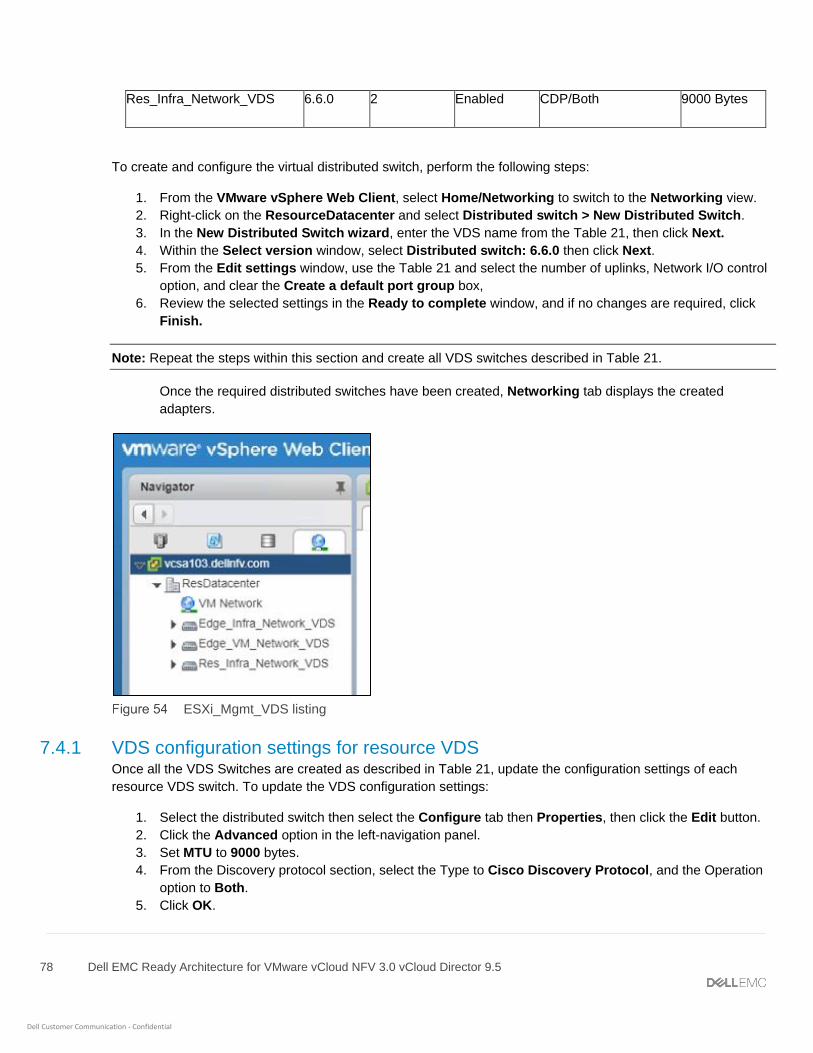
78 Dell EMC Ready Architecture for VMware vCloud NFV 3.0 vCloud Director 9.5
Dell Customer Communication - Confidential
Res_Infra_Network_VDS 6.6.0 2 Enabled CDP/Both 9000 Bytes
To create and configure the virtual distributed switch, perform the following steps:
1. From the VMware vSphere Web Client, select Home/Networking to switch to the Networking view.
2. Right-click on the ResourceDatacenter and select Distributed switch > New Distributed Switch.
3. In the New Distributed Switch wizard, enter the VDS name from the Table 21, then click Next.
4. Within the Select version window, select Distributed switch: 6.6.0 then click Next.
5. From the Edit settings window, use the Table 21 and select the number of uplinks, Network I/O control
option, and clear the Create a default port group box,
6. Review the selected settings in the Ready to complete window, and if no changes are required, click
Finish.
Note: Repeat the steps within this section and create all VDS switches described in Table 21.
Once the required distributed switches have been created, Networking tab displays the created
adapters.
ESXi_Mgmt_VDS listing
7.4.1 VDS configuration settings for resource VDS Once all the VDS Switches are created as described in Table 21, update the configuration settings of each
resource VDS switch. To update the VDS configuration settings:
1. Select the distributed switch then select the Configure tab then Properties, then click the Edit button.
2. Click the Advanced option in the left-navigation panel.
3. Set MTU to 9000 bytes.
4. From the Discovery protocol section, select the Type to Cisco Discovery Protocol, and the Operation
option to Both.
5. Click OK.

79 Dell EMC Ready Architecture for VMware vCloud NFV 3.0 vCloud Director 9.5
Dell Customer Communication - Confidential
Note: Repeat the steps in this section to configure the settings for each VDS.
7.4.2 Create LAG for resource and edge pods Table 22 displays the LAG configuration settings that are used to create LAG for VDS.
VDS-LAG settings
VDS Name Number of ports Mode Load balancing mode
Edge_Infra_Network_VDS EdgeLag1 2 Active Source and destination IP address and TCP/UDP port
Edge_VM_Network_VDS EdgeLag1 2 Active Source and destination IP address and TCP/UDP port
Res_Infra_Network_VDS ResourceLag1 2 Active Source and destination IP address and TCP/UDP port
To create and configure the LAG on virtual distributed switch for the management pod:
1. From the left navigation panel, click to select the Edge_Infra_Network_VDS then click the Configure
tab.
2. Click the Settings listing, select LACP, click Add (+) to create the Migrating network traffic to LAGs.
3. Using the information in table Table 22, enter the Lag name, Number of ports, mode, and Load
balancing mode then click OK.
Note: Using the information provided in Table 22, create the LAG on Edge_VM_Network_VDS, and
Res_Infra_Network_VDS distributed switches.
7.5 Create distributed port group for resource and edge VDS Table 23 displays the port group settings that are used for resource and edge pod VDS.
VDS-port group settings
Port group VLAN type
VLAN ID Teaming and failover settings
Load balancing Network failure detection
Notify switches
Failback Failover order
ESXi_Mgmt_Network_Edge (under Edge_Infra_Network_VDS)
VLAN 100 Route based on IP hash
Link status only
Yes Yes Active uplinks - EdgeLag1
VM_Mgmt_Network_Edge (under Edge_Infra_Network_VDS)
VLAN 20 Route based on IP hash
Link status only
Yes Yes Active uplinks - EdgeLag1

80 Dell EMC Ready Architecture for VMware vCloud NFV 3.0 vCloud Director 9.5
Dell Customer Communication - Confidential
vSAN_Network_Edge (under Edge_Infra_Network_VDS)
VLAN 300 Route based on IP hash
Link status only
Yes Yes Active uplinks - EdgeLag1
vMotion_Network_Edge (under Edge_Infra_Network_VDS)
VLAN 200 Route based on IP hash
Link status only
Yes Yes Active uplinks - EdgeLag1
Overlay_Network (under Edge_VM_Network_VDS)
VLAN trunking
0-4094 Route based on IP hash
Link status only
Yes Yes Active uplinks - EdgeLag1
External_Network (under Edge_VM_Network_VDS)
VLAN trunking
0-4094 Route based on IP hash
Link status only
Yes Yes Active uplinks - EdgeLag1
VM_Mgmt_Network_Res (under Res_Infra_Network_VDS)
VLAN 20 Route based on IP hash
Link status only
Yes Yes Active uplinks - ResouceLag1
ESXi_Mgmt_Network_Res (under Res_Infra_Network_VDS)
VLAN 100 Route based on IP hash
Link status only
Yes Yes Active uplinks - ResouceLag1
vSAN_Network_Res (under Res_Infra_Network_VDS)
VLAN 300 Route based on IP hash
Link status only
Yes Yes Active uplinks - ResouceLag1
vMotion_Network_Res (under Res_Infra_Network_VDS)
VLAN 200 Route based on IP hash
Link status only
Yes Yes Active uplinks - ResouceLag1
To create distributed port group on VDS:
1. Right-click on the VDS and select Distributed Port Group, then New Distributed port group.
2. In the New Distributed Port Group window, use the Table 23 and enter the port group name then click
Next.
3. On the Configure settings window, set the General properties of the new port group as follows:
- Port binding: Static binding
- Port allocation: Elastic
- Number of ports: 8
- Network resource pool: (default)
- VLAN type: Use the information provided in Table 23
- VLAN ID: Use the information provided in Table 23
4. After setting the properties, click Next.
5. Review the selected settings in the Ready to complete window, and if no changes are required, click
Finish. The distributed port group is created, and displays under the VDS in the Topology window.
6. In the left navigation panel, locate the newly created port group, right-click it and select Edit Settings.
81 Dell EMC Ready Architecture for VMware vCloud NFV 3.0 vCloud Director 9.5
Dell Customer Communication - Confidential
7. On the Edit Settings window, select the Teaming and failover tab and see the Table 23 to select the
Load balancing, Network failure detection, Notify switches, Failback, and Active uplinks options,
then click OK.
Note: Repeat steps from step 1 to step 7 to create all the other port groups as described in Table 23.
7.6 Add hosts to VDS on edge pod You must add hosts to the edge cluster of each VDS. See the following sections to add hosts to the edge pod
VDS:
• Add hosts to Edge_Infra_Network_VDS
• Add hosts to Edge_VM_Network_VDS
7.6.1 Add hosts to Edge_Infra_Network_VDS To add hosts to Edge_Infra_Network_VDS:
1. Right click on Edge_Infra_Network_VDS and select Add and Manage Hosts.
2. On the Add and Manage Hosts window, select the Add hosts radio button then click Next.
3. On the Select hosts window, click the (+) New hosts icon.
4. Select all of the hosts for the edge cluster, then click OK.
5. Check the Configure identical network settings on multiple hosts (template mode) box then click
Next.
6. From the Select a template host window, select the network configuration host to apply to the other
hosts, then clicks Next.
7. On the Select network adapter tasks window, check the Manage physical adapter (template mode)
box to associate the necessary uplinks to the DVS, and check the Manage VMKernel adapters
(template mode) box then click Next.
8. On the Manage Physical network and adapters (template mode) window, add physical network
adapters to the distributed switch:
a. Select vmnic4, then click the Assign uplink icon and assign it to EdgeLag1-0.
b. Select vmnic6, then click the Assign uplink icon and assign it to EdgeLag1-1.
c. After assigning the uplink on the template host, click Apply to all to apply the physical network
adapter assignments on the switch for all the hosts, and click Next.
9. In the Manage VMkernel network adapters (template mode) window:
a. Select vmk0 and click the Assign port group icon.
b. Select the destination port group, for example, ESXi_Mgmt_Network_Edge, to migrate the VMkernel
adapters from the source port group, then click OK.
c. Click New adapter to create new network adapters for vSAN port group:
i. On the Select target device window, click the Browse button and select the
vSAN_Network_Edge then click OK, then click Next.
ii. On the Port properties window, specify the VMKernel port settings:
> Network label: vSAN_Network_Edge
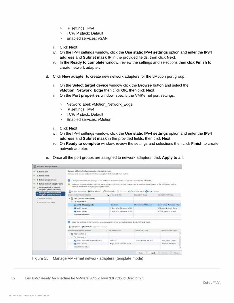
82 Dell EMC Ready Architecture for VMware vCloud NFV 3.0 vCloud Director 9.5
Dell Customer Communication - Confidential
> IP settings: IPv4
> TCP/IP stack: Default
> Enabled services: vSAN
iii. Click Next.
iv. On the IPv4 settings window, click the Use static IPv4 settings option and enter the IPv4
address and Subnet mask IP in the provided fields, then click Next.
v. In the Ready to complete window, review the settings and selections then click Finish to
create network adapter.
d. Click New adapter to create new network adapters for the vMotion port group:
i. On the Select target device window click the Browse button and select the
vMotion_Network_Edge then click OK, then click Next.
ii. On the Port properties window, specify the VMKernel port settings:
> Network label: vMotion_Network_Edge
> IP settings: IPv4
> TCP/IP stack: Default
> Enabled services: vMotion
iii. Click Next.
iv. On the IPv4 settings window, click the Use static IPv4 settings option and enter the IPv4
address and Subnet mask in the provided fields, then click Next.
v. On Ready to complete window, review the settings and selections then click Finish to create
network adapter.
e. Once all the port groups are assigned to network adapters, click Apply to all.
Manage VMkernel network adapters (template mode)
83 Dell EMC Ready Architecture for VMware vCloud NFV 3.0 vCloud Director 9.5
Dell Customer Communication - Confidential
10. On the Apply VMkernel network adapter configuration to other hosts window, enter IPv4 addresses of
the other edge hosts to apply the settings of the VMkernel network adapters of the template host on the
switch to all hosts, then click OK and click Next.
11. From the Analyze impact window, review the impact of the configuration change might have on some
network-dependent services, then click Next.
12. From the Ready to complete window, review the settings and selection and click Finish to add the
host.
7.6.2 Add hosts to Edge_VM_Network_VDS To add hosts to the Edge_VM_Network_VDS:
1. Right-click on the Edge_VM_Network_VDS distributed switch and select Add and Manage Hosts.
2. On the Add and Manage Hosts window, select the Add hosts radio button then click Next.
3. On the Select hosts window, click the (+) New hosts icon. On the displayed window select all of the
edge cluster hosts, then click OK.
4. Check the Configure identical network settings on multiple hosts (template mode) box then click
Next.
5. On the Select a template host window, select the network configuration host to apply to the other
hosts, then clicks Next.
6. On the Select network adapter tasks window, check the Manage physical adapter (template mode)
box to associate the necessary uplinks to the DVS, and check the Manage VMKernel adapters
(template mode) box then click Next.
7. On the Manage Physical network and adapters (template mode) window, add physical network
adapters to the distributed switch.
a. Select vmnic5, then click the Assign uplink icon and assign it to EdgeLag1-0.
b. Select vmnic7, then click the Assign uplink icon and assign it to EdgeLag1-1.
c. After assigning the uplink on the template host, click Apply to all to apply the physical network
adapter assignments on this switch for all the hosts, and click Next.
8. Review the information that is provided in the Manage VMkernel network adapter (template mode)
window, then click Next.
9. From the Analyze impact window, review the impact of the configuration change might have on some
network-dependent services, then click Next.
10. From the Ready to complete window, review the settings and selection and click Finish to add the
host.
7.7 Add hosts to VDS on resource pod The information in this section provides the steps needed to add hosts to the each VDS of the resource cluster.
• Add hosts to Res_Infra_Network_VDS
7.7.1 Add hosts to Res_Infra_Network_VDS To add hosts to a port group:
1. Right-click on Res_Infra_Network_VDS and select Add and Manage Hosts.

84 Dell EMC Ready Architecture for VMware vCloud NFV 3.0 vCloud Director 9.5
Dell Customer Communication - Confidential
2. On the Add and Manage Hosts window, select the Add hosts radio button then click Next.
3. On the Select hosts window, click the (+) New hosts icon.
4. Select all of the hosts for the edge cluster, then click OK.
5. Check the Configure identical network settings on multiple hosts (template mode) box then click
Next.
6. From the Select a template host window, select the network configuration host to apply to the other
hosts, then clicks Next.
7. On the Select network adapter tasks window, check the Manage physical adapter (template mode)
box to associate the necessary uplinks to the DVS, and check the Manage VMKernel adapters
(template mode) box then click Next.
8. On the Manage Physical network and adapters (template mode) window, add physical network
adapters to the distributed switch:
a. Select vmnic4, then click the Assign uplink icon and assign it to ResourceLag1-0.
b. Select vmnic6, then click the Assign uplink icon and assign it to ResourceLag1-1.
c. After assigning the uplink on the template host, click Apply to all to apply the physical network
adapter assignments on the switch for all the hosts, and click Next.
9. In the Manage VMkernel network adapters (template mode) window:
a. Select vmk0 and click the Assign port group icon.
b. Select the destination port group, for example, ESXi_Mgmt_Network_Res, to migrate the VMkernel
adapters from the source port group, then click OK.
c. Click New adapter to create network adapters for vSAN port group:
i. On the Select target device window click the Browse button and select the
vSAN_Network_Res then click OK, then click Next.
ii. On the Port properties window, specify the VMKernel port settings:
> Network label: vSAN_Network_Res
> IP settings: IPv4
> TCP/IP stack: Default
> Enabled services: vSAN
iii. Click Next.
iv. In the IPv4 settings window, click the Use static IPv4 settings option and enter the IPv4
address and Subnet mask IP in the provided fields, then click Next.
v. From the Ready to complete window, review the settings and selections then click Finish to
create network adapter.
d. Click New adapter to create new network adapters for vMotion port group:
i. On the Select target device window click the Browse button and select the
vMotion_Network_Res then click OK, then click Next.
ii. On the Port properties window, specify the VMKernel port settings:
> Network label: vMotion_Network_Res
> IP settings: IPv4
> TCP/IP stack: Default

85 Dell EMC Ready Architecture for VMware vCloud NFV 3.0 vCloud Director 9.5
Dell Customer Communication - Confidential
> Enabled services: vMotion
iii. Click Next.
iv. On the IPv4 settings window, click the Use static IPv4 settings option and enter the IPv4
address and Subnet mask in the provided fields, then click Next.
v. On Ready to complete window, review the settings and selections then click Finish to create
network adapter.
e. Once all the port groups are assigned to network adapters, click Apply to all.
10. On the Apply VMkernel network adapter configuration to other hosts window, enter IPv4 addresses of
the other edge hosts to apply the settings of the VMkernel network adapters of the template host on the
switch to all hosts, then click OK and click Next.
11. From the Analyze impact window, review the impact of the configuration change might have on some
network-dependent services, then click Next.
12. From the Ready to complete window, review the settings and selection and click Finish to add the
host.
86 Dell EMC Ready Architecture for VMware vCloud NFV 3.0 vCloud Director 9.5
Dell Customer Communication - Confidential
8 Configure VMware vSAN clusters The VMware Virtual SAN (vSAN) is a distributed layer of software that runs natively as a part of the ESXi
hypervisor. vSAN aggregates local or direct-attached capacity devices of a host cluster and creates a single
storage pool that is shared across all hosts in the vSAN cluster.
Each server has a hybrid mix of SSD and HDD drives for storage deployment. For vSAN, solid-state disks are
required for the cache tier, while the spinning disks make up the capacity tier. Each Dell EMC server is
configured for Host Bus Adapter (HBA) in non-RAID or pass-through mode since the vSAN software handles the
redundancy and storage cluster information.
8.1 Configure vSAN on resource and edge cluster To configure vSAN on resource and edge cluster:
1. Log in to VCSA using vSphere Web Client and go to the resource cluster.
2. Click the Configure tab.
3. From the vSAN listing, select General then click Configure in the upper-right corner, to edit the Virtual
SAN configuration.
4. In vSAN Capabilities window, leave the default setting as-is and click Next.
Note: It is not possible to remove disks from a disk group after deduplication and compression is enabled on the
cluster. Consider the configuration ahead of time and add all the capacity that you need before activating the
deduplication
5. Confirm the information within the Network Validation window, then click Next.
6. From the Claim disks window, locate the Claim For column and verify that HDD is claimed for the
Capacity tier and that Flash is claimed for the Cache tier.
7. Verify the settings within the Ready to complete window, then click Finish.
8. From the Virtual SAN listing, click the General listing in the left navigation panel and click the
Configure tab.
9. Locate the vSAN status on the Configure tab and verify that vSAN is Turned ON, displays.
Note: Repeat the steps in this section to configure vSAN for the edge cluster.
8.2 Assign vSAN license key to cluster
Note: Add license to Management, Resource, and Edge clusters.
To assign a vSAN license key to a cluster, select from the following options:
• Add a new vSAN license
• Assign vSAN license using an existing license
87 Dell EMC Ready Architecture for VMware vCloud NFV 3.0 vCloud Director 9.5
Dell Customer Communication - Confidential
8.2.1 Add a new vSAN license To assign vSAN license to a vSAN cluster
1. From the VMware vSphere Web Client, go to a cluster where you have enabled vSAN.
2. On the Configure tab, in the Configuration section, select Licensing, and click Assign License.
3. Click the Add (+) icon.
4. In the New Licenses dialog box, type or copy and paste a Virtual SAN license key and click Next.
5. On the Edit license names page, rename the new license as appropriate and click Next.
6. Click Finish.
7. In the Assign License dialog, select the newly created license, and click OK.
8.2.2 Assign vSAN license using an existing license To assign vSAN license using existing license:
1. From the VMware vSphere Web Client, go to a cluster where you have enabled vSAN.
2. On the Configure tab, in the Configuration section, select Licensing, and click Assign License.
3. Select the licensing option, then select an existing license.
4. Click OK.
8.3 Update vSAN HCL database manually
Note: Update vSAN HCL database on management, resource, and edge clusters.
To update the vSAN HCL database manually:
1. Log in to the vCenter Server using VMware vSphere Web Client with administrator credentials.
2. From the vSAN cluster, click the Configure tab.
3. In the vSAN section from left navigation panel, select Health and Performance, on the HCL Database
section:
a. If the vCenter Server can communicate with the Internet, click Get latest version online to update
the HCL Database.
b. If the vCenter server does not have proxy and is unable to communicate with the Internet, download
the updated file locally using the following steps:
i. Log in to a workstation with Internet access.
ii. Open the following link in a browser: https://partnerweb.vmware.com/service/vsan/all.json
iii. Save the file as all.json.
iv. Copy the file to the vCenter Server for upload.
v. Under the Health tab in the HCL Database section, select the Update from file option and
select the all.json file and upload the file.
4. Retest the health by clicking Monitor > Virtual SAN > Health > Retest.

88 Dell EMC Ready Architecture for VMware vCloud NFV 3.0 vCloud Director 9.5
Dell Customer Communication - Confidential
8.4 Enable vSAN performance service
Note: Enable vSAN performance service on the management, resource, and edge clusters.
Prerequisites
• Cluster should be configured on both Management and Resource vCenter Server.
To enable vSAN performance services:
1. Log in into VCSA using vSphere Web Client and go to the Cluster.
2. On the Configure tab. in the vSAN section, select Health and Performance, and click Edit to edit the
performance service settings.
3. Select the Turn On Virtual SAN performance service check box.
4. Select a storage policy and click OK.
Review the settings after Performance service turned on.
Health and Performance settings
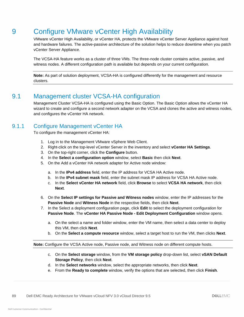
89 Dell EMC Ready Architecture for VMware vCloud NFV 3.0 vCloud Director 9.5
Dell Customer Communication - Confidential
9 Configure VMware vCenter High Availability VMware vCenter High Availability, or vCenter HA, protects the VMware vCenter Server Appliance against host
and hardware failures. The active-passive architecture of the solution helps to reduce downtime when you patch
vCenter Server Appliance.
The VCSA-HA feature works as a cluster of three VMs. The three-node cluster contains active, passive, and
witness nodes. A different configuration path is available but depends on your current configuration.
Note: As part of solution deployment, VCSA-HA is configured differently for the management and resource
clusters.
9.1 Management cluster VCSA-HA configuration Management Cluster VCSA-HA is configured using the Basic Option. The Basic Option allows the vCenter HA
wizard to create and configure a second network adapter on the VCSA and clones the active and witness nodes,
and configures the vCenter HA network.
9.1.1 Configure Management vCenter HA To configure the management vCenter HA:
1. Log in to the Management VMware vSphere Web Client.
2. Right-click on the top-level vCenter Server in the inventory and select vCenter HA Settings.
3. On the top-right corner, click the Configure button.
4. In the Select a configuration option window, select Basic then click Next.
5. On the Add a vCenter HA network adapter for Active node window:
a. In the IPv4 address field, enter the IP address for VCSA HA Active node.
b. In the IPv4 subnet mask field, enter the subnet mask IP address for VCSA HA Active node.
c. In the Select vCenter HA network field, click Browse to select VCSA HA network, then click
Next.
6. On the Select IP settings for Passive and Witness nodes window, enter the IP addresses for the
Passive Node and Witness Node in the respective fields, then click Next.
7. In the Select a deployment configuration page, click Edit to select the deployment configuration for
Passive Node. The vCenter HA Passive Node - Edit Deployment Configuration window opens.
a. On the select a name and folder window, enter the VM name, then select a data center to deploy
this VM, then click Next.
b. On the Select a compute resource window, select a target host to run the VM, then clicks Next.
Note: Configure the VCSA Active node, Passive node, and Witness node on different compute hosts.
c. On the Select storage window, from the VM storage policy drop-down list, select vSAN Default
Storage Policy, then click Next.
d. In the Select networks window, select the appropriate networks, then click Next.
e. From the Ready to complete window, verify the options that are selected, then click Finish.

90 Dell EMC Ready Architecture for VMware vCloud NFV 3.0 vCloud Director 9.5
Dell Customer Communication - Confidential
f. Repeat the steps in this section to complete the deployment configuration setting for witness nodes,
then click Next.
Select a deployment configuration window
8. From the Ready to complete window, verify the options that are selected, then click Finish.
Note: Monitor the tasks pane, as it may take few minutes to clone and deploy the vCenter HA cluster nodes.
When complete, the vCenter HA status shows Enabled and all nodes in the cluster show the Up status.
Status window
Note: You can edit the status of vCenter HA at any time by going back into the vCenter HA menu and clicking
Edit. For the options that are available, see the following Deployment configuration window.

91 Dell EMC Ready Architecture for VMware vCloud NFV 3.0 vCloud Director 9.5
Dell Customer Communication - Confidential
vCenter HA option Window
9.2 Resource cluster VCSA-HA configuration Resource Cluster VCSA-HA is configured using the Advanced Option. Using the Advanced Option to configure
the vCenter HA cluster, makes you responsible to add a second NIC to VCSA and clone the active node to
passive and witness nodes, and configuring the clones.
Note: Each HA node is configured to reside on a different host. Verify that the IPv4 and IPv6 addressing was not
mixed when networking was configured on the nodes. Ensure that a gateway for the HA network was not
specified when configuring the nodes.
Prerequisites:
• dvPortGroup is created on VDS for the private HA network.
• HA private network is set to reside on a different subnet than the one used for management.
• One IP address for management, three private IP addresses, and one for each HA node, are set.
9.2.1 Configure Resource vCenter HA The Configure Resource vCenter HA requires the manual addition of a second network card to the vCSA and
the cloning of the appliance, two times. Also, the creation of passive and witness node clones must be done half
way through the Resource vCenter HA configuration process.
Note: Each VCSA HA node requires its own ESXi host. In the installation process, set the Inventory Layout to
identify and select the ESXi host where the vCSA appliance and HA instances are deployed. These steps are
different than the steps that are used in the Configuring Resource vCenter HA section as the HA is being
configured using the Advanced Option.

92 Dell EMC Ready Architecture for VMware vCloud NFV 3.0 vCloud Director 9.5
Dell Customer Communication - Confidential
To configure Resource vCenter HA:
1. In the VMware vSphere Web Client, add a second network adapter to the vCSA by editing the Resource
VCSA VM settings and associate it to the VCSA HA Network.
Edit Settings window
2. To configure the IP settings for the second network adapter:
a. Log in to the resource VMware vSphere Web Client.
b. Go to: Home > Administration > System Configuration tab, then select the node in which you
need to configure the Network Adapter.
c. From the Manage tab, select Settings. On the Edit Setting window, in the Networking tab click Edit
to configure the second NIC.
d. On the IP4 settings section:
i. Select the Use the following IPv4 settings radio button.
ii. In the IP address field, enter the IP address.
iii. In the Subnet prefix length field, provide the subnet prefix length.
iv. In the Default gateway field, provide the default gateway IP address.
v. Click OK.
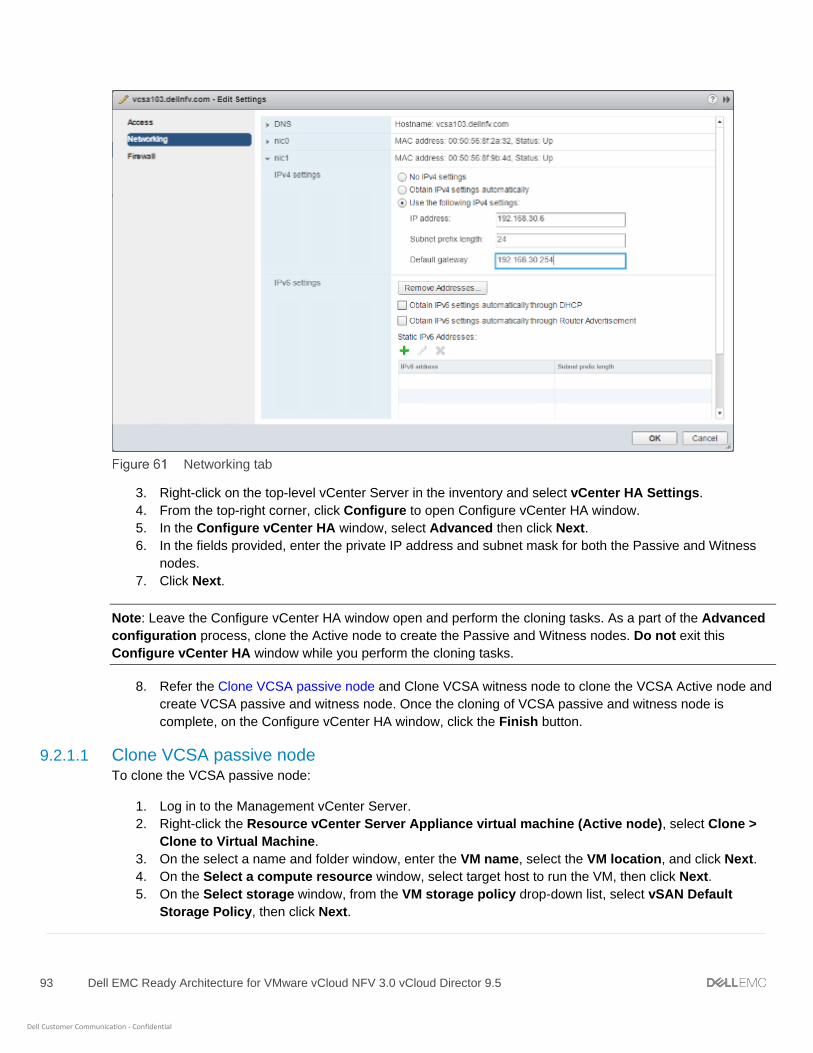
93 Dell EMC Ready Architecture for VMware vCloud NFV 3.0 vCloud Director 9.5
Dell Customer Communication - Confidential
Networking tab
3. Right-click on the top-level vCenter Server in the inventory and select vCenter HA Settings.
4. From the top-right corner, click Configure to open Configure vCenter HA window.
5. In the Configure vCenter HA window, select Advanced then click Next.
6. In the fields provided, enter the private IP address and subnet mask for both the Passive and Witness
nodes.
7. Click Next.
Note: Leave the Configure vCenter HA window open and perform the cloning tasks. As a part of the Advanced
configuration process, clone the Active node to create the Passive and Witness nodes. Do not exit this
Configure vCenter HA window while you perform the cloning tasks.
8. Refer the Clone VCSA passive node and Clone VCSA witness node to clone the VCSA Active node and
create VCSA passive and witness node. Once the cloning of VCSA passive and witness node is
complete, on the Configure vCenter HA window, click the Finish button.
9.2.1.1 Clone VCSA passive node To clone the VCSA passive node:
1. Log in to the Management vCenter Server.
2. Right-click the Resource vCenter Server Appliance virtual machine (Active node), select Clone >
Clone to Virtual Machine.
3. On the select a name and folder window, enter the VM name, select the VM location, and click Next.
4. On the Select a compute resource window, select target host to run the VM, then click Next.
5. On the Select storage window, from the VM storage policy drop-down list, select vSAN Default
Storage Policy, then click Next.
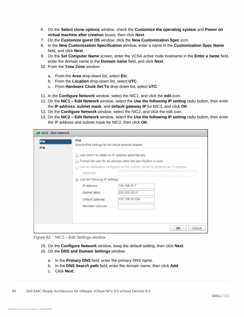
94 Dell EMC Ready Architecture for VMware vCloud NFV 3.0 vCloud Director 9.5
Dell Customer Communication - Confidential
6. On the Select clone options window, check the Customize the operating system and Power on
virtual machine after creation boxes, then click Next.
7. On the Customize guest OS window, click the New Customization Spec icon.
8. In the New Customization Specification window, enter a name in the Customization Spec Name
field, and click Next.
9. On the Set Computer Name screen, enter the VCSA active node hostname in the Enter a name field,
enter the domain name in the Domain name field, and click Next.
10. From the Time Zone window:
a. From the Area drop-down list, select Etc.
b. From the Location drop-down list, select UTC.
c. From Hardware Clock Set To drop-down list, select UTC.
11. In the Configure Network window, select the NIC1, and click the edit icon.
12. On the NIC1 – Edit Network window, select the Use the following IP setting radio button, then enter
the IP address, subnet mask, and default gateway IP for NIC1, and click OK.
13. On the Configure Network window, select the NIC2, and click the edit icon.
14. On the NIC2 – Edit Network window, select the Use the following IP setting radio button, then enter
the IP address and subnet mask for NIC2, then click OK.
NIC2 – Edit Settings window
15. On the Configure Network window, keep the default setting, then click Next.
16. On the DNS and Domain Settings window:
a. In the Primary DNS field, enter the primary DNS name.
b. In the DNS Search path field, enter the domain name, then click Add.
c. Click Next.

95 Dell EMC Ready Architecture for VMware vCloud NFV 3.0 vCloud Director 9.5
Dell Customer Communication - Confidential
17. On the Ready to complete window, review the options and click Finish to create guest VM.
Ready to complete window
18. After the VM is created, on the Customize guest OS window, select the VM, and click Next.
19. On the Customize vApp properties window, click Next.
20. On the Ready to complete window, review the options that are selected then click Finish.
Ready to complete Window.

96 Dell EMC Ready Architecture for VMware vCloud NFV 3.0 vCloud Director 9.5
Dell Customer Communication - Confidential
9.2.1.2 Clone VCSA witness node After cloning the VCSA passive node, clone the active node again for the witness node. The cloning of the
witness node uses the same steps as the cloning of the passive node, with only a few exceptions in the process.
1. Log in to the Management vCenter Server.
2. Right-click the Resource VCSA VM (Active node), select Clone > Clone to Virtual Machine.
3. On the select a name and folder window, enter the VM name, select the VM location, and click Next.
4. On the Select a compute resource window, select target host to run the VM, then click Next.
5. On the Select storage window, select vSAN Default Storage Policy, then click Next.
6. On the Select clone options window, check the Customize the operating system and Power on
virtual machine after creation boxes, then click Next.
7. On the Customize guest OS window, click the New Customization Spec icon.
8. In the New Customization Specification window, enter a name in the Customization Spec Name field,
and click Next.
9. On the Set Computer Name window, enter the VCSA active node hostname in the provided field, enter
the domain name, and click Next.
10. On the Time Zone window:
a. From the Area drop-down list, select Etc.
b. From the Location drop-down list, select UTC.
c. From Hardware Clock Set To drop-down list, select UTC.
11. On the Configure Network window, select the NIC1, and click the edit icon.
12. On the NIC1 – Edit Network window, select the Use the following IP setting radio button, then enter
the IP address, subnet mask, and default gateway IP for NIC1, and click OK.
13. On the Configure Network window, select the NIC2, and click the edit icon.
14. On the NIC2 – Edit Network window, select the Use the following IP setting radio button, then enter
the IP address and subnet mask for NIC2, then click OK.
15. On the Configure Network window, click Next.
16. On the DNS and Domain Settings window:
a. In the Primary DNS field, enter the primary DNS name.
b. In the DNS Search path field, enter the domain name, then click Add.
c. Click Next.
17. On the Ready to complete window, review the options and click Finish to create guest VM.
18. Once the VM is created, on the Customize guest OS window, select the VM, and click Next.
19. On the Customize vApp properties window, within the SSO configuration section, complete the
following fields:
a. In the Directory Username field, enter the username for resource directory
b. In the Directory Password field, set the password for resource directory
c. In the Directory Domain Name field, enter the domain name for resource directory
d. Click Next.

97 Dell EMC Ready Architecture for VMware vCloud NFV 3.0 vCloud Director 9.5
Dell Customer Communication - Confidential
Customize vApp properties window
20. On the Ready to complete window, review the options that are selected then click Finish.
Ready to complete window

98 Dell EMC Ready Architecture for VMware vCloud NFV 3.0 vCloud Director 9.5
Dell Customer Communication - Confidential
10 NSX-T deployment and configuration NSX-T Data Center is the software defined networking component for the vCloud NFV platform. It allows you to
create, delete, and manage software-based virtual networks.
Prerequisites:
• Review the necessary hardware requirements for NSX-T as specified in the System Requirements
for NSX-T section of the NSX-T Installation Guide
• Verify that the following VMware products are installed:
- VMware vCenter Server 6.7U1
- VMware ESXi 6.7U1
• For client and user access, consider the following:
- For ESXi hosts added to the vSphere inventory by name, ensure that forward and reverse name
resolution is working, otherwise, the NSX-T Manager cannot resolve the IP addresses
- Permissions are provided to add and power on virtual machines
- The VMware Client Integration plug-in must be installed
- A web browser that is supported for the version of vSphere Web Client you are using
- IPv4 IP addresses are used as IPv6 is not supported in the previously mentioned version of
NSX-T
10.1 Install NSX-T Manager Virtual Appliance The NSX-T Manager provides a Graphical User Interface (GUI) and REST API for the creation, configuration,
and monitoring of NSX-T components such as logical switches, logical routers, and firewalls. The NSX-T
Manager provides an aggregated system view and is the centralized network management component of NSX.
NSX-T Manager is installed as a virtual appliance on any ESX host in the vCenter environment.
The NSX-T Manager virtual machine is packaged as an OVA file, which allows for the use of the vSphere Web
Client to import the NSX-T Manager into the datastore and virtual machine inventory.
Only one instance of NSX-T Manager can be installed in an environment. When NSX-T Manager is deployed on
an ESXi host, the vSphere high availability (HA) feature can be used to ensure the availability of NSX-T
Manager.
Note: The NSX-T Manager virtual machine installation includes VMware Tools. Do not attempt to upgrade or
remove VMware Tools on the NSX-T Manager.
To install the NSX-T Manager Virtual Appliance, perform the following steps:
1. In a web browser, open the vCenter Server using vSphere Web Client.
2. Select VMs and Templates, then right-click vCenter Server, and select Deploy OVF Template.
3. Enter the download URL or click Browse to select the .ova file on your computer.
Note: Deploy the NSX-T manager OVA file within the Management Cluster vCenter server.
99 Dell EMC Ready Architecture for VMware vCloud NFV 3.0 vCloud Director 9.5
Dell Customer Communication - Confidential
4. If required, edit the NSX-T Manager name, then select the folder or data center location for the
deployed NSX-T Manager and click Next.
Note: The name entered displays in the vCenter inventory. The folder that is selected is used to apply
permissions to the NSX-T Manager.
5. Within the Select a resource screen, select a host, cluster, resource pool, or vApp to deploy the
NSX-T Manager appliance and click Next.
Note: NSX-T Manager should be placed in a cluster that provides network management utilities.
6. On the Review details section, review the details of the OVA template then click Next.
7. On the Select configuration window, select the configuration from the drop-down menu and click Next.
8. On the Select storage window:
a. From the Select virtual disk format drop-down list, select Thin provision.
b. From the VM storage policy drop-down list, select vSAN Default Storage Policy.
c. Select the datastore and click Next.
9. On the Select networks window, select the port group or destination network for the NSX-T Manager
and click Next.
10. On the Customize template window, specify the root, admin, and audit user passwords.
11. On the Customize template window, in the Network properties section, fill the following fields:
a. Hostname: Enter the hostname.
b. Default IPv4 Gateway: Enter the IP address of default gateway for NSX-T Manager.
c. Management Network IPv4 Address: The IPv4 address for the first interface.
d. Management Network Netmask: The netmask for the first interface.
12. In the DNS section:
a. In the DNS Server list field, enter the IP address of DNS Server for NSX-T Manager.
b. In the Domain Search List field, enter the domain name for NSX-T Manager.
13. In the Services Configuration section:
a. In the NTP Server List field, enter the IP address for NTP server.
b. Check the Enable SSH and Allow root SSH logins check boxes to enable SSH service.
c. Click Next.
14. On the Ready to complete window, verify the details before deployment and click Finish to start
deployment.

100 Dell EMC Ready Architecture for VMware vCloud NFV 3.0 vCloud Director 9.5
Dell Customer Communication - Confidential
Ready to complete window
15. Once the deployment is complete, perform the following steps:
a. Power on NSX-T Manager VM from vSphere Web Client.
b. After the NSX-T Manager VM boots completely, connect to the NSX-T Manager GUI using the
following URL: https://<IP/FQDN of NSX-T Manager>
c. Review the EULA, and if you agree to the terms, check I understand and accept the terms of the
license agreement box and click CONTINUE.
d. Click SAVE to finish.
10.2 Add license key To add a license key, perform the following steps:
1. From your browser, log in with admin credentials to an NSX Manager at https://nsx-manager-fqdn.
2. Go to: Main Menu > System > Configuration > License.
3. Click Add (+).
4. On the Add license window enter the license key then click Add.
10.3 Add Compute Manager for management and resource VCSA A compute manager is an application that manages resources such as hosts and VMs. NSX-T polls compute
managers to find out about changes such as the addition or removal of hosts or VMs and update its inventory
accordingly.
To register a resource VCSA as compute manager:
1. From your browser, log in with admin credentials to an NSX Manager at https://nsx-manager-ip-address.
2. From the Home window, go to Main Menu > Fabric > Compute Managers.
3. On the Compute Managers window, click the Add (+) icon to add a new compute manager.
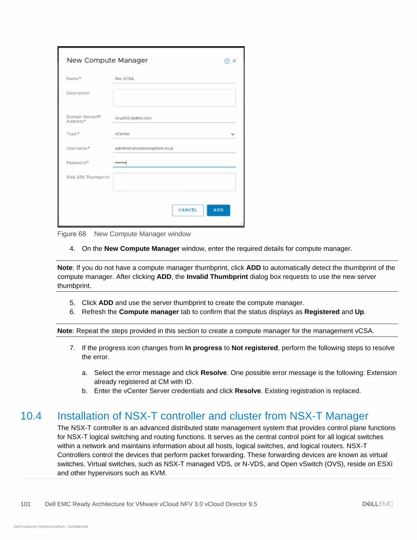
101 Dell EMC Ready Architecture for VMware vCloud NFV 3.0 vCloud Director 9.5
Dell Customer Communication - Confidential
New Compute Manager window
4. On the New Compute Manager window, enter the required details for compute manager.
Note: If you do not have a compute manager thumbprint, click ADD to automatically detect the thumbprint of the
compute manager. After clicking ADD, the Invalid Thumbprint dialog box requests to use the new server
thumbprint.
5. Click ADD and use the server thumbprint to create the compute manager.
6. Refresh the Compute manager tab to confirm that the status displays as Registered and Up.
Note: Repeat the steps provided in this section to create a compute manager for the management vCSA.
7. If the progress icon changes from In progress to Not registered, perform the following steps to resolve
the error.
a. Select the error message and click Resolve. One possible error message is the following: Extension
already registered at CM with ID.
b. Enter the vCenter Server credentials and click Resolve. Existing registration is replaced.
10.4 Installation of NSX-T controller and cluster from NSX-T Manager The NSX-T controller is an advanced distributed state management system that provides control plane functions
for NSX-T logical switching and routing functions. It serves as the central control point for all logical switches
within a network and maintains information about all hosts, logical switches, and logical routers. NSX-T
Controllers control the devices that perform packet forwarding. These forwarding devices are known as virtual
switches. Virtual switches, such as NSX-T managed VDS, or N-VDS, and Open vSwitch (OVS), reside on ESXi
and other hypervisors such as KVM.

102 Dell EMC Ready Architecture for VMware vCloud NFV 3.0 vCloud Director 9.5
Dell Customer Communication - Confidential
You can deploy NSX-T controllers using the NSX-T Manager on vSphere ESXi hosts that are managed by a
vCenter Server. Also, it automatically adds them to a controller cluster. Three NSX-T Controllers are deployed in
this deployment.
Note: You can deploy extra NSX-T controllers to an existing controller cluster. However, to delete a controller
from the cluster, you must first manually remove it from the cluster.
Prerequisites:
• Deployment of the NSX-T Manager
• Deployment of vCenter Server and vSphere ESXi hosts
• Register vSphere ESXi host to the vCenter Server
• vSphere ESXi host has the necessary CPU, memory, and hard disk resources to support 12vCPUs,
48 GB RAM, and 360 GB storage
To deploy the NSX-T controller cluster:
1. From your browser, log in with admin credentials to an NSX Manager at https://nsx-manager-ip-address.
2. Go to Main Menu > System > Components.
3. On the Components window, click ADD CONTROLLERS in Controller Cluster section.
4. On the Common Attributes window, select the Compute Manager.
5. Optionally. You can slide the SSH and Root access toggle button to enable it.
Common Attributes window
6. Enter then confirm the Shared Secret key that is required to initialize and form cluster.
Note: Ensure that all the controller nodes added to the cluster use the same Shared Secret key.

103 Dell EMC Ready Architecture for VMware vCloud NFV 3.0 vCloud Director 9.5
Dell Customer Communication - Confidential
7. Enter the CLI username and root passwords for the controller.
8. Enter the DNS Server ad NTP Server IP address in their respective field.
9. Click Next.
10. On the Controllers page, enter the following details to add a New Controller:
a. In the Host Name/FQDN field, enter the hostname or FQDN for the controller
b. In the Cluster drop-down list, select the cluster to deploy controllers.
c. In the Resource pool drop-down list, select a resource pool if any.
d. In the Host drop-down list, select the ESXi host on which controller is deployed.
e. In the Datastore drop-down list, select a datastore.
f. In the Network drop-down list, select a network for controller.
g. In the Management IP/Netmask field, enter the network IP address or netmask IP.
h. In the Management Gateway field, enter the gateway IP for controllers.
New controller details window
11. Scroll up and click + ADD CONTROLLER to add more controllers. Enter the controller details for each
new controller.
12. Click FINISH.
10.4.1 NSX-T controllers and cluster deployment validation NSX-T Controller deployment can be verified from the NSX-T Manager UI. To validate the deployment, click
System, then Components.

104 Dell EMC Ready Architecture for VMware vCloud NFV 3.0 vCloud Director 9.5
Dell Customer Communication - Confidential
NSX-T Controller details page
To verify successful deployment of the NSX-T controllers and clusters through CLI:
1. From a supported browser, open the vCenter Server using VMware vSphere Web Client.
2. Open the console of the NSX-T controller VM.
3. Log in into controller CLI as an admin user with the password provided during cluster deployment.
• To check the NSX-T manager connectivity with the controller, enter the following command:
nsx-controller-1> get managers
• To get the control cluster status, enter the following command:
nsx-controller-1> get control-cluster status
The commands show the unique ID assigned to the controller nodes along with their IP addresses and
online status.
Note: The master: option is true for only the first controller.
10.5 Configure NSX-T Manager Refer the following to configure the NSX-T Manager:
• Prepare Edge and Resource ESXi hosts as fabric node from NSX-T Manager
• Create Transport Zones
• Create uplink profiles
• Create IP pool for tunnel endpoints
• Create host transport nodes
10.5.1 Prepare Edge and Resource ESXi hosts as fabric node from NSX-T Manager To add ESXi hosts as a fabric node:
1. From your browser, log in with admin credentials to an NSX Manager at https://nsx-manager-ip-address.

105 Dell EMC Ready Architecture for VMware vCloud NFV 3.0 vCloud Director 9.5
Dell Customer Communication - Confidential
2. On the Home window, go to Main Menu > Fabric > Nodes.
3. On the Hosts tab, From the Managed by drop-down list select Resource VCSA.
4. On the displayed Host list, select the ResourceCluster and click Configure Cluster.
5. On the Configure Cluster window, enable Automatically Install NSX-T and click ADD.
Configure Cluster window
NSX-T is installed on all of the ESXi hosts in the Resource cluster.
Note: Repeat the above steps provided in the section to prepare fabric node for Edge cluster.
NSX-T Installed on Resource Cluster window
Note: After installation of NSX-T on the Resource cluster, host connectivity to the NSX-T manager displays.
10.5.2 Create Transport Zones Refer the Table 24 to create transport zones.
Transport Zone details
Name N-VDS Name N-VDS Mode Traffic Type
overlay-TZ nvds-overlay Standard Overlay
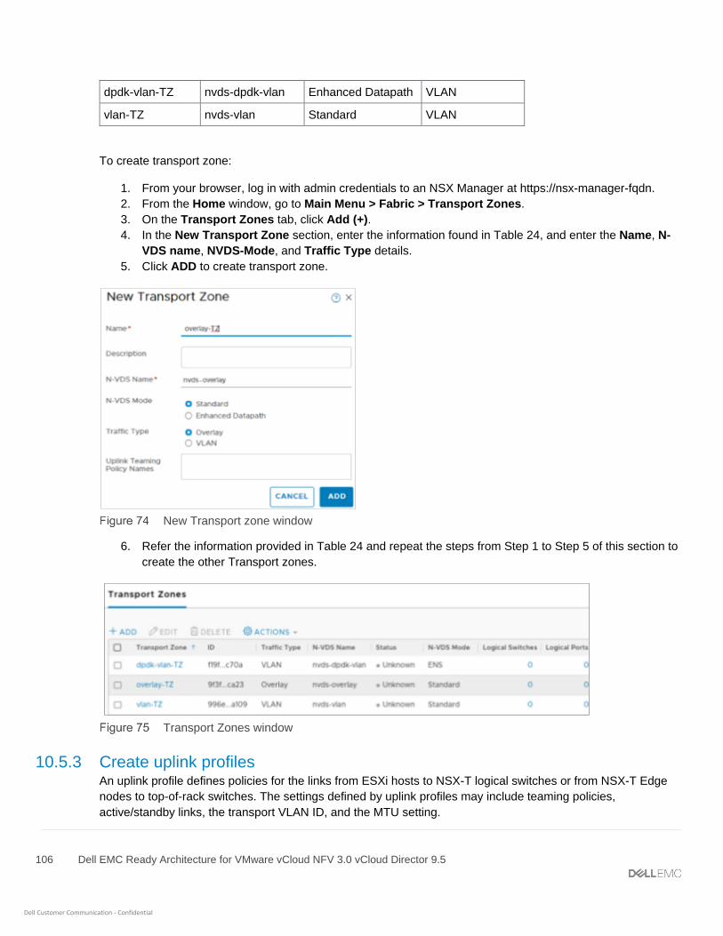
106 Dell EMC Ready Architecture for VMware vCloud NFV 3.0 vCloud Director 9.5
Dell Customer Communication - Confidential
dpdk-vlan-TZ nvds-dpdk-vlan Enhanced Datapath VLAN
vlan-TZ nvds-vlan Standard VLAN
To create transport zone:
1. From your browser, log in with admin credentials to an NSX Manager at https://nsx-manager-fqdn.
2. From the Home window, go to Main Menu > Fabric > Transport Zones.
3. On the Transport Zones tab, click Add (+).
4. In the New Transport Zone section, enter the information found in Table 24, and enter the Name, N-
VDS name, NVDS-Mode, and Traffic Type details.
5. Click ADD to create transport zone.
New Transport zone window
6. Refer the information provided in Table 24 and repeat the steps from Step 1 to Step 5 of this section to
create the other Transport zones.
Transport Zones window
10.5.3 Create uplink profiles An uplink profile defines policies for the links from ESXi hosts to NSX-T logical switches or from NSX-T Edge
nodes to top-of-rack switches. The settings defined by uplink profiles may include teaming policies,
active/standby links, the transport VLAN ID, and the MTU setting.

107 Dell EMC Ready Architecture for VMware vCloud NFV 3.0 vCloud Director 9.5
Dell Customer Communication - Confidential
The Uplink profiles enable you to consistently configure identical capabilities for network adapters across
multiple hosts or nodes. Uplink profiles are containers for the properties or capabilities that you want your
network adapters to have. Instead of configuring individual properties or capabilities for each network adapter,
you can specify the capabilities in uplink profiles that can be applied when you create NSX-T transport nodes.
Prerequisites:
• Verify that each uplink within the uplink profile corresponds to an Up and Available physical link on
your ESXi host or on the NSX-T Edge node.
Uplink Profile details
Name Teaming Policy
Active Uplinks
Standby Uplinks Transport Vlan ID
MTU
edge-overlay-uplink-profile Failover Order Uplink1 - 70 1600
edge-vm-uplink-profile Failover Order uplink1 - 40 1600
edge-vlan-uplink-profile Failover Order uplink1 - 20 1600
host-overlay-uplink-profile Failover Order Uplink1 Uplink2 70 1600
host-dpdk-uplink-profile Failover Order uplink1 uplink2 40 1600
Important: It is recommended that the Maximum Transmission Unit (MTU) settings for the Transport VLAN must
be configured to support 1600 bytes
To create uplink profiles:
1. From your browser, log in with administrator credentials to an NSX Manager at https://nsx-manager-ip-.
2. On the Home screen, select Main Menu > Fabric > Profiles.
3. From the Uplink Profiles tab, click + ADD.
4. On the New Uplink Profile screen, use the information found in Table 25 to enter the uplink profile
name in the Name field.
5. Optionally, from the Description field, enter the description for Uplink profile.
6. In the Teamings section, click Add (+).
7. In Teamings section, use the information from Table 25 to enter Teaming Policy, Active Uplinks,
Standby Uplinks, Transport VLAN and MTU details, then click the ADD button.
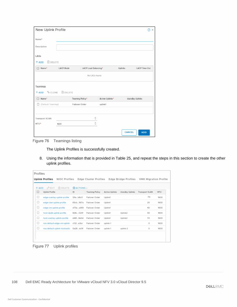
108 Dell EMC Ready Architecture for VMware vCloud NFV 3.0 vCloud Director 9.5
Dell Customer Communication - Confidential
Teamings listing
The Uplink Profiles is successfully created.
8. Using the information that is provided in Table 25, and repeat the steps in this section to create the other
uplink profiles.
Uplink profiles
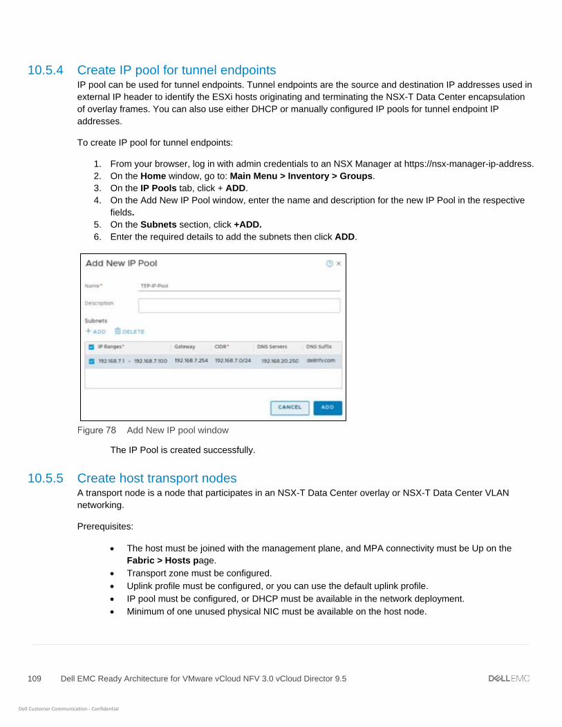
109 Dell EMC Ready Architecture for VMware vCloud NFV 3.0 vCloud Director 9.5
Dell Customer Communication - Confidential
10.5.4 Create IP pool for tunnel endpoints IP pool can be used for tunnel endpoints. Tunnel endpoints are the source and destination IP addresses used in
external IP header to identify the ESXi hosts originating and terminating the NSX-T Data Center encapsulation
of overlay frames. You can also use either DHCP or manually configured IP pools for tunnel endpoint IP
addresses.
To create IP pool for tunnel endpoints:
1. From your browser, log in with admin credentials to an NSX Manager at https://nsx-manager-ip-address.
2. On the Home window, go to: Main Menu > Inventory > Groups.
3. On the IP Pools tab, click + ADD.
4. On the Add New IP Pool window, enter the name and description for the new IP Pool in the respective
fields.
5. On the Subnets section, click +ADD.
6. Enter the required details to add the subnets then click ADD.
Add New IP pool window
The IP Pool is created successfully.
10.5.5 Create host transport nodes A transport node is a node that participates in an NSX-T Data Center overlay or NSX-T Data Center VLAN
networking.
Prerequisites:
• The host must be joined with the management plane, and MPA connectivity must be Up on the
Fabric > Hosts page.
• Transport zone must be configured.
• Uplink profile must be configured, or you can use the default uplink profile.
• IP pool must be configured, or DHCP must be available in the network deployment.
• Minimum of one unused physical NIC must be available on the host node.

110 Dell EMC Ready Architecture for VMware vCloud NFV 3.0 vCloud Director 9.5
Dell Customer Communication - Confidential
To create host transport node:
1. From your browser, log in with admin credentials to an NSX Manager at https://nsx-manager-ip-address.
2. On the Home window, go to: Main Menu > Fabric > Nodes
3. On Transport Nodes tab, click + ADD.
4. On the General tab, in the Name field, enter the transport node name and from the Node drop-down list,
select the host node.
5. In the Transport Zones field, select the transport zone from the Available column to Selected column.
6. On the N-VDS tab and select the N-VDS Name created for overlay network i.e., nvds-overlay from the
drop-down list for.
7. Use the default NIOC Profile and select the Uplink Profile as host-overlay-uplink-profile from the
drop-down list.
8. In the IP Assignment field, select Use IP Pool option from the drop-down- list.
9. In the IP Pool field select TEP-IP-Pool from drop down list.
10. In the Physical NICs field, select vmnic5 and vmnic7 from the drop-down list respectively for Uplink1
and Uplink2.
N-VDS window
11. On the N-VDS tab, click +ADD N-VDS to add second N-VDS for the VLAN Transport Zone.
12. In the N-VDS Name field, select the external network N-VDS, for example, dpdk-vlan-nvds, from the
drop-down list.
13. Use the default NIOC Profile and select the Uplink Profile as dpdk-uplink-profile from the drop-down
list.
14. In the IP Assignment field, select Use IP Pool option from the drop-down- list.
15. In the IP Pool field select TEP-IP-Pool from drop down list.
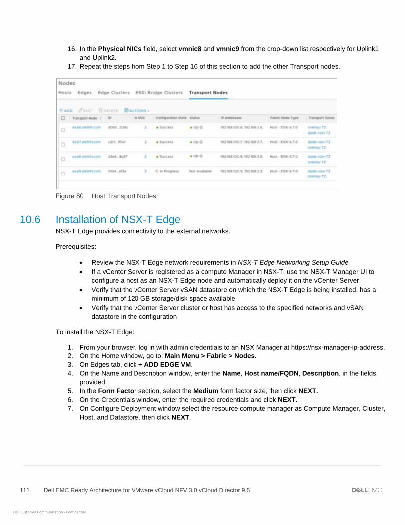
111 Dell EMC Ready Architecture for VMware vCloud NFV 3.0 vCloud Director 9.5
Dell Customer Communication - Confidential
16. In the Physical NICs field, select vmnic8 and vmnic9 from the drop-down list respectively for Uplink1
and Uplink2.
17. Repeat the steps from Step 1 to Step 16 of this section to add the other Transport nodes.
Host Transport Nodes
10.6 Installation of NSX-T Edge NSX-T Edge provides connectivity to the external networks.
Prerequisites:
• Review the NSX-T Edge network requirements in NSX-T Edge Networking Setup Guide
• If a vCenter Server is registered as a compute Manager in NSX-T, use the NSX-T Manager UI to
configure a host as an NSX-T Edge node and automatically deploy it on the vCenter Server
• Verify that the vCenter Server vSAN datastore on which the NSX-T Edge is being installed, has a
minimum of 120 GB storage/disk space available
• Verify that the vCenter Server cluster or host has access to the specified networks and vSAN
datastore in the configuration
To install the NSX-T Edge:
1. From your browser, log in with admin credentials to an NSX Manager at https://nsx-manager-ip-address.
2. On the Home window, go to: Main Menu > Fabric > Nodes.
3. On Edges tab, click + ADD EDGE VM.
4. On the Name and Description window, enter the Name, Host name/FQDN, Description, in the fields
provided.
5. In the Form Factor section, select the Medium form factor size, then click NEXT.
6. On the Credentials window, enter the required credentials and click NEXT.
7. On Configure Deployment window select the resource compute manager as Compute Manager, Cluster,
Host, and Datastore, then click NEXT.

112 Dell EMC Ready Architecture for VMware vCloud NFV 3.0 vCloud Director 9.5
Dell Customer Communication - Confidential
Configure Deployment window
8. On the Configure ports window, select Static for the IP Assignment and enter both the Management
IP and Default Gateway information in the fields provided.
9. In the Management Interface section, select the VM management network from the drop-down list
and select the three Datapath Interfaces, first is overlay network, and remaining two as external
network, then click Finish.
Configure ports window
10. Repeat the steps in this section to deploy three additional Edge VMs.
The status of each edge node displays.
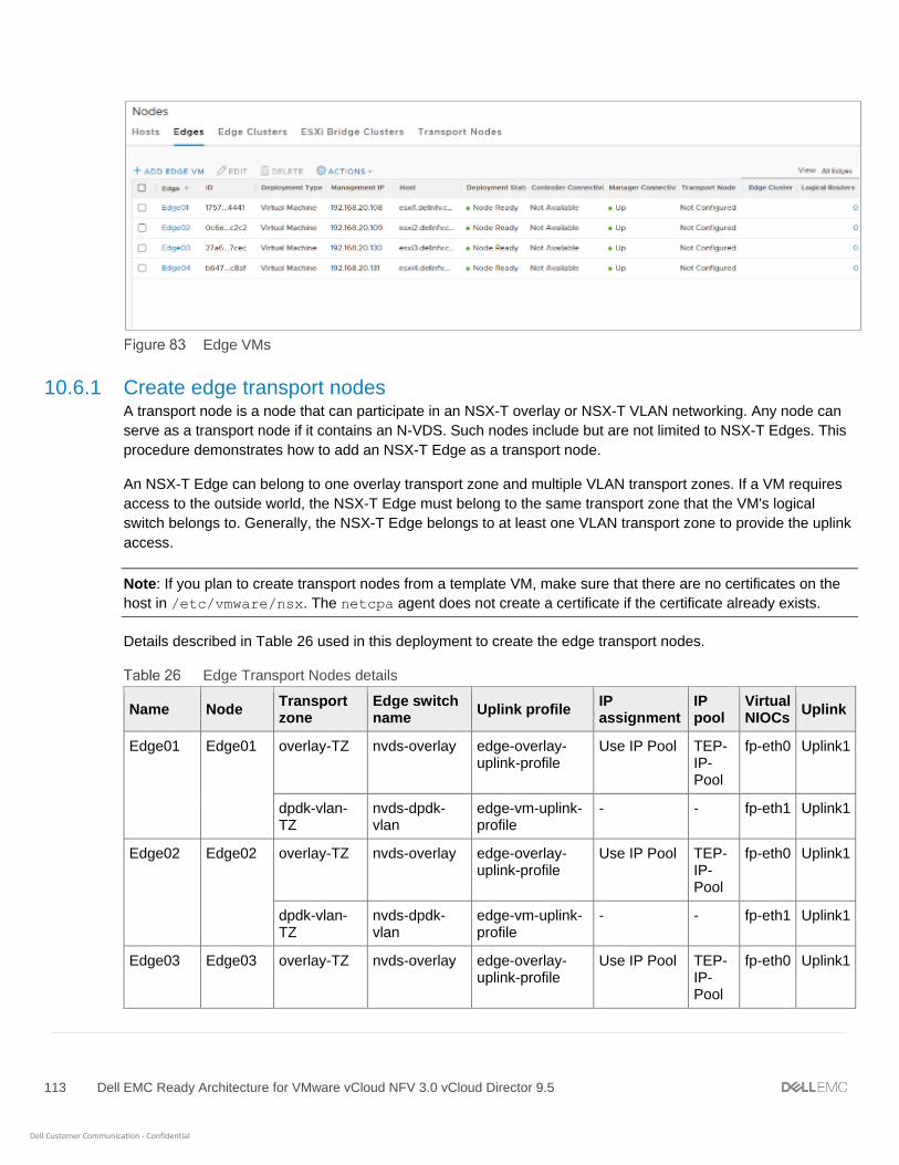
113 Dell EMC Ready Architecture for VMware vCloud NFV 3.0 vCloud Director 9.5
Dell Customer Communication - Confidential
Edge VMs
10.6.1 Create edge transport nodes A transport node is a node that can participate in an NSX-T overlay or NSX-T VLAN networking. Any node can
serve as a transport node if it contains an N-VDS. Such nodes include but are not limited to NSX-T Edges. This
procedure demonstrates how to add an NSX-T Edge as a transport node.
An NSX-T Edge can belong to one overlay transport zone and multiple VLAN transport zones. If a VM requires
access to the outside world, the NSX-T Edge must belong to the same transport zone that the VM's logical
switch belongs to. Generally, the NSX-T Edge belongs to at least one VLAN transport zone to provide the uplink
access.
Note: If you plan to create transport nodes from a template VM, make sure that there are no certificates on the
host in /etc/vmware/nsx. The netcpa agent does not create a certificate if the certificate already exists.
Details described in Table 26 used in this deployment to create the edge transport nodes.
Edge Transport Nodes details
Name Node Transport zone
Edge switch name
Uplink profile IP assignment
IP pool
Virtual NIOCs
Uplink
Edge01 Edge01 overlay-TZ nvds-overlay edge-overlay-uplink-profile
Use IP Pool TEP-IP-Pool
fp-eth0 Uplink1
dpdk-vlan-TZ
nvds-dpdk-vlan
edge-vm-uplink-profile
- - fp-eth1 Uplink1
Edge02 Edge02 overlay-TZ nvds-overlay edge-overlay-uplink-profile
Use IP Pool TEP-IP-Pool
fp-eth0 Uplink1
dpdk-vlan-TZ
nvds-dpdk-vlan
edge-vm-uplink-profile
- - fp-eth1 Uplink1
Edge03 Edge03 overlay-TZ nvds-overlay edge-overlay-uplink-profile
Use IP Pool TEP-IP-Pool
fp-eth0 Uplink1

114 Dell EMC Ready Architecture for VMware vCloud NFV 3.0 vCloud Director 9.5
Dell Customer Communication - Confidential
vlan-TZ nvds-vlan edge-vlan-uplink-profile
- - fp-eth1 Uplink1
Edge04 Edge04 overlay-TZ nvds-overlay edge-overlay-uplink-profile
Use IP Pool TEP-IP-Pool
fp-eth0 Uplink1
vlan-TZ nvds-vlan edge-vlan-uplink-profile
- - fp-eth1 Uplink1
Prerequisites:
• The NSX-T edge must be joined with the management plane
• MPA connectivity must be Up on the Fabric > Edges page. See Join NSX-T Edge with the
Management plane
• Transport zones must be configured
• An uplink profile must be configured or you can use the default uplink profile for bare-metal NSX-T
edge nodes
• An IP pool must be configured or must be available in the network deployment
• At least one unused physical NIC must be available on the host or NSX-T Edge node
To create edge transport nodes:
1. From your browser, log in with admin credentials to an NSX Manager at https://nsx-manager-ip-address.
2. On the Home window, go to: Main Menu > Fabric > Nodes
3. On Transport Nodes tab, click Add (+).
4. On the General tab, enter the edge node name and edge VM name in the Name and Node fields using
the information in Table 26.
5. In the Transport Zones field, use the information in Table 26 and select the transport zone from the
Available column to Selected column.
6. On the N-VDS tab, use the information in Table 26 and select the Edge Switch Name, NIOC Profile, IP
Assignment, IP Pool, and Virtual NICs.

115 Dell EMC Ready Architecture for VMware vCloud NFV 3.0 vCloud Director 9.5
Dell Customer Communication - Confidential
N-VDS window
7. On the N-VDS tab, click +ADD N-VDS to second N-VDS for the VLAN Transport Zone.
8. Using the information in Table 26, select the Edge Switch Name, NIOC Profile, IP Assignment, IP
Pool, and Virtual NICs.
9. To add more transport nodes, use the information from Table 26 to repeat the steps in this section.
Edge Transport Nodes

116 Dell EMC Ready Architecture for VMware vCloud NFV 3.0 vCloud Director 9.5
Dell Customer Communication - Confidential
10.6.2 Create edge cluster Create two edge cluster using two edge VMs in each cluster.
Edge Clusters and their Participating VMs
Cluster Name Participating VM
NSX_Edge_Cluster Edge01 and Edge02
VCD_Edge_Cluster Edge03 and Edge04
To create an edge cluster, perform the following steps:
1. From your browser, log in with admin credentials to an NSX Manager at https://nsx-manager-fqdn.
2. On the Home window, go to Main Menu > Fabric > Nodes.
3. On the Edge Clusters tab, click Add (+).
4. On the Add Edge Cluster window, enter the Name, Description, and select the Edge Cluster Profile.
5. From the Member Type drop-down list, select Edge Node.
6. Use the information from Table 27 to select the required Edge Nodes from the Available column and
move them to the Selected column.
7. Click OK.
Add Edge Cluster window
8. Click ADD to create the Edge Cluster.
9. Repeat the steps in this section to create a second edge cluster.

117 Dell EMC Ready Architecture for VMware vCloud NFV 3.0 vCloud Director 9.5
Dell Customer Communication - Confidential
Cluster status
10.7 Create logical switches Logical switches attach to single or multiple VMs in the network. The VMs connected to a logical switch can
communicate with each other using the tunnels between hypervisors.
In this deployment three logical switches are created:
• One ENS Vlan-backed logical switch for External network connectivity using the VLAN ID of the
External Network.
• Two Standard overlay-backed logical switches using standard overlay transport zone.
• One standard Vlan-backed logical switch for VCD by selecting a standard VLAN backed Transport
Zone and using the VLAN ID of the management network.
Prerequisites:
• NSX-T Manager must be installed and configured.
• A Transport zone must be configured.
• Verify that fabric nodes are successfully connected to NSX-T Management Plane Agent (MPA) and
NSX-T Local Control Plane (LCP).
• Verify that transport nodes are added to the transport zone.
• Verify that the ESXi hosts are added to the NSX-T fabric and VMs are hosted on these ESXi.
• Verify that your NSX-T Controller cluster is stable.
• Verify that compatible Intel NIC drivers are available for DPDK.
Note: QLogic drivers do not support the N-VDS Enhanced data path feature.
Uplink Profile details
Logical Switch Name Transport Zone VLAN
External-LS dpdk-vlan-tz 40
LS-1 overlay-tz -
LS-2 overlay-tz -
VCD-LS vlan-tz 20
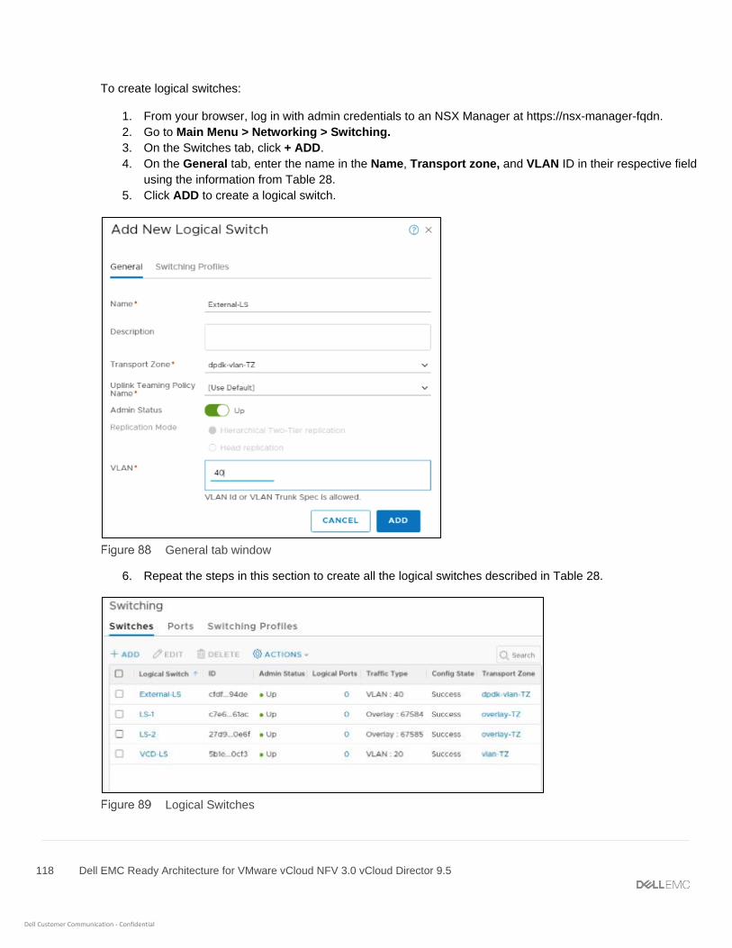
118 Dell EMC Ready Architecture for VMware vCloud NFV 3.0 vCloud Director 9.5
Dell Customer Communication - Confidential
To create logical switches:
1. From your browser, log in with admin credentials to an NSX Manager at https://nsx-manager-fqdn.
2. Go to Main Menu > Networking > Switching.
3. On the Switches tab, click + ADD.
4. On the General tab, enter the name in the Name, Transport zone, and VLAN ID in their respective field
using the information from Table 28.
5. Click ADD to create a logical switch.
General tab window
6. Repeat the steps in this section to create all the logical switches described in Table 28.
Logical Switches

119 Dell EMC Ready Architecture for VMware vCloud NFV 3.0 vCloud Director 9.5
Dell Customer Communication - Confidential
10.8 Create and configure Tier-1 router The Tier-1 logical router must be connected to the Tier-0 logical router to get the northbound physical router
access.
Prerequisites:
• Verify that the logical switches are configured. See section Create a Logical Switches
• Verify that an NSX-T Edge cluster is deployed to perform network address translation (NAT)
configuration See the NSX-T Installation Guide.
To create and configure Tier-1 router:
1. From your browser, log in with admin credentials to an NSX Manager at https://nsx-manager-ip-address.
2. Go to Main Menu > Networking > Routers.
3. On the Routers tab, click + ADD then select Tier-1 Router from the drop-down.
4. On the New Tier-1 Router window, enter the Name as NSX-Tier1 and Description.
5. From the Edge Cluster drop-down list select the NSX_Edge_Cluster.
6. For Failover mode, select Non-Preemptive and click ADD.
New Tier-1 router window
The new tier-1 router is created.

120 Dell EMC Ready Architecture for VMware vCloud NFV 3.0 vCloud Director 9.5
Dell Customer Communication - Confidential
Routers home window
10.8.1 Create Router port on Tier-1 Router Once the tier-1 logical router is created, you need to create a router port to connect the internal logical switch
with Tier-1 Router.
To create router port:
1. Click on the Tier-1 router, then from the Configuration drop-down select Router Ports.
2. In the Logical Router Ports section, click +ADD to add New Logical Router Ports.
3. On the New Router Port window, enter the Name as RP-1 and Description in the fields provided.
4. From the Type drop-down list select Downlink, and from the Logical Switch drop-down list select the
logical switch as LS-1.
5. Select the Attach new switch port radio button, enter the IP Address/Mask, then click ADD.
New Router Port for Router Tier-1
The New Logical router port NSXT-Tier1 is added to the Tier-1 router.
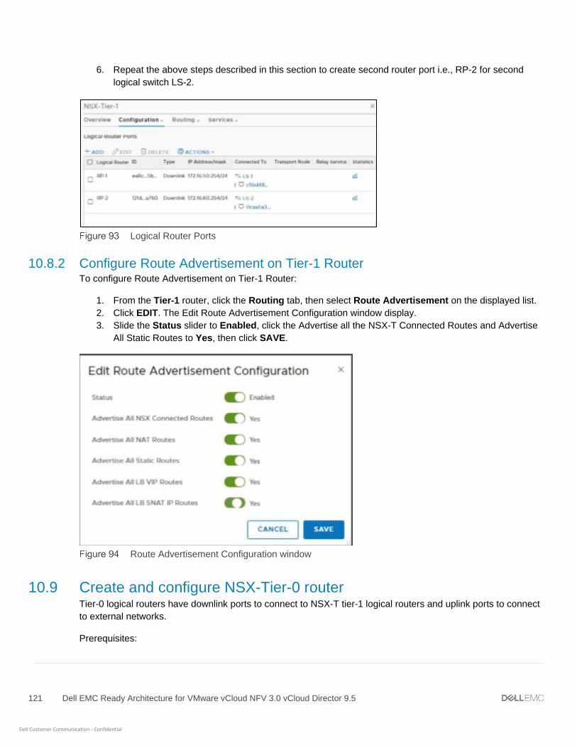
121 Dell EMC Ready Architecture for VMware vCloud NFV 3.0 vCloud Director 9.5
Dell Customer Communication - Confidential
6. Repeat the above steps described in this section to create second router port i.e., RP-2 for second
logical switch LS-2.
Logical Router Ports
10.8.2 Configure Route Advertisement on Tier-1 Router To configure Route Advertisement on Tier-1 Router:
1. From the Tier-1 router, click the Routing tab, then select Route Advertisement on the displayed list.
2. Click EDIT. The Edit Route Advertisement Configuration window display.
3. Slide the Status slider to Enabled, click the Advertise all the NSX-T Connected Routes and Advertise
All Static Routes to Yes, then click SAVE.
Route Advertisement Configuration window
10.9 Create and configure NSX-Tier-0 router Tier-0 logical routers have downlink ports to connect to NSX-T tier-1 logical routers and uplink ports to connect
to external networks.
Prerequisites:

122 Dell EMC Ready Architecture for VMware vCloud NFV 3.0 vCloud Director 9.5
Dell Customer Communication - Confidential
• Minimum of one NSX-T Edge is installed
• NSX-T Controller cluster is stable
• Edge cluster is configured
To create and configure NSX-T Tier 0 router:
1. From your browser, log in with admin credentials to an NSX Manager at https://nsx-manager-ip-address.
2. Go to Main Menu > Networking > Routers.
3. On the Routers tab, click + ADD then select Tier-0 Router from the drop-down.
4. On the New Tier-0 Router window, enter the Name as NSX-Tier0.
5. From the Edge Cluster drop-down list select the NSX_Edge_Cluster.
6. For the High Availability Mode, select the Active-Active radio button, and click ADD.
Tier-0 Router window
The Router NSX-Tier-0 router is successfully created.
10.9.1 Connect Tier-1 router to NSX-Tier-0 router To connect a Tier-1 router to a Tier-0 router:
1. Go to Tier-1 Router, on the Overview tab, in the Tier-0-Connection section click CONNECT.
2. On the Connect to Tier-0 Router window, from the Tier-0-Router drop-down list, select Tier-0 router and
click CONNECT.

123 Dell EMC Ready Architecture for VMware vCloud NFV 3.0 vCloud Director 9.5
Dell Customer Communication - Confidential
Connect to Tier-0 Router window
NSX-Tier-1 and NSX-Tier-0 is successfully connected.
10.9.2 Create Logical Router port on Tier-0 router Once the Tier-0 logical router is created, you need to create a router port to connect the external logical switch
with Tier-0 Router.
To create new logical router port:
1. Click on the Tier-0 router, then from the Configuration drop-down select Router Ports.
2. In the Logical Router Ports section, click +ADD to add New Logical Router Ports.
3. On the New Router Port window, enter the Name as External-RP and Description in the fields
provided.
4. From the Type drop-down list select Uplink, and from the Logical Switch drop-down list select the
logical switch External-LS.
5. Select the Attach new switch port radio button, enter the IP Address/Mask, then click ADD.
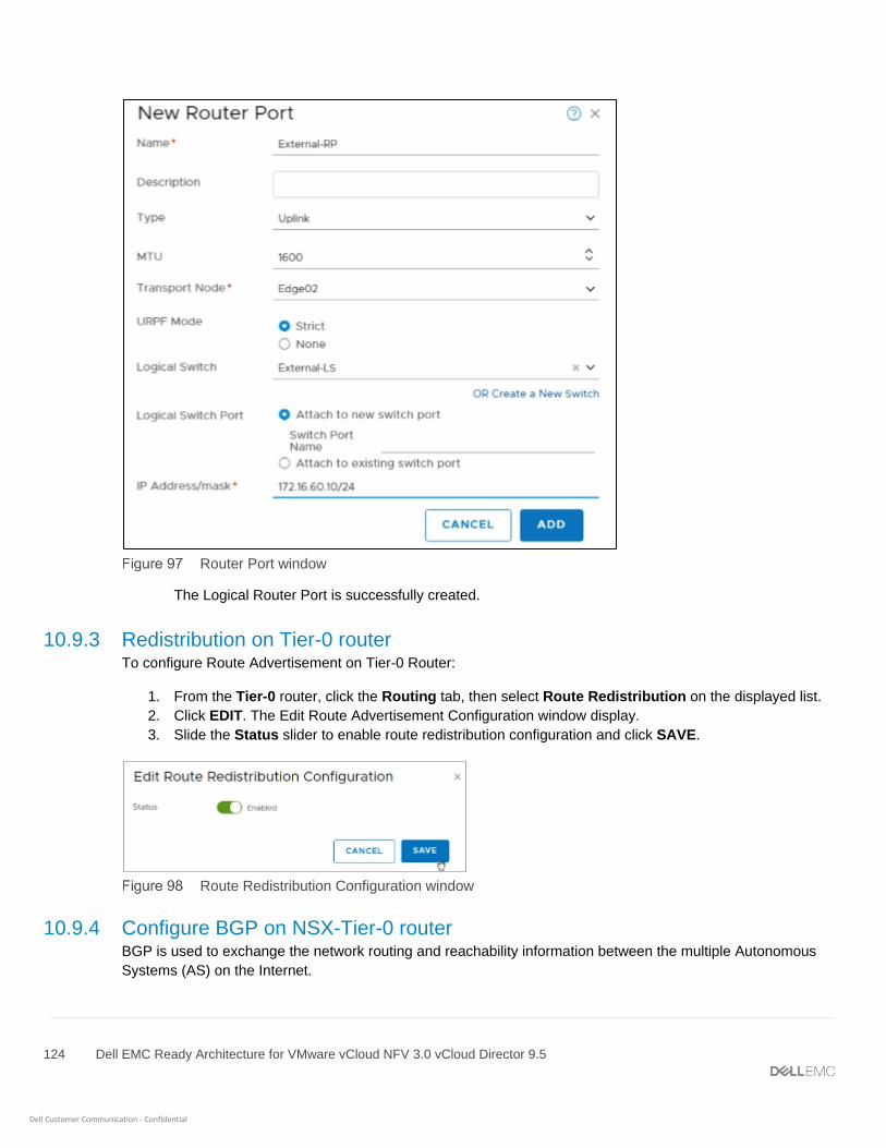
124 Dell EMC Ready Architecture for VMware vCloud NFV 3.0 vCloud Director 9.5
Dell Customer Communication - Confidential
Router Port window
The Logical Router Port is successfully created.
10.9.3 Redistribution on Tier-0 router To configure Route Advertisement on Tier-0 Router:
1. From the Tier-0 router, click the Routing tab, then select Route Redistribution on the displayed list.
2. Click EDIT. The Edit Route Advertisement Configuration window display.
3. Slide the Status slider to enable route redistribution configuration and click SAVE.
Route Redistribution Configuration window
10.9.4 Configure BGP on NSX-Tier-0 router BGP is used to exchange the network routing and reachability information between the multiple Autonomous
Systems (AS) on the Internet.

125 Dell EMC Ready Architecture for VMware vCloud NFV 3.0 vCloud Director 9.5
Dell Customer Communication - Confidential
Prerequisite:
• BGP should be configured on the Leaf switches.
To configure BGP:
1. From the Tier-0 router, click the Routing tab, then select BGP on the displayed list.
2. Click EDIT to display the Edit BGP Configuration window.
3. Slide the Status slider to Enable the BGP status.
4. Slide the ECMP slider to Enable it.
5. In the Local AS field, enter 65002, then click SAVE.
Edit BGP Configuration window
10.9.4.1 Add neighbor to router NSX-Tier-0 To exchange the network routing and reachability information two BGP neighbors are created in this
deployment. Table 29 displays the required information to create neighbors for this deployment.
BGP neighbor details
Field Neighbor-1 Neighbor-2
Admin Status Enable Enable
Remote AS 64502 64503
Maximum Hop Limit 2 2
Keep Alive Time (seconds) 60 60
Hold Down Time (Seconds) 180 180
Once the BGP is configured, To create neighbors:
1. On the BGP Configuration, in the Neighbors section, click + ADD to create new Neighbors.
2. On the New Neighbor window, in the Neighbor tab:
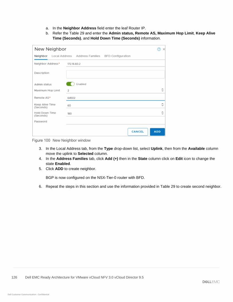
126 Dell EMC Ready Architecture for VMware vCloud NFV 3.0 vCloud Director 9.5
Dell Customer Communication - Confidential
a. In the Neighbor Address field enter the leaf Router IP.
b. Refer the Table 29 and enter the Admin status, Remote AS, Maximum Hop Limit, Keep Alive
Time (Seconds), and Hold Down Time (Seconds) information.
New Neighbor window
3. In the Local Address tab, from the Type drop-down list, select Uplink, then from the Available column
move the uplink to Selected column.
4. In the Address Families tab, click Add (+) then in the State column click on Edit icon to change the
state Enabled.
5. Click ADD to create neighbor.
BGP is now configured on the NSX-Tier-0 router with BFD.
6. Repeat the steps in this section and use the information provided in Table 29 to create second neighbor.
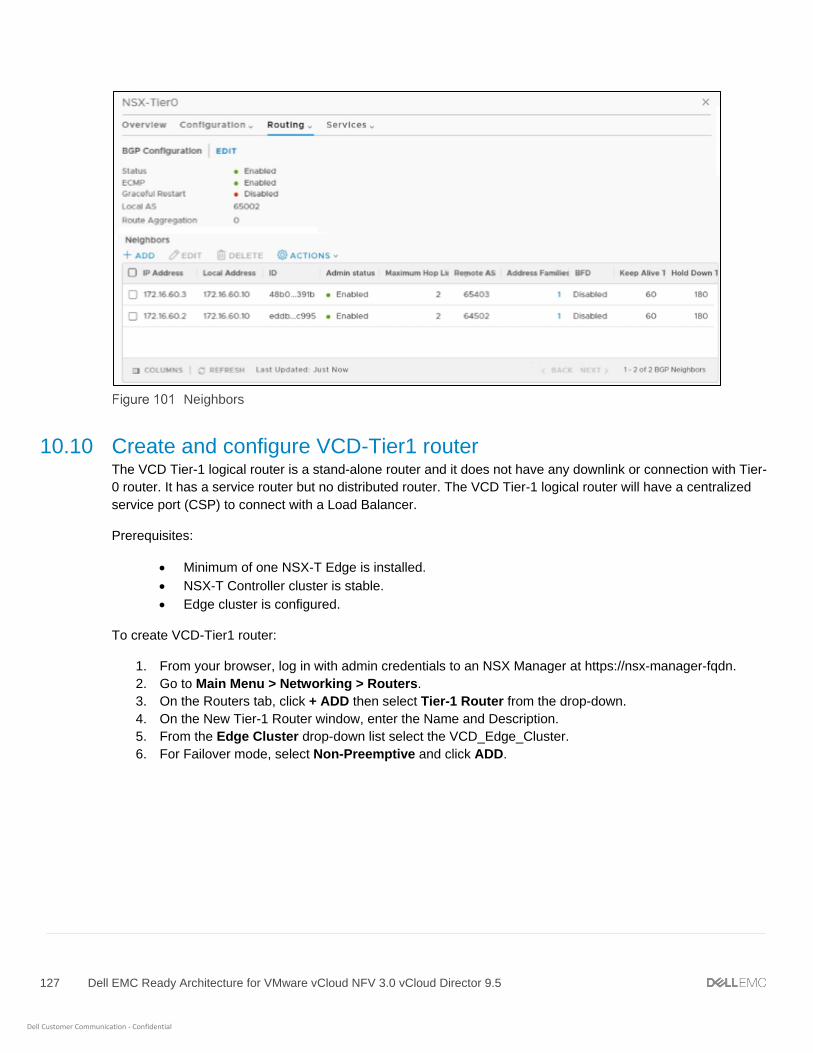
127 Dell EMC Ready Architecture for VMware vCloud NFV 3.0 vCloud Director 9.5
Dell Customer Communication - Confidential
Neighbors
10.10 Create and configure VCD-Tier1 router The VCD Tier-1 logical router is a stand-alone router and it does not have any downlink or connection with Tier-
0 router. It has a service router but no distributed router. The VCD Tier-1 logical router will have a centralized
service port (CSP) to connect with a Load Balancer.
Prerequisites:
• Minimum of one NSX-T Edge is installed.
• NSX-T Controller cluster is stable.
• Edge cluster is configured.
To create VCD-Tier1 router:
1. From your browser, log in with admin credentials to an NSX Manager at https://nsx-manager-fqdn.
2. Go to Main Menu > Networking > Routers.
3. On the Routers tab, click + ADD then select Tier-1 Router from the drop-down.
4. On the New Tier-1 Router window, enter the Name and Description.
5. From the Edge Cluster drop-down list select the VCD_Edge_Cluster.
6. For Failover mode, select Non-Preemptive and click ADD.

128 Dell EMC Ready Architecture for VMware vCloud NFV 3.0 vCloud Director 9.5
Dell Customer Communication - Confidential
Tier-0 Router window
The VCD Tier 1 Router is successfully created.
10.10.1 Create logical router port on VCD tier-1 router To create a logical router port on VCD-Tier-1 router and connect with logical switch:
1. Click on the VCD Tier-1 router, then from the Configuration drop-down select Router Ports.
2. In the Logical Router Ports section, click +ADD to add New Logical Router Ports.
3. On the New Router Port window, enter the Name as VCD-RP and Description in the fields provided.
4. From the Type drop-down list select Centralized then from the Logical Switch drop-down list, select
VCD-LS.
5. Select the Attach new switch port radio button, and in the IP Address/mask field enter the IP Address
or mask, then click ADD.
Router Port window
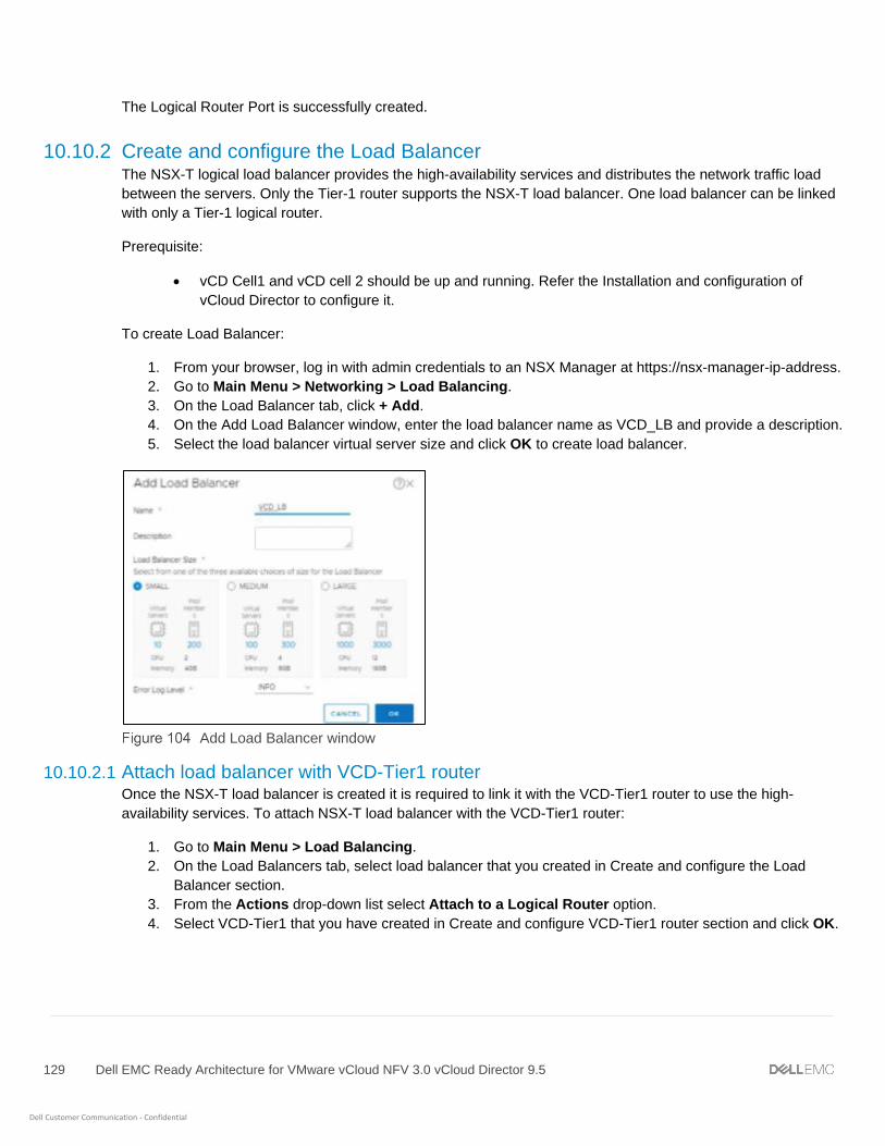
129 Dell EMC Ready Architecture for VMware vCloud NFV 3.0 vCloud Director 9.5
Dell Customer Communication - Confidential
The Logical Router Port is successfully created.
10.10.2 Create and configure the Load Balancer The NSX-T logical load balancer provides the high-availability services and distributes the network traffic load
between the servers. Only the Tier-1 router supports the NSX-T load balancer. One load balancer can be linked
with only a Tier-1 logical router.
Prerequisite:
• vCD Cell1 and vCD cell 2 should be up and running. Refer the Installation and configuration of
vCloud Director to configure it.
To create Load Balancer:
1. From your browser, log in with admin credentials to an NSX Manager at https://nsx-manager-ip-address.
2. Go to Main Menu > Networking > Load Balancing.
3. On the Load Balancer tab, click + Add.
4. On the Add Load Balancer window, enter the load balancer name as VCD_LB and provide a description.
5. Select the load balancer virtual server size and click OK to create load balancer.
Add Load Balancer window
10.10.2.1 Attach load balancer with VCD-Tier1 router Once the NSX-T load balancer is created it is required to link it with the VCD-Tier1 router to use the high-
availability services. To attach NSX-T load balancer with the VCD-Tier1 router:
1. Go to Main Menu > Load Balancing.
2. On the Load Balancers tab, select load balancer that you created in Create and configure the Load
Balancer section.
3. From the Actions drop-down list select Attach to a Logical Router option.
4. Select VCD-Tier1 that you have created in Create and configure VCD-Tier1 router section and click OK.

130 Dell EMC Ready Architecture for VMware vCloud NFV 3.0 vCloud Director 9.5
Dell Customer Communication - Confidential
Attach to a Virtual Server window
10.10.2.2 Create a health monitor for load balancer Once the load balancer is created, create a health monitor to test whether a server is available. This health
monitor does the different tests to monitor severs health. The health monitor starts health checks once:
• The sever pool is added to the load balancer and
• Load balancer is linked to VCD tier-1 router.
To create a health monitor for load balancer:
1. Go to Main menu > Networking > Load Balancing.
2. On the Monitors tab, click + Add to create a new active health monitor.
3. On the Monitor Properties window, enter the name and provide as TCP_VCD a description for health
monitor.
4. From the Health Check Protocol drop-down list, select LbTcpMonitor option.
5. In the Monitoring Port field, enter the 443 as port number.
6. Keep the default options for Monitoring interval (sec), Fall Count, Rise Count, and Timeout Period (sec),
then click Next.
Monitor properties
7. Review the health check configuration settings and click Finish. The Active health monitor is created
successfully.

131 Dell EMC Ready Architecture for VMware vCloud NFV 3.0 vCloud Director 9.5
Dell Customer Communication - Confidential
10.10.2.3 Add a server pool for load balancing Server pool is made of multiple servers that are configured and running on the same environment.
To add a server pool for load balancing:
1. Go to Main Menu > Load Balancing.
2. On the Server Pools tab and click + Add to create a new server pool.
3. On the General Properties window, enter a name as VCD_IP and description for the load balancer pool.
4. From the Load Balancing Algorithm drop-down select ROUND_ROBIN for the server pool.
5. Keep the default option for TCP Multiplexing and Maximum Multiplexing Connections then click
Next.
General Properties window
6. On the SNAT Translation window, select the Translation Mode to Auto Map, then keep the default
options for Port Overload and Overload Factor and click Next.
7. On the Pool Members window, select the Membership Type to Static.
8. In the Static Membership section click + ADD and add two pool members:
a. In the Name column, enter the pool member name.
b. In the IP column, enter the IP address of VCD Cell 1.
c. In the State column, select Enabled from the drop-down list.
d. Click + Add in the Static Membership section and create second pool members.
e. Click Next.

132 Dell EMC Ready Architecture for VMware vCloud NFV 3.0 vCloud Director 9.5
Dell Customer Communication - Confidential
Pool Members window
9. On the Health Monitors window, select the Active Health Monitor that you have created in Create a
health monitor for load balancer section.
10. Click Finish to add server pool.
10.10.2.4 Create a virtual server Virtual servers receive all the client connections and distribute them among the servers. A virtual server has an
IP address, a port, and a protocol.
To create virtual servers:
1. Go to Main Menu > Load Balancing.
2. On the Virtual Servers tab click + ADD to add a new virtual server.
3. On the General Properties window:
a. Enter a name as VCD_IP and description for the virtual server.
b. From the Load Balancer Application Profile option, select the Layer 4 radio button.
c. From the Application Profile drop-down list, select nsx-default-lb-fast-tcp-profile option.
d. Keep the default option selected for Access Log then click Next.
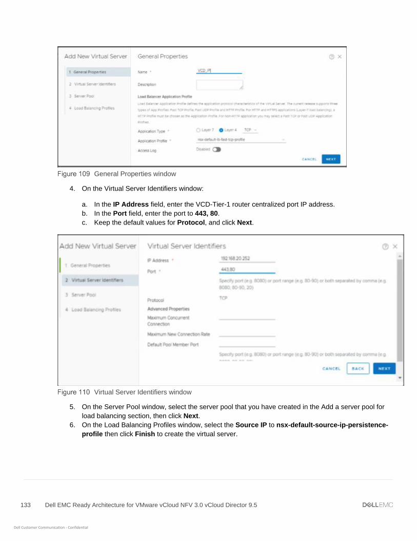
133 Dell EMC Ready Architecture for VMware vCloud NFV 3.0 vCloud Director 9.5
Dell Customer Communication - Confidential
General Properties window
4. On the Virtual Server Identifiers window:
a. In the IP Address field, enter the VCD-Tier-1 router centralized port IP address.
b. In the Port field, enter the port to 443, 80.
c. Keep the default values for Protocol, and click Next.
Virtual Server Identifiers window
5. On the Server Pool window, select the server pool that you have created in the Add a server pool for
load balancing section, then click Next.
6. On the Load Balancing Profiles window, select the Source IP to nsx-default-source-ip-persistence-
profile then click Finish to create the virtual server.
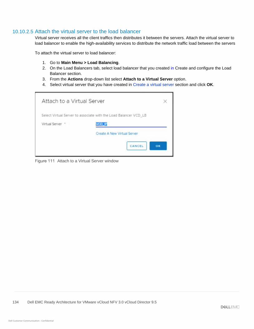
134 Dell EMC Ready Architecture for VMware vCloud NFV 3.0 vCloud Director 9.5
Dell Customer Communication - Confidential
10.10.2.5 Attach the virtual server to the load balancer Virtual server receives all the client traffics then distributes it between the servers. Attach the virtual server to
load balancer to enable the high-availability services to distribute the network traffic load between the servers
To attach the virtual server to load balancer:
1. Go to Main Menu > Load Balancing.
2. On the Load Balancers tab, select load balancer that you created in Create and configure the Load
Balancer section.
3. From the Actions drop-down list select Attach to a Virtual Server option.
4. Select virtual server that you have created in Create a virtual server section and click OK.
Attach to a Virtual Server window

135 Dell EMC Ready Architecture for VMware vCloud NFV 3.0 vCloud Director 9.5
Dell Customer Communication - Confidential
11 Configure vCloud Director VMware vCloud Director (vCD) is a VIM component and works on top of other VIM components, vCenter Server,
and NSX-T Manager. The vCloud Director is deployed on the Management pod. vCloud Director connects with:
• vCenter Server to manage the workloads
• NSX Manager associated with tenant networking
The vCloud Director server is grouped by deploying two vCD instances to create vCD cells. These cells are
attached with the NSX-T load balancer for high availability. An external PostgreSQL database instance is also
deployed to exchange the information between vCD cells. An NFS server instance is also created to provide the
temporary storage for upload or download the catalog items that are published externally.
Four VMs will be used to install and configure the vCD:
• Linux CentOS 7.0 PostgreSQL server instance
• Linux CentOS 7.0 or above for NFS Server
• Linux CentOS 7.0 or above for vCloud Director Cell1
• Linux CentOS 7.0 or above for vCloud Director Cell2
11.1 Configure a PostgreSQL database Prerequisites:
• Minimum hardware requirements to install PostgreSQL:
- ESXi server up and running
- Management IP must be configured and have access to Internet.
- CentOS 7.0 installed and running with the following minimum configuration:
> 16 GB Memory
> Disk Space: 100 GB
> vCPU: 2
> vNIC: 1
• Resource vCenter Server Appliance registered with Resource NSX-T Manager.
• AD, DNS, and NTP server should be up and running.
• PostgreSQL VM must have Internet connectivity.
To install the PostgreSQL server:
1. On the CentOS VM, open the terminal.
2. Run the following command and update the repository: #yum update
3. On the terminal, run the following command to install the PostgreSQL repository:
yum install -y https://download.postgresql.org/pub/repos/yum/10/redhat/rhel-
7-x86_64/pgdg-centos10-10-2.noarch.rpm
4. Once the PostgreSQL repository is installed, run to following command to install PostgreSQL 10:

136 Dell EMC Ready Architecture for VMware vCloud NFV 3.0 vCloud Director 9.5
Dell Customer Communication - Confidential
yum install -y postgresql10-server postgresql10
5. Once the installation is completed, you are required to initialize it before using it for the first time. Run
the following command to initialize it:
/usr/pgsql-10/bin/postgresql-10-setup initdb
6. Once the PostgreSQL is initialized, run the following command to start PostgreSQL service:
systemctl start postgresql-10
7. Run the following command to enable the auto start the PostgreSQL service at system startup:
systemctl enable postgresql-10
8. Run the following command to check the PostgreSQL service status:
systemctl status postgresql-10
9. Enable the access for external networks:
a. Run the following command to edit the configuration file:
vi /var/lib/pgsql/10/data/postgresql.conf
b. Uncomment the listen_addresses and port number.
Uncomment the listen address and port
10. Configure the remote connections for PostgreSQL:
a. Run the following command to edit the pg_hba.conf file:
vi /var/lib/pgsql/10/data/pg_hba.conf
b. Make an entry in the forms:

137 Dell EMC Ready Architecture for VMware vCloud NFV 3.0 vCloud Director 9.5
Dell Customer Communication - Confidential
pg_hba.conf file
c. Make an entry to access PostgreSQL from all the hosts:
pg_hba.conf file
Note: In the Address column, enter the IP address range of management server.
11. Run the following command and restart the PostgreSQL services:
systemctl restart postgresql-10
12. Run the following command to change the user to PostgreSQL user: su - postgres
13. Run the following command and set the server encoding value of the database to UTF-8:
/usr/pgsql-10/bin/initdb –locale=en_US.UTF-8
14. Run the following command to run pSQL: psql
15. Run the following command and create a database user: create user vcloud;
16. Run the following command and create a database instance and give it an owner:
create database vcloud owner vcloud;
17. Run the following command and assign a password to database owner account:
alter user vcloud password 'vcloudpass';

138 Dell EMC Ready Architecture for VMware vCloud NFV 3.0 vCloud Director 9.5
Dell Customer Communication - Confidential
18. Run the following command and enable the login of database owner to database:
alter role vcloud with login;
11.2 Installation of NFS server You must deploy and configure an NFS server accessible to all the servers of vCD server group. You must
configure each vCD cell in vCD server group to attach and use the NFS server.
Prerequisites:
• A virtual machine running CentOS7 with following configuration:
- 8GB Memory
- Disk space: 1 TB
- vCPU:1
- vNIC:1
• Management IP must be configured and have access to the Internet.
To install the NFS Server
1. Log in as a root user into Linux CentOS virtual machine and open the terminal.
2. Run the following command to install package nfs-utils:
yum install nfs-utils
3. Run the following command to start NFS-related services:
systemctl start nfs-server
4. Run the following command and make an export directory:
mkdir /opt/vcd-share
5. Append the following line within the /etc/exports file:
/opt/vcd-share *(rw,sync,no_root_squash)
6. Stop the firewall then turn it off using the following commands:
systemctl stop firewalld
chkconfig firewalld off
11.3 Installation and configuration of vCloud Director A vCloud Director server group consists of one or more Linux servers. Each server in the group runs number of
services called by vCloud Director cell. These cells have a common database and connect with management
and resource vCenter Server, ESXi hosts, and NSX-T Manager. The process to install and configure the vCloud
Director creates cells. In this deployment, the CentOS VM is used to create two vCloud Director cells.
11.3.1 Installation of vCD Cell 1 Prerequisites: Minimum hardware requirements to install vCD Cell1:
• ESXi server up and running
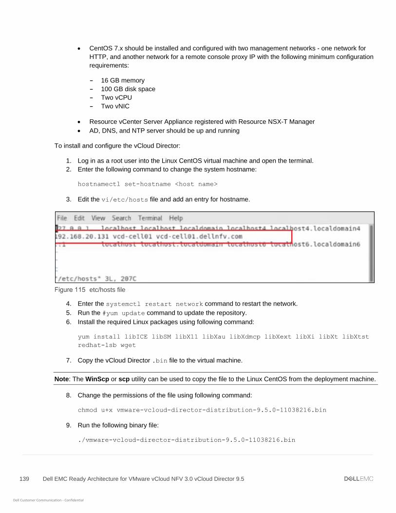
139 Dell EMC Ready Architecture for VMware vCloud NFV 3.0 vCloud Director 9.5
Dell Customer Communication - Confidential
• CentOS 7.x should be installed and configured with two management networks - one network for
HTTP, and another network for a remote console proxy IP with the following minimum configuration
requirements:
- 16 GB memory
- 100 GB disk space
- Two vCPU
- Two vNIC
• Resource vCenter Server Appliance registered with Resource NSX-T Manager
• AD, DNS, and NTP server should be up and running
To install and configure the vCloud Director:
1. Log in as a root user into the Linux CentOS virtual machine and open the terminal.
2. Enter the following command to change the system hostname:
hostnamectl set-hostname <host name>
3. Edit the vi/etc/hosts file and add an entry for hostname.
etc/hosts file
4. Enter the systemctl restart network command to restart the network.
5. Run the #yum update command to update the repository.
6. Install the required Linux packages using following command:
yum install libICE libSM libX11 libXau libXdmcp libXext libXi libXt libXtst
redhat-lsb wget
7. Copy the vCloud Director .bin file to the virtual machine.
Note: The WinScp or scp utility can be used to copy the file to the Linux CentOS from the deployment machine.
8. Change the permissions of the file using following command:
chmod u+x vmware-vcloud-director-distribution-9.5.0-11038216.bin
9. Run the following binary file:
./vmware-vcloud-director-distribution-9.5.0-11038216.bin

140 Dell EMC Ready Architecture for VMware vCloud NFV 3.0 vCloud Director 9.5
Dell Customer Communication - Confidential
Once the installation is complete, the Would you like to run the script? message displays.
10. Enter no then exit.
11. In the /etc/fstab file, enter the following commands to ensure that the NFS mount point is available
on the reboot:
a. Run the following command to go to: /etc/fstab file: vi /etc/fstab
b. Make an entry using following command:
<nfs-server-ip>:<export-path> /opt/vmware/vcloud-director/data/transfer nfs
intr 0 0
Note: In the export-path field enter the export directory that you have created in Installation of NFS server
section.
c. Save and close the /etc/fstab file using following command: wq
d. Run following command to mount NFS server: mount -a
12. Generate self-signed SSL certificate. For this go to /opt/vmware/vcloud-director/bin and run following
command:
./cell-management-tool generate-certs -j -p -o /tmp/cell.ks -w <password>
Note: If CA signed certificates are available use that certificates.
13. Run the following command and provide read and write permission to all users and change ownership to
vCloud by running following command:
chown -R vcloud:vcloud /opt/vmware/vcloud-director/data/transfer
14. Go to cd /opt/vmware/vcloud-director/bin and run following command to configure vCD:
./configure
The Welcome to the vCloud Director service message displays.
15. Review the information to configure and start the vCD
16. From the list of available IPs, enter the choice of IP for HTTP service, IP address to access the user
interface and REST API, then press Enter.
17. Once the HTTP service IP is provided, enter the IP for the remote console proxy IP address to be used
for all remote console connections and traffic, then press Enter.
18. After the remote console proxy IP address is provided, enter the file location of the SSL certificates and
private keys generated in Step 12, then press Enter.
19. Enter the password for the SSL certificate provided in Step 12 then press Enter.
20. Enter the Syslog hostname or IP address in the field provided, then press Enter.
21. From the options provided, select the database type as PostgreSQL then press Enter.
22. Enter the host IP address for the database, then press Enter.
23. In the required field, enter the database port number or press Enter to keep the default port number.
24. Enter the database name or press Enter to select the default database name.
25. From the database username field, enter the database user name then press Enter.

141 Dell EMC Ready Architecture for VMware vCloud NFV 3.0 vCloud Director 9.5
Dell Customer Communication - Confidential
26. Enter the password for the database user then press Enter.
Note: If you would like for the database password to be null, leave this field blank.
The system validates the provided information, initializes the database, and connects the server to it.
Connecting to the database
27. The option to participate in the VMware Customer Experience Improvement Program (CEIP) options
displays.
a. Enter y to join or enter n to decline, then press Enter.
The Database configuration complete message displays.
Note: The Setup wizard connection URL is accessible after the vCloud Director Service starts.
- The system will ask to start vCloud Director services now?, enter Y then press enter to start.
Complete the configuration
Following message displays: The service was started; it may be several minutes before it is ready for
use. Please check the logs for complete details.
b. Run the following command to stop firewall: systemctl stop firewalld
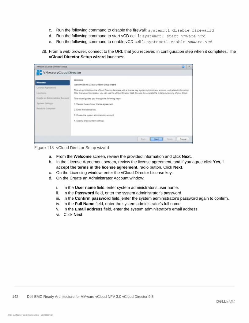
142 Dell EMC Ready Architecture for VMware vCloud NFV 3.0 vCloud Director 9.5
Dell Customer Communication - Confidential
c. Run the following command to disable the firewall: systemctl disable firewalld
d. Run the following command to start vCD cell 1: systemctl start vmware-vcd
e. Run the following command to enable vCD cell 1: systemctl enable vmware-vcd
28. From a web browser, connect to the URL that you received in configuration step when it completes. The
vCloud Director Setup wizard launches:
vCloud Director Setup wizard
a. From the Welcome screen, review the provided information and click Next.
b. In the License Agreement screen, review the license agreement, and if you agree click Yes, I
accept the terms in the license agreement. radio button. Click Next.
c. On the Licensing window, enter the vCloud Director License key.
d. On the Create an Administrator Account window:
i. In the User name field, enter system administrator's user name.
ii. In the Password field, enter the system administrator's password.
iii. In the Confirm password field, enter the system administrator's password again to confirm.
iv. In the Full Name field, enter the system administrator's full name.
v. In the Email address field, enter the system administrator's email address.
vi. Click Next.
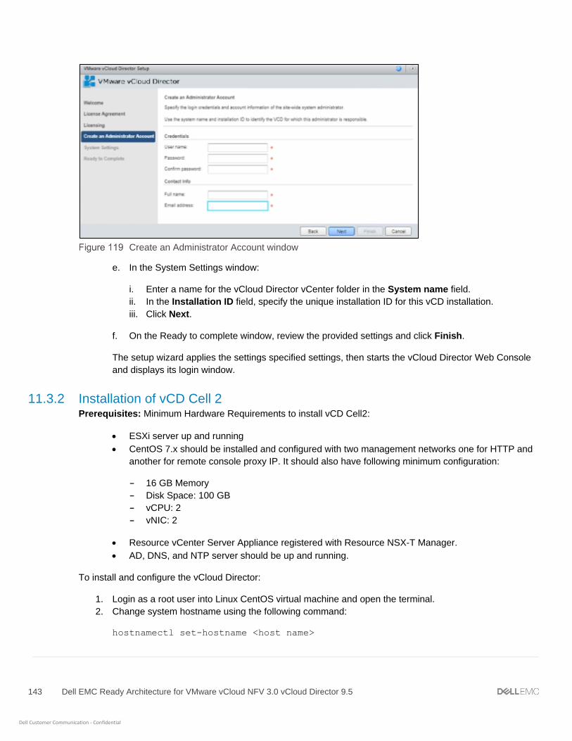
143 Dell EMC Ready Architecture for VMware vCloud NFV 3.0 vCloud Director 9.5
Dell Customer Communication - Confidential
Create an Administrator Account window
e. In the System Settings window:
i. Enter a name for the vCloud Director vCenter folder in the System name field.
ii. In the Installation ID field, specify the unique installation ID for this vCD installation.
iii. Click Next.
f. On the Ready to complete window, review the provided settings and click Finish.
The setup wizard applies the settings specified settings, then starts the vCloud Director Web Console
and displays its login window.
11.3.2 Installation of vCD Cell 2 Prerequisites: Minimum Hardware Requirements to install vCD Cell2:
• ESXi server up and running
• CentOS 7.x should be installed and configured with two management networks one for HTTP and
another for remote console proxy IP. It should also have following minimum configuration:
- 16 GB Memory
- Disk Space: 100 GB
- vCPU: 2
- vNIC: 2
• Resource vCenter Server Appliance registered with Resource NSX-T Manager.
• AD, DNS, and NTP server should be up and running.
To install and configure the vCloud Director:
1. Login as a root user into Linux CentOS virtual machine and open the terminal.
2. Change system hostname using the following command:
hostnamectl set-hostname <host name>

144 Dell EMC Ready Architecture for VMware vCloud NFV 3.0 vCloud Director 9.5
Dell Customer Communication - Confidential
3. Edit the vi/etc/hosts file, and make entry for hostname.
4. Restart the network using the following command:
systemctl restart network
5. Install the required Linux packages using following command:
yum install libICE libSM libX11 libXau libXdmcp libXext libXi libXt libXtst
redhat-lsb wget
6. Copy 'vmware-vcloud-director-distribution-9.5.0-11038216.bin' to the virtual machine. User can use
WinScp or scp utility to copy the file to the Linux CentOS from Deployment Machine.
7. Change permissions of the file using following command:
chmod u+x vmware-vcloud-director-distribution-9.5.0-11038216.bin
8. Execute the binary file:
./vmware-vcloud-director-distribution-9.5.0-11038216.bin
9. Enter y when prompted to install on an unsupported OS and wait for the installation to finish.
10. Once the installation is complete, the following message will display: Would you like to run the script?
enter no and exit.
11. Make an entry in /etc/fstab file to ensure that the NFS mount point will be available on the reboot:
a. Run the following command to go to: /etc/fstab file: vi /etc/fstab
b. Make an entry using following command:
<nfs-server-ip>:<export-path> /opt/vmware/vcloud-director/data/transfer nfs
intr 0 0
Note: In the export-path field enter the export directory that you have created in Installation of NFS server.
c. Save and close the /etc/fstab file using following command :wq
d. Run following command to mount NFS server: mount -a
12. Generate self-signed SSL certificate. For this go to /opt/vmware/vcloud-director/bin and run following
command:
./cell-management-tool generate-certs -j -p -o /tmp/cell.ks -w <password>
Note: If CA signed certificates are available use that certificates.
13. Copy the responses.properties, from vCD Cell1 directory at /opt/vmware/vcloud-
director/etc/responses.properties, to vCD Cell2 directory at /opt/vmware/vcloud-
director/etc/
14. Run the following commands and provide read and write permission to all users and change ownership
to vCloud by running following commands:
chmod 666 /opt/vmware/vcloud-director/etc/responses.properties

145 Dell EMC Ready Architecture for VMware vCloud NFV 3.0 vCloud Director 9.5
Dell Customer Communication - Confidential
chown vcloud:vcloud /opt/vmware/vcloud-director/etc/responses.properties
chown -R vcloud:vcloud /opt/vmware/vcloud-director/data/transfer
15. Run the following command and stop vCD: service vmware-vcd stop
16. Go to cd /opt/vmware/vcloud-director/bin and run following command to configure vCD:
./configure –r /opt/vmware/vcloud-director/etc/responses.properties
Welcome to the vCloud Director service. message displays. Review the information provided. You will
be prompted to enter a number of parameters required to configure and start the vCD.
a. From the list of available IPs, enter the choice of IP for HTTP service IP address to access the user
interface and REST API then press enter from your keyboard to continue.
b. Once the HTTP service IP is provided, enter the choice of IP for remote console proxy IP address
used for all remote console connections and traffic then press enter from your keyboard to continue.
Database configuration complete. Message displays. On the window:
- You can also view a URL at which you can use connect to the Setup wizard after vCloud
Director Service starts.
- The system will ask to start vCloud Director services now?, enter Y then press enter to start.
Start vCloud Director
Following message displays: The service was started; it may be several minutes before it is ready for
use. Please check the logs for complete details.
a. Run the following command to stop firewall: systemctl stop firewalld

146 Dell EMC Ready Architecture for VMware vCloud NFV 3.0 vCloud Director 9.5
Dell Customer Communication - Confidential
b. Run the following command to disable the firewall: systemctl disable firewalld
c. Run the following command to start vCD cell 2: systemctl start vmware-vcd
d. Run the following command to enable vCD cell 2: systemctl enable vmware-vcd
17. Open the web browser, enter https://<http-ip-address> or FQDN and select Manage and
Monitor > Cloud Resources> Cloud Cells to view the new entry of new vCloud Director cell’s
hostname and IP address.
11.4 Creating a session token for vCD You must generate a vCD session token to integrate vCD with vCenter Server and NSX-T manager. For more
information, see the VMware API Reference Guide.
Prerequisites:
• Download and install Postman on the deployment VM. For more information, see Postman
Documentation.
• Open the Postman application and go to Settings and turn-off the SSL Certificate Verification.
To generate the session token:
1. On the deployment VM, open the postman application.
2. POST a request to the vCD login URL and enter the vCD administrator credentials into the Authorization
header of the request.
url = https://<FQDN>/api/sessions
Method = POST
Authorization
Type- Basic Auth
HEADERS
Key VALUE
Accept application/*+xml;version=31.0;
Note: The values provided in the above example only for reference purposes, update the values as per your
requirement.

147 Dell EMC Ready Architecture for VMware vCloud NFV 3.0 vCloud Director 9.5
Dell Customer Communication - Confidential
Update the value for above parameter using the following table:
Parameter description
Parameter Description
FQDN Enter the FQDN for vCloud Director.
Response status 200 OK display means session code is generated successfully.
3. In the headers section of the response, note the value of x-vcloud-authorization field. This value
will be used as session token in all other API calls that we will make.
11.5 Register a VIM server Register VIM Server (vCenter Server) in vCD by creating a POST request in postman. This enables vCD to use
network resources from the NSX-T Data Center for vSphere. For more information, see the VMware API
Reference Guide.
Prerequisites:
• Postman application should be installed. For more information see Postman Documentation
• vCenter Server must be up and running
To register VIM Server in the vCD:
1. On the deployment server, open the postman application.
2. Paste the following parameters in the Postman Headers:
url = https://<FQDN>/api/admin/extension/action/registervimserver
Method = POST
Authorization
Type- No Auth
HEADERS:
Key VALUES
Accept application/*+xml;version=31.0;
Content-Type application/vnd.vmware.admin.registerVimServerParams+xml
Content-Length 596
x-vcloud-authorization Use the value fetched from the sessions api
Update the values for above parameters using the following table:
Uplink Profile details
148 Dell EMC Ready Architecture for VMware vCloud NFV 3.0 vCloud Director 9.5
Dell Customer Communication - Confidential
Parameter Description
FQDN Enter the FQDN for vCloud Director.
Content-Length Enter the total number of character available in Body section.
x-vcloud-authorization Enter the session ID received from the Creating a session token for vCD.
3. In the body tab, select the raw radio button paste the following parameters to create a POST request to
register VIM Server.
BODY:
<?xml version="1.0" encoding="UTF-8"?>
<vmext:RegisterVimServerParams
xmlns:vmext="http://www.vmware.com/vcloud/extension/v1.5">
<vmext:VimServer
name="ResVCSA-name">
<vmext:Username>[email protected]</vmext:Username>
<vmext:Password>***********</vmext:Password>
<vmext:Url><https://FQDN:443></vmext:Url>
<vmext:IsEnabled>false</vmext:IsEnabled>
<vmext:IsConnected>true</vmext:IsConnected>
<vmext:UseVsphereService>false</vmext:UseVsphereService>
</vmext:VimServer>
</vmext:RegisterVimServerParams>
Update the values for above parameters using the following table
Uplink Profile details
Parameter Description
name Enter the resource vCenter server name
Username Enter the resource vCenter server administrator user name
Password Enter the password of provided user name
Url Enter the FQDN for resource vCenter server
Note: Any change in the body section will be required to update the Content-Length in the header section.
Depending on the number of characters you add or delete in the Body section, update the Content-Length in the
Header section by the same amount.
4. Keep the remaining parameters default and POST the request.
Response status 200 OK display means vCenter Server is registered successfully.
149 Dell EMC Ready Architecture for VMware vCloud NFV 3.0 vCloud Director 9.5
Dell Customer Communication - Confidential
11.6 Update VIM server Create a PUT request on the postman to update VIM server. For more information, see the VMware API
Reference Guide.
To update VIM server:
1. On the deployment server, open the postman application.
2. Paste the following parameters in the Postman Headers:
url = https://<FQDN>/api/admin/extension/vimServer/{ID}
Method = PUT
Authorization
Type- Basic Auth
HEADERS
Key VALUES
Accept application/*+xml;version=31.0;
Content-Type
application/vnd.vmware.admin.vmwvirtualcenter+xml;version=31.0;
Content-Length 596
x-vcloud-authorization Use the value fetched from the sessions api
Update the values for above parameters using the following table
Uplink Profile details
Parameter Description
FQDN Enter the FQDN for vCloud Director
ID Enter the VIM Server ID received from the response of Register a VIM server
Content-Length Enter the total number of character available in Body section
x-vcloud-authorization Enter the session ID received from the Creating a session token for vCD
3. In the body tab, select the raw radio button paste the following parameters to create a PUT request to
register VIM Server.
BODY:
<?xml version="1.0" encoding="UTF-8"?>
<vmext:VimServer
xmlns:vcloud="http://www.vmware.com/vcloud/v1.5"
150 Dell EMC Ready Architecture for VMware vCloud NFV 3.0 vCloud Director 9.5
Dell Customer Communication - Confidential
xmlns:vmext="http://www.vmware.com/vcloud/extension/v1.5"
name="ResVCSA-Name">
<vmext:Username>[email protected]</vmext:Username>
<vmext:Password>*********</vmext:Password>
<vmext:Url>https://FQDN:443</vmext:Url>
<vmext:IsEnabled>true</vmext:IsEnabled>
<vmext:IsConnected>true</vmext:IsConnected>
<vmext:UseVsphereService>true</vmext:UseVsphereService>
</vmext:VimServer>
Update the values for above parameter meters using the following table
Uplink Profile details
Parameter Description
name Enter the resource vCenter server name
Username Enter the resource vCenter server administrator user name
Password Enter the password of provided user name
Url Enter the FQDN for resource vCenter server
Note: Any change in the body section will required to update the Content-Length in the header section.
Depending on the number of characters you add or delete in the Body section, update the Content-Length in the
Header section by the same amount.
4. Keep the remaining parameters default and POST the request.
Note: Response status 202 Accepted display means that the vCenter Server is updated successfully.
11.7 Retrieve the list of available resource pool You can retrieve the list of available resource pools available on the vCenter server to create a provider VDC. To
retrieve the list, create a GET request. For more information, see the VMware API Reference Guide.
To retrieve the list of available resource pool:
1. On the deployment server, open the postman application.
2. Paste the following parameters to create a GET request to retrieve the list of available resource pool:
url = https://<FQDN>/api/admin/extension/vimServer/<ID>/resourcePoolList
151 Dell EMC Ready Architecture for VMware vCloud NFV 3.0 vCloud Director 9.5
Dell Customer Communication - Confidential
Method = GET
HEADERS
Key VALUES
Accept application/*+xml;version=31.0;
Content-Type application/vnd.vmware.admin.resourcePoolList+xml;
x-vcloud-authorization Value as obtained from sessions api
3. Update the values for the parameters above using the following table:
Uplink Profile details
Parameter Description
FQDN Enter the FQDN for vCloud Director
ID Enter the VIM Server ID received from the response of Register a VIM server
x-vcloud-authorization Enter the session ID received from the Creating a session token for vCD.
Note: The values provided in the example above are for reference only. Update the values as required for your
configuration.
Response status 200 OK displays and a list of available resource pools displays.
11.8 Register NSX-T Manager to vCloud Director Register the NSX-T Manager with the vCD to use logical switch as an organization network in vCD. Register
NSX-T manager in the vCD by creating a POST request in postman. For more information, see the VMware API
Reference Guide.
To register NSX-T Manager:
1. On the deployment VM, open the postman application.
2. Paste the following parameters in the Postman Headers.
url = https://<FQDN>/api/admin/extension/nsxtManagers
Method = POST
Authorization
Type- No Auth
HEADERS
Key VALUES
Accept application/*+xml;version=31.0;

152 Dell EMC Ready Architecture for VMware vCloud NFV 3.0 vCloud Director 9.5
Dell Customer Communication - Confidential
Content-Type application/vnd.vmware.admin.nsxTmanager+xml;
x-vcloud-authorization Use the value fetched from the sessions api
3. Update the values for the parameters above using the following table:
Uplink profile details
Parameter Description
FQDN Enter the FQDN for vCloud Director
x-vcloud-authorization Enter the session ID received from the Creating a session token for vCD
4. In the Body tab, select the raw radio button paste the following parameters to create a POST request to
register NSX-T Manager.
BODY:
<?xml version="1.0" encoding="UTF-8" standalone="yes"?>
<vmext:NsxTManager xmlns="http://www.vmware.com/vcloud/v1.5"
xmlns:vmext="http://www.vmware.com/vcloud/extension/v1.5"
name="nsxManager-name">
<Description>NSX-T Manager</Description>
<vmext:Username>admin</vmext:Username>
<vmext:Password>**********</vmext:Password>
<vmext:Url>https://FQDN</vmext:Url>
</vmext:NsxTManager>
5. Update the values for the parameters above using the following table:
Parameter description
Parameter Description
name Enter the NSX-T Manager name
Description Provide a description
Username Enter the NSX-T Manager administrator user name
Password Enter the password of provided user name
Url Enter the FQDN for NSX-T Manager
6. Keep the remaining parameters default and POST the request.

153 Dell EMC Ready Architecture for VMware vCloud NFV 3.0 vCloud Director 9.5
Dell Customer Communication - Confidential
The Response status 200 OK message that displays indicates that the update of the NSX-T Manager
is successful.
11.9 Retrieve VIM server details Post a GET request on vCD to retrieve the VIM server details.
To retrieve VIM server details:
1. On the deployment VM, open the Postman application.
2. Paste the following parameters in the Postman Headers.
url: GET <FQDN>/api/admin/extension/vimServerReferences
Header:
x-vcloud-authorization: Use the value fetched from the session API.
3. Update the values for the parameters above using the following table:
Parameter description
Parameter Description
FQDN Enter the FQDN for vCloud Director
x-vcloud-authorization Enter the session ID received from the Creating a session token for vCD
The Response status 200 OK message displays.
4. From the received response, make note of the href, name, and id of the vCenter Server as shown in the
highlighted example below. This information is required when creating the provider VDC.
<?xml version="1.0" encoding="UTF-8" standalone="yes"?>
<vmext:VMWVimServerReferences xmlns="http://www.vmware.com/vcloud/v1.5"
xmlns:vmext="http://www.vmware.com/vcloud/extension/v1.5"
xmlns:ovf="http://schemas.dmtf.org/ovf/envelope/1"
xmlns:vssd="http://schemas.dmtf.org/wbem/wscim/1/cim-
schema/2/CIM_VirtualSystemSettingData"
xmlns:common="http://schemas.dmtf.org/wbem/wscim/1/common"
xmlns:rasd="http://schemas.dmtf.org/wbem/wscim/1/cim-
schema/2/CIM_ResourceAllocationSettingData"
xmlns:vmw="http://www.vmware.com/schema/ovf"
xmlns:ovfenv="http://schemas.dmtf.org/ovf/environment/1"
xmlns:ns9="http://www.vmware.com/vcloud/versions"
type="application/vnd.vmware.admin.vmwVimServerReferences+xml">
<Link rel="up" href="https://192.168.20.124/api/admin/extension"
type="application/vnd.vmware.admin.vmwExtension+xml"/>
<vmext:VimServerReference
href="https://192.168.20.124/api/admin/extension/vimServer/3cd1ac67-88de-
4c4b-8e1a-d171e322d8d1" id="urn:vcloud:vimserver:3cd1ac67-88de-4c4b-8e1a-
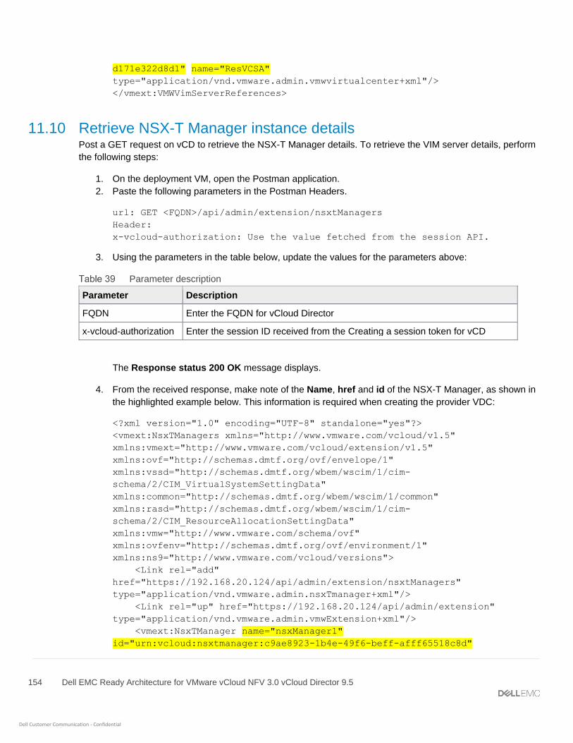
154 Dell EMC Ready Architecture for VMware vCloud NFV 3.0 vCloud Director 9.5
Dell Customer Communication - Confidential
d171e322d8d1" name="ResVCSA"
type="application/vnd.vmware.admin.vmwvirtualcenter+xml"/>
</vmext:VMWVimServerReferences>
11.10 Retrieve NSX-T Manager instance details Post a GET request on vCD to retrieve the NSX-T Manager details. To retrieve the VIM server details, perform
the following steps:
1. On the deployment VM, open the Postman application.
2. Paste the following parameters in the Postman Headers.
url: GET <FQDN>/api/admin/extension/nsxtManagers
Header:
x-vcloud-authorization: Use the value fetched from the session API.
3. Using the parameters in the table below, update the values for the parameters above:
Parameter description
Parameter Description
FQDN Enter the FQDN for vCloud Director
x-vcloud-authorization Enter the session ID received from the Creating a session token for vCD
The Response status 200 OK message displays.
4. From the received response, make note of the Name, href and id of the NSX-T Manager, as shown in
the highlighted example below. This information is required when creating the provider VDC:
<?xml version="1.0" encoding="UTF-8" standalone="yes"?>
<vmext:NsxTManagers xmlns="http://www.vmware.com/vcloud/v1.5"
xmlns:vmext="http://www.vmware.com/vcloud/extension/v1.5"
xmlns:ovf="http://schemas.dmtf.org/ovf/envelope/1"
xmlns:vssd="http://schemas.dmtf.org/wbem/wscim/1/cim-
schema/2/CIM_VirtualSystemSettingData"
xmlns:common="http://schemas.dmtf.org/wbem/wscim/1/common"
xmlns:rasd="http://schemas.dmtf.org/wbem/wscim/1/cim-
schema/2/CIM_ResourceAllocationSettingData"
xmlns:vmw="http://www.vmware.com/schema/ovf"
xmlns:ovfenv="http://schemas.dmtf.org/ovf/environment/1"
xmlns:ns9="http://www.vmware.com/vcloud/versions">
<Link rel="add"
href="https://192.168.20.124/api/admin/extension/nsxtManagers"
type="application/vnd.vmware.admin.nsxTmanager+xml"/>
<Link rel="up" href="https://192.168.20.124/api/admin/extension"
type="application/vnd.vmware.admin.vmwExtension+xml"/>
<vmext:NsxTManager name="nsxManager1"
id="urn:vcloud:nsxtmanager:c9ae8923-1b4e-49f6-beff-afff65518c8d"

155 Dell EMC Ready Architecture for VMware vCloud NFV 3.0 vCloud Director 9.5
Dell Customer Communication - Confidential
href="https://192.168.20.124/api/admin/extension/nsxtManagers/c9ae8923-1b4e-
49f6-beff-afff65518c8d" type="application/vnd.vmware.admin.nsxTmanager+xml">
<Description>NSX-T Manager</Description>
<vmext:Username>admin</vmext:Username>
<vmext:Url>https://192.168.20.104</vmext:Url>
</vmext:NsxTManager>
</vmext:NsxTManagers>
11.11 Create a provider VDC A provider VDC is a collection of compute, memory, and storage resources from a vCenter Server instance. For
network resources, a provider VDC uses NSX-T Data Center. A provider VDC provides resources to
organization VDCs. For more information, see the VMware API Reference Guide.
Prerequisites
• A vCenter Server instance must be available to provide a resource pool and storage information to
provider VDC
To create a provider VDC:
1. On the deployment VM, open the postman application.
2. Paste the following parameters in the Postman Headers.
url = https://<FQDN>/api/admin/extension/providervdcsparams
Method = POST
Authorization
Type- Basic Auth
HEADERS
Key VALUES
Accept application/*+xml;version=31.0;
Content-Type application/vnd.vmware.admin.createProviderVdcParams+xml;
x-vcloud-authorization Use the value fetched from the sessions api
Update the values for above parameters using the following table
Uplink profile details
Parameter Description
FQDN Enter the FQDN for vCloud Director
x-vcloud-authorization Enter the session ID received from the Creating a session token for vCD section

156 Dell EMC Ready Architecture for VMware vCloud NFV 3.0 vCloud Director 9.5
Dell Customer Communication - Confidential
3. In the body tab, select the raw radio button paste the following parameters to create a POST request to
create VDC provider.
BODY:
<?xml version="1.0" encoding="UTF-8"?>
<vmext:VMWProviderVdcParams
xmlns="http://www.vmware.com/vcloud/v1.5"
xmlns:vmext="http://www.vmware.com/vcloud/extension/v1.5"
name="nsxTPvdc1">
<vmext:ResourcePoolRefs>
<vmext:VimObjectRef>
<vmext:VimServerRef
href="https://192.168.20.124/api/admin/extension/vimServer/3cd1ac67-88de-
4c4b-8e1a-d171e322d8d1"/>
<vmext:MoRef>resgroup-10</vmext:MoRef>
<vmext:VimObjectType>RESOURCE_POOL</vmext:VimObjectType>
</vmext:VimObjectRef>
</vmext:ResourcePoolRefs>
<vmext:VimServer
href="https://192.168.20.124/api/admin/extension/vimServer/3cd1ac67-88de-4c4b-
8e1a-d171e322d8d1"
id="urn:vcloud:vimserver:3cd1ac67-88de-4c4b-8e1a-d171e322d8d1"
name="ResVCSA-name"
type="application/vnd.vmware.admin.vmwvirtualcenter+xml"/>
<vmext:NsxTManagerReference
href="https://192.168.20.124/api/admin/extension/nsxtManagers/c9ae8923-1b4e-49f6-
beff-afff65518c8d"
id="urn:vcloud:nsxtmanager:c9ae8923-1b4e-49f6-beff-afff65518c8d"
name="nsxManager-name"
type="application/vnd.vmware.admin.nsxTmanager+xml"/>

157 Dell EMC Ready Architecture for VMware vCloud NFV 3.0 vCloud Director 9.5
Dell Customer Communication - Confidential
<vmext:HighestSupportedHardwareVersion>vmx-
7</vmext:HighestSupportedHardwareVersion>
<vmext:IsEnabled>true</vmext:IsEnabled>
<vmext:StorageProfile>*</vmext:StorageProfile>
</vmext:VMWProviderVdcParams>
Update the values for above parameter meters using the following table
Uplink Profile details
Parameter Description
name Enter the name of provider VDC
For ResourcePoolRefs
VimServerRef herf Provide the VimServerRef hyperlink received from the Retrieve VIM server details response
MoRef Provide the MoRef value received from the Retrieve the list of available resource pool response
VimObjectType Provide the VimObjectType value received from the Retrieve the list of available resource pool response
For VimServer
VimServerRef herf Provide the VimServerRef hyperlink received from the Retrieve VIM server details response
id Provide the vCenter Server ID received from the Retrieve VIM server details response
name Enter the resource vCenter server name received from the Retrieve VIM server details response
For NSX_ManagerReference
name Enter the NSX-T Manager name received from the Retrieve NSX-T Manager instance details response
href Provide the NSX-T Manager link received from the Retrieve NSX-T Manager instance details response
id Provide the NSX-T Manager ID received from the Retrieve NSX-T Manager instance details response
HighestSupprtedHardwareVersion Enter the supported VMX hardware version
4. Keep the remaining parameters default and POST the request.
Response status 201 Accepted display means Provider VDC is created successfully.
11.12 Create an organization VDC To create an organization VDC:

158 Dell EMC Ready Architecture for VMware vCloud NFV 3.0 vCloud Director 9.5
Dell Customer Communication - Confidential
1. In your web browser, log in to the vCloud Director Cell1 with Administrator credentials.
2. On the Manage & Monitor tab, click Organizations in the left pane.
3. Click the Add (+) icon to create a new organization. The New Organization wizard opens.
4. In the Organization name enter an organization name.
Note: The name provided in this field is a unique identifier that displays as a part of URL that organization users
use to log in to the organization.
5. In the Organization full name field, enter the organization name.
Note: The name provided in this field displays in the browser header when the user logs in to the organization.
6. Click Next.
7. In the LDAP Options window, select an LDAP option.
8. In the Add Local Users window, click Add (+) to create users for the organization:
- - On the New User window, in the User name field enter username.
- - In the Password and Confirm password field, provide a password for their login.
- - Check the Enable box.
- - From the Role drop-down list, select a role for the user.
- - Set the All VMs quota and Running VMs quota to Unlimited.
- - Click OK to create user.
9. Click Next.
10. Keep the default settings in the Catalog, Email Preferences, and Policies window, then click Next.
11. In the Ready to Complete window, review the organization information, and click Finish to create
organization.
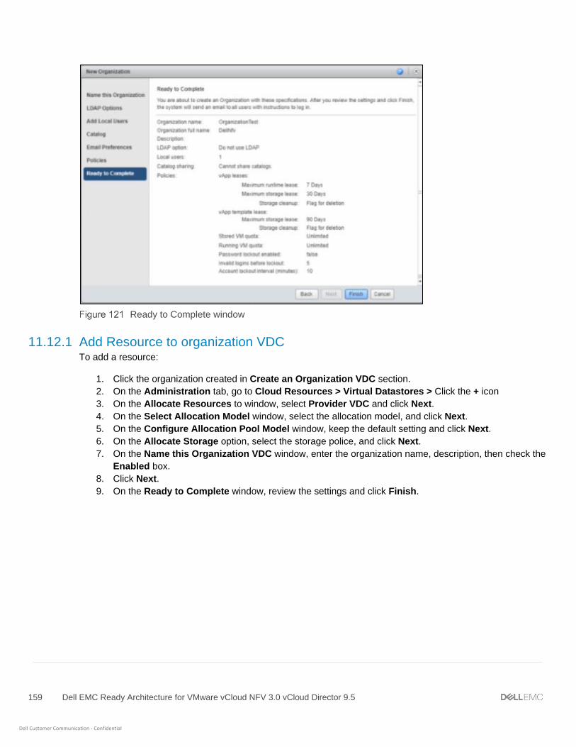
159 Dell EMC Ready Architecture for VMware vCloud NFV 3.0 vCloud Director 9.5
Dell Customer Communication - Confidential
Ready to Complete window
11.12.1 Add Resource to organization VDC To add a resource:
1. Click the organization created in Create an Organization VDC section.
2. On the Administration tab, go to Cloud Resources > Virtual Datastores > Click the + icon
3. On the Allocate Resources to window, select Provider VDC and click Next.
4. On the Select Allocation Model window, select the allocation model, and click Next.
5. On the Configure Allocation Pool Model window, keep the default setting and click Next.
6. On the Allocate Storage option, select the storage police, and click Next.
7. On the Name this Organization VDC window, enter the organization name, description, then check the
Enabled box.
8. Click Next.
9. On the Ready to Complete window, review the settings and click Finish.
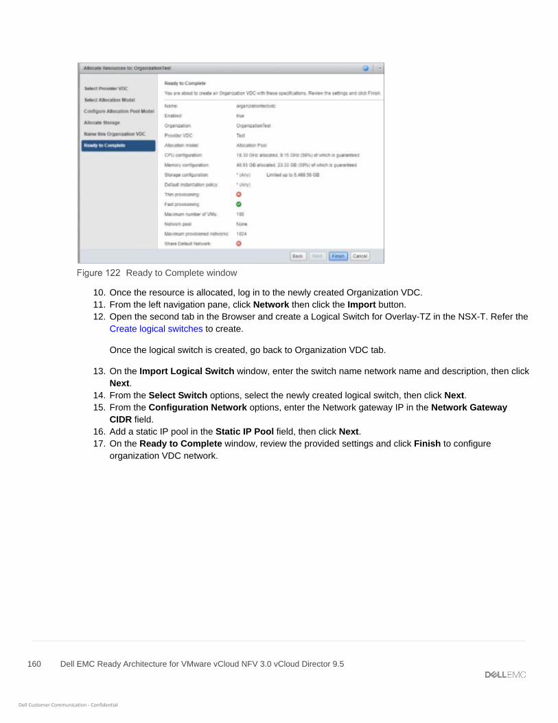
160 Dell EMC Ready Architecture for VMware vCloud NFV 3.0 vCloud Director 9.5
Dell Customer Communication - Confidential
Ready to Complete window
10. Once the resource is allocated, log in to the newly created Organization VDC.
11. From the left navigation pane, click Network then click the Import button.
12. Open the second tab in the Browser and create a Logical Switch for Overlay-TZ in the NSX-T. Refer the
Create logical switches to create.
Once the logical switch is created, go back to Organization VDC tab.
13. On the Import Logical Switch window, enter the switch name network name and description, then click
Next.
14. From the Select Switch options, select the newly created logical switch, then click Next.
15. From the Configuration Network options, enter the Network gateway IP in the Network Gateway
CIDR field.
16. Add a static IP pool in the Static IP Pool field, then click Next.
17. On the Ready to Complete window, review the provided settings and click Finish to configure
organization VDC network.

161 Dell EMC Ready Architecture for VMware vCloud NFV 3.0 vCloud Director 9.5
Dell Customer Communication - Confidential
Ready to Complete window
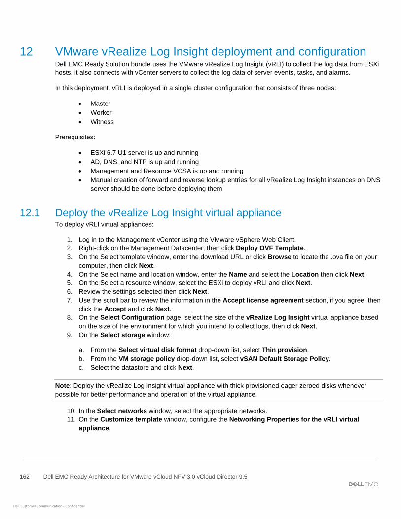
162 Dell EMC Ready Architecture for VMware vCloud NFV 3.0 vCloud Director 9.5
Dell Customer Communication - Confidential
12 VMware vRealize Log Insight deployment and configuration Dell EMC Ready Solution bundle uses the VMware vRealize Log Insight (vRLI) to collect the log data from ESXi
hosts, it also connects with vCenter servers to collect the log data of server events, tasks, and alarms.
In this deployment, vRLI is deployed in a single cluster configuration that consists of three nodes:
• Master
• Worker
• Witness
Prerequisites:
• ESXi 6.7 U1 server is up and running
• AD, DNS, and NTP is up and running
• Management and Resource VCSA is up and running
• Manual creation of forward and reverse lookup entries for all vRealize Log Insight instances on DNS
server should be done before deploying them
12.1 Deploy the vRealize Log Insight virtual appliance To deploy vRLI virtual appliances:
1. Log in to the Management vCenter using the VMware vSphere Web Client.
2. Right-click on the Management Datacenter, then click Deploy OVF Template.
3. On the Select template window, enter the download URL or click Browse to locate the .ova file on your
computer, then click Next.
4. On the Select name and location window, enter the Name and select the Location then click Next
5. On the Select a resource window, select the ESXi to deploy vRLI and click Next.
6. Review the settings selected then click Next.
7. Use the scroll bar to review the information in the Accept license agreement section, if you agree, then
click the Accept and click Next.
8. On the Select Configuration page, select the size of the vRealize Log Insight virtual appliance based
on the size of the environment for which you intend to collect logs, then click Next.
9. On the Select storage window:
a. From the Select virtual disk format drop-down list, select Thin provision.
b. From the VM storage policy drop-down list, select vSAN Default Storage Policy.
c. Select the datastore and click Next.
Note: Deploy the vRealize Log Insight virtual appliance with thick provisioned eager zeroed disks whenever
possible for better performance and operation of the virtual appliance.
10. In the Select networks window, select the appropriate networks.
11. On the Customize template window, configure the Networking Properties for the vRLI virtual
appliance.
163 Dell EMC Ready Architecture for VMware vCloud NFV 3.0 vCloud Director 9.5
Dell Customer Communication - Confidential
Note: If you do not provide network settings such as an IP address, DNS server, and gateway information,
vRLI utilizes DHCP to set those settings.
Note: Do not specify more than two domain name servers. If you specify more than two domain name servers,
the configured domain name servers are ignored within the vRealize log.
12. On the Customize template page, select Other Properties and set the root password for the vRealize
Log Insight virtual appliance, then click Next.
13. Review the settings in Ready to complete window and click Finish to deploy the vRLI VM.
Review Configuration data window
Note: Repeat the steps in this section two more times to deploy worker nodes and create a cluster of three
appliances, with only the Master node powered on.
12.2 Configure the root SSH password for vRLI virtual appliance
Note: The steps in this section are optional and only required if the root SSH password is not set at the time of
vRealize Log Insight .ova file deployment.
By default, the SSH connection to the virtual appliance is disabled. You can configure the root SSH password
from the VMware Remote Console or when you deploy the vRLI virtual appliance. You can also enable SSH and
set the root password from the VMware Remote Console.
Before configuring the root SSH password for vRLI virtual appliance, verify that the vRealize Log Insight virtual
appliance is deployed and running.
To configure root SSH password:

164 Dell EMC Ready Architecture for VMware vCloud NFV 3.0 vCloud Director 9.5
Dell Customer Communication - Confidential
1. In the vSphere Client inventory, click the vRealize Log Insight virtual appliance, and open the
Console tab.
2. Go to a command line by following the key combination specified on the splash window.
3. In the console, type root, and press Enter.
4. Leave the password empty and press Enter. The Password change requested. Choose a new
password message displays in the console.
5. Leave the old password empty and press Enter.
6. Enter a new password for the root user, then press Enter.
7. Enter the new password again for the root user, and press Enter.
Note: The password must consist of at least eight characters, and must include at least one upper case letter,
one lower case letter, one digit, and one special character. You cannot repeat the same character more than
four times
The Password changed message displays.
12.3 Master node configuration To configure the master node, perform the following steps:
1. Go to the vRLI Web user interface: <https://<vRLI_Host_IP/FQDN>.
2. From the Setup window, click Next.
3. On the Choose Deployment Type window, click Start New Deployment.
4. From the Admin Credentials screen:
a. In the Email field, enter the admin email ID.
b. In the New password field, enter the admin password.
c. In the Confirm new password field, reenter the password to confirm.
d. Click Save and Continue.
5. Enter the license key, then click Add License, and click Save and Continue.
6. On the General Configuration page, enter an email address in the field that is provided to receive
system notifications from vRealize Log Insight.
7. Optionally, you can participate in the Customer Experience Improvement Program by selecting the
Join the VMware Customer Experience Program check box, else, leave the check box blank.
8. Click Save and Continue.
9. On the Time Configuration page, set how time is synchronized on the VRLI appliance by selecting NTP
server then enter the IP address for NTP server and click Test.
10. Once the test is successful, click Save and Continue.
11. On the SMTP Configuration window, keep the default settings, and click Skip.
12. On the Setup complete window, click Finish to complete the setup.
12.4 Worker node configuration
Note: Configure a minimum of three nodes in a vRLI cluster to provide ingestion, configuration, and user space
high availability.

165 Dell EMC Ready Architecture for VMware vCloud NFV 3.0 vCloud Director 9.5
Dell Customer Communication - Confidential
To configure worker node:
1. Power on the second Log Insight Appliance and wait for the configuration process to complete.
2. Go to the second Log Insight URL, for example https://<vRLI 2nd Host IP/FQDN>.
3. On the Setup window, click Next.
4. On the Choose Deployment Type window, click Join Existing Deployment.
5. Enter the IP address or hostname of the vRLI master node and click Go.
6. Select Click here to access the Cluster Management page to be redirected to the Master Node vRLI
login page.
7. Click Allow button on the Cluster Management page for the new worker node appliance to join.
8. Repeat the steps from step 1 to step 7 to configure a third Log Insight Appliance.
12.5 Enable Integrated Load Balancer The Integrated Load Balancer (ILB) ensures that incoming Ingestion traffic is accepted by vRLI even if some
vRLI nodes become unavailable. The ILB also balances incoming traffic fairly among available vRLI nodes. vRLI
clients, using both the Web user interface and ingestion (through Syslog or the Ingestion API), should connect to
the vRLI using the ILB address.
Prerequisites:
• Verify that all vRLI nodes and the specified Integrated Load Balancer IP address are on the same
network.
• DNS records have been configured for the IP addresses.
To enable integrated load balancer:
1. Login to the Master node Log Insight web UI with Admin login, for example, https://<Log Insight FQDN>
2. From the upper-right menu, click the Administration then select Cluster.
3. On the Cluster page, click +NEW VIRTUAL IP ADDRESS.
4. On the New Virtual IP window, enter the IP and FQDN for ILB, then click Save.
5. Refresh the Cluster Management page to confirm that the LB Status displays as Available.
Note: You can configure multiple virtual IP addresses. Click +NEW VIRTUAL IP ADDRESS and enter the IP
Address in the field provided. This option also allows you to enter the FQDN and tags.
12.6 Integrate vRLI with AD Follow the below to integrate vRLI with AD
1. Navigate and login to vRLI, for example, https://<Log Insight FQDN>
2. From the upper-right menu, click the Administration then select Authentication.
3. On the Active Directory tab configure as follows:
- Enable Active Directory support: slide the toggle button to ON.
- Default Domain: Enter the relevant domain name.
- Username: user must admin rights.
- Password: Password for above user.
- Connection Type: Can be Standard or can be set to Custom for testing specific ports.

166 Dell EMC Ready Architecture for VMware vCloud NFV 3.0 vCloud Director 9.5
Dell Customer Communication - Confidential
- Require SSL: Check if SSL required.
4. Click Test Connection to validate the settings.
5. Once the connection is validated successfully, click Save.
12.7 Integrate vRLI with VMware vCenter Integrate vRLI with VMware vCenter to pull the tasks, events, and alerts. To integrate the vRLI with VMware
vCenter:
1. Go to the URL for the Master Node Log Insight sever, for example, https://<Log Insight FQDN/IP>
2. From the upper right corner of the window, click Administration then select vSphere, then click + Add
vCenter Server.
3. Enter the Hostname (IP/FQDN) for the Management vCenter and the user credentials to connect to the
vCenter Server system and click Test Connection to verify the connection.
4. Once tested successfully, click Save.
VMware vSphere integration log in Window
5. Repeat the above steps to configure the integration of the edge cluster and resource vCenter.
12.8 Configure vRLI to send notifications to vRealize Operations Manager You can configure vRLI to send alert notifications to vRealize Operations (vROps) Manager. Integrating vRLI
alerts with vROps Manager allows you to view all information about your environment in a single user interface.
You can send notification events from multiple vRLI instances to a single vROps Manager instance.
Prerequisite:
• vROps Manager VM should be powered on and configured properly
• vROps FQDN should be registered with DNS
1. Go to the URL for the Log Insight sever, for example, https://<Log Insight FQDN>
2. From the upper right corner of the window, click Administration then select vRealize Operations.

167 Dell EMC Ready Architecture for VMware vCloud NFV 3.0 vCloud Director 9.5
Dell Customer Communication - Confidential
3. Enter the FQDN/IP in the Hostname, field for the vROps then enter user credentials to connect with
vROps server system.
4. Check the Enable alerts integration box.
5. Click Test Connection to verify the connection.
6. Once tested successfully, click Save.
12.9 Add Log Insight content packs The Content Pack Marketplace is where you can access content packs for VMware and non-VMware products.
Content Packs include domain specific queries, alerts, dashboards, field extractions and agent group templates
for their associated products. A content pack is not required to ingest logs from a specific product. Essentially,
the content pack makes it easier and faster to find critical log data by selecting and alerting admin to common
issues that are present in the ingested log data. As a result, troubleshooting and root cause analysis efforts take
significantly less time.
Note: Ensure you download the latest and compatible Content Packs for vSAN, vROps, NSX-T, VCD, and
vSphere from VMware Marketplace.
12.9.1 Offline update for content pack Prerequisite:
• Content pack needs to be downloaded for the import.
• Components which requires the content packs: vSAN, vROps, NSX-T, VCD, and vSphere.
• The browser time and server time must be in same time zone as UTC to forward the log with
different products.
To update content pack:
1. Go to the URL for the Log Insight sever, such as https://<Log Insight FQDN>
2. From the upper right corner of the window, select Content Packs then click Import Content Pack.
3. Browse for the downloaded Content Pack and select Import.
4. Click OK to complete Content Pack import.
5. Repeat the steps in this section to install content packs for the remaining components.
12.9.2 Online update for content pack Prerequisites:
• Require Internet connectivity.
• Components which requires the content packs: vSAN, vROps, NSX-T, VCD, and vSphere.
To update content pack online:
1. Content packs are available for many of the components used in the DELL NFV and can be imported
into any instance of the Log Insight.
2. Go to the URL for the Log Insight sever, such as https://<Log Insight FQDN>
3. From the upper right corner of the screen, click Content Packs.
4. From the Customer Pack Marketplace, click Marketplace.
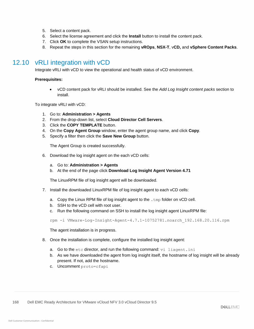
168 Dell EMC Ready Architecture for VMware vCloud NFV 3.0 vCloud Director 9.5
Dell Customer Communication - Confidential
5. Select a content pack.
6. Select the license agreement and click the Install button to install the content pack.
7. Click OK to complete the VSAN setup instructions.
8. Repeat the steps in this section for the remaining vROps, NSX-T, vCD, and vSphere Content Packs.
12.10 vRLI integration with vCD Integrate vRLI with vCD to view the operational and health status of vCD environment.
Prerequisites:
• vCD content pack for vRLI should be installed. See the Add Log Insight content packs section to
install.
To integrate vRLI with vCD:
1. Go to: Administration > Agents
2. From the drop-down list, select Cloud Director Cell Servers.
3. Click the COPY TEMPLATE button.
4. On the Copy Agent Group window, enter the agent group name, and click Copy.
5. Specify a filter then click the Save New Group button.
The Agent Group is created successfully.
6. Download the log insight agent on the each vCD cells:
a. Go to: Administration > Agents
b. At the end of the page click Download Log Insight Agent Version 4.71
The LinuxRPM file of log insight agent will be downloaded.
7. Install the downloaded LinuxRPM file of log insight agent to each vCD cells:
a. Copy the Linux RPM file of log insight agent to the .tmp folder on vCD cell.
b. SSH to the vCD cell with root user.
c. Run the following command on SSH to install the log insight agent LinuxRPM file:
rpm -i VMware-Log-Insight-Agent-4.7.1-10752781.noarch_192.168.20.116.rpm
The agent installation is in progress.
8. Once the installation is complete, configure the installed log insight agent:
a. Go to the etc director, and run the following command: vi liagent.ini
b. As we have downloaded the agent from log insight itself, the hostname of log insight will be already
present. If not, add the hostname.
c. Uncomment proto=cfapi
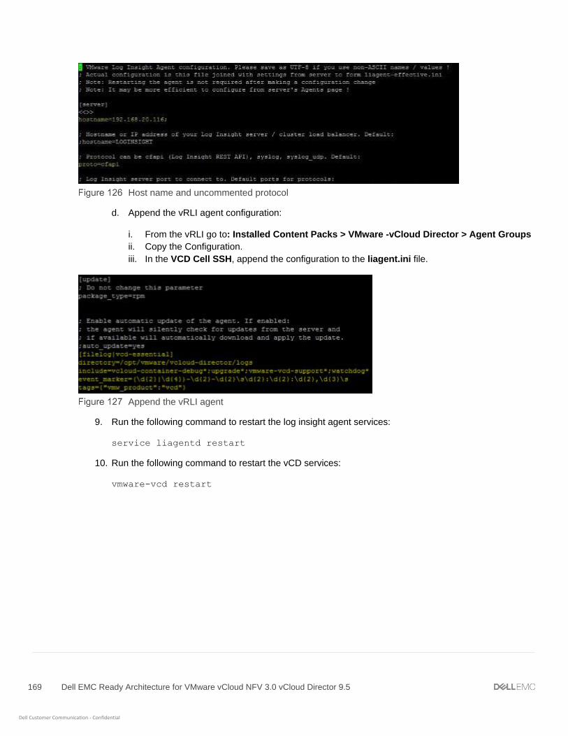
169 Dell EMC Ready Architecture for VMware vCloud NFV 3.0 vCloud Director 9.5
Dell Customer Communication - Confidential
Host name and uncommented protocol
d. Append the vRLI agent configuration:
i. From the vRLI go to: Installed Content Packs > VMware -vCloud Director > Agent Groups
ii. Copy the Configuration.
iii. In the VCD Cell SSH, append the configuration to the liagent.ini file.
Append the vRLI agent
9. Run the following command to restart the log insight agent services:
service liagentd restart
10. Run the following command to restart the vCD services:
vmware-vcd restart

170 Dell EMC Ready Architecture for VMware vCloud NFV 3.0 vCloud Director 9.5
Dell Customer Communication - Confidential
13 VMware vRealize Operations Manager deployment and
configuration The vRealize Operations (vROps) Manager delivers intelligent operations management with application-to-
storage visibility across physical, virtual, and cloud infrastructures. Using policy-based automation, operations
teams automate key processes and improve IT efficiency.
As part of the vROps Manager deployment, three nodes will be deployed as follows:
• Master
• Data
• Data used as a master replica node
Note: The vROps deployment covered in this document has been done for Medium configuration. The vROps
OVA template deployment is to be done three nodes – data, master, and replica. The vRealize Operations
Manager UI can be used to add the Management vCenter and the Resources vCenter.
13.1 Deployment prerequisites for vRealize Operations Manager You can create a single node and configure it as a master node or create a master node in a cluster to handle
additional data. All vRealize Operations Manager installations require a master node. With a single node cluster,
administration and data functions are on the same master node. A multiple-node vRealize Operations Manager
cluster contains one master node and one or more nodes for handling additional data.
Prerequisites:
• ESXi 6.7 U1 server is up and running
• AD, DNS, and NTP is up and running
• vCenter, vSAN, vRLI is installed, configured, and running
• Manual creation of forward and reverse lookup entries that are completed for all vROps instances
on DNS server before deploying them
13.2 Deploy vRealize Operations Manager The first stage is the deployment of the OVA File as a vRealize Operations Manager. To deploy vROps
Manager:
1. Log in to vCenter using vSphere web Client, right click on the vCenter server and select Deploy OVF
Template
2. Enter the Name and select the Location click Next.
3. On the Select a resource window, select an ESXi for vROps.
4. On the Review details window, review the entered information then click Next.
5. Read and if you agree then accept the license agreement and click Next.
6. On the Select configuration window select the configuration size based on the size of the environment,
then click Next.
7. On the Select storage window select virtual disk format, VM storage policy, and vsanDatastore
store then click Next

171 Dell EMC Ready Architecture for VMware vCloud NFV 3.0 vCloud Director 9.5
Dell Customer Communication - Confidential
8. In the Select networks window, select the appropriate networks for vROps, then click Next.
9. On the Customize template window, configure the Networking Properties for the vROps virtual
appliance, and click Next.
10. On the Ready to complete window, review the configuration data and click Finish.
Note: Repeat the steps in this section two more times to deploy more nodes.
13.3 Configuration of vRealize Operations Manager To configure the vROps manager master node:
1. Go to the FQDN or IP address of the node that will be the master node of vRealize Operations Manager.
2. Log in to vRealize Operations Manager and click New Installation.
3. From the Getting started window, review the information, then click Next.
4. Set the Administrator password and click Next.
5. Choose the appropriate certificate, then click Next.
Note: If certificates need to be installed, select the Install a certificate option and browse to the selected file.
6. On the Deployment Settings window, enter the Cluster Master Node Name then the NTP Server
FQDN/IP address for the environment and click Add, then click Next.
7. Keep the default settings on the Add Nodes window, and click Next.
8. On the Ready to complete window, review the entered information then click Finish to complete initial
set up.
13.4 Add data nodes to scale out vRealize Operations Manager
Note: Add two data nodes using the steps in this section. The second data node works as the replica of the
master node.
To add a data node in vROps:
1. Log in to the new node of vRealize Operations Manager, then select Expand an Existing Installation.
2. On the Expand Existing Cluster window, review the information then, click Next.
3. On the Enter node settings and cluster information window, enter the name of the node in the Node
name field, and select the Data, from the. Node Type drop-down.
4. In the Master node IP address or FQDN field, enter the FQDN or IP address of the master node, then
click VALIDATE to validate master node connection.
5. Verify the displayed master node certificate information and if correct check the Accept this certificate
box, and click Next.
6. In the Username and Password window verify that the vROps administrator username is admin, and
enter the vROps Manager Admin password, then click Next.
7. On the Ready to Complete screen, verify the configuration details and click Finish.
8. In the System Status window, click START vREALIZE OPERATIONS MANAGER to start the node.
Once the node loads, the status changes to Online.

172 Dell EMC Ready Architecture for VMware vCloud NFV 3.0 vCloud Director 9.5
Dell Customer Communication - Confidential
13.5 Add master replica node To add the master replica node:
1. Log in to new node of vRealize Operations Manager, then select Expand an Existing Installation.
2. On the Expand Existing Cluster window, review the information then, click Next.
3. On the Enter node settings and cluster information window, enter the name of the node in the Node
name field, and select the Data, from the. Node Type drop-down.
4. In the Master node IP address or FQDN field, enter the FQDN or IP address of the master node, then
click the VALIDATE button to validate master node connection.
5. Verify the displayed master node certificate information and if correct check the Accept this certificate
box and click Next.
6. On the Username and Password window verify that the vROps administrator username is admin,
and enter the vROps Manager Admin password, then click Next.
7. On the Ready to Complete screen, verify the configuration details and click Finish.
8. In the System Status window, click START vREALIZE OPERATIONS MANAGER to start the node.
Once the node loads, the status changes to Online.
13.6 Enable High Availability for clusters Prerequisites:
• Ensure the configuration and operation of the Add master replica node is complete
To enable high availability for vROps clusters:
1. From the System Status window, select the node and click the Enable button in the High Availability
field.
Enable HA settings window
2. On the Enable High Availability window, select the master node, and check the Enable High
Availability for the cluster box, then click OK.
While performing Cluster Configuration, if the process stops responding when at the Waiting for Analytics
window, perform the following steps:
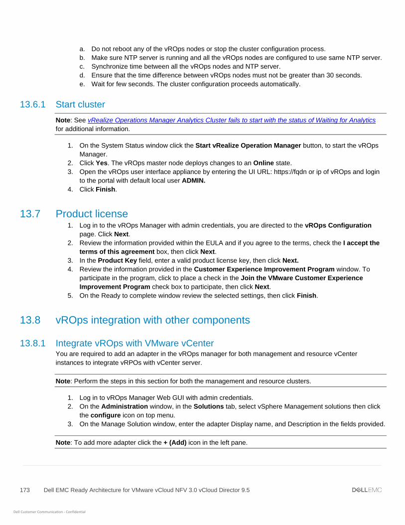
173 Dell EMC Ready Architecture for VMware vCloud NFV 3.0 vCloud Director 9.5
Dell Customer Communication - Confidential
a. Do not reboot any of the vROps nodes or stop the cluster configuration process.
b. Make sure NTP server is running and all the vROps nodes are configured to use same NTP server.
c. Synchronize time between all the vROps nodes and NTP server.
d. Ensure that the time difference between vROps nodes must not be greater than 30 seconds.
e. Wait for few seconds. The cluster configuration proceeds automatically.
13.6.1 Start cluster
Note: See vRealize Operations Manager Analytics Cluster fails to start with the status of Waiting for Analytics
for additional information.
1. On the System Status window click the Start vRealize Operation Manager button, to start the vROps
Manager.
2. Click Yes. The vROps master node deploys changes to an Online state.
3. Open the vROps user interface appliance by entering the UI URL: https://fqdn or ip of vROps and login
to the portal with default local user ADMIN.
4. Click Finish.
13.7 Product license 1. Log in to the vROps Manager with admin credentials, you are directed to the vROps Configuration
page. Click Next.
2. Review the information provided within the EULA and if you agree to the terms, check the I accept the
terms of this agreement box, then click Next.
3. In the Product Key field, enter a valid product license key, then click Next.
4. Review the information provided in the Customer Experience Improvement Program window. To
participate in the program, click to place a check in the Join the VMware Customer Experience
Improvement Program check box to participate, then click Next.
5. On the Ready to complete window review the selected settings, then click Finish.
13.8 vROps integration with other components
13.8.1 Integrate vROps with VMware vCenter You are required to add an adapter in the vROps manager for both management and resource vCenter
instances to integrate vRPOs with vCenter server.
Note: Perform the steps in this section for both the management and resource clusters.
1. Log in to vROps Manager Web GUI with admin credentials.
2. On the Administration window, in the Solutions tab, select vSphere Management solutions then click
the configure icon on top menu.
3. On the Manage Solution window, enter the adapter Display name, and Description in the fields provided.
Note: To add more adapter click the + (Add) icon in the left pane.
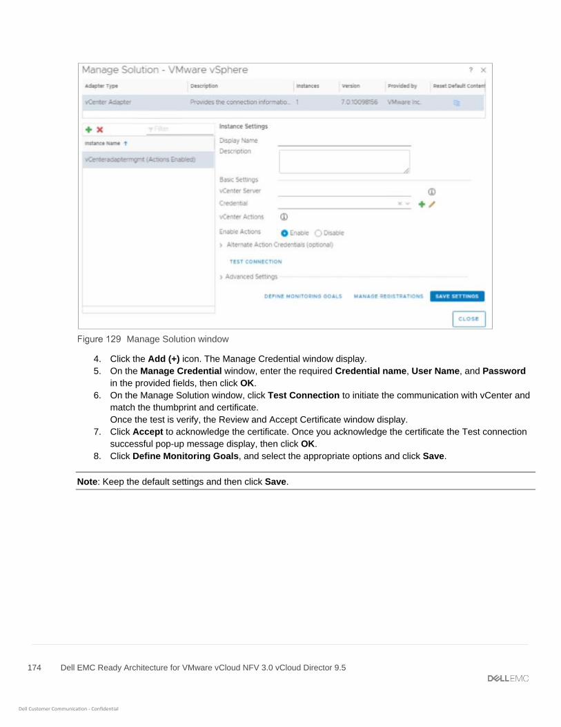
174 Dell EMC Ready Architecture for VMware vCloud NFV 3.0 vCloud Director 9.5
Dell Customer Communication - Confidential
Manage Solution window
4. Click the Add (+) icon. The Manage Credential window display.
5. On the Manage Credential window, enter the required Credential name, User Name, and Password
in the provided fields, then click OK.
6. On the Manage Solution window, click Test Connection to initiate the communication with vCenter and
match the thumbprint and certificate.
Once the test is verify, the Review and Accept Certificate window display.
7. Click Accept to acknowledge the certificate. Once you acknowledge the certificate the Test connection
successful pop-up message display, then click OK.
8. Click Define Monitoring Goals, and select the appropriate options and click Save.
Note: Keep the default settings and then click Save.

175 Dell EMC Ready Architecture for VMware vCloud NFV 3.0 vCloud Director 9.5
Dell Customer Communication - Confidential
Define Monitoring Goals window
9. On the Success window, the default policy has been successfully configured message displays, then
Click OK.
10. Click Save settings for adapter instance to be successfully saved, then click Close. The vRealize
Operations Manager starts to collect information about vCenter and its linked hosts and services.
11. Click the Home icon to display information.
Solutions window
vROps is deployed, configured and integrated with vCenter Server managing Management Cluster.
Note: Repeat the steps from step 1 to 11 as describing in this section to integrate resource vCenter Server with
vROps.

176 Dell EMC Ready Architecture for VMware vCloud NFV 3.0 vCloud Director 9.5
Dell Customer Communication - Confidential
13.8.2 vROps integration with AD To integrate vROps with AD:
1. Log in to the vRealize Operations Manager user interface with administrator privileges.
2. On the Administration screen, click Authentication Sources in the left navigation panel.
3. Click the Add (+) to add an Authentication source.
4. On the Add Source for User Group Import window, enter the AD domain details in the required
fields, then click Test to validate settings.
5. Once the settings are validated, the Test connection was successful message displays.
6. Click OK to close the window. The Active Directory is added.
Authentication Sources window
13.8.2.1 Importing users to AD Once the AD is integrated with vROps import the AD users. To import users to AD:
1. From the Administration screen, click Access Control in the left navigation panel.
2. Click the User Accounts tab, then click the Import User icon.
3. In the Import From field, select the AD Domain previously added.
4. In the Search string field, enter a full or partial group name to search for, then click Search.
5. On the Display search results screen, select a group and click Next.
6. Click the Objects tab and from the Select Role drop-down list, assign a relevant role to the user group.
7. Check the Allow access to all objects in the system box and click Finish.
8. Users are added in the AD with the necessary permissions.
Note: Users can also be added using the Importing Users from User Accounts function.
9. Log in to vROps from one of the accounts imported and verify that the selected permissions are
accessible.
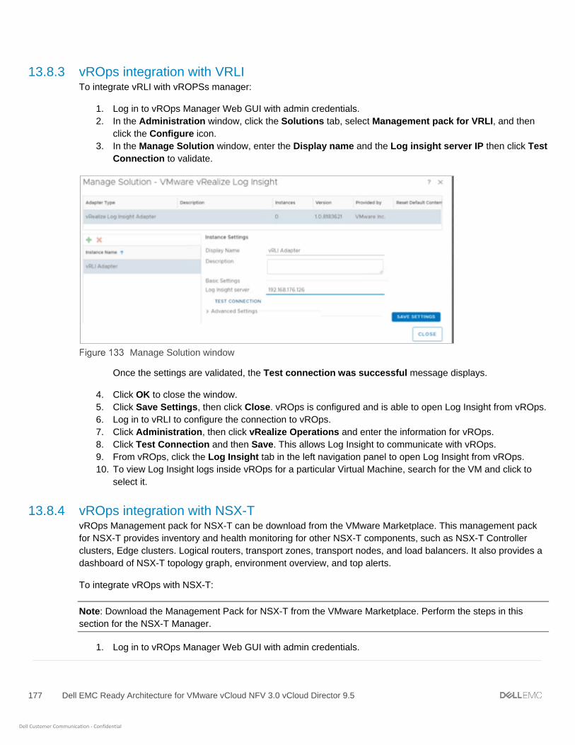
177 Dell EMC Ready Architecture for VMware vCloud NFV 3.0 vCloud Director 9.5
Dell Customer Communication - Confidential
13.8.3 vROps integration with VRLI To integrate vRLI with vROPSs manager:
1. Log in to vROps Manager Web GUI with admin credentials.
2. In the Administration window, click the Solutions tab, select Management pack for VRLI, and then
click the Configure icon.
3. In the Manage Solution window, enter the Display name and the Log insight server IP then click Test
Connection to validate.
Manage Solution window
Once the settings are validated, the Test connection was successful message displays.
4. Click OK to close the window.
5. Click Save Settings, then click Close. vROps is configured and is able to open Log Insight from vROps.
6. Log in to vRLI to configure the connection to vROps.
7. Click Administration, then click vRealize Operations and enter the information for vROps.
8. Click Test Connection and then Save. This allows Log Insight to communicate with vROps.
9. From vROps, click the Log Insight tab in the left navigation panel to open Log Insight from vROps.
10. To view Log Insight logs inside vROps for a particular Virtual Machine, search for the VM and click to
select it.
13.8.4 vROps integration with NSX-T vROps Management pack for NSX-T can be download from the VMware Marketplace. This management pack
for NSX-T provides inventory and health monitoring for other NSX-T components, such as NSX-T Controller
clusters, Edge clusters. Logical routers, transport zones, transport nodes, and load balancers. It also provides a
dashboard of NSX-T topology graph, environment overview, and top alerts.
To integrate vROps with NSX-T:
Note: Download the Management Pack for NSX-T from the VMware Marketplace. Perform the steps in this
section for the NSX-T Manager.
1. Log in to vROps Manager Web GUI with admin credentials.
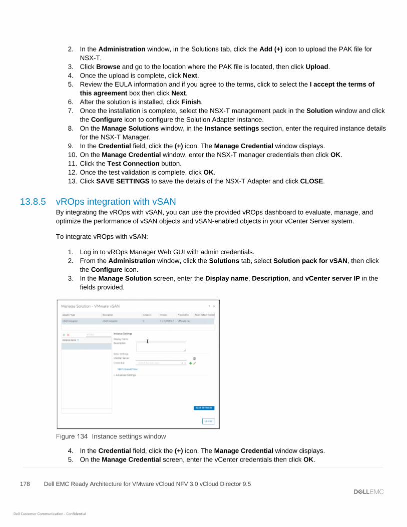
178 Dell EMC Ready Architecture for VMware vCloud NFV 3.0 vCloud Director 9.5
Dell Customer Communication - Confidential
2. In the Administration window, in the Solutions tab, click the Add (+) icon to upload the PAK file for
NSX-T.
3. Click Browse and go to the location where the PAK file is located, then click Upload.
4. Once the upload is complete, click Next.
5. Review the EULA information and if you agree to the terms, click to select the I accept the terms of
this agreement box then click Next.
6. After the solution is installed, click Finish.
7. Once the installation is complete, select the NSX-T management pack in the Solution window and click
the Configure icon to configure the Solution Adapter instance.
8. On the Manage Solutions window, in the Instance settings section, enter the required instance details
for the NSX-T Manager.
9. In the Credential field, click the (+) icon. The Manage Credential window displays.
10. On the Manage Credential window, enter the NSX-T manager credentials then click OK.
11. Click the Test Connection button.
12. Once the test validation is complete, click OK.
13. Click SAVE SETTINGS to save the details of the NSX-T Adapter and click CLOSE.
13.8.5 vROps integration with vSAN By integrating the vROps with vSAN, you can use the provided vROps dashboard to evaluate, manage, and
optimize the performance of vSAN objects and vSAN-enabled objects in your vCenter Server system.
To integrate vROps with vSAN:
1. Log in to vROps Manager Web GUI with admin credentials.
2. From the Administration window, click the Solutions tab, select Solution pack for vSAN, then click
the Configure icon.
3. In the Manage Solution screen, enter the Display name, Description, and vCenter server IP in the
fields provided.
Instance settings window
4. In the Credential field, click the (+) icon. The Manage Credential window displays.
5. On the Manage Credential screen, enter the vCenter credentials then click OK.
179 Dell EMC Ready Architecture for VMware vCloud NFV 3.0 vCloud Director 9.5
Dell Customer Communication - Confidential
6. From the Manage Solution screen, click the Test Connection button to validate.
7. Once the connection is validated, the Review and Accept Certificate window displays.
8. Review the certificate details and click Accept to accept the certificate.
9. Click OK to acknowledge the test results.
10. Click Save Settings then click Close.
Note: Repeat the steps in this section to add the resource and edge clusters.
11. Return to the Home screen and verify that the VSAN has dedicated dashboard items available on
vROps.
13.8.6 vROps integration with vCD VROPs Management pack for vCloud Director can be download from the VMware Marketplace. vROps uses this
pack to monitors the vCloud Director health and sends the early warnings, alerts.
To integrate vROps with vCD:
Note: Download the Management Pack for vCD from the VMware Marketplace. Perform the steps in this section
for the vCD.
1. Log in to vROps Manager Web GUI with admin credentials.
2. On the Administration screen, click the Solutions tab then click the Add (+) icon to upload the PAK file
for vCD.
3. Click Browse to go to the location where the PAK file is located, then click Upload.
4. Once the upload is complete, click Next.
5. Review the EULA and if you agree to the terms, click to place a check in the I accept the terms of this
agreement box then click Next.
6. After the solution is installed, click Finish.
7. Once the installation is complete, select the vCD management pack in the Solution window and click the
Configure icon to configure the Solution Adapter instance.
8. On the Administration window, click the Solutions tab, select Solution pack for vCD, then click the
Configure icon.
9. From the Manage Solution screen, enter the Display name, Description, and vCloud Director
name/IP for vCD Cell 1 in the fields provided.

180 Dell EMC Ready Architecture for VMware vCloud NFV 3.0 vCloud Director 9.5
Dell Customer Communication - Confidential
Manage Solution window
10. In the Credential field, click the (+) icon. The Manage Credential window displays.
11. On the Manage Credential window, locate and click on the Credential kind drop-down list, select
vCloud System Credential, and enter the vCD Cell1 credentials then click OK.
12. On the Manage Solution window, click the Test Connection button to validate. Once the connection is
validated, the Review and Accept Certificate message displays.
13. Review the certificate details and click Accept to accept the certificate.
14. Click OK to acknowledge the test results.
15. Click Save Settings.
16. In the left navigation pane, click the (+) icon to add vCD Cell 2.
17. Enter the Display name, Description, and vCloud Director name/IP for vCD Cell 2 in the fields
provided.
18. In the Credential field, click the (+) icon. The Manage Credential window display.
19. On the Manage Credential window, enter the vCD Cell2 credentials then click OK.
20. On the Manage Solution window, click the Test Connection button to validate. Once the connection is
validated, the Review and Accept Certificate message displays.
21. Review the certificate details and click Accept to accept the certificate.
22. Click OK to acknowledge the test results.
23. Click Save Settings, then click Close.

181 Dell EMC Ready Architecture for VMware vCloud NFV 3.0 vCloud Director 9.5
Dell Customer Communication - Confidential
14 Set up anti-affinity rules The Affinity rule setting establishes a relationship between two or more VMware VMs and hosts. Anti-affinity
rules tell the vSphere hypervisor platform to keep virtual entities separated.
Anti-affinity rules are created to keep two or more VMs separated on different hosts.
Note: The anti-affinity rules can be created for management and edge cluster VMs. The creation of a separate
anti-affinity rule for the VMs listed is recommended for the respective cluster. Dell EMC recommends the
execution of this section only after every component has been deployed and configured.
To create anti-affinity rules for management and edge pod components, see the Create an anti-affinity rule
section.
Table 42 displays a list of management cluster VMs that must be kept on different hosts using an anti-affinity
rule. For example, create an anti-affinity rule for management VCSA to always keep its three VMs (Active,
passive and witness node VM) on different hosts.
Management VM cluster list:
Rule name Create rule for virtual machines
Mgmt VCSA VCSA-Mgmt-Active VCSA-Mgmt-Passive VCSA-Mgmt-witness
Resource VCSA VCSA-Res-Active VCSA-Res-Passive VCSA-Res-witness
vRLI_Rule vRLI-master vRLI-worker1 vRLI-worker2
vROPS_Rule vROPS-master vROPS-data vROPS-replica
Controller_Rule Nsx-controller1 Nsx-controller2 Nsx-controller3
vCD_Rule vCD_Cell1 vCD_Cell2
The following is a list of edge cluster VMs that must be kept on different hosts using an anti-affinity rule:
Edge cluster list:
Rule name Create rule for VMs
Edge_Rule01 Edge01 Edge02
Edge_Rule02 Edge03 Edge04
Prerequisites:
• All components of the management cluster are deployed
• All components of the resource cluster are deployed
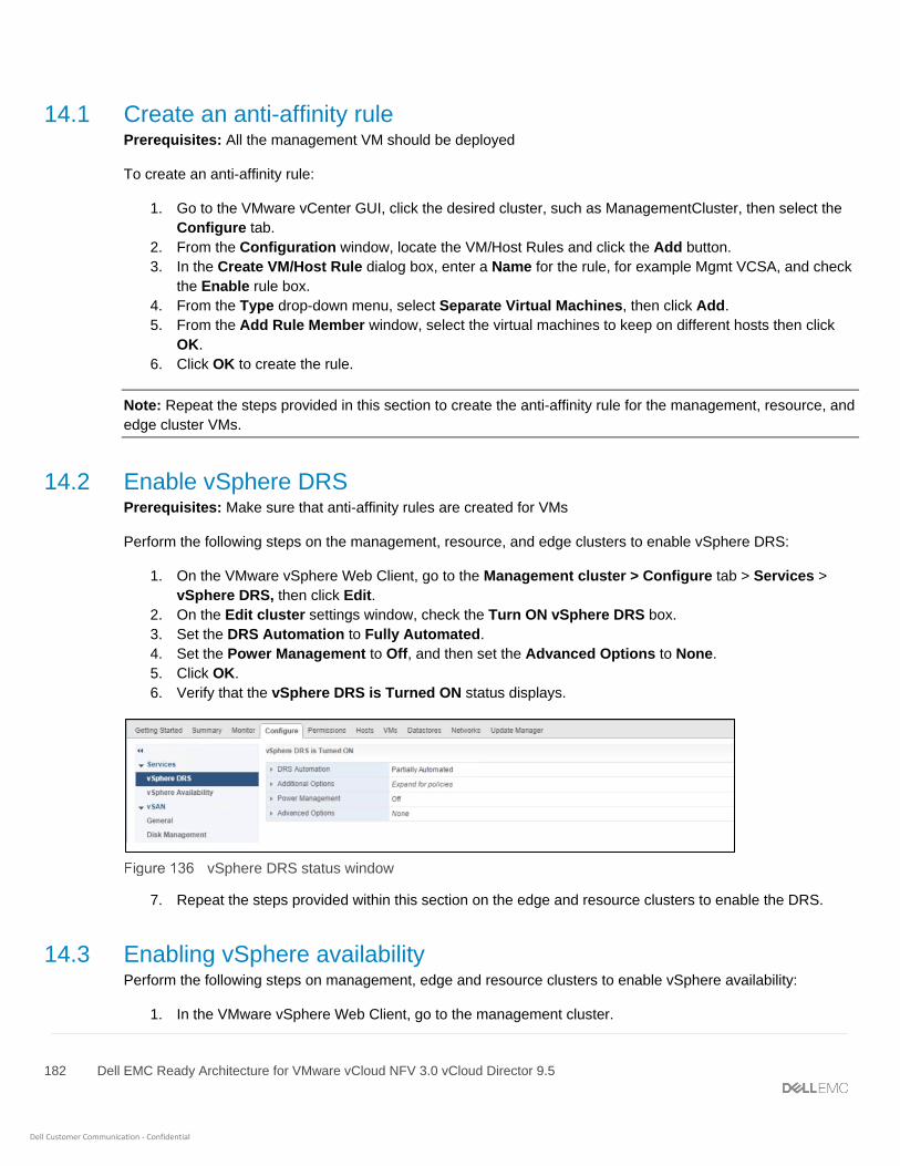
182 Dell EMC Ready Architecture for VMware vCloud NFV 3.0 vCloud Director 9.5
Dell Customer Communication - Confidential
14.1 Create an anti-affinity rule Prerequisites: All the management VM should be deployed
To create an anti-affinity rule:
1. Go to the VMware vCenter GUI, click the desired cluster, such as ManagementCluster, then select the
Configure tab.
2. From the Configuration window, locate the VM/Host Rules and click the Add button.
3. In the Create VM/Host Rule dialog box, enter a Name for the rule, for example Mgmt VCSA, and check
the Enable rule box.
4. From the Type drop-down menu, select Separate Virtual Machines, then click Add.
5. From the Add Rule Member window, select the virtual machines to keep on different hosts then click
OK.
6. Click OK to create the rule.
Note: Repeat the steps provided in this section to create the anti-affinity rule for the management, resource, and
edge cluster VMs.
14.2 Enable vSphere DRS Prerequisites: Make sure that anti-affinity rules are created for VMs
Perform the following steps on the management, resource, and edge clusters to enable vSphere DRS:
1. On the VMware vSphere Web Client, go to the Management cluster > Configure tab > Services >
vSphere DRS, then click Edit.
2. On the Edit cluster settings window, check the Turn ON vSphere DRS box.
3. Set the DRS Automation to Fully Automated.
4. Set the Power Management to Off, and then set the Advanced Options to None.
5. Click OK.
6. Verify that the vSphere DRS is Turned ON status displays.
vSphere DRS status window
7. Repeat the steps provided within this section on the edge and resource clusters to enable the DRS.
14.3 Enabling vSphere availability Perform the following steps on management, edge and resource clusters to enable vSphere availability:
1. In the VMware vSphere Web Client, go to the management cluster.

183 Dell EMC Ready Architecture for VMware vCloud NFV 3.0 vCloud Director 9.5
Dell Customer Communication - Confidential
2. Click the Configure tab, then go to Services, click vSphere Availability, then click the Edit button.
3. Click to place a check in the Turn ON vSphere HA and Turn on Proactive HA boxes.
4. In the Failures and Responses section and select Enable Host Monitoring, then click OK.
5. Repeat the steps in this section, on the resource cluster.

184 Dell EMC Ready Architecture for VMware vCloud NFV 3.0 vCloud Director 9.5
Dell Customer Communication - Confidential
15 Forwarding logs to vRLI
15.1 Forwarding vROps log to vRLI You can configure vROps VM to send log messages to a remote logging server.
Prerequisites
• Configured vRLI server to receive the logs
To forward the vROps logs to vRLI:
1. Login into vROps master VM.
2. From the top navigation panel, click Administrator and select the Management tab.
3. Click on Log forwarding.
4. Select the box: output logs to external log server.
5. Select the other for Log Insight Servers:
• In Host give FQDN of vrli master.
• Port:9000
• Protocol: cfapi
Log forwarding

185 Dell EMC Ready Architecture for VMware vCloud NFV 3.0 vCloud Director 9.5
Dell Customer Communication - Confidential
15.2 Forwarding vSAN logs to vRLI To forward vSAN logs to vRLI
1. Open the vRealize Log Insight UI in a browser.
2. From the vRealize Log Insight UI, click Admin then click Content Packs.
3. Click Interactive Analytics.
4. Click the Bell icon and select Manage Alerts.
5. Select the alerts that are vSAN related. In the search box of the Alerts dialog box, enter vSAN as a
search phrase.
Alerts
6. Select the alerts VMware-vSAN content pack box. Click Enable.
7. In the Enable Alerts dialog box provide Email ID, fallback object, and Criticality.
Enable alerts

186 Dell EMC Ready Architecture for VMware vCloud NFV 3.0 vCloud Director 9.5
Dell Customer Communication - Confidential
8. Click Enable.
15.3 Forwarding logs from vCD to vRLI To forward the vCD logs to vRLI:
1. Open your browser and log in to vCD Cell1 with administrator credentials.
2. From the Administrator screen, locate the System Settings section and click General.
3. Enter the vRLI Master node IP in Syslog server 1.
4. Enter the vRLI virtual IP in Syslog server 2.
5. Click Apply to save the change.
Syslog server for vCD
15.4 Configure syslog server for NSX-T You can configure NSX-T appliances to send log messages to a remote logging server.
Prerequisites
• Configured vRLI server to receive the logs
To configure remote logging on an NSX-T appliance:
1. From the CLI, log in to the NSX-T – Manager using admin credentials.
2. Run the following command to configure a log server and the types of messages to send to the log
server.
Note: Multiple facilities or message IDs can be specified as a comma delimited list, without spaces.

187 Dell EMC Ready Architecture for VMware vCloud NFV 3.0 vCloud Director 9.5
Dell Customer Communication - Confidential
set logging-server <hostname-or-ip-address[:port]> proto <proto> level
<level> [facility <facility>] [messageid <messageid>] [certificate
<filename>] [structured-data <structureddata>]
Note: For more information about this command, see the NSX-T CLI Reference section.
The command can be run multiple times to add multiple logging server configurations. For example:
nsx> set logging-server 192.168.20.113 proto udp level info facility syslog
messageid
SYSTEM,FABRIC structured-data audit=true
nsx> set logging-server 192.168.20.113 proto udp level info facility
auth,user
3. To view the logging configuration, enter the get logging-server command. For example:
nsx-manager> get logging-servers
192.168.20.113 proto udp level info facility syslog messageid
SYSTEM,FIREWALL structured-data audit="true"
192.168.20.113 proto udp level info facility syslog messageid
SYSTEM,MONITORING structured-data audit="true"
192.168.20.113 proto udp level info facility syslog messageid SYSTEM,DHCP
structured-data audit="true"
192.168.20.113 proto udp level info facility syslog messageid SYSTEM,ROUTING
structured-data audit="true"
192.168.20.113 proto udp level info facility syslog messageid
SYSTEM,SWITCHING structured-data audit="true"
192.168.20.113 proto udp level info facility syslog messageid
SYSTEM,FIREWALL-PKTLOG structured-data audit="true"
192.168.20.113 proto udp level info facility syslog messageid SYSTEM,-
structured-data audit="true"
192.168.20.113 proto udp level info facility syslog messageid SYSTEM,SYSTEM
structured-data audit="true"
192.168.20.113 proto udp level info facility syslog messageid
SYSTEM,GROUPING structured-data audit="true"
Note: Repeat the steps in this section for the NSX-T Controller and NSX-T Edge to configure remote logging
on each node individually.
15.5 Log Message IDs In a log message, the message ID field identifies the type of message. You can use the messageid parameter
in the set logging-server command to filter which log messages are sent to a logging server. Table 44 displays
the list of available log Message IDs.
Log Message IDs
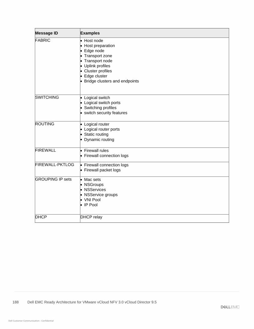
188 Dell EMC Ready Architecture for VMware vCloud NFV 3.0 vCloud Director 9.5
Dell Customer Communication - Confidential
Message ID Examples
FABRIC • Host node
• Host preparation
• Edge node
• Transport zone
• Transport node
• Uplink profiles
• Cluster profiles
• Edge cluster
• Bridge clusters and endpoints
SWITCHING • Logical switch
• Logical switch ports
• Switching profiles
• switch security features
ROUTING • Logical router
• Logical router ports
• Static routing
• Dynamic routing
FIREWALL • Firewall rules
• Firewall connection logs
FIREWALL-PKTLOG • Firewall connection logs
• Firewall packet logs
GROUPING IP sets • Mac sets
• NSGroups
• NSServices
• NSService groups
• VNI Pool
• IP Pool
DHCP DHCP relay

189 Dell EMC Ready Architecture for VMware vCloud NFV 3.0 vCloud Director 9.5
Dell Customer Communication - Confidential
Message ID Examples
SYSTEM • Appliance management (remote syslog, ntp, etc)
• Cluster management
• Trust management
• Licensing
• User and roles
• Task management
• Install (NSX-T Manager, NSX-T Controller)
• Upgrade (NSX-T Manager, NSX-T Controller, NSX-T Edge and host-packages upgrades)
• Realization
• Tags
MONITORING • SNMP
• Port connection
• Traceflow
• All other log messages.
190 Dell EMC Ready Architecture for VMware vCloud NFV 3.0 vCloud Director 9.5
Dell Customer Communication - Confidential
A Reference documentation
Refer the following documentation for more system information:
• Dell EMC Ready Solution vCloudNFV3.0 OpenStack - Deployment Manual Operations Guide
• Dell EMC PowerEdge R640 Installation and Service Manual
• Dell EMC PowerEdge R740 Installation and Service Manual
• Dell PowerEdge R740xd Owner's Manual
• VMware vCloud NFV Reference Architecture v3.0
• VMware API Reference Guide
• NSX-T Installation Guide
• Postman Documentation