dell emc elastic cloud storage software on hp proliant ... · pdf filedell emc elastic cloud...
TRANSCRIPT

WHITE PAPER
DELL EMC ELASTIC CLOUD STORAGE SOFTWARE ON HP PROLIANT SL4540 GEN 8
Reference Architecture
ABSTRACT
This document provides a reference architecture overview of Dell EMC® Elastic Cloud
Storage (ECS™) software running on HP ProLiant SL4540 Gen 8. ECS is a software-
defined cloud-scale object storage platform that combines the cost advantages of
commodity infrastructure with the reliability, availability and serviceability of traditional
arrays. The HP ProLiant SL4540 is a platform which provides cost-effective commodity
hardware for ECS object storage.
April 2017

2
The information in this publication is provided “as is.” Dell Inc. makes no representations or warranties of any kind with respect to the
information in this publication, and specifically disclaims implied warranties of merchantability or fitness for a particular purpose.
Use, copying, and distribution of any software described in this publication requires an applicable software license.
Copyright © 2016 Dell Inc. or its subsidiaries. All Rights Reserved. Dell, EMC, and other trademarks are trademarks of Dell Inc. or its
subsidiaries. Other trademarks may be the property of their respective owners. Published in the USA April 2017, White Paper,
H15234.4.
Dell EMC believes the information in this document is accurate as of its publication date. The information is subject to change without
notice.
3
TABLE OF CONTENTS
INTRODUCTION ........................................................................................................................4
AUDIENCE ........................................................................................................................................ 4
SCOPE .............................................................................................................................................. 4
VALUE OF ECS ON INDUSTRY STANDARD HARDWARE ...................................................4
REFERENCE ARCHITECTURE OVERVIEW ...........................................................................4
ECS SOFTWARE BUNDLE .............................................................................................................. 5
ECS Software ............................................................................................................................................ 5
Infrastructure .............................................................................................................................................. 6
Tools .......................................................................................................................................................... 6
HP PROLIANT SL4540 HARDWARE ............................................................................................. 10
SL4540 Gen8 1x60 .................................................................................................................................. 12
SL4540 Gen8 2x25 .................................................................................................................................. 12
SL4540 Gen8 3x15 .................................................................................................................................. 12
NETWORK SWITCHES .................................................................................................................. 13
DEPLOYMENT ....................................................................................................................... 15
CONFIGURATIONS ........................................................................................................................ 15
EXPANSION ................................................................................................................................... 17
CUSTOMER PROVIDED INFRASTRUCTURE .............................................................................. 17
VALIDATION TESTING .......................................................................................................... 18
SIZING .................................................................................................................................... 18
ORDERING AND COST ......................................................................................................... 18
SUPPORT ............................................................................................................................... 19
INSTALL SUPPORT ....................................................................................................................... 19
GENERAL SUPPORT ..................................................................................................................... 19
CONCLUSION ........................................................................................................................ 20
REFERENCES ........................................................................................................................ 20

4
INTRODUCTION
Dell EMC® Elastic Cloud Storage™ (ECS) is an enterprise grade, multiprotocol, simple and efficient object-based storage platform
designed for next-generation applications and traditional workloads. It can be deployed as a turnkey storage appliance or software only
solution architected to run on industry-standard hardware. ECS software solution allows customers to leverage commercial off the shelf
hardware to reduce costs. There are two options available for customers who desire a software only solution which include:
Certified - ECS software bundle running on certified industry standard hardware.
Custom – ECS software running on hardware, operating system and tools outside of certified matrix.
The certified offering is targeted for customers needing small to large petabytes of object storage whereas custom is for big customer
deployments requiring a significant amount in petabytes of object storage.
This whitepaper provides a reference architecture overview of ECS software bundle running on one of the certified hardware, the HP
Proliant SL4540. The HP Proliant SL4540 Gen 8 is well suited for running ECS software. It comes in several configurations and is a
low-cost, highly efficient and scalable hardware platform.
AUDIENCE
This paper is intended for field personnel and customers who are interested in designing an object storage solution using ECS software
bundle and HP Proliant SL4540. It provides an overview of ECS software bundle, HP Proliant SL4540 hardware, and related
networking and services.
SCOPE
This document does not cover installation, administration, and upgrade procedures for ECS deployed on HP Proliant SL4540. Its
primary focus is to provide a reference architecture overview and value of deploying ECS software on industry standard hardware such
as the HP Proliant SL4540. Links to other related documents are provided under References section. Updates to this document are
done periodically and coincides usually with a major release or new feature and functionality change. To get the latest version of this
document, please download from this link.
VALUE OF ECS ON INDUSTRY STANDARD HARDWARE
ECS Software on industry standard hardware provides several advantages and options for customers. By utilizing commercial off the
shelf hardware, capital expense can be significantly reduced. It also prevents vendor lock-in allowing customers to re-purpose
hardware or move to a different software defined storage vendor if required. Furthermore, it enables customers to build homogenous
datacenter infrastructure with unified commodity hardware. ECS software on industry standard hardware are primarily for large
enterprises and high growth potential verticals such as service providers, telecom, life sciences and others whose main uses include
global content repository, web, IoT, and data analytics.
REFERENCE ARCHITECTURE OVERVIEW
ECS software bundle running on HP Proliant SL4540 Gen 8 has been verified and certified by Dell EMC ECS quality engineering team.
It has endured the same types of rigorous testing done for the ECS Appliance. This section will describe the main components of this
reference architecture which include:
ECS Software bundled with SUSE Linux Enterprise Server 12 Service Pack 1 (SLES 12 SP1), Docker, Java Virtual Machine
(JVM) and tools.
HP Proliant SL4540 Gen 8
Network Switches for Data and Management
In order to utilize ECS software on certified or customized hardware, there are some minimum requirements that are highlighted in
Table 1. The different HP Proliant SL4540 configurations to support these requirements will be expanded in the Hardware and
Deployment sections.
5
ECS SOFTWARE BUNDLE
Version 2.2.1 HF1 is the minimum version of ECS software supported to deploy on industry standard hardware. Bundled with ECS
software are the tools to verify the health of system and assist in configuration; and the infrastructure required to run ECS which include
SLES 12 SP1, Docker, and JVM. Incorporating the tools and infrastructure with ECS software simplifies the install and configuration.
This section will provide a quick overview on the contents of this bundle and their functions. For more in-depth details on ECS
Architecture, refer to the ECS Architecture Whitepaper.
ECS SOFTWARE
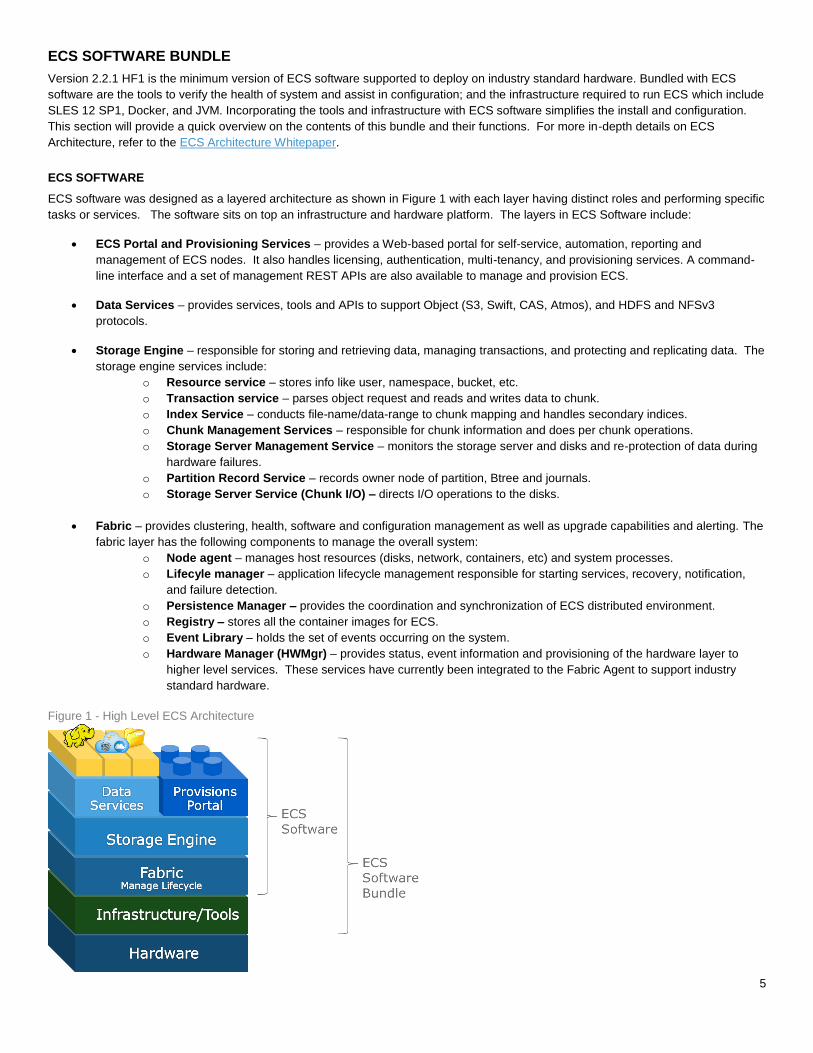
ECS software was designed as a layered architecture as shown in Figure 1 with each layer having distinct roles and performing specific
tasks or services. The software sits on top an infrastructure and hardware platform. The layers in ECS Software include:
ECS Portal and Provisioning Services – provides a Web-based portal for self-service, automation, reporting and
management of ECS nodes. It also handles licensing, authentication, multi-tenancy, and provisioning services. A command-
line interface and a set of management REST APIs are also available to manage and provision ECS.
Data Services – provides services, tools and APIs to support Object (S3, Swift, CAS, Atmos), and HDFS and NFSv3
protocols.
Storage Engine – responsible for storing and retrieving data, managing transactions, and protecting and replicating data. The
storage engine services include:
o Resource service – stores info like user, namespace, bucket, etc.
o Transaction service – parses object request and reads and writes data to chunk.
o Index Service – conducts file-name/data-range to chunk mapping and handles secondary indices.
o Chunk Management Services – responsible for chunk information and does per chunk operations.
o Storage Server Management Service – monitors the storage server and disks and re-protection of data during
hardware failures.
o Partition Record Service – records owner node of partition, Btree and journals.
o Storage Server Service (Chunk I/O) – directs I/O operations to the disks.
Fabric – provides clustering, health, software and configuration management as well as upgrade capabilities and alerting. The
fabric layer has the following components to manage the overall system:
o Node agent – manages host resources (disks, network, containers, etc) and system processes.
o Lifecyle manager – application lifecycle management responsible for starting services, recovery, notification,
and failure detection.
o Persistence Manager – provides the coordination and synchronization of ECS distributed environment.
o Registry – stores all the container images for ECS.
o Event Library – holds the set of events occurring on the system.
o Hardware Manager (HWMgr) – provides status, event information and provisioning of the hardware layer to
higher level services. These services have currently been integrated to the Fabric Agent to support industry
standard hardware.
Figure 1 - High Level ECS Architecture

6
INFRASTRUCTURE
Bundled with ECS Software is the infrastructure components which include Suse Linux Enterprise 12 SP1 (SLES 12 SP1) with Docker
and JVM. ECS software is a java application running within several Docker containers on top an operating system. Thus, each of the
nodes used for ECS is installed with a SLES 12 SP1 with Docker and JVM and each container is responsible for running a specific task.
The name of the containers running and purpose are as follow:
object-main – contains the resources and processes relating to the data service, storage engine, portal and provisioning
services. Runs on every node in ECS.
fabric-lifecycle – contains the processes, information and resources required for the monitoring, configuration management
and health management of the system Depending on the number of nodes in the system, there will be an odd number of
fabric-lifecycle instances running. For example, there will be three instances running on a four-node system and five instances
for an eight-node system.
fabric-zookeeper – centralized service for coordination and synchronization of distributed processes, configuration
information, groups and naming services. It is referred to as the persistence manager and runs on odd number of nodes, for
instance, three for a four-node system and five for an eight –node system.
fabric-registry – location or registry of the ECS images. Only one instance of this is running per ECS system.
Some of the containers listed above run on all nodes and some run on odd number of the nodes. The containers are lightweight and
consist of only the runtime, system tools and libraries required to run ECS. Docker containers are individual processes sharing the
same operating system and hardware resources. Figure 2 provides an example of how ECS can be deployed on an eight node system.
Filesystem Layout
Each node has its own set of commodity disks. Each disk is formatted and mounted as an XFS filesystem and has a unique identifier
(UUID). Data are stored in 128MB chunks and the chunks are stored in files within the filesystem. Each disk partition or filesystem is
filled with files that are 10GB in size. These files are created during installation such that contiguous blocks are allocated for the files.
The number of files within each disk depends on the disk size. For instance, a 1TB disk will have 100, 10GB files. The names of the
files inside the disk are “0000”, “0001”, “0002”, and so forth.
TOOLS
Existing tools and libraries were enhanced and new tools were created to support ECS software deployed on industry standard
hardware. These tools assist in verifying the hardware configuration, provides health and status of hardware and ECS software
services, and utilities that interact with the hardware. The tools and libraries are also packaged with the ECS Software.
Figure 2 - ECS Docker containers on 8 node system example
7
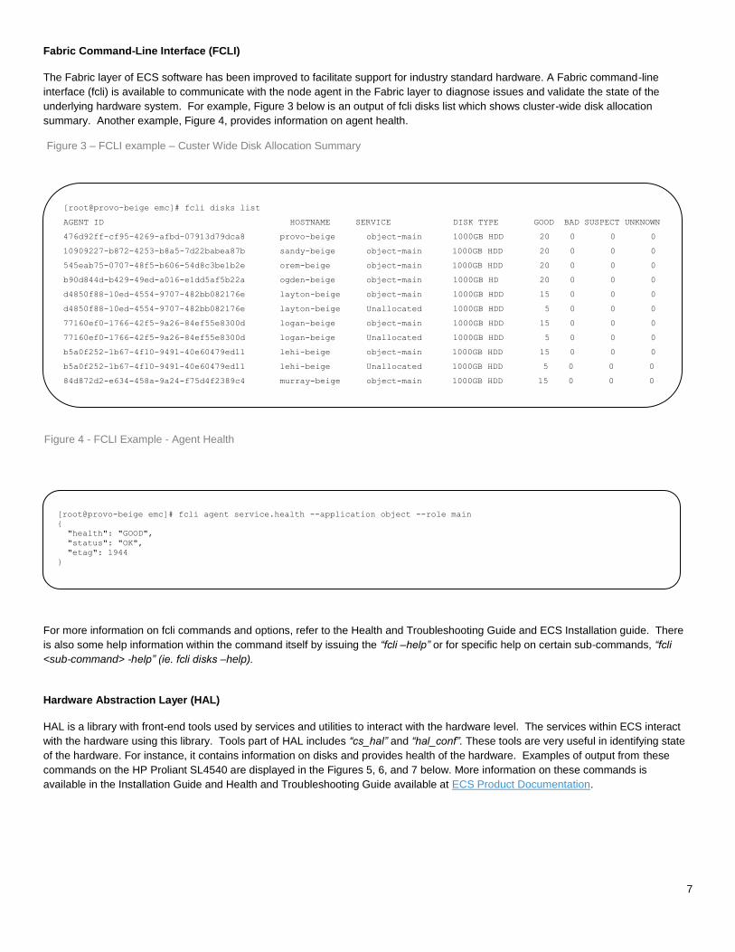
Fabric Command-Line Interface (FCLI)
The Fabric layer of ECS software has been improved to facilitate support for industry standard hardware. A Fabric command-line
interface (fcli) is available to communicate with the node agent in the Fabric layer to diagnose issues and validate the state of the
underlying hardware system. For example, Figure 3 below is an output of fcli disks list which shows cluster-wide disk allocation
summary. Another example, Figure 4, provides information on agent health.
For more information on fcli commands and options, refer to the Health and Troubleshooting Guide and ECS Installation guide. There
is also some help information within the command itself by issuing the “fcli –help” or for specific help on certain sub-commands, “fcli
<sub-command> -help” (ie. fcli disks –help).
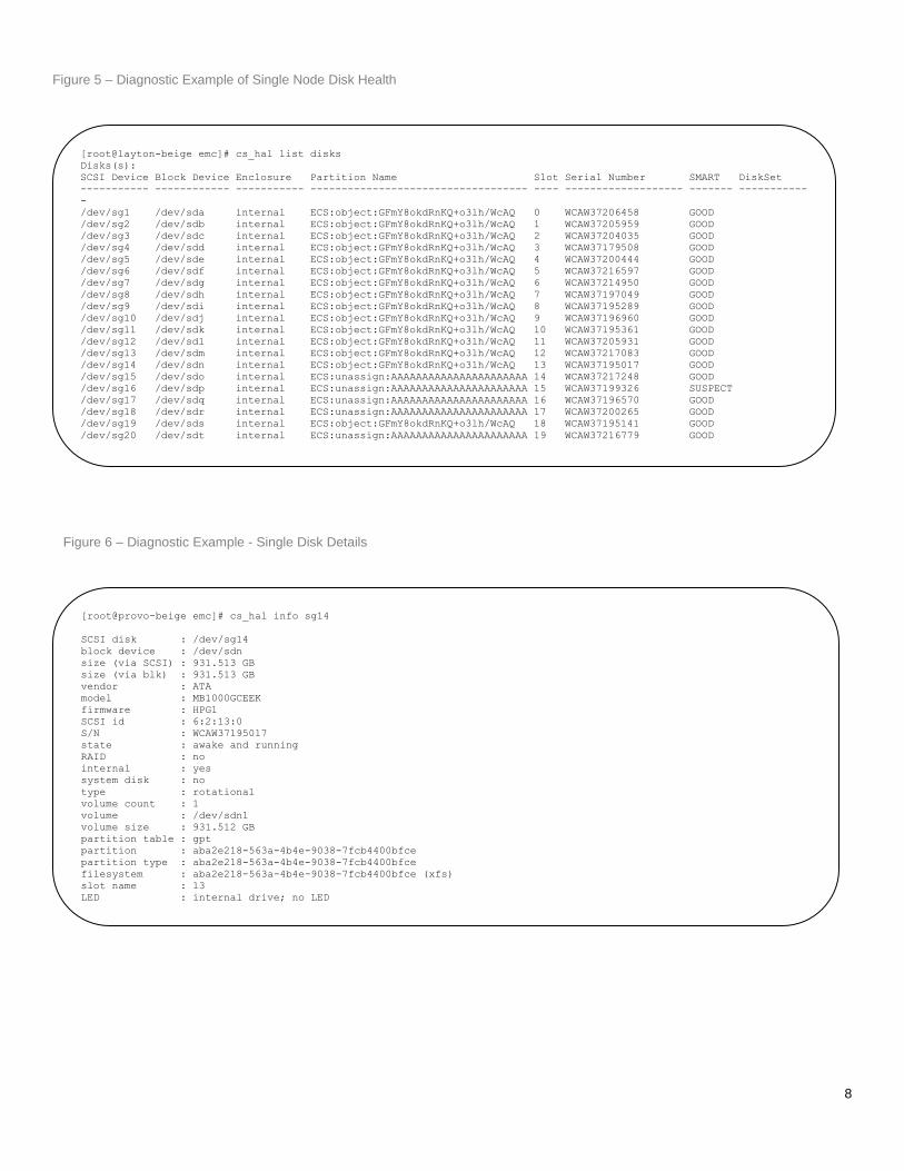
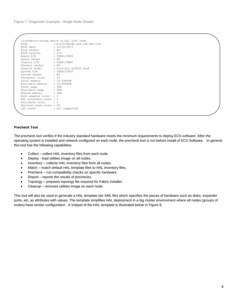
Hardware Abstraction Layer (HAL)
HAL is a library with front-end tools used by services and utilities to interact with the hardware level. The services within ECS interact
with the hardware using this library. Tools part of HAL includes “cs_hal” and “hal_conf”. These tools are very useful in identifying state
of the hardware. For instance, it contains information on disks and provides health of the hardware. Examples of output from these
commands on the HP Proliant SL4540 are displayed in the Figures 5, 6, and 7 below. More information on these commands is
available in the Installation Guide and Health and Troubleshooting Guide available at ECS Product Documentation.
[root@provo-beige emc]# fcli agent service.health --application object --role main
{
"health": "GOOD",
"status": "OK",
"etag": 1944
}
[root@provo-beige emc]# fcli disks list
AGENT ID HOSTNAME SERVICE DISK TYPE GOOD BAD SUSPECT UNKNOWN
476d92ff-cf95-4269-afbd-07913d79dca8 provo-beige object-main 1000GB HDD 20 0 0 0
10909227-b872-4253-b8a5-7d22babea87b sandy-beige object-main 1000GB HDD 20 0 0 0
545eab75-0707-48f5-b606-54d8c3be1b2e orem-beige object-main 1000GB HDD 20 0 0 0
b90d844d-b429-49ed-a016-e1dd5af5b22a ogden-beige object-main 1000GB HD 20 0 0 0
d4850f88-10ed-4554-9707-482bb082176e layton-beige object-main 1000GB HDD 15 0 0 0
d4850f88-10ed-4554-9707-482bb082176e layton-beige Unallocated 1000GB HDD 5 0 0 0
77160ef0-1766-42f5-9a26-84ef55e8300d logan-beige object-main 1000GB HDD 15 0 0 0
77160ef0-1766-42f5-9a26-84ef55e8300d logan-beige Unallocated 1000GB HDD 5 0 0 0
b5a0f252-1b67-4f10-9491-40e60479ed11 lehi-beige object-main 1000GB HDD 15 0 0 0
b5a0f252-1b67-4f10-9491-40e60479ed11 lehi-beige Unallocated 1000GB HDD 5 0 0 0
84d872d2-e634-458a-9a24-f75d4f2389c4 murray-beige object-main 1000GB HDD 15 0 0 0
84d872d2-e634-458a-9a24-f75d4f2389c4 murray-beige Unallocated 1000GB HDD 5 0 0 0
Figure 3 – FCLI example – Custer Wide Disk Allocation Summary
Figure 4 - FCLI Example - Agent Health
8
[root@layton-beige emc]# cs_hal list disks
Disks(s):
SCSI Device Block Device Enclosure Partition Name Slot Serial Number SMART DiskSet
----------- ------------ ----------- ----------------------------------- ---- ------------------- ------- -----------
-
/dev/sg1 /dev/sda internal ECS:object:GFmY8okdRnKQ+o3lh/WcAQ 0 WCAW37206458 GOOD
/dev/sg2 /dev/sdb internal ECS:object:GFmY8okdRnKQ+o3lh/WcAQ 1 WCAW37205959 GOOD
/dev/sg3 /dev/sdc internal ECS:object:GFmY8okdRnKQ+o3lh/WcAQ 2 WCAW37204035 GOOD
/dev/sg4 /dev/sdd internal ECS:object:GFmY8okdRnKQ+o3lh/WcAQ 3 WCAW37179508 GOOD
/dev/sg5 /dev/sde internal ECS:object:GFmY8okdRnKQ+o3lh/WcAQ 4 WCAW37200444 GOOD
/dev/sg6 /dev/sdf internal ECS:object:GFmY8okdRnKQ+o3lh/WcAQ 5 WCAW37216597 GOOD
/dev/sg7 /dev/sdg internal ECS:object:GFmY8okdRnKQ+o3lh/WcAQ 6 WCAW37214950 GOOD
/dev/sg8 /dev/sdh internal ECS:object:GFmY8okdRnKQ+o3lh/WcAQ 7 WCAW37197049 GOOD
/dev/sg9 /dev/sdi internal ECS:object:GFmY8okdRnKQ+o3lh/WcAQ 8 WCAW37195289 GOOD
/dev/sg10 /dev/sdj internal ECS:object:GFmY8okdRnKQ+o3lh/WcAQ 9 WCAW37196960 GOOD
/dev/sg11 /dev/sdk internal ECS:object:GFmY8okdRnKQ+o3lh/WcAQ 10 WCAW37195361 GOOD
/dev/sg12 /dev/sdl internal ECS:object:GFmY8okdRnKQ+o3lh/WcAQ 11 WCAW37205931 GOOD
/dev/sg13 /dev/sdm internal ECS:object:GFmY8okdRnKQ+o3lh/WcAQ 12 WCAW37217083 GOOD
/dev/sg14 /dev/sdn internal ECS:object:GFmY8okdRnKQ+o3lh/WcAQ 13 WCAW37195017 GOOD
/dev/sg15 /dev/sdo internal ECS:unassign:AAAAAAAAAAAAAAAAAAAAAA 14 WCAW37217248 GOOD
/dev/sg16 /dev/sdp internal ECS:unassign:AAAAAAAAAAAAAAAAAAAAAA 15 WCAW37199326 SUSPECT
/dev/sg17 /dev/sdq internal ECS:unassign:AAAAAAAAAAAAAAAAAAAAAA 16 WCAW37196570 GOOD
/dev/sg18 /dev/sdr internal ECS:unassign:AAAAAAAAAAAAAAAAAAAAAA 17 WCAW37200265 GOOD
/dev/sg19 /dev/sds internal ECS:object:GFmY8okdRnKQ+o3lh/WcAQ 18 WCAW37195141 GOOD
/dev/sg20 /dev/sdt internal ECS:unassign:AAAAAAAAAAAAAAAAAAAAAA 19 WCAW37216779 GOOD
total: 20
[root@provo-beige emc]# cs_hal info sg14
SCSI disk : /dev/sg14
block device : /dev/sdn
size (via SCSI) : 931.513 GB
size (via blk) : 931.513 GB
vendor : ATA
model : MB1000GCEEK
firmware : HPG1
SCSI id : 6:2:13:0
S/N : WCAW37195017
state : awake and running
RAID : no
internal : yes
system disk : no
type : rotational
volume count : 1
volume : /dev/sdn1
volume size : 931.512 GB
partition table : gpt
partition : aba2e218-563a-4b4e-9038-7fcb4400bfce
partition type : aba2e218-563a-4b4e-9038-7fcb4400bfce
filesystem : aba2e218-563a-4b4e-9038-7fcb4400bfce (xfs)
slot name : 13
LED : internal drive; no LED
SMART : GOOD
Figure 5 – Diagnostic Example of Single Node Disk Health
Figure 6 – Diagnostic Example - Single Disk Details
9
Precheck Tool
The precheck tool verifies if the industry standard hardware meets the minimum requirements to deploy ECS software. After the
operating system is installed and network configured on each node, the precheck tool is run before install of ECS Software. In general
this tool has the following capabilities:
Collect – collect HAL inventory files from each node.
Deploy - load utilities image on all nodes.
Inventory – collects HAL inventory files from all nodes.
Match – match default HAL template files to HAL inventory files.
Precheck – run compatibility checks on specific hardware.
Report – reports the results of prechecks.
Topology – prepares topology file required for Fabric installer.
Cleanup – removes utilities image on each node.
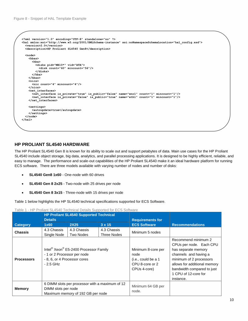
This tool will also be used to generate a HAL template (an XML file) which specifies the pieces of hardware such as disks, expander
ports, etc. as attributes with values. The template simplifies HAL deployment in a big cluster environment where all nodes (groups of
nodes) have similar configuration. A snippet of the HAL template is illustrated below in Figure 8.
[root@provo-beige emc]# cs_hal info node
Node : provo-beige.sea.lab.emc.com
BIOS date : 12/20/2013
Bios vendor : HP
BIOS version : P74
Board S/N : USE411TBY0
Board vendor : HP
Chassis S/N : USE411TBXV
Chassis vendor : HP
Chassis model : ProLiant SL4540 Gen8
System S/N : USE411TBY0
System vendor : HP
Processor count : 12
Total memory : 70.5966GB
Available memory : 32.8698GB
Total swap : 4GB
Available swap : 4GB
Shared memory : 0GB
Host adapter count : 2
Net interface count : 5
Enclosure count : 0
External disk count : 20
LED state : not supported
Figure 7- Diagnostic Example - Single Node Details
10
HP PROLIANT SL4540 HARDWARE
The HP Proliant SL4540 Gen 8 is known for its ability to scale out and support petabytes of data. Main use cases for the HP Proliant
SL4540 include object storage, big data, analytics, and parallel processing applications. It is designed to be highly efficient, reliable, and
easy to manage. The performance and scale-out capabilities of the HP Proliant SL4540 make it an ideal hardware platform for running
ECS software. There are three models available with varying number of nodes and number of disks:
SL4540 Gen8 1x60 - One-node with 60 drives
SL4540 Gen 8 2x25 - Two-node with 25 drives per node
SL4540 Gen 8 3x15 - Three-node with 15 drives per node
Table 1 below highlights the HP SL4540 technical specifications supported for ECS Software.
Table 1 - HP Proliant SL4540 Technical Details Supported for ECS Software
Category
HP Proliant SL4540 Supported Technical
Details Requirements for
ECS Software Recommendations 1x60 2X25 3 x 15
Chassis 4.3 Chassis
Single Node
4.3 Chassis
Two Nodes
4.3 Chassis
Three Nodes Minimum 5 nodes
Processors
Intel® Xeon
® E5-2400 Processor Family
- 1 or 2 Processor per node
- 8, 6, or 4 Processor cores
- 2.5 GHz
Minimum 8-core per
node
(i.e., could be a 1
CPU 8-core or 2
CPUs 4-core)
Recommend minimum 2
CPUs per node. Each CPU
has separate memory
channels and having a
minimum of 2 processors
allows for additional memory
bandwidth compared to just
1 CPU of 12-core for
instance.
Memory
6 DIMM slots per processor with a maximum of 12
DIMM slots per node
Maximum memory of 192 GB per node
Minimum 64 GB per
node.
<?xml version="1.0" encoding="UTF-8" standalone="no" ?>
<hal xmlns:xsi="http://www.w3.org/2001/XMLSchema-instance" xsi:noNamespaceSchemaLocation="hal_config.xsd">
<version>2.0</version>
<description>HP ProLiant SL4540 Gen8</description>
<node>
<hbas>
<hba>
<disks pid="MB10*" vid="ATA">
<disk count="60" mincount="56"/>
</disks>
</hba>
</hbas>
<nics>
<nic count="4" mincount="4"/>
</nics>
<net_interfaces>
<net_interface is_private="true" is_public="false" name="eno1" count="1" mincount="1"/>
<net_interface is_private="false" is_public="true" name="eth1" count="1" mincount="1"/>
</net_interfaces>
<settings>
<autoupdate>true</autoupdate>
</settings>
</node>
</hal>
Figure 8 - Snippet of HAL Template Example
11
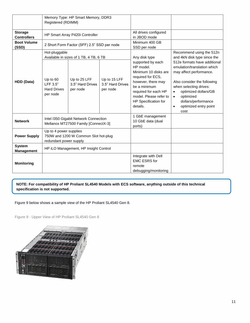
Memory Type: HP Smart Memory, DDR3
Registered (RDIMM)
Storage
Controllers HP Smart Array P420i Controller
All drives configured
in JBOD mode
Boot Volume
(SSD) 2 Short Form Factor (SFF) 2.5” SSD per node
Minimum 400 GB
SSD per node
HDD (Data)
Hot-pluggable
Available in sizes of 1 TB, 4 TB, 6 TB Any disk type
supported by each
HP model.
Minimum 10 disks are
required for ECS,
however, there may
be a minimum
required for each HP
model. Please refer to
HP Specification for
details.
Recommend using the 512n
and 4kN disk type since the
512e formats have additional
emulation/translation which
may affect performance.
Also consider the following
when selecting drives:
optimized dollars/GB
optimized
dollars/performance
optimized entry point
cost
Up to 60
LFF 3.5”
Hard Drives
per node
Up to 25 LFF
3.5” Hard Drives
per node
Up to 15 LFF
3.5” Hard Drives
per node
Network Intel I350 Gigabit Network Connection
Mellanox MT27500 Family [ConnectX-3]
1 GbE management
10 GbE data (dual
ports)
Power Supply
Up to 4 power supplies
750W and 1200 W Common Slot hot-plug
redundant power supply
System
Management HP iLO Management, HP Insight Control
Monitoring
Integrate with Dell
EMC ESRS for
remote
debugging/monitoring
Figure 9 below shows a sample view of the HP Proliant SL4540 Gen 8.
Figure 9 - Upper View of HP Proliant SL4540 Gen 8
NOTE: For compatibility of HP Proliant SL4540 Models with ECS software, anything outside of this technical
specification is not supported.
12
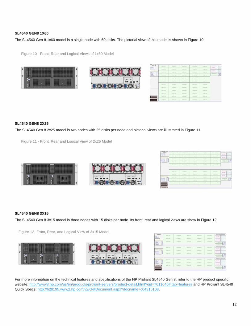
SL4540 GEN8 1X60
The SL4540 Gen 8 1x60 model is a single node with 60 disks. The pictorial view of this model is shown in Figure 10.
SL4540 GEN8 2X25
The SL4540 Gen 8 2x25 model is two nodes with 25 disks per node and pictorial views are illustrated in Figure 11.
SL4540 GEN8 3X15
The SL4540 Gen 8 3x15 model is three nodes with 15 disks per node. Its front, rear and logical views are show in Figure 12.
For more information on the technical features and specifications of the HP Proliant SL4540 Gen 8, refer to the HP product specific
website: http://www8.hp.com/us/en/products/proliant-servers/product-detail.html?oid=7611040#!tab=features and HP Proliant SL4540
Quick Specs: http://h20195.www2.hp.com/v2/GetDocument.aspx?docname=c04315108.
Figure 10 - Front, Rear and Logical Views of 1x60 Model
Figure 11 - Front, Rear and Logical View of 2x25 Model
Figure 12- Front, Rear, and Logical View of 3x15 Model
13
NETWORK SWITCHES
The same set of Arista switches used for the ECS Appliance will be used with the industry standard certified hardware. For more
detailed information on the switches supported, please refer to the ECS Hardware and Cabling Guide. Note: Using a different switch
would be considered a “custom” configuration and would need to be processed via ASD Helpdesk as a custom configuration.
Two10GbE switch is required for data transfer and one 1GbE switch for management.
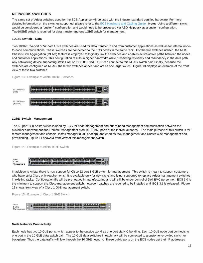
10GbE Switch – Data
Two 10GbE, 24-port or 52-port Arista switches are used for data transfer to and from customer applications as well as for internal node-
to-node communications. These switches are connected to the ECS nodes in the same rack. For the two switches utilized, the Multi-
Chassis Link Aggregation (MLAG) feature is employed to logically link the switches and enables active-active paths between the nodes
and customer applications. This configuration results in higher bandwidth while preserving resiliency and redundancy in the data path.
Any networking device supporting static LAG or IEEE 802.3ad LACP can connect to this MLAG switch pair. Finally, because the
switches are configured as MLAG, these two switches appear and act as one large switch. Figure 13 displays an example of the front
view of these two switches.
Figure 13 - Example of Arista 10GbE Switches
1GbE Switch - Management
The 52-port 1Gb Arista switch is used by ECS for node management and out-of-band management communication between the
customer’s network and the Remote Management Module (RMM) ports of the individual nodes. The main purpose of this switch is for
remote management and console, install manager (PXE booting), and enables rack management and cluster wide management and
provisioning. Figure 14 shows a front view of this management switch.
In addition to Arista, there is now support for Cisco 52 port 1 GbE switch for management. This switch is meant to support customers
who have strict Cisco only requirements. It is available only for new racks and is not supported to replace Arista management switches
in existing racks. Configuration file will be pre-loaded in manufacturing and will still be under control of Dell EMC personnel. ECS 3.0 is
the minimum to support the Cisco management switch; however, patches are required to be installed until ECS 3.1 is released. Figure
12 shows front view of a Cisco 1 GbE management switch.
Figure 15 - Example of Cisco 1 GbE Switch
Node Network Connectivity
Each node has two 10 GbE ports, which appear to the outside world as one port via NIC bonding. Each 10 GbE node port connects to
one port in the 10 GbE data switch pair . The 10 GbE data switches in each rack will be connected to a customer-provided switch or
backplane. Thus the data traffic will flow through the 10 GbE network. These public ports on the ECS nodes get their IP addresses
Figure 14 - Example of Arista 1GbE Switch
14
from the customer’s network, either statically or via a DHCP server. Customer applications connect to ECS by using the 10 GbE public
IP addresses of the ECS nodes.
The 1GbE management port on each node connects to an appropriate port in the 1GbE switch and has a private address of
192.168.219.X. Each physical unit also has a connection between its RMM port (iLO port on the HP Proliant SL4540) and a port in the
1GbE switch, which in turn has access to a customer’s network to provide out-of-band management of the servers. To enable access
for the RMM ports to the customer’s network, ports 51 and/or 52 in 1 GbE management switch are linked to directly to the customer’s
network. The RMM port is used by Dell EMC field service personnel for monitoring, troubleshooting and installation. You can expand
an ECS rack by linking one or more racks to an existing rack also via ports 51 and 52 of the management switches. The 1GbE switches
in the racks are used for serially linking the racks.
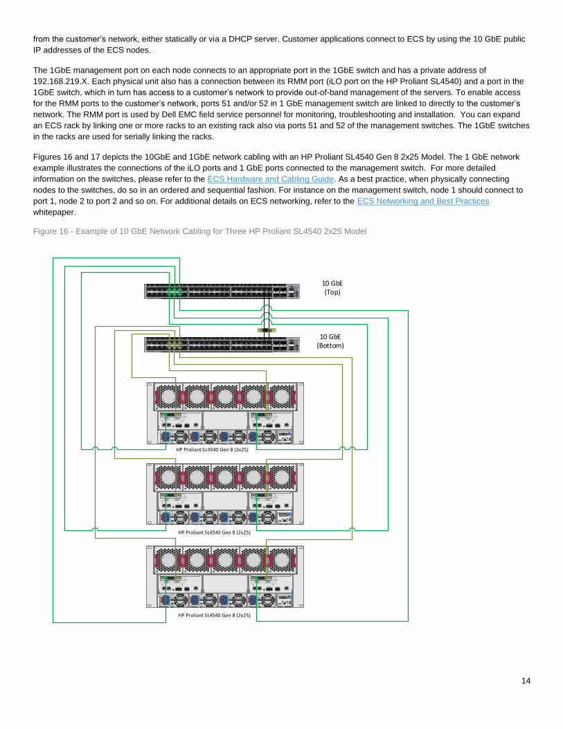
Figures 16 and 17 depicts the 10GbE and 1GbE network cabling with an HP Proliant SL4540 Gen 8 2x25 Model. The 1 GbE network
example illustrates the connections of the iLO ports and 1 GbE ports connected to the management switch. For more detailed
information on the switches, please refer to the ECS Hardware and Cabling Guide. As a best practice, when physically connecting
nodes to the switches, do so in an ordered and sequential fashion. For instance on the management switch, node 1 should connect to
port 1, node 2 to port 2 and so on. For additional details on ECS networking, refer to the ECS Networking and Best Practices
whitepaper.
Figure 16 - Example of 10 GbE Network Cabling for Three HP Proliant SL4540 2x25 Model
2121
2121
2121
HP Proliant SL4540 Gen 8 (2x25)
HP Proliant SL4540 Gen 8 (2x25)
HP Proliant SL4540 Gen 8 (2x25)
P2 P1ACT LINK ACTLINKP2 P1ACT LINK ACTLINK
P2 P1ACT LINK ACTLINKP2 P1ACT LINK ACTLINK
P2 P1ACT LINK ACTLINKP2 P1ACT LINK ACTLINK
10 GbE (Top)
10 GbE(Bottom)
MLAG

15
Figure 17 - Example of 1 GbE Network Cabling for Three HP Proliant SL4540 2x25 Model
2121
2121
2121
HP Proliant SL4540 Gen 8 (2x25)
HP Proliant SL4540 Gen 8 (2x25)
HP Proliant SL4540 Gen 8 (2x25)
M LAG
10 GbE (Top)
10 GbE(Bottom)
1 GbE(Mgmt)
DEPLOYMENT
ECS can be deployed on a single or multi-site (replicated) configuration. In a multi-site replicated environment, different hardware
platform can be used in the other replicated sites. For instance, industry standard hardware such as the HP Proliant SL4540 can be in
one site and the replicated site can be an ECS Appliance. As previously mentioned, there are minimum configurations required to run
ECS Software on industry standard hardware. Depending on the model of hardware chosen, configurations will vary to meet these
requirements. Once the hardware is selected and setup, ECS software functions in the same fashion as if it was running on an ECS
appliance. This section discusses the configurations to install ECS Software bundle on the HP Proliant SL4540 Gen 8. It will also
discuss the customer provided infrastructure needed.
CONFIGURATIONS
There are flexible entry points with rapid scalability to petabytes and exabytes of data. ECS scales linearly both in capacity and
performance by just adding additional nodes and disks to your environment – with minimal impact to the business. The basic hardware
required to run ECS software on industry standard hardware include at minimum five compute nodes with data disks, two 10 Gbe
switches for data, and a single 1 Gbe management switch. NOTE: As mentioned previously in the Network Switches section, the
switches supported for the certified hardware is the Arista switches for data and Arista or Cisco for management. Table 2 highlights the
16
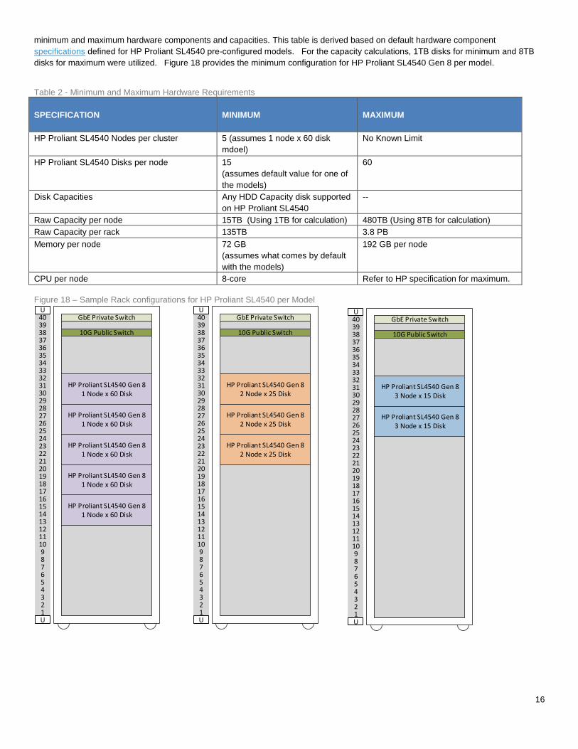
minimum and maximum hardware components and capacities. This table is derived based on default hardware component
specifications defined for HP Proliant SL4540 pre-configured models. For the capacity calculations, 1TB disks for minimum and 8TB
disks for maximum were utilized. Figure 18 provides the minimum configuration for HP Proliant SL4540 Gen 8 per model.
Table 2 - Minimum and Maximum Hardware Requirements
SPECIFICATION MINIMUM MAXIMUM
HP Proliant SL4540 Nodes per cluster 5 (assumes 1 node x 60 disk
mdoel)
No Known Limit
HP Proliant SL4540 Disks per node
15
(assumes default value for one of
the models)
60
Disk Capacities Any HDD Capacity disk supported
on HP Proliant SL4540
--
Raw Capacity per node 15TB (Using 1TB for calculation) 480TB (Using 8TB for calculation)
Raw Capacity per rack 135TB 3.8 PB
Memory per node 72 GB
(assumes what comes by default
with the models)
192 GB per node
CPU per node 8-core Refer to HP specification for maximum.
Figure 18 – Sample Rack configurations for HP Proliant SL4540 per Model
40393837363534333231302928272625242322212019181716151413121110987654321
UGbE Private Switch
10G Public Switch
U
HP Proliant SL4540 Gen 81 Node x 60 Disk
HP Proliant SL4540 Gen 81 Node x 60 Disk
HP Proliant SL4540 Gen 81 Node x 60 Disk
HP Proliant SL4540 Gen 81 Node x 60 Disk
HP Proliant SL4540 Gen 81 Node x 60 Disk
40393837363534333231302928272625242322212019181716151413121110987654321
UGbE Private Switch
10G Public Switch
U
HP Proliant SL4540 Gen 82 Node x 25 Disk
HP Proliant SL4540 Gen 82 Node x 25 Disk
HP Proliant SL4540 Gen 82 Node x 25 Disk
40393837363534333231302928272625242322212019181716151413121110987654321
UGbE Private Switch
10G Public Switch
U
HP Proliant SL4540 Gen 83 Node x 15 Disk
HP Proliant SL4540 Gen 83 Node x 15 Disk

17
EXPANSION
When adding nodes and drives to current deployment, there are some rules and best practices to adhere to.
Rules include:
Add drives up to what is supported for the node model.
Add a drive per node across all nodes evenly. For instance, if desiring to add 2 drives, add 2 drives on all nodes in the current
deployment.
For HP Proliant SL4540, add same model node(s) with the same number of drives as current nodes at a time.
Follow minimum disks and node rules supported as indicated in “Table 1”.
Best practices include:
Add drives of same type and capacity.
Best practice is not to wait until the storage platform is completely “full” before adding drives/nodes. A reasonable storage
utilization threshold is 70% taking consideration daily ingest rate and expected order, delivery and integration time of added
drives/nodes.
CUSTOMER PROVIDED INFRASTRUCTURE
In order to be able to deploy ECS, certain customer provided infrastructure requirements need to be reachable by the ECS system. A
list of required and optional components includes:
Authentication Providers – users (system admin, namespace admin and object users) can be authenticated using Active
Directory or LDAP or Keystone
DNS Server – Domain Name server or forwarder
NTP Server – Network Time Protocol server. Please refer to the NTP best practices for guidance on optimum configuration
SMTP Server – (optional) Simple Mail Transfer Protocol Server is used for sending reports from the ECS rack.
DHCP server – only if assigning IP addresses via DHCP
Load Balancer - (optional but highly recommended) evenly distributes loads across all data services nodes. Load balancers
can use simple algorithms such as random choice or round robin. More sophisticated load balancers may take additional
factors into account, such as a server's reported load, response times, up/down status, number of active connections,
geographic location and so on. The customer is responsible for implementing load balancers; customers have several options
including Manual IP allocation, DNS Round Robin, Client-Side Load Balancing, Load Balancer Appliances, and Geographic
Load Balancers. The following are brief descriptions of each of those methods:
o Manual IP Allocation - Data node IP addresses are manually distributed to applications. This is not recommended
because it does not evenly distribute loads between the nodes and does not provide any fault-tolerance if a node
fails.
o DNS Round-Robin - With DNS Round-Robin, a DNS name is created for ECS and includes all of the IP addresses
for the data nodes. The DNS server will randomly return the IP addresses when queried and provide some pseudo-
load balancing. This generally does not provide fault-tolerance because you would need to remove the IP addresses
from DNS to keep them out of rotation. Even after removing them, there is generally some TTL (time-to-live) issues
where there is a delay to propagate the removal. Also, some operating systems like Windows will cache DNS
lookups and can cause "stickiness," where a client keeps binding to the same IP address, reducing the amount of
load distribution to the data nodes.
o Physical or Virtual load balancing- This option is the most common approach to load balancing. In this mode, an
appliance (hardware or software) receives the HTTP request and forwards it on to the data nodes. The appliance
keeps track of the state of all of the data nodes (up/down, # of connections) and can intelligently distribute load

18
amongst the nodes. Generally, the appliance will proactively "health check" the node (e.g. GET/?ping on the S3
head) to ensure the node is up and available. If the node becomes unavailable it will immediately be removed from
rotation until it passes a health check. Another advantage to this kind of load balancing is SSL termination. You can
install the SSL certificate on the load balancer and have the load balancer handle the SSL negotiation. The
connection between the load balancer and the data node is then unencrypted. This reduces the load on the data
nodes because they do not have to handle the CPU-intensive task of SSL negotiation.
o Geographic load balancing - Geographic load balancing takes Physical or Virtual Load Balancing one step further:
it adds load balancing into the DNS infrastructure. When the DNS lookups occur, they are routed via an "NS" record
in DNS to delegate the lookups to a load balancing appliance like the Riverbed SteelApp. The load balancer can
then use Geo-IP or some other mechanism to determine which site to route the client to. If a site is detected to be
down, the site can be removed quickly from DNS and traffic will be routed to surviving sites.
Available for reference is ECS with HAProxy Load Balancer Deployment Reference Guide which provides information and
examples how to implement HAProxy, an open-source and free load balancer software, with ECS.
VALIDATION TESTING
Tests were conducted to validate and certify Dell EMC-approved industry standard hardware with ECS Software Bundle. These sets of
tests are also used on the ECS Appliance and exercise the entire integrated system to the fullest to verify that there are no issues in
using ECS Software Bundle with the hardware. The set of tests run include:
Installation – tests install of ECS software.
Extend – extend an ECS cluster by adding more nodes.
Upgrade – upgrade cluster to a newer version of ECS Software.
Geo - clusters spans multiple physical locations.
Load testing – puts load on ECS running on the infrastructure and hardware for numerous hours.
Serviceability and service procedure testing - node shutdown, disk replacement and node replacement tests.
Mixed mode testing - validates ECS running on varying hardware at each site, ie. HP Proliant hardware and ECS appliance
deployed in a geo-replicated environment.
Since varying certified hardware and models can be used for the ECS software, a precheck tool was developed to check that industry
standard hardware meets the minimum specifications as discussed in the Tools section. Also, the precheck tool creates the
configurations files needed to install ECS Software.
SIZING
Sizing and configuration for your particular use case is determined during preliminary qualification and engagement with Dell EMC ECS
sales and support personnel. Generally your capacity and performance requirements would define the HP Proliant SL4540 model
needed. However, here is a list of considerations when sizing:
Capacity and Ingest rate –net data capacity needed and expected rate of growth (i.e. how many objects will be created each
day, what is the average size of each object, etc.)
Performance – dependent on your application needs for performance (i.e. any known throughput or latency expectations, how
many hosts/devices will be creating this data, etc.).
Erasure coding scheme – ECS utilizes a 12+4 or 10+2 erasure coding schemes. The 10+2 erasure coding is mostly used for
cold archive use case.
Number of Replication sites– replicating to 3 or more sites reduces ECS storage overhead and must be considered when
sizing.
The sizing and capacity tool will eventually be updated for industry standard hardware to assist in sizing. Performance results will also
be available soon to further provide information on which hardware model would be ideal to meet your storage requirements.
ORDERING AND COST
Ordering and quoting of ECS Software is available via ASD Helpdesk. The licensing model of ECS Software is based on the amount
of storage deployed per site of the customer. The cost consists of the software license plus cost of premium support and professional
services support.
19
SUPPORT
Support for ECS Software Bundle on industry standard hardware is a combination of both customer and Dell EMC support. The
installation is done by both customer and Dell EMC personnel. After all ECS Software Bundle has been successfully installed, then
hardware issues are handled by customer and ECS software and infrastructure such as operating system and Docker container issues
are handled by Dell EMC support with customer assistance.
INSTALL SUPPORT
Installation of certified hardware is a collaborated engagement between customer and Dell EMC personnel (ECS Professional and
Engineering services (as needed)). The steps of engagement and process of install include the following:
1. Customer Engagement and Qualification - preliminary discussions between customer and Dell EMC field or professional
services personnel to gather requirements, use cases, current infrastructure, and other information.
2. Node Preparation
a. Setup hardware and networking
b. Install operating system and Docker
c. Setup or use customer provided infrastructure - DNS, NTP, authentication providers, load balancers, etc, password-
less ssh (Customer)
3. Validation of Hardware platform - Precheck
a. ECS precheck tool is run to assess the deployed environment and hardware
b. If precheck PASSES “clean”, proceed to Step 4 - Install.
c. If precheck FAILS, remediate environment and escalate accordingly to the appropriate engineering teams (i.e.
ASD/CSE or ASD/Engineering).
d. Resolve precheck issues with assistance from ECS Engineering (i.e. ASD/CSE, ASD/Engineering).
4. Install of ECS Software– deploy ECS layers & services – HAL, Fabric, and Object similarly to the same way the ECS
Appliance is done.
5. Provisioning – provision storage and ready for use
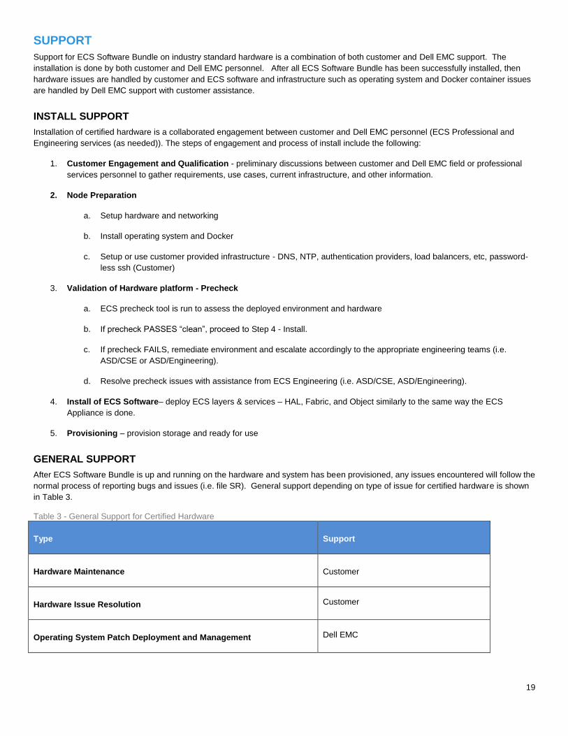
GENERAL SUPPORT
After ECS Software Bundle is up and running on the hardware and system has been provisioned, any issues encountered will follow the
normal process of reporting bugs and issues (i.e. file SR). General support depending on type of issue for certified hardware is shown
in Table 3.
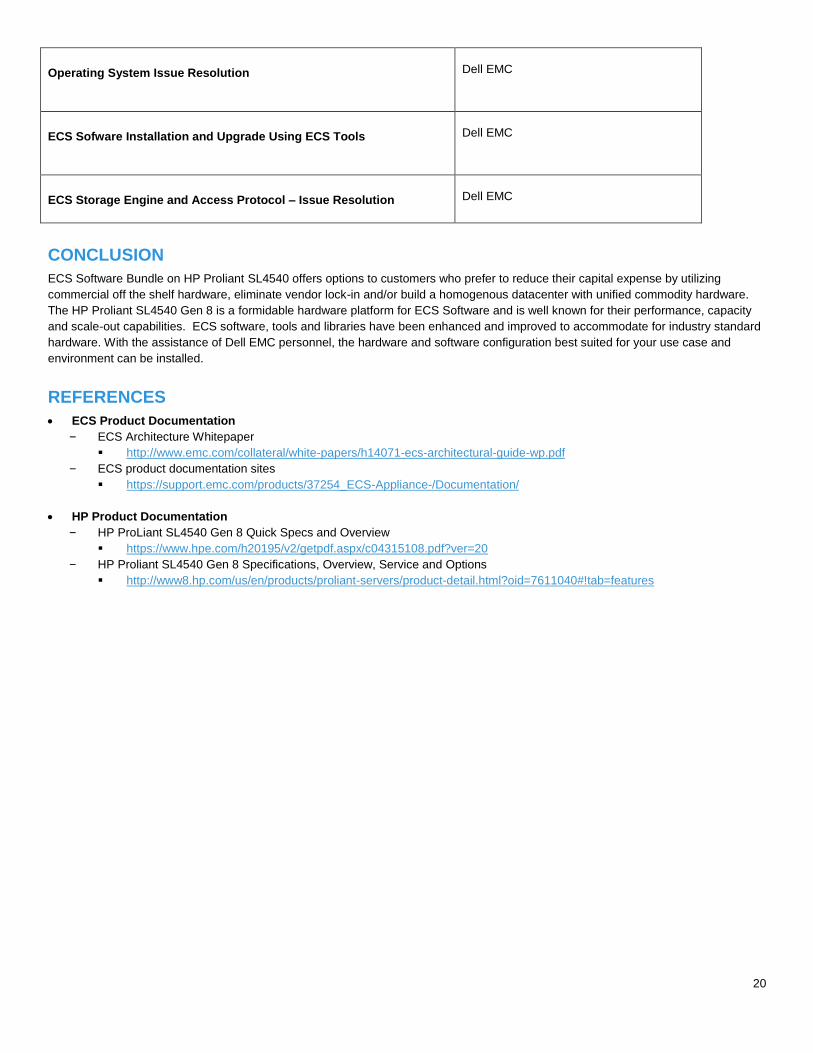
Table 3 - General Support for Certified Hardware
Type Support
Hardware Maintenance Customer
Hardware Issue Resolution
Customer
Operating System Patch Deployment and Management
Dell EMC
20
Operating System Issue Resolution
Dell EMC
ECS Sofware Installation and Upgrade Using ECS Tools
Dell EMC
ECS Storage Engine and Access Protocol – Issue Resolution
Dell EMC
CONCLUSION
ECS Software Bundle on HP Proliant SL4540 offers options to customers who prefer to reduce their capital expense by utilizing
commercial off the shelf hardware, eliminate vendor lock-in and/or build a homogenous datacenter with unified commodity hardware.
The HP Proliant SL4540 Gen 8 is a formidable hardware platform for ECS Software and is well known for their performance, capacity
and scale-out capabilities. ECS software, tools and libraries have been enhanced and improved to accommodate for industry standard
hardware. With the assistance of Dell EMC personnel, the hardware and software configuration best suited for your use case and
environment can be installed.
REFERENCES
ECS Product Documentation
– ECS Architecture Whitepaper
http://www.emc.com/collateral/white-papers/h14071-ecs-architectural-guide-wp.pdf
– ECS product documentation sites
https://support.emc.com/products/37254_ECS-Appliance-/Documentation/
HP Product Documentation
– HP ProLiant SL4540 Gen 8 Quick Specs and Overview
https://www.hpe.com/h20195/v2/getpdf.aspx/c04315108.pdf?ver=20
– HP Proliant SL4540 Gen 8 Specifications, Overview, Service and Options
http://www8.hp.com/us/en/products/proliant-servers/product-detail.html?oid=7611040#!tab=features