delivering exceptional service to every customer. every...
TRANSCRIPT

Delivering exceptional service to every customer. Every time.

www.flowcosolutions.com
When you’re focused on only one thing, you tend to do it better. Smarter.
Flowco Production Solutions is artificial lift. It’s all we do. All day. Every day. Founded and operated by the pioneers of the artificial lift industry, Flowco is redefining well “optimization” with the very latest in USA-made gas lift and plunger lift technologies and delivering unrivaled customer support wherever and whenever you need it. Call one of our Service Centers today and see just how fast Flowco can focus on you.

2
4
8
11
12
Optimization Services
Gas Lift
Plunger Lift
Plunger Assisted Gas Lift
NitroGEN®
www.flowcosolutions.com
With a shared pride in workmanship and reliability, and years of combined expertise, Flowco offers a full spectrum of artificial lift and well optimization services.
Services
+ Review of existing wells with gas lift or plunger lift already installed • Optimization/troubleshooting + Review of candidacy for new gas lift and plunger lift applications • Provide downhole and surface recommendations based on design application + Shoot fluid levels with echometers to troubleshoot and optimize gas
lift systems+ Provide gauges for running flowing temperature and pressure
surveys and the personnel to support the slickline companies on following proper API procedures
+ Analyze the collected well data and generate a report on the state of the well, plus optimization opportunities
+ Compare the status of the well to the proposed design of recommended artificial lift system prior to equipment install
+ Installation and kick-off of artificial lift systems + Maintenance, upgrades and troubleshooting for optimal performance
through the life of the well+ NitroGEN® Services for rapid fluid recovery
2 Flowco Optimization Services
Flowco provides turnkey artificial lift solutions to optimize production.
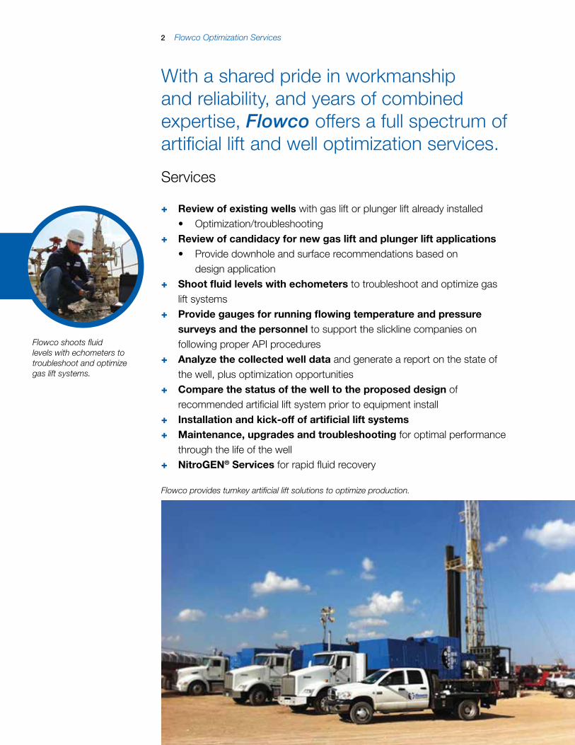
Flowco shoots fluid levels with echometers to troubleshoot and optimize gas lift systems.
Lunch and LearnsThis is an excellent way to obtain an overview of gas lift or plunger lift during your lunch break. We provide our knowledgeable experts for an on-site visit and assist you in your understanding of our lift systems during lunch. Similar training is also available at any time of the day.
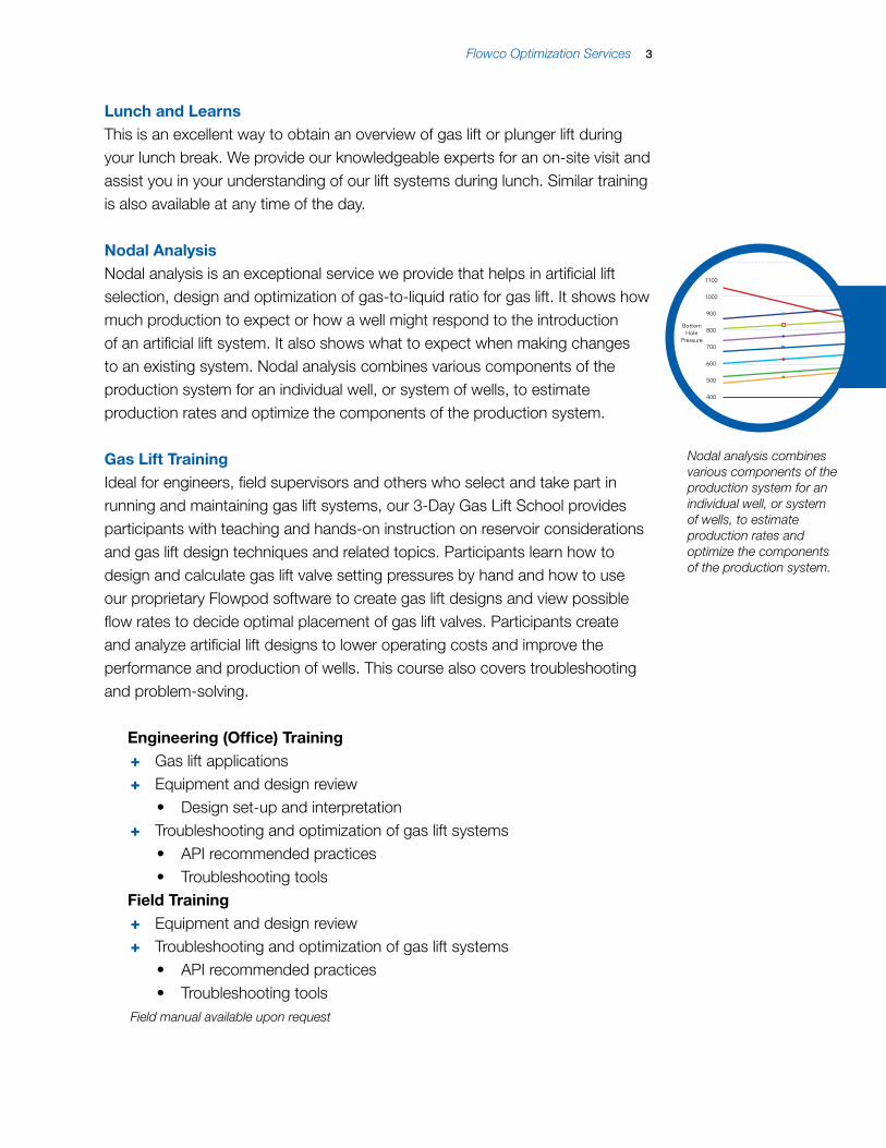
Nodal AnalysisNodal analysis is an exceptional service we provide that helps in artificial lift selection, design and optimization of gas-to-liquid ratio for gas lift. It shows how much production to expect or how a well might respond to the introduction of an artificial lift system. It also shows what to expect when making changes to an existing system. Nodal analysis combines various components of the production system for an individual well, or system of wells, to estimate production rates and optimize the components of the production system.
Gas Lift TrainingIdeal for engineers, field supervisors and others who select and take part in running and maintaining gas lift systems, our 3-Day Gas Lift School provides participants with teaching and hands-on instruction on reservoir considerations and gas lift design techniques and related topics. Participants learn how to design and calculate gas lift valve setting pressures by hand and how to use our proprietary Flowpod software to create gas lift designs and view possible flow rates to decide optimal placement of gas lift valves. Participants create and analyze artificial lift designs to lower operating costs and improve the performance and production of wells. This course also covers troubleshooting and problem-solving.
Engineering (Office) Training+ Gas lift applications+ Equipment and design review
• Design set-up and interpretation+ Troubleshooting and optimization of gas lift systems
• API recommended practices• Troubleshooting tools
Field Training+ Equipment and design review+ Troubleshooting and optimization of gas lift systems
• API recommended practices• Troubleshooting tools
Field manual available upon request
Flowco Optimization Services 3
Nodal analysis combines various components of the production system for an individual well, or system of wells, to estimate production rates and optimize the components of the production system.
1100
1000
900
800
700
600
500
400
Bottom Hole
Pressure
If you’re looking for a method of artificial lift to optimize production all the way from kickoff to depletion of your well, then Flowco Gas Lift is the answer.
Types of Gas Lift
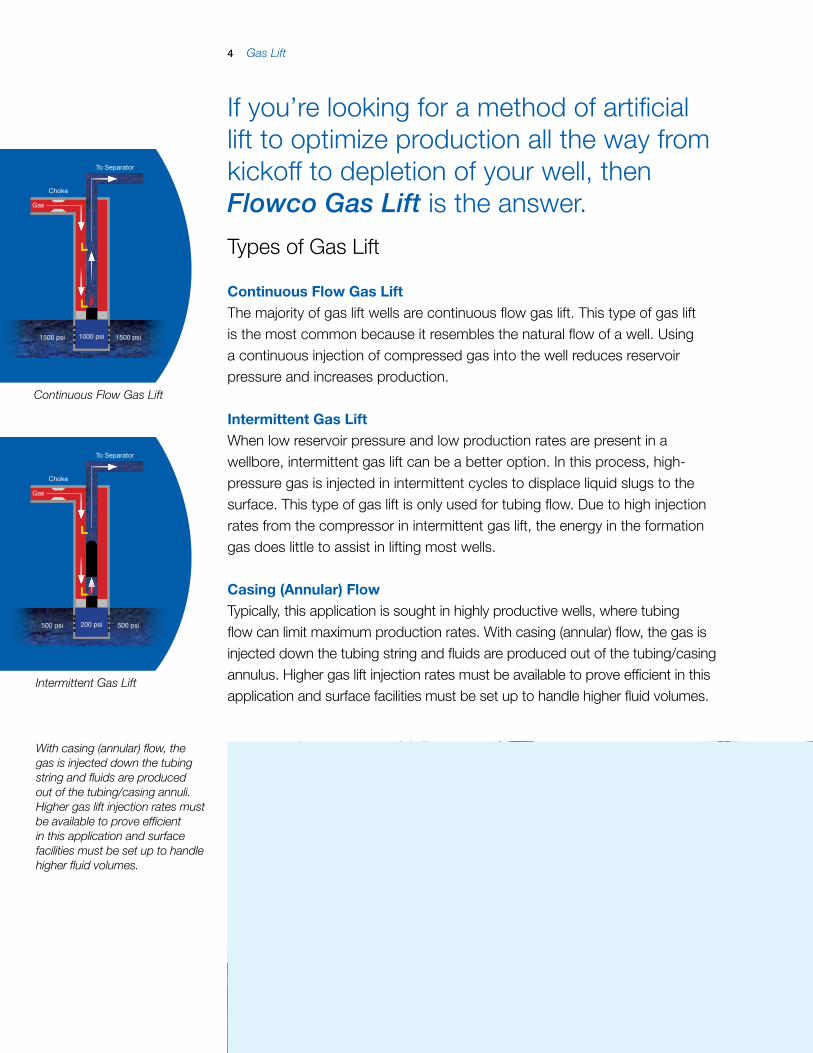
Continuous Flow Gas LiftThe majority of gas lift wells are continuous flow gas lift. This type of gas lift is the most common because it resembles the natural flow of a well. Using a continuous injection of compressed gas into the well reduces reservoir pressure and increases production.
Intermittent Gas LiftWhen low reservoir pressure and low production rates are present in a wellbore, intermittent gas lift can be a better option. In this process, high-pressure gas is injected in intermittent cycles to displace liquid slugs to the surface. This type of gas lift is only used for tubing flow. Due to high injection rates from the compressor in intermittent gas lift, the energy in the formation gas does little to assist in lifting most wells.
Casing (Annular) Flow Typically, this application is sought in highly productive wells, where tubing flow can limit maximum production rates. With casing (annular) flow, the gas is injected down the tubing string and fluids are produced out of the tubing/casing annulus. Higher gas lift injection rates must be available to prove efficient in this application and surface facilities must be set up to handle higher fluid volumes.
4 Gas Lift
Intermittent Gas Lift
Continuous Flow Gas Lift
With casing (annular) flow, the gas is injected down the tubing string and fluids are produced out of the tubing/casing annuli. Higher gas lift injection rates must be available to prove efficient in this application and surface facilities must be set up to handle higher fluid volumes.
1500 psi 1500 psi1000 psi
Gas
Choke
To Separator
500 psi 500 psi200 psi
Gas
Choke
To Separator

Beyond conventional, continuous flow applications:
Packer Bypass System (PBS)The Packer Bypass System (PBS) is a nice combination of the conventional gas lift system with a packer, and the open-ended, packerless system. With tubing and gas lift valves above the packer and a bypass assembly, injected gas can travel through the packer. This allows the gas lift system to reach the end of the tubing tail below the packer, in the curve of the wellbore. This is the ideal point of lift for the lowest flowing bottom-hole pressure and lowest flowing gradient. With injection gas above and below the packer through the unloading of the well, it is easy to treat the tubing and casing string with chemicals, if needed. When the well is shut-in, the packer prevents fluid from re-entering the annulus above the packer, and exposing the upper gas lift valves to fluid and wellbore “trash.” Upon resuming gas injection and unloading the well again, this prevents issues such as a hung open gas lift valve or erosion of gas lift equipment, when kicking the well back off.
Gas Lift Systems 5
Gas
Fluid
Conventional Gas Lift Mandrel
Wireline Retrievable Side Pocket Mandrel
Gas Lift Mandrels
A system with no packer until you need one.

Micro-Annulus Crossover SystemA horizontal micro-annulus system utilizes a crossover flow adapter and a distinct mini wellbore below the packer. This method allows for a deeper point of gas injection, as compared to a conventional gas lift system, usually in a toe-up horizontal lateral. It also does not cause extra back pressure on the formation. This method is better than a conventional gas lift at lowering flowing bottom-hole pressure. An example application
might include 2-3/8” tubing above the packer with a crossover flow adapter and 2-7/8” tail pipe below the packer with a 1” or
1-1/4” internal injection string inside the tail pipe. Gas is contained in the small string and lift is annular in the
controlled micro-annular area for optimum gas utilization and density reduction.
A vertical micro-annulus system is a good option for wells with low reservoir pressure where it is imperative to isolate gas lift pressure from the perforations. This method provides the ability to manage large casing wellbores with lower amounts of injection gas volumes and pressures. Injection pressure is kept strictly in the injection string and isolated from the
perforated interval. The compressed gas moves down the casing annulus and travels
through the crossover flow adapter into the 1” or 1-1/4” internal injection string. When the gas
travels through the gas lift valve, it exits into the produced fluid, reducing the density and delivering
the production to the surface.
6 Gas Lift Systems
A horizontal micro-annulus system utilizes a crossover flow adapter and a distinct mini wellbore below the packer. This method allows for a deeper point of gas injection, as compared to a conventional gas lift system.
Wireline Gas Lift Valve

Increased Annular Velocity System (IAV)The horizontal IAV system provides tubing and gas lift valves that are above a packer, along with a properly sized injection string with internally mounted gas lift valves below the packer. It is imperative to use the proper size tubing and injection string to keep unloading velocities above critical rate and successfully keep liquid off the reservoir. To guarantee the preservation of adequate flow velocity throughout the entire length of the well, acceptable compression must be accessible at the surface for the proper amount of injection gas.
The vertical IAV system creates the ability to reduce the cross-sectional area of flow from larger casing wellbores, along with reduced density of the hydrostatic fluid on the perforations and the formation. The compressed gas moves down the tubing/casing annulus above the packer, through the crossover adapter assembled to the packer and into a dead string of tubing that also serves as an area for compressed gas to travel down and stay separate from the flow area. The gas then leaves the gas lift valves that are placed at various points in the dead string tail pipe and combines with produced fluid and gas in the annulus. Injection gas pressure is isolated from the perforated interval and kept in the injection string. Fluid and gas flow up through the crossover flow adapter, back into tubing flow above the packer and then to the surface through the production tubing. This application is a great choice if low reservoir pressure is present and it is imperative to isolate the gas lift pressure from long perforated intervals. Beneath packer gas lift requires no alterations to the wellhead and installation is simple.
Gas Lift Systems 7
The vertical IAV system creates the ability to reduce the cross-sectional area of flow from larger casing wellbores, along with reduced density of the hydrostatic fluid on the perforations and the formation.
ConventionalCheck Valve

Plunger lift is widely used and the most economical method of artificial lift. It uses the well’s natural energy to bring liquids and gas to the surface and prevent liquid fallback.
Plunger Lift Basics
Plunger lift is typically used in high gas/liquid ratio (GLR) gas and oil wells, but is versatile enough to be used in lower GLR wells as well. As with other artificial lift methods, the purpose of plunger lift is to remove liquids from the wellbore so that the well can be produced at the lowest bottom-hole pressure and maximum rate.
A plunger lift system relies directly on the natural buildup of pressure in a shut-in gas well and gas velocity in a well struggling to flow. The plunger cycle starts on top of the bottom-hole bumper spring or in the surface lubricator. When the well is shut-in the plunger falls through the gas and liquid to the bottom-hole bumper spring. When the well is opened up, the plunger travels from the bottom-hole bumper spring to the surface. The controller opens a motor valve at the surface and the well’s shut-in pressure creates a differential pressure that forces the plunger interface up and lifts the liquid to surface. An arrival sensor recognizes and records plunger arrivals, plunger speeds and valve counts, and sets the controller to on, off or sales mode. Plunger Lift uses a free piston that travels up and down the tubing string and acts as an interface between liquids and gas energy. Because the plunger provides a seal between the liquid and the gas, the well’s own energy is used to lift liquids out of the wellbore economically and efficiently.
8 Plunger Lift
MSO Sensor
Drip Pot/Regulator
Gas Drive
Oil & GasFormation
The high-efficiency Surge® RAGE plunger series* features a solid one-piece design.
*PATENT PENDING

Conventional Plunger LiftA conventional plunger is a great application if you have a low volume, low pressure or marginal well. Typical production rates for conventional plunger lift systems are wells that produce under 50 blp/d and/or under 200mcf/d. This type of plunger is also ideal for wells with tubing irregularities or wells producing less than critical flow rates.+ Efficient seal + Maintains a full OD seal+ Moves fluids at low velocities+ Long plunger life+ Durable and cost effective
Continuous Flow Plunger LiftA continuous flow plunger is a great application for high volume or flowing wells because it allows a well to continue production as it works. A by-pass valve allows the plunger to bring a continuous flow of fluid removal with minimal shut-in time so you will frequently see an improvement in production. Typical production rates for continuous flow plunger applications are wells that can produce over 300mcf/d and/or fluid rates from 5-300blp/d.+ Shorter shut-in times for your high volume gas and liquid wells+ High gas and fluid rates+ Paraffin control+ One-piece design for operation+ Bar stock and pad designs+ Require minimal or no shut-in time + Average fall speed in fluid: 700 feet/min+ Potential fall speed in shut-in well: 2,000 feet/min.
Plunger Lift 9
Our best-in-class FlexPak bumper springs* come in 2 3/8” and 2 7/8”.
*PATENT PENDING

When is plunger lift an optimal choice for the well?+ Producing wells with low bottom-hole pressure+ Rig-less artificial lift application required+ Low maintenance+ Producing wells with high and low GLRs+ Extending the life of the well to economic depletion+ Minimizing shut-ins and well downtime+ Minimizing venting to the atmosphere+ Enhancing gas lift operations+ Economic lift method is needed
Operating considerations would be:+ Primarily used in high GLR gas wells+ Controls hydrate and paraffin buildup+ Removes and prevents scale buildup+ Easy to install and extremely cost effective with low initial equipment costs
and minimal operating costs + Fluctuating back pressures (Line PSI)+ Wells that produce roughly 400 blp/d or less+ GLR requirement: 400 scf per barrel per 1000’+ Gas is the lift energy needed to make the plunger operate
10 Plunger Lift
Ask your local sales representative for information on our robust line of individual plungers and plunger lift equipment.
Plunger lift is typically used in high gas/liquid ratio (GLR) gas and oil wells, but is versatile enough to be used in lower GLR wells as well.

Just as there are two types of gas lift systems, there are two ways to combine gas lift and plunger lift for custom artificial lift solutions.
Plunger Assisted Gas Lift
Continuous Flow Gas Lift System with a Continuous Flow PlungerThere are several reasons/scenarios why you should consider a continuous flow plunger introduced to a continuous flow gas lift system: + To lift fluids more efficiently than a standalone gas lift system + To mitigate or eliminate paraffin or scale build up in the tubing + To reduce the required gas lift injection volumes on single well sites or
field gas lift systems thereby saving on compression costs or possibly eliminating compression
Intermittent Gas Lift System with a Conventional Plunger Lift SystemAn intermittent gas lift system by itself can prove to produce less than desirable results in deeper wells, strictly due to the liquid fallback and the total liquid recovered per cycle. Liquid fallback in the tubing per cycle can be as much as 10% of the initial liquid slug per 1000’ of lift. With the addition of a conventional plunger, liquid fallback can be significantly reduced and more of the slug is delivered to the surface each cycle.
Plunger Assisted Gas Lift 11
With the addition of a conventional plunger to an intermittent gas lift system, liquid fallback can be significantly reduced and more of the slug is delivered to the surface each cycle.
Conventional Gas Lift Valve

2Membranes separate air into rich, inert nitrogen gas at >95% purity and oxygen waste
1Low pressure air compressor pulls atmospheric air to the membrane separator
3High pressure booster compressor discharges nitrogen gas volumes all the way up to 600 scfm at 5,000 psi
For more rapid recovery of downhole fluids, pair your gas lift system with on-site nitrogen generation.
Flowco NitroGEN® Services
Let Flowco handle the heavy liftingNitrogen is efficient, inert and non-corrosive and works seamlessly with all Flowco gas lift valves. Flowco is proud to offer the largest pressure and volume-producing units at the best purity in the business. + 24/7 supervision and daily reporting+ Well jetting and unloading+ De-watering+ Reservoir pressure maintenance+ Pipeline purging+ Supply gas for gas lift system+ Well clean out + Pipeline pressure testing+ New well completion activity+ New well drill outs+ Well testing
12 NitroGEN® Services
Flowco NitroGEN offers the largest pressure and volume-producing units at the best purity in the business.
Nitrogen is efficient, inert and non-corrosive and works seamlessly with all Flowco gas lift valves.
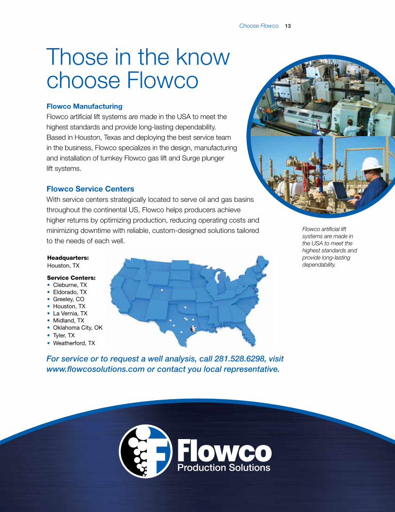
Those in the know choose FlowcoFlowco ManufacturingFlowco artificial lift systems are made in the USA to meet the highest standards and provide long-lasting dependability. Based in Houston, Texas and deploying the best service team in the business, Flowco specializes in the design, manufacturing and installation of turnkey Flowco gas lift and Surge plunger lift systems.
Flowco Service CentersWith service centers strategically located to serve oil and gas basins throughout the continental US, Flowco helps producers achieve higher returns by optimizing production, reducing operating costs and minimizing downtime with reliable, custom-designed solutions tailored to the needs of each well.
Choose Flowco 13
Headquarters: Houston, TX
Service Centers:• Cleburne, TX• Eldorado, TX• Greeley, CO• Houston, TX• La Vernia, TX• Midland, TX• Oklahoma City, OK• Tyler, TX• Weatherford, TX
For service or to request a well analysis, call 281.528.6298, visit www.flowcosolutions.com or contact you local representative.
Flowco artificial lift systems are made in the USA to meet the highest standards and provide long-lasting dependability.
Printed 073115
Flowco Corporate Headquarters18511 Imperial Valley Dr.
Houston, Texas 77073, USAO: 281.528.6298 F: 281.528.6319
www.flowcosolutions.com
Service Centers• Cleburne, TX• Eldorado, TX• Greeley, CO• Houston, TX• La Vernia, TX• Midland, TX• Oklahoma City, OK• Tyler, TX• Weatherford, TX