deliverable d1.4 periodic technical and administrative report · ahmed mokhtar (jcp-c) dimitrios...
TRANSCRIPT

D1.4 – Periodic technical and administrative report
TERRANOVA Project Page 1 of 99
This project has received funding from Horizon 2020, European Union’s Framework Programme for Research and Innovation, under grant agreement
No. 761794
Deliverable D1.4 Periodic technical and administrative
report Work Package 1 – Project Management
TERRANOVA Project Grant Agreement No. 761794 Call: H2020-ICT-2016-2 Topic: ICT-09-2017 - Networking research beyond 5G Start date of the project: 1 July 2017 Duration of the project: 30 months
Ref. Ares(2018)4117487 - 05/08/2018

D1.4 – Periodic technical and administrative report
TERRANOVA Project Page 2 of 99
Disclaimer This document contains material, which is the copyright of certain TERRANOVA contractors, and may not be reproduced or copied without permission. All TERRANOVA consortium partners have agreed to the full publication of this document. The commercial use of any information contained in this document may require a license from the proprietor of that information. The reproduction of this document or of parts of it requires an agreement with the proprietor of that information. The document must be referenced if used in a publication. The TERRANOVA consortium consists of the following partners.
No. Name Short Name Country
1 (Coordinator)
University of Piraeus Research Center UPRC Greece
2 Fraunhofer Gesellschaft (FhG-HHI & FhG-IAF)
FhG Germany
3 Intracom Telecom ICOM Greece
4 University of Oulu UOULU Finland
5 JCP-Connect JCP-C France
6 Altice Labs ALB Portugal
7 PICAdvanced PIC Portugal

D1.4 – Periodic technical and administrative report
TERRANOVA Project Page 3 of 99
Document Information
Project short name and number TERRANOVA (653355)
Work package WP1
Number D1.4
Title Periodic technical and administrative report
Version v1.0
Responsible unit UPRC
Involved units UPRC, FhG, ICOM, JCP-C, UOULU, ALB, PIC
Type1 R
Dissemination level2 PU
Contractual date of delivery 30.06.2018
Last update 04.08.2018
1 Types. R: Document, report (excluding the periodic and final reports); DEM: Demonstrator, pilot, prototype, plan
designs; DEC: Websites, patents filing, press & media actions, videos, etc.; OTHER: Software, technical diagram,
etc. 2 Dissemination levels. PU: Public, fully open, e.g. web; CO: Confidential, restricted under conditions set out in
Model Grant Agreement; CI: Classified, information as referred to in Commission Decision 2001/844/EC.

D1.4 – Periodic technical and administrative report
TERRANOVA Project Page 4 of 99
Document History
Version Date Status Authors, Reviewers Description
v0.1 29.06.2018 Draft Alexandros-Apostolos A. Boulogeorgos (UPRC)
Initial version, structure definition
v0.2 11.07.2018 Draft Alexandros-Apostolos A. Boulogeorgos (UPRC)
Contribution to Section 4
v0.3 11.07.2018 Draft José Machado (ALB) Contribution to Section 2
v0.4 11.07.2018 Draft Joonas Kokkoniemi (UOULU) Contribution to Section 3
v0.5 11.07.2018 Draft Alexandros-Apostolos A. Boulogeorgos (UPRC)
Contribution to Section 3
v0.6 11.07.2018 Draft Robert Elschner (FhG) Contribution to Section 6
v0.7 11.07.2018 Draft Alexandros-Apostolos A. Boulogeorgos (UPRC)
Contribution to Section 6
v0.8 12.07.2018 Draft Ahmed Mokhtar (JCP-C) José Machado (ALB)
Dessy Yankova (JCP-C)
Contribution to Section 7
v0.9 12.07.2018 Draft Alexandros-Apostolos A. Boulogeorgos (UPRC)
Contribution to Section 1
v0.10 12.07.2018 Draft Janne Lehtomäki (UOULU) Contribution to Section 6.1
v0.11 12.07.2018 Draft Georgia Ntouni (ICOM) Dimitrios Kritharidis (ICOM) Joonas Kokkoniemi (UOULU)
Contribution to Section 3
v0.12 13.07.2018 Draft José Machado ALB) Georgia Ntouni (ICOM)
Dimitrios Kritharidis (ICOM)
Contribution to Section 2
v0.13 14.07.2018 Draft Ahmed Mokhtar (JCP-C) Contribution to Section 7
v0.14 15.07.2018 Draft Alexandros-Apostolos A. Boulogeorgos (UPRC)
Contribution to Section 8; Editing in all Sections
v0.15 16.07.2018 Draft Robert Elschner (FhG) Contribution to Section 6.4
v0.16 18.07.2018 Draft Thomas Merkle (FhG) Contribution to Section 5
v0.17 19.07.2018 Draft Ricardo Ferreira (PICadvanced)
Contribution to Sections 2.1 and 5.4

D1.4 – Periodic technical and administrative report
TERRANOVA Project Page 5 of 99
v0.18 23.07.2018 Draft Thomas Dasaklis (UPRC) Contribution to Section 8
v0.19 27.07.2018 Draft Alexandros-Apostolos A. Boulogeorgos (UPRC)
Editing in all Sections
v0.20 28.07.2018 Draft Angeliki Alexiou (UPRC) Revision of all sections, contribution to Section 8
v0.21 29.07.2018 Draft Alexandros-Apostolos A. Boulogeorgos (UPRC)
Contribution to Section 3. Editing in all Sections
v0.22 31.07.2018 Draft Alexandros-Apostolos A. Boulogeorgos (UPRC)
Editing in all Sections
v0.23 31.07.2018 Draft Ricardo Ferreira (PICadvanced)
Contribution to Section 2.5.1.
v0.24 31.07.2018 Draft Angeliki Alexiou (UPRC) Ahmed Mokhtar (JCP-C)
Dimitrios Kritharidis (ICOM) Georgia Ntouni (ICOM)
Revision of all sections, Contribution to Sections 7 and 8
v0.25 1.08.2018 Draft Angeliki Alexiou (UPRC) Thomas Dasaklis (UPRC)
Contribution to Section 8
v0.26 2.08.2018 Draft Angeliki Alexiou (UPRC)
Final Editing of all sections
v0.27 3.08.2018 Draft Ahmed Mokhtar (JCP-C)
Contribution to section 8 Contribution to section 7 Revision of all sections
v1.0 4.08.2018 Final Angeliki Alexiou (UPRC) Dimitrios Kritharidis (ICOM)
Georgia Ntouni (ICOM) Alexandros-Apostolos A.
Boulogeorgos (UPRC)
Final Editorial Corrections

D1.4 – Periodic technical and administrative report
TERRANOVA Project Page 6 of 99
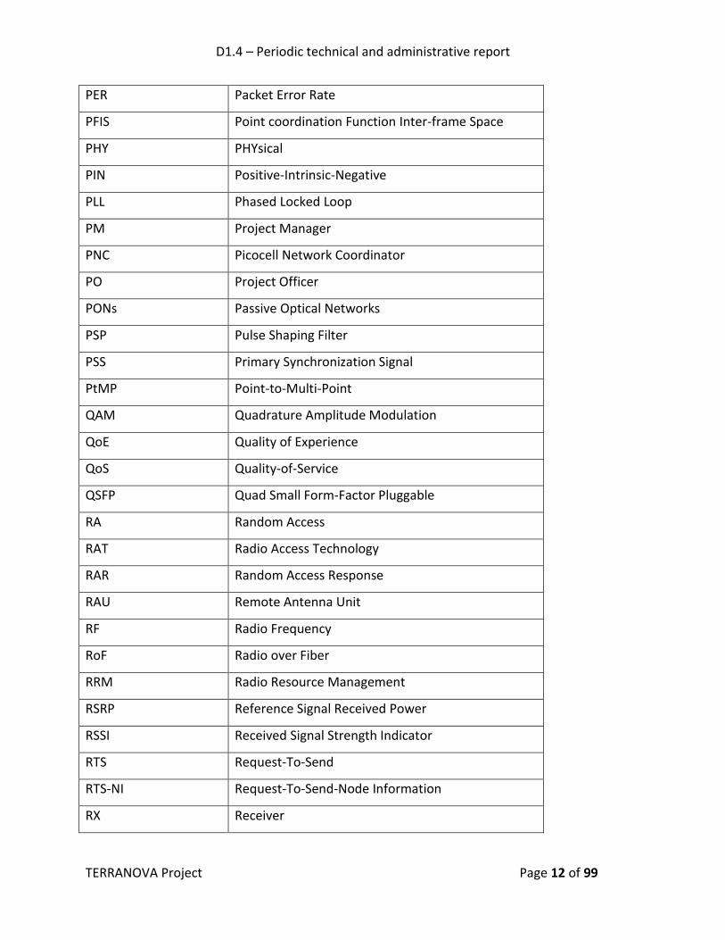
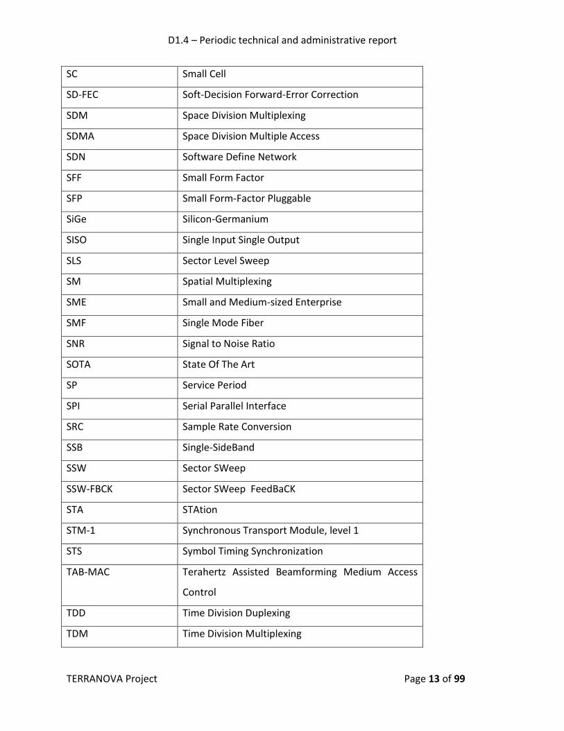
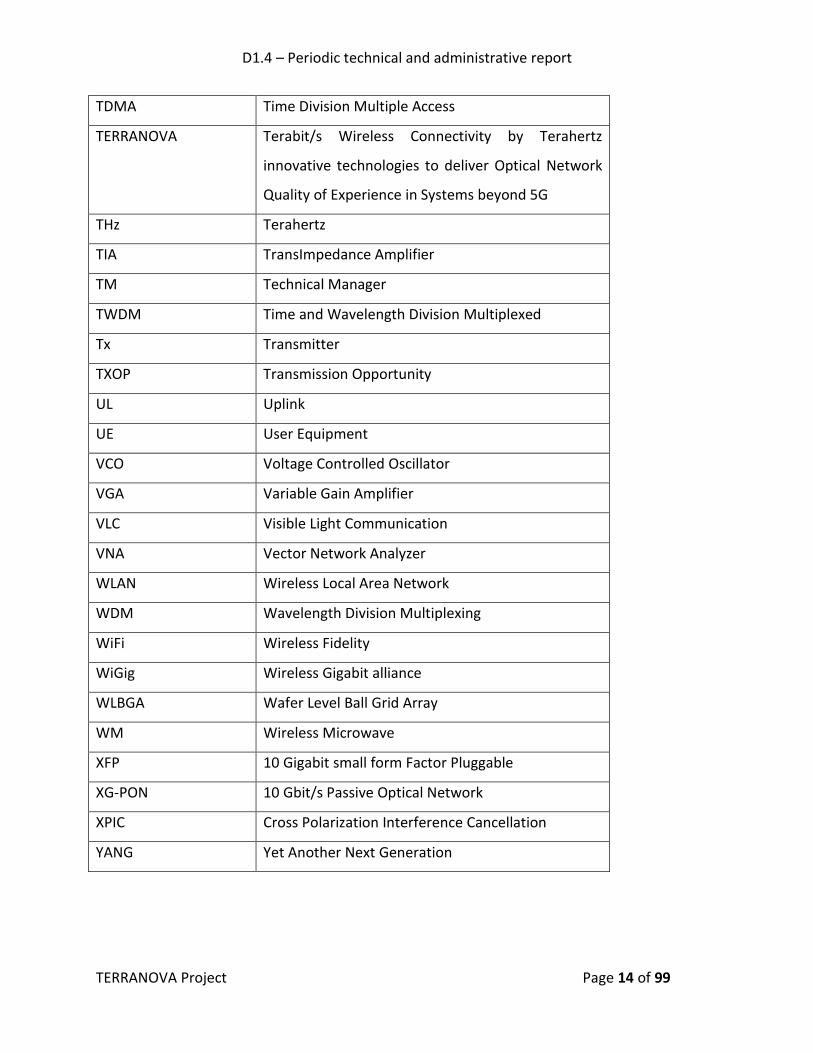
Acronyms and Abbreviations
Acronym/Abbreviation Description
2G Second Generation
3G Third Generation
3GPP Third Generation Partnership Project
5G Fifth Generation
A-BFT Associate BeamForming Training
A-MSDU Aggregated Medium access control Service Data
Unit
A-MSPU Aggregated Medium access control Service Protocol
Unit
ACK Acknowledgement
ACO Analog Coherent Optics
ADC Analog-to-Digital Converter
AFC Automatic Frequency Correction
AFE Analogue FrontEnd
AGC Automatic Gain Control
AiP Antenna-in-Package
AM Amplitude Modulation
AMC Adaptive Modulation and Coding
AP Access Point
ASIC Application-Specific Integrated Circuit
ATDE Adaptive Time Domain Equalizer
ATI Announcement Transmission Interval
AWG Arrayed Waveguide Gratings
AWGN Additive White Gaussian Noise
AWV Antenna Weight Vector

D1.4 – Periodic technical and administrative report
TERRANOVA Project Page 7 of 99
B2B Business-to-Business
B2C Business-to-Consumer
BB BaseBand
BC Beam Combining
BEOL Back End Of Line
BER Bit Error Rate
BF BeamForming
BHI Beacon Header Interval
BI Beacon Interval
BOC Back-Off Counter
BPSK Binary Phase Shift Keying
BRP Beam Refinement Protocol
BS Base Station
BTI Beacon Transmission Interval
BW BandWidth
CA Consortium Agreement
CAP Contention Access Period
CAUI 100 gigabit Attachment Unit Interface
CBAP Contention-Based Access Period
CapEx Capital Expenditure
CC Central Cloud
CCH Control CHannel
CDR Clock and Data Recovery
CFP C-Form Factor Pluggable
CMOS Complementary Metal–Oxide–Semiconductor
CoMP Coordination Multi-Point
COTS Commercial Off-The-Shelf
CPR Carrier Phase Recovery

D1.4 – Periodic technical and administrative report
TERRANOVA Project Page 8 of 99
CRC Cyclic Redundancy Code
CS Compressive Sensing
CSI Channel State Information
CSMA/CA Carrier Sense Multiple Access with Collision
Avoidance
CTA Channel Time Allocation
CTAP Channel Time Allocation Period
CTS Clear-To-Send
CTS-NI Clear-To-Send-Node-Information
CW Continuous Wave
D2D Device-to-Device
DAC Digital to Analog Converter
DC Direct Current
DCH Data CHannel
DDC Digital Down Conversion
DEMUX DE-MUltipleXer
DL DownLink
DMG Directional Multi-Gigabit
DMT Discrete Multi-Tone
DO Directional-Omni
DoA Direction of Arrival
DoF Degree of Freedom
DP Detection Probability
DP-IQ Dual Polarization In-phase and Quadrature
DPD Digital PreDistortion
DSB Double SideBand
DSP Digital Signal Processing
DTI Data Transfer Interval

D1.4 – Periodic technical and administrative report
TERRANOVA Project Page 9 of 99
DUC Digital Up Conversion
DWDM Dense Wavelength Division Multiplexing
EC European Commission
EDCA Enhanced Distributed Channel Access
EDMG Enhanced Directional Multi-Gigabit
E/O Electrical-Optical
ESE Extended Schedule Element
ETSI European Telecommunications Standards Institute
eWLB embedded Wafer Level Ball grid array
FAP False-Alarm Probability
FEC Forward Error Correction
FCS Frame Check Sequence
FD Full Duplex
FDD Frequency Division Duplexing
FDMA Frequency Division Multiple Access
FIFO First In First Out
FM Frequency Modulation
FPGA Field-Programmable Gate Array
FS Fixed Service
FSO Free-Space Optics
FSPL Free Space Path Loss
FTTH Fiber To The Home
FWA Fixed Wireless Access
GA Grant Agreement
GaAs Gallium Arsenide
HEMT High Electron Mobility Transistor
HFT High Frequency Trading
HSPA High Speed Packet Access

D1.4 – Periodic technical and administrative report
TERRANOVA Project Page 10 of 99
HSPA+ evolved High Speed Packet Access
I/Q In-phase and Quadrature
I2C Inter-Integrated Circuit
IA Initial Access
ICF Intermediate Carrier Frequency
IEEE Institute of Electrical and Electronics Engineers
IF Intermediate Frequency
IoT Internet of Things
IM/DD Intensity Modulation/Direct Detection
IP Internet protocol layer
ISI InterSymbol Interference
ISM Industrial Scientific and Medical band
ITU International Telecommunication Union
ITU-R Radiocommunication sector of the International
Telecommunication Union
IQ COMP In-phase and Quadrature impairments
COMPensator
IQD Indoor Quasi Directional
KPI Key Performance Indicator
LDPC Low-Density Parity-Check
LMS Land Mobile Service
LO Local Oscillator
LOS Line Of Sight
LTE-A Long Term Evolution Advanced
MAC Medium Access Control
MCE MAC Coordination Entity
MID Multiple sector IDentifier
MIMO Multiple Input Multiple Output

D1.4 – Periodic technical and administrative report
TERRANOVA Project Page 11 of 99
MMIC Monolithic Microwave Integrated Circuit
mmWave Millimeter Wave
MUE Mobile User Equipment
MUX MUltipleXer
MZI Mach-Zehnder Interferometer
NAV Network Allocation Vector
NETCONF NETwork CONFiguration
NI Node Information
NGPON2 Next-Generation Passive Optical Network 2
NLOS Non-Line Of Sight
NR New Radio
NRZ Non-Return to Zero
OFDM Orthogonal Frequency Division Modulation
OIF Optical Internetworking Forum
OLT Optical Line Terminal
ONUs Optical Network Units
OOK On-Off Keying
OpEx Operating Expenses
P2MP Point-to-Multi-Point
P2P Point-to-Point
PA Power Amplifier
PAM Pulse Amplitude Modulation
PBSS Personal Basic Service Set
PCB Printed Circuit Board
PCP Personal basic service set control point
PDM Polarization-Division Multiplexing
PDM-QAM Polarization Multiplexed Quadrature Amplitude
Modulation
D1.4 – Periodic technical and administrative report
TERRANOVA Project Page 12 of 99
PER Packet Error Rate
PFIS Point coordination Function Inter-frame Space
PHY PHYsical
PIN Positive-Intrinsic-Negative
PLL Phased Locked Loop
PM Project Manager
PNC Picocell Network Coordinator
PO Project Officer
PONs Passive Optical Networks
PSP Pulse Shaping Filter
PSS Primary Synchronization Signal
PtMP Point-to-Multi-Point
QAM Quadrature Amplitude Modulation
QoE Quality of Experience
QoS Quality-of-Service
QSFP Quad Small Form-Factor Pluggable
RA Random Access
RAT Radio Access Technology
RAR Random Access Response
RAU Remote Antenna Unit
RF Radio Frequency
RoF Radio over Fiber
RRM Radio Resource Management
RSRP Reference Signal Received Power
RSSI Received Signal Strength Indicator
RTS Request-To-Send
RTS-NI Request-To-Send-Node Information
RX Receiver
D1.4 – Periodic technical and administrative report
TERRANOVA Project Page 13 of 99
SC Small Cell
SD-FEC Soft-Decision Forward-Error Correction
SDM Space Division Multiplexing
SDMA Space Division Multiple Access
SDN Software Define Network
SFF Small Form Factor
SFP Small Form-Factor Pluggable
SiGe Silicon-Germanium
SISO Single Input Single Output
SLS Sector Level Sweep
SM Spatial Multiplexing
SME Small and Medium-sized Enterprise
SMF Single Mode Fiber
SNR Signal to Noise Ratio
SOTA State Of The Art
SP Service Period
SPI Serial Parallel Interface
SRC Sample Rate Conversion
SSB Single-SideBand
SSW Sector SWeep
SSW-FBCK Sector SWeep FeedBaCK
STA STAtion
STM-1 Synchronous Transport Module, level 1
STS Symbol Timing Synchronization
TAB-MAC Terahertz Assisted Beamforming Medium Access
Control
TDD Time Division Duplexing
TDM Time Division Multiplexing
D1.4 – Periodic technical and administrative report
TERRANOVA Project Page 14 of 99
TDMA Time Division Multiple Access
TERRANOVA Terabit/s Wireless Connectivity by Terahertz
innovative technologies to deliver Optical Network
Quality of Experience in Systems beyond 5G
THz Terahertz
TIA TransImpedance Amplifier
TM Technical Manager
TWDM Time and Wavelength Division Multiplexed
Tx Transmitter
TXOP Transmission Opportunity
UL Uplink
UE User Equipment
VCO Voltage Controlled Oscillator
VGA Variable Gain Amplifier
VLC Visible Light Communication
VNA Vector Network Analyzer
WLAN Wireless Local Area Network
WDM Wavelength Division Multiplexing
WiFi Wireless Fidelity
WiGig Wireless Gigabit alliance
WLBGA Wafer Level Ball Grid Array
WM Wireless Microwave
XFP 10 Gigabit small form Factor Pluggable
XG-PON 10 Gbit/s Passive Optical Network
XPIC Cross Polarization Interference Cancellation
YANG Yet Another Next Generation

D1.4 – Periodic technical and administrative report
TERRANOVA Project Page 15 of 99
Contents 1. INTRODUCTION ......................................................................................................... 20
1.1 Scope .............................................................................................................................. 22
2. WP2 - System requirements, concepts and architecture ......................................... 23
2.1 Challenges ...................................................................................................................... 23
2.2 WP Objectives ................................................................................................................ 24
2.3 Work Organisation ......................................................................................................... 24
2.4 Partners Involvement ..................................................................................................... 25
2.5 Outcomes and Achievements ........................................................................................ 26
2.5.1 Task 2.1 - System Requirements ............................................................................. 26
2.5.2 Task 2.2 - System Architecture ............................................................................... 29
2.6 Future Work ................................................................................................................... 35
2.6.1 Task 2.3 - System Performance Evaluation by Simulations .................................... 35
3. WP3 - THz wireless link design .................................................................................. 35
3.1 WP Objectives ................................................................................................................ 35
3.2 Work Organisation ......................................................................................................... 36
3.3 Outcomes, Achievements and Workplan for the Remaining Period ............................. 36
3.3.1 Task 3.1: Channel and Propagation Modelling and Characterization .................... 36
3.3.2 Task 3.2: Pencil Beam-forming and Device Tracking .............................................. 38
3.3.3 Task 3.3: THz Network Information Theory ............................................................ 40
3.4 Partners Involvement ..................................................................................................... 42
4. WP4 - THz wireless access and resource management ............................................ 43
4.1 Challenges ...................................................................................................................... 43
4.2 WP Objectives ................................................................................................................ 44
4.3 Work Organisation ......................................................................................................... 45
4.4 Partners Involvement ..................................................................................................... 47
4.5 Outcomes & Achievements ............................................................................................ 48
4.6 Future work .................................................................................................................... 51
5. WP5 - THz system technology ................................................................................... 51
5.1 Challenges ...................................................................................................................... 51
5.2 WP Objectives ................................................................................................................ 51

D1.4 – Periodic technical and administrative report
TERRANOVA Project Page 16 of 99
5.3 Work Organisation ......................................................................................................... 52
5.4 Achievements and Progress ........................................................................................... 54
5.5 Partners Involvement ..................................................................................................... 57
5.6 Future Work ................................................................................................................... 58
6. WP6 - THz Demonstrator Implementation and Validation ....................................... 59
6.1 WP Objectives ................................................................................................................ 59
6.2 Work Organisation ......................................................................................................... 60
6.3 Partners Involvement ..................................................................................................... 60
6.4 Outcomes, Achievements and Future Work .................................................................. 61
7. WP7 - Dissemination, standardisation and business modelling ............................... 62
7.1 WP Objectives ................................................................................................................ 62
7.2 Work Organisation ......................................................................................................... 62
7.3 Partners Involvement ..................................................................................................... 63
7.4 Outcomes & Achievements ............................................................................................ 64
7.4.1 Task7.1 – Dissemination / Communication ............................................................ 64
7.4.2 Task7.2 - Standardisation ........................................................................................ 79
7.4.3 Task7.3-Business Modelling and Exploitation ........................................................ 80
8. Project Management (WP1), Resources used and Overall Assessment of the First Year of TERRANOVA ...................................................................................................................... 85
8.1 WP1 Objectives .............................................................................................................. 85
8.2 Work Organisation ......................................................................................................... 85
8.2.1 TASK1.1-Project Organisation and Management ................................................... 85
8.2.2 TASK 1.2-Technical and Innovation Management .................................................. 86
8.2.3 TASK 1.3-Project Office and Quality Management ................................................. 86
8.3 Partners Involvement in WP1 ........................................................................................ 87
8.4 Outcomes & Achievements of WP1 ............................................................................... 88
8.5 Resources Use and Allocation in WPs ............................................................................ 89
8.6 Deliverable Completed and Milestones Achieved ......................................................... 92
8.7 Risks Identification and Risk Management Plan ............................................................ 96
8.8 Overall Assessment, Impact and Deviations from the Project Workplan...................... 99

D1.4 – Periodic technical and administrative report
TERRANOVA Project Page 17 of 99
List of Figures Figure 1: WP2 Gantt Chart & effort allocation. ............................................................................ 25
Figure 2: Application use case classification. ................................................................................ 27
Figure 3: General network architecture. ...................................................................................... 27
Figure 4: Schematic depiction of optical-wireless systems for replacement of fibre link by a wireless THz link (upper part) and an example for an optical-wireless system with optical RF-frontend based on state-of-the-art 100GBase-LR4 QSFP 28 transponder modules (lower part).28
Figure 5: Candidate architectures for the implementation of scenario 1 (P2P). ......................... 30
Figure 6: Candidate architecture (a) for the implementation of scenario 2 (P2P). ...................... 31
Figure 7: Candidate architecture (b) for the implementation of scenario 2 (P2MP). .................. 33
Figure 8: Candidate architecture for the implementation of scenario 3 (indoor quasi-omnidirectional). ........................................................................................................................... 34
Figure 9: WP3 Gantt Chart & effort allocation. ............................................................................ 36
Figure 10: Molecular absorption loss at various distances for the lower THz band. ................... 38
Figure 11: Capacity as a function of the temperature and the relative humidity. ....................... 41
Figure 12: Achievable data rate as a function of the transmission distance, for different values of Pb and γ = 0.1 dB (black colored lines), and γ = 1 dB (red colored lines). With blue color, we illustrate the achievable data rate when no modulation adaptation (only BPSK) is employed. . 42
Figure 13: WP4 Gantt Chart & effort allocation. .......................................................................... 45
Figure 14: Tasks and deliverables of WP4. ................................................................................... 46
Figure 15: Average utility function values and average percentage of UEs covered as a function of the number of UEs, obtained by both algorithms for radius equals 10 m. .............................. 49
Figure 16: The coverage area as a function of the operating beamwidth, assuming 10-5 BS/m2. Options 1, 2 and 3 respectively correspond to omni-, semi- and full-directional operation modes. ........................................................................................................................................... 50
Figure 17: The average number of epochs for discovering a UE as a function of the LOS BS density per unit of area. ................................................................................................................ 50
Figure 18: WP5 Gantt Chart & effort allocation. .......................................................................... 53
Figure 19: Deliverables and major interaction between WP5 and other WPs. ........................... 54
Figure 20: Received constellation under best case conditions for 32 GBaud 16-QAM with pre-emphasis at BER equals 1.1·10-2. .................................................................................................. 55
Figure 21: IM/DD solution based on amplitude linear transceivers. ............................................ 56
Figure 22: Coherent solution based on the dual-polarization THz radio interface with optional DSP at the radio frontend. ............................................................................................................ 56
Figure 23: Chip photograph of the fabricated 220 -260 GHz power amplifier for the DL frequency band, left 3LPP design, right 4L design. ....................................................................... 56
Figure 24: On-wafer measured RF performance of the 220 -260 GHz power amplifier, left S-parameters, right output power at 240 GHz. ............................................................................... 57
Figure 25: WP6 Gantt Chart & effort allocation. .......................................................................... 60
Figure 26: WP7 Gantt Chart & effort allocation. .......................................................................... 63
D1.4 – Periodic technical and administrative report
TERRANOVA Project Page 18 of 99
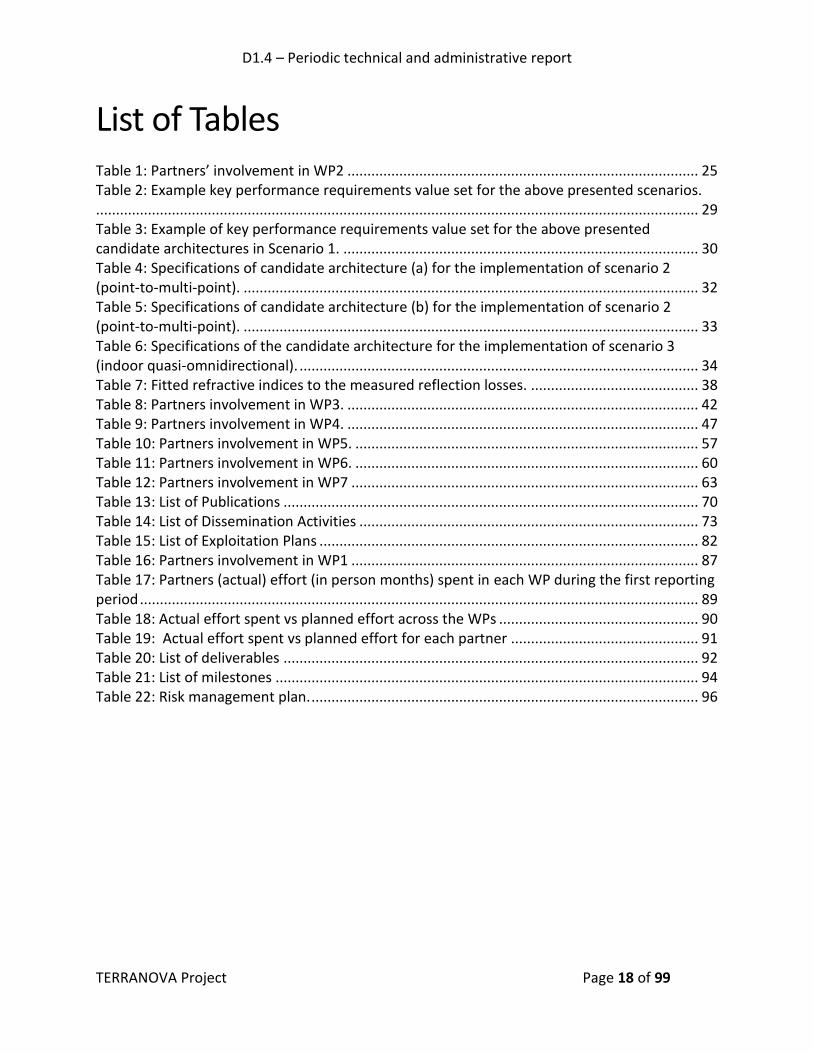
List of Tables Table 1: Partners’ involvement in WP2 ........................................................................................ 25
Table 2: Example key performance requirements value set for the above presented scenarios........................................................................................................................................................ 29
Table 3: Example of key performance requirements value set for the above presented candidate architectures in Scenario 1. ......................................................................................... 30
Table 4: Specifications of candidate architecture (a) for the implementation of scenario 2 (point-to-multi-point). .................................................................................................................. 32
Table 5: Specifications of candidate architecture (b) for the implementation of scenario 2 (point-to-multi-point). .................................................................................................................. 33
Table 6: Specifications of the candidate architecture for the implementation of scenario 3 (indoor quasi-omnidirectional). .................................................................................................... 34
Table 7: Fitted refractive indices to the measured reflection losses. .......................................... 38
Table 8: Partners involvement in WP3. ........................................................................................ 42
Table 9: Partners involvement in WP4. ........................................................................................ 47
Table 10: Partners involvement in WP5. ...................................................................................... 57
Table 11: Partners involvement in WP6. ...................................................................................... 60
Table 12: Partners involvement in WP7 ....................................................................................... 63
Table 13: List of Publications ........................................................................................................ 70
Table 14: List of Dissemination Activities ..................................................................................... 73
Table 15: List of Exploitation Plans ............................................................................................... 82
Table 16: Partners involvement in WP1 ....................................................................................... 87
Table 17: Partners (actual) effort (in person months) spent in each WP during the first reporting period ............................................................................................................................................ 89
Table 18: Actual effort spent vs planned effort across the WPs .................................................. 90
Table 19: Actual effort spent vs planned effort for each partner ............................................... 91
Table 20: List of deliverables ........................................................................................................ 92
Table 21: List of milestones .......................................................................................................... 94
Table 22: Risk management plan. ................................................................................................. 96

D1.4 – Periodic technical and administrative report
TERRANOVA Project Page 19 of 99
Executive Summary The present deliverable, “D1.4 Periodic technical and administrative report,” focuses on reporting the technical achievements as well as the administrative activities that were carried out during the first reporting period (12 months) of the TERRANOVA project. The main technical outcomes of TERRANOVA are highlighted in Sections 2-7, where the objectives, organisation of the work, achievements, outcomes and deliverables of all technical work packages (WPs) are discussed, along with the partners’ involvement as well as the next steps in each work package. In Section 8, the project technical and administrative management activities are outlined, the resources used (partners effort) during this first reporting period are presented, deviations from the planned effort allocation are discussed and an updated risk management plan is provided.
D1.4 – Periodic technical and administrative report
TERRANOVA Project Page 20 of 99
1. INTRODUCTION
Over the last years, the proliferation of wireless devices and the increasing number of high quality emerging wireless services have dramatically raised the demand for spectral bandwidth along with the requirement for high data rate transmission. While the wireless world is moving towards the fifth generation (5G) era and several technological advances have been proposed as promising enablers, such as massive multiple input multiple output (MIMO), full duplexing, and millimetre wave (mmWave) communications, there seem to be significant limitations in the capability to efficiently and flexibly handle the massive amount of data that is expected to be exchanged in the future big-data-driven communication networks, under stringent quality of service (QoS) and quality of experience (QoE) constraints, along with ultra-high data rate and almost-zero latency requirements. As a consequence, wireless terahertz (THz) communications –along with the supporting backhaul network infrastructure- are expected to become one of the most promising technology trends within the next ten years and beyond. Networks beyond 5G are envisioned to provide unprecedented performance excellence, not only by targeting data rates in the Terabit-per-second (Tbps) regime, but also by inherently supporting a large dynamic range of novel usage scenarios and applications, which combine these extreme data rates with agility, reliability, almost-zero response time and artificial intelligence. Virtual presence, 3D printing, cyber physical systems for intelligent transport and industry 4.0 are only a few indicative examples of several highly challenging anticipated use cases. Although 5G seems more than willing to embrace several game-changing design principles, like virtualisation, softwarisation and commoditisation of resources, in order to enhance scalability, flexibility and efficient resources use, it can be easily understood that fundamental performance limitations related to available bandwidth, transmission and processing delay as well as cost and energy consumption still define the envelope of 5G capabilities. In order to break these barriers in networks beyond 5G, it is required to bring little-explored resources and technologies to validation and exploitation, by directing research towards de-risking technological concepts, components, architectures and systems concepts. Innovative joint investigation, assessment and design of theoretical models, aligned and supported by experimental parameter extraction and validation are required for this reason. Motivated by the above, the objective of the project “TERRANOVA - Terabit/s Wireless Connectivity by Terahertz innovative technologies to deliver Optical Network Quality of Experience in Systems beyond 5G” is to provide unprecedented performance excellence, not only by targeting data rates in the Tbps regime, but also by inherently supporting novel usage scenarios and applications, such as virtual reality, virtual office, etc., which combine these ultra-high data rates with agility, reliability and almost-zero response time. Additionally, in the near future, users in both rural and remote regions - in which the access is not easily established (e.g., mountains and islands) - should be able to be connected with high data rates up to 10 Gbps, since it has been proven that access to high-speed internet for all is crucial to guarantee equal opportunities in the global competition. Nowadays, this is either infeasible or prohibitively costly, when using solely optical fibre solutions. As a result, the use of wireless THz links as backhaul extension of the optical fibre is considered an important building block to

D1.4 – Periodic technical and administrative report
TERRANOVA Project Page 21 of 99
bridge the ‘divide’ between rural areas and major cities and ensure high-speed internet access everywhere, in the era beyond 5G. Finally, the increasing number of mobile and fixed end users in both the industry and the service sector will require hundreds of Gbps in the communication to or between cell towers (backhaul) as well as between remote radio heads (RRHs) located at the cell towers and centralized baseband units (fronthaul). In all these beyond 5G usage scenarios, THz communications are expected to play a decisive role and TERRANOVA project aspires to contribute to the definition of the system concept/architecture and fundamental analysis framework, the design and development of enabling technologies, as well as the evaluation and validation of the proposed innovations.

D1.4 – Periodic technical and administrative report
TERRANOVA Project Page 22 of 99
1.1 Scope
This deliverable focuses on reporting the technical and administrative activities that were conducted during the first reporting period of the TERRANOVA project. In more detail, in this deliverable, we review the TERRANOVA project objectives and organisation and we report on the main achievements, during the first 12 months of the project. Moreover, we present the partners’ involvement in each work package and the future work planned for the next reporting period, towards the achievement of the overall project goals and the completion of the project workplan.

D1.4 – Periodic technical and administrative report
TERRANOVA Project Page 23 of 99
2. WP2 - SYSTEM REQUIREMENTS, CONCEPTS AND ARCHITECTURE
This section presents the challenges, objectives, work organisation, outcomes and achievements, as well as our future plans regarding work package 2.
2.1 Challenges
As the design and development of a THz wireless system and baseband interface are still ongoing, it is difficult to state precisely what the final system characteristics would be. Nevertheless, it is already possible to identify the critical technology gaps and the appropriate enablers, which will boost the system utilisation and efficiency. It is also possible to identify key use cases for TERRANOVA and further refine the design of the system in order to take into account the challenges and technology gaps as well as the expected usage scenarios critical parameters and requirements. Currently, themes that pervade multiple features are channel and noise modelling, which will allow the theoretical analysis of the THz link and network as well as the development of physical (PHY) and medium access control (MAC) layers schemes. The transceiver radio frequency (RF) frontend and baseband design is important for matching the data rates of the optical and THz wireless link. Besides, it is expected to be crucial for the increase of the spectral and energy efficiency and for the link distance in order to meet the performance targets of several applications. Given the defined system requirements, TERRANOVA will need to use novel technology concepts, including the joint design of baseband digital signal processing (DSP) for the complete optical and wireless link, the development of broadband and spectrally efficient RF-frontends for frequencies above 275 GHz, as well as channel modelling, waveforms, antenna array and multiple-access schemes design. Finally, specific candidate system architectures need to be identified, corresponding to the three main technical scenarios in TERRANOVA, namely outdoor fixed point-to-point (P2P), outdoor/indoor point-to-multipoint (P2MP), and outdoor/indoor “quasi”-omnidirectional links. From today’s perspective, these candidate architectures are designed in order to provide full support for the identified target key performance indicators (KPIs) in each scenario. However, there are still several aspects and issues that need careful theoretical analysis, algorithm and protocol design, practical implementation and experimental validation to verify their suitability to meet these KPIs. The required actions are being taken during the course of the TERRANOVA project within the framework of the corresponding tasks and WPs.

D1.4 – Periodic technical and administrative report
TERRANOVA Project Page 24 of 99
2.2 WP Objectives Motivated by the above mentioned challenges, the objectives that have been set for WP2, entitled “System Requirements, Concept and Architecture”, are:
• To identify the system requirements, the architecture design and the overall evaluation
framework.
• To determine the system requirements for a wireless THz access based system that
should be integrated with the optical part of the network, i.e., the requirements for co-
designed THz and fibre optical networks.
• To propose a system architecture design, satisfying the identified requirements
specified at the beginning of the project.
• At a later stage in the project, to gather and compile the link- and system-level
simulation results that have been obtained in all WPs (especially WP3 and WP4) for
evaluating the system performance and benchmarking the demonstration and
validation performance in WP6. Furthermore, complementary system simulations will
be conducted to quantify the complete system level performance.
2.3 Work Organisation
WP2 is organised around the following tasks:
Task 2.1-Requirements, which started and finalized in months 1 and 6, respectively. The leader of this task was ALB.
Task 2.2-System architecture, which started and ended in months 2 and 8, respectively. Its leader was FhG.
Task 2.3-System performance, which started in month 9 and will end in month 30. The leader of Task2.3 is UOULU.
Moreover, the following deliverables have been or will be submitted:
• D2.1 - TERRANOVA system requirements (M6/December/2017) (ALB): Completed and
Submitted
• D2.2 - TERRANOVA system architecture (M8/February/2018) (FhG): Completed and
Submitted
• D2.3 - Final report on system level performance evaluation by simulations (M30)
(UOULU)
Figure 1 depicts the Gantt chart for WP2.

D1.4 – Periodic technical and administrative report
TERRANOVA Project Page 25 of 99
Figure 1: WP2 Gantt Chart & effort allocation.
2.4 Partners Involvement Table 1 briefly summarizes the partners’ involvement in each of the tasks of WP2.
Table 1: Partners’ involvement in WP2
Partner Task Short description
ALB ALB is the leader of WP2 and the Task2.1
Task 2.1 Identification of TERRANOVA use cases that are used to identify requirements, both in terms of functionality and performance that the system must support.
Description of the preliminary network architecture.
Specification of the technical scenarios that correspond to the application use cases as well as their key performance requirements.
FhG FhG is the leader of Task2.2.
Task 2.1 Main contributions on the network architecture and on the system requirements.
Definition of the network elements of the envisioned TERRANOVA system.
Task 2.3 Evaluate end-to-end metrics to see effectiveness of the TERRANOVA co-designed networks.
UOULU UOULU is the leader of Task2.3.
Task 2.1 Contributions on the network architecture and on the system requirements.
Task 2.3 Complement and support the hardware/testbed oriented work in WPs 5 and 6 by providing performance benchmarks.
ICOM Task 2.1 Contributions on the network architecture and on the system requirements.
Review of D2.1
Task 2.2 Description of wireless reference system architectures
2017 2020
Today
JUL OCT DEC FEB 2018
D2.1 - TERRANOVA system requirements(M6/December/2017) >> Closed12/29/2017
D2.2 - TERRANOVA system architecture (M8/February/2018) >> Closed2/28/2018
D2.3 - Final report on system level performance evaluation by simulations (M30)
12/31/2019
M1-M6, TL: ALBTask 2.1 - Requirements
M2-M8 , TL FhGTask 2.2 - System architecture
M9-M30, TL:
UOULUTask 2.3 - System Performence evalution by simulation
JANNOV MAR MAYAPR JUN JUL SEPAUG OCT DECNOV
JUN
Lead JCP-C FHG ICOM UOulu UPRC ALB PIC Total PMs
WP2 System Requirements, Concept and Architecture ALB 1,0 7,0 4,0 7,0 4,0 6,0 4,0 33,0
Task 2.1 Requirements >> Closed ALB 3,0 2,0 2,0 1,0 3,0 2,0 13,0
Task 2.2 System architecture >> Closed FHG 1,0 3,0 2,0 1,0 1,0 3,0 2,0 13,0
Task 2.3 System performance evaluation by simulations OuO - 1,0 - 4,0 2,0 - - 7,0
2019

D1.4 – Periodic technical and administrative report
TERRANOVA Project Page 26 of 99
Description of beamforming subsystems
Contribution on candidate architectures
Review of D2.2
UPRC Task 2.1 Identification of TERRANOVA use cases that are used to specify requirements, both in terms of functionality and performance that the system must support.
Specification of the technical scenarios that correspond to the application use cases as well as their key performance requirements.
Task 2.3 Collect and unify system performance simulations done in other WPs (especially in WP3 and WP4).
Evaluate simulations for the representative set of test scenarios under realistic modelling assumptions.
JCP-C Task 2.1 Requirements investigation for mac interfaces and caching system for TERRANOVA system
Task 2.2 Proposed the first caching and meta-MAC architecture and functional components
PIC Task 2.1 Revision on the network architecture and on the system requirements.
All Partners Task 2.2 Definition of the applicable use cases and key requirements
Definition of a high-level network architecture
Definition of the System requirements (based on the key use cases and relevant input parameters from simulations)
2.5 Outcomes and Achievements In this section, we present the main achievements, challenges and outcomes of the work performed during the first year of the project within the framework of WP2 tasks.
2.5.1 Task 2.1 - System Requirements
TERRANOVA consortium defined two main group use cases for the future TERRANOVA system concept, namely:
Backhaul & Fronthaul; and
Mobile & Fixed Wireless Access. Within each use case, several applications were identified as the most promising candidates for the TERRANOVA system applications. As illustrated in Figure 2, for the Backhaul & Fronthaul use case, the fibre extender, P2P and redundancy scenarios were considered, while for the Mobile & Fixed Wireless Access, the Corporate Backup Connection, IoT dense environments, Data Centres, Indoor short range, Ad-hoc Access and Last Mile and Open Space Events scenarios were taken into account.

D1.4 – Periodic technical and administrative report
TERRANOVA Project Page 27 of 99
Figure 2: Application use case classification.
In the context of the above use cases, the general network architecture was defined, as depicted in Figure 3.
Figure 3: General network architecture.
In TERRANOVA, we envision that a heterogeneous highly-flexible optical-wireless network architecture becomes an enabler of ultra-fast (in the order of 1 Tbps) beyond 5G networks, where it will be critical to efficiently and flexibly handle the massive amount of QoS/QoE-oriented data that will be exchanged in the future big-data-driven networks, along with the ultra-high data rate and almost zero latency requirements. As a result, wireless Tbps communications and the supporting backhaul network infrastructure are expected to become the main technology trend within the next ten years and beyond.

D1.4 – Periodic technical and administrative report
TERRANOVA Project Page 28 of 99
In order to satisfy the TERRANOVA use cases requirements, in the radio access network, a combination and integration of new concepts with existing technology enablers as well as key technology modules was anticipated, having the fibre extender/P2P use case as reference. For the optical transport, TERRANOVA explores passive optical network (PON) transceivers. PONs have been considered as an effective solution for access networks, since they are able to provide huge bandwidth in a cost effective manner. Current PONs need further evolution in order to achieve the 1 Tbps goal. Therefore, NG-PON2 transceivers, which uses wavelength division multiplexing (WDM) enabling multiple 10 Gbps signals, seems to be an attractive solution in order to deal with the intense telecommunication traffic, expected to characterise systems beyond 5G.
Figure 4: Schematic depiction of optical-wireless systems for replacement of fibre link by a
wireless THz link (upper part) and an example for an optical-wireless system with optical RF-frontend based on state-of-the-art 100GBase-LR4 QSFP 28 transponder modules (lower part).
Related to the link performance requirements derived from the relevant use case scenarios for the co-designed THz and fibre-optical network, the relevant key performance indicators are [with ideal performance in brackets]:
Aggregate throughput of wireless access for any traffic load/pattern [Tbps]
Throughput of the point-to-point ‘fibre optic - THz wireless’ link [Tbps]
Link latency of the ‘fibre optic - THz wireless’ [‘zero’ latency]
Range of the ‘fibre optic - THz wireless’ link [tens of km optical, 1 km THz wireless]
Reliable communications [probability of achieving a target bit error rate (BER) and
packet error rate (PER)]
Availability [‘Always’ available connectivity of ‘infinite’ number of devices]
Additionally to the above KPIs, energy efficiency, measured in terms of energy per information bit, will also be crucial to the success of the THz networks implementation (this is even more critical for mobile equipment).

D1.4 – Periodic technical and administrative report
TERRANOVA Project Page 29 of 99
For deterministic performance measurement definitions and according to the previously defined use cases, the following key performance requirement scenarios were also defined:
Scenario 1: Outdoor fixed P2P
Scenario 2: Outdoor/indoor P2MP
Scenario 3: Indoor/outdoor “quasi”-omnidirectional The performance requirements for these scenarios are summarized in Table 2.
Table 2: Example key performance requirements value set for the above presented scenarios.
KPI Scenario 1 Scenario 2 Scenario 3
Max. THz link latency 1 ms 1 ms 1 ms
Max. THz link range 1000 m 1000 m 10 m
Max. optical link range 50 km 10 km 1 km
Number of connections per THz node 1 10 100
Max. THz link throughput x range 1000 Gbps x 1000 m
100 Gbps x 1000 m
10 Gbps x 10 m
Max. THz link throughput x connections (= aggregate throughput)
1000 Gbps x 1 connection
100 Gbps x 10 connections
10 Gbps x 100 connections
Target BER ~10-12 Application dependent
Application dependent
Availability Critical Critical Application dependent
In order to access and simulate the performance requirements within the different scenarios, a rough estimation of the performance of a reference THz link is instructive. The reference link was defined as follows:
Point-to-point LOS, single beam, single in-phase and quadrature (I/Q);
Ideal transmitter, limited by output power;
Ideal channel, only limited by loss;
Ideal receiver, limited by additive white Gaussian noise (AWGN) thermal noise floor;
M-quadrature amplitude modulation (QAM) and demodulation.
This reference link is based on the classic AWGN channel model, which allows for the estimation of upper bounds on the THz link capacity and range as a function of basic component and link parameters. While this simplification neglects many known impairments, such as phase noise, bandwidth limitations and nonlinearities, we assume that the use of digital impairments compensation and mitigation algorithms can efficiently idealize a real THz link, so that the calculated upper bounds are still close enough to what will be achievable in reality.
2.5.2 Task 2.2 - System Architecture
In this task TERRANOVA partners agreed on the candidate architectures for implementation of each of the relevant TERRANOVA scenarios as defined in deliverable D2.1.

D1.4 – Periodic technical and administrative report
TERRANOVA Project Page 30 of 99
For “Scenario 1: P2P”, two candidate architectures were defined. The main research aspect of these architectures is the realization of a combined optical/THz link providing transparency for the signals on the physical layer without digital signal processing at optical/THz interface. For both architectures, a full-duplex symmetric link type is assumed, as well as the use of a single frequency window at 220 GHz – 300 GHz. In Figure 5, candidate (a) follows the transparent optical link architecture while candidate (b) follows the digital optical link architecture with analogue media converter. An indicative example of key performance requirements value set is provided in Table 3.
Figure 5: Candidate architectures for the implementation of scenario 1 (P2P).
Table 3: Example of key performance requirements value set for the above presented candidate architectures in Scenario 1.
Candidate architecture (a) Candidate architecture (b)
Link type Line of sight (LOS), Full duplex (FD), symmetric
LOS, FD, symmetric
Duplex implementation Frequency Polarization or frequency
Expected throughput Up to 1 Tbps FD Up to 200 Gbps FD
Used frequency window 220 GHz – 300 GHz 220 GHz – 300 GHz
Optical channel Standard single mode fibre (SSMF)
SSMF
Optical transceiver CFP2-ACO XFP
Optical modulation Single-carrier PDM-QAM N x NRZ
THz modulation Single-carrier PDM-QAM and multi-carrier schemes (OFDM)
4-PAM
Media converter type Not required
Analog MUX: 1:N/2 TDM rate conversion NRZ-to-PAM4 conversion
L2 switch L2 switch
CFP2ACO
CFP2 ACO
L2 switch L2 switch
N ×XFP
MUXDEMUX
DSP DAC
ADC
ADC
DAC DSP
CFP2 ACO
CFP2 ACO
MUXDEMUX
THz frontend THz frontend
THz frontend THz frontend
N ×XFP
N ×XFP
N ×XFP
(a)
(b)
D1.4 – Periodic technical and administrative report
TERRANOVA Project Page 31 of 99
THz RF frontend type Double I/Q DSB AM + Envelope detection
THz RF frontend bandwidth
40 GHz 80 GHz
THz antenna 2 polarizations (for polarization multiplexing)
2 polarization in case of polarization duplexing; 1 polarization in case of frequency duplexing
Beam forming type High gain
Dynamic beam steering Small angle
Due to the fixed position, there is low beam steering requirements.
Dynamic user equipment (UE) detection
Not required
Spatial synchronization Required
Network Caching Required to reduce latency
PHY Caching Not required
CoMP Not required
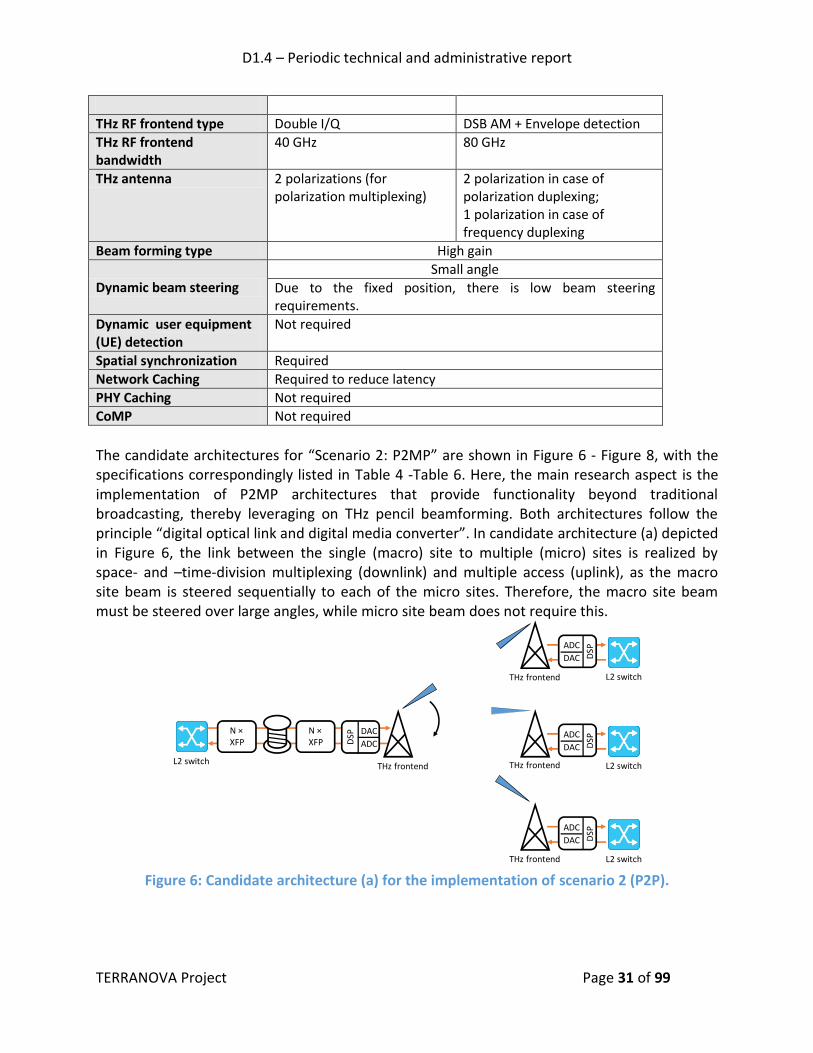
The candidate architectures for “Scenario 2: P2MP” are shown in Figure 6 - Figure 8, with the specifications correspondingly listed in Table 4 -Table 6. Here, the main research aspect is the implementation of P2MP architectures that provide functionality beyond traditional broadcasting, thereby leveraging on THz pencil beamforming. Both architectures follow the principle “digital optical link and digital media converter”. In candidate architecture (a) depicted in Figure 6, the link between the single (macro) site to multiple (micro) sites is realized by space- and –time-division multiplexing (downlink) and multiple access (uplink), as the macro site beam is steered sequentially to each of the micro sites. Therefore, the macro site beam must be steered over large angles, while micro site beam does not require this.
Figure 6: Candidate architecture (a) for the implementation of scenario 2 (P2P).
L2 switch
L2 switch
L2 switch
L2 switch
DSP DAC
ADC
THz frontend
THz frontend
THz frontend
THz frontend
ADC
DAC DSP
ADC
DAC DSP
ADC
DAC DSP
N ×XFP
N ×XFP

D1.4 – Periodic technical and administrative report
TERRANOVA Project Page 32 of 99
Table 4: Specifications of candidate architecture (a) for the implementation of scenario 2 (point-to-multi-point).
Candidate architecture (a)
Link type LOS, symmetric FD (per time slot)
Duplex implementation Frequency
Used frequency window 220 GHz – 300 GHz
Multi-user access Space and time-division multiple access
Optical channel SSMF
Optical transceiver XFP
Optical modulation N x NRZ
Media converter type Digital (DSP + DAC/ADC)
Downlink Uplink
Expected throughput Up to 500 Gbps (e.g. 38-GBd PDM-256-QAM single carrier)
Up to 500 Gbps shared by N users (e.g., 38-GBd PDM-256-QAM single carrier)
THz frontend type Double I/Q
THz frontend bandwidth 40 GHz
THz antenna 2 Polarizations (for polarization multiplexing)
Beam forming type High gain, space-division multiple access
Dynamic beam steering Large angle Small angle
Dynamic UE discovery Fast and accurate with low discovery overhead.
-
Spatial synchronization Required
Network Caching Required to reduce latency
PHY Caching Required to manage mobility and handovers
CoMP Required to manage mobility and handovers
Alternatively, the downlink can be realized by using spatial multiplexing only (candidate architecture b in Figure 7), where multiple fixed beams are employed to simultaneously transmit traffic to every micro site. This option increases significantly the throughput per link (per user), but it also increases the hardware complexity (antennas, RF chains, etc.), in order to support multiple beams that are associated to multiple data streams.

D1.4 – Periodic technical and administrative report
TERRANOVA Project Page 33 of 99
Figure 7: Candidate architecture (b) for the implementation of scenario 2 (P2MP).
Table 5: Specifications of candidate architecture (b) for the implementation of scenario 2 (point-to-multi-point).
Candidate architecture (b)
Link type LOS, symmetric (in terms of throughput per link)
Duplex implementation Frequency
Used frequency window 220 GHz – 300 GHz
Multi-user access STMA
Optical channel SSMF
Optical transceiver XFP
Optical modulation N x NRZ
Media converter type Digital (DSP + DAC/ADC)
Downlink Uplink
Expected throughput Up to 500 Gbps per link (e.g., 38-GBd PDM-256-QAM single carrier)
Up to 500 Gbps per link (e.g., 38-GBd PDM-256-QAM single carrier)
THz frontend type Double I/Q
THz frontend bandwidth (RF)
40 GHz
THz antenna 2 Polarizations (for polarization multiplex)
Beam forming type High gain, SDMA
Dynamic beam steering Large angle Small angle
Dynamic UE discovery Fast and accurate with low discovery overhead.
-
Spatial synchronization Required
Network Caching Required to reduce latency
PHY Caching Required to manage mobility and handovers
L2 switch
L2 switch
L2 switch
L2 switch
DSP DAC
ADC
THz frontend
THz frontend
THz frontend
THz frontend
ADC
DAC DSP
ADC
DAC DSP
ADC
DAC DSP
N ×XFP
N ×XFP
D1.4 – Periodic technical and administrative report
TERRANOVA Project Page 34 of 99
Dynamic UE discovery Fast and accurate with low discovery overhead
Spatial synchronization Required
Network Caching Required to reduce latency
-
PHY Caching Required to manage mobility and handovers
CoMP Required to manage mobility and handovers
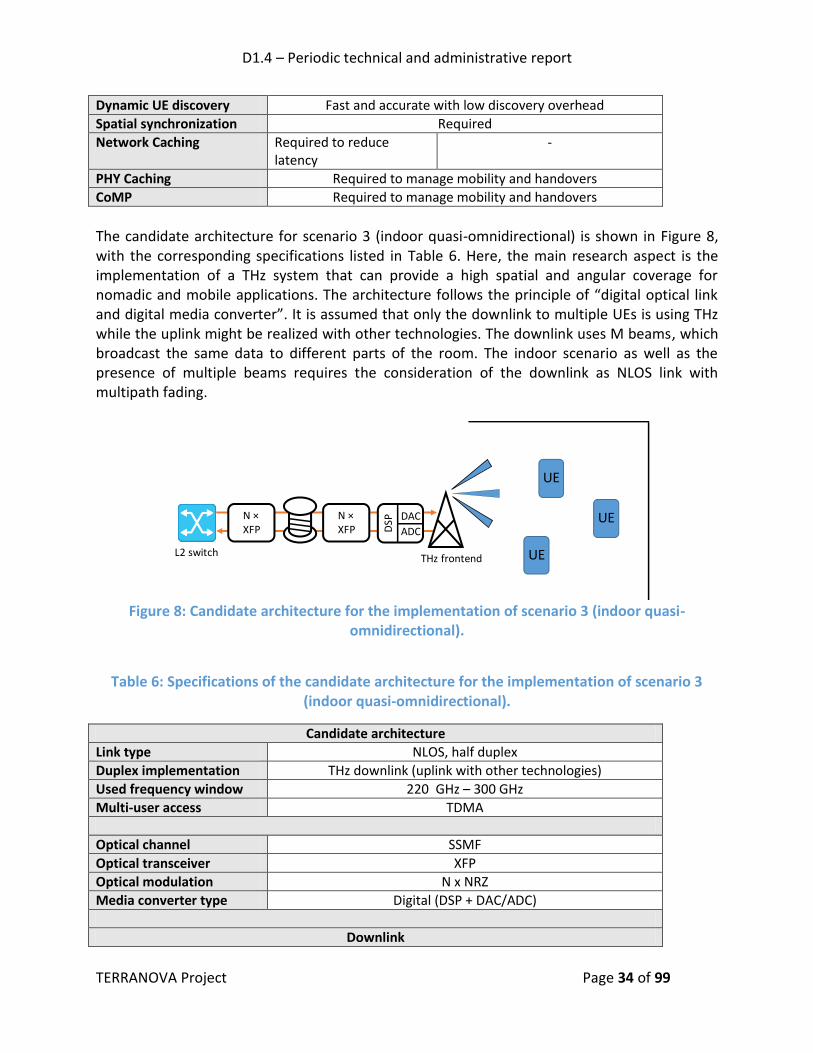
The candidate architecture for scenario 3 (indoor quasi-omnidirectional) is shown in Figure 8, with the corresponding specifications listed in Table 6. Here, the main research aspect is the implementation of a THz system that can provide a high spatial and angular coverage for nomadic and mobile applications. The architecture follows the principle of “digital optical link and digital media converter”. It is assumed that only the downlink to multiple UEs is using THz while the uplink might be realized with other technologies. The downlink uses M beams, which broadcast the same data to different parts of the room. The indoor scenario as well as the presence of multiple beams requires the consideration of the downlink as NLOS link with multipath fading.
Figure 8: Candidate architecture for the implementation of scenario 3 (indoor quasi-
omnidirectional).
Table 6: Specifications of the candidate architecture for the implementation of scenario 3 (indoor quasi-omnidirectional).
Candidate architecture
Link type NLOS, half duplex
Duplex implementation THz downlink (uplink with other technologies)
Used frequency window 220 GHz – 300 GHz
Multi-user access TDMA
Optical channel SSMF
Optical transceiver XFP
Optical modulation N x NRZ
Media converter type Digital (DSP + DAC/ADC)
Downlink
L2 switch
DSP DAC
ADC
THz frontend
N ×XFP
N ×XFP
UE
UE
UE

D1.4 – Periodic technical and administrative report
TERRANOVA Project Page 35 of 99
Expected throughput Up to 400 Gbps shared by multiple users (e.g. 64-GBd 256QAM single carrier)
THz frontend type I/Q
THz frontend bandwidth (RF)
80 GHz
THz antenna M antennas for multiple indoor beams
Beam forming type High opening angle for high coverage
Dynamic beam steering Not required
Network Caching Required to reduce latency
PHY Caching Required to manage mobility and handovers
Dynamic UE discovery Fast and accurate with low discovery overhead.
Spatial synchronization Not required
CoMP Required to ensure coverage
2.6 Future Work
2.6.1 Task 2.3 - System Performance Evaluation by Simulations
Accurate performance evaluation is critical to confirm the success of the TERRANOVA proposed concepts and algorithms. Towards this direction, this task collects and unifies system performance simulations done in other WPs (especially in WP3 and WP4). Simulations are carried out for a representative set of test scenarios under realistic modelling assumptions (such as using the TERRANOVA accurate channel model derived in T3.1) and with carefully selected performance metrics (such as end-to-end metrics to see effectiveness of the TERRANOVA co-designed networks). This work complements and supports the hardware/testbed oriented work in WPs 5 and 6 by providing performance benchmarks.
Simulation work is ongoing in WP4 and will be later continued in WP2 where all the simulation results are collected.
3. WP3 - THZ WIRELESS LINK DESIGN
3.1 WP Objectives
The WP3 objectives have been set as follows:
To develop theoretical THz propagation models with experimental verification;
To design THz channel models with statistical and deterministic components;
To extend the short-range channel models to larger range by theoretical modelling;
To find an accurate model for the open issue of self-induced molecular noise, potentially present in THz systems;

D1.4 – Periodic technical and administrative report
TERRANOVA Project Page 36 of 99
To identify the requirements (for hardware and software) for efficient pencil-beamforming algorithms especially for device tracking in the THz regime and design practical device tracking and position algorithms, and
To design analytical models for theoretically estimating the capacity bounds for the link and network level THz communication.
3.2 Work Organisation
Figure 9: WP3 Gantt Chart & effort allocation.
To achieve these objectives, the involved partners, i.e., UPRC, UOULU, FhG and ICOM divided the work load into three (3) tasks as follows:
Task 3.1-Channel and propagation modelling and characterization (led by UOULU);
Task 3.2-Pencil Beam-forming and Device Tracking (led by UOULU); and
Task 3.3-THz Network Information Theory (led by UPRC). The detailed workplan, work structure, deliverables and partners’ efforts is WP3 is depicted in Figure 9.
3.3 Outcomes, Achievements and Workplan for the Remaining Period In this section, we present the main achievements and outcomes of the work performed during the first year of the project within the framework of WP3 tasks, along with the immediate workplan for the remaining period (up to M18).
3.3.1 Task 3.1: Channel and Propagation Modelling and Characterization
The aim of Task 3.1 is to develop novel channel models for the THz band applications considered in TERRANOVA. Those include long and short distance link channel models, and non-line of sight (NLOS) channel models. The general line of sight (LOS) link for any distance has been modelled theoretically. The NLOS links rely on conducted channel measurements that gave parameters for the reflection and scattering models. The NLOS paths also give an opportunity to theoretically model the multipath propagation. The measurement results and the consequent NLOS channel models, as well as the LOS models were utilised in ray-tracing

D1.4 – Periodic technical and administrative report
TERRANOVA Project Page 37 of 99
based simulation model to study the signal propagation in realistic environment. Furthermore, an additional simulation model for random environments was developed that can be utilised to study the signal propagation in the presence of random and deterministic objects. The main focus of the channel modelling is on frequencies below 1 THz, but since the tools and methods allow more general channel modelling, most of the results have been derived for the full THz band (0.1 – 10 THz). The final results will be reported in D3.2 in M14. The main results of Task 3.1 by the end of M12 are as follows:
A simplified channel model for the frequency range 200 – 450 GHz has been derived. This focuses on modelling the complex molecular absorption loss (see Figure 10) by simple polynomials without sacrificing the accuracy in comparison to more complicated database-based approaches. As a side-product, the simplified channel model also produced a transmission window bandwidth estimate as a function of the transmission distance for the frequency range 200 – 400 GHz.
Measurements for various common indoor materials have been conducted. The measurements gave the refractive indices of the materials (see example materials in Table 7) as well as the parameters required for modelling the scattering on the materials.
A generic channel model suitable for any location or altitude was derived. This model takes into account the altitude and location dependent atmospheric temperature, pressure, molecular composition, and their relationship to the absorption loss. The model is dynamic and is suitable for modelling links from any altitude to any altitude. Therefore, it accurately describes the LOS signal in all conditions. Possible rain and fog or cloud attenuations can be included.
A ray-tracing model was developed based on the derived NLOS models as well as the LOS models. This provided a tool to study multipath signal modelling with various antenna and Tx-Rx configurations.
A geometric simulation model was developed to study the signal behaviour in the presence of random and deterministic objects. This model will be further used to study large and small scale fading in the future.

D1.4 – Periodic technical and administrative report
TERRANOVA Project Page 38 of 99
Figure 10: Molecular absorption loss at various distances for the lower THz band.
Table 7: Fitted refractive indices to the measured reflection losses.
MATERIAL 300 GHz 1000 GHz
Concrete 2.1 1.8
MDF, painted 2.4 1.4
MDF, plaster 1.65 1.5
MDF, laminated 2.9 1.7
Floor, rubber 1.85 1.45
Glass 2.85 2.3
Metal N/A N/A
In the remaining period, we intend to:
perform more measurements on different materials to extend the available set of material parameters;
finalize the analysis on the generic theoretical LOS channel model and its applications;
continue to fine-tune the channel models for the large and small scale fading research.
3.3.2 Task 3.2: Pencil Beam-forming and Device Tracking
This task focuses on beamforming, effects of phase noise on beamforming performance, channel estimation, device discovery (finding out that a device is present), beam discovery (finding out the proper beamforming direction to use), and fast beam tracking (keeping track of
D1.4 – Periodic technical and administrative report
TERRANOVA Project Page 39 of 99
proper beamforming direction when movement/rotation is present in at least in one end) for realizing Tbps wireless connectivity. The work started with a literature survey on beamforming, beam discovery and beam tracking, especially on mmWave band since many papers have been written for mmWave but only few for the THz band (lower THz band belongs also to mmWave band). Later this survey was extended and included in the deliverable D3.1. Therein, different beamforming architectures were presented, and their benefits and drawbacks were demonstrated. Beam discovery methods avoiding exhaustive full search were discussed. Beam tracking methods reducing the search space were also discussed. Based on the literature survey and our views on the development of future THz technology, hybrid beamforming with the array-of-subarrays architecture at THz was selected as our reference system. Results from Task 3.2 work were reported in month 10 in D3.1. This is the initial version of the deliverable and final results will be included in D3.3 in month 18. The main results of Task 3.2 included in D3.1 are summarized below:
Literature survey on beamforming, beam discovery and beam tracking;
Selection of reference architecture, i.e., array-of-subarrays;
A simple phase noise model with correlation factor was presented.
The performance of beamforming was assessed as a function of the number of antenna elements. Beamforming results were presented for various beam directions, where the half power beamwidth was evaluated.
The effects of phase noise were considered, for which the metrics including main lobe gain, error in beam pointing direction, and side lobe gain were presented.
A channel estimation algorithm for supporting beamforming was presented.
A fast tracking method was presented, and results were provided for both linear and crooked user movement.
Device discovery results were presented considering a log likelihood detector. Results were extracted as a function of the detection threshold.
In the remaining period, the goals are summarized as follows:
It has been concluded that in order to achieve pencil beamforming, the number of antenna elements of the array and their positioning in space should be properly selected. To this end, we plan to conduct an analysis to derive the optimal configuration of the antenna array.
It has been inferred that very wideband beamforming cannot be implemented simply by phase shifters, because the main beam direction varies with frequency. Thus, other

D1.4 – Periodic technical and administrative report
TERRANOVA Project Page 40 of 99
techniques, such as time alignment of signals or subband beamforming, will be studied for utilisation in these cases.
We intend to perform a more accurate performance analysis taking into account imperfections, non-linearities, and more detailed phase noise models.
We intend to investigate beamwidth adaptive tracking algorithms to optimize the performance complexity trade-off.
We will investigate the effect of misalignment (for example resulting from the phase noise in the phase shifters or other sources) and fading in the different UE discovery approaches.
We intend to find results for 2-stage user UE discovery approaches.
We will implement advanced detection techniques.
3.3.3 Task 3.3: THz Network Information Theory
Concerning Task 3.3, until M12, we have:
evaluated the performance of wireless THz systems, in which the particularities of the THz channel have been considered for different propagation scenarios;
quantified the impact of hardware imperfections in the THz systems that employ digital beamforming, and derived the links’ capacity bounds that depend on the level of hardware imperfections;
capitalised the performance metrics and presented an adaptive modulation and coding scheme;
performed a literature review of small scale fading in THz communications; and
obtained the signal to interference plus noise ratio (SINR) of a network using tools from stochastic geometry.
Next, we present indicative results of our work in Task 3.3. We quantitatively compare the effectiveness of the THz link in terms of capacity, assuming different atmospheric conditions, and normalized to noise effective radiated power equal to 100 dB, assuming flat transmission signal PSD, bandwidth of 125 GHz and distance of 100 m between transmitter and receiver (Figure 11). As expected, for a fixed temperature, as the relative humidity increases, the channel capacity decreases. For example, for a temperature equal to 25oC, a 10% capacity degradation occurs, as the relative humidity alters from 60% to 90%. Moreover, for a given relative humidity, as the temperature increases, the capacity decreases. For instance, for a relative humidity equal to 50%, the capacity decreases for about 53.91%, as the temperature increases from 20 to 50oC. This reveals that the impact of

D1.4 – Periodic technical and administrative report
TERRANOVA Project Page 41 of 99
temperature variation in the THz link performance are more severe compared with that of humidity variations.
Figure 11: Capacity as a function of the temperature and the relative humidity.
Next, we provide simulation results for the proposed distance and bandwidth dependent adaptive modulation scheme, which is suitable for communication systems operating in the THz band. In more detail, after determining the transmission bandwidth, the proposed scheme evaluates the subcarrier bandwidth of the orthogonal frequency division modulated (OFDM) transmission signal, in order to countermeasure the frequency selectivity of the THz channel. The power is allocated to the OFDM subcarriers and the modulation order of the quadrature modulated (QAM) symbol loaded in each subcarrier is selected, based on the instantaneous channel conditions and a predetermined bit error rate (BER), Pb, requirement. The proposed link adaptation algorithm has low computational complexity and can significantly increase the link’s throughput. In this sense, Figure 12 depicts the achievable data rate as a function of the transmission distance, for different Pb and tolerance of the absorption loss deviation, γ, requirements. As a benchmark, the corresponding achievable rate for the case in which, instead of the adaptive modulation scheme, BPSK is employed, and γ = 0.1 dB, is plotted (blue colored lines). As expected, for a given Pb and γ, as transmission distance increases, the available bandwidth decreases; hence, the data rate also decreases. For instance, for Pb = 10−5 and γ = 0.1 dB, the data rate decreases from 100 Gbps to 1.2 Gbps, as the distance alters from 0.1 to 10 m. Moreover, for given transmission distance and BER requirements, as γ increases, i.e., as the frequency flatness requirement gets relaxed, the available bandwidth and the number of subcarriers increases; therefore, the data rate also increases.

D1.4 – Periodic technical and administrative report
TERRANOVA Project Page 42 of 99
Figure 12: Achievable data rate as a function of the transmission distance, for different values of Pb and γ = 0.1 dB (black colored lines), and γ = 1 dB (red colored lines). With blue color, we illustrate the achievable data rate when no modulation adaptation (only BPSK) is employed.
In the remaining period, we intend to:
investigate the impact of of receiver (Rx) and transmitter (Tx) misalignment in THz communications and derive closed-form performance metrics;
study the joint impact of small scale fading and phase noise;
derive bounds of the link capacity and coverage probability; and
extend our analysis to multi-hop THz communication systems.
3.4 Partners Involvement
The following table briefly summarizes the partners’ involvement in each task of WP3.
Table 8: Partners involvement in WP3.
Partner Task Short description
UOULU UOULU is the leader of WP3, Task3.1 and Task3.2.
Task3.1 Simple and accurate channel model for THz links
Measurements of material properties for reflection and scattering
Channel model suitable for any location and any altitude

D1.4 – Periodic technical and administrative report
TERRANOVA Project Page 43 of 99
Ray-tracing based modelling using parameters values obtained using real measurements
Simulator including both deterministic (e.g. walls) and random (e.g. obstacles) components
Task3.2 Literature survey
Selection of reference method
Effects of phase noise on main lobe gain, beam pointing direction, and side lobe gain
Channel estimation supporting beamforming
Task3.3 Stochastic geometry-based SINR evaluations.
UPRC UPRC is the leader of Task3.3.
Task 3.1 Novel two path channel model
Task3.2 Fast tracking method evaluation
Device discovery performance analysis
Modelling of amplifier non-linearities and I/Q imbalance
Contribution on D3.1
Task3.3 Evaluated the performance of wireless THz systems, in which the particularities of the THz channel are considered, for different propagation scenarios
Derived the links capacity bounds that depends on the level of hardware imperfections
Capitalised the performance metrics and presented an adaptive modulation and coding scheme
ICOM Task3.2 Contribution on the literature survey regarding beamforming
Evaluation of different beamforming architectures
Evaluation of beamforming with different number of antenna elements and different beam pointing
Effect of beamforming with phase shifting in wideband transmission
Review of D3.1
FhG Task 3.2 Contributions to phase noise modelling
Contributions to modelling power consumption of an array
Review of D3.1
4. WP4 - THZ WIRELESS ACCESS AND RESOURCE MANAGEMENT
4.1 Challenges
Due to the fundamental characteristics of the THz systems, it is evident that the propagation environment suffers from sparse-scattering. This causes to the majority of the channel direction of arrivals (DoAs) below noise floor figures. As a consequence, in order to achieve sufficient coverage, a channel in a wireless THz system can be established in a specific direction with a

D1.4 – Periodic technical and administrative report
TERRANOVA Project Page 44 of 99
range that varies according to the directionality level. However, the directionality of wireless THz channels results in two consequences, namely:
Blockage, which refers to the high penetration loss, due to obstacles and cannot be solved by just increasing the transmission power.
Deafness, which refers to the situation, in which the main beams of the transmitter and the receiver are not aligned to each other. This prevents the establishment of the communication link.
Moreover, in order to countermeasure the physical limitations of wireless THz systems, the MAC mechanisms may simultaneously exploit both the microwave and THz bands. In this scenario, MAC mechanisms may need to facilitate the co-existence of several communication technologies with different coverage. As a consequence, two different types of heterogeneity are observed in wireless THz networks, namely:
Spectrum heterogeneity that refers to scenarios in which wireless THz UEs use both high (THz) and lower frequencies (e.g., in the microwave band). On the one hand, THz frequencies provide a massive amount of bandwidth for high data rate communications. On the other hand, the microwave frequencies are used for control message exchange, which demands much lower data rates, but higher reliability than data communications. This facilitates the deployment of wireless THz networks, due to possible omnidirectional transmission/reception of control messages, as well as higher link stability, at lower frequencies. However, the use of both microwave and THz bands in UEs increases the fabrication cost and may result to an important reduction of the mobile UE (MUE) energy autonomy. Moreover, due to the blockage and deafness effects, the establishment of a microwave control channel (CCH) might not (necessarily also) result in establishing the corresponding THz data transmission channel.
Deployment heterogeneity, which introduces two scenarios for THz networks, namely stand-alone and integrated networks. In the stand-alone scenario, a complete THz network (from macro to pico-levels) will be deployed, whereas the integrated network solution is an amendment to existing microwave networks for performance enhancement, and includes wireless THz small cells and/or THz hotspots.
4.2 WP Objectives
Motivated by the above challenges, the objectives that have been set for WP4, entitled “THz wireless access and resource management”, are:
To identify, explore and design key hybrid multi-user/device MAC protocols for THz communication systems;
To evaluate the effectiveness of already presented discovery algorithms and develop new ones in order to address the massive amount of devices as well as the THz channel particularities;
To present mobility management schemes that take into account the user’s movement;

D1.4 – Periodic technical and administrative report
TERRANOVA Project Page 45 of 99
To utilise a new “meta-MAC” protocol that operates on top of all TERRANOVA MAC protocols;
To design novel approaches in optimization theory and machine learning for achieving optimal single-/multi-hop system performance; and
To develop a new highly adaptable framework for overall optimal resource allocation and management in THz communication systems.
4.3 Work Organisation
Figure 13: WP4 Gantt Chart & effort allocation.
To achieve these objectives, the involved partners, i.e., UPRC, JCP-C, UOULU, FhG and ALB, divided the work load into three (3) tasks as follows:
Task4.1-THz MAC layer design;
Task4.2-Caching placement study; and
Task4.3-Overall resource management. The objectives of Task4.1, which started in M1, will end in M24 and involves UPRC, JCP-C, UOULU as well as FhG, are:
To develop receiver-initiated transmission schemes to guarantee alignment between the transmitter and the receiver.
To design device discovery algorithms, which address the massive amount of devices and the other THz communication characteristics.
To exploit fast-steerable narrow beams and develop stochastic models for multi-user/device interference that will assist the design of new MAC protocols.
To derive medium access and hybrid multi-user/device multiplexing methods and algorithms, by leveraging the latest developments in optimisation theory, such as machine learning. Of note these methods are expected to cope with the absence of an omnidirectional broadcast channel and distance-dependent bandwidth.
To utilise a “meta-MAC” protocol, which optimally combine their individual transmission decisions into a final decision.

D1.4 – Periodic technical and administrative report
TERRANOVA Project Page 46 of 99
Likewise, the objectives of Task4.2, which started in M6, will end in M25 and involves JCP-C as well as UPRC, are:
To design a socially-aware caching mechanism that leverages the knowledge from a social abstract graph and from the underlying THz-PHY parameters (SNIR, transmission power, PHY data rate, carrier sense range).
To develop a multi-cell content pre-fetching that takes into account content popularity and users’ mobility patterns to pre-fetch content in neighbouring cells in order to improve latency and control.
Finally, the objectives of Task4.3, which started in M6, will end in M28 and involves UPRC, JCP-C, UOULU as well as ALB, are:
To redefine the conventional network resources allocation approaches in order to guarantee user/device QoS/QOE and overall system performance in the super-wideband transmissions with pencil-beam antennas in THz systems.
To determine the number of ultrahigh-speed links that can be simultaneously and efficiently supported in the THz band.
To develop algorithms for dynamically and efficiently allocating spectral and spatial resources to users/devices in various time-scales, in order to guarantee differentiated QoS/QoE across multiple served users/devices, by leveraging the latest developments in optimisation theory.
To propose a highly adaptable framework for optimal resource management, combining various resource allocation techniques, in a distance-aware bandwidth-adaptive manner for multi-user/device highly densified THz band communication networks.
As illustrated in Figure 14, the outcomes of Task4.1 are reported in deliverables “D4.1-TERRANOVA’s MAC layer definition & resource management formulation”, which was submitted in M12, and “D4.2- THz-driven MAC layer design and caching overlay method” that will be submitted in M25. Moreover, in “D4.2-THz-driven MAC layer design and caching overlay method”, the outcomes of Task4.1 will be included, while, the early outcomes of Task4.3 were discussed in “D4.1-TERRANOVA’s MAC layer definition & resource management formulation”, while the final outcomes will be reported in “D4.3 - TERRANOVA’s resource management optimisation framework for THz networks”, which will be submitted in M28.
Figure 14: Tasks and deliverables of WP4.
M12 M25
D4.1 - TERRANOVA’s MAC layer definition & resource management formulation
D4.2 - THz-driven MAC layer design and caching
overlay method
M1 M28M24
Task4.1
M6
Task4.2
D4.3 - TERRANOVA’s resource management
optimisation framework for THz networks
Task4.3

D1.4 – Periodic technical and administrative report
TERRANOVA Project Page 47 of 99
4.4 Partners Involvement The following table briefly summarizes the partners’ involvement in each task of WP4.
Table 9: Partners involvement in WP4.
Partner Task Short description
UPRC UPRC is the leader of WP4, Task 4.1 and Task 4.3.
Task 4.1 Identification of the particularities of the wireless THz system that will affect the design of MAC/RRM.
Radio resource block definition.
Identification of the required functionalities in both MAC and RRM layers.
Comparison of random and scheduled access schemes.
Contribution to D4.1.
Task 4.2 Definition of the PHY parameters that should be taken into account when designing the socially-aware caching algorithm.
Presentation of the combined CoMP and caching approach to countermeasure user mobility.
Task 4.3 Presentation of a novel user association scheme.
JCP-C JCP-C is the leader of Task 4.2.
Task 4.1 Elaboration of the new medium access definition
MetaMAC concept design and interfaces
Task 4.2 Caching layered architecture definition
Setting out the caching general architecture and defining the caching system modules and its functionality.
Defined the interactivity between different modules in the caching systems and provided the details in D4.1.
In the same document, showed the detailed call flows with complete explanation for each flow between system elements. Four different call flows were introduced: the mac level call flows, the general cache call flow, the content localization detailed call flow, a handover scenario call flow.
Task 4.3 Definition of exchange between Cache controller and resource manager
Simulated the caching functionality with frequent connection loss and showed the important of including the cache in the edge.
UOULU Task 4.1 Contribution on providing appropriate channel models that accommodate the particularities of the THz wireless channel;
Identification of the interference types that need to be managed in THz systems;
Development of stochastic model for multi-user/device interference that is expected to assist in the design of the new MAC protocol;
Utilisation of ALOHA protocol in THz wireless systems;
Contribution to D4.1.

D1.4 – Periodic technical and administrative report
TERRANOVA Project Page 48 of 99
4.5 Outcomes & Achievements As presented in the deliverable “D4.1-TERRANOVA’s MAC layer definition & resource management formulation”, the outcomes of WP4, until M12, are as follows:
The identification of the particularities of the wireless THz system that need to be countermeasured by the MAC and radio resource management (RRM) layers.
The definition of the radio resource block in the time-frequency-space domain.
The definition of the required functionalities in both MAC and RRM layer to support the identified use cases of the TERRANOVA system.
The description and comparison of possible utilisation and approaches for the THz MAC/RRM protocols, as well as the presentation of a hybrid MAC approach that combines scheduled and random access based on the UEs/devices demands.
The presentation of a novel user association scheme that, by employing a machine learning scheme, namely grey wolf optimizer (GWO), defines the THz dynamic cell, based on the individual UE’s demands, the trade-off between macro-level fairness and spectral efficiency and connection robustness.
The demonstration of a receiver-initiated transmission initial access scheme that can guarantee alignment between the transmitter and the receiver.
The discussion of possible mobility management and handover approaches that employ UE tracking and/or coordinate multi-point (CoMP) together with physical layer caching in order to reduce the handover latency.
The identification of the interference types that need to be managed in THz systems.
The discussion of the caching approach, architecture, units placement and operations that are adopted by TERRANOVA, as well as the required system signalling.
The presentation of initial simulation results that evaluate the performance of the proposed procedures and schemes.
Next, we present indicative illustrative results. First, we present simulation results that evaluate the performance of the UE association algorithm that was proposed. We consider a scenario in which 120 UEs are randomly deployed and served by 6 BSs. Each UE requires a minimum data rate that is randomly selected within [1, 10 Gbps] with bandwidth equal to 1 GHz. Moreover, we assume that the UE and the BS are placed in a uniform random manner within a circle of
radius equal to 50 m, while
, where P, Gb, Gu and N0, stand for the
transmission power, the BS and UE antenna gains, and the noise power, respectively. Note that for simplicity and without loss of generality, we assume that the BS and UE corresponding beams can be perfectly aligned. Moreover, it is assumed that all the BSs/UEs antennas can provide the same gain. Moreover, standard atmospheric conditions are assumed, i.e., the temperature, relative humidity and pressure are set to 25oC, 50% and 101325 Pa, respectively. The population size is 200 and the number of maximum generations is set to 150. Finally, in order to evaluate the effectiveness of the proposed approach, we compare it with the corresponding particle swarm optimizer (PSO) method. Both algorithms are executed for 20 independent topologies. To evaluate the algorithms performance for increasing UE number, we

D1.4 – Periodic technical and administrative report
TERRANOVA Project Page 49 of 99
set the circle radius to 10 m and obtain results from 10 to 260 users with step 10 using both algorithms. In this sense, Figure 15 illustrates the results for this case. We observe that both algorithms obtain results that are very close. In general, PSO outperforms the GWO-based algorithm for small user number. On the other hand, GWO-based algorithm achieves better performances for larger number of UEs. This indicates that GWO-based algorithm is more suitable for higher dimensional problems. Moreover, we see that as the number of UEs increases, the utility function value tends to 160 Gbps, whereas the percentage of UEs served tends to 43%. Finally, from this figure, it is evident that both algorithms are capable of serving all the UEs, when the user number is below 60.
Figure 15: Average utility function values and average percentage of UEs covered as a function of the number of UEs, obtained by both algorithms for radius equals 10 m.
In order to quantify the complexity of spatial synchronization and graphically illustrate the directionality requirement, in Figure 16, we plot the coverage area as a function of the operating beamwidth assuming 10-5 BSs/m2 for the omni- (option 1), semi- (option 2) and full-directional (option 3) operation mode, while in Figure 17, the average number of epochs for discovering a UE as a function of LOS base-station (BS) density per unit of area, assuming that the operation frequency is 0.4 THz, the bandwidth of the control channel is set to 50 kHz, the SNR threshold is 0 dB, the beamwidth is 20o, and the exhaustive search approach is used. Figure 16 reveals that in order to achieve an acceptable coverage probability, pencil beamforming should be employed. However, this comes with a complexity cost that is presented in Figure 17. This figure indicates that for a given BS density, the employment of fully directional model requires a higher number of epochs, i.e., increased overhead, in order to achieve spatial synchronization. In other words, a trade-off between range and latency exists in THz systems.

D1.4 – Periodic technical and administrative report
TERRANOVA Project Page 50 of 99
Figure 16: The coverage area as a function of the operating beamwidth, assuming 10-5 BS/m2.
Options 1, 2 and 3 respectively correspond to omni-, semi- and full-directional operation modes.
Figure 17: The average number of epochs for discovering a UE as a function of the LOS BS
density per unit of area.
Operation frequency 0.4 THz
Bandwidth of the CC 50 KHz
SNR threshold 0 dB
BS transmission power 30 dBm
Beamwidth 20o
Operation frequency 0.4 THz
Bandwidth of the CC 50 KHz
SNR threshold 0 dB
BS transmission power 30 dBm
BS density [BS/m2] 10-5

D1.4 – Periodic technical and administrative report
TERRANOVA Project Page 51 of 99
4.6 Future work To sum up, our results reveal that due to the use of highly directional antennas, the multiuser interference is greatly reduced. However, the high directivity results in several challenges that should be counter-measured in the MAC and RRM layers. In more detail, alignment between transmit and receive antennas should be guaranteed and the deafness phenomenon should be avoided. Moreover, since the penetration loss, due to obstacles, cannot be solved by just increasing the transmission power, alternative links and multiple connections in lower frequency bands might need to be established. These bring several challenges regarding the user association, initial access (IA), and mobility management mechanisms. Motivated by this, we intend to continue our research regarding MAC and RRM by:
Proposing cooperative device discovery algorithms with constraint overhead, which will significantly reduce the initial access latency;
Developing CoMP schemes that countermeasure the blockage effect and, when combined with appropriate caching mechanisms, deal with the mobility issue;
Studying the performance of multi-hop systems that are able to extend the cells coverage;
Proposing algorithms for optimally allocating the space-time-frequency resource blocks; and
Designing social-aware caching mechanisms that leverage the knowledge from social abstract graphs and from the underlying THz-PHY parameters.
5. WP5 - THZ SYSTEM TECHNOLOGY
5.1 Challenges
This WP addresses research challenges and innovations within the two TERRANOVA pillars, i.e., “Tbit/s Wireless Connectivity” and “Co-Design of Optical and THz Wireless Links”. Related to these pillars are the following important interdisciplinary topics:
Spectral efficient THz transceivers above 200 GHz
End-to-end optimized hybrid optical – THz wireless links
Signal conversion between optical and electrical carriers
Coherency and synchronization, also in phased array architectures
THz antenna arrays and suitable beamforming approaches.
5.2 WP Objectives
WP5 follows two overall main objectives. Firstly, research towards software and hardware components that address the peculiarities and challenges of hybrid optical-THz wireless communication systems. Secondly, practically implementing and providing components for the integration in the two system demonstrators of WP6. More specifically, the following objectives were proposed at the start of the project:

D1.4 – Periodic technical and administrative report
TERRANOVA Project Page 52 of 99
(Task 5.1) Development of new RF frontends for a carrier frequency of 300 GHz, enabling wireless transmission at bandwidth of up to 50 GHz together with highly spectrally efficient modulation schemes, using the FhG-IAF 35 nm InAlAs/InGaAs mHEMT technology.
(Task 5.2) Investigations of different concepts for phased array beamforming at high carrier frequencies and development of a solution for the frequency band between 275 and 325 GHz.
(Task 5.2) Realization and optimization of an antenna array for the frequency band between 275 and 325 GHz using a mature waveguide packaging technology for prototype testing.
(Task 5.3) Baseband signal and code design for THz systems, allowing high-spectral efficiencies for Tbps access and accurate control of the coherency between carrier and local oscillator
(Task 5.3) Development of baseband signal processing code allowing de-emphasis, front-end correction and impairment mitigation in the combined optical-wireless Terabit transmission links.
(Task 5.4) Investigation of different concepts for the optical link between a baseband unit and a remote THz antenna unit, which allow data transmission rates > 100 Gbps over a few km with a simple and versatile optical-wireless interface.
(Task 5.4) Development of an electro-optical RF frontend, by means of co-integrating a state-of-the-art high optical transponder and a THz RF frontend in a compact, cost and energy efficient unit.
(Task 5.1, 5.4) Advancement and employment of a new MMIC BEOL process technology, and investigation of advanced electro-optical packaging solutions, considering also the progress in photonic integrated circuits.
5.3 Work Organisation
The objectives of WP5 are addressed by four tasks. Task 5.1 addresses the challenges of the RF frontend and antenna interface with focus on the design of new integrated chipsets and the development of a new back-end-of-line process. Phased array beamforming algorithms are covered in Task 5.2, considering also the frontend hardware in collaboration with Task 5.1. New baseband digital signal processing for Tbps data transmissions is developed in Task 5.3 and possibilities for the hybrid optical-wireless integration are investigated in Task 5.4, also in collaboration with Task 5.1. An overview of the project time line for the different tasks is provided in Figure 18. All tasks require close interaction among each other to address the objectives properly.

D1.4 – Periodic technical and administrative report
TERRANOVA Project Page 53 of 99
Figure 18: WP5 Gantt Chart & effort allocation.
Since WP5 is a very condensed work package, there is also a closed interaction with other work packages, which is required in order to manage the work load. Some examples are provided in Figure 19. The system architecture candidates were collected in WP2 and basic beamforming approaches in WP3. In return WP5, feeds hardware limitations and implementation details back to WP2 and WP3. The developed components and sub-components of WP5 will be used in WP6 for further system integration. The design of module packages for the integration of the components, and the practical real-time implementation of algorithms is part of WP6. WP5 expands from M1 to M24. The official hand-over of the signal processing algorithms for real-time implementation to WP6 is planned in M18, while the development of the hardware components is scheduled to be completed by end of M24. The planning and design of the integration of software and hardware components in WP6 started in M12 in close interaction with WP5.
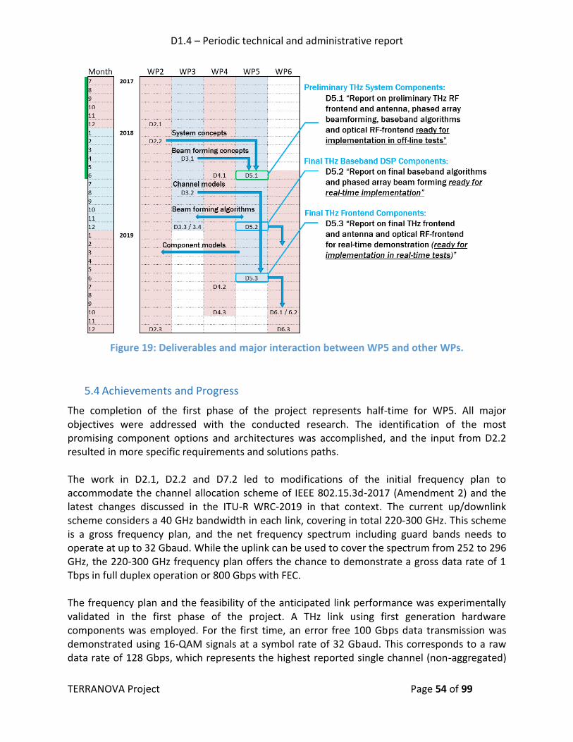
D1.4 – Periodic technical and administrative report
TERRANOVA Project Page 54 of 99
Figure 19: Deliverables and major interaction between WP5 and other WPs.
5.4 Achievements and Progress
The completion of the first phase of the project represents half-time for WP5. All major objectives were addressed with the conducted research. The identification of the most promising component options and architectures was accomplished, and the input from D2.2 resulted in more specific requirements and solutions paths. The work in D2.1, D2.2 and D7.2 led to modifications of the initial frequency plan to accommodate the channel allocation scheme of IEEE 802.15.3d-2017 (Amendment 2) and the latest changes discussed in the ITU-R WRC-2019 in that context. The current up/downlink scheme considers a 40 GHz bandwidth in each link, covering in total 220-300 GHz. This scheme is a gross frequency plan, and the net frequency spectrum including guard bands needs to operate at up to 32 Gbaud. While the uplink can be used to cover the spectrum from 252 to 296 GHz, the 220-300 GHz frequency plan offers the chance to demonstrate a gross data rate of 1 Tbps in full duplex operation or 800 Gbps with FEC. The frequency plan and the feasibility of the anticipated link performance was experimentally validated in the first phase of the project. A THz link using first generation hardware components was employed. For the first time, an error free 100 Gbps data transmission was demonstrated using 16-QAM signals at a symbol rate of 32 Gbaud. This corresponds to a raw data rate of 128 Gbps, which represents the highest reported single channel (non-aggregated)

D1.4 – Periodic technical and administrative report
TERRANOVA Project Page 55 of 99
data rate transmitted over a wireless link at 300 GHz so far, to the best of the authors knowledge. Figure 20 gives an indicative example of the received constellation diagram at a BER of 1.1·10-2 as reported in D5.1. The detailed characterization of this link allowed the test of existing signal processing algorithms and the identification of required improvements.
Figure 20: Received constellation under best case conditions for 32 GBaud 16-QAM with pre-emphasis at BER equals 1.1·10-2.
The all-digital carrier phase estimation was successfully tested in that context. Its performance actually improves with increasing symbol rate; thus, operating at low symbol rates requires special caution. Task 5.2 evaluated basic analog and digital beamforming schemes in the first phase. The main focus was on implementing beamforming with weights corresponding to phase shifts. However, multiplying the phase shifts with a vector of non-negative real values, i.e. taper vector, has been also studied. Moreover, adaptive and null-steering beamforming schemes have been also presented and evaluated with simulations. This activity was used to establish a simulation environment that allows the implementation and testing of new beamforming algorithms at THz frequencies. As a first outcome, the demonstrator hardware architecture options could be narrowed down. The initial ideas for the hybrid optical THz wireless link, as developed in D2.2 were refined and further detailed in Task 5.4. Part of the challenge was to identify among many different options the most promising candidates and start investigating and implementing first functions of the TERRANOVA media converter. Figure 21 and Figure 22 show the two main candidates, using an intensity modulated / direct detection (IM/DD) system (i.e., non-coherent optical link) and a dual-polarization coherent optical system, respectively, as discussed in deliverable D5.1. In this context, approaches for the co-integration of state-of-the-art optical transponder modules with the THz wireless frontend were also analyzed. Some critical components were implemented for risk assessment and a feasibility study, which helped identify practical problems to be solved in the second phase of the project by means of a new baseband integration platform.
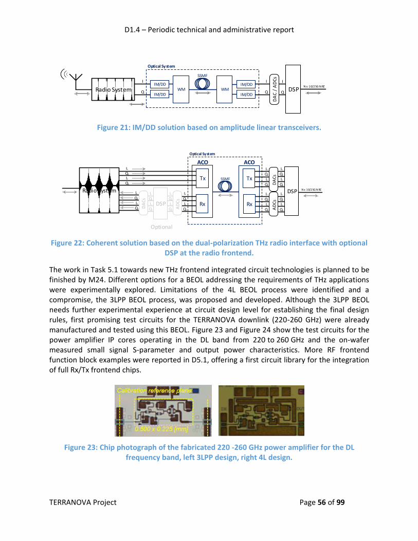
D1.4 – Periodic technical and administrative report
TERRANOVA Project Page 56 of 99
Radio System
SSMF
WM
Optical System
I
Q
IM/DD
IM/DD
IM/DD
IM/DDWM
I
Q
DA
C /
AD
Cs I
Q
N x 10/25G N RZDSP
Figure 21: IM/DD solution based on amplitude linear transceivers.
SSMF
Optical System
Ix
Qx
Iy
Qy
Ix
Qx
Iy
Qy
Qx
Ix
Ix
Qx
ACO
Ix
Qx
Iy
Qy
Ix
Qx
Iy
QyAD
CsRx
N x 10/25G N RZ
ACO
Tx
Rx
AD
CsIy
Qy
Tx
Qy
Iy
DA
Cs
Radio System
Ix
Qx
Iy
Qy
Ix
Qx
Iy
QyDA
Cs
DSPIx
Qx
Iy
Qy
DSP
Optional
Figure 22: Coherent solution based on the dual-polarization THz radio interface with optional DSP at the radio frontend.
The work in Task 5.1 towards new THz frontend integrated circuit technologies is planned to be finished by M24. Different options for a BEOL addressing the requirements of THz applications were experimentally explored. Limitations of the 4L BEOL process were identified and a compromise, the 3LPP BEOL process, was proposed and developed. Although the 3LPP BEOL needs further experimental experience at circuit design level for establishing the final design rules, first promising test circuits for the TERRANOVA downlink (220-260 GHz) were already manufactured and tested using this BEOL. Figure 23 and Figure 24 show the test circuits for the power amplifier IP cores operating in the DL band from 220 to 260 GHz and the on-wafer measured small signal S-parameter and output power characteristics. More RF frontend function block examples were reported in D5.1, offering a first circuit library for the integration of full Rx/Tx frontend chips.
Figure 23: Chip photograph of the fabricated 220 -260 GHz power amplifier for the DL frequency band, left 3LPP design, right 4L design.

D1.4 – Periodic technical and administrative report
TERRANOVA Project Page 57 of 99
Figure 24: On-wafer measured RF performance of the 220 -260 GHz power amplifier, left S-parameters, right output power at 240 GHz.
5.5 Partners Involvement The major involvement of each partner in WP5 is summarized task-by-task in Table 10. An interaction between the different tasks was crucial. During the first year, this was supported by telephone conferences and the face-2-face meetings, as well as the joint investigation on the system architectures and use case scenarios, as part of D2.1 and D2.2. There was also a strong interaction with WP3 on beamforming algorithms. Discussions and work on impairment modelling and correction was also started in collaboration with WP4. Analytic approximations of the channel models in WP3 were transferred to WP5 for the co-simulation with the frontend components.
Table 10: Partners involvement in WP5.
Partner Task Short description
FhG FhG-IAF is the leader of WP5 and of Task 5.1, FhG-HHI is the leader of Task 5.3
Task 5.1 Research on and design of hardware components for the RF frontend and THz antenna array. Development of a new BEOL process addressing the requirements for THz circuit design with higher integration level
Investigation of a chipset for multi-channel integration, based on a 300 GHz beamforming prototype
Contributed to the investigation of new electro-optical RF front-end packaging approaches
Task 5.2 Contributed with hardware input to the design of antenna arrays and beamforming algorithms
Task 5.3 Design of a high level implementation architecture, early testing using acquisition of data samples with real-time oscilloscopes
Development of novel signal processing algorithms for the baseband PHY, with focus on high RF bandwidths and higher order modulation schemes

D1.4 – Periodic technical and administrative report
TERRANOVA Project Page 58 of 99
Task 5.4 Co-integration of coherent optical and THz wireless components and analog E/O interface design
Investigate the use of coherent optical transponder solutions
ICOM Task 5.2 ICOM is the leader of Task 5.2
Established a simulation environment for the development and test of THz specific beamforming algorithms
Investigation of baseband digital beamforming considering phase shifting, taper vectors, null-steering and adaptive schemes
Identification of beamforming implementation issues of the demonstrator
Development of beamforming algorithms for implementation using a mmWave modem
UOULU Task 5.2 Task 5.3
Contribution to beamforming algorithms and phase noise modelling
Scientific support on state-of-the-art calibration and beamforming and innovations
UPRC Task 5.3 Contribution to impairment correction and modelling of components for system simulations
Scientific support on state-of-the-art review and identification of innovative solutions
Contribution to D5.1
ALB Task 5.4 Contribution to the design of the optical – THz wireless link design
PIC PIC is the leader of Task 5.4
Task 5.1 Contributed to the investigation of new electro-optical RF front-end packaging solutions
Task 5.4 Design of the optical – THz wireless interface (“TERRANOVA media converter”) considering current optical transponder solutions and functionalities
Investigated non-coherent optical links between the THz frontend and the digital baseband modem
5.6 Future Work
The first phase of the work package was focused on down-selecting different options based on the architectures discussed in D2.2. In the next phase, the final components for WP6 will be designed, manufactured and tested, namely baseband signal processing and beamforming algorithms. In Task 5.1, the design of the UL (covering 252-292 GHz) will be addressed. The UL is held compatible with the IEEE 802.15.3 frequency plan for re-use of hardware and related future exploitation plans. The passive component models for the 3LPP BEOL require a further iteration to finalize the design rules and check for unexpected failure mechanisms by more complex and higher integrated circuits. For this reason, the next MMIC tape-out is planned in July with

D1.4 – Periodic technical and administrative report
TERRANOVA Project Page 59 of 99
further test circuits of higher integration level. The scheduled tape-out in December is planned for manufacturing full transceivers using the designed and tested IP core library by then. The task expands till M24 and the final tape-out is planned for beginning of March with one optional design iteration as a backup in July 2019. Using the established simulation environment for THz antenna arrays, Task 5.2 will investigate the effect of impairments and phase noise on the array performance with more realistic models. A 4-channel array architecture will be used, since a first generation hardware exists as a first reference design which provides experimental experience and test results. This work will be also supported by WP3. In the next phase, the focus will be on digital beamforming algorithms for several reasons, which are practical implementation considerations but also performance considerations. It is planned to develop a scheme for the calibration and control of the small 4 element test array ready for implementation in WP6. Task 5.3 will model and design a new generation of baseband algorithms based on the experience from first transmission experiments with the current algorithm toolbox. One of the main targets will be the implementation of realistic simulation models for current and next generation THz components for that purpose, also in collaboration with Task 5.1 and WP4. The observed imperfections and artefacts (for example seen in the constellation diagrams) will be further analyzed and countermeasures will be developed to increase the modulation order to 64-QAM. This will also result in new hardware specifications for the final transceiver implementation. It is also planned to start investigating polarization MIMO and the E2E simulation including the optical link. Task 5.4 will start to actually implement the TERRANOVA media converter solutions. In a first step, back-to-back experiments omitting the THz link will be used for testing. In the next step, also part of WP6, the THz link will be included. The two most promising solutions for the transmission of the IQ baseband signals will be addressed. The analog coherent and non-coherent links both have advantages and disadvantages to be further investigated by test implementations. Finally, the most promising co-integration platforms for optical transponders and THz frontends will be practically implemented and tested.
6. WP6 - THZ DEMONSTRATOR IMPLEMENTATION AND VALIDATION
6.1 WP Objectives
The following objectives have been set for this work package:
To implement a THz Beamforming Demonstrator to test and validate TERRANOVA’s technologies and solutions;
To implement a THz High-capacity Demonstrator to test and validate TERRANOVA’s technologies and solutions for HF-frontend and antenna, MAC layer, PHY and combined optical and THz wireless system;

D1.4 – Periodic technical and administrative report
TERRANOVA Project Page 60 of 99
To perform proof-of-concept and validation experiments using the two demonstrator setups.
6.2 Work Organisation
The Gantt Chart for WP6 is depicted in Figure 25.
Figure 25: WP6 Gantt Chart & effort allocation.
To achieve the WP6 objectives, all partners, i.e., UPRC, FhG, ICOM, UOULU, JCP-C, ALB and PIC, have defined the following tasks:
Task 6.1: THz Beamforming Demonstrator Implementation (M12-M28) o Will be reported in D6.1 “THz Beamforming Demonstrator implementation report”
(M28)
Task 6.2: THz High-capacity Demonstrator Implementation (M12-M28) o Will be reported in D6.2 “THz High-capacity Demonstrator implementation report”
(M28)
Task 6.3: THz System performance validation and testing (M28-M30) o Will be reported in D6.3 “TERRANOVA proof-of-concept test and validation report”
(M30).
6.3 Partners Involvement Table 11 briefly summarizes the individual partners’ involvement in each task of WP6.
Table 11: Partners involvement in WP6.
Partner Task Short description
FhG FhG (HHI) is the leader of WP6 and of Task 6.2
Task 6.1 Implementation of HF frontend and THz antenna array
Task 6.2 Implementation of optical-HF frontend
Implementation of baseband unit with an FPGA-based THz class modem

D1.4 – Periodic technical and administrative report
TERRANOVA Project Page 61 of 99
Implementation of THz antenna with single element
Test of hardware and software from WPs 3, 4 and 5
ICOM ICOM is the leader of Task 6.1
Task 6.1 Implementation of mmWave-based baseband unit with FPGA-based modem including beamforming algorithms
Test of hardware and software from WPs 3, 4 and 5
PIC PIC is the leader of Task 6.3
Task 6.2 Implementation of optical-HF frontend
JCP-C Task 6.3 Study of the demonstrator architecture; splitting between POC and simulator for caching part.
Study of multi-objective simulation parameters for user attachment to involve suitable caching parameters.
ALL partners
Task 6.1/6.2/6.3
Definition of demonstrator implementation and use cases to be demonstrated
Test of hardware and software from WP3, 4 and 5
TERRANOVA system performance validation and testing
6.4 Outcomes, Achievements and Future Work As of now, the work in WP6 has just started. On the basis of the current results from WPs 2, 3, 4 and 5, the technical definition of the two demonstrators is ongoing, as well as the definition of the use cases, which should be demonstrated. In particular, the current objective in this early phase of WP6 is to narrow down the hardware and software options for the demonstrators implementation, which is an essential step towards an agreement on the demonstrator design. In this regard, the following conclusions could be drawn in each WP within the first deliverables: It has been found in D3.1 that for very wideband cases, simple phase shifters are not enough. Depending on the demonstrator targeted bandwidth this needs to be taken into account. Further research on this using other techniques, such as time alignment of signals or subband beamforming will be studied in WP3. Further, it was found in D3.1 that phase noise can significantly degrade performance. Therefore, the architecture for the demonstrator needs to be selected with phase noise issues in mind. In D5.1, the initial ideas for the hybrid optical THz link design, as developed in D2.2, were refined and further detailed. In particular, the most promising integration approaches for the co-integration of state-of-of-the-art optical transponder modules with the THz wireless front-end were identified to be applicable for the THz High-Capacity Demonstrator, i.e. two different solutions based on IM/DD and on coherent optical transponder technologies, respectively. For the THz frontend integration itself, different options for a BEOL addressing the requirements of THz applications were explored, and the 3LPP BEOL process was developed showing promising results in the frequency range of 220-260 GHz.
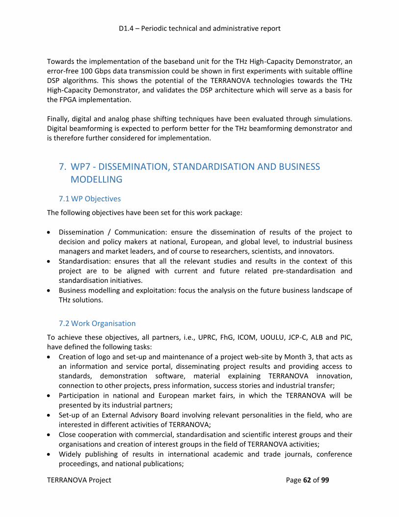
D1.4 – Periodic technical and administrative report
TERRANOVA Project Page 62 of 99
Towards the implementation of the baseband unit for the THz High-Capacity Demonstrator, an error-free 100 Gbps data transmission could be shown in first experiments with suitable offline DSP algorithms. This shows the potential of the TERRANOVA technologies towards the THz High-Capacity Demonstrator, and validates the DSP architecture which will serve as a basis for the FPGA implementation. Finally, digital and analog phase shifting techniques have been evaluated through simulations. Digital beamforming is expected to perform better for the THz beamforming demonstrator and is therefore further considered for implementation.
7. WP7 - DISSEMINATION, STANDARDISATION AND BUSINESS MODELLING
7.1 WP Objectives
The following objectives have been set for this work package:
Dissemination / Communication: ensure the dissemination of results of the project to decision and policy makers at national, European, and global level, to industrial business managers and market leaders, and of course to researchers, scientists, and innovators.
Standardisation: ensures that all the relevant studies and results in the context of this project are to be aligned with current and future related pre-standardisation and standardisation initiatives.
Business modelling and exploitation: focus the analysis on the future business landscape of THz solutions.
7.2 Work Organisation
To achieve these objectives, all partners, i.e., UPRC, FhG, ICOM, UOULU, JCP-C, ALB and PIC, have defined the following tasks:
Creation of logo and set-up and maintenance of a project web-site by Month 3, that acts as an information and service portal, disseminating project results and providing access to standards, demonstration software, material explaining TERRANOVA innovation, connection to other projects, press information, success stories and industrial transfer;
Participation in national and European market fairs, in which the TERRANOVA will be presented by its industrial partners;
Set-up of an External Advisory Board involving relevant personalities in the field, who are interested in different activities of TERRANOVA;
Close cooperation with commercial, standardisation and scientific interest groups and their organisations and creation of interest groups in the field of TERRANOVA activities;
Widely publishing of results in international academic and trade journals, conference proceedings, and national publications;

D1.4 – Periodic technical and administrative report
TERRANOVA Project Page 63 of 99
Organisation of industrial and academic workshops, as well as seminars for presenting project results;
Contribution to formal pre-standardisation and standardisation bodies, fora and industry groups and exchanging continuously background information.
Dissemination and exchange of project results towards other European operators and vendors. The following Gantt chart shows the workplan and the effort allocation in WP7.
Figure 26: WP7 Gantt Chart & effort allocation.
7.3 Partners Involvement
The following table briefly summarizes the partners’ involvement in each task of WP7.
Table 12: Partners involvement in WP7
Partner Task Short description JCP-C JCP-C is the leader of WP7 and of Tasks 7.1 and 7.3
Task 7.1 Dissemination / Communication activities conducted in the first year includes
1. Development of dissemination plan as per D7.1 2. Development and maintenance of TERRANOVA website 3. Development and maintenance of Publication follow up form 4. Development and maintenance of Dissemination table 5. Support of organising workshops and dissemination events.
Task 7.3 Business modelling and exploitation ALB ALB is the leader of Task 7.2
Task 7.2 Standardisation plan and roadmap for TERRANOVA, following activities in relevant bodies and coordinating updates, and contributions
ALL partners
Task 7.1/7.2/7.3
Participate in the dissemination effort and provide the necessary materials for website updates after the dissemination

D1.4 – Periodic technical and administrative report
TERRANOVA Project Page 64 of 99
events/actions.
Participate in the standardisation efforts when possible/applicable.
Provide the necessary data for business modelling, including filling in questionnaires/forms etc.
7.4 Outcomes & Achievements
7.4.1 Task7.1 – Dissemination / Communication
Deliverable D7.1 describes in detail the dissemination and communication plan for TERRANOVA project. The set-up of the website objective is attained and a maintenance task is set. The website acts as an information and service portal, which disseminates the project results and provides access to materials. The list of published papers can be found in the TERRANOVA website. The website is updated regularly with deliverables, papers, reports, news etc. A brochure and a poster that show TERRANOVA activities were designed and reviewed by all partners. The brochure was first distributed to the attendees of EUCNC 2018 (June 2018 in Ljubljana). All partners are committed to distribute the brochure during relevant events in order to demonstrate/publicise the TERRANOVA project objectives and activities. Partners are committed to provide the necessary materials and inputs needed for dissemination in different channels. In the following paragraphs of this section the website and its contents are presented, the TERRANOVA leaflet and poster are illustrated and the lists of publications and other dissemination activities during the course of the first reporting period are provided.
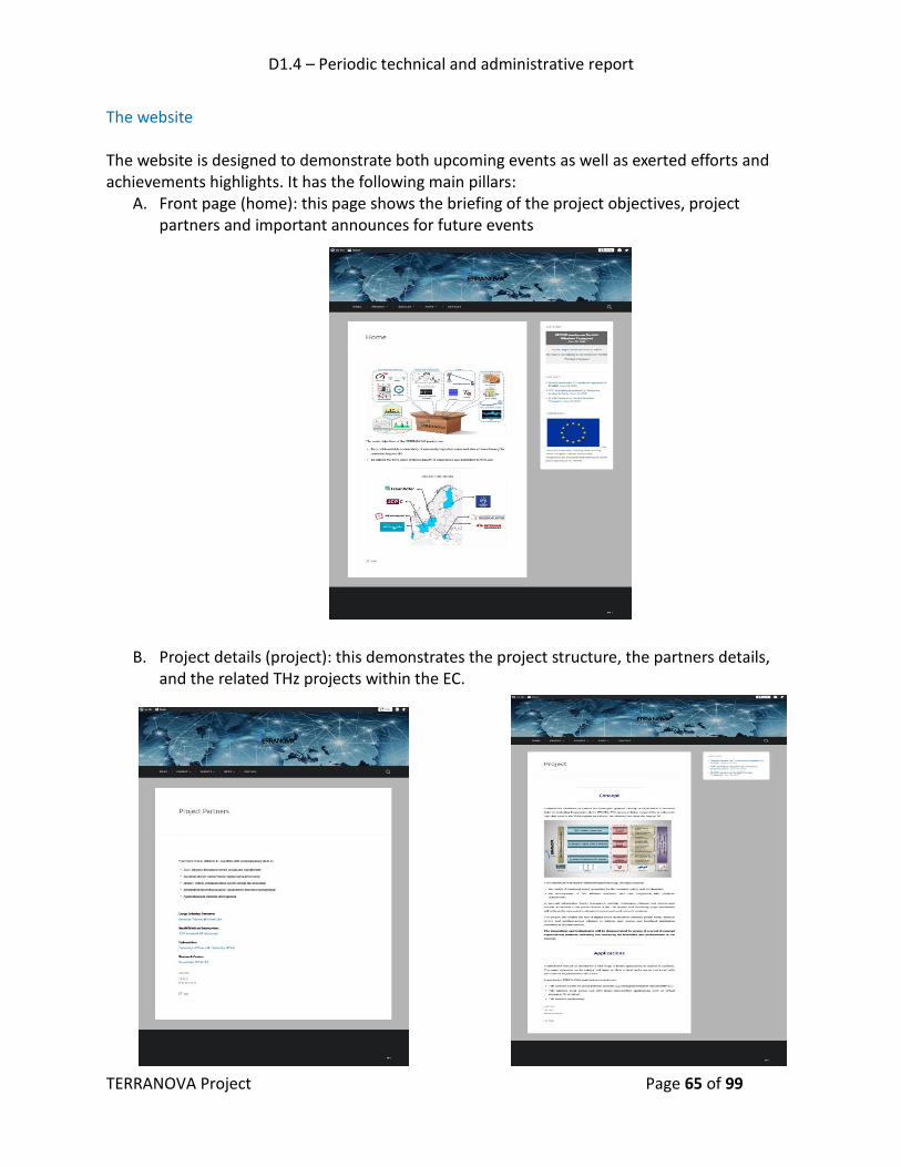
D1.4 – Periodic technical and administrative report
TERRANOVA Project Page 65 of 99
The website The website is designed to demonstrate both upcoming events as well as exerted efforts and achievements highlights. It has the following main pillars:
A. Front page (home): this page shows the briefing of the project objectives, project partners and important announces for future events
B. Project details (project): this demonstrates the project structure, the partners details, and the related THz projects within the EC.

D1.4 – Periodic technical and administrative report
TERRANOVA Project Page 66 of 99
C. Project outcomes (results): this includes the project deliverables, publication lists and resulted datasets from research efforts.
D. Project news: in this section, announcements for new events are demonstrated as well as the previous announcements and posts for the previous events.

D1.4 – Periodic technical and administrative report
TERRANOVA Project Page 67 of 99
E. Project contact information (contacts): includes the contact information for both the project coordinator and the technical manager.

D1.4 – Periodic technical and administrative report
TERRANOVA Project Page 68 of 99
The Leaflet
A double face leaflet is produced with detailed information about the project objectives, technical pillars, expected outcomes, partners’ involvement, and contact information.

D1.4 – Periodic technical and administrative report
TERRANOVA Project Page 69 of 99
The poster
The poster contains a summary of the project information including both technical and administrative information.

D1.4 – Periodic technical and administrative report
TERRANOVA Project Page 70 of 99
Publication and dissemination efforts As per D7.1, the conducted publications and dissemination efforts are recorded and saved in the following tables (Table 13 and Table 14).
Table 13: List of Publications
No. Title Main author Title of the
periodical or the series
Number, date or frequency
Publisher Place of publication
Year of publication
Relevant pages
Permanent identifiers (if available)
Is/Will open access provided to this publication?
1 Performance Evaluation of THz Wireless Systems Operating in 275-400 GHz Band
A.-A. A. Boulogeorgos
IEEE 87th Vehicular Technology Conference: VTC2018-Spring
Jun-18 IEEE Porto, Portugal
2018 https://ieeexplore.ieee.org/document/8417891/
10.1109/VTCSpring.2018.8417891
Yes - TERRANOVA webpage
2 Terahertz Technologies to Deliver Optical Network Quality of Experience in Wireless System Beyond 5G
A.-A. A. Boulogeorgos
IEEE Communications Magazine
Jun-18 IEEE 2018 https://ieeexplore.ieee.org/document/8387218/
10.1109/MCOM.2018.1700890
Yes - arxiv

D1.4 – Periodic technical and administrative report
TERRANOVA Project Page 71 of 99
3 A distance and bandwidth dependent adaptive modulation scheme for THz communications
A.-A. A. Boulogeorgos
9th IEEE International Workshop on Signal Processing Advances in Wireless Communications (SPAWC)
Jun-18 IEEE Kalamata, Greece
2018 Not yet available in IEEExplore
Not yet available
Yes - TERRANOVA webpage
4 Users Association in Ultra Dense THz Networks
A.-A. A. Boulogeorgos
9th IEEE International Workshop on Signal Processing Advances in Wireless Communications (SPAWC)
Jun-18 IEEE Kalamata, Greece
2018 Not yet available in IEEExplore
Not yet available
Yes - TERRANOVA webpage
5 A New Look to 275 to 400 GHz Band Channel Model and Performance Evaluation
E. N. Papasotiriou
IEEE International Symposium on Personal, Indoor and Mobile Radio Communications (PIMRC)
Sep-18 IEEE Bologna, Italy
2018 Not yet available in IEEExplore
Not yet available
Yes - TERRANOVA webpage

D1.4 – Periodic technical and administrative report
TERRANOVA Project Page 72 of 99
6 Wireless Terahertz System Architectures for Networks Beyond 5G
A.-A. A. Boulogeorgos
White paper Jul-18 TERRANOVA
2018 https://ict-terranova.eu/2018/03/24/towards-terahertz-communication-workshop/
Not available Yes - TERRANOVA webpage
7 Reflection Coefficients for Common Indoor Materials in the Terahertz Band’
J. Kokkoniemi ACM International Conference on Nanoscale Computing and Communication (ACM NanoCom)
September 2018
ACM Reykjavik, Iceland
2018 1 to 6 not yet not fully open access but will be provided to TERRANOVA&UOULU website
8 Simplified Molecular Absorption Loss Model for 275 – 400 Gigahertz Frequency Band
J. Kokkoniemi European Conference on Antennas and Propagation (EuCAP)
April 2018 IEEE London, UK 2018 1 to 6 not yet not fully open access but will be provided to TERRANOVA&UOULU website

D1.4 – Periodic technical and administrative report
TERRANOVA Project Page 73 of 99
9 Last Meter Indoor Terahertz Wireless Access: Performance Insights and Implementation Roadmap
V. Petrov IEEE Communications Magazine
18 June 2018
IEEE n/a 2018 158 to 165
DOI: 10.1109/MCOM.2018.1600300
not fully open access but will be provided to TERRANOVA&UOULU website
10 Stochastic Geometry Analysis for Band-Limited Terahertz Band Communications
J. Kokkoniemi IEEE 87th Vehicular Technology Conference: VTC2018-Spring,
June 2018 IEEE Porto, Portugal
2018 1 to 6 not yet not fully open access but will be provided to TERRANOVA&UOULU website
Table 14: List of Dissemination Activities
No. Type of activities
Main leader
Title Date/Period Place Type of audience
Size of audience
Countries addressed
1 Announcement in Interview magazine
ICOM Delivering optical network QoE in wireless systems beyond 5G
February 2018 Athens International unknown Worldwide
2 Conference Publication
UOULU ‘Reflection Coefficients for Common Indoor Materials in the Terahertz Band’
September 5-7, 2018
ACM International Conference on Nanoscale Computing and Communication (ACM NanoCom)
Nano/THz communication researchers
around 50 Worldwide

D1.4 – Periodic technical and administrative report
TERRANOVA Project Page 74 of 99
Reykjavik, Iceland
3 Conference Publication
UOULU “Simplified Molecular Absorption Loss Model for 275 – 400 Gigahertz Frequency Band“
April 9–13, 2018
EUCAP 2018 London UK.
Antennas and Propagation researchers
whole conference: around 1000
Worldwide
4 Conference Publication
UOULU “Stochastic Geometry Analysis for Band-Limited Terahertz Band Communications”
3–6 June 2018 IEEE 87th Vehicular Technology Conference: VTC2018-Spring, Porto, Portugal
THz Research community
around 20 in session
Worldwide
5 Journal Publication
UOULU (from TERRANOVA)
“Last Meter Indoor Terahertz Wireless Access: Performance Insights and Implementation Roadmap“
June 2018 IEEE Communications Magazine.
General Research community
Reader of Comm. Mag.
Worldwide
6 Conference presentation
UPRC Performance Evaluation of THz Wireless Systems Operating in 275-400 GHz Band
Jun-18 Porto, Portugal Wireless communications experts
30 International
7 Conference poster
UPRC A distance and bandwidth dependent adaptive modulation scheme for THz communications
Jun-18 Kalamata, Greece Wireless communications & signal processing experts
International

D1.4 – Periodic technical and administrative report
TERRANOVA Project Page 75 of 99
8 Conference poster
UPRC Users Association in Ultra Dense THz Networks
Jun-18 Kalamata, Greece Wireless communications & signal processing experts
International
9 Workshop presentation
UPRC EC Workshop: Towards TeraHertz Communication Workshop
Mar-18 Brussels,Belgium International
10 Workshop organisation
UPRC International Workshop on THz Communication Technologies for Systems Beyond 5G
Jun-18 Porto, Portugal Wireless communications experts
30 International
11 Special session organisation
UPRC EUCNC: Terabit Wireless Transport for Networks Beyond 5G
20-Jun-18 Ljubljana, Slovenia Wireless communications experts
EU
12 Workshop presentation
UPRC Tbps Wireless Connectivity to deliver Optical Network QoE in Systems beyond 5G
15-Dec-18 Thessaloniki, Greece Wireless communications experts
13 Conference presentation
UPRC Reliable and Scalable Tbit/s Connectivity to Extend the Fibre Optic Systems QoE into the Wireless Domain
20-Jun-18 Ljubljana, Slovenia Wireless communications experts
EU
14 Keynote speaker
JC Point Caching in the edge - TERRANOVA approach
26-Mar-18 ICCS18 Rennes, France
Computer science experts
International
15 Announcement made in the context of a National
ALB TERRANOVA system as a complement for Mobile Backhaul/Fronthaul
May 2018 Aveiro - Portugal Portuguese Scientific community
20 Technical Leaders
Portugal

D1.4 – Periodic technical and administrative report
TERRANOVA Project Page 76 of 99
(Portugal) Project P2020 "Mobilizador 5G"
16 Project Reference indication at the FTTH Council Europe
ALB NG-PON to boost 5G backhaul/fronthaul deployments
Feb 2018 Valencia - Spain FTTH Equipment and materials Industry
Unkown Europe
17 Conference Publication
IAF "Testbed for Phased Array Communications from 275 to 325 GHz,"
22.-25. October 2017
IEEE Compound Semiconductor IC Symposium (CSICS), Oct. 2017. Miami /FL /USA
Compound Semiconductor Industry
>300 Worldwide
18 Workshop Presentation
IAF "III-V CMOS Circuits for RF and mmW (Integration paths to a III-V device technology with additional CMOS functionality),"
8. October, 16:50-17:30
Workshop WS-06 on „Integration of III-V nanowire semiconductors for next generation high performance CMOS SOC technologies, and competitive solutions“, European Microwave Week, 2017 . Nuremberg /Germany
Microwave Industry
>1000 Worldwide
19 Conference Publication
IAF "Investigation of differential broadband amplifiers in normally-on mHEMT technology,"
March 12–14, 2018
The 11th German Microwave The 11th German Microwave
Microwave Industry
>300 National German, listed in IEEE

D1.4 – Periodic technical and administrative report
TERRANOVA Project Page 77 of 99
Conference (GEMIC) 2018. Freiburg / Germany
20 News Article IAF "Terranova – Thinking beyond a network standard, "
August 2017 online: https://www.iaf.fraunhofer.de/en/media/newsarchive/communication-beyond-5G.html
Fraunhofer IAF customers
Worldwide
21 News Article IAF/HHI " Beyond 5G – der übernächste Schritt"
November 11/2018
in Fraunhofer News Magazine "Forschung Kompakt", online: https://www.fraunhofer.de/de/presse/newsletter/forschung-kompakt.html
Fraunhofer customers
Worldwide
22 Press Release IAF/HHI "Beyond 5G – after the next generation"
November 11/2018
Online General International
mostly Europe
23 Interview for General Computer Magazine Article
IAF/HHI "Datenlast jenseits von 5G",
January 2018 Online / Printed in Special Edition on Data Center and Network Infrastructure, Heisse Gmbh, Online: https://www.heise.de/ix/05/2/3/9/4/1/7/0/rz-infrastruktur-2018-01.pdf
General National
National German
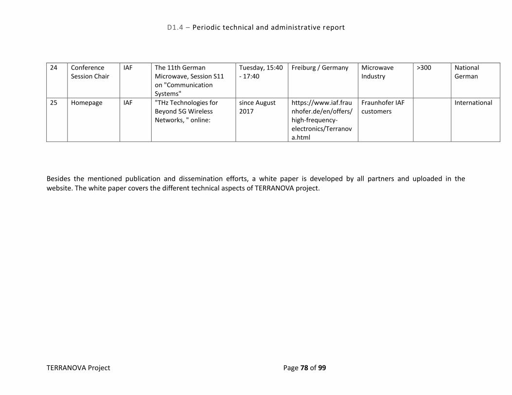
D1.4 – Periodic technical and administrative report
TERRANOVA Project Page 78 of 99
24 Conference Session Chair
IAF The 11th German Microwave, Session S11 on "Communication Systems"
Tuesday, 15:40 - 17:40
Freiburg / Germany Microwave Industry
>300 National German
25 Homepage IAF "THz Technologies for Beyond 5G Wireless Networks, " online:
since August 2017
https://www.iaf.fraunhofer.de/en/offers/high-frequency-electronics/Terranova.html
Fraunhofer IAF customers
International
Besides the mentioned publication and dissemination efforts, a white paper is developed by all partners and uploaded in the website. The white paper covers the different technical aspects of TERRANOVA project.

D1.4 – Periodic technical and administrative report
TERRANOVA Project Page 79 of 99
7.4.2 Task7.2 - Standardisation
The D7.2 – Standardisation document was delivered in time accounting for the consortium activity in the standardisation domain. Partners’ activities at the standardisation level were considered to be adequate in the context of the TERRANOVA project goals and targets. The undergoing work in standardisation bodies, IEEE 802.15 (wireless personal area network) and IEEE 802.11ay (wireless channel bonding and MIMO), are the ones receiving closer look by the consortium. Besides IEEE 802.15 technical studies contribution, the IEEE 802.11ay is also important and will be closely followed for future assessment, with respect to a potential future technical contribution at the MAC level domain. Other optical technology standards as ITU-T G.989 (NG-PON2), ITU G.HSP (High Speed PON) and IEEE 802.3ca (100G-EPON) as well as other industry initiatives as the Common Public Radio Initiative (CPRI/eCPRI) are also to be taken into consideration, once they are directly linked with the optical component part of the TERRANOVA communication system. TERRANOVA consortium also commits to a standardisation dashboard reflecting the current and future activities on relevant technical forums (considering the project time frame) as well as pre-standardisation and standardisation organisation initiatives. The WRC-19 preparation is in progress and approaching final deadlines. Consolidation with regional groups and individual member states has started, the first ITU inter-regional workshop was held in November 2017, and the ITU responsible working parties will report by August 31, 2018 to the CPM-19, based the CPM draft report will be prepared. The IEEE 802.15.3d has prepared two different channel assignment plans in 2016, of which channel plan A was adopted in IEEE Std 802.15.3d-2017. As of today, however, it is not clear if and how this channel assignment plan will be considered in the WRC-19 preparation process, which concerns on the spectrum from 275 GHz to 450 GHz, which does not fully comply with the proposed channel plan. Since this is the most critical hard limitation to be considered and addressed by TERRANOVA, it will be necessary to monitor the process closely in 2018 and 2019. It needs to be also clarified if exemptions for indoor applications or FS applications with very high gain antennas are possible (> 50 dBi, very low sidelobe levels). With the former amendment 2 (IEEE Std 802.15.3c-2009) on a 60 GHz PHY with beamforming options, the IEEE802.15.3 standard became more dominant by exploiting new mmWave bands, and the logical consequence was the work on THz frequencies above 252 GHz. For this reason, the IEEE 802.15.3 is an excellent candidate for incorporating ideas of TERRANOVA. There are hard and soft limitations to be considered within TERRANOVA. In conclusion, the TERRANOVA consortium should try to influence the IEEE 802.15.3 amendment on a 100 Gbps wireless switched point-to-point PHY towards incorporating also dual polarized fixed point-to-point links for 400 Gbps. This

D1.4 – Periodic technical and administrative report
TERRANOVA Project Page 80 of 99
would be consistent with the evolution of the Ethernet Gigabit and Terabit standards and the next logical step to achieve compatibility and interoperability between wireless and wired connectivity solutions. It may be also considered to extend the standardisation of IEEE 802.15.3 in the next phase by an amendment on 200 Gbps and 400 Gbps based on the work of TERRANOVA. Further, the non-coherent PHY considers only OOK modulation so far which may be extended by PAM-n modulation schemes consistent with optical non-coherent transmission formats. The available frequency spectrum will be decided at the WRC-19 and the preparation activities have advanced to the point where modifications are difficult to propose except if opting for special exemptions, e.g. indoor applications, or very high gain antenna solutions (> 50 dBi with very low sidelobes) for FS. Reconfigurable antennas will be very difficult to implement with such antenna specifications, if they will be at all accepted by the ITU for LMS. While CPRI and eCPRI address the implementation of C-RAN topologies, or in other words front-hauling applications, the TERRANOVA candidate architectures focus on embedding wireless links into optical links, or in other words back-hauling applications. However, from an application point of view, following the evolution of eCPRI and CPRI may reveal technology gaps that could be filled with the TERRANOVA technologies. It may be also important to follow the requirements of carrying synchronization information and control and management information for packet-oriented traffic, when using point-to-multipoint candidate architectures together with time-division multiple access techniques.
7.4.3 Task7.3-Business Modelling and Exploitation
During the first year of the project task 7.3 had as focus the analysis of the future business landscape of THz solutions. T7.3 had interactions with T2.1 “Requirements” in the first half of the year and later in the second half of the year continued with the help of the project partners with the business landscape study. In T7.3 we took a larger approach to the identification of the possible applications of TERRANOVA outcomes. The reason is that in T7.3 we take a business approach and we attempt to evaluate their potential to become wide-spread solutions in lucrative markets. In this sense, the applications in T2.1 could be considered a subset of the identified applications in T7.3. We have grouped the possible list of TERRANOVA applications based on a diverse set of criteria:
The first group combines applications which rely on transmission over rather large distances (mostly outdoors). The leading principle of grouping is that once the technology is mature enough, the decision to implement or not is to be

D1.4 – Periodic technical and administrative report
TERRANOVA Project Page 81 of 99
taken by one actor (a network operator) with clear cost-to-benefit motivation. This group does not rely on proliferation of THz consumer enabled devices but can very well support them.
The second group of applications considers the emergence of concentrated “islands” (mostly indoors), running applications, demanding almost zero latency and high bandwidth. Examples include home entertainment, hospitals of the future; etc. These use cases are based on the assumption that THz transceivers on business-to-business (B2B) and business-to-customer (B2C) devices can reach low enough pricing. A large group of actors is then needed in these cases to coordinate efforts at least in the first stages of adoption. The key to fast proliferation is the quality of the enabling service (for example augmented reality).
The third group of applications can effectively become available once the first two groups become wide-spread enough. These applications with truly beyond 5G nature and radical potential have the ability to bring transformational change to the society.
Although the applications of the third group are easy to be foreseen as possible in a rather distant future, the speed of proliferation of applications in the first and second group is not that obvious to predict. The reason is that beyond criteria like technology maturity and QoS, quite many other factors can speed up or slow down the adoption of certain applications. To gauge this complexity, we have created a Scorecard, evaluating the potential of the applications in these two groups to reach the market in the near future. We have used two main sets of criteria – technological and market criteria. The future ecosystem created by TERRANOVA outcomes and the possible changes which can happen in it with the introduction of these outcomes was also the part of the efforts in this task during the reporting period. We trace the strategic interest of various actors and their possible positioning in beyond 5G landscape. In the second year of the project, T7.3 will have two main activities:
The elaboration of scorecards evaluating the business potential of project outcomes (separately or in logical groups – e.g. per project objective)
The preparation of the exploitation plans of the project partners.
In the following table a list of current partners’ exploitation plans is presented.

D1.4 – Periodic technical and administrative report
TERRANOVA Project Page 82 of 99
Table 15: List of Exploitation Plans
Partners Type of Exploitable Foreground
Description of exploitable foreground
Confidential YES/NO
Foreseen embargo date
Exploitable product(s) or measure(s)
Sector(s) of application
Timetable, commercial or any other use
Patents or other IPR exploitation (licenses)
Owner & Other Beneficiary(s) involved
PIC
Commercial exploitation of R&D results
High-speed analog interfaces. Include RoF capabilities on the next generation of optoelectronic transceivers. YES
Next-generation media converters
J61 - Telecommunications 2020- NO PIC
PIC
General advancement of knowledge
RoF interfaces for local P2P fiber extensions of wireless communications YES
Extension of current applications
J61 - Telecommunications 2020- NO PIC
ICOM
Commercial exploitation of R&D results
The introduction of an electronically steering antenna in mmWave Small Cell backhaul, will further improve auto-alignment YES
StreetNode™ family of mmWave Small Cell backhaul products
C26.3 - Manufacture of communication equipment 2020- NO ICOM
ICOM
Commercial exploitation of R&D results
The phased array will be utilised in both P2P and P2MP applications, to add multi- YES Antennas
C26.3 - Manufacture of communication equipment 2020- NO ICOM

D1.4 – Periodic technical and administrative report
TERRANOVA Project Page 83 of 99
connection capability.
JCP-C
Commercial exploitation of R&D results
The caching architecture and system customization will be applied to JCP-C portfolio of caching solutions NO
Caching solutions for various verticals
J61 - Telecommunications 2019-2022
possible licensing JCP-C
ALB
Commercial exploitation of R&D results
The TERRANOVA system might have a future use as part of the ALB portfolio in the context of the Mobile Backhaul/Fronthaul domain YES
OLT system linecards
C26.3 - Manufacture of communication equipment 2020- NO ALB
ALB
Commercial exploitation of R&D results
The TERRANOVA very high communication bitrates may be a complement to the FTTx ALB portfolio as a fiber extender for NG-PON technologies uplink YES
OLT system linecards
C26.3 - Manufacture of communication equipment 2020- NO ALB
ALB
Commercial exploitation of R&D results
Due to its very high bitrate, the TERRANOVA system may be of future use in the YES
Novel wireless to optical integrated system
C26.3 - Manufacture of communication equipment 2020- NO ALB

D1.4 – Periodic technical and administrative report
TERRANOVA Project Page 84 of 99
context of the Fronthaul solutions for the 5G and beyong 5G scenarios mobile scenarios

D1.4 – Periodic technical and administrative report
TERRANOVA Project Page 85 of 99
8. PROJECT MANAGEMENT (WP1), RESOURCES USED AND OVERALL ASSESSMENT OF THE FIRST YEAR OF TERRANOVA
In this section we present the Project Management approach adopted in the TERRANOVA project, the associated objectives and tasks along with the partners’ involvement in project management activities. Furthermore, a detailed presentation of the utilised resources is given for each WP and each partner. Finally, an overall assessment is presented of the progress made so far, in terms of deliverables, milestones and impact, while deviations from the initial project workplan and the risk management strategy are clearly described and elaborated.
8.1 WP1 Objectives
The objectives that have been set for WP1, entitled “Project Management”, are summarized below:
To ensure that the project is conducted in accordance with the European Commission’s (EC) rules;
To manage and keep up-to-date the overall technical directions of the project;
To provide methodologies for effective coordination of all project activities and maintenance of contact with EC representatives;
To manage the administration and internal communication processes of the project;
To undertake quality assessment of project progress, results and impact;
To achieve timely submission of progress reports and cost statements to the EC; and
To maintain and update the Grant Agreement and Consortium Agreement.
8.2 Work Organisation
To achieve these objectives, the involved partners, i.e., UPRC, FhG, JCP-C, ICOM, UOULU, ALB, and PIC divided the work load into three (3) tasks as follows:
TASK 1.1-Project Organisation and Management (led by UPRC);
TASK 1.2-Technical and Innovation Management (led by FhG); and
TASK 1.3- Project Office and Quality management (led by JCP-C).
8.2.1 TASK1.1-Project Organisation and Management
This task begun in M1 and its duration is 30 months. This task is led by UPRC, who is the Project Manager. Task 1.1 involves the daily management and control of the project, as well as provides the liaison with the EC and external organisations. In particular, the objectives of this task are to:

D1.4 – Periodic technical and administrative report
TERRANOVA Project Page 86 of 99
Ensure the daily management of the project to monitor the overall progress of the work, the production of the deliverables and deliveries at the agreed milestones; monitor project progress according to budget and partners spending and take appropriate actions;
Ensure the communications between the project, other R&D projects, and the EC (representation at the regular Concertation meetings, participation to events organised by other projects, organisation of events, etc.) and to external organisations;
Manage and mobilise resources to optimise the project efficiency (the project may be slightly modified or re-focused if necessary taking into account project evolution and risks);
Report to the Project Officer (PO) appointed by the EC: quarterly management reports, periodic reports, cost claims, and final report have to be prepared and submitted;
Manage knowledge and IPR.
8.2.2 TASK 1.2-Technical and Innovation Management
This task begun in M1, has 30 months duration and is led by FhG. The Project Manager (PM) and the Technical Manager (TM) work closely together in order to monitor the progress, initiate solutions and, if necessary, re-direct the technical objectives of the work, and also apply a risk management plan. Furthermore, together with the Innovation Manager (IM) and the WP leaders, they organise the workplan and monitor the milestones and deliverables. The TM participates in the WP meetings in order to supervise the technical developments. Additionally, this task focuses on the innovation aspects of TERRANOVA. It performs exploitation analysis while the project is achieving each of its major milestones, where a set of technological and marketing questions are being properly assessed and answered and where exploitation paths of project deliveries/outcomes are identified.
8.2.3 TASK 1.3-Project Office and Quality Management
This task begun in M1 and has 30 months duration. To ensure the quality and consistency against quality standards, technical and contractual aspects of the project the PM, TM and Quality Manager (QM) -JCP-C assumed this role as T1.3 leader- collaborate with all partners to implement a quality control and risk management plan to cover quality assurance and practical management methodologies. The plan includes aspects related to:
risk management;
communication; and

D1.4 – Periodic technical and administrative report
TERRANOVA Project Page 87 of 99
deliverables. Internal processes for validation and acceptance of documents and internal communication are also addressed. The QM has proposed to the WP leaders and the Project Coordinator, key indicators (on a quantified basis) to assess the project progress and its quality. The Project Office acts as daily project management instrument and supports the Project Coordinator in administrative activities (e.g., document templates, website, creation of dissemination material (e.g. leaflet), documents repository, production of meeting minutes, etc.). The Project Office tasks are performed by JCP-C staff.
8.3 Partners Involvement in WP1
The following table briefly summarizes the partners’ involvement in each task of WP1.
Table 16: Partners involvement in WP1
Partner Task Short description UPRC UPRC, as the Project Coordinator, is the leader of WP1 and of Task 1.1
Task 1.1 Carried out all coordination, administrative, financial and organisational activities, by interacting/collaborating with the PO, taking care of all reporting activities and contractual obligations (deliverables final review and submission), representing TERRANOVA in THz projects clustering activities and meetings, in conferences, special sessions and workshops. UPRC carried out all day-to-day management activities, organising/chairing all f2f meetings (4 f2f meetings were organized during the 1st year) and weekly teleconferences.
Task 1.2 Contributed to the research/technological directions refinement and strategic planning, and gave technical presentations on the vision, approach and results of the work in TERRANOVA.
Task 1.3 Oversaw and supported all activities and processes related to the Project Office and Quality, innovation and risk management.
FhG FhG, as the project Technical Manager, is the leader of Task 1.2
Task 1.1 Contributed significantly in the TERRANOVA interactions with the EC and global scientific / technological community by presenting TERRANOVA at the THz EC Workshop and the IEEE 802.15.3 THz Group Workshop
Task 1.2 Provided insight on the implementation (RF, DSP, Optical) aspects limitations in order to direct and efficiently focus the theoretical, modelling, algorithmic and system design studies.
JCP-C JCP-C is the leader of Task 1.3
Task 1.1 Set up teleconferencing services for regular project telcos

D1.4 – Periodic technical and administrative report
TERRANOVA Project Page 88 of 99
Provided first version of WP1 deliverables D1.1, D1.2, D1.3. Helped with meeting minutes of project telcos / meetings
Provided document management structure/templates on project server
Participated in the preparation of D1.4 Task 1.3 Set up and performed risk management and quality assurance
procedures including
Implementation and follow up of risk tracking form Implementation and follow up of QM tracking forms JCP-C participated in all processes and activities of Project Office as assigned.
ALL partners
Task 1.1/1.2/1.3
Participated/contributed in the presentations of TERRANOVA to external event by providing material
Participated in all project management committee meetings The WP leaders provided (and continuously provide) significant
input in refining the project directions/workplan/approach and in maximizing impact.
8.4 Outcomes & Achievements of WP1
During the course of the first reporting period WP1 achieved all its objectives with respect to:
Managing, directing and supporting the strategic, operational and technical activities and targets of TERRANOVA;
Reporting to the EC and interacting with the PO;
Interacting with the THz cluster within the EC and the scientific and technological communication in Europe and globally;
Supporting day-to-day operations, f2f meeting, conference calls and information exchange;
Fostering, coordinating and directing collaborations among the consortium and contributions to the international research/technological community, and
Producing and promoting high quality output, i.e. deliverable, publications, presentation and other dissemination material.

D1.4 – Periodic technical and administrative report
TERRANOVA Project Page 89 of 99
8.5 Resources Use and Allocation in WPs
In this section, we report on the partners’ effort in all WPs during the first reporting period (first 12 months). The partners’ actual (spent) effort during the first reporting period is presented in Table 17. In Table 18 the total effort during the first reporting period is presented for each WP and compared with both the planned effort during the same period and the total planned effort (for the whole duration of the project), when uniform distribution of effort along the duration of the associated WP is assumed. The effort contributed by each partner in all WPs for the reporting period is illustrated in Table 19 and compared against both the planned effort for the reporting period and the total planned effort (for the whole duration of the project), when, again, uniform distribution of effort along the duration of each WP is assumed. If a deviation higher than 15% is occurred, a brief justification/explanation is provided in each case and may be seen in the last column of these tables. Table 17: Partners (actual) effort (in person months) spent in each WP during the first
reporting period
WP1 WP2 WP3 WP4 WP5 WP6 WP7 Total
UPRC 1,84 1,83 4,32 3,96 0,06 0,00 1,10 13,11
Fraunhofer 2,99 5,41 1,46 0,00 20,18 0,75 0,43 31,22
ICOM 0,55 4,00 1,31 0,00 7,80 0,00 0,50 14,16
UOULU 0,19 0,32 12,35 0,67 0,00 0,00 0,00 13,53
JCP-C 1,11 1,25 0,00 7,86 0,00 0,50 5,59 16,31
ALTICE LABS 0,60 5,10 0,00 0,50 0,90 0,40 1,70 9,2
PICadvanced 0,40 2,00 0,00 0,00 7,20 0,10 0,70 10,4
Total 7,68 19,91 19,44 12,99 36,14 1,75 10,02 107,93

D1.4 – Periodic technical and administrative report
TERRANOVA Project Page 90 of 99
Table 18: Actual effort spent vs planned effort across the WPs
WPs Actual effort
Planned effort
Total planned
effort
Justification for deviation (applicable where deviation exceeds 15%)
WP1 7,68 9,20 23,00
The consortium as a whole underspent the planned budget during the reporting period in WP1. In particular, UPRC had several difficulties in recruiting/contracting researchers (due to bureaucratic reasons and administrative formalities). In addition, UOULU’s hours for telcos/F2F meeting have not been included in WP1.
WP2 19,91 13,20 33,00
The consortium as a whole overspent the planned budget during the reporting period in WP2. For instance, ICOM participates only in T2.1 and T2.2, which were both completed during the 1st year. Thus, ICOM has already consumed all of its effort in WP2. The same holds for Fraunhofer.
WP3 19,44 24,66 37,00
The consortium as a whole underspent the planned budget during the reporting period in WP3. UPRC and UOULU spent less effort, mainly due to delayed recruitment of new researchers/PhD students etc.
WP4 12,99 21,43 50,00
The consortium as a whole underspent the planned budget during the reporting period in WP4. UPRC and UOULU spent less effort, mainly due to delayed recruitment of new researcher/PhD students etc.
WP5 36,14 40,00 80,00 n/a
WP6 1,75 4,61 83,00 Officially WP6 started in M12.
WP7 10,02 11,60 29,00 n/a
Total 107,93 124,70 335,00

D1.4 – Periodic technical and administrative report
TERRANOVA Project Page 91 of 99
Table 19: Actual effort spent vs planned effort for each partner
Partner Actual effort
Planned effort
Total planned
effort
Justification for deviation (applicable where deviation exceeds 15%)
UPRC 13,11 25,12 57,00
UPRC underspent the planned budget during the reporting period for several reasons: a) there were difficulties in recruiting/hiring researchers (due to bureaucratic reasons and administrative formalities). b) The aforementioned difficulties in recruiting PhD students combined with restrictions attributed to UPRC’s academic calendar led to a rather slow start (for instance, the project started in July and the academic year traditionally starts in October).
Fraunhofer 31,22 28,32 84,00 n/a
ICOM 14,16 11,63 48,00
ICOM overspent the planned budget during the reporting period for several reasons: a) In WP2 ICOM participates only in T2.1 and T2.2, which were both completed during the 1st year. Thus, all of its effort was spent. b) In WP5 ICOM participates only in T5.2 (M4-M17). Thus, the majority of the effort has also been consumed during the 1st year.
UOULU 13,53 22,59 42,00
UOULU underspent the planned budget during the reporting period. In particular, in WP2 UOULU will focus on later tasks (like task T2.3), which continue until M30. Additionally more work for WP5 is expected in the next project year, such as in the form of simulations with fixed point.
JCP-C 16,31 16,13 44,00 n/a
ALTICE LABS 9,20 7,27 24,00 n/a
PICadvanced 10,40 13,64 36,00 n/a
Total 107,93 124,70 335,00

D1.4 – Periodic technical and administrative report
TERRANOVA Project Page 92 of 99
8.6 Deliverable Completed and Milestones Achieved
The following tables provide the list of deliverables and milestones as well as their status.
Table 20: List of deliverables
No Deliverable name WP Lead Type Dissemination level
Delivery date
Status
D1.1 Project Management Plan
1 UPRC R PU M1 Submitted
D7.1 Dissemination and Communication Plan
7 JCP-C R PU M1 Submitted
D1.2 The Project Quality Assurance Manual
1 JCP-C R PU M6 Submitted
D1.3 Data Management Plan 1 JCP-C R PU M6 Submitted D2.1 TERRANOVA system
requirements 2 ALB R PU M6 Submitted
D2.2 TERRANOVA system architecture
2 FhG R PU M8 Submitted
D3.1 Pencil beamforming and device tracking algorithms and performance, v1.0
3 UOULU R PU M10 Submitted
D4.1 TERRANOVA’s MAC layer definition & resource management formulation
4 UPRC R PU M12 Submitted
D5.1 Report on preliminary THz RF-Frontend and Antenna, Phased array beamforming, baseband algorithms and optical RF-frontend ready for implementation in off-line tests
5 FhG R PU M12 Submitted
D7.2 Standardization activities
7 ALB R PU M12 Submitted
D1.4 Periodic technical and administrative report
1 UPRC R CO M12 Submitted
D3.2 Channel and propagation models
3 UOULU R PU M14
D3.3 Pencil beamforming and device tracking
3 UOULU R PU M18
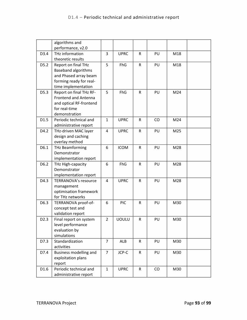
D1.4 – Periodic technical and administrative report
TERRANOVA Project Page 93 of 99
algorithms and performance, v2.0
D3.4 THz information theoretic results
3 UPRC R PU M18
D5.2 Report on final THz Baseband algorithms and Phased array beam forming ready for real-time implementation
5 FhG R PU M18
D5.3 Report on final THz RF-Frontend and Antenna and optical RF-frontend for real-time demonstration
5 FhG R PU M24
D1.5 Periodic technical and administrative report
1 UPRC R CO M24
D4.2 THz-driven MAC layer design and caching overlay method
4 UPRC R PU M25
D6.1 THz Beamforming Demonstrator implementation report
6 ICOM R PU M28
D6.2 THz High-capacity Demonstrator implementation report
6 FhG R PU M28
D4.3 TERRANOVA’s resource management optimisation framework for THz networks
4 UPRC R PU M28
D6.3 TERRANOVA proof-of-concept test and validation report
6 PIC R PU M30
D2.3 Final report on system level performance evaluation by simulations
2 UOULU R PU M30
D7.3 Standardization activities
7 ALB R PU M30
D7.4 Business modelling and exploitation plans report
7 JCP-C R PU M30
D1.6 Periodic technical and administrative report
1 UPRC R CO M30
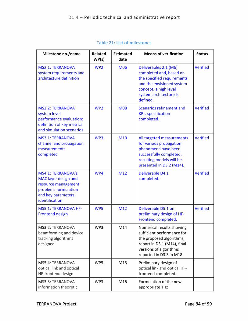
D1.4 – Periodic technical and administrative report
TERRANOVA Project Page 94 of 99
Table 21: List of milestones
Milestone no./name Related WP(s)
Estimated date
Means of verification Status
MS2.1: TERRANOVA system requirements and architecture definition
WP2 M06 Deliverables 2.1 (M6) completed and, based on the specified requirements and the envisioned system concept, a high level system architecture is defined.
Verified
MS2.2: TERRANOVA system level performance evaluation: definition of key metrics and simulation scenarios
WP2 M08 Scenarios refinement and KPIs specification completed.
Verified
MS3.1: TERRANOVA channel and propagation measurements completed
WP3 M10 All targeted measurements for various propagation phenomena have been successfully completed, resulting models will be presented in D3.2 (M14).
Verified
MS4.1: TERRANOVA’s MAC layer design and resource management problems formulation and key parameters identification
WP4 M12 Deliverable D4.1 completed.
Verified
MS5.1: TERRANOVA HF-Frontend design
WP5 M12 Deliverable D5.1 on preliminary design of HF-Frontend completed.
Verified
MS3.2: TERRANOVA beamforming and device tracking algorithms designed
WP3 M14 Numerical results showing sufficient performance for the proposed algorithms, report in D3.1 (M14), final versions of algorithms reported in D3.3 in M18.
MS5.4: TERRANOVA optical link and optical HF-frontend design
WP5 M15 Preliminary design of optical link and optical HF-frontend completed.
MS3.3: TERRANOVA information theoretic
WP3 M16 Formulation of the new appropriate THz

D1.4 – Periodic technical and administrative report
TERRANOVA Project Page 95 of 99
problem and performance indicators defined
Information Theory framework completed. Results reported in D3.4 (M18).
MS5.2: TERRANOVA Phased Array Beam-forming and Antenna design
WP5 M18 Deliverable D5.1 on preliminary design of Phased Array completed.
MS1.1: TERRANOVA project review
All WPs M18 The project has passed the Review and can continue its activities.
MS6.1: Off-line signal processing tests in THz Beamforming & THz High-capacity Demonstrators finished
WP5 M20 Results of off-line tests for both demonstrators available.
MS5.3: TERRANOVA Baseband signal and code design
WP5 M24 Deliverable D5.1 on preliminary baseband design completed.
MS2.3: TERRANOVA system level performance evaluation: final simulation results
WP2 M28 Deliverable D2.3 (M30)
MS4.2: Development of TERRANOVA’s wireless access and overall resource management
WP4 M28 Deliverables D4.2 and D4.3 completed.

D1.4 – Periodic technical and administrative report
TERRANOVA Project Page 96 of 99
8.7 Risks Identification and Risk Management Plan
Table 22 briefly reports the TERRANOVA’s consortium risk management plan.
Table 22: Risk management plan.
Risk No
Owner WP involved
Cause Prob. Impact Contigency Plan
Project Execution
1 UPRC ALL WP cost/time overrun
L L The project will be frequently reviewed and checked in order to track such issues and make any required rearrangements.
2 HHI/IAF ALL Incongruity in the technical approaches
L M The technical manager informs the corresponding WP leader(s).
3 HHI/IAF ALL Technical work diverges from project goals
L M The regular reviews and teleconferences will help identify such divergence in time, in order to correct them as soon as possible.
4 UPRC ALL Partner quits the project
L H In case that another partner of the consortium cannot undertake the responsibilities of the leaving partner, the consortium will try to recruit a new suitable one.
Technical Approach
5 UOULU WP3 Measurements: non-repairable equipment failure for wideband THz-TDS device
L M Simulations can be used instead for making the channel models based on the measurements that could be successfully performed. Also, possible to use partners' measurement equipment such as vector network analyzers in low THz band.
6 UOULU/UPRC WP3 Derivation of information theoretic fundamental bounds is intractable for some of the TERRANOVA models.
M M Benefit from the multidisciplinary nature of the project consortium and take alternative paths, consider simplified models.

D1.4 – Periodic technical and administrative report
TERRANOVA Project Page 97 of 99
7 ALB WP2 WP5 WP6
A data rate of 1 Tbps cannot be achieved.
L H Analyse the limits of all parts in the transmission chain; identify the bottlenecks and identify alternative paths. Evaluate the alternative paths at least by simulation/theory, if time for redesign and/or new technology run is too short.
8 UPRC WP4 The designed resource management scheme is too complex for practical implementation.
L M Develop sub-optimal framework (by relaxing constraints) that is implementable.
9 HHI/IAF WP2 WP3 WP4 WP5 WP6
Significant advances in the state-of-the-art outside TERRANOVA.
L M Continue to monitor state-of-the-art, and if necessary consider alternative solutions going even beyond the advances in the state-of-the-art and refocus/replan those parts of the project.
10 HHI WP5 WP6
FPGA implementation of baseband algorithms in the modem is too complex
M M Demonstration of the baseband algorithms by off-line signal processing (capturing of sampled data using a real-time oscilloscope and processing the data on a PC)
11 IAF WP3 WP5 WP6
Beamforming concept implementation fails
L H Analyse the root source of failure and identify alternative solutions. Evaluate the alternative paths at least by simulation/theory, if time for redesign and/or new technology run is too short.
12 IAF WP5 WP6
Existing first generation 300 GHz SISO and phased array testbed of IAF will drop out
L M Prototype solutions are kept modular which minimizes risk of failure of the complete hardware. Prepare backup of most critical module parts to minimize repair time.
13 IAF WP5 Next MMIC generation will not achieve required
M M Work plan covers 3 MMIC design iterations in 24 months.
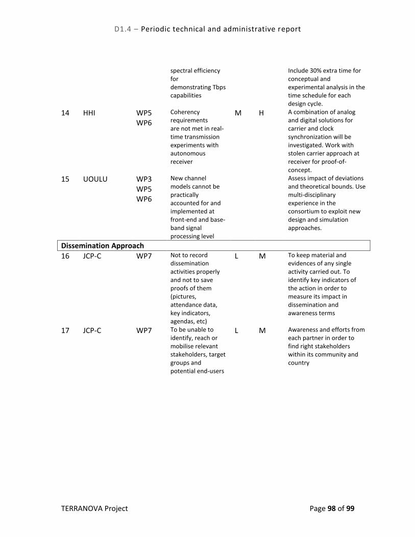
D1.4 – Periodic technical and administrative report
TERRANOVA Project Page 98 of 99
spectral efficiency for demonstrating Tbps capabilities
Include 30% extra time for conceptual and experimental analysis in the time schedule for each design cycle.
14 HHI WP5 WP6
Coherency requirements are not met in real-time transmission experiments with autonomous receiver
M H A combination of analog and digital solutions for carrier and clock synchronization will be investigated. Work with stolen carrier approach at receiver for proof-of-concept.
15 UOULU WP3 WP5 WP6
New channel models cannot be practically accounted for and implemented at front-end and base-band signal processing level
Assess impact of deviations and theoretical bounds. Use multi-disciplinary experience in the consortium to exploit new design and simulation approaches.
Dissemination Approach
16 JCP-C WP7 Not to record dissemination activities properly and not to save proofs of them (pictures, attendance data, key indicators, agendas, etc)
L M To keep material and evidences of any single activity carried out. To identify key indicators of the action in order to measure its impact in dissemination and awareness terms
17 JCP-C WP7 To be unable to identify, reach or mobilise relevant stakeholders, target groups and potential end-users
L M Awareness and efforts from each partner in order to find right stakeholders within its community and country

D1.4 – Periodic technical and administrative report
TERRANOVA Project Page 99 of 99
8.8 Overall Assessment, Impact and Deviations from the Project Workplan
During the first year of the project, TERRANOVA team collaborated towards successfully addressing and timely attaining/delivering all research/technical objectives and milestones. High quality deliverables, publications, presentations and other dissemination material verify the extent and value of the produced output and the created impact so far. The TERRANOVA consortium also placed a lot of effort on communicating, disseminating and interacting with the THz community and all the relevant stakeholders. In terms of utilisation of resources the TERRANOVA consortium underspent, (i.e. spent 13.45% less) compared to the effort planned for the first year, assuming uniform distribution of effort along time. The main reason for this underspending is that the actual- according to the workplan- effort distribution is not indeed uniform. One additional reason is that some consortium partners experienced some delays in recruiting researchers right at the beginning of the project. Other than these minor reasons, the TERRANOVA team has the right mix of expertise, skills and the right amount of resources to carry out the objectives and deliverables of this and the next reporting period.