delaware sediment and stormwater program technical document · a pre-construction meeting must be...
TRANSCRIPT

Delaware
Sediment and Stormwater Program
Technical Document
Article 4. Construction Review and
Compliance

03/2013 4.01-1
4.01
Construction Review Guidelines
Construction Site Stormwater Management (CSSWM) Pre-Construction Meeting
A written notification must be submitted to the review agency five days in advance of
requesting a pre-construction meeting and the notification must be accompanied by the
Certified Construction Reviewer (CCR) Application form. A construction site stormwater
management pre-construction meeting must be held before any land disturbing activity
may occur. The pre-construction meeting should always be held at the proposed site
unless the Delegated Agency approves of another location. While at the meeting,
attendees review the sequence of construction, the anticipated work area in conjunction
with any site concerns or questions.
A pre-construction meeting must be held for all projects that require a detailed plan.
For Standard Plan applications, the Delegated Agency determines whether a pre-
construction meeting is required. The required attendees for a pre-construction meeting
are the owner (or owner’s representative), the site project manager, site contractor,
Certified Construction Reviewer (if required), the Responsible Person (Blue Card
Holder), and the Delegated Agency site reviewer. The essential items that must be
covered at the pre-construction meeting are listed in the Pre-Construction Meeting
Check List at Appendix 4.01.1. While on the site, review the site to locate all existing
drainage inlets and check the inlets against those noted on the approved Plan. Review
the construction site access and confirm that the access is suitable for construction
vehicles.
Perimeter Control Review (PCR)
The Department requires the installation and review of the perimeter construction site
stormwater management (CSSWM) practices before any land disturbing activity
commences. The perimeter controls are contained on the approved Sediment and
Stormwater Plan and their installation and review are included in the Sequence of

03/2013 4.01-2
Construction. The review must be conducted by DNREC or the Delegated Agency prior
to proceeding with bulk grading or other construction activities on the construction site.
In some cases where perimeter controls that require land disturbance such as berms,
dikes, swales and traps are not started until after the initial perimeter control review.
Upon completion of the berms, dikes, swales, and traps another review may be required
by DNREC or the Delegated Agency. These site review timeframes will be established
at the pre-construction meeting.
Pollution Prevention Review
The pollution prevention details on the Delaware approved Sediment and Stormwater
Plan are required elements for compliance with Chapter 60 of Title 7 of the Delaware
Code Section 9.1.02 of Delaware’s Regulations Governing the Control of Water
Pollution, 7 Del. Admin. Code 7201 and the EPA Stormwater Pollution Prevention Plan
(SWPPP). The construction site pollution prevention best management practices
(reference the Delaware Erosion and Sediment Control Handbook) must be reviewed
and documented in the CSSWM report.
Construction Site Stormwater Management Review by the Delegated Agency:
The Department requires regular construction site reviews to be conducted such that
the local Delegated Agency is overseeing and verifying that the requirements of the
Chapter 60 of Title 7 of the Delaware Code Section 9.1.02 of Delaware’s Regulations
Governing the Control of Water Pollution, 7 Del. Admin. Code 7201 are met which
includes the implementation of the Sediment and Stormwater Plan. The regular review
should verify that a Responsible Person is on site daily during construction site work
that involves any land disturbing activity, which includes fine grading and utility work that
could impact CSSWM practices.
• Each time a site is visited there must be documentation of the visit.

03/2013 4.01-3
• The site reviewer should verify that the approved Sediment and Stormwater Plan
is on site.
• Each time a construction review is conducted, a CSSWM report must be written.
• The report must be provided to the owner, construction manager, and
CCR (if applicable) as a minimum.
• The report describes items in compliance with the approved Plan and any
deficiencies.
• The report contains the prescribed action to correct deficiencies.
• The report must be kept digitally or a paper copy in the project file.
• Any field modifications that affect the stormwater management system design
must be communicated to the owner/developer through the Delegated Agency.
When a revision is necessary, the Delegated Agency will instruct the
owner/developer to submit a Plan revision for review.
• In the case where the Delegated Agency is the responsible party for review of the
stormwater management facilities, the construction reviewer must be present on
the site to observe the facility construction to the extent that the stormwater
facility construction checklist can be filled out for each facility.
• If a violation is observed on site, the owner/developer of the project must be
notified in writing of the nature of the violation, the corrective action, and a
timeframe for violation correction.
• At the completion of a project, the Delegated Agency can require a vacuuming of
the entire storm system.
• Refer to the technical document entitled Article 4.05 Project Completion for
guidance on project completion and Construction General Permit termination.

03/2013 4.01-4
Construction Site Stormwater Management Review by a CCR:
The Department requires regular construction site reviews to be conducted such that
the approved Sediment and Stormwater Plan is fully implemented and the requirements
of the Chapter 60 of Title 7 of the Delaware Code Section 9.1.02 of Delaware’s
Regulations Governing the Control of Water Pollution, 7 Del. Admin. Code 7201 are
met. The Chapter 60 of Title 7 of the Delaware Code Section 9.1.02 of Delaware’s
Regulations Governing the Control of Water Pollution, 7 Del. Admin. Code 7201
contains monitoring requirements that must be fulfilled by the owner, and often times, a
CCR is obtained to fulfill this requirement. When the owner employs a CCR to perform
construction review, the CCR must fill out the CCR Application and provide the original
to the Delegated Agency prior to land disturbing activity. The details of who will be
performing the construction reviews are discussed with the Delegated Agency at the
pre-construction meeting.
• A CSSWM report must be written and provided to the owner, construction
manager, and Delegated Agency as a minimum. The report is prepared and
provided in a way that meets the performance standards of a CCR.
• The pollution prevention practices must be reviewed and documented in the
CSSWM report. The standard detail and specifications for Site Pollution
Prevention are contained on the Sediment and Stormwater Plan details sheet.
• The CCR must utilize the most current version of the Delaware Erosion and
Sediment Control Handbook as a reference for installation, specifications, and
maintenance of erosion and sediment control best management practices.
• When the CCR is the responsible party for review of the stormwater
management facilities, the CCR must be present on the site to observe the
facility construction to the extent that the stormwater facility construction checklist
can be filled out for each facility.
• Any CSSWM practices that are not capable of controlling the sediment may have
to be improved or revised. Any changes must be reviewed by the Delegated

03/2013 4.01-5
Agency. Allow the Delegated Agency to determine whether the resolution is a
field change or whether it necessitates a revised Sediment and Stormwater Plan.
The Delegated Agency will guide the process of contacting the owner and how to
proceed toward a resolution to the site issue. Once the resolution is approved by
the Delegated Agency, field changes are annotated on the approved set of plans;
whereby a revision to the plan will usually require a new set of engineered-
stamped plans. Changes need to be documented on the next CCR and
Delegated Agency CSSWM report.
• The report should contain a reasonable deadline for all CSSWM items to be
corrected.
• Follow-up the site review with a written CSSWM report within the timeframe set
forth by the local Delegated Agency; not to exceed 7 calendar days. It is the
CCR’s responsibility to ensure that the local Delegated Agency is receiving the
reports signed by the CCR and the Signing Professional Engineer (PE).
• At the completion of a project, the Delegated Agency can require a vacuuming of
the entire stormwater management system. The vacuuming of the system must
be reviewed by the CCR or the Delegated Agency to observe that the sediment
removal is satisfactorily completed.
Construction Site Stormwater Management (CSSWM) Report:
The construction site stormwater management report is the means of communicating
construction site observations to the project owner. The CCR has received training
through the Department’s CCR course and re-certification course on the report content
requirements. A CCR must adhere to the local agency reporting requirements. In
addition, some agencies may require digital report submissions instead of facsimiles
and hardcopies; again, the site reviewer must adopt the accepted submission format of
the local Delegated Agency. The CSSWM report form is located on the Department
website.

03/2013 4.01-6
Indicating Site Compliance on the CSSWM Report:
In general, site compliance is determined by the observations of the site reviewer at the
time of the review and any outstanding CSSWM issues from the previous report(s). The
three nomenclatures used on the CSSWM report to describe the condition of a specific
CSSWM practice are (S) for satisfactory, (U) for unsatisfactory, and (NA) for not
applicable to the site. In some cases, a CSSWM item may be reported as NA because
that item has not been implemented on the site yet; for instance a stone check dam or
outlet protection. Once the CSSWM practice is installed it will be reported as a U or S.
Likewise, when construction is coming to a conclusion some CSSWM practices will be
removed upon the direction of the local agency; those practices can then be reflected as
NA. The report narrative must support the NA nomenclature by stating that the practice
had been removed.
If a CSSWM practice receives an unsatisfactory, the narrative portion of the report must
provide the reviewer’s observations and corrective action. An overall rating of
compliance or non-compliance must be placed on the CSSWM report.
Stormwater Facility Installation and Review:
When stormwater facilities are being installed on a construction site, the site reviewer
must have the required Department construction checklist for that specific facility. The
construction checklists for each stormwater facility are contained in Appendix 4.01.2
entitled BMP Construction Checklists. The designated person, either the CCR or a
Delegated Agency representative, conducting the stormwater facility review is
determined at the pre-construction meeting and all the construction principals are
informed that the reviewer must be on site when installation is occurring. All aspects of
the construction must be documented; especially with underground systems that include
stormwater pond outfall pipe, bioretention area, infiltration trench, manifold systems,
level spreaders, and underdrains. Photographic documentation of underground
systems is required. The site reviewer must verify that all the elements on the Sediment
and Stormwater Plan are being implemented for each stormwater facility. Any deviation

03/2013 4.01-7
from the plan must be discussed with the Delegated Agency and project manager; then
follow up with a notation on the plan and in the CSSWM report.
Once the stormwater facility is installed, the owner will submit the stormwater facility
post construction verification document within 60 days. Appendix 4.01.3 contains the
Post Construction Verification Document checklist. Before project close out, the
stormwater facilities must be converted to permanent use and post construction
verification documents submitted again to the Delegated Agency.
Releasing the CCR Review Requirement
As a construction project is applying stabilization by hard surfacing, stone, vegetation,
and landscaping; the amount of disturbed soils is being reduced. The owner (or the
CCR) can contact the local Delegated Agency and request a site review to determine
whether the CCR reviews are still required. Only the local agency reviewer can release
the CCR from the construction reviews if it is determined that the CCR is no longer
required. The owner must continue to adhere to the requirements under the Delaware
Regulations Governing the Control of Water Pollution, Section 9.1.02, Monitoring until
project termination.
Site Construction Inactivity
At times during construction, a site may become inactive due to a variety of
circumstances. Some circumstances may be due to irregular funding, reduced housing
demand, change of phases, change of contractor, change in owner, a lapse between
remediation activities and construction, etc. Site activity, circumstances, and
requirements shall comply with Chapter 60 of Title 7 of the Delaware Code Section
9.1.02 of Delaware’s Regulations Governing the Control of Water Pollution, 7 Del.
Admin. Code 7201.

03/2013 4.01.1-1
Pre-Construction Meeting Check List � The sign in sheet has the following items for contact information
� Name � Company name, address, telephone numbers (office, fax, cell phone) � E-mail address
� Request business cards for the project file
� When is the anticipated start and end of construction?
� How will the construction vehicles access the site?
� How will the personal vehicles be handled in and around the construction site?
� Method for sending and receiving reports (e-mail, fax, or hard copy).
� Determine who the responsible person is, Blue Card Holder, and request to see the Blue Card to verify the
card is current. Record their card number on the sign-in sheet. Go over the Blue Card responsibilities while
there is site activity.
� Determine who will be performing the CCR duties, and request to see the CCR Card to verify the card is
current. Record their card number on the sign-in sheet.
� Provide the CCR Application to the CCR and begin the process of filing it out is all parties are available. (No
land disturbing activity begins until the CCR Application form has been received by the plan review agency)
� Requirement to have the approved plan on site at all times.
� Requirement to have a copy of the Notice of Intent on site at all times.
� NPDES requirements during construction activity
� Weekly site reviews of the erosion and sediment controls � Reviews of erosion and sediment controls after a rain event that produces runoff � Maintaining the erosion and sediment control reviews on site in a log � Discuss if stormwater monitoring is a requirement, and if so, the monitoring log to be on site
Sequence of Construction and Construction General Notes
� Read through and discuss the Sequence of Construction. Discuss all General Construction Notes that are
pertinent.
� Go over pollution prevention details as they pertain to this project.
� Discuss setting up the required perimeter control review (PCR) and define which controls must be installed.
Discuss what the PCR will entail.
� Discuss the requirement for all stormwater conveyance channels and swales to have erosion control matting
installed. If matting is not on the approved sediment and stormwater plan, contact the design engineer for the
appropriate product.
� Discuss stockpiling of material on site. Discuss exporting of material off-site, the intended location of the
materials and necessary E&S controls if operation of stockpiling is over 5000 sqft.

03/2013 4.01.1-2
� It is required for the owner of a site to have a Nutrient Management Plan for the use of fertilizers on the
construction site when more than 10 acres of fertilizers are being applied and the fertilizer must be applied by
a certified nutrient applier.
Stormwater Facility
� Discuss whether a pre-construction meeting is necessary prior to pond or bioretention installation
� Provide the stormwater facility construction check lists to the CCR for the pertinent facilities to be installed.
Tell the CCR that the construction check lists must be submitted to the local agency reviewer and the local
agency stormwater engineer that will be reviewing the post construction verification documents (PCVD).
� Provide the post construction verification document check lists to the project manager that will order the PCV
surveys.
� Discuss the requirement of the CCR being on site for all aspects of the stormwater facility installation and the
CCR must be notified at least 72 hours in advance of the construction start. For bioretention areas, the CCR
must receive a copy of the delivery tickets for the biosoil.
� (If applicable) Discuss soil compaction and cordoning off areas of proposed stormwater facilities that rely on
infiltration. If compaction during construction is suspect, the delegated agency can require new infiltration
testing prior to the stormwater facility being installed to verify infiltration.
Project Termination
� Sediment removal from the stormwater facility is required before project termination.
� CCR must receive the permanent seed mix tags from the bags. If there is a specific mix called for on the
approved sediment and stormwater plan, the tags must match the designed mix.
� Discuss the NPDES General Permit coverage termination requirements with the owner
� (If applicable) Discuss when stormwater facility PCV surveys will be done (after installation and at project
completion). Provide the CCR with the appropriate stormwater facility construction checklists. Construction
check list must be submitted to the delegated agency site reviewer and submitted with the PCVDs to the
delegated agency.
� Releasing the CCR/converting to weekly reviews by the owner must be approved by the delegated
agency. � 70 % germination of permanent seed is required for project termination. The delegated agency can
grant a temporary certificate of occupancy for a period of up to six (6) months while vegetative growth is establishing.
� Discuss the requirement that all elements on the approved sediment and stormwater plan have been met.
� (If applicable) Discuss stormwater management system maintenance requirements
Periods of Site Inactivity
� If for any reason a construction site becomes inactive, the local delegated agency must be contacted.
03/2013 4.01.2-1
Appx. 4.01.2 Best Management Practices (BMP) Construction Checklists When stormwater facilities are being constructed on a site, it is required that a BMP checklist is filled out for each stormwater facility constructed. The person responsible for reviewing stormwater facility construction and installation is the person also responsible for filling out the BMP checklists. For example, if a site has three bioretention areas being installed, a bioretention construction checklist for each bioretention must be filled out and supplied to the local Delegated Agency. The BMP checklists are contained in the sub-appendices under 4.01.2.

03/2013 4.02.1-1
Infiltration Construction Checklist This checklist has been designed for infiltration practices constructed
in accordance with the Delaware Sediment and Stormwater Program’s Post Construction Stormwater Management BMP Standards and Specifications
PROJECT INFORMATION Project Name:
Location:
Contractor:
Construction Reviewer:
Date(s) / Time(s) of Inspections:
KEY: Item meets standard
X Item not acceptable N/A Item not applicable
I. Pre-Construction A. Facility location staked out. Extents of infiltration practice (to include pre-treatment area) delineated and access by equipment prohibited to prevent compaction of existing soils. B. Upstream drainage area stabilized or effectively diverted. C. Materials on-site and dimensions and properties checked.
(1) Underdrain/discharge pipe (2) Overdrain/discharge pipe (3) Underdrain stone (4) Geotextile fabric (5) Sand (6) Supplemental storage pipe (7) Outfall pipe (8) Riser pipe (9) Observation ports D. Equipment on the site large enough to excavate infiltration area from the sides of the facility.

Infiltration Construction Checklist, page 2
Project Name:
Construction Reviewer:
03/2013 4.02.1-2
II. Excavation A. Facility excavated to dimensions and at location as per the approved plan.
B. Stepwise excavation used for infiltration facilities.
C. Facility excavated from the sides so as to not compact the existing soil.
D. Groundwater not encountered during excavation. (Note: If groundwater is encountered during the excavation process, construction of the facility must cease and the designer notified that a plan modification is necessary)
E. Sides of infiltration trench excavation vertical.
F. Bottom of excavation within design slope range.
G. Bottom of trench excavation scarified prior to placement of sand. H. Geotextile fabric placed along the vertical sides of the trench, tuck into sand at the
bottom for anchoring. III. Structural Components (For infiltration practices containing underdrains and/or overdrain pipe discharge components) A. Discharge pipe installed from overdrain to discharge point.
Discharge pipe diameter:
Discharge pipe material:
B. Outlet protection provided at discharge point.
C. Underdrain pipe material according to approved plan. (Note: If underdrain pipe material is not specified, it shall be SDR 35 minimum)
Underdrain pipe material: D. Underdrain pipe sizes according to approved plans.
Underdrain pipe diameter(s):
E. Underdrain pipe perforations according to approved plans. (Note: If not specified on the plan, three rows of 5/8” diameter perforations, 6” on-center, shall be provided)
F. Underdrain piping lay flat or with positive slope toward outlet.
G. Clean-outs and/or observation ports provided at endpoints of underdrain pipes or as shown on the approved Plan.
H. Double-washed crushed aggregate, clean DE #57 stone, used for the underdrain gravel. Stone free of rock dust, fines and soil particles.
I. Depth of stone over underdrain piping checked. Depth of stone: ______________

Infiltration Construction Checklist, page 3
Project Name:
Construction Reviewer:
03/2013 4.02.1-3
IV. Grading
A. Channel protection and/or level spreader provided at infiltration practice inlets as specified on the approved plan.
B. Side slopes of infiltration basin no steeper than 3:1. C. Bottom of basin graded as per the Plan.
D. Earth spillway constructed to design elevation and dimensions.
VI. Vegetation
A. Vegetation planted on the bottom and slopes of the basin as indicated on the vegetation spec on the Plan.
B. For trenches, placement of topsoil and sod over the pea gravel, if this option is specified on Plan.
VII. Erosion and Sediment Control
A. Installed matting in spillway as specified on Plan. B. For trenches, geotextile emerges from the sides of the trench and folds over stone to protect against sediment contamination during site construction.

03/2013 4.01.2.2-1
Bioretention Facility Construction Checklist This checklist has been designed for bioretention facilities constructed
in accordance with the Delaware Sediment and Stormwater Program’s Post Construction Stormwater Management BMP Standards and Specifications
PROJECT INFORMATION Project Name:
Location:
Contractor:
Construction Reviewer:
Date(s) / Time(s) of Inspections:
KEY: Item meets standard
X Item not acceptable N/A Item not applicable
I. Pre-Construction A. Pre-construction meeting held.
B. Facility location staked out. Extents of bioretention facility delineated and access by equipment prohibited to prevent compaction of existing soils.
C. Upstream drainage area stabilized or effectively diverted.
D. Materials on-site and dimensions and properties checked.
(1) Underdrain/discharge pipe (2) Overflow catch basin (3) Underdrain stone (4) Filter fabric (5) Bioretention soil media (6) Plants (Note: Plants need not be at the site at onset of construction) E. Equipment on the site large enough to excavate bioretention trench from the sides of
the facility.

Bioretention Facility Construction Checklist, page 2 KEY:
Item Meets Standard
Project Name: X Item Not Acceptable
Construction Reviewer: N/A Item Not Applicable
03/2013 4.01.2.2-2
II. Excavation A. Facility excavated to dimensions and at location as per the approved plan.
B. Stepwise excavation used for infiltration bioretention facilities. (Note: only excavate the portion of the bioretention facility that may be backfilled with
bioretention soil media in the same day) C. Facility excavated from the sides so as to not compact the existing soil.
D. Groundwater not encountered during excavation. (Note: If groundwater is encountered during the excavation process, construction of the facility must cease and the designer notified that a plan modification is necessary)
E. Sides of excavation vertical.
F. Bottom of excavation within design slope range.
G. Sides and bottom of excavation scarified prior to placement of bioretention soil media.
III. Structural Components (For bioretention facilities containing underdrains and/or pipe discharge components) A. Discharge pipe installed from overflow catch basin to discharge point.
Discharge pipe diameter:
Discharge pipe material:
B. Outlet protection provided at discharge point.
C. Overflow catch basin installed at elevations as specified on the approved plan (minimum of 6” higher than design top elevation of bioretention soil media).
D. Underdrain pipe material according to approved plan. (Note: If underdrain pipe material is not specified, it shall be SDR 35 minimum) Underdrain pipe material: E. Underdrain pipe sizes according to approved plans.
Underdrain pipe diameter(s):
F. Underdrain pipe perforations according to approved plans. (Note: If not specified on the plan, three rows of 5/8” diameter perforations, 6” on-center, shall be provided)

Bioretention Facility Construction Checklist, page 3 KEY:
Item Meets Standard
Project Name: X Item Not Acceptable
Construction Reviewer: N/A Item Not Applicable
03/2013 4.01.2.2-3
III. Structural Components (continued)
G. Underdrain piping laid flat or with positive slope toward outlet.
H. Clean-outs and/or observation ports provided at endpoints of underdrain pipes.
I. Double-washed crushed aggregate, clean DE #57 stone, used for the underdrain gravel. Stone free of rock dust, fines and soil particles.
J. Minimum 3” of gravel over underdrain piping.
K. Filter fabric in accordance with approved plan specification laid between underdrain gravel layer and bioretention soil media.
Filter fabric manufacturer’s product number:
IV. Grading
A. Channel protection and/or level spreader provided at bioretention facility inlets as specified on the approved plan.
B. Side slopes of buffer area (above design top of bioretention soil media) no steeper than 3:1.
C. Top of berm constructed to design elevation and width.
D. Earth spillway constructed to design elevation and dimensions.
V. Bioretention Soil Media
A. Bioretention soil media provided in accordance with current DNREC policy.
B. Bioretention soil media placed in lifts of one foot and spread out using an excavator from the side of the excavation to minimize compaction. Skid steer loaders or other small equipment shall not be used within the bioretention facility excavation to place the soil media.
C. Bioretention soil media placed when media is optimally moist (not wet or dry) and there is no precipitation.
D. Bioretention soil media placed within infiltration bioretention facilities during the same day that the area is excavated to prevent contamination if a runoff event should occur prior to placement of soil media.
E. Bioretention soil media allowed to settle for at least one storm event before the final lift is added.

Bioretention Facility Construction Checklist, page 4 KEY:
Item Meets Standard
Project Name: X Item Not Acceptable
Construction Reviewer: N/A Item Not Applicable
03/2013 4.01.2.2-4
V. Bioretention Soil Media (continued)
F. Bioretention soil media depth not less than 36” unless otherwise specified on the
approved plan. G. Topdressing of 3” double-shredded aged hardwood mulch applied if desired or required
by the approved plan. (Note: A biodegradable netting may be used to prevent wind losses until several wet-dry cycles have occurred)
VI. Vegetation
A. Vegetation planted within the bioretention soil media according to the numbers and species on the approved bioretention planting plan.
B. Plants occupy not more than 50% of the total surface area of the bioretention soil media. C. Individual plant spacing follows the recommendations on the plan.
D. Trees planted only around the perimeter of the facility in the native soils, not in the bioretention soil media.
VII. Erosion and Sediment Control
A. Silt fence placed around the bioretention area perimeter to prevent sediment contamination prior to full stabilization of contributory drainage area.
B. Inlet protection provided on any catch basins that discharge to the bioretention facility.

03/2013 4.01.2.8-1
Vegetated Channels Construction Checklist
This checklist has been designed for vegetated channels in accordance with the Delaware Sediment and Stormwater Program’s
Post Construction Stormwater Management BMP Standards and Specifications.
PROJECT INFORMATION Project Name:
Location:
Contractor:
Construction Reviewer:
Date(s) / Time(s) of Inspections:
KEY: Item meets standard
X Item not acceptable N/A Item not applicable
I. Pre-Construction A. Facility location staked out. Extents of vegetated channel (to include pre-treatment area) delineated and access by equipment prohibited to prevent compaction of existing soils. B. Upstream drainage area stabilized or effectively diverted prior to beginning construction
of the channel. C. Pretreatment type
(1) Grass Filter Strip (2) Gravel or Stone Diaphragm (3) Gravel or Stone Level Spreader (4) Initial Sediment Forebay (5) Check Dams, if required on the approved Plan (5) Other: _____________________________________________________ D. Verify the equipment on the site are large enough to excavate the channel from the sides; not sitting in the bottom of the channel footprint.

Vegetated Channels Construction Checklist, page 2
Project Name:
Construction Reviewer:
03/2013 4.01.2.8-2
II. Excavation A. Facility excavated to dimensions and at location as per the approved plan.
B. Facility excavated from the sides so as to not compact the existing soil. C. Groundwater not encountered during excavation.
(Note: If groundwater is encountered during the excavation process, construction of the facility must cease and the designer notified that a plan modification is necessary)
D. Outlet protection provided at discharge point.
IV. Grading
A. Proper grading connecting the pretreatment practice to the vegetated channel as specified on the approved Plan. B. Side slopes installed as per the approved Plan. C. Bottom of channel graded as per the approved Plan.
D. Installation of stone check dams, if required on the approved Plan.
VI. Vegetation
A. Vegetation planted on the bottom and slopes of the channel as indicated on the approved Plan.
B. Seeding applied at a rate to achieve 90% germination.
VII. Erosion and Sediment Control
A. Installed erosion control matting in the conveyance area as specified on the approved Plan.

03/2013 4.01.2.10.1-1
Dry Detention Facilty Construction Checklist
For permanent structures per Delaware NRCS Pond Code 378, Delaware Sediment and Stormwater Regulations, and Post Construction Stormwater
Management BMP Standards and Specifications
PROJECT INFORMATION Project Name:
Location:
Contractor:
Construction Reviewer:
Date(s) / Time(s) of Inspections:
KEY: Item meets standard
X Item not acceptable N/A Item not applicable
I. Materials and equipment. _____ Pipe and appurtenances on-site prior to construction and dimensions checked.
____ 1) Material (including protective coating, if specified). ____ 2) Diameter
____ 3) Dimensions of pre-cast concrete outlet structure. ____ 4) Required dimensions between water control structures (orifices, weirs, etc.)
are in accordance with plans. ____ 5) Barrel stub for prefabricated pipe structures at proper angle for design barrel
slope. ____ 6) Number and dimensions of prefabricated anti-seep collars.
____ 7) Watertight connectors and gaskets. ____ 8) Outlet drain valve.
_____ Appropriate compaction equipment available, including hand and small power tamps. _____ Project benchmark near pond site.
_____ Equipment for temporary de-watering.

Dry Detention Facility Construction Checklist, page 2
Project Name:
Construction Reviewer:
03/2013 4.01.2.10.1-2
II. Subgrade preparation.
_____ Area beneath embankment stripped of all vegetation, topsoil and organic matter. _____ Cut-off trench excavated a minimum of 4 FT below subgrade and minimum 4 FT below
proposed pipe invert, with side slopes no steeper than 1:1. _____ Impervious material used to backfill cut-off trench.
III. Pipe spillway installation. _____ Method of installation detailed on plans.
A. Bed preparation. _____ Installation trench excavated with 1:1 side slopes.
_____ Stable, uniform, dry subgrade of relatively impervious material. (If subgrade is wet, contractor shall have defined steps before proceeding with installation.)
_____ Invert at proper elevation and grade. B. Pipe placement.
_____ Metal/Plastic pipe ____ 1) Watertight connectors and gaskets properly installed
____ 2) Anti-seep collars properly spaced and having watertight connections to pipe.
____ 3) Backfill placed and tamped by hand under “haunches” of pipe. ____ 4) Remaining backfill placed in max. 8” lifts using small power tamping
equipment until 2’ cover over pipe is reached. _____ Concrete pipe
____ 1) Pipe set on blocks or concrete slab for pouring of low cradle. ____ 2) Pipe installed with rubber gasket joints with no spalling in gasket interface
area. ____ 3) Excavation for lower half of anti-seep collar(s) with reinforcing steel set.
____ 4) Entire area where anti-seep collar(s) will come in contact with pipe coated with mastic or other approved waterproof sealant.
____ 5) Low cradle and bottom half of anti-seep collar installed as monolithic pour and of an approved mix.
____ 6) Upper half of anti-seep collar(s) formed with reinforcing steel set.

Dry Detention Facility Construction Checklist, page 3
Project Name:
Construction Reviewer:
03/2013 4.01.2.10.1-3
Concrete pipe (continued)
____ 7) Concrete for collar of an approved mix and vibrated into place. (Protected from freezing while curing, if necessary.)
____ 8) Forms stripped and collar inspected for honeycomb prior to backfilling. Parge if necessary.
C. Backfilling _____ Fill placed in maximum 8” lifts.
_____ Backfill taken minimum 2’ above top of anti-seep collar elevation before traversing with heavy equipment.
IV. Riser/Outlet structure installation. A. Metal riser
_____ Riser base excavated or formed on stable subgrade to design dimensions. _____ Embedded section of aluminum or aluminized pipe to be painted with zinc chromate or
equivalent on inside and outside surfaces. _____ Set on blocks to design elevations and plumbed.
_____ Reinforcing bars placed at right angles and projecting into sides of riser. _____ Concrete poured so as to fill inside of riser to invert of barrel.
B. Pre-cast concrete structure _____ Dry and stable subgrade.
_____ Riser base set to design elevation. _____ If more than one section, no spalling in gasket interface area; gasket or approved caulking
material placed securely. _____ Watertight and structurally sound collar or gasket joint where structure connects to pipe
spillway. C. Poured concrete structure
_____ Footing excavated or formed on stable subgrade, to design dimensions with reinforcing steel set.
_____ Structure formed to design dimensions, with reinforcing steel set as per plan. _____ Concrete of an approved mix and vibrated into place. (Protected from freezing while curing,
if necessary.) _____ Forms stripped and structure inspected for “honeycomb” prior to backfilling. Parge if
necessary.
V. Embankment construction. A. Fill material.

Dry Detention Facility Construction Checklist, page 4
Project Name:
Construction Reviewer:
03/2013 4.01.2.10.1-4
_____ Soil engineer’s test.
_____ Visual test by inspector. B. Compaction.
_____ Soil engineer’s test. _____ Visual test by inspector.
C. Embankment. _____ Fill placed in max. 8” lifts and compacted with appropriate equipment.
_____ Constructed to design cross-section, side slopes and top width. _____ Constructed to design elevation plus allowance for settlement.
VI. Impounded area construction. _____ Excavated/graded to design contours and side slopes.
_____ Inlet pipes have adequate outfall protection. _____ Forebay
VII. Earth emergency spillway construction. _____ Spillway located in cut or structurally stabilized with riprap, gabions, concrete, etc.
_____ Excavated to proper cross-section, side slopes and bottom width. _____ Entrance channel, crest, and exit channel constructed to design grades and elevations.
VIII. Outlet protection. A. End section.
_____ Securely in place and properly backfilled. B. Endwall
_____ Footing excavated or formed on stable subgrade, to design dimensions and reinforcing steel set, if specified.
_____ Endwall formed to design dimensions with reinforcing steel set as per plan. _____ Concrete of an approved mix and vibrated into place. (Protected from freezing, if
necessary.) _____ Forms stripped and structure inspected for “honeycomb” prior to backfilling. Parge if
necessary. C. Riprap apron/channel.
_____ Apron/channel excavated to design cross-section with proper transition to existing ground. _____ Geotextile in place.
_____ Stone sized as per plan and uniformly placed at the thickness specified.

Dry Detention Facility Construction Checklist, page 5
Project Name:
Construction Reviewer:
03/2013 4.01.2.10.1-5
IX. Vegetative stabilization. _____ Approved seed mixture or sod. _____ Proper surface preparation and required soil amendments.
_____ Stabilization matting or other stabilization materials, as per plan.
IX. Miscellaneous. _____ Toe drain.
_____ Temporary dewatering device installed as per plan w/appropriate fabric, stone size and perforations if included.
_____ Drain for ponds having a permanent pool. _____ Trash rack/anti-vortex device secured to outlet structure.
_____ Trash protection for low flow pipes, orifices, etc. _____ Fencing (when required).
_____ Access road. _____ Set aside area for clean-out and maintenance.

03/2013 4.01.2.10.2-1
Underground Detention Facility Construction Checklist
This checklist has been designed for underground detention facilities constructed in accordance with the Delaware Sediment and Stormwater Program’s
Post Construction Stormwater Management BMP Standards and Specifications
PROJECT INFORMATION Project Name:
Location:
Contractor:
Construction Reviewer:
Date(s) / Time(s) of Inspections:
KEY: Item meets standard
X Item not acceptable N/A Item not applicable
I. Pre-Construction. A. Pre-construction meeting held prior to beginning the facility (as required by the Delegated Agency). B. Facility location staked out.
C. Upstream drainage area stabilized or effectively diverted.
D. Materials on-site and dimensions and properties checked.
(1) Underground chambers and end caps (2) Manhole/Maintenance access catch basin (3) Perforated pipe outlet underdrains, if applicable (4) Filter fabric as specified on the Plan (5) Acceptable size of washed, crushed angular stone as per the Plan (6) Acceptable fill materials as per the Plan (7) Vibratory roller (8) Dewatering equipment

Underground Detention Facility Construction Checklist, page 2 KEY:
Item Meets Standard
Project Name: X Item Not Acceptable
Construction Reviewer: N/A Item Not Applicable
03/2013 4.01.2.10.2-2
II. Excavation. A. Facility excavated to dimensions and at location as per the approved plan. Excavation
must be free of any standing water. B. Stepwise excavation used for infiltration facilities by preventing any compaction in the
bottom of the facility. C. Facility excavated from the sides so as to not compact the existing soil.
D. Groundwater encountered during excavation? (Note: If groundwater is encountered during the excavation process, construction of the facility must cease and the designer notified that a plan modification is necessary)
E. Sides of excavation vertical.
F. Bottom of excavation level.
III. Structural Components. A. Discharge pipe installed at discharge point.
Discharge pipe diameter:
Discharge pipe material:
B. Outlet protection provided at discharge point, if applicable.
C. Outlet control structure installed at correct invert.
D. Manhole/maintenance catch basin installed at elevations as specified on the approved plan.
E. Clean-outs and/or observation ports installed as per the Plan.
F. Inlet catch basins installed at the correct inverts.
G. Washed, crushed angular stone used for the facility bed. H. Minimum 6” of stone on the bottom of excavation or as prescribed by the design
engineer. Stone depth: __________ I. Chambers laid out in the method shown on Plan.
J. Minimum 6” of stone on the top of the chambers or at the depth prescribed by the design engineer. Stone placed on top of the installed chambers as per the Plan.
Stone depth: __________
Underground Detention Facility Construction Checklist, page 3 KEY:
Item Meets Standard
Project Name: X Item Not Acceptable
Construction Reviewer: N/A Item Not Applicable
03/2013 4.01.2.10.2-3
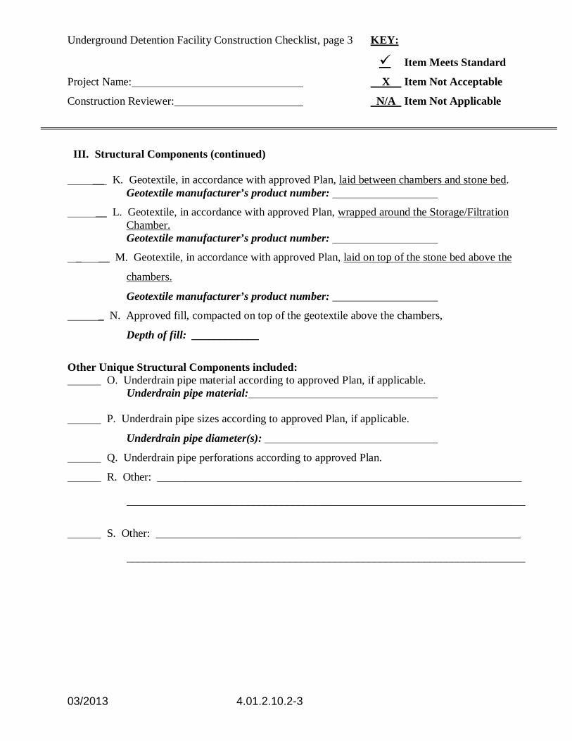
III. Structural Components (continued) __ K. Geotextile, in accordance with approved Plan, laid between chambers and stone bed. Geotextile manufacturer’s product number:
__ L. Geotextile, in accordance with approved Plan, wrapped around the Storage/Filtration Chamber.
Geotextile manufacturer’s product number:
_ __ M. Geotextile, in accordance with approved Plan, laid on top of the stone bed above the
chambers.
Geotextile manufacturer’s product number:
_ N. Approved fill, compacted on top of the geotextile above the chambers,
Depth of fill: ____________
Other Unique Structural Components included: O. Underdrain pipe material according to approved Plan, if applicable. Underdrain pipe material: P. Underdrain pipe sizes according to approved Plan, if applicable.
Underdrain pipe diameter(s):
Q. Underdrain pipe perforations according to approved Plan.
R. Other: _________________________________________________________________
_______________________________________________________________________
S. Other: _________________________________________________________________
_______________________________________________________________________

Underground Detention Facility Construction Checklist, page 4 KEY:
Item Meets Standard
Project Name: X Item Not Acceptable
Construction Reviewer: N/A Item Not Applicable
03/2013 4.01.2.10.2-4
IV. Grading for impervious finished surface
A. Pavement sub-base, compacted. Material: ____________________________________ B. Impervious finished surface applied and finished grade lines achieved. Other finished surface options:
C. Fill material compacted. Material: ____________________________________
D. Finished surface of vegetation, 4” minimum of topsoil, amendments, mulching, and mulch anchoring as per the vegetation specifications on the Plan.
VI. Erosion and Sediment Control.
A. Site stormwater diverted around the excavation of the underground detention system. B. Inlet protection provided on any catch basins that discharge to the underground detention
system.

03/2013 4.01.2.11-1
Filtering Systems Construction Checklist
This checklist has been designed for filtering systems constructed in accordance with the Delaware Sediment and Stormwater Program’s
Post Construction Stormwater Management BMP Standards and Specifications
PROJECT INFORMATION Project Name:
Location:
Contractor:
Construction Reviewer:
Date(s) / Time(s) of Inspections:
KEY: Item meets standard
X Item not acceptable N/A Item not applicable
I. Pre-Construction. A. Pre-construction meeting held prior to beginning the facility (as required by the Delegated Agency). Facility location staked out. B. Materials on-site and dimensions and properties checked.
(1) Underground precast chambers. (2) Connector pipes and gaskets between chambers. (3) Outlet pipe. (4) Geotextile fabric as specified on the Plan, if applicable. (5) Clean AASHTO M-6/ASTM C-33 medium aggregate concrete sand. (6) Underdrain or perforated pipe as specified on the Plan. (7) Dewatering equipment

Filtering Systems Construction Checklist, page 2
Project Name:
Construction Reviewer:
03/2013 4.01.2.11-2
II. Excavation. A. Facility excavated to dimensions and at location as per the approved plan. Excavation
must be free of any standing water. B. Stepwise excavation used for infiltration facilities by preventing any compaction in the
bottom of the facility. C. Facility excavated from the sides so as to not compact the existing soil.
D. Groundwater encountered during excavation? (Note: If groundwater is encountered during the excavation process, construction of the facility must cease and the designer notified that a plan modification is necessary)
E. Sides of excavation vertical.
F. Bottom of excavation level.
III. Structural Components. A. Discharge pipe installed at discharge point.
Discharge pipe diameter:
Discharge pipe material:
B. Outlet protection provided at discharge point, if applicable.
C. Outlet control structure installed at correct invert.
D. Manhole/maintenance catch basin installed at elevations as specified on the approved plan.
E. Clean-outs and/or observation ports installed as per the Plan.
F. Inlet catch basins installed at the correct inverts.
G. Washed, crushed angular stone used for the facility bed. H. Minimum 6” of stone on the bottom of excavation or as prescribed by the design
engineer. Stone depth: __________ I. Chambers laid out in the method shown on Plan.
J. Minimum 6” of stone on the top of the chambers or at the depth prescribed by the design engineer. Stone placed on top of the installed chambers as per the Plan.
Stone depth: __________
Filtering Systems Construction Checklist, page 3
Project Name:
Construction Reviewer:
03/2013 4.01.2.11-3
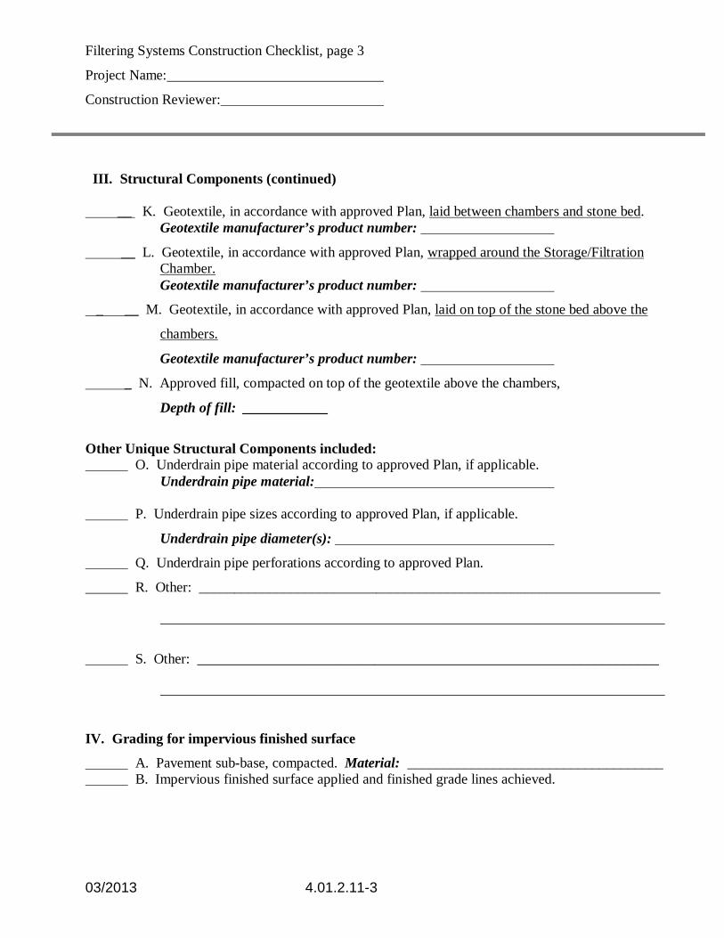
III. Structural Components (continued) __ K. Geotextile, in accordance with approved Plan, laid between chambers and stone bed. Geotextile manufacturer’s product number:
__ L. Geotextile, in accordance with approved Plan, wrapped around the Storage/Filtration Chamber.
Geotextile manufacturer’s product number:
_ __ M. Geotextile, in accordance with approved Plan, laid on top of the stone bed above the
chambers.
Geotextile manufacturer’s product number:
_ N. Approved fill, compacted on top of the geotextile above the chambers,
Depth of fill: ____________
Other Unique Structural Components included: O. Underdrain pipe material according to approved Plan, if applicable. Underdrain pipe material: P. Underdrain pipe sizes according to approved Plan, if applicable.
Underdrain pipe diameter(s):
Q. Underdrain pipe perforations according to approved Plan.
R. Other: _________________________________________________________________
_______________________________________________________________________
S. Other: _________________________________________________________________
_______________________________________________________________________
IV. Grading for impervious finished surface
A. Pavement sub-base, compacted. Material: ____________________________________ B. Impervious finished surface applied and finished grade lines achieved.

Filtering Systems Construction Checklist, page 4
Project Name:
Construction Reviewer:
03/2013 4.01.2.11-4
Other finished surface options:
C. Fill material compacted. Material: ____________________________________
D. Finished surface of vegetation, 4” minimum of topsoil, amendments, mulching, and mulch anchoring as per the vegetation specifications on the Plan.
VI. Erosion and Sediment Control.
A. Site stormwater diverted around the excavation of the underground detention system. B. Inlet protection provided on any catch basins that discharge to the underground detention
system.

03/2013 4.01.2.13-1
SEDIMENT/STORMWATER MANAGEMENT BASIN CONSTRUCTION CHECKLIST For permanent structures per Delaware NRCS Pond Code 378,
Delaware Sediment and Stormwater Regulations, and Post Construction Stormwater Management BMPs Standards and Specifications.
KEY PROJECT INFORMATION √ Item meets standard Project ID:_______________________________ X Item not acceptable Contractor:_______________________________ N/A Item not applicable Inspector: _______________________________ C Item requires engineer’s cert. Date(s): _______________________________
I. Materials and equipment.
_____ Pipe and appurtenances on-site prior to construction and dimensions checked.
____ 1) Material (including protective coating, if specified).
____ 2) Diameter
____ 3) Dimensions of metal riser or pre-cast concrete outlet structure.
____ 4) Required dimensions between water control structures (orifices, weirs, etc.) are in accordance with plans.
____ 5) Barrel stub for prefabricated pipe structures at proper angle for design barrel slope.
____ 6) Number and dimensions of prefabricated anti-seep collars.
____ 7) Watertight connectors and gaskets.
____ 8) Outlet drain valve.
_____ Appropriate compaction equipment available, including hand and small power tamps.
_____ Project benchmark near pond site.
_____ Equipment for temporary de-watering.
II. Subgrade preparation.
_____ Area beneath embankment stripped of all vegetation, topsoil and organic matter.
_____ Cut-off trench excavated a minimum of 4 FT below subgrade and minimum 4 FT below proposed pipe invert, with side slopes no steeper than 1:1.
_____ Impervious material used to backfill cut-off trench.

03/2013 4.01.2.13-2
III. Pipe spillway installation.
_____ Method of installation detailed on plans.
A. Bed preparation.
_____ Installation trench excavated with 1:1 side slopes.
_____ Stable, uniform, dry subgrade of relatively impervious material. (If subgrade is wet, contractor shall have defined steps before proceeding with installation.)
_____ Invert at proper elevation and grade.
B. Pipe placement.
_____ Metal/Plastic pipe
____ 1) Watertight connectors and gaskets properly installed
____ 2) Anti-seep collars properly spaced and having watertight connections to pipe.
____ 3) Backfill placed and tamped by hand under “haunches” of pipe.
____ 4) Remaining backfill placed in max. 8” lifts using small power tamping equipment until 2’ cover over pipe is reached.
_____ Concrete pipe
____ 1) Pipe set on blocks or concrete slab for pouring of low cradle.
____ 2) Pipe installed with rubber gasket joints with no spalling in gasket interface area.
____ 3) Excavation for lower half of anti-seep collar(s) with reinforcing steel set.
____ 4) Entire area where anti-seep collar(s) will come in contact with pipe coated with mastic or other approved waterproof sealant.
____ 5) Low cradle and bottom half of anti-seep collar installed as monolithic pour and of an approved mix.
____ 6) Upper half of anti-seep collar(s) formed with reinforcing steel set.
____ 7) Concrete for collar of an approved mix and vibrated into place. (Protected from freezing while curing, if necessary.)
____ 8) Forms stripped and collar inspected for honeycomb prior to backfilling. Parge if necessary.
C. Backfilling
_____ Fill placed in maximum 8” lifts.
_____ Backfill taken minimum 2’ above top of anti-seep collar elevation before traversing with heavy equipment.

03/2013 4.01.2.13-3
IV. Riser/Outlet structure installation.
A. Metal riser
_____ Riser base excavated or formed on stable subgrade to design dimensions.
_____ Embedded section of aluminum or aluminized pipe to be painted with zinc chromate or equivalent on inside and outside surfaces.
_____ Set on blocks to design elevations and plumbed.
_____ Reinforcing bars placed at right angles and projecting into sides of riser.
_____ Concrete poured so as to fill inside of riser to invert of barrel.
B. Pre-cast concrete structure
_____ Dry and stable subgrade.
_____ Riser base set to design elevation.
_____ If more than one section, no spalling in gasket interface area; gasket or approved caulking material placed securely.
_____ Watertight and structurally sound collar or gasket joint where structure connects to pipe spillway.
C. Poured concrete structure
_____ Footing excavated or formed on stable subgrade, to design dimensions with reinforcing steel set.
_____ Structure formed to design dimensions, with reinforcing steel set as per plan.
_____ Concrete of an approved mix and vibrated into place. (Protected from freezing while curing, if necessary.)
_____ Forms stripped and structure inspected for “honeycomb” prior to backfilling. Parge if necessary.
V. Embankment construction.
A. Fill material.
_____ Soil engineer’s test.
_____ Visual test by inspector.
B. Compaction.
_____ Soil engineer’s test.
_____ Visual test by inspector.
C. Embankment.
_____ Fill placed in max. 8” lifts and compacted with appropriate equipment.
_____ Constructed to design cross-section, side slopes and top width.
_____ Constructed to design elevation plus allowance for settlement.

03/2013 4.01.2.13-4
VI. Impounded area construction.
_____ Excavated/graded to design contours and side slopes.
_____ Inlet pipes have adequate outfall protection.
_____ Forebay
_____ Wet pond requirements.
____ 1) 10 FT reverse slope bench one foot above normal pool elevation.
____ 2) 10 FT wide level bench one foot below normal pool elevation.
VII. Earth emergency spillway construction.
_____ Spillway located in cut or structurally stabilized with riprap, gabions, concrete, etc.
_____ Excavated to proper cross-section, side slopes and bottom width.
_____ Entrance channel, crest, and exit channel constructed to design grades and elevations.
VIII. Outlet protection.
A. End section.
_____ Securely in place and properly backfilled.
B. Endwall
_____ Footing excavated or formed on stable subgrade, to design dimensions and reinforcing steel set, if specified.
_____ Endwall formed to design dimensions with reinforcing steel set as per plan.
_____ Concrete of an approved mix and vibrated into place. (Protected from freezing, if necessary.)
_____ Forms stripped and structure inspected for “honeycomb” prior to backfilling. Parge if necessary.
C. Riprap apron/channel.
_____ Apron/channel excavated to design cross-section with proper transition to existing ground.
_____ Filter fabric in place.
_____ Stone sized as per plan and uniformly placed at the thickness specified.
IX. Vegetative stabilization.
_____ Approved seed mixture or sod.
_____ Proper surface preparation and required soil amendments.
_____ Excelsior mat or other stabilization materials, as per plan.

03/2013 4.01.2.13-5
X. Miscellaneous
_____ Toe drain.
_____ Temporary dewatering device installed as per plan w/appropriate fabric, stone size and perforations if included.
_____ Drain for ponds having a permanent pool.
_____ Trash rack/anti-vortex device secured to outlet structure.
_____ Trash protection for low flow pipes, orifices, etc.
_____ Fencing (when required).
_____ Access road.
_____ Set aside area for clean-out and maintenance.

STORMWATER MANAGEMENT FACILITY
POST CONSTRUCTION VERIFICATION DOCUMENT SUBMITTAL CHECKLIST
03/2013 4.01.3-1
Submittal Requirements
Post Construction Verification Document survey plan in accordance with the items of this Checklist
Supporting calculations in accordance with the items of this Checklist A copy of the completed Post Construction Verification Document Submittal Checklist Stormwater Management Facility Construction Checklist completed during construction of the
facility, if applicable Geotechnical engineer’s report, if applicable
Post Construction Verification Document
Plan Requirements All Plans: Plans must be submitted on minimum 24” x 36” sheets Provide a location map on the plan Provide a north arrow on the plan The title block must include: Project name indicating “Post Construction Verification Document” in the plan title Name, address, telephone and fax numbers of the individual preparing the plan Scale of plan (maximum plan scale accepted will be 1”=50’) Date of the survey Hundred, County, and State Street address of the project site Signature and seal of Delaware Registered Professional Engineer or Professional Land
Surveyor
Delineate and properly label the following (as applicable): Roads adjoining the stormwater management facility Property lines adjacent to the stormwater management facility Easements (i.e. drainage, utility, access, etc.) adjacent to the stormwater management
facility

STORMWATER MANAGEMENT FACILITY
POST CONSTRUCTION VERIFICATION DOCUMENT SUBMITTAL CHECKLIST
03/2013 4.01.3-2
Ponds
Provide the following as it relates to the stormwater management pond’s storage volume: Surveyed contours of the constructed stormwater management pond including forebays,
micropools, and elevations below permanent pool at 1- or 2-foot intervals based on the datum of the approved plan. (One-foot contours will generally be expected for projects located in Kent and Sussex Counties. For sites with greater elevation differences (+20’ across the site) such as is often found in New Castle County, 2-foot contours will be accepted.)
Pond bottom elevations on a fifty-foot grid with high and low points noted Lowest top of bank elevation at fill for embankment/combination pond or lowest top of bank
elevation for excavated pond. ***The acceptable top of bank elevation may be no lower than the design elevation for top of bank.
Actual cross section showing elevations, inside slopes, benching, top width and backslope, as applicable (to scale).
Elevation of permanent pool, if applicable. Calculations of the volume of the pond as constructed with incremental storage and
cumulative storage volumes in cubic feet for each one-foot elevation contour. ***The allowable variance from the design volume of the basin is ten percent.
Provide the following information related to the inlet and outlet structures within the stormwater facility. ***The allowable variance for invert elevations on any structure is 0.1 ft: Diameter and material of all inlet and outlet pipes Invert elevations of all inlet and outlet pipes Dimensions (length, width, depth, d50) for all areas of rock outlet protection Dimensions and material of outfall structures Profile through principal spillway showing inverts and dimensions of all pipes, weirs,
orifices, risers and other appurtenances, as applicable (to scale) Cross-section of emergency spillway (to scale) Profile through emergency spillway (to scale)
***When the allowable variances are exceeded for either stormwater management pond volume or outlet structure invert elevations, supplemental calculations must be submitted to determine if the stormwater management pond, as constructed, meets the design requirements. Submit the following: Calculations of outflow from the stormwater management pond for all design storms.
Routing computations must be based on the post construction verification survey volumes and elevations for the facility.
STORMWATER MANAGEMENT FACILITY
POST CONSTRUCTION VERIFICATION DOCUMENT SUBMITTAL CHECKLIST
03/2013 4.01.3-3
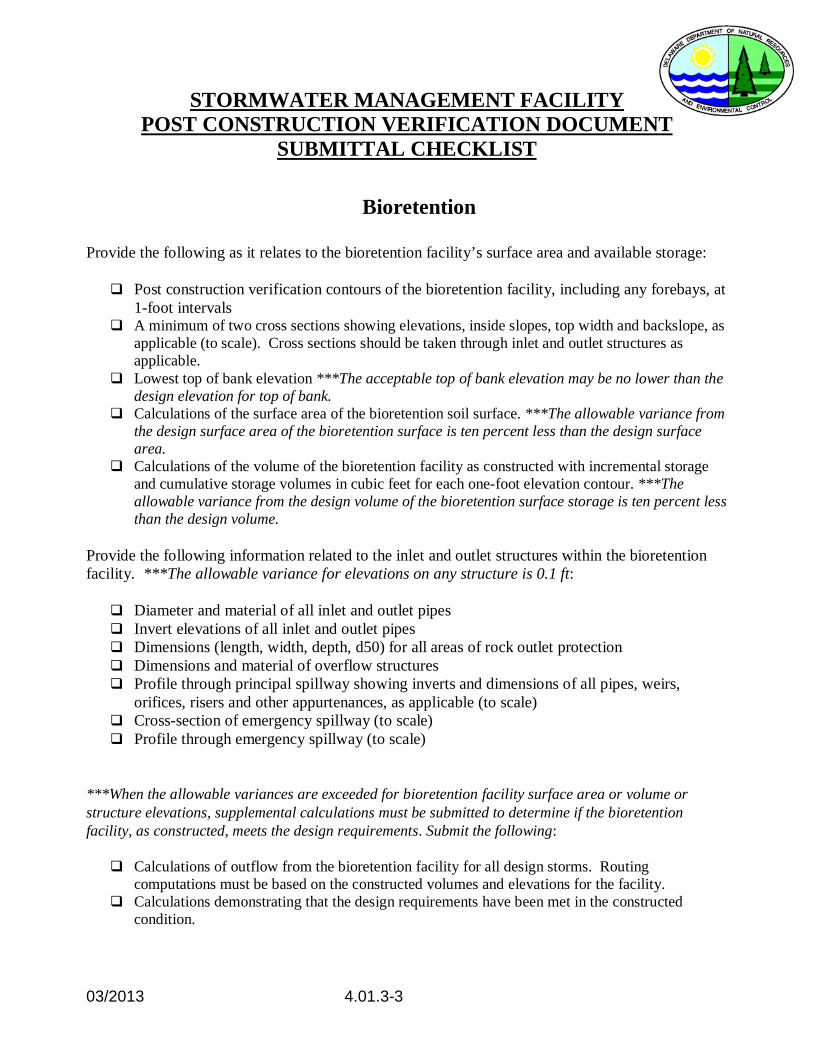
Bioretention
Provide the following as it relates to the bioretention facility’s surface area and available storage: Post construction verification contours of the bioretention facility, including any forebays, at
1-foot intervals A minimum of two cross sections showing elevations, inside slopes, top width and backslope, as
applicable (to scale). Cross sections should be taken through inlet and outlet structures as applicable.
Lowest top of bank elevation ***The acceptable top of bank elevation may be no lower than the design elevation for top of bank.
Calculations of the surface area of the bioretention soil surface. ***The allowable variance from the design surface area of the bioretention surface is ten percent less than the design surface area.
Calculations of the volume of the bioretention facility as constructed with incremental storage and cumulative storage volumes in cubic feet for each one-foot elevation contour. ***The allowable variance from the design volume of the bioretention surface storage is ten percent less than the design volume.
Provide the following information related to the inlet and outlet structures within the bioretention facility. ***The allowable variance for elevations on any structure is 0.1 ft: Diameter and material of all inlet and outlet pipes Invert elevations of all inlet and outlet pipes Dimensions (length, width, depth, d50) for all areas of rock outlet protection Dimensions and material of overflow structures Profile through principal spillway showing inverts and dimensions of all pipes, weirs,
orifices, risers and other appurtenances, as applicable (to scale) Cross-section of emergency spillway (to scale) Profile through emergency spillway (to scale)
***When the allowable variances are exceeded for bioretention facility surface area or volume or structure elevations, supplemental calculations must be submitted to determine if the bioretention facility, as constructed, meets the design requirements. Submit the following:
Calculations of outflow from the bioretention facility for all design storms. Routing computations must be based on the constructed volumes and elevations for the facility.
Calculations demonstrating that the design requirements have been met in the constructed condition.

STORMWATER MANAGEMENT FACILITY
POST CONSTRUCTION VERIFICATION DOCUMENT SUBMITTAL CHECKLIST
03/2013 4.01.3-4
Biofiltration Swales
Provide the following as it relates to the biofiltration swale’s slope and cross section: Profile along the length of the biofiltration swale (parallel to flow direction) with high and
low spot elevations along the bottom noted. ***The allowable variance for the constructed slope of the swale is 0.001 ft/ft.
Cross-section at the beginning of the swale Cross-section at the discharge point of the swale Cross-sections at fifty-foot stations along the swale. Label the cross section locations on plan view to correspond with the individual cross
section details. All cross-sections must include the following: Bottom width dimension
***The acceptable bottom width may be no less than the design bottom width Top width dimension Swale bottom elevation at left and right bank Top of bank elevation for left and right bank Left and right side slope (H:V)
***The side slopes may be no steeper than 3:1 Provide the following information related to the structures within the biofiltration swale. ***The allowable variance for invert elevations on any structure is 0.1 ft:
Diameter and material of all pipes Invert elevations of all pipes Dimensions (length, width, depth, d50) for all areas of rock outlet protection Diameter, material and invert of underdrain at the discharge point, if applicable Overflow elevation of level spreader, if applicable Delineate locations of permanent check dams, if applicable. Provide weir overflow elevation of each permanent check dam, if applicable.
***When the allowable variances are exceeded for the biofiltration swale slope or structure invert elevations, or the constructed bottom width of the swale is less than the design width, supplemental calculations must be submitted to determine if the biofiltration swale, as constructed, meets the design requirements. Submit the following: Calculations demonstrating that the water quality management and conveyance requirements
have been met in the constructed condition.

STORMWATER MANAGEMENT FACILITY
POST CONSTRUCTION VERIFICATION DOCUMENT SUBMITTAL CHECKLIST
03/2013 4.01.3-5
Filter Strips Provide the following as it relates to the filter strip’s slope:
Profiles through the width of the filter strip (parallel to flow direction) at fifty-foot intervals
along the length of the filter strip, including profiles at either end of the filter strip. ***The allowable variance for the constructed slope of the filter strip is 0.001 ft/ft.
Each profile should provide the following: Elevation at the edge of the impervious surface Elevation of top of level spreader stone trench, if applicable Elevation at the beginning of the filter strip Elevation at the design downstream point of the filter strip
Provide the following as it relates to the filter strip’s drainage area: Spot grades on a 50-foot grid within the filter strip’s drainage area to delineate the full
drainage area flowing to the filter strip. Area in acres or square feet of the drainage area noted on the plan.
***When the allowable variance is exceeded for the filter strip slope, or the drainage area or flow length exceeds the design, supplemental calculations must be submitted to determine if the filter strip, as constructed, meets the design requirements. Submit the following: Calculations demonstrating that the water quality management requirements have been met in
the constructed condition.

STORMWATER MANAGEMENT FACILITY
POST CONSTRUCTION VERIFICATION DOCUMENT SUBMITTAL CHECKLIST
03/2013 4.01.3-6
Sand Filters
Provide the following information related to the structural elevations and dimensions of the sand filter. ***The allowable variance for elevations on any structure is 0.1 ft:
Chamber dimensions of sedimentation (wet) chamber and filtration (sand) chamber. If
modular units are used, chamber dimensions must be provided for all units. Grate elevations at all four corners of the sand filter. If modular units are used, provide
corner elevations of each modular unit. Internal weir elevations between the two chambers. Water surface elevation in the sedimentation chamber. Sand surface elevation in the filtration chamber. Overflow catch basin dimensions, grate elevation and invert elevation. Pipe material and diameter of discharge pipe from overflow catch basin.

STORMWATER MANAGEMENT FACILITY
POST CONSTRUCTION VERIFICATION DOCUMENT SUBMITTAL CHECKLIST
03/2013 4.01.3-7
Underground Storage Facilities
Provide the following information related to the structural elevations and dimensions of the underground storage facility. ***The allowable variance for elevations on any structure is 0.1 ft: Grate and invert elevations of all structures Invert and diameter of all pipes or chambers within underground storage system that is
accessible following construction. Elevation and dimension of any weirs within underground structures.

03/2013 4.02-1
4.02 Enforcement and Penalties Site Violations Whenever the Department or Delegated Agency discovers noncompliance with 7 Del. C., Ch. 40 (Delaware Sediment and Stormwater Law and/or Delaware Sediment and Stormwater Regulations) and 7 Del. C., Ch. 60 (Federal National Pollutant Discharge Elimination System (NPDES) requirements) enforcement action may be taken. Site violations can be generated through the following ways: 1) no plan violations; 2) the construction and maintenance review process; and 3) referrals from delegated agencies. No Plan Violations If a site has no plan and the disturbance is greater than 5,000 square feet the Department or Delegated Agency will issue a letter requiring the owner to submit specified information within a specified deadline to gain compliance. If the owner does not submit the required information within the specified deadline a Notice of Violation will be issued and may result in the Department seeking additional enforcement action. Construction Review and Maintenance Non-compliances will be documented in the construction review reports or maintenance review reports and include a reasonable deadline for compliance. If the site deficiencies have not been corrected a Notice of Violation will be sent to the owner by the Department or Delegated Agency. The Department may seek additional enforcement action. Referral of a Site Violation to the Department When a Delegated Agency cannot obtain compliance on a site they may use local enforcement options, as well as referring a site to the Department for enforcement action. The Department may request of the local permitting agency that no building permits be issued, pursue criminal and/or administrative penalties and other enforcement actions, such as a Cease and Desist Order.

03/2013 4.02.1-1
4.02.1 COMPLIANCE ASSISTANCE POLICY Section I. Introduction
This policy establishes a formal procedure to be followed by the Department of Natural Resources and Environmental Control (DNREC) Sediment and Stormwater Program and their Delegated Agencies (“Agency”) to address noncompliance with the State’s Sediment and Stormwater Law and Regulations and the Federal National Pollutant Discharge Elimination System (NPDES) requirements. Noncompliance cases can be generated in any of the six ways:
(1) through the construction review process;
(2) through referrals from an Agency;
(3) through Sediment and Stormwater Plan violations;
(4) through violations of the NPDES General Permit Regulations for Construction Activities;
(5) through no plan violations; and
(6) through citizen concerns of individuals, groups, etc.
Section II. Construction Review Whenever the Agency discovers noncompliance(s), the noncompliance(s)
will be addressed by an appropriate enforcement response, which will, at a minimum:
1. Document the noncompliance(s) in the Agency construction review
reports and provide a reasonable deadline for achieving or restoring compliance. The Agency should notify DNREC in writing on significant noncompliance issues such as discharge of sediment to a water body, pumping without a dirt bag, disturbance of greater than 20 acres and inadequate pollution prevention practices that involve hazardous substances.
2. If noncompliance(s) have been corrected, it should be documented in the Agency construction review reports.

03/2013 4.02.1-2
3. If noncompliance(s) have not been corrected in accordance with the Agency construction review reports the following process should occur:
• The Agency will issue a notice of non-compliance (NON) to the owner/developer or authorized agent.
• The NON should include the following:
1) The date and time of the construction review; 2) the noncompliance(s); 3) the corrective measures to be taken; 4) deadline to complete the work 5) require an on-site meeting with an owner’s
representative, the responsible person(s), the and a representative from DNREC.
• The NON shall be sent to the owner/developer. A copy shall
also be sent to the responsible person(s) on site and DNREC.
4. Compliance Review
At the end of the time period specified in the NON, a follow-up
construction review shall take place to determine whether compliance has been achieved. Depending on that determination, the following actions may occur:
a. Noncompliance(s) Corrected:
If all previous noncompliance(s) have been corrected, the site reviewer shall issue a return to compliance letter specifying compliance and the site shall be returned to a normal Construction Review status.
b. Noncompliance(s) Not Corrected:
If all previous noncompliance(s) have not been satisfactorily corrected, the site should be referred to DNREC as outlined in Section III.
Section III. Referrals
Referrals from an Agency will be handled in the following manner:
1) In the event when the Agency has followed the steps in Section II and noncompliance(s) persist, cases will be referred directly to the DNREC, Sediment and Stormwater Program, by way of a referral package.

03/2013 4.02.1-3
The referral package should contain the following:
• a referral letter from the Agency documenting why the case is being referred along with a brief history;
• the current owner/developer information; • tax parcel ID for the site; • the Notice of Intent number associated with the site and
confirmation that the owner on the NOI is current; • contact information for the CCR, design engineer, project
manager, and site contractor; • the approved plan expiration date; • previous Agency construction review reports and Certified
Construction Reviewer (CCR) reports for the last six (6) months; • the NON letter sent to the owner/developer; • and the approved Sediment and Stormwater Management plan.
Site conditions will be verified by DNREC Sediment and Stormwater Program. At the point of referral DNREC Sediment and Stormwater Program will be the lead agency for the project. DNREC Sediment and Stormwater Program will keep the Agency apprised of the project status, will coordinate all plan reviews with them, and will copy them on all correspondence. Agencies may assume plan review or construction review responsibilities at the request of DNREC.
2) DNREC Sediment and Stormwater Program will issue a Notice of Violation (NOV) letter to the owner/developer specifying the following:
• the regulatory requirements with which the owner/developer failed to comply;
• occasion(s) on which the violation was observed or discovered by the Agency or DNREC Sediment and Stormwater Program;
• a reasonable deadline or deadlines by which the
owner/developer is required to come into compliance with the requirement(s) described in the NOV.
• DNREC may assess criminal or civil/administrative penalties
under Chapter 40 and/or Chapter 60.
3) At the end of the specified time frame on the NOV, DNREC Sediment and Stormwater Program will review the site for compliance. If all work has been satisfactorily completed DNREC Sediment and Stormwater Program will:

03/2013 4.02.1-4
• conduct a joint construction review between DNREC Sediment
and Stormwater Program, the Agency, and the owner/developer;
• provide a letter from the DNREC Sediment and Stormwater
Program, referring the project back to the Agency for Plan and construction review responsibilities;
• issue a Return to Compliance letter to the owner/developer and
furnish a copy to the Agency;
• return all approved plans and pertinent correspondence to the Agency.
Section IV. No Plan Violations
If unlawful land disturbing activity is alleged at a site, the Agencies will request a site review through a letter to the land owner in order to verify how much land disturbance has occurred. 1) If the land disturbance is greater than 5000 square feet and less
than one (1) acre, the Agency will issue a NON letter requiring the owner/developer to submit a standard plan within a stated deadline. The letter will enumerate all the requirements to bring the site into compliance with the Sediment and Stormwater Regulations and the Federal NPDES or,
2) If the land disturbance is greater than one (1) acre the Agency will
issue a NON letter requiring the owner/developer to submit a detailed Sediment and Stormwater Management Plan to the Agency. The letter will also instruct the owner/developer to submit a Notice of Intent with a stated deadline and requirements to bring the site into compliance with the Sediment and Stormwater Regulations and the Federal NPDES. A copy of the owner/developer’s NON letter must be furnished to the DNREC Sediment and Stormwater Program.
3) If the owner/developer does not meet the required deadline set by
the Agency, the Agency shall notify DNREC in writing (email will suffice) with the following:
• the current owner/developer information; • tax parcel ID for the site; • and copies of all correspondence to the owner/developer.

03/2013 4.02.1-5
4) DNREC Sediment and Stormwater Program will issue a Notice of Violation (NOV) letter to the owner/developer specifying the following:
• the regulatory requirements with which the owner/developer failed to comply;
• occasion(s) on which the violation(s) was observed or discovered by the Agency or DNREC Sediment and Stormwater Program;
• a reasonable deadline or deadlines by which the
owner/developer is required to come into compliance with the requirement(s) described in the NOV.
• DNREC may assess criminal or civil/administrative penalties
under Chapter 40 and/or Chapter 60. Section V. Citizen Concerns Citizen Concerns will be handled in the following manner:
1) All concerns will be entered into the Drainage and Stormwater Assistance database and then assigned to its respective program.
2) Each Agency should then investigate the concern and document the resolution in the Drainage and Stormwater Assistance database.
3) In some cases, DNREC may coordinate an on-site meeting with the
Agency and the concerned citizen. Section VI. Enforcement Options for Failure to Comply
1) DNREC may issue a cease and desist order to any persons violating any provision of Chapter 40, and/or the Regulations by ordering that all site work stop except that necessary to comply with any administrative order.
2) DNREC may request withholding any further building or grading
permits until outstanding violations have been remedied.
3) DNREC may initiate criminal or civil/administrative penalties under Chapter 40 and/or Chapter 60. Complete information concerning enforcement and penalties is contained in Chapter 40 Title 7 of the Delaware Code and the Delaware Sediment and Stormwater Regulations.
03/2013 4.03-1
4.03 Contractor Certification Program
Contractor’s Certification Course & Applicability
The Delaware Sediment and Stormwater Law requires that at least one individual
engaging in construction activity function as a responsible person who has received the
Department sponsored or approved training for the control of erosion and sediment.
Any foreman or superintendent who is in charge of on-site clearing and land disturbing
activities for sediment and stormwater control associated with a construction project
should obtain Contractor’s Training Certification (also known as the Blue Card). A Blue
Card Holder is someone who has received and passed the Contractor’s Training course
and whose certification is deemed current.
The Contractor’s Training Course provides an overview of the Delaware Sediment and
Stormwater Program, Delaware’s Sediment and Stormwater Law and Regulations,
erosion and sediment control measures, general stormwater management design,
principles of stormwater runoff, and pollution prevention measures. Contractor
Certification shall be valid until the Department notifies the individual, or announces in
local newspapers that recertification is required due to a change in course content.
Blue Card Holder Responsibilities
The Blue Card Holder functions independently and is usually employed by contractors
that engage in land disturbing activity. The Blue Card Holder is responsible for
checking the site daily during active land disturbance for general compliance with the
Delaware Sediment and Stormwater Regulations, the Delaware Sediment and
Stormwater Law (Chapter 40 of the Delaware Code), and Chapter 60 of the Delaware
Code in regards to Environmental release, meaning “any spillage, leakage, emission,
discharge or delivery into the air or waters or on or into the lands of this State.” At the
end of each work day, the Blue Card Holder is responsible to ensure that the site is
prepared for impending weather conditions.

03/2013 4.03-2
The Blue Card Holder should attend the Construction Site Stormwater Management
pre-construction meeting, and participate in the regular construction review conducted
by the local delegated agency.
In order to keep the certification current, the Blue Card Holder is responsible to re-certify
when notified by the Department and attend the Department approved course.

03/2013 4.04-1
4.04 Certified Construction Reviewer (CCR) CCR & Applicability A Certified Construction Reviewer (CCR) is a private reviewer of sediment and stormwater controls who is hired by an owner/developer. The primary role of a CCR is to determine conformance with Delaware’s Sediment and Stormwater Regulations and the approved Sediment and Stormwater Plan by reviewing the on-site construction activities in conjunction with the Department or Delegated Agency construction reviewer. The CCR produces a Construction Site Stormwater Management (CSSWM) Report which contains the CCR’s observations and the report is submitted to the owner/developer and the appropriate Delegated Agency. All Department- approved construction projects require a CCR. A CCR is required on all projects 20 acres or greater and sites that require discharge monitoring for the maximum daily discharge limitation under Federal requirements. For projects approved through a delegated agency, the delegated agency’s CCR policy may be more stringent and the CCR must conform to that policy. In extenuating circumstances, the Department or the Delegated Agency has the authority to tailor the frequency of CCR review to ensure construction overview and documenting site compliance. CCR Certification Requirements The CCR course offers detailed information on sediment control and stormwater management practices, and is provided as training to individuals who wish to qualify as CCRs as specified in the Delaware Sediment and Stormwater Regulations. In addition, the course benefits anyone in the government, engineering, consulting, contracting, or land development professions that work in the field of sediment and stormwater management. Certification is valid for five years. In order to attain certification, the CCR candidate must attend all sessions of the Department-sponsored CCR course and pass a written comprehensive exam. CCR Re-Certification Requirements
The CCR Re-certification course is offered for those individuals who are already CCR certified and want to maintain continuous certification for a subsequent five year period. This course highlights any changes in the regulations, along with any new policies, best management practices, and approaches to stormwater management.

03/2013 4.04-2
CCR Course
Course topics may include but will not be limited to: • CCR responsibilities • Laws and regulations • Erosion and sediment control practices • Basic hydrology and hydraulics • Basics in soils and establishment of vegetation • Stabilization products and applications • Stormwater management best management practices • The Sediment and Stormwater Plan • CCR site review and Construction Site Stormwater Management (CSSWM)
Report writing • Federal and state enforcement options
CCR Responsibilities The CCR shall function under the direction of a professional engineer (PE) registered in the State of Delaware, where the PE will be responsible for signing all CCR reports. When conducting a review and writing the report, the facts are to be noted and reported completely, accurately, and objectively. If a site review that a particular sediment or erosion control measure is not properly functioning, it is the CCR’s responsibility to contact the appropriate Delegated Agency and report the site observations.
The CCR shall be responsible for the following:
• Ensure that CCR certification is up-to-date throughout the project duration. • Complete the CCR application form for each site being reviewed and provide the
copy with “live” signatures to the local delegated agency. • Review construction sites weekly and submit reports • Review active construction sites after rain events resulting in runoff. • Assist the property owner/developer with technical assistance for erosion and
sediment controls, Best Management Practices, and following the sequence of construction on the Sediment and Stormwater Plans. Though the CCR can provide technical assistance, the CCR cannot make changes to the approved plan, only the design engineer or delegated agency has the authority to do so.
03/2013 4.04-3
Professional Engineer (PE) Responsibilities The PE is responsible for overseeing and verifying the accuracy of the CCR review, and for signing the CCR reports. The PE must maintain an ongoing knowledge of the site conditions, through periodic site visits and/or discussions with the CCR. The PE shall only sign CCR reports that were prepared under their direct supervision, for sites where the PE has knowledge of the site conditions. The PE’s involvement in the CCR process should be guided by the Delaware Association of Professional Engineers (DAPE) Code of Ethics. CCR Reporting Requirements Generally, CCR reviews are required once every seven days during active construction, and within 24 hours after a rainfall event that results in runoff. The local Delegated Agency may have more stringent requirements whereby the local policies must be adhered to. The CCR is required to review the installation of all stormwater facilities, photo document the activity, and complete the construction checklist for each installed element of the facility. Photo documentation and construction checklists must be submitted to the owner/developer and the local Delegated Agency as each stormwater facility is completed in the field. In any event that results in the CCR halting reporting activities; the CCR must contact the local Delegated Agency and inform them of the circumstances. In the same vein, if the CCR anticipates a short absence from the construction site, such as vacation or sick leave, the CCR must arrange coverage of the weekly site reviews by another CCR. If the construction site activity subsides and the CCR requests to reduce the weekly reporting; the local delegated agency must be notified of the intent. The local Delegated Agency will then give guidance to the owner/developer on how to proceed with site reviews to ensure compliance with Federal site monitoring requirements. The Construction Site Stormwater Management (CSSWM) review report submitted by the CCR must have the CCR’s company letterhead, not the letterhead of DNREC or the Delegated Agency. CSSWM review reports must be submitted to the local Delegated Agency, owner/developer, contractor, and other interested parties, and be signed by the CCR and professional engineer. Digital submission of the CSSWM review reports is encouraged along with photo documentation to ensure quick communication. The method of submitting reports may be more stringent at the local delegated agency and those methods must be adhered to.

03/2013 4.04-4
All the elements of the CSSWM review report, an example report, a blank report, and construction site review are contained in the Site Review Section of these technical documents. CCR Certification Revocation A CCR who is not performing at an acceptable level as compared to the Delaware Sediment and Stormwater Regulations, the CCR Performance Standards, and CCR Course training will be notified by the local plan approval agency; the delegated agency or DNREC. The Delegated Agency or DNREC will state the corrective action for the delinquencies. If the CCR continues to be delinquent in the CCR responsibilities, the Delegated Agency may refer the CCR to DNREC for certification revocation. At that time DNREC will review the CCR and the signing PE performances. Based on the DNREC review and documentation from the Delegated Agency, DNREC will determination whether to (1) revoke the CCR certification and/or (2) report the delinquencies of the PE to the Delaware Association of Professional Engineers. Official proceedings under Chapter 60 will be followed if any of the parties involved seek to appear before the Environmental Appeals Board.

03/2013 4.05-1
4.05 Project Completion Project Completion Guidelines The termination of the Federal National Pollution Discharge Elimination System
(NPDES) General Permit for Construction Activities is required at the end of all
construction projects that are functioning under the NPDES Notice of Intent. The
following items must be accomplished before the project can be deemed complete and
thus terminate the NPDES General Construction Permit:
• Conversion of temporary stormwater facilities into the permanent configurations
as per the approved Sediment and Stormwater Plan
• Completion of the stormwater system vacuuming out of sediment, when required
by the delegated agency
• Post construction verification documents for all stormwater facilities have been
received and accepted by the local delegated agency
• Post construction verification documents for all stormwater facilities have been
incorporated onto the Operation and Maintenance Plan
• A final construction site stormwater management site review report from the local
delegated agency stating:
• that all elements of the approved Sediment and Stormwater Plan have
been implemented
• all disturbed areas associated with the construction project meet the
definition of final stabilization as contained in the NPDES General
Construction Permit
• all the temporary erosion and sediment controls have been removed and
properly stabilized
• Acceptance of the maintenance responsibilities as outlined in the Operation and
Maintenance Plan contained in the approved Sediment and Stormwater Plan

03/2013 4.05-2
A Notice of Completion letter will be sent to the owner of the project after the
construction verification documents have been received and accepted. The Notice of
Completion will indicate the name of the project to be terminated and it will contain the
following enclosures:
• The Notice of Termination instructions and form
• The local delegated agency final construction site stormwater management
review report
• Declaration of the stormwater facility maintenance responsibilities on the
Maintenance Obligation, if stormwater facilities were constructed
• Recommendations for routine stormwater facility maintenance, if stormwater
facilities were constructed
Once the Notice of Termination has been sent to the Department Sediment and
Stormwater Program, the local Delegated Agency places the completed site into the
Stormwater Maintenance database held locally at each Delegated Agency. The local
Delegated Agency will perform regular reviews of the stormwater management systems
as outlined under Article 5 entitled Maintenance of Permanent Stormwater Management
Systems.