degree thesis materials processing technology 2017
TRANSCRIPT
Degree Thesis
Flexural Rigidity (D) in Beams
Author: Zious Karis
Instructor: Rene Herrmann
Degree Thesis
Materials Processing Technology
2017

2
DEGREE THESIS
Arcada University of Applied Sciences, Helsinki, Finland
Degree Programme: Materials Processing Technology
Identification number:
Author: Zious Karis
Title: Flexural Rigidity in Beams
Supervisor (Arcada): Rene Herrmann
Commissioned by:
Abstract:
This thesis presents the theory behind the symmetrical and unsymmetrical beams with
different cross-sections, the mathematical procedure in calculating the flexural rigidity of
symmetrical beams and summarizing the experimental verification by mathematical data
processing of the flexural rigidity by three-point bending.
The core of the method section is to test theoretically by using the composite compressive
strength modeler (CCSM) software and experimentally in the laboratory by using the
material bending machine a solid fiberglass and a sandwich beam. The results obtained
for the solid fiberglass was found to be theoretically 32 Nmm2 and experimentally 31.1
MNmm2. For the sandwich beam along the direction of the orientation of the fiber
theoretically 155 Nmm2 and experimentally 153.3 Nmm2. As for the sandwich beam with
the same properties but with a direction perpendicular to the fiber theoretically 45.1
Nmm2 and experimentally 47.22 Nmm2. The comparison of flexural rigidity values was
found to be 3.1% for the solid fiberglass, 1.1% for the sandwich beam along the direction
of the orientation of the fiber and -4.6% with a direction perpendicular to the fiber.
Moreover, for the four-section module, the values obtained for the moments of the outer
layer contributed seven times more to rigidity than the inner layer and for the six-section
module the second outermost layer contributed seven times more than the innermost layer
and the outermost layer nineteen times more to rigidity than the innermost layer.
Keywords: Flexural rigidity, deflection in beams, symmetrical
bending, sandwich structure, composite beams, (CCSM)
modeler, three-point bending
Number of pages: 60
Language: English
Date of acceptance:

3
CONTENTS
1 INTRODUCTION ........................................................................................ 9
1.1 Problem Definition .................................................................................. 9
1.2 Aims and Objectives .............................................................................. 10
1.3 Method ................................................................................................. 10
1.4 Background ........................................................................................... 10
1.4.1 Flexural Rigidity ................................................................................ 11
2 THEORY ................................................................................................... 12
2.1 Second Moment of Area ......................................................................... 12
2.2 Materials ............................................................................................... 13
2.2.1 Composite Materials ........................................................................... 13
2.2.2 Composites versus Metallic ................................................................. 14
2.3 Bending Stiffness of Beams .................................................................... 15
2.3.1 Theory of Simple Bending with Assumptions Made ............................... 15
2.3.2 Bending of Composite Beams .............................................................. 16
2.3.3 Symmetrical Bending .......................................................................... 18
2.3.4 Examples of Symmetrical Bending ....................................................... 18
2.3.5 Unsymmetrical Bending ...................................................................... 29
2.4 History of Sandwich Structure ................................................................. 31
2.4.1 Sandwich Structure ............................................................................. 32
2.4.2 Flexural Rigidity in Sandwich Beams ................................................... 33
2.4.3 Deflection of Beams ........................................................................... 35
3 METHOD .................................................................................................. 41
3.1 Composite Compressive Strength Modeler (CCSM) .................................. 41
3.1.1 A Solid UD Lamina ............................................................................ 41
3.2 Bending ................................................................................................ 42
3.2.1 Three-Point & Four-Point Bending ....................................................... 43
4 RESULTS .................................................................................................. 46
4.1 Bending Test and CCSM Modelling ........................................................ 46
5 DISCUSSION ............................................................................................. 56

4
6 CONCLUSION .......................................................................................... 58
7 REFERENCES ........................................................................................... 59

5
Figures
Figure 2.1 Composite structure [6] ................................................................................. 14
Figure 2.2 Steel vs. sandwich [9] ................................................................................... 15
Figure 2.3 Strain [11] ..................................................................................................... 17
Figure 2.4 I-beam [13] .................................................................................................... 19
Figure 2.5 Rectangular cross-section.............................................................................. 20
Figure 2.6 Centroidal x-axis ........................................................................................... 21
Figure 2.7 Two-sections ................................................................................................. 22
Figure 2.8 Four-sections ................................................................................................. 23
Figure 2.9 Six-sections ................................................................................................... 26
Figure 2.10 Rectangular beam [15] & Figure 2.11 Upward restoring force [15] ........... 28
Figure 2.12 T-beam [16] ................................................................................................. 30
Figure 2.13 Efficiency of sandwich structure [9, p. 256] ............................................... 32
Figure 2.14 Sandwich structure [18, p. 5] ...................................................................... 33
Figure 2.15 Sandwich beam cross section [4] ................................................................ 34
Figure 2.16 Deflection and curvature due to bending [20] ............................................ 36
Figure 2.17 Cantilever beam [20] ................................................................................... 36
Figure 2.18 Simply supported beam [20] ....................................................................... 38
Figure 2.19 Simply supported beam, deflection at center .............................................. 38
Figure 2.20 Simply supported beam, uniformly distributed load ................................... 39
Figure 3.1 Principal material axes in a UD lamina [23] ................................................. 42
Figure 4.1 Materials testing machine ............................................................................. 46
Figure 4.2 Solid fiberglass - theoretical.......................................................................... 48
Figure 4.3 Solid fiberglass – theoretical – d11 ................................................................ 48
Figure 4.4 Solid fiberglass - experimental...................................................................... 49
Figure 4.5 Sandwich beam 1 - theoretical ...................................................................... 51
Figure 4.6 Sandwich beam 1 – theoretical – d11 ............................................................. 51
Figure 4.7 Sandwich beam 1 - experimental .................................................................. 52
Figure 4.8 Sandwich beam 2 - theoretical ...................................................................... 53
Figure 4.9 Sandwich beam 2 – theoretical d11 ................................................................ 53
Figure 4.10 Sandwich beam 2 - experimental ................................................................ 54

6
Tables
Table 1. Composites versus metals under certain conditions. [9] .................................. 15
Table 2. ASTM standards for three-point bend. [27] ..................................................... 44
Table 3. ASTM standards for four-point bend. [27]....................................................... 45
Table 4. Values for the CCSM Modeler. ........................................................................ 47
Table 5. Results .............................................................................................................. 56

7
List of Symbols
Name Symbol Unit
1. Flexural rigidity D Nm2
2. Bending modulus (material property) E Pa = N/m2
3. Young´s modulus of faces Ef Pa
4. Second moment of inertia I m4
5. Width b m
6. Thickness t m
7. Distance d m
8. Force F N
9. Height h m
10. Moment/Bending moment M Nm
11. Stress σ Pa = N/m2
12. Length L m
13. Area A m2
14. Strain Ε - or mm/mm
15. Shear stress Q Pa
16. Slope Θ (k) N/mm
17. Distance along beam x m
18. Radius of neutal axis r m
19. Distance of surface (NS) y m
20. Torque τ Nm
21. Deflection Y mm
22. Distributed load W N/m

8
FOREWORD
I would like to thank Mr. Rene Herrmann for the supervision throughout this thesis.
I would like to thank all the professors and staff for their guidance during my three years
of studying at Arcada University of Applied Sciences. Special thanks to Mr. Erland
Nyroth for his encouragement and advices throughout my studies.
Finally, I would like to thank my family and friends for their continued support over last
few years, particularly during the completion of this thesis. Special thanks to my father
for his unlimited support and encouragement. Special thanks also to Mr. Manuel
Eisenbarth for his unlimited support and help especially over the thesis time.

9
1 INTRODUCTION
The purpose of this thesis work is to summarize the mathematical procedure to calculate
the bending stiffness of symmetrical and unsymmetrical beams with different cross
sections such as I-, Rectangular-, and T-cross-sections.
This paved the way for the summary of the experimental verification by mathematical
data processing of the flexural rigidity by 3-point, a review on composites and metals as
well the comparison between them.
Moreover, it is intended to summarize on some examples the theoretical and
experimental flexural rigidity and to review international measurement standards for
polymer and composite materials, finally, using the CCSM (Composite Compressive
Strength Modeler) for deformation analysis of composite materials.
1.1 Problem Definition
Structural efficiency is one of the most important character to engineers in the aerospace,
boats, car industries and in many other fields. Therefore, a high-performance product
made of lightweight materials and yet efficient to withstanding harsh loading conditions
is required.
The stiffness as a material property is very important in structural engineering as it extents
the materials resist deformation in response to applied load. The use of sandwich
composites has been considered in this thesis due to the relevance of its stiff light weight
structure, which significantly increases the load resistance capacity on one hand without
much increase in weight on the other hand.
To design a member such as a beam, it is very essential to make sure that it satisfies
specific strength, stability, and deflection requirements. Therefore, the bending stiffness
analysis plays a major role in choosing materials as it shows how a component behaves
under certain loads.

10
1.2 Aims and Objectives
In order to fulfil the aim of this thesis, the research is conducted aiming to calculating
mathematically the flexural rigidity of symmetrical cross sections, verify the
experimental results of mathematical data processing of the flexural rigidity by 3-point
bending, present some examples to illustrate the theoretical and experimental flexural
rigidity, review of verification methods for 4-point bending, comparing composite
materials to metals using some international measurement standards and using composite
compressive strength modeler (CCSM) software for modelling of flexural rigidity.
1.3 Method
In order to achieve the aim of this thesis and get the theoretical knowledge of the
problem, the theory of bending stiffness for different beams and plates have been
studied. In the consideration of the bending stiffness analysis of composite material
structures, the composite compressive strength modeler (CCSM) and experiments on
different materials in the laboratory have been conducted.
There are several software packages available for rigidity analysis and deformation
tests. In this thesis work, the composite compressive strength modeler (CCSM) software
is used for flexural rigidity simulation.
1.4 Background
Flexural rigidity is related to bending and non-rigid structures as a force couple that is
required to bend a non-rigid structure in one unit of curvature, where force couples also
known as pure moments are the forces that rotate a body without translation or
acceleration of the center of mass. [1]
Since force couples are free vectors in rigid bodies, their effects on a body are independent
of the point of application. A couple is known as a combination of two forces, they are
equal in magnitude, asymmetrically directed, and displaced by a perpendicular distance
or moment. [1]
11
1.4.1 Flexural Rigidity
Flexural rigidity can be modelled by using different methods. In this scientific discourse,
three of the very well-known methods in the bending stiffness of a profile are treated.
The first method can be applied when the modulus is constant, and the cross section is
simple then the single formula of second moment of inertia (equation 2, p.12) can be
used to obtain the required results of flexural rigidity D. [2]
The second method is used when the modulus is constant, and the cross section is not
simple but can be however reduced to a simple cross section with a displacement from
the neutral axis, in this case the parallel axis theorem can be used effectively by
determining the second moment of area or mass moment of inertia of a rigid body about
any axis. [3]
While the third method which is known as the sandwich beam theory or the Euler-
Bernoulli beam theory that describes the behavior of a beam, plate, or a shell when
calculating the load-carrying and deflection characteristics of beams. It is used when the
profile is not constant in bending modulus, but the profile can be approximated or
considered as a layered structure of different materials. [4]
The flexural rigidity (D) is defined as EI. In a beam or rod, flexural rigidity varies along
the length as a function of (x):
EIdy
dx= ∫ M(x)dx + C1
x
0
(1) [1]
Where,
E = Young´s modulus (Pa)
I = second moment of area (m4)
y = transverse displacement at x (m)
M (x) = bending moment at x (Nm)
12
2 THEORY
The Euler Bernoulli´s Equation and the bending stiffness of a rigid body expresses clearly
the flexural rigidity. [1] Euler Bernoulli is known as an engineer of beam theory, which
simplifies the linear theory of elasticity. It provides a calculation for the load-carrying
and deflection characteristics of beams and it covers the case for infinitesimal strains and
small rotations of a beam which are only subjected to lateral loads. [5]
The theory can be extended in a straightforward manner to problems with moderately
large rotations by using the von Kármán strains, which provides that the strain remains
small. However, in this thesis work the focus is on bending stiffness. [5]
Stiffness describes the rigidity of an object, in other words it is the resistance to
deformation when a force is applied on it. So, the flexibility of materials is very essential,
the more flexible an object is, the less stiff it is. The stiffness of a body is a measure of
the resistance offered by an elastic body to deformation.
The bending stiffness of a beam is a function of elastic modulus “E”, the area moment of
inertia “I “of the beam cross-section about the axis of interest, length of the beam and the
beam boundary conditions. The bending stiffness of a beam can be analytically derived
from the equation of beam deflection when it is applied by a force. [1]
2.1 Second Moment of Area
Second moment of area is the property of a cross section. It is normally used to predict
the resistance of beams to bending and deflection. The deflection of beams under a certain
load doesn´t depend only on the load but also on the geometry of the beam´s cross section.
Beams with a large second moment of area are stiffer than those with a smaller second
moment and therefore, they are more resistant to bending. The second moment of area
has in other words the meaning of second moment of inertia: [2]
I = I0 + Ad2 (2) [2]
Where,
I = second moment of inertia (m4)
I0 = second moment of area at centroidal axis (m4)

13
A = area (m2)
d = distance (m)
2.2 Materials
Nowadays, the designing of materials and material properties play a big role in the
development of materials. However, there are two main types of materials. The first type
is known as structural materials, where the mechanical properties are mainly considered,
such as strength, stiffness, and deformation. And the second type is known as functional
materials where, the magnetic properties are mainly considered, such as the sound, light,
electricity, and heat. [6]
Moreover, these materials can be divided into three types depending on the way the atoms
or molecules are bonded together. Metallic materials describe the first type, where metal
elements are combined with metal bonds, organic polymer materials stand for the second
type, where non-metallic elements are bonded covalently to macromolecular compounds
while ceramic materials describe the third type, where non-metallic elements and metal
elements are combined by covalent bonds, ionic bonds, or a mixture of the two bonds. [6]
2.2.1 Composite Materials
Composite material also known as a multi-phase combination material. Composites are
formed by combining materials together to form an overall structure with properties that
differ from the sum of the individual components. [7]
They are generally used for buildings, bridges, and structures due to their benefits such
as chemical and corrosion resistance, durable, flexible in design, high flexural modulus
to carry demanding loads, high impact strength, high performance at elevated
temperature, etc. [7]
Composite materials consist of matrix material and reinforcing material as shown in
figure 2.1 below, where matrix materials are defined as a continuous phase, which
includes metal matrix composite materials, inorganic non-metallic matrix composite
materials as well polymer matrix composites by the different matrix material. Reinforcing
material is defined as a dispersed phase which includes usually fibrous materials, such as
glass fiber, and organic fiber. [6]

14
Figure 2.1 Composite structure [6]
Normally the strength of fiber depends on its length and orientation with respect to the
stress direction, however, the strength and modulus of fiber are much higher than the
matrix material, due its length and accordingly the orientation of stress direction
therefore, fibers are the main load-bearing components. However, to firmly bond fibers
together, there must be a matrix material with good adhesion properties that can provide
a uniformly distributed applied load and transfer the loads to fiber. [6]
Composite materials should have at least four characteristics. The composite should be
made of a non-homogeneous material, the components that make up the composite should
have different levels of performance, the performance should be the main characteristic
of all composites, and the fraction of each component of the composites should be larger
than 10 percent of the volume of the composite. [6]
2.2.2 Composites versus Metallic
Composites and metals have different physical characteristics. For instance, composites
are greatly anisotropic which means their properties and values are changeable with
direction as well as their strength and stiffness, depending on the orientation of the
reinforcing fibers. [8]
In addition, composites are lighter in weight, they can tailor the lay-up for optimum
strength and stiffness, improve fatigue life, corrosion resistance, etc. While the metals are
isotropic which means their physical properties have the same values in different
directions, they are much heavier than composites in weight. Figure 2.2 and table 1 below
illustrate an example of some main differences between a composite and a metal. [8]

15
Figure 2.2 Steel vs. sandwich [9]
Table 1. Composites versus metals under certain conditions. [9]
Condition
Comparative behavior
relative to metals
Load-strain relationship More linear strain to failure
Static Greater sensitivity
Fatigue Less sensitivity
Transverse properties Weaker
Mechanical property Higher
Fatigue strength Higher
Sensitivity to
hydrothermal
Greater
Sensitivity to corrosion Much less
Damage growth
mechanism
In-plane delamination instead
of through thickness cracks
2.3 Bending Stiffness of Beams
This section covers some concepts about the bending stiffness of symmetrical and
unsymmetrical beams with different cross sections, the study of simple bending, and
bending of composite beams.
2.3.1 Theory of Simple Bending with Assumptions Made
Simple bending happens at the length of a beam that is subjected to a constant bending
moment and when there is no shear force, that is (Q = 0). Which means that the stresses
will be arranged along the length of the beam, due to the bending moments only.
Therefore, that length of the beam is said to be in pure bending.
The assumptions made in the theory of simple bending are known as, the beam is
homogeneous and isotropic, the Young´s modulus of elasticity in tension and

16
compression has the same value, the transverse sections which were plane before bending
remain plane after bending, the beam at the beginning of the experiment is straight, and
all longitudinal filaments bend into circular arcs with a common center of curvature, the
radius of curvature is large compared with the dimensions of the cross section, and each
layer of the beam is free to expand or contract, independently of the layer above or below
it. [10]
However, there are some other tools to use for complicated designs such as a
superposition principle or property tool. This tool is used in linear systems for the beams.
The superposition principle is one of the most important tools for solving beam loading
problems as it allows the simplification of very complicated designs. [10]
For the beams that are subjected to several loads of different types the resulting shear
force, bending moment, slope and deflection can be found at any location by summing
the effects due to each load acting separately to the other loads. The superposition
principle is a combination of homogeneity and additivity and satisfies the following
equations. [10]
Additivity:
F(x1 + x2) = F(x1) + F(x2) (3) [10]
Homogeneity:
F(ax) = aF(x) (4) [10]
Simple bending is when a straight bar of homogeneous material is subjected to only a
moment at one end and an equal and opposite moment at the other end.
2.3.2 Bending of Composite Beams
A composite beam is made of two or more different materials where these materials are
connected rigidly, and the composite behaves like a single piece once it is made. The
basic assumption in this case assumes that the plane surface remains plane during
bending within the elastic limit [10]. Therefore, the strain remains constant down at the
full width of the beam, where the deflection is proportional to the distance from the
neutral axis of the beam, in this case the strain can be found easily, and it is equal to
(stress/Young´s Modulus E) [11]. As shown in figure 2.3 below.

17
Figure 2.3 Strain [11]
The dimensions of the replacement material have the same mechanical properties as the
original material, and the overall depth of the transformed section is the same as the
original section. Therefore, the resulting strain in any element dA of the transformed
section must be constant. [11]
Strain (ε) =σ
E
(5) [11]
Where,
ε = strain (mm/mm)
σ = stress (N/m2)
E = bending modulus (material property) (Pa)
The bending stresses of a composite beam can be calculated using two conditions as
follows. [10]
1. The resulted strain on a layer with an equal distance from the neutral axis is the same
for both materials.
σ1
E1=
σ2
E2
σ1 = σ2 ∙ (E1
E2) = mσ2
(6) [10]
2. The moment of resistance of a composite beam can be determined simply by summing
up the individual moments of resistance of the members.
M = M1 + M2 (7) [10]

18
M1 = σ1 ∙ (I1
y)
M2 = σ2 ∙ (I2
y)
M =σ1
yI1 +
σ2
yI2
Where,
σ = stress (N/m2)
E = bending modulus (material property) (Pa)
M = bending moment (Nm)
I = moment of inertia (m4)
y = distance (m)
m = modular ratio, which means in construction the ratio of Young’s Moduli of
elasticity of the two different materials. (N/m2)
2.3.3 Symmetrical Bending
The symmetrical bending can be defined as a bending where the bending moments are
symmetrical around the neutral axis that passes through the center. Symmetrical bending
mainly happens in beams that have symmetrical cross section which can be either single
or double layers. [11]
The second moment of area which is needed in calculations of bending in beams and also
known as the moment of inertia of a shape, it depends on the geometry of objects and it
describes how points or particles of an object or an area are distributed about an axis that
can be chosen arbitrarily. [11]
2.3.4 Examples of Symmetrical Bending
One of the examples of symmetrical bending is an I-cross-section beam. Tension and
compression loads are applied to the flanges and the body (web) is the core that keeps
the facings in place by resisting transverse shear loads. [12]
The second moment of area is very high in I-section beam because most of its material
is located in the flanges which are placed far from the center of bending (neutral axis),

19
and the web has enough material that makes the flanges work together and resist shear
and buckling. [12]
There are different ways to calculate the bending stiffness of beams. However, for the
following shape as an example and since the beam is symmetric from the top to bottom,
there is no need to find the centroid of the location. [13]
Figure 2.4 I-beam [13]
As it shows from the figure 2.3 above, the I cross section consists of three pieces,
instead of treating each piece separately and making separate calculations. It is valuable
to treat the whole beam as a rectangle and as a total solid cross section which can be
divided into two symmetrical pieces around x-axis and since the centroids of all
segments lie on x-axis, there is no need to use the parallel axis theorem. [13]
So, the solution for this particular example can be obtained using the following simple
moment equation.
Ix =1
12bcenterh3
center (8) [13]
The flexural rigidity can be determined from equation 1 page 13.
However, in the case of taking all three pieces into consideration, knowing that the beam
is symmetric and the center of gravity in the middle then the flexural rigidity D is: [1]
D = ∑ Di = E(Itop + Ibottom + Icenter) (9)
Considering that, [13]
Icenter =1
12bcenterhcenter
3

20
And for the bottom and top parts, there is a distance d from the neutral line, so the
moment is: [3]
I = Icenter + Ad2
Itop =1
12btophtop
3 + btophtopd2
Where the displacement d is:
d =hcenter
2+
htop
2
And the area A is:
A = btophtop
Since it is symmetric then:
Itop = Ibottom
Another well-known example of a symmetrical bending is a rectangular cross section
beam. The calculation in this case can be done in different ways, one way is by finding
the second moment of inertia of the area of a structural section and using the parallel
axis theorem. Another common way used in calculations is known as section modulus
method. An explanation of both methods is discussed below. [12]
1. Parallel Axis Theorem:
In this method a rectangular cross section beam that has a width b and height h is
considered as shown in figure 2.4 below.
Figure 2.5 Rectangular cross-section
Then the area A is:
A = b ∙ h (10) [12]

21
And the moment of inertia I around x-axis that passes through the centroid of the rectangle
is:
I =1
12bh3
And it can be used to calculate the flexural rigidity as follows: [12]
D = E ∙ I = E ∙1
12bh3
When the rotation is around an axis at a distance d from x-axis and is parallel to the
centroidal axis as shown in figure 2.6 below.
Figure 2.6 Centroidal x-axis
Then we use the following parallel axis theorem: [3]
Ix´ = Ix + Ad2
2. Section Modulus Method:
In this method the cross-section beam is considered to be symmetric from top to bottom,
so there is no need to find location centroid. Therefore, the entire rectangle is taken as a
total solid cross section and divided into many sections. However, in this thesis work two-
, four-, and six sections are considered below. [13]
Two-Section Modulus:
In this case a rectangular beam is cut into two-section modulus as in figure below.

22
Figure 2.7 Two-sections
The moment of inertia for each element from top to bottom in this case can be obtained
first and then summing up to get the main moment I which can be used to calculate the
flexural rigidity as below:
For each element – top or bottom: [3]
I = I0 + Ad2
Where,
A = b ∙h
2
d =h
4
I0 =1
12b ∙ (
h
2)
3
b = width (m)
h = height (m)
The moment of inertia for the upper part of the beam is found by substituting A and r into
moment equation so we get:
Iup =1
12b (
h
2)
3
+ b (h
2) ∙ (
h
4)
2
Iup =1
96bh3 + bh3
1
32
And the moment of inertia for the bottom part is determined by substituting the same A
and r values into the moment equation again, taking into consideration the negative sign
of d, that is (-d). So, we get:

23
Idown =1
12b (
h
2)
3
+ b (h
2) ∙ (−
h
4)
2
Idown =1
96bh3 + bh3
1
32
Then the total moment I is the sum of top and bottom moments:
Itot = Iup + Idown = 2I = bh3 (32 + 96
32 ∙ 96) ∙ 2
= bh3 (128
32 ∙ 96) ∙ 2 = bh3
1
12
So, the flexural rigidities can be calculated when E, b, h are given and as follows:
D = E ∙ Itot
𝐷 = 𝐸 (𝑏ℎ31
12)
Four-Section Modulus:
In this module the beam is divided to four sections, the individual moments are calculated
in a similar way to the two-section modulus and then the total moment is substituted in
the equation of flexural rigidity. The figure 2.8 below illustrates the sections and
dimensions used in calculations.
Figure 2.8 Four-sections
For each element – top or bottom: [3]
I = I0 + Ad2

24
Where,
A = b ∙h
4
d =h
8
That leads to,
𝐼0 =1
12𝑏 ∙ (
ℎ
2)
3
The first moment 𝐼1 can be obtained by substituting these values into the following
equation:
I1 = I0 + Ad2 = 1
12b ∙ (
h
2)
3
+bh
4∙ (
h
8)
2
I1 = bh3 ∙ (1
12∙
1
8+
1
4∙
1
64)
= bh3 (1
96+
1
256)
For I2 an additional distance of (𝐡
𝟒) which is (
𝐡
𝟖) + (
𝐡
𝟖) is considered in calculations as
shown below:
𝐼2 = 1
12𝑏 ∙ (
ℎ
4)
3
+𝑏ℎ
4∙ (
ℎ
4+
ℎ
8)
2
=1
12𝑏
ℎ3
64+ 𝑏
ℎ
4(
3ℎ
8)
2
I2 = bh3 (1
768+
9
256)
The moments I3 and I4 can be obtained in the same way and then Itotal which is the sum of
the moments of all elements is substituted in the flexural rigidity equation 1 page 13.
Moreover, the moments related to the thickness t can be calculated in a similar way.
The general formula for the moment I in this case is:
I =1
12b(4t)3 =
bt3
12∙ 64
(11) [3]
So, for I1 with thickness t1 we get:

25
I1 =1
12bt1
3 + bt ∙ (t
2)
2
And for I2 we get,
I2 =1
12bt2
3 + bt ∙ (−t
2)
2
For the first and the second moment I1/2 we get,
I1/2 = b (1
12t3 + t ∙ (
t
2)
2
) ∙ 2
I1/2 = bt3 (1
12+
1
4) ∙ 2 = bt3 (
4+12
48) ∙ 2
I1/2 = bt316
24
In a similar way the third and the fourth moments are obtained and then we get I3/4:
I3/4 = b (1
12t3 + t ∙ (
3
2t)
2
) ∙ 2
I3/4 = bt3 (1
12+
9
4) ∙ 2 = bt3 (
4 + (9 ∙ 12)
48) ∙ 2
I3/4 = bt3224
48= bt3
112
24
So, Itotal is:
Itot = ∑ Ii = I1/2 + I3/4 =bt3
24(128)
Itot =bt3
12∙ 64
It can be seen from the values obtained for the moments of the outer and the inner layers,
that is values of I1/2 and I3/4 that the outer layer contributes seven times more to the
rigidity than the inner layer, since the ratio of the outer and the inner layer is:
112
16= 7

26
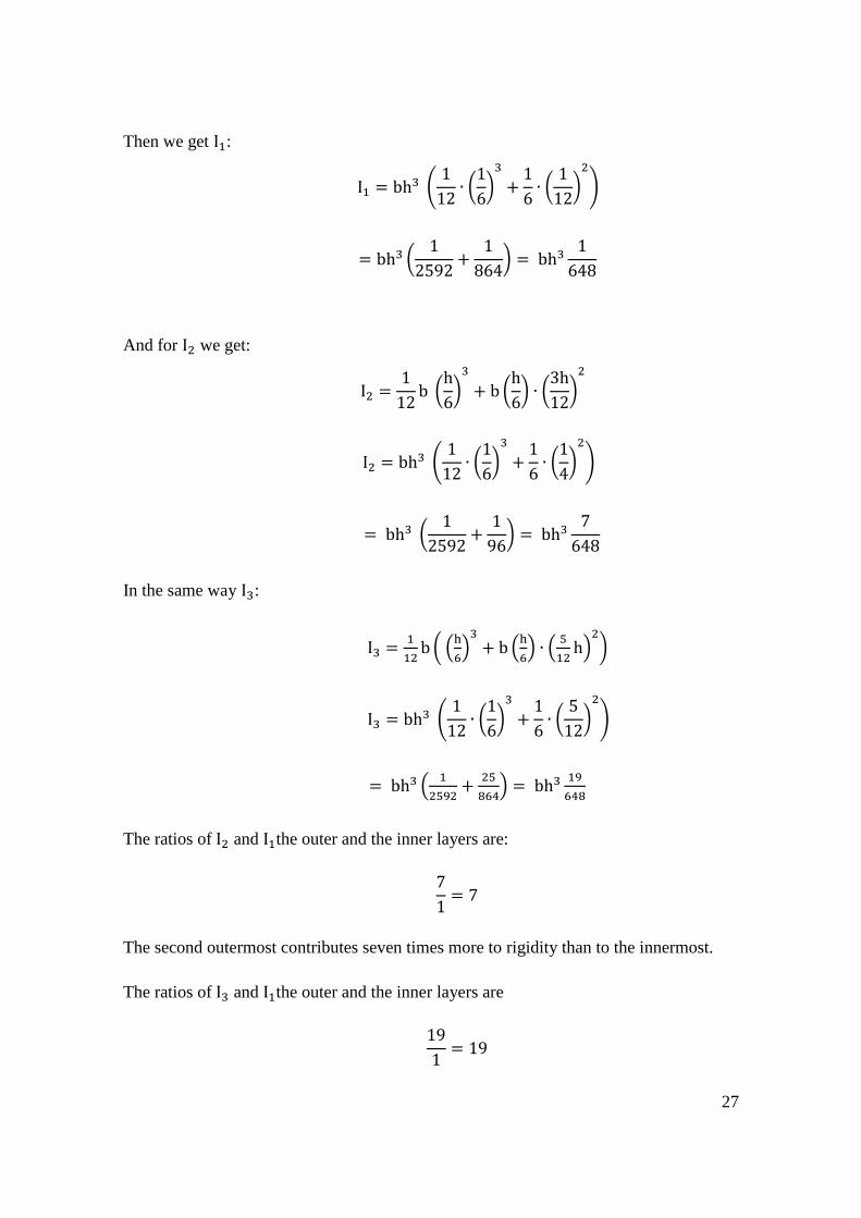
Six-Section Modulus:
In this symmetric six section module, the moments for three layers will be considered and
calculated and then generalize the results to the other three since the module is symmetric
as shown below.
Figure 2.9 Six-sections
For each element – top or bottom:
I = I0 + Ad2
Where,
A = b (h
6)
And the three distances are:
d1 =h
6∙
1
2
d2 =h
6+
h
12
d3 =h
6∙ 2 +
h
12
Applying the general moment equation below:
I =1
12b (
h
6)
3
+ bh
6∙ (
h
12)
2
(12) [2]
27
Then we get I1:
I1 = bh3 (1
12∙ (
1
6)
3
+1
6∙ (
1
12)
2
)
= bh3 (1
2592+
1
864) = bh3
1
648
And for I2 we get:
I2 =1
12b (
h
6)
3
+ b (h
6) ∙ (
3h
12)
2
I2 = bh3 (1
12∙ (
1
6)
3
+1
6∙ (
1
4)
2
)
= bh3 (1
2592+
1
96) = bh3
7
648
In the same way I3:
I3 =1
12b ( (
h
6)
3
+ b (h
6) ∙ (
5
12h)
2
)
I3 = bh3 (1
12∙ (
1
6)
3
+1
6∙ (
5
12)
2
)
= bh3 (1
2592+
25
864) = bh3 19
648
The ratios of I2 and I1the outer and the inner layers are:
7
1= 7
The second outermost contributes seven times more to rigidity than to the innermost.
The ratios of I3 and I1the outer and the inner layers are
19
1= 19

28
And the outermost contributes nineteen times more to rigidity than the innermost.
From the results and as a conclusion, it can be seen that the outer moments are also
dominating in this case by comparing the obtained values of I1, I2, and I3 which gives a
clear idea that the rigidity is higher at outer layers, according to the equation of flexural
rigidity.
It should be mentioned that in a rectangular cross section the contact force and deflections
are of great importance, especially when the contact force is directly proportional to the
area moment of inertia I of the cross section, where the elastic modulus of the beam
material and the beam geometry play a big role in the amount of stress and applied force.
So, for instance when the beam is pushed down, there will be an upward restoring force
which is equal in magnitude but in opposite direction to the applied force as shown in
figure 2.11 below. [14]
Figure 2.10 Rectangular beam [15] Figure 2.11 Upward restoring force [15]
These forces, deflection, yield, and maximum deflection can be calculated according to
the following formulas.
Contact Force:
F = [E ∙ w ∙ t
4 ∙ L3] ∙ d
(13) [14]
Deflection at the yield:
Yyield = 2 ∙ L2
3 ∙ E ∙ t ∙ σyield
(14) [14]
Maximum deflection at load:
Y =Fl3
48EI
(15) [14]
29
Contact force at yield:
Fyield = [E ∙ w ∙ t3
4 ∙ L3] ∙ dyield
= [E ∙ w ∙ t3
4 ∙ L3] ∙ [
2 ∙ L2
3 ∙ E ∙ t ] ∙ σyield
(16) [14]
Where,
Y = deflection (mm)
d = distance (m)
F = force (N)
σ = stress (N/m2)
L = length (m)
t = thickness (m)
w = b = width (m)
I = area moment of inertia (m4)
E = bending modulus (material property) (Pa)
For known parameters such as dimensions, applied force, and other parameters then the
maximum deflection at load for instance can be calculated from equation 19 by using
flexural rigidity equation. Which shows the importance of flexural rigidity when
studying deflection, contact force at yield, deflection at yield, etc.
2.3.5 Unsymmetrical Bending
In the case of nonsymmetrical section, the neutral axis doesn´t pass through the center of
the geometrical section. So, the value of y which is the distance of the layer from the
neutral axis varies for layers that are located for example at the top and bottom of the
section. In order to calculate the bending and since the module is unsymmetrical, the
center of gravity of the sections must be found first. [10]
The center of gravity (Cg) is defined to be the center to an object´s weight distribution,
where the gravity force is considered. It is the point where the object is balanced
completely, regardless of point of rotation or turning around. Knowing that the neutral
axis normally passes through the center of gravity of the section, so by calculating the
30
center of gravity of the section, one can find the y values for topmost layer as well for the
bottom layer of the section. [10]
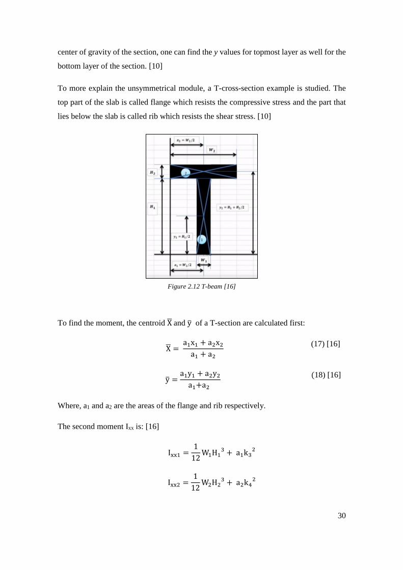
To more explain the unsymmetrical module, a T-cross-section example is studied. The
top part of the slab is called flange which resists the compressive stress and the part that
lies below the slab is called rib which resists the shear stress. [10]
Figure 2.12 T-beam [16]
To find the moment, the centroid X̅ and y̅ of a T-section are calculated first:
X̅ = a1x1 + a2x2
a1 + a2
(17) [16]
y̅ =a1y1 + a2y2
a1+a2
(18) [16]
Where, a1 and a2 are the areas of the flange and rib respectively.
The second moment Ixx is: [16]
Ixx1 =1
12W1H1
3 + a1k32
Ixx2 =1
12W2H2
3 + a2k42

31
Ixx = Ixx1 + Ixx2
Where,
ki = Radius of gyration
k3 = y̅ − y1
k4 = y̅ − y2
To calculate Iyy: [16]
Iyy1 =1
12W1H1
3 + a1k12
Iyy2 =1
12W2H2
3 + a2k22
Iyy = Iyy1 + Iyy2
Where,
ki = Radius of gyration
k1 = x̅ − x1
k2 = x̅ − x2
So, the flexural rigidity is obtained as in previous sections by substituting the total
moment I in the rigidity formula.
2.4 History of Sandwich Structure
According to [17]. Delau in England introduced the first sandwich construction, back to
Fairbairn 1849. The first use of sandwich panels “aircraft sandwich” was used in World
War II. Mainly because of the lack of other materials during the war.
The Sandwich Structure theoretically appeared in the 50´s. The use of sandwich structure
had some limitation in aircraft industry as honeycomb was mainly used as core material
and there were big problems with corrosion due to water absorption, UV-Radiation, aging
etc. [4]. Figure 2.14 below illustrates the Sandwich Structure efficiency.

32
Figure 2.13 Efficiency of sandwich structure [9, p. 256]
However, during the early 60´s, there was a production of different cellular plastics which
were suitable as core materials. Soft materials were used in the beginning because of their
insulation properties such as polystyrene and polyurethane. Later sandwich structure
became very useful and flexible concept as harder cellular plastics with higher densities
were possible to produce caused by diverse progresses in material production. [17]
Nowadays, there is an enormous number of different qualities of cellular plastics that
are used as core materials. Sandwich panels became an important composite structure in
aerospace applications as well as in high performance automobiles, boats, and wind
turbines, because it is an extremely lightweight type of construction that exhibits high
stiffness and high strength-to-weight ratios. [4]
2.4.1 Sandwich Structure
The importance of studying and analyzing these structures is growing as mentioned in the
history of sandwich structure. The calculation for flexural rigidity and other quantities
can be seen clearly when considering a sandwich structures as they are a suitable example
of composites.
Sandwich structure consists of two stiff, strong faces separated by a lightweight core and
joints (adhesives), which can be seen in figure 2.14 below. [4]

33
Figure 2.14 Sandwich structure [18, p. 5]
Facing sheets of a typical sandwich structure are mainly thin with a relatively thick
lightweight core that separates the two faces in order to increases the moment of inertia.
It is for important for engineers or designers of sandwich structures to make the core
strong enough to withstand heavy loads and keep their positions. [9]
Each component of the sandwich structures has some specific properties that make the
sandwich function effectively as a one-unit object. It is preferred by engineers to make
the faces of the sandwich structure from some very well-known metals such as steel,
stainless steel, or aluminum due to their stiffness and strength, due to the fact that these
materials have some special mechanical properties and they are uncomplicated to use and
fabricate. However, in some cases fiber - reinforced plastics are used as face materials as
well, because they have good physical properties such as strength. [17]
The core has several critical capacities. It must be sufficiently stiff to keep the separation
between the faces steady and it must be so rigid in shear to prevent the faces from sliding
over each other. The core must be strong in shear to keep the faces cooperating with each
other, if the core is weak in shear, the sandwich loses its stiffness.
To keep the faces and the core cooperating with each other, the adhesive layer must be
added as it enables the transmission of the shear forces between the faces and the core.
The adhesive must have the capacity to carry shear and tensile stresses. [4]
2.4.2 Flexural Rigidity in Sandwich Beams
Since sandwiches are composites and according to their properties, engineers managed to
modify and adjust the beam theories so that they can be applied to the sandwich structures
and can be used in analyzing and calculating flexural rigidity of sandwiches. [4]
34
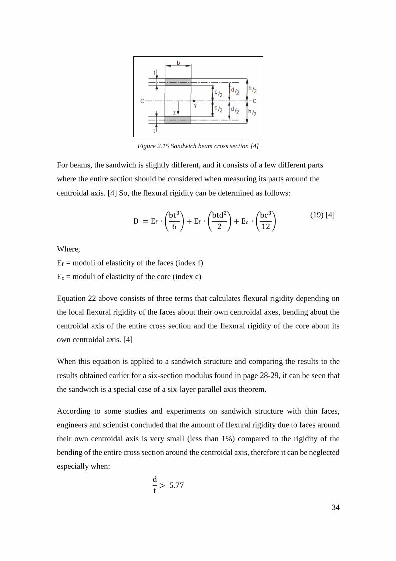
Figure 2.15 Sandwich beam cross section [4]
For beams, the sandwich is slightly different, and it consists of a few different parts
where the entire section should be considered when measuring its parts around the
centroidal axis. [4] So, the flexural rigidity can be determined as follows:
D = Ef ∙ (bt3
6) + Ef ∙ (
btd2
2) + Ec ∙ (
bc3
12)
(19) [4]
Where,
Ef = moduli of elasticity of the faces (index f)
Ec = moduli of elasticity of the core (index c)
Equation 22 above consists of three terms that calculates flexural rigidity depending on
the local flexural rigidity of the faces about their own centroidal axes, bending about the
centroidal axis of the entire cross section and the flexural rigidity of the core about its
own centroidal axis. [4]
When this equation is applied to a sandwich structure and comparing the results to the
results obtained earlier for a six-section modulus found in page 28-29, it can be seen that
the sandwich is a special case of a six-layer parallel axis theorem.
According to some studies and experiments on sandwich structure with thin faces,
engineers and scientist concluded that the amount of flexural rigidity due to faces around
their own centroidal axis is very small (less than 1%) compared to the rigidity of the
bending of the entire cross section around the centroidal axis, therefore it can be neglected
especially when:
d
t> 5.77

35
And the proportion is less than 0.25% at a ratio of:
d
t > 11.55
Since the faces are thin, not only the first term can be ignored but in fact experiments
showed that the third term of equation 28 is also very small (less than 1%) of the second
term which means that it can be ignored as well when:
(Ef
Ec ) ∙ (
td2
c2) > 16.7
(20) [4]
So, the formula for flexural rigidity D is then reduced to:
D = Ef ∙ (btd2
2)
(21) [4]
As a mentioned earlier this is almost the same case as six-section module and when
applying the parallel axis theorem, one would expect the same calculations and results.
So, the expectation is that the rigidity at the outer layers contributes with a higher amount
of flexural rigidity than the inner layers when considering the entire sandwich structure.
2.4.3 Deflection of Beams
This section deals with beam deflection. Deflection occurs when a specified load is
applied to a cross section beam, and the amount of deflection and stress are very important
to determine for sandwich structures and beams, for example in case of sandwich, as the
core has a relatively low shear modulus, and the beam may deflect a considerable amount
due to shear deformations, to neglect the proper consideration of the shear modulus of the
core may lead to unconservative prediction of deflections or critical loads. [11]
In addition, it is very important to know the limits of deflections for sandwich structure
beams to ensure the integrity and stability of a structure or to prevent any attached brittle
materials from cracking Therefore, it is essential to determine the modulus and take its
effect into account. [19]

36
The deflection of beams depends mostly on the modulus of elasticity of the chosen
material and must occur within the elastic limit of the material. They are determined using
the elastic theory. There is always some additional deflection in the material due to shear,
but it is normally so small that it can be neglected. Figure below illustrates the deflection
and curvature due to bending. [11]
Figure 2.16 Deflection and curvature due to bending [20]
There are different types of supports for example supports that resist a force like a pin or
a displacement, another supports for instance resist a moment like a fixed end support,
resist displacement or a rotation [20]. The following examples illustrate the deflection
of a cantilever and a simply supported beam. [21, pp. 33-35]
Cantilever beam:
A cantilever beam is when a beam is attached at only one end and free on the other end
as shown in figure below. [21, pp. 33-35]
Figure 2.17 Cantilever beam [20]
The deflection for a cantilever beam at any section in terms of x at free end is given by:
Y =Fx2
6EI(3L − x)
(22)
And the maximum deflection at the free end is:

37
Ymax =FL3
3EI
(23)
When the load F is concentrated at any point as shown below, then the deflection is:
Y = Fx2
6EI(3a − x) for 0 < x < a
Y =Fa2
6EI(3x − a) for a < x < L
(24)
And the maximum deflection in this case is:
Ymax =Fa2
3EI(3L − a)
(25)
When the load is constant and uniformly distributed (W), then the deflection is:
Y =𝐖x2
24EI(x2 + 6L2 − 4Lx)
(26)
And the maximum deflection in this case is:
Ymax =WL4
8EI
(27)
When the load is variable but still uniformly distributed then the deflection is:
Y =W0x2
120LEI(10L3 − 10L2x + 5Lx2 − x3)
(28)
Similarly, the maximum deflection in this case is:
Ymax =W0L4
30EI
(29)
For the couple moment M at the free end of the beam, we have:
Y =Mx2
2EI
(30)
And maximum is:
Ymax =ML2
2EI
(31)

38
Where,
Y = deflection (mm)
x = d = distance (m)
F = force (N)
L = length (m)
I = area moment of inertia (m4)
E = bending modulus (material property) (Pa)
M = bending moment (Nm)
W = distributed load (N/m)
Simply supported beam:
A simply supported beam has pinned support at one end and a roller support at the other
end. In figure 2.17 below represents the pinned end and B the roller end. [21, pp. 33-35]
Figure 2.18 Simply supported beam [20]
The governing equations of this module are very similar to the previous case when it
comes to types of loads, location of the loads, etc. A review and brief description of the
equations are given and illustrated in figure below.
Figure 2.19 Simply supported beam, deflection at center
39
Deflection at concentrated load (P = F) at the center is:
Y = Fx
12EI[3L2
4− x] for 0 < x <
1
2
(32) [20]
And the maximum deflection (𝛿𝑚𝑎𝑥 = ymax) at the center is:
Ymax = FL3
48EI
(33) [20]
Concentrated load F at any point:
Y =Fbx
6LEI(L2 − x2 − b2) for 0 < x < a
Y =Fb
6LEI(
L
b(x − a)3 + (L2 − b2)x − x2) for a < x < L
(34)
Maximum deflection at the center:
Ymax =Fb(L2 − b2)3/2
9√3LEI at x = √(L2 − b2)/3
(35)
Y =Fb
48EI(3L2 − 4b2) at the center if a > b
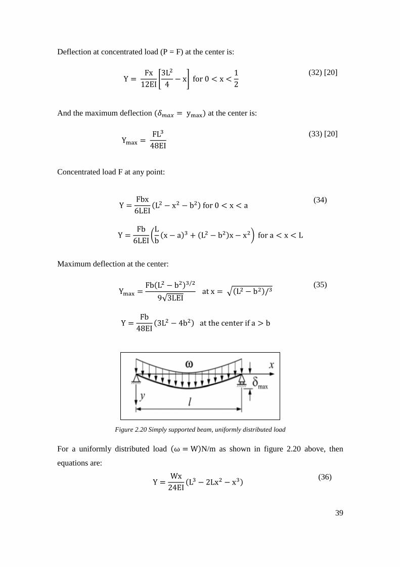
Figure 2.20 Simply supported beam, uniformly distributed load
For a uniformly distributed load (ω = W)N/m as shown in figure 2.20 above, then
equations are:
Y =Wx
24EI(L3 − 2Lx2 − x3)
(36)

40
Maximum deflection:
Ymax =5WL4
384EI
(37)
When the load is uniform and variable, then deflection can be expressed as:
Y =W0x
360LEI(7L4 − 10L2x2 + 3x4) (38)
When the couple moment M is at the right end, then:
Y =MLx
6EI(1 −
x2
L2 ) (39)
And the maximum is:
Ymax =ML2
9√3EI at x = 1/√3
(40)
Where,
Y = deflection (mm)
x = d = distance (m)
F = force (N)
L = length (m)
I = area moment of inertia (m4)
E = bending modulus (material property) (Pa)
M = bending moment (Nm)
b = width (m)
W = distributed load (N/m)

41
3 METHOD
For the practical part and laboratory experiments of this thesis work, the following
module, software, and concepts are considered.
1. Composite Compressive Strength Modeler (CCSM)
2. A case of a solid UD lamina
3. Sandwich structure
4. Three-Point and Four-Point bending
5. Data analysis
3.1 Composite Compressive Strength Modeler (CCSM)
According to User´s Manual of CCSM modeler, it deals with many different aspects of
beams and plates in terms of deflection, flexural rigidity, etc. Some of the main features
of this software include classical laminate theory, stress-strain analysis, failure prediction
for composite plates, and a very useful user-expandable database to store material and
geometrical properties. However, in this thesis work the modeler is used for determining
the stiffness and compliance matrices of beams when sufficient information about the
beams, lamina, stiffness, etc. are given. [22]
In this thesis work when stiffness and compliance matrices are considered using CCSM
modeler the flexural rigidity D will be calculated using width (b) and d11. And in this
case, it is:
Dtheory =b
d11
(41) [22]
3.1.1 A Solid UD Lamina
A lamina is a building block of modern composites laminated structures, a lamina is also
known as a ply or a layer and in our case the UD lamina refers to a unidirectional lamina
since each lamina may have more than one type of fibers and these fibers may be oriented
in different directions, different thickness, fiber orientation angle and matrix material.
[22]

42
The geometry of a laminate is normally layers that have three planes of material that are
symmetric. Therefore, they exhibit orthotropic behavior (having three mutually
perpendicular planes of elastic symmetry at each point).
When a lamina cut cross these planes of symmetry, they will exhibit the same mechanical
properties. Lines which are normal to these planes of material symmetry are called
material axes which are designed as 1, 2, and 3 they are also known as principal material
directions. Figure 3.1 below illustrate these axes in a UD lamina. [22]
Figure 3.1 Principal material axes in a UD lamina [24]
When dealing with fibers, matrix and lamina, it should be mentioned that fibers´ strength
and stiffness are significantly larger than that of the matrix, a lamina is stiffest and
strongest in longitudinal direction which is the 0-degree direction and they are very weak
in the 90-degree direction because the load must be carried by the much weaker polymeric
matrix.
A lamina´s mechanical properties in any direction lying in the 2-3 planes are quite similar
and therefore, a unidirectional lamina is considered as transversely isotropic. Each layer
has approximately the same properties in-plane but different properties through the
thickness. [23]
3.2 Bending
Bend testing also known as flex or flexural testing is commonly performed to measure
the flexural strength and modulus of all types of materials and products. The bending of
a material or product can be tested using a bending machining tool. [24]

43
A universal bending machine consists of a basic machine that can be adjusted and used
for a variety of bends. The basic machine consists of a CNC-operated (computer
numerically controlled), a work bench and a software for programming and operating.
There are three key analysis when performing bend testing which are, the flexural
modulus that deals with measuring slope, stress-strain curve, and stiffness of materials,
flexural strength which measures the maximum force that a material can resist before it
breaks or yields, and yield point of a material, it is a point at which the material can´t
restore its normal shape after it. [24]
3.2.1 Three-Point & Four-Point Bending
Flexural rigidity, modulus of elasticity and other related quantities can be determined
when the values of Three-Point bending are given. The advantage of using three-point
flexural test is the ease of the specimen preparation and testing. Therefore, the three-point
bending will be the module in the practical part of this thesis work. [25]
The four-point bending flexural test is very similar to the three-point bending test. The
major difference is the addition of a 4th bearing, which brings a much larger portion of
the beam to the maximum stress. This difference needs to be taken into account when
studying for example the brittle materials, since it can be used to indicate the flexural
strength and crack initiation for instance, in case of asphalt mixtures that are used in road
paving, however the four-point bending test won´t be included in the practical part of this
scientific discourse. [26]

44
Tables below show some international standard testing methods.
Table 2. ASTM standards for three-point bend. [27]
ASTM
Standard Test Method
ASTM-C1161 Flexural Strength of Advanced Ceramics
at Ambient Temperature
ASTM-C1341 Flexural Properties of Continuous Fiber-
Reinforced Advanced Ceramic
Composites
ASTM-C1684 Flexural Strength of Advanced Ceramics
at Ambient Temperature-Cylindrical Rod
Strength
ASTM-C203 Breaking Load and Flexural Properties of
Block-Type Thermal Insulation
ASTM-C473 Physical Testing of Gypsum Panel
Products
ASTM-C598 Annealing Point and Strain Point of Glass
by Beam Bending
ASTM-C674 for Flexural Properties of Ceramic White-
Ware Materials
ASTM-D1184 form Flexural Strength of Adhesive
Bonded Laminated Assemblies
ASTM-D143 Small Clear Specimens of Timber
ASTM-D2344 for Short-Beam Strength of Polymer
Matrix Composite Materials and Their
Laminates
ASTM-D3044 Shear Modulus of Wood-Based
Structural Panels
ASTM-D349 Laminated Round Rods Used for
Electrical Insulation
ASTM-D4476 Flexural Properties of Fiber Reinforced
Pultruded Plastic Rods
ASTM-D7264 Flexural Properties of Polymer Matrix
Composite Materials
ASTM-D790 Flexural Properties of Unreinforced and
Reinforced Plastics and Electrical
Insulating Materials
ASTM-E855 Bend Testing of Metallic Flat Materials
for Spring Applications Involving Static
Loading
ASTM-F1575 Determining Bending Yield Moment of
Nails
ASTM-F2193-02 Components Used in the Surgical
Fixation of the Spinal Skeletal System

45
Table 3. ASTM standards for four-point bend. [27]
ASTM
Standard Test Method
ASTM-C1161 Flexural Strength of Advanced Ceramics
at Ambient Temperature
ASTM-C1341 Flexural Properties of Continuous Fiber-
Reinforced Advanced Ceramic
Composites
ASTM-C1368 Determination of Slow Crack Growth
Parameters of Advanced Ceramics by
Constant Stress-Rate Strength Testing at
Ambient Temperature
ASTM-C1576 Determination of Slow Crack Growth
Parameters of Advanced Ceramics by
Constant Stress Flexural Testing (Stress
Rupture) at Ambient Temperature
ASTM-C158 Strength of Glass Flexure (Determination
of Modulus of Rupture)
ASTM-C1674 Flexural Strength of Advanced Ceramics
with Engineered Porosity (Honeycomb
Cellular Channels) at Ambient
Temperatures
ASTM-C1684 Flexural Strength of Advanced Ceramics
at Ambient Temperature-Cylindrical Rod
Strength
ASTM-C393 Core Shear Properties of Sandwich
Constructions by Beam Flexure
ASTM-C480 Flexure Creep of Sandwich Constructions
ASTM-C651 Flexural Strength of Manufactured
Carbon and Graphite Articles Using
Four-Point Loading at Room
Temperature
ASTM-D6272 – Flexural Properties of Unreinforced and
Reinforced Plastics and Electrical
Insulating Materials by Four-Point
ASTM-D7249 Facing Properties of Sandwich
Constructions by Long Beam Flexure
ASTM-D7264 Flexural Properties of Polymer Matrix
Composite Materials
ASTM-D790 Flexural Properties of Unreinforced and
Reinforced Plastics and Electrical
Insulating Materials
ASTM-E855 Bend Testing of Metallic Flat Materials
for Spring Applications Involving Static
Loading

46
4 RESULTS
This section deals with the results, graphs, CCSM modeler, experiments, and data
analysis in both theoretical and experimental cases as below.
4.1 Bending Test and CCSM Modelling
In this section the goal is to make a comparative analysis between theoretical and
experimental flexural rigidity D on a solid fiberglass and a sandwich beam with different
orientations using the material testing machine under three-point bending with a uniform
constant load and the CCSM modeler for the theoretical part.
Figure 4.1 Materials testing machine

47
A solid beam of 10 plies and a sandwich beam of 4 plies are used as examples to obtain
the theoretical results of stiffness and compliance matrices for zero degree [0º] using
the software package CCSM modeler.
The CCSM modeler program can be used by entering the obtained geometry of the
beam, that is, the required beam dimensions, save ply data in the input and then
calculate for elastic properties according to the user´s manual.
It should be mentioned that for the sake of time saving and ease of use the same lamina
properties and thickness can be saved and used for other layers as long as they are of the
same material. However, when the lamina is of different material then the reentering
data of each lamina along with corresponding properties is required.
1. Theoretical test solid fiberglass (CCSM modeler):
The module in this example as mentioned earlier is symmetric and all layers are made
of same material (fiberglass). Both theoretical and experimental tests are applied to this
module according to the values given in the table below.
Table 4. Values for the CCSM Modeler.
Property Symbol Unit
Width b 25 mm
Thickness (unidirection) tA 0.75 mm
Longitudinal modulus E11 36.5 GPa
Transverse direction E22 5.7 GPA
Poisson number Nu 0.3
Shear Modulus G12 2.1GPa
Angle ℃ 0

48
The first step is to enter the above data to the CCSM modeler.
Figure 4.2 Solid fiberglass - theoretical
The data used in this example are taken from a real lamina tested in the laboratory using
a microscope. So, the data are almost exact. After running the software, the following
results are obtained, and we are mainly interested in the d11 value that will be used in
determining the value of flexural rigidity.
Figure 4.3 Solid fiberglass – theoretical – d11

49
Based on the CCSM modeler the value of d11 and knowing the total thickness of the
lamina, that is:
b = 25 mm
d11 = 779.3
So, the theoretical flexural rigidity is: [22]
Dtheory =b(mm)
d11(Nm)−1=
25 Nmm2
779.3 ∙ 1000 = 32 Nmm2
The flexural rigidity D𝑡ℎ𝑒𝑜𝑟𝑦 of the 10 layers fiber glass plies is according to the result
above is 32 Nmm2.
2. Experimental test solid fiberglass:
This test is performed in the laboratory using material testing machine model
M 350-3CT available at Arcada laboratory. The same exact solid beam along with the
same exact data are used for this experimental test for the sake of comparison between
the theoretical and experimental tests and determining the effectiveness and accuracy of
CCSM modeler. Figure below shows the linear elasticity and the slope which is of main
interest in calculating flexural rigidity.
Figure 4.4 Solid fiberglass - experimental
y = 54.898x + 24.163R² = 0.9978
0
500
1000
1500
2000
2500
0 5 10 15 20 25 30 35 40
F (N)Y
X
(Linear)

50
The experimental calculations of flexural rigidity D are as follows:
Slope =dF
dy= k =
48D
L3
(42) [22]
Where,
L = length between supports
k = Slope = 54.898N
mm
Rearranging the equation 50 leads to:
Dexp = kL3
48= k
(300mm)3
48
Dexp = 54.898 ∙ 562500 [ N
mm ] [
mm3
1]
= 30880125 Nmm2
Dexp ≈ 31 Nmm2
The relative error is 1 −Dexp
Dtheory= 1 −
31
32= 1 − 0,96875, corresponding to 3.1%
1. Theoretical test sandwich beam (number 1):
This example is a sandwich beam with four plies and width of 13mm total, with a 1.5mm
width for each face and the longitudinal modulus in this example is assumed 15.5 GPa
based on the obtained experimental results of this example as shown in figure 4.5 below.

51
Figure 4.5 Sandwich beam 1 - theoretical
After entering the required data and running the simulation, the following results are
obtained as shown below.
Figure 4.6 Sandwich beam 1 – theoretical – d11
In a similar way to the first case, the theoretical flexural rigidity can be calculated as
follows:
Dtheory =b(mm)
d11(Nm)−1=
100 Nmm2
644.3131000 = 155 Nmm2

52
2. Experimental test sandwich beam (number 1):
In this laboratory test a sandwich beam made of core cell M80 and the facings made of
vinyl ester is used and the other material properties and constants are taken from table 5
page 56.
Figure 4.7 Sandwich beam 1 - experimental
Applying the flexural rigidity equation again with the obtained slope k, then:
Dexp = kL3
48= k
(300mm)3
48
Dexp = 272.59 ∙ 562500 [ N
mm ] [
mm3
1]
= 153331875 Nmm2
Dexp = 153,3 Nmm2
The relative error is 1 −Dexp
Dtheory= 1 −
153,3
155= 1 − 0,989032258, corresponding to 1,1%
y = 272.59x - 162.81R² = 0.9997
0
500
1000
1500
2000
2500
0 1 2 3 4 5 6 7 8 9 10
F [N]

53
1. Theoretical test sandwich beam (number 2):
The sandwich beam in this test differs from the previous one by angle of orientation,
otherwise all the material, data, dimensions are the same. Figure below shows a
screenshot of CCSM modeler with entered data. For convenience and suitability, the
longitudinal modulus E11 is taken 50 GPa in this test in order to meet the results obtained
from the experimental part, since the slope of the linear elasticity gets much smaller in
this case due to orientation of the sandwich beam under three-point bending.
Figure 4.8 Sandwich beam 2 - theoretical
After running CCSM modeler software, then the following results are obtained for
compliance matrix d11.
Figure 4.9 Sandwich beam 2 – theoretical d11

54
In the same way the flexural rigidity D is calculated bellow:
d11 = 200.264
Dtheory =b(mm)
d11(Nm)−1=
90 Nmm2
200.2641000 = 45.1 Nmm2
The theoretical flexural rigidity D is about 45.1 MNmm2 which will be discussed and
compared with the practical results in details in conclusion section.
2. Experimental test for sandwich beam (number 2):
For the sake of comparison, an experimental test is performed at the laboratory for the
same sandwich beam and the following figure and calculations are obtained.
Figure 4.10 Sandwich beam 2 - experimental
y = 83.906x + 85.096R² = 0.9925
0
200
400
600
800
1000
1200
1400
1600
1800
0 2 4 6 8 10 12 14 16 18 20
F (N)

55
Applying the flexural rigidity equation with L = 300mm which is the length between the
two supporters and slope k from the linear equation in figure above, then:
Dexp = kL3
48= k
(300mm)3
48
Dexp = 83.906 ∙ 562500 [ N
mm ] [
mm3
1]
= 47197125 Nmm2
Dexp = 47.2 Nmm2
The relative error is 1 −Dexp
Dtheory= 1 −
47.2
45.1= 1 − 1.04653193, corresponding to
−4.6%.
The theoretical and experimental results differ by around 1.1, 3.2 and -4.6 percent in these
tests, due to the fact that the beam measurements were not accurate 100 percent during
the laboratory test because of the roughness and unleveled edges of the sandwich beam.

56
5 DISCUSSION
In this scientific discourse, three laboratory experiments were conducted for practical
tests along with the use of composite compressive strength modeler (CCSM) for
theoretical tests for the sake of comparison between the results obtained in case of a solid
fiberglass and a sandwich beam.
The experiments were conducted using materials testing machine in order to have an
understanding of the behavior of the beams under three-point bending. The properties of
the material used in these tests were provided by the manufacturer (Gurit company). The
tests were conducted in longitudinal direction in order to obtain relevant constitutive
behavior of the facing material.
For the theoretical part, from different available software packages, the CCSM modeler
software was used for its simplicity, friendly user interface and its fast performance.
Moreover, for simple geometries it may be clear what the loading is. However, for more
complicated geometries the program may be used as part of a larger calculation to find
d11 which can be used to calculate flexural rigidity D. As well it can be used to check for
failure at critical points in the structure.
Both experimental and theoretical results obtained along with a percentage comparison
between both cases are presented in the table below.
Table 5. Results
Specimen and
material
C
(mm)
b
(mm)
L
(mm)
Slope
k(N/mm)
Experimental
D(MNmm2)
Theoretical
D(MNmm2)
Comparison
percentage
Solid (fiberglass) 7.5 25 300 55.284 31.1 32 3.1%
Sandwich beam 1 13.0 100 300 272.59 153.3 155 1.1%
Sandwich beam 2 13.0 90 300 86.888 47.22 45.1 −4.6%
57
Where,
L = Distance between the supports (m)
b = width (m)
C = thickness (m)
k = slope (N/mm)
D = flexural rigidity (Nm2)
From the results one can see that, the theoretical results obtained using CCSM modeler
are very close to the experimental results and in all cases the percentage difference ranged
from 1.1 percent to 4 percent which is acceptable and reasonable. The results also show
the effectiveness and accuracy of the CCSM modeler.
For the experimental tests and under the same load and speed, it appeared that the
direction of orientation plays a major role in the stiffness of beams as it can be seen from
the flexural rigidity values. The composite seemed to be stronger along the direction of
orientation of the fiber with flexural rigidity value of 153.3 Nmm2 and weaker when the
direction was perpendicular to the fiber with flexural rigidity of 47.22 Nmm2.
Results also showed that the beam displayed a linear behavior to the cracking moment in
both cases. The sandwich beam carried most of the bending and in-plane loads in the
facings, while the core was the main source of flexural stiffness, out-of-plane shear, and
compressive behavior.
The solid fiberglass was weaker as expected, its flexural rigidity D=31.1 MNmm2 was
much less than that for sandwich beams of the same length L between the two supporters
and under the same load and the rest of the conditions.

58
6 CONCLUSION
The basic idea of this thesis work is to investigate and determine the flexural rigidity that
is, the bending stiffness of beams with different cross sections of the same material
properties. Three beams were tested under three-point bending using material testing
machine and the other purpose of this thesis work was to compare the results obtained in
both cases that is, composite compressive strength modeler (CCSM) results and
laboratory results.
The conclusions of this thesis work are based on the sandwich beam theory and
experiments done in the laboratory as well on the CCSM modeler software. One of the
main conclusions is that the sandwich constructions are very suitable in engineering
structures and many other fields due to their lightweight structures and their flexural
stiffness along with manufacturing of new composites with high qualities regarding
bending, strength, and many other properties.
From Euler-Bernoulli beam theory concept, it is essential to mention that the second
moment of inertia of cross-sectional shapes of beams play one of the biggest roles and in
some cases even the main key role. It is easy to see that a beam with a higher moment of
inertia is more resistance to bending than a beam with a smaller moment of inertia
according to the results obtained. Therefore, it is logical to have a cross sectional area
concentrated away from the beam center. As a general rule, to increase rigidity of a beam,
it is recommended to make the second moment of area as large as possible.
One more important conclusion achieved in this thesis work is that the structural
performance of the sandwich beam doesn´t only depend on the properties of the skin, but
also on orientation and geometrical dimensions of the component, that is why it is
essential to choose the right orientation, geometrical dimensions, and other factors into
considerations to make sure the designed structure satisfies specific strength, stability,
and deflection requirements. Therefore, the bending stiffness analysis plays a big role in
choosing materials, as it shows how the material behaves under certain loads that helps
engineers in building, designing, manufacturing and in many other fields.

59
7 REFERENCES
[1] L. D. Landau and E. M. Lifšic, "Flexural Rigidity," in Theory of Elasticity, 3rd
edition ed., vol. Volume 7, Moscow, Butterworth-Heinemann, 2008, pp. P. 42, 46,
50, 108.
[2] F. P. Beer, "Second moment of area," in Vector mechanics for engineers, 10th ed.,
McGraw-Hill, 2013, p. 471.
[3] E. H. Arthur, Parallel Axis Theorem, 2nd ed. ed., Van Nostrand, 1928, p. 86.
[4] K. P. Divinycell, DIAB AB, 2003, p. 51.
[5] L. Euler, "Euler Bernoulli," in The Rational Mechanics of Flexible Or Elastic
Bodies , 5 ed., vol. 2, C. Truesdell, Ed., 1638 - 1788, pp. P. 219, 222, 244, 374,
383, 401.
[6] S.-R.-Z. Y. G. Z. Ru-Min Wang, "Polymer Matrix Composites and Technology,"
in Polymer Matrix Composites and Technology, Elsevier, 2011, pp. 23-28.
[7] R. M. Jones, "Composite Materials," in Mechanics of composite materials, 2nd ed.
ed., Philadelphia, Taylor & Francis, 1999.
[8] ACMA, "Compositeslab," American Composites Manufacturers Association,
2016 . [Online]. Available: http://compositeslab.com/composites-
compared/composites-vs-steel/. [Accessed 08 11 2017].
[9] F. C. Campbell, Structural composite materials, ASM International, 2010, pp.
255-285.
[10] R. K. Bansal, A text book of strength of materials (in S.I. units), Laxmi
Publications, 2001, pp. 220, 221, 224, 229, 264, 298, 327, 360-380.
[11] R. Beardmore, "Elastic Bending Theory," 2013. [Online]. Available:
http://www.roymech.co.uk/Useful_Tables/Beams/Beam_theory.html. [Accessed
01 11 2017].
[12] T.-H. Megson, Structural and Stress Analysis, 2nd ed. ed., Amsterdam:
Butterworth-Heinemann, 2014, pp. 323-353.
[13] J. M. Gere and B. J. Goodno, Mechanics of Materials, 8th ed. ed., Stamford CT:
Cengage Learning, 2003, pp. 4, 45, 80, 210, 354, 371.
[14] ECUSW, "Moment of Inertia Examples," 16 5 2013. [Online]. Available:
https://www.youtube.com/watch?v=WDdkdC1sFQQ. [Accessed 01 11 2017].
[15] L. P. Kollár and G. S. Springer, Mechanics of Composite Structures, Cambridge
University Press, 2003, pp. 332-338.

60
[16] M. Gedeon, "Impact Resistance," 30 06 2011. [Online]. Available:
https://materion.com/-/media/files/pdfs/alloy/newsletters/technical-tidbits/issue-
no-30---round-versus-rectangular-cross-sections.pdf. [Accessed 05 10 2017].
[17] Chinmayacademy, "Youtube," 29 11 2015. [Online]. Available:
https://www.youtube.com/watch?v=q8xw9Btk5EU. [Accessed 08 11 2017].
[18] J. B. Lawrence and H. K. Richand, Engineering Applications of Composites, vol.
3, B. R. Noton, Ed., Elsevier, 2016, pp. 2, 26, 70, 176, 364.
[19] M. P. Jennings, "Seeking Alpha," Miles P. Jennings, 2012.
[20] J. M. Gere, Mechanics of Materials, 8th ed. ed., Cengage Learning, 2012.
[21] D. Roylance, "Stresses in Beams," 2000.
[22] C. M. Wang, J. N. Reddy and K. H. Lee, Shear Deformable Beams and Plates, 1st
ed. ed., C. M. Wang, J. N. Reddy and K. H. Lee, Eds., Elsevier Science, 2000, pp.
89-105.
[23] X. J. X. N. A. F. P. T. C. M. P. F. Sutcliffe, "Composite Compressive Strength
Modeller, User's Manual," p. 56, 2013.
[24] G. W. Milton, The Theory of Composites, 1st ed. ed., Cambridge University
Press, 2002.
[25] A. DeWolfe, "Material testing system manufacturer," Andrew DeWolfe, 2010.
[26] S. W. Tsai, Composite Materials: Testing and Design, Fifth Conference ed., New
Orleans, La: American society for testing and materials, 1979, pp. 201 - 228.
[27] J. C. Pais and J. T. Harvey, Four-Point Bending, J. C. Pais and J. T. Harvey, Eds.,
Taylor & Francis Group, 2012.
[28] "Test Standards Flexure," mecmesin, 2016. [Online]. Available:
http://www.mecmesin.com/flexure-test-standards. [Accessed 31 10 2017].