degradation pathways for monoethanolamine in a co 2 capture facility
TRANSCRIPT

Degradation Pathways for Monoethanolamine in a CO2Capture Facility
Brian R. Strazisar,* Richard R. Anderson, and Curt M. White
National Energy Technology Laboratory, U. S. Department of Energy, P.O. Box 10940,Pittsburgh, Pennsylvania 15236
Received November 19, 2002. Revised Manuscript Received May 13, 2003
One of the highest priorities in carbon sequestration science is the development of techniquesfor CO2 separation and capture, because it is expected to account for the majority of the totalcost (∼75%). The most common currently used method of CO2 separation is reversible chemicalabsorption using monoethanolamine (MEA) solvent. In the current study, solvent degradationfrom this technique was studied using degraded MEA samples from the IMC Chemicals Facilityin Trona, California. A major pathway to solvent degradation that had not been previouslyobserved in laboratory experiments has been identified. This pathway, which is initiated byoxidation of the solvent, is a much more significant source of solvent degradation than thepreviously identified carbamate dimerization mechanism.
Introduction
The combustion of fossil fuels is responsible for ∼85%of the world’s energy supply. It is also the mostsignificant source of carbon dioxide (CO2) emissionsworldwide. Because of concern about the effect of CO2emissions on the global climate, as well as the world’sgreat dependence on fossil fuels, the development ofstrategies for the reduction of CO2 emissions has becomeincreasingly important.1,2 One such strategy that hasreceived a great deal of attention involves the captureof CO2 from large point sources (such as fossil fuel-firedpower plants) and the long-term storage of CO2 under-ground or in the ocean. However, there is great concernin regard to what impact such a plan would have onelectricity prices.3-5 Because CO2 comprises <15% offlue gas from conventional fossil fuel combustion pro-cesses, it would be impractical or too expensive tocompress and store the total flue gas output from aboiler. Therefore, it is important to separate the CO2from other flue gas constituents prior to storage. ThisCO2 separation and capture step is expected to consti-tute the majority (up to 75%) of the expense for a carbonsequestration process.3
Although there are several different methods thathave been proposed for the capture and separation ofCO2, the method that has been most widely used on anindustrial scale is chemical absorption using an aqueous
solution of monoethanolamine (MEA) as a solvent.3 Inthis method, MEA absorbs CO2 through chemical reac-tion in an absorber column. Because the reaction isreversible, the CO2 can be driven off by heating the CO2-rich amine in a separate stripper column. The MEA maythen be recycled through the process. For the low CO2partial pressure that is present in flue gas, alternativemethods of CO2 removal are less efficient and moreexpensive than chemical absorption.3
There are alternative approaches to electrical powergeneration, such as integrated coal gasification com-bined cycle (IGCC), which produce a higher pressureand higher concentration stream of CO2.6-8 This allowsthe use of precombustion CO2 capture by physicalabsorption, which is a method for CO2 separation thatis less energy-intensive and less expensive than chemi-cal absorption. However, the great majority (>90%) ofnew power plants that are projected for construction inthe United States by 2020, as well as most existingplants, produce flue gas at 1 atm with a CO2 concentra-tion of <15%.9 Clearly, if a significant reduction in CO2emissions is to be achieved, chemical absorption willneed to play an essential role.
A major problem associated with chemical absorptionusing MEA is the degradation of the solvent through
* Author to whom correspondence should be addressed. E-mail:[email protected].
(1) U.S. Department of Energy. Carbon Sequestration Research andDevelopment. Report No. DOE/SC/FE-1, 1999.
(2) Herzog, H.; Drake, E.; Adams, E. CO2 Capture, Reuse, andStorage Technologies for Mitigating Global Climate Change. ReportNo. DE-AF22-96PC01257 (A White Paper), 1997; pp 1-66.
(3) Herzog, H. An Introduction to CO2 Separation and CaptureTechnologies. Energy Laboratory Working Paper. MassachusettsInstitute of Technology: Cambridge, MA, 1999; pp 1-8.
(4) Leci, C. L. Energy Convers. Manage. 1997, 38, S45-S50.(5) Meisen, A.; Shuai, X. Energy Convers. Manage. 1997, 38, S37-
S42.
(6) Seabright, J.; Lee, A.; Weissman, R. Environmental Enterprise:Carbon Sequestration Using Texaco Gasification Process. Presentedat the First National Conference on Carbon Sequestration, Washing-ton, DC, May 14, 2001.
(7) Doctor, R. D.; Molburg, J. C.; Brockmeier, N. F.; Manfredo, L.;Gorokhov, V.; Ramezan, M.; Steigel, G. J. Life-Cycle Analysis of a ShellGasification-Based Multi-Product System with CO2 Recovery. Pre-sented at the First National Conference on Carbon Sequestration,Washington, DC, May 14, 2001.
(8) Tam, S. S.; Stanton, M. E.; Ghose, S.; Deppe, G.; Spencer, D. F.;Currier, R. P.; Young, J. S.; Anderson, G. K.; Le, L. A.; Devlin, D. J. AHigh-Pressure Carbon Dioxide Separation Process for IGCC Plants.Presented at the First National Conference on Carbon Sequestration,Washington, DC, 2001.
(9) U. S. Energy Information Administration. Annual Energy Out-look with Projections to 2020. Report No. DOE/EIA-0383, 2001.
1034 Energy & Fuels 2003, 17, 1034-1039
10.1021/ef020272i This article not subject to U.S. Copyright. Published 2003 by the American Chemical SocietyPublished on Web 06/04/2003

irreversible side reactions with CO2 and other flue gascomponents,10-12 which leads to numerous problemswith the process. First, the degradation of MEA resultsin solvent loss, which requires the replacement of ∼2.2kg of MEA per tonne of CO2 captured.13 It is also knownto lead to foaming,14 fouling,15,16 and increased viscos-ity10 of the amine. In existing CO2 capture facilities thatuse MEA, the degradation products are separated in anevaporative reclaimer and disposed of as hazardouschemical waste, leading to increased disposal costs.17
In the case of carbon sequestration, the most signifi-cant problem presented by MEA degradation is associ-ated with increased corrosion that is caused by thedegradation products.10,18 To keep machinery corrosionrates at an acceptable level, the concentration of MEAmust be kept low (typically under 20% for coal boilersand ∼30% for natural gas-derived flue gas if corrosioninhibitors are employed). Low MEA concentration re-duces the effectiveness of the solvent, which necessitateslarge equipment sizes and faster circulation rates. Inaddition, more energy is required in the strippingcolumn to raise the temperature and regenerate theamine.4 This increased “parasitic load” is of particularconcern for carbon sequestration. In addition to beingan additional cost, production of this extra energy leadsto increased CO2 emissions, which decreases the overallbenefit of sequestration.3 A previously reported sensitiv-ity analysis indicates that increasing the concentrationof MEA to 70% will cut the parasitic load on a powerplant by more than one-half.4
Although CO2 separation using MEA is a relativelymature technology, the process has not been optimizedfor the abatement of CO2 emissions from fossil fuel-firedpower plants.16,19 Its primary uses have been thesweetening of natural gas streams14 and the commercialproduction of CO2 from flue gas.13,20 Because of theincreased concern with efficiency and the parasitic loadon a plant, decreasing the role of solvent degradationis a much more important issue to sequestration thanto previous applications of the MEA process.
The current study is aimed at developing a funda-mental chemical understanding of MEA degradationprocesses. Increased insight into the mechanisms andchemical pathways associated with MEA degradationmay result in decreasing or eliminating its negativeeffects. There have been several previous studies on
reactions of alkanolamines with O2,12 CO2,10,21 COS,22
or CS2.23 The results of some of these studies will befurther discussed in the Results section of this paper,with comparison to the results of the current study.Most of these previous studies were aimed at under-standing natural gas sweetening processes, and all wereconducted with pure gases under laboratory-controlledconditions. However, in flue gas from a fossil fuel-firedboiler, the process becomes much more complicated,because of the presence of a mixture of CO2, O2, CO,SOx, NOx, fly ash, and other constituents. The degrada-tion process in this case remains poorly understood,particularly under conditions that are common to powerplants.5
The IMC Chemicals Facility in Trona, CA, is a plantthat has been performing CO2 capture from flue gassince 1978, longer than any other such plant in theworld. CO2 is separated from flue gas of a coal-firedboiler, which is used to produce electricity. In this case,the captured CO2 is used for the carbonation of brinefrom Searles Lake, CA, for the commercial productionof sodium carbonate.13
Experimental Section
For the current study, MEA samples were obtained fromthis plant to identify the degradation products from the CO2
separation process. Three samples were obtained: (1) virginconcentrated MEA; (2) “lean” MEA, which was taken beforethe CO2 absorption step; and (3) reclaimer bottoms, whichrepresent the still bottoms that remain after the amine isreclaimed by distillation to remove the degradation products.
To identify the volatile organic compounds in the samples,each mixture was separated and analyzed using combined gaschromatography-mass spectrometry (GC-MS), combined gaschromatography-Fourier transform infrared absorption spec-trophotometry (GC-FTIR), and combined gas chromatogra-phy-atomic emission detection (GC-AED). Two different gaschromatographic columns were used for separation. The firstwas a 60 m × 0.32 mm (inner diameter) fused silica columnthat was coated with a 0.25-µm film of 14%-(cyanopropyl-phenyl)-methylpolysiloxane (DB-1701, from J&W Scientific).Separations with this column were performed using a tem-perature program from 35 to 280 °C at a rate of 1 °C/min. Thesecond column, which was a 60 m × 0.25 mm (inner diameter)column that was coated with 0.25-µm nitroterephthalic acid-modified poly(ethylene glycol) (Nukol, from Supelco), wastemperature-programmed from 50 to 200 °C at a rate of 5 °C/min. Helium carrier gas was used, with initial linear velocitiesof 40 and 36 cm/s, respectively. In both cases, samples wereintroduced via a split injector held at 250 °C. GC-MSexperiments were performed using mass selective detection(MSD) (Hewlett-Packard model HP 5973), and GC-FTIRexperiments employed infrared detection (IRD) (Hewlett-Packard model HP 5965A). GC-AED experiments were per-formed using an Agilent model G2350A atomic emissiondetector. To determine the elemental ratios of carbon, hydro-gen, nitrogen, and oxygen in each compound (by GC-AED),three injections were made, each corresponding to a differentspectral range of emission detection.
In addition, precise molecular masses of the organic com-pounds were obtained using low-voltage, high-resolution mass
(10) Polderman, L. D.; Steele, A. B. Oil Gas J. 1956, 54, 180-183.(11) Chi, S.; Rochelle, G. T. Oxidative Degradation of Monoethano-
lamine. Presented at the First National Conference on CarbonSequestration, Washington, DC, May 14, 2001.
(12) Rooney, P. C.; DuPart, M. S.; Bacon, T. R. Hydrocarbon Process.1998, 77, 109-113.
(13) Arnold, D. S.; Barrett, D. A.; Isom, R. H. Oil Gas J. 1982, 80,130-136.
(14) Kohl, A. L.; Riesenfeld, F. C. Gas Purification; Gulf Publish-ing: Houston, TX, 1985.
(15) Chakma, A.; Meisen, A. Can. J. Chem. Eng. 1987, 65, 264-273.
(16) Yagi, T.; Shibuya, H.; Sasaki, T. Energy Convers. Manage. 1992,33, 349-355.
(17) Barchas, R.; Davis, R. Energy Convers. Manage. 1992, 33, 333-340.
(18) DeHart, T. R.; Hansen, D. A.; Mariz, C. L.; McCullough, J. G.Solving Corrosion Problems at the NEA Bellingham MassachusettsCarbon Dioxide Recovery Plant. Presented at NACE InternationalConference Corrosion ‘99, San Antonio, TX, 1999; Paper No. 264.
(19) Chakma, A. Energy Convers. Manage. 1997, 38, S51-S56.(20) Sander, M. T.; Mariz, C. L. Energy Convers. Manage. 1992, 33,
341-348.
(21) Yazvikova, N. V.; Zelenskaya, L. G.; Balyasnikova, L. V. Zh.Prikl. Khim. 1975, 48, 674-676.
(22) Dawodu, O. F.; Meisen, A. Ind. Eng. Chem. Res. 1994, 33, 480-487.
(23) Dawodu, O. F.; Meisen, A. Gas Sep. Purif. 1996, 10, 1-11.
Degradation of MEA in a CO2 Capture Facility Energy & Fuels, Vol. 17, No. 4, 2003 1035
spectrometry (LVHRMS).24 Mass spectra were acquired on aKratos model MS-50 high-resolution mass spectrometer. Theionizing voltage was set to ∼11.5 eV, to minimize fragmenta-tion and, therefore, enhance the detection of molecular ions.In this experiment, the samples were introduced to the ionsource directly, without prior separation.
Inorganic ionic species were identified using ion chroma-tography (IC), as well as combined inductively coupled plasma-atomic emission spectroscopy (ICP-AES). IC experimentswere performed for anions using a Dionex model DX-100 ionchromatograph that was equipped with a conductivity detector.The analytical column used was an IonPac CS14 (4 mm), andthe guard column was an IonPac AG14 (4 mm). The eluentwas 3.5 mM sodium carbonate/1 mM sodium bicarbonate, ata flow rate of 1.2 mL/min. A self-regenerating ASRS-Ultra(4 mm) suppressor was used. ICP-AES experiments wereperformed using a Perkin-Elmer model Optima 3000 systemto measure trace-metal concentrations.
Also, analyses were performed to determine the totalnitrosamine concentration in each sample, using a techniquethat has been described in detail elsewhere.25 Briefly, thesamples were treated with a mixture of hydrobromic and aceticacids, causing the nitroso compounds to release NO. Thereleased NO was detected by chemiluminescence, using aThermedics Inc. model 543 thermal energy analyzer.
Results
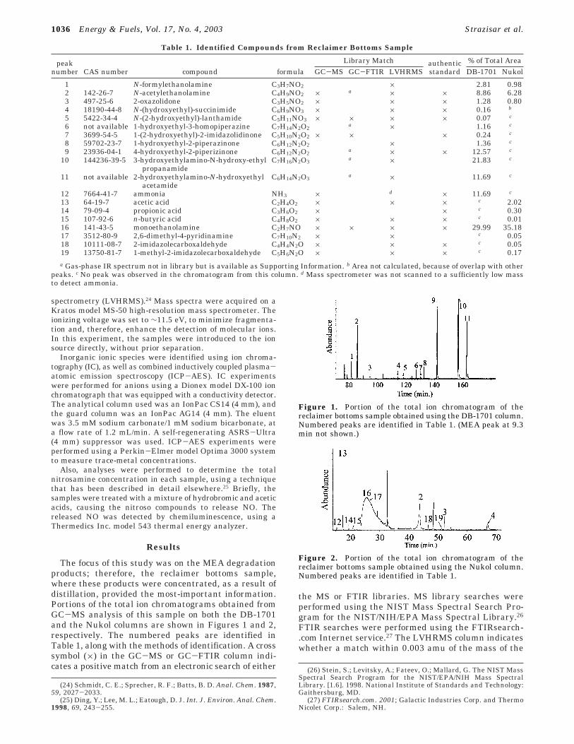
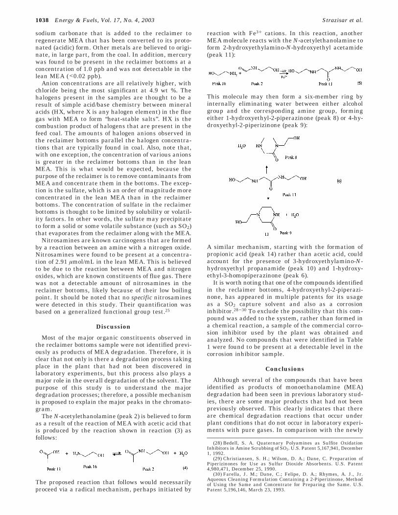
The focus of this study was on the MEA degradationproducts; therefore, the reclaimer bottoms sample,where these products were concentrated, as a result ofdistillation, provided the most-important information.Portions of the total ion chromatograms obtained fromGC-MS analysis of this sample on both the DB-1701and the Nukol columns are shown in Figures 1 and 2,respectively. The numbered peaks are identified inTable 1, along with the methods of identification. A crosssymbol (×) in the GC-MS or GC-FTIR column indi-cates a positive match from an electronic search of either
the MS or FTIR libraries. MS library searches wereperformed using the NIST Mass Spectral Search Pro-gram for the NIST/NIH/EPA Mass Spectral Library.26
FTIR searches were performed using the FTIRsearch-.com Internet service.27 The LVHRMS column indicateswhether a match within 0.003 amu of the mass of the
(24) Schmidt, C. E.; Sprecher, R. F.; Batts, B. D. Anal. Chem. 1987,59, 2027-2033.
(25) Ding, Y.; Lee, M. L.; Eatough, D. J. Int. J. Environ. Anal. Chem.1998, 69, 243-255.
(26) Stein, S.; Levitsky, A.; Fateev, O.; Mallard, G. The NIST MassSpectral Search Program for the NIST/EPA/NIH Mass SpectralLibrary. [1.6]. 1998. National Institute of Standards and Technology:Gaithersburg, MD.
(27) FTIRsearch.com. 2001; Galactic Industries Corp. and ThermoNicolet Corp.: Salem, NH.
Table 1. Identified Compounds from Reclaimer Bottoms Sample
Library Match % of Total Areapeaknumber CAS number compound formula GC-MS GC-FTIR LVHRMS
authenticstandard DB-1701 Nukol
1 N-formylethanolamine C3H7NO2 × 2.81 0.982 142-26-7 N-acetylethanolamine C4H9NO2 × a × × 8.86 6.283 497-25-6 2-oxazolidone C3H5NO2 × × × 1.28 0.804 18190-44-8 N-(hydroxyethyl)-succinimide C6H9NO3 × × × 0.16 b
5 5422-34-4 N-(2-hydroxyethyl)-lanthamide C5H11NO3 × × × × 0.07 c
6 not available 1-hydroxyethyl-3-homopiperazine C7H14N2O2a × 1.16 c
7 3699-54-5 1-(2-hydroxyethyl)-2-imidazolidinone C5H10N2O2 × × × 0.24 c
8 59702-23-7 1-hydroxyethyl-2-piperazinone C6H12N2O2 × 1.36 c
9 23936-04-1 4-hydroxyethyl-2-piperizinone C6H12N2O2a × × 12.57 c
10 144236-39-5 3-hydroxyethylamino-N-hydroxy-ethylpropanamide
C7H16N2O3a × 21.83 c
11 not available 2-hydroxyethylamino-N-hydroxyethylacetamide
C6H14N2O3a × 11.69 c
12 7664-41-7 ammonia NH3 × d × 11.69 c
13 64-19-7 acetic acid C2H4O2 × × × c 2.0214 79-09-4 propionic acid C3H6O2 × × c 0.3015 107-92-6 n-butyric acid C4H8O2 × × × c 0.0116 141-43-5 monoethanolamine C2H7NO × × × × 29.99 35.1817 3512-80-9 2,6-dimethyl-4-pyridinamine C7H10N2 × × c 0.0518 10111-08-7 2-imidazolecarboxaldehyde C4H4N2O × × × c 0.0519 13750-81-7 1-methyl-2-imidazolecarboxaldehyde C5H6N2O × × × c 0.17a Gas-phase IR spectrum not in library but is available as Supporting Information. b Area not calculated, because of overlap with other
peaks. c No peak was observed in the chromatogram from this column. d Mass spectrometer was not scanned to a sufficiently low massto detect ammonia.
Figure 1. Portion of the total ion chromatogram of thereclaimer bottoms sample obtained using the DB-1701 column.Numbered peaks are identified in Table 1. (MEA peak at 9.3min not shown.)
Figure 2. Portion of the total ion chromatogram of thereclaimer bottoms sample obtained using the Nukol column.Numbered peaks are identified in Table 1.
1036 Energy & Fuels, Vol. 17, No. 4, 2003 Strazisar et al.

indicated molecule was present in the mass spectrumof the entire sample. Also included in Table 1 is anindication of the column used for the experiment inwhich each compound was detected. The percentage oftotal area refers to the integrated peak area from thetotal ion chromatogram, as a percentage of the totalsignal intensity for each chromatogram. Other than theMEA, none of the peaks shown in Figures 1 and 2 werepresent in identical experiments that were performedon the virgin MEA.
The use of two separate GC columns (one intermedi-ate and one polar stationary phase) was necessary,because of the large variation in polarity of the degrada-tion products, which is a result of the large number ofheteroatoms present in the compounds. This is il-lustrated by the fact that each chromatogram (Figures1 and 2) has some major peaks that are not present inthe other. This is, in part, due to the fact that the Nukolstationary phase incorporates nitroterephthalic acidfunctional groups. This allows the column to transmitacidic compounds that might not otherwise be eluted,while adsorbing basic compounds. Thus, the carboxylicacids were observed using the Nukol column, but notthe DB-1701 column. For the same reason, the Nukolcolumn does not transmit basic compounds well; someof them are adsorbed and, therefore, do not appear inthe chromatogram.
Many of the major organic degradation products donot appear in either the MS or IR libraries; therefore,the identity of some peaks needed to be deduced byinterpreting the mass spectra and IR spectra. Thisinterpretation was facilitated by the determination ofmolecular formulas using GC-AED. For element ratiocalibration, two compounds in the sample that had beenpreviously identified and verified by co-chromatographywith authentic standards were used: 1-(2-hydroxy-ethyl)-2-imidazoline and N-acetylethanolamine. Thecalculated empirical formulas for each peak are shownin Table 2. For the majority of the compounds identified,an authentic standard was obtained for verification ofthe identity. However, in some cases, as noted in Table1, the standards were not available. For each of thesesix compounds, identification was based solely on theempirical formula, the mass spectrum, and the gas-phase IR spectrum.
One mechanism of MEA degradation that has beenpreviously studied is carbamate dimerization.10,21 This
process is a result of reaction between CO2 and MEAat high temperatures (typically in the stripper column).This process is initiated by the formation of 2-oxazoli-done:
which can, in turn, react with another MEA moleculeto form N-(2-hydroxyethyl)-ethylenediamine via inter-mediates of N,N′-di(hydroxyethyl)urea and 1-(2-hy-droxyethyl)-2-imidazolidinone:21
Two of the molecules in this mechanism, 2-oxazolidoneand 1-(2-hydroxyethyl)-2-imidazolidinone, were ob-served in the present study (peaks 3 and 7). However,these are relatively minor components. The carboxylicacids (peaks 13, 14, and 15) and ammonia (peak 12)have been previously identified as products of oxygen-induced MEA degradation.12 The mechanism for theproduction of acetic acid and ammonia is as follows:
The results of the ICP-AES and IC analyses areshown in Table 3. ICP-AES measurements were madefor 23 different metal cations. Shown in the table areseven metals that were present at a concentration ofg0.2 ppm in either of the two samples. Most prominentis the sodium concentration, mostly because of the
Table 2. Molecular Formulas Calculated from GC-AEDExperiments
retention time(min)
peak number(from Figure 1) C H N O
76.03 N/Aa 6 9 1 180.77 1 3 7 1 285.02 2b 4 9 1 289.26 3 3 5 1 2
103.23 N/Aa 5 8 2 1113.80 4 6 9 1 3117.93 5 5 11 1 3123.97 N/Aa 7 14 2 3127.09 6 7 14 2 2130.12 7b 5 10 2 2132.39 8 6 12 2 2141.50 9 6 12 2 2156.54 10 7 16 2 3162.58 11 6 14 2 3
a Not applicable. b Compounds used as calibration standards forelement ratios.
Table 3. Ion Concentrations
Ion Concentration (ppm)
lean MEA reclaimer bottoms
Cationssodium 80 821potassium 2.2 18calcium 1.1 1.3iron 1.4 1.1copper 0.2 0.1zinc 0.3 0.2aluminum not detectable 0.4selenium not detectable 17.4arsenic not detectable 1.7
Anionsfluoride 300 1500chloride 1600 49000bromide 0.9 80sulfate 2200 250nitrate 290 3100nitrite 130 a
phosphate 7.8 230a Not quantified, because of overlap with the chloride peak.
Degradation of MEA in a CO2 Capture Facility Energy & Fuels, Vol. 17, No. 4, 2003 1037
sodium carbonate that is added to the reclaimer toregenerate MEA that has been converted to its proto-nated (acidic) form. Other metals are believed to origi-nate, in large part, from the coal. In addition, mercurywas found to be present in the reclaimer bottoms at aconcentration of 1.0 ppb and was not detectable in thelean MEA (<0.02 ppb).
Anion concentrations are all relatively higher, withchloride being the most significant at 4.9 wt %. Thehalogens present in the samples are thought to be aresult of simple acid/base chemistry between mineralacids (HX, where X is any halogen element) in the fluegas with MEA to form “heat-stable salts”. HX is thecombustion product of halogens that are present in thefeed coal. The amounts of halogen anions observed inthe reclaimer bottoms parallel the halogen concentra-tions that are typically found in coal. Also, note that,with one exception, the concentration of various anionsis greater in the reclaimer bottoms than in the leanMEA. This is what would be expected, because thepurpose of the reclaimer is to remove contaminants fromMEA and concentrate them in the bottoms. The excep-tion is the sulfate, which is an order of magnitude moreconcentrated in the lean MEA than in the reclaimerbottoms. The concentration of sulfate in the reclaimerbottoms is thought to be limited by solubility or volatil-ity factors. In other words, the sulfate may precipitateto form a solid or some volatile substance (such as SO2)that evaporates from the reclaimer along with the MEA.
Nitrosamines are known carcinogens that are formedby a reaction between an amine with a nitrogen oxide.Nitrosamines were found to be present at a concentra-tion of 2.91 µmol/mL in the lean MEA. This is believedto be due to the reaction between MEA and nitrogenoxides, which are known constituents of flue gas. Therewas not a detectable amount of nitrosamines in thereclaimer bottoms, likely because of their low boilingpoint. It should be noted that no specific nitrosamineswere detected in this study. Their quantification wasbased on a generalized functional group test.25
Discussion
Most of the major organic constituents observed inthe reclaimer bottoms sample were not identified previ-ously as products of MEA degradation. Therefore, it isclear that not only is there a degradation process takingplace in the plant that had not been discovered inlaboratory experiments, but this process also plays amajor role in the overall degradation of the solvent. Thepurpose of this study is to understand the majordegradation processes; therefore, a possible mechanismis proposed to explain the major peaks in the chromato-gram.
The N-acetylethanolamine (peak 2) is believed to formas a result of the reaction of MEA with acetic acid thatis produced by the reaction shown in reaction (3) asfollows:
The proposed reaction that follows would necessarilyproceed via a radical mechanism, perhaps initiated by
reaction with Fe3+ cations. In this reaction, anotherMEA molecule reacts with the N-acetylethanolamine toform 2-hydroxyethylamino-N-hydroxyethyl acetamide(peak 11):
This molecule may then form a six-member ring byinternally eliminating water between either alcoholgroup and the corresponding amine group, formingeither 1-hydroxyethyl-2-piperazinone (peak 8) or 4-hy-droxyethyl-2-piperizinone (peak 9):
A similar mechanism, starting with the formation ofpropionic acid (peak 14) rather than acetic acid, couldaccount for the presence of 3-hydroxyethylamino-N-hydroxyethyl propanamide (peak 10) and 1-hydroxy-ethyl-3-homopiperazinone (peak 6).
It is worth noting that one of the compounds identifiedin the reclaimer bottoms, 4-hydroxyethyl-2-piperazi-none, has appeared in multiple patents for its usageas a SO2 capture solvent and also as a corrosioninhibitor.28-30 To exclude the possibility that this com-pound was added to the system, rather than formed ina chemical reaction, a sample of the commercial corro-sion inhibitor used by the plant was obtained andanalyzed. No compounds that were identified in Table1 were found to be present at a detectable level in thecorrosion inhibitor sample.
Conclusions
Although several of the compounds that have beenidentified as products of monoethanolamine (MEA)degradation had been seen in previous laboratory stud-ies, there are some major products that had not beenpreviously observed. This clearly indicates that thereare chemical degradation reactions that occur underplant conditions that do not occur in laboratory experi-ments with pure gases. In comparison with the newly
(28) Bedell, S. A. Quaternary Polyamines as Sulfite OxidationInhibitors in Amine Scrubbing of SO2. U.S. Patent 5,167,941, December1, 1992.
(29) Christiansen, S. H.; Wilson, D. A.; Dane, C. Preparation ofPiperizinones for Use as Sulfur Dioxide Absorbents. U.S. Patent4,980,471, December 25, 1990.
(30) Farella, J. M.; Dane, C.; Felipe, D. A.; Rhymes, A. J., Jr.Aqueous Cleaning Formulation Containing a 2-Piperizinone, Methodof Using the Same and Concentrate for Preparing the Same. U.S.Patent 5,196,146, March 23, 1993.
1038 Energy & Fuels, Vol. 17, No. 4, 2003 Strazisar et al.

proposed degradation mechanism, carbamate dimeriza-tion is a relatively minor pathway. It is important tonote that the samples for this study have been takenfrom the reclaimer, where degradation products areconcentrated and temperatures are higher than any-where else in the process. It is possible that some of thedegradation products identified were formed in thereclaimer itself, rather than in the stripper.
In addition to the neutral degradation products, thereare large amounts of “heat-stable” salts produced in theprocess, as evidenced by the ion chromatographic re-sults. This is not surprising, on the basis of previousliterature on the subject.16
It is evident from Figure 2 that the reclaimer bottomscontain a substantial amount of MEA. It may be possibleto employ a more efficient distillation system to reducethe amount of waste produced and reduce MEA make-up costs.
Acknowledgment. Reference in this report to anyspecific commercial product, process, or service is tofacilitate understanding and does not necessarily imply
endorsement or favoring by the United States Depart-ment of Energy. Some work was performed while B.R.S.held a National Research Council Research Associate-ship Award at the National Energy Technology Labora-tory. GC-IR spectra were obtained at the Mass Spec-trometry Facility, Department of Chemistry and Chem-ical Biology, Cornell University in Ithaca, NY. Nitro-samines analyses were performed by Delbert Eatoughat Brigham Young University in Provo, UT. The authorswish to thank Leroy Williams (IMC Chemicals, Inc.,Troma, CA) for providing the samples and informationabout the process, Peter Griffiths for assistance ininterpreting the IR spectra, and Stephen Bedell (DowChemicals, Midland, MI) for providing a sample of4-hydroxyethyl-2-piperazinone.
Supporting Information Available: Gas-phase infraredspectra of selected compounds (PDF). (See Table 1.) Thismaterial is available free of charge via the Internet athttp://pubs.acs.org.
EF020272I
Degradation of MEA in a CO2 Capture Facility Energy & Fuels, Vol. 17, No. 4, 2003 1039