deformation control of rheological food dough using a forming
TRANSCRIPT

Deformation Control of Rheological Food Dough Using A Forming Process Model
Shinichi T o k u m o t o and Shinichi Hira i
Dep t . of Robo t i c s ,
R i t s u m e i k a n Univ . , K u s a t s u , Shiga 525-8577, J a p a n
E-mai l : h i r a i@se . r i t sume i . ac . j p
Abstract A new approach to the forming control using a
forming process model of rheological food dough is pre- sented. Manipulative operations of rheological objects can be found in many industrial fields such as food industry and medical product industry. For example, automatic operations of rheological objects such as food dough are eagerly required in food industry. Since food dough deforms during operation processes, it is neces- sary to estimate their deformation for the automatic operations.
We will propose a forming control of rheological food dough using a forming process model. First, an extensional forming system of food dough is develope- d. Second, we will examine the deformations of actual food dough. Third, we will propose a forming process model consisting of the expansion part and the residu- al part. Finally, we will propose forming control using forming process model and will demonstrate the valid- ity of the proposed forming control experimentally.
1 Introduction In food industry, we can find many manipulative
operations that deal with deformable rheological ma- terials such as dough, paste, jelly, and meat. Most of these operations are done by people. Especially, operations with large deformation of rheologic objects depend upon people. For example, forming of pizza dough to a thin circular shape is performed by peo- ple while the extension of dough can be done by me- chanical stretchers. Thus, automatic operations with machines are strongly required for the cost reduction and the cleanness of food.
Object deformation has been investigated in various research fields. Modeling of elastic or viscoelastic ob- jects have been studied in computer graphics [1, 2, 3] and virtual reality [4]. These researches focus on the deformation modeling of elastic or viscoelastic objects and forming operations of their objects are out of con- sideration. Thus, we have no method to determine a forming strategy based on the object model. Material nature of rheological objects is investigated extensive- ly in theology [5]. Unfortunately, deformation of rhe- ological objects in 3D space is not studied in rheology. Handling operations of deformable objects have been studied recently. Automatic handling of deformable
parts in garment industry and shoe industry has been experimentally studied [6, 7]. Zheng and Chen have proposed a strategy to insert a deformable beam into a hole [8]. Wada et al. have proposed a control law for the positioning operation of extensible clothes [9]. These researches focus on handling of elastic objects and forming operations of rheological objects are out of focus.
In this paper, we will propose a forming control of rheological food dough using a forming process model. First, an extensional forming system of food dough is developed. Second, we will examine the deformations of actual food dough. Third, we will propose a forming process model consisting of the expansion part and the residual part. Finally, we will propose forming control using forming process model and will demonstrate the validity of the proposed forming control experimental- ly.
2 A Vision-based Forming S y s t e m o f
Rheological Food dough In this section, we will develop a forming machine
of food dough with multi degrees of freedom. It has been proved that three degrees of freedom are essen- tial for the planar forming of food dough [11]. Based on the investigation, we have developed a forming ma- chine shown in Figure 1, where the three freedoms can be controlled to change the configuration between a roller and a table. The table of the developed form- ing machine can rotate around its central axis and can translate in a horizontal direction. The roller of the machine can rotate its central axis and can translate vertically. Roller height and table angle are position- controlled while translational motion of the table is velocity-controlled. Translational motion of the table and rotational motion of the roller are synchronized by a belt. Thus, we have three independent degrees of freedom in the developed forming machine. We will assume that the velocity of the table is constant. This implies that we have two controllable variables, roller height h and table angle ¢, as illustrated in Figure 2.
Planar deformation is essential in the forming of food dough. A CCD camera is installed to capture the deformed shape of the object. The captured im- age is sent to a PC and the motion of mechanism is
1457

~:~:~:~:~:~:~:~:~:~:~:~:~:~:~:~:~:~:~:~:~:~:~:~:~:~:~t~:~:~:~:~:~:~:~:~:~:~:~:~:~:~:~:~:~:~:~:~:~:~:~:~:~:~ ~ii',i',i',~[i~,i~,! ...... "~'iiiii~i~ i~:~:~!::!~::i i', ~ i~:~:~!~::a:~::~::!::!~::l':i!i!i;ii~,iiiiii~i~:::;: ::::::~::: iiiiiiiiiiiiiiiiiiiiiiiiiiiiiiiiiiiiiiiiiiiiiiiiiiiii!ii!iiiiiiiiiiiiiiiiiiiiiiiiiiiiiiiiiiiiiiiiiiiiiiiiiiiiiii~ ~iii~i~Y:~!i!2;;i:2;ii~iii i~:~2::::::::::::~::~:!~!~;~ ~:~
i~i~i~i~i~i~i~i~i~i~i~i~iiiii~?~!i;~i~ii~%iiii~i~! ~ :~:,~!!ii~:~::;i!ii!>:~ iii ~i~iii~ :~ iii ii i ~ ~ ~:~::%:%~ili
::;~i~ii~i~: ~iG:;i;:;i:;:~iiiiiii~ii~:F:;i;!:i!~L ~:~ i ii ::::::::::::::::::::::::::::::::: :i~i~i~i~}~ ~i ;:;~:;::~:~:: iii ii ~i::ii::iiiiiii~i~i~i~[~[[[ .............................................................. ~iiiiiiiiiiii;)~!iiiii~iiiiiiiiiiii~i~;~iiiiii~!ii!~iiiiiiiiii!i~i~i~ii~iiiiii~iii~?~ii~iiiiiiii~ • ::~ii~ ii ii !i!~ ............ ii~ ii ii~iiiiiiiiiiiiiiiiiiiiiiii~iiiiiiiiiiiiiiiiiiiiiiiiiiiiiiiiiiiiiiiiiiiiiiiiiiiiiiiiiiiiii
i ~iiiiiiiiiiiiiiiiiiiiiiiiii~iiiIiiiiiiiiiiii~iiiiiiiiiiiiiiiiiiiiiiiiiiiii~iiiiiiiiiiNiiiii~i~i~i~ii5~:~̀ "~i,~ii~̀i~i~iii~iiiiiiiiiiiiiiiiiiiiiiiiiiiiiiiiiiiiiiiiiiiiiiiiiiiii!i i iiiiiiiiiiiiiiiiiiiiiiiiiiiiiiiiiiii
~:~:~::~ - ..... !!~======================================!~i~i~iii~i~i~i~i~iii;iiii~i~i~iiiiiiiiiiii~i~i~i~i~i~i~i~i~i~i~i~̀̀~~ ~ii~i~i~i~i~i~i~i~i~i~i~i~i~i~i~G~iii~i~i~i~i~i~i~iii~iii~i~i~i~i~i~i:~iiiii~iii~i~i~i~i~i~i~i~i~i~i~i~i~i~i~i~iiii~ ~?~ i i~iiiNb|~i~i~i~i~i~i~i~i~i~i~i~i~i~i~i~i~i~~ i
~i~i~i~i~i~i=======================================================================================================ii~i~i~i~i~i~i~i~ii~i~ii~i~i~i~i~i~i~i~i~i~i~i~i~i~i~i~i~i~i~i~iiiiiiiiiiiiiiiiiiiiiiiiiiii~ii
~ ::::i::~i::~ :::~ ..... ~ ......... ~;i: : i : : i i i : : i : : i : : i : : i : : i : : ~::::i::ii::i::i::i::ii::i ~: . . . . . ::::i::i::i::i::i::i::i::i::i::i::i::i::i::i::i::i::::® ::~::::~::~: ~ ..................... ~ ...... -:::i:i~i::~:i~::::~::~::::::}~:~:::::::::::::::::::::?~ .::::::::::L-"::::::::::::::::~::I~ ::::::::::::::::::::::::::::::::::::::::::::::::::::::::::::Y:~ N~ ............................ .................... ~ i ~ ~ i ~ ~i~:: .... ::~::::::::::::::::~::~:a~::N::~
::::::::::::::::::::::::::::::::::::::::::::::::::::::::::::::::::::::::::::::::::::::::::::::::::::::: ............. iiiiiiiiiiiiiiiiiiiiiiiiiiiiiiiii " ............... ::::::::::::::::::::::::::::::::::::::::::::::::::::::::::::::::::::::::::::::::::::::::::::::::::::H!iiiiiiiiiiiiiiiiiiIiiiiiiiiiiiiiiiiiiii~ .... ---,:-- .:~::::::::::::~::
Figure 1" Prototype of forming system
determined according to the captured image.
/
\"...,... "\ / TableL
(a)table rotational angle
Roller
I
(b)roller height h
Figure 2" Control variables
3 E x p e r i m e n t s o n F o o d D o u g h D e f o r -
m a t i o n Since it is difficult to form food dough to a desired
shape by one forming action, it is required to form the dough by multiple forming actions. Forming action is defined as a single forming operation, which is char- acterized by a pair of roller height h and table angle ~. Forming process is then described as a series of forming actions and resulting in deformed shapes fol- lowing individual forming actions. In this session, we will analyze forming actions for deformation control. First, we will define an outline function. Next, we will examine actual deformation and will analyze forming processes. 3 .1 D e f o r m e d S h a p e D e s c r i p t i o n o f Food
D o u g h In this paper, an outline function is introduced to
describe two-dimensional shape of food dough. Let f(0) be the distance from the gravity center G to the contour of the deformed shape at angle 0 from x-axis, as illustrated in Figure 3-(a). The deformed shape of a rheological object is then described by a function f(0)(0 _~ tO _~ 2u), which is referred to as an outline
Rheological otliect
(a) definition 50 ' ' ' ' I
rD E ~40
°o! Angle[radl
(b) object (c) distance
Figure 3" Concept of outline function
function of the deformed shape. Figure 3-(b) shows an example of deformed shape and the outline function corresponding to the shape is plotted in Figure 3-(c). An area of a small region in an object surrounded by half lines at angle O and O+dO is given by (1/2) f2 (0)dO, as illustrated in Figure 3-(a). Consequently, total area of the object is represented as follows:
~0 2~ 1 f2 A - ~ (0)de. (1)
Namely, an area of an object can be computed from its outline function.
3 .2 A n a l y s i s o f Area Trans i t ion d u r i n g Forming A c t i o n s
In this section, we will investigate area transit ion of food dough during forming actions.
3.2.1 Analysis of Area Transition during Sin- gle Forming Action
Let us examine the forming actions of food dough ex- perimentally. Food dough made of wheat flour and water at weight ratio 1 : 3 is formed by the devel- oped forming machine. Translational velocity of the table is fixed to 100 [mm/s]. Rectangular-shaped food dough of 13 [mm] height is formed by various forming actions. Obtained results are enumerated in Figure 4- (a) through (1). White regions in the figures describe the initial shapes while gray regions show the formed shapes.
Figure 4 shows that dough is expanded most along the direction of ¢ + ~[rad]. Moreover, the area of deformed shape is larger for a smaller value of roller height h. Let Ainit and Adef be the initial shape and the deformed shape, respectively. Let us investigate the relationship between area ratio (~ = Adcf/Ainit and forming actions specified by h and ¢. Figure 5 describes the relationship between roller height h and area ratio a for some values of table angle ¢. White
1458

-
h - 12[ram] (b)~ - 7c/4[rad]
h - 12[mrn] (c)~ - 7c/2[rad]
h - 12[ram]
to forming actions of h = 13[rnm]. From Figure 6-(h), it turns out that area ratio a depends on roller height h alone, that is, the ratio does not depend on initial shape. Other experiments support this result. Con- sequently, we find that area ratio does not depend on initial shape.
(d)~ - O[rad] h - 10[ram]
(e)~ -- 7c/4[rad] h - 10[mrn]
(f)~ - 7r/2[rad] h - 10[ram]
(a)Trial 1 (b)Trial 2 (c)Trial 3
(g)¢ -O[rad] (h)~ - 7c/4[rad] (i)~b - 7c/2[rad] h - h - h -
(d)Trial 4 (e)Trial 5 (f)Trial 6
(j)O - O[rad] (k)O - 7c/4[rad] (1)~ - 7r/2[rad]
Figure 4: Formed shapes
circles, black circles, and triangles correspond to ~ = 0, f = 7r/4, and ~ = 7c/2, respectively. From Figure 5, it turns out that area ratio a depends on roller height h alone, that is, the ratio does not depend on table angle ~. Other experiments support this result. Consequently, we find that area ratio does not depend on the table angle.
1.8
1.(
._z
'~ 1.4
< 1.2
___o__ 0 o . 4 5 °
90 °
8 10 12 R o l l e r height h[mm]
Figure 5" Area ratio corresponding to different form- ing actions
Next, let us investigate area ratio corresponding to different initial shapes with the same height and the same area. Seven different initial shapes are listed in Figure 6-(a) through (g). Height of all initial shapes is 16[rnm] and all initial shapes have the same ar- eas. Figure 6-(h) describe area ratios corresponding
(g) Trial 7
1 ; f t ---o--Trial 1 1. • Trial 2
~ Trial 3 .~ A Trial 4
2l- ~ ---o-- Trial 5 -1 1. / ~ - . . ~ ; Trial 6 /
[ " ~ ~ ~ T r i a l 7 ]
~2 ~ fx ....... i4 ~5 r6 ~ ~7 Roller height h[mm]
(h)Area ratio a
Figure 6" Area ratio corresponding to different initial shapes
3.2.2 A n a l y s i s of A r e a Trans i t ions dur ing M u l t i p l e F o r m i n g A c t i o n s
In this section, we will analyze the forming process consisting of multiple forming actions. Experimental conditions are the same as the previous section.
Let us investigate transitions of area ratio during forming the process consisting of multiple forming ac- tions. An initial shape of dough is of 16 [mm] in height. The initial shape is formed by a series of six forming actions. Values of roller height h correspond- ing to the forming actions are 13 [rnm], 11 [rnm], 9 [turn], 8 [turn], 7 [ram], and 6 [rnm], respectively. Values of table angle are selected at random. We have performed seven trials of the above forming process- es. Figure 7 shows an example of deformed shapes in one trial. Figure 8 shows area ratio transitions by
1459

these deformations. From Figure 8, it turns out that area ratio transitions depend on roller height h alone, that is, the ratio transitions do not depend on table angle ~. Other experiments support this result. Con- sequently, we find that area ratio transitions do not depend on the table angle.
(a)Initial shape ( b ) h - 13[ram] ( c ) h - l l[mm]
( d ) h - 9[ram] ( e ) h - 8[mm] ( f ) h - 7[mm]
(g)h - 6[mini
Figure 7: Formed shapes in Trial 1
we find that food dough is expanded most along roller direction. Namely, expansion along roller direction of food dough is longer than that perpendicular to the roller direction. Let x-axis be along the roller direc- tion and y-axis be perpendicular to it, as illustrated in Figure 9. Let Kx and Ky be expansion ratio of the formed shape with respect to the initial shape along x-axis and along y-axis, respectively. We can roughly estimate the deformed shape by expanding the initial shape by K~ and Ky along x-axis and y-axis, respec- tively. This estimation is referred to as constant ex- pansion part, which is abbreviated as CEP. Let f¢xp(O) be the outline function of CEP. Moreover, let us intro- duce an additional part into the estimation to improve the accuracy of estimated formed shapes. In an exam- ple shown in Figure 4-(k), lower left side of the formed shape cannot be described by CEP alone and an ad- ditional part is needed. Let us divide the contour of food dough into two; roller approaching side and roller departure side. The roller of a forming machine ap- proaches to food dough at the approaching side while it departs from food dough at the departure side. We find that the formed shape which is at the approach- ing side can be estimated by CEP while which is at the departure side cannot be described by CEP alone. Thus, we will introduce an additional part into the departure side. This part is referred to as residual ex- pansion part, which is abbreviated by REP. Let g(0) be the outline function of the REP. Outline function fest(O) of the estimated shape is then given as follows:
2.5
, ~ , ---o--- Trial 1 " ~ * Trial 2 1 ~ + Trial 3
.~ ~ A Trial 4. ~ + Trial 5-
= Trial 6 1.5- 7
.
1 " , I , I , I , I , ~ " ~
~6 8 10 12 14 1 Roller height h[mm]
Figure 8" Transition of area ratio
From the above results, we will conclude that area ratio depends on area and height of the initial shape and roller height while it does not depend on the shape and the table angle.
4 A F o r m i n g P r o c e s s M o d e l In this session, we will propose a forming process
model to perform a forming control of food dough. First, we will propose forming process model. Nex- t, we will estimate the constant expansion part and residual expansion part from actual experiments in session 3. Finally, we will verify validity of a form- ing process model. 4.1 E s t i m a t i o n of Formed Shapes
In this section, we will propose a method to esti- mate formed shapes. From deformation experiments,
{ f¢xp(O) + g(O) roller departure side fest(O) - fcxp(O) roller approaching side.
(2) 4.2 E s t i m a t i o n s o f C E P a n d R E P
In this section, we will estimate CEP and REP from actual deformed shape. Recall that the outline func- tion of CEP is given by fc~p(¢). Assume that contour of CEP at an angle ¢ corresponds to contour of the initial shape at an angle 0. That is,
] [ Kxfb~y(O)cos(O) ] From the above equation, we have
(3)
¢ = atan2(KysinO, KxcosO), - +
(4) Note that the estimated shape at the roller approach- ing side is described by CEP alone. Thus, Kx and Kv, which specify the CEP, are identified experimentally from the formed shape at approaching side. Figure 10 shows the identified value of Kx and Kv. Figure 10-(a) shows relationship between K~ and area ratio a while Figure 10-(b) shows relationship between Ky and area ratio c~. From these results, we find that K~ and Ky depend on area ratios a and not depend on differences of the shapes. Ratio K~ and Ky are thus described as functions of an area ratio a. In an example plotted in Figure 10, Kx and Kv can be approximated by the
1460

following equations.
0.4545. (a - 1) + 1 K ~ ( a ) - 0.4483 ( a - 1.2)+ 1.0909
0.3182 ( a - 1 ) + 1 K y ( a ) - 0.1862 ( a - 1.2)+ 1.0636
(a < 1.2) (a > 1.2) (a < 1.2) (a > 1.2)
(5) (a) Before (b) Deformed
• fe#O) ................... y .................
f~g0)
s ..... ,(0)d0 ~ : ~ ......... . . . . . . . . . ........... .... ....... .... ,
. . . . . . . - . . . . . . . . . . . . . . . . . .
'" ' ' ~ . . . . . _ _ _ ~
fegO) Roller ............
Figure 9" Estimation of deformed shape
1.3
1.2
1.1
1 1.2 1.4 1.6 1.8 Area ratio a
1.2
1 . 1 5 ~
1.1
1.05
1 1.2 1.4 1.6 1.8 2 Area ratio a
(b) Ky
Figure 10: Expansion ratios
Let us investigate the REP by talking a simple ex- ample given in Figure 11. Figure 11-(a) shows an ini- tial shape and Figure 11-(b) represents its deformed shape after a forming action. The computed CEP cor- responding to the initial shape is shown in Figure 11- (c). We will construct the REP so that it can describe the difference between the deformed shape and the CEP. Let d(¢) be the tangent vector of the contour of the CEP at an angle ¢ as illustrated in Figure 9. Vector d(¢) is described as follows using the outline function fCx~ (¢):
d ( ¢ ) -
! f¢xp(¢)cos(¢)- f~xp(¢)sin(¢) f¢xp(¢)sin(¢) + .L~p(¢)cos(¢) (6)
Let us define the roller approaching side and the roller departure side. Recall that the roller moves along x- axis from its positive side, as shown in the figure. Let fl be the angle between vector d(¢) and x-axis. On the
(c) Expanded (d) Estimated
Figure 11" Estimated shapes
one hand, when angle fl is involved in region [~r, 2~r], the contour corresponding to the angle is stretched by the roller. On the other hand, when an angle fl is involved in region [0, 7r], the corresponding contour is contracted by the roller. We will thus define the roller departure side as the region where an angle fl is in- volved in [;r, 27r]. The approaching side is defined as the region where an angle fl is involved in [0, 7r]. Let ~1 be the angle where ~ is equal to 7r, as illustrates in the figure. Then, vector d(¢1) is given by a scalar multiple of vector [-1, 0] with a positive coefficient. Let ~2 be the angle where fl is equal to 27r, as illus- trates in the Figure. Then, vector d(¢2) is given by a scalar multiple of vector [1, 0] with a positive coeffi- cient. Angles ~/)1 and ~2 can be computed by solving the following equation:
f~xp(¢)cos(¢) - £~p(O)sin(¢) - O.
As a result, an angle ¢ is involved in the region [¢1, ¢2] at the departure side while it is involved in region [¢2, ¢1 + 27r] at the approaching side. Next, let us formulate the REP. Let S~st(¢) be the area densi- ty of the difference between fdef(¢) and f, xp(¢) at an angle ¢. Area between an angle ¢ and an angle ¢ + de is then given by S~s,t(¢)d¢, as illustrated in Figure 9. Recall that the REP is given by the differ- ence between the deformed shape and the CEP. Area between angle ¢ and ¢ + de of the deformed shape is given by (1/2)f 2 dCf(¢)d¢ and that of the CEP is given by (1/2)f~%p(¢)d¢. Thus, area S~c~t(¢)d¢ is equal to the difference between (1/2)f 2 dCf (¢)d¢ and (1/2)f,%p(¢)d¢. Consequently, we have the following equation:
1 2 S~st(¢) - ~[ f~f (¢) - f~xp(¢)]. (7)
A broken line in Figure 12 shows function S~st (¢) that specifies the difference between the deformed shape given in Figure l l-(b) and the CEP given in Figure 11-(c). We will approximate area density S~st(¢) by a piecewise linear function plotted by a solid line in
1461
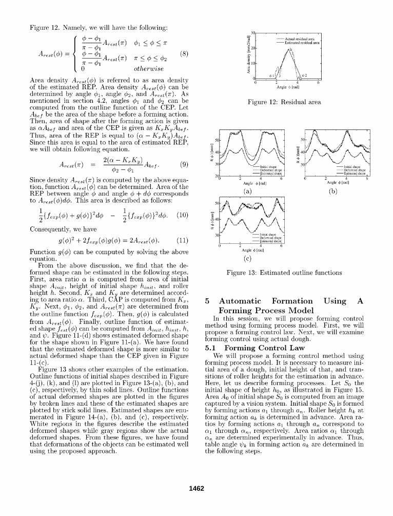
Figure 12. Namely, we will have the following:
¢ - - ¢ 1
7"( -- ~1 0
~ A ~ t ( ~ r ) 0~ < ¢ < ~r
otherwise
(8)
Area density A~st(¢) is referred to as area density of the estimated REP. Area density Arest(¢) can be determined by angle ¢1, angle ¢~, and A~est(Tr). As mentioned in section 4.2, angles ¢1 and Ce can be computed from the outline function of the CEP. Let Abel be the area of the shape before a tbrming action. Then, area of shape after the forming action is given as ctAbef and area of tile CEP is given as KxKyA~f . Thus, area of the REP is equal to (c~ - K~Ky)A~f. Since this area is equal to the area of estimate~t REP, we will obtain following equation.
A~.~t(Tr) = 2(c~- K~Ky)A~f. (9) ¢2 -- ¢1
Since density A~st(Tc) is computed by the above equa- tion, function A ~ t ( ¢ ) can be determined. Area of the REP between angle ¢ and angle ¢ + de corresponds to A~t(O)d¢. This area is described as follows:
1 ~{f~p(¢) + g(O)}2d¢
I ~ {f~p(¢)}gd¢. (10)
Consequently, we have
g(0)2 + 2f~p(¢)g(¢) - 2A,.~t(¢). (11)
Function g(¢) can be computed by solving the above equation.
From the above discussion, we find that the de- formed shape can be estimated in the following steps. First, area ratio c~ is computed from area of initial shape Ainit, height of initial shape hinit, and roller height h. Second, Kx and Ky are determined accord- ing to area ratio c~. Third, CAP is computed from Kx, Ky. Next, ¢1, ¢2, and A~t(zc) are determined from the outline function f~ ; (¢ ) . Then, g(¢) is calculated from A~t(¢) . Finally, outline fimction of estimat- ed shape f~t (¢) can be computed from Ainit, hinit, h, and ~b. Figure 11-(d) shows estimated deformed shape for the shape shown in Figure 11-(a). We have found that the estimated deformed shape is more similar to actual deformed shape than the CEP given in Figure 11-(c).
Figure 13 shows other examples of the estimation. Outline functions of initial shapes described in Figure 4-(j), (k), and (1) are plotted in Figure 13-(a), (b), and (c), respectively, by thin solid lines. Outline functions of actual deformed shapes are plotted in the figures by broken lines and these of the estimated shapes are plotted by stick solid lines. Estimated shapes are enu- merated in Figure 14-(a), (b), and (c), respectively. White regions in the figures describe the estimated deformed shapes while gray regions show the actual deformed shapes. From these figures, we have found that deformations of the objects can be estimated well using the proposed approach.
301 v F c i ~
[ . . . . . . Actual residual area / - - E s t i m a t e d residual area
I ~10
1/'
0 2 4 6 A n g l e ~) [rad]
Figure 12" Residual area
50 i' , ,---, E
40
3og" ~ ] - - Initial shape. I- . . . . . Defomled shape
20 l . , - - ,E~t im~ted shap K 0 2 4 6
Angle (k [rad]
{40 . . . . . . . . . . . . . . . . . . . . . .
0 2 4 6 Angle 4~ [rad]
(c)
T 1 r T
50 : ,' ",,
40 --'
3O
0 2 4 6 Angle 4) [rad]
(b)
Figure 13" Estimated outline flmctions
5 A u t o m a t i c F o r m a t i o n U s i n g A F o r m i n g P r o c e s s M o d e l
In this session, we will propose forming control method using forming process model. First, we will propose a forming control law. Next, we will examine forming control using actual dough.
5.1 Forming Control Law We will propose a forming control method using
forming process model. It is necessary to measure ini- tial area of a dough, initial height of that, and tran- sitions of roller heights for the estimation in advance. Here, let us describe forming processes. Let So tile initial shape of height h0, as illustrated in Figure 15. Area A0 of initial shape So is computed from an image captured by a vision system. Initial shape So is formed by forming actions al through a~. Roller height hk at forming action ak is determined in advance. Area ra- tios by forming actions al through aN correspond to c~1 through aN, respectively. Area ratios aj through ct,~ are determined experimentally in advance. Thus, table angle ~Pk in forming action a~ are determined in the following steps.
1462

(b)
Figure 14" Estimated shapes
Recall that forming action ak is specified by roller height hk and table angle Ck. Roller height hk is de- termined in advance. Here, we will select table angle Ck appropriate for the forming based on the forming process model. Let ¢~'~ - mAC be a possible table angle, where m E [0, M - 1] and Atb = 27r/M. Name- ly, we have M candidates 0 ¢~ through t) M-1 of roller angle Ck. We can estimate the deformed shape S~ ~ af- ter a candidate forming action specified by ~ . As a result, we have M estimated shapes S O through S M-1 corresponding to individual candidates. Then, we will evaluate the difference between the estimated shapes and the goal shape to select one estimated shape near- est to the goal shape. Forming action corresponding to the nearest estimated shape is thus selected as the following forming action.
Then, evaluating function is denoted by the following equation"
jr0 2rr E~ -- {f¢,t(¢) - )~(0)}~d¢. (13)
The closer estimated shape is to target shape, the s- maller evaluating function is. Thus, we will select a forming action that minimizes the above evaluating function. Figure 16 shows the result of forming con- trol. From these figures, evaluating flmction decrease from 6849.3 to 391.97. We find that the shape of food dough is more and more close to a circular shape.
( a ) h - 16[ram] ( b ) h - 13[ram] ( c ) h - l l [mm]
(d) h - 9[ram] (e)h- 8[turn] ( f ) h - 7[ram]
........................ '...
S O .... ~ ....... ,~ h0,&
....................... a 1 [h1,~11
........................ ................
. . . . .
"~' 1 ",1 . . . . . . . . - ~ : .... S 2 .. . . . . . . ...
....................... ... a 2 ...
[h2 ,lflr 2 ]
. . . . . .
) . . . . . t ~ . . . . . . . . 1~ .... St t
a t 7 .......................
[h~ ,~]
Figure 15" Forming process parameters
5.2 Experiments on Forming Control In this section, we will show experimental results
on forming control of dough. Height of initial shape is 16 [ram]. Values of roller height h corresponding to the forming actions are 13 [ram], 11 [mm], 9 [mini, 8 [ram], 7 [mini, and 6 [ram], respectively. Area ratio c~k at each roller height is determined in advance. An average value of area ratio at each roller height is cal- culated from seven deformed shapes shown in Figure 8.
We have two target shapes; 1) circular shape and 2) long and narrow shape. We will determine the e- valuating functions for these two goal shapes.
[Forming to circular shape] Let o~k be target shape of deformed shape after
forming by forming action ak. Target shape Sk is a circle with area c~kA0. Outline flmction fk(¢) of target shape Sk is then given as follows"
9~(¢)- i °~A°rc (12)
( g ) h -
_ . . . . .....
40
3O 0 2 4 6
Angle 0 [rad]
(h) outline functions
Figure 16" Automatic forming to circular shape
[Forming to long and narrow shape] Target shape is a long and narrow shape. Let Lk
be maximum length along x-axis and Sk be maximum length along y-axis. Maximum length Lk along x- axis and maximum length S~ along y-axis are obtained from the estimated shapes. The evaluating function is determined as follows:
Sk - - - . ( 1 4 )
Lk
The smaller this evaluating function is, the longer and narrower the shape is. Thus, we will select a forming
1463

action that minimizes the above evaluating function. Figure 17 shows the result of forming control. From these figures, evaluating function decrease from 0.6826 to 0.6413. We find that the shape of food dough is much closer to a long and narrow shape.
(a)h = 16[mini (b)h = 13[mini (c)h = 11[mini
(d)h = 9[ram] (e)h = 8[ram] (f)h = 7[ram]
( g ) h =
\ , 7 0
60
g" 50
4(
3(3: . . . . . . . . . ~ . . . . . . . . . . . . . . . . 2 ~ . . . . . . . . . . . . 4 6=
A n g l e 0 [ rad]
(h) outline functions
Figure 17: Automatic forming to long and narrow shape
[2] Terzopoulos, D., and Fleisher, K., Modeling In- elastic Deformation: Viscoelasticity, Plastici- ty, Fracture, Computer Graphics, Vol.22, No.4, pp.269--278, 1988
[3] Joukhader, A., Deguet, A., and Laugie, C., A Collision Model for Rigid and Deformable Bod- ies, Proc. IEEE Int. Conf. on Robotics and Au- tomation, pp.982-988, Alberquerque, May, 1998
[4] Chai, Y., and Luecke, G. R., Virtual Clay Model- ing Using the ISU Ezoskeleton, Proc. IEEE Vir- tual Reality Annual Int. Symp., pp.76--80, 1998
[5] Barnes, H. A., Hutton, J. F., and Walters, K., An Introduction to Rheology, Elsevier Science Pub- lishers, 1989
[6] Taylor, P. M., eds., Sensory Robotics for the Han- dling of Limp Materials, Springer-Verlag, 1990
[7] Henrich, D., and WSrn, H. eds., Robot Manip- ulation of Deformable Objects, Springer-Verlag, Advanced Manufacturing Series, 2000
[8] Zheng, Y. F., Pei, R., and Chen, C., Strategies for Automatic Assembly of Deformable Objects, Proc. IEEE Int. Conf. on Robotics and Automa- tion, pp.2598-2603, 1991
[9] Hirai, S., Wada, T., Indirect Simultaneous Posi- tioning of Deformable Objects with Multi Pinch- ing Fingers Based on Uncertain Model, Robotica, Millennium Issue on Grasping and Manipulation, Vo1.18, pp.3-11, 2000
[10] Tokumoto, S., Fujita, Y., and Hirai, S., Defor- mation Modeling of Viscoelastic Objects for Their Shape Control, Proc. IEEE Int. Conf. on Robotic- s and Automation, Vol.1, pp.767--772, Detroit, May, 1999
[11] Tokumoto, S., Saito, T., and Hirai, S., Vision- based Automatic Forming of Rheological Object- s Using Deformation Transition Graphs, Proc. IEEE Int. Conf. on Robotics and Automation, Vol.1, pp.812---817, Seoul, May, 2001
6 Concluding Remarks In this article, we have proposed a forming control
of food dough using a forming process model. First, an extensional forming system of food dough has been developed. Second, we have experimentally examined deformations of actual food dough. Third, we have proposed a forming process model consisting of the constant expansion part and residual expansion part. Next, we have proposed forming control using forming process model and have demonstrated the validity of the proposed forming control experimentally.
Future issues include (1) investigation of the shapes which can be formed by this machine, (2) determina- tion of roller height.
References [1] Terzopoulos, D., Platt, J., and Fleisher, K., Elas-
tically Deformable Models, Computer Graphics, Vol.21, No.4, pp.205--214, 1987
1464