definite purpose control - dixie electric controls
TRANSCRIPT
Definite Purpose Control
Product Focus
PG03502001E_Cover.qxd:CoverVersion6.qxd 5/15/07 1:09 PM Page 1

PG03502001E_InsideF&BCovers.qxd:InsideCoversPage2.qxd 5/15/07 1:34 PM Page 1

EATON CORPORATION Innovation in Definite Purpose Control i
Eaton’s Cutler-Hammer� Definite Purpose (DP)Contactors are designed to improve control of refrigeration, air conditioning, ventilation and resistance heating applications. The complete lineoffers everything from compact DPs to the smallest 50 ampere DP Contactor in the world — an average of 20% smaller than the competition.
Always looking for new ways to improve the customerexperience, Eaton launched the 50mm DP Contactorwith an innovative sealed housing design to keep out contaminants and lower noise. Building on thatsuccess, the new series of Compact DPs are now available in a sleek new sealed design.
Continuing to innovate and upgrade products, Eatonoffers the perfect definite purpose solution for yourHVACR applications.
New Series of Compact Definite Purpose Contactors
The new 20 – 40 ampere, single- and double-pole,Type C25 compact DP contactors feature a compact,efficient design with a low VA coil and straight-through wiring. These devices are economicallypriced, UL� recognized/CSA� certified, are currentrated and hp/kW rated with magnet coils rated Class F,155°C (most are Class B, 130°C) and designed with lowVA current ratings for less energy consumption.
With the ability to be mounted vertically, horizontallyor tabletop, the new series of compact DPs will meetall your definite purpose application needs.
2 1. Compact DP Contactor
2. 50mm DP Contactor with Quick Connect Terminals
3. 50mm Reversing DP Contactor with Quick Connect Terminals
1
3
Innovation in Definite Purpose Control
PG03502001E_Page3_1stB&W.qxd:PG03502001E_infrntCVR.qxd 5/15/07 1:39 PM Page 1

Definite Purpose Control
May 2007
For more information visit:
www.eaton.com
PG03502001E
Description Page
Product Family Overview
Application Description. . . . . . . . . . . . . . . . . . . . . . . . . . . . . . . . . . . . . . . . .
1
Catalog Number Selection . . . . . . . . . . . . . . . . . . . . . . . . . . . . . . . . . . . . . .
1
Contactors
20 – 40A, Compact 1- and 2-Pole — C25 . . . . . . . . . . . . . . . . . . . . . . . . . . .
2
15 – 360A, 2-, 3- and 4-Pole — C25. . . . . . . . . . . . . . . . . . . . . . . . . . . . . . . .
4
15 – 360A, Options and Accessories . . . . . . . . . . . . . . . . . . . . . . . . . . . . . .
6
15 – 40A, 3-Pole Fuse Block . . . . . . . . . . . . . . . . . . . . . . . . . . . . . . . . . . . . .
8
15 – 75A, Reversing and 2-Speed — C65. . . . . . . . . . . . . . . . . . . . . . . . . . .
9
Starters
25 – 60A, Single and Three-Phase — A25, B25 . . . . . . . . . . . . . . . . . . . . . .
10
Overload Relay and Accessories . . . . . . . . . . . . . . . . . . . . . . . . . . . . . . . . .
12
Heater Packs — Class 10 and Class 20. . . . . . . . . . . . . . . . . . . . . . . . . . . . .
13
15 – 45A, Single and Three-Phase — A27, B27 . . . . . . . . . . . . . . . . . . . . . .
14
Overload Relay Specifications . . . . . . . . . . . . . . . . . . . . . . . . . . . . . . . . . . .
17
15 – 75A, Single and Three-Phase — A29, B29 . . . . . . . . . . . . . . . . . . . . .
19
NEMA Type 1 Enclosed Control
15 – 60A Contactors — C25. . . . . . . . . . . . . . . . . . . . . . . . . . . . . . . . . . . . . .
25
25 – 60A Starters — A25, B25 . . . . . . . . . . . . . . . . . . . . . . . . . . . . . . . . . . . .
26
15 – 45A Starters — A27, B27 . . . . . . . . . . . . . . . . . . . . . . . . . . . . . . . . . . . .
27
Dimensions . . . . . . . . . . . . . . . . . . . . . . . . . . . . . . . . . . . . . . . . . . . . . . . . . . . . . 28
Renewal Parts. . . . . . . . . . . . . . . . . . . . . . . . . . . . . . . . . . . . . . . . . . . . . . . . . . . 31
Technical Data and Specifications . . . . . . . . . . . . . . . . . . . . . . . . . . . . . . . . . . 34
Dimensions, Weights and Ratings
Dimensions, weights and ratings given in this Product Guide
are approximate and should
not be used for construction purposes. Drawings giving exact dimensions are available upon request. All listed product specifications and ratings are subject to change without notice. Photographs are representative of production units.
Terms and Conditions
All orders accepted by Eaton are subject to the general terms and conditions as set forth in Sellers Policy 25-000.
Other Cutler-Hammer
®
Products
Eaton’s electrical business is a leader in the development and manufacturing of power distribution equipment, electrical control products and advanced industrial automation solutions.
For more information on Cutler-Hammer products and services, visit our Web site at www.eaton.com.
WARNING
The installation and use of Cutler-Hammer products should be in accordance withthe provisions of the U.S. National Electrical Code and/or other local codes orindustry standards that are pertinent to the particular end use. Installation or usenot in accordance with these codes and standards could be hazardous topersonnel and/or equipment.

May 2007
PG03502001E For more information visit:
www.eaton.com
1Definite Purpose ControlProduct Family Overview
Application Description
These Cutler-Hammer
®
ampere and horsepower rated devices from Eaton’s electrical business are designed for
service in applications such as Refrigeration, Air Conditioning
and Resistance Heating and are manufactured to traditional Cutler-Hammer standards for quality and reliability. They are subjected to stringent quality assurance inspections and
testing procedures. The life expectancy, both electrical and mechanical, will meet or exceed industry performance requirements for Definite Purpose devices.
If more detailed technical information is required — specifi-cations, ratings, etc. — contact your local Eaton distributor or sales office.
Catalog Number Selection
Table 1. Definite Purpose Control Catalog Numbering System
Model
C = ContactorA = Three-Phase StarterB = Single-Phase Starter
Type
25 = Non-reversing Contactors & Starters27 = Non-reversing Starters29 = Non-reversing Starters65 = Reversing Contactors
C 2 5 D N A 2 1 5 A A 1 6 1 - 8 4
Contactor Frame Size
A = Compact 1-PoleB = Compact 2-PoleC = Compact 1-Pole W/ShuntD = 15 – 50A, 2- and 3-PoleE = 25 – 40A, 4-PoleF = 60 – 75A, 2- and 3-PoleG = 90A, 2- and 3-PoleH = 120A, 2- and 3-PoleK = 200 and 300A, 3-PoleL = 360A, 3-Pole
For Starters Only
C = Common Control WiringS = Separate Control Wiring
Enclosure Type
N = Open with Metal Mounting PlateR = Open with DIN Rail Mounting Adapter
(2- and 3-Pole, 15 – 50A Contactors Only)G = NEMA Type 1 Enclosed
No. of Poles
1 = 1-Pole2 = 2-Pole3 = 3-Pole4 = 4-Pole
Bulk Packaging
Blank = individual pkg.-84 = 20 pc./pkg. (C25D_)
50 pc./pkg. (C25A_, C25B_, C25C_)
-86 = Rotate coil terminals 180°for 15A – 50A Contactors
Fuse Blocks
161 = Class M, 600V, 30A237 = Class G, 300V, 15A238 = Class G, 300V, 20A231 = Class G, 300V, 30A232 = Class G, 300V, 60A361 = Class J, 600V, 30A362 = Class J, 600V, 60A431 = Class T, 300V, 30A432 = Class T, 300V, 60A461 = Class T, 600V, 30A462 = Class T, 600V, 60A521 = Class H, 250V, 30A522 = Class H, 250V, 60A621 = Class R, 250V, 30A622 = Class R, 250V, 60A
� Not available on 50A devices.
Power Terminals
A = Binding Head ScrewB = Binding Head Screw and Quick Connect
Terminals (side by side)C = Screw/Pressure Plate �D = Screw/Pressure Plate and Quick Connect
Terminals (side by side) �E = Box Lugs (Posidrive Setscrew)F = Box Lugs (Posidrive Setscrew) and Quick
Connect Terminals (side by side)G = Binding Head Screw and Quick Connect
Terminals (vertical in-line)H = Screw/Pressure Plate and Quick Connect
Terminals (vertical in-line) �J = Box Lugs (Posidrive Setscrew) and Quick
Connect Terminals (vertical in-line)K = Box Lugs (Hex Socket Allen Head Setscrew)L = Box Lugs (Hex Socket Allen Head Setscrew) and
Quick Connect Terminals (side by side)M =Box Lugs (Hex Socket Allen Head Setscrew) and
Quick Connect Terminals (vertical in-line)
Auxiliary Contacts (Side Mount)
A = 1NO Pressure PlateB = 1NC Pressure PlateC = 1NO-1NC Pressure PlateD = 2NO Pressure PlateE = 2NC Pressure PlateF = 1NO Pressure Plate and QCG = 1NC Pressure Plate and QCH = 1NO-1NC Pressure Plate and QCJ = 2NO Pressure Plate and QCK = 2NC Pressure Plate and QCL = 1NO-1NC Snap Switch QC OnlyM =2NO-2NC Snap Switch QC Only
Coil Selection
A = 110 – 120V AC, 50/60 HzB = 208 – 240V AC, 50/60 HzC = 440 – 480V AC, 50/60 HzD = 550 – 600V AC, 50/50 HzH = 277V AC, 60 HzJ = 220 – 240 V AC, 50/60 HzL = 380 – 415V AC, 50 Hz
R = 12V AC, 50/60 HzT = 24V AC, 50/60 Hz1R = 12V DC1T = 24V DC1W = 48V DC1A = 120V DC
Current Rating
15 = 15A25 = 25A30 = 30A40 = 40A50 = 50A60 = 60A
75 = 75A90 = 90A
120 = 120A200 = 200A300 = 300A360 = 360A

May 2007
2
For more information visit:
www.eaton.com
PG03502001E
Definite Purpose ControlContactors
20 – 40A, Compact 1- and 2-Pole — C25
Contents
Description Page
Compact 1- and 2-Pole Contactors 20 – 40A
Product Description. . . . . . .
2
Standards and Certifications . . . . . . . . . . .
2
Technical Data — Specifications . . . . . . . . . .
2
Options . . . . . . . . . . . . . . . . .
2
Dimensions . . . . . . . . . . . . .
3
Product Selection . . . . . . . .
3
Compact 2-Pole
Product Description
Cutler-Hammer
®
20 – 40A, single- and double-pole, Type C25 contactors from Eaton’s electrical business feature a compact, efficient design with a low VA coil and straight-through wiring. New contactor housing design effec-tively limits dust and other contami-nants from magnet structure — reduces or eliminates noise. These economically priced, UL recognized/CSA certified, ampere rated devices are well suited for use in heating/air conditioning, refrigeration, data pro-cessing and food service applications.
Standards and Certifications
■
UL Recognized Components: UL File Number E1491, Guides NLDX2 and NLDX8
■
CSA Certified Components: CSA C22.2 No. 14-05, File Number 238083 Class 3211 84
■
IEC 60947-4-1
■
EN 60947-4-1
■
ARI 780/790 Standard
■
RoHS Compliance
Technical Data — Specifications■ Insulation Voltage: 690V■ Current Rated and hp/kW Rated■ Contacts: Double Break■ Magnet Coil: Class F, 155°C■ Contact Arc Covers are standard on
all Contactors
■ Standard Power Terminals —❑ 5/16" Hex Washer Head Screws❑ Quad (4) Quick Connect Terminals
on all Line and Load Terminals❑ Box Lugs available as option
■ Contactors are marked with Line and Load Terminal Designations
■ Operating Temperature Range: -13 to 158°F (-25 to 70°C)
■ Terminal Wire Range —❑ Hex Washer Head Screws:
16 – 10 AWG, 30 lb-in torque rating
❑ Box Lugs: 16 – 10 AWG, 35 lb-in torque rating; 8 AWG, 40 lb-in torque rating; 6 – 4 AWG, 45 lb-in torque rating
■ Mounting Position: Vertical, Horizontal or Tabletop
Table 2. Coil Characteristics
OptionsTable 3. Compact Options — Factory Installed
AC CoilVoltage 50/60 Hz
Max.InrushVA
Max.SealedVA
Max.SealedWatts
One-Pole24
120208/240277
33333333
6666
2222
Two-Pole24
120208/240277480
4141414141
6.56.56.56.56.5
33333
Description *Box lugs with quick connects for 20 – 40A contactors:
1-Pole1-Pole with shunt2-Pole
To order replace letter in the 6th posi-tion of Catalog Number with letter F. EXAMPLE: C25BNF240A
Discount Symbol . . . . . . . . . . . . . . . . . . . . . . 1CD-5C* Consult Sales Office for Pricing

May 2007
PG03502001E For more information visit: www.eaton.com
3Definite Purpose ControlContactors20 – 40A, Compact 1- and 2-Pole — C25
Dimensions
Figure 1. Compact Approximate Dimensions in Inches (mm) and Shipping Weights
Compact 1-Pole
Compact 1-Pole with Shunt
Compact 2-Pole
2.32 (59)
3.19(81)
0.25 (6.3)0.03(0.8)
1.61 (41)
1.97 (50)
0.21(5.2)
1.50(38)
1.77(45)
2.40(61)
0.03(0.8)
1.61 (41)
1.97 (50)
0.21(5.2)
1.50(38)
1.77(45)
2.40(61)
2.32 (59)
3.19(81)
0.25 (6.3)
1-Pole and 1-Pole +ShuntShip. Wt.: 0.5 lb. (0.2 kg)
2-PoleShip. Wt.: 0.7 lb. (0.3 kg)
Product SelectionWhen Ordering Specify■ Catalog Number plus Magnet Coil
Suffix.■ Modify Catalog Number for any
options required — see factory installed Options Page 2.
Table 4. Catalog Numbering System
Table 5. Compact Contactors Product Selection— Open Type
� Rating per pole.� Incomplete Catalog Number. Replace underscore (_) in Catalog Number with Coil Suffix letter
from Table 6.� Bulk pack quantities are available in quantities of 50, contact local sales office.
Table 6. Magnet Coil Selection
Incomplete Catalog Number
Magnet Coil Suffix
C25BNB230 A
Ampere Ratings � Max. Motor Horsepower
Max. Motor Kilowatts
CatalogNumber �� *
Inductive Full Load
Resistive Locked Rotor
240 – 277V 480V 600V 115V 230V 115V 230V
Single-Pole253040
304050
150150240
5075
200
4050
160
223
357-1/2
1.51.52.2
2.23.75.5
C25ANB125_C25ANB130_C25ANB140_
Single-Pole with Shunt253040
304050
150150240
5075
200
4050
160
223
357-1/2
1.51.52.2
2.23.75.5
C25CNB125_C25CNB130_C25CNB140_
Double-Pole20253040
30354050
120150150240
100125125200
80100100160
1-1/2223
3357-1/2
1.11.51.52.2
2.22.23.75.5
C25BNB220_C25BNB225_C25BNB230_C25BNB240_
AC Coil Voltage50/60 Hz
Coil Suffix
24110 – 120208 – 240277380 – 415 (50 Hz); 440 – 480 (60 Hz)
TABHC
Technical Data. . . . . . . . . . . . . . . . . . . . . . . . Page 2Options . . . . . . . . . . . . . . . . . . . . . . . . . . . . . . Page 2Discount Symbol . . . . . . . . . . . . . . . . . . . . . . 1CD-5C
* Consult Sales Office for Pricing

May 2007
4
For more information visit: www.eaton.com PG03502001E
Definite Purpose ControlContactors15 – 360A, 2-, 3- and 4-Pole — C25
50 mm DP Contactor
Product DescriptionCutler-Hammer® Type C25 Definite Purpose Contactors 15A through 360A, from Eaton’s electrical business incor-porate most competitive contactor mounting dimensions into a single baseplate. Contactors are dual-rated with inductive and resistive ratings as well as horsepower and kilowatt rat-ings. C25 contactors are furnished with pressure plates and quick connect ter-minals as standard on 15, 25 and 30A devices and with box lugs and quick-connect terminals on 40, 50, 60 and 75A. Other terminal configurations are available, see Table 14. Contactors will accept add-on auxiliary contacts — order factory assembled or as kits for field installation.The separately available snap-on mechanical interlock permits interlock-ing two contactors for reversing or two-speed applications.Contactors rated 15 – 50A only are available with DIN rail mount as a fac-tory installed option.
Standards and Certifications■ UL Recognized Components
UL File #E-1491, Guide NLDX2■ CSA Certified Components
File #LR353, Class 3211 04, 481301 & 122201
■ IEC 60947-4-1■ EN 60947-4-1
■ RoHS Compliance (15A to 50A Only)
Technical Data and Specifications■ Magnet coil:
❑ Class B (C25E, F, G, H and K), 130°C
❑ Class F (C25D and L), 155°C❑ Class H (C25D), 180°C (Available
as factory installed option)
■ Contacts: Double break■ Coil terminals: 10 – 14 AWG■ Ambient temperature: 150°F (65°C)
maximum■ UL recognized, CSA certified and
conform to ARI 780■ CE mark■ Terminal wire range:
❑ #8–32 binding head screw: 14 – 12 AWG (one conductor-solid)
❑ #8–32 screw/pressure plate:– 14 – 8 AWG (one conductor)– 14 – 8 AWG (two conductors)
❑ Box lugs — 15 – 50A:– # 2 posidrive screw or 5/32 hex
socket screw– Upper Level: 14 – 4 AWG (one
conductor)– Lower Level: 14 – 6 AWG (one
conductor)
❑ Box lugs — 60 – 75A– Upper Level: 14 – 2 AWG– Lower Level: 14 – 6 AWGNote: The box lugs on the 15 – 75A device can accept two conductors per pole.
❑ Box lugs — 90A: 1/0 – 14 AWG❑ Box lugs — 120A: 3/0 – 8 AWG❑ Box lugs — 200 – 300A: 350
MCM – 6 AWG❑ Box lugs — 360A: 750 MCM – 2 AWG
Table 7. Lighting Duty Ratings (25A to 50A Only)
Table 8. IEC/CE Ratings (IEC 60947-4-1, EN 60947-4-1) for 15A through 50A C25D_Contactors
Table 9. DC Ratings (15A to 50A Only)
Table 10. Contactor Torque Ratings
� The box lugs on the 15 – 50A device can accept 2 conductors per pole, the upper section will accept 4 – 14 AWG and the lower section will accept 6 – 14 AWG.
� The box lugs on the 60 – 75A device can accept 2 conductors per pole, the upper section will accept 3 – 14 AWG and the lower section will accept 6 – 14 AWG.
C25D_ Inductive Rating
Tungsten & Ballast (480V)
25A30A40A50A
30A40A50A60A
C25D_Inductive Rating
AC-1 (Ic) AC-3 (Ie) AC-4 (Ie) AC-8a
480V 600V 480V 600V 480V 600V 480V 600V
15A25A30A40A50A
20A30A40A50A65A
20A30A40A—65A
15A25A30A40A50A
15A25A30A—50A
15A25A30A40A50A
—————
15A25A30A40A50A
15A25A30A—50A
Voltage 2-Pole, 15 – 30A Inductive
2-Pole,40A Inductive
3-Pole,15 – 30A Inductive
3-Pole,40A Inductive
UL/CSA
DC-3/DC-5
UL/CSA
DC-3/DC-5
UL/CSA
DC-3/DC-5
UL/CSA
DC-3/DC-5
FLA hp Ie FLA hp Ie FLA hp Ie FLA hp Ie
240V DC 3 Poles in Series — — — — — — 4 3/4 4 5 1 5
120V DC 3 Poles in Series — — — — — — 8 3/4 8 10 1 10
120V DC 2 Poles in Series 5.5 1/2 5.5 8 3/4 8 5.5 1/2 5.5 8 3/4 8
120V DC per Pole 2 1/10 2 3.5 1/4 3.5 2 1/10 2 3.5 1/4 3.5
24V DC per Pole 15 — 15 20 — 20 15 — 15 20 — 20
Contactor Size Terminal Wire Range Tightening Torque
15 – 50A � 8–32 Binding Head Screw 12 – 14 AWG 22 lb-in
Screw/Pressure Plate 8 – 14 AWG 15 lb-in
Box Lug 12 – 14 AWG10 AWG8 AWG4 – 6 AWG
15 lb-in25 lb-in40 lb-in45 lb-in
60 – 75A � Box Lug 10 – 14 AWG8 AWG3 – 6 AWG
40 lb-in45 lb-in50 lb-in
90A Box Lug 1/0 – 14 AWG 60 lb-in
120A Box Lug 8 AWG4 – 6 AWG3 – 1/0 AWG
40 lb-in45 lb-in50 lb-in
200 – 300A Box Lug 6 – 350 MCM 200 lb-in
360A Box Lug 2 – 750 MCM 550 lb-in

May 2007
PG03502001E For more information visit: www.eaton.com
5Definite Purpose ControlContactors15 – 360A, 2-, 3- and 4-Pole — C25
Product SelectionWhen Ordering Specify■ Catalog Number plus Magnet Coil
Suffix, below.
■ Modify Catalog Number for any options required — see Options, Page 6.
■ Catalog Numbers of accessory kits required, Page 6.
Table 11. Catalog Numbering System
Table 12. C25 Contactors Product Selection— Open Type
� Incomplete Catalog Number. Replace under-score (_) in Catalog Number with Magnet Coil Suffix from table below.
� Carton quantities including 20 individually packaged units are available for 2- and 3-pole units through 60A inductive.
� Contactors with DC coils (only available up to 75A) include an early break NC auxiliary contact, C320KGD1. See Page 33 for more details.
� Available only for 15A through 75A contactors and 4-pole contactors.
� Available through 75A.� Available through 120A. � Available 120 – 360A.� Available 15 – 90A, others 240V. � Available through 50A.
Table 13. Magnet Coil Selection � 104 – 120V 50/60 Hz for 60A, 75A and all 4-Pole Contactors (25A – 40A).
� Class H AC Coils available as option for 15A – 50A Contactor. Add 2 before AC Coil Suffix letter.
IncompleteCatalogNumber
MagnetCoil Suffix
Option Code as necessary
C25DND215 A X
Rating, Amperes Maximum MotorHorsepower
Maximum MotorKilowatts
Numberof Poles
Open Type with Metal Mounting Plate
Open Type with DIN Rail Adapter
InductiveFull Load
Resistiveper Pole
LineVoltage
LockedRotor
CatalogNumber �� * Catalog
Number �� *1-Phase 3-Phase 1-Phase 3-Phase
15 20 115230460575
90907560
3/4 2——
— 3 5 5
0.40 1.5——
— 2.2 3.7 3.7
23
C25DND215_C25DND315_
C25DRD215_C25DRD315_
25 35 115230460575
150150125100
2 3——
— 7-1/21010
1.5 2.2——
— 5.5 7.5 7.5
234
C25DND225_C25DND325_C25END425_
C25DRD225_C25DRD325_
30 40 115230460575
180180150120
2 5——
—101515
1.5 3.7——
— 7.51111
234
C25DND230_C25DND330_C25END430_
C25DRD230_C25DRD330_
40 50 115230460575
240240200160
3 7-1/2——
—102020
2.2 5.5——
— 7.51515
234
C25DNF240_C25DNF340_C25ENF440_
C25DRF240_C25DRF340_
50 65 115230460575
300300250200
310——
—153030
2.2 7.5——
—112222
23
C25DNJ250_C25DNJ350_
C25DRJ250_C25DRJ350_
60 75 115230460575
360360300240
510——
—204040
3.7 7.5——
—153030
23
C25FNF260_C25FNF360_
NA
75 90 115230460575
450450375300
515——
—205050
3.711——
—18.53737
23
C25FNF275_C25FNF375_
NA
90 120 115230460575
540540450360
7-1/220——
—305050
5.715.1——
—223737
23
C25GNF290_C25GNF390_
NA
120 140 230460575
720720570
———
———
———
———
3 C25HNE3120_ NA
200 200 240480600
120012001000
———
———
———
———
3 C25KNE3200_ NA
300 300 240480600
180018001500
———
———
———
———
3 C25KNE3300_ NA
360 360 240480600
232023201900
———
———
———
———
3 C25LNE3360_ NA
Voltage CoilSuffix60 Hertz 50 Hertz
AC �
12 �24 �
110 – 120 �208 �208 – 240 �240 �277—440 – 480550 – 600
1224
110 – 120 �—208 – 240220—380 – 415440 – 480550 – 600
RTAEBJHLCD
DC �
122448
120
1R1T1W1A �
Technical Data. . . . . . . . . . . . . . . . . . . . Pages 4, 34Options . . . . . . . . . . . . . . . . . . . . . . . . . . Page 6 Accessories . . . . . . . . . . . . . . . . . . . . . . Page 6Dimensions. . . . . . . . . . . . . . . . . . . . . . . Page 30Discount Symbol . . . . . . . . . . . . . . . . . . 1CD-5C
* Consult Sales Office for Pricing

May 2007
6
For more information visit: www.eaton.com PG03502001E
Definite Purpose ControlContactors15 – 360A, Options and Accessories
Options — Factory InstalledTo order C25, C65, A25 and B25 Contactors and Starters with the factory installed options listed below, change the basic Catalog Number listed in the Product Selection Table as noted.
Table 14. Factory Installed Options
� 4-Pole contactors have box lugs with slotted screws.� Screw/Pressure Plate terminals are not available on 50A Contactors.
Auxiliary Contacts (Side Mount)Table 15. Auxiliary Contacts — Factory Installed
� 90A available only with binding head screw and quick connect terminals.
Accessories
Auxiliary Contact Kits (Side Mounted)
Side Mounted Auxiliary Contact
Table 16. Heavy-Duty Pilot Rated for 10A at 600V AC
Table 17. Snap Switch Design Side Mounted Auxiliary Contacts
Description CodeLetter
Number ofPoles
*Terminals — 15A through 50ABinding Head ScrewsWithout Quick Connect TerminalsWith Quick Connect Terminals(Side-by-Side)
With Quick Connect Terminals(Vertical In-Line)
AB
G
2-, 3-, 4-Pole2-, 3-, 4-Pole
2-, 3-Pole
Screw/Pressure Plate �
Without Quick Connect TerminalsWith Quick Connect Terminals(Side-by-Side)
With Quick Connect Terminals(Vertical In-Line)
CD
H
2-, 3-, 4-Pole2-, 3-, 4-Pole
2-, 3-Pole
Box Lugs (#2 Posidrive/Slotted Screw)Without Quick Connect TerminalsWith Quick Connect Terminals(Side-by-Side)
With Quick Connect Terminals(Vertical In-Line)
EF
J
2-, 3-, 4-Pole �2-, 3-, 4-Pole �
2-, 3-Pole
Box Lugs (Hex Socket Allen Head Screw)Without Quick Connect TerminalsWith Quick Connect Terminals(Side-by-Side)
With Quick Connect Terminals(Vertical In-Line)
KL
M
2-, 3-Pole2-, 3-Pole
2-, 3-Pole
Terminals — 60A through 75AReplace letter in the 6th position of Catalog Number with Code Letter listed below. EXAMPLE: Change C25FNF250 to C25FNE250.Box Lugs (Slotted Screw)Without Quick Connect TerminalsWith Quick Connect Terminals
EF
2-, 3-Pole2-, 3-Pole
Add Code Letter listed below to complete Catalog Number. EXAMPLE: Change C25DND215A to C25DND215AA.Description With Standard
Pressure Plate Terminals
With Quick Connect Terminals
Snap Switch Design with Quick Connect Terminals
Code Letter
* Code Letter
* Code Letter
*For 15 through 90A �
1NO1NC1NO-1NC2NO2NC
ABCDE
FGHJK
—————
For 15 through 75A1NO-1NC2NO-2NC
——
——
LM
For 120 through 360A1NO1NO-1NC2NO2NC
ACDE
————
————
Special MarkingSpecial contactor marking, consult local sales office.
Circuit With Standard PressurePlate Terminals
With Pressure Plate andQuick Connect Terminals
CatalogNumber
* CatalogNumber
*For 15 through 75A1NO1NC1NO-1NC2NO2NC
C320KG1C320KG2C320KG3C320KG4C320KG5
C320KG11C320KG12C320KG13C320KG14C320KG15
For 90A1NO1NC1NO-1NC2NO
————
C320DPG10C320DPG01C320DPG11C320DPG20
For 120 through 360A1NO1NC1NO-1NC
C320KGS20C320KGS21C320KGS22
———
Circuit Snap Switch Design with Quick Connect Terminals
CatalogNumber
*
1NO-1NC2NO-2NC
C320SNP11C320SNP22
Discount Symbol . . . . . . . . . . . . . . . . . . . . . 1CD-5C* Consult Sales Office for Pricing
Side Mounted Snap Switch

May 2007
PG03502001E For more information visit: www.eaton.com
7Definite Purpose ControlContactors15 – 360A, Options and Accessories
Magnet Coil Quick Connect TerminalTable 18. Magnet Coil Quick Connect Terminal
� To order, add Suffix Number 9 to the complete Catalog Number.Example: C25DND215A9.
Auxiliary Contact Kits (Top Mounted)
Table 19. Heavy-Duty Pilot Rated for 10A at 600V AC
� Not available for 4-pole contactors (15 – 40 Amp).
Mechanical Interlock Kit
Table 20. Mechanical Interlock Kit for 15 through 75A
Solid-State ON DELAY Timer
Side Mounted on C25D, C25E and C25F FrameThis timer is designed to be wired in series with the load (typically a coil). When the START button is pushed (power applied to timer), the ON DELAY timing function starts. At the completion of the set timing period, timer and series wired load will both be energized.
Table 21. Solid-State ON DELAY Timer
� Add operating voltage Suffix to Catalog Number. A = 120V, B = 240V, E = 208V
� Rated .5 ampere pilot duty — not to be used on larger contactors.� Terminal connections are quick connects only. Two per side.
Separate Enclosures
Table 22. Separate Enclosures — NEMA 1
Description *Extra Dual Quick Connect Terminals (U-shaped) for Magnet Coil Terminals �
Circuit With Standard Pressure Plate Terminals
CatalogNumber
*For 15 through 75A �
1NO1NC
C320KGT1C320KGT2
1NO-1NC2NO2NC
C320KGT3C320KGT4C320KGT5
3NO2NO-1NC1NO-2NC3NC4NO
C320KGT9C320KGT10C320KGT11C320KGT12C320KGT13
3NO-1NC2NO-2NC1NO-3NC4NC
C320KGT14C320KGT15C320KGT16C320KGT17
CatalogNumber
*
C321KM60B
Top Mounted Auxiliary Contact
Mechanical Interlock
TimingRange
CatalogNumber ��� *
.1 – 1.0 Seconds1 – 30 Seconds
30 – 300 Seconds5 – 30 Minutes
C320TDN1_C320TDN30_C320TDN300_C320TDN3000_
Application CatalogNumber
*
15 through 50A, 2- and 3-Pole C799B18
60A, 2- and 3-Pole or25 through 40A, 4-Pole
C799B19
Discount Symbol . . . . . . . . . . . . . . . . . . . . . . 1CD-5C* Consult Sales Office for Pricing
Solid-StateON DELAY Timer
NEMA 1 Enclosure — Cat. No. C799B19

May 2007
8
For more information visit: www.eaton.com PG03502001E
Definite Purpose ControlContactors15 – 40A, 3-Pole Fuse Block
Optional 3-Pole Fuse Block
Available only on 3-Pole, 15 – 50A Contactors Designed to save space and reduce installation costs, these 3-pole Fuse Blocks will accommodate a variety of fuse classes and fuse holders to satisfy a wide range of electrical/electronic applications such as commercial space and water heaters, dishwashers, food coolers and sterilizing equipment. They are supplied either factory assembled, mounted and wired to the contactor or in kit form.
Table 23. 3-Pole Fuse Block
Dimensions
Figure 2. 3-Pole Fuse Block and Contactor Dimensions
Fuse Holder Fuse Dimensions in Inches (mm)
Terminal Type and Maximum Wire Size
Factory InstalledOrdering Suffix
Field Installation KitCatalog Number
*Volts Amperes Diameter Length
Class M600 30 0.41 (10.4) 1.50 (38.1) Pressure Plate 10 AWG Cu 161 C350KM61
Class G600 15
200.41 (10.4) 1.31 (33.3)
1.41 (35.8)Pressure PlatePressure Plate
10 AWG Cu10 AWG Cu
237238
C350KG37C350KG38
480 3060
0.41 (10.4) 1.63 (41.4)2.25 (57.2)
Pressure PlateBox Lug
10 AWG Cu2 AWG Cu/Al
231232
C350KG31C350KG32
Class J600 30
600.81 (20.6)1.06 (26.9)
2.25 (57.2)2.38 (60.5)
Pressure PlateBox Lug
10 AWG Cu2 AWG Cu/Al
361362
C350KJ61C350KJ62
Class T300 30
600.41 (10.4)0.56 (14.2)
0.88 (22.4)0.88 (22.4)
Box LugBox Lug
6 AWG Cu2 AWG Cu/Al
431432
C350KT31C350KT32
600 3060
0.56 (14.2)0.81 (20.6)
1.50 (38.1)1.56 (39.6)
Box LugBox Lug
6 AWG Cu2 AWG Cu/Al
461462
C350KT61C350KT62
Class H250 30
600.56 (14.2)0.81 (20.6)
2.00 (50.8)3.00 (76.2)
Pressure PlateBox Lug
10 AWG Cu2 AWG Cu/Al
521522
C350KH21C350KH22
Class R250 30
600.56 (14.2)0.81 (20.6)
2.00 (50.8)3.00 (76.2)
Pressure PlateBox Lug
10 AWG Cu2 AWG Cu/Al
621622
C350KR21C350KR22
B
AFront View
Side ViewC
To order factory assembled, add Suffix Number from table below to Catalog Number of contactor listed on Page 5 and make necessary price addi-tion. EXAMPLE: C25DND325A361.
3-Pole Fuse Block
Table 24. Approximate Dimensions for 3-Pole Fuse Block and ContactorFuse Size Dimensions in Inches (mm)
Class Amps Volts WideA
HighB
DeepC
For Dimensions Not Shown, See Next Page.G 15
20600 2.41 (61)
2.41 (61)2.81 (71)2.81 (71)
5.14 (131)5.14 (131)
3060
480 2.41 (61)2.62 (67)
2.81 (71)4.25 (108)
5.14 (131)5.18 (132)
H 3060
250 3.00 (76)4.22 (107)
3.03 (77)4.75 (121)
5.33 (135)5.86 (149)
J 3060
600 4.81 (122)4.81 (122)
4.12 (105)4.12 (105)
5.92 (150)5.92 (150)
M 30 600 2.41 (61) 2.81 (71) 5.14 (131)
R 3060
250 3.00 (76)4.22 (107)
3.03 (77)4.75 (121)
5.33 (135)5.86 (149)
T 30603060
300300600600
3.44 (87)3.44 (87)3.75 (95)4.87 (124)
2.75 (70)2.75 (70)3.19 (81)2.94 (75)
5.43 (138)5.43 (138)5.36 (136)5.68 (144)
Discount Symbol . . . . . . . . . . . . . . . . . . . . . . 1CD-5C* Consult Sales Office for Pricing

May 2007
PG03502001E For more information visit: www.eaton.com
9Definite Purpose ControlContactors15 – 75A, Reversing and 2-Speed — C65
Product DescriptionCutler-Hammer® C65 Reversing Contactors from Eaton’s electrical business are furnished with pressure plates and quick connect terminals as standard on 15, 25 and 30A devices and with box lugs and quick connect terminals on 40, 50, 60 and 75A.
Other terminal configurations are available — see Factory Installed Options Table on Page 6. Reversing contactors will accept add-on Auxiliary Contacts on either side — order factory assembled or as kits for field installation. See Page 6.
Table 25. Catalog Numbering System Standards and Certifications■ UL Recognized Components
UL File #E-1491, Guide NLDX2■ CSA Certified Components
File #LR353, Guide 380w-1.14 Class 3211 04
Product SelectionTable 26. Reversing and 2-Speed Contactors Product Selection — Open Type — Unwired, Mechanically Interlocked Only
� Incomplete Catalog Number. Replace underscore (_) with Magnet Coil Suffix from Table 27.
� Available through 50A.� 104 – 120V 50/60 Hz for 60A, 75A.� Class H AC Coils available as option for
15A – 50A Contactor. Add 2 before AC Coil Suffix letter.
Table 27. Magnet Coil Selection Table 28. Magnet Coil Options
IncompleteCatalogNumber
MagnetCoil Suffix
Option Code as necessary
C65DND315 A X
C65 Reversing Contactor
Rating, Amperes Maximum MotorHorsepower
Maximum MotorKilowatts
Numberof Poles
Open Type with Metal Mounting Plate
Open Type with DIN Rail Adapter
InductiveFull Load
Resistiveper Pole
LineVoltage
LockedRotor
CatalogNumber �
* CatalogNumber �
*1-Phase 3-Phase 1-Phase 3-Phase
15 20 115230460575
90907560
3/4 2——
— 3 5 5
0.40 1.5——
— 2.2 3.7 3.7
23
C65DND215_C65DND315_
C65DRD215_C65DRD315_
25 35 115230460575
150150125100
2 3——
— 7-1/21010
1.5 2.2——
— 5.5 7.5 7.5
23
C65DND225_C65DND325_
C65DRD225_C65DRD325_
30 40 115230460575
180180150120
2 5——
—101515
1.5 3.7——
— 7.51111
23
C65DND230_C65DND330_
C65DRD230_C65DRD330_
40 50 115230460575
240240200160
3 7-1/2——
—102020
2.2 5.5——
— 7.51515
23
C65DNF240_ C65DNF340_
C65DRF240_ C65DRF340_
50 65 115230460575
300300250200
310——
—153030
2.2 7.5——
—112222
23
C65DNJ250_C65DNJ350_
C65DRJ250_C65DRJ350_
60 75 115230460575
360360300240
510——
—204040
3.7 7.5——
—153030
23
C65FNF260_C65FNF360_
NA
75 90 115230460575
450450375300
515——
—205050
3.711——
—18.53737
23
C65FNF275_C65FNF375_
NA
Volts Coil Suffix �
60 Hz 50 Hz
1224
110 – 120 �208 – 240240 �277—440 – 480550 – 600
1224
110 – 120 �208 – 240220—380 – 415440 – 480550 – 600
RTABJHLCD
Description *Extra dual quick connect terminals (“U” shaped) for magnet coil terminals.To order, add Suffix Number 9 to the complete Catalog Number. EXAMPLE: C65DND315A9.
Torque Ratings. . . . . . . . . . . . . . . . . . . . . . . . Page 4Options . . . . . . . . . . . . . . . . . . . . . . . . . . . . . . Page 6Dimensions. . . . . . . . . . . . . . . . . . . . . . . . . . . Page 30Discount Symbol . . . . . . . . . . . . . . . . . . . . . . 1CD-5C
* Consult Sales Office for Pricing

May 2007
10
For more information visit: www.eaton.com PG03502001E
Definite Purpose ControlStarters25 – 60A, Single and Three-Phase — A25, B25
ContentsDescription Page
Starters 25 – 60A
Product Description. . 10
Features . . . . . . . . . . . 10
Standards and Certifications . . . . . . 10
Technical Dataand Specifications. . . 10, 34
Product Selection . . . 11
Overload Relay . . . . . 12
Accessories . . . . . . . . 12
Heater Packs. . . . . . . . 13
Dimensions . . . . . . . . 28
Renewal Parts . . . . . . 31
Product DescriptionCutler-Hammer® A25 and B25 Definite Purpose Starters from Eaton’s electrical business combine the features and flexibility of the C25 Definite Purpose Contactors and Freedom Series Bi-metallic Ambient Compensated Over-load Relays mounted on a common mounting plate.
A25 Starter
FeaturesOverload Relay■ Selectable Manual or Automatic
Reset operation■ Interchangeable Heater Packs
adjustable ±24% to match motor FLA and calibrated for use with 1.0 and 1.15 service factor motors
■ Class 10 or 20 heater packs■ Bimetallic, ambient compensated
operated. Trip free mechanism.■ Electrically isolated NO-NC contacts
(pull RESET button to test)■ Overload trip indication■ Shrouded or fingerproof terminals
to reduce possibility of electrical shock
■ Single-phase sensitivity
Standards and Certifications■ UL Recognized Components
UL File #E-1491, Guide NLDX2■ CSA Certified Components
File #LR353, Guide 380W-1.14Class 3211 04
Technical Data and SpecificationsTable 29. Terminal Wire Sizes
� Line side (contactor) torque ratings can be found on Page 4.
Table 30. Power Terminals — Load — Cu Only (Stranded or Solid)
Table 31. Overload Relay UL/CSA Contact Ratings Control Circuit
Figure 3. Starter Wiring Diagrams
Line Side (Contactor) �
TerminalType
Wire Range — Solid or Stranded
Power Terminals
Coil Terminals
Screw/Pressure Plate
8 – 14 AWG 12 – 16 AWG
Box Lug — 25 – 50A
4 – 14 AWG 12 – 16 AWG
Box Lug — 60A
3 – 14 AWG 12 – 16 AWG
Terminal Range Torque Rating
25 and 30 Ampere
14 – 6 AWG 20 lb-in (14 – 10 AWG)
40, 50 and 60 Ampere
14 – 2 AWG 35 lb-in (14 – 10 AWG)40 lb-in (8 AWG)45 lb-in (6 – 4 AWG)50 lb-in (3 – 2 AWG)
Control Terminals — Cu Only12 – 16 AWG stranded, 12 – 14 AWG solid
AC Volts 120V 240V 480V 600V
NC Contact B600Make and Break
30A 15A 7.5A 6A
Break 3A 1.5A 0.75A 0.6A
Continuous 5A 5A 5A 5A
NO Contact C600Make and Break
15A 7.5A 3.375A 3A
Break 1.5A 0.75A 0.375A 0.3A
Continuous 2.5A 2.5A 2.5A 2.5A
1NO Aux.Contact(When
Supplied)
Reset
Wire “D”(Supplied
with1NO Aux.Contact)
Wire “C”(Supplied
withCommonControl)
113
14
L1 L2
T1
4/T22/T1
T2
AC Motor
Single-PhaseConnections
Three-PhaseConnections
AC Motor
T2
L1 L2 L3
1
98
9796
95
13
14
T1
6/T32/T1 4/T2
T3
98
9796
95
Wire “D”(Supplied
with1NO Aux.Contact)
Wire “C”(Supplied
withCommonControl)
1NO Aux.Contact(When
Supplied)

May 2007
PG03502001E For more information visit: www.eaton.com
11Definite Purpose ControlStarters25 – 60A, Single and Three-Phase — A25, B25
Product SelectionWhen Ordering Specify■ Catalog Number plus Magnet Coil Suffix■ Heater Packs for specific FLA of motor, see Page 13
Table 32. Catalog Numbering System
� Order Catalog Number A25CNC30A. Note: Modify Catalog Number for any options required.
Table 33. Single- and Three-Phase Starters Product Selection— Open Type
� Incomplete Catalog Number. Replace underscore (_) with Magnet Coil Suffix from Table 34.� Starters do not include heater packs. Select heater pack from tables, Page 13.� Set of 3 heater packs required for single-phase applications.
Table 34. Magnet Coil Selection
� Starters with DC coils include an early breaking auxiliary contact, C320KGD1. See Page 33 for more detail.
� Available through 50A.� 104 – 120V 50/60 Hz for 60A Contactor. Class H AC Coils available as option for 15A – 50A Contactor. Add 2
before AC Coil Suffix letter.
IncompleteCatalogNumber
MagnetCoil Suffix
A25CNC30 A �
Ampere Rating Max. Motor hp Max. Motor kW Single-Phase �� Three-Phase �
InductiveFull Load
Line Voltage
Locked Rotor
1-Phase 3-Phase 1-Phase 3-Phase CommonControl
SeparateControl
* CommonControl
Separate Control
*Catalog Number �
Catalog Number �
Catalog Number �
Catalog Number �
25 115230460575
150150125100
23——
—7-1/2
1010
1.52.2——
—5.57.57.5
B25CNC25_ B25SNC25_ A25CNC25_ A25SNC25_
30 115230460575
180180150120
25——
—101515
1.53.7——
—7.5
1111
B25CNC30_ B25SNC30_ A25CNC30_ A25SNC30_
40 115230460575
240240200160
37-1/2——
—102020
2.25.5——
—7.5
1515
B25CNE40_ B25SNE40_ A25CNE40_ A25SNE40_
50 115230460575
300300250200
————
—153030
————
—112222
— — A25CNE50_ A25SNE50_
60 115230460575
360360300240
————
—204040
————
—153030
— — A25CNE60_ A25SNE60_
AC DC �
Voltage CoilSuffix
Voltage CoilSuffix60 Hertz 50 Hertz
1224
110 – 120 �208 – 240240 �277—440 – 480550 – 600
1224
110 – 120 �208 – 240220—380 – 415440 – 480550 – 600
RTABJHLCD
122448
120
1R1T1W1A
Technical Data . . . . . . . . . . . . . . . . . . . Pages 10, 34 Accessories . . . . . . . . . . . . . . . . . . . . . Page 6Dimensions . . . . . . . . . . . . . . . . . . . . . . Page 28Discount Symbol . . . . . . . . . . . . . . . . . 1CD-5C
* Consult Sales Office for Pricing

May 2007
12
For more information visit: www.eaton.com PG03502001E
Definite Purpose ControlStartersOverload Relay and Accessories
Overload Relay
GeneralOverload relays are provided to protect motors, motor con-trol apparatus and motor-branch circuit conductors against excessive heating due to motor overloads and failure to start. This definition does not include: 1) motor circuits over 600 volts, 2) short circuits, 3) ground faults and 4) fire pump control. (NEC Art. 430-31)
Time Current CharacteristicsThe time-current characteristics of an overload relay is an expression of performance which defines its operating time at various multiples of its current setting. Tests are run at Underwriters Laboratory (UL) in accordance with NEMA Standards and the NEC.
UL requires■ When tested at 100 percent of its current rating, the over-
load relay shall trip ultimately.■ When tested at 200 percent of its current rating, the over-
load relay shall trip in not more than 8 minutes.■ When tested at 600 percent of its current rating, the over-
load relay shall trip in not more than 10 or 20 seconds, depending on the Class of the relay or heater packs.
“Current Rating” is defined as the minimum current at which the relay will trip. Per NEC, an overload must ulti-mately trip at 125% of FLA current (heater) setting for a 1.15 service factor motor and 115% FLA for a 1.0 service factor motor.
“Current Setting” is defined as the FLA (Full Load Amperes) of the motor and thus the overload heater pack setting.
Example: 600% of current rating is defined as 750% (600 x 1.25) of FLA current (heater) setting for a 1.15 service factor motor. A 10 ampere heater setting must trip in 20 seconds or less at 75 amperes motor current for a Class 20 relay.
Overload Relay Setting
FLA Dial AdjustmentFor motors having a 1.15 service factor, rotate the FLA adjustment dial to correspond to the motor’s FLA rating. Estimate the dial position when the motor FLA falls between two letter values as shown in the example.
For motors having a 1.0 service factor, rotate the FLA dial one-half position counterclockwise (CCW).
Manual/Automatic ResetThe overload relay is factory set at M for manual reset oper-ation. For automatic reset operation, turn the reset adjust-ment dial to the A position as shown in the illustration.
Automatic reset is not intended for two-wire control devices.
Test for Trip IndicationTo test overload relay for trip indication when in manual reset, pull out the blue RESET button. An orange flag will appear indicating that the device has tripped. Push RESET button in to reset.
Figure 4. FLA Dial Adjustment
Table 35. Replacement Overload with Connectors
Accessories
Contactor AccessoriesSee Pages 6 and 7.
Locking Cover for Overload RelaySnap-on transparent or opaque plastic panel for covering access port to the overload relay trip setting dial — helps prevent accidental or unauthorized changes to trip and reset setting.
Table 36. Locking Cover for Overload Relay
Separate EnclosuresTable 37. Separate Enclosures — NEMA 1
Starter Size Overload Part Number *25 and 30A40A and 50A60A
10-712510-713210-7131
Description Min. OrderQuantity(Std. Pkg.)
CatalogNumber
*
Clear cover, no accessibility 50 C320PC3
Gray cover, no accessibility, with Auto only nib
50 C320PC4
Gray cover, no accessibility, with Manual only nib
50 C320PC5
Gray cover with FLA dial accessibility, A, B, C, D positions and Auto only nib
50 C320PC6
Gray cover with FLA dial accessibility, A, B, C, D positions and Manual only nib
50 C320PC7
Application CatalogNumber
*
25 and 30A40, 50 and 60A
C799B11C799B13
Discount Symbol . . . . . . . . . . . . . . . . . . . . . . 1CD-1C* Consult Sales Office for Pricing
A
FLA Dial Adjustment Reset Adjustment Dial
Example of 12.0 FLA setting for heaterpack number H2011B showing position
for 1.0 or 1.15 service factor motors.Example of settingfor manual reset.
A D
CB
1.0ServiceFactor
1.15ServiceFactor
M

May 2007
PG03502001E For more information visit: www.eaton.com
13Definite Purpose ControlStartersHeater Packs — Class 10 and Class 20
Heater Packs
Fast Trip — Class 10 Heater Packs
Manual or Automatic ResetNote: Heater packs are shipped 3 to a carton. Catalog Numbers listed below are for 3 heater packs.
Table 38. Fast Trip Ratings
� For motor full load amperes between listed values, adjust dial clock-wise for higher or counterclockwise for lower motor currents. The currents listed are for 1.5 service factor motors. A position adjustment is provided for 1.0 service factor motors.
� Set of three heater packs are required for both single- and three-phase applications.
Standard Trip — Class 20 Heater Packs
Manual or Automatic ResetNote: Heater packs are shipped 3 to a carton. Catalog Numbers and prices listed below are for 3 heater packs.
Table 39. Standard Trip Ratings
� For motor full load amperes between listed values, adjust dial clock-wise for higher or counterclockwise for lower motor currents. The currents listed are for 1.5 service factor motors. A position adjustment is provided for 1.0 service factor motors.
� Set of three heater packs are required for both single- and three-phase applications.
Trip Curves — Bimetallic Ambient Compensated Overload Relay — 25°C Open Rating
Figure 5. Class 10 Overload Relay25°C Open Rating
Figure 6. Class 20 Overload Relay25°C Open Rating
Motor Full Load Ampere Rating � CatalogNumber �
(Includes 3 Heater Packs)
*Dial Position
A B C D
0.2600.3840.5700.8461.28
0.3130.4640.6881.021.55
0.3670.5430.8061.201.83
0.4200.6230.9241.372.10
H2101B-3H2102B-3H2103B-3H2104B-3H2105B-3
1.922.303.384.967.07
2.332.794.106.038.58
2.743.284.827.09
10.1
3.153.775.548.16
11.6
H2106B-3H2107B-3H2108B-3H2109B-3H2110B-3
9.6014.418.723.5
11.217.521.827.3
12.820.725.031.0
14.423.828.134.8
H2111B-3H2112B-3H2113B-3H2114B-3
28.336.653.8
32.642.360.8
37.048.167.9
41.353.874.9
H2115B-3H2116B-3H2117B-3
Motor Full Load Ampere Rating � CatalogNumber �
(Includes 3 Heater Packs)
*Dial Position
A B C D
0.2540.3750.5600.8141.20
0.3060.4520.6760.9831.45
0.3590.5300.7911.151.71
0.4110.6070.9071.321.96
H2001B-3H2002B-3H2003B-3H2004B-3H2005B-3
1.792.153.234.556.75
2.162.603.905.508.17
2.533.044.566.459.58
2.903.495.237.40
11.0
H2006B-3H2007B-3H2008B-3H2009B-3H2010B-3
9.1414.018.723.5
10.816.922.728.5
12.419.926.733.5
14.022.830.738.5
H2011B-3H2012B-3H2013B-3H2014B-3
29.039.653.9
34.045.560.9
39.151.567.9
44.157.474.9
H2015B-3H2016B-3H2017B-3
Discount Symbol . . . . . . . . . . . . . . . . . . . . . . 1CD-1C* Consult Sales Office for Pricing
0
12345
10
20304050
100
200300400500
1000
2000300040005000
10,000
2 4 6 8 10
FromHot Start
FromCold Start
Multiples of Current Setting
Trip Time(Seconds)
0
12345
10
20304050
100
200300400500
1000
2000300040005000
10,000
2 4 6 8 10
FromHot Start
FromCold Start
Multiples of Current Setting
Trip Time(Seconds)

May 2007
14
For more information visit: www.eaton.com PG03502001E
Definite Purpose ControlStarters15 – 45A, Single and Three-Phase — A27, B27
ContentsDescription Page
Starters 15 – 45A
Product Description. . . . . . . 14
Features . . . . . . . . . . . . . . . . 14
Standards and Certifications . . . . . . . . . . . 14
Technical Dataand Specifications. . . . . . . 14
Product Selection . . . . . . . . 15
Overload RelaySpecifications . . . . . . . . . . 17
Dimensions . . . . . . . . . . . . . 29
Renewal Parts . . . . . . . . . . . 31
Product DescriptionCutler-Hammer® A27 and B27 Definite Purpose Starters from Eaton’s electrical business combine the features and flexibility of the C25 Definite Purpose Contactors and XT Series Bi-metallic Ambient Compensated Overload Relays.
A27 Starter
Features■ Selectable Manual or Automatic
Reset operation■ Class 10 Trip Class■ Bimetallic, ambient compensated
operated. Trip free mechanism.■ Electrically isolated NO-NC contacts
(pull TEST button to test)■ Shrouded or fingerproof terminals
to reduce possibility of electrical shock
■ Single-phase sensitivity
Standards and Certifications■ UL Recognized Components
UL File #E-1491, Guide NLDX2■ CSA Certified Components
File #LR353, Guide 380W-1.14Class 3211 04
Technical Data and SpecificationsTable 40. Terminal Wire Sizes
� Line side (contactor) torque ratings can be found on Page 4.
Table 41. Power Terminals — Load — Cu Only (Stranded or Solid)
Figure 7. Starter Wiring Diagrams
Line Side (Contactor) �
TerminalType
Wire Range — Solid or Stranded
Power Terminals
Coil Terminals
Screw/Pressure Plate
8 – 14 AWG 12 – 16 AWG
Box Lug — 15 – 45A
4 – 14 AWG 12 – 16 AWG
Terminal Range Torque Rating
15 and 25 Ampere
14 – 8 AWG 16 lb-in (14 – 8 AWG)
30, 40 and 45 Ampere
14 – 2 AWG 31 lb-in (14 – 2 AWG)
Control Terminals — Cu Only12 – 16 AWG stranded, 12 – 14 AWG solid
1NO Aux.Contact(When
Supplied)
Reset
Wire “D”(Supplied
with1NO Aux.Contact)
Wire “C”(Supplied
withCommonControl)
113
14
L1 L2
T1
4/T22/T1
T2
AC Motor
Single-PhaseConnections
Three-PhaseConnections
AC Motor
T2
L1 L2 L3
1
98
9796
95
13
14
T1
6/T32/T1 4/T2
T3
98
9796
95
Wire “D”(Supplied
with1NO Aux.Contact)
Wire “C”(Supplied
withCommonControl)
1NO Aux.Contact(When
Supplied)

May 2007
PG03502001E For more information visit: www.eaton.com
15Definite Purpose ControlStarters15 – 45A, Single and Three-Phase — A27, B27
Product SelectionWhen Ordering Specify■ Catalog Number plus Magnet Coil Suffix plus Overload
Relay Suffix (see example at right)
Table 42. Catalog Numbering System
� Order Catalog Number A27CNE30A040.Note: Modify Catalog Number for any options required.
Table 43. Three-Phase Starter Product Selection — Open Type
� Incomplete Catalog Number. Replace underscore (_) with Magnet Coil Suffix from Table 44 and Overload Relay Suffix from Table 45.
Table 44. Magnet Coil Selection
� Starters with DC coils include an early breaking auxiliary contact, C320KGD1. See Page 33 for more detail.
� Available through 45A.� Class H AC Coils available as option. Add 2 before AC Coil Suffix letter.
Table 45. Overload Relay Suffix
IncompleteCatalogNumber
MagnetCoil Suffix
A27CNE30 A
Overload Relay Suffix
040 �
Ampere Rating Max. Motorhp
Max. MotorkW
Common Control Separate Control *Inductive Full Load
Line Voltage
Locked Rotor
MetalMounting Plate
DIN RailAdapter
MetalMounting Plate
DIN RailAdapter
CatalogNumber �
CatalogNumber �
CatalogNumber �
CatalogNumber �
15 115230460575
90907560
—355
—2.23.73.7
A27CNC15_ A27CRC15_ A27SNC15_ A27SRC15_
25 115230460575
150150125100
—7-1/2
1010
—5.57.57.5
A27CNC25_ A27CRC25_ A27SNC25_ A27SRC25_
30 115230460575
180180150120
—101515
—7.5
1111
A27CNE30_ A27CRE30_ A27SNE30_ A27SRE30_
40 115230460575
240240200160
—102020
—7.5
1515
A27CNE40_ A27CRE40_ A27SNE40_ A27SRE40_
45 115230460575
270270225180
—153030
—112222
A27CNE45_ A27CRE45_ A27SNE45_ A27SRE45_
AC � DC �
Voltage CoilSuffix
Voltage CoilSuffix60 Hertz 50 Hertz
1224
110 – 120 208 – 240240 �277—440 – 480550 – 600
1224
110 – 120 208 – 240220—380 – 415440 – 480550 – 600
RTABJHLCD
122448
120
1R1T1W1A
Motor FullLoad Amperes
SuffixCode
For use with ContactorAmp Range
Frame C0.1 – 0.160.16 – 0.240.24 – 0.40.4 – 0.6
P16 P24 P40 P60
15 – 25A15 – 25A15 – 25A15 – 25A
0.6 – 11 – 1.61.6 – 2.42.4 – 4
0011P6 2P4004
15 – 25A15 – 25A15 – 25A15 – 25A
4 – 66 – 10
10 – 1616 – 2424 – 32
006010016024032
15 – 25A15 – 25A15 – 25A15 – 25A15 – 25A
Frame D6 – 10
10 – 1616 – 24
010016024
30 – 45A30 – 45A30 – 45A
24 – 4040 – 57
040057
30 – 45A30 – 45A
Discount Symbol . . . . . . . . . . . . . . . . . . . . . . . . . . . 1CD-5C* Consult Sales Office for Pricing

May 2007
16
For more information visit: www.eaton.com PG03502001E
Definite Purpose ControlStarters15 – 45A, Single and Three-Phase — A27, B27
Table 46. Single-Phase Starter Product Selection — Open Type
� Incomplete Catalog Number. Replace underscore (_) with Magnet Coil Suffix from Table 47 and Overload Relay Suffix from Table 48.
Table 47. Magnet Coil Selection
� Starters with DC coils include an early breaking auxiliary contact, C320KGD1. See Page 33 for more detail.
� Available through 45A.� Class H AC Coils available as option. Add 2 before AC Coil Suffix letter.
Table 48. Overload Relay Suffix
Ampere Rating Max. Motorhp
Max. MotorkW
Common Control Separate Control *Inductive Full Load
Line Voltage
Locked Rotor
MetalMounting Plate
DIN RailAdapter
MetalMounting Plate
DIN RailAdapter
CatalogNumber �
CatalogNumber �
CatalogNumber �
CatalogNumber �
15 115230460575
90907560
3/42——
0.41.5——
B27CNC15_ B27CRC15_ B27SNC15_ B27SRC15_
25 115230460575
150150125100
23——
1.52.2——
B27CNC25_ B27CRC25_ B27SNC25_ B27SRC25_
30 115230460575
180180150120
25——
1.53.7——
B27CNE30_ B27CRE30_ B27SNE30_ B27SRE30_
40 115230460575
240240200160
37-1/2——
2.25.5——
B27CNE40_ B27CRE40_ B27SNE40_ B27SRE40_
45 115230460575
270270225180
37-1/2——
2.27.5——
B27CNE45_ B27CRE45_ B27SNE45_ B27SRE45_
AC � DC �
Voltage CoilSuffix
Voltage CoilSuffix60 Hertz 50 Hertz
1224
110 – 120 208 – 240240 �277—440 – 480550 – 600
1224
110 – 120 208 – 240220—380 – 415440 – 480550 – 600
RTABJHLCD
122448
120
1R1T1W1A
Motor FullLoad Amperes
SuffixCode
For use with ContactorAmp Range
Frame C0.1 – 0.160.16 – 0.240.24 – 0.40.4 – 0.6
P16 P24 P40 P60
15 – 25A15 – 25A15 – 25A15 – 25A
0.6 – 11 – 1.61.6 – 2.42.4 – 4
0011P6 2P4004
15 – 25A15 – 25A15 – 25A15 – 25A
4 – 66 – 10
10 – 1616 – 2424 – 32
006010016024032
15 – 25A15 – 25A15 – 25A15 – 25A15 – 25A
Frame D6 – 10
10 – 1616 – 24
010016024
30 – 45A30 – 45A30 – 45A
24 – 4040 – 57
040057
30 – 45A30 – 45A
Discount Symbol . . . . . . . . . . . . . . . . . . . . . . 1CD-5C* Consult Sales Office for Pricing

May 2007
PG03502001E For more information visit: www.eaton.com
17Definite Purpose ControlStartersOverload Relay Specifications
Overload RelaysThese tripping characteristics are the mean values of the spread at 20°C ambient temperature in a cold state.
Tripping time depends on response current. With devices at operating tem-perature, the tripping time of the over-load relay reduces to approximately 25% of the read off value. Specific characteristics for each individual setting range can be found in MN03402001E.
Figure 8. Tripping Characteristics
Table 49. Overload Relay — Technical Data and Specifications
� Ambient temperature operating range to IEC/EN 60947, PTB: -5°C to +50°C.� 6 mm2 flexible with ferrules to DIN 46228.� Main contact terminal capacity, solid and stranded conductors with ferrules: When using 2 conductors use identical cross-section.
2h1006040
20
1064
2
140
20
1064
2
10.6
XTOB...CC1,XTOB...DC1
1 1.5 2 3 4 6 8 10 15 20
2-Phase
Seco
nds
Min
utes
3-Phase
Description XTOB…CC1 XTOB…DC1
GeneralStandards IEC/EN 60947, VDE 0660, UL, CSA IEC/EN 60947, VDE 0660, UL, CSAClimatic Proofing Damp heat, constant, to IEC 60068-2-78;
Damp heat, cyclic, to IEC 60 068-2-30Damp heat, constant, to IEC 60068-2-78; Damp heat, cyclic, to IEC 60 068-2-30
Ambient Temperature � -25 to 50°C [-13 to 122°F] -25 to 50°C [-13 to 122°F]
Temperature Compensation Continuous ContinuousMechanical Shock Resistance (IEC/EN 60068-2-27)Half-sinusoidal Shock 10 mS 10g 10g
Degree of Protection IP20 IP20Protection against Direct Contact when Actuatedfrom Front (IEC 536)
Finger and back of hand proof Finger and back of hand proof
Insulation Voltage (Ui) VAC 690 690Overvoltage Category /Pollution Degree III/3 III/3Impulse Withstand Voltage (Uimp) VAC 6000 6000Operational Voltage (Ue) VAC 690 690Safe Isolation to VDE 0106 Part 101 and Part 101/A1Between auxiliary contacts and main contacts (VAC)Between main contacts (VAC)
440440
440440
Overload Relay Setting Range 0.1 – 32A 6 – 75ATemperature Compensation Residual Error >20°C (%/K) ≤ 0.25 ≤ 0.25Current Heat Loss (3 Conductors)Lower value of setting range, WUpper value of setting range, W
2.56
37.5
Terminal CapacitySolid, mm2
Flexible with ferrule, mm2
2 x (1 – 6)2 x (1 – 4)2 x (1 – 6) �
2 x (1 – 16)1 x 252 x (1 – 10) �
Solid or Stranded, AWG 14-8 14-2Terminal ScrewTightening TorqueNmLb-in
M4
1.816
M6
3.531
ToolsPozidrive screwdriverStandard screwdriver
Size 21 x 6
Size 21 x 6

May 2007
18
For more information visit: www.eaton.com PG03502001E
Definite Purpose ControlStartersOverload Relay Specifications
Table 49. Overload Relay — Technical Data and Specifications (Continued)
� Rated operational current: Making and breaking conditions to DC-13, L/R constant as stated.
Table 50. Overload Relay Replacement Catalog Numbers
Description XTOB…CC1 XTOB…DC1
Auxiliary and Control Circuit ConnectionsImpulse Withstand Voltage (Uimp) VAC 6000 6000Overvoltage Category/Pollution Degree III/3 III/3Terminal CapacitySolid, mm2
Flexible with ferrule, mm2
Solid or stranded, AWG
2 x (0.75 – 4)2 x (0.75 – 2.5)2 x (18 – 12)
2 x (0.75 – 4)2 x (0.75 – 2.5)2 x (18 – 12)
Terminal ScrewTightening TorqueNmLb-in
M3.5
0.8 – 1.37 – 11.5
M3.5
0.8 – 1.37 – 11.5
ToolsPozidrive screwdriverStandard screwdriver
Size 21 x 6
Size 21 x 6
Auxiliary Circuit Rated Insulation Voltage (Ui) VAC 500 500Rated Operational Voltage (Ue) VAC 500 500Safe Isolation to VDE 0106 Part 101 and Part 101/A1Between the auxiliary contacts (VAC) 240 240
Conventional Thermal Current, Ith 6 6Rated Operational Current —AC-15NO Contact120V240V415V500V
1.51.50.50.5
1.51.50.50.5
NC Contact120V240V415V500V
1.51.50.90.8
1.51.50.90.8
Rated Operational Current —DC-13 L/R ≤15 mS �
24V60V
110V220V
0.90.750.40.2
0.90.750.40.2
Short Circuit Rating without WeldingMaximum fuse, A gG/gL 6 6
Motor FullLoad Amperes
SuffixCode
For use withContactorAmp Range
Overload RelayCatalogNumber
*
Frame C0.1 – 0.160.16 – 0.240.24 – 0.40.4 – 0.6
P16 P24 P40 P60
15 – 25A15 – 25A15 – 25A15 – 25A
XTOBP16CC1DPXTOBP24CC1DPXTOBP40CC1DPXTOBP60CC1DP
0.6 – 11 – 1.61.6 – 2.42.4 – 4
0011P6 2P4004
15 – 25A15 – 25A15 – 25A15 – 25A
XTOB001CC1DPXTOB1P6CC1DPXTOB2P4CC1DPXTOB004CC1DP
4 – 66 – 10
10 – 1616 – 2424 – 32
006010016024032
15 – 25A15 – 25A15 – 25A15 – 25A15 – 25A
XTOB006CC1DPXTOB010CC1DPXTOB016CC1DPXTOB024CC1DPXTOB032CC1DP
Frame D6 – 10
10 – 1616 – 24
010016024
30 – 45A30 – 45A30 – 45A
XTOB010DC1DPXTOB016DC1DPXTOB024DC1DP
24 – 4040 – 57
040057
30 – 45A30 – 45A
XTOB040DC1DPXTOB057DC1DP
Discount Symbol . . . . . . . . . . . . . . . . . . . . . . 1CD-1C* Consult Sales Office for Pricing

May 2007
PG03502001E For more information visit: www.eaton.com
19Definite Purpose ControlStarters15 – 75A, Single and Three-Phase — A29, B29
ContentsDescription Page
Starters 15 – 75A
Product Description . . . . . . 19
Features . . . . . . . . . . . . . . . 19
Standards and Certifications . . . . . . . . . . 19
Catalog Number Selection . . . . . . . . . . . . . 20
Product Selection. . . . . . . . 21
Overload RelaySpecifications . . . . . . . . . 23
A29 Starter
Product DescriptionCutler-Hammer® A29 and B29 Definite Purpose Starters from Eaton’s electrical business combine the features and flexibility of the C25 Definite Purpose Contactors and C396 Electronic Over-load Relays.
Features■ Standard Version: Selectable Trip
Class (5, 10, 20, 30) with Selectable Manual or Auto Reset (45 and 65 mm Frames)
■ Current Adjustment Range: 5:1■ Self-Powered Design — will accept
AC voltages from 12 to 690V 50/60 Hz
■ Ambient Temperature Compensation■ Low Heat Generation■ Phase Loss Protection■ Phase Unbalance Protection■ Electrically isolated 1NO-1NC Con-
tacts (Push-to-Test)■ Trip Status Indicator
Standards and Certifications■ UL Listed Components■ CSA Certified Components■ IEC EN 60947-4-1, EN 60947-5-1■ CE Certified Components■ CCC Certified Components■ RoHS Certified Components
Figure 9. Starter Wiring Diagrams
AvailableJune 2007
1NO Aux.Contact(When
Supplied)
Reset
Wire “D”(Supplied
with1NO Aux.Contact)
Wire “C”(Supplied
withCommonControl)
113
14
L1 L2
T1
4/T22/T1
T2
AC Motor
Single-PhaseConnections
Three-PhaseConnections
AC Motor
T2
L1 L2 L3
1
98
9796
95
13
14
T1
6/T32/T1 4/T2
T3
98
9796
95
Wire “D”(Supplied
with1NO Aux.Contact)
Wire “C”(Supplied
withCommonControl)
1NO Aux.Contact(When
Supplied)

May 2007
20
For more information visit: www.eaton.com PG03502001E
Definite Purpose ControlStarters15 – 75A, Single and Three-Phase — A29, B29
Catalog Number SelectionTable 51. A29 and B29 DP Catalog Numbering System
AvailableJune 2007
Designation
A = Three-Phase StarterB = Single-Phase Starter
Type
29 = Non-reversing69 = Reversing
A 2 9 C N C 2 5 A X 3 E 0 0 5
Control
C = Common ControlS = Separate Control
Enclosure Type
N = Open with Metal Mounting PlateR = Open with DIN Rail Mounting Adapter
(2- and 3-Pole, 15 – 50A Contactors Only)G = NEMA Type 1 Enclosed
Overload Range
DP Starters with C396 Electronic Overload
15A – 75A ContactorP50 = 0.1 – 0.5A002 = 0.4 – 2.0A005 = 1 – 5A008 = 1.6 – 8.0A032 = 6.4 – 32A045 = 9 – 45A075 = 15 – 75A
OLR Model Designation
3E = Standard C396 OLR SEL Reset, SEL Class
Power Terminals
15 – 40A ContactorA = Binding Head Screws without Quick Connect
TerminalsB = Binding Head Screws with Quick Connect
TerminalsC = Pressure Plate without Quick Connect TerminalsD = Pressure Plate with Quick Connect TerminalsE = Lugs without Quick Connect TerminalsF = Lugs with Quick Connect Terminals
50 – 75A ContactorE = Lugs without Quick Connect TerminalsF = Lugs with Quick Connect Terminals
Auxiliary Contacts (Side Mount)
A = 1NO Pressure PlateB = 1NC Pressure PlateC = 1NO-1NC Pressure PlateD = 2NO Pressure PlateE = 2NC Pressure PlateF = 1NO Pressure Plate and QCG = 1NC Pressure Plate and QCH = 1NO-1NC Pressure Plate and QCJ = 2NO Pressure Plate and QCK = 2NC Pressure Plate and QCL = 1NO-1NC Snap Switch QC OnlyM = 2NO-2NC Snap Switch QC OnlyX = none
AC Coil Codes
R = 12VT = 24VA = 110/120VB = 208/240VC = 440/480V
D = 550/600VH = 277VL = 380/415VJ = 240V/60 Hz; 220V/50 Hz
(Available through 50A)Current Ratings
15 = 15A25 = 25A30 = 30A40 = 40A
50 = 50A60 = 60A75 = 75A

May 2007
PG03502001E For more information visit: www.eaton.com
21Definite Purpose ControlStarters15 – 75A, Single and Three-Phase — A29, B29
Product SelectionWhen Ordering Specify■ Catalog Number plus AC Coil Code, Auxiliary Contact
Code, OLR Model Designation and Overload Range Code (see Table 52).
Table 52. Catalog Numbering System
Table 53. Three-Phase Starter Product Selection — Open Type
� Incomplete Catalog Number. Replace underscore (_) with Suffix (see Table 52).
AvailableJune 2007
Ampere Rating Max. Motorhp
Max. MotorkW
Common Control Separate Control *Inductive Full Load
Line Voltage
Locked Rotor
MetalMounting Plate
DIN RailAdapter
MetalMounting Plate
DIN RailAdapter
CatalogNumber �
CatalogNumber �
CatalogNumber �
CatalogNumber �
15 115230460575
90907560
—355
—2.23.73.7
A29CNC15_ A29CRC15_ A29SNC15_ A29SRC15_
25 115230460575
150150125100
—7-1/2
1010
—5.57.57.5
A29CNC25_ A29CRC25_ A29SNC25_ A29SRC25_
30 115230460575
180180150120
—101515
—7.5
1111
A29CNE30_ A29CRE30_ A29SNE30_ A29SRE30_
40 115230460575
240240200160
—102020
—7.5
1515
A29CNE40_ A29CRE40_ A29SNE40_ A29SRE40_
50 115230460575
300300250200
—153030
—112222
A29CNE50_ A29CRE50_ A29SNE50_ A29SRE50_
60 115230460575
360360300240
—204040
—153030
A29CNE60_ — A29SNE60_ —
75 115230460575
450450375300
—205050
—18.53737
A29CNE75_ — A29SNE75_ —
A 2 9 C N C 1 5 A X 3 E 0 0 5Overload Range
DP Starters with C396 Electronic Overload
15A, 25A and 30A ContactorP50 = 0.1 – 0.5A002 = 0.4 – 2.0A005 = 1 – 5A008 = 1.6 – 8.0A032 = 6.4 – 32A045 = 9 – 45A075 = 15 – 75A
OLR Model Designation
3E = Standard C396 OLR SEL Reset, SEL Class
Auxiliary Contacts (Side Mount)
A = 1NO Pressure PlateB = 1NC Pressure PlateC = 1NO-1NC Pressure PlateD = 2NO Pressure PlateE = 2NC Pressure PlateF = 1NO Pressure Plate and QCG = 1NC Pressure Plate and QCH = 1NO-1NC Pressure Plate and QCJ = 2NO Pressure Plate and QCK = 2NC Pressure Plate and QCL = 1NO-1NC Snap Switch QC OnlyM = 2NO-2NC Snap Switch QC OnlyX = none
AC Coil Codes
R = 12VT = 24VA = 110/120VB = 208/240VC = 440/480V
D = 550/600VH = 277VL = 380/415VJ = 240V/60 Hz; 220V/50 Hz
(Available through 50A)
Incomplete Catalog Number
Discount Symbol . . . . . . . . . . . . . . . . . . . . . . 1CD-5C* Consult Sales Office for Pricing

May 2007
22
For more information visit: www.eaton.com PG03502001E
Definite Purpose ControlStarters15 – 75A, Single and Three-Phase — A29, B29
Product SelectionWhen Ordering Specify■ Catalog Number plus AC Coil Code, Auxiliary Contact
Code, OLR Model Designation and Overload Range Code (see Table 54).
Table 54. Catalog Numbering System
Table 55. Single-Phase Starter Product Selection — Open Type
� Incomplete Catalog Number. Replace underscore (_) with Suffix (see Table 54).
AvailableJune 2007
Ampere Rating Max. Motorhp
Max. MotorkW
Common Control Separate Control *Inductive Full Load
Line Voltage
Locked Rotor
MetalMounting Plate
DIN RailAdapter
MetalMounting Plate
DIN RailAdapter
CatalogNumber �
CatalogNumber �
CatalogNumber �
CatalogNumber �
15 115230460575
90907560
3/4 2——
0.41.5——
B29CNC15_ B29CRC15_ B29SNC15_ B29SRC15_
25 115230460575
150150125100
2 3——
1.52.2——
B29CNC25_ B29CRC25_ B29SNC25_ B29SRC25_
30 115230460575
180180150120
2 5——
1.53.7——
B29CNE30_ B29CRE30_ B29SNE30_ B29SRE30_
40 115230460575
240240200160
3 7-1/2——
2.25.5——
B29CNE40_ B29CRE40_ B29SNE40_ B29SRE40_
50 115230460575
300300250200
310——
2.27.5——
B29CNE45_ B29CRE45_ B29SNE45_ B29SRE45_
B 2 9 C N C 1 5 A X 3 E 0 0 5
Overload Range
DP Starters with C396 Electronic Overload
15A, 25A and 30A ContactorP50 = 0.1 – 0.5A002 = 0.4 – 2.0A005 = 1 – 5A008 = 1.6 – 8.0A032 = 6.4 – 32A045 = 9 – 45A075 = 15 – 75A
OLR Model Designation
3E = Standard C396 OLR SEL Reset, SEL Class
Auxiliary Contacts (Side Mount)
A = 1NO Pressure PlateB = 1NC Pressure PlateC = 1NO-1NC Pressure PlateD = 2NO Pressure PlateE = 2NC Pressure PlateF = 1NO Pressure Plate and QCG = 1NC Pressure Plate and QCH = 1NO-1NC Pressure Plate and QCJ = 2NO Pressure Plate and QCK = 2NC Pressure Plate and QCL = 1NO-1NC Snap Switch QC OnlyM = 2NO-2NC Snap Switch QC OnlyX = none
AC Coil Codes
R = 12VT = 24VA = 110/120VB = 208/240VC = 440/480V
D = 550/600VH = 277VL = 380/415VJ = 240V/60 Hz; 220V/50 Hz
(Available through 50A)
Incomplete Catalog Number
Discount Symbol . . . . . . . . . . . . . . . . . . . . . . 1CD-5C* Consult Sales Office for Pricing

May 2007
PG03502001E For more information visit: www.eaton.com
23Definite Purpose ControlStartersOverload Relay Specifications
Technical Data and SpecificationsTable 56. Overload Relay Specifications
Table 56. Overload Relay Specifications (Continued)
General Description
C396_2_
Standard
ProtectionThermal 1.05 x FLA: Does not trip
1.25 x FLA: Overload trip
Phase Loss 1 Phase = 0, Trip time = 3s (Hot Status)
Phase Imbalance Max - Min / Max > 40%,Trip time = 3s (Hot Status)
Inrush Current > 8 x Max FLA, Trip time is 0.3s (Cold Status)
Trip ClassClass 5, 10, 20, 30 Selectable
ResetM / M-OA / A-O
Manual / Manual + StopAuto / Auto + StopAuto Reset Time = 165s
IndicationsTest Indicator Yellow
Trip Indicator Yellow
PCBAPower Sensing 3 phase
Instant Reset by Power ON CPU reset by Power ON after 2 – 3s
Thermal memory < 3 min.
Cold and Hot Trip Curves Power ON > 20 min. is Hot Status
Power Consumption < 300 mW
OptionsSafety Cover Covers FLA dial, DIP switches
Remote Reset 24V DC, 24V AC, 120V AC, 240V AC
AvailableJune 2007
General Description
C396_2_
Standard
Climate ConsiderationsAmbient Temperature (Operating)
-25° to 65°C (-13° to 149°F) inside enclosure
Ambient Temperature (Storage / Transportation)
-40° to 80°C (-40° to 176°F)
Humidity UL991 (H3): 20 – 95% non-condensing
Altitude (Operating) NEMA ICS1: 2000 meters max above sea level
Pollution (Operating — External)
Pollution degree 3
Mechanical Shock Resistance (IEC/EN 68-2-17)
15g
Vibration (Lloyd’s Register of Shipping, Vibration Test 2)
6g
Temperature Compensation
Continuous
VoltagesControl Voltage 12 – 690V AC, 50/60 Hz
Insulation Voltage (Ui) — Main Circuit
1000V AC
Insulation Voltage (Ui) — Control Circuit
690V AC
Impulse Withstand Voltage (Uimp) VAC
6000
FLA Range45 mm Frame: C396A_ 0.1 – 45A
65 mm Frame: C396B_ 15 – 110A
110 mm Frame: C396C_ 30 – 150A
SafetyDegree of Protection IP20 (Stand-Alone Version Only)
CapacityControl Terminal Capacity 18 – 14 AWG
Control Terminal Tightening Torque in Nm (lb-in)
0.79 (7)
Load Terminal Capacity45 mm Frame: C396A_ 14 – 6 AWG
65 mm Frame: C396B_ 10 – 1 AWG
110 mm Frame: C396C_ 6 AWG – 250 mcm
Load Terminal Tightening Torque in Nm (lb-in)45 mm Frame: C396A_ 3.2 (28)
65 mm Frame: C396B_ 9.0 (80)
110 mm Frame: C396C_ 22.6 (200)
May 2007
24
For more information visit: www.eaton.com PG03502001E
Definite Purpose ControlStartersOverload Relay Specifications
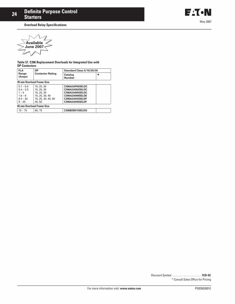
Table 57. C396 Replacement Overloads for Integrated Use with DP Contactors
AvailableJune 2007
FLARange(Amps)
DP Contactor Rating
Standard Class 5/10/20/30
CatalogNumber
*45 mm Overload Frame Size0.1 – 0.50.4 – 2.01 – 51.6 – 86.4 – 329 – 45
15, 25, 3015, 25, 3015, 25, 3015, 25, 30, 4015, 25, 30, 40, 5040, 50
C396A2AP05SELDCC396A2A002SELDCC396A2A005SELDCC396A2A008SELDEC396A2A032SELDFC396A2A045SELDF
65 mm Overload Frame Size15 – 75 60, 75 C396B2B075SELDG
Discount Symbol . . . . . . . . . . . . . . . . . . . . . . 1CD-5C* Consult Sales Office for Pricing

May 2007
PG03502001E For more information visit: www.eaton.com
25Definite Purpose ControlNEMA Type 1 Enclosed Control15 – 60A Contactors — C25
NEMA 1 Enclosed DP Contactor
Product SelectionWhen Ordering Specify■ Catalog Number plus Magnet Coil
Suffix, below.■ Modify Catalog Number for any
options required — see Options, Page 6.
Table 58. Catalog Numbering System
Table 59. 2-, 3- and 4-Pole NEMA Type 1 Enclosed Contactors Product Selection
� Incomplete Catalog Number. Replace underscore (_) in Catalog Number with Magnet Coil Suffix from table below.
Table 60. Magnet Coil Selection
� Contactors with DC coils include an early break NC auxiliary contact, C320KGD1. See Page 33 for more details.
� Available through 50A. � 104 – 120A 50/60 Hz for 60A Contactor.� Class H AC Coils available as option. Add 2
before Coil Suffix letter.
IncompleteCatalogNumber
MagnetCoil Suffix
Option Code as necessary
C25DGD215 A X
Rating, Amperes Maximum MotorHorsepower
Maximum MotorKilowatts
Numberof Poles
NEMA Type 1
InductiveFull Load
Resistiveper Pole
LineVoltage
LockedRotor
CatalogNumber �
*1-Phase 3-Phase 1-Phase 3-Phase
15 20 115230460575
90907560
3/4 2——
— 3 5 5
0.40 1.5——
— 2.2 3.7 3.7
23
C25DGD215_C25DGD315_
25 35 115230460575
150150125100
2 3——
— 7-1/21010
1.5 2.2——
— 5.5 7.5 7.5
234
C25DGD225_C25DGD325_C25EGD425_
30 40 115230460575
180180150120
2 5——
—101515
1.5 3.7——
— 7.51111
234
C25DGD230_C25DGD330_C25EGD430_
40 50 115230460575
240240200160
3 7-1/2——
—102020
2.2 5.5——
— 7.51515
234
C25DGF240_C25DGF340_C25EGF440_
50 65 115230460575
300300250200
310——
—153030
2.2 7.5——
—112222
23
C25DGJ250_C25DGJ350_
60 75 115230460575
360360300240
510——
—204040
3.7 7.5——
—153030
23
C25FGF260_C25FGF360_
Voltage CoilSuffix60 Hertz 50 Hertz
AC �
1224
110 – 120 �208 – 240 240 �277—440 – 480550 – 600
1224
110 – 120 �208 – 240220—380 – 415440 – 480550 – 600
RTABJHLCD
DC �
122448
120
1R1T1W1A
Technical Data. . . . . . . . . . . . . . . . . . . . Pages 4, 34 Options . . . . . . . . . . . . . . . . . . . . . . . . . . Page 6 Accessories . . . . . . . . . . . . . . . . . . . . . . Page 6Dimensions. . . . . . . . . . . . . . . . . . . . . . . Page 30 Discount Symbol . . . . . . . . . . . . . . . . . . 1CD-5C
* Consult Sales Office for Pricing

May 2007
26
For more information visit: www.eaton.com PG03502001E
Definite Purpose ControlNEMA Type 1 Enclosed Control25 – 60A Starters — A25, B25
NEMA 1 Enclosed DP Starter
Product DescriptionCutler-Hammer® A25 and B25 Definite Purpose Starters from Eaton’s electrical business combine the features and flexibility of the C25 Definite Purpose Contactors and Freedom Series Bi-metallic Ambient Compensated Over-load Relays mounted on a common mounting plate.
Standards and Certifications■ UL Recognized Components UL File
#E-1491, Guide NLDX2■ CSA Certified Components File
#LR353, Guide 380W-1.14Class 3211 04
Product SelectionWhen Ordering Specify■ Catalog Number plus Magnet Coil
Suffix■ Heater Packs for specific FLA of
motor, see Page 13.
Table 61. Catalog Numbering System
Table 62. Single- and Three-Phase NEMA Type 1 Enclosed Starters Product Selection
� Incomplete Catalog Number. Replace under-score (_) with Magnet Coil Suffix from Table 63.
� Starters do not include heater packs. Select heater pack from tables, Page 13.
� Set of 3 heater packs required for single-phase applications.
� Starters with DC coils include an early breaking auxiliary contact, C320KGD1. See Page 33 for more detail.
� Available through 50A.� 104 – 120A 50/60 Hz for 60A Contactor.� Class H AC Coils available as option. Add 2
before Coil Suffix letter.
Table 63. Magnet Coil Selection
IncompleteCatalogNumber
MagnetCoil Suffix
Option Code as necessary
A25CGC30 A X
Ampere Rating Max. Motor hp Max. Motor kW Single-Phase �� Three-Phase �
InductiveFull Load
Line Voltage
Locked Rotor
1-Phase 3-Phase 1-Phase 3-Phase CommonControl
SeparateControl
* CommonControl
Separate Control
*Catalog Number �
Catalog Number �
Catalog Number �
Catalog Number �
25 115230460575
150150125100
23——
—7-1/2
1010
1.52.2——
—5.57.57.5
B25CGC25_ B25SGC25_ A25CGC25_ A25SGC25_
30 115230460575
180180150120
25——
—101515
1.53.7——
—7.5
1111
B25CGC30_ B25SGC30_ A25CGC30_ A25SGC30_
40 115230460575
240240200160
37-1/2——
—102020
2.25.5——
—7.5
1515
B25CGE40_ B25SGE40_ A25CGE40_ A25SGE40_
50 115230460575
300300250200
————
—153030
————
—112222
— — A25CGE50_ A25SGE50_
60 115230460575
360360300240
————
—204040
————
—153030
— — A25CGE60_ A25SGE60_
Voltage CoilSuffix60 Hertz 50 Hertz
AC �
1224
110 – 120 �208 – 240 240 �277—440 – 480550 – 600
1224
110 – 120 �208 – 240220—380 – 415440 – 480550 – 600
RTABJHLCD
DC �
122448
120
1R1T1W1A
Technical Data . . . . . . . . . . . . . . . . . . . Pages 10, 34 Accessories . . . . . . . . . . . . . . . . . . . . . Page 6Dimensions . . . . . . . . . . . . . . . . . . . . . . Page 28Discount Symbol . . . . . . . . . . . . . . . . . 1CD-5C
* Consult Sales Office for Pricing

May 2007
PG03502001E For more information visit: www.eaton.com
27Definite Purpose ControlNEMA Type 1 Enclosed Control15 – 45A Starters — A27, B27
NEMA 1 Enclosed DP Starter
Product DescriptionCutler-Hammer® A27 and B27 Definite Purpose Starters from Eaton’s electrical business combine the features and flexi-bility of the C25 Definite Purpose Contac-tors and XT Series Bi-metallic Ambient Compensated Overload Relays.
Standards and Certifications■ UL Recognized Components UL File
#E-1491, Guide NLDX2■ CSA Certified Components File
#LR353, Guide 380W-1.14Class 3211 04
Product SelectionWhen Ordering Specify■ Catalog Number plus Magnet Coil
Suffix plus Overload Relay Suffix
Table 64. Catalog Numbering System
Table 65. Single- and Three-Phase NEMA Type 1 Enclosed Starters Product Selection
� Incomplete Catalog Number. Replace underscore (_) with Magnet Coil Suffix from Table 66 and Overload Relay Suffix from Table 67.
Table 66. Magnet Coil Selection
� Available through 45A.� Starters with DC coils include an early
breaking auxiliary contact, C320KGD1. See Page 33 for more detail.
� Class H AC Coils available as option. Add 2 before Coil Suffix letter.
Table 67. Overload Relay Suffix
IncompleteCatalogNumber
MagnetCoil Suffix
Overload Relay Suffix
A27CGE30 A 040
Ampere Rating Max. Motor hp Max. Motor kW Single-Phase Three-Phase
InductiveFull Load
Line Voltage
Locked Rotor
1-Phase 3-Phase 1-Phase 3-Phase CommonControl
SeparateControl
* CommonControl
Separate Control
*Catalog Number �
Catalog Number �
Catalog Number �
Catalog Number �
15 115230460575
90907560
3/42——
—355
0.41.5——
—2.23.73.7
B27CGC15_ B27SGC15_ A27CGC15_ A27SGC15_
25 115230460575
150150125100
23——
—7-1/2
1010
1.52.2——
—5.57.57.5
B27CGC25_ B27SGC25_ A27CGC25_ A27SGC25_
30 115230460575
180180150120
25——
—101515
1.53.7——
—7.5
1111
B27CGE30_ B27SGE30_ A27CGE30_ A27SGE30_
40 115230460575
240240200160
37-1/2——
—102020
2.25.5——
—7.5
1515
B27CGE40_ B27SGE40_ A27CGE40_ A27SGE40_
45 115230460575
270270225180
37-1/2——
—153030
2.27.5——
—112222
B27CGE45_ B27SGE45_ A27CGE45_ A27SGE45_
Voltage CoilSuffix60 Hertz 50 Hertz
AC �
1224
110 – 120208 – 240 240 �
1224
110 – 120208 – 240220
RTABJ
277—440 – 480550 – 600
—380 – 415440 – 480550 – 600
HLCD
DC �
122448
120
1R1T1W1A
Motor FullLoad Amperes
SuffixCode
For use with Contactor Amp Range
Frame C0.1 – 0.160.16 – 0.240.24 – 0.40.4 – 0.6
P16 P24 P40 P60
15 – 25A15 – 25A15 – 25A15 – 25A
0.6 – 11 – 1.61.6 – 2.42.4 – 4
0011P6 2P4004
15 – 25A15 – 25A15 – 25A15 – 25A
4 – 66 – 10
10 – 1616 – 2424 – 32
006010016024032
15 – 25A15 – 25A15 – 25A15 – 25A15 – 25A
Frame D6 – 10
10 – 1616 – 24
010016024
30 – 45A30 – 45A30 – 45A
24 – 4040 – 57
040057
30 – 45A30 – 45A
Technical Data. . . . . . . . . . . . . . . . . . . Pages 14, 34 Accessories . . . . . . . . . . . . . . . . . . . . . Page 6Dimensions. . . . . . . . . . . . . . . . . . . . . . Page 29Discount Symbol . . . . . . . . . . . . . . . . . 1CD-5C
* Consult Sales Office for Pricing

May 2007
28
For more information visit: www.eaton.com PG03502001E
Definite Purpose ControlDimensions
A25 and B25 StartersTable 68. Approximate Dimensions and Shipping Weights
Figure 10. Approximate Dimensions — Open Type
Figure 11. NEMA 1 Enclosed Dimensions
AmpereSize
Dimensions in Inches (mm) Ship. Wt.Lbs. (kg)Wide
AHighB
Deep Mounting AuxiliaryContactAdder
C D E G H
Open Type25 and 30
2.50(64.0)
7.14(181.0)
3.56(90.4)
3.69(93.7)
6.55(166.0)
.20(5.1)
.54(13.7)
1.8 (.8)
40 2.56(65.0)
8.08(205.0)
3.50(89.0)
3.66(93.0)
7.50(190.5)
2.00(51.0)
.54(13.7)
1.8 (.8)
50 and60
2.56(65.0)
8.08(205.0)
4.15(105.0)
3.66(93.0)
7.50(190.5)
2.00(51.0)
.54(13.7)
3.6 (1.6)
NEMA 1 Enclosed25 and30
5.63(143.0)
10.17(258.0)
5.81(148.0)
— 8.00(203.0)
4.50(114.0)
— 4.8 (2.2)
40, 50and 60
7.64(194.0)
13.27(337.0)
6.67(169.0)
— 10.75(273.0)
6.00(152.0)
— 10.6 (4.8)
G D G D
C
Mtg. for #10-32 Screw Mtg. for #10-32 Screw
AH H CAH H
B E B E
25 and 30 AmpereOpen Type
40, 50 and 60 AmpereOpen Type
G C
EB
A
25, 30, 40, 50 and 60 AmpereNEMA 1 Enclosed

PG03502001E For more information visit: www.eaton.com
29Definite Purpose Control
May 2007Dimensions
A27 and B27 StartersTable 69. Approximate Dimensions and Shipping Weights
Figure 12. Approximate Dimensions — Open Type
Figure 13. NEMA 1 Enclosed Dimensions
AmpereSize
Dimensions in Inches (mm) Ship. Wt.Lbs. (kg)Wide
AHighB
Deep Mounting AuxiliaryContactAdder
C D E G H
Open Type15 and 25(Metal Plate)
2.40(61.0)
5.50(139.0)
3.35(85.0)
3.70(94.0)
3.13(82.6)
— .54(13.7)
1.6(.7)
15 and 25(DIN Rail Mount)
2.23(56.5)
5.20(133.0)
3.35(85.0)
3.70(94.0)
— — .54(13.7)
1.6(.7)
30, 40 and 45(Metal Plate)
2.40(61.0)
6.00(152.0)
3.35(85.0)
3.90(98.0)
3.13(82.6)
— .54(13.7)
1.11(.9)
30, 40 and 45(DIN Rail Mount)
2.23(56.5)
5.70(145.0)
3.35(85.0)
3.90(98.0)
— — .54(13.7)
1.11(.9)
NEMA 1 Enclosed15, 25 and 30 5.63
(143.0)10.17(258.0)
5.81(148.0)
— 8.00(203.0)
4.50(114.0)
— 4.8 (2.2)
40 and 45 7.64(194.0)
13.27(337.0)
6.67(169.0)
— 10.75(273.0)
6.00(152.0)
— 10.6(4.8)
15 and 25 AmpereOpen Type
D
30, 40 and 45 AmpereOpen Type
D
CA H CA H
B
E
B
E
G C
EB
A
15, 25, 30, 40 and 50 AmpereNEMA 1 Enclosed

May 2007
30
For more information visit: www.eaton.com PG03502001E
Definite Purpose ControlDimensions
C25 ContactorsTable 70. Approximate Dimensions and Shipping Weights
� Add 0.30 inch (8 mm) to width for C25 contactors with DC coils.
Figure 14. Enclosures
Figure 15. 15 – 360A, 2-, 3- and 4-Pole
AmpereSize
Numberof Poles
Dimensions in Inches (mm) Ship. Wt.Lbs. (kg)
WideA
HighB
DeepC
Mounting SideAuxiliaryContactAdder
D E F G H J
Open Type15 – 50 2 and 3 2.40 (61.0) � 3.75 (95.0) 3.35 (85.0) 3.25 (83.0) 2.00 (51.0) — 3.13 (79.0) 1.50 (38.0) 0.34 (8.6) 1.3 (.6)
25 – 40 4 2.68 (68.0) � 3.75 (95.0) 3.38 (86.0) 3.25 (83.0) 2.00 (51.0) 1.5 (38.0) 3.13 (79.0) 1.50 (38.0) 0.50 (12.5) 2.3 (1.0)
60 – 75 2 and 3 2.63 (67.0) � 3.75 (95.0) 3.97 (101.0) 3.25 (83.0) 2.00 (51.0) 1.5 (38.0) 3.13 (79.0) 1.50 (38.0) 0.37 (9.5) 2.8 (1.3)
90 2 and 3 3.39 (86.0) 5.12 (130.0) 4.76 (121.0) 4.44 (113.0) 2.87 (73.0) — — 2.50 (63.5) 0.54 (13.7) 4.0 (1.8)
120 2 and 3 4.08 (104.0) 7.17 (182.0) 5.94 (151.0) 3.00 (76.0) 6.63 (168.0) — — — 0.54 (13.7) 8.5 (3.9)
200 and 300 2 and 3 7.05 (179.0) 9.11 (232.0) 7.25 (184.0) 6.00 (152.0) 8.50 (216.0) — — — — 20.0 (9.1)
360 2 and 3 7.05 (179.0) 13.12 (333.0) 7.78 (198.0) 6.00 (152.0) 12.50 (318.0) — — — — 23.0 (10.4)
Open Type — Reversing15 – 50 2 and 3 5.0 (127) 3.75 (95) 3.35 (85) 3.25 (83) 4.53 (118) — 3.13 (79) 4.13 (105) 0.34 (8.6) 2.6 (1.2)
60 – 75 2 and 3 5.77 (147) 3.75 (95) 3.97 (101) 3.25 (83) 5.15 (131) 3.15 (80) 3.13 (79) 4.65 (118) 0.37 (9.5) 5.6 (2.5)
NEMA 1 Enclosed15 – 50 2 and 3 4.10 (104.0) 6.75 (171.0) 3.50 (89.0) 2.75 (70).0 4.88 (124.0) — — — — 3.4 (1.5)
25 – 40 4 5.62 (142.0) 9.51 (241.0) 4.81 (122.0) 4.50 (114.0) 8.00 (203.0) — — — — 5.8 (2.6)
60 2 and 3 6.3 (2.9)
DC
EB
A
15–50 Ampere,2- and 3-Pole(C799B18)
D C
EB
A
25–40 Ampere, 4-Pole —60 Ampere, 2- and 3-Pole(C799B19)
C HEMtg. Holes/Slots for 8 Screws
Mtg. Holes for 3 Screws
15–75 Ampere (Non-reversing)
F
AJ J
B G D
Au
x. Co
nt.
Au
x. Co
nt.
AA CJ
90 Ampere 120 Ampere 200–360 Ampere
CA
C HE
D B
D
Aux.
B E B ESideMtd.Aux.
C
Mtg. Holes for 3 ScrewsD
HEMtg. Holes/Slots for 16 Screws
15–75 Ampere (Reversing)
F
AI
J J
B G D
Au
x. Co
nt.
Au
x. Co
nt.

May 2007
PG03502001E For more information visit: www.eaton.com
31Definite Purpose ControlRenewal Parts
Renewal PartsRenewal Contact Kits for C25 Definite Purpose Contactors■ Replace complete contactor for:
❑ C25A…❑ C25B…❑ C25C…❑ C25D…
AC Coils Table 71. AC Coil Selection AC CoilVoltage
Frequency Inrush (Maximum) Sealed (Maximum) CoilSuffix
Coil Part Number *VA Watts VA Watts Class Standard
15, 25, 30 and 40A — 2- and 3-Pole (Series D1)1224
110/120208/240
60 74.8581.3574.6982.64
46.149.751.659.1
5.535.835.796.96
1.681.741.812.38
RTAB
Class F, 155°C 9-3185-59-3185-69-3185-19-3185-2
220/240440/480550/600277
60 74.0373.3979.4772.88
51.852.151.752.4
5.856.096.566.09
1.992.583.052.58
JCDH
Class F, 155°C 9-3185-109-3185-39-3185-49-3185-7
380/415 50 64.50 50.6 6.08 2.43 L Class F, 155°C 9-3185-8
15, 25, 30 and 40A — 2- and 3-Pole (Series C1)1224
104/120
60 65.00 65.00 65.00
30.030.030.0
11.0011.0011.00
2.502.502.50
RTA
Class F, 155°C 9-3125-59-3125-69-3125-1
208/240440/480550/600
50 75.00 75.00 75.00
35.035.035.0
17.0017.0017.00
3.503.503.50
BCD
Class F, 155°C 9-3125-29-3125-39-3125-4
277 60 65.00 30.0 11.00 2.50 H Class F, 155°C 9-3125-8
380/415 50 75.00 35.0 17.00 3.50 L Class F, 155°C 9-3125-8
15, 25, 30 and 40A — 2- and 3-Pole (Series D1)1224
110/120208/240
60 74.8581.3574.6982.64
46.149.751.659.1
5.535.835.796.96
1.681.741.812.38
RTAB
Class H, 180°C 9-3252-59-3252-69-3252-19-3252-2
220/240440/480550/600277
60 74.0373.3979.4772.88
51.852.151.752.4
5.856.096.566.09
1.992.583.052.58
JCDH
Class H, 180°C 9-3252-109-3252-39-3252-49-3252-7
380/415 50 64.50 50.6 6.08 2.43 L Class H, 180°C 9-3252-8
50A — 2- and 3-Pole (Series D1)1224
110/120208/240
60 115.8118.1110.7124.9
73.670.773.390.3
7.717.587.67
10.04
2.802.792.893.74
RTAB
Class F, 155°C 9-3186-59-3186-69-3186-19-3186-2
220/240440/480550/600277
60 112.9114.7109.0115.4
76.275.678.673.1
7.608.018.217.73
3.023.684.113.12
JCDH
Class F, 155°C 9-3186-109-3186-39-3186-49-3186-7
380/415 50 110.3 77.0 8.66 3.31 L Class F, 155°C 9-3186-8
Table 72. Renewal Contact Kits for C25 Definite Purpose Contactors
� Order one kit per pole, 2 for 2-pole and 3 for 3-pole devices.
CatalogNumber
1-Pole KitPart No.
* 2-Pole KitPart No.
* 3-Pole KitPart No.
*
C25FNF250C25FNF350C25FNF260C25FNF360C25FNF275C25FNF375
——————
6-65-5—6-65-7—6-65-20—
—6-65-6—6-65-8—6-65-19
C25GNF290C25GNF390C25HNE3120C25KNE3200C25KNE3300C25LNE3360
6-647-1 �
6-647-1 �
————
——————
——6-43-66-2886-2866-45-2
Discount Symbol . . . . . . . . . . . . . . . . . . . . . . 1CD-1C* Consult Sales Office for Pricing

May 2007
32
For more information visit: www.eaton.com PG03502001E
Definite Purpose ControlRenewal Parts
Table 71. AC Coil Selection — ContinuedAC CoilVoltage
Frequency Inrush (Maximum) Sealed (Maximum) CoilSuffix
Coil Part Number *VA Watts VA Watts Class Standard
50A — 2- and 3-Pole (Series D1)1224
110/120208/240
60 115.8118.1110.7124.9
73.670.773.390.3
7.717.587.67
10.04
2.802.792.893.74
RTAB
Class H, 180°C 9-3253-59-3253-69-3253-19-3253-2
220/240440/480550/600277
60 112.9114.7109.0115.4
76.275.678.673.1
7.608.018.217.73
3.023.684.113.12
JCDH
Class H, 180°C 9-3253-109-3253-39-3253-49-3253-7
380/415 50 110.3 77.0 8.66 3.31 L Class H, 180°C 9-3253-8
60 and 75A — 2- and 3-Pole; 25, 30 and 40A — 4-Pole1224
104/120
60 204.0 84.0 36.5 8.00 RTA
Class B, 130°C 9-3256-59-3256-69-3256-1
208/240440/480550/600
50 240.0 100.8 50.4 10.80 BCD
Class B, 130°C 9-3256-29-3256-39-3256-4
277 60 204.0 84.0 36.5 8.00 H Class B, 130°C 9-3256-7
380/415 50 199.0 88.8 37.8 8.80 L Class B, 130°C 9-3256-8
90A — 2- and 3-Pole24
110/120208/240
60 214.0 — 19.0 6.80 TAB
Class B, 130°C 9-3079-19-3079-29-3079-3
440/480550/600
50 247.0 — 19.0 6.80 CD
Class B, 130°C 9-3079-59-3079-6
277 60 214.0 — 19.0 6.80 H Class B, 130°C 9-3079-4
120A — 3-Pole24
110/120220/240440/480550/600
50/60 390.0 112.0 49.8 13.00 TABCD
Class B, 130°C 9-2756-169-2756-19-2756-29-2756-39-2756-4
208277
60 390.0 112.0 49.8 13.00 EH
Class B, 130°C 9-2756-59-2756-9
200, 300 and 360A — 3-Pole110/120220/240440/480550/600
50/60 1040.0 216.0 116.0 17.00 ABCD
Class F, 155°C 9-1891-19-1891-29-1891-39-1891-4
208277
60 1040.0 216.0 116.0 17.00 EH
Class F, 155°C 9-1891-139-1891-26
Discount Symbol . . . . . . . . . . . . . . . . . . . . . . 1CD-1C* Consult Sales Office for Pricing
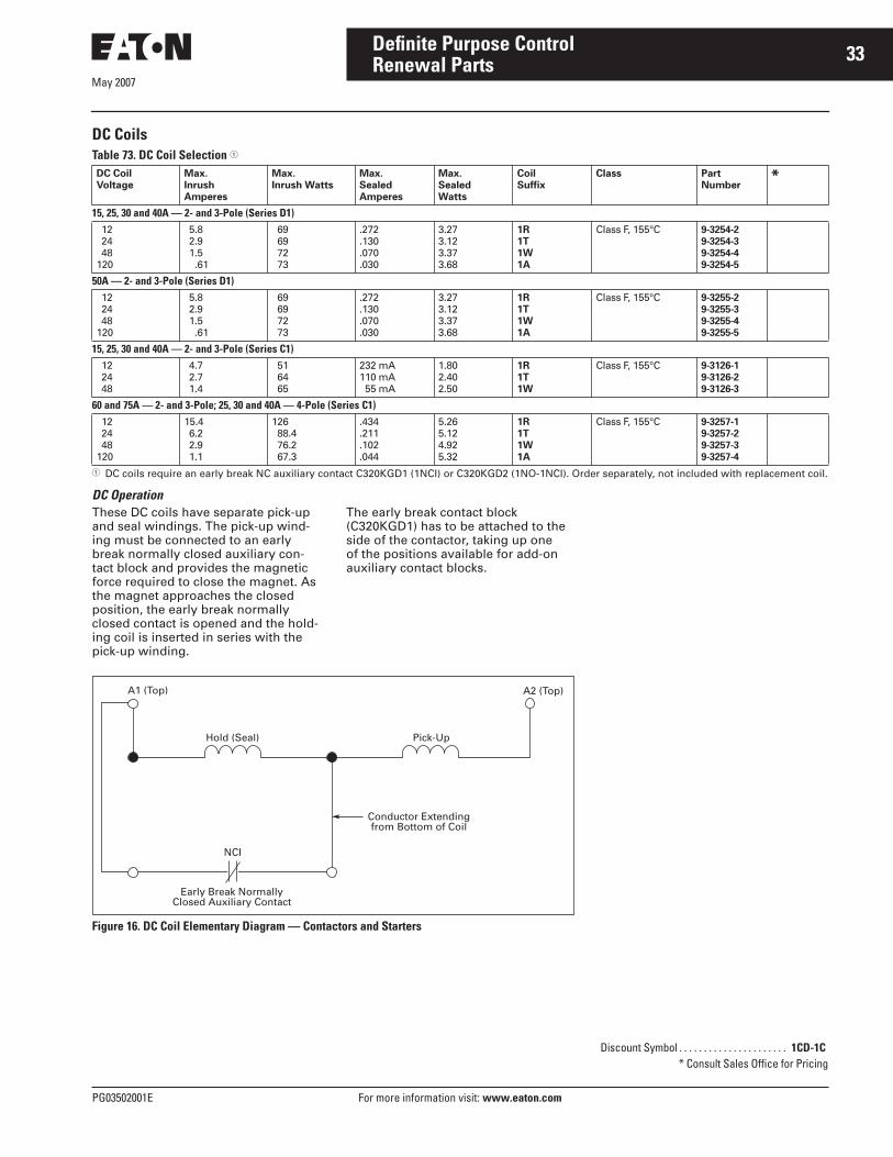
May 2007
PG03502001E For more information visit: www.eaton.com
33Definite Purpose ControlRenewal Parts
DC Coils Table 73. DC Coil Selection �
� DC coils require an early break NC auxiliary contact C320KGD1 (1NCI) or C320KGD2 (1NO-1NCI). Order separately, not included with replacement coil.
DC OperationThese DC coils have separate pick-up and seal windings. The pick-up wind-ing must be connected to an early break normally closed auxiliary con-tact block and provides the magnetic force required to close the magnet. As the magnet approaches the closed position, the early break normally closed contact is opened and the hold-ing coil is inserted in series with the pick-up winding.
The early break contact block (C320KGD1) has to be attached to the side of the contactor, taking up one of the positions available for add-on auxiliary contact blocks.
Figure 16. DC Coil Elementary Diagram — Contactors and Starters
DC CoilVoltage
Max.InrushAmperes
Max.Inrush Watts
Max.SealedAmperes
Max.SealedWatts
Coil Suffix
Class PartNumber
*
15, 25, 30 and 40A — 2- and 3-Pole (Series D1)122448
120
5.82.91.5.61
69697273
.272
.130
.070
.030
3.273.123.373.68
1R1T1W1A
Class F, 155°C 9-3254-29-3254-39-3254-49-3254-5
50A — 2- and 3-Pole (Series D1)122448
120
5.82.91.5.61
69697273
.272
.130
.070
.030
3.273.123.373.68
1R1T1W1A
Class F, 155°C 9-3255-29-3255-39-3255-49-3255-5
15, 25, 30 and 40A — 2- and 3-Pole (Series C1)122448
4.72.71.4
516465
232 mA110 mA55 mA
1.802.402.50
1R1T1W
Class F, 155°C 9-3126-19-3126-29-3126-3
60 and 75A — 2- and 3-Pole; 25, 30 and 40A — 4-Pole (Series C1)122448
120
15.46.22.91.1
12688.476.267.3
.434
.211
.102
.044
5.265.124.925.32
1R1T1W1A
Class F, 155°C 9-3257-19-3257-29-3257-39-3257-4
A1 (Top)
NCI
Conductor Extendingfrom Bottom of Coil
Early Break NormallyClosed Auxiliary Contact
Hold (Seal) Pick-Up
A2 (Top)
Discount Symbol . . . . . . . . . . . . . . . . . . . . . . 1CD-1C* Consult Sales Office for Pricing

May 2007
34
For more information visit: www.eaton.com PG03502001E
Definite Purpose ControlTechnical Data and Specifications
Ampere Rating of AC MotorsAmpere ratings of motors vary somewhat, depending upon the type of motor. The values given below are for drip-proof, Class B insulated (T Frame) where available, 1.15 service factor, NEMA Design B motors. These values represent an average full load motor current which was calculated from the motor performance data published by several motor manufacturers. In the case of high torque squirrel cage motors, the ampere ratings will be at least 10% greater than the values given below.
Caution — These average ratings could be high or low for a specific motor and therefore heater coil selection on this basis always involves risk. For fully reliable motor protection, select heater coils on the basis of full load current rating as shown on the motor nameplate.
Ampere Ratings of Three-Phase, 60 Hz, AC Induction Motor
� To convert horsepower to kW, multiply horsepower by .7457.� 380V 50 Hz.
hp � Syn.SpeedRPM
Current in Amperes
200V 230V 380V � 460V 575V 2200V
1/4 18001200900
1.091.611.84
.951.401.60
.55
.81
.93
.48
.70
.80
.38
.56
.64
———
1/3 18001200900
1.371.832.07
1.191.591.80
.69
.921.04
.60
.80
.90
.48
.64
.72
———
1/2 18001200900
1.982.472.74
1.722.152.38
.991.241.38
.861.081.19
.69
.86
.95
———
3/4 18001200900
2.833.363.75
2.462.923.26
1.421.691.88
1.231.461.63
.981.171.30
———
1 360018001200900
3.224.094.324.95
2.803.563.764.30
1.702.062.282.60
1.401.781.882.15
1.121.421.501.72
————
1-1/2 360018001200900
5.015.596.076.44
4.364.865.285.60
2.642.943.203.39
2.182.432.642.80
1.741.942.112.24
————
2 360018001200900
6.447.367.879.09
5.606.406.847.90
3.393.874.144.77
2.803.203.423.95
2.242.562.743.16
————
3 360018001200900
9.5910.811.713.1
8.349.40
10.211.4
5.025.706.206.90
4.174.705.125.70
3.343.764.104.55
————
5 360018001200900
15.516.618.218.3
13.514.415.815.9
8.208.749.599.60
6.767.217.917.92
5.415.786.326.33
————
7-1/2 360018001200900
22.424.725.126.5
19.521.521.823.0
11.813.013.213.9
9.7910.710.911.5
7.818.558.709.19
————
10 360018001200900
29.230.832.235.1
25.426.828.030.5
15.416.316.918.5
12.713.414.015.2
10.110.711.212.2
————
15 360018001200900
41.945.147.651.2
36.439.241.444.5
22.023.725.026.9
18.219.620.722.2
14.515.716.517.8
————
20 360018001200900
58.058.960.763.1
50.451.252.854.9
30.531.031.933.2
25.225.626.427.4
20.120.521.121.9
————
hp � Syn.SpeedRPM
Current in Amperes
200V 230V 380V � 460V 575V 2200V
25 360018001200900
69.974.575.477.4
60.864.865.667.3
36.839.239.640.7
30.432.432.833.7
24.325.926.227.0
————
30 360018001200900
84.886.990.694.1
73.775.678.881.8
44.445.747.649.5
36.837.839.440.9
29.430.231.532.7
————
40 360018001200900
111116117121
96.4101102105
58.261.061.263.2
48.250.450.652.2
38.540.340.441.7
————
50 360018001200900
138143145150
120124126130
72.975.276.278.5
60.162.263.065.0
48.249.750.452.0
————
60 360018001200900
164171173177
143140150154
86.890.091.093.1
71.774.575.077.0
57.359.460.061.5
————
75 360018001200900
206210212222
179183184193
108111112117
89.691.692.096.5
71.773.273.577.5
————
100 360018001200900
266271275290
231236239252
140144145153
115118120126
92.294.895.6
101
—23.624.224.8
125 360018001200900
————
292293298305
176177180186
146147149153
116117119122
—29.229.930.9
150 360018001200900
————
343348350365
208210210211
171174174183
137139139146
—34.835.537.0
200 360018001200900
————
452458460482
257265266279
226229230241
181184184193
—46.747.049.4
250 360018001200900
————
559568573600
338343345347
279284287300
223227229240
—57.558.560.5
300 18001200
——
678684
392395
339342
271274
69.070.0
400 1800 — 896 518 448 358 91.8
500 1800 — 1110 642 555 444 116

PG03502001E_InsideF&BCovers.qxd:InsideCoversPage2.qxd 5/15/07 1:34 PM Page 1

© 2007 Eaton CorporationAll Rights ReservedPrinted in USAPublication No. PG03502001E / Z5681May 2007
Eaton CorporationElectrical Group1000 Cherrington ParkwayMoon Township, PA 15108United States877-ETN CARE (877-386-2273)Eaton.com
CSA is a registered trademark of theCanadian Standards Association. Cutler-Hammer is a federally registered trademark ofEaton Corporation. National Electrical Codeand NEC are registered trademarks of theNational Fire Protection Association, Quincy,Mass. NEMA is the registered trademarkand service mark of the National ElectricalManufacturers Association. UL is a registeredtrademark of Underwriters Laboratories Inc.
Eaton’s electrical business is a global leader in electrical control, power distribution, uninterruptible power supply and industrial automation products and services. Eaton’sglobal electrical brands, including Cutler-Hammer�, Powerware�, Holec� and MEM�, provide customer-driven PowerChain Management� solutions to serve the power system needs of the industrial, institutional, government, utility, commercial, residential, IT, mission critical and OEM markets worldwide.
Eaton Corporation is a diversified industrial manufacturer with 2006 sales of $12.4 billion. Eaton is a global leader in electrical systems and components for power quality,distribution and control; fluid power systems and services for industrial, mobile and aircraft equipment; intelligent truck drivetrain systems for safety and fuel economy; andautomotive engine air management systems, powertrain solutions and specialty controlsfor performance, fuel economy and safety. Eaton has 61,000 employees and sells products to customers in more than 125 countries. For more information, visit www.eaton.com.
PG03502001E_BackCover.qxd:PG03502001E_backCVR.qxd 5/15/07 1:01 PM Page 1