defense technical information center compilation part notice · & soderberg (1988) fig. 4....
TRANSCRIPT
UNCLASSIFIED
Defense Technical Information CenterCompilation Part Notice
ADPO1 1823TITLE: Review of Fatigue of Coatings/Substrates
DISTRIBUTION: Approved for public release, distribution unlimited
This paper is part of the following report:
TITLE: NATO Advanced Research Workshop on Nanostructured Filmsand Coatings. Series 3. High Technology - Volume 78
To order the complete compilation report, use: ADA399041
The component part is provided here to allow users access to individually authored sectionsf proceedings, annals, symposia, etc. However, the component should be considered within
[he context of the overall compilation report and not as a stand-alone technical report.
The following component part numbers comprise the compilation report:ADPO11800 thru ADP011832
UNCLASSIFIED

REVIEW OF FATIGUE OF COATINGS/SUBSTRATES
K. SADANANDA* AND R. L. HOLTZMaterials Science and Technology DivisionCode 6323, Physical Metallurgy BranchNaval Research Laboratory, Washington D.C..Currently on Sabbatical as Visiting ProfessorAt Indian Institute of Technology, Madras, India.
ABSTRACT
A review of fatigue of coatings/substrates is presented. Fatigue damage is either local orgeneral, depending on the range of cyclic loads. Local fatigue damage includes rollingcontact fatigue (RCF), fretting fatigue, fatigue-wear and general wear. Applied loads arelocalized consisting of rolling contacts or sliding contacts, and the resulting damage ismostly surface related. Crack initiation, surface pitting, delamination, spalling, bucklingand enhanced wear can result from local fatigue damage of coatings. General fatiguedamage results when the loads are of longer range such as cyclic bending, torsion oruniaxial or biaxial tension/compression etc. The mechanics of fatigue, role ofmicrostructure, micromechanics in terms of crack nucleation, growth and fracture arereviewed. Defects produced during processing form precursors for crack nucleation. It isshown that optimization of the processing conditions to minimize defect density isessential to enhance fatigue resistance of coatings/substrates.
1. INTRODUCTION
The integrity of coatings/substrate composite depends on the nature of applied loads,environment, temperature and internal stresses introduced from the processing route aswell as on the accommodating micromechanisms present. Understanding of the interplayof these factors, and the mechanics of the failures is important for the development ofefficient and cost effective coatings. In this review, we examine the fatigue behavior ofcoating/substrates composites to evaluate the mechanical and microstructural factors thatare involved in their fatigue damage. Since the microstructure and intrinsic defects thatare formed depend on the processing conditions, we limit our discussion mainly to
283
G.M. Chow et al. (eds.), Nanostructured Films and Coatings, 283-295.Q 2000 Kluwer Academic Publishers. Printed in the Netherlands.
284
thermal-spray coatings that are of current interest to US Navy, although the generalprinciples discussed are applicable to all coatings. Through microstructural refinement,new nano-structured coatings are being developed to improve wear and corrosionresistance for many Navy structural components. The fatigue properties of these newnanostructured coatings are of interest, particularly in comparison to the conventionalcoatings. Some of these developments are also of interest to commercial sector underdual use technology.
2. MECHANICAL AND MICROSTRUCTURAL CONSIDERATIONS
Mechanical incompatibilities at bimaterial interfaces involving coatings/substrates resultin internal stresses that affect the integrity of the coatings. The sources of internalstresses include:(a) Elastic modulus mismatch(b) Thermal coefficient of expansion mismatch(c) Lattice parameter mismatch(d) Plastic flow mismatchSeveral analyses and reviews [1-7] exist in the literature quantifying the nature of theinternal stresses that are generated at interfaces in coatings/substrates and resulting fromthese mismatches in the material properties at the bimaterial interfaces.
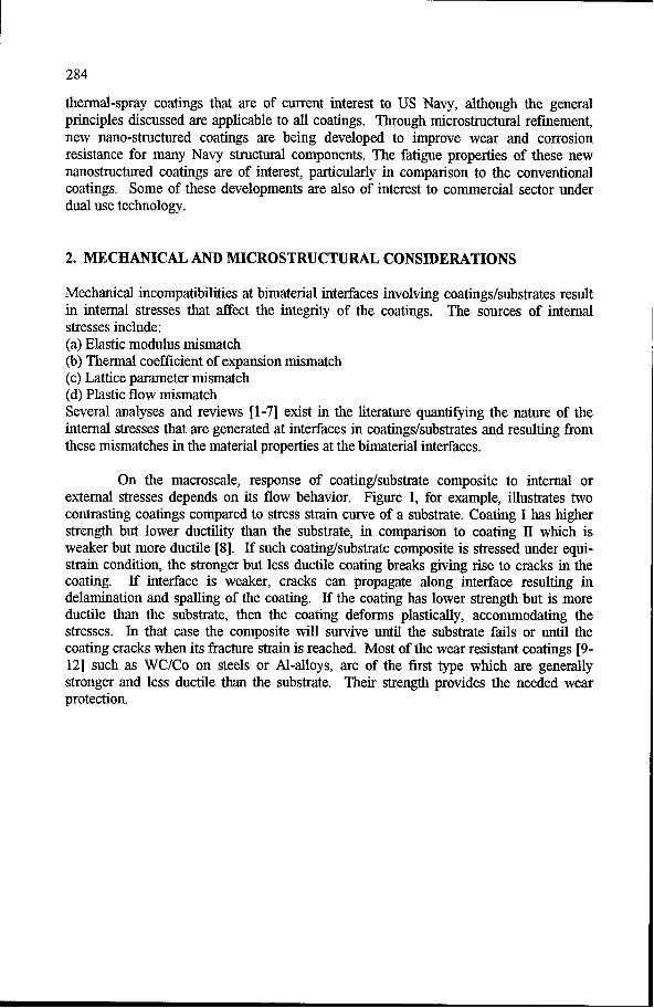
On the macroscale, response of coating/substrate composite to internal orexternal stresses depends on its flow behavior. Figure 1, for example, illustrates twocontrasting coatings compared to stress strain curve of a substrate. Coating I has higherstrength but lower ductility than the substrate, in comparison to coating HI which isweaker but more ductile [8]. If such coating/substrate composite is stressed under equi-strain condition, the stronger but less ductile coating breaks giving rise to cracks in thecoating. If interface is weaker, cracks can propagate along interface resulting indelamination and spalling of the coating. If the coating has lower strength but is moreductile than the substrate, then the coating deforms plastically, accommodating thestresses. In that case the composite will survive until the substrate fails or until thecoating cracks when its fracture strain is reached. Most of the wear resistant coatings [9-12] such as WC/Co on steels or Al-alloys, are of the first type which are generallystronger and less ductile than the substrate. Their strength provides the needed wearprotection.
285
Coating I - High E & LowDuctility
(y Substrate
Cotig 1-Low E &HighV Ductility
Strain
Fig. 1 Contrasting stress-strain behavior of ductile versus brittle coatings.
2.1 RESIDUAL STRESSES
Residual stresses arise from all of the above sources, but the thermal coefficient ofexpansion mismatch across the coating/substrate interface provides their major source.Residual stresses play a dominant role in the integrity of the coatings/substrates [13-17].Ac is defined as (c. -(x,), where c and x, are the coefficients of thermal expansion ofcoating and substrate, respectively. If the stresses are compressive in the coating, whichis the case when cooled from high processing temperature to the application temperatureand when Ac is negative. The residual stresses inhibit the nucleation and growth ofcracks. On the other hand, they can augment the compressive forces that will beintroduced during contact fatigue and accentuate failures associated with contact fatigue.In addition the compressive forces can cause buckling of the coating if the cracks areformed parallel to the stress axis. This leads to delamination and spalling of the coatings.Another source of residual stresses which is not discussed above, occurs due tomechanical impact when the coating particles impinge on the substrate at high velocities,

286
such as during plasma spray or thermal spray processes [18]. Figure 2, for example,shows the nature of the residual stresses introduced in thermally sprayed WC/Cocoatings, where spraying is done using high velocity guns.
3. CLASSIFICATION OF FATIGUE DAMAGE
One can classify the fatigue damage of coating/substrate assembly broadly into twotypes. They are (a) local fatigue damage and (b) bulk fatigue damage. The local fatiguedamage is such that the scale factor is less than the coating thickness or volume. Localfatigue damage includes (a) rolling contact fatigue (RCF), (b) fretting fatigue, and (c)fretting wear, wherein the damage scale is smaller than the thickness of the coatings.
200 1 ...
C-AM
WC-Co on 6061-T6551-200
McGrann et al. (1998)FeIDL -400
_ 0 0 Coating/Substrate Interface-
cr- -800-1000
-12000 0.5 1 1.5
Distance (mm)Fig. 2. Compressive residual stresses in WC-Co coating on an Al-alloy.
287
The bulk fatigue damage, on the other hand, involves intrinsic fatigue properties of thecoating and substrate, bulk stresses, which extend to larger volume and the presence ofdefects or formation of cracks that are larger than the coatings thickness. Fatigueevaluation tests of the coatings/substrates such as push-pull or four-point bend tests etc.,fall under this category.
3.1. LOCAL FATIGUE DAMAGE
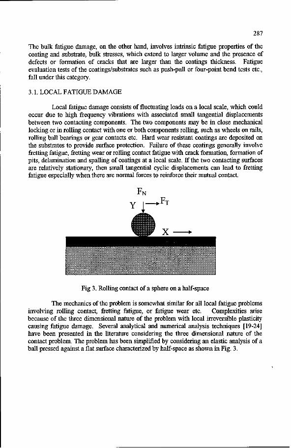
Local fatigue damage consists of fluctuating loads on a local scale, which couldoccur due to high frequency vibrations with associated small tangential displacementsbetween two contacting components. The two components may be in close mechanicallocking or in rolling contact with one or both components rolling, such as wheels on rails,rolling ball bearings or gear contacts etc. Hard wear resistant coatings are deposited onthe substrates to provide surface protection. Failure of these coatings generally involvefretting fatigue, fretting wear or rolling contact fatigue with crack formation, formation ofpits, delamination and spalling of coatings at a local scale. If the two contacting surfacesare relatively stationary, then small tangential cyclic displacements can lead to frettingfatigue especially when there are normal forces to reinforce their mutual contact.
FNy -- FT
Fig 3. Rolling contact of a sphere on a half-space
The mechanics of the problem is somewhat similar for all local fatigue problemsinvolving rolling contact, fretting fatigue, or fatigue wear etc. Complexities arisebecause of the three dimensional nature of the problem with local irreversible plasticitycausing fatigue damage. Several analytical and numerical analysis techniques [19-24]have been presented in the literature considering the three dimensional nature of thecontact problem. The problem has been simplified by considering an elastic analysis of aball pressed against a flat surface characterized by half-space as shown in Fig. 3.

288
Fretting occurs in the regime depending on the frequency, displacementamplitude, 8, or amplitude of the tangential force. Examining the nature of the damageduring cyclic contact displacement, Madlin [22-23] has shown that under contactpressure, the shear stress required to overcome the static frictional resistance will have amaximum at the center of the circular contact area. While Madlin's analysis assumeselastic conditions, the three-dimensional nature of the problem and local plasticity effectshave been considered recently using numerical techniques[24-28]. There are threeconditions - stick, partial slip and general slip [29-32]. The load-displacement curvesfor the three are schematically represented in Fig.4 based on which fretting maps havebeen developed. Case A is considered elastic with tangential displacements being small.FT -d curve shows transition from predominately elastic to plastic shear, which representsthe plastic yield of not only the asperities but also of the underlying bulk material.
Fretting Map CForce, BB
NA - Stick A<Aj
B - Partial SlipA<A<A
2
C - Gross Slip A>A: >
Slip Distance, A, gm
Vi _gsbo & Soderberg (1988)
Fig. 4. Force-distance curve of contact bodies, stick, partial slip and gross slip regimes.
A second contribution to the leveling-off of the tangential force above a certaindisplacement stems from the fact that part of the applied shear stress is relaxed by theintroduction of slip in the annular slip region. Figure 4 indicates that there are two

289
critical displacements, A1 and A2, defining the three regimes, stick, partial slip and grossslip. Nonlinear displacements in contact fatigue, Figure 4, result in fatigue damage. Ifthe frequency and the number of cycles become sufficiently large, the damage becomessignificant and is termed fretting fatigue. Cyclic straining during continued frettingmight lead to the nucleation and propagation of surface fatigue cracks, particularly alongthe rim of the contact area. Generally the displacement amplitudes are within the range of1-2 tm for fretting fatigue. But the damage can be significant when the number of cyclesare in the range of 107 cycles.
Since fretting and wear both result from local fatigue damage, the fretting mapcan be superimposed on wear map using displacement amplitude as the independentvariable. Although wear damage is not discussed here, the same region subjected torepeated rubbing by two contact surfaces exhibits both fatigue and wear. In fact wearitself could be due to fatigue, although characteristically referred to as wear fatigue toseparate it from other forms of fatigue. Thus fretting damage manifests in two forms,fretting wear and fretting fatigue, which are somewhat related. Fretting wear starts whenparticles are formed within or at the edge of the contacts.
4. BULK FATIGUE
In addition to local fatigue problems, which are surface contact induced fatigue damage,the coatings/substrates are subjected to fluctuating gross scale loads that cause general orbulk fatigue. The mechanics of the problems and the nature and the extent of the damageare sufficiently general requiring separate evaluation. There have been several analysesof the coating/substrate mechanics to evaluate the fracture and fatigue properties of thecoated material [1-7,33,34]. The analyses have been done considering combined Mode Iand Mode II stresses for a body bonded by a thin adhesive layer. The difference instrength and elastic properties of the bimaterial and the strength of the interface alongwith the nature of the applied or induced stresses dictate the behavior of thecoating/substrates.
4.1 FAILURE MODES
Under general loading conditions, there are three types of fatigue failuresobserved depending on the nature of residual stresses[5]. These correspond todelamination of the interface, splitting of the film and substrate cracking. There is also afourth mechanism of failure that involves buckling of the coating and subsequentdelamination of the interface. The later mode of failure relies on the existence ofcompressive stresses within the coating. The presence of a superimposed tensile stresscan cause delamination along the interface, or cracking in the film or substrate. Failure

290
induced by a compressive stress involves a complex interaction between buckling of thefilm and delamination along the interface.
Microstructure also plays a major role in crack nucleation and growth process.Process induced defects such as voids and inclusions etc. form nucleation centers forcracks. Grain size is expected to have dual roles. It is well known that decreasing grainsize increases the endurance limit under fatigue. From the dislocation pile up analysis itis clear that decrease in grain size decreases the slip band length and hence increase thenumber of cycles (or endurance stress) for crack nucleation life. On the other hand,reducing grain size has been found to increase the resistance to crack growth particularlyin planar slip materials. For coatings, in general, a reduction in grain size is expected tobe beneficial in terms of fatigue life, since crack nucleation life has more sensitivedependence on grain size than the crack propagation life. In addition, fine grain size inthe nano-range is expected to be beneficial in terms of increasing the strength of thecoatings and in relaxing the residual stresses by grain boundary sliding.
5. APPLICATION TO THERMAL SPRAY COATINGS
In the following we discuss the application of the above understanding of the fatiguedamage process to thermal spray coatings which are increasingly being used for manyapplications. The available experimental results on fatigue will be examined in terms ofthe resulting microstructure and the associated local and bulk fatigue damage.
Thermal spray coatings have a unique microstructure that affect their properties.It was noted earlier, Fig. 2, that compressive residual stresses are present in the coatingdue to high velocity impact of the particles during thermal spray [18]. As the molten orsemi-molten feed particles impact on the cold substrate surface, they flatten and freeze.In addition to the impact stresses there will also be some residual stresses due tomismatch in thermal coefficient of expansion. The next incoming particle falls on theprevious one thus forming a layer structure. In the inter-layers, the inter-particleboundaries called splat boundaries are formed, which are significantly weak[7-12].Major concern is that these weak boundaries are parallel to the surface hence parallel toshearing forces that arise during Rolling Contact Fatigue. In addition to splat boundaries,there is grain nucleation and growth perpendicular to the splat boundaries. Thus eachprojectile particle during thermal spray forms a multigrain particles each separated fromthe others by splat boundaries. The size of each splat depends on the size of the feedparticles. For micron size particles, high velocity oxy-fuel (HOVF) process resulted insplat boundaries that are about 30-40 pm wide, while the size of grain boundaries withinthe splat is about 2 pm. The aspect ratio of splat boundaries is very high [12).

291
5.1. FATIGUE OF THERMAL SPRAY COATINGS
The extent of the study of fatigue damage of thermal spray coatings is limited.McGrann et al. [18] have investigated the performance of WC-17%Co thermal spraycoatings on SAE 4130 steel and 6061-T6511 Al-alloy substrates. The WC-Co coatingswere applied by HVOF. Residual stresses in Fig. 2 were also determined. Fatigue testswere done using bending tests with zero mean stress. Three sets of thermal spray-coatedAl-specimens were tested: A1-L, Al-M and Al-H, where L, M and H corresponds to light,medium and heavy coatings in terms of compressive residual stresses present. Thestresses are of the order of 80, 500, and 760 MPa, respectively. For steel specimens,
300_ WC-Co on 6061-T6511-
250 McGrann et al. (1998)
200
150
W ~.00
50A-L50 -"1- AI-M
0 -,- 6061-AI
0.01 0.1 1 10N X 06 Cyclesf
Fig. 5 Effect of WC-Co coatings on an Al-alloy substrate.
the coatings are of L and H types in addition to conventional chrome plated and shot-peened specimens. The average residual compressive stresses in the steel specimenswere 125 and 365 Mpa for L and H types, respectively. Figures 5 and 6 show the fatigue

292
results in terms of maximum applied stress versus the number of cycles to failure for eachof the coated and uncoated specimens. For Al-alloys, in comparison to uncoatedspecimens, there is significant improvement (30 times) in life with coating. Examinationof the results indicates that improvement is associated solely with the compressiveresidual stresses than coatings properties per sec, since with increasing residual stresses(for the same thickness) the fatigue life is increased significantly. Similar results areobtained for the steel specimens. The WC-Co with H type of coatings fared well in parwith the shot peened specimens, where compressive residual stresses are deliberatelyintroduced. The WC-Co coatings are much better than the conventional chrome platedspecimens. Clearly the improvement arises from the compressive residual stresses sinceWC-Co coatings of L type did not show noticeable improvement due to low residualstresses. Figures 5 and 6 clearly demonstrate the importance of the residual stresses.The materials are coated to improve the wear resistance and bulk fatigue tests are onlypart of the acceptance tests for these coatings. There is no degradation of the propertiesas a result of the coatings. If fatigue is the life or performance-limiting factor thenprocessing needs to be optimized to arrive at improved fatigue resistant coatings. Theresults thus indicate that WC-Co coatings can improve fatigue resistance compared to theconventional coatings currently used.
900 . . . . ... ... I
WC-Co on 4130 Steel850 McGrann et al.
" 800
I; 750
tj 700, Chrome Plated
650 - WC-Co-L• ,,jmWCCoH
4'uu"Shot Peened
6000.1 61 10Nf X110 Cycles
Fig. 6. Effect of WC-Co coating on fatigue life of 4130 Steel.

293
6. SUMMARY AND CONCLUSIONS
Coatings are provided to improve wear, corrosion, and oxidation of the substratesincluding as thermal barriers for high temperature components. Since the componentsare subjected to variable loads, the fatigue resistance of the coatings is of concern.Fatigue damage can result from local variations in loads such as in rolling contact fatigue,fretting fatigue or wear-fatigue or from global application of loads. Fatigue damage ingeneral manifests in terms of irreversible plasticity, crack initiation, crack propagationand failure. Failure processes include cracking, pitting, particle decohesion,delamination, spalling, buckling etc. Mechanics of these are examined along with thereview of available results. It is shown that fatigue performance of the coatings dependson the microstmcture and residual stresses, and defect density and distribution.Processing optimization is essential in order to improve performance of the coatings.
7. ACKNOWLEDGEMENTS
The authors express their gratitude to Professor S. Sampath for providing data of thermalspray coatings. The review was completed when one of the authors (K.S) was onsabbatical at the Indian Institute of Technology, Madras. K.S expresses his appreciationto the Director of the Institute for hosting him during his sabbatical. The work issupported by the Office of Naval Research. Helpful discussions with Drs. L. Kabacoffand A.K. Vasudevan and their support are gratefully acknowledged.
8. REFERENCES
1. Evens, A.G. and Hutchinson J. W. (1984) Int. J Solids and Struct. 20, 455.2. Rice, J.R.(1988), "Elastic Fracture mechanics for interfacial cracks" , J. Appl. Mech.
Trans ASME, 55, pp. 98-103.3. Hu, M.S., Thouless, M.D. and Evans, A.G., (1988), "The de-cohesion of thin films
from brittle substrates", Acta Met. 36, pp. 1301-1307.4. Sue, Z and Hutchinson, J.W., (1990) "Interface crack between two elastic layers",
Int. J. Fracture", 43, 1-18.5. Thouless, M.D. (1991), "Cracking and Delamination of coatings", J. Vac. Sci and
Tech. 9a, 2510-2515.6. Evans, A.G. and Hutchinson, J.W. (1989) "Effect of non-planarity on the mixed
mode fracture resistance of bimaterial interfaces", Acta Met., 37, 909-916.7. Thouless, M.D. Evans, A.G., Ashby, M.F. and J.W. Hutchinson, J.W., (1988), Acta
Metall. 35, 1333-1341.

294
8. Grunling, H.W., Schneider, K., and Singheiser, L., (1987),"Mechanical Properties ofCoated Systems", Mat. Sci. Engrg., 88, 177-189.
9. Ramaswamy, S and Herman, H., (1986), "Metallurgical characterization of PlasmaSprayed WC-Co Coatings, in Advances in Thermal Spraying", Pergamon Press, pp.101-110.
10. M.E. Vinayo, F. Kassabji, J. Guyonnet and P. Fauchais, Plasma Sprayed WC-CoCoatings: Influence of Spray Conditions, on the Crystal Structure, porosity, andHardness, (1985), J. Vac. Sci. Technol. A, 3, pp. 2483-2489
11. Ramnath, V, and Jayaraman, N., (1989), "Characterization and Wear Performanceof Plasma Sprayed WC-Co Coatings", Mater. Sci. Tech., 5, 382-388
12. Sampath, S, and. Wayne, S.F, (1994) "Microstructure and Properties of Plasma-Sprayed Mo-Mo2C composites", J. Thermal Spray Technology, 3, 282-288.
13. Johnson, K.L. and Jefferis, M.A., (1963), "Plastic flow and Residual Stresses inRolling and Sliding Contact", Proc. Symp. on Fatigue in Rolling Contact", pp. 54-65.
14. Cao, H.C., Thouless, M.D. and Evans, A.G., "Residual stresses and cracking inbrittle solids bonded with a thin ductile layer", Acta Met., 36, 2036-2046.
15. Charalambides, P.G., and Evans, A.G. (1989), "Debonding properties of residuallystressed brittle matrix composites", J Amer. Ceram. Soc. 72, 746-753.
16. Drory, M.D, Thouless, M.D. and Evans, A.G. (1988),"On the decohesion ofresidually stressed thin films", Acta Met. 36,2019-2028.
17. Landgraf, R.W., Chermenkoff, R.A. (1988), "Residual stress effects on fatiguesurface processed steels, analytical and experimental methods", ASTM-STP 1004, 1-12.
18. McGrann, RtT.R., Greying, D.J., Shadley, J.R., Rybicki, E.F., Kruecke T.L. andBodger, B.E., (1984), "The Effect of Coating Residual Stress on the Fatigue Life ofThermal Spray-Coated Steel and Aluminum", Surface and Coating Technology, 108-109, 59-64.
19. Hertz., H.,(1882) "Uber die Beruhrang fester elastischer Korper" (On the contact ofElastic Solids", J. reine und angewandre Mathematik, 92, 156-171. (Englishtranslation in Miscellaneous Papers by Hertz, H., Eds., Jones and Schott, (1986)MacMilan, London).
20. Timoshenko, S.P. and Goodier, J. N. (1970), "Theory of Elasticity", Third edition,MacGraw-Hill New York, pp. 409-420.
21. Bentall, R. H., and Johnson, K.L. (1968), "An elastic strip in plane rolling contact":,Int. J. Mech. Sci., 10, pp. 637-663.
22. Madlin, R.D., (1949), J. Appl. Mech. 16, 259.23. Madlin, R.D. and Deresiewicz, H., (1953), "Elastic Spheres in Contact Under
Varying Oblique Forces", J. Appl. Mech., 20, 327-344.24. Hamilton, G.M. and Goodman, L.E., (1966), J. Appl. Mech. 33, p. 37 1 .
295
25. Lin, W. Kuo, C.H., and Keer, L.M., (1991), "Analysis of transversely isotropic halfspace under normal and tangential loading", ASME J. Tribol. 113, 335-338.
26. Hanson, M.T., (1992), "The elastic field for conical indentation including slidingfriction for transverse isotropy, ASME, J. Appl. Mech., 59, 123-130.
27. Hamilton, G.M., (1983), Proc. Inst. Mech. Engng, 197C, p53.28. Merwin, M., and Johnson, K.L., (1963), "An Analysis of Plastic Deformation in
Rolling Contact", "Proceedings of the Institute of Mechanical Engineers", London,Vol. 177, 676-685, 1963.
29. Vingsbo, 0., and S. Soderberg, S., (1988), "On Fretting Maps", Wear, 126, 131-147.30. Vingsbo, 0., Odfolk, M., and Shew, N.E., (1989), "Fretting maps - Fretting wear of
some fcc metals and alloys", Wear Mater, 275-282.31. Vincent, L, Berthier, Y., Dubourg, M.C.,and Godet, M.D., (1992) "Mechanics and
Materials in Fretting", Wear, 153, 135-148.32. Sheppard, S.D., Barber, J.R., and Comninou, M., (1987), "Subsurface Cracks under
conditions of Slip, Stick, and Separation Caused by a Moving Compressive Load", J.of Appl. Mech., 54, 393-398.
33. Hutchinson, J.W., Mear, M.E., and Rice, J.R., (1987), "Crack Paralleling an interfacebetween dissimilar materials J Appl. Mech. (Trans ASME), 54, 828-832.
34. He, M.Y., and Hutchinson, J.W., (1989), "Crack Deflection at an interface betweendissimilar elastic materials", Int J solid struct. 25, 1053-1067.