defect layer method to capture effect of gaps and overlaps...
TRANSCRIPT

Composite Structures 97 (2013) 245–251
Contents lists available at SciVerse ScienceDirect
Composite Structures
journal homepage: www.elsevier .com/locate /compstruct
Defect layer method to capture effect of gaps and overlaps in variablestiffness laminates made by Automated Fiber Placement
Kazem Fayazbakhsh, Mahdi Arian Nik, Damiano Pasini ⇑, Larry LessardDepartment of Mechanical Engineering, McGill University, Macdonald Engineering Building, 817 Sherbrooke West, Montreal, QC, Canada H3A 2K6
a r t i c l e i n f o
Article history:Available online 6 November 2012
Keywords:Variable stiffness compositesFinite element methodDefect layer methodAutomated Fiber Placement
0263-8223/$ - see front matter � 2012 Elsevier Ltd. Ahttp://dx.doi.org/10.1016/j.compstruct.2012.10.031
⇑ Corresponding author. Tel.: +1 514 398 6295; faxE-mail address: [email protected] (D. Pasi
a b s t r a c t
A variable stiffness design can increase the structural performance of composite laminates. In this paper,a composite laminate with curvilinear fiber paths is designed to maximize simultaneously its in-planestiffness and buckling load. After obtaining the Pareto front through a surrogate-based optimization algo-rithm, two variable stiffness laminates among the solution set are selected that can be manufactured byan Automated Fiber Placement machine. Due to the characteristics of the manufacturing process, defectsappearing in the form of gaps and/or overlaps emerge within the composite laminate. MATLAB subrou-tines are developed here to capture the location and extent of the defects. A novel method, called defectlayer, is proposed to characterize the change in properties of each layer in the composite laminates thatresults from the occurrence of gaps and overlaps. Such a method allows calculating the in-plane stiffnessand buckling load of a composite laminate with embedded defects. The results show that by incorporat-ing gaps in the laminates the buckling load improvement resulting from fiber steering reduces by 15%compared to the laminates where gaps are ignored. A maximum improvement of 71% in the buckling loadover the quasi-isotropic laminates can be observed for a variable stiffness laminate built with a completeoverlap strategy.
� 2012 Elsevier Ltd. All rights reserved.
1. Introduction
Automated Fiber Placement (AFP) is a technology capable ofcombining tape placement and filament winding techniques toovercome their limitations and exploit their benefits. The formertechnique is generally more efficient in manufacturing large and flatpanels but its use is limited to components with simple geometry.The latter, on the other hand, has limitations in terms of the manu-facturable shape of a final component, which is basically restrictedto convex geometries. An AFP machine typically has a self-containedfiber placement head with multiple degrees of freedom (DOF),which is then mounted on a motion base with several translationalDOF. A mandrel with an additional rotational DOF provides a toolsurface on which a band of tows, called a ‘‘course’’, is placed [1].As a result, more complex geometries, e.g. concave or double curva-ture surfaces, can be manufactured. Furthermore, tows can beplaced in a pre-designed pattern, e.g. a curvilinear path within theplane of laminates. AFP allows the manufacture of variable stiffnesslaminates with curvilinear fiber paths which offer a more favorablestress distribution and an improved structural performance [2–6].
It has been demonstrated that variable stiffness laminates cansimultaneously maximize buckling load and in-plane stiffness,
ll rights reserved.
: +1 514 398 7365.ni).
two conflicting design objectives, as opposed to traditional designstrategies of constant stiffness laminates [7,8]. Gürdal et al. [5–7]designed variable stiffness laminates with a curvilinear fiber path,where the fiber angle changes linearly from one end of a plate tothe other. They showed that variable stiffness design can decouplethe buckling load and the overall in-plane stiffness of the plate.Variable stiffness laminates were designed to provide the samein-plane stiffness as a constant stiffness laminate with higherbuckling load and vice versa. Arian Nik et al. [8] used a surro-gate-based optimization algorithm and obtained a set of optimumsolutions maximizing the in-plane stiffness and buckling loadsimultaneously. They concluded that both buckling load and in-plane stiffness can be increased with respect to a quasi-isotropiclaminate. In the previously mentioned works, the minimum turn-ing radius, which determines the maximum amount of steeringthat is possible with an AFP machine, was not considered in the de-sign process. As a result, not all the solutions obtained could bemanufactured via AFP machine. In addition, these previous worksassumed no sudden cut tows within the course and defect-freelaminates. Due to the manufacturing features inherent to AFP,however, the laminates are not exempt from imperfections; certaindefects, mainly gaps and/or overlaps, often appear in the final part,thereby affecting its structural performance [9].
Several authors conducted experiments to investigate the effectof gaps and/or overlaps on the mechanical properties of a constant

246 K. Fayazbakhsh et al. / Composite Structures 97 (2013) 245–251
stiffness laminate made by AFP machine. It was found that intro-ducing gaps reduces the laminate strength [10], and the averagestrain [11], while the overlaps can cause an increase in strengthof maximum 13% compared to a non-defective laminate [12], and93% improvement in buckling load of a panel compared to astraight fiber case [13]. Blom et al. [9] investigated the influenceof gaps on the strength and stiffness of variable-stiffness laminatesusing Finite Element Method (FEM). They found that increasing thetotal gap area in the laminate deteriorates the strength and stiff-ness properties. Their work mainly considered gaps and did notmodel overlaps. In addition, the elements were assumed to be inareas filled with either regular composite material or resin only.This method requires the size of the elements to be small enoughto capture precisely the gap areas. Therefore, the number of ele-ments in the FE model drastically increases with the plate size,resulting in a reduced computational efficiency.
In this paper, a novel method, called ‘‘defect layer’’, is intro-duced to reduce the computational burden of FE analysis of a var-iable stiffness composite laminate with embedded gaps and/oroverlaps. The method enables to calculate precisely gap and over-lap area percentage regardless of the number of elements. The pa-per is organized as follows: Section 2 describes two variablestiffness laminates selected as case studies. In Section 3, locationand extent of gaps or overlaps are first determined using MATLABsubroutines developed by the authors [14]. Then, the defect layermethod is introduced to build the finite element model of the var-iable stiffness laminates under investigation. In Section 4, the re-sults, in particular the effect of gaps or overlaps on the in-planestiffness and the buckling load, are discussed.
2. Problem definition
This section describes the fiber path used to design variablestiffness laminates followed by an explanation of the two testproblems including the applied loads and boundary conditions.Two representative designs with an optimum fiber path are se-lected to investigate the effect of gaps or overlaps on the perfor-mance of the laminates.
2.1. Fiber path definition
A variable stiffness laminate can be designed by setting a refer-ence fiber path and offsetting the subsequent fibers to cover thewhole laminate. To define the reference fiber path, we considerhere a constant curvature path presented by Blom et al. [9]. Alongthe reference path, the fiber orientation can be obtained as:
sinu ¼ sin T0 þ jjxj ð1Þ
where u is the fiber orientation along the fiber path, T0 is the fiberangle at the plate center, and j is the curvature of the fiber path.The fiber orientation varies between T0 (at the plate center, x = 0)and T1 (at the plate edges, x = ±w) where the curvature of the pathremains constant (Fig. 1a). To manufacture the entire plate, the ref-erence fiber path should be shifted along the y-direction since thefiber orientation varies along the x-direction (Fig. 1b). A single layerwith this fiber path definition may be represented by (T0, j), wherej = 0 represents the case of straight fiber.
2.2. Test problem
We consider a 0.254 � 0.4064 m (10 � 16 in) rectangular platemade of 16-ply balanced symmetric laminate subjected to a uni-form end shortening along the y-direction. Concerning the bound-ary conditions, the transverse edges are considered free (Fig. 1b)for in-plane displacement and all edges are simply supported
against out of plane movement. Carbon epoxy Cytec� G40-800/5276-1 material properties used in this study are summarized inTable 1.
As representative laminate design for this problem, we selecttwo variable stiffness laminates and we investigate the effect ofgaps or overlaps on their in-plane stiffness and buckling load. Var-iable stiffness laminates are chosen from the set of optimum solu-tions (Pareto front) obtained by the simultaneous maximization ofthe in-plane stiffness and buckling load. The Pareto front is ob-tained using a Non-dominated Sorting Genetic Algorithm-II(NSGAII) integrated with a surrogate model (Radial Basis Function)algorithm (Fig. 2) [8]. The laminate configurations of design (A) and(B), selected here as case studies, are shown in Table 2. Design (A),which offers the maximum achievable buckling load, is chosen toevaluate the real improvement in the buckling load after consider-ing the effect of gaps or overlaps. Design (B), which offers higherbuckling load and the same in-plane stiffness compared to thebaseline, is chosen to evaluate the effect of gaps or overlaps onboth the design objectives.
We note that no gaps or overlaps in variable stiffness laminatesare assumed in the calculation of the objective functions, i.e. in-plane stiffness and buckling load. The objective functions of thevariable stiffness laminates are normalized with respect to the cor-responding values of a constant stiffness quasi-isotropic laminatewith [45/0/�45/90]2s layup, the baseline.
3. Methodology
In this section, we first explain the approach for locating gaps oroverlaps in the selected designs. As an example, the distribution ofgaps and overlaps for a lamina in design (A) is illustrated. Then, adefect layer method is proposed to build efficient FE models ofcomposite laminates, which includes gaps or overlaps. Finally,the FE models of the design (A) and (B) are created and the effectof gaps or overlaps on the in-plane stiffness and the buckling loadis investigated.
3.1. Identification of gap or overlap locations
To manufacture the selected design laminates, the AFP machinehead places the first course along the reference fiber path. Then, thehead is offset along the y-direction for placing the subsequentcourses to cover the whole laminate. The offset value, i.e. thevertical distance between the left and right course boundaries, isdetermined to prevent the formation of any major gaps and/oroverlaps. As a result, the course width is required to change contin-uously along the fiber path. In practice, however, the AFP machinecan change the course width only by a discrete value via either add-ing or dropping tows. Thus, small areas of triangular gap and/oroverlap appear between adjacent courses. There are several strate-gies to drop the tows. 0% coverage (complete gap) is a strategy thatinvolves the cutting of a tow as soon as one edge of the tow reachesthe course boundary; it creates small triangular areas withoutfibers, i.e. gaps. The other method is a 100% coverage (completeoverlap); here a tow is cut when both edges of the tow cross thecourse boundary, thereby creating small areas of triangular over-laps. An intermediate scenario is when the coverage is between0% and 100% [15]. Similar strategies can be followed to add tows,which in turn results in the formation of gaps and/or overlaps.
MATLAB subroutines developed by the authors [14] are used tolocate gaps or overlaps for the selected designs. Two strategies, i.e.complete gap and complete overlap are selected to simulate thelaminates manufacturing. A complete gap strategy results in a con-stant thickness laminate, which is essential in certain aerospaceapplications requiring aerodynamic smoothness. Compared to a

(a) (b)
Free Free
u0
u0
Fig. 1. Reference fiber path; (a) constant curvature fiber path definition. (b) The loading and boundary condition applied to the case studies.
Table 1Material properties.
G40-800/5276-1 Resin properties
E1 (GPa) 143.0 3.7E2 (GPa) 9.1 3.7G (GPa) 4.8 1.4m12 0.3 0.3
Normalized Stiffness 0.5 1.0 1.5 2.0 2.5 3.0
Nor
mal
ized
buc
klin
g lo
ad
0.2
0.4
0.6
0.8
1.0
1.2
1.4
1.6
Design ADesign B
Baseline
Fig. 2. Pareto front obtained without considering the effect of gaps or overlaps.
K. Fayazbakhsh et al. / Composite Structures 97 (2013) 245–251 247
complete gap strategy, the complete overlap strategy is often pre-ferred since it provides higher structural improvements, eventhough the thickness of the final laminate does not remain constant.
We now consider the location of gaps and overlaps in thelaminates under investigation in the test problem described in
Table 2Selected designs from the Pareto front without considering the effect of gaps or overlaps.
Design Description Normalized in-plastiffness
(A) Maximum buckling load 0.73
(B) Same stiffness and higher buckling load compare to thebaseline
1
Section 2.2. Fig. 3 shows the location of gaps and overlaps for the[+(44, �1.57)] lamina in design (A). Considering the relative smallsize of the laminates, eight tows in each course and a tow width of3.175 mm (1/8 in.) are considered as manufacturing parameters.Fig. 3a shows the location of gaps obtained with a complete gapstrategy. The gap area percentage (total gap area divided by thelamina area) is 11.7%. Fig. 3b indicates the location of overlapsfor the same lamina using a complete overlap strategy. The totaloverlap area in this case is 9.5%.
3.2. Defect layer method
Blom et al. [9] have used FE analysis to investigate the effect ofgaps on the stiffness and strength of a composite laminate. In theirFE model, it is assumed that the elements are completely either inregular composite material or gap areas. As a result of this assump-tion, the element size was considered to be sufficiently small tocapture precisely the gaps. We introduce here a defect layer, whichcan be a regular composite material with embedded defects (gapsor overlaps). The FE model based on the defect layer method iscapable of capturing the effect of gaps or overlaps with a muchlower number of elements compared to the existing approach in[9].
The defect layer is similar to a regular composite layer withmodified properties or thickness. The defect area percentage (gapor overlap area in each layer of a shell element divided by the ele-ment area) is the only parameter used to modify the properties orthe thickness of a regular composite layer. It should be noted thatfor a gap-modified defect layer, elastic properties are reduced,whereas for an overlap-modified defect layer they do not changewith respect to those of a regular composite material. While thethickness of a gap-modified defect layer is that of a regular com-posite layer, the thickness of an overlap-modified defect layer in-creases proportionally with the overlap area percentage.
ne Normalized bucklingload
Layup [±(T01, j1)/±(T02, j2)/±(T03, j3)/±(T04,j4)]s
1.37 [±(43, 0.48)/± (44, �1.57)/±(35, �1.57)/±(38,�1.57)]s
1.31 [±(43, 0.48)/± (48, �1.57)/±(30, �1.57)/±(26,�1.57)]s

Fig. 3. Location of defects in the [+(44, �1.57)] lamina; (a) location of gaps resultingfrom a complete gap strategy; (b) location of overlaps obtained with a completeoverlap strategy.
248 K. Fayazbakhsh et al. / Composite Structures 97 (2013) 245–251
In a previous work by the authors [16], FE analysis was used tostudy the effect of gaps or overlaps on the longitudinal compres-sion strength of a quasi-isotropic laminate. The FE models wereverified using experimental data. The same approach is used hereto build the FE model of the gap-modified defect layer and findthe reduction in elastic properties. It should be noted that for thepurpose of this study, which is to quantify the effect of defectson in-plane stiffness and buckling load, we focus on the elasticproperties only. Further work is necessary to investigate thestrength properties of a gap-modified defect layer to perform astrength analysis, such as progressive damage simulation, on vari-able stiffness panels.
3.2.1. Gap-modified defect layerA 0.0254 � 0.0254 m (1 � 1 in.) single layer [0]T laminate with a
gap at the plate center and along the fiber direction is consideredto calculate the properties of the gap-modified defect layer(Fig. 4a).
Longitudinal compression and tension tests along x (fiber direc-tion) and y (transverse direction) axes as well as a shear test havebeen simulated using FE analysis to find elastic properties (EX, EY,and G) for the gap-modified defect layer. For the sake of brevity,the process is explained here only for calculating EX. A uniformend-shortening along the fiber direction is applied to the laminate.The laminate is divided into three distinct areas as shown in Fig. 5.Areas 1 and 3 represent non-defective laminate (regular compositematerial), whereas area 2 denotes the gap area. ANSYS Shell 181with layerwise formulation, which is a four-node element withsix degrees of freedom at each node, is used to mesh the laminate;the element size in the regular and gap areas is identical. The gapwidth can be varied to change the gap area percentage between 0%(regular composite layer) and 100% (layer completely made of re-sin). EX values for the gap-modified defect layer are normalizedwith respect to the non-defective laminate value, as shown in
(a) (b)
Fig. 4. Defect layer; (a) a gap-modified defect layer; (b) an overlap-modified defectlayer.
Fig. 6. Elastic properties for the gap-modified defect layer versusgap area percentage are plotted in Fig. 6. These properties can bedescribed as polynomial functions of gap area percentage and thenused in FEA.
3.2.2. Overlap-modified defect layerFig. 4b shows an overlap-modified defect layer, where a thick-
ness build-up appears along the fiber direction. The elastic proper-ties for the overlap-modified defect layer are the same as those of aregular composite material. Thus, the overlap-modified defectlayer can be replaced with a regular composite layer of a higherthickness.
3.3. Building FE model
Once the location of gaps or overlaps have been predictedthrough the MATLAB subroutines presented in Section 3.1, the FEmodel of the variable stiffness laminates can be generated inANSYS. The number of elements should be sufficiently large toavoid altering the panel stiffness distribution, thereby influencingthe in-plane stiffness and buckling load.
The local stacking sequence at the mid-point of each element iscalculated via Eq. (1) and used in the section property of the mul-tilayer Shell 181 element in ANSYS. We note that each layer of anelement might have any defect area percentage; for this purposeMATLAB subroutines are developed to calculate the defect areapercentage for each layer of an element.
Fig. 7a shows the real gap distribution for the [+(44, �1.57)]lamina in design (A) plotted earlier in Section 3.1. Fig. 7b illustratesthe gap distribution in the FE model obtained with the approachpresented in [9]. To generate this model, we used3.175 � 3.175 mm (1/8 � 1/8 in.) elements (10240 in total), whichmight exist completely in composite material areas (white, 0% gap)or in gap areas (black, 100% gap). For unchanged lamina and num-ber of elements, the gap distribution obtained through the defectlayer method is depicted in Fig. 7c. We recall here that each layerof an element might have any gap area percentage ranging fromwhite (0% or no gap) to black (100%, complete gap). By comparingthe models in Fig. 7b and c, we observe that the latter can capturethe geometry, extent and distribution of gaps with higher precisionand accuracy than the existing approach in [9].
Furthermore, it is worthy to mention that the element length inthe existing approach [9] is governed by the tow width, a modelfeature that requires a very large number of elements to predictthe gap area percentage precisely. However, in the defect layermethod, the element size is independent of the tow width, thus alarger element size can be efficiently used to model large struc-tures. For example, the error in calculating the gap area percentagefor the [+(44, �1.57)] lamina using the two approaches is shown inFig. 8. The number of elements is changed between 640 and40,960. As can be seen in Fig. 8, the error of the existing approachin finding the gap area percentage is random and changes with thenumber of elements. In contrast, the defect layer method can al-ways predict the exact value of the actual gap area percentage.For plates with overlaps, the process to determine overlap areapercentage in each layer of an element is the same as what is ex-plained for gaps; it results in a similar trend as that shown in Fig. 8.
Considering the defect area percentage in each layer of an ele-ment, elastic properties can be calculated for the gap-modifiedlayer using Fig. 6, while these properties for the overlap-modifiedlayer are given in Table 1. Defect area percentage is also used tocalculate the thickness of an overlap-modified layer while a gap-modified layer has the same thickness as the regular compositelayer. Fiber orientation, elastic properties, and the thickness ofeach layer of an element are passed to ANSYS using ANSYS Para-metric Design Language (APDL) codes to create the FE model of a
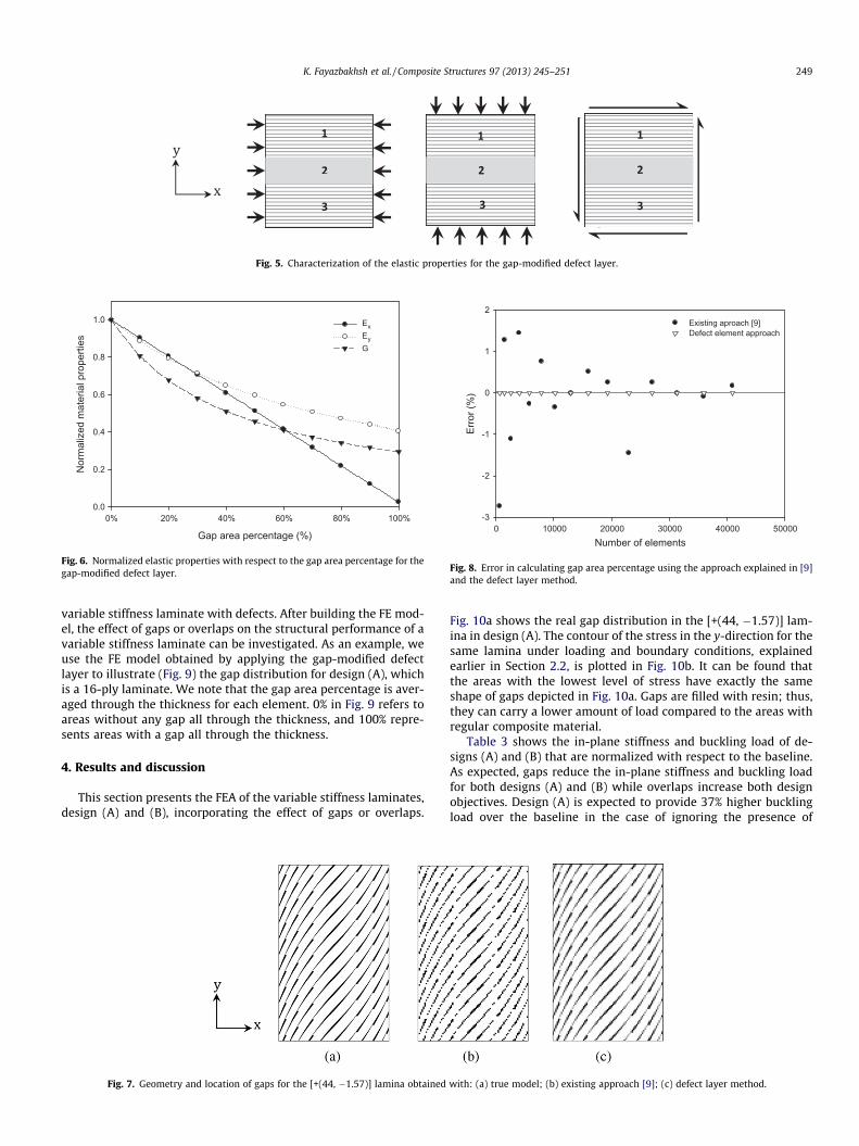
Fig. 5. Characterization of the elastic properties for the gap-modified defect layer.
Gap area percentage (%)
0% 20% 40% 60% 80% 100%
Nor
mal
ized
mat
eria
l pro
perti
es
0.0
0.2
0.4
0.6
0.8
1.0 ExEyG
Fig. 6. Normalized elastic properties with respect to the gap area percentage for thegap-modified defect layer.
Number of elements0 10000 20000 30000 40000 50000
Erro
r (%
)
-3
-2
-1
0
1
2Existing aproach [9]Defect element approach
Fig. 8. Error in calculating gap area percentage using the approach explained in [9]and the defect layer method.
K. Fayazbakhsh et al. / Composite Structures 97 (2013) 245–251 249
variable stiffness laminate with defects. After building the FE mod-el, the effect of gaps or overlaps on the structural performance of avariable stiffness laminate can be investigated. As an example, weuse the FE model obtained by applying the gap-modified defectlayer to illustrate (Fig. 9) the gap distribution for design (A), whichis a 16-ply laminate. We note that the gap area percentage is aver-aged through the thickness for each element. 0% in Fig. 9 refers toareas without any gap all through the thickness, and 100% repre-sents areas with a gap all through the thickness.
4. Results and discussion
This section presents the FEA of the variable stiffness laminates,design (A) and (B), incorporating the effect of gaps or overlaps.
Fig. 7. Geometry and location of gaps for the [+(44, �1.57)] lamina obtained
Fig. 10a shows the real gap distribution in the [+(44, �1.57)] lam-ina in design (A). The contour of the stress in the y-direction for thesame lamina under loading and boundary conditions, explainedearlier in Section 2.2, is plotted in Fig. 10b. It can be found thatthe areas with the lowest level of stress have exactly the sameshape of gaps depicted in Fig. 10a. Gaps are filled with resin; thus,they can carry a lower amount of load compared to the areas withregular composite material.
Table 3 shows the in-plane stiffness and buckling load of de-signs (A) and (B) that are normalized with respect to the baseline.As expected, gaps reduce the in-plane stiffness and buckling loadfor both designs (A) and (B) while overlaps increase both designobjectives. Design (A) is expected to provide 37% higher bucklingload over the baseline in the case of ignoring the presence of
with: (a) true model; (b) existing approach [9]; (c) defect layer method.

0%
40%
30%
20%
10%
60%
50%
70%
80%
90%
100%
Fig. 9. Gap distribution for design (A).
(a) (b)
Fig. 10. (a) The real gap distribution. (b) The contour plot of the stress in the y-direction.
Table 3In-plane stiffness and buckling load after incorporating the effects of gaps or overlapsof designs (A) and (B) normalized with respect to the baseline.
Laminate Normalizedstiffness
Normalizedbuckling load
Value Change(%)
Value Change(%)
Design (A)Ignoring defects 0.73 – 1.37 –Full gap (total gap area: 12.4%) 0.61 �15.1 1.20 �12.4Full overlap (total overlap area:
9.6%)0.78 +9.6 1.78 +29.9
Design (B)Ignoring defects 1 – 1.31 –Full gap (total gap area: 12.3%) 0.86 �14 1.15 �12.2Full overlap (total overlap area:
9.4%)1.11 +11 1.71 +30.5
250 K. Fayazbakhsh et al. / Composite Structures 97 (2013) 245–251
manufacturing defects (gaps or overlaps) in the laminate. However,Table 3 shows that with the full gap strategy for manufacturing de-sign (A), there is only 20% improvement in the buckling load com-pared to the baseline. In other words, the emerging gaps in thelaminate (gap area of 12.4%) reduce the buckling load improve-ment by 12.4%, which is about one third of the expected improve-ment in the buckling load. On the other hand, the use of the fulloverlap strategy, which produces thickness build-ups in the lami-nate (total overlap area of 9.6%), can increase the buckling loadby 78% over the baseline. This increase is about two times of theimprovement expected when the presence of overlaps is ignored.
For design (A), higher buckling load comes at the cost of a 27%reduction in the in-plane stiffness ignoring the presence of gaps oroverlaps. By taking into account the effect of gaps, 15.1% furtherreduction in the in-plane stiffness is observed. On the other hand,the use of the complete overlap strategy can improve the in-planestiffness of design (A) by 9.6% compared to the case, where theoverlaps are ignored. Generally, it can be concluded that gaps havehigher effect on the in-plane stiffness compared to overlaps, whileoverlaps have higher effect on the buckling load.
Compared to the baseline with no effect of gaps or overlaps, de-sign (B) offers 31% improvement in the buckling load with nochange in stiffness. Considering the effect of gaps, the improve-ment in the buckling load over the baseline is only 15% and itcomes with 14% reduction in the in-plane stiffness. As a result,gaps produced during the manufacturing process has the effectof reducing the benefit of fiber steering, whereas overlaps can
increase the in-plane stiffness and the buckling load over the base-line by 11% and 71%, respectively.
5. Conclusion
In this work, the effect of gaps or overlaps on the in-plane stiff-ness and buckling load of variable stiffness laminates has beeninvestigated. A defect layer method has been introduced to capturethe geometry and location of gaps and overlaps, and applied to twolaminate designs obtained from the optimal solutions of the Paretofront. Compared with the outcome obtained with an alternativeapproach existing in literature, the results demonstrate that thedefect layer method is more precise in locating and calculatingthe defect area percentage, regardless of the number of elements.
With reference to the two variable stiffness laminates of the testproblem investigated in this paper, the following results have beenobserved: gaps deteriorate both in-plane stiffness and bucklingload, whereas overlaps improve the structural performance. In par-ticular, for the first laminate configuration, the improvement inbuckling load resulting from the fiber steering (37%) decreases to20% when the effect of gaps is modelled. On the other hand, over-laps increase the improvement in the buckling load to 78%. For thesecond laminate configuration, overlaps have been shown to im-prove the in-plane stiffness and buckling load by 11% and 71%,respectively. It should be noted that the gains in the in-plane stiff-ness and buckling load may depend on the loading and boundaryconditions.
Future work is required to obtain a Pareto front that considersthe effect of gaps or overlaps on the in-plane stiffness and thebuckling load of the laminates. These results would provide impor-tant design guidelines of direct interest to industry. The effect ofmanufacturing parameters, e.g. tow width and number of tows inone course, which affect defect size and distribution, can also beinvestigated. Different loading and boundary conditions can alsobe considered. Furthermore, strength properties for a defect layercan be derived and used in a progressive damage simulation of var-iable stiffness laminates with gaps and/or overlap.
Acknowledgements
The authors would like to acknowledge the financial supportprovided by the Natural Sciences and Engineering Research Councilof Canada (NSERC) and Consortium for Research and Innovation inAerospace in Québec (CRIAQ). We also thank the support of the Na-tional Research Council of Canada, Bombardier Aerospace andComposites Atlantic.

K. Fayazbakhsh et al. / Composite Structures 97 (2013) 245–251 251
References
[1] Gürdal Z, Tatting BF, Wu KC. Tow-placement technology and fabrication issuesfor laminated composite structures. In: 46th AIAA/ASME/ASCE/AHS/ASCstructures, structural dynamics & materials conference. Austin, Texas; 2005.p. 1–17.
[2] Hyer M, Charette R. Use of curvilinear fiber format in composite structuredesign. AIAA J 1991;29:1011–5.
[3] Hyer M, Lee H. The use of curvilinear fiber format to improve bucklingresistance of composite plates with central circular holes. Compos Struct1991;18:239–61.
[4] Ghiasi H, Fayazbakhsh K, Pasini D, Lessard L. Optimum stacking sequencedesign of composite materials. Part II: Variable stiffness design. Compos Struct2010;93:1–13.
[5] Gürdal Z, Olmedo R. In-plane response of laminates with spatially varying fiberorientations: variable stiffness concept. AIAA J 1993;31:751–8.
[6] Olmedo R, Güdal Z. Buckling response of laminates with spatially varying fiberorientations. Washington (DC): American Institute of Aeronautics andAstronautics, SW; 1993. p. 2261–9.
[7] Gürdal Z, Tatting BF, Wu CK. Variable stiffness composite panels: effects ofstiffness variation on the in-plane and buckling response. Compos Part A: ApplSci Manuf 2008;39:911–22.
[8] Arian Nik M, Fayazbakhsh K, Pasini D, Lessard L. Surrogate-based multi-objective optimization of a composite laminate with curvilinear fibers. ComposStruct 2012;94:2306–13.
[9] Blom AW, Lopes CS, Kromwijk PJ, Gürdal Z, PP C. A theoretical model to studythe influence of tow-drop areas on the stiffness and strength of variable-stiffness laminates. Comput Mater 2009;43:403–25.
[10] Sawicki A, PJ M. The Effect of intraply overlaps and gaps upon the compressionstrength of composite laminates. In: 39th AIAA structural, dynamics, &materials conference. Long Beach, CA; 1998. p. 744–54.
[11] Cairns DS, Licewicz LB, Walker T. Far-field and near-field strain response ofautomated tow-placed laminates to stress concentrations. Comput Eng1993;3:1087–97.
[12] Croft K, Lessard L, Pasini D, Hojjati M, Chen J, Yousefpour A. Experimentalstudy of the effect of Automated Fiber Placement induced defects on theperformance of composite laminates. Computer Part A 2011;42:484–91.
[13] Lopes CS, Camanho PP, Gürdal Z, Tatting BF. Progressive failure analysis oftow-placed, variable-stiffness composite panels. Int J Solids Struct2007;44:8493–516.
[14] Fayazbakhsh K, Pasini D, Lessard L. The effect of manufacturing parameters onthe tow drop regions of a variable stiffness composite cone made out ofAutomated Fiber Placement. In: 42nd ISTC. Salt Lake, City, UT; 2010.
[15] Tatting BF, Gürdal Z. Automated finite element analysis of elastically-tailoredplates. NASA contractor report no NASA/CR-2003-212679. 2003.
[16] Fayazbakhsh K, Prabhakar S, Pasini D, Lessard L. A study of the influence ofgaps and overlaps on the strength of composite panels made by AutomatedFiber Placement. In: The 26th ASC technical conference (the second joint US-Canada conference on composites). Montreal, Canada; 2011.