deepening the wreck of the assi euro link by using the ... · deepening the wreck of the assi euro...
TRANSCRIPT

Deepening the wreck of the Assi Euro Link by using the Trailing Suction Hopper Dredger Prins der Nederlanden
B. Jacobs1
Abstract: In January 2003 the freight ship Assi Euro Link sank after a collision, 48 nm off the north coast of the Netherlands. As the wreck was located in a busy shipping lane it had to be either removed or lowered below the guaranteed navigable depth of 29 m. After taking cost and feasibility into consideration Rijkswaterstaat (Dutch Maritime Authorities) decided to have the Assi Euro Link lowered by dredging the existing sea bottom material around the wreck. During the second half of 2003 Rijkswaterstaat and Boskalis developed the dredging option. The combination of site conditions made the operation a dredging challenge, since it had never been executed before under these conditions. First the location of the wreck was unfavorable for working conditions, due to the open sea environment, very busy shipping and the depth of the sea bottom, which was almost 45 m. These conditions lead to the choice of a modern, versatile and highly manoeuverable trailing suction hopper dredger, being able to dredge up to 80 m. Second the soil properties played an important role, since the material had to flow from underneath the Assi Euro Link after dredging a hole around the wreck’s hull. Third the Assi Euro Link had broken up into two parts and some sections had even collapsed. The risk of damaging or even losing the suction pipe, by uncontrolled movements of wreckage was high. To ensure a safe operation a monitoring system with motion sensors was installed on the wreck, which registered sudden movements and gave a warning. Since the goal of the project was to lower the wreck below the required navigable depth an effort has been made to continuously monitor the exact location by using an Ultra Short Baseline (USBL) system. As a part of the system several acoustic sensors were fitted on the wreck, prior to dredging operations. Keywords: wreck, deepening, dredging
1 Dredging Department, Royal Boskalis Westminster, Rosmolenweg 20, P.O. Box 43, 3350 AA Papendrecht, The Netherlands, E-mail: [email protected]
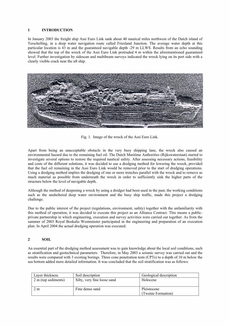
1 INTRODUCTION In January 2003 the freight ship Assi Euro Link sank about 40 nautical miles northwest of the Dutch island of Terschelling, in a deep water navigation route called Friesland Junction. The average water depth at this particular location is 43 m and the guaranteed navigable depth -29 m LLWS. Results from an echo sounding showed that the top of the wreck of the Assi Euro Link protruded 4 m within the aforementioned guaranteed level. Further investigation by sidescan and multibeam surveys indicated the wreck lying on its port side with a clearly visible crack near the aft ship.
Fig. 1. Image of the wreck of the Assi Euro Link.
Apart from being an unacceptable obstacle in the very busy shipping lane, the wreck also caused an environmental hazard due to the remaining fuel oil. The Dutch Maritime Authorities (Rijkswaterstaat) started to investigate several options to restore the required nautical safety. After assessing necessary actions, feasibility and costs of the different solutions, it was decided to use a dredging method for lowering the wreck, provided that the fuel oil remaining in the Assi Euro Link would be removed prior to the start of dredging operations. Using a dredging method implies the dredging of one or more trenches parallel with the wreck and to remove as much material as possible from underneath the wreck in order to sufficiently sink the higher parts of the structure below the level of navigable depth. Although the method of deepening a wreck by using a dredger had been used in the past, the working conditions such as the unsheltered deep water environment and the busy ship traffic, made this project a dredging challenge. Due to the public interest of the project (regulations, environment, safety) together with the unfamiliarity with this method of operation, it was decided to execute this project as an Alliance Contract. This means a public-private partnership in which engineering, execution and survey activities were carried out together. As from the summer of 2003 Royal Boskalis Westminster participated in the engineering and preparation of an execution plan. In April 2004 the actual dredging operation was executed. 2 SOIL An essential part of the dredging method assessment was to gain knowledge about the local soil conditions, such as stratification and geotechnical parameters. Therefore, in May 2003 a seismic survey was carried out and the results were compared with 3 existing borings. Three cone penetration tests (CPTs) to a depth of 10 m below the sea bottom added more detailed information. It was concluded that the soil stratification was as follows:
Layer thickness Soil description Geological description 2 m (top sediments) Silty, very fine loose sand
Holocene
2 m Fine dense sand
Pleistocene (Twente Formation)

7 m Medium to coarse, very dense sand
Pleistocene (Eem & Molengat Formation)
Hard clay Pleistocene (Clever Bank Formation)
The results from the soil investigation provided sufficient information to answer questions concerning:
• Dredgebility of the material with existing dredging equipment. • Slope development of the material underneath the wreck. • Possible excavation depth to create the required buffer to sufficiently sink the wreck parts.
3 EQUIPMENT CHOICE After studying the boundary conditions it was decided to use the brand new 16,000 m3 trailing suction hopper dredger “Prins der Nederlanden”, because of the advantageous characteristics for the execution of the project:
• Sufficient depth range. The vessel is equipped with one standard suction pipe layout, being able to dredge up to 55 m depth and one deep dredging layout for a working depth of 83 m. Furthermore the deep dredging layout contains an underwater pump, giving more flexibility and a higher production output when working in water depths of more than 30 m.
• A lot of installed jet power (up to 3,000 kW). As the Pleistocene sand layer was considered to be very densely packed it was foreseen that the slope development needed to be activated by means of jetting.
• Good manoeuvrability characteristics, making the vessel most suitable for working in a restricted area and anticipate on possible ship traffic passing the site.
• Being able to operate at wave heights up to 3 m., which was considered a very important issue when working in April on the North Sea in offshore conditions.
• Equipped with dynamic positioning (DP) and dynamic tracking (DT), giving the possibility to work very accurately.
• The vessel being self propelled and therefore suitable to evenly spread its load over the sea bottom at any given distance, without being an obstacle in the shipping lane.
4 RISKS From all the available soil information it was concluded that the Pleistocene sand layer was strongly over-consolidated due to an ancient glacial ice cover. Slopes in the excavated trench were expected to remain steep due to the soil behaviour, which would prevent the sand flowing from underneath the wreck in a natural way. Calculations showed that at least a hole of 10 m would be necessary to create sufficient slope development to have the wreck sliding on its own weight into the dredged trench. At approximately 10 m however there was the risk of encountering a hard clay of the Cleaver Formation, which was expected to have a negative effect on the formation of a slip circle, thus preventing sufficient slope development. To overcome the high soil risks, a special jetting device was developed to activate the slope development by jet water force. For this purpose, the jet consisted of two side nozzles and a nozzle directed backward. The device could be mounted on the suction tube of the trailing suction hopper dredger and a total power of 5,500 kW was available (from one dredge pump and three jet pumps). A second option to create sufficient instability of the sand layer underneath the wreck was to dredge a second trench on the opposite side. Large pieces of debris, possible scattered around the wreck on the sea bottom causing damage on the suction pipe could stagnate the whole operation. Therefore special focus was made on locating these pieces. This was done by ROV inspection, before the dredging operations started and during the start of the project by so called reconnaissance dredging. Reconnaissance dredging contained pre dredging by covering the complete area around the wreck with one pipe, using the standard pipe line lay-out. Since this lay-out would not be used during the remaining dredging operations, damage on the pipe or draghead would not jeopardize the project planning. Knowing the exact position and monitoring the behaviour of the wreck during the operation was considered essential, as one of the objectives was to sink the wreck parts in a controlled way and for safety of the dredging operation. Especially the speed at which the wreck moved and the way it changed position, by means of sliding
or turning over, would determine the further approach of dredging operations. The wreck monitoring set up was based on two systems:
• Roll and pitch measurement. • An Ultra Short Base Line (USBL) system.
Two roll and pitch sensors were mounted on the wreck and used as an early warning system to register whether the wreck, or parts of it, would move or shift during operations. The signal from each roll and pitch indicator was linked via a data cable to a navigation buoy, marking the site. Data output was then sent to the dredging vessel by radio telemetry and loaded into a 3D model, which was created from previous multibeam surveys and original ship drawings from the Assi Euro Link. The system also provided an alarm function, when sudden movements of the wreck were registered, by means of sound. The USBL system was used to monitor the exact location of the wreck parts during dredging operations. Therefore transponder beacons were mounted on the wreck. The USBL transducer head, which was located on the suction pipe of the “Prins der Nederlanden” interrogated the transponder beacons and any change in position was related to the position of the dredger. The horizontal control of the dredger “Prins der Nederlanden” was done by using C & C Technologies Satellite Navigation System C-NAV. As the dredging process produced too much noise which interfered with the beacon acoustic signals, dredging operations had to be stopped at regular intervals to obtain a good position update. 5 DREDGING OPERATIONS Dredging operations started in April 2004, after a winter period with severe storms. A multibeam survey, executed in March 2004, showed that the wreck had actually broken up into two parts, where the fore part had moved significantly and some sections had collapsed. The aft section still had to be lowered 4 m, while the front section was just 1 m above the guaranteed navigable depth of 29 m below LLWS. The dredging plan changed drastically because there were now two wreck parts which needed deepening separately. Dredging operations had to focus on the aft section and the manoeuvring space for the dredger was reduced to a minimum. The plan of approach was set up as follows:
• Upon arrival at the site performing a multibeam survey to determine the position of the wreck and its surroundings.
• Reconnaissance dredging to locate possible large pieces of the wreck. • Dredging the first trench along the deck side of the aft ship section to a depth of 10 m below the sea-
bottom floor or up to the hard clay layer. This first trench was located at the deck side which was less preferable from a stability point of view since the point of gravity was located on the opposite keel side. The choice was based on the fact that the deck side was easier accessible and was expected to contain less debris.
• Depending on the movement of the wreck it would be decided if one had to create a similar trench on the keel side of the aft section of the wreck.
• Finally, trenches would be dredged along the keel and deck side of the front section. • If the wreck would have been shifted insufficiently, the specially designed jet device could be
mounted. • The dredged material would be discharged, depending on the direction of the current, at one of two
disposal locations at a distance of 2,500 m from the wreck site. The load was discharged in a controlled way to avoid shoaling as much as possible.
In order to monitor the dredge and/or jet process and the effect on the slope, a profiler was mounted on the suction pipe. The profiler consisted of a multibeam echosounder and was fixed horizontally at a height of 4 m above the draghead/jet device.

Fig. 2. Dredging trenches along the wreck.
Fig. 3. Jetting the remaining material. 6 CONTINGENCY STRATEGY Encountering a hard clay layer above the assumed depth was considered to be an important risk factor. Therefore a contingency strategy was set up to deal with such an occurrence. After dredging trenches on both sides of the wreck until reaching the hard clay, the existing drag-head would be adjusted into a so called boulder clay drag-head. This means reducing the suction opening (to avoid clogging with stones) and mounting ripper teeth. In this way, an additional 1 or 2 meter of clay could be removed. As previously mentioned, a purpose built jet device was available. The jet device has side jets for activating the slope (figure 3). Furthermore a 5 m long jet pipe was mounted at the back. By manoeuvring the “Prins der Nederlanden” perpendicular to the wreck, and positioning the jet pipe under a wreck section, material could be removed by jetting. As large parts of debris could slide down, a break bolt construction was added to avoid

damage on the suction pipe. An additional three weeks were estimated for jetting operations in case the slopes would not develop sufficiently to lower the aft wreck section by at least 4 m. 7 ACTUAL EXECUTION OF THE PROJECT The actual execution of the project started on April 13th, 2004. Preparatory actions consisted of the calibration of the multibeam, the execution of an in-survey of the area surrounding the wreck, and activating the USBL beacons. After the reconnaissance dredging operation around the wreck, the first trench was dredged by using the deep dredging suction pipe layout. The dimensions of the trench were 70 m long and 25 m wide and a safety margin of 10 m was considered from the side of the wreck to the trench. Of the actual dredging only 35% was effective loading time, the rest was used for manoeuvring and positioning. The optimum trail speed was 0.6 knots. The initial side slopes of the trench started with 1:1, very soon becoming 1:2. After 2 days of dredging, having removed well over 30,000 m3, slopes had developed to 1:4. At that time, when returning to the site from dumping a full load, survey results showed a trench bottom which had become 3 m shallower, indicating the material from the slopes flowing into the trench. At this point the aft section started to move for the first time: three degrees list and three degrees trim. In the next two days the list increased to 20 degrees. Although the soil investigation indicated a hard clay layer as from 10 m below the sea bottom level, in actual fact this layer was not encountered up to a depth of more than 15 m below the sea floor. This meant that the removed sand layer in combination with a realised slope of 1:4, eroded sufficient material from under the wreck part to have it slide into the trench so much, that the highest point did not reach above -30 m LLWS. The total volume dredged for the aft section of the wreck was 168,000 m3. For the front section another 60,000 m3 was dredged to have it sufficiently lowered. At the end of the project a total quantity of 228,000 m3 has been removed in 1.5 weeks. 8 CONCLUSIONS Deepening a wreck in a navigation channel below the required depth is a technical feasible and cost effective operation. However, environmental hazards, such as remaining fuel oil or load, have to be looked at separately. When executing this type of project, a public-private partnership is preferable. Since the wreck is not actually removed from the sea bottom, nautical and environmental risks, together with other public interests need to be carefully assessed and taken into account when drawing up a project preparation plan. Sufficient time is needed to gather vital information concerning the characteristics of the sunken vessel and soil. The last item is essential in order to be able to prepare a dredging planning. Soil information should be available from the immediate vicinity of the wreck location; otherwise a soil investigation needs to be executed. The costs for motion sensors and the USBL system proved to be well spent, since the behaviour of the wreck parts could be monitored and anticipated with dredging operations accordingly. Contingency strategies should be ready before dredging operations start. The Assi Euro Link project clearly showed that those strategies, in combination with a careful monitoring system for the wreck and soil behaviour, make it possible to take adequate steps in dynamic uncertain project conditions.