deep sea electronics plc -...
TRANSCRIPT

7400 Configuration Suite Software Manual Issue 2
DEEP SEA ELECTRONICS PLC DSE7400 Configuration Suite Software
Manual
Document Number 057-160
Author: Allan Jones
http://bestgenerator.spb.ru/?page_id=6765
7400 Configuration Suite Software Manual
2
DEEP SEA ELECTRONICS PLC Highfield House Hunmanby North Yorkshire YO14 0PH ENGLAND Sales Tel: +44 (0) 1723 890099 Sales Fax: +44 (0) 1723 893303 E-mail : [email protected] Website : www.deepseaplc.com
DSE7400 Series configuration suite © Deep Sea Electronics Plc All rights reserved. No part of this publication may be reproduced in any material form (including photocopying or storing in any medium by electronic means or other) without the written permission of the copyright holder except in accordance with the provisions of the Copyright, Designs and Patents Act 1988. Applications for the copyright holder’s written permission to reproduce any part of this publication should be addressed to Deep Sea Electronics Plc at the address above. The DSE logo is a UK registered trademarks of Deep Sea Electronics PLC. Any reference to trademarked product names used within this publication is owned by their respective companies. Deep Sea Electronics Plc reserves the right to change the contents of this document without prior notice. Amendments List Issue Comments Minimum
Module version required
Minimum Configuration Suite
Version required
1 Initial release V1.0.0 2011.10v1.07 2 Added CT Location feature and corresponding Mains Current Options V1.3 205.16v1.242.6
Typeface: The typeface used in this document is Arial. Care should be taken not to mistake the upper case letter I with the numeral 1. The numeral 1 has a top serif to avoid this confusion.
http://bestgenerator.spb.ru/?page_id=6765
7400 Configuration Suite Software Manual
3
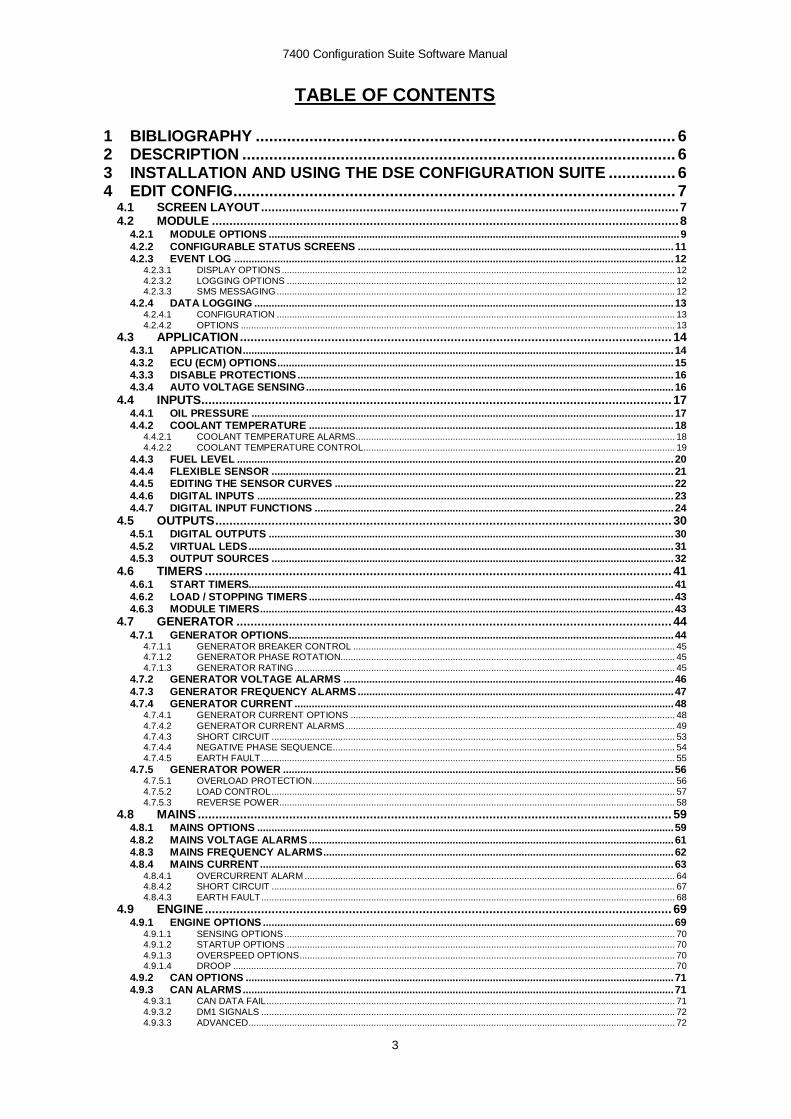
TABLE OF CONTENTS
1 BIBLIOGRAPHY .............................................................................................. 6
2 DESCRIPTION ................................................................................................. 6
3 INSTALLATION AND USING THE DSE CONFIGURATION SUITE ............... 6
4 EDIT CONFIG ................................................................................................... 7
4.1 SCREEN LAYOUT ....................................................................................................................... 7
4.2 MODULE ..................................................................................................................................... 8
4.2.1 MODULE OPTIONS ............................................................................................................................................... 9
4.2.2 CONFIGURABLE STATUS SCREENS .............................................................................................................. 11
4.2.3 EVENT LOG ......................................................................................................................................................... 12 4.2.3.1 DISPLAY OPTIONS .......................................................................................................................................................... 12 4.2.3.2 LOGGING OPTIONS ........................................................................................................................................................ 12 4.2.3.3 SMS MESSAGING ............................................................................................................................................................ 12
4.2.4 DATA LOGGING .................................................................................................................................................. 13 4.2.4.1 CONFIGURATION ............................................................................................................................................................ 13 4.2.4.2 OPTIONS .......................................................................................................................................................................... 13
4.3 APPLICATION ........................................................................................................................... 14
4.3.1 APPLICATION ...................................................................................................................................................... 14
4.3.2 ECU (ECM) OPTIONS .......................................................................................................................................... 15
4.3.3 DISABLE PROTECTIONS ................................................................................................................................... 16
4.3.4 AUTO VOLTAGE SENSING ................................................................................................................................ 16
4.4 INPUTS ...................................................................................................................................... 17
4.4.1 OIL PRESSURE ................................................................................................................................................... 17
4.4.2 COOLANT TEMPERATURE ............................................................................................................................... 18 4.4.2.1 COOLANT TEMPERATURE ALARMS ............................................................................................................................. 18 4.4.2.2 COOLANT TEMPERATURE CONTROL .......................................................................................................................... 19
4.4.3 FUEL LEVEL ........................................................................................................................................................ 20
4.4.4 FLEXIBLE SENSOR ............................................................................................................................................ 21
4.4.5 EDITING THE SENSOR CURVES ...................................................................................................................... 22
4.4.6 DIGITAL INPUTS ................................................................................................................................................. 23
4.4.7 DIGITAL INPUT FUNCTIONS ............................................................................................................................. 24
4.5 OUTPUTS .................................................................................................................................. 30
4.5.1 DIGITAL OUTPUTS ............................................................................................................................................. 30
4.5.2 VIRTUAL LEDS .................................................................................................................................................... 31
4.5.3 OUTPUT SOURCES ............................................................................................................................................ 32
4.6 TIMERS ..................................................................................................................................... 41
4.6.1 START TIMERS.................................................................................................................................................... 41
4.6.2 LOAD / STOPPING TIMERS ............................................................................................................................... 43
4.6.3 MODULE TIMERS ................................................................................................................................................ 43
4.7 GENERATOR ............................................................................................................................ 44
4.7.1 GENERATOR OPTIONS...................................................................................................................................... 44 4.7.1.1 GENERATOR BREAKER CONTROL .............................................................................................................................. 45 4.7.1.2 GENERATOR PHASE ROTATION................................................................................................................................... 45 4.7.1.3 GENERATOR RATING ..................................................................................................................................................... 45
4.7.2 GENERATOR VOLTAGE ALARMS ................................................................................................................... 46
4.7.3 GENERATOR FREQUENCY ALARMS .............................................................................................................. 47
4.7.4 GENERATOR CURRENT .................................................................................................................................... 48 4.7.4.1 GENERATOR CURRENT OPTIONS ............................................................................................................................... 48 4.7.4.2 GENERATOR CURRENT ALARMS ................................................................................................................................. 49 4.7.4.3 SHORT CIRCUIT .............................................................................................................................................................. 53 4.7.4.4 NEGATIVE PHASE SEQUENCE...................................................................................................................................... 54 4.7.4.5 EARTH FAULT .................................................................................................................................................................. 55
4.7.5 GENERATOR POWER ........................................................................................................................................ 56 4.7.5.1 OVERLOAD PROTECTION .............................................................................................................................................. 56 4.7.5.2 LOAD CONTROL .............................................................................................................................................................. 57 4.7.5.3 REVERSE POWER........................................................................................................................................................... 58
4.8 MAINS ....................................................................................................................................... 59
4.8.1 MAINS OPTIONS ................................................................................................................................................. 59
4.8.2 MAINS VOLTAGE ALARMS ............................................................................................................................... 61
4.8.3 MAINS FREQUENCY ALARMS .......................................................................................................................... 62
4.8.4 MAINS CURRENT ................................................................................................................................................ 63 4.8.4.1 OVERCURRENT ALARM ................................................................................................................................................. 64 4.8.4.2 SHORT CIRCUIT .............................................................................................................................................................. 67 4.8.4.3 EARTH FAULT .................................................................................................................................................................. 68
4.9 ENGINE ..................................................................................................................................... 69
4.9.1 ENGINE OPTIONS ............................................................................................................................................... 69 4.9.1.1 SENSING OPTIONS ......................................................................................................................................................... 70 4.9.1.2 STARTUP OPTIONS ........................................................................................................................................................ 70 4.9.1.3 OVERSPEED OPTIONS ................................................................................................................................................... 70 4.9.1.4 DROOP ............................................................................................................................................................................. 70
4.9.2 CAN OPTIONS ..................................................................................................................................................... 71
4.9.3 CAN ALARMS ...................................................................................................................................................... 71 4.9.3.1 CAN DATA FAIL ................................................................................................................................................................ 71 4.9.3.2 DM1 SIGNALS .................................................................................................................................................................. 72 4.9.3.3 ADVANCED....................................................................................................................................................................... 72
http://bestgenerator.spb.ru/?page_id=6765

7400 Configuration Suite Software Manual
4
4.9.5 GAS ENGINE OPTIONS ...................................................................................................................................... 73
4.9.6 CRANKING ........................................................................................................................................................... 74
4.9.7 SPEED SETTINGS ............................................................................................................................................... 75
4.9.8 PLANT BATTERY ................................................................................................................................................ 76
4.9.9 INLET TEMPERATURE ....................................................................................................................................... 77
4.10 COMMUNICATIONS ...................................................................................................................78
4.10.1 COMMUNICATION OPTIONS......................................................................................................................... 78
4.10.2 RS232 PORT .................................................................................................................................................... 79 4.10.2.1 BASIC ................................................................................................................................................................................ 79 4.10.2.2 ADVANCED ....................................................................................................................................................................... 81
4.10.3 TROUBLESHOOTING MODEM COMMUNICATIONS .................................................................................. 83 4.10.3.1 MODEM COMMUNICATION SPEED SETTING .............................................................................................................. 83 4.10.3.2 GSM MODEM CONNECTION .......................................................................................................................................... 83
4.10.4 RS485 PORT .................................................................................................................................................... 84
4.10.5 ETHERNET PORT ........................................................................................................................................... 85
4.11 SCHEDULER .............................................................................................................................86
4.12 MAINTENANCE ALARM ............................................................................................................87
4.13 ALTERNATIVE CONFIGURATIONS ...........................................................................................88
4.13.1 ALTERNATIVE CONFIGURATION OPTIONS ............................................................................................... 88
4.13.2 ALTERNATIVE CONFIGURATIONS EDITOR ............................................................................................... 88
4.13.3 EXAMPLE OF USAGE .................................................................................................................................... 89 4.13.3.1 ENABLING THE DEFAULT CONFIGURATION ............................................................................................................... 89 4.13.3.2 USING THE ALTERNATIVE CONFIGURATION TO HANDLE SPEED CHANGE .......................................................... 90
4.14 EXPANSION...............................................................................................................................91
4.14.1 DSE2130 INPUT MODULES ........................................................................................................................... 92 4.14.1.1 DIGITAL INPUTS (A-D) ..................................................................................................................................................... 92 4.14.1.2 ANALOGUE INPUTS (E-H) ............................................................................................................................................... 93
4.14.2 DSE2131 RATIOMETRIC EXPANSION INPUT MODULE ............................................................................ 94 4.14.2.1 EDITING THE SENSOR CURVES ................................................................................................................................... 97
4.14.3 DSE2133 RTD / THERMOCOUPLE INPUT MODULE .................................................................................. 98
4.14.4 DSE2152 ANALOGUE OUTPUT MODULE .................................................................................................100 4.14.4.1 EDITING THE OUTPUT CURVE .................................................................................................................................... 101
4.14.5 DSE2157 RELAY MODULES........................................................................................................................102
4.14.7 DSE2548 LED EXPANSION .........................................................................................................................103
4.15 ADVANCED ............................................................................................................................. 104
4.15.1 ADVANCED OPTIONS ..................................................................................................................................105 4.15.1.1 PROTECTIONS ............................................................................................................................................................... 105 4.15.1.2 OTHER TIMERS.............................................................................................................................................................. 105
4.15.2 PLC LOGIC ....................................................................................................................................................106 4.15.2.1 MENU .............................................................................................................................................................................. 106 4.15.2.2 FLAGS ............................................................................................................................................................................. 107 4.15.2.3 TIMERS ........................................................................................................................................................................... 107 4.15.2.4 COUNTERS..................................................................................................................................................................... 108 4.15.2.5 PLC FUNCTIONS ............................................................................................................................................................ 109 4.15.2.6 CREATING AND EDITING RUNGS................................................................................................................................ 111 4.15.2.7 CONDITIONS .................................................................................................................................................................. 112 4.15.2.8 ACTIONS ......................................................................................................................................................................... 114 4.15.2.9 EXAMPLES ..................................................................................................................................................................... 116
4.15.3 CONFIGURABLE GENCOMM PAGES ........................................................................................................117
5 SCADA .........................................................................................................118
5.1 GENERATOR IDENTITY .......................................................................................................... 119
5.2 MIMIC ....................................................................................................................................... 119
5.3 LANGUAGES ........................................................................................................................... 120
5.4 DIGITAL INPUTS...................................................................................................................... 120
5.5 DIGITAL OUTPUTS .................................................................................................................. 121
5.6 VIRTUAL LEDS ........................................................................................................................ 121
5.7 MAINS ...................................................................................................................................... 122
5.7.1 FREQUENCY AND VOLTAGES........................................................................................................................122
5.7.2 POWER ...............................................................................................................................................................123
5.8 GENERATOR ........................................................................................................................... 124
5.8.1 FREQUENCY, VOLTAGES AND CURRENT ...................................................................................................124
5.8.2 POWER ...............................................................................................................................................................125
5.9 ENGINE.................................................................................................................................... 126
5.10 FLEXIBLE SENSOR ................................................................................................................. 126
5.11 ALARMS .................................................................................................................................. 127
5.12 STATUS ................................................................................................................................... 128
5.13 EVENT LOG ............................................................................................................................. 129
5.14 ENHANCED CANBUS .............................................................................................................. 130
5.15 REMOTE CONTROL ................................................................................................................ 131
5.16 MAINTENANCE ....................................................................................................................... 132
5.16.1 RECALIBRATE TRANSDUCERS.................................................................................................................132
5.16.3 EXPANSION CALIBRATION ........................................................................................................................133
5.16.4 HOURS RUN AND NUMBER OF STARTS ..................................................................................................133
5.16.5 TIME ................................................................................................................................................................133
5.16.6 ACCUMULATED INSTRUMENTATION .......................................................................................................134
5.16.7 MAINTENANCE ALARM RESET .................................................................................................................135
5.16.8 MODULE PIN .................................................................................................................................................135
http://bestgenerator.spb.ru/?page_id=6765

7400 Configuration Suite Software Manual
5
5.17 DATALOG ............................................................................................................................... 136
5.18 PLC ......................................................................................................................................... 137
5.19 EXPANSION ............................................................................................................................ 138
6 ALARM TYPES ............................................................................................ 139
http://bestgenerator.spb.ru/?page_id=6765

Bibliography
7400 Configuration Suite Software Manual Issue 2
1 BIBLIOGRAPHY This document refers to and is referred to by the following DSE publications which can be obtained from the DSE website www.deepseaplc.com: DSE PART DESCRIPTION 057-004 Electronic Engines and DSE wiring 057-161 DSE7400 Operators Manual 057-082 DSE2130 Input Expansion Manual 057-139 DSE2131 Input Expansion Manual 057-140 DSE2133 Input Expansion Manual 057-141 DSE2152 Input Expansion Manual 057-083 DSE2157 Input Expansion Manual 057-084 DSE2548 Input Expansion Manual The following third party documents are also referred to: ISBN DESCRIPTION 1-55937-879-4 IEEE Std C37.2-1996 IEEE Standard Electrical Power System Device Function Numbers
and Contact Designations. Published by Institute of Electrical and Electronics Engineers Inc
2 DESCRIPTION This manual covers the operation of the DSE Configuration Suite for DSE7400 series modules. Separate manuals cover the remaining DSE modules supported by the software
The DSE Configuration Suite allows the DSE7400 family of modules to be connected to a PC via USB ‘A –USB B’ cable. Once connected the various operating parameters within the module can be viewed or edited as required by the engineer. This software allows easy controlled access to these values and also has diagnostic monitoring facilities. The configuration suite should only be used by competent, qualified personnel, as changes to the operation of the module may have safety implications on the panel / generating set to which it is fitted. Access to critical operational sequences and settings for use by qualified engineers, may be barred by a security code set by the generator provider. The information contained in this manual should be read in conjunction with the information contained in the appropriate module documentation. This manual only details which settings are available and how they may be used. A separate manual deals with the operation of the individual module (See section entitled Bibliography elsewhere in this document).
3 INSTALLATION AND USING THE DSE CONFIGURATION SUITE SOFTWARE For information in regards to instating and using the DSE Configuration Suite Software please refer to DSE publication: 057-151 DSE Configuration Suite PC Software Installation & Operation Manual which can be found on our website: www.deepseaplc.com
http://bestgenerator.spb.ru/?page_id=6765

Edit Configuration module
7
4 EDIT CONFIG This menu allows module configuration, to change the function of Inputs, Outputs and LED’s, system timers and level settings to suit a particular application. 4.1 SCREEN LAYOUT
The type of configuration file being edited
Close this configuration file
Move to the Previous or Next configuration page
The coloured shading shows the currently selected page.
Click + or – to show or hide the sub settings within each sections.
Click to select the subsection to view / edit
Click to return to this page at any time
Step forward or backward through previously viewed pages

Edit Configuration - Module
8
4.2 MODULE The module page is subdivided into smaller sections. Select the required section with the mouse. This section allows the user to change the options related to the module itself.
Edit Configuration - Module
9
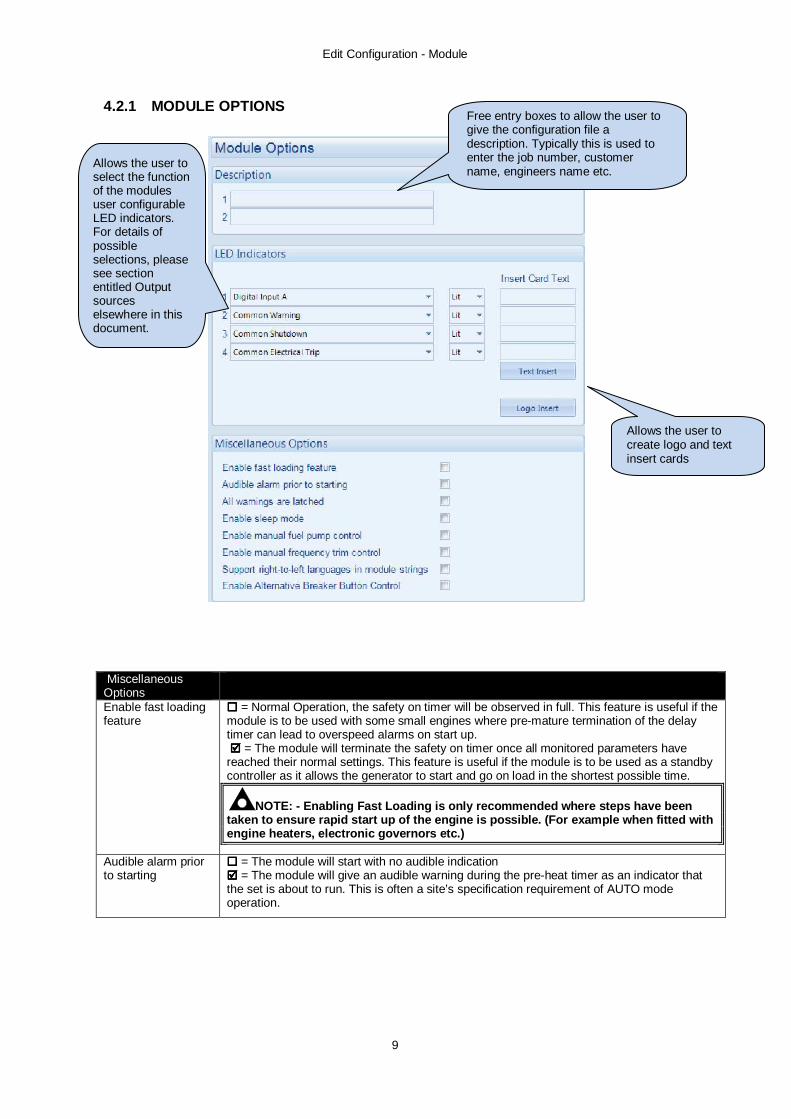
4.2.1 MODULE OPTIONS
Miscellaneous Options
Enable fast loading feature
= Normal Operation, the safety on timer will be observed in full. This feature is useful if the module is to be used with some small engines where pre-mature termination of the delay timer can lead to overspeed alarms on start up. = The module will terminate the safety on timer once all monitored parameters have reached their normal settings. This feature is useful if the module is to be used as a standby controller as it allows the generator to start and go on load in the shortest possible time.
NOTE: - Enabling Fast Loading is only recommended where steps have been taken to ensure rapid start up of the engine is possible. (For example when fitted with engine heaters, electronic governors etc.)
Audible alarm prior to starting
= The module will start with no audible indication = The module will give an audible warning during the pre-heat timer as an indicator that the set is about to run. This is often a site’s specification requirement of AUTO mode operation.
Free entry boxes to allow the user to give the configuration file a description. Typically this is used to enter the job number, customer name, engineers name etc.
Allows the user to select the function of the modules user configurable LED indicators. For details of possible selections, please see section entitled Output sources elsewhere in this document.
Allows the user to create logo and text insert cards

Edit Configuration - Module
10
Miscellaneous Options
All Warnings Are Latched
= Normal Operation, the warnings and pre-alarms will automatically reset once the triggering condition has cleared. = Warnings and pre-alarms latch when triggered. Resetting the alarm is performed by either an external reset applied to one of the inputs or, the ‘Stop/Reset’ pushbutton must be operated (once the triggering condition has been cleared).
Enable Alternative Breaker Button Control Not DSE7410
Default breaker button control is transfer to Generator/ Transfer to mains: Alternative breaker button control is:- Open Mains breaker / Close mains breaker Open Generator breaker / Close breaker.
Enable sleep mode =Normal operation =The module goes into "sleep mode” if left in manual mode for a prolonged time with no button presses.
Enable manual fuel pump control
=Normal operation =Allows manual fuel pump control when the “fuel level” instrument page is being viewed.
Support right-left languages in module strings
Determines the direction of text input where supported (i.e. configurable input text) =left to right language support =right to left language support

Edit Configuration - Module
11
4.2.2 CONFIGURABLE STATUS SCREENS Configurable Status Screens allow the operator to design the status screen to match the requirements of the end user or application more closely. For instance it is possible to configure the module to show the factory set ‘summary screen’ and then cycle the display to show instruments specified by the end user. This display cycling occurs with no user intervention.
This is the page that appears automatically when the engine is running (either instrumentation or status)
These instruments are displayed one after the other when the set runs. If an entry is set to ‘Not Used’, or is not applicable, the entry is skipped over and not displayed.

Edit Configuration - Module
12
4.2.3 EVENT LOG 4.2.3.1 DISPLAY OPTIONS The module display option allows the operator to choose between `Date and Time` or `Engine Hours` displayed on the bottom of the screen. 4.2.3.2 LOGGING OPTIONS The event log can be configured to allow users to select which events are stored.
4.2.3.3 SMS MESSAGING When using the controller, logged events will also cause modem ‘dial outs’ and SMS messages to be sent if the module is configured to do so and connected to a suitable external GSM modem with functioning SIM card.

Edit Configuration - Module
13
4.2.4 DATA LOGGING
NOTE: - Data logging to internal and external memory is available. The Data Logging page is subdivided into smaller sections. Select the required section with the mouse.
4.2.4.1 CONFIGURATION
4.2.4.2 OPTIONS
Setting Description Only log when engine is running
= The module will log data regardless of engine running state. = The module will only log data when the engine is running.
Log to USB drive = The module will log data to the modules internal memory. = The module will log data to an external USB device connect to the USB host socket on the module.
Keep oldest data = When the logging memory is full, the module will overwrite the oldest data first with the new data. = When the logging memory is full, the module will stop recording new data.
Select the instrument / item to be logged. Twenty (20) selection points are possible.
Select the logging interval of the data.

Edit Configuration - Application
14
4.3 APPLICATION 4.3.1 APPLICATION
See overleaf for description of the parameters....
Allows selection of the Engine type being used (ie Conventional Diesel Engine, Gas Engine or Electronic Engine)
Auto Voltage Sensing to automatically select the module configuration from available ‘alternative configurations’

Edit Configuration - Application
15
4.3.2 ECU (ECM) OPTIONS Parameter Description Engine type Select the engine type appropriate to your system
Conventional Engine: Select this if you have a traditional (non ECU) engine, either Energise to Run or Energise to Stop. Conventional Gas Engine: Select this if you have a traditional (non ECU) engine and require GAS engine functionality. This enables control of configurable outputs for Gas Choke and Gas Ignition and instructs the module to follow the gas engine timers. Other Engines: The list of supported CAN (or Modbus) engines is constantly updated, check the DSE website at www.deepseaplc.com for the latest version of Configuration Suite software.
Enhanced J1939 = The module will read ‘Basic’ instrumentation from the engine ECU and display (where supported by the engine) :
• Engine Speed • Oil Pressure • Engine Coolant Temperature • Hours Run
= The module will read and display an ‘Enhanced’ instrumentation list (where supported by the engine) :
• Engine Speed • Oil Pressure • Engine Coolant Temperature • Hours Run • Engine Oil Temperature • Exhaust Temperature • Fuel Pressure • Total Fuel used • Fuel Consumption • Inlet Manifold Temperature • Coolant Pressure • Turbo Pressure
Where an instrument is not supported by the engine ECU, the instrument is not displayed. DSE Reserve the right to change these lists in keeping with our policy of continual development.
Alternative Engine Speed
= The engine is instructed to run at its Nominal Speed as configured by the Engine Manufacturer.
= The engine is instructed to run at its Alternative Speed as configured by the Engine Manufacturer.
Modbus Engine Comms Port
RS485 Port: The modules RS485 port is used to communicate to the engine (when a Modbus engine type is selected. DSENet Port: The modules DSENet port is used to communicate to the engine (when a Modbus engine type is selected. This ‘frees’ the RS485 port in case connection to BMS or other RS485 compatible equipment is required.
Edit Configuration - Application
16
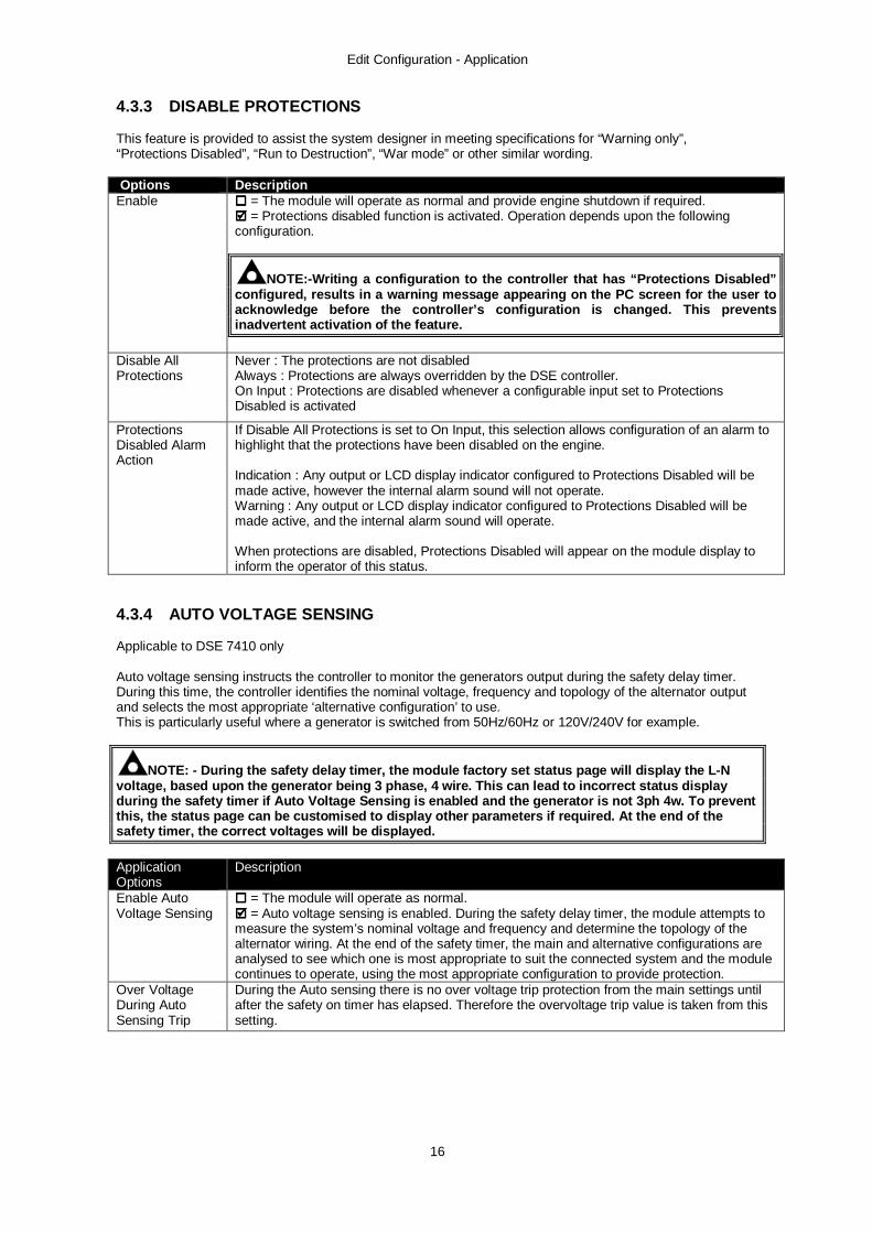
4.3.3 DISABLE PROTECTIONS This feature is provided to assist the system designer in meeting specifications for “Warning only”, “Protections Disabled”, “Run to Destruction”, “War mode” or other similar wording. Options Description Enable = The module will operate as normal and provide engine shutdown if required.
= Protections disabled function is activated. Operation depends upon the following configuration.
NOTE:-Writing a configuration to the controller that has “Protections Disabled” configured, results in a warning message appearing on the PC screen for the user to acknowledge before the controller’s configuration is changed. This prevents inadvertent activation of the feature.
Disable All Protections
Never : The protections are not disabled Always : Protections are always overridden by the DSE controller. On Input : Protections are disabled whenever a configurable input set to Protections Disabled is activated
Protections Disabled Alarm Action
If Disable All Protections is set to On Input, this selection allows configuration of an alarm to highlight that the protections have been disabled on the engine. Indication : Any output or LCD display indicator configured to Protections Disabled will be made active, however the internal alarm sound will not operate. Warning : Any output or LCD display indicator configured to Protections Disabled will be made active, and the internal alarm sound will operate. When protections are disabled, Protections Disabled will appear on the module display to inform the operator of this status.
4.3.4 AUTO VOLTAGE SENSING Applicable to DSE 7410 only Auto voltage sensing instructs the controller to monitor the generators output during the safety delay timer. During this time, the controller identifies the nominal voltage, frequency and topology of the alternator output and selects the most appropriate ‘alternative configuration’ to use. This is particularly useful where a generator is switched from 50Hz/60Hz or 120V/240V for example.
NOTE: - During the safety delay timer, the module factory set status page will display the L-N voltage, based upon the generator being 3 phase, 4 wire. This can lead to incorrect status display during the safety timer if Auto Voltage Sensing is enabled and the generator is not 3ph 4w. To prevent this, the status page can be customised to display other parameters if required. At the end of the safety timer, the correct voltages will be displayed.
Application Options
Description
Enable Auto Voltage Sensing
= The module will operate as normal. = Auto voltage sensing is enabled. During the safety delay timer, the module attempts to measure the system’s nominal voltage and frequency and determine the topology of the alternator wiring. At the end of the safety timer, the main and alternative configurations are analysed to see which one is most appropriate to suit the connected system and the module continues to operate, using the most appropriate configuration to provide protection.
Over Voltage During Auto Sensing Trip
During the Auto sensing there is no over voltage trip protection from the main settings until after the safety on timer has elapsed. Therefore the overvoltage trip value is taken from this setting.
Edit Configuration - Inputs
17
4.4 INPUTS The inputs page is subdivided into smaller sections. Select the required section with the mouse.
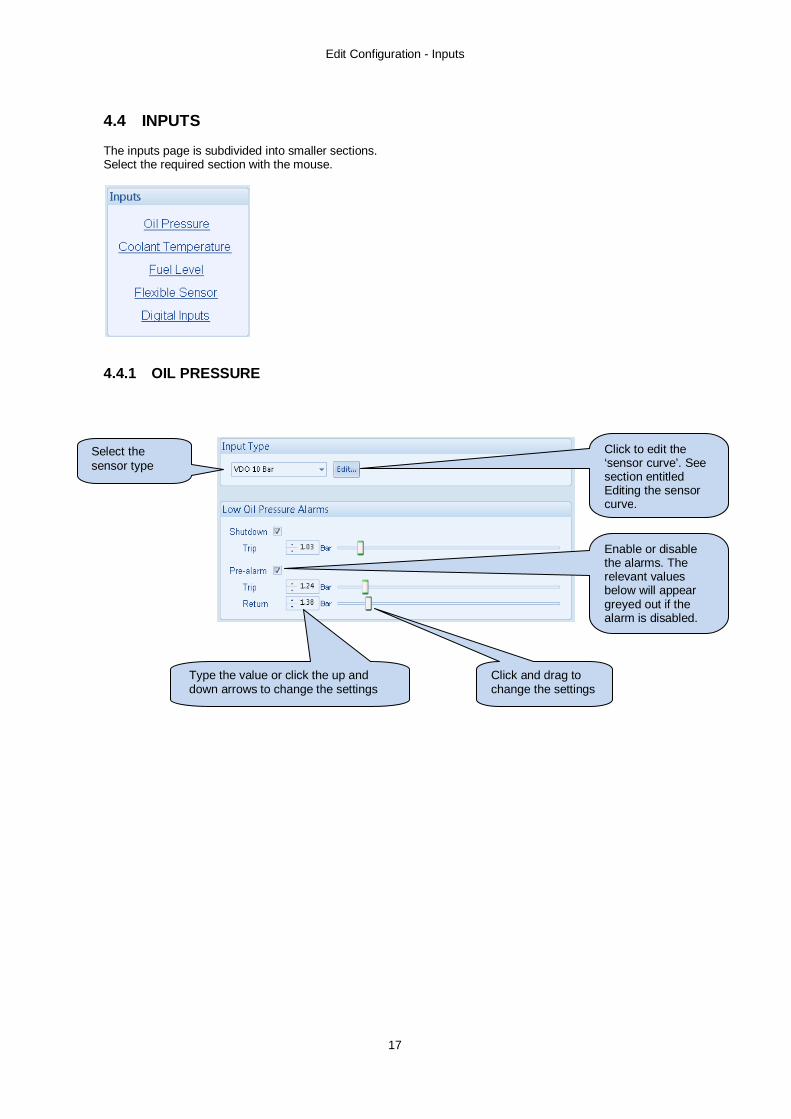
4.4.1 OIL PRESSURE
Click to edit the ‘sensor curve’. See section entitled Editing the sensor curve.
Enable or disable the alarms. The relevant values below will appear greyed out if the alarm is disabled.
Select the sensor type
Click and drag to change the settings
Type the value or click the up and down arrows to change the settings

Edit Configuration - Inputs
18
4.4.2 COOLANT TEMPERATURE
4.4.2.1 COOLANT TEMPERATURE ALARMS
Options Description Pre alarm = Pre-alarm is disabled
= If the temperature exceeds the trip setting, an alarm is generated. The temperature must fall below the return setting to cease the alarm.
Electrical Trip
= Electrical trip is disabled = If the temperature exceeds the trip setting, an alarm is generated, the load switch is opened and the module enters the cooling timer after which the set is stopped.
Shutdown If the temperature exceeds the trip setting, an alarm is generated, the load switch is opened and the set is immediately stopped.
Click to edit the ‘sensor curve’. See section entitled Editing the sensor curve.
Select the sensor type
Click and drag to change the settings Type the value or click the up and
down arrows to change the settings
Enable or disable the alarms. The relevant values below will appear greyed out if the alarm is disabled.

Edit Configuration -Inputs
19
4.4.2.2 COOLANT TEMPERATURE CONTROL The Coolant temperature control settings provide for control of coolant heaters / coolers using the Coolant Temperature Sensor as the control input. Outputs should be configured to Coolant Cooler Control and/or Coolant Heater Control to achieve this.
Coolant temperature control
Coolant heater control
= Coolant Heater Control function is disabled = Coolant Heater Control function is enabled. If the engine coolant temperature falls below the On setting, any output configured to Coolant Heater Control will be energised. This is designed to control an external engine heater. If the coolant temperature rises above the Off setting, the output is de-energised.
Coolant Cooler control
= Coolant Cooler Control function is disabled = Coolant Cooler Control function is enabled. If the engine coolant temperature rises above the On setting, any output configured to Coolant Cooler Control will be energised. This is designed to control an external engine cooling system, for instance an additional cooling fan. If the coolant temperature falls below the On setting, the output is de-energised.
Fan Control An output configured to Fan Control will energise when the engine becomes available (up to speed and volts). This output is designed to control an external cooling fan. When the engine stops, the cooling fan will remain running for the duration of the Fan Overrun Delay.
Enable or disable the alarms. The relevant values below will appear greyed out if the alarm is disabled.
Click and drag to change the settings
Type the value or click the up and down arrows to change the settings
Click and drag to change the settings
Edit Configuration - Inputs
20
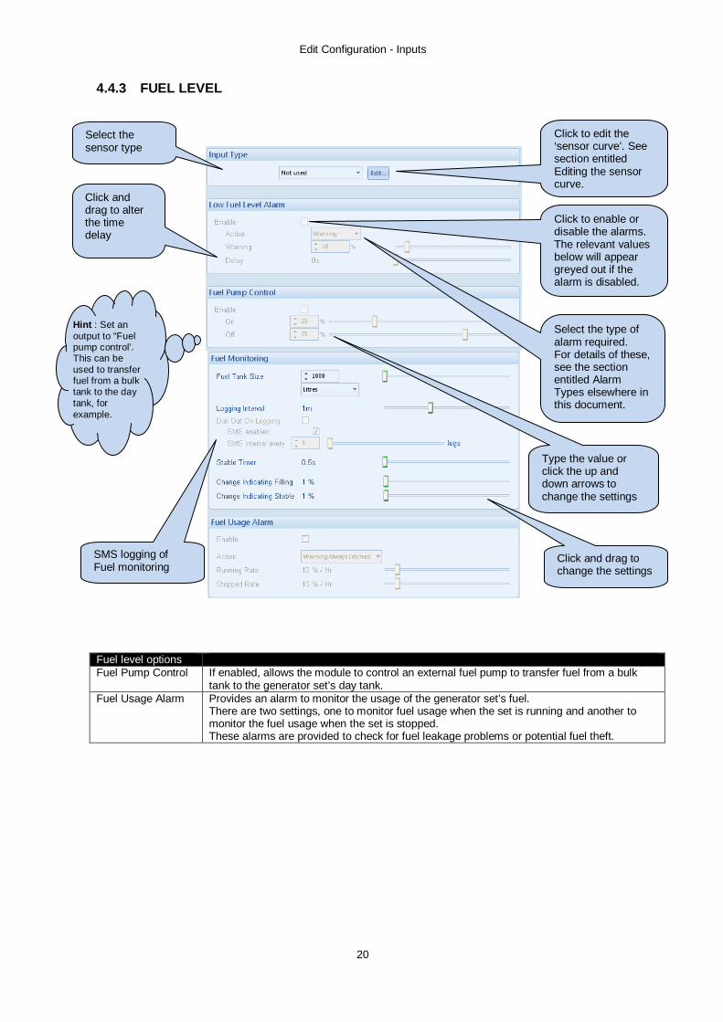
4.4.3 FUEL LEVEL
Fuel level options Fuel Pump Control If enabled, allows the module to control an external fuel pump to transfer fuel from a bulk
tank to the generator set’s day tank. Fuel Usage Alarm Provides an alarm to monitor the usage of the generator set’s fuel.
There are two settings, one to monitor fuel usage when the set is running and another to monitor the fuel usage when the set is stopped. These alarms are provided to check for fuel leakage problems or potential fuel theft.
Click to edit the ‘sensor curve’. See section entitled Editing the sensor curve.
Select the sensor type
Click and drag to change the settings
Type the value or click the up and down arrows to change the settings
Click to enable or disable the alarms. The relevant values below will appear greyed out if the alarm is disabled.
Hint : Set an output to “Fuel pump control’. This can be used to transfer fuel from a bulk tank to the day tank, for example.
Select the type of alarm required. For details of these, see the section entitled Alarm Types elsewhere in this document.
Click and drag to alter the time delay
SMS logging of Fuel monitoring

Edit Configuration -Inputs
21
4.4.4 FLEXIBLE SENSOR The following screen shot shows the configuration when set for Temperature Sensor. When set to other Sensor Type, consult the relevant manual section for details (Digital inputs, Oil Pressure input etc)
Click to edit the ‘sensor curve’. See section entitled Editing the sensor curve.
Select the sensor type
Click and drag to change the settings
Type the value or click the up and down arrows to change the settings
Click to enable or disable the alarms. The relevant values below will appear greyed out if the alarm is disabled.
Type the text you want to appear on the screen when the alarm is triggered.
Select the type of alarm required. For details of these, see the section entitled Alarm Types elsewhere in this document.
Edit Configuration - Inputs
22
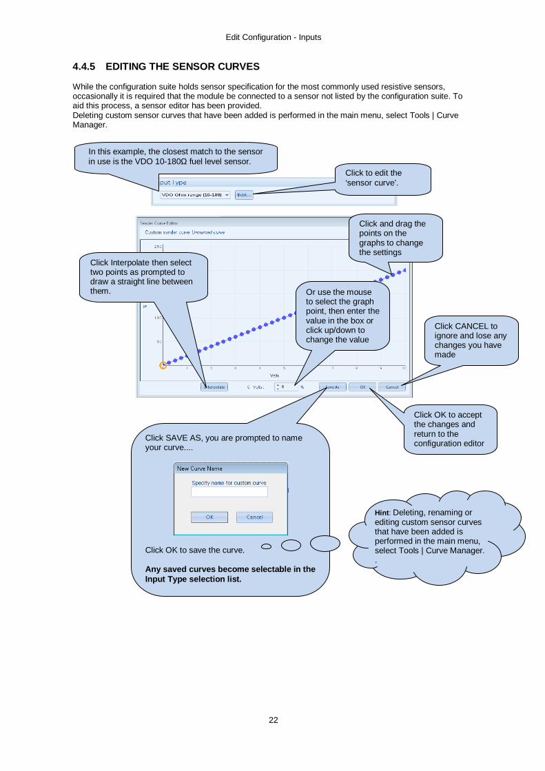
4.4.5 EDITING THE SENSOR CURVES While the configuration suite holds sensor specification for the most commonly used resistive sensors, occasionally it is required that the module be connected to a sensor not listed by the configuration suite. To aid this process, a sensor editor has been provided. Deleting custom sensor curves that have been added is performed in the main menu, select Tools | Curve Manager.
In this example, the closest match to the sensor in use is the VDO 10-180Ω fuel level sensor. Click to edit the
‘sensor curve’.
Click and drag the points on the graphs to change the settings
Or use the mouse to select the graph point, then enter the value in the box or click up/down to change the value
Click OK to accept the changes and return to the configuration editor
Click CANCEL to ignore and lose any changes you have made
Click SAVE AS, you are prompted to name your curve....
Click OK to save the curve. Any saved curves become selectable in the Input Type selection list.
Hint: Deleting, renaming or editing custom sensor curves that have been added is performed in the main menu, select Tools | Curve Manager. .
Click Interpolate then select two points as prompted to draw a straight line between them.

Edit Configuration -Inputs
23
4.4.6 DIGITAL INPUTS The digital inputs page is subdivided into smaller sections. Select the required section with the mouse.
Input function. See section entitled Input functions for details of all available functions
Example of a user configured input
Close or open to activate
Select the type of alarm required. For details of these, see the section entitled Alarm Types elsewhere in this document.
Click and drag to change the setting. This is used to give a delay on acceptance of the input. Useful for liquid level switches or to mask short term operations of the external switch device.
This is the text that will be displayed on the module screen when the alarm is triggered.
Configures when the input is active: Never, always, active from starting, active from the end of the safety timer
As this example shows a predefined function, these parameters are greyed out as they are not applicable

Edit Configuration - Inputs
24
4.4.7 DIGITAL INPUT FUNCTIONS Where a digital input is NOT configured as “user configured”, a selection can be made from a list of predefined functions. The selections are as follows: Under the scope of IEEE 37.2, function numbers can also be used to represent functions in microprocessor devices and software programs. Where the DSE input functions can be represented by IEEE 37.2, the function number is listed below.
NOTE: - Input selection is dependant on controller.
Function Description Air flap closed auxiliary IEEE 37.2 - 3 Checking or interlocking relay
This input is used to connect to the Air flap switch contacts. This will give an immediate shutdown in the event of the air-flap being closed. It will also prevent the generator from being restarted if the air flap has not been reset following an overspeed shutdown.
Alarm Mute This input is used to silence the audible alarm from an external source, such as a remote mute switch.
Alarm Reset This input is used to reset any latched alarms from a remote location. It is also used to clear any latched warnings which may have occurred (if configured) without having to stop the generator.
Alt Config 1-3 Select
These inputs are used to instruct the module to follow one of the alternative configuration settings instead of the main configuration settings.
Auto Restore Inhibit IEEE 37.2 - 3 checking or interlocking relay
In the event of a remote start/mains failure, the generator will be instructed to start and take load. On removal of the remote start signal/mains return the module will continue to run the generator on load until the Auto Restore Inhibit input is removed. This input allows the controller to be fitted as part of a system where the restoration to mains is controlled remotely or by an automated system.
Auto start Inhibit IEEE 37.2 - 3 checking or interlocking relay
This input is used to provide an over-ride function to prevent the controller from starting the generator in the event of a remote start/mains out of limits condition occurring. If this input is active and a remote start signal/mains failure occurs the module will not give a start command to the generator. If this input signal is then removed, the controller will operate as if a remote start/mains failure has occurred, starting and loading the generator. This function can be used to give an ‘AND’ function so that a generator will only be called to start if the mains fails and another condition exists which requires the generator to run. If the ‘Auto start Inhibit’ signal becomes active once more it will be ignored until the module has returned the mains supply on load and shutdown. This input does not prevent starting of the engine in MANUAL or TEST modes.
Auxiliary Mains Fail
The module will monitor the incoming single or three phase supply for Over voltage, Under Voltage, Over Frequency or Under frequency. It may be required to monitor a different mains supply or some aspect of the incoming mains not monitored by the controller. If the devices providing this additional monitoring are connected to operate this input, the controller will operate as if the incoming mains supply has fallen outside of limits, the generator will be instructed to start and take the load. Removal of the input signal will cause the module to act if the mains has returned to within limits providing that the mains sensing also indicates that the mains is within limits.

Edit Configuration -Inputs
25
Function Description Close Generator IEEE 37.2 - 52 AC circuit breaker
Closes the Generator load switch (synchronising first if required)
Coolant Temperature High switch
This input is used to give a Coolant Temperature High shutdown from a digital normally open or closed switch. It allows coolant temperature protection using the switch and the analogue input can be used in parallel to give protection or configured to be used for indication only.
Disable Protections
The system designer provides this switch (not DSE) so its location will vary depending upon manufacturer, however it normally takes the form of a key operated switch to prevent inadvertent activation. Depending upon configuration, a warning alarm may be generated when the switch is operated. When active, and the module is suitably configured (see section entitled ‘Application’) this prevents the engine being stopped upon critical alarm (Sometimes called War Mode or Run to Destruction)
Droop enable
This input is used to switch the engine into droop mode on CAN engines that support this function.
EJP1
For the French EJP (Effacement Jours de Pointe) tarrif system. This input is functionally identical to Remote Start Off Load. If this input is active, operation will be similar to the ‘Remote Start on load’ function except that the generator will not be instructed to take the load. This function can be used where an engine only run is required e.g. for exercise.
EJP2
For the French EJP (Effacement Jours de Pointe) tarrif system. This input is functionally identical to Remote Start On Load. When in auto mode, the module will perform the start sequence and transfer load to the generator. If in Manual mode, the load will be transferred to the generator if the engine is already running, however in manual mode, this input will not generate start/stop requests of the engine. In both cases, synchronising takes place if required.
External Panel Lock This input is used to provide security to the installation. If the External Panel lock input is active, the module will not respond to operation of the Mode select or start buttons. This allows the module to be placed into a specific mode (such as Auto) and then secured. The operation of the module is not affected and the operator will still be able to view the various instrumentation pages etc. (Front panel configuration access is still possible while the system lock is active).
NOTE: - External control sources (i.e. Simulate Start Button) are not affected by the external panel lock input and will continue to operate normally.

Edit Configuration - Inputs
26
Function Description Generator Closed Auxiliary IEEE 37.2 - 3 Checking or interlocking relay
This input is used to provide feedback to allow the DSE7400 to give true indication of the contactor or circuit breaker switching status. It should be connected to the generator load switching device auxiliary contact. Action: Warning (Alarm only, No shutdown)
Generator Load Inhibit IEEE 37.2 - 52 AC circuit breaker
This input is used to prevent the DSE7410/DSE7420 from loading the generator. If the generator is already on load, activating this input will cause the DSE7410/DSE7420 to unload the generator. Removing the input will allow the generator to be loaded again.
NOTE: -This input only operates to control the generator-switching device if the DSE7410/DSE7420 load switching logic is attempting to load the generator. It will not control the generator-switching device when the mains supply is on load.
Inhibit Retransfer To Mains IEEE 37.2 - 3 checking or interlocking relay
When active, this input prevents the load being transferred back to the mains supply, even in the event of the generators failing.
Inhibit Scheduled Run IEEE 37.2 - 3 checking or interlocking relay
This input is used to provide a means of disabling a scheduled run.
Lamp Test This input is used to provide a test facility for the front panel indicators fitted to the DSE8600 module. When the input is activated all LED’s should illuminate.
Low Fuel Level Switch A digital normally open or closed fuel level switch gives this input. It allows fuel level detection using the switch and the analogue input to be used in parallel to give protection or to be used for fuel level indication only.
Main Config Select This input is used to select the Main configuration when Alternative configurations are enabled.
Mains closed Auxiliary IEEE 37.2 - 3 Checking or interlocking relay
This input is used to provide feedback to allow the module to give true indication of the contactor or circuit breaker switching status. It should be connected to the mains load switching device auxiliary contact. Incorrect application of this signal does not trigger an alarm condition, it is used solely for indication of the breaker status.
Mains Load Inhibit IEEE 37.2 - 3 checking or interlocking relay
This input is used to prevent the from loading the mains supply. If the mains supply is already on load activating this input will cause the module to unload the mains supply. Removing the input will allow the mains to be loaded again.
NOTE: -This input only operates to control the mains switching device if the DSE7400 load switching logic is attempting to load the mains. It will not control the mains switching device when the generator is on load.

Edit Configuration -Inputs
27
Function Description Oil Pressure Switch
A digital normally open or closed oil pressure switch gives this input. It allows oil pressure protection using the switch and the analogue input to be used in parallel to give protection or to be used for oil pressure indication only.
Remote Start off load
If this input is active, operation will be similar to the ‘Remote Start on load’ function except that the generator will not be instructed to take the load. This function can be used where an engine only run is required e.g. for exercise.
Remote Start on load When in auto mode, the module will perform the start sequence and transfer load to the generator. In Manual mode, the load will be transferred to the generator if the engine is already running, however in manual mode; this input will not generate start/stop requests of the engine.
Remote Start On Load Demand
If this input is active, the load demand start up and shut down scheme will be activated when two or more generators are running in parallel. On application, all sets will start a race for the bus. The first available set will close onto the dead bus and the others will synchronise to it. Once the sets are on load they will compare load levels and redundant sets will commence a shutdown sequence and return to standby until the load level is such that they are required.
Reset Maintenance Alarm 1-3
These inputs are used to reset the maintenance alarms. When activated it will reset the maintenance counter to the pre-configured value (i.e. 250 hours). If the maintenance alarm is configured to monitor the monthly service interval this will also be reset to the pre-configured period (i.e. 6 Months).
Simulate Auto Button NOTE: - If a call to start is present when AUTO MODE is entered,
the starting sequence will begin. Call to Start can come from a number of sources depending upon module type and configuration and includes (but is not limited to) : Remote start input present, Mains failure, Scheduled run, Auxiliary mains failure input present, Telemetry start signal from remote locations.
This input mimic’s the operation of the ‘Auto’ button and is used to provide a remotely located Auto mode push button.
Simulate Lamp test \ Alarm Mute Button
This input is used to provide a test facility for the front panel indicators fitted to the module. When the input is activated all LED’s should illuminate. The input also serves a second function, in that it also provides a mute signal to silence the audible alarm. The input is recognised by the module as though it was the Push button on the module itself being operated.
Simulate Mains available
This function is provided to override the module’s internal monitoring function. If this input is active, the module will not respond to the state of the incoming AC mains supply.
Simulate Manual Button
This input mimic’s the operation of the ‘Manual’ button and is used to provide a remotely located Manual mode push button.
Simulate Start Button
This input mimic’s the operation of the ‘Start’ button and is used to provide a remotely located start push button.
Simulate Stop Button
This input mimic’s the operation of the ‘Stop’ button and is used to provide a remotely located stop/reset push button.
Simulate Test on load button
This input mimics the operation of the ‘Test’ button and is used to provide a remotely located Test on load mode push button.

Edit Configuration - Inputs
28
Function Description Smoke limit IEEE 37.2 – 18 accelerating or decelerating device
This input instructs the module to give a run at idle speed command to the engine either via an output configured to smoke limit or by data commands when used with supported electronic engines.
Start Pause IEEE 37.2 - 3 checking or interlocking relay
This input is intended to be used to allow the generator start sequence to commence, but not to complete. This feature can be used with Air start engines for example to give a controlled start sequence. The function operates such that if the ‘Start pause’ input is active and an engine start is commanded, the module will perform its start sequence thus: - The pre-heat output (if used) will be activated for the duration of the pre-heat timer. The Fuel output will then be energised and the module will then enter a pause state - ‘Awaiting clear to start’. If the ‘start pause’ signal becomes inactive at this time then the module will continue its normal start sequence. The ‘start pause’ mode uses the ‘manual crank limit’ timer and if this expires during the ‘Awaiting clear to start’ state then a ‘Fail to start’ alarm will be generated and the set shutdown.
Stop and Panel Lock
Combined function input that instructs the module to enter STOP MODE and also perform the Panel Lock function. Once the input is active, the module will not respond to operation of the Mode select or start buttons. The operator will still be able to view the various instrumentation pages etc. (Front panel configuration access is still possible while the system lock is active).

Edit Configuration -Inputs
29
Function Description Transfer to Mains/ Open Generator IEEE 37.2 - 52 AC circuit breaker
This input is used to transfer the load to the mains supply (AMF module) when running in MANUAL MODE or provide the ‘Open Generator’ signal in a non AMF Module.)
Transfer to generator/Open Mains IEEE 37.2 - 52 AC circuit breaker
This input is used to transfer the load to the generator when running in MANUAL MODE On the DSE 7420 module only: Once synchronised the genset and bus/mains will parallel. The second press of the button (or expiry of the parallel run timer) will then cause the genset to take full load and open the mains contactor.
Edit Configuration - Outputs
30
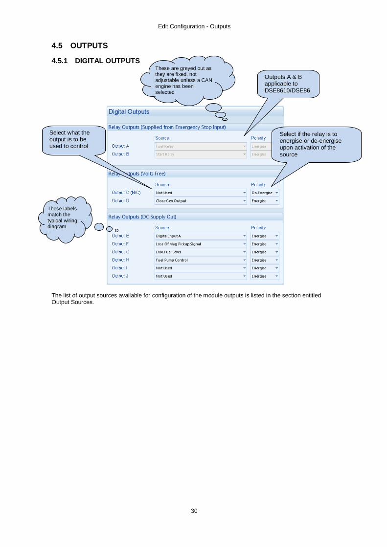
4.5 OUTPUTS 4.5.1 DIGITAL OUTPUTS
The list of output sources available for configuration of the module outputs is listed in the section entitled Output Sources.
Select if the relay is to energise or de-energise upon activation of the source
Select what the output is to be used to control
These labels match the typical wiring diagram
These are greyed out as they are fixed, not adjustable unless a CAN engine has been selected
Outputs A & B applicable to DSE8610/DSE8620 only

Edit Configuration - Outputs
31
4.5.2 VIRTUAL LEDS
The list of output sources available for configuration of the module Virtual LEDs is listed in the section entitled Output Sources.
Allows the configuration of ‘status’ items. These items are not available for viewing on the module itself but can be seen in the SCADA section of the PC software, or read by third party systems (i.e. BMS or PLCs) using the Modbus protocol.

Edit Configuration - Outputs
32
4.5.3 OUTPUT SOURCES The list of output sources available for configuration of the module relay outputs also applies to the LED configuration and expansion relay outputs. Under the scope of IEEE 37.2, function numbers can also be used to represent functions in microprocessor devices and software programs. Where the DSE output functions can be represented by IEEE 37.2, the function number is listed below.
NOTE: - Output selection is dependant on controller. Output source Activates… Is not active….
Not Used The output will not change state (Unused)
Air Flap Alarm This output indicates that the air-flap is closed; to operate it requires an input configured as ‘Air-flap closed’ connected to the external air-flap switch.
Air Flap Relay Normally used to control an air flap, this output becomes active upon an Emergency Stop or Over-speed situation.
Inactive when the set has come to rest
Alternative Config 1-3 selected Indicates which of the three alternative configurations has been selected (if any)
Alarm Mute Indicates that an alarm mute operation is in progress by digital input
Alarm Reset Indicates that an alarm reset operation is in progress by digital input
Arm Safety On Alarms Becomes active at the end of the safety delay timer whereupon all alarms configured to ‘From Safety On’ become active
Inactive when : • When the set is at rest • In the starting sequence before
the Safety Delay timer has expired
Audible Alarm IEEE 37.2 – 74 alarm relay
This output indicates that the internal sounder is operating to allow it to feed an external sounder. Operation of the Mute pushbutton will reset this output once activated.
Inactive if the internal sounder is not operating.
Auto Mode Active when the controller is in AUTO mode Inactive in any other mode.
Auto Start Inhibit IEEE 37.2 – 3 Checking or Interlocking relay
Indicates that an auto start inhibit operation is in progress.
Battery High Voltage IEEE 37.2 – 59DC over voltage relay
This output indicates that a Battery Over voltage alarm has occurred.
Inactive when battery voltage is not High
The outputs are in alphabetical order with the parameter first. For instance for overspeed output, it’s
listed as Engine Overspeed.

Edit Configuration - Outputs
33
Output source Activates… Is not active….
Calling For Scheduled Run Active during a scheduled run request from the inbuilt scheduler.
CAN ECU Data Fail Becomes active when no CAN data is received from the ECU after the safety delay timer has expired
Inactive when: • CAN data is being received • The set is at rest • During the starting sequence before
the safety delay timer has expired CAN ECU Power Used to switch an external relay to power the CAN ECU. Exact timing of this
output is dependent upon the type of the engine ECU CAN ECU Shutdown The engine ECU has indicated that a
Shutdown alarm is present. Inactive when no Shutdown alarm from the ECU is present
CAN ECU Stop Active when the DSE controller is requesting that the CAN ECU stops the engine.
CAN ECU Warning The engine ECU has indicated that a Warning alarm is present.
Inactive when no Warning alarm from the ECU is present
Charge Alternator Failure (Shutdown or warning)
Indicates that there is a charging fault with the auxiliary charging alternator
• When the set is at rest • During the starting sequence before
the safety delay timer has expired Close Gen Output IEEE 37.2 – 52 ac circuit breaker
Used to control the load switching device. Whenever the 8600 module selects the generator to be on load this control source will be active.
Inactive whenever the generator is not required to be on load
Close Gen Output Pulse IEEE 37.2 – 52 ac circuit breaker
Used to control the load switching device. Whenever the DSE7400 module selects the generator to be on load this control source will be active for the duration of the Breaker Close Pulse timer, after which it will become inactive again.
Close Mains Output IEEE 37.2 – 52 ac circuit breaker
Used to control the load switching device. Whenever the DSE7400 module selects the mains to be on load this control source will be active.
The output is inactive whenever the mains is not required to be on load
Close Mains Output Pulse IEEE 37.2 – 52 ac circuit breaker
Used to control the load switching device. Whenever the DSE7400 module selects the mains to be on load this control source will be active for the duration of the Breaker Close Pulse timer, after which it will become inactive again.
Closed to mains state Used to be active when the status of the mains breaker is closed.
Combined Mains Failure
Active when the mains supply is out of limits OR the input for Auxiliary Mains Failure is active
Combined Maintenance alarm Indicates that one of the maintenance alarms is active
Combined Remote Start Output Indicates that a remote start input is active.
Combined Under and Over frequency shutdown IEEE 37.2 - 81 frequency relay
Active when the generator is shutdown due to either under OR over frequency
Combined Under and Over frequency warning IEEE 37.2 - 81 frequency relay
Active when the generator alarm for either under OR over frequency is active

Edit Configuration - Outputs
34
Output source Activates… Is not active….
Combined Under and Overvoltage shutdown IEEE 37.2 – 27AC under voltage relay IEEE 37.2 – 59AC over voltage relay
Active when the generator is shutdown due to either under OR overvoltage
Combined Under and Overvoltage warning IEEE 37.2 – 27AC under voltage relay IEEE 37.2 – 59AC over voltage relay
Active when the generator alarm for either under OR overvoltage is active
Common Alarm IEEE 37.2 – 74 alarm relay
Active when one or more alarms (of any type) are active
The output is inactive when no alarms are present
Common Electrical Trip IEEE 37.2 – 74 alarm relay
Active when one or more Electrical trip alarms are active
The output is inactive when no electrical alarms are present
Common Shutdown IEEE 37.2 – 74 alarm relay
Active when one or more Shutdown alarms are active
The output is inactive when no shutdown alarms are present
Common Warning IEEE 37.2 – 74 alarm relay
Active when one or more Warning alarms are active
The output is inactive when no warning alarms are present
Coolant Cooler Control IEEE 37.2 – 23 temperature control device
Activated by the Coolant Cooler Control in conjunction with the Coolant Temperature Sensor.
Coolant Heater Control IEEE 37.2 – 23 temperature control device
Activated by the Coolant Heater Control in conjunction with the Coolant Temperature Sensor.
Cooling Down Active when the Cooling timer is in progress The output is inactive at all other times
Digital Input A - K Active when the digital input is active Inactive when : • If the input is not active • If the input is active but
conditioned by activation delay, safety timer or Arming requirements.
Dummy Load Control (1-5) Becomes active when the engine kW falls below the Dummy Load Control Trip Setting.
Inactive when the engine kW returns to above the Dummy Load Control Return setting.
Droop Enable Becomes active when an input configured to Droop enable is active or if Droop Enable has been activated in the module configuration (CAN engine only)
Earth Fault Trip alarm IEEE 37.2 – 71 level switch
Indicates that an earth fault alarm is active.
EJP1 / EJP2 Indicates that an input configured to EJP1 or EJP2 is active
Emergency Stop IEEE 37.2 – 86 lockout relay
Active when the Emergency Stop input has been activated
Energise to Stop Normally used to control an Energise to Stop solenoid, this output becomes active when the controller wants the set to stop running.
Becomes inactive a configurable amount of time after the set has stopped. This is the ETS hold time.
Fail to Stop IEEE 37.2 - 48 Incomplete Sequence Relay
If the set is still running a configurable amount of time after it has been given the stop command, the output will become active. This is the Fail to stop timer.
Fail to Start IEEE 37.2 - 48 Incomplete Sequence Relay
Becomes active if the set is not seen to be running after the configurable number of start attempts.
Fan Control Energises when the engine becomes available (up to speed and volts). This output is designed to control an external cooling fan. When the engine stops, the cooling fan will remain running for the duration of the Fan Overrun Delay.
Flexible Sensor x (pre) alarm Indicates that the respective flexible sensor alarm is active.
Fuel Pump Control IEEE 37.2 – 71 level switch
Becomes active when the Fuel level falls below the Fuel Pump Control ON setting and is normally used to transfer fuel from the bulk tank to the day tank.
If the output is already active it will become inactive when the Fuel level is above the Fuel Pump Control OFF settings.

Edit Configuration - Outputs
35
Output source Activates… Is not active….
Fuel Relay Becomes active when the controller requires the governor/fuel system to be active.
Becomes inactive whenever the set should be stopped, including between crank attempts, upon controlled stops and upon fault shutdowns.
Fuel Usage Alarm Becomes active when the amount of fuel used over a set time period exceeds the set value.
Gas Choke On Becomes active during starting for the duration of the Gas Choke timer. Normally used to choke a gas engine.
Inactive at all other times
Gas Ignition Becomes active during starting.
Becomes inactive a configurable amount of time after the fuel relay becomes inactive. This is the Gas ignition off timer.
Generator at Rest
This output indicates that the generator is not running.
Generator Available Becomes active when the generator is available to take load.
Inactive when • Loading voltage and loading
frequency have not been reached • After electrical trip alarm • During the starting sequence
before the end of the warming timer.
Generator Closed Aux Active when the Generator closed auxiliary input is active
Generator Excite IEEE 37.2 – 31 separate excitation device
Used to control the excitation of the main alternator (AC).
Becomes inactive when the set is stopped.
Generator Failed to Close IEEE 37.2 - 48 Incomplete Sequence Relay
This output source is intended to be used to indicate a failure of the generator contactor or breaker. It can only be used if the module is configured to use ‘Generator Closed Auxiliary’ feedback.
Generator Failed to Open IEEE 37.2 - 48 Incomplete Sequence Relay
This output source is intended to be used to indicate a failure of the generator contactor or breaker. It can only be used if the module is configured to use ‘Generator Closed Auxiliary’ feedback.
Generator Load Inhibit This output indicates that a digital input that has been configured as ‘Generator Load Inhibit’ is active. Refer to the ‘Edit Inputs’ section of this manual for details.
Generator High Voltage Shutdown IEEE 37.2 – 59AC over voltage relay
Active when the generator voltage exceeds the High Voltage Shutdown setting
Generator High Voltage Warning IEEE 37.2 – 59AC over voltage relay
Active when the generator voltage exceeds the High Voltage Warning setting
Generator Low Voltage Shutdown IEEE 37.2 – 27AC under voltage relay
Active when the generator voltage falls below the Low Voltage Shutdown
Inactive when • The set is stopped • During starting sequence before
the safety delay time has expired. Generator Low Voltage Alarm IEEE 37.2 – 27AC under voltage relay
Active when the generator voltage falls below the Low Voltage Warning setting
Inactive when • The set is stopped • During starting sequence before
the safety delay time has expired. Generator Under Frequency Warning(Alarm) / Shutdown IEEE 37.2 – 81 frequency relay
Active when the generator falls below the low frequency Warning/ Shutdown setting
Inactive when • The set is stopped During starting sequence before the safety delay time has expired.
Generator Over Frequency Warning(Alarm) / Shutdown
Active when the generator rises above the high frequency Warning/ Shutdown setting
Inactive when • The set is stopped During starting sequence before the safety delay time has expired.
Generator Phase Rotation Alarm This output indicates that the module has detected a phase sequence error from the generator output.
Generator Reverse Power This output indicates that a Generator Reverse Power alarm has occurred. Generator Stopping This output source indicates that the engine has been instructed to stop but
has not yet come to rest. Once the engine comes to a standstill this output will become in-active.
High Coolant Temperature Shutdown
Active when the Coolant Temperature exceeds the High Coolant Temperature Shutdown setting
High Coolant Temperature Warning
Active when the Coolant Temperature exceeds the High Coolant Temperature Warning setting
High Inlet Temperature Shutdown Active when the Inlet Temperature exceeds the High Inlet Temperature Shutdown setting
High Inlet Temperature Warning Active when the Inlet Temperature exceeds the High Inlet Temperature Warning setting

Edit Configuration - Outputs
36
Output source Activates… Is not active….
Inhibit Retransfer to Mains Indicates when mains fails,Gens fails and mains not enough capacity to take load inhibit retransfer.
Interlock Override Comes on just before and just after the gen-set goes into parallel enabling an output for a mechanical or electrical interlock
kW Overload Shutdown / Electrical Trip
Active when the measured kW are above the setting of the kW overload shutdown / electrical trip alarm. Can be used to give alarms on overload, control a dummy load breaker or for load shedding functionality.
kW Overload Warning
Active when the measured kW are above the setting of the kW overload warning alarm. Can be used to give alarms on overload, control a dummy load breaker or for load shedding functionality.
Lamp test This output indicates that the module is performing a lamp test. Once the lamp test is completed, the output will become inactive again. The output can be used to feed a lamp test on external modules or panel lamps.
Loading Frequency Not Reached Indicates that the generator frequency has not reached the configured loading frequency during the starting process.
Loading Voltage Not Reached Indicates that the generator voltage has not reached the configured loading voltage during the starting process.
Load Shedding Control (1-5) Becomes active when the engine kW exceeds Load Shedding Control Trip Setting.
Inactive when the engine kW returns to below the Load Shedding Control Return setting.
Loss of Mag Pickup Signal Active when the controller senses the loss of signal from the magnetic pickup probe
Louvre Control Normally used to drive ventilation louvres for the generator set, this output becomes active when the fuel relay becomes active
Inactive when the fuel relay becomes inactive.
Low Coolant Temperature Active when the Coolant Temperature falls below the Low Coolant Temperature alarm setting
Low Fuel Level IEEE 37.2 – 71 level switch
Active when the Fuel Level falls below the Fuel Level Low setting
Low Oil Pressure Shutdown IEEE 37.2 - 63 pressure switch
Active when the Oil Pressure falls below the Low Oil Pressure Shutdown setting
Inactive when • The set is stopped • During starting sequence before the
safety delay time has expired. Low Oil Pressure Warning IEEE 37.2 - 63 pressure switch
Active when the Oil Pressure falls below the Low Oil Pressure Warning setting
Inactive when • The set is stopped • During starting sequence before the
safety delay time has expired. Low Load Indicates that the stopping sequence is beginning due to low load levels.
(Load Demand Scheme) MPU open circuit
This output indicates that the module has detected an open circuit failure in the Magnetic Pickup transducer circuit.
Main Config Selected Indicates that the main configuration fail has been selected
Mains Closed Aux Active when the Mains closed auxiliary input is active
Mains Decoupling High Frequency This output indicates that the mains decoupling high frequency alarm has been triggered.
Mains Decoupling High Voltage This output indicates that the mains decoupling high voltage alarm has been triggered.
Mains Decoupling Low Frequency This output indicates that the mains decoupling low frequency alarm has been triggered.
Mains Decoupling Low Voltage This output indicates that the mains decoupling low voltage alarm has been triggered.
Mains failed to close This output indicates the mains breaker failed to close Mains failed to open This output indicates the mains breaker failed to open Mains Failure IEEE 37.2 - 81 frequency relay IEEE 37.2 – 27AC under voltage relay IEEE 37.2 – 59AC over voltage relay
The output indicates that one or more of the module’s sources of determining mains failure is active. The output is inactive when the mains supply is healthy
Mains Over Frequency IEEE 37.2 - 81 frequency relay
Active when the mains frequency exceeds the High Frequency setting
Mains Over Voltage IEEE 37.2 – 59AC overvoltage relay
Active when the mains voltage exceeds the High Voltage setting
Mains Under Frequency IEEE 37.2 - 81 frequency relay
Active when the mains frequency falls below the Low Frequency setting
Mains Under Voltage IEEE 37.2 – 27AC under voltage relay
Active when the mains voltage falls below the Low Voltage setting

Edit Configuration - Outputs
37
Output source Activates… Is not active….
Maintenance Alarm 1,2,3 Due Indicates that the specified maintenance alarm is due
Manual Mode Active when the controller is in MANUAL mode
Inactive in any other mode.
Mute / Lamp test button pressed This output indicates that the alarm mute / Lamp test pushbutton is being operated. Once the button is released, the output will become inactive.
Negative Phase Sequence Alarm IEEE 37.2 - 46 phase balance current relay
Active when the Negative Phase Sequence alarm is active
Oil Pressure Sensor Open Circuit Active when the Oil Pressure Sensor is detected as being open circuit.
Open Gen Output IEEE 37.2 – 52 ac circuit breaker
Used to control the load switching device. Whenever the module selects the generator to be off load this control source will be active.
Inactive whenever the generator is required to be on load
Open Gen Output Pulse IEEE 37.2 – 52 ac circuit breaker
Used to control the load switching device. Whenever the module selects the generator to be off load this control source will be active for the duration of the Breaker Open Pulse timer, after which it will become inactive again.
Open Mains IEEE 37.2 – 52 ac circuit breaker
Used to control the load switching device. Whenever the module selects the mains to be off load this control source will be active.
The output is inactive whenever the mains is required to be on load
Open Mains Pulse IEEE 37.2 – 52 ac circuit breaker
Used to control the load switching device. Whenever the module selects the mains to be off load this control source will be active for the duration of the Breaker Open Pulse timer, after which it will become inactive again.
Over Current IDMT Alarm IEEE 37.2 – 51 ac time overcurrent relay
Active when an overcurrent condition has caused the Overcurrent IDMT alarm to trigger
Over Current Immediate Warning IEEE 37.2 – 50 instantaneous overcurrent relay
Active when an overcurrent condition exceeds the Overcurrent alarm Trip setting. At the same time, the controller begins following the IDMT curve. If the overload condition exists for an excess time, the Overcurrent IDMT alarm will activate.
Generator Over Frequency Warning IEEE 37.2 - 81 frequency relay
Active when the generator frequency exceeds the High Frequency Warning setting
Generator Over Frequency Shutdown IEEE 37.2 - 81 frequency relay
Active when the generator frequency exceeds the High Frequency Shutdown setting

Edit Configuration - Outputs
38
Output source Activates… Is not active….
Over Speed Shutdown IEEE 37.2 – 12 over speed device
Active if the engine speed exceeds the Over Speed Shutdown setting
Over Speed Warning IEEE 37.2 – 12 over speed device
Active if the engine speed exceeds the Over Speed Warning setting
Panel locked This output indicates that the module ‘Panel Lock’ is active. If the Panel lock input is active, the module will not respond to operation of the Mode select or start buttons. This allows the module to be placed into a specific mode (such as Auto) and then secured. The operation of the module is not affected and the operator will still be able to view the various instrumentation pages etc. (Front panel configuration access is barred while system lock is active).
Panel lock by digital input This output indicates that a digital input that has been configured as ‘Panel Lock’ is active. If the Panel lock input is active, the module will not respond to operation of the Mode select or start buttons. This allows the module to be placed into a specific mode (such as Auto) and then secured. The operation of the module is not affected and the operator will still be able to view the various instrumentation pages etc. (Front panel configuration access is barred while system lock is active). Refer to the ‘Edit Inputs’ section of this manual for details.
Panel lock by telemetry This output indicates that remote ‘Panel Lock’ via telemetry is active. If the Panel lock is active, the module will not respond to operation of the Mode select or start buttons. This allows the module to be controller remotely without local interference. The operation of the module is not affected and the local operator will still be able to view the various instrumentation pages etc. (Front panel configuration access is barred while system lock is active).
PLC Output Flag 1-20 A Series of user configured flags that can be used by the PLC to control / drive internal and external functions
Preheat During Preheat Timer Becomes active when the preheat timer begins. Normally used to control the engine preheat glow-plugs.
Inactive when : • The set is stopped • The preheat timer has expired
Preheat Until End Of Cranking Becomes active when the preheat timer begins. Normally used to control the engine preheat glow-plugs.
Inactive when : • The set is stopped • The set has reached crank
disconnect conditions Preheat Mode Until End Of Safety Timer
Becomes active when the preheat timer begins. Normally used to control the engine preheat glow-plugs.
Inactive when : • The set is stopped • The set has reached the end of the
safety delay timer Preheat Mode Until End Of Warming Timer
Becomes active when the preheat timer begins. Normally used to control the engine preheat glow-plugs.
Inactive when : • The set is stopped • The set has reached the end of the
warming timer Protections Disabled Indicates the protection system of the module has been disabled by configuration or by
digital input configured to perform this disabling function. Remote Control 1-10
A series of output sources that can be controlled by remote control in the SCADA section of the software. They can be used to control external circuits or can be used in the control logic section of the configuration suite.
Remote Start In Island Mode This output indicates that a digital input that has been configured as ‘Remote Start in island mode’ is active. This output could be used to pass the start signal on to elsewhere in the control system.
Remote Start Off Load
This output indicates that a digital input that has been configured as ‘Remote Start off load’ is active. This output could be used to pass the remote start signal on to elsewhere in the control system.
Remote Start On Load This output indicates that a digital input that has been configured as ‘Remote Start on load’ is active. This output could be used to pass the remote start signal on to elsewhere in the control system.

Edit Configuration - Outputs
39
Output source Activates… Is not active….
Return delay in progress This output source will be active to indicate that the return timer is running. Short Circuit Generator
This output indicates that the module has detected a short circuit on the generator output.
Shutdown Blocked Indicates that a Shutdown type alarm is active but that the shutdown function has been blocked because the Protections Disabled function is active.
Smoke Limiting Becomes active when the controller requests that the engine runs at idle speed. As an output, this can be used to give a signal to the Idle input of an engine speed governor (if available)
Becomes inactive when the controller requests that the engine runs at rated speed.
Start Delay in Progress This output source will be active to indicate that the module’s internal start delay timer is running. Once this timer expires the module with initiate its start sequence.
Start Relay IEEE 37.2 – 54 turning gear engaging device
Active when the controller requires the cranking of the engine.
Starting Alarm
This output is used to supply an external sounder with a signal that the engine is about to start. The output will be active AFTER the start delay time, during the pre heat delay (if used) and will continue until the set starts.
Starting alarms armed
This output indicates that the starting alarms are now enabled. It can be used to control external logic circuitry. Starting alarms are armed as soon as the module commences starting of the engine and remain armed until the engine is at rest.
Stop Button Pressed This output indicates that the stop pushbutton is being operated. Once the button is released, the output will become inactive.
Stop Mode Active when the controller is in STOP mode
Inactive in any other mode.
System healthy This output indicates that the module is in Auto mode and there are no alarms present.
Telemetry Active (Relay) Active when the communication port is live and for a short time after transmission stops. Can be used as a relay or LED source.
Telemetry Data Active (LED) Active when data is being transmitted. This output will change continuously state (flash) upon data transfer. Normally used as an LED source rather than a relay source as this source will flash repeatedly. For a similar source more suited to drive a relay, see Telemetry Active.
Test Mode
Active when the controller is in TEST mode Inactive in any other mode.

Edit Configuration - Outputs
40
Output source Activates… Is not active….
Under Frequency Warning IEEE 37.2 - 81 frequency relay
Active when the generator frequency falls below the Low Frequency Warning
Inactive when • The set is stopped • During starting sequence before
the safety delay time has expired. Under Frequency Shutdown IEEE 37.2 - 81 frequency relay
Active when the generator frequency falls below the Low Frequency Shutdown
Inactive when • The set is stopped • During starting sequence before
the safety delay time has expired. Under Speed Shutdown IEEE 37.2 - 14 under speed relay
Active when the engine speed falls below the Under speed Shutdown setting
Under Speed Warning IEEE 37.2 - 14 under speed relay
Active when the engine speed falls below the Under speed Warning setting
User Defined Control 1-3 active Indicates that the specified User Defined Control (Control Logic) is active
Waiting for generator
This output indicates that the engine has been instructed to start but has not yet become available. Once the generator becomes available this output will become in-active. (Available = Generator Frequency and Voltage levels are above the ‘Loading’ levels set in the configuration)
Waiting for Manual Restore IEEE 37.2 – 3 Checking or Interlocking relay
Becomes active when the generator is on load and the mains supply is healthy but an input configured to Manual Restore is active. This can be used to signal to an operator that action is required before the set can transfer back to the mains supply.

Edit Configuration - Timers
41
4.6 TIMERS
Many timers are associated with alarms. Where this occurs, the timer for the alarm is located on the same page as the alarm setting. Timers not associated with an alarm are located on the timers page. The Timers page is subdivided into smaller sections. Select the required section with the mouse.
4.6.1 START TIMERS
Timer Description
Remote Start Off Load Used to give a delay before starting in AUTO mode. This timer is activated upon the respective start command being issued. Typically this timer is applied to prevent starting upon fleeting remote start signals or short term mains failures.
Remote Start On Load Mains fail Telemetry Start
Mains Transient Delay
Used to delay the detection of mains failure. This is normally used to prevent short term transients or brownout conditions from being classified as a Mains Failure and opening the breaker.
Parameters detailed overleaf...
Click and drag to change the setting. Timers increment in steps of 1 second up to one minute, then in steps of 30 seconds up to 30 minutes, then in steps of 30 minutes thereafter (where allowed by the limits of the timer).

Edit Configuration - Timers
42
Timer Description
Pre-heat Give a ‘pre start’ time during which the Preheat output and Starting alarm will become active (if configured)
Pre-heat bypass Should the set be stopped, the Pre-heat bypass timer begins. Should the set be called to start again, before the timer expires, the pre-heat sequence is bypassed as heating is not required since the set is still warm after the last run.
Cranking time The length of each crank attempt
Crank rest time The time between multiple crank attempts.
Engage Attempt time
(Only available if using Magnetic pick-up and multiple engage attempts) This timer dictates the duration that the module will attempt to engage the starter motor during each engage attempt. If the Magnetic Pick-up is not detecting movement of the flywheel when this timer expires, the engage attempt will terminate. Once all engage attempts have been made, the next start attempt begins.
Engage Rest Time
(Only available if using Magnetic pick-up and multiple engage attempts) This timer dictates the duration that the module will wait between attempts to engage to starter.
Delay Crank
(Only available if using Magnetic pick-up and multiple engage attempts) This is the difference in time when the fuel relay energises and the crank relay energises.
Smoke limit The amount of time that the engine will be requested to run at idle speed upon starting. This is typically used to limit emissions at start up.
Smoke limit off This should be set to a little longer than the amount of time that the set takes to run up to rated speed after removal of the command to run at idle speed. If this time is too short, the set could be stopped due to under speed failure. If the time is too long, under speed protection is disabled until the Smoke limit time off time has expired.
Safety on delay The amount of time at start up that the controller will ignore oil pressure, engine speed, alternator voltage and other delayed alarms. This is used to allow the engine to run up to speed before protections are activated.
Warming up time The amount of time that the set will run BEFORE being allowed to take load. This is used to warm the engine to prevent excessive wear.
Sensor fail delay
(Only available if using Magnetic pick-up) This is only used if magnetic pick speed sensing is selected. Once cranking has commenced the module must receive a speed signal within this time. If no signal is present, the generator will be shutdown and a Loss of Speed Sensing alarm given.

Edit Configuration - Timers
43
4.6.2 LOAD / STOPPING TIMERS
Timer Description
Transfer time/ Load Delay
This timer has two functions 1: The time between the mains load switch being opened and the generator load switch being closed (and vice versa). 2. The time between the Load Shed Control outputs (if configured) being energised and the generator being placed on load (at start up).
Breaker close pulse The amount of time that Breaker Close Pulse signals will be present when the request to close a breaker is given.
Breaker Trip pulse The amount of time that Breaker Open Pulse signals will be present when the request to open a breaker is given.
Return delay A delay, used in auto mode only, that allows for short term removal of the request to stop the set before action is taken. This is usually used to ensure the set remains on load before accepting that the start request has been removed.
Cooling time The amount of time that the set will be made to run OFF LOAD before being stopped. This is to allow the set to cool down and is particularly important for engines with turbo chargers.
ETS Solenoid hold The amount of time the Energise to stop solenoid will be kept energised after the engine has come to rest. This is used to ensure the set has fully stopped before removal of the stop solenoid control signal.
Fail to stop delay If the set is called to stop and is still running after the fail to stop delay, a Fail to Stop alarm is generated.
Generator transient delay
Used to delay the generator under/over volts/frequency alarms. Typically this is used to prevent spurious shutdown alarms caused by large changes in load levels.
4.6.3 MODULE TIMERS
Timer Description
LCD Page timer If the module is left unattended for the duration of the LCD Page Timer it will revert to show the Status page.
LCD Scroll Timer The scroll time between parameters on a selected page
Click and drag to change the setting. Timers increment in steps of 1second up to one minute, then in steps of 30 seconds up to 30 minutes, then in steps of 30 minutes thereafter (where allowed by the limits of the timer).

Edit Configuration - Generator
44
4.7 GENERATOR The generator page is subdivided into smaller sections. Select the required section with the mouse.
4.7.1 GENERATOR OPTIONS
These parameters are described overleaf...
Click to enable or disable the feature. The relevant values below appear greyed out if the alarm is disabled.
If there is no input configured to Generator Closed Auxiliary this option is greyed out
Click to enable or disable the alarms. The relevant values below appear greyed out if the alarm is disabled.
Select your AC system. A schematic is shown below with connection details from the alternator to the module.

Edit Configuration - Generator
45
Parameter Description
Alternator fitted = There is no alternator in the system, it is an engine only application = An alternator is fitted to the engine, it is a generator application.
Poles The number of poles on the alternator
VT Fitted = The voltage sensing to the controller is direct from the alternator = The voltage sensing to the controller is via Voltage Transformers (VTs or PTs) This is used to step down the generated voltage to be within the controller voltage specification. By entering the Primary and Secondary voltages of the transformer, the controller will display the Primary voltage rather than the actual measured voltage. This is typically used to interface the DSE module to high voltage systems (ie 11kV) but can also be used on systems such as 600V ph-ph.
4.7.1.1 GENERATOR BREAKER CONTROL Parameter Description
Generator Breaker Alarm
= Generator fail to open/fail to close alarm is disabled = If the generator breaker does not open/close, within the time alarm an alarm is raised.
4.7.1.2 GENERATOR PHASE ROTATION Parameter Description
Generator Phase Rotation IEEE 37.2 – 47 phase sequence relay
= Generator phase rotation is not checked. = An electrical trip alarm is generated if the phase rotation is not as configured.
4.7.1.3 GENERATOR RATING The Generator kW and kVAr rating must be correctly set. The values you set here are the kW and kVAr, NOT the kVA or Power Factor! These values are used for many functions including Generator Power functions and Load Share functions. Calculating the VAr rating of a genset
• Most generators are rated for a power factor (W \ VA) of 0.8 • From Pythagoras :
Cos Φ = W / VA Cos Φ = 0.8
Φ = Cos-1 0.8 = 36.87° • From this we can calculate the VAr rating of the typical 0.8 pf rated generator as :
Tan Φ = VAr / W VAr = Tan 36.87 x W VAr = 0.75 x W
• Or to simplify this, the VAr rating of a 0.8 pf rated generator is ¾ of the W rating (kVAr rating = 75% of kW rating)

Edit Configuration - Generator
46
4.7.2 GENERATOR VOLTAGE ALARMS
Alarm IEEE designation Generator Under voltage IEEE 37.2 - 27AC Under voltage relay
Generator Over voltage IEEE 37.2 - 59AC Over voltage relay
Click to enable or disable the alarms. The relevant values below appear greyed out if the alarm is disabled.
Click and drag to change the setting.
Type the value or click the up and down arrows to change the settings
Click to enable alarm upon failure tor reach loading voltage.
Select the type of alarm required. For details of these, see the section entitled Alarm Types elsewhere in this document.

Edit Configuration - Generator
47
4.7.3 GENERATOR FREQUENCY ALARMS
Alarm IEEE designation Generator Under Frequency IEEE 37.2 -81 Frequency relay
Generator Over Frequency IEEE 37.2 -81 Frequency relay
Click to enable or disable the alarms. The relevant values below appear greyed out if the alarm is disabled.
Click and drag to change the setting.
Type the value or click the up and down arrows to change the settings
Over frequency Shutdown can only be disabled if another method of speed protection is available (i.e. CAN or Magnetic Pickup). Hence the checkbox is greyed out
Click to enable alarm upon failure tor reach loading frequency

Edit Configuration - Generator
48
4.7.4 GENERATOR CURRENT The Generator Current page is subdivided into smaller sections. Select the required section with the mouse.
4.7.4.1 GENERATOR CURRENT OPTIONS
Timer Description
CT Primary Primary rating of the Current Transformers CT Secondary Secondary rating of the Current Transformers CT Location Determine the location of the Current Transformers
Gen: The CTs are in the feed from the generator and shows only generator current and power Load: The CTs are in the common feed to the load. The module displays load current and power, provided by the mains supply or the generator.
Full Load Rating Full load rating (100% rating) of the generator Earth CT Primary Primary rating of the Current Transformer used for earth fault (optional)
Where No Earth Fault CT is fitted, ensure the Earth Fault Alarm is disabled and the CT common is wired correctly.

Edit Configuration - Generator
49
4.7.4.2 GENERATOR CURRENT ALARMS
Parameters detailed overleaf....
Click to enable or disable the option. The relevant values below appear greyed out if the alarm is disabled.
Click and drag to change the setting.
Often called Negative Sequence Current, this checks that the alternator is not loaded ‘out of balance’ with one phase loaded excessively more than another.

Edit Configuration - Generator
50
GENERATOR OverCURRENT ALARM Overcurrent Alarm The overcurrent alarm combines a simple warning trip level combined with a fully functioning IDMT curve for thermal protection. Immediate warning IEEE 37.2 -50 instantaneous overcurrent relay If the current exceeds the Trip level the Immediate Warning activates. IDMT Alarm IEEE 37.2 -51 AC time overcurrent relay (shutdown / electrical trip)
If the IDMT Alarm is enabled, the 7400 Series controller begins following the IDMT ‘curve’. If the Trip is surpassed for an excess amount of time the IDMT Alarm triggers (Shutdown or Electric trip as selected in Action).
The higher the overload, the faster the trip. The speed of the trip is dependent upon the fixed formula:
T = t / ((IA / I T) – 1) 2
Where: T is the tripping time in seconds
IA is the actual current of the most highly loaded line (L1 or L2 or L3) IT is the delayed over-current trip point t is the time multiplier setting and also represents the tripping time in seconds at twice full load (when IA / IT = 2).
Typical settings for the IDMT Alarm when used on a brushless alternator are:
These settings provide for normal running of the generator up to 100% full load. If full load is surpassed, the Immediate Warning alarm is triggered, the set continues to run. The effect of an overload on the generator is that the alternator windings begin to overheat; the aim of the IDMT alarm is to prevent the windings being overload (heated) too much. The amount of time that the set can be safely overloaded is governed by how high the overload condition is. See overleaf for details of the IDMT alarm factory settings and examples of different settings for the Time Multiplier (t). The IDMT alarm factory settings, allows for overload of the set to the limits of the Typical Brushless Alternator whereby 110% overload is permitted for 1 hour. If the set load is reduced, the controller then follows a cooling curve. This means that a second overload condition may trip much sooner than the first as the controller knows if the windings have not cooled sufficiently. For further details on the Thermal damage curve of your alternator, you are referred to your alternator manufacturer.
IT (Trip setting value)
t (time multiplier)

Edit Configuration - Generator
51
Factory setting
(Tim
e Multiplier = 36
‘Fastest’ trip setting
(Tim
e Multiplier = 1
Slow
er than Factory setting
(Tim
e Multiplier = 72
Faster than F
actory setting (T
ime M
ultiplier = 18

Edit Configuration - Generator
52
Creating an Excel spreadsheet of the IDMT curve.
The formula used: T = t / ( ( IA / I T ) – 1 ) 2
Can be simplified for addition into a spreadsheet. This can be useful for ‘trying out’ differering values of t (Time Multiplier) and viewing the results, without actually testing this on the engine.
The formula for the Tripping Time cells is:
(IA / I T)
Multiple of the Trip setting
(from 1.01 to 3.0 in steps of 0.1)
t – Time Multiplier
Factory setting is 36
T – Tripping time (seconds)

Edit Configuration - Generator
53
4.7.4.3 SHORT CIRCUIT IEEE 37.2 -51 AC time overcurrent relay (shutdown / electrical trip) For overload conditions caused by a short circuit, the overcurrent alarm is not fast enough to protect the system. The Short Circuit alarm performs this protection.
If the Short Circuit alarm is enabled, and the current is excessive, the controller begins following the IDMT ‘curve’. If the Trip is surpassed for an excess amount of time the Alarm triggers (Shutdown or Electric trip as selected in Action).
The higher the short circuit current, the faster the trip. The speed of the trip is dependent upon the fixed formula:
T = K x 0.14 / ((I / Is) 0.02 -1)
Where: T is the tripping time in seconds (accurate to +/- 5% or +/- 50ms (whichever is the greater)
K is the time multiplier setting I is the actual current measured Is is the trip setting value
IS (Trip setting value)
K (time multiplier setting)

Edit Configuration - Generator
54
4.7.4.4 NEGATIVE PHASE SEQUENCE (Negative Sequence Current / Unbalanced Load) Unbalanced loads cause negative sequence current in the alternator stator. These currents cause harmonics which can eventually lead to overheating and melting of the rotor. An unbalanced load is however, permissible within limits. For recommended settings you should contact your alternator manufacturer.
Permitted imbalance of one phase
current to another (Percentage of full generator current) Reaction timer
Click to enable or disable the option. The relevant values below will appear greyed out if the alarm is disabled.

Edit Configuration - Generator
55
4.7.4.5 EARTH FAULT IEEE 37.2 -51 AC time overcurrent relay (shutdown / electrical trip) When the module is suitably connected using the ‘Earth Fault CT’. The module measures Earth Fault and can optionally be configured to generate an alarm condition when a specified level is surpassed.
If the Earth Fault alarm is enabled, the controller begins following the IDMT ‘curve’. If the Trip is surpassed for an excess amount of time the Alarm triggers (Shutdown or Electric trip as selected in Action).
The higher the Earth Fault, the faster the trip. The speed of the trip is dependent upon the fixed formula:
T = K x 0.14 / ((I / Is) 0.02 -1)
Where: T is the tripping time in seconds (accurate to +/- 5% or +/- 50ms (whichever is the greater)
K is the time multiplier setting I is the actual earth current measured Is is the trip setting
IS (Trip setting) K (time multiplier setting)

Edit Configuration - Generator
56
4.7.5 GENERATOR POWER The Power page is subdivided into smaller sections. Select the required section with the mouse.
4.7.5.1 OVERLOAD PROTECTION Overload protection is a subpage of the Generator Power page.
Setting Description
Overload Protection = Overload Protection function is disabled. = The module will monitor the kW load level and provide an alarm function if the level exceeds the Trip setting for the configured amount of time in the Delay setting. Action Electrical Trip: The generator is taken off load and the set stopped after the Cooling timer. Any output or LCD display set to kW Overload Protection is energised. Indication: No alarm is generated; however any output or LCD display set to kW Overload Protection is energised. The kW load must fall below the Return level in order to cancel the output source. Shutdown: The generator is taken off load and the set stopped immediately. Warning: An alarm is generated but the set continues to run. Any output or LCD display set to kW Overload Protection is energised. The kW load must fall below the Return level in order to cancel the output source.
Click to enable or disable the option. The relevant values below will appear greyed out if the alarm is disabled.
Click and drag to change the setting.

Edit Configuration - Generator
57
4.7.5.2 LOAD CONTROL
Setting Description
Dummy Load Control Provides control of configurable outputs set to Dummy Load Control. = Dummy Load Control is disabled. = The module will monitor the load and control any outputs configured to Dummy Load Control (1-5) Outputs in scheme: The amount of Dummy Load Control outputs that will be included in the function. Trip / Trip Delay: If the load level is below the Trip setting for the duration of the Trip Delay, then the ‘next’ output configured to Dummy Load Control is activated (max 5) Return / Return Delay: If the load level is above the Return setting for the duration of the Return Delay, then the ‘highest numbered’ output configured to Dummy Load Control is de-activated and the timer is reset.
Continued overleaf...
Click to enable or disable the option. The relevant values below will appear greyed out if the alarm is disabled.
Click to enable or disable the option. The relevant values below will appear greyed out if the alarm is disabled.

Edit Configuration - Generator
58
Setting Description
Load Shedding Control Provides control of configurable outputs set to Load shedding control. = Load Shedding Control is disabled. = The module will monitor the load and control any outputs configured to Load Shedding Control (1-5) Outputs in Scheme: The number of outputs (max 5) that will be included in the function. Outputs at Start: The number of outputs configured to Load Shedding Control 1-5 that will be energised when the set is required to take load. The Transfer Delay / Load Delay timer begins. At the end of this timer, the generator load switch is closed – The Generator is placed on load. Trip / Trip Delay: If the load level is above the Trip setting for the duration of the Trip Delay, then the ‘next’ output configured to Load Shedding Control is activated (max 5) Return / Return Delay: If the load level is below the Return setting for the duration of the Return Delay, then the ‘highest numbered’ output configured to Load Shedding Control is de-activated and the timer is reset. Transfer Time / Load Delay: The time between closing the Load Shedding Control outputs (Outputs at Start) and closing the generator load switching device.
4.7.5.3 REVERSE POWER
Setting Description
Reverse Power IEEE 37.2 -32 Directional power relay
This setting is used to configure the generator reverse power alarm: - = Generator reverse power will NOT give an electrical trip alarm. = Generator reverse power WILL give an electrical trip alarm in the event of the reverse power exceeding the displayed ‘reverse power trip’ values for the configured time. Actions Warning (Alarm only, No shutdown) Shutdown (Alarm and shutdown) Electrical Trip (Alarm/off-load generator followed by shutdown after cooling)
Click to enable or disable the option. The relevant values below will appear greyed out if the alarm is disabled.
Click and drag to change the setting.

Edit Configuration - Mains
59
4.8 MAINS The Mains page is subdivided into smaller sections. Select the required section with the mouse.
4.8.1 MAINS OPTIONS
Parameters are detailed overleaf…
This is ‘read only’ for information purposes. The AC system is configured in the ‘Generator Options’ page.

Edit Configuration - Mains
60
Timer Description
AC System
These settings are used to detail the type of AC system to which the module is connected: 3 phase 4 wire, 1 phase 2 wire, 2 phase 3 wire – L1-L2, 2 phase 3 wire – L1-L3, 3 phase 3 wire, 3 phase 4 wire delta
This list is not exhaustive. DSE reserve the right to add to this list as part of our policy of continual development
Mains Phase Rotation IEEE 37.2 – 47 phase sequence relay
= Mains phase rotation is not checked. = A ‘mains failure’ situation is generated if the phase rotation is not as configured.
Breaker Control Timer before the fail to close alarm is activated Parameter Description VT Fitted
= The voltage sensing to the controller is direct from the mains = The voltage sensing to the controller is via Voltage Transformers (VTs or PTs) This is used to step down the supplied voltage to be within the modules controller voltage specification. By entering the Primary and Secondary voltages of the transformer, the controller will display the Primary voltage rather than the actual measured voltage. This is typically used to interface the DSE module to high voltage systems (ie 11kV) but can also be used on systems such as 600V ph-ph.

Edit Configuration - Mains
61
4.8.2 MAINS VOLTAGE ALARMS
Alarm IEEE designation Mains Under voltage IEEE 37.2 - 27AC Under voltage relay
Mains Over voltage IEEE 37.2 - 59AC Over voltage relay
Click and drag to change the setting.
Type the value or click the up and down arrows to change the settings
Click to enable or disable the alarms. The relevant values below will appear greyed out if the alarm is disabled.
Edit Configuration - Mains
62
4.8.3 MAINS FREQUENCY ALARMS
Alarm IEEE designation Mains Under Frequency IEEE 37.2 -81 Frequency relay Mains Over Frequency IEEE 37.2 -81 Frequency relay
Click and drag to change the setting.
Type the value or click the up and down arrows to change the settings
Click to enable or disable the alarms. The relevant values below will appear greyed out if the alarm is disabled.

Edit Configuration - Mains
63
4.8.4 MAINS CURRENT
NOTE: Mains Current Alarms are provided on DSE7420 modules V1.3 and higher only, and only when the Current Transformers are fitted into the ‘load leg’.
Parameter Description Alarm Action
NOTE: Mains Current Alarms generate a Mains Failure in addition to the configured Alarm Action. Shutdown: A Shutdown Alarm is activated and the generator is prevented from starting. In case the generator was already running, this option causes an immediate shutdown of the set. Electrical Trip: An Electrical Trip Alarm is activated and the generator is prevented from starting. In case the generator was already running, this option causes the set breaker to open and the engine is cooled down before stopping. Warning Always Latched: A Latched Warning Alarm is activated and the generator is started. In case the generator was already running, this option causes the set breaker to close and the generator supplies the load. These alarms are reset by pressing the Stop button or via activating a configured digital input for Alarm Reset.

Edit Configuration - Mains
64
4.8.4.1 OVERCURRENT ALARM The overcurrent alarm combines a simple warning trip level combined with a fully functioning IDMT curve for thermal protection. Immediate Warning IEEE 37.2 -50 instantaneous overcurrent relay If the current exceeds the Trip level the Immediate Warning activates. IDMT Alarm IEEE 37.2 -51 AC time overcurrent relay (shutdown / electrical trip)
If the IDMT Alarm is enabled, the controller follows the IDMT ‘curve’. If the Trip is surpassed for an excess amount of time the IDMT Alarm triggers (Shutdown or Electric trip as selected in Action).
The higher the overload, the faster the trip. The speed of the trip is dependent upon the fixed formula :
T = t / ( ( IA / I T ) – 1 ) 2
Where: T is the tripping time in seconds
IA is the actual current of the most highly loaded line (L1 or L2 or L3) IT is the delayed over-current trip point t is the time multiplier setting and also represents the tripping time in seconds at twice full load (when IA/IT =2).
Typical settings for the IDMT Alarm when used on a brushless alternator are:
These settings provide for normal use of the mains up to 100% full load. If full load is surpassed, the Immediate Warning alarm is triggered, the mains continues to power the load. The effect of an overload on the mains is that the supply cables and transformer windings begin to overheat, the aim of the IDMT alarm is to prevent them being overloaded (heated) too much. The amount of time that the cables can be safely overloaded is governed by how high the overload condition is. See overleaf for details of the IDMT alarm factory settings and examples of different settings for the Time Multiplier (t). The IDMT alarm factory settings, allows for overload of the mains supply to the limits of typical supply cables whereby 110% overload is permitted for 1 hour. If the set load is reduced, the controller then follows a cooling curve. This means that a second overload condition may trip much sooner than the first as the controller knows if the windings have not cooled sufficiently. For further details on the Thermal damage curve of your alternator, you are referred to your alternator manufacturer.
IT (Trip setting value)
t (time multiplier)

Edit Configuration - Mains
65
Factory setting
(Tim
e Multiplier = 36
‘Fastest’ trip setting
(Tim
e Multiplier = 1
Slow
er than Factory setting
(Tim
e Multiplier = 72
Faster than F
actory setting (T
ime M
ultiplier = 18

Edit Configuration - Mains
66
Creating an Excel spreadsheet of the IDMT curve.
The formula used: T = t / ( ( IA / I T ) – 1 ) 2
Can be simplified for addition into a spreadsheet. This can be useful for ‘trying out’ differering values of t (Time Multiplier) and viewing the results, without actually testing this on the controller.
The formula for the Tripping Time cells is :
(IA / I T)
Multiple of the Trip setting
(from 1.01 to 3.0 in steps of 0.1)
t – Time Multiplier
Factory setting is 36
T – Tripping time (seconds)

Edit Configuration - Mains
67
4.8.4.2 SHORT CIRCUIT IEEE 37.2 -51 AC Time Overcurrent Relay (shutdown / electrical trip)
If the Short Circuit alarm is enabled, the DSE7400 Series controller begins following the IDMT ‘curve’. If the Trip is surpassed for an excess amount of time the Alarm triggers (Shutdown or Electric trip as selected in Action).
The higher the Short Circuit, the faster the trip. The speed of the trip is dependent upon the fixed formula :
T = K x 0.14 / ( ( I / Is)0.02 -1 )
Where: T is the tripping time in seconds (accurate to +/- 5% or +/- 50ms (whichever is the greater))
K is the time multiplier setting I is the actual current measured Is is the trip setting value
IS (Trip setting value)
K (time multiplier setting)

Edit Configuration - Mains
68
4.8.4.3 EARTH FAULT IEEE 37.2 -51 AC Time Overcurrent Relay (shutdown / electrical trip) When the module is suitably connected using the ‘Earth Fault CT’. The module measures Earth Fault and can optionally be configured to generate an alarm condition when a specified level is surpassed.
If the Earth Fault alarm is enabled, the DSE7400 Series controller begins following the IDMT ‘curve’. If the Trip is surpassed for an excess amount of time the Alarm triggers (Shutdown or Electric trip as selected in Action).
The higher the Earth Fault, the faster the trip. The speed of the trip is dependent upon the fixed formula:
T = K x 0.14 / ( ( I / Is)0.02 -1 )
Where: T is the tripping time in seconds (accurate to +/- 5% or +/- 50ms (whichever is the greater))
K is the time multiplier setting I is the actual earth current measured Is is the trip setting value
IS (Trip setting value)
K (time multiplier setting)

Edit Configuration - Engine
69
4.9 ENGINE The Engine page is subdivided into smaller sections. Select the required section with the mouse.
4.9.1 ENGINE OPTIONS
Parameters detailed overleaf...
Click to enable or disable the option. The relevant values below will appear greyed out if the alarm is disabled.
Overspeed setting is temporarily raised by the Overspeed Overshoot amount during the Overshoot timer at start up
This item is not adjustable here, it’s read only. To change this item, visit the Module | Application menu.
Enables Engine Droop on supported electronic (ECU) engines

Edit Configuration - Engine
70
4.9.1.1 SENSING OPTIONS Parameter Description
Disable ECM Speed Sensing
= An ECM is fitted to the DSE module and being used for speed sensing. = An ECM is fitted to the DSE module but another form of speed sensing fitted to the DSE module is being used.
Magnetic pickup fitted
= Magnetic pickup device is not fitted to the DSE module. = A low impedance magnetic pickup device is fitted to the DSE module to measure engine speed. Specifications of the DSE module Magnetic Pickup Input are contained within DSE publication 057-161 7400 Series Operator Manual.
Flywheel teeth The number of teeth on the engine flywheel. This is read by the magnetic pickup device. 4.9.1.2 STARTUP OPTIONS Parameter Description
Enable Multiple Engage Attempts
= Only one engage attempt per start attempt is given. If no magnetic pickup pulses are detected during cranking, the Loss of Sensing alarm is given. = If no magnetic pickup pulses are detected during cranking, it is assumed that the starter has not engaged to turn the engine. The starter is withdrawn and re-energised for the configured number of Engage Attempts
Start Attempts The number of starting attempts the module will make. If the module does not detect that the engine has fired before the end of the Cranking time, then the current start attempt is cancelled and the Crank Rest time takes place before the next crank attempt begins. If, after all configured start attempts, the engine is not detected as running, the Fail to Start shutdown alarm is generated. The engine is detected as running by checking all methods of Crank Disconnect. For further details, see the section entitled Crank Disconnect elsewhere in this document.
Loss of sensing signal
If the speed sensing signal is lost during engine running (or not present during cranking when Multiple Engage Attempts is enabled), an alarm is generated : Shutdown: The generator is removed from load and the set is immediately stopped. Warning: The generator continues to run, however a warning alarm is raised.
Magnetic Pickup Open Circuit
If the magnetic pickup device is not detected, an alarm is generated : Shutdown: The generator is removed from load and the set is immediately stopped. Warning: The generator continues to run, however a warning alarm is raised.
4.9.1.3 OVERSPEED OPTIONS
Parameter Description
Overspeed overshoot % Overspeed overshoot delay
To prevent spurious overspeed alarms at engine start up, the module includes configurable overspeed overshoot protection. This allows the engine speed to ‘overshoot’ the Overspeed / Over frequency setting during the starting process for a short time. Rather than ‘inhibiting’ the Overspeed / Over frequency alarms, the levels are temporarily raised by the Overspeed Overshoot % for the duration of the Overspeed Overshoot delay.
4.9.1.4 DROOP
NOTE: Droop options are available only where supported by the Engine ECU over the CAN or Modbus datalink. Contact engine manufacturer for further details.
Parameter Description
Enable Droop %
= Engine droop is not enabled. = Where supported by the electronic engine ECU, the module enables droop in the engine ECU governor at the %age configured.

Edit Configuration - Engine
71
4.9.2 CAN OPTIONS
4.9.3 CAN ALARMS The CAN alarms page is subdivided into smaller sections. Select the required section with the mouse.
4.9.3.1 CAN DATA FAIL
Configuration of the CAN data fail alarm, providing protection against the failure of the engine ECU data link.
When enabled, DSE module counts Engine Run Hours. When disabled, Engine ECU provides Run Hours.
When enabled, DSE module periodically ‘powers up’ the engine ECU when the engine is stopped. This can be utilised to provide coolant temperature measurement when the engine is stopped.

Edit Configuration - Engine
72
4.9.3.2 DM1 SIGNALS
DM1 signals are messages from the CAN ECU. The following parameters allows configuration of how the DSE module responds to these messages.
4.9.3.3 ADVANCED Allows configuration of selected additional CAN messages from the engine ECU.

Edit Configuration - Engine
73
4.9.5 GAS ENGINE OPTIONS
Controls the amount of time that the Gas Choke output will be active during the starting sequence.
Controls the amount of time between energising the Gas Ignition and energising the Fuel output. Used in the starting sequence to purge old gas from the engine.
Controls the amount of time between de-energising the Fuel output and de-energising the Gas Ignition output. Used in the stopping sequence to purge unburnt gas from the engine before it is stopped.
For these timers to have any meaning, outputs are required for Gas Choke, Gas Ignition and Fuel.

Edit Configuration - Engine
74
4.9.6 CRANKING Crank disconnect settings are used to detect when the set fires during the starting sequence. As the set is cranked, the first parameter that passes it’s crank disconnect setting will result in the cessation of the cranking signal. Having more than one crank disconnect source allows for a much faster crank disconnect response leading to less wear on the engine and starter components, and provides added safety in case one source is lost, by a blown or tripped fuse for example.
Click and drag to change the setting.
Type the value or click the up and down arrows to change the settings
If check oil pressure prior to starting is enabled, the cranking will not be allowed if the oil pressure is not seen as being low. This used as a double check that the engine is stopped before the starter is engaged
When enabled, releasing the start button during a manual start will also disconnect the crank. Manual Crank Limit is provided to protect the engine from being cranked too long in case of a start failure.

Edit Configuration - Engine
75
4.9.7 SPEED SETTINGS
Click to enable or disable the option. The relevant values below will appear greyed out if the alarm is disabled.
Type the value or click the up and down arrows to change the settings
Click and drag to change the setting.
Overspeed shutdown cannot be disabled.
Select the type of alarm required. For details of these, see the section entitled Alarm Types elsewhere in this document.

Edit Configuration - Engine
76
4.9.8 PLANT BATTERY
Alarm IEEE designation Plant Battery Under volts IEEE 37.2 -27 DC Under voltage relay
Plant Battery Over volts IEEE 37.2 -59 DC Over voltage relay
Click and drag to change the setting.
Type the value or click the up and down arrows to change the settings

Edit Configuration - Engine
77
4.9.9 INLET TEMPERATURE Provides inlet temperature alarms when the module is used in conjunction with electronic (ECU) engines that support the reading of inlet temperature.
Click and drag to change the setting.
Type the value or click the up and down arrows to change the settings
Click to enable or disable the option. The relevant values below will appear greyed out if the alarm is disabled.
If a supported ECU engine is not selected on the Application page of the configuration, the whole page is greyed out and cannot be enabled.

Edit Configuration - Communications
78
4.10 COMMUNICATIONS
4.10.1 COMMUNICATION OPTIONS Provides a means of giving the control an identity name. This is used in the SCADA section to allow the operator to see the site name and genset identity that is currently connected to the SCADA. As this could be a remote module connected over modem or Ethernet connection this is a very useful feature.
Free text entries to identify the generator set. This text is displayed on the SCADA screen when the module is connected to the PC.

Edit Configuration - Communications
79
4.10.2 RS232 PORT
4.10.2.1 BASIC
SERIAL PORT CONFIGURATION Timer Description
Port usage Only one of the two serial ports can be used at any one time (RS232 or RS485) The options are : No Modem – RS232 ports is used for direct RS232 connection to PLC, BMS etc Incoming modem calls – RS232 port connected to modem, used to accept incoming calls only. Incoming and outgoing modem – RS232 port connected to modem used to accept incoming calls and also make calls upon shutdown alarms. Outgoing modem alarms - RS232 port connected to modem, used to make calls upon shutdown alarms.
Selects how the port is to be used
Baud rate adjustable from 1200-57600
These items are greyed out until a relevant option in Port Usage is selected.
Modbus Slave ID

Edit Configuration - Communications
80
MODEM SETTINGS Timer Description
Alarm Number The phone number that the module will dial upon an alarm condition. This number must be connected to a PC modem on a PC running the Configuration Suite Software.
GSM Modem = The connected modem is a fixed line telephone modem = The connected modem is a GSM (cellular) modem. The GSM signal strength meter and GSM operator are shown on the module display.
SMS Message Centre Modem
The Message centre used so send SMS messages. This number is usually stored on the SIM card and need not be entered here. A number is only needed here if it is not stored on the SIM card.
SMS Recipient Numbers
Numbers of the cell phones to send SMS messages to. Leave blank if SMS function is not required.
RECOMMENDED MODEMS DSE stock and supply the following recommended modems: PSTN (fixed line) modem Description DSE Part Number Multitech ZBA Global Modem 020-252 Modem Localisation kit for Europe 020-253 Modem Localisation kit for Iceland/Sweden 020-254 Modem Localisation kit for New Zealand 020-264 Modem Localisation kit for Netherlands 020-265 Modem Localisation kit for USA 020-286 Other Localisation Kits can be obtained from www.multitech.com GSM modem DSE do not stock or supply CSD SIM cards for the modem, these must be obtained from your local GSM provider. Description DSE Part Number Wavecom Fastrak Xtend GSM Modem supplied with power supply cable, RS232 connection cable and GSM antenna. Suitable for GSM operating on 900/1800 MHz bands.
NOTE: This modem is supplied ready configured to operate with the DSE module. When purchasing from a third party, the modem is not configured to communicate with the module.
0830-001-01
Edit Configuration - Communications
81
4.10.2.2 ADVANCED
INITIALISATION STRINGS The initialisation strings are commands that are sent to the modem upon powering up the DSE module and additionally at regular intervals subsequently, whenever the module initialises (resets) the modem. Factory set initialisation strings Setting Description E0 Echo off S7=60 Wait for carrier time 60s S0=0 (not auto answer) S0=2 (auto answer)
Do not answer Answer after two rings
&S0 DSR always on &C1 DCD is active if modem is online &D3 Reset (ATZ) on DTR-drop H0 Hang up (disconnect) Silent operation The modem connected to the controller will usually make dialling noises and ‘squeal’ in the initial stages of making a data call. To control this noise, add the following command to the end of the initialisation string: Setting Description M0 Silent operation M1 Sounds during the initial stages of making a data call M2 Sounds always when connected (not recommended for normal use but can be of use for
troubleshooting) Multitech ZBA Global Modem initialisation strings The factory settings for the initialisation strings are suited to the Multitech ZBA Global Modem:
Modem initialisation strings. These set up the modem to perform the functions required.

Edit Configuration - Communications
82
Wavecom Fastrak Xtreme GSM Modem initialisation strings When connected to the Wavecom Fastrak Xtreme GSM modem, the initialisation strings must be altered by changing the factory set &D3 to &D2. Setting Description &D2 (required for Wavecom Fastrak Supreme) Hang up on DTR-drop
&D3 (DSE7300 series factory settings) Reset on DTR-drop
OTHER MODEMS When using modems not recommended by DSE first try either of the options shown above. If problems are still encountered, you should contact your modem supplier for further advice. CONNECTION SETTINGS
Timer Description
Master inactivity timeout The module looks by default at the USB port for communications. When activity is detected on the RS232 or RS485 port, the module switches to look at the relevant port for further data. If no data activity is detected on the port for the duration of the master inactivity timer, it reverts to looking at the USB port. This should be set longer than the time between modbus polls from the master.
Connect delay The amount of time that is allowed to elapse between the alarm being registered and the controller dialling out with the fault.
Retries Retry delay
The number of times the module will attempt to contact the remote PC by modem. The amount of time between retries

Edit Configuration - Communications
83
4.10.3 TROUBLESHOOTING MODEM COMMUNICATIONS 4.10.3.1 MODEM COMMUNICATION SPEED SETTING First ensure the modem is set to communication with the DSE module at 9600 baud – Modems supplied by DSE are factory adjusted to operate with the module. Only modems purchased from a third party may require adjustment. To change the modems RS232 baud rate you will need a command line terminal program (Hyperterminal by Microsoft is a good solution). Operation of this terminal program is not supported by DSE; you should contact your terminal program supplier. Connect the modem RS232 port to your PCs RS232 port. You may need an additional card in your PC to provide this facility. Use Hyperterminal (or similar) to connect to the modem at its current baud rate. You may need to contact your modem supplier to obtain this detail. If this is not possible, use ‘trial and error’ methods. Select a baud rate, attempt connection, press <ENTER> a few times. If the modem responds with OK> then you are connected at the correct baud rate. Any other response (including nothing) means you are not connected so select another baud rate. When connected, enter the following command: AT+IPR=9600 and press <ENTER> This sets the modem to 9600 baud. Close the Hyperterminal connection (do not remove power from the modem) then open a new connection to the modem at 9600 baud. Enter the following command: AT&W and press <ENTER> This saves the new setting in the modem. Power can now be removed. The next time power is applied, the modem starts with the new settings (Baud rate = 9600), suitable to communicate with the DSE7400 series module. 4.10.3.2 GSM MODEM CONNECTION Most GSM modems have a Status LED. The Wavecom Fastrack Supreme as recommended and supplied by DSE has a RED Status LED, operating as follows. LED STATE Description Off Modem is not powered On Continuous Not connected to GSM network Flashing Slow (approx once every two seconds) Connected to GSM network Flashing Fast (approx twice per second) Connected to GSM network data transmission in progress.

Edit Configuration - Communications
84
4.10.4 RS485 PORT
Timer Description
Master inactivity timeout The module looks by default at the USB port for communications. When activity is detected on the RS232 or RS485 port, the module switches to look at the relevant port for further data. If no data activity is detected on the port for the duration of the master inactivity timer, it reverts to looking at the USB port. This should be set longer than the time between modbus polls from the master.
Baud rate adjustable from 1200-57600
Modbus Slave ID

Edit Configuration - Communications
85
4.10.5 ETHERNET PORT
NOTE: Consult the network administrator of the host network before changing these settings. Incorrect settings could cause network errors in the existing network. These settings must only be changed by qualified network administrators.
Firewall configuration for internet access As modem/routers differ enormously in their configuration, it is not possible for DSE to give a complete guide to their use with the module. However it is possible to give a description of the requirements in generic terms. For details of how to achieve the connection to your modem/router you are referred to the supplier of your modem/router equipment.
The module makes its data available to a configurable TCP port number.
You must configure your modem/router to allow inbound traffic on this port. For more information you are referred to your WAN interface device (modem/router) manufacturer. Incoming traffic (virtual server) Network Address and Port Translation (NAPT) allows a single device, such as the modem/router gateway, to act as an agent between the Internet (or "public external network") and a local (or "internal private") network. This means that only a single, unique IP address is required to represent an entire group of computers. For our DSE7400 application, this means that the WAN IP address of the modem/router is the IP address we need to access the site from an external (internet) location. When requests reach the modem/router, we want this passed to a ‘virtual server’ for handling, in our case this is the DSE7400 series module. Example
Virtual Servers Filter Name Source Port Destination (LAN) Address DSE7410/DSE7420 1003 192.168.1.3 Result : Traffic arriving from the WAN (internet) on port 1003 is automatically sent to IP address 192.168.1.3 on the LAN (DSE7400) for handling.
After the IP address is changed by writing the configuration, the controller must be power cycled before the change takes effect.
Network port number that the modbus TCP communications will operate over. Ensure any firewall in the system (for instance within the router) is configured to allow traffic on this port.
IP Address of the DSE7400 series controller
Port number of the communications (must match the configuration of the DSE7400 controller
User provided name for the Port Forwarding rule

Edit Configuration - Communications
86
4.11 SCHEDULER The Exercise Scheduler is used to give up to 16 scheduled runs. This run schedule is configurable to repeat every 7 days (weekly) or every 28 days (monthly). The run can be on load or off load.
Click to enable or disable the option. The relevant values below will appear greyed out if the alarm is disabled. Configure the
required start time and run duration.

Edit Configuration - Maintenance
87
4.12 MAINTENANCE ALARM Three maintenance alarms are available to provide maintenance schedules to the end user. For instance Maintenance Alarm 1 can be used for an oil change schedule, Maintenance Alarm 2 for a battery change schedule etc.
There are two ways to reset the maintenance alarm:
1) Activate a digital input configured to “Reset Maintenance Alarm”. 2) Use the SCADA | Maintenance | Maintenance Alarm section of this PC Software.
Click to enable or disable the option. The relevant values below will appear greyed out if the alarm is disabled.
Maintenance Alarm will occur when the engine has run for the specified number of hours OR the specified date interval has passed (whichever occurs soonest)
Edit Configuration – Alternative Configurations
88
4.13 ALTERNATIVE CONFIGURATIONS Alternative Configurations are provided to allow the system designer to cater for different AC requirements utilising the same generator system. Typically this feature is used by Rental Set Manufacturers where the set is capable of being operated at (for instance) 120V 50Hz and 240V 50Hz using a selector switch, or by taking advantage of the “auto voltage sensing” option of the module. There are four configurations within the module, the main configuration file, and three selectable Alternative Configurations. Selecting between the main and alternative configurations is achieved using either:
• Configuration Suite Software (Selection for ‘Default Configuration) • DSE7400 Series Fascia Editor • Via external signal to DSE7400 Series module input configured to “Alt Config x” select. • Auto Voltage Sensing. Whereby during the starting sequence, the AC system, voltage and frequency
of the connected supply is monitored. The module selects the most appropriate configuration (alternative 1, 2 or 3 or the main configuration) to suit the connected supply.
4.13.1 ALTERNATIVE CONFIGURATION OPTIONS
4.13.2 ALTERNATIVE CONFIGURATIONS EDITOR The Alternative Configurations Editor allows for editing of the parameters that will be changed when an Alternative Configuration is selected.
Alternative configuration options contain a subset of the main configuration. The adjustable parameters are not discussed here as they are identical to the main configuration options.
Select the ‘default’ configuration that will be used when there is no instruction to use an ‘alternative configuration’.
Edit Configuration – Alternative Configurations
89
4.13.3 EXAMPLE OF USAGE The DSE module contains a configuration file, holding the settings for inputs, outputs, timers, voltage and frequency trip points etc. This is called the ‘main configuration’. Additionally ‘alternative configuration’ files are present, holding a subset of the main configuration file. This allows another collection of settings for items such as voltage and frequency trip points. By PC software, external switch or by front panel configuration we can select either the ‘main’ or the ‘alternative’ configuration. This informs the module which set of parameters to use. 4.13.3.1 ENABLING THE DEFAULT CONFIGURATION
Click the symbol alongside Alternative Configurations to make further choices:
Main configuration
Alternative configurations
Main configuration
Select one of the three Alternative Configurations, and then select configuration options....
...and enable it.

Edit Configuration – Alternative Configurations
90
4.13.3.2 USING THE ALTERNATIVE CONFIGURATION TO HANDLE SPEED CHANGE
This shows how to use the default configuration to handle automatic speed change of a CAN engine. The same process is also used to select different configurations for other purposes. The ‘main configuration’ is set to suit a 50Hz generator. The engine is a 1500RPM Volvo TAD9 with EMS2b ECU.
The alternative configure has been enabled, And the alternative engine speed has been selected. When this configuration is activated, the engine will be instructed to run at its configured alternative speed. For a 1500RPM engine, the alternative speed will be 1800RPM.
As the engine will be running at a higher speed, we also need to select appropriate settings for the speed and frequency trip points in the alternative configuration.
Selecting between the main and alternative configurations is achieved using either:
• Configuration Suite Software (Selection for ‘Default Configuration) • DSE7400 Series Fascia Editor • Via external signal to the module input configured to “Alt Config x” select. • Auto Voltage Sensing. Whereby during the starting sequence, the AC system, voltage and frequency
of the connected supply is monitored. The module selects the most appropriate configuration (alternative 1, 2 or 3 or the main configuration) to suit the connected supply.

Edit Configuration – Expansion
91
4.14 EXPANSION The Expansion page is subdivided into smaller sections. Select the required section with the mouse.
See overleaf for description of the different expansion modules.
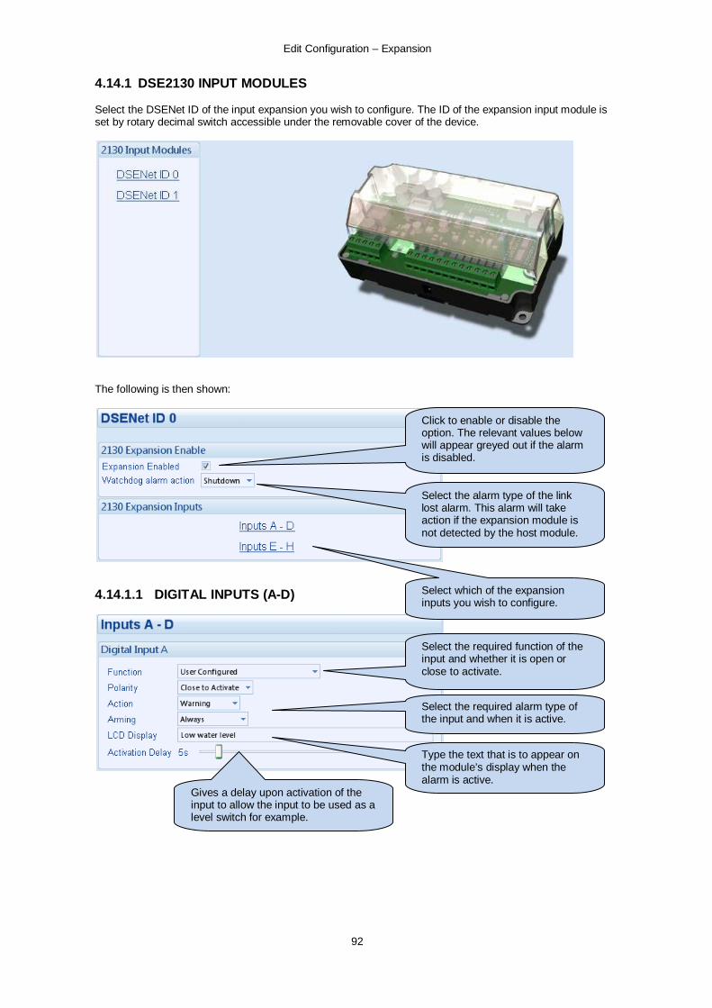
Edit Configuration – Expansion
92
4.14.1 DSE2130 INPUT MODULES Select the DSENet ID of the input expansion you wish to configure. The ID of the expansion input module is set by rotary decimal switch accessible under the removable cover of the device.
The following is then shown:
4.14.1.1 DIGITAL INPUTS (A-D)
Click to enable or disable the option. The relevant values below will appear greyed out if the alarm is disabled.
Select the alarm type of the link lost alarm. This alarm will take action if the expansion module is not detected by the host module.
Select which of the expansion inputs you wish to configure.
Select the required function of the input and whether it is open or close to activate.
Select the required alarm type of the input and when it is active.
Type the text that is to appear on the module’s display when the alarm is active.
Gives a delay upon activation of the input to allow the input to be used as a level switch for example.

Edit Configuration – Expansion
93
4.14.1.2 ANALOGUE INPUTS (E-H)
Depending upon your selection above, either the Analogue Input or Digital Input configuration screen is shown Used as an Analogue Input
Used as a Digital Input
Configure the sensor type. Select Digital Input to use the analogue input as a digital input
Edit the sensor curve if required.
Click to enable or disable the option. The relevant values below will appear greyed out if the alarm is disabled.
Type the value or click the up and down arrows to change the settings
Click and drag to change the setting.
Select the required function of the input and whether it is open or close to activate.
Select the required alarm type of the input and when it is active.
Type the text that is to appear on the module’s display when the alarm is active.
Gives a delay upon activation of the input to allow the input to be used as a liquid level switch for example.
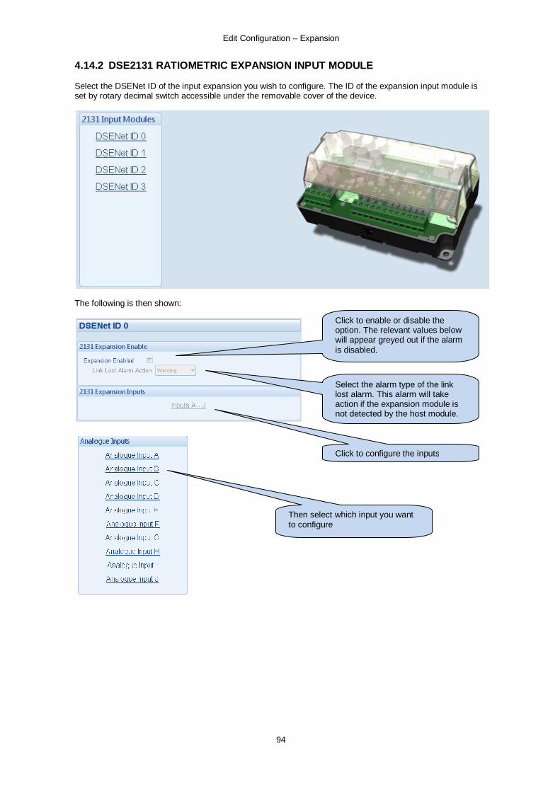
Edit Configuration – Expansion
94
4.14.2 DSE2131 RATIOMETRIC EXPANSION INPUT MODULE Select the DSENet ID of the input expansion you wish to configure. The ID of the expansion input module is set by rotary decimal switch accessible under the removable cover of the device.
The following is then shown:
Click to enable or disable the option. The relevant values below will appear greyed out if the alarm is disabled.
Select the alarm type of the link lost alarm. This alarm will take action if the expansion module is not detected by the host module.
Click to configure the inputs
Then select which input you want to configure

Edit Configuration – Expansion
95
Depending upon your selection of Sensor Type, one of the following configuration screens are shown : Used as a Digital Input
Used as an Analogue Input
Select the required function of the input and whether it is open or close to activate.
Select the required alarm type of the input and when it is active.
Type the text that is to appear on the module’s display when the alarm is active.
Gives a delay upon activation of the input to allow the input to be used as a liquid level switch for example.
Select the required function of the input. Percentage, Pressure, Temperature or Digital input.
Select the required type of the input. Voltage (0-10V), Current (4-20mA), Resistive
Name the sensor appropriately to describe the measurements on the module’s display
Edit the sensor curve if required.

Edit Configuration – Expansion
96
The following screen shot shows the configuration when set for Temperature Sensor. When set to other Sensor Type, consult the relevant manual section for details (Digital inputs, Oil Pressure input etc)
Click to edit the ‘sensor curve’. See section entitled Editing the sensor curve.
Select the sensor type
Click and drag to change the settings
Type the value or click the up and down arrows to change the settings
Click to enable or disable the alarms. The relevant values below will appear greyed out if the alarm is disabled.
Type the text you want to appear on the screen when the alarm is triggered.
Select the type of alarm required. For details of these, see the section entitled Alarm Types elsewhere in this document.

Edit Configuration – Expansion
97
4.14.2.1 EDITING THE SENSOR CURVES
Click and drag the points on the graphs to change the settings
Click OK to accept the changes and return to the configuration editor
Click CANCEL to ignore and lose any changes you have made
Click SAVE AS, you are prompted to name your curve....
Click OK to save the curve. Any saved curves become selectable in the Input Type selection list.
Hint: Deleting, renaming or editing custom sensor curves that have been added is performed in the main menu, select Tools | Curve Manager. .
Click Interpolate then select two points as prompted to draw a straight line between them.

Edit Configuration – Expansion
98
4.14.3 DSE2133 RTD / THERMOCOUPLE INPUT MODULE Select the DSENet ID of the input expansion you wish to configure. The ID of the expansion input module is set by rotary decimal switch accessible under the removable cover of the device.
The following is then shown:
Click to enable or disable the option. The relevant values below will appear greyed out if the alarm is disabled.
Select the alarm type of the link lost alarm. This alarm will take action if the expansion module is not detected by the host module.
Click to configure the inputs
Then select which input you want to configure

Edit Configuration – Expansion
99
Increases temperature alarms to 1300 deg C
Choose between Type J or Type K thermocouples or RTD (PT100)
Set the alarm trip points if required.
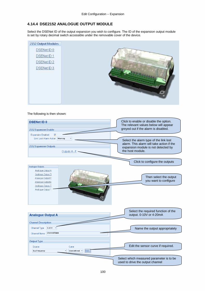
Edit Configuration – Expansion
100
4.14.4 DSE2152 ANALOGUE OUTPUT MODULE Select the DSENet ID of the output expansion you wish to configure. The ID of the expansion output module is set by rotary decimal switch accessible under the removable cover of the device.
The following is then shown:
Click to enable or disable the option. The relevant values below will appear greyed out if the alarm is disabled.
Select the alarm type of the link lost alarm. This alarm will take action if the expansion module is not detected by the host module.
Click to configure the outputs
Then select the output you want to configure
Select the required function of the output. 0-10V or 4-20mA
Select which measured parameter is to be used to drive the output channel
Name the output appropriately
Edit the sensor curve if required.

Edit Configuration – Expansion
101
4.14.4.1 EDITING THE OUTPUT CURVE
Click and drag the points on the graphs to change the settings. In this example 0 Hz – 60 Hz wiill be output as 2 V to 8 V.
Click OK to accept the changes and return to the configuration editor
Click CANCEL to ignore and lose any changes you have made
Click SAVE AS, you are prompted to name your curve....
Click OK to save the curve. Any saved curves become selectable in the Input Type selection list.
Hint: Deleting, renaming or editing custom sensor curves that have been added is performed in the main menu, select Tools | Curve Manager. .
Show and hide the knee point (middle point) of the output curve
Choose the x axis start and end points

Edit Configuration – Expansion
102
4.14.5 DSE2157 RELAY MODULES Select the DSENet ID of the relay expansion you wish to configure. The ID of the relay board is set by rotary decimal switch accessible under the removable cover of the device.
The following is then shown:
Click to enable or disable the option. The relevant values below will appear greyed out if the alarm is disabled.
Select the alarm type of the link lost alarm. This alarm will take action if the expansion module is not detected by the host module.
Select the output source and the polarity required. For example this output will energise when the module is in the Auto mode.

Edit Configuration – Expansion
103
4.14.7 DSE2548 LED EXPANSION Select the DSENet ID of the LED expansion you wish to configure. The ID of the Annunciator is set by rotary decimal switch accessible on the back of the device.
The following is then shown:
Click to enable or disable the option. The relevant values below will appear greyed out if the alarm is disabled.
Select the alarm type of the link lost alarm. This alarm will take action if the expansion module is not detected by the host module.
- If the mute / lamp test button is pressed, other DSE2548 modules configured to Follow main unit and the host module will also lamp test / mute their alarm and vice-versa. - If the mute / lamp test button is pressed, other DSE2548 modules and the host module will not respond to this.
Enable or disable the expansion module’s internal sounder.
Select the configuration for the LED. For instance this LED is configured to be unlit when in auto mode. Hence this is a not in auto LED.

Edit Configuration – Advanced
104
4.15 ADVANCED These settings are provided for advanced users only. Take care when changing these options and ensure you fully understand the consequences of any change made.

Edit Configuration – Advanced – PLC Logic
105
4.15.1 ADVANCED OPTIONS
4.15.1.1 PROTECTIONS This feature is provided to assist the system designer in meeting specifications for “Warning only”, “Protections Disabled”, “Run to Destruction”, “War mode” or other similar wording.
WARNING! - Enabling this feature will prevent the set being stopped upon critical alarm conditions. All shutdown alarms are disabled with the exception of EMERGENCY STOP which continues to operate. Options Description Disable = The module will operate as normal and provide engine shutdown if required.
= Protections disabled function is activated. Operation depends upon the following configuration.
NOTE:-Writing a configuration to the controller that has “Protections Disabled” configured, results in a warning message appearing on the PC screen for the user to acknowledge before the controller’s configuration is changed. This prevents inadvertent activation of the feature.
Protections are disabled
Never : The protections are not disabled Always: Protections are always overridden by the DSE controller. On Input : Protections are disabled whenever a configurable input set to Protections Disabled is activated
Protections Disabled Alarm Action
If Disable All Protections is set to On Input, this selection allows configuration of an alarm to highlight that the protections have been disabled on the engine. Indication: Any output or LCD display indicator configured to Protections Disabled will be made active; however the internal alarm sound will not operate. Warning: Any output or LCD display indicator configured to Protections Disabled will be made active, and the internal alarm sound will operate. When protections are disabled, Protections Disabled will appear on the module display to inform the operator of this status.
4.15.1.2 OTHER TIMERS Options Description Interlock override off Timer to delay the re-assertion of the interlock override.

Edit Configuration – Advanced – PLC Logic
106
4.15.2 PLC LOGIC PLC Logic adds comprehensive PLC functionality to the DSE controller. This is an advanced section, used entirely at your own risk. 4.15.2.1 MENU
In PLC logic, the ladder of logic is made up of a series of rungs. The ladder is the complete PLC program. This program may perform a single task, or multiple tasks. Each rung contains a number of conditions and actions. For instance if the conditions in the rung are met, the action takes place.
PLC Logic Conditions
PLC Logic Actions
PLC Logic Counters and Timers configuration
PLC Ladder made of two rungs
Click the to erase the entire rung
Condition (example Check Flag) Action (example Start timer)
A condition with a diagonal line through it means NOT. (example Timer has NOT expired)

Edit Configuration – Advanced – PLC Logic
107
4.15.2.2 FLAGS A flag is set when a condition within the DSE controller is met. For instance, if the module is in Auto Mode an internal flag is set. This flag is exposed as an output source when configuring module outputs and LEDs. In addition to internal flags, a further twenty (20) custom flags are available (named PLC Flag 1-20). These can be used to ‘memorise’ that a condition has been met, and/or used to drive module outputs and LEDs’. For example if a timer expires, a flag can be set to make a note of the timer expiring for later use in the ladder. 4.15.2.3 TIMERS The PLC logic section contains twenty (20) user timers for use in the ladder. A timer is configured by clicking in the menu bar. The ‘Edit time limits’ window appears.
A timer is used by adding the timer action to the ladder. When this action takes place, the timer begins. Upon the timer reaching the configured ‘Timer limit’, a test for the timer will be successful:
Start Timer
Test Timer
Click and drag to change the time, or press keyboard left and right arrow keys to change by small amounts.

Edit Configuration – Advanced – PLC Logic
108
4.15.2.4 COUNTERS The PLC logic section contains twenty (20) user counters for use in the ladder. A counter is configured by clicking in the menu bar. The ‘Edit counter limits’ window appears.
A counter is used by incrementing (adding to) or decrementing (subtracting from) to the counter on the ladder. Upon the counter reaching the configured ‘Counter limit’, a test for the counter will be successful:
Increment Counter
Test Counter
Click and drag to change the setting, or press keyboard left and right arrow keys to change by small amounts.
Decrement Counter
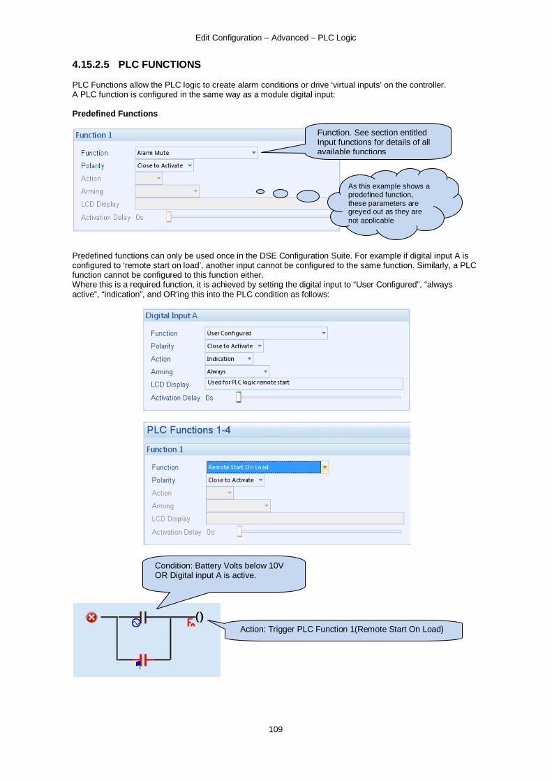
Edit Configuration – Advanced – PLC Logic
109
4.15.2.5 PLC FUNCTIONS PLC Functions allow the PLC logic to create alarm conditions or drive ‘virtual inputs’ on the controller. A PLC function is configured in the same way as a module digital input: Predefined Functions
Predefined functions can only be used once in the DSE Configuration Suite. For example if digital input A is configured to ‘remote start on load’, another input cannot be configured to the same function. Similarly, a PLC function cannot be configured to this function either. Where this is a required function, it is achieved by setting the digital input to “User Configured”, “always active”, “indication”, and OR’ing this into the PLC condition as follows:
Function. See section entitled Input functions for details of all available functions
As this example shows a predefined function, these parameters are greyed out as they are not applicable
Condition: Battery Volts below 10V OR Digital input A is active.
Action: Trigger PLC Function 1(Remote Start On Load)

Edit Configuration – Advanced – PLC Logic
110
User Defined alarms
Example of a user configured input
Close or open to activate
Select the type of alarm required. For details of these, see the section entitled Alarm Types elsewhere in this document. Click and drag to change
the setting. This is used to give a delay on acceptance of the input. Useful for liquid level switches or to mask short term operations of the external switch device.
This is the text that will be displayed on the module screen when the alarm is triggered.
Configures when the input is active: Never, always, active from starting, active from the end of the safety timer
Edit Configuration – Advanced – PLC Logic
111
4.15.2.6 CREATING AND EDITING RUNGS
• Click a symbol in the tool bar and drag it to the bar ( ) to create the first rung in your ladder.
• Click a symbol in the tool bar and drag it to a blank space below existing rungs to create a new rung. • Click a symbol in the tool bar and drag it to the ladder diagram to place the symbol. • To move a placed symbol, click and drag it to its new location. • To copy a placed symbol, press the keyboard CTRL button, then click and drag the symbol to the
location you want to copy it to. • To delete a placed symbol, click on it, it changes colour to red, now press the keyboard DELETE
button. • Click next to a rung to erase the entire rung.
Imagine the schematic like a simple circuit with a battery and a bulb.
There are two switches (Output sources) in parallel to provide an OR function and one switch (Output source) in series to provide an AND function. When the conditions are satisfied, the bulb will illuminate (The action will occur). An equivalent PLC ladder rung looks like this :
Rungs are processed in order (rung 1, rung 2, rung 3 etc). This sequence repeats every 100mS. Careless setting of the PLC logic can cause toggling of an output at a rate of 100mS on/off. This may shorten the life and/or cause damage to externally connected slave relays or other connected equipment. Conditions can be placed in series to form an AND operation, or in parallel for form an OR operation:
Actions can be placed in parallel to perform multiple actions upon one condition:
PLC Logic OR Conditions PLC Logic AND Conditions
PLC Logic multiple actions

Edit Configuration – Advanced – PLC Logic
112
4.15.2.7 CONDITIONS Conditions
Test flag (for instance : test module inputs, test for certain condition)
Test an instrumentation value
Test a counter
Test a timer
Test for a specific time period in the day
Edit Configuration – Advanced – PLC Logic
113
Conditions Test for a certain day
Test for a certain week
Test for a certain month
Test for a module button press
Edit Configuration – Advanced – PLC Logic
114
4.15.2.8 ACTIONS
Actions Set a PLC flag (Set to 1)
Reset a PLC flag (Set to 0)
Toggle a flag (swap 0/1 or 1/0)
Drive a flag (automatically clears when the condition is false)
Increment a counter
Decrement a counter
Set a counter to zero
Start a timer
Edit Configuration – Advanced – PLC Logic
115
Actions Drive a PLC function
Write a value to a Gencomm register
Reset an alarm

Edit Configuration – Advanced – PLC Logic
116
4.15.2.9 EXAMPLES
AUTO MUTE after 30 seconds and provide a manual mute function using Digital Input C.
Condition Action Flag Test (Audible Alarm)
Start Timer 1 (30 seconds)
If the audible alarm is active Begin a 30 second delay
Condition Action Timer 1 expired OR Flag Test (Digital Input C)
Trigger Function (Alarm Mute)
When the timer expires OR Digital Input C is activated
Trigger the alarm mute function
PLC Function 1 configured to Alarm Mute.
Digital Input C configured to Indication. This input will be checked for by the PLC logic. Descriptive text placed in the “LCD Display” box for future reference. (LCD Display text does not appear on the screen for “indication” inputs).

Edit Configuration – Advanced – PLC Logic
117
4.15.3 CONFIGURABLE GENCOMM PAGES
For advanced Modbus users of the controller, configurable Gencomm pages are available. The intention is to allow the user to create personal collections of data in subsequent registers to minimise the number of modbus reads required by the master, and hence speed up data collection. The configurable modbus pages are : Page Hex address Decimal address 166 A600 42496 167 A700 42752 168 A800 43008 169 A900 43264 Example of page configuration
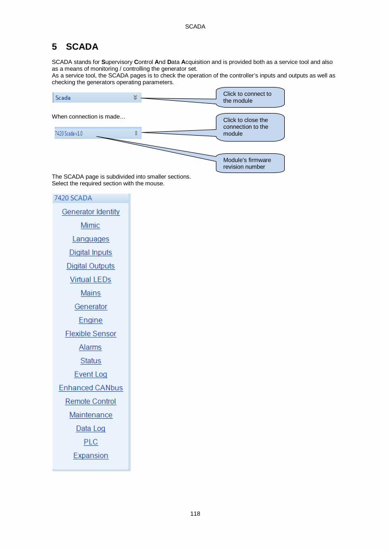
SCADA
118
5 SCADA SCADA stands for Supervisory Control And Data Acquisition and is provided both as a service tool and also as a means of monitoring / controlling the generator set. As a service tool, the SCADA pages is to check the operation of the controller’s inputs and outputs as well as checking the generators operating parameters.
When connection is made…
The SCADA page is subdivided into smaller sections. Select the required section with the mouse.
Click to connect to the module
Click to close the connection to the module
Module’s firmware revision number

SCADA
119
5.1 GENERATOR IDENTITY Shows the module’s current settings for Site ID and genset ID. This information is particularly helpful when the current connection is made remotely by modem or internet for example or when the connected set is one of a number of sets on an RS485 data link.
5.2 MIMIC This screen provides a mimic of the control module and allows the operator to change the control mode of the module. Only the mode control and load switch buttons are operational in the mimic display. The menu navigation buttons are inoperable.
Click the bottom row of buttons to change module mode. The load switch buttons are also operable (in manual mode as with the module’s own fascia buttons)
Hint: Before the mimic buttons will operate, ensure you have this
enabled under TOOLS | ACCESS PERMISSIONS
Module status information. This is not an exact duplicate of the module’s own display.

SCADA
120
5.3 LANGUAGES
5.4 DIGITAL INPUTS
Select new language
Click to send the new language to the module
State of the input (open or closed to battery negative)
State of the Emergency stop input (open or closed to battery positive). This input MUST be closed to battery positive for normal operation. If the input is open, the set will be stopped if it’s already running and will not be allowed to start.
Shows if the input channel is active or not. This input is open but is active. The input is configured to be open to activate
Shows if the input channel is active or not. This input is closed and is active. The input is configured to be close to activate

SCADA
121
5.5 DIGITAL OUTPUTS
5.6 VIRTUAL LEDS Shows the state of the Virtual LEDs. These LEDs are not fitted to the module or expansion modules, they are not physical LEDs. They are provided to show status and appear only in the SCADA section of the configuration suite, or can be read by third party PLC or Building Management Systems (for example) using the modbus RTU protocol.
State of the output (open or closed) Shows if the output channel is active or not. This
output is closed but is active. The output is configured to be Close Mains de-energise. As the relay is normally closed (N/C) and the Close Mains source is not present, the relay is activated to open the N/C relay.
Shows if the Virtual LED is active or not
Shows what the Virtual LED is configured for (shows the LED number if not configured)

SCADA
122
5.7 MAINS
DSE7420 AMF MODULES ONLY Shows the modules measurements of the mains supply.
5.7.1 FREQUENCY AND VOLTAGES Shows the modules measurements of the mains supply

SCADA
123
5.7.2 POWER Shows the modules measurements of the mains supply power
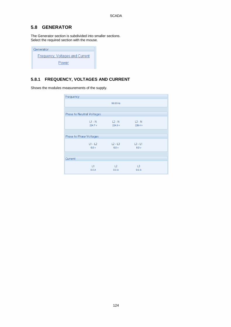
SCADA
124
5.8 GENERATOR The Generator section is subdivided into smaller sections. Select the required section with the mouse.
5.8.1 FREQUENCY, VOLTAGES AND CURRENT Shows the modules measurements of the supply.

SCADA
125
5.8.2 POWER Shows the modules measurements of the supply power.

SCADA
126
5.9 ENGINE Shows the modules measurements of the engine parameters.
5.10 FLEXIBLE SENSOR Shows the measurement of the Flexible Sensor (If configured)

SCADA
127
5.11 ALARMS Shows any present alarm conditions. For a description of the different alarm types, see the section entitled Alarm Types elsewhere in this manual.
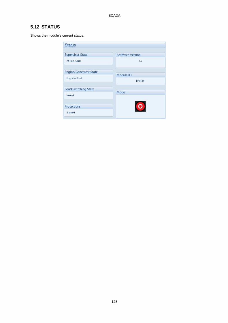
SCADA
128
5.12 STATUS Shows the module’s current status.

SCADA
129
5.13 EVENT LOG Shows the contents of the module’s event log.
Click to save the log to an Excel or csv file for use in an external spreadsheet program
Click to save the log to a pdf (Adobe Acrobat) file
Click to print the log

SCADA
130
5.14 ENHANCED CANBUS If the module is connected to a compatible electronic engine, the following information is read from the ECU (if supported by the engine ECU).

SCADA
131
5.15 REMOTE CONTROL The remote control section of the SCADA section is used for monitoring and control of module ‘remote control’ sources. Any of the module outputs, expansion outputs, LED indicators, or remote Annunciator LEDs can be configured to Remote Control 1-10. This output source is energised/de-energised by click the respective check box as shown below in the Activate column below.

SCADA
132
5.16 MAINTENANCE The Maintenance section is subdivided into smaller sections. Select the required section with the mouse.
5.16.1 RECALIBRATE TRANSDUCERS This section allows the analogue sensor inputs to be calibrated to remove inaccuracies caused by the tolerance of the sensor devices. The engine can be running when the instruments are calibrated and reference should be made to a third party accurate sensing device to ensure accurate recalibration.
Click and drag the control until the display beneath matches the reference meter being used to calibrate against.
Click to reset the custom calibration back to factory default settings
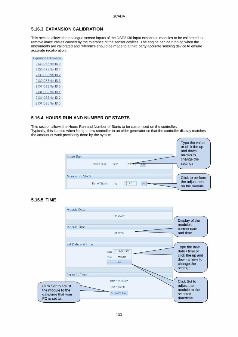
SCADA
133
5.16.3 EXPANSION CALIBRATION This section allows the analogue sensor inputs of the DSE2130 input expansion modules to be calibrated to remove inaccuracies caused by the tolerance of the sensor devices. The engine can be running when the instruments are calibrated and reference should be made to a third party accurate sensing device to ensure accurate recalibration.
5.16.4 HOURS RUN AND NUMBER OF STARTS This section allows the Hours Run and Number of Starts to be customised on the controller. Typically, this is used when fitting a new controller to an older generator so that the controller display matches the amount of work previously done by the system.
5.16.5 TIME
Type the value or click the up and down arrows to change the settings
Click to perform the adjustment on the module
Display of the module’s current date and time
Type the new date / time or click the up and down arrows to change the settings
Click Set to adjust the module to the selected date/time.
Click Set to adjust the module to the date/time that your PC is set to.

SCADA
134
5.16.6 ACCUMULATED INSTRUMENTATION Allows the user to view or change the module’s accumulated instrumentation.
Type the new value or click the up and down arrows to change the settings
Click Set to adjust the module to the selected value
Display of the module’s current value for the parameter
Click to reset all the accumulated instrumentation counters to zero.

SCADA
135
5.16.7 MAINTENANCE ALARM RESET Three maintenance alarms active in the control module. Each is reset individually; only one alarm is shown below for clarity.
5.16.8 MODULE PIN
NOTE : If the PIN is lost of forgotten, it will not be possible to access the module! Allows a PIN (Personal Identification Number) to be set in the controller. This PIN must be entered to either access the front panel configuration editor or before a configuration file can be sent to the controller from the PC software.
Enter the desired PIN number and reconfirm.
Click to set the PIN number in the module.
Reset the maintenance alarm based upon the module’s configuration.

SCADA
136
5.17 DATALOG Allows viewing of the module datalog (if configured).
NOTE: - Data logging is a ‘live’ function – Maximum 8hrs duration is shown so long as the PC is left connected to the controller.
Selects the timescale of the displayed graphs. Scroll bars on the graphs ‘x’ axis can also be used to scroll the graph backwards and forwards in time.
The data is automatically collated and presented in the graphs. For exampled Voltages are displayed in the same graph, but not mixed with kW for example, which are shown on a separate graph.
Zoom slider
Navigation sliders

SCADA
137
5.18 PLC Allows monitoring of the PLC functions within the controller.
Green highlighting shows the condition is True.
Live timer and counter display subject to the speed of update over the communications link
Flag State – Clear means the flag is not set.
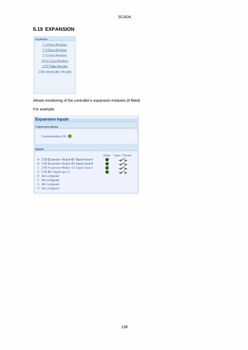
SCADA
138
5.19 EXPANSION
Allows monitoring of the controller’s expansion modules (if fitted) For example:

Alarm Types
139
6 ALARM TYPES The protection included with the DSE control modules provides increasing levels of notification, depending upon the severity of the situation: Alarm type Description Indication No audible alarm or common warning signal occurs.
Indication alarms are only used to illuminate indicators or to activate outputs. Warning Audible alarm and common alarm signal is generated. The set continues to
run. Warning alarms are used to draw the operator’s attention to a minor issue or to a problem that may escalate to an Electrical Trip or Shutdown Alarm if left untreated.
Electrical Trip Audible alarm and common alarm signal is generated. The set is taken off load and the cooling timer begins, after which the set is stopped. Electrical Trip alarms are series issues that require the set to be taken off load. As the name implies, this is often electrical faults that occur ‘after’ the load breaker. The set is allowed to cool before stopping.
Shutdown Audible alarm and common alarm signal is generated. The set is taken off load and immediately stopped. Shutdown alarms are serious issues that demand immediate stopping of the generator. For instance Emergency Stop or Overspeed alarms require immediate shutdown.
http://bestgenerator.spb.ru/?page_id=6765