decision feedback equalization for digital magnetic recording systems
TRANSCRIPT
IEEE TRANSACTIONS ON MAGNETICS, VOL. 24, NO. 1. JANUARY 1988 683
Decision Feedback Equalization for Digital Magnetic Recording Systems
JAN W. M. BERGMANS, MEMBER. IEEE
Ab.tract-The merits of decision feedback equalization are investi
gated as an alternative to the conventional linear method of equaliza
tion for combating intersymbol interference and noise in digital mag
netic recording systems. It is argued and exemplified that several
benefits may be expected from its application.
I. INTRODUCTION
CURRENT DIGITAL magnetic recording systems almost all tackle the intersymbol interference problem
by means of linear equalization, mostly implemented without the capability of adaptation to slowly varying channel parameters, While for reasons of complexity this approach is favorable over other approaches, some strong drawbacks are associated with it. First, as the physical dimensions of a recorded bit decrease, the influence of spread in recording media, playback heads and playhack equipment becomes preponderant and requires adaptivity to be incorporated. Secondly, the significant noise enhancement of the linear equalizer strongly conflicts with the increasing influence of noise at higher bit rates and in new (e.g., magnetooptical) recording media. Decision feedback equalization can provide relief in both directions at moderate expenses to complexity, as the present paper indicates. The merits of decision feedback equalization will be illustrated by means of theoretical considerations and simulation results on the basis of rather idealized system models.
II. DECISION FEEDBACK EQUALIZATION
Decision feedback equal ization [I] can be applied to received signals of the form
r(t) = L.: bkh(t - kT) + n(t) (I) k� -00
where bk E { -1, + I} is a binary data sequence to be conveyed, h(t) is the bit response of the channel, Tis the time separation between two successive bits, and n (t) is an additive noise signal. In what follows we shall assume that n (t) is Gaussian and white. This first-order approximation is common in communication-theoretical studies
Manuscript receIved February 4. 1987; revised September 9, 1987. A condensed version of this paper was presented at the Sixth International IEEE Conference on Video, Audio. and Data Recording. Brighton. England. March 18-21. 1986.
The author is with Philips Research Laboratories. PO Box 80.000. 5600 JA Eindhoven, The Netherlands.
IEEE Log Number 8717852.
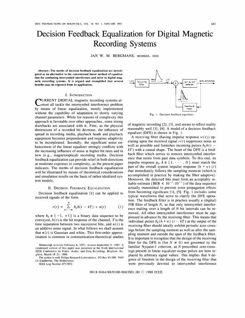
Fig. 1. Decision feedback equalizer.
of magnetic recording 12J, 13], and seems to reflect reality reasonably well [3], [41. A model of a decision feedback equalizer (DFE) is shown in Fig. I.
A receiving filter (having impulse response w(t» operating upon the received signal ret) suppresses noise as well as possible and furnishes incoming pulses bkh (t -kT) with a causal shape. The heart of the DFE is a feedback filter which serves to remove intersymbol interference that stems from past data symbols. To this end, its impulse response Pk> k E { 1, . . . , N} must match the part of the overall system impulse response (h * w) (t) that immediately follows the sampling moment (which is accomplished in practice by making the filter adaptive), Moreover, the detected bits must form an acceptably reliable estimate (BER < 10-2_10-1) of the data sequence actually transmitted to prevent error propagation effects from becoming significant fl1. [51. Fig. 1 includes some typical waveforms that serve to clarify the DFE operation. The feedback filter is in practice usually a (digital) FIR filter of length N, so that only intersymbol interference trailing over a length of N bit intervals can be removed. All other intersymbol interference must be suppressed in advance by the receiving filter. This means that individual pulses bk (h * w) (t - kT) at the output of the receiving filter should ideally exhibit periodic zero crossings before the sampling moment as well as after the sampling moment and outside the span of the feedback filter. It is important to recognize that the design of the receiving filter for the DFE is (for N '* 0) not governed by the familiar Nyquist- l criterion, as N prescribed zero-crossings present in linear equalizer output pulses are here replaced by arbitrary signal values. This implies that N degrees of freedom in the design of the receiving filter that were previously devoted to intersymbol interference
0018-9464/88/0100-0683$01.00 @ 1988 IEEE

684
suppression can now be used for noise suppression, i.e., that better signal-to-noise ratios at the input to the detector are feasible.
It is possible to carry out the operations in the forward signal path using analog (fast) technology. The feedback filter can easily be digital as it is excited by a binary data sequence, so that neither analog-to-digital conversion nor multiplications are necessary and use can be made of. e.g., the attractive (and fast) table lookup structure [6]. A most relevant feature of the table lookup structure is its ability to handle nonlinear input-output relations, of which saturation effects and dc offsets arc typical examples. Adaptivity can be incorporated in digital filters without substantial additional complexity (6), [7], thus allowing the coefficients Pk to attain their optimum values automatically, and irrespective of slow channel variations or a lack of a priori channel knowledge. In contrast, to incorporate adaptivity in a linear equalizer it is necessary to digitize the forward signal path, which is only possible at the (relatively large) expense of an analog-to-digital converter and complex digital multiplications. We will quantify some of the benefits of adaptivity later on.
An important drawback of the DFE appears to be its relatively high susceptibility to fast channel gain variations (i.e., variations with speeds beyond the range of filter adaptation algorithms), which is essentially due to the fact that decision feedback equalization is a compensation method. A pessimistic estimate of this susceptibility can be obtained by assuming a total absence of adaptivity. In this situation, which is elaborated numerically in [8], the performance advantage of the DFE relative to the linear equalizer invariably decreases in the presence of gain variations. Of course, if the magnitudes of variation are extreme, as they often are in digital magnetic recording (dropouts!), neither the linear equalizer nor the DFE will continue to function properly, and refuge must be sought in error protection techniques.
An important issue associated with the DFE is the optimum design of the receiving filter. An extensive body of theory is available on this subject [1], [5] (in which the degenerate case N = 0 of course specifies the optimum linear equalizer), from which we will freely and implicitly draw in the following.
III. A PERFORMANCE COMPARISON FOR NRZ-LIKE TRANSMISSION CODES
The nonretum to zero (NRZ) transmission code [3 J, [9] and derivatives thereof (such as 8-to-1O codes [10]) are frequently applied in digital magnetic recording systems. When differentiating playback heads are used, the associated N RZ bit response h ( t), cf. (1), can, in the absence of phase distortion, be represented as [9]. [11]
1 1 h(t)= 7 7 '
1 + (2S(t/T)f 1 + (2S{t/T - 1))" (2)
The relative separation S in (2) determines the dispersivity of the recording channel (which depends upon tape
IEEE TRANSACTIONS ON MAGNETICS. VOL. 24. NO. I. JANUARY 1988
0.17.���--------------
� -10.
� -20. �
t -3D
t -40.
0.5 - normalized frequency (f. T)
Fig. 2. Amplitude spectra of NRZ bit responses.
10 �---------------,
o
{!j -10. .;:
! -20.
t -3D
-400. 0..5 1.0 _ normalized frequency 1f.T}
Fig. 3. Amplitude-frequency characteristics of minimum mean-square error linear equalizers for channels of Fig. 2 and SNR of 20 dB.
speed and the quality of tape and head, among other things) or, equivalently, the information density on tape. Fig. 2 depicts the amplitude spectrum I H U ) I of h (t) for three different values of S.
H ( f) has zeros at all integral multiples of the bit frequency (including a null at dc). This type of spectrum can never be transformed into a spectrum that satisfies the Nyquist-1 criterion by means of a filter with a finite transfer at all frequencies [12]. In other words, when employing a non ideal integrator as part of a linear equalizer a residual quantity of intersymbol interference is inevitable. The residual interference level is strongly affected by the extent to which ideal integration is approximated. Unfortunately, integration strongly boosts noise at low frequencies, so that a signal-to-noise ratio dependent trade-off arises between noise and residual intersymbol interference. The optimum characteristics of the equalizer also depend quite heavily upon the dispersivity. This is illustrated in Fig. 3 for the channels of Fig. 2.
The amplitude-frequency characteristics of Fig. 3 were calculated using the minimum-mean-square error criterion [5] for a signal-to-noise ratio
SNR (3)

BERGMANS: DIGITAL MAGNETIC RECORDING SYSTEMS 685
Fig. 4. Eye patterns for S = 0.67 equalizer of Fig. 3 when operating on channel with S = 0.67 (left) and S = 0. 5 (right). In both cases, SNR of 20 dB has been used. Dashed line indicates optimum decision moment.
� �10 � � �20 .2
1-30 t
�40
- normalized frequency (f. T I Fig. 5. Receiving filter amplitude-frequency characteristics of minimum
mean�square error DFE's with N = 6 for channels of Fig. 2 and SNR of 20 dB.
of 20 dB. Here No is the power spectral density of the noise signal n (t). Because 20 dB is a relatively poor value, the low-frequency behavior of the curves of Fig. 3 indicates only a modest degree of integration. It is apparent from Fig. 3 that the linear equalizer can withstand only a restricted variation of S relative to the nominal
value for which it has been dimensioned. This is more
clearly illustrated in Fig. 4, which shows eye patterns that were calculated for the S = 0.67-equalizer of Fig. 3 when
operating on channels with the nominal value S = 0.67 and with the somewhat smaller value S = 0 .5, respectively. In both cases an SNR of 20 dB has been used. It is seen that a relatively small reduction of the channel bandwidth already induces a serious degradation of the
transmission quality. The effects just described are typical for the linear
equalizer and are much less present for the DFE, particularly when equipped with an adaptive feedback filter. For
this case, Fig. 5 shows optimum receiving filter ampli
tude-frequency characteristics for a feedback filter length N = 6. The curves were again calculated for the channels of Fig. 2, using an SNR of20 dB and the minimum mean
square error criterion.
Because the task of dealing with intersymbol interfer
ence is now largely shifted towards the feedback filter, the receiving filter can concentrate most of its attention
on the suppression of noise and no longer needs to make
the delicate compromise described earlier. This explains why the curves of Fig. 5 are much less dependent on the SNR than their linear counterparts of Fig. 3. A striking
(and distinguishing) feature of the characteristics is their apparent insensitivity to variations of S, as induced by, e.g., tape and head production tolerances. As a conse
quence, the residual intersymbol interference levels prior to detection are also relatively insensitive to variations of S. This is exemplified in Fig. 6, which shows eye patterns
that were calculated for a DFE with an adaptive feedback
filter of length N = 6 and the S = 0.67 receiving filter of Fig. 5, operating on channels with S = 0.67 and S = 0.5, respectively, and in both cases again using an SNR of 20
dB. Comparison of Figs. 4 and 6 clearly illustrates the reduced sensitivity of the DFE to dispersivity changes.
Instead of (pseudo-)integration near dc and a large ripple near the Nyquist frequency, the curves of Fig. 5 exhibit a gentle behavior that is reminiscent of conventional
(Butterworth, Chebyshev, etc.) filter types. Judged by Fig. 5, the synthesis of a suitable analog receiving filter could be based upon conventional low-pass filter types,
although additional phase equalization would be required to achieve the desired extent of asymmetry of the overall system impulse response (h * w) (t). The latter aspect
definitely deserves study, yet its practical elaboration extends beyond the scope of the present paper.
In the amplitude scaling of Figs. 3 and 5, the differ
ences in received signal power between S = 0.33, S =
0.5, and S = 0.67 have been compensated. Moreover, as both figures have the same O-dB level, comparison of the
curves provides a direct indication of the differences in noise enhancement. For both the linear equalizer and the DFE, the larger average transfer magnitude of the S =
0.33 curve (as compared to the S = 0.5 and S = 0.67 curves) indicates a (roughly 2 dB ) larger noise enhance� ment, as should be expected from the strongly degraded
686 IEEE TRAI'SACTIONS ON MAGNETICS. VOL. 24. NO. I. JANUARY 1988
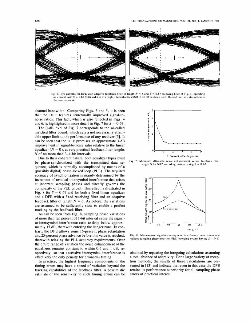
T 0 Fig. 6. Eye patterns for DFE with adaptive feedback filter of length N = 6 and S = 0.67 receiving filter of Fig. 4. operating
on channel with S = 0.67 (left) and S = 0.5 (right). In both cases SNR of 20 dB has been used. Dashed line indicates optimum decision moment.
channel bandwidth. Comparing Figs. 3 and 5, it is seen that the DFE features structurally improved signal-tonoise ratios. This fact, which is also reflected in Figs. 4 and 6, is highlighted in more detail in Fig. 7 for S = 0.67.
The O-dB level of Fig. 7 corresponds to the so-called matched filter bound, which sets a not necessarily attainable upper limit to the performance of any receiver [5]. It can be seen that the DFE promises an approximate 3-dB improvement in signal-to-noise ratio relative to the linear equalizer (N = 0 ), at very practical feedback filter lengths N of no more than 3-4-bit intervals.
Due to their coherent nature, both equalizer types must be phase-synchronized with the transmitted data sequence, which is normally accomplished by means of a (possibly digital) phase-locked loop (PLL). The required accuracy of synchronization is mainly determined by the increment of residual intersymbol interference that arises at incorrect sampling phases and directly governs the complexity of the PLL circuit. This effect is illustrated in Fig. 8 for S = 0.67 and for both a fixed linear equalizer and a DFE with a fixed receiving filter and an adaptive feedback filter of length N = 6. As before, the variations are assumed to be sufficiently slow to enable a perfect tracking by the feedback filter.
As can be seen from Fig. 8, sampling phase variations of more than ten percent of I-bit interval cause the signalto-intersymbol interference ratio to drop below approximately 15 dB, therewith entering the danger zone. In contrast, the DFE allows some IS-percent phase retardation and 25-percent phase advance before this value is reached, therewith relaxing the PLL accuracy requirements. Over the entire range of variation the noise enhancement of the equalizers remains constant to within 0.5 and I dB, respectively, so that excessive intersymbol interference is effectively the only penalty for erroneous timing.
In practice, the highest frequency components of the timing errors may have a speed of variation beyond the tracking capabilities of the feedback filter. A pessimistic estimate of the sensitivity to such timing errors can be
5,----------------------,
--- feedback filter length IN)
Fig. 7. Minimum attainable noise enhancement versus feedback filter length N for NRZ recording system having S = 0.67.
� 40 r----------------------,
� � 2 30
� .2 DFE ..!. 20 g .2' '" � linear equal izer g 10 0-
� t � O L-�����--�����
-02 -01 o 0.1 0.2
- fo/T
Fig. 8. Mean-square signal-to-intersymhol interference ratio versus normalized sampling phase error for NRZ recording system having S = 0.67,
obtained by repeating the foregoing calculations assuming a total absence of adaptivity, For a large variety of reception methods, the results of these calculations are presented in [13] and indicate that even in this case the DFE retains its performance superiority for all sampling phase errors of practical interest.
BERGMANS: DIGITAL MAGNETIC RECORDING SYSTEMS
IV. COMPARISON FOR THE BI-PHASE TRANSMISSION
CODE
Apart from NRZ-like codes the bi-phase transmission code is in common use, for which, again assuming differentiating playback heads and absence of phase distortion, h (t) can be described as [9]
h{t) 2
2 + (2S(t/T)) 1 + (2S{t/T - 1/2))
2
1 + -----------;;2 .
I + (2S(t/T - I) (4)
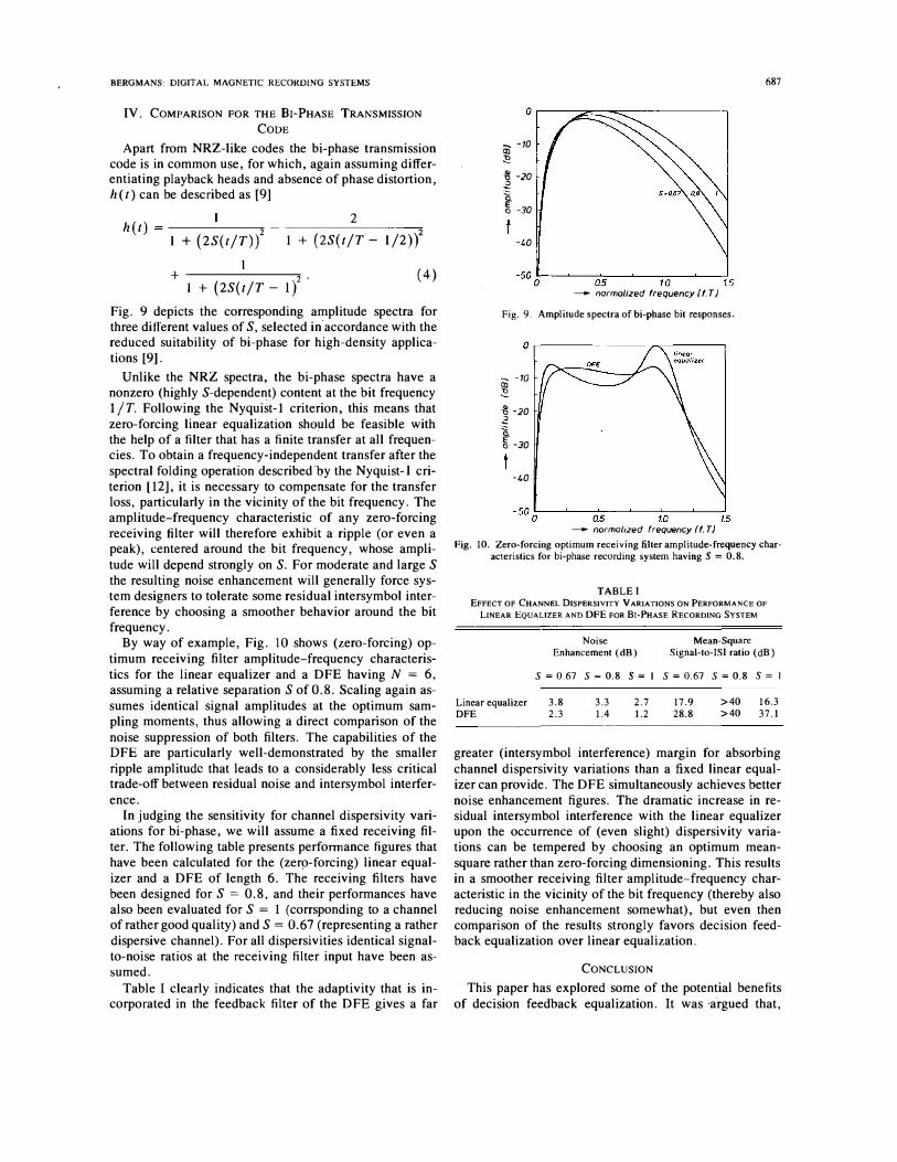
Fig. 9 depicts the corresponding amplitude spectra for three different values of S, selected in accordance with the reduced suitability of bi-phase for high-density applications [9].
Unlike the NRZ spectra, the bi-phase spectra have a nonzero (highly S-dependent) content at the bit frequency 1/ T. Following the Nyquist-l criterion, this means that zero-forcing linear equalization should be feasible with the help of a filter that has a finite transfer at all frequencies. To obtain a frequency-independent transfer after the spectral folding operation described by the Nyquist-I criterion [12], it is necessary to compensate for the transfer loss, particularly in the vicinity of the bit frequency. The amplitude-frequency characteristic of any zero-forcing receiving filter will therefore exhibit a ripple (or even a peak), centered around the bit frequency, whose amplitude will dcpend strongly on S. For moderate and large S the resulting noise enhancement will generally force system designers to tolerate some residual intersymbol interference by choosing a smoother behavior around the bit frequency.
By way of example, Fig. 10 shows (zero-forcing) optimum receiving filter amplitude-frequency characteristics for the linear equalizer and a DFE having N = 6, assuming a relative separation S of 0.8. Scaling again assumes identical signal amplitudes at the optimum sampling moments, thus allowing a direct comparison of the noise suppression of both filters. The capabilities of the DFE are particularly well-demonstrated by the smaller ripple amplitude that leads to a considerably less critical trade-off between residual noise and intersymbol interference.
In judging the sensitivity for channel dispersivity variations for bi-phase, we will assume a fixed receiving filter. The following table presents performance figures that have been calculated for the (zero-forcing) linear equalizer and a DFE of length 6. The receiving filters have been designed for S = 0.8, and their performances have also been evaluated for S = 1 (corrsponding to a channel of rather good quality) and S = 0.67 (representing a rather dispersive channel). For all dispersivities identical signalto-noise ratios at the receiving filter input have been assumed.
Table I clearly indicates that the adaptivity that is incorporated in the feedback filter of the DFE gives a far
687
o �----����---------�
� -10 CXl � � -20 � t " -30
-40
-500L---�--�Q�.5��----!L.O-�--�15 - normalized frequency (f.T)
Fig. 9. Ampl itude spectra ofbi-phase bit responses.
o �-------____ ----�
� -10
� � -20 �
� " -30
-40
- normalized frequency (f. T)
Fig. 10. Zero-forcing optimum receiving lilter amplitude-frequency characteristics for bi-phase recording system having S = 0.8.
TABLE I EFFECT OF CHANNEL OISPERSIVITY VARIATIONS ON PERFORMANCE OF
LINEAR EQUALIZER AND OFE FOR BI-PHASE RECORDING SYSTEM
Linear equalizer OFE
Noise Enhancement (dB)
Mean-Square Signal-to-ISI ratio (dB)
S = 0.67 S = 0.8 S = I S = 0.67 S = 0.8 S = I
3.8 2.3
3.3 1.4
2.7 1.2
17.9 28.8
>40 16.3 >40 37.1
greater (intersymbol interference) margin for absorbing channel dispersivity variations than a fixed linear equalizer can provide. The DFE simultaneously achieves better noise enhancement figures. The dramatic increase in residual intersymbol interference with the linear equalizer upon the occurrence of (even slight) dispersivity variations can be tempered by choosing an optimum meansquare rather than zero-forcing dimensioning. This results in a smoother receiving filter amplitude-frequency characteristic in the vicinity of the bit frequency (thereby also reducing noise enhancement somewhat), but even then comparison of the results strongly favors decision feedback equalization over linear equalization.
CONCLUSION
This paper has explored some of the potential benefits of decision feedback equalization. It was a'rgued that,

688
compared to linear equalization, decision feedback equalization allows easier incorporation of adaptivity, thereby reducing the influence of slow channel variations and timing errors on the overall transmission quality. In addition, the more advanced nature of decision feedback equalization structurally lowers noise enhancement and reduces the need to compromise between noise and intersymbol interference suppression requirements. These effects were quantified as considerable for two examples of practical importance, and comparable improvements should be anticipated for a much broader range of digital magnetic recording systems. A more comprehensive performance comparison, which also covers the use of partial response techniques and of Viterbi detection, is provided in [8].
REFERENCES
[1] C. Belfiore and 1. Park. "Decision feedback equalization." Pmc. IEEE, vol. 67, pp. 1143-1156, Aug. 1979.
[2] H. Osawa, S. Tazaki. and S. Ando, • 'Performance analysis of partial response systems for nonreturn-to-zero recording," IEEE Trans. Magn., vol. MAG-22, pp. 253-258, July 1986.
[3] S. Nakagawa, K. Yokoyama, and H. Katayama, "A study on detection methods of NRZ recording," IEEE Trans. Magn., vol. MAG-16, pp. 104-110, Jan. 1980.
[4] C. Yamamitsu, K. Suesada, I. Ogura, and A. Iketani, " High density recording and bit rate reduction for a 2-hour digital VTR," in Proe. 6th Int. Can! Video, Audio and Data Recording, Brighton, UK. Mar. 1986, pp. 113-120.
[5] 1. Proakis , Digital Communications. New York: McGraw-Hill. 1983.
[6] P. van Gerwen, N. A. M. Verhoeckx, and T. A. C. M. Classen. "Design considerations for a 144 kbit/s digital transmission unit for
IEEE TRANSACTIONS ON MAGNETICS. VOL. 24, NO. I, JANUARY 1988
the local telephone network," IEEE J. Selected Areas in Commun., vol. SAC-2, pp. 314-323, Mar. 1984.
[7] C. F. N. Cowan and P. M. Grant, Adaptive Filters. Englewood Cliffs, NJ: Prentice-Hall, 1985.
[8] J. W. M. Bergmans, "Partial response equalization," Philips J. Res . . vol. 42, pp. 209-245, 1987.
[9] -, "Density improvements in digital magnetic recording by decision feedback equalization," IEEE Trans. Magn., vol. MAG-22, pp. 157-162, May 1986.
[10] K. A. S. Immink, "Construction of binary dc-constrained codes," Philips J. Res., vol. 40, pp. 22-39, Apr. 1985.
[II] J. Newman and R. Fisher, "Performance calculations of digital magnetic recording systems, " IEEE Trans. Magn., vol. MAG-20, pp. 96-98, Jan. 1984.
[12] O. Rikkert de Koe and P. van der Wurf, "On some extensions of Nyquist·s telegraph transmission theory," Proc. IEEE, vol. 57, pp. 701-702, Apr. 1969.
[13] J. W. M. Bergmans, "Performance consequences of timing errors in digital magnetic recording, " Philips J. Res., vol. 42, pp. 281-307. 1987.
Jan W. M. Bergmans (M'85) was born in Tilburg, The Netherlands, on August 15, 1957. He received the Ingenieur degree in electrical engineering and the Ph.D. degree from Eindhoven University of Technology , Eindhoven, The Netherlands, in 1981 and 1987, respectively.
From 1981 to 1982, he was a manager for communication projects in the Royal Netherlands Navy. In 1982 he joined Philips Research Laboratorics, Eindhoven. There, he has been engaged in research on digital transmission and recording . with special emphasis on structured algorithmic design tools, smearing filters, and equalization and detection methods. He is currently on leave of absence at Hitachi Central Research Laboratories, Tokyo, Japan.
Dr. Bergmans is a member of the URSI committee of The Netherlands and of the committee of the Nederlands Electronica- en Radio Genootschap (NERG).