dec 10000 axp system vax 10000 site preparation guidedecdoc.itsx.net/dec94mds/1000bsp2.pdf ·...
TRANSCRIPT

digital equipment corporationmaynard, massachusetts
DEC 10000 AXP SystemVAX 10000Site Preparation Guide
Order Number EK–1000B–SP.002
This guide is intended for use by Digital customer service engineers andcustomers in preparing a site for a DEC 10000 system or a VAX 10000 sys-tem.

First Printing, November 1992
The information in this document is subject to change without notice and shouldnot be construed as a commitment by Digital Equipment Corporation.
Digital Equipment Corporation assumes no responsibility for any errors that mayappear in this document.
The software, if any, described in this document is furnished under a license andmay be used or copied only in accordance with the terms of such license. No re-sponsibility is assumed for the use or reliability of software or equipment that isnot supplied by Digital Equipment Corporation or its affiliated companies.
Copyright © 1992 by Digital Equipment Corporation.
All Rights Reserved.Printed in U.S.A.
The following are trademarks of Digital Equipment Corporation:
Alpha AXP DECUS VAXBIAXP DWMVA VAXELNDEC OpenVMS VMSclusterDECchip ULTRIX XMIDEC LANcontroller UNIBUS The AXP logoDECnet VAX
OSF/1 is a registered trademark of the Open Software Foundation, Inc.
FCC NOTICE: The equipment described in this manual generates, uses, and mayemit radio frequency energy. The equipment has been type tested and found tocomply with the limits for a Class A computing device pursuant to Subpart J ofPart 15 of FCC Rules, which are designed to provide reasonable protection againstsuch radio frequency interference when operated in a commercial environment. Operation of this equipment in a residential area may cause interference, in whichcase the user at his own expense may be required to take measures to correct theinterference.

iii
Contents
Preface ....................................................................................................... v
Chapter 1 Site Preparation1.1 Site Preparation Overview .................................................... 1-21.2 General Description ............................................................... 1-41.3 Space Requirements .............................................................. 1-61.4 Electrical Requirements ........................................................ 1-81.5 Cabling Requirements ......................................................... 1-101.6 Environmental Requirements ............................................. 1-121.7 Planning for Delivery ........................................................... 1-15
Figures1-1 Five-Cabinet System .............................................................. 1-21-2 Three-Cabinet System ........................................................... 1-31-3 Five-Cabinet System (Front Dimensions) ............................ 1-41-4 Three-Cabinet System (Front Dimensions) .......................... 1-51-5 Floor Space Requirements ..................................................... 1-61-6 AC Power Inputs .................................................................... 1-81-7 Electrical Connectors and Receptacles ............................... 1-101-8 DEC Power Bus Cable ......................................................... 1-111-9 Airflow (System and Expander Cabinets) .......................... 1-131-10 Floor Cutout Locations (Raised Floors) .............................. 1-14
Tables1 DEC 10000/VAX 10000 Documentation ................................ vii2 Related Documents .................................................................. ix1-1 Free-Standing Cabinet Dimensions and Weights ................ 1-71-2 AC Input Voltages .................................................................. 1-91-3 Power Requirements and Heat Dissipation ......................... 1-9

iv
1-4 Environmental Requirements ............................................. 1-121-5 Shipping Specifications ....................................................... 1-16

v
Preface
Intended AudienceThis manual is written for Digital customer service engineers and custom-ers preparing a site for a DEC 10000 or VAX 10000 system.
Document StructureThis manual uses a structured documentation design. Topics are organ-ized into small sections for efficient on-line and printed reference. Eachtopic begins with an abstract. You can quickly gain a comprehensive over-view by reading only the abstracts. Next is an illustration or example,which also provides quick reference. Last in the structure are descriptivetext and syntax definitions.This manual has one chapter as follows:• Chapter 1, Site Preparation, provides pre-installation require-
ments and guidelines for DEC 10000 and VAX 10000 systems.

vi
Conventions Used in This DocumentTerminology. Unless specified otherwise, the use of "system" refers toeither a DEC 10000 AXP or VAX 10000 system. The DEC 10000 AXP sys-tems use the Alpha AXP architecture. References in text use DEC 10000to refer to DEC 10000 AXP systems. When a discussion applies to only one system, an icon is used to highlightthat system. Otherwise, the discussion applies to both systems. Thus, theabstract for a module that applies only to DEC 10000 systems would looklike this:
Book titles. In text, if a book is cited without a product name, that book ispart of the hardware documentation. It is listed in Table 1 along with itsorder number.Icons. Icons such as those shown below are used in illustrations for desig-nating part placement in the system described. A shaded area in the iconshows the location of the component or part being discussed.
Documentation TitlesTable 1 lists the books in the DEC 10000 and VAX 10000 documentationset. Table 2 lists other documents that you may find useful.
DEC10000
This section shows a sample boot of OpenVMS Alpha AXPfrom the RRD42 CD drive for DEC 10000 systems. The firststep is issuing the show device command to determine thelocation of the RRD42.
RearFront
vii
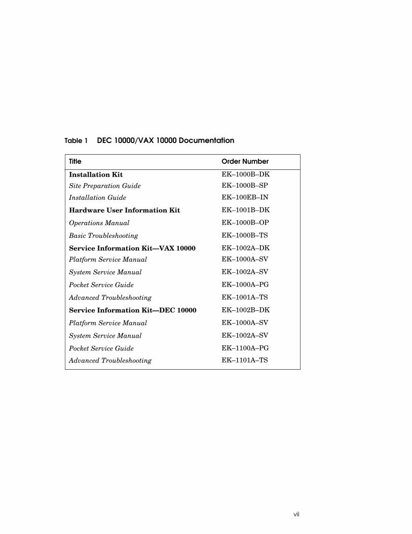
Table 1 DEC 10000/VAX 10000 Documentation
Title Order Number
Installation Kit EK–1000B–DK
Site Preparation Guide EK–1000B–SP
Installation Guide EK–100EB–IN
Hardware User Information Kit EK–1001B–DK
Operations Manual EK–1000B–OP
Basic Troubleshooting EK–1000B–TS
Service Information Kit—VAX 10000 EK–1002A–DK
Platform Service Manual EK–1000A–SV
System Service Manual EK–1002A–SV
Pocket Service Guide EK–1000A–PG
Advanced Troubleshooting EK–1001A–TS
Service Information Kit—DEC 10000 EK–1002B–DK
Platform Service Manual EK–1000A–SV
System Service Manual EK–1002A–SV
Pocket Service Guide EK–1100A–PG
Advanced Troubleshooting EK–1101A–TS

viii
Table 1 DEC 10000/VAX 10000 Documentation (Continued)
Title Order Number
Reference ManualsConsole Reference Manual EK–70C0B–TM
KA7AA CPU Technical Manual EK–KA7AA–TM
KN7AA CPU Technical Manual EK–KN7AA–TM
MS7AA Memory Technical Manual EK–MS7AA–TM
I/O System Technical Manual EK–70I0A–TM
Platform Technical Manual EK–7000A–TM
Upgrade ManualsKA7AA CPU Installation Guide EK–KA7AA–IN
KN7AA CPU Installation Guide EK–KN7AA–IN
MS7AA Memory Installation Guide EK–MS7AA–IN
KZMSA Adapter Installation Guide EK–KXMSX–IN
DWLMA XMI PIU Installation Guide EK–DWLMA–IN
DWMBB VAXBI PIU Installation Guide EK–DWMBB–IN
H7237 Battery PIU Installation Guide EK–H7237–IN
H7263 Power Regulator Installation Guide EK–H7263–IN
BA654 DSSI Disk PIU Installation Guide EK–BA654–IN
BA655 SCSI Disk and Tape PIU Installation Guide
EK–BA655–IN
Removable Media Installation Guide EK–TFRRD–IN

ix
Table 2 Related Documents
Title Order Number
General Site PreparationSite Environmental Preparation Guide EK–CSEPG–MA
System I/O OptionsBA350 DECstor/me Modular Storage ShelfSubsystem Configuration Guide
EK–BA350–CG
BA350 DECstor/me Modular Storage ShelfSubsystem User’s Guide
EK–BA350–UG
BA350-LA DECstor/me Modular Storage ShelfUser’s Guide
EK–350LA–UG
CIXCD Interface User Guide EK–CIXCD–UG
DEC FDDIcontroller 400 Installation/ProblemSolving
EK–DEMFA–IP
DEC LANcontroller 400 Installation Guide EK–DEMNA–IN
DEC LANcontroller 400 Technical Manual EK–DEMNA–TM
DSSI VAXcluster Installation and TroubleshootingManual
EK–410AA–MG
InfoServer 150 Installation and Owner’s Guide EK–INFSV–OM
KDM70 Controller User Guide EK–KDM70–UG
KFMSA Module Installation and User Manual EK–KFMSA–IM
KFMSA Module Service Guide EK–KFMSA–SV
RRD42 Disc Drive Owner’s Manual EK–RRD42–OM
RF Series Integrated Storage Element User Guide EK–RF72D–UG
TF85 Cartridge Tape Subsystem Owner’s Manual EK–OTF85–OM
TLZ06 Cassette Tape Drive Owner’s Manual EK–TLZ06–OM
x
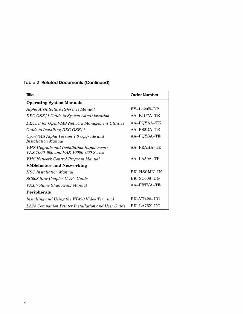
Table 2 Related Documents (Continued)
Title Order Number
Operating System ManualsAlpha Architecture Reference Manual EY–L520E–DP
DEC OSF/1 Guide to System Administration AA–PJU7A–TE
DECnet for OpenVMS Network Management Utilities AA–PQYAA–TK
Guide to Installing DEC OSF/1 AA–PS2DA–TE
OpenVMS Alpha Version 1.0 Upgrade andInstallation Manual
AA–PQYSA–TE
VMS Upgrade and Installation Supplement: VAX 7000–600 and VAX 10000–600 Series
AA–PRAHA–TE
VMS Network Control Program Manual AA–LA50A–TE
VMSclusters and NetworkingHSC Installation Manual EK–HSCMN–IN
SC008 Star Coupler User’s Guide EK–SC008–UG
VAX Volume Shadowing Manual AA–PBTVA–TE
Peripherals
Installing and Using the VT420 Video Terminal EK–VT420–UG
LA75 Companion Printer Installation and User Guide EK–LA75X–UG

Site Preparation 1-1
Chapter 1
Site PreparationThis book should be used in conjunction with the Site EnvironmentalPreparation Guide (EK–CSEPG–MA). Use the Guide for information onthe general considerations of planning any site, and use this book for siteplanning information specific to the system. Sections in this book include:• Site Preparation Overview• General Description• Space Requirements• Electrical Requirements• Cabling Requirements• Environmental Requirements• Planning for Delivery

1-2 Site Preparation
1.1 Site Preparation Overview
The tasks that must be performed at a site prior to installation arecovered in detail in the Site Environmental Preparation Guide. The list that follows is an overview of the site preparation process. Refer to the Guide for information on preliminary site prepara-tion.
Figure 1-1 Five-Cabinet System
BXB-0031-92
Battery Cabinet
Battery Cabinet
Expander Cabinet
Expander Cabinet
System Cabinet

Site Preparation 1-3
Figure 1-2 Three-Cabinet System
Site Planning Considerations:
• Plan the physical layout of the system cabinet, expander cabinet(s), bat-tery cabinet(s), console terminal, printer, and other system units.
• Plan to place all equipment away from heavy traffic centers, leavingenough room for airflow and maintenance.
• Obtain cabinet weights and dimensions to check against floor loadingrestrictions.
• Determine the sizes of circuit breakers and the number of branch cir-cuits required.
• Determine the number, type, and location of required AC power outlets.
• Check the compatibility of different power sources. This must bechecked when multiple types of power distribution transformers orpower conditioning equipment is used.
• Determine system power consumption to calculate the input line powerrequirement.
• Establish a system grounding scheme for the installation.
• Determine environmental cooling requirements.
• Check the location and requirements of cabling for communication de-vices such as Ethernet.
BXB-0047-92
Battery Cabinet
Expander Cabinet
System Cabinet

1-4 Site Preparation
1.2 General Description
Systems are available in either a 5-cabinet or a 3-cabinet configu-ration. The 5-cabinet configuration (Figure 1-3) consists of a sys-tem cabinet, two expander cabinets, and two battery cabinets. The3-cabinet configuration (Figure 1-4) consists of a system cabinet,one expander cabinet, and one battery cabinet.
Figure 1-3 Five-Cabinet System (Front Dimensions)
System Cabinet
60 cm (23.6 in)
Expander Cabinet
80 cm (31.5 in)
Battery Cabinet
60 cm (23.6 in)
170
cm (
67 in
)
80 cm (31.5 in)
80 cm (31.5 in)
Expander Cabinet
Battery Cabinet
BXB-0001F-92

Site Preparation 1-5
Figure 1-4 Three-Cabinet System (Front Dimensions)
System Cabinet
Expander Cabinet
80 cm (31.5 in)
Battery Cabinet
60 cm (23.6 in)
80 cm (31.5 in)
BXB-0001H-92
170
cm (
67 in
)

1-6 Site Preparation
1.3 Space Requirements
Floor space and floor loading requirements vary according to thenumber of cabinets in a system, as shown in Figure 1-5 and Table1-1.
Figure 1-5 Floor Space Requirements
Rear Clearance 1 m (39 in)
Front Clearance 1.5 m (59 in)
360 cm (141.7 in)
87.5 cm (34.5 in)
Expander Cabinet
System Cabinet
Battery Cabinet
220 cm (86.6 in)
Battery Cabinet
Expander Cabinet
= 3-Cabinet System BXB-0001K-92

Site Preparation 1-7
Table 1-1 Free-Standing Cabinet Dimensions and Weights
Height cm (in)
Width cm (in)
Depth cm (in)
Weight kg (lb)
System:
3-Cabinet System
170 (67) 220 (86.6) 87.5 (34.5) 1640 (3600)
5-Cabinet System
170 (67) 360 (141.7) 87.5 (34.5) 2600 (5700)
Cabinets:
System Cabinet
170 (67) 80 (31.5) 87.5 (34.5) 680 (1500)
ExpanderCabinet
170 (67) 80 (31.5) 87.5 (34.5) 408 (900)
Battery Cabinet
170 (67) 60 (23.6) 87.5 (34.5) 545 (1200)

1-8 Site Preparation
1.4 Electrical Requirements
System power is applied to the system cabinet and expander cabi-net(s) by AC power cables (Figure 1-6). Table 1-2 shows the AC re-quirements for 3-cabinet and 5-cabinet systems with various ACinput voltages. Table 1-3 summarizes system power requirements.
Figure 1-6 AC Power Inputs
Rear
= 3-Cabinet System
BXB-0060B-92AC Input

Site Preparation 1-9
Table 1-2 AC Input Voltages
The 3-cabinet system has two line cords. The 5-cabinet system has threeline cords. Power receptacles are also required for console terminals and printers.
Table 1-3 Power Requirements and Heat Dissipation
Country
InputVoltage(Nominal) Phases
MaximumInput CurrentPer Phase(rms amps)
Surge Current(peakamps)
Breaker Rating(amps)
NorthAmerica
120/208Wye1
50–60 Hz
3-phase star4-wire N-GND
24 50 30
Europe/GIA
380–415Wye1
50–60 Hz
3-phase star4-wire N-GND
12.8 50 16
Japan 202 Delta1
50–60 Hz3-phase Delta4-wire mid-GND 3-wirejunction-GND
24 50 30
1Per line cord.
SystemWatts(Max)
BTU/hr (Max)
3-Cabinet 6,600 22,500
5-Cabinet 10,900 37,200

1-10 Site Preparation
1.5 Cabling Requirements
AC power cables are 2.8 m (9 ft) in length. Each cable containsthree-phase leads (X, Y, and Z) plus neutral (W/N) and ground (G). AC power connectors and receptacles are shown in Figure 1-7. The DEC power bus cable if present must also be planned for (Fig-ure 1-8).
NOTE: Neutral and ground lines are not interchangeable and must bothbe individually connected from the bulk three-phase power to com-plete the Wye configuration. Power must not be connected tothe site until power checks are performed. See the Installa-tion Guide for more information.
Figure 1-7 Electrical Connectors and Receptacles
Receptacle
NEMA L21-30R DEC 12-12315
Plug
NEMA L21-30P DEC 12-12314
120/208 V 30A
3-Phase Y
220/380 V or 240/415 V
3-Phase Y
Plug Receptacle
DEC 12-30333-02 (IEC 309) MENNEKES 3
BXB-0002A-92
Z
Y
W
X
G
W
X
Z
Y
G
16 AMENNEKES 5048
N
T3
R1
S2
G
N
G

Site Preparation 1-11
Figure 1-8 DEC Power Bus Cable
BXB-0061-92
Rear
DEC Power Bus Connector

1-12 Site Preparation
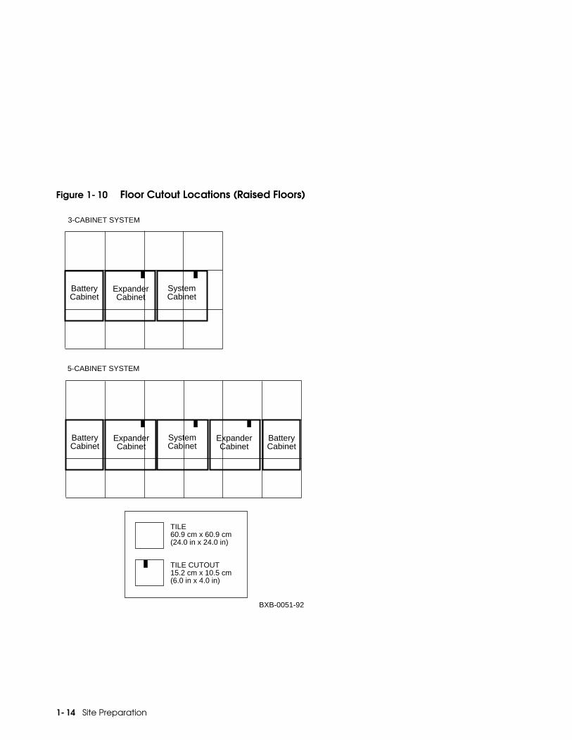
1.6 Environmental Requirements
Environmental factors such as temperature, humidity, altitude, vibration, and airflow must be considered when planning the site. If the site has a raised floor, appropriate floor cutouts must bemade for cables (Figure 1-10).
Table 1-4 Environmental Requirements
Condition TemperatureRelativeHumidity Altitude Vibration
Operating 15C to 28C59F to 82F
20% to 80% 0 to 2.4 km0 to 8000 ft
2 to 22 Hz @ 0.01 " daminimum
Non-Operating
−40C to 66C −40F to 151F
10% to 95% 0 to 9.1 km0 to 30,000 ft
22 to 500 Hz@ 0.25 gmaximum

Site Preparation 1-13
Figure 1-9 Airflow (System and Expander Cabinets)
Air is taken in through the top and bottom of the cabinet by a central dualwheel blower. The air is then circulated through the card cages and powerregulators. It is exhausted at the middle of the cabinet front and rear.
NOTE: Do not place anything on top of a cabinet that would block airflow. Inadequate airflow can result in the system shutting down.
BXB-0056A-92
1-14 Site Preparation
Figure 1-10 Floor Cutout Locations (Raised Floors)
Expander Cabinet
System Cabinet
Battery Cabinet
Battery Cabinet
Expander Cabinet
BXB-0051-92
TILE 60.9 cm x 60.9 cm (24.0 in x 24.0 in)
TILE CUTOUT 15.2 cm x 10.5 cm (6.0 in x 4.0 in)
System Cabinet
Battery Cabinet
Expander Cabinet
5-CABINET SYSTEM
3-CABINET SYSTEM

Site Preparation 1-15
1.7 Planning for Delivery
Prepare the site for delivery of the cabinets (Table 1-5).
Check the delivery route and refer to Table 1-5.• Check the height, width, and location of doors and passageways for
adequate clearance.• Check floor loading and consider protective covering along passage-
ways.• Check passageway restrictions such as corners, ramps, or obstructions.• Check the size, capacity, and availability of elevators.
The system, expander, and battery cabinets are boxed separately. Table1-5 shows the weight and dimensions of each cabinet with packing materi-als and mounted on a pallet.

1-16 Site Preparation
Table 1-5 Shipping Specifications
WARNING: Serious injury may result if cabinets are improperly han-dled or proper safety conditions are not met. Refer to the In-stallation Guide for specific unpacking and assembly in-structions, and always use at least two people to move acabinet or to remove it from a skid.
CabinetShipping Dimensions(Height, Width, Depth)
Shipping Weight(Fully Configured)
System 195 cm x 109.5 cm x 121 cm(76.8 in x 43.1 in x 47.5 in)
720 kg (1600 lbs)
Expander 195 cm x 109.5 cm x 121 cm (76.8 in x 43.1 in x 47.5 in)
448 kg (1000 lbs)
Battery 200 cm x 91 cm x 120 cm(79 in x 36 in x 47.25 in)
585 kg (1300 lbs)
For more information:
Installation Guide
Index-1
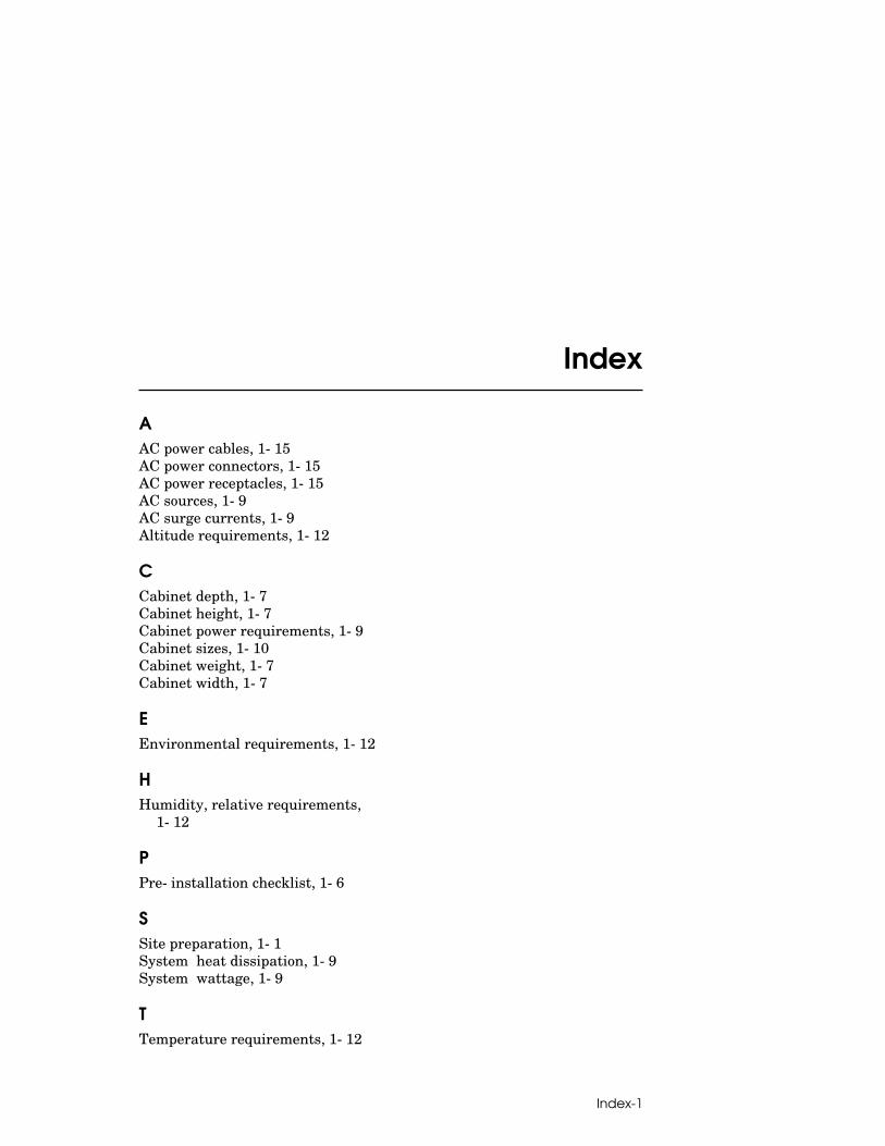
Index
AAC power cables, 1-15AC power connectors, 1-15AC power receptacles, 1-15AC sources, 1-9AC surge currents, 1-9Altitude requirements, 1-12
CCabinet depth, 1-7Cabinet height, 1-7Cabinet power requirements, 1-9Cabinet sizes, 1-10Cabinet weight, 1-7Cabinet width, 1-7
EEnvironmental requirements, 1-12
HHumidity, relative requirements,
1-12
PPre-installation checklist, 1-6
SSite preparation, 1-1System heat dissipation, 1-9System wattage, 1-9
TTemperature requirements, 1-12