dds 7000 - duraline systems manual.pdf · dds 7000 sterilization cycle, your valuable instruments...
TRANSCRIPT

DDS 7000Dry Heat Sterilization System (115V/230V)
Operating Instructions

2

3
TABLE OF CONTENTS
INTRODUCTION 4
GENERAL AND TECHNICAL SPECIFICATIONS 5
DDS 7000 UNIT OVERVIEW 6
UNPACKING YOUR DDS 7000 7
SERIAL NUMBER LABELS 7
SELECTING YOUR STERILIZATION AREA 8
VENTING 9
CONNECTING TO A POWER SOURCE 10
STERILIZER CONTROLS 10
INDICATOR LED LIGHTS 11
DIGITAL TEMPERATURE DISPLAY 11
DOOR LATCH 11
SAFETY DOOR INTERLOCK 12
FIRST TIME USE CYCLE TEST 12
STERILIZING YOUR INSTRUMENTS 12
INSTRUMENT HANDLING 13
PLIER RACKS 14
LOADING YOUR DDS 7000 PLIER RACKS 14
LOADING THE STERILIZATION CHAMBER 16
OPERATION 17
SPECIAL NOTE ON MOUTH MIRRORS 19
ABORTING A CYCLE 20
RESETTING THE TEMPERATURE OVERLOAD SENSOR 20
BIOLOGICAL TESTING IN YOUR STERILIZER 21
MAINTENANCE AND CLEANING 22
SELECTING USER OPTIONS 24
USING THE COM PORT 26
WARRANTY / RETURN POLICY 28
STERILIZER RETURN PROCEDURE 28
APPENDIX I (SYMBOL EXPLANATION). 29
APPENDIX II (ERROR CODES) 30

4
INTRODUCTIONThank you for your purchase of the DDS 7000 Dry Heat Sterilization System. We appreciate your commitment to safe sterilization and effective patient care. The DDS 7000 Dry Heat Sterilizer is a convection type unit, designed for the sterilization of un-bagged orthodontic instruments that can withstand temperatures of up to 420ºF(215ºC). The DDS 7000 System is programmed to rap-idly increase load temperature to 374ºF (190ºC), maintain this temperature for an effective and complete kill in three (3) minutes and then quickly cool the load for immediate handling. Optimum results are achieved with the Dry Heat method by uniform load distribution. Your DDS 7000 is equipped with a unique rack system for sterilizing hinged instruments. This design guarantees equal spacing of instruments and racks in the sterilization chamber and greatly simplifies loading, han-dling, and dispensing of all instrumentation. Since no moisture, pressure, or chemicals are used in the DDS 7000 sterilization cycle, your valuable instruments are protected from rust, corrosion, and dulling of cutting edges. The design includes a safety interlock switch on the door to prevent access to the chamber until the load has been properly cooled. Dentronix is confident that you will find this sys-tem easy to integrate into your office procedures, as well as simple to use by all staff members. The following operating instructions have been written to familiarize you with the principles of Dry Heat Sterilization and the specific operating procedures for the DDS 7000. It is imperative that you read these operating procedures carefully before operating your unit.
NOTE: The DDS 7000 Sterilizer has been manufactured for specific and safe operating procedures as contained in this manual.
CAUTION!
Never use the DDS 7000 for other uses. i.e. sterilization of bagged instruments or use of cassettes, as a warming chamber or heating device, for the preparation of food or other items. If you are unsure of your unit’s correct usage, please contact your sales representative or the Dentronix Customer Service Hotline.
Questions? Please call the Dentronix Sterilizer Repair Hotline – 800-523-5944 (ext. 8925) in U.S. and Canada or 330-916-8925 or e-mail [email protected] or fax 330-645-8758 so that we can help you maximize the full capabilities of the DDS 7000 System.
Please record your Serial Number here for more efficient customer service:
5
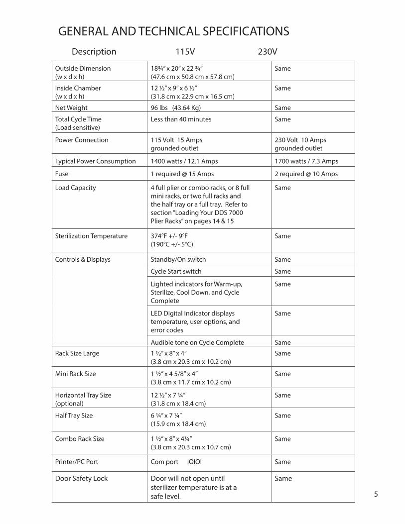
Outside Dimension (w x d x h)
18¾” x 20” x 22 ¾”(47.6 cm x 50.8 cm x 57.8 cm)
Same
Inside Chamber (w x d x h)
12 ½” x 9” x 6 ½”(31.8 cm x 22.9 cm x 16.5 cm)
Same
Net Weight 96 lbs (43.64 Kg) Same
Total Cycle Time (Load sensitive)
Less than 40 minutes Same
Power Connection 115 Volt 15 Amps grounded outlet
230 Volt 10 Ampsgrounded outlet
Typical Power Consumption 1400 watts / 12.1 Amps 1700 watts / 7.3 Amps
Fuse 1 required @ 15 Amps 2 required @ 10 Amps
Load Capacity 4 full plier or combo racks, or 8 full mini racks, or two full racks and the half tray or a full tray. Refer to section “Loading Your DDS 7000 Plier Racks” on pages 14 & 15
Same
Sterilization Temperature 374°F +/- 9°F(190°C +/- 5°C)
Same
Controls & Displays Standby/On switch Same
Cycle Start switch Same
Lighted indicators for Warm-up, Sterilize, Cool Down, and Cycle Complete
Same
LED Digital Indicator displays temperature, user options, and error codes
Same
Audible tone on Cycle Complete Same
Rack Size Large 1 ½” x 8” x 4”(3.8 cm x 20.3 cm x 10.2 cm)
Same
Mini Rack Size 1 ½” x 4 5/8” x 4”(3.8 cm x 11.7 cm x 10.2 cm)
Same
Horizontal Tray Size (optional)
12 ½” x 7 ¼”(31.8 cm x 18.4 cm)
Same
Half Tray Size 6 ¼” x 7 ¼”(15.9 cm x 18.4 cm)
Same
Combo Rack Size 1 ½” x 8” x 4¼”(3.8 cm x 20.3 cm x 10.7 cm)
Same
Printer/PC Port Com port IOIOI Same
Door Safety Lock Door will not open until sterilizer temperature is at a safe level.
Same
GENERAL AND TECHNICAL SPECIFICATIONS Description 115V 230V

6
DDS 7000 UNIT OVERVIEW
Figure 1: Outside view of the DDS 7000
Louvers
Door Switch
COMPort
RackChannels
Standby/On
Door Lock
DigitalDisplay
CycleStart Switch
CycleIndicatorLights
Magnetic HEPA Filter Cover
1. 2. 3. 4.
7
DDS 7000 UNIT OVERVIEW
UNPACKING YOUR DDS 7000
Your DDS 7000 Dry Heat Sterilization System is delivered in two or more packages:
1. One large carton containing the DDS 7000 Dry Heat Sterilizer, Operating Instructions and Accessory Kit. 2. One or more small cartons containing other accessories that may have been purchased.
WARNING!
This is a heavy piece of equipment. Please follow safe handling methods.
Examine each carton for any external damage. Be sure to check the corners of the box. Immediately upon receipt open the large box, remove the protective packaging inserts and the sterilizer from the carton. Carefully inspect the DDS 7000 for any damage.
Damage should be reported immediately to the transport carrier that delivered your unit as well as to the Dentronix Sterilizer Repair Department 800-523-5944 (ext. 8925) or 330-916-8925 or e-mail [email protected] or fax 330-645-8758.
CAUTION!
Read the Operating Instructions completely before operating the sterilizer
.
Set-up your DDS 7000 Sterilizer in a dry location according to the directions in the Operating Instructions. Run your unit through a complete cycle with an empty chamber.
WARNING!
This is a heavy piece of equipment (96 pounds/43.64 Kg). Please make sure the counter top will safely support the weight.
NOTE: RETAIN PACKAGING MATERIALS FOR FUTURE SHIPPING. The DDS 7000 should be serviced by a professional on an annual basis, or when two consecutive spore strip test results come back positive.
SERIAL NUMBER LABELS
Before proceeding further, check the specification label on the sides of the DDS 7000 to obtain important information regarding model number, serial number and power requirements. Make sure that this unit matches the power capabilities in your office regarding voltage, amperage and cycles. Record the serial number for future reference. (See Introduction Section, Page 4)

8
SELECTING YOUR STERILIZATION AREA
This is a heavy piece of equipment. Please make sure the counter top will safely support the weight. Locate your sterilizer in an area that is clean and dry with easy access to patient treatment areas. Utilizing extra counter space, in close proximity to your cleaning area, will make instrument processing smooth and orga-nized. When placing your unit on the counter, do not push the exhaust stack against the wall. Leave a minimum of 1” (2.54 cm) back clearance between the exhaust stack and wall to prevent heat damage to building materi-als. Leave at least 4” (10.2 cm) side clearance between cabinets and walls to allow unrestricted passage of cool down intake air. Failure to allow a four-inch side clearance could result in a considerably longer cool down cycle and may result in an error message. For direct venting, the minimum clearance is 12” (30.5cm) from top of unit to allow hot exhaust air to exit. The optimum clearance is 36” (91 cm) When building the DDS 7000 into a cabinet system, maintain a minimum of 4” (10.2 cm) clearance around the entire unit and use vent adaptors DAD-UL or DAD-BL.
Exhaust stack of DDS 7000 - It is important to leave 4-inches around the sides of the unit and 12-inches above the top of the unit to maintain proper airflow during the cool down cycle.
Exhaust Stack
Figure 2
8
9
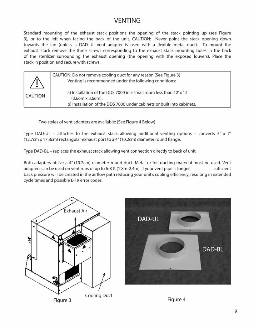
VENTING
Standard mounting of the exhaust stack positions the opening of the stack pointing up (see Figure 3), or to the left when facing the back of the unit. CAUTION: Never point the stack opening down towards the fan (unless a DAD-UL vent adapter is used with a flexible metal duct). To mount the exhaust stack remove the three screws corresponding to the exhaust stack mounting holes in the back of the sterilizer surrounding the exhaust opening (the opening with the exposed louvers). Place the stack in position and secure with screws.
CAUTION
CAUTION: Do not remove cooling duct for any reason (See Figure 3) Venting is recommended under the following conditions: a) Installation of the DDS 7000 in a small room less than 12’ x 12’ (3.66m x 3.66m). b) Installation of the DDS 7000 under cabinets or built into cabinets.
Two styles of vent adapters are available: (See Figure 4 Below)
Type DAD-UL – attaches to the exhaust stack allowing additional venting options – converts 5” x 7” (12.7cm x 17.8cm) rectangular exhaust port to a 4” (10.2cm) diameter round flange.
Type DAD-BL – replaces the exhaust stack allowing vent connection directly to back of unit.
Both adapters utilize a 4” (10.2cm) diameter round duct. Metal or foil ducting material must be used. Vent adapters can be used on vent runs of up to 6-8 ft (1.8m-2.4m). If your vent pipe is longer, sufficient back pressure will be created in the airflow path reducing your unit’s cooling efficiency, resulting in extended cycle times and possible E-19 error codes.
Figure 4Figure 3
Exhaust Air
Cooling Duct
DAD-BL
DAD-UL

10
CONNECTING TO A POWER SOURCE
Connect the DDS 7000 to a grounded power source in compliance with the specification label on the side of the unit.
115V: Sterilizers used in the U.S. and Canada require a 15-amp, 115-volt grounded receptacle and operate at 50/60 Hz. A dedicated circuit is recommended. Other high-powered equipment (such as lathes, trimmers, X-ray equipment) should not be placed on the same circuit.
CAUTION!
Do not install more than one DDS 7000 Sterilizer in a single circuit.
230V: Sterilizers require a 10-amp minimum 230V receptacle and operate at 50/60 Hz.
STERILIZER CONTROLS
The DDS 7000 is an automatic sterilizing system. Sterilization time and temperature have been pre-set at the factory providing for optimum performance.
1) Standby/On switch – push the top of the switch to the “ON” position to activate all electrical control circuits. Push the bottom of the switch to deactivate all electrical control circuits. If the switch is switched to the Standby position during warm-up, sterilization or cool down cycles, an error code will be displayed. This switch does not actually break incoming power. That can only be accomplished by unplugging the device.2) Cycle Start switch – depress the top of this switch in order to initiate the sterilization cycle.
Figure 5: Control Panel for DDS 7000.
11
INDICATOR LED LIGHTS
The control panel of your DDS 7000 is equipped with four (4) indicator lamps to monitor progress of the sterilization cycle.
1) Warm-up – this Yellow LED will illuminate after pressing the “Cycle Start”switch. It indicates heating element activation to raise instrument load to sterilizing temperature of 374°F (190°C). The warm up time is load sensitive and will vary based on the load density. 2) Sterilize – this Amber/Orange LED indicates that the temperature controller has sensed a load temperature of 374°F (190°C) and has started the 3-minute sterilizing phase. During this phase, the heating element will cycle on and off to maintain an even temperature in the chamber. This LED will turn off at the beginning of the Cool Down phase.
3) Cool Down – this Blue LED will illuminate during the Cool Down phase. In this phase, cool air is drawn into the unit through a HEPA filter. The LED will stay lit until instruments reach a safe handling temperature.
4) Cycle Complete – this Green LED will illuminate at the completion of the cool down phase and indicates that instruments are sterilized and ready to unload. It is also your indication that the DDS 7000 has completed the sterilization process. An audible tone will signal the completion of the cycle. The door must be opened, to turn this LED off and to allow unit to begin a new cycle.
WARNING!
DO NOT UNLOAD INSTRUMENTS UNLESS THE “CYCLE COMPLETE” LIGHT IS ON.
NOTE: The indicator LIGHTS will flash when a problem is detected during a cycle. Refer to APPENDIX II for error code explanations.
DIGITAL TEMPERATURE DISPLAY
An LED display on the right-hand side of the control panel monitors sterilizing chamber/load temperature in degrees Fahrenheit or Celsius. This display is activated when the “Standby/On” switch is in the “On” position. User options and error codes will also display in this area.
DOOR LATCH
Turning the handle clockwise unlocks the door and allows it to swing open. To close, push the door gently against the rubber door gasket and turn the knob counter – clockwise to engage the cam lock, which pulls the door against the gasket, sealing the chamber.

12
SAFETY DOOR INTERLOCK
Your DDS 7000 is equipped with a cut-off switch beneath the door. (see Page 6) This switch prevents the sterilization cycle from starting whenever the door is not properly closed. This switch also interrupts the cycle if the door is opened during any cycle.
WARNING!
DISABLING THE DOOR LOCK AND OPENING THE DOOR AT ANY TIME DURING THE CYCLE PRI-OR TO “CYCLE COMPLETE” MAY EXPOSE OPERATOR TO DANGEROUSLY HOT INSTRUMENTS. DO NOT ATTEMPT TO REMOVE THESE INSTRUMENTS WITHOUT SUFFICIENT PROTECTION.
The DDS 7000 has an additional safety door lock mechanism, which prevents the door from open-ing until the chamber temperature is at a “safe handling temperature”. In the event of an emergency, requiring access to the chamber during any cycle, press and hold down the “cycle start” switch for 5 seconds. The door safety lock mechanism will unlock temporarily for a few seconds allowing access. NOTE WARNING ABOVE: An Error Code will display notifying the operator of an interruption. Toggling the “Standby/On” switch from “On” to “Standby” then back to “On” will clear the error message. To restart the cycle, press “Cycle Start”. The DDS 7000 will first cool down and then restart the complete cycle from the beginning.
FIRST TIME USE CYCLE TEST
After the sterilizer is connected to a properly rated and grounded outlet (see page 10) follow the opera-tion procedures found on pages 17-19 with an EMPTY CHAMBER.
Make sure that air is blowing out of the exhaust stack during the cool down phase.
WARNING!
The dry air may be hot 265˚F (129˚C).
STERILIZING YOUR INSTRUMENTS
What CAN be sterilized in the DDS 7000?
All metal instruments can be safely processed – stainless steel, aluminum, chrome and nickel-plated, silver-brazed components and some high temperature plastics.
What CANNOT be sterilized in the DDS 7000?
Bagged instruments, cassettes, vinyl, rubber and plastic items, paper products, soldered components (such as some impression trays, boley gauges, some band pushers), petroleum-based lubricants, and any materials not capable of withstanding 420°F (215°C).
12

13
CAUTION!
ITEMS THAT ARE LABELED “AUTOCLAVABLE” ARE NOT NECESSARILY DRY HEAT STERILIZ-ABLE. IF IN DOUBT ABOUT SPECIFIC PRODUCTS, CONTACT THE MANUFACTURER.
CAUTION!
REMOVE ALL VINYL GRIPS FROM PLIERS BEFORE STERILIZING.

14
INSTRUMENT HANDLING
The most important guideline in any sterilization procedure is:
STERILIZE ONLY CLEAN INSTRUMENTS!
Pre-cleaning is essential with any sterilization process because the elevated temperatures of the sterilization cycle will bake on any residual materials or debris. The most effective and thorough method of cleaning is to use an Ultrason-ic Cleaning Unit (such as the Dentronix DDUS60 Ultrasonic Cleaner). Non-Ionic multi-purpose cleaning concentrates, which include a rust inhibitor and require no rinsing (such as Dentronix MP-US Plus), are highly effective for the process-ing of orthodontic pliers. Ultrasonic cleaning will remove dirt, debris and old lubricants, which could cause discoloration and stiffening of joints. Weekly lubrication of the plier joint with a pure silicone product (such as Dentronix DSL-16 or DSY-20) will maintain smooth joint travel.
WARNING!
If instruments are dropped, sprayed, or mishandled after sterilization, the instruments must be pre-cleaned as recommended above. Never return the items to the sterilizer without first cleaning them.
WARNING!
DO NOT USE ANY OF THE FOLLOWING:
• DO NOT USE IODOPHORS TO CLEAN PLIERS PRIOR TO STERILIZATION • DO NOT USE ALCOHOL TO CLEAN PLIERS OR TO DISPLACE MOISTURE PRIOR TO STERIL-
IZATION• DO NOT USE ANY CLEANER WHICH LEAVES A RESIDUE. THIS MAY RESULT IN SMOKING
OR UNDESIRED FUMES DURING THE STERILIZATION CYCLE.• DO NOT USE PLAIN SOAP AND WATER TO CLEAN PLIERS PRIOR TO STERILIZATION.• DO NOT DIP PLIERS IN ANY FLAMMABLE LIQUID PRIOR TO LOADING IN STERILIZER.• DO NOT LUBRICATE PLIERS OR INSTRUMENTS WITH PETROLEUM-BASED LUBRICANTS.• DO NOT USE WITH CASSETTES OR INSTRUMENT BAGS• DO NOT LOAD INSTRUMENTS ON THE BOTTOM OF THE CHAMBER OR BETWEEN THE
PLIER RACKS. FOR INSTRUMENTS THAT DO NOT FIT THE RACKS AS SHOWN, USE HORI-ZONTAL TRAY CAT. NO. D5000S-T OR HALF TRAY CAT. NO. D5000S-HT.
• DO NOT PLACE ANY ITEMS BELOW THE TRAY OR SHELF UNITS TO BE STERILIZED.• DO NOT PLACE ANY INSTRUMENTS INSIDE THE PLIER RACKS.

15
PLIER RACKS
The four anodized plier racks that are supplied with your DDS 7000 are manufactured from aluminum for optimum heat transfer and to reduce weight. Also available are: A) Mini Rack holds 4 pliers B) Combo Rack holds 5 pliers plus 5 Mathieu Hemostats or other hand instruments. C) Long Handle Combination Rack holds 2 Long Handle Pliers, 3 Regular Pliers, 5 Mathieu Hemostats or other hand instruments. D) The plier racks supplied offer convenient transport to chairside.
WARNING!
The DDS 7000 has been tested and approved for use with Dentronix racks. Do not use cassettes or other delivery systems as they may cause overheating or failure to sterilize.
LOADING YOUR DDS 7000 PLIER RACKS
The effectiveness of Dry Heat is dependent on exposure of the instrument load to the convective properties of the heated airflow in the sterilization chamber. The DDS 7000 rack system was designed to provide a predictable location and spacing for the instrument load so that optimum exposure can be achieved. Pliers should only be loaded in the notches of the rack (see Figure 6). Never place instruments inside of plier racks. Doing so may impede air flow resulting in an error code or failure to sterilize.
In addition to the plier racks, Dentronix also offers a Horizontal Tray (Part No. D5000S-T) and a Half Horizontal Tray (Part No. D5000S-HT). These trays can be used for instruments that do not fit onto the racks. These trays were specially de-signed for use in a Dry Heat Sterilizer. The half tray allows the user to sterilize single-handled instruments along with two full racks of pliers. Use of trays other than the D5000S-T and D5000S-HT will impede the airflow around the instruments and will result in failure to sterilize the instruments.
Figure 6
Correct and Incorrect placement of racks in DDS 7000. Note: The incorrectly placed rack is not over the air vents of the rack channel, whereas the correctly placed rack is.
WRONG
IncorrectRack
Placement
Correct Rack Placement
16
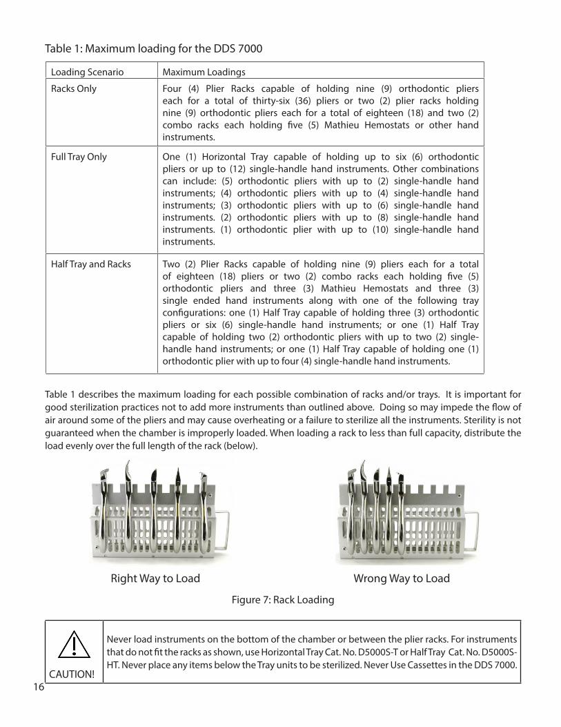
Table 1 describes the maximum loading for each possible combination of racks and/or trays. It is important for good sterilization practices not to add more instruments than outlined above. Doing so may impede the flow of air around some of the pliers and may cause overheating or a failure to sterilize all the instruments. Sterility is not guaranteed when the chamber is improperly loaded. When loading a rack to less than full capacity, distribute the load evenly over the full length of the rack (below).
Figure 7: Rack Loading
CAUTION!
Never load instruments on the bottom of the chamber or between the plier racks. For instruments that do not fit the racks as shown, use Horizontal Tray Cat. No. D5000S-T or Half Tray Cat. No. D5000S-HT. Never place any items below the Tray units to be sterilized. Never Use Cassettes in the DDS 7000.
Loading Scenario Maximum Loadings
Racks Only Four (4) Plier Racks capable of holding nine (9) orthodontic pliers each for a total of thirty-six (36) pliers or two (2) plier racks holding nine (9) orthodontic pliers each for a total of eighteen (18) and two (2) combo racks each holding five (5) Mathieu Hemostats or other hand instruments.
Full Tray Only One (1) Horizontal Tray capable of holding up to six (6) orthodontic pliers or up to (12) single-handle hand instruments. Other combinations can include: (5) orthodontic pliers with up to (2) single-handle hand instruments; (4) orthodontic pliers with up to (4) single-handle hand instruments; (3) orthodontic pliers with up to (6) single-handle hand instruments. (2) orthodontic pliers with up to (8) single-handle hand instruments. (1) orthodontic plier with up to (10) single-handle hand instruments.
Half Tray and Racks Two (2) Plier Racks capable of holding nine (9) pliers each for a total of eighteen (18) pliers or two (2) combo racks each holding five (5) orthodontic pliers and three (3) Mathieu Hemostats and three (3) single ended hand instruments along with one of the following tray configurations: one (1) Half Tray capable of holding three (3) orthodontic pliers or six (6) single-handle hand instruments; or one (1) Half Tray capable of holding two (2) orthodontic pliers with up to two (2) single-handle hand instruments; or one (1) Half Tray capable of holding one (1) orthodontic plier with up to four (4) single-handle hand instruments.
Table 1: Maximum loading for the DDS 7000
Right Way to Load Wrong Way to Load

17
LOADING THE STERILIZATION CHAMBER
Example of proper and improper loadings
Figure 7A: Properly Loaded DDS 7000 with Figure 7B: Properly Loaded DDS 7000four Plier Racks. with Half-Tray and two Plier Racks.
Figure 7C: Improperly loaded Half Tray with Figure7D: Close up of improperly loadedPlier Rack. The Plier Rack is not in the proper half tray. Instruments should be placed sorack channel and covers the air vents. This that they do not touch one another or extendwill impede airflow around the instruments. over the tray periphery.
ALSO AVAILABLE: FULL TRAY FOR HAND INSTRUMENTS.

18
OPERATION
Once the DDS 7000 is loaded, it is time to begin the sterilization process. Close the door by gently pushing the door against the rubber door gasket and turning the knob counter-clockwise. This will engage the cam lock, which pulls the door against the gasket, sealing the chamber.
Figure 8A Figure 8B
Depress the “Standby/On” switch to “On”. The Standby/On switch activates the control panel. The display shows ambient temperature. No LEDs are lit at this time. Press the Cycle Start switch to initiate a cycle. The cycle is preprogrammed and cannot be altered by the user.
Figure 8C Figure 8D
Once the “Cycle Start” switch is pressed, the “warm up” LED lights up indicating that the DDS 7000 is in the warm-up phase of the cycle.
The Safety Door Interlock engages as chamber exceeds 122ºF (50ºC). The lock activation is indicated by a dot that appears in the lower right corner of the display. The device will continue warm-up until the set point is reached. The time required for warm-up is dependent on the size of the load.
73°F
73°F 124°F

19
The DDS 7000 is programmed to sterilize for three (3) minutes. At the completion of three (3) minutes, the DDS 7000 automatically begins the cool down phase of the cycle. The blue “Cool Down” LED is lit.
Cool down is achieved by forcing ambient filtered air across the load and expelling the heated air. The door interlock disengages at 113ºF (45ºC) and the indicator dot disappears from the lower right of the display.
Once the operating temperature of 374ºF (190ºC) is reached, the DDS 7000 begins the sterilize (exposure) phase. The amber “Sterilize” LED lights up. During this phase, the internal temperature is closely monitored and controlled. The temperature on the display is the temperature of the air as measured after it has left the chamber. The displayed temperatures during this phase are typically between 368 - 376ºF (187 – 191ºC). If the display tempera-ture ever drops below 365ºF (185ºC), the cycle will fail.
374°F
374°F
113°F
Figure 9
Figure 10
Figure 11
20
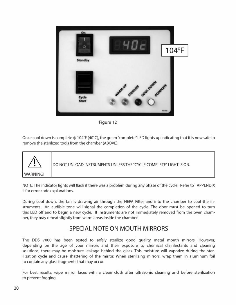
Once cool down is complete @ 104˚F (40˚C), the green “complete” LED lights up indicating that it is now safe to remove the sterilized tools from the chamber (ABOVE).
WARNING!
DO NOT UNLOAD INSTRUMENTS UNLESS THE “CYCLE COMPLETE” LIGHT IS ON.
NOTE: The indicator lights will flash if there was a problem during any phase of the cycle. Refer to APPENDIX II for error code explanations.
During cool down, the fan is drawing air through the HEPA Filter and into the chamber to cool the in-struments. An audible tone will signal the completion of the cycle. The door must be opened to turn this LED off and to begin a new cycle. If instruments are not immediately removed from the oven cham-ber, they may reheat slightly from warm areas inside the chamber.
SPECIAL NOTE ON MOUTH MIRRORS
The DDS 7000 has been tested to safely sterilize good quality metal mouth mirrors. However, depending on the age of your mirrors and their exposure to chemical disinfectants and cleaning solutions, there may be moisture leakage behind the glass. This moisture will vaporize during the ster-ilization cycle and cause shattering of the mirror. When sterilizing mirrors, wrap them in aluminum foil to contain any glass fragments that may occur.
For best results, wipe mirror faces with a clean cloth after ultrasonic cleaning and before sterilization to prevent fogging.
104°F
Figure 12

21
ABORTING A CYCLE
In the event of an emergency that requires aborting the sterilization process, the following procedure should be used.
To abort the DDS 7000 in any cycle phase, toggle the lower portion of the “Standby/On” switch to the “Standby” position. An error code will display in the red LED window, alerting user of a power interrup-tion. An audible tone will sound, and the cycle phase LED will flash notifying the user of the phase at which the interruption occurred. There is no recovery from an aborted cycle.
If the chamber temperature is above 122°F (50°C), Safety Door Interlock will be engaged. In order to open the chamber door, switch the Standby/On switch to “Stand by” and then back to the “On” position and activate the Cycle Start Switch. The cooling fan will turn on and cool the chamber down to 104°F (40°C). Once the chamber cools below 113°F (45°C), the safety door interlock will disengage and you will be able to open the door.
WARNING!
If immediate access to the chamber is required, hold down the “Cycle Start” Switch for 5 seconds. The Safety Door Interlock will unlock for a few seconds allowing the door to be opened. Depending on where in the sterilization cycle the interruption occurred, the contents of the chamber could be extremely hot. Appropriate protective equipment should be worn when handling the contents of the chamber.
To begin sterilization after aborting a cycle, follow the steps above. If the unit is restarted after an error code has been displayed and if the chamber temperature is at 122°F (50°C) or above, the unit will first cool down the chamber temperature to 104°F (40°C) and then restart the sterilization cycle from the beginning.
RESETTING THE TEMPERATURE OVERLOAD SENSOR
The DDS7000 incorporates a temperature overload sensor designed to interrupt power to the heater should operating temperatures exceed normal levels. To reset the sensor:
1. Unplug the sterilizer.2. Turn sterilizer around to face the back.3. Remove exhaust box, if installed, on the left-hand side of the sterilizer back panel.4. Locate the round, black, plastic cap on the upper left-hand corner of the back panel.5. Remove black cap.6. Depress the red button in center of opening while listening for a small “click.”7. Re-install black cap and exhaust box (if installed).8. Plug sterilizer back in to run a test cycle to ensure that the sterilizer will heat.9. After completing a test cycle, make sure that the unit is loaded according to instructions using Dentronix racks or shelves.
22
BIOLOGICAL TESTING IN YOUR STERILIZER
The Centers for Disease Control, the American Dental Association and Dentronix recommend testing your sterilizer with biological indicators at least once per week. Spore strips compatible with the dry heat process (live Bacillus spores) should be used (i.e. DPS-012 PassPort Monitoring Service, DEMS-012 Monitoring Service or DCS-020 SporView Culture Set). Your DDS 7000 has been validated according to the requirements of ANSI/AAMI ST50:2010, “Dry Heat (heated air) Sterilizers”.
Outside the United States, the DCS-020 Spore View Culture Set may be used or you may use your local laboratory for spore testing. Spore strips should be inoculated with B Stearothermophilis and Bacillus Atrophaeus.
Monitoring can be performed following the procedure below using the DSSH-1 Spore Strip Holder (supplied). Use of the Spore Strip Holder is recommended in order to keep the biological indicator from moving around the chamber which may result in false test results.
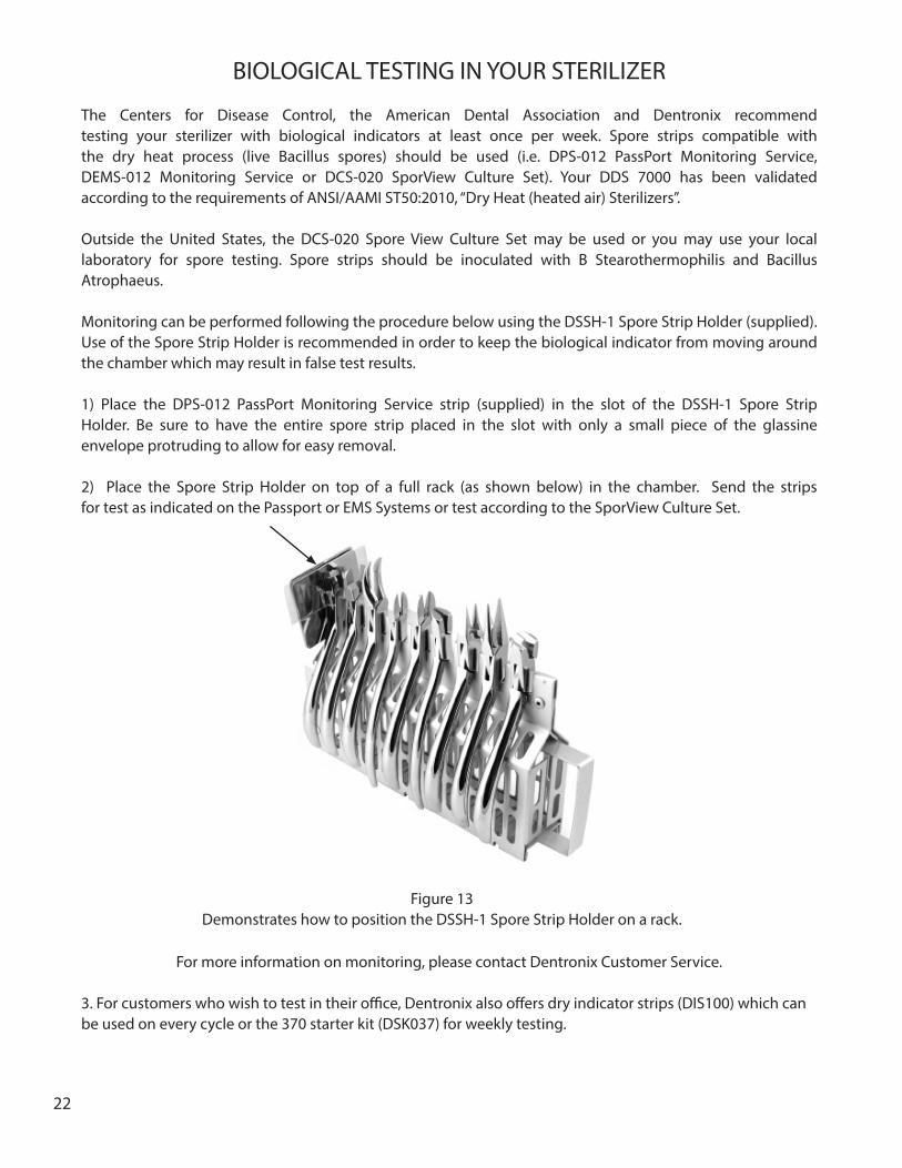
1) Place the DPS-012 PassPort Monitoring Service strip (supplied) in the slot of the DSSH-1 Spore Strip Holder. Be sure to have the entire spore strip placed in the slot with only a small piece of the glassine envelope protruding to allow for easy removal. 2) Place the Spore Strip Holder on top of a full rack (as shown below) in the chamber. Send the strips for test as indicated on the Passport or EMS Systems or test according to the SporView Culture Set.
For more information on monitoring, please contact Dentronix Customer Service.
3. For customers who wish to test in their office, Dentronix also offers dry indicator strips (DIS100) which can be used on every cycle or the 370 starter kit (DSK037) for weekly testing.
Figure 13Demonstrates how to position the DSSH-1 Spore Strip Holder on a rack.

23
MAINTENANCE AND CLEANING
MAINTENANCE: Only the following three components are serviceable by the end user:
1) FUSE (located next to the power cord). In the event of no power to unit, (UNPLUG) disconnect from electric supply and replace with correct amp fuse. (See General and Technical Specifications, Page 5)
2) HEPA Filter located below unit. Remove magnetic strip and replace filter when dirty or if an error code is indicated during cool-down cycle. An increased “Cool Down Cycle” time is a good indication that the HEPA filter needs replacing. Replacement filter is available from Dentronix Inc. (Cat. No. D7000F).
Fuse
Figure 14
HEPA FilterMagnetic cover
HEPA Filter
Figure 15
24
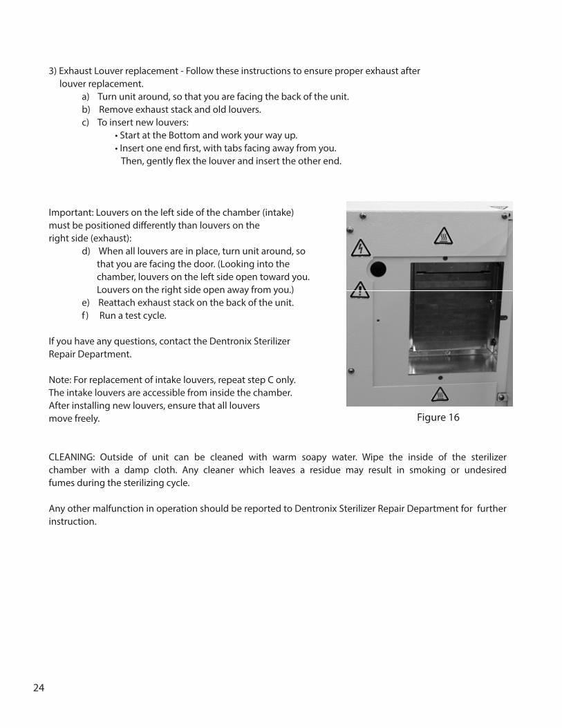
3) Exhaust Louver replacement - Follow these instructions to ensure proper exhaust after louver replacement. a) Turn unit around, so that you are facing the back of the unit. b) Remove exhaust stack and old louvers. c) To insert new louvers: • Start at the Bottom and work your way up. • Insert one end first, with tabs facing away from you. Then, gently flex the louver and insert the other end.
Important: Louvers on the left side of the chamber (intake) must be positioned differently than louvers on the right side (exhaust): d) When all louvers are in place, turn unit around, so that you are facing the door. (Looking into the chamber, louvers on the left side open toward you. Louvers on the right side open away from you.) e) Reattach exhaust stack on the back of the unit. f ) Run a test cycle.
If you have any questions, contact the Dentronix Sterilizer Repair Department.
Note: For replacement of intake louvers, repeat step C only. The intake louvers are accessible from inside the chamber. After installing new louvers, ensure that all louvers move freely.
CLEANING: Outside of unit can be cleaned with warm soapy water. Wipe the inside of the sterilizer chamber with a damp cloth. Any cleaner which leaves a residue may result in smoking or undesired fumes during the sterilizing cycle.
Any other malfunction in operation should be reported to Dentronix Sterilizer Repair Department for further instruction.
Figure 16

25
SELECTING USER OPTIONS
The DDS 7000 user interface has been designed to allow the user to change aspects of how the display looks and responds to the user. The user can change temperature units from Fahrenheit to Celsius, en-able or disable the door interlock, enable or disable audible sounds, add additional cooling time, print log reports and perform a self test to assist you with trouble shooting.
Switch definitions and functions:
Standby/On Switch: must be in “Standby” to enter menu Cycle Start Switch: used to enter the user menu and to change menu items Door Switch: used to change the value of the item in the menu
To enter the user menu:
1) Depress the lower portion of the Standby/On switch to the Standby position.
2) Open the door, releasing the Door Switch.
3) Press and hold the Cycle Start Switch until the display shows 4 red dots (5 seconds). The display will go blank for 1 second and then the first menu item will appear.
4) The first menu item is Temperature. The display will show the current setting, either Celsius or Fahrenheit. To change the setting toggle the Door Switch. To advance to the next menu, toggle the Cycle Start Switch
(Indicates degrees Celsius)
(Indicates degrees Fahrenheit)
5) The second menu item is Audible Sounds. The display will show the current setting, either sound on or off. To change the setting toggle the Door Switch. To advance to the next menu, toggle the Cycle Start Switch.
(Indicates Audible Sound “on”) *default setting (Indicates Audible Sound “off”) NOTE: No Audible Sound will alert operator of errors or cycle complete.
26
6) The third menu item is Additional Cooling Time. The display will show the current setting from 0 to 9 minutes. To change the setting toggle the Door Switch once to add one minute, 3 times to add three minutes, etc. To advance to the next menu, toggle the Cycle Start Switch.
(Indicates no additional minutes are added to the cool down cycle.) *default setting
(Indicates additional minutes have been added to the cool down cycle.) This example shows 9 minutes of additional cooling time.
7) The fourth menu item is the Cycle Log Print. To print a cycle log via the COM port, toggle the door swich. (See section on COM Port).
8) The fifth menu item is the Service Log Print. To print a service log via the COM port, toggle the door switch. (See section on COM Port).
9). The sixth menu item is Self Test. This feature is to be used if you suspect that the sterilizer is not working properly. The Self Test will cause each of the systems to operate in a short period of time to assure that all systems are working. If needed, perform this test with the door open in order to see and hear the operations.
a). Press the door switch, OR turn the “Stand-by/On” switch to “On” then “Stand-by” b). All of the displays will light – observe that all lights work. c). The Door Lock Pin will activate – observe activation d). The Heat and Circulating Fan will activate for 10 seconds – observe and hear activation e). The Circulating Fan and Cool Down Fan will run for 10 seconds – hear the fans run f ). A sound will “beep” indicating end of test
If one of these systems does not work, contact the Dentronix Sterilizer Repair Department.
(Indicates Test Mode Enabled)
10) The final menu item is “Done”. To exit the user menu, toggle the Door Switch and to advance to the first menu again, toggle the Cycle Start Switch.
(Indicates end of user interface menu)

27
USING THE COM PORT
Figure 11 shows the location of the COM Port. This port can be used to print logs via a se-rial printer. Note: Refer to menus 4 and 5 of the User Menu Options found on page 25.
Once connected, the user is capable of printing the last cycle log information. The log prints a header containing the manufacturer, Model No., Firmware version, Serial No., and the Cycle count of the last cycle completed. Each phase of the sterilization process i.e. HEAT, STERILIZE, COOL, and COMPLETE is then printed providing respective temperature information during each cycle, the length of time in minutes and seconds of each cycle, and the appropriate status PASS or FAIL. A COMMENT area is left on the bottom of each report printout for hand written user information. (See the following page for a representative printout of a PASS and FAIL cycle).
Since the device is not set up to automatically print the date, you will have to add the date to the comment section. Logs should be printed immediately after each cycle. Once a new cycle is started the information from the previous cycle cannot be retrieved. These logs should be filed in a safe place.
NOTE: In the printout under the section titled COMPLETE, the total cycle time is printed and whether the total sterilization process has met a PASS or FAIL condition. If a FAIL is reported here, an error code statement will ap-pear. Unit #1000011 failed in the Cool Down cycle. An error code E19 was generated and printed. (See Appendix II for a list of all possible error codes.)
Figure 17COM Port Location on DDS 7000.
The COM Port can be found on the left hand side of the control panel.
COM Port

28
Dentronix --------- DDS-7000Dry Heat Sterilizer a subsidiary ofColtene Whaledent Copyright 2004All Rights Reserved FIRMWARE VERSION: 02.05 SERIAL NUMBER 1000011 CYCLE COUNT: 1 HEAT Start Temp: 75F Final Temp: 375F Time: 23:06 Status: Pass
STERILIZE Min Temp: 372F Max Temp: 376F Time: 3:00 Status: Pass COOL Start Temp: 372F Final Temp: 104F Time: 18:15 Status: Pass COMPLETE Time: 44:21 Status: Pass COMMENTS:
Dentronix --------- DDS-7000 Dry Heat Sterilizer a subsidiary of Coltene Whaledent Copyright 2004All Rights Reserved FIRMWARE VERSION: 02.05 SERIAL NUMBER: 1000011 CYCLE COUNT: 5 HEAT Start Temp: 75F Final Temp: 374F Time: 16:33 Status: Pass STERILIZE Min Temp: 372F Max Temp: 376F Time: 3:00 Status: Pass COOL Start Temp: 372F Final Temp: 135F Time: 22:00 Status: Fail COMPLETE Time: 41:33 Status: Fail Error Code: E19 COMMENTS:
…PASS Cycle Report… …Failed Cycle Report…
29
WARRANTY / RETURN POLICY
Warranty: The Dentronix DDS 7000 is guaranteed to be free from defects in material and/or workmanship for a period of one year from date of purchase. There are no other warranties, expressed or implied, including but not limited to warranties of merchantability and fitness for a particular purpose. Dentronix products are manufactured from new parts.
Return Policy: Obtain prior authorization if a Dentronix Sterilizer requires return to the factory for any reason. Ship in original shipping containers; Dentronix sterilizers that require return to the factory for any reason must have prior authorization and must be returned in their original carton. Extra cartons and packaging materials are available from Dentronix at a nominal fee. Loaners are available at no charge if unit to be repaired is under warranty. After one year from date of sale, loaners are available at a nominal charge. All shipping costs are the responsibility of the customer.
STERILIZER RETURN PROCEDURE
1. Contact Dentronix Sterilizer repair Department (800-523-5944, ext. 8925) in U.S. and Canada or 330-916-8925 or e-mail [email protected] or fax 330-645-8758 for packing materials and return authorization. DO NOT SEND UNIT BACK WITHOUT AUTHORIZATION.
2. Package sterilizer in original shipping container.
3. Contact UPS for Ground Delivery (in the United States) of unit to:
Dentronix Inc., 235 Ascot Parkway, Cuyahoga Falls, OH 44223
In other areas, contact Dentronix for recommended shipping instructions.
4. Insure package for current market price – shipping weight is 118 lbs. (53.64 Kg.).
30
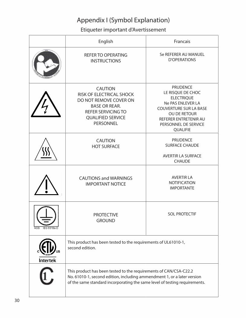
English Francais
REFER TO OPERATING INSTRUCTIONS
Se REFERER AU MANUEL D'OPERATIONS
CAUTIONRISK OF ELECTRICAL SHOCKDO NOT REMOVE COVER ON
BASE OR REAR. REFER SERVICING TO QUALIFIED SERVICE
PERSONNEL
PRUDENCELE RISQUE DE CHOC
ELECTRIQUENe PAS ENLEVER LA
COUVERTURE SUR LA BASE OU DE RETOUR
REFERER ENTRETENIR AU PERSONNEL DE SERVICE
QUALIFIE
CAUTIONHOT SURFACE
PRUDENCESURFACE CHAUDE
AVERTIR LA SURFACE CHAUDE
CAUTIONS and WARNINGSIMPORTANT NOTICE
AVERTIR LANOTIFICATION IMPORTANTE
PROTECTIVEGROUND
SOL PROTECTIF
Appendix I (Symbol Explanation)Etiqueter important d’Avertissement
This product has been tested to the requirements of CAN/CSA-C22.2 No. 61010-1, second edition, including ammendment 1, or a later version of the same standard incorporating the same level of testing requirements.
This product has been tested to the requirements of UL61010-1, second edition.

31
the same failure or related failure is identified a second time, contact the dentronix Sterilization Repair Department.
If an error occurs, the LED light representing the phase of the cycle where the error occurred will be flashing. For exam-ple, if the yellow and blue LED’s are flashing, an error occurred during the warm-up phase and cool down phase.
Appendix II (Error CodesThe DDS 7000 Dry Heat Sterilizer is programmed to allow optimum time to warm up, sterilize and cool down during a complete cycle. If any stage of this process is interrrupted before a cycle has completed, the DDS 7000 will display an error code. The error codes are defined below:Code Description Solution
E01 Door is open. Close door, press STANDY/ON switch to STANDBY, then ON. Press CYCLE START switch.
E04 Cycle temperature parameter fails be-fore pre-cooldown phase.
Press STANDY/ON switch to STANDBY, then ON. Press CYCLE START switch.
E05 STANDBY/ON switch is switched from ON to STANDBY.
Press STANDY/ON switch to STANDBY, then ON. Press CYCLE START switch.
E07 **Cycle fails to reach warm-up condi-tions. (E07 can occurr if Temperature Overload Sensor is ripped. see page 20 for testing instructions.
Press STANDY/ON switch to STANDBY, then ON. Press CYCLE START switch.
E13 ** Failure to maintain sterilization tem-perature parameters.
Press STANDY/ON switch to STANDBY, then ON. Press CYCLE START switch.
E19 **Failure to reach cooldown tempera-ture parameters.
Press STANDY/ON switch to STANDBY, then ON. Press CYCLE START switch.
E30 System ErrorE31 Building Power Interruption. Press STANDY/ON switch to STANDBY, then ON. Press
CYCLE START switch.E42 Oven RTD Failure Contact Dentronix Sterilizer Repair Department.E43 Calibration Required. Contact Dentronix Sterilizer Repair Department.E44 Calibration out of range. Contact Dentronix Sterilizer Repair Department.
Door is open
Cycle temperature parameter fails before pre-cooldown* phase.
STANDBY/ ON switch is switched from ON to STANDBY.
** Cycle fails to reach warm-up conditions.E 07 can occur if Temperature Overload Sensor is tripped. See page 20 for resetting instructions.
** Failure to maintain sterilization tempera-ture parameters.
**Failure to reach cooldown temperature parameters.
System error.
Building power interruption.
Oven RTD Failure.
Calibration required.
Calibration out of range
Close door, press STANDBY/ON switch to STANDBY, then ON. Press CYCLE START Switch.
Press STANDBY/ON switch to STAND-BY, then ON. Press CYCLE START Switch.
Press STANDBY/ON switch to STAND-BY, then ON. Press CYCLE START Switch.
Press STANDBY/ON switch to STAND-BY, then ON. Press CYCLE START Switch.
Press STANDBY/ON switch to STAND-BY, then ON. Press CYCLE START Switch.
Press STANDBY/ON switch to STAND-BY, then ON. Press CYCLE START Switch.
Contact Dentronix Service Department
Press STANDBY/ON switch to STAND-BY, then ON. Press CYCLE START Switch.
Contact Dentronix Service Department
Contact Dentronix Service Department
Contact Dentronix Service Department
E 01
E 04
E 05
E 07
E 13
E 19
E 30
E 31
E 42
E 43
E 44
The DDS 7000 Dry Heat Sterilizer is programmed to allow optimum time to warm up, sterilize, and cool down during a com-plete cycle. If any stage of this process is interrupted before a cycle has completed, the DDS 7000 will display an error code. The following chart defines the error codes:
Appendix II (Error Codes)
* Pre-cool down is a phase that only occurs when a cycle is aborted and the chamber temperature is above 113° F (45°C). The device must cool down before any other action can occur, including opening the door. The blue LED light will be illumi-nated to indicate cooldown.** These error codes suggest a potential problem with the device or a user error. To troubleshoot, verify that the load configu-ration is consistent with loading instructions on page 14-16. Verify that the instruments in the chamber have been cleaned and dried prior to attempting sterilization and that the trays and/or racks have been positioned properly. Attempt the cycle again. If the same failure or related failure is identified a second time, contact the Dentronix Service Department.
If an error occurs, the LED light representing the phase of the cycle where the error occured will be flashing. For ex-ample, if the yellow and blue LED’s are flashing, an eror occured during the warm-up phase and cool down phase.

32
Manufactured for: Dentronix Inc.Subsidiary of Coltène/Whaledent Inc. 235 Ascot Parkway Cuyahoga Falls, OH 44223/USATel. USA & Canada +1 800 523 5944 +1 330 916 7300 Fax + 1 330 916 [email protected]
P/N
300
0318
5B
06/
22/1
5Coltene/Whaledent GmbH + Co. KGRaiffeisenstrasse 3089129 Langenau/GermanyTel. +49 (0) 7345 805 0Fax +49 (0) 7345 805 [email protected]
© 2015 Printed in U.S.A.