ddos secure gui user guide - juniper networks - network ... ·...
TRANSCRIPT
DDoS Secure
GUI User Guide
Release
5.14.1-0
Published: 2014-05-14
Copyright © 2014, Juniper Networks, Inc.

Juniper Networks, Inc.1194 North Mathilda AvenueSunnyvale, California 94089USA408-745-2000www.juniper.net
Copyright © 2014, Juniper Networks, Inc.
Copyright ©Webscreen Technology 2001-2013
Juniper Networks, Junos, Steel-Belted Radius, NetScreen, and ScreenOS are registered trademarks of Juniper Networks, Inc. in the UnitedStates and other countries. The Juniper Networks Logo, the Junos logo, and JunosE are trademarks of Juniper Networks, Inc. All othertrademarks, service marks, registered trademarks, or registered service marks are the property of their respective owners.
Juniper Networks assumes no responsibility for any inaccuracies in this document. Juniper Networks reserves the right to change, modify,transfer, or otherwise revise this publication without notice.
DDoS Secure GUI User GuideCopyright © 2014, Juniper Networks, Inc.All rights reserved.
The information in this document is current as of the date on the title page.
YEAR 2000 NOTICE
Juniper Networks hardware and software products are Year 2000 compliant. Junos OS has no known time-related limitations through theyear 2038. However, the NTP application is known to have some difficulty in the year 2036.
ENDUSER LICENSE AGREEMENT
The Juniper Networks product that is the subject of this technical documentation consists of (or is intended for use with) Juniper Networkssoftware. Use of such software is subject to the terms and conditions of the End User License Agreement (“EULA”) posted athttp://www.juniper.net/support/eula.html. By downloading, installing or using such software, you agree to the terms and conditions ofthat EULA.
Copyright © 2014, Juniper Networks, Inc.ii
Table of Contents
About the Documentation . . . . . . . . . . . . . . . . . . . . . . . . . . . . . . . . . . . . . . . . . . . . xiii
Documentation and Release Notes . . . . . . . . . . . . . . . . . . . . . . . . . . . . . . . . . xiii
Documentation Conventions . . . . . . . . . . . . . . . . . . . . . . . . . . . . . . . . . . . . . . xiii
Documentation Feedback . . . . . . . . . . . . . . . . . . . . . . . . . . . . . . . . . . . . . . . . . xv
Requesting Technical Support . . . . . . . . . . . . . . . . . . . . . . . . . . . . . . . . . . . . . xvi
Self-Help Online Tools and Resources . . . . . . . . . . . . . . . . . . . . . . . . . . . xvi
Opening a Case with JTAC . . . . . . . . . . . . . . . . . . . . . . . . . . . . . . . . . . . . . xvi
Part 1 DDoS Secure GUI Overview
Chapter 1 DDoS Secure Appliance Feature Overview . . . . . . . . . . . . . . . . . . . . . . . . . . . . . 3
DDoS Secure Appliance Feature Overview . . . . . . . . . . . . . . . . . . . . . . . . . . . . . . . . 3
Chapter 2 DDoS Secure Appliance Getting Started . . . . . . . . . . . . . . . . . . . . . . . . . . . . . . . 7
Connecting a DDoS Secure Appliance to the Network . . . . . . . . . . . . . . . . . . . . . . . 7
Understanding the DDoS Secure Appliance Interface Conventions . . . . . . . . . . . . 9
UnderstandingDefendingVersusLoggingOperationalModesof theDDoSSecure
Appliance . . . . . . . . . . . . . . . . . . . . . . . . . . . . . . . . . . . . . . . . . . . . . . . . . . . . . . 10
Accessing a Secure DDoS Appliance . . . . . . . . . . . . . . . . . . . . . . . . . . . . . . . . . . . . 11
Imaging a DDoS Secure Appliance . . . . . . . . . . . . . . . . . . . . . . . . . . . . . . . . . . . . . . 11
Reimaging a DDoS Secure Appliance After Hardware Replacement . . . . . . . . . . . 12
Configuring Basic Settings for a DDoS Secure Appliance After Hardware
Replacement . . . . . . . . . . . . . . . . . . . . . . . . . . . . . . . . . . . . . . . . . . . . . . . . . . . 12
Configuring the Management Interface for a DDoS Secure Appliance . . . . . . . . . . 13
Configuring the Management Interface Using a Keyboard and Monitor or a
Serial Interface . . . . . . . . . . . . . . . . . . . . . . . . . . . . . . . . . . . . . . . . . . . . . . 13
Configuring the Management Interface Using an Ethernet Interface . . . . . . . 14
Configuring a DDoS Secure Appliance Using Integrated Lights Out
Functionality . . . . . . . . . . . . . . . . . . . . . . . . . . . . . . . . . . . . . . . . . . . . . . . . . . . 15
Connecting to a DDoS Secure Appliance . . . . . . . . . . . . . . . . . . . . . . . . . . . . . . . . . 16
End User License Agreement . . . . . . . . . . . . . . . . . . . . . . . . . . . . . . . . . . . . . . . . . . 18
Understanding the Summary Dashboard of a DDoS Secure ApplianceWeb
Interface . . . . . . . . . . . . . . . . . . . . . . . . . . . . . . . . . . . . . . . . . . . . . . . . . . . . . . . 21
DDoS Secure ApplianceWeb Interface Overview . . . . . . . . . . . . . . . . . . . . . . . . . . 22
Understanding DDoS Secure Filter Options . . . . . . . . . . . . . . . . . . . . . . . . . . . . . . 23
Using the DDoS Secure Appliance Web Interface . . . . . . . . . . . . . . . . . . . . . . . . . 25
Expanding the Central Pane Area . . . . . . . . . . . . . . . . . . . . . . . . . . . . . . . . . . . 25
Arranging Table Ordering . . . . . . . . . . . . . . . . . . . . . . . . . . . . . . . . . . . . . . . . . 26
Arranging Column Ordering . . . . . . . . . . . . . . . . . . . . . . . . . . . . . . . . . . . . . . . 27
Sorting Data and Add-Remove Columns . . . . . . . . . . . . . . . . . . . . . . . . . . . . . 27
Understanding Action Cells . . . . . . . . . . . . . . . . . . . . . . . . . . . . . . . . . . . . . . . 28
iiiCopyright © 2014, Juniper Networks, Inc.
Understanding IP/AS Number/Location Details . . . . . . . . . . . . . . . . . . . . . . . 29
Understanding Graphs . . . . . . . . . . . . . . . . . . . . . . . . . . . . . . . . . . . . . . . . . . . 29
Chapter 3 DDoS Secure Appliance Configuration and Logs . . . . . . . . . . . . . . . . . . . . . . 33
DDoS Secure Appliance Configuration Overview . . . . . . . . . . . . . . . . . . . . . . . . . . 33
Setting Access Control in a DDoS Secure Appliance . . . . . . . . . . . . . . . . . . . . . . . 35
User Access . . . . . . . . . . . . . . . . . . . . . . . . . . . . . . . . . . . . . . . . . . . . . . . . . . . . 36
Configuring the DDoS Secure Interfaces . . . . . . . . . . . . . . . . . . . . . . . . . . . . . . . . . 39
Understanding Common Interface Information in a DDoS Secure
Appliance . . . . . . . . . . . . . . . . . . . . . . . . . . . . . . . . . . . . . . . . . . . . . . . . . . 41
Configuring DDoS Secure . . . . . . . . . . . . . . . . . . . . . . . . . . . . . . . . . . . . . . . . . . . . 46
DDoS Secure Appliance Internet Gateways . . . . . . . . . . . . . . . . . . . . . . . . . . 48
Adding an Internet MAC Address to a DDoS Secure Appliance . . . . . . . . . . . 49
Configuring a DDoS Secure Appliance . . . . . . . . . . . . . . . . . . . . . . . . . . . . . . 50
Configuring Sharing Information . . . . . . . . . . . . . . . . . . . . . . . . . . . . . . . . . . . . 57
Configuring a Protected Gateway Based on MAC Address . . . . . . . . . . . . . . . 58
Configuring Portals . . . . . . . . . . . . . . . . . . . . . . . . . . . . . . . . . . . . . . . . . . . . . . . . . 59
Configuring DDoS Secure Portals . . . . . . . . . . . . . . . . . . . . . . . . . . . . . . . . . . 60
Configuring DDoS Secure Appliance Individual Portals . . . . . . . . . . . . . . . . . 63
Configuring DDoS Secure Appliance Bandwidth and Port Filters . . . . . . . . . . 63
Configuring DDoS Secure Appliance Configure Filter Aggregations . . . . . . . . 67
Configuring DDoS Secure Appliance Configure Protected IP addresses . . . . 68
Configuring DDoS Secure Appliance Defined Protected IP Addresses . . . . . . 72
Configuring SSL . . . . . . . . . . . . . . . . . . . . . . . . . . . . . . . . . . . . . . . . . . . . . . . . . . . . 74
Global Configuration . . . . . . . . . . . . . . . . . . . . . . . . . . . . . . . . . . . . . . . . . . . . . 74
FIPS 140-2 Mode . . . . . . . . . . . . . . . . . . . . . . . . . . . . . . . . . . . . . . . . . . . . 74
SSL Decryption . . . . . . . . . . . . . . . . . . . . . . . . . . . . . . . . . . . . . . . . . . . . . 74
Management GUI SSL Certificate . . . . . . . . . . . . . . . . . . . . . . . . . . . . . . . 74
Uploading SSL Decrypt Private Key File . . . . . . . . . . . . . . . . . . . . . . . . . . . . . . 76
Adding Default Domain SSL Decrypt Key . . . . . . . . . . . . . . . . . . . . . . . . . . . . 76
Adding a Specific Domain SSL Decrypt Key . . . . . . . . . . . . . . . . . . . . . . . . . . 76
Configured SSL Decrypt Keys . . . . . . . . . . . . . . . . . . . . . . . . . . . . . . . . . . . . . . 77
Configuring Date and Time on DDoS Secure Appliance . . . . . . . . . . . . . . . . . . . . . 77
Configuring Logging on a DDoS Secure Appliance . . . . . . . . . . . . . . . . . . . . . . . . . 78
Setting Up Portals . . . . . . . . . . . . . . . . . . . . . . . . . . . . . . . . . . . . . . . . . . . . . . . 79
Setting Up SNMP . . . . . . . . . . . . . . . . . . . . . . . . . . . . . . . . . . . . . . . . . . . . . . . 79
Setting Up a Syslog Server . . . . . . . . . . . . . . . . . . . . . . . . . . . . . . . . . . . . . . . . 80
Setting Up a Structured Syslog Server . . . . . . . . . . . . . . . . . . . . . . . . . . . . . . . 82
Setting Up a Netflow Server . . . . . . . . . . . . . . . . . . . . . . . . . . . . . . . . . . . . . . . 82
Setting Up a Mail Server . . . . . . . . . . . . . . . . . . . . . . . . . . . . . . . . . . . . . . . . . . 83
Setting Up a Proxy Server . . . . . . . . . . . . . . . . . . . . . . . . . . . . . . . . . . . . . . . . . 85
Setting Up GeoIP Database(s) . . . . . . . . . . . . . . . . . . . . . . . . . . . . . . . . . . . . 86
Setting Up an Incident Create Threshold . . . . . . . . . . . . . . . . . . . . . . . . . . . . . 86
Setting Up an Incident Alert Threshold . . . . . . . . . . . . . . . . . . . . . . . . . . . . . . 87
Setting Up an Incident View Threshold . . . . . . . . . . . . . . . . . . . . . . . . . . . . . . 87
Setting Up Incident Peak Values . . . . . . . . . . . . . . . . . . . . . . . . . . . . . . . . . . . 88
Setting Up the Worst Offenders Logging Threshold . . . . . . . . . . . . . . . . . . . . 88
Setting Up Debug Options . . . . . . . . . . . . . . . . . . . . . . . . . . . . . . . . . . . . . . . . 89
Copyright © 2014, Juniper Networks, Inc.iv
DDoS Secure GUI User Guide

Managing DDoS Secure Appliance General Logs . . . . . . . . . . . . . . . . . . . . . . 89
DDoS Secure Appliance Configuration Files . . . . . . . . . . . . . . . . . . . . . . . . . . . . . . 92
DDoS Secure Appliance Statistics Reports . . . . . . . . . . . . . . . . . . . . . . . . . . . . . . 93
Managing DDoS Secure Appliance Incident Logs . . . . . . . . . . . . . . . . . . . . . . . . . 94
Managing DDoS Secure Appliance Worst Offenders Log File . . . . . . . . . . . . . . . . 96
Reporting on a Specific Time . . . . . . . . . . . . . . . . . . . . . . . . . . . . . . . . . . . . . . . . . . 97
Reporting on a Specific IP or Network Activity . . . . . . . . . . . . . . . . . . . . . . . . . . . . 97
Upgrading a DDoS Secure Appliance with Patches Using File Upload . . . . . . . . . 98
Understanding DDoS Secure Appliance Packet Capture Options . . . . . . . . . . . . 100
Terminating a DDoS Secure Appliance Packet Capture Recording . . . . . . . . . . . 102
Displaying a DDoS Secure Appliance Packet Capture . . . . . . . . . . . . . . . . . . . . . 103
Downloading and Saving DDoS Secure Appliance Packet Capture Details . . . . 105
Shutting Down a DDoS Secure Appliance . . . . . . . . . . . . . . . . . . . . . . . . . . . . . . . 107
Chapter 4 DDoS Secure Statistical Displays Overview . . . . . . . . . . . . . . . . . . . . . . . . . . 109
DDoS Secure Appliance Statistical Summary Overview . . . . . . . . . . . . . . . . . . . 109
DDoS Secure Appliance Status Information . . . . . . . . . . . . . . . . . . . . . . . . . . . . . . 111
DDoS Secure Appliance Protected IP Information . . . . . . . . . . . . . . . . . . . . . . . . . 114
DDoS Secure Appliance Live Incidents Information . . . . . . . . . . . . . . . . . . . . . . . . 117
DDoS Secure Appliance Worst Offenders Information . . . . . . . . . . . . . . . . . . . . . 118
DDoS Secure Appliance Temporarily Black-Listed Information . . . . . . . . . . . . . . 121
DDoS Secure Appliance Tracked IP Information . . . . . . . . . . . . . . . . . . . . . . . . . . 122
Tracking Country-Wide Usage Information in a DDoS Secure Appliance . . . . . . . 124
DDoS Secure Appliance TCP Information . . . . . . . . . . . . . . . . . . . . . . . . . . . . . . . 126
DDoS Secure Appliance UDP Information . . . . . . . . . . . . . . . . . . . . . . . . . . . . . . . 127
DDoS Secure Appliance ICMP Information . . . . . . . . . . . . . . . . . . . . . . . . . . . . . . 129
DDoS Secure Appliance Other IP Protocol Information . . . . . . . . . . . . . . . . . . . . 130
DDoS Secure Appliance Fragment Information . . . . . . . . . . . . . . . . . . . . . . . . . . 132
DDoS Secure Appliance URL Information . . . . . . . . . . . . . . . . . . . . . . . . . . . . . . . 133
DDoS Secure Appliance DNS Information . . . . . . . . . . . . . . . . . . . . . . . . . . . . . . . 135
DDoS Secure Appliance SIP Information . . . . . . . . . . . . . . . . . . . . . . . . . . . . . . . . 136
DDoS Secure Appliance Bandwidth Information . . . . . . . . . . . . . . . . . . . . . . . . . 138
DDoS Secure Appliance Rerouting Information . . . . . . . . . . . . . . . . . . . . . . . . . . 139
DDoS Secure BGP FlowSpec Information . . . . . . . . . . . . . . . . . . . . . . . . . . . . . . . 140
DDoS Secure Appliance MAC Information . . . . . . . . . . . . . . . . . . . . . . . . . . . . . . 143
Miscellaneous Information . . . . . . . . . . . . . . . . . . . . . . . . . . . . . . . . . . . . . . . . . . . 145
DDoS Secure Appliance Miscellaneous Information . . . . . . . . . . . . . . . . . . . 145
Network Logging . . . . . . . . . . . . . . . . . . . . . . . . . . . . . . . . . . . . . . . . . . . . . . . 145
Resources . . . . . . . . . . . . . . . . . . . . . . . . . . . . . . . . . . . . . . . . . . . . . . . . . . . . 146
Queues . . . . . . . . . . . . . . . . . . . . . . . . . . . . . . . . . . . . . . . . . . . . . . . . . . . . . . . 146
Disk Activity . . . . . . . . . . . . . . . . . . . . . . . . . . . . . . . . . . . . . . . . . . . . . . . . . . . 147
System Load . . . . . . . . . . . . . . . . . . . . . . . . . . . . . . . . . . . . . . . . . . . . . . . . . . 147
DDoS Secure Appliance Tables . . . . . . . . . . . . . . . . . . . . . . . . . . . . . . . . . . . . 147
Interface Errors . . . . . . . . . . . . . . . . . . . . . . . . . . . . . . . . . . . . . . . . . . . . . . . . 149
Chapter 5 DDoS Secure Defense Information Overview . . . . . . . . . . . . . . . . . . . . . . . . . 151
Understanding DDoS Secure Appliance Operational Mode . . . . . . . . . . . . . . . . . 151
Understanding DDoS Secure Appliance Failover States . . . . . . . . . . . . . . . . . . . . 153
Understanding DDoS Secure Appliance Failover Information . . . . . . . . . . . . . . . 153
Understanding DDoS Secure Appliance State Synchronization Information . . . . 153
vCopyright © 2014, Juniper Networks, Inc.
Table of Contents
Understanding DDoS Secure Appliance Record/Replay State . . . . . . . . . . . . . . . 154
Understanding DDoS Secure Appliance Transition States . . . . . . . . . . . . . . . . . . 154
Understanding DDoS Secure Appliance Protected IP Information . . . . . . . . . . . . 155
Understanding DDoS Secure Appliance Defense Status Information . . . . . . . . . 156
Understanding DDoS Secure Appliance Additional Status Information . . . . . . . 158
Part 2 Appendixes
Appendix A TCP States . . . . . . . . . . . . . . . . . . . . . . . . . . . . . . . . . . . . . . . . . . . . . . . . . . . . . . 165
Understanding DDoS Secure Appliance TCP States . . . . . . . . . . . . . . . . . . . . . . 165
Appendix B ICMP Types . . . . . . . . . . . . . . . . . . . . . . . . . . . . . . . . . . . . . . . . . . . . . . . . . . . . . . 167
Understanding DDoS Secure Appliance ICMP Types . . . . . . . . . . . . . . . . . . . . . . 167
Appendix C Index Attack Types . . . . . . . . . . . . . . . . . . . . . . . . . . . . . . . . . . . . . . . . . . . . . . . 169
Understanding Index Attack Types . . . . . . . . . . . . . . . . . . . . . . . . . . . . . . . . . . . . 169
Appendix D Country Codes . . . . . . . . . . . . . . . . . . . . . . . . . . . . . . . . . . . . . . . . . . . . . . . . . . . 175
DDoS Secure Appliance Country Codes . . . . . . . . . . . . . . . . . . . . . . . . . . . . . . . . . 175
Appendix E Panel Information . . . . . . . . . . . . . . . . . . . . . . . . . . . . . . . . . . . . . . . . . . . . . . . . 199
DDoS Secure Appliance Panel Information . . . . . . . . . . . . . . . . . . . . . . . . . . . . . . 199
DDoS Secure-1200-Fail-Safe Panels . . . . . . . . . . . . . . . . . . . . . . . . . . . . . . . 199
Appendix F Troubleshooting . . . . . . . . . . . . . . . . . . . . . . . . . . . . . . . . . . . . . . . . . . . . . . . . . 201
Troubleshooting a DDoS Secure Appliance . . . . . . . . . . . . . . . . . . . . . . . . . . . . . . 201
Appendix G Customizing the Web Interface . . . . . . . . . . . . . . . . . . . . . . . . . . . . . . . . . . . . 203
Customizing the DDoS Secure Web Interface . . . . . . . . . . . . . . . . . . . . . . . . . . . 203
Login Page . . . . . . . . . . . . . . . . . . . . . . . . . . . . . . . . . . . . . . . . . . . . . . . . . . . . 203
Images/CSS Files . . . . . . . . . . . . . . . . . . . . . . . . . . . . . . . . . . . . . . . . . . . . . . 203
Updating Customized Files . . . . . . . . . . . . . . . . . . . . . . . . . . . . . . . . . . . . . . 204
Removing Customized Files . . . . . . . . . . . . . . . . . . . . . . . . . . . . . . . . . . . . . . 204
Appendix H TAPMode . . . . . . . . . . . . . . . . . . . . . . . . . . . . . . . . . . . . . . . . . . . . . . . . . . . . . . . 205
Configuring DDoS Secure for Running in TAP Mode . . . . . . . . . . . . . . . . . . . . . . . 205
Configuration . . . . . . . . . . . . . . . . . . . . . . . . . . . . . . . . . . . . . . . . . . . . . . . . . 206
Copyright © 2014, Juniper Networks, Inc.vi
DDoS Secure GUI User Guide

List of Figures
Part 1 DDoS Secure GUI Overview
Chapter 1 DDoS Secure Appliance Feature Overview . . . . . . . . . . . . . . . . . . . . . . . . . . . . . 3
Figure 1: Traffic Flow Through a DDoS Secure Appliance . . . . . . . . . . . . . . . . . . . . . 3
Figure 2: Attack Traffic Flow Through a DDoS Secure Appliance . . . . . . . . . . . . . . . 4
Figure 3: Traffic Analysis Block Diagram . . . . . . . . . . . . . . . . . . . . . . . . . . . . . . . . . . 4
Chapter 2 DDoS Secure Appliance Getting Started . . . . . . . . . . . . . . . . . . . . . . . . . . . . . . . 7
Figure 4: DDoS Secure Standalone Appliance . . . . . . . . . . . . . . . . . . . . . . . . . . . . . 8
Figure 5: DDoS Secure Appliance Network Connection in a High-Availability
Cluster . . . . . . . . . . . . . . . . . . . . . . . . . . . . . . . . . . . . . . . . . . . . . . . . . . . . . . . . . 9
Figure 6: Navigation Block Error . . . . . . . . . . . . . . . . . . . . . . . . . . . . . . . . . . . . . . . . 16
Figure 7: DDoS Secure Appliance Landing Page . . . . . . . . . . . . . . . . . . . . . . . . . . . 17
Figure 8: Security Login Page . . . . . . . . . . . . . . . . . . . . . . . . . . . . . . . . . . . . . . . . . . 18
Figure 9: End User License Agreement . . . . . . . . . . . . . . . . . . . . . . . . . . . . . . . . . . 19
Figure 10: DDoS Secure Appliance Summary Dashboard . . . . . . . . . . . . . . . . . . . . 21
Figure 11: DDoS Secure Appliance Web Interface Layout . . . . . . . . . . . . . . . . . . . . 22
Figure 12: View Filter Options . . . . . . . . . . . . . . . . . . . . . . . . . . . . . . . . . . . . . . . . . . 23
Figure 13: View Filter Option Example . . . . . . . . . . . . . . . . . . . . . . . . . . . . . . . . . . . 24
Figure 14: Select View Option . . . . . . . . . . . . . . . . . . . . . . . . . . . . . . . . . . . . . . . . . 24
Figure 15: Viewing Icon . . . . . . . . . . . . . . . . . . . . . . . . . . . . . . . . . . . . . . . . . . . . . . . 25
Figure 16: Expanding Center Pane Option . . . . . . . . . . . . . . . . . . . . . . . . . . . . . . . . 26
Figure 17: Displaying Left and Right Pane Option . . . . . . . . . . . . . . . . . . . . . . . . . . 26
Figure 18: Table Arranging Options . . . . . . . . . . . . . . . . . . . . . . . . . . . . . . . . . . . . . 26
Figure 19: Table Arranging–Finding Position . . . . . . . . . . . . . . . . . . . . . . . . . . . . . . 27
Figure 20: Table Arranging–Position Found . . . . . . . . . . . . . . . . . . . . . . . . . . . . . . 27
Figure 21: Table Sorting . . . . . . . . . . . . . . . . . . . . . . . . . . . . . . . . . . . . . . . . . . . . . . 28
Figure 22: Action Location on Cell . . . . . . . . . . . . . . . . . . . . . . . . . . . . . . . . . . . . . . 28
Figure 23: Action on Cell . . . . . . . . . . . . . . . . . . . . . . . . . . . . . . . . . . . . . . . . . . . . . . 28
Figure 24: IP/AS/Location Details . . . . . . . . . . . . . . . . . . . . . . . . . . . . . . . . . . . . . . 29
Figure 25: Graph Details . . . . . . . . . . . . . . . . . . . . . . . . . . . . . . . . . . . . . . . . . . . . . . 30
Figure 26: Previous Graph Option . . . . . . . . . . . . . . . . . . . . . . . . . . . . . . . . . . . . . . 30
Figure 27: Custom Period Configuration . . . . . . . . . . . . . . . . . . . . . . . . . . . . . . . . . . 31
Chapter 3 DDoS Secure Appliance Configuration and Logs . . . . . . . . . . . . . . . . . . . . . . 33
Figure 28: Configuration Overview Page Snippet 1 . . . . . . . . . . . . . . . . . . . . . . . . . 34
Figure 29: Configuration Overview Page Snippet 2 . . . . . . . . . . . . . . . . . . . . . . . . . 35
Figure 30: Access Control Page . . . . . . . . . . . . . . . . . . . . . . . . . . . . . . . . . . . . . . . . 36
Figure 31: Configure Interface Page Snippet 1 . . . . . . . . . . . . . . . . . . . . . . . . . . . . . 39
Figure 32: Configure Interface Page Snippet 2 . . . . . . . . . . . . . . . . . . . . . . . . . . . . 40
Figure 33: DDoS Secure Configuration . . . . . . . . . . . . . . . . . . . . . . . . . . . . . . . . . . . 47
Figure 34: Configure Portal Definitions . . . . . . . . . . . . . . . . . . . . . . . . . . . . . . . . . . 48
viiCopyright © 2014, Juniper Networks, Inc.
Figure 35: DDoS Secure Portal Configuration Overview Page. . . . . . . . . . . . . . . . . 60
Figure 36: DDoS Secure Portal Configure Bandwidth and Port State Filters . . . . 64
Figure 37: DDoS Secure Portal Configure State Filter Aggregations . . . . . . . . . . . 68
Figure 38: Management Only SSL Certificate Option . . . . . . . . . . . . . . . . . . . . . . . 75
Figure 39: Individual Portal Details . . . . . . . . . . . . . . . . . . . . . . . . . . . . . . . . . . . . . 75
Figure 40: Specific Domain Details . . . . . . . . . . . . . . . . . . . . . . . . . . . . . . . . . . . . . 77
Figure 41: Data and Time Page . . . . . . . . . . . . . . . . . . . . . . . . . . . . . . . . . . . . . . . . . 77
Figure 42: DDoS Secure Portal Options . . . . . . . . . . . . . . . . . . . . . . . . . . . . . . . . . . 79
Figure 43: DDoS Secure SNMP Options . . . . . . . . . . . . . . . . . . . . . . . . . . . . . . . . . 80
Figure 44: DDoS Secure Syslog Server Options . . . . . . . . . . . . . . . . . . . . . . . . . . . . 81
Figure 45: DDoS Secure Structured Syslog Server Options . . . . . . . . . . . . . . . . . . 82
Figure 46: DDoS Secure Logging Netflow Server . . . . . . . . . . . . . . . . . . . . . . . . . . 83
Figure 47: DDoS Secure Logging Mail Server . . . . . . . . . . . . . . . . . . . . . . . . . . . . . 84
Figure 48: DDoS Secure Logging Proxy Server . . . . . . . . . . . . . . . . . . . . . . . . . . . . 85
Figure 49: DDoS Secure GeoIP Server . . . . . . . . . . . . . . . . . . . . . . . . . . . . . . . . . . 86
Figure 50: DDoS Secure Incident Create Threshold . . . . . . . . . . . . . . . . . . . . . . . . 87
Figure 51: DDoS Secure Incident Alert Threshold . . . . . . . . . . . . . . . . . . . . . . . . . . 87
Figure 52: DDoS Secure Incident View Threshold . . . . . . . . . . . . . . . . . . . . . . . . . 88
Figure 53: DDoS Secure Incident Peak Values . . . . . . . . . . . . . . . . . . . . . . . . . . . . 88
Figure 54: Worst Offenders Logging Threshold . . . . . . . . . . . . . . . . . . . . . . . . . . . 89
Figure 55: Debug Options . . . . . . . . . . . . . . . . . . . . . . . . . . . . . . . . . . . . . . . . . . . . 89
Figure 56: DDoS Secure General Logs Page . . . . . . . . . . . . . . . . . . . . . . . . . . . . . . 90
Figure 57: Configuration File Options . . . . . . . . . . . . . . . . . . . . . . . . . . . . . . . . . . . . 92
Figure 58: Configuration File Page . . . . . . . . . . . . . . . . . . . . . . . . . . . . . . . . . . . . . . 92
Figure 59: Statistics Report Page . . . . . . . . . . . . . . . . . . . . . . . . . . . . . . . . . . . . . . 93
Figure 60: Incident Logs . . . . . . . . . . . . . . . . . . . . . . . . . . . . . . . . . . . . . . . . . . . . . . 95
Figure 61: Specific Display Incident Page . . . . . . . . . . . . . . . . . . . . . . . . . . . . . . . . 96
Figure 62: Worst Offenders Log Page Snippet . . . . . . . . . . . . . . . . . . . . . . . . . . . . 96
Figure 63: Specific Time Report . . . . . . . . . . . . . . . . . . . . . . . . . . . . . . . . . . . . . . . . 97
Figure 64: Specific IP Report . . . . . . . . . . . . . . . . . . . . . . . . . . . . . . . . . . . . . . . . . . 97
Figure 65: Upgrade Software Page . . . . . . . . . . . . . . . . . . . . . . . . . . . . . . . . . . . . . 98
Figure 66: Upgrade Software Using File Upload . . . . . . . . . . . . . . . . . . . . . . . . . . 99
Figure 67: Confirmation Dialog Message . . . . . . . . . . . . . . . . . . . . . . . . . . . . . . . . . 99
Figure 68: Upgrade Confirmation Details . . . . . . . . . . . . . . . . . . . . . . . . . . . . . . . . 99
Figure 69: Upgrade Reboot Screen . . . . . . . . . . . . . . . . . . . . . . . . . . . . . . . . . . . . 100
Figure 70: New Packet Capture Page . . . . . . . . . . . . . . . . . . . . . . . . . . . . . . . . . . . 101
Figure 71: Existing Packet Capture Page . . . . . . . . . . . . . . . . . . . . . . . . . . . . . . . . . 102
Figure 72: Packet Capture Display Page . . . . . . . . . . . . . . . . . . . . . . . . . . . . . . . . 104
Figure 73: Packet Capture Display Column Page . . . . . . . . . . . . . . . . . . . . . . . . . . 105
Figure 74: Packet Capture Download Recording Page . . . . . . . . . . . . . . . . . . . . . 106
Figure 75: Packet Capture Recording Download Page . . . . . . . . . . . . . . . . . . . . . 107
Figure 76: Packet Capture Recording Download Confirmation Page . . . . . . . . . . 107
Figure 77: Shut Down Page . . . . . . . . . . . . . . . . . . . . . . . . . . . . . . . . . . . . . . . . . . . 107
Chapter 4 DDoS Secure Statistical Displays Overview . . . . . . . . . . . . . . . . . . . . . . . . . . 109
Figure 78: Summary Dashboard Page . . . . . . . . . . . . . . . . . . . . . . . . . . . . . . . . . . 110
Figure 79: Status Information Page . . . . . . . . . . . . . . . . . . . . . . . . . . . . . . . . . . . . . 111
Figure 80: Protected IP Information Page . . . . . . . . . . . . . . . . . . . . . . . . . . . . . . . 114
Figure 81: Live Incidents List . . . . . . . . . . . . . . . . . . . . . . . . . . . . . . . . . . . . . . . . . . . 117
Copyright © 2014, Juniper Networks, Inc.viii
DDoS Secure GUI User Guide
Figure 82: Live Incidents Page . . . . . . . . . . . . . . . . . . . . . . . . . . . . . . . . . . . . . . . . . 118
Figure 83: Worst Offenders Information Page . . . . . . . . . . . . . . . . . . . . . . . . . . . . 119
Figure 84: Last Reason Expand Page . . . . . . . . . . . . . . . . . . . . . . . . . . . . . . . . . . . 120
Figure 85: Temporarily Black List Confirmation . . . . . . . . . . . . . . . . . . . . . . . . . . . 120
Figure 86: IP Temporarily Black Listed Information Page . . . . . . . . . . . . . . . . . . . . 121
Figure 87: Black List Removal Confirmation . . . . . . . . . . . . . . . . . . . . . . . . . . . . . 122
Figure 88: IP Tracked Information Page . . . . . . . . . . . . . . . . . . . . . . . . . . . . . . . . . 122
Figure 89: Country-Wide Usage Information . . . . . . . . . . . . . . . . . . . . . . . . . . . . . 124
Figure 90: Black List Menu Options . . . . . . . . . . . . . . . . . . . . . . . . . . . . . . . . . . . . 125
Figure 91: TCP Information Options . . . . . . . . . . . . . . . . . . . . . . . . . . . . . . . . . . . . 126
Figure 92: UDP Information Page . . . . . . . . . . . . . . . . . . . . . . . . . . . . . . . . . . . . . . 128
Figure 93: ICMP Information Page . . . . . . . . . . . . . . . . . . . . . . . . . . . . . . . . . . . . . 129
Figure 94: Other IP Protocol Information Page . . . . . . . . . . . . . . . . . . . . . . . . . . . 130
Figure 95: Fragmentation Information Page . . . . . . . . . . . . . . . . . . . . . . . . . . . . . 132
Figure 96: URL Information Page . . . . . . . . . . . . . . . . . . . . . . . . . . . . . . . . . . . . . . 133
Figure 97: URL Information Option Page . . . . . . . . . . . . . . . . . . . . . . . . . . . . . . . . 134
Figure 98: DNS Information Page . . . . . . . . . . . . . . . . . . . . . . . . . . . . . . . . . . . . . . 135
Figure 99: SIP Information Page . . . . . . . . . . . . . . . . . . . . . . . . . . . . . . . . . . . . . . 136
Figure 100: Bandwidth Information Page . . . . . . . . . . . . . . . . . . . . . . . . . . . . . . . 138
Figure 101: Re-Route Info Page . . . . . . . . . . . . . . . . . . . . . . . . . . . . . . . . . . . . . . . . 139
Figure 102: BGP FlowSpec Information Page . . . . . . . . . . . . . . . . . . . . . . . . . . . . . 141
Figure 103: MAC Information Page . . . . . . . . . . . . . . . . . . . . . . . . . . . . . . . . . . . . . 143
Figure 104: Miscellaneous Information Page . . . . . . . . . . . . . . . . . . . . . . . . . . . . . 145
Chapter 5 DDoS Secure Defense Information Overview . . . . . . . . . . . . . . . . . . . . . . . . . 151
Figure 105: Operational Modes . . . . . . . . . . . . . . . . . . . . . . . . . . . . . . . . . . . . . . . . 152
Figure 106: Appliance or Protected IP Information Page . . . . . . . . . . . . . . . . . . . . 155
Figure 107: Defense Status Information . . . . . . . . . . . . . . . . . . . . . . . . . . . . . . . . . 156
Figure 108: Additional Status Page . . . . . . . . . . . . . . . . . . . . . . . . . . . . . . . . . . . . 158
Part 2 Appendixes
Appendix E Panel Information . . . . . . . . . . . . . . . . . . . . . . . . . . . . . . . . . . . . . . . . . . . . . . . . 199
Figure 109: DDoS Secure-1200-Fail-Safe Front Panel . . . . . . . . . . . . . . . . . . . . . 199
Figure 110: DDoS Secure-1200-Fail-Safe Back Panel . . . . . . . . . . . . . . . . . . . . . . 199
Appendix H TAPMode . . . . . . . . . . . . . . . . . . . . . . . . . . . . . . . . . . . . . . . . . . . . . . . . . . . . . . . 205
Figure 111: Logging Tap Details . . . . . . . . . . . . . . . . . . . . . . . . . . . . . . . . . . . . . . . . 206
Figure 112: MAC Information for an Appliance . . . . . . . . . . . . . . . . . . . . . . . . . . . . 207
Figure 113: IP Address Out of Local Protected Network Range . . . . . . . . . . . . . . . 207
Figure 114: Protected Side Configuration . . . . . . . . . . . . . . . . . . . . . . . . . . . . . . . . 208
ixCopyright © 2014, Juniper Networks, Inc.
List of Figures

Copyright © 2014, Juniper Networks, Inc.x
DDoS Secure GUI User Guide
List of Tables
About the Documentation . . . . . . . . . . . . . . . . . . . . . . . . . . . . . . . . . . . . . . . . . xiii
Table 1: Notice Icons . . . . . . . . . . . . . . . . . . . . . . . . . . . . . . . . . . . . . . . . . . . . . . . . . xiv
Table 2: Text and Syntax Conventions . . . . . . . . . . . . . . . . . . . . . . . . . . . . . . . . . . xiv
Part 1 DDoS Secure GUI Overview
Chapter 3 DDoS Secure Appliance Configuration and Logs . . . . . . . . . . . . . . . . . . . . . . 33
Table 3: Access Control Page Details . . . . . . . . . . . . . . . . . . . . . . . . . . . . . . . . . . . 36
Table 4: DDoS Secure Interface Page Details . . . . . . . . . . . . . . . . . . . . . . . . . . . . . 41
Table 5: Configure Internet MAC Addresses . . . . . . . . . . . . . . . . . . . . . . . . . . . . . . 48
Table 6: Appliance Configuration Page Details . . . . . . . . . . . . . . . . . . . . . . . . . . . 50
Table 7: Configure Sharing Information . . . . . . . . . . . . . . . . . . . . . . . . . . . . . . . . . . 58
Table 8: Configure Protected Gateway . . . . . . . . . . . . . . . . . . . . . . . . . . . . . . . . . . 59
Table 9: Configure Portal Details . . . . . . . . . . . . . . . . . . . . . . . . . . . . . . . . . . . . . . 60
Table 10: Configure Bandwidth and Port Filters Details . . . . . . . . . . . . . . . . . . . . . 64
Table 11: Configure Filter Aggregations Details . . . . . . . . . . . . . . . . . . . . . . . . . . . . 68
Table 12: Configure Protected IP Addresses . . . . . . . . . . . . . . . . . . . . . . . . . . . . . . 68
Table 13: Defined Protected IP Address Details . . . . . . . . . . . . . . . . . . . . . . . . . . . . 72
Table 14: SSL Decryption Mode . . . . . . . . . . . . . . . . . . . . . . . . . . . . . . . . . . . . . . . . 74
Table 15: Default Domain SSL Decrypt Key Details . . . . . . . . . . . . . . . . . . . . . . . . . 76
Table 16: Specific Domain SSL Decrypt Key Details . . . . . . . . . . . . . . . . . . . . . . . . 76
Table 17: DDoS Secure SNMP Details . . . . . . . . . . . . . . . . . . . . . . . . . . . . . . . . . . . 80
Table 18: DDoS Secure Syslog Server Option Details . . . . . . . . . . . . . . . . . . . . . . . 81
Table 19: DDoS Secure Structured Syslog Logging Details . . . . . . . . . . . . . . . . . . . 82
Table 20: DDoS Secure Netflow Server Details . . . . . . . . . . . . . . . . . . . . . . . . . . . 83
Table 21: DDoS Secure Mail Server Details . . . . . . . . . . . . . . . . . . . . . . . . . . . . . . . 84
Table 22: DDoS Secure Proxy Server Details . . . . . . . . . . . . . . . . . . . . . . . . . . . . . . 86
Table 23: GeoIP Database Details . . . . . . . . . . . . . . . . . . . . . . . . . . . . . . . . . . . . . . 86
Table 24: DDoS Secure Statistics Report Details . . . . . . . . . . . . . . . . . . . . . . . . . . 94
Chapter 4 DDoS Secure Statistical Displays Overview . . . . . . . . . . . . . . . . . . . . . . . . . . 109
Table 25: Summary Dashboard Information Page . . . . . . . . . . . . . . . . . . . . . . . . . 110
Table 26: Status Information Page Details . . . . . . . . . . . . . . . . . . . . . . . . . . . . . . . 111
Table 27: Protected IP Information Page Details . . . . . . . . . . . . . . . . . . . . . . . . . . 115
Table 28: Worst Offender Information Page Details . . . . . . . . . . . . . . . . . . . . . . . 119
Table 29: Temporarily Black Listed Information Page Details . . . . . . . . . . . . . . . . 121
Table 30: Tracked IP Information Page Details . . . . . . . . . . . . . . . . . . . . . . . . . . . 123
Table 31: Country Usage Information Page Details . . . . . . . . . . . . . . . . . . . . . . . . 124
Table 32: TCP Information Page Details . . . . . . . . . . . . . . . . . . . . . . . . . . . . . . . . 126
Table 33: UDP Information Page Details . . . . . . . . . . . . . . . . . . . . . . . . . . . . . . . . 128
Table 34: ICMP Information Page Details . . . . . . . . . . . . . . . . . . . . . . . . . . . . . . . 129
xiCopyright © 2014, Juniper Networks, Inc.
Table 35: Other IP Information Page Details . . . . . . . . . . . . . . . . . . . . . . . . . . . . . . 131
Table 36: Fragment Information Page Details . . . . . . . . . . . . . . . . . . . . . . . . . . . . 132
Table 37: URL Information Page Details . . . . . . . . . . . . . . . . . . . . . . . . . . . . . . . . . 133
Table 38: DNS Information Page Details . . . . . . . . . . . . . . . . . . . . . . . . . . . . . . . . 135
Table 39: SIP Information Page Details . . . . . . . . . . . . . . . . . . . . . . . . . . . . . . . . . 137
Table 40: Bandwidth Information Page Details . . . . . . . . . . . . . . . . . . . . . . . . . . 138
Table 41: Re-Route Information Page Details . . . . . . . . . . . . . . . . . . . . . . . . . . . . 140
Table 42: BGP FlowSpec Information Page Details . . . . . . . . . . . . . . . . . . . . . . . . 141
Table 43: MAC Information Page Details . . . . . . . . . . . . . . . . . . . . . . . . . . . . . . . . 143
Table 44: Network Logging . . . . . . . . . . . . . . . . . . . . . . . . . . . . . . . . . . . . . . . . . . . 146
Table 45: Resource Usage Page Details . . . . . . . . . . . . . . . . . . . . . . . . . . . . . . . . . 146
Table 46: Appliance Internal Usage Page Details . . . . . . . . . . . . . . . . . . . . . . . . . 146
Table 47: Disc Activity Details . . . . . . . . . . . . . . . . . . . . . . . . . . . . . . . . . . . . . . . . . 147
Table 48: System Load Details . . . . . . . . . . . . . . . . . . . . . . . . . . . . . . . . . . . . . . . . 147
Table 49: Appliance Queue Usage Details . . . . . . . . . . . . . . . . . . . . . . . . . . . . . . 148
Table 50: Interface Error Details . . . . . . . . . . . . . . . . . . . . . . . . . . . . . . . . . . . . . . . 149
Chapter 5 DDoS Secure Defense Information Overview . . . . . . . . . . . . . . . . . . . . . . . . . 151
Table 51: Operational Modes Details . . . . . . . . . . . . . . . . . . . . . . . . . . . . . . . . . . . 152
Table 52: Failover State Details . . . . . . . . . . . . . . . . . . . . . . . . . . . . . . . . . . . . . . . 153
Table 53: Record/Replay State Details . . . . . . . . . . . . . . . . . . . . . . . . . . . . . . . . . 154
Table 54: Transition States Details . . . . . . . . . . . . . . . . . . . . . . . . . . . . . . . . . . . . 154
Table 55: Transition States Details . . . . . . . . . . . . . . . . . . . . . . . . . . . . . . . . . . . . 156
Table 56: Defense Status Details page . . . . . . . . . . . . . . . . . . . . . . . . . . . . . . . . . 157
Table 57: Additional Status Details . . . . . . . . . . . . . . . . . . . . . . . . . . . . . . . . . . . . 159
Part 2 Appendixes
Appendix A TCP States . . . . . . . . . . . . . . . . . . . . . . . . . . . . . . . . . . . . . . . . . . . . . . . . . . . . . . 165
Table 58: TCP Status Details . . . . . . . . . . . . . . . . . . . . . . . . . . . . . . . . . . . . . . . . . 165
Appendix B ICMP Types . . . . . . . . . . . . . . . . . . . . . . . . . . . . . . . . . . . . . . . . . . . . . . . . . . . . . . 167
Table 59: ICMPv4 Details . . . . . . . . . . . . . . . . . . . . . . . . . . . . . . . . . . . . . . . . . . . . 167
Table 60: ICMPv6 Details . . . . . . . . . . . . . . . . . . . . . . . . . . . . . . . . . . . . . . . . . . . . 168
Appendix C Index Attack Types . . . . . . . . . . . . . . . . . . . . . . . . . . . . . . . . . . . . . . . . . . . . . . . 169
Table 61: Type Code Details . . . . . . . . . . . . . . . . . . . . . . . . . . . . . . . . . . . . . . . . . . 169
Table 62: Attack Type Details . . . . . . . . . . . . . . . . . . . . . . . . . . . . . . . . . . . . . . . . 169
Appendix D Country Codes . . . . . . . . . . . . . . . . . . . . . . . . . . . . . . . . . . . . . . . . . . . . . . . . . . . 175
Table 63: Code Type Details . . . . . . . . . . . . . . . . . . . . . . . . . . . . . . . . . . . . . . . . . . 175
Table 64: Sort by Country . . . . . . . . . . . . . . . . . . . . . . . . . . . . . . . . . . . . . . . . . . . . 176
Table 65: Sort by Code . . . . . . . . . . . . . . . . . . . . . . . . . . . . . . . . . . . . . . . . . . . . . . 187
Table 66: Sort by Country . . . . . . . . . . . . . . . . . . . . . . . . . . . . . . . . . . . . . . . . . . . 188
Appendix E Panel Information . . . . . . . . . . . . . . . . . . . . . . . . . . . . . . . . . . . . . . . . . . . . . . . . 199
Table 67: DDoS Secure 1200-Fail-Safe Callout Details . . . . . . . . . . . . . . . . . . . . 199
Copyright © 2014, Juniper Networks, Inc.xii
DDoS Secure GUI User Guide
About the Documentation
• Documentation and Release Notes on page xiii
• Documentation Conventions on page xiii
• Documentation Feedback on page xv
• Requesting Technical Support on page xvi
Documentation and Release Notes
To obtain the most current version of all Juniper Networks®technical documentation,
see the product documentation page on the Juniper Networks website at
http://www.juniper.net/techpubs/.
If the information in the latest release notes differs from the information in the
documentation, follow the product Release Notes.
Juniper Networks Books publishes books by Juniper Networks engineers and subject
matter experts. These books go beyond the technical documentation to explore the
nuances of network architecture, deployment, and administration. The current list can
be viewed at http://www.juniper.net/books.
Documentation Conventions
Table 1 on page xiv defines notice icons used in this guide.
xiiiCopyright © 2014, Juniper Networks, Inc.
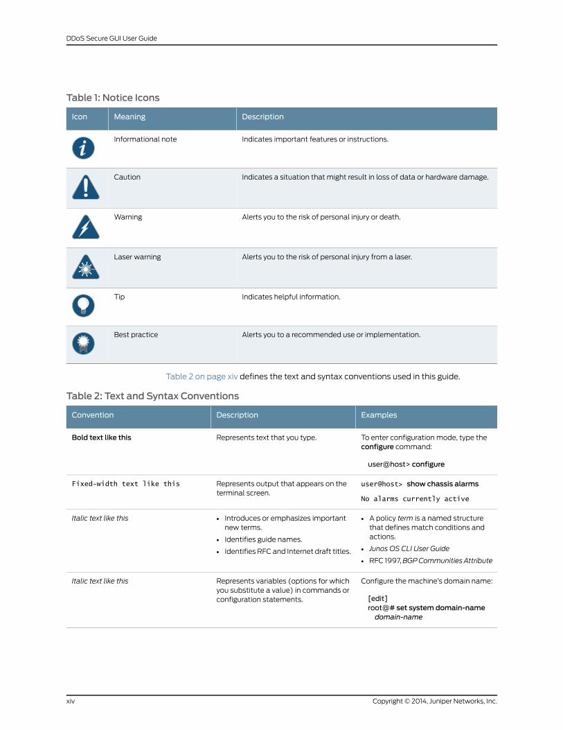
Table 1: Notice Icons
DescriptionMeaningIcon
Indicates important features or instructions.Informational note
Indicates a situation that might result in loss of data or hardware damage.Caution
Alerts you to the risk of personal injury or death.Warning
Alerts you to the risk of personal injury from a laser.Laser warning
Indicates helpful information.Tip
Alerts you to a recommended use or implementation.Best practice
Table 2 on page xiv defines the text and syntax conventions used in this guide.
Table 2: Text and Syntax Conventions
ExamplesDescriptionConvention
To enter configuration mode, type theconfigure command:
user@host> configure
Represents text that you type.Bold text like this
user@host> show chassis alarms
No alarms currently active
Represents output that appears on theterminal screen.
Fixed-width text like this
• A policy term is a named structurethat defines match conditions andactions.
• Junos OS CLI User Guide
• RFC 1997,BGPCommunities Attribute
• Introduces or emphasizes importantnew terms.
• Identifies guide names.
• Identifies RFC and Internet draft titles.
Italic text like this
Configure themachine’s domain name:
[edit]root@# set system domain-namedomain-name
Represents variables (options for whichyou substitute a value) in commands orconfiguration statements.
Italic text like this
Copyright © 2014, Juniper Networks, Inc.xiv
DDoS Secure GUI User Guide
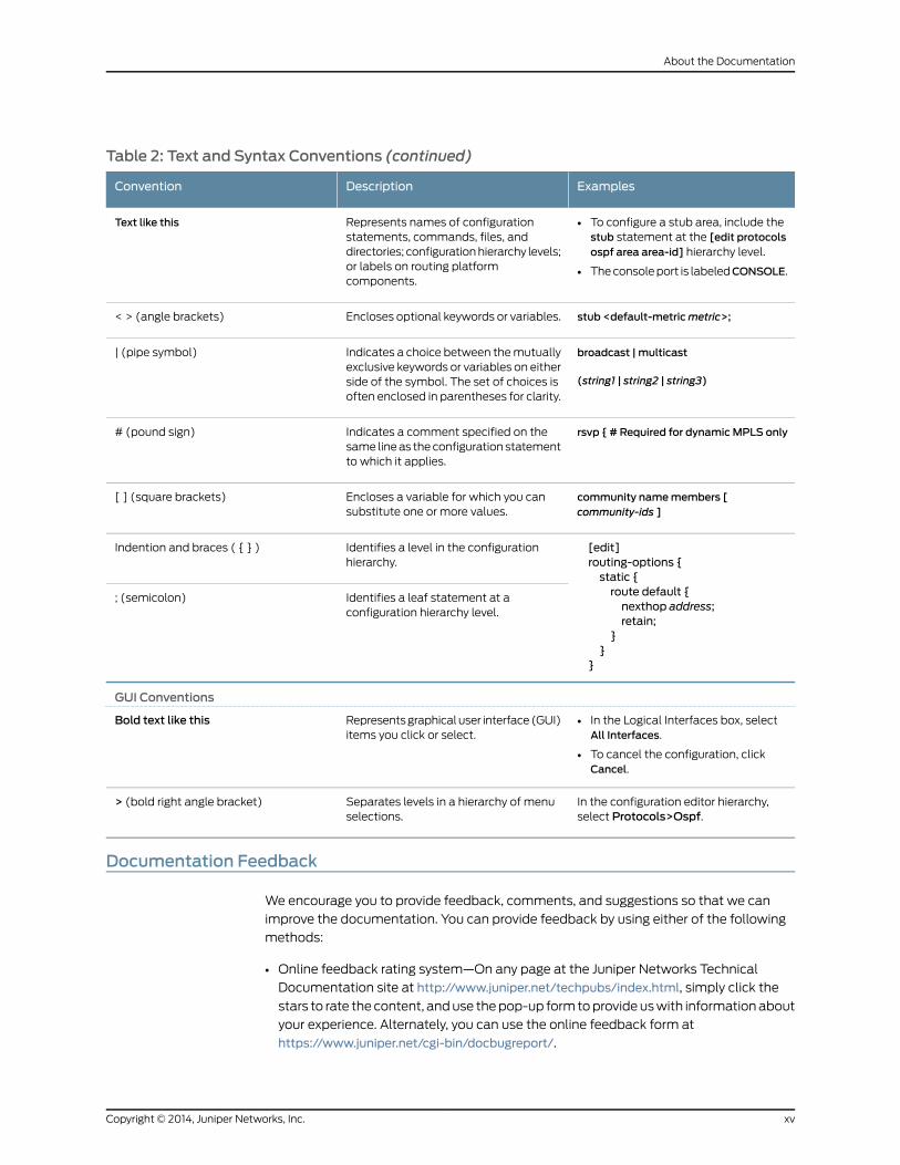
Table 2: Text and Syntax Conventions (continued)
ExamplesDescriptionConvention
• To configure a stub area, include thestub statement at the [edit protocolsospf area area-id] hierarchy level.
• Theconsoleport is labeledCONSOLE.
Represents names of configurationstatements, commands, files, anddirectories; configurationhierarchy levels;or labels on routing platformcomponents.
Text like this
stub <default-metricmetric>;Encloses optional keywords or variables.< > (angle brackets)
broadcast | multicast
(string1 | string2 | string3)
Indicates a choice between themutuallyexclusive keywords or variables on eitherside of the symbol. The set of choices isoften enclosed in parentheses for clarity.
| (pipe symbol)
rsvp { # Required for dynamicMPLS onlyIndicates a comment specified on thesame lineas theconfiguration statementto which it applies.
# (pound sign)
community namemembers [community-ids ]
Encloses a variable for which you cansubstitute one or more values.
[ ] (square brackets)
[edit]routing-options {static {route default {nexthop address;retain;
}}
}
Identifies a level in the configurationhierarchy.
Indention and braces ( { } )
Identifies a leaf statement at aconfiguration hierarchy level.
; (semicolon)
GUI Conventions
• In the Logical Interfaces box, selectAll Interfaces.
• To cancel the configuration, clickCancel.
Representsgraphicaluser interface(GUI)items you click or select.
Bold text like this
In the configuration editor hierarchy,select Protocols>Ospf.
Separates levels in a hierarchy of menuselections.
> (bold right angle bracket)
Documentation Feedback
We encourage you to provide feedback, comments, and suggestions so that we can
improve the documentation. You can provide feedback by using either of the following
methods:
• Online feedback rating system—On any page at the Juniper Networks Technical
Documentation site at http://www.juniper.net/techpubs/index.html, simply click the
stars to rate the content, anduse thepop-up form toprovideuswith informationabout
your experience. Alternately, you can use the online feedback form at
https://www.juniper.net/cgi-bin/docbugreport/.
xvCopyright © 2014, Juniper Networks, Inc.
About the Documentation
• E-mail—Sendyourcommentsto [email protected]. Includethedocument
or topic name, URL or page number, and software version (if applicable).
Requesting Technical Support
Technical product support is available through the JuniperNetworksTechnicalAssistance
Center (JTAC). If you are a customer with an active J-Care or JNASC support contract,
or are covered under warranty, and need post-sales technical support, you can access
our tools and resources online or open a case with JTAC.
• JTAC policies—For a complete understanding of our JTAC procedures and policies,
review the JTAC User Guide located at
http://www.juniper.net/us/en/local/pdf/resource-guides/7100059-en.pdf.
• Product warranties—For product warranty information, visit
http://www.juniper.net/support/warranty/.
• JTAC hours of operation—The JTAC centers have resources available 24 hours a day,
7 days a week, 365 days a year.
Self-Help Online Tools and Resources
For quick and easy problem resolution, Juniper Networks has designed an online
self-service portal called the Customer Support Center (CSC) that provides youwith the
following features:
• Find CSC offerings: http://www.juniper.net/customers/support/
• Search for known bugs: http://www2.juniper.net/kb/
• Find product documentation: http://www.juniper.net/techpubs/
• Find solutions and answer questions using our Knowledge Base: http://kb.juniper.net/
• Download the latest versions of software and review release notes:
http://www.juniper.net/customers/csc/software/
• Search technical bulletins for relevant hardware and software notifications:
http://kb.juniper.net/InfoCenter/
• Join and participate in the Juniper Networks Community Forum:
http://www.juniper.net/company/communities/
• Open a case online in the CSC Case Management tool: http://www.juniper.net/cm/
Toverify serviceentitlementbyproduct serial number, useourSerialNumberEntitlement
(SNE) Tool: https://tools.juniper.net/SerialNumberEntitlementSearch/
Opening a Casewith JTAC
You can open a case with JTAC on theWeb or by telephone.
• Use the Case Management tool in the CSC at http://www.juniper.net/cm/.
• Call 1-888-314-JTAC (1-888-314-5822 toll-free in the USA, Canada, and Mexico).
Copyright © 2014, Juniper Networks, Inc.xvi
DDoS Secure GUI User Guide

For international or direct-dial options in countries without toll-free numbers, see
http://www.juniper.net/support/requesting-support.html.
xviiCopyright © 2014, Juniper Networks, Inc.
About the Documentation

Copyright © 2014, Juniper Networks, Inc.xviii
DDoS Secure GUI User Guide
PART 1
DDoS Secure GUI Overview
• DDoS Secure Appliance Feature Overview on page 3
• DDoS Secure Appliance Getting Started on page 7
• DDoS Secure Appliance Configuration and Logs on page 33
• DDoS Secure Statistical Displays Overview on page 109
• DDoS Secure Defense Information Overview on page 151
1Copyright © 2014, Juniper Networks, Inc.

Copyright © 2014, Juniper Networks, Inc.2
DDoS Secure GUI User Guide
CHAPTER 1
DDoSSecureApplianceFeatureOverview
This chapter includes the following topics:
• DDoS Secure Appliance Feature Overview on page 3
DDoS Secure Appliance Feature Overview
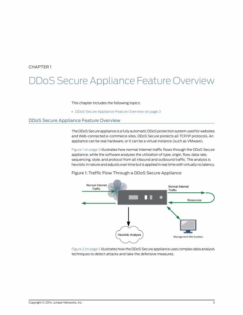
TheDDoSSecureappliance isa fullyautomaticDDoSprotectionsystemused forwebsites
andWeb-connected e-commerce sites. DDoS Secure protects all TCP/IP protocols. An
appliance can be real hardware, or it can be a virtual instance (such as VMware).
Figure 1 on page 3 illustrates how normal Internet traffic flows through the DDoS Secure
appliance, while the software analyzes the utilization of type, origin, flow, data rate,
sequencing, style, and protocol from all inbound and outbound traffic. The analysis is
heuristic in natureandadjusts over timebut is applied in real timewith virtually no latency.
Figure 1: Traffic Flow Through a DDoS Secure Appliance
Figure2onpage4 illustrateshowtheDDoSSecureapplianceusescomplexdataanalysis
techniques to detect attacks and take the defensive measures.
3Copyright © 2014, Juniper Networks, Inc.
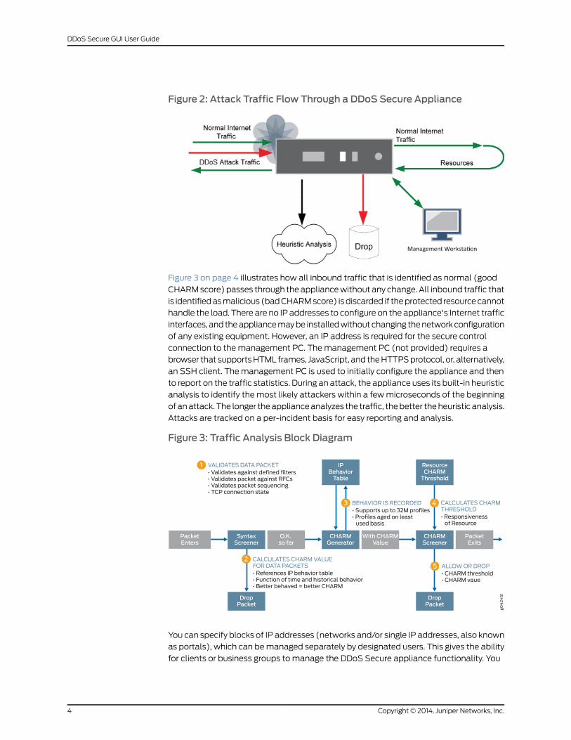
Figure 2: Attack Traffic Flow Through a DDoS Secure Appliance
Figure 3 on page 4 illustrates how all inbound traffic that is identified as normal (good
CHARMscore) passes through theappliancewithout any change. All inbound traffic that
is identifiedasmalicious (badCHARMscore) isdiscarded if theprotected resourcecannot
handle the load. There are no IP addresses to configure on the appliance's Internet traffic
interfaces, and theappliancemaybe installedwithoutchanging thenetworkconfiguration
of any existing equipment. However, an IP address is required for the secure control
connection to the management PC. Themanagement PC (not provided) requires a
browser that supportsHTML frames, JavaScript, and theHTTPSprotocol, or, alternatively,
an SSH client. Themanagement PC is used to initially configure the appliance and then
to report on the traffic statistics. During an attack, the appliance uses its built-in heuristic
analysis to identify themost likely attackers within a fewmicroseconds of the beginning
ofanattack. The longer theapplianceanalyzes the traffic, thebetter theheuristic analysis.
Attacks are tracked on a per-incident basis for easy reporting and analysis.
Figure 3: Traffic Analysis Block Diagram
You can specify blocks of IP addresses (networks and/or single IP addresses, also known
as portals), which can bemanaged separately by designated users. This gives the ability
for clients or business groups to manage the DDoS Secure appliance functionality. You
Copyright © 2014, Juniper Networks, Inc.4
DDoS Secure GUI User Guide
can change the portal configuration if you have amanagement permissions. The primary
portal is known as -General-.
RelatedDocumentation
• Connecting a DDoS Secure Appliance to the Network on page 7
• Accessing a Secure DDoS Appliance on page 11
• Connecting to a DDoS Secure Appliance on page 16
5Copyright © 2014, Juniper Networks, Inc.
Chapter 1: DDoS Secure Appliance Feature Overview

Copyright © 2014, Juniper Networks, Inc.6
DDoS Secure GUI User Guide
CHAPTER 2
DDoS Secure Appliance Getting Started
This chapter helps you to connect your DDoS Secure appliance to the network.
• Connecting a DDoS Secure Appliance to the Network on page 7
• Understanding the DDoS Secure Appliance Interface Conventions on page 9
• Understanding Defending Versus Logging Operational Modes of the DDoS Secure
Appliance on page 10
• Accessing a Secure DDoS Appliance on page 11
• Imaging a DDoS Secure Appliance on page 11
• Reimaging a DDoS Secure Appliance After Hardware Replacement on page 12
• Configuring Basic Settings for a DDoS Secure Appliance After Hardware
Replacement on page 12
• Configuring the Management Interface for a DDoS Secure Appliance on page 13
• Configuring a DDoS Secure Appliance Using Integrated Lights Out
Functionality on page 15
• Connecting to a DDoS Secure Appliance on page 16
• End User License Agreement on page 18
• Understanding the Summary Dashboard of a DDoS Secure ApplianceWeb
Interface on page 21
• DDoS Secure ApplianceWeb Interface Overview on page 22
• Understanding DDoS Secure Filter Options on page 23
• Using the DDoS Secure ApplianceWeb Interface on page 25
Connecting a DDoS Secure Appliance to the Network
Figure 4 on page 8 illustrates the setup for a single standalone DDoS Secure appliance.
7Copyright © 2014, Juniper Networks, Inc.
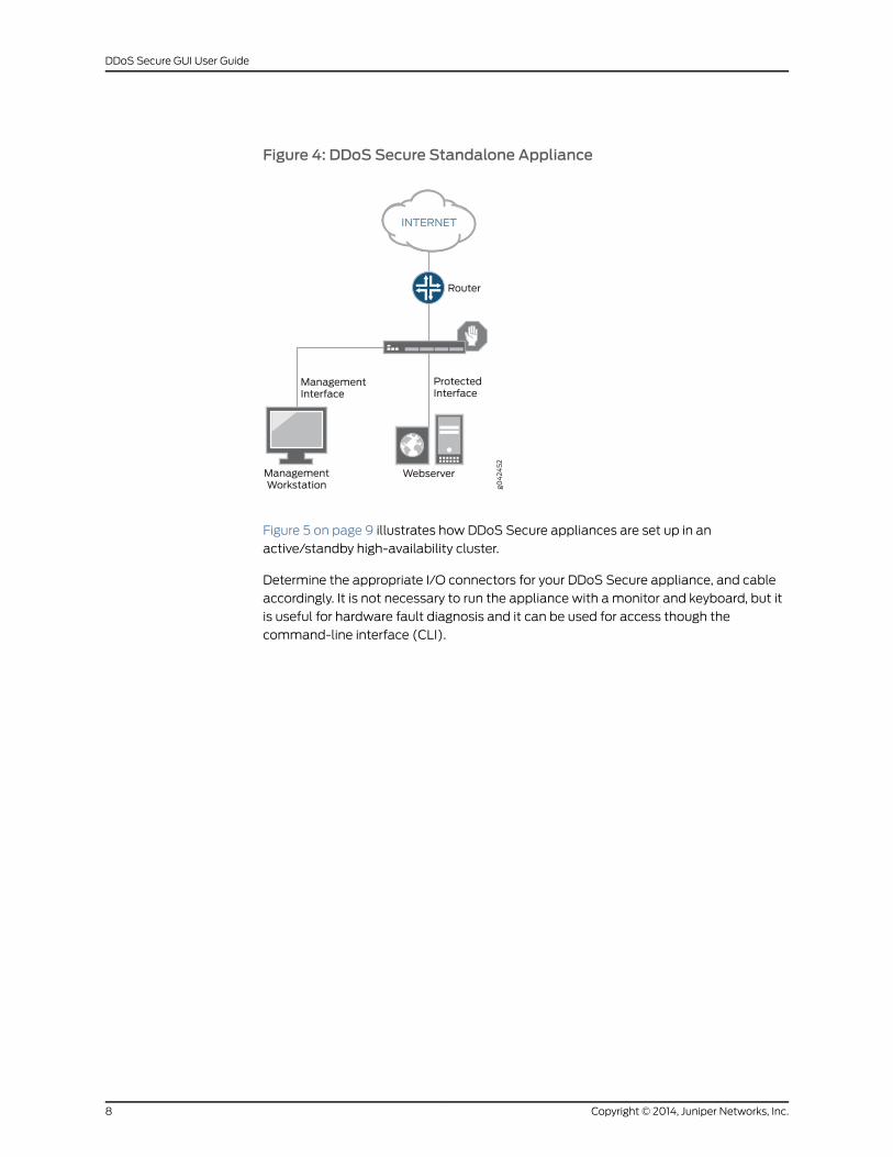
Figure 4: DDoS Secure Standalone Appliance
Figure 5 on page 9 illustrates how DDoS Secure appliances are set up in an
active/standby high-availability cluster.
Determine the appropriate I/O connectors for your DDoS Secure appliance, and cable
accordingly. It is not necessary to run the appliance with amonitor and keyboard, but it
is useful for hardware fault diagnosis and it can be used for access though the
command-line interface (CLI).
Copyright © 2014, Juniper Networks, Inc.8
DDoS Secure GUI User Guide
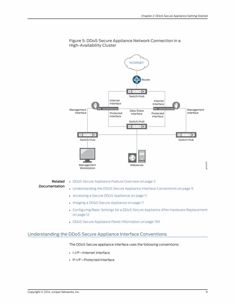
Figure 5: DDoS Secure Appliance Network Connection in aHigh-Availability Cluster
RelatedDocumentation
DDoS Secure Appliance Feature Overview on page 3•
• Understanding the DDoS Secure Appliance Interface Conventions on page 9
• Accessing a Secure DDoS Appliance on page 11
• Imaging a DDoS Secure Appliance on page 11
• Configuring Basic Settings for a DDoS Secure Appliance After Hardware Replacement
on page 12
• DDoS Secure Appliance Panel Information on page 199
Understanding the DDoS Secure Appliance Interface Conventions
The DDoS Secure appliance interface uses the following conventions:
• I-I/F—Internet Interface
• P-I/F—Protected Interface
9Copyright © 2014, Juniper Networks, Inc.
Chapter 2: DDoS Secure Appliance Getting Started
• M-I/F—Management PC Interface
• D-I/F—Data Share Interface (Optional)
Crossover cablesmight be required when plugging directly into a server, router, or similar
gateway device. A standard cable should be used for connecting to a switch or hub. The
same switch or hubmust not be used for connecting to both I-I/F and P-I/F, unless there
is VLAN separation.
Themanagement device can be directly connected to the appliance with a crossover
cable or through a network with a hub/switch and, optionally, through a router (after the
correct default gateway is set on the appliance). Depending on your security policy, you
might want to connect the M-I/F to the Internet or protected networks.
RelatedDocumentation
DDoS Secure Appliance Feature Overview on page 3•
• Connecting a DDoS Secure Appliance to the Network on page 7
• Configuring Basic Settings for a DDoS Secure Appliance After Hardware Replacement
on page 12
Understanding Defending Versus Logging Operational Modes of the DDoS SecureAppliance
The DDoS Secure appliance supports different components in one of two operational
modes:
• Defending—If the DDoS Secure appliance detects an undesirable packet, it logs the
issue, and the packet is dropped.
• Logging—If theDDoSSecure appliancedetects anundesirablepacket, it logs the issue,
and the packet is passed.
Examples of different components are:
• Overall operation—logging or defending
• Portal operation—logging or defending
• Protected IP address operation—logging or defending
• White-listed client IP address—logging
• Black-listed client IP address—defending
If an activity uses components that contain a combination of defending and logging, the
resultant operational mode will be logging. Thus, for a black-listed client IP address and
anoverall operationofdefending, aportal operationof logging, andaprotected IPaddress
operation of defending, the client IP address is not dropped.
RelatedDocumentation
DDoS Secure Appliance Feature Overview on page 3•
• Understanding the DDoS Secure Appliance Interface Conventions on page 9
• Imaging a DDoS Secure Appliance on page 11
Copyright © 2014, Juniper Networks, Inc.10
DDoS Secure GUI User Guide
• Configuring Logging on a DDoS Secure Appliance on page 78
Accessing a Secure DDoS Appliance
You access the DDoS Secure appliance through one of the following methods:
• Keyboard or monitor—Used for CLI access or to configure the management interface
IP address.
• Serial interface—Used for CLI access or to configure the management interface IP
address.
• SSH connection—Used for secure remote CLI access only.
• SecureWeb interface—Used for secureWeb interface.
RelatedDocumentation
DDoS Secure Appliance Feature Overview on page 3•
• Connecting a DDoS Secure Appliance to the Network on page 7
• Connecting to a DDoS Secure Appliance on page 16
• Configuring Basic Settings for a DDoS Secure Appliance After Hardware Replacement
on page 12
Imaging a DDoS Secure Appliance
To image your DDoS Secure appliance:
1. Insert the DDoS Secure appliance CD into the CD drive.
2. Power cycle the appliance.
NOTE: If your system is connected to a keyboard, you will be prompted toconfirm to indicate whether or not you want to overwrite the disk.
If there is an existing DDoS Secure appliance configuration on the systemdisk, you will be prompted to indicate whether or not you want to retain theconfiguration. By default, any existing configuration is retained on the disk ifthe system is not connected to a keyboard.
Allow 20minutes for the system reimage process. After the re-imagingprocess is complete, the CDwill be ejected from the CD drive.
EnteringNO at the prompt that asks if you want to keep the existingconfiguration results in removal of all the existing data. This includesheuristically obtained information aswell as the system configuration. If youchoose this option, you will need to reconfigure the DDoS Secure appliance.
11Copyright © 2014, Juniper Networks, Inc.
Chapter 2: DDoS Secure Appliance Getting Started
RelatedDocumentation
DDoS Secure Appliance Feature Overview on page 3•
• Connecting a DDoS Secure Appliance to the Network on page 7
• Accessing a Secure DDoS Appliance on page 11
• Upgrading a DDoS Secure Appliance with Patches Using File Upload on page 98
Reimaging a DDoS Secure Appliance After Hardware Replacement
To reimage an appliance, use one of the options through the BIOS boot options menu:
1. Boot off the internal SD drive—Type reinstall and press Enter, or, using the serialinterface, type serial and press Enter.
2. Boot off a CD—Press Enter, or, using the serial interface, type serial and press Enter.
NOTE: Wheneveranyhardware is replaced,we recommendthatyou reimagethe DDoS Secure appliance so that the image process can correctly detectthe new hardware and build it correctly.
DDoS Secure appliances are shipped with an internal SD recovery drive thatkeeps a copy of the DDoS Secure appliance ISO image on it for recovery.
RelatedDocumentation
DDoS Secure Appliance Feature Overview on page 3•
• Imaging a DDoS Secure Appliance on page 11
• Upgrading a DDoS Secure Appliance with Patches Using File Upload on page 98
Configuring Basic Settings for aDDoSSecureApplianceAfter HardwareReplacement
Before you begin the initial configuration, the following information is required:
• The IP address and netmask for the appliancemanagement interface (M-I/F).
• The default gateway IP address for M-I/F.
• The outgoing bandwidth of the pipe (your Internet connection).
• The hard-coded interface speed for P-I/F, I-I/F, M-I/F, andD-I/F (if not auto selection).
• (Optional) The inbound bandwidth of the protected IP addresses that the appliance
will bedefending (usually set to link speed). If a loadbalancingdevice isbeingdefended,
the bandwidth used should be for the load balancer.
Copyright © 2014, Juniper Networks, Inc.12
DDoS Secure GUI User Guide
• (Optional) Depending on the cluster configuration, the IP address and netmask for the
applianceData Share Interface (D-I/F) for synchronizing states betweenDDoSSecure
appliances.
• (Optional) A list of ports and protocols that you wish to allow through the appliance.
Formaximumprotection, theseports andprotocols shouldbe theminimumnecessary
for business purposes.
NOTE: In the factory defaults settings, choose values to fit in with yournetwork-addressing schema.
RelatedDocumentation
DDoS Secure Appliance Feature Overview on page 3•
• Configuring the Management Interface for a DDoS Secure Appliance on page 13
• Configuring a DDoS Secure Appliance Using Integrated Lights Out Functionality on
page 15
• DDoS Secure Appliance Configuration Overview on page 33
Configuring theManagement Interface for a DDoS Secure Appliance
Youcanconfigure the IPaddressof themanagement interfaceusingeitherof the following
methods:
• Console—Keyboard andmonitor, or serial interface.
• Network Connection—Default settings for the management Ethernet interface.
1. Configuring the Management Interface Using a Keyboard and Monitor or a Serial
Interface on page 13
2. Configuring the Management Interface Using an Ethernet Interface on page 14
Configuring theManagement Interface Using a Keyboard andMonitor or a Serial Interface
If you have a keyboard andmonitor attached to the DDoS Secure appliance, or a device
connected to the serial interface at 9600 baud, 8 bits, with no parity, the appliance can
be configured once the appliance has booted.
Toconfigure themanagement interfaceusingakeyboardandmonitor or a serial interface:
1. Log in to the appliance using the username configure and the password configure.
A list of interface mappings is displayed.
2. Enter n to the interface association question.
A series of parameters todefine themanagement interface IPaddress, networkmask,
gateway IP address and interface speed as shown below is displayed.
If you do not enter new values, values entered previously appear in the parentheses
and are used as the default data.
13Copyright © 2014, Juniper Networks, Inc.
Chapter 2: DDoS Secure Appliance Getting Started

IP Address (192.168.0.196) :Netmask (255.255.255.0) :Gateway (192.168.0.1) :Speed (auto) [auto/10half/10full/100half/100full/1000full] :
Input Values :-IP Address : 192.168.0.196Netmask : 255.255.255.0Gateway : 192.168.0.1Speed : autoOK [y/n]?
When the values are accepted, the management interface is updated with the new
values. You can abort this process by pressing CTRL-C.
NOTE: Configuring themanagement IPaddress forvirtual instancesofDDoSSecure is slightly different for some of the fields. For more information, seethe DDoS Secure VMware Virtual Edition Installation Guide.
With the serial interface, youmight need to hit the Break key several times(wait 5 seconds between each break) to get a login prompt, as the rates9600, 57600, and 115200 baud are supported. Any appliance bootingmessages are always displayed at 9600 baud.
Configuring theManagement Interface Using an Ethernet Interface
To configure the management interface using an Ethernet interface:
1. Set up a browser PC with IP address 192.168.0.1.
2. Use a crossover cable between the PC and the DDoS Secure appliancemanagement
interface.
3. Power on the DDoS Secure appliance.
4. Connect the PC browser to URL https://192.168.0.196.
Copyright © 2014, Juniper Networks, Inc.14
DDoS Secure GUI User Guide
NOTE: After you accept the EULAs, reconfigure the IP address of themanagement interface using the DDoS Secure applianceWeb interfaceas explained in Configuring the Management Interface Using a Keyboardand Monitor or a Serial Interface. The Protected and Internet speeddefinitions should be identical, and you should take the DDoS Secureengine offline to validate that traffic can still flow and bypass theappliance. If there is a change in switchport speeds (for example: Internet1G, protected 100M), then auto only should be configured for bothinterfaces, and on the router/switch ports to which the appliance isconnected.
5. Common interface displayed information—Once you have reconfigured the
management interface, you can connect it to your network. You can also revert the
browser PC to its original settings at this time.
RelatedDocumentation
DDoS Secure Appliance Feature Overview on page 3•
• Configuring Basic Settings for a DDoS Secure Appliance After Hardware Replacement
on page 12
Configuring a DDoS Secure Appliance Using Integrated Lights Out Functionality
DDoSSecure appliances support the ILO functionality. The ILOshares the sameEthernet
portas themanagement interface,buthasadifferentEthernetMACaddressand requires
a unique IP address. The ILO can only be configured by breaking into the BIOS boot
process, and configuring the ILO. The ILO IP address has to be unique, which means it
cannot be the same as themanagement IP address. However, it should be in the same
network as the management IP address, with the same default gateway. After the ILO
is set up, it can be accessed using your Web browser.
NOTE: The default user is root and password is calvin.
Change your password after logging in for the first time.
RelatedDocumentation
DDoS Secure Appliance Feature Overview on page 3•
• Configuring Basic Settings for a DDoS Secure Appliance After Hardware Replacement
on page 12
• Configuring the Management Interface for a DDoS Secure Appliance on page 13
15Copyright © 2014, Juniper Networks, Inc.
Chapter 2: DDoS Secure Appliance Getting Started
Connecting to a DDoS Secure Appliance
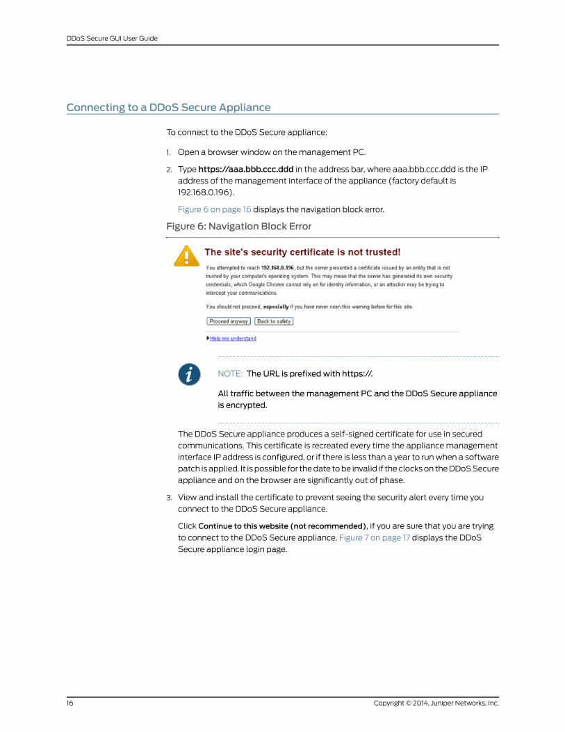
To connect to the DDoS Secure appliance:
1. Open a browser window on themanagement PC.
2. Type https://aaa.bbb.ccc.ddd in the address bar, where aaa.bbb.ccc.ddd is the IPaddress of the management interface of the appliance (factory default is
192.168.0.196).
Figure 6 on page 16 displays the navigation block error.
Figure 6: Navigation Block Error
NOTE: The URL is prefixed with https://.
All traffic between themanagement PC and the DDoS Secure applianceis encrypted.
The DDoS Secure appliance produces a self-signed certificate for use in secured
communications. This certificate is recreated every time the appliancemanagement
interface IP address is configured, or if there is less than a year to runwhen a software
patch isapplied. It is possible for thedate tobe invalid if theclockson theDDoSSecure
appliance and on the browser are significantly out of phase.
3. View and install the certificate to prevent seeing the security alert every time you
connect to the DDoS Secure appliance.
Click Continue to this website (not recommended), if you are sure that you are trying
to connect to the DDoS Secure appliance. Figure 7 on page 17 displays the DDoS
Secure appliance login page.
Copyright © 2014, Juniper Networks, Inc.16
DDoS Secure GUI User Guide
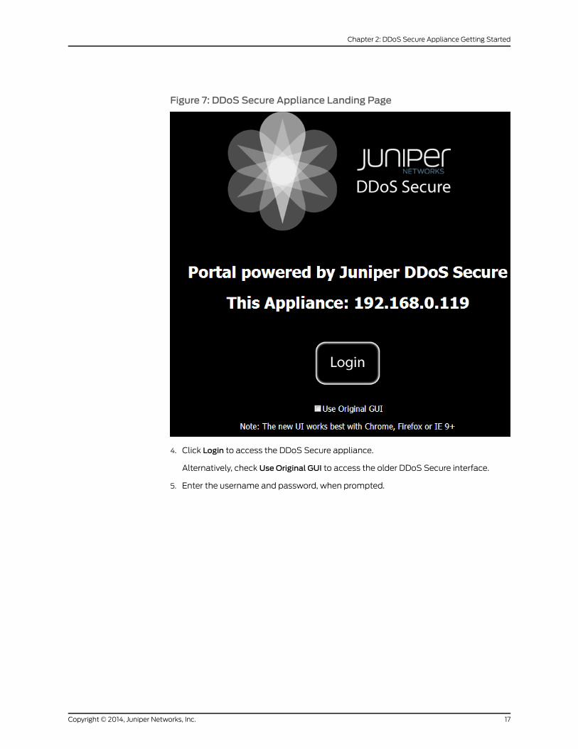
Figure 7: DDoS Secure Appliance Landing Page
4. Click Login to access the DDoS Secure appliance.
Alternatively, check Use Original GUI to access the older DDoS Secure interface.
5. Enter the username and password, when prompted.
17Copyright © 2014, Juniper Networks, Inc.
Chapter 2: DDoS Secure Appliance Getting Started
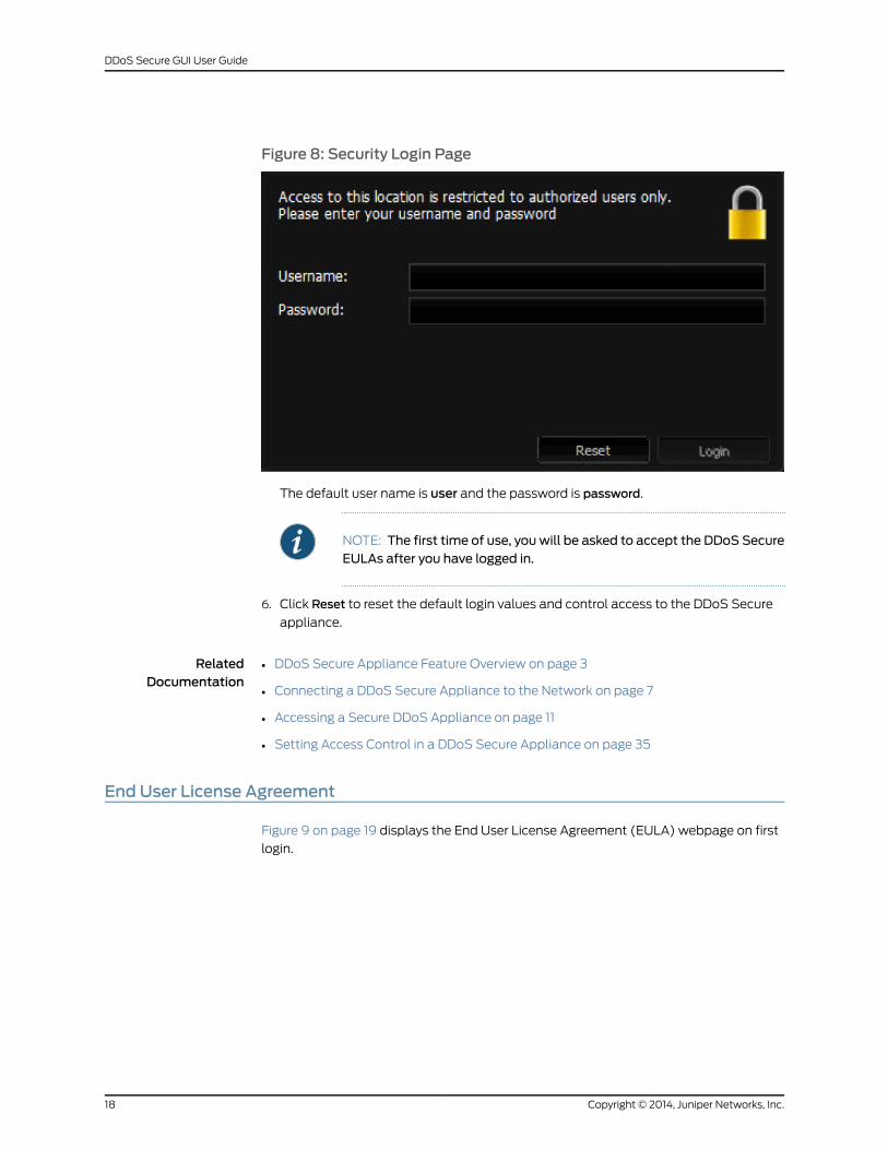
Figure 8: Security Login Page
The default user name is user and the password is password.
NOTE: The first time of use, youwill be asked to accept the DDoS SecureEULAs after you have logged in.
6. Click Reset to reset the default login values and control access to the DDoS Secure
appliance.
RelatedDocumentation
DDoS Secure Appliance Feature Overview on page 3•
• Connecting a DDoS Secure Appliance to the Network on page 7
• Accessing a Secure DDoS Appliance on page 11
• Setting Access Control in a DDoS Secure Appliance on page 35
End User License Agreement
Figure 9 on page 19 displays the End User License Agreement (EULA) webpage on first
login.
Copyright © 2014, Juniper Networks, Inc.18
DDoS Secure GUI User Guide

Figure 9: End User License Agreement
19Copyright © 2014, Juniper Networks, Inc.
Chapter 2: DDoS Secure Appliance Getting Started
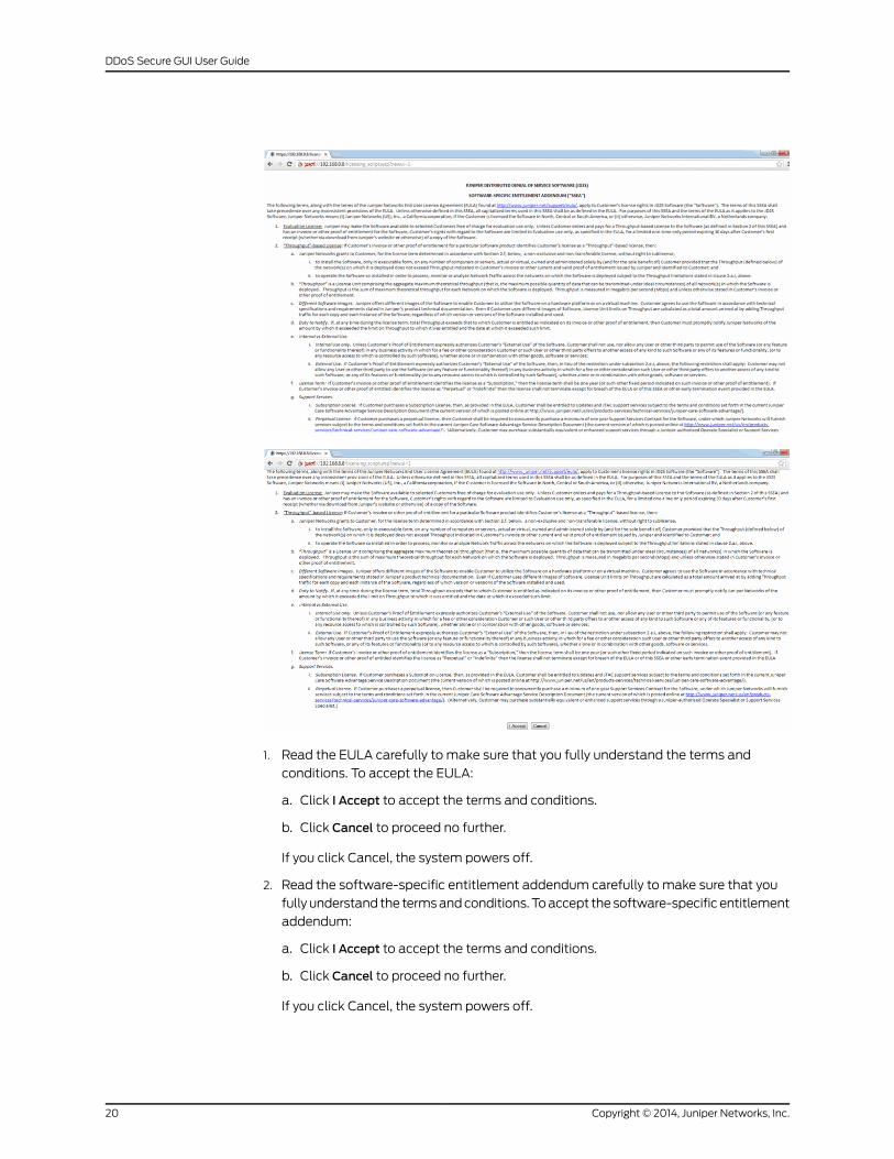
1. Read the EULA carefully to make sure that you fully understand the terms and
conditions. To accept the EULA:
a. Click I Accept to accept the terms and conditions.
b. Click Cancel to proceed no further.
If you click Cancel, the system powers off.
2. Read the software-specific entitlement addendum carefully to make sure that you
fullyunderstand the termsandconditions.Toaccept thesoftware-specific entitlement
addendum:
a. Click I Accept to accept the terms and conditions.
b. Click Cancel to proceed no further.
If you click Cancel, the system powers off.
Copyright © 2014, Juniper Networks, Inc.20
DDoS Secure GUI User Guide
Once you have accepted the terms and conditions of the license, the DDoS Secure
appliance redirects to the DDoS Secure Appliance Summary Dashboard page.
RelatedDocumentation
DDoS Secure Appliance Feature Overview on page 3•
• Understanding the Summary Dashboard of a DDoS Secure ApplianceWeb Interface
on page 21
• DDoS Secure ApplianceWeb Interface Overview on page 22
Understanding the Summary Dashboard of a DDoS Secure ApplianceWeb Interface
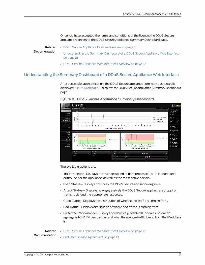
After successful authentication, the DDoS Secure appliance summary dashboard is
displayed. Figure 10onpage21displays theDDoSSecureapplianceSummaryDashboard
page.
Figure 10: DDoS Secure Appliance Summary Dashboard
The available options are:
• Traffic Monitor—Displays the average speed of data processed, both inbound and
outbound, for the appliance, as well as the most active portals.
• Load Status— Displays how busy the DDoS Secure appliance engine is.
• Attack Status— Displays how aggressively the DDoS Secure appliance is dropping
traffic to defend the appropriate resources.
• Good Traffic—Displays the distribution of where good traffic is coming from.
• Bad Traffic—Displays distribution of where bad traffic is coming from.
• Protected Performance—Displays how busy a protected IP address is from an
aggregatedCHARMperspective, andwhat theaverage traffic toand fromthe IPaddress
is.
RelatedDocumentation
DDoS Secure ApplianceWeb Interface Overview on page 22•
• End User License Agreement on page 18
21Copyright © 2014, Juniper Networks, Inc.
Chapter 2: DDoS Secure Appliance Getting Started
• Understanding DDoS Secure Filter Options on page 23
DDoS Secure ApplianceWeb Interface Overview
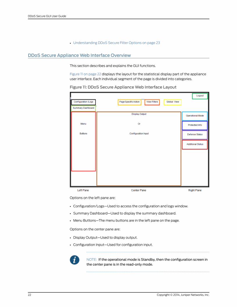
This section describes and explains the GUI functions.
Figure 11 on page 22 displays the layout for the statistical display part of the appliance
user interface. Each individual segment of the page is divided into categories.
Figure 11: DDoS Secure ApplianceWeb Interface Layout
Options on the left pane are:
• Configuration/Logs—Used to access the configuration and logs window.
• Summary Dashboard—Used to display the summary dashboard.
• Menu Buttons—Themenu buttons are in the left pane on the page.
Options on the center pane are:
• Display Output—Used to display output.
• Configuration Input—Used for configuration input.
NOTE: If the operational mode is Standby, then the configuration screen inthe center pane is in the read-only mode.
Copyright © 2014, Juniper Networks, Inc.22
DDoS Secure GUI User Guide
Option on the topmenu bar is Logout.
Options on the right pane are:
• Operational Mode
• Protected Info
• Defense Status—When an item in defense status turns from black to red, then DDoS
Secure appliance is actively defending this situation.
• Additional Status
Options on the top center pane are:
• Page Specific Action—Actions specific to the page.
• View Filters—The view filter button is available from any page within the statistical
display section of the DDoS Secure appliance. Any value entered into the filter will be
setuntil the filter is cleared, evenwhenaccessinganotherpagewithin theDDoSSecure
appliance statistical display section.
RelatedDocumentation
End User License Agreement on page 18•
• Understanding the Summary Dashboard of a DDoS Secure ApplianceWeb Interface
on page 21
• Understanding DDoS Secure Appliance Operational Mode on page 151
• DDoS Secure Appliance Country Codes on page 175
Understanding DDoS Secure Filter Options
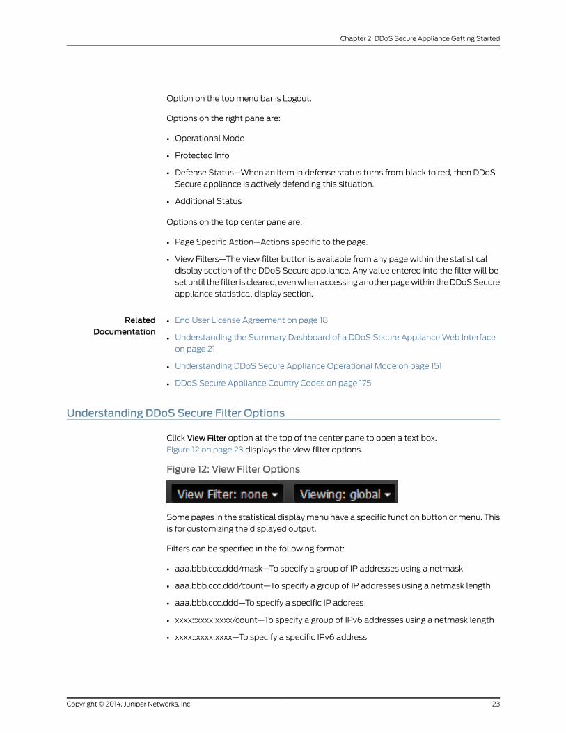
Click View Filter option at the top of the center pane to open a text box.
Figure 12 on page 23 displays the view filter options.
Figure 12: View Filter Options
Somepages in the statistical displaymenu have a specific function button ormenu. This
is for customizing the displayed output.
Filters can be specified in the following format:
• aaa.bbb.ccc.ddd/mask—To specify a group of IP addresses using a netmask
• aaa.bbb.ccc.ddd/count—To specify a group of IP addresses using a netmask length
• aaa.bbb.ccc.ddd—To specify a specific IP address
• xxxx::xxxx:xxxx/count—To specify a group of IPv6 addresses using a netmask length
• xxxx::xxxx:xxxx—To specify a specific IPv6 address
23Copyright © 2014, Juniper Networks, Inc.
Chapter 2: DDoS Secure Appliance Getting Started
• ABC—To specify a three-letter country code
• AS#nnnnn—To specify a specific AS number
Once a filter is active, the View Filter button will change to display the actual filter text,
as shown in Figure 13 on page 24.
Figure 13: View Filter Option Example
Other View Filters
When viewing URL, DNS, or SIP information, you see an additional filter. This filter can
be used for doing an appropriate string match.
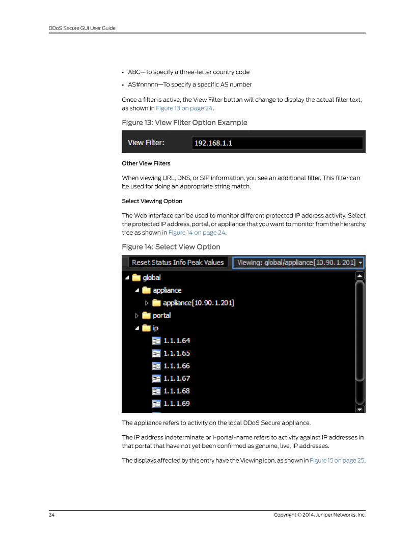
Select Viewing Option
TheWeb interface can be used to monitor different protected IP address activity. Select
theprotected IPaddress, portal, or appliance that youwant tomonitor fromthehierarchy
tree as shown in Figure 14 on page 24.
Figure 14: Select ViewOption
The appliance refers to activity on the local DDoS Secure appliance.
The IP address indeterminate or I-portal-name refers to activity against IP addresses in
that portal that have not yet been confirmed as genuine, live, IP addresses.
Thedisplaysaffectedby this entry have theViewing icon, as shown inFigure 15onpage25.
Copyright © 2014, Juniper Networks, Inc.24
DDoS Secure GUI User Guide
Figure 15: Viewing Icon
The list is initially set to global; click on the arrow in front of the folder icon to expand.
The three options that you can select are:
• Appliance—The local DDoS Secure appliance
• Portal—Lists defined portals that can be selected or drilled down to list IP addresses
in the portal
• IP—Lists all protected servers by IP address
RelatedDocumentation
DDoS Secure Appliance Feature Overview on page 3•
• Understanding the Summary Dashboard of a DDoS Secure ApplianceWeb Interface
on page 21
• Using the DDoS Secure ApplianceWeb Interface on page 25
• Understanding DDoS Secure Appliance Operational Mode on page 151
• DDoS Secure Appliance Protected IP Information on page 114
Using the DDoS Secure ApplianceWeb Interface
• Expanding the Central Pane Area on page 25
• Arranging Table Ordering on page 26
• Arranging Column Ordering on page 27
• Sorting Data and Add-Remove Columns on page 27
• Understanding Action Cells on page 28
• Understanding IP/AS Number/Location Details on page 29
• Understanding Graphs on page 29
Expanding the Central Pane Area
You can expand the center pane on the user interface. The arrow icons highlighted below
extend the center pane over the left of right pane, as shown in Figure 16 on page 26.
25Copyright © 2014, Juniper Networks, Inc.
Chapter 2: DDoS Secure Appliance Getting Started
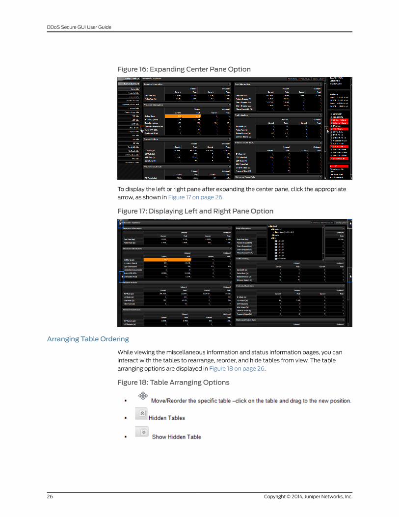
Figure 16: Expanding Center Pane Option
To display the left or right pane after expanding the center pane, click the appropriate
arrow, as shown in Figure 17 on page 26.
Figure 17: Displaying Left and Right Pane Option
Arranging Table Ordering
While viewing the miscellaneous information and status information pages, you can
interact with the tables to rearrange, reorder, and hide tables from view. The table
arranging options are displayed in Figure 18 on page 26.
Figure 18: Table Arranging Options
Copyright © 2014, Juniper Networks, Inc.26
DDoS Secure GUI User Guide
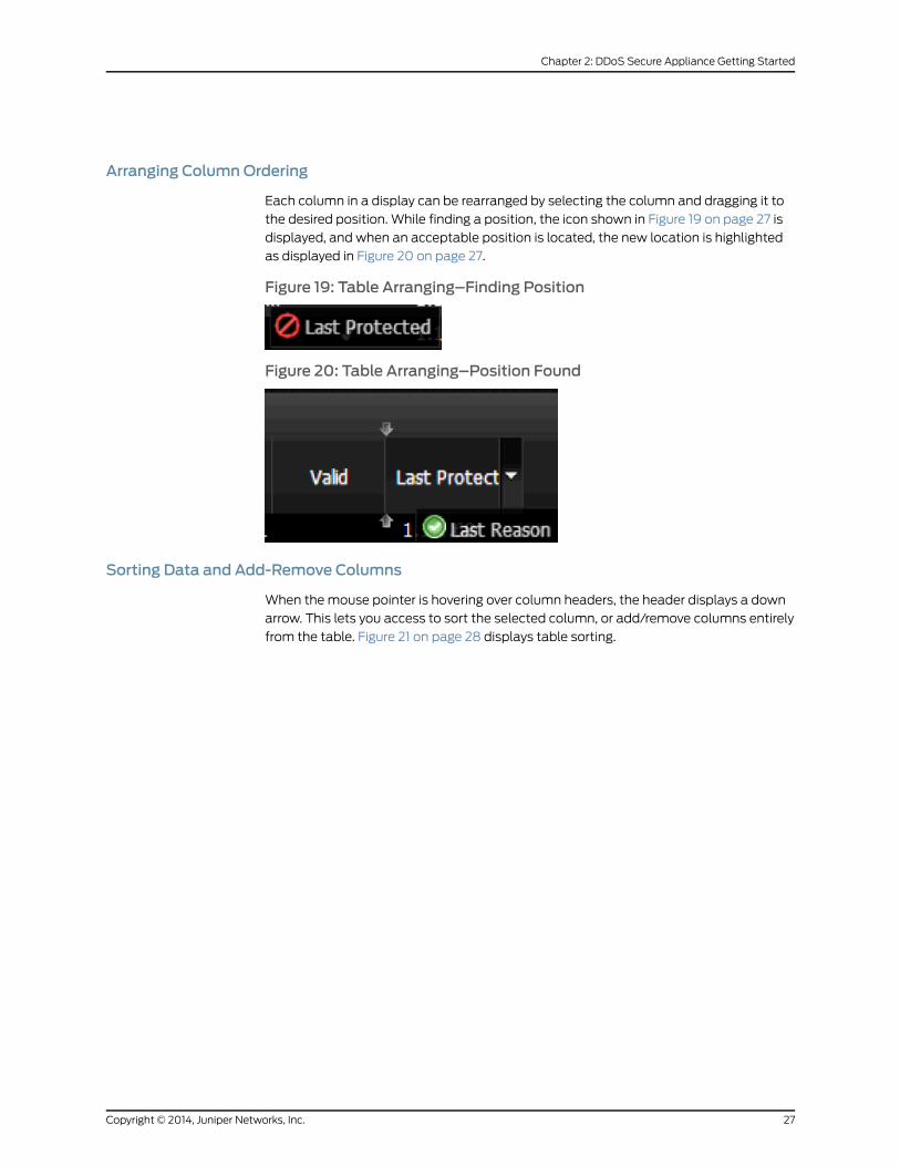
Arranging ColumnOrdering
Each column in a display can be rearranged by selecting the column and dragging it to
the desired position. While finding a position, the icon shown in Figure 19 on page 27 is
displayed, and when an acceptable position is located, the new location is highlighted
as displayed in Figure 20 on page 27.
Figure 19: Table Arranging–Finding Position
Figure 20: Table Arranging–Position Found
Sorting Data and Add-Remove Columns
When themouse pointer is hovering over column headers, the header displays a down
arrow. This lets you access to sort the selected column, or add/remove columns entirely
from the table. Figure 21 on page 28 displays table sorting.
27Copyright © 2014, Juniper Networks, Inc.
Chapter 2: DDoS Secure Appliance Getting Started
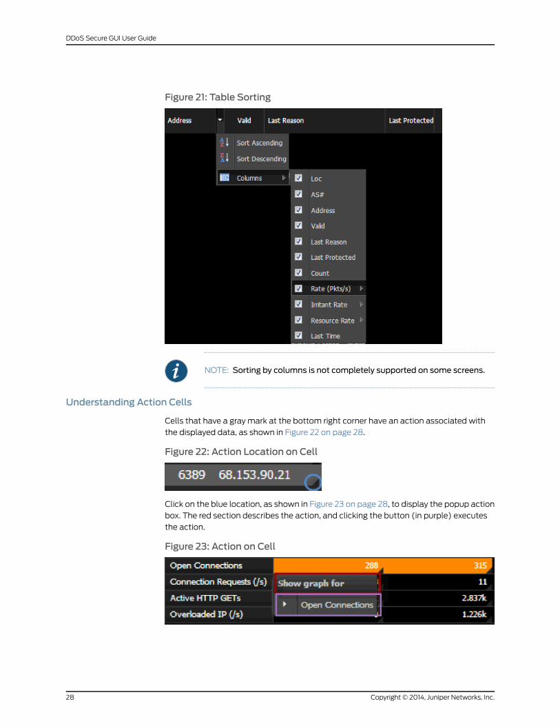
Figure 21: Table Sorting
NOTE: Sorting by columns is not completely supported on some screens.
Understanding Action Cells
Cells that have a gray mark at the bottom right corner have an action associated with
the displayed data, as shown in Figure 22 on page 28.
Figure 22: Action Location on Cell
Click on the blue location, as shown in Figure 23 on page 28, to display the popup action
box. The red section describes the action, and clicking the button (in purple) executes
the action.
Figure 23: Action on Cell
Copyright © 2014, Juniper Networks, Inc.28
DDoS Secure GUI User Guide

Action cells can be used to:
• View graphs
• Block/unblock IP addresses
• Block/unblock countries
• Track URLs
• Track DNS name query type
• Track SIP URIs
Understanding IP/AS Number/Location Details
DDoS Secure appliance uses a GeoIP database, which can be used to find more
information on Internet IP addresses.
Figure 24 on page 29 displays the pop-up information box that appearswhen themouse
pointer is hovered over the location cells.
Figure 24: IP/AS/Location Details
Understanding Graphs
All the graphs have a common interface. The options available are:
The graph legend is highlighted in purple as shown in Figure 25 on page 30.
Hovering the mouse over the legend labels will highlight the corresponding graph data
in bold.
29Copyright © 2014, Juniper Networks, Inc.
Chapter 2: DDoS Secure Appliance Getting Started
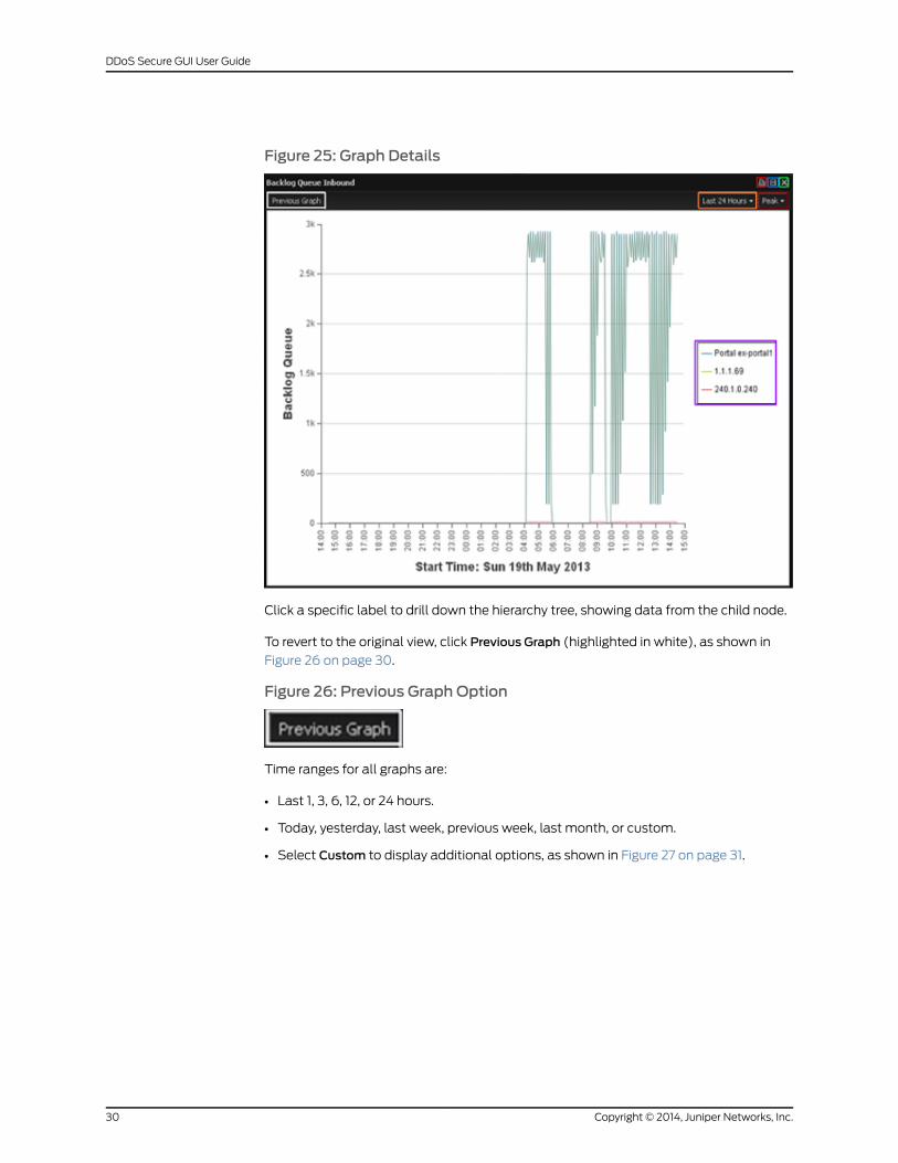
Figure 25: Graph Details
Click a specific label to drill down the hierarchy tree, showing data from the child node.
To revert to the original view, click Previous Graph (highlighted in white), as shown in
Figure 26 on page 30.
Figure 26: Previous Graph Option
Time ranges for all graphs are:
• Last 1, 3, 6, 12, or 24 hours.
• Today, yesterday, last week, previous week, last month, or custom.
• Select Custom to display additional options, as shown in Figure 27 on page 31.
Copyright © 2014, Juniper Networks, Inc.30
DDoS Secure GUI User Guide
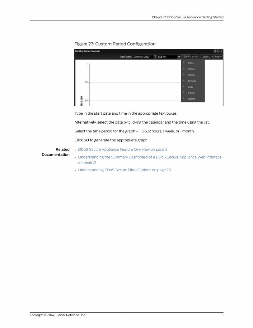
Figure 27: CustomPeriod Configuration
Type in the start date and time in the appropriate text boxes.
Alternatively, select the date by clicking the calendar and the time using the list.
Select the time period for the graph – 1,3,6,12 hours, 1 week, or 1 month.
Click GO to generate the appropriate graph.
RelatedDocumentation
• DDoS Secure Appliance Feature Overview on page 3
• Understanding the Summary Dashboard of a DDoS Secure ApplianceWeb Interface
on page 21
• Understanding DDoS Secure Filter Options on page 23
31Copyright © 2014, Juniper Networks, Inc.
Chapter 2: DDoS Secure Appliance Getting Started

Copyright © 2014, Juniper Networks, Inc.32
DDoS Secure GUI User Guide
CHAPTER 3
DDoSSecureApplianceConfigurationandLogs
This chapter describes the administration and configuration options available in the
DDoS Secure applianceWeb interface portal.
• DDoS Secure Appliance Configuration Overview on page 33
• Setting Access Control in a DDoS Secure Appliance on page 35
• Configuring the DDoS Secure Interfaces on page 39
• Configuring DDoS Secure on page 46
• Configuring Portals on page 59
• Configuring SSL on page 74
• Configuring Date and Time on DDoS Secure Appliance on page 77
• Configuring Logging on a DDoS Secure Appliance on page 78
• DDoS Secure Appliance Configuration Files on page 92
• DDoS Secure Appliance Statistics Reports on page 93
• Managing DDoS Secure Appliance Incident Logs on page 94
• Managing DDoS Secure ApplianceWorst Offenders Log File on page 96
• Reporting on a Specific Time on page 97
• Reporting on a Specific IP or Network Activity on page 97
• Upgrading a DDoS Secure Appliance with Patches Using File Upload on page 98
• Understanding DDoS Secure Appliance Packet Capture Options on page 100
• Terminating a DDoS Secure Appliance Packet Capture Recording on page 102
• Displaying a DDoS Secure Appliance Packet Capture on page 103
• Downloading and Saving DDoS Secure Appliance Packet Capture Details on page 105
• Shutting Down a DDoS Secure Appliance on page 107
DDoS Secure Appliance Configuration Overview
The configuration overview provides details about the DDoS Secure appliance
configuration, including general information, user-definable details, and table size used.
33Copyright © 2014, Juniper Networks, Inc.
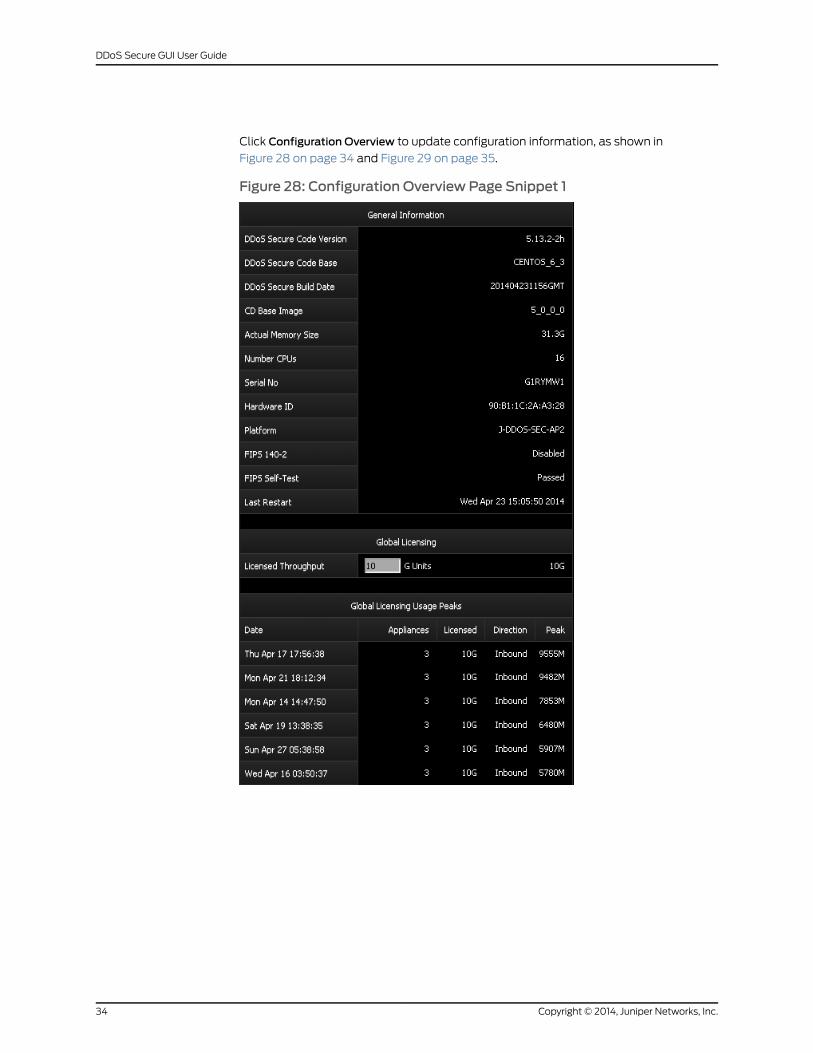
Click Configuration Overview to update configuration information, as shown in
Figure 28 on page 34 and Figure 29 on page 35.
Figure 28: Configuration Overview Page Snippet 1
Copyright © 2014, Juniper Networks, Inc.34
DDoS Secure GUI User Guide
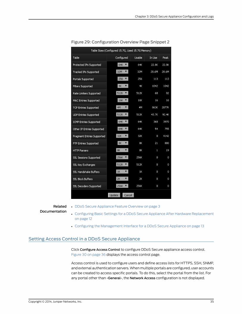
Figure 29: Configuration Overview Page Snippet 2
RelatedDocumentation
DDoS Secure Appliance Feature Overview on page 3•
• Configuring Basic Settings for a DDoS Secure Appliance After Hardware Replacement
on page 12
• Configuring the Management Interface for a DDoS Secure Appliance on page 13
Setting Access Control in a DDoS Secure Appliance
Click Configure Access Control to configure DDoS Secure appliance access control.
Figure 30 on page 36 displays the access control page.
Access control is used to configure users and define access lists for HTTPS, SSH, SNMP,
andexternal authentication servers.Whenmultiple portals are configured, user accounts
can be created to access specific portals. To do this, select the portal from the list. For
any portal other than -General-, the Network Access configuration is not displayed.
35Copyright © 2014, Juniper Networks, Inc.
Chapter 3: DDoS Secure Appliance Configuration and Logs
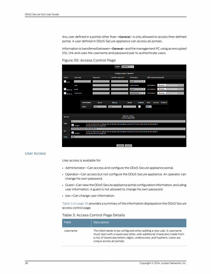
Any user defined in a portal other than –General– is only allowed to access their defined
portal. A user defined in DDoS Secure appliance can access all portals.
Information is transferredbetween–General–andthemanagementPCusinganencrypted
SSL link and uses the username and password pair to authenticate users.
Figure 30: Access Control Page
User Access
User access is available for:
• Administrator—Can access and configure the DDoS Secure appliance portal.
• Operator—Can access but not configure the DDoS Secure appliance. An operator can
change his own password.
• Guest—CanviewtheDDoSSecureapplianceportal configuration information, excluding
user information. A guest is not allowed to change his own password.
• sso—Can change user information.
Table 3onpage36provides a summaryof the informationdisplayedon theDDoSSecure
access control page.
Table 3: Access Control Page Details
DescriptionField
This field needs to be configured when adding a new user. A usernamemust start with a lowercase letter, with additional characters made fromamix of lowercase letters, digits, underscores, and hyphens. Users areunique across all portals.
Username
Copyright © 2014, Juniper Networks, Inc.36
DDoS Secure GUI User Guide
Table 3: Access Control Page Details (continued)
DescriptionField
Enteravalue if youwant tochange thepassword.Apasswordmustcontain(ASCII) printable characters with a minimum of 6 characters and amaximum of 35 characters.
Password
Enter the new password again to confirm.Confirm Password
Select administrator, operator, guest, or sso from the pull-down list.Permissions
This allows for public/private keys to be used for user access to the DDoSSecure insteadof passwords. Thepublic key part of anSSHpublic/privatekey pair can be uploaded for use.
SSH AuthorizedKeys file
We recommend that you choose a password that has 10 or more characters, with a
combination of uppercase and lowercase letters, numbers, and special characters. Do
not disclose your password to anybody. An administrator password should be available
to authorized people for use in an emergency. In such cases, the administrator should
change the password.
NOTE: If you loseyourpassword, it ismost likely that youwill have to reimageyour DDoS Secure appliance. By reimaging your appliance, you will lose allconfiguration information.
External Authenticators
RADIUS external authentication is supported. The appropriate fields need to be updated
as specified by the owner of the RADIUS server. The user needs to be defined on the
DDoS Secure appliance for both GUI and SSH access. The authentication sequence is
check remote password – if failure, then check local password.
Network Access Definitions
IP addresses can be specified with one of the following formats:
• all—All IP addresses are valid.
• aaa.bbb.ccc.ddd/mask—To specify a group of IP addresses using a subnet mask.
• aaa.bbb.ccc.ddd/count—Tospecify agroupof IPaddressesusingasubnetmask length.
• aaa.bbb.ccc.ddd—To specify a specific IP address.
• none—No valid IP addresses.
Values can also be separated using commas. Thus, 11.22.33.44,44.33.22.11 allows access
from host addresses 11.22.33.44 or 44.33.22.11.
37Copyright © 2014, Juniper Networks, Inc.
Chapter 3: DDoS Secure Appliance Configuration and Logs
NOTE: The value all has the highest precedence in a list and will replace allother values, and the value none has the lowest precedence in a list and will
be ignored if not used on its own.
The preferred range notation is the aaa.bbb.ccc.ddd/count format. When a
new configuration is accepted, this preferred format will be used to displaythe current configuration. Any entrieswith the /mask formatwill be replacedwith /count. In addition, any redundant values will also be removed, leavingjust the larger address ranges that encompass the redundant values.
Network Services
https—Access to the DDoS Secure appliance is strictly controlled. By default, any IP
address can access the appliance through a secured HTTPSWeb connection. If users
try to connect to the regular HTTP port using the homepage (http://w.x.y.z/), they will
be immediately redirected to the secured HTTPSWeb connection (https://w.x.y.z/).
Only valid users can access the appliance. We strongly recommend that the list of valid
users be limited to a specific set of IP addresses, if the management interface is directly
connected to the Internet.
The list of Juniper Networks public IP addresses can easily be enabled or disabled for
Juniper Networks personnel access by selecting or clearing the appliance check box. We
recommend that you leave this check box enabled (as well as providing access to the
appliancemanagement interface through firewalls and so on) so that Juniper Networks
personnel can quickly help you in DDoS attack scenarios.
SSH—By default, only private (RFC1918) and Juniper Networks public IP addresses can
access the appliance through an SSH connection. A CLI is provided. Only valid users can
access the CLI.We strongly recommend that the list of valid users be limited to a specific
set of IP addresses, if the management interface is directly connected to the Internet.
New connections are rate limited, so if there is a connection timeout failure, wait a few
minutes before trying again.
The list of Juniper Networks IP address public IP addresses can easily be enabled or
disabled for Juniper Networks personnel access by checking or unchecking the appliance
check box. We recommend that you leave this check box enabled (as well as providing
access to the appliancemanagement interface through firewalls and so on) so that
Juniper Networks personnel can rapidly help you in DDoS attack scenarios.
SNMP—By default, SNMP access is not enabled. SNMP access can be enabled for
third-party packages such as HP Openview. If SNMP traps are enabled, then the trap
receiver address is automatically included in this field.
RelatedDocumentation
DDoS Secure Appliance Feature Overview on page 3•
• Connecting a DDoS Secure Appliance to the Network on page 7
• Connecting to a DDoS Secure Appliance on page 16
Copyright © 2014, Juniper Networks, Inc.38
DDoS Secure GUI User Guide
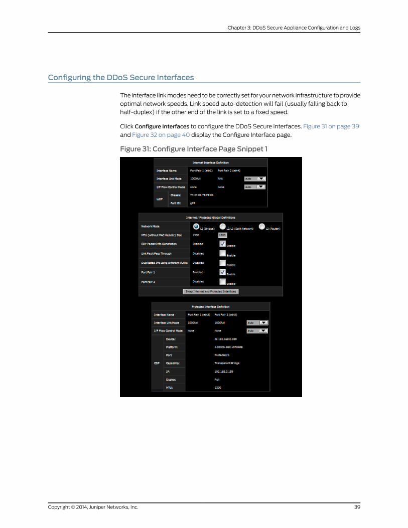
Configuring the DDoS Secure Interfaces
The interface linkmodesneed tobecorrectly set for your network infrastructure toprovide
optimal network speeds. Link speed auto-detection will fail (usually falling back to
half-duplex) if the other end of the link is set to a fixed speed.
Click Configure Interfaces to configure the DDoS Secure interfaces. Figure 31 on page 39
and Figure 32 on page 40 display the Configure Interface page.
Figure 31: Configure Interface Page Snippet 1
39Copyright © 2014, Juniper Networks, Inc.
Chapter 3: DDoS Secure Appliance Configuration and Logs
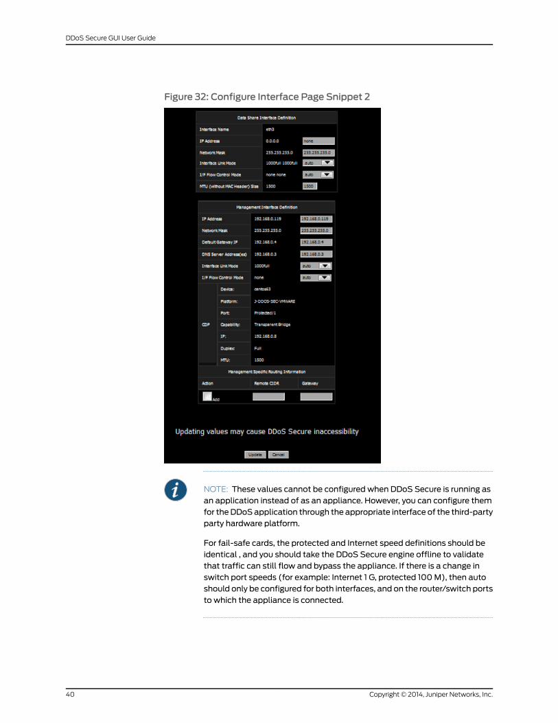
Figure 32: Configure Interface Page Snippet 2
NOTE: These values cannot be configured when DDoS Secure is running asan application instead of as an appliance. However, you can configure themfor theDDoSapplication through the appropriate interface of the third-partyparty hardware platform.
For fail-safe cards, the protected and Internet speed definitions should beidentical , and you should take the DDoS Secure engine offline to validatethat traffic can still flow and bypass the appliance. If there is a change inswitch port speeds (for example: Internet 1 G, protected 100M), then autoshould only be configured for both interfaces, and on the router/switch portsto which the appliance is connected.
Copyright © 2014, Juniper Networks, Inc.40
DDoS Secure GUI User Guide
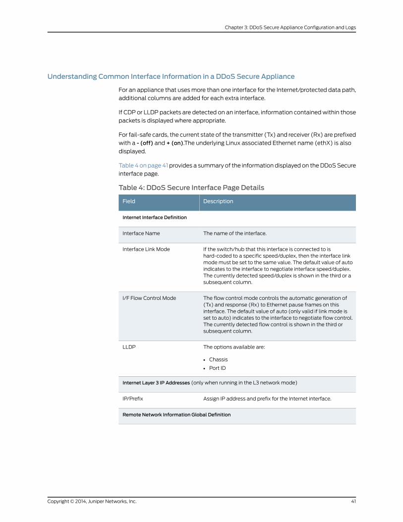
Understanding Common Interface Information in a DDoS Secure Appliance
For an appliance that usesmore than one interface for the Internet/protected data path,
additional columns are added for each extra interface.
If CDP or LLDP packets are detected on an interface, information containedwithin those
packets is displayed where appropriate.
For fail-safe cards, the current state of the transmitter (Tx) and receiver (Rx) are prefixed
with a - (off) and + (on).The underlying Linux associated Ethernet name (ethX) is also
displayed.
Table 4 onpage41 provides a summary of the information displayed on theDDoSSecure
interface page.
Table 4: DDoS Secure Interface Page Details
DescriptionField
Internet Interface Definition
The name of the interface.Interface Name
If the switch/hub that this interface is connected to ishard-coded to a specific speed/duplex, then the interface linkmodemust be set to the same value. The default value of autoindicates to the interface to negotiate interface speed/duplex.The currently detected speed/duplex is shown in the third or asubsequent column.
Interface Link Mode
The flow control mode controls the automatic generation of(Tx) and response (Rx) to Ethernet pause frames on thisinterface. The default value of auto (only valid if link mode isset to auto) indicates to the interface to negotiate flow control.The currently detected flow control is shown in the third orsubsequent column.
I/F Flow Control Mode
The options available are:
• Chassis
• Port ID
LLDP
Internet Layer 3 IP Addresses (only when running in the L3 network mode)
Assign IP address and prefix for the Internet interface.IP/Prefix
Remote Network Information Global Definition
41Copyright © 2014, Juniper Networks, Inc.
Chapter 3: DDoS Secure Appliance Configuration and Logs
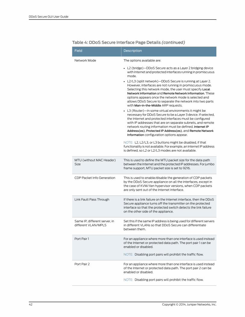
Table 4: DDoS Secure Interface Page Details (continued)
DescriptionField
The options available are:
• L2 (bridge)—DDoS Secure acts as a Layer 2 bridging devicewith Internetandprotected interfaces running inpromiscuousmode.
• L2/L3 (split network)—DDoS Secure is running at Layer 2.However, interfaces are not running in promiscuous mode.Selecting this network mode, the user must specify LocalNetwork InformationandRemoteNetwork Information. Theseoptions appears once the network mode is selected andallows DDoS Secure to separate the network into two partswithMan-in-the-Middle ARP requests.
• L3 (Router)—In some virtual environments it might benecessary for DDoSSecure to be a Layer 3 device. If selected,the Internet and protected interfaces must be configuredwith IP addresses that are on separate subnets, and remotenetwork routing information must be defined. Internet IPAddress(es), Protected IP Address(es), and Remote NetworkInformation configuration options appear.
NOTE: L2, L2/L3, or L3 buttons might be disabled, if thatfunctionality is notavailable. For example, an Internet IPaddressis defined, so L2 or L2/L3modes are not available.
Network Mode
This is used to define the MTU packet size for the data pathbetween the Internetand theprotected IPaddresses. For jumboframe support, MTU packet size is set to 9216.
MTU (without MAC Header)Size
This is used to enable/disable the generation of CDP packetsby the DDoS Secure appliance on all the interfaces, except inthe case of KVM/Xen hypervisor versions, when CDP packetsare only sent out of the Internet Interface.
CDP Packet Info Generation
If there is a link failure on the Internet interface, then the DDoSSecure appliance turns off the transmitter on the protectedinterface so that the protected switch detects the link failureon the other side of the appliance.
Link Fault Pass Through
Set this if the same IPaddress is being used for different serversin different VLANs so that DDoS Secure can differentiatebetween them.
Same IP, different server, indifferent VLAN/MPLS
For an appliancewheremore thanone interface is used insteadof the Internet or protected data path. The port pair 1 can beenabled or disabled.
NOTE: Disabling port pairs will prohibit the traffic flow.
Port Pair 1
For an appliancewheremore thanone interface is used insteadof the Internet or protected data path. The port pair 2 can beenabled or disabled.
NOTE: Disabling port pairs will prohibit the traffic flow.
Port Pair 2
Copyright © 2014, Juniper Networks, Inc.42
DDoS Secure GUI User Guide
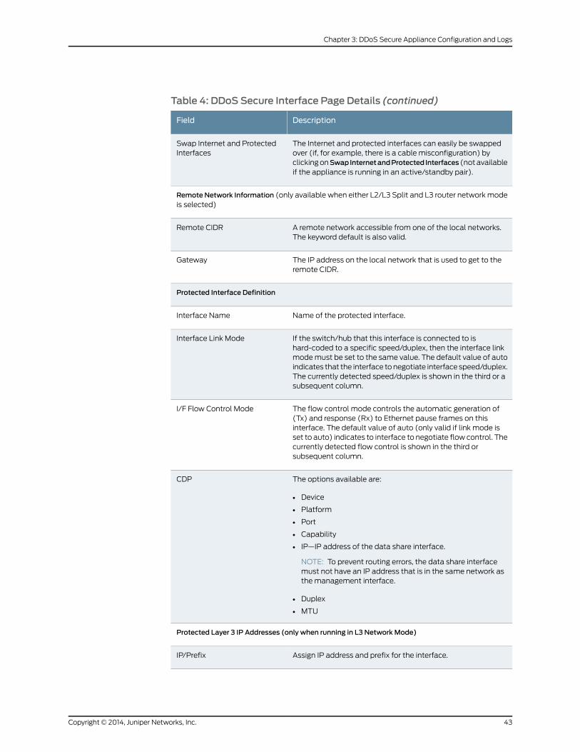
Table 4: DDoS Secure Interface Page Details (continued)
DescriptionField
The Internet and protected interfaces can easily be swappedover (if, for example, there is a cable misconfiguration) byclickingonSwapInternetandProtected Interfaces (notavailableif the appliance is running in an active/standby pair).
Swap Internet and ProtectedInterfaces
Remote Network Information (only available when either L2/L3 Split and L3 router networkmodeis selected)
A remote network accessible from one of the local networks.The keyword default is also valid.
Remote CIDR
The IP address on the local network that is used to get to theremote CIDR.
Gateway
Protected Interface Definition
Name of the protected interface.Interface Name
If the switch/hub that this interface is connected to ishard-coded to a specific speed/duplex, then the interface linkmodemust be set to the same value. The default value of autoindicates that the interface tonegotiate interface speed/duplex.The currently detected speed/duplex is shown in the third or asubsequent column.
Interface Link Mode
The flow control mode controls the automatic generation of(Tx) and response (Rx) to Ethernet pause frames on thisinterface. The default value of auto (only valid if link mode isset to auto) indicates to interface to negotiate flow control. Thecurrently detected flow control is shown in the third orsubsequent column.
I/F Flow Control Mode
The options available are:
• Device
• Platform
• Port
• Capability
• IP—IP address of the data share interface.
NOTE: To prevent routing errors, the data share interfacemust not have an IP address that is in the same network asthe management interface.
• Duplex
• MTU
CDP
Protected Layer 3 IP Addresses (only when running in L3 Network Mode)
Assign IP address and prefix for the interface.IP/Prefix
43Copyright © 2014, Juniper Networks, Inc.
Chapter 3: DDoS Secure Appliance Configuration and Logs
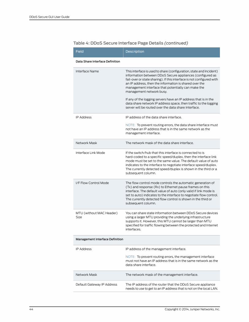
Table 4: DDoS Secure Interface Page Details (continued)
DescriptionField
Data Share Interface Definition
This interface is used toshare (configuration, stateand Incident)information between DDoS Secure appliances (configured asfail-over or state sharing). If this interface is not configuredwithan IP address, then the information is shared over themanagement interface that potentially canmake themanagement network busy.
If any of the logging servers have an IP address that is in thedata share network IP address space, then traffic to the loggingserver will be routed over the data share Interface.
Interface Name
IP address of the data share interface.
NOTE: To prevent routing errors, the data share interfacemustnot have an IP address that is in the same network as themanagement interface.
IP Address
The network mask of the data share interface.Network Mask
If the switch/hub that this interface is connected to ishard-coded to a specific speed/duplex, then the interface linkmodemust be set to the same value. The default value of autoindicates to the interface to negotiate interface speed/duplex.The currently detected speed/duplex is shown in the third or asubsequent column.
Interface Link Mode
The flow control mode controls the automatic generation of(Tx) and response (Rx) to Ethernet pause frames on thisinterface. The default value of auto (only valid if link mode isset to auto) indicates to the interface to negotiate flow control.The currently detected flow control is shown in the third orsubsequent column.
I/F Flow Control Mode
You can share state information betweenDDoSSecure devicesusing a larger MTU providing the underlying infrastructuresupports it. However, this MTU cannot be larger than MTUspecified for traffic flowing between the protected and Internetinterfaces.
MTU (without MAC Header)Size
Management Interface Definition
IP address of the management interface.
NOTE: To prevent routing errors, the management interfacemust not have an IP address that is in the same network as thedata share interface.
IP Address
The network mask of the management interface.Network Mask
The IP address of the router that the DDoS Secure applianceneeds to use to get to an IP address that is not on the local LAN.
Default Gateway IP Address
Copyright © 2014, Juniper Networks, Inc.44
DDoS Secure GUI User Guide
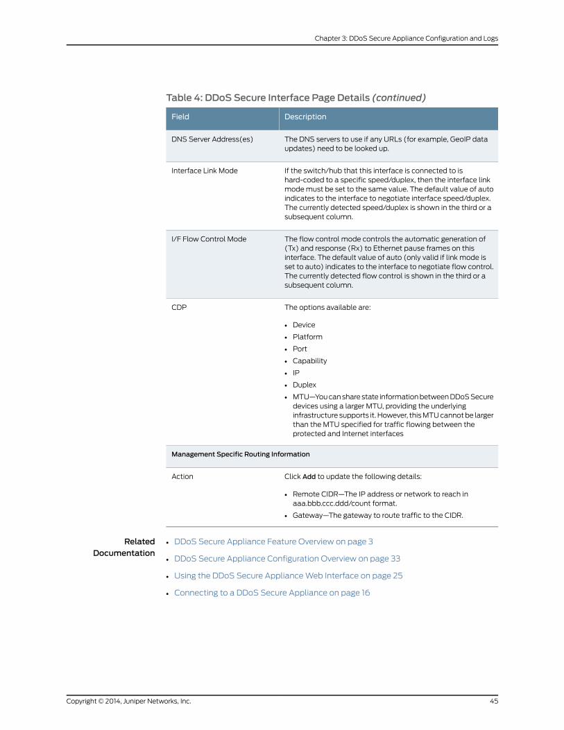
Table 4: DDoS Secure Interface Page Details (continued)
DescriptionField
The DNS servers to use if any URLs (for example, GeoIP dataupdates) need to be looked up.
DNS Server Address(es)
If the switch/hub that this interface is connected to ishard-coded to a specific speed/duplex, then the interface linkmodemust be set to the same value. The default value of autoindicates to the interface to negotiate interface speed/duplex.The currently detected speed/duplex is shown in the third or asubsequent column.
Interface Link Mode
The flow control mode controls the automatic generation of(Tx) and response (Rx) to Ethernet pause frames on thisinterface. The default value of auto (only valid if link mode isset to auto) indicates to the interface to negotiate flow control.The currently detected flow control is shown in the third or asubsequent column.
I/F Flow Control Mode
The options available are:
• Device
• Platform
• Port
• Capability
• IP
• Duplex
• MTU—Youcansharestate informationbetweenDDoSSecuredevices using a larger MTU, providing the underlyinginfrastructure supports it. However, thisMTUcannotbe largerthan the MTU specified for traffic flowing between theprotected and Internet interfaces
CDP
Management Specific Routing Information
Click Add to update the following details:
• Remote CIDR—The IP address or network to reach inaaa.bbb.ccc.ddd/count format.
• Gateway—The gateway to route traffic to the CIDR.
Action
RelatedDocumentation
DDoS Secure Appliance Feature Overview on page 3•
• DDoS Secure Appliance Configuration Overview on page 33
• Using the DDoS Secure ApplianceWeb Interface on page 25
• Connecting to a DDoS Secure Appliance on page 16
45Copyright © 2014, Juniper Networks, Inc.
Chapter 3: DDoS Secure Appliance Configuration and Logs
Configuring DDoS Secure
The parameters displayed in Figure 33 on page 47 should be set on the DDoS Secure
appliance immediately after the first power-up. These parameters are used by the
appliance algorithm to tune responses to attacks. The default values are used if no
user-defined values are entered. Click Configure DDoS Secure to configure the DDoS
Secure appliance. This view is available only to appliance-level users.
Copyright © 2014, Juniper Networks, Inc.46
DDoS Secure GUI User Guide
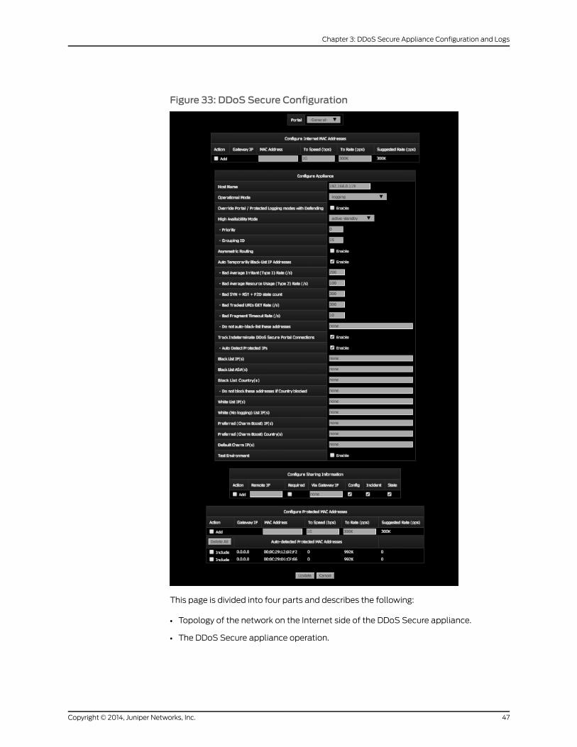
Figure 33: DDoS Secure Configuration
This page is divided into four parts and describes the following:
• Topology of the network on the Internet side of the DDoS Secure appliance.
• The DDoS Secure appliance operation.
47Copyright © 2014, Juniper Networks, Inc.
Chapter 3: DDoS Secure Appliance Configuration and Logs
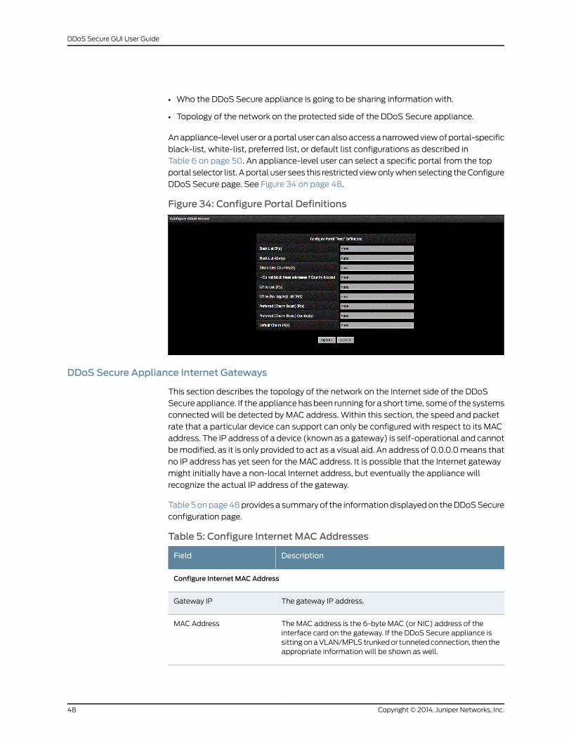
• Who the DDoS Secure appliance is going to be sharing information with.
• Topology of the network on the protected side of the DDoS Secure appliance.
Anappliance-level user or aportal user canalsoaccessanarrowedviewofportal-specific
black-list, white-list, preferred list, or default list configurations as described in
Table 6 on page 50. An appliance-level user can select a specific portal from the top
portal selector list. Aportal user sees this restrictedviewonlywhenselecting theConfigure
DDoS Secure page. See Figure 34 on page 48.
Figure 34: Configure Portal Definitions
DDoS Secure Appliance Internet Gateways
This section describes the topology of the network on the Internet side of the DDoS
Secure appliance. If theappliancehasbeen running for a short time, someof the systems
connected will be detected by MAC address. Within this section, the speed and packet
rate that a particular device can support can only be configured with respect to its MAC
address. The IP address of a device (knownas a gateway) is self-operational and cannot
bemodified, as it is only provided to act as a visual aid. An address of 0.0.0.0means that
no IP address has yet seen for the MAC address. It is possible that the Internet gateway
might initially have a non-local Internet address, but eventually the appliance will
recognize the actual IP address of the gateway.
Table5onpage48providesa summaryof the informationdisplayedon theDDoSSecure
configuration page.
Table 5: Configure Internet MAC Addresses
DescriptionField
Configure Internet MAC Address
The gateway IP address.Gateway IP
The MAC address is the 6-byte MAC (or NIC) address of theinterface card on the gateway. If the DDoS Secure appliance issittingonaVLAN/MPLStrunkedor tunneledconnection, then theappropriate information will be shown as well.
MAC Address
Copyright © 2014, Juniper Networks, Inc.48
DDoS Secure GUI User Guide
Table 5: Configure Internet MAC Addresses (continued)
DescriptionField
Themaximum data rate that the gateway device can accept forpassing on towhatever is behind the gateway. For example, if thegatewaywere connected to a 1544Kbps (T1) line, then the speedshould be defined as 1544K, or 1.544M. Speed can be specified inunits of K (1,000), M (1,000,000) or G (1,000,000,000). 0 or Umeans unrestricted. This speed is used in the appliancesalgorithms fordeterminingwhenbandwidth shouldbecontrolled.
To Speed (bps)
Themaximumpacket rate (packetsper second) that thegatewaydevice can accept for passing on to whatever is behind thegateway. Speed can be specified in units of K (1,000), M(1,000,000) or G (1,000,000,000). If the value is set to 0 or U, itmeans it is unrestricted. We recommend that you use thesuggested rate, if themaximumpackethandling rate is not known.
To Rate (pps)
The recommended default is normally 25% of the theoreticallymaximumnumberof small packets thatcan fit downtheToSpeedof the gateway.On lower bandwidth links (linkswith a bandwidthless than8Mbs) the recommendedvaluewill behigher than25%of the theoreticalmaximum, andonhigher speed links, thismightbe less than 25%.
Suggested Rate (pps)
Adding an Internet MAC Address to a DDoS Secure Appliance
You can define an Internet gateway MAC address that has not been auto-detected. You
will need to ensure that the Add check box is selected, and then click Update at the end
of the configuration page, or top right for a new item to be included. VLAN and/or MPLS
information can be included by using the following prefixes:
• v—VLAN
• q—QINQ
• u—Unicast MPLS label
• m—Multicast MPLS label
• IPv4—IPv6 traffic tunneled in IPv4
• GRE—IPv4 traffic in a GRE tunnel
Defined Internet MAC Addresses
This section contains all the defined Internet MAC addresses. Select the Remove check
box to remove inactive InternetMAC addresses from the display. ClickUpdate to confirm
this change.
Auto-Detected Internet MAC Addresses
This section contains all Internet MAC addresses detected by the appliance, apart from
those reported above. Select the Include check box to move this MAC address into the
defined Internet MAC addresses section, where interface speeds can bemodified. To
49Copyright © 2014, Juniper Networks, Inc.
Chapter 3: DDoS Secure Appliance Configuration and Logs
purge all the auto-detected Internet MAC addresses, click Delete All. Inactive
auto-detected MAC addresses are deleted automatically after five days.
Configuring a DDoS Secure Appliance
Table 6 on page 50 provides a summary of the information displayed on the appliance
configuration page.
Table 6: Appliance Configuration Page Details
DescriptionField
Configure Appliance
The default for the hostname is the IP address of the DDoS Secureappliance. Changing the entry causes the name in the browser tab toalso update the browser and the system name in any generated CDPpackets.
Host Name
The DDoS Secure appliance can operate in different modes, some ofwhich are primarily used for diagnostic purposes. Thesemodes are:
Defending—In this mode, the DDoS Secure appliance is behavingnormally, passing packets and defending as required.
Defending-NoStateLearn—For the first five minutes following a reboot,or a network cable being plugged in, the appliance bypasses its normalstate table rigorous checkingand re-syncs statewith anyactive existingconnections.These fiveminutesofgraceprevent theblockingofpacketsfromexisting connections active at the timeof the appliance restarting.This can be overridden by setting the DDoS Secure appliance intoDefending-NoStateLearnmode. Doing this will cause a substantialnumber of connections to be dropped, and so is not normallyrecommended.
Logging—Where theappliancemonitors the traffic and flagsanyattacksdetected but does not drop any packets prior to transmission out of theopposite interface. Consequently, some of the entries inTCP/UDP/ICMP/Other Info pagesmight be highlighted in yellow to flagthese discrepancies. Some of the other reported statistics might beskewed by the fact that packets should have been dropped, but werenot seen. In thismode, the appliance is allowed to proactively generatepackets (such as TCP keepalives to test for genuine idle connections,or fail-over heartbeats).
Logging-NoKeepAlives—This is same as logging, except that TCPkeepaliveswill notbegeneratedproactively. Theappliancewill, however,generate fail-over heartbeats if configured for fail-over. Running in thismodewill causeahigher incidenceofBlockedState–NoState Incidentsas the DDoS Secure appliance is unable to determine if a session hasexpired.
Operational Mode
Copyright © 2014, Juniper Networks, Inc.50
DDoS Secure GUI User Guide
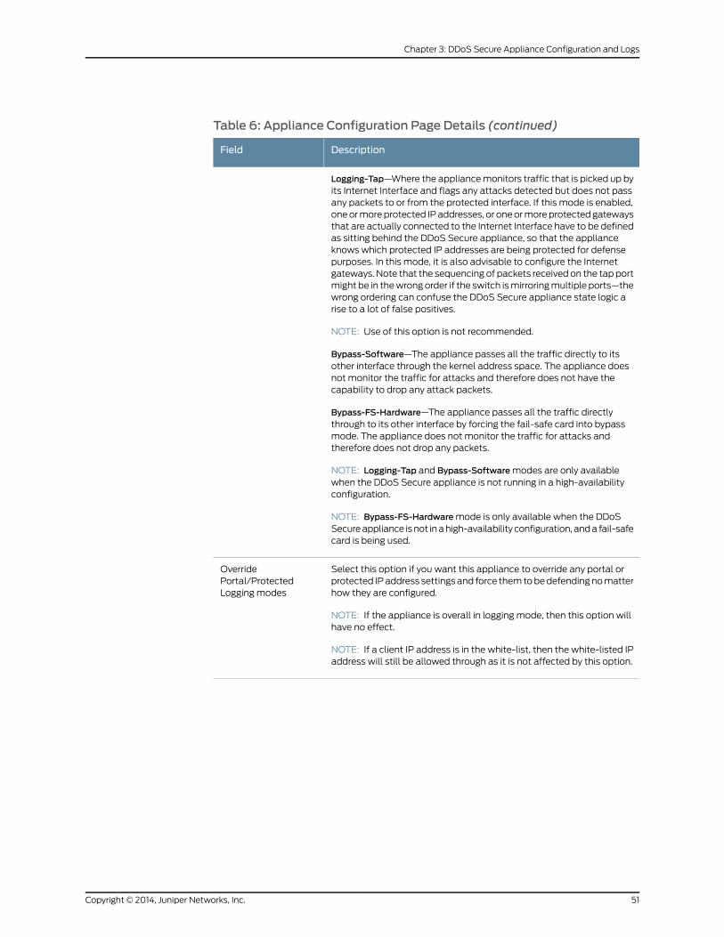
Table 6: Appliance Configuration Page Details (continued)
DescriptionField
Logging-Tap—Where the appliancemonitors traffic that is picked up byits Internet Interface and flags any attacks detected but does not passany packets to or from the protected interface. If this mode is enabled,oneormoreprotected IPaddresses, or oneormoreprotectedgatewaysthat are actually connected to the Internet Interface have to be definedas sitting behind the DDoS Secure appliance, so that the applianceknows which protected IP addresses are being protected for defensepurposes. In this mode, it is also advisable to configure the Internetgateways. Note that the sequencing of packets received on the tap portmight be in thewrongorder if the switch ismirroringmultiple ports—thewrong ordering can confuse the DDoS Secure appliance state logic arise to a lot of false positives.
NOTE: Use of this option is not recommended.
Bypass-Software—The appliance passes all the traffic directly to itsother interface through the kernel address space. The appliance doesnot monitor the traffic for attacks and therefore does not have thecapability to drop any attack packets.
Bypass-FS-Hardware—The appliance passes all the traffic directlythrough to its other interface by forcing the fail-safe card into bypassmode. The appliance does not monitor the traffic for attacks andtherefore does not drop any packets.
NOTE: Logging-Tap and Bypass-Softwaremodes are only availablewhen the DDoS Secure appliance is not running in a high-availabilityconfiguration.
NOTE: Bypass-FS-Hardwaremode is only available when the DDoSSecureappliance isnot inahigh-availability configuration, anda fail-safecard is being used.
Select this option if you want this appliance to override any portal orprotected IPaddress settingsand force themtobedefendingnomatterhow they are configured.
NOTE: If the appliance is overall in logging mode, then this option willhave no effect.
NOTE: If a client IP address is in the white-list, then the white-listed IPaddress will still be allowed through as it is not affected by this option.
OverridePortal/ProtectedLogging modes
51Copyright © 2014, Juniper Networks, Inc.
Chapter 3: DDoS Secure Appliance Configuration and Logs
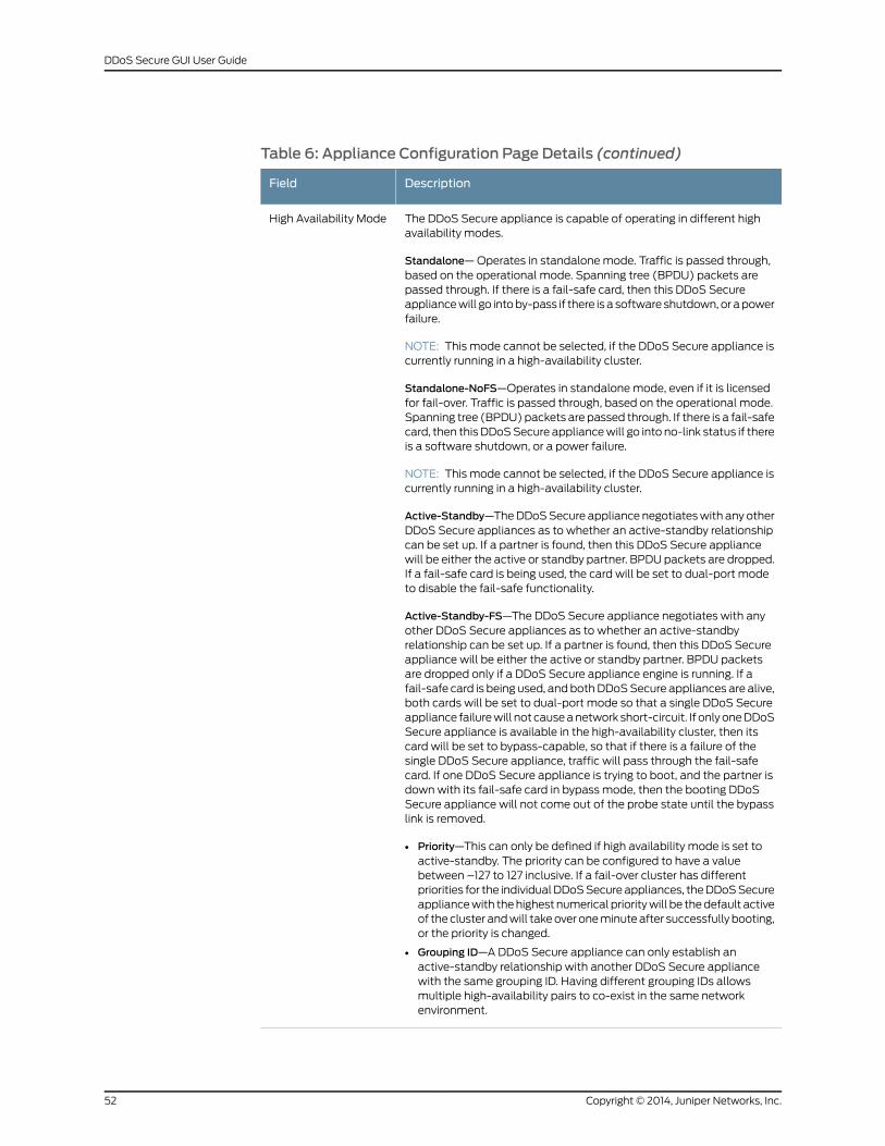
Table 6: Appliance Configuration Page Details (continued)
DescriptionField
The DDoS Secure appliance is capable of operating in different highavailability modes.
Standalone—Operates in standalonemode. Traffic is passed through,based on the operational mode. Spanning tree (BPDU) packets arepassed through. If there is a fail-safe card, then this DDoS Secureappliancewill go intoby-pass if there is a software shutdown, or apowerfailure.
NOTE: This mode cannot be selected, if the DDoS Secure appliance iscurrently running in a high-availability cluster.
Standalone-NoFS—Operates in standalonemode, even if it is licensedfor fail-over. Traffic is passed through, based on the operational mode.Spanning tree (BPDU)packets are passed through. If there is a fail-safecard, then this DDoSSecure appliancewill go into no-link status if thereis a software shutdown, or a power failure.
NOTE: This mode cannot be selected, if the DDoS Secure appliance iscurrently running in a high-availability cluster.
Active-Standby—TheDDoSSecure appliance negotiateswith any otherDDoS Secure appliances as to whether an active-standby relationshipcan be set up. If a partner is found, then this DDoS Secure appliancewill be either the active or standby partner. BPDU packets are dropped.If a fail-safe card is being used, the card will be set to dual-port modeto disable the fail-safe functionality.
Active-Standby-FS—The DDoS Secure appliance negotiates with anyother DDoS Secure appliances as to whether an active-standbyrelationship can be set up. If a partner is found, then this DDoS Secureappliance will be either the active or standby partner. BPDU packetsare dropped only if a DDoS Secure appliance engine is running. If afail-safe card is being used, andbothDDoSSecure appliances are alive,both cards will be set to dual-port mode so that a single DDoS Secureappliance failurewill not causeanetwork short-circuit. If onlyoneDDoSSecure appliance is available in the high-availability cluster, then itscard will be set to bypass-capable, so that if there is a failure of thesingle DDoS Secure appliance, traffic will pass through the fail-safecard. If one DDoS Secure appliance is trying to boot, and the partner isdown with its fail-safe card in bypass mode, then the booting DDoSSecure appliance will not come out of the probe state until the bypasslink is removed.
• Priority—This can only be defined if high availability mode is set toactive-standby. The priority can be configured to have a valuebetween –127 to 127 inclusive. If a fail-over cluster has differentpriorities for the individualDDoSSecureappliances, theDDoSSecureappliancewith thehighest numerical prioritywill be thedefault activeof thecluster andwill takeover oneminuteafter successfully booting,or the priority is changed.
• Grouping ID—ADDoS Secure appliance can only establish anactive-standby relationship with another DDoS Secure appliancewith the same grouping ID. Having different grouping IDs allowsmultiple high-availability pairs to co-exist in the same networkenvironment.
High Availability Mode
Copyright © 2014, Juniper Networks, Inc.52
DDoS Secure GUI User Guide
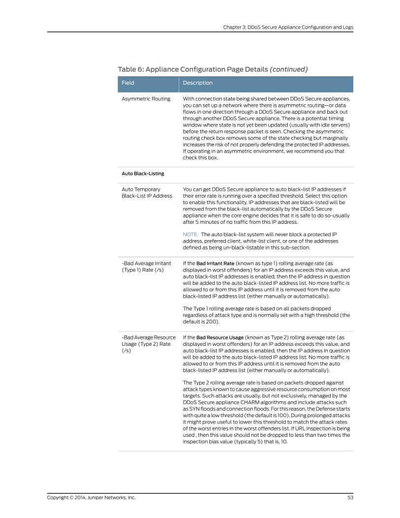
Table 6: Appliance Configuration Page Details (continued)
DescriptionField
With connection state being shared between DDoS Secure appliances,you can set up a network where there is asymmetric routing—or dataflows in one direction through a DDoS Secure appliance and back outthrough another DDoS Secure appliance. There is a potential timingwindowwhere state is not yet been updated (usually with idle servers)before the return response packet is seen. Checking the asymmetricrouting check box removes some of the state checking but marginallyincreases the risk of not properly defending the protected IP addresses.If operating in an asymmetric environment, we recommend you thatcheck this box.
Asymmetric Routing
Auto Black-Listing
You can get DDoS Secure appliance to auto black-list IP addresses iftheir error rate is running over a specified threshold. Select this optionto enable this functionality. IP addresses that are black-listed will beremoved from the black-list automatically by the DDoS Secureappliance when the core engine decides that it is safe to do so-usuallyafter 5 minutes of no traffic from this IP address.
NOTE: The auto black-list systemwill never block a protected IPaddress, preferred client, white-list client, or one of the addressesdefined as being un-black-listable in this sub-section.
Auto TemporaryBlack-List IP Address
If the Bad Irritant Rate (known as type 1) rolling average rate (asdisplayed in worst offenders) for an IP address exceeds this value, andauto black-list IP addresses is enabled, then the IP address in questionwill be added to the auto black-listed IP address list. Nomore traffic isallowed to or from this IP address until it is removed from the autoblack-listed IP address list (either manually or automatically).
The Type 1 rolling average rate is based on all packets droppedregardless of attack type and is normally set with a high threshold (thedefault is 200).
-Bad Average Irritant(Type 1) Rate (/s)
If the Bad Resource Usage (known as Type 2) rolling average rate (asdisplayed in worst offenders) for an IP address exceeds this value, andauto black-list IP addresses is enabled, then the IP address in questionwill be added to the auto black-listed IP address list. Nomore traffic isallowed to or from this IP address until it is removed from the autoblack-listed IP address list (either manually or automatically).
The Type 2 rolling average rate is based on packets dropped againstattack types known tocauseaggressive resource consumptiononmosttargets. Such attacks are usually, but not exclusively, managed by theDDoS Secure appliance CHARM algorithms and include attacks suchasSYNfloodsandconnection floods. For this reason, theDefensestartswithquitea lowthreshold (thedefault is 100).Duringprolongedattacksit might prove useful to lower this threshold to match the attack ratesof theworst entries in theworst offenders list. If URL Inspection is beingused , then this value should not be dropped to less than two times theinspection bias value (typically 5) that is, 10.
-BadAverageResourceUsage (Type 2) Rate(/s)
53Copyright © 2014, Juniper Networks, Inc.
Chapter 3: DDoS Secure Appliance Configuration and Logs
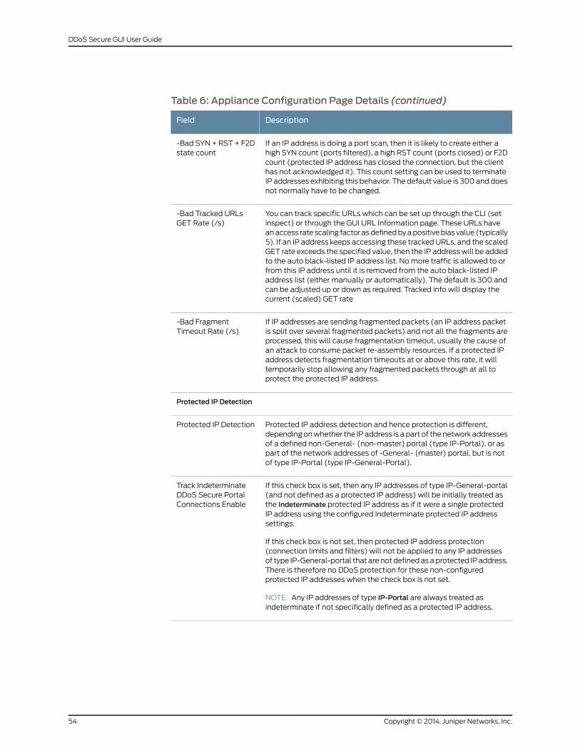
Table 6: Appliance Configuration Page Details (continued)
DescriptionField
If an IP address is doing a port scan, then it is likely to create either ahigh SYN count (ports filtered), a high RST count (ports closed) or F2Dcount (protected IP address has closed the connection, but the clienthas not acknowledged it). This count setting can be used to terminateIP addresses exhibiting this behavior. The default value is 300anddoesnot normally have to be changed.
-Bad SYN +RST + F2Dstate count
You can track specific URLs which can be set up through the CLI (setinspect) or through the GUI URL Information page. These URLs haveanaccess rate scaling factor asdefinedbyapositivebias value (typically5). If an IP address keeps accessing these trackedURLs, and the scaledGET rate exceeds the specified value, then the IP addresswill be addedto the auto black-listed IP address list. Nomore traffic is allowed to orfrom this IP address until it is removed from the auto black-listed IPaddress list (either manually or automatically). The default is 300 andcan be adjusted up or down as required. Tracked info will display thecurrent (scaled) GET rate
-Bad Tracked URLsGET Rate (/s)
If IP addresses are sending fragmented packets (an IP address packetis split over several fragmented packets) and not all the fragments areprocessed, this will cause fragmentation timeout, usually the cause ofan attack to consume packet re-assembly resources. If a protected IPaddress detects fragmentation timeouts at or above this rate, it willtemporarily stop allowing any fragmented packets through at all toprotect the protected IP address.
-Bad FragmentTimeout Rate (/s)
Protected IP Detection
Protected IP address detection and hence protection is different,dependingonwhether the IPaddress is apart of thenetworkaddressesof a defined non-General- (non-master) portal (type IP-Portal), or aspart of the network addresses of -General- (master) portal, but is notof type IP-Portal (type IP-General-Portal).
Protected IP Detection
If this check box is set, then any IP addresses of type IP-General-portal(and not defined as a protected IP address) will be initially treated asthe Indeterminate protected IP address as if it were a single protectedIP address using the configured Indeterminate protected IP addresssettings.
If this check box is not set, then protected IP address protection(connection limits and filters) will not be applied to any IP addressesof type IP-General-portal that arenotdefinedasaprotected IPaddress.There is therefore no DDoS protection for these non-configuredprotected IP addresses when the check box is not set.
NOTE: Any IP addresses of type IP-Portal are always treated asindeterminate if not specifically defined as a protected IP address.
Track IndeterminateDDoS Secure PortalConnections Enable
Copyright © 2014, Juniper Networks, Inc.54
DDoS Secure GUI User Guide
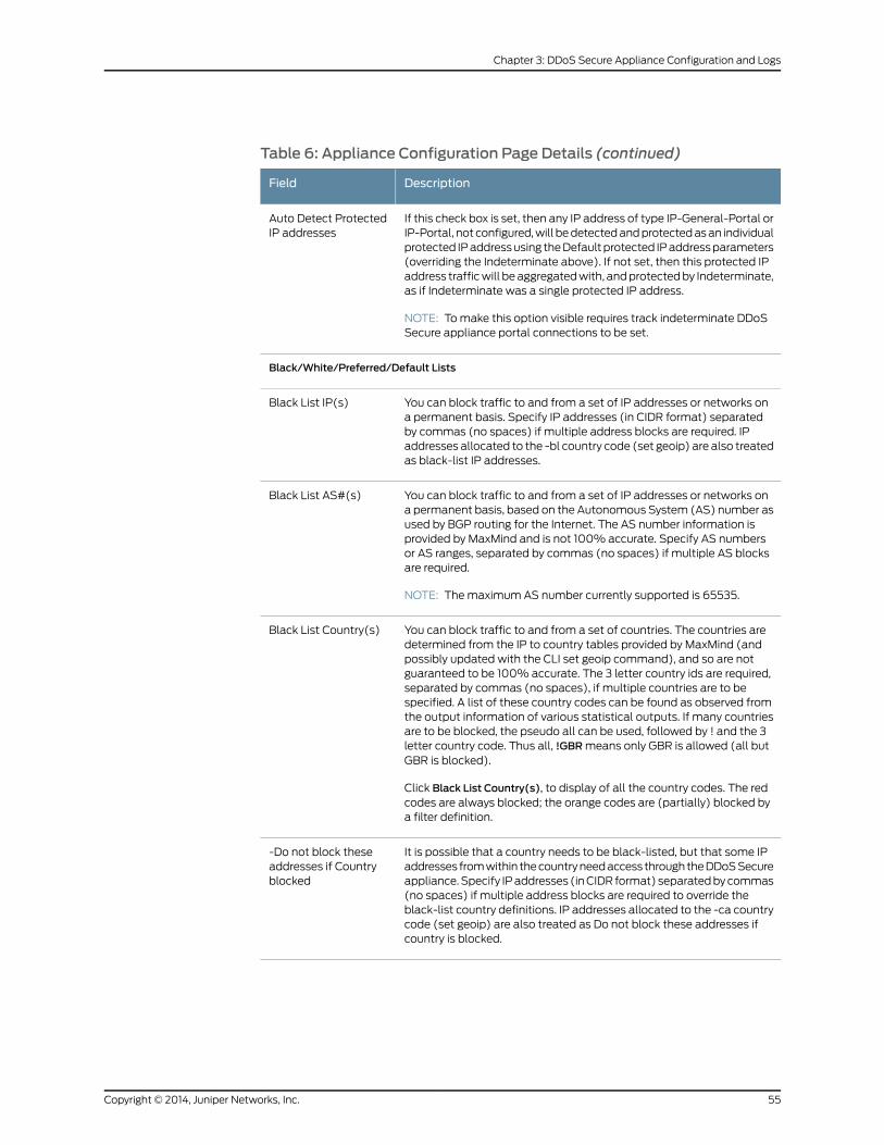
Table 6: Appliance Configuration Page Details (continued)
DescriptionField
If this check box is set, then any IP address of type IP-General-Portal orIP-Portal, not configured,will bedetectedandprotectedasan individualprotected IPaddressusing theDefaultprotected IPaddressparameters(overriding the Indeterminate above). If not set, then this protected IPaddress trafficwill beaggregatedwith, andprotectedby Indeterminate,as if Indeterminate was a single protected IP address.
NOTE: Tomake this option visible requires track indeterminate DDoSSecure appliance portal connections to be set.
Auto Detect ProtectedIP addresses
Black/White/Preferred/Default Lists
You can block traffic to and from a set of IP addresses or networks ona permanent basis. Specify IP addresses (in CIDR format) separatedby commas (no spaces) if multiple address blocks are required. IPaddresses allocated to the -bl country code (set geoip) are also treatedas black-list IP addresses.
Black List IP(s)
You can block traffic to and from a set of IP addresses or networks ona permanent basis, based on the Autonomous System (AS) number asused by BGP routing for the Internet. The AS number information isprovided by MaxMind and is not 100% accurate. Specify AS numbersor AS ranges, separated by commas (no spaces) if multiple AS blocksare required.
NOTE: Themaximum AS number currently supported is 65535.
Black List AS#(s)
You can block traffic to and from a set of countries. The countries aredetermined from the IP to country tables provided by MaxMind (andpossibly updated with the CLI set geoip command), and so are notguaranteed to be 100% accurate. The 3 letter country ids are required,separated by commas (no spaces), if multiple countries are to bespecified. A list of these country codes can be found as observed fromthe output information of various statistical outputs. If many countriesare to be blocked, the pseudo all can be used, followed by ! and the 3letter country code. Thus all, !GBRmeans only GBR is allowed (all butGBR is blocked).
Click Black List Country(s), to display of all the country codes. The redcodes are always blocked; the orange codes are (partially) blocked bya filter definition.
Black List Country(s)
It is possible that a country needs to be black-listed, but that some IPaddresses fromwithin thecountryneedaccess throughtheDDoSSecureappliance.Specify IPaddresses (inCIDR format) separatedbycommas(no spaces) if multiple address blocks are required to override theblack-list country definitions. IP addresses allocated to the -ca countrycode (set geoip) are also treated as Do not block these addresses ifcountry is blocked.
-Do not block theseaddresses if Countryblocked
55Copyright © 2014, Juniper Networks, Inc.
Chapter 3: DDoS Secure Appliance Configuration and Logs
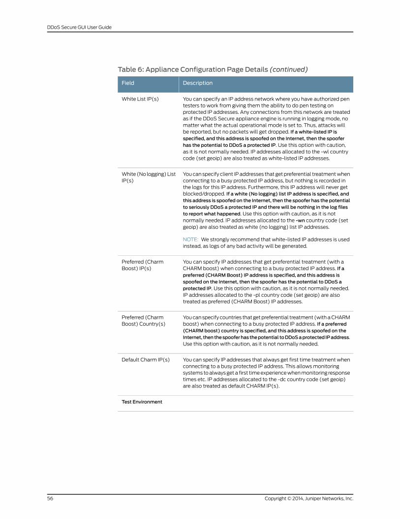
Table 6: Appliance Configuration Page Details (continued)
DescriptionField
You can specify an IP address network where you have authorized pentesters to work from giving them the ability to do pen testing onprotected IP addresses. Any connections from this network are treatedas if the DDoS Secure appliance engine is running in logging mode, nomatter what the actual operational mode is set to. Thus, attacks willbe reported, but no packets will get dropped. If a white-listed IP isspecified, and this address is spoofed on the Internet, then the spooferhas the potential to DDoS a protected IP. Use this option with caution,as it is not normally needed. IP addresses allocated to the -wl countrycode (set geoip) are also treated as white-listed IP addresses.
White List IP(s)
Youcanspecify client IPaddresses that getpreferential treatmentwhenconnecting to a busy protected IP address, but nothing is recorded inthe logs for this IP address. Furthermore, this IP address will never getblocked/dropped. If a white (No logging) list IP address is specified, andthis address is spoofed on the Internet, then the spoofer has the potentialto seriously DDoS a protected IP and there will be nothing in the log filesto report what happened. Use this option with caution, as it is notnormally needed. IP addresses allocated to the -wn country code (setgeoip) are also treated as white (no logging) list IP addresses.
NOTE: We strongly recommend that white-listed IP addresses is usedinstead, as logs of any bad activity will be generated.
White (No logging) ListIP(s)
You can specify IP addresses that get preferential treatment (with aCHARM boost) when connecting to a busy protected IP address. If apreferred (CHARMBoost) IP address is specified, and this address isspoofed on the Internet, then the spoofer has the potential to DDoS aprotected IP. Use this option with caution, as it is not normally needed.IP addresses allocated to the -pl country code (set geoip) are alsotreated as preferred (CHARM Boost) IP addresses.
Preferred (CharmBoost) IP(s)
Youcanspecify countries thatgetpreferential treatment (withaCHARMboost) when connecting to a busy protected IP address. If a preferred(CHARMboost) country is specified, and this address is spoofed on theInternet, thenthespooferhasthepotential toDDoSaprotected IPaddress.Use this option with caution, as it is not normally needed.
Preferred (CharmBoost) Country(s)
You can specify IP addresses that always get first time treatmentwhenconnecting to a busy protected IP address. This allowsmonitoringsystemstoalwaysgeta first timeexperiencewhenmonitoring responsetimes etc. IP addresses allocated to the -dc country code (set geoip)are also treated as default CHARM IP(s).
Default Charm IP(s)
Test Environment
Copyright © 2014, Juniper Networks, Inc.56
DDoS Secure GUI User Guide
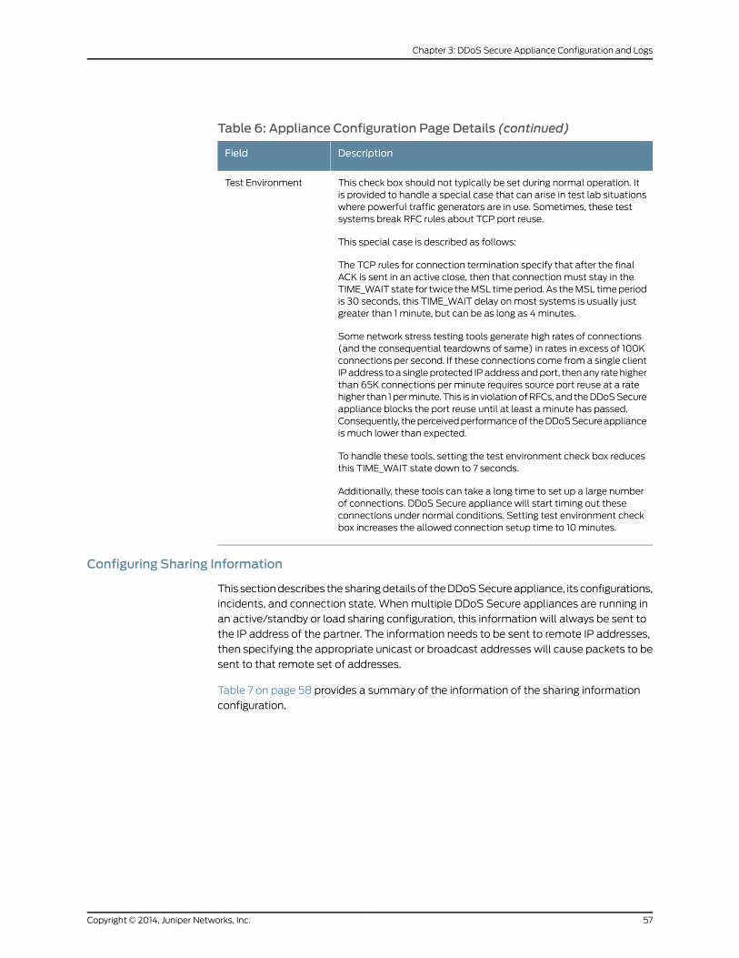
Table 6: Appliance Configuration Page Details (continued)
DescriptionField
This check box should not typically be set during normal operation. Itis provided to handle a special case that can arise in test lab situationswhere powerful traffic generators are in use. Sometimes, these testsystems break RFC rules about TCP port reuse.
This special case is described as follows:
The TCP rules for connection termination specify that after the finalACK is sent in an active close, then that connection must stay in theTIME_WAIT state for twice theMSL timeperiod. As theMSL timeperiodis 30 seconds, this TIME_WAIT delay onmost systems is usually justgreater than 1 minute, but can be as long as 4minutes.
Some network stress testing tools generate high rates of connections(and the consequential teardowns of same) in rates in excess of 100Kconnections per second. If these connections come from a single clientIPaddress toa singleprotected IPaddressandport, thenany ratehigherthan 65K connections per minute requires source port reuse at a ratehigher than 1perminute.This is in violationofRFCs, and theDDoSSecureappliance blocks the port reuse until at least a minute has passed.Consequently, theperceivedperformanceof theDDoSSecureapplianceis much lower than expected.
To handle these tools, setting the test environment check box reducesthis TIME_WAIT state down to 7 seconds.
Additionally, these tools can take a long time to set up a large numberof connections. DDoS Secure appliance will start timing out theseconnections under normal conditions. Setting test environment checkbox increases the allowed connection setup time to 10minutes.
Test Environment
Configuring Sharing Information
This sectiondescribes thesharingdetails of theDDoSSecureappliance, its configurations,
incidents, and connection state. Whenmultiple DDoS Secure appliances are running in
an active/standby or load sharing configuration, this information will always be sent to
the IP address of the partner. The information needs to be sent to remote IP addresses,
then specifying the appropriate unicast or broadcast addresses will cause packets to be
sent to that remote set of addresses.
Table 7 on page 58 provides a summary of the information of the sharing information
configuration.
57Copyright © 2014, Juniper Networks, Inc.
Chapter 3: DDoS Secure Appliance Configuration and Logs
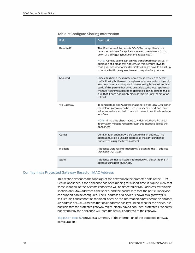
Table 7: Configure Sharing Information
DescriptionField
The IP address of the remote DDoS Secure appliance or abroadcast address for appliance in a remote network (to cutdown of traffic going between the appliances).
NOTE: Configurations can only be transferred to an actual IPaddress, not a broadcast address, so three entries (two forconfigurations, one for incidents/state) might have to be set upto reduce traffic being sent to a remote pair of appliances.
Remote IP
Check this box, if the remote appliance is required to detecttraffic flowing bothways through a appliance cluster – typicallyin an asymmetric routing environment using fail-safe interfacecards. If this partner becomes unavailable, the local appliancewill take itself into a degraded (pseudo logging) state to makesure that it does not simply block any traffic until the situationis fixed.
Required
To send data to an IP address that is not on the local LAN, eitherthe default gateway can be used, or a specific next hop routeraddress canbe specified, if data is to be sent over thedata shareinterface.
NOTE: If the data share interface is defined, then all sharedinformation must be routed through this interface across theappliances.
Via Gateway
Configuration changes will be sent to this IP address. Thisaddress must be a unicast address as the configuration istransferred using the https protocol.
Config
Appliance Defense information will be sent to this IP addressusing port 5556/udp.
Incident
Appliance connection state information will be sent to this IPaddress using port 5555/udp.
State
Configuring a Protected Gateway Based onMACAddress
This section describes the topology of the network on the protected side of the DDoS
Secure appliance. If the appliance has been running for a short time, it is quite likely that
some, if not all, of the systems connected will be detected by MAC address. Within this
section, only MAC addresses, the speed, and the packet rate that the particular device
can support can be configured. The IP address of a device (known as a gateway) is
self-learning and cannot bemodified, because the information is provided as an aid only.
An address of 0.0.0.0 means that no IP address has (yet) been seen for the device. It is
possible that theprotectedgatewaymight initially haveanon-local protected IPaddress,
but eventually the appliance will learn the actual IP address of the gateway.
Table 8 on page 59 provides a summary of the information of the protected gateway
configuration.
Copyright © 2014, Juniper Networks, Inc.58
DDoS Secure GUI User Guide
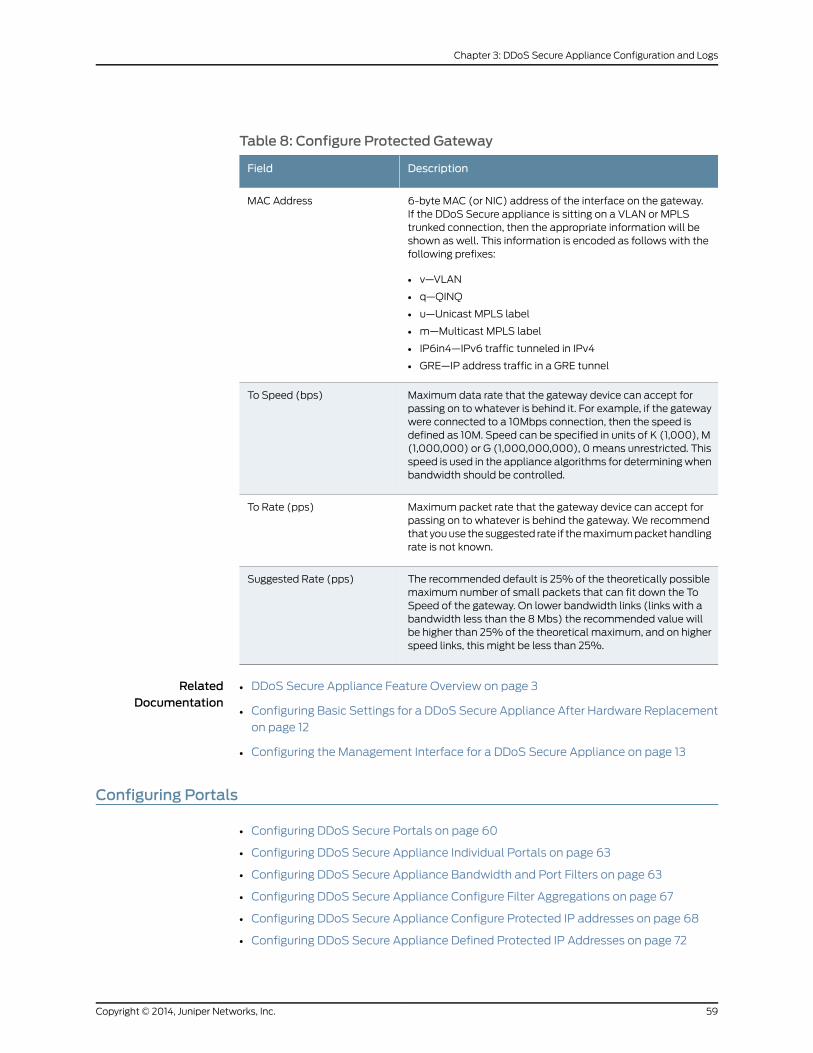
Table 8: Configure Protected Gateway
DescriptionField
6-byte MAC (or NIC) address of the interface on the gateway.If the DDoS Secure appliance is sitting on a VLAN or MPLStrunked connection, then the appropriate information will beshown as well. This information is encoded as follows with thefollowing prefixes:
• v—VLAN
• q—QINQ
• u—Unicast MPLS label
• m—Multicast MPLS label
• IP6in4—IPv6 traffic tunneled in IPv4
• GRE—IP address traffic in a GRE tunnel
MAC Address
Maximum data rate that the gateway device can accept forpassing on to whatever is behind it. For example, if the gatewaywere connected to a 10Mbps connection, then the speed isdefined as 10M. Speed can be specified in units of K (1,000), M(1,000,000) or G (1,000,000,000), 0 means unrestricted. Thisspeed is used in the appliance algorithms for determiningwhenbandwidth should be controlled.
To Speed (bps)
Maximum packet rate that the gateway device can accept forpassing on to whatever is behind the gateway. We recommendthat youuse thesuggested rate if themaximumpackethandlingrate is not known.
To Rate (pps)
The recommended default is 25% of the theoretically possiblemaximum number of small packets that can fit down the ToSpeed of the gateway. On lower bandwidth links (links with abandwidth less than the 8 Mbs) the recommended value willbe higher than 25% of the theoretical maximum, and on higherspeed links, this might be less than 25%.
Suggested Rate (pps)
RelatedDocumentation
DDoS Secure Appliance Feature Overview on page 3•
• Configuring Basic Settings for a DDoS Secure Appliance After Hardware Replacement
on page 12
• Configuring the Management Interface for a DDoS Secure Appliance on page 13
Configuring Portals
• Configuring DDoS Secure Portals on page 60
• Configuring DDoS Secure Appliance Individual Portals on page 63
• Configuring DDoS Secure Appliance Bandwidth and Port Filters on page 63
• Configuring DDoS Secure Appliance Configure Filter Aggregations on page 67
• Configuring DDoS Secure Appliance Configure Protected IP addresses on page 68
• Configuring DDoS Secure Appliance Defined Protected IP Addresses on page 72
59Copyright © 2014, Juniper Networks, Inc.
Chapter 3: DDoS Secure Appliance Configuration and Logs
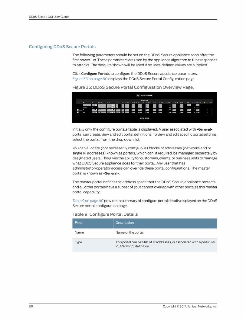
Configuring DDoS Secure Portals
The following parameters should be set on the DDoS Secure appliance soon after the
first power-up. These parameters are used by the appliance algorithm to tune responses
to attacks. The defaults shown will be used if no user-defined values are supplied.
Click Configure Portals to configure the DDoS Secure appliance parameters.
Figure 35 on page 60 displays the DDoS Secure Portal Configuration page.
Figure 35: DDoS Secure Portal Configuration Overview Page.
Initially only the configure portals table is displayed. A user associated with -General-
portal cancreate, viewandedit portal definitions. Toviewandedit specific portal settings,
select the portal from the drop down list.
You can allocate (not necessarily contiguous) blocks of addresses (networks and or
single IP addresses) known as portals, which can, if required, be managed separately by
designatedusers. This gives theability for customers, clients, or businessunits tomanage
what DDoS Secure appliance does for their portal. Any user that has
administrator/operator access can override these portal configurations. Themaster
portal is known as -General-.
The master portal defines the address space that the DDoS Secure appliance protects,
and all other portals have a subset of (but cannot overlapwith other portals) thismaster
portal capability.
Table9onpage60providesasummaryofconfigureportaldetailsdisplayedon theDDoS
Secure portal configuration page.
Table 9: Configure Portal Details
DescriptionField
Name of the portal.Name
This portal canbea list of IPaddresses, or associatedwithaparticularVLAN/MPLS definition.
Type
Copyright © 2014, Juniper Networks, Inc.60
DDoS Secure GUI User Guide
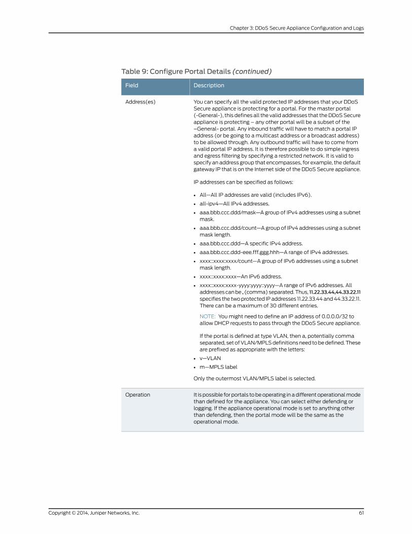
Table 9: Configure Portal Details (continued)
DescriptionField
You can specify all the valid protected IP addresses that your DDoSSecure appliance is protecting for a portal. For the master portal(-General-), this defines all the valid addresses that theDDoSSecureappliance is protecting – any other portal will be a subset of the–General- portal. Any inbound traffic will have to match a portal IPaddress (or be going to amulticast address or a broadcast address)to be allowed through. Any outbound traffic will have to come froma valid portal IP address. It is therefore possible to do simple ingressand egress filtering by specifying a restricted network. It is valid tospecify an address group that encompasses, for example, the defaultgateway IP that is on the Internet side of the DDoS Secure appliance.
IP addresses can be specified as follows:
• All—All IP addresses are valid (includes IPv6).
• all-ipv4—All IPv4 addresses.
• aaa.bbb.ccc.ddd/mask—A group of IPv4 addresses using a subnetmask.
• aaa.bbb.ccc.ddd/count—Agroup of IPv4 addresses using a subnetmask length.
• aaa.bbb.ccc.ddd—A specific IPv4 address.
• aaa.bbb.ccc.ddd-eee.fff.ggg.hhh—A range of IPv4 addresses.
• xxxx::xxxx:xxxx/count—A group of IPv6 addresses using a subnetmask length.
• xxxx::xxxx:xxxx—An IPv6 address.
• xxxx::xxxx:xxxx-yyyy:yyyy::yyyy—A range of IPv6 addresses. Alladdressescanbe , (comma)separated.Thus, 11.22.33.44,44.33.22.11specifies the twoprotected IPaddresses 11.22.33.44and44.33.22.11.There can be amaximum of 30 different entries.
NOTE: Youmight need to define an IP address of 0.0.0.0/32 toallow DHCP requests to pass through the DDoS Secure appliance.
If the portal is defined at type VLAN, then a, potentially commaseparated, setofVLAN/MPLSdefinitionsneed tobedefined.Theseare prefixed as appropriate with the letters:
• v—VLAN
• m—MPLS label
Only the outermost VLAN/MPLS label is selected.
Address(es)
It is possible for portals tobeoperating inadifferentoperationalmodethan defined for the appliance. You can select either defending orlogging. If the appliance operational mode is set to anything otherthan defending, then the portal mode will be the same as theoperational mode.
Operation
61Copyright © 2014, Juniper Networks, Inc.
Chapter 3: DDoS Secure Appliance Configuration and Logs
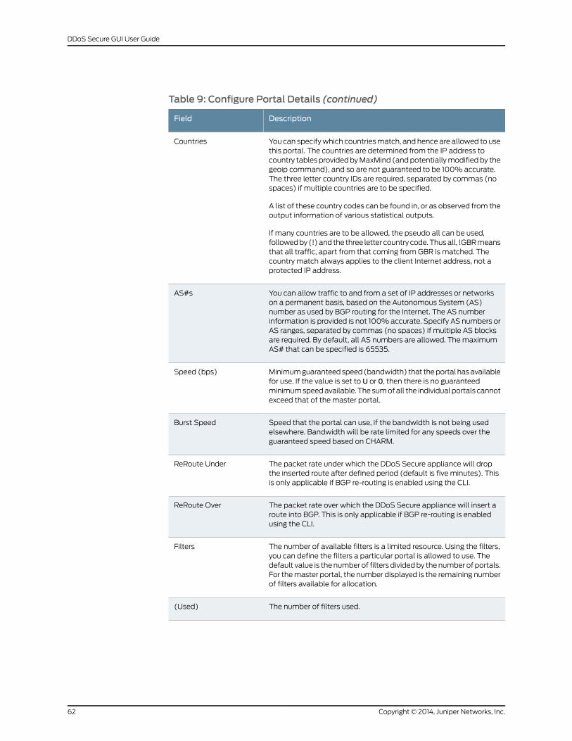
Table 9: Configure Portal Details (continued)
DescriptionField
You can specifywhich countriesmatch, and hence are allowed to usethis portal. The countries are determined from the IP address tocountry tables providedbyMaxMind (andpotentiallymodified by thegeoip command), and so are not guaranteed to be 100% accurate.The three letter country IDs are required, separated by commas (nospaces) if multiple countries are to be specified.
A list of these country codes can be found in, or as observed from theoutput information of various statistical outputs.
If many countries are to be allowed, the pseudo all can be used,followedby (!)and the three letter country code.Thusall, !GBRmeansthat all traffic, apart from that coming from GBR is matched. Thecountry match always applies to the client Internet address, not aprotected IP address.
Countries
You can allow traffic to and from a set of IP addresses or networkson a permanent basis, based on the Autonomous System (AS)number as used by BGP routing for the Internet. The AS numberinformation is provided is not 100%accurate. Specify AS numbers orAS ranges, separated by commas (no spaces) if multiple AS blocksare required. By default, all AS numbers are allowed. ThemaximumAS# that can be specified is 65535.
AS#s
Minimumguaranteedspeed(bandwidth) that theportal hasavailablefor use. If the value is set to U or 0, then there is no guaranteedminimumspeedavailable. Thesumofall the individualportals cannotexceed that of the master portal.
Speed (bps)
Speed that the portal can use, if the bandwidth is not being usedelsewhere. Bandwidth will be rate limited for any speeds over theguaranteed speed based on CHARM.
Burst Speed
The packet rate under which the DDoS Secure appliance will dropthe inserted route after defined period (default is five minutes). Thisis only applicable if BGP re-routing is enabled using the CLI.
ReRoute Under
The packet rate over which the DDoS Secure appliance will insert aroute into BGP. This is only applicable if BGP re-routing is enabledusing the CLI.
ReRoute Over
The number of available filters is a limited resource. Using the filters,you can define the filters a particular portal is allowed to use. Thedefault value is thenumber of filters dividedby thenumber of portals.For themaster portal, the number displayed is the remaining numberof filters available for allocation.
Filters
The number of filters used.(Used)
Copyright © 2014, Juniper Networks, Inc.62
DDoS Secure GUI User Guide
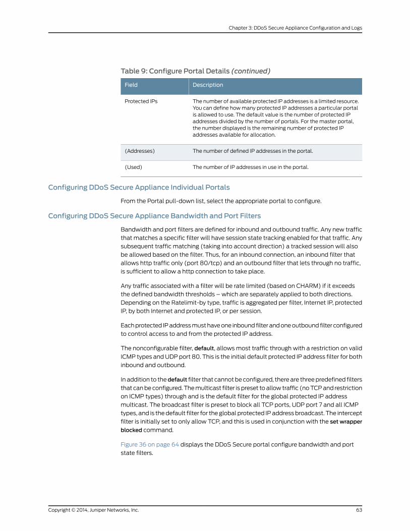
Table 9: Configure Portal Details (continued)
DescriptionField
The number of available protected IP addresses is a limited resource.You can define howmany protected IP addresses a particular portalis allowed to use. The default value is the number of protected IPaddresses divided by the number of portals. For the master portal,the number displayed is the remaining number of protected IPaddresses available for allocation.
Protected IPs
The number of defined IP addresses in the portal.(Addresses)
The number of IP addresses in use in the portal.(Used)
Configuring DDoS Secure Appliance Individual Portals
From the Portal pull-down list, select the appropriate portal to configure.
Configuring DDoS Secure Appliance Bandwidth and Port Filters
Bandwidth and port filters are defined for inbound and outbound traffic. Any new traffic
thatmatches a specific filter will have session state tracking enabled for that traffic. Any
subsequent traffic matching (taking into account direction) a tracked session will also
be allowed based on the filter. Thus, for an inbound connection, an inbound filter that
allows http traffic only (port 80/tcp) and an outbound filter that lets through no traffic,
is sufficient to allow a http connection to take place.
Any traffic associated with a filter will be rate limited (based on CHARM) if it exceeds
the defined bandwidth thresholds – which are separately applied to both directions.
Depending on the Ratelimit-by type, traffic is aggregated per filter, Internet IP, protected
IP, by both Internet and protected IP, or per session.
Eachprotected IPaddressmusthaveone inbound filterandoneoutbound filter configured
to control access to and from the protected IP address.
The nonconfigurable filter, default, allowsmost traffic through with a restriction on valid
ICMP types andUDPport 80. This is the initial default protected IP address filter for both
inbound and outbound.
In addition to thedefault filter that cannotbeconfigured, thereare threepredefined filters
that canbeconfigured. Themulticast filter is preset toallow traffic (noTCPand restriction
on ICMP types) through and is the default filter for the global protected IP address
multicast. The broadcast filter is preset to block all TCP ports, UDP port 7 and all ICMP
types, and is thedefault filter for theglobal protected IPaddressbroadcast. The intercept
filter is initially set to only allow TCP, and this is used in conjunction with the set wrapper
blocked command.
Figure 36 on page 64 displays the DDoS Secure portal configure bandwidth and port
state filters.
63Copyright © 2014, Juniper Networks, Inc.
Chapter 3: DDoS Secure Appliance Configuration and Logs
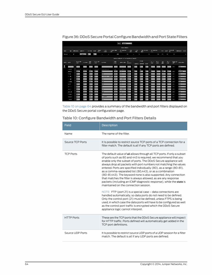
Figure36:DDoSSecurePortalConfigureBandwidthandPortStateFilters
Table 10 on page 64 provides a summary of the bandwidth and port filters displayed on
the DDoS Secure portal configuration page.
Table 10: Configure Bandwidth and Port Filters Details
DescriptionField
The name of the filter.Name
It Is possible to restrict source TCP ports of a TCP connection for afilter match. The default is all if any TCP ports are defined.
Source TCP Ports
Thedefault value of allallows throughall TCPports. If only a subsetof ports such as 80 and 443 is required, we recommend that youenable only the subset of ports. The DDoS Secure appliance willalways drop all packetswith port numbers notmatching the valuesentered. Ports are specified individually (80), as a range (80-81),as a comma-separated list (80,443), or as a combination(80-81,443). The keyword none is also supported. Any connectionthat matches the filter is always allowed, as are any responsepackets (including an ICMP diagnostic response), while the state ismaintained on the connection session.
NOTE: FTP (port 21) is a special case – data connections arehandled automatically, so data ports do not need to be defined.Only the control port (21) must be defined, unless FTPS is beingused, inwhich case the data portswill have to be configured aswellas the control port traffic is encrypted which the DDoS Secureappliance logic cannot interpret.
TCP Ports
Theseare theTCPports that theDDoSSecureappliancewill inspectfor HTTP traffic. Ports defined will automatically get added in theTCP port definitions.
HTTP Ports
It Is possible to restrict sourceUDPports of aUDPsession for a filtermatch. The default is all if any UDP ports are defined.
Source UDP Ports
Copyright © 2014, Juniper Networks, Inc.64
DDoS Secure GUI User Guide
Table 10: Configure Bandwidth and Port Filters Details (continued)
DescriptionField
Thedefault valueofallallows throughallUDPports. If only a subsetof ports such as 53 (DNS) is necessary for the correct operation ofthe protected IP addresses, it is suggested that only these areenabled. DDoS Secure appliance will always drop all packets withport numbers not matching the values entered. Ports are specifiedas an individual port 53, or as a range of ports 53-54, a commaseparated list of ports 53,100, or as a combination 53-54,100. Thekeyword none is also supported. AnyUDP request thatmatches thefilter is always allowed the response packets (including an ICMPdiagnostic response) as state is maintained on the connection.However, this state expires after 30 seconds of inactivity, so if youhave a UDP protocol that can be started from either end (such asport 500 for IPSEC IKE traffic), youwill need to specify theUDPportas being valid in both the inbound and outbound filter of theprotected IP address definition.
UDP Ports
ICMPv4 types necessary (in addition to valid state matchingdiagnostic responses) for the correct operation of all protected IPaddresses being defended should be listed. The appliancewill denyall other ICMP types whether or not the protected IP addresses areunder attack. Types are specified as either an individual type 8, asa range of types 3-4, as a comma separated list of types 3,8, or asa combination 3-4,8. The keyword none is also supported. A list oftypes for ICMP is given in ICMP diagnostic responses that match avalid state for an existing session are always let through. Thisincludes, for example, ping responses to ping requests. Currently,the highest RFC ICMPv4 defined type is 18, so the keyword all refersto types0 through 18. If other ICMPtypesare required, theywill needto be separately added in (for example: 0-18,21).
ICMP Types
ICMPv6 types necessary (in addition to valid state matchingdiagnostic responses) for the correct operation of all protected IPaddresses being defended should be listed. The appliancewill denyall other ICMP types whether or not the protected IP addresses areunder attack. Types are specified as either an individual type 8, asa range of types 3-4, as a comma separated list of types 3,8, or asa combination 3-4,8. The keyword none is also supported. ICMPdiagnostic responses thatmatchavalid state foranexisting sessionare always let through. This includes, for example, ping responsesto ping requests. Currently, ICMPv6 uses 0 through 4, and 128 to154, so the keyword all refers to types 0 through 4, and 128 through154 inclusive. If other ICMP types are required, they will need to beseparately added in (for example: 0-4,128-154,156).
ICMPv6 Types
65Copyright © 2014, Juniper Networks, Inc.
Chapter 3: DDoS Secure Appliance Configuration and Logs
Table 10: Configure Bandwidth and Port Filters Details (continued)
DescriptionField
IP address protocols (other than TCP, UDP, ICMPv4 and ICMPv6)necessary for the correct operation of all protected IP addressesbeing defended should be listed. Examples could be IPSEC(protocols 50 and or 51) or GRE (protocol 47). The appliance willdeny all other IP address protocols whether or the protected IPaddresses are under attack. Protocols are specified as either anindividual protocol 47, as a range of protocols 50-51, as a commaseparated list of protocols 47,50, or as a combination 47,50-51. Thekeyword none is also supported. Any IP address request thatmatches the filter is alwaysallowed the responsepackets (includingan ICMPdiagnostic response)asstate ismaintained for thesession.However, this state expires after 30 seconds of inactivity, so youwill need to specify the IP address protocol as being valid in boththe inbound and outbound filter of the protected IP addressdefinition.
IP Protocols
You can specify which countries match, and hence are allowed touse this filter. The countries are determined from the IP address tocountry tables provided and potentially modified by the geoipcommand), and so are not guaranteed to be 100% accurate. Thethree letter country IDs are required, separated by commas (nospaces) if multiple countries are specified. A list of these countrycodes can be found in, or as observed from the output informationof various statistical outputs. If many countries are to be allowed,the pseudo all can be used, followed by ! and the 3 letter countrycode. Thus all, GBRmeans that all traffic, apart from that comingfrom GBR is matched. The country match always applies to theclient’s Internet address, not a protected IP address.
Countries
You can specify which networks match, and hence are allowed touse this filter. The network match always applies to the client’sInternet address, not a protected IP address. Thus, you can specify,only certain IP addresses are able to access port 22 on a protectedIP address. It should be noted that if port 22 is allowed in anotherfilter match as part of a filter aggregation definition, then port 22might not be blocked as expected. The network match alwaysapplies to the client Internet address, not a protected IP address.
Networks
Youcanspecifywhichnetworksmatched,basedontheAutonomousSystem (AS) number as used by BGP routing for the Internet. TheAS number information is provided by MaxMind and is not 100%accurate. Specify AS numbers or AS ranges, separated by commas(no spaces) if multiple AS blocks are required. By default, all ASnumbers are allowed. Themaximum AS# that can be specified is65535.
AS#s
Traffic (in packets per sec)below this valuewill not get rate-limited.If the value is set to U or 0, then there is no rate-limiting.
Speed (bps)
Bursty traffic is allowedover the Speed value (bps) for brief periodsof time up to the defined Burst speed; otherwise, it is restricted toSpeed (bps).
Burst Speed
Copyright © 2014, Juniper Networks, Inc.66
DDoS Secure GUI User Guide
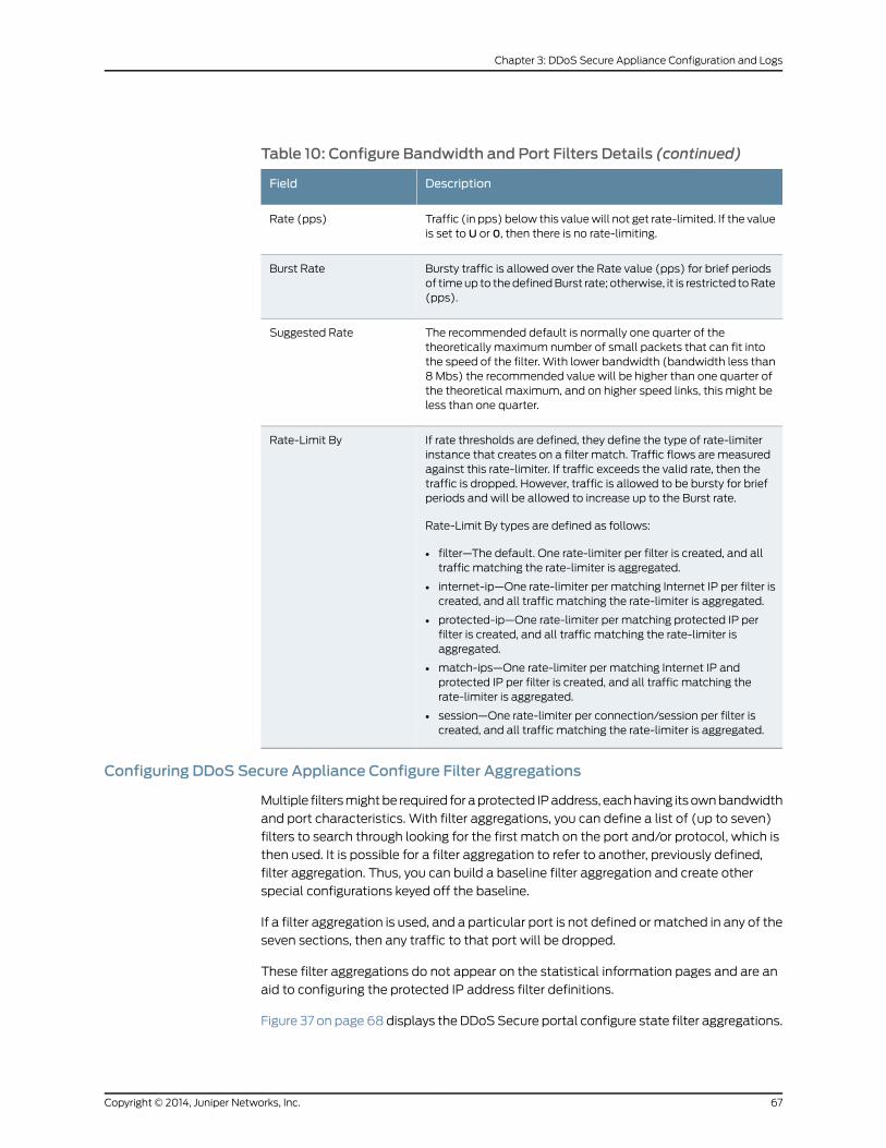
Table 10: Configure Bandwidth and Port Filters Details (continued)
DescriptionField
Traffic (in pps) below this valuewill not get rate-limited. If the valueis set to U or 0, then there is no rate-limiting.
Rate (pps)
Bursty traffic is allowed over the Rate value (pps) for brief periodsof timeup to thedefinedBurst rate; otherwise, it is restricted toRate(pps).
Burst Rate
The recommended default is normally one quarter of thetheoretically maximum number of small packets that can fit intothe speed of the filter. With lower bandwidth (bandwidth less than8 Mbs) the recommended value will be higher than one quarter ofthe theoretical maximum, and on higher speed links, this might beless than one quarter.
Suggested Rate
If rate thresholds are defined, they define the type of rate-limiterinstance that creates on a filter match. Traffic flows are measuredagainst this rate-limiter. If traffic exceeds the valid rate, then thetraffic is dropped. However, traffic is allowed to be bursty for briefperiods and will be allowed to increase up to the Burst rate.
Rate-Limit By types are defined as follows:
• filter—The default. One rate-limiter per filter is created, and alltraffic matching the rate-limiter is aggregated.
• internet-ip—One rate-limiter per matching Internet IP per filter iscreated, and all traffic matching the rate-limiter is aggregated.
• protected-ip—One rate-limiter per matching protected IP perfilter is created, and all traffic matching the rate-limiter isaggregated.
• match-ips—One rate-limiter per matching Internet IP andprotected IP per filter is created, and all traffic matching therate-limiter is aggregated.
• session—One rate-limiter per connection/session per filter iscreated, and all traffic matching the rate-limiter is aggregated.
Rate-Limit By
Configuring DDoS Secure Appliance Configure Filter Aggregations
Multiple filtersmightbe required foraprotected IPaddress, eachhaving itsownbandwidth
and port characteristics. With filter aggregations, you can define a list of (up to seven)
filters to search through looking for the first match on the port and/or protocol, which is
then used. It is possible for a filter aggregation to refer to another, previously defined,
filter aggregation. Thus, you can build a baseline filter aggregation and create other
special configurations keyed off the baseline.
If a filter aggregation is used, and a particular port is not defined ormatched in any of the
seven sections, then any traffic to that port will be dropped.
These filter aggregations do not appear on the statistical information pages and are an
aid to configuring the protected IP address filter definitions.
Figure 37 on page 68 displays the DDoSSecure portal configure state filter aggregations.
67Copyright © 2014, Juniper Networks, Inc.
Chapter 3: DDoS Secure Appliance Configuration and Logs

Figure 37: DDoS Secure Portal Configure State Filter Aggregations
Table 11 on page 68 provides a summary of a configuration filter aggregation.
Table 11: Configure Filter Aggregations Details
DescriptionField
Name of the filter aggregation.We recommend a filter aggregation namethat can be easily differentiated from the filter name for ease ofconfiguration troubleshooting.
Name
Select a filter name or a filter aggregation name from the pull-down list.It is valid to have the -undefined- entry between genuine entries.
Filter [1 2 3 4 5 6 7]
Configuring DDoS Secure Appliance Configure Protected IP addresses
The protected IP address definitions are automatically updated in the configuration file
everymidnight.Theyprovideastartingvaluehint to theDDoSSecurealgorithmswhenever
the DDoS Secure engine is restarted. This is only true for protected IP addresses that are
defined, not just detected.
Table 12 on page 68 provides a summary of the configuration filter aggregation.
Table 12: Configure Protected IP Addresses
DescriptionField
The IP address of the IP address being protected.Protected IP
Copyright © 2014, Juniper Networks, Inc.68
DDoS Secure GUI User Guide
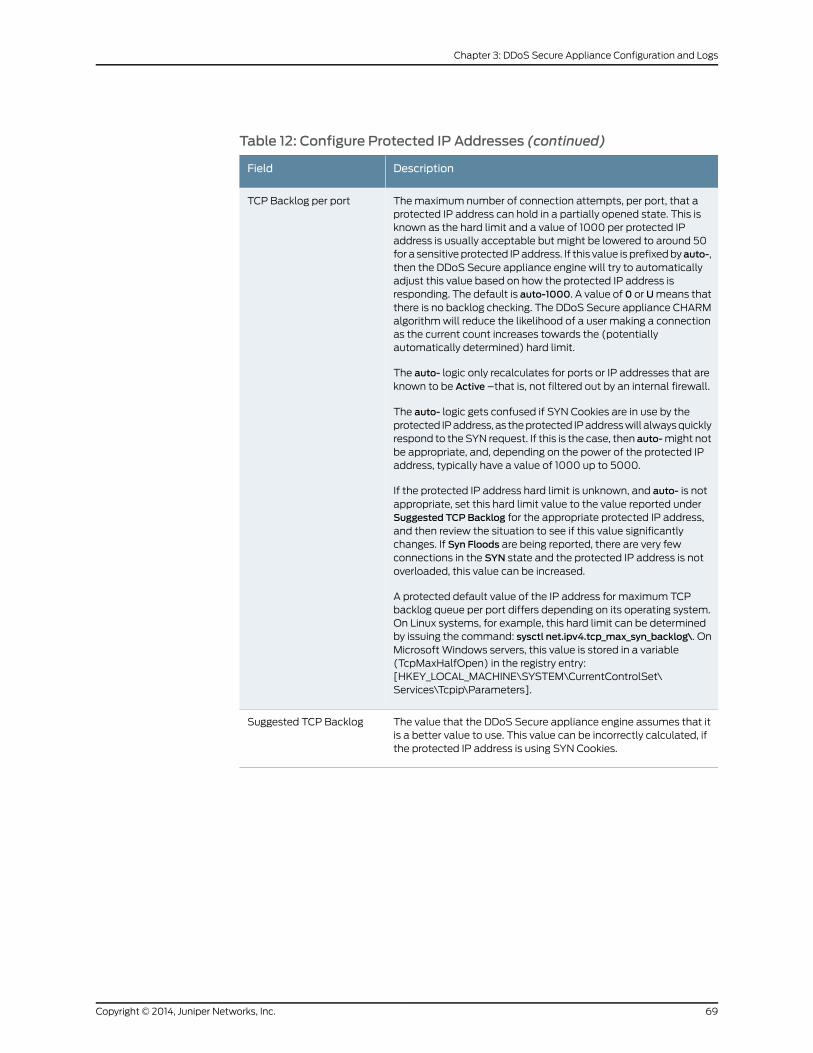
Table 12: Configure Protected IP Addresses (continued)
DescriptionField
Themaximum number of connection attempts, per port, that aprotected IP address can hold in a partially opened state. This isknown as the hard limit and a value of 1000 per protected IPaddress is usually acceptable but might be lowered to around 50for a sensitive protected IPaddress. If this value is prefixedbyauto-,then the DDoS Secure appliance engine will try to automaticallyadjust this value based on how the protected IP address isresponding. The default is auto-1000. A value of 0 orUmeans thatthere is no backlog checking. The DDoS Secure appliance CHARMalgorithmwill reduce the likelihood of a user making a connectionas the current count increases towards the (potentiallyautomatically determined) hard limit.
The auto- logic only recalculates for ports or IP addresses that areknown to be Active –that is, not filtered out by an internal firewall.
The auto- logic gets confused if SYN Cookies are in use by theprotected IPaddress, as theprotected IPaddresswill alwaysquicklyrespond to the SYN request. If this is the case, then auto-might notbe appropriate, and, depending on the power of the protected IPaddress, typically have a value of 1000 up to 5000.
If the protected IP address hard limit is unknown, and auto- is notappropriate, set this hard limit value to the value reported underSuggested TCP Backlog for the appropriate protected IP address,and then review the situation to see if this value significantlychanges. If Syn Floods are being reported, there are very fewconnections in the SYN state and the protected IP address is notoverloaded, this value can be increased.
A protected default value of the IP address for maximum TCPbacklog queue per port differs depending on its operating system.On Linux systems, for example, this hard limit can be determinedby issuing the command: sysctl net.ipv4.tcp_max_syn_backlog\. OnMicrosoft Windows servers, this value is stored in a variable(TcpMaxHalfOpen) in the registry entry:[HKEY_LOCAL_MACHINE\SYSTEM\CurrentControlSet\Services\Tcpip\Parameters].
TCP Backlog per port
The value that the DDoS Secure appliance engine assumes that itis a better value to use. This value can be incorrectly calculated, ifthe protected IP address is using SYN Cookies.
Suggested TCP Backlog
69Copyright © 2014, Juniper Networks, Inc.
Chapter 3: DDoS Secure Appliance Configuration and Logs
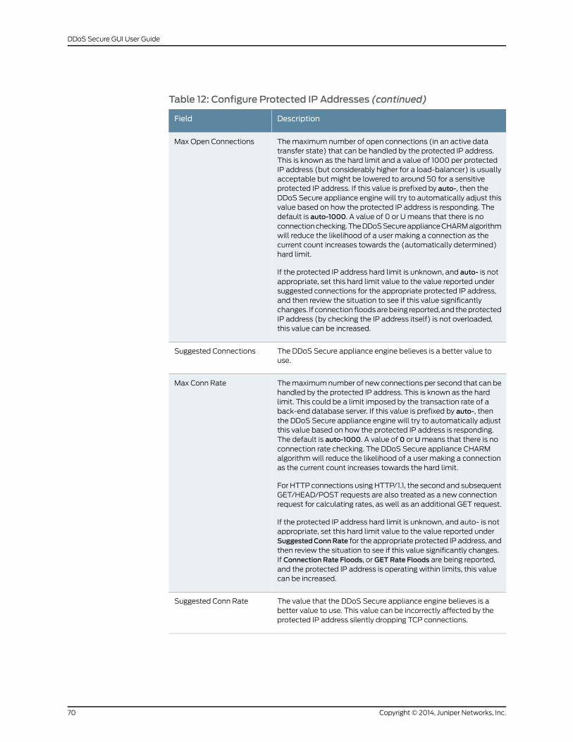
Table 12: Configure Protected IP Addresses (continued)
DescriptionField
Themaximum number of open connections (in an active datatransfer state) that can be handled by the protected IP address.This is known as the hard limit and a value of 1000 per protectedIP address (but considerably higher for a load-balancer) is usuallyacceptable but might be lowered to around 50 for a sensitiveprotected IP address. If this value is prefixed by auto-, then theDDoS Secure appliance engine will try to automatically adjust thisvalue based on how the protected IP address is responding. Thedefault is auto-1000. A value of 0 or Umeans that there is noconnectionchecking.TheDDoSSecureapplianceCHARMalgorithmwill reduce the likelihood of a user making a connection as thecurrent count increases towards the (automatically determined)hard limit.
If the protected IP address hard limit is unknown, and auto- is notappropriate, set this hard limit value to the value reported undersuggested connections for the appropriate protected IP address,and then review the situation to see if this value significantlychanges. If connection floodsarebeing reported, and theprotectedIP address (by checking the IP address itself) is not overloaded,this value can be increased.
Max Open Connections
The DDoS Secure appliance engine believes is a better value touse.
Suggested Connections
Themaximumnumber of new connections per second that can behandled by the protected IP address. This is known as the hardlimit. This could be a limit imposed by the transaction rate of aback-end database server. If this value is prefixed by auto-, thenthe DDoS Secure appliance engine will try to automatically adjustthis value based on how the protected IP address is responding.The default is auto-1000. A value of 0 or Umeans that there is noconnection rate checking. The DDoS Secure appliance CHARMalgorithmwill reduce the likelihood of a user making a connectionas the current count increases towards the hard limit.
For HTTP connections usingHTTP/1.1, the second and subsequentGET/HEAD/POST requests are also treated as a new connectionrequest for calculating rates, as well as an additional GET request.
If the protected IP address hard limit is unknown, and auto- is notappropriate, set this hard limit value to the value reported underSuggestedConnRate for the appropriate protected IP address, andthen review the situation to see if this value significantly changes.If Connection Rate Floods, or GET Rate Floods are being reported,and the protected IP address is operating within limits, this valuecan be increased.
Max Conn Rate
The value that the DDoS Secure appliance engine believes is abetter value to use. This value can be incorrectly affected by theprotected IP address silently dropping TCP connections.
Suggested Conn Rate
Copyright © 2014, Juniper Networks, Inc.70
DDoS Secure GUI User Guide
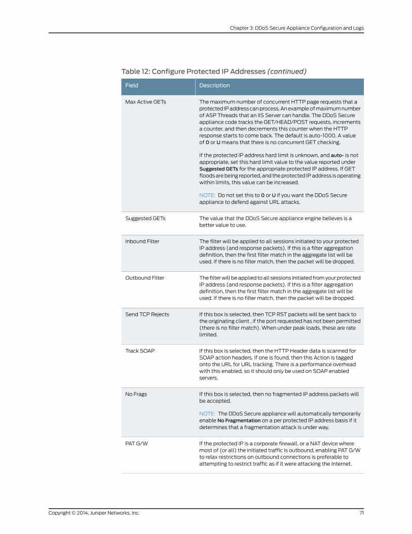
Table 12: Configure Protected IP Addresses (continued)
DescriptionField
Themaximum number of concurrent HTTP page requests that aprotected IPaddresscanprocess.Anexampleofmaximumnumberof ASP Threads that an IIS Server can handle. The DDoS Secureappliance code tracks the GET/HEAD/POST requests, incrementsa counter, and then decrements this counter when the HTTPresponse starts to come back. The default is auto-1000. A valueof 0 or Umeans that there is no concurrent GET checking.
If the protected IP address hard limit is unknown, and auto- is notappropriate, set this hard limit value to the value reported underSuggested GETs for the appropriate protected IP address. If GETfloodsarebeing reported, and theprotected IPaddress isoperatingwithin limits, this value can be increased.
NOTE: Do not set this to 0 or U if you want the DDoS Secureappliance to defend against URL attacks.
Max Active GETs
The value that the DDoS Secure appliance engine believes is abetter value to use.
Suggested GETs
The filter will be applied to all sessions initiated to your protectedIP address (and response packets). If this is a filter aggregationdefinition, then the first filter match in the aggregate list will beused. If there is no filter match, then the packet will be dropped.
Inbound Filter
The filterwill beapplied toall sessions initiated fromyourprotectedIP address (and response packets). If this is a filter aggregationdefinition, then the first filter match in the aggregate list will beused. If there is no filter match, then the packet will be dropped.
Outbound Filter
If this box is selected, then TCP RST packets will be sent back tothe originating client , if the port requested has not been permitted(there is no filter match). When under peak loads, these are ratelimited.
Send TCP Rejects
If this box is selected, then the HTTP Header data is scanned forSOAP action headers. If one is found, then this Action is taggedonto the URL for URL tracking. There is a performance overheadwith this enabled, so it should only be used on SOAP enabledservers.
Track SOAP
If this box is selected, then no fragmented IP address packets willbe accepted.
NOTE: The DDoS Secure appliancewill automatically temporarilyenable No Fragmentation on a per protected IP address basis if itdetermines that a fragmentation attack is under way.
No Frags
If the protected IP is a corporate firewall, or a NAT device wheremost of (or all) the initiated traffic is outbound, enabling PAT G/Wto relax restrictions on outbound connections is preferable toattempting to restrict traffic as if it were attacking the Internet.
PAT G/W
71Copyright © 2014, Juniper Networks, Inc.
Chapter 3: DDoS Secure Appliance Configuration and Logs
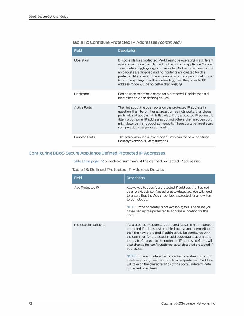
Table 12: Configure Protected IP Addresses (continued)
DescriptionField
It is possible for aprotected IPaddress tobeoperating in adifferentoperationalmode thandefined for the portal or appliance. You canselect defending, logging, or not reported. Not reportedmeans thatno packets are dropped and no incidents are created for thisprotected IP address. If the appliance or portal operational modeis set to anything other than defending, then the protected IPaddress mode will be no better than logging.
Operation
Can be used to define a name for a protected IP address to aididentification when defining values.
Hostname
The hint about the open ports on the protected IP address inquestion. If a filter or filter aggregation restricts ports, then theseports will not appear in this list. Also, if the protected IP address isfiltering out some IP addresses but not others, then an open portmight bounce in andout of active ports. Theseports get reset everyconfiguration change, or at midnight.
Active Ports
The actual inbound allowed ports. Entries in red have additionalCountry/Network/AS# restrictions.
Enabled Ports
Configuring DDoS Secure Appliance Defined Protected IP Addresses
Table 13 on page 72 provides a summary of the defined protected IP addresses.
Table 13: Defined Protected IP Address Details
DescriptionField
Allows you to specify a protected IP address that has notbeen previously configured or auto-detected. You will needto ensure that the Add check box is selected for a new itemto be included.
NOTE: If the add entry is not available; this is because youhave used up the protected IP address allocation for thisportal.
Add Protected IP
If a protected IP address is detected (assuming auto detectprotected IPaddresses isenabled,buthasnotbeendefined),then the new protected IP address will be configured withthe definition for protected IP address defaults acting as atemplate. Changes to the protected IP address defaults willalso change the configuration of auto-detected protected IPaddresses.
NOTE: If the auto-detected protected IP address is part ofadefinedportal, then theauto-detectedprotected IPaddresswill take on the characteristics of the portal Indeterminateprotected IP address.
Protected IP Defaults
Copyright © 2014, Juniper Networks, Inc.72
DDoS Secure GUI User Guide
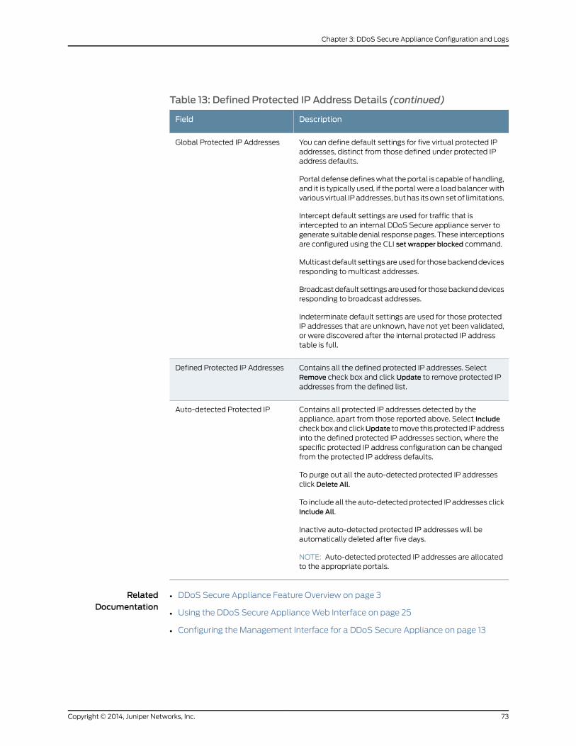
Table 13: Defined Protected IP Address Details (continued)
DescriptionField
You can define default settings for five virtual protected IPaddresses, distinct from those defined under protected IPaddress defaults.
Portal defensedefineswhat theportal is capableof handling,and it is typically used, if the portal were a load balancerwithvarious virtual IPaddresses, buthas itsownsetof limitations.
Intercept default settings are used for traffic that isintercepted to an internal DDoS Secure appliance server togenerate suitabledenial responsepages. These interceptionsare configured using the CLI set wrapper blocked command.
Multicastdefault settingsareused for thosebackenddevicesresponding to multicast addresses.
Broadcastdefault settingsareused for thosebackenddevicesresponding to broadcast addresses.
Indeterminate default settings are used for those protectedIP addresses that are unknown, have not yet been validated,or were discovered after the internal protected IP addresstable is full.
Global Protected IP Addresses
Contains all the defined protected IP addresses. SelectRemove check box and click Update to remove protected IPaddresses from the defined list.
Defined Protected IP Addresses
Contains all protected IP addresses detected by theappliance, apart from those reported above. Select IncludecheckboxandclickUpdate tomove thisprotected IPaddressinto the defined protected IP addresses section, where thespecific protected IP address configuration can be changedfrom the protected IP address defaults.
To purge out all the auto-detected protected IP addressesclick Delete All.
To include all the auto-detectedprotected IP addresses clickInclude All.
Inactive auto-detected protected IP addresses will beautomatically deleted after five days.
NOTE: Auto-detected protected IP addresses are allocatedto the appropriate portals.
Auto-detected Protected IP
RelatedDocumentation
DDoS Secure Appliance Feature Overview on page 3•
• Using the DDoS Secure ApplianceWeb Interface on page 25
• Configuring the Management Interface for a DDoS Secure Appliance on page 13
73Copyright © 2014, Juniper Networks, Inc.
Chapter 3: DDoS Secure Appliance Configuration and Logs
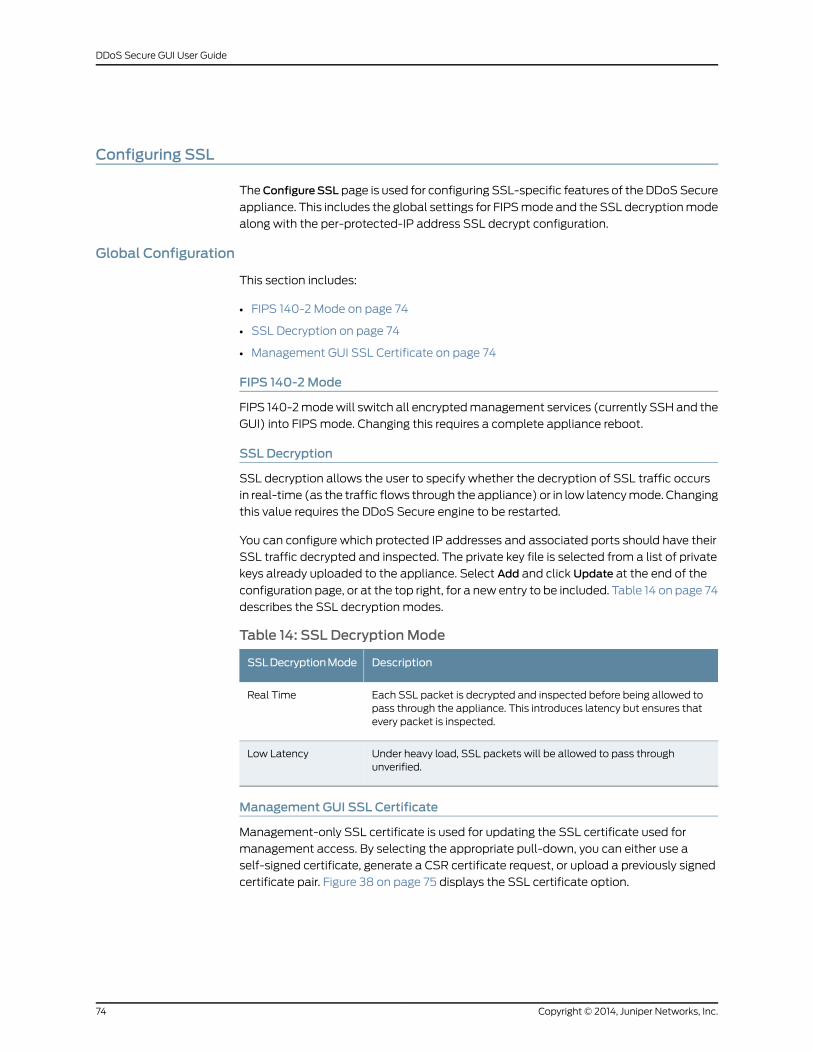
Configuring SSL
TheConfigureSSL page is used for configuring SSL-specific features of the DDoSSecure
appliance. This includes the global settings for FIPSmode and the SSL decryptionmode
along with the per-protected-IP address SSL decrypt configuration.
Global Configuration
This section includes:
• FIPS 140-2 Mode on page 74
• SSL Decryption on page 74
• Management GUI SSL Certificate on page 74
FIPS 140-2Mode
FIPS 140-2modewill switch all encryptedmanagement services (currently SSH and the
GUI) into FIPSmode. Changing this requires a complete appliance reboot.
SSL Decryption
SSL decryption allows the user to specify whether the decryption of SSL traffic occurs
in real-time (as the traffic flows through the appliance) or in low latencymode. Changing
this value requires the DDoS Secure engine to be restarted.
You can configure which protected IP addresses and associated ports should have their
SSL traffic decrypted and inspected. The private key file is selected from a list of private
keys already uploaded to the appliance. Select Add and click Update at the end of the
configuration page, or at the top right, for a new entry to be included. Table 14 on page 74
describes the SSL decryption modes.
Table 14: SSL DecryptionMode
DescriptionSSLDecryptionMode
Each SSL packet is decrypted and inspected before being allowed topass through the appliance. This introduces latency but ensures thatevery packet is inspected.
Real Time
Under heavy load, SSL packets will be allowed to pass throughunverified.
Low Latency
Management GUI SSL Certificate
Management-only SSL certificate is used for updating the SSL certificate used for
management access. By selecting the appropriate pull-down, you can either use a
self-signed certificate, generate a CSR certificate request, or upload a previously signed
certificate pair. Figure 38 on page 75 displays the SSL certificate option.
Copyright © 2014, Juniper Networks, Inc.74
DDoS Secure GUI User Guide
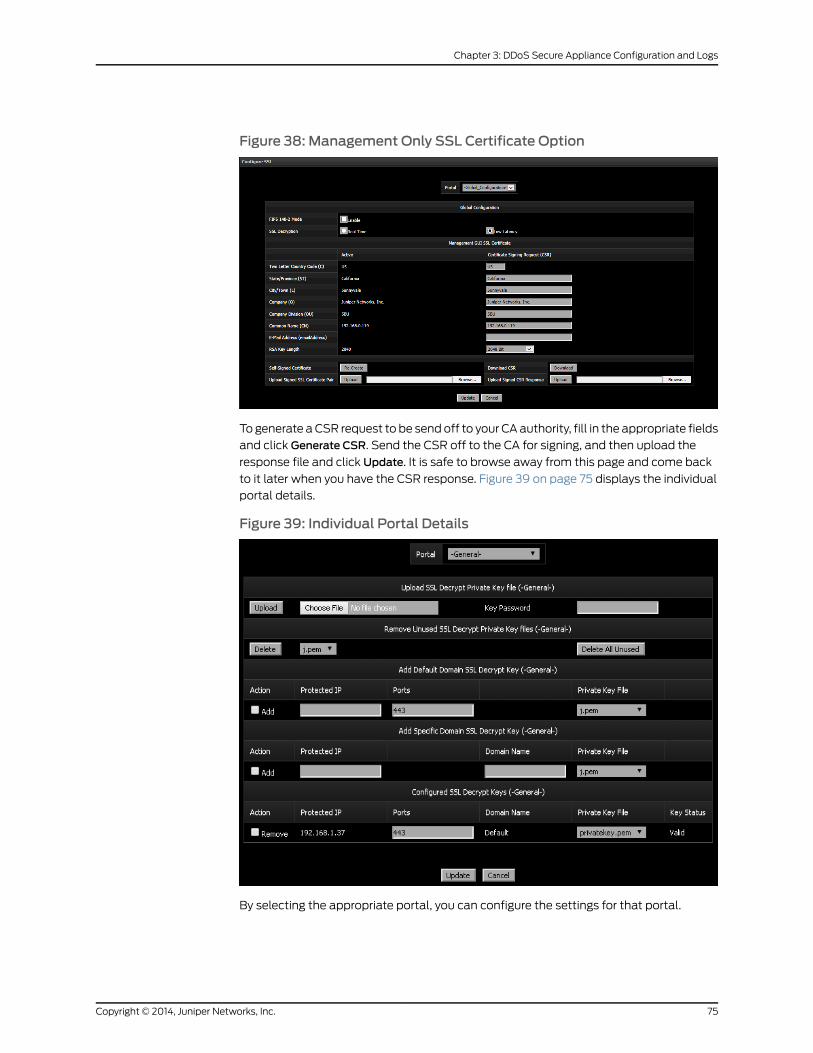
Figure 38: Management Only SSL Certificate Option
To generate aCSR request to be send off to your CAauthority, fill in the appropriate fields
and click Generate CSR. Send the CSR off to the CA for signing, and then upload the
response file and click Update. It is safe to browse away from this page and come back
to it later when you have the CSR response. Figure 39 on page 75 displays the individual
portal details.
Figure 39: Individual Portal Details
By selecting the appropriate portal, you can configure the settings for that portal.
75Copyright © 2014, Juniper Networks, Inc.
Chapter 3: DDoS Secure Appliance Configuration and Logs
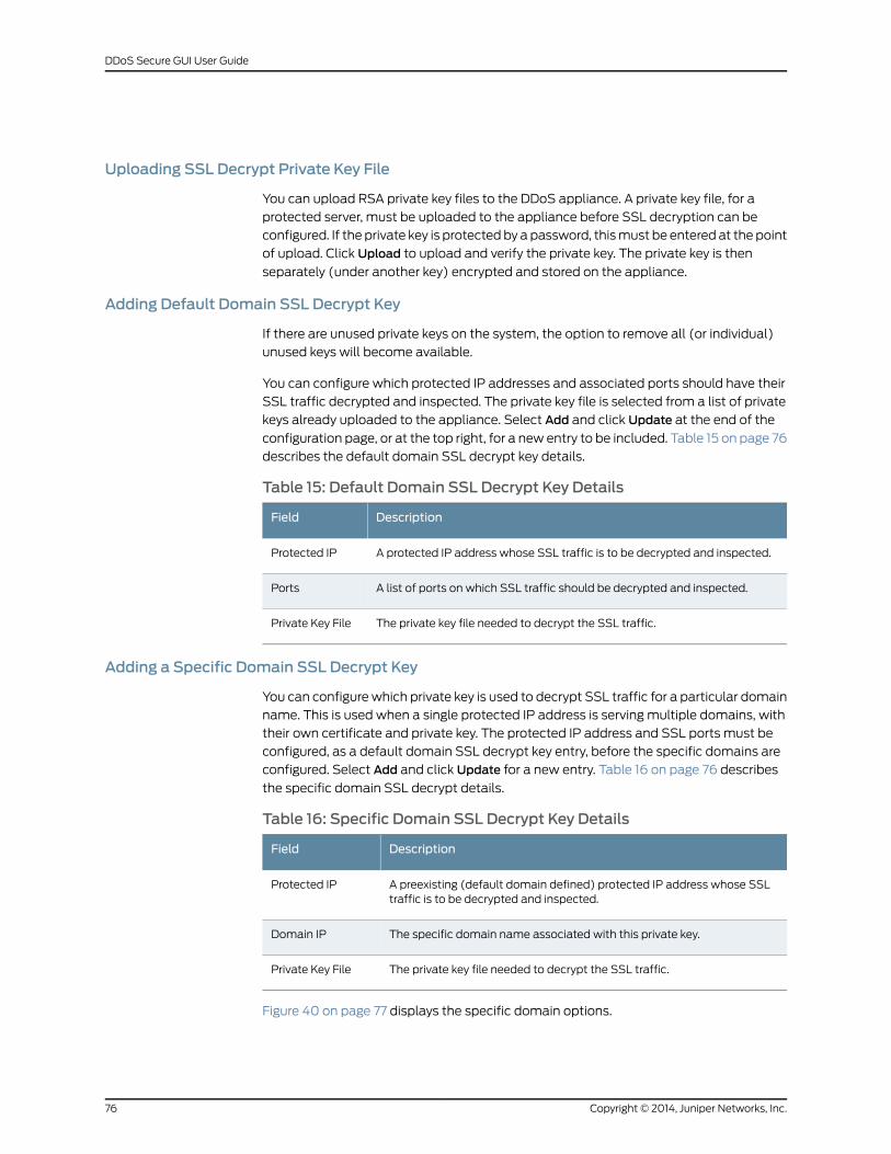
Uploading SSL Decrypt Private Key File
You can upload RSA private key files to the DDoS appliance. A private key file, for a
protected server, must be uploaded to the appliance before SSL decryption can be
configured. If the private key is protectedby apassword, thismust be entered at the point
of upload. Click Upload to upload and verify the private key. The private key is then
separately (under another key) encrypted and stored on the appliance.
Adding Default Domain SSL Decrypt Key
If there are unused private keys on the system, the option to remove all (or individual)
unused keys will become available.
You can configure which protected IP addresses and associated ports should have their
SSL traffic decrypted and inspected. The private key file is selected from a list of private
keys already uploaded to the appliance. Select Add and click Update at the end of the
configuration page, or at the top right, for a new entry to be included. Table 15 on page 76
describes the default domain SSL decrypt key details.
Table 15: Default Domain SSL Decrypt Key Details
DescriptionField
A protected IP address whose SSL traffic is to be decrypted and inspected.Protected IP
A list of ports on which SSL traffic should be decrypted and inspected.Ports
The private key file needed to decrypt the SSL traffic.Private Key File
Adding a Specific Domain SSL Decrypt Key
You can configurewhich private key is used to decrypt SSL traffic for a particular domain
name. This is used when a single protected IP address is serving multiple domains, with
their own certificate and private key. The protected IP address and SSL ports must be
configured, as a default domain SSL decrypt key entry, before the specific domains are
configured. Select Add and click Update for a new entry. Table 16 on page 76 describes
the specific domain SSL decrypt details.
Table 16: Specific Domain SSL Decrypt Key Details
DescriptionField
A preexisting (default domain defined) protected IP address whose SSLtraffic is to be decrypted and inspected.
Protected IP
The specific domain name associated with this private key.Domain IP
The private key file needed to decrypt the SSL traffic.Private Key File
Figure 40 on page 77 displays the specific domain options.
Copyright © 2014, Juniper Networks, Inc.76
DDoS Secure GUI User Guide
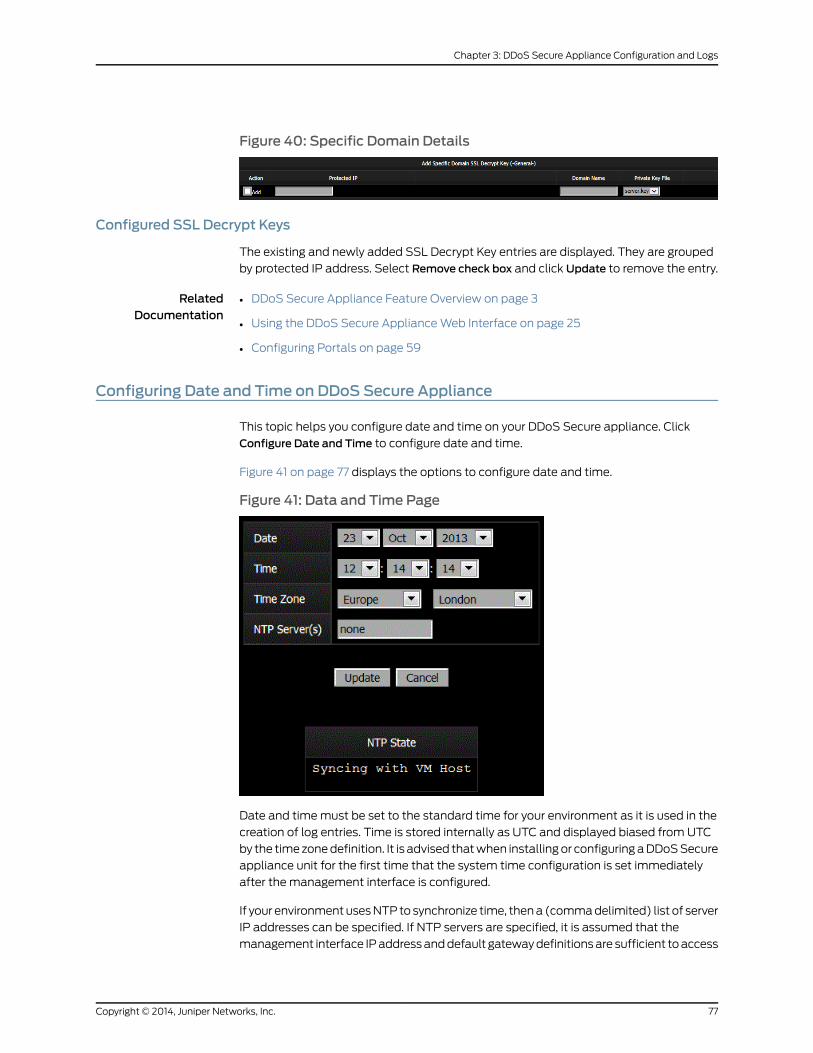
Figure 40: Specific Domain Details
Configured SSL Decrypt Keys
The existing and newly added SSL Decrypt Key entries are displayed. They are grouped
by protected IP address. Select Remove check box and click Update to remove the entry.
RelatedDocumentation
DDoS Secure Appliance Feature Overview on page 3•
• Using the DDoS Secure ApplianceWeb Interface on page 25
• Configuring Portals on page 59
Configuring Date and Time on DDoS Secure Appliance
This topic helps you configure date and time on your DDoS Secure appliance. Click
Configure Date and Time to configure date and time.
Figure 41 on page 77 displays the options to configure date and time.
Figure 41: Data and Time Page
Date and timemust be set to the standard time for your environment as it is used in the
creation of log entries. Time is stored internally as UTC and displayed biased from UTC
by the timezonedefinition. It is advised thatwhen installingor configuringaDDoSSecure
appliance unit for the first time that the system time configuration is set immediately
after the management interface is configured.
If your environmentusesNTP to synchronize time, thena (commadelimited) list of server
IP addresses can be specified. If NTP servers are specified, it is assumed that the
management interface IPaddressanddefault gatewaydefinitionsare sufficient toaccess
77Copyright © 2014, Juniper Networks, Inc.
Chapter 3: DDoS Secure Appliance Configuration and Logs
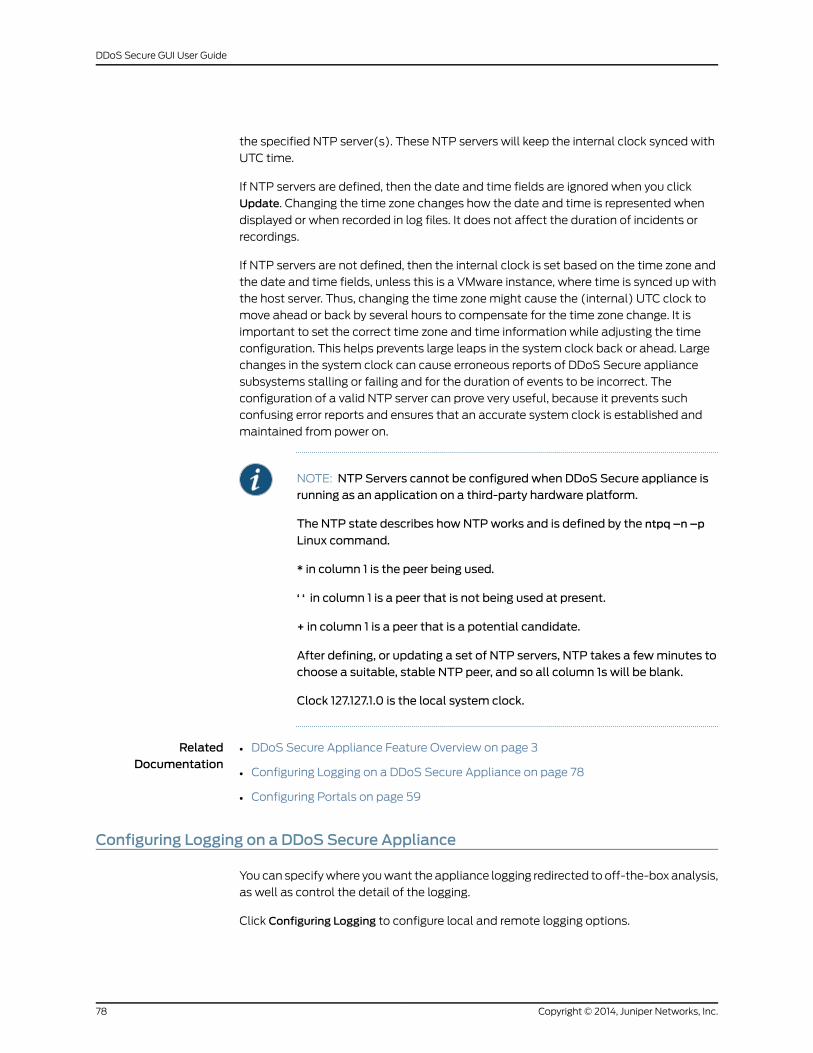
the specified NTP server(s). These NTP servers will keep the internal clock synced with
UTC time.
If NTP servers are defined, then the date and time fields are ignored when you click
Update. Changing the time zone changes how the date and time is represented when
displayed or when recorded in log files. It does not affect the duration of incidents or
recordings.
If NTP servers are not defined, then the internal clock is set based on the time zone and
the date and time fields, unless this is a VMware instance, where time is synced up with
the host server. Thus, changing the time zonemight cause the (internal) UTC clock to
move ahead or back by several hours to compensate for the time zone change. It is
important to set the correct time zone and time information while adjusting the time
configuration. This helps prevents large leaps in the system clock back or ahead. Large
changes in the system clock can cause erroneous reports of DDoS Secure appliance
subsystems stalling or failing and for the duration of events to be incorrect. The
configuration of a valid NTP server can prove very useful, because it prevents such
confusing error reports and ensures that an accurate system clock is established and
maintained from power on.
NOTE: NTP Servers cannot be configured when DDoS Secure appliance isrunning as an application on a third-party hardware platform.
The NTP state describes howNTPworks and is defined by the ntpq –n –p
Linux command.
* in column 1 is the peer being used.
‘ ‘ in column 1 is a peer that is not being used at present.
+ in column 1 is a peer that is a potential candidate.
After defining, or updating a set of NTP servers, NTP takes a fewminutes tochoose a suitable, stable NTP peer, and so all column 1s will be blank.
Clock 127.127.1.0 is the local system clock.
RelatedDocumentation
DDoS Secure Appliance Feature Overview on page 3•
• Configuring Logging on a DDoS Secure Appliance on page 78
• Configuring Portals on page 59
Configuring Logging on a DDoS Secure Appliance
You can specifywhere youwant the appliance logging redirected to off-the-box analysis,
as well as control the detail of the logging.
Click Configuring Logging to configure local and remote logging options.
Copyright © 2014, Juniper Networks, Inc.78
DDoS Secure GUI User Guide
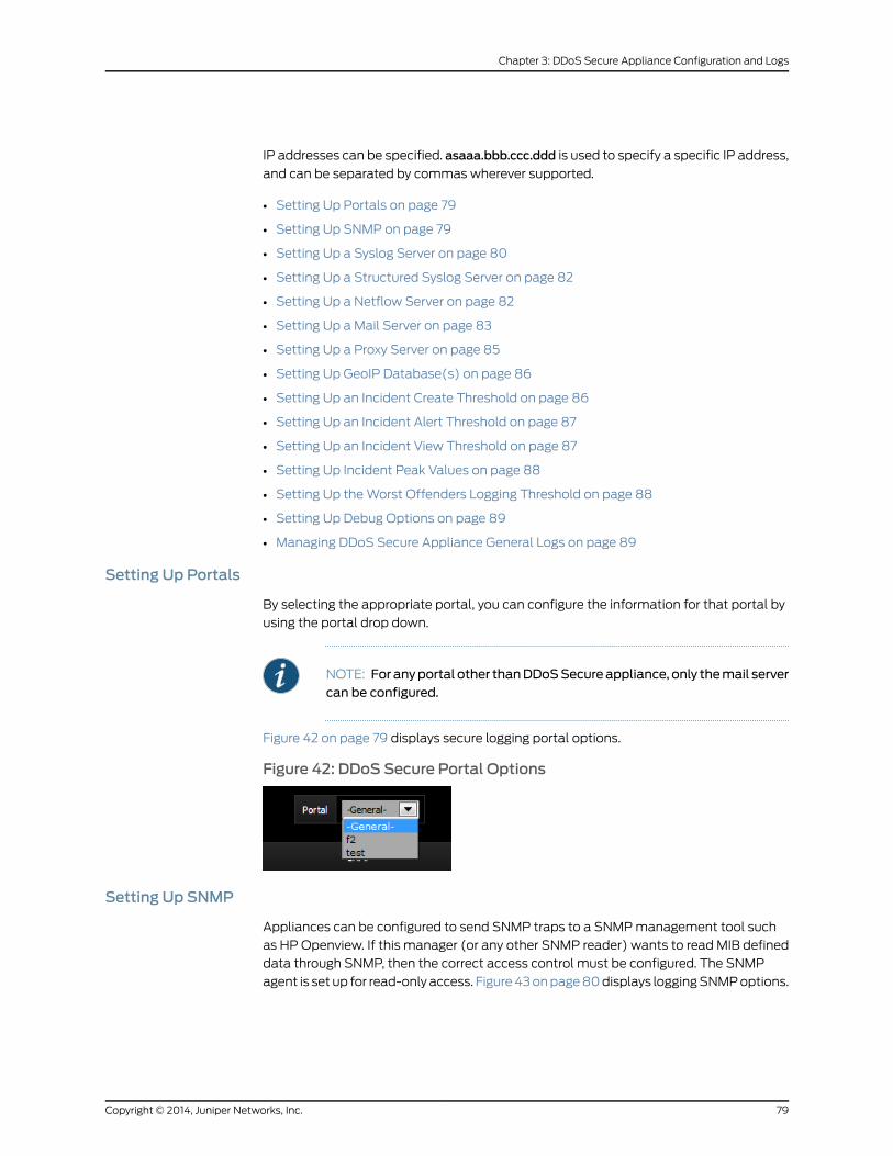
IP addresses can be specified. asaaa.bbb.ccc.ddd is used to specify a specific IP address,
and can be separated by commas wherever supported.
• Setting Up Portals on page 79
• Setting Up SNMP on page 79
• Setting Up a Syslog Server on page 80
• Setting Up a Structured Syslog Server on page 82
• Setting Up a Netflow Server on page 82
• Setting Up a Mail Server on page 83
• Setting Up a Proxy Server on page 85
• Setting Up GeoIP Database(s) on page 86
• Setting Up an Incident Create Threshold on page 86
• Setting Up an Incident Alert Threshold on page 87
• Setting Up an Incident View Threshold on page 87
• Setting Up Incident Peak Values on page 88
• Setting Up theWorst Offenders Logging Threshold on page 88
• Setting Up Debug Options on page 89
• Managing DDoS Secure Appliance General Logs on page 89
Setting Up Portals
By selecting the appropriate portal, you can configure the information for that portal by
using the portal drop down.
NOTE: For anyportal other thanDDoSSecureappliance, only themail servercan be configured.
Figure 42 on page 79 displays secure logging portal options.
Figure 42: DDoS Secure Portal Options
Setting Up SNMP
Appliances can be configured to send SNMP traps to a SNMPmanagement tool such
as HP Openview. If this manager (or any other SNMP reader) wants to read MIB defined
data through SNMP, then the correct access control must be configured. The SNMP
agent is set up for read-only access. Figure43onpage80displays loggingSNMPoptions.
79Copyright © 2014, Juniper Networks, Inc.
Chapter 3: DDoS Secure Appliance Configuration and Logs
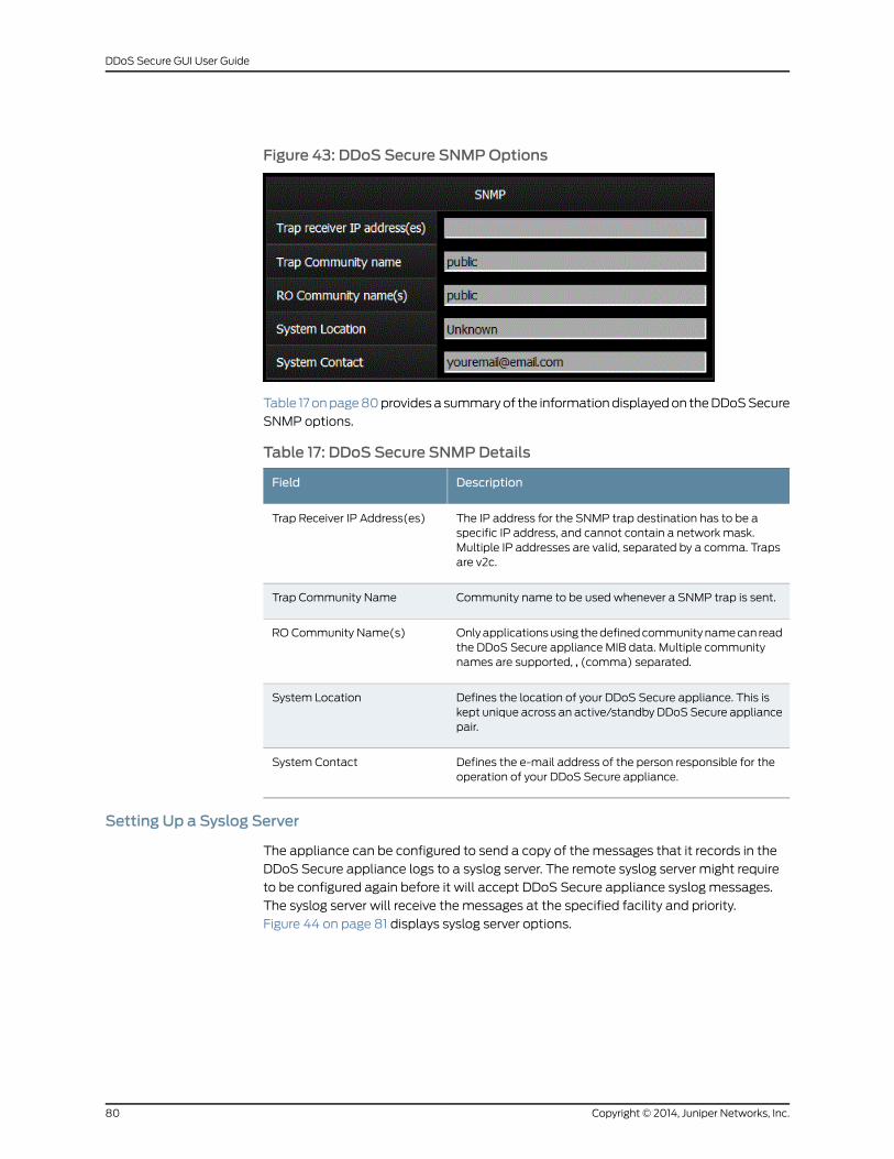
Figure 43: DDoS Secure SNMPOptions
Table 17onpage80providesasummaryof the informationdisplayedon theDDoSSecure
SNMP options.
Table 17: DDoS Secure SNMPDetails
DescriptionField
The IP address for the SNMP trap destination has to be aspecific IP address, and cannot contain a network mask.Multiple IP addresses are valid, separated by a comma. Trapsare v2c.
Trap Receiver IP Address(es)
Community name to be used whenever a SNMP trap is sent.Trap Community Name
Onlyapplicationsusing thedefinedcommunitynamecan readthe DDoS Secure appliance MIB data. Multiple communitynames are supported, , (comma) separated.
RO Community Name(s)
Defines the location of your DDoS Secure appliance. This iskept unique across an active/standby DDoSSecure appliancepair.
System Location
Defines the e-mail address of the person responsible for theoperation of your DDoS Secure appliance.
System Contact
Setting Up a Syslog Server
The appliance can be configured to send a copy of the messages that it records in the
DDoS Secure appliance logs to a syslog server. The remote syslog server might require
to be configured again before it will accept DDoS Secure appliance syslog messages.
The syslog server will receive the messages at the specified facility and priority.
Figure 44 on page 81 displays syslog server options.
Copyright © 2014, Juniper Networks, Inc.80
DDoS Secure GUI User Guide
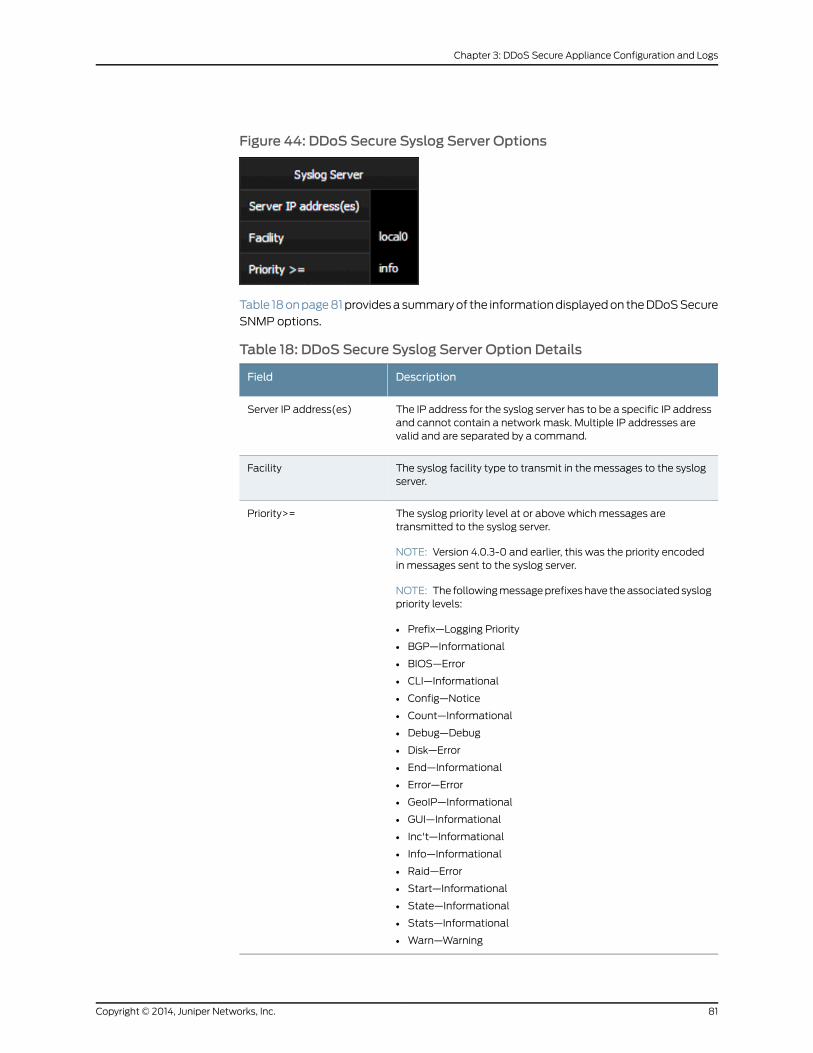
Figure 44: DDoS Secure Syslog Server Options
Table 18onpage81providesasummaryof the informationdisplayedon theDDoSSecure
SNMP options.
Table 18: DDoS Secure Syslog Server Option Details
DescriptionField
The IP address for the syslog server has to be a specific IP addressand cannot contain a network mask. Multiple IP addresses arevalid and are separated by a command.
Server IP address(es)
The syslog facility type to transmit in the messages to the syslogserver.
Facility
The syslog priority level at or above which messages aretransmitted to the syslog server.
NOTE: Version 4.0.3-0 and earlier, this was the priority encodedin messages sent to the syslog server.
NOTE: The followingmessageprefixeshave theassociatedsyslogpriority levels:
• Prefix—Logging Priority
• BGP—Informational
• BIOS—Error
• CLI—Informational
• Config—Notice
• Count—Informational
• Debug—Debug
• Disk—Error
• End—Informational
• Error—Error
• GeoIP—Informational
• GUI—Informational
• Inc't—Informational
• Info—Informational
• Raid—Error
• Start—Informational
• State—Informational
• Stats—Informational
• Warn—Warning
Priority>=
81Copyright © 2014, Juniper Networks, Inc.
Chapter 3: DDoS Secure Appliance Configuration and Logs
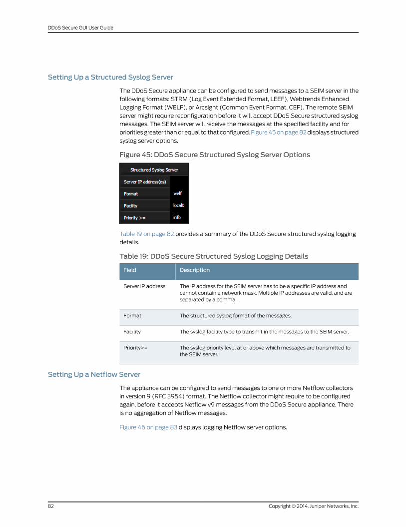
Setting Up a Structured Syslog Server
The DDoS Secure appliance can be configured to sendmessages to a SEIM server in the
following formats: STRM (Log Event Extended Format, LEEF), Webtrends Enhanced
Logging Format (WELF), or Arcsight (Common Event Format, CEF). The remote SEIM
server might require reconfiguration before it will accept DDoS Secure structured syslog
messages. The SEIM server will receive the messages at the specified facility and for
priorities greater thanor equal to that configured. Figure45onpage82displays structured
syslog server options.
Figure 45: DDoS Secure Structured Syslog Server Options
Table 19 on page 82 provides a summary of the DDoS Secure structured syslog logging
details.
Table 19: DDoS Secure Structured Syslog Logging Details
DescriptionField
The IP address for the SEIM server has to be a specific IP address andcannot contain a network mask. Multiple IP addresses are valid, and areseparated by a comma.
Server IP address
The structured syslog format of the messages.Format
The syslog facility type to transmit in the messages to the SEIM server.Facility
The syslog priority level at or above which messages are transmitted tothe SEIM server.
Priority>=
Setting Up a Netflow Server
The appliance can be configured to sendmessages to one or more Netflow collectors
in version 9 (RFC 3954) format. The Netflow collector might require to be configured
again, before it accepts Netflow v9messages from the DDoS Secure appliance. There
is no aggregation of Netflowmessages.
Figure 46 on page 83 displays logging Netflow server options.
Copyright © 2014, Juniper Networks, Inc.82
DDoS Secure GUI User Guide
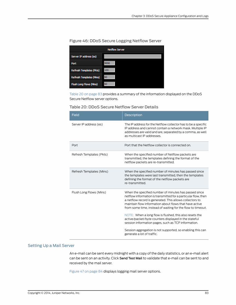
Figure 46: DDoS Secure Logging Netflow Server
Table 20 on page 83 provides a summary of the information displayed on the DDoS
Secure Netflow server options.
Table 20: DDoS Secure Netflow Server Details
DescriptionField
The IP address for theNetflow collector has to be a specificIP address and cannot contain a networkmask. Multiple IPaddresses are valid and are, separated by a comma, aswellas multicast IP addresses.
Server IP address (es)
Port that the Netflow collector is connected on.Port
When the specified number of Netflow packets aretransmitted, the templates defining the format of thenetflow packets are re-transmitted.
Refresh Templates (Pkts)
When the specified number of minutes has passed sincethe templates were last transmitted, then the templatesdefining the format of the netflow packets arere-transmitted.
Refresh Templates (Mins)
When the specified number of minutes has passed sincenetflow information is transmitted for aparticular flow, thena netflow record is generated. This allows collectors tomaintain flow information about flows that have activefrom some time, instead of waiting for the flow to timeout.
NOTE: When a long flow is flushed, this also resets theactive/packet/byte counters displayed in the statefulsession information pages, such as TCP information.
Session aggregation is not supported, so enabling this cangenerate a lot of traffic.
Flush Long Flows (Mins)
Setting Up aMail Server
An e-mail can be sent everymidnightwith a copy of the daily statistics, or an e-mail alert
can be sent on an activity. Click Send TestMail to validate that e-mail can be sent to and
received by the mail server.
Figure 47 on page 84 displays logging mail server options.
83Copyright © 2014, Juniper Networks, Inc.
Chapter 3: DDoS Secure Appliance Configuration and Logs
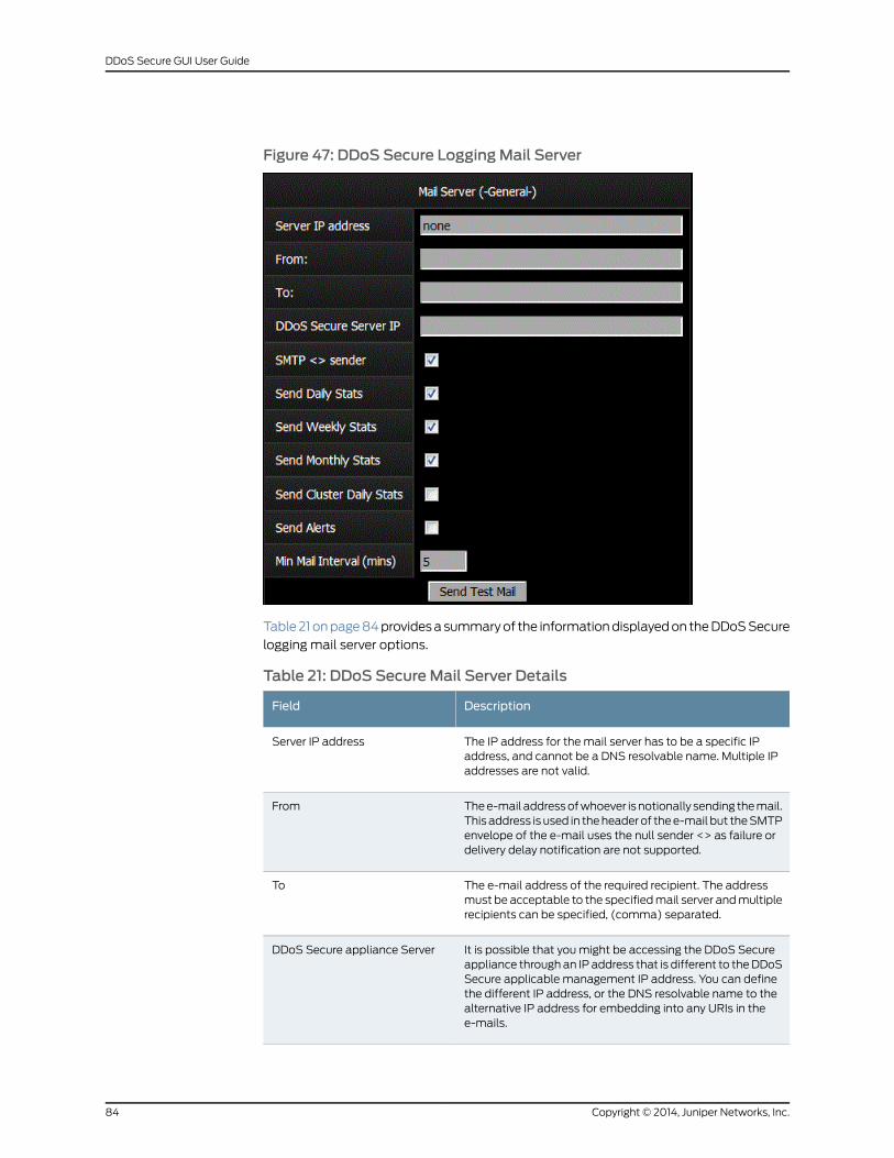
Figure 47: DDoS Secure LoggingMail Server
Table21onpage84providesasummaryof the informationdisplayedon theDDoSSecure
logging mail server options.
Table 21: DDoS SecureMail Server Details
DescriptionField
The IP address for the mail server has to be a specific IPaddress, and cannot be a DNS resolvable name. Multiple IPaddresses are not valid.
Server IP address
Thee-mail addressofwhoever isnotionally sending themail.This address is used in theheaderof thee-mail but theSMTPenvelope of the e-mail uses the null sender <> as failure ordelivery delay notification are not supported.
From
The e-mail address of the required recipient. The addressmust be acceptable to the specifiedmail server andmultiplerecipients can be specified, (comma) separated.
To
It is possible that youmight be accessing the DDoS Secureappliance through an IP address that is different to theDDoSSecure applicable management IP address. You can definethe different IP address, or the DNS resolvable name to thealternative IP address for embedding into any URIs in thee-mails.
DDoS Secure appliance Server
Copyright © 2014, Juniper Networks, Inc.84
DDoS Secure GUI User Guide
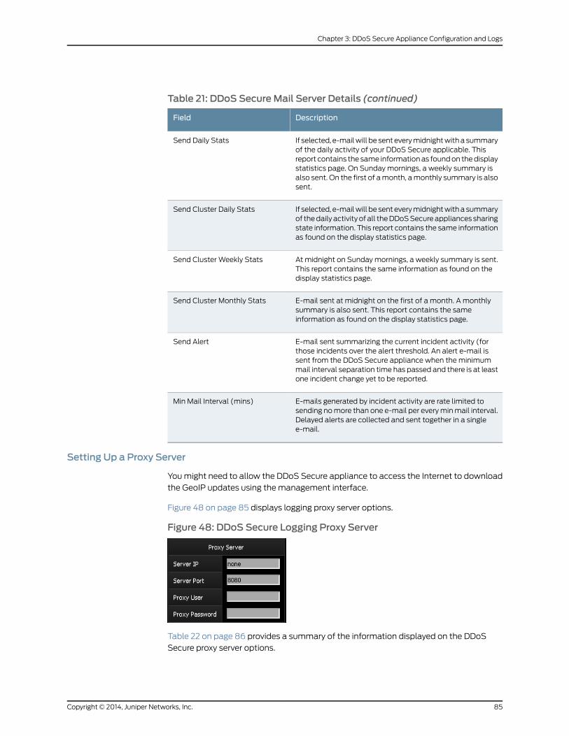
Table 21: DDoS SecureMail Server Details (continued)
DescriptionField
If selected, e-mailwill be sent everymidnightwitha summaryof the daily activity of your DDoS Secure applicable. Thisreport contains the same informationas foundon thedisplaystatistics page. On Sundaymornings, a weekly summary isalso sent. On the first of amonth, amonthly summary is alsosent.
Send Daily Stats
If selected, e-mailwill be sent everymidnightwitha summaryof thedaily activityofall theDDoSSecureappliancessharingstate information. This report contains the same informationas found on the display statistics page.
Send Cluster Daily Stats
At midnight on Sundaymornings, a weekly summary is sent.This report contains the same information as found on thedisplay statistics page.
Send Cluster Weekly Stats
E-mail sent at midnight on the first of a month. A monthlysummary is also sent. This report contains the sameinformation as found on the display statistics page.
Send Cluster Monthly Stats
E-mail sent summarizing the current incident activity (forthose incidents over the alert threshold. An alert e-mail issent from the DDoS Secure appliance when theminimummail interval separation time has passed and there is at leastone incident change yet to be reported.
Send Alert
E-mails generated by incident activity are rate limited tosending nomore than one e-mail per everyminmail interval.Delayed alerts are collected and sent together in a singlee-mail.
Min Mail Interval (mins)
Setting Up a Proxy Server
Youmight need to allow the DDoS Secure appliance to access the Internet to download
the GeoIP updates using the management interface.
Figure 48 on page 85 displays logging proxy server options.
Figure 48: DDoS Secure Logging Proxy Server
Table 22 on page 86 provides a summary of the information displayed on the DDoS
Secure proxy server options.
85Copyright © 2014, Juniper Networks, Inc.
Chapter 3: DDoS Secure Appliance Configuration and Logs
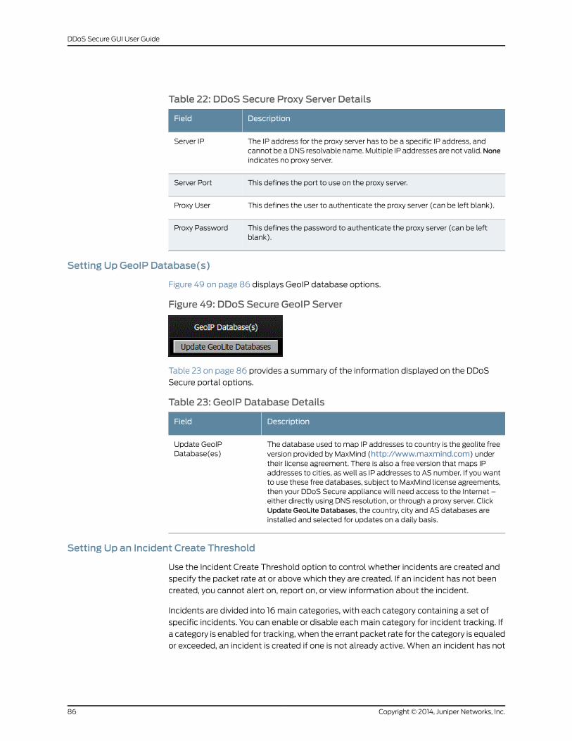
Table 22: DDoS Secure Proxy Server Details
DescriptionField
The IP address for the proxy server has to be a specific IP address, andcannot be aDNS resolvable name.Multiple IP addresses are not valid.Noneindicates no proxy server.
Server IP
This defines the port to use on the proxy server.Server Port
This defines the user to authenticate the proxy server (can be left blank).Proxy User
This defines the password to authenticate the proxy server (can be leftblank).
Proxy Password
Setting Up GeoIP Database(s)
Figure 49 on page 86 displays GeoIP database options.
Figure 49: DDoS Secure GeoIP Server
Table 23 on page 86 provides a summary of the information displayed on the DDoS
Secure portal options.
Table 23: GeoIP Database Details
DescriptionField
The database used to map IP addresses to country is the geolite freeversion provided by MaxMind (http://www.maxmind.com) undertheir license agreement. There is also a free version that maps IPaddresses to cities, as well as IP addresses to AS number. If you wantto use these free databases, subject to MaxMind license agreements,then your DDoS Secure appliance will need access to the Internet –either directly using DNS resolution, or through a proxy server. ClickUpdate GeoLite Databases, the country, city and AS databases areinstalled and selected for updates on a daily basis.
Update GeoIPDatabase(es)
Setting Up an Incident Create Threshold
Use the Incident Create Threshold option to control whether incidents are created and
specify the packet rate at or above which they are created. If an incident has not been
created, you cannot alert on, report on, or view information about the incident.
Incidents are divided into 16main categories, with each category containing a set of
specific incidents. You can enable or disable eachmain category for incident tracking. If
a category is enabled for tracking, when the errant packet rate for the category is equaled
or exceeded, an incident is created if one is not already active. When an incident has not
Copyright © 2014, Juniper Networks, Inc.86
DDoS Secure GUI User Guide
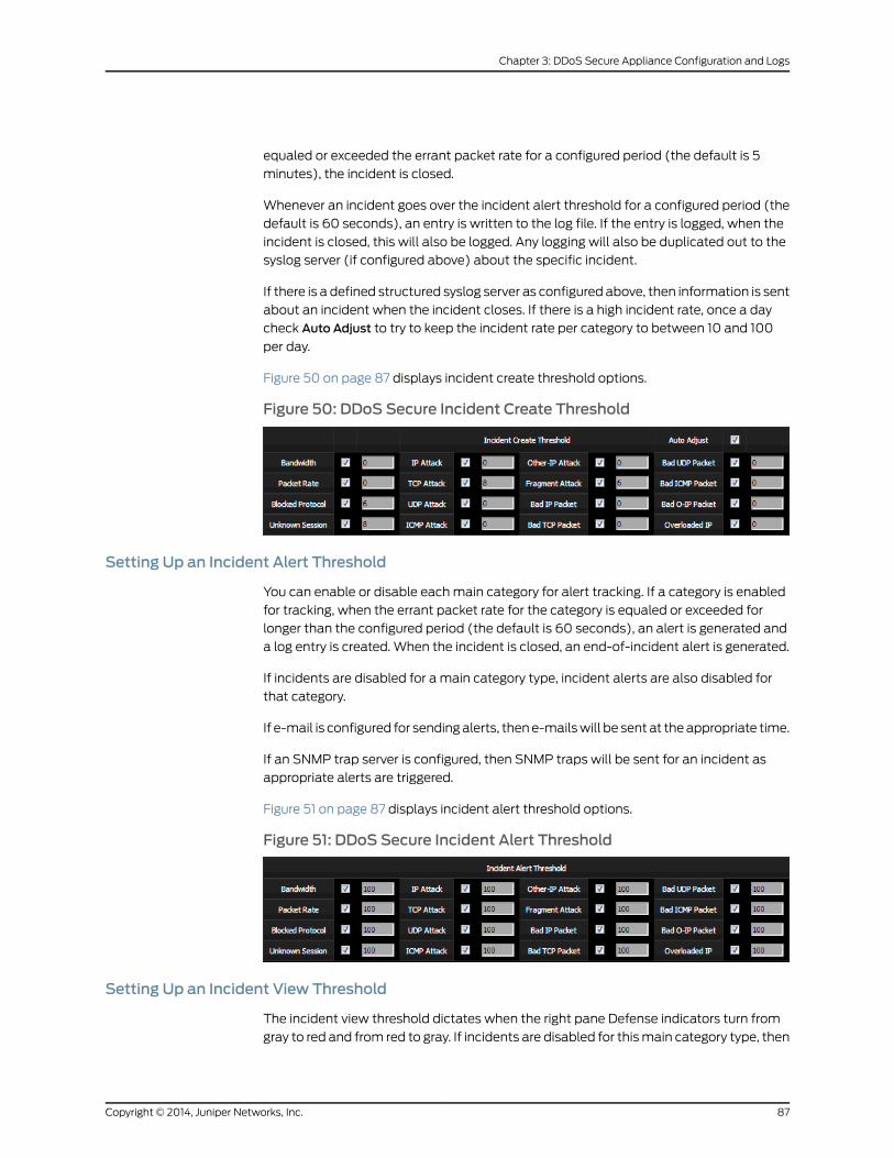
equaled or exceeded the errant packet rate for a configured period (the default is 5
minutes), the incident is closed.
Whenever an incident goes over the incident alert threshold for a configured period (the
default is 60 seconds), an entry is written to the log file. If the entry is logged, when the
incident is closed, this will also be logged. Any logging will also be duplicated out to the
syslog server (if configured above) about the specific incident.
If there is a defined structured syslog server as configured above, then information is sent
about an incident when the incident closes. If there is a high incident rate, once a day
check Auto Adjust to try to keep the incident rate per category to between 10 and 100
per day.
Figure 50 on page 87 displays incident create threshold options.
Figure 50: DDoS Secure Incident Create Threshold
Setting Up an Incident Alert Threshold
You can enable or disable eachmain category for alert tracking. If a category is enabled
for tracking, when the errant packet rate for the category is equaled or exceeded for
longer than the configured period (the default is 60 seconds), an alert is generated and
a log entry is created. When the incident is closed, an end-of-incident alert is generated.
If incidents are disabled for a main category type, incident alerts are also disabled for
that category.
If e-mail is configured for sendingalerts, thene-mailswill be sent at theappropriate time.
If an SNMP trap server is configured, then SNMP traps will be sent for an incident as
appropriate alerts are triggered.
Figure 51 on page 87 displays incident alert threshold options.
Figure 51: DDoS Secure Incident Alert Threshold
Setting Up an Incident View Threshold
The incident view threshold dictates when the right pane Defense indicators turn from
gray to red and from red to gray. If incidents are disabled for thismain category type, then
87Copyright © 2014, Juniper Networks, Inc.
Chapter 3: DDoS Secure Appliance Configuration and Logs
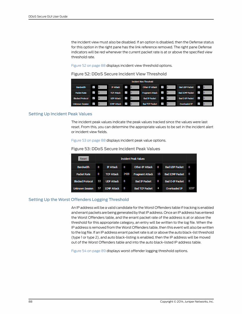
the incident viewmust also be disabled. If an option is disabled, then the Defense status
for this option in the right pane has the link reference removed. The right pane Defense
indicators will be red whenever the current packet rate is at or above the specified view
threshold rate.
Figure 52 on page 88 displays incident view threshold options.
Figure 52: DDoS Secure Incident View Threshold
Setting Up Incident Peak Values
The incident peak values indicate the peak values tracked since the values were last
reset. From this, you can determine the appropriate values to be set in the incident alert
or incident view fields.
Figure 53 on page 88 displays incident peak value options.
Figure 53: DDoS Secure Incident Peak Values
Setting Up theWorst Offenders Logging Threshold
An IPaddresswill be a valid candidate for theWorstOffenders table if tracking is enabled
anderrantpacketsarebeinggeneratedby that IPaddress.Oncean IPaddresshasentered
theWorst Offenders table, and the errant packet rate of the address is at or above the
threshold for this appropriate category, an entry will be written to the log file. When the
IP address is removed from theWorstOffenders table, then this eventwill also bewritten
to the log file. If an IPaddress errant packet rate is at or above theautoblack-list threshold
(type 1 or type 2), and auto black-listing is enabled, then the IP address will be moved
out of theWorst Offenders table and into the auto black-listed IP address table.
Figure 54 on page 89 displays worst offender logging threshold options.
Copyright © 2014, Juniper Networks, Inc.88
DDoS Secure GUI User Guide
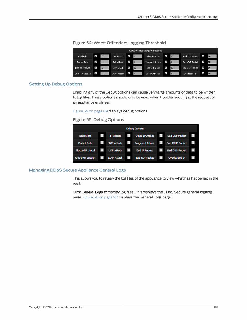
Figure 54:Worst Offenders Logging Threshold
Setting Up Debug Options
Enabling any of the Debug options can cause very large amounts of data to be written
to log files. These options should only be used when troubleshooting at the request of
an appliance engineer.
Figure 55 on page 89 displays debug options.
Figure 55: Debug Options
Managing DDoS Secure Appliance General Logs
This allows you to review the log files of the appliance to viewwhat has happened in the
past.
Click General Logs to display log files. This displays the DDoS Secure general logging
page. Figure 56 on page 90 displays the General Logs page.
89Copyright © 2014, Juniper Networks, Inc.
Chapter 3: DDoS Secure Appliance Configuration and Logs
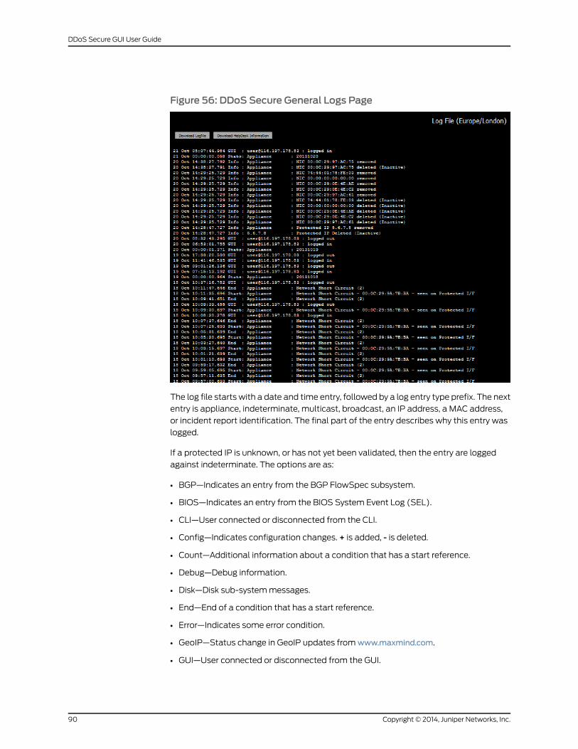
Figure 56: DDoS Secure General Logs Page
The log file starts with a date and time entry, followed by a log entry type prefix. The next
entry is appliance, indeterminate, multicast, broadcast, an IP address, a MAC address,
or incident report identification. The final part of the entry describes why this entry was
logged.
If a protected IP is unknown, or has not yet been validated, then the entry are logged
against indeterminate. The options are as:
• BGP—Indicates an entry from the BGP FlowSpec subsystem.
• BIOS—Indicates an entry from the BIOS System Event Log (SEL).
• CLI—User connected or disconnected from the CLI.
• Config—Indicates configuration changes. + is added, - is deleted.
• Count—Additional information about a condition that has a start reference.
• Debug—Debug information.
• Disk—Disk sub-systemmessages.
• End—End of a condition that has a start reference.
• Error—Indicates some error condition.
• GeoIP—Status change in GeoIP updates fromwww.maxmind.com.
• GUI—User connected or disconnected from the GUI.
Copyright © 2014, Juniper Networks, Inc.90
DDoS Secure GUI User Guide
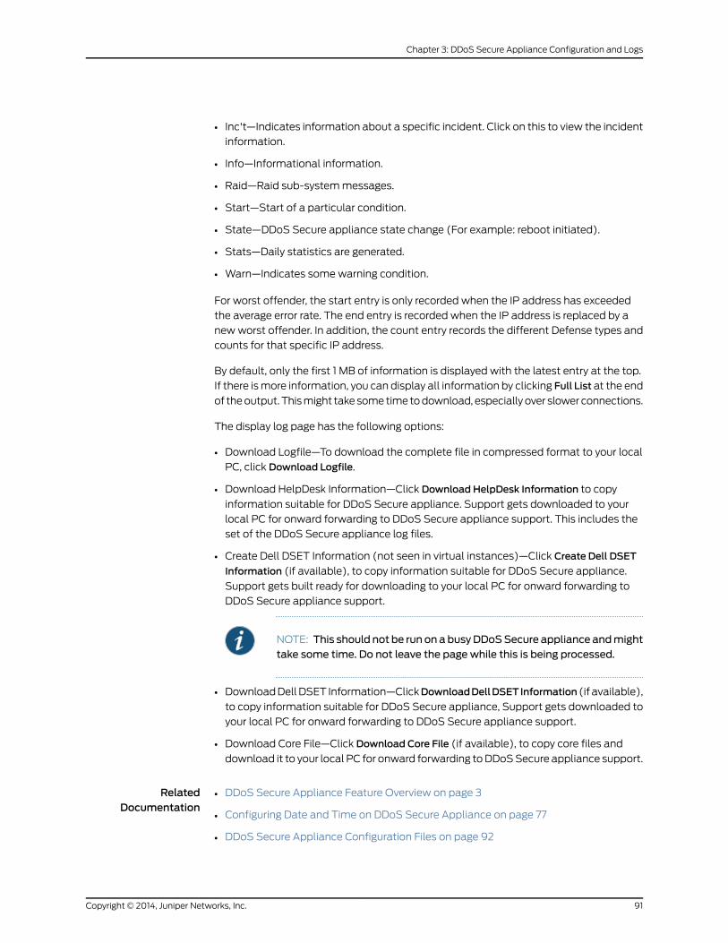
• Inc't—Indicates information about a specific incident. Click on this to view the incident
information.
• Info—Informational information.
• Raid—Raid sub-systemmessages.
• Start—Start of a particular condition.
• State—DDoS Secure appliance state change (For example: reboot initiated).
• Stats—Daily statistics are generated.
• Warn—Indicates some warning condition.
For worst offender, the start entry is only recorded when the IP address has exceeded
the average error rate. The end entry is recorded when the IP address is replaced by a
newworst offender. In addition, the count entry records the different Defense types and
counts for that specific IP address.
By default, only the first 1 MB of information is displayed with the latest entry at the top.
If there ismore information, you can display all information by clicking Full List at the end
of theoutput. Thismight takesometime todownload, especially over slower connections.
The display log page has the following options:
• Download Logfile—To download the complete file in compressed format to your local
PC, click Download Logfile.
• Download HelpDesk Information—Click Download HelpDesk Information to copy
information suitable for DDoS Secure appliance. Support gets downloaded to your
local PC for onward forwarding to DDoS Secure appliance support. This includes the
set of the DDoS Secure appliance log files.
• Create Dell DSET Information (not seen in virtual instances)—Click Create Dell DSET
Information (if available), to copy information suitable for DDoS Secure appliance.
Support gets built ready for downloading to your local PC for onward forwarding to
DDoS Secure appliance support.
NOTE: This should not be run on abusyDDoSSecure appliance andmighttake some time. Do not leave the page while this is being processed.
• DownloadDellDSET Information—ClickDownloadDellDSETInformation (if available),
to copy information suitable for DDoS Secure appliance, Support gets downloaded to
your local PC for onward forwarding to DDoS Secure appliance support.
• Download Core File—Click Download Core File (if available), to copy core files and
download it to your local PC for onward forwarding toDDoSSecure appliance support.
RelatedDocumentation
DDoS Secure Appliance Feature Overview on page 3•
• Configuring Date and Time on DDoS Secure Appliance on page 77
• DDoS Secure Appliance Configuration Files on page 92
91Copyright © 2014, Juniper Networks, Inc.
Chapter 3: DDoS Secure Appliance Configuration and Logs
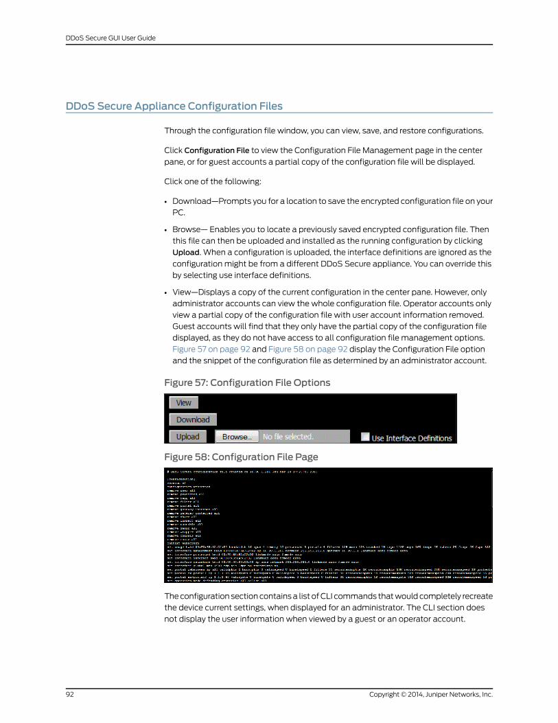
DDoS Secure Appliance Configuration Files
Through the configuration file window, you can view, save, and restore configurations.
Click Configuration File to view the Configuration File Management page in the center
pane, or for guest accounts a partial copy of the configuration file will be displayed.
Click one of the following:
• Download—Prompts you for a location to save the encrypted configuration file on your
PC.
• Browse— Enables you to locate a previously saved encrypted configuration file. Then
this file can then be uploaded and installed as the running configuration by clicking
Upload. When a configuration is uploaded, the interface definitions are ignored as the
configuration might be from a different DDoS Secure appliance. You can override this
by selecting use interface definitions.
• View—Displays a copy of the current configuration in the center pane. However, only
administrator accounts can view the whole configuration file. Operator accounts only
view a partial copy of the configuration file with user account information removed.
Guest accounts will find that they only have the partial copy of the configuration file
displayed, as they do not have access to all configuration file management options.
Figure 57 on page 92 and Figure 58 on page 92 display the Configuration File option
and the snippet of the configuration file as determined by an administrator account.
Figure 57: Configuration File Options
Figure 58: Configuration File Page
Theconfiguration sectioncontainsa list ofCLI commands thatwouldcompletely recreate
the device current settings, when displayed for an administrator. The CLI section does
not display the user information when viewed by a guest or an operator account.
Copyright © 2014, Juniper Networks, Inc.92
DDoS Secure GUI User Guide
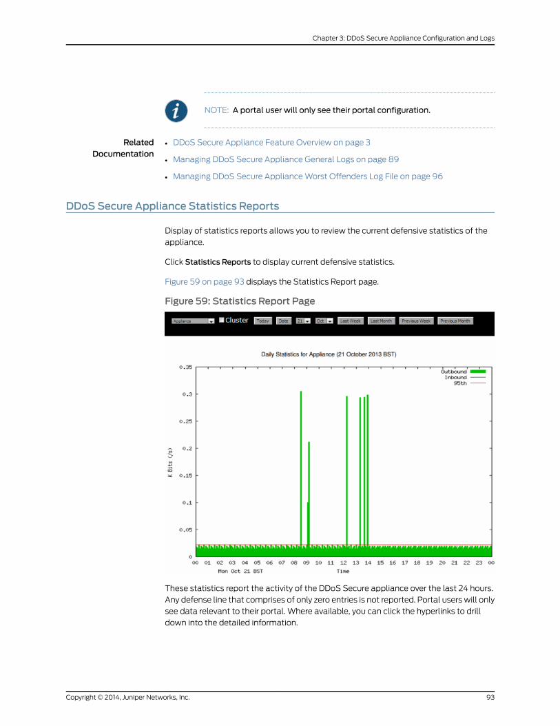
NOTE: A portal user will only see their portal configuration.
RelatedDocumentation
DDoS Secure Appliance Feature Overview on page 3•
• Managing DDoS Secure Appliance General Logs on page 89
• Managing DDoS Secure ApplianceWorst Offenders Log File on page 96
DDoS Secure Appliance Statistics Reports
Display of statistics reports allows you to review the current defensive statistics of the
appliance.
Click Statistics Reports to display current defensive statistics.
Figure 59 on page 93 displays the Statistics Report page.
Figure 59: Statistics Report Page
These statistics report the activity of the DDoS Secure appliance over the last 24 hours.
Any defense line that comprises of only zero entries is not reported. Portal users will only
see data relevant to their portal. Where available, you can click the hyperlinks to drill
down into the detailed information.
93Copyright © 2014, Juniper Networks, Inc.
Chapter 3: DDoS Secure Appliance Configuration and Logs

The statistics are divided into six sections, and output can cover a day, week, or month,
depending on the options selected. Some sectionsmight not be presented, as these are
not appropriate to the selected options.
On theDDoSSecure Statistic Report page, click the appropriate button to view statistics
for the previous week andmonth. Click Date for a specific date. Up to 60 days of
information is held, but the amount depends on available disk space. A copy of this
statistical report can be e-mailed every midnight, if required.
Table24onpage94asummaryof the informationdisplayedon theDDoSSecureStatistic
Report page.
Table 24: DDoS Secure Statistics Report Details
DescriptionField
This section summarizes the traffic throughput, the traffic aftercleansing, the traffic dropped (Internet noise, black-listed andattack) and the traffic dropped (attack only).
Graphical Summary
This section summarizes the packet drop activity and reasons thepackets were dropped, as well as situations that occurred wherethere was no packet drop activity.
Packet Drop/NotificationActivity
This section reports top worst offenders tracked over the month,week, and day.
TopWorst Offenders
This section reports the top incidents trackedover themonth,week,and day.
Top Incidents
These statistics reflect the usage of different tableswith the DDoSSecure appliance software.
Over time, the Tracked IPs, URLs, DNS, SIP, andWorst Offenderstables reach 100%,which isnormal.When the table is full, the leastrecently used entry is discarded.
Table Usage
These statistics reflect how the appliance is being utilized.
Memoryusage is always likely tobehighas theunderlyingoperatingsystem uses spare memory for disk caching.
TheDDoSSecureapplianceautomaticallymanages thedisk space.
Resource Usage
RelatedDocumentation
DDoS Secure Appliance Feature Overview on page 3•
• Managing DDoS Secure Appliance General Logs on page 89
• DDoS Secure Appliance Configuration Files on page 92
Managing DDoS Secure Appliance Incident Logs
The Display Incident page allows you to review the active incidents tracked by the
appliance.
Copyright © 2014, Juniper Networks, Inc.94
DDoS Secure GUI User Guide

Click Incident Logs to display active incident information. For an incident defense type to
be displayed (the default), it has to be enabled in Incident Create Threshold.
Figure 60 on page 95 displays the incident logs.
Figure 60: Incident Logs
NOTE: Entries that are in the red font are for incidents that have been overthe alert threshold for at least oneminute.
• Incidents can be filtered by protected IP address or portal by selecting from the pull
down list. The options are:
• Today to bring up a log of incidents that has taken place today.
• Date tobringupa logof incidents that have takenplacewithin the specifieddate range.
Only the last 60 days of incidents are kept on disk.
• CSVDisplay to bring up a comma-separated detail of incidents that have taken place
within the specified date range. You can look up a specific incident by entering the
incident number, which is in the format yyyymmdd/nnnnnn.
• Date and Time hyperlink to get to the specific detail of an incident.
Displaying Incident Details
Byhovering themouseoveran IPaddress, youcan roughlydeterminewhere the IPaddress
is.
There are three types of Incident activity – recorded on the seventh line of output.
• Packets Dropped—Packets are actually being dropped (unless in logging mode).
• Packets Noted—Packets are actually being noted (as in logging mode)
• Occurred—The situation is observed number of times.
Figure 61 on page 96 displays the Specific Incident page.
95Copyright © 2014, Juniper Networks, Inc.
Chapter 3: DDoS Secure Appliance Configuration and Logs

Figure 61: Specific Display Incident Page
RelatedDocumentation
DDoS Secure Appliance Feature Overview on page 3•
• Managing DDoS Secure Appliance General Logs on page 89
• Managing DDoS Secure ApplianceWorst Offenders Log File on page 96
Managing DDoS Secure ApplianceWorst Offenders Log File
ClickWorst Offender Log to display worst offenders. Figure 62 on page 96 displays the
Worst Offenders page.
Figure 62:Worst Offenders Log Page Snippet
Click Download Logfile for a copy of the log file that can be used for post processing on
the worst offender information. Other download options are:
• Download CSV logfile.
• Download black-listed IP addresses CSV logfile.
• Download previous month CSV logfile.
• Download previous month black-listed IP addresses CSV logfile.
Copyright © 2014, Juniper Networks, Inc.96
DDoS Secure GUI User Guide
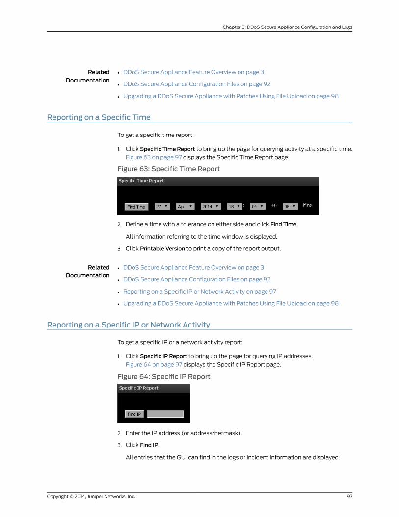
RelatedDocumentation
DDoS Secure Appliance Feature Overview on page 3•
• DDoS Secure Appliance Configuration Files on page 92
• Upgrading a DDoS Secure Appliance with Patches Using File Upload on page 98
Reporting on a Specific Time
To get a specific time report:
1. Click Specific Time Report to bring up the page for querying activity at a specific time.
Figure 63 on page 97 displays the Specific Time Report page.
Figure 63: Specific Time Report
2. Define a time with a tolerance on either side and click Find Time.
All information referring to the time window is displayed.
3. Click Printable Version to print a copy of the report output.
RelatedDocumentation
DDoS Secure Appliance Feature Overview on page 3•
• DDoS Secure Appliance Configuration Files on page 92
• Reporting on a Specific IP or Network Activity on page 97
• Upgrading a DDoS Secure Appliance with Patches Using File Upload on page 98
Reporting on a Specific IP or Network Activity
To get a specific IP or a network activity report:
1. Click Specific IP Report to bring up the page for querying IP addresses.
Figure 64 on page 97 displays the Specific IP Report page.
Figure 64: Specific IP Report
2. Enter the IP address (or address/netmask).
3. Click Find IP.
All entries that the GUI can find in the logs or incident information are displayed.
97Copyright © 2014, Juniper Networks, Inc.
Chapter 3: DDoS Secure Appliance Configuration and Logs
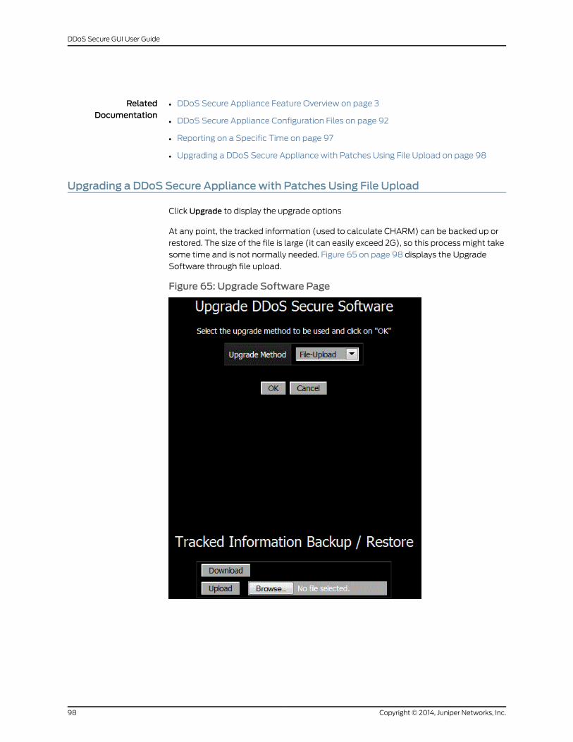
RelatedDocumentation
DDoS Secure Appliance Feature Overview on page 3•
• DDoS Secure Appliance Configuration Files on page 92
• Reporting on a Specific Time on page 97
• Upgrading a DDoS Secure Appliance with Patches Using File Upload on page 98
Upgrading a DDoS Secure Appliance with Patches Using File Upload
Click Upgrade to display the upgrade options
At any point, the tracked information (used to calculate CHARM) can be backed up or
restored. The size of the file is large (it can easily exceed 2G), so this process might take
some time and is not normally needed. Figure 65 on page 98 displays the Upgrade
Software through file upload.
Figure 65: Upgrade Software Page
Copyright © 2014, Juniper Networks, Inc.98
DDoS Secure GUI User Guide
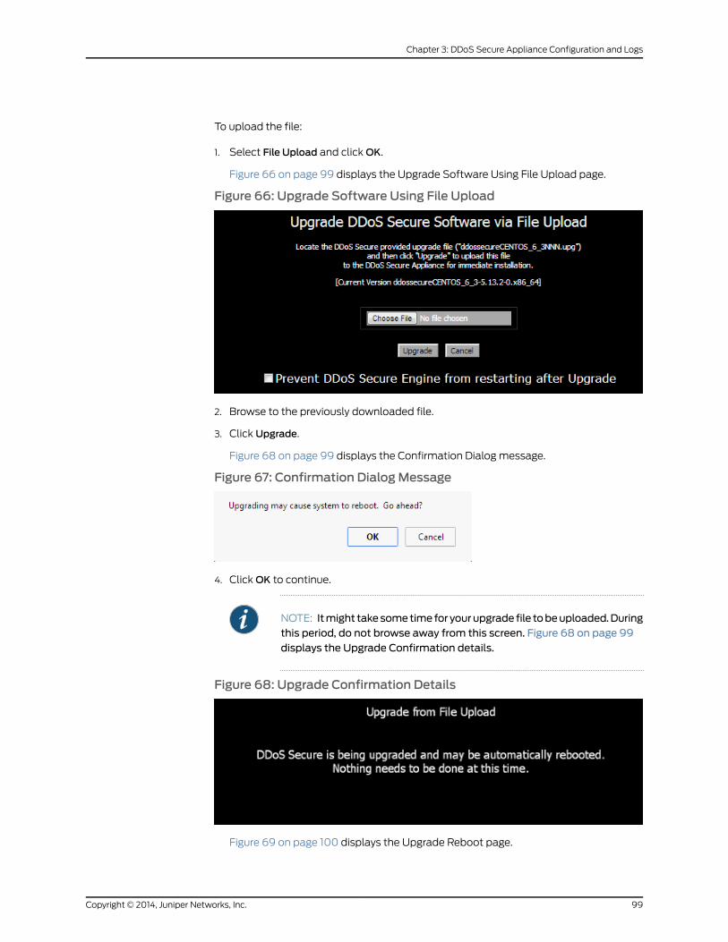
To upload the file:
1. Select File Upload and clickOK.
Figure 66 on page 99 displays the Upgrade Software Using File Upload page.
Figure 66: Upgrade Software Using File Upload
2. Browse to the previously downloaded file.
3. Click Upgrade.
Figure 68 on page 99 displays the Confirmation Dialog message.
Figure 67: Confirmation DialogMessage
4. ClickOK to continue.
NOTE: Itmight takesometimefor yourupgrade file tobeuploaded.Duringthis period, do not browse away from this screen. Figure 68 on page 99displays the Upgrade Confirmation details.
Figure 68: Upgrade Confirmation Details
Figure 69 on page 100 displays the Upgrade Reboot page.
99Copyright © 2014, Juniper Networks, Inc.
Chapter 3: DDoS Secure Appliance Configuration and Logs
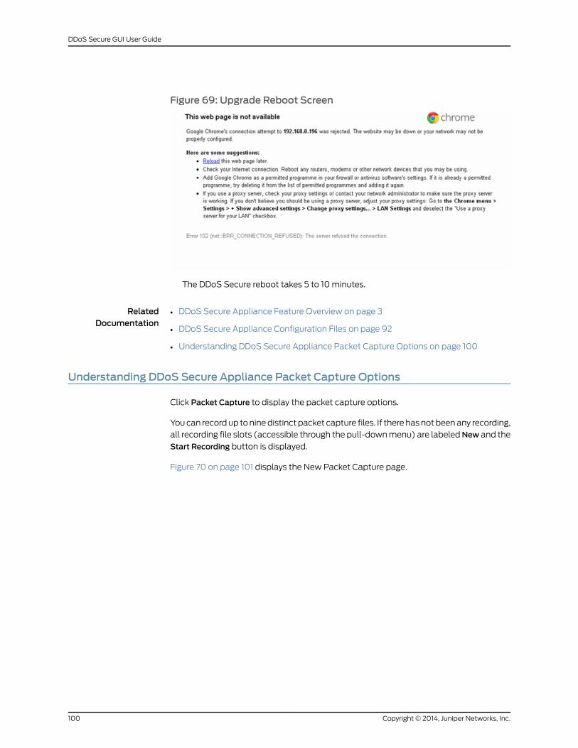
Figure 69: Upgrade Reboot Screen
The DDoS Secure reboot takes 5 to 10minutes.
RelatedDocumentation
DDoS Secure Appliance Feature Overview on page 3•
• DDoS Secure Appliance Configuration Files on page 92
• Understanding DDoS Secure Appliance Packet Capture Options on page 100
Understanding DDoS Secure Appliance Packet Capture Options
Click Packet Capture to display the packet capture options.
Youcan recordup toninedistinct packet capture files. If there hasnotbeenany recording,
all recording file slots (accessible through the pull-downmenu) are labeledNew and the
Start Recording button is displayed.
Figure 70 on page 101 displays the New Packet Capture page.
Copyright © 2014, Juniper Networks, Inc.100
DDoS Secure GUI User Guide

Figure 70: New Packet Capture Page
If a recording does exist, it will be identified by its timestamp in one of the recording file
slots. Select a recording by choosing its entry in the pull-downmenu. A table displays
statistics associated with that file. Figure 71 on page 102 displays the Existing Packet
Capture page.
Click Start Recording to start a new recording and that overwrites any existing recording
in this file slot. You can restrict the IP addresses that are recorded by specifying an IP
address, or a network with a network mask. Setting such a restriction does not strip out
all non-masked traffic, as IP addresses might not be easily determined (to minimize
performanceoverhead)at the timeof recording. It is alsopossible to enable a continuous
recording loop by selecting Continuous. In continuous mode, a new recording is started
in the next recording slot when the current recording slot becomes full or the system is
restarted.Once the last record slot nine is used the systemrestarts, thecontinuous record
loop with slot one.
CAUTION: When recording, there is a performance overhead (about 10%,CPU usage and disk write activity) that might cause your DDoS Secure
101Copyright © 2014, Juniper Networks, Inc.
Chapter 3: DDoS Secure Appliance Configuration and Logs
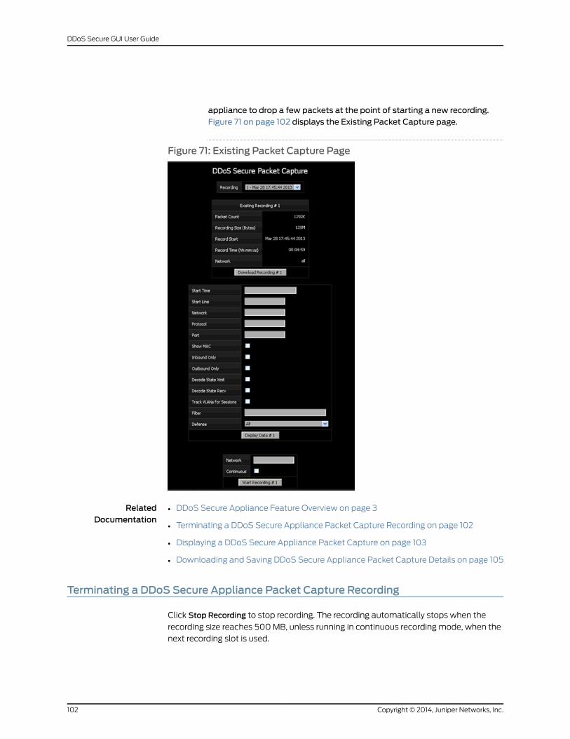
appliance to drop a few packets at the point of starting a new recording.Figure 71 on page 102 displays the Existing Packet Capture page.
Figure 71: Existing Packet Capture Page
RelatedDocumentation
DDoS Secure Appliance Feature Overview on page 3•
• Terminating a DDoS Secure Appliance Packet Capture Recording on page 102
• Displaying a DDoS Secure Appliance Packet Capture on page 103
• Downloading and Saving DDoS Secure Appliance Packet Capture Details on page 105
Terminating a DDoS Secure Appliance Packet Capture Recording
Click Stop Recording to stop recording. The recording automatically stops when the
recording size reaches 500MB, unless running in continuous recording mode, when the
next recording slot is used.
Copyright © 2014, Juniper Networks, Inc.102
DDoS Secure GUI User Guide
Before displaying any recorded data, you can select a specific network address, protocol,
port or Defense type, or any combination of these types in order to reduce the displayed
data. Furthermore, filter syntax (based on BPF (as used by tcpdump)) can be specified
for further data reduction.
RelatedDocumentation
DDoS Secure Appliance Feature Overview on page 3•
• Understanding DDoS Secure Appliance Packet Capture Options on page 100
• Displaying a DDoS Secure Appliance Packet Capture on page 103
• Downloading and Saving DDoS Secure Appliance Packet Capture Details on page 105
Displaying a DDoS Secure Appliance Packet Capture
Before displaying any recorded data, you can select a specific network address, protocol,
port or defense type, or any combination of these types in order to reduce the displayed
data. Furthermore, filter syntax based on BPF as used by tcpdump can be specified for
further data reduction.
NOTE: If the BPF filter is being used, and the DDoS Secure appliance is on aVLAN/MPLS trunk, then the appropriate VLAN/MPLS keywordsmust to beused.
You can enable the output of MAC address information for the packets displayed, select
whether to showonly inboundor outboundpackets anddecode thepackets that contain
state information that is being shared between DDoS Secure appliances.
Having entered any of the optional data reduction options, click Display Data to review
the recording. This step can be performed even on a recording that is still in progress.
Figure 72 on page 104 displays the packet capture display page.
103Copyright © 2014, Juniper Networks, Inc.
Chapter 3: DDoS Secure Appliance Configuration and Logs

Figure 72: Packet Capture Display Page
The records are color-coded as follows:
• Black—Packet is good and passed through.
• Amber—Indicates that packets were dropped.
• Blue—Indicates generated packets.
• Gray—Traffic detected by DDoS Secure appliance that is not appropriate to pass
through. The reasons are provided.
• Pink—Received state synchronization packet details.
• Yellow—Packet that would have been dropped if DDoS Secure was not in Logging
mode for this session.
• Green—Sent state synchronization packet details.
• Purple—Redirected packet to the Intercept server.
The columns are generally divided as:
| Time | Protocol | Src IP| Src Port | Direction | Dest IP | Dst Port | Length| Fragment ID |.
For TCP, this continues as: |TCP Flags | TCP State | Sequence numbers| Window Size.
For ICMP, this can continue as: |Sequence numbers.|
For fragmented packets, H: is start fragment, M: is middle fragment, T: is tail fragment
and O: is starting offset.
HB is the heart beat protocol that DDoS Secure appliance uses for fail over
synchronization.
Figure 73 on page 105 displays the Packet Capture Display Column page.
Copyright © 2014, Juniper Networks, Inc.104
DDoS Secure GUI User Guide
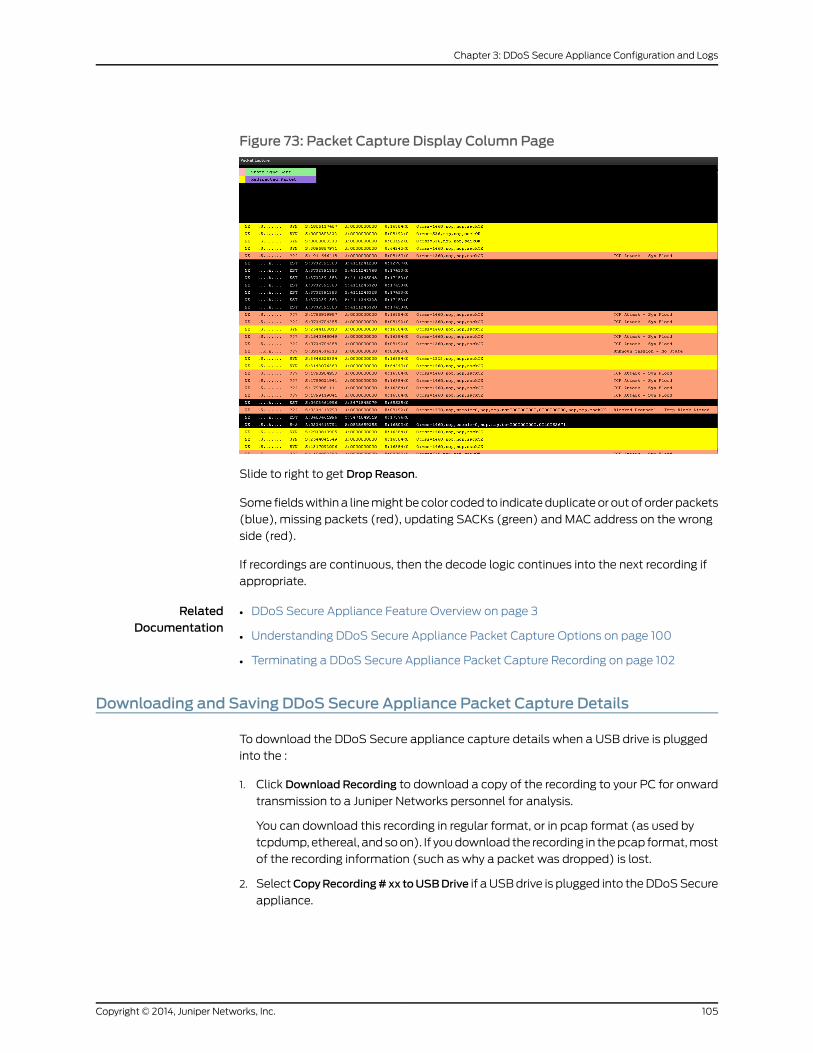
Figure 73: Packet Capture Display Column Page
Slide to right to get Drop Reason.
Some fieldswithina linemightbecolor coded to indicateduplicateor outof orderpackets
(blue), missing packets (red), updating SACKs (green) and MAC address on the wrong
side (red).
If recordings are continuous, then the decode logic continues into the next recording if
appropriate.
RelatedDocumentation
DDoS Secure Appliance Feature Overview on page 3•
• Understanding DDoS Secure Appliance Packet Capture Options on page 100
• Terminating a DDoS Secure Appliance Packet Capture Recording on page 102
Downloading and Saving DDoS Secure Appliance Packet Capture Details
To download the DDoS Secure appliance capture details when a USB drive is plugged
into the :
1. Click Download Recording to download a copy of the recording to your PC for onward
transmission to a Juniper Networks personnel for analysis.
You can download this recording in regular format, or in pcap format (as used by
tcpdump, ethereal, andsoon). If youdownload the recording in thepcap format,most
of the recording information (such as why a packet was dropped) is lost.
2. SelectCopyRecording#xx toUSBDrive if a USBdrive is plugged into theDDoSSecure
appliance.
105Copyright © 2014, Juniper Networks, Inc.
Chapter 3: DDoS Secure Appliance Configuration and Logs
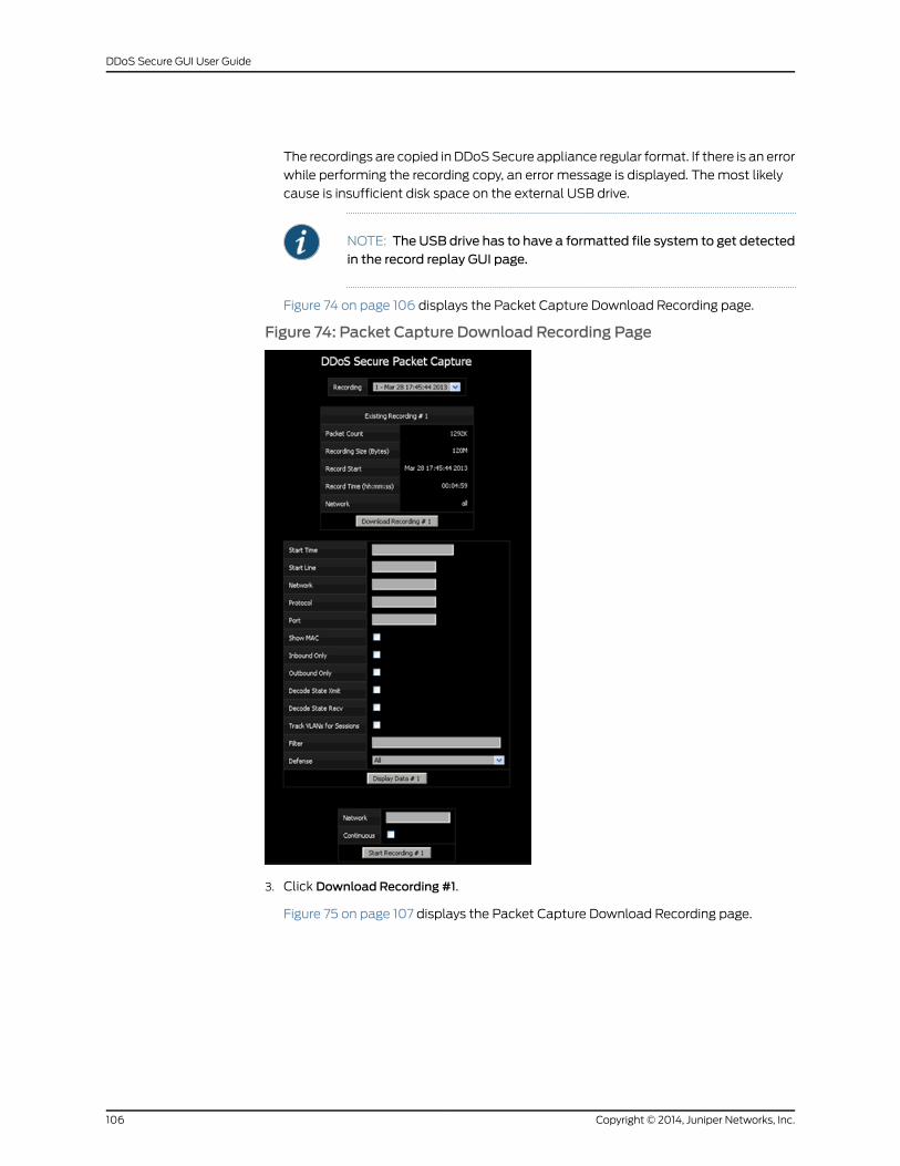
The recordings are copied in DDoSSecure appliance regular format. If there is an error
while performing the recording copy, an error message is displayed. Themost likely
cause is insufficient disk space on the external USB drive.
NOTE: The USB drive has to have a formatted file system to get detectedin the record replay GUI page.
Figure 74 on page 106 displays the Packet Capture Download Recording page.
Figure 74: Packet Capture Download Recording Page
3. Click Download Recording #1.
Figure 75 on page 107 displays the Packet Capture Download Recording page.
Copyright © 2014, Juniper Networks, Inc.106
DDoS Secure GUI User Guide
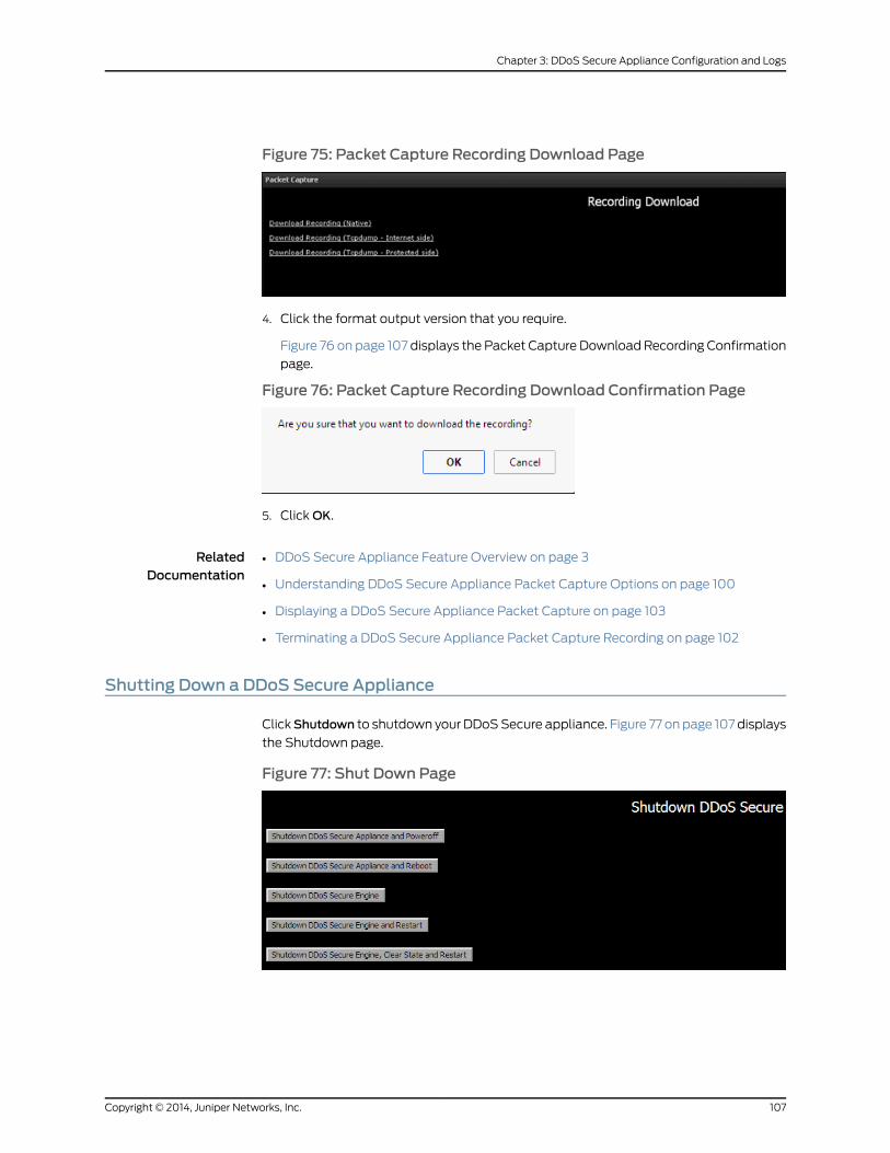
Figure 75: Packet Capture Recording Download Page
4. Click the format output version that you require.
Figure 76 on page 107 displays the Packet Capture Download Recording Confirmation
page.
Figure 76: Packet Capture Recording Download Confirmation Page
5. ClickOK.
RelatedDocumentation
DDoS Secure Appliance Feature Overview on page 3•
• Understanding DDoS Secure Appliance Packet Capture Options on page 100
• Displaying a DDoS Secure Appliance Packet Capture on page 103
• Terminating a DDoS Secure Appliance Packet Capture Recording on page 102
Shutting Down a DDoS Secure Appliance
ClickShutdown to shutdown your DDoSSecure appliance. Figure 77 on page 107 displays
the Shutdown page.
Figure 77: Shut Down Page
107Copyright © 2014, Juniper Networks, Inc.
Chapter 3: DDoS Secure Appliance Configuration and Logs

There are five options with an optional sixth option, if the DDoS Secure appliance is
running as active in a fail-over relationship.
• Shutdown DDoS Secure Appliance and Poweroff—The appliance can be powered off
using this control. All file systems are updated safely using this method. To restart, the
appliance requires a power cycle.
NOTE: This option is not availablewhenDDoSSecure appliance is runningas an application on a third-party hardware platform.
• Shutdown DDoS Secure appliance and Reboot—During normal operation, it should not
be necessary to reboot the DDoS Secure appliance. However, all file systems are
updated safely using this method and the appliance reboots automatically, taking
around five minutes.
NOTE: This option is not availablewhenDDoSSecure appliance is runningas an application on a third-party hardware platform.
• Shutdown DDoS Secure appliance engine—This stops the DDoS Secure appliance
engine, leaving the GUI running. To restart the DDoS Secure appliance engine, click
Restart DDoS Secure appliance Engine.
NOTE: If themanagementaccess to theDDoSSecureappliance is throughthe DDoS Secure appliance, if you do not have a high-availability system,or a fail-safe card, you will lose access to the DDoS Secure appliance.
• ShutdownDDoSSecureapplianceengineandrestart—This stopsand thenautomatically
restarts the DDoS Secure appliance engine. This is not the same as shutting down
DDoS Secure appliance and rebooting, that completely shuts down the operating
system and then completely reboots the appliance from scratch.
• Shutdown DDoS Secure appliance engine, clear state and restart—This stops and then
automatically restarts the DDoS Secure appliance engine. All state information is
cleared providing a clean start for the DDoS Secure appliance. This is not the same as
shutting down DDoS Secure appliance and rebooting that completely shuts down the
operating system and then completely reboots the appliance from scratch.
• Go standby—This option is only displayed when the DDoS Secure appliance is the
activeDDoSSecureappliance ina fail-over cluster. This optioncauses theDDoSSecure
appliance to drop out of active state so that a partner in the cluster takes over the
active role.
RelatedDocumentation
• DDoS Secure Appliance Feature Overview on page 3
• Configuring Basic Settings for a DDoS Secure Appliance After Hardware Replacement
on page 12
• Understanding DDoS Secure Appliance Packet Capture Options on page 100
Copyright © 2014, Juniper Networks, Inc.108
DDoS Secure GUI User Guide
CHAPTER 4
DDoS Secure Statistical DisplaysOverview
This chapter describes the statistical displays of the appliance protected traffic that can
be viewed using the Summary Dashboard display button.
• DDoS Secure Appliance Statistical Summary Overview on page 109
• DDoS Secure Appliance Status Information on page 111
• DDoS Secure Appliance Protected IP Information on page 114
• DDoS Secure Appliance Live Incidents Information on page 117
• DDoS Secure ApplianceWorst Offenders Information on page 118
• DDoS Secure Appliance Temporarily Black-Listed Information on page 121
• DDoS Secure Appliance Tracked IP Information on page 122
• Tracking Country-Wide Usage Information in a DDoS Secure Appliance on page 124
• DDoS Secure Appliance TCP Information on page 126
• DDoS Secure Appliance UDP Information on page 127
• DDoS Secure Appliance ICMP Information on page 129
• DDoS Secure Appliance Other IP Protocol Information on page 130
• DDoS Secure Appliance Fragment Information on page 132
• DDoS Secure Appliance URL Information on page 133
• DDoS Secure Appliance DNS Information on page 135
• DDoS Secure Appliance SIP Information on page 136
• DDoS Secure Appliance Bandwidth Information on page 138
• DDoS Secure Appliance Rerouting Information on page 139
• DDoS Secure BGP FlowSpec Information on page 140
• DDoS Secure Appliance MAC Information on page 143
• Miscellaneous Information on page 145
DDoS Secure Appliance Statistical Summary Overview
Click Summary Dashboard to display summary dashboard details.
109Copyright © 2014, Juniper Networks, Inc.

Summary dashboard contains six tables or information and graphs summarizing the
traffic passing through the DDoS Secure appliance. Figure 78 on page 110 displays
Summary Dashboard page.
Figure 78: Summary Dashboard Page
Table 25 on page 110 provides the parameters of the summary dashboard information
page.
Table 25: Summary Dashboard Information Page
DescriptionField
This shows the peak traffic usage (inbound and outbound)over the selected period (default is 24 hrs).
Traffic Monitor
This reports on how busy the DDoS Secure engine is.Load Status
This reports on howaggressively theDDoSSecure applianceis dropping traffic to defend the appropriate resources.
Attack Status
This reportson thedistributionofwheregood traffic is comingfrom.
Good Traffic
This reports on the distribution of where the bad traffic isrouted from.
Bad Traffic
This reports on how busy a protected IP address is from anaggregatedCHARMperspective, andwhat theaverage trafficto and from the IP is.
Protected Performance
RelatedDocumentation
DDoS Secure Appliance Feature Overview on page 3•
• DDoS Secure Appliance Status Information on page 111
Copyright © 2014, Juniper Networks, Inc.110
DDoS Secure GUI User Guide
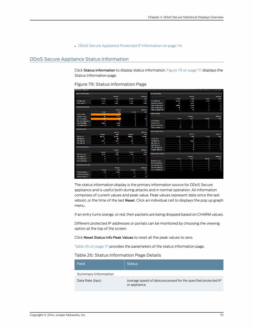
• DDoS Secure Appliance Protected IP Information on page 114
DDoS Secure Appliance Status Information
Click Status Information to display status information. Figure 79 on page 111 displays the
Status Information page.
Figure 79: Status Information Page
The status information display is the primary information source for DDoS Secure
appliance and is useful both during attacks and in normal operation. All information
comprises of current values and peak value. Peak values represent data since the last
reboot, or the time of the last Reset. Click an individual cell to displays the pop up graph
menu.
If an entry turns orange, or red, then packets are being dropped based on CHARM values.
Different protected IP addresses or portals can bemonitored by choosing the viewing
option at the top of the screen.
Click Reset Status Info Peak Values to reset all the peak values to zero.
Table 26 on page 111 provides the parameters of the status information page.
Table 26: Status Information Page Details
StatusField
Summary Information
Average speed of data processed for the specified protected IPor appliance.
Data Rate (bps)
111Copyright © 2014, Juniper Networks, Inc.
Chapter 4: DDoS Secure Statistical Displays Overview
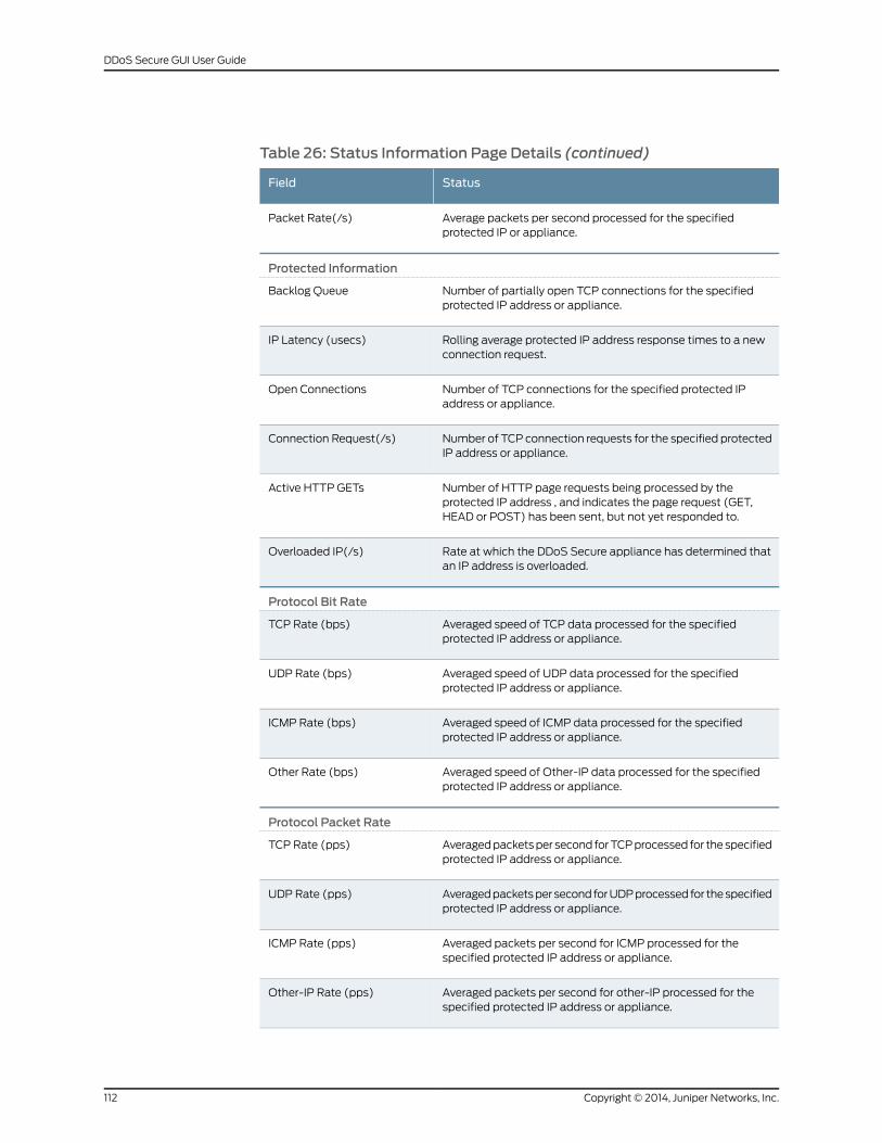
Table 26: Status Information Page Details (continued)
StatusField
Average packets per second processed for the specifiedprotected IP or appliance.
Packet Rate(/s)
Protected Information
Number of partially open TCP connections for the specifiedprotected IP address or appliance.
Backlog Queue
Rolling average protected IP address response times to a newconnection request.
IP Latency (usecs)
Number of TCP connections for the specified protected IPaddress or appliance.
Open Connections
Number of TCP connection requests for the specified protectedIP address or appliance.
Connection Request(/s)
Number of HTTP page requests being processed by theprotected IP address , and indicates the page request (GET,HEAD or POST) has been sent, but not yet responded to.
Active HTTP GETs
Rate at which the DDoS Secure appliance has determined thatan IP address is overloaded.
Overloaded IP(/s)
Protocol Bit Rate
Averaged speed of TCP data processed for the specifiedprotected IP address or appliance.
TCP Rate (bps)
Averaged speed of UDP data processed for the specifiedprotected IP address or appliance.
UDP Rate (bps)
Averaged speed of ICMP data processed for the specifiedprotected IP address or appliance.
ICMP Rate (bps)
Averaged speed of Other-IP data processed for the specifiedprotected IP address or appliance.
Other Rate (bps)
Protocol Packet Rate
Averagedpacketsper second forTCPprocessed for thespecifiedprotected IP address or appliance.
TCP Rate (pps)
Averagedpacketsper second forUDPprocessed for thespecifiedprotected IP address or appliance.
UDP Rate (pps)
Averaged packets per second for ICMP processed for thespecified protected IP address or appliance.
ICMP Rate (pps)
Averaged packets per second for other-IP processed for thespecified protected IP address or appliance.
Other-IP Rate (pps)
Copyright © 2014, Juniper Networks, Inc.112
DDoS Secure GUI User Guide
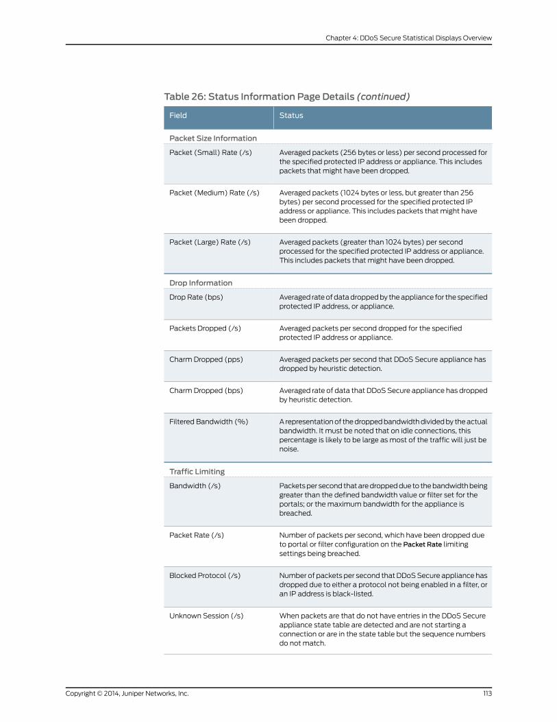
Table 26: Status Information Page Details (continued)
StatusField
Packet Size Information
Averaged packets (256 bytes or less) per second processed forthe specified protected IP address or appliance. This includespackets that might have been dropped.
Packet (Small) Rate (/s)
Averaged packets (1024 bytes or less, but greater than 256bytes) per second processed for the specified protected IPaddress or appliance. This includes packets that might havebeen dropped.
Packet (Medium) Rate (/s)
Averaged packets (greater than 1024 bytes) per secondprocessed for the specified protected IP address or appliance.This includes packets that might have been dropped.
Packet (Large) Rate (/s)
Drop Information
Averaged rateofdatadroppedby theappliance for thespecifiedprotected IP address, or appliance.
Drop Rate (bps)
Averaged packets per second dropped for the specifiedprotected IP address or appliance.
Packets Dropped (/s)
Averaged packets per second that DDoS Secure appliance hasdropped by heuristic detection.
Charm Dropped (pps)
Averaged rate of data that DDoSSecure appliance has droppedby heuristic detection.
Charm Dropped (bps)
A representationof thedroppedbandwidthdividedby theactualbandwidth. It must be noted that on idle connections, thispercentage is likely to be large as most of the traffic will just benoise.
Filtered Bandwidth (%)
Traffic Limiting
Packetsper second thataredroppeddue to thebandwidthbeinggreater than the defined bandwidth value or filter set for theportals; or the maximum bandwidth for the appliance isbreached.
Bandwidth (/s)
Number of packets per second, which have been dropped dueto portal or filter configuration on the Packet Rate limitingsettings being breached.
Packet Rate (/s)
Number of packets per second thatDDoSSecure appliance hasdropped due to either a protocol not being enabled in a filter, oran IP address is black-listed.
Blocked Protocol (/s)
When packets are that do not have entries in the DDoS Secureappliance state table are detected and are not starting aconnection or are in the state table but the sequence numbersdo not match.
Unknown Session (/s)
113Copyright © 2014, Juniper Networks, Inc.
Chapter 4: DDoS Secure Statistical Displays Overview
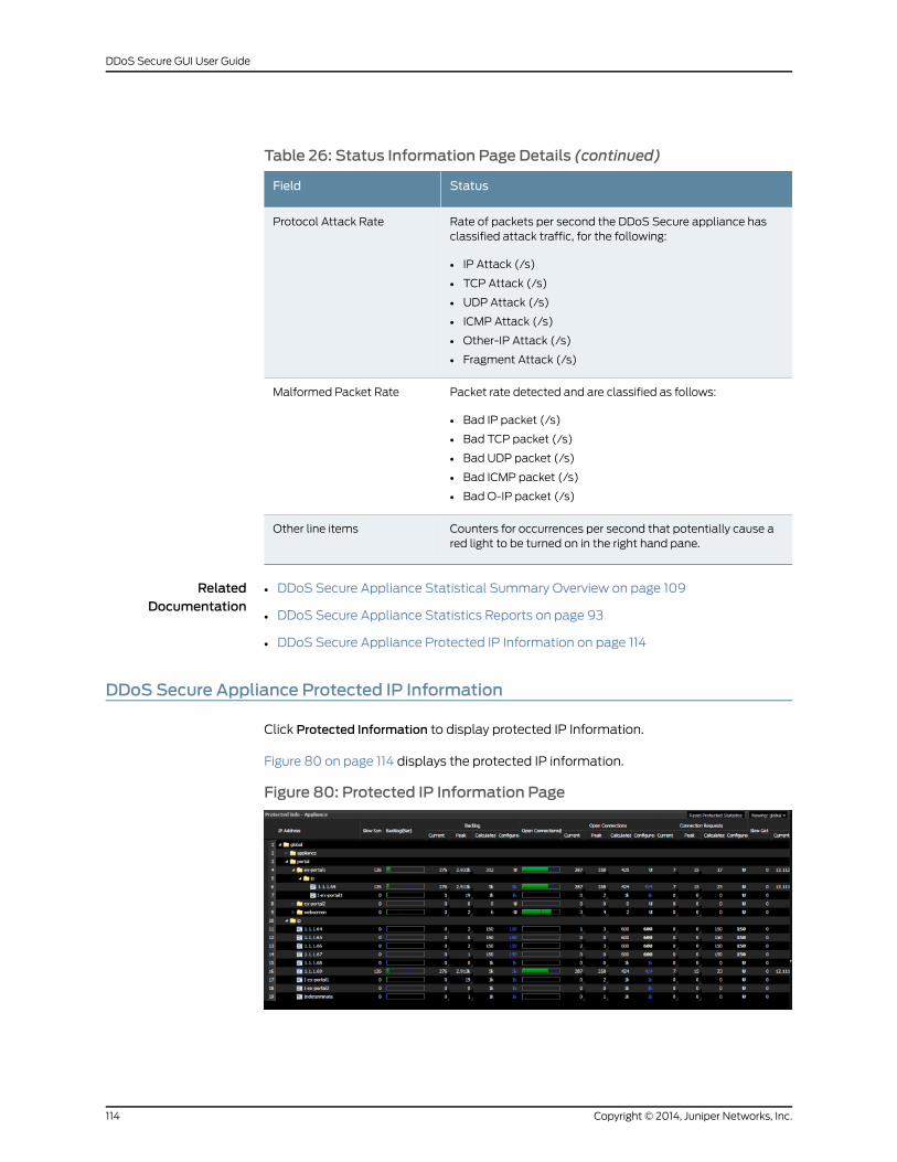
Table 26: Status Information Page Details (continued)
StatusField
Rate of packets per second the DDoS Secure appliance hasclassified attack traffic, for the following:
• IP Attack (/s)
• TCP Attack (/s)
• UDP Attack (/s)
• ICMP Attack (/s)
• Other-IP Attack (/s)
• Fragment Attack (/s)
Protocol Attack Rate
Packet rate detected and are classified as follows:
• Bad IP packet (/s)
• Bad TCP packet (/s)
• Bad UDP packet (/s)
• Bad ICMP packet (/s)
• Bad O-IP packet (/s)
Malformed Packet Rate
Counters for occurrences per second that potentially cause ared light to be turned on in the right hand pane.
Other line items
RelatedDocumentation
DDoS Secure Appliance Statistical Summary Overview on page 109•
• DDoS Secure Appliance Statistics Reports on page 93
• DDoS Secure Appliance Protected IP Information on page 114
DDoS Secure Appliance Protected IP Information
Click Protected Information to display protected IP Information.
Figure 80 on page 114 displays the protected IP information.
Figure 80: Protected IP Information Page
Copyright © 2014, Juniper Networks, Inc.114
DDoS Secure GUI User Guide
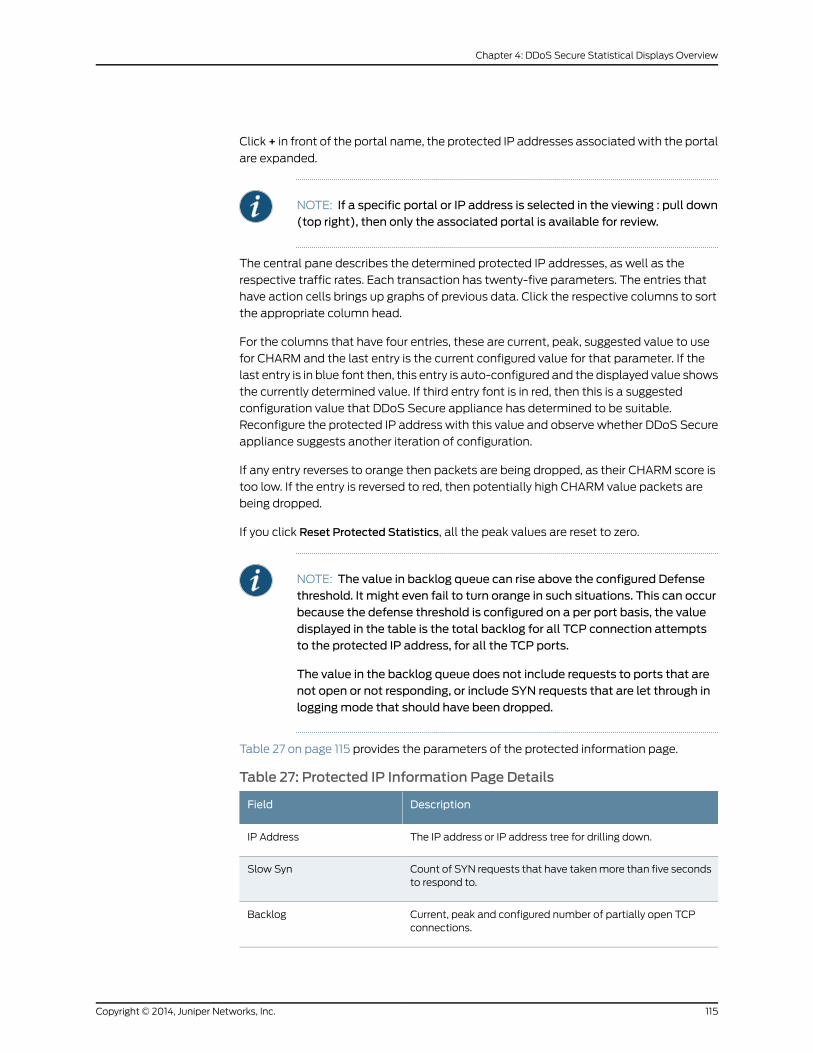
Click + in front of the portal name, the protected IP addresses associatedwith the portal
are expanded.
NOTE: If a specific portal or IP address is selected in the viewing : pull down(top right), then only the associated portal is available for review.
The central pane describes the determined protected IP addresses, as well as the
respective traffic rates. Each transaction has twenty-five parameters. The entries that
have action cells brings up graphs of previous data. Click the respective columns to sort
the appropriate column head.
For the columns that have four entries, these are current, peak, suggested value to use
for CHARM and the last entry is the current configured value for that parameter. If the
last entry is in blue font then, this entry is auto-configured and the displayed value shows
the currently determined value. If third entry font is in red, then this is a suggested
configuration value that DDoS Secure appliance has determined to be suitable.
Reconfigure the protected IP address with this value and observe whether DDoS Secure
appliance suggests another iteration of configuration.
If any entry reverses to orange then packets are being dropped, as their CHARM score is
too low. If the entry is reversed to red, then potentially high CHARM value packets are
being dropped.
If you click Reset Protected Statistics, all the peak values are reset to zero.
NOTE: The value in backlog queue can rise above the configured Defensethreshold. It might even fail to turn orange in such situations. This can occurbecause the defense threshold is configured on a per port basis, the valuedisplayed in the table is the total backlog for all TCP connection attemptsto the protected IP address, for all the TCP ports.
The value in the backlog queue does not include requests to ports that arenot open or not responding, or include SYN requests that are let through inloggingmode that should have been dropped.
Table 27 on page 115 provides the parameters of the protected information page.
Table 27: Protected IP Information Page Details
DescriptionField
The IP address or IP address tree for drilling down.IP Address
Count of SYN requests that have takenmore than five secondsto respond to.
Slow Syn
Current, peak and configured number of partially open TCPconnections.
Backlog
115Copyright © 2014, Juniper Networks, Inc.
Chapter 4: DDoS Secure Statistical Displays Overview
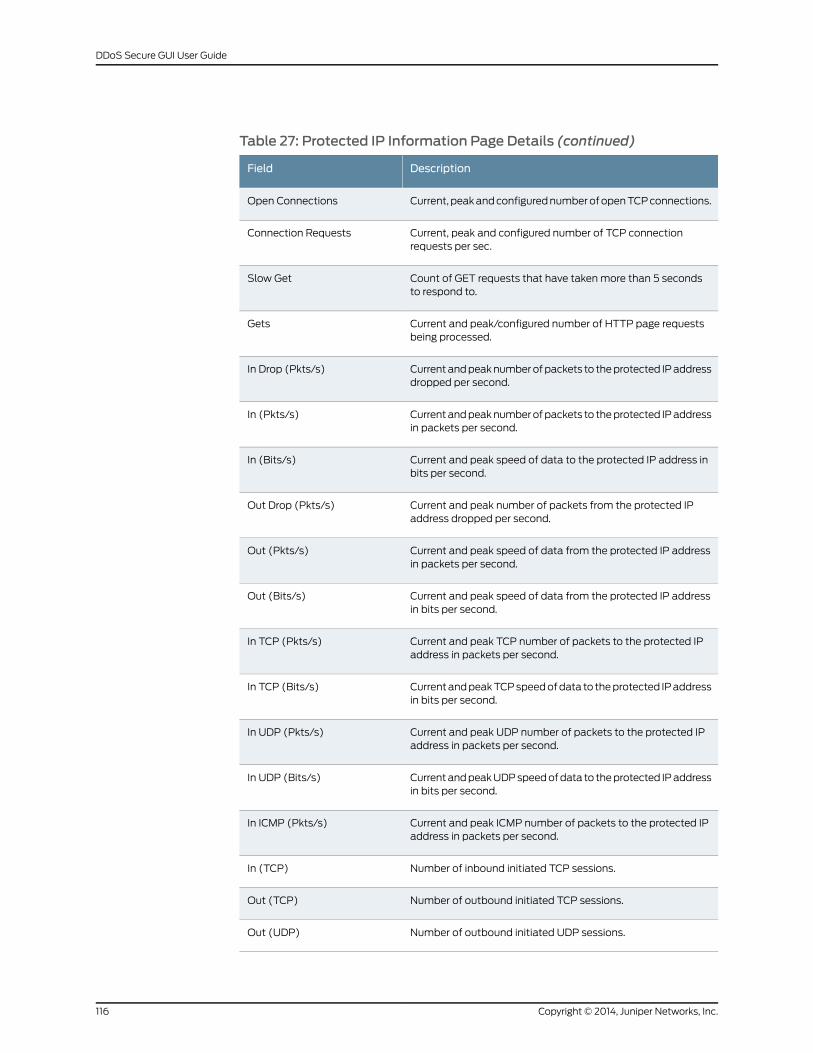
Table 27: Protected IP Information Page Details (continued)
DescriptionField
Current, peakandconfigurednumberofopenTCPconnections.Open Connections
Current, peak and configured number of TCP connectionrequests per sec.
Connection Requests
Count of GET requests that have takenmore than 5 secondsto respond to.
Slow Get
Current and peak/configured number of HTTP page requestsbeing processed.
Gets
Currentandpeaknumberofpackets to theprotected IPaddressdropped per second.
In Drop (Pkts/s)
Currentandpeaknumberofpackets to theprotected IPaddressin packets per second.
In (Pkts/s)
Current and peak speed of data to the protected IP address inbits per second.
In (Bits/s)
Current and peak number of packets from the protected IPaddress dropped per second.
Out Drop (Pkts/s)
Current and peak speed of data from the protected IP addressin packets per second.
Out (Pkts/s)
Current and peak speed of data from the protected IP addressin bits per second.
Out (Bits/s)
Current and peak TCP number of packets to the protected IPaddress in packets per second.
In TCP (Pkts/s)
CurrentandpeakTCPspeedofdata to theprotected IPaddressin bits per second.
In TCP (Bits/s)
Current and peak UDP number of packets to the protected IPaddress in packets per second.
In UDP (Pkts/s)
CurrentandpeakUDPspeedofdata to theprotected IPaddressin bits per second.
In UDP (Bits/s)
Current and peak ICMP number of packets to the protected IPaddress in packets per second.
In ICMP (Pkts/s)
Number of inbound initiated TCP sessions.In (TCP)
Number of outbound initiated TCP sessions.Out (TCP)
Number of outbound initiated UDP sessions.Out (UDP)
Copyright © 2014, Juniper Networks, Inc.116
DDoS Secure GUI User Guide
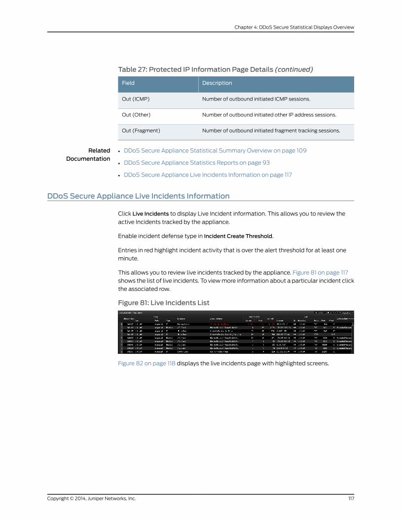
Table 27: Protected IP Information Page Details (continued)
DescriptionField
Number of outbound initiated ICMP sessions.Out (ICMP)
Number of outbound initiated other IP address sessions.Out (Other)
Number of outbound initiated fragment tracking sessions.Out (Fragment)
RelatedDocumentation
DDoS Secure Appliance Statistical Summary Overview on page 109•
• DDoS Secure Appliance Statistics Reports on page 93
• DDoS Secure Appliance Live Incidents Information on page 117
DDoS Secure Appliance Live Incidents Information
Click Live Incidents to display Live Incident information. This allows you to review the
active Incidents tracked by the appliance.
Enable incident defense type in Incident Create Threshold.
Entries in red highlight incident activity that is over the alert threshold for at least one
minute.
This allows you to review live incidents tracked by the appliance. Figure 81 on page 117
shows the list of live incidents. To viewmore information about a particular incident click
the associated row.
Figure 81: Live Incidents List
Figure 82 on page 118 displays the live incidents page with highlighted screens.
117Copyright © 2014, Juniper Networks, Inc.
Chapter 4: DDoS Secure Statistical Displays Overview

Figure 82: Live Incidents Page
• Green Screen—Incidents screen (minimized version than on page load)
• Blue Screen—Summary of specific incident
• Purple Screen—Graph of specific attack vector
• Yellow Screen—List source IP addresses involved in incident, (max 20 individual IP
addresses)
NOTE: The initial incident screen is shown ingreen.Theother screensappearwhen a specific incident is selected.
RelatedDocumentation
DDoS Secure Appliance Statistical Summary Overview on page 109•
• DDoS Secure Appliance Statistics Reports on page 93
• DDoS Secure ApplianceWorst Offenders Information on page 118
DDoS Secure ApplianceWorst Offenders Information
ClickWorst Offenders to display the list of worst offenders.
The central pane shows real-time status of theworst offending IP addresses, alongwith
the reason. Click the head of a column, the output is sorted by this column, with the
triangle indicator showing the sort direction.
Figure 83 on page 119 displays theWorst Offenders information page.
Copyright © 2014, Juniper Networks, Inc.118
DDoS Secure GUI User Guide
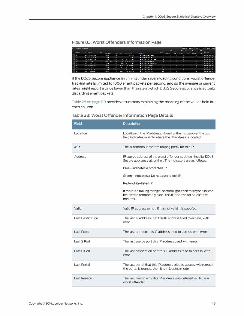
Figure 83:Worst Offenders Information Page
If the DDoS Secure appliance is running under severe loading conditions, worst offender
tracking rate is limited to 1000 errant packets per second, and so the average or current
ratesmight report a value lower than the rate atwhichDDoSSecure appliance is actually
discarding errant packets.
Table 28 on page 119 provides a summary explaining the meaning of the values held in
each column.
Table 28:Worst Offender Information Page Details
DescriptionField
Location of the IP address. Hovering the mouse over the Locfield indicates roughly where the IP address is located.
Location
The autonomous system routing prefix for this IP.AS#
IP source address of theworst offender as determinedbyDDoSSecure appliance algorithm. The indicators are as follows:
Blue—indicates a protected IP
Green—indicates a Do not auto-block IP
Red—white-listed IP
If there is a trailing triangle, bottom right, then this hyperlink canbe used to temporarily block this IP address for at least fiveminutes.
Address
Valid IP address or not. If it is not valid it is spoofed.Valid
The last IP address that this IP address tried to access, witherror.
Last Destination
The last protocol this IP address tried to access, with error.Last Proto
The last source port this IP address used, with error.Last S Port
The last destination port this IP address tried to access, witherror.
Last D Port
The last portal that this IP address tried to access, with error. Ifthe portal is orange, then it is in logging mode.
Last Portal
The last reason why this IP address was determined to be aworst offender.
Last Reason
119Copyright © 2014, Juniper Networks, Inc.
Chapter 4: DDoS Secure Statistical Displays Overview

Table 28:Worst Offender Information Page Details (continued)
DescriptionField
The number of times this IP address is identified as an attacker.Count
The current and peak packet rates per second.Rate (Pkts/s)
Thecurrentandpeakpacket ratesper secondof irritantattacks.Irritant Rate
The current and peak packet rates per second of resourceconsuming attacks.
Resource Usage Rate
The last time this IP address was determined to be a worstoffender.
Last Time
If the last reason column shows a folder icon, it can be expanded to drill down to the
breakout of the different types of Defense invoked against this IP address as shown in
Figure 84 on page 120.
Figure 84: Last Reason Expand Page
Click ResetWorst Offenders (top right side ofWorst Offenders table), to remove all the
worst offender entries.
To temporarily black-list a worst offender, select the IP address and click the triangle at
the bottom right of the cell. This displays the black-list dialog box. Click the dialog box
to confirm the action.
Once completed, the confirmation as shown in Figure 85 on page 120.
Figure 85: Temporarily Black List Confirmation
RelatedDocumentation
DDoS Secure Appliance Statistical Summary Overview on page 109•
• DDoS Secure Appliance Statistics Reports on page 93
• DDoS Secure Appliance Temporarily Black-Listed Information on page 121
Copyright © 2014, Juniper Networks, Inc.120
DDoS Secure GUI User Guide

DDoS Secure Appliance Temporarily Black-Listed Information
Click Temporarily Black Listed to display the temporarily black-listed information.
Figure 86 on page 121 displays the temporarily black-listed information.
Figure 86: IP Temporarily Black Listed Information Page
Table 29onpage 121 provides theparameters of theTemporarily Black Listed information
page.
Table 29: Temporarily Black Listed Information Page Details
DescriptionField
Location of the IP address. Hovering the mouse over the Loc fieldindicates roughly where the IP address is located.
Location
The autonomous system routing prefix for this IP address.AS#
IP address of the worst offender seen by DDoS Secure appliancealgorithm.
Address
Valid IP address or not. If it is not valid it is spoofed.Valid
The last IP address that this IP address tried to access.Last Protected
The last protocol that this IP address tried to access.Last Proto
The last source port that this IP address used.Last S Port
The last destination port that this IP address tried to access.Last D Port
The last portal that this IP address tried to access. If the portal isorange, then it is in logging mode.
Last Portal
The current and peak packet rates per second.Rate (Pkts/s)
The current and peak bit rates per second.Speed (Bits/s)
The number of packets dropped from this IP address.Count
The last time this IP address was blocked.Last Time
The reason why this IP address was temporarily black-listed.Reason
121Copyright © 2014, Juniper Networks, Inc.
Chapter 4: DDoS Secure Statistical Displays Overview
Tomanually remove an IP from the temporary black-list, select the IP address and click
the triangle at the bottom right of the cell. This displays the un-black-list dialog box,
whichmust be clicked to confirm the action. The confirmation screen appears as shown
in Figure 87 on page 122.
Figure 87: Black List Removal Confirmation
ClickPurgeBlack-Liston the top row towards the right, then all IP addresses are removed
from the auto black-list.
NOTE: Purge Black-Listwill also purge any dynamic BGP FlowSpec rules.
IPaddressesareautomatically removed fromtheautoblack-list IP listwhenDDoSSecure
appliance determines that it is safe to do. This is usually after five minutes of inactivity
for this IP address.
RelatedDocumentation
DDoS Secure Appliance Statistical Summary Overview on page 109•
• DDoS Secure Appliance Statistics Reports on page 93
• DDoS Secure Appliance Tracked IP Information on page 122
DDoS Secure Appliance Tracked IP Information
Click IP Tracked Info to display tracked information.
Figure 88 on page 122 displays the IP Tracked information.
Figure 88: IP Tracked Information Page
The central pane outputs some of the IP information used for CHARMcalculations. Each
entry has 22 parameters.
Table 30 on page 123 provides the parameters of the tracked IP information page.
Copyright © 2014, Juniper Networks, Inc.122
DDoS Secure GUI User Guide
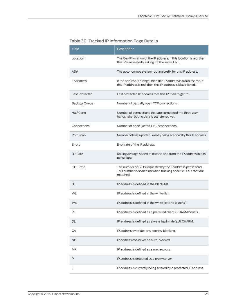
Table 30: Tracked IP Information Page Details
DescriptionField
The GeoIP location of the IP address. If this location is red, thenthis IP is repeatedly asking for the same URL.
Location
The autonomous system routing prefix for this IP address.AS#
If the address is orange, then this IP address is troublesome. Ifthis IP address is red, then this IP address is black-listed.
IP Address
Last protected IP address that this IP tried to get to.Last Protected
Number of partially open TCP connections.Backlog Queue
Number of connections that are completed the three wayhandshake, but no data is transferred yet.
Half Conn
Number of open (active) TCP connections.Connections
Numberofhosts/ports currentlybeingscannedby this IPaddress.Port Scan
Error rate of the IP address.Errors
Rolling average speed of data to and from the IP address in bitsper second.
Bit Rate
The number of GETs requested by the IP address per second.This number is scaled up when tracking specific URLs that arematched.
GET Rate
IP address is defined in the black-list.BL
IP address is defined in the white-list.WL
IP address is defined in the white-list (no logging).WN
IP address is defined as a preferred client (CHARM boost).PL
IP address is defined as always having default CHARM.DL
IP address overrides any country blocking.CA
IP address can never be auto-blocked.NB
IP address is defined as amega-proxy.MP
IP address is detected as a proxy server.P
IP address is currently being filtered by a protected IP address.F
123Copyright © 2014, Juniper Networks, Inc.
Chapter 4: DDoS Secure Statistical Displays Overview
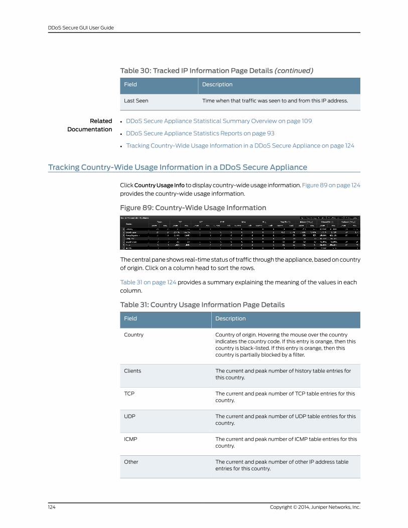
Table 30: Tracked IP Information Page Details (continued)
DescriptionField
Time when that traffic was seen to and from this IP address.Last Seen
RelatedDocumentation
DDoS Secure Appliance Statistical Summary Overview on page 109•
• DDoS Secure Appliance Statistics Reports on page 93
• Tracking Country-Wide Usage Information in a DDoS Secure Appliance on page 124
Tracking Country-Wide Usage Information in a DDoS Secure Appliance
ClickCountryUsage Info todisplay country-wideusage information. Figure89onpage 124
provides the country-wide usage information.
Figure 89: Country-Wide Usage Information
Thecentral paneshows real-timestatusof traffic through theappliance, basedoncountry
of origin. Click on a column head to sort the rows.
Table 31 on page 124 provides a summary explaining the meaning of the values in each
column.
Table 31: Country Usage Information Page Details
DescriptionField
Country of origin. Hovering the mouse over the countryindicates the country code. If this entry is orange, then thiscountry is black-listed. If this entry is orange, then thiscountry is partially blocked by a filter.
Country
The current and peak number of history table entries forthis country.
Clients
The current and peak number of TCP table entries for thiscountry.
TCP
The current and peak number of UDP table entries for thiscountry.
UDP
The current and peak number of ICMP table entries for thiscountry.
ICMP
The current and peak number of other IP address tableentries for this country.
Other
Copyright © 2014, Juniper Networks, Inc.124
DDoS Secure GUI User Guide
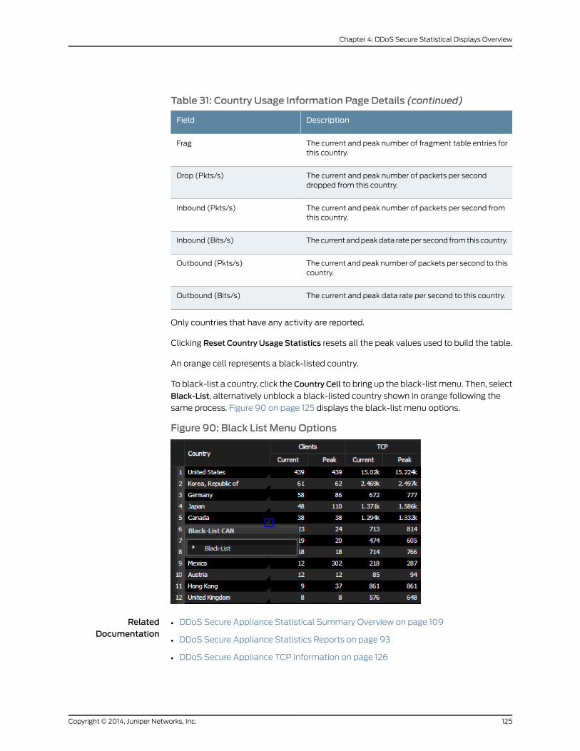
Table 31: Country Usage Information Page Details (continued)
DescriptionField
The current and peak number of fragment table entries forthis country.
Frag
The current and peak number of packets per seconddropped from this country.
Drop (Pkts/s)
The current and peak number of packets per second fromthis country.
Inbound (Pkts/s)
Thecurrentandpeakdata rateper second fromthis country.Inbound (Bits/s)
The current and peak number of packets per second to thiscountry.
Outbound (Pkts/s)
The current and peak data rate per second to this country.Outbound (Bits/s)
Only countries that have any activity are reported.
Clicking Reset Country Usage Statistics resets all the peak values used to build the table.
An orange cell represents a black-listed country.
To black-list a country, click theCountry Cell to bring up the black-listmenu. Then, select
Black-List, alternatively unblock a black-listed country shown in orange following the
same process. Figure 90 on page 125 displays the black-list menu options.
Figure 90: Black List Menu Options
RelatedDocumentation
DDoS Secure Appliance Statistical Summary Overview on page 109•
• DDoS Secure Appliance Statistics Reports on page 93
• DDoS Secure Appliance TCP Information on page 126
125Copyright © 2014, Juniper Networks, Inc.
Chapter 4: DDoS Secure Statistical Displays Overview
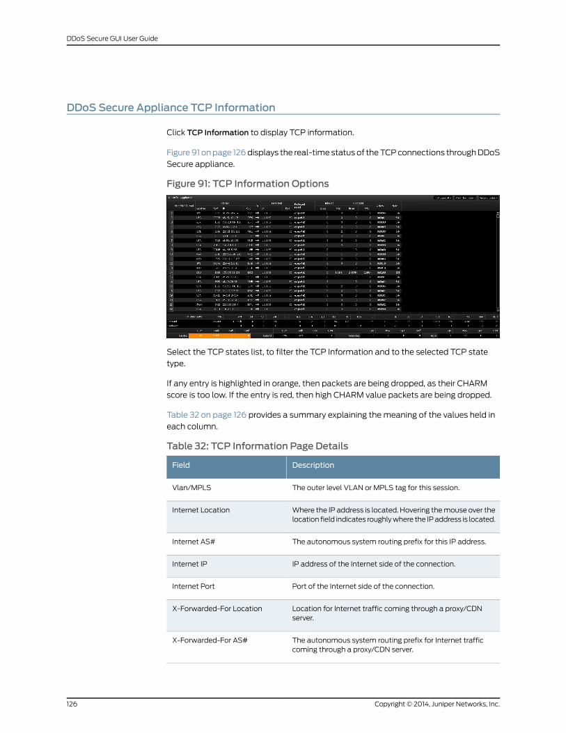
DDoS Secure Appliance TCP Information
Click TCP Information to display TCP information.
Figure91 onpage 126displays the real-time status of theTCPconnections throughDDoS
Secure appliance.
Figure 91: TCP Information Options
Select the TCP states list, to filter the TCP Information and to the selected TCP state
type.
If any entry is highlighted in orange, then packets are being dropped, as their CHARM
score is too low. If the entry is red, then high CHARM value packets are being dropped.
Table 32 on page 126 provides a summary explaining the meaning of the values held in
each column.
Table 32: TCP Information Page Details
DescriptionField
The outer level VLAN or MPLS tag for this session.Vlan/MPLS
Where the IP address is located. Hovering themouse over thelocation field indicates roughlywhere the IPaddress is located.
Internet Location
The autonomous system routing prefix for this IP address.Internet AS#
IP address of the Internet side of the connection.Internet IP
Port of the Internet side of the connection.Internet Port
Location for Internet traffic coming through a proxy/CDNserver.
X-Forwarded-For Location
The autonomous system routing prefix for Internet trafficcoming through a proxy/CDN server.
X-Forwarded-For AS#
Copyright © 2014, Juniper Networks, Inc.126
DDoS Secure GUI User Guide
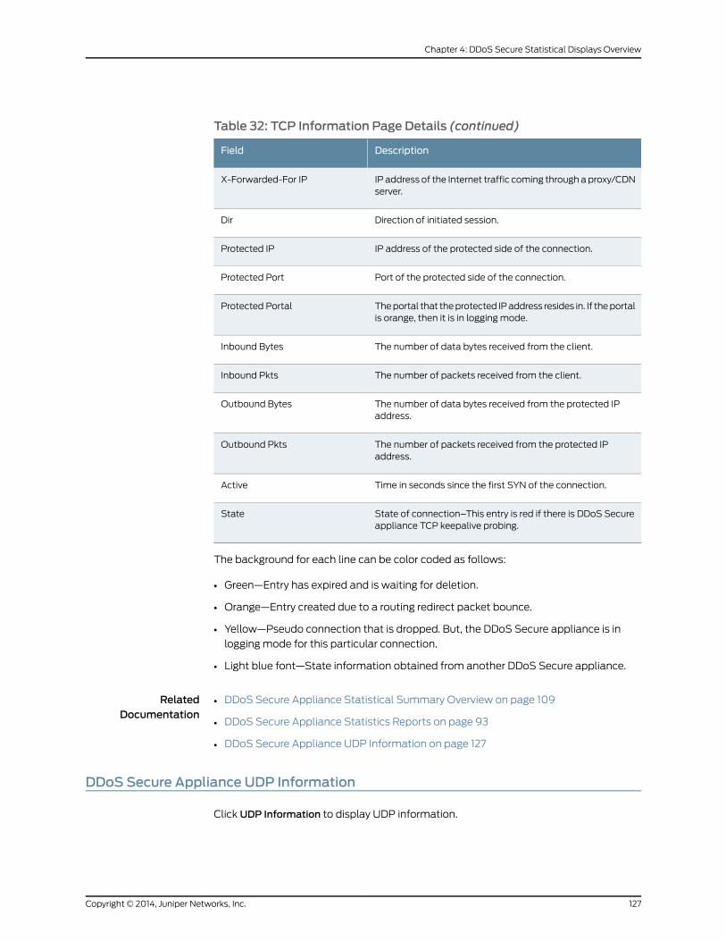
Table 32: TCP Information Page Details (continued)
DescriptionField
IP address of the Internet traffic coming throughaproxy/CDNserver.
X-Forwarded-For IP
Direction of initiated session.Dir
IP address of the protected side of the connection.Protected IP
Port of the protected side of the connection.Protected Port
Theportal that theprotected IPaddress resides in. If theportalis orange, then it is in logging mode.
Protected Portal
The number of data bytes received from the client.Inbound Bytes
The number of packets received from the client.Inbound Pkts
The number of data bytes received from the protected IPaddress.
Outbound Bytes
The number of packets received from the protected IPaddress.
Outbound Pkts
Time in seconds since the first SYN of the connection.Active
State of connection–This entry is red if there is DDoS Secureappliance TCP keepalive probing.
State
The background for each line can be color coded as follows:
• Green—Entry has expired and is waiting for deletion.
• Orange—Entry created due to a routing redirect packet bounce.
• Yellow—Pseudo connection that is dropped. But, the DDoS Secure appliance is in
logging mode for this particular connection.
• Light blue font—State information obtained from another DDoS Secure appliance.
RelatedDocumentation
DDoS Secure Appliance Statistical Summary Overview on page 109•
• DDoS Secure Appliance Statistics Reports on page 93
• DDoS Secure Appliance UDP Information on page 127
DDoS Secure Appliance UDP Information
Click UDP Information to display UDP information.
127Copyright © 2014, Juniper Networks, Inc.
Chapter 4: DDoS Secure Statistical Displays Overview
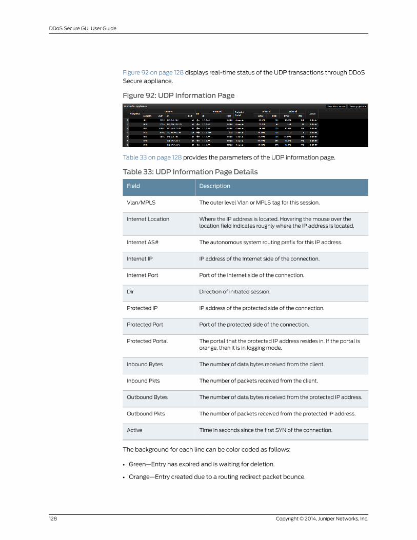
Figure 92 on page 128 displays real-time status of the UDP transactions through DDoS
Secure appliance.
Figure 92: UDP Information Page
Table 33 on page 128 provides the parameters of the UDP information page.
Table 33: UDP Information Page Details
DescriptionField
The outer level Vlan or MPLS tag for this session.Vlan/MPLS
Where the IP address is located. Hovering the mouse over thelocation field indicates roughly where the IP address is located.
Internet Location
The autonomous system routing prefix for this IP address.Internet AS#
IP address of the Internet side of the connection.Internet IP
Port of the Internet side of the connection.Internet Port
Direction of initiated session.Dir
IP address of the protected side of the connection.Protected IP
Port of the protected side of the connection.Protected Port
The portal that the protected IP address resides in. If the portal isorange, then it is in logging mode.
Protected Portal
The number of data bytes received from the client.Inbound Bytes
The number of packets received from the client.Inbound Pkts
The number of data bytes received from the protected IP address.Outbound Bytes
The number of packets received from the protected IP address.Outbound Pkts
Time in seconds since the first SYN of the connection.Active
The background for each line can be color coded as follows:
• Green—Entry has expired and is waiting for deletion.
• Orange—Entry created due to a routing redirect packet bounce.
Copyright © 2014, Juniper Networks, Inc.128
DDoS Secure GUI User Guide
• Yellow—Pseudo connection that is dropped. But, the DDoS Secure appliance is in
logging mode for this particular connection.
• Light blue font—State information obtained from another DDoS Secure appliance.
RelatedDocumentation
DDoS Secure Appliance Statistical Summary Overview on page 109•
• DDoS Secure Appliance Statistics Reports on page 93
• DDoS Secure Appliance ICMP Information on page 129
DDoS Secure Appliance ICMP Information
Click ICMP Information to display ICMP information.
Figure 93 on page 129 displays the real-time status of the ICMP transactions through
DDoS Secure appliance.
Figure 93: ICMP Information Page
Table 34 on page 129 provides the parameters of the ICMP information page.
Table 34: ICMP Information Page Details
DescriptionField
The outer level VLAN or MPLS tag for this session.Vlan/MPLS
Where the IP address is located. Hovering the mouse over thelocation field indicates roughly where the IP address is located.
Internet Location
The autonomous system routing prefix for this IP address.Internet AS#
IP address of the Internet side of the connection.Internet IP
Direction of initiated session.Dir
IP address of the protected side of the connection.Protected IP
ICMP type or code.Type: Code
129Copyright © 2014, Juniper Networks, Inc.
Chapter 4: DDoS Secure Statistical Displays Overview
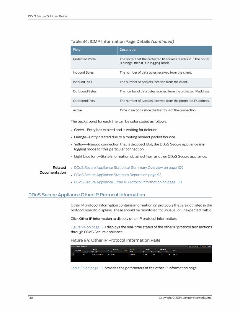
Table 34: ICMP Information Page Details (continued)
DescriptionField
The portal that the protected IP address resides in. If the portalis orange, then it is in logging mode.
Protected Portal
The number of data bytes received from the client.Inbound Bytes
The number of packets received from the client.Inbound Pkts
Thenumberofdatabytes received fromtheprotected IPaddress.Outbound Bytes
The number of packets received from the protected IP address.Outbound Pkts
Time in seconds since the first SYN of the connection.Active
The background for each line can be color coded as follows:
• Green—Entry has expired and is waiting for deletion.
• Orange—Entry created due to a routing redirect packet bounce.
• Yellow—Pseudo connection that is dropped. But, the DDoS Secure appliance is in
logging mode for this particular connection.
• Light blue font—State information obtained from another DDoS Secure appliance.
RelatedDocumentation
DDoS Secure Appliance Statistical Summary Overview on page 109•
• DDoS Secure Appliance Statistics Reports on page 93
• DDoS Secure Appliance Other IP Protocol Information on page 130
DDoS Secure Appliance Other IP Protocol Information
Other IP protocol information contains information on protocols that are not listed in the
protocol specific displays. These should bemonitored for unusual or unexpected traffic.
ClickOther IP Information to display other IP protocol information.
Figure 94 on page 130 displays the real-time status of the other IP protocol transactions
through DDoS Secure appliance.
Figure 94: Other IP Protocol Information Page
Table 35 on page 131 provides the parameters of the other IP information page.
Copyright © 2014, Juniper Networks, Inc.130
DDoS Secure GUI User Guide
Table 35: Other IP Information Page Details
DescriptionField
The VLAN, or MPLS label associated with this connection.Vlan/MPLS
Where the IP address is located. Hovering the mouse over thelocation field indicates roughly where the IP address is located.
Internet Location
The autonomous system routing prefix for this IP.Internet AS#
IP address of the Internet side of the connection.Internet IP
Direction of initiated session.Dir
IP address of the protected side of the connection.Protected IP
IP protocol in use.Proto
Theportal that theprotected IP resides in. If theportal is orange,then it is in logging mode.
Protected Portal
The number of data bytes received from the client.Inbound Bytes
The number of packets received from the client.Inbound Pkts
The number of data bytes received from the protected IP.Outbound Bytes
The number of packets received from the protected IP.Outbound Pkts
Time in seconds since the first SYN of the connection.Active
The background for each line can be color coded as follows:
• Green—Entry has expired and is waiting for deletion.
• Orange—Entry created due to a routing redirect packet bounce.
• Yellow—Pseudo connection that is normally dropped. But, theDDoSSecure appliance
is in logging mode for this particular connection.
• Light blue font—State information obtained from another DDoS Secure appliance.
Details of protocol numbers can be found at:
http://www.iana.org/assignments/protocol-numbers/protocol-numbers.xml#protocol-numbers-1.
RelatedDocumentation
DDoS Secure Appliance Statistical Summary Overview on page 109•
• DDoS Secure Appliance Statistics Reports on page 93
• DDoS Secure Appliance Fragment Information on page 132
131Copyright © 2014, Juniper Networks, Inc.
Chapter 4: DDoS Secure Statistical Displays Overview
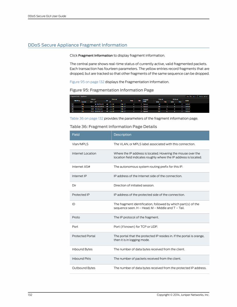
DDoS Secure Appliance Fragment Information
Click Fragment Information to display fragment information.
The central pane shows real-time status of currently active, valid fragmented packets.
Each transaction has fourteen parameters. The yellow entries record fragments that are
dropped, but are tracked so that other fragments of the same sequence can be dropped.
Figure 95 on page 132 displays the Fragmentation Information.
Figure 95: Fragmentation Information Page
Table 36 on page 132 provides the parameters of the fragment information page.
Table 36: Fragment Information Page Details
DescriptionField
The VLAN, or MPLS label associated with this connection.Vlan/MPLS
Where the IP address is located. Hovering the mouse over thelocation field indicates roughly where the IP address is located.
Internet Location
The autonomous system routing prefix for this IP.Internet AS#
IP address of the Internet side of the connection.Internet IP
Direction of initiated session.Dir
IP address of the protected side of the connection.Protected IP
The fragment identification, followed by which part(s) of thesequence seen. H – Head, M –Middle and T – Tail.
ID
The IP protocol of the fragment.Proto
Port (if known) for TCP or UDP.Port
The portal that the protected IP resides in. If the portal is orange,then it is in logging mode.
Protected Portal
The number of data bytes received from the client.Inbound Bytes
The number of packets received from the client.Inbound Pkts
The number of data bytes received from the protected IP address.Outbound Bytes
Copyright © 2014, Juniper Networks, Inc.132
DDoS Secure GUI User Guide
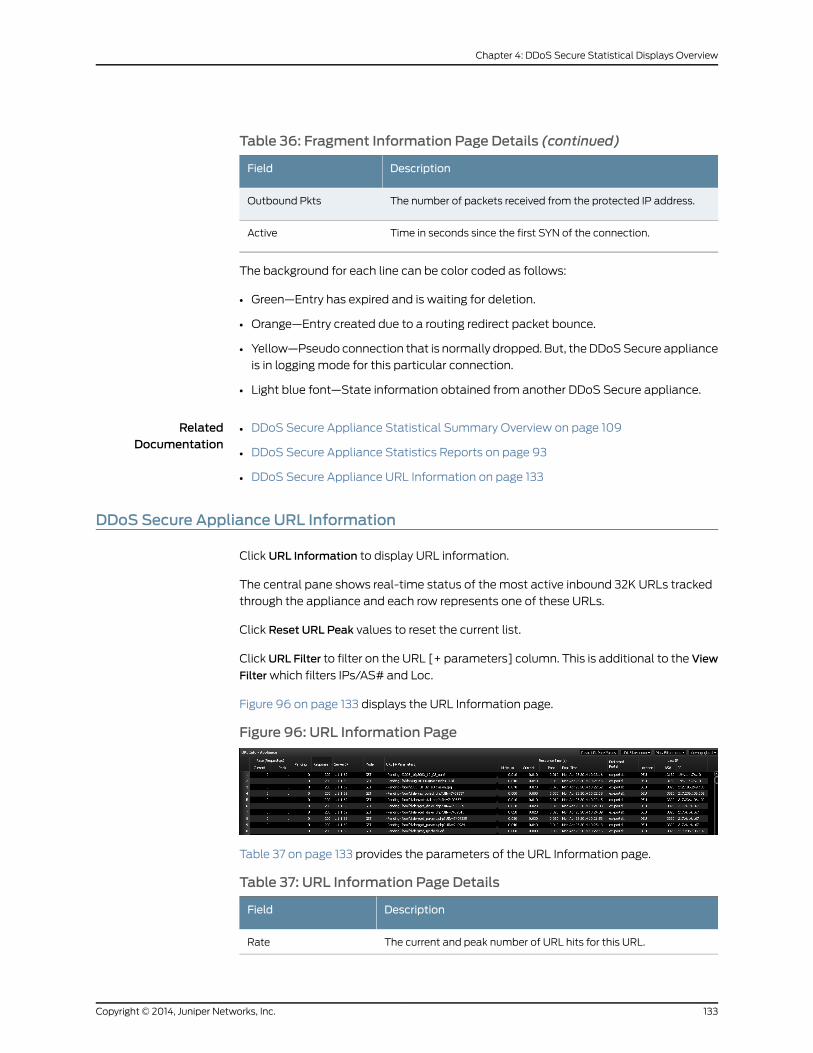
Table 36: Fragment Information Page Details (continued)
DescriptionField
The number of packets received from the protected IP address.Outbound Pkts
Time in seconds since the first SYN of the connection.Active
The background for each line can be color coded as follows:
• Green—Entry has expired and is waiting for deletion.
• Orange—Entry created due to a routing redirect packet bounce.
• Yellow—Pseudo connection that is normally dropped. But, theDDoSSecure appliance
is in logging mode for this particular connection.
• Light blue font—State information obtained from another DDoS Secure appliance.
RelatedDocumentation
DDoS Secure Appliance Statistical Summary Overview on page 109•
• DDoS Secure Appliance Statistics Reports on page 93
• DDoS Secure Appliance URL Information on page 133
DDoS Secure Appliance URL Information
Click URL Information to display URL information.
The central pane shows real-time status of the most active inbound 32K URLs tracked
through the appliance and each row represents one of these URLs.
Click Reset URL Peak values to reset the current list.
ClickURL Filter to filter on the URL [+ parameters] column. This is additional to the View
Filterwhich filters IPs/AS# and Loc.
Figure 96 on page 133 displays the URL Information page.
Figure 96: URL Information Page
Table 37 on page 133 provides the parameters of the URL Information page.
Table 37: URL Information Page Details
DescriptionField
The current and peak number of URL hits for this URL.Rate
133Copyright © 2014, Juniper Networks, Inc.
Chapter 4: DDoS Secure Statistical Displays Overview
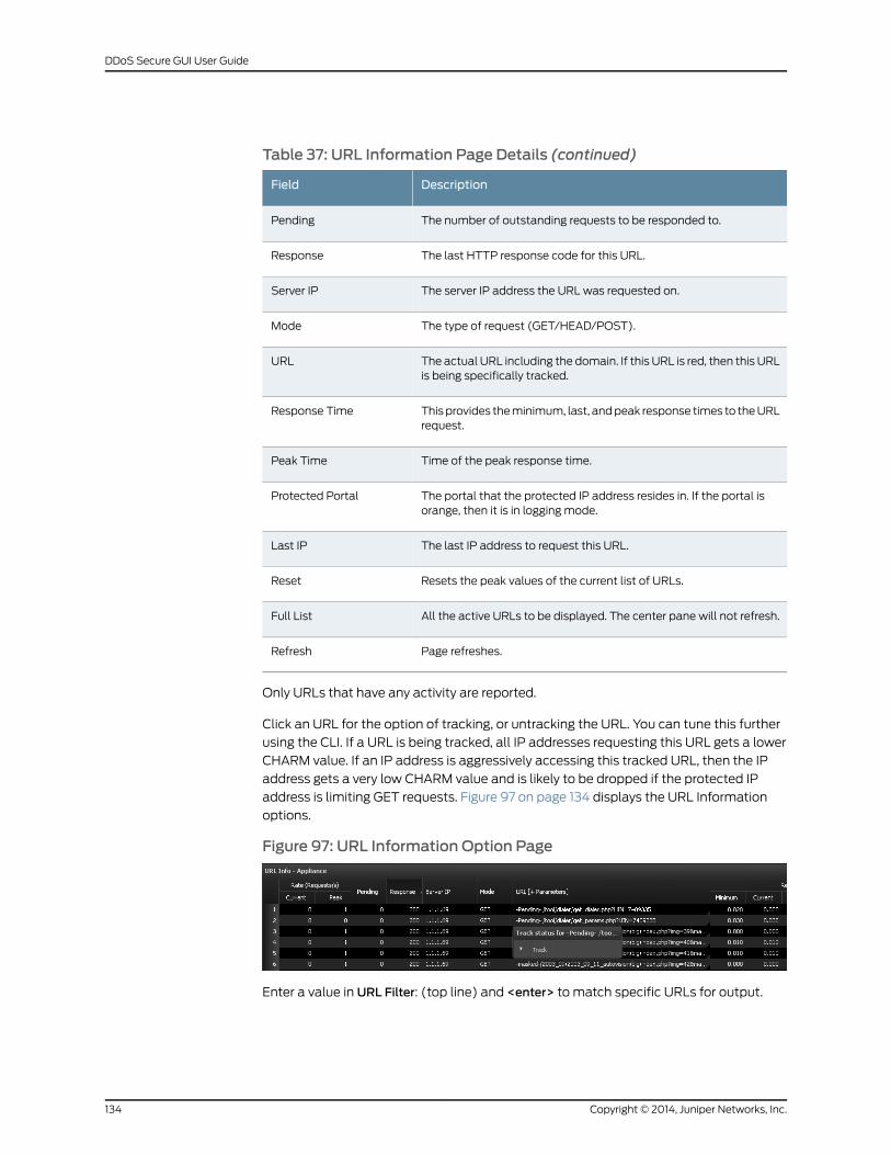
Table 37: URL Information Page Details (continued)
DescriptionField
The number of outstanding requests to be responded to.Pending
The last HTTP response code for this URL.Response
The server IP address the URL was requested on.Server IP
The type of request (GET/HEAD/POST).Mode
The actual URL including the domain. If this URL is red, then this URLis being specifically tracked.
URL
Thisprovides theminimum, last, andpeak response times to theURLrequest.
Response Time
Time of the peak response time.Peak Time
The portal that the protected IP address resides in. If the portal isorange, then it is in logging mode.
Protected Portal
The last IP address to request this URL.Last IP
Resets the peak values of the current list of URLs.Reset
All the active URLs to be displayed. The center pane will not refresh.Full List
Page refreshes.Refresh
Only URLs that have any activity are reported.
Click an URL for the option of tracking, or untracking the URL. You can tune this further
using the CLI. If a URL is being tracked, all IP addresses requesting this URL gets a lower
CHARM value. If an IP address is aggressively accessing this tracked URL, then the IP
address gets a very low CHARM value and is likely to be dropped if the protected IP
address is limiting GET requests. Figure 97 on page 134 displays the URL Information
options.
Figure 97: URL Information Option Page
Enter a value in URL Filter: (top line) and <enter> to match specific URLs for output.
Copyright © 2014, Juniper Networks, Inc.134
DDoS Secure GUI User Guide
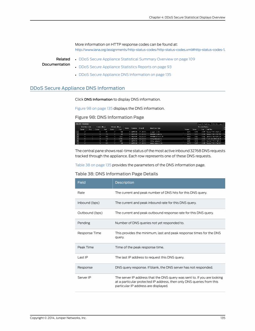
More information on HTTP response codes can be found at:
http://www.iana.org/assignments/http-status-codes/http-status-codes.xml#http-status-codes-1.
RelatedDocumentation
DDoS Secure Appliance Statistical Summary Overview on page 109•
• DDoS Secure Appliance Statistics Reports on page 93
• DDoS Secure Appliance DNS Information on page 135
DDoS Secure Appliance DNS Information
Click DNS Information to display DNS information.
Figure 98 on page 135 displays the DNS information.
Figure 98: DNS Information Page
Thecentral pane shows real-timestatusof themost active inbound32768DNS requests
tracked through the appliance. Each row represents one of these DNS requests.
Table 38 on page 135 provides the parameters of the DNS information page.
Table 38: DNS Information Page Details
DescriptionField
The current and peak number of DNS hits for this DNS query.Rate
The current and peak inbound rate for this DNS query.Inbound (bps)
The current and peak outbound response rate for this DNS query.Outbound (bps)
Number of DNS queries not yet responded to.Pending
This provides the minimum, last and peak response times for the DNSquery.
Response Time
Time of the peak response time.Peak Time
The last IP address to request this DNS query.Last IP
DNS query response. If blank, the DNS server has not responded.Response
The server IP address that the DNS query was sent to. If you are lookingat a particular protected IP address, then only DNS queries from thisparticular IP address are displayed.
Server IP
135Copyright © 2014, Juniper Networks, Inc.
Chapter 4: DDoS Secure Statistical Displays Overview
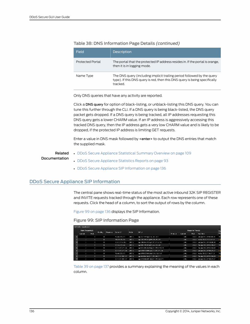
Table 38: DNS Information Page Details (continued)
DescriptionField
Theportal that theprotected IP address resides in. If the portal is orange,then it is in logging mode.
Protected Portal
The DNS query (including implicit trailing period followed by the querytype). If this DNS query is red, then this DNS query is being specificallytracked.
Name Type
Only DNS queries that have any activity are reported.
Click a DNS query for option of black-listing, or unblack-listing this DNS query. You can
tune this further through the CLI. If a DNS query is being black-listed, the DNS query
packet gets dropped. If a DNS query is being tracked, all IP addresses requesting this
DNS query gets a lower CHARM value. If an IP address is aggressively accessing this
tracked DNS query, then the IP address gets a very low CHARM value and is likely to be
dropped, if the protected IP address is limiting GET requests.
Enter a value in DNSmask followed by <enter> to output the DNS entries that match
the supplied mask.
RelatedDocumentation
DDoS Secure Appliance Statistical Summary Overview on page 109•
• DDoS Secure Appliance Statistics Reports on page 93
• DDoS Secure Appliance SIP Information on page 136
DDoS Secure Appliance SIP Information
The central pane shows real-time status of the most active inbound 32K SIP REGISTER
and INVITE requests tracked through the appliance. Each row represents one of these
requests. Click the head of a column, to sort the output of rows by the column.
Figure 99 on page 136 displays the SIP Information.
Figure 99: SIP Information Page
Table 39 on page 137 provides a summary explaining the meaning of the values in each
column.
Copyright © 2014, Juniper Networks, Inc.136
DDoS Secure GUI User Guide
Table 39: SIP Information Page Details
DescriptionField
The current and peak number of requests for this SIP URI.Rate
Number of SIP queries not yet responded to.Pending
This gives the minimum, last and peak response times for the SIP request.Response Time
Time of the peak response time.Peak Time
The last IP address to send this request.Last IP
The last response code for this request. No code indicates that the serverhas yet to issue a response.
Response
The server IP address the request was sent to.Server IP
The portal that the protected IP address resides in. If the portal is orange,then it is in logging mode.
Protected Portal
The type of request (REGISTER or INVITE).Mode
The SIP URI concerning the request. In the case of REGISTER, this is the URIbeing registered. If the request is an INVITE, this is the URI to which theinvitation is being sent.
SIP URI
The current and peak number of requests for this SIP URI.Rate
Number of SIP queries not yet responded to.Pending
This gives the minimum, last and peak response times for the SIP request.Response Time
Click a SIP URI to track or untrack the request. You can further tune this setting through
the CLI. If a SIP request is being tracked, all IP addresses requesting this URI get a lower
CHARM value. If an IP address is aggressively requesting this tracked SIP URI, then the
IP address gets a very low CHARM value and is likely to be dropped, if the protected IP
address is limiting GET requests.
Enter a value in SIP Filter followed by <enter>. Output the SIP requests with URIs that
match the supplied mask.
RelatedDocumentation
DDoS Secure Appliance Statistical Summary Overview on page 109•
• DDoS Secure Appliance Statistics Reports on page 93
• DDoS Secure Appliance Bandwidth Information on page 138
137Copyright © 2014, Juniper Networks, Inc.
Chapter 4: DDoS Secure Statistical Displays Overview
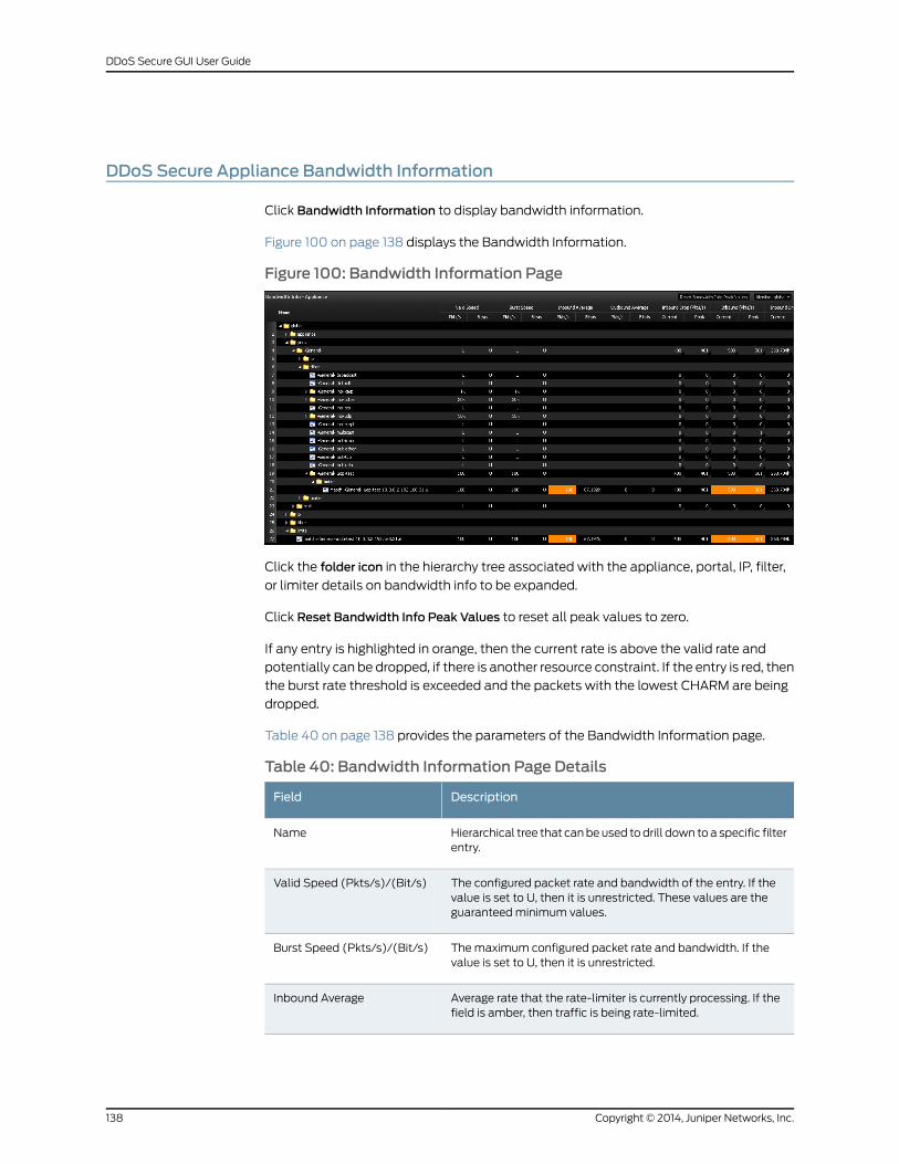
DDoS Secure Appliance Bandwidth Information
Click Bandwidth Information to display bandwidth information.
Figure 100 on page 138 displays the Bandwidth Information.
Figure 100: Bandwidth Information Page
Click the folder icon in the hierarchy tree associated with the appliance, portal, IP, filter,
or limiter details on bandwidth info to be expanded.
Click Reset Bandwidth Info Peak Values to reset all peak values to zero.
If any entry is highlighted in orange, then the current rate is above the valid rate and
potentially can be dropped, if there is another resource constraint. If the entry is red, then
the burst rate threshold is exceeded and the packets with the lowest CHARM are being
dropped.
Table 40 on page 138 provides the parameters of the Bandwidth Information page.
Table 40: Bandwidth Information Page Details
DescriptionField
Hierarchical tree that canbeused todrill down toa specific filterentry.
Name
The configured packet rate and bandwidth of the entry. If thevalue is set to U, then it is unrestricted. These values are theguaranteedminimum values.
Valid Speed (Pkts/s)/(Bit/s)
Themaximum configured packet rate and bandwidth. If thevalue is set to U, then it is unrestricted.
Burst Speed (Pkts/s)/(Bit/s)
Average rate that the rate-limiter is currently processing. If thefield is amber, then traffic is being rate-limited.
Inbound Average
Copyright © 2014, Juniper Networks, Inc.138
DDoS Secure GUI User Guide
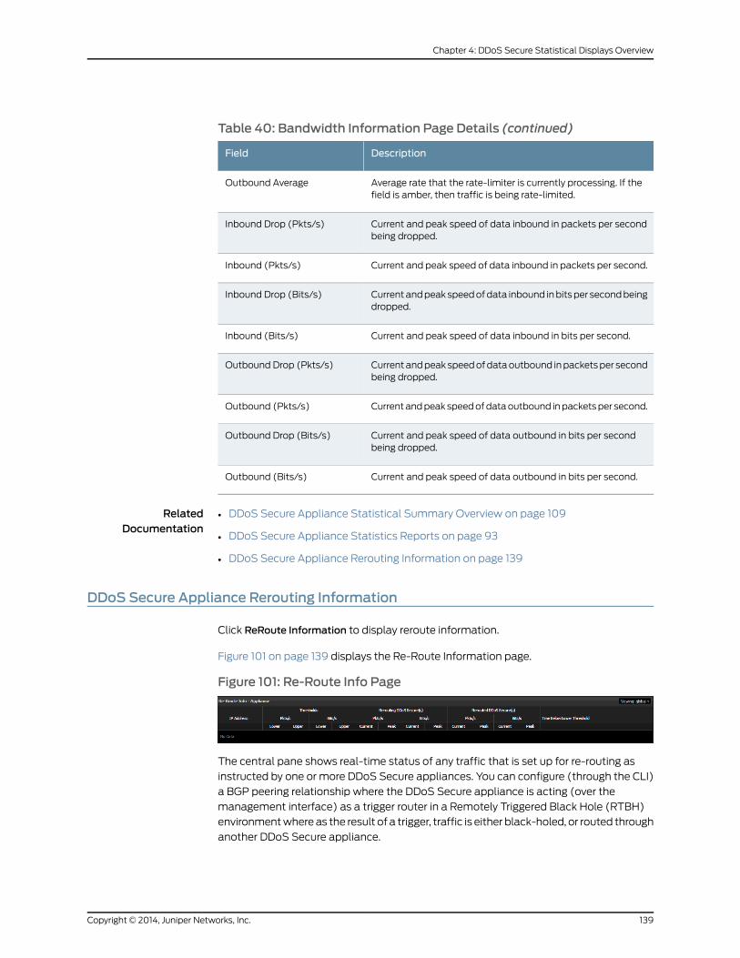
Table 40: Bandwidth Information Page Details (continued)
DescriptionField
Average rate that the rate-limiter is currently processing. If thefield is amber, then traffic is being rate-limited.
Outbound Average
Current and peak speed of data inbound in packets per secondbeing dropped.
Inbound Drop (Pkts/s)
Current and peak speed of data inbound in packets per second.Inbound (Pkts/s)
Currentandpeakspeedofdata inbound inbitsper secondbeingdropped.
Inbound Drop (Bits/s)
Current and peak speed of data inbound in bits per second.Inbound (Bits/s)
Currentandpeakspeedofdataoutbound inpacketsper secondbeing dropped.
Outbound Drop (Pkts/s)
Currentandpeakspeedofdataoutbound inpacketsper second.Outbound (Pkts/s)
Current and peak speed of data outbound in bits per secondbeing dropped.
Outbound Drop (Bits/s)
Current and peak speed of data outbound in bits per second.Outbound (Bits/s)
RelatedDocumentation
DDoS Secure Appliance Statistical Summary Overview on page 109•
• DDoS Secure Appliance Statistics Reports on page 93
• DDoS Secure Appliance Rerouting Information on page 139
DDoS Secure Appliance Rerouting Information
Click ReRoute Information to display reroute information.
Figure 101 on page 139 displays the Re-Route Information page.
Figure 101: Re-Route Info Page
The central pane shows real-time status of any traffic that is set up for re-routing as
instructed by one or more DDoS Secure appliances. You can configure (through the CLI)
a BGP peering relationship where the DDoS Secure appliance is acting (over the
management interface) as a trigger router in a Remotely Triggered Black Hole (RTBH)
environmentwhereas the result of a trigger, traffic is either black-holed, or routed through
another DDoS Secure appliance.
139Copyright © 2014, Juniper Networks, Inc.
Chapter 4: DDoS Secure Statistical Displays Overview
IP addresses can be configured for permanent rerouting (through the CLI); or, if an IP
address goes over the upper rerouting threshold that is defined for the IP address portal,
it then gets added into the rerouting tables and then adds in the IP address to the BGP
routing tables as a trigger. If not permanently configured, the IP address drops out of the
rerouting tables when below the lower rerouting threshold for 5 minutes.
Table 41 on page 140 provides the parameters of the re-route information page.
Table 41: Re-Route Information Page Details
DescriptionField
The IP address that is being re-routed.IP Address
The portal that the protected IP address resides in. If the portalis orange, then it is in logging mode.
Portal
The IP address of the appliance that requested the re-routing.ReRouter
The lower and upper thresholds (packets per sec) for this IP asdetermined from its portal. If 0, then this IP address ispermanently configure for re-routing.
Thresholds (Pkts/s)
The lower and upper thresholds (speed) for this IP address asdetermined from its portal. If 0, then this IP is permanentlyconfigured for re-routing.
Thresholds (Bits/s)
Current and peak packet packets detected as determined bythe DDoS Secure appliance triggering the re-routing.
ReRouting DDoS Secure(s)(Pkts/s)
Current and peak speed as determined by the DDoS Secureappliance triggering the re-routing.
ReRouting DDoS Secure(s)appliance(s) (Bits/s)
Current and peak packet packets per sec as determined by theDDoS Secure appliance handling the re-routing.
ReRouted DDoS Secure(s)(Pkts/s)
Current and peak speed as determined by the DDoS Secureappliance handling the re-routing.
ReRouted DDoS Secure(s)(Bits/s)
The time when this re-routed IP has been below both the lowerpps and bps thresholds.
Time Below Lower Threshold
RelatedDocumentation
DDoS Secure Appliance Statistical Summary Overview on page 109•
• DDoS Secure Appliance Statistics Reports on page 93
• DDoS Secure BGP FlowSpec Information on page 140
• DDoS Secure Appliance MAC Information on page 143
DDoS Secure BGP FlowSpec Information
Click BGP FlowSpec Information to display BGP FlowSpec information.
Copyright © 2014, Juniper Networks, Inc.140
DDoS Secure GUI User Guide
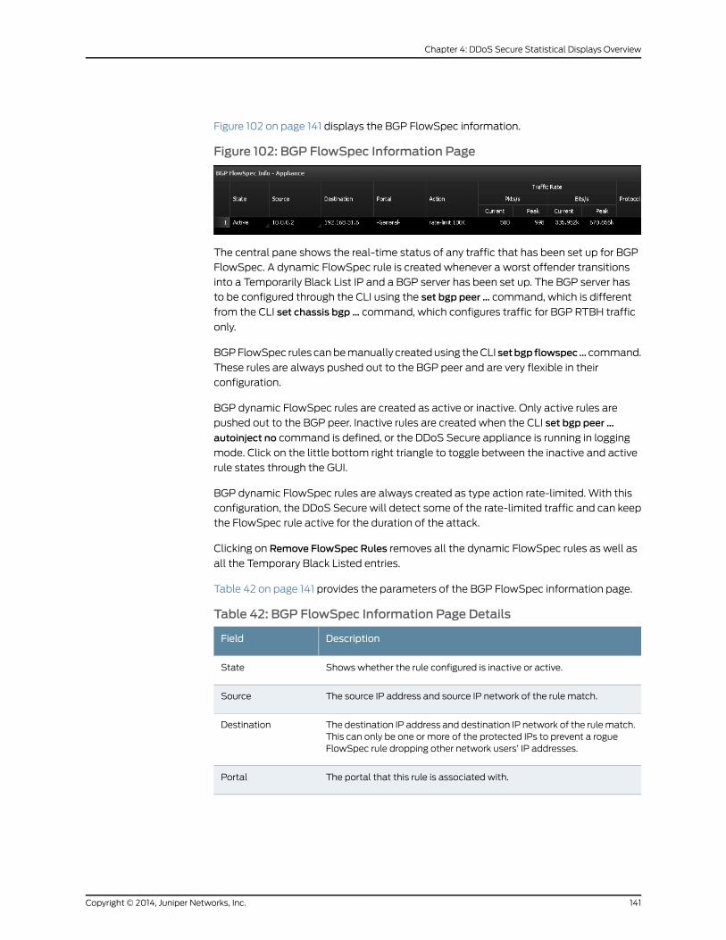
Figure 102 on page 141 displays the BGP FlowSpec information.
Figure 102: BGP FlowSpec Information Page
The central pane shows the real-time status of any traffic that has been set up for BGP
FlowSpec. A dynamic FlowSpec rule is created whenever a worst offender transitions
into a Temporarily Black List IP and a BGP server has been set up. The BGP server has
to be configured through the CLI using the set bgp peer … command, which is different
from the CLI set chassis bgp … command, which configures traffic for BGP RTBH traffic
only.
BGPFlowSpec rules canbemanually createdusing theCLI setbgpflowspec… command.
These rules are always pushed out to the BGP peer and are very flexible in their
configuration.
BGP dynamic FlowSpec rules are created as active or inactive. Only active rules are
pushed out to the BGP peer. Inactive rules are created when the CLI set bgp peer …
autoinject no command is defined, or the DDoS Secure appliance is running in logging
mode. Click on the little bottom right triangle to toggle between the inactive and active
rule states through the GUI.
BGP dynamic FlowSpec rules are always created as type action rate-limited. With this
configuration, the DDoS Secure will detect some of the rate-limited traffic and can keep
the FlowSpec rule active for the duration of the attack.
Clicking on Remove FlowSpec Rules removes all the dynamic FlowSpec rules as well as
all the Temporary Black Listed entries.
Table 42 on page 141 provides the parameters of the BGP FlowSpec information page.
Table 42: BGP FlowSpec Information Page Details
DescriptionField
Shows whether the rule configured is inactive or active.State
The source IP address and source IP network of the rule match.Source
The destination IP address and destination IP network of the rulematch.This can only be one or more of the protected IPs to prevent a rogueFlowSpec rule dropping other network users’ IP addresses.
Destination
The portal that this rule is associated with.Portal
141Copyright © 2014, Juniper Networks, Inc.
Chapter 4: DDoS Secure Statistical Displays Overview

Table 42: BGP FlowSpec Information Page Details (continued)
DescriptionField
This can be one of the following:
• accept—Accept and pass this packet.
• discard—Discard this packet.
• redirect—Redirect this packet to the VRFmatching BGPCommunity:Number.
• rate-limit—Rate-limit to threshold (bps).
• sample—Sample this packet (for Netflow and so on) and/or log it.
• terminal—Stop processing packet matches.
• sample-terminal—Sample this packet and stop processing packetmatches.
Action
Current or peak traffic rates being seen by the DDoS Secure appliancethat match this FlowSpec rule.
Traffic Rate
Protocols to bematched for this FlowSpec rule.Protocol
Fragmented packet types to bematched for this FlowSpec rule.Fragmentation
Source ports of a TCP/UDP session to bematched for this FlowSpecrule.
Src Port
Destination ports of aTCP/UDPsession to bematched for this FlowSpecrule.
Dst Port
TCP flags (for example, SYN) of a TCP session to bematched for thisFlowSpec rule.
Tcp Flags
ICMP types of an ICMP session to bematched for this FlowSpec rule.Icmp Type
ICMP codes of an ICMP session to bematched for this FlowSpec rule.Icmp Code
DSCP values of an IP session to bematched for this FlowSpec rule.DSCP
Packet length specification of an IP session to bematched for thisFlowSpec rule.
Length
An indication as to when the FlowSpec rule is likely to expire.Time Below LowerThreshold
RelatedDocumentation
DDoS Secure Appliance Statistical Summary Overview on page 109•
• DDoS Secure Appliance Statistics Reports on page 93
• DDoS Secure Appliance MAC Information on page 143
Copyright © 2014, Juniper Networks, Inc.142
DDoS Secure GUI User Guide
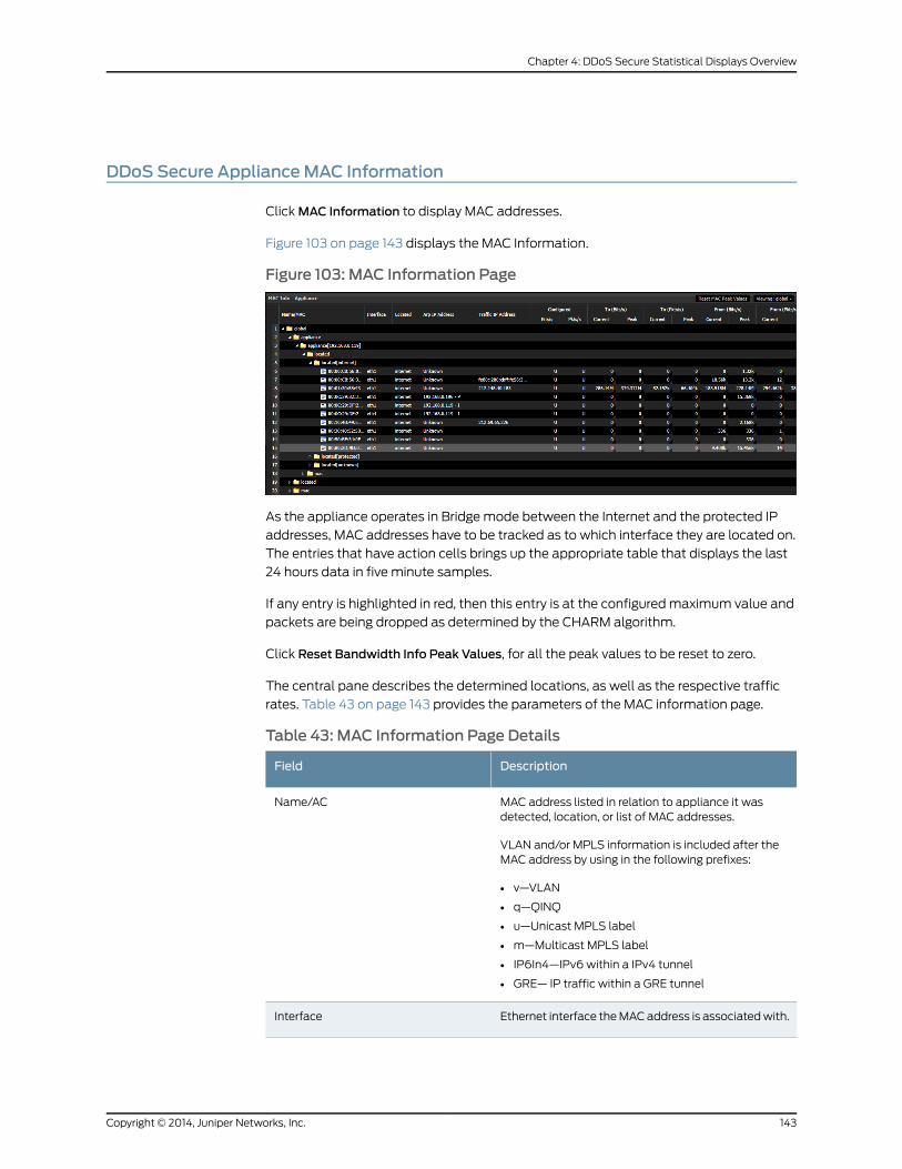
DDoS Secure ApplianceMAC Information
ClickMAC Information to display MAC addresses.
Figure 103 on page 143 displays the MAC Information.
Figure 103: MAC Information Page
As the appliance operates in Bridge mode between the Internet and the protected IP
addresses, MAC addresses have to be tracked as to which interface they are located on.
The entries that have action cells brings up the appropriate table that displays the last
24 hours data in five minute samples.
If any entry is highlighted in red, then this entry is at the configuredmaximum value and
packets are being dropped as determined by the CHARM algorithm.
Click Reset Bandwidth Info Peak Values, for all the peak values to be reset to zero.
The central pane describes the determined locations, as well as the respective traffic
rates. Table 43 on page 143 provides the parameters of the MAC information page.
Table 43: MAC Information Page Details
DescriptionField
MAC address listed in relation to appliance it wasdetected, location, or list of MAC addresses.
VLAN and/or MPLS information is included after theMAC address by using in the following prefixes:
• v—VLAN
• q—QINQ
• u—Unicast MPLS label
• m—Multicast MPLS label
• IP6In4—IPv6 within a IPv4 tunnel
• GRE— IP traffic within a GRE tunnel
Name/AC
Ethernet interface theMACaddress is associatedwith.Interface
143Copyright © 2014, Juniper Networks, Inc.
Chapter 4: DDoS Secure Statistical Displays Overview
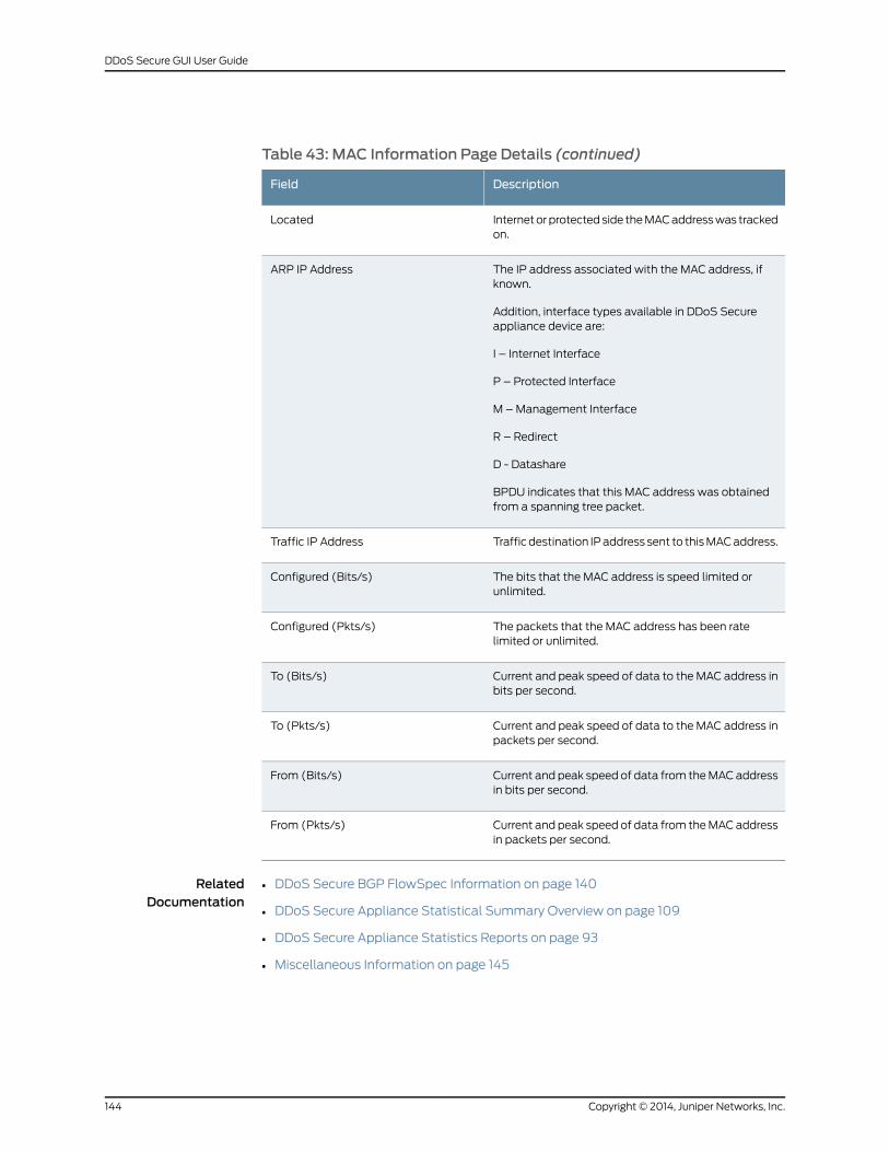
Table 43: MAC Information Page Details (continued)
DescriptionField
Internetorprotectedside theMACaddresswas trackedon.
Located
The IP address associated with the MAC address, ifknown.
Addition, interface types available in DDoS Secureappliance device are:
I – Internet Interface
P – Protected Interface
M –Management Interface
R – Redirect
D - Datashare
BPDU indicates that this MAC address was obtainedfrom a spanning tree packet.
ARP IP Address
Trafficdestination IPaddress sent to thisMACaddress.Traffic IP Address
The bits that the MAC address is speed limited orunlimited.
Configured (Bits/s)
The packets that the MAC address has been ratelimited or unlimited.
Configured (Pkts/s)
Current and peak speed of data to the MAC address inbits per second.
To (Bits/s)
Current and peak speed of data to the MAC address inpackets per second.
To (Pkts/s)
Current and peak speed of data from theMACaddressin bits per second.
From (Bits/s)
Current and peak speed of data from theMACaddressin packets per second.
From (Pkts/s)
RelatedDocumentation
DDoS Secure BGP FlowSpec Information on page 140•
• DDoS Secure Appliance Statistical Summary Overview on page 109
• DDoS Secure Appliance Statistics Reports on page 93
• Miscellaneous Information on page 145
Copyright © 2014, Juniper Networks, Inc.144
DDoS Secure GUI User Guide
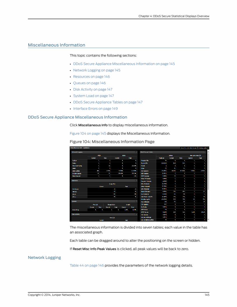
Miscellaneous Information
This topic contains the following sections:
• DDoS Secure Appliance Miscellaneous Information on page 145
• Network Logging on page 145
• Resources on page 146
• Queues on page 146
• Disk Activity on page 147
• System Load on page 147
• DDoS Secure Appliance Tables on page 147
• Interface Errors on page 149
DDoS Secure ApplianceMiscellaneous Information
ClickMiscellaneous Info to display miscellaneous information.
Figure 104 on page 145 displays the Miscellaneous Information.
Figure 104: Miscellaneous Information Page
Themiscellaneous information is divided into seven tables; each value in the table has
an associated graph.
Each table can be dragged around to alter the positioning on the screen or hidden.
If Reset Misc Info Peak Values is clicked, all peak values will be back to zero.
Network Logging
Table 44 on page 146 provides the parameters of the network logging details.
145Copyright © 2014, Juniper Networks, Inc.
Chapter 4: DDoS Secure Statistical Displays Overview
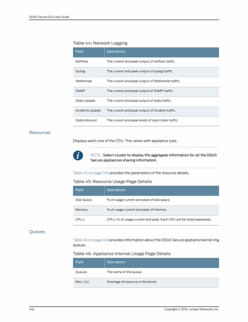
Table 44: Network Logging
DescriptionField
The current and peak output of netflow traffic.NetFlow
The current and peak output of syslog traffic.Syslog
The current and peak output of Webtrends traffic.Webtrends
The current and peak output of SNMP traffic.SNMP
The current and peak output of state traffic.State Update
The current and peak output of incident traffic.Incidents Update
The current and peak levels of input state traffic.State Inbound
Resources
Displays each core of the CPU. This varies with appliance type.
NOTE: Select cluster to display the aggregate information for all the DDoSSecure appliances sharing information.
Table 45 on page 146 provides the parameters of the resource details.
Table 45: Resource Usage Page Details
DescriptionField
%of usage current and peak of disk space.Disk Space
% of usage current and peak of memory.Memory
CPU x% of usage current and peak. Each CPUwill be listed separately.CPU x
Queues
Table 46 on page 146 provides information about the DDoS Secure appliance kernel ring
queues.
Table 46: Appliance Internal Usage Page Details
DescriptionField
The name of the queue.Queues
Shortage of resource in the kernel.Misc (/s)
Copyright © 2014, Juniper Networks, Inc.146
DDoS Secure GUI User Guide
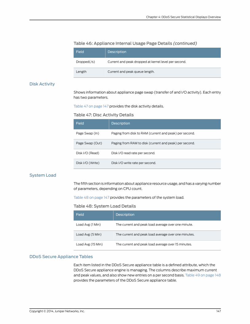
Table 46: Appliance Internal Usage Page Details (continued)
DescriptionField
Current and peak dropped at kernel level per second.Dropped(/s)
Current and peak queue length.Length
Disk Activity
Shows information about appliance page swap (transfer of and I/O activity). Each entry
has two parameters.
Table 47 on page 147 provides the disk activity details.
Table 47: Disc Activity Details
DescriptionField
Paging from disk to RAM (current and peak) per second.Page Swap (In)
Paging from RAM to disk (current and peak) per second.Page Swap (Out)
Disk I/O read rate per second.Disk I/O (Read)
Disk I/O write rate per second.Disk I/O (Write)
System Load
The fifth section is informationaboutappliance resourceusage, andhasavaryingnumber
of parameters, depending on CPU count.
Table 48 on page 147 provides the parameters of the system load.
Table 48: System Load Details
DescriptionField
The current and peak load average over oneminute.Load Avg (1 Min)
The current and peak load average over oneminutes.Load Avg (5 Min)
The current and peak load average over 15 minutes.Load Avg (15 Min)
DDoS Secure Appliance Tables
Each item listed in the DDoS Secure appliance table is a defined attribute, which the
DDoS Secure appliance engine is managing. The columns describe maximum current
and peak values, and also show new entries on a per second basis. Table 49 on page 148
provides the parameters of the DDoS Secure appliance table.
147Copyright © 2014, Juniper Networks, Inc.
Chapter 4: DDoS Secure Statistical Displays Overview

Table 49: Appliance Queue Usage Details
DescriptionField
Number of protected IP address defined.Protected IPs
Internet IP address tracked by the appliance.Tracked IPs
Used portal entries defined in the DDoS Secure appliance table.Portals
Filters defined.Filter
TCP sessions that the appliance is tracking.TCP Sessions
UDP sessions that the appliance is tracking.UDP Sessions
ICMP sessions that the appliance is tracking.ICMP Sessions
Other-IP sessions that the appliance is tracking.Other-IP Sessions
Fragment sessions that the appliance is tracking.Fragment Sessions
Number of protected URLs that the appliance is tracking.URLs Protected
DNS entries that the appliance is tracking.DNSs Protected
SIP entries that the appliance is tracking.SIPs Protected
Live Incidents that the appliance is tracking.Live Incidents
Number of worst offenders tracked by the appliance.Worst Offenders
Temporary black-listed IP addresses.Auto Black-Listed IPs
FTP sessions that the appliance is tracking.FTP Sessions
Misbehaving IP addresses that the appliance is tracking.Misbehaving IP addresses
MAC addresses that the appliance is tracking.MAC Addresses
BGP re-route entries that the appliance is tracking.Re-Routes
ARP entries that the appliance is tracking.ARP Entries
HTTP parser entries that the appliance is tracking.HTTP Parsers
SSL session entries that the appliance is tracking.SSL Sessions
SSL key exchange entries that the appliance is tracking.SSL Key Exchange
SSL handshake entries that the appliance is tracking.SSL Handshake Buffers
Copyright © 2014, Juniper Networks, Inc.148
DDoS Secure GUI User Guide
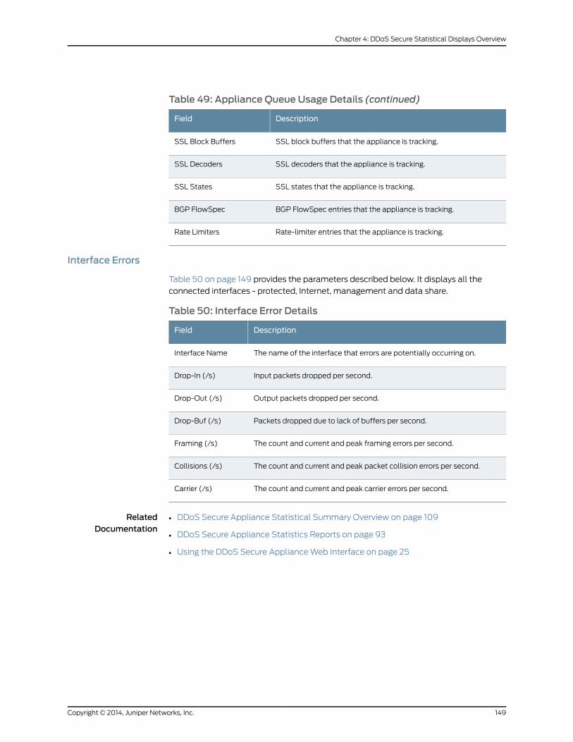
Table 49: Appliance Queue Usage Details (continued)
DescriptionField
SSL block buffers that the appliance is tracking.SSL Block Buffers
SSL decoders that the appliance is tracking.SSL Decoders
SSL states that the appliance is tracking.SSL States
BGP FlowSpec entries that the appliance is tracking.BGP FlowSpec
Rate-limiter entries that the appliance is tracking.Rate Limiters
Interface Errors
Table 50 on page 149 provides the parameters described below. It displays all the
connected interfaces - protected, Internet, management and data share.
Table 50: Interface Error Details
DescriptionField
The name of the interface that errors are potentially occurring on.Interface Name
Input packets dropped per second.Drop-In (/s)
Output packets dropped per second.Drop-Out (/s)
Packets dropped due to lack of buffers per second.Drop-Buf (/s)
The count and current and peak framing errors per second.Framing (/s)
The count and current and peak packet collision errors per second.Collisions (/s)
The count and current and peak carrier errors per second.Carrier (/s)
RelatedDocumentation
• DDoS Secure Appliance Statistical Summary Overview on page 109
• DDoS Secure Appliance Statistics Reports on page 93
• Using the DDoS Secure ApplianceWeb Interface on page 25
149Copyright © 2014, Juniper Networks, Inc.
Chapter 4: DDoS Secure Statistical Displays Overview

Copyright © 2014, Juniper Networks, Inc.150
DDoS Secure GUI User Guide
CHAPTER 5
DDoS Secure Defense InformationOverview
All anomalous behavior (attacks) is tracked on an incident-per-protected-IP address
basis. When an attack is active and running at a rate greater than or equal to the defined
view threshold, the right side of the display (Defense status) changes from black to red.
During an attack with multiple components, multiple attack indicators will be shown.
The attack indicator will go back from red to black when the event rate drops below the
threshold. Click the hyperlink on an icon to display all active incidents for that type in the
center pane. The last 31 days worth of incidents are available for review, and can be
accessed by using the Incident Logs entry under DDoS Configuration/Logs. You can
disable an attack indication icon by disabling the creation of incidents for the attack type
on the configure logging page.
• Understanding DDoS Secure Appliance Operational Mode on page 151
• Understanding DDoS Secure Appliance Failover States on page 153
• Understanding DDoS Secure Appliance Failover Information on page 153
• UnderstandingDDoSSecureApplianceStateSynchronization Informationonpage 153
• Understanding DDoS Secure Appliance Record/Replay State on page 154
• Understanding DDoS Secure Appliance Transition States on page 154
• Understanding DDoS Secure Appliance Protected IP Information on page 155
• Understanding DDoS Secure Appliance Defense Status Information on page 156
• Understanding DDoS Secure Appliance Additional Status Information on page 158
Understanding DDoS Secure Appliance Operational Mode
Figure 105 on page 152 displays the operational modes on the right side.
151Copyright © 2014, Juniper Networks, Inc.
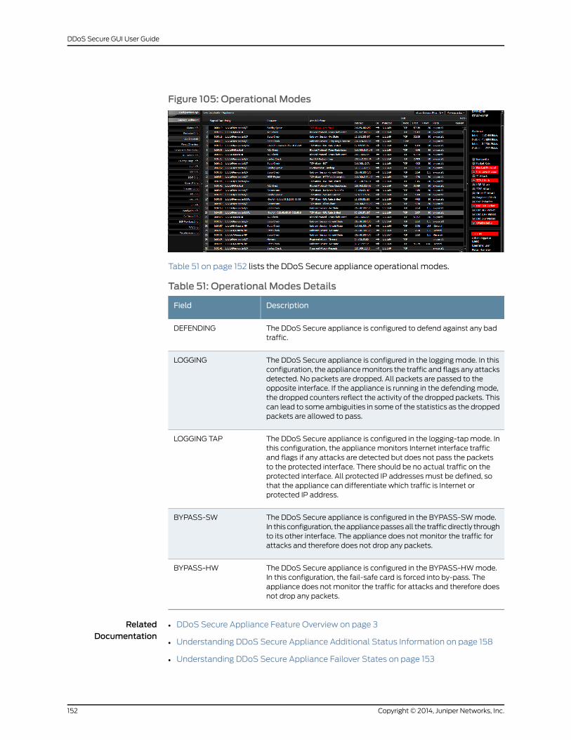
Figure 105: Operational Modes
Table 51 on page 152 lists the DDoS Secure appliance operational modes.
Table 51: Operational Modes Details
DescriptionField
The DDoS Secure appliance is configured to defend against any badtraffic.
DEFENDING
The DDoS Secure appliance is configured in the logging mode. In thisconfiguration, the appliancemonitors the traffic and flags any attacksdetected. No packets are dropped. All packets are passed to theopposite interface. If the appliance is running in the defending mode,the dropped counters reflect the activity of the dropped packets. Thiscan lead to some ambiguities in some of the statistics as the droppedpackets are allowed to pass.
LOGGING
The DDoS Secure appliance is configured in the logging-tapmode. Inthis configuration, the appliancemonitors Internet interface trafficand flags if any attacks are detected but does not pass the packetsto the protected interface. There should be no actual traffic on theprotected interface. All protected IP addresses must be defined, sothat the appliance can differentiate which traffic is Internet orprotected IP address.
LOGGING TAP
The DDoS Secure appliance is configured in the BYPASS-SWmode.In this configuration, theappliancepassesall the trafficdirectly throughto its other interface. The appliance does not monitor the traffic forattacks and therefore does not drop any packets.
BYPASS-SW
The DDoS Secure appliance is configured in the BYPASS-HWmode.In this configuration, the fail-safe card is forced into by-pass. Theappliance does not monitor the traffic for attacks and therefore doesnot drop any packets.
BYPASS-HW
RelatedDocumentation
DDoS Secure Appliance Feature Overview on page 3•
• Understanding DDoS Secure Appliance Additional Status Information on page 158
• Understanding DDoS Secure Appliance Failover States on page 153
Copyright © 2014, Juniper Networks, Inc.152
DDoS Secure GUI User Guide

Understanding DDoS Secure Appliance Failover States
Table 52 on page 153 lists the DDoS Secure appliance failover states.
Table 52: Failover State Details
DescriptionField
The DDoS Secure is running as a standalone entity.STANDALONE
The DDoS Secure appliance is running as an active partner of anactive/standby configuration and passing traffic.
ACTIVE
The DDoS Secure appliance is running as a hot standby partner of anactive/standby configuration and not passing traffic.
STANDBY
The DDoS Secure appliance is determining whether it should be a partof an active/standby configuration. This will continue for 10 seconds,and then transition into standalone or standby.
PROBE
The DDoS Secure appliance is not capable of analyzing and passingtraffic. The fail-safe card might still be operational.
OUT-OF-SERVICE
RelatedDocumentation
DDoS Secure Appliance Feature Overview on page 3•
• Understanding DDoS Secure Appliance Operational Mode on page 151
• Understanding DDoS Secure Appliance Failover Information on page 153
Understanding DDoS Secure Appliance Failover Information
Combined with one of the above failover states may be some IP addresses. For more
information, see “Understanding DDoS Secure Appliance Failover States” on page 153.
The IP addresses may be prefixed with one or more of the characters I, P, or M. If any of
these characters is present, then this indicates a failed or failing communications link on
the Internet, protected, or management connections, respectively, between the two
systems thatare trying toestablishapartner relationship.The IPaddresseshavea trailing
field, indicating the failover state of the remote system.
RelatedDocumentation
DDoS Secure Appliance Feature Overview on page 3•
• Understanding DDoS Secure Appliance Operational Mode on page 151
• UnderstandingDDoSSecureApplianceStateSynchronization Informationonpage 153
Understanding DDoS Secure Appliance State Synchronization Information
If theDDoSSecureappliancesareconfigured for sharing information, thiswill be indicated
by the entry Info Share. Following this are entries for the IP addresses that are being
153Copyright © 2014, Juniper Networks, Inc.
Chapter 5: DDoS Secure Defense Information Overview
actively shared. If the IP address is orange, then there has been a brief loss of connection
with the remote DDoS Secure.
RelatedDocumentation
DDoS Secure Appliance Feature Overview on page 3•
• Understanding DDoS Secure Appliance Operational Mode on page 151
• Understanding DDoS Secure Appliance Record/Replay State on page 154
Understanding DDoS Secure Appliance Record/Replay State
Table 53 on page 154 provides the record/replay state details.
Table 53: Record/Replay State Details
DescriptionField
Traffic through the appliance is currently being recorded. The digit (1 - 9)indicates the recording slot in use.
[Recording # #]
A previous recording of appliance traffic is being injected into the DDoSSecure appliance processing engine. This traffic does not leave theappliance but does alter the defensive responses of the engine. The digit(1 - 9) indicates the recording slot in use.
[Replaying # #]
RelatedDocumentation
DDoS Secure Appliance Feature Overview on page 3•
• Understanding DDoS Secure Appliance Operational Mode on page 151
• Understanding DDoS Secure Appliance Transition States on page 154
Understanding DDoS Secure Appliance Transition States
Table 54 on page 154 provides transition state details.
Table 54: Transition States Details
DescriptionField
The appliance engine is starting up. In addition, theappropriate logic (xyz) that is being initialized is also reported.
DDoSSecureappliance Initializing
Theapplianceengine isbeingshutdown.Theenginewill thengo offline. Depending on whether power down, reboot orrestart is selecteddependsonwhen theenginewill next startto re-initialize or if the connection will be lost.
DDoS Secure appliance GoingOffline
The appliance engine is not currently running.DDoS Secure appliance Offline
Copyright © 2014, Juniper Networks, Inc.154
DDoS Secure GUI User Guide

Table 54: Transition States Details (continued)
DescriptionField
Thiswarningcanbeseenbriefly sometimeswhenthesystemclock is adjusted. The adjustment of the system clock canconfuse theWeb interface briefly. If this warning remains onfor more than a few screen updates, then the applianceenginehashung, and isno longerpassing traffic. If thewarningremains on for more than a few screen updates, take theappliance engine offline, and then back online again byclicking, SHUTDOWNDDoS SECURE followed by shutdownDDoS Secure appliance engine and restart. This is anunexpected condition.
NOTE: If several browser windows (on the same PC) areopen on the same appliance, this can also cause theappliance stall light to come on—as a false positive—as thesecond browser windowmight refresh its right pane at thesame time as the first browser and the webserver enginedetermines that there is not a time difference since the lastrefresh.
DDoS Secure appliance Stall
RelatedDocumentation
DDoS Secure Appliance Feature Overview on page 3•
• Understanding DDoS Secure Appliance Operational Mode on page 151
• Understanding DDoS Secure Appliance Protected IP Information on page 155
Understanding DDoS Secure Appliance Protected IP Information
Figure 106 on page 155 displays the appliance or protected IP address information.
Figure 106: Appliance or Protected IP Information Page
The entry describeswhether theDefense status indicators are for the appliance, a portal,
or a specific protected IP address. Thiswill also apply to the data rate shown for the data
onmany statistics pages.
Table 55 on page 156 defines the transitional states.
155Copyright © 2014, Juniper Networks, Inc.
Chapter 5: DDoS Secure Defense Information Overview
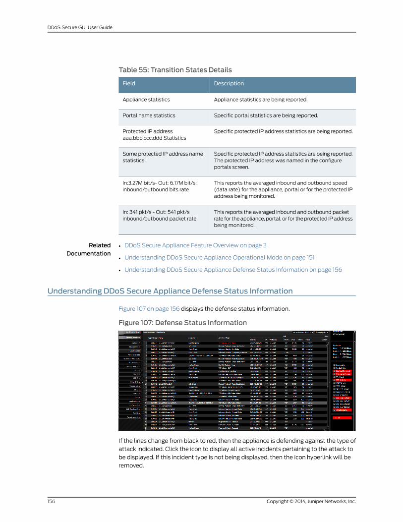
Table 55: Transition States Details
DescriptionField
Appliance statistics are being reported.Appliance statistics
Specific portal statistics are being reported.Portal name statistics
Specific protected IP address statistics are being reported.Protected IP addressaaa.bbb.ccc.ddd Statistics
Specific protected IP address statistics are being reported.The protected IP address was named in the configureportals screen.
Some protected IP address namestatistics
This reports the averaged inbound and outbound speed(data rate) for the appliance, portal or for the protected IPaddress being monitored.
In:3.27M bit/s- Out: 6.17M bit/s:inbound/outbound bits rate
This reports the averaged inbound and outbound packetrate for theappliance, portal, or for theprotected IPaddressbeing monitored.
In: 341 pkt/s - Out: 541 pkt/sinbound/outbound packet rate
RelatedDocumentation
DDoS Secure Appliance Feature Overview on page 3•
• Understanding DDoS Secure Appliance Operational Mode on page 151
• Understanding DDoS Secure Appliance Defense Status Information on page 156
Understanding DDoS Secure Appliance Defense Status Information
Figure 107 on page 156 displays the defense status information.
Figure 107: Defense Status Information
If the lines change from black to red, then the appliance is defending against the type of
attack indicated. Click the icon to display all active incidents pertaining to the attack to
be displayed. If this incident type is not being displayed, then the icon hyperlink will be
removed.
Copyright © 2014, Juniper Networks, Inc.156
DDoS Secure GUI User Guide
Table 56 on page 157 provides defense status details.
Table 56: Defense Status Details page
DescriptionField
This indicates that appliance has detected that the bandwidth availableto one ormore protected IP addresses or Internet gateways is becomingcritical and is inbandwidthDefensemode.Packetsarebeing intelligentlyfiltered to deny access from themost likely attackers. This Defenseposture is applied per protected or Internet gateway basis.
Bandwidth
This indicates that appliance has detected high rates of small packets.DDoSSecure appliance intelligently filters the streamof traffic droppingpackets from themost likely attackers.
Packet Rate
Blocked protocol includes TCP/UDPports that are being dropped by thefilter, as well as ICMP types or other specific IP address protocols, plusany blocked IP addresses. These invalid ports/types/protocols areconfigured.The IPaddressblocking isautomaticbutneeds tobeenabled.
Blocked Protocol
Blocked state includes when any packet that does not match theappliance internal state machine for the specific protocol is blocked.This includesprotocols that are stateless suchas ICMP.With the randomnoise on the Internet, it is likely that this Defense light will be on for alarge amount of the time. BrokenTCP/IP stacks, andbrokenNATdevicesareacommoncauseof this randomnoise, asare the sideeffectsof someDDoS attacks and port scanning tools.
Blocked State
A form of IP address attack is being directed at a protected IP address.For example: land attack.
IP Attack
A form of TCP attack is being directed at a protected IP address. Forexample: The SYN attack or the connection flood.
TCP Attack
A form of UDP attack is being directed at a protected IP address.UDP Attack
A form of ICMP attack is being directed at a protected IP address.ICMP Attack
A form of attack based another IP address protocol is being directed ata protected IP address.
Other IP Attack
Innormal traffic, packets canbesplit (fragmented) intodifferentpackets,which are then reassembled at the protected IP address back into theoriginal packet. Planned attack packets can be used to create invalidpackets when reassembled. This can have a detrimental effect on theprotected IP address. DDoS Secure appliance detects such attacks anddrops the attack packets before they reach the protected IP addresswhile allowing genuine packet fragments through. Fragments droppedby a protected IP address definition also turn on this light.
Fragment Attack
The next five indicators on the right hand side of the appliance displayindicatebadpacketsaredetected.Thesearepackets thatdonotconformto the relevant RFCs and are dropped at all times by DDoS Secureappliance.
Bad Packets (IP,ICMP, TCP, UDP andO-IP)
157Copyright © 2014, Juniper Networks, Inc.
Chapter 5: DDoS Secure Defense Information Overview

Table 56: Defense Status Details page (continued)
DescriptionField
The appliance has detected that a protected IP address is no longerresponding to connection requests. This might be caused by a downedprotected IP address, a slow response to SYN requests, or the protectedIP address is deliberately not responding to SYN requests on specificports. To reduce false alarms and to improve the auto-black-listingresponse to port scanners, apply a suitable DDoS Secure appliancepermit filter. False alarms can also be avoided by adjusting your host (orfirewall) filtering policy to use deny or reject responses to connectionrequests for a closed port, as opposed to drop responses.
NOTE: A drop response provides very few if any security benefits whendefending against a port scan.
OverloadedProtectedIP
RelatedDocumentation
DDoS Secure Appliance Feature Overview on page 3•
• Understanding DDoS Secure Appliance Operational Mode on page 151
• Understanding DDoS Secure Appliance Additional Status Information on page 158
Understanding DDoS Secure Appliance Additional Status Information
Figure 108 on page 158 displays Additional Status page.
Figure 108: Additional Status Page
Additional informationwill bedisplayedabout theDefense statusof theappliance. These
are defined in alphabetical order below (apart from SomeProtectedName), even though
they might be displayed in a different order.
Table 57 on page 159 provides additional status details.
Copyright © 2014, Juniper Networks, Inc.158
DDoS Secure GUI User Guide
Table 57: Additional Status Details
DescriptionField
This protected IP address is being defended. Click the URL linkto display the Defense state for that specific protected IPaddress. The protected IP address namewas specified on theconfiguration screen.
Protected IPSomeProtectedName
The DDoS Secure appliance has detected a BGP session, butthe server is excluded by the DDoS Secure appliance portalnetwork list.
BGPMisconfigured
Theappliancehasusedupall the internal table space for trackingIPaddresses that arebeing temporarily black-listed. Any inactiveblack-listed IP address will be removed from the list.
Black-Listed IP Table Full
The DDoS Secure appliance was unable to transmit theconfiguration file changes to a partner.
Config Transfer Failed
Thedata share Interface (D-I/F) is notphysically connected, andhas an IP address configured.
DataShare-I/F N/C
Oneof the disks has failed aSMART test and should be replacedas soon as possible.
Disk Failure
The system BIOS is reporting that there is a fan failure, or thatthe appliance is running in hot environment. This needs to berepaired as soon as possible to prevent hardware componentfailure.
Fan Failure
The appliance has detected that there is a network short circuitsituation prior to the system being licensed. Consequently, nomore traffic will be passed through until the bypass situation issorted out and the appliance restarted.
Forced Inactive
The appliance has run out of internal table space for handlingfragments. This table size is deliberately restricted. The oldest(by use) entry is dropped.
FRAGMENT Table Full
Theappliancehasusedupall the internal table space for trackingFTP connections. Any entry not required will be flushed out tocreate space for the next FTP connection. This should normallyonly happen when defending against a large-scale attack.
FTP Table Full
The appliance has run out of internal table space for ICMPsessions. This table size is deliberately restricted. The oldest (byuse) entry is dropped. This should normally only happen whendefending against a large-scale attack.
ICMP Table Full
The appliance has run out of internal table space for activeIncidents. The oldest (by use) entry is dropped.
Incident Table Full
On fail-safe systems, the interface speeds on the fail-safe cardaredefined, or detected tobedifferent,whichwill causean issueif the card goes Fail-Safe.
Interface Speed Mismatch
159Copyright © 2014, Juniper Networks, Inc.
Chapter 5: DDoS Secure Defense Information Overview

Table 57: Additional Status Details (continued)
DescriptionField
The Internet Interface (I-I/F) is not physically connected. Thisoccurs when the appliance is running as standby in a VMwareenvironment.
Internet-I/F N/C
AMACaddress is defined as type Internet, or type protected, butthe MAC address is detected on the opposite side of the DDoSSecure appliance. Correct this situation.
MACMisconfigured
The appliance has run out of internal table space for MACaddresses. The oldest (by use) entry is dropped.
MAC Table Full
Themanagement interface (I-I/F) is not physically connected.Management-I/F N/C
A state synchronization partner defined as required is notavailable. The DDoS Secure appliance is running in a degradedstate,where all DDoSactivitywill not bedetectedandprotectedagainst.
Missing Partner
TheDDoSSecure appliance has detected the same sourceMACaddress in use on both the I-I/F and P-I/F interfaces. Bypasspackets are not passed through the appliancewhen in defensivemode. This means that there is either an alternative data patharound the appliance, or a topology change has placed apreviously determined MAC address on the opposite side of theappliance. In the event of a topology change, the cached entrycan bemodified by configuring the MAC address as either anInternet or protected gateway, or if not configured, the MACwillbe allowed to change sides automatically after five seconds.
Network Short Circuit
Theconfigurationhas just beenupdated, potentially bya remoteDDoS Secure.
New Configuration
The DDoS Secure appliance has not been authorized for use.Not Licensed
The appliance has used up all the internal table space for IPaddress protocol sessions. Any entry not requiredwill be flushedout to create space for the next IP address protocol session. Thisshould normally only happen when defending against alarge-scale attack.
OTHER IPProtocolsTableFull
DDoS Secure appliance is having trouble transmitting packetson the Internet Interface. This could be because a downstreamlink is saturated, or a duplex speedmismatch.
Output Error – Internet
DDoS Secure appliance is having trouble transmitting packetson themanagement interface. This could be because adownstream link is saturated, or a duplex speedmismatch.
Output Error - Management
DDoS Secure appliance is having trouble transmitting packetson theprotected interface. This couldbebecauseadownstreamlink is saturated, or a duplex speedmismatch.
Output Error – Protected
Copyright © 2014, Juniper Networks, Inc.160
DDoS Secure GUI User Guide
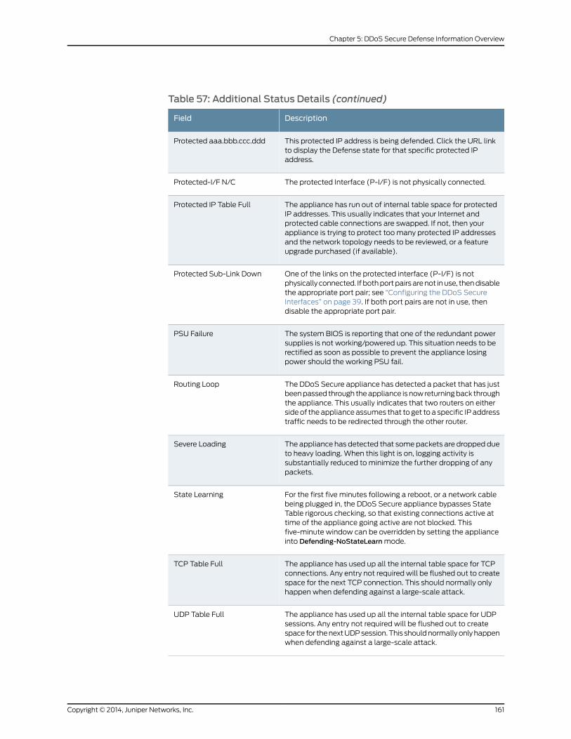
Table 57: Additional Status Details (continued)
DescriptionField
This protected IP address is being defended. Click the URL linkto display the Defense state for that specific protected IPaddress.
Protected aaa.bbb.ccc.ddd
The protected Interface (P-I/F) is not physically connected.Protected-I/F N/C
The appliance has run out of internal table space for protectedIP addresses. This usually indicates that your Internet andprotected cable connections are swapped. If not, then yourappliance is trying to protect toomany protected IP addressesand the network topology needs to be reviewed, or a featureupgrade purchased (if available).
Protected IP Table Full
One of the links on the protected interface (P-I/F) is notphysically connected. If bothportpairsarenot inuse, thendisablethe appropriate port pair; see “Configuring the DDoS SecureInterfaces” on page 39. If both port pairs are not in use, thendisable the appropriate port pair.
Protected Sub-Link Down
The system BIOS is reporting that one of the redundant powersupplies is not working/powered up. This situation needs to berectified as soon as possible to prevent the appliance losingpower should the working PSU fail.
PSU Failure
The DDoS Secure appliance has detected a packet that has justbeenpassed through theappliance isnowreturningback throughthe appliance. This usually indicates that two routers on eithersideof theapplianceassumes that to get toa specific IPaddresstraffic needs to be redirected through the other router.
Routing Loop
The appliance has detected that somepackets are dropped dueto heavy loading. When this light is on, logging activity issubstantially reduced to minimize the further dropping of anypackets.
Severe Loading
For the first five minutes following a reboot, or a network cablebeing plugged in, the DDoS Secure appliance bypasses StateTable rigorous checking, so that existing connections active attime of the appliance going active are not blocked. Thisfive-minute window can be overridden by setting the applianceinto Defending-NoStateLearnmode.
State Learning
The appliance has used up all the internal table space for TCPconnections. Any entry not requiredwill be flushed out to createspace for the next TCP connection. This should normally onlyhappen when defending against a large-scale attack.
TCP Table Full
The appliance has used up all the internal table space for UDPsessions. Any entry not required will be flushed out to createspace for thenextUDPsession.This shouldnormallyonlyhappenwhen defending against a large-scale attack.
UDP Table Full
161Copyright © 2014, Juniper Networks, Inc.
Chapter 5: DDoS Secure Defense Information Overview
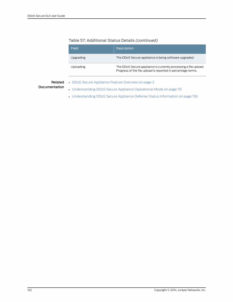
Table 57: Additional Status Details (continued)
DescriptionField
The DDoS Secure appliance is being software upgraded.Upgrading
TheDDoSSecure appliance is currently processing a file upload.Progress of the file upload is reported in percentage terms.
Uploading
RelatedDocumentation
• DDoS Secure Appliance Feature Overview on page 3
• Understanding DDoS Secure Appliance Operational Mode on page 151
• Understanding DDoS Secure Appliance Defense Status Information on page 156
Copyright © 2014, Juniper Networks, Inc.162
DDoS Secure GUI User Guide
PART 2
Appendixes
• TCP States on page 165
• ICMP Types on page 167
• Index Attack Types on page 169
• Country Codes on page 175
• Panel Information on page 199
• Troubleshooting on page 201
• Customizing theWeb Interface on page 203
• TAPMode on page 205
163Copyright © 2014, Juniper Networks, Inc.

Copyright © 2014, Juniper Networks, Inc.164
DDoS Secure GUI User Guide
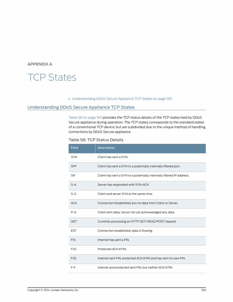
APPENDIX A
TCP States
• Understanding DDoS Secure Appliance TCP States on page 165
Understanding DDoS Secure Appliance TCP States
Table 58 on page 165 provides the TCP status details of the TCP states held by DDoS
Secure appliance during operation. The TCP states corresponds to the standard states
of a conventional TCP device; but are subdivided due to the uniquemethod of handling
connections by DDoS Secure appliance.
Table 58: TCP Status Details
DescriptionField
Client has sent a SYN.SYN
Client has sent a SYN to a potentially internally filtered port.SPF
Client has sent a SYN to a potentially internally filtered IP address.SIF
Server has responded with SYN-ACK.S-A
Client and server SYN at the same time.S-S
Connection Established, but no data from Client or Server.ACK
Client sent data, Server not yet acknowledged any data.P-A
Currently processing an HTTP GET/HEAD/POST request.GET
Connection established, data is flowing.EST
Internet has sent a FIN.F1S
Protected ACK’d FIN.F2S
Internet sent FIN, protected ACK’d FIN and has sent its own FIN.F3S
Internet and protected sent FIN, but neither ACK’d FIN.F-F
165Copyright © 2014, Juniper Networks, Inc.
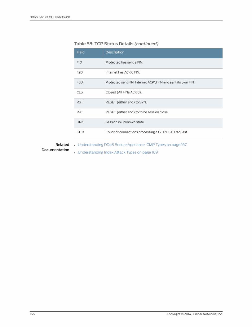
Table 58: TCP Status Details (continued)
DescriptionField
Protected has sent a FIN.F1D
Internet has ACK’d FIN.F2D
Protected sent FIN, Internet ACK’d FIN and sent its own FIN.F3D
Closed (All FINs ACK’d).CLS
RESET (either end) to SYN.RST
RESET (either end) to force session close.R-C
Session in unknown state.UNK
Count of connections processing a GET/HEAD request.GETs
RelatedDocumentation
• Understanding DDoS Secure Appliance ICMP Types on page 167
• Understanding Index Attack Types on page 169
Copyright © 2014, Juniper Networks, Inc.166
DDoS Secure GUI User Guide
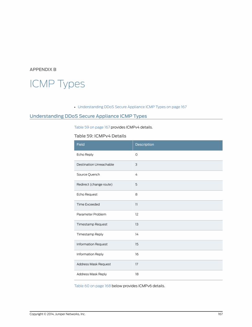
APPENDIX B
ICMP Types
• Understanding DDoS Secure Appliance ICMP Types on page 167
Understanding DDoS Secure Appliance ICMP Types
Table 59 on page 167 provides ICMPv4 details.
Table 59: ICMPv4 Details
DescriptionField
0Echo Reply
3Destination Unreachable
4Source Quench
5Redirect (change route)
8Echo Request
11Time Exceeded
12Parameter Problem
13Timestamp Request
14Timestamp Reply
15Information Request
16Information Reply
17Address Mask Request
18Address Mask Reply
Table 60 on page 168 below provides ICMPv6 details.
167Copyright © 2014, Juniper Networks, Inc.
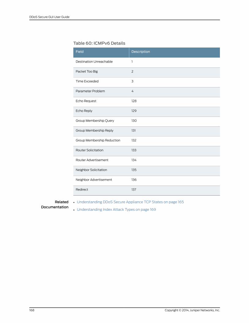
Table 60: ICMPv6 Details
DescriptionField
1Destination Unreachable
2Packet Too Big
3Time Exceeded
4Parameter Problem
128Echo Request
129Echo Reply
130Group Membership Query
131Group Membership Reply
132Group Membership Reduction
133Router Solicitation
134Router Advertisement
135Neighbor Solicitation
136Neighbor Advertisement
137Redirect
RelatedDocumentation
• Understanding DDoS Secure Appliance TCP States on page 165
• Understanding Index Attack Types on page 169
Copyright © 2014, Juniper Networks, Inc.168
DDoS Secure GUI User Guide
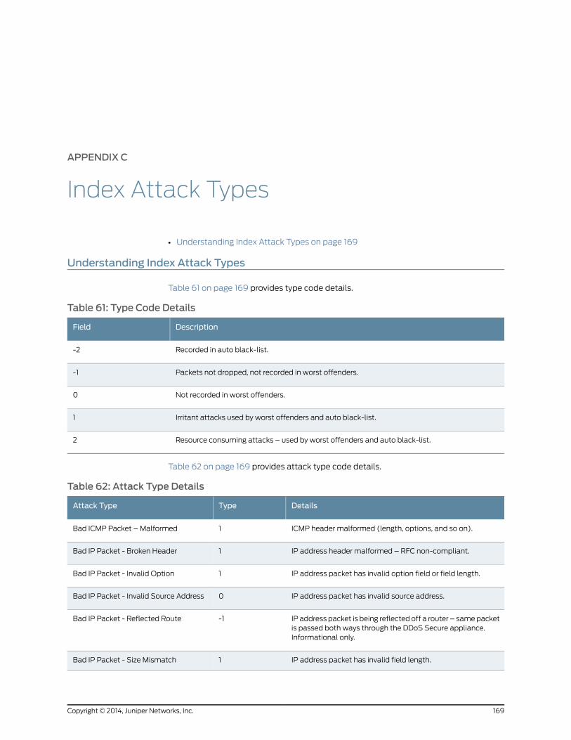
APPENDIX C
Index Attack Types
• Understanding Index Attack Types on page 169
Understanding Index Attack Types
Table 61 on page 169 provides type code details.
Table 61: Type Code Details
DescriptionField
Recorded in auto black-list.-2
Packets not dropped, not recorded in worst offenders.-1
Not recorded in worst offenders.0
Irritant attacks used by worst offenders and auto black-list.1
Resource consuming attacks – used by worst offenders and auto black-list.2
Table 62 on page 169 provides attack type code details.
Table 62: Attack Type Details
DetailsTypeAttack Type
ICMP header malformed (length, options, and so on).1Bad ICMP Packet – Malformed
IP address header malformed – RFC non-compliant.1Bad IP Packet - Broken Header
IP address packet has invalid option field or field length.1Bad IP Packet - Invalid Option
IP address packet has invalid source address.0Bad IP Packet - Invalid Source Address
IP address packet is being reflected off a router – samepacketis passed both ways through the DDoS Secure appliance.Informational only.
-1Bad IP Packet - Reflected Route
IP address packet has invalid field length.1Bad IP Packet - Size Mismatch
169Copyright © 2014, Juniper Networks, Inc.
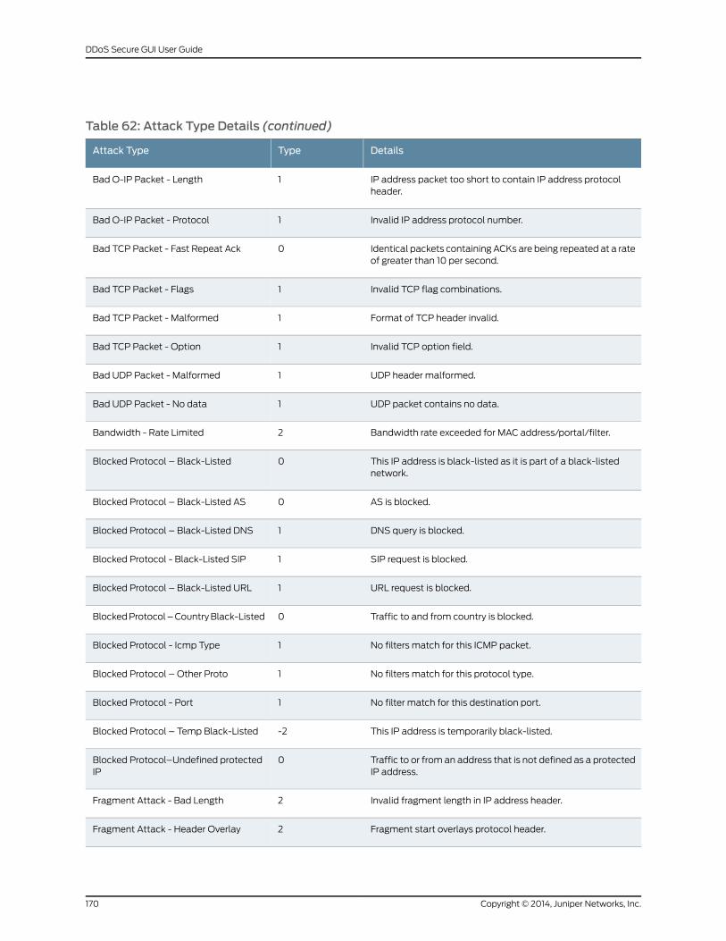
Table 62: Attack Type Details (continued)
DetailsTypeAttack Type
IP address packet too short to contain IP address protocolheader.
1Bad O-IP Packet - Length
Invalid IP address protocol number.1Bad O-IP Packet - Protocol
Identical packets containing ACKs are being repeated at a rateof greater than 10 per second.
0Bad TCP Packet - Fast Repeat Ack
Invalid TCP flag combinations.1Bad TCP Packet - Flags
Format of TCP header invalid.1Bad TCP Packet - Malformed
Invalid TCP option field.1Bad TCP Packet - Option
UDP header malformed.1Bad UDP Packet - Malformed
UDP packet contains no data.1Bad UDP Packet - No data
Bandwidth rate exceeded for MAC address/portal/filter.2Bandwidth - Rate Limited
This IP address is black-listed as it is part of a black-listednetwork.
0Blocked Protocol – Black-Listed
AS is blocked.0Blocked Protocol – Black-Listed AS
DNS query is blocked.1Blocked Protocol – Black-Listed DNS
SIP request is blocked.1Blocked Protocol - Black-Listed SIP
URL request is blocked.1Blocked Protocol – Black-Listed URL
Traffic to and from country is blocked.0BlockedProtocol–CountryBlack-Listed
No filters match for this ICMP packet.1Blocked Protocol - Icmp Type
No filters match for this protocol type.1Blocked Protocol – Other Proto
No filter match for this destination port.1Blocked Protocol - Port
This IP address is temporarily black-listed.-2Blocked Protocol – Temp Black-Listed
Traffic to or from an address that is not defined as a protectedIP address.
0Blocked Protocol–Undefined protectedIP
Invalid fragment length in IP address header.2Fragment Attack - Bad Length
Fragment start overlays protocol header.2Fragment Attack - Header Overlay
Copyright © 2014, Juniper Networks, Inc.170
DDoS Secure GUI User Guide
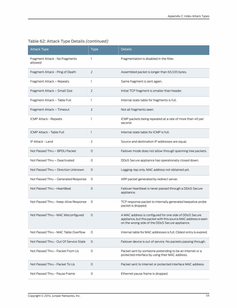
Table 62: Attack Type Details (continued)
DetailsTypeAttack Type
Fragmentation is disabled in the filter.1Fragment Attack - No Fragmentsallowed
Assembled packet is longer than 65,535 bytes.2Fragment Attack - Ping of Death
Same fragment is sent again.1Fragment Attack – Repeats
Initial TCP fragment is smaller than header.2Fragment Attack – Small Size
Internal state table for fragments is full.1Fragment Attack – Table Full
Not all fragments seen.2Fragment Attack – Timeout
ICMP packets being repeated at a rate of more than 40 persecond.
1ICMP Attack - Repeats
Internal state table for ICMP is full.1ICMP Attack - Table Full
Source and destination IP addresses are equal.2IP Attack - Land
Failover mode does not allow through spanning tree packets.0Not Passed Thru – BPDU Packet
DDoS Secure appliance has operationally closed down.0Not Passed Thru – Deactivated
Logging-tap only. MAC address not obtained yet.0Not Passed Thru – Direction Unknown
ARP packet generated by redirect server.0Not Passed Thru – Generated Response
Failover heartbeat is never passed through a DDoS Secureappliance.
0Not Passed Thru - HeartBeat
TCP response packet to internally generated keepalive probepacket is dropped.
0Not Passed Thru - Keep-Alive Response
A MAC address is configured for one side of DDoS Secureappliance, but this packetwith this sourceMACaddress is seenon the wrong side of the DDoS Secure appliance.
0Not Passed Thru - MACMisconfigured
Internal table forMACaddresses is full. Oldest entry is expired.0Not Passed Thru - MAC Table Overflow
Failover device is out of service. No packets passing through.0Not Passed Thru - Out Of Service State
Packet sent by someone pretending to be an Internet or aprotected interface by using their MAC address.
0Not Passed Thru - Packet From Us
Packet sent to Internet or protected interface MAC address.0Not Passed Thru - Packet To Us
Ethernet pause frame is dropped.0Not Passed Thru - Pause Frame
171Copyright © 2014, Juniper Networks, Inc.
Appendix C: Index Attack Types
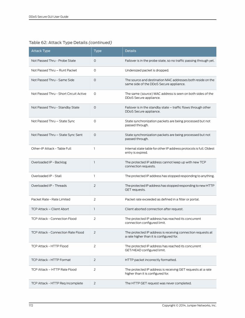
Table 62: Attack Type Details (continued)
DetailsTypeAttack Type
Failover is in the probe state, so no traffic passing through yet.0Not Passed Thru - Probe State
Undersized packet is dropped.0Not Passed Thru – Runt Packet
The source and destinationMACaddresses both reside on thesame side of the DDoS Secure appliance.
0Not Passed Thru - Same Side
The same (source) MAC address is seen on both sides of theDDoS Secure appliance.
0Not Passed Thru - Short Circuit Active
Failover is in the standby state – traffic flows through otherDDoS Secure appliance.
0Not Passed Thru - Standby State
State synchronization packets are being processed but notpassed through.
0Not Passed Thru – State Sync
State synchronization packets are being processed but notpassed through.
0Not Passed Thru – State Sync Sent
Internal state table for other IPaddressprotocols is full. Oldestentry is expired.
1Other-IP Attack - Table Full
The protected IP address cannot keep up with new TCPconnection requests.
1Overloaded IP - Backlog
Theprotected IP address has stopped responding to anything.1Overloaded IP - Stall
Theprotected IPaddresshasstopped responding tonewHTTPGET requests.
2Overloaded IP - Threads
Packet rate exceeded as defined in a filter or portal.2Packet Rate - Rate Limited
Client aborted connection after request.1TCP Attack – Client Abort
The protected IP address has reached its concurrentconnection configured limit.
2TCP Attack - Connection Flood
The protected IP address is receiving connection requests ata rate higher than it is configured for.
2TCP Attack - Connection Rate Flood
The protected IP address has reached its concurrentGET/HEAD configured limit.
2TCP Attack - HTTP Flood
HTTP packet incorrectly formatted.2TCP Attack - HTTP Format
The protected IP address is receiving GET requests at a ratehigher than it is configured for.
2TCP Attack – HTTP Rate Flood
The HTTP GET request was never completed.2TCP Attack - HTTP Req Incomplete
Copyright © 2014, Juniper Networks, Inc.172
DDoS Secure GUI User Guide
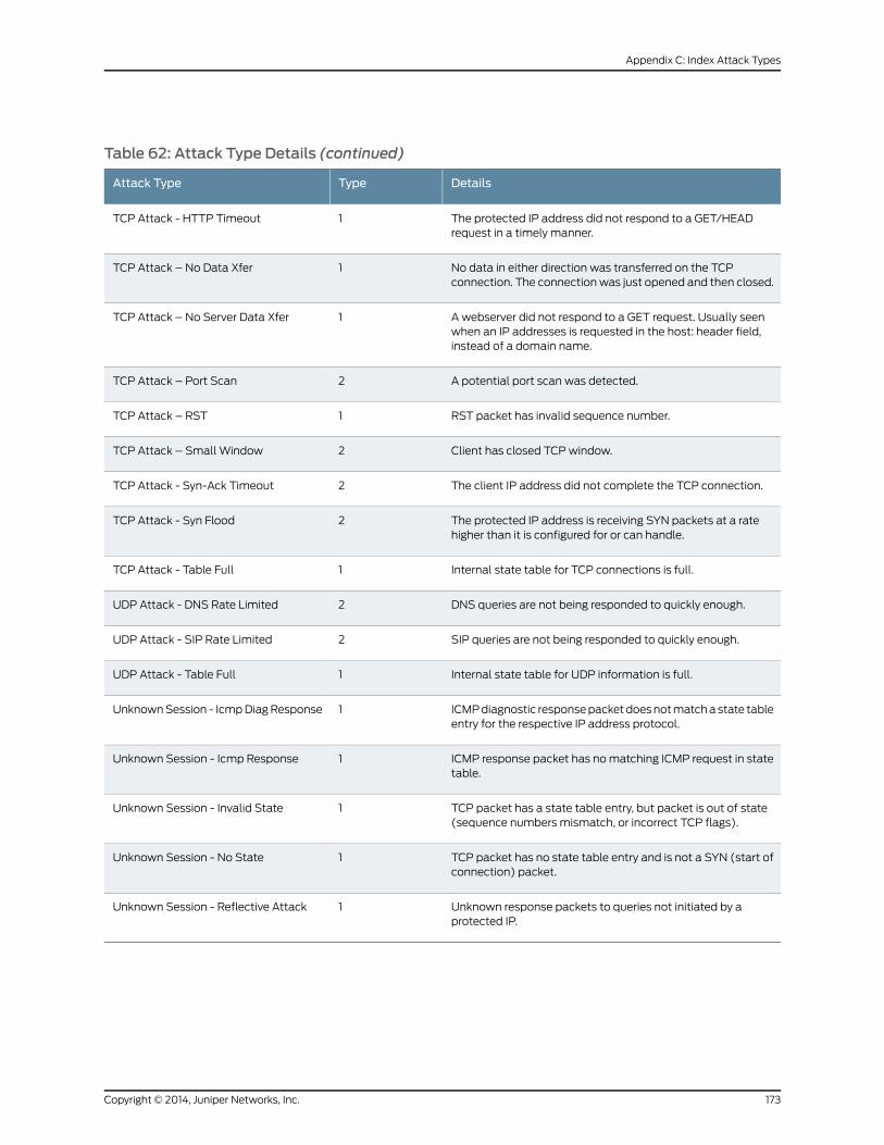
Table 62: Attack Type Details (continued)
DetailsTypeAttack Type
The protected IP address did not respond to a GET/HEADrequest in a timely manner.
1TCP Attack - HTTP Timeout
No data in either direction was transferred on the TCPconnection. The connectionwas just opened and then closed.
1TCP Attack – No Data Xfer
A webserver did not respond to a GET request. Usually seenwhen an IP addresses is requested in the host: header field,instead of a domain name.
1TCP Attack – No Server Data Xfer
A potential port scan was detected.2TCP Attack – Port Scan
RST packet has invalid sequence number.1TCP Attack – RST
Client has closed TCPwindow.2TCP Attack – Small Window
The client IP address did not complete the TCP connection.2TCP Attack - Syn-Ack Timeout
The protected IP address is receiving SYN packets at a ratehigher than it is configured for or can handle.
2TCP Attack - Syn Flood
Internal state table for TCP connections is full.1TCP Attack - Table Full
DNS queries are not being responded to quickly enough.2UDP Attack - DNS Rate Limited
SIP queries are not being responded to quickly enough.2UDP Attack - SIP Rate Limited
Internal state table for UDP information is full.1UDP Attack - Table Full
ICMPdiagnostic responsepacketdoesnotmatchastate tableentry for the respective IP address protocol.
1UnknownSession - IcmpDiagResponse
ICMP response packet has nomatching ICMP request in statetable.
1Unknown Session - Icmp Response
TCP packet has a state table entry, but packet is out of state(sequence numbers mismatch, or incorrect TCP flags).
1Unknown Session - Invalid State
TCP packet has no state table entry and is not a SYN (start ofconnection) packet.
1Unknown Session - No State
Unknown response packets to queries not initiated by aprotected IP.
1Unknown Session - Reflective Attack
173Copyright © 2014, Juniper Networks, Inc.
Appendix C: Index Attack Types

Copyright © 2014, Juniper Networks, Inc.174
DDoS Secure GUI User Guide
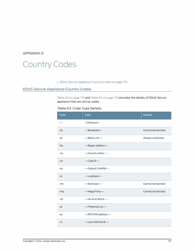
APPENDIX D
Country Codes
• DDoS Secure Appliance Country Codes on page 175
DDoS Secure Appliance Country Codes
Table 63 on page 175 and Table 64 on page 176 provides the details of DDoS Secure
appliance that are sort by codes.
Table 63: Code Type Details
DetailsTypeCode
--Unknown—---
Cannot be blocked---Broadcast----bc
Always is blocked---Black List----bl
---Bogon address----bo
---Country Allow ----ca
---Class E----ce
---Default CHARM----dc
---Loopback----lo
Cannot be blocked---Multicast----mc
Cannot be blocked---Mega Proxy----mp
---No Auto Block----nb
---Preferred List----pl
---RFC1918 address----pr
---User Defined #1----u1
175Copyright © 2014, Juniper Networks, Inc.
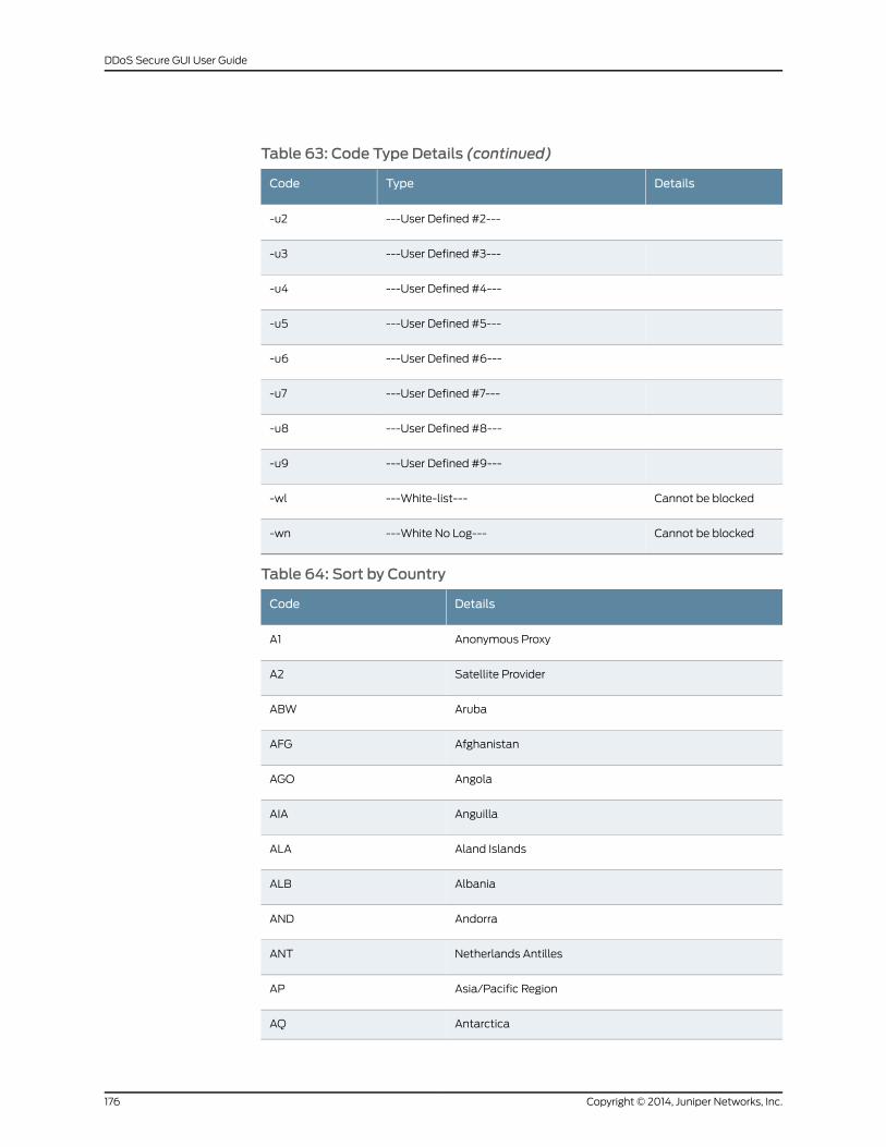
Table 63: Code Type Details (continued)
DetailsTypeCode
---User Defined #2----u2
---User Defined #3----u3
---User Defined #4----u4
---User Defined #5----u5
---User Defined #6----u6
---User Defined #7----u7
---User Defined #8----u8
---User Defined #9----u9
Cannot be blocked---White-list----wl
Cannot be blocked---White No Log----wn
Table 64: Sort by Country
DetailsCode
Anonymous ProxyA1
Satellite ProviderA2
ArubaABW
AfghanistanAFG
AngolaAGO
AnguillaAIA
Aland IslandsALA
AlbaniaALB
AndorraAND
Netherlands AntillesANT
Asia/Pacific RegionAP
AntarcticaAQ
Copyright © 2014, Juniper Networks, Inc.176
DDoS Secure GUI User Guide
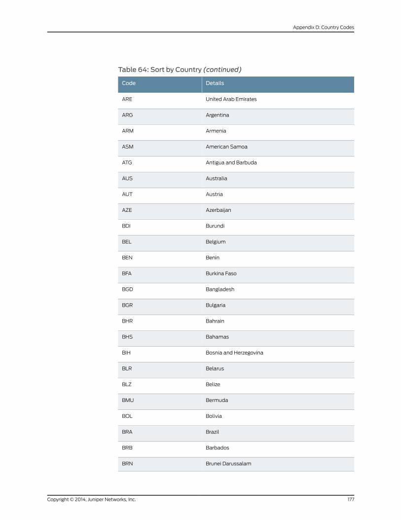
Table 64: Sort by Country (continued)
DetailsCode
United Arab EmiratesARE
ArgentinaARG
ArmeniaARM
American SamoaASM
Antigua and BarbudaATG
AustraliaAUS
AustriaAUT
AzerbaijanAZE
BurundiBDI
BelgiumBEL
BeninBEN
Burkina FasoBFA
BangladeshBGD
BulgariaBGR
BahrainBHR
BahamasBHS
Bosnia and HerzegovinaBIH
BelarusBLR
BelizeBLZ
BermudaBMU
BoliviaBOL
BrazilBRA
BarbadosBRB
Brunei DarussalamBRN
177Copyright © 2014, Juniper Networks, Inc.
Appendix D: Country Codes
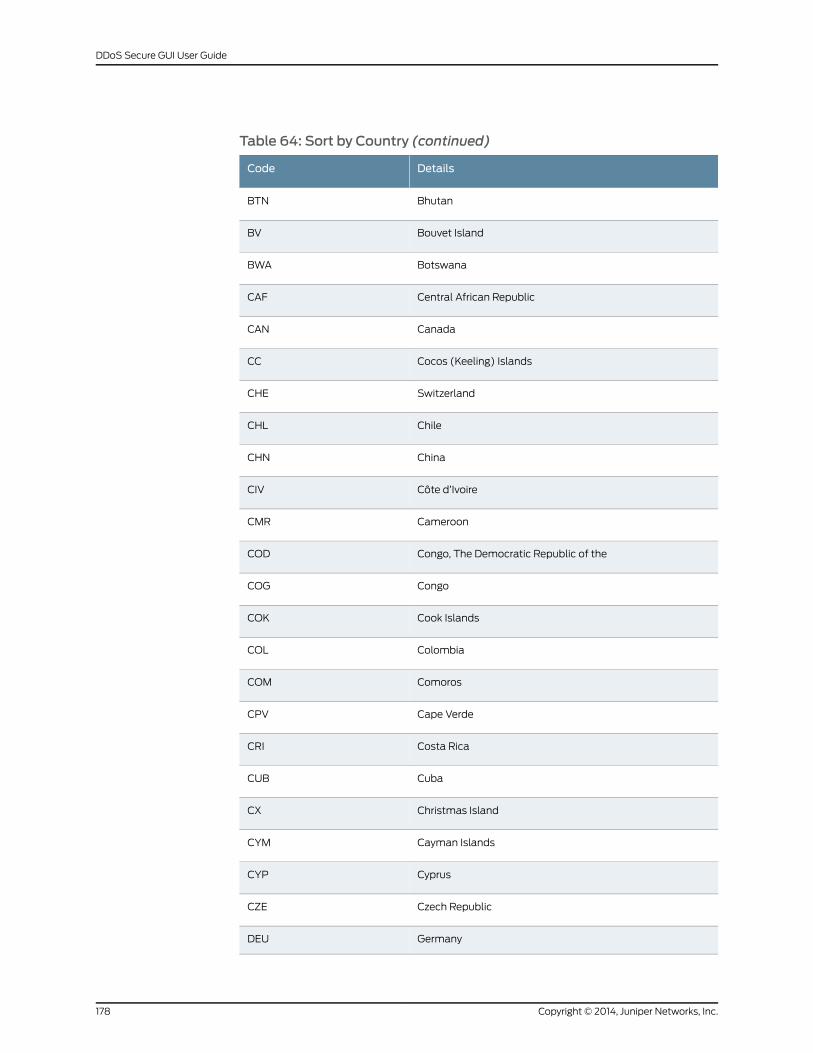
Table 64: Sort by Country (continued)
DetailsCode
BhutanBTN
Bouvet IslandBV
BotswanaBWA
Central African RepublicCAF
CanadaCAN
Cocos (Keeling) IslandsCC
SwitzerlandCHE
ChileCHL
ChinaCHN
Côte d’IvoireCIV
CameroonCMR
Congo, The Democratic Republic of theCOD
CongoCOG
Cook IslandsCOK
ColombiaCOL
ComorosCOM
Cape VerdeCPV
Costa RicaCRI
CubaCUB
Christmas IslandCX
Cayman IslandsCYM
CyprusCYP
Czech RepublicCZE
GermanyDEU
Copyright © 2014, Juniper Networks, Inc.178
DDoS Secure GUI User Guide
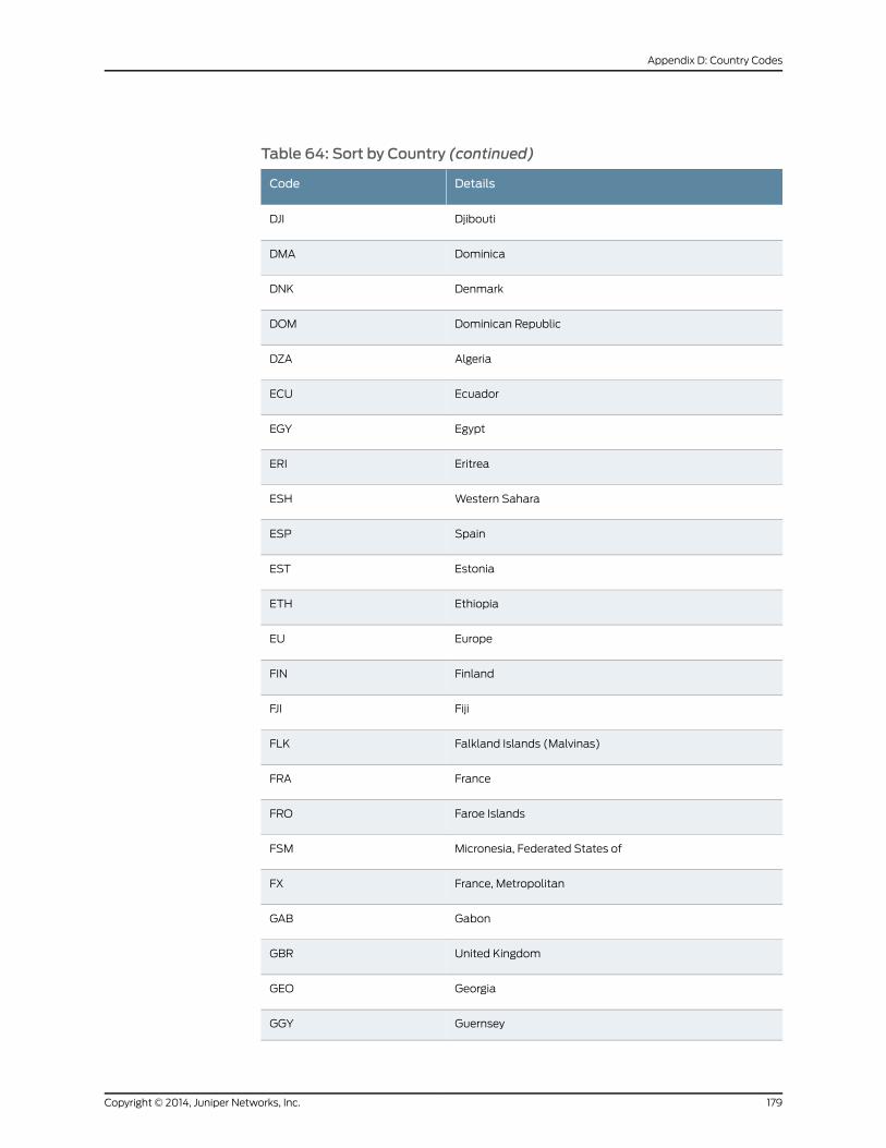
Table 64: Sort by Country (continued)
DetailsCode
DjiboutiDJI
DominicaDMA
DenmarkDNK
Dominican RepublicDOM
AlgeriaDZA
EcuadorECU
EgyptEGY
EritreaERI
Western SaharaESH
SpainESP
EstoniaEST
EthiopiaETH
EuropeEU
FinlandFIN
FijiFJI
Falkland Islands (Malvinas)FLK
FranceFRA
Faroe IslandsFRO
Micronesia, Federated States ofFSM
France, MetropolitanFX
GabonGAB
United KingdomGBR
GeorgiaGEO
GuernseyGGY
179Copyright © 2014, Juniper Networks, Inc.
Appendix D: Country Codes
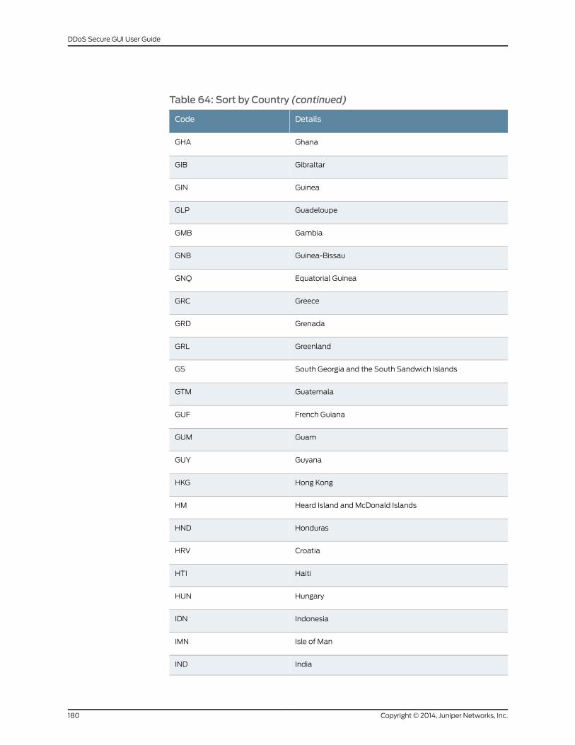
Table 64: Sort by Country (continued)
DetailsCode
GhanaGHA
GibraltarGIB
GuineaGIN
GuadeloupeGLP
GambiaGMB
Guinea-BissauGNB
Equatorial GuineaGNQ
GreeceGRC
GrenadaGRD
GreenlandGRL
South Georgia and the South Sandwich IslandsGS
GuatemalaGTM
French GuianaGUF
GuamGUM
GuyanaGUY
Hong KongHKG
Heard Island and McDonald IslandsHM
HondurasHND
CroatiaHRV
HaitiHTI
HungaryHUN
IndonesiaIDN
Isle of ManIMN
IndiaIND
Copyright © 2014, Juniper Networks, Inc.180
DDoS Secure GUI User Guide
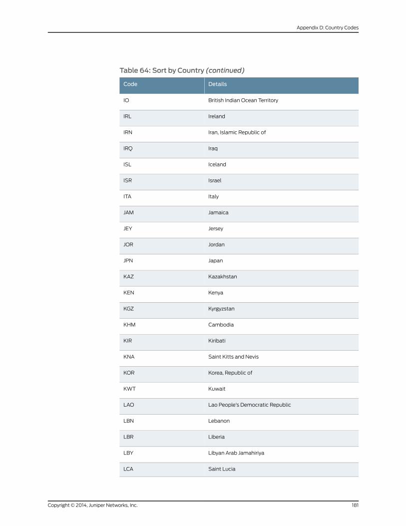
Table 64: Sort by Country (continued)
DetailsCode
British Indian Ocean TerritoryIO
IrelandIRL
Iran, Islamic Republic ofIRN
IraqIRQ
IcelandISL
IsraelISR
ItalyITA
JamaicaJAM
JerseyJEY
JordanJOR
JapanJPN
KazakhstanKAZ
KenyaKEN
KyrgyzstanKGZ
CambodiaKHM
KiribatiKIR
Saint Kitts and NevisKNA
Korea, Republic ofKOR
KuwaitKWT
Lao People’s Democratic RepublicLAO
LebanonLBN
LiberiaLBR
Libyan Arab JamahiriyaLBY
Saint LuciaLCA
181Copyright © 2014, Juniper Networks, Inc.
Appendix D: Country Codes
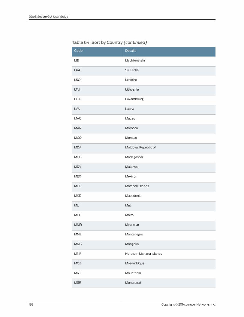
Table 64: Sort by Country (continued)
DetailsCode
LiechtensteinLIE
Sri LankaLKA
LesothoLSO
LithuaniaLTU
LuxembourgLUX
LatviaLVA
MacauMAC
MoroccoMAR
MonacoMCO
Moldova, Republic ofMDA
MadagascarMDG
MaldivesMDV
MexicoMEX
Marshall IslandsMHL
MacedoniaMKD
MaliMLI
MaltaMLT
MyanmarMMR
MontenegroMNE
MongoliaMNG
Northern Mariana IslandsMNP
MozambiqueMOZ
MauritaniaMRT
MontserratMSR
Copyright © 2014, Juniper Networks, Inc.182
DDoS Secure GUI User Guide

Table 64: Sort by Country (continued)
DetailsCode
MartiniqueMTQ
MauritiusMUS
MalawiMWI
MalaysiaMYS
NamibiaNAM
New CaledoniaNCL
NigerNER
Norfolk IslandNFK
NigeriaNGA
NicaraguaNIC
NiueNIU
NetherlandsNLD
NorwayNOR
NepalNPL
NauruNRU
New ZealandNZL
OtherO1
OmanOMN
PakistanPAK
PanamaPAN
Pitcairn IslandsPCN
PeruPER
PhilippinesPHL
PalauPLW
183Copyright © 2014, Juniper Networks, Inc.
Appendix D: Country Codes
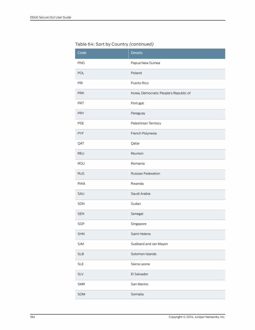
Table 64: Sort by Country (continued)
DetailsCode
Papua New GuineaPNG
PolandPOL
Puerto RicoPRI
Korea, Democratic People’s Republic ofPRK
PortugalPRT
ParaguayPRY
Palestinian TerritoryPSE
French PolynesiaPYF
QatarQAT
ReunionREU
RomaniaROU
Russian FederationRUS
RwandaRWA
Saudi ArabiaSAU
SudanSDN
SenegalSEN
SingaporeSGP
Saint HelenaSHN
Svalbard and Jan MayenSJM
Solomon IslandsSLB
Sierra LeoneSLE
El SalvadorSLV
San MarinoSMR
SomaliaSOM
Copyright © 2014, Juniper Networks, Inc.184
DDoS Secure GUI User Guide
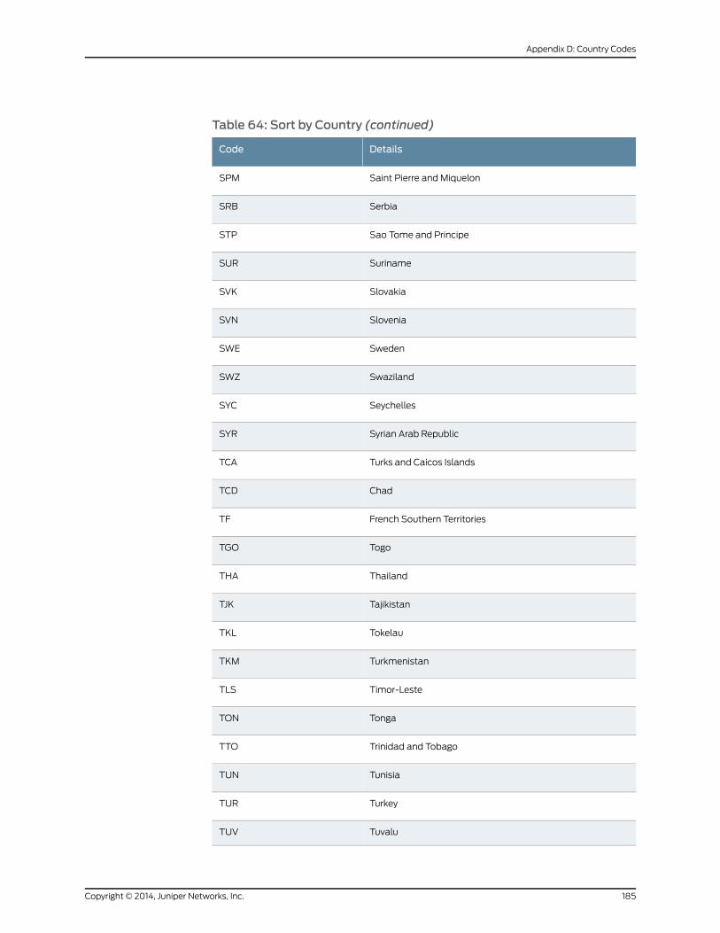
Table 64: Sort by Country (continued)
DetailsCode
Saint Pierre and MiquelonSPM
SerbiaSRB
Sao Tome and PrincipeSTP
SurinameSUR
SlovakiaSVK
SloveniaSVN
SwedenSWE
SwazilandSWZ
SeychellesSYC
Syrian Arab RepublicSYR
Turks and Caicos IslandsTCA
ChadTCD
French Southern TerritoriesTF
TogoTGO
ThailandTHA
TajikistanTJK
TokelauTKL
TurkmenistanTKM
Timor-LesteTLS
TongaTON
Trinidad and TobagoTTO
TunisiaTUN
TurkeyTUR
TuvaluTUV
185Copyright © 2014, Juniper Networks, Inc.
Appendix D: Country Codes
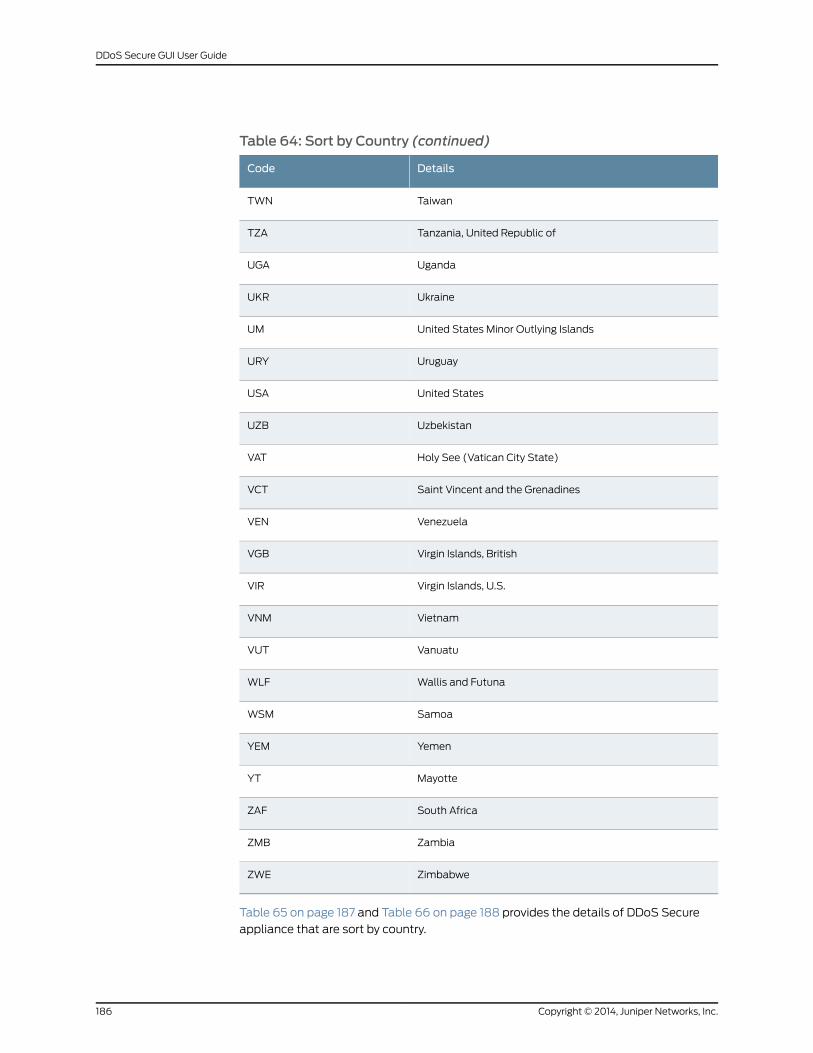
Table 64: Sort by Country (continued)
DetailsCode
TaiwanTWN
Tanzania, United Republic ofTZA
UgandaUGA
UkraineUKR
United States Minor Outlying IslandsUM
UruguayURY
United StatesUSA
UzbekistanUZB
Holy See (Vatican City State)VAT
Saint Vincent and the GrenadinesVCT
VenezuelaVEN
Virgin Islands, BritishVGB
Virgin Islands, U.S.VIR
VietnamVNM
VanuatuVUT
Wallis and FutunaWLF
SamoaWSM
YemenYEM
MayotteYT
South AfricaZAF
ZambiaZMB
ZimbabweZWE
Table 65 on page 187 and Table 66 on page 188 provides the details of DDoS Secure
appliance that are sort by country.
Copyright © 2014, Juniper Networks, Inc.186
DDoS Secure GUI User Guide
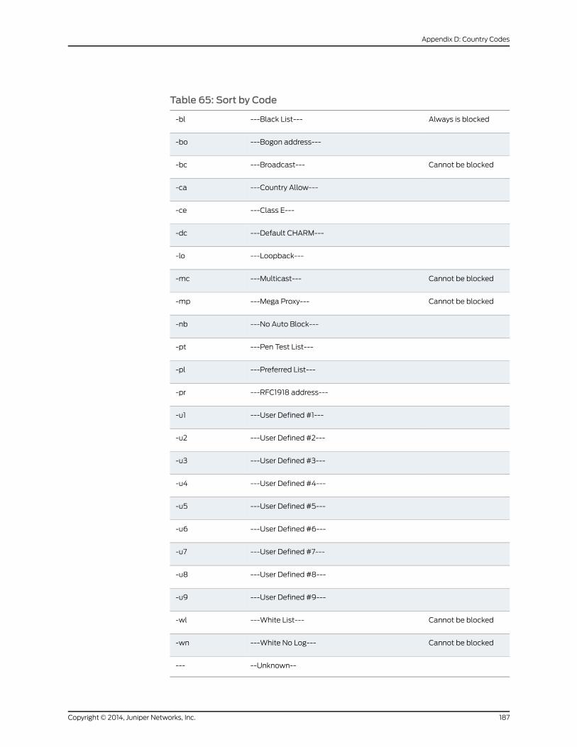
Table 65: Sort by Code
Always is blocked---Black List----bl
---Bogon address----bo
Cannot be blocked---Broadcast----bc
---Country Allow----ca
---Class E----ce
---Default CHARM----dc
---Loopback----lo
Cannot be blocked---Multicast----mc
Cannot be blocked---Mega Proxy----mp
---No Auto Block----nb
---Pen Test List----pt
---Preferred List----pl
---RFC1918 address----pr
---User Defined #1----u1
---User Defined #2----u2
---User Defined #3----u3
---User Defined #4----u4
---User Defined #5----u5
---User Defined #6----u6
---User Defined #7----u7
---User Defined #8----u8
---User Defined #9----u9
Cannot be blocked---White List----wl
Cannot be blocked---White No Log----wn
--Unknown-----
187Copyright © 2014, Juniper Networks, Inc.
Appendix D: Country Codes
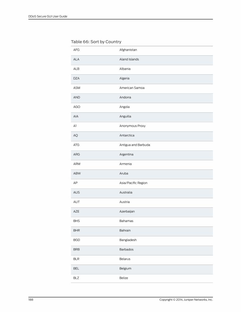
Table 66: Sort by Country
AfghanistanAFG
Aland IslandsALA
AlbaniaALB
AlgeriaDZA
American SamoaASM
AndorraAND
AngolaAGO
AnguillaAIA
Anonymous ProxyA1
AntarcticaAQ
Antigua and BarbudaATG
ArgentinaARG
ArmeniaARM
ArubaABW
Asia/Pacific RegionAP
AustraliaAUS
AustriaAUT
AzerbaijanAZE
BahamasBHS
BahrainBHR
BangladeshBGD
BarbadosBRB
BelarusBLR
BelgiumBEL
BelizeBLZ
Copyright © 2014, Juniper Networks, Inc.188
DDoS Secure GUI User Guide
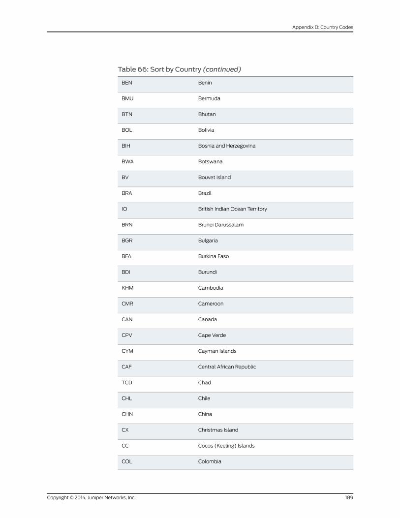
Table 66: Sort by Country (continued)
BeninBEN
BermudaBMU
BhutanBTN
BoliviaBOL
Bosnia and HerzegovinaBIH
BotswanaBWA
Bouvet IslandBV
BrazilBRA
British Indian Ocean TerritoryIO
Brunei DarussalamBRN
BulgariaBGR
Burkina FasoBFA
BurundiBDI
CambodiaKHM
CameroonCMR
CanadaCAN
Cape VerdeCPV
Cayman IslandsCYM
Central African RepublicCAF
ChadTCD
ChileCHL
ChinaCHN
Christmas IslandCX
Cocos (Keeling) IslandsCC
ColombiaCOL
189Copyright © 2014, Juniper Networks, Inc.
Appendix D: Country Codes
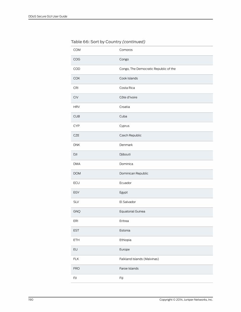
Table 66: Sort by Country (continued)
ComorosCOM
CongoCOG
Congo, The Democratic Republic of theCOD
Cook IslandsCOK
Costa RicaCRI
Côte d’IvoireCIV
CroatiaHRV
CubaCUB
CyprusCYP
Czech RepublicCZE
DenmarkDNK
DjiboutiDJI
DominicaDMA
Dominican RepublicDOM
EcuadorECU
EgyptEGY
El SalvadorSLV
Equatorial GuineaGNQ
EritreaERI
EstoniaEST
EthiopiaETH
EuropeEU
Falkland Islands (Malvinas)FLK
Faroe IslandsFRO
FijiFJI
Copyright © 2014, Juniper Networks, Inc.190
DDoS Secure GUI User Guide
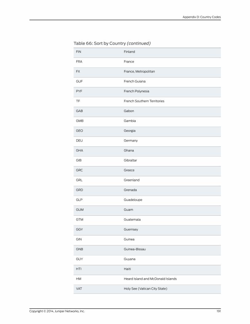
Table 66: Sort by Country (continued)
FinlandFIN
FranceFRA
France, MetropolitanFX
French GuianaGUF
French PolynesiaPYF
French Southern TerritoriesTF
GabonGAB
GambiaGMB
GeorgiaGEO
GermanyDEU
GhanaGHA
GibraltarGIB
GreeceGRC
GreenlandGRL
GrenadaGRD
GuadeloupeGLP
GuamGUM
GuatemalaGTM
GuernseyGGY
GuineaGIN
Guinea-BissauGNB
GuyanaGUY
HaitiHTI
Heard Island and McDonald IslandsHM
Holy See (Vatican City State)VAT
191Copyright © 2014, Juniper Networks, Inc.
Appendix D: Country Codes
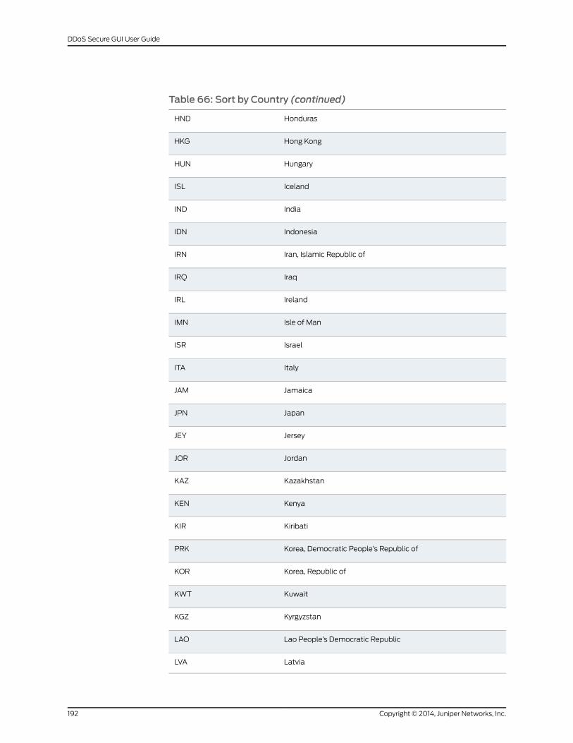
Table 66: Sort by Country (continued)
HondurasHND
Hong KongHKG
HungaryHUN
IcelandISL
IndiaIND
IndonesiaIDN
Iran, Islamic Republic ofIRN
IraqIRQ
IrelandIRL
Isle of ManIMN
IsraelISR
ItalyITA
JamaicaJAM
JapanJPN
JerseyJEY
JordanJOR
KazakhstanKAZ
KenyaKEN
KiribatiKIR
Korea, Democratic People’s Republic ofPRK
Korea, Republic ofKOR
KuwaitKWT
KyrgyzstanKGZ
Lao People’s Democratic RepublicLAO
LatviaLVA
Copyright © 2014, Juniper Networks, Inc.192
DDoS Secure GUI User Guide
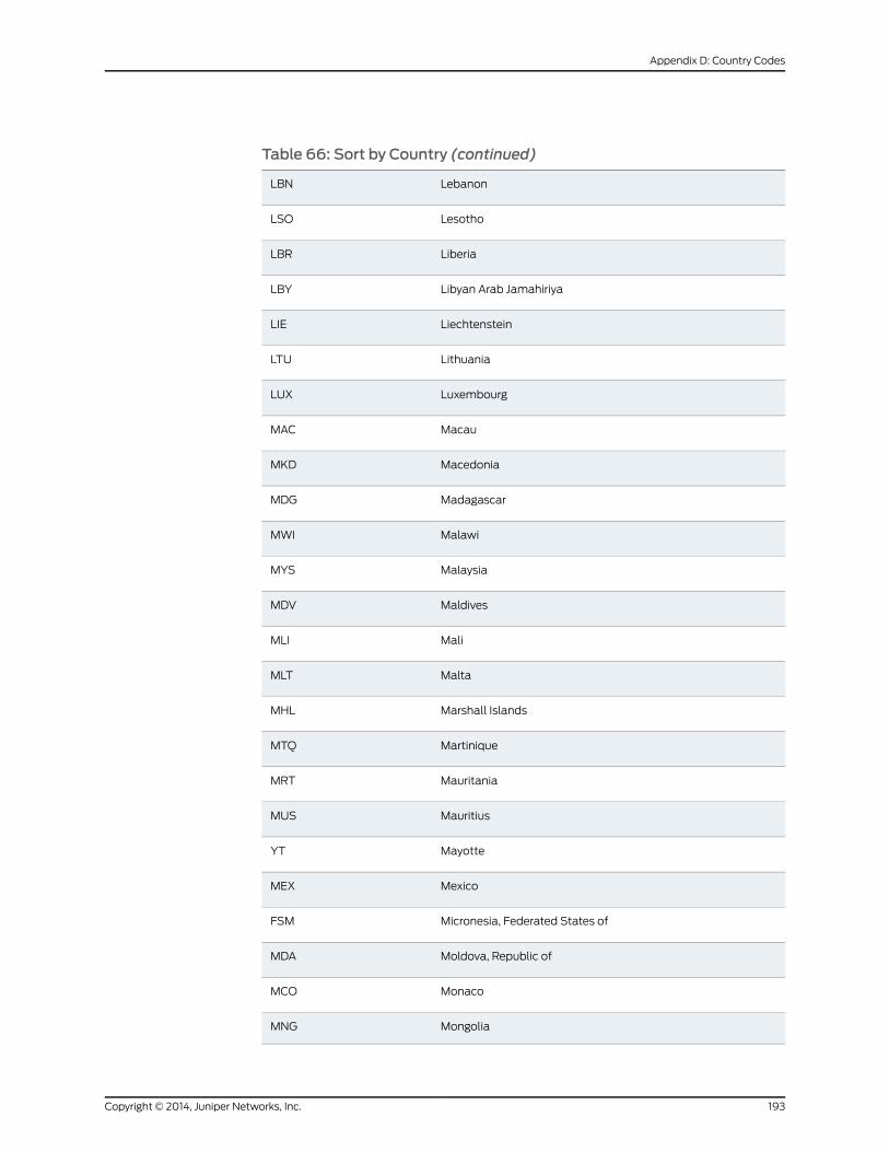
Table 66: Sort by Country (continued)
LebanonLBN
LesothoLSO
LiberiaLBR
Libyan Arab JamahiriyaLBY
LiechtensteinLIE
LithuaniaLTU
LuxembourgLUX
MacauMAC
MacedoniaMKD
MadagascarMDG
MalawiMWI
MalaysiaMYS
MaldivesMDV
MaliMLI
MaltaMLT
Marshall IslandsMHL
MartiniqueMTQ
MauritaniaMRT
MauritiusMUS
MayotteYT
MexicoMEX
Micronesia, Federated States ofFSM
Moldova, Republic ofMDA
MonacoMCO
MongoliaMNG
193Copyright © 2014, Juniper Networks, Inc.
Appendix D: Country Codes
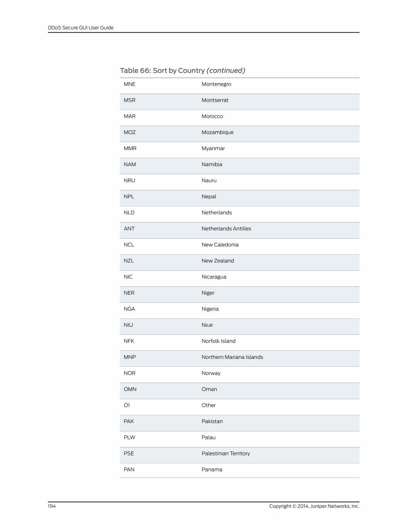
Table 66: Sort by Country (continued)
MontenegroMNE
MontserratMSR
MoroccoMAR
MozambiqueMOZ
MyanmarMMR
NamibiaNAM
NauruNRU
NepalNPL
NetherlandsNLD
Netherlands AntillesANT
New CaledoniaNCL
New ZealandNZL
NicaraguaNIC
NigerNER
NigeriaNGA
NiueNIU
Norfolk IslandNFK
Northern Mariana IslandsMNP
NorwayNOR
OmanOMN
OtherO1
PakistanPAK
PalauPLW
Palestinian TerritoryPSE
PanamaPAN
Copyright © 2014, Juniper Networks, Inc.194
DDoS Secure GUI User Guide
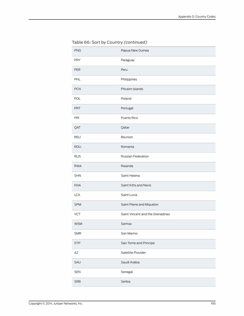
Table 66: Sort by Country (continued)
Papua New GuineaPNG
ParaguayPRY
PeruPER
PhilippinesPHL
Pitcairn IslandsPCN
PolandPOL
PortugalPRT
Puerto RicoPRI
QatarQAT
ReunionREU
RomaniaROU
Russian FederationRUS
RwandaRWA
Saint HelenaSHN
Saint Kitts and NevisKNA
Saint LuciaLCA
Saint Pierre and MiquelonSPM
Saint Vincent and the GrenadinesVCT
SamoaWSM
SanMarinoSMR
Sao Tome and PrincipeSTP
Satellite ProviderA2
Saudi ArabiaSAU
SenegalSEN
SerbiaSRB
195Copyright © 2014, Juniper Networks, Inc.
Appendix D: Country Codes
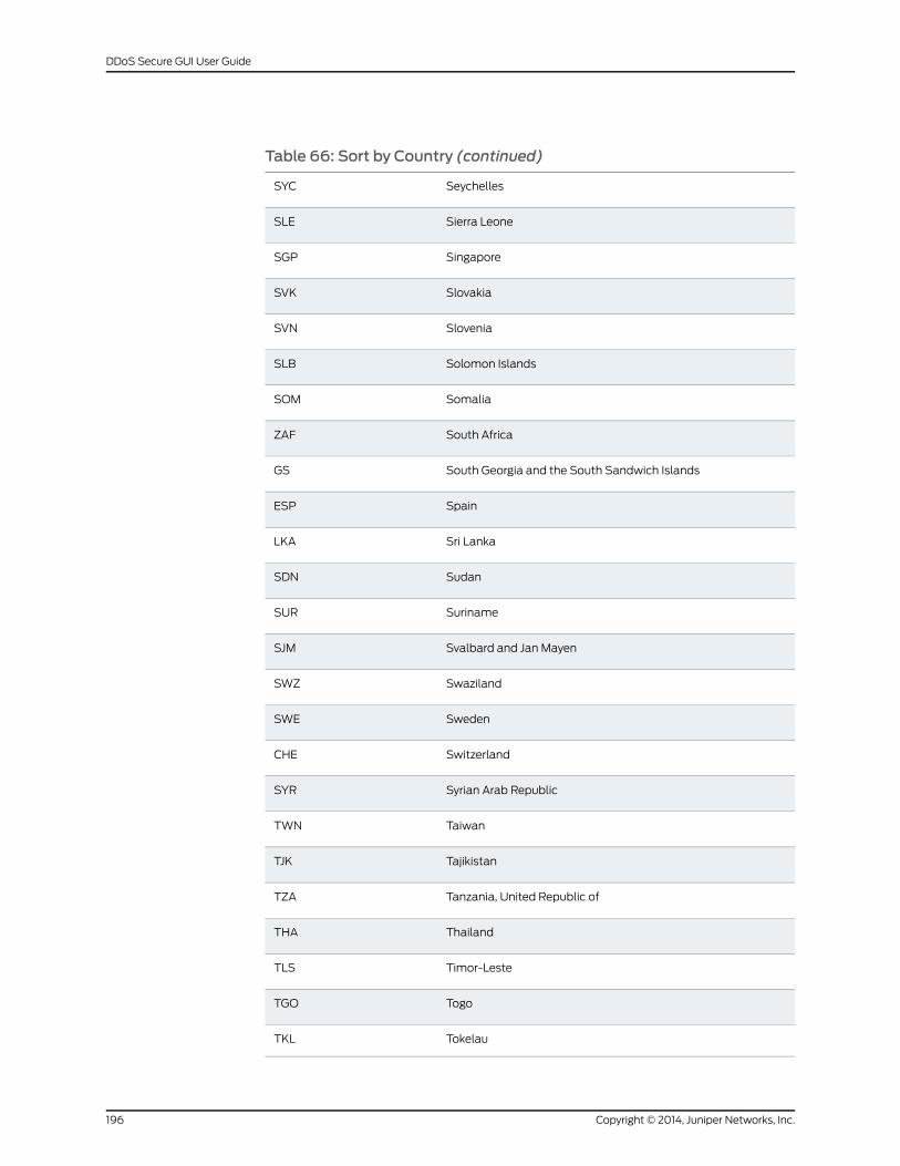
Table 66: Sort by Country (continued)
SeychellesSYC
Sierra LeoneSLE
SingaporeSGP
SlovakiaSVK
SloveniaSVN
Solomon IslandsSLB
SomaliaSOM
South AfricaZAF
South Georgia and the South Sandwich IslandsGS
SpainESP
Sri LankaLKA
SudanSDN
SurinameSUR
Svalbard and Jan MayenSJM
SwazilandSWZ
SwedenSWE
SwitzerlandCHE
Syrian Arab RepublicSYR
TaiwanTWN
TajikistanTJK
Tanzania, United Republic ofTZA
ThailandTHA
Timor-LesteTLS
TogoTGO
TokelauTKL
Copyright © 2014, Juniper Networks, Inc.196
DDoS Secure GUI User Guide
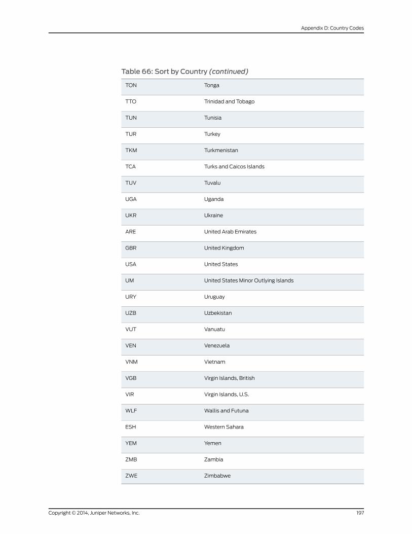
Table 66: Sort by Country (continued)
TongaTON
Trinidad and TobagoTTO
TunisiaTUN
TurkeyTUR
TurkmenistanTKM
Turks and Caicos IslandsTCA
TuvaluTUV
UgandaUGA
UkraineUKR
United Arab EmiratesARE
United KingdomGBR
United StatesUSA
United States Minor Outlying IslandsUM
UruguayURY
UzbekistanUZB
VanuatuVUT
VenezuelaVEN
VietnamVNM
Virgin Islands, BritishVGB
Virgin Islands, U.S.VIR
Wallis and FutunaWLF
Western SaharaESH
YemenYEM
ZambiaZMB
ZimbabweZWE
197Copyright © 2014, Juniper Networks, Inc.
Appendix D: Country Codes

RelatedDocumentation
• Understanding Index Attack Types on page 169
Copyright © 2014, Juniper Networks, Inc.198
DDoS Secure GUI User Guide
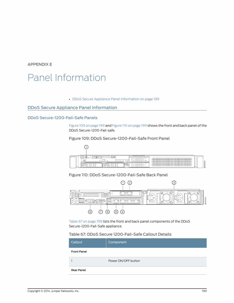
APPENDIX E
Panel Information
• DDoS Secure Appliance Panel Information on page 199
DDoS Secure Appliance Panel Information
DDoS Secure-1200-Fail-Safe Panels
Figure 109 on page 199 and Figure 110 on page 199 shows the front and back panel of the
DDoS Secure-1200-Fail-safe.
Figure 109: DDoS Secure-1200-Fail-Safe Front Panel
Figure 110: DDoS Secure-1200-Fail-Safe Back Panel
Table 67 on page 199 lists the front and back panel components of the DDoS
Secure-1200-Fail-Safe appliance.
Table 67: DDoS Secure 1200-Fail-Safe Callout Details
ComponentCallout
Front Panel
Power ON/OFF button1
Rear Panel
199Copyright © 2014, Juniper Networks, Inc.
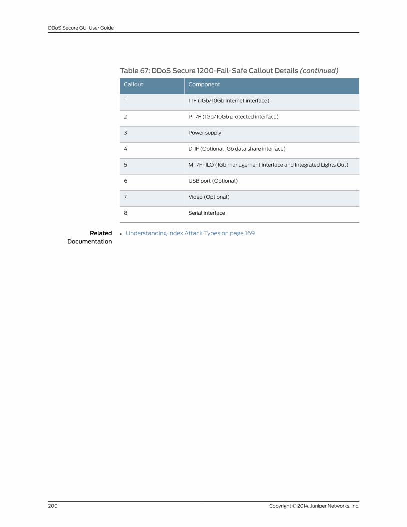
Table 67: DDoS Secure 1200-Fail-Safe Callout Details (continued)
ComponentCallout
I-IF (1Gb/10Gb Internet interface)1
P-I/F (1Gb/10Gb protected interface)2
Power supply3
D-IF (Optional 1Gb data share interface)4
M-I/F+ILO (1Gbmanagement interface and Integrated Lights Out)5
USB port (Optional)6
Video (Optional)7
Serial interface8
RelatedDocumentation
• Understanding Index Attack Types on page 169
Copyright © 2014, Juniper Networks, Inc.200
DDoS Secure GUI User Guide
APPENDIX F
Troubleshooting
• Troubleshooting a DDoS Secure Appliance on page 201
Troubleshooting a DDoS Secure Appliance
1. My browser gives an SSL connection error.
If the DDoS Secure appliance SSL certificate changes for any reason, some PC
browsers chokeon thepreviously installed certificate. If so, the old certificatewill have
to be removed by hand from the Browser Root Certificate cache. It is possible that
exiting the browser and reconnecting fixes the situation.
2. How do I recover my lost username and password?
You are unable to recover the username and password. If Juniper Networks personnel
able to access your appliance, they might be able to reset the password. It might be
that you have to re-image the system.
3. What does Init Phase xxxmean?
When theappliancestartsup, various largedatasetshave tobe initialized. Eachphase
is the initialization of a different data set.
4. What does Exit Phase xxxmean?
When the appliance closes down, various large data sets have to be cleanly closed
down. Each phase is the cleanup of a different data set.
5. Why do I get Protected IP Table Full turning to red?
The appliance is set up to protect a maximum number of protected IP addresses. If
this limit is exceeded, then protected IP address table full will turn to red. If your I-I/F
and P-I/F connectors are reversed, the appliance is effectively protecting the Internet
from your internal users. Confirm this using the Protected Information option. Correct
any cabling errors. Review the location of the appliance in your network topology, if
theappliancehas toprotectmore than thespecifiednumberofprotected IPaddresses.
If cabling arrangements are logically reversed without physical disconnection, the
DDoS Secure appliance engine must be restarted to ensure the correct automatic
detection of the network topology. It is also possible to swap the interfaces with
Configure Interfaces option.
201Copyright © 2014, Juniper Networks, Inc.

RelatedDocumentation
• Understanding Index Attack Types on page 169
Copyright © 2014, Juniper Networks, Inc.202
DDoS Secure GUI User Guide

APPENDIX G
Customizing theWeb Interface
• Customizing the DDoS SecureWeb Interface on page 203
Customizing the DDoS SecureWeb Interface
You can customize both the GUI initial login landing page and the format/style of pages.
Login Page
To customize the login page:
1. Take a copy of the source of the initial login page, https://a.b.c.d, and save it locally.
2. Name the file customer.tmpl or host_uri-customer.tmpl, where host_uri is the name
or IP address that a user uses to access the DDoS Secure appliance.
The customer.tmpl file:
• Is preserved across software upgrades.
• Can include references to external URLs.
• Can reference existing image files or portal-specific images.
• Must link to webviewcheck.wsp to enter the DDoS Secure appliance portal.
For example, If the site is accessed with the URL https://some.host.com, then the
search sequence is some.host.com-customer.tmpl, then customer.tmpl, and finally
the original login page.
Images/CSS Files
Onceyouhave logged in, youareassociatedwithaportal. Any .css file in the /cssdirectory,
or any images in the /images directory, can be customized to modify the output.
For example, you are logged in to portal CustomerX and are requesting
css/center_pane.css. The search order is css/portal-CustomerX-center_pane.css, then
css/portal-center_pane.css, and finally css/center_pane.css. The same is true for any
images.
203Copyright © 2014, Juniper Networks, Inc.
Updating Customized Files
To upload the files on a Linux server, you need to collect all the customized files in a
directory, and then run the following Linux command to create an update package:
echow.x.y>webscreen- ; tar cvf files.upgwebscreen-*customer.tmplportal*.cssportal*.gif
wherew.x.y is the current version of the DDoS Secure appliance (for example: 5.13.1),
and then upload files.upg as a DDoS Secure appliance patch.
Removing Customized Files
Run the following command from the CLI to remove any custom files:
JS>system clear_custom
Copyright © 2014, Juniper Networks, Inc.204
DDoS Secure GUI User Guide
APPENDIX H
TAP Mode
• Configuring DDoS Secure for Running in TAPMode on page 205
Configuring DDoS Secure for Running in TAPMode
DDoSSecure needs todetect the traffic flowing in bothdirections in order to detect Layer
7 attacks as well as detect when protected resources are beginning to get overloaded.
For example, there is a maximum TCP connection count reached.
Doing this on a spanport creates a challenge asDDoSSecure has to identifywhich traffic
is on the Internet side and which traffic is on the protected side. This is done by defining
the location of different MAC addresses that DDoS Secure then uses for determining
what is protected traffic.
CAUTION: RunningDDoSSecure inTAPmodewill give rise to falsepositives,but for proof of concepts, the only acceptable way of demonstrating thecapabilities of DDoS Secure is running DDoS Secure off a span port on aswitch.
DDoS Secure needs to view the traffic flowing in both directions in order to detect Layer
7 attacks as well as detect when protected resources are beginning to get overloaded.
For example, there is a maximum TCP connection count being reached.
The reason for the false positives has to do with packet sequencing. For example, take
the classic TCP 3-way handshake.
1. Client to server SYN
2. Server to client SYN-ACK
3. Client to server ACK
Packet 2 will be flowing through the switch containing the span port in the opposite
direction. It is therefore possible that (as a result of packet serializing within the switch)
that these packets might arrive at the DDoS Secure appliance in the following order:
1. Client to server SYN
2. Client to server ACK
205Copyright © 2014, Juniper Networks, Inc.
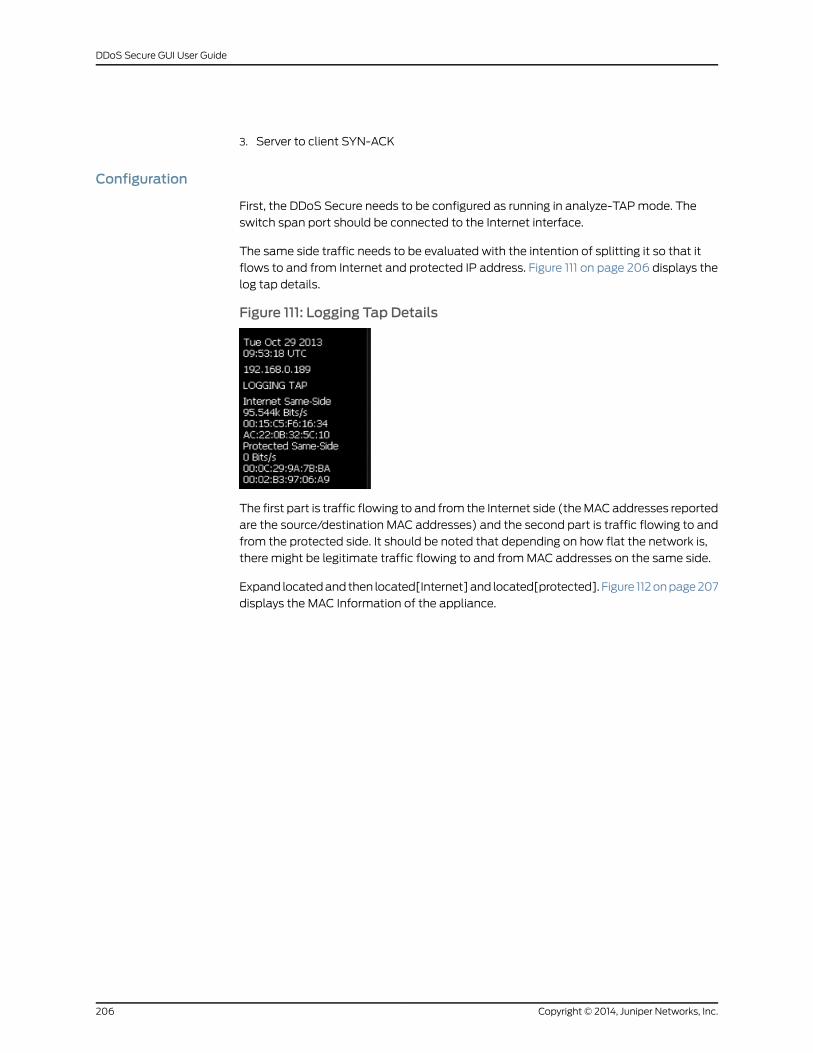
3. Server to client SYN-ACK
Configuration
First, the DDoS Secure needs to be configured as running in analyze-TAPmode. The
switch span port should be connected to the Internet interface.
The same side traffic needs to be evaluated with the intention of splitting it so that it
flows to and from Internet and protected IP address. Figure 111 on page 206 displays the
log tap details.
Figure 111: Logging Tap Details
The first part is traffic flowing to and from the Internet side (theMACaddresses reported
are the source/destination MAC addresses) and the second part is traffic flowing to and
from the protected side. It should be noted that depending on how flat the network is,
there might be legitimate traffic flowing to and fromMAC addresses on the same side.
Expand locatedand then located[Internet]and located[protected]. Figure 112onpage207
displays the MAC Information of the appliance.
Copyright © 2014, Juniper Networks, Inc.206
DDoS Secure GUI User Guide
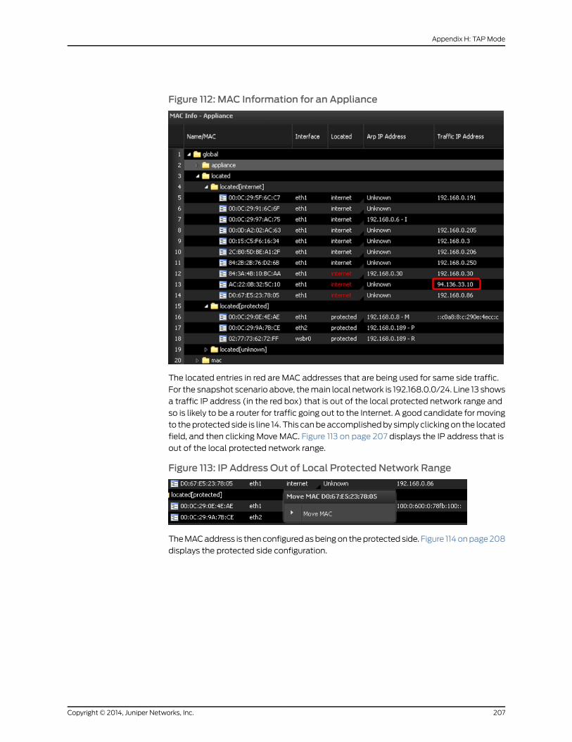
Figure 112: MAC Information for an Appliance
The located entries in red are MAC addresses that are being used for same side traffic.
For the snapshot scenario above, themain local network is 192.168.0.0/24. Line 13 shows
a traffic IP address (in the red box) that is out of the local protected network range and
so is likely to be a router for traffic going out to the Internet. A good candidate formoving
to theprotected side is line 14. This canbeaccomplishedby simply clickingon the located
field, and then clicking Move MAC. Figure 113 on page 207 displays the IP address that is
out of the local protected network range.
Figure 113: IP Address Out of Local Protected Network Range
TheMACaddress is thenconfiguredasbeingon theprotectedside. Figure 114onpage208
displays the protected side configuration.
207Copyright © 2014, Juniper Networks, Inc.
Appendix H: TAPMode
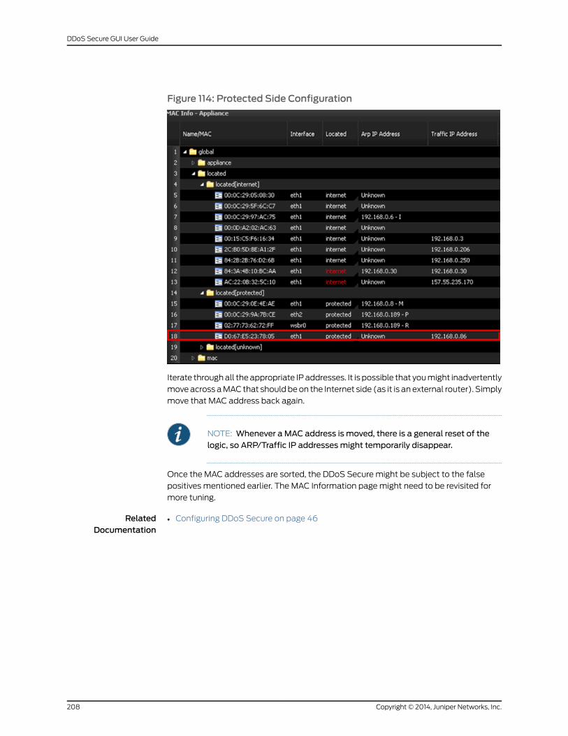
Figure 114: Protected Side Configuration
Iterate throughall theappropriate IPaddresses. It is possible that youmight inadvertently
moveacross aMAC that shouldbeon the Internet side (as it is an external router). Simply
move that MAC address back again.
NOTE: Whenever a MAC address is moved, there is a general reset of thelogic, so ARP/Traffic IP addressesmight temporarily disappear.
Once the MAC addresses are sorted, the DDoS Secure might be subject to the false
positives mentioned earlier. The MAC Information pagemight need to be revisited for
more tuning.
RelatedDocumentation
• Configuring DDoS Secure on page 46
Copyright © 2014, Juniper Networks, Inc.208
DDoS Secure GUI User Guide