dcs thyristor power converters for dc drive systems 25 to … · dcs thyristor power converters for...
TRANSCRIPT

DCS Thyristor Power Convertersfor DC Drive Systems
25 to 5150 A
Operating Instructions
DCS 600 MultiDrive
ABB Automation

How to use the DCS Documentation System
The matrix below indicates all available product documentation and its corresponding order numbers on its left columns aswell as all existing DC Drive systems on its top rows. System descriptions, Technical data and Operating instructions (asfar as they are available for the corresponding drive) are the basic documents and will be delivered together with eachdrive. All other documentation has to be ordered separately.
DC drive systems System Drive Standard Drive 5HEXLOG
Cubicle Module Cubicle Module
Product documentation DC
V 7
00
DC
A 6
00 M
ultiD
rive
DC
F 7
00/5
00
DC
A 6
20 M
ultiD
rive
DC
S 5
00...
11
DC
S 6
00 M
ultiD
rive
DC
F 5
00
DC
F 6
00 M
ultiD
rive
DC
S 5
00 e
nclo
sed
DC
S 5
00B
enc
lose
d
DC
S 4
00
DC
S 5
00...
21
DC
S 5
00B
DC
P 5
00
DC
P 5
00B
DC
R
System description Language Volume3ADW000049 EN, DE II A x x3ADW000062 EN, DE II B x 3ADW000066 EN, DE,FR II D x x3ADW000069 EN, DE II E x3ADW000072 EN, DE II F x x3ADW000121 ➀ EN II F1 x x3ADW000095 (Manual) ➁ EN,DE,FR,IT,SP II K x
Technical Data Language Volume3ADW000054 EN, DE,FR III x x x x x x x x
Operating Instructions Language Volume3ADW000055 EN,DE,FR,SP IV A x x x x x x3ADW000064 EN, DE IV C x x3ADW000080 EN, DE IV F x x x x3ADW000091 (Installation) EN, DE IV F1 x x x x x
Software description Language Volume3ADW000056 EN V A1 x x x3ADW000078 EN V D1 x x x3ADW000076 EN V F x x x x3ADW000050 EN - x x3ADW000031 (Diagr.) EN - x x3ADW000053 EN V C x x3ADW000052 (Diagr.) EN V C x x
Tools Language Volume3AFE61178775 CMT/DCS500 EN - x x x x x xEN 5926915-1 GAD EN - x x x x x x3ADW000048 (Application blocks) EN V A2 x x x x x x3AFY61041486 DDCTool EN - x x x x x x x x x x3AFY61296123 Drive Window EN - x x x x
6HUYLFH�,QVWUXFWLRQV Language Volume3ADW000093 EN VI A x x x x x x x x x x x x3ADW000131 EN VI K x
)LHOGEXV Language Volume3ADW000086 EN - x x x3ADW000097 EN - x x x x
Others Language Volume3ADW000115 12-Pulse operation EN II F2 x x3ADW000092 Rebuild manual EN II H x x x x x x x x x x x x3ADW000128 Paralleling DCS Conv. EN II H1 x x x x
Status: 13.July.1999
➀ Covers information of Technical data➁ Covers information of Technical data, Operating Instructions, Software Description
avai
labl
e on
ly fo
r: D
CS
500
/ 50
0B /
600
driv
e sy
stem
s

2000 ABB Automation Products GmbH. All rights reserved.
Thyristor Power Converters
SeriesDCS 600 MultiDrive
25 to 5150 A
OPERATING INSTRUCTIONS
Code: 3ADW 000 080 R0501 Rev E
DCS6BAEE.DOC
EFFECTIVE: Dec. 18th, 2000SUPERSEDES: Rev D - Dec. 3rd, 1999

DCS 600 Operating Instructions

Safety Instructions
DCS 600 Operating Instructions i
Overview This chapter contains safety instructions which must be compliedwith during installation, operation and maintenance of the powerconverters series DCS 600 MultiDrive. If these instructions arenot complied with, this may result in injuries (perhaps even withfatal) or in damage to the power converter, the motor and thedriven machine. Before starting with any work whatsoever at orwith this unit, you must read the information given in this chapter.
Warnings Warnings provide information on states which if the specifiedprocedure for the state concerned is not meticulously compliedwith may result in a serious error, in major damage to the unit, ininjury to persons and even in death.They are identified by the following symbols:
Danger: High Voltage! This symbol warns you ofhigh voltages which may result in injuries to personsand/or damage to equipment. Where appropriate, thetext printed adjacent to this symbol describes howrisks of this kind may be avoided.
� All electrical installation and maintenance work on the thyristorpower converter must be carried out by properly qualified staffwho have been thoroughly trained in electrical engineering.
� The thyristor power converter and its adjacent units must beproperly earthed by qualified professionals.
� You must NEVER perform any work on the thyristor powerconverter while it is still switched on. First switch the unit off,use a measuring instrument to make absolutely sure that thepower converter has really been de-energized, and only thenyou may start with the work concerned.
� Due to external control circuits, there may be dangerouslyhigh voltages present at the thyristor power converter evenafter the line voltage has been switched off. So always workat the unit with appropriate caution! Non-compliance with theseinstructions may result in injury (or even death!).
Safety Instructions
ii DCS 600 Operating Instructions
General warning: this symbol warns you of non-electrical risks and dangers which may result in seri-ous or even fatal injury to persons and/or in damageto equipment. Where appropriate, the text printed ad-jacent to this symbol describes how risks of this kindmay be avoided.
� When thyristor power converters are in use, the electric motors,power transmission elements and the driven machines areworking in an extended operating range, which means they haveto cope with a relatively high loading.
� You should have made sure that all units, devices and appli-ances used are actually suitable for this higher loading.
� If you have to operate the thyristor power converter at a ratedmotor voltage and/or a rated motor current significantly belowthe figures stated in the thyristor power converter’s output data,you must take appropriate precautionary measures to protectthe unit against overspeed, overload, breakage, etc., by modify-ing the software or hardware appropriately.
� For insulation testing, you must disconnect all cables from thethyristor power converter. You should avoid operating your unitat values other than the rated data. Non-compliance with theseinstructions may cause lasting damage to the thyristor powerconverter.
� The thyristor power converter possesses a number of automaticreset functions. When these functions are executed, the unit willbe reset after an error and will then resume operation. Thesefunctions should not be used if other units and devices are notsuitable for an operating mode of this kind, or if their use mightentail dangerous situations.
Warning of electrostatic discharge:this symbol warns you against electrostatic dis-charges which may damage the unit. Where appro-priate, the text printed next to this symbol describeshow a risk of this kind may be avoided.

Safety Instructions
DCS 600 Operating Instructions iii
Notes Notes supply information on states requiring particular attention, orindicate that additional information is available on a specific topic.For this purpose, the following symbols are used:
CAUTION! Cautions are designed to draw your attention to aparticular state of affairs.
Note A note contains or refers you to additional informa-tion available on the particular topic concerned.
Mains connection You can use a switch disconnector (with fuses) in the power supplyof the thyristor power converter to disconnect the electrical compo-nents of the unit from the power supply for installation and mainte-nance work. The type of disconnector used must be a switch dis-connector as per EN 60947-3, Class B, so as to comply with EUregulations, or a circuit-breaker type which switches off the loadcircuit by means of an auxiliary contact causing the breaker’s maincontacts to open. The mains disconnector must be locked in its"OPEN" position during any installation and maintenance work.
EMERGENCY STOPbuttons
EMERGENCY STOP buttons must be installed at each controldesk and at all other control panels requiring an emergency stopfunction. Pressing the STOP button on the CDP 312 control panelof the thyristor power converter will neither cause an emergencymotor stop, nor will the drive be disconnected from any dangerouspotential.
To avoid unintentional operating states, or to shut the unit down in case ofany imminent danger according to the standards in the safety instructionsit is not sufficient to merely shut down the drive via signals „RUN“, „driveOFF“ or „Emergency Stop“ respectively „control panel“ or „PC tool“.
Intended use The operating instructions cannot take into consideration everypossible case of configuration, operation or maintenance. Thus,they mainly give such advice only, which is required by qualifiedpersonnel for normal operation of the machines and devices inindustrial installations.
If in special cases the electrical machines and devices are in-tended for use in non-industrial installations - which may requirestricter safety regulations (e.g. protection against contact bychildren or similar) -, these additional safety measures for theinstallation must be provided by the customer during assembly.

Contents
iv DCS 600 Operating Instructions
IV F OPERATING INSTRUCTIONS
Safety Instructions
Chapter 1-Introduction
How to use this manual.................................................................................................IV F 1-1Contents of this manual ................................................................................................IV F 1-1Target group .................................................................................................................IV F 1-1Associated publications ...............................................................................................IV F 1-1Incoming inspection ......................................................................................................IV F 1-2Storage and transport ...................................................................................................IV F 1-2Rating plate ..................................................................................................................IV F 1-2
Chapter 2-Start-Up Instructions
General notes ...............................................................................................................IV F 2-12.1 Preparatory work ....................................................................................................IV F 2-72.2 Scaling intra-unit signals ........................................................................................ IV F 2-82.3 Presetting the field supply unit ..............................................................................IV F 2-102.4 Adjusting the current controller..............................................................................IV F 2-132.5 Speed feedback balancing.................................................................................... IV F 2-152.6 Balancing the field supply unit and the EMF controller .......................................... IV F 2-182.7 Balancing the speed controller, plus fine-balancing the EMF ................................ IV F 2-222.8 Matching the thyristor power converter unit to the system conditions concerned ..IV F 2-232.9 Manual balancing of the controllers....................................................................... IV F 2-232.10 Start-Up of the serial communication .................................................................. IV F 2-24
DCS 600 and APC ..........................................................................................IV F 2-24DCS 600 and AC 70 (PM 810) ........................................................................ IV F 2-25DCS 600 and AC 80 Module bus..................................................................... IV F 2-26DCS 600 and AC 80 Drive bus ........................................................................ IV F 2-27DCS 600 and FCI (CI 810) / AC 400................................................................ IV F 2-28DCS 600 and Profibus..................................................................................... IV F 2-29DCS 600 and Modbus PLUS........................................................................... IV F 2-31DCS 600 and CS 31........................................................................................IV F 2-33DCS 600 and DCF 600 by FEXlink.................................................................. IV F 2-34
Chapter 3 - Handling of Control Panel CDP 312
3.1 Overview.................................................................................................................IV F 3-1Panel Link .........................................................................................................IV F 3-1Mounting the Panel ..........................................................................................IV F 3-1Languages for Panel Display.............................................................................IV F 3-1
3.2 Start Mode ..............................................................................................................IV F 3-23.3 Panel Functions ......................................................................................................IV F 3-3
Actual Signal Display Mode...............................................................................IV F 3-3Parameter Mode................................................................................................IV F 3-4Function Mode...................................................................................................IV F 3-4Drive Mode........................................................................................................IV F 3-5Reference Input.................................................................................................IV F 3-5
Contents
DCS 600 Operating Instructions v
3.4 Parameter Selecting and Changing of Value...........................................................IV F 3-63.5 Saving of the Parameters to backup memory..........................................................IV F 3-83.6 FAULT resetting (RESET).......................................................................................IV F 3-93.7 EMERGENCY STOP resetting (RESET).................................................................IV F 3-93.8 Fault History Display .............................................................................................IV F 3-103.9 Uploading and Downloading of Parameters (UPLOAD/DOWNLOAD)...................IV F 3-113.10 Setting of the Display Contrast............................................................................IV F 3-143.11 Full Name of Actual Signals ................................................................................IV F 3-143.12 Selection of Actual Signals Group 1 ... 9 .............................................................IV F 3-153.13 Drive Mode .........................................................................................................IV F 3-163.14 Running the Drive ...............................................................................................IV F 3-17
Operational Command Keys............................................................................IV F 3-17Running the DC- Drive from the CDP 312 ......................................................IV F 3-17
3.15 Speed Reference Setting for the Drive................................................................IV F 3-18
Chapter 4 - Signals and Troubleshooting
4.1 Display of status, alarm and fault signals ................................................................IV F 4-1Categories of signals and possibilities of display ...............................................IV F 4-1
4.2 General messages..................................................................................................IV F 4-2From SDCS-CON-2 board.................................................................................IV F 4-2From SDCS-AMC-DC board..............................................................................IV F 4-2
4.3 Starting errors (E) [from SDCS-CON-2 board] ........................................................IV F 4-24.4 Fault Signals (F)......................................................................................................IV F 4-3
Fault Signals referring to the SDCS-AMC-DC board........................................IV F 4-104.5 Alarm Signals (A) ..................................................................................................IV F 4-12
Alarm Signals referring to the SDCS-AMC-DC board ......................................IV F 4-14

vi DCS 600 Operating Instructions

Chapter 1 - Introduction
DCS 600 Operating Instructions IV F 1 - 1
How to use this manual The purpose of these operating instructions is to provide detailedinformation on how to start up a thyristor power converter from theDCS 600 series.Note: If it is not mentioned explicitly all details given in
these Operating Instructions will be valid for seriesDCS 600!
Contents of this manual Chapter 1 - IntroductionIt describes how to use this manual and the boundary conditionsapplying.Chapter 2 - Start-Up InstructionsWe recommend working your way through the Start-Up Instructionsstep by step, since in this way you will get to perform all importantparameter setting routines.Chapter 3 - How to Handle the Control and Display PanelThis chapter describes how to operate the CDP 312 control anddisplay panel.Chapter 4 - Signals and TroubleshootingThis chapter describes the available signals and possibilities of dis-play with DCS 600. As far as fault signals are concerned there willbe indicated measures (actions) to be taken for troubleshooting.
Target group This manual is designed to help those responsible for planning, in-stalling, starting up and servicing the thyristor power converter.These people should possess• basic knowledge of physics and electrical engineering, electrical
wiring principles, components and symbols used in electrical en-gineering, and
• basic experience with DC drives and products.
Associatedpublications
The DCS 600 documentation includes the following:
System Descriptions DCS 600Technical Data DCS Thyristor Power ConvertersSoftware Description DCS 600Service Manual12-Pulse ManualInstallation ManualDCS 600 - ������������� ���������������������������������������These Operating Instructions

Chapter 1 - Introduction
IV F 1 - 2 DCS 600 Operating Instructions
Incoming inspection After opening this package, you should check whether it containsthe following items:
� DCS 600 thyristor power converter in the configurationordered
� DCS 600 publications� Accessories, including manuals if ordered� Final test report
Check the consignment for any signs of damage. If you find any,please contact the insurance company or the supplier.Check the particulars given on the unit’s rating plate to make sureprior to installation and start-up that you have received the correctunit type and unit version.
If the consignment is incomplete or contains any incorrect items,please contact the supplier.
CAUTION! The thyristor power converter weighs quite a lot andshould therefore not be held by the front cover. Please put the unitdown only on its back (sizes C1 to C3). Always use due care whenhandling the unit, so as to avoid injuries or damage.
Storage and transport If the unit had been in storage prior to installation or is transportedto another location, care must be taken to ensure that the environ-mental conditions are complied with (see "System DescriptionDCS 600").
Rating plate For purposes of identification, each thyristor power converter is fit-ted with rating plates, stating the type code and the serial number,which serve for each unit’s individual identification.The type code contains information on the characteristics and theconfiguration of the unit. The first three digits of the serial numberrefer to the year and week of manufacture. The last digits completethe serial number so as to preclude two units receiving the sametype code and the same serial number.The group 4 provides information on the unit’s software configura-tion.
The technical data and specifications are valid as of going to press.ABB reserves the right to make subsequent alterations.
If you have any questions concerning your drive system, pleasecontact your local ABB agent.

Chapter 2 - Start-Up Instructions
DCS 600 Operating Instructions IV F 2 - 1
General notes
CAUTION: it is absolutely essential that the applicable accident preventionregulations be observed by the user (in this context, please alsoread the chapter entitled "Safety Instructions")!
How this chapter is structured
For better understanding the individual steps of start-up work are distinguished bya) frames without any additional marking on the left side:
� These steps of start-up work must always be performed (= mandatory start-up work)!
Example:
42.06 = Rated line voltageThis is used to scale those parameters referring to the line voltage, .....
b) frames with marking on the left side (“columns” shaded in grey):� These steps of start-up work have to be performed only when the condition stated
(as heading) applies to the selected drive configuration! After this work has beencompleted, the mandatory start-up work has to be continued.
Example:Set this only for units with a rated current ≥ 2050A in case of control board exchange!
42.07 = Rated power converter currentEnter numerical value from rating plate here
Recommended motor voltages and field voltages
• Motor voltage UA when the following units are usedDCS 601: UAmax = Line voltage * 1.16 (2- quadrant unit)DCS 602: UAmax = Line voltage * 1.05 (4- quadrant unit)
• Field voltage UF (= max. output voltage) when the following is being usedSDCS-FEX-1: UF = Line voltage * 0.9If there is a divergence of more than 10 % between the field supply unit’s outputvoltage and the rated field voltage UFrated stated on the motor’s rating plate, then theconnecting voltage UN should be reduced, using a matching transformer or a seriesresistor Rv: Rv = (0.9 * UN - UF) / IF IF = Rated field current(Note: also suitable for fine-balancing the maximum motor voltage)
• Field voltage UF when the following is being usedSDCS-FEX-2 /DCF 503 / DCF 504: UF = Line voltage * 0.6 ... 0.8
• Field voltage UF when the following is being usedDCF 601: UF = Line voltage * 0.5 ... 1.1Maximally possible output voltage UAmax usingDCF 601 / DCF 602: UAmax = Line voltage * 1.35

Chapter 2 - Start-Up Instructions
IV F 2 - 2 DCS 600 Operating Instructions
Phase sequence when connecting to the mains / Potential isolation
No special phase sequence required for the main connections U1, V1 and W1!
Phase coordination between electronics section and power section not necessary!
For potential isolation and for avoiding ground loops, an isolating transformer should beinstalled upstream when an oscilloscope is being used.
Preventing unintended operating states / Shutting the drive down
CAUTION! As laid down in DIN 57100 Part 727 / VDE 0100 Part 727 (Preventingunintended operating states), shutting the drive down by means of thesignals at the binary inputs DIx is not sufficient in itself as the solemeasure involved for avoiding unintended operating states or shuttingthe drive down in the event of danger!
Range of application for the Start-Up Instructions
The Start-Up Instructions are referenced to the parameter settings in their as-deliveredcondition (default values) and to the unit wiring as shown in the connection diagram(see System description DCS 600).These Operating Instructions only describe the start-up procedure via panel CDP 312when in LOCAL mode or/and via PC program DRIVES WINDOW.
Method of functioning of the binary input DI5
• Binary input DI5; designation EM STOPThe binary input DI5, e.g. terminal X6:5 of control board SDCS-CON-2, must beset to logical "1” in order to get no operation of the EMERGENCY STOP function.This configuration takes into account the requirements of a fail-safe-circuit.The incoming signal is inverted by means of the Parameter 13.12 thus setting theinternal signal EMERGENCY STOP to logical "0”. If the external signal is "0”,theEMERGENCY STOP function will be active and the alarm signal A 102 will appear.The drive will react in accordance with the setting of Parameter 21.04 EME_STOP_MODE (presetting is: 1 = STOP WITH RAMP). The ramp time is set by Parame-ter 22.04. After resetting of the signal, i.e. external signal set back tological "1”, the ON command has to be repeated.
Software identification
The software identification of the SDCS-CON2 board is in parameter 4.11.The software identification of the SDCS-AMC-DC board is in parameter 4.2.The application identification from ABB Lampertheim is [DCS600xx] in parameter 4.3.Different coded applications are handled and supported from local ABB organizations.

Chapter 2 - Start-Up Instructions
DCS 600 Operating Instructions IV F 2 - 3
Internal signal connections
The software of the units series DCS 600 is divided into two parts which are handledby processors integrated in the respective boards SDCS-CON-2 (Software 15.2xx) andSDCS-AMC-DC (Software 15.6xx).
The upload of signals from SDCS-CON-2 to SDCS-AMC-DC board are operated by:
• 6 automatic channels
• 11 programmable channels, selectable in group 94 (see Software description - chapter31)
The 6 automatic channels are used by the functions:
• Display signals at control panel CDP 312
• Monitor signals at DriveWindow Tool
• Data Logger at DriveWindow Tool
If
• more than 6 signals of the SDCS-CON-2 board are selected, or
• the function Signals and Parameter of DriveWindow, or
• the overriding control (AC 80, AC 70…)
is used for monitoring, the signals should be selected in group 94.xx
Note: In the below mentioned tables AMC / CON-2 will be used as type designationsinstead of SDCS-AMC-DC / SDCS-CON-2.
• Fixed (defined) valuesCyclic transmission is used for fixed values. Fixed values are:
Cyclic transmission Parameter Function Cyclic trans-from --> to mission time
AMC --> CON-2 Internal Control Word 2 ms
AMC --> CON-2 Reserved 2 ms
AMC --> CON-2 2.13 Torque reference value 2 ms
AMC --> CON-2 5.06 Analogue output 1 2 ms
AMC --> CON-2 5.07 Analogue output 2 2 ms
AMC --> CON-2 Local reference 3 8 ms

Chapter 2 - Start-Up Instructions
IV F 2 - 4 DCS 600 Operating Instructions
CON-2 --> AMC Internal Status Word 2 ms
CON-2 --> AMC 1.02 Actual speed value 2 ms(speed_act)
CON-2 --> AMC 1.08 Actual torque value 2 ms(torque_act)
CON-2 --> AMC 5.02 Analogue input 1 4 ms
CON-2 --> AMC 5.03 Analogue input 2 4 ms
CON-2 --> AMC 5.04 Analogue input 3 4 ms
CON-2 --> AMC 5.05 Analogue input 4 4 ms
CON-2 --> AMC 5.08 Analogue input 5 4 ms
CON-2 --> AMC 5.09 Analogue input 6 4 ms
CON-2 --> AMC 2.17 Calculated positive limit 8 msof torque value(tc_torqmax)
CON-2 --> AMC 2.18 Calculated negative limit 8 msof torque value(tc_torqmin)
CON-2 --> AMC 6.05 Packed signals from 8 msCON-2 (con2_bits)
CON-2 --> AMC 8.05 Packed binary inputs 8 ms(di_status_word)

Chapter 2 - Start-Up Instructions
DCS 600 Operating Instructions IV F 2 - 5
• Programmable values (can be changed for monitoring of other signals)Cyclic transmission time for the first three programmable values is every 2 ms, for allother values every 8 ms:
Cyclic transmission Enter pa- Cyclic trans- Defaultfrom --> to rameter in mission time
AMC --> CON-2 95.01 2 ms 3.11 CURRENT REF
AMC --> CON-2 95.02 2 ms 45.01 FLUX REF
AMC --> CON-2 95.03 2 ms 45.03 EMF REF
AMC --> CON-2 95.04 8 ms 0
AMC --> CON-2 95.05 8 ms 0
AMC --> CON-2 95.06 8 ms 0
AMC --> CON-2 95.07 8 ms 0
AMC --> CON-2 95.08 8 ms 0
AMC --> CON-2 95.09 8 ms 0
AMC --> CON-2 95.10 8 ms 0
AMC --> CON-2 95.11 8 ms 0
AMC --> CON-2 95.12 8 ms 0
AMC --> CON-2 95.13 8 ms 0
CON-2 --> AMC 94.01 2 ms 3.13 ARM ALPHA
CON-2 --> AMC 94.02 2 ms 1.15 CONV CUR
CON-2 --> AMC 94.03 2 ms 3.12 CUR REF3
CON-2 --> AMC 94.04 8 ms 1.11 RL MAINS VOLT ACT
CON-2 --> AMC 94.05 8 ms 1.13 RL ARM VOLT ACT
CON-2 --> AMC 94.06 8 ms 1.28 LOAD CUR ACT FILT
CON-2 --> AMC 94.07 8 ms 1.17 RL EMF VOLT ACT
CON-2 --> AMC 94.08 8 ms 1.24 HEATSINK TEMP
CON-2 --> AMC 94.09 8 ms 1.20 MOT1 CALC TEMP
CON-2 --> AMC 94.10 8 ms 3.17 FIELD CUR REF M1
CON-2 --> AMC 94.11 8 ms 3.19 REL FIELD CUR M1
For example: Display of actual field current value 3.19 in 8 ms ⇒ 94.11 = 3.19.Then call for display of Parameter 3.19.

Chapter 2 - Start-Up Instructions
IV F 2 - 6 DCS 600 Operating Instructions
Symbols for switching the electronics or the power section ON and OFF
El - Switch ON electronics (El)
- Switch ON contactor, i.e.the unit will be connectedto the supply (POWER ON)
Control Panel key:
(when in LOCAL mode)
El - Switch OFF electronics (El)
- Switch OFF contactor, i.e.the unit will be discon-nected from the supply(POWER OFF)
Control Panel key:
(when in LOCAL mode)
Symbols for enabling / disabling the reference
- ENABLE reference, i.e.START DRIVE
Control Panel key:
(when in LOCAL mode)
- DISABLE reference, i.e.STOP DRIVE
Control Panel key:
(when in LOCAL mode)
System-dependent planning
During normal operation the control commands like SWITCH ON and SWITCH OFF,ENABLE etc. will be preset by APC2 or fieldbus adapter. These Operating Instructionsonly describe the start-up procedure via panel CDP 312 when in LOCAL mode or/andvia PC program DRIVES WINDOW.During the start-up procedure a suitable possibility for safe shutdown (switching OFF)will be required if there is a wrong setting of parameters. In most cases it will not besufficient to allow an operation of EMERGENCY STOP (EME-STOP) with a rampfunction!
Symbol for altering parameters
Enter at keyboard (withParameter Mode [PAR])
e.g. 15.05 = 3 Assign the value of 3 toParameter 15.05
Symbol for displaying parameter values
Display
Symbol for measuring physical variables
Measure

Chapter 2 - Start-Up Instructions
DCS 600 Operating Instructions IV F 2 - 7
2.1 Preparatory work
Check the unit for damage in transit or other damage.
Install and wire unit; connect all inputs and outputs required.Proceed in the same way for the field supply unit as well.
Check whether protective measures, earthing, screening, etc. have been taken inaccordance with the system conditions involved.
Check the rated value of the supply voltage for the electronics and the fan:• matching transformer necessary when:
- electronics supply is not equal to 115 V/230 V- single-phase-fan supply is not equal to 230 V- three-phase-fan supply is not within the range of 400 V .... 690 V (star/deltaconnection).
Check the rated value of the supply voltage for the armature-circuit converter’spower section; the particulars given on the rating plate must be > than the ratedline voltage.If this condition is not satisfied, then the following applies:
- use an isolating transformer, or- use a suitable unit.
Check the rated value of the supply voltage for the field supply unit.(Particulars on rating plate > rated line voltage?Is an auxiliary transformer or perhaps a series resistor necessary?)
Check the wiring, fusing, the cross-sectional areas of the cables.
Check the system’s EMERGENCY STOP for proper functioning! Set the system-sidemonitoring functions, and activate them. Check whether auxiliaries, such as motor fansor unit fans, function properly; while doing this, also check for correct direction of rota-tion and voltage level as well!

Chapter 2 - Start-Up Instructions
IV F 2 - 8 DCS 600 Operating Instructions
2.2 Scaling intra-unit signals
Make sure that the existing electronics supply voltage has been set on the SDCS-POW-1 power supply board as well, using the SW1 switch.If an encoder is being used as the speed feedback device, make sure that the correctsupply voltage has been set on the boards
SDCS-POW-1: ⇒ X3: / X4: / X5: SDCS-IOB-3: ⇒ S4
El Switch on the power supply to the electronics section.
The display of the Control Panel CDP 312 / DRIVES WINDOW may show afault or an alarm signal or the seven segment display may indicate an error codeas a sequence of characters and digits.
NOTE: For Software downloading observe the relevant instructionsgiven on the ”read_me” file of the corresponding Software disc!
Set this only for units with a rated current 25 ... 2000A in case of control boardexchange!
15.02 = 22After successful saving of the altered data this Parameter 15.02 will bereset to zero.
Set this only for units with a rated current ≥ 2050A in case of control boardexchange!
42.07 = Rated power converter currentEnter numerical value from rating plate here
42.08 = Rated power converter supply voltage / coding of voltage measurement (see technical data 5-12)
Enter numerical value from rating plate here42.09 = 45 degrees Celsius
Temperature monitoring of power section42.10 = C4 ⇒ Size C4 has been selected
Coding for unit type42.11 = 1 : Single bridge (2-Q) converter ⇒ on rating plate: DCS 601 xxxx
4 : Double bridge (4-Q) converter⇒ on rating plate: DCS 602 xxxxCoding for power section (bridge) type
CAUTION! Please don't forget!Save the altered data of unit type, i.e. Parameters 42.07 ... 42.11:15.02 = 22
After successful saving of the altered data this Parameter 15.02 will bereset to zero.

Chapter 2 - Start-Up Instructions
DCS 600 Operating Instructions IV F 2 - 9
Presetting of the EMERGENCY STOP function via binary input DI5:Connection of this signal has to correspond with the configuration of a fail-safe-circuit, i.e. if the signal applied to DI5 is "0” (parameter 12.16 EME STOP SEL is set toDI5), the EMERGENCY STOP function will operate (will be activated).13.12 = INVERTED
Inverting the incoming signals21.04 = e.g. COAST STOP
The drive will coast to stop with this setting22.04 = e.g. 1 ⇒ 1 sec
Setting of the ramp time with EMERGENCY STOP function provided that theParameter 21.04 = RAMP STOP has been selected
Input of data concerning the connected I/O boards:98.08 = Make settings which correspond to the hardware configuration used.
Input of data is necessary as the software will check the availability of the I/Obords as specified by settings.
Input of motor data and line voltage:41.03 = Rated motor field current
Max. field current of the motor as indicated on rating plate. This is used to scalethose parameters referring to the motor field current, such as field current limitationand field current monitoring.
42.06 = Rated line voltageThis is used to scale those parameters referring to the line voltage, such as lineundervoltage.
99.02 = Rated motor voltageScaling speed for speed control with EMF feedback.
99.03 = Rated motor currentThis is used to scale those parameters referring to the rated motor current, suchas current limitation or torque limitation.
99.05 = Speed at field weakening pointMaximum speed of motor within armature control range and flux control.Scaling speed for speed control with EMF feedback.Note: Calculation of the nominal torque 4.22 is based on this parameter.
41.19 = Int EMF REFReference for voltage control in field weakening range.
50.01 = Speed scalingSpeed of the motor to be scaled to 20 000.This scaling is used for overriding control and for internal dataprocessing, i.e.scaling of the speed dependent parameters, such as min. and max. values.Note 1: The Speed scaling must be set in the range of 87%…500% of the mo-
tor nominal speed (99.05).Note 2: The Software DRIVES WINDOW and the Control Panel CDP 312 will
always display physical units!

Chapter 2 - Start-Up Instructions
IV F 2 - 10 DCS 600 Operating Instructions
2.3 Presetting the field supply unit
Make sure that existing supply voltages for power section, field supply unit (fieldexciter) and field winding, fan, etc. match the rated data of the components used.
Switch ON power.
DANGER: System components now energized!
Please wait a few moments. During this time, the unit compares the phase sequenceset in the parameter with that obtaining at the power section.If the unit outputs the "Phase sequence fault of power section” signal (F 38 PHASSEQU):- switch off unit completely and disconnect from the mains, interchange two phases
at the input, and start again from the beginning of this chapter.or- enter: 42.01 = R-T-S and then acknowledge fault signal.Unit will automatically adapt to phase sequence; this signal is to be interpreted asinformation to the effect that the fans' direction of rotation may be wrong for size-C3or size-C4 units (observe direction of arrow on the fan).
Only for uncontrolled field supply with SDCS-FEX-1!
15.05 = 1
Check field current and field voltage by measuring them.
Switch OFF power!
� Continue with Chapter 2.4
Only for controlled field supply with SDCS-FEX-2 or DCF 503/DCF 504!
15.05= 241.03 = Rated motor field current has already been set44.17= Field current for "Under-excitation" signal
Check field current and field voltage by measuring them;if necessary, correct field current with 41.03.

Chapter 2 - Start-Up Instructions
DCS 600 Operating Instructions IV F 2 - 11
15.02 = 5Activates the field current controller’s auto-tuning function.Action has been completed when ”0” (zero) is shown on thedisplay.
Note: use online mode in DriveWindow
If the unit aborts the auto-tuning routine with the signal 15.02 = -1, the probablecause of this can be read out of Parameter 6.02 and has to be eliminated as faras possible (supply, switching sequence, field contactor wiring etc.).Afterwards repeat the auto-tuning routine.If necessary, perform manual balancing.
Switch OFF power!
� Continue with Chapter 2.4
Only for DCS 600 converters connected to DCF 601 or DCF 602 field supply unit
15.05= 241.03 = Rated motor field current (first field exciter) has already been set.44.17= Field current (first field exciter) for "Under-excitation" signal
Switch OFF power!
Before adjustment of the armature-circuit power converter is continued(Chapters 2.4 etc.), first perform the start-up routine for the DCF 601 orDCF 602 field supply unit.
Chapter 2 - Start-Up Instructions
IV F 2 - 12 DCS 600 Operating Instructions
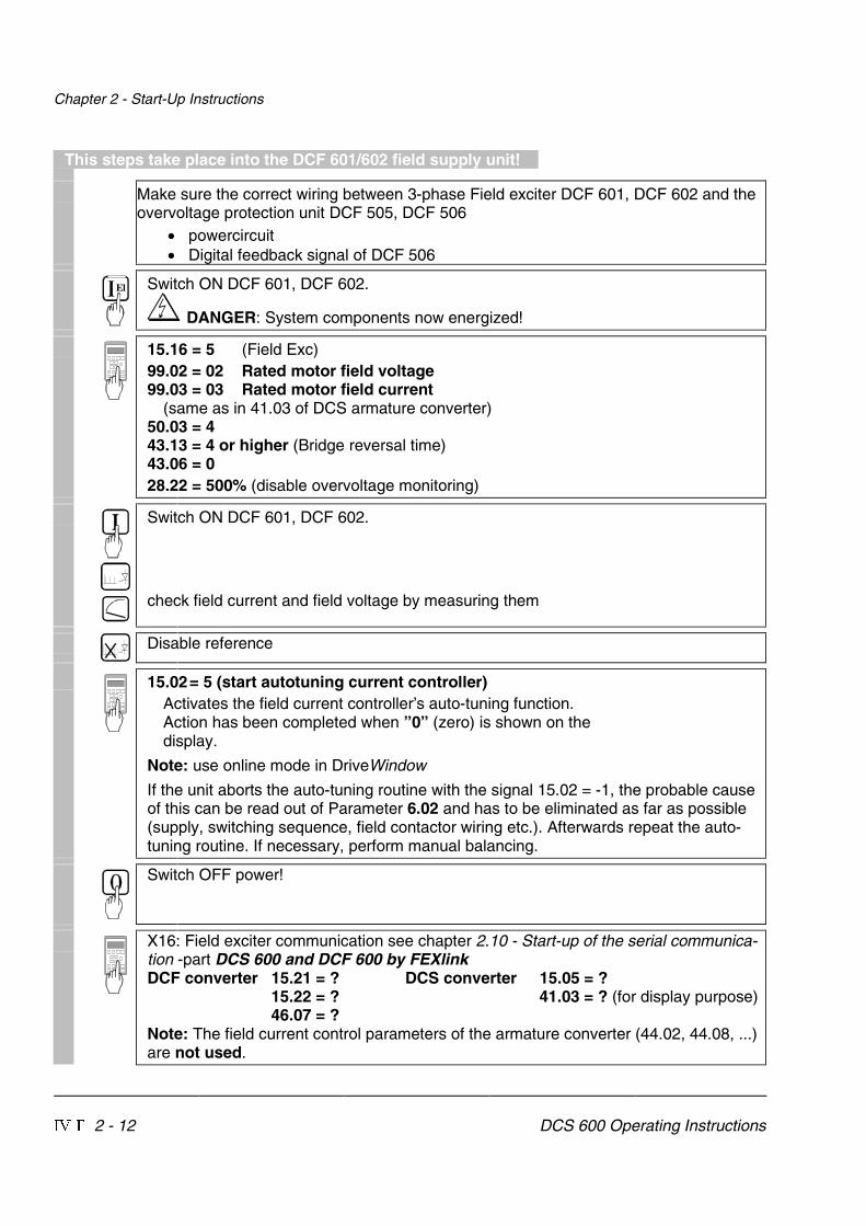
This steps take place into the DCF 601/602 field supply unit!
Make sure the correct wiring between 3-phase Field exciter DCF 601, DCF 602 and theovervoltage protection unit DCF 505, DCF 506
• powercircuit• Digital feedback signal of DCF 506
El Switch ON DCF 601, DCF 602.
DANGER: System components now energized!
15.16 = 5 (Field Exc)99.02 = 02 Rated motor field voltage99.03 = 03 Rated motor field current
(same as in 41.03 of DCS armature converter)50.03 = 443.13 = 4 or higher (Bridge reversal time)43.06 = 028.22 = 500% (disable overvoltage monitoring)
Switch ON DCF 601, DCF 602.
check field current and field voltage by measuring them
Disable reference
15.02= 5 (start autotuning current controller)Activates the field current controller’s auto-tuning function.Action has been completed when ”0” (zero) is shown on thedisplay.
Note: use online mode in DriveWindow
If the unit aborts the auto-tuning routine with the signal 15.02 = -1, the probable causeof this can be read out of Parameter 6.02 and has to be eliminated as far as possible(supply, switching sequence, field contactor wiring etc.). Afterwards repeat the auto-tuning routine. If necessary, perform manual balancing.
Switch OFF power!
X16: Field exciter communication see chapter 2.10 - Start-up of the serial communica-tion -part DCS 600 and DCF 600 by FEXlinkDCF converter 15.21 = ? DCS converter 15.05 = ?
15.22 = ? 41.03 = ? (for display purpose)46.07 = ?
Note: The field current control parameters of the armature converter (44.02, 44.08, ...)are not used.

Chapter 2 - Start-Up Instructions
DCS 600 Operating Instructions IV F 2 - 13
2.4 Adjusting the current controller
Make sure that static current limitation Bridge 1 (20.12) and Bridge 2 (20.13; with4Q-unit) have been set to the same value; values of all parameters for currentreference limitation must be bigger than 20 %; conditions have been satisfied ifdefault setting has been taken as starting point; setting to maximally required motorcurrent is recommended.
Drive must not turn! Do not preset an external reference!15.02 = 3
Activate the current controller’s auto-tuning function.Start the next two steps within the next 20 seconds!
Switch ON power.
DANGER: System components now energized!
Start drive.
When the display shows ”0” (zero) stop drive; it may happen that the unit runsarmature-circuit current since EMF control is active.Note: use online mode in DriveWindow
Switch OFF power!
If the unit aborts the auto-tuning routine with the signal 15.02 = -1, the probablecause of this can be read out of Parameter 6.02 and has to be eliminated as faras possible (supply, switching sequence, field contactor wiring, missing field contactoretc.).Afterwards repeat the auto-tuning routine.If necessary, perform manual balancing.
Only if the unit aborts the auto-tuning routine with a fault signal FIELD REMOVAL?!
Read out values of:41.11 = ......... 41.12 = ......... 43.02 = ......... 43.03 = ............ 43.06 = .........
15.05 = 0
El Switch OFF power supply to the electronics section!Make sure that no field current is flowing, e.g. by removing the supply fuses!
El Switch the electronics section’s power supply on again!
Chapter 2 - Start-Up Instructions
IV F 2 - 14 DCS 600 Operating Instructions
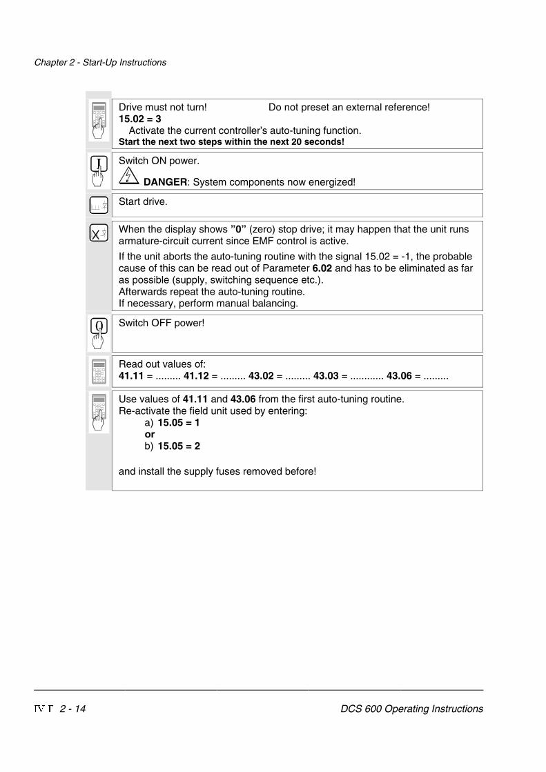
Drive must not turn! Do not preset an external reference!15.02 = 3
Activate the current controller’s auto-tuning function.Start the next two steps within the next 20 seconds!
Switch ON power.
DANGER: System components now energized!
Start drive.
When the display shows ”0” (zero) stop drive; it may happen that the unit runsarmature-circuit current since EMF control is active.
If the unit aborts the auto-tuning routine with the signal 15.02 = -1, the probablecause of this can be read out of Parameter 6.02 and has to be eliminated as faras possible (supply, switching sequence etc.).Afterwards repeat the auto-tuning routine.If necessary, perform manual balancing.
Switch OFF power!
Read out values of:41.11 = ......... 41.12 = ......... 43.02 = ......... 43.03 = ............ 43.06 = .........
Use values of 41.11 and 43.06 from the first auto-tuning routine.Re-activate the field unit used by entering:
a) 15.05 = 1orb) 15.05 = 2
and install the supply fuses removed before!

Chapter 2 - Start-Up Instructions
DCS 600 Operating Instructions IV F 2 - 15
2.5 Speed feedback balancing
Activate EMF speed feedback:50.03 = CALC BY EMFSelect no field weakening mode:15.06 = FIX
50.01 = Desired speed / or motor rating plateScale speed control circuit to maximum speed.
Switch ON power.
DANGER: System components now energized!
Start drive.
Increase reference value in LOCAL mode to 10 % of the maximum speed.
Drive should run up to 10 % of the rated voltage.
Continue with one of the following sections:• Only when an analog tacho is being used!• Only when an encoder (pulse encoder) is being used!• Only when the EMF signal is being used as speed feedback!
Only when an analog tacho is being used!
Connect measuring instrument:- to X3: 1... 3 or X1: 1... 3+ to X3: 4 or X1: 4Check to make sure that the tacho voltage does not exceed the input voltage rangeselected with maximum speed.Turn Potentiometer R2716 [on SDCS-CON-2 board] or R9 [on PS5311 board; ifSDCS-IOB-3 board is used with PS5311] to minimum (left-hand stop).Themeasured value must have a positive sign; if necessary interchange tacho cables.
Stop the drive and switch OFF power!
50.03 = ANALOGUE TACAnalog tacho is used for speed control.
Switch ON power.
DANGER: System components now energized!

Chapter 2 - Start-Up Instructions
IV F 2 - 16 DCS 600 Operating Instructions
Start drive.
Increase reference value in LOCAL mode to 10 % of the maximum speed.
Drive should run up to 10 % of the rated voltage.
Use Potentiometer R2716 [on SDCS-CON-2 board] or R9 [on PS5311 board] toset the tacho voltage to 10 % of the maximum tacho voltage.
Stop the drive and switch OFF power!
Only when an encoder (pulse encoder) is being used!
3.07 = Content of pulse counter *)If the shape of the curve corresponds to the diagram below, this meansthe wiring is correct and the pulses will be correctly evaluated [seealso documentation entitled “Technical Data”, Chapter I/O boards].*) This Parameter must be transmitted from the SDCS-CON-2 board to the SDCS-AMC-DC board!
Fig.: Curve shape of the encoder’s pulse counter for sense of rotation "forwards”
Switch OFF power, thus stopping the drive; drive coasts.
50.04 = Number of encoder pulsesAs specified on the encoder’s rating plate
50.03 = CON- ENCODERThe encoder connected to the SDCS-CON-2 board is used for speed control.
Switch ON power.
DANGER: System components now energized!
Start drive.
Increase reference value in LOCAL mode to 10 % of the maximum speed.

Chapter 2 - Start-Up Instructions
DCS 600 Operating Instructions IV F 2 - 17
Drive should run at 10 % of the desired speed;if possible, check with manual tacho.
Stop the drive and switch OFF power!
Only when the EMF signal is being used as speed feedback!
Drive should run at 10 % of the desired speed;if possible, check with manual tacho.
Stop the drive and switch OFF power!
Chapter 2 - Start-Up Instructions
IV F 2 - 18 DCS 600 Operating Instructions
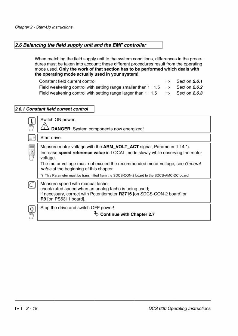
2.6 Balancing the field supply unit and the EMF controller
When matching the field supply unit to the system conditions, differences in the proce-dures must be taken into account; these different procedures result from the operatingmode used. Only the work of that section has to be performed which deals withthe operating mode actually used in your system!
Constant field current control ⇒ Section 2.6.1Field weakening control with setting range smaller than 1 : 1.5 ⇒ Section 2.6.2Field weakening control with setting range larger than 1 : 1.5 ⇒ Section 2.6.3
2.6.1 Constant field current control
Switch ON power.
DANGER: System components now energized!
Start drive.
Measure motor voltage with the ARM_VOLT_ACT signal, Parameter 1.14 *).Increase speed reference value in LOCAL mode slowly while observing the motorvoltage.The motor voltage must not exceed the recommended motor voltage; see Generalnotes at the beginning of this chapter.*) This Parameter must be transmitted from the SDCS-CON-2 board to the SDCS-AMC-DC board!
Measure speed with manual tacho;check rated speed when an analog tacho is being used;if necessary, correct with Potentiometer R2716 [on SDCS-CON-2 board] orR9 [on PS5311 board].
Stop the drive and switch OFF power!
� Continue with Chapter 2.7
Chapter 2 - Start-Up Instructions
DCS 600 Operating Instructions IV F 2 - 19
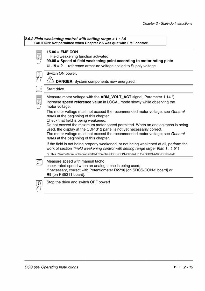
2.6.2 Field weakening control with setting range < 1 : 1.5CAUTION: Not permitted when Chapter 2.5 was quit with EMF control!
15.06 = EMF CONField weakening function activated
99.05 = Speed at field weakening point according to motor rating plate41.19 = ? reference armature voltage scaled to Supply voltage
Switch ON power.
DANGER: System components now energized!
Start drive.
Measure motor voltage with the ARM_VOLT_ACT signal, Parameter 1.14 *).Increase speed reference value in LOCAL mode slowly while observing themotor voltage.The motor voltage must not exceed the recommended motor voltage; see Generalnotes at the beginning of this chapter.Check that field is being weakened.Do not exceed the maximum motor speed permitted. When an analog tacho is beingused, the display at the CDP 312 panel is not yet necessarily correct.The motor voltage must not exceed the recommended motor voltage; see Generalnotes at the beginning of this chapter.
If the field is not being properly weakened, or not being weakened at all, perform thework of section "Field weakening control with setting range larger than 1 : 1.5” !*) This Parameter must be transmitted from the SDCS-CON-2 board to the SDCS-AMC-DC board!
Measure speed with manual tacho;check rated speed when an analog tacho is being used;if necessary, correct with Potentiometer R2716 [on SDCS-CON-2 board] orR9 [on PS5311 board].
Stop the drive and switch OFF power!

Chapter 2 - Start-Up Instructions
IV F 2 - 20 DCS 600 Operating Instructions
2.6.3 Field weakening control with setting range > 1 : 1.5CAUTION: Not permitted when Chapter 2.5 was quit with EMF control!
15.06 = EMF CONField weakening function activated.
46.01 = 046.02 = 0
EMF controller switched off by limitation.46.07 = EXT REF
Links up the Parameter 45.01 as the fluxreference value; this will only be possible, if thereis still no connection to an APC.
45.01 = 100 % (in the PC program DRIVES WINDOW = 99.98 %)Flux reference value set to 100 %
The next steps serve to determine the motor’s field characteristic. For this purpose,the reference setting in ”LOCAL” mode is used to adjust a speed n which is withinthe motor's basic speed range and can be easily converted into 90 %, 70 % and 40 %.Example: if n is selected so as to produce a motor voltage of 300 V, then 90 % willcorrespond to 270 V, 70 % to 210 V and 40 % to 120 V.For determination of the motor's field characteristic the actual values EMF_V(Parameter 1.17) and FIELD1 CUR_ACT (Parameter 3.19) will be required.Both values have to be set by means of the Control Panel in ”ACT” (Actual SignalDisplay) mode and must be transmitted from the SDCS-CON-2 board to the SDCS-AMC-DC board. The Parameter 94.11 already includes Parameter 3.19 as defaultsetting, i.e. only the value of Parameter 1.17 has to be set to e.g. 94.01 = 117:94.01 = 117 (only required, if the values are to be displayed on DRIVES WINDOW!).
Switch ON power.
DANGER: System components now energized!
Start drive.
Increase speed reference value in LOCAL mode until the Parameter 1.17 will showa value of 100 % for RL EMF VOLT ACT (⇒ 300 V in the example) as desired in theaforementioned steps.
45.01 = decrease so that RL EMF VOLT ACT (1.17) is 90 %.Flux and thus the field current as well are reduced.
How to proceed using the Control Panel:1. decrease 45.01 (in steps of 5 at a time)2. press ACT, read off Parameter 1.173. press PAR and correct 45.01 if necessary (then continue with 2.)
Read out and note down value of:3.19 = ......... % (value for 41.16; will later be entered)
FLUXCONTROL
MOTOR NOMSPEED 99.05
MOTOR SPEED
1.02
FLUX REF FLD WEAK
FLUX REF
45.01
3.14
45.02 flux/emf ref sel = EXT REFOR46.07 flux ref sel = EXT REF
MAXIMUMFLUX 45.07

Chapter 2 - Start-Up Instructions
DCS 600 Operating Instructions IV F 2 - 21
45.01 = decrease so that RL EMF VOLT ACT (1.17) is 70%.Flux and thus the field current as well are reduced.
Proceed as described in (1. / 2. / 3.) above!Read out and note down value of:3.19 = ......... % (value for 41.15; will later be entered)
45.01 = decrease so that RL EMF VOLT ACT (1.17) is 40%.Flux and thus the field current as well are reduced.
Proceed as described in (1. / 2. / 3.) above!Read out and note down value of:3.19 = ......... % (value for 41.14; will later be entered)
Stop the drive and switch OFF power!
45.01 = 100 %46.01 = 1046.02 = - 9946.07 = SEL REF
As-delivered values (default values) for all 4 parameters restored.41.19 = ? reference armature voltage scaled to Supply voltage41.16 = enter the 1st noted down value of 3.1941.15 = enter the 2nd noted down value of 3.1941.14 = enter the 3rd noted down value of 3.19
Linearization function matched to field circuit.
99.02 = 90 % of the rated motor voltage.99.05 = 90 % of the value on the motor rating plate.
These settings provide a bigger safety margin for the motor voltage during start-up.
Only if analog tacho is used as speed feedback!
Switch ON power; start drive.
DANGER: System components now energized!
Increase the reference value in LOCAL mode slowly up to maximum speed.Check motor voltage; if value has been set with 99.02, motor voltage mustremain constant, or must not exceed this value.
Measure speed with manual tacho; balance maximum speed with PotentiometerR2716 [on SDCS-CON-2 board] or R9 [on PS5311 board].
Stop the drive and switch OFF power!

Chapter 2 - Start-Up Instructions
IV F 2 - 22 DCS 600 Operating Instructions
2.7 Balancing the speed controller, plus fine-balancing the EMF
The balancing procedure indicated below assumes that the coupled load will with-stand speed jumps. If this is not allowed for the load, a different setting of the listedparameters will be required.Reference values switching over between the internal potentiometers POT1 and POT2(Parameters 17.01 and 17.02) will be used for balancing the controllers. ParameterPERIOD 17.03 defines the period of switch-over; value 1 corresponds to 10 msec.15.02 = 9
Switch-over of reference value for the speed controller, also suitable for the EMFcontroller.
17.04 = SQWAVESelection of the reference value switching over between POT1 and POT2.
22.01 = 0,1 sRamp-up time of ramp-function generator
22.02 = 0,1 sRamp-down time of ramp-function generator
Adjusting the potentiometers for speed controller balancing:During acceleration/ braking, the drive should reach the current limitation, if necessaryincrease the value of POT1.Scaling of 17.01 and 17.02 ⇒ 20 000 corresponds to 100 % speed.17.01 (POT1) = 10%...20% max. speed17.02 (POT2) = 017.03 (PERIOD) = Adapt as necessary.
Switch ON power; start drive.
DANGER: System components now energized!Drive should run at speed values corresponding to POT1 and “0”.
For assessing control quality, the figure below can be used.Oscillograph speed feedback via D/A output, or if one is to hand, use program DRIVESWINDOW to depict it via the Monitor menu and Parameter 1.04.
t
A
BC D E F
Fig.: Transient response of controllerA: reference value jumpB: undercompensated; reset time and P-gain too smallC: undercompensated; P-gain too smallD: normalE: slightly overcompensated; when a higher dynamic response is requiredF: overcompensated; short reset time and a high P-gain

Chapter 2 - Start-Up Instructions
DCS 600 Operating Instructions IV F 2 - 23
EMFCONTROLLER
46.03EMF CON KP46.04EMF CON KI
V REF 13.24
46.12V REF SLOPE
46.05EMF CON BLOCKLEV
46.10V COR
46.11V STEP
46.13V LIM P
46.14V LIM N
V ref Modification
V REF 23.25
VOLT ACTUAL
3.23
For this purpose, the following parameters at the speed controller must be adapted:24.03 (KPS) = desired response (behaviour) of controller24.09 (TIS) = desired response (behaviour) of controller
Only when fine-balancing of the EMF controller is wanted!(Necessary when work as per section 2.6.3. has been performed)
For assessing control quality, the Fig. entitled "Transient response of controller"( ⇒ beginning of this chapter) can be used.41.19 = ? reference armature voltage scaled
to Supply voltage- If fine-balancing of the EMF controller is wanted,
potentiometers’ settings must be adapted:17.01 (POT1) approx. 10 % bigger than speed atfield weakening point17.02 (POT2) approx. 10% smaller than speed atfield weakening pointThe following parameters at the EMF controllermust be adapted:46.03 (EMF_KP) = desired response (behaviour) of controller46.04 (EMF_KI) = desired response (behaviour) of controller.
Stop the drive and switch OFF power!
15.02 = 017.01 = 017.02 = 099.02 = Rated motor voltage as set in Chapter 2.299.05 = Speed at rated motor voltage as set in Chapter 2.2.
2.8 Matching the thyristor power converter unit to the system conditions concerned
- Ramp function generator
- Binary inputs and outputs
- Limit-value messages
- Additional functions
- Link up APC or Fieldbus
2.9 Manual balancing of the controllers
Balancing of the controllers for the armature-circuit current and the field current can beperformed by auto-tuning. If this is not possible for some reason, balancing of these con-trollers as well as balancing of the controllers for speed and EMF has to be performedby the skilled technical start-up personnel.
See also the separate Software Description DCS 600, chapter ”Manual Tuning”.

Chapter 2 - Start-Up Instructions
IV F 2 - 24 DCS 600 Operating Instructions
2.10 Start-Up of the serial communication
DCS 600 and APC
HardwareDCS 600 SDCS-AMC-DC boardAPC YPQ112B boardCable length 0.2 ... 20 m plastic optical fibreConfiguration YPQ112 first board channel 1 Drive No 1
...channel 4 Drive No 4
second board channel 1 Drive No 5...channel 4 Drive No 8
Associated publicationsDCS 600 Technical Data 3ADW000054R0301 ABB Lampertheim
Software Description 3ADW000076R0401 ABB LampertheimDatabase GLOBAL\DEIND\DEIND051.NSF
APC FCB function block 3AFY61281240 ABB HelsinkiYPQ 112 3AFY63982806 ABB HelsinkiDatabase GLOBAL\FIDRI\FIDRI002.NSF
Software settingsDCS 600 Parameter 98.02 = 3 (ADVANT)
70.01 = 1 (fixed)99.10 = Drive No (see above)70.02 = Optical power/ cable length
(use default)70.20 = 1071.21 = Star
Default connected Main control word (data set 10/1)parameters Speed reference (data set 10/2)
Main status word (data set 11/1)Motor speed (data set 11/2)For additional p. see SW Descr. chap. ”Communication”
APC Node Type APC2.2/1 Station 0,0DB element ACS01, ACS02, ACS03
TypeYPQ112A up to four drivesYPQ112B more than four drives
Drtype = ACS600 MultiDrive (high performance)ACS600 SingleDrive (low performance)
FB ACSRX1Control word 7.01 = bit10 = 1(send to drive)
Example for switch-on sequenceSend to control word 7.01 0476H (ON = 0; READY, if there is no failure)
0477H (main contactor ON)047FH (RELEASE for speed and current control)
Note: Before receiving the first dataset the drive sets the CH 0 alarm status

Chapter 2 - Start-Up Instructions
DCS 600 Operating Instructions IV F 2 - 25
DCS 600 and AC 70 (PM 810)
HardwareDCS 600 SDCS-AMC-DC boardAC 70 TB810 board Software release 1.1/1 or laterCable length 0.2 ... 20 m plastic optical fibreTransmission speed 4MbRing configuration up to 12 drivesStar configuration (NDBU95) up to 9 drives
Associated publicationsDCS 600 Technical Data 3ADW000054R0301 ABB Lampertheim
Software Description 3ADW000076R0401 ABB LampertheimDatabase GLOBAL\DEIND\DEIND051.NSF
AC 70 Functional unit part 9 DRICONE 3BSE 013947R0001 ABB SwedenADVANT Controller 70 3BUR 000874R0201 ABB SwedenData base element Advant c. 70 3BSE 009456R0101 ABB SwedenPC elements Advant controller 703BSE 009177R0101 ABB Sweden
Software settingsDCS 600 Parameter 98.02 = 3 (ADVANT)
70.01 = Drive Number70.02 = Optical power/cable length
(use default)70.20 = 1071.21 = Star or Ring
Connected parameters Main control word (data set 10/1)Speed reference (data set 10/2)Main status word (data set 11/1)Motor speed (data set 11/2)For additional p. see SW Descr. chap. ”Communication”
AC 70 Node Type AC 70DB element DRIENG1 Type = Customer string
Ref1 = DRDS 1Position = Drive Number101 ... 112 = 17 ... 28201 ... 212 = 33 ... 44
... = ...701 ... 712 = 113 ... 124
DRIDS for sending and receiving one Dataset to/from DriveWR_ENA = 1 (use ”move element”)ACT = 1 (use ”move element”)DS_No = start with ten for the
first dataset to be sentO-terminals intended for data receivedfrom driveI-terminals intended for data sent to drive
Control word (send to drive) 7.01 = bit10 = 1
Example for switch-on sequenceSend to control word 7.01 0476H (ON = 0; READY, if there is no failure)
0477H (main contactor ON)047FH (RELEASE for speed and current control)
Note: Before receiving the first dataset the drive sets the CH 0 alarm status
Chapter 2 - Start-Up Instructions
IV F 2 - 26 DCS 600 Operating Instructions
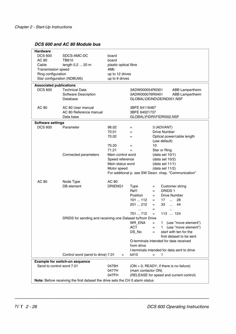
DCS 600 and AC 80 Module bus
HardwareDCS 600 SDCS-AMC-DC boardAC 80 TB810 boardCable length 0.2 ... 20 m plastic optical fibreTransmission speed 4MbRing configuration up to 12 drivesStar configuration (NDBU95) up to 9 drives
Associated publicationsDCS 600 Technical Data 3ADW000054R0301 ABB Lampertheim
Software Description 3ADW000076R0401 ABB LampertheimDatabase GLOBAL\DEIND\DEIND051.NSF
AC 80 AC 80 User manual 3BFE 64116487AC 80 Reference manual 3BFE 64021737Data base GLOBAL\FIDRI\FIDRI002.NSF
Software settingsDCS 600 Parameter 98.02 = 3 (ADVANT)
70.01 = Drive Number70.02 = Optical power/cable length
(use default)70.20 = 1071.21 = Star or Ring
Connected parameters Main control word (data set 10/1)Speed reference (data set 10/2)Main status word (data set 11/1)Motor speed (data set 11/2)For additional p. see SW Descr. chap. ”Communication”
AC 80 Node Type AC 80DB element DRIENG1 Type = Customer string
Ref1 = DRIDS 1Position = Drive Number101 ... 112 = 17 ... 28201 ... 212 = 33 ... 44
... = ...701 ... 712 = 113 ... 124
DRIDS for sending and receiving one Dataset to/from DriveWR_ENA = 1 (use ”move element”)ACT = 1 (use ”move element”)DS_No = start with ten for the
first dataset to be sentO-terminals intended for data receivedfrom driveI-terminals intended for data sent to drive
Control word (send to drive) 7.01 = bit10 = 1
Example for switch-on sequenceSend to control word 7.01 0476H (ON = 0; READY, if there is no failure)
0477H (main contactor ON)047FH (RELEASE for speed and current control)
Note: Before receiving the first dataset the drive sets the CH 0 alarm status

Chapter 2 - Start-Up Instructions
DCS 600 Operating Instructions IV F 2 - 27
DCS 600 and AC 80 Drive bus
HardwareDCS 600 SDCS-AMC-DC boardAC 80 Drive busCable length 0.2 ... 20 m plastic optical fibreTransmission speed 4MbStar configuration (NDBU95) up to 12 drives - select Drive bus mode
Associated publicationsDCS 600 Technical Data 3ADW000054R0301 ABB Lampertheim
Software Description 3ADW000076R0401 ABB LampertheimDatabase GLOBAL\DEIND\DEIND051.NSF
AC 80 AC 80 User manual 3BFE 64116487AC 80 Reference manual 3BFE 64021737Data base GLOBAL\FIDRI\FIDRI002.NSF
Software settingsDCS 600 Parameter 98.02 = 3 (ADVANT)
70.01 = Drive Number70.02 = Optical power/cable length
(use default)70.20 = 1071.21 = Star
Connected parameters Main control word (data set 10/1)Speed reference (data set 10/2)Main status word (data set 11/1)Motor speed (data set 11/2)For additional p. see SW Descr. chap. ”Communication”
AC 80 Node Type AC 80DB element DRB00 DRTYP1 = AMC Classic for AMC DC
DRTYP1 = NAMC 2 for AMC DC Drive BusPC element ACSRX DRNR = Drive number
EN = 1CNTRL = 1DS1 = Data set numberWR = 1
Maximum two data sets in one ACSRX block AMC DC
Example for switch-on sequenceSend to control word 7.01 0476H (ON = 0; READY, if there is no failure)
0477H (main contactor ON)047FH (RELEASE for speed and current control)
Note: Before receiving the first dataset the drive sets the CH 0 alarm status

Chapter 2 - Start-Up Instructions
IV F 2 - 28 DCS 600 Operating Instructions
DCS 600 and FCI (CI 810) / AC 400
HardwareDCS 600 SDCS-AMC-DC boardFCI/AC 400 TB810 board Software release 1.3 or laterCable length 0.2 ... 20 m plastic optical fibreTransmission speed 4MbRing configuration up to 12 drivesStar configuration (NDBU95) up to 9 drives
Associated publicationsDCS 600 Technical Data 3ADW000054R0301 ABB Lampertheim
Software Description 3ADW000076R0401 ABB LampertheimDatabase GLOBAL\DEIND\DEIND051.NSF
FCI Functional unit part 9 DRICONE 3BSE 013947R0001 ABB SwedenFCB Type circuits Drives Objects 3BSE 013131R0201 ABB SwedenDrives FCB type circuits 3BSE013855R0001 ABB SwedenAdva command Drives integration 3BSE012859R0001 ABB SwedenNOTE: Load the option ”Drive Integration”, if the operation station is installed!
Software settingsDCS 600 Parameter 98.02 = 3 (ADVANT)
70.01 = Drive Number70.02 = Optical power/cable length
(use default)70.20 = 1071.21 = Star or Ring
Connected parameters Main control word (data set 10/1)Speed reference (data set 10/2)Main status word (data set 11/1)Motor speed (data set 11/2)For additional p. see SW Descr. chap. ”Communication”
FCI Node Type AC 400DB element DRIENG1 Type = Customer string
Station = Switch at FCIPostion = Drive Number
FB DRI-S For sending data sets (10,12,14...)DRI-R For receiving data set (11,13,15...)[start with ten for the first dataset to be sent]
Control word 7.01 = bit10 = 1(send to drive)
Example for switch-on sequenceSend to control word 7.01 0476H (ON = 0; READY, if there is no failure)
0477H (main contactor ON)047FH (RELEASE for speed and current control)
Note: Before receiving the first dataset the drive sets the CH 0 alarm status

Chapter 2 - Start-Up Instructions
DCS 600 Operating Instructions IV F 2 - 29
DCS 600 and Profibus
HardwareDCS 600 SDCS-AMC-DC Classic boardNPBA02 Software V2.2Cable length 0.2 ... 10 m plastic optical fibre
Associated publicationsDCS 600 Technical Data 3ADW000054R0301 ABB Lampertheim
Software Description 3ADW000076R0401 ABB LampertheimDC Converter Fieldbus 3ADW000097R0101 ABB Lampertheim
(not on database)Database GLOBAL\DEIND\DEIND051.NSF
Profibus NPBA 3AFY58995789R0125 ABB HelsinkiDatabase GLOBAL\FIDRI\FIDRI002.NSF
Software settingsDCS 600 Parameter 98.02 = 2 (FIELDBUS)
70.01 = 170.02 = Optical power/cable length
(use default)70.20 = 1
Default connected Main control word (data set 1/1)parameters Speed reference (data set 1/2)
Main status word (data set 2/1)Motor speed (data set 2/2)
DriveParameter
FieldbusPar. No.
Parameter Name Select
51.01 1 MODULE TYPE PROFIBUS
51.02 2 PROFIBUS MODE DP-PPO1 or DP-PPO2
51.03 3 DRIVE NUMBER 2 to 126
51.04 4 BIT RATE SELECTPROFIBUS
9.6, 19.2, 93.75, 187.5, 500 KBIT;1.5 MBIT; AUTO
51.05 5 DATA SET PAIRS 4 {1, 3, 5, 7 sent to drive}{2, 4, 6, 8 received from drive}
51.06 6 DATA SET OFFSET 0
51.07 7 CUT-OFF TIMEOUT 0 to 255
51.08 8 COM PROFILE 0
Note: After change of Parameters Group 51 switch OFF and ON the DCS 600 and theFieldbus adapter!
To be continued! = Self-adjustment while switching on

Chapter 2 - Start-Up Instructions
IV F 2 - 30 DCS 600 Operating Instructions
DCS 600 and Profibus: Software settings (continued)
Profibus Control word 7.01 = bit10 = 1(send to drive)
Example for switch-on sequenceSend to control word 7.01 0476H (ON = 0; READY, if there is no failure)
0477H (main contactor ON)047FH (RELEASE for speed and current control)
Note: Before receiving the first dataset the drive sets the CH 0 alarm status
Note:Before sending a dataset to the drive the PLC Siemens S 7 requires a data update of thecomplete dataset ( ⇒ Data consistency check).
Chapter 2 - Start-Up Instructions
DCS 600 Operating Instructions IV F 2 - 31
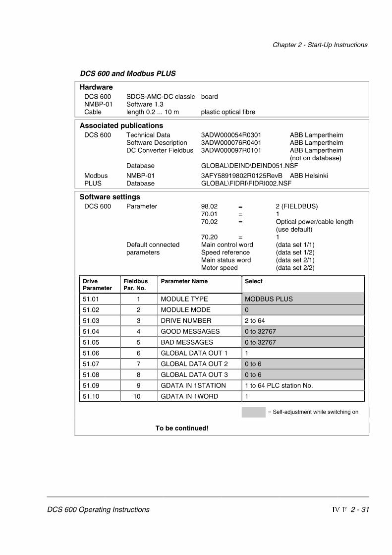
DCS 600 and Modbus PLUS
HardwareDCS 600 SDCS-AMC-DC classic boardNMBP-01 Software 1.3Cable length 0.2 ... 10 m plastic optical fibre
Associated publicationsDCS 600 Technical Data 3ADW000054R0301 ABB Lampertheim
Software Description 3ADW000076R0401 ABB LampertheimDC Converter Fieldbus 3ADW000097R0101 ABB Lampertheim
(not on database)Database GLOBAL\DEIND\DEIND051.NSF
Modbus NMBP-01 3AFY58919802R0125RevB ABB HelsinkiPLUS Database GLOBAL\FIDRI\FIDRI002.NSF
Software settingsDCS 600 Parameter 98.02 = 2 (FIELDBUS)
70.01 = 170.02 = Optical power/cable length
(use default)70.20 = 1
Default connected Main control word (data set 1/1)parameters Speed reference (data set 1/2)
Main status word (data set 2/1)Motor speed (data set 2/2)
DriveParameter
FieldbusPar. No.
Parameter Name Select
51.01 1 MODULE TYPE MODBUS PLUS
51.02 2 MODULE MODE 0
51.03 3 DRIVE NUMBER 2 to 64
51.04 4 GOOD MESSAGES 0 to 32767
51.05 5 BAD MESSAGES 0 to 32767
51.06 6 GLOBAL DATA OUT 1 1
51.07 7 GLOBAL DATA OUT 2 0 to 6
51.08 8 GLOBAL DATA OUT 3 0 to 6
51.09 9 GDATA IN 1STATION 1 to 64 PLC station No.
51.10 10 GDATA IN 1WORD 1
= Self-adjustment while switching on
To be continued!

Chapter 2 - Start-Up Instructions
IV F 2 - 32 DCS 600 Operating Instructions
DCS 600 and Modbus PLUS: Software settings (continued)
DriveParameter
FieldbusPar. No.
Parameter Name Select
51.11 11 GDATA IN 2STATION 0 to 64
51.12 12 GDATA IN 2WORD 0 to 31
51.13 13 GDATA IN 3STATION 0 to 64
51.14 14 GDATA IN 3WORD 0 to 31
= Self-adjustment while switching on
Note: After change of Parameters Group 51 switch OFF and ON the DCS 600 and theFieldbus adapter!
Modbus Control word 7.01 = bit10 = 1PLUS (send to drive)
Example for switch-on sequenceSend to control word 7.01 0476H (ON = 0; READY, if there is no failure)
0477H (main contactor ON)047FH (RELEASE for speed and current control)
Note: Before receiving the first dataset the drive sets the CH 0 alarm status

Chapter 2 - Start-Up Instructions
DCS 600 Operating Instructions IV F 2 - 33
DCS 600 and CS 31
HardwareDCS 600 SDCS-AMC-DC Classic boardNCSA Software V1.5Cable length 0.2 ... 10 m plastic optical fibre
Associated publicationsDCS 600 Technical Data 3ADW000054R0301 ABB Lampertheim
Software Description 3ADW000076R0401 ABB LampertheimDC Converter Fieldbus 3ADW000097R0101 ABB Lampertheim
(not on database)Database GLOBAL\DEIND\DEIND051.NSF
CS 31 NCSA-01 3ADW000043R0201 ABB Lampertheim
Software settingsDCS 600 Parameter 98.02 = 2 (FIELDBUS)
70.01 = 170.02 = Optical power/cable length
(use default)70.20 = 1
Default connected Main control word (data set 1/1)parameters Speed reference (data set 1/2)
Main status word (data set 2/1)Motor speed (data set 2/2)
DriveParameter
FieldbusPar. No.
Parameter Name Select
51.01 1 MODULE TYPE NCSA-01 V1.5
51.02 2 PROTOCOL ABB CS31
51.03 3 MODULU ID 0:WORD
51.04 4 DRIVE NUMBER 0…5 Station No.
51.05 5 ADDR WDEX 0:LOWER
51.06 6 DATA SETS 1…3 sent + receive
51.07 7 DATA SET1 CONST 1 (1 =^ 6ms)
51.08 8 DATA SET2 CONST 1 (1 =^ 6ms)
51.09 9 DATA SET3 CONST 1 (1 =^ 6ms)
51.10 10 DATA SET OFSET 1
= Self-adjustment while switching on
Note: After change of Parameters Group 51 switch OFF and ON the DCS 600 and theFieldbus adapter!
Notice: Software bug V1.5: Only one adapter in CS 31 network is too fast for drive communica-tion!

Chapter 2 - Start-Up Instructions
IV F 2 - 34 DCS 600 Operating Instructions
DCS 600 and DCF 600 by FEXlink
HardwareDCS 600 SDCS-AMC-DC or AMC-DC Classic boardDCF 601/ SDCS-AMC-DC or AMC-DC Classic boardDCF 602
Configuration For first field exciterDCS 600 without SDCS-FEX-1 / SDCS-FEX-2DCF 600 connection by FEXlink (X16)Maincontactor of DCF 600 controlled by armature converter (FEXlink X16)DCF 600 DI1 = H ⇒ connected to 48V
DI2 = H ⇒ connected to DCF 506
Associated publicationsDCS 600 Technical Data 3ADW000054R0301 ABB Lampertheim
Software Description 3ADW000076R0401 ABB LampertheimDatabase GLOBAL\DEIND\DEIND051.NSF
Software settingsDCS 600 Parameter 41.03 = Rated field current
(only used for display)DCF 601/ Parameter 15.16 = 5 operation modeDCF 602
Parameter 15.21 = 1 Node = First field exciterParameter 15.22 = 2 FEXlink commandParameter 46.07 = 3 FEXLINKParameter 43.13 = 4 or higherParameter 99.03 = Rated field current of
the motor
Note: Resetting of DCF 600 with FEXlink control (X16) is performed by switching OFF(DISABLE reference) and ON (ENABLE reference) again:
Control Panel key ⇒ Control Panel key
(when in LOCAL mode) (when in LOCAL mode)

Chapter 3 - Handling of Control Panel CDP 312
DCS 600 Operating Instructions IV F 3 - 1
3.1 Overview The Control and Display Panel CDP 312 [Control Panel] is usedfor parameter setting, for display of actual values and for drivecontrol in ”LOCAL” mode with series DCS 600 thyristor powerconverters.This Control Panel is equipped with 16 keys and a LC displayfeaturing 4 lines with 20 signs per line.
Panel Link An electrical cable or an adapter serves to connect the CDP 312Control Panel with the RS485 interface X33 or X34 situated onthe control board SDCS-CON-2 of the DCS 600 thyristor powerconverter. Via this connection the Control Panel will receive allinformation directly from the SDCS-AMC-DC board.The bus protocol for transmission is MODBUS.
Mounting thePanel
The CDP 312 can be handled in three different ways:• Direct mounting on the thyristor power converter DCS 600;
the CDP 312 is plugged into the moulded part of the cover ofthe converter and connected via an adapter of approx. 45 mm.
• Mounting on the door of the switchgear cabinet using an as-sembly kit equipped with a connection cable.
• Use of the Control Panel as remote control device with aconnection cable; recommended for start-up procedure.
Languages for PanelDisplay
The language for display of texts on the CDP 312 Control Panel isEnglish.
Note: General display texts like LAST FAULT, UPLOAD,DOWNLOAD etc. are stored in the CDP 312 ControlPanel; display texts like Parameter Names, Faults etc.are taken from the Software used with DCS 600.

Chapter 3 - Handling of Control Panel CDP 312
IV F 3 - 2 DCS 600 Operating Instructions
3.2 Start Mode Note: The CDP 312 can be connected to the drive without discon-necting the auxiliary power!
When the CDP 312 is connected and power is applied to the elec-tronics, the display will show:1. Name and Software version of the Control Panel; an increasing
number of points (row) in the lower line will show, that datafrom the Software used with DCS 600 are loaded. If this rowis repeated permanently, it will not be possible to load data as(for example) there is no correct running of the Software or theSDCS-AMC-DC board is missing.
�������������� ��
����������������
2. ID number and number of drives connected to the link.
����������������������
3. Afterwards the display will change over to the Actual SignalDisplay Mode. Now the selected values are shown here.
4. If a fault or alarm is effective, the corresponding (signal) display
will appear after item 3.The following message is displayed if the CDP 312 is not able tocommunicate with the drive:
���������
������������������������������
��� � The CDP is not active for 10 s � The drive is not active for 10 s � No data set received for 2 s Bus administrator is offline
• The drive is not present on the link. This is the case if the drivestops communicating.
• The link does not operate because of a hardware malfunction ora cabling fault.
Action: Disconnect the CDP 312 and connect it again to thedrive. Hereby the CDP 312 will be forced to the StartMode once again!

Chapter 3 - Handling of Control Panel CDP 312
DCS 600 Operating Instructions IV F 3 - 3
3.3 Panel Functions The CDP 312 has four different keypad (operation) modes:• Actual Signal Display Mode (ACT)• Parameter Mode (PAR)• Function Mode (FUNC)• Drive Mode (DRIVE) for further extensions
Actual SignalDisplay Mode
ACT
This keypad mode will show, depending on the drive´s history:• Actual Signals• Faults• Fault History Logger
If the ACT-key is pressed immediately after initialization the follow-ing display is shown. If no panel-key of the CDP 312 is touchedwithin one minute the Actual Signal Display will appear automati-cally, except when ”Status Display” or ”Speed Reference Setting”is active. (see chapter 3.13 and 3.15)
�������������� !����
������������������ !�����������������
��������������"
Run StatusI = RUN0 = STOP
Speed referencerpm
Main contactorstatus0 = OpenI = Closed
ControlLocationL = Local = Remote
ID-numberof the Drive
Statusrow
Actual SignalName, value and unit
#Cursor showsthe selected row
Actual Signal Display
LED bar (NLMD)first row also used for LED bar
0 50
If a fault occurs in the drive, the Fault Display will appear automati-cally. This will happen with all other modes as well, except the DriveMode is active.
Fault Display
�������������� !������������������������� ���$������
Type of fault or alarm
To select Fault History Display see chapter 3.8
...
Fault History Display
Fault or alarm name
1 = last fault2 = second last fault
Total time afterthe power up
�������������� !����������������� ������������%������&� ����
Note: For correct display of the LED bar select always 1.26 to the firstrow of CDP 312 (default) and select desired signal at 18.01.

Chapter 3 - Handling of Control Panel CDP 312
IV F 3 - 4 DCS 600 Operating Instructions
Parameter Mode
PAR
The Parameter Mode is used for:- showing signals and their actual status- showing parameters and changing values of parameters,
if they are not write-protected.When the Parameter mode is entered Parameter [P 13.01] appearsafter initialization, otherwise the finally selected parameter is shown.
�������������� !��������'������(������������&�&�����������
Parameter and Signal DisplayStatusrow
Group numberand nameParameter or signal number and nameParameter value
The firmware consists of a fixed structure. Modifications can bedone by:
• Pointers for designating connections• Parameters for setting values, such as ramp-up / ramp-
down time, controller´s gain, reference values, etc.
If a write-protected parameter is selected, the following warning willbe displayed:
��)���(��)�������������
������������(�
����������
Function Mode
FUNC
The Function mode is used for special functions, such as:• Parameter UPLOAD (Group 0 ... 100) from drive to
CDP 312• Parameter DOWNLOAD (Group 0 ... 100) from CDP 312
to drive• CDP 312 display contrast setting
Statusrow
SelectableFunctions
Display contraadjusting
Function Display
�������������� !����������������*+�*+��)��������+,�+,�����������

Chapter 3 - Handling of Control Panel CDP 312
DCS 600 Operating Instructions IV F 3 - 5
Drive Mode
DRIVE
Drive mode is used to check the drive configuration. The display willshow the type and ID-number of the drive to whom the CDP 312 isconnected to as well as the status of the drives; for more details seechapter 3.13 Drive Mode.
����������
�����������
��������������
Device type
The ID-number
Total numberof drives inthe link
Drive Display
Reference Input
REF
The Reference Button activates one reference signal sent to drive ifdrive is:
• in local mode• in the running status (enable reference)
The meaning and limitation of this signal depends on the DriveMode.
Drive Mode Reference(input)
Reference(displayed)
Limitation
Speed control Local Ref 1 SPEED REF 3 20.0120.02
Torque control Torq Ref B TORQ REF 1Selector 20.01
20.0920.10
Fex mode Cur REF 1 Local REF 3Selector 15.16
20.1220.13

Chapter 3 - Handling of Control Panel CDP 312
IV F 3 - 6 DCS 600 Operating Instructions
3.4 Parameter Selecting and Changing of Value
For Parameter selection with the CDP 312 the following applies:• Ignore the two right-hand digits; the remaining digits are the
Group and are selected at the panel using keys / .• The two right-hand digits are the Index and are selected at the
panel, using the keys / , e.g.:
Parameter ⇒ Group Index
13.01 ⇒ 13 01 (resp. 1)1.26 ⇒ 1 26
Step Function Press key Display after key ispressed
1. To enter the Parameter ModeSelection
PAR
���6���������\ZW�������3�9�=/>>381=����+8�38�>+-2�23�@+6������
2. To select another group.While pressing the key down,only the Group number andname is displayed. When thekey is released, number, nameand value of the first parameterin the Group are displayed.
���6���������\ZW�������=>+<>���=>9:���69-+6�=>9:�79./�<+7:�=>9:
Table to be continued!

Chapter 3 - Handling of Control Panel CDP 312
DCS 600 Operating Instructions IV F 3 - 7
Table (continued): Parameter Selecting and Changing of Value
Step Function Press key Display after key ispressed
3. To select an Index.While pressing the key down,only the Index number andname is displayed. When thekey is released the value of theIndex is also displayed.
���6���������\ZW�������=>+<>���=>9:���/7/�=>9:�79./�
���6���������\ZW�������=>+<>���=>9:���/7/�=>9:�79./�<+7:�=>9:�
4. To select the Parameter value(for changing).
ENTER
���6���������\ZW�������=>+<>���=>9:���/7/�=>9:�79./�E<+7:�=>9:G�
5a. To change the Parametervalue by scrolling:
(slow change)
(fast change)
���6���������\ZW�������=>+<>���=>9:���/7/�=>9:�79./�E>9<;?/�6373>G�
5b. To change the Pointer connec-tion by scrolling at first:
(Group number) --->
then: (Index number) --->of the target.
���6���������\ZW����#��-98��-977?83-+>3���38.B�+->�������W]�E��!G�
6a. To confirm / send the new valueto the drive (to finish thechanging procedure).
ENTER
���6���������\ZW�������=>+<>���=>9:���/7/�=>9:�79./�>9<;?/�6373>�
6b. To cancel the new setting andkeep the original value pressany of the four keys.
The selected Keypad Mode isentered.
ACT PAR
FUNC DRIVE
���6���������\ZW�������=>+<>���=>9:���/7/�=>9:�79./�<+7:�=>9:�

Chapter 3 - Handling of Control Panel CDP 312
IV F 3 - 8 DCS 600 Operating Instructions
3.5 Saving of the Parameters to backup memory(in case of control board exchange)
In general all changed Parameters will be saved immediately in thenon-volatile memory. That is why no separate saving is required.Exception: In case of a control board exchange (SDCS-CON-2/SDCS-
AMC-DC) the detected hardware coding has to be savedto the FPROM (backup memory).Note: For thyristor power converters DCS 600 of size C4(Irated ≥ 2050 A).the rated values etc. (Param. [P 42.07]to [P 42.11]) have to be entered before saving them tothe FPROM; see chapter 2.2 ”Scaling intra-unit signals”.
NOTE: For Software downloading observe the relevant instructions givenon the ”read_me” file of the corresponding Software disc!
Step Function Press key Display after key ispressed
1. To enter the Parameter ModeSelection
PAR
���6���������\ZW�������3�9�=/>>381=����+8�38�>+-2�23�@+6������
2. To select Group 15.
While pressing the arrow down,only the Group number is dis-played. When the key is re-leased, number, name andvalue of the first parameter inthe Group is displayed.
���6���������\ZW�������.<3@/�6913-�:+<����7+38-98>�-98�79./�
���6���������\ZW�������.<3@/�6913-�:+<����7+38-98>�-98�79./�98
3. To select Index 02 fromGroup 15.
While pressing the arrow down,only the signal name and num-ber are displayed. When the keyis released the value is also dis-played.
���6���������\ZW�������.<3@/�6913-�:+<����.<3@/�79./
���6���������\ZW�������.<3@/�6913-�:+<����.<3@/�79./���
4. For activating press ENTER.
ENTER
���6���������\ZW�������.<3@/�6913-�:+<����.<3@/�79./�E�G
5. To select 22 for saving ofchanged values.
Table to be continued!
���6���������\ZW�������.<3@/�6913-�:+<����.<3@/�79./�E��G

Chapter 3 - Handling of Control Panel CDP 312
DCS 600 Operating Instructions IV F 3 - 9
Table (continued): Saving of the Parameters to backup memory
Step Function Press key Display after key ispressed
6a. Confirmation of the saving.Saving procedure is completedwhen 0 is displayed.
ENTER
���6���������\ZW�������.<3@/�6913-�:+<����.<3@/�79./�����
6b. To cancel the saving and keepthe original value press any ofthe four keys.
The selected Keypad Mode isentered.
ACT PAR
FUNC DRIVE
���6���������\ZW�������.<3@/�6913-�:+<����.<3@/�79./����
3.6 FAULT resetting (RESET)
FAULT resetting is possible in both LOCAL and REMOTE mode ofthe drive.
Step Function Press key Display after key ispressed
1. To enter the Actual SignalDisplay Mode
ACT
���6���������\ZW����.-=� ������0+?6>��������89�7�-98>
2. To RESET the FAULT
RESET
���6���������\ZW����6/.�:+8/����������79>9<�=:���������\ZW�-98@�-?<���������+�
3.7 EMERGENCY STOP resetting (RESET)
Resetting (RESET) of the EMERGENCY STOP function is notrequired with DCS 600. If the EMERGENCY STOP commandis cancelled, there will be a self-resetting routine of the corre-sponding signal. For restart a switch ON command (signal)with 0 -> 1 edge has to be used.

Chapter 3 - Handling of Control Panel CDP 312
IV F 3 - 10 DCS 600 Operating Instructions
3.8 Fault History Display
Up to 24 faults are stored time related and displayed together withthe time they appeared after electronics supply switched on.
Step Function Press key Display after key ispressed
1. To enter the Actual SignalDisplay Mode
ACT
���6���������\ZW����6/.�:+8/����������79>9<�=:���������\ZW�-98@�-?<���������+�
2. To enter the Fault History Dis-play.These keys also scroll thescreen from Actual Signal Dis-play to Fault Display, to FaultHistory Display back to ActualSignal Display.
���6���������\ZW�������6+=>�0+?6>��������89�7�-98>>37/$������2����738�
3. To select newer (UP) or olderfault (DOWN).
���6���������\ZW�������6+=>�A+<8381��������/7/<�=>9:>37/$������2��#�738�
4. To return to the Actual SignalDisplay Mode.
���6���������\ZW����6/.�:+8/����������79>9<�=:���������\ZW�-98@�-?<���������+�

Chapter 3 - Handling of Control Panel CDP 312
DCS 600 Operating Instructions IV F 3 - 11
3.9 Uploading and Downloading of Parameters (UPLOAD/DOWNLOAD)
FUNCCAUTION! The drive must be in standstill condition with given
STOP command (controllers blocked, power sectiondisconnected from the network) when UPLOAD/DOWNLOAD function is selected.The upload and download function is operative forgroups 10…97
RAM
FactoryActual User 2User 1
FPROM
Auto-matically
99.11 = Factory
Use
r1S
ave
Use
r1L
oad
Use
r2S
ave
Use
r2L
oad
Start99.9 = Yes
'2:1/2$'
83/2$'
SDCS-CON-2
SDCS-AMC-DC
Only required for changed unit-(type-)dependent values:[P 15.02] = 22
&RQWURO�3DQHO
CDP 312
RAM = Random Access Memory
FPROM = FLASH-PROM
RAM
FPROM
FPROM
'&6����
UPLOAD will copy all parameters, which are different to default,from the RAM memory of the SDCS-AMC-DC board to the FPROMmemory of the Control Panel CDP 312.
Before a DOWNLOAD is started the factory-set values (defaultvalues) should be available within the RAM memory of the SDCS-AMC-DC board. Factory-set values are always available in theFPROM memory of this board and they can be called by means ofAPPLIC_RESTORE parameter 99.09 with the exception of thegroup 99. Parameter 99.11 APPLICATION MACRO has to be setto FACTORY.The exceptional group has to be checked and if necessary,changed by manual setting. Instead of this a saved default pa-rameter set can be loaded by DRIVES WINDOW.The DOWNLOAD will copy all values stored in the FPROM memoryof the CDP 312 to the RAM memory of the SDCS-AMC-DC board.Note: For reasons of safety the DOWNLOAD function will only
operate if “LOCAL mode” of the Control Panel CDP 312is selected!

Chapter 3 - Handling of Control Panel CDP 312
IV F 3 - 12 DCS 600 Operating Instructions
Depending on the drive´s condition and the status of the commis-sioning, UPLOAD has to take place before DOWNLOAD, otherwisea warning may be displayed:
��)���(�������������
��)�����(�
����������

Chapter 3 - Handling of Control Panel CDP 312
DCS 600 Operating Instructions IV F 3 - 13
The drive must be in stopped state during the DOWNLOAD proc-ess, otherwise the following warning is displayed.
��)���(�������������(�
��)�����(�
����������
The drive that receives the downloaded parameters must have acompatible software version to the drive from which the parameterswere uploaded. Otherwise the panel will display a warning:
��)���(������������������
��)�����(�
����������
Step Function Press key Display after key ispressed
1. To enter the Function Mode
FUNC
���6���������\ZW����?:69+.�������&'�&'.9A869+.�����'(�'(-98><+=>������
2. To select a function. ���6���������\ZW����?:69+.�������&'�&'.9A869+.�����'(�'(-98><+=>������
3. To activate the selected func-tion.
ENTER
���6���������\ZW����
'(�'(�'(�'(�'(�'(�'(.9A869+.
4. Loading complete. ���6���������\ZW����6/.�:+8/����������79>9<�=:���������\ZW�-98@�-?<���������+�

Chapter 3 - Handling of Control Panel CDP 312
IV F 3 - 14 DCS 600 Operating Instructions
3.10 Setting of the Display Contrast
Step Function Press key Display after key ispressed
1. To enter the Function Mode.
FUNC
���6���������\ZW����?:69+.�������&'�&'.9A869+.�����'(�'(-98><+=>������
2. To select a function. ���6���������\ZW����?:69+.�������&'�&'.9A869+.�����'(�'(-98><+=>������
3. To enter contrast setting func-tion.
ENTER
���6���������\ZW����-98><+=>�����E�G
4. To set the contrast.(1...7)
���6���������\ZW����-98><+=>�����E G
5. To accept the selected value.
ENTER
���6���������\ZW����?:69+.�������&'�&'.9A869+.�����'(�'(-98><+=>�����
3.11 Full Name of Actual Signals
Step Function Press key Display after key ispressed
1. To display the full name of thethree actual signals press keyand hold.
ACT
���6���������\ZW����6/.�:+8/6�9?>:?>79>9<�=://.����-98@�-?<�+->����
2. To return to the Actual SignalDisplay Mode release key.
ACT
���6���������\ZW����6/.�:+8/����������79>9<�=:���������\ZW�-98@�-?<���������+�

Chapter 3 - Handling of Control Panel CDP 312
DCS 600 Operating Instructions IV F 3 - 15
3.12 Selection of Actual Signals Group 1 ... 9
Note:The selection of actual signals will remain unchanged even if theunit is switched OFF and ON again.
Please observe: if the actual signal Parameter is within the soft-ware part of the SDCS-CON-2 board, the selected actual signalhas to be entered in the Group 94.
Step Function Press key Display after key ispressed
1. To enter the Actual SignalDisplay Mode
ACT
���6���������\ZW����6/.�:+8/����������79>9<�=:���������\ZW�-98@�-?<���������+�
2. To select the desired line. ���6���������\ZW����6/.�:+8/����������79>9<�=:���������\ZW�-98@�-?<���������+�
3. To get acces to the desired line.
ENTER
���6���������\ZW������+->?+6�@+6?/=� �-98@�-?<�+->�����+�
4. To select a different group. ���6���������\ZW������+->?+6�@+6?/=���6373>/.�=://.�</0�����\ZW�
5. To select a Index. ���6���������\ZW������+->?+6�@+6?/=���=://.�.300/</8-/������\ZW�
6. To accept the selection and toreturn to the Actual SignalDisplay Mode. ENTER
���6���������\ZW����6/.�:+8/����������79>9<�=:���������\ZW�=://.�.3�����������
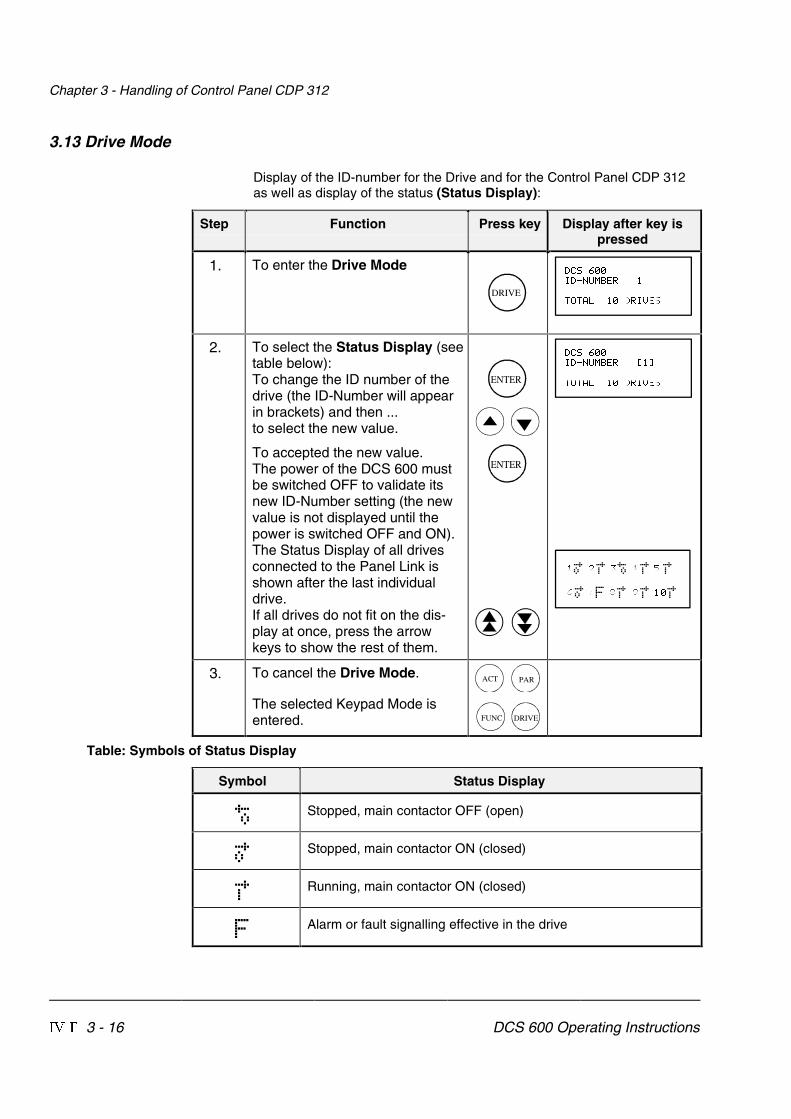
Chapter 3 - Handling of Control Panel CDP 312
IV F 3 - 16 DCS 600 Operating Instructions
3.13 Drive Mode
Display of the ID-number for the Drive and for the Control Panel CDP 312as well as display of the status (Status Display):
Step Function Press key Display after key ispressed
1. To enter the Drive Mode
DRIVE
.-=� ��3.�8?7,/<����
>9>+6�����.<3@/=
2. To select the Status Display (seetable below):To change the ID number of thedrive (the ID-Number will appearin brackets) and then ...to select the new value.
To accepted the new value.The power of the DCS 600 mustbe switched OFF to validate itsnew ID-Number setting (the newvalue is not displayed until thepower is switched OFF and ON).The Status Display of all drivesconnected to the Panel Link isshown after the last individualdrive.If all drives do not fit on the dis-play at once, press the arrowkeys to show the rest of them.
ENTER
ENTER
.-=� ��3.�8?7,/<���E�G
>9>+6�����.<3@/=
��� ��
�
�� �� �� ��
� �! �" �# ���
� �
� � � �
3. To cancel the Drive Mode.
The selected Keypad Mode isentered.
ACT PAR
FUNC DRIVE
Table: Symbols of Status Display
Symbol Status Display
� Stopped, main contactor OFF (open)
� Stopped, main contactor ON (closed)
� Running, main contactor ON (closed)
� Alarm or fault signalling effective in the drive

Chapter 3 - Handling of Control Panel CDP 312
DCS 600 Operating Instructions IV F 3 - 17
3.14 Running the Drive
Operational Com-mand Keys
Operational commands can be given from the Control PanelCDP 312 every time when the status row is displayed. Operationalcommands include START and STOP of the the drive, controllingthe main contactor and adjusting the reference.
CAUTION! To be able to give operational commands from theCDP 312, the selected control location must be theControl Panel. The control location can be changedby means of ������� key to ����� mode.
If ����� mode is activated some of the binary inputsare no longer functioning.Take care that the drive is engineered to allow opera-tion with ����� mode.
ControlPanel Key
Name of Key Function
LOC
REM
LOCAL /REMOTE
To select LOCAL (= CDP 312) or REMOTE(= ext. control system) operation.
START Starts the drive, when in LOCAL mode.
STOP Stops the drive, when in LOCAL mode.
ON Main contactor closing control, when inLOCAL mode.
OFF Main contactor opening control, when inLOCAL mode.
Running the DC-Drive fromthe �������
Ensure safety before you start the drive test!
M
• Select LOCAL mode (LOCAL = CDP 312) by pressing LOC/REMOTE key.
• Close (switch on) the main contactor by pressing the � key• Start the drive by pressing the �����key. Presetting of a ref-
erence value for the motor will now be possible.• Direction of rotation can be changed by presetting the opposite
polarity of reference value in case of 4Q drive.• Stop the drive by pressing the �� key. Motor will decelerate
to zero speed (depending on the parameter LOCAL STOP� �������)
• Finally open (switch off) the main contactor by pressing the ��� key.

Chapter 3 - Handling of Control Panel CDP 312
IV F 3 - 18 DCS 600 Operating Instructions
3.15 Speed Reference Setting for the Drive
Step Function Press key Display after key ispressed
1. Press one of these keys to getthe status row displayed.
ACT PAR
FUNC
���6���������\ZW��336/.�:+8/����������79>9<�=:���������\ZW�-98@�-?<���������+�
2. To enter the Reference SettingMode
REF
���6����E����\ZWG�336/.�:+8/����������79>9<�=:���������\ZW�-98@�-?<���������+�
3. To change the reference:(slow change)
(fast change)
���6��E������\ZWG�336/.�:+8/����������79>9<�=:���������\ZW�-98@�-?<���������+�
4. To exit the Reference SettingMode.
The selected Keypad Mode isentered.
ACT PAR
FUNC DRIVE
���6���������\ZW��336/.�:+8/����������79>9<�=:���������\ZW�-98@�-?<���������+�

Chapter 4 - Signals and Troubleshooting
IV F 4 - 1 DCS 600 Operating Instructions
4.1 Display of status, alarm and fault signals
Categories of signalsand possibilities ofdisplay
The signals (messages) to be available for thyristor power con-verters series DCS 600 are subdivided into four (fifth categorysee below) categories:
General messages
Starting errors
F Fault signals
A Alarm signals
A seven segment display on the control board SDCS-CON-2 of thethyristor power converters series DCS 600 is used to show generalmessages, starting errors, fault and alarm signals.The signals (messages) are displayed as codes. If the codes con-sist of several parts, the characters/individual digits will be indicatedfor 0.7 sec one after the other, e.g.:
0.7s 0.7s0.7s
⇒ ⇒ F 14 = Speed measurement fault⇑ ⇐ ⇓
In addition to this the DCS 600 combined with the LCD of thecontrol panel CDP 312 will be able to show the fault and alarmsignals as numbers with text as well as the status signals(selected in Actual Signal Display Mode [⇒ ACT-key] by signalgroup 1..xx ... 9.xx).
For subsequent evaluation via binary outputs or serial interfacesthe 16 bit informations FAULT WORD1 [9.01], FAULT WORD2 [9.02]and FAULT WORD3 [9.06] as well as ALARM WORD1 [9.04] andALARM WORD2 [9.05] contain several fault and alarm signals asa binary code.

Chapter 4 - Signals and Troubleshooting
IV F 4 - 2 DCS 600 Operating Instructions
4.2 General messages
From SDCS-CON-2 board
The general messages will only be shown on the seven segmentdisplay/LEDs of the boards SDCS-CON-2/SDCS-AMC-DC.
Code sevensegm.display
Text onLCD of control panel
CDP 312(or DRIVES WINDOW)
Definition – Remark
8 Not available Program is not running [SDCS-CON-2] – (1)
. Not available Normal situation, no fault / no alarm signal –
L Not available Indication while loading another firmwareinto the control board SDCS-CON-2
–
From SDCS-AMC-DC board
LED Definition Remark
green Software running SDCS-AMC-DC Software under operation
red Fault Fault occured; Fault and Alarm Words ⇒ group 6, 9
4.3 Starting errors (E) [from SDCS-CON-2 board]
The starting errors will only be shown on the seven segment dis-play of the control board SDCS-CON-2.
With starting errors it will not be possible to start the drive.
Code sevensegm.display
Text onLCD of control panel
CDP 312(or DRIVES WINDOW)
Definition – Remark
E1 Not available ROM memory test error [SDCS-CON-2] – (1)
E2 Not available RAM memory test error [SDCS-CON-2] – (1)
E5 Not available No control program in memory [SDCS-CON-2] – (2)
E6 Not available Hardware is not compatible [SDCS-CON-2] – (1)
(1) Units should be switched off and on electrically; if fault occurs again, the PCBs SDCS-POW-1 and SDCS-CON-2have to be checked and if necessary to be changed.
(2) Load firmware once more.

Chapter 4 - Signals and Troubleshooting
DCS 600 Operating Instructions IV F 4 - 3
4.4 Fault Signals (F)
The fault signals will be shown on the seven segment display ofthe control board SDCS-CON-2 as codes F . . as well as on theLCD of the control panel CDP 312 as numbers with text.Moreover there are fault signals which will only be shown on theLCD of the control panel.All fault signals - with the exception of F 17, F 20 and F 44 - canbe reset (after elimination of the faults).For resetting (RESET) of fault signals the following steps arerequired:• Switching off the commands ON/OFF and RUN• Elimination of the faults• Fault acknowledgement, i.e. resetting (RESET) through input
of the command RESET with APC or in ”LOCAL” mode withcontrol panel CDP 312/DRIVES WINDOW.
• Depending on the application conditions generate the com-mands ON/OFF and RUN once more.
The fault signals will result in tripping the drive (installation-de-pendent).If a fault occurs, there will be three different possibilities of reaction(see column ”Remark” in the fault list):(1) Fault will switch off the signals energizing the main contactor, the
field contactor and the fan contactor.(2) Fault will switch off the signals energizing the main contactor and
the field contactor.(3) Fault will switch off the signal energizing the main contactor.
Code sevensegm.display
Text onLCD of control panel
CDP 312(or DRIVES WINDOW)
Definition / Action
Statussignal
(FAULT_WORD_1/2/3)
Remark
F 1 01 AUX UVOLT Auxiliary voltage faultThe auxiliary voltage (230 V) is too low whilethe drive is in operation. If resetting fails,check internal auxiliary voltages. If faultpersists, change SDCS-CON-2 and/ orSDCS-POW 1 board (if required).
9.01 bit 0 (1)
F 2 02 OVERCURR OvercurrentCheck: - Motor, load and armature cabling
for faults or blocking condition;- Parameter setting of current con-
trol circuit/torque limitation;- Parameter [P 42.05]
(overcurrent detection).- Faulty thyristor
9.01 bit 1 (3)

Chapter 4 - Signals and Troubleshooting
IV F 4 - 4 DCS 600 Operating Instructions
Code sevensegm.display
Text onLCD of control panel
CDP 312(or DRIVES WINDOW)
Definition / Action
Statussignal
(FAULT_WORD_1/2/3)
Remark
F 3 03 C FAN CURR Overcurrent converter fan only in combinati-on 42.14 ≠ 0Check setting:
- Current converter fan- PW 1002 /PW 1003- Parameter [P 42.19]- Parameter [P 42.14]- Monitor [4.14]
9.01 bit 10 (1)
F 4 04 CONV TEMP Overtemperature power sectionCheck: - Fan supply, direction of rotation,
fan components, air inlet andambient temperature;
- Inadmissible load cycle?- connector X12 on SDCS-CON-2
9.01 bit 3 (2)
F 5 05 EARTH FLT Earth fault (Σ IL1,IL2,IL3 differs from zero)Disconnect the mains and verify zero voltagein armature and field circuits.Make insulation test for the completeinstallation.Check sum current transformer; if necessary,change transformer and SDCS-IOB-3 board.
9.01 bit 4 (1)
F 6 06 MOT1 TEMP Overtemperature of MOTOR 1Check: - Temperature sensor and its
cabling;- Motor cooling or sizing;- Inputs for temperature sensor
on board SDCS-IOB-3;- Param. setting [P 28.11] correct?
9.01 bit 5 (2)
F 7 07 MOT1 LOAD Overload of MOTOR 1 (Thermal model 1)Check: - Motor temperature (let motor cool
down and restart);- Motor ratings and parameters of
thermal model;- Motor sizing or load cycle;- Param. setting [P 28.04] correct?
9.01 bit 6 (2)

Chapter 4 - Signals and Troubleshooting
DCS 600 Operating Instructions IV F 4 - 5
Code sevensegm.display
Text onLCD of control panel
CDP 312(or DRIVES WINDOW)
Definition / Action
Statussignal
(FAULT_WORD_1/2/3)
Remark
F 14 14 SPD MEAS Speed feedback (measurement) faultCheck: - Incremental encoder and connec-
tion cable, encoder power supply(feedback might be too low);
- Tacho polarity and voltage(does a total mismatch exist?)
- Position of jumper S4 on boardSDCS-CON-2 O.K.?
- Electronic boards SDCS-CON-2,SDCS-IOB-3, SDCS-POW 1;
- Connection converter – armaturecircuit open?
- Correct setting for selection ofspeed feedback monitoring?
9.02 bit 5 (3)
F 17 17 TYPE CODE (Converter) Type coding faultSDCS-PIN-xx board not connected to boardSDCS-CON-2 or SDCS-PIN-xx not coded.Check: - Flat cables X12 and X13 O.K.?
- Faulty coding on SDCS-PIN-xx?- New boards SDCS-CON-2/SDCS-
AMC-DC installed?- Correct coding of unit size C4?
9.02 bit 8 (1)Can
not bereset
F 18 18 CON FLASH Memory fault on SDCS-CON-2 board(Parameter saving fault)Cause: Wrong or missing checksum, dataerror while writing or reading.Note: Try again saving of type coding; for that purpose
- Move jumper S2 (on board SDCS-CON-2) to Pos. 1–2with electronics supply switched OFF;
- Switch ON electronics again;- Select [P 15.02] = 22;- Save default parameter set;- Switch OFF electronics;- Reset jumper S2 to ist original position;- Switch ON electronics again.
If display shows F 18 once again, change SDCS-CON-2board!
9.06 bit 14 (1)Can
not bereset
F 20 20 CON-SYSTEMFAULT
CON-SYSTEM FAULTThis fault is shown after downloading the soft-ware of the SDCS-AMC-DC board.The auxiliary voltage (230 V) has to be swit-ched OFF and ON again.
9.06 bit 15 (1)Can
not bereset

Chapter 4 - Signals and Troubleshooting
IV F 4 - 6 DCS 600 Operating Instructions
Code sevensegm.display
Text onLCD of control panel
CDP 312(or DRIVES WINDOW)
Definition / Action
Statussignal
(FAULT_WORD_1/2/3)
Remark
F 23 23 MOT STALL Motor stalledWhile starting the motor the current exceededthe value of parameter [P 28.17] for a timelonger than parameter [P 28.15] and thespeed feedback value was below parameter[P 28.16].Check: - Motor stalled?
- Load changed during start?- Correct field current?- Current/torque limitation;- Parameter settings [P 15.08].
9.02 bit 14 (3)
F 27 27 MOT2 LOAD Overload of MOTOR 2 (Thermal model 2).{see Fault Code F 7}
9.01 bit 9 (2)
F 28 28 ARM OVOLT Armature (DC circuit) overvoltageCheck: - Setting of param. [P 28.22] suitable
for the system configuration?- Setting of field current and actual
value as well as the completefield supply (FIELD EXCITER);
- Was the motor accelerated bythe load?
- Speed scaling;- Armature voltage feedback;- Connections between SDCS-
CON-2 and SDCS-PIN boards;- Coding of voltage evaluation on
SDCS-PIN-xx board.
9.01 bit 2 (1)
F 29 29 MAIN UVLT Mains supply undervoltage (AC); setting viaparameters [P 40.01] or/ and [P 40.02]Check: - Is the mains voltage within the
admissible tolerance?- Did the mains contactor close
and open?- Voltage scaling via parameter
[P 42.06] rated line voltagecorrect?
- Connections between SDCS-CON-2 and SDCS-PIN-xx boards;
- Coding of voltage measurementon SDCS-PIN-xx board.
9.01 bit 11 (3)

Chapter 4 - Signals and Troubleshooting
DCS 600 Operating Instructions IV F 4 - 7
Code sevensegm.display
Text onLCD of control panel
CDP 312(or DRIVES WINDOW)
Definition / Action
Statussignal
(FAULT_WORD_1/2/3)
Remark
F 30 30 MAIN OVLT Mains supply overvoltage (AC)Mains voltage > 130% of nominal value(parameter [P 42.06]) for longer than 10s.
Fault tracing see Fault Code F 29.
9.01 bit 12 (1)
F 31 31 NO SYNC Synchronization fault (of mains)Check: - Mains supply, fuses etc.;
- Mains voltage and stability.
9.01 bit 13 (3)
F 32 32 FEX1 OCUR FIELD EXCITER 1 (field supply 1) overcurrentCheck: - FIELD1_OVERCUR_LEV
(parameter [P 20.16]);- Connections of field exciter as
well as insulation level of cableand of field winding.
9.01 bit 14 (1)
F 33 33 FEX1 COMM FIELD EXCITER 1 communication errorCheck: - Flat cable connections X14: or
cable X16: between SDCS-CON-2 board and field exciter;
- Auxil. voltage for ext. field exciter.
9.01 bit 15 (1)
F 34 34 CURR RIPP Armature current rippleOne or several thyristors carry no current.Check: - Current feedback with oscilloscope
(6 pulses within one cycle visible?);- Branch fuses, thyristor gate con-
nection and gate-cathode resis-tance;
- See also parameters [P 43.10],[P 43.11], and [P 43.12]
9.02 bit 0 (3)
F 35 35 FEX2 OCUR FIELD EXCITER 2 (field supply 2) overcurrentCheck: - FIELD2_OVERCUR_LEV
(parameter [P 20.17]);- Connections of field exciter as
well as insulation level of cableand of field winding.
9.02 bit 1 (1)
F 36 36 FEX2 COMM FIELD EXCITER 2 communication error{See Fault Code F 33}
9.02 bit 2 (1)

Chapter 4 - Signals and Troubleshooting
IV F 4 - 8 DCS 600 Operating Instructions
Code sevensegm.display
Text onLCD of control panel
CDP 312(or DRIVES WINDOW)
Definition / Action
Statussignal
(FAULT_WORD_1/2/3)
Remark
F 37 37 OVERSPEED Motor overspeedSpeed feedback higher than parameter[P 20.11].Check: - Scaling of speed controller loop;
- Drive speed;- Field refererence values;- Speed feedback and connection
of speed feedback;- Was the motor accelerated by
the load?
9.02 bit 15 (3)
F 38 38 PHAS SEQU Phase sequence fault of power sectionChange supply phase sequency or makecorrection with parameter [P 42.01].
Attention: Direction of rotation of 3-phasefan correct?
9.02 bit 3 (3)
F 39 39 NO FIELD No field acknowledge from FIELD EXCITERCheck: - Do selection parameters match
the field exciter (field supply)?- Field exciter supply, cable and
field winding;- Status/level of acknowledge signal.
9.02 bit 4 (1)
F 40 40 NO E FAN No acknowledge from FAN of motorCheck: - Contactor circuit/supply for fan of
motor;- Status of binary inputs/outputs
(DI2/DO1) on SDCS-IOB-2/SDCS-CON-2 boards;
- Parameter setting [P 15.07].
9.02 bit 6 (1)
F 41 41 NO M CONT Missing main contactor acknowledgeCheck: - Switch-ON/-OFF sequence
correct?- Status of binary input DI3 for ac-
knowledge signal ACK_M_CONTof main contactor;
- Status of binary output DO3 resp.of auxiliary contactor (relay)closing the main contactor afterON/OFF command.
9.02 bit 7 (3)

Chapter 4 - Signals and Troubleshooting
DCS 600 Operating Instructions IV F 4 - 9
Code sevensegm.display
Text onLCD of control panel
CDP 312(or DRIVES WINDOW)
Definition / Action
Statussignal
(FAULT_WORD_1/2/3)
Remark
F 42 42 FEX1 FLT FIELD EXCITER 1 (field supply 1) faultA fault was found during self-diagnosis offield exciter.Check: - Field exciter operation;
change the unit, if necessary;- Field 1/Field 2 coding O.K.?
9.02 bit 12 (1)
F 43 43 FEX2 FLT FIELD EXCITER 2 (field supply 2) fault{See Fault Code F 42}
9.02 bit 13 (1)
F 44 44 NO I/O Missing input/output (I/O-) boardCheck: - Correct selection of SDCS-IOB-2/3
board (see also param. [P 98.08])- Is +/- 10 V supply available?- Flat cable connections between
SDCS-CON-2 and SDCS-IOB-2/3boards.
9.01 bit 7 (1)
F 48 48 MOT2 TEMP Overtemperature of MOTOR 2Check: - Parameter setting MOT_2_TEMP_
FAULT_L [P 28.14] correct?{See Fault Code F 6}
9.01 bit 8 (2)
F 50 50 NO C FAN No CONVERTER FAN supply acknowledgeDepending on type of unit (size):Size C4 ⇒ Fault signal F 50Sizes C1...C3 ⇒ Alarm signal A 126
Check: - Was input for acknowledgesignal DI1 used?
9.02 bit 10 (2)
F 65 65 REVER FLT Zero current signal not reached within 6.6 msVery fast current rise ramp:
- increase parameter 47.07
9.06 bit 0 (3)
F 66 66 CURR DIFF Current difference in 12-pulse parallel opera-tion
Check: - Setting of master and slavecurrent controller
- increase parameter 47.04
9.06 bit 1 (3)
F 67 67 12P COMM Open 12-pulse fibre optic link (V260) 9.06 bit 2 (3)
F 68 68 SLAVE DIS Fault of 12-pulse master.Master tripped by a fault of the 12-pulse slave.
Check: - Fault logger of 12-pulse slave
9.06 bit 3 (3)
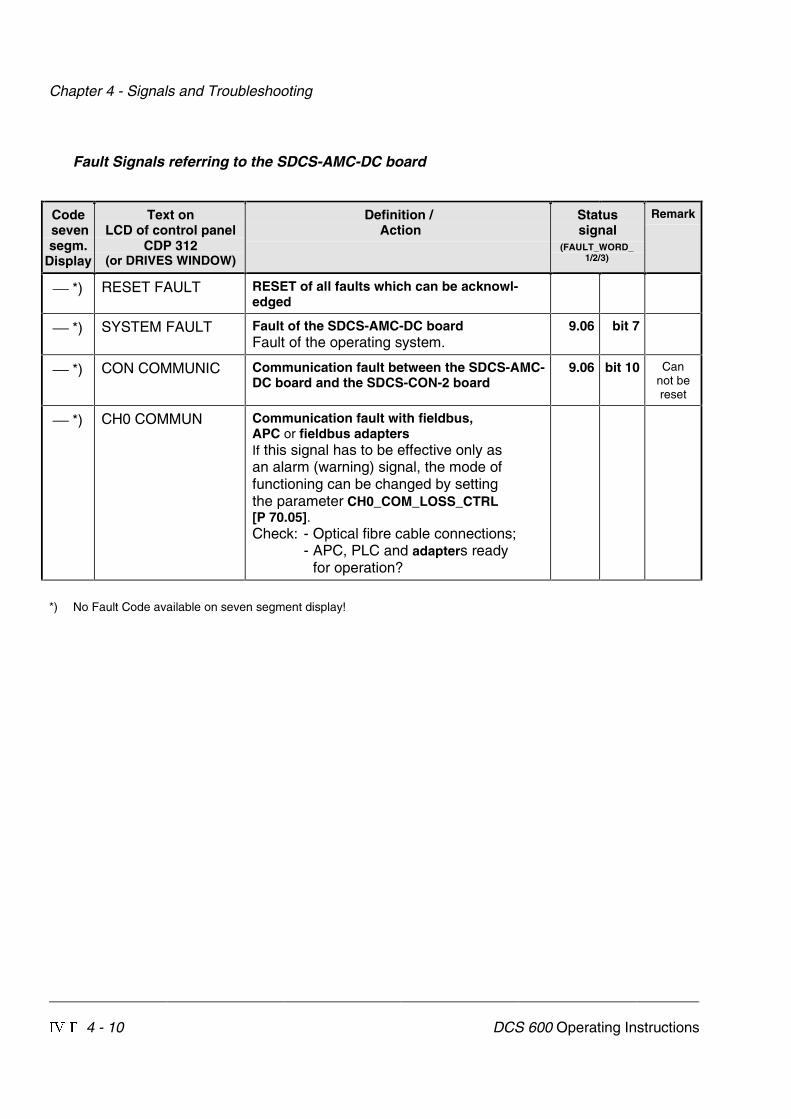
Chapter 4 - Signals and Troubleshooting
IV F 4 - 10 DCS 600 Operating Instructions
Fault Signals referring to the SDCS-AMC-DC board
Code sevensegm.
Display
Text onLCD of control panel
CDP 312(or DRIVES WINDOW)
Definition / Action
Statussignal
(FAULT_WORD_1/2/3)
Remark
*) RESET FAULT RESET of all faults which can be acknowl-edged
*) SYSTEM FAULT Fault of the SDCS-AMC-DC boardFault of the operating system.
9.06 bit 7
*) CON COMMUNIC Communication fault between the SDCS-AMC-DC board and the SDCS-CON-2 board
9.06 bit 10 Cannot bereset
*) CH0 COMMUN Communication fault with fieldbus,APC or fieldbus adaptersIf this signal has to be effective only asan alarm (warning) signal, the mode offunctioning can be changed by settingthe parameter CH0_COM_LOSS_CTRL[P 70.05].Check: - Optical fibre cable connections;
- APC, PLC and adapters readyfor operation?
*) No Fault Code available on seven segment display!

Chapter 4 - Signals and Troubleshooting
DCS 600 Operating Instructions IV F 4 - 11
Code sevensegm.display
Text onLCD of control panel
CDP 312(or DRIVES WINDOW)
Definition / Action
Statussignal
(FAULT_WORD_1/2/3)
Remark
*) M/F LINK Communication fault in the Master-Follower-linkIf this signal has to be effective only asan alarm (warning) signal, the mode offunctioning can be changed by settingthe parameter CH2_COM_LOSS_CTRL[P 70.14].Check: - Optical fibre cable connections.
9.06 bit 11
*) PANEL LOSS Connection fault to the Control PanelCDP 312 or DRIVES WINDOWCheck: - Control Panel CDP 312 discon-
nected?- Connection adapter or cable
damaged?- Communication problems using
the program DRIVES WINDOW in”LOCAL” mode?
9.06 bit 13
*) EXT FAULT External fault at binary input (DI) selected byParameter [P 15.23]An external fault is activated by a ”Low sig-nal” at the binary input (DI) selected by Pa-rameter [P 15.23].
9.02 bit 9
*) SW MISMATCH Software versions loaded to SDCS-CON-2 andSDCS-AMC-DC do not match
see DCS 600 Software release notice
9.06 bit 9
*) No Fault Code available on seven segment display!
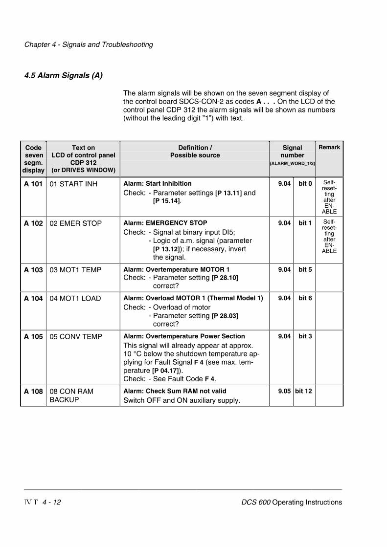
Chapter 4 - Signals and Troubleshooting
IV F 4 - 12 DCS 600 Operating Instructions
4.5 Alarm Signals (A)
The alarm signals will be shown on the seven segment display ofthe control board SDCS-CON-2 as codes A . . . On the LCD of thecontrol panel CDP 312 the alarm signals will be shown as numbers(without the leading digit ”1”) with text.
Code sevensegm.display
Text onLCD of control panel
CDP 312(or DRIVES WINDOW)
Definition /Possible source
Signalnumber
(ALARM_WORD_1/2)
Remark
A 101 01 START INH Alarm: Start InhibitionCheck: - Parameter settings [P 13.11] and
[P 15.14].
9.04 bit 0 Self-reset-tingafterEN-
ABLE
A 102 02 EMER STOP Alarm: EMERGENCY STOPCheck: - Signal at binary input DI5;
- Logic of a.m. signal (parameter[P 13.12]); if necessary, invertthe signal.
9.04 bit 1 Self-reset-tingafterEN-
ABLE
A 103 03 MOT1 TEMP Alarm: Overtemperature MOTOR 1Check: - Parameter setting [P 28.10]
correct?
9.04 bit 5
A 104 04 MOT1 LOAD Alarm: Overload MOTOR 1 (Thermal Model 1)Check: - Overload of motor
- Parameter setting [P 28.03]correct?
9.04 bit 6
A 105 05 CONV TEMP Alarm: Overtemperature Power SectionThis signal will already appear at approx.10 °C below the shutdown temperature ap-plying for Fault Signal F 4 (see max. tem-perature [P 04.17]).Check: - See Fault Code F 4.
9.04 bit 3
A 108 08 CON RAMBACKUP
Alarm: Check Sum RAM not validSwitch OFF and ON auxiliary supply.
9.05 bit 12

Chapter 4 - Signals and Troubleshooting
DCS 600 Operating Instructions IV F 4 - 13
Code sevensegm.display
Text onLCD of control panel
CDP 312(or DRIVES WINDOW)
Definition /Possible source
Signalnumber
(ALARM_WORD_1/2)
Remark
A 115 15 CURR RIPP Armature current rippleOne or several thyristors carry no current.Check: - Current feedback with oscilloscope
(6 pulses within one cycle visible?);- Branch fuses, thyristor gate con-
nection and gate-cathode resis-tance;
- See also parameters [P 43.10],[P 43.11], and [P 43.12]
9.05 bit 0
A 118 18 MAIN UVLT Alarm: Mains Undervoltage (AC)Setting of undervoltage monitoring with Pa-rameter [P 40.01] or/and [P 40.02]Check: - See also Fault Code F 29.
9.04 bit 10
A 120 20 CURR DEV Alarm: Armature Current DeviationIf the current reference ARM_CUR_REF[P 3.12] deviates from the current feedbackfor more than 5 sec by more than 20 %,referenced to the rated current, this signalwill be shown.Check: - Ratio between mains supply
voltage and EMF
9.04 bit 13
A 123 23 MOT2 TEMP Alarm: Overtemperature MOTOR 2Check: - Parameter setting [P 28.13]
correct?See also Fault Code F 6.
9.04 bit 8
A 124 24 MOT2 LOAD Alarm: Overload MOTOR 2 (Thermal Model 2)Check: - Overload of motor
- Parameter setting [P 28.07]correct?
9.04 bit 9
A 125 25 NO ACK Alarm: No Acknowledge DC Break or Dyna-mic Brake contactorCheck: - Digital inputs [P 15.18], [P 15.20]
9.04 bit 2 RUN =blocked
A 126 26 CONV FAN Alarm: No (Thyristor Power) Converter FANAcknowledgeCheck: - See Fault Code F 50.
9.04 bit 12

Chapter 4 - Signals and Troubleshooting
IV F 4 - 14 DCS 600 Operating Instructions
Code sevensegm.display
Text onLCD of control panel
CDP 312(or DRIVES WINDOW)
Definition /Possible source
Signalnumber
(ALARM_WORD_1/2)
Remark
A 127 27 EXT FAN Alarm: No Acknowledge from External FAN(of Motor)Check: - Contactor circuit/supply for fan of
motor;- Status of binary inputs/outputs
(DI2/DO1) on SDCS-IOB-2/SDCS-CON-2 boards;
- Parameter setting [P 15.07].
9.04 bit 15
A 129 29 TYPE CODE Alarm: Type Code (Hardware Code of Thyris-tor Power Converter) changedUnit type code stored in memory differs fromthe hardware coding.Check: - New control board SDCS-
CON-2 installed?- Control board SDCS-CON-2 /
SDCS-PIN-xx board inter-changed?
Action: - Save values in non-volatilememory using parameter DRIVE-MODE [P 15.02] = 22.
9.05 bit 1
A 132 32 AUX UVOLT Auxiliary voltage alarmThe auxiliary voltage (230 V) is too low whilethe drive is not in operation.For more details see Fault Code F 1.
9.05 bit 2
A 133 33 OVERVOLT Overvoltage protection activeConverter blocked (via DI2 in field excitermode)
9.05 bit 3
Alarm Signals referring to the SDCS-AMC-DC board
Code sevensegm.display
Text onLCD of control panel
CDP 312(or DRIVES WINDOW)
Definition /Possible source
Signalnumber
(ALARM_WORD_1/2)
Remark
**) CH0 COMMUN Alarm: Communication fault with fieldbus,APC or fieldbus adaptersIf this signal has to be effective also asa fault signal, the mode of functioningcan be changed by setting the parameterCH0_COM_LOSS_CTRL [P 70.05].
Check: - Optical fibre cable connections;- APC, PLC and adapters ready
for operation?
9.05 bit 11
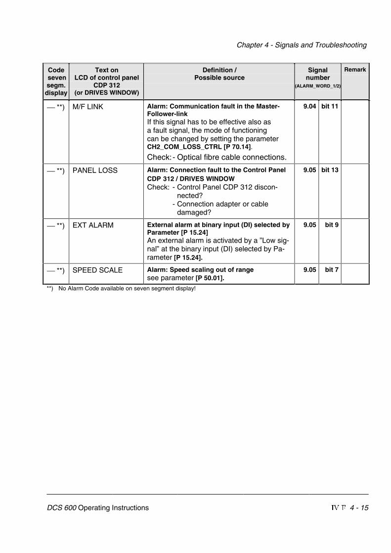
Chapter 4 - Signals and Troubleshooting
DCS 600 Operating Instructions IV F 4 - 15
Code sevensegm.display
Text onLCD of control panel
CDP 312(or DRIVES WINDOW)
Definition /Possible source
Signalnumber
(ALARM_WORD_1/2)
Remark
**) M/F LINK Alarm: Communication fault in the Master-Follower-linkIf this signal has to be effective also asa fault signal, the mode of functioningcan be changed by setting the parameterCH2_COM_LOSS_CTRL [P 70.14].
Check:- Optical fibre cable connections.
9.04 bit 11
**) PANEL LOSS Alarm: Connection fault to the Control PanelCDP 312 / DRIVES WINDOWCheck: - Control Panel CDP 312 discon-
nected?- Connection adapter or cable
damaged?
9.05 bit 13
**) EXT ALARM External alarm at binary input (DI) selected byParameter [P 15.24]An external alarm is activated by a ”Low sig-nal” at the binary input (DI) selected by Pa-rameter [P 15.24].
9.05 bit 9
**) SPEED SCALE Alarm: Speed scaling out of rangesee parameter [P 50.01].
9.05 bit 7
**) No Alarm Code available on seven segment display!

ABB Automation Products GmbH Postfach 1180D-68619 LampertheimTel: +49 (0) 62 06-5 03-0Fax:+49 (0) 62 06-5 03-6 09www.abb.com/motors&drives �����������������
*080R0501A0490000*
Iden
t. N
o.: 3
AD
W 0
00 0
80 R
0501
Rev
E 1
2_00