dcs structured connectivity solutions for brocade …
TRANSCRIPT
1
2
8
2
2
3
4
4
5
6 6
7
7
6
7
5
5
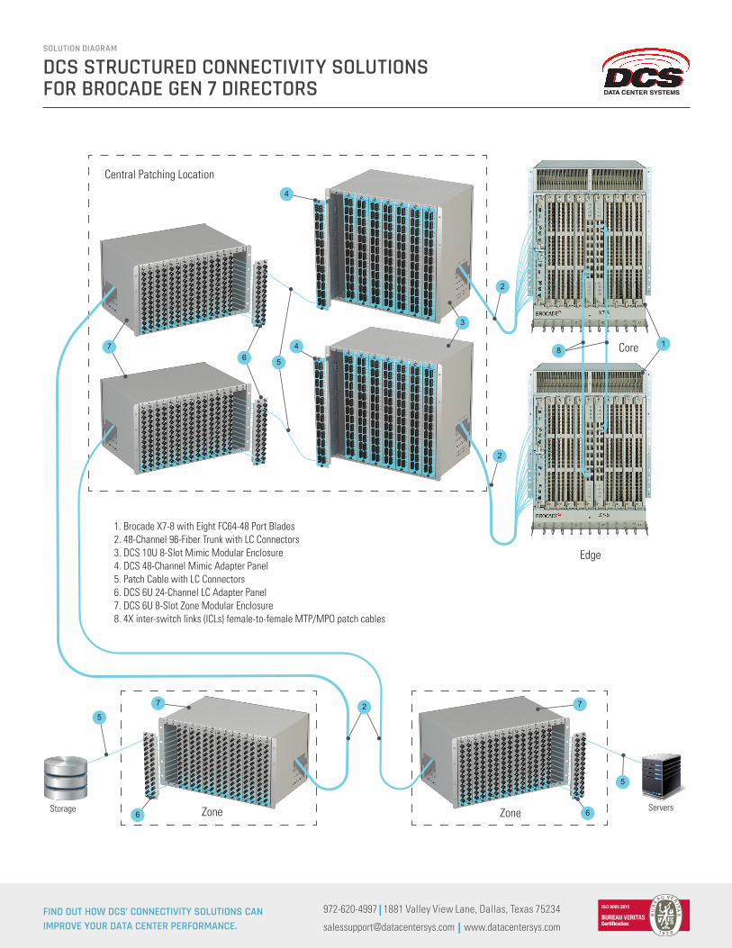
1. Brocade X7-8 with Eight FC64-48 Port Blades2. 48-Channel 96-Fiber Trunk with LC Connectors3. DCS 10U 8-Slot Mimic Modular Enclosure4. DCS 48-Channel Mimic Adapter Panel5. Patch Cable with LC Connectors6. DCS 6U 24-Channel LC Adapter Panel7. DCS 6U 8-Slot Zone Modular Enclosure8. 4X inter-switch links (ICLs) female-to-female MTP/MPO patch cables
Central Patching Location
Edge
Core
ZoneStorage ServersZone
DCS STRUCTURED CONNECTIVITY SOLUTIONS FOR BROCADE GEN 7 DIRECTORS
SOLUTION DIAGRAM
FIND OUT HOW DCS’ CONNECTIVITY SOLUTIONS CAN IMPROVE YOUR DATA CENTER PERFORMANCE.
972-620-4997 | 1881 Valley View Lane, Dallas, Texas 75234
[email protected] | www.datacentersys.com
DATA CENTER SYSTEMS
DCS STRUCTURED CONNECTIVITY SOLUTIONS FOR BROCADE GEN 7 DIRECTORS
SOLUTION DIAGRAM
WHAT YOU NEED TO KNOW
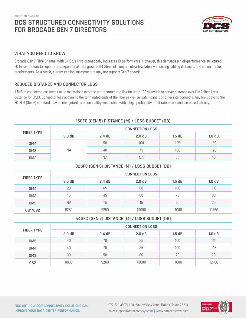
REDUCED DISTANCE AND CONNECTOR LOSS
Brocade Gen 7 Fibre Channel with 64 Gb/s links dramatically increases IO performance. However, this demands a high-performance structured FC Infrastructure to support this exponential data growth. 64 Gb/s links require ultra-low latency, reducing cabling distances and connector loss requirements. As a result, current cabling infrastructure may not support Gen 7 speeds.
1.5dB of connector loss needs to be maintained over the entire structured link for up to 100M switch to server distance over OM4 fiber. Less distance for OM3. Connector loss applies to the terminated ends of the fiber as well as patch panels or other interconnects. Any links beyond the FC-PI-6 (Gen 6) standard may be recognized as an unhealthy connection with a high probability of bit rate errors and increased latency.
FIND OUT HOW DCS’ CONNECTIVITY SOLUTIONS CAN IMPROVE YOUR DATA CENTER PERFORMANCE.
972-620-4997 | 1881 Valley View Lane, Dallas, Texas 75234
[email protected] | www.datacentersys.com
16GFC (GEN 5) DISTANCE (M) / LOSS BUDGET (DB)
FIBER TYPECONNECTION LOSS
3.0 dB 2.4 dB 2.0 dB 1.5 dB 1.0 dB
OM4
NA
50 100 125 150
OM3 40 75 100 120
OM2 NA NA 35 40
32GFC (GEN 6) DISTANCE (M) / LOSS BUDGET (DB)
FIBER TYPECONNECTION LOSS
3.0 dB 2.4 dB 2.0 dB 1.5 dB 1.0 dB
OM4 20 65 80 100 110
OM3 15 45 60 70 80
OM2 NA 15 15 20 25
OS1/OS2 8250 9250 10000 11000 11750
64GFC (GEN 7) DISTANCE (M) / LOSS BUDGET (DB)
FIBER TYPECONNECTION LOSS
3.0 dB 2.4 dB 2.0 dB 1.5 dB 1.0 dB
OM5 40 70 85 100 115
OM4 40 70 85 100 115
OM3 30 50 60 70 75
OS2 8000 9200 10000 11000 12100
DATA CENTER SYSTEMS
FIND OUT HOW DCS’ CONNECTIVITY SOLUTIONS CAN IMPROVE YOUR DATA CENTER PERFORMANCE.
972-620-4997 | 1881 Valley View Lane, Dallas, Texas 75234
[email protected] | www.datacentersys.com
DCS STRUCTURED CONNECTIVITY SOLUTIONS FOR BROCADE GEN 7 DIRECTORS
SOLUTION DIAGRAM
DCS PROFESSIONAL AND MANAGED SERVICES
PRODUCTS
DCS SERVICES
If you are planning to upgrade to Gen 7 directors, DCS can work with you and your team to assess your existing infrastructure and design a new sustainable infrastructure to support current and future requirements.
DCS’ unique products are designed for ease of port identification and cable management. We represent all ports on all devices with Mimic panels in our Multi-Bay open frame central patching facility. Contact us for more information on our Mimic Series of patching components.
• We provide an assessment of your current infrastructure andconsultation on bringing it up to the latest generation standardsand a True Structured Cabling environment.
• We then establish a Central Patching Location (CPL) with ourMulti-Bay to represent all ports on all devices within the datacenter network.
• By adding our Mimic series of connectivity products, we canidentify each piece of equipment in its own image at the CPL.All ports are labeled exactly as the equipment they represent.
• If needed, our Engineering services will design patching and cablemanagement products specific to your data center to improve yourconnectivity infrastructure.
• Installation services will mine out the obsolete cable, installnew infrastructure and cabling from the equipment to the CPL.
• Our product-specific fiber trunk assemblies are built to mimicport labeling at the active equipment. Each connector leg ismeticulously measured to reduce slack at the switch andavoid compromising connectivity.
• Each fiber port is documented and tested to exceed industrystandards.
• Provide a series of fiber patch cords in various lengths andtraining on best practices in cable management.
• DCS Managed Services provide on-site technicians who performday-to-day infrastructure and connectivity services and managemigration of next Generation upgrades.
DATA CENTER SYSTEMS