dc7.pdf
TRANSCRIPT

A Compact 3-dB Coupler on a Dual Substrate Layer with a Rectangular Slotted Microstrip Ground Plane
S.F. Ausordin, S.K.A. Rahim,Norhudah Seman and R. Dewan Wireless Communication Centre,
Universiti Teknologi Malaysia Johor, Malaysia.
[email protected], [email protected], [email protected], [email protected]
Abstract—This paper presents a compact 3-dB coupler on a dual substrate layer with a rectangular slotted microstrip ground plane. The coupler is designed for operating frequency at 2.45 GHz using an inexpensive FR-4 substrate. A compact coupler design with dimension of 19 mm x 7.5 mm offers a size reduction of 62 % while simultaneously enhanced the bandwidth to 42.7 % compared to a conventional coupler.
Keywords-coupler; multilayer technology; compact coupler;
enchanced bandwidth
I. INTRODUCTION
Couplers is the most common device that can be used as power divider or power combiner in various microwave applications such as power dividers, phase shifter[1], balanced amplifier, mixers and butler matrices [2-4] . It is also known as 90o hybrid couplers that are basically 3-dB directional coupler in which the phase difference between the outputs ports are 90o.
Various kinds of 3-dB hybrid couplers in single layer substrate have been designed so far but most of them provide limited bandwidth and bulky design especially at low frequencies application [5]. Several techniques have been proposed in the past to reduce the size of coupler such as by using open stub with high-low impedances, eight two-step stubs, high impedance transmission lines and distributed capacitor, and dual transmission line[6-9] but the bandwidth provided by these techniques is found to be narrow. In [5], compact branch line coupler using open stub with 64% size reduction compared to conventional coupler was introduced. Unfortunately, the bandwidth performance was slightly narrower than the conventional coupler. The alternative size reduction implements eight two-step stubs technique is proposed in [6]. However, only 25% size reduction is achieved while maintaining the similar bandwidth of conventional coupler of about 10%. Another method uses high impedance transmission lines and distributed capacitor has achieved 38.07% of size reduction with 12% of bandwidth [7]. In [8], the performance of microstrip branch line coupler by using a dual transmission line technique with 60% reduction is achieved, in the trade off of bandwidth slightly narrower than the conventional coupler.
Additionally, various techniques have been proposed to overcome the limitation of the bandwidth. As reported in [10-11], the proposed techniques implement the use of the compact waveguide top wall short-slot 3-dB hybrids coupler using full wave Computer Aided Design (CAD) tool and subsequently implemented the multi section hybrid ring, achieving improving bandwidth up to 78 %. However, these coupler designs impose larger dimensions and fabrication complexity that significantly increased the cost.
In this research, one way to overcome the limitation of narrow bandwidth and bulkiness simultaneously is by implementing the multilayer technology proposed in [12]. The proposed coupler in this paper operating at 2.45 GHz using inexpensive FR-4 substrate able to provide a miniaturized size of 62 % and simultaneously achieved 42.7% enhanced bandwidth compared the normal branch line coupler.
II. COUPLER DESIGN
The proposed compact coupler structure consists of three conductor layers sandwiched between two substrates. Top conductor layer connected to port 1 and port 3, and bottom conductor layer connected to port 2 and port 4, as shown in Fig. 1. The upper and lower conductor layers are coupled via a rectangular slot in the substrate’s common ground plane. The plastic screws were used to hold the substrate close together so that there is no air gap between them.
Figure 1. The exploded views of proposed coupler
978-1-4673-5968-9/13/$31.00 ©2013 IEEE
2013 IEEE Business Engineering and Industrial Applications Colloquium (BEIAC)
156
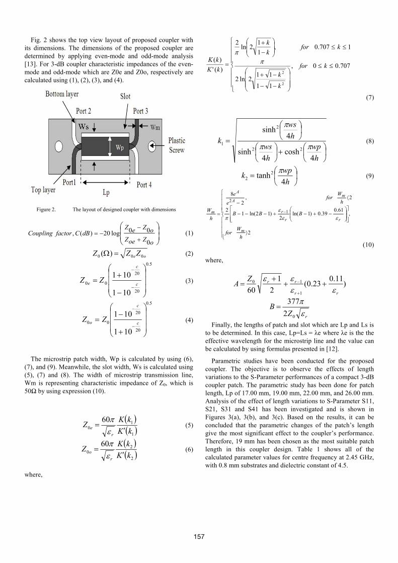
Fig. 2 shows the top view layout of proposed coupler with its dimensions. The dimensions of the proposed coupler are determined by applying even-mode and odd-mode analysis [13]. For 3-dB coupler characteristic impedances of the even-mode and odd-mode which are Z0e and Z0o, respectively are calculated using (1), (2), (3), and (4).
Figure 2. The layout of designed coupler with dimensions
+
−−=
oZoeZ
oZeZdBCfactorCoupling
0
00log20)(, (1)
oeZZZ 000 )( =Ω (2)
5.0
20
20
00
101
101
−
+=
−
−
c
c
e ZZ (3)
5.0
20
20
00
101
101
+
−=
−
−
c
c
o ZZ (4)
The microstrip patch width, Wp is calculated by using (6), (7), and (9). Meanwhile, the slot width, Ws is calculated using (5), (7) and (8). The width of microstrip transmission line, Wm is representing characteristic impedance of Z0, which is 50Ω by using expression (10).
( )( )1
10
60
kK
kKZ
r
e ′=
επ
(5)
( )( )2
20
60
kK
kKZ
r
o ′=
επ
(6)
where,
≤≤
−−
−+
≤≤
−
+
= 707.00,
11
112ln2
1707.0,1
12ln
2
)('
)(
2
2
kfor
k
k
kfork
k
kK
kK ππ
(7)
+
=
h
wp
h
ws
h
ws
k
4cosh
4sinh
4sinh
22
2
1 ππ
π
(8)
=h
wpk
4tanh2
2
π (9)
⟩
−+−+−−−
⟨−
= −
2
,61.0
39.0)1ln(2
)12ln(12
2,2
8
1
2
h
Wfor
BBB
h
Wfor
e
e
h
W
m
rr
r
m
A
A
m
εεε
π
(10)
where,
)11.0
23.0(2
1
60 1
10
rr
rrZA
εεεε
+++
=+
−
rZB
ε
π
02
377=
Finally, the lengths of patch and slot which are Lp and Ls is to be determined. In this case, Lp=Ls = λe where λe is the the effective wavelength for the microstrip line and the value can be calculated by using formulas presented in [12].
Parametric studies have been conducted for the proposed coupler. The objective is to observe the effects of length variations to the S-Parameter performances of a compact 3-dB coupler patch. The parametric study has been done for patch length, Lp of 17.00 mm, 19.00 mm, 22.00 mm, and 26.00 mm. Analysis of the effect of length variations to S-Parameter S11, S21, S31 and S41 has been investigated and is shown in Figures 3(a), 3(b), and 3(c). Based on the results, it can be concluded that the parametric changes of the patch’s length give the most significant effect to the coupler’s performance. Therefore, 19 mm has been chosen as the most suitable patch length in this coupler design. Table 1 shows all of the calculated parameter values for centre frequency at 2.45 GHz, with 0.8 mm substrates and dielectric constant of 4.5.
157

(a) S11
(b)S21 and S31
(c)S41
Figure 3. S-Parameter results of the length variation effect to (a)s11, (b) s21 and S31 and (c) S41
TABLE I. PARAMETER VALUES OF PROPOSED COUPLER
Parameter Symbol Value
Characteristics Impedance (Ω)
Zoe 120.5
Zoo 20.7
Design parameters (mm)
Wp 5.21
Ws 7.47 Lp 19.00
Ls 19.00
III. RESULTS AND DISCUSSION
In this part, the s-parameter performance and dimension of the conventional 3-dB branch line coupler and the proposed compact 3-dB coupler operating at 2.45 GHz are presented. The simulation results for both conventional and proposed coupler by using computer simulation technology (CST) Microwave Studio 2010. The substrate used is FR-4 on 0.8 mm substrates, dielectric constant of 4.5 and copper thickness of 0.035 mm, where, these values used in designed the conventional and proposed couplers.
A. Conventional Branch Line Coupler
Branch-line coupler consists of two transmission lines connected alternately by λ/4 shunt and series branches, as shown in Fig. 4. When, port 1 is fed by input signal, and then the signal travels to port 2 (through) and port 3 (coupled), while port 4 is isolated. With all ports matched, power entering port 1 is evenly divided between ports 2 and 3, with a 90 degrees phase shift between these outputs. Port 4 is the isolated port, and therefore no power is coupled to this port. Moreover, input signal of the coupler can be accurately split the by two divisions with the same power and 90 degree phase difference [9]. By assuming Z0=50 ohm, the impedances of lines port 1 to port 2 and port 3 to port 4 are Z0/√2 = 35.4 ohm, while Z0= 50 ohm for two shunt lines. The overall dimension of conventional coupler is about 19.00 mm x 19.92 mm.
Figure 4. The layout of conventional branch line coupler with
dimensions
158

Figure 5. S- parameter results of conventional branch line coupler
Figure 6. Phase differ result of conventional branch line coupler
Fig. 5 shows the s-parameter results of conventional branch line coupler. For s-parameter results, simulation results show that the values for S11, S21, S31 and S41 are as follows; S11 = -21.47 dB, S21= -3.18 dB, S31 = -3.64 dB and S41 = -23.04 dB at 2.45 GHz. While, the phase difference response result of conventional branch line coupler is 89° at 2.45 GHz is shown in Fig. 6. B. A Proposed Compact 3-dB Coupler
Fig. 7 shows the s-parameter results, return loss is 48.70 dB and isolation performance is 31.03 dB at 2.45 GH. While, coupling and through results shows those values are 3.91 dB and 2.93 dB, respectively at 2.45 GHz. Additionally, the phase differences of simulated result are shown in Fig. 8. Based from the graph, phase difference between port 2 and port 3 is approximately 90° at operated frequency of 2.45 GHz.
Figure 7. S- parameter results of the proposed coupler
Figure 8. Phase difference response between the output ports of the proposed
TABLE II. COMPARISON RESULTS OF CONVENTI0NAL COUPLER
AND PROPOSED COUPLER
Conventional Coupler
Proposed Coupler
S-
parameter, dB
S11 -21.47 -48.70
S21 -3.18 -31.03 S31 -3.64 -3.91 S41 -23.04 -2.93
Phase difference , degree
89 90
Size , mm 19.00 x 19.92 19.00 x 7.5
159
The comparison results for both conventional and proposed couplers are summarized as Table 2. The conventional coupler provides 19.00 mm x 19.92 mm (refer Fig. 4) whereas the proposed compact coupler’s size of 19.00 mm x 7.5 mm which is 62 % size reduction compared to a conventional coupler.
Bandwidth is achieved by considering the through and coupling coefficient denoted by S21 and S31 respectively is -3dB ±1 dB. Return loss is better than 10dB. The simulated bandwidth result of proposed coupler is 42.7% which covers from 1.8 GHz to 2.75 GHz.
IV. CONCLUSION
The design of a compact 3-dB coupler on a dual substrate
layers with a rectangular slotted microstrip ground plane has been presented in this paper. The proposed coupler has exhibit a size reduction and improve bandwidth. The design was simulated by the transient solver in Computer Simulation Technology (CST).
ACKNOWLEDGMENT
The authors acknowledge the Ministry of Science
Technology (MOSTI) and Innovations and Research Management Center for providing financial support under grant R.J130000.7823.4L056, Universiti Teknologi Malaysia.
REFERENCES
[1] S. F. Ausordin, et al., "A 45 degree phase shifter in microstrip-slot technology for beam forming network application," in Wireless
Technology and Applications (ISWTA), 2012 IEEE Symposium on, 2012, pp. 48-50.
[2] D. N. A. Zaidel, et al., "Design of compact single-section directional coupler for butler matrix beam-forming MIMO," 2011.
[3] S. K. A. Rahim and P. Gardner, "Dual butler matrix active antenna system," Microwave and Optical Technology Letters, vol. 49, pp. 3004-3007, 2007.
[4] S. K. A. Rahim and P. Gardner, "Beamforming networks using cascaded Butler Matrices," 2007.
[5] B.-Z. W. J. He, Q.-Q. He, Y.-X. Xing, and Z.-L. Yin, "Wideband X-Band Microstrip Butler Matri," Progress In Electromagnetics
Research, vol. PIER 74, pp. 131-140, 2007. [6] S. K. A. R. M. Y. O. Elhiwaris, U. A. K. Okonkwo and a. N. M.
Jizat, "Miniaturized size branch line coupler using open stubs with high-low impedances," Progress In Electromagnetics Research
Letters, vol. 23, pp. 65-74, 2011. [7] S. K. A. Rahim, et al., "Beamforming networks using reduced size
and Cascaded Butler Matrices," in Antennas and Propagation
(EuCAP), 2010 Proceedings of the Fourth European Conference on, 2010, pp. 1-4.
[8] J. Sung-Chan, et al., "A Design Methodology for Miniaturized 3-dB Branch-Line Hybrid Couplers Using Distributed Capacitors Printed in the Inner Area," Microwave Theory and Techniques,
IEEE Transactions on, vol. 56, pp. 2950-2953, 2008. [9] T. Ching-Wen, et al., "Miniaturization of Microstrip Branch-Line
Coupler With Dual Transmission Lines," Microwave and Wireless
Components Letters, IEEE, vol. 18, pp. 185-187, 2008. [10] R. Beyer and U. Rosenberg, "Compact top-wall hybrid/coupler
design for extreme broad bandwidth applications," in Microwave
Symposium Digest, 2005 IEEE MTT-S International, 2005, p. 4 pp.
[11] C. Chun-Hsiang and C. Chi-Yang, "A new class of wideband multisection 180/spl deg/ hybrid rings using vertically installed planar couplers," Microwave Theory and Techniques, IEEE
Transactions on, vol. 54, pp. 2478-2486, 2006. [12] A. M. Abbosh and M. E. Bialkowski, "Design of Compact
Directional Couplers for UWB Applications," Microwave Theory
and Techniques, IEEE Transactions on, vol. 55, pp. 189-194, 2007.
[13] D. M. Pozar, Microwave Engineering, 3rd ed.: John Wiley and Sons, 2005.
160