dc to dc battery chargers - offgridhappy.com
TRANSCRIPT
©OGH Energy Solutions Ltd email: [email protected] web: www.offgridhappy.com
DC to DC Battery Chargers
©OGH Energy Solutions Ltd email: [email protected] web: www.offgridhappy.com
Victron Energy Orion-Tr Smart DC-DC Chargers
The Victron Orion-Tr Smart DC-DC chargers are professional DC to DC adaptive 3-stage battery
chargers with built-in Bluetooth for easy setup and monitoring.
They are for use in dual battery systems in vehicles or on boats where the (smart) alternator and the
start battery are used to charge the service battery. The unit can be monitored and programmed via
Bluetooth and can be remotely controlled via a remote on/off switch and has an engine running
detection mechanism.
The Orion Tr-Smart chargers can be used in 12V or 24V systems and mixed voltage systems where
there may be a 24V start battery and a 12V service (domestic) battery and are suitable for both lead
acid and lithium batteries. Models are available up to 400W and unlimited multiple units can be
connected in parallel to increase output power. They are suitable for high temperatures up to 55°C
with a full rated output up to 40°C.
Unlike most competing products, the Victron Orion Smart Chargers come with a full 5 year world-wide
warranty, have a tiny background power requirement (less than 100mA on the largest units) and are
very efficient. The built-in Bluetooth connection means you can monitor your batteries in comfort on
your smartphone/tablet via the free to download/use Victron Connect App.
Isolated or Non-isolated?
There are two versions of the Victron Orion DC DC charger available – Isolated and Non-isolated.
These are two frequently used terms for types of DC-DC converters; non-isolated and isolated. The
“isolation” refers to the existence of an electrical barrier (galvanic isolation) between the input and
output of the DC-DC charger/converter. With a non-isolated DC-DC converter there is a common
ground connection (negative) between the two voltages.
Galvanic isolation is a design technique that separates electrical circuits to eliminate stray currents.
Signals can pass between galvanically isolated circuits, but stray currents, such as differences in
ground potential or currents induced by AC power, are blocked. Isolated chargers/convertors protect
sensitive systems and equipment on boats, cars, vans etc., such as navigation and radio equipment,
mobile telephones, car hi-fi systems and computers from noise generating sources such as
alternators, or other motors. The galvanic isolation breaks the ground source, essentially separating
the output (downstream) side from power source (input) side. So if you have sensitive equipment
fitted that may be susceptible to electrical ‘noise’ we’d recommend installing an Isolated DC DC
charger.
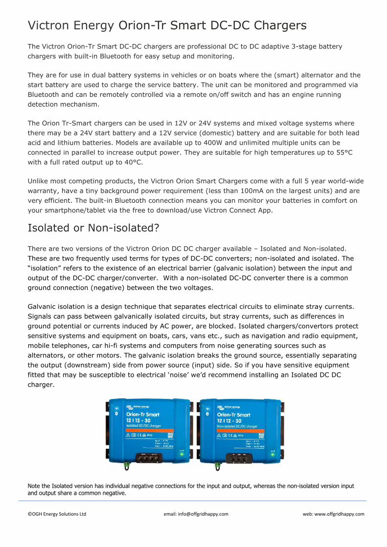
Note the Isolated version has individual negative connections for the input and output, whereas the non-isolated version input and output share a common negative.
www.victronenergy.com
Victron Energy B.V. | De Paal 35 | 1351 JG Almere | The Netherlands General phone: +31 (0)36 535 97 00 | E-mail: [email protected] www.victronenergy.com
Bluetooth Smart enabled Any Bluetooth enabled smart phone, tablet or other device can be used to monitor, to change settings and to update the charger when new software features become available. Fully programmable
- Battery charge algorithm (configurable) or fixed output. - Smart alternator compatibility: engine running detection mechanism.
Adaptive 3-stage charge algorithm: bulk – absorption – float • For lead acid batteries it is important that during shallow discharges the absorption time
is kept short in order to prevent overcharging of the battery. After a deep discharge the absorption time is automatically increased to make sure that the battery is completely recharged.
• For lithium batteries absorption time is fixed, default 2 hours. • Alternatively, a fixed output voltage can be chosen.
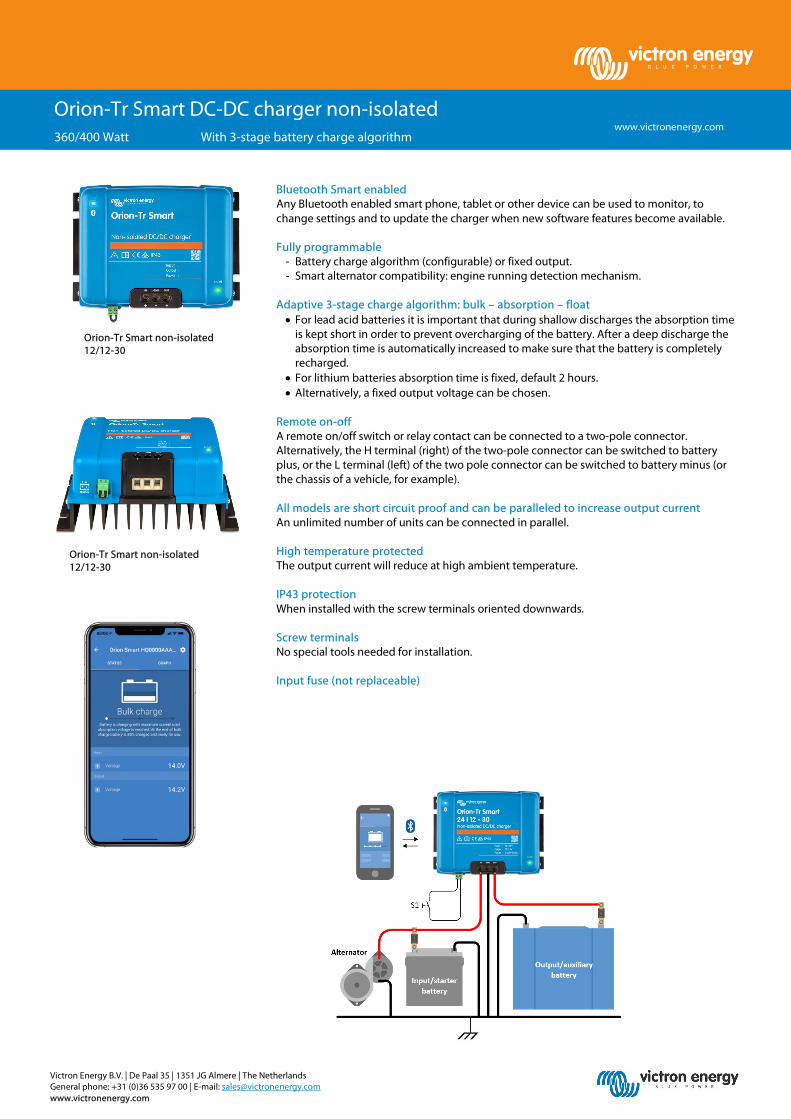
Remote on-off A remote on/off switch or relay contact can be connected to a two-pole connector. Alternatively, the H terminal (right) of the two-pole connector can be switched to battery plus, or the L terminal (left) of the two pole connector can be switched to battery minus (or the chassis of a vehicle, for example). All models are short circuit proof and can be paralleled to increase output current An unlimited number of units can be connected in parallel. High temperature protected The output current will reduce at high ambient temperature. IP43 protection When installed with the screw terminals oriented downwards. Screw terminals No special tools needed for installation. Input fuse (not replaceable)
Orion-Tr Smart DC-DC charger non-isolated 360/400 Watt With 3-stage battery charge algorithm
Orion-Tr Smart non-isolated 12/12-30
Orion-Tr Smart non-isolated 12/12-30

Victron Energy B.V. | De Paal 35 | 1351 JG Almere | The Netherlands General phone: +31 (0)36 535 97 00 | E-mail: [email protected] www.victronenergy.com
Orion-Tr Smart Chargers non-isolated 360 - 400 Watt
12/12-30 (360W)
12/24-15 (360W)
24/12-30 (360W)
24/24-17 (400W)
Input voltage range (1) 10-17V 10-17V 20-35V 20-35V Under voltage shut down 7V 7V 14V 14V Under voltage restart 7,5V 7,5V 15V 15V Nominal output voltage 12,2V 24,2V 12,2V 24,2V Output voltage adjust range 10-15V 20-30V 10-15V 20-30V Output voltage tolerance +/- 0,2V Output noise 2mV rms Cont. output current at nominal output voltage and 40°C 30A 15A 30A 17A
Maximum output current (10 s) at nominal output voltage 40A 25A 45A 25A
Short circuit output current 60A 40A 60A 40A Cont. output power at 25°C 430W 430W 430W 480W Cont. output power at 40°C 360W 360W 360W 400W Efficiency 87% 88% 88% 89% No load input current < 80mA < 100mA < 100mA < 80mA Standby current Less than 1mA Operating temperature range -20 to +55°C (derate 3% per °C above 40°C) Humidity Max. 95% non-condensing DC connection Screw terminals Maximum cable cross-section 16 mm² (AWG6) Weight 12V input and/or 12V output models: 1,8 kg (3 lb) Other models: 1,6 kg (3.5 lb) Dimensions hxwxd 130 x 186 x 80 mm (5.1 x 7.3 x 3.2 inch)
Standards: Safety Emission Immunity Automotive Directive
EN 60950 EN 61000-6-3, EN 55014-1
EN 61000-6-2, EN 61000-6-1, EN 55014-2 ECE R10-5
1) If set to nominal or lower than nominal, the output voltage will remain stable within the specified input voltage range (buck-boost function). If the output voltage is set higher than nominal by a certain percentage, the minimum input voltage at which the output voltage remains stable (does not decrease) increases by the same percentage.
Note 1: The VictronConnect App will not display current in or current out. Note 2: The Orion-Tr Smart is not equipped with a VE.Direct port.
www.victronenergy.com
Victron Energy B.V. | De Paal 35 | 1351 JG Almere | The Netherlands General phone: +31 (0)36 535 97 00 | E-mail: [email protected] www.victronenergy.com
Bluetooth Smart enabled Any Bluetooth enabled smart phone, tablet or other device can be used to monitor, to change settings and to update the charger when new software features become available. Fully programmable
- Battery charge algorithm (configurable) or fixed output. - Smart alternator compatibility: engine running detection mechanism.
Adaptive 3-stage charge algorithm: bulk – absorption – float • For lead acid batteries it is important that during shallow discharges the absorption time
is kept short in order to prevent overcharging of the battery. After a deep discharge the absorption time is automatically increased to make sure that the battery is completely recharged.
• For lithium batteries absorption time is fixed, default 2 hours. • Alternatively, a fixed output voltage can be chosen.
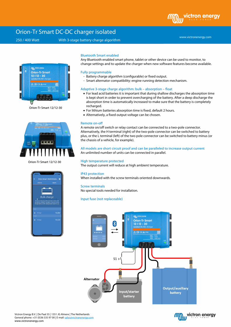
Remote on-off A remote on/off switch or relay contact can be connected to a two-pole connector. Alternatively, the H terminal (right) of the two-pole connector can be switched to battery plus, or the L terminal (left) of the two pole connector can be switched to battery minus (or the chassis of a vehicle, for example). All models are short circuit proof and can be paralleled to increase output current An unlimited number of units can be connected in parallel. High temperature protected The output current will reduce at high ambient temperature. IP43 protection When installed with the screw terminals oriented downwards. Screw terminals No special tools needed for installation. Input fuse (not replaceable)
Orion-Tr Smart DC-DC charger isolated 250 / 400 Watt With 3-stage battery charge algorithm
Orion-Tr Smart 12/12-30
Orion-Tr Smart 12/12-30
Victron Energy B.V. | De Paal 35 | 1351 JG Almere | The Netherlands General phone: +31 (0)36 535 97 00 | E-mail: [email protected] www.victronenergy.com
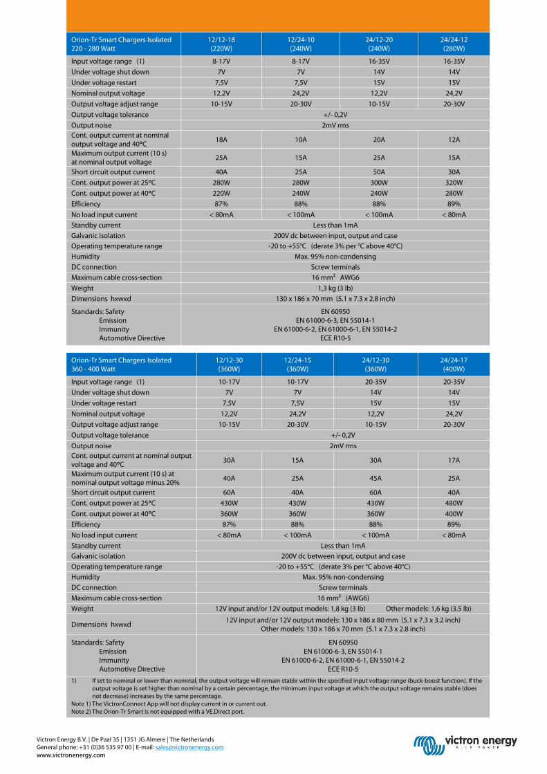
Orion-Tr Smart Chargers Isolated 220 - 280 Watt
12/12-18 (220W)
12/24-10 (240W)
24/12-20 (240W)
24/24-12 (280W)
Input voltage range (1) 8-17V 8-17V 16-35V 16-35V Under voltage shut down 7V 7V 14V 14V Under voltage restart 7,5V 7,5V 15V 15V Nominal output voltage 12,2V 24,2V 12,2V 24,2V Output voltage adjust range 10-15V 20-30V 10-15V 20-30V Output voltage tolerance +/- 0,2V Output noise 2mV rms Cont. output current at nominal output voltage and 40°C 18A 10A 20A 12A
Maximum output current (10 s) at nominal output voltage 25A 15A 25A 15A
Short circuit output current 40A 25A 50A 30A Cont. output power at 25°C 280W 280W 300W 320W Cont. output power at 40°C 220W 240W 240W 280W Efficiency 87% 88% 88% 89% No load input current < 80mA < 100mA < 100mA < 80mA Standby current Less than 1mA Galvanic isolation 200V dc between input, output and case Operating temperature range -20 to +55°C (derate 3% per °C above 40°C) Humidity Max. 95% non-condensing DC connection Screw terminals Maximum cable cross-section 16 mm² AWG6 Weight 1,3 kg (3 lb) Dimensions hxwxd 130 x 186 x 70 mm (5.1 x 7.3 x 2.8 inch)
Standards: Safety Emission Immunity Automotive Directive
EN 60950 EN 61000-6-3, EN 55014-1
EN 61000-6-2, EN 61000-6-1, EN 55014-2 ECE R10-5
Orion-Tr Smart Chargers Isolated 360 - 400 Watt
12/12-30 (360W)
12/24-15 (360W)
24/12-30 (360W)
24/24-17 (400W)
Input voltage range (1) 10-17V 10-17V 20-35V 20-35V Under voltage shut down 7V 7V 14V 14V Under voltage restart 7,5V 7,5V 15V 15V Nominal output voltage 12,2V 24,2V 12,2V 24,2V Output voltage adjust range 10-15V 20-30V 10-15V 20-30V Output voltage tolerance +/- 0,2V Output noise 2mV rms Cont. output current at nominal output voltage and 40°C 30A 15A 30A 17A
Maximum output current (10 s) at nominal output voltage minus 20% 40A 25A 45A 25A
Short circuit output current 60A 40A 60A 40A Cont. output power at 25°C 430W 430W 430W 480W Cont. output power at 40°C 360W 360W 360W 400W Efficiency 87% 88% 88% 89% No load input current < 80mA < 100mA < 100mA < 80mA Standby current Less than 1mA Galvanic isolation 200V dc between input, output and case Operating temperature range -20 to +55°C (derate 3% per °C above 40°C) Humidity Max. 95% non-condensing DC connection Screw terminals Maximum cable cross-section 16 mm² (AWG6) Weight 12V input and/or 12V output models: 1,8 kg (3 lb) Other models: 1,6 kg (3.5 lb)
Dimensions hxwxd 12V input and/or 12V output models: 130 x 186 x 80 mm (5.1 x 7.3 x 3.2 inch) Other models: 130 x 186 x 70 mm (5.1 x 7.3 x 2.8 inch)
Standards: Safety Emission Immunity Automotive Directive
EN 60950 EN 61000-6-3, EN 55014-1
EN 61000-6-2, EN 61000-6-1, EN 55014-2 ECE R10-5
1) If set to nominal or lower than nominal, the output voltage will remain stable within the specified input voltage range (buck-boost function). If the output voltage is set higher than nominal by a certain percentage, the minimum input voltage at which the output voltage remains stable (does not decrease) increases by the same percentage.
Note 1) The VictronConnect App will not display current in or current out. Note 2) The Orion-Tr Smart is not equipped with a VE.Direct port.
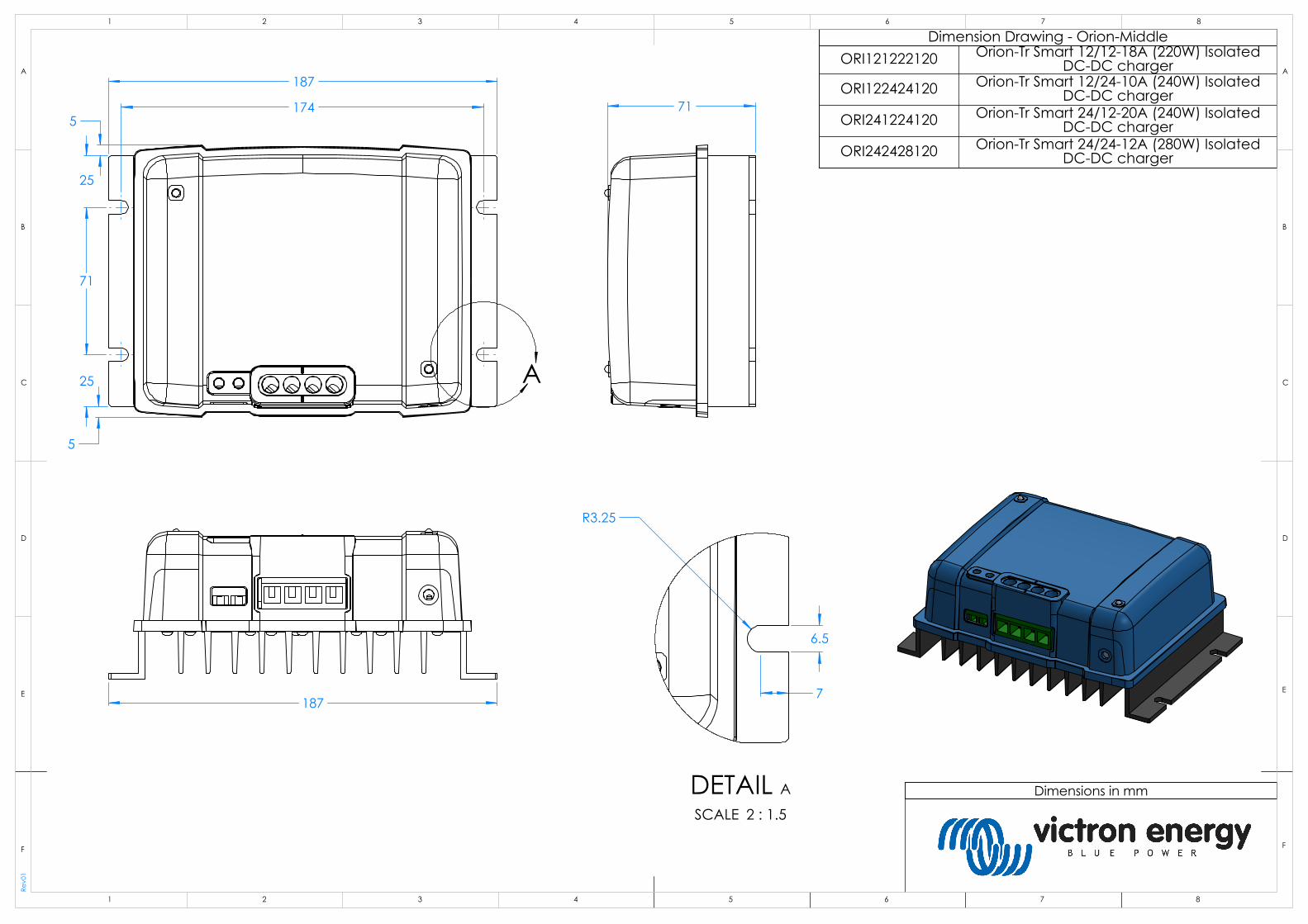
187
174
71
25
25
5
5
A
187
71
6.5
7
R3.25
DETAIL A
SCALE 2 : 1.5
Rev0
1
Dimension Drawing - Orion-Middle
Dimensions in mm
ORI121222120 Orion-Tr Smart 12/12-18A (220W) Isolated DC-DC charger
ORI122424120 Orion-Tr Smart 12/24-10A (240W) Isolated DC-DC charger
ORI241224120 Orion-Tr Smart 24/12-20A (240W) Isolated DC-DC charger
ORI242428120 Orion-Tr Smart 24/24-12A (280W) Isolated DC-DC charger
D
E
F
C
1 2 3 4
B
A
321 5
C
D
4 6 7 8
A
B
8765
F
E
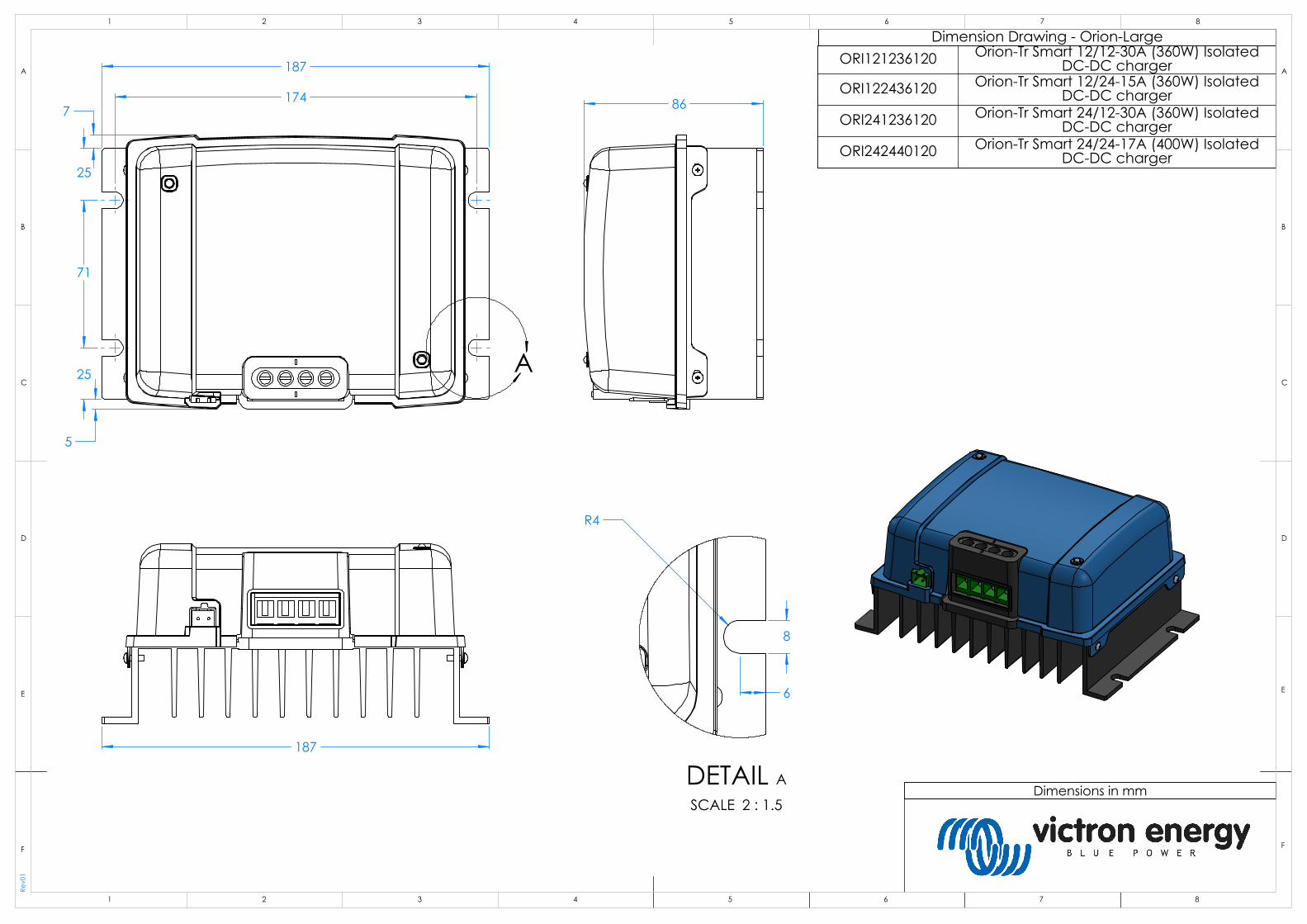
187
174
25
71
25
5
7
A
187
86
8
6
R4
DETAIL A
SCALE 2 : 1.5
Rev0
1
Dimension Drawing - Orion-Large
Dimensions in mm
ORI121236120 Orion-Tr Smart 12/12-30A (360W) Isolated DC-DC charger
ORI122436120 Orion-Tr Smart 12/24-15A (360W) Isolated DC-DC charger
ORI241236120 Orion-Tr Smart 24/12-30A (360W) Isolated DC-DC charger
ORI242440120 Orion-Tr Smart 24/24-17A (400W) Isolated DC-DC charger
D
E
F
C
1 2 3 4
B
A
321 5
C
D
4 6 7 8
A
B
8765
F
E

Manual
EN
Manual
NL
Manuale
FR
Anleitung
DE
Manual
SV
Användarhandbok
CZ
Orion-Tr DC-DC Smart Charger Non-Isolated


1
EN
NL
FR
DE
SV C
Z
1. General Description
The Orion Smart DC-DC chargers are specially developed DC-DC converters for controlled charging or fixed output mode. In charger mode the three-state charge algorithm will increase battery life by properly charging the battery. Especially in the case of vehicles with an alternator smart control, or voltage drop caused by long cable runs, controlled charging is indispensable. Controlled charging will also protect the alternator in lithium systems where direct charging can overload the alternator due to the low impedance of the lithium battery. In fixed output mode the output voltage will remain stable independent of the applied load or varying input voltage (within the specified range).
To ensure that the starter battery of the vehicle is always loaded with priority, the Orion Smart DC-DC charger will only provide power when the engine is running. This is possible thanks to the built-in engine shutdown detection. This also prevents the onboard voltage of the vehicle from becoming too low. It is not necessary to intervene in the system of the vehicle, install a separate motor run sensor or intervene in the CAN bus system. Apart from this detection, the Orion Smart DC-DC charger can also be activated by a forced allowed to charge feature, e.g. connected to the ignition switch.
The Orion Smart DC-DC charger is fully programmable with the VictronConnect app. Discover all setup possibilities here: https://www.victronenergy.com/live/victronconnect:start
2
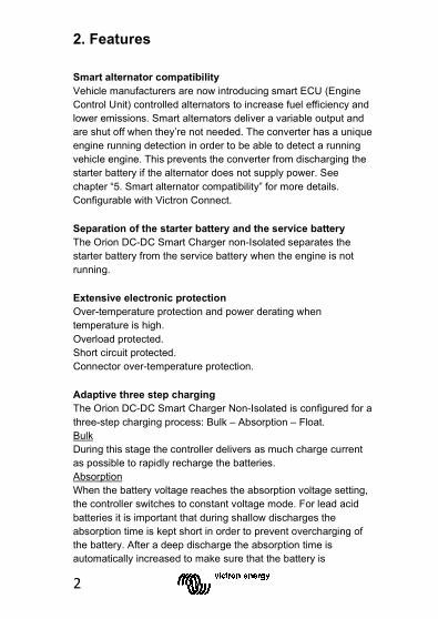
2. Features Smart alternator compatibility Vehicle manufacturers are now introducing smart ECU (Engine Control Unit) controlled alternators to increase fuel efficiency and lower emissions. Smart alternators deliver a variable output and are shut off when they’re not needed. The converter has a unique engine running detection in order to be able to detect a running vehicle engine. This prevents the converter from discharging the starter battery if the alternator does not supply power. See chapter “5. Smart alternator compatibility” for more details. Configurable with Victron Connect.
Separation of the starter battery and the service battery The Orion DC-DC Smart Charger non-Isolated separates the starter battery from the service battery when the engine is not running.
Extensive electronic protection Over-temperature protection and power derating when temperature is high. Overload protected. Short circuit protected. Connector over-temperature protection.
Adaptive three step charging The Orion DC-DC Smart Charger Non-Isolated is configured for a three-step charging process: Bulk – Absorption – Float. Bulk During this stage the controller delivers as much charge current as possible to rapidly recharge the batteries. Absorption When the battery voltage reaches the absorption voltage setting, the controller switches to constant voltage mode. For lead acid batteries it is important that during shallow discharges the absorption time is kept short in order to prevent overcharging of the battery. After a deep discharge the absorption time is automatically increased to make sure that the battery is

3
EN
NL
FR
DE
SV C
Z
completely recharged. For lithium batteries absorption time is fixed, typically 2 hours, the fixed or adaptive mode can be chosen on the battery settings. Float During this stage, float voltage is applied to the battery to maintain it in a fully charged state. When the battery voltage drops below re-bulk voltage, due to a high load, during at least 1 minute a new charge cycle will be triggered.
Flexible charge algorithm Programmable charge algorithm, and eight preprogrammed battery settings. Configurable with VictronConnect.
Adaptive absorption time Automatically calculates the proper absorption time. Configurable with Victron Connect.
Configuring and monitoring Bluetooth Smart built-in: the wireless solution to set-up, monitor and update the controller using Apple and Android smartphones, tablets or other devices. Several parameters can be customized with the VictronConnect app. The VictronConnect app can be downloaded from: http://www.victronenergy.nl/support-and-downloads/software/ Use the manual – VictronConnect - to get the most out of the VictronConnect App when it’s connected to an Orion Smart: https://www.victronenergy.com/live/victronconnect:start
Input voltage lock-out Shutdown if the input voltage drops below the lock-out value and continuous when the input voltage increases above the restart value. Configurable with Victron Connect.

4
Remote on-off Use the remote function to enable and disable the device remotely with the remote on/off connector or using the VictronConnect app. Typical use cases include a user operated hard wired switch and automatic control by for example a Battery Management System.
5
EN
NL
FR
DE
SV C
Z
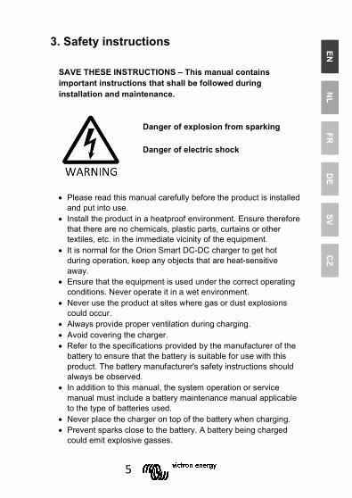
3. Safety instructions
SAVE THESE INSTRUCTIONS – This manual contains important instructions that shall be followed during installation and maintenance.
• Please read this manual carefully before the product is installed and put into use.
• Install the product in a heatproof environment. Ensure therefore that there are no chemicals, plastic parts, curtains or other textiles, etc. in the immediate vicinity of the equipment.
• It is normal for the Orion Smart DC-DC charger to get hot during operation, keep any objects that are heat-sensitive away.
• Ensure that the equipment is used under the correct operating conditions. Never operate it in a wet environment.
• Never use the product at sites where gas or dust explosions could occur.
• Always provide proper ventilation during charging. • Avoid covering the charger. • Refer to the specifications provided by the manufacturer of the
battery to ensure that the battery is suitable for use with this product. The battery manufacturer's safety instructions should always be observed.
• In addition to this manual, the system operation or service manual must include a battery maintenance manual applicable to the type of batteries used.
• Never place the charger on top of the battery when charging. • Prevent sparks close to the battery. A battery being charged
could emit explosive gasses.
Danger of explosion from sparking
Danger of electric shock

6
• This device is not to be used by persons (including children) with reduced physical, sensory or mental capabilities, or lack of experience and knowledge, unless they have been given supervision or instruction.
• Use flexible multistrand copper cable for the connections. The maximum diameter of the individual strands is 0,4mm/0,125mm² (0.016 inch/AWG26).
• The installation must include a fuse in accordance with the recommendations in the table ”CABLE AND FUSE RECOMMENDATIONS”.

7
EN
NL
FR
DE
SV C
Z
4. Installation 4.1 General • Mount vertically on a non-flammable surface, with the power
terminals facing downwards. Observe a minimum clearance of 10 cm under and above the product for optimal cooling.
• Mount close to the battery, but never directly above the battery (in order to prevent damage due to gassing of the battery).
4.2 Connection setup for DC-DC converter mode 1. Disconnect the remote on/off (remove wire bridge). 2. Connect the input supply cables. 3. Open the VictronConnect App to setup the product.
(always adjust the output voltage before connecting in parallel or connecting a battery)
4. Connect the load. The converter is now ready for use. 5. Reconnect the remote on/off to activate the product.
Figure 1: Typical connection setup as DC-DC converter

8
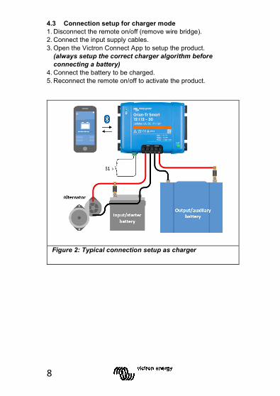
4.3 Connection setup for charger mode 1. Disconnect the remote on/off (remove wire bridge). 2. Connect the input supply cables. 3. Open the VictronConnect App to setup the product.
(always setup the correct charger algorithm before connecting a battery)
4. Connect the battery to be charged. 5. Reconnect the remote on/off to activate the product.
Figure 2: Typical connection setup as charger

9
EN
NL
FR
DE
SV C
Z
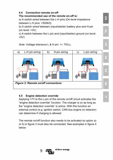
4.4 Connection remote on-off The recommended use of the remote on-off is: a) A switch wired between the L-H pins (On-level impedance between L-H pins: <500kΩ) b) A switch wired between (input/starter) battery plus and H-pin (on level: >3V) c) Connection between “VE.BMS charge disconnect” and H-pin d) A switch between the L-pin and (input/starter) ground (on level: <5V) Note: Voltage tolerance L & H pin: +/- 70VDC
a) L-H pin wiring b) H-pin wiring
c) H-pin wiring BMS d) L-pin wiring
Figure 3: Remote on/off connections

10
4.5 Engine detection override Applying >7V to the L-pin of the remote on/off circuit activates the “engine detection override” function. The charger is on as long as the “engine detection override” is active. With this function an external control (e.g. ignition switch, CAN bus engine on detector) can determine if charging is allowed.
The remote on/off function also needs to be activated so option a) or b) in figure 3 must also be connected. See examples in figure 4 below.
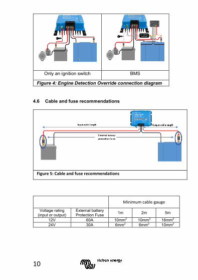
4.6 Cable and fuse recommendations
Figure 5: Cable and fuse recommendations
Only an ignition switch BMS
Figure 4: Engine Detection Override connection diagram

11
EN
NL
FR
DE
SV C
Z
Minimum cable gauge
Voltage rating
(Input or output)
External battery
protection Fuse
0.5m 1m 2m 5m 10m
12V 60A 6mm2 10mm2 10mm2 16mm2 16mm2 24V 30A 4mm2 6mm2 6mm2 10mm2 10mm2
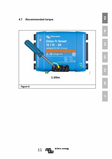
4.7 Recommended torque
Figure 6 Tightening torques

12
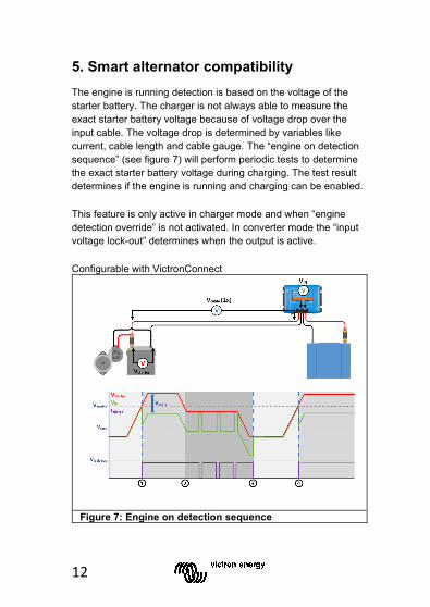
5. Smart alternator compatibility The engine is running detection is based on the voltage of the starter battery. The charger is not always able to measure the exact starter battery voltage because of voltage drop over the input cable. The voltage drop is determined by variables like current, cable length and cable gauge. The “engine on detection sequence” (see figure 7) will perform periodic tests to determine the exact starter battery voltage during charging. The test result determines if the engine is running and charging can be enabled.
This feature is only active in charger mode and when “engine detection override” is not activated. In converter mode the “input voltage lock-out” determines when the output is active.
Configurable with VictronConnect
Figure 7: Engine on detection sequence

13
EN
NL
FR
DE
SV C
Z
0 1: When the engine runs the alternator voltage will ramp-up, when Vstarter increases above Venable, charging starts. 1 2: Due to the charge current a voltage drop will occur across the input cable (Vcable), this voltage reduces the voltage at the input of the charger (VIN). While VIN remains above Vtest, charging is enabled. 2 3: If VIN drops below Vtest, the “engine on detection sequence” is started. Every 2 minutes the charger is paused for 10 seconds to measure the voltage. Without current flow VIN is equal to Vstarter, if VIN is above Vtest, charging will resume. While remaining in this state, the test is performed every 2 minutes. 3 4: During the detection sequence VIN dropped below Vtest, this means that the engine stopped running and charging must be stopped, the charge sequence is paused. 4 5: VIN increases above Venable, the charge sequences continues.
14
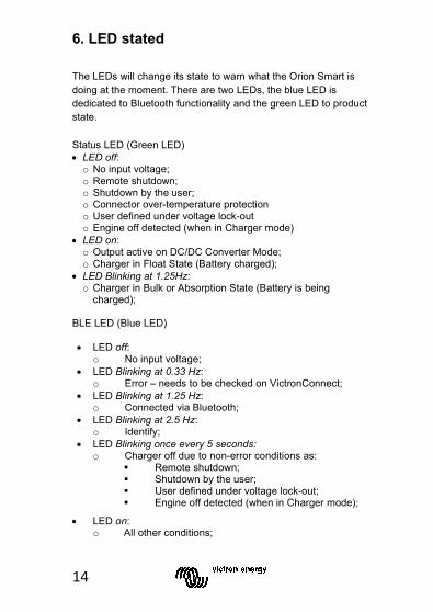
6. LED stated The LEDs will change its state to warn what the Orion Smart is doing at the moment. There are two LEDs, the blue LED is dedicated to Bluetooth functionality and the green LED to product state.
Status LED (Green LED) • LED off: o No input voltage; o Remote shutdown; o Shutdown by the user; o Connector over-temperature protection o User defined under voltage lock-out o Engine off detected (when in Charger mode)
• LED on: o Output active on DC/DC Converter Mode; o Charger in Float State (Battery charged);
• LED Blinking at 1.25Hz: o Charger in Bulk or Absorption State (Battery is being
charged); BLE LED (Blue LED) • LED off:
o No input voltage; • LED Blinking at 0.33 Hz:
o Error – needs to be checked on VictronConnect; • LED Blinking at 1.25 Hz:
o Connected via Bluetooth; • LED Blinking at 2.5 Hz:
o Identify; • LED Blinking once every 5 seconds:
o Charger off due to non-error conditions as: Remote shutdown; Shutdown by the user; User defined under voltage lock-out; Engine off detected (when in Charger mode);
• LED on: o All other conditions;

15
EN
NL
FR
DE
SV C
Z
7. Specifications
Orion-Tr Smart Charger non-Isolated 360 - 400 Watt
12/12-30 (360W)
12/24-15 (360W)
Input voltage range (1) 10-17V 10-17V Under voltage shut down 7V 7V Under voltage restart 7,5V 7,5V Nominal output voltage 12,2V 24,2V Output voltage adjust range 10-15V 20-30V Output voltage tolerance +/- 20mV Output noise 2mV rms Cont. output current at nominal output voltage and 40°C 30A 15A
Maximum output current (10 s) at nominal output voltage 40A 25A
Short circuit output current 60A 40A Cont. output power at 25°C 430W 430W Cont. output power at 40°C 360W 360W Efficiency 87% 88% No load input current < 80mA < 100mA Standby current < 1mA < 1mA Galvanic isolation 200V dc between input, output and case Operating temperature range -20 to +55°C (derate 3% per °C above 40°C) Humidity Max. 95% non-condensing DC connection Screw terminals Maximum cable cross-section 16 mm² AWG6
Weight 12V input and/or 12V output models: 1,8 kg (3 lb) Other models: 1,6 kg (3.5 lb)
Dimensions hxwxd 12V input and/or 12V output models:
130 x 186 x 80 mm (5.1 x 7.3 x 3.2 inch) Other models: 130 x 186 x 70 mm
(5.1 x 7.3 x 2.8 inch) Standards: Safety Emission Immunity Automotive Directive
EN 60950 EN 61000-6-3, EN 55014-1
EN 61000-6-2, EN 61000-6-1, EN 55014-2 ECE R10-5
1) If set to nominal or lower than nominal, the output voltage will remain stable within the specified input voltage range (buck-boost function). If the output voltage is set higher than nominal by a certain percentage, the minimum input voltage at which the output voltage remains stable (does not decrease) increases by the same percentage.

16
Specifications - continuation
Orion-Tr Smart Charger non-Isolated 360 - 400 Watt
24/12-30 (360W)
24/24-17 (400W)
Input voltage range (1) 20-35V 20-35V Under voltage shut down 14V 14V Under voltage restart 15V 15V Nominal output voltage 12,2V 24,2V Output voltage adjust range 10-15V 20-30V Output voltage tolerance +/- 20mV Output noise 2mV rms Cont. output current at nominal output voltage and 40°C 30A 17A
Maximum output current (10 s) at nominal output voltage 45A 25A
Short circuit output current 60A 40A Cont. output power at 25°C 430W 480W Cont. output power at 40°C 360W 400W Efficiency 88% 89% No load input current < 100mA < 80mA Standby current < 1mA < 1mA Galvanic isolation 200V dc between input, output and case Operating temperature range -20 to +55°C (derate 3% per °C above 40°C) Humidity Max. 95% non-condensing DC connection Screw terminals Maximum cable cross-section 16 mm² AWG6
Weight 12V input and/or 12V output models: 1,8 kg (3 lb) Other models: 1,6 kg (3.5 lb)
Dimensions hxwxd 12V input and/or 12V output models:
130 x 186 x 80 mm (5.1 x 7.3 x 3.2 inch) Other models: 130 x 186 x 70 mm
(5.1 x 7.3 x 2.8 inch) Standards: Safety Emission Immunity Automotive Directive
EN 60950 EN 61000-6-3, EN 55014-1
EN 61000-6-2, EN 61000-6-1, EN 55014-2 ECE R10-5
1) If set to nominal or lower than nominal, the output voltage will remain stable within the specified input voltage range (buck-boost function). If the output voltage is set higher than nominal by a certain percentage, the minimum input voltage at which the output voltage remains stable (does not decrease) increases by the same percentage.

Victron Energy Blue Power Distributor: Serial number: Version : 01 Date : February 17th, 2020
Victron Energy B.V. De Paal 35 | 1351 JG Almere PO Box 50016 | 1305 AA Almere | The Netherlands General phone : +31 (0)36 535 97 00 E-mail : [email protected] www.victronenergy.com
Manual
EN
Handleiding
NL
Manuel
FR
Anleitung
DE
Manual
ES
Användarhandbok
SE
Manuale
IT
Orion-Tr Smart Charger Isolated
1
EN
NL
FR
DE
ES SE
IT
1. General Description
The Orion Smart DC-DC chargers can be used as a power supply or as a battery charger. In charger mode the three-state charge algorithm will increase battery life by properly charging the battery. Especially in the case of vehicles with a smart alternator, or voltage drop caused by long cable runs, controlled charging is indispensable. Controlled charging will also protect the alternator in lithium systems where direct charging can overload the alternator due to the low impedance of the lithium battery. In fixed output mode the output voltage will remain stable independent of the applied load or varying input voltage (within the specified range).
The Orion Smart DC-DC charger can be set up to only provide power when the engine is running. This is possible thanks to the built-in engine shutdown detection. This also prevents the onboard voltage of the vehicle from becoming too low. It is not necessary to intervene in the system of the vehicle, to install a separate motor run sensor or to intervene in the CAN-bus system. Apart from this detection, the Orion Smart DC-DC charger can also be activated by a forced allowed to charge feature, e.g. connected to the ignition switch.
The Orion-Tr Smart DC-DC Charger is fully programmable with the VictronConnect app. Discover all setup possibilities here: https://www.victronenergy.com/live/victronconnect:start
2
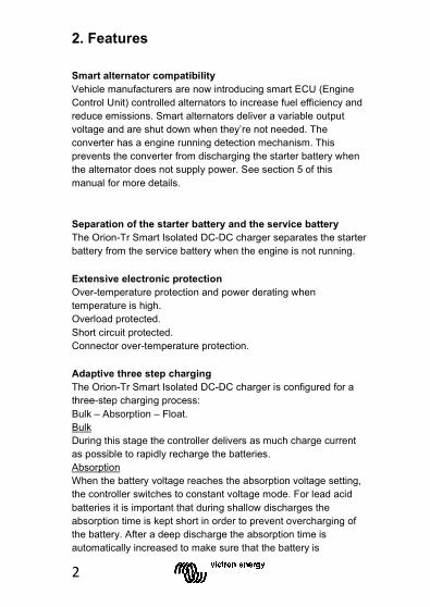
2. Features Smart alternator compatibility Vehicle manufacturers are now introducing smart ECU (Engine Control Unit) controlled alternators to increase fuel efficiency and reduce emissions. Smart alternators deliver a variable output voltage and are shut down when they’re not needed. The converter has a engine running detection mechanism. This prevents the converter from discharging the starter battery when the alternator does not supply power. See section 5 of this manual for more details.
Separation of the starter battery and the service battery The Orion-Tr Smart Isolated DC-DC charger separates the starter battery from the service battery when the engine is not running.
Extensive electronic protection Over-temperature protection and power derating when temperature is high. Overload protected. Short circuit protected. Connector over-temperature protection.
Adaptive three step charging The Orion-Tr Smart Isolated DC-DC charger is configured for a three-step charging process: Bulk – Absorption – Float. Bulk During this stage the controller delivers as much charge current as possible to rapidly recharge the batteries. Absorption When the battery voltage reaches the absorption voltage setting, the controller switches to constant voltage mode. For lead acid batteries it is important that during shallow discharges the absorption time is kept short in order to prevent overcharging of the battery. After a deep discharge the absorption time is automatically increased to make sure that the battery is
3
EN
NL
FR
DE
ES SE
IT
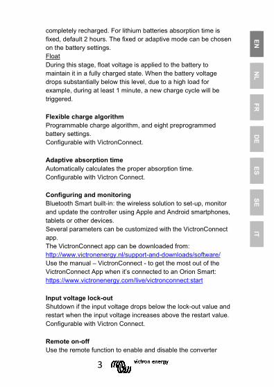
completely recharged. For lithium batteries absorption time is fixed, default 2 hours. The fixed or adaptive mode can be chosen on the battery settings. Float During this stage, float voltage is applied to the battery to maintain it in a fully charged state. When the battery voltage drops substantially below this level, due to a high load for example, during at least 1 minute, a new charge cycle will be triggered.
Flexible charge algorithm Programmable charge algorithm, and eight preprogrammed battery settings. Configurable with VictronConnect.
Adaptive absorption time Automatically calculates the proper absorption time. Configurable with Victron Connect.
Configuring and monitoring Bluetooth Smart built-in: the wireless solution to set-up, monitor and update the controller using Apple and Android smartphones, tablets or other devices. Several parameters can be customized with the VictronConnect app. The VictronConnect app can be downloaded from: http://www.victronenergy.nl/support-and-downloads/software/ Use the manual – VictronConnect - to get the most out of the VictronConnect App when it’s connected to an Orion Smart: https://www.victronenergy.com/live/victronconnect:start
Input voltage lock-out Shutdown if the input voltage drops below the lock-out value and restart when the input voltage increases above the restart value. Configurable with Victron Connect.
Remote on-off Use the remote function to enable and disable the converter

4
remotely with the remote on/off connector or using the VictronConnect app. Typical use cases include a user operated hard wired switch and automatic control by for example a Battery Management System. If the minus of the service battery is not at the same potential as the minus of the alternator or starter battery an isolated remote on/off cable between the BMS and the on/off port is required, see chapter 4.4 for details.
5
EN
NL
FR
DE
ES SE
IT
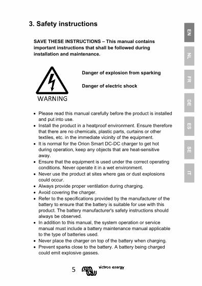
3. Safety instructions
SAVE THESE INSTRUCTIONS – This manual contains important instructions that shall be followed during installation and maintenance.
• Please read this manual carefully before the product is installed and put into use.
• Install the product in a heatproof environment. Ensure therefore that there are no chemicals, plastic parts, curtains or other textiles, etc. in the immediate vicinity of the equipment.
• It is normal for the Orion Smart DC-DC charger to get hot during operation, keep any objects that are heat-sensitive away.
• Ensure that the equipment is used under the correct operating conditions. Never operate it in a wet environment.
• Never use the product at sites where gas or dust explosions could occur.
• Always provide proper ventilation during charging. • Avoid covering the charger. • Refer to the specifications provided by the manufacturer of the
battery to ensure that the battery is suitable for use with this product. The battery manufacturer's safety instructions should always be observed.
• In addition to this manual, the system operation or service manual must include a battery maintenance manual applicable to the type of batteries used.
• Never place the charger on top of the battery when charging. • Prevent sparks close to the battery. A battery being charged
could emit explosive gasses.
Danger of explosion from sparking
Danger of electric shock

6
• This device is not to be used by persons (including children) with reduced physical, sensory or mental capabilities, or lack of experience and knowledge, unless they have been given supervision or instruction.
• Use flexible multistranded copper cable for the connections. The maximum diameter of the individual strands is 0,4mm/0,125mm² (0.016 inch/AWG26).
• The installation must include a fuse in accordance with the recommendations in the table ”CABLE AND FUSE RECOMMENDATIONS”.
7
EN
NL
FR
DE
ES SE
IT
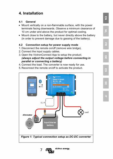
4. Installation 4.1 General • Mount vertically on a non-flammable surface, with the power
terminals facing downwards. Observe a minimum clearance of 10 cm under and above the product for optimal cooling.
• Mount close to the battery, but never directly above the battery (in order to prevent damage due to gassing of the battery).
4.2 Connection setup for power supply mode 1. Disconnect the remote on/off (remove wire bridge). 2. Connect the input supply cables. 3. Open the VictronConnect App to setup the product.
(always adjust the output voltage before connecting in parallel or connecting a battery)
4. Connect the load. The converter is now ready for use. 5. Reconnect the remote on/off to activate the product.
Figure 1: Typical connection setup as DC-DC converter
8
4.3 Connection setup for charger mode 1. Disconnect the remote on/off (remove wire bridge). 2. Connect the input supply cables. 3. Open the Victron Connect App to setup the product.
(always setup the correct charger algorithm before connecting a battery)
4. Connect the battery to be charged. 5. Reconnect the remote on/off to activate the product.
Figure 2: Typical connection setup as charger
9
EN
NL
FR
DE
ES SE
IT
4.4 Connection remote on-off The recommended use of the remote on-off is: a) A switch wired between the L-H pins (On-level impedance between L-H pins: <500kΩ) b) A switch wired between (input/starter) battery plus and H-pin (on level: >3V) c) A switch between the L-pin and (input/starter) ground (on level: <5V)
Note: Voltage tolerance L & H pin: +/- 70VDC
a) L-H pin wiring b) H-pin wiring c) L-pin wiring
Figure 3: Remote on/off connections
4.5 Engine detection override Applying >7V to the L-pin of the remote on/off circuit activates the “engine detection override” function. The charger is on as long as the “engine detection override” is active. With this function an external control (e.g. ignition switch, CAN bus engine on detector) can determine if charging is allowed.
The remote on/off function also needs to be activated so option a) or b) in figure 3 must also be connected. See examples in figure 4 below.
10
Only an ignition switch BMS
Figure 4: Engine Detection Override connection diagram 4.6 Cable and fuse recommendations
Figure 5: Cable and fuse recommendations
Minimum cable gauge
Voltage rating (input or output)
External battery Protection Fuse 1m 2m 5m
12V 60A 10mm2 10mm2 16mm2 24V 30A 6mm2 6mm2 10mm2
11
EN
NL
FR
DE
ES SE
IT
4.7 Recommended torque
Figure 6
12
5. Smart alternator compatibility The engine is running detection is based on the voltage of the starter battery. The charger is not always able to measure the exact starter battery voltage because of voltage drop over the input cable. The voltage drop is determined by variables like current, cable length and cable gauge. The “engine on detection sequence” (see figure 7) will perform periodic tests to determine the exact starter battery voltage during charging. The test result determines if the engine is running and charging can be enabled.
This feature is only active in charger mode and when “engine detection override” is not activated. In converter mode the “input voltage lock-out” determines when the output is active.
Configurable with VictronConnect
Figure 7: Engine on detection sequence

13
EN
NL
FR
DE
ES SE
IT
0 1: When the engine runs the alternator voltage will ramp-up, when Vstarter increases above Venable, charging starts. 1 2: Due to the charge current a voltage drop will occur across the input cable (Vcable), this voltage reduces the voltage at the input of the charger (VIN). While VIN remains above Vtest, charging is enabled. 2 3: If VIN drops below Vtest, the “engine on detection sequence” is started. Every 2 minutes the charger is paused for 10 seconds to measure the voltage. Without current flow VIN is equal to Vstarter, if VIN is above Vtest, charging will resume. While remaining in this state, the test is performed every 2 minutes. 3 4: During the detection sequence VIN dropped below Vtest, this means that the engine stopped running and charging must be stopped, the charge sequence is paused. 4 5: VIN increases above Venable, the charge sequences continues.

14
6. LED stated The blue LED is dedicated to Bluetooth functionality and the green LED to product state.
Status LED (Green LED) • LED off: o No input voltage; o Remote shutdown; o Shutdown by the user; o Connector over-temperature protection o User defined under voltage lock-out o Engine off detected (when in Charger mode)
• LED on: o Output active on DC/DC Converter Mode; o Charger in Float State (Battery charged);
• LED Blinking at 1.25Hz: o Charger in Bulk or Absorption State (Battery is being
charged); BLE LED (Blue LED) • LED off: o No input voltage;
• LED Blinking at 0.33 Hz: o Error – needs to be checked on VictronConnect;
• LED Blinking at 1.25 Hz: o Connected via Bluetooth;
• LED Blinking at 2.5 Hz: o Identify;
• LED on: o All other conditions;
15
EN
NL
FR
DE
ES SE
IT
7. Specifications
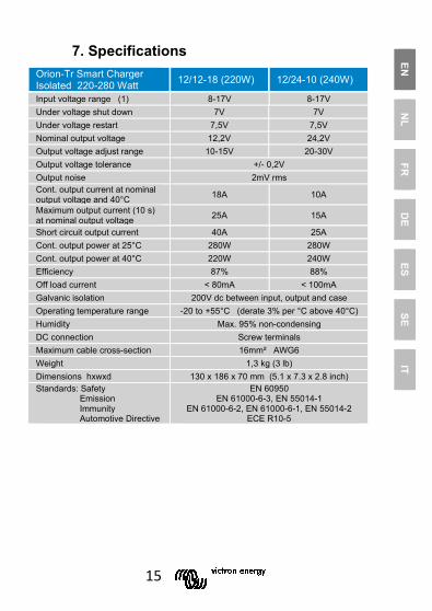
Orion-Tr Smart Charger Isolated 220-280 Watt 12/12-18 (220W) 12/24-10 (240W)
Input voltage range (1) 8-17V 8-17V Under voltage shut down 7V 7V Under voltage restart 7,5V 7,5V Nominal output voltage 12,2V 24,2V Output voltage adjust range 10-15V 20-30V Output voltage tolerance +/- 0,2V Output noise 2mV rms Cont. output current at nominal output voltage and 40°C 18A 10A
Maximum output current (10 s) at nominal output voltage 25A 15A
Short circuit output current 40A 25A Cont. output power at 25°C 280W 280W Cont. output power at 40°C 220W 240W Efficiency 87% 88% Off load current < 80mA < 100mA Galvanic isolation 200V dc between input, output and case Operating temperature range -20 to +55°C (derate 3% per °C above 40°C) Humidity Max. 95% non-condensing DC connection Screw terminals Maximum cable cross-section 16mm² AWG6 Weight 1,3 kg (3 lb) Dimensions hxwxd 130 x 186 x 70 mm (5.1 x 7.3 x 2.8 inch) Standards: Safety Emission Immunity Automotive Directive
EN 60950 EN 61000-6-3, EN 55014-1
EN 61000-6-2, EN 61000-6-1, EN 55014-2 ECE R10-5

16
Specifications - continuation
Orion-Tr Smart Charger Isolated 220 – 280 Watt
24/12-20 (240W)
24/24-12 (280W)
Input voltage range (1) 16-35V 16-35V Under voltage shut down 14V 14V Under voltage restart 15V 15V Nominal output voltage 12,2V 24,2V Output voltage adjust range 10-15V 20-30V Output voltage tolerance +/- 0,2V Output noise 2mV rms Cont. output current at nominal output voltage and 40°C 20A 12A
Maximum output current (10 s) at nominal output voltage 25A 15A
Short circuit output current 50A 30A Cont. output power at 25°C 300W 320W Cont. output power at 40°C 240W 280W Efficiency 88% 89% Off load current < 100mA < 80mA Galvanic isolation 200V dc between input, output and case Operating temperature range -20 to +55°C (derate 3% per °C above 40°C) Humidity Max. 95% non-condensing DC connection Screw terminals Maximum cable cross-section 16mm² AWG6 Weight 1,3 kg (3 lb) Dimensions hxwxd 130 x 186 x 70 mm (5.1 x 7.3 x 2.8 inch) Standards: Safety Emission Immunity Automotive Directive
EN 60950 EN 61000-6-3, EN 55014-1
EN 61000-6-2, EN 61000-6-1, EN 55014-2 ECE R10-5
17
EN
NL
FR
DE
ES SE
IT
Specifications - continuation
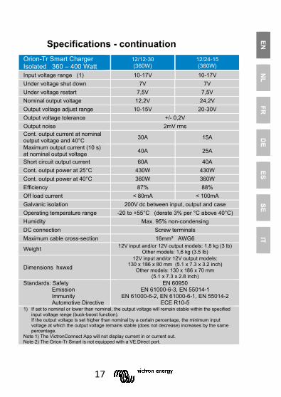
Orion-Tr Smart Charger Isolated 360 – 400 Watt
12/12-30 (360W)
12/24-15 (360W)
Input voltage range (1) 10-17V 10-17V Under voltage shut down 7V 7V Under voltage restart 7,5V 7,5V Nominal output voltage 12,2V 24,2V Output voltage adjust range 10-15V 20-30V Output voltage tolerance +/- 0,2V Output noise 2mV rms Cont. output current at nominal output voltage and 40°C 30A 15A
Maximum output current (10 s) at nominal output voltage 40A 25A
Short circuit output current 60A 40A Cont. output power at 25°C 430W 430W Cont. output power at 40°C 360W 360W Efficiency 87% 88% Off load current < 80mA < 100mA Galvanic isolation 200V dc between input, output and case Operating temperature range -20 to +55°C (derate 3% per °C above 40°C) Humidity Max. 95% non-condensing DC connection Screw terminals Maximum cable cross-section 16mm² AWG6
Weight 12V input and/or 12V output models: 1,8 kg (3 lb) Other models: 1,6 kg (3.5 lb)
Dimensions hxwxd 12V input and/or 12V output models:
130 x 186 x 80 mm (5.1 x 7.3 x 3.2 inch) Other models: 130 x 186 x 70 mm
(5.1 x 7.3 x 2.8 inch) Standards: Safety Emission Immunity Automotive Directive
EN 60950 EN 61000-6-3, EN 55014-1
EN 61000-6-2, EN 61000-6-1, EN 55014-2 ECE R10-5
1) If set to nominal or lower than nominal, the output voltage will remain stable within the specified input voltage range (buck-boost function). If the output voltage is set higher than nominal by a certain percentage, the minimum input voltage at which the output voltage remains stable (does not decrease) increases by the same percentage.
Note 1) The VictronConnect App will not display current in or current out. Note 2) The Orion-Tr Smart is not equipped with a VE.Direct port.

18
Specifications - continuation
Orion-Tr Smart Charger Isolated 360 – 400 Watt
24/12-30 (360W)
24/24-17 (400W)
Input voltage range (1) 20-35V 20-35V Under voltage shut down 14V 14V Under voltage restart 15V 15V Nominal output voltage 12,2V 24,2V Output voltage adjust range 10-15V 20-30V Output voltage tolerance +/- 0,2V Output noise 2mV rms Cont. output current at nominal output voltage and 40°C 30A 17A
Maximum output current (10 s) at nominal output voltage 45A 25A
Short circuit output current 60A 40A Cont. output power at 25°C 430W 480W Cont. output power at 40°C 360W 400W Efficiency 88% 89% Off load current < 100mA < 80mA Galvanic isolation 200V dc between input, output and case Operating temperature range -20 to +55°C (derate 3% per °C above 40°C) Humidity Max. 95% non-condensing DC connection Screw terminals Maximum cable cross-section 16mm² AWG6
Weight 12V input and/or 12V output models: 1,8 kg (3 lb) Other models: 1,6 kg (3.5 lb)
Dimensions hxwxd 12V input and/or 12V output models:
130 x 186 x 80 mm (5.1 x 7.3 x 3.2 inch) Other models: 130 x 186 x 70 mm
(5.1 x 7.3 x 2.8 inch) Standards: Safety Emission Immunity Automotive Directive
EN 60950 EN 61000-6-3, EN 55014-1
EN 61000-6-2, EN 61000-6-1, EN 55014-2 ECE R10-5
1) If set to nominal or lower than nominal, the output voltage will remain stable within the specified input voltage range (buck-boost function). If the output voltage is set higher than nominal by a certain percentage, the minimum input voltage at which the output voltage remains stable (does not decrease) increases by the same percentage.
Note 1) The VictronConnect App will not display current in or current out. Note 2) The Orion-Tr Smart is not equipped with a VE.Direct port.

19
Victron Energy Blue Power
Distributor:
Serial number:
Version : 01 Date : October 23rd, 2019
Victron Energy B.V. De Paal 35 | 1351 JG Almere PO Box 50016 | 1305 AA Almere | The Netherlands
General phone : +31 (0)36 535 97 00 E-mail : [email protected]
www.victronenergy.com