dc-bus communication test environment - yamar electronics
TRANSCRIPT

© 2018-2021 YAMAR Electronics Ltd. 1 AN-DC-BUS Test Environment R1.0
Contact: [email protected]
Shimon Hatarsi Tel Aviv, Israel. Tel (972) 3 5445294 Fax (972) 3 5445279 www.yamar.com
1. General
The performance of data communication over DC power lines (DC-BUS devices) depends on many parameters such as the carrier frequency, cable length, cable capacitance, and the AC loads connected to the power line. A capacitive load contributes to high attenuation of the carrier signal (e.g. 10nF noise fileting capacitor) while an inductive load has a smaller influence (e.g. 10A motor). To allow quick and efficient DC-BUS power line communication tests in a Lab environment, Yamar has developed a DC-BUS Test environment.
2. Test Environment
The test environment consists of DC-BUS Evaluation boards, EVB Tester, a PC Test program, and a DC-Powerline Attenuator that distributes DC power to two DC-BUS EVBs from any power supply. The DC-BUS EVBs has a built-in switching power supply operating between 10V to 36Vdc.
Figure 1 - DC-BUS Test setup using the PC program.
Test messages are generated either by the PC test program or directly by the EVB Tester (When the PC is not connected). The messages are modulated by the DC-BUS devices on its evaluation board. Figure 1 presents the test setup. The modulated messages are attenuated by the DC Powerline attenuator. At the receiving side, the messages are demodulated by the DC-BUS device and transferred to the EVB Tester. The messages are analyzed by the EVB tester or the PC Test program. The DC voltage is not affected by the attenuation.
DC-BUS Communication
Test Environment
Application note
© 2018-2021 YAMAR Electronics Ltd. 2 AN-DC-BUS Test Environment Rev 1.0
Contact: [email protected]
Shimon Hatarsi Tel Aviv, Israel. Tel (972) 3 5445294 Fax (972) 3 5445279 www.yamar.com
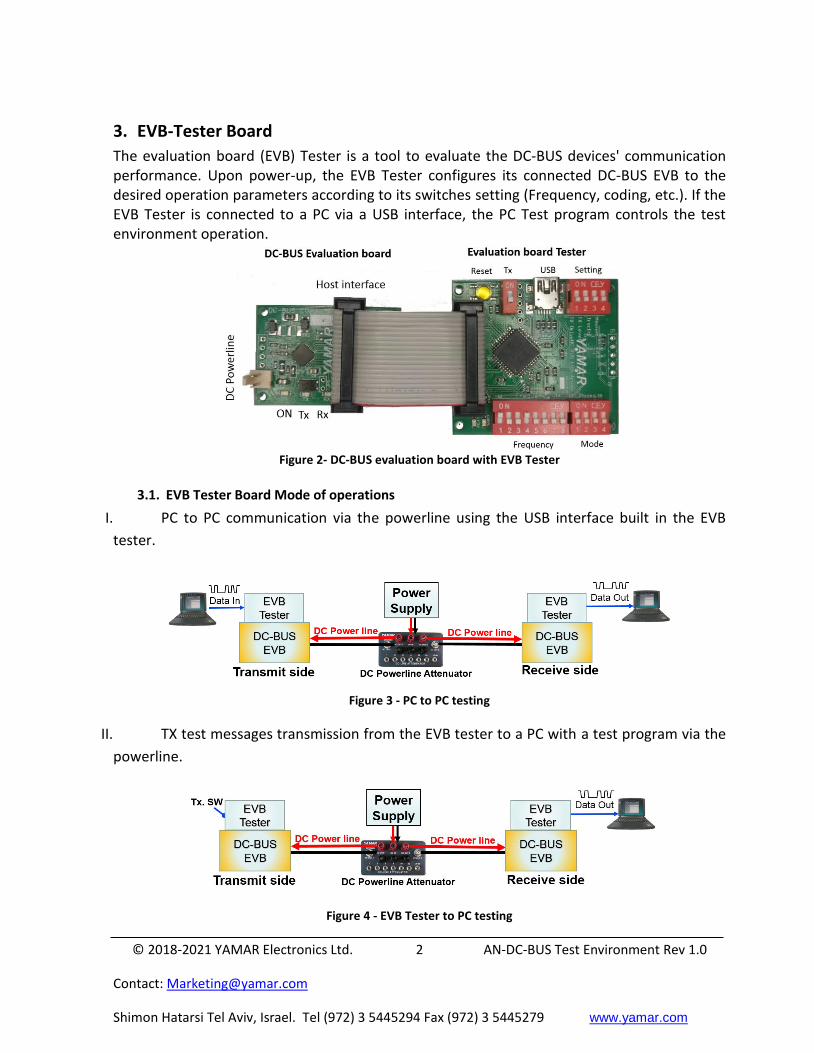
3. EVB-Tester Board
The evaluation board (EVB) Tester is a tool to evaluate the DC-BUS devices' communication performance. Upon power-up, the EVB Tester configures its connected DC-BUS EVB to the desired operation parameters according to its switches setting (Frequency, coding, etc.). If the EVB Tester is connected to a PC via a USB interface, the PC Test program controls the test environment operation.
Figure 2- DC-BUS evaluation board with EVB Tester
3.1. EVB Tester Board Mode of operations
I. PC to PC communication via the powerline using the USB interface built in the EVB
tester.
Figure 3 - PC to PC testing
II. TX test messages transmission from the EVB tester to a PC with a test program via the
powerline.
Figure 4 - EVB Tester to PC testing

© 2018-2021 YAMAR Electronics Ltd. 3 AN-DC-BUS Test Environment Rev 1.0
Contact: [email protected]
Shimon Hatarsi Tel Aviv, Israel. Tel (972) 3 5445294 Fax (972) 3 5445279 www.yamar.com
III. TX test messages transmission from EVB Tester to Rx EVB Tester that analyzes the
received test messages and indicates the results with a LED (Stand-alone mode).
Figure 5 - EVB Tester to EVB Tester testing
User can select the following stand-alone (When not connected to the PC) modes of
operations:
Auto Tx - When the TX switch is ON, the tester generates continuous test messages to the
connected EVB according to the switches’ positions (i.e. bitrate selection, carrier frequency,
protocol interface, TX signal level).
During transmission, Comm. LED is ON. Other EVBs connected to the DC-BUS test software
can detect the test messages over the powerline and perform BER analysis.
Auto Rx - When the TX switch is OFF the EVB Tester board waits for valid test messages
over the powerline from other TX EVB, analyzes it, and turns ON the Comm. LED if the Rx
data is without errors, blinks when an error is detected, or turns LED OFF if no data
detected.
TX-Sweep - When the Tx switch is ON and the Frequency switch is 0xFF (all switches are
ON), test messages are transmitted for a period of ~250ms on each frequency starting from
5MHz up to 30MHz with 0.1MHz spacing (cyclic). During the frequency change period, the
Comm. LED is OFF. This mode allows the user a quick assessment of its powerline channel
frequency response (RX signal level-wise) within device carrier frequency selection full
range (i.e. user can observe the powerline full range carrier frequency level using an
oscilloscope or spectrum- analyzer in various optional nodes located along the powerline).
BER-Sweep – This mode allows a full carrier frequency Sweep BER measurement over the
powerline. This test is under the control of a TX EVB connected to a PC running the DC-BUS
Test SW. Only the RX EVB is in Standalone mode. The RX EVB Tester responds to test
messages from the TX EVB Tester with data errors information for each carrier frequency
between 5MHz to 30MHz, 100kHz spacing.

© 2018-2021 YAMAR Electronics Ltd. 4 AN-DC-BUS Test Environment Rev 1.0
Contact: [email protected]
Shimon Hatarsi Tel Aviv, Israel. Tel (972) 3 5445294 Fax (972) 3 5445279 www.yamar.com
Notice that the transition from flawless communication performance to no communication is very sharp, at the communication edge, adding 2dB to 3dB of attenuation stops the communication.
4. PC Test Software
The DC-BUS Test software tests and configures Yamar’s new generation of devices. The
program tests the communication performance of SIG102, SIG100, DCB1M, DCAN500, and
DMX250 devices over the powerline. The PC operates as a host through the EVB Tester’s USB
port. The Program exclusively operates with Yamar's EVB Tester board. Otherwise, the Test
Program is in Demo mode.
4.1. Test Program Main features
Automatic EVB type detection.
BER Mode - Transmit and receive test pattern and perform BER measurements over a
fixed carrier frequency.
BER Sweep Mode – Auto transmit and receive test pattern and perform BER
measurements over a total of 251 carrier frequencies selection.
DATA Mode - Transmit and receive data in HEX or ASCII formats.
File Mode - Transmit and receive a File.
Logging of BER statistics and data.
Internal register configurations (read and write operations).
© 2018-2021 YAMAR Electronics Ltd. 5 AN-DC-BUS Test Environment Rev 1.0
Contact: [email protected]
Shimon Hatarsi Tel Aviv, Israel. Tel (972) 3 5445294 Fax (972) 3 5445279 www.yamar.com
Figure 6 – PC Test Software Main Display
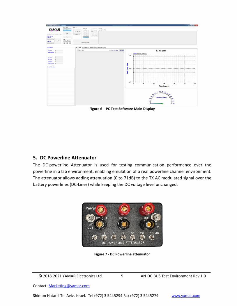
5. DC Powerline Attenuator
The DC-powerline Attenuator is used for testing communication performance over the
powerline in a lab environment, enabling emulation of a real powerline channel environment.
The attenuator allows adding attenuation (0 to 71dB) to the TX AC modulated signal over the
battery powerlines (DC-Lines) while keeping the DC voltage level unchanged.
Figure 7 - DC Powerline attenuator

© 2018-2021 YAMAR Electronics Ltd. 6 AN-DC-BUS Test Environment Rev 1.0
Contact: [email protected]
Shimon Hatarsi Tel Aviv, Israel. Tel (972) 3 5445294 Fax (972) 3 5445279 www.yamar.com
For more details please see Yamar’s Products and Test Tools
@ https://yamar.com/products/