db210 foreman - kreg tool manual for website.pdf · oil, sharp edges or moving parts. damaged or...
TRANSCRIPT

FOREMANDB210
OWNER’S MANUALGUIDE D’UTILISATIONMANUAL DEL PROPIETARIO
www.kregtool.com • 800.447.8638Version 1 - 2/2014
Item# DB210

Safety1.
!!
! WARNING This product contains one or more chemicals known to the State of California to cause cancer and birth defects or other reproductive harm. Wash hands after handling.
General Safety Rules
WARNING For your own safety, read the owner’s manual before operating this pocket-hole machine.
WARNING Read all instructions. Failure to follow all instructions listed below may result in electric shock, fire and/or serious injury. The term "power tool" in all of the warnings listed below refers to your mains-operated (corded) power tool or battery-operated (cordless) power tool.
SAVE THESE INSTRUCTIONS
1) Work area safety a) Keep work area clean and well lit. Cluttered or dark areas invite accidents. b) Don’t use power tools in a dangerous environment. Don’t use power tools in damp or wet locations, or expose them to rain. c) Do not operate power tools in explosive atmospheres, such as inthepresenceofflammableliquids,gasesordust. Power tools create sparks which may ignite the fumes or dust. d) Keepchildrenandbystandersawaywhileoperatingapower tool. Distractions can cause you to lose control. e) Make your workshop child proof with padlocks, master switches, or by removing starter keys.2) Electrical safety a) Do not expose power tools to rain or wet conditions. Water entering a power tool will increase the risk of electric shock. b) Donotabusethecord.Neverusethecordforcarrying, pulling or unplugging the power tool. Keep cord away from heat, oil, sharp edges or moving parts. Damaged or entangled cords increase the risk of electric shock. c) Use a proper extension cord and make sure it is in good condition. When using an extension cord, be sure to use one heavy enough to carry the current your machine draws. An undersized cord causes a drop in line voltage resulting in loss of power and overheating. Table1 on the following page shows the correct cord gauge to use depending on cord length and nameplate ampere rating. If in doubt, use the next heavier gage. The smaller the gage number, the heavier the cord.3) Personal safety a) Stay alert, watch what you are doing and use common sense when operating a power tool. Do not use a power tool while youaretiredorundertheinfluenceofdrugs,alcoholormedication. A moment of inattention while operating power tools may result in serious personal injury. b) Always wear safety glasses. Everyday eyeglasses only have impact resistant lenses, they are NOT safety glasses. c) Usesafetyequipment. Use a face or dust mask when the cutting operation is dusty. Safety equipment such as a dust mask, non- skid safety shoes, hard hat, or hearing protection used for appropriate conditions reduces personal injuries. d) Avoid accidental starting. Make sure the switch is in the off- positionbeforepluggingin. Carrying power tools with your finger on the switch or plugging in power tools that have the switch on invites accidents.
e) Removeanyadjustingkeyorwrenchbeforeturningthepower tool on. A wrench or a key left attached to a rotating part of the power tool may result in personal injury. f) Donotoverreach.Keepproperfootingandbalanceatall times. This enables better control of the power tool in unexpected situations. g) Secure workpieces. Use clamps or a vise to hold work when practical. This is safer than using your hand and it frees both hands to operate the tool. h) Never stand on the machine. Serious injury could occur if the tool tips or if the cutting tool is unintentionally contacted. i) Dress properly. Do not wear loose clothing or jewelry. Keep your hair, clothing and gloves away from moving parts. Loose clothes, jewelry or long hair can be caught in moving parts. j) If devices are provided for the connection of dust extraction and collection facilities, ensure these are connected and properly used. Use of these devices can reduce dust-related hazards.4) Power tool use and care a) Keep guards in place and in working order. b) Do not force the power tool. Use the correct power tool for your application. The correct power tool will do the job better and safer at the rate for which it was designed. c) Use right tool. Don’t force tool or attachment to do a job for which it was not designed. d) Do not use the power tool if the switch does not turn it on and off. Any power tool that cannot be controlled with the switch is dangerous and must be repaired. e) Disconnecttheplugfromthepowersourceand/orthebattery packfromthepowertoolbeforemakinganyadjustments, changing accessories, or storing power tools. Such preventive safety measures reduce the risk of starting the power tool accidentally. f) Never leave tool running unattended. Turn power off. Don’t leave tool until it comes to a complete stop. g) Store idle power tools out of the reach of children and do not allow persons unfamiliar with the power tool or these instructions to operate the power tool. Power tools are dangerous in the hands of untrained users. h) Maintainpowertools.Checkformisalignmentorbindingof movingparts,breakageofpartsandanyotherconditionthat may affect power tool operation. If damaged, have the power toolrepairedbeforeuse. Many accidents are caused by poorly maintained power tools. i) Keep cutting tools sharp and clean. Properly maintained cutting tools with sharp cutting edges are less likely to bind and are easier to control. j) Use the recommended speed for the cutting tool or accessory and workpiece material. k) Onlyusepartsandaccessoriesrecommendedbythe manufacturer. Consult the owner’s manual for recommended accessories. Using improper accessories may cause personal injury. l) Usethepowertool,accessoriesandtoolbitsetc.,in accordance with these instructions and in the manner intended for the particular type of power tool, taking into account the workingconditionsandtheworktobeperformed. Use of the power tool for operations different from those intended could result in a hazardous situation.5) Service a) Haveyourpowertoolservicedbyaqualifiedrepairperson using only identical replacement parts. This ensures that the safety of the power tool is maintained.

Safety 2.
!6) AdditionalSafetyRulesfortheDB210Foreman a) Toreducetheriskofelectricshock,thisequipmenthasa polarizedplug(onebladeiswiderthantheother).Thisplug fitsinapolarizedoutletonlyoneway. If the plug does not fit fully in the outlet, rotate the plug. If it still does not fit, contact a qualified electrician to install the proper outlet. Do not change the plug in any way. b) Keephandsawayfromtherotatingbitandworkpiececlamp when operating the machine. c) Makesurethebitiscompletelywithdrawnfromtheworkpiece andcomestoacompletestopbeforeadjustingtheworkpiece position. d) Secure the machine to prevent tipping or sliding. Never stand on the machine. e) Followalllubricationandmaintenancepracticesdetailedin the instruction manual. f) Thismachineisdesignedforaspecificapplication.Donot modify and/or use it for any other application. If you have questions relative to the application of the machine, DO NOT use it until you have contacted Kreg Tool Company and have been advised accordingly.7) Thelabelonyourmachinemayincludethesymbolsbelow. The symbols and their definitions are as follows:
California Proposition 65
WARNING! Dust created by sanding, sawing, grinding, drilling, and other construction activities may contain chemicals known to the State of California to cause cancer and birth defects or other reproductive harm. Examples of these chemicals are: a) Lead from lead-based paints b) Crystalline silica from bricks and cement and other masonry products c) Arsenic and chromium from chemically treated lumberYour risk from exposure to these chemicals depends on how often you do this type of work. To reduce your exposure, work in a well-ventilated area with approved safety equipment, such as a dust mask specifically designed to filter out microscopic particles.
ForemanDB210motorspecifications120 V~5.0A 2,800 rpm
Guidelines for extension cord useExtension cords are only to be used for temporary purposes. They do not replace the need for installation of outlets and proper wiring where necessary.
In the shop and on construction sites:1. Extension cords with an equipment grounding conductor must be used at all times.2. Extension cords must be protected from damage, and not run through doorways or windows where the doors or windows may close, causing damage to the cord.3. Extension cords should be a minimum of 16 AWG and be rated for the equipment in use.4. Extension cords must be periodically inspected to ensure that the insulation and conductivity of the wires are not compromised.5. Extension cords should not be run through water or allowed to have connections that may be exposed to accumulated water.
Extension cord gauge
Extension Cord LengthNameplate Amperes @120 V
25’ 50’ 75' 100' 150' 200'
0 -5 16 16 16 14 12 12
5.1 - 8 16 16 14 12 10 NR
8.1 -12 14 14 12 10 NR NR
12.1 - 16 12 12 NR NR NR NR
safetyalertsymbol
volts
hertz
amperes
watts
direct current
alternating current
alternating or direct current
ClassIConstruction(grounded)
ClassIIConstruction(doubleinsulated)
earthing terminal
minutes
per minute
beatsperminute
revolutions per minute
no load speed
V
Hz
A
W
min
/min
BPM
RPM
!
English
3
• Be sure that the cutter knives are mounted as described in the instruction manual and check that all bolts are firmly tightened before connecting unit to power source.
• To avoid injury, never rotate the cutter block directly with your hands.
• Keep guards in place and in good working order.• Stay alert – never operate the unit when tired or under the
influence of drugs, alcohol, or medication.• Do not use in dangerous environments. Do not use near
flammable substances, in damp or wet locations, or expose to rain.
• Never plane material which is shorter than 12 inches.• Exhaust chute: remove shavings with brush or vacuum after
power has been shut off and cutter head has stopped rotating.• ALWAYS LOCATE PLANER WITH PROPER CLEARANCE ON
THE OUTFEED SIDE of the unit to prevent pinching or binding of the workpiece against any obstacle.
• Clean out your tool often, especially after heavy use. Dust and grit containing metal particles often accumulate on interior surfaces and could create a risk of serious injury, electric shock or electrocution. ALWAYS WEAR SAFETY GLASSES.WARNING: For your own safety, it is recommended that two
people carry this machine or serious injury could result.WARNING: Always wear proper personal hearing protection
that conforms to ANSI S12.6 (S3.19) during use. Under some conditions and duration of use, noise from this product may contribute to hearing loss.
WARNING: Some dust created by power sanding, sawing, grinding, drilling, and other construction activities contains chemicals known to the State of California to cause cancer, birth defects or other reproductive harm. Some examples of these chemicals are:
• lead from lead-based paints,
• crystalline silica from bricks and cement and other masonry products, and
• arsenic and chromium from chemically-treated lumber.Your risk from these exposures varies, depending on how often you do this type of work. To reduce your exposure to these chemicals: work in a well ventilated area, and work with approved safety equipment, such as those dust masks that are specially designed to filter out microscopic particles.• Avoid prolonged contact with dust from power sanding,
sawing, grinding, drilling, and other construction activities. Wear protective clothing and wash exposed areas with soap and water. Allowing dust to get into your mouth, eyes, or lay on the skin may promote absorption of harmful chemicals.WARNING: A dust mask or respirator should be worn by all
persons entering the work area. The filter should be replaced daily or whenever the wearer has difficulty breathing. See your local hardware store for the proper NIOSH/OSHA approved dust mask.• The label on your tool may include the following symbols. The
symbols and their definitions are as follows:V ......... volts A .......amperesHz ....... hertz W ......wattsmin ..... minutes .....alternating current
... direct current .....alternating or direct current ....... Class I Construction no ......no load speed
........... (grounded) ......earthing terminal ....... Class II Construction .....safety alert symbol
........... (double insulated) BPM ..beats per minute…/min per minute RPM ..revolutions per minute
NR – Not Recommended
TABLE1

Introduction1.
Item# DescriptionParts
1
8
7
6
5
4
3
2
9
10
11
12
13
14
15
16
17
Control arm
Arm lock
Machine base
Handles
Vacuum port
Self-tapping screws
Vacuum shroud
Truss-head machine screws
Hose clamps
Vacuum hose
Access panel
Machine top
3mm hex wrench
Cover levelers
¼-turn fence-lock handles
Fence
Fence-lock screws
Fence-lock bases
Workpiece thickness marks
Drill bit
Drilling-depth stop knob
Drilling-depth setting block
Drill guide (Standard guide included)
Depth-stop jam nut
Clamp-arm housing
Clamp pad
Clamp adjustment knob
Clamp jam nut
Clamp arm
Switch lock-out button
Switch
Workpiece stops
Center-reading measuring tape
#2 square driver bit 6” long
Accessory tray
Foot
Mounting hole
Panel support
Link-release pin
Motor
Guide rods
Quick-change chuck
Motor link
Hinge pivots
Pivot sockets
Drill guide set screw
18
Item# Description
20
19
28
31
38
37
36
35
34
33
32
39
21
22
23
24
25
26
27
29
Congratulations on choosing a Kreg Foreman DB210 semi-automatic pocket-hole machine. Please read all instructions and safety information contained in this manual before using this product.
Owning a Foreman gives you all the advantages of a true production pocket-hole machine with the compactness and portability of a bench-top tool. This manual guides you through the steps necessary to adjust your machine and drill pocket holes. In addition to this manual, you may find the following resources helpful:
30
40
41
42
43
44
45
Kreg Online: To order more pocket-hole screws, view accessories available for your jig, or get help making a particular joint, go to kregtool.com.
Kreg Owner’s Community: Sign up as a member, create your own page, view other members’ projects, post photos of your projects, view how-to videos, and participate in forums by going to kregjig.ning.com.
Kreg YouTube Channel: For project, product, and tip videos, visit youtube.com/user/kregtoolcompany.
Kreg on Facebook: Connect with Kreg on Facebook to share your projects and get inspiration from our fans and friends at facebook.com/kregJig.
46

Logo on white, gray or any lighter shadewhen printing color
Logo on Pantone 2945 or any darker shade when printing color
Logo on white or light shade when printing grayscale
Logo on black or dark shade when printing grayscale
Parts 2.
10
6
5
7
4
32
32
36
37
11
4
15
25
31
30
1
33
1615
2928
27
922
34
13
8
1226
23
2117
17
3

Parts3.
4
2
24
15
21
25
1519
3
Logo on white, gray or any lighter shadewhen printing color
Logo on Pantone 2945 or any darker shade when printing color
Logo on white or light shade when printing grayscale
Logo on black or dark shade when printing grayscale
40
4
35
39
38
14
43
46
14
23
41
20

Assembly 4.
Push down on the control arm (1), release the arm lock (2) at the back of the machine base (3), and guide the control arm to the full-up position. Do not let the arm snap into the full-upright position. For transportation and storage, push down on the control arm and engage the arm lock.
Release the control arm
The Foreman is supplied with a chip-removal system that includes a 11⁄4" vacuum port (5) and self-tapping screws (6), vacuum shroud (7) and machine screws (8), hose clamps (9), and vacuum hose (10). In addition to helping keep your work area clean, efficient chip removal speeds drilling time and reduces heat build-up, extending the life of your drill bit. A Foreman with the chip-removal system installed must be connected to a shop vacuum when in use. Not connecting the chip-collection system to a shop vacuum causes chips to collect in the hose and vacuum shroud and eventually clog the drill bit. The Foreman can be used without the chip-collection system in place. If you install the system and find that you must use your Foreman without a shop vacuum, simply disconnect the vacuum hose from the vacuum shroud.
To install the chip-removal system, turn the Foreman onto one side and from the inside of the machine base (3), insert the vacuum port (5) into the hole in the back of the base and secure it from the outside with two self-tapping screws (6). Fasten the vacuum shroud (7) to the machine with four truss-head machine screws (8).
Slip the hose clamps (9) over the ends of the vacuum hose (10) and slip the vacuum hose ends onto the vacuum port and vacuum shroud. To make it easy to disconnect the vacuum hose from the vacuum shroud when working through the access panel (11), orient the front hose clamp with the screw head facing the front of the machine. Tighten the clamps and turn the Foreman upright.
Install the chip-removal system
9
8
7
6
10
5
7
9
Always disconnect the machine from power before assembly, opening the access cover, or making any adjustments.
Never lift or carry the machine by the control arm. Always use the handles (4) at the front and rear of the machine.
The access panel should be flush with the machine top right out of the box. Should it need adjustment, use the following procedure:
Place the machine on saw horses so you have access to the bottom of the machine. Lay a straight edge across the machine top (12) and access panel (11). Use the 3mm hex wrench (13) supplied with the machine to turn the cover levelers (14).
Level the access panel
11
12
Engage
Release
2
14
13
4
14

Assembly5.
Rotate the ¼-turn fence-lock handles (15) clockwise (locked position). If the fence (16) can be moved with moderate pressure, tighten the fence-lock screws (17). Rotate the handles counterclockwise (unlocked position) and verify that the fence moves freely.
Should it ever be necessary to disassemble the fence locks, the fence-lock bases (18) must be oriented with the flat area indicated in the drawing facing the fence.
Adjust the fence-lock pressure
16
17
For a strong joint, the pocket screw should exit at the center of the workpiece thickness. This is accomplished by adjusting the fence position.
Unlock the fence (16) by rotating the fence-lock handles (15) counterclockwise. Align the rear edge of the fence with the workpiece thickness marks (19) cast into the machine top (12) that correspond to your workpiece thickness. Rotate the handles clockwise to lock the fence in place.
(1) Position the Fence for Workpiece Thickness
To create strong joints, you’ll adjust machine settings to match the thickness of the workpiece and the length of the screw. The Foreman makes this easy, in just four simple steps:
Screw Length Selection GuideMaterial Thickness Screw Length
1⁄2" (12 mm) 3⁄4" (19 mm)5⁄8" (16 mm) 1" (25 mm)3⁄4" (19 mm) 11⁄4" (32 mm)7⁄8" (22 mm) 11⁄2" (38 mm)
1" (25 mm) 11⁄2" (38 mm)
11⁄8" (29 mm) 11⁄2" (38 mm)
11⁄4" (32 mm) 2" (51 mm)
13⁄8" (35 mm) 2" (51 mm)
11⁄2" (38 mm) 21⁄2" (64 mm)
*Screw length is measured from bottom of the head to the tip of the screw
11⁄4"
Kreg offers a complete line of pocket screws for every workpiece thickness and type. Use this guide to select the correct screw length. All Kreg pocket screws are available at your Kreg dealer or online at www.kregjig.com.
(2) Choose a screw
12
19 16 15
15
Operation
Fine ThreadBecause the smaller diameter and thread pitch of our #7 fine-thread screws reduce the chance of splitting the material, we recommend them for hardwoods.
Coarse ThreadDue to the large diameter and thread pitch, our #8 coarse-thread screws offer a strong hold in softwoods and composite materials such as plywood, particleboard, and MDF.
18
flat area
6.Operation
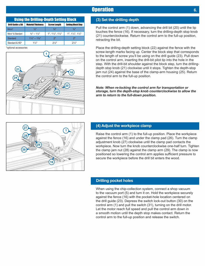
Pull the control arm (1) down, advancing the drill bit (20) until the tip touches the fence (16). If necessary, turn the drilling-depth stop knob (21) counterclockwise. Return the control arm to the full-up position, retracting the bit.
Place the drilling-depth setting block (22) against the fence with the screw-length marks facing up. Center the block step that corresponds to the length of screw you’ll be using on the drill guide (23). Pull down on the control arm, inserting the drill-bit pilot tip into the hole in the step. With the drill-bit shoulder against the block step, turn the drilling-depth stop knob (21) clockwise until it stops. Tighten the depth-stop jam nut (24) against the base of the clamp-arm housing (25). Return the control arm to the full-up position.
Note: When re-locking the control arm for transportation or storage, turn the depth-stop knob counterclockwise to allow the arm to return to the full-down position.
(3) Set the drilling depth
20
1621
1
2522
24
Using the Drilling-Depth Setting BlockDrill Guide & Bit Material Thickness Screw Length Setting Block Step
Micro* ½" ¾" ¾"
Micro* & Standard ⅝" – 1⅛" 1", 1¼", 1½" 1", 1¼", 1½"
Standard 1¼" – 1⅜" 2" 2"
Standard & HD* 1½" 2½" 2½"
*optional accessories
When using the chip-collection system, connect a shop vacuum to the vacuum port (5) and turn it on. Hold the workpiece securely against the fence (16) with the pocket-hole location centered on the drill guide (23). Depress the switch lock-out button (30) on the control arm (1) and pull the switch (31), turning on the drill motor. Let the motor reach full speed and pull the control arm down in a smooth motion until the depth stop makes contact. Return the control arm to the full-up position and release the switch.
Drilling pocket holes
Raise the control arm (1) to the full-up position. Place the workpiece against the fence (16) and under the clamp pad (26). Turn the clamp adjustment knob (27) clockwise until the clamp pad contacts the workpiece. Now turn the knob counterclockwise one-half turn. Tighten the clamp jam nut (28) against the clamp arm (29). The clamp is now positioned so lowering the control arm applies sufficient pressure to secure the workpiece before the drill bit enters the wood.
(4) Adjust the workpiece clamp
16
127
28
2629

Operation7.
In addition to the proper machine settings, proper spacing of pocket holes in the workpiece is important for making a strong joint. For narrow parts such as rails, stiles and frames, locate pocket holes ⅜" to ½" from each edge. Shaded lines on the measuring tape indicate this offset, eliminating the need to mark pocket-hole locations. Simply align the edge of your workpiece with the shaded line and drill. For wide parts such as panels and table tops, place the first pocket hole 2" from the edge and every 6" on center after that.
Pocket-hole placement
A workpiece stop can be used on either side of the drill guide by sliding it out of the fence T-slot, flipping it over so the open end of the stop arm faces center, and reinstalling it in the T-slot.
Loosen the socket-head bolt on the workpiece stop (32) with the 3mm hex wrench (13), slide the stop to the desired location, and tighten the bolt. Keeping the fence (16) centered side to side allows you to use the center-reading measuring tape (33) to position the stops. Override a stop by placing the workpiece over the stop, pressing the spring-loaded stop arm into the stop body.
Workpiece stops
16 13
33
32
Each stop arm can be held in the retracted position by pressing the arm into the stop body and then sliding it toward the socket-head bolt that secures the stop in the fence. The notch in the arm provides a grip point. To reactivate the stop arm, slide it away from the bolt.

8.Operation
To prevent unauthorized use of the machine, a hole through theswitch (31) allows it to be locked in the off position with a padlock(not included).
Switch lock-out
You can store the hex wrench (13), #2 square driver bit (34), and optional Micro and HD drill guides and bits in the accessory tray (35) located under the access panel (11).
Accessory storage
For flexibility in securing your Foreman to a work surface, the foot (36) at each corner of the machine base features a flat surface for temporarily clamping the machine to a work bench as well as a mounting hole (37) for more permanent attachment. (The holes accept #14 x 21⁄2" Kreg HD pocket-hole screws.)
Secure mounting
36
37
31
35

Operation9.
1. Keep the motor clean and the machine base free of wood chips and dust. When used without a shop vacuum, routinely remove waste material from inside the cabinet or mount the machine on an open stand that prevents waste-material accumulation.
2. Periodically lubricate the guide rods with a dry-film lubricant such as Dri-Tool™ Lubricant from Empire Manufacturing. A dry film lubricant will not collect wood chips and dust and will extend the life of the bearings and the guide rods. The motor link and linkage associated with the clamping mechanism should be lubricated periodically to ensure free movement.
3. Use a sharp drill bit. You can drill between 4,000 and 5,000 holes in oak before sharpening the bit. Adjust your sharpening schedule for your settings and the material that you are drilling. Keeping the drill bit clean and free of pitch, resin, and glue significantly extends the life of the bit. Periodically clean the drill bit with a cleaner such as Blade Saver™ and apply a dry lubricant such as OptiCut-XL™, both from Empire Manufacturing. Even a dirty drill bit can be very sharp, so exercise caution when handling the cutting edges.
Kreg offers a sharpening service for Standard pocket-hole drill bits only. Call or e-mail customer service at 800.447.8638 / [email protected] for details.
Use the appropriate procedure below when replacing a drill bit or installing the optional Micro or HD drill bits and drill guides.
To protect the workpiece stops (32) when opening the access panel (11), release the fence-lock handles (15) and move the fence (16) all the way back. Turn the clamp adjustment knob (27) counterclockwise to raise the clamp pad (26). Open the access panel and engage the panel support (38). Remove the link-release pin (39) and slide the motor (40) off the guide rods (41).
To replace the drill bit (20), pull the quick-change chuck (42) collar forward and remove the drill bit. Insert the new drill bit hex shank into chuck, and release the collar. Slide the motor onto the guide rods, inserting the drill bit into the drill guide (23). Align the motor link (43) with the link hole on the motor, and insert the link-release pin. Disengage the access panel support and close the panel.
When switching to the optional Micro or HD drill and guide, change the drill bit as instructed above. Then disconnect the vacuum hose (10) from the vacuum shroud (7). Lift the access panel off the machine, disengaging the hinge pivots (44) on the access panel from the pivot sockets (45) on the machine top (12).
Place the access panel upside down on a flat surface (for example, a tablesaw table). Loosen the drill-guide set screw (46) with the 3mm hex wrench (13) and remove the drill guide. Firmly holding the access cover against the flat surface, slide the new drill guide into the opening, rotate it so the angled face is against the flat surface, and tighten the set screw.
Install the access panel on the machine and engage the panel support. Reconnect the vacuum hose to the vacuum shroud. Slide the motor onto the guide rods, inserting the drill bit into the drill guide. Connect the motor link (43) to the motor with the link-release pin and close the cover.
Replacing a drill bit or installing a drill bit anddrill-guide set
41
45
11
46
12
13
44
42
40
41
20
41
44
Maintenance
23

Two pocket holes with our recommended 9⁄16" center-to center spacing fit entirely on the face of 3⁄4"-thick boards at least 23⁄8" wide. Simply set up the machine for 3⁄4"-thick stock. Then with the mitered end of the workpiece against the fence, drill one hole 7⁄16" from the miter heel and a second hole 25⁄16" from the miter toe.
You also can drill one pocket hole on each side of a miter joint rather than drilling both holes on the same side.
Mitered corners
1⁄2"2 5⁄16"
10.Maintenance
To ensure product safety and reliability, all motor repairs should be performed by the Kreg Tool Company factory service center. Call Kreg Customer Service (800.447.8638) for return authorization and shipping instructions.
Motor service
For a diagram and list of replacement parts and assemblies, go to www.kregtool.com and view the online version of this manual.
Replacement parts
1. Test Pieces Test the joint with scrap pieces cut from the same stock as your final workpiece.
2. Make sure you’re using Kreg Screws Kreg screws feature sharp, self-tapping tips that slice through the wood fibers instead of forcing them apart.
3. Use the Right Screw Type Use fine-thread screws in hardwood. These #7 screws displace less wood than the #8 coarse-thread screws used for softwood, plywood, MDF, and particleboard.
4. Screw it In, Back it Out Drive the screw half-way in, back it out to clear excess wood fibers from the hole, and then drive the screw all the way in.
5. Reduce Friction Apply bee’s wax or other lubricant to the screw to reduce the friction as the screw enters the workpiece.
6. Clamp Correctly Center the pads of your Kreg Face Clamp™ on the joint line with the large clamp pad on the face opposite the pocket holes. Adjust the clamp to apply enough pressure to keep the workpieces flush and stable but not so tight to make clamping difficult.
6 Tips to reduce splittingTips

Tips 11.
Kreg Face Clamps™ITEM# KHC-PREMIUM (3" reach), ITEM# KHC-LARGE (6" reach),ITEM# KHC-XLARGE (10" reach)With a choice of 3"-, 6"-, and 10" reach, there’s a Kreg Face Clamp™ that meets your needs.
Common Board SizesNominal Size Actual Size
1x2 3⁄4" x 11⁄2"
1x3 3⁄4" x 21⁄2"
1x4 3⁄4" x 31⁄2"
1x6 3⁄4" x 51⁄2"
1x8 3⁄4" x 71⁄4"
2x2 11⁄2" x 11⁄2"
2x4 11⁄2" x 31⁄2"
2x6 11⁄2" x 51⁄2"
2x8 11⁄2" x 71⁄4"
4x4 31⁄2" x 31⁄2"
6x6 51⁄2" x 51⁄2"
At a lumber yard or home center you’ll see labels on lumber such as “1x6” and “2x4.” These “nominal” sizes once described the dimensions of rough-cut lumber before it was milled to finished or actual size. Actual size is always less than nominal size.
The board-thickness marks on your Kreg Jig refer the actual thickness of the board. For example, a 1x4 is actually 3⁄4" thick, so you’ll set your jig to the 3⁄4" mark.
Nominal size vs. actual size
HD Drill BitITEM# DB210-HDBReplacement drill bit for the DB210 Foreman G2
Kreg Jig® HD Drill Guide and Drill BitITEM# DB210-HDBBDesigned for use with “2-by” material, this heavy-duty system drill holes for #14 x 21⁄2" pocket screws.
Available from your Kreg dealer or online at www.kregtool.com.
Micro Pocket™ Drill Guide and Drill BitITEM# DB210-MBBWith a hole diameter 25% smaller than our standard pocket hole, the Micro Pocket™ Drill Guide lets you create compact pocket holes in thin stock, and tight repair applications.
Optional Accessories
4"
31⁄2"
11⁄2"
2"
Nominal(2" x 4")
Actual(11⁄2" x 31⁄2")

Foreman DB210 Semi-Automatic Pocket Hole MachineKreg Tool Company warrants the Foreman DB210 Semi-Automatic Pocket Hole Machine to be free of defects in materials and workmanship for a period of one (1) year from the date of delivery to the original purchaser. Drill guide supplied with the machine is warranted for life. This warranty is for purchases from authorized distributors of Kreg products and extends only to the original purchaser. This warranty is not transferable.
During the warranty period, Kreg Tool Company, at its option, will repair or replace the machine or any component part thereof proving defective. This warranty applies only to use in accordance with all instructions pertaining to operation, maintenance, and safety set forth in catalogs, manuals, and instructions furnished by Kreg Tool Company.
This warranty does not apply to:(1) Normal wear and tear, corrosion, abrasion, or repairs required due to natural causes or acts of God.(2) Items that would be consumed or require replacement due to normal wear.(3) The cost of removal of components if such removal is authorized by Kreg Tool Company.(4) Shipment to the Kreg Tool Company repair facility.(5) Reinstallation of parts removed for warranty service.
This warranty is null and void if the product has been subjected to:(1) Misuse, abuse, improper service, or improper storage.(2) Damage resulting from accident, neglect, or other circumstances beyond Kreg Tool Company control.(3) Modifications, disassembly, tampering, alterations, or repairs made outside of Kreg Tool Company facilities without Kreg Tool Company authorization.(4) Removal of the original serial-number tag.
To obtain warranty service, contact Kreg Tool Company at:Kreg Tool Company201 Campus DriveHuxley, IA 50124800.447.8638
DO NOT RETURN THE MACHINE TO THE DEALER FOR WARRANTY SERVICE. Proof of purchase is required before remedy will be provided under the terms of this warranty. Kreg Tool Company assumes no responsibility for products returned without prior authorization. Kreg Tool Company obligations under this warranty shall be limited to repairing or replacing, at Kreg Tool Company option, products which are determined, upon delivery to and inspection by Kreg Tool Company, to be defective. Under no circumstance shall Kreg Tool Company be liable for incidental or consequential damages resulting from defective products, nor shall Kreg Tool Company liability exceed the price paid for the product by the original purchaser.
This is the Kreg Tool Company sole warranty. Any and all other warranties which may be implied by law, including any warranties for merchantability or fitness for a particular purpose, are hereby limited to the duration of this warranty. Kreg Tool Company shall not be liable for any loss, damage or expense directly or indirectly related to the use of this product or from any other cause or for consequential damages, including without limitation, loss of time, inconvenience, and loss of production. The warranty contained herein may not be modified and no other warranty, expressed or implied, shall be made by or on behalf of Kreg Tool Company.
This warranty is in effect only if the accompanying registration card is fully and properly completed and returned to Kreg Tool Company within ten (10) days of date of delivery to the original purchaser.
Keep this form for your records.The following information will be useful in the event warranty service is required. Keep a copy of your purchase invoice with this form.Date of Purchase: ____/____/____Purchased From:Serial Number (located on the side of the machine):
12.Warranty
Kreg Tool Company, 201 Campus Drive, Huxley, IA 50124800.447.8638 • www.kregtool.com

Sécurité1.
!!
! AVERTISSEMENT! Cet article contient un ou plusieurs produits chimiques reconnus par l’État de la Californie comme étant la cause de cancers, d’anomalies congénitales et d’autres problèmes liés aux fonctions reproductrices. Lavez-vous les mains après l’avoir manipulé.
Règles de sécurité générales
AVERTISSEMENT! Pour votre sécurité, lisez le guide d’utilisation avant de faire fonctionner cet appareil pour perçage en angle.
AVERTISSEMENT! Lisez toutes les instructions. Le non-respect des instructions présentées ci-dessous pourrait entraîner un choc électrique, un incendie ou des blessures graves. L’expression « outil électrique » utilisée dans tous les avertissements qui figurent ci-dessous désigne les outils électriques alimentés sur secteur (à fil) ou alimentés par piles (sans fil).
CONSERVEZ CES INSTRUCTIONS
1) Mesures de sécurité dans l’aire de travail a) L’airedetravaildoitêtrepropreetbienéclairée. Une aire de travail encombrée ou peu éclairée augmente le risque d’accident. b) N’utilisezpasunoutilélectriquedansunenvironnement dangereux. N’utilisez pas un outil électrique dans un endroit mouillé ou humide et ne l’exposez pas à la pluie. c) N’utilisezpasd’outilsélectriquesdansuneatmosphère explosive,parexempleenprésencedeliquides,devapeursou depoussièresinflammables. Les outils électriques produisent des étincelles susceptibles d’enflammer ces poussières ou ces vapeurs. d) Gardezlesenfantsetlesautrespersonnesàl’écartlorsque vousutilisezunoutilélectrique.Une distraction peut vous faire perdre la maîtrise de l’outil. e) Empêchez les enfants d’accéder à l’atelier en utilisant des cadenas et un interrupteur général ou en retirant les clés du commutateur d’allumage.2) Consignes de sécurité relatives à l’électricité a) N’exposezpaslesoutilsélectriquesàlapluieouàtoutautre environnement humide. Les risques de choc électrique sont plus élevés si de l’eau s’infiltre dans un outil électrique. b) N’utilisezpaslecordond’alimentationdefaçonabusive. Netransportezjamaisunoutilélectriqueenletenantparson cordon,etnetirezjamaissurlecordonpourledébrancher. Tenez le cordon éloigné des sources de chaleur, del’huile,desobjetscoupantsetdespiècesmobiles. Les risques de choc électrique sont plus élevés si le cordon d’alimentation est endommagé ou emmêlé. c) Utilisezunerallongeappropriéeetassurez-vousqu’elleest enbonétat. Utilisez une rallonge dont le calibre convient au courant consommé par l’outil. Une rallonge de calibre insuffisant causera une baisse de la tension secteur et une perte de puissance qui occasionneront une surchauffe de l’outil. Letableau1 à la page suivante indique le calibre à utiliser en fonction de la longueur de la rallonge et de l’intensité nominale inscrite sur la plaque signalétique. En cas de doute, utilisez une rallonge de calibre supérieur. Plus le numéro du calibre est bas, plus la rallonge est résistante.3) Sécurité personnelle a) Soyezvigilant,prêtezattentionàcequevousfaitesetfaites preuvedebonsenslorsquevousutilisezunoutilélectrique. N’utilisezpasunoutilélectrique lorsquevousêtesfatiguéou sous l’effet de drogues, d’alcool ou de médicaments. Un moment d’inattention pendant que vous utilisez des outils électriques peut occasionner des blessures graves. b) Portez toujours des lunettes de sécurité. Les lunettes ordinaires sont seulement munies de verres résistants aux chocs et ne peuvent PAS être considérées comme des lunettes de sécurité. c) Utilisezdel’équipementdesécurité. Portez un masque facial ou un masque anti-poussières si la coupe produit beaucoup de poussière. Le port d’équipement de sécurité, comme un masque anti-poussières,des chaussures de sécurité antidérapantes, un casque de protection et des protecteurs auditifs, lorsque les conditions l’exigent, réduit les risques de blessures. d) Évitez les mises en marche accidentelles de l’outil. Assurez-vousquel’interrupteurdel’outilestàlapositiond’arrêt
avantdelebrancher. Transporter les outils électriques avec le doigt sur l’interrupteur ou lorsqu’ils sont branchés et sous tension augmente les risques d’accident. e) Retireztouteslesclésderéglagedel’outilélectriqueavant de mettre celui-ci en marche. Une clé de réglage oubliée sur un élément rotatif peut occasionner des blessures graves. f) Ne vous étirez pas pour étendre votre portée. Gardez une posturesécuritaireetunbonéquilibreentouttemps.Vous pourrez ainsi mieux maîtriser l’outil électrique lorsque des situations i nattendues se présentent. g) Fixezbienlapièceàtravailler. Utilisez des colliers de serrage ou un étau pour fixer le matériau sur lequel vous travaillez, au besoin. Cette technique est plus sécuritaire que l’utilisation de vos mains et vous gardez ainsi vos mains libres pour faire fonctionner l’outil. h)Nevoustenezjamaisdeboutsurl’outil. Des blessures graves peuvent survenir si l’outil se renverse ou s’il y a contact accidentel avec des bords tranchants. i) Habillez-vousconvenablement.Neportezpasdevêtements amplesnidebijoux.Gardezvoscheveux,vosvêtementsetvos gantsloindespiècesmobiles. Les vêtements amples, les bijoux et les cheveux longs risquent de se prendre dans les pièces mobiles. j) Si un dispositif permet de raccorder un dépoussiéreur, assurez-vousquecelui-ciestbranchéetutilisécorrectement. L’emploi d’un dépoussiéreur contribue à réduire les dangers liés à la poussière.4) Utilisationetentretiend’unoutilélectrique a) Gardez tous les protecteurs en place et fonctionnels. b) Neforcezpasl’outilélectrique.Utilisezl’outilélectrique appropriéàlatâchequevousenvisagez. L’utilisation de l’outil électrique approprié permet d’obtenir de meilleurs résultats, de façon plus sécuritaire, selon le régime de fonctionnement prévu. c) Utilisezlebonoutil. Ne tentez pas d’utiliser un outil ou l’un de ses accessoires pour effectuer un travail pour lequel il n’est pas conçu. d) N’utilisezpasl’outilélectriquesil’interrupteurnefonctionnepas. Un outil électrique qui ne peut pas être contrôlé par l’interrupteur est dangereux et doit être réparé. e) Débranchezlafichedelapriseouretirezlebloc-pilesde l’outilélectriqueavantd’effectuerdesréglages,dechanger d’accessoire ou de ranger l’outil. De telles mesures de sécurité préventives réduisent les risques de mise en marche accidentelle de l’outil électrique. f) Ne laissez jamais l’outil en marche sans supervision. Coupez l’alimentationélectrique. Ne vous éloignez pas de l’outil tant qu’il ne s’est pas complètement arrêté. g) Rangezlesoutilsélectriquesinutiliséshorsdelaportéedes enfants et ne laissez pas les personnes ne connaissant pas bienl’outiloucesinstructionsutiliserl’outil. Les outils électriques sont dangereux s’ils se retrouvent entre les mains d’utilisateurs qui ne savent pas s’en servir. h) Entretenezlesoutilsélectriques.Vérifiezlespiècespourvous assurerqu’ellesnesontpasdésalignées,enrayées,brisées,ou dans un état pouvant nuire à leur fonctionnement. Si elles sont endommagées, faites-les réparer avant d’utiliser l’outil. De nombreux accidents sont provoqués par des outils mal entretenus. i) Gardez vos outils tranchants affûtés et propres. Des outils tranchants bien entretenus et dont les lames sont affûtées risquent moins de se bloquer et sont plus faciles à maîtriser. j) Utilisez la vitesse recommandée pour l’outil de coupe, l’accessoire et la pièce à travailler. k) N’utilisezquedespiècesetdesaccessoiresrecommandés parlefabricant. Consultez la liste des accessoires recommandés dans le guide d’utilisation. L’utilisation d’accessoires inappropriés peut causer des blessures. l) Utilisezl’outilélectrique,lesaccessoires,lesembouts,etc., conformémentauxinstructionsetauxfinspourlesquelles l’outil a été conçu, en tenant compte des conditions de travail et des tâches à effectuer. L’utilisation de l’outil électrique à des fins autres que celles auxquelles il est destiné pourrait entraîner une situation dangereuse.5) Entretien a) Demandezàuntechnicienqualifiéd’effectuerl’entretien devotreoutilélectriqueenutilisantseulementdespiècesde rechangeidentiquesauxpiècesd’origine. Vous vous assurerez ainsi de respecter les consignes de sécurité de l’outil électrique.

!
Sécurité 2.
6) RèglesdesécuritésupplémentairesduForemanDB210 a) Afinderéduirelesrisquesdechocélectrique,cetappareilest munid’unefichepolarisée(unelameestpluslargequel’autre). Cettefichenepeutêtrebranchéesuruneprisepolariséeque dans un sens. Si la fiche ne peut être branchée sur la prise, essayez dans l’autre sens. Si elle ne s’insère toujours pas, faites appel à un électricien qualifié pour installer une prise appropriée. Ne modifiez la prise d’aucune façon. b) Gardezvosmainsloindelamècheetduserre-jointlorsque vous utilisez la machine. c) Assurez-vousqueleforetestcomplètementretirédelapièce àtravailleretqu’ilestcomplètementarrêtéavantderéglerla position de la pièce. d) Fixezl’outilenplaceafindeprévenirlesbasculementsetles glissements. Ne vous tenez jamais debout sur l’outil. e) Suiveztouteslesconsignesd’entretienetdelubrification détaillées dans le manuel d’instructions. f) Cet appareil est conçu pour une utilisation précise. Ne le modifiezpasetnel’utilisezpasàd’autresfins. Pour toute question en ce qui a trait à l’utilisation, communiquez avec Kreg Tool Company afin d’obtenir de l’aide AVANT d’utiliser l’outil.7) Lessymbolessuivantspeuventfigurersurl’étiquettedevotreoutil. Les symboles et leurs définitions sont les suivants :
Proposition 65 de la Californie
AVERTISSEMENT! La poussière causée par le ponçage, le sciage, le polissage, le perçage et d’autres activités liées à la construction peut contenir des produits chimiques reconnus par l’État de la Californie comme étant la cause de cancers, d’anomalies congénitales et d’autres problèmes liés aux fonctions reproductrices. Voici quelques exemples de ces produits chimiques : a) le plomb provenant de peintures à base de plomb; b) la silice cristalline provenant de la brique, du ciment ou d’autres matériaux de maçonnerie; c) l’arsenic et le chrome provenant du bois d’œuvre traité avec un produit chimique.Les risques liés à l’exposition à ces produits chimiques dépendent du nombre de fois où vous effectuez ce type de travaux. Afin de limiter votre exposition à ces produits, travaillez dans un endroit bien ventilé en vous munissant de l’équipement de sécurité approuvé tel qu’un masque anti-poussières conçu spécialement pour filtrer les particules microscopiques.
CaractéristiquesdumoteurduForemanDB210120 V~5,0 A, 2 800 tours/minute
Directives liées aux rallongesLes rallonges ne servent qu’à un usage temporaire. Elles ne remplacent pas la nécessité d’installer des prises et d’effectuer le câblage, au besoin.
Dans l’atelier ou sur les chantiers de construction :1. Utilisez des rallonges munies d’un conducteur de mise à la terre en tout temps.2. Protégez les rallonges contre les dommages. Ne les faites pas passer par les portes ou les fenêtres, car celles-ci pourraient se refermer et endommager les rallonges.3. Choisissez des rallonges d’un calibre minimal de 16 AWG qui conviennent aux outils que vous utilisez.4. Inspectez périodiquement les rallonges afin de vous assurer que les fils sont bien isolés et que leur conductivité n’est pas compromise.5. Ne faites pas passer de rallonges dans l’eau et ne les raccordez pas dans des endroits où de l’eau pourrait s’accumuler.
Calibre de larallonge
Longueur de la rallongePlaque signalétique : ampères à 120 V
7,62 m 15,24 m 22,86 m 30,48 m 45,72 m 60,96 m
0 -5 16 16 16 14 12 12
5.1 - 8 16 16 14 12 10 NR
8.1 -12 14 14 12 10 NR NR
12.1 - 16 12 12 NR NR NR NR
NR : non recommandé
TABLEAU1
symboled’alertedesécurité
volts
hertz
ampères
watts
courant continu
courant alternatif
courant alternatif ou continu
appareildeclasseI(misàlaterre)
appareildeclasseII(doubleisolation)
bornedemiseàlaterre
minutes
par minute
battementsparminute
tours par minute
vitesse sans charge
V
Hz
A
W
min
/min
BPM
RPM
!
English
3
• Be sure that the cutter knives are mounted as described in the instruction manual and check that all bolts are firmly tightened before connecting unit to power source.
• To avoid injury, never rotate the cutter block directly with your hands.
• Keep guards in place and in good working order.• Stay alert – never operate the unit when tired or under the
influence of drugs, alcohol, or medication.• Do not use in dangerous environments. Do not use near
flammable substances, in damp or wet locations, or expose to rain.
• Never plane material which is shorter than 12 inches.• Exhaust chute: remove shavings with brush or vacuum after
power has been shut off and cutter head has stopped rotating.• ALWAYS LOCATE PLANER WITH PROPER CLEARANCE ON
THE OUTFEED SIDE of the unit to prevent pinching or binding of the workpiece against any obstacle.
• Clean out your tool often, especially after heavy use. Dust and grit containing metal particles often accumulate on interior surfaces and could create a risk of serious injury, electric shock or electrocution. ALWAYS WEAR SAFETY GLASSES.WARNING: For your own safety, it is recommended that two
people carry this machine or serious injury could result.WARNING: Always wear proper personal hearing protection
that conforms to ANSI S12.6 (S3.19) during use. Under some conditions and duration of use, noise from this product may contribute to hearing loss.
WARNING: Some dust created by power sanding, sawing, grinding, drilling, and other construction activities contains chemicals known to the State of California to cause cancer, birth defects or other reproductive harm. Some examples of these chemicals are:
• lead from lead-based paints,
• crystalline silica from bricks and cement and other masonry products, and
• arsenic and chromium from chemically-treated lumber.Your risk from these exposures varies, depending on how often you do this type of work. To reduce your exposure to these chemicals: work in a well ventilated area, and work with approved safety equipment, such as those dust masks that are specially designed to filter out microscopic particles.• Avoid prolonged contact with dust from power sanding,
sawing, grinding, drilling, and other construction activities. Wear protective clothing and wash exposed areas with soap and water. Allowing dust to get into your mouth, eyes, or lay on the skin may promote absorption of harmful chemicals.WARNING: A dust mask or respirator should be worn by all
persons entering the work area. The filter should be replaced daily or whenever the wearer has difficulty breathing. See your local hardware store for the proper NIOSH/OSHA approved dust mask.• The label on your tool may include the following symbols. The
symbols and their definitions are as follows:V ......... volts A .......amperesHz ....... hertz W ......wattsmin ..... minutes .....alternating current
... direct current .....alternating or direct current ....... Class I Construction no ......no load speed
........... (grounded) ......earthing terminal ....... Class II Construction .....safety alert symbol
........... (double insulated) BPM ..beats per minute…/min per minute RPM ..revolutions per minute
English
3
• Be sure that the cutter knives are mounted as described in the instruction manual and check that all bolts are firmly tightened before connecting unit to power source.
• To avoid injury, never rotate the cutter block directly with your hands.
• Keep guards in place and in good working order.• Stay alert – never operate the unit when tired or under the
influence of drugs, alcohol, or medication.• Do not use in dangerous environments. Do not use near
flammable substances, in damp or wet locations, or expose to rain.
• Never plane material which is shorter than 12 inches.• Exhaust chute: remove shavings with brush or vacuum after
power has been shut off and cutter head has stopped rotating.• ALWAYS LOCATE PLANER WITH PROPER CLEARANCE ON
THE OUTFEED SIDE of the unit to prevent pinching or binding of the workpiece against any obstacle.
• Clean out your tool often, especially after heavy use. Dust and grit containing metal particles often accumulate on interior surfaces and could create a risk of serious injury, electric shock or electrocution. ALWAYS WEAR SAFETY GLASSES.WARNING: For your own safety, it is recommended that two
people carry this machine or serious injury could result.WARNING: Always wear proper personal hearing protection
that conforms to ANSI S12.6 (S3.19) during use. Under some conditions and duration of use, noise from this product may contribute to hearing loss.
WARNING: Some dust created by power sanding, sawing, grinding, drilling, and other construction activities contains chemicals known to the State of California to cause cancer, birth defects or other reproductive harm. Some examples of these chemicals are:
• lead from lead-based paints,
• crystalline silica from bricks and cement and other masonry products, and
• arsenic and chromium from chemically-treated lumber.Your risk from these exposures varies, depending on how often you do this type of work. To reduce your exposure to these chemicals: work in a well ventilated area, and work with approved safety equipment, such as those dust masks that are specially designed to filter out microscopic particles.• Avoid prolonged contact with dust from power sanding,
sawing, grinding, drilling, and other construction activities. Wear protective clothing and wash exposed areas with soap and water. Allowing dust to get into your mouth, eyes, or lay on the skin may promote absorption of harmful chemicals.WARNING: A dust mask or respirator should be worn by all
persons entering the work area. The filter should be replaced daily or whenever the wearer has difficulty breathing. See your local hardware store for the proper NIOSH/OSHA approved dust mask.• The label on your tool may include the following symbols. The
symbols and their definitions are as follows:V ......... volts A .......amperesHz ....... hertz W ......wattsmin ..... minutes .....alternating current
... direct current .....alternating or direct current ....... Class I Construction no ......no load speed
........... (grounded) ......earthing terminal ....... Class II Construction .....safety alert symbol
........... (double insulated) BPM ..beats per minute…/min per minute RPM ..revolutions per minute
English
3
• Be sure that the cutter knives are mounted as described in the instruction manual and check that all bolts are firmly tightened before connecting unit to power source.
• To avoid injury, never rotate the cutter block directly with your hands.
• Keep guards in place and in good working order.• Stay alert – never operate the unit when tired or under the
influence of drugs, alcohol, or medication.• Do not use in dangerous environments. Do not use near
flammable substances, in damp or wet locations, or expose to rain.
• Never plane material which is shorter than 12 inches.• Exhaust chute: remove shavings with brush or vacuum after
power has been shut off and cutter head has stopped rotating.• ALWAYS LOCATE PLANER WITH PROPER CLEARANCE ON
THE OUTFEED SIDE of the unit to prevent pinching or binding of the workpiece against any obstacle.
• Clean out your tool often, especially after heavy use. Dust and grit containing metal particles often accumulate on interior surfaces and could create a risk of serious injury, electric shock or electrocution. ALWAYS WEAR SAFETY GLASSES.WARNING: For your own safety, it is recommended that two
people carry this machine or serious injury could result.WARNING: Always wear proper personal hearing protection
that conforms to ANSI S12.6 (S3.19) during use. Under some conditions and duration of use, noise from this product may contribute to hearing loss.
WARNING: Some dust created by power sanding, sawing, grinding, drilling, and other construction activities contains chemicals known to the State of California to cause cancer, birth defects or other reproductive harm. Some examples of these chemicals are:
• lead from lead-based paints,
• crystalline silica from bricks and cement and other masonry products, and
• arsenic and chromium from chemically-treated lumber.Your risk from these exposures varies, depending on how often you do this type of work. To reduce your exposure to these chemicals: work in a well ventilated area, and work with approved safety equipment, such as those dust masks that are specially designed to filter out microscopic particles.• Avoid prolonged contact with dust from power sanding,
sawing, grinding, drilling, and other construction activities. Wear protective clothing and wash exposed areas with soap and water. Allowing dust to get into your mouth, eyes, or lay on the skin may promote absorption of harmful chemicals.WARNING: A dust mask or respirator should be worn by all
persons entering the work area. The filter should be replaced daily or whenever the wearer has difficulty breathing. See your local hardware store for the proper NIOSH/OSHA approved dust mask.• The label on your tool may include the following symbols. The
symbols and their definitions are as follows:V ......... volts A .......amperesHz ....... hertz W ......wattsmin ..... minutes .....alternating current
... direct current .....alternating or direct current ....... Class I Construction no ......no load speed
........... (grounded) ......earthing terminal ....... Class II Construction .....safety alert symbol
........... (double insulated) BPM ..beats per minute…/min per minute RPM ..revolutions per minute
English
3
• Be sure that the cutter knives are mounted as described in the instruction manual and check that all bolts are firmly tightened before connecting unit to power source.
• To avoid injury, never rotate the cutter block directly with your hands.
• Keep guards in place and in good working order.• Stay alert – never operate the unit when tired or under the
influence of drugs, alcohol, or medication.• Do not use in dangerous environments. Do not use near
flammable substances, in damp or wet locations, or expose to rain.
• Never plane material which is shorter than 12 inches.• Exhaust chute: remove shavings with brush or vacuum after
power has been shut off and cutter head has stopped rotating.• ALWAYS LOCATE PLANER WITH PROPER CLEARANCE ON
THE OUTFEED SIDE of the unit to prevent pinching or binding of the workpiece against any obstacle.
• Clean out your tool often, especially after heavy use. Dust and grit containing metal particles often accumulate on interior surfaces and could create a risk of serious injury, electric shock or electrocution. ALWAYS WEAR SAFETY GLASSES.WARNING: For your own safety, it is recommended that two
people carry this machine or serious injury could result.WARNING: Always wear proper personal hearing protection
that conforms to ANSI S12.6 (S3.19) during use. Under some conditions and duration of use, noise from this product may contribute to hearing loss.
WARNING: Some dust created by power sanding, sawing, grinding, drilling, and other construction activities contains chemicals known to the State of California to cause cancer, birth defects or other reproductive harm. Some examples of these chemicals are:
• lead from lead-based paints,
• crystalline silica from bricks and cement and other masonry products, and
• arsenic and chromium from chemically-treated lumber.Your risk from these exposures varies, depending on how often you do this type of work. To reduce your exposure to these chemicals: work in a well ventilated area, and work with approved safety equipment, such as those dust masks that are specially designed to filter out microscopic particles.• Avoid prolonged contact with dust from power sanding,
sawing, grinding, drilling, and other construction activities. Wear protective clothing and wash exposed areas with soap and water. Allowing dust to get into your mouth, eyes, or lay on the skin may promote absorption of harmful chemicals.WARNING: A dust mask or respirator should be worn by all
persons entering the work area. The filter should be replaced daily or whenever the wearer has difficulty breathing. See your local hardware store for the proper NIOSH/OSHA approved dust mask.• The label on your tool may include the following symbols. The
symbols and their definitions are as follows:V ......... volts A .......amperesHz ....... hertz W ......wattsmin ..... minutes .....alternating current
... direct current .....alternating or direct current ....... Class I Construction no ......no load speed
........... (grounded) ......earthing terminal ....... Class II Construction .....safety alert symbol
........... (double insulated) BPM ..beats per minute…/min per minute RPM ..revolutions per minute
English
3
• Be sure that the cutter knives are mounted as described in the instruction manual and check that all bolts are firmly tightened before connecting unit to power source.
• To avoid injury, never rotate the cutter block directly with your hands.
• Keep guards in place and in good working order.• Stay alert – never operate the unit when tired or under the
influence of drugs, alcohol, or medication.• Do not use in dangerous environments. Do not use near
flammable substances, in damp or wet locations, or expose to rain.
• Never plane material which is shorter than 12 inches.• Exhaust chute: remove shavings with brush or vacuum after
power has been shut off and cutter head has stopped rotating.• ALWAYS LOCATE PLANER WITH PROPER CLEARANCE ON
THE OUTFEED SIDE of the unit to prevent pinching or binding of the workpiece against any obstacle.
• Clean out your tool often, especially after heavy use. Dust and grit containing metal particles often accumulate on interior surfaces and could create a risk of serious injury, electric shock or electrocution. ALWAYS WEAR SAFETY GLASSES.WARNING: For your own safety, it is recommended that two
people carry this machine or serious injury could result.WARNING: Always wear proper personal hearing protection
that conforms to ANSI S12.6 (S3.19) during use. Under some conditions and duration of use, noise from this product may contribute to hearing loss.
WARNING: Some dust created by power sanding, sawing, grinding, drilling, and other construction activities contains chemicals known to the State of California to cause cancer, birth defects or other reproductive harm. Some examples of these chemicals are:
• lead from lead-based paints,
• crystalline silica from bricks and cement and other masonry products, and
• arsenic and chromium from chemically-treated lumber.Your risk from these exposures varies, depending on how often you do this type of work. To reduce your exposure to these chemicals: work in a well ventilated area, and work with approved safety equipment, such as those dust masks that are specially designed to filter out microscopic particles.• Avoid prolonged contact with dust from power sanding,
sawing, grinding, drilling, and other construction activities. Wear protective clothing and wash exposed areas with soap and water. Allowing dust to get into your mouth, eyes, or lay on the skin may promote absorption of harmful chemicals.WARNING: A dust mask or respirator should be worn by all
persons entering the work area. The filter should be replaced daily or whenever the wearer has difficulty breathing. See your local hardware store for the proper NIOSH/OSHA approved dust mask.• The label on your tool may include the following symbols. The
symbols and their definitions are as follows:V ......... volts A .......amperesHz ....... hertz W ......wattsmin ..... minutes .....alternating current
... direct current .....alternating or direct current ....... Class I Construction no ......no load speed
........... (grounded) ......earthing terminal ....... Class II Construction .....safety alert symbol
........... (double insulated) BPM ..beats per minute…/min per minute RPM ..revolutions per minute
English
3
• Be sure that the cutter knives are mounted as described in the instruction manual and check that all bolts are firmly tightened before connecting unit to power source.
• To avoid injury, never rotate the cutter block directly with your hands.
• Keep guards in place and in good working order.• Stay alert – never operate the unit when tired or under the
influence of drugs, alcohol, or medication.• Do not use in dangerous environments. Do not use near
flammable substances, in damp or wet locations, or expose to rain.
• Never plane material which is shorter than 12 inches.• Exhaust chute: remove shavings with brush or vacuum after
power has been shut off and cutter head has stopped rotating.• ALWAYS LOCATE PLANER WITH PROPER CLEARANCE ON
THE OUTFEED SIDE of the unit to prevent pinching or binding of the workpiece against any obstacle.
• Clean out your tool often, especially after heavy use. Dust and grit containing metal particles often accumulate on interior surfaces and could create a risk of serious injury, electric shock or electrocution. ALWAYS WEAR SAFETY GLASSES.WARNING: For your own safety, it is recommended that two
people carry this machine or serious injury could result.WARNING: Always wear proper personal hearing protection
that conforms to ANSI S12.6 (S3.19) during use. Under some conditions and duration of use, noise from this product may contribute to hearing loss.
WARNING: Some dust created by power sanding, sawing, grinding, drilling, and other construction activities contains chemicals known to the State of California to cause cancer, birth defects or other reproductive harm. Some examples of these chemicals are:
• lead from lead-based paints,
• crystalline silica from bricks and cement and other masonry products, and
• arsenic and chromium from chemically-treated lumber.Your risk from these exposures varies, depending on how often you do this type of work. To reduce your exposure to these chemicals: work in a well ventilated area, and work with approved safety equipment, such as those dust masks that are specially designed to filter out microscopic particles.• Avoid prolonged contact with dust from power sanding,
sawing, grinding, drilling, and other construction activities. Wear protective clothing and wash exposed areas with soap and water. Allowing dust to get into your mouth, eyes, or lay on the skin may promote absorption of harmful chemicals.WARNING: A dust mask or respirator should be worn by all
persons entering the work area. The filter should be replaced daily or whenever the wearer has difficulty breathing. See your local hardware store for the proper NIOSH/OSHA approved dust mask.• The label on your tool may include the following symbols. The
symbols and their definitions are as follows:V ......... volts A .......amperesHz ....... hertz W ......wattsmin ..... minutes .....alternating current
... direct current .....alternating or direct current ....... Class I Construction no ......no load speed
........... (grounded) ......earthing terminal ....... Class II Construction .....safety alert symbol
........... (double insulated) BPM ..beats per minute…/min per minute RPM ..revolutions per minute

Introduction1.
Item# DescriptionPièces
1
8
7
6
5
4
3
2
9
10
11
12
13
14
15
16
17
Bras de commande
Verrou du bras de commande
Base de l’outil
Poignées
Conduit d’aspiration
Vis autotaraudeuses
Collecteur d’aspiration
Vis à métaux à tête bombée
Colliers de serrage
Tuyau d’aspiration
Panneau d’accès
Dessus de l’outil
Clé hexagonale de 3 mm
Dispositifs de nivellement du couvercle
Leviers de blocage du guide d’un quart de tour
Guide
Vis de blocage du guide
Bases des vis de blocage du guide
Marques indiquant l’épaisseur de la pièce à travailler
Foret
Bouton de blocage de la profondeur de perçage
Bloc d’appui de la profondeur de perçage
Guide-foret (guide standard inclus)
Contre-écrou de la butée de profondeur
Boîtier du bras du serre-joint
Tampon du serre-joint
Bouton de réglage du serre-joint
Contre écrou du serre-joint
Bras du serre-joint
Bouton du verrou de sécurité de l’interrupteur
Interrupteur
Butées de pièce à travailler
Ruban à mesurer à lecture centrale
Embout de tournevis carré no 2 de 6 po
Plateau à accessoires
Pied
Trou de montage
Support du panneau
Goupille de déverrouillage
Moteur
Tiges de guidage
Mandrin à changement rapide
Tige de raccord du moteur
Pivots
Logements des pivots
Drill guide set screw
18
Item# Description
20
19
28
31
38
37
36
35
34
33
32
39
21
22
23
24
25
26
27
29
Félicitations pour votre achat de l’outil pour perçage en angle semi-automatique Foreman DB210 de Kreg. Avant d’utiliser cet article, lisez toutes les instructions et les consignes de sécurités contenues dans le présent manuel.
Lorsque vous possédez un outil Foreman, vous profitez de tous les avantages d’un véritable outil pour perçage en angle industriel, ainsi que de la petite taille et de la portabilité d’un outil d’établi. Le présent manuel vous guidera à travers toutes les étapes nécessaires pour régler votre outil et percer des trous en angle. En plus de celles contenues dans ce manuel, les ressources suivantes pourraient vous être utiles :
30
40
41
42
43
44
45
Kreg en ligne : pour commander des vis pour perçage en angle, voir les accessoires offerts pour votre gabarit ou savoir comment faire un joint en particulier, visitez le site kregtool.com.
Communauté des propriétaires de Kreg : inscrivez-vous en tant que membre, créez votre propre page, regardez les projets des autres membres, affichez les photos de vos projets, visionnez des vidéos d’instructions et participez à des forums en vous rendant au kregjig.ning.com.
Chaîne YouTube de Kreg : pour des projets, des produits et des vidéos d’instructions, visitez le site youtube.com/user/kregtoolcompany.
Kreg sur Facebook : prenez contact avec Kreg sur Facebook afin de partager vos projets et de vous inspirer de nos admirateurs et amis sur facebook.com/kregJig.
46

Logo on white, gray or any lighter shadewhen printing color
Logo on Pantone 2945 or any darker shade when printing color
Logo on white or light shade when printing grayscale
Logo on black or dark shade when printing grayscale
Pièces 2.
10
6
5
7
4
32
32
36
37
11
4
15
25
31
30
1
33
1615
2928
27
922
34
13
8
1226
23
2117
17
3

Pièces3.
4
2
24
15
21
25
1519
3
Logo on white, gray or any lighter shadewhen printing color
Logo on Pantone 2945 or any darker shade when printing color
Logo on white or light shade when printing grayscale
Logo on black or dark shade when printing grayscale
40
4
35
39
38
14
43
46
14
23
41
20

Assemblage 4.
Poussez le bras de commande (1) vers le bas, déverrouillez le verrou du bras de commande (2) situé à l’arrière de la base de l’outil (3), puis soulevez complètement le bras de commande jusqu’à la position verticale. Ne laissez pas le bras s’enclencher entièrement en position verticale. Pour transporter et ranger l’outil, poussez le bras de commande vers le bas et enclenchez le verrou du bras de commande.
Déverrouillage du bras de commande
Installation du système de nettoyage des copeaux
9
8
7
6
10
5
7
9
Débranchez toujours l’outil avant de l’assembler, d’ouvrir le couvercle d’accès ou d’effectuer des réglages.
Ne soulevez ni ne transportez jamais l’outil en le tenant par le bras de commande. Utilisez toujours les poignées (4) situées à l’avant et à l’arrière de l’outil.
Le panneau d’accès devrait être de niveau avec le dessus de l’outil lorsque vous le sortez de la boîte. Si vous devez effectuer des réglages, suivez la procédure suivante :
Placez l’outil sur des chevalets de sciage afin d’avoir accès au dessous. Placez une pièce droite sur le dessus de l’outil (12) et le panneau d’accès (11). Utilisez la clé hexagonale de 3 mm (13) fournie avec l’outil afin de tourner les dispositifs de nivellement du couvercle (14).
Nivellement du panneau d’accès
11
12
Enclencher
Déverrouiller
2
14
13
4
14
Le Foreman est offert avec un système de nettoyage des copeaux qui comprend un orifice d’aspiration de 6,99 cm (5), des vis autotaraudeuses (6), un collecteur d’aspiration (7), des vis à métaux (8), des colliers de serrage (9) et un tuyau d’aspiration (10). En plus d’aider à garder votre aire de travail propre, enlever les copeaux vous permet de percer plus rapidement et de réduire la chaleur, prolongeant ainsi la durée de vie de votre foret. Un appareil Foreman muni du système de nettoyage des copeaux doit être raccordé à un aspirateur d’atelier lorsque vous l’utilisez. Si vous ne raccordez pas le système de nettoyage des copeaux à un aspirateur d’atelier, les copeaux s’accumuleront dans le tuyau et dans le collecteur d’aspiration, ce qui finira par obstruer le foret. Vous pouvez utiliser le Foreman sans avoir installé le système de nettoyage des copeaux. Si vous installez le système et désirez utiliser votre appareil Foreman sans le raccorder à un aspirateur d’atelier, vous n’avez qu’à retirer le tuyau d’aspiration du collecteur.
Pour installer le système de nettoyage des copeaux, couchez le Foreman sur le côté. À partir de l’intérieur de la base de l’outil (3), insérez le conduit d’aspiration (5) dans le trou situé à l’arrière de la base. Fixez-le de l’extérieur à l’aide de deux vis autotaraudeuses (6). Vissez le collecteur d’aspiration (7) à l’outil à l’aide de quatre vis à métaux à tête bombée (8).
Glissez les colliers de serrage (9) sur les extrémités du tuyau d’aspiration (10), puis insérez les extrémités de ce dernier dans le conduit d’aspiration et le collecteur. Pour retirer facilement le tuyau d’aspiration du collecteur à partir du panneau d’accès (11), placez le collier de serrage avant de manière à ce que la tête de la vis soit orientée vers l’avant de l’outil. Serrez les colliers de serrage et remettez le Foreman à l’endroit.

Assemblage5.
Tournez les leviers de blocage du guide d’un quart de tour (15) dans le sens des aiguilles d’une montre (verrouillage). Si le guide (16) peut être bougé en appliquant une pression modérée, serrez les vis de blocage du guide (17). Tournez les leviers dans le sens contraire des aiguilles d’une montre (déverrouillage) et assurez-vous que le guide bouge librement.
S’il est nécessaire de démonter le dispositif de blocage du guide, orientez la section plate des bases des vis de blocage du guide (18) vers le guide, tel que l’illustre le schéma.
Réglage de la pression du dispositif de verrouillage du guide
16
17
Pour un joint solide, la vis pour perçage en angle devrait sortir au centre de la pièce à travailler. Pour ce faire, ajustez la position du guide.
Déverrouillez le guide (16) en tournant les leviers de blocage du guide (15) dans le sens contraire des aiguilles d’une montre. Alignez le rebord arrière du guide avec les marqueurs d’épaisseur de pièce (19) moulés sur le dessus de l’outil (12) qui correspondent à l’épaisseur de votre pièce. Tournez les leviers dans le sens des aiguilles d’une montre pour fixer le guide en place.
(1) Positionnez le guide en fonction de l’épaisseur de la pièce
Pour obtenir des joints solides, vous devez régler votre outil de manière à ce qu’il corresponde à l’épaisseur de votre pièce et à la longueur de la vis. Le Foreman permet de le faire facilement; en quatre étapes seulement :
Guide de sélection des visÉpaisseur du matériau Longueur de la vis
12 mm (1/2 po) 19 mm (3/4 po)
16 mm (5/8 po) 25 mm (1 po)
19 mm (3/4 po) 32 mm (1 1/4 po)
22 mm (7/8 po) 38 mm (1 1/2 po)
25 mm (1 po) 38 mm (1 1/2 po)
29 mm (1 1/8 po) 38 mm (1 1/2 po)
32 mm (1 1/4 po) 51 mm (2 po)
35 mm (1 3/8 po) 51 mm (2 po)
38 mm (1 1/2 po) 64 mm (2 1/2 po)
*La longueur de la vis est calculée du bas de la tête au bout de la vis
1 1/4 po
Kreg vous offre une gamme complète de vis pour perçage à angle pour toutes les épaisseurs et tous les types de pièces travaillées. Utilisez le tableau suivant pour choisir la bonne longueur de vis. Toutes les vis pour perçage à angle Kreg sont offertes chez votre détaillant Kreg ou en ligne sur le site www.kregjig.com.
(2) Choisissez une vis
12
19 16 15
15
Fonctionnement
Vis à filet finEn raison de leur diamètre et de leur pas de filetage plus petits, nos vis à filet fin no 7 réduisent les risques de fendre le matériau. Nous recommandons de les utiliser avec les bois francs.
Vis à filet normalEn raison de leur grand diamètre et de leur grand pas de filetage, nos vis à filet normal no 8 offrent une prise solide sur les bois résineux et les matériaux composites comme le contreplaqué, les panneaux de particules et les MDF.
18
section plate

6.Fonctionnement
Tirez le bras de commande (1) vers le bas, en avançant le foret (20) jusqu’à ce que le bout touche le guide (16). Au besoin, tournez le bouton de blocage de profondeur du perçage (21) dans le sens contraire des aiguilles d’une montre. Ramenez le bras de commande complètement en position verticale, ce qui rétractera le foret.
Placez le bloc d’appui pour la profondeur du perçage (22) contre le guide avec les marques de longueur de la vis pointant vers le haut. Centrez le palier du bloc d’appui correspondant à la longueur de la vis que vous utiliserez sur le guide-foret (23). Tirez le bras de commande vers le bas, en insérant l’embout du foret dans le trou du palier. Avec l’épaulement du foret appuyé contre le palier du bloc d’appui, tournez le bouton de blocage de profondeur du perçage (21) dans le sens des aiguilles d’une montre jusqu’à ce qu’il s’arrête. Serrez le contre-écrou (24) sur la base du boîtier du bras du serre-joint (25). Ramenez le bras de commande complètement en position verticale.
Remarque : Lorsque vous verrouillez le bras de commande pour transporter ou entreposer l’outil, tournez le bouton de blocage de profondeur dans le sens contraire des aiguilles d’une montre afin que le bras revienne complètement vers le bas.
(3) Réglage la profondeur du perçage
20
1621
1
2522
24
Utilisation du bloc d’appui pour laprofondeur du perçage
Guide-foret et foret
Épaisseur du matériau
Longueur de la vis
Réglage du bloc d’appui
Micro* 1/2 po 3/4 po 3/4 po
Micro* et standard 5/8 po à 1 1/8 po 1 po, 1 1/4po,
1 1/2 po1 po, 1 1/4 po,
1 1/2 po
Standard 1 1/4 po à 1 3/8 po 2 po 2 po
Standard et HD* 1 1/2 po 2 1/2po 2 1/2po
*Accessoires en option
Quand vous utilisez le dispositif de nettoyage des copeaux, branchez un aspirateur d’atelier sur le conduit d’aspiration (5) et mettez-le en marche. Maintenez solidement la pièce à travailler contre le guide (16) en gardant l’emplacement du trou en angle centré sur le guide-foret (23). Appuyez sur le bouton de verrouillage de l’interrupteur (30) situé sur le bras de commande (1) puis sur l’interrupteur (31), ce qui mettra le moteur de la perceuse en marche. Attendez que le moteur atteigne sa pleine vitesse, et tirez doucement sur le bras de commande jusqu’à ce qu’il entre en contact avec la butée de profondeur. Ramenez le bras de commande complètement en position verticale et relâchez l’interrupteur.
Perçage des trous en angle
Levez le bras de commande (1) complètement en position verticale. Placez la pièce travaillée contre le guide (16) et sous le tampon du serre-joint (26). Tournez le bouton d’ajustement du serre-joint (27) dans le sens des aiguilles d’une montre jusqu’à ce que le tampon du serre-joint entre en contact avec la pièce à travailler. Ensuite, tournez le bouton d’un demi-tour dans le sens contraire des aiguilles d’une montre. Serrez le contre-écrou (28) contre le bras du serre-joint (29). Le serre-joint est maintenant placé de façon à ce le fait de baisser le bras de commande exerce suffisamment de pression pour fixer la pièce travaillée avant que le foret pénètre dans le bois.
(4) Ajustez le serre-joint
16
127
28
2629

Fonctionnement7.
En plus de bien régler l’outil, il est important d’espacer les trous en angle de façon appropriée sur la surface de la pièce à travailler pour obtenir des joints solides. Pour les pièces étroites comme les traverses, les montants et les cadres, placez les trous en angle de 3/8 po à 1/2 po de chaque rebord. Les lignes ombrées sur le ruban à mesurer indiquent ce décalage. Il n’est donc pas nécessaire de marquer l’emplacement des trous en angle. Alignez simplement le rebord de votre pièce à la ligne ombrée et percez. Pour les pièces larges comme les panneaux et les plateaux de table, placez le premier trou en angle à 2 po de l’extrémité de la pièce et les autres à une distance de 6 po les uns des autres.
Position des trous en angle
Une butée de pièce peut être utilisée de chaque côté du guide-foret en la faisant glisser hors de la fente en T du guide, en l’inversant de manière à ce que le bras de butée soit face au centre et en la réinstallant dans la fente en T.
Desserrez le boulon à tête creuse de la butée de pièce (32) à l’aide de la clé hexagonale de 3 mm (13), glissez la butée jusqu’à l’emplacement désiré et serrez le boulon. Gardez le guide (16) centré bord à bord, cela vous permet d’utiliser le ruban à mesurer à lecture centrale (33) pour positionner les butées. Vous pouvez ne pas utiliser une butée en plaçant la pièce à travailler sur la butée et en poussant le bras de butée à ressort dans le corps de la butée.
Il est possible de maintenir le bras de butée en position rétractée en appuyant le bras dans le corps de la butée, puis en le glissant vers le boulon à tête creuse qui fixe la butée au guide. L’encoche du bras sert de point de saisie. Pour remettre le bras de butée en fonction, glissez-le dans la direction opposée du boulon.
Butées de pièce à travailler
16 13
33
32

8.Fonctionnement
Pour éviter toute utilisation non autorisée de l’outil, un trou dans l’interrupteur (31) vous permet de le verrouiller à la position d’arrêt avec un cadenas. (non inclus).
Verrou de sécurité
Vous pouvez ranger la clé hexagonale (13), l’embout de tournevis carré nº 2 (34), les guide-forets et les forets Micro et HD optionnels dans le plateau à accessoires (35) situé sous le panneau d’accès (11).
Rangement pour accessoires
Afin de vous offrir des options de fixation à une surface de travail, les pieds (36) situés à chaque coin de la base de l’outil Foreman comprennent une surface plane vous permettant de fixer temporairement l’outil à un établi et un trou de montage (37), pour une fixation permanente. (Vous pouvez insérer des vis pour perçage à angle Kreg HD nº 14 de 2 1/2 po dans les trous.)
Fixation sécuritaire
36
37
31
35

Fonctionnement9.
1. Gardez le moteur propre et la base de l’outil exempte de copeaux et de poussière. Si vous n’utilisez pas un aspirateur d’atelier, retirez régulièrement les déchets qui se trouvent à l’intérieur de l’outil, ou fixez l’outil sur un support ouvert afin d’éviter l’accumulation de déchets.
2. Lubrifiez périodiquement les tiges de guidage à l’aide d’un lubrifiant à pellicule sèche comme le lubrifiant Dri-Tool™ d’Empire Manufacturing. Un lubrifiant à pellicule sèche empêchera l’accumulation de copeaux de bois et de poussière et prolongera la durée de vie des roulements et des tiges de guidage. La tige de raccord du moteur et le dispositif de raccord du mécanisme de serrage devraient être lubrifiés périodiquement afin de vous assurer qu’ils bougent sans problème.
3. Utilisez un foret pointu. Vous pouvez percer entre 4 000 et 5 000 trous dans du chêne avant de devoir aiguiser le foret. Planifiez votre horaire d’aiguisage en fonction de vos réglages et des matériaux que vous percez. Gardez le foret propre et exempt de poix, de résine et de colle pour prolonger considérablement sa durée de vie. Nettoyez périodiquement le foret à l’aide d’un nettoyant comme le Blade Saver™ et appliquez un lubrifiant sec comme l’OptiCut-XL™, tous deux offerts par Empire Manufacturing. Même si un foret est sale, il peut être très coupant. Faites toujours preuve de prudence en manipulant les bords tranchants.
Kreg offre un service d’affûtage pour les forets à trous en angles standard seulement. Pour plus de renseignements, communiquez avec notre service à la clientèle par téléphone au 800 447-8638 ou par courriel à [email protected].
Suivez les étapes ci-dessous lors du remplacement d’un foret ou de l’installation des forets et des guide-forets Micro ou HD.
Afin de protéger les butées de pièce (32), déverrouillez les leviers de blocage du guide (15) et ramenez complètement le guide (16) à l’arrière au moment d’ouvrir le panneau d’accès (11). Tournez le bouton d’ajustement du serre-joint (27) dans le sens contraire des aiguilles d’une montre pour relever le tampon du serre-joint (26). Ouvrez le panneau d’accès et enclenchez le support de panneau (38). Retirez la goupille de déverrouillage (39) et glissez le moteur (40) hors des tiges de guidage (41).
Pour remplacer le foret (20), tirez le mandrin à changement rapide (42) vers l’avant et retirez le foret. Insérez la tige hexagonale du nouveau foret dans le mandrin et relâchez le collier. Glissez le moteur sur les tiges de guidage en insérant le foret dans le guide-foret (23). Alignez la tige de raccord du moteur (43) au trou de raccord du moteur, puis insérez la goupille de déverrouillage. Désengagez le support du panneau d’accès et fermez le panneau.
Suivez les étapes ci-dessous quand vous remplacez les forets et les guide-forets pour des forets et des guide-forets Micro ou HD. Puis débranchez le tuyau d’aspiration (10) du collecteur d’aspiration (7). Soulevez le panneau d’accès de l’outil tout en désengageant les pivots (44) des logements des pivots (45) situées sur le dessus de l’outil (12).
Placez le panneau d’accès à l’envers sur une surface plane (comme un plateau de sciage). Desserrez la vis de calage du guide-foret (46) à l’aide de la clé hexagonale de 3 mm (13), puis retirez le guide-foret. En tenant solidement le panneau d’accès sur la surface plane, glissez le nouveau guide-foret dans l’ouverture, puis tournez-le jusqu’à ce que le côté en angle soit contre la surface plane, puis serrez la vis de calage.
Installez le panneau d’accès sur l’outil et enclenchez le support de panneau. Rebranchez le tuyau d’aspirateur au collecteur. Glissez le moteur sur les tiges de guidage en insérant le foret dans le guide-foret. Raccordez la tige de raccord du moteur (43) au moteur à l’aide de la goupille de déverrouillage, puis refermez le panneau.
Remplacement d’un foret ou installation d’un foret et d’un ensemble de foret et de guide-foret
41
45
11
46
12
13
44
42
40
41
20
41
44
Entretien
23

Deux trous en angle percés en suivant l’espacement centre à centre recommandé de 9/16 po s’ajustent entièrement à la surface d’une planche de 3/4 po d’épaisseur et de 2 3/8 po de largeur. Vous n’avez qu’à ajuster l’outil à 3/4 po d’épaisseur. Puis, en plaçant l’extrémité à onglet de la pièce travaillée contre le guide, percez un trou à 7/16 po du talon de l’onglet et un autre à 2 5/16 po de la pointe de l’onglet.
Vous pouvez aussi percer un trou en angle de chaque côté d’un joint à onglet au lieu de percer les deux trous du même côté.
Coins à onglet
1⁄2 po2 5/16 po
10.Entretien
Pour en assurer la sûreté et la fiabilité, toute réparation du moteur doit être effectuée au centre de services de l’usine de Kreg Tool Company. Pour obtenir une autorisation de retour et des instructions d’expédition, communiquez avec le service à la clientèle de Kreg au 800 447-8638.
Entretien du moteur
Pour un tableau et une liste des pièces de rechange, rendez-vous au www.kregtool.com pour voir la version électronique de ce manuel.
Pièces de rechange
1. Effectuez des tests Testez le joint à l’aide de retailles du même matériau que celui de votre pièce à travailler.
2. Assurez-vous d’utiliser des vis Kreg Les vis Kreg sont munies de bouts pointus et autotaraudeurs qui tranchent les fibres du bois au ieu de les séparer de force.
3. Utilisez le bon type de vis Utilisez des vis à filet fin pour le bois franc. Ces vis no 7 déplacent moins de bois que les vis à filet normal no 8 utilisées pour les bois résineux, le contreplaqué, le MDF et les panneaux de particules.
4. Insérez la vis dans un mouvement de va-et-vient Insérez la vis à moitié et retirez-la pour enlever l’excédent de fibres de bois du trou, puis insérez-y complètement la vis.
5. Faites en sorte de diminuer la friction Appliquez de la cire d’abeille ou tout autre lubrifiant sur la vis pour diminuer la friction au moment de l’insérer dans la pièce travaillée.
6. Serrez correctement Centrez les tampons de votre serre-joint Face Clamp™ de Kreg sur la ligne de joint avec le grand tampon sur la face opposée aux trous en angle. Réglez le serrage afin de vous assurer qu’il y a une pression suffisante pour garder les pièces travaillées de niveau et stables, mais pas trop pour éviter que le serrage soit difficile.
6 conseils pour éviter le risque de fendillementConseils

Conseils11.
Serre-joint Face Clamp™ de KregARTICLE # KHC-PREMIUM (PORTÉE DE 3 PO), ARTICLE # KHC-LARGE (PORTÉE DE 6 PO),ARTICLE # KHC-XLARGE (PORTÉE DE 10 PO)Avec un choix de portée de 3 po, 6 po et 10 po, il y a un serre-joint Face Clamp™ de Kreg qui convient à vos besoins.
Common Board SizesNominal Size Actual Size
1x2 3/4 po x 1 1/2 po
1x3 3/4 po x 2 1/2 po
1x4 3/4 po x 3 1/2 po
1x6 3/4 po x 5 1/2 po
1x8 3/4 po x 7 1/2 po
2x2 1 1/2 po x 1 1/2 po
2x4 1 1/2 po x 3 1/2 po
2x6 1 1/2 po x 5 1/2 po
2x8 1 1/2 po x 7 1/4 po
4x4 3 1/2 po x 3 1/2 po
6x6 5 1/2 po x 5 1/2 po
Dans les parcs à bois débités ou dans les centres de rénovation, vous pouvez voir des étiquettes sur le bois d’œuvre indiquant des dimensions comme 1 x 6 ou 2 x 4. Ces dimensions « nominales » ont déjà servi à indiquer les dimensions du bois d’œuvre coupé grossièrement, avant qu’il ne soit usiné pour être fini ou pour obtenir sa dimension réelle. Les dimensions réelles sont toujours plus petites que les dimensions nominales.
Les marques pour mesurer l’épaisseur de la planche sur votre Kreg Jig sont celles de l’épaisseur réelle de la planche. Par exemple, une planche 1 x 4 a en fait une épaisseur de 3/4 po. Vous devez alors régler votre gabarit à la marque 3/4.
Dimensions nominales et dimensions réelles
Foret HDARTICLE # DB210-HDBForet de rechange pour l’appareil Foreman G2 DB210
Guide-foret et foret Kreg Jig® HDARTICLE # DB210-HDBBConçu pour être utilisé avec les pièces de bois de 2 po d’épaisseur, ce système robuste comprend des vis pour perçage à angle no 14 de 2 1/2 po.
Offerts par votre détaillant Kreg ou en ligne sur le site www.kregtool.com.
Guide-foret et foret Micro-Pocket™ARTICLE #DB210-MBBLe guide-foret Micro Pocket™ vous permet de percer des trous en angle 25 % plus petits que nos trous en angle standard. Vous pouvez ainsi créer de petits trous en angle pour les pièces minces et les réparations dans des endroits difficiles d’accès.
Accessoires en option
3 1/2 po
1 1/2 poDimensions nominales
(2 po x 4 po)
4"
2"
Dimensionsréelles
(1 1/2 po x 3 1/2 po)

Appareil pour perçage semi-automatique en angle Foreman DB210 de KregNous garantissons que l’appareil pour perçage semi-automatique en angle Foreman DB210 de Kreg Tool Company ne présentera aucun défaut de matériaux ou de fabrication pendant une période de un (1) an à compter de la date de livraison à l’acheteur initial. Le guide-foret fourni avec l’outil est garanti pendant sa durée de vie. La présente garantie ne couvre que les produits Kreg achetés directement auprès de Kreg Tool Company et de ses distributeurs autorisés et ne s’applique qu’à l’acheteur initial. Cette garantie n’est pas transférable.
Durant la période de garantie, Kreg Tool Company, choisira de réparer ou de remplacer l’outil ou toute pièce jugée défectueuse. La présente garantie s’applique uniquement aux produits utilisés de manière adéquate et conformément aux procédures d’entretien et de sécurité indiquées dans les catalogues, les guides et tout autre manuel d’instructions fournis par Kreg Tool Company.
Cette garantie ne couvre pas :(1) l’usure normale, la corrosion, l’abrasion ni les dommages découlant de causes naturelles ou de cas de force majeure.(2) les articles qui seraient usés ou qui devraient être remplacés à cause de leur usure normale.(3) le coût de retirer des composants si ce retrait est autorisé par Kreg Tool Company.(4) l’expédition au centre de services de Kreg Tool Company.(5) la réinstallation de pièces qui ont été enlevées au titre de la garantie.
Cette garantie n’est pas valable si :(1) le produit a fait l’objet d’un usage inapproprié ou abusif, d’entretien ou d’entreposage inadéquat;(2) le produit a été endommagé à la suite d’un accident, d’une négligence de toute autre circonstance indépendante de la volonté de Kreg Tool Company;(3) le produit a été modifié, démonté, manipulé, transformé ou réparé ailleurs qu’à l’usine de Kreg Tool Company sans l’autorisation de Kreg Tool Company.(4) l’étiquette originale du numéro de série a été enlevée.
Pour effectuer une réclamation au titre de la garantie, communiquez avec Kreg Tool Company :Kreg Tool Company201 Campus DriveHuxley, IA 50124800.447.8638
NE RETOURNEZ PAS L’OUTIL AU DÉTAILLANT POUR LE SERVICE AU TITRE DE LA GARANTIE. Une preuve d’achat est nécessaire pour obtenir une réparation conformément aux conditions de la présente garantie. Kreg Tool Company n’est aucunement responsable des produits retournés sans autorisation préalable. Les obligations de Kreg Tool Company prévues par la présente garantie se limitent exclusivement à la réparation ou au remplacement des produits jugés défectueux après avoir été livrés à Kreg Tool Company et inspectés par cette dernière. Kreg Tool Company ne peut en aucun cas être tenue responsable des dommages accessoires ou consécutifs découlant des produits défectueux, et la responsabilité de Kreg Tool Company ne peut excéder le prix d’achat du produit par l’acheteur initial.
Ce qui précède constitue l’unique garantie de Kreg Tool Company. Toutes les autres garanties prévues par la loi, y compris toute garantie de qualité marchande ou de conformité à un usage particulier, sont limitées, par les présentes, à la durée de cette garantie. Kreg Tool Company n’est pas responsable des pertes, des dommages ni des dépenses découlant, directement ou indirectement, de l’utilisation de ce produit ou de toute autre cause, ni des dommages consécutifs, y compris sans toutefois s’y limiter, la perte de temps, les désagréments et la perte de production. La garantie décrite aux présentes ne peut être modifiée, et aucune autre garantie, qu’elle soit expresse ou implicite, ne peut être offerte par Kreg Tool Company ou en son nom.
La présente garantie est valide seulement si la carte d’enregistrement de la garantie incluse avec le produit a été dûment remplie et retournée à Kreg Tool Company dans les dix (10) jours suivant la date de livraison à l’acheteur initial.
Veuillez conserver ce formulaire.Les renseignements suivants seront utiles si vous devezeffectuer une réclamation au titre de la garantie.Conservez une copie de votre reçu original avec ce formulaire.Date d’achat : ____/____/____Nom du détaillant :Numéro de série (situé sur le côté de l’outil) :
12.Garantie
Kreg Tool Company, 201 Campus Drive, Huxley, IA 50124800.447.8638 • www.kregtool.com

Seguridad1.
!!
! ¡ADVERTENCIA! Este producto contiene una o más sustancias químicas reconocidas por el estado de California como causantes de cáncer, defectos congénitos u otros daños en el aparato reproductivo. Lávese las manos después de manipularlo.
Normas generales de seguridad
¡ADVERTENCIA! Por su propia seguridad, lea el manual del propietario antes de operar esta máquina con cavidades ocultas.
¡ADVERTENCIA! Lea todas las instrucciones. Si no se siguen todas las instrucciones que se detallan a continuación, pueden producirse descargas eléctricas, incendios o lesiones graves. El término “herramienta eléctrica” que aparece en todas las advertencias a continuación se refiere a la herramienta eléctrica que se conecta a la línea principal (con cable) o a la herramienta eléctrica que funciona con batería (inalámbrica).
GUARDE ESTAS INSTRUCCIONES1) Seguridadeneláreadetrabajo a) Mantengaeláreadetrabajolimpiaybieniluminada. En áreas desordenadas u oscuras hay más posibilidades de accidentes. b) No use herramientas eléctricas en entornos peligrosos. No use herramientas eléctricas en áreas húmedas o mojadas ni las exponga a la lluvia. c) Noutiliceherramientaseléctricasenatmósferasenlasqueexista riesgodeexplosión,comoenpresenciadelíquidosinflamables,gases o polvo. Las herramientas eléctricas producen chispas que podrían encender los gases o el polvo. d) Mantenga a los niños y a terceros alejados durante el uso de una herramienta eléctrica. Las distracciones pueden hacerle perder el control. e) Conviertasutallerenunlugarapruebadeniñosconcandadoso interruptoresmaestros,oretirandolallavedearranque.2) Seguridad eléctrica a) No exponga las herramientas eléctricas a la lluvia o a condiciones de humedad. Si ingresa agua a una herramienta eléctrica, aumenta el riesgo de descarga eléctrica. b) Nomaltrateelcable.Notiredelcableparallevar,arrastraro desenchufarlaherramientaeléctrica.Mantengaelcablelejosdelcalor, aceite,bordesfilososopiezasenmovimiento.Los cables dañados o enredados aumentan el riesgo de descarga eléctrica. c) Useunaextensióneléctricaapropiadayasegúresedequeestéen buenascondiciones. Al utilizar una extensión eléctrica, asegúrese de usar una que sea lo suficientemente resistente como para conducir la corriente que su máquina necesita. Una extensión demasiado pequeña provoca la caída del voltaje, lo que genera pérdida de energía y sobrecalentamiento. LaTabla1 en la siguiente página muestra el calibre de cable correcto para usar según la longitud del cable y el amperaje que figura en la placa de datos. Si tiene dudas, utilice el siguiente calibre más resistente. Mientras más pequeño sea el calibre, se necesitará una mayor resistencia.3) Seguridad personal a) Presteatenciónaloquehaceyutiliceelsentidocomúnaloperaruna herramienta eléctrica. No utilice la herramienta eléctrica si está cansado obajolainfluenciadedrogas,alcoholomedicamentos. Un momento de desatención mientras opera herramientas eléctricas puede provocar lesiones personales graves. b) Use gafas de seguridad en todo momento. Los anteojos de uso diario solo tienen lentes resistentes a impactos, NO son gafas de seguridad. c) Utiliceunequipodeseguridad.Use una mascarilla para la cara o una mascarilla antipolvo si la operación de corte desprende demasiado polvo. El equipo de seguridad como mascarillas antipolvo, zapatos de seguridad antideslizantes, casco o protección para los oídos, que se usa para crear condiciones apropiadas, reduce las lesiones personales. d) Evitelosarranquesaccidentales.Asegúresedequeelinterruptor esté en la posición de apagado antes de enchufar la herramienta. Transportar herramientas eléctricas con el dedo en el interruptor o enchufar herramientas eléctricas que tienen el interruptor encendido aumenta las posibilidades de accidentes. e) Retire todas las llaves de ajuste o llaves inglesas antes de encender la herramienta eléctrica. Si se deja una llave inglesa o una llave conectada a una pieza giratoria de la herramienta eléctrica, se pueden producir lesiones personales.
f) Noseextiendademasiado.Mantengaunaposiciónyunequilibrio adecuados en todo momento. Esto permite un mejor control de la herramienta eléctrica en situaciones inesperadas. g) Asegurelaspiezasdetrabajo. Use abrazaderas o una prensa para sostener la pieza de trabajo cuando resulte práctico. Es más seguro que usar las manos y de este modo ambas manos quedan libres para operar la herramienta. h)Noseparesobrelamáquina. Si la herramienta se voltea o si se hace contacto con la herramienta de corte, pueden ocurrir lesiones graves. i) Use ropa adecuada. No use ropa holgada ni joyas. Mantenga elcabello,laropaylosguanteslejosdelaspiezasenmovimiento. La ropa holgada, las joyas o el cabello largo pueden quedar atrapados en las piezas giratorias. j) Si se proporcionan dispositivos para la conexión de complementos deextracciónyrecoleccióndepolvo,asegúresedequeseconecten y se usen adecuadamente. El uso de estos dispositivos puede disminuir los peligros relacionados con el polvo.4) Uso y cuidado de herramientas eléctricas a) Mantengalostopesensulugaryenbuenascondicionesde funcionamiento. b) No fuerce la herramienta eléctrica. Utilice la herramienta eléctrica adecuada para su aplicación. La herramienta apropiada realizará un trabajo mejor y más seguro al ritmo para el que fue diseñada. c) Use la herramienta correcta. No fuerce la herramienta o sus accesorios para hacer un trabajo para el que no fueron diseñados. d) No utilice la herramienta eléctrica si el interruptor no la enciende o apaga. Cualquier herramienta eléctrica que no se pueda controlar con su interruptor es peligrosa y se debe reparar. e) Desconecteelenchufedelafuentedealimentaciónolabatería delaherramientaeléctricaantesderealizarcualquierajuste, cambiaraccesoriosoalmacenarherramientaseléctricas. Este tipo de medidas de seguridad preventivas reduce el riesgo de arranques accidentales de la herramienta eléctrica. f) No deje la herramienta en funcionamiento sin supervisión. Desconecte la alimentación. No desatienda la herramienta hasta que se detenga completamente. g) Almacene las herramientas eléctricas inactivas fuera del alcance de losniñosynopermitaquepersonasnofamiliarizadasconlas herramientas eléctricas o estas instrucciones las operen. Las herramientas eléctricas son peligrosas en manos de usuarios inexpertos. h) Realice mantenimiento a las herramientas eléctricas. Revise si hay desalineación, agarrotamiento rotura de piezas móviles, así como cualquierotracondiciónquepuedaafectarlaoperacióndela herramienta eléctrica. Si encuentra algún daño, haga reparar la herramienta eléctrica antes de usarla. Muchos accidentes son producto del mal mantenimiento de las herramientas. i) Mantengalasherramientasdecorteafiladasylimpias. Las herramientas de corte que se mantienen adecuadamente con sus bordes de corte afilados, tienen un riesgo menor de trabarse y son más fáciles de controlar. j) Utilice la velocidad recomendada para la herramienta de corte o el accesorioyelmaterialdelapiezadetrabajo. k) Solousepiezasyaccesoriosrecomendadosporelfabricante. Consulte el manual del propietario para conocer los accesorios recomendados. Usar accesorios incorrectos puede causar lesiones personales. l) Uselaherramientaeléctrica,losaccesorios,lasbrocas,etc. según estas instrucciones y de la manera adecuada para el tipo de herramienta eléctrica en particular, considerando las condiciones de trabajoyeltrabajoquesevaarealizar. El uso de la herramienta eléctrica en operaciones distintas para las que fue diseñada podría crear una situación de peligro.5) Reparación a) Haga reparar su herramienta eléctrica solo por personal de reparacióncalificadoqueuseexclusivamentepiezasderepuesto idénticas a las originales. Esto asegura que se mantenga la seguridad de la herramienta eléctrica.6) ReglasadicionalesdeseguridadparalaherramientaForemanDB210 a) Parareducirelriesgodedescargaeléctrica,esteequipotiene unenchufepolarizado(unaclavijaesmásanchaquelaotra).Este enchufe encaja en un tomacorriente polarizado de una única manera. Si el enchufe no encaja por completo en el tomacorriente, inviértalo. Si sigue sin encajar, póngase en contacto con un electricista calificado para instalar el tomacorriente apropiado. No modifique el enchufe de ninguna manera.

Seguridad 2.
! b) Mantengalasmanosalejadasdelabrocagiratoriaydelaabrazadera delapiezadetrabajomientrasoperelamáquina. c) Asegúresedequelabrocaestécompletamenteseparadadelapieza detrabajoyquesedetengacompletamenteantesderegularlaposición delapiezadetrabajo. d) Asegurelamáquinaparaevitarinclinacionesodeslices. No se pare sobre la máquina. e) Sigatodaslasprácticasdelubricaciónymantenimientoquese detallan en el manual de instrucciones. f) Estamáquinaestádiseñadaparaunaaplicaciónespecífica.Nola modifiquenilauseparaotraaplicación. Si tiene preguntas relacionadas con la aplicación de la máquina, NO la use hasta ponerse en contacto con Kreg Tool Company y recibir la orientación correspondiente.7) Enlaetiquetadesumáquinapuedenaparecerlossiguientessímbolos. TLos símbolos y sus definiciones son los siguientes:
Propuesta 65 de California
¡ADVERTENCIA! El polvo producido por lijar, serruchar, triturar, taladrar y hacer otras actividades de construcción puede contener químicos reconocidos por el estado de California como causantes de cáncer y defectos congénitos u otros daños en el aparato reproductivo. Algunos ejemplos de estos químicos son: a) Plomo de pinturas a base de plomo b) Sílice cristalina de ladrillos, cemento y otros productos de mampostería c) Arsénico y cromo de madera tratada con químicosEl riesgo que corre debido a la exposición a estos químicos varía dependiendo de la frecuencia con que realice este tipo de trabajo. Para reducir la exposición, trabaje en un área bien ventilada y utilice un equipo de seguridad aprobado, como una mascarilla antipolvo, específicamente diseñado para filtrar partículas microscópicas.
EspecificacionesdelmotorForemanDB210120 V~5.0A 2800 rpm
Pautas para el uso de extensiones eléctricasLas extensiones eléctricas son solo para uso temporal. No reemplazan la necesidad de instalar tomacorrientes y cableado adecuado donde sea necesario.
En el taller y en sitios de construcción:1. Se deben usar extensiones eléctricas con conductor de puesta a tierra del equipo en todo momento.2. Las extensiones eléctricas deben protegerse de daños y no deben tenderse a través de puertas o ventanas, ya que estas puedan cerrarse y dañar el cable.3. Las extensiones eléctricas deben ser de 16 AWG como mínimo y tener una clasificación adecuada para el equipo que se utiliza.4. Las extensiones eléctricas deben inspeccionarse periódicamente para controlar que el aislamiento y la conductividad no se vean comprometidos.5. Las extensiones eléctricas no deben tenderse sobre agua, y no se debe permitir que las conexiones estén expuestas a agua acumulada.
Calibre de la extensión eléctrica
Largo de la extensión eléctricaPlaca de datos: amperios a120 V
25’ 50’ 75' 100' 150' 200'
0 -5 16 16 16 14 12 12
5.1 - 8 16 16 14 12 10 NR
8.1 -12 14 14 12 10 NR NR
12.1 - 16 12 12 NR NR NR NR
NR: no recomendado
TABLA1
símbolodealertadeseguridad
voltios
hercios
amperios
vatios
corriente continua
corriente alterna
corriente alterna o continua
Clase I para construcción (conpuestaatierra)
Clase II para construcción (condobleaislamiento)
terminal de tierra
minutos
por minuto
golpes por minuto
revoluciones por minuto
velocidad sin carga
V
Hz
A
W
min
/min
BPM
RPM
!
English
3
• Be sure that the cutter knives are mounted as described in the instruction manual and check that all bolts are firmly tightened before connecting unit to power source.
• To avoid injury, never rotate the cutter block directly with your hands.
• Keep guards in place and in good working order.• Stay alert – never operate the unit when tired or under the
influence of drugs, alcohol, or medication.• Do not use in dangerous environments. Do not use near
flammable substances, in damp or wet locations, or expose to rain.
• Never plane material which is shorter than 12 inches.• Exhaust chute: remove shavings with brush or vacuum after
power has been shut off and cutter head has stopped rotating.• ALWAYS LOCATE PLANER WITH PROPER CLEARANCE ON
THE OUTFEED SIDE of the unit to prevent pinching or binding of the workpiece against any obstacle.
• Clean out your tool often, especially after heavy use. Dust and grit containing metal particles often accumulate on interior surfaces and could create a risk of serious injury, electric shock or electrocution. ALWAYS WEAR SAFETY GLASSES.WARNING: For your own safety, it is recommended that two
people carry this machine or serious injury could result.WARNING: Always wear proper personal hearing protection
that conforms to ANSI S12.6 (S3.19) during use. Under some conditions and duration of use, noise from this product may contribute to hearing loss.
WARNING: Some dust created by power sanding, sawing, grinding, drilling, and other construction activities contains chemicals known to the State of California to cause cancer, birth defects or other reproductive harm. Some examples of these chemicals are:
• lead from lead-based paints,
• crystalline silica from bricks and cement and other masonry products, and
• arsenic and chromium from chemically-treated lumber.Your risk from these exposures varies, depending on how often you do this type of work. To reduce your exposure to these chemicals: work in a well ventilated area, and work with approved safety equipment, such as those dust masks that are specially designed to filter out microscopic particles.• Avoid prolonged contact with dust from power sanding,
sawing, grinding, drilling, and other construction activities. Wear protective clothing and wash exposed areas with soap and water. Allowing dust to get into your mouth, eyes, or lay on the skin may promote absorption of harmful chemicals.WARNING: A dust mask or respirator should be worn by all
persons entering the work area. The filter should be replaced daily or whenever the wearer has difficulty breathing. See your local hardware store for the proper NIOSH/OSHA approved dust mask.• The label on your tool may include the following symbols. The
symbols and their definitions are as follows:V ......... volts A .......amperesHz ....... hertz W ......wattsmin ..... minutes .....alternating current
... direct current .....alternating or direct current ....... Class I Construction no ......no load speed
........... (grounded) ......earthing terminal ....... Class II Construction .....safety alert symbol
........... (double insulated) BPM ..beats per minute…/min per minute RPM ..revolutions per minute
English
3
• Be sure that the cutter knives are mounted as described in the instruction manual and check that all bolts are firmly tightened before connecting unit to power source.
• To avoid injury, never rotate the cutter block directly with your hands.
• Keep guards in place and in good working order.• Stay alert – never operate the unit when tired or under the
influence of drugs, alcohol, or medication.• Do not use in dangerous environments. Do not use near
flammable substances, in damp or wet locations, or expose to rain.
• Never plane material which is shorter than 12 inches.• Exhaust chute: remove shavings with brush or vacuum after
power has been shut off and cutter head has stopped rotating.• ALWAYS LOCATE PLANER WITH PROPER CLEARANCE ON
THE OUTFEED SIDE of the unit to prevent pinching or binding of the workpiece against any obstacle.
• Clean out your tool often, especially after heavy use. Dust and grit containing metal particles often accumulate on interior surfaces and could create a risk of serious injury, electric shock or electrocution. ALWAYS WEAR SAFETY GLASSES.WARNING: For your own safety, it is recommended that two
people carry this machine or serious injury could result.WARNING: Always wear proper personal hearing protection
that conforms to ANSI S12.6 (S3.19) during use. Under some conditions and duration of use, noise from this product may contribute to hearing loss.
WARNING: Some dust created by power sanding, sawing, grinding, drilling, and other construction activities contains chemicals known to the State of California to cause cancer, birth defects or other reproductive harm. Some examples of these chemicals are:
• lead from lead-based paints,
• crystalline silica from bricks and cement and other masonry products, and
• arsenic and chromium from chemically-treated lumber.Your risk from these exposures varies, depending on how often you do this type of work. To reduce your exposure to these chemicals: work in a well ventilated area, and work with approved safety equipment, such as those dust masks that are specially designed to filter out microscopic particles.• Avoid prolonged contact with dust from power sanding,
sawing, grinding, drilling, and other construction activities. Wear protective clothing and wash exposed areas with soap and water. Allowing dust to get into your mouth, eyes, or lay on the skin may promote absorption of harmful chemicals.WARNING: A dust mask or respirator should be worn by all
persons entering the work area. The filter should be replaced daily or whenever the wearer has difficulty breathing. See your local hardware store for the proper NIOSH/OSHA approved dust mask.• The label on your tool may include the following symbols. The
symbols and their definitions are as follows:V ......... volts A .......amperesHz ....... hertz W ......wattsmin ..... minutes .....alternating current
... direct current .....alternating or direct current ....... Class I Construction no ......no load speed
........... (grounded) ......earthing terminal ....... Class II Construction .....safety alert symbol
........... (double insulated) BPM ..beats per minute…/min per minute RPM ..revolutions per minute
English
3
• Be sure that the cutter knives are mounted as described in the instruction manual and check that all bolts are firmly tightened before connecting unit to power source.
• To avoid injury, never rotate the cutter block directly with your hands.
• Keep guards in place and in good working order.• Stay alert – never operate the unit when tired or under the
influence of drugs, alcohol, or medication.• Do not use in dangerous environments. Do not use near
flammable substances, in damp or wet locations, or expose to rain.
• Never plane material which is shorter than 12 inches.• Exhaust chute: remove shavings with brush or vacuum after
power has been shut off and cutter head has stopped rotating.• ALWAYS LOCATE PLANER WITH PROPER CLEARANCE ON
THE OUTFEED SIDE of the unit to prevent pinching or binding of the workpiece against any obstacle.
• Clean out your tool often, especially after heavy use. Dust and grit containing metal particles often accumulate on interior surfaces and could create a risk of serious injury, electric shock or electrocution. ALWAYS WEAR SAFETY GLASSES.WARNING: For your own safety, it is recommended that two
people carry this machine or serious injury could result.WARNING: Always wear proper personal hearing protection
that conforms to ANSI S12.6 (S3.19) during use. Under some conditions and duration of use, noise from this product may contribute to hearing loss.
WARNING: Some dust created by power sanding, sawing, grinding, drilling, and other construction activities contains chemicals known to the State of California to cause cancer, birth defects or other reproductive harm. Some examples of these chemicals are:
• lead from lead-based paints,
• crystalline silica from bricks and cement and other masonry products, and
• arsenic and chromium from chemically-treated lumber.Your risk from these exposures varies, depending on how often you do this type of work. To reduce your exposure to these chemicals: work in a well ventilated area, and work with approved safety equipment, such as those dust masks that are specially designed to filter out microscopic particles.• Avoid prolonged contact with dust from power sanding,
sawing, grinding, drilling, and other construction activities. Wear protective clothing and wash exposed areas with soap and water. Allowing dust to get into your mouth, eyes, or lay on the skin may promote absorption of harmful chemicals.WARNING: A dust mask or respirator should be worn by all
persons entering the work area. The filter should be replaced daily or whenever the wearer has difficulty breathing. See your local hardware store for the proper NIOSH/OSHA approved dust mask.• The label on your tool may include the following symbols. The
symbols and their definitions are as follows:V ......... volts A .......amperesHz ....... hertz W ......wattsmin ..... minutes .....alternating current
... direct current .....alternating or direct current ....... Class I Construction no ......no load speed
........... (grounded) ......earthing terminal ....... Class II Construction .....safety alert symbol
........... (double insulated) BPM ..beats per minute…/min per minute RPM ..revolutions per minute
English
3
• Be sure that the cutter knives are mounted as described in the instruction manual and check that all bolts are firmly tightened before connecting unit to power source.
• To avoid injury, never rotate the cutter block directly with your hands.
• Keep guards in place and in good working order.• Stay alert – never operate the unit when tired or under the
influence of drugs, alcohol, or medication.• Do not use in dangerous environments. Do not use near
flammable substances, in damp or wet locations, or expose to rain.
• Never plane material which is shorter than 12 inches.• Exhaust chute: remove shavings with brush or vacuum after
power has been shut off and cutter head has stopped rotating.• ALWAYS LOCATE PLANER WITH PROPER CLEARANCE ON
THE OUTFEED SIDE of the unit to prevent pinching or binding of the workpiece against any obstacle.
• Clean out your tool often, especially after heavy use. Dust and grit containing metal particles often accumulate on interior surfaces and could create a risk of serious injury, electric shock or electrocution. ALWAYS WEAR SAFETY GLASSES.WARNING: For your own safety, it is recommended that two
people carry this machine or serious injury could result.WARNING: Always wear proper personal hearing protection
that conforms to ANSI S12.6 (S3.19) during use. Under some conditions and duration of use, noise from this product may contribute to hearing loss.
WARNING: Some dust created by power sanding, sawing, grinding, drilling, and other construction activities contains chemicals known to the State of California to cause cancer, birth defects or other reproductive harm. Some examples of these chemicals are:
• lead from lead-based paints,
• crystalline silica from bricks and cement and other masonry products, and
• arsenic and chromium from chemically-treated lumber.Your risk from these exposures varies, depending on how often you do this type of work. To reduce your exposure to these chemicals: work in a well ventilated area, and work with approved safety equipment, such as those dust masks that are specially designed to filter out microscopic particles.• Avoid prolonged contact with dust from power sanding,
sawing, grinding, drilling, and other construction activities. Wear protective clothing and wash exposed areas with soap and water. Allowing dust to get into your mouth, eyes, or lay on the skin may promote absorption of harmful chemicals.WARNING: A dust mask or respirator should be worn by all
persons entering the work area. The filter should be replaced daily or whenever the wearer has difficulty breathing. See your local hardware store for the proper NIOSH/OSHA approved dust mask.• The label on your tool may include the following symbols. The
symbols and their definitions are as follows:V ......... volts A .......amperesHz ....... hertz W ......wattsmin ..... minutes .....alternating current
... direct current .....alternating or direct current ....... Class I Construction no ......no load speed
........... (grounded) ......earthing terminal ....... Class II Construction .....safety alert symbol
........... (double insulated) BPM ..beats per minute…/min per minute RPM ..revolutions per minute
English
3
• Be sure that the cutter knives are mounted as described in the instruction manual and check that all bolts are firmly tightened before connecting unit to power source.
• To avoid injury, never rotate the cutter block directly with your hands.
• Keep guards in place and in good working order.• Stay alert – never operate the unit when tired or under the
influence of drugs, alcohol, or medication.• Do not use in dangerous environments. Do not use near
flammable substances, in damp or wet locations, or expose to rain.
• Never plane material which is shorter than 12 inches.• Exhaust chute: remove shavings with brush or vacuum after
power has been shut off and cutter head has stopped rotating.• ALWAYS LOCATE PLANER WITH PROPER CLEARANCE ON
THE OUTFEED SIDE of the unit to prevent pinching or binding of the workpiece against any obstacle.
• Clean out your tool often, especially after heavy use. Dust and grit containing metal particles often accumulate on interior surfaces and could create a risk of serious injury, electric shock or electrocution. ALWAYS WEAR SAFETY GLASSES.WARNING: For your own safety, it is recommended that two
people carry this machine or serious injury could result.WARNING: Always wear proper personal hearing protection
that conforms to ANSI S12.6 (S3.19) during use. Under some conditions and duration of use, noise from this product may contribute to hearing loss.
WARNING: Some dust created by power sanding, sawing, grinding, drilling, and other construction activities contains chemicals known to the State of California to cause cancer, birth defects or other reproductive harm. Some examples of these chemicals are:
• lead from lead-based paints,
• crystalline silica from bricks and cement and other masonry products, and
• arsenic and chromium from chemically-treated lumber.Your risk from these exposures varies, depending on how often you do this type of work. To reduce your exposure to these chemicals: work in a well ventilated area, and work with approved safety equipment, such as those dust masks that are specially designed to filter out microscopic particles.• Avoid prolonged contact with dust from power sanding,
sawing, grinding, drilling, and other construction activities. Wear protective clothing and wash exposed areas with soap and water. Allowing dust to get into your mouth, eyes, or lay on the skin may promote absorption of harmful chemicals.WARNING: A dust mask or respirator should be worn by all
persons entering the work area. The filter should be replaced daily or whenever the wearer has difficulty breathing. See your local hardware store for the proper NIOSH/OSHA approved dust mask.• The label on your tool may include the following symbols. The
symbols and their definitions are as follows:V ......... volts A .......amperesHz ....... hertz W ......wattsmin ..... minutes .....alternating current
... direct current .....alternating or direct current ....... Class I Construction no ......no load speed
........... (grounded) ......earthing terminal ....... Class II Construction .....safety alert symbol
........... (double insulated) BPM ..beats per minute…/min per minute RPM ..revolutions per minute
English
3
• Be sure that the cutter knives are mounted as described in the instruction manual and check that all bolts are firmly tightened before connecting unit to power source.
• To avoid injury, never rotate the cutter block directly with your hands.
• Keep guards in place and in good working order.• Stay alert – never operate the unit when tired or under the
influence of drugs, alcohol, or medication.• Do not use in dangerous environments. Do not use near
flammable substances, in damp or wet locations, or expose to rain.
• Never plane material which is shorter than 12 inches.• Exhaust chute: remove shavings with brush or vacuum after
power has been shut off and cutter head has stopped rotating.• ALWAYS LOCATE PLANER WITH PROPER CLEARANCE ON
THE OUTFEED SIDE of the unit to prevent pinching or binding of the workpiece against any obstacle.
• Clean out your tool often, especially after heavy use. Dust and grit containing metal particles often accumulate on interior surfaces and could create a risk of serious injury, electric shock or electrocution. ALWAYS WEAR SAFETY GLASSES.WARNING: For your own safety, it is recommended that two
people carry this machine or serious injury could result.WARNING: Always wear proper personal hearing protection
that conforms to ANSI S12.6 (S3.19) during use. Under some conditions and duration of use, noise from this product may contribute to hearing loss.
WARNING: Some dust created by power sanding, sawing, grinding, drilling, and other construction activities contains chemicals known to the State of California to cause cancer, birth defects or other reproductive harm. Some examples of these chemicals are:
• lead from lead-based paints,
• crystalline silica from bricks and cement and other masonry products, and
• arsenic and chromium from chemically-treated lumber.Your risk from these exposures varies, depending on how often you do this type of work. To reduce your exposure to these chemicals: work in a well ventilated area, and work with approved safety equipment, such as those dust masks that are specially designed to filter out microscopic particles.• Avoid prolonged contact with dust from power sanding,
sawing, grinding, drilling, and other construction activities. Wear protective clothing and wash exposed areas with soap and water. Allowing dust to get into your mouth, eyes, or lay on the skin may promote absorption of harmful chemicals.WARNING: A dust mask or respirator should be worn by all
persons entering the work area. The filter should be replaced daily or whenever the wearer has difficulty breathing. See your local hardware store for the proper NIOSH/OSHA approved dust mask.• The label on your tool may include the following symbols. The
symbols and their definitions are as follows:V ......... volts A .......amperesHz ....... hertz W ......wattsmin ..... minutes .....alternating current
... direct current .....alternating or direct current ....... Class I Construction no ......no load speed
........... (grounded) ......earthing terminal ....... Class II Construction .....safety alert symbol
........... (double insulated) BPM ..beats per minute…/min per minute RPM ..revolutions per minute

Introducción1.
artículo # DescripciónPiezas
1
8
7
6
5
4
3
2
9
10
11
12
13
14
15
16
17
Brazo de control
Bloqueo del brazo
Base de la máquina
Manijas
Puerto de aspiración
Tornillos autorroscantes
Cubierta de aspiración
Tornillos para metal de cabeza en cruz
Abrazaderas de manguera
Manguera para aspiradora
Panel de acceso
Cubierta de la máquina
Llave de tuercas hexagonal de 3 mm
Niveladores de cubierta
Manijas de bloqueo de la regla de ¼ de vuelta
Regla
Tornillos de bloqueo de la regla
Bases de bloqueo de la regla
Marcas de grosor de la pieza de trabajo
Broca para taladro
Perilla de tope de profundidad de taladrado
Bloque de ajuste de profundidad de taladrado
Guía de taladro (se incluye guía estándar)
Contratuerca de tope de profundidad
Carcasa del brazo de la abrazadera
Almohadilla de abrazadera
Perilla de ajuste de la abrazadera
Contratuerca de la abrazadera
Brazo de la abrazadera
Botón de bloqueo del interruptor
Interruptor
Topes de la pieza de trabajo
Cinta métrica de medición central
Punta de destornillador cuadrada #2 de 15,24 cm de largo
Bandeja para accesorios
Pata
Orificio de montaje
Apoyo del panel
Pasador de liberación de enlace
Motor
Varillas de guía
Portabrocas de recambio rápido
Enlace del motor
Pivote giratorio
Receptáculos giratorios
Drill guide set screw
18
artículo # Descripción
20
19
28
31
38
37
36
35
34
33
32
39
21
22
23
24
25
26
27
29
Felicitaciones por haber elegido la máquina para cavidades ocultas semiautomática Kreg Foreman DB210. Lea toda la información sobre seguridad y las instrucciones incluidas en este manual antes de utilizar este producto.
Una Foreman le proporciona todas las ventajas de una máquina para cavidades ocultas de producción real con el tamaño compacto y portabilidad de una herramienta para mesa de trabajo. Este manual lo guiará a través de las etapas necesarias para ajustar su máquina y taladrar cavidades ocultas. Además de este manual, es posible que los siguientes recursos le sean útiles:
30
40
41
42
43
44
45
Kreg en línea: para pedir más tornillos para cavidades ocultas, ver los accesorios disponibles para su plantilla o recibir ayuda sobre cómo hacer una junta en particular, vaya a kregtool.com.
Comunidad de propietarios de Kreg: inscríbase como miembro, cree su propia página, vea los proyectos de otros miembros, publique fotos de sus proyectos, vea videos instructivos y participe en foros visitando kregjig.ning.com.
Canal de YouTube de Kreg: para ver proyectos, productos y videos con consejos, visite youtube.com/user/kregtoolcompany.
Kreg en Facebook: conéctese con Kreg en Facebook para compartir sus proyectos y obtener inspiración de nuestros amigos y fans en facebook.com/kregJig.
46

Logo on white, gray or any lighter shadewhen printing color
Logo on Pantone 2945 or any darker shade when printing color
Logo on white or light shade when printing grayscale
Logo on black or dark shade when printing grayscale
Piezas 2.
10
6
5
7
4
32
32
36
37
11
4
15
25
31
30
1
33
1615
2928
27
922
34
13
8
1226
23
2117
17
3
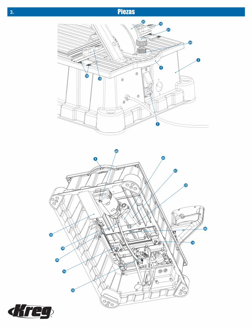
Piezas3.
4
2
24
15
21
25
1519
3
Logo on white, gray or any lighter shadewhen printing color
Logo on Pantone 2945 or any darker shade when printing color
Logo on white or light shade when printing grayscale
Logo on black or dark shade when printing grayscale
40
4
35
39
38
14
43
46
14
23
41
20

Ensamblaje 4.
Baje el brazo de control (1), desactive el bloqueo del brazo (2) en la parte posterior de la base de la máquina (3) y guíe el brazo de control hacia arriba hasta su posición más elevada. No deje el brazo fijo en la posición completamente elevada. Para transporte y almacenaje, baje el brazo de control y active el bloqueo del brazo.
Suelte el brazo de control.
La máquina Foreman cuenta con un sistema de eliminación de astillas que incluye un puerto de aspiración (5) de 11⁄4" y tornillos autorroscantes (6), cubierta de aspiración (7) y tornillos de cabeza plana (8), abrazaderas de manguera (9) y manguera de aspiración (10). Además de ayudar a mantener su área de trabajo limpia, la eliminación eficaz de astillas acelera el tiempo de taladrado y reduce la generación de calor, lo que extiende la vida útil de su broca para taladro. Una máquina Foreman con el sistema de eliminación de astillas instalado debe conectarse a una aspiradora industrial cuando está en uso. No conectar el sistema de recolección de astillas a la aspiradora industrial provoca que las astillas se acumulen en la manguera y en la cubierta de aspiración y que, con el tiempo, se obstruya la broca para taladro. La máquina Foreman puede utilizarse sin el sistema de recolección de astillas. Si instala el sistema y descubre que debe usar su máquina Foreman sin una aspiradora industrial, solo desconecte la manguera de la aspiradora de la cubierta.
Para instalar el sistema de eliminación de astillas, vuelque la máquina Foreman hacia un lado y desde el interior de la base de la máquina (3), inserte el puerto de aspiración (5) en el orificio en la parte posterior de la base y asegúrelo desde afuera con dos tornillos autorroscantes (6). Sujete la cubierta de aspiración (7) a la máquina con cuatro tornillos con cabeza en cruz (8).
Deslice las abrazaderas de manguera (9) sobre los extremos de la manguera de la aspiradora (10) y deslice los extremos de la manguera en el puerto de aspiración y la cubierta de aspiración. Para facilitar la desconexión de la manguera de la aspiradora de la cubierta cuando se trabaja mediante el panel de acceso (11), oriente la abrazadera frontal de la manguera con la cabeza del tornillo hacia el frente de la máquina. Apriete las abrazaderas y ponga la máquina Foreman de pie.
Instale el sistema de eliminación de astillas.
9
8
7
6
10
5
7
9
Desconecte la máquina de la fuente de alimentación antes de ensamblarla, abrir la cubierta de acceso o realizar cualquier ajuste.
No levante ni transporte la máquina por el brazo de control. Use siempre las manijas (4) de la parte frontal y posterior de la máquina.
El panel de acceso debe estar al ras de la cubierta de la máquina. Si necesita ajustes, utilice el siguiente procedimiento:
Coloque la máquina sobre caballetes para acceder a la parte inferior de la máquina. Coloque una guía recta a lo largo de la cubierta de la máquina (12) y el panel de acceso (11). Use la llave hexagonal de 3 mm (13) que se proporciona con la máquina para girar los niveladores de la cubierta (14).
Nivele el panel de acceso
11
12
Activar
Desactivar
2
14
13
4
14

Ensamblaje5.
Gire las manijas de bloqueo de la regla de 1⁄4 de vuelta (15) en dirección de las manecillas del reloj (posición de bloqueo). Si la regla puede moverse bajo presión moderada, apriete los tornillos de bloqueo de la guía (17). Gire las manijas en dirección contraria a las manecillas del reloj (posición de desbloqueo) y verifique que la regla se mueva libremente.
Si es necesario desensamblar los bloqueos de la regla, las bases del bloqueo de la regla (18) deben orientarse con la zona plana que se muestra en el dibujo hacia la regla.
Ajuste la presión del bloqueo de la regla
16
17
Para una unión fuerte, el tornillo para cavidades ocultas debe salir por el centro del grosor de la pieza de trabajo. Esto se logra ajustando la posición de la regla.
Desbloquee la regla (16) girando las manijas de bloqueo de la regla (15) en dirección contraria a las manecillas del reloj. Alinee el borde posterior de la regla con las marcas de grosor de la pieza de trabajo (19) incluidas en la cubierta de la máquina (12) que corresponden al grosor de su pieza de trabajo. Gire las manijas en dirección de las manecillas del reloj para bloquear la regla en su lugar.
(1) Ubique la regla según el grosor de la pieza de trabajo
Para crear uniones fuertes, debe ajustar la configuración de la máquina de manera que coincida con el grosor de la pieza de trabajo y el largo del tornillo. La máquina Foreman le permite hacerlo fácilmente en solo cuatro pasos sencillos:
Guía de selección de tornillosGrosor del material Largo del tornillo
1⁄2" (12 mm) 3⁄4" (19 mm)5⁄8" (16 mm) 1" (25 mm)3⁄4" (19 mm) 11⁄4" (32 mm)7⁄8" (22 mm) 11⁄2" (38 mm)
1" (25 mm) 11⁄2" (38 mm)
11⁄8" (29 mm) 11⁄2" (38 mm)
11⁄4" (32 mm) 2" (51 mm)
13⁄8" (35 mm) 2" (51 mm)
11⁄2" (38 mm) 21⁄2" (64 mm)
*El largo del tornillo se mide desde la parte inferior de la cabeza hasta la punta del tornillo.
11⁄4"
Kreg ofrece una línea completa de tornillos para cavidades ocultas para cada tipo y grosor de pieza de trabajo. Utilice este gráfico para seleccionar el largo correcto de los tornillos. Todos los tornillos para cavidad oculta de Kreg están disponibles en su concesionario Kreg o en línea en www.kregjig.com.
(2) Elija un tornillo
12
19 16 15
15
Funcionamiento
Rosca finaDebido a que el diámetro más pequeño y el paso de rosca de nuestros tornillos de rosca fina #7 reducen la posibilidad de partir el material, los recomendamos para maderas duras.
Roscado gruesoDebido al gran diámetro y al paso de rosca, nuestros tornillos de rosca gruesa #8 ofrecen un fuerte agarre en materiales compuestos y de madera suave como la madera contrachapada, el panel de aglomerado y fibra de densidad media (MDF, por sus siglas en inglés).
18
área plana

6.Funcionamiento
Baje el brazo de control (1) y mueva la broca para taladro (20) hacia delante hasta que la punta toque la regla (16). De ser necesario, gire la perilla de tope de profundidad de taladrado (21) en dirección contraria a las manecillas de reloj. Regrese el brazo de control a su posición previa y retraiga la broca.
Ubique el bloque de ajuste de profundidad de taladrado (22) frente a la regla con las marcas de longitud de tornillos hacia arriba. Ubique la muestra de bloque que corresponde al largo del tornillo que usará en la guía de taladrado (23). Baje el brazo de control e inserte la punta guía de la broca para taladro en el orificio de la muestra. Con el reborde de la broca para taladro frente a la muestra del bloque, gire la perilla de tope de profundidad de taladrado (21) en dirección de las manecillas del reloj hasta que se frene. Apriete la contratuerca de tope de profundidad (24) contra la base de la carcasa del brazo de la abrazadera (25). Regrese el brazo de control a la posición completamente elevada.
Nota: al volver a bloquear el brazo de control para transportar o almacenar, gire la perilla de tope de profundidad en dirección contraria a las manecillas del reloj para permitir que el brazo regrese a la posición inferior.
(3) Ajuste la profundidad de taladrado
20
1621
1
2522
24
Cómo usar el bloque de ajuste deprofundidad de taladrado
Guía y broca de taladro
Grosor del material Largo del tornillo Muestra de bloque de ajuste
Micro* ½" ¾" ¾"
Micro* y estándar ⅝" – 1⅛" 1", 1¼", 1½" 1", 1¼", 1½"
Estándar 1¼" – 1⅜" 2" 2"
Estándar y HD* 1½" 2½" 2½"*Accesorios opcionales
Cuando use el sistema de recolección de astillas, conecte una aspiradora industrial al puerto de aspiración (5) y enciéndala. Sostenga la pieza de trabajo de manera segura contra la regla (16) con las ubicaciones de las cavidades ocultas centradas en la guía de taladrado (23). Presione el botón de bloqueo del interruptor (30) del brazo de control (1) y jale del interruptor (31) para encender el motor del taladro. Permita que el motor alcance la velocidad máxima y baje el brazo de control con un movimiento suave hasta que el tope de profundidad haga contacto. Regrese el brazo de control a la posición completamente elevada y desactive el interruptor.
Taladrado de cavidades ocultas
Suba el brazo de control (1) a la posición completamente elevada. Ubique la pieza de trabajo frente a la regla (16) y bajo la almohadilla de la abrazadera (26). Gire la perilla de ajuste de la abrazadera (27) en dirección de las manecillas del reloj hasta que la almohadilla de la abrazadera entre en contacto con la pieza de trabajo. Gire la perilla en dirección contraria a las manecillas del reloj media vuelta. Apriete la contratuerca de la abrazadera (28) contra el brazo de la abrazadera (29). La abrazadera, ahora, está ubicada de manera que al bajar el brazo de control se aplique suficiente presión para asegurar la pieza de trabajo antes de que la broca para taladro ingrese a la madera.
(4) Ajuste la abrazadera de la pieza de trabajo
16
127
28
2629

Funcionamiento7.
Además de realizar los ajustes adecuados en la máquina, separar las cavidades ocultas de manera apropiada en la pieza de trabajo es importante para obtener una unión resistente. Para piezas estrechas como rieles, montantes y marcos, ubique las cavidades ocultas de 3⁄8" a 1⁄2" de cada borde. Las líneas sombreadas en la cinta métrica indican estos bordes, lo que elimina la necesidad de marcar las ubicaciones de las cavidades ocultas. Simplemente, alinee el borde de su pieza de trabajo con la línea sombreada y taladre. Para piezas anchas, como paneles y partes superiores de mesas, ubique la primera cavidad oculta a 2" del borde y en intervalos de 6" después de eso.
Ubicación de las cavidades ocultas
El tope de una pieza de trabajo se puede utilizar en cualquiera de los lados de la guía de taladrado si se desliza hacia afuera de la ranura en T de la regla y se voltea para que el extremo abierto del brazo de tope este orientado hacia el centro y se vuelve a instalar en la ranura en T.
Afloje el perno con cabeza de dado del tope de la pieza de trabajo (32) con la llave hexagonal de 3 mm (13), deslice el tope hacia la ubicación deseada y apriete el perno. Mantener la regla (16) centrada le permite usar la cinta métrica de medición central (33) para ubicar los topes. Anule un tope ubicando la pieza de trabajo sobre el tope y presionando el brazo de control accionado por resortes en el cuerpo del tope.
Cada brazo de tope puede mantenerse en posición retraída presionando el brazo contra el cuerpo del tope y, luego, deslizándolo hacia el perno con cabeza de dado que asegura al tope en la regla. La ranura del brazo proporciona un punto de sujeción. Para volver a activar el brazo de tope, aléjelo del perno.
Topes de la pieza de trabajo
16 13
33
32

8.Funcionamiento
Para evitar el uso no autorizado de la máquina, un orificio en elinterruptor (31) permite que esta se bloquee en la posición “off” (apagado) con un candado (no se incluye).
Bloqueo del interruptor
Puede almacenar la llave hexagonal (13), la punta de destornillador cuadrada #2 (34) y las guías y las brocas de taladrado micro y HD opcionales en la bandeja para accesorios (35) ubicada debajo del panel de acceso (11).
Almacenaje de accesorios
Para que tenga flexibilidad al fijar su máquina Foreman a una superficie de trabajo, las patas (36) de cada esquina de la base de la máquina poseen una superficie plana para fijar temporalmente la máquina a una mesa de trabajo así como un orificio de montaje (37) para una fijación permanente. (Los orificios aceptan tornillos para cavidades ocultas Kreg HD #14 de 21⁄2").
Ensamblaje seguro
36
37
31
35

Funcionamiento9.
1. Mantenga el motor limpio y la base de la máquina libre de astillas de madera y de polvo. Cuando se use sin una aspiradora industrial, retire regularmente el material de desecho del interior del gabinete o monte la máquina en un espacio abierto que prevenga la acumulación de material de desecho.
2. Lubrique periódicamente las varillas de guía con un lubricante seco como el lubricante Dri-Tool™ de Empire Manufacturing. Un lubricante seco no recolectará astillas de madera ni polvo y extenderá la vida útil de los rodamientos y las varillas de guía. El enlace del motor y el enlace asociado con el mecanismo de las abrazaderas deben lubricarse periódicamente para asegurar el libre movimiento.
3. Use una broca para taladro afilada. Puede taladrar entre 4000 y 5000 cavidades en roble antes de afilar la broca. Establezca su calendario de afilado según sus ajustes y el material que taladra. Mantener la broca para taladro limpia y libre de brea, resina y pegamento extiende significativamente la vida útil de la broca. Limpie periódicamente la broca para taladro con un limpiador como Blade Saver™ y aplique un lubricante seco como OptiCut-XL™, ambos de Empire Manufacturing. Incluso una broca para taladro sucia puede ser muy filosa, por eso, tenga cuidado al manipular los bordes de corte.
Kreg ofrece un servicio de afilado solo para brocas para taladro de cavidades ocultas estándares. Llame o envíe un correo electrónico a Servicio al Cliente al 800.447.8638 o a [email protected] para obtener más detalles.
Utilice el procedimiento adecuado que se describe a continuación cuando reemplace una broca para taladro o instale brocas para taladro micro o HD y guías para taladros opcionales.
Para proteger los topes de la pieza de trabajo (32) cuando se abre el panel de acceso (11), desactive las manijas de bloqueo de la regla (15) y mueva la guía (16) hacia atrás. Gire la perilla de ajuste de la abrazadera (27) en dirección contraria a las manecillas del reloj para levantar la almohadilla de la abrazadera (26). Abra el panel de acceso y active el soporte del panel (38). Retire el pasador de liberación del enlace (39) y deslice el motor (40) fuera de las varillas de guía (41).
Para reemplazar la broca para taladro (20), mueva el anillo del portabrocas de cambio rápido hacia delante y retire la broca para taladro. Inserte la nueva broca para taladro con vástago hexagonal en el portabrocas y libere el anillo. Deslice el motor hacia las varillas de guía e inserte la broca para taladro en la guía de taladro (23). Alinee el enlace del motor (43) con el orificio de enlace del motor e inserte el pasador de liberación del enlace. Desactive el soporte del panel de acceso y cierre el panel.
Cuando instale brocas y guías para taladro micro o HD opcionales, cambie las brocas como se detalla anteriormente. Después, desconecte la manguera de la aspiradora (10) de la cubierta de aspiración (7). Levante el panel de acceso de la máquina, retire los pivotes giratorios (44) del panel de acceso de los receptáculos giratorios (45) de la cubierta de la máquina (12).
Coloque el panel de acceso boca abajo sobre una superficie plana (por ejemplo, una mesa para sierra). Afloje el tornillo de fijación de la guía de taladro (46) con la llave hexagonal de 3 mm (13) y retire la guía para taladro. Mientras sostiene firmemente la cubierta de acceso contra la superficie plana, deslice la nueva guía para taladro en la abertura, gírela para que la cara angular quede contra la superficie plana y apriete el tornillo de fijación.
Instale el panel de acceso en la máquina y active el soporte del panel. Vuelva a conectar la manguera de la aspiradora a la cubierta de aspiración. Deslice el motor hacia las varillas de guía e inserte la broca para taladro en la guía de taladro. Conecte el enlace del motor (43) al motor con el pasador de liberación de enlace y cierre la cubierta.
Reemplazo o instalación de la broca para taladro yde la guía del taladro
41
45
11
46
12
13
44
42
40
41
20
41
44
Mantenimiento
23

Dos cavidades ocultas con nuestra separación recomendada de centro a centro de 9⁄16" caben completamente en la parte frontal de tablas gruesas de 3⁄4" que tienen al menos 23⁄8" de ancho. Solo configure la máquina para el material de 3⁄4" de espesor. Luego, con el extremo ingleteado de la pieza de trabajo contra la regla, taladre un orificio a 7⁄16" del talón del inglete y otro orificio a 25⁄16" del pie del inglete.
También, puede taladrar una cavidad oculta en cada lado de la junta a inglete en lugar de taladrar ambos orificios en el mismo lado.
Esquinas ingletadas
1⁄2"2 5⁄16"
10.Mantenimiento
Para garantizar la seguridad y la confiabilidad del producto, toda reparación del motor debe ser realizada por el centro de servicio de la fábrica Kreg Tool Company. Llame a Servicio al Cliente de Kreg (800.447.8638) para obtener una autorización de devolución e instrucciones de envío.
Servicio del motor
Para ver un diagrama y la lista de las piezas y ensambles de repuesto, diríjase a www.kregtool.com y revise la versión en línea de este manual.
1. Pruebe las piezas Pruebe la junta con piezas de desecho cortadas del mismo material de la pieza de trabajo final.
2. Asegúrese de usar tornillos Kreg Los tornillos Kreg tienen puntas afiladas y autorroscantes que cortan las fibras de la madera en vez de rasgarlas.
3. Use el tipo de tornillo adecuado Use tornillos de rosca fina para madera dura. Estos tornillos #7 cortan menos madera que los tornillos de rosca gruesa #8 utilizados para madera suave, madera contrachapada, MDF y panel de aglomerado.
4. Coloque el tornillo y retírelo Introduzca el tornillo hasta la mitad, sáquelo, limpie el exceso de fibras de madera del orificio y, luego, introduzca el tornillo completamente.
5. Reduzca la fricción Aplique cera de abejas u otro lubricante en el tornillo para reducir la fricción cuando este se introduzca en la pieza de trabajo.
6. Fíjelo con una abrazadera correctamente Centre las almohadillas de su Face Clamp™ de Kreg en la línea de junta con la almohadilla de la abrazadera grande en el lado opuesto a las cavidades ocultas. Regule la abrazadera para aplicar suficiente presión para mantener las piezas de trabajo al ras y estables, pero no tan firmes que dificulten la fijación con abrazaderas.
6 consejos para reducir el resquebrajamientoSugerencias
Piezas de repuesto

Sugerencias11.
Face Clamps™ de KregARTÍCULO #KHC-PREMIUM (3" DE ALCANCE), ARTÍCULO #KHC-LARGE (6" DE ALCANCE),ARTÍCULO #KHC-XLARGE (10" DE ALCANCE)Con opciones de 3", 6" y 10" de alcance, encontrará una Face Clamp™ Kreg que satisfaga sus necesidades.
Tamaños comunes de tablasTamaño nominal Tamaño real
1x2 3⁄4" x 11⁄2"
1x3 3⁄4" x 21⁄2"
1x4 3⁄4" x 31⁄2"
1x6 3⁄4" x 51⁄2"
1x8 3⁄4" x 71⁄4"
2x2 11⁄2" x 11⁄2"
2x4 11⁄2" x 31⁄2"
2x6 11⁄2" x 51⁄2"
2x8 11⁄2" x 71⁄4"
4x4 31⁄2" x 31⁄2"
6x6 51⁄2" x 51⁄2"
En un almacén de madera o una tienda para el hogar verá etiquetas en la madera como “1x6” y “2x4”. Estos tamaños “nominales” solían describir las dimensiones de la madera con corte áspero, antes de que fuese aserrada a su tamaño final o real. El tamaño real es siempre menor que el tamaño nominal.
Las marcas del grosor de la tabla en la plantilla Kreg se refieren al grosor real de la tabla. Por ejemplo, una madera de 1x4 tiene, en verdad, 3⁄4" de grosor, por lo que debe ajustar la plantilla en la marca de 3⁄4".
Tamaño nominal vs. tamaño real
Broca para taladro HDARTÍCULO# DB210-HDBBroca para taladro de repuesto para la máquina DB210 Foreman G2
Guía de taladro y broca para taladro HD Kreg Jig®
ARTÍCULO# DB210-HDBBDiseñado para utilizarse con materiales de “2 pulgadas”, este sistema para trabajo pesado taladra cavidades para tornillos de cavidad oculta #14 de 21⁄2".
Disponibles en su distribuidor de Kreg o en línea en www.kregtool.com.
Guía de taladro y broca para taladro Micro Pocket™ARTÍCULO# DB210-MBBCon un diámetro de orificio un 25% más pequeño que nuestras cavidades ocultas estándares, la guía de taladro Micro Pocket™ le permite crear cavidades ocultas compactas en materiales delgados y reparaciones en espacios pequeños.
Accesorios opcionales
4"
31⁄2"
11⁄2"
2"
Nominal(2" x 4")
Real(11⁄2" x 31⁄2")

Máquina para cavidades ocultas semiautomática Foreman DB210Kreg Tool Company garantiza que la máquina para cavidades ocultas semiautomática Foreman DB210 está libre de defectos de materiales y mano de obra por un período de un (1) año a partir de la fecha de entrega al comprador original. La guía para taladro que se proporciona con la máquina tiene garantía de por vida. Esta garantía es solo para compras a distribuidores autorizados de los productos Kreg y se aplica solo al comprador original. Esta garantía no es transferible.
Durante el periodo de garantía, Kreg Tool Company, a su criterio, reparará o reemplazará la máquina o cualquier componente de esta que presente defectos demostrados. Esta garantía se aplica solo si se usa el producto de acuerdo con todas las instrucciones relacionadas con el funcionamiento, el mantenimiento y la seguridad establecidas en catálogos, manuales e instrucciones proporcionados por Kreg Tool Company.
Esta garantía no se aplica a:(1) Desgaste normal, corrosión, abrasión o reparaciones necesarias por daños causados por fenómenos o desastres naturales(2) Artículos que se consuman o necesita en un reemplazo a causa del desgaste normal(3) El costo del retiro de componentes si el retiro es autorizado por Kreg Tool Company(4) Envío al local de reparación de Kreg Tool Company(5) Reinstalación de las piezas retiradas para el servicio de garantía
Esta garantía se anulará y no tendrá validez si el producto se sujeta a cualquiera de las siguientes condiciones:(1) Mal uso, maltrato, servicio inadecuado o almacenamiento inadecuado(2) Daños causados por accidentes, negligencia u otras circunstancias fuera del control de Kreg Tool Company(3) Modificaciones, desensamblaje, manipulación, alteraciones o reparaciones realizadas fuera de los locales de Kreg Tool Company sin la autorización de Kreg Tool Company(4) Remoción de la etiqueta con el número de serie original
Para obtener el servicio de garantía, póngase en contacto con Kreg Tool Company:Kreg Tool Company201 Campus DriveHuxley, IA 50124800.447.8638
NO DEVUELVA LA MÁQUINA AL DISTRIBUIDOR PARA EL SERVICIO DE GARANTÍA. Se exigirá una prueba de compra antes de proporcionar soluciones según los términos de esta garantía. Kreg Tool Company no asume ninguna responsabilidad por productos devueltos sin autorización previa. La responsabilidad de Kreg Tool Company según esta garantía se limita exclusivamente a la reparación o el reemplazo, a criterio de Kreg Tool Company, de los productos hallados defectuosos después de que se entreguen a Kreg Tool Company y esta los inspeccione. Bajo ninguna circunstancia Kreg Tool Company será responsable por daños accidentales o resultantes causados por productos defectuosos; asimismo, la responsabilidad de Kreg Tool Company no será superior al precio de compra del producto pagado por el comprador original.
La presente es la única garantía de Kreg Tool Company. Cualquier otra garantía que pudiera ser implícita por la ley, incluida cualquier garantía de comerciabilidad o idoneidad para un fin particular, están por tanto limitadas al tiempo a la duración de esta garantía. Kreg Tool Company no será responsable por pérdidas, daños o gastos relacionados de forma directa o indirecta al uso de este producto ni por ninguna otra causa o daño resultante, lo que incluye pero no se limita a pérdidas de tiempo, molestias y pérdidas de producción. La garantía descrita en el presente documento no puede modificarse. Además, ninguna garantía adicional, expresa o implícita, puede ofrecerse por Kreg Tool Company ni en su nombre.
Esta garantía entra en vigor solo si se completa la tarjeta de registro adjunta de manera adecuada y se envía a Kreg Tool Company dentro de los diez (10) días que siguen a la fecha de entrega al comprador original.
Conserve este formulario para sus registros.La siguiente información será útil en caso deque se requiera el servicio de la garantía. Conserveuna copia de su factura de compra con este formulario.Fecha de compra: ____/____/____Comprado en:Número de serie (ubicado en el lateral de la máquina):
12.Garantía
Kreg Tool Company, 201 Campus Drive, Huxley, IA 50124800.447.8638 • www.kregtool.com

13.
www.kregtool.com • 800.447.8638