daylighting calculations in visual 2012 (beta) calculations in...daylighting calculations in visual...
TRANSCRIPT
Daylighting Calculations in Visual 2012 (Beta)
This is an introduction to the beta-version of the daylighting calculation features in Visual 2012. The first section is guide to doing daylighting calculations in Visual 2012: the information you need to supply and output that you can get. The second section gives some details about the data and methods Visual 2012 uses to provide daylighting calculations.
Summary 1. Prepare your project
If you have an exterior project and you are interested in the illuminance and shadows produced outdoor by the sun and sky, you need add nothing to the drawing of your project. If you have an interior project you need to add windows. Windows are just additional surfaces you place directly on opaque walls. Window surfaces are given the property of transparency. You need to nothing more; Visual automatically cuts the appropriate holes in the walls to let sunlight and sky light into interior spaces.
2. Enter additional data required for daylighting calculations a. You need to specify the location (latitude and longitude) of your project site and its
orientation with respect to North. b. You need to specify the date and time for the calculations. Visual will automatically
access data from its own weather station data base and determine the sun and sky conditions at your project site for the date and time you specify.
c. You need to indicate if your windows are multiple glazing.
3. Calculate Visual 2012 can calculate the electric lighting only, daylighting only, or both. The illuminance can be direct only (luminaires, sun, and sky) or include the effects of interreflected light).
4. Render If your calculation includes daylighting, a rendering produced by Visual 2012 will include its effects.

Guide to doing daylighting in Visual 2012
1. Getting the right software and data files. a. Make sure your software is current. Go to the following site and download the latest
version of Visual 2012: http://www.visual-3d.com/Downloads/Software/Setup/2010/Software.aspx
b. Get the additional data files you need to activate the daylighting features in Visual 2012 and the weather data. Go to the following site to download the files: http://www.visual-
3d.com/Tools/Download.aspx?file=Visual2012DaylightSetup. This additional setup will automatically place the daylighting files in the proper folders.
c. Your installation of Visual 2012 will now have an additional tab on the ribbon bar labeled "Daylighting", as shown here.
2. Entering basic daylighting data. The Daylighting tab in the ribbon bar has three areas: Site, Sky Conditions, and Windows. Each providing a place for you to input some of the data Visual 2012 needs to do daylighting calculations. In addtion, the Calculate and Render buttons are also accessible from the Daylighting tab.
a. Site
i. Building location
1. Latitude 2. Longitude
Building location is specified by the latitude and longitude on the globe. Latitude is positive/negative for North/South, respectively. Longitude is positive/negative for East/West, respectively. If you are connected to the Internet, you can use the location finder to get the latitude and longitude of your site. Simply put in as much of an address as you have in the "Location" input box, and click on the magnifying glass. A dropdown list will appear with the possible matches to the information you gave. Select one and click OK. That site's latitude and longitude will be place in the appropriate input box.
Daylighting Tab on the ribbon bar
Site information cells on the Daylighting Tab

ii. Building orientation 1. Degrees of "local north" or "plan-view up" from geographic north
This specifies the orientation of the building. It gives the angle that geographic north is from the positive y-direction in the Visual 2012 drawing of your building. Angles are in degrees, measured clockwise from the positive y-direction. Specifying "90" means that geographic north is off directly to the right of your Visual 2012 drawing.
iii. Ground reflectance
1. Diffuse reflectance of ground around building Daylighting calculations in Visual always and automatically consider a ground plane, extending from your building out to the horizon. It is assumed to have the diffuse reflectance you specify. Note that the ground is assumed to be a plane with a z coordinate of zero. If you want your calculation to include other areas around your building with a different reflectance, such as parking lots, walkways, and such, simply add them to the project, specifying their diffuse reflectance.
b. Sky conditions
i. Date and time
The date and time give the time of day for the daylighting calculations which is necessary to determine the position of the sun and to determine the appropriate weather data to be used. Date and time are specified by clicking choices from the date calendar dropdown and the time quarter-hour dropdown that appear when your click on their respective buttons. The current date is shown circled in the date calendar.
Dropdown box from the Location cell on the Daylighting Tab
Sky Condition information cells on the Daylighting Tab

Dropdown box from the Time cell on the Daylighting Tab
Dropdown box from the Date cell on the Daylighting Tab

ii. Sky and Sun conditions
The default condition for daylighting calculations in Visual 2012 is that the sun and sky conditions are determined from available weather data appropriate for the location you have specified and for the date and time of the calculation. Visual automatically searches its weather station photometric data base and uses the appropriate information. Instead of sky conditions being determined by local weather data, you can specify one of 15 CIE sky types from the Sky Conditions dropdown, shown above. If you leave the "Horizontal Sky Illuminance" and "Direct Sun Illuminance" input cells empty, Visual 2012 uses IES standard procedures to determine the sun and sky illuminances used for calibrating that CIE sky. Or, you can input your own values as may be required for some parametric daylighting studies.
c. Windows
i. Number of panes
ii. Glass thickness An important aspect of windows is the how their transmittance changes with incident angle. The effect is large and important for incident angles larger than about 45 degrees, particularly with multiple-glazed fenestration. In order to properly determine this effect, Visual 2012 must know the number of layers of glass in your windows and the straight-through (perpendicular) transmittance.
Window information cells on the Daylighting Tab
Dropdown box from the Sky Condition cell on the Daylighting Tab

The number of layers (panes) is specified in the "Number of Panes" dropdown. Glass thickness can also be specified here. These properties are assumed to apply to all windows in your project. Window transmittance is specified as a property of the surface that represents the window, and is discussed in the next section.
3. Daylight delivery a. Apertures New to Visual 2012 is the ability to specify apertures (holes or openings) in an otherwise opaque surface. Apertures are simply added to your drawing as additional surfaces. They have a special property: an "image preserving" transmittance. Visual 2012 now supports two types of surface transmittance: diffuse and image preserving. "Diffuse" means that the amount of light passing through the surface is not only reduced but is also scattered uniformly as it passes through the surface, while "image preserving" means the amount of light passing through the surface may be reduced but its direction of travel is not. Similar to the difference between the way several sheets of wax paper transmit light and the way plastic food wrap transmits light. Apertures can be placed anywhere in a project, but if placed directly on another surface, they cut a hole in that surface. This is how you can add windows to your project. b. Windows Perhaps the easiest way to add windows to your project is as follows:
i. Click on the "Align Cursor and Plane to Current View" button and select the surface to which you want to add windows.

ii. Now draw an aperture on that surface. The aperture can have any shape, but since most windows are rectangular, the rectangle drawing tool can be the quickest way.
Multiple apertures (windows) can be created by copying or arraying a single window.
iii. Specify the transmittance by clicking Properties and selecting the window. The transmittance type must be set to "Transparent". The transmittance value is in percent and is the perpendicular or "straight through" transmittance.
If the transmittance is set to 100% then the aperture is just an opening, and no light is lost. Any value less than 100% means the surface has an image preserving transmittance. Note that even very clear, high-quality window glass rarely has a perpendicular transmittance greater than 90%. Commercial window data often supplies this value, or it can be determined from public window analysis software: http://windows.lbl.gov/software/
c. Lightshelves Lightshelves can be added as just another surface to the project; either inside or outside a room. They will act as both shading elements and light reflecting elements. Note that, like all other surface reflectances in Visual 2012, they are assumed to be perfectly diffuse. d. Shades and blinds The effects of Shades and blinds can be modeled by adding surfaces just behind a window that have a diffuse reflectance.

e. External buildings External buildings may have important shading effects on your project and should be included. They can most simply be built using the "Structure" command on the "Construct" tab. They should be given an appropriate reflectance. Note, again, that all reflectances are assumed to be perfectly diffuse. External buildings and other structures and also have image preserving transmissive surfaces.
4. Daylighting calculation results a. Illuminance Calculations The dropdown from the "Calculate" button displays the options for daylighting analysis:
For interior and exterior project, you can calculate the effects of direct light only or direct and interreflected light. For each of these four possibilities you can calculate the effects of electric lighting only, daylighting only, or both. b. Renderings If you have performed daylighting calculations then a rendering of the project will show the effect of sun and skylight, as shown here:

How Daylighting is implemented in Visual 2012
This section of the documentation gives an overview of the process and some of the details of how Visual 2012 does daylighting calculations 1. Basic calculations Visual 2012 uses a radiative transfer model (sometimes referred to as "radiosity") to predict the effect of light sources on a space and to calculate illuminance levels at an array of points. The process is briefly described as follows.
a. Geometric preparation The surfaces drawn (or imported) in Visual describe the rooms, buildings, and objects in a project are sufficient to give a complete geometric description of the space, and luminaires' placement and photometric data fully describe the light input into a space. But for an accurate lighting analysis, the surfaces are usually too big, and need to be broken up, "discretized."
To do this Visual 2012 does an initial, fast analysis of the effect of luminaires, and using that data discretizes user-provided surfaces into smaller pieces, depending on how the light is distributed. These discretized surfaces are the ones used in Visual to perform lighting calculations.
Walls of a room as drawn by the user, with luminaires

After the discretization is completed, Visual 2012 does an occlusion or blocking analysis to see what view each discretized surface has of all the other discretized surfaces. The view of some discretized surfaces may be blocked by other surfaces or a surface may face away from another surface; in which case they cannot trade light by interreflection. This analysis is necessary to determine how light interreflects between all the surfaces. b. Light input For typical lighting calculations, the light input to the space is determined by the number and placement of luminaires, and the photometric data (given in an IES file) that describes them. The amount of light incident on each discretized surface from all the luminaires is determined. This includes the effects of occlusion. Note that Visual 2012 does NOT take spectral effects into account. All light sources are assumed to be spectrally flat; that is, the same amount of radiant power at all visible wavelengths. Similarly, Visual 2012 does NOT take spectral effects of reflectance into account. A surface with a user-specified reflectance,
is assumed to have that reflectance at all visible wavelengths. These two assumptions about radiant power and reflectance are together are commonly called the "gray assumption" and are certainly adequate for illuminance calculations in all cases except those involving deeply color saturated, narrow wavelength band light sources. c. Interreflections Another mathematical analysis then determines how all discretized surfaces interreflect light amongst themselves. The amount of light that is "traded" back-and-forth depends on the view that a pair of surfaces have of each other and on their reflectance. The result is the final amount of light reaching each discretized surface, and accounts for both the light that reaches the surfaces directly, and the light that reaches them by interreflection. d. Illuminance calculations
i. direct A calculation is done for each point in a calculation zone to determine what, if any, illuminance is produced at that point by all the luminaires. Some points cannot "see" a luminaire because of blocking or orientation, and so are not illuminated by that luminaire.
Walls as discretized by Visual 2012 using information from luminaires.
ii. interreflected A calculation is done for each point in a calculation zone to determine what, if any, illuminance is produced at that point by all the discretized surfaces. Some points cannot "see" a surface because of blocking or orientation, and so are not illuminated by that surface.
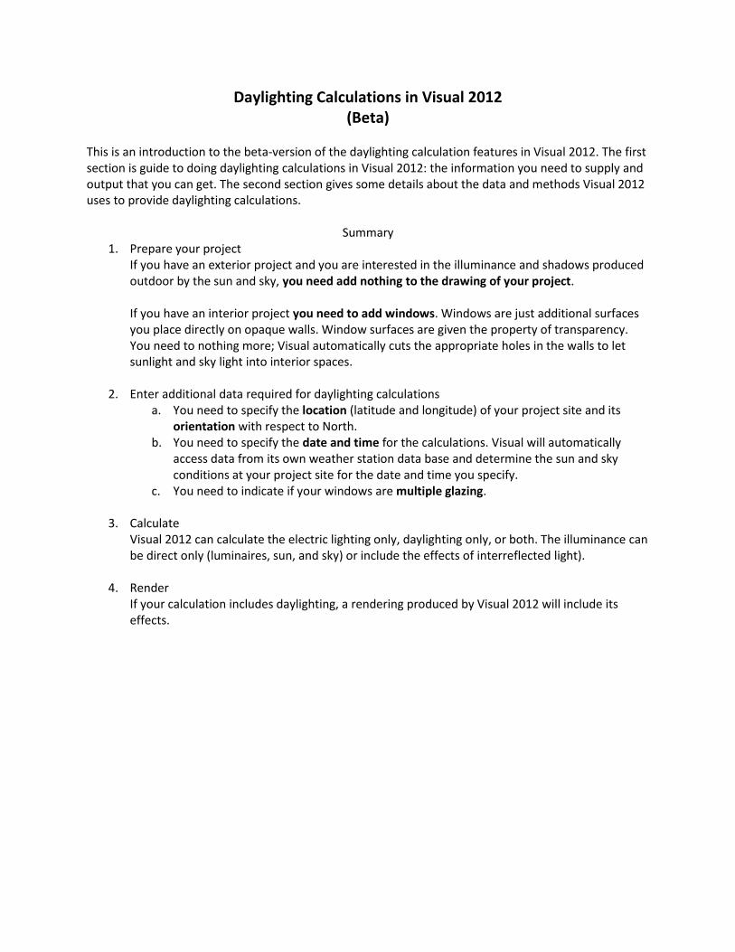
2. Sky and Sun as light sources The basic process described above is used for daylighting calculations as well. In addition to, or instead of, luminaires, the sky and sun act as light sources. The sky is treated as a collection of luminous patches that form a dome over the project. The sky dome's size, orientation, discretization, and luminance distribution are determined from user input data: location, date, time, building orientation, and weather data. The distribution and size of the patches are determined at calculation time, since both depend on the sky luminance distribution and the position of the sun. Smaller patches are used where the sky luminance changes greatly with angle. Here is a view from outside the sky dome of a typical array of sky patches.
The hole in the array of sky patches leaves room for the sun. The hole is considerably larger than the ½-degree circle the sun subtends, because all weather-data-based photometric information that reports light coming from the sun includes about 5 degrees of the sky. The sun is modeled as a luminous disc that subtends an angle of about ½-degree and has a position that depends on location, orientation, date, and time. The luminous power of the sky patches and sun is determined in one of three ways:
a. Weather data appropriate for the project site is used to determine the luminance distribution of the sky and the direct illuminance, if any, produced by the sun.
b. The user provides a CIE sky number which determined the relative sky luminance distribution. The standard IES procedure is used to make the sky luminances absolute and define the direct illuminance, if any, produced by the sun.
c. The user provides a CIE sky number and values for the horizontal illuminance produced by the sky and the direct illuminance of the sun.
Sky dome with sun hole.
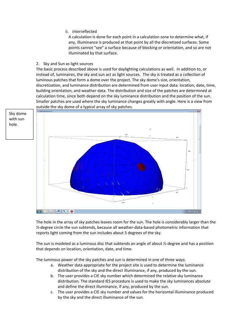
THIS ENTIRE PROCESS IS AUTOMATIC AND CARRIED OUT BY VISUAL 2012 WHENEVER A DAYLIGHTING CALCULATION IS PERFORMED. THE USER NEED TO NOTHING MORE THAN PROVIDE THE SIMPLE DATA DESCRIBED ABOVE IN THE FIRST SECTION OF THE DOCUMENTATION. THE EFFECTS OF THE SKY AND SUN ARE APPARENT IN THE CALCUATIONS AND RENDERINGS, BUT THE SKY DOME AND SUN ARE NOT VISIBLE IN VISUAL. 3. Weather data Photometric data from more than 2000 weather stations from around the world have been assembled into the primary weather data file that supports Visual 2012 daylighting calculations. At each station, hourly data is available that describes the illuminance from the sun and sky, and information from which the sky luminance distribution can be constructed. Here is a Google Earth view of the weather station locations in the North American continent:
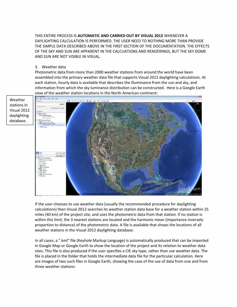
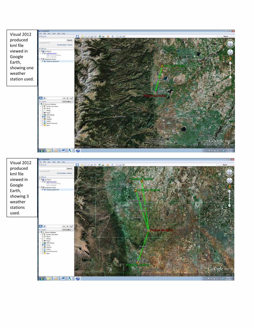
If the user chooses to use weather data (usually the recommended procedure for daylighting calculations) then Visual 2012 searches its weather station data base for a weather station within 25 miles (40 km) of the project site, and uses the photometric data from that station. If no station is within this limit, the 3 nearest stations are located and the harmonic mean (importance inversely proportion to distance) of the photometric data. A file is available that shows the locations of all weather stations in the Visual 2012 daylighting database. In all cases, a ".kml" file (Keyhole Markup Language) is automatically produced that can be imported in Google Map or Google Earth to show the location of the project and its relation to weather data sites. This file is also produced if the user specifies a CIE sky type, rather than use weather data. The file is placed in the folder that holds the intermediate data file for the particular calculation. Here are images of two such files in Google Earth, showing the case of the use of data from one and from three weather stations:
Weather stations in Visual 2012 daylighting database.
Visual 2012 produced kml file viewed in Google Earth, showing one weather station used.
Visual 2012 produced kml file viewed in Google Earth, showing 3 weather stations used.

4. Windows Windows are treated as image-preserving transmissive surfaces. They are characterized by a single, perpendicular (straight through) transmittance value, supplied by the user. From this value, and the user-supplied number of layers or panes in the fenestration, the angular transmittance function is calculated and used wherever required. Here is a plot of a typical transmittance as a function of incident angle for single, double, and triple glazing; each pane has the same glass type.
The only data required of the user is the perpendicular transmittance through the entire fenestration system.
5. Window data In many cases, window manufacturer's data provides the total, perpendicular transmittance of a fenestration system being considered for use on a project. Additionally, software and a supporting database is available to determine this data for a window-system made up from a wide variety of commercially available glass types: http://windows.lbl.gov/software/window/window.html
20 40 60 80Incidence Angle
0.2
0.4
0.6
0.8
Transmittance