day 1 · day 1 today on the advent calendar - nano-board (arduino compatible board) nano-board –...
TRANSCRIPT


2
2018 Arduino Advent Calendar . . . . . . . . . . . . . . . . . . . . . . . . . . 3
Day 1 . . . . . . . . . . . . . . . . . . . . . . . . . . . . . . . . . . . . . . . . . . . . . .4Today on the Advent Calendar . . . . . . . . . . . . . . . . . . . . . . . . . . . . . . . 4Nano-Board – Arduino compatible board . . . . . . . . . . . . . . . . . . . . . . . 4Preparing the Nano . . . . . . . . . . . . . . . . . . . . . . . . . . . . . . . . . . . . . . . 4Software installation in a nutshell . . . . . . . . . . . . . . . . . . . . . . . . . . . . 4mBlock 3 . . . . . . . . . . . . . . . . . . . . . . . . . . . . . . . . . . . . . . . . . . . . . . . 4LED flashes . . . . . . . . . . . . . . . . . . . . . . . . . . . . . . . . . . . . . . . . . . . . . . 5How the program works . . . . . . . . . . . . . . . . . . . . . . . . . . . . . . . . . . . . 6Transferring the program to the Nano board . . . . . . . . . . . . . . . . . . . . . 6
Day 2 . . . . . . . . . . . . . . . . . . . . . . . . . . . . . . . . . . . . . . . . . . . . . . 7Today on the Advent Calendar . . . . . . . . . . . . . . . . . . . . . . . . . . . . . . . 7patch panel . . . . . . . . . . . . . . . . . . . . . . . . . . . . . . . . . . . . . . . . . . . . . 7LEDs . . . . . . . . . . . . . . . . . . . . . . . . . . . . . . . . . . . . . . . . . . . . . . . . . . . 7Alternating flashing light . . . . . . . . . . . . . . . . . . . . . . . . . . . . . . . . . . . . 7The program . . . . . . . . . . . . . . . . . . . . . . . . . . . . . . . . . . . . . . . . . . . . 8How the program works . . . . . . . . . . . . . . . . . . . . . . . . . . . . . . . . . . . . 8
Day 3 . . . . . . . . . . . . . . . . . . . . . . . . . . . . . . . . . . . . . . . . . . . . . .9Today on the Advent Calendar . . . . . . . . . . . . . . . . . . . . . . . . . . . . . . . 9Switching wire . . . . . . . . . . . . . . . . . . . . . . . . . . . . . . . . . . . . . . . . . . . 9LEDs flash with adjustable speed . . . . . . . . . . . . . . . . . . . . . . . . . . . . . 9The program . . . . . . . . . . . . . . . . . . . . . . . . . . . . . . . . . . . . . . . . . . . . 9How the program works . . . . . . . . . . . . . . . . . . . . . . . . . . . . . . . . . . . . 9
Day 4 . . . . . . . . . . . . . . . . . . . . . . . . . . . . . . . . . . . . . . . . . . . . . 10Today on the Advent Calendar . . . . . . . . . . . . . . . . . . . . . . . . . . . . . . .10LEDs flash faster and faster . . . . . . . . . . . . . . . . . . . . . . . . . . . . . . . . .10The program . . . . . . . . . . . . . . . . . . . . . . . . . . . . . . . . . . . . . . . . . . . .10How the program works . . . . . . . . . . . . . . . . . . . . . . . . . . . . . . . . . . . .10
Day 5 . . . . . . . . . . . . . . . . . . . . . . . . . . . . . . . . . . . . . . . . . . . . . 11Today on the Advent Calendar . . . . . . . . . . . . . . . . . . . . . . . . . . . . . . . 11Resistors and their colour codes . . . . . . . . . . . . . . . . . . . . . . . . . . . . . . 11Pushbutton . . . . . . . . . . . . . . . . . . . . . . . . . . . . . . . . . . . . . . . . . . . . . . 11Switching LEDs with pushbutton . . . . . . . . . . . . . . . . . . . . . . . . . . . . . 11The program . . . . . . . . . . . . . . . . . . . . . . . . . . . . . . . . . . . . . . . . . . . . 12How the program works . . . . . . . . . . . . . . . . . . . . . . . . . . . . . . . . . . . . 12
Day 6 . . . . . . . . . . . . . . . . . . . . . . . . . . . . . . . . . . . . . . . . . . . . . 13Today on the Advent Calendar . . . . . . . . . . . . . . . . . . . . . . . . . . . . . . . 13Switching LEDs on the angel wing . . . . . . . . . . . . . . . . . . . . . . . . . . . . 13The program . . . . . . . . . . . . . . . . . . . . . . . . . . . . . . . . . . . . . . . . . . . . 13How the program works . . . . . . . . . . . . . . . . . . . . . . . . . . . . . . . . . . . . 13
Day 7 . . . . . . . . . . . . . . . . . . . . . . . . . . . . . . . . . . . . . . . . . . . . . 14Today on the Advent Calendar . . . . . . . . . . . . . . . . . . . . . . . . . . . . . . . 14LEDs flash randomly . . . . . . . . . . . . . . . . . . . . . . . . . . . . . . . . . . . . . . . 14The program . . . . . . . . . . . . . . . . . . . . . . . . . . . . . . . . . . . . . . . . . . . . 14How the program works . . . . . . . . . . . . . . . . . . . . . . . . . . . . . . . . . . . . 14Improved version of the program . . . . . . . . . . . . . . . . . . . . . . . . . . . . . 14
Day 8 . . . . . . . . . . . . . . . . . . . . . . . . . . . . . . . . . . . . . . . . . . . . . 16Today on the Advent Calendar . . . . . . . . . . . . . . . . . . . . . . . . . . . . . . .16Dimming LEDs . . . . . . . . . . . . . . . . . . . . . . . . . . . . . . . . . . . . . . . . . . .16The program . . . . . . . . . . . . . . . . . . . . . . . . . . . . . . . . . . . . . . . . . . . .16How the program works . . . . . . . . . . . . . . . . . . . . . . . . . . . . . . . . . . . .16
Day 9 . . . . . . . . . . . . . . . . . . . . . . . . . . . . . . . . . . . . . . . . . . . . . 17Today on the Advent Calendar . . . . . . . . . . . . . . . . . . . . . . . . . . . . . . . 17Chaser light on the angel wing . . . . . . . . . . . . . . . . . . . . . . . . . . . . . . . 17The program . . . . . . . . . . . . . . . . . . . . . . . . . . . . . . . . . . . . . . . . . . . . 17How the program works . . . . . . . . . . . . . . . . . . . . . . . . . . . . . . . . . . . . 17
Day 10 . . . . . . . . . . . . . . . . . . . . . . . . . . . . . . . . . . . . . . . . . . . . 18Today on the Advent Calendar . . . . . . . . . . . . . . . . . . . . . . . . . . . . . . .18battery box . . . . . . . . . . . . . . . . . . . . . . . . . . . . . . . . . . . . . . . . . . . . . .18Chaser light with changing speed . . . . . . . . . . . . . . . . . . . . . . . . . . . . .18The program . . . . . . . . . . . . . . . . . . . . . . . . . . . . . . . . . . . . . . . . . . . .18How the program works . . . . . . . . . . . . . . . . . . . . . . . . . . . . . . . . . . . .18
Day 11 . . . . . . . . . . . . . . . . . . . . . . . . . . . . . . . . . . . . . . . . . . . . . 19Today on the Advent Calendar . . . . . . . . . . . . . . . . . . . . . . . . . . . . . . . 19RGB LEDs . . . . . . . . . . . . . . . . . . . . . . . . . . . . . . . . . . . . . . . . . . . . . . . 19Different colours on one RGB LED . . . . . . . . . . . . . . . . . . . . . . . . . . . . 19The program . . . . . . . . . . . . . . . . . . . . . . . . . . . . . . . . . . . . . . . . . . . 20How the program works . . . . . . . . . . . . . . . . . . . . . . . . . . . . . . . . . . . 20
Day 12 . . . . . . . . . . . . . . . . . . . . . . . . . . . . . . . . . . . . . . . . . . . . 21Today on the Advent Calendar . . . . . . . . . . . . . . . . . . . . . . . . . . . . . . . 21RGB colour mixing with PWM . . . . . . . . . . . . . . . . . . . . . . . . . . . . . . . . 21Connecting LEDs . . . . . . . . . . . . . . . . . . . . . . . . . . . . . . . . . . . . . . . . . . 21How the program works . . . . . . . . . . . . . . . . . . . . . . . . . . . . . . . . . . . . 21
Day 13 . . . . . . . . . . . . . . . . . . . . . . . . . . . . . . . . . . . . . . . . . . . . 22Today on the Advent Calendar . . . . . . . . . . . . . . . . . . . . . . . . . . . . . . 22Chaser light in two directions . . . . . . . . . . . . . . . . . . . . . . . . . . . . . . . 22The program . . . . . . . . . . . . . . . . . . . . . . . . . . . . . . . . . . . . . . . . . . . 22How the program works . . . . . . . . . . . . . . . . . . . . . . . . . . . . . . . . . . . 22
Day 14 . . . . . . . . . . . . . . . . . . . . . . . . . . . . . . . . . . . . . . . . . . . . 23Today on the Advent Calendar . . . . . . . . . . . . . . . . . . . . . . . . . . . . . . 23potentiometers . . . . . . . . . . . . . . . . . . . . . . . . . . . . . . . . . . . . . . . . . . 23Control chaser light with a potentiometer . . . . . . . . . . . . . . . . . . . . . . 23The program . . . . . . . . . . . . . . . . . . . . . . . . . . . . . . . . . . . . . . . . . . . 23How the program works . . . . . . . . . . . . . . . . . . . . . . . . . . . . . . . . . . . 23
Day 15 . . . . . . . . . . . . . . . . . . . . . . . . . . . . . . . . . . . . . . . . . . . . 24Today on the Advent Calendar . . . . . . . . . . . . . . . . . . . . . . . . . . . . . . 24Sensor contact made of plasticine . . . . . . . . . . . . . . . . . . . . . . . . . . . 24The program . . . . . . . . . . . . . . . . . . . . . . . . . . . . . . . . . . . . . . . . . . . 24How the program works . . . . . . . . . . . . . . . . . . . . . . . . . . . . . . . . . . . 24
Day 16 . . . . . . . . . . . . . . . . . . . . . . . . . . . . . . . . . . . . . . . . . . . . 25Today on the Advent Calendar . . . . . . . . . . . . . . . . . . . . . . . . . . . . . . 25RGB colour mixing with PWM . . . . . . . . . . . . . . . . . . . . . . . . . . . . . . . 25The program . . . . . . . . . . . . . . . . . . . . . . . . . . . . . . . . . . . . . . . . . . . 25How the program works . . . . . . . . . . . . . . . . . . . . . . . . . . . . . . . . . . . 25
Day 17 . . . . . . . . . . . . . . . . . . . . . . . . . . . . . . . . . . . . . . . . . . . . . 26Today on the Advent Calendar . . . . . . . . . . . . . . . . . . . . . . . . . . . . . . 26RGB colour spectrum . . . . . . . . . . . . . . . . . . . . . . . . . . . . . . . . . . . . . 26The program . . . . . . . . . . . . . . . . . . . . . . . . . . . . . . . . . . . . . . . . . . . 26How the program works . . . . . . . . . . . . . . . . . . . . . . . . . . . . . . . . . . . 26
Day 18 . . . . . . . . . . . . . . . . . . . . . . . . . . . . . . . . . . . . . . . . . . . . 27Today on the Advent Calendar . . . . . . . . . . . . . . . . . . . . . . . . . . . . . . .27LED cube . . . . . . . . . . . . . . . . . . . . . . . . . . . . . . . . . . . . . . . . . . . . . . .27The program . . . . . . . . . . . . . . . . . . . . . . . . . . . . . . . . . . . . . . . . . . . .27How the program works . . . . . . . . . . . . . . . . . . . . . . . . . . . . . . . . . . . .27
Day 19 . . . . . . . . . . . . . . . . . . . . . . . . . . . . . . . . . . . . . . . . . . . . 28Today on the Advent Calendar . . . . . . . . . . . . . . . . . . . . . . . . . . . . . . 28LED cube with realistic cube effect . . . . . . . . . . . . . . . . . . . . . . . . . . . 28The program . . . . . . . . . . . . . . . . . . . . . . . . . . . . . . . . . . . . . . . . . . . 28How the program works . . . . . . . . . . . . . . . . . . . . . . . . . . . . . . . . . . . 28
Day 20 . . . . . . . . . . . . . . . . . . . . . . . . . . . . . . . . . . . . . . . . . . . . 29Today on the Advent Calendar . . . . . . . . . . . . . . . . . . . . . . . . . . . . . . 29Analog level display with LEDs . . . . . . . . . . . . . . . . . . . . . . . . . . . . . 29The program . . . . . . . . . . . . . . . . . . . . . . . . . . . . . . . . . . . . . . . . . . . 29How the program works . . . . . . . . . . . . . . . . . . . . . . . . . . . . . . . . . . . 29
Day 21 . . . . . . . . . . . . . . . . . . . . . . . . . . . . . . . . . . . . . . . . . . . . 30Today on the Advent Calendar . . . . . . . . . . . . . . . . . . . . . . . . . . . . . . 30Controlling lighting effects with sensor contacts . . . . . . . . . . . . . . . . . 30The program . . . . . . . . . . . . . . . . . . . . . . . . . . . . . . . . . . . . . . . . . . . 30How the program works . . . . . . . . . . . . . . . . . . . . . . . . . . . . . . . . . . . 30
Day 22 . . . . . . . . . . . . . . . . . . . . . . . . . . . . . . . . . . . . . . . . . . . . 32Today on the Advent Calendar . . . . . . . . . . . . . . . . . . . . . . . . . . . . . . 32More LEDs than Arduino pins . . . . . . . . . . . . . . . . . . . . . . . . . . . . . . . 32The program . . . . . . . . . . . . . . . . . . . . . . . . . . . . . . . . . . . . . . . . . . . 32How the program works . . . . . . . . . . . . . . . . . . . . . . . . . . . . . . . . . . . 32
Day 23 . . . . . . . . . . . . . . . . . . . . . . . . . . . . . . . . . . . . . . . . . . . . 33Today on the Advent Calendar . . . . . . . . . . . . . . . . . . . . . . . . . . . . . . 33phototransistor . . . . . . . . . . . . . . . . . . . . . . . . . . . . . . . . . . . . . . . . . . 33Christmas light effects in the dark . . . . . . . . . . . . . . . . . . . . . . . . . . . 33The program . . . . . . . . . . . . . . . . . . . . . . . . . . . . . . . . . . . . . . . . . . . 33How the program works . . . . . . . . . . . . . . . . . . . . . . . . . . . . . . . . . . . 34
Day 24 . . . . . . . . . . . . . . . . . . . . . . . . . . . . . . . . . . . . . . . . . . . . 35Today on the Advent Calendar . . . . . . . . . . . . . . . . . . . . . . . . . . . . . . 35piezo buzzer . . . . . . . . . . . . . . . . . . . . . . . . . . . . . . . . . . . . . . . . . . . . 35Christmas lighting with music . . . . . . . . . . . . . . . . . . . . . . . . . . . . . . . 35The program . . . . . . . . . . . . . . . . . . . . . . . . . . . . . . . . . . . . . . . . . . . 35How the program works . . . . . . . . . . . . . . . . . . . . . . . . . . . . . . . . . . . 35
Alle Versuche im Überblick

3
2018 Arduino Advent CalendarThe programming of microcontrollers used to be for engineers and computer scientists only . With the Arduino platform, everyone is able to get started with microcontroller technology thanks to clear hard-ware and easy-to-understand software .
The Arduino brand The Arduino appellation originates from Italy after the Italian king Arduino, who ruled Ivrea, headquar-ters of the Arduino manufacturer, until 1005 . The favourite bar of Arduino developers Massimo Banzi and David Cuartielles is named after King Arduino .
Precautions Under no circumstances should you randomly connect any Arduino pins for testing purposes .
Not all Arduino pins can be freely programmed . Some are permanently set up for power supply and other purposes .
Some Arduino pins are directly connected to microcontroller connectors . A short circuit can com-pletely destroy the Arduino – at least theoretically . The Arduino boards are surprisingly stable against switching errors . If two pins are connected via an LED, a series resistor must always be connected in between .
For logic signals, some Arduino-compatible boards require 3 .3 V, while others require 5 V . The Nano in this ad events calendar uses a +5V signal as a logical HIGH or TRUE .
Warning! Eye protection and LEDs Do not look directly into an LED from a short distance, as it can cause retinal damage when viewed directly . This is particularly true for bright LEDs in clear housings and especially for power LEDs . With white, blue, purple and ultraviolet LEDs, the apparent brightness gives a false impression of the real danger to your eyes . Special care must be taken when using collecting lenses . Operate the LEDs as described in the manual, while avoiding higher currents .

4
Day 1
Today on the Advent Calendar- Nano-Board (Arduino compatible board)
Nano-Board – Arduino compatible boardThe Arduino platform now offers a wide variety of boards for various applications . This Advent calendar contains a board compatible with the Arduino Nano standard and can be plugged directly onto a patch panel allowing connection to further electronics . Every day a hardware experiment and program are presented in the Advent Calendar .
The experiments in this Advent calendar are programmed with mBlock . This programming language is based on Scratch, one of the easiest to learn programming languages ever . The programs used can be downloaded here: bit.ly/c-adventskalender-arduino-18 . Unzip the zip archive into a directory on your hard disk .
Preparing the NanoTo put the Nano into operation, you need:
- PC with Windows
- MicroUSB Cable
- Driver
The connection between PC and Nano is made via a MicroUSB cable . You don’t need to get such a cable; most smartphones use this type of connector . The cable is used both for power supply and data trans-mission .
If possible, connect the cable to a USB 2 .0 port on your PC, as USB 3 .0 ports are more likely to cause connection problems . USB 3 .0 ports are usually differentiated by their blue colour .
Software installation in a nutshellDriver installation in four steps:
1 Unzip the ZIP archive containing the downloaded software to any folder under your Win-dows user folder .
2 Unpack the ZIP archive 67006-9-Nano-board-Treiber.zip into a separate folder .
3 Connect the Nano via the USB cable and then start the driver installation with the file CH341SER.EXE from the Windows subfolder of the driver folder . To install, you must confirm a request from Windows User Account Control .
4 Click on Install in the installation dialog and wait until a confirmation appears indicat-ing that the driver has been successfully installed .
mBlock 3For projects subject to the Advent Calendar we use the easy-to-learn program-ming language mBlock 3, which you can download from www.mblock.cc/software/mblock/mblock3 and install .
By default, the connection to Arduino is blocked by Windows Defender Fire-wall . mBlock requires a permission that you must grant by clicking Allow Access in the dialog box that appears automatically .
If mBlock 3 does not start automatically in English, select the language Eng-lish in mBlock’s Language menu . Then select Edit / Arduino Mode from the menu .
Nano board device driver installation .
Firewall-Zugriff zulassen .
1 . Day
5
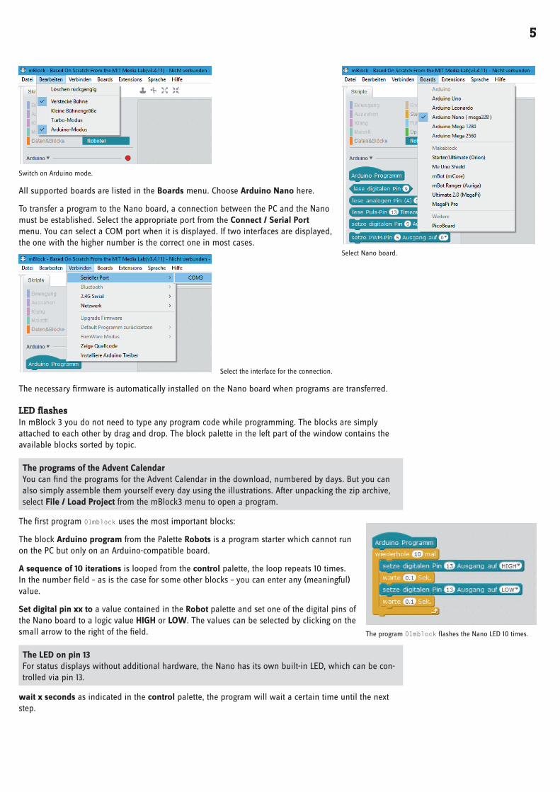
Switch on Arduino mode .
All supported boards are listed in the Boards menu . Choose Arduino Nano here .
To transfer a program to the Nano board, a connection between the PC and the Nano must be established . Select the appropriate port from the Connect / Serial Port menu . You can select a COM port when it is displayed . If two interfaces are displayed, the one with the higher number is the correct one in most cases .
Select the interface for the connection .
The necessary firmware is automatically installed on the Nano board when programs are transferred .
LED flashesIn mBlock 3 you do not need to type any program code while programming . The blocks are simply attached to each other by drag and drop . The block palette in the left part of the window contains the available blocks sorted by topic .
The programs of the Advent Calendar You can find the programs for the Advent Calendar in the download, numbered by days . But you can also simply assemble them yourself every day using the illustrations . After unpacking the zip archive, select File / Load Project from the mBlock3 menu to open a program .
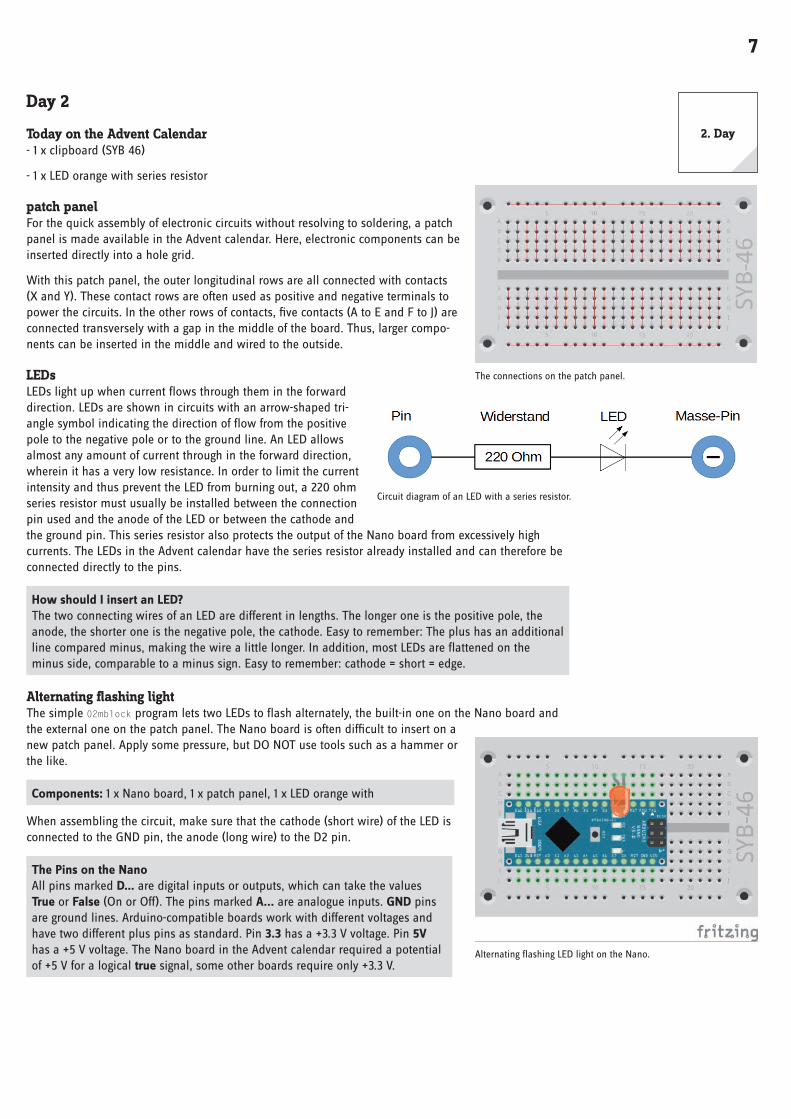
The first program 01mblock uses the most important blocks:
The block Arduino program from the Palette Robots is a program starter which cannot run on the PC but only on an Arduino-compatible board .
A sequence of 10 iterations is looped from the control palette, the loop repeats 10 times . In the number field – as is the case for some other blocks – you can enter any (meaningful) value .
Set digital pin xx to a value contained in the Robot palette and set one of the digital pins of the Nano board to a logic value HIGH or LOW . The values can be selected by clicking on the small arrow to the right of the field .
The LED on pin 13 For status displays without additional hardware, the Nano has its own built-in LED, which can be con-trolled via pin 13 .
wait x seconds as indicated in the control palette, the program will wait a certain time until the next step .
Select Nano board .
The program 01mblock flashes the Nano LED 10 times .

6
Switching off the Nano The Nano does not have an off switch, you simply disconnect the power supply and it switches off . The next time it is switched on, the last saved program starts automatically . The same happens when you press the reset button .
How the program worksThe loop ensures that the contained blocks is executed 10 times in succession .
After the LED at pin 13 is switched on, a 0 .1 seconds delay occurs until the LED lights up . The LED at pin 13 is then switched off again . Now the program waits 0 .1 seconds again . The cycle then repeats itself from the beginning .
Decimal point instead of comma mBlock 3, like many Chinese or American programs, uses the dot as the decimal separator, not the comma as used in Germany .
Transferring the program to the Nano boardThe right part of the mBlock screen shows the automatically generated Arduino pro-gram code . Click on Upload to Arduino in the upper left corner to automatically compile the program and transfer it to the Nano board .
Click Close in the Start Transfer message to follow the transfer .
Message at the start of transmission .
In the lower part of the program window you can see the progress of the transfer . When the text Thank you appears, the transmission is complete .
The program starts automatically after transfer to the Nano board is completed . You can also restart it at any time by pressing the button on the Nano board .
Transfer the program to the Nano board .
7
Day 2
Today on the Advent Calendar- 1 x clipboard (SYB 46)
- 1 x LED orange with series resistor
patch panelFor the quick assembly of electronic circuits without resolving to soldering, a patch panel is made available in the Advent calendar . Here, electronic components can be inserted directly into a hole grid .
With this patch panel, the outer longitudinal rows are all connected with contacts (X and Y) . These contact rows are often used as positive and negative terminals to power the circuits . In the other rows of contacts, five contacts (A to E and F to J) are connected transversely with a gap in the middle of the board . Thus, larger compo-nents can be inserted in the middle and wired to the outside .
LEDsLEDs light up when current flows through them in the forward direction . LEDs are shown in circuits with an arrow-shaped tri-angle symbol indicating the direction of flow from the positive pole to the negative pole or to the ground line . An LED allows almost any amount of current through in the forward direction, wherein it has a very low resistance . In order to limit the current intensity and thus prevent the LED from burning out, a 220 ohm series resistor must usually be installed between the connection pin used and the anode of the LED or between the cathode and the ground pin . This series resistor also protects the output of the Nano board from excessively high currents . The LEDs in the Advent calendar have the series resistor already installed and can therefore be connected directly to the pins .
How should I insert an LED? The two connecting wires of an LED are different in lengths . The longer one is the positive pole, the anode, the shorter one is the negative pole, the cathode . Easy to remember: The plus has an additional line compared minus, making the wire a little longer . In addition, most LEDs are flattened on the minus side, comparable to a minus sign . Easy to remember: cathode = short = edge .
Alternating flashing lightThe simple 02mblock program lets two LEDs to flash alternately, the built-in one on the Nano board and the external one on the patch panel . The Nano board is often difficult to insert on a new patch panel . Apply some pressure, but DO NOT use tools such as a hammer or the like .
Components: 1 x Nano board, 1 x patch panel, 1 x LED orange with
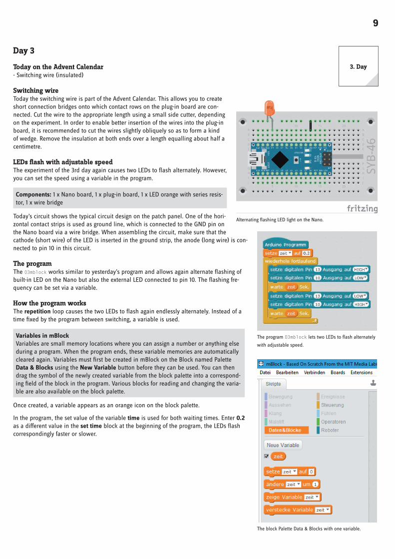
When assembling the circuit, make sure that the cathode (short wire) of the LED is connected to the GND pin, the anode (long wire) to the D2 pin .
The Pins on the Nano All pins marked D… are digital inputs or outputs, which can take the values True or False (On or Off) . The pins marked A... are analogue inputs . GND pins are ground lines . Arduino-compatible boards work with different voltages and have two different plus pins as standard . Pin 3.3 has a +3 .3 V voltage . Pin 5V has a +5 V voltage . The Nano board in the Advent calendar required a potential of +5 V for a logical true signal, some other boards require only +3 .3 V .
The connections on the patch panel .
Circuit diagram of an LED with a series resistor .
Alternating flashing LED light on the Nano .
2 . Day

8
The programThe 02mblock program alternately flashes the built-in LED on the Nano and the externally connected LED .
The 02mblock program lets two LEDs to flash alternately .
How the program worksA continuous loop ensures that the two LEDs to flash endlessly alternately .
After the built-in LED on pin 13 is switched on, the LED on pin 2 is switched off . Now the program waits 0 .1 seconds .
Then the LED at pin 2 is switched on in the same way and the LED at pin 13 is switched off . The cycle repeats itself after another 0 .1 seconds .
9
Day 3
Today on the Advent Calendar- Switching wire (insulated)
Switching wireToday the switching wire is part of the Advent Calendar . This allows you to create short connection bridges onto which contact rows on the plug-in board are con-nected . Cut the wire to the appropriate length using a small side cutter, depending on the experiment . In order to enable better insertion of the wires into the plug-in board, it is recommended to cut the wires slightly obliquely so as to form a kind of wedge . Remove the insulation at both ends over a length equalling about half a centimetre .
LEDs flash with adjustable speedThe experiment of the 3rd day again causes two LEDs to flash alternately . However, you can set the speed using a variable in the program .
Components: 1 x Nano board, 1 x plug-in board, 1 x LED orange with series resis-tor, 1 x wire bridge
Today’s circuit shows the typical circuit design on the patch panel . One of the hori-zontal contact strips is used as ground line, which is connected to the GND pin on the Nano board via a wire bridge . When assembling the circuit, make sure that the cathode (short wire) of the LED is inserted in the ground strip, the anode (long wire) is con-nected to pin 10 in this circuit .
The programThe 03mblock works similar to yesterday’s program and allows again alternate flashing of built-in LED on the Nano but also the external LED connected to pin 10 . The flashing fre-quency can be set via a variable .
How the program worksThe repetition loop causes the two LEDs to flash again endlessly alternately . Instead of a time fixed by the program between switching, a variable is used .
Variables in mBlock Variables are small memory locations where you can assign a number or anything else during a program . When the program ends, these variable memories are automatically cleared again . Variables must first be created in mBlock on the Block named Palette Data & Blocks using the New Variable button before they can be used . You can then drag the symbol of the newly created variable from the block palette into a correspond-ing field of the block in the program . Various blocks for reading and changing the varia-ble are also available on the block palette .
Once created, a variable appears as an orange icon on the block palette .
In the program, the set value of the variable time is used for both waiting times . Enter 0.2 as a different value in the set time block at the beginning of the program, the LEDs flash correspondingly faster or slower .
Alternating flashing LED light on the Nano .
The program 03mblock lets two LEDs to flash alternately
with adjustable speed .
The block Palette Data & Blocks with one variable .
3 . Day

10
Day 4
Today on the Advent Calendar- 1 x LED yellow with series resistor
LEDs flash faster and fasterThe experiment of the 4th day lets two LEDs on the patch panel to flash alternately . The flashing speed increases over time .
Components: 1 x Nano board, 1 x patch panel, 1 x LED orange with series resistor, 1 x LED yellow with series resistor, 1 x wire bridge
The programThe 04mblock works similar to yesterday’s program . Again, two different digital pins are alternately switched on and off in an endless loop . The time variable that deter-mines the flashing time is reduced to 80% of the previous value in each loop pass .
The program 04mblock makes
two LEDs flash .
How the program worksAt the beginning of the program, the variable time is set to 2 seconds . In each of the 20 loop iterations, the variable time is first multiplied by 0 .8 and stored again as a new value for time . The block palette Operators contains blocks for the four basic arithmetic operations and some other mathematical opera-tors .
The other program blocks correspond to the previous program version . The two LEDs flash alternately, whereby the current value of the variable time is used as light duration with each run .
Two LEDs on the patch panel flash .
4 . Day

11
Day 5
Today on the Advent Calendar- 1 x button
- 1 x resistor 10 kOhm (brown – black – orange)
Resistors and their colour codesResistors are used for current control on sensitive electronic components and as series resistors for LEDs . The unit of measurement for resistors is Ohm . 1,000 Ohm corresponds to one kiloohm, abbreviated kOhm . 1,000 kOhm corresponds to a megaohm, abbreviated MOhm . The omega sign Ω is often used for the Ohm unit .
The coloured rings on the resistors indicate the resist-ance value . With a little practice, they are much easier to recognize than tiny, small numbers that can only be found on very old resistors .
Most resistors have four such colour rings . The first two colour rings represent the digits, the third indicates a multiplier and the fourth the tolerance . This tolerance ring is usually gold or silver-coloured – colours that do not appear on the first rings . This ensures that the reading direction is always clear . The tolerance value itself hardly plays a role in digital electronics . The table shows the meaning of the coloured rings on resistors .
It does not matter in which direction a resistor is installed . With LEDs, on the other hand, the installation direction plays an important role .
PushbuttonDigital pins can not only output data, for example via LEDs, but can also be used for data input . In today’s project we use a pushbutton for input, which is plugged directly onto the plug-in board . The pushbutton has four connection pins, whereby two opposite (large distance) pins are connected to each other . As long as the button is pressed, all four connectors are connected to each other . Unlike a switch, a pushbutton does not engage . The connection is immediately disconnected when released .
If a +5 V signal is present on a digital input, it is evaluated as logically true .
With the button open, the input would not have a clearly defined state . If a program queries this pin, random results may occur . To prevent this, a comparatively high resistance – usually 10 kOhm – is connected to the ground . This so-called pull-down resistor pulls the status of the input pin down to 0 V when the button is open . Since the resistance is very high, there is no danger of a short circuit as long as the button is pressed . When the button is depressed, the voltage of the pin becomes +5 V and the ground line is connected directly via this resistor .
Switching LEDs with pushbuttonThe experiment of the 5th day switches LEDs when a button is pressed .
Components: 1 x Nano board, 1 x patch panel, 1 x LED orange with series resistor, 1 x LED yellow with series resistor, 1 x button, 1 x 10 kOhm resistor (brown – black – orange), 3 x wire bridges (different lengths)
Tint Resistance value in Ohm
1st ring (Tens)
2 . Ring (Ones)
3 . Ring (Multiplier)
4 . Ring (Tolerance)
Silver 10−2 = 0,01 ±10 %
Gold 10−1 = 0,1 ±5 %
Black 0 100 = 1
Brown 1 1 101 = 10 ±1 %
Red 2 2 102 = 100 ±2 %
Orange 3 3 103 = 1 .000
Yellow 4 4 104 = 10 .000
Green 5 5 105 = 100 .000 ±0,5 %
Blue 6 6 106 = 1 .000 .000 ±0,25 %
Violet 7 7 107 = 10 .000 .000 ±0,1 %
Grey 8 8 108 = 100 .000 .000 ±0,05 %
White 9 9 109 = 1 .000 .000 .000
Wiring diagram of a push-button with pull-down resistor .
5 . Day

12
Two LEDs are switched over with one button .
The programThe 05mblock program regularly checks whether the button is pressed . Depending on this, one LED is switched on and the other off .
The 05mblock program switches the LEDs
when the button is pressed .
How the program worksIn each run of the endless loop, the if... then... else block sends inquires the digital pin 3 to which the push-button is connected . If the button is pressed, the query returns the logic value true . In this case, the LED on pin 8 is switched on and the LED on pin 10 is switched off . If the button is not pressed, the LED on pin 8 is switched off and the LED on pin 10 is switched on .

13
Day 6
Today on the Advent Calendar- 4 x connection cables
Today connection cables come to play in the Advent calendar, with which the LEDs on the angel wing are connected to the patch panel . Cut out the angel wing from the back of the Advent calendar and insert two LEDs into the holes provided . The positions with two holes are for monochrome LEDs, the positions with four holes are needed later .
Plug the sockets of the connection cables onto the wires of the LEDs . Then plug the connector sides of the connecting cables onto the patch panel as shown in the illus-tration .
Switching LEDs on the angel wingThe experiment of the 6th day switches over two LEDs via a button . Unlike the pre-vious program, the LEDs retain their status after the button is released . On the next day press the button to switches the LEDs again .
Components: 1 x Nano board, 1 x patch panel, 1 x LED orange with series resistor, 1 x LED yellow with series resistor, 1 x push-button, 1 x 10 kOhm resistor (brown – black – orange), 3 x wire jumpers (different lengths), 4 x connection cables
The programThe 06mblock program waits until the button is pressed and then switches the LEDs .
The 06mblock program switches two LEDs with one button .
How the program worksAt the beginning of each loop, the LED on pin 8 is switched on and the LED on pin 10 is switched off . The program then waits until the block read digital pin 3 returns the value true, i .e . the button has been pressed .
Now the LED on pin 8 is switched off and the LED on pin 10 is switched on and the program waits again until the button is pressed . Only then the endless loop restarts and the LEDs are switched back to the initial position .
One button switches two LEDs .
6 . Day

14
Day 7
Today on the Advent Calendar- 1 x orange LED with series resistor
LEDs flash randomlyThe experiment of the 7th day causes three LEDs to flash in random order . The three LEDs are very close to each other on the patch panel, as the program requires con-secutive pin numbers .
Components: 1 x Nano board, 1 x patch panel, 2 x LED orange with series resistor, 1 x LED yellow with series resistor, 1 x wire bridge
The programThe program 07mblock01 lets three LEDs with consecutive pin numbers flash alter-nately .
The program 07mblock01 lets
three LEDs flash randomly .
How are random numbers generated? It is generally thought that nothing can happen accidentally in a program – so how can a program generate random numbers? If you divide a large prime number by any value, starting at the umpteenth decimal place you get numbers that are hardly predictable . They also change without any regularity if the divisor is increased regularly . This result is apparently random, but it can be reproduced at any time by an identical program or by calling the same program several times . But if you take a number composed of some of these digits and divide it again by a number that results from the current com-puter time or the content of any memory location of the computer, you get a result that cannot be reproduced and is therefore called a random number .
How the program worksIn the first step of each loop, the variable n is set to a random number between 7 and 9 . This indicates the pin number of the LED to be switched on . Therefore, the circuit requires three consecutive pin num-bers .
The speed of the colour change is controlled by the variable time, which is set to 0 .2 seconds at the beginning of the program and then applies to each switching operation .
The randomly selected LED is switched on for the set time and then switched off for the same time . In the next loop pass, a new LED is selected randomly . It is quite possible that the same LED lights up sev-eral times in succession .
Improved version of the programIn this program, it is noticeable that the LEDs light up significantly less than in the previous programs .
A look into the Arduino program code in the right pane of mBlock shows the cause of this problem .
Each pin to be used as a digital output must be initialized before its first use . mBlock normally automati-cally creates the necessary lines in the void setup () ... area .
Three LEDs flash randomly .
7 . Day

15
Since the pin numbers used are not mentioned individually, mBlock cannot carry out the initiali-zation in this case .
At the beginning of the program you can set the digital pin on the three blocks . . . with Output on LOW . Then each of the three pins used is switched off individually and thus also initialized .
The program 07mblock02 lets three LEDs flash
randomly, but with higher brightness .
These three blocks ensure that the lines necessary for initializing the outputs are written into the Arduino program code .
In program 07mblock02 the outputs for the LEDs are initialized .
In this program version the LEDs light up at a higher brightness .
The outputs for the LEDs are not initialized .

16
Day 8
Today on the Advent Calendar- 1 x LED yellow with series resistor
Dimming LEDsLEDs are typical components for the output of signals in digital electronics . They can assume two differ-ent states, on and off, 0 and 1 or LOW and HIGH . The same applies to the digital pins defined as out-puts . Thus, it would theoretically not be possible to dim an LED .
With a trick it is still possible to control the brightness of an LED on a digital pin . If an LED flashes fast enough, the human eye no longer perceives it as flashing . The technique known as pulse width modulation (PWM) generates a pulsing signal that switches on and off at very short intervals . The voltage of the signal always remains the same, only the ratio between level LOW (0 V) and level HIGH (+3 .3 V) is changed . The duty cycle is the ratio of the length of the switched-on state to the total duration of a switching cycle .
The smaller the duty cycle, the shorter the LED lighting time within a switching cycle . As a result, the LED appears darker than a permanently switched-on LED .
Components: 1 x Nano board, 1 x plug-in board, 2 x LED yellow with series resistor, 1 x wire bridge
Pins for PWM signals Pins 3, 5, 6, 9, 10, 11 are marked with a ‘-’ symbol on the circuit diagrams . These pins can be used for PWM .
The programProgram 08mblock dims the LEDs on pin 6 cyclically brighter and darker . The LED of the same colour on pin 8 lights up in full brightness for comparison .
How the program worksAt the beginning pin 8 is digitally set to HIGH and thus switched on . Three variables are then defined: time defines the dimming speed, bright indicates the PWM value for the brightness of the LED and step indicates the step size for dimming .
Now an endless loop begins . First, the current value of the variable bright is out-putted to pin 6 as a PWM value for each loop pass . Then the value of the variable is increased by the value step .
In the next step, the system checks whether the value of light has reached the limits 0 or 250 . In this case, one or block is used, which in turn contains space for two further queries . If at least one of these is true, the or block returns the value true and the content of the IF block is executed .
Two equality queries check whether the value of the variable bright has reached the value 0 or 250 . If this is the case, the variable step is set to a new value . Since mBlock does not allow the sign of a variable to be reversed, we use the operator’-’ and subtract the value of the variable from 0, which returns the same result .
Finally, the program waits for the 0 .2 seconds stored in the variable time in each loop pass . Then the endless loop restarts and returns a new PWM value to the LED .
Left: 50 % Duty cycle – right: 20% Duty cycle .
One LED is dimmed, the second one lights up with full bright-
ness for comparison .
The program 08mblock dims an LED at the PWM output .
8 . Day

17
Day 9
Today on the Advent Calendar- 4 x connection cables
Chaser light on the angel wingThe experiment of the 9th day allows four LEDs to light up cyclically as a chaser light . Insert the LEDs into the holes provided for this purpose on the angel wing and connect them to the patch panel using the connection cables as shown in the illus-tration .
Components: 1 x Nano board, 1 x patch panel, 2 x LED orange with series resis-tor, 2 x LED yellow with series resistor, 1 x wire bridge, 8 x connection cables
The programThe program 09mblock allows the four LEDs to light up cyclically as a chaser light . The pin numbers are 2 apart . This way they can easily be incremented in a loop .
The program 09mblock controls a chaser
light consisting of four LEDs on the angel wing .
How the program worksThe program determines the flashing speed at the beginning in the variable time . Of course, you can also enter a different value here . Afterwards, the four pins used for the LEDs are switched off once to initialize them, since they are later only addressed via a variable .
Then the endless loop, which sets the variable n to 4 in each pass, starts the number of the first LED . Each run of the endless loop causes a chaser cycle of all four LEDs .
An inner loop allows the four LEDs to light up briefly one after the other . After each LED, the variable n is increased by 2 and thus the next LED is activated . After all LEDs have illuminated once, the next run of the endless loop starts with the LED on pin 4 .
Four LEDs light up as a chaser light .
9 . Day

18
Day 10
Today on the Advent Calendar- 1 x battery box
battery boxThe Nano board can also be used without a PC and run a stored program . This requires an external power supply . This can be a USB mobile phone charger, a power bank or even a battery . Today, the Advent Calendar contains a battery box that supplies a voltage of 6 V with four AAA batteries, with 4 .8 V batteries, which is also sufficient to power the Nano board . Batteries are not included .
You can stick the clipboard with the self-ad-hesive backside on the backside of the angel wing and carry the whole circuit around with the battery box independently of the PC .
Close the j+ battery box .
The power supply of the Nano is not yet acti-vated, since you still supply the Nano with power via the PC until the new program has been transferred . After disconnecting the USB cable, the battery box is connected to the VIN and GND pins of the Nano board .
Chaser light with changing speedThe experiment of the 10th day lets the four LEDs light up again as chaser light, whereby the speed changes cyclically . After transfer-ring the program, disconnect the USB cable from the PC and connect the battery box as shown in the figure . The program then runs independently on the Nano board .
Components: 1 x Nano board, 1 x patch panel, 2 x LED orange with series resistor, 2 x LED yellow with series resistor, 1 x wire bridge, 8 x connection cables, 1 x battery box
The programThe 10mblock program allows the four LEDs to light up cyclically as a chaser light again . The speed is changed after each cycle . The light duration of each LED varies slowly between 0 .5 seconds and 0 .05 seconds .
How the program worksThe program 10mblock works similar to the program of the 9th day . After each run of the chaser, the variable time is multiplied by the factor f . This factor initially has a value of 0 .8, meaning that each pass only takes 80% of the previous pass . The chaser light is getting faster and faster .
If after several repetitions the flash time of the individual LEDs has become shorter than 0 .05 seconds, the factor f is set to 1 .2 . This means that each future pass takes 20% longer than the previous one . In this way, the chaser light is slowly slowed down until the light time of the individual LEDs has again become longer than 0 .5 seconds . Then f is set to 0 .8 again .
Four LEDs light up as a chaser light .
The 10mblock program lets the LEDs light up as a chaser
with variable speed .
10 . Day

19
Day 11
Today on the Advent Calendar- 1 x RGB LED with series resistors
RGB LEDsA normal LED only ever lights up in one colour . The RGB LEDs used in the Advent calendar can light up in several colours . In principle, three LEDs in different colours are installed in a transparent housing . Each of these three LEDs has its own anode, via which it is connected to a GPIO pin . The cath-ode connected to the ground line is present only once . Therefore, an RGB LED has four connecting wires . On the angel wing there are positions with four holes for RGB LEDs .
The connecting wires of the RGB LEDs are of different lengths to make them clearly identifiable . Unlike normal LEDs, the cathode is the longest wire .
RGB LEDs function like three single LEDs and therefore require three 220 Ohm resistors (red – red – brown) . They are also built into the RGB LEDs in this Advent calendar .
Different colours on one RGB LEDThe experiment of the 11th day shows different basic and mixed colours on an RGB LED .
Components: 1 x Nano board, 1 x plug-in board, 1 x RGB LED with series resistors, 1 x wire bridge
An RGB LED shows changing colours .
Connection pins of an RGB LED .
An RGB LED shows changing colours .
11 . Day
20
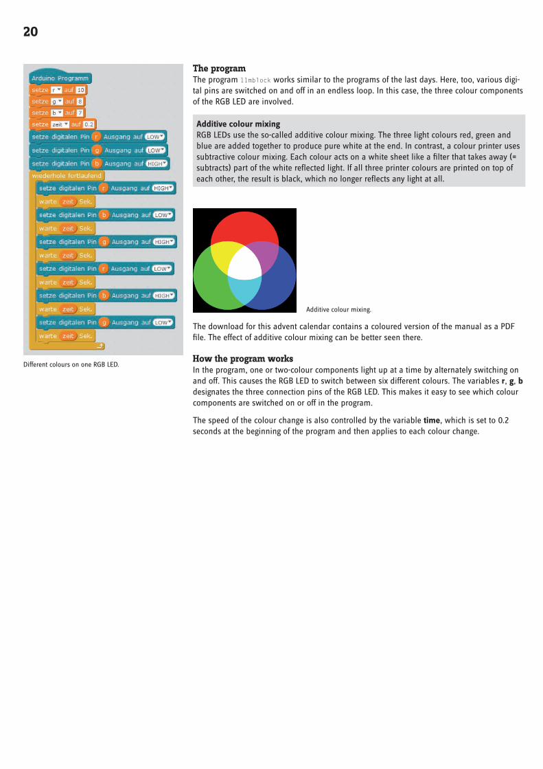
The programThe program 11mblock works similar to the programs of the last days . Here, too, various digi-tal pins are switched on and off in an endless loop . In this case, the three colour components of the RGB LED are involved .
Additive colour mixing RGB LEDs use the so-called additive colour mixing . The three light colours red, green and blue are added together to produce pure white at the end . In contrast, a colour printer uses subtractive colour mixing . Each colour acts on a white sheet like a filter that takes away (= subtracts) part of the white reflected light . If all three printer colours are printed on top of each other, the result is black, which no longer reflects any light at all .
Additive colour mixing .
The download for this advent calendar contains a coloured version of the manual as a PDF file . The effect of additive colour mixing can be better seen there .
How the program worksIn the program, one or two-colour components light up at a time by alternately switching on and off . This causes the RGB LED to switch between six different colours . The variables r, g, b designates the three connection pins of the RGB LED . This makes it easy to see which colour components are switched on or off in the program .
The speed of the colour change is also controlled by the variable time, which is set to 0 .2 seconds at the beginning of the program and then applies to each colour change .
Different colours on one RGB LED .
21
Day 12
Today on the Advent Calendar- 4 x connection cables
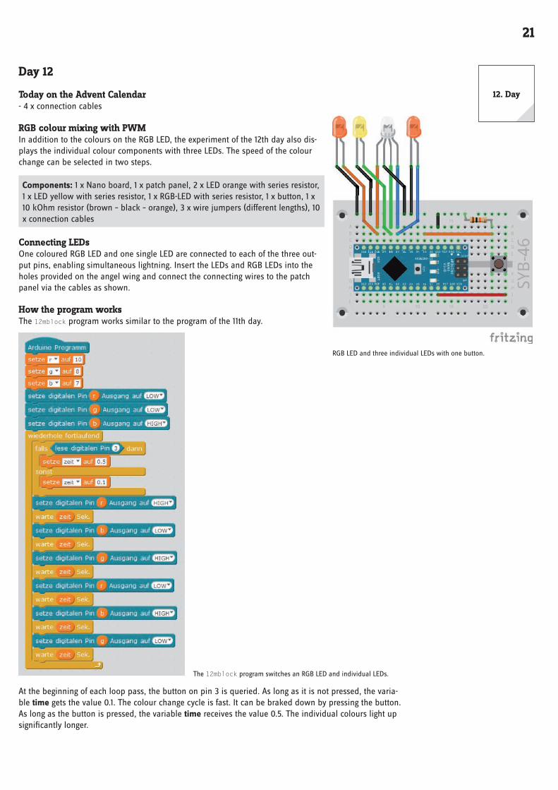
RGB colour mixing with PWMIn addition to the colours on the RGB LED, the experiment of the 12th day also dis-plays the individual colour components with three LEDs . The speed of the colour change can be selected in two steps .
Components: 1 x Nano board, 1 x patch panel, 2 x LED orange with series resistor, 1 x LED yellow with series resistor, 1 x RGB-LED with series resistor, 1 x button, 1 x 10 kOhm resistor (brown – black – orange), 3 x wire jumpers (different lengths), 10 x connection cables
Connecting LEDsOne coloured RGB LED and one single LED are connected to each of the three out-put pins, enabling simultaneous lightning . Insert the LEDs and RGB LEDs into the holes provided on the angel wing and connect the connecting wires to the patch panel via the cables as shown .
How the program worksThe 12mblock program works similar to the program of the 11th day .
The 12mblock program switches an RGB LED and individual LEDs .
At the beginning of each loop pass, the button on pin 3 is queried . As long as it is not pressed, the varia-ble time gets the value 0 .1 . The colour change cycle is fast . It can be braked down by pressing the button . As long as the button is pressed, the variable time receives the value 0 .5 . The individual colours light up significantly longer .
RGB LED and three individual LEDs with one button .
12 . Day

22
Day 13
Today on the Advent Calendar- 1 x button
- 1 x resistor 10 kOhm (brown – black – orange)
Chaser light in two directionsChaser lights are always popular effects, not only for advertising and party rooms . The experiment of the 13th day lets four LEDs light up as a chaser when a button is pressed . The other button allows the chaser light to run in the opposite direction .
Components: 1 x Nano board, 1 x patch panel, 2 x LED orange with series resistor, 2 x LED yellow with series resistor, 2 x push-buttons, 2 x 10 kOhm resistor (brown – black – orange), 5 x wire jumpers (different lengths)
The programThe program 13mblock works similar to the program of the 9th day, but additionally inquires the two buttons to select the direction of the chaser using an additional variable .
How the program worksThe variable i indicates the value by which the pin number for the LED to light is changed in each loop pass . The value 2 makes the chaser light run from right to left: 4, 6, 8, 10, the value -2 makes it run from left to right: 10, 8, 6, 4 .
The variable n contains the number of the pin that is currently lit or is to light next .
Each time the loop is run, the LED on pin n lights up for the time set in the time variable . The two buttons are then queried . If the left button on pin 2 is pressed, the variable i is set to 2 so that the chaser light runs to the left . If the right button on pin 3 is pressed, the variable i is set to -2 so that the chaser light runs to the right .
The pin number n is set to the new value . Then it is checked whether n has exceeded the range of possible values for the LED pins . If n has a value greater than 10, due to the change, the chaser light on the right starts again at pin 4, if the new value of n is less than 4, the chaser light starts again on the left at pin 10 .
Chaser light with four LEDs and two buttons with pull-down resis-
tors .
Direction switch of chaser light with two buttons .
13 . Day

23
Day 14
Today on the Advent Calendar• 15-kOhm-Potentiometer
potentiometersThe potentiometer from today’s Advent calendar is an adjustable resistor, which can take values between 0 Ohm and 15 kOhm by turning the knob . The potentiometer can be used to build a voltage divider which can supply any voltage between 0 V and +5 V . This analogue voltage must be converted into a digital value, which is then processed by the program .
Control chaser light with a potentiometerThe Nano board has eight analogue input pins A0...A8, which convert an applied voltage into a numerical value . A potentiometer on an analogue input pin of the Nano board controls the speed of the chaser .
Components: 1 x Nano board, 1 x patch panel, 2 x LED orange with series resis-tor, 2 x LED yellow with series resistor, 1 x potentiometer, 4 x wire jumpers (dif-ferent lengths)
The programThe 14mblock program controls an LED strip based on the setting of the potentio-meter .
The 14mblock program .
How the program worksThe chaser works similarly to the chaser programs of previous days, only the lighting time of the indi-vidual LEDs is not defined in a variable time but is set interactively via the potentiometer at the A5 ana-logue input .
The A5 analogue pin is queried in each loop pass and its value is divided by 256 to obtain useful values for the chaser light . The value calculated in this way determines the time for which each individual LED lights up .
Control the 4 LEDs chaser with a potentiometer .
14 . Day

24
Day 15
Today on the Advent Calendar- 1 x plasticine
- 1 x 20 MOhm resistor (red – black – blue)
Sensor contact made of plasticineNowadays, traffic lights, door openers, light switches and automatic machines are often controlled with sensor contacts that only need to be touched . Buttons that really need to be pressed are becoming increasingly rare . The experiment of the 15th day switches two LEDs via a simple sensor contact .
The input pin is connected to +5 V via an extremely high impedance resistor (20 MOhm) so that a weak but clearly HIGH defined signal is present . A person who is not floating freely in the air is always grounded and supplies a low level via the
electrically conductive skin . If a person touches a sensor contact, the weak HIGH signal is superimposed by the significantly stronger LOW level of the fingertip and draws the pin to LOW level .
However, how high the resistance between hand and mass really is depends on many things, including shoes and flooring . Barefoot in wet grass provides the best connection to the earth’s mass, as is the case for stone floors . Wooden floors insulate more strongly, plastic floor coverings are often even positively charged . Similar to sensor keys on lifts and doors, an additional ground contact is provided for each circuit to ensure that the circuit always works . If the actual sensor is simultaneously touched, the ground connection is established .
Dough conducts electricity almost as well as human skin . It can be easily shaped to any shape and a kneading contact is much better to the touch than a simple piece of wire . The area with which the hand touches the contact is significantly larger . This way it is not so easy to make a “loose contact” . Cut off an approx . 10 cm long piece of the connecting wire, remove the insulation at both ends to a length of approx . 1 cm and put one end into a piece of plasticine . Insert the other end into the patch panel as shown in the illustration .
Since mBlock always switches on the pull-down resistors built into most Ardui-no-compatible boards, digital inputs are automatically pulled to 0 V and have a low level even without touching them . Arduino-compatible boards have additional analogue inputs, which are very well suited for sensor contacts . Analog inputs pro-vide values between 0 (LOW level) and 1023 (HIGH level) . Depending on the board type, values around 200 are good limit values to distinguish between touched and non-contacted sensor contact .
Components: 1 x Nano board, 1 x patch panel, 1 x LED orange with series resistor, 1 x LED yellow with series resistor, 1 x 20-MOhm resistor (red – black – blue), 2 x plasticine contact, 1 x wire bridge
The programThe program 15mblock switches two LEDs via a sensor contact made of plasticine .
How the program worksThe analogue pin A2 is read out each time the endless loop is run . As long as the sensor contact is not touched, it has a very high value, as it is connected to +5 V via the 20 mA resistor .
If you touch the sensor contact and preferably the ground contact simultaneously, the value of the analogue input pin drops significantly to almost 0 . the program checks whether the value falls below the limit value of 200 . In this case, the LED on pin 10 is switched on and the LED on pin 8 is switched off . As long as the input value is above 200, the LED on pin 8 lights up and the LED on pin 10 is switched off .
Switch LEDs with sensor contact .
The 15mblock program .
15 . Day

25
Day 16
Today on the Advent Calendar- 1 x RGB LED with series resistors
RGB colour mixing with PWMPWM signals can be used to display even more colours on RGB LEDs . In the exper-iment of the 16th day, a potentiometer on one RGB LED controls the red colour, on the other RGB LED the green colour . A kneading contact switches the other colour, green or red, to it . PWM pins of the Nano board are used for the two PWM signals .
Components: 1 x Nano board, 1 x plug-in board, 2 x RGB LEDs with series resistor, 1 x potentiometer, 1 x 20-MOhm resistor (red – black – blue), 2 x kneading contact, 4 x wire bridges (different lengths)
The programDepending on the position of the potentiometer, one RGB LED lights up more or less strongly in red, the other in green . When touching the sensor contact, the colours green and red are switched on in full brightness, which causes an apparent colour reversal with weakly lit LEDs . When the setting is bright, both light up in a bright yellowish green .
The 16mblock program controls two
RGB LEDs via a potentiometer and a
sensor contact .
How the program worksThe connection pins of the blue colour are switched off for both RGB LEDs at the beginning to avoid ran-dom colour distortions . Alternatively, you can leave these connection pins suspended freely in the air or connect them to ground .
The endless loop reads the analogue value at pin A5 and converts it to the scale of possible PWM values . The two PWM pins 5 and 11, to which the green colour of the right and the red colour of the left RGB LED are connected, are set to the calculated value . Then the if...then...otherwise block inquires the sensor contact as in the program of the 15th day and switches on pins 7 and 9, to which the red colour of the right and the green colour of the left RGB LED are connected, when touched .
Control RGB LEDs via potentiometer and kneading contact .
16 . Day

26
Day 17
Today on the Advent Calendar- 4 x connection cables
RGB colour spectrumThe program of the 17th day allows an RGB LED to light up cyclically in all colours of the colour spectrum when the sensor contact is touched . If the sensor is released, the RGB LED goes dark .
Components: 1 x Nano board, 1 x plug-in board, 1 x RGB LED with series resistor, 1 x 20 MOhm resistor (red – black – blue), 2 x kneading contact, 1 x wire bridge, 4 x connection cables
The RGB LED can be inserted into the holes provided on the angel wing .
The programThe main loop of the program 17mblock calculates the RGB values for all colour values of the HSV colour spectrum one after the other . After each value, it is checked whether the sensor contact is touched . If this is the case, the RGB LED lights up in the corresponding colour .
HSV and RGB colour system The RGB colour system, which was previously used in all programs, describes colours as three components, red, green and blue, which are mixed together . It is relatively difficult for a person to imagine a mixed colour . In contrast, the HSV colour system describes the colours using the values H = Hue (colour value), S = Saturation and V = Value (brightness value) . By simply changing the H-value all colours of the colour spectrum can be described in full intensity if the other two values are set to maximum .
How the program worksThe three variables r1, g1, b1 contain the connection pins for the RGB LED defined as PWM outputs . In addition, three variables red, green, blue are created in which the PWM values for the three colour components of the RGB LED are entered during the calculation .
The main loop increments the H value according to the degree numbers on a colour circle between 0 and 360 and calculates the three colour components R, G and B . The values S = Saturation and V = Value are automatically set as the maximum value . As the graph shows, the six 60° ranges each have their own linear curves .
After the RGB values are calculated and stored in the variables red, green, blue, the sensor contact is queried . When touched, the PWM pins are set to their respective colour values .
After a short waiting time, the H value is increased by 1 . After a full 360° cycle, the cycle starts again from 0 .
In the download for the Advent Calendar this manual is contained as a coloured PDF in which the colour spectrum can be recognized as such .
The program 17mblock converts HSV values into RGB .
The graph shows how the H value of an HSV colour is converted
to RGB values .
RGB colour gradient control via kneading contact .
17 . Day

27
Day 18
Today on the Advent Calendar- 1 x RGB LED with series resistors
LED cubeEveryone knows the typical game cubes, which show one to six eyes, and everyone has them at home . Much cooler is an electronically controlled cube that makes your eyes light up at the touch of a button – but not just one to six LEDs in a row, but in the arrangement of a game cube . These have eyes in the typical square arrangement, which requires seven LEDs . On the angel wing you will find matching holes for four monochrome LEDs and three RGB LEDs in the arrangement of cube eyes . The three RGB LEDs are only used as red LEDs in this project . Only one colour is connected at a time .
Only four instead of seven digital pins are needed to control the LEDs, since a cube uses the eyes in pairs to display even numbers .
Components: 1 x Nano board, 1 x patch panel, 2 x LED orange with series resistor, 2 x LED yellow with series resistor, 3 x RGB-LED with series resistor, 1 x 20-MOhm resistor (red – black – blue), 2 x kneading contact, 1 x wire bridge, 14 x connection cables
The programThe program 18mblock rolls a number between 1 and 6 when touching the sensor contact and displays it as a dice image .
How the program worksAn endless loop checks again and again whether the sensor contact is touched . If this is the case, the four pins used for LEDs are switched off first to clear the previ-ously displayed cube result .
Then a random number between 1 and 6 is stored in the variable w . For each pos-sible result there is a separate if... block that switches on the corresponding LEDs . They light up until the sensor contact is touched again .
Chaser light with four LEDs, two RGB LEDs and sensor contacts .
18 . Day
28
Day 19
Today on the Advent Calendar- 4 x connection cables
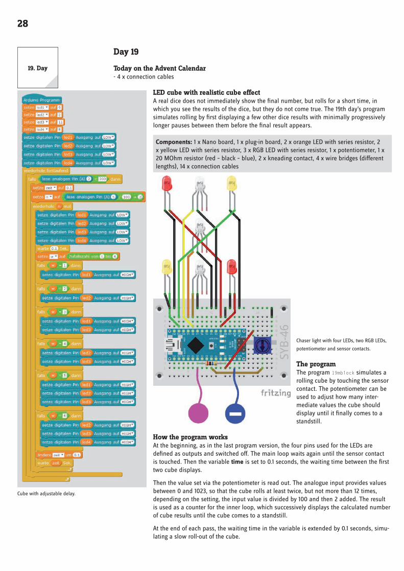
LED cube with realistic cube effectA real dice does not immediately show the final number, but rolls for a short time, in which you see the results of the dice, but they do not come true . The 19th day’s program simulates rolling by first displaying a few other dice results with minimally progressively longer pauses between them before the final result appears .
Components: 1 x Nano board, 1 x plug-in board, 2 x orange LED with series resistor, 2 x yellow LED with series resistor, 3 x RGB LED with series resistor, 1 x potentiometer, 1 x 20 MOhm resistor (red – black – blue), 2 x kneading contact, 4 x wire bridges (different lengths), 14 x connection cables
Chaser light with four LEDs, two RGB LEDs,
potentiometer and sensor contacts .
The programThe program 19mblock simulates a rolling cube by touching the sensor contact . The potentiometer can be used to adjust how many inter-mediate values the cube should display until it finally comes to a standstill .
How the program worksAt the beginning, as in the last program version, the four pins used for the LEDs are defined as outputs and switched off . The main loop waits again until the sensor contact is touched . Then the variable time is set to 0 .1 seconds, the waiting time between the first two cube displays .
Then the value set via the potentiometer is read out . The analogue input provides values between 0 and 1023, so that the cube rolls at least twice, but not more than 12 times, depending on the setting, the input value is divided by 100 and then 2 added . The result is used as a counter for the inner loop, which successively displays the calculated number of cube results until the cube comes to a standstill .
At the end of each pass, the waiting time in the variable is extended by 0 .1 seconds, simu-lating a slow roll-out of the cube .
Cube with adjustable delay .
19 . Day
29
Day 20
Today on the Advent Calendar- 1 x RGB LED with series resistors
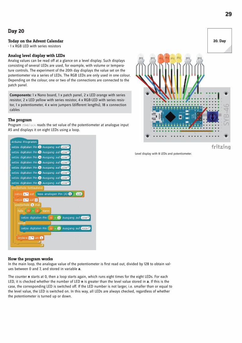
Analog level display with LEDs Analog values can be read off at a glance on a level display . Such displays consisting of several LEDs are used, for example, with volume or tempera-ture controls . The experiment of the 20th day displays the value set on the potentiometer via a series of LEDs . The RGB LEDs are only used in one colour . Depending on the colour, one or two of the connections are connected to the patch panel .
Components: 1 x Nano board, 1 x patch panel, 2 x LED orange with series resistor, 2 x LED yellow with series resistor, 4 x RGB-LED with series resis-tor, 1 x potentiometer, 4 x wire jumpers (different lengths), 18 x connection cables
The programProgram 20mblock reads the set value of the potentiometer at analogue input A5 and displays it on eight LEDs using a loop .
How the program worksIn the main loop, the analogue value of the potentiometer is first read out, divided by 128 to obtain val-ues between 0 and 7, and stored in variable a .
The counter n starts at 0, then a loop starts again, which runs eight times for the eight LEDs . For each LED, it is checked whether the number of LED n is greater than the level value stored in a . If this is the case, the corresponding LED is switched off . If the LED number is not larger, i .e . smaller than or equal to the level value, the LED is switched on . In this way, all LEDs are always checked, regardless of whether the potentiometer is turned up or down .
Level display with 8 LEDs and potentiometer .
20 . Day

30
Day 21
Today on the Advent Calendar- 1 x plasticine
- 1 x 20 MOhm resistor (red – black – blue)
Controlling lighting effects with sensor contactsThe program of the 21st day lights up four LEDs cyclically as a chaser light when one sensor contact is touched . When the other sensor contact is touched, two RGB LEDs flash in different colours .
Components: 1 x Nano board, 1 x patch panel, 2 x LED orange with series resis-tor, 2 x LED yellow with series resistor, 2 x RGB-LED with series resistor, 2 x 20-MOhm resistor (red – black – blue), 3 x kneading contact, 1 x wire bridge, 16 x connection cables
Since the assembly drawing with the many connection cables looks slightly confus-ing, the following illustrations show the same assembly again in two parts, only the individual LEDs and only the RGB LEDs .
The programThe program 21mblock uses the possibility to generate own blocks in mBlock . In other programming languages, these are referred to as functions .
How the program worksThe main program initializes the connection pins of the LEDs and RGB LEDs . Then an endless loop runs, which outputs different light patterns via self-defined blocks .
To build your own block, click on New Block in the Data&Blocks block palette .
Chaser light with four LEDs, two RGB LEDs and sensor contacts .
Assembly drawing
in two parts .
21 . Day

31
In the New Block window, you define what you want to see in the block later . These can be label texts, number fields, text fields and Boolean fields . Then build the program blocks to be executed under the block definition . The new block can use global variables from the main program and its own parameters that are passed when the block is called . Drag them, in the program as number1, number2, . . . like variables from the block definition .
The new block appears on the Data&-Blocks block palette and can be used like any other block in the program . The fields for the Parameter must be filled with the desired values .
In program 21mblock the self-defined block contains four fields, which can be filled with 0 or 1 and let the individual LEDs light up . In addition, there are twice three fields for the three colours of the two RGB LEDs, which are controlled according to the same scheme .
In the endless loop, the block is called six times in succession, whereby different combinations of LEDs should light up each time .
The new block queries the sensor contact on pin A3 each time it is called . If this is touched, LEDs are switched on or off according to the first four parameters . As long as the sensor contact is not touched, all four LEDs remain off, regardless of which values were transferred to the block during the call . With this method, the chaser light continues to run in the background, but can only be seen when the sensor contact is touched .
In the same way, the RGB LEDs light up in different colours as long as the sensor contact on pin A1 is touched . At the end of the block, the program waits for the time defined in the variable time . This means that the wait block does not have to be entered in the main program after each individual block call .
The program 21mblock flashes with a self-defined block of LEDs .
Define new block .
32
Day 22
Today on the Advent Calendar- 4 x connection cables
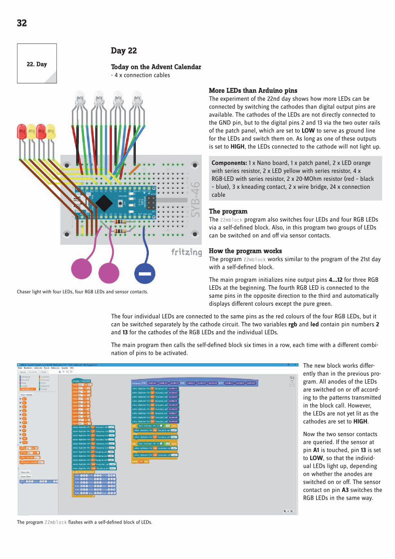
More LEDs than Arduino pinsThe experiment of the 22nd day shows how more LEDs can be connected by switching the cathodes than digital output pins are available . The cathodes of the LEDs are not directly connected to the GND pin, but to the digital pins 2 and 13 via the two outer rails of the patch panel, which are set to LOW to serve as ground line for the LEDs and switch them on . As long as one of these outputs is set to HIGH, the LEDs connected to the cathode will not light up .
Components: 1 x Nano board, 1 x patch panel, 2 x LED orange with series resistor, 2 x LED yellow with series resistor, 4 x RGB-LED with series resistor, 2 x 20-MOhm resistor (red – black – blue), 3 x kneading contact, 2 x wire bridge, 24 x connection cable
The programThe 22mblock program also switches four LEDs and four RGB LEDs via a self-defined block . Also, in this program two groups of LEDs can be switched on and off via sensor contacts .
How the program worksThe program 22mblock works similar to the program of the 21st day with a self-defined block .
The main program initializes nine output pins 4...12 for three RGB LEDs at the beginning . The fourth RGB LED is connected to the same pins in the opposite direction to the third and automatically displays different colours except the pure green .
The four individual LEDs are connected to the same pins as the red colours of the four RGB LEDs, but it can be switched separately by the cathode circuit . The two variables rgb and led contain pin numbers 2 and 13 for the cathodes of the RGB LEDs and the individual LEDs .
The main program then calls the self-defined block six times in a row, each time with a different combi-nation of pins to be activated .
The new block works differ-ently than in the previous pro-gram . All anodes of the LEDs are switched on or off accord-ing to the patterns transmitted in the block call . However, the LEDs are not yet lit as the cathodes are set to HIGH .
Now the two sensor contacts are queried . If the sensor at pin A1 is touched, pin 13 is set to LOW, so that the individ-ual LEDs light up, depending on whether the anodes are switched on or off . The sensor contact on pin A3 switches the RGB LEDs in the same way .
Chaser light with four LEDs, four RGB LEDs and sensor contacts .
The program 22mblock flashes with a self-defined block of LEDs .
22 . Day

33
Day 23
Today on the Advent Calendar- 1 x phototransistor
phototransistorA phototransistor is a light-sensitive component that looks like a transparent LED at first glance . Depend-ing on the intensity of the light incidence, different values can be achieved with the circuit shown on an analogue input of the Nano board . The brighter the light on the phototransistor, the lower the value at the analogue input . Unlike LEDs, a phototransistor connects the long terminal to ground, not the short one .
Circuit diagram for a phototransistor .
Christmas light effects in the darkThe experiment of the 23rd day makes LEDs flash brightly when it is dark enough . Once you have glued the clipboard to the back of the angel wing, connect the battery box after programming and carry the angel wing into a dark corner . Then the LEDs start flashing .
Components: 1 x Nano board, 1 x plug-in board, 2 x orange LED with series resistor, 2 x yellow LED with series resistor, 4 x RGB LED with series resistor, 1 x 10 kOhm resistor (brown – black – orange), 5 x wire bridges (different lengths), 24 x connection cables, 1 x battery box
Chaser light with four LEDs, four RGB LEDs and phototransistor .
The circuit only looks confusing at first glance, all red connections of the four RGB LEDs are connected in row 21 of the patch panel and connected to pin 2 via a wire bridge, the green connections are connected in row 23 and connected to pin 3, the blue connections are connected in row 24 and connected to pin 4 . The cathodes of the RGB LEDs are connected to pins 4, 5, 6, 7 .
The programThe program 23mblock shows how connection pins can be saved by separate switching of anodes and cathodes of the RGB LEDs . Only seven (3 x anode, 4 x cathode) instead of 13 pins (12 x anode, 1 x cath-ode) are used for four RGB LEDs .
23 . Day

34
The program 23mblock shows light effects in the dark .
How the program worksAfter all output pins used have been initialized, the main loop of the program waits for the analogue input A2 to assume a value greater than 500 . Depending on the brightness, the phototransistor delivers an analogue value, which is all the higher with the circuit used, the darker the environment is . Depend-ing on the environment, you can also change the value 500 in the range between 1 and 1023 .
If the phototransistor is in a dark environment, a self-defined block runs six times in succession, which makes the RGB LEDs light up in different colours as a chaser light . The desired colours are passed to the block as RGB parameters with each call .
Each time the new block is called, the three pins used for the anodes of the RGB LEDs are switched on or off according to the desired colour . Since the cathodes are all set to HIGH, the RGB LEDs do not yet light up .
The variable k contains the number of the cathode to be switched . This is set to 5 at the beginning for the first RGB LED . A loop runs four times and increases this variable by 1 each time to drive the four RGB LEDs one after the other as a chaser light . For this purpose, the corresponding cathode is set to LOW and after a short time back to HIGH . During this time the RGB LED lights up in the set colour .
As long as one of the RGB LEDs is lit, the individual LEDs flash briefly in quick succession, which also determines the light duration of an RGB LED . A similar loop is used here, which switches on the four anodes of the individual LEDs in the led variable one after the 0 .04 seconds stored in the time variable .
When the phototransistor is illuminated again, the currently running flashing sequence, which always starts with red and ends with purple, still runs completely to the end . The phototransistor is only queried again at the beginning of the next loop pass .

35
Day 24
Today on the Advent Calendar- 1 x piezo buzzer
piezo buzzerThe piezo buzzer contained in today’s Advent cal-endar makes electrical vibrations audible . If a pul-sating DC voltage is applied between the two poles of the buzzer, it is made to oscillate . Depending on the frequency, individual clicks or a continuous tone can be heard . Frequencies of a few hertz (oscilla-tions per second) are still perceived by the human ear as individual tones, frequencies between about 20 hertz and 16 kHertz are perceived as a continu-ous tone of different pitch .
Christmas lighting with musicThe piezo buzzer is connected to a PWM pin . Change yesterday’s circuit as shown in the figure . The individual LEDs now use pins 10...13, thus releasing the PWM-capable pin 9 for the piezo buzzer . The rest of the circuitry corresponds to the 23rd day .
Components: 1 x Nano board, 1 x plug-in board, 2 x orange LED with series resistor, 2 x yellow LED with series resistor, 4 x RGB LED with series resistor, 1 x 10 kOhm resistor (brown – black – orange), 1 x piezo buzzer, 5 x wire bridges (different lengths), 24 x connection cables, 1 x battery box
The programThe program 24mblock makes the LEDs on the angel wing flash similar to the program of the 23rd day . A Christmas song is played on the piezo buzzer .
How the program worksIf the angel wing with the phototransistor is in the dark, a series of games will play the sound x for the number of times called . This block plays a specific tone on a piezo buzzer on a PWM pin without having to know the exact frequency for the PWM signal . Due to a design error in mBlock 3, the blocks for quarter notes are displayed in two lines . However, it is the same block that is used for the other note lengths . In addition, the self-defined block is called up, which shows a short chaser effect with a colour character-istic of the sound on the RGB LEDs . At the end of the song, the program takes a short break so that the next beginning of the song does not follow seamlessly after the end of the previous song .
We wish you a merry Christmas Anyone who hears this melody almost daily in shopping malls and Christmas markets in the run-up to Christmas suspects that it is a modern American Christmas song . In fact, however, it is a song from the English Christmas tradition that can be traced back to the year 1500 and can therefore be used today without copyright .
Merry Christmas!
Christmas lighting with music .
The first blocks of the program show how the Christmas song is played .
24 . Day