davis-besse nuclear power station reactor vessel … Ł davis-besse shutdown for refueling outage...
TRANSCRIPT

1
DavisDavis--Besse Nuclear Power StationBesse Nuclear Power StationReactor Vessel HeadReactor Vessel Head
April 10, 2002April 10, 2002

2
� Introduction - John Wood
� Inspection Results �Mark McLaughlin
� Repair Concept �Jim Powers
� Final Reactor Core Configuration �Robb Borland
AgendaAgenda
3
Present results of the Davis-Besse Nuclear Power Station
reactor pressure vessel head inspections and the repair concept
Meeting ObjectiveMeeting Objective

4
Inspection ResultsInspection Results
Mark McLaughlinMark McLaughlinField Activities Team LeaderField Activities Team Leader

5
� Davis-Besse shutdown for Refueling Outage February 16, 2002
� Reactor Pressure Vessel Head (RPV) Inspections performed in response to NRC Bulletin 2001-01
� Performed ultrasonic (UT) examinations on all Control Rod Drive Mechanism Nozzles
� UT results independently verified by EPRI
� Performed visual inspections of RPV head
Inspection ResultsInspection Results
6
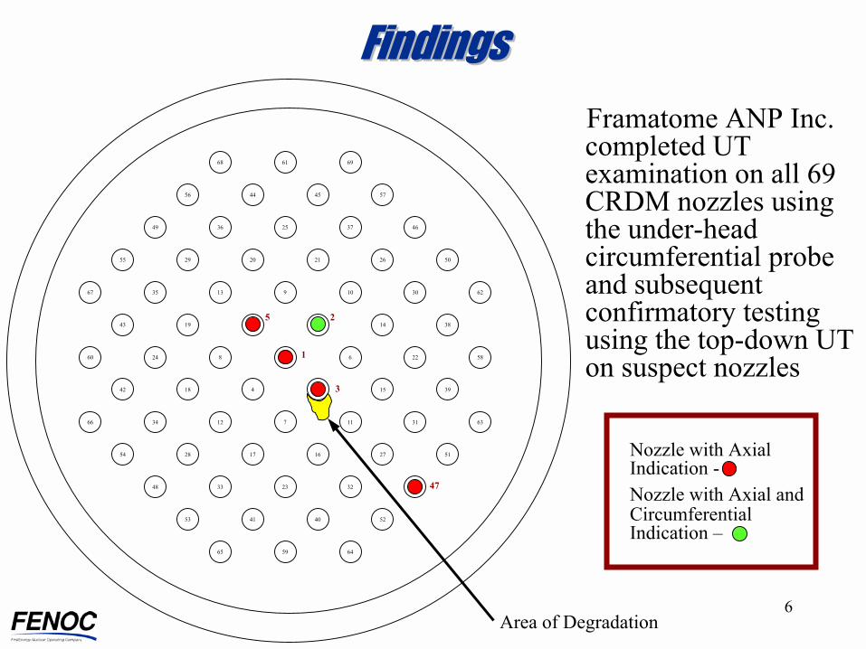
Framatome ANP Inc. completed UT examination on all 69 CRDM nozzles using the under-head circumferential probe and subsequent confirmatory testing using the top-down UT on suspect nozzles
FindingsFindings
Nozzle with Axial Indication -Nozzle with Axial and Circumferential Indication �
47
3
25
11 5822682460
59
23
7
9
25
68
633111123466
623010133567
64
32
37
69
65
33
36
61
3 391541842
16 5127172854
2 381451943
21 5026202955
45 574456
40 524153
4649
4748
Area of Degradation

7
Reactor Vessel Head and Service Structure
Inspection ResultsInspection Results
Control Rod Drives (
Vessel Head
Insulation
Source: EPRI/DEI
Side view
Spare Nozzle

8
Inspection ResultsInspection Results
Typical B&WControl Rod Drive Nozzle
Split Nut Ring
Bolts
Stainless Steel Flange
Flexitallic Type Gaskets
"Mirror" Type Insulation
Low-Alloy SteelReactor Vessel Head
Alloy 600 Nozzle
Control Rod Drive Mechanism
Cover Plate
J-Groove Weld
Shell Cladding18-8 SS

9
Inspection ResultsInspection Results
Extent of Condition Investigation
�Remove Nozzles 2 and 11
�Liquid Penetrant Examination (PT) on bores
�Remove wastage area around Nozzle 3 and PT bore
Area of Degradation
10
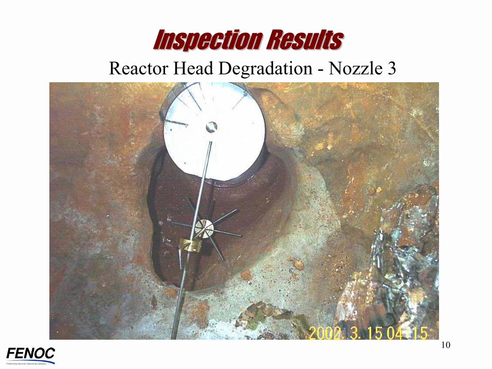
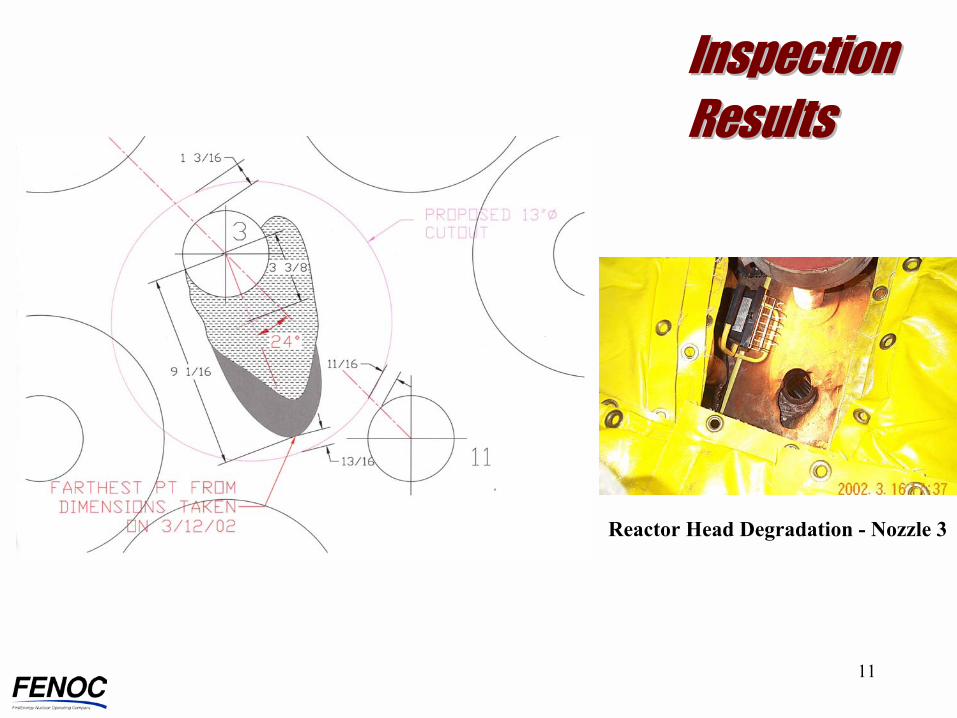
Inspection ResultsInspection ResultsReactor Head Degradation - Nozzle 3
11
Inspection Inspection ResultsResults
Reactor Head Degradation - Nozzle 3

12
Repair ConceptRepair Concept
Jim PowersJim PowersEngineering Evaluation Team LeaderEngineering Evaluation Team Leader
13
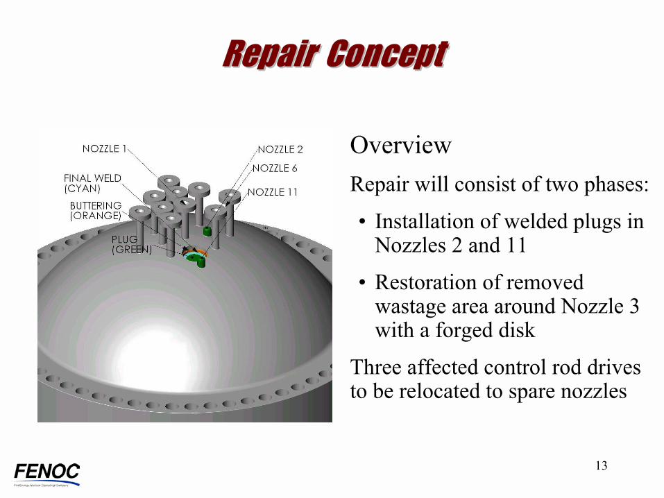
Repair ConceptRepair Concept
OverviewRepair will consist of two phases:
� Installation of welded plugs in Nozzles 2 and 11
� Restoration of removed wastage area around Nozzle 3 with a forged disk
Three affected control rod drives to be relocated to spare nozzles

14
Design Criteria� Repair will meet design requirements of American
Society of Mechanical Engineers (ASME) Boiler & Pressure Vessel Code (BPVC) Section III
� Includes all normal, off-normal and accident transient cycles and is designed for remaining licensed plant life
� Repairs will be performed by a team consisting of personnel from Davis-Besse, Framatome ANP Inc., and Welding Services, Inc.
� Third party design analysis by Structural Integrity Associates
� Mock-ups will be used to demonstrate effectiveness of cutting, welding and examination techniques
Repair ConceptRepair Concept

15
Applicable Codes� Design code for the Reactor Vessel was ASME Section
III, 1968 Edition, Summer 1968 Addenda
� Design code to be used for the repair is the ASME BPVC Section III, 1989 Edition
� ASME BPVC Section XI, 1995 Edition, with 1996 Addendum is governing inservice inspection code for Davis-Besse
� Non-destructive examinations (NDE) of repair will be performed in accordance with Section III
Repair Concept Repair Concept

16
Nozzles 2 & 11Nozzles 2 & 11Repair Sequence� Machine and perform Liquid
Penetrant (PT) examination of bore
� Machine plug to match bore
� Insert and weld plug using remote machine Gas Tungsten Arc Welding Ambient Temperature Temper Bead and Alloy 52 Weld Filler Material
� Perform PT and Ultrasonic (UT) examination on completed weld

17
Forged DiskForged Disk
Forging Material Alloy 690, SB-564, UNS N06690

18
Nozzle 3 and Adjacent AreaNozzle 3 and Adjacent Area
Repair Sequence� Inspect walls using Liquid
Penetrant Examination (PT)� Butter the bore surface using
Ambient Temperature Temper Bead welding process
� Machine and after 48 hours hold inspect using PT and UT examination
� Fit up and weld in forged disk� Weld to be inspected using PT
and Radiographic (RT) examination
19
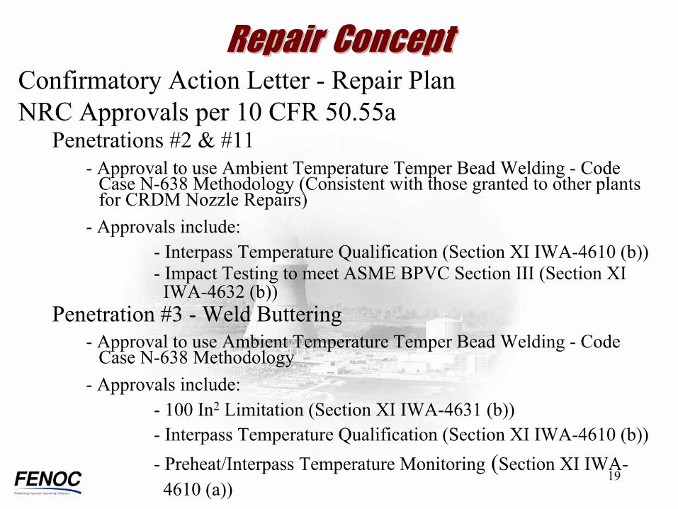
Repair ConceptRepair ConceptConfirmatory Action Letter - Repair Plan NRC Approvals per 10 CFR 50.55a
Penetrations #2 & #11- Approval to use Ambient Temperature Temper Bead Welding - Code
Case N-638 Methodology (Consistent with those granted to other plants for CRDM Nozzle Repairs)
- Approvals include:- Interpass Temperature Qualification (Section XI IWA-4610 (b)) - Impact Testing to meet ASME BPVC Section III (Section XI IWA-4632 (b))
Penetration #3 - Weld Buttering- Approval to use Ambient Temperature Temper Bead Welding - Code
Case N-638 Methodology- Approvals include:
- 100 In2 Limitation (Section XI IWA-4631 (b)) - Interpass Temperature Qualification (Section XI IWA-4610 (b))- Preheat/Interpass Temperature Monitoring (Section XI IWA-4610 (a))

20
Repair ConceptRepair Concept
Post Repair and Inspection Testing
� Liquid Penetrant Examination
� Radiographic Examination
� Code Case N-416-1
- System leakage test at full temperature and pressure

21
Final Reactor Core ConfigurationFinal Reactor Core Configuration
Robb BorlandRobb BorlandFENOC Nuclear Fuel SupervisorFENOC Nuclear Fuel Supervisor

22
Overview� Total number of control rod assemblies (CRAs)
remains the same
� Number of individual CRAs in each control rod group remains the same
� Original Cycle 14 fuel loading pattern maintained
Final Reactor Core ConfigurationFinal Reactor Core Configuration

23
Proposed Changes� Three CRAs moved to new core positions using
existing spare CRDM nozzles
� Eight CRAs exchanged between two control rod groups to maintain appropriate core symmetry
� Cycle 14 reload analysis redone by Framatome ANP for the new CRA pattern
Final Reactor Core ConfigurationFinal Reactor Core Configuration

24
Core ModificationsCore Modifications
21
3
11
16
HV
15
Normal CRA Locations
New CRA Locations
(Nozzles 15, 16, 21)
L K H G F E D C B AMNOPR
6
5
4
3
2
1
7
8
9
10
11
12
13
14
15APSR Locations
Non-Rodded Locations
Spare CRDM Nozzles
(HV = Head Vent)
2

25
CRA Relocation CRA Relocation
L K H G F E D C B AMNOPR
6
5
4
3
2
1
7
8
9
10
11
12
13
14
15
Original Group 1 New Group 1
Group 1 Relocations
L K H G F E D C B AMNOPR
6
5
4
3
2
1
7
8
9
10
11
12
13
14
15

26
Original Group 3 New Group 3
CRA Relocation CRA Relocation Group 3 Relocations
L K H G F E D C B AMNOPR
6
5
4
3
2
1
7
8
9
10
11
12
13
14
15
L K H G F E D C B AMNOPR
6
5
4
3
2
1
7
8
9
10
11
12
13
14
15
27
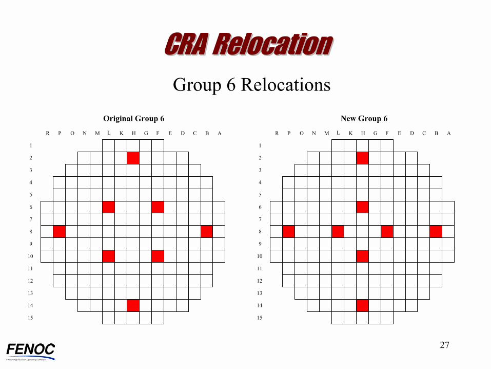
CRA Relocation CRA Relocation
Original Group 6 New Group 6
Group 6 Relocations
L K H G F E D C B AMNOPR
6
5
4
3
2
1
7
8
9
10
11
12
13
14
15
L K H G F E D C B AMNOPR
6
5
4
3
2
1
7
8
9
10
11
12
13
14
15
28
All CRA worths (total, group, stuck, ejected, dropped) well within those assumed in USAR safety analyses
Rod insertion limits meet shutdown margin requirements
CRA RelocationCRA Relocation
CRA Relocation Effect

29
Final Reactor Core ConfigurationFinal Reactor Core Configuration
NRC approvals in accordance with Confirmatory Action Letter
30
Concluding RemarksConcluding Remarks