datta meghe college of engineering - basic...
TRANSCRIPT
DATTA MEGHE COLLEGE OF ENGINEERING, AIROLI
DEPARTMENT OF MECHANICAL ENGINEERING
DMCE AIROLI/MECHANICAL ENGINEERING/BASIC WORKSHOP PRACTICE-I MANUAL/AY 2018-19 Page 1
BASIC WORKSHOP PRACTICE - I
(FEL101)
LABORATORY MANUAL
NAME OF THE STUDENT: ________________________________________________
YEAR / SEM / DIV / BATCH: _______________________________________________
ROLL NO: ______________________________________________________________
DATTA MEGHE COLLEGE OF ENGINEERING, AIROLI
DEPARTMENT OF MECHANICAL ENGINEERING
DMCE AIROLI/MECHANICAL ENGINEERING/BASIC WORKSHOP PRACTICE-I MANUAL/AY 2018-19 Page 2
DATTA MEGHE COLLEGE OF ENGINEERING
AIROLI, NAVI MUMBAI
DEPARTMENT OF MECHANICAL ENGINEERING
C E R T I F I C A T E
This is to certify that Mr. / Miss___________________________________________________
of Class First Year Division ___________ & Roll No. _____________________
Subject _____________________________________________has performed the experiments
mentioned in the index, on the date _____________________ in the premises of this institution.
Practical In charge: ___________________________________________
Head of Department: ___________________________________________
Principal: ___________________________________________
DATE: _________________
Examined on,
Examiner 1:_____________________ Examiner 2:_____________________

DATTA MEGHE COLLEGE OF ENGINEERING, AIROLI
DEPARTMENT OF MECHANICAL ENGINEERING
DMCE AIROLI/MECHANICAL ENGINEERING/BASIC WORKSHOP PRACTICE-I MANUAL/AY 2018-19 Page 3
INDEX
Sr. No. Particular Page No.
01 List of experiments 04
02 Syllabus 05
03 Instructions for Laboratory 06
04 Carpentry Section 07
� Work Holding Devices/ Clamping Tools. 07
� Measuring Tools. 09
� Marking Tools. 10
� Cutting Tools. 12
� Striking Tools. 14
� Drilling Tools. 14
� Miscellaneous Tools. 15
� Wood Turning 17
� Wood Turning shapes 19
05 Welding Section 20
� Introduction 21
� Welding transformers 21
� Welding Electrodes 22
� Welding Tools 24
� Techniques of Welding 25
DATTA MEGHE COLLEGE OF ENGINEERING, AIROLI
DEPARTMENT OF MECHANICAL ENGINEERING
DMCE AIROLI/MECHANICAL ENGINEERING/BASIC WORKSHOP PRACTICE-I MANUAL/AY 2018-19 Page 4
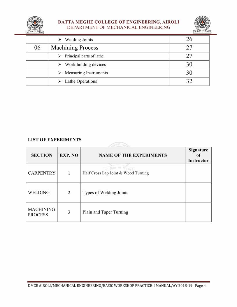
� Welding Joints 26
06 Machining Process 27
� Principal parts of lathe 27
� Work holding devices 30
� Measuring Instruments 30
� Lathe Operations 32
LIST OF EXPERIMENTS
SECTION EXP. NO NAME OF THE EXPERIMENTS
Signature
of
Instructor
CARPENTRY 1 Half Cross Lap Joint & Wood Turning
WELDING 2 Types of Welding Joints
MACHINING
PROCESS 3 Plain and Taper Turning

DATTA MEGHE COLLEGE OF ENGINEERING, AIROLI
DEPARTMENT OF MECHANICAL ENGINEERING
DMCE AIROLI/MECHANICAL ENGINEERING/BASIC WORKSHOP PRACTICE-I MANUAL/AY 2018-19 Page 5
BASIC WORKSHOP PRACTICE – I (FEL101)
Syllabus (Common to all branches)
OBJECTIVES:
The objective is to impart training to help the students develop engineering skill sets. This
exercise also aims in inculcating respect for physical work and hard labor in addition to some
amount of value addition by getting exposed to interdisciplinary engineering domains.
OUTCOMES: Learner will be able to…
Basic practice sessions must be conducted in the trades mentioned and then products of
Industrial application (with combination of different trades) may be produced with the available
resources.
• Ascertain and select measuring instrument and measure dimension of components
and evaluate for accuracy.
• Make choices to carry out routine jobs of marking out the components for
planning, chiseling, wood & metal turning, filing, sawing, welding, fitting and
allied operations where choices are clear.
• Demonstrate practical skills by using appropriate tools & equipments.
• Explain and apply working principle of welding, perform ARC & gas welding
and wood & metal turning using appropriate materials with minimal assistance.
TRADE FOR EXERCISES:
• CARPENTRY SECTION
• Use and setting of hand tools like hacksaws, jack planes, chisels and gauges for construction
of various joints, wood tuning and modern wood turning methods.
• Term work to include one carpentry job involving a joint and report on demonstration of a
job involving wood turning.
TRADES FOR DEMONSTRATION AND HANDS ON EXPERIENCE:
• WELDING SECTION
• Edge preparation for welding jobs. Arc welding for different job like, Lap welding of two
plates, butt welding of plates with simple cover, arc welding to join plates at right angles.
• MACHINE SHOP
• At least one turning job is to be demonstrated.
DATTA MEGHE COLLEGE OF ENGINEERING, AIROLI
DEPARTMENT OF MECHANICAL ENGINEERING
DMCE AIROLI/MECHANICAL ENGINEERING/BASIC WORKSHOP PRACTICE-I MANUAL/AY 2018-19 Page 6
Instructions for Laboratory
• The objective of the laboratory is learning. The experiments are designed to
illustrate phenomena in different areas of Workshop and to expose you to
uses of instruments. Conduct the job with interest and an attitude of learning.
• You need to come well prepared for the job.
• Work quietly and carefully (the whole purpose of experimentation is to
make reliable measurements!) and equally share the work with your
partners.
• All presentations of job and diagram should be neatly and carefully done.
• Diagrams should be neatly drawn with pencil. Always display units.
• Come equipped with scales, pencils etc.
• Do not fiddle idly with apparatus. Handle instruments with care. Report any
breakage to the Instructor. Return all the equipment you have signed out for
the purpose of your experiment.

DATTA MEGHE COLLEGE OF ENGINEERING, AIROLI
DEPARTMENT OF MECHANICAL ENGINEERING
DMCE AIROLI/MECHANICAL ENGINEERING/BASIC WORKSHOP PRACTICE-I MANUAL/AY 2018-19 Page 7
CARPENTRY SECTION
The term carpentry is related to assembly of parts, after bringing the dimension or shape
to the required size or form, in order to secure the necessary fit. The operations required for the
same are usually carried out on a work bench, hence the term bench work is also added with the
name carpentry. The bench work and fitting plays an important role in engineering. Although in
today's industries most of the work is done by automatic machines which produces the jobs with
good accuracy but still it (job) requires some hand operations called carpentry operations. The
person working in the carpentry shop is called carpenter.
CARPENTRY TOOLS:
carpentry shop tools are classified as below:
• Work Holding Devices/ Clamping Tools.
• Measuring Tools.
• Marking Tools.
• Cutting Tools.
• Striking Tools.
• Drilling Tools.
• Planing Tools.
I. WORK HOLDING DEVICES /CLAMPING TOOLS:
1. Work Bench:
A carpentry process can be done at various
places, but most of the important operations of
fitting are generally carried out on a table called
work bench.
The work bench is a strong, heavy and rigid
table made up of hard wood.
The size of the work bench required is about 150
to 180 cm length, nearly 90 cm width and
approximately 76 to 84 cm height.
DATTA MEGHE COLLEGE OF ENGINEERING, AIROLI
DEPARTMENT OF MECHANICAL ENGINEERING
DMCE AIROLI/MECHANICAL ENGINEERING/BASIC WORKSHOP PRACTICE
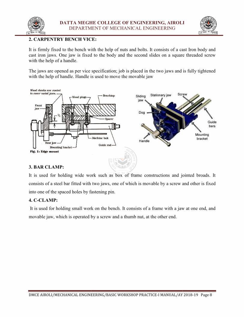
2. CARPENTRY BENCH VICE:
It is firmly fixed to the bench with the help of nuts and bolts. It consists of a cast Iron body and
cast iron jaws. One jaw is fixed to the body and the second slides on a square threaded screw
with the help of a handle.
The jaws are opened as per vice
with the help of handle. Handle is used to move the movable jaw
3. BAR CLAMP:
It is used for holding wide work such as box of frame constructions and jointed broads. It
consists of a steel bar fitted with two jaws, one of which is movable by a screw and other is fixed
into one of the spaced holes by fastening pin.
4. C-CLAMP:
It is used for holding small work on the bench. It consists of a frame with a jaw at one end, and
movable jaw, which is operated by a screw and a thumb nut, at the other end.
DATTA MEGHE COLLEGE OF ENGINEERING, AIROLI
DEPARTMENT OF MECHANICAL ENGINEERING
ENGINEERING/BASIC WORKSHOP PRACTICE-I MANUAL/AY 201
BENCH VICE:
It is firmly fixed to the bench with the help of nuts and bolts. It consists of a cast Iron body and
cast iron jaws. One jaw is fixed to the body and the second slides on a square threaded screw
as per vice specification; job is placed in the two jaws and is fully tightened
with the help of handle. Handle is used to move the movable jaw
It is used for holding wide work such as box of frame constructions and jointed broads. It
a steel bar fitted with two jaws, one of which is movable by a screw and other is fixed
into one of the spaced holes by fastening pin.
It is used for holding small work on the bench. It consists of a frame with a jaw at one end, and
aw, which is operated by a screw and a thumb nut, at the other end.
DATTA MEGHE COLLEGE OF ENGINEERING, AIROLI
DEPARTMENT OF MECHANICAL ENGINEERING
I MANUAL/AY 2018-19 Page 8
It is firmly fixed to the bench with the help of nuts and bolts. It consists of a cast Iron body and
cast iron jaws. One jaw is fixed to the body and the second slides on a square threaded screw
; job is placed in the two jaws and is fully tightened
It is used for holding wide work such as box of frame constructions and jointed broads. It
a steel bar fitted with two jaws, one of which is movable by a screw and other is fixed
It is used for holding small work on the bench. It consists of a frame with a jaw at one end, and

DATTA MEGHE COLLEGE OF ENGINEERING, AIROLI
DEPARTMENT OF MECHANICAL ENGINEERING
DMCE AIROLI/MECHANICAL ENGINEERING/BASIC WORKSHOP PRACTICE
II. MEASURING TOOLS:
1. Steel Rule
It consist of a hardened steel strip having line graduation etched or engraved in it they are usually
150 mm or 300mm long and is used to take
These are marked in inches or millimeters. All the faces are machined true. The edges of steel
rule should be protected from rough handling
2. Calipers
These are generally used to measure the inside or outside diameters. Different types are:
i. Outside Caliper: It is used to measure the outside dimensions.
ii. Inside Caliper: It is used to measure the inside dimensions.
iii. Spring Caliper: Spring is provided to app
any desired position.
iv. Hermaphrodite, Jenny or Oddleg Caliper: One leg is bent at the tip inwardly and the other
has a straight pointed end. It is used to scribe lines parallel to the straight edges.
DATTA MEGHE COLLEGE OF ENGINEERING, AIROLI
DEPARTMENT OF MECHANICAL ENGINEERING
ENGINEERING/BASIC WORKSHOP PRACTICE-I MANUAL/AY 201
It consist of a hardened steel strip having line graduation etched or engraved in it they are usually
and is used to take linear measurement to an accuracy 1mm
These are marked in inches or millimeters. All the faces are machined true. The edges of steel
rule should be protected from rough handling.
These are generally used to measure the inside or outside diameters. Different types are:
Outside Caliper: It is used to measure the outside dimensions.
Inside Caliper: It is used to measure the inside dimensions.
Spring Caliper: Spring is provided to apply the pressure and lock nut is provided to lock
Hermaphrodite, Jenny or Oddleg Caliper: One leg is bent at the tip inwardly and the other
has a straight pointed end. It is used to scribe lines parallel to the straight edges.
DATTA MEGHE COLLEGE OF ENGINEERING, AIROLI
DEPARTMENT OF MECHANICAL ENGINEERING
I MANUAL/AY 2018-19 Page 9
It consist of a hardened steel strip having line graduation etched or engraved in it they are usually
linear measurement to an accuracy 1mm or 0.5mm.
These are marked in inches or millimeters. All the faces are machined true. The edges of steel
These are generally used to measure the inside or outside diameters. Different types are:
ly the pressure and lock nut is provided to lock
Hermaphrodite, Jenny or Oddleg Caliper: One leg is bent at the tip inwardly and the other
has a straight pointed end. It is used to scribe lines parallel to the straight edges.
DATTA MEGHE COLLEGE OF ENGINEERING, AIROLI
DEPARTMENT OF MECHANICAL ENGINEERING
DMCE AIROLI/MECHANICAL ENGINEERING/BASIC WORKSHOP PRACTICE
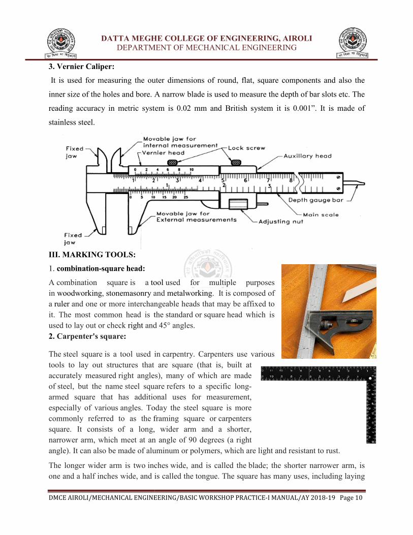
3. Vernier Caliper:
It is used for measuring the outer dimensions of round, flat, square components and also the
inner size of the holes and bore. A narrow blade is used to measure the depth of bar slots etc. The
reading accuracy in metric system is 0.02 mm
stainless steel.
III. MARKING TOOLS:
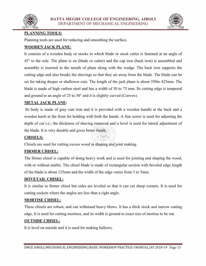
1. combination-square head:
A combination square is a tool
in woodworking, stonemasonry and
a ruler and one or more interchangeable
it. The most common head is the
used to lay out or check right and 45° angles
2. Carpenter's square:
The steel square is a tool used in
tools to lay out structures that are square (that is, built at
accurately measured right angles
of steel, but the name steel square
armed square that has additional uses for measurement,
especially of various angles. Today the steel square is more
commonly referred to as the framing square
square. It consists of a long, wider arm and a shorter,
narrower arm, which meet at an angle
angle). It can also be made of aluminum
The longer wider arm is two inches
one and a half inches wide, and is called the
DATTA MEGHE COLLEGE OF ENGINEERING, AIROLI
DEPARTMENT OF MECHANICAL ENGINEERING
ENGINEERING/BASIC WORKSHOP PRACTICE-I MANUAL/AY 201
It is used for measuring the outer dimensions of round, flat, square components and also the
inner size of the holes and bore. A narrow blade is used to measure the depth of bar slots etc. The
reading accuracy in metric system is 0.02 mm and British system it is 0.001”. It is made of
tool used for multiple purposes
and metalworking. It is composed of
interchangeable heads that may be affixed to
mon head is the standard or square head which is
and 45° angles.
is a tool used in carpentry. Carpenters use various
tools to lay out structures that are square (that is, built at
right angles), many of which are made
steel square refers to a specific long-
armed square that has additional uses for measurement,
. Today the steel square is more
framing square or carpenters
. It consists of a long, wider arm and a shorter,
arm, which meet at an angle of 90 degrees (a right
luminum or polymers, which are light and resistant to rust.
inches wide, and is called the blade; the shorter narrower arm, is
one and a half inches wide, and is called the tongue. The square has many uses, including laying
DATTA MEGHE COLLEGE OF ENGINEERING, AIROLI
DEPARTMENT OF MECHANICAL ENGINEERING
I MANUAL/AY 2018-19 Page 10
It is used for measuring the outer dimensions of round, flat, square components and also the
inner size of the holes and bore. A narrow blade is used to measure the depth of bar slots etc. The
and British system it is 0.001”. It is made of
, which are light and resistant to rust.
; the shorter narrower arm, is
. The square has many uses, including laying

DATTA MEGHE COLLEGE OF ENGINEERING, AIROLI
DEPARTMENT OF MECHANICAL ENGINEERING
DMCE AIROLI/MECHANICAL ENGINEERING/BASIC WORKSHOP PRACTICE
out common rafters, hip rafters and
octagonal scale. On the newer framing squares there are degree conversions for different pitches
and fractional equivalents.
3. Marking Gauge and Scriber
Marking gauge made from hard wood and i
Scriber is made up of high carbon steel and is hardened from the front edge. It is used for
marking of the lines.
4. Try Square:
It is used for checking squareness of two
consists of a blade made up of steel, which is attached to a
base at 90 degree. The base is made up of cast iron or
steel. It is also used to mark the right angles and
measuring straightness of surfaces. Never use try square
as a hammer.
METHOD OF MARKING
Marking means setting out dimensions with the help of a working drawing or directly
transferring them from a similar part. The procedure of marking is as follows:
1. The surface to be marked is
2. Then the work is held In a holding device depending upon shape
3. Lines in horizontal direction are scribed by means of a
angles can be drawn by try square
4. The centre on the end of a
gauge etc.
5. The circles and arcs on a flat surface are marked by means of a divider.
DATTA MEGHE COLLEGE OF ENGINEERING, AIROLI
DEPARTMENT OF MECHANICAL ENGINEERING
ENGINEERING/BASIC WORKSHOP PRACTICE-I MANUAL/AY 201
rafters and stairs. It has a diagonal scale, board foot
scale. On the newer framing squares there are degree conversions for different pitches
Scriber:
gauge made from hard wood and its scribing pin is made up of high carbon steel
Scriber is made up of high carbon steel and is hardened from the front edge. It is used for
It is used for checking squareness of two surfaces. It
consists of a blade made up of steel, which is attached to a
base at 90 degree. The base is made up of cast iron or
steel. It is also used to mark the right angles and
measuring straightness of surfaces. Never use try square
Marking means setting out dimensions with the help of a working drawing or directly
transferring them from a similar part. The procedure of marking is as follows:
The surface to be marked is smooth with the jack plane.
n a holding device depending upon shape
Lines in horizontal direction are scribed by means of a marking gauge. Lines at right
try square and then using the scriber, If true surface is available
The centre on the end of a wood log can be located by using an odd leg caliper, surface
The circles and arcs on a flat surface are marked by means of a divider.
DATTA MEGHE COLLEGE OF ENGINEERING, AIROLI
DEPARTMENT OF MECHANICAL ENGINEERING
I MANUAL/AY 2018-19 Page 11
board foot scale and an
scale. On the newer framing squares there are degree conversions for different pitches
is made up of high carbon steel.
Scriber is made up of high carbon steel and is hardened from the front edge. It is used for
Marking means setting out dimensions with the help of a working drawing or directly
gauge. Lines at right
If true surface is available.
can be located by using an odd leg caliper, surface
DATTA MEGHE COLLEGE OF ENGINEERING, AIROLI
DEPARTMENT OF MECHANICAL ENGINEERING
DMCE AIROLI/MECHANICAL ENGINEERING/BASIC WORKSHOP PRACTICE-I MANUAL/AY 2018-19 Page 12
IV. CUTTING TOOLS
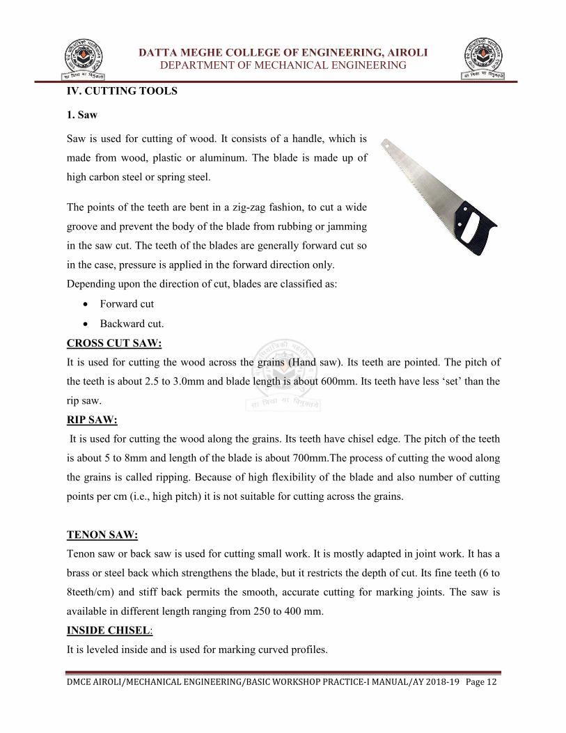
1. Saw
Saw is used for cutting of wood. It consists of a handle, which is
made from wood, plastic or aluminum. The blade is made up of
high carbon steel or spring steel.
The points of the teeth are bent in a zig-zag fashion, to cut a wide
groove and prevent the body of the blade from rubbing or jamming
in the saw cut. The teeth of the blades are generally forward cut so
in the case, pressure is applied in the forward direction only.
Depending upon the direction of cut, blades are classified as:
• Forward cut
• Backward cut.
CROSS CUT SAW:
It is used for cutting the wood across the grains (Hand saw). Its teeth are pointed. The pitch of
the teeth is about 2.5 to 3.0mm and blade length is about 600mm. Its teeth have less ‘set’ than the
rip saw.
RIP SAW:
It is used for cutting the wood along the grains. Its teeth have chisel edge. The pitch of the teeth
is about 5 to 8mm and length of the blade is about 700mm.The process of cutting the wood along
the grains is called ripping. Because of high flexibility of the blade and also number of cutting
points per cm (i.e., high pitch) it is not suitable for cutting across the grains.
TENON SAW:
Tenon saw or back saw is used for cutting small work. It is mostly adapted in joint work. It has a
brass or steel back which strengthens the blade, but it restricts the depth of cut. Its fine teeth (6 to
8teeth/cm) and stiff back permits the smooth, accurate cutting for marking joints. The saw is
available in different length ranging from 250 to 400 mm.
INSIDE CHISEL:
It is leveled inside and is used for marking curved profiles.
DATTA MEGHE COLLEGE OF ENGINEERING, AIROLI
DEPARTMENT OF MECHANICAL ENGINEERING
DMCE AIROLI/MECHANICAL ENGINEERING/BASIC WORKSHOP PRACTICE-I MANUAL/AY 2018-19 Page 13
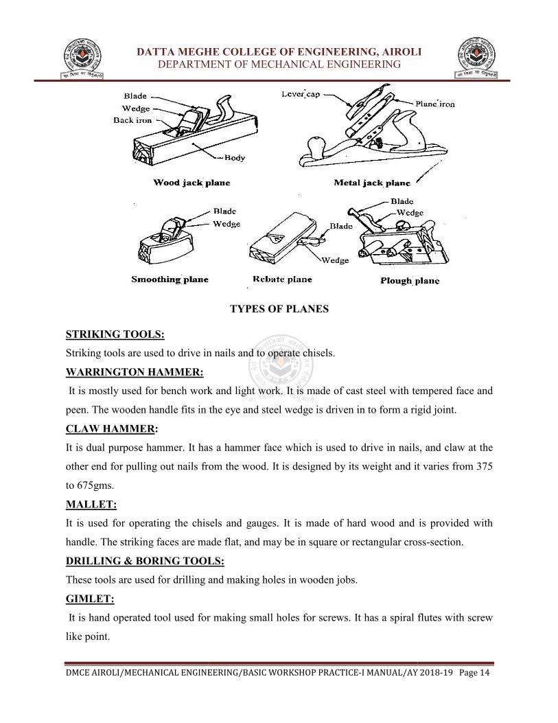
PLANNING TOOLS:
Planning tools are used for reducing and smoothing the surface.
WOODEN JACK PLANE:
It consists of a wooden body or stocks in which blade or stock cutter is fastened at an angle of
45° to the sole. The plane is on (blade or cutter) and the cap iron (back iron) is assembled and
assembly is inserted in the mouth of plane along with the wedge. The back iron supports the
cutting edge and also breaks the shavings so that they air away from the blade. The blade can be
set for taking deeper or shallower cuts. The length of the jack plane is about 350to 425mm. The
blade is made of high carbon steel and has a width of 50 to 75 mm. Its cutting edge is tempered
and ground to an angle of 25 to 30° and it is slightly curved (Convex).
METAL JACK PLANE:
Its body is made of gray cast iron and it is provided with a wooden handle at the back and a
wooden knob at the front for holding with both the hands. A fine screw is used for adjusting the
depth of cut i.e.; the thickness of shaving removed and a level is used for lateral adjustment of
the blade. It is very durable and gives better finish.
CHISELS:
Chisels are used for cutting excess wood in shaping and joint making.
FIRMER CHISEL:
The firmer chisel is capable of doing heavy work and is used for jointing and shaping the wood,
with or without mallet. The chisel blade is made of rectangular section with beveled edge length
of the blade is about 125mm and the width of the edge varies from 3 to 5mm.
DOVETAIL CHISEL:
It is similar to firmer chisel but sides are leveled so that it can cut sharp corners. It is used for
cutting sockets where the angles are less than a right angle.
MORTISE CHISEL:
These chisels are robust, and can withstand heavy blows. It has a thick stock and narrow cutting
edge. It is used for cutting mortises, and its width is ground to exact size of mortise to be out.
OUTSIDE CHISEL:
It is level on outside and it is used for making hallows.
DATTA MEGHE COLLEGE OF ENGINEERING, AIROLI
DEPARTMENT OF MECHANICAL ENGINEERING
DMCE AIROLI/MECHANICAL ENGINEERING/BASIC WORKSHOP PRACTICE
STRIKING TOOLS:
Striking tools are used to drive in nails and to operate chisels.
WARRINGTON HAMMER:
It is mostly used for bench work and light work. It is made of cast steel
peen. The wooden handle fits in the eye and steel wedge is driven in to form a rigid joint.
CLAW HAMMER:
It is dual purpose hammer. It has a hammer face which is used to drive in nails, and claw at the
other end for pulling out nails from the wood. It is designed by its weight and it varies from 375
to 675gms.
MALLET:
It is used for operating the chisels
handle. The striking faces are made flat, and may be in square or rectangular cross
DRILLING & BORING TOOLS:
These tools are used for drilling and making holes in wooden jobs.
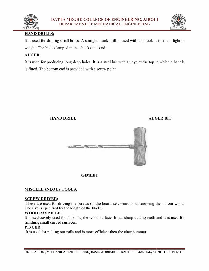
GIMLET:
It is hand operated tool used for making small holes for screws. It has a spiral flutes with screw
like point.
DATTA MEGHE COLLEGE OF ENGINEERING, AIROLI
DEPARTMENT OF MECHANICAL ENGINEERING
ENGINEERING/BASIC WORKSHOP PRACTICE-I MANUAL/AY 201
TYPES OF PLANES
Striking tools are used to drive in nails and to operate chisels.
It is mostly used for bench work and light work. It is made of cast steel with tempered face and
peen. The wooden handle fits in the eye and steel wedge is driven in to form a rigid joint.
It is dual purpose hammer. It has a hammer face which is used to drive in nails, and claw at the
other end for pulling out nails from the wood. It is designed by its weight and it varies from 375
It is used for operating the chisels and gauges. It is made of hard wood and is provided with
handle. The striking faces are made flat, and may be in square or rectangular cross
DRILLING & BORING TOOLS:
These tools are used for drilling and making holes in wooden jobs.
is hand operated tool used for making small holes for screws. It has a spiral flutes with screw
DATTA MEGHE COLLEGE OF ENGINEERING, AIROLI
DEPARTMENT OF MECHANICAL ENGINEERING
I MANUAL/AY 2018-19 Page 14
with tempered face and
peen. The wooden handle fits in the eye and steel wedge is driven in to form a rigid joint.
It is dual purpose hammer. It has a hammer face which is used to drive in nails, and claw at the
other end for pulling out nails from the wood. It is designed by its weight and it varies from 375
and gauges. It is made of hard wood and is provided with
handle. The striking faces are made flat, and may be in square or rectangular cross-section.
is hand operated tool used for making small holes for screws. It has a spiral flutes with screw
DATTA MEGHE COLLEGE OF ENGINEERING, AIROLI
DEPARTMENT OF MECHANICAL ENGINEERING
DMCE AIROLI/MECHANICAL ENGINEERING/BASIC WORKSHOP PRACTICE
HAND DRILLS:
It is used for drilling small holes. A straight shank drill is used with this tool. It is small, light in
weight. The bit is clamped in the chuck at its end.
AUGER:
It is used for producing long deep holes. It is a steel bar with an eye at the top in which a handle
is fitted. The bottom end is provided with a screw point.
HAND DRILL
MISCELLANEOUS TOOLS:
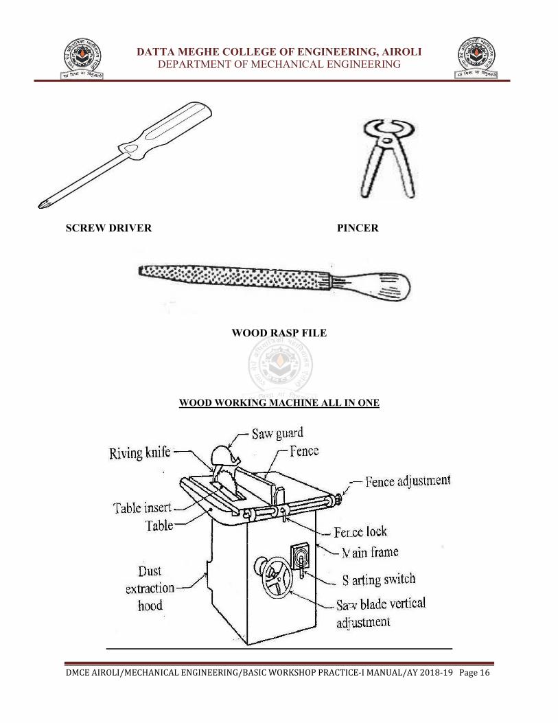
SCREW DRIVER:
These are used for driving the screws on the board i.e., wood or unscrewing them from wood.
The size is specified by the length of the blade.
WOOD RASP FILE:
It is exclusively used for finishing the wood surface. It has sharp cutting teeth and it is used for
finishing small curved surfaces.
PINCER:
It is used for pulling out nails and is more efficient then the claw hammer
DATTA MEGHE COLLEGE OF ENGINEERING, AIROLI
DEPARTMENT OF MECHANICAL ENGINEERING
ENGINEERING/BASIC WORKSHOP PRACTICE-I MANUAL/AY 201
It is used for drilling small holes. A straight shank drill is used with this tool. It is small, light in
in the chuck at its end.
It is used for producing long deep holes. It is a steel bar with an eye at the top in which a handle
is fitted. The bottom end is provided with a screw point.
AUGER BIT
GIMLET
MISCELLANEOUS TOOLS:
These are used for driving the screws on the board i.e., wood or unscrewing them from wood.
The size is specified by the length of the blade.
It is exclusively used for finishing the wood surface. It has sharp cutting teeth and it is used for
It is used for pulling out nails and is more efficient then the claw hammer
DATTA MEGHE COLLEGE OF ENGINEERING, AIROLI
DEPARTMENT OF MECHANICAL ENGINEERING
I MANUAL/AY 2018-19 Page 15
It is used for drilling small holes. A straight shank drill is used with this tool. It is small, light in
It is used for producing long deep holes. It is a steel bar with an eye at the top in which a handle
AUGER BIT
These are used for driving the screws on the board i.e., wood or unscrewing them from wood.
It is exclusively used for finishing the wood surface. It has sharp cutting teeth and it is used for
DATTA MEGHE COLLEGE OF ENGINEERING, AIROLI
DEPARTMENT OF MECHANICAL ENGINEERING
DMCE AIROLI/MECHANICAL ENGINEERING/BASIC WORKSHOP PRACTICE-I MANUAL/AY 2018-19 Page 16
SCREW DRIVER PINCER
WOOD RASP FILE
WOOD WORKING MACHINE ALL IN ONE

DATTA MEGHE COLLEGE OF ENGINEERING, AIROLI
DEPARTMENT OF MECHANICAL ENGINEERING
DMCE AIROLI/MECHANICAL ENGINEERING/BASIC WORKSHOP PRACTICE-I MANUAL/AY 2018-19 Page 17
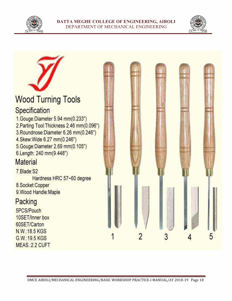
WOOD TURNING:
Woodturning is the craft of using the wood lathe with hand-held tools to cut a shape that is
symmetrical around the axis of rotation. Like the potter's wheel, the wood lathe is a simple
mechanism which can generate a variety of forms. The operator is known as a turner, and the
skills needed to use the tools were traditionally known as turnery. In pre-industrial England,
these skills were sufficiently difficult to be known as 'the misterie' of the turners guild. The skills
to use the tools by hand, without a fixed point of contact with the wood, distinguish woodturning
and the wood lathe from the machinists lathe, or metal-working lathe.
Items made on the lathe include tool handles, candlesticks, egg cups, knobs, lamps, rolling pins,
cylindrical boxes, Christmas ornaments, bodkins, knitting needles, needle cases, thimbles, pens,
chessmen, spinning tops; legs, spindles and pegs for furniture; balusters and newel posts for
architecture; baseball bats, hollow forms such as woodwind musical instruments, urns,
sculptures; bowls, platters, and chair seats. Industrial production has replaced many of these
products from the traditional turning shop. However, the wood lathe is still used for
decentralized production of limited or custom turnings. A skilled turner can produce a wide
variety of objects with five or six simple tools. The tools can be reshaped easily for the task at
hand.
WOOD TURNING MACHINE WOOD TURNING TOOLS
DATTA MEGHE COLLEGE OF ENGINEERING, AIROLI
DEPARTMENT OF MECHANICAL ENGINEERING
DMCE AIROLI/MECHANICAL ENGINEERING/BASIC WORKSHOP PRACTICE-I MANUAL/AY 2018-19 Page 18

DATTA MEGHE COLLEGE OF ENGINEERING, AIROLI
DEPARTMENT OF MECHANICAL ENGINEERING
DMCE AIROLI/MECHANICAL ENGINEERING/BASIC WORKSHOP PRACTICE-I MANUAL/AY 2018-19 Page 19
WOOD TURNING / PLANING SHAPES

DATTA MEGHE COLLEGE OF ENGINEERING, AIROLI
DEPARTMENT OF MECHANICAL ENGINEERING
DMCE AIROLI/MECHANICAL ENGINEERING/BASIC WORKSHOP PRACTICE-I MANUAL/AY 2018-19 Page 20
WELDING SECTION
INTRODUCTION
Welding is the process of joining similar metals by the application of heat, with or without
application of pressure or filler metal, in such a way that the joint is equivalent in composition
and characteristics of the metals joined. In the beginning, welding was mainly used for repairing
all kinds of worn or damaged parts. Now, it is extensively used in manufacturing industry,
construction industry (construction of ships, tanks, locomotives and automobiles) and
maintenance work, replacing riveting and bolting, to a greater extent.
The various welding processes are:
1. Electric arc welding,
2. Gas welding
3. Thermal welding
4. Electrical Resistance welding and
5. Friction welding
However, only electric arc welding process is discussed in the subject point of view.
Electric arc welding Arc welding is the welding process, in which heat is generated by an electric arc struck between
an electrode and the work piece. Electric arc is luminous electrical discharge between two
electrodes through ionized gas.
Any arc welding method is based on an electric circuit consisting of the following parts: a. Power supply (AC or DC);
b. Welding electrode;
c. Work piece;
d. Welding leads (electric cables) connecting the electrode and work piece to the power
supply. Electric arc between the electrode and work piece closes the electric circuit. The arc
temperature may reach 10000°F (5500°C), which is sufficient for fusion the work piece edges
and joining them. When a long joint is required the arc is moved along the joint line. The front
edge of the weld pool melts the welded surfaces when the rear edge of the weld pool solidifies
forming the joint. Transformers, motor generators and rectifiers’ sets are used as arc welding
machines. These machines supply high electric currents at low voltage and an electrode is used
to produce the necessary arc. The electrode serves as the filler rod and the arc melts the surface
so that, the metals to be joined are actually fixed together.
Sizes of welding machines are rated according to their approximate amperage capacity at 60%
duty cycle, such as 150,200,250,300,400,500 and 600 amperes. This amperage is the rated
current output at the working terminal.

DATTA MEGHE COLLEGE OF ENGINEERING, AIROLI
DEPARTMENT OF MECHANICAL ENGINEERING
DMCE AIROLI/MECHANICAL ENGINEERING/BASIC WORKSHOP PRACTICE-I MANUAL/AY 2018-19 Page 21
Transformers
The transformers type of welding machine produces A.C current and is considered to be the least
expensive. It takes power directly from power supply line and transforms it to the voltage
required for welding. Transformers are available in single phase and three phases in the market.
Motor generators
These are D.C generators sets, in which electric motor and alternator are mounted on the same
shaft to produce D.C power as pert the requirement for welding. These are designed to
produce D.C current in either straight or reversed polarity. The polarity selected for welding
depends upon the kind of electrode used and the material to be welded.
Rectifiers
These are essentially transformers, containing an electrical device which changes A.C into D.C
by virtue of which the operator can use both types of power (A.C or D.C, but only one at a
time).In addition to the welding machine; certain accessories are needed for carrying out the
welding work.
Welding cables
Two welding cables are required, one from machine to the electrode holder and the other,
from the machine to the ground clamp. Flexible cables are usually preferred because of the case
of using and coiling the cables. Cables are specified by their current carrying capacity,
say 300 A, 400 A, etc.
Fig 1.1: The Basic circuit for arc welding
DATTA MEGHE COLLEGE OF ENGINEERING, AIROLI
DEPARTMENT OF MECHANICAL ENGINEERING
DMCE AIROLI/MECHANICAL ENGINEERING/BASIC WORKSHOP PRACTICE-I MANUAL/AY 2018-19 Page 22
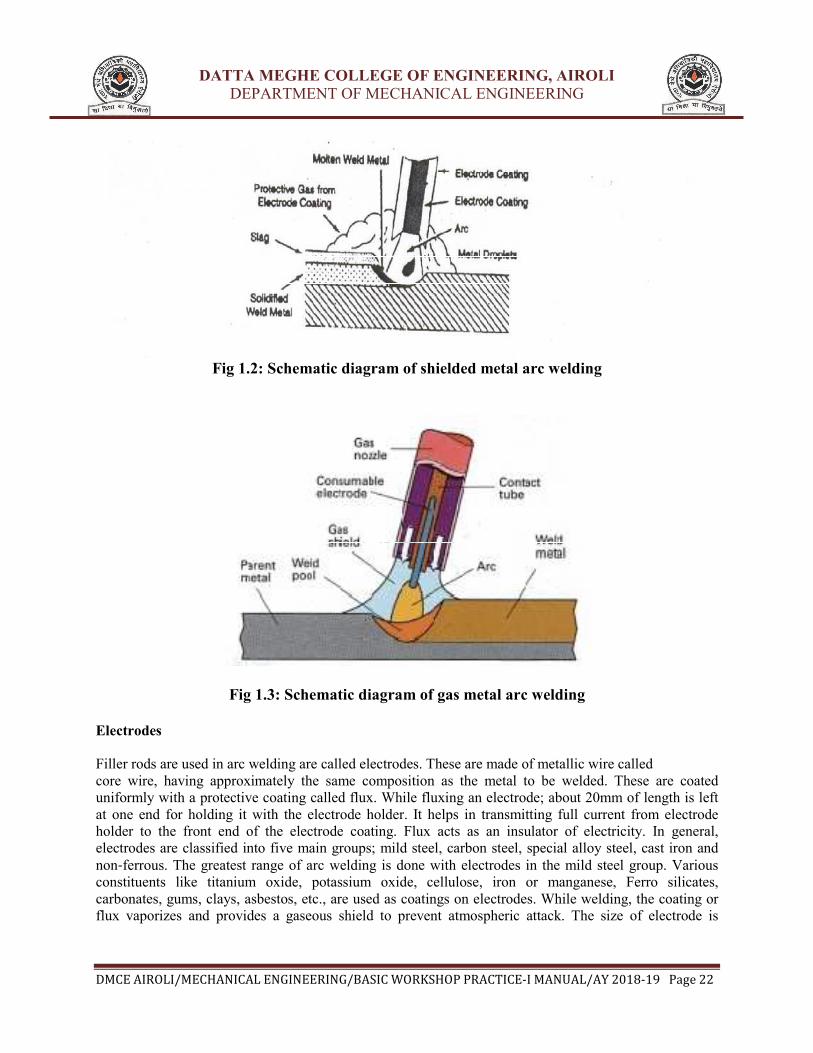
Fig 1.2: Schematic diagram of shielded metal arc welding
Fig 1.3: Schematic diagram of gas metal arc welding
Electrodes
Filler rods are used in arc welding are called electrodes. These are made of metallic wire called
core wire, having approximately the same composition as the metal to be welded. These are coated
uniformly with a protective coating called flux. While fluxing an electrode; about 20mm of length is left
at one end for holding it with the electrode holder. It helps in transmitting full current from electrode
holder to the front end of the electrode coating. Flux acts as an insulator of electricity. In general,
electrodes are classified into five main groups; mild steel, carbon steel, special alloy steel, cast iron and
non‐ferrous. The greatest range of arc welding is done with electrodes in the mild steel group. Various
constituents like titanium oxide, potassium oxide, cellulose, iron or manganese, Ferro silicates,
carbonates, gums, clays, asbestos, etc., are used as coatings on electrodes. While welding, the coating or
flux vaporizes and provides a gaseous shield to prevent atmospheric attack. The size of electrode is

DATTA MEGHE COLLEGE OF ENGINEERING, AIROLI
DEPARTMENT OF MECHANICAL ENGINEERING
DMCE AIROLI/MECHANICAL ENGINEERING/BASIC WORKSHOP PRACTICE-I MANUAL/AY 2018-19 Page 23
measured and designated by the diameter of the core wire in SWG and length, apart from the brand and
code names; indicating the purpose for which there are most suitable
Electrodes may be classified on the basis of thickness of the coated flux. As
1. Dust coated or light coated
2. Semi or medium coated and
3. Heavily coated or shielded
Electrodes are also classified on the basis of materials, as
1. Metallic and
2. Non‐metallic or carbon
Metallic arc electrodes are further sub‐divided into
1. Ferrous metal arc electrode (mild steel, low/medium/high carbon steel, cast iron, stainless steel )
2. Non‐ferrous metal arc electrodes (copper, brass, bronze, aluminum, etc). In case of non‐metallic arc
electrodes, mainly carbon and graphite are used to make the electrodes.
Electrode holder Ground Clamp
Wire brush Chipping hammer
DATTA MEGHE COLLEGE OF ENGINEERING, AIROLI
DEPARTMENT OF MECHANICAL ENGINEERING
DMCE AIROLI/MECHANICAL ENGINEERING/BASIC WORKSHOP PRACTICE
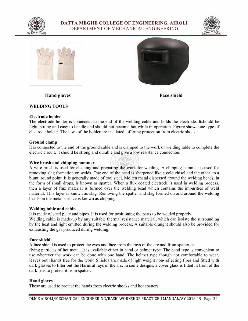
Hand gloves
WELDING TOOLS
Electrode holder The electrode holder is connected to the end of the welding cable and holds the electrode. Itshould be
light, strong and easy to handle and should not become hot while in operation. Figure shows one type of
electrode holder. The jaws of the holder are insu
Ground clamp It is connected to the end of the ground cable and is clamped to the work or welding table to complete the
electric circuit. It should be strong and durable and give a low resistance connection.
Wire brush and chipping hammer
A wire brush is used for cleaning and preparing the work for welding. A chipping hammer is used for
removing slag formation on welds. One end of the head is sharpened like a cold chisel and the other, to a
blunt, round point. It is generally made of tool steel. Molten metal disperse
the form of small drops, is known as spatter. When a flux coated electrode is used in welding process,
then a layer of flux material is formed over the welding bead which contains the impurities of weld
material. This layer is known as slag. Removing the spatter and slag formed on and around the welding
beads on the metal surface is known as chipping.
Welding table and cabin It is made of steel plate and pipes. It is used for positioning the parts to be welded properly.
Welding cabin is made‐up by any suitable thermal resistance material, which can isolate the surrounding
by the heat and light emitted during the welding process. A suitable draught should also be provided for
exhausting the gas produced during welding.
Face shield A face shield is used to protect the eyes and face from the rays of the arc and from spatter or
flying particles of hot metal. It is available either in hand or helmet type. The hand type is convenient to
use wherever the work can be done with o
leaves both hands free for the work. Shields are made of light weight non
dark glasses to filter out the Harmful rays of the arc. In some designs, a cover glass is fi
dark lens to protect it from spatter.
Hand gloves These are used to protect the hands from electric shocks and hot spatters
DATTA MEGHE COLLEGE OF ENGINEERING, AIROLI
DEPARTMENT OF MECHANICAL ENGINEERING
ENGINEERING/BASIC WORKSHOP PRACTICE-I MANUAL/AY 201
Face shield
The electrode holder is connected to the end of the welding cable and holds the electrode. Itshould be
light, strong and easy to handle and should not become hot while in operation. Figure shows one type of
electrode holder. The jaws of the holder are insulated, offering protection from electric shock.
It is connected to the end of the ground cable and is clamped to the work or welding table to complete the
electric circuit. It should be strong and durable and give a low resistance connection.
Wire brush and chipping hammer eaning and preparing the work for welding. A chipping hammer is used for
removing slag formation on welds. One end of the head is sharpened like a cold chisel and the other, to a
blunt, round point. It is generally made of tool steel. Molten metal dispersed around the welding heads, in
the form of small drops, is known as spatter. When a flux coated electrode is used in welding process,
then a layer of flux material is formed over the welding bead which contains the impurities of weld
s known as slag. Removing the spatter and slag formed on and around the welding
beads on the metal surface is known as chipping.
It is made of steel plate and pipes. It is used for positioning the parts to be welded properly.
up by any suitable thermal resistance material, which can isolate the surrounding
by the heat and light emitted during the welding process. A suitable draught should also be provided for
exhausting the gas produced during welding.
A face shield is used to protect the eyes and face from the rays of the arc and from spatter or
flying particles of hot metal. It is available either in hand or helmet type. The hand type is convenient to
use wherever the work can be done with one hand. The helmet type though not comfortable to wear,
leaves both hands free for the work. Shields are made of light weight non‐reflecting fiber and fitted with
dark glasses to filter out the Harmful rays of the arc. In some designs, a cover glass is fi
These are used to protect the hands from electric shocks and hot spatters
DATTA MEGHE COLLEGE OF ENGINEERING, AIROLI
DEPARTMENT OF MECHANICAL ENGINEERING
I MANUAL/AY 2018-19 Page 24
The electrode holder is connected to the end of the welding cable and holds the electrode. Itshould be
light, strong and easy to handle and should not become hot while in operation. Figure shows one type of
lated, offering protection from electric shock.
It is connected to the end of the ground cable and is clamped to the work or welding table to complete the
eaning and preparing the work for welding. A chipping hammer is used for
removing slag formation on welds. One end of the head is sharpened like a cold chisel and the other, to a
d around the welding heads, in
the form of small drops, is known as spatter. When a flux coated electrode is used in welding process,
then a layer of flux material is formed over the welding bead which contains the impurities of weld
s known as slag. Removing the spatter and slag formed on and around the welding
It is made of steel plate and pipes. It is used for positioning the parts to be welded properly.
up by any suitable thermal resistance material, which can isolate the surrounding
by the heat and light emitted during the welding process. A suitable draught should also be provided for
A face shield is used to protect the eyes and face from the rays of the arc and from spatter or
flying particles of hot metal. It is available either in hand or helmet type. The hand type is convenient to
ne hand. The helmet type though not comfortable to wear,
reflecting fiber and fitted with
dark glasses to filter out the Harmful rays of the arc. In some designs, a cover glass is fitted in front of the

DATTA MEGHE COLLEGE OF ENGINEERING, AIROLI
DEPARTMENT OF MECHANICAL ENGINEERING
DMCE AIROLI/MECHANICAL ENGINEERING/BASIC WORKSHOP PRACTICE
TECHNIQUES OF WELDING
WELDING POSITIONS Depending upon the location of the welding joints, appropriate
hand movement is selected. The figure shows different welding positions.
Flat position welding In this position, the welding is performed from the upper side of the joint, and the face of the weld is
approximately horizontal. Flat welding is the preferred term; however, the same position is sometimes
called down hand.
Horizontal position welding In this position, welding is performed on the upper side of an approximately horizontal surface
and against an approximately vertical surface.
Vertical position welding In this position, the axis of the weld is approximately vertical as shown in figure.
Overhead position welding
In this welding position, the welding is performed from the unde
DATTA MEGHE COLLEGE OF ENGINEERING, AIROLI
DEPARTMENT OF MECHANICAL ENGINEERING
ENGINEERING/BASIC WORKSHOP PRACTICE-I MANUAL/AY 201
Depending upon the location of the welding joints, appropriate position of the electrode and
hand movement is selected. The figure shows different welding positions.
In this position, the welding is performed from the upper side of the joint, and the face of the weld is
al. Flat welding is the preferred term; however, the same position is sometimes
In this position, welding is performed on the upper side of an approximately horizontal surface
and against an approximately vertical surface.
In this position, the axis of the weld is approximately vertical as shown in figure.
In this welding position, the welding is performed from the underside of a joint
Weld positions
DATTA MEGHE COLLEGE OF ENGINEERING, AIROLI
DEPARTMENT OF MECHANICAL ENGINEERING
I MANUAL/AY 2018-19 Page 25
position of the electrode and
In this position, the welding is performed from the upper side of the joint, and the face of the weld is
al. Flat welding is the preferred term; however, the same position is sometimes
In this position, welding is performed on the upper side of an approximately horizontal surface

DATTA MEGHE COLLEGE OF ENGINEERING, AIROLI
DEPARTMENT OF MECHANICAL ENGINEERING
DMCE AIROLI/MECHANICAL ENGINEERING/BASIC WORKSHOP PRACTICE
DATTA MEGHE COLLEGE OF ENGINEERING, AIROLI
DEPARTMENT OF MECHANICAL ENGINEERING
ENGINEERING/BASIC WORKSHOP PRACTICE-I MANUAL/AY 201
WELDING JOINTS
DATTA MEGHE COLLEGE OF ENGINEERING, AIROLI
DEPARTMENT OF MECHANICAL ENGINEERING
I MANUAL/AY 2018-19 Page 26

DATTA MEGHE COLLEGE OF ENGINEERING, AIROLI
DEPARTMENT OF MECHANICAL ENGINEERING
DMCE AIROLI/MECHANICAL ENGINEERING/BASIC WORKSHOP PRACTICE
INTRODUCTION
In a machine shop, metals are cut to shape on different machine tools. A lathe is used to cut and
shape the metal by revolving the work against a cutting tool. The
chuck, fitted on to the lathe spindle or in
post, mounted on a movable carriage that is positioned on the lathe bed. The cutting tool can be
fed on to the work, either len
counter‐clockwise direction, when viewed from the tail stock end.
PRINCIPAL PARTS OF A LATHE
Figure 4.1 shows a center lathe, indicating the main parts. The name is due to the fact that
workpieces are held by the centers.
BED
It is an essential part of a lathe, which must be strong and rigid. It carries all parts of the
machine and resists the cutting forces. The carriage and the tail stock move along the guide ways
provided on the bed. It is usually made of cast iron.
HEAD STOCK
It contains either a cone pulley or gearings to provide the necessary range of speeds and feeds.It
contains the main spindle, to which the work is held and rotated.
TAIL STOCK
DATTA MEGHE COLLEGE OF ENGINEERING, AIROLI
DEPARTMENT OF MECHANICAL ENGINEERING
ENGINEERING/BASIC WORKSHOP PRACTICE-I MANUAL/AY 201
MACHINE SHOP
In a machine shop, metals are cut to shape on different machine tools. A lathe is used to cut and
shape the metal by revolving the work against a cutting tool. The work is clamped either in a
chuck, fitted on to the lathe spindle or in‐between the centers. The cutting tool is fixed in a tool
post, mounted on a movable carriage that is positioned on the lathe bed. The cutting tool can be
fed on to the work, either lengthwise or cross‐wise. While turning, the chuck rotates in
clockwise direction, when viewed from the tail stock end.
RINCIPAL PARTS OF A LATHE
Figure 4.1 shows a center lathe, indicating the main parts. The name is due to the fact that
workpieces are held by the centers.
It is an essential part of a lathe, which must be strong and rigid. It carries all parts of the
e cutting forces. The carriage and the tail stock move along the guide ways
provided on the bed. It is usually made of cast iron.
It contains either a cone pulley or gearings to provide the necessary range of speeds and feeds.It
main spindle, to which the work is held and rotated.
DATTA MEGHE COLLEGE OF ENGINEERING, AIROLI
DEPARTMENT OF MECHANICAL ENGINEERING
I MANUAL/AY 2018-19 Page 27
In a machine shop, metals are cut to shape on different machine tools. A lathe is used to cut and
work is clamped either in a
between the centers. The cutting tool is fixed in a tool
post, mounted on a movable carriage that is positioned on the lathe bed. The cutting tool can be
wise. While turning, the chuck rotates in
Figure 4.1 shows a center lathe, indicating the main parts. The name is due to the fact that
It is an essential part of a lathe, which must be strong and rigid. It carries all parts of the
e cutting forces. The carriage and the tail stock move along the guide ways
It contains either a cone pulley or gearings to provide the necessary range of speeds and feeds.It
DATTA MEGHE COLLEGE OF ENGINEERING, AIROLI
DEPARTMENT OF MECHANICAL ENGINEERING
DMCE AIROLI/MECHANICAL ENGINEERING/BASIC WORKSHOP PRACTICE-I MANUAL/AY 2018-19 Page 28
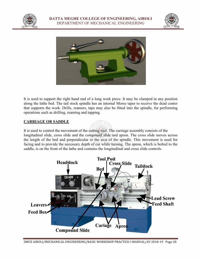
It is used to support the right hand end of a long work piece. It may be clamped in any position
along the lathe bed. The tail stock spindle has an internal Morse taper to receive the dead center
that supports the work. Drills, reamers, taps may also be fitted into the spindle, for performing
operations such as drilling, reaming and tapping.
CARRIAGE OR SADDLE
It is used to control the movement of the cutting tool. The carriage assembly consists of the
longitudinal slide, cross slide and the compound slide and apron. The cross slide moves across
the length of the bed and perpendicular to the axis of the spindle. This movement is used for
facing and to provide the necessary depth of cut while turning. The apron, which is bolted to the
saddle, is on the front of the lathe and contains the longitudinal and cross slide controls.

DATTA MEGHE COLLEGE OF ENGINEERING, AIROLI
DEPARTMENT OF MECHANICAL ENGINEERING
DMCE AIROLI/MECHANICAL ENGINEERING/BASIC WORKSHOP PRACTICE-I MANUAL/AY 2018-19 Page 29
COMPOUND REST
It supports the tool post. By swiveling the compound rest on the cross slide, short tapers may be
turned to any desired angles.
TOOL POST
The tool post holds the tool holder or the tool, which may be adjusted to any working position.
LEAD SCREW
It is a long threaded shaft, located in front of the carriage, running from the head‐stock to the
tail stock. It is geared to the spindle and controls the movement of the tool, either for automatic
feeding or for cutting threads.
CENTERS
There are two centers known as dead center and live center. The dead center is positioned in
the tail stock spindle and the live center, in the head‐stock spindle. While turning between
centers, the dead center does not revolve with the work while the live center revolves with the
work.

DATTA MEGHE COLLEGE OF ENGINEERING, AIROLI
DEPARTMENT OF MECHANICAL ENGINEERING
DMCE AIROLI/MECHANICAL ENGINEERING/BASIC WORKSHOP PRACTICE-I MANUAL/AY 2018-19 Page 30
WORK‐HOLDING DEVICES
1. THREE JAW CHUCK
It is a work holding device having three jaws (self‐centering) which will close or open with
respect to the chuck center or the spindle center, as shown in figure. It is used for holding regular
objects like round bars, hexagonal rods, etc.
FACE PLATE
It is a plate of large diameter, used for turning operations. Certain types of work that cannot be
held in chucks are held on the face plate with the help of various accessories.
LATHE DOGS AND DRIVING PLATE
These are used to drive a work piece that is held between centers. These are provided with an
opening to receive and clamp the work piece and dog tail, the tail of the dog is carried by the pin
provided in the driving plate for driving the work piece.
MEASURING INSTRUMENTS
1. OUTSIDE AND INSIDE CALIPERS
Firm joint or spring calipers are used for transfer of dimensions with the help of a steel rule.

DATTA MEGHE COLLEGE OF ENGINEERING, AIROLI
DEPARTMENT OF MECHANICAL ENGINEERING
DMCE AIROLI/MECHANICAL ENGINEERING/BASIC WORKSHOP PRACTICE-I MANUAL/AY 2018-19 Page 31
2. VERNIER CALIPERS
Vernier caliper is a versatile instrument with which both outside and inside measurements may
be made accurately. These instruments may have provision for depth measurement also.
3. MICROMETERS
Outside and inside micrometers are used for measuring components where greater accuracy is
required.
CUTTING PARAMETERS
1. CUTTING SPEED
It is defined as the speed at which the material is removed and is specified in meters per
minute. Ti depends upon the work piece material, feed, depth of cut, type of operation and so
many other cutting conditions. It is calculated from the relation, Spindle speed (RPM) =
cutting speed x 1000 / (πD) Where D is the work piece diameter in mm.
2. FEED
It is the distance traversed by the tool along the bed, during one revolution of the work. Its value
depends upon the depth of cut and surface finish of the work desired.
3. DEPTH OF CUT
It is the movement of the tip of the cutting tool, from the surface of the work piece and
perpendicular to the lathe axis. Its value depends upon the nature of operation like rough turning
or finish turning.

DATTA MEGHE COLLEGE OF ENGINEERING, AIROLI
DEPARTMENT OF MECHANICAL ENGINEERING
DMCE AIROLI/MECHANICAL ENGINEERING/BASIC WORKSHOP PRACTICE-I MANUAL/AY 2018-19 Page 32
TOOL MATERIALS
General purpose hand cutting tools are usually made from carbon steel or tool steel. The single
point lathe cutting tools are made of high speed steel (HSS).the main alloying elements in 18‐4‐1
HSS tools are 18 percent tungsten, 4 percent chromium and 1 percent vanadium.5 to 10 percent
cobalt is also added to improve the heat resisting properties of the tool.
Carbide tipped tools fixed in tool holders, are mostly used in production shops.
LATHE OPERATIONS
1. TURNING
Cylindrical shapes, both external and internal, are produced by turning operation. Turning is the
process in which the material is removed by a traversing cutting tool, from the surface of a
rotating workpiece. The operation used for machining internal surfaces is often called the boring
operation in which a hole previously drilled is enlarged. For turning long work, first it should be
faced and center drilled at one end and then supported by means of the tail‐stock centre.
2.BORING
Boring is enlarging a hole and is used when correct size drill is not available. However, it should
be noted that boring cannot make a hole.
3.FACING
Facing is a machining operation, performed to make the end surface of the work piece, flat and
perpendicular to the axis of rotation. For this, the work piece may be held in a chuck and rotated
about the lathe axis. A facing tool is fed perpendicular to the axis of the lathe. The tool is slightly
inclined towards the end of the work piece.

DATTA MEGHE COLLEGE OF ENGINEERING, AIROLI
DEPARTMENT OF MECHANICAL ENGINEERING
DMCE AIROLI/MECHANICAL ENGINEERING/BASIC WORKSHOP PRACTICE-I MANUAL/AY 2018-19 Page 33
4.TAPER TURNING
A taper is defined as the uniform change in the diameter of a work piece, measured along its
length. It is expressed as a ratio of the difference in diameters to the length. It is also expressed in
degrees of half the included (taper) angle. Taper turning refers to the production of a conical
surface, on the work piece on a lathe. Short steep tapers may be cut on a lathe by swiveling the
compound rest to the required angle. Here, the cutting tool is fed by means of the compound
slide feed handle. The work piece is rotated in a chuck or face plate or between centers.
5.DRILLING
Holes that are axially located in cylindrical parts are produced by drilling operation, using a twist
drill. For this, the work piece is rotated in a chuck or face plate. The tail stock spindle has a
standard taper. The drill bit is fitted into the tail stock spindle directly or through drill chuck. The
tail stock is then moved over the bed and clamped on it near the work. When the job rotates, the
drill bit is fed into the work by turning the tail stock hand wheel.
6.KNURLING
It is the process of embossing a diamond shaped regular pattern on the surface of a work piece
using a special knurling tool. This tool consists of a set of hardened steel rollers in a holder with
the teeth cut on their surface in a definite pattern. The tool is held rigidly on the tool post and the
rollers are pressed against the revolving work piece to squeeze the metal against the multiple
cutting edges. The purpose of knurling is to provide an effective gripping surface on a work
piece to prevent it from slipping when operated by hand.
7.CHAMFERING
It is the operation of beveling the extreme end of a work piece. Chamfer is provided for better
look, to enable nut to pass freely on threaded work piece, to remove burrs and protect the end of
the work piece from being damaged.
8.THREADING
Threading is nothing but cutting helical groove on a work piece. Threads may be cut either on
the internal or external cylindrical surfaces. A specially shaped cutting tool, known as thread
cutting tool, is used for this purpose. Thread cutting in a lathe is performed by traversing the
cutting tool at a definite rate, in proportion to the rate at which the work revolves.