date: july 22, 2008
TRANSCRIPT
Project Number: ME-MAD-07B
.
LED LIGHT DESIGN
A Major Qualifying Project Report
submitted to the Faculty
of the
WORCESTER POLYTECHNIC INSTITUTE
in partial fulfillment of the requirements for the
Degree of Bachelor of Science
Date: July 22, 2008
WPI Project Team
David Embree
Christopher Kingsley
Advisor: Professor Yiming Rong
HUST Project Team
Lu Wei
Guo Huimin
Deng Yujun
Advisor: Professor Liang Gao

Abstract Three prototype light fixtures that used Light Emitting Diodes (LED) for machine tools
were developed. These light fixtures were designed with a significant focus on improving
current light fixtures in the areas of efficiency, light head shape, fixture to machine tool, light
quality, and heat dissipation. The prototypes were tested by trial at the Rapid Engineering
Manufacturing factory in Wuxi, China, and suggestions for future improvements to each design
were developed.

Acknowledgements
Professor Rong For setting up the MQP in China and making sure that we were taken care of every step of the way.
Mr. Al Barry For sponsoring the project and helping us with project management. Professor Gao
For helping us to work with the HUST facilities and continuing to give us money, even when we had spent far more than any of the other groups.
Professor Qiu For all of his helpful comments at our weekly presentations Mr. Wang For interfacing with the workers at the Training Facility and fixing our drawings Sheetmetal Worker
We don’t know his name, but without him, creating the Rounded Bar would have been nigh impossible
HUST Engineering Training Center For providing us with tools and a room to work in. East 1 Manufacturing Facility For all of their useful input on our designs.

Introduction

Table of Contents
ABSTRACT .............................................................................................................................................................. 2
INTRODUCTION ..................................................................................................................................................... 4
TABLE OF CONTENTS .............................................................................................................................................. 5
TABLE OF FIGURES ......................................................................................................................................................... 8
TABLE OF TABLES ........................................................................................................................................................... 8
GOAL STATEMENT ................................................................................................................................................. 9
BACKGROUND ..................................................................................................................................................... 10
LED’S ........................................................................................................................................................................ 10
RAPID ENGINEERING MANUFACTURING ........................................................................................................................... 12
METHODOLOGY ................................................................................................................................................... 14
INTRODUCTION ............................................................................................................................................................ 14
OVERALL PROJECT PLANNING ......................................................................................................................................... 14
PLANNING PHASE ........................................................................................................................................................ 14
Shape of Housing Design .................................................................................................................................... 14
Heat Dissipation ................................................................................................................................................. 16
Circuit Design DE ................................................................................................................................................ 18
Structural Frame ................................................................................................................................................ 18
Light Quality CK ................................................................................................................................................. 23
FABRICATION STAGE ..................................................................................................................................................... 25
Structural Frame Fabrication ............................................................................................................................. 25
Shape Fabrication............................................................................................................................................... 26
TESTING STAGE ........................................................................................................................................................... 32
Tests Done and Analysis ..................................................................................................................................... 32
Modifications Made ........................................................................................................................................... 32
RESULTS ............................................................................................................................................................... 33
STRUCTURAL FRAME DECISION ....................................................................................................................................... 33
FINAL DESIGN CHOICE .................................................................................................................................................. 33
Heat Experiment Results .................................................................................................................................... 33
Light Output Results ........................................................................................................................................... 33
Factory Worker Results ...................................................................................................................................... 33
CONCLUSIONS ..................................................................................................................................................... 33
WHAT WE’VE LEARNED ................................................................................................................................................. 33
FUTURE RECOMMENDATIONS ............................................................................................................................. 34
CURRENT ISSUES .......................................................................................................................................................... 34
Rounded Bar ....................................................................................................................................................... 34
Structural Frame ................................................................................................................................................ 34
Magnetic Grips ................................................................................................................................................... 35
SPRING BOARD IDEA DYJ .............................................................................................................................................. 35

Experiments ........................................................................................................................................................ 35
Models ................................................................................................................................................................ 35
OTHER RECCOMENDATIONS ........................................................................................................................................... 36
Retail Price ......................................................................................................................................................... 36
More rigorous photometrics testing .................................................................................................................. 37
Improvements to Heat Dissipation Expt. ............................................................................................................ 37
REFERENCES ......................................................................................................................................................... 38
APPENDIX A: EXPERIMENTS AND TESTS ............................................................................................................... 39
POWER TEST ............................................................................................................................................................... 39
WORKERS’ OPINIONS ................................................................................................................................................... 40
PHOTOMETRICS TEST .................................................................................................................................................... 41
APPENDIX B: ENGINEERING DRAWINGS .............................................................................................................. 42
APPENDIX C: CAD MODELS (.STL) ......................................................................................................................... 43
APPENDIX D: ACCOUNTS ..................................................................................................................................... 44
JOINTED BAR .............................................................................................................................................................. 44
ROUNDED BAR ............................................................................................................................................................ 45
STEPPED CONE ............................................................................................................................................................ 46
APPENDIX E: WEEKLY WORK SCHEDULES ............................................................................................................. 47
WEEK 2 ..................................................................................................................................................................... 47
WEEK 3 ..................................................................................................................................................................... 48
WEEK 4 ..................................................................................................................................................................... 49
WEEK 5 ..................................................................................................................................................................... 50
WEEK 6 ..................................................................................................................................................................... 51
WEEK 7 ..................................................................................................................................................................... 52
APPENDIX F: ORIGINAL PROJECT PROPOSAL ........................................................................................................ 53
ABSTRACT .................................................................................................................................................................. 54
INTRODUCTION ............................................................................................................................................................ 55
BACKGROUND INFORMATION ......................................................................................................................................... 56
LED’s ................................................................................................................................................................... 56
Rapid Engineering Manufacturing ..................................................................................................................... 58
METHOD OF RESEARCH AND DEVELOPMENT ..................................................................................................................... 60
TENTATIVE TIMELINE .................................................................................................................................................... 61
EXPECTED RESULTS ...................................................................................................................................................... 64
REFERENCES ............................................................................................................................................................... 65
APPENDIX G: PROPORTIONALITY OF LIGHT FLUX ................................................................................................. 67
APPENDIX H: HEAT EXPERIMENT PROCEDURE AND EQUIPMENT LIST ................................................................. 68
PROCEDURE ................................................................................................................................................................ 68
EQUIPMENT USED ........................................................................................................................................................ 69
APPENDIX I: SHAPE MATRICES ............................................................................................................................. 70

FINAL MATRIX ............................................................................................................................................................. 70
INDIVIDUAL SHAPE MATRICES ........................................................................................................................................ 71
Lu Wei ................................................................................................................................................................ 71
Deng Yujun ......................................................................................................................................................... 72
David .................................................................................................................................................................. 73
Chris ................................................................................................................................................................... 74
David .................................................................................................................................................................. 75
APPENDIX J: PHOTOMETRICS SHEETS .................................................................................................................. 76

Table of Figures FIGURE 1: BRAINSTORMING RESULTS ................................................................................................................................... 15
FIGURE 2: RELATIVE LIGHT OUTPUT VS. CIRCUIT BOARD TEMPERATURE ...................................................................................... 17
FIGURE 3: TIME OF DAY VS. TEMPERATURE ........................................................................................................................... 18
FIGURE 4: INCANDESCENT FIXTURE USED ON A LATHE .............................................................................................................. 19
FIGURE 5: PLANING MACHINE HALOGEN .............................................................................................................................. 19
FIGURE 6: LED FLASHLIGHT USED AT THE TAPPING AND COUNTERSINKING STATION ....................................................................... 20
FIGURE 7: LED FLASHLIGHT IN USE ...................................................................................................................................... 20
FIGURE 8: FOUR-BAR ARM ATTACHED TO A VERTICAL MILLING MACHINE ...................................................................................... 20
FIGURE 9: HALOGEN GOOSENECK ........................................................................................................................................ 21
FIGURE 10: STRUCTURAL FRAME POSSIBILITIES ...................................................................................................................... 22
FIGURE 11: FLEXIBLE COOLANT TUBING SEGMENT ................................................................................................................... 23
FIGURE 12: ROUNDED BAR CONCEPTUAL SHAPE .................................................................................................................... 26
FIGURE 13: PROTEL DIAGRAM OF THE BLINKING PCB .............................................................................................................. 26
FIGURE 14: PROTEL DIAGRAM OF THE CONSTANT PCB ............................................................................................................ 27
FIGURE 15:WIRING DIAGRAM FOR ROUNDED BAR ................................................................................................................. 28
FIGURE 16: EXPLODED VIEW OF THE STEPPED CONE DESIGN ..................................................................................................... 29
FIGURE 17: ADJUSTABLE HOOKS ......................................................................................................................................... 29
FIGURE 18: SMALL STEPPED CONE PROTOTYPE ...................................................................................................................... 30
FIGURE 19: LARGE PROTOTYPE SHELL ................................................................................................................................... 31
FIGURE 20: BREADBOARD ARRANGEMENT ............................................................................................................................. 68
FIGURE 21: OVERALL ASSEMBLY ......................................................................................................................................... 68
Table of Tables TABLE 1: FINAL DECISION MATRIX ....................................................................................................................................... 16
TABLE 2: AVERAGE OPERATING TEMPERATURE (°C) ................................................................................................................ 18
TABLE 3: TABLE SHOWING THE CONNECTIONS BETWEEN CONTACTS. WHITE AND BLACK REFER TO THE TWO DIFFERENT SIDES OF THE AC
POWER INPUT ......................................................................................................................................................... 28
TABLE 4: RESULTS OF FINAL FACTORY INTERVIEW .................................................................................................................... 33
TABLE 5: PRICE OF THE LIGHTS CURRENTLY USED IN THE FACTORY ............................................................................................... 36
TABLE 6: RESEARCH ON THE CURRENT PRICE OF LIGHTS ............................................................................................................ 36
TABLE 7: FINAL PROTOYPE COSTS ........................................................................................................................................ 37

Goal Statement The goal of this project is to design and create LED factory task lights with emphasis on
the following five features: efficient circuit, appropriate light head shape, functional structural
frame, adequate heat dissipation, and excellent light quality.

Background
LED’s
Light Emitting Diodes, more commonly known as LED’s, were invented in the second
half of the twentieth century. The earliest LED’s were only able to emit light in the infrared
range, and thus their applications were limited. Since then, LED technology has developed into
the visible spectrum, and LED’s are finding all kinds of applications, from flashlights to
jumbotrons.
LED Benefits
The advantages that LED’s hold over existing lights are both economic and
environmental.
Economically, LED’s consume much less power than both incandescent and fluorescent
lights. In terms of efficiency, LED’s can produce about 90 lumens per watt of power consumed,
and this number is steadily increasing. A standard incandescent light generally produces a
maximum of 20 lumens per watt, and a standard fluorescent light only produces up to 40
lumens per watt. In addition, the lifespan of an LED is far longer than that of other lights.
Most manufacturers rate the life of their LED’s at approximately 100,000 hours, where
incandescents are generally rated for a 1,000 hour life, and fluorescent lights are at 20,000
hours. This increase in lamp life decreases lamp replacement costs.
LED’s hold a strong environmental advantage over modern fluorescent lights because
production and disposal are environmentally friendly. Fluorescent lights must contain a certain
amount of mercury in order to work. Mercury is toxic, so fluorescent lights require special
handling for disposal, which adds to their overall cost.
LED Technology
LED’s are semiconductor chips. They emit light at a very specific frequency when
electrons jump between separate p-type and n-type semiconductors. The point of contact
between these chips is called the p-n junction. Both the specific frequency of light emitted and
the electric potential needed cause the jump depend on atoms of exotic elements being
substituted for a small percentage of the silicon atoms. The process of exposing pure silicon to
atmospheres containing high concentrations of these elements is called “doping”, and the
material’s charge and conductivity are very dependant on the elements that they’ve been
doped with.
In order to understand how the electrons jump from one side to the other, one must
first understand how materials conduct electricity. Electrons in the atoms of most materials are
gathered in two different “bands”: the valence band, and the conduction band. The conduction
band corresponds to the outermost electron shell and, in accordance with its name, is where
transfer of electrons between atoms takes place. The valence band, on the other hand, refers

to the outermost shell of electrons that is filled to capacity with electrons. The difference in
distinct energy levels between these two shells is known as the band gap. Metals have no
distinct band gap, therefore electrons are free to move to the conduction band at no energy
cost, and therefore metals conduct electricity well. Nonmetals have a large band gap, so
valence electrons can’t get to the conduction band easily, and thus nonmetals do not conduct
well. Semiconductors, as their name implies, have a medium band gap, and so their electrons
can jump to the conduction band with only a little energy input. Doped semiconductors, in
addition to having different numbers of electrons, have different band gaps than their non-
doped counterparts.
P-type semiconductors have been doped so that they are lacking in electrons (p means
positive here). As a result, their valence bands are not quite full, and their conduction bands
are empty. Each location in the p-type material that is missing an electron is known as a hole.
N-type semiconductors, on the other hand, have been doped to have an excess of electrons, so
their valence bands are full, and there are some extra electrons in their conduction bands.
Both p- and n-type semiconductors are normally electrically stable, however when an
electric potential is applied across the two, electrons travel easily between them, jumping from
the crowded n-type conduction band to the empty p-type valence band. For the individual
electrons, this jump, in addition to switching atoms, means a change in energy level. As we
know from basic physics, when an electron falls from a higher atomic energy level to a lower
energy level, the excess energy leaves the electron in the form of a photon and thus light is
emitted.
The exact color of the light emitted depends directly on the amount of energy lost in the
jump from the n-type to the p-type, and thus the band gaps associated with the two. As a
result of that, the choice of doping materials for both the n and p sides of the LED controls the
color output of the LED. Since the band gap associated with a given doping material is very
consistent for all samples of a doped semiconductor, LED’s of a given type emit only very
specific frequencies of light, which generally come across as the primary colors of light (red,
green, and blue). In order to create white LED’s, manufacturers dope the LED materials with
several different materials to create a mixed light output that comes across as white.
The supply voltage that is required to get the electrons over the band gap is also directly
proportional to the size of the band gap, so differently colored LED’s require slightly different
input voltages to emit light. Supplying too great of a voltage will cause electrons to move
through the material too quickly, and the LED will burn itself out. Without enough voltage, the
electrons will not make the jump, and nothing will happen. It should also be noted that if the
supply voltage is attached backwards, and enough voltage is supplied to make the electrons
flow backwards, then the doping of the n-type and p-type semiconductors will break down and
the LED will become unusable.
Existing LED Applications

Lighting as a field began to develop in the early twentieth century with the advent of the
electric light bulb. Finally, there was a source of lighting with a relatively constant light output.
Light is measured in several different ways. The most basic unit is intensity, measured in
candela or millicandela. Intensity is generally only measured for a single light source, so any
fixtures that incorporate more than a single light source (i.e. most LED systems) are measured
differently. Luminosity is a measure of the total light reflected per unit area off of a surface
that has been placed at a specified distance. Luminosity is a useful measure because it can be
measured on a per-fixture basis rather than on a per-light source basis.
Most existing LED applications can be categorized into two basic categories: small-scale
and large. Small-scale applications, such as flashlights, reading lights, and indicator lights
usually only make use of very few LED’s and are intended for very specific purposes. They are
also generally powered by batteries. Large-scale applications involving multiple thousands of
LED’s include LED jumbotrons in sports arenas and architectural lighting showcases, like the
Fremont Street experience in Las Vegas. Neither of these categories provides light on the scale
that we will be designing for; however both of them contribute something to our knowledge of
the problem.
Most of the early uses for LED’s were in small-scale applications, they were especially
useful as indicator lights because the are small, work for hundreds of thousands of hours with
very little decrease in light output, consume little power, and give off very little heat when
compared to incandescent bulbs. More recently, LED’s have found their way into small
portable task lights, especially flashlights. Their low power consumption makes them ideal for
this because they make better use of their batteries. To relate this to the goals of our project,
these small-scale applications exploit the simplicity of LED’s. Our goal is to make our fixtures as
simple to power and rearrange as possible.
Large-scale applications of LED’s showcase both their versatility and their durability.
One of the best examples of large-scale applications is the Fremont Street Experience in Las
Vegas. The Experience uses 1.4 million individual LED’s to illuminate the underside of a large
pavilion in Las Vegas. The LED’s are controlled by a set of computers and are used for shows
underneath the pavilion. The Experience has been running with LED’s and without any major
interruptions since 2004, even with external components exposed to the weather.
While both of these applications give off light, neither of them is concerned with
illumination. Smaller products are focused on lighting individual tasks, while larger products
don’t really provide illumination as much as they provide a lighted screen on which to display
images. The smaller products emphasize power advantages of LED’s and larger products
emphasize the durability and versatility advantages of LED’s. With our fixtures, we want to
emphasize both of these characteristics.
Rapid Engineering Manufacturing

Rapid Engineering Manufacturing (REM) is a small contract manufacturer based in Wuxi,
China. They mostly do short runs of custom fasteners, ball valves, or really anything, but they
are also looking to expand their business into other fields. They have a relatively new facility
and are looking at the long-term costs of maintaining it. One way that they want to cut down
on operating costs is to install highly efficient LED lighting systems throughout the factory.
Since they have a new factory, installing a new system should be relatively easy to do. Also, if
these LED lights work out, they could consider creating a whole product line of low-cost LED
task lighting.
REM has already begun the changeover to LED illumination with their overhead lights.
We will be furthering the changeover by developing fixtures to be used as task lighting on
specific machine tools. Currently, most of the task lighting that they have is incandescent; the
bulbs frequently burn out and don’t always get replaced. With our LED fixtures, we would like
to see that change. Specifically, replacement costs and maintenance time will be reduced or
eliminated.
REM’s business is specialty nuts, pins, and rivets, and the machine tools that we will be
designing our fixtures for will be working metal. As a result, the fixtures that we design will
have to be able to withstand flying metal chips and other dangers that are associated with the
shop environment.

Methodology
Introduction
Our methodology, at a first glance is very simple. First we planned our time and
researched the current task lighting. Then, we created several computer aided design (CAD)
models and prototyped. Finally, we ran some test on the prototypes and installed them in the
REM facility so that we could get direct feedback from the workers.
Overall Project Planning
During our first week in Wuxi, our REM sponsor, Al Barry, gave us a few lectures on
project planning. The sumary of those lectures can be found in Appendix XX; suffice it to say
that we followed those guidelines as we laid out a plan for our project.
We divided our project into three major phases: planning, fabrication, testing. In the
planning phase, we researched and experimented with various pieces of our
Planning Phase
In the planning phase, we separated our work into five directions. The first was to find
an appropriate shape for the light head, the second was to figure out if heat dissipation is a
problem for LED light fixtures, the third was to design a simple AC circuit, the fourth to design a
structural frame to hold the light head, and finally, the fifth was to determine the light quality
that we desired from our lights.
Shape of Housing Design
Compared with common lights, LED’s possess several unique characteristics, such as
narrower light angles, lower heat emission, cooler light colors, and so forth. Because of these
new characteristics, the task light housings that are currently in use simply aren’t appropriate
for LED lights, so for this project we have designed a new shape fit for LED lights. In our design
process, we divided the schedule into three phases: brainstorming, creating a decision matrix
and choosing three shapes for future development.
Brainstorming
Brainstorming is a group activity used to identify many ideas as potential solutions to one
problem. We first wrote down as many different housing shapes as we could think of. The point
of this was simply to gather ideas. We then analyzed their strong and weak points in order to
find the best shapes.
The following chart (Figure 1) is the result of our brainstorming. There are five directions,
including rectangular shapes, circular shapes, trapezoidal shapes, compound shapes, triangular
shapes and rectangular shapes. Furthermore, each direction is followed by between 2 and 7
similar shapes, resulting in a total of 18 potential shapes for our design.

Figure 1: Brainstorming Results
Creating a Decision Matrix
After shapes brainstorming, we created a decision matrix to choose the stronger solutions.
Decision matrices are commonly used in engineering to make design decisions or rank options.
In this case, we used it to rank options coming from shapes brainstorming.
The following table (Table 1) is our final decision matrix. In this table, there are nine main
key factors, including feasibility, innovation, appearance, focusability, heat dissipation, light
area, printing PCB and collapsible function. Additionally, each factor has a coefficient that
varies from 1 to 2.5. Each project member filled out a similar matrix, and the scores shown
below are the average of those five tables (which can be found in

Appendix I: Shape Matrices).
Table 1: Final Decision Matrix
Choosing Three Shapes
From the decision matrix, we took the top ten shapes from the matrix and narrowed them
down to three final shapes that we would then develop into prototypes. In order to make the
final decisions, we discussed these ten shapes and then took a final vote. The shapes that
scored the highest in this final vote are displayed below with a basic overview of their benefits.
Rounded Bar: Simple structure, pretty appearance, and good focus function.
Jointed Bar: High innovation, great adjustability, wide light area, and an easy-to-print PCB.
Stepped Cone: Great innovation, pretty appearance, and collapsibility for changing light
angle.
Heat Dissipation
Previous research shows that the major failure mechanism for LED’s is heati. Many
current LED lighting fixtures have a published life expectancy of over 100,000 hoursii. That life
expectancy is, however, based on the rated life of a single LED at 25°C and does not take into
account the increased operating temperature of an LED enclosed in a fixture. As a result, the
actual life tends to be much lower than the rated lifeiii.
The Alliance for Solid-State Illumination Systems and Technologies (ASSIST) has
reccomends that the useful life of an LED ends when light output falls below 70% of its original
value. Figure 2 shows, roughly, the correlation between operating temperature and light
output for an LED fixture similar to ours.

Figure 2: Relative Light output vs. Circuit Board Temperature
iv
From Figure 2, it can be seen that light output remains consistent below 87°C, and, as a
result, it is difficult to estimate their lifetimes. For fixtures operating above that temperature,
however, the estimated lifetime is as low as 2100 hoursv, approaching that of an incandescent
light bulbvi. Because of this, we will set the upper temperature limit for our fixtures at 87°C.
Because of this temperature limit, we designed an experiment to estimate the operating
temperature of our final prototypes. In our experiment, we measured the operating
temperature of our LED’s at our circuit’s operating current without any devices added to aid
heat dissipation. If the LED temperature climbs above 87°C, then we would be required to add
some sort of heat dissipation solution (i.e. heatsink, fan, or etc.) to our prototypes. If the
temperature remains low, however, we would probably not need to add anything to increase
heat dissipation because these add cost and complexity while we aim to create a light that is
both cheap and simple.
Regardless of the outcome, we must still perform heat experiments on our final
prototypes. The purpose of this experiment was simply to give us an idea of whether or not we
needed to design a heat dissipation system into our first prototypes.
Initial Experiment Results
We performed the experiment according to the procedure laid out in Appendix H.
Figure 3 below shows the temperature of the box, oil with LED’s and the control oil over the
course of the day, and Table 2 shows the average operating temperature both inside of the box
and the oil.
87 °C
0%
50%
100%
150%
50 60 70 80 90 100 110 120
Re
lati
ve L
igh
t O
utp
ut
(%)
Temperature (°C)
Relative Light Output vs. Circuit Board Temperature
Relative Flux

Figure 3: Time of Day vs. Temperature
Box Oil
Average Temperature (°C) 28.2 54.27
Table 2: Average Operating Temperature (°C)
Looking at the temperature of the LED’s in both the box and the oil, we saw that the oil
temperature was higher, and so we used the oil temperature to predict the worst-case scenario.
The average oil temperature remained well below our limit of 86°C, so we concluded that heat
dissipation would only be a minor problem for our prototypes.
Circuit Design DE
Introduction to AC Rectifying Bridge
Development
Experiments
Inductor vs. Capacitor
Structural Frame
Structural frame is the name we’ve given to the method by which a task light is held in
place. For most machine tools, this boils down to an adjustable arm with the light head on its
end. We took three steps to investigate this aspect of the light. First, we researched current
structural frames. Second, we brainstormed for new designs, and finally we decided what kind
of structural frame to use for our prototypes.
Factory Research
Since we didn’t know much about different structural frame, we started by researching
in the REM factory. We then used this information to form our brainstorming session. So we
0
20
40
60
80
100
120
140
160
9:37 10:12 10:49 11:27 12:00 13:43 14:40 15:46 16:50 17:50
Tem
pe
ratu
re (
°F)
Time of Day
Box
Control oil
Top oil

walked down to the REM Factory floor and found the six structural frames currently in use. We
then analyzed each arm’s degrees of freedom, stability, and method of attachment (if any) to
the machine tool.
Figure 4: Incandescent fixture used on a lathe
Figure 4 shows and incandescent fixture that we found attached to an automatic lathe.
This frame has five degrees of freedom and is kept stable by friction bearings located at each
joint (there are four) of the arm. This frame is attached to the lathe by a simple L-bracket at the
base of the arm.
An sidenote to this situation is that the lathes came with a different light installed in a
completely different manner. The original light had two flourescent tubes mounted directly
above the workpiece and tool area, and it was mounted inside of an immovable housing. When
we asked why the lights had been switched, we were told that the flourescents had several
issues: they were difficult to change, they weren’t flexible enough to throw light where that
they needed to, and the bulbs were expensive to replace and burned out often. While only the
flexibility can be addressed by the structural frame, we kept the other two issues in mind as we
designed our fixtures.
Figure 5: Planing Machine Halogen

In Figure 5 above, we show a halogen light mounted on a planing machine. This arm has
only four degrees of freedom, the least of any arm that we looked at. Like the lathe
incandescent above, this fixture is held in place by friction bearings at each of the joints.
However, unlike the incandescent, this arm The arm is attached directly to the machine tool’s
housing by four screws.
Figure 6: LED Flashlight used at the tapping and
countersinking station
Figure 7: LED Flashlight in use
This next light (Figure 6) is a relatively recent addition to the factory. It is an LED
flashlight that is used mainly at night by the tapping and countersinking stations (Figure 7). For
degrees of freedom, it has four, and has only a single friction bearing to hold it in position. It
also isn’t actually attached to the machine, it just lays on the worktable during use.
Figure 8: Four-bar arm attached to a vertical milling machine
This next frame (Figure 8) is very similar to the setup seen on many drafting tables. The
arm consists of two four-bar systems attached together and driven by springs. When properly
adjusted, the springs can hold the arm in a variety of useful positions. This particular arm,
however, was not very well adjusted, and thus it was difficult to get it to stay put.

In any case, the four-bar arm has five degrees of freedom and, in addition to the spring
joints, two locking friction joints. It is attached to the machine in with the same L-bracket
configuration as the incandescent on the lathe.
Figure 9: Halogen Gooseneck
The final structural frame that we analyzed was this gooseneck (Figure 9) used on
several different machines throughout the factory. The gooseneck has five degrees of freedom:
X, Y, and Z planar; and X and Y rotational. It can be attached to a machine tool pretty easily via
four bolts at its base. In our interviews with the workers in the factory, we found that they
preferred this kind of arm because they can easily move the light to wherever it needs to be,
and it stays there.
Brainstorm for new designs
From our research of current structural frames in the factory, we saw that there are
essentially four important aspects of the structural frame: location of the attachment to the
machine, method of attachment, adjustability of the arm, and the ability to lock the arm in
place. So, in each of these areas, we listed all of the possible solutions that we could think of
(Figure 10).

Figure 10: Structural Frame Possibilities
After we made this list, we brainstormed for some new ideas to add onto this list and
came up with four basic ideas: fixing the arm to the machine with magnetic grips, attaching a
ball joint to the light head, using segmented coolant tubes as a part of the frame, and putting a
ball joint at the base of the arm.
Magnetic Grips
Magnetic grips are currently used to fix the workpieces to the worktable in the factory.
We like it as a base because it is very stable when engaged, but can also be disengaged and
moved if necessary
Ball Joint on the Light Head
This idea comes from talking with the workers in the REM factory. They said that, in
addition to the arm being easy to adjust, the head of the light should separately adjustable. So
we thought about putting a ball joint in the head of the light to make it more flexible and
adjustable.
Flexible Coolant Tubing
We thought about using the flexible coolant tubing (shown below in Figure 11) that’s
commonly found in various milling machines for a few different reasons, foremost among them
being that it is easy to find, stays in whatever position it is placed in, and has the additional
feature of being able to fairly easily adjust the length of the arm.
Structural Frame Brainstorm
Structural Frame
Location:
Top
Left/right
Front/back
Flash light
Around the tool
Method:
Bolts
Magnet-
temporary
Adjustment:
4-bar
Pin joint
Ball joint
Rotating joint
Gooseneck
Multiple ball joint
Locking:
Pin-hole
Automatic
Tightenable
Not tightenable
Friction clutch

Figure 11: Flexible coolant tubing segment
Final Directions
In our conversations with them, the workers let us know that, of the structural frames
currently in use, their favorite was the gooseneck. So we took that idea and split into two
directions when creating our prototypes. The jointed bar design used the segmented coolant
tubing because it is relatively easy to attach and remove, while the stepped cone and rounded
bar designs both use a regular gooseneck.
Light Quality CK
One of our main concerns as we began the design process was the quality of the light
coming out of our fixtures. Will they be bright enough? Will the light be comfortable for the
workers? If the answer to either of these questions is no, then our designs will have failed.
So we divided the planning phase of light quality into two sections. The first was an
interview with the workers at REM about what they want to see in a task light, and the second
was photometric measurements of current task lights that allowed us to create quantified
requirements for our own prototypes to meet.
Research
Factory Interview
We interviewed the workers at REM to find out what they thought about the current
lighting in the factory. We asked them several questions about the quality of the LED flashlights
and incandescent task lights that are currently being used in the factory. For the full set of
interview questions, see Appendix A: Experiments and Tests Opinions.
From the interview, we found that they want to see the following qualities in any new
factory task lighting:
Bright enough, but not too harsh
Less heat output from the head
Sufficient illumination area

Photometrics
In order to determine the illuminating parameters of the current lights quantitatively,
we performed some basic photometric experiments. See Appendix XX for more information
about how the tests were operated and Appendix XX for the results of these experiments.
Based on our measurements of the current lights and our interviews of the workers, we
developed a set of specifications that we will use to evaluate the effectiveness of our
prototypes.
Brightness: Center brightness is about 10,000 lx at workpiece. (Average working distance is 20-40cm)
Beam Angle: 50-60 degrees
Harshness: LED’s must not be directly visible while in the working position
Beam Spread: soft transition between light and dark; the curve which shows the relationship between the luminosity and the angle should be widely spread.

Fabrication Stage
The fabrication stage of our project is, well, fairly self-explanatory. During the third,
fourth, and fifth weeks, we worked at HUST to fabricate our designs for the structural frame
and each of the three light head shapes. Most of the fabrication work was done with the tools
at the HUST Engineering Training Facility, and the rest of it was done by either workers in the
market of at the East 1 manufacturing facility. At the end of this stage, we had produced three
different prototypes.
Structural Frame Fabrication
In fabricating the structural frame, we took two separate approaches for the different
prototypes. In keeping with our earlier decision, both of these approaches were goosenecks.
The first approach we’ll call the segmented approach and we’ll call the second approach the
classic gooseneck approach.
Segmented Approach
The segmented approach used a special kind of flexible coolant tubing. In the States,
this tubing is known as Loc-Line tubing, and can be found on almost all kinds of machine tools.
The tubing is popular for a number of reasons, most of which make it prefect for application as
a gooseneck. The first of these reasons is that it is both flexible and stable, and the second is its
modularity. Loc-Line is composed of a series of small segments(XXX). A section of tubing can
be lengthened or shortened as needed by simply attaching or detaching these segments.
One of our original goals with the Jointed Bar design was to make a series of light heads
that could be attached and detached as required. The Loc-Line segments do this well, so we
designed the Jointed Bar with a protrusion that’s the same size and shape as the male tubing
segments.
We made the base for the segmented structural frame from a simple piece of 1cm thick
aluminum. The coolant tubes that we found came with a threaded section, so we just drilled a
hole in our aluminum block and matched the threading (XXX).
Classic Gooseneck
For both the Stepped Cone and the Rounded Bar, we took a classic gooseneck approach
to the structural frame. By classic gooseneck, we mean that we simply found an existing
gooseneck and attached it to our light head. The only gooseneck that we could find in the
market was another kind of coolant tube that was internally threaded on either end. Neither
our lights nor the ball joint that we planned to used at the base had this threading, so we had to
make a couple of additional attachment pieces.
The first piece that we made connected the gooseneck to the ball joint. Both of these
pieces were internally threaded, so we made a double-threaded connector. The second piece
attached the light head to the gooseneck. The gooseneck was, again, internally threaded, but

the light head needed to be bolted flat. So, we made a piece that was threaded on one side
and flat with holes in it on the other. The engineering drawings for both of these connectors
can be found in Appendix B: Engineering Drawings.
Shape Fabrication
Rounded Bar
The first shape, the rounded bar, is was chosen for its simplicity. It is, in theory, just a
rectangular prism whose back is rounded to provide a simple focusing mechanism for the LED’s
(see Figure 12 below). In addition to this simplicity, our prototype involves another layer of
modularity with the PCB’s being able to slide in and be replaced easily. This feature helps to
strengthen a weak point in the circuit design by allowing any single leg of the circuit to be
replaced easily. The creation of the prototype can be divided into three steps: printed circuit
board (PCB) design, computer-aided housing design, and prototype fabrication.
Figure 12: Rounded Bar Conceptual Shape
CAD Design CK
There are two basic parts of the rounded bar: the frame and the slide tracks. Below, in
XXX, the final CAD model of the rounded bar is shown. Here, the ideal shapes of both the slide
tracks and the frame are shown. Unfortunately, we weren’t able to realize these exact shapes
in our final prototypes.
PCB Design
When designing the circuit boards for the rounded bar, we pursued modularity. We
split the circuit up into six simple segments and arranged them symmetrically across the inside
of the bar. Four of these segments, representing the outer legs of the rectifying circuit, blink at
50 Hz, and the center leg is split into two constantly powered segments. With the PCB’s split
into these two groups, we will only have to print two different types of circuit boards.
Figure 13: Protel Diagram of the blinking PCB

We created all of our design s using Protel 99 SE, a simple program that allows us to do
both PCB design and basic simulations. In Figure 13 above, the PCB for the outer legs is shown.
The wiring is shown in red, the edge of the board is shows in purple, and anything in red is the
wiring on the board. There are 21 LED’s lined up in series along the length of the board, and
there are contacts on the right side that will allow the individual boards to be removed as
necessary. Four of these PCB’s will be used in each prototype.
Figure 14: Protel Diagram of the constant PCB
Figure 14 shows the Protel diagram of the constantly shining circuit board (see above for
the color coding scheme. There are 18 LED’s and one 50V, 22μF capacitor here. Putting two of
these boards together will give is the center leg of the circuit board with a total of 36 LED’s and
2 capacitors. This is a slight modification on the original circuit design, with two smaller
capacitors instead of one larger one. To check for any problems before we realized the design,
we set the modified circuit up with a breadboard and let it run for a few hours. There were no
problems in that time period, so the modified design was accepted.
Fabrication Methods
We divided the fabrication of the rounded bar into three sections: frame, slide tracks,
and attachment to the structural frame. Finally, we assembled each of these sections together
to create the final prototype.
We created the frame of the rounded bar from a 9cm x 21 cm piece of .75mm sheet iron.
First, we cut this piece from the stock sheet using a large sheet metal cutter in the HUST
Engineering Training Facility. Then, we drilled holes: one in the center for wiring and two lines
set 3 cm in from either end for attaching the slides. Please see XXX for detailed drawings.
Then, with the aid of one of the workers in the Facility, we bent our piece into an arc
with a roughly 25cm diameter. We say roughly because there wasn’t a bending tool available
that could create a perfect 25 cm radius. Instead, we used a large die-bending machine to
make seven small bends in the metal that appriximated a 25 cm radius. We used the same
machine to make the final right angle bends along each side of the bar. The final frame is
shown here in XXX.
The slide tracks hold the PCB in place. Originally, the slide tracks were supposed to be
similar to the tracks shown in Figure XX. The LED strip lights that are currently being used in the
REM facility use these same tracks for the exact same purpose (they are not, however,
removable as we would like them to be). However, when we went shopping, we were unable
to find a shop that sells these kinds of tracks so we were forced to come up with another plan.
The next idea for the slide tracks was to make them out of scrap sheet metal using the
hand tools available in the Metal Forming Practice Room at the Training Facility. Since we were
using small pieces of scrap for this design, we changed the shape of the tracks slightly. Instead
of attaching each PCB with one long track, we made two separate pieces for each track (see
XXX). We made several of these pieces and even got as far as attaching them to the frame
before we realized exactly how difficult it would be to electrically isolate the circuit boards from
the frame if everything were made of metal. So we finally nixed this idea in favor of the final
one.
The slide tracks that we ended up using are shown here in XXX. We had seen them in
the market when we were initially looking for slide tracks but dismissed them then because
they weren’t the exact shape that we had been looking for. When we realized the difficulties of
using metal slide tracks, however, these were suddenly a pretty viable solution. This kind of
track is actually household electrical conduit, commonly used to hide lower-power electrical
cable. For us, it was convenient because it separates into two sections that can slide together,
thus emulating the original design. We attached one side to the PCB and the other to the frame.
This, however, is not ideal because if the PCB breaks, we’d have to discard one half of a length
of conduit to replace it; but it demonstrated the functionality for our prototype.
Ideally, we would have put each PCB on its own track, but because of the size of the
conduit that we used (1cm x 2 cm), six lengths of conduit simply would not have fit into the
frame. So, on two of the pieces of conduit, we glued two PCB’s right next to each other (See
Figure XX).
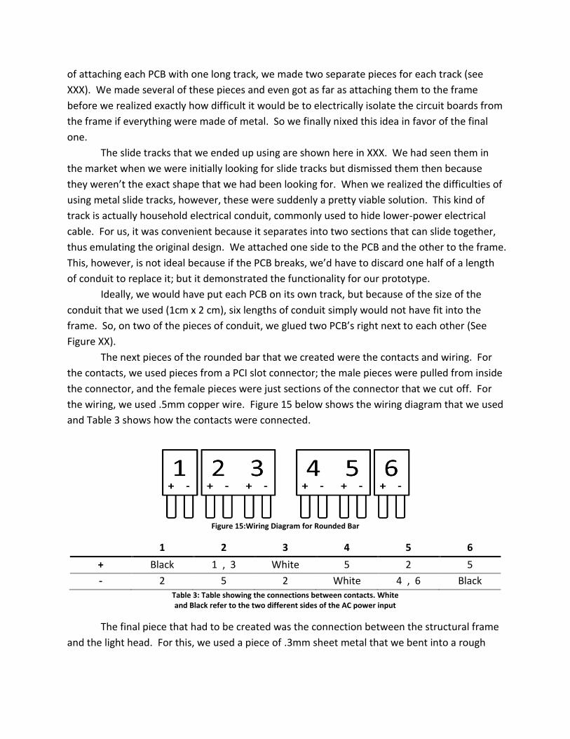
The next pieces of the rounded bar that we created were the contacts and wiring. For
the contacts, we used pieces from a PCI slot connector; the male pieces were pulled from inside
the connector, and the female pieces were just sections of the connector that we cut off. For
the wiring, we used .5mm copper wire. Figure 15 below shows the wiring diagram that we used
and Table 3 shows how the contacts were connected.
Figure 15:Wiring Diagram for Rounded Bar
1 2 3 4 5 6
+ Black 1 , 3 White 5 2 5
- 2 5 2 White 4 , 6 Black Table 3: Table showing the connections between contacts. White and Black refer to the two different sides of the AC power input
The final piece that had to be created was the connection between the structural frame
and the light head. For this, we used a piece of .3mm sheet metal that we bent into a rough

box. Holes in the bottom allowed for bolting to the light head frame and holes in one side
allowed for connection to the structural frame.
Final Prototype
Finally, we assembled the whole prototype. The female contacts were glued in place on
top of plexiglass spacers so that they mated with the contacts on the PCB’s. All other assenbly
was done with 3mm diameter bolts and nuts. The final prototype is shown in XXX below.
Stepped Cone
When we were brainstorming for different shapes, the stepped cone came up as an
extension of the stepped pyramid design. It was originally intended to be focusable via a
collapsible function. However, further investigation showed us that simply collapsing the frame
wouldn’t change the focus, so we abandoned that concept.
CAD Design
The stepped cone, shown in Figure 16 below, has three basic layers: the outer ring, the
inner ring, and a disc-shape backplate. Each layer is 20mm deep, and from the disc to the top
layer, the outer diameters are 110mm, 130mm, 150mm respectively. Finally, the outer and
inner rings are both 10mm wide while the disc layer has a solid center.
Figure 16: Exploded View of the stepped cone design
Different lights have different illumination areas, but the workers don’t always need the
same illumination area. We designed the stepped cone with this in mind. Each layer can be
adjusted relative to the other layers in order to either narrow or widen the beam. In the CAD
model, this was accomlished via a series of pawls and hooks at three locations on the edge of
each layer (Figure 17).
Figure 17: Adjustable Hooks

PCB Design
Our circuit design, as explained above consists of many LED’s in series. This,
unfortunately, means that if a single LED burns out completely, then all LED’s that are in series
with it will cease to function. In order to help mitigate this problem, we have designed the
stepped cone’s circuit board to be modular. Each layer of the design has a circuit board that
can be easily pulled out and replaced.
Our circuit design can be divided pretty clearly into five groups: the four blinking outer
legs, and the constant center leg. The backplate’s circuit board has two of the blinking legs and
the capacitor from the center leg on it. In order to help mitigate any blinking, the two legs on
the backplate are out of phase with each other. That is to say that when one of them is on, the
other is off. By putting these two opposite legs close to each other, we hope to make any
blinkin less noticeable.
The 36 LED’s in the middle layer all belong to the central, constantly shining leg. They
are separated from the capacitor because, basically, the capacitor is too large to fit on the
10mm wide middle circuit board. Finally, the outer ring holds the remaining two legs which
blink out of phase with each other, much like the backplate LED’s.
Fabrication Methods
As we finally moved towards making a prototype of the stepped cone, we considered
how to actually make it collapsible. The hooks in the CAD model required tolerances that were
simply too difficult to realize, so we instead put a screw thread in between each layer. Making
a full-scale model of this idea, however, proved to be too expensive, so we decided to make
two different prototypes, a small one that would demonstrate the collapsibility, and full-scale
one that we could install and test for light output.
Figure 18: Small Stepped Cone Prototype
The small prototype, shown in Figure 18 above, was milled out of 5cm bar stock
aluminum. The individual layers are connected by a simple screw thread with a pitch of 2 mm.
This threading would allow the the workers to adjust the beam of the light by simply screwing
or unscrewing the individual layers. To keep the wires that hold the different layers together
from becoming tangled during the unscrewing process, we plan to put connectors on the wires
so that they can be removed during the screwing process.

Figure 19: Large prototype shell
The shell for the full-scale prototype (Figure 19) was made out of 0.75mm sheet metal
and soldered together by a skilled worker that we hired in the Wuchang market. To attach the
circuit boards to the shell, we found some plastic motherboard risers and attached them first to
the shell and then to the PCB’s.
To attach to the head to the structural frame, we first tried bolting on a ball joint
(<HERE>) in an attempt to make the light more flexible. The ball joint, however, proved too
heavy for the gooseneck, so we ended up fabricating a simple, inflexible connection to the light
head similar to the rounded bar’s connection.
We also considered attaching a plexiglass cover to the front of the light to protect it
from chips coming off of the machine. However, with the plexiglass attached, the light was
sealed, and the internal temperature increased, causing the capacitor to overheat and explode.
We decided that this was bad and removed the plexiglass from our final design.
The Actual Prototype
Our final prototype of the stepped cone is shown here in <HERE>.
Jointed Bar DE
PCB Design
CAD Design
Fabrication Methods
Materials
Difficulties
Actual Prototype

Testing Stage
In the testing stage, we returned to the REM factory in Wuxi and performed several
tests on each prototype, including operating temperature, photometrics, power consumption,
and finally a field test in the factory.
Tests Done and Analysis
Modifications Made

Results
Structural Frame Decision
Final Design Choice
Heat Experiment Results
Light Output Results
Factory Worker Results
Table 4: Results of final factory interview
Conclusions
What we’ve learned

Future Recommendations This section gives our suggestions for what future work should be done with our designs.
We’ve divided this into three parts. First, we’ll talk about the problems that we’ve noticed with
our designs (mistakes we’ve made, design choices that could be better, etc.), and then we’ll talk
about other ideas that we’ve had, but didn’t have the time, resources, or expertise to explore in
this project. And finally, we’ll give some advice about how future work, experiments, etc. in
general should be conducted.
Current Issues
There were a number of issues with each design; some of them we were able to fix, and
others will need to be fixed in a future iteration. The section below details these issues and our
suggestions for each design.
Rounded Bar
First off for the rounded Bar, both the frame and the PCB’s were designed to be 21cm
long. So when we installed the slot connectors on the end, which took up about 2 cm, the
PCB’s stuck out of the end of the frame. This should be fixed future iterations by simply making
the frame a little bit longer.
Another problem that we ran into was that the flange that we had designed to prevent
glare simply wasn’t long enough. So, in future iterations, these flanges should be made long
enough to prevent the light from directly reaching the workers’ eyes.
The next issue came up in the worker feedback. The light coming from the fixture was
visibly blinking in both the rounded bar and stepped cone designs, but not in the jointed bar
design. We think that this is because the blinking LED’s in the Jointed Bar were placed so close
together. So to address this, we suggest changing the PCB design to have mix to have LED’s
that blink out of phase next to each other(XXX). This would not change the modularity of the
design, as all of the individual strips of LED’s would still be identical.
In fact, the only difficulties that this change could produce would be with the contact
design. Because two separate legs would be running on the same circuit board, each PCB
would need four contacts. As it stands, the contacts are too wide to fit four on a board, so a
new, smaller kind of contact would have to be found.
Structural Frame
Ball Joint Attached to the Light Head
We tried attaching a ball joint to the head of the stepped cone prototype, but that failed
because the gooseneck could not support the extra weight. To solve this, we suggest that either
a plastic ball joint be used or the weight of the light head be reduced.

Reducing the weight of the light head could be achieved in a couple of different ways.
The simplest would be to make the frame out of a lighter material. This would work especially
well for the stepped cone and rounded bar designs because their prototype frames were made
out of sheet iron, which is a very dense material. If they were made out of aluminum or even
plastic, their weights would be cut significantly.
The second weight reduction method that we suggest is to remove unnecessary
material from the frames. In every one of the designs, there are places where holes could be
added into the frame simple for the sake of removing material. For the stepped cone design,
these holes would serve the second purpose of providing ventilation when a cover is atttached.
Gooseneck
The only gooseneck material that we could find in the market was an oil tube. As such,
it was not really intended to hold weight in the way that we were using it and it was difficult to
get it to stay in position without falling down. When we attached the ball joint to the head in
the stepped cone design, the head became far too heavy and fell nearly every time. There are
two approaches to fixing this problem, and we believe that any future work on these designs
should use both of them.
The first approach would be to make the light head weigh less. This could be done to
both the stepped cone and rounded bar designs by removing unnecessary material or making
the fixture out of a lighter material.
The second approach would be to strengthen the gooseneck. Upon inspecting the
current fixtures, we found that few of their arms were completely made of the gooseneck
material; many of them had a short (10-12 cm) section of rigid tubing at their base. If we found
a gooseneck with a similar design, it might be more stable
Magnetic Grips
When brainstorming for the structural frame, we thought about attaching the arms to
the machine via a magnetic grip. Ideally, this grip would be strong enough to hold the weight of
the entire fixture, and it could also be easily disengaged. Similar magnets are already used in
the factory to fix a workpieces to worktables, and adapting those magnets should be relatively
simple.
Spring Board Idea DYJ
Experiments
Models

Other Reccomendations
Retail Price
After interview the purchaser and foremen at REM, we found that they have only ever
used four kinds of lights, the incandescent light, the halogen light, the fluorescent light and the
LED flashlight. The price of the lights is shown in
Bulb price Light price Average Bulb Life
Incandescent light 1 RMB 20 RMB Less than 1 week
Halogen light 15 RMB 50 RMB More than 1 year
LED torch n/a 32 RMB Unknown
Table 5: Price of the lights currently used in the factory
Many of those We also did some research on the internet to find more information
about the cost of a new fixture. The lights that we found (see Table 6 below) varied in price
from 50 RMB to 300 RMB.
Price Structural frame Features
50 RMB
Many ball joints and a
gooseneck
Many degrees of
freedom
80RMB
One ball joint and a
gooseneck
Long Life
300RMB
Many ball joints and a
gooseneck
Many degrees of
freedom
Long Life
Table 6: Research on the current price of lights
From this research and suggestions from our sponsor, we suggest that, in order to be
competitive in the marketplace, Future LED products should be sold at a price of 60 RMB. If
sold in the United States, that price should be increased by a significant margin. Compared
with the prices for our prototypes (See Table 7 below and Appendix D: Accounts for more
detailed information), this is an ambitious goal, but we feel that with a larger-scale production
scheme, it will be an attainable one.

Design Final Prototype Cost
Jointed Bar ¥396.39
Stepped Cone ¥221.92
Rounded Bar ¥160.67 Table 7: Final Protoype Costs
More rigorous photometrics testing
Improvements to Heat Dissipation Expt.
Thermocouples attached directly to the leads

References

Appendix A: Experiments and Tests
Power Test

Workers’ Opinions
We designed our interviews with the workers to focus on five different areas: Bulb life,
illumination area, brightness, heat output, and the number of defects produced while using
task lights. We also asked a few questions that were specifically about the LED flashlights
currently used in the factory.
Interview Questions
Lifetime
How often do the bulbs need changing?
Why do the bulbs break?
Heat
Are they hot or not?
Brightness
Do they illuminate enough now?
and the illumination area enough or not?
Are they too bright or not?
Do you want to be able to see the bulb?
Usage
We’ve notice that currently lights don’t get used very much. Why?
Are there any methods currently used to clean the fixture?
Is the fixturing convenient?
How often do you use the lights?
Why don’t you use the light?
Quality Control (this question was only asked to the quality control workers)
Is there different in the average number of defects produced by the day shift vs. that of
the night shift
Yellow Flashlight
Charge time/battery life
More convenient than traditional solution?
How could it be better?
Do you prefer the LED color over the incandescent/halogen color?
What do you use the light for?
How much area needs to be illuminated?

We made the following form to record the findings of our interviews
Questions Worker
1
Worker
2
Worker
3
Fixed
light
1 Hot or not
2 Parts that
need light
3 Light area
(enough or not)
4 Frequency of
changing bulbs
5 Luminous
intensity
6 The ratio of
defects
Yellow
torch
8 Light area
(enough or not)
9 Convenient or
not
10 Hot or not
11 Luminous
intensity
Photometrics Test

Appendix B: Engineering Drawings

Appendix C: CAD Models (.stl)

Appendix D: Accounts Here we have included an spreadsheet of our spending for each prototype
Jointed Bar
Item Qty. Price per
Item (¥)
Extended
(¥)
Light Head
Rapid Prototype Housing 1 250.00 250.00
2mm Nails (for hinges) 4 0.05 0.20
2mm Acrilic Sheet 1 10.00 10.00
PCI Slot Connector 1 11.00 11.00
PCB 1 25.00 25.00
White LED 120 0.30 36.00
Capacitor (100μF, 100V) 1 1.00 1.00
Single-strand Copper Wire, .5mm Ø (per meter) 0.25 0.56 0.14
Coaxial Wire 5 0.50 2.50
2 Prong Electrical Connector 1 2.50 2.50
220 Volt AC to 12 Volt DC Transformer 1 15.00 15.00
12 Volt, .26 Amp DC fan 1 5.00 5.00
AB Glue (per gram) 4 0.09 0.35
Solder 3.00
Total 361.69
Structural Frame
Jointed Arm 1 10.00 10.00
Hose Clamp 1 3.00 3.00
Aluminum Connector (material, per kg) 0.05 33.00 1.65
Aluminum Connector (labor) 1 10.00 10.00
3mm philips head bolt 2 0.05 0.10
Aluminum Baseplate (material, per kg) 0.15 33.00 4.95
Aluminum Baseplate (labor) 1 5.00 5.00
Total 34.70
Grand Total ¥396.39

Rounded Bar
Item Qty. Price per
Item (¥)
Extended
(¥)
Light Head
.75 mm White Iron (9 cm x 21 cm) 1 6.3 6.3
.3 mm White Iron (14 cm x 7 cm) 1 3 3
84 cm Square Plastic conduit (1 cm x .5 cm) 1 4.2 4.2
PCI Slot Connector 1 11 11
Blinking PCB 4 7.5 30
Constant PCB 2 7.5 15
White LED 120 0.3 36
Capacitor (22μF, 50V) 2 0.2 0.4
Bolt, 3mm 16 0.05 0.8
Nut, 3mm ID 16 0.01 0.16
Pop rivet, 3mm 4 0.1 0.4
Single-strand Copper Wire, .5mm Ø 0.5 0.56 0.28
Electrical Tape (per meter) 0.2 0.15 0.03
Stranded Copper Wire, 1mm Ø (per meter) 3 1.1 3.3
Solder 3
Total 113.87
Structural Frame
Gooseneck 1 15 15
Ball Joint assembly 1 5 5
Bolt, 6mmØ 4 0.1 0.4
Nut, 6mmØ 4 0.05 0.2
Washer, 6mm ID 4 0.05 0.2
White Iron Sheet, .75mm, 9cm x 14cm 1 6 6
Total 26.8
Gooseneck Connector A (Threads and Bolts)
Aluminum 1 2.5 2.5
Labor 1 7.5 7.5
Total 10
Gooseneck Connector B (Double-Threaded)
Aluminum 1 2.5 2.5
Labor 1 7.5 7.5
Total 10 Grand Total ¥160.67
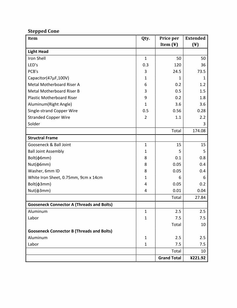
Stepped Cone
Item Qty. Price per
Item (¥)
Extended
(¥)
Light Head
Iron Shell 1 50 50
LED's 0.3 120 36
PCB's 3 24.5 73.5
Capacitor(47μF,100V) 1 1 1
Metal Motherboard Riser A 6 0.2 1.2
Metal Motherboard Riser B 3 0.5 1.5
Plastic Motherboard Riser 9 0.2 1.8
Aluminum(Right Angle) 1 3.6 3.6
Single-strand Copper Wire 0.5 0.56 0.28
Stranded Copper Wire 2 1.1 2.2
Solder 3
Total 174.08
Structral Frame
Gooseneck & Ball Joint 1 15 15
Ball Joint Assembly 1 5 5
Bolt(φ6mm) 8 0.1 0.8
Nut(φ6mm) 8 0.05 0.4
Washer, 6mm ID 8 0.05 0.4
White Iron Sheet, 0.75mm, 9cm x 14cm 1 6 6
Bolt(φ3mm) 4 0.05 0.2
Nut(φ3mm) 4 0.01 0.04
Total 27.84
Gooseneck Connector A (Threads and Bolts)
Aluminum 1 2.5 2.5
Labor 1 7.5 7.5
Total 10
Gooseneck Connector B (Threads and Bolts)
Aluminum 1 2.5 2.5
Labor 1 7.5 7.5
Total 10
Grand Total ¥221.92

Appendix E: Weekly Work Schedules
Week 2

Week 3
Monday Tuesday Wednesday Thursday Friday
Morning
Travel from Wuxi
to HUST
Travel to HUST
CAD: Build model
of each each shape
CAD Presentation
Buy capacitors at the market Choose shapes
Afternoon
Finish
circuit
design
Discuss design
specifications
(L.Q)
Research
epoxies and
polycarbonate
(Fabrication)
PCB Design
Plan next week
(Week 4) PPT work

Week 4

Week 5

Week 6

Week 7
Monday Tuesday Wednesday Thursday Friday
Morning
Everyone does
preparations for
the final document
Continue the final
document
Prepare for the
final presentation
and finish the PPT
Distribute the task
and modify the
PPT
Final Presentation
Afternoon
Prepare the
questions for the
final presentation
Discuss the main
part of final
document
Rehearsal Continue the final
document

Appendix F: Original Project Proposal MQP Proposal
REM LED Lighting David Embree Christopher Kingsley
Registration #MQP YR – CH85
Sponsored by: Dr. Yiming Rong Mechanical Engineering Al Barry Rapid Engineering Manufacturing Submitted: 4/28/08

Abstract
This proposal will describe, in detail, the plan and basis for the Rapid Engineering
Manufacturing (REM) LED Lighting MQP. We first introduce the theoretical basis of how LED’s
work, and then the economic justification for switching to LED-based lighting systems. We also
present some background information on REM, the company that we will be working with to
design these LED fixtures. Then, we will present an outline of how and where we plan to spend
our time in China, and what our final goals for the project will be.

Introduction
Since the invention of Light Emitting Diodes (LED’s) in the late twentieth century, the
uses of these devices have been constantly multiplying. They have gone from being simple
indicator lights to seven-segment display applications, and more recently have been applied to
huge architectural projects. Only recently, however, have people begun to think about LED’s as
illuminating devices for work and living spaces. Our goal with this project is to begin designing
and prototyping a product that will effectively bring LED’s into the industrial workspace.
So why aren’t LED’s used to light most workspaces around the world? The answer is
that the fixtures and power sources that house and drive the LED’s are still very expensive. The
cost of the LED’s themselves, however, has been decreasing. There is an opportunity here to
design LED-driven lighting fixtures that are cost-effective.
LED’s are attractive to businesses for two reasons: long lamp life and low power
consumption. The light output per unit of power input for an LED is typically at least twice that
of current incandescent or fluorescent equivalents, and the lamp life is approximately ten times
greater.
For this project, we will focus on creating several different prototype lighting fixtures
that will light workspaces within the REM facility. We will then evaluate the performance of
these fixtures with respect to both cost and quality of lighting. Then, we will modify these
prototypes and test them again.
Most LED products are still very expensive because they are focused towards retrofitting
existing lighting systems rather than installing a system that is designed to drive LED’s. LED’s
need their own power systems because they are so different from other forms of lights. LED’s
only function at very specific voltages and they can only be powered by a DC circuit. These two
requirements have, thus far, kept the cost of the LED systems high while the cost of the LED’s
themselves remains relatively low.
Our project will take advantage of a simple, unique circuit that will power three banks of
LED’s, one at full power and two at half power. This circuit will be able to attach directly to an
AC power supply without needing many additional parts. Overall, we want to create a modular
LED system that can be applied in several forms to a number of settings.

Background Information
LED’s
Light Emitting Diodes, more commonly known as LED’s, were invented in the second
half of the twentieth century. The earliest LED’s were only able to emit light in the infrared
range, and thus their applications were limited. Since then, LED technology has developed into
the visible spectrum, and LED’s are finding all kinds of applications, from flashlights to
jumbotrons.
LED Benefits
The advantages that LED’s hold over existing lights are both economic and
environmental.
Economically, LED’s consume much less power than both incandescent and fluorescent
lights. In terms of efficiency, LED’s can produce about 90 lumens per watt of power consumed,
and this number is steadily increasing. A standard incandescent light generally produces a
maximum of 20 lumens per watt, and a standard fluorescent light only produces up to 40
lumens per watt. In addition, the lifespan of an LED is far longer than that of other lights.
Most manufacturers rate the life of their LED’s at approximately 100,000 hours, where
incandescents are generally rated for a 1,000 hour life, and fluorescent lights are at 20,000
hours. This increase in lamp life decreases lamp replacement costs.
LED’s hold a strong environmental advantage over modern fluorescent lights because
production and disposal are environmentally friendly. Fluorescent lights must contain a certain
amount of mercury in order to work. Mercury is toxic, so fluorescent lights require special
handling for disposal, which adds to their overall cost.
LED Technology
LED’s are semiconductor chips. They emit light at a very specific frequency when
electrons jump between separate p-type and n-type semiconductors. The point of contact
between these chips is called the p-n junction. Both the specific frequency of light emitted and
the electric potential needed cause the jump depend on atoms of exotic elements being
substituted for a small percentage of the silicon atoms. The process of exposing pure silicon to
atmospheres containing high concentrations of these elements is called “doping”, and the
material’s charge and conductivity are very dependant on the elements that they’ve been
doped with.
In order to understand how the electrons jump from one side to the other, one must
first understand how materials conduct electricity. Electrons in the atoms of most materials are
gathered in two different “bands”: the valence band, and the conduction band. The conduction
band corresponds to the outermost electron shell and, in accordance with its name, is where
transfer of electrons between atoms takes place. The valence band, on the other hand, refers

to the outermost shell of electrons that is filled to capacity with electrons. The difference in
distinct energy levels between these two shells is known as the band gap. Metals have no
distinct band gap, therefore electrons are free to move to the conduction band at no energy
cost, and therefore metals conduct electricity well. Nonmetals have a large band gap, so
valence electrons can’t get to the conduction band easily, and thus nonmetals do not conduct
well. Semiconductors, as their name implies, have a medium band gap, and so their electrons
can jump to the conduction band with only a little energy input. Doped semiconductors, in
addition to having different numbers of electrons, have different band gaps than their non-
doped counterparts.
P-type semiconductors have been doped so that they are lacking in electrons (p stands
for positive here). As a result, their valence bands are not full, and their conduction bands are
empty. Each location in the p-type material that is missing an electron is known as a hole. N-
type semiconductors, on the other hand, have been doped to have an excess of electrons.
These excess electrons stay in the conduction band of the semiconductor.
Both p- and n-type semiconductors are normally electrically stable, however when an
electric potential is applied across the two, electrons travel easily between them, jumping from
the crowded n-type conduction band to the empty p-type valence band. For the individual
electrons, this jump, in addition to switching atoms, means a change in energy level. As we
know from basic physics, when an electron falls from a higher atomic energy level to a lower
energy level, the excess energy leaves the electron in the form of a photon and thus light is
emitted.
The exact color of the light emitted depends directly on the amount of energy lost in the
jump from the n-type to the p-type, and thus the band gaps associated with the two. As a
result of that, the choice of doping materials for both the n and p sides of the LED controls the
color output of the LED. Since the band gap associated with a given doping material is very
consistent for all samples of a doped semiconductor, LED’s of a given type emit only very
specific frequencies of light, which generally come across as the primary colors of light (red,
green, and blue). In order to create white LED’s, manufacturers dope the LED materials with
several different materials to create a mixed light output that comes across as white.
The supply voltage that is required to get the electrons over the band gap is also directly
proportional to the size of the band gap, so differently colored LED’s require slightly different
input voltages to emit light. Supplying too great of a voltage will cause electrons to move
through the material too quickly, and the LED will burn itself out. Without enough voltage, the
electrons will not make the jump, and nothing will happen. It should also be noted that if the
supply voltage is attached backwards, and enough voltage is supplied to make the electrons
flow backwards, then the doping of the n-type and p-type semiconductors will break down and
the LED will become unusable.
Existing LED Applications

Lighting as a field began to develop in the early twentieth century with the advent of the
electric light bulb. Finally, there was a source of lighting with a relatively constant light output.
Light is measured in several different ways. The most basic unit is intensity, measured in
candela or millicandela. Intensity is generally only measured for a single light source, so any
fixtures that incorporate more than a single light source (i.e. most LED systems) are measured
differently. Luminosity is a measure of the total light reflected per unit area off of a surface
that has been placed at a specified distance. Luminosity is a useful measure because it can be
measured on a per-fixture basis rather than on a per-light source basis.
Most existing LED applications can be categorized into two basic categories: small-scale
and large. Small-scale applications, such as flashlights, reading lights, and indicator lights
usually only make use of very few LED’s and are intended for very specific purposes. They are
also generally powered by batteries. Large-scale applications involving multiple thousands of
LED’s include LED jumbotrons in sports arenas and architectural lighting showcases, like the
Fremont Street experience in Las Vegas. Neither of these categories provides light on the scale
that we will be designing for; however both of them contribute something to our knowledge of
the problem.
Most of the early uses for LED’s were in small-scale applications, they were especially
useful as indicator lights because the are small, work for hundreds of thousands of hours with
very little decrease in light output, consume little power, and give off very little heat when
compared to incandescent bulbs. More recently, LED’s have found their way into small
portable task lights, especially flashlights. Their low power consumption makes them ideal for
this because they make better use of their batteries. To relate this to the goals of our project,
these small-scale applications exploit the simplicity of LED’s. Our goal is to make our fixtures as
simple to power and rearrange as possible.
Large-scale applications of LED’s showcase both their versatility and their durability.
One of the best examples of large-scale applications is the Fremont Street Experience in Las
Vegas. The Experience uses 1.4 million individual LED’s to illuminate the underside of a large
pavilion in Las Vegas. The LED’s are controlled by a set of computers and are used for shows
underneath the pavilion. The Experience has been running with LED’s and without any major
interruptions since 2004, even with external components exposed to the weather.
While both of these applications give off light, neither of them is concerned with
illumination. Smaller products are focused on lighting individual tasks, while larger products
don’t really provide illumination as much as they provide a lighted screen on which to display
images. The smaller products emphasize power advantages of LED’s and larger products
emphasize the durability and versatility advantages of LED’s. With our fixtures, we want to
emphasize both of these characteristics.
Rapid Engineering Manufacturing

Rapid Engineering Manufacturing (REM) is a small metal-working company that is based
in Wuxi, China. They have a relatively new facility and are looking at the long-term costs of
maintaining it. One way that they want to cut down on operating costs is to install highly
efficient LED lighting systems throughout the factory. Since they have a new factory, installing
a new system should be relatively easy to do.
REM has already begun the changeover to LED illumination with their overhead lights.
We will be furthering the changeover by developing fixtures to be used as task lighting on
specific machine tools. Currently, most of the task lighting that they have is incandescent; the
bulbs frequently burn out and don’t always get replaced. With our LED fixtures, we would like
to see that change. Specifically, replacement costs and maintenance time will be reduced or
eliminated.
REM’s business is specialty nuts, pins, and rivets, and the machine tools that we will be
designing our fixtures for will be working metal. As a result, the fixtures that we design will
have to be able to withstand flying metal chips and other dangers that are associated with the
shop environment.

Method of Research and Development
Over the course of the last term, we have developed a simple, modular circuit design
that can be used with Alternating Current (AC) power delivered directly from standard wall 120
volt or 220 volt outlets. The physical shape of the circuit depends entirely on the mounting
location, or locations, within the individual machines at the factory. This means that actual
designs of the lights must wait until we have seen the machines in person and determined
possible mounting locations within them. Additionally, a light intensity sensor should be
employed to gather data about current lighting conditions so that quantitative comparisons can
be made at the conclusion of this project.
Some work can be done before arriving in China, however. LEDs have been ordered to
begin the process of testing the circuit design on a breadboard with AC power, with variations
on the number and arrangement of LEDs being the primary focus. Strength and placement of
inductors will also be investigated. The basic design is a rectifying bridge created completely
with LEDs, with the addition of an inductor to maintain the current through the primary LEDs
during the periods of low voltage in the AC waveform.
When we arrive at the factory, each machine will be individually evaluated. Pictures will
be taken of each, highlighting the areas we want to illuminate with the LEDs and positions
where mounting is possible. Measurements and sketches of these locations must be made as
well, so that circuit designs and housing molds can be created precisely. Interviews of the
employees responsible for each machine should also be conducted, so that areas they think are
important can be given extra consideration. A folder containing all information on each
machine will keep the data organized.
Once all machines have been evaluated, we will return to HUST and begin design and
fabrication of the prototypes. The first step is to compare all the information gathered about
the machines and determine the minimum number of shapes necessary to be used among all
machines. Ideally, this will be between 3 - 6 shapes. Prototype circuit boards can then be
designed in an electrical engineering program that produces diagrams which will be sent to the
circuit board printing company for production. While the boards are being fabricated,
complimentary housing molds can be designed and fabricated from aluminum.
Each light will be a circuit board embedded in solid plastic. The type of plastic is subject
to the results of testing; primary candidates are Plexiglas, polycarbonate and two part epoxy.
Each will be evaluated for clarity, robustness, ease of preparation and use, possible interference
with LEDs or circuits, and affect on light focusing. Once the best material has been selected,
production can begin on all shapes.

Soldering the LEDs into the circuits will be a time consuming part of fabrication, since
every light will have between 55 – 80 LEDs which all need to be soldered into place, along with
the inductor and power wires. Fortunately, soldering becomes very quick and easy with
practice, and there should be time between the testing of the housing materials and full scale
production for each team member to become proficient in the art of soldering LEDs into a
circuit board.
Once there is an example of each of the shapes fully manufactured, a trip should be
made back to the factory to test them in actual machines. If there are any problems with the fit,
changes can be made to the mold, without wasting assembled circuits. Evaluations by factory
employees can also be made at this time to determine preliminary effectiveness of each design.
Any problems can be addressed before time is wasted, and while there is time correct them.
Pictures and light intensity measurements should also be made for each design.
Full scale production can begin at this point. Jigs and holders can be fabricated to
decrease assembly time, and the advice of manufacturing majors can be pursued and utilized.
Extra prototypes can be assembled if time permits for hands on demonstration at the final
presentation. The last phase is the writing of the final report, which will include graphs,
diagrams and images created during the project, and a presentation based on it.
Tentative Timeline
Before arrival in Shanghai, research can be completed on the configuration of LEDs on a
breadboard circuit. 100 LEDs have been ordered to complete a test circuit, and various
inductors will be purchased from Radio Shack.
Arrive in Shanghai on Sunday, June 15th in the afternoon. Professor Rong will meet us
at the airport and accompany us to the hotel in Shanghai where we will spend the night. In the
morning, (Monday, June 16th) several groups will travel to Wuxi to visit their respective
companies. We will be getting a tour of the REM facility and given the details on where LEDs
need to be installed. Introductions to the employees will also be made.
Travel overnight to Wuhan by train to arrive on the 17th at HUST. We will meet our
Chinese partners at this point, and compare notes and objectives. Preliminary presentations
will be made at this point to the HUST professors and sponsors, outlining the objectives for the
project and the tentative schedule. Tours of HUST will also be made during this time. Total
time for the REM team in Wuhan: 2 days.
Travel back to Wuxi on Friday, the 20th to categorize the machines at the factory. Each
machine will have detailed pictures taken, with precise measurements of possible LED
mounting locations. Initial ambient light readings at locations of interest will also be made.

Additionally, light readings at inspection stations outside the machines (at desks or work
benches, for example) must also be made. This will take approximately two weeks.
Return to Wuhan by train on Friday the 4th of July. On Monday, the 6th, begin creating
shapes for each machine’s mounting location. Combine shapes until only 4-6 shapes remain.
By Tuesday, the 7th, develop prototype circuits in the electrical engineering program that
match the final shapes. Work should be finished by Tuesday, the 7th so that prototypes can be
fabricated at a local circuit printing company. At least 5 of each shape need to be ordered so
that alternate configurations of LEDs can be tested. On Wednesday, the 8th, purchase enough
LEDs, inductors and wiring for prototypes. Begin CAD designs for housing molds in SolidWorks,
until prototype circuit boards arrive. Work on the prototypes should begin immediately; LEDs,
inductors and wires need to be soldered into the boards so that light quality tests can be
conducted. Once optimal configurations are determined, circuit designs are modified to reflect
the changes. By Friday, the 11th, final circuit designs are submitted to the circuit printing
company for fabrication. Any extra time must be devoted to housing mold design and
fabrication.
The week of Monday, July 14th, should be devoted to fabrication and testing of the
housing molds. Polycarbonate, Plexiglas and epoxy materials will be tested for ease of use,
strength, scratch resistance, effect on LEDs, effect on light transmission/refraction/etc, and
weight. The best substance will be used for the final production. The prototype circuit boards
will be used for these tests, so that they are not wasted. On Wednesday, the 16th, additional
LEDs, inductors and wires should be purchased; enough for all final designs. When the final
circuit boards are delivered on Thursday or Friday, final production can begin.
The week of Monday, July 21st, full scale production of each shape should start. Each
team member will rotate through each stage of production:
1) counting of individual components and sub assembly into “jigs” to hold parts in place;
2) soldering LEDs, inductors and wires onto the circuit board;
3) testing of lights to assure full functionality, and troubleshooting any problems;
4) pouring of plastic around circuits in the molds.
Any improvements to the processes will be noted and passed on to the next workers at each
station. The team members should rotate stations once an hour to stretch, and to alleviate
boredom. If one station gets significantly ahead of the next station in the sequence, members
of that station should move to the other station and help until caught up.

Production should be finished by Friday, July 25th. Prototypes will be packaged and
transported to Wuxi, and team members will travel by train overnight on Sunday, the 27th.
Installation and testing will begin on Monday the 28th. Tests of lighting conditions will be made,
and interviews with machine operators will be conducted. Installation should be complete by
Wednesday, the 29th. Team will return to Wuhan that night.
Remaining time from Thursday, July 24th to the presentation date on Friday, August 1st,
will be dedicated to documentation of the project. Light intensity data must be analyzed,
responses of machine operators will be compiled, and representative images for the
presentation shall be selected. Final circuit diagrams will be prepared, power requirements will
be measured, lumen to wattage ratios will be calculated, total cost of the project will be
counted, material cost of an individual unit will be determined, and fabrication processes will
be documented.

Expected Results
1. At the end of this project, we expect to have designed and fabricated a number of
prototype fixtures. We also expect to have made at least a few revisions to the prototypes
after having tested them in the REM factory.
2. Complete, simple circuit design to drive the LED’s off of an AC power source.
3. Possibly the most important outcome of this will be a cost-analysis for each prototype.
4. We plan to have quantitative results for increased light intensity at critical locations within
the machines.
5. Images of each design and its effectiveness.

References
luminous efficacy:
-LED
-Incand
-Fluor
Lamp Life:
-LED
-Incand
-Fluor
Fluor. Hg
P-type def.
N-type def.
banding, etc.
def. of luminosity, etc.
Fremont St.
Jumbotrons
Casiday, Rachel and Frey, Regina. Bonds, Bands, and Doping: How Do LEDs Work?


Appendix G: Proportionality of Light Flux
Assuming that across a small area within a beam of light, illuminance is constant. Proportionality of light flux (lumens) between two distances within the same beam Assuming that a beam of light is a cone shape,
For two different distances,
𝐿1
𝐿2=𝑟1𝑟2
If the area of the base at a give distance is, 𝐴 = 𝜋𝑟2
then
𝐿1
𝐿2=
𝐴1
𝐴2
From the definition of illuminance, we know that
𝐼𝑣 =𝐹
𝐴
or
𝐴 =𝐹
𝐼𝑣
where 𝐼𝑣 is illuminance, 𝐹 is luminous flux, and 𝐴 is area. Substituting, we now have a relationship between intensity, illuminance, and distance.
𝐿1
𝐿2=
𝐼2𝐼1
×𝐹1
𝐹2
If we assume that the total amount of luminous flux in the given area is the same at both distances (F2=F1), then we have
𝐿1
𝐿2=
𝐼2𝐼1
or 𝐼2𝐼1
= 𝐿1
𝐿2 2

Appendix H: Heat Experiment Procedure and Equipment List
Procedure
1. Place the LED’s on the breadboard in lines of 3 attached in series. Then attach 5 of these
lines together in parallel at each end of the breadboard. You should end up with two sets
of 5 lines of LED’s (Figure 20)
Figure 20: Breadboard arrangement
2. Prepare the oil and control oil cups by filling them partway with oil.
3. Prepare the box by cutting a hole near the top that is just big enough for the breadboard to
be put through and assemble all pieces as shown (Figure 21). Make sure that one half of
the breadboard is inside of the box and that the LED capsules on the other half are
immersed in water.
Figure 21: Overall Assembly
4. Attach the breadboard to the DC power source (9.2V) and confirm that all LED’s are
functional.
5. Using the thermometer, take and record initial readings for the following: air temperature,
temperature inside the box, temperature of the oil, and temperature of the control oil.

6. Record the temperatures of the ambient air, the air inside the box, the control oil, and the
oil with the LED’s in it. When measuring the oil with the LED’s in it, be sure to measure the
temperature near the base of the LED’s in order to best approximate the junction
temperature.
7. Repeat step 6 every thirty minutes for eight hours.
Equipment Used
Items Manufacturer Part # Serial # (if applicable)
30LED's Shenzhen City Mizuhiro Optoelectronic Equipment Co.
5W4DC-WG-WR008
DC power supply Shenzhen Zhaoxin Electronics TXN-1502D 2N3055 - O5U3D
Digital Thermometer Uni-Trend UT70A 3080096352
Breadboard
Plastic Cup
Cooking oil
Cardboard box

Appendix I: Shape Matrices
Final Matrix
Feasibility Innovation Appearance Focus
function Adjustability
Heat
dissipation
Light
area
Printing
PCB
Collapsible
function Total Rank
Weighting
Factor 2 2 1 1.5 1 1.5 2.5 2.5 1.5
2 hinged
rectangle 3.375 3.5 3.125 2.5 4.25 3.75 4.125 5 4.25 59.68 1
Jointed bar 3 4.25 2.625 2.25 4.5 4 4.25 4.5 3.75 59.25 2
Ziggurat 3.25 4.5 4.5 2.5 2 3.625 3.75 4 3.25 55.43 3
Stepped cone 3.25 4 4.5 2.5 2 3.125 3.75 3.5 3.25 52.43 4
Torus 3.75 4.5 3.625 2.75 2 4.25 3.75 3.5 0.25 51.12 5
Round bar 3.75 3 3.75 3.75 2.5 3.5 3.5 3.75 0.5 49.50 6
Cage 2.5 4 3.25 3.5 1.5 4.5 3.875 2.375 2.25 48.75 7
Right
tetrahedron 2.875 3.375 3.5 2.5 2.25 2.75 3.625 4.25 1.25 47.68 8
Concave lens 3.5 3.125 3.5 4 2.25 3.875 3.125 2.5 0.5 45.62 9
Truncated cone 3.5 2.625 3.25 3.25 2 3.125 3.625 2.875 1.25 45.18 10
Short cylinder 4 2 2.75 1.5 1.75 3.5 3.625 4.5 0.5 45.06 11
Bar 4 1.875 1.875 2 2 2.5 3.25 4.5 0.75 42.87 12
Parabolic 3 3.25 3.75 3.625 1.75 2.75 3.25 1.875 1 41.87 13
Convex lens 3.25 3.125 2.75 0.5 1.75 4 4 2.25 0.75 40.75 14
Hemisphere 3.5 3 3.25 3 2 2.5 3.25 1.625 0.25 39.06 15

Individual Shape Matrices
Lu Wei
Feasibility Innovation
Appearance Focus
function
Adjustability Heat
dissipation
Light
area
Printing
PCB
Collapsible
function Total Rank
Weighting
Factor 2 2
1 1.5 1 1.5 2.5 2.5 1.5
2 hinged
rectangle 4 5 5 0 5 5 4 5 4 64 1
Jointed bar 5 5 3 0 5 5 4 5 4 64 2
Ziggurat 3 5 4 0 0 4 4 5 5 56 3
Short cylinder 5 3 5 0 0 5 5 5 0 53.5 4
Stepped cone 3 5 5 0 0 3 4 4 5 53 5
cage 4 5 4 3 0 5 3 4 0 51.5 6
Convex lens 4 5 5 0 0 5 5 3 0 50.5 7
Torus 4 5 4 0 0 5 4 4 0 49.5 8
Round bar 4 3 5 3 0 4 3 5 0 49.5 8
Concave lens 4 3 5 4 0 4 4 3 0 48.5 10
Truncated
cone 4 4 5 3 0 4 3 3 0 46.5 11
Hemisphere 5 3 5 4 0 3 3 3 0 46.5 12
Bar 5 3 3 0 0 4 3 5 0 45 13
Parabolic 4 3 5 5 0 3 3 2 0 43.5 14
Right
tetrahedron 3 3 4 2 0 3 3 4 0 41 15

Deng Yujun
Feasibility Innovation
Appearance Focus
function
Adjustability Heat
dissipation
Light
area
Printing
PCB
Collapsible
function Total Rank
Weighting
Factor 2 2 1 1.5 1 1.5 2.5 2.5 1.5
2 hinged
rectangle 5 5 4 0 5 5 5 5 4 67.5 1
Jointed bar 4 5 4 0 5 5 4 5 4 63 2
Ziggurat 3 5 4 0 0 3 4 5 5 54.5 3
Stepped cone 3 5 5 0 0 4 4 4 5 54.5 4
cage 4 5 4 3 0 5 4 3 0 51.5 5
Short cylinder 5 3 5 0 0 5 4 5 0 51 6
Torus 4 5 5 0 0 5 4 4 0 50.5 7
Round bar 4 3 5 3 0 4 3 5 0 49.5 8
Concave lens 4 4 5 4 0 5 3 3 0 49.5 8
Convex lens 4 4 5 0 0 5 5 3 0 48.5 10
Truncated
cone 4 3 5 3 0 3 4 4 0 48 11
Right
tetrahedron 4 4 4 2 0 3 4 4 0 47.5 12
Parabolic 4 3 5 4 0 3 3 3 0 44.5 13
Hemisphere 5 3 5 4 0 3 3 2 0 44 14
Bar 5 2 4 0 0 4 3 5 0 44 15

David
Feasibility Innovation
Appearance Focus
function
Adjustability Heat
dissipation
Light
area
Printing
PCB
Collapsible
function Total Rank
Weighting
Factor 2 2 1 1.5 1 1.5 2.5 2.5 1.5
2 hinged
rectangle 3 4 2 1 3 4 4 5 4 55 1
Stepped
cone 3 4 4 3 3 3 4 3 2 50.5 2
Torus 4 5 3 3 2 4 4 2 1 50 3
Ziggurat 3 4 4 3 2 3 4 3 2 49.5 4
Round bar 4 4 3 4 4 3 3 2 2 49 5
Convex lens 3 3 3 1 3 4 5 2 3 47.5 6
Concave
lens 3 3 2 3 3 4 3 3 2 45.5 7
Jointed bar 2 3 2 1 3 4 4 4 2 45.5 8
Short
cylinder 3 3 2 2 2 3 4 3 2 44 9
Parabolic 3 3 3 2 2 3 4 2 2 42.5 10
Hemisphere 4 3 3 2 2 2 4 2 1 41.5 11
Right
tetrahedron 3 2 2 2 3 2 3 4 2 41.5 12
Truncated
cone 3 3 2 2 2 3 4 2 2 41.5 13
Bar 3 2 2 4 3 1 3 3 2 40.5 14
cage 2 2 2 2 2 3 3 2 2 35 15

Chris
Feasibility Innovation
Appearance Focus
function
Adjustability Heat
dissipation
Light
area
Printing
PCB
Collapsible
function Total Rank
Weighting
Factor 2 2 1 1.5 1 1.5 2.5 2.5 1.5
Jointed bar 3 5 2 4 5 4 4 4 5 62.5 1
Ziggurat 4 4 5 4 3 4 4 5 2 61.5 2
Right
tetrahedron 4 4 5 4 3 3 4 5 0 57 3
2 hinged
rectangle 2 2 2 5 5 3 3 5 5 54.5 4
Stepped
cone 4 3 5 4 3 2 4 4 2 54 5
Round bar 4 2 4 4 3 4 4 5 0 53.5 6
cage 1 5 2 5 1 5 5 2 3 52 7
Torus 3 4 3 3 2 5 3 5 0 51 8
Truncated
cone 4 1 4 4 3 3 4 4 0 47.5 9
Parabolic 2 4 4 5 3 2 4 2 0 44.5 10
Bar 3 2 1 2 3 2 4 5 1 44 11
Short
cylinder 4 1 2 2 3 3 3 5 0 42.5 12
Concave
lens 3 2 4 4 3 3 4 2 0 42.5 13
Hemisphere 2 2 3 3 3 2 3 1 0 31.5 14
Convex lens 3 2 1 1 3 3 2 2 0 30 15

David
Feasibility Innovation Appearance
Focus
function Adjustability
Heat
dissipation
Light
area
Printing
PCB
Collapsible
function Total Rank
Weighting
Factor 2 2 1 1.5 1 1.5 2.5 2.5 1.5
Jointed bar 4 4 3 4 5 3 5 5 4 65.5 1
2 hinged
rectangle 4 3 4 4 4 3 5 5 4 63.5 2
cage 3 4 5 4 3 5 4 2 4 56.5 3
Ziggurat 3 5 5 3 3 4 3 3 4 55.5 4
Torus 4 4 4 5 4 3 4 3 0 53.5 5
Stepped
cone 3 4 4 3 2 4 3 3 4 51.5 6
Right
tetrahedron 1 4 3 2 3 3 4 4 3 48 7
Round bar 3 3 3 4 3 3 4 3 0 46 8
Concave
lens 4 4 3 5 3 4 2 2 0 45.5 9
Truncated
cone 3 3 2 4 3 3 3 2 3 44.5 10
Bar 5 1 1 2 2 3 3 5 0 42.5 11
Short
cylinder 4 1 2 2 2 3 3 5 0 41.5 12
Hemisphere 3 4 2 3 3 3 3 1 0 38 13
Parabolic 3 3 3 3 2 3 2 1 2 36.5 14
Convex lens 3 3 2 0 1 4 4 2 0 36 15

Appendix J: Photometrics Sheets For each of our prototypes and also for each of our current fixtures, we created a
photometrics sheet that showed several values, including beam angle and a rough luminosity
distribution curve. Beam angle measurements were taken according to the procedure set forth
in Appendix A: Experiments and Tests.
Light output at a given working distance was calculated usingcombination of the beam
angle, luminosity measurements taken at an arbitrary distance, and simple proportions. For a
detailed explanation of these calculations, please see Appendix G: Proportionality of Light Flux

Yellow FlashlightLight Output
Measuring
Distance (cm) Luminosity (lux) Lumens output lux meter area: 12.08105 cm^2
6 0.001208 m^2
Center 3000 3.624315096
Top 1000 1.208105032
Left 290 0.350350459
Bottom 1000 1.208105032
Right 290 0.350350459
Beam Angle
Trial #
Distance from
Wall (cm) Beam Width (cm)
Beam
Height(cm)
1 0 3.5 7
2 6 14.1 16.1
Beam Width Beam Height
Side B (cm) 6 6
Side A (cm) 5.3 4.55
θ 41.45526856 37.17428623
φ 82.91053712 74.34857247
General Usage
Distance (cm): 6
Projected light output at usage distance
I2=I1(L1/L2)^2
I2 (lux) 3000
Beam Distribution
Width Height
Location (deg) -41.45526856 0 41.4552686 -37.17428623 0 37.174286
Luminosity 0.350350459 3.624315096 0.35035046 1.208105032 3.624315 1.208105
Aθ
Point Source Emission Angle = φ = 2θ
B
C
LED
01234
-100 -50 0 50 100
Lum
ino
us
Flu
x (l
m)
Angular Distribution (degrees)
Width Distribution
01234
-100 -50 0 50 100
Lum
ino
us
Flu
x (l
m)
Angular Distribution (degrees)
Height Distribution

FourBar IncandescentLight Output
Measuring Distance
(cm) Luminosity (lux)
Lumens
output
lux meter
area: 12.0810503 cm^2
82 0.00120811 m^2
Center 299 0.3612234
Top 4 0.0048324
Left Not Testable #VALUE!
Bottom 6 0.0072486
Right 5 0.0060405
Beam Angle
Trial #
Distance from
Wall (cm)
Beam
Diameter
(cm) Side B Side A θ φ
1 0 17.3 1.5 3.85 68.7136529 137.4273
2 1.5 25
Average φ: 137.4273
General Usage
Distance (cm): 18
Projected center light output at usage distance
I2=I1(L1/L2)^2
I2 (lux) 6205.17284
Beam Distribution
Location (deg) -68.71365293 0 68.71365
Luminosity 0.00483242 0.3612234 0.007249
Aθ
Point Source Emission Angle = φ = 2θ
B
C
LED
0
0.1
0.2
0.3
0.4
-100 -50 0 50 100
Lum
ino
us
Flu
x (l
m)
Angular Distribution (degrees)

Gooseneck HalogenLight Output
Measuring Distance
(cm) Luminosity (lux) Lumens output
lux meter
area: 12.08105 cm^2
126.2 0.0012081 m^2
Center 970 1.171861881
Top 123 0.148596919
Left 83 0.100272718
Bottom 110 0.132891554
Right 85 0.102688928
Beam Angle
Trial #
Distance from
Wall (cm)
Beam Diameter
(cm) Side B Side A θ φ
1 0 7.6 12.4 3.2 14.470306 28.94061
2 12.4 14 14.1 5.5 21.309329 42.61866
3 26.5 25 26.5 8.7 18.175121 36.35024
Average φ: 35.96984
Average θ 17.984919
General Usage Distance
(cm): 20
Projected center light output at usage distance
I2=I1(L1/L2)^2
I2 (lux) 38621.617
Beam Distribution
Location (deg) -17.98491869 0 17.98492
Luminosity 0.124434818 1.171861881 0.11779
Aθ
Point Source Emission Angle = φ = 2θ
B
C
LED
0
0.2
0.4
0.6
0.8
1
1.2
1.4
-100 -50 0 50 100
Lum
ino
sity
(lu
x)
Angular Location (degrees)

Planer HalogenLight Output
Measuring
Distance (cm) Luminosity (lux) Lumens output
lux meter
area: 12.0810503 cm^2
126.3 0.00120811 m^2
Center 170 0.205377855
Top Machine in way #VALUE!
Left 36 0.043491781
Bottom 33 0.039867466
Right 34 0.041075571
Beam Angle
Trial #
Distance from Wall
(cm)
Beam Diameter
(cm) Side B Side A θ φ
1 0 7 26 9 19.0935081 38.18702
2 26 25
Average φ: 38.18702
General Usage
Distance (cm): 6
Projected center light output at usage distance
I2=I1(L1/L2)^2
I2 (lux) 75327.425
Beam Distribution
Location (deg) -19.09350813 0 19.09351
Luminosity 0.043491781 0.205377855 0.041076
Aθ
Point Source Emission Angle = φ = 2θ
B
C
LED
0
0.05
0.1
0.15
0.2
0.25
-100 -50 0 50 100
Lum
ino
sity
(lu
x)
Angular Location (degrees)

Jointed RectangleLight Output
Measuring Distance
(cm) Luminosity (lux)
Lumens
output
lux meter
area: 12.0810503 cm^2
107 0.00120811 m^2
Center 445 0.5376067
Top 150 0.1812158
Left 230 0.2778642
Bottom 150 0.1812158
Right 220 0.2657831
Beam Angle
Trial #
Distance from
Wall (cm)
Beam
Diameter Side B Side A θ φ
1 0 8.5 13 2.75 11.9441873 23.88837
2 13 14 32 5.5 9.75243318 19.50487
3 45 25 45 8.25 10.3888666 20.77773
Average φ: 21.39032
Average θ: 10.6951623
General Usage
Distance (cm): 25
Projected center light output at usage distance
I2=I1(L1/L2)^2
I2 (lux) 8151.688
Beam Distribution
Location (deg) -10.69516235 0 10.69516
Luminosity 0.229539956 0.5376067 0.223499
Aθ
Point Source Emission Angle = φ = 2θ
B
C
LED
0
0.1
0.2
0.3
0.4
0.5
0.6
-100 -50 0 50 100
Lum
ino
us
Flu
x (l
m)
Angular Distribution (degrees)

Rounded BarLight Output
Measuring
Distance (cm) Luminosity (lux) Lumens output lux meter area: 12.08105 cm^2
25 0.001208 m^2
Center 2230 2.694074221
Top 1100 1.328915535
Left 700 0.845673522
Bottom 900 1.087294529
Right 570 0.688619868
Beam Angle
Trial #
Distance from
Wall (cm) Beam Width (cm)
Beam
Height(cm)
1 0 8 21
2 6 16 25
Beam Width Beam Height
Side B (cm) 6 6
Side A (cm) 4 2
θ 33.69009598 18.43496439
φ 67.38019197 36.86992879
General Usage
Distance (cm): 25
Projected light output at usage distance
I2=I1(L1/L2)^2
I2 (lux) 2230
Beam Distribution
Width Height
Location (deg) -33.69009598 0 33.690096 -18.43496439 0 18.434964
Luminosity 0.845673522 2.694074221 0.68861987 1.328915535 2.694074 1.0872945
Aθ
Point Source Emission Angle = φ = 2θ
B
C
LED
0
1
2
3
-100 -50 0 50 100
Lum
ino
us
Flu
x (l
m)
Angular Distribution (degrees)
Width Distribution
0
1
2
3
-100 -50 0 50 100
Lum
ino
us
Flu
x (l
m)
Angular Distribution (degrees)
Height Distribution

Stepped ConeLight Output
Measuring Distance
(cm) Luminosity (lux)
Lumens
output
lux meter
area: 12.08 cm^2
76.00 0.00 m^2
Center 350.00 0.42
Top 150.00 0.18
Left 70.00 0.08
Bottom 180.00 0.22
Right 73.00 0.09
Beam Angle
Trial #
Distance from
Wall (cm)
Beam
Diameter
(cm) Side B Side A θ φ
1.00 0.00 16.00 20.00 4.50 12.68 25.36
2.00 20.00 25.00
Average φ: 25.36
General Usage
Distance (cm): 18.00
Projected center light output at usage distance
I2=I1(L1/L2)^2
I2 (lux) 6239.51
Beam Distribution
Location (deg) -12.68 0.00 12.68
Luminosity 0.15 0.42 0.13
Aθ
Point Source Emission Angle = φ = 2θ
B
C
LED
0.00
0.10
0.20
0.30
0.40
0.50
-100.00 -50.00 0.00 50.00 100.00
Lum
ino
us
Flu
x (l
m)
Angular Distribution (degrees)
Luminosity