date: galep-adapter 40-dil => isp page: article-no.: 210865 1 of 16 · 2013-02-05 ·...
TRANSCRIPT

Date:
05/02/13GALEP-Adapter 40-DIL => ISPArticle-No.: 210865
Page:
1 of 16
-- English --
Adapter for MCU’s, which are in system programmable.
-- Deutsch --
Adapter für MCU’s, die im System programmiertwerden können.
Date:
05/02/13GALEP-Adapter 40-DIL => ISPArticle-No.: 210865
Page:
2 of 16
ISP Adapter
Conitec Part No. 210865
(Valid for SW Release version > 1.16.11)
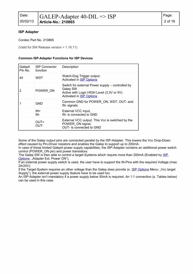
Common ISP-Adapter Functions for ISP Devices
Galep4 Pin No.
ISP Connector function
Description
40 WDTWatch-Dog Trigger output.Activated in ISP Options
2 POWER_ON
Switch for external Power supply – controlled by Galep SWActive with Logic HIGH Level (3,3V or 5V)Activated in ISP Options
1 GNDCommon GND for POWER_ON, WDT, OUT- and IN- signals.
IN+IN-
External VCC input,IN- is connected to GND
OUT+OUT-
External VCC output. This Vcc is switched by the POWER_ON signal.OUT- is connected to GND
Some of the Galep output pins are connected parallel by the ISP-Adapter. This lowers the Vcc Drop-Down effect caused by Pin-Driver resistors and enables the Galep to support up to 200mA.In case of these limited Galep4 power supply capabilities, the ISP-Adapter contains an additional power switch control (POWER_ON pin) and power transistors.The Galep SW is then able to control a target-Systems which require more than 200mA (Enabled by ISP Options: „Adapter Ext. Power ON“).If an external power supply switch is used, the user have to support the IN-Pins with the required Voltage (max. 2A/20V).If the Target-System requires an other voltage than the Galep does provide (s. ISP Options Menu: „Vcc target Supply“), the external power supply feature have to be used too.An ISP-Adapter isn't mandatory if a power supply below 50mA is required. An 1:1 connection (s. Tables below) can be used in this case.
Date:
05/02/13GALEP-Adapter 40-DIL => ISPArticle-No.: 210865
Page:
3 of 16
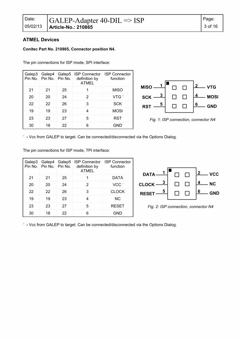
ATMEL Devices
Conitec Part No. 210865, Connector position N4.
The pin connections for ISP mode, SPI interface:
Galep3Pin No.
Galep4Pin No.
Galep5Pin No.
ISP Connectordefinition by
ATMEL
ISP Connectorfunction
21 21 25 1 MISO
20 20 24 2 VTG 1
22 22 26 3 SCK
19 19 23 4 MOSI
23 23 27 5 RST
30 18 22 6 GND
1 - Vcc from GALEP to target. Can be connected/disconnected via the Options Dialog.
The pin connections for ISP mode, TPI interface:
Galep3Pin No.
Galep4Pin No.
Galep5Pin No.
ISP Connectordefinition by
ATMEL
ISP Connectorfunction
21 21 25 1 DATA
20 20 24 2 VCC 1
22 22 26 3 CLOCK
19 19 23 4 NC
23 23 27 5 RESET
30 18 22 6 GND
1 - Vcc from GALEP to target. Can be connected/disconnected via the Options Dialog.
Fig. 2: ISP connection, connector N4
NC
VCC1DATA 2
3CLOCK 4
GND5 RESET 6
Fig. 1: ISP connection, connector N4
MOSI
VTG1MISO 2
3SCK 4
GND5RST 6

Date:
05/02/13GALEP-Adapter 40-DIL => ISPArticle-No.: 210865
Page:
4 of 16
Conitec Part No. 210865, Connector position N5.
The pin connections for ISP mode, AT89S/LP microcontrollers :
Galep3Pin No.
Galep4Pin No.
Galep5Pin No.
ISP Connectordefinition by
ATMEL
ISP Connectorfunction
21 21 25 1 SCK
20 20 24 2 GND
22 22 26 3 MISO
29 19 23 4 VCC 1
23 23 27 5 RST
6 NC
7 NC
17 17 21 8 SS 2
25 25 29 9 MOSI
16 16 20 10 GND
1 - Vcc from GALEP to target. Can be connected/disconnected via the Options Dialog.2 - Optional.
The pin connections for ISP mode, AVR microcontrollers :
Galep3Pin No.
Galep4Pin No.
Galep5Pin No.
ISP Connectordefinition by
ATMEL
ISP Connectorfunction
21 21 25 1 MOSI
20 20 24 2 VTG 1
3 NC
19 23 4 GND 2
23 23 27 5 RST
30 18 22 6 GND
24 24 28 7 SCK
17 21 8 GND 2
25 25 29 9 MISO
16 16 20 10 GND
1 - Vcc from GALEP to target. Can be connected/disconnected via the Options Dialog.2 - Not available on GALEP-3.
Fig. 4: ISP connection, connector N5
VTG1MOSI 2
GND3NC 4
GND5RST 6
GND7SCK 8
GND9MISO 10
Fig. 3: ISP connection, connector N5
GND1SCK 2
VCC3MISO 4
NC5RST 6
SS7NC 8
GND9MOSI 10

Date:
05/02/13GALEP-Adapter 40-DIL => ISPArticle-No.: 210865
Page:
5 of 16
Silicon Laboratories Devices
Conitec Part No. 210865, Connector position N5.
The pin connections for ISP mode:
Galep4Pin No.
Galep5Pin No.
ISP Connectordefinition by
SiliconLaboratories
ISP Connectorfunction
21 25 1 VDC
20 24 2 GND
22 26 3 GND
19 23 4 C2D
5 Not Connected
6 Not Connected
24 28 7 C2CK
8 Not Connected
25 29 9 GND
10 Not Connected
Fig. 5: ISP connection, connector N5
GND1VDC 2
C2D3GND 4
NC5NC 6
NC7C2CK 8
GND9GND 10

Date:
05/02/13GALEP-Adapter 40-DIL => ISPArticle-No.: 210865
Page:
6 of 16
EM Microelectronic-Marin SA Devices.
Conitec Part No. 210865, Connector position N5.
EM4176,EM4276,EM4376,EM6869
Galep5Pin No.
ISPConnector
Pin No.
ISP Connectorfunction
25 1 VBAT
24 2 TEST_IN
3 Not Connected
4 Not Connected
5 Not Connected
22 6 SDIO
28 7 VSS
21 8 SCLK
29 9 VSS
10 Not Connected
EM6819
Galep5Pin No.
ISPConnector
Pin No.
ISP Connectorfunction
25 1 VSUP
2 Not Connected
3 Not Connected
23 4 TM
5 Not Connected
22 6 DATA / PB7
28 7 VSS
21 8 SCLK / BP6
29 9 VSS
10 Not Connected Fig. 7: ISP connection, connector N5
NC1VSUP 2
TM3NC 4
DATA5NC 6
SCLK7VSS 8
NC9VSS 10
Fig. 6: ISP connection, connector N5
TEST_IN1VBAT 2
NC3NC 4
SDIO5NC 6
SCLK7VSS 8
NC9VSS 10
Date:
05/02/13GALEP-Adapter 40-DIL => ISPArticle-No.: 210865
Page:
7 of 16
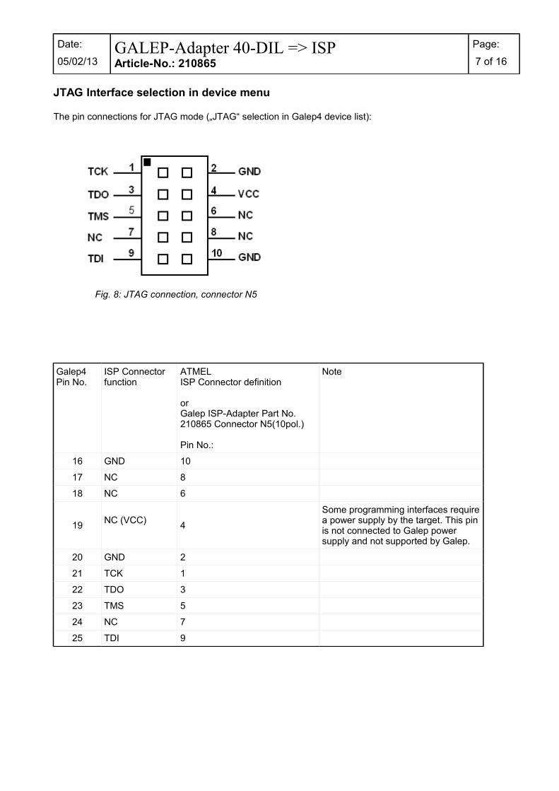
JTAG Interface selection in device menu
The pin connections for JTAG mode („JTAG“ selection in Galep4 device list):
Galep4 Pin No.
ISP Connector function
ATMELISP Connector definition
or Galep ISP-Adapter Part No. 210865 Connector N5(10pol.)
Pin No.:
Note
16 GND 10
17 NC 8
18 NC 6
19NC (VCC)
4
Some programming interfaces requirea power supply by the target. This pinis not connected to Galep power supply and not supported by Galep.
20 GND 2
21 TCK 1
22 TDO 3
23 TMS 5
24 NC 7
25 TDI 9
Fig. 8: JTAG connection, connector N5

Date:
05/02/13GALEP-Adapter 40-DIL => ISPArticle-No.: 210865
Page:
8 of 16
Fujitsu Devices : MB95Fxxx
Conitec Part No. 210865, Connector position N5.
The pin connections for ISP ( ASYNC ) mode:
Galep5Pin No.
ISPConnector
ISP Connectorfunction
25 1 VCC
24 2 GND
26 3 RSTIN 1
23 4 RSTOUT
5 Not Connected
6 Not Connected
7 Not Connected
21 8 DBG
9 Not Connected
10 Not Connected
1 - This connection is need only for MB95F2xx.
Fig. 9: ISP connection, connector N5
GND1VCC 2
RSTOUT3RSTIN 4
5NC 6
7 8
GND9NC 10
NC
DBGNC

Date:
05/02/13GALEP-Adapter 40-DIL => ISPArticle-No.: 210865
Page:
9 of 16
Fuitsu Devices
Conitec Part No. 210865, Connector position N5.
See ISP Options for selecting the ISP functions.
Activate „Vcc by Galep“ in ISP Options menu if no other power source is available.
Caution: Deactivate „VCC by Galep“ in ISP Options menu when Target don't use the Power supply by Galep4– Target or Galep device damage is possible.
„SYNC“ adapter selected in device menu
ISP cable length max. 20cm. A cable length of up to 60cm can be used if 220Ohm resistors are added in serial of P01, P00, SCK, SIN, SOT, MD0 and MD2 wire.Selection of cable length >20cm and if 220Ohm have to be used, depends on target layout and have to be selected by the user.Check FUJITSU application notes AN-000004-11 for more informations.
The pin connections for synchronous mode („SYNC“ selection in Galep4 device list):
Fig. 10: Fujitsu SYNC connection, connector N5

Date:
05/02/13GALEP-Adapter 40-DIL => ISPArticle-No.: 210865
Page:
10 of 16
Galep4 Pin No.
ISP Connector function
ISP Connector definition by Fujitsu
or Galep ISP-Adapter Part No. 210865 Connector N5(10pol.) or N6(14pol.)
Pin No.:
Note
16 GND 10
17 SCK 8
18 SIN 6
19 MD2 4
20 P01 (P31, P81) 2
This pin is used as a BUSY signal for Galep SW when MCU kernel is running.It Should be connected to Galep for best performance. Otherwise fixed delay times are assumed by Galep SW.Don't connect this pin without pull-up or pull-down to VCC or GND. This could damage the device or programmer during SYNC mode.
21 P00 (P30, P80) 1
22 MD0 3
23 /RESET 5
24 SOT 7
25 VCC 9
See Fujitsu Application Notes shows how to connect the 10 pins to your target system.

Date:
05/02/13GALEP-Adapter 40-DIL => ISPArticle-No.: 210865
Page:
11 of 16
„ASYNC“ adapter selected in device menu
In asynchronous mode you need a PC RS232 Port only (signals RxD and TxD at least). A Galep4 is mandatory to be connected as a dongle.
The pin connections for asynchronous mode („ASYNC“ selection in Galep4 device list):
PC RS232, DB-9PIN No.:
Connector function
Note
1 NC
2 RxD
3 TxD
4 DTR Used for Reset signal or Mode Controls. „RTS reset, DTR mode selection“
5 GND
6 DTR Connected to DTR
7 RTSUsed for Reset signal or Mode Controls. „RTS reset, DTR mode selection“
8 CTS Connected to RTS
9 NC
If „ASYNC“ is being selected, the ISP-Adapter (Part No. 210865) is mandatory only, when GALEP have to provide the target power supply (200mA max.) or the Galep have to generate a Watch-Dog trigger signal.
If a target clock sources of 5MHz, 10MHz or 20MHz is used, some targets require to set P00 or P30 or P80 to logic HIGH.
For more details check Fujitsu Application Notes how to connect a RS232 to your target system.
Date:
05/02/13GALEP-Adapter 40-DIL => ISPArticle-No.: 210865
Page:
12 of 16
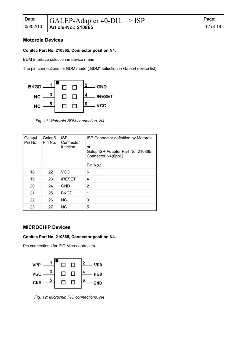
Motorola Devices
Conitec Part No. 210865, Connector position N4.
BDM Interface selection in device menu
The pin connections for BDM mode („BDM“ selection in Galep4 device list):
Galep4 Pin No.
Galep5 Pin No.
ISP Connector function
ISP Connector definition by Motorola
or Galep ISP-Adapter Part No. 210865 Connector N4(6pol.)
Pin No.:
18 22 VCC 6
19 23 /RESET 4
20 24 GND 2
21 25 BKGD 1
22 26 NC 3
23 27 NC 5
MICROCHIP Devices
Conitec Part No. 210865, Connector position N4.
Pin connections for PIC Microcontrollers.
Fig. 11: Motorola BDM connection, N4
Fig. 12: Microchip PIC connections, N4
Date:
05/02/13GALEP-Adapter 40-DIL => ISPArticle-No.: 210865
Page:
13 of 16
ISP OptionsCommon options for all devices using the ISP-Adapter. Please note: Select the ISP version – not the socketversion – of the device!
Vcc by GalepThis switch enables the power supply by Galep for a target system. The voltage depends on the selected deviceand is visible below. This switch can also be activated when a COM port is used for programming. This switch is disabled if „Adapter Ext. Power ON“ is selected.
Adapter Ext. Power ONThis switch enables a control pin for external power supply switching.If the signal is raised to HIGH level during start of device initialization, a 100ms delay is added to respect external Vcc raise time.Activating this switch disables the „Vcc by Galep“ switch.If not enabled the output will be HIGH-Z.
Reset by GalepThis switch enables the reset signal for the target system.The duration of active phase and active polarity can be selected.
Depending on the ISP-SW algorithm, a reset will be activated by a SW-command too (transmitted via the communication lines).If mandatory by the device, this signal is fixed to active.
Depending of the selected connection, Reset is active only at ISP-Adapter or at RS232 connector lines.
Reset enable/Pulse timeDefine the Reset period length.
Reset enable/PolarityThis button is used to respect signal inverter on the target system.
WDT Trigger by GalepActivates a Watch-Dog trigger signal during an action is running.If enabled, the duration of the trigger periods can be selected.This signal is output by the ISP-Adapter.If not enabled the output will be HIGH-Z.This switch is also active when a COM port is used for programming.
Default ValuesReset all values.
FUJITSU (ASYNC/SYNC)
If a device is being selected with „SYNC“ or „ASYNC“, this options menu is visible.
„SYNC“ in device list means a synchronous connection (fast connection with SDIN, SDOUT and SCLK signals).The ISP-Adapter is mandatory in this case.
„ASYNC“ in device list means an asynchronous connection.A PC COM Port have to be used.
The target system have to fulfil the requirements for synchron or asynchron programming (see manufacturers design notes).

Date:
05/02/13GALEP-Adapter 40-DIL => ISPArticle-No.: 210865
Page:
14 of 16
If „ASYNC“ is being selected, an ISP-Adapter is only mandatory when GALEP have to provide the target power supply or have to generate a Watch-Dog trigger signal.
ASYNC OptionsIf a device with „ASYNC“ adapter is selected the following options are visible too:
COMPortOne of PC COM ports COM1 ..COM3 can be selected for connection.
Baud RateActive when RS232 communication speed of the Target system can be selected.
The signals RTS and DTR are used for Reset and Control functions.
RTS reset, DTR mode selectionRTS signal on selected COM port is toggled at reset.DTR signal is used for mode selection.
DTR reset, RTS mode selectionDTR signal on selected COM port is toggled at reset.RTS signal is used for mode selection.
CPU mode PolaritySelect polarity of CPU mode when active.This button is used to respect signal inverter on the target system.
MCU clockSelect target MCU Crystal frequency to compute the correct Baudrate.
Default ValuesReset all values.
SYNC Options
If a device with „SYNC“ adapter is selected the following option is visible too:
Sync SpeedSelects Bit I/O clock from 125kHz up to 1MHz. Respect Sync clock max. 1/8 of crystal frequency.
MOTOROLA (BDM)
BDM COM Options
Don't enable the „Vcc by Galep“ switch. VCC in BDM interface is defined to support the Programming interface and not to be supported by the interface.In case of limited Galep FPGA clock source generation, the devices are initialised in active background mode during Reset.Check the Device documentation if any of the values below are changed.
MCU Bus ClockSelect MCU bus Clock (½ of Crystal frequency) to process a new FCDIV value for the internal MCU Programming clock (150kHz -200kHz required).
FCDIV_RegisterHex Value for FCDIV register changed if MCU Bus clock is changed or by user edit.
Alternate ClockSelect value of communication alternate clock of BDM interface

Date:
05/02/13GALEP-Adapter 40-DIL => ISPArticle-No.: 210865
Page:
15 of 16
Enable ACK SignalEnables Acknowledge signal for communication.
Select alternate FrequencyThe value selected in „Alternate Clock“ is used as a base frequency for communication.
Date:
05/02/13GALEP-Adapter 40-DIL => ISPArticle-No.: 210865
Page:
16 of 16
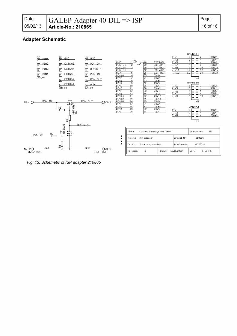
Adapter Schematic
Fig. 13: Schematic of ISP adapter 210865