datasheet copyright 20200513 / ver. c lm3535md
TRANSCRIPT

2020-05-13 TL3535LUXxxNA Page 1 of 18
Rev.R0C
3535 SMD(Surface Mount Device) Package
UV Radiant power up to 15mW
Dimension : 3.7 x 3.7 x 1.86 mm
Lead-free reflow soldering application
RoHS compliant
DATASHEET
LUMENS CO., LTD
12, Wongomae-ro, Giheung-gu, Yongin-si, Gyeonggi-do, Korea
http://lumensleds.com
Copyright 20200513 / Ver. C
LM3535MD
( TL3535LUXxxNAxx )

2020-05-13 TL3535LUXxxNA Page 2 of 18
Rev.R0C
Table of Contents
1. Product description ……………………………………………………………… 3
2. Absolute maximum ratings …..………………………………………………… 3
3. Electro-optical characteristics (Ta=25℃)……………………………………….. 4
4. Electro-optical chart (Ta=25℃)…………………………...…………………….. 4
5. Ranks (Ta=25℃)……………………………………………….…………………….. 5
6. Characteristic Graphs (Ta=25℃)……………………………………………… 6-8
7. Outline Dimensions ……………………………………………………………… 9
8. Reliability test items and conditions………………………………………….. 10
9. Reel……………………………………………………………………………….. 11
10. Packing …………………………………………………………………………… 12
11. Reflow condition………………………………………………………………… 13
12. Product and Model name Nomenclature………………………………. 14-15
13. Cautions ………………………………………………………………………. 16-18

2020-05-13 TL3535LUXxxNA Page 3 of 18
Rev.R0C
1. Product description
(1) Description
The UV LED is designed for the high power operation to get the high power output applications.
Spec output peak wavelengths are typical 275nm which enable powerful and compact applications in
disinfection
(2) Features
Lead frame type LED Package : 3.7mm x 3.7mm x 1.86mm ( L x W x H )
Available in from 270nm to 280nm
Low thermal resistance as low as 22℃/W
Viewing angle of 115 degrees
Chip material : AIGaN based
Reflow soldering
RoHS compliant
(3) Applications
Disinfection (Water / Surface / Air)
Portable devices
2. Absolute maximum ratings
Parameters Symbol Value Unit
Power dissipated PD 0.9 W
Forward current IF 150 mA
Operating temperature TOPR -10 ~ +55 ℃
Storage temperature TSTG -30 ~ +65 ℃
(1)Junction temperature TJ ≤ 90 ℃
Soldering temperature Reflow Soldering : 260℃ for 10 sec.
(1) Proper current derating must be observed to maintain junction temperature below the Maximum.

2020-05-13 TL3535LUXxxNA Page 4 of 18
Rev.R0C
3. Electro-optical characteristics (Ta=25℃)
Parameters Symbol If(mA) Typ. Unit
Forward voltage Vf 120 7.5 V
Viewing angle FWHM 2θ1/2 120 115 degrees
Thermal resistance junction to solder pad Rthj-a 120 22 ℃/W
Lumens maintains a tolerance of 3% on forward voltage measurements.
Viewing angle 115±5 degree.
4. Electro-optical chart (Sorting current=120mA, Ta=25℃)
Parameter Symbol Min Typ Max Unit
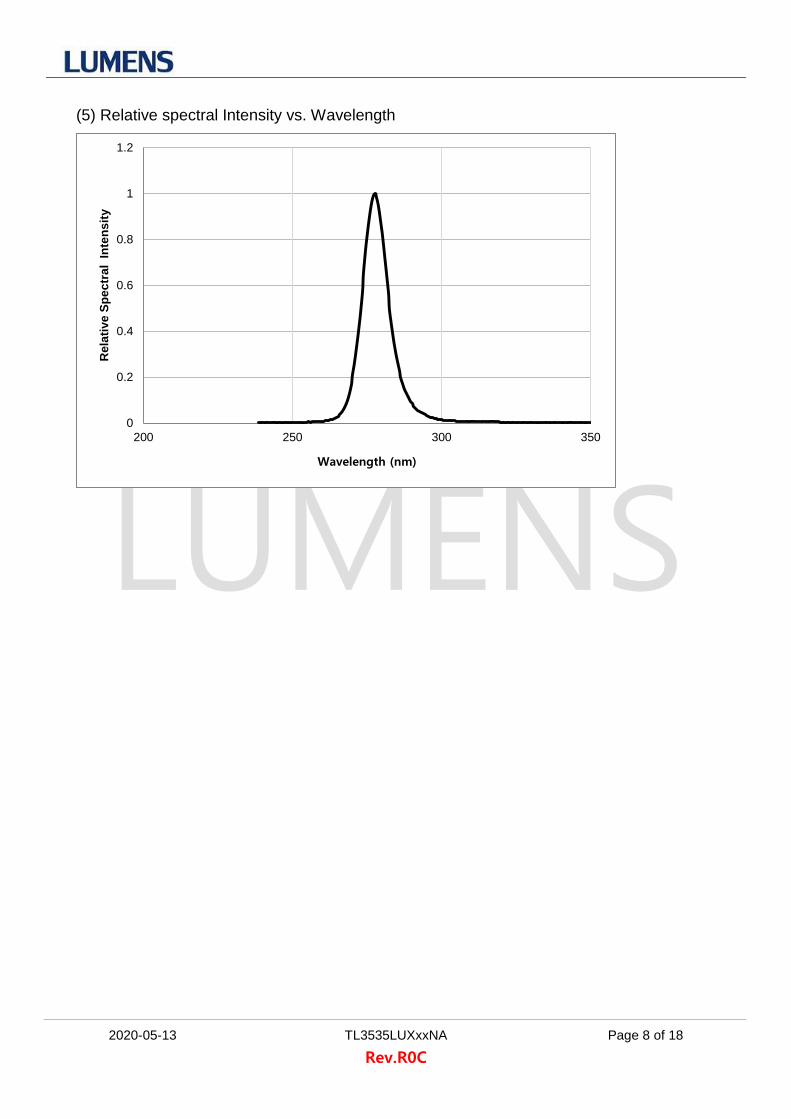
Peak wavelength λp 270 275 280 nm
Radiant power Φe 10.0 12.5 15.0 mW
Forward voltage Vf 6.5 7.5 8.5 V
FWHM Δλ - 9.7 - nm
View angle 2θ 1/2 - 115 - deg.
Thermal resistance RθJ-s 22 ℃/W
Tested and binned at 120mA, 25℃
Lumens maintains a tolerance of 2nm on Peak wavelength measurements.
Lumens maintains a tolerance of 10% on Radiant flux measurements.
Lumens maintains a tolerance of 0.5 on Forward voltage measurements.

2020-05-13 TL3535LUXxxNA Page 5 of 18
Rev.R0C
5. Ranks (Sorting current=120mA, Ta=25℃)
Item Symbol Model name Wavelength Range (nm)
Rank
If=120mA (Sorting current)
Unit
Min Typ Max
Radiant Flux Φe TL3535LUX27NAxx 270 - 280
PA 10.0 - 11.0
mW
PB 11.0 - 12.0
PC 12.0 - 13.0
PD 13.0 - 14.0
PE 14.0 - 15.0
Forward voltage
Vf All
VB 6.5 - 7.5
V
VC 7.5 - 8.5
Lumens maintains a tolerance of 7% on Radiant flux measurements.
Lumens maintains a tolerance of 3% on Forward voltage measurements.
Lumens maintains a tolerance of 1 on wavelength measurements.

2020-05-13 TL3535LUXxxNA Page 6 of 18
Rev.R0C
6. Characteristic Graphs (Ta=25℃)
(1) Typical Forward Current vs. Forward Voltage
(2) Typical Relative Radiant Power vs. Forward Current
0
20
40
60
80
100
120
140
160
4.0 5.0 6.0 7.0 8.0 9.0
Fo
rwa
rd c
urr
en
t (m
A)
Forward voltage (V)
0
2
4
6
8
10
12
14
16
0 20 40 60 80 100 120 140 160
Rad
ian
t p
ow
er
(mW
)
Forward current (mA)

2020-05-13 TL3535LUXxxNA Page 7 of 18
Rev.R0C
(3) Typical Relative Radiant power vs. Junction Temperature
(4) Typical Spatial Radiation Characteristic
0
0.2
0.4
0.6
0.8
1
1.2
25 35 45 55 65 75 85 95
Re
lati
ve
Ra
dia
nt
po
we
r (%
)
Junctinon temperature (℃)
0
0.2
0.4
0.6
0.8
1
-90 -60 -30 0 30 60 90
Rela
tive
In
ten
sit
y (
%)
Angular Displacement (degrees)
Radiation Characteristic
2020-05-13 TL3535LUXxxNA Page 8 of 18
Rev.R0C
(5) Relative spectral Intensity vs. Wavelength
0
0.2
0.4
0.6
0.8
1
1.2
200 250 300 350
Re
lati
ve
Sp
ec
tra
l I
nte
ns
ity
Wavelength (nm)
2020-05-13 TL3535LUXxxNA Page 9 of 18
Rev.R0C
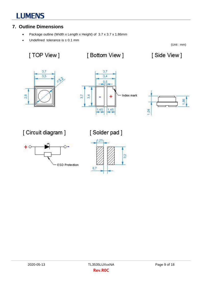
7. Outline Dimensions
Package outline (Width x Length x Height) of 3.7 x 3.7 x 1.86mm
Undefined tolerance is ± 0.1 mm
(Unit : mm)

2020-05-13 TL3535LUXxxNA Page 10 of 18
Rev.R0C
8. Reliability test items and conditions
Item Reference Test Conditions Duration Cycle
Room Temperature Operating Life (RTOL)
Internal Reference
Ta = 25℃, If = Sorting current 1,000 hours
High Temperature Operating Life (HTOL)
Internal Reference
Ta = 85℃, If = Sorting current 1,000 hours
Low Temperature Storage (LTS)
Internal Reference
Ta = -40℃ 1,000 hours
High Temperature Storage (HTS)
Internal Reference
Ta = 100℃ 1,000 hours
Wet Operating Life of High Temperature (WHTOL)
Internal Reference
Ta = 60℃, 90% RH
If= Sorting current 1,000 hours
Moisture Sensitivity Level (MSL)
Internal Reference
Tsoldering = 260℃
(Pre-treatment 60℃, 60%, 168hr) 1 times
(1) Criteria for judging the damage
Item Symbol Condition
Criteria for Judgment
MIN MAX
Forward Voltage Vf If = 120mA - USL (1) × 1.1
Radiant Intensity Φe If = 120mA LSL (2) × 0.7 -
USL : Upper Standard Level
LSL : Lower Standard Level

2020-05-13 TL3535LUXxxNA Page 11 of 18
Rev.R0C
9. Reel
Specifying Part Number, Quantity and Lot Number

2020-05-13 TL3535LUXxxNA Page 12 of 18
Rev.R0C
10. Packing
• Reel size : 7Inch
• Reel color : Black
• Quantity= 500pcs or 1,000pcs / reel
• Antistatic shielding (250x230mm)
- 1 Reel / Bag (T=0.1mm)
- Reel + Dry-pack + Humidity Indicator
H.I
D.P
260
• Inner box size = 240(L) x 130(W) x 272(H)mm
• 10bag / Inner box
• Max. 10,000pcs / Inner box
240
272
130
• Carton box size = 500(L) x 290(W) x 290(H)mm
• 4 Inner box / Carton
• Max. 40,000pcs / Carton
290
290
500
2020-05-13 TL3535LUXxxNA Page 13 of 18
Rev.R0C
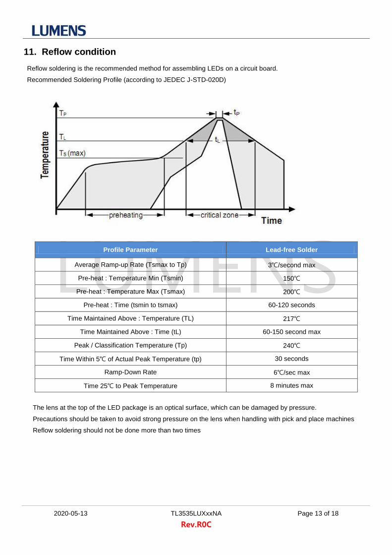
11. Reflow condition Reflow soldering is the recommended method for assembling LEDs on a circuit board.
Recommended Soldering Profile (according to JEDEC J-STD-020D)
Profile Parameter Lead-free Solder
Average Ramp-up Rate (Tsmax to Tp) 3℃/second max
Pre-heat : Temperature Min (Tsmin) 150℃
Pre-heat : Temperature Max (Tsmax) 200℃
Pre-heat : Time (tsmin to tsmax) 60-120 seconds
Time Maintained Above : Temperature (TL) 217℃
Time Maintained Above : Time (tL) 60-150 second max
Peak / Classification Temperature (Tp) 240℃
Time Within 5℃ of Actual Peak Temperature (tp) 30 seconds
Ramp-Down Rate 6℃/sec max
Time 25℃ to Peak Temperature 8 minutes max
The lens at the top of the LED package is an optical surface, which can be damaged by pressure.
Precautions should be taken to avoid strong pressure on the lens when handling with pick and place machines
Reflow soldering should not be done more than two times

2020-05-13 TL3535LUXxxNA Page 14 of 18
Rev.R0C
12. Product and Model name Nomenclature
(1) Product detail (2) Model name detail
Basic Definition
(Lumens Product)
L M 3 5 3 5 M D
Power Class
M : Mid Power / H : High Power
Package Size 35 : 3.5mm / 35 : 3.5mm
Power and Range
LD : Low power Deep
MD : Middle Power Deep
T L 3 5 3 5 L U X x x N A x x
Power Series
TL : Low / TM : Middle / TH : High
Package Size
50 : 5.0mm / 50 : 5.0mm
CRI
Internal code
Wavelength
27 : 270-280nm
Lens type
LU : Dome lens
Voltage & Chip array

2020-05-13 TL3535LUXxxNA Page 15 of 18
Rev.R0C
(3) Label structure and detail
The lot number is composed of the following characters.
2 0 0 1 0 0 1 - x x x x x - x
Production Year
20 : 2020
21 : 2021
︙
Production Month
01 : January
︙
12 : December
Wavelength
27 : 270-280nm
Internal Number
Production Serial Number
001 : 001
︙
999 : 999
x

2020-05-13 TL3535LUXxxNA Page 16 of 18
Rev.R0C
13. Cautions
(1) Eye and Skin Safety Guidelines
Do not directly look at the light when the LEDs are on. Proceed with caution to avoid any risks of damage
to the eyes when examining the LEDs with optical instruments. Protect your eyes and skin while operating.
Equipment should be designed to completely screen or filter UV radiation
The attached label should be used on products and systems that use UV LEDs
(2) Cleaning
2.1 Do not scrub the LEDs using hard brush or with excessive force
2.2 Do not clean LEDs using acetone or trichloroethylene.
2.3 To clean LEDs, only use soft foam-tip clean-room swab and isopropyl alcohol with gentle cleaning
motions. Distilled water can be used for rinsing, but LEDs must be completely dried. (for example with
nitrogen blow dry) before they can be used
2.4 Electrical and optical measurements are recommended before and after cleaning to ensure that LEDs
are not damaged.
(3) Handling of Glass (Lens) LEDs
3.1 Avoid silicone resin parts especially with sharp tools such as tweezers.
3.2 Avoid leaving fingerprints on silicone lens part.
(4) Thermal Management
The thermal design of the system must be considered, particularly at the beginning of the system design
process. In order to maximize performance it is necessary to reduce heat in the system by optimizing
thermal conductivity of circuit boards and housings and also by minimizing density of the LED array and
other components.

2020-05-13 TL3535LUXxxNA Page 17 of 18
Rev.R0C
(5) Static Electricity
Wristbands and anti-electrostatic gloves are strongly recommended and all devices, equipment and
machinery must be properly grounded when handling the LEDS, which are sensitive to static electricity.
Precautions should be taken against surge voltage to the equipment that mounts the LEDs. Unusual
characteristics such as significant increase of current leakage, decrease of turn-on voltage, or non-
operation at a low current can occur when the LED is damaged
(6) Moisture-Proof Package
6.1 When moisture is absorbed into the LED package it may vaporize and expand products during soldering.
There is a possibility that this may cause exfoliation of the contacts and damage to the optical
characteristics of the LEDs. For this reason, the moisture-proof package is used to keep moisture to a
minimum in the package.
6.2 A package of a moisture-absorbent material (silica gel) is inserted into the shielding bag. The silica gel
changes its color from blue to pink as it absorbs moisture.
(7) Current limiting
A resistor should be used to limit current spikes that can be caused by voltage fluctuations.
Otherwise damage could occur.
(8) Storage Conditions
8.1 Before opening the package: The LEDs should be kept at 30℃ or less and 90%RH or less. The LEDs
should be used within a year. When storing the LEDs, moisture-proof packaging with moisture-absorbent
material (silica gel) is recommended.
8.2 After opening the package: The LEDs should be kept at 30℃ or less and 70%RH or less. The LEDs
should be soldered within 168 hours (7 days) after opening the package. If unused LEDs remain, they
should be stored in moisture-proof packages, such as sealed containers with packages of moisture-
absorbent material (silica gel). It is also recommended to return the LEDs to the original moisture-proof
bag and to reseal the moisture-proof bag again.
8.3 If the moisture-absorbent material (silica gel) has faded away or the LEDs have exceeded the
recommended storage time, baking treatment should be performed using the following conditions.
Baking treatment: more than 24 hours at 65±5℃
8.4 Lumens LED electrode sections are comprised of a silver-plated copper alloy. The silver surface may be
affected by environments which contain corrosive gases and so on. Please avoid condition which may
cause difficulty environments during soldering operations. It is recommended that the user uses the
LEDs as soon as possible.
8.5 Please avoid rapid transitions in ambient temperature, especially in high humidity environments where
condensation can occur.

2020-05-13 TL3535LUXxxNA Page 18 of 18
Rev.R0C
(9) Usage
9.1 Do not exceed the values given in this specification.