databook - tinlavir. bine ai venit · the chillers feature a high efficiency scroll compressors,...
TRANSCRIPT
EWAQ~E- R3.4.4 Databook 20/09/2012
CSS - Rev. 6.1.1 Printing date: Code:
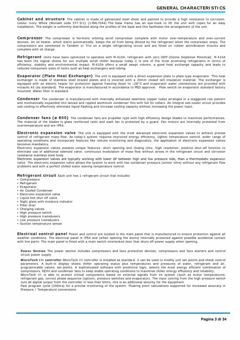
Air cooled scroll chillers
EWAQ~E- XS (High Efficiency - Standard Noise) - Cooling Capacity from 178 to 336 kW XL (High Efficiency - Low Noise) - Cooling Capacity from 178 to 336 kW XR (High Efficiency - Reduced Noise) - Cooling Capacity from 173 to 323 kW
Performance according to EN14511.

FEATURES AND BENEFITS
Low operating cost and extended operating life This chiller range is the result of careful design, aimed to optimize the energy efficiency of the chillers, with the objective of bringing down operating costs and improving installation profitability, effectiveness and economical management. The chillers feature a high efficiency scroll compressors, large condenser coil surface area for maximum heat transfer and low discharge pressure, advanced technology condenser fans and a 'plate to plate' evaporator with low refrigerant pressure drops.
Low operating sound levels Very low sound levels both at full load and part load conditions are achieved by the latest compressor design and by a unique new fan that moves large volume of air at exceptionally low sound levels and by the virtually vibration-free operation.
Outstanding reliability The chillers have two truly independent refrigerant circuits, in order to assure maximum safety for any maintenance, whether planned or not. They are equipped with hermetic orbiting scroll compressor complete with motor over-temperature and over-current devices and protection against excessive gas discharge temperature, a proactive control logic and are full factory-run-tested to optimized trouble-free operation.
Superior control logic The new MicroTech III controller provides an easy to use control environmental. The control logic is designed to provide maximum efficiency, to continue operation in unusual operating conditions and to provide a history of unit operation. One of the greatest benefits is the easy interface with LonWorks, Bacnet, Ethernet TCP/IP or Modbus communications.
Code requirements – Safety and observant of laws/directives Units are designed and manufactured in accordance with applicable selections of the following:
Construction of pressure vessel Machinery Directive Low Voltage Electromagnetic Compatibility Electrical & Safety codes Manufacturing Quality Stds
97/23/EC (PED) 2006/42/EC 2006/95/EC 2004/108/EC EN 60204–1 / EN 60335-2-40 UNI – EN ISO 9001:2004
Certifications Units are CE marked, complying with European directives in force, concerning manufacturing and safety. On request units can be produced complying with laws in force in non European countries (ASME, GOST, etc.), and with other applications, such as naval (RINA, etc.).
Versions This range is available in one version: HIGH EFFICIENCY 6 sizes to cover a range 178 up to 336 kW with an EER up to 3.11 and an ESEER up to 4.31 (data referred to Standard Noise). The EER (Energy Efficiency Ratio) is the ratio of the Cooling Capacity to the Power Input of the unit. The Power Input includes: the power input for operation of the compressor, the power input of all control and safety devices, the power input for fans. The ESEER (European Seasonal Energy Efficiency Ratio) is a weighed formula enabling to take into account the variation of EER with the load rate and the variation of air inlet condenser temperature. ESEER = A x EER100% + B x EER75% + C x EER50% + D x EER25%
K = Coefficient; T = Air inlet condenser temperature.
Sound configurations Standard, low and reduced sound configurations available as follows: STANDARD SOUND Condenser fan rotating at 900 rpm, rubber antivibration under compressor LOW SOUND Condenser fan rotating at 900 rpm, rubber antivibration under compressor, compressor sound enclosure. REDUCED SOUND Condenser fan rotating at 705 rpm, rubber antivibration under compressor, compressor sound enclosure.
Pagina 2 di 34
GENERAL CHARACTERISTICS
Cabinet and structure The cabinet is made of galvanized steel sheet and painted to provide a high resistance to corrosion. Colour Ivory White (Munsell code 5Y7.5/1) (±RAL7044).The base frame has an eye-hook to lift the unit with ropes for an easy installation. The weight is uniformly distributed along the profiles of the base and this facilitates the arrangement of the unit.
Compressor The compressor is hermetic orbiting scroll compressor complete with motor over-temperature and over-current devices. An oil heater, which starts automatically, keeps the oil from being diluted by the refrigerant when the compressor stops. The compressors are connected in Tandem or Trio on a single refrigerating circuit and are fitted on rubber antivibration mounts and complete with oil charge.
Refrigerant Units have been optimized to operates with R-410A, refrigerant with zero ODP (Ozone Depletion Potential). R-410A has been the logical choice for our multiple scroll chiller because today it is one of the most promising refrigerants in terms of efficiency, stability and environmental impact. R-410A offers a small swept volume, a good heat exchange capacity and leads to reduced component sizes of items such as heat exchangers and tubing.
Evaporator (Plate Heat Exchanger) The unit is equipped with a direct expansion plate to plate type evaporator. This heat exchanger is made of stainless steel brazed plates and is covered with a 20mm closed cell insulation material. The exchanger is equipped with an electric heater for protection against freezing down to –28°C and evaporator water connections are provided with victaulic kit (as standard). The evaporator is manufactured in accordance to PED approval. Flow switch on evaporator standard factory mounted. Water filter is standard.
Condenser The condenser is manufactured with internally enhanced seamless copper tubes arranged in a staggered row pattern and mechanically expanded into lanced and rippled aluminum condenser fins with full fin collars. An integral sub-cooler circuit provides sub-cooling to effectively eliminate liquid flashing and increase cooling capacity without increasing the power input.
Condenser fans (ø 800) The condenser fans are propeller type with high efficiency design blades to maximize performances. The material of the blades is glass reinforced resin and each fan is protected by a guard. Fan motors are internally protected from overtemperature and are IP54.
Electronic expansion valve The unit is equipped with the most advanced electronic expansion valves to achieve precise control of refrigerant mass flow. As today’s system requires improved energy efficiency, tighter temperature control, wider range of operating conditions and incorporate features like remote monitoring and diagnostics, the application of electronic expansion valves becomes mandatory. Electronic expansion valves possess unique features: short opening and closing time, high resolution, positive shut-off function to eliminate use of additional solenoid valve, continuous modulation of mass flow without stress in the refrigerant circuit and corrosion resistance stainless steel body. Electronic expansion valves are typically working with lower ΔP between high and low pressure side, than a thermostatic expansion valve. The electronic expansion valve allows the system to work with low condenser pressure (winter time) without any refrigerant flow problems and with a perfect chilled water leaving temperature control.
Refrigerant circuit Each unit has 1 refrigerant circuit that includes: • Compressors • Refrigerant • Evaporator • Air Cooled Condenser • Electronic expansion valve • Liquid line shut off valve • Sight glass with moisture indicator • Filter drier • Charging valves • High pressure switch • High pressure transducers • Low pressure transducers • Suction temperature sensor
Electrical control panel Power and control are located in the main panel that is manufactured to ensure protection against all weather conditions. The electrical panel is IP54 and (when opening the doors) internally protected against possible accidental contact with live parts. The main panel is fitted with a main switch interlocked door that shuts off power supply when opening.
Power Section The power section includes compressors and fans protection devices, compressors and fans starters and control circuit power supply.
MicroTech III controller MicroTech III controller is installed as standard; it can be used to modify unit set-points and check control parameters. A built-in display shows chiller operating status plus temperatures and pressures of water, refrigerant and air, programmable values, set-points. A sophisticated software with predictive logic, selects the most energy efficient combination of compressors, EEXV and condenser fans to keep stable operating conditions to maximise chiller energy efficiency and reliability. MicroTech III is able to protect critical components based on external signals from its system (such as motor temperatures, refrigerant gas, correct phase sequence (option), pressure switches and evaporator). The input coming from the high pressure switch cuts all digital output from the controller in less than 50ms, this is an additional security for the equipment. Fast program cycle (200ms) for a precise monitoring of the system. Floating point calculations supported for increased accuracy in Pressure / Temperature conversions.
Pagina 3 di 34
GENERAL CHARACTERISTICS
Control section - main features Control Section has the following feature. • Management of the refrigerant circuit capacity and fans modulation. • Chiller enabled to work in partial failure condition. • Full routine operation at condition of: - high ambient temperature value - high thermal load - high evaporator entering water temperature (start-up) • Display of evaporator entering/leaving water temperature. • Display of Outdoor Ambient Temperature. • Display of condensing-evaporating temperature and pressure, suction and superheat for each circuit. • Leaving water evaporator temperature regulation. • Compressor and evaporator pumps hours counter. • Display of Status Safety Devices. • Number of starts and compressor working hours. • Optimized management of circuit load. • Fan management according to condensing pressure. • Re-start in case of power failure (automatic / manual). • Start at high evaporator water temperature. • Return Reset (Set Point Reset based on return water temperature). • OAT (Outside Ambient temperature) Reset. • Set point Reset (optional). • Application and system upgrade with commercial SD cards. • Ethernet port for remote or local servicing using standard web browsers. • Two different sets of default parameters could be stored for easy restore.
Safety device / logic for each refrigerant circuit The following devices / logics are available. • High pressure (pressure switch). • High pressure (transducer). • Low pressure (transducer). • High motor winding temperature. • Low pressure ratio. • No pressure change at start.
System security The following securities are available. • Low Ambient temperature lock-out. • Freeze protection.
Regulation type Proportional + integral + derivative regulation on the evaporator leaving water output probe.
MicroTech III MicroTech III built-in terminal has the following features. • 164x44 dots liquid crystal display with white back lighting. Supports Unicode fonts for multi-lingual. • Key-pad consisting of 3 keys. • Push’n’Roll control for an increased usability. • Memory to protect the data. • General faults alarm relays. • Password access to modify the setting. • Application security to prevent application tampering or hardware usability with third party applications. • Service report displaying all running hours and general conditions. • Alarm history memory to allow an easy fault analysis.
Supervising systems (on request) MicroTech III remote communication MicroTech III is able to communicate to BMS (Building Management System) based on the most common protocols as: • ModbusRTU • LonWorks, now also based on the international 8040 Standard Chiller Profile and LonMark Technology. • BacNet BTP certifief over IP and MS/TP (class 4) (Native). • Ethernet TCP/IP.
Pagina 4 di 34
OPTIONS
Standard Options (supplied on basic unit) Direct on line starter (DOL)
Double setpoint - Dual leaving water temperature setpoints.
Evaporator victaulic kit - Hydraulic joint with gasket for an easy and quick water connection.
20mm evaporator insulation - The external shell is covered with a 20mm closed cell insulation material.
Evaporator electric heater - Electric heater (controlled by a thermostat) to protect the evaporator from freezing down to -28°C ambient temperature, providing the power supply is on.
Evaporator flow switch - Supplied separately to be wired and installed on the evaporator water piping (by the customer).
Electronic expansion valve
Ambient outside temperature sensor and setpoint reset
General fault contactor
Hour run meter
Main switch interlock door
Water filter - The water filter removes impurities from water by means of a fine physical barrier.
Options (on request) MECHANICAL
Partial heat recovery - Produced with plate to plate heat exchangers to produce hot water.
Brine version - Allows the unit to operate down to -8°C leaving liquid temperature (antifreeze required).
Axial fans (250 Pa lift)
Condenser coil guards
Evaporator area guards
Cu-Cu condenser coil - To give better protection against corrosion by aggressive environments.
Cu-Cu-Sn condenser coil - To give better protection against corrosion in aggressive environments and by salty air.
Alucoat fins coil - Fins are protected by a special acrylic paint with a high resistance to corrosion.
Discharge line shut-off valve - Installed on the discharge port of the compressor to facilitate maintenance operation.
Suction line shut-off valve - Installed on the suction port of the compressor to facilitate maintenance operation.
High pressure side manometers
Low pressure side manometers
One centrifugal pump (low lift) - Hydronic kit consists of: single direct driven centrifugal pump, water filling system with pressure gauge, safety valve, drain valve. The motor pump is protected by a circuit breaker installed in control panel. The kit is assembled and wired to the control panel. The pipe and pump are protected from freezing with an additional electrical heater.
One centrifugal pump (high lift) Hydronic kit consists of: single direct driven centrifugal pump, water filling system with pressure gauge, safety valve, drain valve. The motor pump is protected by a circuit breaker installed in control panel. The kit is assembled and wired to the control panel. The pipe and pump are protected from freezing with an additional electrical heater.
Two centrifugal pump (low lift) - Hydronic kit consists of: twin direct driven centrifugal pumps, water filling system with pressure gauge, safety valve, drain valve. The motor pump is protected by a circuit breaker installed in control panel. The kit is assembled and wired to the control panel. The pipe and pumps are protected from freezing with an additional electrical heater.
Two centrifugal pump (high lift) Hydronic kit consists of: twin direct driven centrifugal pumps, water filling system with pressure gauge, safety valve, drain valve. The motor pump is protected by a circuit breaker installed in control panel. The kit is assembled and wired to the control panel. The pipe and pumps are protected from freezing with an additional electrical heater.
Double pressure relief valve with diverter
ELECTRICAL / CONTROL
Pagina 5 di 34
OPTIONS
Compressor thermal overload relays - Safety electronic devices that, added to the standard protection devices, protect compressor motors against overload and current unbalance.
Phase monitor - Device that monitors input voltage and stops the chiller in case of phase loss or wrong phase sequence.
Under / Over voltage control - Electronic device that monitors and displays input voltage, and stops the chiller in case of phase loss, wrong phase sequence, or voltage exceeding minimum and maximum allowed values.
Energy meter - Device installed inside the control box that displays all chiller electrical power parameters at line input such as line voltage and phase current, input active and reactive power, active and reactive energy. An integrated RS485 module allows a Modbus communication to an external BMS.
Capacitors for power factor correction - Devices that increase the power factor of the unit. The capacitors are “dry” self-regenerating type with over pressure disconnecting safety device insulated with a no toxic dielectric mix without PCB or PCT.
Speedtrol (fan speed control device - ON/OFF - up to -18°C) - Continuous fan speed regulation on the first fan (VFD driven) of each circuit. It allows unit operation down to -18ºC.
Setpoint reset, Demand limit and Alarm from external device - Setpoint Reset: The leaving water temperature set-point can be overwritten with an external 4-20mA, through the ambient temperature, or through the evaporator water temperature ΔT. Demand Limit: Chiller capacity can be limited through an external 4-20mA signal or via network. Alarm from external device: The unit controller is able to receive an external alarm signal. The user can decide whether this alarm signal will stop the unit or not.
Compressors circuit breakers Safety devices that include in a single device all safety functions otherwise provided by standard fuses and optional thermal relays, such as protection against overcurrent, overload, current unbalance.
Fans circuit breakers - Safety devices that, added to the standard protection devices, protect fan motors against overload and overcurrent.
Fans speed regulation (+ fan silent mode) - Continuous fan speed regulation of all fans (VFD driven) for improved sound level of the unit during low ambient temperature operation. At very low temperatures, all fans except the first are switched off thus allowing unit operation down to -18°C.
INSTALLATION
Rubber anti vibration mounts - Supplied separately, these are positioned under the base of the unit during installation. Ideal to reduce the vibrations when the unit is floor mounted.
Spring anti vibration mounts - Supplied separately, these are positioned under the base of the unit during installation. Ideal for dampening vibrations for installation on roofs and metallic structures.
External tank without cabinet (500 L)
External tank without cabinet (1000 L)
External tank with cabinet (500 L)
External tank with cabinet (1000 L)
OTHER
Container Kit
Witness test
Acoustic test
Pagina 6 di 34

NOMENCLATURE
E W A Q 1 8 0 E - X S
= Air cooled chiller cooling only = Air cooled chiller heat pump = Air cooled condensing unit
EWA EWY ERA
Machine type
Refrigerant D P Q
= R-134a = R-407C = R-410A
Capacity class in kW (Cooling) Always 3-digit code
Model series A, B, …..
Inverter - = Non inverter
Efficiency level X = Standard Efficiency
= High Efficiency
Sound level
S L R
= Standard sound = Low sound = Reduced sound
Pagina 7 di 34
TECHNICAL SPECIFICATIONS
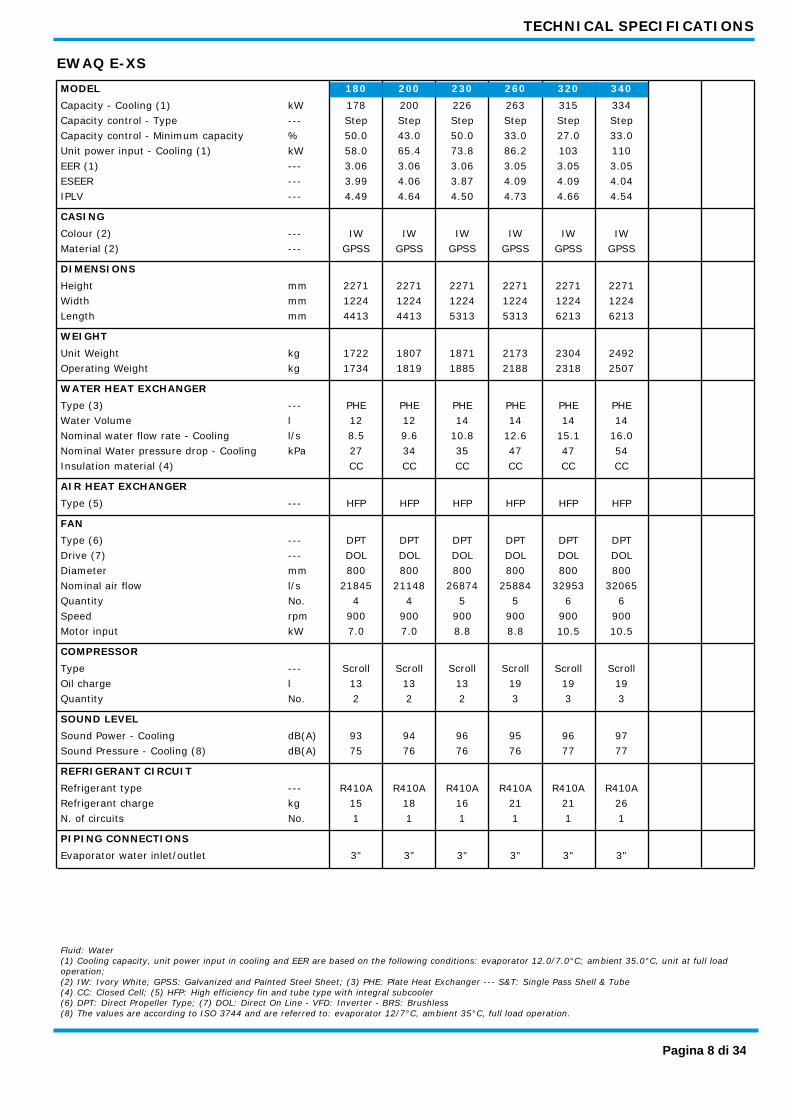
EWAQ E-XS 200 230 260 320 340 180 MODEL
Capacity - Cooling (1) kW 334 315 263 200 178 226 Capacity control - Type --- Step Step Step Step Step Step Capacity control - Minimum capacity % 33.0 27.0 33.0 43.0 50.0 50.0 Unit power input - Cooling (1) kW 110 103 86.2 65.4 58.0 73.8 EER (1) --- 3.05 3.05 3.05 3.06 3.06 3.06 ESEER --- 4.04 4.09 4.09 4.06 3.99 3.87 IPLV --- 4.54 4.66 4.73 4.64 4.49 4.50
CASING Colour (2) --- IW IW IW IW IW IW Material (2) --- GPSS GPSS GPSS GPSS GPSS GPSS
DIMENSIONS Height mm 2271 2271 2271 2271 2271 2271 Width mm 1224 1224 1224 1224 1224 1224 Length mm 6213 6213 5313 4413 4413 5313
WEIGHT Unit Weight kg 2492 2304 2173 1807 1722 1871 Operating Weight kg 2507 2318 2188 1819 1734 1885
WATER HEAT EXCHANGER Type (3) --- PHE PHE PHE PHE PHE PHE Water Volume l 14 14 14 12 12 14 Nominal water flow rate - Cooling l/s 16.0 15.1 12.6 9.6 8.5 10.8 Nominal Water pressure drop - Cooling kPa 54 47 47 34 27 35 Insulation material (4) CC CC CC CC CC CC
AIR HEAT EXCHANGER Type (5) --- HFP HFP HFP HFP HFP HFP
FAN Type (6) --- DPT DPT DPT DPT DPT DPT Drive (7) --- DOL DOL DOL DOL DOL DOL Diameter mm 800 800 800 800 800 800 Nominal air flow l/s 32065 32953 25884 21148 21845 26874 Quantity No. 6 6 5 4 4 5 Speed rpm 900 900 900 900 900 900 Motor input kW 10.5 10.5 8.8 7.0 7.0 8.8
COMPRESSOR Type --- Scroll Scroll Scroll Scroll Scroll Scroll Oil charge l 19 19 19 13 13 13 Quantity No. 3 3 3 2 2 2
SOUND LEVEL Sound Power - Cooling dB(A) 97 96 95 94 93 96 Sound Pressure - Cooling (8) dB(A) 77 77 76 76 75 76
REFRIGERANT CIRCUIT Refrigerant type --- R410A R410A R410A R410A R410A R410A Refrigerant charge kg 26 21 21 18 15 16 N. of circuits No. 1 1 1 1 1 1
PIPING CONNECTIONS Evaporator water inlet/outlet 3" 3" 3" 3" 3" 3"
Fluid: Water (1) Cooling capacity, unit power input in cooling and EER are based on the following conditions: evaporator 12.0/7.0°C; ambient 35.0°C, unit at full load operation; (2) IW: Ivory White; GPSS: Galvanized and Painted Steel Sheet; (3) PHE: Plate Heat Exchanger --- S&T: Single Pass Shell & Tube (4) CC: Closed Cell; (5) HFP: High efficiency fin and tube type with integral subcooler (6) DPT: Direct Propeller Type; (7) DOL: Direct On Line - VFD: Inverter - BRS: Brushless (8) The values are according to ISO 3744 and are referred to: evaporator 12/7°C, ambient 35°C, full load operation.
Pagina 8 di 34
TECHNICAL SPECIFICATIONS
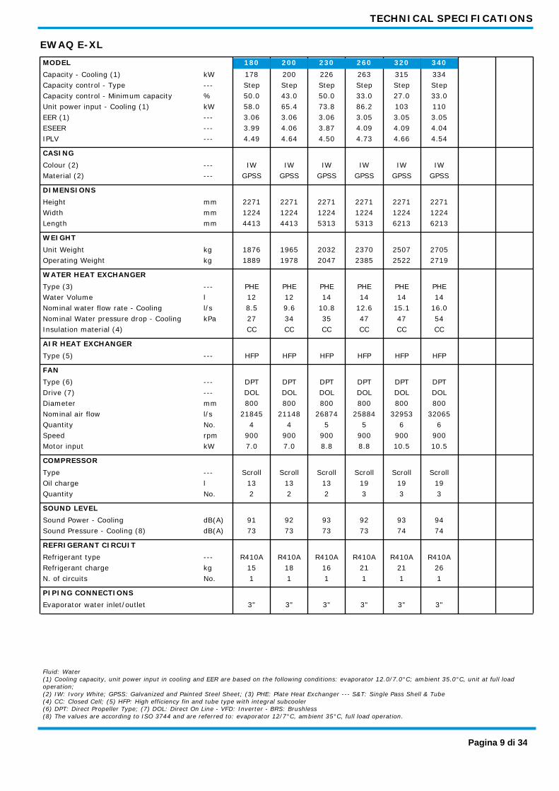
EWAQ E-XL 200 230 260 320 340 180 MODEL
Capacity - Cooling (1) kW 334 315 263 200 178 226 Capacity control - Type --- Step Step Step Step Step Step Capacity control - Minimum capacity % 33.0 27.0 33.0 43.0 50.0 50.0 Unit power input - Cooling (1) kW 110 103 86.2 65.4 58.0 73.8 EER (1) --- 3.05 3.05 3.05 3.06 3.06 3.06 ESEER --- 4.04 4.09 4.09 4.06 3.99 3.87 IPLV --- 4.54 4.66 4.73 4.64 4.49 4.50
CASING Colour (2) --- IW IW IW IW IW IW Material (2) --- GPSS GPSS GPSS GPSS GPSS GPSS
DIMENSIONS Height mm 2271 2271 2271 2271 2271 2271 Width mm 1224 1224 1224 1224 1224 1224 Length mm 6213 6213 5313 4413 4413 5313
WEIGHT Unit Weight kg 2705 2507 2370 1965 1876 2032 Operating Weight kg 2719 2522 2385 1978 1889 2047
WATER HEAT EXCHANGER Type (3) --- PHE PHE PHE PHE PHE PHE Water Volume l 14 14 14 12 12 14 Nominal water flow rate - Cooling l/s 16.0 15.1 12.6 9.6 8.5 10.8 Nominal Water pressure drop - Cooling kPa 54 47 47 34 27 35 Insulation material (4) CC CC CC CC CC CC
AIR HEAT EXCHANGER Type (5) --- HFP HFP HFP HFP HFP HFP
FAN Type (6) --- DPT DPT DPT DPT DPT DPT Drive (7) --- DOL DOL DOL DOL DOL DOL Diameter mm 800 800 800 800 800 800 Nominal air flow l/s 32065 32953 25884 21148 21845 26874 Quantity No. 6 6 5 4 4 5 Speed rpm 900 900 900 900 900 900 Motor input kW 10.5 10.5 8.8 7.0 7.0 8.8
COMPRESSOR Type --- Scroll Scroll Scroll Scroll Scroll Scroll Oil charge l 19 19 19 13 13 13 Quantity No. 3 3 3 2 2 2
SOUND LEVEL Sound Power - Cooling dB(A) 94 93 92 92 91 93 Sound Pressure - Cooling (8) dB(A) 74 74 73 73 73 73
REFRIGERANT CIRCUIT Refrigerant type --- R410A R410A R410A R410A R410A R410A Refrigerant charge kg 26 21 21 18 15 16 N. of circuits No. 1 1 1 1 1 1
PIPING CONNECTIONS Evaporator water inlet/outlet 3" 3" 3" 3" 3" 3"
Fluid: Water (1) Cooling capacity, unit power input in cooling and EER are based on the following conditions: evaporator 12.0/7.0°C; ambient 35.0°C, unit at full load operation; (2) IW: Ivory White; GPSS: Galvanized and Painted Steel Sheet; (3) PHE: Plate Heat Exchanger --- S&T: Single Pass Shell & Tube (4) CC: Closed Cell; (5) HFP: High efficiency fin and tube type with integral subcooler (6) DPT: Direct Propeller Type; (7) DOL: Direct On Line - VFD: Inverter - BRS: Brushless (8) The values are according to ISO 3744 and are referred to: evaporator 12/7°C, ambient 35°C, full load operation.
Pagina 9 di 34

TECHNICAL SPECIFICATIONS
EWAQ E-XR 190 220 260 300 320 170 MODEL
Capacity - Cooling (1) kW 321 302 254 193 172 219 Capacity control - Type --- Step Step Step Step Step Step Capacity control - Minimum capacity % 33.0 27.0 33.0 43.0 50.0 50.0 Unit power input - Cooling (1) kW 109 102 85.4 64.4 56.5 71.8 EER (1) --- 2.95 2.96 2.97 3.00 3.05 3.05 ESEER --- 4.43 4.52 4.54 4.48 4.41 4.27 IPLV --- 5.02 4.96 4.93 4.99 5.09 4.87
CASING Colour (2) --- IW IW IW IW IW IW Material (2) --- GPSS GPSS GPSS GPSS GPSS GPSS
DIMENSIONS Height mm 2271 2271 2271 2271 2271 2271 Width mm 1224 1224 1224 1224 1224 1224 Length mm 6213 6213 5313 4413 4413 5313
WEIGHT Unit Weight kg 2840 2632 2489 2064 1970 2134 Operating Weight kg 2855 2647 2503 2076 1982 2148
WATER HEAT EXCHANGER Type (3) --- PHE PHE PHE PHE PHE PHE Water Volume l 14 14 14 12 12 14 Nominal water flow rate - Cooling l/s 15.4 14.5 12.1 9.2 8.2 10.5 Nominal Water pressure drop - Cooling kPa 50 43 44 32 26 33 Insulation material (4) CC CC CC CC CC CC
AIR HEAT EXCHANGER Type (5) --- HFP HFP HFP HFP HFP HFP
FAN Type (6) --- DPT DPT DPT DPT DPT DPT Drive (7) --- DOL DOL DOL DOL DOL DOL Diameter mm 800 800 800 800 800 800 Nominal air flow l/s 24604 25243 20056 16285 16743 20618 Quantity No. 6 6 5 4 4 5 Speed rpm 705 705 705 705 705 705 Motor input kW 4.5 4.5 3.8 3.0 3.0 3.8
COMPRESSOR Type --- Scroll Scroll Scroll Scroll Scroll Scroll Oil charge l 19 19 19 13 13 13 Quantity No. 3 3 3 2 2 2
SOUND LEVEL Sound Power - Cooling dB(A) 89 88 86 86 85 87 Sound Pressure - Cooling (8) dB(A) 69 68 67 67 66 68
REFRIGERANT CIRCUIT Refrigerant type --- R410A R410A R410A R410A R410A R410A Refrigerant charge kg 26 21 21 18 15 16 N. of circuits No. 1 1 1 1 1 1
PIPING CONNECTIONS Evaporator water inlet/outlet 3" 3" 3" 3" 3" 3"
Fluid: Water (1) Cooling capacity, unit power input in cooling and EER are based on the following conditions: evaporator 12.0/7.0°C; ambient 35.0°C, unit at full load operation; (2) IW: Ivory White; GPSS: Galvanized and Painted Steel Sheet; (3) PHE: Plate Heat Exchanger --- S&T: Single Pass Shell & Tube (4) CC: Closed Cell; (5) HFP: High efficiency fin and tube type with integral subcooler (6) DPT: Direct Propeller Type; (7) DOL: Direct On Line - VFD: Inverter - BRS: Brushless (8) The values are according to ISO 3744 and are referred to: evaporator 12/7°C, ambient 35°C, full load operation.
Pagina 10 di 34

ELECTRICAL SPECIFICATIONS
EWAQ E-XS 200 230 260 320 340 180 MODEL
POWER SUPPLY Phases Nr 3 3 3 3 3 3 Frequency Hz 50 50 50 50 50 50 Voltage V 400 400 400 400 400 400 Voltage tolerance Minimum % -10% -10% -10% -10% -10% -10% Voltage tolerance Maximum % +10% +10% +10% +10% +10% +10%
UNIT Maximum starting current A 384 482 500 447 563 577 Nominal running current cooling A 103 115 129 151 179 190 Mximum running current A 133 147 165 195 227 241 Maximum current for wires sizing A 146 162 181 215 250 265
FANS Nominal running current cooling A 16 16 20 20 24 24
COMPRESSORS Phases Nr 3 3 3 3 3 3 Voltage V 400 400 400 400 400 400 Voltage tolerance Minimum % -10% -10% -10% -10% -10% -10% Voltage tolerance Maximum % +10% +10% +10% +10% +10% +10% Maximum running current A 117 131 145 175 203 217 Starting method --- DOL DOL DOL DOL DOL DOL
Fluid: Water Allowed voltage tolerance ± 10%. Voltage unbalance between phases must be within ± 3%. Maximum starting current: starting current of biggest compressor + current of the other compressors at maximum load + fans current at maximum load Nominal current in cooling mode is referred to the following conditions: evaporator 12/7°C; ambient 35°C; compressors + fans current. Maximum running current is based on max compressor absorbed current in its envelope and max fans absorbed current Maximum unit current for wires sizing is based on minimum allowed voltage Maximum current for wires sizing: (compressors full load ampere + fans current) x 1,1.
Pagina 11 di 34
ELECTRICAL SPECIFICATIONS
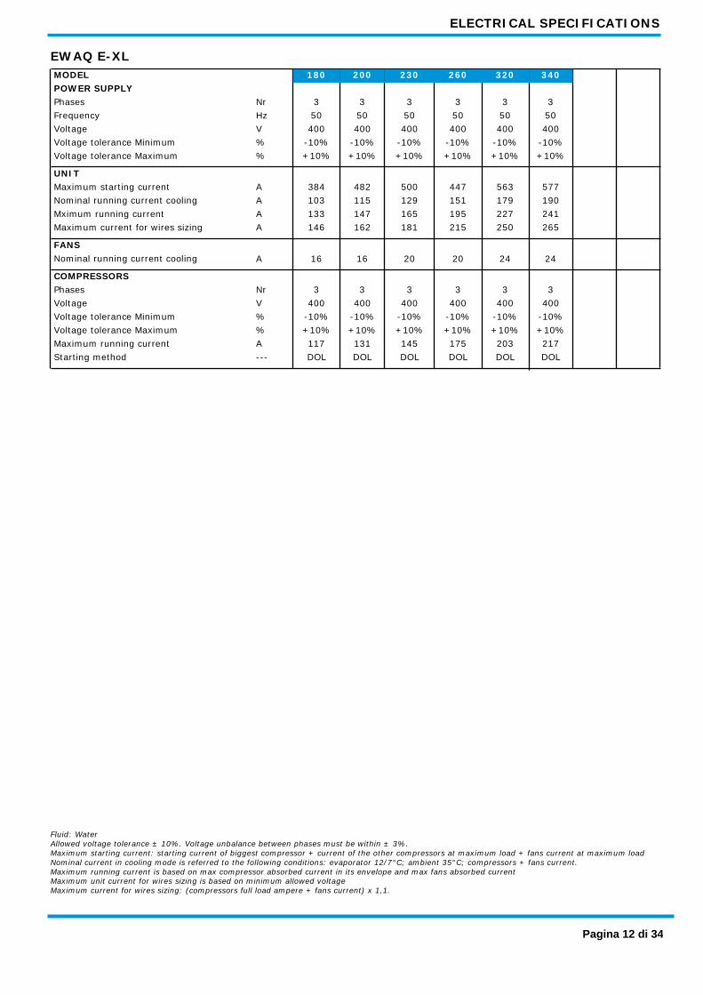
EWAQ E-XL 200 230 260 320 340 180 MODEL
POWER SUPPLY Phases Nr 3 3 3 3 3 3 Frequency Hz 50 50 50 50 50 50 Voltage V 400 400 400 400 400 400 Voltage tolerance Minimum % -10% -10% -10% -10% -10% -10% Voltage tolerance Maximum % +10% +10% +10% +10% +10% +10%
UNIT Maximum starting current A 384 482 500 447 563 577 Nominal running current cooling A 103 115 129 151 179 190 Mximum running current A 133 147 165 195 227 241 Maximum current for wires sizing A 146 162 181 215 250 265
FANS Nominal running current cooling A 16 16 20 20 24 24
COMPRESSORS Phases Nr 3 3 3 3 3 3 Voltage V 400 400 400 400 400 400 Voltage tolerance Minimum % -10% -10% -10% -10% -10% -10% Voltage tolerance Maximum % +10% +10% +10% +10% +10% +10% Maximum running current A 117 131 145 175 203 217 Starting method --- DOL DOL DOL DOL DOL DOL
Fluid: Water Allowed voltage tolerance ± 10%. Voltage unbalance between phases must be within ± 3%. Maximum starting current: starting current of biggest compressor + current of the other compressors at maximum load + fans current at maximum load Nominal current in cooling mode is referred to the following conditions: evaporator 12/7°C; ambient 35°C; compressors + fans current. Maximum running current is based on max compressor absorbed current in its envelope and max fans absorbed current Maximum unit current for wires sizing is based on minimum allowed voltage Maximum current for wires sizing: (compressors full load ampere + fans current) x 1,1.
Pagina 12 di 34

ELECTRICAL SPECIFICATIONS
EWAQ E-XR 190 220 260 300 320 170 MODEL
POWER SUPPLY Phases Nr 3 3 3 3 3 3 Frequency Hz 50 50 50 50 50 50 Voltage V 400 400 400 400 400 400 Voltage tolerance Minimum % -10% -10% -10% -10% -10% -10% Voltage tolerance Maximum % +10% +10% +10% +10% +10% +10%
UNIT Maximum starting current A 379 477 493 440 554 568 Nominal running current cooling A 101 113 127 151 179 189 Mximum running current A 127 141 158 188 219 233 Maximum current for wires sizing A 140 155 174 207 241 256
FANS Nominal running current cooling A 10 10 13 13 16 16
COMPRESSORS Phases Nr 3 3 3 3 3 3 Voltage V 400 400 400 400 400 400 Voltage tolerance Minimum % -10% -10% -10% -10% -10% -10% Voltage tolerance Maximum % +10% +10% +10% +10% +10% +10% Maximum running current A 117 131 145 175 203 217 Starting method --- DOL DOL DOL DOL DOL DOL
Fluid: Water Allowed voltage tolerance ± 10%. Voltage unbalance between phases must be within ± 3%. Maximum starting current: starting current of biggest compressor + current of the other compressors at maximum load + fans current at maximum load Nominal current in cooling mode is referred to the following conditions: evaporator 12/7°C; ambient 35°C; compressors + fans current. Maximum running current is based on max compressor absorbed current in its envelope and max fans absorbed current Maximum unit current for wires sizing is based on minimum allowed voltage Maximum current for wires sizing: (compressors full load ampere + fans current) x 1,1.
Pagina 13 di 34
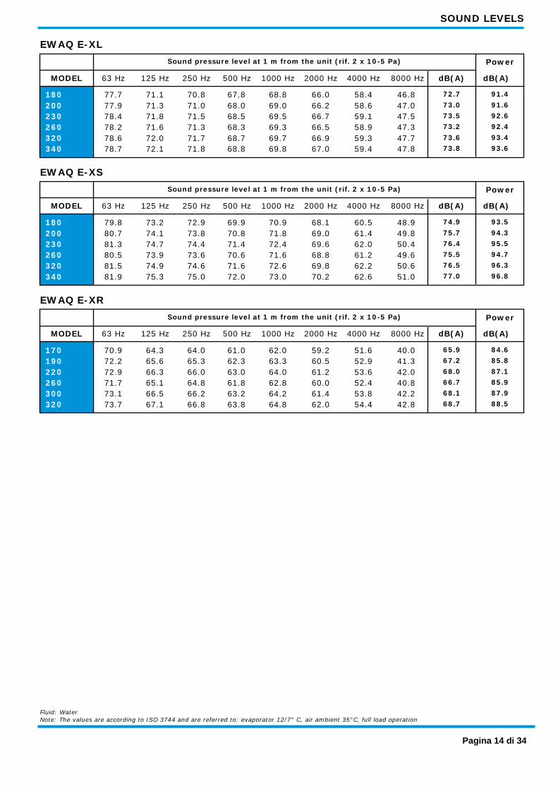
SOUND LEVELS
EWAQ E-XL Sound pressure level at 1 m from the unit (rif. 2 x 10⁻⁵ Pa) Power
63 Hz 125 Hz 250 Hz 500 Hz 1000 Hz 2000 Hz 4000 Hz 8000 Hz dB(A) dB(A) MODEL
180 71.1 67.8 66.0 58.4 46.8 72.7 70.8 91.4 77.7 68.8 200 71.3 68.0 66.2 58.6 47.0 73.0 71.0 91.6 77.9 69.0 230 71.8 68.5 66.7 59.1 47.5 73.5 71.5 92.6 78.4 69.5 260 71.6 68.3 66.5 58.9 47.3 73.2 71.3 92.4 78.2 69.3 320 72.0 68.7 66.9 59.3 47.7 73.6 71.7 93.4 78.6 69.7 340 72.1 68.8 67.0 59.4 47.8 73.8 71.8 93.6 78.7 69.8
EWAQ E-XS Sound pressure level at 1 m from the unit (rif. 2 x 10⁻⁵ Pa) Power
63 Hz 125 Hz 250 Hz 500 Hz 1000 Hz 2000 Hz 4000 Hz 8000 Hz dB(A) dB(A) MODEL
180 73.2 69.9 68.1 60.5 48.9 74.9 72.9 93.5 79.8 70.9 200 74.1 70.8 69.0 61.4 49.8 75.7 73.8 94.3 80.7 71.8 230 74.7 71.4 69.6 62.0 50.4 76.4 74.4 95.5 81.3 72.4 260 73.9 70.6 68.8 61.2 49.6 75.5 73.6 94.7 80.5 71.6 320 74.9 71.6 69.8 62.2 50.6 76.5 74.6 96.3 81.5 72.6 340 75.3 72.0 70.2 62.6 51.0 77.0 75.0 96.8 81.9 73.0
EWAQ E-XR Sound pressure level at 1 m from the unit (rif. 2 x 10⁻⁵ Pa) Power
63 Hz 125 Hz 250 Hz 500 Hz 1000 Hz 2000 Hz 4000 Hz 8000 Hz dB(A) dB(A) MODEL
170 64.3 61.0 59.2 51.6 40.0 65.9 64.0 84.6 70.9 62.0 190 65.6 62.3 60.5 52.9 41.3 67.2 65.3 85.8 72.2 63.3 220 66.3 63.0 61.2 53.6 42.0 68.0 66.0 87.1 72.9 64.0 260 65.1 61.8 60.0 52.4 40.8 66.7 64.8 85.9 71.7 62.8 300 66.5 63.2 61.4 53.8 42.2 68.1 66.2 87.9 73.1 64.2 320 67.1 63.8 62.0 54.4 42.8 68.7 66.8 88.5 73.7 64.8
Fluid: Water Note: The values are according to ISO 3744 and are referred to: evaporator 12/7° C, air ambient 35°C, full load operation
Pagina 14 di 34
OPERATING LIMITS
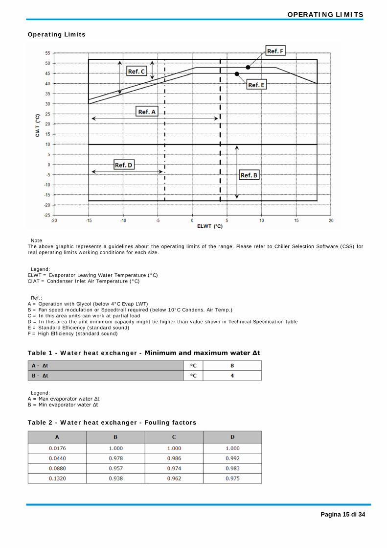
Operating Limits
Note The above graphic represents a guidelines about the operating limits of the range. Please refer to Chiller Selection Software (CSS) for real operating limits working conditions for each size.
Legend: ELWT = Evaporator Leaving Water Temperature (°C) CIAT = Condenser Inlet Air Temperature (°C)
Ref.: A = Operation with Glycol (below 4°C Evap LWT) B = Fan speed modulation or Speedtroll required (below 10°C Condens. Air Temp.) C = In this area units can work at partial load D = In this area the unit minimum capacity might be higher than value shown in Technical Specification table E = Standard Efficiency (standard sound) F = High Efficiency (standard sound)
Table 1 - Water heat exchanger - Minimum and maximum water Δt
Legend: A = Max evaporator water Δt B = Min evaporator water Δt
Table 2 - Water heat exchanger - Fouling factors
Pagina 15 di 34

OPERATING LIMITS
Legend: A = Fouling factors (m2 °C / kW) B = Cooling capacity correction factor C = Power input correction factor D = EER correction factor
Table 3 - Air heat exchanger - Altitude correction factors
Legend: A = Elevation above sea level (m) B = Barometric pressure (mbar) C = Cooling capacity correction factor D = Power input correction factor - Maximum operating altitude is 2000 m above sea level - Contact factory in case the unit has to be installed at altitudes between 1000 and 2000 m above sea level
Table 4 - Minimum glycol percentage for low air ambient temperature
Legend: AAT = Air Ambient Temperature (°C) (2) A = Ethylene glycol (%) (1) B = Propylene glycol (%) (1) (1) Minimum glycol percentage to prevent freezing of water circuit at indicated air ambient temperature (2) Air ambient temperature do exceed the operating limits of the unit, as protection of water circuit may be needed in winter season at non-working conditions.
Table 5.1 - Available fan static pressure correction factors
The above data are referred to: - Fan 800 mm diameter - Fan speed 890 rpm or 900 rpm Legend: A = External Static Pressure (Pa) B = Cooling Capacity (kW) Correction factor C = Compressor Power Input (kW) Correction factor D = Reduction of Maximum Condenser Inlet Air Temperature (°C)
Table 5.2 - Available fan static pressure correction factors
Pagina 16 di 34
OPERATING LIMITS
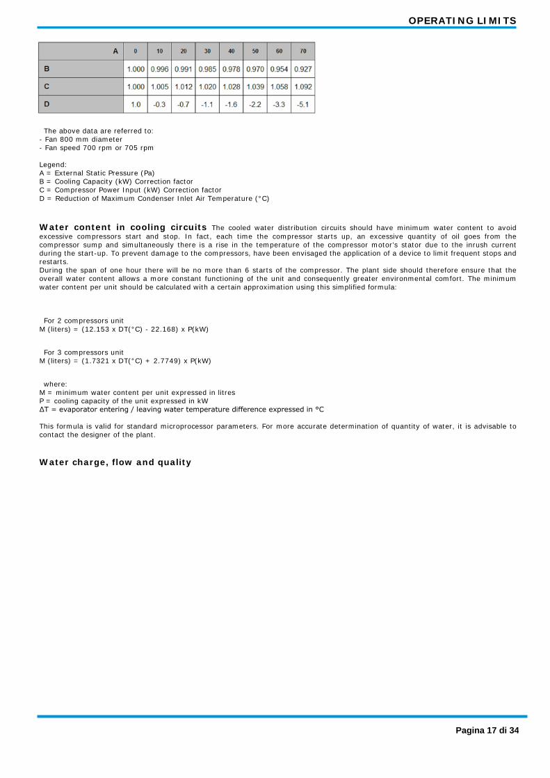
The above data are referred to: - Fan 800 mm diameter - Fan speed 700 rpm or 705 rpm Legend: A = External Static Pressure (Pa) B = Cooling Capacity (kW) Correction factor C = Compressor Power Input (kW) Correction factor D = Reduction of Maximum Condenser Inlet Air Temperature (°C)
Water content in cooling circuits The cooled water distribution circuits should have minimum water content to avoid excessive compressors start and stop. In fact, each time the compressor starts up, an excessive quantity of oil goes from the compressor sump and simultaneously there is a rise in the temperature of the compressor motor’s stator due to the inrush current during the start-up. To prevent damage to the compressors, have been envisaged the application of a device to limit frequent stops and restarts. During the span of one hour there will be no more than 6 starts of the compressor. The plant side should therefore ensure that the overall water content allows a more constant functioning of the unit and consequently greater environmental comfort. The minimum water content per unit should be calculated with a certain approximation using this simplified formula:
For 2 compressors unit M (liters) = (12.153 x DT(°C) - 22.168) x P(kW)
For 3 compressors unit M (liters) = (1.7321 x DT(°C) + 2.7749) x P(kW)
where: M = minimum water content per unit expressed in litres P = cooling capacity of the unit expressed in kW ΔT = evaporator entering / leaving water temperature difference expressed in °C This formula is valid for standard microprocessor parameters. For more accurate determination of quantity of water, it is advisable to contact the designer of the plant.
Water charge, flow and quality
Pagina 17 di 34

OPERATING LIMITS
Pagina 18 di 34

COOLING PERFORMANCE
EWAQ E-XS 180 200
43 40 35 30 25 46 43 40 35 30 25 46 Ta Twout
CC kW 5 187 178 168 157 150 143 211 200 189 177 169 161 PI kW 48.7 52.6 57.1 62.3 65.7 69.4 55.3 59.5 64.4 69.9 73.7 77.7 qw l/s 8.9 8.5 8.0 7.5 7.2 6.8 10.1 9.6 9.0 8.5 8.1 7.7 dpw kPa 30 27 24 21 20 18 38 34 31 27 24 22
CC kW 7 198 188 178 166 159 152 223 212 200 187 179 171 PI kW 49.5 53.5 58 63.2 66.6 70.3 56.2 60.5 65.4 70.9 74.7 78.7 qw l/s 9.5 9.0 8.5 8.0 7.6 7.3 10.7 10.1 9.6 9.0 8.6 8.2 dpw kPa 34 31 27 24 22 20 43 38 34 30 27 25
CC kW 9 209 199 188 176 168 160 236 224 211 198 189 180 PI kW 50.4 54.4 59 64.1 67.6 71.3 57.2 61.5 66.4 72 75.7 79.7 qw l/s 10.0 9.5 9.0 8.4 8.1 7.7 11.3 10.7 10.1 9.5 9.1 8.6 dpw kPa 38 34 31 27 25 22 48 43 38 34 31 28
CC kW 11 221 210 198 185 177 169 248 236 223 208 199 190 PI kW 51.4 55.4 60 65.2 68.6 72.4 58.3 62.6 67.5 73 76.8 80.8 qw l/s 10.6 10.1 9.5 8.9 8.5 8.1 11.9 11.3 10.7 10.0 9.6 9.1 dpw kPa 42 38 34 30 27 25 53 48 43 37 34 31
CC kW 13 233 221 208 195 187 178 261 248 234 219 210 200 PI kW 52.4 56.4 61 66.3 69.7 73.5 59.4 63.7 68.6 74.1 77.9 81.9 qw l/s 11.2 10.6 10.0 9.4 9.0 8.5 12.6 11.9 11.3 10.5 10.1 9.6 dpw kPa 47 42 38 33 30 28 59 53 47 41 38 34
CC kW 15 245 232 219 205 196 187 275 261 246 231 221 211 PI kW 53.5 57.5 62.2 67.5 70.9 74.7 60.6 64.9 69.7 75.3 79 83 qw l/s 11.8 11.2 10.5 9.9 9.4 9.0 13.2 12.6 11.8 11.1 10.6 10.1 dpw kPa 52 47 42 37 34 31 65 59 52 46 42 38
230 260
43 40 35 30 25 46 43 40 35 30 25 46 Ta Twout
CC kW 5 239 227 214 200 191 182 277 263 249 233 223 212 PI kW 63.2 67.6 72.8 78.7 82.7 87.1 72 78 84.8 92.7 97.9 104 qw l/s 11.4 10.8 10.2 9.6 9.1 8.7 13.2 12.6 11.9 11.1 10.7 10.1 dpw kPa 39 35 32 28 25 23 52 47 42 37 34 30
CC kW 7 252 240 226 212 202 193 292 278 263 246 236 224 PI kW 64.2 68.7 73.8 79.7 83.7 88.1 73.3 79.3 86.2 94.1 99.3 105 qw l/s 12.1 11.5 10.8 10.1 9.7 9.2 14.0 13.3 12.6 11.8 11.3 10.7 dpw kPa 44 40 35 31 28 26 58 52 47 41 38 34
CC kW 9 266 253 239 223 214 204 308 293 277 260 249 237 PI kW 65.3 69.8 74.9 80.8 84.8 89.1 74.7 80.8 87.7 95.5 101 106 qw l/s 12.8 12.1 11.4 10.7 10.2 9.8 14.8 14.1 13.3 12.5 11.9 11.4 dpw kPa 49 44 39 35 32 29 65 58 52 46 42 38
CC kW 11 281 267 252 236 226 215 325 309 292 274 262 250 PI kW 66.5 70.9 76 81.9 85.8 90.1 76.2 82.3 89.2 97.1 102 108 qw l/s 13.5 12.8 12.1 11.3 10.8 10.3 15.6 14.8 14.0 13.1 12.6 12.0 dpw kPa 55 49 44 39 35 32 72 65 58 51 47 42
CC kW 13 296 281 265 248 238 227 342 325 307 288 275 263 PI kW 67.6 72.1 77.2 83 86.9 91.2 77.8 83.9 90.9 98.8 104 110 qw l/s 14.2 13.5 12.7 11.9 11.4 10.9 16.4 15.6 14.8 13.8 13.2 12.6 dpw kPa 61 55 49 43 39 36 80 72 64 56 52 47
CC kW 15 311 295 279 261 250 239 359 341 322 302 289 276 PI kW 68.8 73.3 78.3 84.1 88 92.2 79.5 85.7 92.7 101 106 112 qw l/s 15.0 14.2 13.4 12.6 12.0 11.5 17.3 16.4 15.5 14.5 13.9 13.3 dpw kPa 67 61 54 47 43 40 88 80 71 62 57 52
Pagina 19 di 34

COOLING PERFORMANCE
EWAQ E-XS 320 340
43 40 35 30 25 46 43 40 35 30 25 46 Ta Twout
CC kW 5 333 316 298 279 266 253 353 336 317 296 283 270 PI kW 87.3 93.9 101 110 116 122 93.4 100 108 117 123 130 qw l/s 15.9 15.1 14.3 13.3 12.7 12.1 16.9 16.1 15.2 14.2 13.5 12.9 dpw kPa 52 47 42 37 33 30 60 54 48 42 39 35
CC kW 7 351 334 315 294 281 268 373 354 334 313 299 285 PI kW 88.9 95.5 103 112 118 124 95.1 102 110 119 125 131 qw l/s 16.8 16.0 15.1 14.1 13.5 12.8 17.9 17.0 16.0 15.0 14.3 13.6 dpw kPa 58 53 47 41 37 34 67 61 54 47 43 39
CC kW 9 370 352 332 311 297 283 393 373 352 330 316 301 PI kW 90.6 97.2 105 113 119 125 96.9 104 111 120 126 133 qw l/s 17.8 16.9 15.9 14.9 14.2 13.6 18.9 17.9 16.9 15.8 15.1 14.4 dpw kPa 65 59 52 46 42 38 75 67 60 53 48 44
CC kW 11 390 370 349 327 313 298 413 393 371 347 333 317 PI kW 92.3 98.9 106 115 121 127 98.7 105 113 122 128 135 qw l/s 18.7 17.8 16.8 15.7 15.0 14.3 19.9 18.9 17.8 16.7 16.0 15.2 dpw kPa 72 65 58 51 47 42 83 75 67 58 54 49
CC kW 13 410 389 367 344 329 314 434 413 390 365 350 334 PI kW 94.1 101 108 117 123 129 100 107 115 124 130 136 qw l/s 19.7 18.7 17.7 16.5 15.8 15.1 20.9 19.9 18.8 17.6 16.8 16.0 dpw kPa 80 72 64 56 52 47 92 83 74 65 59 54
CC kW 15 430 408 386 361 346 330 455 433 409 384 368 351 PI kW 95.9 103 110 119 124 131 102 109 117 126 132 138 qw l/s 20.7 19.7 18.6 17.4 16.6 15.8 21.9 20.9 19.7 18.5 17.7 16.9 dpw kPa 88 80 71 62 57 52 101 91 82 72 66 60
Fluid: Water Ta: Condenser inlet air temperature; Twout: Evaporator leaving water temperature (Δt 5°C) CC: Cooling capacity; PI: Power input; qw: Fluid flow rate; dpw: Fluid pressure drop * For working condition where dpw value is "Italic-Red Color" please contac factory
Pagina 20 di 34
COOLING PERFORMANCE
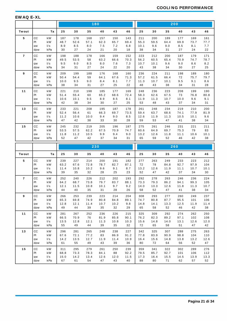
EWAQ E-XL 180 200
43 40 35 30 25 46 43 40 35 30 25 46 Ta Twout
CC kW 5 187 178 168 157 150 143 211 200 189 177 169 161 PI kW 48.7 52.6 57.1 62.3 65.7 69.4 55.3 59.5 64.4 69.9 73.7 77.7 qw l/s 8.9 8.5 8.0 7.5 7.2 6.8 10.1 9.6 9.0 8.5 8.1 7.7 dpw kPa 30 27 24 21 20 18 38 34 31 27 24 22
CC kW 7 198 188 178 166 159 152 223 212 200 187 179 171 PI kW 49.5 53.5 58 63.2 66.6 70.3 56.2 60.5 65.4 70.9 74.7 78.7 qw l/s 9.5 9.0 8.5 8.0 7.6 7.3 10.7 10.1 9.6 9.0 8.6 8.2 dpw kPa 34 31 27 24 22 20 43 38 34 30 27 25
CC kW 9 209 199 188 176 168 160 236 224 211 198 189 180 PI kW 50.4 54.4 59 64.1 67.6 71.3 57.2 61.5 66.4 72 75.7 79.7 qw l/s 10.0 9.5 9.0 8.4 8.1 7.7 11.3 10.7 10.1 9.5 9.1 8.6 dpw kPa 38 34 31 27 25 22 48 43 38 34 31 28
CC kW 11 221 210 198 185 177 169 248 236 223 208 199 190 PI kW 51.4 55.4 60 65.2 68.6 72.4 58.3 62.6 67.5 73 76.8 80.8 qw l/s 10.6 10.1 9.5 8.9 8.5 8.1 11.9 11.3 10.7 10.0 9.6 9.1 dpw kPa 42 38 34 30 27 25 53 48 43 37 34 31
CC kW 13 233 221 208 195 187 178 261 248 234 219 210 200 PI kW 52.4 56.4 61 66.3 69.7 73.5 59.4 63.7 68.6 74.1 77.9 81.9 qw l/s 11.2 10.6 10.0 9.4 9.0 8.5 12.6 11.9 11.3 10.5 10.1 9.6 dpw kPa 47 42 38 33 30 28 59 53 47 41 38 34
CC kW 15 245 232 219 205 196 187 275 261 246 231 221 211 PI kW 53.5 57.5 62.2 67.5 70.9 74.7 60.6 64.9 69.7 75.3 79 83 qw l/s 11.8 11.2 10.5 9.9 9.4 9.0 13.2 12.6 11.8 11.1 10.6 10.1 dpw kPa 52 47 42 37 34 31 65 59 52 46 42 38
230 260
43 40 35 30 25 46 43 40 35 30 25 46 Ta Twout
CC kW 5 239 227 214 200 191 182 277 263 249 233 223 212 PI kW 63.2 67.6 72.8 78.7 82.7 87.1 72 78 84.8 92.7 97.9 104 qw l/s 11.4 10.8 10.2 9.6 9.1 8.7 13.2 12.6 11.9 11.1 10.7 10.1 dpw kPa 39 35 32 28 25 23 52 47 42 37 34 30
CC kW 7 252 240 226 212 202 193 292 278 263 246 236 224 PI kW 64.2 68.7 73.8 79.7 83.7 88.1 73.3 79.3 86.2 94.1 99.3 105 qw l/s 12.1 11.5 10.8 10.1 9.7 9.2 14.0 13.3 12.6 11.8 11.3 10.7 dpw kPa 44 40 35 31 28 26 58 52 47 41 38 34
CC kW 9 266 253 239 223 214 204 308 293 277 260 249 237 PI kW 65.3 69.8 74.9 80.8 84.8 89.1 74.7 80.8 87.7 95.5 101 106 qw l/s 12.8 12.1 11.4 10.7 10.2 9.8 14.8 14.1 13.3 12.5 11.9 11.4 dpw kPa 49 44 39 35 32 29 65 58 52 46 42 38
CC kW 11 281 267 252 236 226 215 325 309 292 274 262 250 PI kW 66.5 70.9 76 81.9 85.8 90.1 76.2 82.3 89.2 97.1 102 108 qw l/s 13.5 12.8 12.1 11.3 10.8 10.3 15.6 14.8 14.0 13.1 12.6 12.0 dpw kPa 55 49 44 39 35 32 72 65 58 51 47 42
CC kW 13 296 281 265 248 238 227 342 325 307 288 275 263 PI kW 67.6 72.1 77.2 83 86.9 91.2 77.8 83.9 90.9 98.8 104 110 qw l/s 14.2 13.5 12.7 11.9 11.4 10.9 16.4 15.6 14.8 13.8 13.2 12.6 dpw kPa 61 55 49 43 39 36 80 72 64 56 52 47
CC kW 15 311 295 279 261 250 239 359 341 322 302 289 276 PI kW 68.8 73.3 78.3 84.1 88 92.2 79.5 85.7 92.7 101 106 112 qw l/s 15.0 14.2 13.4 12.6 12.0 11.5 17.3 16.4 15.5 14.5 13.9 13.3 dpw kPa 67 61 54 47 43 40 88 80 71 62 57 52
Pagina 21 di 34

COOLING PERFORMANCE
EWAQ E-XL 320 340
43 40 35 30 25 46 43 40 35 30 25 46 Ta Twout
CC kW 5 333 316 298 279 266 253 353 336 317 296 283 270 PI kW 87.3 93.9 101 110 116 122 93.4 100 108 117 123 130 qw l/s 15.9 15.1 14.3 13.3 12.7 12.1 16.9 16.1 15.2 14.2 13.5 12.9 dpw kPa 52 47 42 37 33 30 60 54 48 42 39 35
CC kW 7 351 334 315 294 281 268 373 354 334 313 299 285 PI kW 88.9 95.5 103 112 118 124 95.1 102 110 119 125 131 qw l/s 16.8 16.0 15.1 14.1 13.5 12.8 17.9 17.0 16.0 15.0 14.3 13.6 dpw kPa 58 53 47 41 37 34 67 61 54 47 43 39
CC kW 9 370 352 332 311 297 283 393 373 352 330 316 301 PI kW 90.6 97.2 105 113 119 125 96.9 104 111 120 126 133 qw l/s 17.8 16.9 15.9 14.9 14.2 13.6 18.9 17.9 16.9 15.8 15.1 14.4 dpw kPa 65 59 52 46 42 38 75 67 60 53 48 44
CC kW 11 390 370 349 327 313 298 413 393 371 347 333 317 PI kW 92.3 98.9 106 115 121 127 98.7 105 113 122 128 135 qw l/s 18.7 17.8 16.8 15.7 15.0 14.3 19.9 18.9 17.8 16.7 16.0 15.2 dpw kPa 72 65 58 51 47 42 83 75 67 58 54 49
CC kW 13 410 389 367 344 329 314 434 413 390 365 350 334 PI kW 94.1 101 108 117 123 129 100 107 115 124 130 136 qw l/s 19.7 18.7 17.7 16.5 15.8 15.1 20.9 19.9 18.8 17.6 16.8 16.0 dpw kPa 80 72 64 56 52 47 92 83 74 65 59 54
CC kW 15 430 408 386 361 346 330 455 433 409 384 368 351 PI kW 95.9 103 110 119 124 131 102 109 117 126 132 138 qw l/s 20.7 19.7 18.6 17.4 16.6 15.8 21.9 20.9 19.7 18.5 17.7 16.9 dpw kPa 88 80 71 62 57 52 101 91 82 72 66 60
Fluid: Water Ta: Condenser inlet air temperature; Twout: Evaporator leaving water temperature (Δt 5°C) CC: Cooling capacity; PI: Power input; qw: Fluid flow rate; dpw: Fluid pressure drop * For working condition where dpw value is "Italic-Red Color" please contac factory
Pagina 22 di 34

COOLING PERFORMANCE
EWAQ E-XR 170 190
43 40 35 30 25 46 43 40 35 30 25 46 Ta Twout
CC kW 5 182 173 163 152 145 138 205 194 183 170 162 154 PI kW 46.6 50.7 55.5 60.9 64.5 68.3 53.6 58.1 63.2 69.2 73.1 77.4 qw l/s 8.7 8.3 7.8 7.3 6.9 6.6 9.8 9.3 8.7 8.1 7.8 7.4 dpw kPa 29 26 23 20 18 16 36 32 29 25 23 20
CC kW 7 193 183 172 161 153 146 217 205 193 180 171 163 PI kW 47.5 51.7 56.5 61.9 65.5 69.4 54.7 59.2 64.4 70.3 74.2 78.5 qw l/s 9.2 8.8 8.2 7.7 7.3 7.0 10.4 9.8 9.2 8.6 8.2 7.8 dpw kPa 32 29 26 22 20 18 40 36 32 28 25 23
CC kW 9 203 193 182 169 162 154 228 216 203 190 181 172 PI kW 48.5 52.8 57.6 63 66.6 70.5 55.8 60.4 65.5 71.5 75.4 79.7 qw l/s 9.8 9.2 8.7 8.1 7.7 7.4 10.9 10.4 9.7 9.1 8.7 8.2 dpw kPa 36 32 29 25 23 20 45 40 35 31 28 25
CC kW 11 214 203 191 178 170 162 240 228 214 199 190 181 PI kW 49.6 53.9 58.7 64.2 67.8 71.7 57 61.6 66.8 72.7 76.6 80.9 qw l/s 10.3 9.7 9.2 8.6 8.2 7.8 11.5 10.9 10.3 9.6 9.1 8.7 dpw kPa 40 36 32 28 25 23 50 45 39 34 31 28
CC kW 13 226 214 201 188 179 102 253 239 225 210 200 126 PI kW 50.7 55.1 59.9 65.5 69.1 32.6 58.2 62.8 68 74 77.9 41.2 qw l/s 10.8 10.3 9.7 9.0 8.6 4.9 12.1 11.5 10.8 10.1 9.6 6.0 dpw kPa 44 40 35 31 28 9 55 49 44 38 34 14
CC kW 15 237 224 211 197 188 108 265 251 236 220 210 133 PI kW 51.9 56.3 61.2 66.8 70.4 33.1 59.5 64.1 69.4 75.3 79.2 41.6 qw l/s 11.4 10.8 10.1 9.5 9.0 5.2 12.8 12.1 11.4 10.6 10.1 6.4 dpw kPa 49 44 39 34 31 10 61 54 48 42 38 15
220 260
43 40 35 30 25 46 43 40 35 30 25 46 Ta Twout
CC kW 5 233 220 207 193 184 175 269 255 240 224 214 203 PI kW 60.4 65.1 70.6 76.9 81.1 85.7 70.2 76.6 83.9 92.2 97.7 104 qw l/s 11.1 10.5 9.9 9.2 8.8 8.4 12.9 12.2 11.5 10.7 10.2 9.7 dpw kPa 37 33 30 26 23 21 49 44 39 34 31 28
CC kW 7 246 233 219 204 195 185 284 269 254 237 226 214 PI kW 61.6 66.3 71.8 78 82.3 86.8 71.7 78.1 85.4 93.8 99.3 105 qw l/s 11.8 11.1 10.5 9.8 9.3 8.8 13.6 12.9 12.1 11.3 10.8 10.3 dpw kPa 42 37 33 29 26 24 55 49 44 38 35 31
CC kW 9 259 245 231 215 205 195 299 284 267 249 238 226 PI kW 62.8 67.5 73 79.2 83.4 88 73.3 79.8 87.1 95.5 101 107 qw l/s 12.4 11.8 11.1 10.3 9.8 9.3 14.4 13.6 12.8 11.9 11.4 10.8 dpw kPa 46 42 37 32 29 26 61 55 48 42 38 35
CC kW 11 273 258 243 227 216 206 315 298 281 262 250 180 PI kW 64.1 68.8 74.2 80.5 84.6 89.2 75 81.5 88.9 97.3 103 66.5 qw l/s 13.1 12.4 11.7 10.9 10.4 9.9 15.1 14.3 13.5 12.6 12.0 8.6 dpw kPa 52 46 41 36 32 29 68 61 54 47 43 22
CC kW 13 286 271 255 238 228 216 330 313 295 275 262 190 PI kW 65.3 70.1 75.5 81.7 85.9 90.3 76.8 83.4 90.8 99.2 105 67.5 qw l/s 13.8 13.0 12.3 11.4 10.9 10.4 15.9 15.1 14.2 13.2 12.6 9.1 dpw kPa 57 51 45 39 36 32 75 67 59 52 47 25
CC kW 15 301 285 268 250 239 138 346 328 309 288 275 200 PI kW 66.7 71.4 76.8 83 87.1 41.3 78.7 85.3 92.9 101 107 68.6 qw l/s 14.5 13.7 12.9 12.0 11.5 6.6 16.7 15.8 14.9 13.9 13.2 9.6 dpw kPa 63 57 50 44 40 13 82 74 65 57 52 27
Pagina 23 di 34
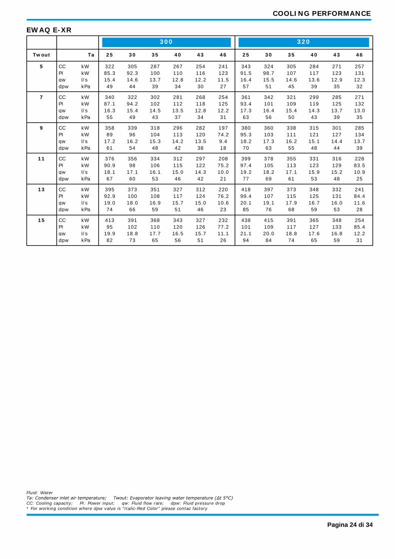
COOLING PERFORMANCE
EWAQ E-XR 300 320
43 40 35 30 25 46 43 40 35 30 25 46 Ta Twout
CC kW 5 322 305 287 267 254 241 343 324 305 284 271 257 PI kW 85.3 92.3 100 110 116 123 91.5 98.7 107 117 123 131 qw l/s 15.4 14.6 13.7 12.8 12.2 11.5 16.4 15.5 14.6 13.6 12.9 12.3 dpw kPa 49 44 39 34 30 27 57 51 45 39 35 32
CC kW 7 340 322 302 281 268 254 361 342 321 299 285 271 PI kW 87.1 94.2 102 112 118 125 93.4 101 109 119 125 132 qw l/s 16.3 15.4 14.5 13.5 12.8 12.2 17.3 16.4 15.4 14.3 13.7 13.0 dpw kPa 55 49 43 37 34 31 63 56 50 43 39 35
CC kW 9 358 339 318 296 282 197 380 360 338 315 301 285 PI kW 89 96 104 113 120 74.2 95.3 103 111 121 127 134 qw l/s 17.2 16.2 15.3 14.2 13.5 9.4 18.2 17.3 16.2 15.1 14.4 13.7 dpw kPa 61 54 48 42 38 18 70 63 55 48 44 39
CC kW 11 376 356 334 312 297 208 399 378 355 331 316 228 PI kW 90.9 98 106 115 122 75.2 97.4 105 113 123 129 83.5 qw l/s 18.1 17.1 16.1 15.0 14.3 10.0 19.2 18.2 17.1 15.9 15.2 10.9 dpw kPa 67 60 53 46 42 21 77 69 61 53 48 25
CC kW 13 395 373 351 327 312 220 418 397 373 348 332 241 PI kW 92.9 100 108 117 124 76.2 99.4 107 115 125 131 84.4 qw l/s 19.0 18.0 16.9 15.7 15.0 10.6 20.1 19.1 17.9 16.7 16.0 11.6 dpw kPa 74 66 59 51 46 23 85 76 68 59 53 28
CC kW 15 413 391 368 343 327 232 438 415 391 365 348 254 PI kW 95 102 110 120 126 77.2 101 109 117 127 133 85.4 qw l/s 19.9 18.8 17.7 16.5 15.7 11.1 21.1 20.0 18.8 17.6 16.8 12.2 dpw kPa 82 73 65 56 51 26 94 84 74 65 59 31
Fluid: Water Ta: Condenser inlet air temperature; Twout: Evaporator leaving water temperature (Δt 5°C) CC: Cooling capacity; PI: Power input; qw: Fluid flow rate; dpw: Fluid pressure drop * For working condition where dpw value is "Italic-Red Color" please contac factory
Pagina 24 di 34

OPTIONS (TECHNICAL DATA)
Water Pump Kit
Single Pump (2 poles) Discharge Head
Legend: PH = Pump Discharge Head (m); WF = Water Flow (l/s)
Note - the above curves are referred to the discharge head of the pump only - when selecting the pump you have to consider the installation and evaporator pressure drops - when using mixture of water and glycol please contact the factory as above specification can change
Pagina 25 di 34
OPTIONS (TECHNICAL DATA)
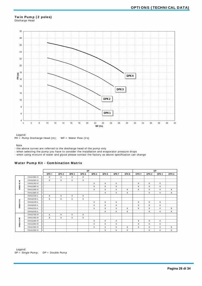
Twin Pump (2 poles) Discharge Head
Legend: PH = Pump Discharge Head (m); WF = Water Flow (l/s)
Note - the above curves are referred to the discharge head of the pump only - when selecting the pump you have to consider the installation and evaporator pressure drops - when using mixture of water and glycol please contact the factory as above specification can change
Water Pump Kit - Combination Matrix
Legend: SP = Single Pump; DP = Double Pump
Pagina 26 di 34
OPTIONS (TECHNICAL DATA)
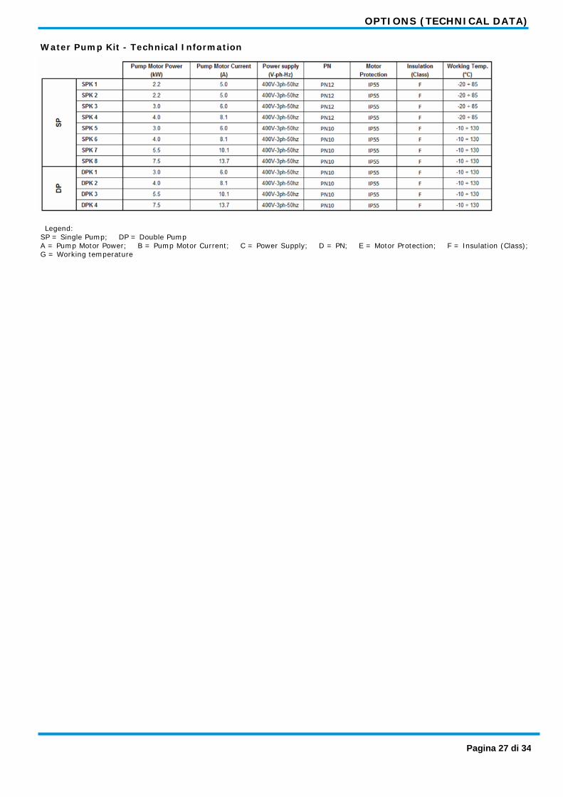
Water Pump Kit - Technical Information
Legend: SP = Single Pump; DP = Double Pump A = Pump Motor Power; B = Pump Motor Current; C = Power Supply; D = PN; E = Motor Protection; F = Insulation (Class); G = Working temperature
Pagina 27 di 34
DIMENSIONAL DRAWING
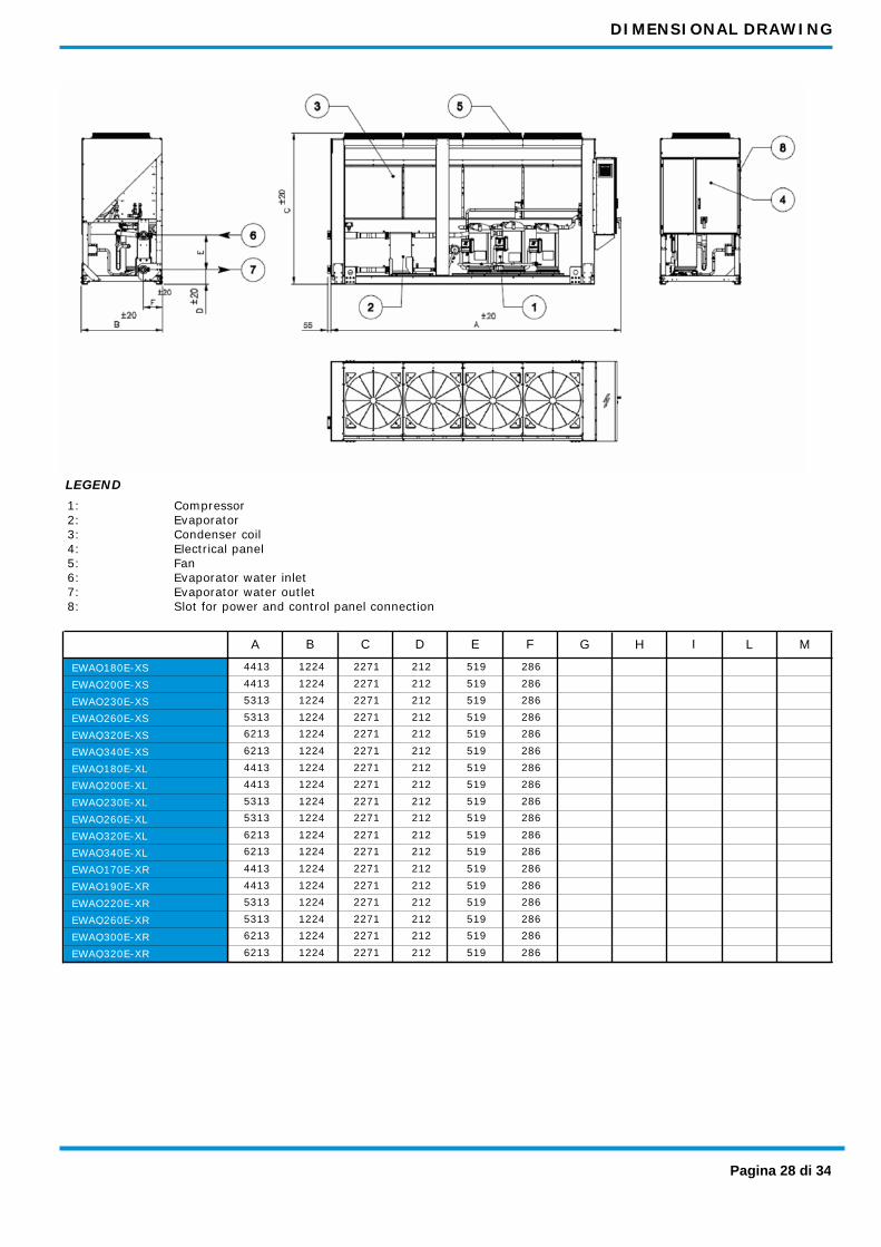
1: 2: 3: 4: 5: 6: 7: 8:
Compressor Evaporator Condenser coil Electrical panel Fan Evaporator water inlet Evaporator water outlet Slot for power and control panel connection
LEGEND
A M L I H G B C F E D
4413 212 519 2271 286 1224 EWAQ180E-XS 4413 212 519 2271 286 1224 EWAQ200E-XS 5313 212 519 2271 286 1224 EWAQ230E-XS 5313 212 519 2271 286 1224 EWAQ260E-XS 6213 212 519 2271 286 1224 EWAQ320E-XS 6213 212 519 2271 286 1224 EWAQ340E-XS 4413 212 519 2271 286 1224 EWAQ180E-XL 4413 212 519 2271 286 1224 EWAQ200E-XL 5313 212 519 2271 286 1224 EWAQ230E-XL 5313 212 519 2271 286 1224 EWAQ260E-XL 6213 212 519 2271 286 1224 EWAQ320E-XL 6213 212 519 2271 286 1224 EWAQ340E-XL 4413 212 519 2271 286 1224 EWAQ170E-XR 4413 212 519 2271 286 1224 EWAQ190E-XR 5313 212 519 2271 286 1224 EWAQ220E-XR 5313 212 519 2271 286 1224 EWAQ260E-XR 6213 212 519 2271 286 1224 EWAQ300E-XR 6213 212 519 2271 286 1224 EWAQ320E-XR
Pagina 28 di 34

INSTALLATION NOTES
Warning Installation and maintenance of the unit must to be performed only by qualified personnel who have knowledge with local codes and regulations, and experience with this type of equipment. Must be avoided the unit installation in places that could be considered dangerous for all the maintenance operations.
Handling Care should be taken to avoid rough handling or shock due to dropping the unit. Do not push or pull the unit from anything other than the base frame. Never allow the unit to fall during unloading or moving as this may result in serious damage. To lift the unit, rings are provided in the base frame of the unit. Spreader bar and cables should be arranged to prevent damage to the condenser coil or unit cabinet.
Location The units are produced for outside installation on roofs, floors or below ground level on condition that the area is free from obstacles for the passage of the condenser air. The unit should be positioned on solid foundations and perfectly level; in the case of installation on roofs or floors, it may be advisable to arrange the use of suitable weight distribution beams. When the units are installed on the ground, a concrete base at least 250 mm wider and longer than the unit’s footprint should be laid. Furthermore, this base should withstand the unit weight mentioned in the technical data table.
Space requirements The units are air-cooled, then it is important to respect the minimum distances which guarantee the best ventilation of the condenser coils. Limitations of space reducing the air flow could cause significant reductions in cooling capacity and an increase in electricity consumption. To determinate unit placement, careful consideration must be given to assure a sufficient air flow across the condenser heat transfer surface. Two conditions must be avoided to achieve the best performance: warm air recirculation and coil starvation. Both these conditions cause an increase of condensing pressures that results in reductions in unit efficiency and capacity. Moreover the unique microprocessor has the ability to calculate the operating environment of the air cooled chiller and the capacity to optimize its performance staying on-line during abnormal conditions. Each side of the unit must be accessible after installation for periodic service. 'Fig.1' shows you minimum recommended clearance requirements. Vertical condenser air discharge must be unobstructed because the unit would have its capacity and efficiency significantly reduced. If the units are positioned in places surrounded by walls or obstacles of the same height as the units, the units should follow the minimum recommended clearance requirements shown in 'Fig.2'. In the event the obstacles are higher than the units, the minimum recommended clearance requirements are shown in 'Fig.3'. Units installed closer than the minimum recommended distance to a wall or other vertical riser may experience a combination of coil starvation and warm air recirculation, thus causing reduction in unit capacity and efficiency reductions. The microprocessor control is proactive in response “of design condition”. In the case of single or compounded influences restricting airflow to the unit, the microprocessor will act to keep the compressor(s) running (at reduced capacity) rather than allowing a shut-off on high discharge pressure. When two or more units are positioned side by side it is recommended that the condenser coils are at a minimum distance from one another as shown in 'Fig.4'; strong wind could be the cause of air warm recirculation. For other installation solutions, consult our technicians. The above recommended information are representative of general installation. A specific evaluation should be done by contractor depending on the case.
Pagina 29 di 34

INSTALLATION NOTES
Acoustic protection When noise level must meet special requirements, it is necessary to pay the maximum attention to ensure the perfect insulation of the unit from the support base by applying appropriate vibration-dampening devices on the unit, on the water pipes and on the electrical connections.
Storage The environment conditions have to be in the following limits:
Minimum ambient temperature: Maximum ambient temperature: Maximum R.H.:
-20°C +42°C 95% not condensing
Pagina 30 di 34
TECHNICAL SPECIFICATIONS
General The chiller will be designed and manufactured in accordance with the following European directives: • Construction of pressure vessel 97/23/EC (PED) • Machinery Directive 2006/42/EC • Low Voltage 2006/95/EC • Electromagnetic Compatibility 2004/108/EC • Electrical & Safety codes EN 60204–1 / EN 60335-2-40 • Manufacturing Quality Standards UNI – EN ISO 9001:2004 To avoid any losses, the unit will be tested at full load in the factory (at the nominal working conditions and water temperatures). The chiller will be delivered to the job site completely assembled and charged with refrigerant and oil. The installation of the chiller must comply with the manufacturer’s instructions for rigging and handling equipment. The unit will be able to start up and operate (as standard) at full load with: - outside air temperature from ............... °C to ............... °C - evaporator leaving fluid temperature between ............... °C and ............... °C
Refrigerant Only HFC 410A can be used.
Performance Chiller shall supply the following performances: • Number of chiller(s) : ............... unit(s) • Cooling capacity for single chiller : ............... kW • Power input for single chiller in cooling mode : ............... kW • Heat exchanger entering water temperature in cooling mode : ............... °C • Heat exchanger leaving water temperature in cooling mode : ............... °C • Heat exchanger water flow : ............... l/s • Nominal outside working ambient temperature in cooling mode : ............... °C Operating voltage range should be 400V ±10%, 3ph, 50Hz, voltage unbalance maximum 3%, without neutral conductor and shall only have one power connection point.
Unit description Chiller shall include as standard: one refrigerant circuit, two or three hermetic type rotary scroll compressors (depending on the size), electronic expansion device (EEXV), refrigerant direct expansion plate to plate heat exchanger, air-cooled condenser section, R-410A refrigerant, motor starting components, control system and all components necessary for a safe and stable unit operation. The chiller will be factory assembled on a robust base frame made of galvanized steel, protected by an epoxy paint.
Sound level and vibrations Sound pressure level at 1 meter distance in free field, semispheric conditions, shall not exceed ………dB(A). The sound pressure levels must be rated in accordance to ISO 3744 (other types of rating can not be used). Vibration on the base frame should not exceed 2 mm/s.
Dimensions Unit dimensions shall not exceed following indications: - Unit length ............... mm - Unit width ............... mm - Unit height ............... mm
Evaporator (PHE) The units shall be equipped with a direct expansion plate to plate type evaporator. • The evaporator will be made of of stainless steel brazed plates and shall be linked with an electrical heater to prevent freezing down to -28°C ambient temperature, controlled by a thermostat and shall be insulated with flexible, closed cell polyurethane insulation material (20-mm thick). • The evaporator will have 1 refrigerant circuit. • The water connections shall be VICTAULIC type connections as standard to ensure quick mechanical disconnection between the unit and the hydronic network. • The evaporator will be manufactured in accordance to PED approval. • Flow switch will be standard factory mounted. • Water filter will be standard.
Condenser coil The unit shall be equipped with condenser coils constructed with internally finned seamless copper tubes and arranged in a staggered row pattern and mechanically expanded into lanced and rippled aluminum fins with full fin collars for higher efficiencies. The space between the fins is given by a collar that will increase the surface area in connection with the tubes, protecting them from ambient corrosion. • The condenser coils will have an integral subcooler circuit that provides sufficient subcooling to effectively eliminate the possibility of liquid flashing and increase the unit's efficiency with 5% to 7% without increasing in energy consumption. • The condenser coils shall be leak-tested and submitted to a pressure test with dry air.
Pagina 31 di 34
TECHNICAL SPECIFICATIONS
Condenser fans The condenser fans used in conjunction with the condenser coils, shall be propeller type with glass reinforced resin blades for higher efficiencies and lower sound. Each fan shall be protected by a fan guard. • The air discharge shall be vertical and each fan must be coupled to the electrical motor, supplied as standard to IP54 and capable to work to ambient temperatures of - 20°C to + 65°C. • The condenser fans shall have as a standard an internally protection from overtemperature.
Refrigerant circuit The unit shall have one refrigerant circuit. • The circuit shall include as standard: electronic expansion device piloted by unit’s microprocessor control, liquid line shut-off valve, sight glass with moisture indicator, replaceable filter drier, charging valves, high pressure switch, high and low pressure transducers and insulated suction line.
Condensation control The units will be provided with an automatic control for condensing pressure which ensures the working at low external temperatures down to - …………… °C, to maintain condensing pressure. • The unit automatically unloads when abnormal high condensing pressure is detected. This to prevent the shutdown of the refrigerant circuit (shutdown of the unit) due to a high-pressure fault.
Low sound unit configurations (on request) The unit compressor shall be connected with unit’s metal base frame by rubber antivibration supports to prevent the transmission of vibrations to all metal unit structure, in order to control the unit sound. • The chiller shall be provided with an acoustical compressor enclosure. This enclosure shall be realized with a light, corrosion resisting aluminum structure and metal panels. The compressor sound-proof enclosure shall be internally fitted with flexible, multi-layer, high density materials.
Hydronic kit options (on request) The hydronic module shall be integrated in the chiller chassis without increasing its dimensions and includes the following elements: centrifugal pump with motor protected by a circuit breaker installed in control panel, water filling system with pressure gauge, safety valve, drain valve. • The hydronic module shall be assembled and wired to the control panel. • The water piping shall be protected against corrosion and freezing and insulated to prevent condensation. • A choice of two pump types shall be available: - in-line single pump - in-line twin pumps.
Electrical control panel Power and control shall be located in the main panel that will be manufactured to ensure protection against all weather conditions. • The electrical panel shall be IP54 and (when opening the doors) internally protected against possible accidental contact with live parts. • The main panel shall be fitted with a main switch interlocked door that shuts off power supply when opening. • The power section will include compressors and funs protection devices, compressors and fans starters and control circuit power supply.
Controller The controller will be installed as standard and it will be used to modify unit set-points and check control parameters. • A built-in display will shows chiller operating status plus temperatures and pressures of water, refrigerant and air, programmable values, set-points. • A sophisticated software with predictive logic, will select the most energy efficient combination of compressors, EEXV and condenser fans to keep stable operating conditions to maximize chiller energy efficiency and reliability. • The controller will be able to protect critical components based on external signals from its system (such as motor temperatures, refrigerant gas and oil pressures, correct phase sequence, pressure switches and evaporator). The input coming from the high pressure switch cuts all digital output from the controller in less than 50ms, this will be an additional security for the equipment. • Fast program cycle (200ms) for a precise monitoring of the system. • Floating point calculations supported for increased accuracy in P/T conversions.
Pagina 32 di 34
TECHNICAL SPECIFICATIONS
Controller main features Controller shall be garantee following minimu functions: • Management of the compressor stepless capacity and fans modulation. • Chiller enabled to work in partial failure condition. • Full routine operation at condition of: - high ambient temperature value - high thermal load - high evaporator entering water temperature (start-up) • Display of evaporator entering/leaving water temperature. • Display of Outdoor Ambient Temperature. • Display of condensing-evaporating temperature and pressure, suction and discharge superheat for each circuit. • Leaving water evaporator temperature regulation (temperature tolerance = 0,1°C). • Compressor and evaporator pumps hours counter. • Display of Status Safety Devices. • Number of starts and compressor working hours. • Optimized management of compressor load. • Fan management according to condensing pressure. • Re-start in case of power failure (automatic / manual). • Soft Load (optimized management of the compressor load during the start-up). • Start at high evaporator water temperature. • Return Reset (Set Point Reset based on return water temperature). • OAT (Outside Ambient temperature) Reset. • Set point Reset (optional). • Application and system upgrade with commercial SD cards. • Ethernet port for remote or local servicing using standard web browsers. • Two different sets of default parameters could be stored for easy restore.
High Level Communications Interface (on request) The chiller shall be able to communicate to BMS (Building Management System) based on the most common protocols as: - ModbusRTU - LonWorks, now also based on the international 8040 Standard Chiller Profile and LonMark Technology - BacNet BTP certifief over IP and MS/TP (class 4) (Native) - Ethernet TCP/IP.
Pagina 33 di 34