data sharing and access using aggregate key concept
TRANSCRIPT

St. Cloud State UniversitytheRepository at St. Cloud State
Culminating Projects in Information Assurance Department of Information Systems
3-2018
Data Sharing and Access Using Aggregate KeyConceptRahul VeeravelliSt. Cloud State University, [email protected]
Follow this and additional works at: https://repository.stcloudstate.edu/msia_etds
This Starred Paper is brought to you for free and open access by the Department of Information Systems at theRepository at St. Cloud State. It has beenaccepted for inclusion in Culminating Projects in Information Assurance by an authorized administrator of theRepository at St. Cloud State. For moreinformation, please contact [email protected].
Recommended CitationVeeravelli, Rahul, "Data Sharing and Access Using Aggregate Key Concept" (2018). Culminating Projects in Information Assurance. 58.https://repository.stcloudstate.edu/msia_etds/58

Data Sharing and Access Using Aggregate Key Concept
by
Rahul Veeravelli
A Starred Paper
Submitted to the Graduate Faculty of
St. Cloud State University
in Partial Fulfillment of the Requirements
for the Degree of
Master of Information Assurance
March, 2018
Starred Paper Committee:
Susantha Herath, Chairperson
Dennis Guster
Sneh Kalia

2
Abstract
Cloud Storage is a capacity of information online in the cloud, which is available from
different and associated assets. Distributed storage can provide high availability and consistent
quality, reliable assurance, debacle free restoration, and reduced expense. Distributed storage has
imperative usefulness, i.e., safely, proficiently, adaptably offering information to others. Data
privacy is essential in the cloud to ensure that the user’s identity is not leaked to unauthorized
persons. Using the cloud, anyone can share and store the data, as much as they want. To share
the data in a secure way, cryptography is very useful. By using different encryption techniques, a
user can store data in the cloud. Encryption and decryption keys are created for unique data that
the user provides. Only a particular set of decryption keys are shared so that the data can be
decrypted. A public–key encryption system which is called a Key-Aggregate cryptosystem
(KAC) is presented. This system produces constant size ciphertexts. Any arrangement of secret
keys can be aggregated and make them into a single key, which has the same power of the keys
that are being used. This total key can then be sent to the others for decoding of a ciphertext set
and remaining encoded documents outside the set stays private. The project presented in this
paper is an implementation of the proposed system.

3
Acknowledgement
I would like to extend my gratitude to many people who helped me to bring this paper to
fruition. I would like to thank my committee members Dr. Susantha Herath, Dr. Dennis Guster,
and Dr. Sneh Kalia for their help, professionalism, and valuable guidance throughout this paper.
I would also like to thank my friends. This accomplishment would not have been possible
without them.

4
Table of Contents
Page
List of Tables ..................................................................................................................................8
List of Figures ..................................................................................................................................9
Chapter
I. Introduction ........................................................................................................................11
Introduction ..................................................................................................................11
Problem Statement .......................................................................................................14
Nature and Significance of the Problem ......................................................................15
Objective of the Study .................................................................................................15
Limitations of the Study...............................................................................................15
Summary ......................................................................................................................16
II. Background and Review of Literature ...............................................................................17
Introduction ..................................................................................................................17
Background Related to the Problem ............................................................................17
Literature Related to Methodology ..............................................................................17
Literature Related to Existing Systems ........................................................................20
Hierarchical Encryption .........................................................................................20
Compact Key Symmetric Encryption ....................................................................22
Compact Key Identity-Based Encryption ..............................................................22
Attribute-Based Encryption ...................................................................................23
Proxy Re-Encryption .............................................................................................24

5
Chapter Page
Concepts of Cloud Computing ....................................................................................25
Characteristics of Cloud .........................................................................................26
Cloud Service Models ............................................................................................27
Deployment Model in Cloud .................................................................................29
Cloud Storage Requirements .................................................................................30
Types of Attacks on the Cloud...............................................................................35
Proposed System ..........................................................................................................37
III. Methodology ......................................................................................................................38
Introduction ..................................................................................................................38
Key Aggregate Cryptosystem ................................................................................38
Framework ...................................................................................................................38
Sharing the Data .....................................................................................................39
Modules Design ...........................................................................................................41
Registration of User and Authentication ................................................................41
Key Generation ......................................................................................................42
Encryption and Storage ..........................................................................................43
Data Sharing Using Aggregate Key .......................................................................44
Decryption and Viewing Content ..........................................................................45
Algorithm Used ............................................................................................................46
Applications of KAC ...................................................................................................48

6
Chapter Page
IV. Technology Stack...............................................................................................................50
Introduction ..................................................................................................................50
Technologies Used .......................................................................................................50
About Java .............................................................................................................50
J2EE Technologies.................................................................................................52
Java Servlets...........................................................................................................52
MYSQL Database ..................................................................................................53
Java Database Connectivity (JDBC) ......................................................................54
Java Server Pages (JSP) .........................................................................................55
Hypertext Markup Language (HTML) ..................................................................56
Cascading Style Sheets (CSS) ...............................................................................56
Eclipse IDE ............................................................................................................57
Tomcat Application Server ....................................................................................58
Software and Hardware Requirements ........................................................................58
V. Implementation ..................................................................................................................60
Introduction ..................................................................................................................60
Installation Procedure ..................................................................................................60
Application Screen Shots .............................................................................................64
VI. System Design ...................................................................................................................75

7
Chapter Page
UML Diagrams ............................................................................................................75
Architecture Diagram.............................................................................................75
Data Flow Diagram ................................................................................................76
Use Case Diagram..................................................................................................78
Sequence Diagram .................................................................................................80
Activity Diagram ...................................................................................................82
VII. Testing................................................................................................................................84
Testing Types ...............................................................................................................84
Testing Implemented for the Project ............................................................................88
VIII. Conclusion .........................................................................................................................89
Conclusion ...................................................................................................................89
Limitations and Future Work .......................................................................................89
References ......................................................................................................................................91

8
List of Table
Table Page
1. Comparison of KAC with Related Schemes .........................................................................25

9
List of Figures
Figure Page
1. Communication Between Two Users ...................................................................................14
2. Tree Structure in Hierarchical Encryption ............................................................................21
3. Data Sharing Using KAC......................................................................................................40
4. Registration and Authentication ...........................................................................................42
5. Key Generation .....................................................................................................................43
6. Encryption and Storage .........................................................................................................44
7. Data Sharing Using Aggregate Key ......................................................................................45
8. Decryption and Content View ..............................................................................................46
9. Servlet Architecture ..............................................................................................................53
10. Servlet Lifecycle Diagram ....................................................................................................53
11. JDBC Connectivity ...............................................................................................................54
12. JDBC Code Snippet ..............................................................................................................55
13. Eclipse Platform Overview ...................................................................................................58
14. Schema Connection ..............................................................................................................61
15. Tomcat Apache Download Page ...........................................................................................62
16. Eclipse Servers Page .............................................................................................................62
17. Tomcat Server List in Eclipse ...............................................................................................63
18. Adding Tomcat Server ..........................................................................................................63
19. Add or Remove Application .................................................................................................64
20. Registration Page ..................................................................................................................65

10
Figure Page
21. Admin Login Page ................................................................................................................65
22. Admin Landing Page ............................................................................................................66
23. Admin View Page .................................................................................................................66
24. User Login Page ....................................................................................................................67
25. Verify User Credentials ........................................................................................................68
26. User Landing Page ................................................................................................................68
27. Secret Message Sharing Values ............................................................................................69
28. Secret Message Encryption ...................................................................................................70
29. User Peter Login ...................................................................................................................70
30. View Shared Details .............................................................................................................71
31. Decryption of Data by the Key .............................................................................................72
32. Decrypted Details..................................................................................................................72
33. Performing Search ................................................................................................................73
34. Search Results Page ..............................................................................................................74
35. Architecture Diagram............................................................................................................76
36. Data Flow Sender ..................................................................................................................77
37. Data Flow Receiver...............................................................................................................78
38. Use Case Diagram.................................................................................................................80
39. Sequence Diagram ................................................................................................................81
40. Activity Diagram ..................................................................................................................83

11
Chapter I: Introduction
Introduction
Cloud computing is the way of providing the resources to a user, as a service over the
network. Nowadays, cloud computing is in high demand in the market because data can be made
available to a user from any place at any point in time. Distributed storage is a method, which
implements cloud computing, where data from a single physical machine is spread across
different virtual machines (VM) on the same machine. Due to this distributed storage, the
concept of data outsourcing is in high in demand. But data is of the most importance to the cloud
service providers, and it must be shared securely so that it does not fall into the wrong hands.
The Internet provides many services to users. Cloud computing is one of the vital
services provided on the Internet. It provides an on-demand technology by providing a resource
as a service or platform as a service or infrastructure as a service to the user. Using cloud
computing a user can access the data and store the data in the cloud storage from anywhere in the
world. This is the main advantage of cloud usage. Security is one of the primary concerns of
cloud storage in the present scenario. Security is the primary intention to prevent unauthorized
users to access the data. The users can store the data in the cloud and access it whenever needed,
by storing the data in remote cloud servers. But data confidentiality might be an issue while
storing the data on the third-party servers. To avoid this problem, data must be encrypted before
it is outsourced to the cloud. Usually, before storing the data in the cloud, the data owner uses
some encryption technique to store the data on the cloud servers. Though it provides data
confidentiality, it may not offer dynamic data modification and high security (Mahalle &
Pawade, 2015). While transferring the data by the data owner to the cloud servers, the intruder

12
may get the data, or he may access and decrypt the data by cryptographic keys (Mahalle &
Pawade, 2015). The intruder may modify the data and again store the data in cloud servers. The
data owners and the end users may not identify the breach. The data may resemble the original
data. The users may think that the data is coming from the data owners and the data owners may
think they are sharing the valid data. This may affect the data integrity, data originality, security
and data origin point of authentication. Here we can use different encryption schemas like
public-key encryption also known as asymmetric key encryption or symmetric key encryption.
Using symmetric key encryption, when the data wants to be received by the user, they must
provide their private key, which is not desirable in some scenarios. While coming to the public
key encryption, there is a difference in the keys being used. It uses two pairs of keys: a public
key and the private key. This provides authentication, as the public key used verifies the owner
of the paired private key, thereby allowing only the intended owner to decrypt the data. The
public key is open, and the private key is only known to the data owner.
In today’s era, anyone can apply for free accounts for email, photo storage, file sharing,
remote access, etc., and can get a storage space of more than 50GB (this can be increased to
more than 1TB by paying some extra money). Because of the advancement in the wireless
networks, this stored information can be accessed through a mobile device, from anywhere in the
world. Though the cloud storage makes the data more readily available to the user, there are
security constraints, which must be implemented before sharing the data so that only the
legitimate user can use the data. Even though the data is readily available across different VM’s,
there might be a problem as data in a target VM could be stolen by instantiating another VM
copy with the target one (More & Singh, 2015). On behalf of the data owner, there are a series of

13
cryptographic schemes that allow a third-party auditor to check for a files availability without
giving anything about the data, or without compromising the data owner’s privacy (More &
Singh, 2015). The cloud server can reduce the responsibility of customers from the
overwhelming weight of capacity administration and support. The most prominent contrast of
distributed storage from customary in-house stockpiling of data is that the information is
exchanged using the Internet and put away in an unverifiable area, not under control of the
customers by any stretch of the imagination.
Considering data security, an ordinary way to deal with the objective without question is
to rely on upon the server to approve the passageway control after affirmation, which suggests
any unanticipated advantage increasing speed will reveal all data. In a shared residency
disseminated figuring environment, things end up being significantly more severe. Information
from different clients can be encouraged on segregated virtual machines (VMs) be that as it may,
harp on a single physical device. Because of this, the cloud users may not have a firm belief that
the cloud service providers are providing the confidentiality. For this reason, the cloud users may
encrypt their data before storing it in the cloud. This can be explained using a simple example.
Using Figure1.1, let us assume there are two users: Alice and Bob. Alice has an account in
Dropbox.com. Alice wants to store her photographs in Dropbox.com. But she doesn’t trust the
security features provided by Dropbox.com. So, she encrypts all her photos and uploads them to
the Dropbox (Chu et al., 2014). Bob who is a friend of Alice requests her to send the
photographs that he is present in. If Alice sends them directly to Bob, then Bob cannot view
them because they are encrypted with a key. Here there is a constraint as to how the decryption
rights should be provided to Bob. Alice can encrypt all the files with one single key and send the
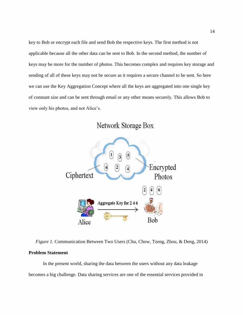
14
key to Bob or encrypt each file and send Bob the respective keys. The first method is not
applicable because all the other data can be sent to Bob. In the second method, the number of
keys may be more for the number of photos. This becomes complex and requires key storage and
sending of all of these keys may not be secure as it requires a secure channel to be sent. So here
we can use the Key Aggregation Concept where all the keys are aggregated into one single key
of constant size and can be sent through email or any other means securely. This allows Bob to
view only his photos, and not Alice’s.
Figure 1. Communication Between Two Users (Chu, Chow, Tzeng, Zhou, & Deng, 2014)
Problem Statement
In the present world, sharing the data between the users without any data leakage
becomes a big challenge. Data sharing services are one of the essential services provided in

15
cloud computing. Data in the cloud is of higher importance and needs to be protected from
unauthorized access. To avoid any data leakage, usually, the data is stored in an encrypted
format. However, the problem comes while sharing the encrypted data and providing the
decryption rights to the users. An efficient encryption solution is necessary that provides
decryption rights to the users for multiple sets of ciphertext classes using a single key that
comprises the power of several individual keys that are combined.
Nature and Significance of the Problem
Data privacy is a critical concern when accounting for a user’s requirement. As the
decryption rights should be given only for the requested data, the key aggregate system is used.
Objective of the Study
The main aim of the study is to implement how an aggregate key can be used for data
sharing and accessing between two or more users. To study the emergence of developing public
and private data security in cloud computing. To analyze the architecture, methodology and
system design and present the output results to users.
Limitations of the Study
The research has some limitations as follows:
1. The research is limited in analyzing the cloud computing in networking.
2. The study mainly focuses on the implementation of the private and public key using
services in cloud technology.
3. The data collection for the research and practical programming may not be accurate.

16
Summary
In this section, an overview regarding the cloud computing and distributed storage are
presented. Also, how data outsourcing plays an important role in the present situation and how
the user can store the data in the cloud is explained. Furthermore, the necessity of encrypting the
data and how the data is encrypted and the keys for decryption should be shared between the
users is discussed. Also, the concept of a key-aggregate cryptosystem is introduced.

17
Chapter II: Background and Review of Literature
Introduction
In this section, the fundamental concepts of cloud computing, the characteristics and
deployment models related to cloud, background related to the problem and various literature
reviews of authors are discussed, and the proposed system is presented.
Background Related to the Problem
In the previous section, an example regarding the data sharing between the two users is
given. The encrypted data is stored in the cloud, but the problem comes with how to share the
keys securely so that all the unnecessary information should not be exposed to the user. If the
sender encrypts all the information using a single key and sends it to the receiver, he is exposing
all the important information to the receiver, which is a breach of privacy. Also, if he sends each
key for the encrypted data, then he needs to send decryption keys for each encrypted data. This is
acceptable when the number of keys is small, but for thousands of keys, separate storage needs to
be maintained, and these must be sent through a secure channel, where there might be a chance
for data leakage. So, to overcome this problem, a key aggregate cryptosystem concept is
developed where a single aggregate key of constant size is formed from the set of keys and sent
to the receiver (Chu et al., 2014). This also uses the concept of public key encryption, using this
makes the decryption is difficult or nearly impossible without the key.
Literature Related to Methodology
In the present scenario, online data sharing, access, and performance are the preliminary
requirements for any organization. The data available is shared across geographical boundaries,
and it is available to a multitude of users to perform operations on the data. To do so, the data

18
owner ideally must use different encryption mechanisms before they store the data and provide
the decryption power for some of the users while retaining the ability to revoke access for any
users at any point in time. The efficient solution would be providing decryption rights to
different ciphertexts with the use of a single aggregate key, as proposed by (Chu et al., 2014).
According to Cui, Liu, and Wang (2016), the ability to share encoded information via
public storage with different clients can significantly reduce the data disclosures in the cloud. To
provide that kind of encryption schemas requires excellent management of keys. However,
sharing a unique number of selected documents with a different number of users requires
different encryption keys to be used for a various number of documents. This implies, a large
number of decryption keys to be passed securely and to be stored properly. Also, to perform a
search over the data, a large number of keyword trapdoors must be passed to the cloud storage to
get the data. This scenario seems to be impractical with the current cloud capacity accessed by
millions of users. To address this problem, Cui et al. (2016) proposed the novel concept of Key
Aggregate Searchable Encryption (KASE) and instantiated the idea through a concrete KASE
scheme. This KASE schema can be applied to any cloud that supports searchable group data
sharing. This implies that a user can share a group of files to a group of users and the users can
perform the search over the files and retrieve the files they are authorized to access. Efficient key
management can be done as follows, the data owner should provide only the aggregate key to the
user to share a group of files, and the user needs to provide a single aggregate trapdoor to
perform the search over the cloud to get the data.
Recently, Patranabis, Shrivastava, and Mukhopadhyay (2017) proposed Chosen Plaintext
Attacks (CPA) and Chosen Cipher Attacks (CCA) secure KAC constructions that can be

19
implemented in cloud environments, which uses elliptical curves, and is a first of its kind. This
extended broadcast key aggregate cryptosystem is based on the fundamental KAC proposed by
(Chu et al., 2014) and the broadcast encryption proposed by Benaloh (2009). In the broadcast
scenario, the single ciphertext is transmitted to different users, and the respective users can
decrypt using their allocated private key. While in KAC a single aggregate key will be
distributed to multiple users and they can be used to decode the ciphertexts encrypted with
reference to different classes. In the broadcast scenario, the focus is on shorter ciphertexts with
individual decryption keys and with KAC the focus is on shorter ciphertexts with individual
lower head aggregation key (Patranabis et al., 2017). They also described how the standalone
KAC scheme could be efficiently combined with broadcast encryption to cater to m data users
and M data owners while reducing the secure channel requirement from O(mM). In the
standalone case O(m+M) (Patranabis et al., 2017). They proposed a CCA collusion resistant
system and the addition and revocation of new users can be easily implemented. Also, the
addition of new users is easily handled in the proposed extended KAC construction by
generating a new key for each newly added user in the system and ensuring that all future
aggregate key broadcast operations consider the access rights of the new users in addition to the
existing ones (Patranabis et al., 2017).
The key aggregate cryptosystem is one of the most efficient, scalable and secured
techniques that can be implemented in cloud storage. A key aggregate cryptosystem is a public
key cryptosystem in which all of the sets of secret keys are aggregated into a single key, and the
aggregated key has the power of all the secret keys. Wang and Zhou (2016) proposed a leakage
resilient key aggregate cryptosystem with auxiliary input based on the KAC scheme which was

20
proposed by Chu et al. (2014). This method is used to overcome the side channel attacks. Using
this attack, the attacker may be able to access a part of the information of the secret key by
observing the physical properties like temperature and power usage of a cryptosystem (Wang &
Zhou, 2016). To overcome this, they have designed a leakage resistant cryptosystem, even
though the attacker may get the leaked bits of the aggregate key, they cannot get the information
of the master key. They have used an auxiliary input model which is the best among the other
leakage models, which are continuous leakage model and bounded retrieval model. However,
this proposed model only protects the master key, and the cost of decryption is high when using
this model, which could be an improvement in their future work.
Literature Related to Existing Systems
In this section, the details regarding the existing systems are discussed. There are some
public and private cryptographic schemes for online data sharing and some of them concentrate
on the key aggregation, although only a few of the systems emphasize on producing constant size
keys, to decrypt a random number of encrypted objects (Patranabis, Shrivastava, &
Mukhopadhyay, 2015).
Hierarchical encryption. Hierarchical encryption is used to provide access control in
cloud storage (Patranabis et al., 2015). This is one of the most prominent methods, which uses a
pre-defined hierarchy of secret keys like in a tree structure, where access to the key to any
corresponding node provides access to the all of the subtrees consequent to that node. The
primary aim of this schema is to reduce the cost for storing the secret keys. Sandhu (1988)
proposed the methods that use repeated calculations of a pseudo-random function or block cipher
on a fixed secret user to generate symmetric keys in a tree hierarchy. There are few advanced

21
schemes in hierarchical encryption that provide access to acyclic and cyclic graphs. One of the
major disadvantages in using a hierarchical encryption scheme is that providing access to one of
the branches within a given subtree licenses an increase in the number of secret keys. This
increase in the number of keys will in turn expands the size of the shared key. Thus, the
hierarchical cryptosystem provides an excellent delegate mechanism when there are files to be
shared in a given branch, however its efficiency drops, as the complexity of the key size
increases. Using the Figure 2, the hierarchical encryption scheme is explained. The parent node
represents the secret, and the child nodes represent the ciphertext classes. The small circles in
Figure 2 are the classes which need to be delegated. The rectangle represents the keys to be
granted. Every non-leaf node can generate the keys of its child node. Considering an example
provided by Kumari and Lakshmi (2014), if a user wants to upload data in the professor
category, the child nodes come under the professor class. “Department” and “Classes” are
classes under the Rectangle. Using the Figure 2, if Alice wants to share some data in the
“Professor” category, the keys need to be only granted for the “Professor” node which will grant
and delegate the keys of the descendant nodes, “Department” and “Classes.”
Figure 2. Tree Structure in Hierarchical Encryption (Kumari & Lakshmi, 2014)

22
Compact key symmetric encryption. In symmetric key setting, compact key encryption
was proposed by Benaloh (2009) to solve the problem of quickly transmitting a large number of
keys in a broadcast scenario. In this, the basic methodology is to divide the entire cipher-text
space into a finite set of classes, thus overcoming the problem of multiclass delegation in
hierarchical schemas. According to Patranabis et al. (2015), this method is not always desirable
and is practically not applicable for some cloud applications. To overcome this, some other
schemas in the symmetric key setting have tried to reduce the key size but the sharing of
decryption keys are not aimed at these schemas.
Advantages:
The size of the ciphertext is constant.
Easy to construct.
The size of the decryption key is constant.
It takes less space to store the ciphertext and keys.
Disadvantages:
The same key performs the encryption and decryption.
To encrypt the files, the owner should get the corresponding key.
Compact key identity-based encryption. Identity-based encryption (IBE) is a public
key encryption scheme in which the public key corresponds to the identity string related to that
user (Bachhav, Chaudhari, Shinde, & Kaloge, 2015). This can be a user’s email address or a
mobile number. In IBE, each user receives a private key from the Private Key Generator (PKG)
based on user’s Identity. This PKG holds a master-secret key. In IBE, the content provider uses
the public parameter and the user’s identity to encrypt the message. The recipient using his

23
private key can decrypt the message. Guo, Mu, and Chen (2007) tried to build IBE using key
aggregation scheme. Here the constraint is that all the keys that need to be aggregated come from
various “Identity divisions.” While there an exponential number of user identities and thus
having many private keys, only a polynomial of them can be aggregated. This leads to an
increase in storage cost and transmission of ciphertexts. However, this scenario impractical when
it comes to shared cloud storage. In Fuzzy IBE (Sahai & Waters, 2005), a single compact key
can be used to decrypt multiple ciphertexts, provided that they should have been encrypted in a
close set of identities and this scenario fails to work when arbitrary identities are used.
Advantages:
This is a public key encryption schema.
A dependent party that grasps the secret key.
The secret key is delivered based on identity.
Decryption key size is constant.
Disadvantages:
The transmission of cipher-texts and storage is costly.
The size of cipher-text is not constant.
Attribute-based encryption. Attribute-based encryption scheme allows every user to be
identified over a set of attributes (Patranabis & Mukhopadhyay, 2016). Only the user who has
access privileges for the corresponding secret key will be able to decrypt the encrypted file
stored in the cloud storage. The secret key will be provided via a secure channel to the user, who
satisfies the access control policies set by the data owner. The primary disadvantage of this

24
scheme is that, whenever the user access rights are revoked, the cipher-text in the cloud must be
re-encrypted. One of the major drawbacks of ABE is collusion resistance.
Advantages:
ABE uses public key encryption.
The size of the ciphertext is constant.
Disadvantages:
The size of the key increases linearly with the increase in the number of attributes.
The size of the decryption key is not constant.
It requires more storage to store keys, and it is expensive to maintain keys.
Proxy re-encryption. To provide fine-grain access control and for scalable user
revocation in unreliable clouds, proxy re-encryption is used. In this mechanism, the semi-trusted
proxy cloud and the data owner shares a secret key in advance. Because of sharing of the secret
key, on behalf of the data owner, the proxy cloud is delegated and can be able to re-encrypt the
data. Using the public key of the data owner the semi-trusted proxy converts the data into a file
and using the secret key of the client the file can be decrypted. In this overall process, the proxy
has no knowledge regarding the data being sent. An addition to this technique is that the cloud
servers can re-encrypt the data without any external triggers, using the internal clocks. The
drawback of proxy re-encryption is that it transfers the responsibility of the key storage to the
semi-trusted proxy and it may be vulnerable to collusion attacks. Here, the transformation key of
the proxy should be well protected, and every time interaction is required with the proxy
regarding the decryption which is undesirable in some of the applications in the cloud. Table 1

25
shows the comparison of KAC with related schemas, regarding the type of encryption used in
each schema, the size of ciphertext and the size of the decryption key produced.
Table 1
Comparison of KAC with Related Schemes (Kate & Potdukhe, 2014)
Size of Cipher Text Size of Decryption Key Type of Encryption
Key assignment schemas constant non-constant symmetric or public key
Symmetric key encryption with
compact key
constant constant symmetric key
Identity based encryption with
compact key
non-constant constant public key
Attribute based encryption constant non-constant public key
KAC constant constant public key
Concepts of Cloud Computing
Cloud computing is evolving as the latest trend in various fields related to information
technology, academic fields, health and for personal use. In cloud computing the user connects to
the “cloud” which appears as a single entity although it resides on multiple servers, where the
user can upload, access, share and can modify the data remotely. They are allowed to access
multiple services from a shared pool of configurable computing resources. This pay-per-use
model in cloud services brings savings to users and offers flexibility and scalability in terms of
capacity and performance. Using the distributed storage provided by the cloud service providers
(CSP), users can store their data. Although the storage is secure, this allows the CSP to have
control over a user’s data (Vanitha & Elavarasi, 2014).

26
Characteristics of cloud. According to NIST, cloud computing has the following main
characteristics (Mell & Grance, 2009):
Measured Service: The cloud is built on the pay-per-use model. Cloud computing can
efficiently monitor use, and customers can dynamically access the use of cloud
services. The measurement is used to bill the customers on pay as you use model. The
resource usage can be monitored, reported and controlled so that there exists
transparency between the user and the provider.
On-demand self-service: Without any human interaction with the CSP, the cloud
customer can utilize the resources provided by the CSP. In addition to this, the user
can schedule, manage and timely deploy any of the cloud services like computational
storage and server time. This helps in the reduction of personnel overhead and the cut
in the cost of the offered services.
Broad Network Access: The cloud services are readily available and are accessed by
the users over the network via standardized interfaces that can be deployed quickly
not only on the complex devices like personal computers but also on the lightweight
devices like smartphones. High level of utilization of resources is provided because of
the lowered cost of high-bandwidth of network communication to the cloud provider.
Location independent resource pooling: The virtualization concept of the cloud
allows the CSP to pool multiple resources using a multi-tenant model. This resource
pooling helps to share multiple virtual and physical resources to multiple customers
and can be dynamically assigned and reassigned on customer demand. In general, the
resource provided to the customer satisfies the characteristics of location

27
independence as the customer has no control over resource location (Mell & Grance,
2009).
Rapid Elasticity: The ability to quickly allocate and reallocate the resources
efficiently and effectively to the user to meet the self-service goal of cloud computing
by an automated process that the procurement time is decreased when in need and
prevents the abundant use of the computing power when the need is finished.
Peer to Peer service: Cloud computing also provides a peer to peer model with a
distributed architecture that there is no need for central coordination. Another
advantage of cloud computing is that it allows for a cloud sandbox, which is an
isolated environment in which, the file, program, or the code can run without
affecting the application. Amazon web services provide this usage. Grid computing is
provided by the cloud, which is a form of distributed and parallel computing, where it
creates a virtual supercomputer connected over a network with loosely coupled
computers acting in accordance to perform huge tasks.
Cloud service models. Cloud service providers provide many services to the user. The
primary service models offered by the cloud are infrastructure-as-a-service (IaaS), platform-as-a-
service(PaaS) and software-as-a-service (SaaS), which are categorized by the Software,
Platform, and Infrastructure (SPI) model.
Infrastructure-as-a-Service (Iaas): It is a service model which provides the
infrastructure like network equipment, storage, computational servers as a service
using which the platform to develop and execute the application which is set. Using
this model reduces the infrastructure cost of buying software and hardware

28
components. Instead, services can be accessed to virtualized objects and using an
interface to control them. When there is a need for additional storage, the consumer
can request the services and will be billed according to their pay per use model.
Examples include Amazon EC2, Rackspace, etc.
Platform-as-a-Service (PaaS): In this services delivery model, using a platform by
which the applications can be developed and deployed, is provided as a service. The
platform usually consists of the programming environment, databases, web servers
using where the development takes place, and the consumers have the full access to
the environment settings. This model reduces the cost of buying software, hardware
components and managing them. The developers can later be able to deploy their
developed apps into the cloud very quickly. Examples include Microsoft Azure and
AWS elastic beanstalk.
Software-as-a-Service (SaaS): In this service delivery model, one or more services or
applications and the computational resources that are required for the working of the
application are delivered. This service model reduces the cost of software
development, infrastructure components, and maintenance operations. The software
provided by the service provider usually resides on their infrastructure or are hosted
by third-party vendor’s infrastructure and the consumer can access the service using a
web application like a browser. This mechanism is implemented using a licensing
model, and the service can be provided to a user or group of users or an organization.
Here, the security necessities are managed by the service provider and the consumer

29
will not be controlling or having access to the underlying infrastructure. An example
is Microsoft Office 365.
Deployment models in cloud.
Private Cloud: The Private cloud infrastructure is solely implemented for an
organization, either operated by a third-party service provider or resides in an internal
data center and can be hosted externally or internally. Only the authorized people who
have authentication and belong to that organization can be able to access the data in
the cloud. Efficient security policies must be implemented by the organization while
deploying a private cloud. By using the private cloud, the organization will have an
advantage over the infrastructure, computational resources and consumers data than
on a public cloud (Jansen & Grance, 2011).
Public Cloud: Contrary to the private cloud, a public cloud is accessible to everyone
and users can use them to store their data and access the data anytime, using the
Internet. Anyone can use the computational power and infrastructure services
provided by it. It is owned and operated by cloud service providers, and it is external
to any organization. SkyDrive, Google Drive, Dropbox, etc., are some of the public
clouds available.
Community Cloud: Community cloud can sometimes be referred as a mix of public
and private clouds. It is implemented between two or more organizations that share
similar security and privacy policies, rather than a single organization (Jansen &
Grance, 2011). It is identical to a private cloud, but the computational power,
resources and the infrastructure are exclusive to both the organizations involved.

30
Hybrid Cloud: The Hybrid cloud infrastructure is a mix of two or more clouds, that is
used to perform distinct functions within an organization. These clouds can be a
combination of either public cloud, private cloud or a community cloud and are
bound together by a standardized proprietary technology that enables application
portability (Mell & Grance, 2009). An example for the use of hybrid cloud
implementation is that an organization that implements hybrid cloud may store the
clients’ sensitive data in the private cloud application and interconnect that
application to a business intelligence application running on a public cloud, as
software as a service (Hybrid cloud, n.d.).
Cloud storage requirements. With the advent of cloud computing, data sharing is one of
the prominent uses of the cloud. Cloud sharing has gained interest in the organizational sector,
health care systems, social users because of the services provided by it. The data is distributed
across many servers and can be accessed at any given time. Many organizations outsource their
data and store it in the cloud because they do not need to maintain physical storage, which cuts
the cost and they are still able to share the data with other business organizations. Social users
like to save their photos, videos, and documents in the cloud, provided by the CSP, as there is no
loss of data occurs in the cloud compared to storing data in a physical location on a device,
which once lost it is lost forever.
One more advantage is data sharing, where the user can share their data whenever
wherever and with whomever they want, with the access to the Internet. Cloud computing is the
underlying technology for many of the everyday applications that are used, and which can be
accessed from a browser. However, with the vast benefits provided there are security concerns

31
regarding the use of the cloud. One of the concerns is the data stored in the cloud should be
protected from unauthorized access. Recently, the ICloud leak of celebrities’ photos are an
example. Another concern is the data stored in the cloud is available to the CSP. The access to
the data and the data should be protected from the CSP. The following are the requirements for
data sharing while using the cloud.
Data confidentiality: Including the CSP, the data in the cloud should be protected
from unauthorized access, at any given time. Data should remain confidential during
the transfer of data, at an idle state or as backup data. Only the authorized users
should be provided access to the data at any given time.
User revocation: If the data in the cloud is authorized to a user and later the rights are
revoked, the user shouldn’t have access to the data when the new change is
implemented. Also, the revocation of a particular user should not affect the
authorization provided to other users. An example for this is if a group of users are
authorized to access a project in team foundation server, and later for one user access
is revoked to that project, then the remaining people should still be able to access the
project except the revoked user.
Scalability and efficiency: Cloud allows for a large storage of data. An enormous
number of users access cloud on a daily basis and their count and usage is
unpredictable. Many of them join and leave, so it is necessary that the system should
be efficient and scalable (Kumar, 2015).
Collusion between the entities: In the cloud, data sharing services should be provided
in such a way that even when malicious users try to collude, the data access should be

32
efficient such that it should be granted only to authorized users. To provide proper
authorization to access the data or resources access control mechanisms should be
implemented. Access control is a security model that allows the users to access or
deny or restrict permissions. Access control mechanism is very useful in tracking the
users who have been provided access and also maintains a list of attempts made by a
user before accessing a system or a resource.
User-based access control: Using UBAC the system applications and services are
restricted at a user level. UBAC permissions are implemented with a combination of
login and password, which are stored in the access control list which either grants or
rejects the user to access a resource. Companies with high-security concerns
implement this access control and because it has high management overhead and as
the number of users accessing the cloud is high, this is not a feasible approach to
implement in the cloud.
Role-based access control: RBAC is a control mechanism in which the users are
provided access according to their assigned roles. This can be implemented for a
system, network or cloud, using roles assigned to individual which users can then
access data according to their roles. The access can be referred to as the user’s ability
to view, create or modify the data and perform some operations. An example of this
in an enterprise setting, the director of the organization can have access to the files of
all the employees and while a manager can have access to the people under them. The
requested data can be accessed, only when the role constraint is satisfied. It is easy to
assign or remove or modify roles using this mechanism. There are other access

33
control mechanisms like mandatory access control (MAC) and discretionary access
control (DAC). MAC, DAC, RBAC—all of these mechanisms come under the
umbrella of Identity-based access control models (Kumar, 2015).
Attribute-based access control (ABAC): ABAC is a mechanism in which the access
is provided on the basis of attributes assigned to the user on a set of policies. The
access to the data stored in the cloud is provided after satisfying the policy for the
provided attributes. ABAC is based on the evaluation of subjects (users), objects
(resources) and sometimes environmental conditions and the access policy for the
rules satisfying the subject-object attributes. Using only the access control
mechanisms in the cloud for data privacy and security can lead to privilege escalation
attacks as the data in the cloud comes from multiple users and exists on the same
server (Patranabis et al., 2017). The data in the cloud should be protected from
unauthorized access and as well as the cloud service providers. The CSP provides
data security, however, they also have access to the data. To overcome this, the data
must be encrypted by the user using different cryptographic schemes before it is
outsourced to the cloud, which provides data confidentiality. The cloud storage
system should be effective in such a way that the users can also be able to search a
part of the stored encrypted data. The cloud storage system should be able to return
the searched data, and they should be unaware of what portion of the searched data is
returned (Kumar, 2015). Data sharing in the cloud is a significant concern. The most
prominent challenge in the cloud is how to share the encrypted data to users. The
traditional way is the users can download the encrypted data, decrypt it and then share

34
it with others. However, using the cloud this way loses the usage of cloud service.
The data sharing service should be effective in such a way that the user should be
provided with the access rights of data to others so that they can download the data
directly from the server. Using simple encryption and decryption techniques are not
sufficient to achieve this. Complex encryption schemes should be applied, which
makes the use of keys and a proper and secure key management system is necessary,
as keys are very important for data retrieval. Adequate encryption schemes should be
applied to data while it is transmitted over networks, while it is at rest or in a backup
state. This is done to protect the data from the malicious cloud service providers and
unauthorized users. Efficient key management which includes key storage and access
to the key storage should be securely implemented as loss of keys may compromise
the stored encrypted data. Key management refers to the storage of keys, access to the
keys, transportation of keys, activation and deactivation of keys and the creation or
deletion of keys (Kumar, 2015). The data usually is encrypted by the user and the
CSP before the data is stored. So, both the encryption and key management is
necessary to protect and share data in the cloud securely. The requirements of proper
key management are discussed below (Kumar, 2015).
Secure key stores: Key storage is the storage space where all the keys related to
encryption or decryption will be stored. A proper security mechanism should be used
to prevent the malicious users from gaining access. If the access to the storage is
compromised, they can gain access to the keys related to encrypted data and to

35
corresponding decryption keys. To avoid this, the key stores should protect
themselves from malicious users, while in storage, in transit or on a backup media.
Access to key stores: Proper access control mechanism should be implemented while
providing access to the key stores. Limited access should be given to access the key
stores, for the users who have access to the data. Access control should be provided
based on the roles, and the entity that uses the given key should not be the one to
store keys (Kumar, 2015). As key stores contain essential information related to the
keys, proper safety measures should be taken, otherwise the loss of data will occur.
Recoverability and backup of keys: Data is usually stored in an encrypted form. Keys
help convert the plaintext into ciphertext. This encrypted data gets shared with others.
So, the loss of keys makes the decryption process difficult or sometimes impossible.
Proper key recovery and backup mechanisms should also be implemented. Loss of
keys eventually leads to loss of data. Proper key recoverability and backup
mechanisms should be applied by the cloud service providers, or if not, the access to
data will be lost.
Types of attacks on the cloud. Cloud provides a distributed service of data where many
people across the world can access it. Although cloud is secure and different security
mechanisms are implemented it is still prone to privacy and security attacks by hackers. Some of
the attacks are discussed below (Kumar, 2015).
Law enforcement request: Users store the data on a cloud provided by the CSP. When
the government or any government agency requests the data regarding the user, most

36
of the time, a CSP will not have a choice to deny their request. Because of this, there
is a loss of confidentiality of the data.
Data-stealing attacks: This attack refers to stealing data from a user by any means,
gaining access to a user account and password information using techniques like brute
force or over the shoulder techniques. This is a threat to user confidentiality and could
lead to a breach of data. To overcome this, one of the security mechanisms that can
be implemented is using authenticator application or two-factor authentication, where
a message is received with a code to verify the authenticity of the user. Many
organizations apply this method to provide authorized access.
Flooding attacks: In this kind of attack the malicious user sends a request to the cloud.
The attacker then overloads the server by sending bogus data requests to the server,
thereby increasing the workload of the services and utilizing all of the available
resources and potentially crashes the server.
Denial-of-service attacks: In this kind of attack, malicious code is injected into
browsers which opens multiple windows, and this then denies services to the
authorized user. These kinds of attack can often be seen while using the browser.
Cross-site scripting attacks: In this kind of attack, the attacker injects a malicious
piece of payload into the legitimate website or web application. In this way, the
attacker is not affecting the victim directly, but by making use of the vulnerability in
the application, the user would visit (Acunetix, n.d.).

37
XML signature wrapping attacks: Using this kind of attack, the attacker, can get
administrative rights of the cloud user and can create, delete or modify the
information of the user.
Proposed System
Technology is emerging rapidly day-by-day, and cloud storage has become a
predominant source of storage and sharing of data and is where a large amount of user data is
stored. There is a high possibility of data leakage in this process of storing and sharing of data.
To avoid this, the proposed system is based on the aggregate key concept. Using this, the
successful delegation of decryption rights for a set of ciphertext classes are provided to the
receiver. In this system, multiple encryption operations are performed, and an aggregate key is
generated. This aggregate key is passed on to the delegate and using this key the decryption is
performed to obtain the original text. This system guarantees a secure data exchange between the
sender and receiver, and only the authorized user will be able to decrypt and thus view the shared
information.

38
Chapter III: Methodology
Introduction
In this section, the details regarding the methodology used in the key aggregate
cryptosystem is explained. Also, the framework, the modules involved in design, the algorithm
used and applications of KAC are presented.
Key aggregate cryptosystem. The key aggregate cryptosystem is a public key
cryptosystem which is implemented in cloud storage for successful delegation of keys, to decrypt
the data. The users not only encode the message under an open key but also under an identifier of
ciphertext called a class. The ciphertexts again are classified into classes. Anybody can encrypt
the message using their public keys and can choose which ciphertext class is related to the
plaintext message to be encoded. The information owner holds the master key pair which can be
used to generate secret keys for the set of classes. The produced key is an aggregate key, which
is compacted as a secret key for a single class but possesses the power of many such secret keys
which are combined. By providing this key, the user, for the authorized set of classes is be able
to decrypt the information and the rest out of the set stay private.
Framework
The key aggregate encryption scheme consists of five polynomial time algorithms (Chu
et al., 2014). They are as follows:
1. Setup (1λ, n): In this step, the data owner registers on a server which is untrusted.
Here the 1 λ is the security level parameter and n is the set of ciphertext class for
which a public param is generated.

39
2. KeyGen: In this phase, a random master key and public key pair are generated by the
dataowner(pk, msk).
3. Encrypt (pk, i, m): In this encrypt phase, the encryption operation is performed, and it
takes the input as a public key(pk), a message (m), and index I each of the ciphertext
classes.
4. Extract (msk, S): In this phase the delegating power or the decryption rights for the
receiver who satisfies for the set of indices I are provided. For this, it takes the input
as master secret key and set of ciphertext classes and it outputs an aggregate key Ks.
5. Decrypt (Ks, S, I, C): In this final step, the delegate who receives the aggregate key
Ks, which is obtained in the Extract phase, takes the key Ks as input along with the
index I for a set of indices S and the ciphertext classes C are generated, to decrypt and
obtain the original message m (Kate & Potdukhe, 2014).
Sharing the data. The main usage of KAC is to share data efficiently. The aggregation
property is useful when the delegation to be provided is efficient and flexible. Using KAC
schemes, the data owner can share the data in a secure, confidential and selective way, by
providing each authorized user a single aggregate key, with a small ciphertext expansion. The
data sharing between two users Alice and Bob using KAC is explained with an example shown
in Figure 3. Suppose, if user Alice wants to share her data {m1,m2,m3…..mn}, she first
performs the setup (1λ,n) to get the public system parameter ‘param.’ Then she executes the
KeyGen to generate a public master-secret key pair (pk,msk). The ‘param’ and the public key
‘pk’ can be made public, but Alice should hide the master secret key. Anyone can encrypt each
of Alice’s messages by doing Encrypt (pk, i, mi) to produce ciphertext Ci. This encrypted data

40
can be uploaded to the server. Once Alice wants to share her set ‘S’ of data to user Bob, Alice
can perform Extract (msk, S) to produce an aggregate key Ks. The aggregate key generated is of
a constant size and can be securely transferred in the email. After receiving the key, Bob can
download the data set for which the authorization is provided. For each i ϵ S, Bob can download
the Ci from the server and be using the aggregate key Ks; decryption can be performed using
Decrypt (Ks, S, I, Ci) for each i ϵ S
Figure 3. Data Sharing Using KAC (Jadhav & Nargundi, 2014)

41
Modules Design
The design phase is to ensure that the project gets developed according to the
requirements. The entire design is divided into five modules and each module has a specific
functionality, and it is related to other modules. Following are the five modules:
Registration of user and authentication
Key generation
Encryption and storage
Data sharing using aggregate key
Decryption and view content
Registration of user and authentication. The registration module allows users to
register on the application. Users can then create accounts by providing their details regarding
username, email id, password, etc. A new user should go through the registration process. Any
registered user can log in to the application by entering the details that are provided during the
registration process. This module also checks for already existing usernames, during registration,
to avoid duplication and a unique id is assigned to each user (Revathi & John, 2016).
The authentication mechanism ensures that only eligible users are provided access, by
comparing the credentials with the values stored in the database. Implementing a proper
authentication reduces the risk of data leakage. After the login, a user has various options using
which they can search, share messages, view messages and log out of the application. Figure
4shows the registration and authentication process.

42
Figure 4. Registration and Authentication
Key generation. Key generation is a process of producing cryptographic keys. Figure 5
shows the process of key generation. When a user is registered with the application, the public
key and private key are generated for each user and assigned to them. These keys are stored for
the particular user profile and can be retrieved at a later point. After login, the user has the option
to share the message with the other users.

43
Figure 5. Key Generation
Encryption and storage. Encryption is a process of scrambling the contents of the
message where only the authorized person can be able to access it, by providing the secret key.
This module describes the encryption process that happens after a successful login of a user. The
encryption operation is needed before sharing any data. After a user registers and is successfully
authenticated, he can share the information with another user only if it is properly encrypted.
When the sender sends a message to the receiver, the sender’s message gets encrypted using
symmetric encryption. This symmetric encryption generates symmetric ciphertexts. The
encrypted values are stored in the database, and a unique identifier or a master key is assigned
for this set of information. This unique identifier is encrypted using ElGamal encryption, which

44
generates ciphertexts and these are aggregated and passed to the receiver. Figure 6 shows the
encryption process.
Figure 6. Encryption and Storage
Data sharing using aggregate key. Using ElGamal encryption, the unique message
identifier is encrypted. This encryption process produces a set of ciphertexts. These ciphertexts
c1 and c2 are combined to generate an aggregate key. This aggregate key has the decryption
power on the set of symmetric generated ciphertexts. This aggregate key is passed along with the
symmetrically encrypted ciphertexts. Figure 7 displays the process of aggregate key data sharing.

45
Figure 7. Data Sharing Using Aggregate Key
Decryption and viewing content. The encrypted message is shared from the sender to
the receiver. When the receiver logs in, they receive the encoded message along with the
aggregate key. By using this key, the individual ciphertexts c1 and c2 are extracted. Using the
ElGamal decryption, which takes the c1 and c2 values as input, the unique message identifier is
calculated. As the unique identifier is associated with the symmetrically encrypted ciphertexts,
the ciphertexts are retrieved and using the symmetric decryption, and the original values are
displayed to the receiver. Figure 8 shows the decryption process.

46
Figure 8. Decryption and Content View
Algorithm Used
The ElGamal algorithm is one of the best practices to achieve secure encryption and
decryption process of sharing information. There are three components: (a) key generation, (b)
encryption, and (c) decryption.
Key generation: The key generator works as follows:
1. Peter generates an efficient description of a multiplicative cyclic group G and pick a
prime p with generator g

47
2. Peter chooses a random x from{0 …… p-1}
3. Peter computes y = gx
4. Peter publishes y, along with the description of G, p, g as his public key. Peter
retains x as his private key which must be kept secret
Encryption: The encryption algorithm works as follows:
To encrypt a message m to Peter under his public key (G, p, g, y)
1. David chooses a random i from {1 …… p-2} then calculates c1 = gy
2. David calculates the shared secret s = yi
3. David converts his secret message m into an element m’ of G
4. David calculates c2 = m’.s
5. David sends the ciphertext to Peter (c1, c2) = (gi.m’.yi) = (gi.m’.(gx)i)
Decryption: The decryption algorithm works as follows:
To decrypt a ciphertext (c1, c2) with his private key x
1. Peter calculates the shared secret s = c1x
2. Then he will calculate plaintext message m, by converting c2.s-1
Where c2 = m’.yi , S= yi and. y = gx
c2.s-1 = m’.yi.(gxi)-1
= m’.gxi.g-xi
= m’. (gxi/ gxi)
= m’

48
Applications of KAC
Some of the applications in which KAC can be implemented are as follows (Patranabis &
Mukhopadhyay, 2016).
1. Patient Controlled Encryption (PCE): Patient controlled encryption (PCE) is a
recently introduced concept. PCE allows the patients (users) to upload their individual
medical records onto the cloud and allow them to provide the delegation of rights for
the decryption of data, to only authorized health care personnel and as per their
requirements. The KAC concept can be used here, by which users can create their
own hierarchy of medical data and provide the decryption rights on this data to
different specialists or organizations, using the concept of the aggregate key. As the
health records of individuals are considered as sensitive data, storing them on a local
or physical machine is not a viable solution and the cloud is a best alternative for the
storage of data and KAC provides a two-way advantage in this scenario. It not only
allows different users across the globe to store their data efficiently, but also allows
them to gain the support of different health personnel across the globe, by providing
them access to their data securely using the aggregate key.
2. Distribution of product licenses or activation keys: Aggregate key concept can be
implemented for an organization that allocates product licenses to its users. For
example, consider that an organization has large number of products and wants to
distribute the licenses or activation files of the products to different users. Using
KAC, the license files can be encrypted and stored in the cloud. The aggregate key
associated with multiple licenses for different products can be shared to customers to

49
legally authenticate them, as per their requirements (Patranabis & Mukhopadhyay,
2016). The legal authentication is provided to the users who buys the products from
the company and an authentication key is given to the user. Using the aggregate key
user can be able to decrypt the license file for each product. Since the keys produced
are of a constant size, distributing a single aggregate key is easier than sharing
multiple keys for the licenses (Patranabis & Mukhopadhyay, 2016).

50
Chapter IV: Technology Stack
Introduction
In this section, the various technologies that are used to implement the project and a brief
overview regarding each of them are presented. The software and hardware requirements
required for the application is provided.
Technologies Used
Various technical stacks are used to develop this application. Some of them are:
Java 1.8
J2EE technologies like JSP, Servlet, JDBC
MySQL database
Eclipse IDE
Tomcat Application Server
HTML and CSS
About Java. Java is a programming language widely used to develop platform
independent applications. Since it has a wide variety of predominant features like Graphical User
Interface (GUI) systems and Java 2 Platform Enterprise Edition (J2EE) libraries, most of the
applications are developed in Java. Many web applications have risk factors with different kinds
of security and portability issues: Java resolves these issues using bytecode which is executed by
the Java compiler with a highly optimized set of instructions that are designed in Java Virtual
Machine (JVM). Since bytecode is highly optimized, it enables JVM to run and execute
programs faster. Any Java program can be run when a runtime exists for a system. Java programs

51
can be translated into bytecodes which enables it to run it in a wide variety of environments
easily.
Java progressively handles memory compared to other programming languages which
makes it more dynamic and easy to run code across a network. Java is an enhanced version of
C++, but Java uses an entirely different approach to problem-solving. Java provides APIs for
developing web applications with I/O, XML parsing, database connections, client-based utilities.
Java has a wide variety of J2EE frameworks like Spring, Struts, Hibernate, GWT, Maven, JSF,
etc., which makes the development process easier for an application. Java is more stable and
predictable hence it enables cross-platform development.
Advantages of Java.
1. Simple: Easy to learn if you know the object-oriented programming language, it is
based on the C and C++ programming languages.
2. Secure and Portable: Since the Java program translates into bytecode it is more secure
and can run on any platform.
3. Robust: Java is more robust because of its capability to do runtime and compile time
error checks.
4. Multithreaded: Running one or more threads simultaneously in the same program is
called multithreading, Java allows a program to run in a multithreaded environment.
5. High performance: Java uses the Just-In-Time (JIT) compiler to compile, which
enables high performance.

52
6. Distributed: Most of the J2EE and web applications which runs on the Internet are
distributed, and Java has great flexibility to develop the distributed system without
any constraints.
J2EE technologies. J2EE provides a variety of services to build large-scale, distributed,
multi-tier applications. The codes are written once and run on different platforms. J2EE is
comprised of a wide variety of technologies like Java Servlets, JSP, JDBC, etc. Major
advantages include: (a) different platforms support applications developed using J2EE, and (b)
most application servers that support J2EE are portable.
Java servlets. Servlets are programs run on a web application server. It handles HTTP
requests. It is a technology that creates web applications, provides interfaces and classes, used to
implement the interfaces, and is deployed on the servers. They can be created using
javax.servlet and javax.servlet.http packages. Servlet lifecycle includes three paths from
initiation till destruction: (a) initialization by init( ), (b) Service( ) method to process the HTTP
request, and (c) destruction or termination by destroy( ). Service() method is used to process
HTTP request and perform the task. This includes receiving requests from clients and responding
back to the requests. A new thread gets created whenever a request is received. Different types of
HTTP methods are used during the service phase such as doGet, doPost, doPut, doDelete, etc.
throughout the lifecycle. Figure 9 shows the architecture diagram for the servlet. Figure 10
shows the lifecycle diagram for servlets.

53
Figure 9. Servlet Architecture (Tutorials Point, n.d.-a)
Figure 10. Servlet Lifecycle Diagram (Tutorials Point, n.d.)
MYSQL database. A database is used to store the collection of data with subsequent
relational mappings to the tables. To do any CRUD (Create, Read, Update and Delete)
operations on any database we use Structured Query Language (SQL). MySQL is one among the
many prevalent open-source DBMS (Database Management Systems) which is provided by
Oracle. Because of fast performance, high usability and its user-friendly nature most of the

54
web/J2EE applications use MySQL. Initially, it is developed and supported by MySQL AB.
MySQL provides a MySQL Workbench (GUI), which is made for the user to execute SQL,
create or drop schemas and tables.
Java database connectivity (JDBC). JDBC is a Java API for database dependent
connections between Java programs and databases. JDBC is often used for SQL and Procedural
Language SQL (PL/SQL) statements to send to different databases. An API (Application
Programming Interface) consists of all the features related to a product in a documented form.
Figure 11 shows the JDBC Architecture and how it consists of two layers
a) JDBC API: Connection between Application to JDBC
b) JDBC Driver API: Connection between JDBC and Driver
Figure 11. JDBC Connectivity
To process a query (SQL statement) using JDBC, the following steps are followed: (a)
establish a connection, (b) create statement, (c) execute queries, (d) process result set, and (e)
close the connection.

55
Figure 12 shows the code snap shot for connecting to a database using JDBC.
Figure 12. JDBC Code Snippet
Java server pages (JSP). For developing web applications, JSPs are often used. It is a
very significant technology which is an extension of Java servlet, which has scripting, form
actions and directive elements in the form of static (HTML, CSS, etc.) as wells as dynamic code.
JSPs are used for developing presentation layer or client-side applications.
There are three types of scripting elements that can be used in JSP:
Declaration element (tag: <%! %>)
Expression element (tag: <%= >)
Scriptlet element (tag: <% %>)
Life Cycle methods of a JSP:
Pre-translated: Before compiled to Servlet
Translated: Compiled to Servlet
Initialized: Before handling the service requests
Servicing: Services the client requests
Out of Service: Completing the services or calls the jspDestory() method

56
Hypertext markup language (HTML). Web pages are designed using different
structures, HTML is a language used to describe various structures of web pages using markups.
It uses tags to format the code. The tags are enclosed in angle braces <Tag name>. HTML
consists of elements, the codes are written with opening tags <abc> and closing tags </abc> and
using various content. Elements comprise an opening tag, content, and closing tags. Attributes
contain information related to elements using additional symbols, as described below:
<h> : Used for headings
<p> : Used for paragraphs
<ul> or <ol> : Used to create menus
<div> : Used to create containers for parts
<a href> : Used to create links
<img> : Used to link images
HTML comprises a header and a body. The header consists of the title of the document
and the body consists of the main content (code). Images and tables can also be created using
HTML pages (HTML Basics, n. d.). HTML uses a variety of properties to define elements such
as text color, fonts, size, formatting (Special functions) and alignment, etc. Links are created
using anchor tags <a> for web pages or other source documents, and email links are also created
using HTML.
Cascading style sheets (CSS). CSS is interlinked with HTML as it helps in applying
styles to elements in HTML documents. CSS consists of a set of rules in a code format. Every
HTML file consists of a CSS with different codes needed to style the pages. CSS consists of two

57
different types of attributes like type (used for text) and media (used for screens, projections,
etc.). CSS consists of three different types:
Internal Stylesheets: This includes insertion of CSS code within the HTML file.
External Stylesheets: Text created in notepad and saved as a .css file and linked to a
HTML file.
Inline Style: Used to style single elements.
Different kinds of tags are used in the layout of the content such as:
Eg: h1 {
Color: #Red;
}
Eclipse IDE. Eclipse provides an integrated Development Environment (IDE). It is the
most widely used IDE tool for development of J2EE and web applications. It is an open source
software and user-friendly development tool available in the market. It has great features to
support and develop the application in commonly used programming languages. Eclipse provides
a structured workbench with all subsystems included by means of implementing one or more
plugins. For developing the current system, the Eclipse neon version is used.

58
Figure 13. Eclipse Platform Overview
Tomcat application server. Application servers are used to maintain service-oriented
components like Servlets and JSP's. They are used to gather data from the database and to apply
business tools for an application to have full control over the user sessions. On a web server, an
application server clustering (loosely coupling on a network) is performed for high scalability
and load balancing. The Apache Tomcat Application Server is a product of Apache Software
Foundation which is an open source application to implement J2EE and web applications. It has
a Servlet container which is specifically used to run Servlets and JSPs. Tomcat can be used for
exposing the business logic and dynamic content to the client using HTTP protocol. Tomcat 8.0
is used in the current system implementation.
Software and Hardware Requirements
Hardware requirements include any system processor, not before Pentium IV and RAM
of 2GB or above and hard disk space not less than 30 GB is sufficient to deploy the application.
Software requirements:
Operating system: Windows, macOS, Linux

59
Programming language: JAVA 1.8
IDE: Eclipse JEE (Neon version)
Server: Apache Tomcat Server 8
Database: MYSQL
Front End: HTML, CSS, JSP

60
Chapter V: Implementation
Introduction
In this section software used for the execution of the application, installation process and
the environment setup are discussed. Also, the implemented application screenshots and a
description of each screenshot is presented.
Installation Procedure
For achieving the implementation of the system, the below steps are followed:
Java Installation: In developing the system, JRE 1.8 version is used, which is available
on Oracle site as an open source application. Steps to follow include:
Download JRE 1.8 from the Oracle site.
Set the environment variable by adding JAVA_HOME path in system variables.
JAVA_HOME path would be the JRE location that has been downloaded.
Add %JAVA_HOME%\bin to environment path variable.
To check if JRE installed in the system, open CMD, and type for “java -version” or “java
-help.”
Eclipse Neon Installation: In developing the application, Eclipse Neon 4.6 version is
used, which can be obtained from www.eclipse.org/downloads, it is open source software
available in the market. Steps to get Eclipse installed are as follows:
For Windows:
Choose 64-bit or 32-bit Eclipse IDE for Java EE Developers Neon version and click
on download.
Unzip the downloaded Eclipse zip folder and click on the Eclipse executable icon.

61
For Mac:
Choose Eclipse IDE for Java EE Developers Neon version for Mac and click on
download.
Unzip the downloaded Eclipse zip folder and click on the Eclipse executable icon.
MySQL installation: Download MySQL community installer, which is an open source
available on the MySQL site. For a better user interface, MySQL provides MySQL
Workbench. MySQL Workbench is a rich interface to work on SQL operations such as
DDL (Data Definition Language), DML (Data Manipulation Language) and DCL (Data
Control Language). MySQL Workbench is used to connect to Oracle databases by
providing server host, port, username, password, and schema information. Figure 14
shows the schema connection.
Figure 14. Schema Connection

62
Installing Tomcat Application Server: Eclipse provides the option to use the tomcat
application server. To get the Tomcat Application Server, you must go to the apache site
(https://tomcat.apache.org/download-80.cgi). For this system, apache tomcat 8.5 server is
used. Figure 15 shows the screenshot of the tomcat site where tomcat server is
downloaded.
Figure 15. Tomcat Apache Download Page
Once Tomcat Server 8.5 is downloaded, extract the zip file and place that folder in a
specific location. Now open Eclipse and click on the link to create a new server. Figure
16 shows the Eclipse server page to add a server.
Figure 16. Eclipse Servers Page

63
This opens the screen depicted in Figure 17 where the list of servers is displayed. Select
Tomcat v8.5 server and click on finish. Figure 17 shows the available tomcat servers
listed in Eclipse.
Figure 17. Tomcat Server List in Eclipse
It will prompt a dialog box to specify the installation directory for tomcat server. Now
browse to the directory where you copied the downloaded tomcat v8.5 core installation
package. And select the installed JRE in the system then click finish. Figure 18 shows the
process to add a tomcat server.
Figure 18. Adding Tomcat Server

64
This is the final step for installing tomcat application server through Eclipse. This allows
a user to add or remove the application from the Tomcat application server. To add on to
the server, select the application and click on the finish button, the app gets deployed. To
run the server, right click and choose “Run” to run the application. Figure 19 shows how
to add an application to the server and run it.
Figure 19. Add or Remove Application
Application Screen Shots
Registration page: Initially, the user must register in the application by providing their
details regarding the name, email id, password, gender, and location to send secure messages to
other users. While registering their details, a unique public key and the private key is generated
to every user, using key generation and these details are saved. Figure 20 shows the registration
page.

65
Figure 20. Registration Page
Admin login page: is screen is the admin login page. Here the admin must log in with
their user credentials to manage the application. Figure 21 shows the admin login page, and
Figure 22 shows the admin landing page.
Figure 21. Admin Login Page

66
Figure 22. Admin Landing Page
Admin view page: This screen shows the what the admin sees after their login. Users
need to register to use and share the messages. The admin is able to see the information
regarding the list of users who are registered with the application and when they were registered.
Admin has privileges to manage the list of users. They also have access to the home and logout
button. Figure 23 shows the admin view page.
Figure 23. Admin View Page

67
User login page: After the user has registered with the application, the user needs to log
in with their credentials that were provided during the registration time. If they provide only the
correct credentials, then they will be allowed to log in. Figure 24 shows the user login page.
Figure 24. User Login Page
Below is the login for a user named Peter.
Verify user credentials: If Peter user enters incorrect login credentials, then he will not
be provided access to the application. His credentials are compared with the values that are

68
stored in the DB, and an error message is thrown, and the user will be redirected to the login
page, by clicking on the login back button. Only the authorized users are provided access. Figure
25 shows the error message that is thrown.
Figure 25. Verify User Credentials
After login options: When a user successfully logs in using proper authentication, Figure
26 is the landing page. There they have various options to search, share, view and log out. Figure
26 shows after the login options page. Search is used to search for the received username.
ShareMessage button is used to share the information regarding different fields to another user.
The View message is to check the received messages.
Figure 26. User Landing Page

69
Secret message sharing values: Let us consider an example regarding the sharing of
information between two users Peter and David. The user David wants to share some
information regarding the university name, professor name, course name, location, and message
this to Peter. The details can be seen below in the Figure 27. To send the message he must click
on share message option. Once he clicks on the share message button, a secret message screen
appears, and he can provide the required details in the secret message screen with a message or
image that he wants to share.
Figure 27. Secret Message Sharing Values
Secret message encryption: When David clicks the “Send Message” button, the
information that he provided will be encrypted using symmetric encryption, and ciphertext
classes are generated, and these ciphertext classes are then stored in the database. These cipher
text classes are represented by integer message id ‘M' and by using ElGamal encryption

70
algorithm, this message id is converted into ciphertext and an aggregate cipher key is generated
and it is sent to Peter. Figure 28 shows the message encryption.
Figure 28. Secret Message Encryption
View shared details: Figure 29 shows Peter logging in to see the received message.
Figure 29. User Peter Login
After logging in, the receiver is able to view the shared message. Figure 30 displays the
view of the message. The information that David sent in the message, and which he received will

71
be in an encrypted format. By clicking the view link in the message, he will be redirected to a
new page where he needs to enter the key.
Figure 30. View Shared Details
Decryption of data by the key: Peter needs to enter the aggregate key information that
he has received in the message. When he enters the key in the secret message text field, it takes
the input and the ElGamal decryption algorithm kicks in and the ciphertext of the message id ‘M'
is converted into plaintext message id ‘M'. As the ciphertext classes are identified by this value
‘M', after the ElGamal decryption, these ciphertext classes are decrypted using the symmetric
key decryption and the original plaintext details are received. Figure 31 shows the decryption of
the details by the key.

72
Figure 31. Decryption of Data by the Key
Decrypted details: Figure 32 shows the information that is displayed after decryption.
When user Peter enters the aggregate key, the decryption algorithm kicks in, and the encrypted
data which is sent by David to Peter is decrypted, and the plaintext text information is displayed
to Peter and the message is readable.
Figure 32. Decrypted Details
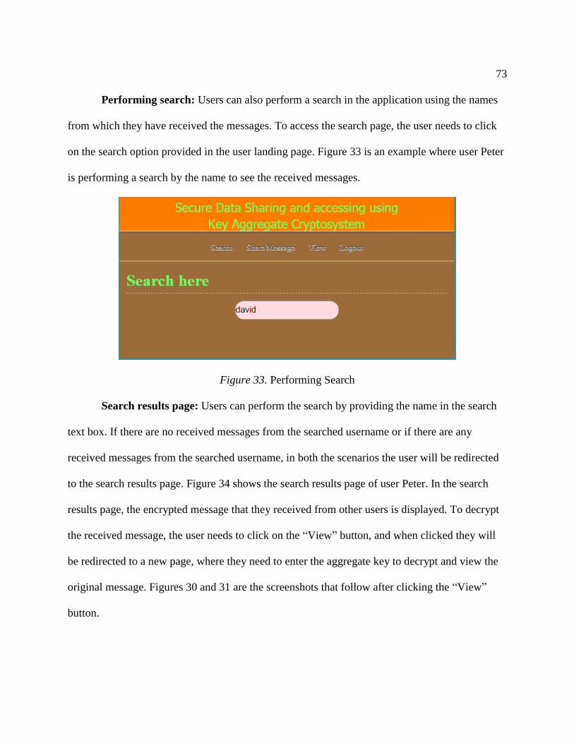
73
Performing search: Users can also perform a search in the application using the names
from which they have received the messages. To access the search page, the user needs to click
on the search option provided in the user landing page. Figure 33 is an example where user Peter
is performing a search by the name to see the received messages.
Figure 33. Performing Search
Search results page: Users can perform the search by providing the name in the search
text box. If there are no received messages from the searched username or if there are any
received messages from the searched username, in both the scenarios the user will be redirected
to the search results page. Figure 34 shows the search results page of user Peter. In the search
results page, the encrypted message that they received from other users is displayed. To decrypt
the received message, the user needs to click on the “View” button, and when clicked they will
be redirected to a new page, where they need to enter the aggregate key to decrypt and view the
original message. Figures 30 and 31 are the screenshots that follow after clicking the “View”
button.

74
Figure 34. Search Results Page

75
Chapter VI: System Design
UML Diagrams
UML Stands for Unified Modeling Language. UML is helpful in understanding and
visualizing any system. The system can be a software program or a non-software unit. It helps in
designing, modeling and getting the artifacts required for a system before it is developed or
during the development process. It helps to understand the architecture, structural, and
behavioral implementations of a software program. It can be applied in any phase of a software
development lifecycle which helps to identify the requirements and to get the resources that are
needed. It is a pictorial language that allows creating software blueprints (Tutorials Point, n.d.-b
n.d.). It helps the business analysts, software architects, and developers to specify, describe,
visualize, design and to document the existing or new business scenarios and to get the structural
and behavioral artifacts related to the system. UML diagrams are classified into two types: based
on the static behavior and dynamic behavior. In this section, the implementation using the
diagrams like activity diagrams, sequence diagrams, and use case diagrams is also discussed
along with the architectural design and the data flow of the system.
Architecture diagram. The architecture diagram shows the various components that are
involved in the system and their dependency on each other. The users, admin, and database are
the components that are involved, and each component performs a specific operation. The users
exchange messages between themselves. The information and keys are stored in the database,
and the admin can control users and view user details using the database. Figure 35 shows the
architecture of the system.

76
Figure 35. Architecture Diagram
Data flow diagram. Data flow diagram (DFD) is used to model a new system or an
existing system. DFD is a graphical representation of the flow of data for a particular system or
process (Data flow diagram, n.d.). It is also known as a bubble chart. It helps to visually
represent things that are hard to explain in words and thus can be used for technical and non-
technical people (Data flow, n.d.). It is used to identify various components that are present in
the system and their interactions with each other and layout external entities that interact with the
system and to map the flow of data in a system. Figure 36 describes the data flow for a sender. A
sender after successful registration and login can send the encrypted message to the receivers
along with the aggregate key. Figure 37 describes the data flow for the receiver. A receiver
receives the encrypted message along with the aggregate key, shared by the sender. The user
enters the key, followed by the decryption mechanism, which displays the original message to
the user.

77
Figure 36. Data Flow Sender

78
Figure 37. Data Flow Receiver
Use case diagram. A use case diagram is used to model the functionality of a system
using use cases and actors. A use case diagram is a simple representation of a system which
shows the relation between users and the use cases and the use cases in which the user is
involved, interacting with the system. A use case diagram can be useful to design a system from

79
the end user's perspective. It only summarizes the relationship between the use cases, actors, and
the system but not show the internal mechanism or steps involved. The scope of the use case
diagram is to capture (Tutorials Point, n.d.-c) requirements of a system, validate a systems
architecture and to specify the context of the system involved. The use case diagram consists of
the following components:
Actor: An actor is the one who interacts with the system using some use cases. In a
use case diagram, the actor is represented using a stick figure.
Use case: A use case is a methodology used in which the system requirements are
analyzed and gathered. Every actor involved in the use case diagram is linked to a
specific use case.
Figure 38 shows the use case diagram, showing the interaction of two users with the
system and the set of use cases involved.

80
Figure 38. Use Case Diagram
Sequence diagram. A sequence diagram is used to show the high-level interaction
between the objects that are present in a system and how the operations are carried out within a
time sequence. It is a type of interaction diagram. Sequence diagrams are useful for the business
and developers to understand the requirements of a new system or an existing one. These are
sometimes referred as event diagrams or event scenarios. Different parts combine to form a
sequence diagram.

81
Actors: Actors are the entities or persons that interact with a system and are external
to a system.
Objects: Objects are the instances of a class which are arranged horizontally. Usually,
they represented by a rectangle box with a name and followed by a semicolon
Lifeline: Lifeline is represented by a downward line that projects the sequential
events that happen to an object during the interactions.
Activation: Activation is represented by a solid rectangle box on the lifeline, which
shows the active time of the objects where it interacts with the system.
Messages: The arrow lines between the objects, where objects interact with each
other either synchronously or asynchronously. All of these components constitute the
sequence diagram. Figure 39 shows the sequence diagram where different objects are
interacting with each other.
Figure 39. Sequence Diagram

82
Activity diagram. Activity diagrams are used to represent step-by-step the flow of a
working of a system. They also serve dynamic aspects of a system. These are an advanced form
of flow charts. They are used to represent the flow of data between one operation to another
operation. They are primarily used to describe the complete flow of operations in a system and
what happens after one operation and then another. Activity diagrams are constructed using a
limited number of shapes where the rounded rectangle represents the action state, the black circle
represents the start of a process, and the encircled black circle represents the final node or end of
the process. The bars that are used to describe the fork and join operations that happen in a
system.
Figure 40 shows the activity diagram and the activities that happen after a user is
registered. After successful registration, the key generation takes place and keys are generated
for each user, followed by the ElGamal encryption and decryption process to generate the
aggregate key.

83
Figure 40. Activity Diagram

84
Chapter VII: Testing
Any application that is developed needs to be tested before it is used in the real world.
Testing is essential to make sure that the developed application is working according to the
desired requirement. Testing ensures the quality and suitability of the application. It helps to
identify the defects, which are not found during the development phase by the programmers.
This helps them to correct the code and making sure that the application is fit for use. Testing is a
continuous verification and validation process.
Testing Types
There are many testing types, where each of them is used during a particular time of the
development process or after that. Some of the testing types are as follows:
Unit Testing
Integration testing
Functional testing
Black box testing
White box testing
Stress testing
Performance testing
Usability testing
Acceptance testing
Regression testing
Each of the above testing types has their advantage and helps to identify the bugs. A brief
overview regarding these is as follows:

85
Unit testing. Unit testing is performed by the developer, during the development
process of a feature. Developers perform the unit testing using the testing snippet for
a function, to make sure that it is working correctly, by providing a valid input and
thereby verifying the desired output. Performing unit testing is a best practice, and it
also makes sure that there is 100% code coverage. Unit testing falls into the category
of white-box testing.
Integration testing. Integration testing ensures that all of the developed individual
components when combined work accordingly. This testing is also performed by
developers to ensure that all the components of an application work properly when
combined and there is no breakage of code. An example for this is, when a request is
passed to a web-service for any feature, it produces a response as an output. When the
database is queried to access the data related to the same functionality, the
information presented should be identical. This kind of testing is essential to test the
modules that are present in different networks. Integration testing is a form of both
black box testing and white box testing.
Functional testing. Functional testing ensures that the functionality of a developed
function is working correctly. To verify this, input data which is accepted by that
function is passed and an expected output is desired. Functional testing is an example
of white box testing.
White box testing. White box testing mainly focuses on the internal mechanism of a
system and verifies all the functions in the system works as expected. It is also known
as glass box testing or transparent testing or structural testing. It validates the internal

86
code of the system. The appropriate input paths are chosen from the code base for the
application and testing will be done according to that.
Black box testing. Black box testing, in contrast to white box testing, neglects the
internal workflow of the system and concentrates on the output of the system. The
name is given because, the internal software or code is like a black box to the tester,
which they cannot see. The black box testing can be classified into functional and
non-functional tests, but most of the time they are functional. The advantage of the
black box testing is that they can be done irrespective of the developer’s area and
there is no bias. Also, the tester does not need programming language knowledge to
test and it can be tested from the users’ perspective according to specifications and
listed objectives. They can start working when a component is developed. To
summarize, white box testing is used for verification, and black box testing is used for
validation.
Stress testing. Stress testing is a form of black box testing, and it is mainly used to
test an application under immense pressure by providing unfavorable conditions like
substantial input, more overload, and continuous requests. Many e-commerce sites
use this mechanism to see how their application works when a large number of users
access the site for a given period and at the same time.
Performance testing. Performance testing is used to test the effectiveness, speed and
fast data retrieval of a system and to check whether the system is generating results
within a specific time period which meets its performance requirements. Load testing,

87
stress testing, endurance testing, and spike testing are types of performance testing.
This comes under black box testing.
Usability testing. Usability testing is a type of black box testing, to ensure how the
developed product is easy to use. Testing is done from the end user's perspective to
test the ease of use, ability to learn and understand, the design of the application, the
attractiveness of the GUI and operational capability. This is very useful to check
whether the developed application meets the client's requirements.
Regression testing. Regression testing is essential testing that is performed in the
software environment. It is mainly used to check any new enhancements,
modifications or fixes have not broken the existing code and to check everything
works accordingly. It can be done during any phase of the testing process. It does not
involve writing new test cases, but the old ones are rerun to see if there are any
changes. Regression tests help to identify the coverage area of the tests. In an agile IT
environment, regression testing is of high value. Usually, there are many automation
tools which are available, and they are used to do the testing. Daily, weekly, and
monthly regression runs are performed, the reports are generated, and the results are
analyzed.
Acceptance testing. Acceptance testing is done by the end users where the developed
project is according to the business requirements. It is also referred to as user
acceptance testing. It is the last level of testing performed. The end users may conduct
themselves or customers of the organization or internal members of an organization.

88
Testing Implemented for the Project
1. Tested the UI fields accepting input for the username and password.
2. Tested the UI fields accepting input for the admin login and password.
3. Tested proper login, logout mechanism for admin and users.
4. Tested proper authentication of admin and users and displaying error messages.
5. Tested the data workflow between different pages.
6. Tested user options and pages displayed for each user.
7. Tested admin view options and pages that need to be displayed.
8. Tested proper database connection with inputs properly stored and displayed.
9. Tested fields in the pages available for users to provide data.
10. Tested encryption mechanism when user shares the data.
11. Tested generation of keys happening when the user shares the data.
12. Tested incoming messages, when user shares the message.
13. Tested decryption mechanism is happening when the user enters the appropriate key.
14. Tested the search functionality of the user to search using a different username.
15. Tested the application functionality in negative and positive scenarios.
All the scenarios have passed the tests and are working according to their designed
functionality.

89
Chapter VIII: Conclusion
Conclusion
In the present world, the sharing of the data between the users without any data leakage
has become a big challenge. Data sharing services are one of the essential functions provided in
cloud computing. Data in the cloud is of greater importance and needs to be protected from
unauthorized access. In this paper an efficient method is analyzed to avoid any data leakage.
Usually, the data is stored in an encrypted format, which will make the data storage in the cloud
more secure. However, the problem comes while sharing the encoded data and providing the
decryption rights to the users. An analysis and implementation are provided to share the
encrypted data to the end user. In this proposed implementation, encryption processes are done at
two places one at the time of storing and another at the time of sharing. The users who share their
secret messages should also need to know the decryption process. In the proposed paper, a set of
decryption keys are aggregated and sent to the end user. One must decrypt the data with the
aggregate key to see the original text. By this policy of encryption and decryption, it will
effectively increase the secure manner of communication and provides successful delegation of
decryption rights to the intended user over the ciphertexts that they are authorized to view. The
implemented application has been tested in various scenarios and executed successfully.
Limitations and Future Work
The limitation of the implemented system is that the aggregate key is sent directly to the
intended receiver along with the shared encrypted message. Although the key will only be sent to
the authorized user, an improvement for this can be transmitting the key through a secured
channel like an email. One of the limitations is the predefined bound concerning the maximum

90
number of ciphertext classes. For future work, enough ciphertext classes should be reserved
because when it is implemented in cloud storage, the number of ciphertexts increase rapidly. In
this implemented system, the ElGamal algorithm is used for encryption and decryption. In future,
more secure and efficient algorithms can be used to cope up with the speed and security
requirements. User revocation and access controls are important security measures implemented
in the cloud. An aggregate key system incorporated with user revocation (Gan, Wang, & Wu,
2017) provides enhanced security to the existing system. However, storing the assigned keys in a
mobile device with no trusted software may result in the disclosure of the key. Designing a
leakage resilient cryptosystem (Wang & Zhou, 2016) which provides efficient access of keys is
another area of future work. An Intrusion Detection System (IDS) can also be used to monitor
the network and to detect security breaches while sharing the data. Implementing a key aggregate
cryptosystem with an IDS is also an interesting direction of future work that can be investigated
(Kumari & Lakshmi, 2014).

91
References
Acunetix. (n.d.) XSSAttack. Retrieved from https://www.acunetix.com/websitesecurity/cross-
site-scripting/
Bachhav, S., Chaudhari, C., Shinde, N., & Kaloge, P. (2015). Secure multi-cloud data sharing
using key aggregate cryptosystem for scalable data sharing. International Journal of
Computer Science and Information Technologies, 6(5), 4479-4482.
Benaloh, J. (2009). Key compression and its application to digital fingerprinting. Technical
Report, Microsoft Research.
Chu, C. K., Chow, S. S., Tzeng, W. G., Zhou, J., & Deng, R. H. (2014). Key-aggregate
cryptosystem for scalable data sharing in cloud storage. IEEE Transactions on Parallel
and Distributed Systems, 25(2), 468-477.
Cui, B., Liu, Z., & Wang, L. (2016). Key-aggregate searchable encryption (KASE) for group
data sharing via cloud storage. IEEE Transactions on Computers,65(8).
Data flow diagram. (n.d.). In Wikipedia. Retrieved from
https://en.wikipedia.org/wiki/Data_flow_diagram
Data flow. (n.d.). In Wikipedia. Retrieved from https://www.lucidchart.com/pages/data-flow-
diagram
Gan, Q., Wang, X., & Wu, D. (2017). Revocable key-aggregate cryptosystem for data sharing in
cloud. Security and Communication Networks.
Guo, F., Mu, Y., & Chen, Z. (2007). Identity-based encryption: How to decrypt multiple
ciphertexts using a single decryption key. In Proceedings of Pairing-Based Cryptography
(Pairing ’07),4575, 392-406.

92
HTML Basics. (n.d.). Welcome to HTML basics. Retrieved from
https://www.austincc.edu/hr/profdev/eworkshops/docs/HTML_Basics.pdf
Hybrid cloud. (n.d.). In Wikipedia. Retrieved from
https://en.wikipedia.org/wiki/Cloud_computing
Jadhav, R., & Nargundi, S. (2014). Review on key-aggregate cryptosystem for scalable data
sharing in cloud storage. International Journal of Research in Engineering and
Technology, 376-379.
Jansen, W., & Grance, T. (2011). Guidelines on. NIST Special Publication, 800(144).
Kate, K., & Potdukhe, S. (2014). Data sharing in cloud storage with key-aggregate
cryptosystem. International Journal of Engineering Research and General Science,2(6),
882-886.
Kumar, S. N. (2015). Cryptography during data sharing and accessing over cloud. International
Transaction of Electrical and Computer Engineers System,3(1), 12-18. Retrieved from
http://pubs.sciepub.com/iteces/3/1/2
Kumari, G., & Lakshmi, M. (2014). Key aggregate cryptosystem & intrusion detection for data
sharing in cloud. Multidisciplinary Journal of Research in Engineering and
Technology,3(1), 308-317.
Mahalle, R. V., & Pawade, P. (2015). A review of secure data sharing in cloud using key
aggregate cryptosystem and decoy technology. International Journal of Science and
Research (IJSR),4(1), 210-213.
Mell, P., & Grance, T. (2009). The NIST definition of cloud computing. Retrieved from
https://www.nist.gov/sites/default/files/documents/itl/cloud/cloud-def-v15.pdf

93
More, V., & Singh, A. (2015). Key-aggregate crypto system for scalable data sharing in cloud
storage. International Journal on Emerging Technologies,6(2), 182-187.
Patranabis, S., & Mukhopadhyay, D. (2016). Identity-based key aggregate cryptosystem from
multilinear maps. Retrieved from https://eprint.iacr.org/2016/693
Patranabis, S., Shrivastava, Y., & Mukhopadhyay, D. (2017). Provably secure key-aggregate
cryptosystems with Broadcast Aggregate Keys for Online Data Sharing on the Cloud.
IEEE Transactions on Computers,66(5).
Patranabis, S., Shrivastava, Y., & Mukhopadhyay, D. (2015). Dynamic key-aggregate
cryptosystem on elliptic curves for online data sharing. In Proceedings of International
Conference in Cryptology in India (pp. 25-44).
Revathi, B., & John, M. S. (2016). Secure sharing data using constant key size-aggregate key
system. In Proceedings of International Conference on Advanced Computing and
Communication Systems.
Sahai, A., & Waters, B. (2005). Fuzzy identity-based encryption. In R. Cramer (Ed.), Advances
in cryptology-EUROCRYPT, Vol. 3494, pp. 1-15.
Sandhu, R. S. (1988). Cryptographic implementation of a tree hierarchy for access control.
Information Processing Letters, 27(2), 95-98.
Tutorials Point. (n.d.-a) Servlets overview. Retrieved from
https://www.tutorialspoint.com/servlets/servlets_overview.htm
Tutorials Point. (n.d.-b). UML tutorial point. Retrieved from
https://www.tutorialspoint.com/uml/uml_overview.htm

94
Tutorials Point. (n.d.-c). UML Use case. Retrieved from
https://www.tutorialspoint.com/uml/uml_use_case_diagram.htm
Vanitha, R., & Elavarasi, V. (2014). An aggregate key based cryptosystem for secure data
sharing in cloud computing. International Journal of Computer Science and Mobile
Computing, 3(4), 547-557.
Wang, Z., & Zhou, L. (2016). Leakage-resilient key-aggregate cryptosystem with auxiliary input.
In Computer Communication and Networks 2016 International Conference.