data-over-cable service interface specifications docsis
TRANSCRIPT
Data-Over-Cable Service Interface Specifications DOCSIS® 3.1
CCAP™ Operations Support System Interface Specification
CM-SP-CCAP-OSSIv3.1-I11-171220
ISSUED
Notice
This DOCSIS specification is the result of a cooperative effort undertaken at the direction of Cable Television Laboratories, Inc. for the benefit of the cable industry and its customers. You may download, copy, distribute, and reference the documents herein only for the purpose of developing products or services in accordance with such documents, and educational use. Except as granted by CableLabs® in a separate written license agreement, no license is granted to modify the documents herein (except via the Engineering Change process), or to use, copy, modify or distribute the documents for any other purpose.
This document may contain references to other documents not owned or controlled by CableLabs®. Use and understanding of this document may require access to such other documents. Designing, manufacturing, distributing, using, selling, or servicing products, or providing services, based on this document may require intellectual property licenses from third parties for technology referenced in this document. To the extent this document contains or refers to documents of third parties, you agree to abide by the terms of any licenses associated with such third-party documents, including open source licenses, if any.
Cable Television Laboratories, Inc. 2014-2017
CM-SP-CCAP-OSSIv3.1-I11-171220 Data-Over-Cable Service Interface Specifications
2 CableLabs® 12/20/17
DISCLAIMER
This document is furnished on an "AS IS" basis and neither CableLabs nor its members provides any representation or warranty, express or implied, regarding the accuracy, completeness, noninfringement, or fitness for a particular purpose of this document, or any document referenced herein. Any use or reliance on the information or opinion in this document is at the risk of the user, and CableLabs and its members shall not be liable for any damage or injury incurred by any person arising out of the completeness, accuracy, or utility of any information or opinion contained in the document.
CableLabs reserves the right to revise this document for any reason including, but not limited to, changes in laws, regulations, or standards promulgated by various entities, technology advances, or changes in equipment design, manufacturing techniques, or operating procedures described, or referred to, herein.
This document is not to be construed to suggest that any company modify or change any of its products or procedures, nor does this document represent a commitment by CableLabs or any of its members to purchase any product whether or not it meets the characteristics described in the document. Unless granted in a separate written agreement from CableLabs, nothing contained herein shall be construed to confer any license or right to any intellectual property. This document is not to be construed as an endorsement of any product or company or as the adoption or promulgation of any guidelines, standards, or recommendations.
CCAP™ Operations Support System Interface Specification CM-SP-CCAP-OSSIv3.1-I11-171220
12/20/17 CableLabs 3
Document Status Sheet
Document Control Number: CM-SP-CCAP-OSSIv3.1-I11-171220
Document Title: CCAP™ Operations Support System Interface Specification
Revision History: I01 - Released 08/08/2014 I02 - Released 11/20/2014 I03 - Released 03/26/2015 I04 - Released 06/11/2015 I05 - Released 09/10/2015 I06 - Released 12/10/2015 I07 - Released 06/02/2016 I08 - Released 01/11/2017 I09 - Released 05/10/2017 I10 - Released 09/06/2017 I11 - Released 12/20/2017
Date: December 20, 2017
Status: Work in Progress
Draft Issued Closed
Distribution Restrictions: Author Only CL/Member CL/ Member/ Vendor
Public
Key to Document Status Codes
Work in Progress An incomplete document, designed to guide discussion and generate feedback that may include several alternative requirements for consideration.
Draft A document in specification format considered largely complete, but lacking review by Members and vendors. Drafts are susceptible to substantial change during the review process.
Issued A generally public document that has undergone Member and Technology Supplier review, cross-vendor interoperability, and is for Certification testing if applicable. Issued Specifications are subject to the Engineering Change Process.
Closed A static document, reviewed, tested, validated, and closed to further engineering change requests to the specification through CableLabs.
Trademarks CableLabs® is a registered trademark of Cable Television Laboratories, Inc. Other CableLabs marks are listed at http://www.cablelabs.com/certqual/trademarks. All other marks are the property of their respective owners.
CM-SP-CCAP-OSSIv3.1-I11-171220 Data-Over-Cable Service Interface Specifications
4 CableLabs® 12/20/17
Table of Contents 1 SCOPE .............................................................................................................................................................. 25
1.1 Introduction and Purpose ........................................................................................................................... 25 1.2 Background ................................................................................................................................................ 25
1.2.1 Broadband Access Network ............................................................................................................... 25 1.2.2 Network and System Architecture ...................................................................................................... 25 1.2.3 Service Goals ..................................................................................................................................... 28 1.2.4 Statement of Compatibility ................................................................................................................. 28 1.2.5 DOCSIS 3.1 Documents ..................................................................................................................... 28
1.3 Requirements ............................................................................................................................................. 28 1.4 Conventions ............................................................................................................................................... 29 1.5 Organization of Document ......................................................................................................................... 29
1.5.1 Annexes (Normative) .......................................................................................................................... 30 1.5.2 Appendices (Informative) ................................................................................................................... 30
2 REFERENCES................................................................................................................................................. 31 2.1 Normative References ................................................................................................................................ 31 2.2 Informative References .............................................................................................................................. 35 2.3 Reference Acquisition ................................................................................................................................ 37
3 TERMS AND DEFINITIONS ........................................................................................................................ 38
4 ABBREVIATIONS, ACRONYMS, AND NAMESPACES .......................................................................... 41 4.1 XML Namespaces ...................................................................................................................................... 46
5 OVERVIEW ..................................................................................................................................................... 48 5.1 FCAPS Network Management Model ....................................................................................................... 48
5.1.1 Fault Management ............................................................................................................................. 48 5.1.2 Configuration Management ............................................................................................................... 49 5.1.3 Accounting Management .................................................................................................................... 50 5.1.4 Performance Management ................................................................................................................. 51 5.1.5 Security Management ......................................................................................................................... 51
5.2 Management Architectural Overview ........................................................................................................ 51 5.3 DOCSIS 3.1 OSSI Key Features ................................................................................................................ 52
5.3.1 Fault Management Features .............................................................................................................. 53 5.3.2 Configuration Management Features ................................................................................................ 53 5.3.3 Performance Management Features .................................................................................................. 53
5.4 Information Models ................................................................................................................................... 53
6 CONFIGURATION MANAGEMENT .......................................................................................................... 55 6.1 CCAP Configuration Theory of Operation ................................................................................................ 55 6.2 CCAP Configuration and Transport Protocol Requirements ..................................................................... 55
6.2.1 Configuration Object Datastore ........................................................................................................ 55 6.2.2 DHCP Relay Agent Requirements ..................................................................................................... 55 6.2.3 Dynamic Management of QAMs ........................................................................................................ 56 6.2.4 Video Configuration Requirements .................................................................................................... 56 6.2.5 DOCSIS Configuration Requirements ............................................................................................... 56
6.3 CCAP XML File-Based Configuration ...................................................................................................... 56 6.3.1 CCAP XML Configuration File Theory of Operation ........................................................................ 56 6.3.2 CCAP XML Configuration Files ........................................................................................................ 57 6.3.3 XML Configuration File Checksum ................................................................................................... 58 6.3.4 XML Configuration File Validation ................................................................................................... 58 6.3.5 XML Configuration File Execution Command and NETCONF Operations ...................................... 59 6.3.6 XML Configuration File Parsing and Error Logging ........................................................................ 61
CCAP™ Operations Support System Interface Specification CM-SP-CCAP-OSSIv3.1-I11-171220
12/20/17 CableLabs 5
6.3.7 File Transfer Mechanisms ................................................................................................................. 62 6.3.8 Exporting the Configuration Object Data Store ................................................................................ 64
6.4 CCAP NETCONF-Based Configuration ................................................................................................... 64 6.4.1 NETCONF Theory of Operation ........................................................................................................ 64 6.4.2 NETCONF Overview ......................................................................................................................... 65 6.4.3 NETCONF Requirements ................................................................................................................... 66
6.5 CCAP Data Type Definitions .................................................................................................................... 66 6.5.1 AdminState ......................................................................................................................................... 69 6.5.2 AttrAggrRuleMask ............................................................................................................................. 69 6.5.3 AttributeMask ..................................................................................................................................... 69 6.5.4 BitRate ............................................................................................................................................... 69 6.5.5 ChannelList ........................................................................................................................................ 70 6.5.6 ChChgInitTechMap ............................................................................................................................ 70 6.5.7 ChId ................................................................................................................................................... 70 6.5.8 ChSetId ............................................................................................................................................... 70 6.5.9 CmtsCmRegState ................................................................................................................................ 70 6.5.10 Dsid .................................................................................................................................................... 72 6.5.11 DsOfdmCyclicPrefixType ................................................................................................................... 72 6.5.12 DsOfdmModulationType .................................................................................................................... 72 6.5.13 DsOfdmSubcarrierSpacingType ........................................................................................................ 72 6.5.14 DsOfdmWindowingType .................................................................................................................... 73 6.5.15 HePidValue ........................................................................................................................................ 73 6.5.16 Host .................................................................................................................................................... 73 6.5.17 HundredthdB ...................................................................................................................................... 73 6.5.18 ifDirection .......................................................................................................................................... 73 6.5.19 IpAddress ........................................................................................................................................... 73 6.5.20 InetAddressPrefixLength .................................................................................................................... 73 6.5.21 InetIpPrefix ........................................................................................................................................ 73 6.5.22 InetIpv4Prefix .................................................................................................................................... 73 6.5.23 InetIpv6Prefix .................................................................................................................................... 74 6.5.24 InetPortNum ....................................................................................................................................... 74 6.5.25 InetHost .............................................................................................................................................. 74 6.5.26 IPHostPrefix ...................................................................................................................................... 74 6.5.27 Ipv4HostPrefix ................................................................................................................................... 74 6.5.28 Ipv6HostPrefix ................................................................................................................................... 74 6.5.29 NodeName .......................................................................................................................................... 74 6.5.30 PartialChannelType ........................................................................................................................... 75 6.5.31 PartialChanReasonType .................................................................................................................... 75 6.5.32 PartialServiceType ............................................................................................................................. 75 6.5.33 PartialServiceReasonType ................................................................................................................. 75 6.5.34 PrimaryDsIndicatorType ................................................................................................................... 75 6.5.35 QuarterdB .......................................................................................................................................... 76 6.5.36 RcpId .................................................................................................................................................. 76 6.5.37 SchedulingType .................................................................................................................................. 76 6.5.38 TenthdB .............................................................................................................................................. 76 6.5.39 ThousandthdB .................................................................................................................................... 76 6.5.40 TriggerFlag ........................................................................................................................................ 76 6.5.41 UpDownTrapEnabled ........................................................................................................................ 76 6.5.42 UsOfdmaCyclicPrefixType ................................................................................................................. 77 6.5.43 UsOfdmaModulationType .................................................................................................................. 77 6.5.44 UsOfdmaWindowingSizeType ............................................................................................................ 77
6.6 UML Configuration Object Model ............................................................................................................ 77 6.6.1 CCAP UML Configuration Object Model Overview ......................................................................... 77 6.6.2 Vendor-Specific Extensions ................................................................................................................ 78 6.6.3 CCAP Configuration Objects ............................................................................................................. 79 6.6.4 CCAP Chassis Objects ....................................................................................................................... 81
CM-SP-CCAP-OSSIv3.1-I11-171220 Data-Over-Cable Service Interface Specifications
6 CableLabs® 12/20/17
6.6.5 CCAP Video Session Configuration Objects ..................................................................................... 91 6.6.6 DOCSIS Configuration Objects ....................................................................................................... 112 6.6.7 CCAP Network Configuration Objects ............................................................................................ 210 6.6.8 Interface Configuration Objects ...................................................................................................... 226 6.6.9 Management Configuration Objects ................................................................................................ 233 6.6.10 CCAP EPON Configuration Objects ............................................................................................... 248
6.7 Status Monitoring and Control Requirements .......................................................................................... 250 6.7.1 Status Monitoring and Control UML Object Models ....................................................................... 250
7 PERFORMANCE MANAGEMENT ........................................................................................................... 257 7.1 Performance Management Requirements and Transport Protocols ......................................................... 257
7.1.1 SNMP and MIB Requirements ......................................................................................................... 257 7.2 Performance Management UML Object Models ..................................................................................... 280
7.2.1 State Data Objects ........................................................................................................................... 281 7.2.2 Statistical Data Objects ................................................................................................................... 345
7.3 Proactive Network Maintenance Object Model ....................................................................................... 393 7.3.1 Overview .......................................................................................................................................... 393 7.3.2 Data Type Definitions ...................................................................................................................... 394 7.3.3 PNM Common Information Model ................................................................................................... 396 7.3.4 PNM Downstream Object Model ..................................................................................................... 397 7.3.5 PNM Upstream Object Models ........................................................................................................ 402 7.3.6 CCAP Bulk Data Transfer ............................................................................................................... 431 7.3.7 Triggering OPT Messages ............................................................................................................... 434
7.4 IPDR ........................................................................................................................................................ 444 7.4.1 IPDR Service Definitions ................................................................................................................. 444
8 ACCOUNTING MANAGEMENT ............................................................................................................... 445 8.1 SAMIS ..................................................................................................................................................... 445
8.1.1 Subscriber Usage Billing and class of services ............................................................................... 445 8.1.2 DOCSIS Subscriber Usage Billing Requirements ............................................................................ 449
8.2 IPDR Protocol .......................................................................................................................................... 449 8.2.1 Introduction ..................................................................................................................................... 449 8.2.2 IP Detail Record (IPDR) Standard .................................................................................................. 449 8.2.3 IPDR Streaming Model .................................................................................................................... 453 8.2.4 CCAP IPDR Specifications Support ................................................................................................ 462 8.2.5 Requirements for IPv6 ..................................................................................................................... 464 8.2.6 Data Collection Methodologies for DOCSIS IPDR Service Definitions .......................................... 464 8.2.7 IPDR Streaming Protocol Security Model ....................................................................................... 464
8.3 IPDR Service Definition Schemas ........................................................................................................... 464 8.3.1 Requirements for DOCSIS SAMIS Service Definitions .................................................................... 466 8.3.2 Requirements for DOCSIS Spectrum Measurement Service Definition ........................................... 467 8.3.3 Requirements for DOCSIS Diagnostic Log Service Definitions ...................................................... 468 8.3.4 Requirements for DOCSIS CMTS CM Registration Status Service Definition ................................ 468 8.3.5 Requirements for DOCSIS CMTS CM Upstream Status Service Definition .................................... 468 8.3.6 Requirements for DOCSIS CMTS Topology Service Definition ...................................................... 469 8.3.7 Requirements for DOCSIS CPE Service Definition ......................................................................... 469 8.3.8 Requirements for DOCSIS CMTS Upstream Utilization Statistics Service Definition .................... 469 8.3.9 Requirements for DOCSIS CMTS Downstream Utilization Statistics Service Definition ................ 469 8.3.10 Requirements for DOCSIS CMTS CM Service Flow Service Definition.......................................... 470 8.3.11 Requirements for IP Multicast Statistics Service Definition ............................................................ 470 8.3.12 Requirements for DOCSIS CMTS CM Downstream OFDM Service Definition .............................. 470 8.3.13 Requirements for DOCSIS CMTS CM Downstream OFDM Profile Service Definition .................. 471 8.3.14 Requirements for DOCSIS CMTS CM Upstream OFDMA Service Definition ................................ 471 8.3.15 Requirements for DOCSIS CMTS CM Upstream OFDMA Profile Service Definition .................... 471 8.3.16 Requirements for DOCSIS Downstream OFDM Profile Statistics Service Definition .................... 472 8.3.17 Requirements for DOCSIS Upstream OFDMA Profile Statistics Service Definition ....................... 472
CCAP™ Operations Support System Interface Specification CM-SP-CCAP-OSSIv3.1-I11-171220
12/20/17 CableLabs 7
8.3.18 Requirements for Auxiliary Schemas ............................................................................................... 472
9 FAULT MANAGEMENT AND REPORTING REQUIREMENTS......................................................... 473 9.1 Fault Management Requirements and Transport Protocols ..................................................................... 473 9.2 Event Reporting ....................................................................................................................................... 473
9.2.1 SNMP Usage .................................................................................................................................... 473 9.2.2 Event Notification ............................................................................................................................ 473 9.2.3 Event Priorities and Vendor-Specific Events ................................................................................... 478 9.2.4 NETCONF Notifications .................................................................................................................. 479 9.2.5 Trap and Syslog Throttling, Limiting and Inhibiting ....................................................................... 479 9.2.6 Non-SNMP Fault Management Protocols ....................................................................................... 479
9.3 Fault Management UML Object Model ................................................................................................... 479 9.3.1 Event Notification Objects ............................................................................................................... 479
ANNEX A DETAILED MIB REQUIREMENTS (NORMATIVE) ............................................................. 482 A.1 MIB Object Details .................................................................................................................................. 482 A.2 CCAP-MIB Object Details ...................................................................................................................... 530 A.3 HMS-MIB Object Details ........................................................................................................................ 531 A.4 PNM MIB Object Details ........................................................................................................................ 535
ANNEX B IPDR FOR DOCSIS CABLE DATA SYSTEMS SUBSCRIBER USAGE BILLING RECORDS (NORMATIVE) ................................................................................................................................. 540
B.1 Service Definition .................................................................................................................................... 540 B.1.1 DOCSIS Service Requirements ........................................................................................................ 540 B.1.2 SAMIS Usage Attribute List ............................................................................................................. 541
B.2 IPDR Service Definition Schemas ........................................................................................................... 542
ANNEX C AUXILIARY SCHEMAS FOR DOCSIS IPDR SERVICE DEFINITIONS (NORMATIVE)543 C.1 Overview .................................................................................................................................................. 543 C.2 XML Semantics ....................................................................................................................................... 543
C.2.1 Import Element................................................................................................................................. 543 C.2.2 Element References .......................................................................................................................... 543
C.3 CMTS Information................................................................................................................................... 544 C.3.1 CmtsHostName ................................................................................................................................ 544 C.3.2 CmtsSysUpTime ............................................................................................................................... 544 C.3.3 CmtsIpv4Addr .................................................................................................................................. 544 C.3.4 CmtsIpv6Addr .................................................................................................................................. 544 C.3.5 CmtsMdIfName ................................................................................................................................ 545 C.3.6 CmtsMdIfIndex ................................................................................................................................. 545
C.4 CM Information Schema .......................................................................................................................... 545 C.5 Record Information .................................................................................................................................. 545
C.5.1 RecType ............................................................................................................................................ 545 C.5.2 RecCreationTime ............................................................................................................................. 545
C.6 QoS Information ...................................................................................................................................... 546 C.6.1 ServiceFlowChSet ............................................................................................................................ 546 C.6.2 ServiceAppId .................................................................................................................................... 546 C.6.3 ServiceDsMulticast .......................................................................................................................... 546 C.6.4 ServiceIdentifier ............................................................................................................................... 546 C.6.5 ServiceGateId ................................................................................................................................... 546 C.6.6 ServiceClassName ............................................................................................................................ 546 C.6.7 ServiceDirection .............................................................................................................................. 547 C.6.8 ServiceOctetsPassed ........................................................................................................................ 547 C.6.9 ServicePktsPassed ............................................................................................................................ 547 C.6.10 ServiceSlaDropPkts ......................................................................................................................... 547 C.6.11 ServiceSlaDelayPkts ........................................................................................................................ 547 C.6.12 ServiceTimeCreated ......................................................................................................................... 548
CM-SP-CCAP-OSSIv3.1-I11-171220 Data-Over-Cable Service Interface Specifications
8 CableLabs® 12/20/17
C.6.13 ServiceTimeActive ............................................................................................................................ 548 C.7 CPE Information ...................................................................................................................................... 548
C.7.1 CpeMacAddr .................................................................................................................................... 548 C.7.2 CpeIpv4AddrList .............................................................................................................................. 548 C.7.3 CpeIpv6AddrList .............................................................................................................................. 549 C.7.4 CpeFqdn ........................................................................................................................................... 549
C.8 Spectrum Measurement Information ........................................................................................................ 549 C.9 Diagnostic Log Information ..................................................................................................................... 549 C.10 CMTS CM Upstream Status Information ............................................................................................ 549 C.11 CMTS CM Node Channel Information ................................................................................................ 549 C.12 CMTS MAC Domain Node Information ............................................................................................. 549 C.13 CMTS Upstream Utilization Information ............................................................................................ 549
C.13.1 IfIndex .............................................................................................................................................. 550 C.13.2 ifName .............................................................................................................................................. 550 C.13.3 UsChId ............................................................................................................................................. 550 C.13.4 Interval ............................................................................................................................................. 550 C.13.5 IndexPercentage .............................................................................................................................. 550 C.13.6 TotalMslots ...................................................................................................................................... 551 C.13.7 UcastGrantedMslots ........................................................................................................................ 551 C.13.8 TotalCntnMslots ............................................................................................................................... 551 C.13.9 UsedCntnMslots ............................................................................................................................... 551 C.13.10 CollCntnMslots ............................................................................................................................ 551 C.13.11 TotalCntnReqMslots..................................................................................................................... 551 C.13.12 UsedCntnReqMslots ..................................................................................................................... 551 C.13.13 CollCntnReqMslots ...................................................................................................................... 551 C.13.14 TotalCntnReqDataMslots ............................................................................................................. 552 C.13.15 UsedCntnReqDataMslots ............................................................................................................. 552 C.13.16 CollCntnReqDataMslots .............................................................................................................. 552 C.13.17 TotalCntnInitMaintMslots ............................................................................................................ 552 C.13.18 UsedCntnInitMaintMslots ............................................................................................................ 552 C.13.19 CollCntnInitMaintMslots ............................................................................................................. 552
C.14 CMTS Downstream Utilization Information ....................................................................................... 552 C.14.1 IfIndex .............................................................................................................................................. 553 C.14.2 IfName .............................................................................................................................................. 553 C.14.3 DsChId ............................................................................................................................................. 553 C.14.4 Interval ............................................................................................................................................. 553 C.14.5 IndexPercentage .............................................................................................................................. 553 C.14.6 TotalBytes ........................................................................................................................................ 553 C.14.7 UsedBytes ......................................................................................................................................... 553
C.15 Service Flow Information .................................................................................................................... 553 C.15.1 ServiceTrafficPriority ...................................................................................................................... 554 C.15.2 ServiceMaxSustained ....................................................................................................................... 554 C.15.3 ServiceMaxBurst .............................................................................................................................. 554 C.15.4 ServiceMinReservedRate ................................................................................................................. 554 C.15.5 ServiceMinReservedPktSize ............................................................................................................. 554 C.15.6 ServiceIpTos ..................................................................................................................................... 554 C.15.7 ServicePeakRate .............................................................................................................................. 555 C.15.8 ServiceSchedule ............................................................................................................................... 555 C.15.9 ServiceNomPollInterval ................................................................................................................... 555 C.15.10 ServiceTolPollJitter ..................................................................................................................... 555 C.15.11 ServiceUGSize .............................................................................................................................. 555 C.15.12 ServiceNomGrantInterval ............................................................................................................ 555 C.15.13 ServiceTolGrantJitter ................................................................................................................... 555 C.15.14 ServiceGrantsPerInterval ............................................................................................................ 555 C.15.15 ServicePacketClassifiers .............................................................................................................. 555
C.16 IP Multicast Information ...................................................................................................................... 555
CCAP™ Operations Support System Interface Specification CM-SP-CCAP-OSSIv3.1-I11-171220
12/20/17 CableLabs 9
C.16.1 IpMcastSrcIpv4Addr ........................................................................................................................ 556 C.16.2 IpMcastSrcIpv6Addr ........................................................................................................................ 556 C.16.3 IpMcastGrpIpv4Addr ....................................................................................................................... 556 C.16.4 IpMcastGrpIpv6Addr ....................................................................................................................... 556 C.16.5 IpMcastGsfId.................................................................................................................................... 556 C.16.6 IpMcastDsid ..................................................................................................................................... 556 C.16.7 IpMcastSessionProtocolType ........................................................................................................... 556 C.16.8 IpMcastCpeMacAddrList ................................................................................................................. 556 C.16.9 IpMcastJoinTime .............................................................................................................................. 556 C.16.10 IpMcastLeaveTime ....................................................................................................................... 556
C.17 CMTS CM Downstream OFDM Information ...................................................................................... 557 C.18 CMTS CM Partial Channel/Service Information ................................................................................. 557 C.19 CMTS CM Upstream OFDMA Information ........................................................................................ 557 C.20 OFDM Profile Status Information ....................................................................................................... 557
ANNEX D FORMAT AND CONTENT FOR EVENT, SYSLOG, AND SNMP NOTIFICATION (NORMATIVE) ..................................................................................................................................................... 558
D.1 Deprecated Events ................................................................................................................................... 586 D.2 Example SNMP Notification and Syslog Event Message ........................................................................ 588
ANNEX E EXTENDING THE CONFIGURATION DATA MODEL (NORMATIVE) ........................... 589 E.1 XML Schema Extension .......................................................................................................................... 589
E.1.1 Sample Vendor-Specific XSD Extensions ......................................................................................... 589 E.2 YANG Configuration Model Extension .................................................................................................. 592
E.2.1 YANG Extension Principles ............................................................................................................. 592 E.2.2 Creating Vendor Extensions ............................................................................................................ 592 E.2.3 Example Vendor-Proprietary Extensions in YANG Configuration Messages ................................. 595
ANNEX F CCAP DATA TYPE DEFINITIONS (NORMATIVE) .............................................................. 597 F.1 Overview .................................................................................................................................................. 597 F.2 Data Types Mapping ................................................................................................................................ 597 F.3 Data Types Requirements and Classification........................................................................................... 597 F.4 Data Type Mapping Methodology ........................................................................................................... 597 F.5 General Data Types (SNMP and IPDR Mapping) ................................................................................... 598 F.6 Primitive Data Types (YANG Mapping) ................................................................................................. 599 F.7 Extended Data Types (SNMP and IPDR Mapping) ................................................................................. 599 F.8 Derived Data Types (YANG Mapping) ................................................................................................... 600
ANNEX G DIAGNOSTIC LOG (NORMATIVE) ......................................................................................... 601 G.1 Overview .................................................................................................................................................. 601 G.2 Object Definitions .................................................................................................................................... 601
G.2.1 Type Definitions ............................................................................................................................... 602 G.2.2 LogGlobal Object ............................................................................................................................. 603 G.2.3 LogTriggersCfg Object .................................................................................................................... 604 G.2.4 Log Object ........................................................................................................................................ 606 G.2.5 LogDetail Object .............................................................................................................................. 606
APPENDIX I SAMPLE CCAP XML CONFIGURATION (INFORMATIVE) .......................................... 608 I.1 CCAP XML Configuration File ............................................................................................................... 608 I.2 CCAP Partial Configuration .................................................................................................................... 655 I.3 Sample NETCONF Message Exchanges ................................................................................................. 655
I.3.1 Changes Made to running-config without Locks or Timeouts ............................................................. 655 I.3.2 Changes Made to candidate-config with a Lock .................................................................................. 656
APPENDIX II USE CASES (INFORMATIVE) ........................................................................................... 659 II.1 Identifying Replicated QAMs .................................................................................................................. 659
CM-SP-CCAP-OSSIv3.1-I11-171220 Data-Over-Cable Service Interface Specifications
10 CableLabs® 12/20/17
APPENDIX III VENDOR SCHEMA VERSION IN THE CCAP XSD (INFORMATIVE) ...................... 660
APPENDIX IV CONVERTING YANG TO XSD (INFORMATIVE) ......................................................... 661 IV.1 Using PYANG to Generate an XSD from the CCAP YANG Modules ................................................... 661 IV.2 Creating In-Line Data Types in the CCAP.XSD ..................................................................................... 661
APPENDIX V DOCSIS IPDR SAMPLE INSTANCE DOCUMENTS (INFORMATIVE) ..................... 663 V.1 Collector Aggregation .............................................................................................................................. 663 V.2 Schema Location ...................................................................................................................................... 663 V.3 DIAG-LOG-TYPE ................................................................................................................................... 663
V.3.1 Use Case .......................................................................................................................................... 663 V.3.2 Instance Document ........................................................................................................................... 663
V.4 DIAG-LOG-DETAIL-TYPE ................................................................................................................... 664 V.4.1 Use Case .......................................................................................................................................... 664 V.4.2 Instance Document ........................................................................................................................... 664
V.5 DIAG-LOG-EVENT-TYPE .................................................................................................................... 664 V.5.1 Use Case .......................................................................................................................................... 665 V.5.2 Instance Document ........................................................................................................................... 665
V.6 SPECTRUM-MEASUREMENT-TYPE .................................................................................................. 665 V.6.1 Use Case .......................................................................................................................................... 665 V.6.2 Instance Document ........................................................................................................................... 666
V.7 CMTS-CM-US-STATS-TYPE ................................................................................................................ 667 V.7.1 Use Case .......................................................................................................................................... 667 V.7.2 Instance Document ........................................................................................................................... 668
V.8 CMTS-CM-REG-STATUS-TYPE .......................................................................................................... 668 V.8.1 Use Case .......................................................................................................................................... 668 V.8.2 Instance Document ........................................................................................................................... 669
V.9 CMTS-TOPOLOGY-TYPE..................................................................................................................... 670 V.9.1 Use Case .......................................................................................................................................... 670 V.9.2 Instance Document ........................................................................................................................... 670
V.10 CPE-TYPE ........................................................................................................................................... 671 V.10.1 Use Case .......................................................................................................................................... 671 V.10.2 Instance Document ........................................................................................................................... 671
V.11 SAMIS-TYPE-1 and SAMIS-TYPE-2 ................................................................................................ 671 V.11.1 Use Case .......................................................................................................................................... 671 V.11.2 SAMIS Type 1 Instance Document ................................................................................................... 673 V.11.3 SAMIS Type 2 Instance Document ................................................................................................... 674
V.12 CMTS-US-UTIL-STATS-TYPE ......................................................................................................... 675 V.12.1 Use Case .......................................................................................................................................... 675 V.12.2 Instance Document ........................................................................................................................... 675
V.13 CMTS-DS-UTIL-STATS-TYPE ......................................................................................................... 676 V.13.1 Use Case .......................................................................................................................................... 676 V.13.2 Instance Document ........................................................................................................................... 677
V.14 CMTS-CM-SERVICE-FLOW-TYPE ................................................................................................. 677 V.14.1 Use Case .......................................................................................................................................... 677 V.14.2 Instance Document ........................................................................................................................... 678
APPENDIX VI SPECTRUM ANALYSIS USE CASES (INFORMATIVE) ............................................... 680 VI.1 Normalization of RF Impairments Measurements ................................................................................... 680
VI.1.1 Problem Description ........................................................................................................................ 680 VI.1.2 Use Cases ......................................................................................................................................... 680
VI.2 Upstream Spectrum Measurement Monitoring ........................................................................................ 682 VI.2.1 Problem Description ........................................................................................................................ 682 VI.2.2 Use Cases ......................................................................................................................................... 682
APPENDIX VII INFORMATION MODEL NOTATION (INFORMATIVE) ............................................ 687
CCAP™ Operations Support System Interface Specification CM-SP-CCAP-OSSIv3.1-I11-171220
12/20/17 CableLabs 11
VII.1 Overview .............................................................................................................................................. 687 VII.2 Information Model Diagram ................................................................................................................ 687
VII.2.1 Classes ............................................................................................................................................. 687 VII.2.2 Associations ..................................................................................................................................... 687 VII.2.3 Generalization.................................................................................................................................. 687 VII.2.4 Dependencies ................................................................................................................................... 688 VII.2.5 Comment .......................................................................................................................................... 688 VII.2.6 Diagram Notation ............................................................................................................................ 688
VII.3 Object Instance Diagram ...................................................................................................................... 688 VII.4 ObjectA Definition Example ............................................................................................................... 689 VII.5 Common Terms Shortened .................................................................................................................. 690
VII.5.1 Exceptions ........................................................................................................................................ 691
APPENDIX VIII ACKNOWLEDGMENTS (INFORMATIVE) ................................................................... 692
APPENDIX IX REVISION HISTORY .......................................................................................................... 693
List of Figures Figure 1 - The DOCSIS Network .............................................................................................................................. 26 Figure 2 - Data-over-Cable Reference Architecture .................................................................................................. 27 Figure 3 - CCAP Interface Reference Architecture ................................................................................................... 27 Figure 4 - Transparent IP Traffic through the Data-Over-Cable System ................................................................... 28 Figure 5 - Fault Management Use Cases ................................................................................................................... 49 Figure 6 - Configuration Management Use Cases ..................................................................................................... 50 Figure 7 - CMTS and CCAP Management Architecture ........................................................................................... 52 Figure 8 - CCAP XML File-Based Configuration Use Case ..................................................................................... 57 Figure 9 - CCAP NETCONF-Based Configuration Use Case ................................................................................... 65 Figure 10 - CCAP Configuration Objects .................................................................................................................. 79 Figure 11 - CCAP Chassis Objects ............................................................................................................................ 81 Figure 12 - CCAP Video Session Configuration Objects .......................................................................................... 91 Figure 13 - DOCSIS Configuration Objects ............................................................................................................ 113 Figure 14 - DOCSIS Security Configuration Objects .............................................................................................. 117 Figure 15 - DOCSIS Subscriber Management Configuration Objects .................................................................... 125 Figure 16 - DOCSIS QoS Configuration Objects .................................................................................................... 132 Figure 17 - DOCSIS Multicast QoS Configuration Objects .................................................................................... 140 Figure 18 - MAC Domain Configuration Objects ................................................................................................... 146 Figure 19 - DOCSIS Multicast Authorization Configuration Objects ..................................................................... 159 Figure 20 - DOCSIS Upstream Interface Configuration Objects ............................................................................ 164 Figure 21 - Downstream DOCSIS and Video Configuration Objects ..................................................................... 177 Figure 22 - DSG Configuration Objects .................................................................................................................. 189 Figure 23 - PacketCable Configuration Objects ...................................................................................................... 198 Figure 24 - Load Balance Configuration Objects .................................................................................................... 202 Figure 25 - CCAP Network Configuration Objects ................................................................................................. 210 Figure 26 - Interface Configuration Objects ............................................................................................................ 227 Figure 27 - Management Configuration Objects ..................................................................................................... 233 Figure 28 - Fault Management Configuration Objects ............................................................................................ 234 Figure 29 - SNMP Agent Configuration Objects ..................................................................................................... 240
CM-SP-CCAP-OSSIv3.1-I11-171220 Data-Over-Cable Service Interface Specifications
12 CableLabs® 12/20/17
Figure 30 - IPDR Configuration Objects ................................................................................................................. 244 Figure 31 - EPON Configuration Objects ................................................................................................................ 248 Figure 32 - Fault Management Control Objects ...................................................................................................... 250 Figure 33 - Performance Management Control and Monitoring Information Model .............................................. 251 Figure 34 - ifStack Table for CCAP RF Interfaces .................................................................................................. 269 Figure 35 - CMTS Bonding Performance Management Objects ............................................................................. 281 Figure 36 - RxCh Performance Management Objects ............................................................................................. 286 Figure 37 - DOCS-L2VPN-MIB: State Objects ...................................................................................................... 291 Figure 38 - DOCSIS Load Balance Status Information Model................................................................................ 292 Figure 39 - DOCS-MCAST-AUTH-MIB Performance Management Objects ........................................................ 298 Figure 40 - Figure 7-7 - DOCSIS QoS State Performance Management Information Model ................................. 302 Figure 41 - DOCS-SEC-MIB Performance Management Objects .......................................................................... 328 Figure 42 - DOCS-SUBMGT3-MIB Performance Management Objects ............................................................... 331 Figure 43 - CCAP Topology Performance Management Objects ............................................................................ 337 Figure 44 - CCAP-MIB Performance Management Objects ................................................................................... 339 Figure 45 - SCTE-HMS-MPEG-MIB: State Objects Performance Management Objects ...................................... 344 Figure 46 - DOCS-DRF-MIB Performance Management Objects .......................................................................... 345 Figure 47 - DOCS-IF-MIB Performance Management Objects .............................................................................. 346 Figure 48 - CMTS CM Status Information Model ................................................................................................... 347 Figure 49 - DOCS-L2VPN-MIB: Statistics Objects ................................................................................................ 359 Figure 50 - DOCS-MCAST-MIB Performance Management Objects .................................................................... 360 Figure 51 - DOCSIS QoS Statistical Performance Management Information Model ............................................. 365 Figure 52 - Upstream OFDMA Status Objects ........................................................................................................ 377 Figure 53 - Downstream OFDM Status Objects ...................................................................................................... 384 Figure 54 - DOCS-IF3-MIB Statistical Performance Management Information Model ......................................... 393 Figure 55 - PNM Common Information Model ....................................................................................................... 396 Figure 56 - Downstream PNM Object Model .......................................................................................................... 397 Figure 57 - Upstream PNM Information Model ...................................................................................................... 402 Figure 58 - Upstream Triggered Spectrum Capture Information Model ................................................................. 418 Figure 59 - CCAP OPT PNM Information Model ................................................................................................... 435 Figure 60 - Basic Network Model (ref (IPDR/BSR)) .............................................................................................. 450 Figure 61 - IPDRDoc 3.5.1 Master Schema ............................................................................................................ 451 Figure 62 - Sequence Diagram for DOCSIS Time Interval Session Streaming Requirements ................................ 456 Figure 63 - Sequence Diagram for DOCSIS Event Based Session Streaming Requirement ................................... 457 Figure 64 - Sequence Diagram for DOCSIS Ad-hoc Based Session Streaming Requirement ................................ 458 Figure 65 - Sequence Diagram for a Multisession Streaming Example .................................................................. 460 Figure 66 - Billing Collection Interval Example...................................................................................................... 467 Figure 67 - CCAP Event Notification Objects ......................................................................................................... 480 Figure 68 - Auxiliary Schema Import ...................................................................................................................... 543 Figure 69 - Diagnostic Log Object Model Diagram ................................................................................................ 602 Figure 70 - Identifying a Replicated QAM by Looking at mpegOutputTSTSID .................................................... 659 Figure 71 - Set of CM Services in an Arbitrary Period of Time (Left Graphic)Set of Records Associated to the
Collection Interval 10:30 to 11:00 AM (Right Graphic).................................................................................. 673 Figure 72 - Sequence Diagram for Streaming of Spectrum Analysis Measurement Data ....................................... 684 Figure 73 - Spectrum Amplitude Constructed Graph from Collected Data ............................................................. 686
CCAP™ Operations Support System Interface Specification CM-SP-CCAP-OSSIv3.1-I11-171220
12/20/17 CableLabs 13
Figure 74 - Spectrum Amplitude Detail Graph from Collected Data ...................................................................... 686 Figure 75 - Object Model UML Class Diagram Notation ....................................................................................... 688 Figure 76 - Object Instance Diagram for ObjectA ................................................................................................... 688
List of Tables Table 1 - DOCSIS 3.1 Series of Specifications ......................................................................................................... 28 Table 2 - Public XML Namespaces ........................................................................................................................... 46 Table 3 - IPDR Service Definition Namespaces ........................................................................................................ 46 Table 4 - Auxiliary Schema Namespaces .................................................................................................................. 47 Table 5 - Management Feature Requirements for DOCSIS 3.1................................................................................. 52 Table 6 - TLS Certificate Profile ............................................................................................................................... 63 Table 7 - Data Types .................................................................................................................................................. 66 Table 8 - Pre-3.0 DOCSIS and DOCSIS 3.0/3.1 CMTS CM Registration Status Mapping ...................................... 72 Table 9 - Ccap Object Attributes ............................................................................................................................... 79 Table 10 - Ccap Object Associations ......................................................................................................................... 79 Table 11 - Chassis Object Associations ..................................................................................................................... 81 Table 12 - Slot Object Attributes ............................................................................................................................... 82 Table 13 - Slot Object Associations ........................................................................................................................... 82 Table 14 - LineCard Abstract Object Attributes ........................................................................................................ 82 Table 15 - LineCard Object Associations .................................................................................................................. 82 Table 16 - RfLineCard Object Associations .............................................................................................................. 83 Table 17 - EponLineCard Object Associations .......................................................................................................... 83 Table 18 - SreLineCard Object Associations ............................................................................................................. 83 Table 19 - Port Object Attributes ............................................................................................................................... 84 Table 20 - DsRfPort Object Attributes ...................................................................................................................... 84 Table 21 - DsRfPort Object Associations .................................................................................................................. 84 Table 22 - FiberNodeCfg Object Attributes .............................................................................................................. 85 Table 23 - FiberNodeCfg Object Associations .......................................................................................................... 85 Table 24 - UsRfPort Object Associations .................................................................................................................. 86 Table 25 - EnetPort Object Associations ................................................................................................................... 87 Table 26 - OneGigEthernet Object Attributes ........................................................................................................... 87 Table 27 - OneGigEthernet Object Associations ....................................................................................................... 87 Table 28 - TenGigEthernet Object Associations ....................................................................................................... 87 Table 29 - FortyGigEthernet Object Associations ..................................................................................................... 88 Table 30 - OneHundredGigEthernet Object Associations ......................................................................................... 88 Table 31 - PonPort Object Associations .................................................................................................................... 88 Table 32 - OneGigEpon Object Attributes ................................................................................................................ 88 Table 33 - OneGigEpon Object Associations ............................................................................................................ 88 Table 34 - TenGigEpon Object Attributes ................................................................................................................. 89 Table 35 - TenGigEpon Object Associations ............................................................................................................ 89 Table 36 - VideoCfg Object Associations ................................................................................................................. 91 Table 37 - GlobalInputTsCfg Object Attributes ........................................................................................................ 92 Table 38 - GlobalOutputTsCfg Object Attributes ...................................................................................................... 92
CM-SP-CCAP-OSSIv3.1-I11-171220 Data-Over-Cable Service Interface Specifications
14 CableLabs® 12/20/17
Table 39 - UdpMap Object Attributes ....................................................................................................................... 93 Table 40 - StaticUdpMap Object Associations .......................................................................................................... 93 Table 41 - ReservedUdpMap Object Associations .................................................................................................... 94 Table 42 - ReservedPidRange Object Attributes ....................................................................................................... 94 Table 43 - InputRegistration Object Attributes .......................................................................................................... 94 Table 44 - CasInfo Object Attributes ......................................................................................................................... 95 Table 45 - EncryptionData Object Attributes ............................................................................................................ 96 Table 46 - EncryptControl Object Attributes ............................................................................................................. 97 Table 47 - VideoInputTs Object Attributes ............................................................................................................... 98 Table 48 - VideoInputTs Object Associations ........................................................................................................... 98 Table 49 - UnicastVideoInputTs Object Attributes ................................................................................................... 98 Table 50 - UnicastVideoInputTs Object Associations ............................................................................................... 99 Table 51 - MulticastVideoInputTs Object Attributes ................................................................................................ 99 Table 52 - MulticastVideoInputTs Object Associations ............................................................................................ 99 Table 53 - VideoOutputTs Object Attributes ........................................................................................................... 100 Table 54 - VideoOutputTs Object Associations ...................................................................................................... 100 Table 55 - ErmParams Object Attributes ................................................................................................................. 100 Table 56 - ErmParams Object Associations ............................................................................................................ 101 Table 57 - EncryptionCapability Object Attributes ................................................................................................. 102 Table 58 - ErmRegistration Object Attributes ......................................................................................................... 102 Table 59 - VideoSession Object Attributes .............................................................................................................. 105 Table 60 - VideoSession Object Associations ......................................................................................................... 105 Table 61 - ProgramSession Object Attributes .......................................................................................................... 105 Table 62 - ProgramSession Object Associations ..................................................................................................... 105 Table 63 - MptsPassThruSession Object Associations ............................................................................................ 106 Table 64 - PidSession Object Attributes .................................................................................................................. 106 Table 65 - PidSession Object Associations .............................................................................................................. 107 Table 66 - Decryptor Object Attributes ................................................................................................................... 107 Table 67 - Decryptor Object Associations ............................................................................................................... 108 Table 68 - EcmdUsage Object Attributes ................................................................................................................ 108 Table 69 - EcmdUsage Object Associations ............................................................................................................ 108 Table 70 - Ecmd Object Attributes .......................................................................................................................... 109 Table 71 - Ecmd Object Associations ...................................................................................................................... 109 Table 72 - Ecm Object Attributes ............................................................................................................................ 109 Table 73 - Encryptor Object Attributes.................................................................................................................... 110 Table 74 - Encryptor Object Associations ............................................................................................................... 110 Table 75 - EcmgUsage Object Attributes ................................................................................................................ 111 Table 76 - EcmgUsage Object Associations ............................................................................................................ 111 Table 77 - Ecmg Object Attributes .......................................................................................................................... 111 Table 78 - Ecmg Object Associations ...................................................................................................................... 111 Table 79 - StaticUdpMapEncryption Object Attributes ........................................................................................... 112 Table 80 - StaticUdpMapEncryption Object Associations ...................................................................................... 112 Table 81 - DocsCfg Object Associations ................................................................................................................. 113 Table 82 - DocsisGlobalCfg Object Attributes ........................................................................................................ 114
CCAP™ Operations Support System Interface Specification CM-SP-CCAP-OSSIv3.1-I11-171220
12/20/17 CableLabs 15
Table 83 - CmRemoteQuery Object Attributes ....................................................................................................... 115 Table 84 - CmRemoteQuery Object Associations ................................................................................................... 116 Table 85 - CmVendorOui Object Attributes ............................................................................................................ 116 Table 86 - OfdmGuardBandCfg Object Attributes .................................................................................................. 116 Table 87 - SecCfg Object Associations ................................................................................................................... 118 Table 88 - SavCfgList Object Attributes ................................................................................................................. 118 Table 89 - SavCfgList Object Associations ............................................................................................................. 118 Table 90 - SavRule Object Attributes ...................................................................................................................... 119 Table 91 - CmtsSavCtrl Object Attributes ............................................................................................................... 119 Table 92 - CmtsServerCfg Object Attributes ........................................................................................................... 120 Table 93 - CmtsEncrypt Object Attributes .............................................................................................................. 120 Table 94 - CmtsCertificate Object Attributes .......................................................................................................... 121 Table 95 - CmtsCertRevocationList Object Attributes ............................................................................................ 122 Table 96 - CmtsCmEaeExclusion Object Attributes ............................................................................................... 122 Table 97 - CmtsOnlineCertStatusProtocol Object Attributes .................................................................................. 123 Table 98 - CmtsCmBpi2EnforceExclusion Object Attributes ................................................................................. 123 Table 99 - SysBpiCfg Object Attributes .................................................................................................................. 124 Table 100 - SubMgmtCfg Object Associations ....................................................................................................... 126 Table 101 - Base Object Attributes .......................................................................................................................... 126 Table 102 - FilterGrp Object Attributes ................................................................................................................... 128 Table 103 - DocsQosCfg Object Attributes ............................................................................................................. 132 Table 104 - ocsQosCfg Object Associations ........................................................................................................... 133 Table 105 - ServiceClass Object Attributes ............................................................................................................. 133 Table 106 - AsfQosProfile Object Attributes........................................................................................................... 138 Table 107 - IatcProfile Object Attributes ................................................................................................................. 138 Table 109 - IatcAppIdObject Attributes .................................................................................................................. 139 Table 110 - IatcScn Object Attributes...................................................................................................................... 139 Table 111 - GrpCfg Object Associations ................................................................................................................. 141 Table 112 - CmtsGrpCfg Object Attributes ............................................................................................................. 142 Table 113 - CmtsGrpCfg Object Associations......................................................................................................... 142 Table 114 - CmtsGrpEncryptCfg Object Attributes ................................................................................................ 143 Table 115 - CmtsGrpQosCfg Object Attributes....................................................................................................... 144 Table 116 - CmtsGrpQosCfg Object Associations .................................................................................................. 144 Table 117 - DefGrpSvcClass Object Associations .................................................................................................. 145 Table 118 - MacCfg Object Associations ................................................................................................................ 147 Table 119 - MdCfg Object Attributes ...................................................................................................................... 147 Table 120 - MdCfg Object Associations .................................................................................................................. 148 Table 121 - MdBpiCfg Object Attributes ................................................................................................................ 151 Table 122 - MacDomainCfg Object Attributes ........................................................................................................ 151 Table 123 - IfCmtsMacCfg Object Attributes ......................................................................................................... 152 Table 124 - DsBondingGrpCfg Object Attributes ................................................................................................... 153 Table 125 - DsBondingGrpCfg Object Associations ............................................................................................... 153 Table 126 - UsBondingGrpCfg Object Attributes ................................................................................................... 154 Table 127 - UsBondingGrpCfg Object Associations ............................................................................................... 154
CM-SP-CCAP-OSSIv3.1-I11-171220 Data-Over-Cable Service Interface Specifications
16 CableLabs® 12/20/17
Table 128 - RccCfg Object Attributes ..................................................................................................................... 155 Table 129 - RccCfg Object Associations ................................................................................................................. 155 Table 130 - RxChCfg Object Attributes .................................................................................................................. 156 Table 131 - RxChCfg Object Associations .............................................................................................................. 156 Table 132 - RxModuleCfg Object Attributes........................................................................................................... 157 Table 133 - RxModuleCfg Object Associations ...................................................................................................... 157 Table 134 - DenyCm Object Attributes ................................................................................................................... 158 Table 135 - McastAuthCfg Object Associations ..................................................................................................... 160 Table 136 - Profiles Object Attributes ..................................................................................................................... 160 Table 137 - Profiles Object Associations ................................................................................................................. 160 Table 138 - Ctrl Object Attributes ........................................................................................................................... 160 Table 139 - Ctrl Object Associations ....................................................................................................................... 161 Table 140 - ProfileSessRule Object Attributes ........................................................................................................ 162 Table 141 - Ctrl Object Associations ....................................................................................................................... 162 Table 142 - Ssm Object Attributes ........................................................................................................................... 163 Table 143 - DocsIfCfg Object Associations ............................................................................................................ 164 Table 144 - ModulationProfile Object Attributes .................................................................................................... 165 Table 145 - ModulationProfile Object Associations ................................................................................................ 165 Table 146 - IntervalUsageCode Object Attributes ................................................................................................... 165 Table 147 - UpstreamPhysicalChannel Object Attributes ....................................................................................... 166 Table 148 - UpstreamPhysicalChannel Object Associations ................................................................................... 166 Table 149 - UpstreamLogicalChannel Object Attributes ......................................................................................... 167 Table 150 - UpstreamLogicalChannel Object Associations .................................................................................... 168 Table 151 - ScdmaLogicalChannel Object Attributes ............................................................................................. 169 Table 152 - ScdmaLogicalChannel Object Associations ......................................................................................... 169 Table 153 - TdmaLogicalChannel Object Associations .......................................................................................... 170 Table 154 - AtdmaLogicalChannel Object Associations ......................................................................................... 170 Table 155 - TdmaAndAtdmaLogicalChannel Object Associations ......................................................................... 170 Table 156 - UsOfdmaChannelCfg Object Attributes ............................................................................................... 170 Table 157 - UsOfdmaChannelCfg Object Associations .......................................................................................... 171 Table 158 - UsOfdmaChanDataIuc Object Attributes ............................................................................................. 172 Table 159 - UsOfdmaChanDataIuc Object Associations ......................................................................................... 172 Table 160 - UsOfdmaMinislotCfg Object Attributes ............................................................................................... 173 Table 161 - UsOfdmaExclusion Object Attributes .................................................................................................. 173 Table 162 - UsOfdmaModulationTemplate Object Attributes................................................................................. 174 Table 163 - UsOfdmaModulationTemplate Object Associations ............................................................................ 174 Table 164 - UsOfdmaInitialRangingIuc Object Attributes ...................................................................................... 175 Table 165 - UsOfdmaFineRangingIuc Object Attributes ........................................................................................ 176 Table 166 - UsOfdmaDataIuc Object Attributes ..................................................................................................... 176 Table 167 - DownChannel Object Attributes........................................................................................................... 177 Table 168 - DownChannel Object Associations ...................................................................................................... 178 Table 169 - DocsisDownChannel Object Attributes ................................................................................................ 181 Table 170 - DocsisDownChannel Object Associations ........................................................................................... 181 Table 171 - VideoDownChannel Object Attributes ................................................................................................. 181
CCAP™ Operations Support System Interface Specification CM-SP-CCAP-OSSIv3.1-I11-171220
12/20/17 CableLabs 17
Table 172 - VideoDownChannel Object Associations ............................................................................................ 181 Table 173 - DocsisPhyProfile Object Attributes ...................................................................................................... 182 Table 174 - DocsisPhyProfile Object Associations ................................................................................................. 182 Table 175 - VideoPhyProfile Object Attributes ....................................................................................................... 182 Table 176 - VideoPhyProfile Object Associations .................................................................................................. 182 Table 177 - DownChannelPhyParams Object Attributes ......................................................................................... 183 Table 178 - DsOfdmChannelCfg Object Attributes ................................................................................................. 184 Table 179 - DsOfdmChannelCfg Object Associations ............................................................................................ 184 Table 180 - DsOfdmProfileCfg Object Attributes ................................................................................................... 187 Table 181 - DsOfdmProfileCfg Object Associations ............................................................................................... 187 Table 182 - DsOfdmSubcarrierCfg Object Attributes ............................................................................................. 187 Table 183 - DsOfdmExclusionCfg Object Attributes .............................................................................................. 188 Table 184 - DsNcpExclusionCfg Object Attributes ................................................................................................. 188 Table 185 - DsgCfg Object Associations ................................................................................................................. 190 Table 186 - TimerCfg Object Attributes .................................................................................................................. 190 Table 187 - DsgDownstream Object Attributes ....................................................................................................... 191 Table 188 - DsgDownstream Object Associations .................................................................................................. 191 Table 189 - DsgChannelList Object Attributes ........................................................................................................ 192 Table 190 - DsgChannelList Object Associations ................................................................................................... 192 Table 191 - DsgChannel Object Attributes .............................................................................................................. 192 Table 192 - TunnelGroupToChannelList Object Attributes .................................................................................... 192 Table 193 - TunnelGrpToChannel Object Associations .......................................................................................... 193 Table 194 - TunnelGroupChannel Object Attributes ............................................................................................... 193 Table 195 - TunnelGroupChannel Object Associations .......................................................................................... 193 Table 196 - Classifier Object Attributes .................................................................................................................. 193 Table 197 - Classifier Object Associations .............................................................................................................. 194 Table 198 - TunnelCfg Object Attributes ................................................................................................................ 195 Table 199 - TunnelCfg Object Associations ............................................................................................................ 195 Table 200 - ClientIdCfgList Object Attributes ........................................................................................................ 195 Table 201 - ClientIdCfgList Object Associations .................................................................................................... 196 Table 202 - DsgClient Object Attributes ................................................................................................................. 196 Table 203 - DsgClient Object Associations ............................................................................................................. 196 Table 204 - VendorParametersList Object Associations ......................................................................................... 197 Table 205 - PcCfg Object Associations ................................................................................................................... 198 Table 206 - PacketCableConfig Object Attributes ................................................................................................... 199 Table 207 - PcEventCfg Object Attributes .............................................................................................................. 200 Table 208 - LoadBalanceCfg Object Attributes ....................................................................................................... 203 Table 209 - LoadBalanceCfg Object Associations .................................................................................................. 203 Table 210 - GeneralGrpCfg Object Attributes ......................................................................................................... 203 Table 211 - GeneralGroupCfg Object Associations ................................................................................................ 204 Table 212 - FiberNodeListEntry Object Attributes ................................................................................................. 205 Table 213 - FiberNodeListEntry Object Associations ............................................................................................. 205 Table 214 - GeneralGrpDefaults Object Attributes ................................................................................................. 205 Table 215 - GeneralGrpDefaults Object Associations ............................................................................................. 205
CM-SP-CCAP-OSSIv3.1-I11-171220 Data-Over-Cable Service Interface Specifications
18 CableLabs® 12/20/17
Table 216 - BasicRule Object Attributes ................................................................................................................. 206 Table 217 - BasicRule Object Associations ............................................................................................................. 206 Table 218 - Policy Object Attributes ....................................................................................................................... 207 Table 219 - Policy Object Associations ................................................................................................................... 207 Table 220 - LoadBalanceRule Object Attributes ..................................................................................................... 207 Table 221 - ResGrpCfg Object Attributes ............................................................................................................... 207 Table 222 - ResGrpCfg Object Associations ........................................................................................................... 208 Table 223 - RestrictCmCfg Object Attributes ......................................................................................................... 209 Table 224 - RestrictCmCfg Object Associations ..................................................................................................... 209 Table 225 - NetworkCfg Object Associations ......................................................................................................... 211 Table 226 - DnsResolver Object Attributes ............................................................................................................. 211 Table 227 - DnsServer Object Attributes ................................................................................................................. 212 Table 228 - IntegratedServers Object Attributes ..................................................................................................... 212 Table 229 - IntegratedServers Object Associations ................................................................................................. 212 Table 230 - SshServer Object Attributes ................................................................................................................. 213 Table 231 - SshServer Object Associations ............................................................................................................. 213 Table 232 - TelnetServer Object Attributes ............................................................................................................. 214 Table 233 - TelnetServer Object Associations......................................................................................................... 214 Table 234 - AuthenticationPolicy Object Attributes ................................................................................................ 215 Table 235 - LocalAuth Object Attributes ................................................................................................................ 215 Table 236 - Authorizer Object Attributes ................................................................................................................ 216 Table 237 - Authorizer Object Associations ............................................................................................................ 216 Table 238 - Radius Object Attributes ...................................................................................................................... 217 Table 239 - Radius Object Associations .................................................................................................................. 217 Table 240 - TacacsPlus Object Attributes ................................................................................................................ 218 Table 241 - TacacsPlus Object Associations ........................................................................................................... 218 Table 242 - KeyChain Object Attributes ................................................................................................................. 218 Table 243 - IpAcl Object Attributes ........................................................................................................................ 219 Table 244 - IpAcl Object Associations .................................................................................................................... 219 Table 245 - IpAclRule Object Attributes ................................................................................................................. 219 Table 246 - UserTerminal Object Attributes ........................................................................................................... 223 Table 247 - UserTerminal Object Associations ....................................................................................................... 223 Table 248 - VirtualTerminal Object Attributes ........................................................................................................ 224 Table 249 - VirtualTerminal Object Associations ................................................................................................... 224 Table 250 - ConsoleTerminal Object Associations ................................................................................................. 224 Table 251 - TerminalService Object Attributes ....................................................................................................... 224 Table 252 - TerminalService Object Associations ................................................................................................... 224 Table 253 - InputTransportControls Object Attributes ............................................................................................ 225 Table 254 - FailOver Object Attributes ................................................................................................................... 225 Table 255 - LocalTime Object Attributes ................................................................................................................ 225 Table 256 - LocalTime Object Associations ............................................................................................................ 226 Table 257 - IfCfg Object Associations .................................................................................................................... 227 Table 258 - Loopback Object Associations ............................................................................................................. 228 Table 259 - VirtualInterfaceObject Attributes ......................................................................................................... 228
CCAP™ Operations Support System Interface Specification CM-SP-CCAP-OSSIv3.1-I11-171220
12/20/17 CableLabs 19
Table 260 - VirtualInterface Object Associations .................................................................................................... 228 Table 261 - IpInterface Object Attributes ................................................................................................................ 228 Table 262 - IpInterface Object Associations ............................................................................................................ 228 Table 263 - PrimaryIpv4 Object Attributes ............................................................................................................. 229 Table 264 - Ipv6 Object Attributes .......................................................................................................................... 229 Table 265 - SecondaryIpv4 Object Attributes ......................................................................................................... 229 Table 266 - CableBundle Object Attributes ............................................................................................................. 230 Table 267 - CableBundle Object Associations ........................................................................................................ 230 Table 268 - CableHelperCfg Object Attributes ....................................................................................................... 230 Table 269 - SecondaryGiAddr Object Attributes ..................................................................................................... 231 Table 270 - MgmdRouterInterface Object Attributes .............................................................................................. 232 Table 271 - MgmtCfg Object Associations ............................................................................................................. 233 Table 272 - FmCfg Object Associations .................................................................................................................. 235 Table 273 - CmtsEventCtrl Object .......................................................................................................................... 236 Table 274 - DiagLogGlobalCfg Object Attributes ................................................................................................... 236 Table 275 - DiagLogTriggersCfg Object Attributes ................................................................................................ 237 Table 276 - SyslogServer Object Attributes ............................................................................................................ 239 Table 277 - SyslogServer Object Associations ........................................................................................................ 239 Table 278 - SnmpCfg Object Associations .............................................................................................................. 240 Table 279 - AccessCfg Object Attributes ................................................................................................................ 241 Table 280 - AccessCfg Object Associations ............................................................................................................ 241 Table 281 - ViewCfg Object Attributes ................................................................................................................... 241 Table 282 - NotifReceiverCfg Object Attributes ..................................................................................................... 242 Table 283 - NotifReceiverCfg Object Associations ................................................................................................. 243 Table 284 - IpdrCfg Object Associations ................................................................................................................ 244 Table 285 - IpdrExporterCfg Object Attributes ....................................................................................................... 245 Table 286 - IpdrExporterCfg Object Associations ................................................................................................... 245 Table 287 - StreamingSession Object Attributes ..................................................................................................... 245 Table 288 - StreamingSession Object Associations ................................................................................................. 245 Table 289 - Template Object Attributes .................................................................................................................. 247 Table 290 - Collector Object Attributes ................................................................................................................... 247 Table 291 - EponCfg Object Associations ............................................................................................................... 249 Table 292 - EponMdCfg Object Associations ......................................................................................................... 249 Table 293 - DenyOnu Object Attributes .................................................................................................................. 249 Table 294 - FmCtrl Object Associations .................................................................................................................. 250 Table 295 - CmtsSignalQualityExt Object .............................................................................................................. 252 Table 296 - CmtsCmCtrlCmd Object ...................................................................................................................... 252 Table 297 - ChgOverGroup Object .......................................................................................................................... 253 Table 298 - CmtsDebugDsid Object ........................................................................................................................ 256 Table 299 - IETF SNMP-related RFCs.................................................................................................................... 258 Table 300 - SMIv2 IETF SNMP-related RFCs ....................................................................................................... 259 Table 301 - Diffie-Helman IETF SNMP-related RFC ............................................................................................. 259 Table 302 - CableLabs MIBs ................................................................................................................................... 260 Table 303 - IETF RFC MIBs ................................................................................................................................... 261
CM-SP-CCAP-OSSIv3.1-I11-171220 Data-Over-Cable Service Interface Specifications
20 CableLabs® 12/20/17
Table 304 - docsIfDownChannelTable Requirements for OFDM Channels ........................................................... 263 Table 305 - docsIfUpChannelTable Requirements for OFDMA Channels ............................................................. 264 Table 306 - IF-MIB Counter Rules .......................................................................................................................... 267 Table 307 - CCAP ifStack Table Representation .................................................................................................... 269 Table 308 - IfTable/IfXTable Details for Ethernet Interfaces .................................................................................. 269 Table 309 - IfTable/IfXTable for RF and DOCSIS Interfaces ................................................................................. 271 Table 310 - CCAP ifCounters Information .............................................................................................................. 272 Table 311 - entPhysicalTable Requirements ........................................................................................................... 275 Table 312 - MdUsToDsChMapping Object ............................................................................................................. 281 Table 313 - DsChSet Object .................................................................................................................................... 282 Table 314 - UsChSet Object .................................................................................................................................... 282 Table 315 - DsBondingGrpStatus Object ................................................................................................................ 283 Table 316 - UsBondingGrpStatus Object ................................................................................................................ 283 Table 317 - BondingGrpCfg Object ........................................................................................................................ 284 Table 318 - MdChCfg Object .................................................................................................................................. 285 Table 319 - RccStatus Object .................................................................................................................................. 286 Table 320 - RxModuleStatus Object ........................................................................................................................ 287 Table 321 - RxChStatus Object ............................................................................................................................... 288 Table 322 - RxChStatus Object ............................................................................................................................... 289 Table 323 - UsChExt Object Attributes ................................................................................................................... 290 Table 324 - CmtsCmParams Object Attributes ........................................................................................................ 293 Table 325 - GrpStatus Object Attributes .................................................................................................................. 294 Table 326 - ChgOverStatus Object .......................................................................................................................... 295 Table 327 - LoadBalanceStatus Object .................................................................................................................... 298 Table 328 - CmtsCmStatus Object Attributes .......................................................................................................... 299 Table 329 - StaticSessRule Object ........................................................................................................................... 300 Table 330 - PktClass Object .................................................................................................................................... 303 Table 331 - ParamSet Object ................................................................................................................................... 309 Table 332 - ServiceFlow Object .............................................................................................................................. 320 Table 333 - CmtsMacToSrvFlow Object ................................................................................................................. 323 Table 334 - ServiceFlowSidCluster Object ............................................................................................................. 323 Table 335 - GrpServiceFlow Object ........................................................................................................................ 324 Table 336 - GrpPktClass Object .............................................................................................................................. 325 Table 337 - CmtsDsid Object .................................................................................................................................. 325 Table 338 - SavCmAuth Object ............................................................................................................................... 328 Table 339 - SavStaticList Object ............................................................................................................................. 329 Table 340 - CmtsCmSavStats Object....................................................................................................................... 330 Table 341 - CmtsCertRevocationListStatus Object ................................................................................................. 330 Table 342 - CpeCtrl Object ...................................................................................................................................... 332 Table 343 - CpeIp Object ......................................................................................................................................... 333 Table 344 - Grp Object ............................................................................................................................................ 334 Table 345 - MdNodeStatus Object .......................................................................................................................... 337 Table 346 - MdDsSgStatus Object .......................................................................................................................... 338 Table 347 - MdUsSgStatus Object .......................................................................................................................... 338
CCAP™ Operations Support System Interface Specification CM-SP-CCAP-OSSIv3.1-I11-171220
12/20/17 CableLabs 21
Table 348 - CcapInterfaceIndexMap Object Attributes ........................................................................................... 339 Table 349 - EcmgStatus Object Attributes .............................................................................................................. 340 Table 350 - EcmdStatus Object Attributes .............................................................................................................. 341 Table 351 - CcapMpegInputProg Object Attributes ................................................................................................ 341 Table 352 - CcapMpegOutputProg Object Attributes ............................................................................................. 342 Table 353 - CcapMpegInputProgVideoSession Object Attributes .......................................................................... 342 Table 354 - CcapMpegInputProgVideoSession Object Associations ...................................................................... 343 Table 355 - CmtsCmRegStatus Object .................................................................................................................... 347 Table 356 - CmtsCmUsStatus Object ...................................................................................................................... 352 Table 357 - CmtsCmUsOfdmaStatus Object ........................................................................................................... 354 Table 358 - CmtsCmUsOfdmaProfileStatus Object ................................................................................................ 356 Table 359 - CmtsCmDsOfdmStatus Object ............................................................................................................. 357 Table 360 - CmtsCmDsOfdmProfileStatus Object .................................................................................................. 358 Table 361 - CmtsCmEmStats Object ....................................................................................................................... 358 Table 362 - CmtsReplSess Object ........................................................................................................................... 361 Table 363 - IpMulticastStats Object ........................................................................................................................ 362 Table 364 - IpMulticastCpeList Object ................................................................................................................... 363 Table 365 - IpMulticastBandwidth Object ............................................................................................................... 364 Table 366 - ServiceFlowStats Object....................................................................................................................... 365 Table 367 - UpstreamStats Object ........................................................................................................................... 367 Table 368 - DynamicServiceStats Object ................................................................................................................ 367 Table 369 - ServiceFlowLog Object ........................................................................................................................ 372 Table 370 - UpChCounterExt Object....................................................................................................................... 373 Table 371 - ServiceFlowCcfStats Object Attributes ................................................................................................ 374 Table 372 - CmtsIatcProfileStats Object Attributes ................................................................................................. 375 Table 373 - CmtsDebugDsidStats Object ................................................................................................................ 376 Table 374 - UsOfdmaChannelStatus Object Attributes ........................................................................................... 377 Table 375 - UsOfdmaChannelStatus Object Associations ....................................................................................... 378 Table 376 - UsOfdmaSubcarrierType Object Attributes ......................................................................................... 381 Table 377 - UsOfdmaChannelDataIucStats Object Attributes ................................................................................ 381 Table 378 - UsOfdmaChannelDataIucStats Object Associations ............................................................................ 381 Table 379 - UsOfdmaChannelDataIucDetailStatus Object Attributes ..................................................................... 382 Table 380 - UsOfdmaChannelDataRangingIucStatus Object Attributes ................................................................. 383 Table 381 - DsOfdmChannelStatus Object Attributes ............................................................................................. 384 Table 382 - DsOfdmChannelStatus Object Associations ........................................................................................ 385 Table 383 - DsOfdmChannelPower Object Attributes ............................................................................................ 388 Table 384 - DsOfdmSubcarrierType Object Attributes ........................................................................................... 389 Table 385 - DsOfdmProfileStats Object Attributes ................................................................................................. 389 Table 386 - DsOfdmProfileStats Object Associations ............................................................................................. 390 Table 387 - DsOfdmSubcarrierStatus Object Attributes.......................................................................................... 392 Table 388 - SignalQualityExt Object ....................................................................................................................... 393 Table 389 - Data Types ............................................................................................................................................ 394 Table 390 - Format for ImpulseNoiseEventType .................................................................................................... 395 Table 391 - PnmCaptureFile Object ........................................................................................................................ 396
CM-SP-CCAP-OSSIv3.1-I11-171220 Data-Over-Cable Service Interface Specifications
22 CableLabs® 12/20/17
Table 392 - DsOfdmSymbolCapture Object Attributes ........................................................................................... 398 Table 393 - CCAP Symbol Capture File Format ..................................................................................................... 400 Table 394 - DsOfdmNoisePowerRatio Object Attributes ........................................................................................ 401 Table 395 - CmtsUsOfdmaActiveAndQuietProbe Object Attributes ...................................................................... 403 Table 396 - Active and Quiet Probe File Format ..................................................................................................... 405 Table 397 - UsImpulseNoise Object Attributes ....................................................................................................... 407 Table 398 - Impulse Noise File Format ................................................................................................................... 409 Table 399 - UpstreamHistogram Object Attributes ................................................................................................. 410 Table 400 - Upstream Histogram File Format ......................................................................................................... 412 Table 401 - Histogram Bin Centers ......................................................................................................................... 413 Table 402 - UsOfdmaRxPower Object Attributes ................................................................................................... 414 Table 403 - UsOfdmaRxMerPerSubcarrier Object Attributes ................................................................................. 415 Table 404 - RxMER File Format ............................................................................................................................. 416 Table 405 - Attributes Required to be Configured for Each Trigger Mode ............................................................. 419 Table 406 - UsTriggeredSpectrumCaptureCapab Object ........................................................................................ 420 Table 407 - UsTriggeredSpectrumCaptureFile Object ............................................................................................ 421 Table 408 - UsTriggeredSpectrumCaptureCfg Object............................................................................................. 423 Table 409 - UsTriggeredSpectrumCaptureCtrl Object ............................................................................................ 430 Table 410 - UsTriggeredSpectrumCaptureStatus Object ......................................................................................... 430 Table 411 - UsTriggeredSpectrumCaptureResult Object ........................................................................................ 431 Table 412 - CcapBulkDataControl Object ............................................................................................................... 432 Table 413 - CcapBulkDataFile Object ..................................................................................................................... 433 Table 414 - Profile Tests .......................................................................................................................................... 435 Table 415 - OptReq Attributes ................................................................................................................................. 436 Table 416 - OptMerThresholdCfg Attributes .......................................................................................................... 439 Table 417 - OptResp Attributes ............................................................................................................................... 441 Table 418 - ProfileChangeCfg Attributes ................................................................................................................ 443 Table 419 - Subscriber Usage Billing Model Mapping to DOCSIS Management Object ....................................... 448 Table 420 - IPDR-related Standards ........................................................................................................................ 449 Table 421 - DOCSIS IPDR Collection Methodologies Sequence Diagram Details ................................................ 459 Table 422 - Multisession Streaming Example Sequence Diagram Details .............................................................. 461 Table 423 - IPDRDoc Element/Attribute Mapping ................................................................................................. 461 Table 424 - DOCSIS 3.1 IPDR Service Definitions and Schemas .......................................................................... 465 Table 425 - CMTS Default Event Reporting Mechanism Versus Priority (Non-Volatile Local Log Support Only)
......................................................................................................................................................................... 478 Table 426 - CMTS Default Event Reporting Mechanism Versus Priority (Volatile Local Log Support Only) ...... 478 Table 427 - CMTS Default Event Reporting Mechanism Versus Priority .............................................................. 478 Table 428 - Event Priorities Assignment ................................................................................................................. 479 Table 429 - MIB Implementation Support ............................................................................................................... 482 Table 430 - SNMP Access Requirements ................................................................................................................ 482 Table 431 - MIB Object Details............................................................................................................................... 482 Table 432 - CMTS Information Attributes .............................................................................................................. 544 Table 433 - Record Information Attributes .............................................................................................................. 545 Table 434 - QoS Information Attributes .................................................................................................................. 546 Table 435 - CPE Information Attributes .................................................................................................................. 548
CCAP™ Operations Support System Interface Specification CM-SP-CCAP-OSSIv3.1-I11-171220
12/20/17 CableLabs 23
Table 436 - CMTS Upstream Utilization Information Attributes ............................................................................ 550 Table 437 - CMTS Downstream Utilization Information Attributes ....................................................................... 552 Table 438 - Service Flow Information Attributes .................................................................................................... 554 Table 439 - IP Multicast Information Attributes...................................................................................................... 555 The CCAP MUST support all mandatory events as defined in ............................................................................... 559 Table 440 - Event Format and Content .................................................................................................................... 560 Table 441 - CCAP Events ........................................................................................................................................ 583 Table 442 - Deprecated Events ................................................................................................................................ 586 Table 443 - Extending CCAP Configuration Objects with the augment Statement ................................................ 593 Table 444 - Extending CCAP Configuration Objects with the deviation Statement ............................................... 594 Table 445 - General Data Types .............................................................................................................................. 598 Table 446 - Primitive Data Types ............................................................................................................................ 599 Table 447 - Extended Data Types ............................................................................................................................ 600 Table 448 - Derived Data Types .............................................................................................................................. 600 Table 449 - Data Type Definitions .......................................................................................................................... 603 Table 450 - LogGlobal Object ................................................................................................................................. 603 Table 451 - LogTriggersCfg Object......................................................................................................................... 604 Table 452 - Log Object ............................................................................................................................................ 606 Table 453 - LogDetail Object .................................................................................................................................. 607 Table 454 - Sample of Records for the Period 10:30 to 11:00 AM ......................................................................... 672 Table 455 - RF Management Statistics available in DOCSIS 3.0............................................................................ 680 Table 456 - Spectrum Analysis Measurement Constructed Graph from collected data........................................... 685 Table 457 - ObjectA Example Table Layout ........................................................................................................... 689 Table 458 - Shortened Common Terms ................................................................................................................... 690

CM-SP-CCAP-OSSIv3.1-I11-171220 Data-Over-Cable Service Interface Specifications
24 CableLabs® 12/20/17
This page left blank intentionally.
CCAP™ Operations Support System Interface Specification CM-SP-CCAP-OSSIv3.1-I11-171220
12/20/17 CableLabs 25
1 SCOPE
1.1 Introduction and Purpose
This specification is part of the DOCSIS® family of specifications developed by Cable Television Laboratories (CableLabs). In particular, this specification is part of a series of specifications that define the fifth generation of high-speed data-over-cable systems, DOCSIS 3.1. This specification was developed for the benefit of the cable industry, and includes contributions by operators and vendors from North America, Europe, and other regions.
This document defines the requirements necessary for the Configuration, Fault Management, and Performance Management of the Cable Modem Termination System (CMTS) and the Converged Cable Access Platform (CCAP) system. The intent of this specification is to define a common, cross-vendor set of functionality for the configuration and management of CMTSs and CCAPs.
This specification defines a standard configuration object model for the configuration of the CCAP. This specification also defines the SNMP Management requirements for a CCAP. These SNMP requirements include both protocol conformance and management object definitions, based largely upon existing industry standard management objects found in DOCSIS CMTSs and Universal EQAMs. In addition, this specification defines the standard Event Messaging requirements of a CCAP system.
Full Duplex DOCSIS 3.1, an extension to DOCSIS 3.1 specifications that builds on DOCSIS 3.1 technology and significantly increases upstream capacity, was introduced in the eleventh-issued version of this document.
1.2 Background
1.2.1 Broadband Access Network A coaxial-based broadband access network is assumed. This may take the form of either an all-coax or hybrid-fiber/coax (HFC) network. The generic term "cable network" is used here to cover all cases.
A cable network uses a tree-and-branch architecture with analog transmission. The key functional characteristics assumed in this document are the following:
• Two-way transmission. • A maximum optical/electrical spacing between the CMTS and the most distant CM of 100 miles (160 km) in
each direction, although typical maximum separation may be 10-15 miles (16-24 km).
1.2.2 Network and System Architecture
1.2.2.1 The DOCSIS Network The elements that participate in the provisioning of DOCSIS services are shown in Figure 1.
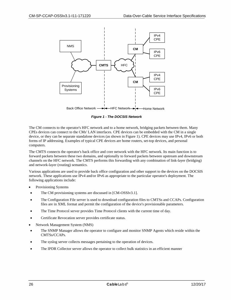
CM-SP-CCAP-OSSIv3.1-I11-171220 Data-Over-Cable Service Interface Specifications
26 CableLabs® 12/20/17
Figure 1 - The DOCSIS Network
The CM connects to the operator's HFC network and to a home network, bridging packets between them. Many CPEs devices can connect to the CMs' LAN interfaces. CPE devices can be embedded with the CM in a single device, or they can be separate standalone devices (as shown in Figure 1). CPE devices may use IPv4, IPv6 or both forms of IP addressing. Examples of typical CPE devices are home routers, set-top devices, and personal computers.
The CMTS connects the operator's back office and core network with the HFC network. Its main function is to forward packets between these two domains, and optionally to forward packets between upstream and downstream channels on the HFC network. The CMTS performs this forwarding with any combination of link-layer (bridging) and network-layer (routing) semantics.
Various applications are used to provide back office configuration and other support to the devices on the DOCSIS network. These applications use IPv4 and/or IPv6 as appropriate to the particular operator's deployment. The following applications include:
• Provisioning Systems • The CM provisioning systems are discussed in [CM-OSSIv3.1].
• The Configuration File server is used to download configuration files to CMTSs and CCAPs. Configuration files are in XML format and permit the configuration of the device's provisionable parameters.
• The Time Protocol server provides Time Protocol clients with the current time of day.
• Certificate Revocation server provides certificate status.
• Network Management System (NMS) • The SNMP Manager allows the operator to configure and monitor SNMP Agents which reside within the
CMTSs/CCAPs.
• The syslog server collects messages pertaining to the operation of devices.
• The IPDR Collector server allows the operator to collect bulk statistics in an efficient manner
ProvisioningSystems
IPv6CPE
IPv4CPE
Back Office Network HFC Network Home Network
CMTS
CM
IPv6CPE
IPv4CPE
CM
NMS
HFC
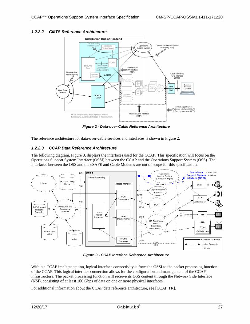
CCAP™ Operations Support System Interface Specification CM-SP-CCAP-OSSIv3.1-I11-171220
12/20/17 CableLabs 27
1.2.2.2 CMTS Reference Architecture
Figure 2 - Data-over-Cable Reference Architecture
The reference architecture for data-over-cable services and interfaces is shown in Figure 2.
1.2.2.3 CCAP Data Reference Architecture The following diagram, Figure 3, displays the interfaces used for the CCAP. This specification will focus on the Operations Support System Interface (OSSI) between the CCAP and the Operations Support System (OSS). The interfaces between the OSS and the eSAFE and Cable Modems are out of scope for this specification.
Figure 3 - CCAP Interface Reference Architecture
Within a CCAP implementation, logical interface connectivity is from the OSSI to the packet processing function of the CCAP. This logical interface connection allows for the configuration and management of the CCAP infrastructure. The packet processing function will receive its OSS content through the Network Side Interface (NSI), consisting of at least 160 Gbps of data on one or more physical interfaces.
For additional information about the CCAP data reference architecture, see [CCAP TR].
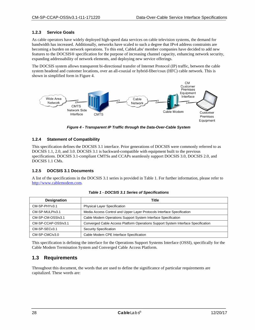
CM-SP-CCAP-OSSIv3.1-I11-171220 Data-Over-Cable Service Interface Specifications
28 CableLabs® 12/20/17
1.2.3 Service Goals
As cable operators have widely deployed high-speed data services on cable television systems, the demand for bandwidth has increased. Additionally, networks have scaled to such a degree that IPv4 address constraints are becoming a burden on network operations. To this end, CableLabs' member companies have decided to add new features to the DOCSIS® specification for the purpose of increasing channel capacity, enhancing network security, expanding addressability of network elements, and deploying new service offerings.
The DOCSIS system allows transparent bi-directional transfer of Internet Protocol (IP) traffic, between the cable system headend and customer locations, over an all-coaxial or hybrid-fiber/coax (HFC) cable network. This is shown in simplified form in Figure 4.
Figure 4 - Transparent IP Traffic through the Data-Over-Cable System
1.2.4 Statement of Compatibility This specification defines the DOCSIS 3.1 interface. Prior generations of DOCSIS were commonly referred to as DOCSIS 1.1, 2.0, and 3.0. DOCSIS 3.1 is backward-compatible with equipment built to the previous specifications. DOCSIS 3.1-compliant CMTSs and CCAPs seamlessly support DOCSIS 3.0, DOCSIS 2.0, and DOCSIS 1.1 CMs.
1.2.5 DOCSIS 3.1 Documents
A list of the specifications in the DOCSIS 3.1 series is provided in Table 1. For further information, please refer to http://www.cablemodem.com.
Table 1 - DOCSIS 3.1 Series of Specifications
Designation Title CM-SP-PHYv3.1 Physical Layer Specification
CM-SP-MULPIv3.1 Media Access Control and Upper Layer Protocols Interface Specification
CM-SP-CM-OSSIv3.1 Cable Modem Operations Support System Interface Specification
CM-SP-CCAP-OSSIv3.1 Converged Cable Access Platform Operations Support System Interface Specification
CM-SP-SECv3.1 Security Specification
CM-SP-CMCIv3.0 Cable Modem CPE Interface Specification
This specification is defining the interface for the Operations Support Systems Interface (OSSI), specifically for the Cable Modem Termination System and Converged Cable Access Platform.
1.3 Requirements
Throughout this document, the words that are used to define the significance of particular requirements are capitalized. These words are:
CCAP™ Operations Support System Interface Specification CM-SP-CCAP-OSSIv3.1-I11-171220
12/20/17 CableLabs 29
"MUST" This word means that the item is an absolute requirement of this specification. "MUST NOT" This phrase means that the item is an absolute prohibition of this specification. "SHOULD" This word means that there may exist valid reasons in particular circumstances to ignore this item, but
the full implications should be understood and the case carefully weighed before choosing a different course.
"SHOULD NOT" This phrase means that there may exist valid reasons in particular circumstances when the listed behavior is acceptable or even useful, but the full implications should be understood and the case carefully weighed before implementing any behavior described with this label.
"MAY" This word means that this item is truly optional. One vendor may choose to include the item because a particular marketplace requires it or because it enhances the product, for example; another vendor may omit the same item.
This document defines many features and parameters, and a valid range for each parameter is usually specified. Equipment (CMTS and CCAP) requirements are always explicitly stated. Equipment complying with all mandatory (MUST and MUST NOT) requirements are considered compliant with this specification. Support of non-mandatory features and parameter values is optional.
1.4 Conventions
In this specification the following convention applies any time a bit field is displayed in a figure. The bit field should be interpreted by reading the figure from left to right, then from top to bottom, with the MSB being the first bit so read and the LSB being the last bit so read. MIB syntax, XML Schema and YANG module syntax are represented by this code sample font.
NOTE: Notices and/or Warnings are identified by this style font and label.
1.5 Organization of Document
Section 1 provides an overview of the DOCSIS 3.1 CCAP/CMTS specification including the reference architecture and statement of compatibility.
Section 2 includes a list of normative and informative references used within this specification.
Section 3 defines the terms used throughout this specification.
Section 4 defines the acronyms and XML namespaces used throughout this specification.
Section 5 provides an introduction to the FCAPS Network Management Model, which forms the organizational structure of this specification. In order to provide a more logical flow, one that mirrors processes in place at MSOs, the order of functions has been shifted, and is organized as CPAF:
• Configuration Management • Performance Management • Accounting Management • Fault Management
Note that Security Management topics are covered in context of these topics.
Key feature and Use Cases for each management function are provided along with a high-level CCAP management architectural view. An introduction to the concept of Information Models and Data Models is also provided.
Section 6 defines the Configuration Management functions of the CCAP, including theory of operation, network management protocols and Information Models.
Section 7 defines the Performance Management functions of the CCAP, including network management protocols, Information Models and Data Model requirements.
Section 8 defines the Accounting Management functions of the CCAP, including IPDR network management protocols, SAMIS and Data Model requirements.
CM-SP-CCAP-OSSIv3.1-I11-171220 Data-Over-Cable Service Interface Specifications
30 CableLabs® 12/20/17
Section 9 defines the Fault Management functions of the CCAP including network management protocols, event reporting requirements and Information Models.
1.5.1 Annexes (Normative) Annex A includes a detailed list of MIB object requirements for the CMTS and CCAP.
Annex B describes the IPDR for DOCSIS Cable Data Systems Subscriber Usage Billing Records.
Annex C describes the Auxiliary Schemas for DOCSIS IPDR Service Definitions.
Annex D describes the format and content for Event, SYSLOG, and SNMP Notification.
Annex E describes how vendors can extend the configuration data model.
Annex F describes the CCAP Data Type Definitions used in both the Information Models and data models.
Annex G describes the Diagnostic Log network management feature including Information Models.
1.5.2 Appendices (Informative)
Appendix I contains a sample CCAP XML Configuration.
Appendix II contains a method for identifying replicated QAMs.
Appendix III describes the vendor schema versioning in the CCAP XSD.
Appendix IV describes the process of converting YANG to XSD.
Appendix V contains DOCSIS IPDR sample instance documents.
Appendix VI contains spectrum analysis use cases.
Appendix VII describes the Unified Modeling Language (UML) notation used in defining Information Models.
Appendix VIII lists the acknowledgments for authoring this specification.
Appendix IX contains the revision history.
CCAP™ Operations Support System Interface Specification CM-SP-CCAP-OSSIv3.1-I11-171220
12/20/17 CableLabs 31
2 REFERENCES
2.1 Normative References
In order to claim compliance with this specification, it is necessary to conform to the following standards and other works as indicated, in addition to the other requirements of this specification. Notwithstanding, intellectual property rights may be required to use or implement such normative references.
[CANN] CableLabs Assigned Names and Numbers, CL-SP-CANN-I17-171220, December 20, 2017, Cable Television Laboratories, Inc.
[CCAP-CONFIG-YANG]
CCAP YANG Configuration Module, http://www.cablelabs.com/YANG/DOCSIS/3.1
[CCAP-EVENTS-YANG]
CCAP YANG Module for Event Messaging, CCAPevents.yang, http://www.cablelabs.com/YANG/DOCSIS
[CCAP-MIB] Converged Cable Access Platform MIB, CCAP-MIB, http://www.cablelabs.com/MIBs/DOCSIS/. [CLAB-DEF-MIB] CableLabs Definition MIB Specification, CL-SP-MIB-CLABDEF-I12-160325, March 25, 2016, Cable
Television Laboratories, Inc. [CLAB-TOPO-MIB] CableLabs Topology MIB, CLAB-TOPO-MIB, http://www.cablelabs.com/MIBs/common/. [CM-OSSIv3.1] DOCSIS 3.1 Cable Modem OSSI Specification, CM-SP-CM-OSSIv3.1-I11-171220, December
20, 2017, Cable Television Laboratories, Inc.
[DOCS-DIAG-MIB] DOCSIS Diagnostic Log MIB, DOCS-DIAG-MIB, http://www.cablelabs.com/MIBs/DOCSIS/. [DOCS-IF3-MIB] DOCSIS Interface 3 MIB Module, DOCS-IF3-MIB, http://www.cablelabs.com/MIBs/DOCSIS/. [DOCS-IF31-MIB] DOCSIS Interface 3.1 MIB Module, DOCS-IF31-MIB, http://www.cablelabs.com/MIBs/DOCSIS/. [DOCS-IFEXT2-MIB]
DOCSIS Interface Extension 2 MIB Module, DOCS-IFEXT2-MIB, http://www.cablelabs.com/MIBs/DOCSIS/.
[DOCS-LOADBAL3-MIB]
DOCSIS Load Balancing 3 MIB Module, DOCS-LOADBAL3-MIB, http://www.cablelabs.com/MIBs/DOCSIS/.
[DOCS-MCAST-AUTH-MIB]
DOCSIS Multicast Authorization MIB Module, DOCS-MCAST-AUTH-MIB, http://www.cablelabs.com/MIBs/DOCSIS/.
[DOCS-MCAST-MIB]
DOCSIS Multicast MIB Module, DOCS-MCAST-MIB, http://www.cablelabs.com/MIBs/DOCSIS/.
[DOCS-PNM-MIB] DOCSIS PNM MIB Module, DOCS-PNM-MIB, http://www.cablelabs.com/MIBs/DOCSIS/. [DOCS-QOS3-MIB]
DOCSIS Quality of Service 3 MIB Module, DOCS-QOS3-MIB, http://www.cablelabs.com/MIBs/DOCSIS/.
[DOCS-SEC-MIB] DOCSIS Security MIB, DOCS-SEC-MIB, http://www.cablelabs.com/MIBs/DOCSIS/. [DOCS-SUBMGT3-MIB]
DOCSIS Subscriber Management 3 MIB, DOCS-SUBMGT3-MIB, http://www.cablelabs.com/MIBs/DOCSIS/.
[DOCSIS-CM] DOCSIS CM Information Schema, DOCSIS-CM_3.5.1-A.3.xsd, http://www.cablelabs.com/namespaces/DOCSIS/3.0/xsd/ipdr/DOCSIS-CM
[DOCSIS-CMTS] DOCSIS CMTS Information Schema, DOCSIS-CMTS_3.5.1-A.1.xsd, http://www.cablelabs.com/namespaces/DOCSIS/3.0/xsd/ipdr/DOCSIS-CMTS
[DOCSIS-CMTS-CM-DS-OFDM]
DOCSIS CMTS CM Downstream OFDM Information Schema, DOCSIS-CMTS-CM-DS-OFDM _3.5.1-B.1.xsd, http://www.cablelabs.com/namespaces/DOCSIS/3.1/xsd/ipdr/DOCSIS-CMTS-CM-DS-OFDM
[DOCSIS-CMTS-CM-DS-OFDM-PROFILE-TYPE]
DOCSIS CMTS CM Downstream OFDM Profile Status Type Schema, DOCSIS-CMTS-CM-DS-OFDM-PROFILE-STATUS-TYPE_3.5.1-B.1.xsd, http://www.cablelabs.com/namespaces/DOCSIS/3.1/xsd/ipdr/DOCSIS-CMTS-CM-DS-OFDM-PROFILE-STATUS-TYPE
[DOCSIS-CMTS-CM-DS-OFDM-STATUS-TYPE]
DOCSIS CMTS CM Downstream OFDM Status Type Schema, DOCSIS-CMTS-CM-DS-OFDM-STATUS-TYPE_3.5.1-B.1.xsd, http://www.cablelabs.com/namespaces/DOCSIS/3.1/xsd/ipdr/DOCSIS-CMTS-CM-DS-OFDM-STATUS-TYPE
[DOCSIS-CMTS-CM-NODE-CH]
DOCSIS CMTS CM Node Channel Information Schema, DOCSIS-CMTS-CM-NODE-CH_3.5.1-A.2.xsd, http://www.cablelabs.com/namespaces/DOCSIS/3.0/xsd/ipdr/DOCSIS-CMTS-CM-NODE-CH
[DOCSIS-CMTS-CM-PARTIAL]
DOCSIS CMTS CM Partial Service/Channel Information Schema, DOCSIS-CMTS-CM-PARTIAL_3.5.1-B.1.xsd, http://www.cablelabs.com/namespaces/DOCSIS/3.1/xsd/ipdr/DOCSIS-CMTS-CM-PARTIAL
CM-SP-CCAP-OSSIv3.1-I11-171220 Data-Over-Cable Service Interface Specifications
32 CableLabs® 12/20/17
[DOCSIS-CMTS-CM-REG-STATUS-TYPE]
DOCSIS CMTS CM Registration Status Type Schema, DOCSIS-CMTS-CM-REG-STATUS-TYPE_3.5.1-B.1.xsd, http://www.cablelabs.com/namespaces/DOCSIS/3.1/xsd/ipdr/DOCSIS-CMTS-CM-REG-STATUS-TYPE
[DOCSIS-CMTS-CM-SERVICE-FLOW-TYPE]
DOCSIS CMTS CM Service Flow Type Schema, DOCSIS-CMTS-CM-SERVICE-FLOW-TYPE_3.5.1-B.1.xsd, http://www.cablelabs.com/namespaces/DOCSIS/3.1/xsd/ipdr/DOCSIS-CMTS-CM-SERVICE-FLOW-TYPE
[DOCSIS-CMTS-CM-US]
DOCSIS CMTS CM Upstream Information Schema, DOCSIS-CMTS-CM-US_3.5.1-A.3.xsd, http://www.cablelabs.com/namespaces/DOCSIS/3.0/xsd/ipdr/DOCSIS-CMTS-CM-US
[DOCSIS-CMTS-CM-US-OFDMA]
DOCSIS CMTS CM Upstream OFDMA Information Schema, DOCSIS-CMTS-CM-US-OFDMA_3.5.1-B.1.xsd, http://www.cablelabs.com/namespaces/DOCSIS/3.1/xsd/ipdr/DOCSIS-CMTS-CM-US-OFDMA
[DOCSIS-CMTS-CM-US-OFDMA-PROFILE-TYPE]
DOCSIS CMTS CM Upstream OFDMA Profile Status Type Schema, DOCSIS-CMTS-CM-US-OFDMA-PROFILE-STATUS-TYPE_3.5.1-B.1.xsd, http://www.cablelabs.com/namespaces/DOCSIS/3.1/xsd/ipdr/DOCSIS-CMTS-CM-US-OFDMA-PROFILE-STATUS-TYPE
[DOCSIS-CMTS-CM-US-OFDMA-STATUS-TYPE]
DOCSIS CMTS CM Upstream OFDMA Status Type Schema, DOCSIS-CMTS-CM-US-OFDMA-STATUS-TYPE_3.5.1-B.1.xsd, http://www.cablelabs.com/namespaces/DOCSIS/3.1/xsd/ipdr/DOCSIS-CMTS-CM-US-OFDMA-STATUS-TYPE
[DOCSIS-CMTS-CM-US-STATS-TYPE]
DOCSIS CMTS CM Upstream Status Schema, DOCSIS-CMTS-CM-US-STATS-TYPE_3.5.1-A.2.xsd, http://www.cablelabs.com/namespaces/DOCSIS/3.0/xsd/ipdr/DOCSIS-CMTS-CM-US-STATS-TYPE
[DOCSIS-CMTS-DS-UTIL]
DOCSIS CMTS Downstream Utilization Information Schema, DOCSIS-CMTS-DS-UTIL_3.5.1-A.3.xsd, http://www.cablelabs.com/namespaces/DOCSIS/3.0/xsd/ipdr/DOCSIS-CMTS-DS-UTIL
[DOCSIS-CMTS-DS-UTIL-STATS-TYPE]
DOCSIS CMTS Downstream Utilization Status Schema, DOCSIS-CMTS-DS-UTIL-STATS-TYPE_3.5.1-A.3.xsd, http://www.cablelabs.com/namespaces/DOCSIS/3.0/xsd/ipdr/DOCSIS-CMTS-DS-UTIL-STATS-TYPE
[DOCSIS-CMTS-TOPOLOGY-TYPE]
DOCSIS CMTS Topology Type Schema, DOCSIS-CMTS-TOPOLOGY-TYPE_3.5.1-A.2.xsd, http://www.cablelabs.com/namespaces/DOCSIS/3.0/xsd/ipdr/DOCSIS-CMTS-TOPOLOGY-TYPE
[DOCSIS-CMTS-US-UTIL]
DOCSIS CMTS Upstream Utilization Schema, DOCSIS-CMTS-US-UTIL_3.5.1-A.3.xsd, http://www.cablelabs.com/namespaces/DOCSIS/3.0/xsd/ipdr/DOCSIS-CMTS-US-UTIL
[DOCSIS-CMTS-US-UTIL-STATS-TYPE]
DOCSIS CMTS Upstream Utilization Status Schema, DOCSIS-CMTS-US-UTIL-STATS-TYPE_3.5.1-A.4.xsd, http://www.cablelabs.com/namespaces/DOCSIS/3.0/xsd/ipdr/DOCSIS-CMTS-US-UTIL-STATS-TYPE
[DOCSIS-CPE] DOCSIS CPE Information Schema, DOCSIS-CPE_3.5.1-A.2.xsd, http://www.cablelabs.com/namespaces/DOCSIS/3.0/xsd/ipdr/DOCSIS-CPE
[DOCSIS-CPE-TYPE]
DOCSIS CPE Type Schema, DOCSIS-CPE-TYPE_3.5.1-A.2.xsd, http://www.cablelabs.com/namespaces/DOCSIS/3.0/xsd/ipdr/DOCSIS-CPE-TYPE
[DOCSIS-DIAG-LOG]
DOCSIS Diagnostic Log Information Schema, DOCSIS-DIAG-LOG_3.5.1-A.1.xsd, http://www.cablelabs.com/namespaces/DOCSIS/3.0/xsd/ipdr/DOCSIS-DIAG-LOG
[DOCSIS-DIAG-LOG-DETAIL]
DOCSIS Diagnostic Log Detail Schema, DOCSIS-DIAG-LOG-DETAIL_3.5.1-A.1.xsd, http://www.cablelabs.com/namespaces/DOCSIS/3.0/xsd/ipdr/DOCSIS-DIAG-LOG-DETAIL
[DOCSIS-DIAG-LOG-DETAIL-TYPE]
DOCSIS Diagnostic Log Detail Type Schema, DOCSIS-DIAG-LOG-DETAIL-TYPE_3.5.1-A.2.xsd, http://www.cablelabs.com/namespaces/DOCSIS/3.0/xsd/ipdr/DOCSIS-DIAG-LOG-DETAIL-TYPE
[DOCSIS-DIAG-LOG-EVENT-TYPE]
DOCSIS Diagnostic Log Event Type Schema, DOCSIS-DIAG-LOG-EVENT-TYPE_3.5.1-A.2.xsd, http://www.cablelabs.com/namespaces/DOCSIS/3.0/xsd/ipdr/DOCSIS-DIAG-LOG-EVENT-TYPE
[DOCSIS-DIAG-LOG-TYPE]
DOCSIS Diagnostic Log Type Schema, DOCSIS-DIAG-LOG-TYPE_3.5.1-A.2.xsd, http://www.cablelabs.com/namespaces/DOCSIS/3.0/xsd/ipdr/DOCSIS-DIAG-LOG-TYPE
[DOCSIS-DS-OFDM-PROFILE-STATS-TYPE]
DOCSIS Downstream OFDM Profile Stats Type Schema, DOCSIS-DS-OFDM-PROFILE-STATS-TYPE_3.5.1-B.1.xsd, http://www.cablelabs.com/namespaces/DOCSIS/3.1/xsd/ipdr/DOCSIS-DS-OFDM-PROFILE-STATS-TYPE
[DOCSIS-IP-MULTICAST]
DOCSIS IP Multicast Information Schema, DOCSIS-IP-MULTICAST_3.5.1-A.1.xsd, http://www.cablelabs.com/namespaces/DOCSIS/3.0/xsd/ipdr/DOCSIS-IP-MULTICAST
[DOCSIS-IP-MULTICAST-STATS-TYPE]
DOCSIS IP Multicast Statistics Type Schema, DOCSIS-IP-MULTICAST-STATS-TYPE_3.5.1-A.1.xsd, http://www.cablelabs.com/namespaces/DOCSIS/3.0/xsd/ipdr/DOCSIS-IP-MULTICAST-STATS-TYPE
[DOCSIS-MD-NODE]
DOCSIS MAC Domain Node Information Schema, DOCSIS-MD-NODE_3.5.1-A.2.xsd, http://www.cablelabs.com/namespaces/DOCSIS/3.0/xsd/ipdr/DOCSIS-MD-NODE
CCAP™ Operations Support System Interface Specification CM-SP-CCAP-OSSIv3.1-I11-171220
12/20/17 CableLabs 33
[DOCSIS-OFDM-PROFILE]
DOCSIS OFDM Profile Information Schema, DOCSIS-OFDM-PROFILE_3.5.1-B.1.xsd, http://www.cablelabs.com/namespaces/DOCSIS/3.1/xsd/ipdr/DOCSIS-OFDM-PROFILE
[DOCSIS-QOS] DOCSIS QoS Information Schema, DOCSIS-QOS_3.5.1-A.1.xsd, http://www.cablelabs.com/namespaces/DOCSIS/3.0/xsd/ipdr/DOCSIS-QOS
[DOCSIS-REC] DOCSIS Record Information Schema, DOCSIS-REC_3.5.1-A.1.xsd, http://www.cablelabs.com/namespaces/DOCSIS/3.0/xsd/ipdr/DOCSIS-REC
[DOCSIS-SAMIS-TYPE-1]
DOCSIS SAMIS Type 1 Schema, DOCSIS-SAMIS-TYPE-1_3.5.1-A.1.xsd, http://www.cablelabs.com/namespaces/DOCSIS/3.0/xsd/ipdr/DOCSIS-SAMIS-TYPE-1
[DOCSIS-SAMIS-TYPE-2]
DOCSIS SAMIS Type 2 Schema, DOCSIS-SAMIS-TYPE-2_3.5.1-A.1.xsd, http://www.cablelabs.com/namespaces/DOCSIS/3.0/xsd/ipdr/DOCSIS-SAMIS-TYPE-2.
[DOCSIS-SERVICE-FLOW]
DOCSIS Service Flow Information Schema, DOCSIS-SERVICE-FLOW_3.5.1-B.1.xsd, http://www.cablelabs.com/namespaces/DOCSIS/3.1/xsd/ipdr/DOCSIS-SERVICE-FLOW.
[DOCSIS-SPECTRUM]
DOCSIS Spectrum Measurement Information Schema, DOCSIS-SPECTRUM_3.5.1-A.2.xsd, http://www.cablelabs.com/namespaces/DOCSIS/3.0/xsd/ipdr/DOCSIS-SPECTRUM/
[DOCSIS-SPECTRUM-MEASUREMENT-TYPE]
DOCSIS Spectrum Measurement Type Schema, DOCSIS-SPECTRUM-MEASUREMENT-TYPE_3.5.1-A.2.xsd, http://www.cablelabs.com/namespaces/DOCSIS/3.0/xsd/ipdr/DOCSIS-SPECTRUM-MEASUREMENT-TYPE.
[DOCSIS-US-OFDMA-PROFILE-STATS-TYPE]
DOCSIS Upstream OFDMA Profile Stats Type, DOCSIS-US-OFDMA-PROFILE-STATS-TYPE_3.5.1-B.1.xsd, http://www.cablelabs.com/namespaces/DOCSIS/3.1/xsd/ipdr/DOCSIS-US-OFDMA-PROFILE-STATS-TYPE
[DPoE OSSIv1.0] DOCSIS Provisioning of EPON OSSI Specification, DPoE-SP-OSSIv1.0-C01-160830, August 30, 2016, Cable Television Laboratories, Inc.
[DPoE OSSIv2.0] DOCSIS Provisioning of EPON OSSI Specification, DPoE-SP-OSSIv2.0-I11-170510, May 10, 2017, Cable Television Laboratories, Inc.
[eDOCSIS] eDOCSIS Specification, CM-SP-eDOCSIS-I29-170906, September 6, 2017, Cable Television Laboratories, Inc.
[IPDR/BSR] IPDR Business Solution Requirements - Network Data Management Usage (NDM-U), Version 3.7, TM Forum, October 2009.
[IPDR/CAPAB] IPDR/Capability File Format, Version 3.9, TM Forum, October 2009. [IPDR/SP] IPDR Streaming Protocol (IPDR/SP) Specification, TMF8000-IPDR-IIS-PS, Version 2.7, TM Forum,
November 2011. [IPDR/SSDG] IPDR Service Specification Design Guide, Version 3.8, TM Forum, October 2009. [IPDR/XDR] IPDR/XDR File Encoding Format, Version 3.5.1, TM Forum, October 2009. [L2VPN] Business Services over DOCSIS: Layer 2 Virtual Private Networks, CM-SP-L2VPN-I15-150528, May 28,
2015, Cable Television Laboratories, Inc. [M-OSSI] DOCSIS M-CMTS Operations Support Interface, CM-SP-M-OSSI-I08-081209, December 9, 2008,
Cable Television Laboratories, Inc.
[MPEG] Information technology - Generic coding of moving pictures and associated audio information: Systems, ISO/IEC 13818-1: 2007.
[MULPIv3.0] MAC and Upper Layer Protocols Interface Specification, CM-SP-MULPIv3.0-C01-171207, December 7, 2017, Cable Television Laboratories, Inc.
[MULPIv3.1] MAC and Upper Layer Protocols Interface Specification, CM-SP-MULPIv3.1-I13-171220, December 20, 2017, Cable Television Laboratories, Inc.
[OSSIv3.0] Operations Support System Interface Specification, CM-SP-OSSIv3.0-C01-171207, December 7, 2017, Cable Television Laboratories, Inc.
[PCMM] PacketCable Multimedia Specification, PKT-SP-MM-I07-151110, November 10, 2015, Cable Television Laboratories, Inc.
[PHYv3.1] DOCSIS Physical Layer Specification, CM-SP-PHYv3.1-I13-171220, December 20, 2017, Cable Television Laboratories, Inc.
[PKT-DQOS] PacketCable Dynamic Quality of Service Specification, PKT-SP-DQOS-C01-071129, November 29, 2007, Cable Television Laboratories. Inc.
[PORT NUMS] Port Numbers, IANA, http://www.iana.org/assignments/port-numbers. [RFC 1112] IETF RFC 1112, Host Extensions for IP Multicasting, August 1989. [RFC 1350] IETF RFC 1350/STD0033, The TFTP Protocol (Revision 2), July 1992. [RFC 1832] IETF RFC 1832, XDR: External Data Representation Standard, August 1995.

CM-SP-CCAP-OSSIv3.1-I11-171220 Data-Over-Cable Service Interface Specifications
34 CableLabs® 12/20/17
[RFC 2133] IETF RFC 2133, Basic Socket Interface Extensions for IPv6, April 1997. [RFC 2236] IETF RFC 2236, Internet Group Management Protocol, Version 2, November 1997. [RFC 2348] IETF RFC 2348, TFTP Blocksize Option, May 1998. [RFC 2460] IETF RFC 2460, Internet Protocol, Version 6 (IPv6), December 1998. [RFC 2464] IETF RFC 2464, Transmission of IPv6 Packets over Ethernet Networks, December 1998. [RFC 2560] IETF RFC 2560, X.509 Internet Public Key Infrastructure Online Certification Status Protocol -
OCSP, June 1999.
[RFC 2573] IETF RFC 2786, SNMP Applications, April 1999. [RFC 2575] IETF RFC 2575, View-based Access Control Model (VACM) for the Simple Network
Management Protocol (SNMP), April 1999.
[RFC 2578] IETF RFC 2578, Structure of Management Information Version 2 (SMIv2), April 1999. [RFC 2669] IETF RFC 2669, DOCSIS Cable Device MIB Cable Device Management Information Base for
DOCSIS compliant Cable Modems and Cable Modem Termination Systems, August 1999.
[RFC 2710] IETF RFC 2710, Multicast Listener Discovery (MLD) for IPv6, October 1999. [RFC 2786] IETF RFC 2786, Diffie-Helman USM Key Management, March 2000. [RFC 2790] IETF RFC 2790, Host Resources MIB, March 2000. [RFC 2821] IETF RFC 2821, Simple Mail Transfer Protocol, April 2001. [RFC 2856] IETF RFC 2856, Textual Conventions for Additional High Capacity Data Types, June 2000. [RFC 2863] IETF RFC 2863, The Interfaces Group MIB, June 2000. [RFC 2933] IETF RFC 2933, Internet Group Management Protocol MIB, October 2000. [RFC 3019] IETF RFC 3019, IP Version 6 Management Information Base for the Multicast Listener
Discovery Protocol, January 2001.
[RFC 3083] IETF RFC 3083, Baseline Privacy Interface Management Information Base for DOCSIS Compliant Cable Modems and Cable Modem Termination Systems, March 2001.
[RFC 3164] IETF RFC 3164, The BSD Syslog Protocol, August 2001. [RFC 3289] IETF RFC 3289, Management Information Base for the Differentiated Services Architecture,
June 2002.
[RFC 3306] IETF RFC 3306, Unicast-Prefix-based IPv6 Multicast Addresses, August 2002. [RFC 3376] IETF RFC 3376, Internet Group Management Protocol, Version 3, October 2002. [RFC 3412] IETF RFC 3412, Message Processing and Dispatching for the Simple Network Management
Protocol (SNMP), December 2002.
[RFC 3418] IETF RFC 3418/STD0062, Management Information Base (MIB) for the Simple Network Management Protocol (SNMP), December 2002.
[RFC 3433] IETF RFC 3433, Entity Sensor Management Information Base, December 2002. [RFC 3484] IETF RFC 3484, Default Address Selection for Internet Protocol version 6 (IPv6), March 2003. [RFC 3569] IETF RFC 3569, An Overview of Source-Specific Multicast (SSM), July 2003. [RFC 3584] IETF RFC 3584, Coexistence between Version 1, Version 2, and Version 3 of the Internet-
standard Network Management Framework, August 2003.
[RFC 3635] IETF RFC 3635, Definitions of Managed Objects for the Ethernet-like Interface Types, October 2003.
[RFC 3810] IETF RFC 3810, Multicast Listener Discovery Version 2 (MLDv2) for IPv6, June 2004. [RFC 4022] IETF RFC 4022, Management Information Base for the Transmission Control Protocol (TCP),
March 2005.
[RFC 4113] IETF RFC 4113, Management Information Base for the User Datagram Protocol (UDP), June 2005.
[RFC 4133] IETF RFC 4133, Entity MIB (Version 3), August 2005. [RFC 4181] IETF RFC 4181, Guidelines for Authors and Reviewers of MIB Documents, September 2005. [RFC 4188] IETF RFC 4188, Definitions of Managed Objects for Bridges, September 2005. [RFC 4250] IETF RFC 4250, The Secure Shell (SSH) Protocol Assigned Numbers, January 2006. [RFC 4251] IETF RFC 4251, The Secure Shell (SSH) Protocol Architecture, January 2006. [RFC 4252] IETF RFC 4252, The Secure Shell (SSH) Authentication Protocol, January 2006. [RFC 4253] IETF RFC 4253, The Secure Shell (SSH) Transport Layer Protocol, January 2006.
CCAP™ Operations Support System Interface Specification CM-SP-CCAP-OSSIv3.1-I11-171220
12/20/17 CableLabs 35
[RFC 4254] IETF RFC 4254, The Secure Shell (SSH) Connection Protocol, January 2006. [RFC 4293] IETF RFC 4293, Management Information Base for the Internet Protocol (IP), April 2006. [RFC 4323] IETF RFC 4323, Data Over Cable System Interface Specification Quality of Service
Management Information Base (DOCSIS-QOS-MIB), January 2006.
[RFC 4506] IETF RFC 4506/STD0067, XDR: External Data Representation Standard. M. Eisler, Ed. May 2006.
[RFC 4546] IETF RFC 4546, Radio Frequency (RF) Interface Management Information Base for Data over Cable Service Interface Specifications (DOCSIS) 2.0 Compliant RF Interfaces, June 2006.
[RFC 4601] IETF RFC 4601, Protocol Independent Multicast - Sparse Mode (PIM-SM): Protocol Specification (Revised), August 2006.
[RFC 4639] IETF RFC 4639, Cable Device Management Information Base for Data-Over-Cable Service Interface Specification (DOCSIS) Compliant Cable Modems and Cable Modem Termination Systems, December 2006.
[RFC 4742] IETF RFC 4742, Using the NETCONF Configuration Protocol over Secure Shell (SSH), December 2006.
[RFC 5132] IETF RFC 5132, IP Multicast MIB, December 2007. [RFC 5246] IETF RFC 5246, The Transport Layer Security (TLS) Protocol Version 1.2, August 2008. [RFC 5277] IETF RFC 5277, NETCONF Event Notifications, July 2008. [RFC 5280] IETF RFC 5280, Internet X.509 Public Key Infrastructure Certificate and Certificate Revocation
List (CRL) Profile, May 2008.
[RFC 6241] IETF RFC 6241, NETCONF Configuration Protocol, June 2011. [RFC 6243] IETF RFC 6243, With-defaults Capability for NETCONF, June, 2011. [RFC 6991] IETF RFC 6991, Common YANG Data Types, July 2013. [RMI-SDR] DOCSIS Resource Management Interface, Service Discovery and Registration Specification,
CM-SP-RMI-SDR-I02-150528, May 28, 2015, Cable Television Laboratories, Inc.
[SCTE 154-2] ANSI SCTE 154-2 2008, SCTE-HMS-QAM-MIB. [SCTE 154-4] ANSI SCTE 154-4 2008, MPEG Management Information Base - SCTE-HMS-MPEG-MIB. [SCTE 154-5] ANSI SCTE 154-5 2008, SCTE-HMS-HEADENDIDENT TEXTUAL CONVENTIONS MIB. [SECv3.1] DOCSIS 3.1 Security Specification, CM-SP-SECv3.1-I07-170111, January 11, 2017, Cable
Television Laboratories, Inc.
[W3XML1.0] Extensible Markup Language (XML) 1.0 (Third Edition), W3C Recommendation 04, February 2004.
[W3XSD1.0] XML Schema Part 1: Structures Second Edition, W3C Recommendation 28, October 2004.
2.2 Informative References
This specification uses the following informative references.
[CCAP TR] Converged Cable Access Platform Architecture Technical Report, CM-TR-CCAP-V03-120511, May 11, 2012, Cable Television Laboratories, Inc.
[DRFI] DOCSIS Downstream RF Interface Specification, CM-SP-DRFI-I16-170111, January 11, 2017, Cable Television Laboratories, Inc.
[DSG] DOCSIS Set-top Gateway (DSG) Interface Specification, CM-SP-DSG-I25-170906, September 6, 2017, Cable Television Laboratories, Inc.
[ISO 11404] BS ISO/IEC 11404:1996 Information technology--Programming languages, their environments and system software interfaces--Language-independent datatypes, January 2002.
[ISO 19501] ISO/IEC 19501:2005, Information technology - Open Distributed Processing - Unified Modeling Language (UML) Version 1.4.2.
[ITU-T M.3400] ITU-T Recommendation M.3400 (02/2000): TMN AND Network Maintenance: International Transmission Systems, Telephone Circuits, Telegraphy, Facsimile and Leased Circuits, TMN management functions.
[ITU-T X.692] ITU-T Recommendation X.692 (03/2002), Information technology - ASN.1 encoding rules: Specification of Encoding Control Notation (ECN).
[NSI] Cable Modem Termination System - Network Side Interface Specification, SP-CMTS-NSI-C01-171207, December 7, Cable Television Laboratories, Inc.
CM-SP-CCAP-OSSIv3.1-I11-171220 Data-Over-Cable Service Interface Specifications
36 CableLabs® 12/20/17
[PMI] Edge QAM Provisioning and Management Interface Specification, CM-SP-EQAM-PMI-I02-111117, November 17, 2011, Cable Television Laboratories, Inc.
[PKT EM] PacketCable Event Messages Specification, PKT-SP-EM-C01-071129, November 29, 2007, Cable Television Laboratories, Inc.
[RFC 791] IETF RFC 791, Internet Protocol, September 1981. [RFC 1042] IETF RFC 1042/STD0043, Standard for the transmission of IP datagrams over IEEE 802 networks,
February 1988. [RFC 1123] IETF RFC 1123/STD0003, Requirements for Internet Hosts - Application and Support, October 1989. [RFC 1157] IETF RFC 1157. Simple Network Management Protocol (SNMP), May 1990. [RFC 1213] IETF RFC 1213, Management Information Base for Network Management of TCP/IP-based
internets:MIB-II, March 1991. [RFC 1901] IETF RFC 1901, Introduction to Community-based SNMPv2, January 1996. [RFC 2326] IETF RFC 2326, Real Time Streaming Protocol (RTSP), April 1998. [RFC 2579] IETF RFC 2579, Textual Conventions for SMIv2, April 1999. [RFC 2580] IETF RFC 2580, Conformance Statements for SMIv2, April 1999. [RFC 3168] IETF RFC 3168, The Addition of Explicit Congestion Notification (ECN) to IP, September 2001. [RFC 3260] IETF RFC 3260, New Terminology and Clarifications for Diffserv, April 2002. [RFC 3339] IETF RFC 3339, Date and Time on the Internet: Timestamps, July 2002. [RFC 3410] IETF RFC 3410, Introduction and Applicability Statements for Internet-Standard Management
Framework, December 2002. [RFC 3411] IETF RFC 3411/STD0062, An Architecture for Describing Simple Network Management Protocol
(SNMP) Management Frameworks, December 2002. [RFC 3413] IETF RFC 3413, Simple Network Management Protocol (SNMP) Applications, December 2002. [RFC 3414] IETF RFC 3414/STD0062, User-based Security Model (USM) for version 3 of the Simple Network
Management Protocol (SNMPv3), December 2002.
[RFC 3415] IETF RFC 3415, View-based Access Control Model (VACM) for the Simple Network Management Protocol (SNMP), December 2002.
[RFC 3416] IETF RFC 3416, Version 2 of the Protocol Operations for the Simple Network Management Protocol (SNMP), December 2002.
[RFC 3417] IETF RFC 3417, Transport Mappings for the Simple Network Management Protocol (SNMP), December 2002.
[RFC 3419] IETF RFC 3419, Textual Conventions for Transport Addresses. M. Daniele, J. Schoenwaelder. December 2002.
[RFC 3423] IETF RFC 3423, XACCT's Common Reliable Accounting for Network Element (CRANE), Protocol Specification Version 1.0, November 2002.
[RFC 3826] IETF RFC 3826, The Advanced Encryption Standard (AES) Cipher Algorithm in the SNMP User-based Security Model, June 2004.
[RFC 4001] IETF RFC 4001, Textual Conventions for Internet Network Addresses, February 2005. [RFC 4131] IETF RFC 4131, Management Information Base for Data Over Cable Service Interface Specification
(DOCSIS) Cable Modems and Cable Modem Termination Systems for Baseline Privacy Plus, September 2005.
[RFC 4291] IETF RFC 4291, IP Version 6 Addressing Architecture, February 2006. [RFC 4743] IETF RFC 4743, Using NETCONF over the Simple Object Access Protocol (SOAP), December 2006. [RFC 4744] IETF RFC 4744, Using the NETCONF Protocol over the Blocks Extensible Exchange Protocol (BEEP),
December 2006. [RFC 5519] IETF RFC 5519, Multicast Group Membership Discovery MIB, April 2009. [RFC 5539] IETF RFC 5539, NETCONF over Transport Layer Security (TLS), May 2009. [RFC 6020] IETF RFC 6020, YANG - A data modeling language for the Network Configuration Protocol
(NETCONF), October 2010. [RFC 6021] IETF RFC 6021, Common YANG Data Types, October 2010.

CCAP™ Operations Support System Interface Specification CM-SP-CCAP-OSSIv3.1-I11-171220
12/20/17 CableLabs 37
2.3 Reference Acquisition
• Cable Television Laboratories, Inc., 858 Coal Creek Circle, Louisville, CO 80027; Phone +1-303-661-9100; Fax +1-303-661-9199; http://www.cablelabs.com
• American National Standards Institute, Inc. 1819 L Street, NW, 6th floor Washington, DC 20036; Phone +1-202-293-8020; Fax +1-202-293-9287; http://www.ansi.org
• IANA, Internet Assigned Numbers Authority (IANA); http://www.iana.org • IETF, Internet Engineering Task Force (IETF) Secretariat, 48377 Fremont Blvd., Suite 117, Fremont,
California 94538, USA; Phone: +1-510-492-4080, Fax: +1-510-492-4001; http://www.ietf.org/ • IPDR Specifications, 240 Headquarters Plaza, East Tower, 10th Floor, Morristown, NJ 07960; Phone +1-973-
944-5100; Fax +1-973-944-5110; http://www.tmforum.org • ISO Specifications, International Organization for Standardization (ISO), 1, rue de Varembé, Case postale 56,
CH-1211 Geneva 20, Switzerland; Phone +41 22 749 01 11; Fax +41 22 733 34 30; http://www.iso.org • ITU Recommendations, International Telecommunication Union, Place des Nations, CH-1211, Geneva 20,
Switzerland; Phone +41-22-730-51-11; Fax +41-22-733-7256; http://www.itu.int • SCTE, Society of Cable Telecommunications Engineers Inc., 140 Philips Road, Exton, PA 19341;
Phone: 610-363-6888 / 800-542-5040; Fax: 610-363-5898; http://www.scte.org/ • World Wide Web Consortium (W3C), Massachusetts Institute of Technology, 32 Vassar Street, Room 32-
G515, Cambridge, MA 02139; Phone +1-617-253-2613, Fax +1-617-258-5999; http://www.w3.org/Consortium/
CM-SP-CCAP-OSSIv3.1-I11-171220 Data-Over-Cable Service Interface Specifications
38 CableLabs® 12/20/17
3 TERMS AND DEFINITIONS This specification uses the following terms:
Aggregation A special type of object association for Configuration Object Models in which objects are assembled or configured together to create a more complex object.
Bridging CMTS A CMTS that makes traffic forwarding decisions between its Network Systems Interfaces and MAC Domain Interfaces based upon the Layer 2 Ethernet MAC address of a data frame.
Cable Modem A modulator-demodulator at subscriber locations intended for use in conveying data communications on a cable television system.
Cable Modem Termination System
An access-side networking element or set of elements that includes one or more MAC Domains and one or more Network System Interfaces. This unit is located at the cable television system headend or distribution hub and provides data connectivity between a DOCSIS Radio Frequency Interface and a wide-area network.
Cable Modem Termination System - Network Side Interface (CMTS-NSI)
The interface, defined in [NSI], between a CMTS and the equipment on its network side.
Carrier-to-Noise plus Interference Ratio (CNIR)
The ratio of the expected commanded received signal power at the CMTS input to the noise plus interference in the channel.
Channel The frequency spectrum occupied by a signal. Usually specified by center frequency and bandwidth parameters.
Command Line Interface A mechanism used to interact with the CCAP by typing text-based commands into a system interface.
Configuration Objects Managed objects in the CCAP configuration that support writeability. The CCAP is configured by specifying the attributes of these objects.
Converged Cable Access Platform
An access-side networking element or set of elements that combines the functionality of a CMTS with that of an Edge QAM, providing high-density services to cable subscribers.
Customer Premises Equipment
Equipment at the end user's premises; may be provided by the service provider.
Datastore A collection of configuration objects used by the CCAP to define its configuration. Downstream Transmissions from CCAP to CM/CPE.
Also, RF spectrum used to transmit signals from a cable operator's headend or hub site to subscriber locations.
Edge QAM A headend or hub device that receives packets of digital video or data. It repacketizes the video or data into an MPEG transport stream and digitally modulates the digital transport stream onto a downstream RF carrier using quadrature amplitude modulation (QAM).
Extensible Markup Language
A universal file format for storing and exchanging structured data. The CCAP configuration file is created in XML and has a specific schema, generated from a set of YANG modules, which are a physical implementation of an object model created to describe CCAP configuration.
FCAPS A set of principles for managing networks and systems, wherein each letter represents one principle. F is for Fault, C is for Configuration, A is for Accounting, P is for Performance, S is for Security.
Flow A stream of packets used to transport data of a certain priority from the source to the sink. Full Duplex Band Contiguous range of RF spectrum defined in [PHYv3.1] configured for Full Duplex operation.
See also Full Duplex Spectrum [PHYv3.1]. Full Duplex DOCSIS An extension of the DOCSIS 3.1 specification that is targeted at significantly increasing
upstream capacity by using the spectrum currently used for downstream transmission for simultaneous upstream and downstream communications via full duplex communications.
Generalization A relationship in which one configuration model element (the child) is based on another model element (the parent). A generalization relationship indicates that the child receives all of the attributes, operations, and relationships that are defined in the parent.
Hybrid Fiber/Coax System A broadband bidirectional shared-media transmission system using optical fiber trunks between the headend and the fiber nodes, and coaxial cable distribution from the fiber nodes to the customer locations.
Institute of Electrical and Electronic Engineers
A voluntary organization which, among other things, sponsors standards committees and is accredited by the American National Standards Institute (ANSI).
Internet Engineering Task Force
A body responsible for, among other things, developing standards used in the Internet.
CCAP™ Operations Support System Interface Specification CM-SP-CCAP-OSSIv3.1-I11-171220
12/20/17 CableLabs 39
Internet Protocol An Internet network-layer protocol. Internet Protocol Detail Records
Provides information about Internet Protocol (IP)-based service usage and other activities that can be used by Operational Support Systems (OSS) and Business Support Systems (BSS).
IPDRDoc Master IPDR Schema Document [IPDR/BSR] MAC Domain A grouping of Layer 2 devices that can communicate with each other without using bridging or
routing. In DOCSIS, it is the group of CMs that are using upstream and downstream channels linked together through a MAC forwarding entity.
MAC Domain Cable Modem Service Group
The subset of a Cable Modem Service Group which is confined to the Downstream Channels and Upstream Channels of a single MAC domain. Differs from a CM-SG only if multiple MAC domains are assigned to the same CM-SGs.
Management Functions on the CCAP that monitor for faults and for overall system performance, including traps and alarms.
Media Access Control Used to refer to the Layer 2 element of the system which would include DOCSIS framing and signaling.
Management Information Base
A database of device configuration and performance information which is acted upon by SNMP.
Multimedia Terminal Adapter
A combination cable modem and telephone adapter.
Multiple System Operator A corporate entity that owns and/or operates more than one cable system. Network Configuration Protocol
An IETF network management protocol that provides mechanisms to manipulate the configuration of a device, commonly referred to as NETCONF. NETCONF executes YANG-based XML files containing configuration objects.
Open Systems Interconnection (OSI)
A framework of ISO standards for communication between different systems made by different vendors, in which the communications process is organized into seven different categories that are placed in a layered sequence based on their relationship to the user. Each layer uses the layer immediately below it and provides a service to the layer above. Layers 7 through 4 deal with end-to-end communication between the message source and destination, and layers 3 through 1 deal with network functions.
Physical (PHY) Layer Layer 1 in the Open System Interconnection (OSI) architecture; the layer that provides services to transmit bits or groups of bits over a transmission link between open systems and which entails electrical, mechanical and handshaking procedures.
pyang A YANG validator, transformer, and code generator, written in Python, that is used to generate the CCAP schema file from the CCAP YANG modules.
Quadrature Amplitude Modulation
A modulation technique in which an analog signal's amplitude and phase vary to convey information, such as digital data.
QAM Channel Analog RF channel that uses quadrature amplitude modulation (QAM) to convey information. Radio Frequency In cable television systems, this refers to electromagnetic signals in the range 5 to 1000 MHz. Remote Authentication Dial In User Service
Networking protocol that provides centralized authentication, authorization, and accounting (AAA) management for computers to connect and use a network service.
Request for Comments A technical policy document of the IETF; these documents can be accessed at http://www.rfc-editor.org/.
Routing CMTS A CMTS that makes traffic forwarding decisions between its Network System Interfaces and MAC Domain Interfaces based upon the Layer 3 (network) address of a packet.
Running-config Configuration objects that control CCAP behavior, along with any vendor-proprietary configurations.
Secure Copy Protocol A secure file transfer protocol based on Secure Shell (SSH). Simple Network Management Protocol
Allows a host to query modules for network-related statistics and error conditions.
Specialization A relationship in which one configuration model element (the parent) is used to model another element (the child). The specialized child element receives all of the attributes, operations, and relationships that are defined in the parent and defines additional attributes, operations and relationships that enable its specialized behavior.
Startup-config The configuration objects stored in non-volatile memory. Terminal Access Controller Access-Control System Plus
Protocol that provides access control for routers, network access servers and other networked computing devices via one or more centralized servers.

CM-SP-CCAP-OSSIv3.1-I11-171220 Data-Over-Cable Service Interface Specifications
40 CableLabs® 12/20/17
Upstream Transmissions from CM to CCAP. Also, RF spectrum used to transmit signals from a subscriber location to a cable operator's headend or hub site.
Video-on-Demand System System that enables individuals to select and watch video. X.509 ITU-T Recommendation standard for a public key infrastructure (PKI) for single sign-on (SSO)
and Privilege Management Infrastructure (PMI). YANG A data modeling language for the NETCONF network configuration protocol. Though the CCAP
physical data model for configuration makes use of one or more YANG modules, NETCONF implementation is not required for the integrated CCAP.
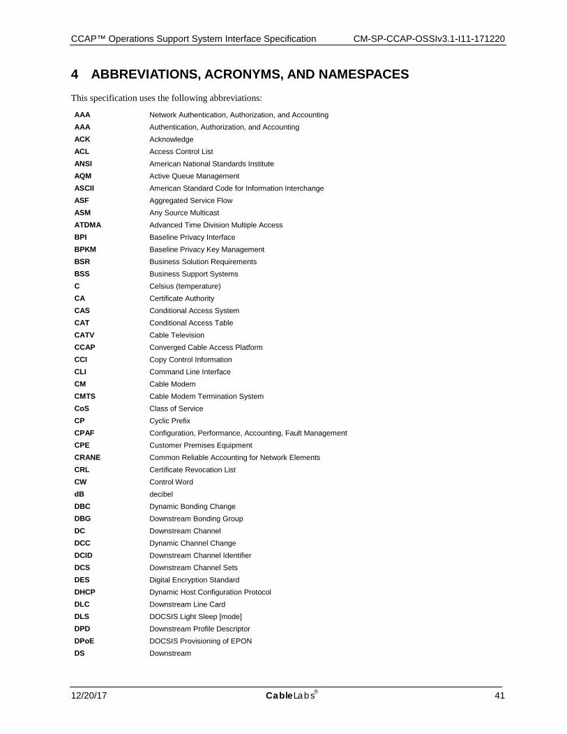
CCAP™ Operations Support System Interface Specification CM-SP-CCAP-OSSIv3.1-I11-171220
12/20/17 CableLabs 41
4 ABBREVIATIONS, ACRONYMS, AND NAMESPACES This specification uses the following abbreviations:
AAA Network Authentication, Authorization, and Accounting AAA Authentication, Authorization, and Accounting ACK Acknowledge ACL Access Control List ANSI American National Standards Institute AQM Active Queue Management ASCII American Standard Code for Information Interchange ASF Aggregated Service Flow ASM Any Source Multicast ATDMA Advanced Time Division Multiple Access BPI Baseline Privacy Interface BPKM Baseline Privacy Key Management BSR Business Solution Requirements BSS Business Support Systems C Celsius (temperature) CA Certificate Authority CAS Conditional Access System CAT Conditional Access Table CATV Cable Television CCAP Converged Cable Access Platform CCI Copy Control Information CLI Command Line Interface CM Cable Modem CMTS Cable Modem Termination System CoS Class of Service CP Cyclic Prefix CPAF Configuration, Performance, Accounting, Fault Management CPE Customer Premises Equipment CRANE Common Reliable Accounting for Network Elements CRL Certificate Revocation List CW Control Word dB decibel DBC Dynamic Bonding Change DBG Downstream Bonding Group DC Downstream Channel DCC Dynamic Channel Change DCID Downstream Channel Identifier DCS Downstream Channel Sets DES Digital Encryption Standard DHCP Dynamic Host Configuration Protocol DLC Downstream Line Card DLS DOCSIS Light Sleep [mode] DPD Downstream Profile Descriptor DPoE DOCSIS Provisioning of EPON DS Downstream
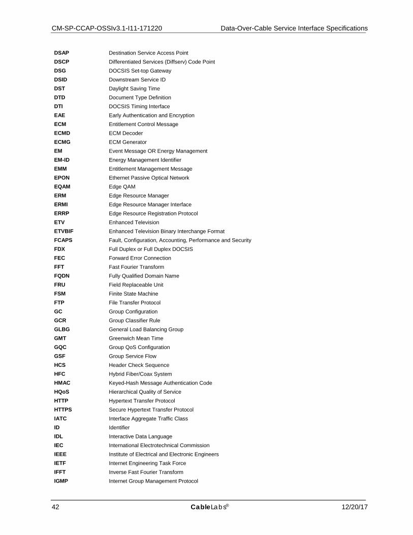
CM-SP-CCAP-OSSIv3.1-I11-171220 Data-Over-Cable Service Interface Specifications
42 CableLabs® 12/20/17
DSAP Destination Service Access Point DSCP Differentiated Services (Diffserv) Code Point DSG DOCSIS Set-top Gateway DSID Downstream Service ID DST Daylight Saving Time DTD Document Type Definition DTI DOCSIS Timing Interface EAE Early Authentication and Encryption ECM Entitlement Control Message ECMD ECM Decoder ECMG ECM Generator EM Event Message OR Energy Management EM-ID Energy Management Identifier EMM Entitlement Management Message EPON Ethernet Passive Optical Network EQAM Edge QAM ERM Edge Resource Manager ERMI Edge Resource Manager Interface ERRP Edge Resource Registration Protocol ETV Enhanced Television ETVBIF Enhanced Television Binary Interchange Format FCAPS Fault, Configuration, Accounting, Performance and Security FDX Full Duplex or Full Duplex DOCSIS FEC Forward Error Connection FFT Fast Fourier Transform FQDN Fully Qualified Domain Name FRU Field Replaceable Unit FSM Finite State Machine FTP File Transfer Protocol GC Group Configuration GCR Group Classifier Rule GLBG General Load Balancing Group GMT Greenwich Mean Time GQC Group QoS Configuration GSF Group Service Flow HCS Header Check Sequence HFC Hybrid Fiber/Coax System HMAC Keyed-Hash Message Authentication Code HQoS Hierarchical Quality of Service HTTP Hypertext Transfer Protocol HTTPS Secure Hypertext Transfer Protocol IATC Interface Aggregate Traffic Class ID Identifier IDL Interactive Data Language IEC International Electrotechnical Commission IEEE Institute of Electrical and Electronic Engineers IETF Internet Engineering Task Force IFFT Inverse Fast Fourier Transform IGMP Internet Group Management Protocol
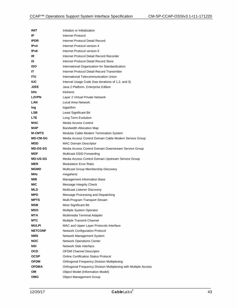
CCAP™ Operations Support System Interface Specification CM-SP-CCAP-OSSIv3.1-I11-171220
12/20/17 CableLabs 43
INIT Initialize or Initialization IP Internet Protocol IPDR Internet Protocol Detail Record IPv4 Internet Protocol version 4 IPv6 Internet Protocol version 6 IR Internet Protocol Detail Record Recorder IS Internet Protocol Detail Record Store ISO International Organization for Standardization IT Internet Protocol Detail Record Transmitter ITU International Telecommunication Union IUC Interval Usage Code (has iterations of 1,2, and 3) J2EE Java 2 Platform, Enterprise Edition kHz kilohertz L2VPN Layer 2 Virtual Private Network LAN Local Area Network log logarithm LSB Least Significant Bit LTE Long Term Evolution MAC Media Access Control MAP Bandwidth Allocation Map M-CMTS Modular Cable Modem Termination System MD-CM-SG Media Access Control Domain Cable Modem Service Group MDD MAC Domain Descriptor MD-DS-SG Media Access Control Domain Downstream Service Group MDF Multicast DSID Forwarding MD-US-SG Media Access Control Domain Upstream Service Group MER Modulation Error Ratio MGMD Multicast Group Membership Discovery MHz megahertz MIB Management Information Base MIC Message Integrity Check MLD Multicast Listener Discovery MPD Message Processing and Dispatching MPTS Multi-Program Transport Stream MSB Most Significant Bit MSO Multiple System Operator MTA Multimedia Terminal Adapter MTC Multiple Transmit Channel MULPI MAC and Upper Layer Protocols Interface NETCONF Network Configuration Protocol NMS Network Management System NOC Network Operations Center NSI Network Side Interface OCD OFDM Channel Descriptor OCSP Online Certification Status Protocol OFDM Orthogonal Frequency Division Multiplexing OFDMA Orthogonal Frequency Division Multiplexing with Multiple Access OM Object Model (Information Model) OMG Object Management Group
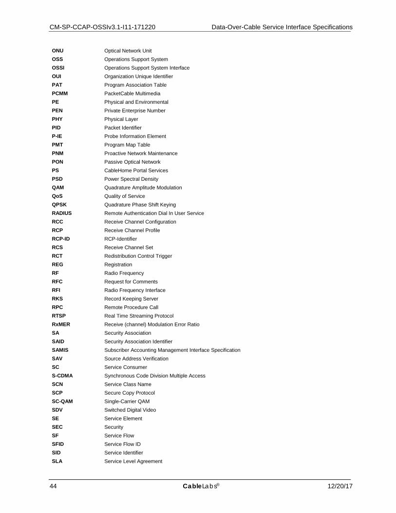
CM-SP-CCAP-OSSIv3.1-I11-171220 Data-Over-Cable Service Interface Specifications
44 CableLabs® 12/20/17
ONU Optical Network Unit OSS Operations Support System OSSI Operations Support System Interface OUI Organization Unique Identifier PAT Program Association Table PCMM PacketCable Multimedia PE Physical and Environmental PEN Private Enterprise Number PHY Physical Layer PID Packet Identifier P-IE Probe Information Element PMT Program Map Table PNM Proactive Network Maintenance PON Passive Optical Network PS CableHome Portal Services PSD Power Spectral Density QAM Quadrature Amplitude Modulation QoS Quality of Service QPSK Quadrature Phase Shift Keying RADIUS Remote Authentication Dial In User Service RCC Receive Channel Configuration RCP Receive Channel Profile RCP-ID RCP-Identifier RCS Receive Channel Set RCT Redistribution Control Trigger REG Registration RF Radio Frequency RFC Request for Comments RFI Radio Frequency Interface RKS Record Keeping Server RPC Remote Procedure Call RTSP Real Time Streaming Protocol RxMER Receive (channel) Modulation Error Ratio SA Security Association SAID Security Association Identifier SAMIS Subscriber Accounting Management Interface Specification SAV Source Address Verification SC Service Consumer S-CDMA Synchronous Code Division Multiple Access SCN Service Class Name SCP Secure Copy Protocol SC-QAM Single-Carrier QAM SDV Switched Digital Video SE Service Element SEC Security SF Service Flow SFID Service Flow ID SID Service Identifier SLA Service Level Agreement
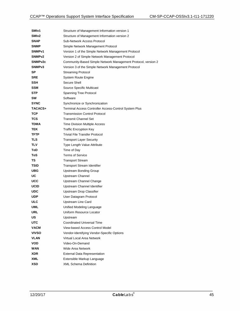
CCAP™ Operations Support System Interface Specification CM-SP-CCAP-OSSIv3.1-I11-171220
12/20/17 CableLabs 45
SMIv1 Structure of Management Information version 1 SMIv2 Structure of Management Information version 2 SNAP Sub-Network Access Protocol SNMP Simple Network Management Protocol SNMPv1 Version 1 of the Simple Network Management Protocol SNMPv2 Version 2 of Simple Network Management Protocol SNMPv2c Community-Based Simple Network Management Protocol, version 2 SNMPv3 Version 3 of the Simple Network Management Protocol SP Streaming Protocol SRE System Route Engine SSH Secure Shell SSM Source Specific Multicast STP Spanning Tree Protocol SW Software SYNC Synchronize or Synchronization TACACS+ Terminal Access Controller Access-Control System Plus TCP Transmission Control Protocol TCS Transmit Channel Set TDMA Time Division Multiple Access TEK Traffic Encryption Key TFTP Trivial File Transfer Protocol TLS Transport Layer Security TLV Type Length Value Attribute ToD Time of Day ToS Terms of Service TS Transport Stream TSID Transport Stream Identifier UBG Upstream Bonding Group UC Upstream Channel UCC Upstream Channel Change UCID Upstream Channel Identifier UDC Upstream Drop Classifier UDP User Datagram Protocol ULC Upstream Line Card UML Unified Modeling Language URL Uniform Resource Locator US Upstream UTC Coordinated Universal Time VACM View-based Access Control Model VIVSO Vendor-Identifying Vendor-Specific Options VLAN Virtual Local Area Network VOD Video-On-Demand WAN Wide Area Network XDR External Data Representation XML Extensible Markup Language XSD XML Schema Definition
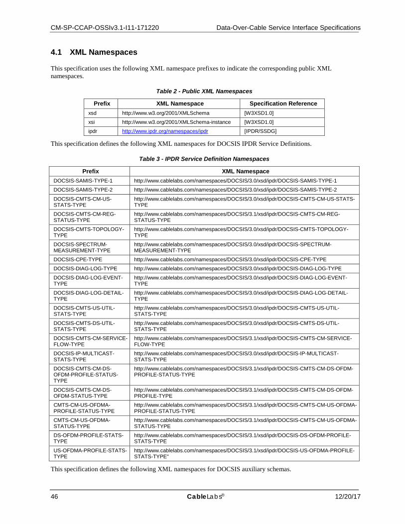
CM-SP-CCAP-OSSIv3.1-I11-171220 Data-Over-Cable Service Interface Specifications
46 CableLabs® 12/20/17
4.1 XML Namespaces
This specification uses the following XML namespace prefixes to indicate the corresponding public XML namespaces.
Table 2 - Public XML Namespaces
Prefix XML Namespace Specification Reference xsd http://www.w3.org/2001/XMLSchema [W3XSD1.0]
xsi http://www.w3.org/2001/XMLSchema-instance [W3XSD1.0]
ipdr http://www.ipdr.org/namespaces/ipdr [IPDR/SSDG]
This specification defines the following XML namespaces for DOCSIS IPDR Service Definitions.
Table 3 - IPDR Service Definition Namespaces
Prefix XML Namespace DOCSIS-SAMIS-TYPE-1 http://www.cablelabs.com/namespaces/DOCSIS/3.0/xsd/ipdr/DOCSIS-SAMIS-TYPE-1
DOCSIS-SAMIS-TYPE-2 http://www.cablelabs.com/namespaces/DOCSIS/3.0/xsd/ipdr/DOCSIS-SAMIS-TYPE-2
DOCSIS-CMTS-CM-US-STATS-TYPE
http://www.cablelabs.com/namespaces/DOCSIS/3.0/xsd/ipdr/DOCSIS-CMTS-CM-US-STATS-TYPE
DOCSIS-CMTS-CM-REG-STATUS-TYPE
http://www.cablelabs.com/namespaces/DOCSIS/3.1/xsd/ipdr/DOCSIS-CMTS-CM-REG-STATUS-TYPE
DOCSIS-CMTS-TOPOLOGY-TYPE
http://www.cablelabs.com/namespaces/DOCSIS/3.0/xsd/ipdr/DOCSIS-CMTS-TOPOLOGY-TYPE
DOCSIS-SPECTRUM-MEASUREMENT-TYPE
http://www.cablelabs.com/namespaces/DOCSIS/3.0/xsd/ipdr/DOCSIS-SPECTRUM-MEASUREMENT-TYPE
DOCSIS-CPE-TYPE http://www.cablelabs.com/namespaces/DOCSIS/3.0/xsd/ipdr/DOCSIS-CPE-TYPE
DOCSIS-DIAG-LOG-TYPE http://www.cablelabs.com/namespaces/DOCSIS/3.0/xsd/ipdr/DOCSIS-DIAG-LOG-TYPE
DOCSIS-DIAG-LOG-EVENT-TYPE
http://www.cablelabs.com/namespaces/DOCSIS/3.0/xsd/ipdr/DOCSIS-DIAG-LOG-EVENT-TYPE
DOCSIS-DIAG-LOG-DETAIL-TYPE
http://www.cablelabs.com/namespaces/DOCSIS/3.0/xsd/ipdr/DOCSIS-DIAG-LOG-DETAIL-TYPE
DOCSIS-CMTS-US-UTIL-STATS-TYPE
http://www.cablelabs.com/namespaces/DOCSIS/3.0/xsd/ipdr/DOCSIS-CMTS-US-UTIL-STATS-TYPE
DOCSIS-CMTS-DS-UTIL-STATS-TYPE
http://www.cablelabs.com/namespaces/DOCSIS/3.0/xsd/ipdr/DOCSIS-CMTS-DS-UTIL-STATS-TYPE
DOCSIS-CMTS-CM-SERVICE-FLOW-TYPE
http://www.cablelabs.com/namespaces/DOCSIS/3.1/xsd/ipdr/DOCSIS-CMTS-CM-SERVICE-FLOW-TYPE
DOCSIS-IP-MULTICAST-STATS-TYPE
http://www.cablelabs.com/namespaces/DOCSIS/3.0/xsd/ipdr/DOCSIS-IP-MULTICAST-STATS-TYPE
DOCSIS-CMTS-CM-DS-OFDM-PROFILE-STATUS-TYPE
http://www.cablelabs.com/namespaces/DOCSIS/3.1/xsd/ipdr/DOCSIS-CMTS-CM-DS-OFDM-PROFILE-STATUS-TYPE
DOCSIS-CMTS-CM-DS-OFDM-STATUS-TYPE
http://www.cablelabs.com/namespaces/DOCSIS/3.1/xsd/ipdr/DOCSIS-CMTS-CM-DS-OFDM-PROFILE-TYPE
CMTS-CM-US-OFDMA-PROFILE-STATUS-TYPE
http://www.cablelabs.com/namespaces/DOCSIS/3.1/xsd/ipdr/DOCSIS-CMTS-CM-US-OFDMA-PROFILE-STATUS-TYPE
CMTS-CM-US-OFDMA-STATUS-TYPE
http://www.cablelabs.com/namespaces/DOCSIS/3.1/xsd/ipdr/DOCSIS-CMTS-CM-US-OFDMA-STATUS-TYPE
DS-OFDM-PROFILE-STATS-TYPE
http://www.cablelabs.com/namespaces/DOCSIS/3.1/xsd/ipdr/DOCSIS-DS-OFDM-PROFILE-STATS-TYPE
US-OFDMA-PROFILE-STATS-TYPE
http://www.cablelabs.com/namespaces/DOCSIS/3.1/xsd/ipdr/DOCSIS-US-OFDMA-PROFILE-STATS-TYPE"
This specification defines the following XML namespaces for DOCSIS auxiliary schemas.
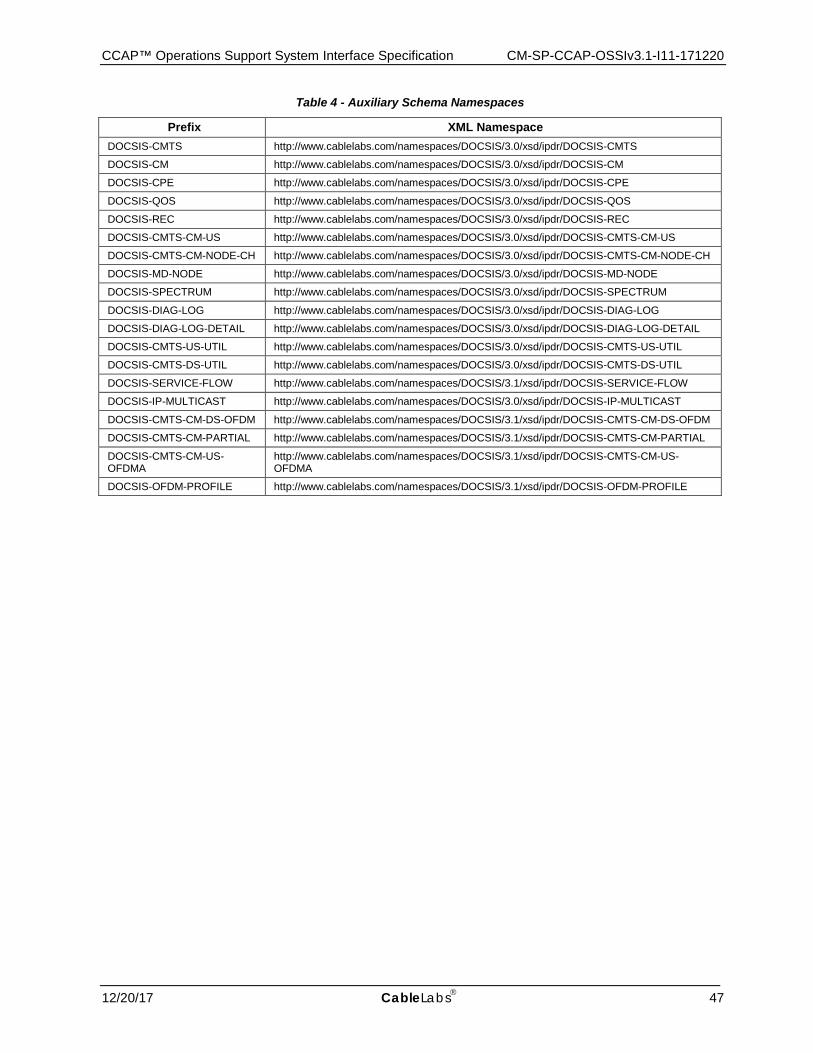
CCAP™ Operations Support System Interface Specification CM-SP-CCAP-OSSIv3.1-I11-171220
12/20/17 CableLabs 47
Table 4 - Auxiliary Schema Namespaces
Prefix XML Namespace DOCSIS-CMTS http://www.cablelabs.com/namespaces/DOCSIS/3.0/xsd/ipdr/DOCSIS-CMTS
DOCSIS-CM http://www.cablelabs.com/namespaces/DOCSIS/3.0/xsd/ipdr/DOCSIS-CM
DOCSIS-CPE http://www.cablelabs.com/namespaces/DOCSIS/3.0/xsd/ipdr/DOCSIS-CPE
DOCSIS-QOS http://www.cablelabs.com/namespaces/DOCSIS/3.0/xsd/ipdr/DOCSIS-QOS
DOCSIS-REC http://www.cablelabs.com/namespaces/DOCSIS/3.0/xsd/ipdr/DOCSIS-REC
DOCSIS-CMTS-CM-US http://www.cablelabs.com/namespaces/DOCSIS/3.0/xsd/ipdr/DOCSIS-CMTS-CM-US
DOCSIS-CMTS-CM-NODE-CH http://www.cablelabs.com/namespaces/DOCSIS/3.0/xsd/ipdr/DOCSIS-CMTS-CM-NODE-CH
DOCSIS-MD-NODE http://www.cablelabs.com/namespaces/DOCSIS/3.0/xsd/ipdr/DOCSIS-MD-NODE
DOCSIS-SPECTRUM http://www.cablelabs.com/namespaces/DOCSIS/3.0/xsd/ipdr/DOCSIS-SPECTRUM
DOCSIS-DIAG-LOG http://www.cablelabs.com/namespaces/DOCSIS/3.0/xsd/ipdr/DOCSIS-DIAG-LOG
DOCSIS-DIAG-LOG-DETAIL http://www.cablelabs.com/namespaces/DOCSIS/3.0/xsd/ipdr/DOCSIS-DIAG-LOG-DETAIL
DOCSIS-CMTS-US-UTIL http://www.cablelabs.com/namespaces/DOCSIS/3.0/xsd/ipdr/DOCSIS-CMTS-US-UTIL
DOCSIS-CMTS-DS-UTIL http://www.cablelabs.com/namespaces/DOCSIS/3.0/xsd/ipdr/DOCSIS-CMTS-DS-UTIL
DOCSIS-SERVICE-FLOW http://www.cablelabs.com/namespaces/DOCSIS/3.1/xsd/ipdr/DOCSIS-SERVICE-FLOW
DOCSIS-IP-MULTICAST http://www.cablelabs.com/namespaces/DOCSIS/3.0/xsd/ipdr/DOCSIS-IP-MULTICAST
DOCSIS-CMTS-CM-DS-OFDM http://www.cablelabs.com/namespaces/DOCSIS/3.1/xsd/ipdr/DOCSIS-CMTS-CM-DS-OFDM
DOCSIS-CMTS-CM-PARTIAL http://www.cablelabs.com/namespaces/DOCSIS/3.1/xsd/ipdr/DOCSIS-CMTS-CM-PARTIAL
DOCSIS-CMTS-CM-US-OFDMA
http://www.cablelabs.com/namespaces/DOCSIS/3.1/xsd/ipdr/DOCSIS-CMTS-CM-US-OFDMA
DOCSIS-OFDM-PROFILE http://www.cablelabs.com/namespaces/DOCSIS/3.1/xsd/ipdr/DOCSIS-OFDM-PROFILE
CM-SP-CCAP-OSSIv3.1-I11-171220 Data-Over-Cable Service Interface Specifications
48 CableLabs® 12/20/17
5 OVERVIEW
5.1 FCAPS Network Management Model
The International Telecommunication Union (ITU) Recommendation [ITU-T M.3400] defines a set of management categories, referred to as the FCAPS model, represented by the individual management categories of Fault, Configuration, Accounting, Performance and Security. Telecommunications operators, including MSOs, commonly use this model to manage large networks of devices. This specification uses these management categories to organize the requirements for the configuration and management of the CCAP platform.
Fault management seeks to identify, isolate, correct and record system faults. Configuration management modifies system configuration variables and collects configuration information. Accounting management collects usage statistics for subscribers, sets usage quotas and bills users according to their use of the system. Performance management focuses on the collection of performance metrics, analysis of these metrics and the setting of thresholds and rate limits. Security management encompasses identification and authorization of users and equipment, provides audit logs and alerting functions, as well as providing vulnerability assessment.
Each of these management categories is discussed in further detail in the following sections.
5.1.1 Fault Management
Fault management is a proactive and on-demand network management function that allows non-standard/abnormal operation on the network to be detected, diagnosed, and corrected. A typical use case involves network elements detecting service-impacting abnormalities; when detected, an autonomous event (often referred to as an alarm notification) is sent to the network operations center (NOC) to alert the MSO of a possible fault condition in the network affecting a customer's service. Once the MSO receives the event notification, further troubleshooting and diagnostics can be performed by the MSO to correct the fault condition and restore the service to proper operation. Example Fault Management use cases are shown in the following diagram.
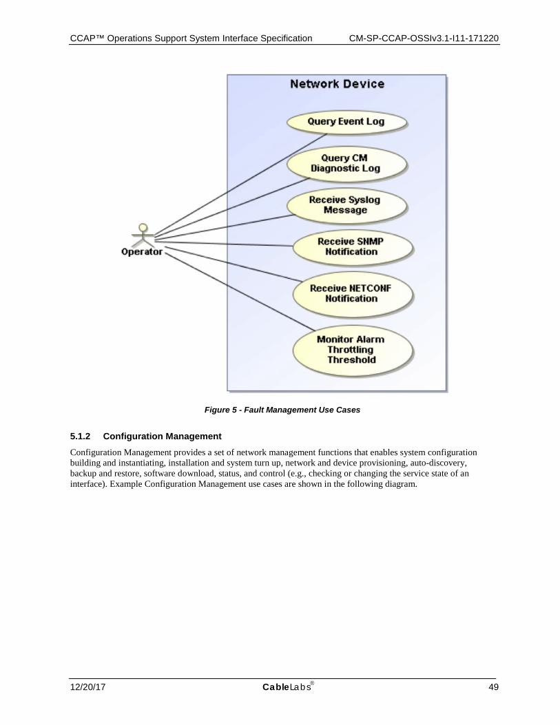
CCAP™ Operations Support System Interface Specification CM-SP-CCAP-OSSIv3.1-I11-171220
12/20/17 CableLabs 49
Figure 5 - Fault Management Use Cases
5.1.2 Configuration Management
Configuration Management provides a set of network management functions that enables system configuration building and instantiating, installation and system turn up, network and device provisioning, auto-discovery, backup and restore, software download, status, and control (e.g., checking or changing the service state of an interface). Example Configuration Management use cases are shown in the following diagram.

CM-SP-CCAP-OSSIv3.1-I11-171220 Data-Over-Cable Service Interface Specifications
50 CableLabs® 12/20/17
Figure 6 - Configuration Management Use Cases
Configuration Management is primarily concerned with network control via modifying operating parameters on network elements such as the CCAP. Configuration parameters could include both physical resources (for example, an Ethernet interface) and logical objects (for example, QoS parameters for a given service flow).
While the network is in operation, Configuration Management is responsible for monitoring the configuration state and making changes in response to commands by a management system or some other network management function.
For example, a performance management function may detect that response time is degrading due to a high number of uncorrected frames, and may issue a Configuration Management change to modify the modulation type from 16-QAM to QPSK. A Fault Management function may detect and isolate a fault and may issue a configuration change to mitigate or correct that fault.
5.1.3 Accounting Management
Accounting Management is a network management function that allows MSOs to measure the use of network services by subscribers for the purposes of cost estimation and subscriber billing. The CCAP is the network
CCAP™ Operations Support System Interface Specification CM-SP-CCAP-OSSIv3.1-I11-171220
12/20/17 CableLabs 51
element that is responsible for providing the usage statistics to support billing. Subscriber Accounting Management Interface Specification (SAMIS) is an example of an implemented Accounting Management function. Billing is outside the scope of this specification.
5.1.4 Performance Management
Performance Management is a proactive and on-demand network management function. The ITU Recommendation [ITU-T M.3400] defines its role as gathering and analyzing "statistical data for the purpose of monitoring and correcting the behavior and effectiveness of the network, network equipment, or other equipment and to aid in planning, provisioning, maintenance and the measurement of quality." A Performance Management use case might include the NOC performing periodic (15 min, for example) collections of QoS measurements from network elements to perform monitoring and identification of any potential performance issues that may be occurring with the service being monitored. With the historical data that has been collected, trending analysis can be performed to identify issues that may be related to certain times of day or other corollary events. The MSO can run reports on the data to identify suspect problems in service quality, or the NOC application can be provisioned, so that when certain performance thresholds are violated, the MSO is automatically notified that a potential service quality problem may be pending. Significant intelligence can be integrated into the NOC application to automate the ability to detect the possible degradation of a customer's service quality, and take actions to correct the condition. Service level agreement compliance is not possible without strong performance management.
Performance Management functions include collecting statistics of parameters such as number of frames lost at the MAC layer and number of codeword errors at the PHY layer. These monitoring functions are used to determine the health of the network and whether the offered Quality of Service (QoS) to the subscriber is met. The quality of signal at the PHY layer is an indication of plant conditions.
5.1.5 Security Management
Security Management provides for the management of network and operator security, as well as providing an umbrella of security for the telecommunications management network functions. Security Management functions include authentication, access control, data confidentiality, data integrity, event detection, and reporting. A Security Management use case might include providing authentication and data confidentiality when transferring a configuration file that contains the entire configuration data set for the device to a network element. These functions are covered in context within this specification.
5.2 Management Architectural Overview
Figure 7 illustrates the CCAP management architecture from the MSO back office interface perspective. The CM and CCAP reside within the Network Layer where services are provided to end Subscribers and various metrics are collected about network and service performance, among other things. Various management servers reside in the Network Management Layer within the MSO back office to provision, monitor and administer the Network Elements within the Network Layer (CM in this case). These management servers include, but are not limited to:
• SNMP Manager - performs SNMP queries against a CCAP's SNMP Agent. • Configuration File Server - has the responsibility of transferring XML configuration files to the CCAP. • Notification Receiver - receives autonomous SNMP and optional NETCONF notifications and Syslog
messages from a CCAP. • DHCP Server - has the responsibility of assigning a CCAP its IPv4 and/or IPv6 addresses as well as other
DHCP parameters. • Time Server - provides a CCAP with current Time of Day (ToD). • IPDR Collectors - primary and secondary - collect bulk data statistics, such as usage metrics, via the IPDR/SP
protocol. • Certificate Revocation Server - provides information and status for security certificates.
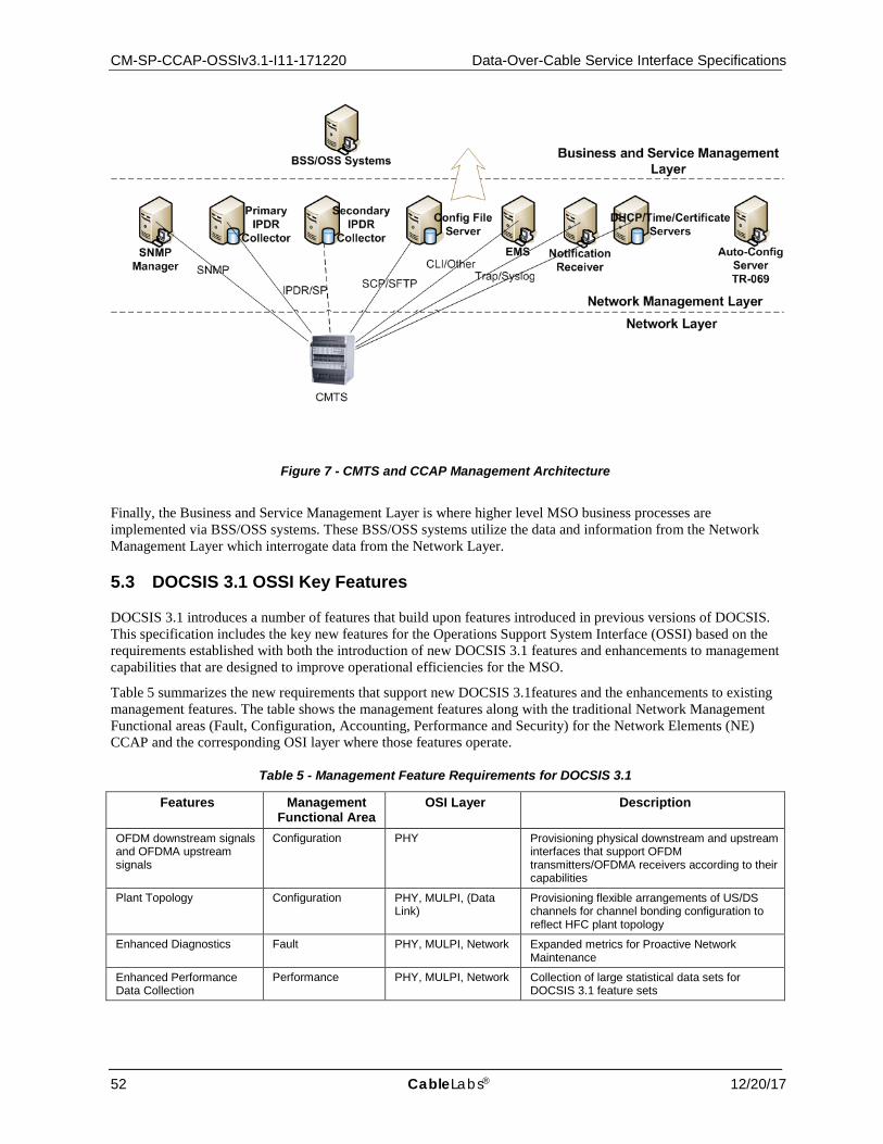
CM-SP-CCAP-OSSIv3.1-I11-171220 Data-Over-Cable Service Interface Specifications
52 CableLabs® 12/20/17
Figure 7 - CMTS and CCAP Management Architecture
Finally, the Business and Service Management Layer is where higher level MSO business processes are implemented via BSS/OSS systems. These BSS/OSS systems utilize the data and information from the Network Management Layer which interrogate data from the Network Layer.
5.3 DOCSIS 3.1 OSSI Key Features
DOCSIS 3.1 introduces a number of features that build upon features introduced in previous versions of DOCSIS. This specification includes the key new features for the Operations Support System Interface (OSSI) based on the requirements established with both the introduction of new DOCSIS 3.1 features and enhancements to management capabilities that are designed to improve operational efficiencies for the MSO.
Table 5 summarizes the new requirements that support new DOCSIS 3.1features and the enhancements to existing management features. The table shows the management features along with the traditional Network Management Functional areas (Fault, Configuration, Accounting, Performance and Security) for the Network Elements (NE) CCAP and the corresponding OSI layer where those features operate.
Table 5 - Management Feature Requirements for DOCSIS 3.1
Features Management Functional Area
OSI Layer Description
OFDM downstream signals and OFDMA upstream signals
Configuration PHY Provisioning physical downstream and upstream interfaces that support OFDM transmitters/OFDMA receivers according to their capabilities
Plant Topology Configuration PHY, MULPI, (Data Link)
Provisioning flexible arrangements of US/DS channels for channel bonding configuration to reflect HFC plant topology
Enhanced Diagnostics Fault PHY, MULPI, Network Expanded metrics for Proactive Network Maintenance
Enhanced Performance Data Collection
Performance PHY, MULPI, Network Collection of large statistical data sets for DOCSIS 3.1 feature sets
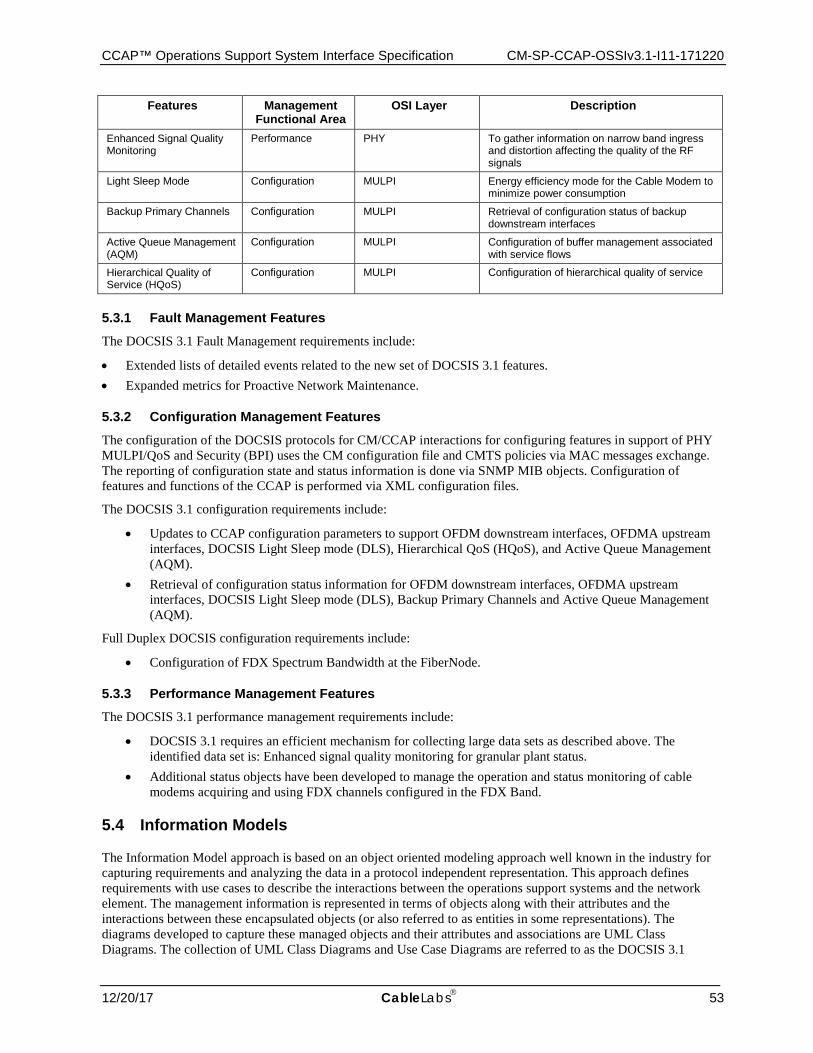
CCAP™ Operations Support System Interface Specification CM-SP-CCAP-OSSIv3.1-I11-171220
12/20/17 CableLabs 53
Features Management Functional Area
OSI Layer Description
Enhanced Signal Quality Monitoring
Performance PHY To gather information on narrow band ingress and distortion affecting the quality of the RF signals
Light Sleep Mode Configuration MULPI Energy efficiency mode for the Cable Modem to minimize power consumption
Backup Primary Channels Configuration MULPI Retrieval of configuration status of backup downstream interfaces
Active Queue Management (AQM)
Configuration MULPI Configuration of buffer management associated with service flows
Hierarchical Quality of Service (HQoS)
Configuration MULPI Configuration of hierarchical quality of service
5.3.1 Fault Management Features
The DOCSIS 3.1 Fault Management requirements include:
• Extended lists of detailed events related to the new set of DOCSIS 3.1 features. • Expanded metrics for Proactive Network Maintenance.
5.3.2 Configuration Management Features
The configuration of the DOCSIS protocols for CM/CCAP interactions for configuring features in support of PHY MULPI/QoS and Security (BPI) uses the CM configuration file and CMTS policies via MAC messages exchange. The reporting of configuration state and status information is done via SNMP MIB objects. Configuration of features and functions of the CCAP is performed via XML configuration files.
The DOCSIS 3.1 configuration requirements include:
• Updates to CCAP configuration parameters to support OFDM downstream interfaces, OFDMA upstream interfaces, DOCSIS Light Sleep mode (DLS), Hierarchical QoS (HQoS), and Active Queue Management (AQM).
• Retrieval of configuration status information for OFDM downstream interfaces, OFDMA upstream interfaces, DOCSIS Light Sleep mode (DLS), Backup Primary Channels and Active Queue Management (AQM).
Full Duplex DOCSIS configuration requirements include:
• Configuration of FDX Spectrum Bandwidth at the FiberNode.
5.3.3 Performance Management Features The DOCSIS 3.1 performance management requirements include:
• DOCSIS 3.1 requires an efficient mechanism for collecting large data sets as described above. The identified data set is: Enhanced signal quality monitoring for granular plant status.
• Additional status objects have been developed to manage the operation and status monitoring of cable modems acquiring and using FDX channels configured in the FDX Band.
5.4 Information Models
The Information Model approach is based on an object oriented modeling approach well known in the industry for capturing requirements and analyzing the data in a protocol independent representation. This approach defines requirements with use cases to describe the interactions between the operations support systems and the network element. The management information is represented in terms of objects along with their attributes and the interactions between these encapsulated objects (or also referred to as entities in some representations). The diagrams developed to capture these managed objects and their attributes and associations are UML Class Diagrams. The collection of UML Class Diagrams and Use Case Diagrams are referred to as the DOCSIS 3.1
CM-SP-CCAP-OSSIv3.1-I11-171220 Data-Over-Cable Service Interface Specifications
54 CableLabs® 12/20/17
Information Models. With the introduction of several new, complex features in DOCSIS 3.0 and DOCSIS 3.1 and the operator needs for a more proactive and efficient approach to management information, information modeling methodologies offer the ability to reuse the same definitions when new protocols are introduced in the future.
The managed objects are then represented in a protocol specific form referred to as a management data model. The management data models when using SNMP are described using the Structure of Management Information Version 2 (SMIv2) [RFC 2578] and the design of these models is determined by the capabilities of the protocol. The management data models when using NETCONF are described using the YANG data modeling language [RFC 6020]. The management data models when using IPDR/SP are described using the IPDR Service Definition Schemas [IPDR/SSDG]. The management data models when using XML configuration file download are described using XML Schema [W3XSD1.0].
Refer to Appendix VII for information modeling concepts used throughout this specification.
CCAP™ Operations Support System Interface Specification CM-SP-CCAP-OSSIv3.1-I11-171220
12/20/17 CableLabs 55
6 CONFIGURATION MANAGEMENT DOCSIS 3.0 introduced a new methodology and approach for configuration management in the CCAP by moving away from using the SNMP interface to using an XML-based methodology as described in this section.
In addition to the XML-based approach to modify the attribute values stored in the CCAP, vendor-specific methods such as a Command Line Interface (CLI) or an HTTP interface could be present. Irrespective of the method used, it is necessary to assure the data integrity as a result of changes performed using different interfaces. For example when the attribute value is modified using one management interface, this changed value is reported when that attribute is accessed from any of the other interfaces. When a change in the value of the attribute does not succeed, requesting the same change from another interface also results in failure (assuming the same level of access control for all those interfaces for the specific operation). If an event is generated as a result of making the change in one management interface, this is reported independent of how the change was initiated.
6.1 CCAP Configuration Theory of Operation
The CCAP combines the functionality of an EQAM with a CMTS. While these are distinct functions, the configuration of the CCAP will treat these functions in a consolidated way. To facilitate the configuration of such a complex and dense device, this specification describes two methods for configuring the device:
• Processing of an XML-based configuration file transferred to the device and executed locally • Configuring the device via the NETCONF protocol
Aspects of CCAP configuration include:
• Standard data model for configuration, with vendor-specific extensions for the inclusion of proprietary features • XML-based configuration file • Ability to configure a full set of standardized and vendor-proprietary configuration elements • Ability to configure a partial set of standardized and vendor-proprietary configuration elements • Light-weight protocols for transferring configuration files to and from the CCAP for XML-based file
configuration • NETCONF options to manage the CCAP configuration
It is anticipated that the CCAP will contain only basic default settings in its startup configuration when initially powered on, and the operator will begin configuration of the CCAP via serial console connection. Basic default settings are vendor-specific. The following sections define standardized CCAP configuration mechanisms and processes.
6.2 CCAP Configuration and Transport Protocol Requirements
6.2.1 Configuration Object Datastore
The CCAP implements the standard configuration objects defined by this specification.
These configuration objects control CCAP behavior and, along with any vendor-proprietary configurations, are referred to as the "running-config".
The CCAP MUST provide a method for saving the state of the running-config to non-volatile memory. For NETCONF-based configuration, the NETCONF "copy-config" operation protocol provides this mechanism. However, for XML file-based configuration, this mechanism will be vendor-specific.
The configuration objects stored in non-volatile memory are referred to as the "startup-config".
6.2.2 DHCP Relay Agent Requirements
The CCAP MUST support the configuration of the relay function of the Dynamic Host Configuration Protocol, as specified in [MULPIv3.1].

CM-SP-CCAP-OSSIv3.1-I11-171220 Data-Over-Cable Service Interface Specifications
56 CableLabs® 12/20/17
The CCAP MUST support the ability to be configured with multiple concurrent DHCPv6 server addresses for routing mode operation.
If no DHCPv6 server addresses are configured on the CCAP, the CCAP SHOULD forward upstream DHCPv6 messages out of its network side interfaces to the DHCPv6 multicast group.
The CCAP MUST support configuration of at least four distinct DHCP helper addresses, so that devices such as CMs, MTAs, and CPE can be directed to separate DHCP servers by a CCAP operating in non-routing mode.
The CCAP MUST support the configuration of relay agent and VIVSO options. This does not imply that all DOCSIS features of the CCAP need to be governed by this setting.
The CCAP MUST support the CableLabs DHCPv6 VIVSO option for CM MAC address in RELAY-FORW. This is the equivalent of DHCPv4 option 82 remote-id for both CM and CPE.
The CCAP MUST support the ability to configure the throttling rate of DHCP renews (unicast) to abate flooding of the DHCP server for routing mode operation.
6.2.3 Dynamic Management of QAMs
When the downloaded configuration file contains updates to the QAM channel parameter configuration, the CCAP can send an ERMI-1 UPDATE message with a Service Status indicating "maintenance mode" for the particular QAM channel(s) affected. Once there are no active dynamic sessions and no traffic on the static UDP ports for each QAM channel, the channel is taken down, updates made, and then brought up and advertised with a new UPDATE.
For details, refer to the EQAM Dynamic Provisioning section of [PMI].
There can be a minimum number of preconfigured QAMs for DOCSIS and an additional set of channels that are demand based. When demand is low, those additional channels are available for other services. Conversely, when demand is high, more of these resources are assigned to DOCSIS, up to a configurable limit.
6.2.3.1 Dynamic Assignment of SDV/VOD QAMs The ERM will control QAMs for SDV and VOD.
6.2.4 Video Configuration Requirements
The CCAP MUST enable adjustability of the size of the de-jitter buffer.
6.2.5 DOCSIS Configuration Requirements
The CCAP MUST support the configuration of blocked bandwidth limits.
The CCAP MUST support the ability to configure Concatenation (configurable on/off for each MAC domain, for pre-DOCSIS 3.0 modems, MAC wildcard).
The CCAP MUST support the ability to configure Fragmentation (configurable on/off for each MAC domain, for pre-DOCSIS 3.0 modems, MAC wildcard).
The CCAP MUST support the ability to configure enabling/disabling IPv6 provisioning mode via the DOCSIS MDD message.
The CCAP MUST support the ability to configure steering a modem to a different CMTS or CCAP based on TLV 43.11 - Service Type Identifier per [MULPIv3.1].
6.3 CCAP XML File-Based Configuration
6.3.1 CCAP XML Configuration File Theory of Operation
The CCAP will be configurable via the execution of an XML-based configuration file that holds the configuration details for the platform. The XML configuration files are conformant to the XML schemas based on the CCAP

CCAP™ Operations Support System Interface Specification CM-SP-CCAP-OSSIv3.1-I11-171220
12/20/17 CableLabs 57
configuration object model specified in this document. A given XML configuration file for the CCAP platform is expected to be validated against these schemas.
The use case for configuring a CCAP with an XML configuration file is depicted in Figure 8.
Figure 8 - CCAP XML File-Based Configuration Use Case
The CCAP parses and processes XML configuration files that are stored locally. These files are generated by processes and systems out of scope for this specification. Operators place XML configuration files in CCAP local storage via file transfer. Before executing an XML configuration file, the CCAP verifies that it has not been corrupted in the file transfer process. The XML configuration file is then validated against the configuration file schema to ensure that the configuration is valid. This validation step can also be performed independent of configuration file execution.
The CCAP parses the entire XML configuration file and processes the configuration objects represented in the file in a vendor-proprietary manner. The CCAP allows partial execution of configuration files; invalid configuration instructions can be ignored while valid instructions will still be processed. The CCAP can also reject configuration instructions if they cannot be met by the capabilities of the hardware present.
The CCAP XML configuration file process is defined in the following sections.
6.3.2 CCAP XML Configuration Files The CCAP MUST support the use of an XML configuration file to set the values of standard CCAP configuration objects. A CCAP XML configuration file is an XML UTF-8 text representation of the keysets and attribute values of a set of configuration objects.
The CCAP MUST support the processing of an XML configuration file, which includes configuration elements that are related to hardware that is not installed in the CCAP chassis at the time of processing to allow for pre-provisioning.
Many configuration objects in the CCAP XML configuration file are nested within other configuration objects. The configuration file can contain the full hierarchy of elements where all element contexts are explicit. For an example of a configuration in a nested hierarchy, see Appendix I.1, CCAP XML Configuration File.
This specification makes use of the unified modeling language (UML) to define the common configuration elements of a CCAP. XML schemas and YANG modules are based on the CCAP configuration UML object model.
CM-SP-CCAP-OSSIv3.1-I11-171220 Data-Over-Cable Service Interface Specifications
58 CableLabs® 12/20/17
The CCAP MUST support an XML configuration file that is conformant to the most recent version of the following XML schema: [email protected], where yyyy-mm-dd represents the date on which the most recent version of the schema was published.
This schema is available at the following location: http://www.cablelabs.com/YANG/DOCSIS.
A single XML configuration file - containing both standard as well as vendor-proprietary elements - will be delivered to the CCAP. The file makes use of both the standard and vendor-proprietary namespaces. An XML configuration file may include proprietary extensions targeting multiple vendors. While validating or executing the configuration file, the CCAP is expected to ignore proprietary extensions it does not support.
The CCAP MUST only accept an XML configuration file if it indicates the version number(s) of the schemas/modules for which the file is intended to be conformant.
6.3.3 XML Configuration File Checksum
When the XML configuration file is downloaded or uploaded between the CCAP and a remote host, there exists a possibility that contents of the file may get corrupted or lost during a transfer.
The CCAP MUST provide a POSIX-compliant MD5 "checksum" command used to verify the integrity of a downloaded XML configuration file.
The operator can compare the output of the checksum command for the file on the CCAP with that of a checksum command on the remote host where the configuration file originated to confirm that the file has not been altered or corrupted.
6.3.4 XML Configuration File Validation
Before attempting to execute a given XML configuration file on a CCAP, the operator might want to first validate the file against the XML schemas supported.
On a CCAP, it is anticipated that the operator will attempt to validate an XML configuration file that contains elements belonging to schemas of a single CCAP vendor. Note that even when an XML configuration file is successfully validated, errors could still be encountered when the same file is later executed by the operator.
The CCAP MUST support a CLI command to validate an XML configuration file located on a local file system against the XML schemas supported by the software running on the CCAP.
The CCAP validate command MUST validate that the XML configuration file is well-formed XML.
The CCAP validate command SHOULD also check the XML configuration file for the following:
• References to undefined configuration data • Attribute value constraints • Resource constraints
When an XML configuration file successfully validates, the CCAP MUST log an event with severity level "Info" (Event ID: 70000103).
When the validation of the XML configuration file experiences errors, the CCAP MUST create a validation output log file to be stored on a local file system.
The CCAP MUST name the validation output log file such that the name contains the configuration file name (e.g., <XML configuration file name>-<user>-<time>-validate.log.) and is different from the filename of the execution output log file defined in Section 6.3.6.
When the validation of the XML configuration file experiences any error, the CCAP MUST include the following fields for each error entry, separated by a semi-colon (;), in the validation output log file:
• line number of the error • configuration element, including namespace • error message
CCAP™ Operations Support System Interface Specification CM-SP-CCAP-OSSIv3.1-I11-171220
12/20/17 CableLabs 59
When an XML configuration file fails to validate, the CCAP MUST provide an error message to the user via the user interface (regardless of the type of terminal session in use by the user), log an event with severity level "Notice" (Event ID: 70000104), and log the errored lines to the validation output log file as defined above.
6.3.5 XML Configuration File Execution Command and NETCONF Operations
Since the XML Configuration File downloaded to the CCAP is not automatically executed by the CCAP, it is necessary to define a CCAP CLI command to perform specific parsing and execution actions on a given XML Configuration File.
The CCAP MUST support a CLI command to execute a full XML configuration file located on a local file system, where the CCAP executes the operations specified for each element in the file.
The CCAP MUST support a CLI command to execute a partial XML configuration file located on a local file system, where the CCAP executes the operations specified for each element in the file.
The CCAP MUST support the "merge", "replace", and "delete" operations defined in section 7.2 of [RFC 6241]. This specification does not intend to make use of the "create" operation.
All configuration changes of an XML file are conceptually executed simultaneously, without regard to the order of the individual object operations in the file. The actual execution of an XML configuration file is expected to be implemented as a sequence of individual element operations in a vendor-specific order. Individual element operations can succeed or fail; the CCAP will log unsuccessful element operations.
The CCAP MUST NOT reject a configuration object because it is dependent upon or related to a configuration object that occurs later in the configuration file and has not yet been processed.
For example, it is valid to execute an XML configuration file that contains an object_A that refers to a new object_B, when the object_A reference appears earlier in the file than the creation of object_B.
A "Full" XML configuration file is one that is intended to replace the entire set of configuration objects on the CCAP.
A Full XML configuration file will contain the operation="replace" attribute in the <ccap:ccap> tag at the root of the configuration tree. When the CCAP saves or exports the current running-config or the startup-config to an XML format, the CCAP MUST insert operation="replace" in a single top-level <ccap:ccap> tag.
A "Partial" XML configuration file is one that is intended to augment the current running-config, replace a subset of the configuration objects on the CCAP, or to act on "control" objects (such as objects that allow a log to be reset or a diagnostic mode to be enabled).
A Partial XML configuration file will contain all of the parent object containers for the objects being configured, all the way up the configuration hierarchy to the "ccap" container. Because of this, caution is to be taken when using the "replace" or "delete" operations. While a "merge" operation will only update the attributes that are explicitly provided in the XML configuration file, the "replace" and "delete" operations act upon all objects within the configuration tree. This could cause the entire device configuration to be deleted.
A Partial XML configuration file using a merge or delete operation may exclude mandatory configurable attributes if they are not a key for the configuration object being acted upon. When a partial configuration is using a merge or delete operation, the CCAP MUST ignore validation errors related to missing mandatory configuration attributes unless the missing attribute is the key for the configuration object being acted upon.
The following is an example of how to use the merge operation to update the configuration of a QAM channel on an existing downstream RF port. The file would have the following structure: <ccap:ccap xmlns:xsi="http://www.w3.org/2001/XMLSchema-instance" SchemaVersion="2013-04-04" xsi:schemaLocation="urn:cablelabs:params:xml:ns:yang:ccap [email protected]" xmlns:ccap="urn:cablelabs:params:xml:ns:yang:ccap" operation="merge"> <chassis> <slot> <slot-number>1</slot-number> <rf-line-card> <ds-rf-port> <port-number>1</port-number>
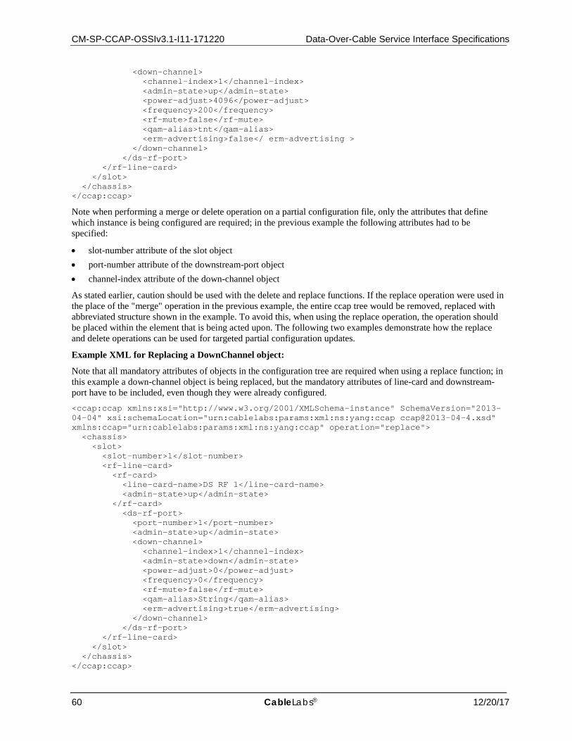
CM-SP-CCAP-OSSIv3.1-I11-171220 Data-Over-Cable Service Interface Specifications
60 CableLabs® 12/20/17
<down-channel> <channel-index>1</channel-index> <admin-state>up</admin-state> <power-adjust>4096</power-adjust> <frequency>200</frequency> <rf-mute>false</rf-mute> <qam-alias>tnt</qam-alias> <erm-advertising>false</ erm-advertising > </down-channel> </ds-rf-port> </rf-line-card> </slot> </chassis> </ccap:ccap>
Note when performing a merge or delete operation on a partial configuration file, only the attributes that define which instance is being configured are required; in the previous example the following attributes had to be specified:
• slot-number attribute of the slot object • port-number attribute of the downstream-port object • channel-index attribute of the down-channel object
As stated earlier, caution should be used with the delete and replace functions. If the replace operation were used in the place of the "merge" operation in the previous example, the entire ccap tree would be removed, replaced with abbreviated structure shown in the example. To avoid this, when using the replace operation, the operation should be placed within the element that is being acted upon. The following two examples demonstrate how the replace and delete operations can be used for targeted partial configuration updates.
Example XML for Replacing a DownChannel object:
Note that all mandatory attributes of objects in the configuration tree are required when using a replace function; in this example a down-channel object is being replaced, but the mandatory attributes of line-card and downstream-port have to be included, even though they were already configured. <ccap:ccap xmlns:xsi="http://www.w3.org/2001/XMLSchema-instance" SchemaVersion="2013-04-04" xsi:schemaLocation="urn:cablelabs:params:xml:ns:yang:ccap [email protected]" xmlns:ccap="urn:cablelabs:params:xml:ns:yang:ccap" operation="replace"> <chassis> <slot> <slot-number>1</slot-number> <rf-line-card> <rf-card> <line-card-name>DS RF 1</line-card-name> <admin-state>up</admin-state> </rf-card> <ds-rf-port> <port-number>1</port-number> <admin-state>up</admin-state> <down-channel> <channel-index>1</channel-index> <admin-state>down</admin-state> <power-adjust>0</power-adjust> <frequency>0</frequency> <rf-mute>false</rf-mute> <qam-alias>String</qam-alias> <erm-advertising>true</erm-advertising> </down-channel> </ds-rf-port> </rf-line-card> </slot> </chassis> </ccap:ccap>

CCAP™ Operations Support System Interface Specification CM-SP-CCAP-OSSIv3.1-I11-171220
12/20/17 CableLabs 61
Example XML for Deleting a DownChannel Object: <ccap:ccap xmlns:xsi="http://www.w3.org/2001/XMLSchema-instance" SchemaVersion="2013-04-04" xsi:schemaLocation="urn:cablelabs:params:xml:ns:yang:ccap [email protected]" xmlns:ccap="urn:cablelabs:params:xml:ns:yang:ccap" operation="delete"> <chassis> <slot> <slot-number>1</slot-number> <rf-line-card> <ds-rf-port> <port-number>1</port-number> <down-channel> <channel-index>100</channel-index> </down-channel> </ds-rf-port> </rf-line-card> </slot> </chassis> </ccap:ccap>
The CCAP will support only one occurrence of the same NETCONF operation ("merge", "replace", or "delete") in a single file. If an operator needs to perform more than one operation type to configure the CCAP, separate configuration files will need to be created and the operator will execute those files sequentially.
If an XML configuration file does not contain one and only one explicit operation type value of "merge", "replace", or "delete", upon attempted execution of the file, the CCAP MUST reject the entire file, make no changes to the running-config, and log the fatal error as an event with a severity level "Warning" (Event ID: 70000108).
If the ccap:ccap node in the XML configuration file has a "replace" operation value, and the subtree in the XML configuration file for that node is missing one or more mandatory elements (either standard elements or vendor-extensions), then the CCAP MUST retain the mandatory elements, attempt the execution of the remaining elements in the file, and log the non-fatal errors as an event with a severity level "Error" (Event ID: 70000107).
The CCAP MUST allow the pre-provisioning of configuration objects associated with line cards that are not yet present in the chassis.
Note that if a "replace" operation value is used, and parts of the subtree in the XML configuration file are missing one or more non-mandatory (vendor-specific or standard) elements, then the CCAP deletes the absent non-mandatory elements from its running-config.
Conversely, for a "merge" operation, the CCAP MUST preserve both standard and vendor-extension objects in the affected subtree that are not present in the merged XML configuration file.
For a "delete" operation, the CCAP MUST delete both standard and vendor-extension objects in the affected subtree.
If an XML configuration file contains an explicit "create" operation value, upon attempted execution of the file the CCAP MUST reject the entire file, make no changes to the running-config, and log the fatal error as an event with a severity level of "Warning" (Event ID: 70000108).
6.3.6 XML Configuration File Parsing and Error Logging
Before a configuration file is applied to the CCAP, the CCAP performs several checks against the file. If the configuration file does not pass these checks, the CCAP will reject the file. The CCAP can also reject individual objects within the configuration file. In all rejection cases, the CCAP will log the rejection as an error.
When executed, the CCAP MUST verify that the configuration file is well-formed XML.
If the CCAP fails to verify the file is well-formed as part of an execution, the CCAP MUST reject the file, make no changes to the running-config, log the fatal error as an event with a severity level "Warning" (Event ID: 70000109), log the errored lines to the execution output log file in the format defined later in this section, and provide an error message to the user interface, regardless of the type of terminal session in use by the user.
CM-SP-CCAP-OSSIv3.1-I11-171220 Data-Over-Cable Service Interface Specifications
62 CableLabs® 12/20/17
If the module/schema version number contained within the executed XML configuration file is not compatible with the module/schema set supported by the CCAP, the CCAP MUST reject the file, make no changes to the running-config, log the fatal error as an event with a severity level "Warning" (Event ID: 70000109), log the line(s) where the module/schema version mismatch was detected to the execution output log file in the format defined later in this section, and provide an error message to the user interface, regardless of the type of terminal session in use by the user.
When the execution of the XML configuration file completes without error, the CCAP MUST log an event with severity level "Notice" (Event ID: 70000105).
When the execution of the XML configuration file completes without error, the CCAP MAY create an execution output log file containing execution time, user, and XML configuration filename information.
The CCAP supports "partial execution" of an XML configuration file, where certain elements in the file are successfully executed and other elements in the file are unable to be executed.
When the execution of the XML configuration file experiences errors, the CCAP MUST create an execution output log file to be stored on a local file system.
The CCAP MUST name the execution output log file such that the name contains the executed configuration file (e.g., <executed XML configuration file name>-<user>-<time>-out.log) and is different from the filename of the validation output log file defined in Section 6.3.4.
When the execution of the XML configuration file experiences any error, the CCAP MUST use a standard format for each error entry, separated by a semi-colon (;), in the execution output log file and include:
• line number of the error • configuration element, including namespace • error message
When an executed XML configuration file contains elements that are not supported by the CCAP, the CCAP MUST process the elements it does support, and log the non-fatal error as an event with severity level "Error" (Event ID: 70000106), and log the unsupported lines to the execution output log file as defined above.
The CCAP MUST perform the validate function as an initial step of the execute command before any changes are applied to the configuration store.
If the CCAP fails to validate the file as part of an execution, the CCAP MUST reject the file, make no changes to the running-config, log the fatal error as an event with a severity level "Warning" (Event ID: 70000109), log the errored lines to the execution output log file as defined above, and provide an error message to the user interface, regardless of the type of terminal session in use by the user.
If during the execution of a validated configuration file an error is encountered, the CCAP MUST apply the configuration of the non-errored elements, log the non-fatal error as an event with severity level "Error" (Event ID: 70000107), log the errored lines to the execution output log file as defined above, and provide an error message to the user interface, regardless of the type of terminal session in use by the user.
6.3.7 File Transfer Mechanisms
The CCAP will implement several file transfer mechanisms that can be used to "download" an XML configuration file or software image from an external host to the CCAP or "upload" a copy of an XML configuration file or software image to an external host.
The CCAP MUST support the Secure Copy Protocol (SCP) - based on Secure Shell version 2 - for both file download and upload operations.
The CCAP MUST support the initiation of Secure Copy download and upload operations from both a remote host and from the CCAP CLI.
The CCAP MUST support the Trivial File Transfer Protocol (TFTP), as specified in [RFC 1350], for both file download and upload operations.
CCAP™ Operations Support System Interface Specification CM-SP-CCAP-OSSIv3.1-I11-171220
12/20/17 CableLabs 63
Since TFTP has no inherent authentication mechanism, the CCAP MUST only support the initiation of Trivial File Transfer download and upload operations from the CCAP CLI by an authenticated and authorized user.
The CCAP SHOULD support Secure Hypertext Transfer Protocol (HTTPS) for both file download and upload operations.
The CCAP SHOULD support the initiation of HTTPS download and upload operations from both a remote host and from the CCAP CLI.
If HTTPS download initiation from a remote host is supported by the CCAP, the CCAP MUST implement TLS validation of the X.509 certificate presented by the remote host.
For both SCP and HTTPS file download and upload operations, the CCAP MUST support the ability to authenticate the file transfer connection via TACACS+ and RADIUS as well as usernames configured locally on the CCAP.
If an initiated file transfer fails, the CCAP MUST log an event with severity level "Error" (Event ID: 70000102) and provide an error message to the user interface indicating that the file transfer failed, regardless of the type of terminal session in use by the user.
6.3.7.1 TLS for HTTPS Authentication of the remote host server by the CCAP is performed by validating the certificate provided by the remote host during TLS setup.
The CCAP MUST negotiate TLS-related integrity protection and encryption features at the TLS layer.
The remote host will always offer TLS cipher suites to be used for the session, as specified in [RFC 5246].
The CCAP MUST decide which TLS cipher suites are used, as specified in [RFC 5246].
The CCAP MUST verify that the data is sent and received according to [RFC 5246]. This verification is also used to detect if the received data has been tampered with.
The CCAP MUST support the following TLS profiles (per [RFC 5246]):
• TLS_RSA_WITH_3DES_EDE_CBC_SHA • TLS_RSA_WITH_AES_128_CBC_SHA
The use of NULL integrity protection and/or NULL encryption by the CCAP is not anticipated.
The remote host will present X.509 digital certificates, per [RFC 5280], for authentication in TLS, as profiled in Table 6.
Table 6 - TLS Certificate Profile
TLS Server Certificates Subject Name Form
C=<Country> O=<Company> CN=<FQDN> FQDN is the remote host's fully qualified domain name (e.g., es.example.com). Only a single FQDN is allowed in the CN field. Additional fields may be present in the subject name.
Intended Usage These certificates are used to authenticate TLS handshake exchanges (and encrypt when using RSA key exchange).
Validity Period Set by operator policy
Modulus Length 1024, 1536, 2048
Extensions KeyUsage[critical](digitalSignature, keyEncipherment) extendedKeyUsage (id-kp-serverAuth, id-kp-clientAuth) authorityKeyIdentifier (keyIdentifier=<subjectKeyIdentifier value from CA cert>)
Remote host certificates will be issued by the cable operator.

CM-SP-CCAP-OSSIv3.1-I11-171220 Data-Over-Cable Service Interface Specifications
64 CableLabs® 12/20/17
The CCAP MUST verify that the remote host's TLS certificates are part of a certificate chain that chains up to the cable operator's certificate authority (CA).
If changes other than the certificate serial number, validity period and the value of the signature exist in the root certificate that was sent by the remote host to the CCAP in comparison to the known root certificate, the CCAP MUST conclude that the certificate verification has failed.
The CCAP MUST build the certificate chain and validate the TLS certificate according to the "Certificate Path Validation" procedures described in [RFC 5280].
6.3.8 Exporting the Configuration Object Data Store
The CCAP MUST support a CLI command to export the startup-config into an XML configuration file to be stored on local non-volatile storage.
The CCAP MUST support a CLI command to export the current running-config of the device to an XML Configuration File to be stored on local non-volatile storage.
The CCAP MUST support the export of XML configuration files in a format that conforms to the standard CCAP schema set, including optional vendor extensions.
The CCAP MUST allow the user to specify the full file system path and filename of the exported XML Configuration File.
The CCAP SHOULD support XML configuration file export operations with both concise and verbose options. The output of the concise export operation does not include optional attributes that are set to the default value/have not been configured. The output of the verbose operation does include these items.
When exporting to an XML configuration file, the CCAP MUST encrypt in a vendor-specific way the content of configuration items intended to be "secret", including, but not limited to:
• passwords (including lawful intercept) • DOCSIS shared secret • TACACS+ and RADIUS keys • routing protocol keys
The CCAP MUST be able to import a previously exported configuration file containing encrypted attributes, where the configuration file was previously exported from that vendor's CCAP devices.
It is expected that encrypted attributes in an exported XML configuration file can be imported on another CCAP produced by the same vendor.
6.4 CCAP NETCONF-Based Configuration
6.4.1 NETCONF Theory of Operation
The CCAP may also support configuration via the NETCONF protocol. In this case configuration instructions are sent using XML-encoded remote procedure calls (RPCs) in NETCONF protocol messages from a configuration management tool to the CCAP. The XML configuration data, representing the CCAP configuration, is conformant to the YANG modules specified in this document.
The use case for configuring a CCAP via NETCONF is depicted in Figure 9.
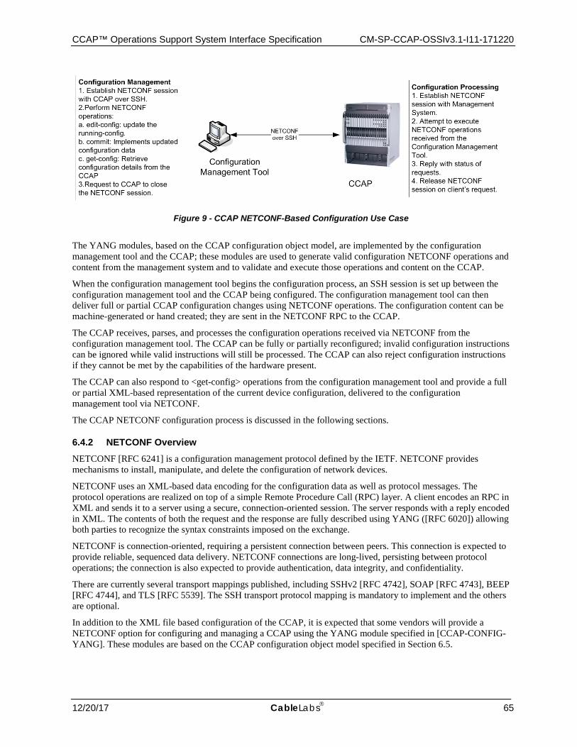
CCAP™ Operations Support System Interface Specification CM-SP-CCAP-OSSIv3.1-I11-171220
12/20/17 CableLabs 65
Figure 9 - CCAP NETCONF-Based Configuration Use Case
The YANG modules, based on the CCAP configuration object model, are implemented by the configuration management tool and the CCAP; these modules are used to generate valid configuration NETCONF operations and content from the management system and to validate and execute those operations and content on the CCAP.
When the configuration management tool begins the configuration process, an SSH session is set up between the configuration management tool and the CCAP being configured. The configuration management tool can then deliver full or partial CCAP configuration changes using NETCONF operations. The configuration content can be machine-generated or hand created; they are sent in the NETCONF RPC to the CCAP.
The CCAP receives, parses, and processes the configuration operations received via NETCONF from the configuration management tool. The CCAP can be fully or partially reconfigured; invalid configuration instructions can be ignored while valid instructions will still be processed. The CCAP can also reject configuration instructions if they cannot be met by the capabilities of the hardware present.
The CCAP can also respond to <get-config> operations from the configuration management tool and provide a full or partial XML-based representation of the current device configuration, delivered to the configuration management tool via NETCONF.
The CCAP NETCONF configuration process is discussed in the following sections.
6.4.2 NETCONF Overview NETCONF [RFC 6241] is a configuration management protocol defined by the IETF. NETCONF provides mechanisms to install, manipulate, and delete the configuration of network devices.
NETCONF uses an XML-based data encoding for the configuration data as well as protocol messages. The protocol operations are realized on top of a simple Remote Procedure Call (RPC) layer. A client encodes an RPC in XML and sends it to a server using a secure, connection-oriented session. The server responds with a reply encoded in XML. The contents of both the request and the response are fully described using YANG ([RFC 6020]) allowing both parties to recognize the syntax constraints imposed on the exchange.
NETCONF is connection-oriented, requiring a persistent connection between peers. This connection is expected to provide reliable, sequenced data delivery. NETCONF connections are long-lived, persisting between protocol operations; the connection is also expected to provide authentication, data integrity, and confidentiality.
There are currently several transport mappings published, including SSHv2 [RFC 4742], SOAP [RFC 4743], BEEP [RFC 4744], and TLS [RFC 5539]. The SSH transport protocol mapping is mandatory to implement and the others are optional.
In addition to the XML file based configuration of the CCAP, it is expected that some vendors will provide a NETCONF option for configuring and managing a CCAP using the YANG module specified in [CCAP-CONFIG-YANG]. These modules are based on the CCAP configuration object model specified in Section 6.5.
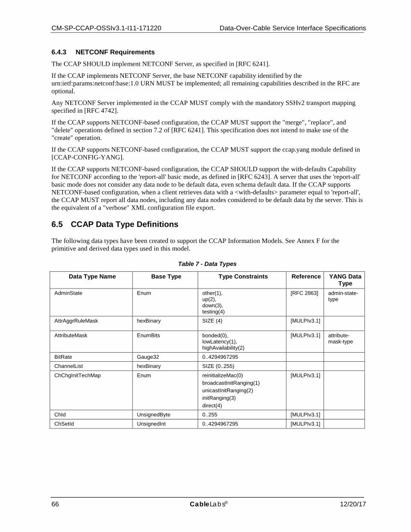
CM-SP-CCAP-OSSIv3.1-I11-171220 Data-Over-Cable Service Interface Specifications
66 CableLabs® 12/20/17
6.4.3 NETCONF Requirements
The CCAP SHOULD implement NETCONF Server, as specified in [RFC 6241].
If the CCAP implements NETCONF Server, the base NETCONF capability identified by the urn:ietf:params:netconf:base:1.0 URN MUST be implemented; all remaining capabilities described in the RFC are optional.
Any NETCONF Server implemented in the CCAP MUST comply with the mandatory SSHv2 transport mapping specified in [RFC 4742].
If the CCAP supports NETCONF-based configuration, the CCAP MUST support the "merge", "replace", and "delete" operations defined in section 7.2 of [RFC 6241]. This specification does not intend to make use of the "create" operation.
If the CCAP supports NETCONF-based configuration, the CCAP MUST support the ccap.yang module defined in [CCAP-CONFIG-YANG].
If the CCAP supports NETCONF-based configuration, the CCAP SHOULD support the with-defaults Capability for NETCONF according to the 'report-all' basic mode, as defined in [RFC 6243]. A server that uses the 'report-all' basic mode does not consider any data node to be default data, even schema default data. If the CCAP supports NETCONF-based configuration, when a client retrieves data with a <with-defaults> parameter equal to 'report-all', the CCAP MUST report all data nodes, including any data nodes considered to be default data by the server. This is the equivalent of a "verbose" XML configuration file export.
6.5 CCAP Data Type Definitions
The following data types have been created to support the CCAP Information Models. See Annex F for the primitive and derived data types used in this model.
Table 7 - Data Types
Data Type Name Base Type Type Constraints Reference YANG Data Type
AdminState Enum other(1), up(2), down(3), testing(4)
[RFC 2863] admin-state-type
AttrAggrRuleMask hexBinary SIZE (4) [MULPIv3.1]
AttributeMask EnumBits bonded(0), lowLatency(1), highAvailability(2)
[MULPIv3.1] attribute-mask-type
BitRate Gauge32 0..4294967295
ChannelList hexBinary SIZE (0..255)
ChChgInitTechMap Enum reinitializeMac(0) broadcastInitRanging(1) unicastInitRanging(2) initRanging(3) direct(4)
[MULPIv3.1]
ChId UnsignedByte 0..255 [MULPIv3.1]
ChSetId UnsignedInt 0..4294967295 [MULPIv3.1]
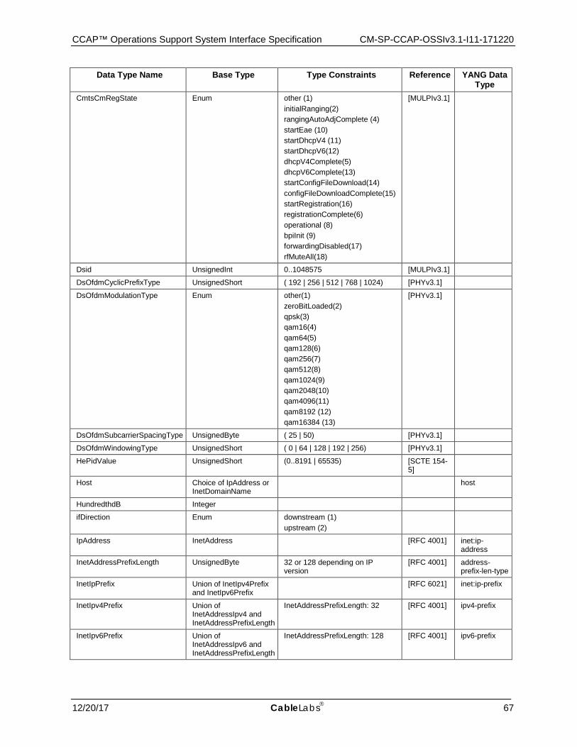
CCAP™ Operations Support System Interface Specification CM-SP-CCAP-OSSIv3.1-I11-171220
12/20/17 CableLabs 67
Data Type Name Base Type Type Constraints Reference YANG Data Type
CmtsCmRegState Enum other (1) initialRanging(2) rangingAutoAdjComplete (4) startEae (10) startDhcpV4 (11) startDhcpV6(12) dhcpV4Complete(5) dhcpV6Complete(13) startConfigFileDownload(14) configFileDownloadComplete(15) startRegistration(16) registrationComplete(6) operational (8) bpiInit (9) forwardingDisabled(17) rfMuteAll(18)
[MULPIv3.1]
Dsid UnsignedInt 0..1048575 [MULPIv3.1]
DsOfdmCyclicPrefixType UnsignedShort ( 192 | 256 | 512 | 768 | 1024) [PHYv3.1]
DsOfdmModulationType Enum other(1) zeroBitLoaded(2) qpsk(3) qam16(4) qam64(5) qam128(6) qam256(7) qam512(8) qam1024(9) qam2048(10) qam4096(11) qam8192 (12) qam16384 (13)
[PHYv3.1]
DsOfdmSubcarrierSpacingType UnsignedByte ( 25 | 50) [PHYv3.1]
DsOfdmWindowingType UnsignedShort ( 0 | 64 | 128 | 192 | 256) [PHYv3.1]
HePidValue UnsignedShort (0..8191 | 65535) [SCTE 154-5]
Host Choice of IpAddress or InetDomainName
host
HundredthdB Integer
ifDirection Enum downstream (1) upstream (2)
IpAddress InetAddress [RFC 4001] inet:ip-address
InetAddressPrefixLength UnsignedByte 32 or 128 depending on IP version
[RFC 4001] address-prefix-len-type
InetIpPrefix Union of InetIpv4Prefix and InetIpv6Prefix
[RFC 6021] inet:ip-prefix
InetIpv4Prefix Union of InetAddressIpv4 and InetAddressPrefixLength
InetAddressPrefixLength: 32 [RFC 4001] ipv4-prefix
InetIpv6Prefix Union of InetAddressIpv6 and InetAddressPrefixLength
InetAddressPrefixLength: 128 [RFC 4001] ipv6-prefix
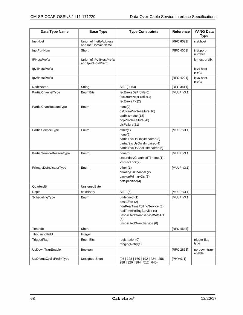
CM-SP-CCAP-OSSIv3.1-I11-171220 Data-Over-Cable Service Interface Specifications
68 CableLabs® 12/20/17
Data Type Name Base Type Type Constraints Reference YANG Data Type
InetHost Union of InetIpAddress and InetDomainName
[RFC 6021] inet:host
InetPortNum Short [RFC 4001] inet:port-number
IPHostPrefix Union of IPv4HostPrefix and Ipv6HostPrefix
ip-host-prefix
Ipv4HostPrefix ipv4-host-prefix
Ipv6HostPrefix [RFC 4291] ipv6-host-prefix
NodeName String SIZE(0..64) [RFC 3411]
PartialChannelType EnumBits fecErrorsDsProfile(0) fecErrorsNcpProfile(1) fecErrorsPlc(2)
[MULPIv3.1]
PartialChanReasonType Enum none(0) dsOfdmProfileFailure(16) dpdMismatch(18) ncpProfileFailure(20) plcFailure(21)
PartialServiceType Enum other(1) none(2) partialSvcDsOnlyImpaired(3) partialSvcUsOnlyImpaired(4) partialSvcDsAndUsImpaired(5)
[MULPIv3.1]
PartialServiceReasonType Enum none(0) secondaryChanMddTimeout(1), lostFecLock(2)
[MULPIv3.1]
PrimaryDsIndicatorType Enum other (1) primaryDsChannel (2) backupPrimaryDs (3) notSpecified(4)
[MULPIv3.1]
QuarterdB UnsignedByte
RcpId hexBinary SIZE (5) [MULPIv3.1]
SchedulingType Enum undefined (1) bestEffort (2) nonRealTimePollingService (3) realTimePollingService (4) unsolicitedGrantServiceWithAD (5) unsolicitedGrantService (6)
[MULPIv3.1]
TenthdB Short [RFC 4546]
ThousandthdB Integer
TriggerFlag EnumBits registration(0) rangingRetry(1)
trigger-flag-type
UpDownTrapEnable Boolean [RFC 2863] up-down-trap-enable
UsOfdmaCyclicPrefixType Unsigned Short (96 | 128 | 160 | 192 | 224 | 256 | 288 | 320 | 384 | 512 | 640)
[PHYv3.1]
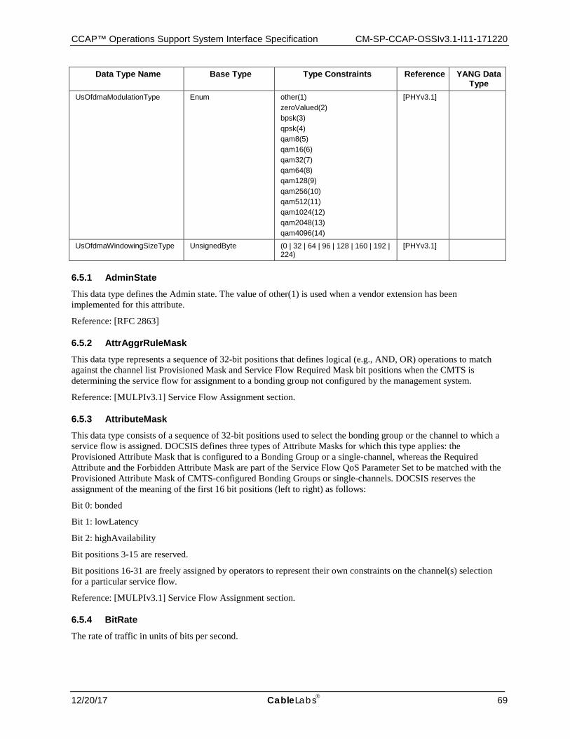
CCAP™ Operations Support System Interface Specification CM-SP-CCAP-OSSIv3.1-I11-171220
12/20/17 CableLabs 69
Data Type Name Base Type Type Constraints Reference YANG Data Type
UsOfdmaModulationType Enum other(1) zeroValued(2) bpsk(3) qpsk(4) qam8(5) qam16(6) qam32(7) qam64(8) qam128(9) qam256(10) qam512(11) qam1024(12) qam2048(13) qam4096(14)
[PHYv3.1]
UsOfdmaWindowingSizeType UnsignedByte (0 | 32 | 64 | 96 | 128 | 160 | 192 | 224)
[PHYv3.1]
6.5.1 AdminState
This data type defines the Admin state. The value of other(1) is used when a vendor extension has been implemented for this attribute.
Reference: [RFC 2863]
6.5.2 AttrAggrRuleMask
This data type represents a sequence of 32-bit positions that defines logical (e.g., AND, OR) operations to match against the channel list Provisioned Mask and Service Flow Required Mask bit positions when the CMTS is determining the service flow for assignment to a bonding group not configured by the management system.
Reference: [MULPIv3.1] Service Flow Assignment section.
6.5.3 AttributeMask
This data type consists of a sequence of 32-bit positions used to select the bonding group or the channel to which a service flow is assigned. DOCSIS defines three types of Attribute Masks for which this type applies: the Provisioned Attribute Mask that is configured to a Bonding Group or a single-channel, whereas the Required Attribute and the Forbidden Attribute Mask are part of the Service Flow QoS Parameter Set to be matched with the Provisioned Attribute Mask of CMTS-configured Bonding Groups or single-channels. DOCSIS reserves the assignment of the meaning of the first 16 bit positions (left to right) as follows:
Bit 0: bonded
Bit 1: lowLatency
Bit 2: highAvailability
Bit positions 3-15 are reserved.
Bit positions 16-31 are freely assigned by operators to represent their own constraints on the channel(s) selection for a particular service flow.
Reference: [MULPIv3.1] Service Flow Assignment section.
6.5.4 BitRate
The rate of traffic in units of bits per second.
CM-SP-CCAP-OSSIv3.1-I11-171220 Data-Over-Cable Service Interface Specifications
70 CableLabs® 12/20/17
6.5.5 ChannelList
This data type represents a unique set of channel IDs in either the upstream or the downstream direction. Each octet represents an upstream channel identifier (UCID) or a downstream channel identifier (DCID), depending on the direction of the channels within the list. The CCAP MUST ensure that this combination of channels is unique per direction within the MAC Domain.
A query to retrieve the value of an attribute of this type returns the set of channels in the channel list in ascending order of channel IDs.
6.5.6 ChChgInitTechMap
This data type enumerates the allowed initialization techniques for Dynamic Channel Change (DCC) and Dynamic Bonding Change (DBC) operations. The techniques are represented by the 5 most significant bits (MSB). Bits 0 through 4 map to initialization techniques 0 through 4.
Each bit position represents the internal associated technique as described below:
• 'reinitializeMac' Reinitialize the MAC
• 'broadcastInitRanging' Perform Broadcast initial ranging on new channel before normal operation
• 'unicastInitRanging' Perform unicast ranging on new channel before normal operation
• 'initRanging' Perform either broadcast or unicast ranging on new channel before normal operation
• 'direct' Use the new channel(s) directly without re-initializing or ranging
Multiple bits may be set to 1 to allow the CMTS to select the most suitable technique in a proprietary manner.
An empty value or a value with all bits in '0' means no channel changes allowed
References: [MULPIv3.1] Initialization Technique.
6.5.7 ChId This data type is an 8-bit number that represents a provisioned DCID or a provisioned UCID. A channel ID is unique per direction within a MAC Domain. The value zero is reserved for use when the channel ID is unknown.
References: [MULPIv3.1] Upstream Channel Descriptor (UCD) section.
6.5.8 ChSetId
This data type is a CMTS-derived unique number within a MAC Domain used to reference a Channel Set within the CMTS. Values in the range of 1 to 255 define a single-channel Channel Set and correspond to either the DCID or an UCID of that channel. Values greater than 255 indicate a Channel Set consisting of two or more channels in the same direction within the MAC Domain. The value zero is reserved for use when the Channel Set is unknown.
References: [MULPIv3.1] Channel Bonding section.
6.5.9 CmtsCmRegState
This data type defines the CM connectivity states as reported by the CMTS.
References: [MULPIv3.1] Cable Modem - CMTS Interaction section.
The enumerated values associated with the CmtsCmRegState are:
- other
'other' indicates any state not described below.
CCAP™ Operations Support System Interface Specification CM-SP-CCAP-OSSIv3.1-I11-171220
12/20/17 CableLabs 71
- initialRanging
'initialRanging' indicates that the CMTS has received an Initial Ranging Request message from the CM, and the ranging process is not yet complete.
- rangingAutoAdjComplete
'rangingAutoAdjComplete' indicates that the CM has completed initial ranging and the CMTS sends a Ranging Status of success in the RNG-RSP.
- startEae
'startEae' indicates that the CMTS has received an Auth Info message for EAE from the CM.
- startDhcpV4
'startDhcpV4' indicates that the CMTS has received a DHCPv4 DISCOVER message from the CM.
- startDhcpV6
'startDhcpV6' indicates that the CMTS has received a DHCPv6 Solicit message from the CM.
- dhcpV4Complete
'dhcpV4Complete' indicates that the CMTS has sent a DHCPv4 ACK message to the CM.
- dhcpV6Complete
'dhcpV6Complete' indicates that the CMTS has sent a DHCPv6 Reply message to the CM.
- startConfigFileDownload
'startConfigFileDownload' indicates that the CM has started the config file download. If the TFTP Proxy feature is not enabled, the CMTS may not report this state.
- configFileDownloadComplete
'configFileDownloadComplete' indicates that the CM has completed the config file download process. If the TFTP Proxy feature is not enabled, the CMTS is not required to report this state.
- startRegistration
'startRegistration' indicates that the CMTS has received a Registration Request (REG-REQ or REG-REQ-MP) from the CM.
- registrationComplete
'registrationComplete' indicates that the CMTS has received a Registration Acknowledge (REG-ACK) with a confirmation code of okay/success.
- operational
'operational' indicates that the CM has completed all necessary initialization steps and is operational.
- bpiInit
'bpiInit' indicates that the CMTS has received an Auth Info or Auth Request message as part of BPI Initialization.
- forwardingDisabled
'forwardingDisabled' indicates that the CM registration process was completed, but the network access option in the received configuration file prohibits the CM from forwarding.
- rfMuteAll
'rfMuteAll' indicates that the CM is instructed to mute all channels in the CM-CTRL-REQ message from CMTS.
The following table provides a mapping of Pre-3.0 DOCSIS and DOCSIS 3.0 registration states as reported by CMTS.
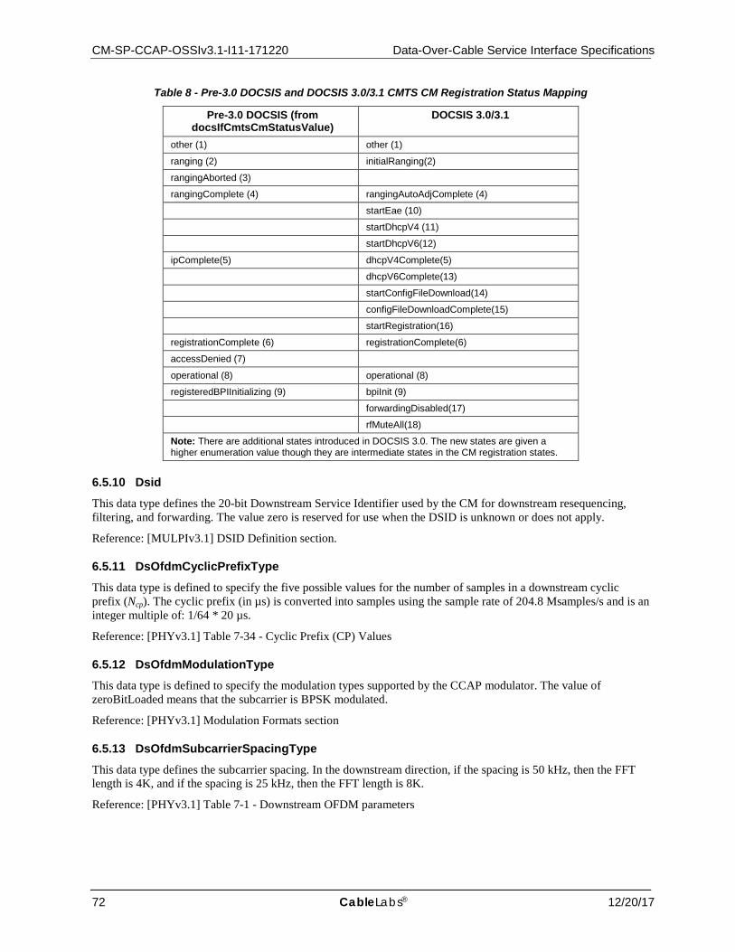
CM-SP-CCAP-OSSIv3.1-I11-171220 Data-Over-Cable Service Interface Specifications
72 CableLabs® 12/20/17
Table 8 - Pre-3.0 DOCSIS and DOCSIS 3.0/3.1 CMTS CM Registration Status Mapping
Pre-3.0 DOCSIS (from docsIfCmtsCmStatusValue)
DOCSIS 3.0/3.1
other (1) other (1)
ranging (2) initialRanging(2)
rangingAborted (3)
rangingComplete (4) rangingAutoAdjComplete (4)
startEae (10)
startDhcpV4 (11)
startDhcpV6(12)
ipComplete(5) dhcpV4Complete(5)
dhcpV6Complete(13)
startConfigFileDownload(14)
configFileDownloadComplete(15)
startRegistration(16)
registrationComplete (6) registrationComplete(6)
accessDenied (7)
operational (8) operational (8)
registeredBPIInitializing (9) bpiInit (9)
forwardingDisabled(17)
rfMuteAll(18)
Note: There are additional states introduced in DOCSIS 3.0. The new states are given a higher enumeration value though they are intermediate states in the CM registration states.
6.5.10 Dsid
This data type defines the 20-bit Downstream Service Identifier used by the CM for downstream resequencing, filtering, and forwarding. The value zero is reserved for use when the DSID is unknown or does not apply.
Reference: [MULPIv3.1] DSID Definition section.
6.5.11 DsOfdmCyclicPrefixType
This data type is defined to specify the five possible values for the number of samples in a downstream cyclic prefix (Ncp). The cyclic prefix (in µs) is converted into samples using the sample rate of 204.8 Msamples/s and is an integer multiple of: 1/64 * 20 µs.
Reference: [PHYv3.1] Table 7-34 - Cyclic Prefix (CP) Values
6.5.12 DsOfdmModulationType This data type is defined to specify the modulation types supported by the CCAP modulator. The value of zeroBitLoaded means that the subcarrier is BPSK modulated.
Reference: [PHYv3.1] Modulation Formats section
6.5.13 DsOfdmSubcarrierSpacingType
This data type defines the subcarrier spacing. In the downstream direction, if the spacing is 50 kHz, then the FFT length is 4K, and if the spacing is 25 kHz, then the FFT length is 8K.
Reference: [PHYv3.1] Table 7-1 - Downstream OFDM parameters

CCAP™ Operations Support System Interface Specification CM-SP-CCAP-OSSIv3.1-I11-171220
12/20/17 CableLabs 73
6.5.14 DsOfdmWindowingType
This data type is defined to specify the five possible values for the downstream windowing roll-off period samples. The Roll-Off Period Samples are given in number of samples per roll-off period (NRP).
Reference: [PHYv3.1] Roll-off Period (RP) Values Table
6.5.15 HePidValue
This data type represents a packet identifier (PID) value which ranges from 0 to (213 - 1). The value of 65535 indicates that either the PID is invalid or does not exist.
Reference: [SCTE 154-5]
6.5.16 Host The Host data type represents either a strongly-typed IP address or a DNS domain name. Use of this type avoids the weak validation inherent in the union-based inet:host type, as with this type an ip-address cannot be inappropriately validated as a domain-name accidentally. For a particular use of this data type, the CCAP MAY support only one of these choices: either an IP address or an FQDN.
For attributes with the Host data type, the CCAP MUST support configuring an IP address. For attributes with the Host data type, the CCAP SHOULD support configuring an FQDN.
6.5.17 HundredthdB
The HundredthdB data type represents power levels that are normally expressed in dB. Units are in hundredths of a dB. For example, 5.17 dB will be represented as 517 when the data type is HundredthdB.
6.5.18 ifDirection
Indicates a direction on an RF MAC interface. The value downstream(1) is from CCAP to CM. The value upstream(2) is from CM to CCAP.
Reference: [MULPIv3.1] Terms and Definitions section.
6.5.19 IpAddress
The IpAddress data type refers to the InetAddress textual convention defined in [RFC 4001]. It is an octet string of length 4 for an IPv4 address and of length 16 for an IPv6 address. An object of type InetAddress is always interpreted in the context of an object of InetAddressType that selects whether the InetAddress is IPv4 or IPv6.
Reference: [RFC 4001]
6.5.20 InetAddressPrefixLength
This data type corresponds to the InetAddressPrefixLength textual description defined in [RFC 4001]. It is the number of contiguous "1" bits from the most significant bit of an InetAddress.
Reference: [RFC 4001]
6.5.21 InetIpPrefix This data type is a union of InetIpv4Prefix and InetIpv6prefix and represents an IP prefix. It is IP version neutral. The format of the textual representations implies the IP version.
6.5.22 InetIpv4Prefix
This data type is a union of the InetAddressIpv4 and InetAddressPrefixLength textural conventions defined in. It corresponds to the ipv4-prefix data type defined in [RFC 6021].
Reference: [RFC 4001]
CM-SP-CCAP-OSSIv3.1-I11-171220 Data-Over-Cable Service Interface Specifications
74 CableLabs® 12/20/17
6.5.23 InetIpv6Prefix
This data type is a union of the InetAddressIpv6 and InetAddressPrefixLength textural conventions defined in [RFC 4001]. It corresponds to the ipv6-prefix data type defined in [RFC 6021].
Reference: [RFC 4001], [RFC 6021]
6.5.24 InetPortNum
The value in this data type represents the port number configured.
Reference: [RFC 4001]
6.5.25 InetHost
This data type represents a FQDN, or IPv4 address or IPv6 address and a port number.
Reference: [RFC 6021]
6.5.26 IPHostPrefix
This data type represents an IP host address plus prefix and is IP version neutral. The format of the textual representations implies the IP version. This type is similar to inet:ip-prefix.
This data type is the union of the Ipv4HostPrefix data type and the Ipv6HostPrefix data type.
6.5.27 Ipv4HostPrefix This data type represents an IPv4 host address plus the prefix length, separated by a slash. The prefix length is given by a number less than or equal to 32 following the slash character. A prefix length value of n corresponds to an IP address mask that has n contiguous 1-bits from the most significant bit (MSB) and all other bits set to 0.
This type is derived from the inet:ipv4-prefix type, which has all bits of the IPv4 address set to zero that are not part of the IPv4 prefix. Use of that type requires separate configuration of the interface host address.
The pattern for this looks like: (([0-9]|[1-9][0-9]|1[0-9][0-9]|2[0-4][0-9]|25[0-5])\.){3}([0-9]|[1-9][0-9]|1[0-9][0-9]|2[0-4][0-9]|25[0-5])/(([0-9])|([1-2][0-9])|(3[0-2]))
6.5.28 Ipv6HostPrefix
This data type is derived from the inet:ipv6-prefix type, which has all bits of the IPv6 address set to zero that are not part of the IPv6 prefix. Use of that type requires separate configuration of the interface host address. The IPv6 address is represented in the compressed format described in [RFC 4291], section 2.2, item 2 with the following additional rules: the "::" substitution is applied to the longest sequence of all-zero 16-bit chunks in an IPv6 address. If there is a tie, the first sequence of all-zero 16-bit chunks is replaced by "::". Single, all-zero 16-bit chunks are not compressed. The canonical format using lowercase characters and leading zeros are not allowed.
Reference: [RFC 4291]
The pattern for this looks like this:
((:|[0-9a-fA-F]{0,4}):)([0-9a-fA-F]{0,4}:){0,5}' + '((([0-9a-fA-F]{0,4}:)?(:|[0-9a-fA-F]{0,4}))|' + '(((25[0-5]|2[0-4][0-9]|[01]?[0-9]?[0-9])\.){3}' + '(25[0-5]|2[0-4][0-9]|[01]?[0-9]?[0-9])))' + '(/(([0-9])|([0-9]{2})|(1[0-1][0-9])|(12[0-8])))';
pattern '(([^:]+:){6}(([^:]+:[^:]+)|(.*\..*)))|' + '((([^:]+:)*[^:]+)?::(([^:]+:)*[^:]+)?)' + '(/.+)';
6.5.29 NodeName
This data type is a human readable string that represents the name of a fiber node. Internationalization is supported by conforming to the SNMP textual convention SnmpAdminString. The US-ASCII control characters (0x00 - 0x1F), the DEL character (0x7F), and the double-quote mark (0x22) are prohibited within the syntax of this data type.
CCAP™ Operations Support System Interface Specification CM-SP-CCAP-OSSIv3.1-I11-171220
12/20/17 CableLabs 75
References: [RFC 3411]
6.5.30 PartialChannelType
This data type enumerates each of the possible profiles or channel attributes which can contribute to an OFDM channel being considered a Partial Channel by the MAC layer. As more than one of these error conditions can exist at the same time this data type is based on EnumBits. The bits from low to high are:
Bit 0: fecErrorsDsProfile
Bit 1: fecErrorsNcpProfile
Bit 2: fecErrorsPlc
6.5.31 PartialChanReasonType This data type enumerates the CM-STATUS events which a CM can utilize to report a Partial Channel situation.
none(0),
dsOfdmProfileFailure(16),
dpdMismatch(18),
ncpProfileFailure(20),
plcFailure(21),
6.5.32 PartialServiceType
This data type enumerates the type of channel issue which the MAC Layer indicates is causing the CM to be in DOCSIS 3.0 Partial Service mode. The possible values are as follows:
other(1)
none(2)
partialSvcDsOnlyImpaired(3)
partialSvcUsOnlyImpaired(4)
partialSvcDsAndUsImpaired(5)
6.5.33 PartialServiceReasonType
This data type enumerates the CM-STATUS events which a CM can utilize to report a Partial Service situation.
none(0),
secondaryChanMddTimeout(1),
lostFecLock(2)
6.5.34 PrimaryDsIndicatorType
This data type enumerates the different type of Primary downstream channels. Possible values are:
• Channel - when both the CM and CCAP are using DOCSIS 3.1 mode, this value indicates that the channel is the primary channel for the CM receiving this RCC. The CCAP MUST NOT use an RCC configuration having more than one primaryDsChannel when using DOCSIS 3.1 mode. When DOCSIS 3.0 mode is in use, this value indicates that the channel is primary-capable; multiple such channels are allowed in this mode.
• backupPrimaryDs - when both the CM and CCAP are using DOCSIS 3.1 mode, this value indicates that the channel is a backup primary channel for the CM receiving this RCC. The priority-ordered list of backup primary channels sent to the CM is the same order as the backupPrimaryDs channels are
CM-SP-CCAP-OSSIv3.1-I11-171220 Data-Over-Cable Service Interface Specifications
76 CableLabs® 12/20/17
configured in RxChCfg. When DOCSIS 3.0 mode is in use, this value indicates that the channel is primary-capable; DOCSIS 3.0 does not support the backup primary channel feature.
• notSpecified - indicates that this channel has not been specified as a primary-capable channel. • other - indicates a vendor-specific value.
References: [MULPIv3.1] Receive Channel Primary Downstream Channel Indicator section in the Common Radio Frequency Interface Encodings Annex.
6.5.35 QuarterdB
The QuarterdB data type represents power levels that are normally expressed in dB. Units are in quarters of a dB.
The base data type is an unsigned byte where every bit of value is a quarter dB (e.g., a QuarterdB value of 0x5F represents 23.75 dB). The range is 0 to 63.5 dB in 1/4 dB steps. The value 0xFF is used to indicate no measurement is available for a given subcarrier. Any value over 63.5 dB is reported as 63.5 dB. Any value below 0 dB is reported as 0 dB.
Some attributes with a data type of QuarterdB choose to use HundredthdB with a quarter-dB accuracy for easier readability.
6.5.36 RcpId
This data type defines a 'Receive Channel Profile Identifier' (RCP-ID). An RCP-ID consists of a 5-octet length string where the first 3-bytes (from left to right) correspond to the Organizational Unique ID (OUI), followed by a two-byte vendor-maintained identifier to represent multiple versions or models of RCP-IDs.
References: [MULPIv3.1] RCP-ID section in the Common Radio Frequency Interface Encodings Annex.
6.5.37 SchedulingType
The scheduling service provided by a CMTS for an upstream Service Flow. This parameter is reported as 'undefined' for downstream QoS Parameter Sets.
Reference: [MULPIv3.1] Service Flow Scheduling Type section
6.5.38 TenthdB
This data type represents power levels that are normally expressed in dB. Units are in tenths of a dB; for example, 5.1 dB will be represented as 51.
Reference: [RFC 4546]
6.5.39 ThousandthdB The ThousandthdB data type represents power levels that are normally expressed in dB. Units are in thousands of a dB. For example, 5.175 dB will be represented as 5175 when the data type is ThousandthdB.
6.5.40 TriggerFlag
This data type defines the union of Diagnostic Log trigger types. Bit 0 represents the registration trigger, Bit 1 represents the ranging retry trigger.
6.5.41 UpDownTrapEnabled Indicates whether linkUp/linkDown traps should be generated for this interface. This is a boolean type, where true means that the trap is enabled.
Reference: [RFC 2863], ifLinkUpDownTrapEnable

CCAP™ Operations Support System Interface Specification CM-SP-CCAP-OSSIv3.1-I11-171220
12/20/17 CableLabs 77
6.5.42 UsOfdmaCyclicPrefixType
This data type is defined to specify the eleven possible values for the number of samples in the upstream cyclic prefix (Ncp). The cyclic prefix (in µs) is converted into samples using the sample rate of 102.4 Msamples/s and is an integer multiple of: 1/64 * 20 µs.
Reference: [PHYv3.1] Table 7-4 - Cyclic Prefix (CP) Values
6.5.43 UsOfdmaModulationType
This data type is defined to specify the modulation order of a given OFDMA subcarrier.
Reference: [PHYv3.1] Modulation Formats section
6.5.44 UsOfdmaWindowingSizeType This data type is defined to specify the eight possible values for the upstream windowing roll-off period samples. The Roll-Off Period Samples (NRP) are given in number of samples using the sample rate of 102.4 Msamples/s.
Reference: [PHYv3.1] Table 7-5 - Roll-Off Period (RP) Values
6.6 UML Configuration Object Model
6.6.1 CCAP UML Configuration Object Model Overview
The CCAP UML configuration object model, as well as the schemas based on that object model, have been divided into eight distinct groupings:
• CCAP: The Ccap object is the container of all CCAP configuration objects. • Chassis: Consists of objects for configuring the hardware components of the CCAP. • Video: Consists of those objects that are related to the EQAM functions of the CCAP, including ERM,
encryption and decryption objects. • DOCSIS: Consists of the DOCSIS configuration objects that are needed for configuring DOCSIS Mac
Domains and services such as DSG. • Network: Consists of objects related to configuring the core services for things like integrated servers, access
lists, Syslog, HTTP, FTP, SSH, and other related network services. • Interfaces: Consists of the objects needed to configure interfaces within the CCAP. • Management: Consists of objects used to configure SNMP and Fault Management for the CCAP. • EPON: Consists of the objects that are related to the DPoE configuration of the CCAP.
The CCAP configuration object model strives to make maximum re-use of existing SCTE HMS and OSSIv3.0 MIBS and object models. In some cases these models were modified to address specific issues that were CCAP-related.
The CCAP supports the configuration objects defined in the following sections via implementation of the CCAP XSD.
6.6.1.1 Default Values and Mandatory Configuration of Attributes in the Configuration Object Model
In the configuration object model attribute tables in the following sections, a default value is defined in the Default table column for some object attributes. In cases where a default value is defined for an element, the CCAP will use the specified default value if the XML configuration file does not include the attribute.
In cases where the Default column reads "vendor-specific", the CCAP MUST provide a default value of the vendor's choosing for the attribute in the implementation. In cases where the vendor is defining the default value, the operator need not include these attributes in the XML configuration file.
CM-SP-CCAP-OSSIv3.1-I11-171220 Data-Over-Cable Service Interface Specifications
78 CableLabs® 12/20/17
Attributes explicitly required in the XML configuration file are marked "Yes" in the Required Attribute column; these attributes do not have a default value. In these cases the operator needs to provide a value for these attributes in the XML configuration file when an object containing those attributes is being configured. In cases where the Required Attribute column reads "No", either a default value is provided in the table or the CCAP will provide a vendor-specific value.
6.6.1.2 Enumeration Values in the Configuration Object Model In the configuration object model attribute tables in the following sections, enumerated lists are all intended to begin at a value of "1"; in most cases, the first value will be other ("other(1)"). Since this specification borrows objects from existing MIBs, there will be cases where the enumeration values specified here do not match those of the MIB on which the object attribute was based. CCAP vendors are expected to properly translate values provided in the XML configuration file into the correct values needed for SNMP reporting via the standard MIB objects.
Note that integers are specified for each enumeration in the UML configuration object model. When the UML is translated into other formats (XSD, YANG, SNMP, etc.), the enumeration labels and/or integers are included in these outputs as appropriate. For XSD and YANG, enumeration labels will be included.
6.6.1.3 Use of Interface Names in Configuration Several configuration objects defined in this specification are identified with keys in the form of a text string name. In general, these configuration objects are modeled after interfaces that have equivalent representation in SNMP (ifTable). While this specification does not impose formal requirements on the format of interface names, CCAP vendors are expected to implement consistent conventions for assigning textual names to interfaces and disclose the rules on which such conventions are based. The CCAP SHOULD reject a configuration that includes an interface name that does not follow the vendor's naming conventions.
6.6.1.4 Unconstrained Strings in the Configuration Object Model For object attributes with a data type of String, there are cases where this specification does not provide a length constraint. For these attributes, the CCAP MAY impose a vendor-specific length constraint. If a value in the XML configuration file exceeds this vendor-specific length constraint, the CCAP SHOULD truncate the text string to that limit. In addition, if a value in the XML configuration file exceeds this vendor-specific length constraint, the CCAP MUST log the non-fatal error as an event with severity level "Error" (Event ID: 70000107), log the errored lines to the execution output log file, and provide an error message that describes the vendor-specific length constraint and details how the string was handled (truncated, rejected, etc.).
6.6.2 Vendor-Specific Extensions
A CCAP is expected to implement vendor-proprietary configuration objects beyond those defined in this specification. Standard objects are those that have been defined in the configuration UML object model, defined in the following sections. Vendor-proprietary configuration objects consist of both new configuration objects not represented in the CCAP configuration UML object model and new or modified attributes of configuration objects that exist in the CCAP configuration UML object model.
The CCAP's configuration object model can be extended via the creation of vendor-proprietary XSD schemas and/or vendor-proprietary YANG modules. A valid approach to vendor extensions is to perform extensions solely in XML schema utilizing the extension points in the standard schema (as described in Annex E) in conjunction with a vendor-defined schema. Vendor extensions can also be performed in YANG. A CCAP that supports vendor extension in YANG MUST support configuration via an XML configuration file based on an XSD schema that is the result of the conversion of the standard YANG module with extensions. Refer to Appendix IV for details on converting a YANG module to XSD.
Modifications to standard configuration objects are allowed within the specific rules defined in Annex E.
See Annex E for requirements related to implementing vendor-specific extensions to the CCAP configuration. Annex E also specifies rules for modifications to standard configuration objects.
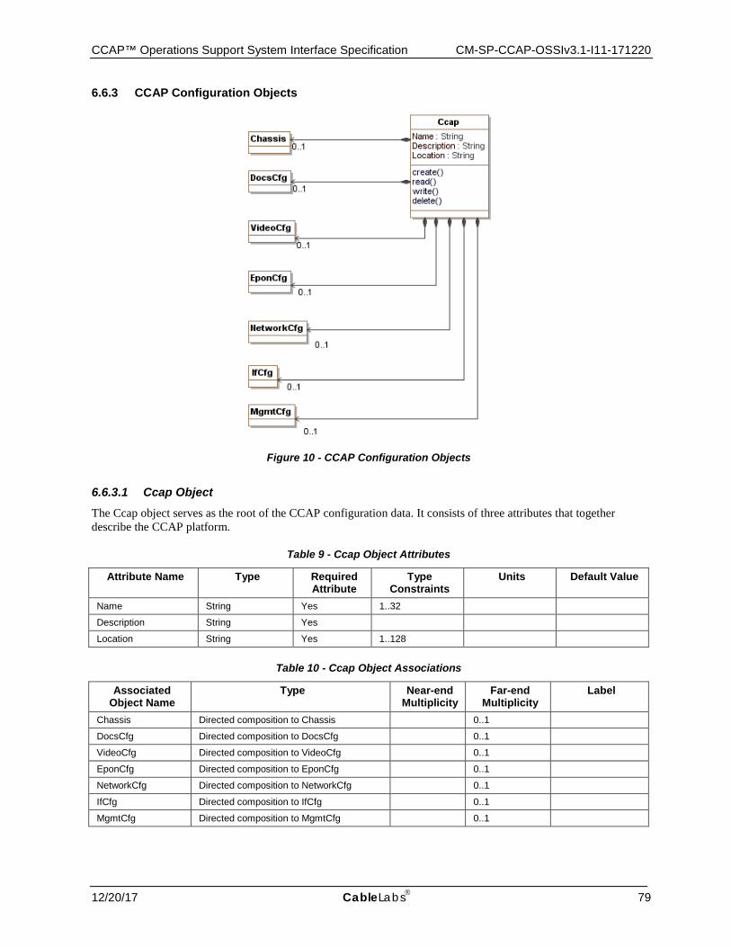
CCAP™ Operations Support System Interface Specification CM-SP-CCAP-OSSIv3.1-I11-171220
12/20/17 CableLabs 79
6.6.3 CCAP Configuration Objects
Figure 10 - CCAP Configuration Objects
6.6.3.1 Ccap Object The Ccap object serves as the root of the CCAP configuration data. It consists of three attributes that together describe the CCAP platform.
Table 9 - Ccap Object Attributes
Attribute Name Type Required Attribute
Type Constraints
Units Default Value
Name String Yes 1..32
Description String Yes
Location String Yes 1..128
Table 10 - Ccap Object Associations
Associated Object Name
Type Near-end Multiplicity
Far-end Multiplicity
Label
Chassis Directed composition to Chassis 0..1
DocsCfg Directed composition to DocsCfg 0..1
VideoCfg Directed composition to VideoCfg 0..1
EponCfg Directed composition to EponCfg 0..1
NetworkCfg Directed composition to NetworkCfg 0..1
IfCfg Directed composition to IfCfg 0..1
MgmtCfg Directed composition to MgmtCfg 0..1

CM-SP-CCAP-OSSIv3.1-I11-171220 Data-Over-Cable Service Interface Specifications
80 CableLabs® 12/20/17
6.6.3.1.1 Ccap Object Attributes
6.6.3.1.1.1 Name
This attribute defines the name of the CCAP platform being configured.
6.6.3.1.1.2 Description
This attribute contains the description of the CCAP platform.
6.6.3.1.1.3 Location
This attribute contains any location information for the CCAP.
6.6.3.2 Chassis This configuration object is included in Figure 10 for reference. It is defined in Section 6.6.4.2, Chassis.
6.6.3.3 DocsCfg This configuration object is included in Figure 10 for reference. It is defined in Section 6.6.6.1.2, DocsCfg.
6.6.3.4 VideoCfg This configuration object is included in Figure 10 for reference. It is defined in Section 6.6.5.2, VideoCfg.
6.6.3.5 EponCfg This configuration object is included in Figure 10 for reference. It is defined in Section 6.6.10.2, EponCfg.
6.6.3.6 NetworkCfg This configuration object is included in Figure 10 for reference. It is defined in Section 6.6.7.2, NetworkCfg.
6.6.3.7 IfCfg This configuration object is included in Figure 10 for reference. It is defined in Section 6.6.8.2, IfCfg.
6.6.3.8 MgmtCfg This configuration object is included in Figure 10 for reference. It is defined in Section 6.6.9.2, MgmtCfg.
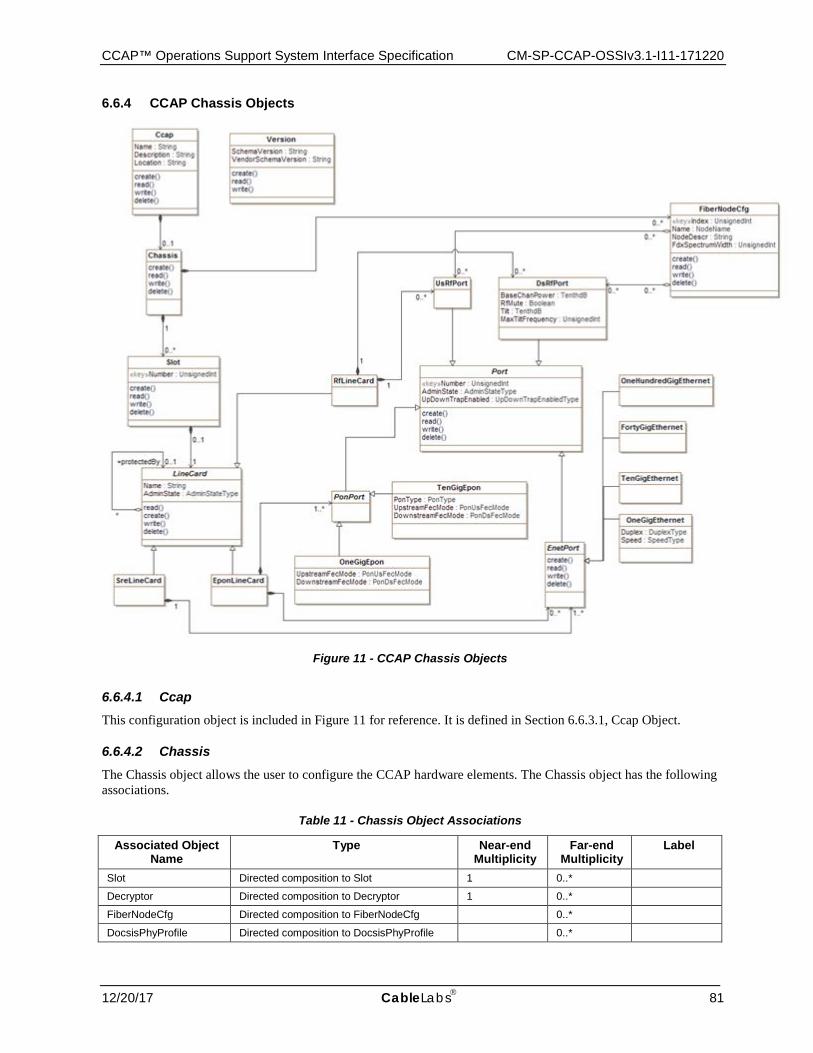
CCAP™ Operations Support System Interface Specification CM-SP-CCAP-OSSIv3.1-I11-171220
12/20/17 CableLabs 81
6.6.4 CCAP Chassis Objects
Figure 11 - CCAP Chassis Objects
6.6.4.1 Ccap This configuration object is included in Figure 11 for reference. It is defined in Section 6.6.3.1, Ccap Object.
6.6.4.2 Chassis The Chassis object allows the user to configure the CCAP hardware elements. The Chassis object has the following associations.
Table 11 - Chassis Object Associations
Associated Object Name
Type Near-end Multiplicity
Far-end Multiplicity
Label
Slot Directed composition to Slot 1 0..*
Decryptor Directed composition to Decryptor 1 0..*
FiberNodeCfg Directed composition to FiberNodeCfg 0..*
DocsisPhyProfile Directed composition to DocsisPhyProfile 0..*
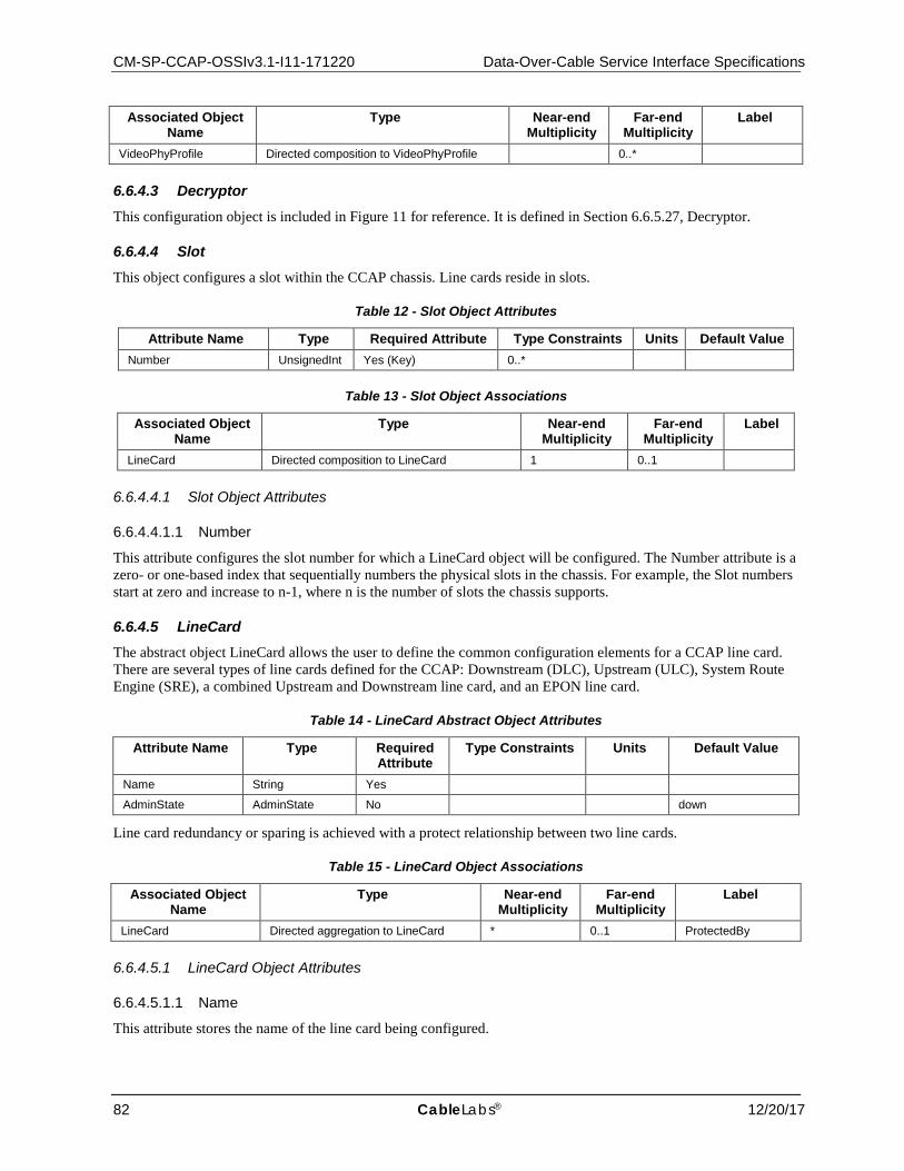
CM-SP-CCAP-OSSIv3.1-I11-171220 Data-Over-Cable Service Interface Specifications
82 CableLabs® 12/20/17
Associated Object Name
Type Near-end Multiplicity
Far-end Multiplicity
Label
VideoPhyProfile Directed composition to VideoPhyProfile 0..*
6.6.4.3 Decryptor This configuration object is included in Figure 11 for reference. It is defined in Section 6.6.5.27, Decryptor.
6.6.4.4 Slot This object configures a slot within the CCAP chassis. Line cards reside in slots.
Table 12 - Slot Object Attributes
Attribute Name Type Required Attribute Type Constraints Units Default Value Number UnsignedInt Yes (Key) 0..*
Table 13 - Slot Object Associations
Associated Object Name
Type Near-end Multiplicity
Far-end Multiplicity
Label
LineCard Directed composition to LineCard 1 0..1
6.6.4.4.1 Slot Object Attributes
6.6.4.4.1.1 Number
This attribute configures the slot number for which a LineCard object will be configured. The Number attribute is a zero- or one-based index that sequentially numbers the physical slots in the chassis. For example, the Slot numbers start at zero and increase to n-1, where n is the number of slots the chassis supports.
6.6.4.5 LineCard The abstract object LineCard allows the user to define the common configuration elements for a CCAP line card. There are several types of line cards defined for the CCAP: Downstream (DLC), Upstream (ULC), System Route Engine (SRE), a combined Upstream and Downstream line card, and an EPON line card.
Table 14 - LineCard Abstract Object Attributes
Attribute Name Type Required Attribute
Type Constraints Units Default Value
Name String Yes
AdminState AdminState No down
Line card redundancy or sparing is achieved with a protect relationship between two line cards.
Table 15 - LineCard Object Associations
Associated Object Name
Type Near-end Multiplicity
Far-end Multiplicity
Label
LineCard Directed aggregation to LineCard * 0..1 ProtectedBy
6.6.4.5.1 LineCard Object Attributes
6.6.4.5.1.1 Name
This attribute stores the name of the line card being configured.
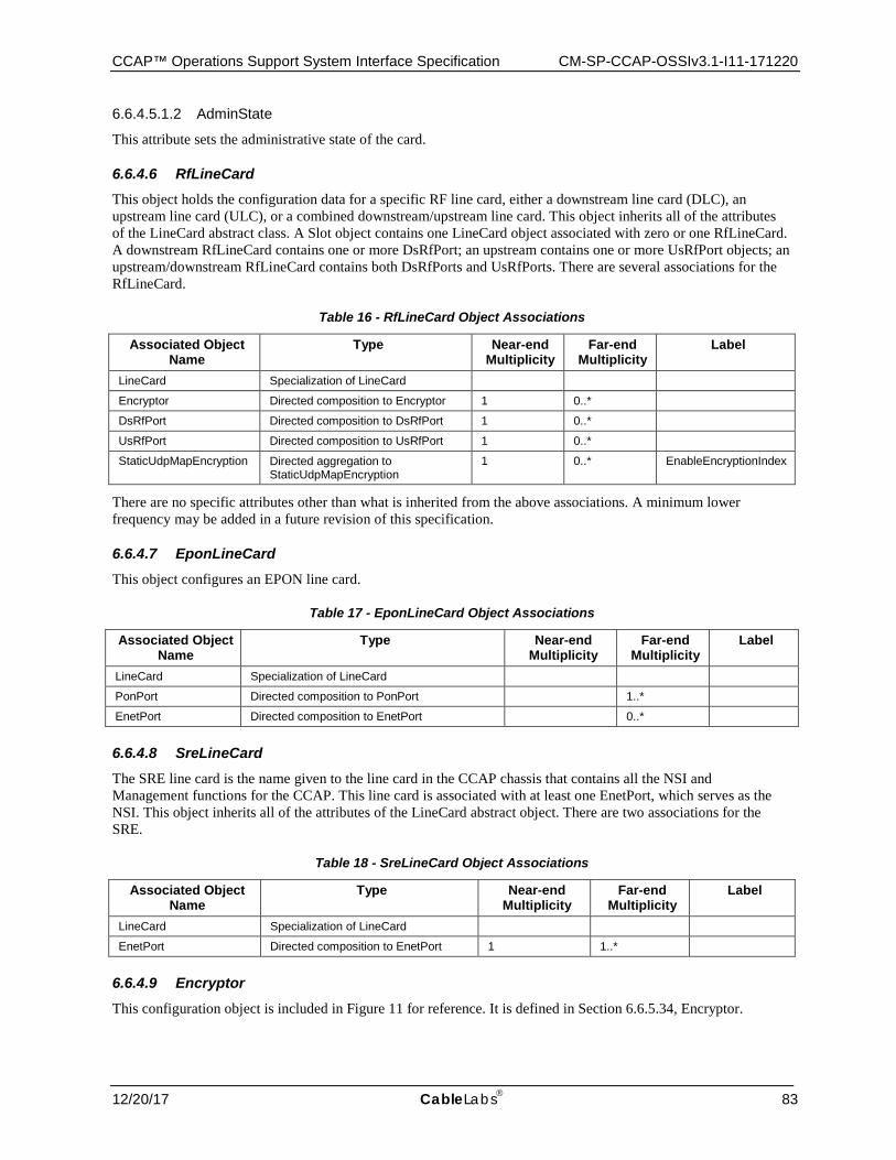
CCAP™ Operations Support System Interface Specification CM-SP-CCAP-OSSIv3.1-I11-171220
12/20/17 CableLabs 83
6.6.4.5.1.2 AdminState
This attribute sets the administrative state of the card.
6.6.4.6 RfLineCard This object holds the configuration data for a specific RF line card, either a downstream line card (DLC), an upstream line card (ULC), or a combined downstream/upstream line card. This object inherits all of the attributes of the LineCard abstract class. A Slot object contains one LineCard object associated with zero or one RfLineCard. A downstream RfLineCard contains one or more DsRfPort; an upstream contains one or more UsRfPort objects; an upstream/downstream RfLineCard contains both DsRfPorts and UsRfPorts. There are several associations for the RfLineCard.
Table 16 - RfLineCard Object Associations
Associated Object Name
Type Near-end Multiplicity
Far-end Multiplicity
Label
LineCard Specialization of LineCard
Encryptor Directed composition to Encryptor 1 0..*
DsRfPort Directed composition to DsRfPort 1 0..*
UsRfPort Directed composition to UsRfPort 1 0..*
StaticUdpMapEncryption Directed aggregation to StaticUdpMapEncryption
1 0..* EnableEncryptionIndex
There are no specific attributes other than what is inherited from the above associations. A minimum lower frequency may be added in a future revision of this specification.
6.6.4.7 EponLineCard This object configures an EPON line card.
Table 17 - EponLineCard Object Associations
Associated Object Name
Type Near-end Multiplicity
Far-end Multiplicity
Label
LineCard Specialization of LineCard
PonPort Directed composition to PonPort 1..*
EnetPort Directed composition to EnetPort 0..*
6.6.4.8 SreLineCard The SRE line card is the name given to the line card in the CCAP chassis that contains all the NSI and Management functions for the CCAP. This line card is associated with at least one EnetPort, which serves as the NSI. This object inherits all of the attributes of the LineCard abstract object. There are two associations for the SRE.
Table 18 - SreLineCard Object Associations
Associated Object Name
Type Near-end Multiplicity
Far-end Multiplicity
Label
LineCard Specialization of LineCard
EnetPort Directed composition to EnetPort 1 1..*
6.6.4.9 Encryptor This configuration object is included in Figure 11 for reference. It is defined in Section 6.6.5.34, Encryptor.
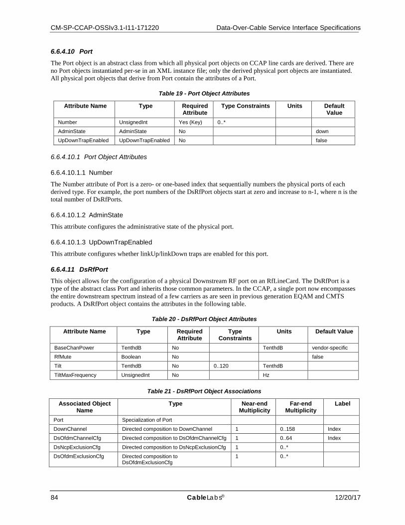
CM-SP-CCAP-OSSIv3.1-I11-171220 Data-Over-Cable Service Interface Specifications
84 CableLabs® 12/20/17
6.6.4.10 Port The Port object is an abstract class from which all physical port objects on CCAP line cards are derived. There are no Port objects instantiated per-se in an XML instance file; only the derived physical port objects are instantiated. All physical port objects that derive from Port contain the attributes of a Port.
Table 19 - Port Object Attributes
Attribute Name Type Required Attribute
Type Constraints Units Default Value
Number UnsignedInt Yes (Key) 0..*
AdminState AdminState No down
UpDownTrapEnabled UpDownTrapEnabled No false
6.6.4.10.1 Port Object Attributes
6.6.4.10.1.1 Number
The Number attribute of Port is a zero- or one-based index that sequentially numbers the physical ports of each derived type. For example, the port numbers of the DsRfPort objects start at zero and increase to n-1, where n is the total number of DsRfPorts.
6.6.4.10.1.2 AdminState
This attribute configures the administrative state of the physical port.
6.6.4.10.1.3 UpDownTrapEnabled
This attribute configures whether linkUp/linkDown traps are enabled for this port.
6.6.4.11 DsRfPort This object allows for the configuration of a physical Downstream RF port on an RfLineCard. The DsRfPort is a type of the abstract class Port and inherits those common parameters. In the CCAP, a single port now encompasses the entire downstream spectrum instead of a few carriers as are seen in previous generation EQAM and CMTS products. A DsRfPort object contains the attributes in the following table.
Table 20 - DsRfPort Object Attributes
Attribute Name Type Required Attribute
Type Constraints
Units Default Value
BaseChanPower TenthdB No TenthdB vendor-specific
RfMute Boolean No false
Tilt TenthdB No 0..120 TenthdB
TiltMaxFrequency UnsignedInt No Hz
Table 21 - DsRfPort Object Associations
Associated Object Name
Type Near-end Multiplicity
Far-end Multiplicity
Label
Port Specialization of Port
DownChannel Directed composition to DownChannel 1 0..158 Index
DsOfdmChannelCfg Directed composition to DsOfdmChannelCfg 1 0..64 Index
DsNcpExclusionCfg Directed composition to DsNcpExclusionCfg 1 0..*
DsOfdmExclusionCfg Directed composition to DsOfdmExclusionCfg
1 0..*
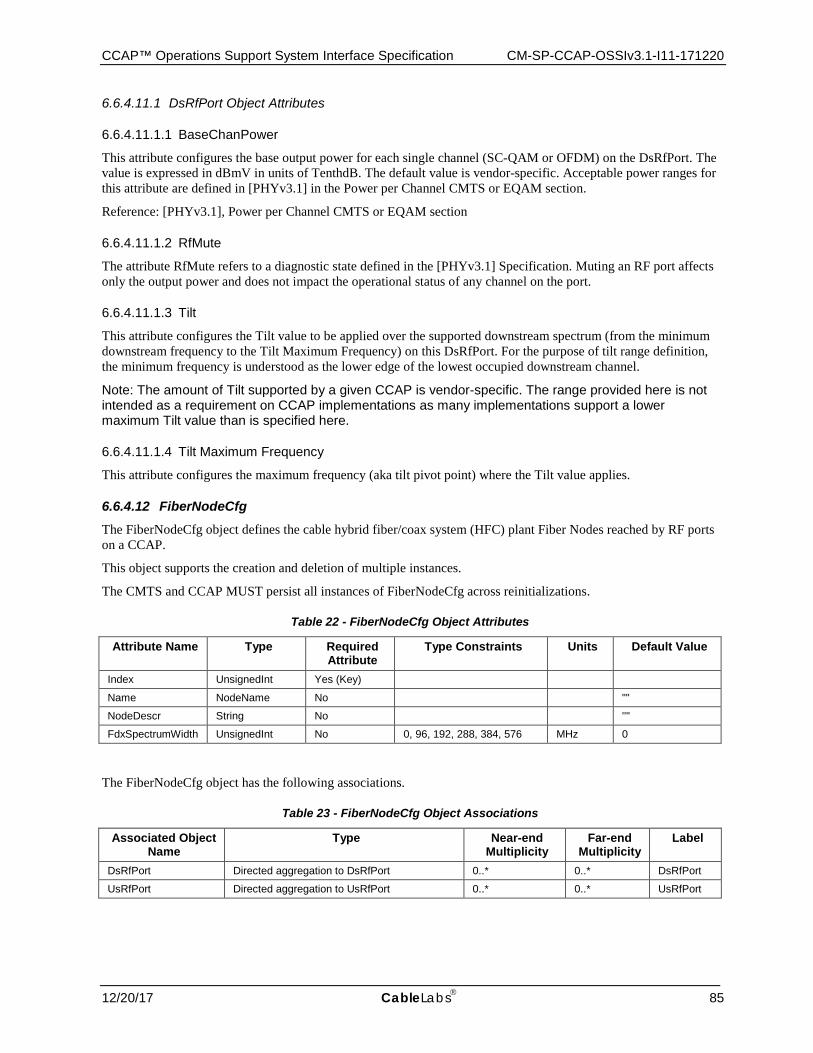
CCAP™ Operations Support System Interface Specification CM-SP-CCAP-OSSIv3.1-I11-171220
12/20/17 CableLabs 85
6.6.4.11.1 DsRfPort Object Attributes
6.6.4.11.1.1 BaseChanPower
This attribute configures the base output power for each single channel (SC-QAM or OFDM) on the DsRfPort. The value is expressed in dBmV in units of TenthdB. The default value is vendor-specific. Acceptable power ranges for this attribute are defined in [PHYv3.1] in the Power per Channel CMTS or EQAM section.
Reference: [PHYv3.1], Power per Channel CMTS or EQAM section
6.6.4.11.1.2 RfMute
The attribute RfMute refers to a diagnostic state defined in the [PHYv3.1] Specification. Muting an RF port affects only the output power and does not impact the operational status of any channel on the port.
6.6.4.11.1.3 Tilt
This attribute configures the Tilt value to be applied over the supported downstream spectrum (from the minimum downstream frequency to the Tilt Maximum Frequency) on this DsRfPort. For the purpose of tilt range definition, the minimum frequency is understood as the lower edge of the lowest occupied downstream channel.
Note: The amount of Tilt supported by a given CCAP is vendor-specific. The range provided here is not intended as a requirement on CCAP implementations as many implementations support a lower maximum Tilt value than is specified here.
6.6.4.11.1.4 Tilt Maximum Frequency
This attribute configures the maximum frequency (aka tilt pivot point) where the Tilt value applies.
6.6.4.12 FiberNodeCfg The FiberNodeCfg object defines the cable hybrid fiber/coax system (HFC) plant Fiber Nodes reached by RF ports on a CCAP.
This object supports the creation and deletion of multiple instances.
The CMTS and CCAP MUST persist all instances of FiberNodeCfg across reinitializations.
Table 22 - FiberNodeCfg Object Attributes
Attribute Name Type Required Attribute
Type Constraints Units Default Value
Index UnsignedInt Yes (Key)
Name NodeName No ""
NodeDescr String No ''"
FdxSpectrumWidth UnsignedInt No 0, 96, 192, 288, 384, 576 MHz 0
The FiberNodeCfg object has the following associations.
Table 23 - FiberNodeCfg Object Associations
Associated Object Name
Type Near-end Multiplicity
Far-end Multiplicity
Label
DsRfPort Directed aggregation to DsRfPort 0..* 0..* DsRfPort
UsRfPort Directed aggregation to UsRfPort 0..* 0..* UsRfPort
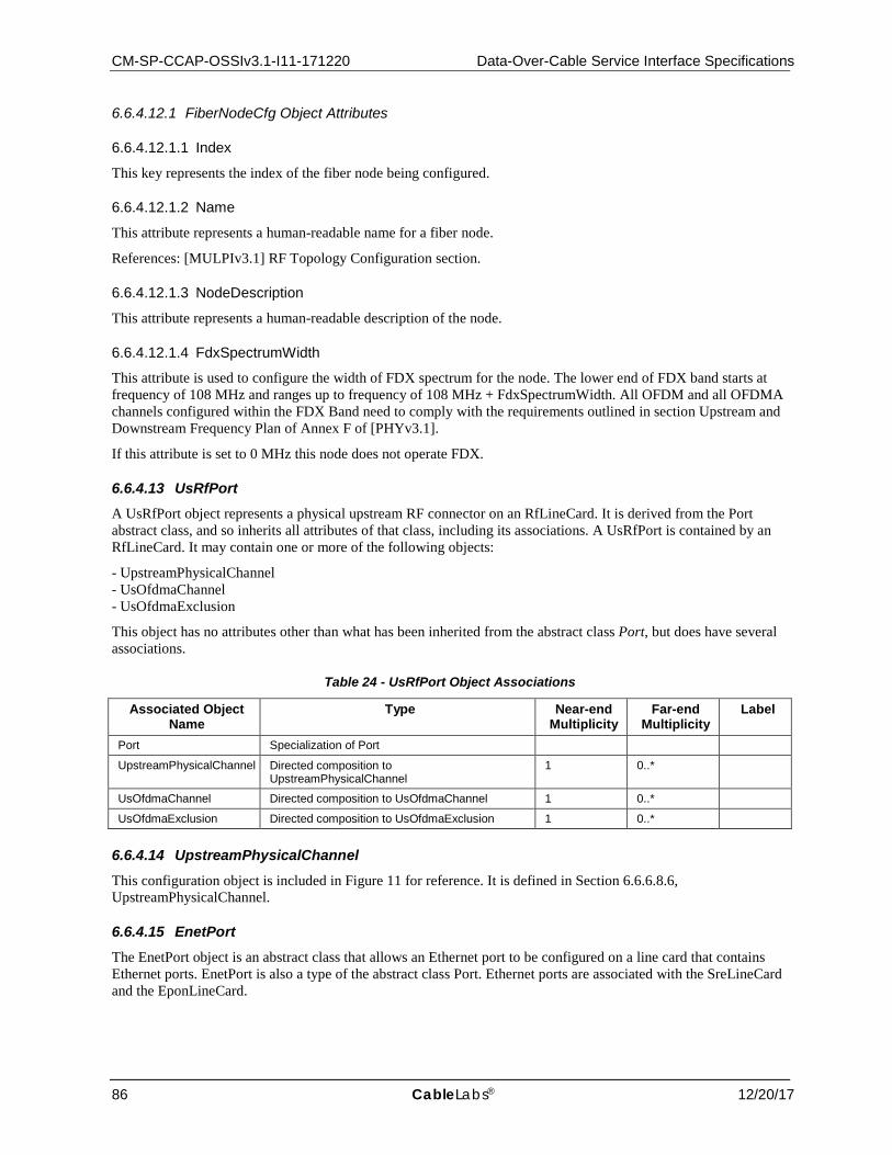
CM-SP-CCAP-OSSIv3.1-I11-171220 Data-Over-Cable Service Interface Specifications
86 CableLabs® 12/20/17
6.6.4.12.1 FiberNodeCfg Object Attributes
6.6.4.12.1.1 Index
This key represents the index of the fiber node being configured.
6.6.4.12.1.2 Name
This attribute represents a human-readable name for a fiber node.
References: [MULPIv3.1] RF Topology Configuration section.
6.6.4.12.1.3 NodeDescription
This attribute represents a human-readable description of the node.
6.6.4.12.1.4 FdxSpectrumWidth
This attribute is used to configure the width of FDX spectrum for the node. The lower end of FDX band starts at frequency of 108 MHz and ranges up to frequency of 108 MHz + FdxSpectrumWidth. All OFDM and all OFDMA channels configured within the FDX Band need to comply with the requirements outlined in section Upstream and Downstream Frequency Plan of Annex F of [PHYv3.1].
If this attribute is set to 0 MHz this node does not operate FDX.
6.6.4.13 UsRfPort A UsRfPort object represents a physical upstream RF connector on an RfLineCard. It is derived from the Port abstract class, and so inherits all attributes of that class, including its associations. A UsRfPort is contained by an RfLineCard. It may contain one or more of the following objects:
- UpstreamPhysicalChannel - UsOfdmaChannel - UsOfdmaExclusion
This object has no attributes other than what has been inherited from the abstract class Port, but does have several associations.
Table 24 - UsRfPort Object Associations
Associated Object Name
Type Near-end Multiplicity
Far-end Multiplicity
Label
Port Specialization of Port
UpstreamPhysicalChannel Directed composition to UpstreamPhysicalChannel
1 0..*
UsOfdmaChannel Directed composition to UsOfdmaChannel 1 0..*
UsOfdmaExclusion Directed composition to UsOfdmaExclusion 1 0..*
6.6.4.14 UpstreamPhysicalChannel This configuration object is included in Figure 11 for reference. It is defined in Section 6.6.6.8.6, UpstreamPhysicalChannel.
6.6.4.15 EnetPort The EnetPort object is an abstract class that allows an Ethernet port to be configured on a line card that contains Ethernet ports. EnetPort is also a type of the abstract class Port. Ethernet ports are associated with the SreLineCard and the EponLineCard.
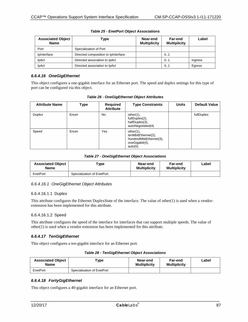
CCAP™ Operations Support System Interface Specification CM-SP-CCAP-OSSIv3.1-I11-171220
12/20/17 CableLabs 87
Table 25 - EnetPort Object Associations
Associated Object Name
Type Near-end Multiplicity
Far-end Multiplicity
Label
Port Specialization of Port
IpInterface Directed composition to IpInterface 0..1
IpAcl Directed association to IpAcl 0..1 Ingress
IpAcl Directed association to IpAcl 0..1 Egress
6.6.4.16 OneGigEthernet This object configures a one-gigabit interface for an Ethernet port. The speed and duplex settings for this type of port can be configured via this object.
Table 26 - OneGigEthernet Object Attributes
Attribute Name Type Required Attribute
Type Constraints Units Default Value
Duplex Enum No other(1), fullDuplex(2), halfDuplex(3), autoNegotiated(4)
fullDuplex
Speed Enum Yes other(1), tenMbitEthernet(2), hundredMbitEthernet(3), oneGigabit(4), auto(5)
Table 27 - OneGigEthernet Object Associations
Associated Object Name
Type Near-end Multiplicity
Far-end Multiplicity
Label
EnetPort Specialization of EnetPort
6.6.4.16.1 OneGigEthernet Object Attributes
6.6.4.16.1.1 Duplex
This attribute configures the Ethernet DuplexState of the interface. The value of other(1) is used when a vendor-extension has been implemented for this attribute.
6.6.4.16.1.2 Speed
This attribute configures the speed of the interface for interfaces that can support multiple speeds. The value of other(1) is used when a vendor-extension has been implemented for this attribute.
6.6.4.17 TenGigEthernet This object configures a ten-gigabit interface for an Ethernet port.
Table 28 - TenGigEthernet Object Associations
Associated Object Name
Type Near-end Multiplicity
Far-end Multiplicity
Label
EnetPort Specialization of EnetPort
6.6.4.18 FortyGigEthernet This object configures a 40-gigabit interface for an Ethernet port.
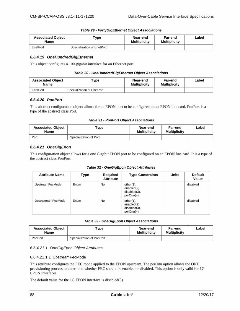
CM-SP-CCAP-OSSIv3.1-I11-171220 Data-Over-Cable Service Interface Specifications
88 CableLabs® 12/20/17
Table 29 - FortyGigEthernet Object Associations
Associated Object Name
Type Near-end Multiplicity
Far-end Multiplicity
Label
EnetPort Specialization of EnetPort
6.6.4.19 OneHundredGigEthernet This object configures a 100-gigabit interface for an Ethernet port.
Table 30 - OneHundredGigEthernet Object Associations
Associated Object Name
Type Near-end Multiplicity
Far-end Multiplicity
Label
EnetPort Specialization of EnetPort
6.6.4.20 PonPort This abstract configuration object allows for an EPON port to be configured on an EPON line card. PonPort is a type of the abstract class Port.
Table 31 - PonPort Object Associations
Associated Object Name
Type Near-end Multiplicity
Far-end Multiplicity
Label
Port Specialization of Port
6.6.4.21 OneGigEpon This configuration object allows for a one Gigabit EPON port to be configured on an EPON line card. It is a type of the abstract class PonPort.
Table 32 - OneGigEpon Object Attributes
Attribute Name Type Required Attribute
Type Constraints Units Default Value
UpstreamFecMode Enum No other(1), enabled(2), disabled(3), perOnu(4)
disabled
DownstreamFecMode Enum No other(1), enabled(2), disabled(3), perOnu(4)
disabled
Table 33 - OneGigEpon Object Associations
Associated Object Name
Type Near-end Multiplicity
Far-end Multiplicity
Label
PonPort Specialization of PonPort
6.6.4.21.1 OneGigEpon Object Attributes
6.6.4.21.1.1 UpstreamFecMode
This attribute configures the FEC mode applied to the EPON upstream. The perOnu option allows the ONU provisioning process to determine whether FEC should be enabled or disabled. This option is only valid for 1G EPON interfaces.
The default value for the 1G EPON interface is disabled(3).
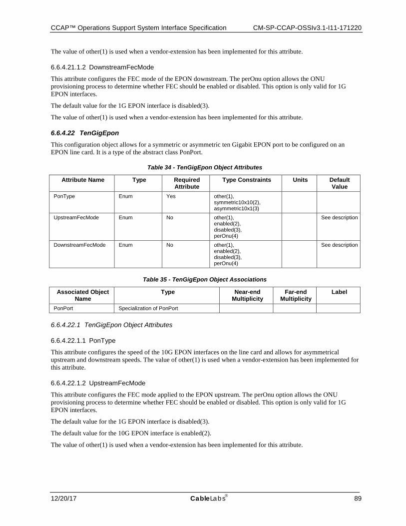
CCAP™ Operations Support System Interface Specification CM-SP-CCAP-OSSIv3.1-I11-171220
12/20/17 CableLabs 89
The value of other(1) is used when a vendor-extension has been implemented for this attribute.
6.6.4.21.1.2 DownstreamFecMode
This attribute configures the FEC mode of the EPON downstream. The perOnu option allows the ONU provisioning process to determine whether FEC should be enabled or disabled. This option is only valid for 1G EPON interfaces.
The default value for the 1G EPON interface is disabled(3).
The value of other(1) is used when a vendor-extension has been implemented for this attribute.
6.6.4.22 TenGigEpon This configuration object allows for a symmetric or asymmetric ten Gigabit EPON port to be configured on an EPON line card. It is a type of the abstract class PonPort.
Table 34 - TenGigEpon Object Attributes
Attribute Name Type Required Attribute
Type Constraints Units Default Value
PonType Enum Yes other(1), symmetric10x10(2), asymmetric10x1(3)
UpstreamFecMode Enum No other(1), enabled(2), disabled(3), perOnu(4)
See description
DownstreamFecMode Enum No other(1), enabled(2), disabled(3), perOnu(4)
See description
Table 35 - TenGigEpon Object Associations
Associated Object Name
Type Near-end Multiplicity
Far-end Multiplicity
Label
PonPort Specialization of PonPort
6.6.4.22.1 TenGigEpon Object Attributes
6.6.4.22.1.1 PonType
This attribute configures the speed of the 10G EPON interfaces on the line card and allows for asymmetrical upstream and downstream speeds. The value of other(1) is used when a vendor-extension has been implemented for this attribute.
6.6.4.22.1.2 UpstreamFecMode
This attribute configures the FEC mode applied to the EPON upstream. The perOnu option allows the ONU provisioning process to determine whether FEC should be enabled or disabled. This option is only valid for 1G EPON interfaces.
The default value for the 1G EPON interface is disabled(3).
The default value for the 10G EPON interface is enabled(2).
The value of other(1) is used when a vendor-extension has been implemented for this attribute.

CM-SP-CCAP-OSSIv3.1-I11-171220 Data-Over-Cable Service Interface Specifications
90 CableLabs® 12/20/17
6.6.4.22.1.3 DownstreamFecMode
This attribute configures the FEC mode of the EPON downstream. The perOnu option allows the ONU provisioning process to determine whether FEC should be enabled or disabled. This option is only valid for 1G EPON interfaces.
The default value for the 1G EPON interface is disabled(3).
The default value for the 10G EPON interface is enabled(2).
The value of other(1) is used when a vendor-extension has been implemented for this attribute.
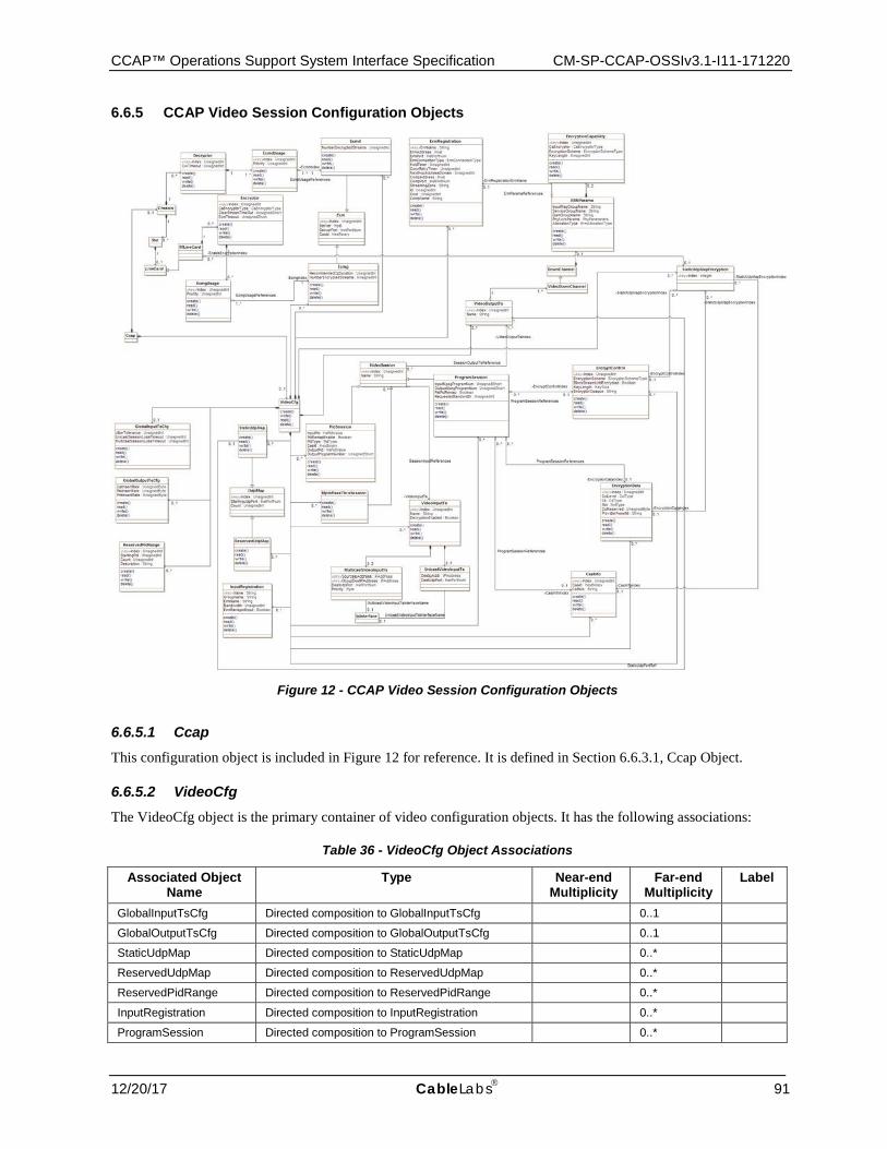
CCAP™ Operations Support System Interface Specification CM-SP-CCAP-OSSIv3.1-I11-171220
12/20/17 CableLabs 91
6.6.5 CCAP Video Session Configuration Objects
Figure 12 - CCAP Video Session Configuration Objects
6.6.5.1 Ccap This configuration object is included in Figure 12 for reference. It is defined in Section 6.6.3.1, Ccap Object.
6.6.5.2 VideoCfg The VideoCfg object is the primary container of video configuration objects. It has the following associations:
Table 36 - VideoCfg Object Associations
Associated Object Name
Type Near-end Multiplicity
Far-end Multiplicity
Label
GlobalInputTsCfg Directed composition to GlobalInputTsCfg 0..1
GlobalOutputTsCfg Directed composition to GlobalOutputTsCfg 0..1
StaticUdpMap Directed composition to StaticUdpMap 0..*
ReservedUdpMap Directed composition to ReservedUdpMap 0..*
ReservedPidRange Directed composition to ReservedPidRange 0..*
InputRegistration Directed composition to InputRegistration 0..*
ProgramSession Directed composition to ProgramSession 0..*
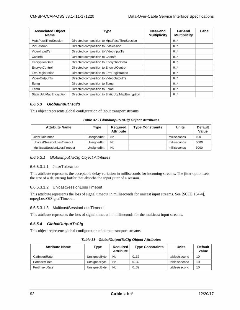
CM-SP-CCAP-OSSIv3.1-I11-171220 Data-Over-Cable Service Interface Specifications
92 CableLabs® 12/20/17
Associated Object Name
Type Near-end Multiplicity
Far-end Multiplicity
Label
MptsPassThruSession Directed composition to MptsPassThruSession 0..*
PidSession Directed composition to PidSession 0..*
VideoInputTs Directed composition to VideoInputTs 0..*
CasInfo Directed composition to CasInfo 0..*
EncryptionData Directed composition to EncryptionData 0..*
EncryptControl Directed composition to EncryptControl 0..*
ErmRegistration Directed composition to ErmRegistration 0..*
VideoOutputTs Directed composition to VideoOutputTs 0..*
Ecmg Directed composition to Ecmg 0..*
Ecmd Directed composition to Ecmd 0..*
StaticUdpMapEncryption Directed composition to StaticUdpMapEncryption 0..*
6.6.5.3 GlobalInputTsCfg This object represents global configuration of input transport streams.
Table 37 - GlobalInputTsCfg Object Attributes
Attribute Name Type Required Attribute
Type Constraints Units Default Value
JitterTolerance UnsignedInt No milliseconds 100
UnicastSessionLossTimeout UnsignedInt No milliseconds 5000
MulticastSessionLossTimeout UnsignedInt No milliseconds 5000
6.6.5.3.1 GlobalInputTsCfg Object Attributes
6.6.5.3.1.1 JitterTolerance
This attribute represents the acceptable delay variation in milliseconds for incoming streams. The jitter option sets the size of a dejittering buffer that absorbs the input jitter of a session.
6.6.5.3.1.2 UnicastSessionLossTimeout
This attribute represents the loss of signal timeout in milliseconds for unicast input streams. See [SCTE 154-4], mpegLossOfSignalTimeout.
6.6.5.3.1.3 MulticastSessionLossTimeout
This attribute represents the loss of signal timeout in milliseconds for the multicast input streams.
6.6.5.4 GlobalOutputTsCfg This object represents global configuration of output transport streams.
Table 38 - GlobalOutputTsCfg Object Attributes
Attribute Name Type Required Attribute
Type Constraints Units Default Value
CatInsertRate UnsignedByte No 0..32 tables/second 10
PatInsertRate UnsignedByte No 0..32 tables/second 10
PmtInsertRate UnsignedByte No 0..32 tables/second 10
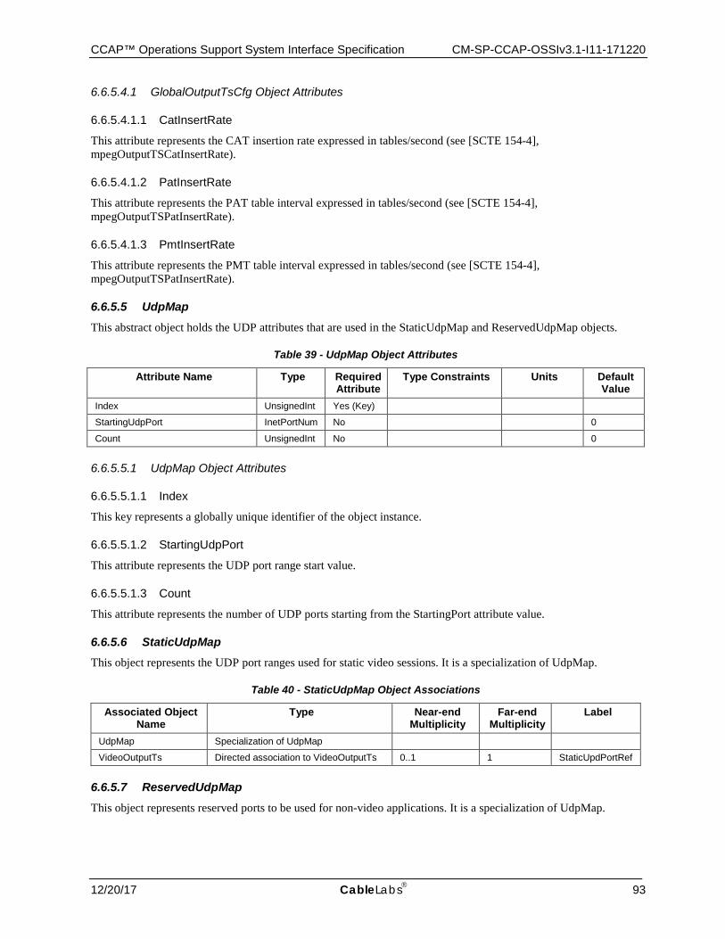
CCAP™ Operations Support System Interface Specification CM-SP-CCAP-OSSIv3.1-I11-171220
12/20/17 CableLabs 93
6.6.5.4.1 GlobalOutputTsCfg Object Attributes
6.6.5.4.1.1 CatInsertRate
This attribute represents the CAT insertion rate expressed in tables/second (see [SCTE 154-4], mpegOutputTSCatInsertRate).
6.6.5.4.1.2 PatInsertRate
This attribute represents the PAT table interval expressed in tables/second (see [SCTE 154-4], mpegOutputTSPatInsertRate).
6.6.5.4.1.3 PmtInsertRate
This attribute represents the PMT table interval expressed in tables/second (see [SCTE 154-4], mpegOutputTSPatInsertRate).
6.6.5.5 UdpMap This abstract object holds the UDP attributes that are used in the StaticUdpMap and ReservedUdpMap objects.
Table 39 - UdpMap Object Attributes
Attribute Name Type Required Attribute
Type Constraints Units Default Value
Index UnsignedInt Yes (Key)
StartingUdpPort InetPortNum No 0
Count UnsignedInt No 0
6.6.5.5.1 UdpMap Object Attributes
6.6.5.5.1.1 Index
This key represents a globally unique identifier of the object instance.
6.6.5.5.1.2 StartingUdpPort
This attribute represents the UDP port range start value.
6.6.5.5.1.3 Count
This attribute represents the number of UDP ports starting from the StartingPort attribute value.
6.6.5.6 StaticUdpMap This object represents the UDP port ranges used for static video sessions. It is a specialization of UdpMap.
Table 40 - StaticUdpMap Object Associations
Associated Object Name
Type Near-end Multiplicity
Far-end Multiplicity
Label
UdpMap Specialization of UdpMap
VideoOutputTs Directed association to VideoOutputTs 0..1 1 StaticUpdPortRef
6.6.5.7 ReservedUdpMap This object represents reserved ports to be used for non-video applications. It is a specialization of UdpMap.

CM-SP-CCAP-OSSIv3.1-I11-171220 Data-Over-Cable Service Interface Specifications
94 CableLabs® 12/20/17
Table 41 - ReservedUdpMap Object Associations
Associated Object Name
Type Near-end Multiplicity
Far-end Multiplicity
Label
UdpMap Specialization of UdpMap
6.6.5.8 ReservedPidRange This object represents reserved PID range to not be used on ERM assignments.
Table 42 - ReservedPidRange Object Attributes
Attribute Name Type Required Attribute
Type Constraints Units Default Value
Index UnsignedInt Yes (Key)
StartingPid UnsignedInt No 0
Count UnsignedInt No 0
Description String No ""
6.6.5.8.1 ReservedPidRange Object Attributes
6.6.5.8.1.1 Index
This key represents the unique identifier of an instance of this object.
6.6.5.8.1.2 StartingPid
This attribute represents the PID range starts for other applications' reserved PIDs.
6.6.5.8.1.3 Count
This attribute represents the number of reserved PIDs starting from the StartingPid attribute value.
6.6.5.8.1.4 Description
This attribute represents the description associated with a PID range configured instance.
6.6.5.9 InputRegistration This object configures which input interfaces are advertised to the ERM and whether a given advertised interface has its capacity managed by the ERM or the CCAP.
Table 43 - InputRegistration Object Attributes
Attribute Name Type Required Attribute
Type Constraints Units Default Value
Name String Yes (Key)
GroupName String No ""
ErmName String Yes
Bandwidth UnsignedInt No 0
ErmManagedInput Boolean Yes
6.6.5.9.1 InputRegistration Object Attributes
6.6.5.9.1.1 Name
This key represents the Input interface name. This name corresponds to the [RFC 4133], ENTITY-MIB entPhysicalName.
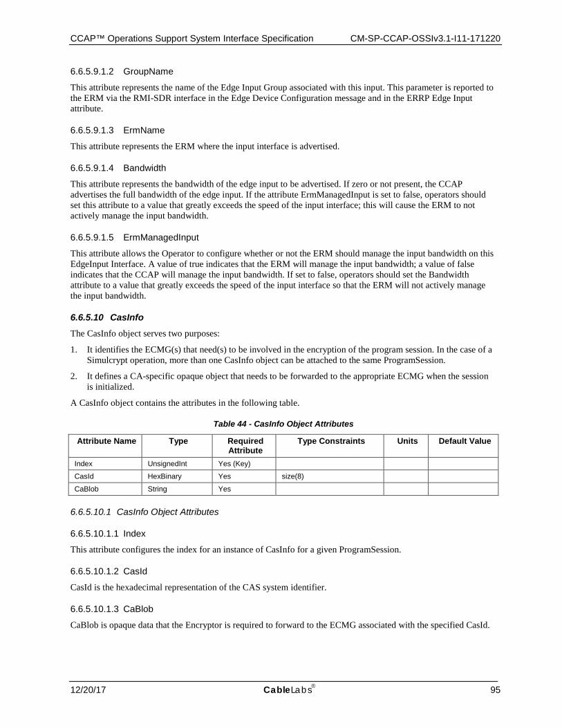
CCAP™ Operations Support System Interface Specification CM-SP-CCAP-OSSIv3.1-I11-171220
12/20/17 CableLabs 95
6.6.5.9.1.2 GroupName
This attribute represents the name of the Edge Input Group associated with this input. This parameter is reported to the ERM via the RMI-SDR interface in the Edge Device Configuration message and in the ERRP Edge Input attribute.
6.6.5.9.1.3 ErmName
This attribute represents the ERM where the input interface is advertised.
6.6.5.9.1.4 Bandwidth
This attribute represents the bandwidth of the edge input to be advertised. If zero or not present, the CCAP advertises the full bandwidth of the edge input. If the attribute ErmManagedInput is set to false, operators should set this attribute to a value that greatly exceeds the speed of the input interface; this will cause the ERM to not actively manage the input bandwidth.
6.6.5.9.1.5 ErmManagedInput
This attribute allows the Operator to configure whether or not the ERM should manage the input bandwidth on this EdgeInput Interface. A value of true indicates that the ERM will manage the input bandwidth; a value of false indicates that the CCAP will manage the input bandwidth. If set to false, operators should set the Bandwidth attribute to a value that greatly exceeds the speed of the input interface so that the ERM will not actively manage the input bandwidth.
6.6.5.10 CasInfo The CasInfo object serves two purposes:
1. It identifies the ECMG(s) that need(s) to be involved in the encryption of the program session. In the case of a Simulcrypt operation, more than one CasInfo object can be attached to the same ProgramSession.
2. It defines a CA-specific opaque object that needs to be forwarded to the appropriate ECMG when the session is initialized.
A CasInfo object contains the attributes in the following table.
Table 44 - CasInfo Object Attributes
Attribute Name Type Required Attribute
Type Constraints Units Default Value
Index UnsignedInt Yes (Key)
CasId HexBinary Yes size(8)
CaBlob String Yes
6.6.5.10.1 CasInfo Object Attributes
6.6.5.10.1.1 Index
This attribute configures the index for an instance of CasInfo for a given ProgramSession.
6.6.5.10.1.2 CasId
CasId is the hexadecimal representation of the CAS system identifier.
6.6.5.10.1.3 CaBlob
CaBlob is opaque data that the Encryptor is required to forward to the ECMG associated with the specified CasId.
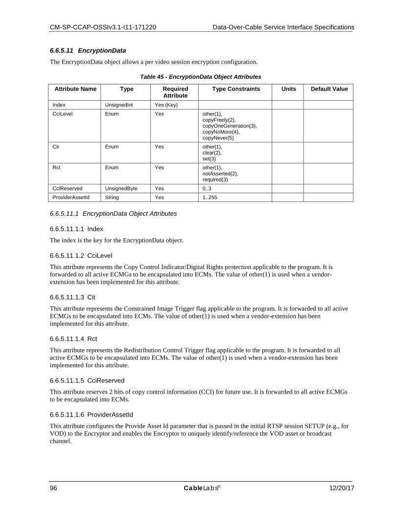
CM-SP-CCAP-OSSIv3.1-I11-171220 Data-Over-Cable Service Interface Specifications
96 CableLabs® 12/20/17
6.6.5.11 EncryptionData The EncryptionData object allows a per video session encryption configuration.
Table 45 - EncryptionData Object Attributes
Attribute Name Type Required Attribute
Type Constraints Units Default Value
Index UnsignedInt Yes (Key)
CciLevel Enum Yes other(1), copyFreely(2), copyOneGeneration(3), copyNoMore(4), copyNever(5)
Cit Enum Yes other(1), clear(2), set(3)
Rct Enum Yes other(1), notAsserted(2), required(3)
CciReserved UnsignedByte Yes 0..3
ProviderAssetId String Yes 1..255
6.6.5.11.1 EncryptionData Object Attributes
6.6.5.11.1.1 Index
The index is the key for the EncryptionData object.
6.6.5.11.1.2 CciLevel
This attribute represents the Copy Control Indicator/Digital Rights protection applicable to the program. It is forwarded to all active ECMGs to be encapsulated into ECMs. The value of other(1) is used when a vendor-extension has been implemented for this attribute.
6.6.5.11.1.3 Cit
This attribute represents the Constrained Image Trigger flag applicable to the program. It is forwarded to all active ECMGs to be encapsulated into ECMs. The value of other(1) is used when a vendor-extension has been implemented for this attribute.
6.6.5.11.1.4 Rct
This attribute represents the Redistribution Control Trigger flag applicable to the program. It is forwarded to all active ECMGs to be encapsulated into ECMs. The value of other(1) is used when a vendor-extension has been implemented for this attribute.
6.6.5.11.1.5 CciReserved
This attribute reserves 2 bits of copy control information (CCI) for future use. It is forwarded to all active ECMGs to be encapsulated into ECMs.
6.6.5.11.1.6 ProviderAssetId
This attribute configures the Provide Asset Id parameter that is passed in the initial RTSP session SETUP (e.g., for VOD) to the Encryptor and enables the Encryptor to uniquely identify/reference the VOD asset or broadcast channel.

CCAP™ Operations Support System Interface Specification CM-SP-CCAP-OSSIv3.1-I11-171220
12/20/17 CableLabs 97
6.6.5.12 EncryptControl This configuration object selects the encryption option of a static encryption session.
Table 46 - EncryptControl Object Attributes
Attribute Name Type Required Attribute
Type Constraints
Units Default Value
Index UnsignedInt Yes (Key)
EncryptionScheme Enum Yes other(1), des(2), aes(3), 3des(4), dvbcsa(5), dvbcsa3(6)
BlockStreamUntilEncrypted Boolean No true
KeyLength Enum Yes other(1), 56bits(2), 128bits(3), 192bits(4), 256bits(5)
EncryptorOpaque String Yes
6.6.5.12.1 EncryptControl Object Attributes
6.6.5.12.1.1 Index
This attribute configures the index for an instance of EncryptControl for a given ProgramSession.
6.6.5.12.1.2 EncryptionScheme
This attribute defines the encryption algorithm to be used for a given video session. The value of other(1) is used when a vendor-extension has been implemented for this attribute.
6.6.5.12.1.3 BlockStreamUntilEncrypted
BlockStreamUntilEncrypted indicates if the encryption engine should block the program until it can encrypt it (i.e., it has received a first Entitlement Control Message (ECM) and Control Word (CW) from the ECMG) or release it in the clear to the destination or output. Values are 0 meaning false or 1 meaning true. Note that this parameter can be used to enforce synchronous behavior, wherein the RTSP server (i.e., Encryption Engine) will not acknowledge the session request back to the ERM until it has actually started to encrypt the stream. Obviously, this assurance comes at the expense of setup latency.
6.6.5.12.1.4 KeyLength
This attribute configures the number of bits in the encryption keys used by encryption algorithm defined by the EncryptionScheme attribute. The value of other(1) is used when a vendor-extension has been implemented for this attribute.
6.6.5.12.1.5 EncryptorOpaque
EncryptorOpaque holds private data used by the Encryptor that may be under CA license from the CA vendor.
6.6.5.13 VideoInputTs The VideoInputTs object configures a given MPEG-2 Transport stream that may be unicast or multicast. Each VideoInputTs object MUST have either:
• one or two MulticastVideoInputTs objects associated with it, • one UnicastVideoInputTs object associated with it.
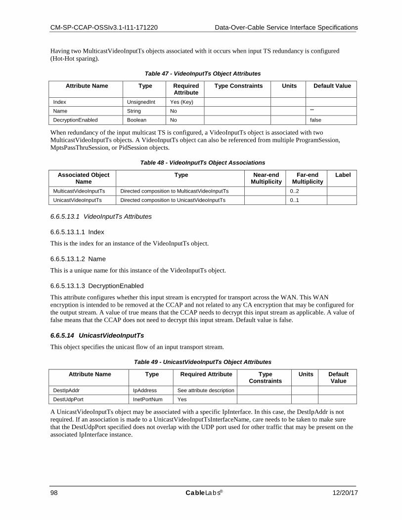
CM-SP-CCAP-OSSIv3.1-I11-171220 Data-Over-Cable Service Interface Specifications
98 CableLabs® 12/20/17
Having two MulticastVideoInputTs objects associated with it occurs when input TS redundancy is configured (Hot-Hot sparing).
Table 47 - VideoInputTs Object Attributes
Attribute Name Type Required Attribute
Type Constraints Units Default Value
Index UnsignedInt Yes (Key)
Name String No ""
DecryptionEnabled Boolean No false
When redundancy of the input multicast TS is configured, a VideoInputTs object is associated with two MulticastVideoInputTs objects. A VideoInputTs object can also be referenced from multiple ProgramSession, MptsPassThruSession, or PidSession objects.
Table 48 - VideoInputTs Object Associations
Associated Object Name
Type Near-end Multiplicity
Far-end Multiplicity
Label
MulticastVideoInputTs Directed composition to MulticastVideoInputTs 0..2
UnicastVideoInputTs Directed composition to UnicastVideoInputTs 0..1
6.6.5.13.1 VideoInputTs Attributes
6.6.5.13.1.1 Index
This is the index for an instance of the VideoInputTs object.
6.6.5.13.1.2 Name
This is a unique name for this instance of the VideoInputTs object.
6.6.5.13.1.3 DecryptionEnabled
This attribute configures whether this input stream is encrypted for transport across the WAN. This WAN encryption is intended to be removed at the CCAP and not related to any CA encryption that may be configured for the output stream. A value of true means that the CCAP needs to decrypt this input stream as applicable. A value of false means that the CCAP does not need to decrypt this input stream. Default value is false.
6.6.5.14 UnicastVideoInputTs This object specifies the unicast flow of an input transport stream.
Table 49 - UnicastVideoInputTs Object Attributes
Attribute Name Type Required Attribute Type Constraints
Units Default Value
DestIpAddr IpAddress See attribute description
DestUdpPort InetPortNum Yes
A UnicastVideoInputTs object may be associated with a specific IpInterface. In this case, the DestIpAddr is not required. If an association is made to a UnicastVideoInputTsInterfaceName, care needs to be taken to make sure that the DestUdpPort specified does not overlap with the UDP port used for other traffic that may be present on the associated IpInterface instance.

CCAP™ Operations Support System Interface Specification CM-SP-CCAP-OSSIv3.1-I11-171220
12/20/17 CableLabs 99
Table 50 - UnicastVideoInputTs Object Associations
Associated Object Name
Type Near-end Multiplicity
Far-end Multiplicity
Label
IpInterface Association to IpInterface 0..1 UnicastVideoInputTsInterfaceName
6.6.5.14.1 UnicastVideoInputTs Object Attributes
6.6.5.14.1.1 DestIpAddr
This attribute corresponds to the IP destination address of the UDP IP flow of the input TS. This attribute is required unless the UnicastVideoInputTs object is associated with an IpInterface instance. If the IP address specified in the DestIpAddr attribute does not exist on the CCAP, the CCAP MUST reject this configuration.
When the value of the DestIpAddr attribute is set to all zeros (e.g., 0.0.0.0), the CCAP MUST listen for the traffic on the specified UDP port number on all IP interfaces.
6.6.5.14.1.2 DestUdpPort
This attribute corresponds to the UDP destination port of the UDP IP flow of the input TS.
6.6.5.15 MulticastVideoInputTs This object specifies the multicast flows of an input transport stream. Having two MulticastVideoInputTs objects for one VideoInputTs occurs when input TS redundancy is configured (Hot-Hot sparing). If two MulticastVideoInputTs objects have the same Priority, this implies HOT-HOT redundancy. Which stream is actually forwarded is vendor-specific.
Table 51 - MulticastVideoInputTs Object Attributes
Attribute Name Type Required Attribute
Type Constraints Units Default Value
SourceIpAddress IpAddress Yes (Key)
GroupDestIpAddress IpAddress Yes (Key)
DestUdpPort InetPortNum No 0
Priority Byte Yes
A MulticastVideoInputTs object may be associated with a specific IpInterface. This associations provides a static mapping of the source of an input transport stream to an IP interface.
Table 52 - MulticastVideoInputTs Object Associations
Associated Object Name
Type Near-end Multiplicity
Far-end Multiplicity
Label
IpInterface Association to IpInterface 0..1 MulticastVideoInputTsInterfaceName
6.6.5.15.1 MulticastVideoInputTs Object Attributes
6.6.5.15.1.1 SourceIpAddress
This attribute corresponds to the Source Specific Multicast IP Address of the UDP IP flow.
6.6.5.15.1.2 GroupDestIpAddress
This attribute corresponds to the group address of a SSM (Source Specific Multicast) origination input TS.
6.6.5.15.1.3 DestUdpPort
This attribute corresponds to the UDP destination port of the UDP IP flow of the input TS.
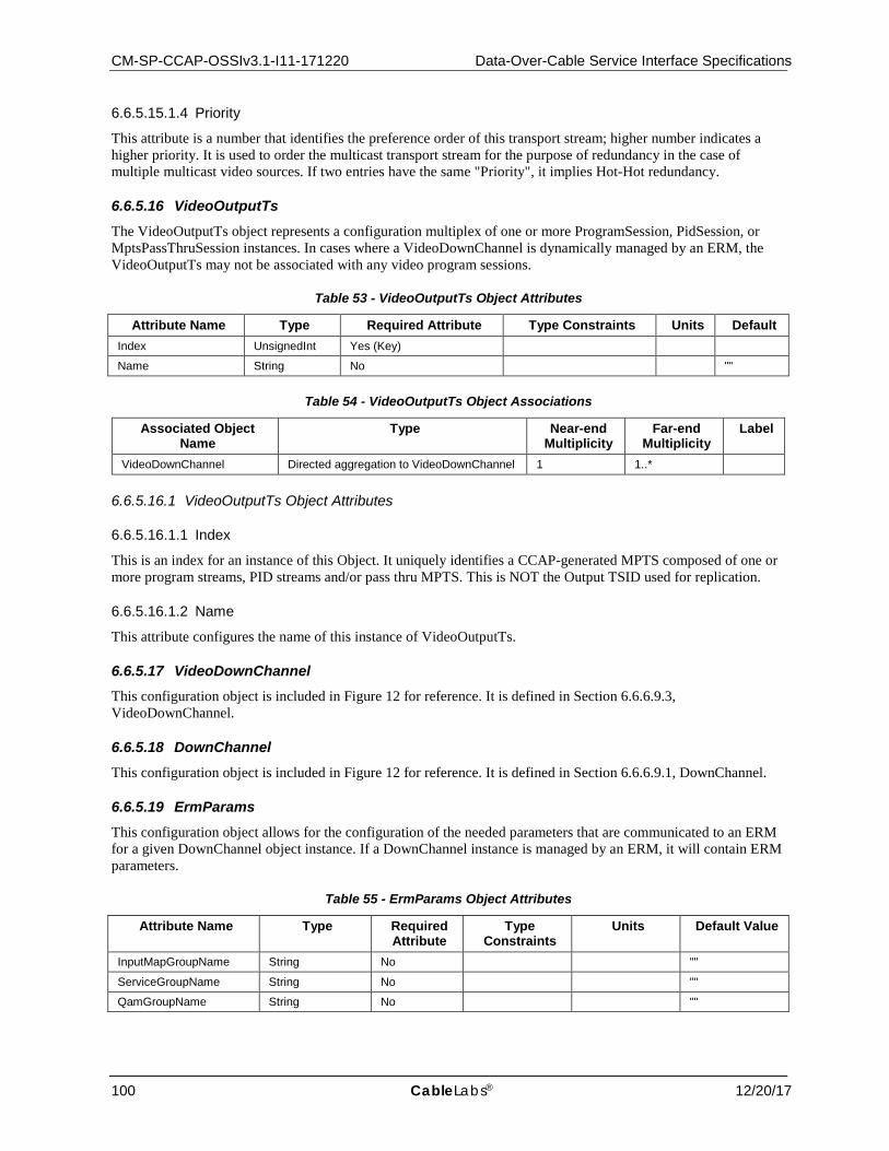
CM-SP-CCAP-OSSIv3.1-I11-171220 Data-Over-Cable Service Interface Specifications
100 CableLabs® 12/20/17
6.6.5.15.1.4 Priority
This attribute is a number that identifies the preference order of this transport stream; higher number indicates a higher priority. It is used to order the multicast transport stream for the purpose of redundancy in the case of multiple multicast video sources. If two entries have the same "Priority", it implies Hot-Hot redundancy.
6.6.5.16 VideoOutputTs The VideoOutputTs object represents a configuration multiplex of one or more ProgramSession, PidSession, or MptsPassThruSession instances. In cases where a VideoDownChannel is dynamically managed by an ERM, the VideoOutputTs may not be associated with any video program sessions.
Table 53 - VideoOutputTs Object Attributes
Attribute Name Type Required Attribute Type Constraints Units Default Index UnsignedInt Yes (Key)
Name String No ""
Table 54 - VideoOutputTs Object Associations
Associated Object Name
Type Near-end Multiplicity
Far-end Multiplicity
Label
VideoDownChannel Directed aggregation to VideoDownChannel 1 1..*
6.6.5.16.1 VideoOutputTs Object Attributes
6.6.5.16.1.1 Index
This is an index for an instance of this Object. It uniquely identifies a CCAP-generated MPTS composed of one or more program streams, PID streams and/or pass thru MPTS. This is NOT the Output TSID used for replication.
6.6.5.16.1.2 Name
This attribute configures the name of this instance of VideoOutputTs.
6.6.5.17 VideoDownChannel This configuration object is included in Figure 12 for reference. It is defined in Section 6.6.6.9.3, VideoDownChannel.
6.6.5.18 DownChannel This configuration object is included in Figure 12 for reference. It is defined in Section 6.6.6.9.1, DownChannel.
6.6.5.19 ErmParams This configuration object allows for the configuration of the needed parameters that are communicated to an ERM for a given DownChannel object instance. If a DownChannel instance is managed by an ERM, it will contain ERM parameters.
Table 55 - ErmParams Object Attributes
Attribute Name Type Required Attribute
Type Constraints
Units Default Value
InputMapGroupName String No ""
ServiceGroupName String No ""
QamGroupName String No ""
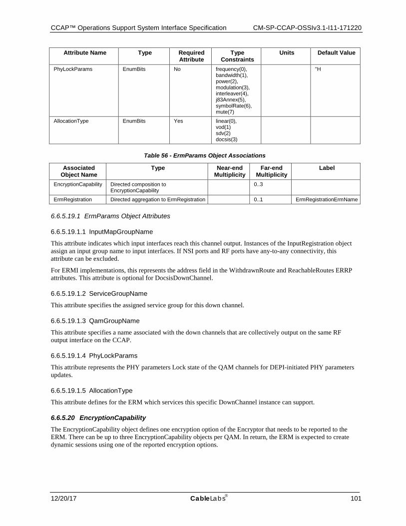
CCAP™ Operations Support System Interface Specification CM-SP-CCAP-OSSIv3.1-I11-171220
12/20/17 CableLabs 101
Attribute Name Type Required Attribute
Type Constraints
Units Default Value
PhyLockParams EnumBits No frequency(0), bandwidth(1), power(2), modulation(3), interleaver(4), j83Annex(5), symbolRate(6), mute(7)
''H
AllocationType EnumBits Yes linear(0), vod(1) sdv(2) docsis(3)
Table 56 - ErmParams Object Associations
Associated Object Name
Type Near-end Multiplicity
Far-end Multiplicity
Label
EncryptionCapability Directed composition to EncryptionCapability
0..3
ErmRegistration Directed aggregation to ErmRegistration 0..1 ErmRegistrationErmName
6.6.5.19.1 ErmParams Object Attributes
6.6.5.19.1.1 InputMapGroupName
This attribute indicates which input interfaces reach this channel output. Instances of the InputRegistration object assign an input group name to input interfaces. If NSI ports and RF ports have any-to-any connectivity, this attribute can be excluded.
For ERMI implementations, this represents the address field in the WithdrawnRoute and ReachableRoutes ERRP attributes. This attribute is optional for DocsisDownChannel.
6.6.5.19.1.2 ServiceGroupName
This attribute specifies the assigned service group for this down channel.
6.6.5.19.1.3 QamGroupName
This attribute specifies a name associated with the down channels that are collectively output on the same RF output interface on the CCAP.
6.6.5.19.1.4 PhyLockParams
This attribute represents the PHY parameters Lock state of the QAM channels for DEPI-initiated PHY parameters updates.
6.6.5.19.1.5 AllocationType
This attribute defines for the ERM which services this specific DownChannel instance can support.
6.6.5.20 EncryptionCapability The EncryptionCapability object defines one encryption option of the Encryptor that needs to be reported to the ERM. There can be up to three EncryptionCapability objects per QAM. In return, the ERM is expected to create dynamic sessions using one of the reported encryption options.
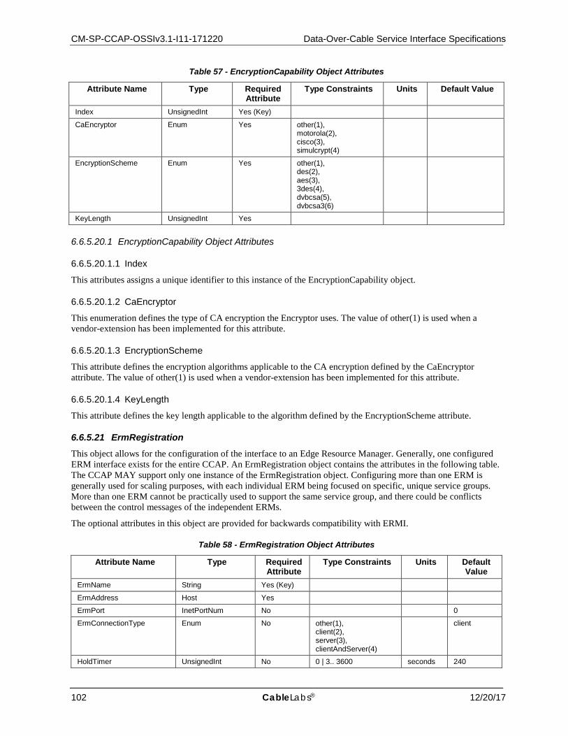
CM-SP-CCAP-OSSIv3.1-I11-171220 Data-Over-Cable Service Interface Specifications
102 CableLabs® 12/20/17
Table 57 - EncryptionCapability Object Attributes
Attribute Name Type Required Attribute
Type Constraints Units Default Value
Index UnsignedInt Yes (Key)
CaEncryptor Enum Yes other(1), motorola(2), cisco(3), simulcrypt(4)
EncryptionScheme Enum Yes other(1), des(2), aes(3), 3des(4), dvbcsa(5), dvbcsa3(6)
KeyLength UnsignedInt Yes
6.6.5.20.1 EncryptionCapability Object Attributes
6.6.5.20.1.1 Index
This attributes assigns a unique identifier to this instance of the EncryptionCapability object.
6.6.5.20.1.2 CaEncryptor
This enumeration defines the type of CA encryption the Encryptor uses. The value of other(1) is used when a vendor-extension has been implemented for this attribute.
6.6.5.20.1.3 EncryptionScheme
This attribute defines the encryption algorithms applicable to the CA encryption defined by the CaEncryptor attribute. The value of other(1) is used when a vendor-extension has been implemented for this attribute.
6.6.5.20.1.4 KeyLength
This attribute defines the key length applicable to the algorithm defined by the EncryptionScheme attribute.
6.6.5.21 ErmRegistration This object allows for the configuration of the interface to an Edge Resource Manager. Generally, one configured ERM interface exists for the entire CCAP. An ErmRegistration object contains the attributes in the following table. The CCAP MAY support only one instance of the ErmRegistration object. Configuring more than one ERM is generally used for scaling purposes, with each individual ERM being focused on specific, unique service groups. More than one ERM cannot be practically used to support the same service group, and there could be conflicts between the control messages of the independent ERMs.
The optional attributes in this object are provided for backwards compatibility with ERMI.
Table 58 - ErmRegistration Object Attributes
Attribute Name Type Required Attribute
Type Constraints Units Default Value
ErmName String Yes (Key)
ErmAddress Host Yes
ErmPort InetPortNum No 0
ErmConnectionType Enum No other(1), client(2), server(3), clientAndServer(4)
client
HoldTimer UnsignedInt No 0 | 3.. 3600 seconds 240
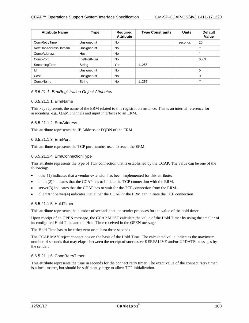
CCAP™ Operations Support System Interface Specification CM-SP-CCAP-OSSIv3.1-I11-171220
12/20/17 CableLabs 103
Attribute Name Type Required Attribute
Type Constraints Units Default Value
ConnRetryTimer UnsignedInt No seconds 20
NextHopAddressDomain UnsignedInt No ""
CompAddress Host No "
CompPort InetPortNum No 6069
StreamingZone String Yes 1..255
Id UnsignedInt No 0
Cost UnsignedInt No 0
CompName String No 1..255 ""
6.6.5.21.1 ErmRegistration Object Attributes
6.6.5.21.1.1 ErmName
This key represents the name of the ERM related to this registration instance. This is an internal reference for associating, e.g., QAM channels and input interfaces to an ERM.
6.6.5.21.1.2 ErmAddress
This attribute represents the IP Address or FQDN of the ERM.
6.6.5.21.1.3 ErmPort
This attribute represents the TCP port number used to reach the ERM.
6.6.5.21.1.4 ErmConnectionType
This attribute represents the type of TCP connection that is established by the CCAP. The value can be one of the following:
• other(1) indicates that a vendor-extension has been implemented for this attribute. • client(2) indicates that the CCAP has to initiate the TCP connection with the ERM. • server(3) indicates that the CCAP has to wait for the TCP connection from the ERM. • clientAndServer(4) indicates that either the CCAP or the ERM can initiate the TCP connection.
6.6.5.21.1.5 HoldTimer
This attribute represents the number of seconds that the sender proposes for the value of the hold timer.
Upon receipt of an OPEN message, the CCAP MUST calculate the value of the Hold Timer by using the smaller of its configured Hold Time and the Hold Time received in the OPEN message.
The Hold Time has to be either zero or at least three seconds.
The CCAP MAY reject connections on the basis of the Hold Time. The calculated value indicates the maximum number of seconds that may elapse between the receipt of successive KEEPALIVE and/or UPDATE messages by the sender.
6.6.5.21.1.6 ConnRetryTimer
This attribute represents the time in seconds for the connect retry timer. The exact value of the connect retry timer is a local matter, but should be sufficiently large to allow TCP initialization.
CM-SP-CCAP-OSSIv3.1-I11-171220 Data-Over-Cable Service Interface Specifications
104 CableLabs® 12/20/17
6.6.5.21.1.7 NextHopAddressDomain
This attribute represents the address domain number of the next-hop server. The NextHopServer specifies the address to which a manager should use to connect to the component in order to control the resource specified in the reachable route. This parameter is used in the ERRP NextHopServer attribute.
6.6.5.21.1.8 CompAddress
This attribute represents the host portion of the ERRP NextHopServer attribute. This field contains an FQDN, or an IPv4 address using the textual representation defined in section 2.1 of [RFC 1123], or an IPv6 address using the textual representation defined in section 2.2 of [RFC 4291]. This value is sent in the ERRP NextHopServer attribute with the CompPort value in the ERRP messages. The attribute is optional when signaling DOCSIS only resources, however it is defined as a mandatory attribute since the typical use of ErmRegistration is for video.
6.6.5.21.1.9 CompPort
This attribute represents the port portion of the ERRP NextHopServer attribute. This field contains numerical value (1-65535) representing the port number. If the port is empty or not given, the default port 6069 is assumed. This value is sent in the ERRP NextHopServer attribute with the CompAddress value in the ERRP messages. The attribute is optional when signaling DOCSIS only resources, however it is defined as a mandatory attribute since the typical use of ErmRegistration is for video.
6.6.5.21.1.10 StreamingZone
This attribute represents the name of the Streaming Zone within which the component operates. This parameter is used in the ERRP OPEN message. StreamingZone Name is a mandatory parameter when supporting video applications. The capability is optional when signaling DOCSIS only resources.
The value is to be set to the string that represents the StreamingZone Name, i.e., <region>. The characters comprising the string are in the set within TEXT defined in section 15.1 of [RFC 2326]. The CCAP MUST support minimum string lengths of 64 for the StreamingZone attribute of the ErmRegistration object; however, the composition of the string used is defined by implementation agreements specified by the service provider.
A CCAP will exist in a single streaming zone.
6.6.5.21.1.11 Id
This attribute represents the unique identifier for the CCAP device within its Streaming Zone. This value can be set to the 4-octet value of an IPv4 address assigned to that device. This ID value is determined on startup and is the same for all peer connections. This parameter is used in the ERRP OPEN message header.
6.6.5.21.1.12 Cost
This attribute represents the static cost for use of this resource.
6.6.5.21.1.13 CompName
The name of the component for which the data in the update message applies. This parameter is used in the ERRP OPEN message. Component Name is a mandatory parameter when supporting video applications. The capability is optional when signaling DOCSIS only resources.
The value is to be set to the string that represents the Component Name, i.e., <region>.<localname>. The characters comprising the string are in the set within TEXT defined in section 15.1 of [RFC 2326]. The CCAP MUST support minimum string lengths of 64 for the CompName attribute of the ErmRegistration object; however, the composition of the string used is defined by implementation agreements specified by the service provider.
6.6.5.22 VideoSession The VideoSession abstract object holds the common attributes for the session configuration objects (program, PID, and MPTS passthrough).
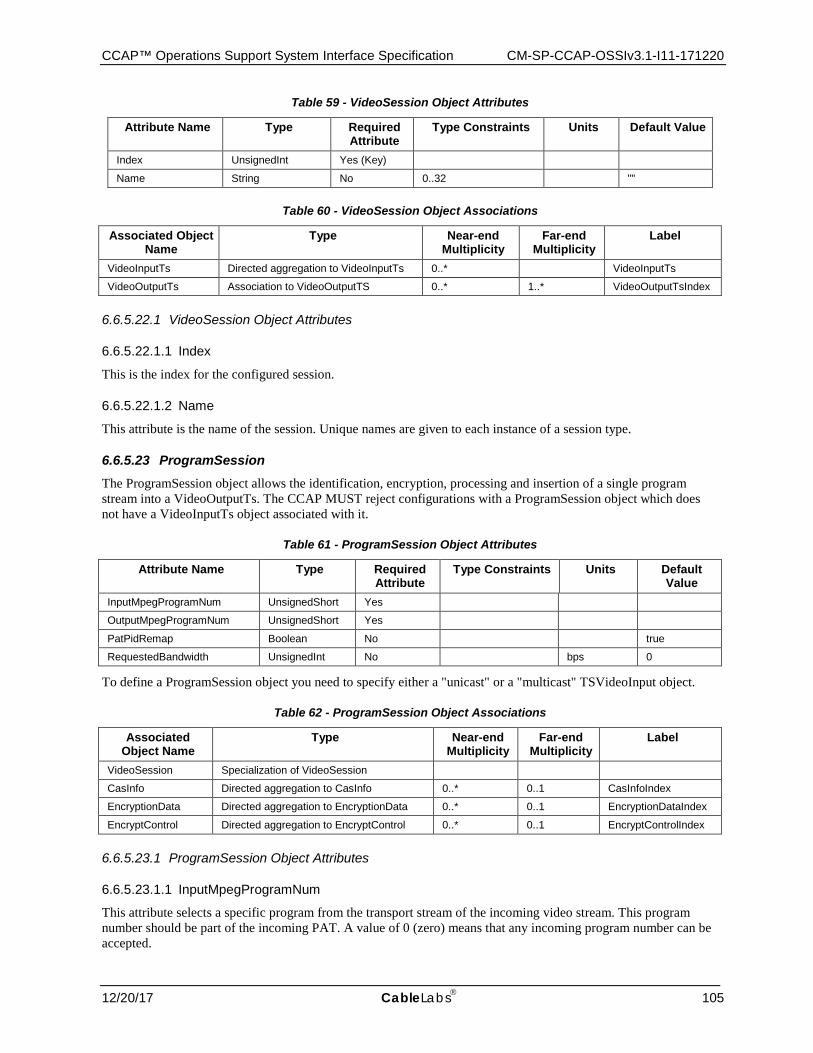
CCAP™ Operations Support System Interface Specification CM-SP-CCAP-OSSIv3.1-I11-171220
12/20/17 CableLabs 105
Table 59 - VideoSession Object Attributes
Attribute Name Type Required Attribute
Type Constraints Units Default Value
Index UnsignedInt Yes (Key)
Name String No 0..32 ""
Table 60 - VideoSession Object Associations
Associated Object Name
Type Near-end Multiplicity
Far-end Multiplicity
Label
VideoInputTs Directed aggregation to VideoInputTs 0..* VideoInputTs
VideoOutputTs Association to VideoOutputTS 0..* 1..* VideoOutputTsIndex
6.6.5.22.1 VideoSession Object Attributes
6.6.5.22.1.1 Index
This is the index for the configured session.
6.6.5.22.1.2 Name
This attribute is the name of the session. Unique names are given to each instance of a session type.
6.6.5.23 ProgramSession The ProgramSession object allows the identification, encryption, processing and insertion of a single program stream into a VideoOutputTs. The CCAP MUST reject configurations with a ProgramSession object which does not have a VideoInputTs object associated with it.
Table 61 - ProgramSession Object Attributes
Attribute Name Type Required Attribute
Type Constraints Units Default Value
InputMpegProgramNum UnsignedShort Yes
OutputMpegProgramNum UnsignedShort Yes
PatPidRemap Boolean No true
RequestedBandwidth UnsignedInt No bps 0
To define a ProgramSession object you need to specify either a "unicast" or a "multicast" TSVideoInput object.
Table 62 - ProgramSession Object Associations
Associated Object Name
Type Near-end Multiplicity
Far-end Multiplicity
Label
VideoSession Specialization of VideoSession
CasInfo Directed aggregation to CasInfo 0..* 0..1 CasInfoIndex
EncryptionData Directed aggregation to EncryptionData 0..* 0..1 EncryptionDataIndex
EncryptControl Directed aggregation to EncryptControl 0..* 0..1 EncryptControlIndex
6.6.5.23.1 ProgramSession Object Attributes
6.6.5.23.1.1 InputMpegProgramNum
This attribute selects a specific program from the transport stream of the incoming video stream. This program number should be part of the incoming PAT. A value of 0 (zero) means that any incoming program number can be accepted.
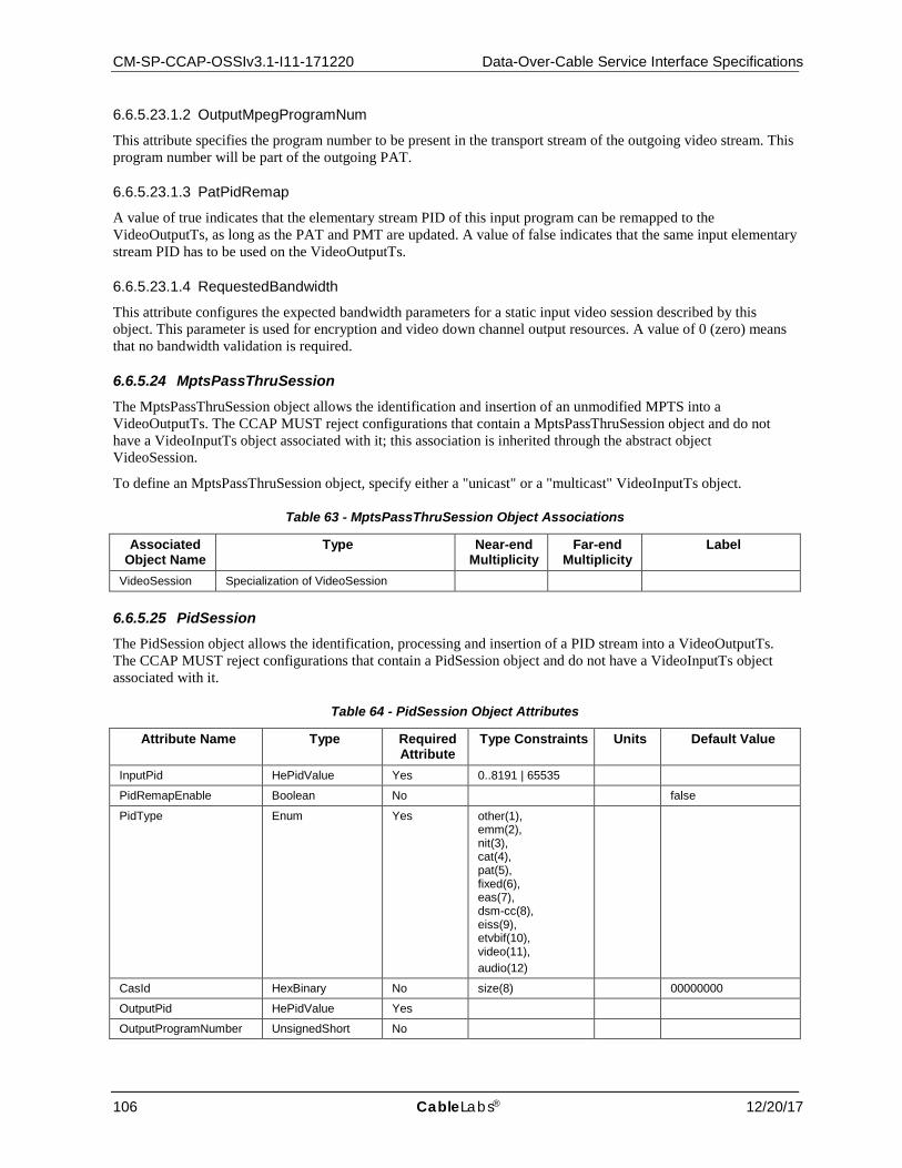
CM-SP-CCAP-OSSIv3.1-I11-171220 Data-Over-Cable Service Interface Specifications
106 CableLabs® 12/20/17
6.6.5.23.1.2 OutputMpegProgramNum
This attribute specifies the program number to be present in the transport stream of the outgoing video stream. This program number will be part of the outgoing PAT.
6.6.5.23.1.3 PatPidRemap
A value of true indicates that the elementary stream PID of this input program can be remapped to the VideoOutputTs, as long as the PAT and PMT are updated. A value of false indicates that the same input elementary stream PID has to be used on the VideoOutputTs.
6.6.5.23.1.4 RequestedBandwidth
This attribute configures the expected bandwidth parameters for a static input video session described by this object. This parameter is used for encryption and video down channel output resources. A value of 0 (zero) means that no bandwidth validation is required.
6.6.5.24 MptsPassThruSession The MptsPassThruSession object allows the identification and insertion of an unmodified MPTS into a VideoOutputTs. The CCAP MUST reject configurations that contain a MptsPassThruSession object and do not have a VideoInputTs object associated with it; this association is inherited through the abstract object VideoSession.
To define an MptsPassThruSession object, specify either a "unicast" or a "multicast" VideoInputTs object.
Table 63 - MptsPassThruSession Object Associations
Associated Object Name
Type Near-end Multiplicity
Far-end Multiplicity
Label
VideoSession Specialization of VideoSession
6.6.5.25 PidSession The PidSession object allows the identification, processing and insertion of a PID stream into a VideoOutputTs. The CCAP MUST reject configurations that contain a PidSession object and do not have a VideoInputTs object associated with it.
Table 64 - PidSession Object Attributes
Attribute Name Type Required Attribute
Type Constraints Units Default Value
InputPid HePidValue Yes 0..8191 | 65535
PidRemapEnable Boolean No false
PidType Enum Yes other(1), emm(2), nit(3), cat(4), pat(5), fixed(6), eas(7), dsm-cc(8), eiss(9), etvbif(10), video(11), audio(12)
CasId HexBinary No size(8) 00000000
OutputPid HePidValue Yes
OutputProgramNumber UnsignedShort No
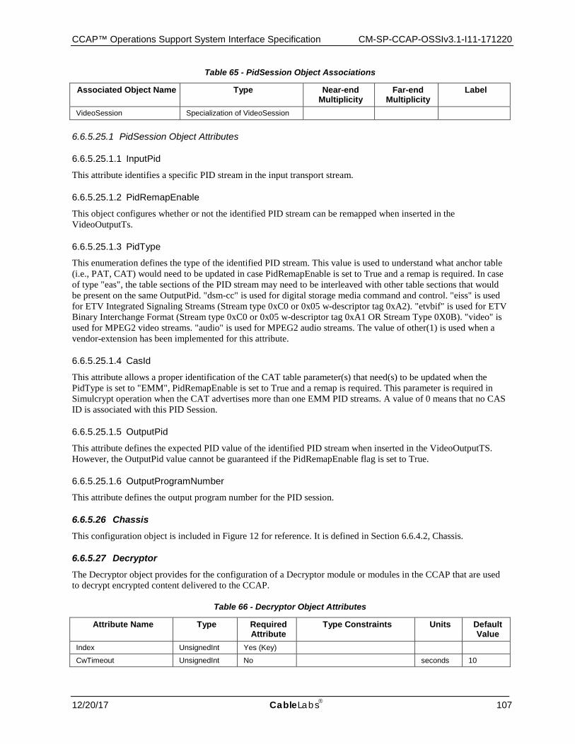
CCAP™ Operations Support System Interface Specification CM-SP-CCAP-OSSIv3.1-I11-171220
12/20/17 CableLabs 107
Table 65 - PidSession Object Associations
Associated Object Name Type Near-end Multiplicity
Far-end Multiplicity
Label
VideoSession Specialization of VideoSession
6.6.5.25.1 PidSession Object Attributes
6.6.5.25.1.1 InputPid
This attribute identifies a specific PID stream in the input transport stream.
6.6.5.25.1.2 PidRemapEnable
This object configures whether or not the identified PID stream can be remapped when inserted in the VideoOutputTs.
6.6.5.25.1.3 PidType
This enumeration defines the type of the identified PID stream. This value is used to understand what anchor table (i.e., PAT, CAT) would need to be updated in case PidRemapEnable is set to True and a remap is required. In case of type "eas", the table sections of the PID stream may need to be interleaved with other table sections that would be present on the same OutputPid. "dsm-cc" is used for digital storage media command and control. "eiss" is used for ETV Integrated Signaling Streams (Stream type 0xC0 or 0x05 w-descriptor tag 0xA2). "etvbif" is used for ETV Binary Interchange Format (Stream type 0xC0 or 0x05 w-descriptor tag 0xA1 OR Stream Type 0X0B). "video" is used for MPEG2 video streams. "audio" is used for MPEG2 audio streams. The value of other(1) is used when a vendor-extension has been implemented for this attribute.
6.6.5.25.1.4 CasId
This attribute allows a proper identification of the CAT table parameter(s) that need(s) to be updated when the PidType is set to "EMM", PidRemapEnable is set to True and a remap is required. This parameter is required in Simulcrypt operation when the CAT advertises more than one EMM PID streams. A value of 0 means that no CAS ID is associated with this PID Session.
6.6.5.25.1.5 OutputPid
This attribute defines the expected PID value of the identified PID stream when inserted in the VideoOutputTS. However, the OutputPid value cannot be guaranteed if the PidRemapEnable flag is set to True.
6.6.5.25.1.6 OutputProgramNumber
This attribute defines the output program number for the PID session.
6.6.5.26 Chassis This configuration object is included in Figure 12 for reference. It is defined in Section 6.6.4.2, Chassis.
6.6.5.27 Decryptor The Decryptor object provides for the configuration of a Decryptor module or modules in the CCAP that are used to decrypt encrypted content delivered to the CCAP.
Table 66 - Decryptor Object Attributes
Attribute Name Type Required Attribute
Type Constraints Units Default Value
Index UnsignedInt Yes (Key)
CwTimeout UnsignedInt No seconds 10

CM-SP-CCAP-OSSIv3.1-I11-171220 Data-Over-Cable Service Interface Specifications
108 CableLabs® 12/20/17
The Decryptor object has the following association.
Table 67 - Decryptor Object Associations
Associated Object Name
Type Near-end Multiplicity
Far-end Multiplicity
Label
EcmdUsage Directed composition to EcmdUsage 1 1..*
6.6.5.27.1 Decryptor Object Attributes
6.6.5.27.1.1 Index
The Index is an unsigned, 32-bit identifier used as a key for this object.
6.6.5.27.1.2 CwTimeout
This attribute configures the length of time in seconds that the Decryptor should wait for an ECM Decoder (ECMD) before switching to a redundant unit.
6.6.5.28 EcmdUsage The EcmdUsage object provides for the configuration of multiple decryption sessions. It is an intermediate object that provides linkages between Decryptor objects and the ECMD(s) associated with those encrypted streams. The ECMD object is defined in Section 6.6.5.29, Ecmd.
Table 68 - EcmdUsage Object Attributes
Attribute Name Type Required Attribute
Type Constraints Units Default Value
Index UnsignedInt Yes (Key)
Priority UnsignedInt Yes
The EcmdUsage object has the following association.
Table 69 - EcmdUsage Object Associations
Associated Object Name
Type Near-end Multiplicity
Far-end Multiplicity
Label
Ecmd Directed aggregation to Ecmd 1..* 1 EcmdIndex
6.6.5.28.1 EcmdUsage Object Attributes
6.6.5.28.1.1 Index
This is an index for an instance of this Object. The EcmdUsage object is a pointer to the Ecmd object that can be used for any program session that requires decryption as long as the CAS identifier of the input program matches.
6.6.5.28.1.2 Priority
This is the configured selection priority for any program session that requires decryption when multiple ECMDs with the same CAS identifier are active. The ECMD with the lowest number should be selected first.
6.6.5.29 Ecmd This object allows for the configuration of the interface to an Entitlement Control Message Decoder (ECMD).
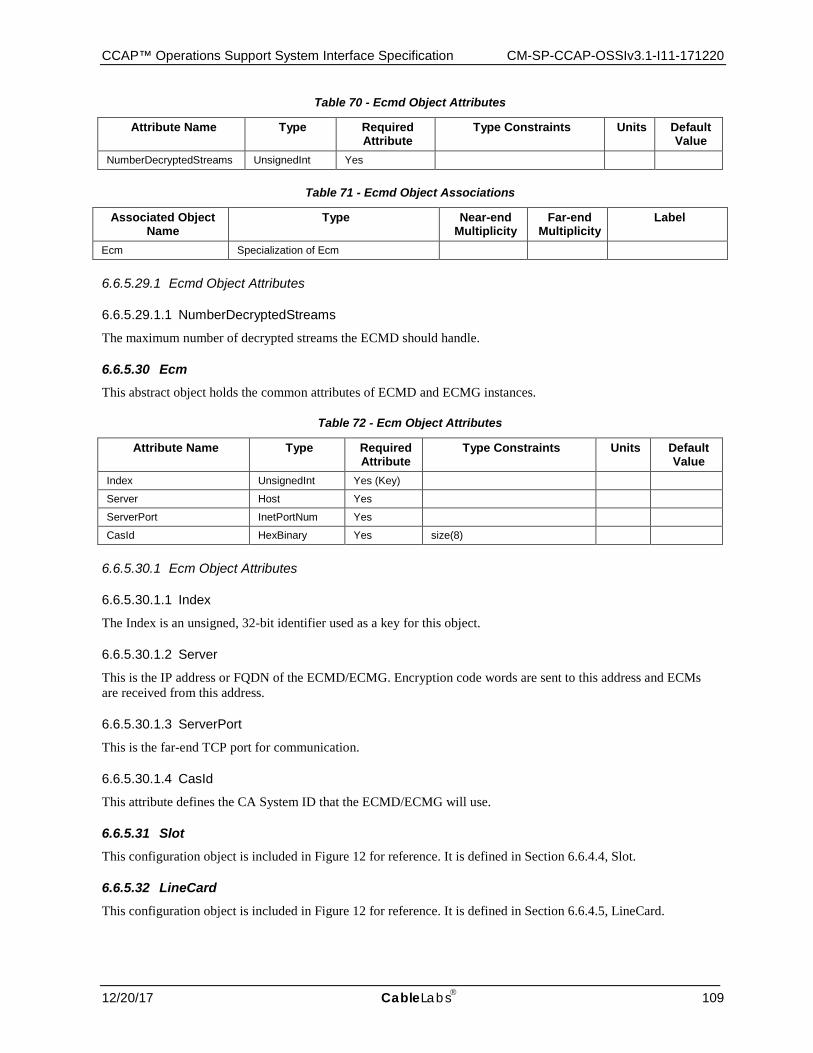
CCAP™ Operations Support System Interface Specification CM-SP-CCAP-OSSIv3.1-I11-171220
12/20/17 CableLabs 109
Table 70 - Ecmd Object Attributes
Attribute Name Type Required Attribute
Type Constraints Units Default Value
NumberDecryptedStreams UnsignedInt Yes
Table 71 - Ecmd Object Associations
Associated Object Name
Type Near-end Multiplicity
Far-end Multiplicity
Label
Ecm Specialization of Ecm
6.6.5.29.1 Ecmd Object Attributes
6.6.5.29.1.1 NumberDecryptedStreams
The maximum number of decrypted streams the ECMD should handle.
6.6.5.30 Ecm This abstract object holds the common attributes of ECMD and ECMG instances.
Table 72 - Ecm Object Attributes
Attribute Name Type Required Attribute
Type Constraints Units Default Value
Index UnsignedInt Yes (Key)
Server Host Yes
ServerPort InetPortNum Yes
CasId HexBinary Yes size(8)
6.6.5.30.1 Ecm Object Attributes
6.6.5.30.1.1 Index
The Index is an unsigned, 32-bit identifier used as a key for this object.
6.6.5.30.1.2 Server
This is the IP address or FQDN of the ECMD/ECMG. Encryption code words are sent to this address and ECMs are received from this address.
6.6.5.30.1.3 ServerPort
This is the far-end TCP port for communication.
6.6.5.30.1.4 CasId
This attribute defines the CA System ID that the ECMD/ECMG will use.
6.6.5.31 Slot This configuration object is included in Figure 12 for reference. It is defined in Section 6.6.4.4, Slot.
6.6.5.32 LineCard This configuration object is included in Figure 12 for reference. It is defined in Section 6.6.4.5, LineCard.
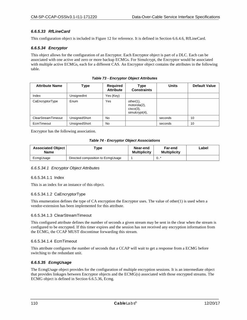
CM-SP-CCAP-OSSIv3.1-I11-171220 Data-Over-Cable Service Interface Specifications
110 CableLabs® 12/20/17
6.6.5.33 RfLineCard This configuration object is included in Figure 12 for reference. It is defined in Section 6.6.4.6, RfLineCard.
6.6.5.34 Encryptor This object allows for the configuration of an Encryptor. Each Encryptor object is part of a DLC. Each can be associated with one active and zero or more backup ECMGs. For Simulcrypt, the Encryptor would be associated with multiple active ECMGs, each for a different CAS. An Encryptor object contains the attributes in the following table.
Table 73 - Encryptor Object Attributes
Attribute Name Type Required Attribute
Type Constraints
Units Default Value
Index UnsignedInt Yes (Key)
CaEncryptorType Enum Yes other(1), motorola(2), cisco(3), simulcrypt(4),
ClearStreamTimeout UnsignedShort No seconds 10
EcmTimeout UnsignedShort No seconds 10
Encryptor has the following association.
Table 74 - Encryptor Object Associations
Associated Object Name
Type Near-end Multiplicity
Far-end Multiplicity
Label
EcmgUsage Directed composition to EcmgUsage 1 0..*
6.6.5.34.1 Encryptor Object Attributes
6.6.5.34.1.1 Index
This is an index for an instance of this object.
6.6.5.34.1.2 CaEncryptorType
This enumeration defines the type of CA encryption the Encryptor uses. The value of other(1) is used when a vendor-extension has been implemented for this attribute.
6.6.5.34.1.3 ClearStreamTimeout
This configured attribute defines the number of seconds a given stream may be sent in the clear when the stream is configured to be encrypted. If this timer expires and the session has not received any encryption information from the ECMG, the CCAP MUST discontinue forwarding this stream.
6.6.5.34.1.4 EcmTimeout
This attribute configures the number of seconds that a CCAP will wait to get a response from a ECMG before switching to the redundant unit.
6.6.5.35 EcmgUsage The EcmgUsage object provides for the configuration of multiple encryption sessions. It is an intermediate object that provides linkages between Encryptor objects and the ECMG(s) associated with those encrypted streams. The ECMG object is defined in Section 6.6.5.36, Ecmg.
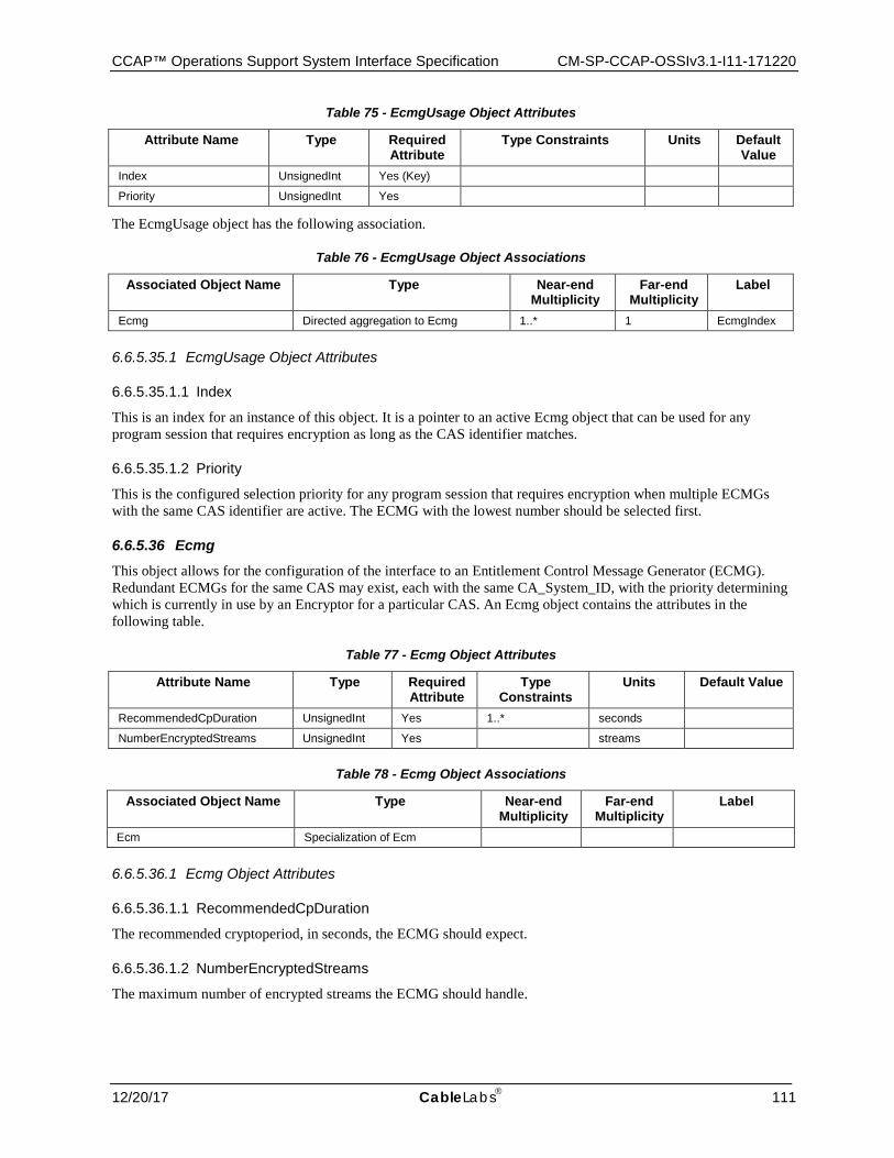
CCAP™ Operations Support System Interface Specification CM-SP-CCAP-OSSIv3.1-I11-171220
12/20/17 CableLabs 111
Table 75 - EcmgUsage Object Attributes
Attribute Name Type Required Attribute
Type Constraints Units Default Value
Index UnsignedInt Yes (Key)
Priority UnsignedInt Yes
The EcmgUsage object has the following association.
Table 76 - EcmgUsage Object Associations
Associated Object Name Type Near-end Multiplicity
Far-end Multiplicity
Label
Ecmg Directed aggregation to Ecmg 1..* 1 EcmgIndex
6.6.5.35.1 EcmgUsage Object Attributes
6.6.5.35.1.1 Index
This is an index for an instance of this object. It is a pointer to an active Ecmg object that can be used for any program session that requires encryption as long as the CAS identifier matches.
6.6.5.35.1.2 Priority
This is the configured selection priority for any program session that requires encryption when multiple ECMGs with the same CAS identifier are active. The ECMG with the lowest number should be selected first.
6.6.5.36 Ecmg This object allows for the configuration of the interface to an Entitlement Control Message Generator (ECMG). Redundant ECMGs for the same CAS may exist, each with the same CA_System_ID, with the priority determining which is currently in use by an Encryptor for a particular CAS. An Ecmg object contains the attributes in the following table.
Table 77 - Ecmg Object Attributes
Attribute Name Type Required Attribute
Type Constraints
Units Default Value
RecommendedCpDuration UnsignedInt Yes 1..* seconds
NumberEncryptedStreams UnsignedInt Yes streams
Table 78 - Ecmg Object Associations
Associated Object Name Type Near-end Multiplicity
Far-end Multiplicity
Label
Ecm Specialization of Ecm
6.6.5.36.1 Ecmg Object Attributes
6.6.5.36.1.1 RecommendedCpDuration
The recommended cryptoperiod, in seconds, the ECMG should expect.
6.6.5.36.1.2 NumberEncryptedStreams
The maximum number of encrypted streams the ECMG should handle.
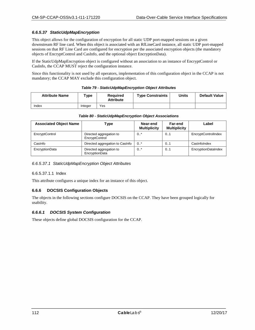
CM-SP-CCAP-OSSIv3.1-I11-171220 Data-Over-Cable Service Interface Specifications
112 CableLabs® 12/20/17
6.6.5.37 StaticUdpMapEncryption This object allows for the configuration of encryption for all static UDP port-mapped sessions on a given downstream RF line card. When this object is associated with an RfLineCard instance, all static UDP port-mapped sessions on that RF Line Card are configured for encryption per the associated encryption objects (the mandatory objects of EncryptControl and CasInfo, and the optional object EncryptionData).
If the StaticUdpMapEncryption object is configured without an association to an instance of EncryptControl or CasInfo, the CCAP MUST reject the configuration instance.
Since this functionality is not used by all operators, implementation of this configuration object in the CCAP is not mandatory; the CCAP MAY exclude this configuration object.
Table 79 - StaticUdpMapEncryption Object Attributes
Attribute Name Type Required Attribute
Type Constraints Units Default Value
Index Integer Yes
Table 80 - StaticUdpMapEncryption Object Associations
Associated Object Name Type Near-end Multiplicity
Far-end Multiplicity
Label
EncryptControl Directed aggregation to EncryptControl
0..* 0..1 EncryptControlIndex
CasInfo Directed aggregation to CasInfo 0..* 0..1 CasInfoIndex
EncryptionData Directed aggregation to EncryptionData
0..* 0..1 EncryptionDataIndex
6.6.5.37.1 StaticUdpMapEncryption Object Attributes
6.6.5.37.1.1 Index
This attribute configures a unique index for an instance of this object.
6.6.6 DOCSIS Configuration Objects The objects in the following sections configure DOCSIS on the CCAP. They have been grouped logically for usability.
6.6.6.1 DOCSIS System Configuration These objects define global DOCSIS configuration for the CCAP.
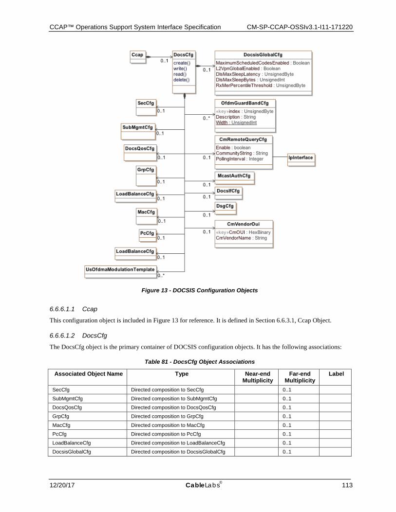
CCAP™ Operations Support System Interface Specification CM-SP-CCAP-OSSIv3.1-I11-171220
12/20/17 CableLabs 113
Figure 13 - DOCSIS Configuration Objects
6.6.6.1.1 Ccap
This configuration object is included in Figure 13 for reference. It is defined in Section 6.6.3.1, Ccap Object.
6.6.6.1.2 DocsCfg
The DocsCfg object is the primary container of DOCSIS configuration objects. It has the following associations:
Table 81 - DocsCfg Object Associations
Associated Object Name Type Near-end Multiplicity
Far-end Multiplicity
Label
SecCfg Directed composition to SecCfg 0..1
SubMgmtCfg Directed composition to SubMgmtCfg 0..1
DocsQosCfg Directed composition to DocsQosCfg 0..1
GrpCfg Directed composition to GrpCfg 0..1
MacCfg Directed composition to MacCfg 0..1
PcCfg Directed composition to PcCfg 0..1
LoadBalanceCfg Directed composition to LoadBalanceCfg 0..1
DocsisGlobalCfg Directed composition to DocsisGlobalCfg 0..1
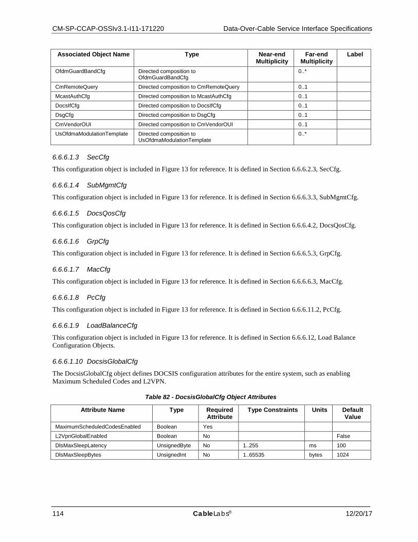
CM-SP-CCAP-OSSIv3.1-I11-171220 Data-Over-Cable Service Interface Specifications
114 CableLabs® 12/20/17
Associated Object Name Type Near-end Multiplicity
Far-end Multiplicity
Label
OfdmGuardBandCfg Directed composition to OfdmGuardBandCfg
0..*
CmRemoteQuery Directed composition to CmRemoteQuery 0..1
McastAuthCfg Directed composition to McastAuthCfg 0..1
DocsIfCfg Directed composition to DocsIfCfg 0..1
DsgCfg Directed composition to DsgCfg 0..1
CmVendorOUI Directed composition to CmVendorOUI 0..1
UsOfdmaModulationTemplate Directed composition to UsOfdmaModulationTemplate
0..*
6.6.6.1.3 SecCfg
This configuration object is included in Figure 13 for reference. It is defined in Section 6.6.6.2.3, SecCfg.
6.6.6.1.4 SubMgmtCfg
This configuration object is included in Figure 13 for reference. It is defined in Section 6.6.6.3.3, SubMgmtCfg.
6.6.6.1.5 DocsQosCfg
This configuration object is included in Figure 13 for reference. It is defined in Section 6.6.6.4.2, DocsQosCfg.
6.6.6.1.6 GrpCfg
This configuration object is included in Figure 13 for reference. It is defined in Section 6.6.6.5.3, GrpCfg.
6.6.6.1.7 MacCfg
This configuration object is included in Figure 13 for reference. It is defined in Section 6.6.6.6.3, MacCfg.
6.6.6.1.8 PcCfg
This configuration object is included in Figure 13 for reference. It is defined in Section 6.6.6.11.2, PcCfg.
6.6.6.1.9 LoadBalanceCfg
This configuration object is included in Figure 13 for reference. It is defined in Section 6.6.6.12, Load Balance Configuration Objects.
6.6.6.1.10 DocsisGlobalCfg
The DocsisGlobalCfg object defines DOCSIS configuration attributes for the entire system, such as enabling Maximum Scheduled Codes and L2VPN.
Table 82 - DocsisGlobalCfg Object Attributes
Attribute Name Type Required Attribute
Type Constraints Units Default Value
MaximumScheduledCodesEnabled Boolean Yes
L2VpnGlobalEnabled Boolean No False
DlsMaxSleepLatency UnsignedByte No 1..255 ms 100
DlsMaxSleepBytes UnsignedInt No 1..65535 bytes 1024
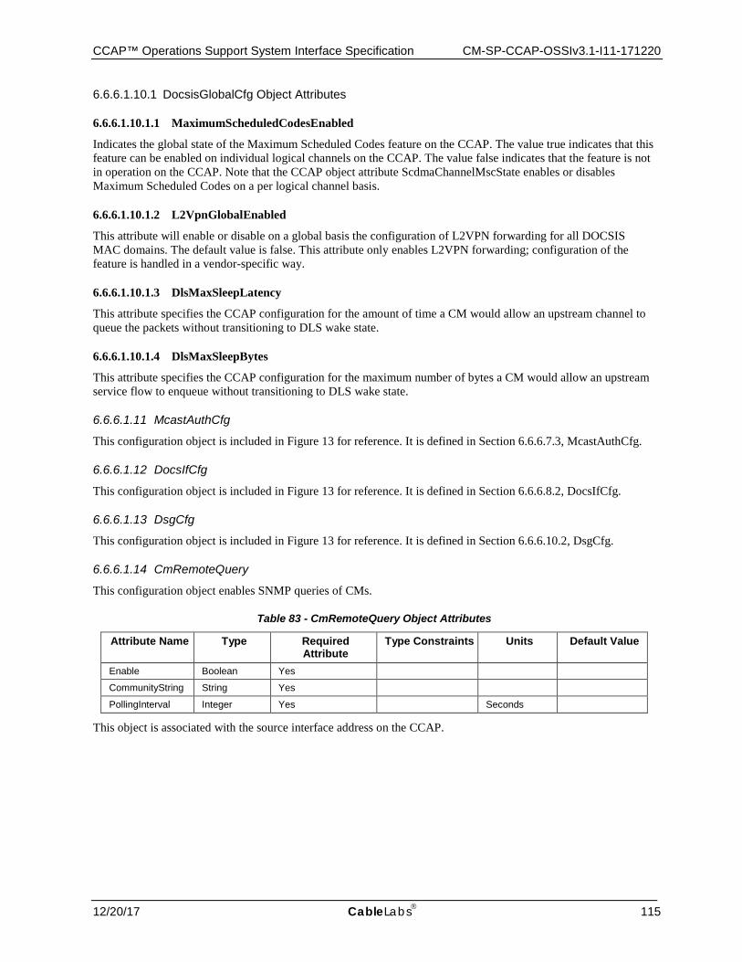
CCAP™ Operations Support System Interface Specification CM-SP-CCAP-OSSIv3.1-I11-171220
12/20/17 CableLabs 115
6.6.6.1.10.1 DocsisGlobalCfg Object Attributes
6.6.6.1.10.1.1 MaximumScheduledCodesEnabled
Indicates the global state of the Maximum Scheduled Codes feature on the CCAP. The value true indicates that this feature can be enabled on individual logical channels on the CCAP. The value false indicates that the feature is not in operation on the CCAP. Note that the CCAP object attribute ScdmaChannelMscState enables or disables Maximum Scheduled Codes on a per logical channel basis.
6.6.6.1.10.1.2 L2VpnGlobalEnabled
This attribute will enable or disable on a global basis the configuration of L2VPN forwarding for all DOCSIS MAC domains. The default value is false. This attribute only enables L2VPN forwarding; configuration of the feature is handled in a vendor-specific way.
6.6.6.1.10.1.3 DlsMaxSleepLatency
This attribute specifies the CCAP configuration for the amount of time a CM would allow an upstream channel to queue the packets without transitioning to DLS wake state.
6.6.6.1.10.1.4 DlsMaxSleepBytes
This attribute specifies the CCAP configuration for the maximum number of bytes a CM would allow an upstream service flow to enqueue without transitioning to DLS wake state.
6.6.6.1.11 McastAuthCfg
This configuration object is included in Figure 13 for reference. It is defined in Section 6.6.6.7.3, McastAuthCfg.
6.6.6.1.12 DocsIfCfg
This configuration object is included in Figure 13 for reference. It is defined in Section 6.6.6.8.2, DocsIfCfg.
6.6.6.1.13 DsgCfg
This configuration object is included in Figure 13 for reference. It is defined in Section 6.6.6.10.2, DsgCfg.
6.6.6.1.14 CmRemoteQuery
This configuration object enables SNMP queries of CMs.
Table 83 - CmRemoteQuery Object Attributes
Attribute Name Type Required Attribute
Type Constraints Units Default Value
Enable Boolean Yes
CommunityString String Yes
PollingInterval Integer Yes Seconds
This object is associated with the source interface address on the CCAP.
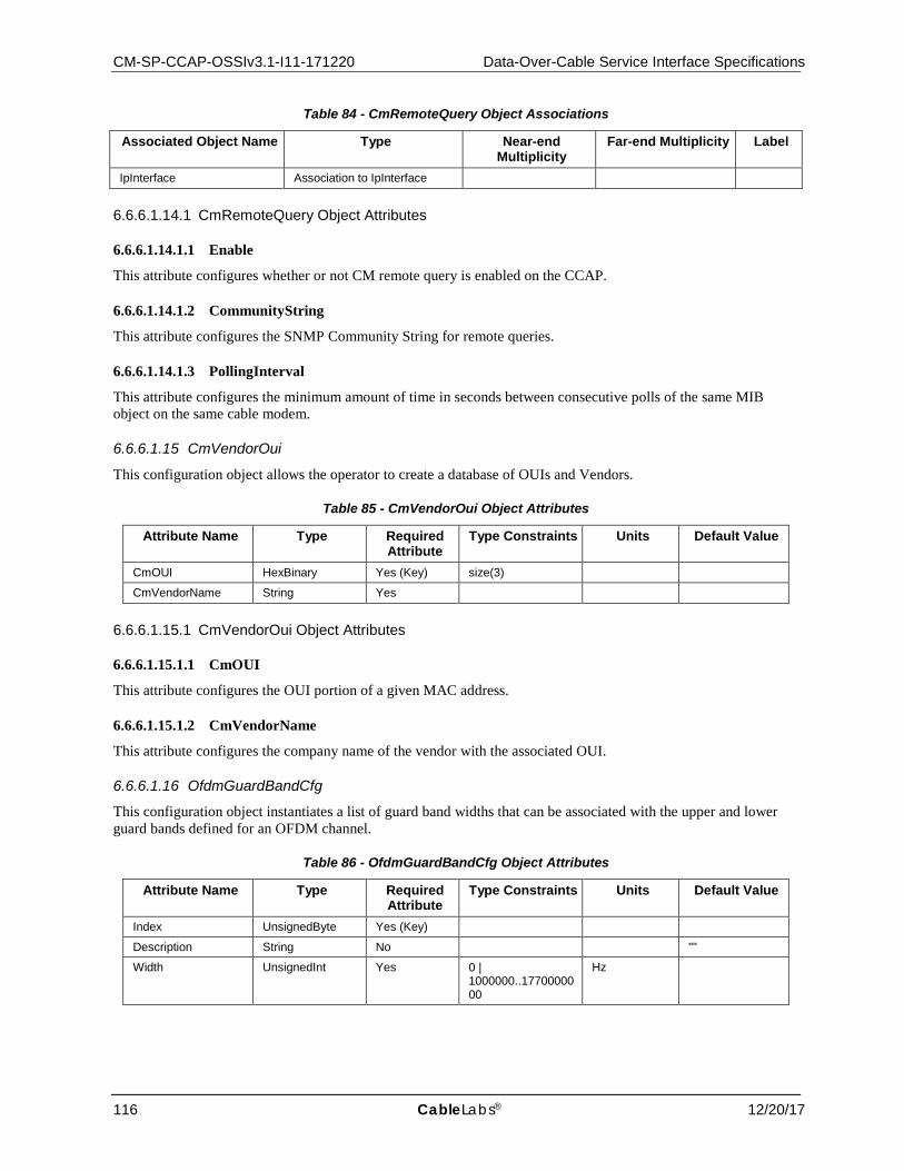
CM-SP-CCAP-OSSIv3.1-I11-171220 Data-Over-Cable Service Interface Specifications
116 CableLabs® 12/20/17
Table 84 - CmRemoteQuery Object Associations
Associated Object Name Type Near-end Multiplicity
Far-end Multiplicity Label
IpInterface Association to IpInterface
6.6.6.1.14.1 CmRemoteQuery Object Attributes
6.6.6.1.14.1.1 Enable
This attribute configures whether or not CM remote query is enabled on the CCAP.
6.6.6.1.14.1.2 CommunityString
This attribute configures the SNMP Community String for remote queries.
6.6.6.1.14.1.3 PollingInterval
This attribute configures the minimum amount of time in seconds between consecutive polls of the same MIB object on the same cable modem.
6.6.6.1.15 CmVendorOui
This configuration object allows the operator to create a database of OUIs and Vendors.
Table 85 - CmVendorOui Object Attributes
Attribute Name Type Required Attribute
Type Constraints Units Default Value
CmOUI HexBinary Yes (Key) size(3)
CmVendorName String Yes
6.6.6.1.15.1 CmVendorOui Object Attributes
6.6.6.1.15.1.1 CmOUI
This attribute configures the OUI portion of a given MAC address.
6.6.6.1.15.1.2 CmVendorName
This attribute configures the company name of the vendor with the associated OUI.
6.6.6.1.16 OfdmGuardBandCfg
This configuration object instantiates a list of guard band widths that can be associated with the upper and lower guard bands defined for an OFDM channel.
Table 86 - OfdmGuardBandCfg Object Attributes
Attribute Name Type Required Attribute
Type Constraints Units Default Value
Index UnsignedByte Yes (Key)
Description String No ""
Width UnsignedInt Yes 0 | 1000000..1770000000
Hz
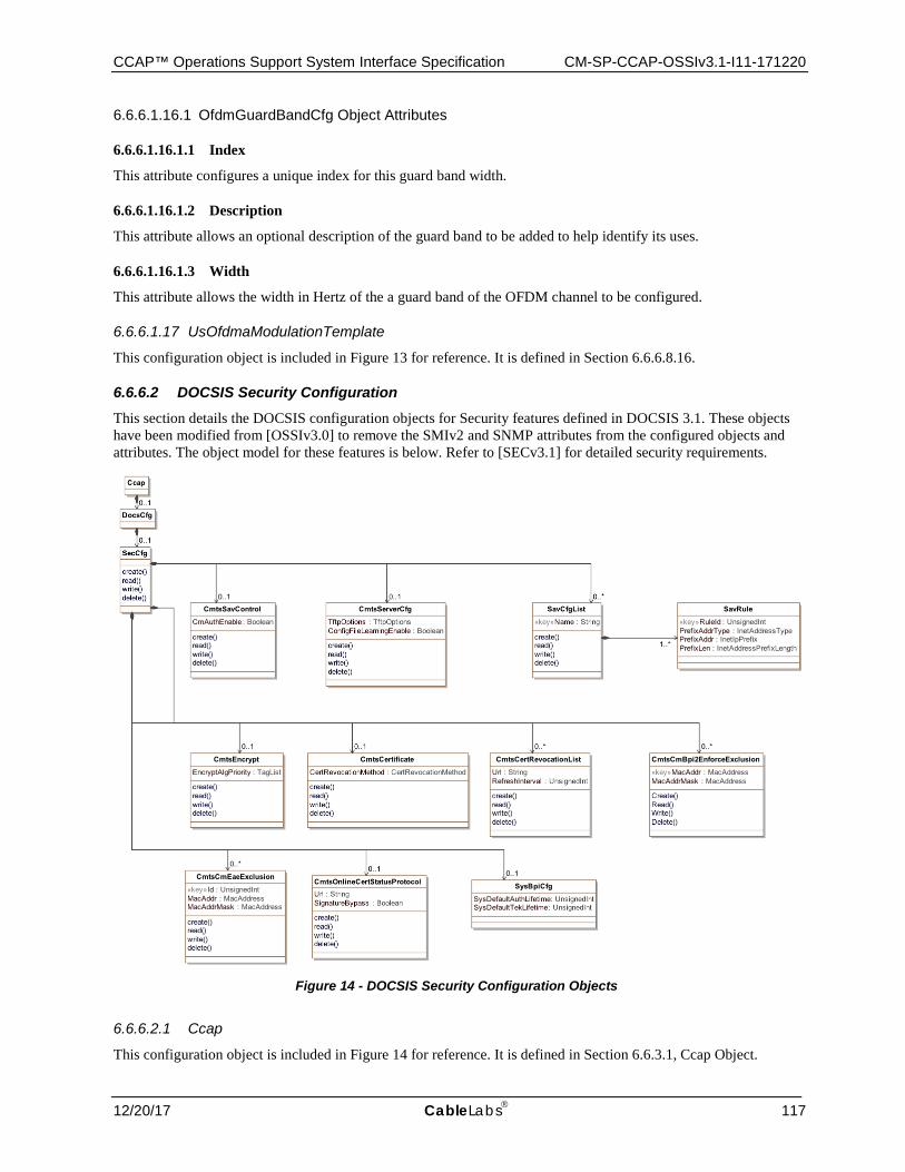
CCAP™ Operations Support System Interface Specification CM-SP-CCAP-OSSIv3.1-I11-171220
12/20/17 CableLabs 117
6.6.6.1.16.1 OfdmGuardBandCfg Object Attributes
6.6.6.1.16.1.1 Index
This attribute configures a unique index for this guard band width.
6.6.6.1.16.1.2 Description
This attribute allows an optional description of the guard band to be added to help identify its uses.
6.6.6.1.16.1.3 Width
This attribute allows the width in Hertz of the a guard band of the OFDM channel to be configured.
6.6.6.1.17 UsOfdmaModulationTemplate
This configuration object is included in Figure 13 for reference. It is defined in Section 6.6.6.8.16.
6.6.6.2 DOCSIS Security Configuration This section details the DOCSIS configuration objects for Security features defined in DOCSIS 3.1. These objects have been modified from [OSSIv3.0] to remove the SMIv2 and SNMP attributes from the configured objects and attributes. The object model for these features is below. Refer to [SECv3.1] for detailed security requirements.
Figure 14 - DOCSIS Security Configuration Objects
6.6.6.2.1 Ccap
This configuration object is included in Figure 14 for reference. It is defined in Section 6.6.3.1, Ccap Object.
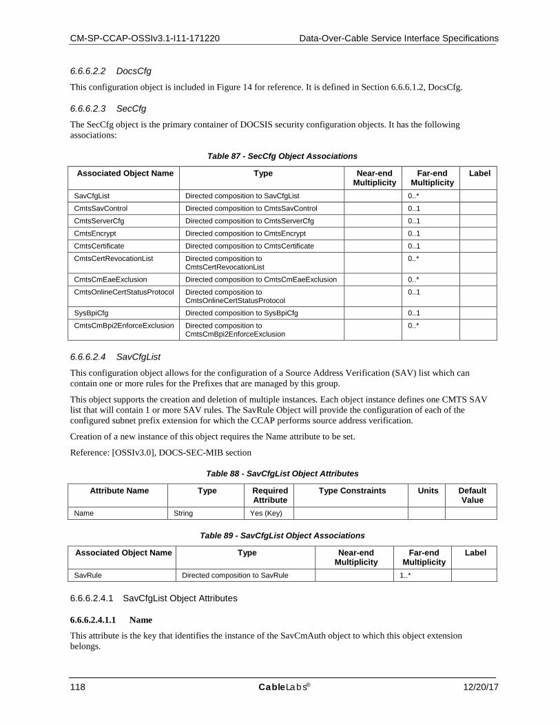
CM-SP-CCAP-OSSIv3.1-I11-171220 Data-Over-Cable Service Interface Specifications
118 CableLabs® 12/20/17
6.6.6.2.2 DocsCfg
This configuration object is included in Figure 14 for reference. It is defined in Section 6.6.6.1.2, DocsCfg.
6.6.6.2.3 SecCfg
The SecCfg object is the primary container of DOCSIS security configuration objects. It has the following associations:
Table 87 - SecCfg Object Associations
Associated Object Name Type Near-end Multiplicity
Far-end Multiplicity
Label
SavCfgList Directed composition to SavCfgList 0..*
CmtsSavControl Directed composition to CmtsSavControl 0..1
CmtsServerCfg Directed composition to CmtsServerCfg 0..1
CmtsEncrypt Directed composition to CmtsEncrypt 0..1
CmtsCertificate Directed composition to CmtsCertificate 0..1
CmtsCertRevocationList Directed composition to CmtsCertRevocationList
0..*
CmtsCmEaeExclusion Directed composition to CmtsCmEaeExclusion 0..*
CmtsOnlineCertStatusProtocol Directed composition to CmtsOnlineCertStatusProtocol
0..1
SysBpiCfg Directed composition to SysBpiCfg 0..1
CmtsCmBpi2EnforceExclusion Directed composition to CmtsCmBpi2EnforceExclusion
0..*
6.6.6.2.4 SavCfgList
This configuration object allows for the configuration of a Source Address Verification (SAV) list which can contain one or more rules for the Prefixes that are managed by this group.
This object supports the creation and deletion of multiple instances. Each object instance defines one CMTS SAV list that will contain 1 or more SAV rules. The SavRule Object will provide the configuration of each of the configured subnet prefix extension for which the CCAP performs source address verification.
Creation of a new instance of this object requires the Name attribute to be set.
Reference: [OSSIv3.0], DOCS-SEC-MIB section
Table 88 - SavCfgList Object Attributes
Attribute Name Type Required Attribute
Type Constraints Units Default Value
Name String Yes (Key)
Table 89 - SavCfgList Object Associations
Associated Object Name Type Near-end Multiplicity
Far-end Multiplicity
Label
SavRule Directed composition to SavRule 1..*
6.6.6.2.4.1 SavCfgList Object Attributes
6.6.6.2.4.1.1 Name
This attribute is the key that identifies the instance of the SavCmAuth object to which this object extension belongs.
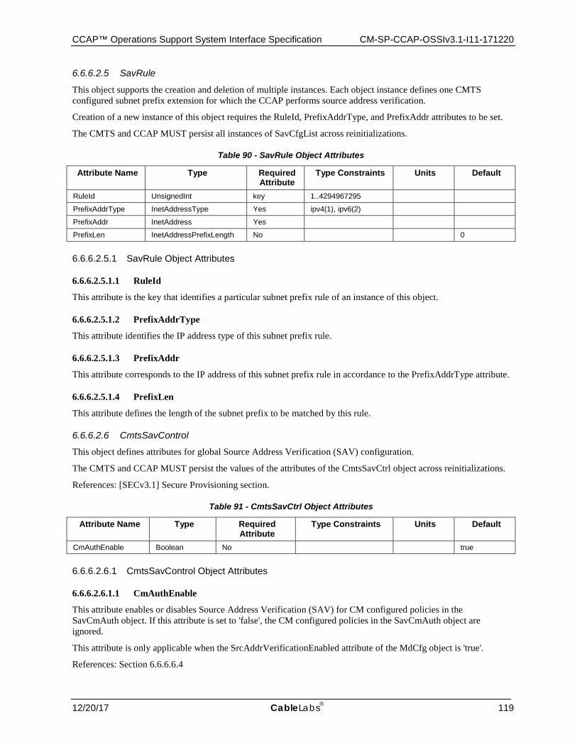
CCAP™ Operations Support System Interface Specification CM-SP-CCAP-OSSIv3.1-I11-171220
12/20/17 CableLabs 119
6.6.6.2.5 SavRule
This object supports the creation and deletion of multiple instances. Each object instance defines one CMTS configured subnet prefix extension for which the CCAP performs source address verification.
Creation of a new instance of this object requires the RuleId, PrefixAddrType, and PrefixAddr attributes to be set.
The CMTS and CCAP MUST persist all instances of SavCfgList across reinitializations.
Table 90 - SavRule Object Attributes
Attribute Name Type Required Attribute
Type Constraints Units Default
RuleId UnsignedInt key 1..4294967295
PrefixAddrType InetAddressType Yes ipv4(1), ipv6(2)
PrefixAddr InetAddress Yes
PrefixLen InetAddressPrefixLength No 0
6.6.6.2.5.1 SavRule Object Attributes
6.6.6.2.5.1.1 RuleId
This attribute is the key that identifies a particular subnet prefix rule of an instance of this object.
6.6.6.2.5.1.2 PrefixAddrType
This attribute identifies the IP address type of this subnet prefix rule.
6.6.6.2.5.1.3 PrefixAddr
This attribute corresponds to the IP address of this subnet prefix rule in accordance to the PrefixAddrType attribute.
6.6.6.2.5.1.4 PrefixLen
This attribute defines the length of the subnet prefix to be matched by this rule.
6.6.6.2.6 CmtsSavControl
This object defines attributes for global Source Address Verification (SAV) configuration.
The CMTS and CCAP MUST persist the values of the attributes of the CmtsSavCtrl object across reinitializations.
References: [SECv3.1] Secure Provisioning section.
Table 91 - CmtsSavCtrl Object Attributes
Attribute Name Type Required Attribute
Type Constraints Units Default
CmAuthEnable Boolean No true
6.6.6.2.6.1 CmtsSavControl Object Attributes
6.6.6.2.6.1.1 CmAuthEnable
This attribute enables or disables Source Address Verification (SAV) for CM configured policies in the SavCmAuth object. If this attribute is set to 'false', the CM configured policies in the SavCmAuth object are ignored.
This attribute is only applicable when the SrcAddrVerificationEnabled attribute of the MdCfg object is 'true'.
References: Section 6.6.6.6.4

CM-SP-CCAP-OSSIv3.1-I11-171220 Data-Over-Cable Service Interface Specifications
120 CableLabs® 12/20/17
6.6.6.2.7 CmtsServerCfg
This object defines attributes for configuring TFTP Configuration File Security features.
The CMTS and CCAP MUST persist the values of the attributes of the CmtsServerCfg object across reinitializations.
Table 92 - CmtsServerCfg Object Attributes
Attribute Name Type Required Attribute
Type Constraints Units Default
TftpOptions EnumBits No hwAddr(0) netAddr(1)
''H"
ConfigFileLearningEnable Boolean No true
6.6.6.2.7.1 CmtsServerCfg Object Attributes
6.6.6.2.7.1.1 TftpOptions
This attribute instructs the CMTS to insert the source IP address and/or MAC address of received TFTP packets into the TFTP option fields before forwarding the packets to the Config File server.
This attribute is only applicable when the TftpProxyEnabled attribute of the MdCfg object is 'true'.
References: Section 6.6.6.6.4
6.6.6.2.7.1.2 ConfigFileLearningEnable
This attribute enables and disables Configuration File Learning functionality.
If this attribute is set to 'true' the CMTS will respond with Authentication Failure in the REG-RSP message when there is a mismatch between learned config file parameters and REG-REQ parameters. If this attribute is set to 'false', the CMTS will not execute config file learning and mismatch check.
This attribute is only applicable when the TftpProxyEnabled attribute of the MdCfg object is 'true'.
References: Section 6.6.6.6.4; [SECv3.1] Secure Provisioning section; [MULPIv3.1].
6.6.6.2.8 CmtsEncrypt
This object includes an attribute that defines the order in which encryption algorithms are to be applied.
The CMTS and CCAP MUST persist the values of the attributes of the CmtsEncrypt object across reinitializations.
Table 93 - CmtsEncrypt Object Attributes
Attribute Name Type Required Attribute
Type Constraints Units Default
EncryptAlgPriority TagList No aes128CbcMode des56CbcMode des40CbcMode
"aes128CbcMode des56CbcMode des40CbcMode"
6.6.6.2.8.1 CmtsEncrypt Object Attributes
6.6.6.2.8.1.1 EncryptAlgPriority
This attribute allows for configuration of a prioritized list of encryption algorithms the CMTS will use when selecting the primary SAID encryption algorithm for a given CM. The CMTS selects the highest priority encryption algorithm from this list that the CM supports. By default the following encryption algorithms are listed from highest to lowest priority (left being the highest): 128 bit AES, 56 bit DES, 40 bit DES.
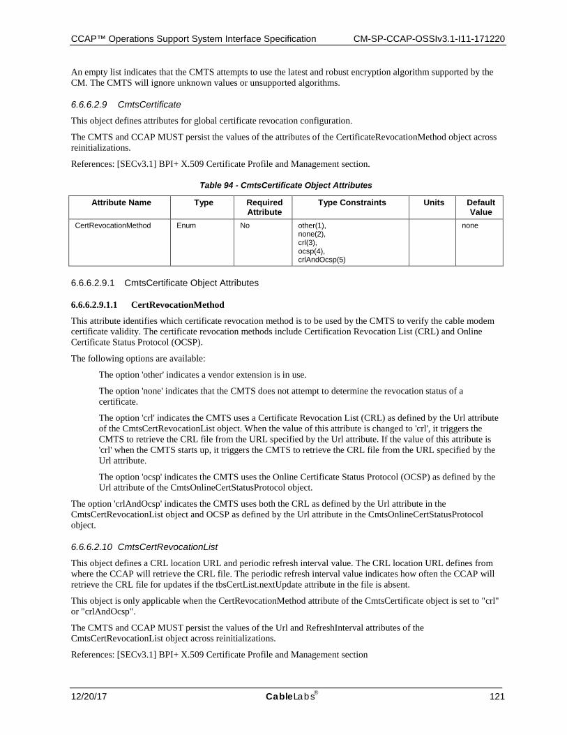
CCAP™ Operations Support System Interface Specification CM-SP-CCAP-OSSIv3.1-I11-171220
12/20/17 CableLabs 121
An empty list indicates that the CMTS attempts to use the latest and robust encryption algorithm supported by the CM. The CMTS will ignore unknown values or unsupported algorithms.
6.6.6.2.9 CmtsCertificate
This object defines attributes for global certificate revocation configuration.
The CMTS and CCAP MUST persist the values of the attributes of the CertificateRevocationMethod object across reinitializations.
References: [SECv3.1] BPI+ X.509 Certificate Profile and Management section.
Table 94 - CmtsCertificate Object Attributes
Attribute Name Type Required Attribute
Type Constraints Units Default Value
CertRevocationMethod Enum No other(1), none(2), crl(3), ocsp(4), crlAndOcsp(5)
none
6.6.6.2.9.1 CmtsCertificate Object Attributes
6.6.6.2.9.1.1 CertRevocationMethod
This attribute identifies which certificate revocation method is to be used by the CMTS to verify the cable modem certificate validity. The certificate revocation methods include Certification Revocation List (CRL) and Online Certificate Status Protocol (OCSP).
The following options are available:
The option 'other' indicates a vendor extension is in use.
The option 'none' indicates that the CMTS does not attempt to determine the revocation status of a certificate.
The option 'crl' indicates the CMTS uses a Certificate Revocation List (CRL) as defined by the Url attribute of the CmtsCertRevocationList object. When the value of this attribute is changed to 'crl', it triggers the CMTS to retrieve the CRL file from the URL specified by the Url attribute. If the value of this attribute is 'crl' when the CMTS starts up, it triggers the CMTS to retrieve the CRL file from the URL specified by the Url attribute.
The option 'ocsp' indicates the CMTS uses the Online Certificate Status Protocol (OCSP) as defined by the Url attribute of the CmtsOnlineCertStatusProtocol object.
The option 'crlAndOcsp' indicates the CMTS uses both the CRL as defined by the Url attribute in the CmtsCertRevocationList object and OCSP as defined by the Url attribute in the CmtsOnlineCertStatusProtocol object.
6.6.6.2.10 CmtsCertRevocationList
This object defines a CRL location URL and periodic refresh interval value. The CRL location URL defines from where the CCAP will retrieve the CRL file. The periodic refresh interval value indicates how often the CCAP will retrieve the CRL file for updates if the tbsCertList.nextUpdate attribute in the file is absent.
This object is only applicable when the CertRevocationMethod attribute of the CmtsCertificate object is set to "crl" or "crlAndOcsp".
The CMTS and CCAP MUST persist the values of the Url and RefreshInterval attributes of the CmtsCertRevocationList object across reinitializations.
References: [SECv3.1] BPI+ X.509 Certificate Profile and Management section
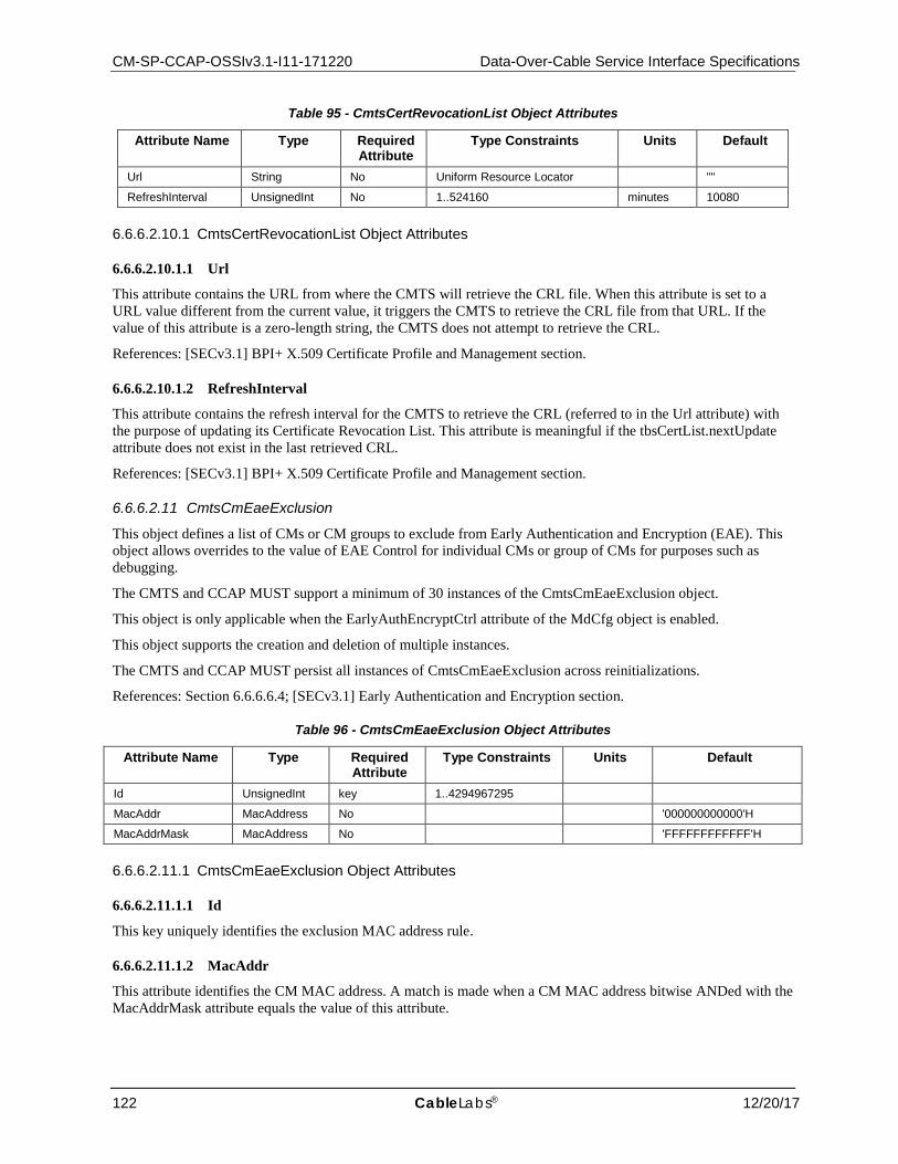
CM-SP-CCAP-OSSIv3.1-I11-171220 Data-Over-Cable Service Interface Specifications
122 CableLabs® 12/20/17
Table 95 - CmtsCertRevocationList Object Attributes
Attribute Name Type Required Attribute
Type Constraints Units Default
Url String No Uniform Resource Locator ""
RefreshInterval UnsignedInt No 1..524160 minutes 10080
6.6.6.2.10.1 CmtsCertRevocationList Object Attributes
6.6.6.2.10.1.1 Url
This attribute contains the URL from where the CMTS will retrieve the CRL file. When this attribute is set to a URL value different from the current value, it triggers the CMTS to retrieve the CRL file from that URL. If the value of this attribute is a zero-length string, the CMTS does not attempt to retrieve the CRL.
References: [SECv3.1] BPI+ X.509 Certificate Profile and Management section.
6.6.6.2.10.1.2 RefreshInterval
This attribute contains the refresh interval for the CMTS to retrieve the CRL (referred to in the Url attribute) with the purpose of updating its Certificate Revocation List. This attribute is meaningful if the tbsCertList.nextUpdate attribute does not exist in the last retrieved CRL.
References: [SECv3.1] BPI+ X.509 Certificate Profile and Management section.
6.6.6.2.11 CmtsCmEaeExclusion
This object defines a list of CMs or CM groups to exclude from Early Authentication and Encryption (EAE). This object allows overrides to the value of EAE Control for individual CMs or group of CMs for purposes such as debugging.
The CMTS and CCAP MUST support a minimum of 30 instances of the CmtsCmEaeExclusion object.
This object is only applicable when the EarlyAuthEncryptCtrl attribute of the MdCfg object is enabled.
This object supports the creation and deletion of multiple instances.
The CMTS and CCAP MUST persist all instances of CmtsCmEaeExclusion across reinitializations.
References: Section 6.6.6.6.4; [SECv3.1] Early Authentication and Encryption section.
Table 96 - CmtsCmEaeExclusion Object Attributes
Attribute Name Type Required Attribute
Type Constraints Units Default
Id UnsignedInt key 1..4294967295
MacAddr MacAddress No '000000000000'H
MacAddrMask MacAddress No 'FFFFFFFFFFFF'H
6.6.6.2.11.1 CmtsCmEaeExclusion Object Attributes
6.6.6.2.11.1.1 Id
This key uniquely identifies the exclusion MAC address rule.
6.6.6.2.11.1.2 MacAddr
This attribute identifies the CM MAC address. A match is made when a CM MAC address bitwise ANDed with the MacAddrMask attribute equals the value of this attribute.

CCAP™ Operations Support System Interface Specification CM-SP-CCAP-OSSIv3.1-I11-171220
12/20/17 CableLabs 123
6.6.6.2.11.1.3 MacAddrMask
This attribute identifies the CM MAC address mask and is used with the MacAddr attribute.
6.6.6.2.12 CmtsOnlineCertStatusProtocol
This object contains an OCSP Responder URL and an attribute to bypass signature checking of the OCSP response, as detailed in [RFC 2560]. The CCAP will use the URL for OCSP communications in checking a certificate's revocation status. This object is only applicable when the CertRevocationMethod attribute of the CmtsCertificate object is set to "ocsp" or "crlAndOcsp".
The CMTS and CCAP MUST persist the values of the attributes of the CmtsOnlineCertStatusProtocol object across reinitializations.
Table 97 - CmtsOnlineCertStatusProtocol Object Attributes
Attribute Name Type Required Attribute
Type Constraints Units Default
Url String No Uniform Resource Locator ""
SignatureBypass Boolean No false
6.6.6.2.12.1 CmtsOnlineCertStatusProtocol Object Attributes
6.6.6.2.12.1.1 Url
This attribute contains the URL string to retrieve OCSP information. If the value of this attribute is a zero-length string, the CMTS does not attempt to request the status of a CM certificate.
References: [SECv3.1] BPI+ X.509 Certificate Profile and Management section; [RFC 2560].
6.6.6.2.12.1.2 SignatureBypass
This attribute enables or disables signature checking on OCSP response messages.
References: [SECv3.1] BPI+ X.509 Certificate Profile and Management section; [RFC 2560].
6.6.6.2.13 CmtsCmBpi2EnforceExclusion
This object defines a list of CMs or CM groups to exclude from BPI+ enforcement policies configured within the CMTS. This object allows overrides to the value of BPI+ enforcement control for individual CMs or group of CMs for purposes such as debugging. The CMTS MUST support a minimum of 30 instances of the CmtsCmBpi2EnforceExclusion object.
This object supports the creation and deletion of multiple instances.
The CMTS MUST persist all instances of CmtsCmBpi2EnforceExclusion across reinitializations.
References: Section 6.6.6.6.4; [SECv3.1] BPI+ Enforce section.
Table 98 - CmtsCmBpi2EnforceExclusion Object Attributes
Attribute Name Type Required Attribute
Type Constraints Units Default
MacAddr MacAddress Yes(key)
MacAddrMask MacAddress No 'FFFFFFFFFFFF'H
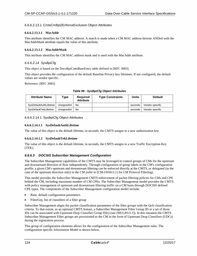
CM-SP-CCAP-OSSIv3.1-I11-171220 Data-Over-Cable Service Interface Specifications
124 CableLabs® 12/20/17
6.6.6.2.13.1 CmtsCmBpi2EnforceExclusion Object Attributes
6.6.6.2.13.1.1 MacAddr
This attribute identifies the CM MAC address. A match is made when a CM MAC address bitwise ANDed with the MacAddrMask attribute equals the value of this attribute.
6.6.6.2.13.1.2 MacAddrMask
This attribute identifies the CM MAC address mask and is used with the MacAddr attribute.
6.6.6.2.14 SysBpiCfg
This object is based on the DocsBpiCmtsBaseEntry table defined in [RFC 3083].
This object provides the configuration of the default Baseline Privacy key lifetimes. If not configured, the default values are vendor specific.
Reference: [RFC 3083]
Table 99 - SysBpiCfg Object Attributes
Attribute Name Type Required Attribute
Type Constraints Units Default
SysDefaultAuthLifetime UnsignedInt No seconds Vendor specific
SysDefaultTekLifetime UnsignedInt No seconds Vendor specific
6.6.6.2.14.1 SysBpiCfg Object Attributes
6.6.6.2.14.1.1 SysDefaultAuthLifetime
The value of this object is the default lifetime, in seconds, the CMTS assigns to a new authorization key.
6.6.6.2.14.1.2 SysDefaultTekLifetime
The value of this object is the default lifetime, in seconds, the CMTS assigns to a new Traffic Encryption Key (TEK).
6.6.6.3 DOCSIS Subscriber Management Configuration The Subscriber Management capabilities of the CMTS may be leveraged to control groups of CMs for the upstream and downstream direction of flow independently. Through configuration of group labels in the CM's configuration profile, a given CM's upstream and downstream filtering can be enforced directly at the CMTS, or delegated (in the case of the upstream direction only) to the CM (refer to [CM-OSSIv3.1] for CM Protocol Filtering).
This model provides the Subscriber Management CMTS enforcement of packet filtering policies for CMs and CPE behind the CM, including maximum number of CM CPEs. The Subscriber Management model provides the CMTS with policy management of upstream and downstream filtering traffic on a CM basis through DOCSIS defined CPE types. The components of the Subscriber Management configuration model include:
• Base, default configuration parameters • FilterGrp, list of classifiers of a filter group
Subscriber Management aligns the packet classification parameters of the filter groups with the QoS classification criteria. To that extent, as an optional CMTS feature, a Subscriber Management Filter Group ID or a set of those IDs can be associated with Upstream Drop Classifier Group ID(s) (see [MULPIv3.1]). In this situation the CMTS Subscriber Management Filter groups are provisioned to the CM in the form of Upstream Drop Classifiers (UDCs) during the registration process.
This group of configuration elements allows for the configuration of the Subscriber Management rules. The configuration specific Information Model is shown below.
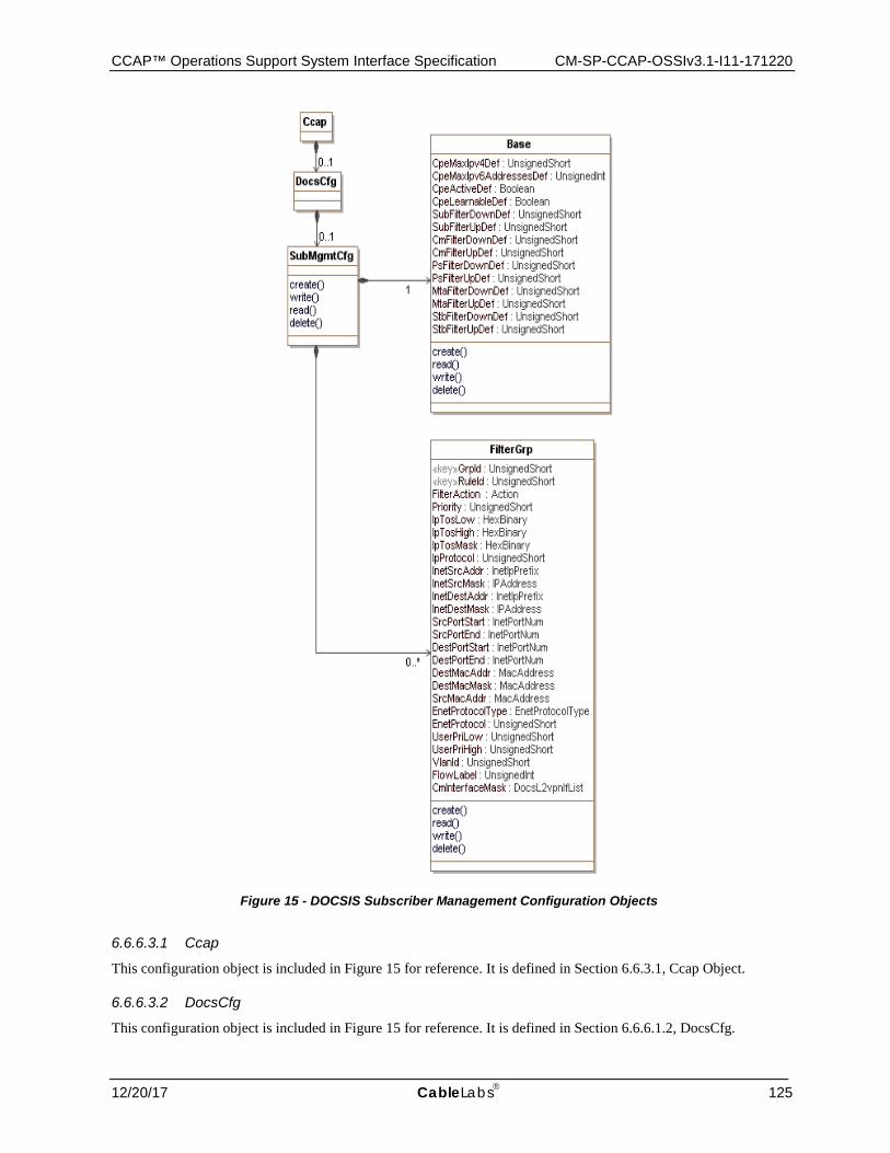
CCAP™ Operations Support System Interface Specification CM-SP-CCAP-OSSIv3.1-I11-171220
12/20/17 CableLabs 125
Figure 15 - DOCSIS Subscriber Management Configuration Objects
6.6.6.3.1 Ccap
This configuration object is included in Figure 15 for reference. It is defined in Section 6.6.3.1, Ccap Object.
6.6.6.3.2 DocsCfg
This configuration object is included in Figure 15 for reference. It is defined in Section 6.6.6.1.2, DocsCfg.

CM-SP-CCAP-OSSIv3.1-I11-171220 Data-Over-Cable Service Interface Specifications
126 CableLabs® 12/20/17
6.6.6.3.3 SubMgmtCfg
The SubMgmtCfg object is the primary container of DOCSIS security configuration objects. It has the following associations:
Table 100 - SubMgmtCfg Object Associations
Associated Object Name Type Near-end Multiplicity
Far-end Multiplicity
Label
Base Directed composition to Base 1
FilterGrp Directed composition to FilterGrp 0..*
6.6.6.3.4 Base
This object defines the configuration parameters of Subscriber Management features for the CM in case the CM does not signal any of the parameters during the registration process.
Table 101 - Base Object Attributes
Attribute Name Type Required Attribute
Type Constraints Units Default
CpeMaxIpv4Def UnsignedShort No 0..1023 16
CpeMaxlpv6PrefixesDef UnsignedShort No 0..1023 3
CpeActiveDef Boolean No false
CpeLearnableDef Boolean No false
SubFilterDownDef UnsignedShort No 0..1024 0
SubFilterUpDef UnsignedShort No 0..1024 0
CmFilterDownDef UnsignedShort No 0..1024 0
CmFilterUpDef UnsignedShort No 0..1024 0
PsFilterDownDef UnsignedShort No 0..1024 0
PsFilterUpDef UnsignedShort No 0..1024 0
MtaFilterDownDef UnsignedShort No 0..1024 0
MtaFilterUpDef UnsignedShort No 0..1024 0
StbFilterDownDef UnsignedShort No 0..1024 0
StbFilterUpDef UnsignedShort No 0..1024 0
6.6.6.3.4.1 Base Object Attributes
6.6.6.3.4.1.1 CpeMaxIpv4Def
This attribute represents the maximum number of IPv4 addresses allowed for the CM's CPE if not signaled in the registration process.
6.6.6.3.4.1.2 CpeMaxIpv6PrefixesDef
This attribute represents the maximum number of IPv6 IA_PDs (delegated prefixes) allowed for the CM's CPEs. IPv6 IA_PDs are counted against the 'CpeMaxIpv6PrefixesDef'. This contrasts with the CpeMaxIPv4AddressesDef attribute which controls the maximum number of individual IPv4 addresses. Because this attribute only counts IA_PDs against the default, IA_NA addresses and Link-Local addresses are not counted against this default limit.
6.6.6.3.4.1.3 CpeActiveDef
This attribute represents the default value for enabling Subscriber Management filters and controls in the CM if the parameter is not signaled in the DOCSIS Registration process.
CCAP™ Operations Support System Interface Specification CM-SP-CCAP-OSSIv3.1-I11-171220
12/20/17 CableLabs 127
6.6.6.3.4.1.4 CpeLearnableDef
This attribute represents the default value for enabling the CPE learning process for the CM if the parameter is not signaled in the DOCSIS Registration process.
6.6.6.3.4.1.5 SubFilterDownDef
This attribute represents the default value for the subscriber (CPE) downstream filter group for the CM if the parameter is not signaled in the DOCSIS Registration process.
6.6.6.3.4.1.6 SubFilterUpDef
This attribute represents the default value for the subscriber (CPE) upstream filter group for the CM if the parameter is not signaled in the DOCSIS Registration process.
6.6.6.3.4.1.7 CmFilterDownDef
This attribute represents the default value for the CM stack downstream filter group applying to the CM if the parameter is not signaled in the DOCSIS Registration process.
6.6.6.3.4.1.8 CmFilterUpDef
This attribute represents the default value for the CM stack upstream filter group for the CM if the parameter is not signaled in the DOCSIS Registration process.
6.6.6.3.4.1.9 PsFilterDownDef
This attribute represents the default value for the PS or eRouter downstream filter group for the CM if the parameter is not signaled in the DOCSIS Registration process.
6.6.6.3.4.1.10 PsFilterUpDef
This attribute represents the default value for the PS or eRouter upstream filter group for the CM if the parameter is not signaled in the DOCSIS Registration process.
6.6.6.3.4.1.11 MtaFilterDownDef
This attribute represents the default value for the MTA downstream filter group for the CM if the parameter is not signaled in the DOCSIS Registration process.
6.6.6.3.4.1.12 MtaFilterUpDef
This attribute represents the default value for the MTA upstream filter group for the CM if the parameter is not signaled in the DOCSIS Registration process.
6.6.6.3.4.1.13 StbFilterDownDef
This attribute represents the default value for the STB downstream filter group for the CM if the parameter is not signaled in the DOCSIS Registration process.
6.6.6.3.4.1.14 StbFilterUpDef
This attribute represents the default value for the STB upstream filter group for the CM if the parameter is not signaled in the DOCSIS Registration process.
6.6.6.3.5 FilterGrp
This object describes a set of filter or classifier criteria. Classifiers are assigned by group to the individual CMs. That assignment is made via the "Subscriber Management TLVs" encodings sent upstream from the CM to the CCAP during registration, or in their absence, default values configured in the CCAP.
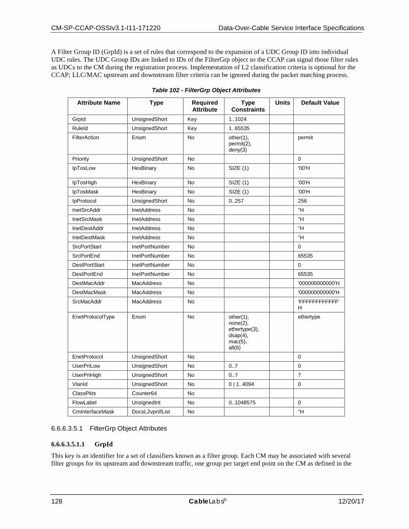
CM-SP-CCAP-OSSIv3.1-I11-171220 Data-Over-Cable Service Interface Specifications
128 CableLabs® 12/20/17
A Filter Group ID (GrpId) is a set of rules that correspond to the expansion of a UDC Group ID into individual UDC rules. The UDC Group IDs are linked to IDs of the FilterGrp object so the CCAP can signal those filter rules as UDCs to the CM during the registration process. Implementation of L2 classification criteria is optional for the CCAP; LLC/MAC upstream and downstream filter criteria can be ignored during the packet matching process.
Table 102 - FilterGrp Object Attributes
Attribute Name Type Required Attribute
Type Constraints
Units Default Value
GrpId UnsignedShort Key 1..1024
RuleId UnsignedShort Key 1..65535
FilterAction Enum No other(1), permit(2), deny(3)
permit
Priority UnsignedShort No 0
IpTosLow HexBinary No SIZE (1) '00'H
IpTosHigh HexBinary No SIZE (1) '00'H
IpTosMask HexBinary No SIZE (1) '00'H
IpProtocol UnsignedShort No 0..257 256
InetSrcAddr InetAddress No ''H
InetSrcMask InetAddress No ''H
InetDestAddr InetAddress No ''H
InetDestMask InetAddress No ''H
SrcPortStart InetPortNumber No 0
SrcPortEnd InetPortNumber No 65535
DestPortStart InetPortNumber No 0
DestPortEnd InetPortNumber No 65535
DestMacAddr MacAddress No '000000000000'H
DestMacMask MacAddress No '000000000000'H
SrcMacAddr MacAddress No 'FFFFFFFFFFFF'H
EnetProtocolType Enum No other(1), none(2), ethertype(3), dsap(4), mac(5), all(6)
ethertype
EnetProtocol UnsignedShort No 0
UserPriLow UnsignedShort No 0..7 0
UserPriHigh UnsignedShort No 0..7 7
VlanId UnsignedShort No 0 | 1..4094 0
ClassPkts Counter64 No
FlowLabel UnsignedInt No 0..1048575 0
CmInterfaceMask DocsL2vpnIfList No ''H
6.6.6.3.5.1 FilterGrp Object Attributes
6.6.6.3.5.1.1 GrpId
This key is an identifier for a set of classifiers known as a filter group. Each CM may be associated with several filter groups for its upstream and downstream traffic, one group per target end point on the CM as defined in the
CCAP™ Operations Support System Interface Specification CM-SP-CCAP-OSSIv3.1-I11-171220
12/20/17 CableLabs 129
Grp object. Typically, many CMs share a common set of filter groups. The range for this attribute is 1 to 1024 to align it with the values used in the Base Object.
6.6.6.3.5.1.2 RuleId
This key represents an ordered classifier identifier within the group. Filters are applied in order if the Priority attribute is not supported.
6.6.6.3.5.1.3 FilterAction
This attribute represents the action to take upon this filter matching. 'permit' means to stop the classification matching and accept the packet for further processing. 'deny' means to drop the packet. 'other' indicates a vendor extension is in use.
6.6.6.3.5.1.4 Priority
This attribute defines the order in which the classifiers are compared against packets. The higher the value, the higher the priority.
6.6.6.3.5.1.5 IpTosLow
This attribute represents the low value of a range of ToS (Type of Service) octet values. The IP ToS octet, as originally defined in [RFC 791], has been superseded by the 6-bit Differentiated Services Field (DSField, [RFC 3260]) and the 2-bit Explicit Congestion Notification Field (ECN field, [RFC 3168]). This attribute is defined as an 8-bit octet as per the DOCSIS Specification for packet classification.
References: [MULPIv3.1]; [RFC 791]; [RFC 3168]; [RFC 3260].
6.6.6.3.5.1.6 IpTosHigh
This attribute represents the high value of a range of ToS octet values. The IP ToS octet, as originally defined in [RFC 791], has been superseded by the 6-bit Differentiated Services Field (DSField, [RFC 3260]) and the 2-bit Explicit Congestion Notification Field (ECN field, [RFC 3168]). This attribute is defined as an 8-bit octet as per the DOCSIS Specification for packet classification.
References: [MULPIv3.1]; [RFC 791]; [RFC 3168]; [RFC 3260].
6.6.6.3.5.1.7 IpTosMask
This attribute represents the mask value that is bitwise ANDed with ToS octet in an IP packet, and the resulting value is used for range checking of IpTosLow and IpTosHigh.
6.6.6.3.5.1.8 IpProtocol
This attribute represents the value of the IP Protocol field required for IP packets to match this rule. The value 256 matches traffic with any IP Protocol value. The value 257 by convention matches both TCP and UDP.
6.6.6.3.5.1.9 InetSrcAddr
This attribute specifies the value of the IP Source Address required for packets to match this rule. An IP packet matches the rule when the packet's IP Source Address bitwise ANDed with the InetSrcMask value equals the InetSrcAddr value. The address type of this object is specified by the InetAddrType attribute.
6.6.6.3.5.1.10 InetSrcMask
This attribute represents which bits of a packet's IP Source Address are compared to match this rule. An IP packet matches the rule when the packet's IP Source Address bitwise ANDed with the InetSrcMask value equals the InetSrcAddr value. The address type of this object is specified by InetAddrType.
CM-SP-CCAP-OSSIv3.1-I11-171220 Data-Over-Cable Service Interface Specifications
130 CableLabs® 12/20/17
6.6.6.3.5.1.11 InetDestAddr
This attribute specifies the value of the IP Destination Address required for packets to match this rule. An IP packet matches the rule when the packet's IP Destination Address bitwise ANDed with the InetSrcMask value equals the InetDestAddr value. The address type of this object is specified by the InetAddrType attribute.
6.6.6.3.5.1.12 InetDestMask
This attribute represents which bits of a packet's IP Destination Address are compared to match this rule. An IP packet matches the rule when the packet's IP Destination Address bitwise ANDed with the InetDestMask value equals the InetDestAddr value. The address type of this object is specified by InetAddrType.
6.6.6.3.5.1.13 SrcPortStart
This attribute represents the low-end inclusive range of TCP/UDP source port numbers to which a packet is compared. This attribute is irrelevant for non-TCP/UDP IP packets.
6.6.6.3.5.1.14 SrcPortEnd
This attribute represents the high-end inclusive range of TCP/UDP source port numbers to which a packet is compared. This attribute is irrelevant for non-TCP/UDP IP packets.
6.6.6.3.5.1.15 DestPortStart
This attribute represents the low-end inclusive range of TCP/UDP destination port numbers to which a packet is compared. This attribute is irrelevant for non-TCP/UDP IP packets.
6.6.6.3.5.1.16 DestPortEnd
This attribute represents the high-end inclusive range of TCP/UDP destination port numbers to which a packet is compared. This attribute is irrelevant for non-TCP/UDP IP packets.
6.6.6.3.5.1.17 DestMacAddr
This attribute represents the criteria to match against an Ethernet packet MAC address bitwise ANDed with DestMacMask.
6.6.6.3.5.1.18 DestMacMask
An Ethernet packet matches an entry when its destination MAC address bitwise ANDed with the DestMacMask attribute equals the value of the DestMacAddr attribute.
6.6.6.3.5.1.19 SrcMacAddr
This attribute represents the value to match against an Ethernet packet source MAC address.
6.6.6.3.5.1.20 EnetProtocolType
This attribute indicates the format of the layer 3 protocol ID in the Ethernet packet. A value of 'none' means that the rule does not use the layer 3 protocol type as a matching criteria. A value of 'ethertype' means that the rule applies only to frames that contain an EtherType value. Ethertype values are contained in packets using the DEC-Intel-Xerox (DIX) encapsulation or the [RFC 1042] Sub-Network Access Protocol (SNAP) encapsulation formats. A value of 'dsap' means that the rule applies only to frames using the IEEE802.3 encapsulation format with a Destination Service Access Point (DSAP) other than 0xAA (which is reserved for SNAP). A value of 'mac' means that the rule applies only to MAC management messages for MAC management messages. A value of 'all' means that the rule matches all Ethernet packets. If the Ethernet frame contains an 802.1P/Q Tag header (i.e., EtherType 0x8100), this attribute applies to the embedded EtherType field within the 802.1p/Q header.
The value 'mac' is only used for passing UDCs to CMs during Registration. The CMTS ignores filter rules that include the value of this attribute set to 'mac' for CMTS enforced upstream and downstream subscriber management filter group rules.
CCAP™ Operations Support System Interface Specification CM-SP-CCAP-OSSIv3.1-I11-171220
12/20/17 CableLabs 131
The value 'other' indicates a vendor extension is in use.
References: [RFC 1042] Sub-Network Access Protocol (SNAP) encapsulation formats.
6.6.6.3.5.1.21 EnetProtocol
This attribute represents the Ethernet protocol type to be matched against the packets. For EnetProtocolType set to 'none', this attribute is ignored when considering whether a packet matches the current rule. If the attribute EnetProtocolType is 'ethertype', this attribute gives the 16-bit value of the EtherType that the packet needs to match in order to match the rule. If the attribute EnetProtocolType is 'dsap', the lower 8 bits of this attribute's value needs to match the DSAP byte of the packet in order to match the rule. If the Ethernet frame contains an 802.1p/Q Tag header (i.e., EtherType 0x8100), this attribute applies to the embedded EtherType field within the 802.1p/Q header.
6.6.6.3.5.1.22 UserPriLow
This attribute applies only to Ethernet frames using the 802.1p/Q tag header (indicated with EtherType 0x8100). Such frames include a 16-bit Tag that contains a 3-bit Priority field and a 12-bit VLAN number. Tagged Ethernet packets needs to have a 3-bit Priority field within the range of PriLow to PriHigh in order to match this rule.
6.6.6.3.5.1.23 UserPriHigh
This attribute applies only to Ethernet frames using the 802.1p/Q tag header (indicated with EtherType 0x8100). Such frames include a 16-bit Tag that contains a 3-bit Priority field and a 12-bit VLAN number. Tagged Ethernet packets needs to have a 3-bit Priority field within the range of PriLow to PriHigh in order to match this rule.
6.6.6.3.5.1.24 VlanId
This attribute applies only to Ethernet frames using the 802.1p/Q tag header. Tagged packets need to have a VLAN Identifier that matches the value in order to match the rule.
6.6.6.3.5.1.25 FlowLabel
This attribute represents the Flow Label field in the IPv6 header to be matched by the classifier.
The value zero indicates that the Flow Label is not specified as part of the classifier and is not matched against packets.
6.6.6.3.5.1.26 CmInterfaceMask
This attribute represents a bit-mask of the CM in-bound interfaces to which this classifier applies. This attribute only applies to upstream Drop Classifiers being sent to CMs during the registration process.
6.6.6.4 DOCSIS QoS Configuration This group of configuration elements allows for the configuration of DOCSIS QoS. The configuration specific object model is shown below.
The QosProfile object has been deprecated and removed from Figure 16 since the DOCSIS 1.0 Class of Service (CoS) service class definition type was deprecated and is not supported in DOCSIS 3.1.
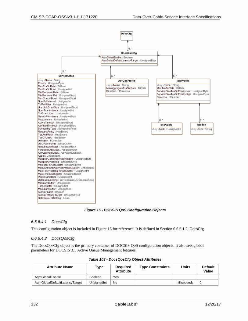
CM-SP-CCAP-OSSIv3.1-I11-171220 Data-Over-Cable Service Interface Specifications
132 CableLabs® 12/20/17
Figure 16 - DOCSIS QoS Configuration Objects
6.6.6.4.1 DocsCfg
This configuration object is included in Figure 16 for reference. It is defined in Section 6.6.6.1.2, DocsCfg.
6.6.6.4.2 DocsQosCfg
The DocsQosCfg object is the primary container of DOCSIS QoS configuration objects. It also sets global parameters for DOCSIS 3.1 Active Queue Management features.
Table 103 - DocsQosCfg Object Attributes
Attribute Name Type Required Attribute
Type Constraints Units Default Value
AqmGlobalEnable Boolean Yes
AqmGlobalDefaultLatencyTarget UnsignedInt No milliseconds 0
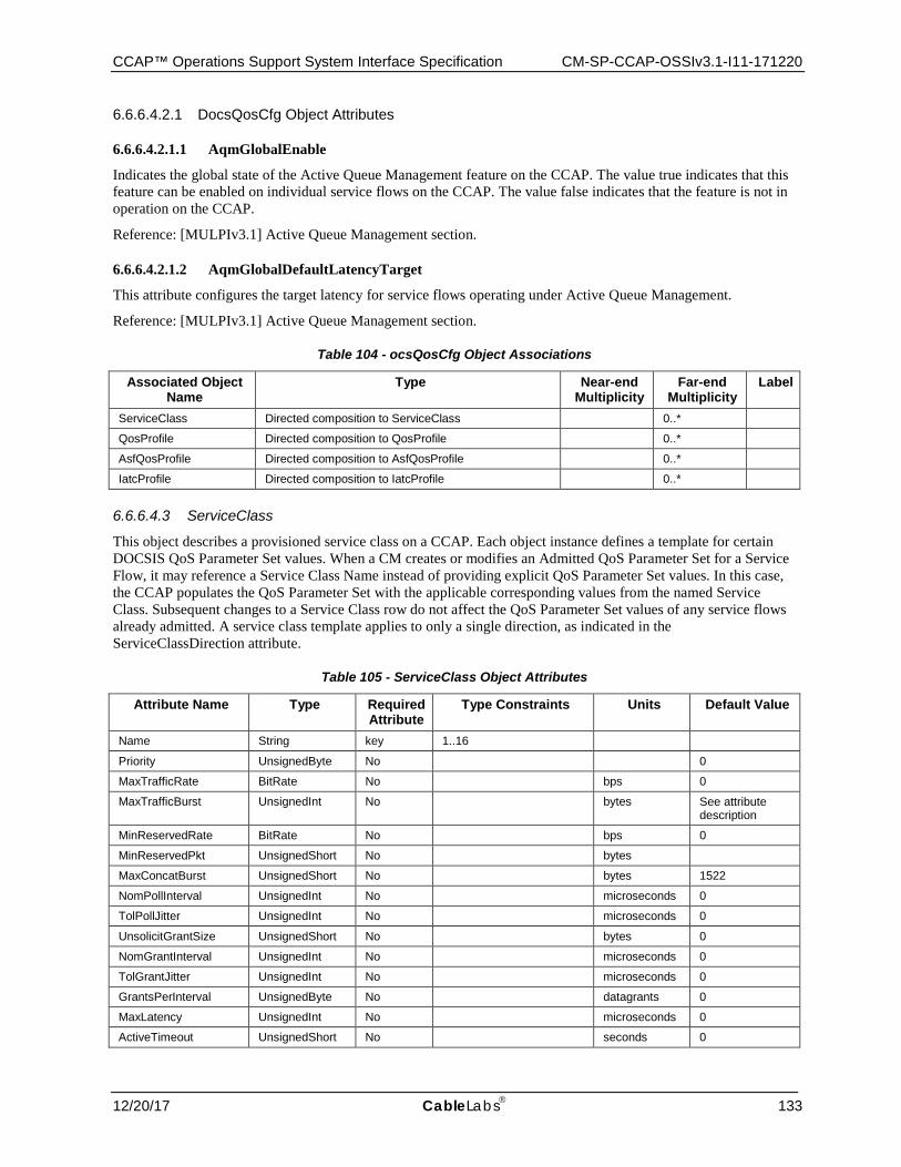
CCAP™ Operations Support System Interface Specification CM-SP-CCAP-OSSIv3.1-I11-171220
12/20/17 CableLabs 133
6.6.6.4.2.1 DocsQosCfg Object Attributes
6.6.6.4.2.1.1 AqmGlobalEnable
Indicates the global state of the Active Queue Management feature on the CCAP. The value true indicates that this feature can be enabled on individual service flows on the CCAP. The value false indicates that the feature is not in operation on the CCAP.
Reference: [MULPIv3.1] Active Queue Management section.
6.6.6.4.2.1.2 AqmGlobalDefaultLatencyTarget
This attribute configures the target latency for service flows operating under Active Queue Management.
Reference: [MULPIv3.1] Active Queue Management section.
Table 104 - ocsQosCfg Object Associations
Associated Object Name
Type Near-end Multiplicity
Far-end Multiplicity
Label
ServiceClass Directed composition to ServiceClass 0..*
QosProfile Directed composition to QosProfile 0..*
AsfQosProfile Directed composition to AsfQosProfile 0..*
IatcProfile Directed composition to IatcProfile 0..*
6.6.6.4.3 ServiceClass
This object describes a provisioned service class on a CCAP. Each object instance defines a template for certain DOCSIS QoS Parameter Set values. When a CM creates or modifies an Admitted QoS Parameter Set for a Service Flow, it may reference a Service Class Name instead of providing explicit QoS Parameter Set values. In this case, the CCAP populates the QoS Parameter Set with the applicable corresponding values from the named Service Class. Subsequent changes to a Service Class row do not affect the QoS Parameter Set values of any service flows already admitted. A service class template applies to only a single direction, as indicated in the ServiceClassDirection attribute.
Table 105 - ServiceClass Object Attributes
Attribute Name Type Required Attribute
Type Constraints Units Default Value
Name String key 1..16
Priority UnsignedByte No 0
MaxTrafficRate BitRate No bps 0
MaxTrafficBurst UnsignedInt No bytes See attribute description
MinReservedRate BitRate No bps 0
MinReservedPkt UnsignedShort No bytes
MaxConcatBurst UnsignedShort No bytes 1522
NomPollInterval UnsignedInt No microseconds 0
TolPollJitter UnsignedInt No microseconds 0
UnsolicitGrantSize UnsignedShort No bytes 0
NomGrantInterval UnsignedInt No microseconds 0
TolGrantJitter UnsignedInt No microseconds 0
GrantsPerInterval UnsignedByte No datagrants 0
MaxLatency UnsignedInt No microseconds 0
ActiveTimeout UnsignedShort No seconds 0
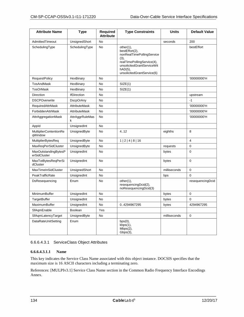
CM-SP-CCAP-OSSIv3.1-I11-171220 Data-Over-Cable Service Interface Specifications
134 CableLabs® 12/20/17
Attribute Name Type Required Attribute
Type Constraints Units Default Value
AdmittedTimeout UnsignedShort No seconds 200
SchedulingType SchedulingType No other(1), bestEffort(2), nonRealTimePollingService(3), realTimePollingService(4), unsolicitedGrantServiceWithAD(5), unsolicitedGrantService(6)
bestEffort
RequestPolicy HexBinary No '00000000'H
TosAndMask HexBinary No SIZE(1)
TosOrMask HexBinary No SIZE(1)
Direction IfDirection No upstream
DSCPOverwrite DscpOrAny No -1
RequiredAttrMask AttributeMask No '00000000'H
ForbiddenAttrMask AttributeMask No '00000000'H
AttrAggregationMask AttrAggrRuleMask
No '00000000'H
AppId UnsignedInt No
MultiplierContentionReqWindow
UnsignedByte No 4..12 eighths 8
MultiplierBytesReq UnsignedByte No 1 | 2 | 4 | 8 | 16 4
MaxReqPerSidCluster UnsignedByte No requests 0
MaxOutstandingBytesPerSidCluster
UnsignedInt No bytes 0
MaxTotBytesReqPerSidCluster
UnsignedInt No bytes 0
MaxTimeInSidCluster UnsignedShort No milliseconds 0
PeakTrafficRate UnsignedInt No bps 0
DsResequencing Enum No other(1), resequencingDcid(2), noResequencingDcid(3)
resequencingDcid
MinimumBuffer UnsignedInt No bytes 0
TargetBuffer UnsignedInt No bytes 0
MaximumBuffer UnsignedInt No 0..4294967295 bytes 4294967295
SfAqmEnable Boolean Yes
SfAqmLatencyTarget UnsignedByte No milliseconds 0
DataRateUnitSetting Enum bps(0), kbps(1), Mbps(2), Gbps(3),
6.6.6.4.3.1 ServiceClass Object Attributes
6.6.6.4.3.1.1 Name
This key indicates the Service Class Name associated with this object instance. DOCSIS specifies that the maximum size is 16 ASCII characters including a terminating zero.
References: [MULPIv3.1] Service Class Name section in the Common Radio Frequency Interface Encodings Annex.

CCAP™ Operations Support System Interface Specification CM-SP-CCAP-OSSIv3.1-I11-171220
12/20/17 CableLabs 135
6.6.6.4.3.1.2 Priority
This attribute is the template for the Priority attribute of the QoS Parameter Set.
6.6.6.4.3.1.3 MaxTrafficRate
This attribute is the template for the MaxTrafficRate attribute of the QoS Parameter Set.
6.6.6.4.3.1.4 MaxTrafficBurst
This attribute is the template for the MaxTrafficBurst attribute of the QoS Parameter Set. If this value is not set, the default for DOCSIS 3.0 is 3044, and for DOCSIS 3.1 the default value is 3044, or 4000 if support for extended packet size is enabled.
6.6.6.4.3.1.5 MinReservedRate
This attribute is the template for the MinReservedRate attribute of the QoS Parameter Set.
6.6.6.4.3.1.6 MinReservedPkt
This attribute is the template for the MinReservedPkt attribute of the QoS Parameter Set. Vendor-dependent.
6.6.6.4.3.1.7 MaxConcatBurst
This attribute is the template for the MaxConcatBurst attribute of the QoS Parameter Set.
6.6.6.4.3.1.8 NomPollInterval
This attribute is the template for the NomPollInterval attribute of the QoS Parameter Set.
6.6.6.4.3.1.9 TolPollJitter
This attribute is the template for the TolPolJitter attribute of the QoS Parameter Set.
6.6.6.4.3.1.10 UnsolicitGrantSize
This attribute is the template for the UnsolicitGrantSize attribute of the QoS Parameter Set.
6.6.6.4.3.1.11 NomGrantInterval
This attribute is the template for the NomGrantInterval attribute of the QoS Parameter Set.
6.6.6.4.3.1.12 TolGrantJitter
This attribute is the template for the TolGrantJitter attribute of the QoS Parameter Set.
6.6.6.4.3.1.13 GrantsPerInterval
This attribute is the template for the GrantsPerInterval attribute of the QoS Parameter Set.
6.6.6.4.3.1.14 MaxLatency
This attribute is the template for the MaxLatency attribute of the QoS Parameter Set.
6.6.6.4.3.1.15 ActiveTimeout
This attribute is the template for the ActiveTimeout attribute of the QoS Parameter Set.
6.6.6.4.3.1.16 AdmittedTimeout
This attribute is the template for the AdmittedTimeout attribute of the QoS Parameter Set.

CM-SP-CCAP-OSSIv3.1-I11-171220 Data-Over-Cable Service Interface Specifications
136 CableLabs® 12/20/17
6.6.6.4.3.1.17 SchedulingType
This attribute is the template for the SchedulingType attribute of the QoS Parameter Set. A value of 'other' indicates a vendor extension is in use.
6.6.6.4.3.1.18 RequestPolicy
This attribute is the template for the RequestPolicyOct attribute of the QoS Parameter Set.
6.6.6.4.3.1.19 TosAndMask
This attribute is the template for the TosAndMask attribute of the QoS Parameter Set.
6.6.6.4.3.1.20 TosOrMask
This attribute is the template for the TosOrMask attribute of the QoS Parameter Set.
6.6.6.4.3.1.21 Direction
This attribute is the template for the Direction attribute of the QoS Parameter Set. A value of 'other' indicates a vendor extension is in use.
6.6.6.4.3.1.22 DSCPOverwrite
This attribute allows the overwrite of the DSCP field per [RFC 3260].
If this attribute is -1, then the corresponding TosAndMask value is set to be 'FF'H and TosOrMask is set to '00'H. Otherwise, this attribute is in the range of 0..63, and the corresponding TosAndMask value is '03'H and TosOrMask value is this attribute value shifted left by two bit positions.
6.6.6.4.3.1.23 RequiredAttrMask
This attribute is the template for the RequiredAttrMask attribute of the QoS Parameter Set.
6.6.6.4.3.1.24 ForbiddenAttrMask
This attribute is the template for the ForbiddenAttrMask attribute of the QoS Parameter Set.
6.6.6.4.3.1.25 AttrAggrRuleMask
This attribute is the template for the AttrAggregationMask attribute of the QoS Parameter Set.
6.6.6.4.3.1.26 AppId
This attribute is the template for the AppId attribute of the QoS Parameter Set.
6.6.6.4.3.1.27 MultiplierContentionReqWindow
This attribute is the template for the MultiplierContentionReqWindow attribute of the QoS Parameter Set.
6.6.6.4.3.1.28 MultiplierBytesReq
This attribute is the template for the MultiplierBytesReq attribute of the QoS Parameter Set.
6.6.6.4.3.1.29 MaxReqPerSidCluster
This attribute is the template for the MaxReqPerSidCluster attribute of the QoS Parameter Set. A value of 0 means unlimited.

CCAP™ Operations Support System Interface Specification CM-SP-CCAP-OSSIv3.1-I11-171220
12/20/17 CableLabs 137
6.6.6.4.3.1.30 MaxOutstandingBytesPerSidCluster
This attribute is the template for the MaxOutstandingBytesPerSidCluster attribute of the QoS Parameter Set. A value of 0 means unlimited.
6.6.6.4.3.1.31 MaxTotBytesReqPerSidCluster
This attribute is the template for the MaxTotBytesReqPerSidCluster attribute of the QoS Parameter Set. A value of 0 means unlimited.
6.6.6.4.3.1.32 MaxTimeInSidCluster
This attribute is the template for the MaxTimeInSidCluster attribute of the QoS Parameter Set. A value of 0 means unlimited.
6.6.6.4.3.1.33 PeakTrafficRate
This attribute is the template for the PeakTrafficRate attribute of the QoS Parameter Set. A value of 0 means the downstream peak traffic rate is not limited.
6.6.6.4.3.1.34 DsResequencing
This attribute is the template for the DsResequencing attribute of the QoS Parameter Set. A value of 'other' indicates a vendor extension is in use.
6.6.6.4.3.1.35 MinimumBuffer
This attribute is the template for the MinimumBuffer attribute of the QoS Parameter Set.
6.6.6.4.3.1.36 TargetBuffer
This attribute is the template for the TargetBuffer attribute of the QoS Parameter Set. A value of 0 means that a vendor-specific default value is used.
6.6.6.4.3.1.37 MaximumBuffer
This attribute is the template for the MaximumBuffer attribute of the QoS Parameter Set. A value of 4294967295 means unlimited.
6.6.6.4.3.1.38 SfAqmEnable
If AqmGlobalEnable in the DocsQosCfg object is set to "true", this attribute indicates the state of the Active Queue Management feature for this ServiceClass. The value true indicates that this feature is enabled for this service class. The value false indicates that the feature is not active for this service class. This attribute applies to both upstream and downstream service flows. If AqmGlobalEnable in the DocsQosCfg object is set to "false", this attribute is ignored.
Reference: [MULPIv3.1] Active Queue Management section.
6.6.6.4.3.1.39 SfAqmLatencyTarget
This attribute configures the target latency for this service class when operating under Active Queue Management. If set to 0, the value in the AqmGlobalLatencyTarget attribute of the DocsQosCfg object will be used. This attribute applies to both upstream and downstream service flows. This attribute is only used when AqmGlobalEnable in the DocsQosCfg object is set to "true" and the SfAqmEnable attribute is set to "true".
Reference: [MULPIv3.1] Active Queue Management section.
6.6.6.4.3.1.40 DataRateUnitSetting
The default units for the traffic rate parameters (Maximum Sustained Traffic Rate, Minimum Reserved Traffic Rate, and Peak Traffic Rate) within a Service Flow are bits per second (bps). This parameter indicates the base unit

CM-SP-CCAP-OSSIv3.1-I11-171220 Data-Over-Cable Service Interface Specifications
138 CableLabs® 12/20/17
for the rates configured using the Maximum Sustained Traffic Rate, Minimum Reserved Traffic Rate, and Peak Traffic Rate. The value of this parameter allows for their interpretation in units of bps, or kbps, or Mbps or Gbps.
6.6.6.4.4 AsfQosProfile
This object describes a provisioned QoS profile for Aggregate Service Flows on a CCAP. Each object instance defines a template for certain Aggregate QoS Parameter Set values. AsfQosProfile for ASF is an equivalent to Service Class for a Service Flow. The object as defined in this specification contains only one standardized QoS parameter: MaxAggregateTrafficRate. Other aggregate QoS parameters can be added through vendor-specific extensions.
Table 106 - AsfQosProfile Object Attributes
Attribute Name Type Required Attribute
Type Constraints Units Default Value
Name String key 1..16
MaxAggregateTrafficRate BitRate No bps 0
Direction IfDirection Yes
6.6.6.4.4.1 AsfQosProfile Object Attributes
6.6.6.4.4.1.1 Name
This key indicates the ASF QoS Profile Name associated with this object instance. DOCSIS specifies that the maximum size is 16 ASCII characters including a terminating zero. The terminating zero is not represented in this SnmpAdminString syntax attribute.
6.6.6.4.4.1.2 MaxAggregateTrafficRate
This attribute is the template for the Maximum Aggregate Traffic Rate attribute for ASFs.
6.6.6.4.4.1.3 Direction
This attribute is the template for the Direction attribute of the AsfQosProfile.
6.6.6.4.5 IatcProfile
This object represents a template for configuration of an Interface Aggregate Traffic Class. An Interface Aggregate Traffic Class (IATC) represents a grouping of one or more Service Flows mapped to a single channel or a bonding group. The IATCs enable the operators to virtually divide the bandwidth of service groups, bonding groups or channels between distinct services or users.
Table 107 - IatcProfile Object Attributes
Attribute Name Type Required Attribute
Type Constraints Units Default Value
Name String key 1..16
MaxAggregateTrafficRate BitRate No bps 0
ServiceFlowTrafficPriorityLow unsignedByte No 0
ServiceFlowTrafficPriorityHigh unsignedByte No 0
Direction IfDirection Yes
Table 108 - IatcProfile Object Associations
Associated Object Name Type Near-end Multiplicity
Far-end Multiplicity
Label
IatcAppId Directed composition to IatcAppId 0..*
IatcSCN Directed composition to IatcSCN 0..*

CCAP™ Operations Support System Interface Specification CM-SP-CCAP-OSSIv3.1-I11-171220
12/20/17 CableLabs 139
6.6.6.4.5.1 IatcProfile Object Attributes
6.6.6.4.5.1.1 Name
This key indicates the IATC Profile Name associated with this object instance.
6.6.6.4.5.1.2 MaxAggregateTrafficRate
This attribute is the template for the Maximum Aggregate Traffic Rate attribute for this IATC object instance.
6.6.6.4.5.1.3 ServiceFlowTrafficPriorityLow and ServiceFlowTrafficPriorityHigh (separate, high >= low)
The attributes ServiceFlowTrafficPriorityLow and ServiceFlowTrafficPriorityHigh define a range of Service Flow Traffic Priority values that the CCAP will use to match service flows to the IATC profile.
6.6.6.4.5.1.4 Direction
This attribute is the template for the Direction attribute of the IatcProfile.
6.6.6.4.6 IatcAppId
The IatcAppId object allows for the configuration of a list of one or more application IDs by which Service Flows can be matched to the IATC profile.
Table 109 - IatcAppIdObject Attributes
Attribute Name Type Required Attribute
Type Constraints Units Default Value
AppId unsignedInt Yes (Key)
6.6.6.4.6.1 IatcAppIdObject Attributes
6.6.6.4.6.1.1 AppId
This attribute is the template for the AppId attribute, which represents an Application ID by which Service Flows can be matched to an IATC.
6.6.6.4.7 IatcScn
The IatcScn object allows for the configuration of a list of one or more Service Class Names by which Service Flows can be matched to the IATC profile.
Table 110 - IatcScn Object Attributes
Attribute Name Type Required Attribute
Type Constraints Units Default Value
SCN String Yes (Key) 1..16
6.6.6.4.7.1 IatcScn Object Attributes
6.6.6.4.7.1.1 SCN
This attribute is a Service Class Name by which Service Flows can be matched to IATC.
6.6.6.5 DOCSIS Multicast QoS Configuration Multicast configuration includes per multicast session policies to configure QoS and BPI encryption of multicast sessions. This Information Model defines the configuration requirements for multicast session QoS and privacy over the HFC by extending the DOCSIS QoS model [MULPIv3.1] and Baseline Privacy Interface (BPI) [SECv3.1] requirements respectively. The components of the Multicast Configuration model are:
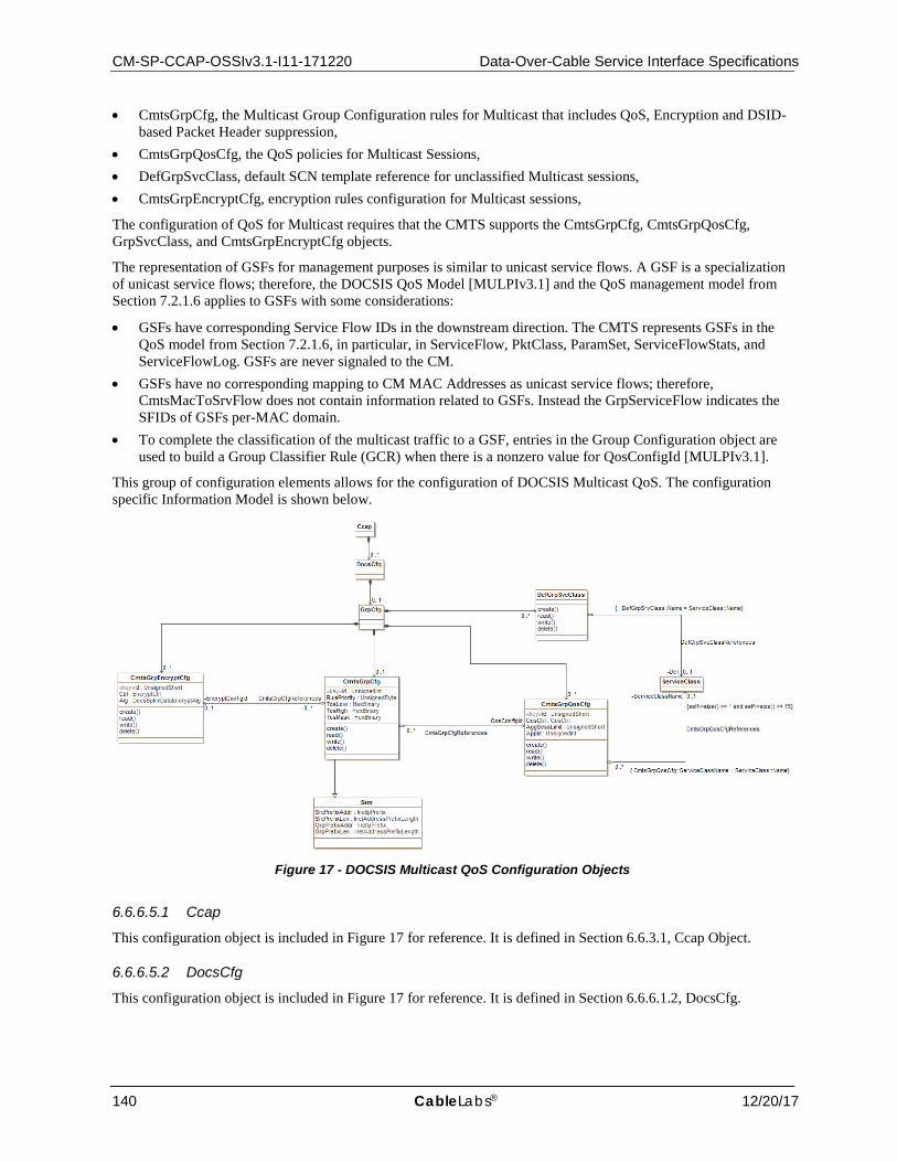
CM-SP-CCAP-OSSIv3.1-I11-171220 Data-Over-Cable Service Interface Specifications
140 CableLabs® 12/20/17
• CmtsGrpCfg, the Multicast Group Configuration rules for Multicast that includes QoS, Encryption and DSID-based Packet Header suppression,
• CmtsGrpQosCfg, the QoS policies for Multicast Sessions, • DefGrpSvcClass, default SCN template reference for unclassified Multicast sessions, • CmtsGrpEncryptCfg, encryption rules configuration for Multicast sessions,
The configuration of QoS for Multicast requires that the CMTS supports the CmtsGrpCfg, CmtsGrpQosCfg, GrpSvcClass, and CmtsGrpEncryptCfg objects.
The representation of GSFs for management purposes is similar to unicast service flows. A GSF is a specialization of unicast service flows; therefore, the DOCSIS QoS Model [MULPIv3.1] and the QoS management model from Section 7.2.1.6 applies to GSFs with some considerations:
• GSFs have corresponding Service Flow IDs in the downstream direction. The CMTS represents GSFs in the QoS model from Section 7.2.1.6, in particular, in ServiceFlow, PktClass, ParamSet, ServiceFlowStats, and ServiceFlowLog. GSFs are never signaled to the CM.
• GSFs have no corresponding mapping to CM MAC Addresses as unicast service flows; therefore, CmtsMacToSrvFlow does not contain information related to GSFs. Instead the GrpServiceFlow indicates the SFIDs of GSFs per-MAC domain.
• To complete the classification of the multicast traffic to a GSF, entries in the Group Configuration object are used to build a Group Classifier Rule (GCR) when there is a nonzero value for QosConfigId [MULPIv3.1].
This group of configuration elements allows for the configuration of DOCSIS Multicast QoS. The configuration specific Information Model is shown below.
Figure 17 - DOCSIS Multicast QoS Configuration Objects
6.6.6.5.1 Ccap
This configuration object is included in Figure 17 for reference. It is defined in Section 6.6.3.1, Ccap Object.
6.6.6.5.2 DocsCfg
This configuration object is included in Figure 17 for reference. It is defined in Section 6.6.6.1.2, DocsCfg.
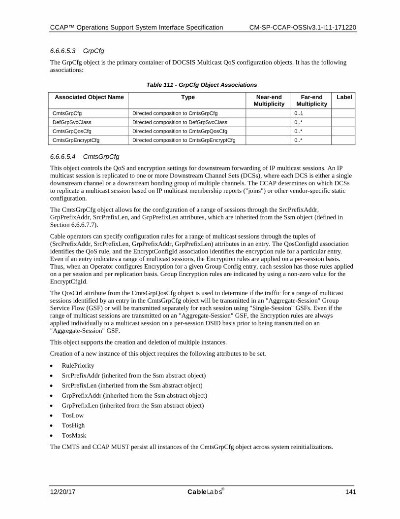
CCAP™ Operations Support System Interface Specification CM-SP-CCAP-OSSIv3.1-I11-171220
12/20/17 CableLabs 141
6.6.6.5.3 GrpCfg
The GrpCfg object is the primary container of DOCSIS Multicast QoS configuration objects. It has the following associations:
Table 111 - GrpCfg Object Associations
Associated Object Name Type Near-end Multiplicity
Far-end Multiplicity
Label
CmtsGrpCfg Directed composition to CmtsGrpCfg 0..1
DefGrpSvcClass Directed composition to DefGrpSvcClass 0..*
CmtsGrpQosCfg Directed composition to CmtsGrpQosCfg 0..*
CmtsGrpEncryptCfg Directed composition to CmtsGrpEncryptCfg 0..*
6.6.6.5.4 CmtsGrpCfg
This object controls the QoS and encryption settings for downstream forwarding of IP multicast sessions. An IP multicast session is replicated to one or more Downstream Channel Sets (DCSs), where each DCS is either a single downstream channel or a downstream bonding group of multiple channels. The CCAP determines on which DCSs to replicate a multicast session based on IP multicast membership reports ("joins") or other vendor-specific static configuration.
The CmtsGrpCfg object allows for the configuration of a range of sessions through the SrcPrefixAddr, GrpPrefixAddr, SrcPrefixLen, and GrpPrefixLen attributes, which are inherited from the Ssm object (defined in Section 6.6.6.7.7).
Cable operators can specify configuration rules for a range of multicast sessions through the tuples of (SrcPrefixAddr, SrcPrefixLen, GrpPrefixAddr, GrpPrefixLen) attributes in an entry. The QosConfigId association identifies the QoS rule, and the EncryptConfigId association identifies the encryption rule for a particular entry. Even if an entry indicates a range of multicast sessions, the Encryption rules are applied on a per-session basis. Thus, when an Operator configures Encryption for a given Group Config entry, each session has those rules applied on a per session and per replication basis. Group Encryption rules are indicated by using a non-zero value for the EncryptCfgId.
The QosCtrl attribute from the CmtsGrpQosCfg object is used to determine if the traffic for a range of multicast sessions identified by an entry in the CmtsGrpCfg object will be transmitted in an "Aggregate-Session" Group Service Flow (GSF) or will be transmitted separately for each session using "Single-Session" GSFs. Even if the range of multicast sessions are transmitted on an "Aggregate-Session" GSF, the Encryption rules are always applied individually to a multicast session on a per-session DSID basis prior to being transmitted on an "Aggregate-Session" GSF.
This object supports the creation and deletion of multiple instances.
Creation of a new instance of this object requires the following attributes to be set.
• RulePriority • SrcPrefixAddr (inherited from the Ssm abstract object) • SrcPrefixLen (inherited from the Ssm abstract object) • GrpPrefixAddr (inherited from the Ssm abstract object) • GrpPrefixLen (inherited from the Ssm abstract object) • TosLow • TosHigh • TosMask
The CMTS and CCAP MUST persist all instances of the CmtsGrpCfg object across system reinitializations.
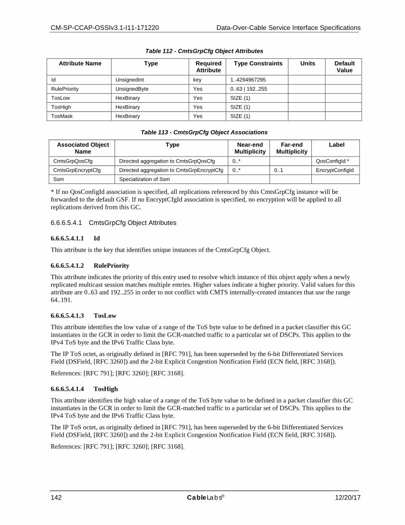
CM-SP-CCAP-OSSIv3.1-I11-171220 Data-Over-Cable Service Interface Specifications
142 CableLabs® 12/20/17
Table 112 - CmtsGrpCfg Object Attributes
Attribute Name Type Required Attribute
Type Constraints Units Default Value
Id UnsignedInt key 1..4294967295
RulePriority UnsignedByte Yes 0..63 | 192..255
TosLow HexBinary Yes SIZE (1)
TosHigh HexBinary Yes SIZE (1)
TosMask HexBinary Yes SIZE (1)
Table 113 - CmtsGrpCfg Object Associations
Associated Object Name
Type Near-end Multiplicity
Far-end Multiplicity
Label
CmtsGrpQosCfg Directed aggregation to CmtsGrpQosCfg 0..* QosConfigId *
CmtsGrpEncryptCfg Directed aggregation to CmtsGrpEncryptCfg 0..* 0..1 EncryptConfigId
Ssm Specialization of Ssm
* If no QosConfigId association is specified, all replications referenced by this CmtsGrpCfg instance will be forwarded to the default GSF. If no EncryptCfgId association is specified, no encryption will be applied to all replications derived from this GC.
6.6.6.5.4.1 CmtsGrpCfg Object Attributes
6.6.6.5.4.1.1 Id
This attribute is the key that identifies unique instances of the CmtsGrpCfg Object.
6.6.6.5.4.1.2 RulePriority
This attribute indicates the priority of this entry used to resolve which instance of this object apply when a newly replicated multicast session matches multiple entries. Higher values indicate a higher priority. Valid values for this attribute are 0..63 and 192..255 in order to not conflict with CMTS internally-created instances that use the range 64..191.
6.6.6.5.4.1.3 TosLow
This attribute identifies the low value of a range of the ToS byte value to be defined in a packet classifier this GC instantiates in the GCR in order to limit the GCR-matched traffic to a particular set of DSCPs. This applies to the IPv4 ToS byte and the IPv6 Traffic Class byte.
The IP ToS octet, as originally defined in [RFC 791], has been superseded by the 6-bit Differentiated Services Field (DSField, [RFC 3260]) and the 2-bit Explicit Congestion Notification Field (ECN field, [RFC 3168]).
References: [RFC 791]; [RFC 3260]; [RFC 3168].
6.6.6.5.4.1.4 TosHigh
This attribute identifies the high value of a range of the ToS byte value to be defined in a packet classifier this GC instantiates in the GCR in order to limit the GCR-matched traffic to a particular set of DSCPs. This applies to the IPv4 ToS byte and the IPv6 Traffic Class byte.
The IP ToS octet, as originally defined in [RFC 791], has been superseded by the 6-bit Differentiated Services Field (DSField, [RFC 3260]) and the 2-bit Explicit Congestion Notification Field (ECN field, [RFC 3168]).
References: [RFC 791]; [RFC 3260]; [RFC 3168].
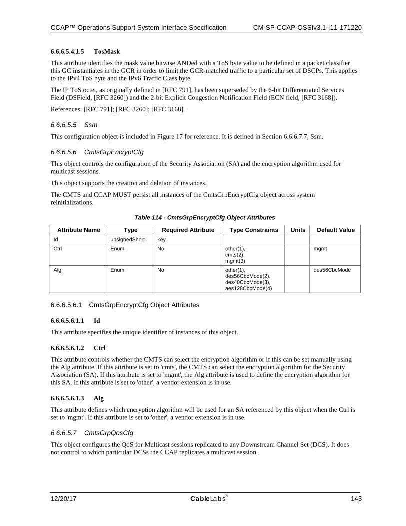
CCAP™ Operations Support System Interface Specification CM-SP-CCAP-OSSIv3.1-I11-171220
12/20/17 CableLabs 143
6.6.6.5.4.1.5 TosMask
This attribute identifies the mask value bitwise ANDed with a ToS byte value to be defined in a packet classifier this GC instantiates in the GCR in order to limit the GCR-matched traffic to a particular set of DSCPs. This applies to the IPv4 ToS byte and the IPv6 Traffic Class byte.
The IP ToS octet, as originally defined in [RFC 791], has been superseded by the 6-bit Differentiated Services Field (DSField, [RFC 3260]) and the 2-bit Explicit Congestion Notification Field (ECN field, [RFC 3168]).
References: [RFC 791]; [RFC 3260]; [RFC 3168].
6.6.6.5.5 Ssm
This configuration object is included in Figure 17 for reference. It is defined in Section 6.6.6.7.7, Ssm.
6.6.6.5.6 CmtsGrpEncryptCfg
This object controls the configuration of the Security Association (SA) and the encryption algorithm used for multicast sessions.
This object supports the creation and deletion of instances.
The CMTS and CCAP MUST persist all instances of the CmtsGrpEncryptCfg object across system reinitializations.
Table 114 - CmtsGrpEncryptCfg Object Attributes
Attribute Name Type Required Attribute Type Constraints Units Default Value Id unsignedShort key
Ctrl Enum No other(1), cmts(2), mgmt(3)
mgmt
Alg Enum No other(1), des56CbcMode(2), des40CbcMode(3), aes128CbcMode(4)
des56CbcMode
6.6.6.5.6.1 CmtsGrpEncryptCfg Object Attributes
6.6.6.5.6.1.1 Id
This attribute specifies the unique identifier of instances of this object.
6.6.6.5.6.1.2 Ctrl
This attribute controls whether the CMTS can select the encryption algorithm or if this can be set manually using the Alg attribute. If this attribute is set to 'cmts', the CMTS can select the encryption algorithm for the Security Association (SA). If this attribute is set to 'mgmt', the Alg attribute is used to define the encryption algorithm for this SA. If this attribute is set to 'other', a vendor extension is in use.
6.6.6.5.6.1.3 Alg
This attribute defines which encryption algorithm will be used for an SA referenced by this object when the Ctrl is set to 'mgmt'. If this attribute is set to 'other', a vendor extension is in use.
6.6.6.5.7 CmtsGrpQosCfg
This object configures the QoS for Multicast sessions replicated to any Downstream Channel Set (DCS). It does not control to which particular DCSs the CCAP replicates a multicast session.

CM-SP-CCAP-OSSIv3.1-I11-171220 Data-Over-Cable Service Interface Specifications
144 CableLabs® 12/20/17
An instance of this object is called a GQC entry. A GQC entry controls how the CCAP instantiates a Group Classifier Rule (GCR) on the DCS to match packets of the multicast session. A GCR uses source and destination IP address and ToS criteria.
A GQC entry controls how and with what QoS parameters a GSF is created on a DCS. All downstream multicast packets are scheduled on a GSF. The QoS Type attribute of the GQC entry controls whether the CCAP creates one GSF for each single IP multicast session or whether the CCAP creates one GSF for the aggregate of all sessions that match the GQC criteria. The GQC instance contains a reference to a Service Class Name QoS Parameter Set template. The Service Class defines the list of QoS parameters for the GSF(s) instantiated for the GQC entry.
A CCAP identifies one Service Class as the Default Group QoS Service Class. The CCAP instantiates a Default GSF on each single-channel DCS based on the parameters of the Default Group QoS Service Class.
The set of GCRs and GSFs instantiated on a DCS control how QoS is provided to multicast packets replicated to the DCS. For each multicast packet, the CCAP classifies the packet to the highest priority matching GCR on that DCS. The GCR refers to a single GSF, which controls the scheduling of the packets on the DCS. If the multicast packet does not match any GCR on the DCS, the packet is scheduled on the Default GSF of the DCS. The CCAP replicates unclassified multicast traffic to only DCSs consisting of a single downstream channel. Thus, the Maximum Sustained Traffic Rate QoS parameter of the Default Group Service Class limits the aggregate rate of unclassified multicast traffic on each downstream channel.
The CCAP is expected to instantiate GCRs and GSFs controlled by the entries in this table only for the duration of replication of the multicast sessions matching the entry.
This object supports the creation of multiple instances.
Creation of new instances of this object require the following objects to be set:
• ServiceClassName • QosCtrl • AggSessLimit
The CMTS and CCAP MUST persist all instances of the CmtsGrpQosCfg object across system reinitialization.
Table 115 - CmtsGrpQosCfg Object Attributes
Attribute Name Type Required Attribute Type Constraints Units Default Value
Id unsignedShort key
QosCtrl Enum Yes other(1), singleSession(2), aggregateSession(3)
AggSessLimit UnsignedShort Yes 1.. 65535 sessions
AppId UnsignedInt Yes 0
Table 116 - CmtsGrpQosCfg Object Associations
Associated Object Name
Type Near-end Multiplicity
Far-end Multiplicity
Label
ServiceClass Directed aggregation to ServiceClass 0..* 0..1 ServiceClassName
6.6.6.5.7.1 CmtsGrpQosCfg Object Attributes
6.6.6.5.7.1.1 Id
This attribute identifies a unique Group QoS Configuration object instance.
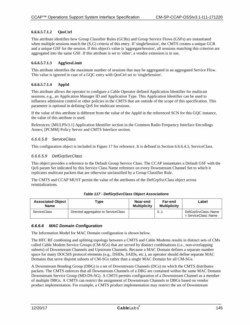
CCAP™ Operations Support System Interface Specification CM-SP-CCAP-OSSIv3.1-I11-171220
12/20/17 CableLabs 145
6.6.6.5.7.1.2 QosCtrl
This attribute identifies how Group Classifier Rules (GCRs) and Group Service Flows (GSFs) are instantiated when multiple sessions match the (S,G) criteria of this entry. If 'singleSession', the CMTS creates a unique GCR and a unique GSF for the session. If this object's value is 'aggregateSession', all sessions matching this criterion are aggregated into the same GSF. If this attribute is set to 'other', a vendor extension is in use.
6.6.6.5.7.1.3 AggSessLimit
This attribute identifies the maximum number of sessions that may be aggregated in an aggregated Service Flow. This value is ignored in case of a GQC entry with QosCtrl set to 'singleSession'.
6.6.6.5.7.1.4 AppId
This attribute allows the operator to configure a Cable Operator defined Application Identifier for multicast sessions, e.g., an Application Manager ID and Application Type. This Application Identifier can be used to influence admission control or other policies in the CMTS that are outside of the scope of this specification. This parameter is optional in defining QoS for multicast sessions.
If the value of this attribute is different from the value of the AppId in the referenced SCN for this GQC instance, the value of this attribute is used.
References: [MULPIv3.1] Application Identifier section in the Common Radio Frequency Interface Encodings Annex; [PCMM] Policy Server and CMTS Interface section.
6.6.6.5.8 ServiceClass
This configuration object is included in Figure 17 for reference. It is defined in Section 6.6.6.4.3, ServiceClass.
6.6.6.5.9 DefGrpSvcClass
This object provides a reference to the Default Group Service Class. The CCAP instantiates a Default GSF with the QoS param Set indicated by this Service Class Name reference on every Downstream Channel Set to which it replicates multicast packets that are otherwise unclassified by a Group Classifier Rule.
The CMTS and CCAP MUST persist the value of the attributes of the DefGrpSvcClass object across reinitializations.
Table 117 - DefGrpSvcClass Object Associations
Associated Object Name
Type Near-end Multiplicity
Far-end Multiplicity
Label
ServiceClass Directed aggregation to ServiceClass 0..1 DefGrpSrvClass::Name = ServiceClass::Name
6.6.6.6 MAC Domain Configuration The Information Model for MAC Domain configuration is shown below.
The HFC RF combining and splitting topology between a CMTS and Cable Modems results in distinct sets of CMs called Cable Modem Service Groups (CM-SGs) that are served by distinct combinations (i.e., non-overlapping subsets) of Downstream Channels and Upstream Channels. Because a MAC Domain defines a separate number space for many DOCSIS protocol elements (e.g., DSIDs, SAIDs, etc.), an operator should define separate MAC Domains that serve disjoint subsets of CM-SGs rather than a single MAC Domain for all CM-SGs.
A Downstream Bonding Group (DBG) is a set of Downstream Channels (DCs) on which the CMTS distributes packets. The CMTS enforces that all Downstream Channels of a DBG are contained within the same MAC Domain Downstream Service Group (MD-DS-SG). A CMTS permits configuration of a Downstream Channel as a member of multiple DBGs. A CMTS can restrict the assignment of Downstream Channels to DBGs based on vendor product implementation. For example, a CMTS product implementation may restrict the set of Downstream
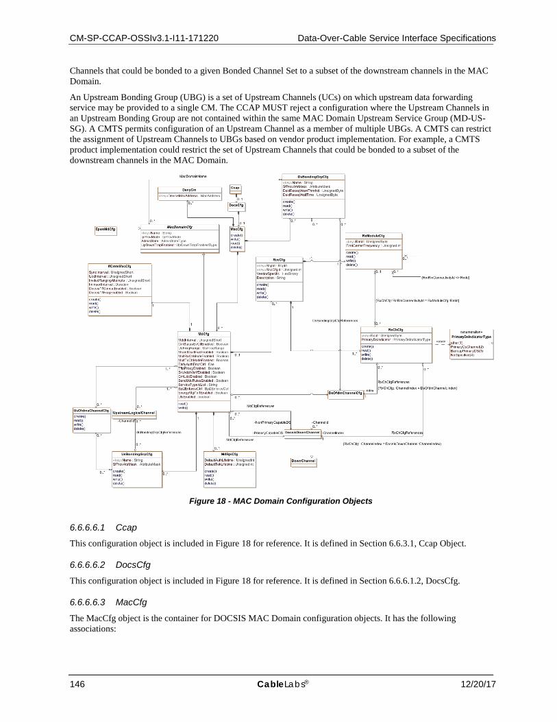
CM-SP-CCAP-OSSIv3.1-I11-171220 Data-Over-Cable Service Interface Specifications
146 CableLabs® 12/20/17
Channels that could be bonded to a given Bonded Channel Set to a subset of the downstream channels in the MAC Domain.
An Upstream Bonding Group (UBG) is a set of Upstream Channels (UCs) on which upstream data forwarding service may be provided to a single CM. The CCAP MUST reject a configuration where the Upstream Channels in an Upstream Bonding Group are not contained within the same MAC Domain Upstream Service Group (MD-US-SG). A CMTS permits configuration of an Upstream Channel as a member of multiple UBGs. A CMTS can restrict the assignment of Upstream Channels to UBGs based on vendor product implementation. For example, a CMTS product implementation could restrict the set of Upstream Channels that could be bonded to a subset of the downstream channels in the MAC Domain.
Figure 18 - MAC Domain Configuration Objects
6.6.6.6.1 Ccap
This configuration object is included in Figure 18 for reference. It is defined in Section 6.6.3.1, Ccap Object.
6.6.6.6.2 DocsCfg
This configuration object is included in Figure 18 for reference. It is defined in Section 6.6.6.1.2, DocsCfg.
6.6.6.6.3 MacCfg
The MacCfg object is the container for DOCSIS MAC Domain configuration objects. It has the following associations:
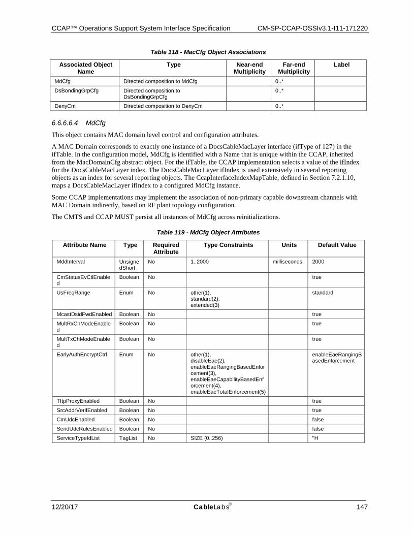
CCAP™ Operations Support System Interface Specification CM-SP-CCAP-OSSIv3.1-I11-171220
12/20/17 CableLabs 147
Table 118 - MacCfg Object Associations
Associated Object Name
Type Near-end Multiplicity
Far-end Multiplicity
Label
MdCfg Directed composition to MdCfg 0..*
DsBondingGrpCfg Directed composition to DsBondingGrpCfg
0..*
DenyCm Directed composition to DenyCm 0..*
6.6.6.6.4 MdCfg
This object contains MAC domain level control and configuration attributes.
A MAC Domain corresponds to exactly one instance of a DocsCableMacLayer interface (ifType of 127) in the ifTable. In the configuration model, MdCfg is identified with a Name that is unique within the CCAP, inherited from the MacDomainCfg abstract object. For the ifTable, the CCAP implementation selects a value of the ifIndex for the DocsCableMacLayer index. The DocsCableMacLayer ifIndex is used extensively in several reporting objects as an index for several reporting objects. The CcapInterfaceIndexMapTable, defined in Section 7.2.1.10, maps a DocsCableMacLayer ifIndex to a configured MdCfg instance.
Some CCAP implementations may implement the association of non-primary capable downstream channels with MAC Domain indirectly, based on RF plant topology configuration.
The CMTS and CCAP MUST persist all instances of MdCfg across reinitializations.
Table 119 - MdCfg Object Attributes
Attribute Name Type Required Attribute
Type Constraints Units Default Value
MddInterval UnsignedShort
No 1..2000 milliseconds 2000
CmStatusEvCtlEnabled
Boolean No true
UsFreqRange Enum No other(1), standard(2), extended(3)
standard
McastDsidFwdEnabled Boolean No true
MultRxChModeEnabled
Boolean No true
MultTxChModeEnabled
Boolean No true
EarlyAuthEncryptCtrl Enum No other(1), disableEae(2), enableEaeRangingBasedEnforcement(3), enableEaeCapabilityBasedEnforcement(4), enableEaeTotalEnforcement(5)
enableEaeRangingBasedEnforcement
TftpProxyEnabled Boolean No true
SrcAddrVerifEnabled Boolean No true
CmUdcEnabled Boolean No false
SendUdcRulesEnabled Boolean No false
ServiceTypeIdList TagList No SIZE (0..256) ''H
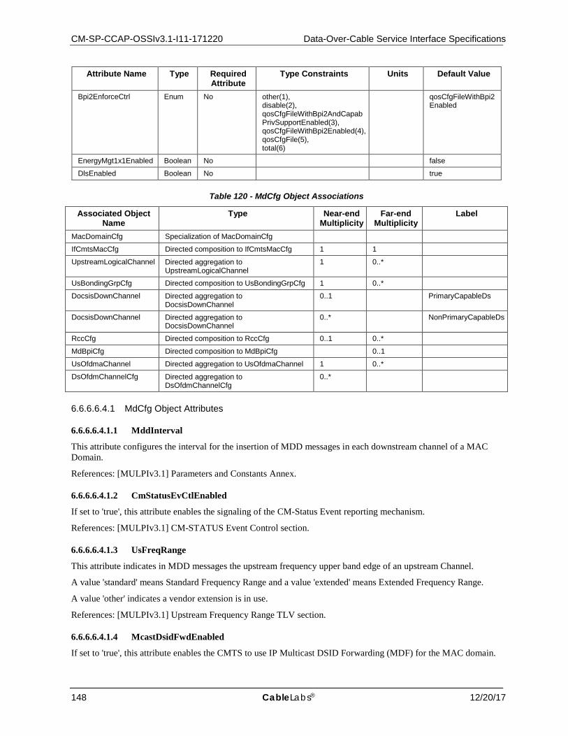
CM-SP-CCAP-OSSIv3.1-I11-171220 Data-Over-Cable Service Interface Specifications
148 CableLabs® 12/20/17
Attribute Name Type Required Attribute
Type Constraints Units Default Value
Bpi2EnforceCtrl Enum No other(1), disable(2), qosCfgFileWithBpi2AndCapabPrivSupportEnabled(3), qosCfgFileWithBpi2Enabled(4), qosCfgFile(5), total(6)
qosCfgFileWithBpi2Enabled
EnergyMgt1x1Enabled Boolean No false
DlsEnabled Boolean No true
Table 120 - MdCfg Object Associations
Associated Object Name
Type Near-end Multiplicity
Far-end Multiplicity
Label
MacDomainCfg Specialization of MacDomainCfg
IfCmtsMacCfg Directed composition to IfCmtsMacCfg 1 1
UpstreamLogicalChannel Directed aggregation to UpstreamLogicalChannel
1 0..*
UsBondingGrpCfg Directed composition to UsBondingGrpCfg 1 0..*
DocsisDownChannel Directed aggregation to DocsisDownChannel
0..1 PrimaryCapableDs
DocsisDownChannel Directed aggregation to DocsisDownChannel
0..* NonPrimaryCapableDs
RccCfg Directed composition to RccCfg 0..1 0..*
MdBpiCfg Directed composition to MdBpiCfg 0..1
UsOfdmaChannel Directed aggregation to UsOfdmaChannel 1 0..*
DsOfdmChannelCfg Directed aggregation to DsOfdmChannelCfg
0..*
6.6.6.6.4.1 MdCfg Object Attributes
6.6.6.6.4.1.1 MddInterval
This attribute configures the interval for the insertion of MDD messages in each downstream channel of a MAC Domain.
References: [MULPIv3.1] Parameters and Constants Annex.
6.6.6.6.4.1.2 CmStatusEvCtlEnabled
If set to 'true', this attribute enables the signaling of the CM-Status Event reporting mechanism.
References: [MULPIv3.1] CM-STATUS Event Control section.
6.6.6.6.4.1.3 UsFreqRange
This attribute indicates in MDD messages the upstream frequency upper band edge of an upstream Channel.
A value 'standard' means Standard Frequency Range and a value 'extended' means Extended Frequency Range.
A value 'other' indicates a vendor extension is in use.
References: [MULPIv3.1] Upstream Frequency Range TLV section.
6.6.6.6.4.1.4 McastDsidFwdEnabled
If set to 'true', this attribute enables the CMTS to use IP Multicast DSID Forwarding (MDF) for the MAC domain.
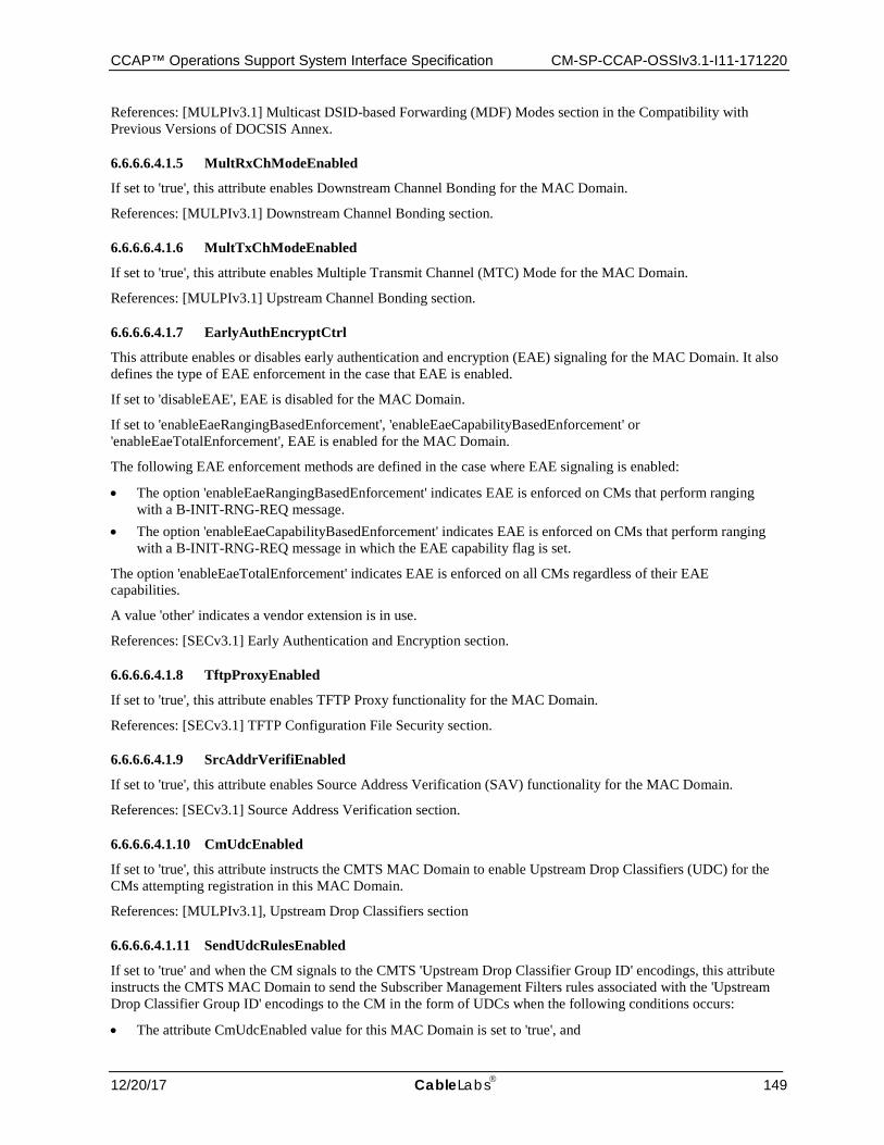
CCAP™ Operations Support System Interface Specification CM-SP-CCAP-OSSIv3.1-I11-171220
12/20/17 CableLabs 149
References: [MULPIv3.1] Multicast DSID-based Forwarding (MDF) Modes section in the Compatibility with Previous Versions of DOCSIS Annex.
6.6.6.6.4.1.5 MultRxChModeEnabled
If set to 'true', this attribute enables Downstream Channel Bonding for the MAC Domain.
References: [MULPIv3.1] Downstream Channel Bonding section.
6.6.6.6.4.1.6 MultTxChModeEnabled
If set to 'true', this attribute enables Multiple Transmit Channel (MTC) Mode for the MAC Domain.
References: [MULPIv3.1] Upstream Channel Bonding section.
6.6.6.6.4.1.7 EarlyAuthEncryptCtrl
This attribute enables or disables early authentication and encryption (EAE) signaling for the MAC Domain. It also defines the type of EAE enforcement in the case that EAE is enabled.
If set to 'disableEAE', EAE is disabled for the MAC Domain.
If set to 'enableEaeRangingBasedEnforcement', 'enableEaeCapabilityBasedEnforcement' or 'enableEaeTotalEnforcement', EAE is enabled for the MAC Domain.
The following EAE enforcement methods are defined in the case where EAE signaling is enabled:
• The option 'enableEaeRangingBasedEnforcement' indicates EAE is enforced on CMs that perform ranging with a B-INIT-RNG-REQ message.
• The option 'enableEaeCapabilityBasedEnforcement' indicates EAE is enforced on CMs that perform ranging with a B-INIT-RNG-REQ message in which the EAE capability flag is set.
The option 'enableEaeTotalEnforcement' indicates EAE is enforced on all CMs regardless of their EAE capabilities.
A value 'other' indicates a vendor extension is in use.
References: [SECv3.1] Early Authentication and Encryption section.
6.6.6.6.4.1.8 TftpProxyEnabled
If set to 'true', this attribute enables TFTP Proxy functionality for the MAC Domain.
References: [SECv3.1] TFTP Configuration File Security section.
6.6.6.6.4.1.9 SrcAddrVerifiEnabled
If set to 'true', this attribute enables Source Address Verification (SAV) functionality for the MAC Domain.
References: [SECv3.1] Source Address Verification section.
6.6.6.6.4.1.10 CmUdcEnabled
If set to 'true', this attribute instructs the CMTS MAC Domain to enable Upstream Drop Classifiers (UDC) for the CMs attempting registration in this MAC Domain.
References: [MULPIv3.1], Upstream Drop Classifiers section
6.6.6.6.4.1.11 SendUdcRulesEnabled
If set to 'true' and when the CM signals to the CMTS 'Upstream Drop Classifier Group ID' encodings, this attribute instructs the CMTS MAC Domain to send the Subscriber Management Filters rules associated with the 'Upstream Drop Classifier Group ID' encodings to the CM in the form of UDCs when the following conditions occurs:
• The attribute CmUdcEnabled value for this MAC Domain is set to 'true', and
CM-SP-CCAP-OSSIv3.1-I11-171220 Data-Over-Cable Service Interface Specifications
150 CableLabs® 12/20/17
• The CM has the UDC capability advertised as supported.
If there is no a single Subscriber Management Filter configured in the CMTS for the CM's signaled UDC Group ID, the CMTS does not send UDC encodings to the CM.
It is vendor specific whether the CMTS maintains enforcement of the CM signaled or default Subscriber Management Filter groups in the upstream direction.
References: [MULPIv3.1], Upstream Drop Classifiers section
6.6.6.6.4.1.12 ServiceTypeIdList
This attribute indicates the list of Service Type IDs associated with the MAC Domain.
During the CM registration process the CMTS will attempt to redirect the CM to a MAC Domain where the CM' Service Type TLV is contained in this attribute.
References: [MULPIv3.1], Service Type Identifier section in the Common Radio Frequency Interface Encodings Annex.
6.6.6.6.4.1.13 Bpi2EnforceCtrl
This attribute indicates the level of BPI+ enforcement policies with the MAC Domain.
The following BPI+ enforcement policies are defined in the case where BPI+ is enabled:
• The option 'disable' indicates that CMTS does not enforce BPI+. • The option 'qosCfgFileWithBpi2AndCapabPrivSupportEnabled' indicates the CMTS enforces BPI+ on CMs
that register with parameters indicating BPI+ is enabled (missing TLV 29 or containing TLV 29 set to enable) and with a Modem Capabilities Privacy Support TLV (5.6) set to BPI+ support.
• The option 'qosCfgFileWithBpi2Enabled' indicates the CMTS enforces BPI+ on CMs that register with parameters indicating BPI+ is enabled (missing TLV 29 or containing TLV 29 set to enable).
• The option 'qosCfgFile' indicates the CMTS enforces BPI+ on CMs that register with a DOCSIS 1.1 style configuration file. Because DOCSIS 3.1 devices will only register with a DOCSIS 1.1 style configuration file, the 'qosCfgFile' is the same as the 'total' option in DOCSIS 3.1.
• The option 'total' indicates the CMTS enforces BPI+ on all CMs. • A value 'other' indicates a vendor extension is in use.
References: [SECv3.1] BPI+ Enforce section.
6.6.6.6.4.1.14 EnergyMgt1x1Enabled
This attribute indicates whether the CMTS is configured for 1x1 Energy Management Mode of operation on a per MAC Domain basis.
If this attribute is set to 'true', the CMTS is configured for 1x1 Energy Management Mode of operation on this MAC Domain. If this attribute is set to 'false', the Energy Management 1x1 Mode of operation is disabled in the CMTS on this MAC Domain.
References: [MULPIv3.1], Energy Management Capabilities section.
6.6.6.6.4.1.15 DlsEnabled
This attribute indicates whether the CMTS is configured for DOCSIS Light Sleep (DLS) Mode of operation on a per MAC Domain basis. If this attribute is set to 'true', the CMTS is configured for DLS Mode of operation on this MAC Domain. If this attribute is set to 'false', the DLS Mode of operation is disabled in the CMTS on this MAC Domain. References: [MULPIv3.1], DOCSIS Light Sleep (DLS) Feature.
6.6.6.6.5 MdBpiCfg
This object is based on the DocsBpiCmtsBaseEntry table defined in [RFC 3083].
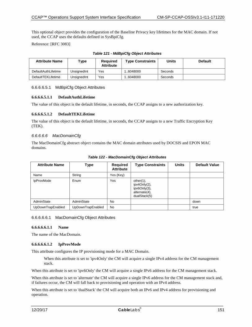
CCAP™ Operations Support System Interface Specification CM-SP-CCAP-OSSIv3.1-I11-171220
12/20/17 CableLabs 151
This optional object provides the configuration of the Baseline Privacy key lifetimes for the MAC domain. If not used, the CCAP uses the defaults defined in SysBpiCfg.
Reference: [RFC 3083]
Table 121 - MdBpiCfg Object Attributes
Attribute Name Type Required Attribute
Type Constraints Units Default
DefaultAuthLifetime UnsignedInt Yes 1..6048000 Seconds
DefaultTEKLifetime UnsignedInt Yes 1..6048000 Seconds
6.6.6.6.5.1 MdBpiCfg Object Attributes
6.6.6.6.5.1.1 DefaultAuthLifetime
The value of this object is the default lifetime, in seconds, the CCAP assigns to a new authorization key.
6.6.6.6.5.1.2 DefaultTEKLifetime
The value of this object is the default lifetime, in seconds, the CCAP assigns to a new Traffic Encryption Key (TEK).
6.6.6.6.6 MacDomainCfg
The MacDomainCfg abstract object contains the MAC domain attributes used by DOCSIS and EPON MAC domains.
Table 122 - MacDomainCfg Object Attributes
Attribute Name Type Required Attribute
Type Constraints Units Default Value
Name String Yes (Key)
IpProvMode Enum Yes other(1), ipv4Only(2), ipv6Only(3), alternate(4), dualStack(5)
AdminState AdminState No down
UpDownTrapEnabled UpDownTrapEnabled No true
6.6.6.6.6.1 MacDomainCfg Object Attributes
6.6.6.6.6.1.1 Name
The name of the MacDomain.
6.6.6.6.6.1.2 IpProvMode
This attribute configures the IP provisioning mode for a MAC Domain.
When this attribute is set to 'ipv4Only' the CM will acquire a single IPv4 address for the CM management stack.
When this attribute is set to 'ipv6Only' the CM will acquire a single IPv6 address for the CM management stack.
When this attribute is set to 'alternate' the CM will acquire a single IPv6 address for the CM management stack and, if failures occur, the CM will fall back to provisioning and operation with an IPv4 address.
When this attribute is set to 'dualStack' the CM will acquire both an IPv6 and IPv4 address for provisioning and operation.
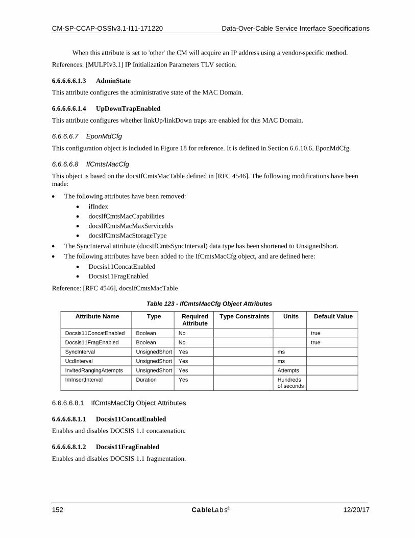
CM-SP-CCAP-OSSIv3.1-I11-171220 Data-Over-Cable Service Interface Specifications
152 CableLabs® 12/20/17
When this attribute is set to 'other' the CM will acquire an IP address using a vendor-specific method.
References: [MULPIv3.1] IP Initialization Parameters TLV section.
6.6.6.6.6.1.3 AdminState
This attribute configures the administrative state of the MAC Domain.
6.6.6.6.6.1.4 UpDownTrapEnabled
This attribute configures whether linkUp/linkDown traps are enabled for this MAC Domain.
6.6.6.6.7 EponMdCfg
This configuration object is included in Figure 18 for reference. It is defined in Section 6.6.10.6, EponMdCfg.
6.6.6.6.8 IfCmtsMacCfg
This object is based on the docsIfCmtsMacTable defined in [RFC 4546]. The following modifications have been made:
• The following attributes have been removed: • ifIndex • docsIfCmtsMacCapabilities • docsIfCmtsMacMaxServiceIds • docsIfCmtsMacStorageType
• The SyncInterval attribute (docsIfCmtsSyncInterval) data type has been shortened to UnsignedShort. • The following attributes have been added to the IfCmtsMacCfg object, and are defined here:
• Docsis11ConcatEnabled • Docsis11FragEnabled
Reference: [RFC 4546], docsIfCmtsMacTable
Table 123 - IfCmtsMacCfg Object Attributes
Attribute Name Type Required Attribute
Type Constraints Units Default Value
Docsis11ConcatEnabled Boolean No true
Docsis11FragEnabled Boolean No true
SyncInterval UnsignedShort Yes ms
UcdInterval UnsignedShort Yes ms
InvitedRangingAttempts UnsignedShort Yes Attempts
ImInsertInterval Duration Yes Hundreds of seconds
6.6.6.6.8.1 IfCmtsMacCfg Object Attributes
6.6.6.6.8.1.1 Docsis11ConcatEnabled
Enables and disables DOCSIS 1.1 concatenation.
6.6.6.6.8.1.2 Docsis11FragEnabled
Enables and disables DOCSIS 1.1 fragmentation.
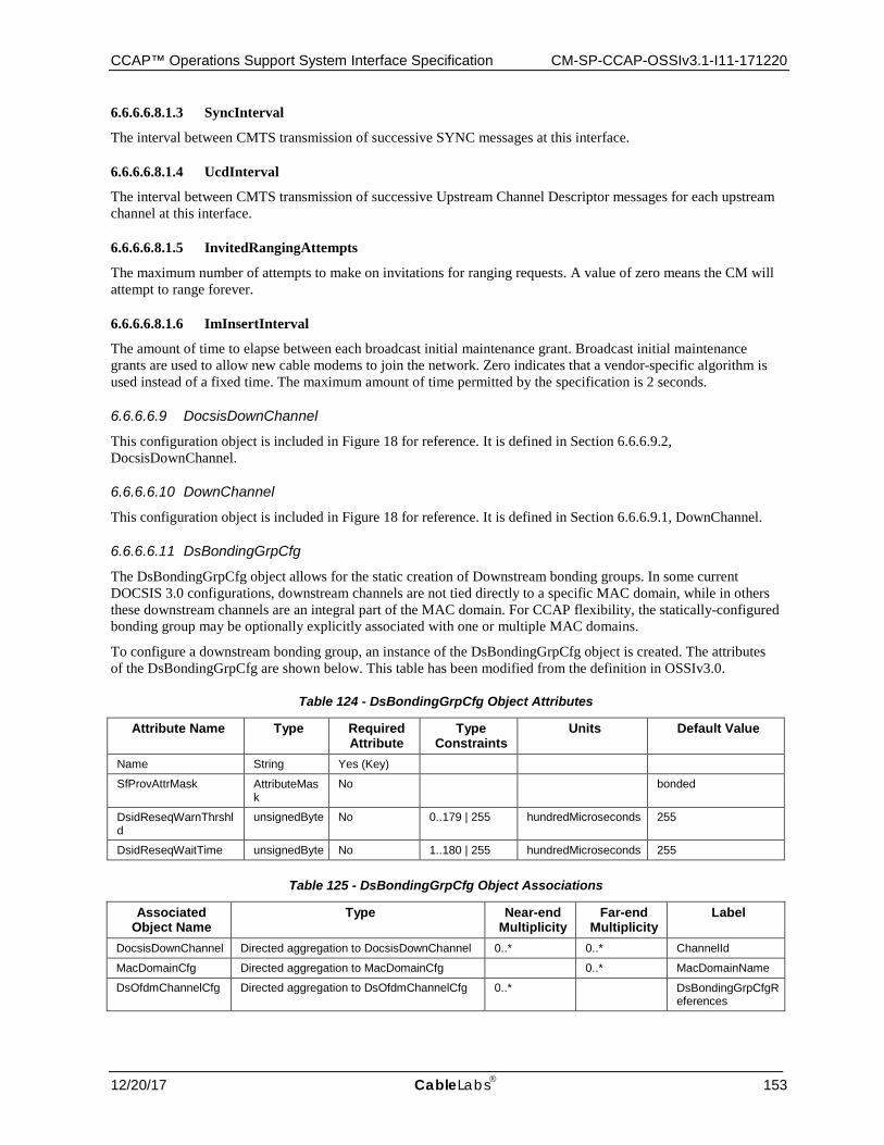
CCAP™ Operations Support System Interface Specification CM-SP-CCAP-OSSIv3.1-I11-171220
12/20/17 CableLabs 153
6.6.6.6.8.1.3 SyncInterval
The interval between CMTS transmission of successive SYNC messages at this interface.
6.6.6.6.8.1.4 UcdInterval
The interval between CMTS transmission of successive Upstream Channel Descriptor messages for each upstream channel at this interface.
6.6.6.6.8.1.5 InvitedRangingAttempts
The maximum number of attempts to make on invitations for ranging requests. A value of zero means the CM will attempt to range forever.
6.6.6.6.8.1.6 ImInsertInterval
The amount of time to elapse between each broadcast initial maintenance grant. Broadcast initial maintenance grants are used to allow new cable modems to join the network. Zero indicates that a vendor-specific algorithm is used instead of a fixed time. The maximum amount of time permitted by the specification is 2 seconds.
6.6.6.6.9 DocsisDownChannel
This configuration object is included in Figure 18 for reference. It is defined in Section 6.6.6.9.2, DocsisDownChannel.
6.6.6.6.10 DownChannel
This configuration object is included in Figure 18 for reference. It is defined in Section 6.6.6.9.1, DownChannel.
6.6.6.6.11 DsBondingGrpCfg
The DsBondingGrpCfg object allows for the static creation of Downstream bonding groups. In some current DOCSIS 3.0 configurations, downstream channels are not tied directly to a specific MAC domain, while in others these downstream channels are an integral part of the MAC domain. For CCAP flexibility, the statically-configured bonding group may be optionally explicitly associated with one or multiple MAC domains.
To configure a downstream bonding group, an instance of the DsBondingGrpCfg object is created. The attributes of the DsBondingGrpCfg are shown below. This table has been modified from the definition in OSSIv3.0.
Table 124 - DsBondingGrpCfg Object Attributes
Attribute Name Type Required Attribute
Type Constraints
Units Default Value
Name String Yes (Key)
SfProvAttrMask AttributeMask
No bonded
DsidReseqWarnThrshld
unsignedByte No 0..179 | 255 hundredMicroseconds 255
DsidReseqWaitTime unsignedByte No 1..180 | 255 hundredMicroseconds 255
Table 125 - DsBondingGrpCfg Object Associations
Associated Object Name
Type Near-end Multiplicity
Far-end Multiplicity
Label
DocsisDownChannel Directed aggregation to DocsisDownChannel 0..* 0..* ChannelId
MacDomainCfg Directed aggregation to MacDomainCfg 0..* MacDomainName
DsOfdmChannelCfg Directed aggregation to DsOfdmChannelCfg 0..* DsBondingGrpCfgReferences
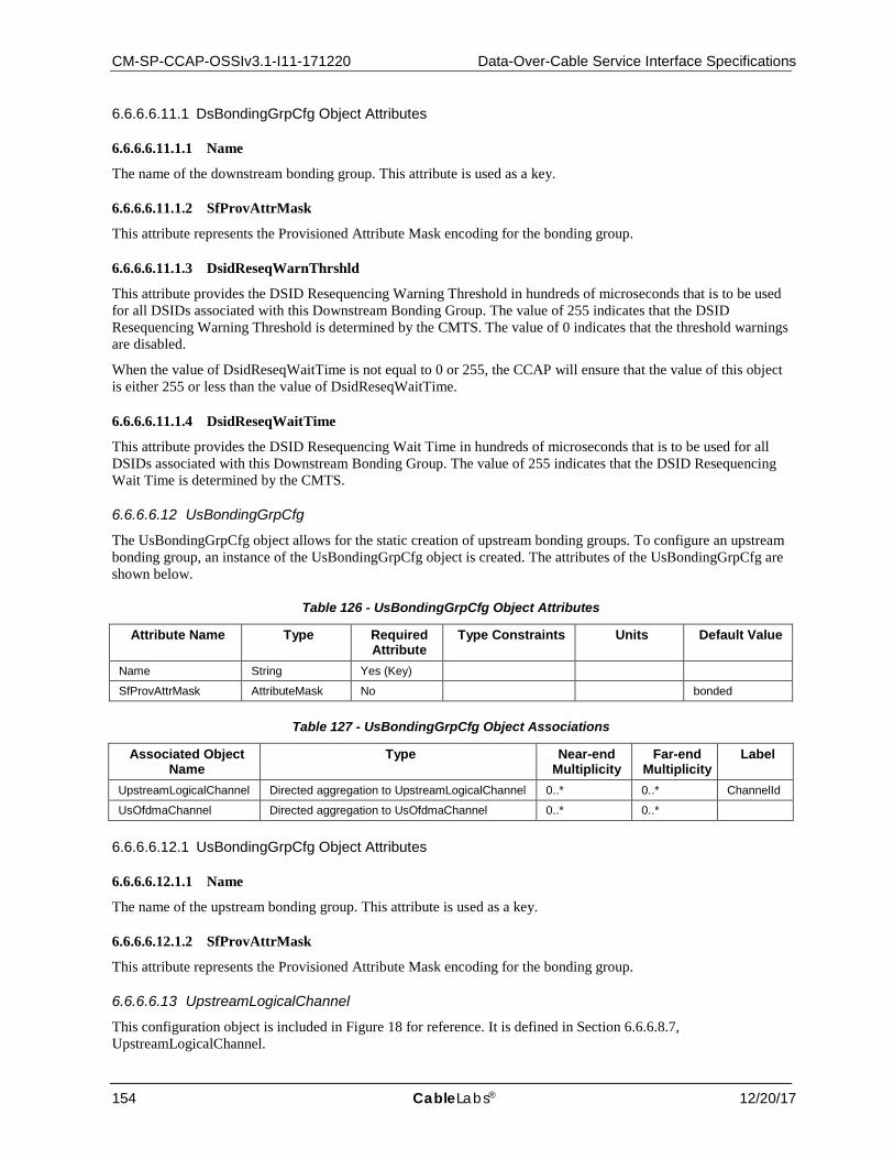
CM-SP-CCAP-OSSIv3.1-I11-171220 Data-Over-Cable Service Interface Specifications
154 CableLabs® 12/20/17
6.6.6.6.11.1 DsBondingGrpCfg Object Attributes
6.6.6.6.11.1.1 Name
The name of the downstream bonding group. This attribute is used as a key.
6.6.6.6.11.1.2 SfProvAttrMask
This attribute represents the Provisioned Attribute Mask encoding for the bonding group.
6.6.6.6.11.1.3 DsidReseqWarnThrshld
This attribute provides the DSID Resequencing Warning Threshold in hundreds of microseconds that is to be used for all DSIDs associated with this Downstream Bonding Group. The value of 255 indicates that the DSID Resequencing Warning Threshold is determined by the CMTS. The value of 0 indicates that the threshold warnings are disabled.
When the value of DsidReseqWaitTime is not equal to 0 or 255, the CCAP will ensure that the value of this object is either 255 or less than the value of DsidReseqWaitTime.
6.6.6.6.11.1.4 DsidReseqWaitTime
This attribute provides the DSID Resequencing Wait Time in hundreds of microseconds that is to be used for all DSIDs associated with this Downstream Bonding Group. The value of 255 indicates that the DSID Resequencing Wait Time is determined by the CMTS.
6.6.6.6.12 UsBondingGrpCfg
The UsBondingGrpCfg object allows for the static creation of upstream bonding groups. To configure an upstream bonding group, an instance of the UsBondingGrpCfg object is created. The attributes of the UsBondingGrpCfg are shown below.
Table 126 - UsBondingGrpCfg Object Attributes
Attribute Name Type Required Attribute
Type Constraints Units Default Value
Name String Yes (Key)
SfProvAttrMask AttributeMask No bonded
Table 127 - UsBondingGrpCfg Object Associations
Associated Object Name
Type Near-end Multiplicity
Far-end Multiplicity
Label
UpstreamLogicalChannel Directed aggregation to UpstreamLogicalChannel 0..* 0..* ChannelId
UsOfdmaChannel Directed aggregation to UsOfdmaChannel 0..* 0..*
6.6.6.6.12.1 UsBondingGrpCfg Object Attributes
6.6.6.6.12.1.1 Name
The name of the upstream bonding group. This attribute is used as a key.
6.6.6.6.12.1.2 SfProvAttrMask
This attribute represents the Provisioned Attribute Mask encoding for the bonding group.
6.6.6.6.13 UpstreamLogicalChannel
This configuration object is included in Figure 18 for reference. It is defined in Section 6.6.6.8.7, UpstreamLogicalChannel.
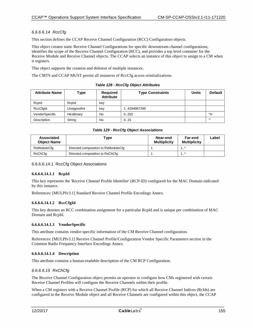
CCAP™ Operations Support System Interface Specification CM-SP-CCAP-OSSIv3.1-I11-171220
12/20/17 CableLabs 155
6.6.6.6.14 RccCfg
This section defines the CCAP Receive Channel Configuration (RCC) Configuration objects.
This object creates static Receive Channel Configurations for specific downstream channel configurations, identifies the scope of the Receive Channel Configuration (RCC), and provides a top level container for the Receive Module and Receive Channel objects. The CCAP selects an instance of this object to assign to a CM when it registers.
This object supports the creation and deletion of multiple instances.
The CMTS and CCAP MUST persist all instances of RccCfg across reinitializations.
Table 128 - RccCfg Object Attributes
Attribute Name Type Required Attribute
Type Constraints Units Default
RcpId RcpId key
RccCfgId UnsignedInt key 1..4294967295
VendorSpecific HexBinary No 0..252 ''H
Description String No 0..15 ""
Table 129 - RccCfg Object Associations
Associated Object Name
Type Near-end Multiplicity
Far-end Multiplicity
Label
RxModuleCfg Directed composition to RxModuleCfg 1 1..*
RxChCfg Directed composition to RxChCfg 1 1..*
6.6.6.6.14.1 RccCfg Object Associations
6.6.6.6.14.1.1 RcpId
This key represents the 'Receive Channel Profile Identifier' (RCP-ID) configured for the MAC Domain indicated by this instance.
References: [MULPIv3.1] Standard Receive Channel Profile Encodings Annex.
6.6.6.6.14.1.2 RccCfgId
This key denotes an RCC combination assignment for a particular RcpId and is unique per combination of MAC Domain and RcpId.
6.6.6.6.14.1.3 VendorSpecific
This attribute contains vendor-specific information of the CM Receive Channel configuration.
References: [MULPIv3.1] Receive Channel Profile/Configuration Vendor Specific Parameters section in the Common Radio Frequency Interface Encodings Annex.
6.6.6.6.14.1.4 Description
This attribute contains a human-readable description of the CM RCP Configuration.
6.6.6.6.15 RxChCfg
The Receive Channel Configuration object permits an operator to configure how CMs registered with certain Receive Channel Profiles will configure the Receive Channels within their profile.
When a CM registers with a Receive Channel Profile (RCP) for which all Receive Channel Indices (RcIds) are configured in the Receive Module object and all Receive Channels are configured within this object, the CCAP
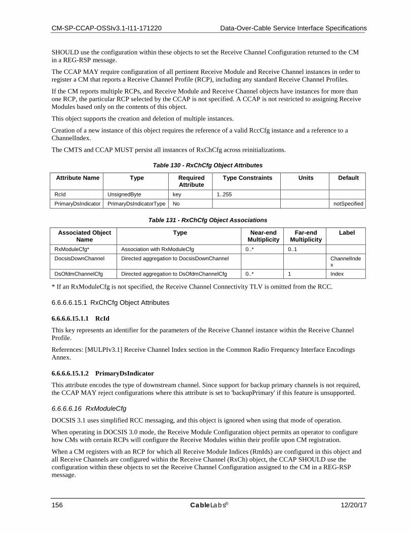
CM-SP-CCAP-OSSIv3.1-I11-171220 Data-Over-Cable Service Interface Specifications
156 CableLabs® 12/20/17
SHOULD use the configuration within these objects to set the Receive Channel Configuration returned to the CM in a REG-RSP message.
The CCAP MAY require configuration of all pertinent Receive Module and Receive Channel instances in order to register a CM that reports a Receive Channel Profile (RCP), including any standard Receive Channel Profiles.
If the CM reports multiple RCPs, and Receive Module and Receive Channel objects have instances for more than one RCP, the particular RCP selected by the CCAP is not specified. A CCAP is not restricted to assigning Receive Modules based only on the contents of this object.
This object supports the creation and deletion of multiple instances.
Creation of a new instance of this object requires the reference of a valid RccCfg instance and a reference to a ChannelIndex.
The CMTS and CCAP MUST persist all instances of RxChCfg across reinitializations.
Table 130 - RxChCfg Object Attributes
Attribute Name Type Required Attribute
Type Constraints Units Default
RcId UnsignedByte key 1..255
PrimaryDsIndicator PrimaryDsIndicatorType No notSpecified
Table 131 - RxChCfg Object Associations
Associated Object Name
Type Near-end Multiplicity
Far-end Multiplicity
Label
RxModuleCfg* Association with RxModuleCfg 0..* 0..1
DocsisDownChannel Directed aggregation to DocsisDownChannel ChannelIndex
DsOfdmChannelCfg Directed aggregation to DsOfdmChannelCfg 0..* 1 Index
* If an RxModuleCfg is not specified, the Receive Channel Connectivity TLV is omitted from the RCC.
6.6.6.6.15.1 RxChCfg Object Attributes
6.6.6.6.15.1.1 RcId
This key represents an identifier for the parameters of the Receive Channel instance within the Receive Channel Profile.
References: [MULPIv3.1] Receive Channel Index section in the Common Radio Frequency Interface Encodings Annex.
6.6.6.6.15.1.2 PrimaryDsIndicator
This attribute encodes the type of downstream channel. Since support for backup primary channels is not required, the CCAP MAY reject configurations where this attribute is set to 'backupPrimary' if this feature is unsupported.
6.6.6.6.16 RxModuleCfg
DOCSIS 3.1 uses simplified RCC messaging, and this object is ignored when using that mode of operation.
When operating in DOCSIS 3.0 mode, the Receive Module Configuration object permits an operator to configure how CMs with certain RCPs will configure the Receive Modules within their profile upon CM registration.
When a CM registers with an RCP for which all Receive Module Indices (RmIds) are configured in this object and all Receive Channels are configured within the Receive Channel (RxCh) object, the CCAP SHOULD use the configuration within these objects to set the Receive Channel Configuration assigned to the CM in a REG-RSP message.
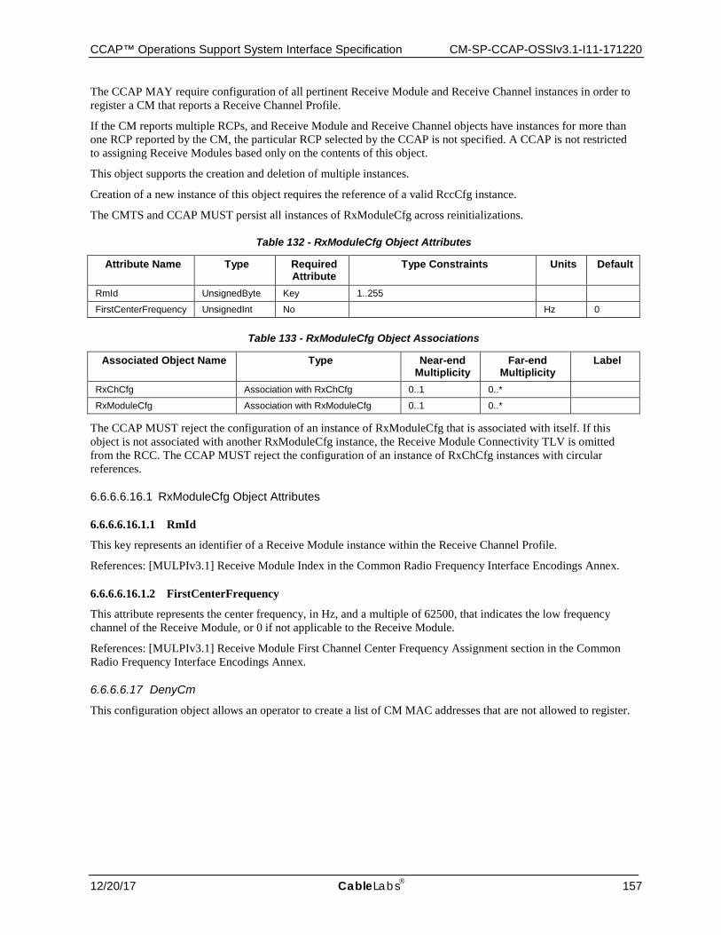
CCAP™ Operations Support System Interface Specification CM-SP-CCAP-OSSIv3.1-I11-171220
12/20/17 CableLabs 157
The CCAP MAY require configuration of all pertinent Receive Module and Receive Channel instances in order to register a CM that reports a Receive Channel Profile.
If the CM reports multiple RCPs, and Receive Module and Receive Channel objects have instances for more than one RCP reported by the CM, the particular RCP selected by the CCAP is not specified. A CCAP is not restricted to assigning Receive Modules based only on the contents of this object.
This object supports the creation and deletion of multiple instances.
Creation of a new instance of this object requires the reference of a valid RccCfg instance.
The CMTS and CCAP MUST persist all instances of RxModuleCfg across reinitializations.
Table 132 - RxModuleCfg Object Attributes
Attribute Name Type Required Attribute
Type Constraints Units Default
RmId UnsignedByte Key 1..255
FirstCenterFrequency UnsignedInt No Hz 0
Table 133 - RxModuleCfg Object Associations
Associated Object Name Type Near-end Multiplicity
Far-end Multiplicity
Label
RxChCfg Association with RxChCfg 0..1 0..*
RxModuleCfg Association with RxModuleCfg 0..1 0..*
The CCAP MUST reject the configuration of an instance of RxModuleCfg that is associated with itself. If this object is not associated with another RxModuleCfg instance, the Receive Module Connectivity TLV is omitted from the RCC. The CCAP MUST reject the configuration of an instance of RxChCfg instances with circular references.
6.6.6.6.16.1 RxModuleCfg Object Attributes
6.6.6.6.16.1.1 RmId
This key represents an identifier of a Receive Module instance within the Receive Channel Profile.
References: [MULPIv3.1] Receive Module Index in the Common Radio Frequency Interface Encodings Annex.
6.6.6.6.16.1.2 FirstCenterFrequency
This attribute represents the center frequency, in Hz, and a multiple of 62500, that indicates the low frequency channel of the Receive Module, or 0 if not applicable to the Receive Module.
References: [MULPIv3.1] Receive Module First Channel Center Frequency Assignment section in the Common Radio Frequency Interface Encodings Annex.
6.6.6.6.17 DenyCm
This configuration object allows an operator to create a list of CM MAC addresses that are not allowed to register.

CM-SP-CCAP-OSSIv3.1-I11-171220 Data-Over-Cable Service Interface Specifications
158 CableLabs® 12/20/17
Table 134 - DenyCm Object Attributes
Attribute Name Type Required Attribute Type Constraints Units Default Value DeviceMacAddress MacAddress Yes (Key)
6.6.6.6.17.1 DenyCm Object Attributes
6.6.6.6.17.1.1 DeviceMacAddress
The MAC address of the CM that will be added to the deny list. This attribute is used as a key.
6.6.6.7 DOCSIS Multicast Authorization Configuration The CCAP authorization module allows operators to selectively authorize access to multicast content for subscribers. This group of configuration elements allows for the configuration of DOCSIS Multicast Authorization. The configuration specific Information Model is shown below. This model provides the Multicast Conditional Access Model for the authorization of clients to join multicast sessions. The components of the Multicast Authorization model are:
• Ctrl, global configuration of Multicast authorization • ProfileSessRule, DOCSIS Multicast profile-based authorization
A Multicast Authorization Profile Session rule consist of a pair source and group prefix addresses, an authorization action and a priority configured in the CMTS. This rule corresponds to the expansion of the IP Multicast Authorization Profile Name Subtype encoding signaled by the CM during registration.
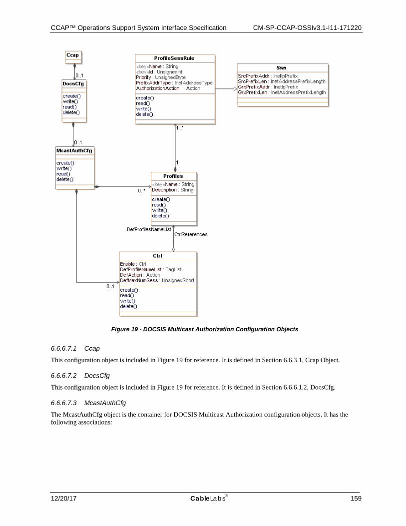
CCAP™ Operations Support System Interface Specification CM-SP-CCAP-OSSIv3.1-I11-171220
12/20/17 CableLabs 159
Figure 19 - DOCSIS Multicast Authorization Configuration Objects
6.6.6.7.1 Ccap
This configuration object is included in Figure 19 for reference. It is defined in Section 6.6.3.1, Ccap Object.
6.6.6.7.2 DocsCfg
This configuration object is included in Figure 19 for reference. It is defined in Section 6.6.6.1.2, DocsCfg.
6.6.6.7.3 McastAuthCfg
The McastAuthCfg object is the container for DOCSIS Multicast Authorization configuration objects. It has the following associations:
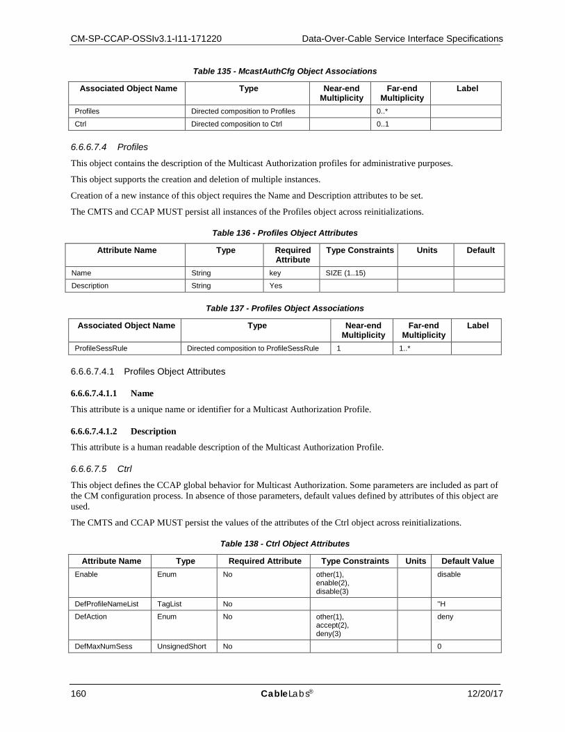
CM-SP-CCAP-OSSIv3.1-I11-171220 Data-Over-Cable Service Interface Specifications
160 CableLabs® 12/20/17
Table 135 - McastAuthCfg Object Associations
Associated Object Name Type Near-end Multiplicity
Far-end Multiplicity
Label
Profiles Directed composition to Profiles 0..*
Ctrl Directed composition to Ctrl 0..1
6.6.6.7.4 Profiles
This object contains the description of the Multicast Authorization profiles for administrative purposes.
This object supports the creation and deletion of multiple instances.
Creation of a new instance of this object requires the Name and Description attributes to be set.
The CMTS and CCAP MUST persist all instances of the Profiles object across reinitializations.
Table 136 - Profiles Object Attributes
Attribute Name Type Required Attribute
Type Constraints Units Default
Name String key SIZE (1..15)
Description String Yes
Table 137 - Profiles Object Associations
Associated Object Name Type Near-end Multiplicity
Far-end Multiplicity
Label
ProfileSessRule Directed composition to ProfileSessRule 1 1..*
6.6.6.7.4.1 Profiles Object Attributes
6.6.6.7.4.1.1 Name
This attribute is a unique name or identifier for a Multicast Authorization Profile.
6.6.6.7.4.1.2 Description
This attribute is a human readable description of the Multicast Authorization Profile.
6.6.6.7.5 Ctrl
This object defines the CCAP global behavior for Multicast Authorization. Some parameters are included as part of the CM configuration process. In absence of those parameters, default values defined by attributes of this object are used.
The CMTS and CCAP MUST persist the values of the attributes of the Ctrl object across reinitializations.
Table 138 - Ctrl Object Attributes
Attribute Name Type Required Attribute Type Constraints Units Default Value Enable Enum No other(1),
enable(2), disable(3)
disable
DefProfileNameList TagList No ''H
DefAction Enum No other(1), accept(2), deny(3)
deny
DefMaxNumSess UnsignedShort No 0
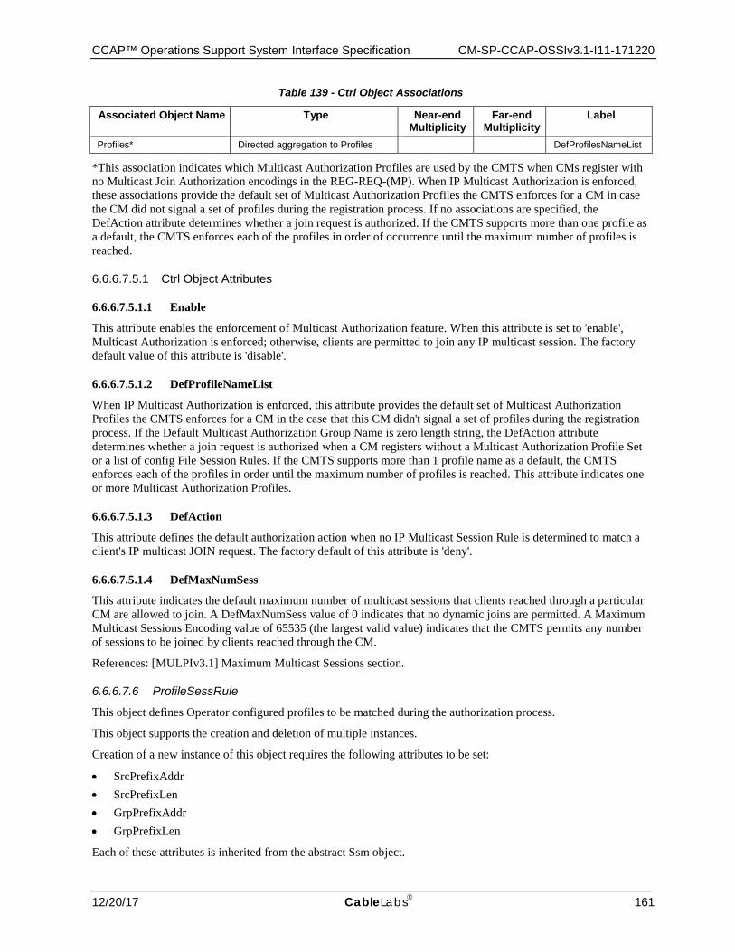
CCAP™ Operations Support System Interface Specification CM-SP-CCAP-OSSIv3.1-I11-171220
12/20/17 CableLabs 161
Table 139 - Ctrl Object Associations
Associated Object Name Type Near-end Multiplicity
Far-end Multiplicity
Label
Profiles* Directed aggregation to Profiles DefProfilesNameList
*This association indicates which Multicast Authorization Profiles are used by the CMTS when CMs register with no Multicast Join Authorization encodings in the REG-REQ-(MP). When IP Multicast Authorization is enforced, these associations provide the default set of Multicast Authorization Profiles the CMTS enforces for a CM in case the CM did not signal a set of profiles during the registration process. If no associations are specified, the DefAction attribute determines whether a join request is authorized. If the CMTS supports more than one profile as a default, the CMTS enforces each of the profiles in order of occurrence until the maximum number of profiles is reached.
6.6.6.7.5.1 Ctrl Object Attributes
6.6.6.7.5.1.1 Enable
This attribute enables the enforcement of Multicast Authorization feature. When this attribute is set to 'enable', Multicast Authorization is enforced; otherwise, clients are permitted to join any IP multicast session. The factory default value of this attribute is 'disable'.
6.6.6.7.5.1.2 DefProfileNameList
When IP Multicast Authorization is enforced, this attribute provides the default set of Multicast Authorization Profiles the CMTS enforces for a CM in the case that this CM didn't signal a set of profiles during the registration process. If the Default Multicast Authorization Group Name is zero length string, the DefAction attribute determines whether a join request is authorized when a CM registers without a Multicast Authorization Profile Set or a list of config File Session Rules. If the CMTS supports more than 1 profile name as a default, the CMTS enforces each of the profiles in order until the maximum number of profiles is reached. This attribute indicates one or more Multicast Authorization Profiles.
6.6.6.7.5.1.3 DefAction
This attribute defines the default authorization action when no IP Multicast Session Rule is determined to match a client's IP multicast JOIN request. The factory default of this attribute is 'deny'.
6.6.6.7.5.1.4 DefMaxNumSess
This attribute indicates the default maximum number of multicast sessions that clients reached through a particular CM are allowed to join. A DefMaxNumSess value of 0 indicates that no dynamic joins are permitted. A Maximum Multicast Sessions Encoding value of 65535 (the largest valid value) indicates that the CMTS permits any number of sessions to be joined by clients reached through the CM.
References: [MULPIv3.1] Maximum Multicast Sessions section.
6.6.6.7.6 ProfileSessRule
This object defines Operator configured profiles to be matched during the authorization process.
This object supports the creation and deletion of multiple instances.
Creation of a new instance of this object requires the following attributes to be set:
• SrcPrefixAddr • SrcPrefixLen • GrpPrefixAddr • GrpPrefixLen
Each of these attributes is inherited from the abstract Ssm object.
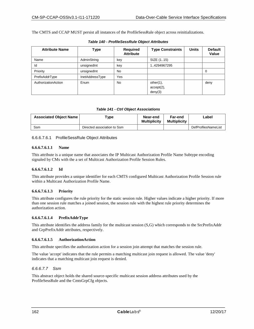
CM-SP-CCAP-OSSIv3.1-I11-171220 Data-Over-Cable Service Interface Specifications
162 CableLabs® 12/20/17
The CMTS and CCAP MUST persist all instances of the ProfileSessRule object across reinitializations.
Table 140 - ProfileSessRule Object Attributes
Attribute Name Type Required Attribute
Type Constraints Units Default Value
Name AdminString key SIZE (1..15)
Id unsignedInt key 1..4294967295
Priority unsignedInt No 0
PrefixAddrType InetAddressType Yes
AuthorizationAction Enum No other(1), accept(2), deny(3)
deny
Table 141 - Ctrl Object Associations
Associated Object Name Type Near-end Multiplicity
Far-end Multiplicity
Label
Ssm Directed association to Ssm DefProfilesNameList
6.6.6.7.6.1 ProfileSessRule Object Attributes
6.6.6.7.6.1.1 Name
This attribute is a unique name that associates the IP Multicast Authorization Profile Name Subtype encoding signaled by CMs with the a set of Multicast Authorization Profile Session Rules.
6.6.6.7.6.1.2 Id
This attribute provides a unique identifier for each CMTS configured Multicast Authorization Profile Session rule within a Multicast Authorization Profile Name.
6.6.6.7.6.1.3 Priority
This attribute configures the rule priority for the static session rule. Higher values indicate a higher priority. If more than one session rule matches a joined session, the session rule with the highest rule priority determines the authorization action.
6.6.6.7.6.1.4 PrefixAddrType
This attribute identifies the address family for the multicast session (S,G) which corresponds to the SrcPrefixAddr and GrpPrefixAddr attributes, respectively.
6.6.6.7.6.1.5 AuthorizationAction
This attribute specifies the authorization action for a session join attempt that matches the session rule.
The value 'accept' indicates that the rule permits a matching multicast join request is allowed. The value 'deny' indicates that a matching multicast join request is denied.
6.6.6.7.7 Ssm
This abstract object holds the shared source-specific multicast session address attributes used by the ProfileSessRule and the CmtsGrpCfg objects.
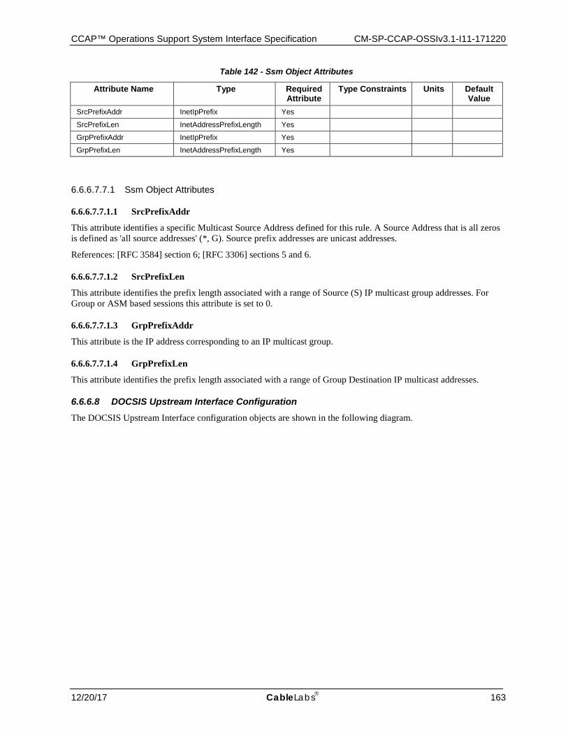
CCAP™ Operations Support System Interface Specification CM-SP-CCAP-OSSIv3.1-I11-171220
12/20/17 CableLabs 163
Table 142 - Ssm Object Attributes
Attribute Name Type Required Attribute
Type Constraints Units Default Value
SrcPrefixAddr InetIpPrefix Yes
SrcPrefixLen InetAddressPrefixLength Yes
GrpPrefixAddr InetIpPrefix Yes
GrpPrefixLen InetAddressPrefixLength Yes
6.6.6.7.7.1 Ssm Object Attributes
6.6.6.7.7.1.1 SrcPrefixAddr
This attribute identifies a specific Multicast Source Address defined for this rule. A Source Address that is all zeros is defined as 'all source addresses' (*, G). Source prefix addresses are unicast addresses.
References: [RFC 3584] section 6; [RFC 3306] sections 5 and 6.
6.6.6.7.7.1.2 SrcPrefixLen
This attribute identifies the prefix length associated with a range of Source (S) IP multicast group addresses. For Group or ASM based sessions this attribute is set to 0.
6.6.6.7.7.1.3 GrpPrefixAddr
This attribute is the IP address corresponding to an IP multicast group.
6.6.6.7.7.1.4 GrpPrefixLen
This attribute identifies the prefix length associated with a range of Group Destination IP multicast addresses.
6.6.6.8 DOCSIS Upstream Interface Configuration The DOCSIS Upstream Interface configuration objects are shown in the following diagram.

CM-SP-CCAP-OSSIv3.1-I11-171220 Data-Over-Cable Service Interface Specifications
164 CableLabs® 12/20/17
Figure 20 - DOCSIS Upstream Interface Configuration Objects
6.6.6.8.1 DocsCfg
This configuration object is included in Figure 20 for reference. It is defined in Section 6.6.6.1.2, DocsCfg.
6.6.6.8.2 DocsIfCfg
The DocsIfCfg object is the container for the DOCSIS 3.0 upstream interface configuration objects. It has the following associations:
Table 143 - DocsIfCfg Object Associations
Associated Object Name Type Near-end Multiplicity
Far-end Multiplicity
Label
ModulationProfile Directed composition to ModulationProfile 1..*
6.6.6.8.3 ModulationProfile
This object allows a modulation profile to be associated to a DOCSIS 3.0 upstream logical channel. It has a single attribute, ModulationIndex, which is based on the Index attribute defined in docsIfCmtsModulationTable defined in [RFC 4546].
Reference: [RFC 4546], docsIfCmtsModulationTable
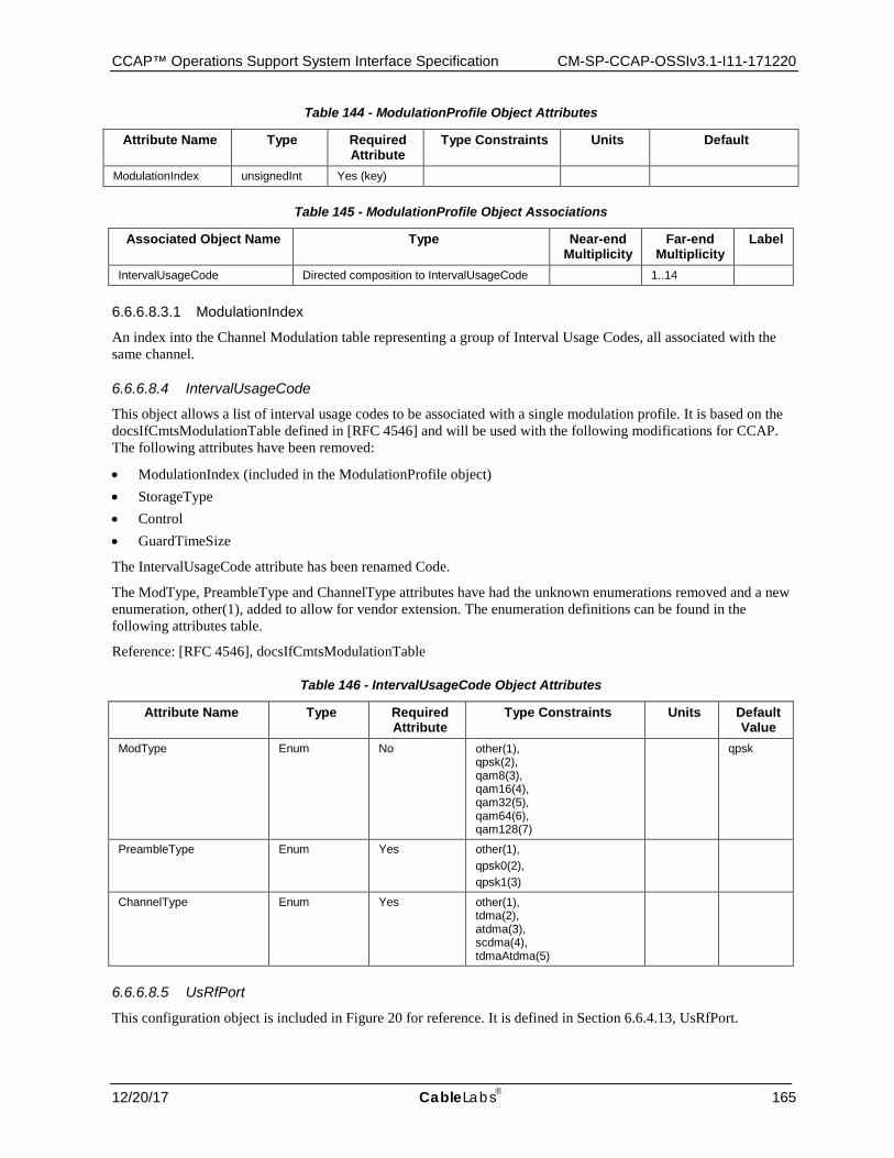
CCAP™ Operations Support System Interface Specification CM-SP-CCAP-OSSIv3.1-I11-171220
12/20/17 CableLabs 165
Table 144 - ModulationProfile Object Attributes
Attribute Name Type Required Attribute
Type Constraints Units Default
ModulationIndex unsignedInt Yes (key)
Table 145 - ModulationProfile Object Associations
Associated Object Name Type Near-end Multiplicity
Far-end Multiplicity
Label
IntervalUsageCode Directed composition to IntervalUsageCode 1..14
6.6.6.8.3.1 ModulationIndex
An index into the Channel Modulation table representing a group of Interval Usage Codes, all associated with the same channel.
6.6.6.8.4 IntervalUsageCode
This object allows a list of interval usage codes to be associated with a single modulation profile. It is based on the docsIfCmtsModulationTable defined in [RFC 4546] and will be used with the following modifications for CCAP. The following attributes have been removed:
• ModulationIndex (included in the ModulationProfile object) • StorageType • Control • GuardTimeSize
The IntervalUsageCode attribute has been renamed Code.
The ModType, PreambleType and ChannelType attributes have had the unknown enumerations removed and a new enumeration, other(1), added to allow for vendor extension. The enumeration definitions can be found in the following attributes table.
Reference: [RFC 4546], docsIfCmtsModulationTable
Table 146 - IntervalUsageCode Object Attributes
Attribute Name Type Required Attribute
Type Constraints Units Default Value
ModType Enum No other(1), qpsk(2), qam8(3), qam16(4), qam32(5), qam64(6), qam128(7)
qpsk
PreambleType Enum Yes other(1), qpsk0(2), qpsk1(3)
ChannelType Enum Yes other(1), tdma(2), atdma(3), scdma(4), tdmaAtdma(5)
6.6.6.8.5 UsRfPort
This configuration object is included in Figure 20 for reference. It is defined in Section 6.6.4.13, UsRfPort.
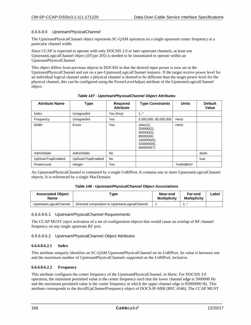
CM-SP-CCAP-OSSIv3.1-I11-171220 Data-Over-Cable Service Interface Specifications
166 CableLabs® 12/20/17
6.6.6.8.6 UpstreamPhysicalChannel
The UpstreamPhysicalChannel object represents SC-QAM operation on a single upstream center frequency at a particular channel width.
Since CCAP is expected to operate with only DOCSIS 2.0 or later upstream channels, at least one UpstreamLogicalChannel object (ifType 205) is needed to be instantiated to operate within an UpstreamPhysicalChannel.
This object differs from previous objects in DOCSIS in that the desired input power is now set at the UpstreamPhysicalChannel and not on a per-UpstreamLogicalChannel instance. If the target receive power level for an individual logical channel under a physical channel is desired to be different than the target power level for the physical channel, this can be configured using the PowerLevelAdjust attribute of the UpstreamLogicalChannel object.
Table 147 - UpstreamPhysicalChannel Object Attributes
Attribute Name Type Required Attribute
Type Constraints Units Default Value
Index UnsignedInt Yes (Key) 1..*
Frequency UnsignedInt Yes 5,000,000..85,000,000 Hertz
Width Enum Yes other(1), 200000(2), 400000(3), 800000(4) 1600000(5), 3200000(6), 6400000(7)
Hertz
AdminState AdminState No down
UpDownTrapEnabled UpDownTrapEnabled No true
PowerLevel Integer Yes TenthdBmV
An UpstreamPhysicalChannel is contained by a single UsRfPort. It contains one or more UpstreamLogicalChannel objects. It is referenced by a single MacDomain.
Table 148 - UpstreamPhysicalChannel Object Associations
Associated Object Name
Type Near-end Multiplicity
Far-end Multiplicity
Label
UpstreamLogicalChannel Directed composition to UpstreamLogicalChannel 1 1..*
6.6.6.8.6.1 UpstreamPhysicalChannel Requirements
The CCAP MUST reject activation of a set of configuration objects that would cause an overlap of RF channel frequency on any single upstream RF port.
6.6.6.8.6.2 UpstreamPhysicalChannel Object Attributes
6.6.6.8.6.2.1 Index
This attribute uniquely identifies an SC-QAM UpstreamPhysicalChannel on its UsRfPort. Its value is between one and the maximum number of UpstreamPhysicalChannels supported on the UsRfPort, inclusive.
6.6.6.8.6.2.2 Frequency
This attribute configures the center frequency of the UpstreamPhysicalChannel, in Hertz. For DOCSIS 3.0 operation, the minimum permitted value is the center frequency such that the lower channel edge is 5000000 Hz and the maximum permitted value is the center frequency at which the upper channel edge is 85000000 Hz. This attribute corresponds to the docsIfUpChannelFrequency object of DOCS-IF-MIB [RFC 4546]. The CCAP MUST

CCAP™ Operations Support System Interface Specification CM-SP-CCAP-OSSIv3.1-I11-171220
12/20/17 CableLabs 167
reject the configuration of an UpstreamPhysicalChannel instance that overlaps in frequency with another UpstreamPhysicalChannel instance on the same upstream RF port.
6.6.6.8.6.2.3 Width
This attribute configures the width of the UpstreamPhysicalChannel, in Hertz. While the only permitted values for DOCSIS 3.0 are 1,600,000, 3,200,000, and 6,400,000, this specification also includes widths of 200,000, 400,000, and 800,000 for backward compatibility. This attribute corresponds to the docsIfUpChannelFrequency object of DOCS-IF-MIB [RFC 4546].
The value of other(1) is used when a vendor-extension has been implemented for this attribute.
6.6.6.8.6.2.4 AdminState
This attribute configures the administrative state of this instance.
6.6.6.8.6.2.5 UpDownTrapEnabled
This attribute configures whether linkUp/linkDown traps are enabled for this channel.
6.6.6.8.6.2.6 PowerLevel
This attribute configures the desired input power level, in TenthdBmV, common to all upstream logical channels associated with this physical channel instance. This attribute represents the desired total average receive power for the channel regardless of whether there are 3.1 CMs operational on the channel. The power level for an individual logical channel can deviate from the common power level through the configuration of the PowerLevelAdjust attribute of the UpstreamLogicalChannel object.
6.6.6.8.7 UpstreamLogicalChannel
The UpstreamLogicalChannel object represents scheduled intervals of time on a single UpstreamPhysicalChannel. An SC-QAM UpstreamLogicalChannel is either SCDMA, TDMA, ATDMA, or both TDMA and ATDMA. Each UpstreamLogicalChannel is identified with a DOCSIS upstream channel ID. The MAP management messages transmitted downstream by the CCAP schedule intervals of time for each DOCSIS upstream channel ID. In the SNMP MIB, an UpstreamLogicalChannel is an interface with ifType UpstreamLogicalChannel (205).
Table 149 - UpstreamLogicalChannel Object Attributes
Attribute Name Type Required Attribute
Type Constraints
Units Default Value
Index UnsignedInt Yes (Key)
AdminState AdminState No down
UpDownTrapEnabled UpDownTrapEnabled No false
ChannelId ChId No 0
SlotSize UnsignedInt Yes ticks
RangingBackoffStart UnsignedByte Yes 0..16 power of 2
RangingBackoffEnd UnsignedByte Yes 0..16 power of 2
TxBackoffStart UnsignedByte Yes 0..16
TxBackoffEnd UnsignedByte Yes 0..16
PreEqEnable Boolean Yes
ProvAttrMask AttributeMask Yes
PowerLevelAdjust Short No TenthdB 0
This object differs from the same object in previous versions of DOCSIS in that the desired common input power is now set at the Upstream Physical Channel and power level adjustments can only be configured on a per UpstreamLogicalChannel basis.
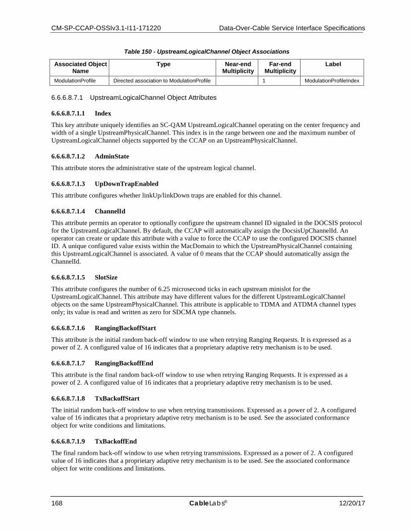
CM-SP-CCAP-OSSIv3.1-I11-171220 Data-Over-Cable Service Interface Specifications
168 CableLabs® 12/20/17
Table 150 - UpstreamLogicalChannel Object Associations
Associated Object Name
Type Near-end Multiplicity
Far-end Multiplicity
Label
ModulationProfile Directed association to ModulationProfile 1 ModulationProfileIndex
6.6.6.8.7.1 UpstreamLogicalChannel Object Attributes
6.6.6.8.7.1.1 Index
This key attribute uniquely identifies an SC-QAM UpstreamLogicalChannel operating on the center frequency and width of a single UpstreamPhysicalChannel. This index is in the range between one and the maximum number of UpstreamLogicalChannel objects supported by the CCAP on an UpstreamPhysicalChannel.
6.6.6.8.7.1.2 AdminState
This attribute stores the administrative state of the upstream logical channel.
6.6.6.8.7.1.3 UpDownTrapEnabled
This attribute configures whether linkUp/linkDown traps are enabled for this channel.
6.6.6.8.7.1.4 ChannelId
This attribute permits an operator to optionally configure the upstream channel ID signaled in the DOCSIS protocol for the UpstreamLogicalChannel. By default, the CCAP will automatically assign the DocsisUpChannelId. An operator can create or update this attribute with a value to force the CCAP to use the configured DOCSIS channel ID. A unique configured value exists within the MacDomain to which the UpstreamPhysicalChannel containing this UpstreamLogicalChannel is associated. A value of 0 means that the CCAP should automatically assign the ChannelId.
6.6.6.8.7.1.5 SlotSize
This attribute configures the number of 6.25 microsecond ticks in each upstream minislot for the UpstreamLogicalChannel. This attribute may have different values for the different UpstreamLogicalChannel objects on the same UpstreamPhysicalChannel. This attribute is applicable to TDMA and ATDMA channel types only; its value is read and written as zero for SDCMA type channels.
6.6.6.8.7.1.6 RangingBackoffStart
This attribute is the initial random back-off window to use when retrying Ranging Requests. It is expressed as a power of 2. A configured value of 16 indicates that a proprietary adaptive retry mechanism is to be used.
6.6.6.8.7.1.7 RangingBackoffEnd
This attribute is the final random back-off window to use when retrying Ranging Requests. It is expressed as a power of 2. A configured value of 16 indicates that a proprietary adaptive retry mechanism is to be used.
6.6.6.8.7.1.8 TxBackoffStart
The initial random back-off window to use when retrying transmissions. Expressed as a power of 2. A configured value of 16 indicates that a proprietary adaptive retry mechanism is to be used. See the associated conformance object for write conditions and limitations.
6.6.6.8.7.1.9 TxBackoffEnd
The final random back-off window to use when retrying transmissions. Expressed as a power of 2. A configured value of 16 indicates that a proprietary adaptive retry mechanism is to be used. See the associated conformance object for write conditions and limitations.
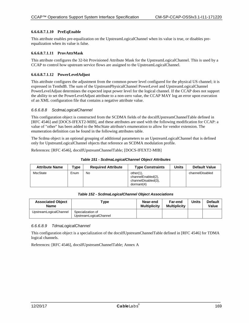
CCAP™ Operations Support System Interface Specification CM-SP-CCAP-OSSIv3.1-I11-171220
12/20/17 CableLabs 169
6.6.6.8.7.1.10 PreEqEnable
This attribute enables pre-equalization on the UpstreamLogicalChannel when its value is true, or disables pre-equalization when its value is false.
6.6.6.8.7.1.11 ProvAttrMask
This attribute configures the 32-bit Provisioned Attribute Mask for the UpstreamLogicalChannel. This is used by a CCAP to control how upstream service flows are assigned to the UpstreamLogicalChannel.
6.6.6.8.7.1.12 PowerLevelAdjust
This attribute configures the adjustment from the common power level configured for the physical US channel; it is expressed in TenthdB. The sum of the UpstreamPhysicalChannel PowerLevel and UpstreamLogicalChannel PowerLevelAdjust determines the expected input power level for the logical channel. If the CCAP does not support the ability to set the PowerLevelAdjust attribute to a non-zero value, the CCAP MAY log an error upon execution of an XML configuration file that contains a negative attribute value.
6.6.6.8.8 ScdmaLogicalChannel
This configuration object is constructed from the SCDMA fields of the docsIfUpstreamChannelTable defined in [RFC 4546] and [DOCS-IFEXT2-MIB], and these attributes are used with the following modification for CCAP: a value of "other" has been added to the MscState attribute's enumeration to allow for vendor extension. The enumeration definition can be found in the following attributes table.
The Scdma object is an optional grouping of additional parameters to an UpstreamLogicalChannel that is defined only for UpstreamLogicalChannel objects that reference an SCDMA modulation profile.
References: [RFC 4546], docsIfUpstreamChannelTable; [DOCS-IFEXT2-MIB]
Table 151 - ScdmaLogicalChannel Object Attributes
Attribute Name Type Required Attribute Type Constraints Units Default Value MscState Enum No other(1),
channelEnabled(2), channelDisabled(3), dormant(4)
channelDisabled
Table 152 - ScdmaLogicalChannel Object Associations
Associated Object Name
Type Near-end Multiplicity
Far-end Multiplicity
Units Default Value
UpstreamLogicalChannel Specialization of UpstreamLogicalChannel
6.6.6.8.9 TdmaLogicalChannel
This configuration object is a specialization of the docsIfUpstreamChannelTable defined in [RFC 4546] for TDMA logical channels.
References: [RFC 4546], docsIfUpstreamChannelTable; Annex A
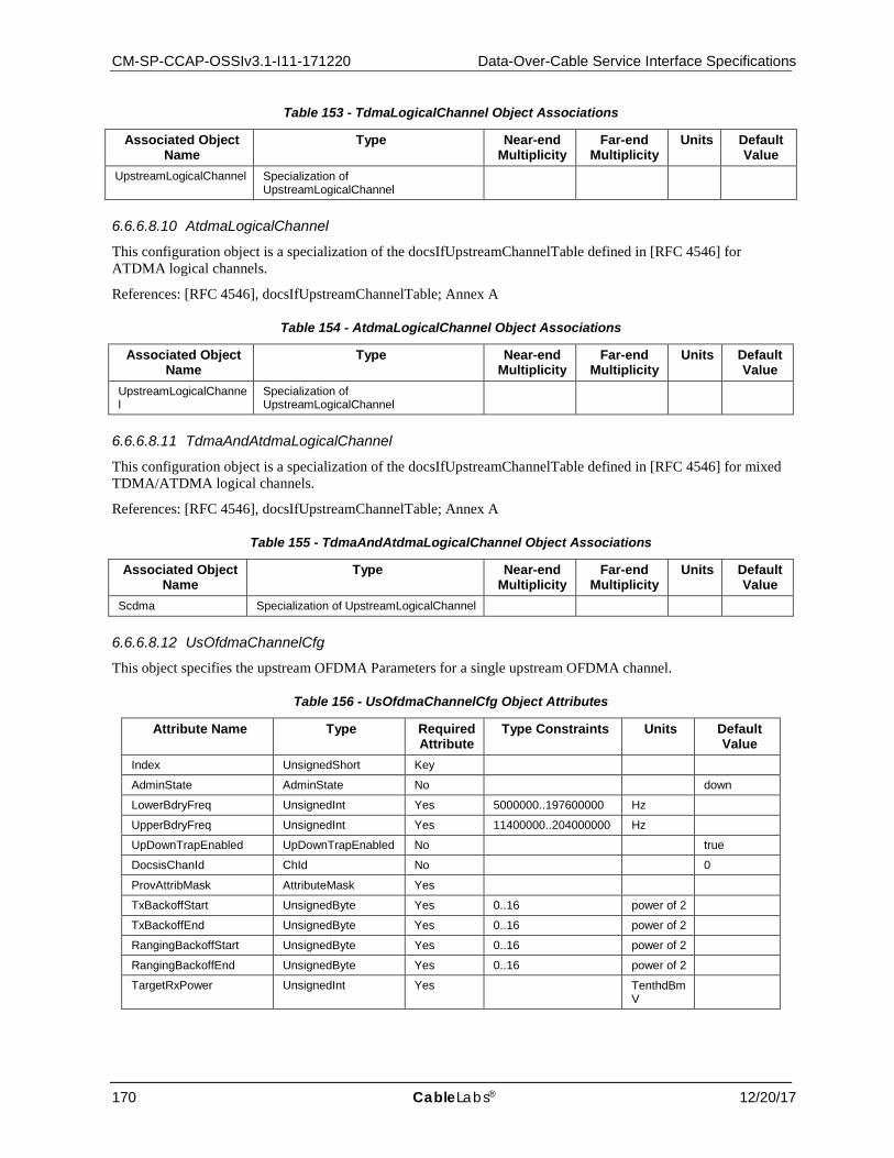
CM-SP-CCAP-OSSIv3.1-I11-171220 Data-Over-Cable Service Interface Specifications
170 CableLabs® 12/20/17
Table 153 - TdmaLogicalChannel Object Associations
Associated Object Name
Type Near-end Multiplicity
Far-end Multiplicity
Units Default Value
UpstreamLogicalChannel Specialization of UpstreamLogicalChannel
6.6.6.8.10 AtdmaLogicalChannel
This configuration object is a specialization of the docsIfUpstreamChannelTable defined in [RFC 4546] for ATDMA logical channels.
References: [RFC 4546], docsIfUpstreamChannelTable; Annex A
Table 154 - AtdmaLogicalChannel Object Associations
Associated Object Name
Type Near-end Multiplicity
Far-end Multiplicity
Units Default Value
UpstreamLogicalChannel
Specialization of UpstreamLogicalChannel
6.6.6.8.11 TdmaAndAtdmaLogicalChannel
This configuration object is a specialization of the docsIfUpstreamChannelTable defined in [RFC 4546] for mixed TDMA/ATDMA logical channels.
References: [RFC 4546], docsIfUpstreamChannelTable; Annex A
Table 155 - TdmaAndAtdmaLogicalChannel Object Associations
Associated Object Name
Type Near-end Multiplicity
Far-end Multiplicity
Units Default Value
Scdma Specialization of UpstreamLogicalChannel
6.6.6.8.12 UsOfdmaChannelCfg
This object specifies the upstream OFDMA Parameters for a single upstream OFDMA channel.
Table 156 - UsOfdmaChannelCfg Object Attributes
Attribute Name Type Required Attribute
Type Constraints Units Default Value
Index UnsignedShort Key
AdminState AdminState No down
LowerBdryFreq UnsignedInt Yes 5000000..197600000 Hz
UpperBdryFreq UnsignedInt Yes 11400000..204000000 Hz
UpDownTrapEnabled UpDownTrapEnabled No true
DocsisChanId ChId No 0
ProvAttribMask AttributeMask Yes
TxBackoffStart UnsignedByte Yes 0..16 power of 2
TxBackoffEnd UnsignedByte Yes 0..16 power of 2
RangingBackoffStart UnsignedByte Yes 0..16 power of 2
RangingBackoffEnd UnsignedByte Yes 0..16 power of 2
TargetRxPower UnsignedInt Yes TenthdBmV

CCAP™ Operations Support System Interface Specification CM-SP-CCAP-OSSIv3.1-I11-171220
12/20/17 CableLabs 171
Table 157 - UsOfdmaChannelCfg Object Associations
Associated Object Name Type Near-end Multiplicity
Far-end Multiplicity
Label
UsOfdmaModulationTemplate* Directed association to UsOfdmaModulationTemplate
0..* 0..1 UsOfdmaModulationTemplate.Index
UsOfdmaChanDataIuc Directed composition to UsOfdmaChanDataIuc
1 0..7
*A template does not need to be assigned if the vendor supports automatic profile assignment.
6.6.6.8.12.1 UsOfdmaChannelCfg Object Attributes
6.6.6.8.12.1.1 Index
This attribute is a key defined to provide an index into the table.
6.6.6.8.12.1.2 AdminState
This attribute is the admin state for the upstream OFDMA channel.
6.6.6.8.12.1.3 LowerBdryFreq
This attribute defines the lower frequency for the US Channel.
Per the CM Transmitter Output Signal Characteristics table in [PHYv3.1], the minimum occupied bandwidth is 6.4 MHz and 10 MHz for 25 kHz and 50 kHz Subcarrier Spacing, respectively. Thus, for 25kHz Subcarrier Spacing the maximum value for this attribute is 197,600,000 Hz and for 50 kHz Subcarrier Spacing the maximum value for this attribute is 194,000,000 Hz.
The minimum configured bandwidth for an OFDMA channel includes both 500 kHz guard bands along with the minimum bandwidth. This gives the minimum configured OFDMA channel bandwidth as 7.4 MHz and 11 MHz for 25 kHz and 50 kHz Subcarrier Spacing, respectively. When an OFDMA channel is configured with 25 kHz Subcarrier Spacing, the CCAP MUST reject configurations where UpperBdryFreq - LowerBdryFreq < 7.4 MHz.
Similarly, when an OFDMA channel is configured with 50 kHz Subcarrier Spacing, the CCAP MUST reject configurations where UpperBdryFreq - LowerBdryFreq < 11 MHz.
6.6.6.8.12.1.4 UpperBdryFreq
This attribute defines the upper frequency for the US Channel. The CCAP MUST reject configurations where UpperBdryFreq - LowerBdryFreq > 96 MHz.
6.6.6.8.12.1.5 UpDownTrapEnabled
This attribute indicates if a trap should be sent when the Channel transitions from enable to disable and disable to enable.
6.6.6.8.12.1.6 DocsisChanId
This attribute permits an operator to optionally configure the upstream channel ID signaled in the DOCSIS protocol for the OFDMA upstream channel. By default, the CCAP will automatically assign the DOCSIS Channel ID. An operator can create or update this attribute with a value to force the CCAP to use the configured DOCSIS Channel ID. A unique configured value exists within the MacDomain to which the OFDMA Channel is associated for each channel in that MacDomain - SC or OFDMA. A value of 0 means that the CCAP should automatically assign the Channel ID.
6.6.6.8.12.1.7 ProvAttribMask
This attribute configures the 32-bit Provisioned Attribute Mask for the OFDMA upstream channel. This is used by a CCAP to control how upstream service flows are assigned to the OFDMA upstream channel.
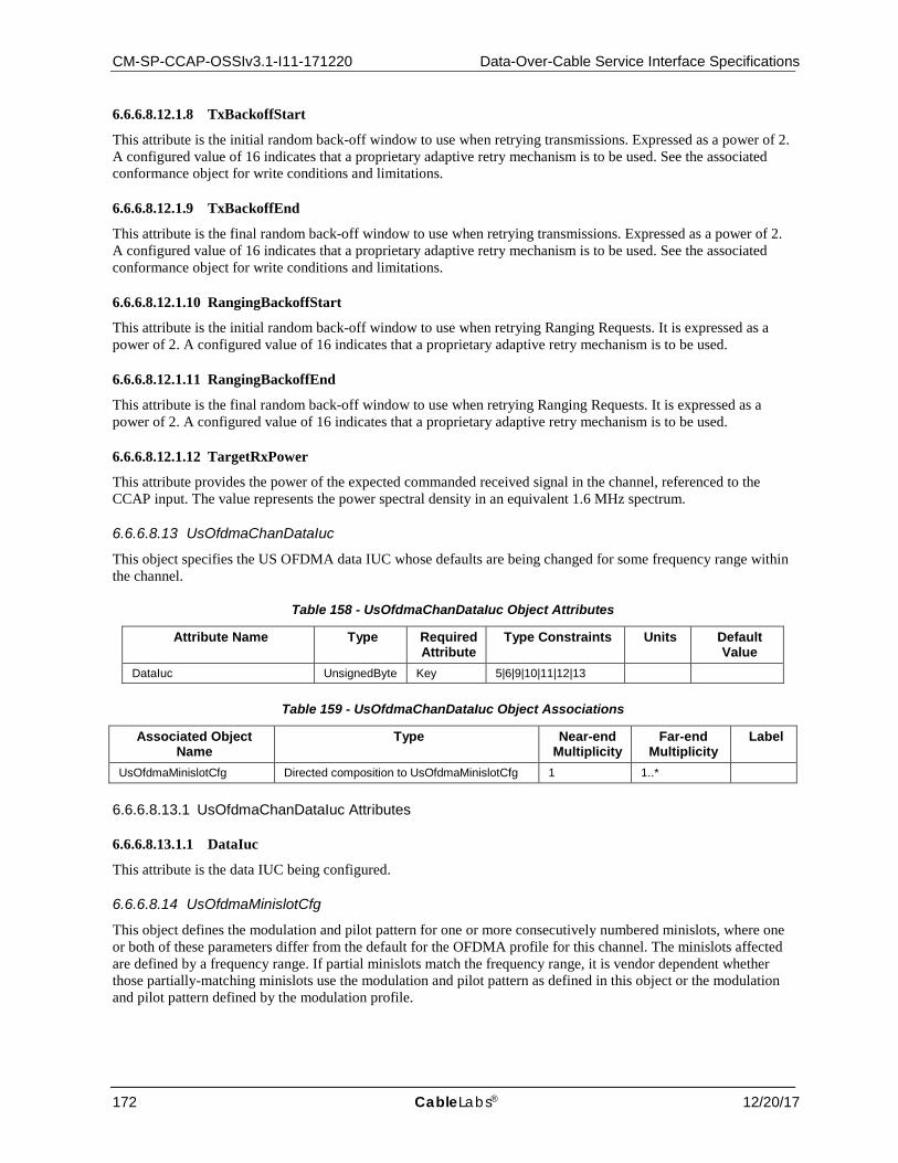
CM-SP-CCAP-OSSIv3.1-I11-171220 Data-Over-Cable Service Interface Specifications
172 CableLabs® 12/20/17
6.6.6.8.12.1.8 TxBackoffStart
This attribute is the initial random back-off window to use when retrying transmissions. Expressed as a power of 2. A configured value of 16 indicates that a proprietary adaptive retry mechanism is to be used. See the associated conformance object for write conditions and limitations.
6.6.6.8.12.1.9 TxBackoffEnd
This attribute is the final random back-off window to use when retrying transmissions. Expressed as a power of 2. A configured value of 16 indicates that a proprietary adaptive retry mechanism is to be used. See the associated conformance object for write conditions and limitations.
6.6.6.8.12.1.10 RangingBackoffStart
This attribute is the initial random back-off window to use when retrying Ranging Requests. It is expressed as a power of 2. A configured value of 16 indicates that a proprietary adaptive retry mechanism is to be used.
6.6.6.8.12.1.11 RangingBackoffEnd
This attribute is the final random back-off window to use when retrying Ranging Requests. It is expressed as a power of 2. A configured value of 16 indicates that a proprietary adaptive retry mechanism is to be used.
6.6.6.8.12.1.12 TargetRxPower
This attribute provides the power of the expected commanded received signal in the channel, referenced to the CCAP input. The value represents the power spectral density in an equivalent 1.6 MHz spectrum.
6.6.6.8.13 UsOfdmaChanDataIuc
This object specifies the US OFDMA data IUC whose defaults are being changed for some frequency range within the channel.
Table 158 - UsOfdmaChanDataIuc Object Attributes
Attribute Name Type Required Attribute
Type Constraints Units Default Value
DataIuc UnsignedByte Key 5|6|9|10|11|12|13
Table 159 - UsOfdmaChanDataIuc Object Associations
Associated Object Name
Type Near-end Multiplicity
Far-end Multiplicity
Label
UsOfdmaMinislotCfg Directed composition to UsOfdmaMinislotCfg 1 1..*
6.6.6.8.13.1 UsOfdmaChanDataIuc Attributes
6.6.6.8.13.1.1 DataIuc
This attribute is the data IUC being configured.
6.6.6.8.14 UsOfdmaMinislotCfg
This object defines the modulation and pilot pattern for one or more consecutively numbered minislots, where one or both of these parameters differ from the default for the OFDMA profile for this channel. The minislots affected are defined by a frequency range. If partial minislots match the frequency range, it is vendor dependent whether those partially-matching minislots use the modulation and pilot pattern as defined in this object or the modulation and pilot pattern defined by the modulation profile.
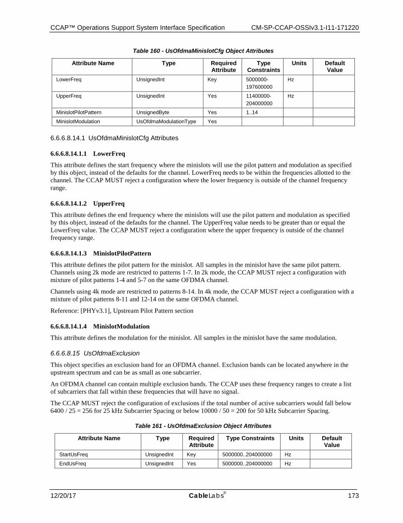
CCAP™ Operations Support System Interface Specification CM-SP-CCAP-OSSIv3.1-I11-171220
12/20/17 CableLabs 173
Table 160 - UsOfdmaMinislotCfg Object Attributes
Attribute Name Type Required Attribute
Type Constraints
Units Default Value
LowerFreq UnsignedInt Key 5000000- 197600000
Hz
UpperFreq UnsignedInt Yes 11400000- 204000000
Hz
MinislotPilotPattern UnsignedByte Yes 1..14
MinislotModulation UsOfdmaModulationType Yes
6.6.6.8.14.1 UsOfdmaMinislotCfg Attributes
6.6.6.8.14.1.1 LowerFreq
This attribute defines the start frequency where the minislots will use the pilot pattern and modulation as specified by this object, instead of the defaults for the channel. LowerFreq needs to be within the frequencies allotted to the channel. The CCAP MUST reject a configuration where the lower frequency is outside of the channel frequency range.
6.6.6.8.14.1.2 UpperFreq
This attribute defines the end frequency where the minislots will use the pilot pattern and modulation as specified by this object, instead of the defaults for the channel. The UpperFreq value needs to be greater than or equal the LowerFreq value. The CCAP MUST reject a configuration where the upper frequency is outside of the channel frequency range.
6.6.6.8.14.1.3 MinislotPilotPattern
This attribute defines the pilot pattern for the minislot. All samples in the minislot have the same pilot pattern. Channels using 2k mode are restricted to patterns 1-7. In 2k mode, the CCAP MUST reject a configuration with mixture of pilot patterns 1-4 and 5-7 on the same OFDMA channel.
Channels using 4k mode are restricted to patterns 8-14. In 4k mode, the CCAP MUST reject a configuration with a mixture of pilot patterns 8-11 and 12-14 on the same OFDMA channel.
Reference: [PHYv3.1], Upstream Pilot Pattern section
6.6.6.8.14.1.4 MinislotModulation
This attribute defines the modulation for the minislot. All samples in the minislot have the same modulation.
6.6.6.8.15 UsOfdmaExclusion
This object specifies an exclusion band for an OFDMA channel. Exclusion bands can be located anywhere in the upstream spectrum and can be as small as one subcarrier.
An OFDMA channel can contain multiple exclusion bands. The CCAP uses these frequency ranges to create a list of subcarriers that fall within these frequencies that will have no signal.
The CCAP MUST reject the configuration of exclusions if the total number of active subcarriers would fall below 6400 / 25 = 256 for 25 kHz Subcarrier Spacing or below 10000 / 50 = 200 for 50 kHz Subcarrier Spacing.
Table 161 - UsOfdmaExclusion Object Attributes
Attribute Name Type Required Attribute
Type Constraints Units Default Value
StartUsFreq UnsignedInt Key 5000000..204000000 Hz
EndUsFreq UnsignedInt Yes 5000000..204000000 Hz
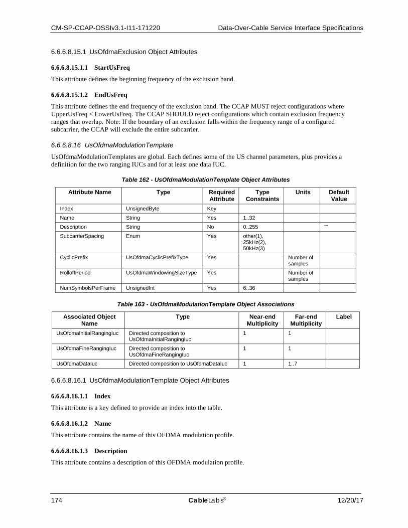
CM-SP-CCAP-OSSIv3.1-I11-171220 Data-Over-Cable Service Interface Specifications
174 CableLabs® 12/20/17
6.6.6.8.15.1 UsOfdmaExclusion Object Attributes
6.6.6.8.15.1.1 StartUsFreq
This attribute defines the beginning frequency of the exclusion band.
6.6.6.8.15.1.2 EndUsFreq
This attribute defines the end frequency of the exclusion band. The CCAP MUST reject configurations where UpperUsFreq < LowerUsFreq. The CCAP SHOULD reject configurations which contain exclusion frequency ranges that overlap. Note: If the boundary of an exclusion falls within the frequency range of a configured subcarrier, the CCAP will exclude the entire subcarrier.
6.6.6.8.16 UsOfdmaModulationTemplate
UsOfdmaModulationTemplates are global. Each defines some of the US channel parameters, plus provides a definition for the two ranging IUCs and for at least one data IUC.
Table 162 - UsOfdmaModulationTemplate Object Attributes
Attribute Name Type Required Attribute
Type Constraints
Units Default Value
Index UnsignedByte Key
Name String Yes 1..32
Description String No 0..255 ""
SubcarrierSpacing Enum Yes other(1), 25kHz(2), 50kHz(3)
CyclicPrefix UsOfdmaCyclicPrefixType Yes Number of samples
RolloffPeriod UsOfdmaWindowingSizeType Yes Number of samples
NumSymbolsPerFrame UnsignedInt Yes 6..36
Table 163 - UsOfdmaModulationTemplate Object Associations
Associated Object Name
Type Near-end Multiplicity
Far-end Multiplicity
Label
UsOfdmaInitialRangingIuc Directed composition to UsOfdmaInitialRangingIuc
1 1
UsOfdmaFineRangingIuc Directed composition to UsOfdmaFineRangingIuc
1 1
UsOfdmaDataIuc Directed composition to UsOfdmaDataIuc 1 1..7
6.6.6.8.16.1 UsOfdmaModulationTemplate Object Attributes
6.6.6.8.16.1.1 Index
This attribute is a key defined to provide an index into the table.
6.6.6.8.16.1.2 Name
This attribute contains the name of this OFDMA modulation profile.
6.6.6.8.16.1.3 Description
This attribute contains a description of this OFDMA modulation profile.
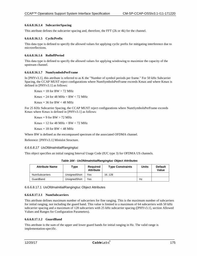
CCAP™ Operations Support System Interface Specification CM-SP-CCAP-OSSIv3.1-I11-171220
12/20/17 CableLabs 175
6.6.6.8.16.1.4 SubcarrierSpacing
This attribute defines the subcarrier spacing and, therefore, the FFT (2k or 4k) for the channel.
6.6.6.8.16.1.5 CyclicPrefix
This data type is defined to specify the allowed values for applying cyclic prefix for mitigating interference due to microreflections.
6.6.6.8.16.1.6 RolloffPeriod
This data type is defined to specify the allowed values for applying windowing to maximize the capacity of the upstream channel.
6.6.6.8.16.1.7 NumSymbolsPerFrame
In [PHYv3.1], this attribute is referred to as K the "Number of symbol periods per frame." For 50 kHz Subcarrier Spacing, the CCAP MUST reject configurations where NumSymbolsPerFrame exceeds Kmax and where Kmax is defined in [PHYv3.1] as follows:
Kmax = 18 for BW > 72 MHz
Kmax = 24 for 48 MHz < BW < 72 MHz
Kmax = 36 for BW < 48 MHz
For 25 KHz Subcarrier Spacing, the CCAP MUST reject configurations where NumSymbolsPerFrame exceeds Kmax where Kmax is defined in [PHYv3.1] as follows:
Kmax = 9 for BW > 72 MHz
Kmax = 12 for 48 MHz < BW < 72 MHz
Kmax = 18 for BW < 48 MHz
Where BW is defined as the encompassed spectrum of the associated OFDMA channel.
Reference: [PHYv3.1] Minislot Structure.
6.6.6.8.17 UsOfdmaInitialRangingIuc
This object specifies an initial ranging Interval Usage Code (IUC type 3) for OFDMA US channels.
Table 164 - UsOfdmaInitialRangingIuc Object Attributes
Attribute Name Type Required Attribute
Type Constraints Units Default Value
NumSubcarriers UnsignedShort Yes 16..128
GuardBand UnsignedShort Yes Hz
6.6.6.8.17.1 UsOfdmaInitialRangingIuc Object Attributes
6.6.6.8.17.1.1 NumSubcarriers
This attribute defines maximum number of subcarriers for fine ranging. This is the maximum number of subcarriers for initial ranging, not including the guard band. This value is limited to a maximum of 64 subcarriers with 50 kHz subcarrier spacing and a maximum of 128 subcarriers with 25 kHz subcarrier spacing ([PHYv3.1], section Allowed Values and Ranges for Configuration Parameters).
6.6.6.8.17.1.2 GuardBand
This attribute is the sum of the upper and lower guard bands for initial ranging in Hz. The valid range is implementation-specific.
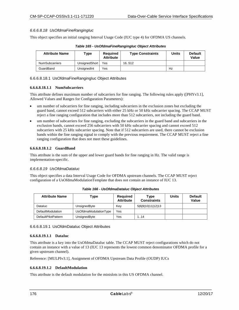
CM-SP-CCAP-OSSIv3.1-I11-171220 Data-Over-Cable Service Interface Specifications
176 CableLabs® 12/20/17
6.6.6.8.18 UsOfdmaFineRangingIuc
This object specifies an initial ranging Interval Usage Code (IUC type 4) for OFDMA US channels.
Table 165 - UsOfdmaFineRangingIuc Object Attributes
Attribute Name Type Required Attribute
Type Constraints Units Default Value
NumSubcarriers UnsignedShort Yes 16..512
GuardBand UnsignedInt Yes Hz
6.6.6.8.18.1 UsOfdmaFineRangingIuc Object Attributes
6.6.6.8.18.1.1 NumSubcarriers
This attribute defines maximum number of subcarriers for fine ranging. The following rules apply ([PHYv3.1], Allowed Values and Ranges for Configuration Parameters):
• um number of subcarriers for fine ranging, including subcarriers in the exclusion zones but excluding the guard band, cannot exceed 512 subcarriers with either 25 kHz or 50 kHz subcarrier spacing. The CCAP MUST reject a fine ranging configuration that includes more than 512 subcarriers, not including the guard band.
• um number of subcarriers for fine ranging, excluding the subcarriers in the guard band and subcarriers in the exclusion bands, cannot exceed 256 subcarriers with 50 kHz subcarrier spacing and cannot exceed 512 subcarriers with 25 kHz subcarrier spacing. Note that if 512 subcarriers are used, there cannot be exclusion bands within the fine ranging signal to comply with the previous requirement. The CCAP MUST reject a fine ranging configuration that does not meet these guidelines.
6.6.6.8.18.1.2 GuardBand
This attribute is the sum of the upper and lower guard bands for fine ranging in Hz. The valid range is implementation-specific.
6.6.6.8.19 UsOfdmaDataIuc
This object specifies a data Interval Usage Code for OFDMA upstream channels. The CCAP MUST reject configuration of a UsOfdmaModulationTemplate that does not contain an instance of IUC 13.
Table 166 - UsOfdmaDataIuc Object Attributes
Attribute Name Type Required Attribute
Type Constraints
Units Default Value
DataIuc UnsignedByte Key 5|6|9|10|11|12|13
DefaultModulation UsOfdmaModulationType Yes
DefaultPilotPattern UnsignedByte Yes 1..14
6.6.6.8.19.1 UsOfdmDataIuc Object Attributes
6.6.6.8.19.1.1 DataIuc
This attribute is a key into the UsOfdmaDataIuc table. The CCAP MUST reject configurations which do not contain an instance with a value of 13 (IUC 13 represents the lowest common denominator OFDMA profile for a given upstream channel).
Reference: [MULPIv3.1], Assignment of OFDMA Upstream Data Profile (OUDP) IUCs
6.6.6.8.19.1.2 DefaultModulation
This attribute is the default modulation for the minislots in this US OFDMA channel.
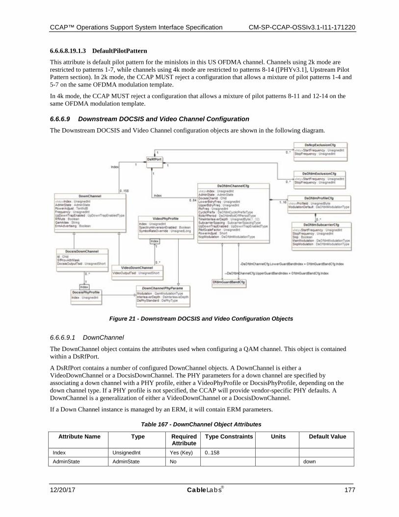
CCAP™ Operations Support System Interface Specification CM-SP-CCAP-OSSIv3.1-I11-171220
12/20/17 CableLabs 177
6.6.6.8.19.1.3 DefaultPilotPattern
This attribute is default pilot pattern for the minislots in this US OFDMA channel. Channels using 2k mode are restricted to patterns 1-7, while channels using 4k mode are restricted to patterns 8-14 ([PHYv3.1], Upstream Pilot Pattern section). In 2k mode, the CCAP MUST reject a configuration that allows a mixture of pilot patterns 1-4 and 5-7 on the same OFDMA modulation template.
In 4k mode, the CCAP MUST reject a configuration that allows a mixture of pilot patterns 8-11 and 12-14 on the same OFDMA modulation template.
6.6.6.9 Downstream DOCSIS and Video Channel Configuration The Downstream DOCSIS and Video Channel configuration objects are shown in the following diagram.
Figure 21 - Downstream DOCSIS and Video Configuration Objects
6.6.6.9.1 DownChannel
The DownChannel object contains the attributes used when configuring a QAM channel. This object is contained within a DsRfPort.
A DsRfPort contains a number of configured DownChannel objects. A DownChannel is either a VideoDownChannel or a DocsisDownChannel. The PHY parameters for a down channel are specified by associating a down channel with a PHY profile, either a VideoPhyProfile or DocsisPhyProfile, depending on the down channel type. If a PHY profile is not specified, the CCAP will provide vendor-specific PHY defaults. A DownChannel is a generalization of either a VideoDownChannel or a DocsisDownChannel.
If a Down Channel instance is managed by an ERM, it will contain ERM parameters.
Table 167 - DownChannel Object Attributes
Attribute Name Type Required Attribute
Type Constraints Units Default Value
Index UnsignedInt Yes (Key) 0..158
AdminState AdminState No down
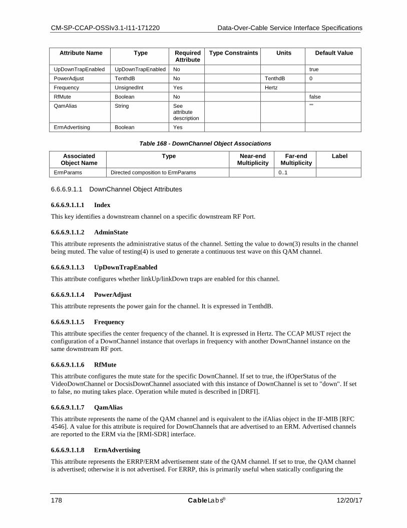
CM-SP-CCAP-OSSIv3.1-I11-171220 Data-Over-Cable Service Interface Specifications
178 CableLabs® 12/20/17
Attribute Name Type Required Attribute
Type Constraints Units Default Value
UpDownTrapEnabled UpDownTrapEnabled No true
PowerAdjust TenthdB No TenthdB 0
Frequency UnsignedInt Yes Hertz
RfMute Boolean No false
QamAlias String See attribute description
""
ErmAdvertising Boolean Yes
Table 168 - DownChannel Object Associations
Associated Object Name
Type Near-end Multiplicity
Far-end Multiplicity
Label
ErmParams Directed composition to ErmParams 0..1
6.6.6.9.1.1 DownChannel Object Attributes
6.6.6.9.1.1.1 Index
This key identifies a downstream channel on a specific downstream RF Port.
6.6.6.9.1.1.2 AdminState
This attribute represents the administrative status of the channel. Setting the value to down(3) results in the channel being muted. The value of testing(4) is used to generate a continuous test wave on this QAM channel.
6.6.6.9.1.1.3 UpDownTrapEnabled
This attribute configures whether linkUp/linkDown traps are enabled for this channel.
6.6.6.9.1.1.4 PowerAdjust
This attribute represents the power gain for the channel. It is expressed in TenthdB.
6.6.6.9.1.1.5 Frequency
This attribute specifies the center frequency of the channel. It is expressed in Hertz. The CCAP MUST reject the configuration of a DownChannel instance that overlaps in frequency with another DownChannel instance on the same downstream RF port.
6.6.6.9.1.1.6 RfMute
This attribute configures the mute state for the specific DownChannel. If set to true, the ifOperStatus of the VideoDownChannel or DocsisDownChannel associated with this instance of DownChannel is set to "down". If set to false, no muting takes place. Operation while muted is described in [DRFI].
6.6.6.9.1.1.7 QamAlias
This attribute represents the name of the QAM channel and is equivalent to the ifAlias object in the IF-MIB [RFC 4546]. A value for this attribute is required for DownChannels that are advertised to an ERM. Advertised channels are reported to the ERM via the [RMI-SDR] interface.
6.6.6.9.1.1.8 ErmAdvertising
This attribute represents the ERRP/ERM advertisement state of the QAM channel. If set to true, the QAM channel is advertised; otherwise it is not advertised. For ERRP, this is primarily useful when statically configuring the
CCAP™ Operations Support System Interface Specification CM-SP-CCAP-OSSIv3.1-I11-171220
12/20/17 CableLabs 179
QAM channels and when the QAM channel is not made part of the ERM channel list. This attribute is optional for DocsisDownChannel.
6.6.6.9.1.2 ERM Management of DownChannel Instances
A CCAP that supports the Resource Management Interfaces (RMI) will support the following types of video down channels:
• Dynamically Managed: The VideoDownChannel instance is configured with an empty output transport stream and is dynamically managed by the ERM. These channels are advertised to the ERM and the ERM uses the ERM-EDGE interface to setup video sessions.
• UDP Port Mapped: The VideoDownChannel instance is configured with an output transport stream and VideoSessions that are statically mapped to a UDP port via a StaticUdpMap object instance. The CCAP listens on the configured UDP ports for narrowcast content and multiplexes packets received onto the appropriate VideoSession output transport stream on a VideoDownChannel instance. These channels are advertised to the ERM, but since they are statically provisioned, the ERM does not actively manage the channel.
• Statically Configured: The VideoDownChannel instance is configured with SPTS and MPTS program streams that make up linear broadcast content. These channels are not advertised to an ERM.
DownChannel instances in which ErmAdvertising is true are reported by the CCAP to the ERM, as described in [RMI-SDR]. The CCAP identifies a given down channel instance to the ERM by its output TSID and its QAM name (configured in the QamAlias attribute). The CCAP MUST reject the configuration of a VideoDownChannel or a DocsisDownChannel if it is advertised to the ERM but does not have both output TSID and QamAlias configured.
When a change in configuration results in the properties of an advertised down channel instance changing, the CCAP transmits its complete configuration data to the ERM, as specified in [RMI-SDR].
6.6.6.9.1.3 DownChannel Configuration Constraints
The CCAP MUST reject activation of a set of configuration objects that would attempt to enable more than one QAM channel with the same center frequency on any single downstream RF port.
There are two types of QAM in the CCAP device regarding the advertisement to the ERM.
• Pilot QAM that are advertised • Replicated QAM that are not advertised
In the CCAP configuration model, there are two types of Output TSIDs: VideoOutputTsid, required for all VideoDownChannel instances, and DocsisOutputTsid, an optional attribute of a DocsisDownChannel. The CCAP MAY reject configurations that cause the same Output TSID value to be advertised to the same ERM more than once; therefore, exactly one pilot QAM is advertised to the ERM per replication group. If the CCAP allows configurations in which the same output TSID is configured to be advertised to the ERM for multiple down channels, then the CCAP MUST only advertise one of those TSIDs to the ERM as a pilot QAM. The CCAP will use vendor-proprietary rules to decide which QAM to advertise as the pilot in this case.
When a change in configuration results in a replicated QAM transitioning to a pilot QAM, the CCAP MUST advertise the transitioned QAM as a new resource to the ERM.
When a change in configuration results in a pilot QAM transitioning to a replicated QAM, the CCAP MUST notify the ERM and delete the corresponding QAM resource from the ERM. This notification takes place so the sessions can be properly torn down and repositioned.
When advertising the pilot QAM to the ERM, the CCAP MUST include a list all fiber nodes to which it is replicated.
Output TSIDs are unique per DsRfPort. Therefore, when the CCAP replicates a QAM, the CCAP MUST de-advertise that QAM from the ERM.
The CCAP MUST reject configurations of Output TSIDs values that are not unique on a specific DsRfPort.
CM-SP-CCAP-OSSIv3.1-I11-171220 Data-Over-Cable Service Interface Specifications
180 CableLabs® 12/20/17
The CCAP MUST support the configuration of whether or not duplicate Output TSID values are allowed on the CCAP.
6.6.6.9.1.4 Output Replication Requirements
An input transport stream is a sequence of MPEG frames received at a single IP address and UDP port by the CCAP. An input transport stream typically consists of a set of programs that are each identified by an input program number. Each input program consists of a number of elementary streams, each individually identified by a PID. An input transport stream may contain elementary streams that are not part of a program.
A VideoInputTs object configures an input transport stream. A UnicastVideoInputTs object configures a unicast input transport stream; a MulticastVideoInputTs object configures a multicast input transport stream.
An output transport stream is defined as a sequence of MPEG frames transmitted by a CCAP. An output transport stream typically consists of multiple output programs. Each output program consists of a set of elementary streams each identified by an individual PID. An output Multi-Program Transport Stream (MPTS) is an output transport stream that contains tables that identify its programs and associated elementary streams. An output TSID is a 16-bit number that uniquely identifies a MPTS in a streaming zone.
A VideoOutputTs object statically configures a video output transport stream on the CCAP. A VideoOuputTs object is identified with a CCAP-unique Index. A VideoOutputTs object is statically associated with either MptsPassThruSession instances or can be configured as an MPTS that multiplexes several ProgramSession instances and/or PidSession instances. VideoOutputTs instances are only associated with sessions, not directly with video input transport streams. A VideoOutputTs instance is associated with a VideoDownChannel instance, configured with a VideoOutputTsid that is included in its PAT, as transmitted by the CCAP.
A ProgramSession object statically configures the mapping of input transport streams to one or more VideoOutputTs instances. A PidSession object statically configures the mapping of input elementary streams to VideoOutputTs instances. An MptsPassThruSession object statically configures the mapping of an entire input MPTS to VideoOutputTs instances.
It is expected that a given MPTS identified by a unique VideoOutputTs Index can be replicated on more than one CCAP RF port. For example, a narrowcast VOD or SDV MPTS may be transmitted to two, three, or four CCAP downstream RF ports, while digital broadcast video content may be replicated to most or all CCAP downstream RF ports.
A VideoOutputTs instance is statically configured to one or more VideoDownChannel instances via its association to the VideoDownChannel instances in which it will be included. Each VideoDownChannel object represents the contents transmitted on a single RF port at a single frequency. The CCAP MUST replicate the output transport stream represented by a VideoOutputTs object to all of the QAM channels represented by the VideoDownChannel objects to which the VideoOutputTs is associated.
Depending on CCAP vendor implementation, the CCAP MAY transmit the replicated MPEG packets of the multiplexed set of video sessions in exactly the same order.
The CCAP MUST meet all MPEG requirements, per [MPEG], for replicated video sessions.
The CCAP SHOULD allow the configuration of different frequencies and DownChannelPhyParams for different VideoDownChannels to which a VideoOutputTs instance is associated.
The CCAP MAY reject a configuration in which a VideoOutputTs is associated with VideoDownChannel instances that reside on different frequencies.
6.6.6.9.2 DocsisDownChannel
The DocsisDownChannel object is a DownChannel used exclusively for DOCSIS. The DownChannel is its generalization.
The DocsisDownChannel object is a specialization of DownChannel.
Some CCAP implementations may implement the association of non-primary capable downstream channels with MAC domain indirectly, based on RF plant topology configuration. In such a case, CCAP device may ignore
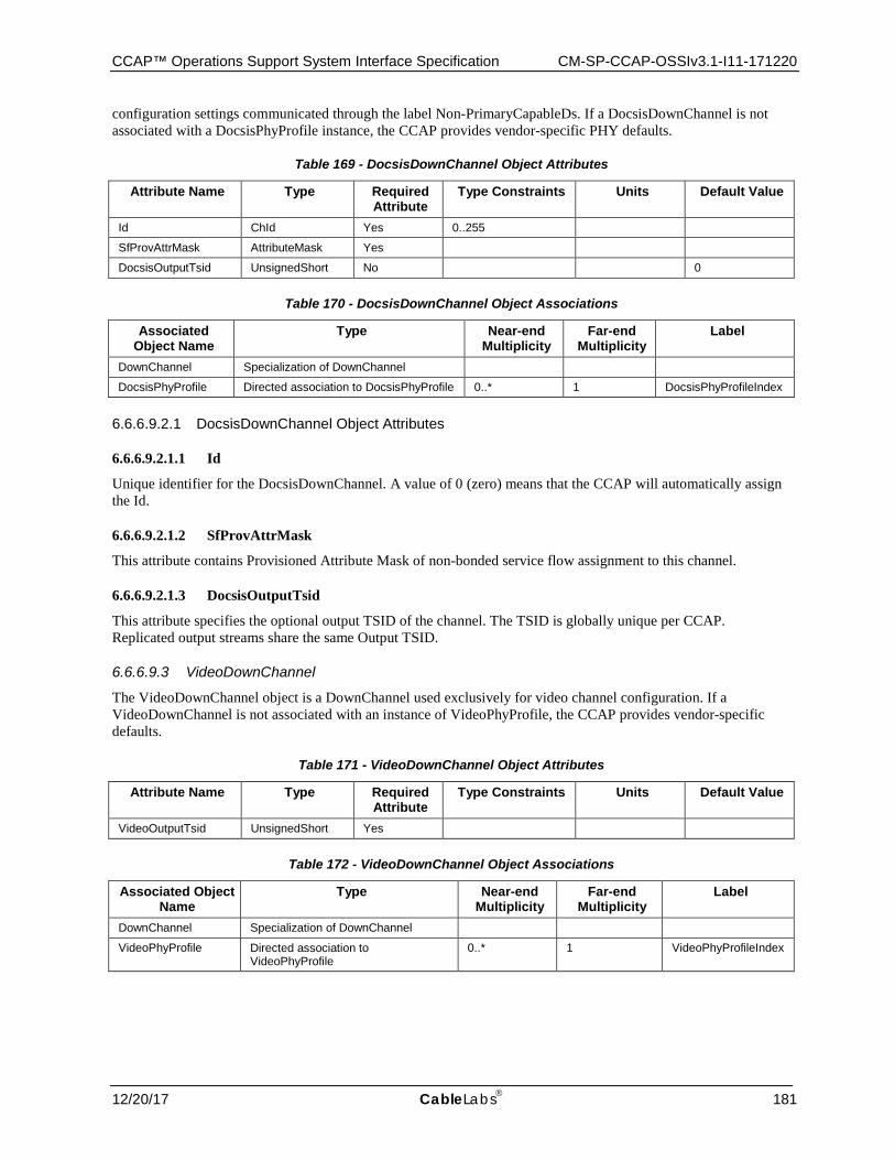
CCAP™ Operations Support System Interface Specification CM-SP-CCAP-OSSIv3.1-I11-171220
12/20/17 CableLabs 181
configuration settings communicated through the label Non-PrimaryCapableDs. If a DocsisDownChannel is not associated with a DocsisPhyProfile instance, the CCAP provides vendor-specific PHY defaults.
Table 169 - DocsisDownChannel Object Attributes
Attribute Name Type Required Attribute
Type Constraints Units Default Value
Id ChId Yes 0..255
SfProvAttrMask AttributeMask Yes
DocsisOutputTsid UnsignedShort No 0
Table 170 - DocsisDownChannel Object Associations
Associated Object Name
Type Near-end Multiplicity
Far-end Multiplicity
Label
DownChannel Specialization of DownChannel
DocsisPhyProfile Directed association to DocsisPhyProfile 0..* 1 DocsisPhyProfileIndex
6.6.6.9.2.1 DocsisDownChannel Object Attributes
6.6.6.9.2.1.1 Id
Unique identifier for the DocsisDownChannel. A value of 0 (zero) means that the CCAP will automatically assign the Id.
6.6.6.9.2.1.2 SfProvAttrMask
This attribute contains Provisioned Attribute Mask of non-bonded service flow assignment to this channel.
6.6.6.9.2.1.3 DocsisOutputTsid
This attribute specifies the optional output TSID of the channel. The TSID is globally unique per CCAP. Replicated output streams share the same Output TSID.
6.6.6.9.3 VideoDownChannel
The VideoDownChannel object is a DownChannel used exclusively for video channel configuration. If a VideoDownChannel is not associated with an instance of VideoPhyProfile, the CCAP provides vendor-specific defaults.
Table 171 - VideoDownChannel Object Attributes
Attribute Name Type Required Attribute
Type Constraints Units Default Value
VideoOutputTsid UnsignedShort Yes
Table 172 - VideoDownChannel Object Associations
Associated Object Name
Type Near-end Multiplicity
Far-end Multiplicity
Label
DownChannel Specialization of DownChannel
VideoPhyProfile Directed association to VideoPhyProfile
0..* 1 VideoPhyProfileIndex
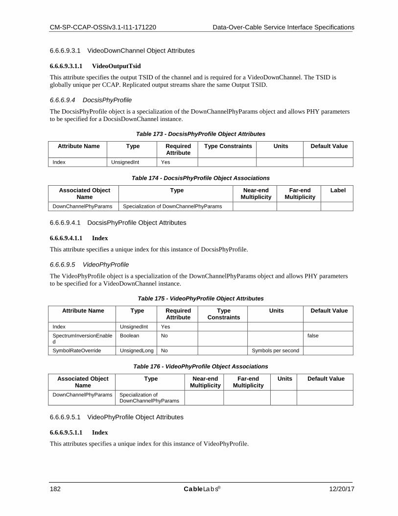
CM-SP-CCAP-OSSIv3.1-I11-171220 Data-Over-Cable Service Interface Specifications
182 CableLabs® 12/20/17
6.6.6.9.3.1 VideoDownChannel Object Attributes
6.6.6.9.3.1.1 VideoOutputTsid
This attribute specifies the output TSID of the channel and is required for a VideoDownChannel. The TSID is globally unique per CCAP. Replicated output streams share the same Output TSID.
6.6.6.9.4 DocsisPhyProfile
The DocsisPhyProfile object is a specialization of the DownChannelPhyParams object and allows PHY parameters to be specified for a DocsisDownChannel instance.
Table 173 - DocsisPhyProfile Object Attributes
Attribute Name Type Required Attribute
Type Constraints Units Default Value
Index UnsignedInt Yes
Table 174 - DocsisPhyProfile Object Associations
Associated Object Name
Type Near-end Multiplicity
Far-end Multiplicity
Label
DownChannelPhyParams Specialization of DownChannelPhyParams
6.6.6.9.4.1 DocsisPhyProfile Object Attributes
6.6.6.9.4.1.1 Index
This attribute specifies a unique index for this instance of DocsisPhyProfile.
6.6.6.9.5 VideoPhyProfile
The VideoPhyProfile object is a specialization of the DownChannelPhyParams object and allows PHY parameters to be specified for a VideoDownChannel instance.
Table 175 - VideoPhyProfile Object Attributes
Attribute Name Type Required Attribute
Type Constraints
Units Default Value
Index UnsignedInt Yes
SpectrumInversionEnabled
Boolean No false
SymbolRateOverride UnsignedLong No Symbols per second
Table 176 - VideoPhyProfile Object Associations
Associated Object Name
Type Near-end Multiplicity
Far-end Multiplicity
Units Default Value
DownChannelPhyParams Specialization of DownChannelPhyParams
6.6.6.9.5.1 VideoPhyProfile Object Attributes
6.6.6.9.5.1.1 Index
This attributes specifies a unique index for this instance of VideoPhyProfile.
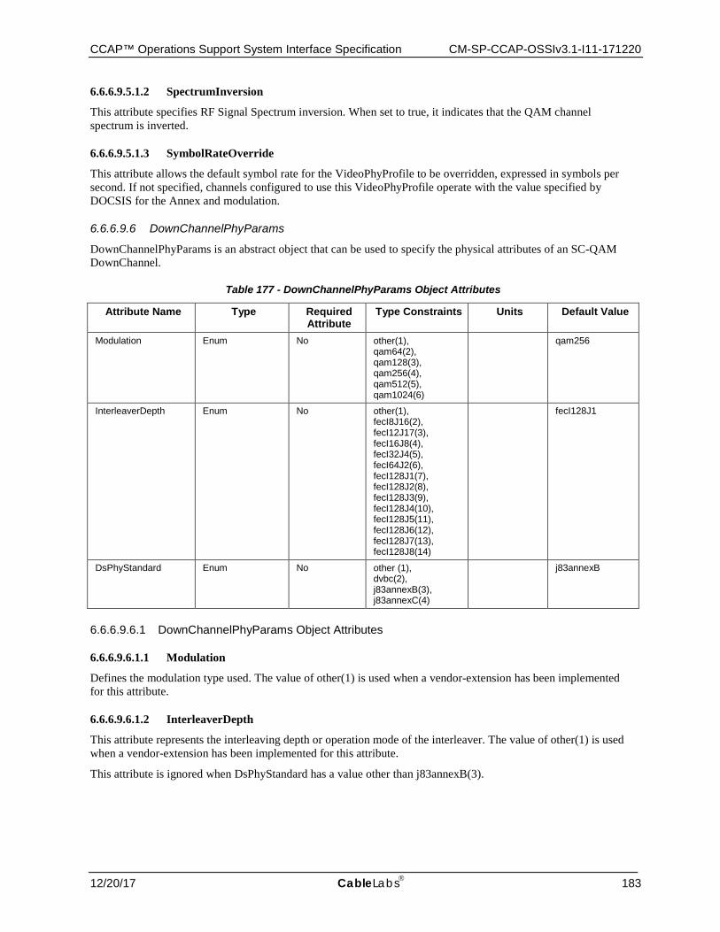
CCAP™ Operations Support System Interface Specification CM-SP-CCAP-OSSIv3.1-I11-171220
12/20/17 CableLabs 183
6.6.6.9.5.1.2 SpectrumInversion
This attribute specifies RF Signal Spectrum inversion. When set to true, it indicates that the QAM channel spectrum is inverted.
6.6.6.9.5.1.3 SymbolRateOverride
This attribute allows the default symbol rate for the VideoPhyProfile to be overridden, expressed in symbols per second. If not specified, channels configured to use this VideoPhyProfile operate with the value specified by DOCSIS for the Annex and modulation.
6.6.6.9.6 DownChannelPhyParams
DownChannelPhyParams is an abstract object that can be used to specify the physical attributes of an SC-QAM DownChannel.
Table 177 - DownChannelPhyParams Object Attributes
Attribute Name Type Required Attribute
Type Constraints Units Default Value
Modulation Enum No other(1), qam64(2), qam128(3), qam256(4), qam512(5), qam1024(6)
qam256
InterleaverDepth Enum No other(1), fecI8J16(2), fecI12J17(3), fecI16J8(4), fecI32J4(5), fecI64J2(6), fecI128J1(7), fecI128J2(8), fecI128J3(9), fecI128J4(10), fecI128J5(11), fecI128J6(12), fecI128J7(13), fecI128J8(14)
fecI128J1
DsPhyStandard Enum No other (1), dvbc(2), j83annexB(3), j83annexC(4)
j83annexB
6.6.6.9.6.1 DownChannelPhyParams Object Attributes
6.6.6.9.6.1.1 Modulation
Defines the modulation type used. The value of other(1) is used when a vendor-extension has been implemented for this attribute.
6.6.6.9.6.1.2 InterleaverDepth
This attribute represents the interleaving depth or operation mode of the interleaver. The value of other(1) is used when a vendor-extension has been implemented for this attribute.
This attribute is ignored when DsPhyStandard has a value other than j83annexB(3).
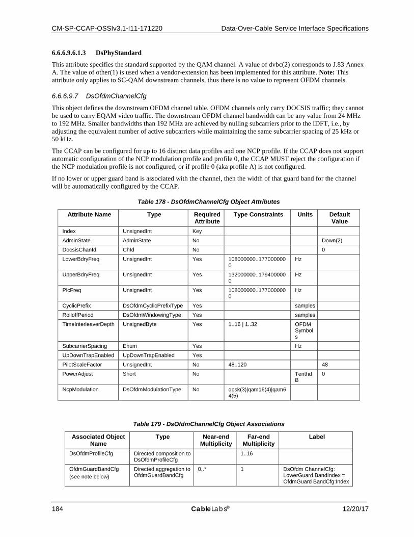
CM-SP-CCAP-OSSIv3.1-I11-171220 Data-Over-Cable Service Interface Specifications
184 CableLabs® 12/20/17
6.6.6.9.6.1.3 DsPhyStandard
This attribute specifies the standard supported by the QAM channel. A value of dvbc(2) corresponds to J.83 Annex A. The value of other(1) is used when a vendor-extension has been implemented for this attribute. Note: This attribute only applies to SC-QAM downstream channels, thus there is no value to represent OFDM channels.
6.6.6.9.7 DsOfdmChannelCfg
This object defines the downstream OFDM channel table. OFDM channels only carry DOCSIS traffic; they cannot be used to carry EQAM video traffic. The downstream OFDM channel bandwidth can be any value from 24 MHz to 192 MHz. Smaller bandwidths than 192 MHz are achieved by nulling subcarriers prior to the IDFT, i.e., by adjusting the equivalent number of active subcarriers while maintaining the same subcarrier spacing of 25 kHz or 50 kHz.
The CCAP can be configured for up to 16 distinct data profiles and one NCP profile. If the CCAP does not support automatic configuration of the NCP modulation profile and profile 0, the CCAP MUST reject the configuration if the NCP modulation profile is not configured, or if profile 0 (aka profile A) is not configured.
If no lower or upper guard band is associated with the channel, then the width of that guard band for the channel will be automatically configured by the CCAP.
Table 178 - DsOfdmChannelCfg Object Attributes
Attribute Name Type Required Attribute
Type Constraints Units Default Value
Index UnsignedInt Key
AdminState AdminState No Down(2)
DocsisChanId ChId No 0
LowerBdryFreq UnsignedInt Yes 108000000..1770000000
Hz
UpperBdryFreq UnsignedInt Yes 132000000..1794000000
Hz
PlcFreq UnsignedInt Yes 108000000..1770000000
Hz
CyclicPrefix DsOfdmCyclicPrefixType Yes samples
RolloffPeriod DsOfdmWindowingType Yes samples
TimeInterleaverDepth UnsignedByte Yes 1..16 | 1..32 OFDM Symbols
SubcarrierSpacing Enum Yes Hz
UpDownTrapEnabled UpDownTrapEnabled Yes
PilotScaleFactor UnsignedInt No 48..120 48
PowerAdjust Short No TenthdB
0
NcpModulation DsOfdmModulationType No qpsk(3)|qam16(4)|qam64(5)
Table 179 - DsOfdmChannelCfg Object Associations
Associated Object Name
Type Near-end Multiplicity
Far-end Multiplicity
Label
DsOfdmProfileCfg Directed composition to DsOfdmProfileCfg
1..16
OfdmGuardBandCfg (see note below)
Directed aggregation to OfdmGuardBandCfg
0..* 1 DsOfdm ChannelCfg: LowerGuard BandIndex = OfdmGuard BandCfg:Index
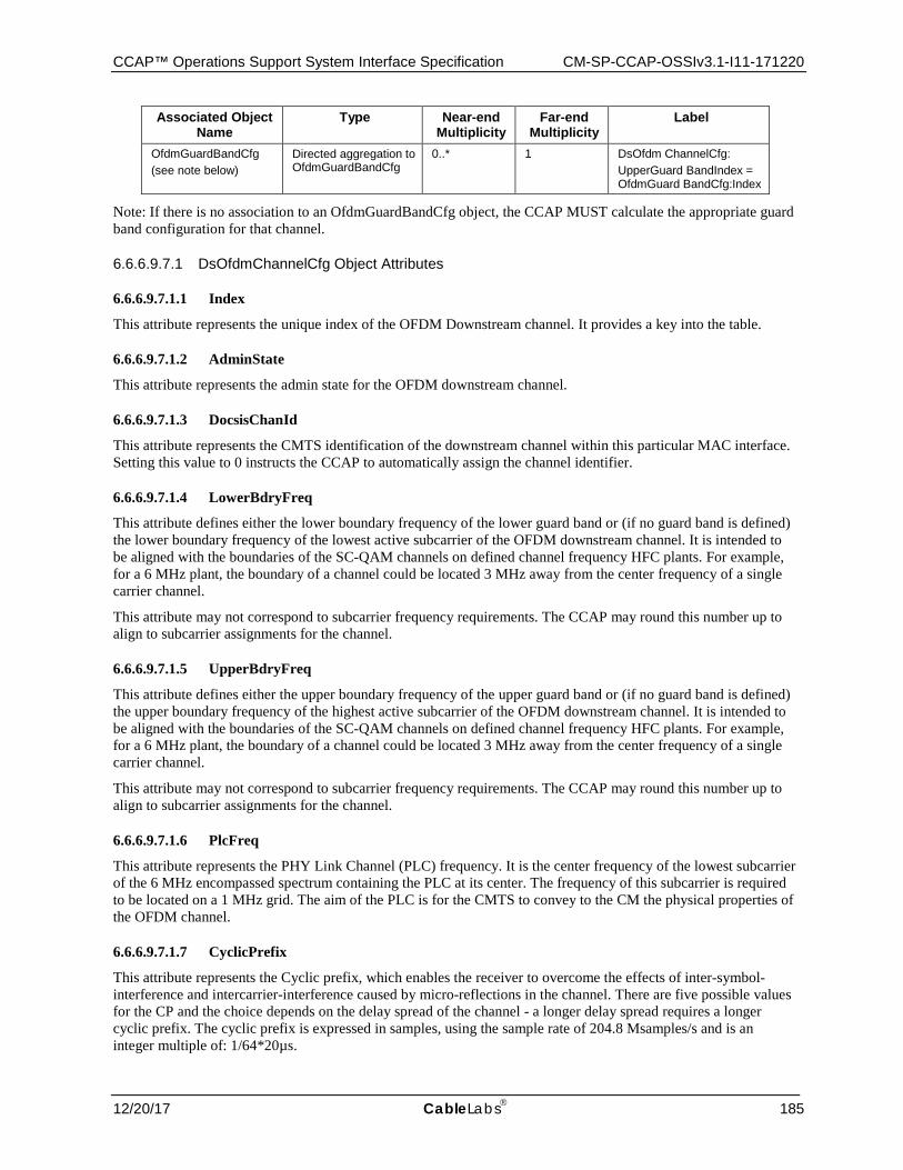
CCAP™ Operations Support System Interface Specification CM-SP-CCAP-OSSIv3.1-I11-171220
12/20/17 CableLabs 185
Associated Object Name
Type Near-end Multiplicity
Far-end Multiplicity
Label
OfdmGuardBandCfg (see note below)
Directed aggregation to OfdmGuardBandCfg
0..* 1 DsOfdm ChannelCfg: UpperGuard BandIndex = OfdmGuard BandCfg:Index
Note: If there is no association to an OfdmGuardBandCfg object, the CCAP MUST calculate the appropriate guard band configuration for that channel.
6.6.6.9.7.1 DsOfdmChannelCfg Object Attributes
6.6.6.9.7.1.1 Index
This attribute represents the unique index of the OFDM Downstream channel. It provides a key into the table.
6.6.6.9.7.1.2 AdminState
This attribute represents the admin state for the OFDM downstream channel.
6.6.6.9.7.1.3 DocsisChanId
This attribute represents the CMTS identification of the downstream channel within this particular MAC interface. Setting this value to 0 instructs the CCAP to automatically assign the channel identifier.
6.6.6.9.7.1.4 LowerBdryFreq
This attribute defines either the lower boundary frequency of the lower guard band or (if no guard band is defined) the lower boundary frequency of the lowest active subcarrier of the OFDM downstream channel. It is intended to be aligned with the boundaries of the SC-QAM channels on defined channel frequency HFC plants. For example, for a 6 MHz plant, the boundary of a channel could be located 3 MHz away from the center frequency of a single carrier channel.
This attribute may not correspond to subcarrier frequency requirements. The CCAP may round this number up to align to subcarrier assignments for the channel.
6.6.6.9.7.1.5 UpperBdryFreq
This attribute defines either the upper boundary frequency of the upper guard band or (if no guard band is defined) the upper boundary frequency of the highest active subcarrier of the OFDM downstream channel. It is intended to be aligned with the boundaries of the SC-QAM channels on defined channel frequency HFC plants. For example, for a 6 MHz plant, the boundary of a channel could be located 3 MHz away from the center frequency of a single carrier channel.
This attribute may not correspond to subcarrier frequency requirements. The CCAP may round this number up to align to subcarrier assignments for the channel.
6.6.6.9.7.1.6 PlcFreq
This attribute represents the PHY Link Channel (PLC) frequency. It is the center frequency of the lowest subcarrier of the 6 MHz encompassed spectrum containing the PLC at its center. The frequency of this subcarrier is required to be located on a 1 MHz grid. The aim of the PLC is for the CMTS to convey to the CM the physical properties of the OFDM channel.
6.6.6.9.7.1.7 CyclicPrefix
This attribute represents the Cyclic prefix, which enables the receiver to overcome the effects of inter-symbol-interference and intercarrier-interference caused by micro-reflections in the channel. There are five possible values for the CP and the choice depends on the delay spread of the channel - a longer delay spread requires a longer cyclic prefix. The cyclic prefix is expressed in samples, using the sample rate of 204.8 Msamples/s and is an integer multiple of: 1/64*20µs.

CM-SP-CCAP-OSSIv3.1-I11-171220 Data-Over-Cable Service Interface Specifications
186 CableLabs® 12/20/17
6.6.6.9.7.1.8 RolloffPeriod
This attribute represents the roll off period or windowing which maximizes channel capacity by sharpening the edges of the spectrum of the OFDM signal. For windowing purposes another segment at the start of the IDFT output is appended to the end of the IDFT output -the roll-off postfix (RP). There are five possible values for the RP, and the choice depends on the bandwidth of the channel and the number of exclusion bands within the channel. A larger RP provides sharper edges in the spectrum of the OFDM signal; however, there is a time vs. frequency trade-off. Larger RP values reduce the efficiency of transmission in the time domain, but because the spectral edges are sharper, more useful subcarriers appear in the frequency domain. There is an optimum value for the RP that maximizes capacity for a given bandwidth and/or exclusion band scenario. The CCAP MUST reject configurations where the roll-off period is greater than the cyclic prefix.
6.6.6.9.7.1.9 TimeInterleaverDepth
This attribute represents the depth of the time interleaver for the OFDM downstream channel expressed as a number of symbol durations. The value ranges from one and is limited to 16 symbol duration for 25 kHz SubcarrierSpacing and to 32 symbol durations for 50 kHz SubcarrierSpacing, respectively.
6.6.6.9.7.1.10 SubcarrierSpacing
This attribute defines the subcarrier spacing configured on the OFDM downstream channel. If the SubcarrierSpacing is 50 kHz, then the FFT length is 4K. If the SubcarrierSpacing is 25 kHz, then the FFT length is 8K.
6.6.6.9.7.1.11 UpDownTrapEnabled
This attribute indicates if a trap should be sent when the Channel transitions from up to down and down to up.
6.6.6.9.7.1.12 PilotScaleFactor
This attribute indicates the scale factor for calculating the number of continuous pilots.
6.6.6.9.7.1.13 PowerAdjust
This attribute specifies the power level adjustment for this OFDM channel from the value specified by BaseChanPower. The PowerAdjust attribute (in TenthdB) is added to BaseChanPower to provide a power spectral density for the OFDM channel by defining power in every 6 MHz (CTA) channel within the OFDM channel. The CCAP Core configures power for the entire channel with PowerAdjust and BaseChanPower. PowerAdjust allows setting the OFDM channel power independent of the channel width and consistent with the definition of the BaseChanPower attribute. Tilt is applied independently of these settings.
6.6.6.9.7.1.14 NcpModulation
This attribute defines the NCP modulation order. The CCAP MUST reject any modulationDefault values other than qpsk(3), qam16(4), or qam64(5).
6.6.6.9.8 DsOfdmProfileCfg
This object defines the OFDM Channel Profile Table. DOCSIS 3.1 introduces the concept of downstream profiles for OFDM channels. A profile is a list of modulation orders that are defined for each of the subcarriers within an OFDM channel. The CMTS can define multiple profiles for use in an OFDM channel, where the profiles differ in the modulation orders assigned to each subcarrier. It is optional for profiles to be configured via the management system. The CMTS can configure them without management intervention.
CCAP™ Operations Support System Interface Specification CM-SP-CCAP-OSSIv3.1-I11-171220
12/20/17 CableLabs 187
Table 180 - DsOfdmProfileCfg Object Attributes
Attribute Name Type Required Attribute
Type Constraints
Units Default Value
ProfileId UnsignedByte Key 0..15
ModulationDefault DsOfdmModulationType Yes None
Table 181 - DsOfdmProfileCfg Object Associations
Associated Object Name
Type Near-end Multiplicity
Far-end Multiplicity
Label
DsOfdmSubcarrierCfg Directed composition to DsOfdmSubcarrierCfg 0..*
6.6.6.9.8.1 DsOfdmProfileCfg Object Attributes
6.6.6.9.8.1.1 ProfileId
This attribute is a key defined to provide an index into the table. The NCP profile has an assigned ProfileId of 255.
6.6.6.9.8.1.2 ModulationDefault
This attribute defines the default bit loading applied to subcarriers in the OFDM downstream channel. If a subcarrier is not configured with a specific modulation order, it will use this value. The CCAP MUST reject a modulationDefault value of zeroBitLoaded(2).
6.6.6.9.9 DsOfdmSubcarrierCfg
This object specifies the OFDM Subcarrier Configuration Table. It defines the modulation for a list of subcarriers.
Table 182 - DsOfdmSubcarrierCfg Object Attributes
Attribute Name Type Required Attribute
Type Constraints Units Default Value
StartFrequency UnsignedInt Key 108000000..1770000000 Hz
StopFrequency UnsignedInt Yes 108000000..1770000000 Hz
Skip Boolean No false
MainModulation DsOfdmModulationType Yes
SkipModulation DsOfdmModulationType No
6.6.6.9.9.1 DsOfdmSubcarrierCfg Object Attributes
6.6.6.9.9.1.1 StartFrequency
This attribute is a key defined to provide an index into the table and specifies the starting frequency for a range of frequencies allocated for data subcarriers. The CCAP MUST reject a configuration where the start frequency is outside of the channel frequency range.
6.6.6.9.9.1.2 StopFrequency
This attribute specifies the end frequency of a range of frequencies allocated for data subcarriers. The stop frequency is required to be at least one subcarrier width larger than the start frequency. The CCAP MUST reject a configuration where the stop frequency is outside of the channel frequency range.
CM-SP-CCAP-OSSIv3.1-I11-171220 Data-Over-Cable Service Interface Specifications
188 CableLabs® 12/20/17
6.6.6.9.9.1.3 Skip
This attribute indicates if the configuration uses the method of alternating modulation order between subcarriers in the defined range.
6.6.6.9.9.1.4 MainModulation
This attribute represents the modulation of the subcarriers. In case of skip modulation enabled, the MainModulation is the modulation order of the first, the third, the fifth, etc., subcarriers in the range.
6.6.6.9.9.1.5 SkipModulation
This attribute represents the modulation of every other subcarrier in the defined range.
6.6.6.9.10 DsOfdmExclusionCfg
This object specifies the Downstream OFDM Exclusion Configuration Table. This is a global table that lists excluded subcarriers that can be referenced by any Downstream RF Port.
Muted subcarriers are subcarriers that have a value of zero in the bit-loading pattern of a profile.
Table 183 - DsOfdmExclusionCfg Object Attributes
Attribute Name Type Required Attribute
Type Constraints Units Default Value
StartFrequency UnsignedInt Key 108000000..1794000000 Hz
StopFrequency UnsignedInt Yes 108000000..1794000000 Hz
6.6.6.9.10.1 DsOfdmExclusionCfg Object Attributes
6.6.6.9.10.1.1 StartFrequency
This attribute is a key defined to provide an index into the table and specifies the starting frequency of the exclusion entry.
6.6.6.9.10.1.2 StopFrequency
This attribute provides the ending frequency for the exclusion entry. The stop frequency is required to be at least one subcarrier width larger than the start frequency.
6.6.6.9.11 DsNcpExclusionCfg
This object specifies the Downstream NCP Exclusion Configuration Table. This is a global table that lists excluded subcarriers that can be referenced by any Downstream RF Port.
Table 184 - DsNcpExclusionCfg Object Attributes
Attribute Name Type Required Attribute
Type Constraints Units Default Value
StartFrequency UnsignedInt Key 108000000..1794000000 Hz
StopFrequency UnsignedInt Yes 108000000..1794000000 Hz
6.6.6.9.11.1 DsNcpExclusionCfg Object Attributes
6.6.6.9.11.1.1 StartFrequency
This attribute is a key defined to provide an index into the table and specifies the starting subcarrier frequency of the NCP exclusion entry.
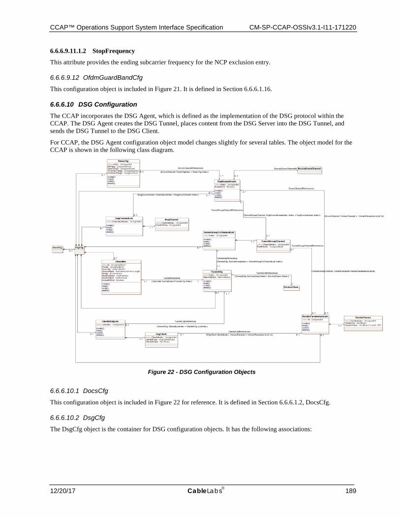
CCAP™ Operations Support System Interface Specification CM-SP-CCAP-OSSIv3.1-I11-171220
12/20/17 CableLabs 189
6.6.6.9.11.1.2 StopFrequency
This attribute provides the ending subcarrier frequency for the NCP exclusion entry.
6.6.6.9.12 OfdmGuardBandCfg
This configuration object is included in Figure 21. It is defined in Section 6.6.6.1.16.
6.6.6.10 DSG Configuration The CCAP incorporates the DSG Agent, which is defined as the implementation of the DSG protocol within the CCAP. The DSG Agent creates the DSG Tunnel, places content from the DSG Server into the DSG Tunnel, and sends the DSG Tunnel to the DSG Client.
For CCAP, the DSG Agent configuration object model changes slightly for several tables. The object model for the CCAP is shown in the following class diagram.
Figure 22 - DSG Configuration Objects
6.6.6.10.1 DocsCfg
This configuration object is included in Figure 22 for reference. It is defined in Section 6.6.6.1.2, DocsCfg.
6.6.6.10.2 DsgCfg
The DsgCfg object is the container for DSG configuration objects. It has the following associations:
CM-SP-CCAP-OSSIv3.1-I11-171220 Data-Over-Cable Service Interface Specifications
190 CableLabs® 12/20/17
Table 185 - DsgCfg Object Associations
Associated Object Name
Type Near-end Multiplicity
Far-end Multiplicity
Label
TimerCfg Directed composition to TimerCfg 0..*
DsgDownstream Directed composition to DsgDownstream 0..*
DsgChannelList Directed composition to DsgChannelList 0..*
TunnelGroupToChannelList Directed composition to TunnelGroupToChannelList
0..*
Classifier Directed composition to Classifier 0..*
TunnelCfg Directed composition to TunnelCfg 0..*
ClientIdCfgList Directed composition to ClientIdCfgList 0..*
VendorParametersList Directed composition to VendorParametersList 0..*
6.6.6.10.3 TimerCfg
This configuration object is based on the dsgIfTimerTable defined in [DSG] and will be used with modifications for CCAP.
The DSG Timer Table contains timers that are sent to the DSG client(s) via the DCD message.
Reference: [DSG], DOCSIS Set-top Gateway Agent MIB Definition section
Table 186 - TimerCfg Object Attributes
Attribute Name Type Required Attribute
Type Constraints
Units Default Value
Index UnsignedInt Yes (Key)
InitTdsg UnsignedShort No 1..65535 Seconds 2
OperTdsg2 UnsignedShort No 1..65535 Seconds 600
TwoWayTdsg3 UnsignedShort No Seconds 300
OneWayTdsg4 UnsignedShort No Seconds 1800
6.6.6.10.3.1 TimerCfg Object Attributes
6.6.6.10.3.1.1 Index
The index for this object.
6.6.6.10.3.1.2 InitTdsg
Initialization Timeout. This is the timeout period in seconds for the DSG packets during initialization of the DSG client. The default value is 2 seconds.
6.6.6.10.3.1.3 OperTdsg2
Operational Timeout. This is the timeout period in seconds for the DSG packets during normal operation of the DSG client. Default value is 600 seconds.
6.6.6.10.3.1.4 TwoWayTdsg3
Two-way retry timer. This is the retry timer that determines when the DSG client attempts to reconnect with the DSG Agent and established two-way connectivity. Default value is 300 seconds. The value 0 indicates that the client will continuously retry two-way operation.
CCAP™ Operations Support System Interface Specification CM-SP-CCAP-OSSIv3.1-I11-171220
12/20/17 CableLabs 191
6.6.6.10.3.1.5 OneWayTdsg4
One-way retry timer. This is the retry timer that determines when the client attempts to rescan for a DOCSIS downstream channel that contains DSG packets after a TimerTdsg1 or TimerTdsg2 timeout. Default value is 1800 seconds. Setting the value to 0 indicates that the client will immediately begin scanning upon TimerTdsg1 or TimerTdsg2 timeout.
6.6.6.10.4 DsgDownstream
The DsgDownstream object represents an individual downstream channel for DSG configuration purposes. It has been modified from the DSG Specification definitions.
Table 187 - DsgDownstream Object Attributes
Attribute Name Type Required Attribute
Type Constraints
Units Default Value
Index UnsignedInt Yes (Key)
EnableDcd Boolean Yes
The DsgDownstream object has the following associations.
Table 188 - DsgDownstream Object Associations
Associated Object Name
Type Near-end Multiplicit
y
Far-end Multiplicit
y
Label
TimerCfg Directed aggregation to TimerCfg 1..* 0..1
DsgChannelList Directed aggregation to DsgChannelList 1..* 0..1
DocsisDownChannel Directed aggregation to DocsisDownChannel 0..1 DocsisDownChannelId
VendorParametersList Directed aggregation to VendorParametersList
0..* 0..1
6.6.6.10.4.1 DsgDownstream Object Attributes
6.6.6.10.4.1.1 Index
This is the key for an instance of this object.
6.6.6.10.4.1.2 EnableDcd
This attribute is used to enable or disable DCD messages to be sent on this downstream channel. The value is always true for those downstreams that contain DSG tunnels.
6.6.6.10.5 DocsisDownChannel
This configuration object is included in Figure 22 for reference. It is defined in Section 6.6.6.9.2, DocsisDownChannel.
6.6.6.10.6 DsgChannelList
This configuration object is based on the dsgIfChannelListTable defined in [DSG] and will be used with modifications for CCAP.
The DsgChannelList object allows for configuration of a list of one or multiple downstream frequencies that are carrying DSG tunnel(s). This configuration object has been modified from the DSG Specification definitions.
Reference: [DSG], DOCSIS Set-top Gateway Agent MIB Definition section
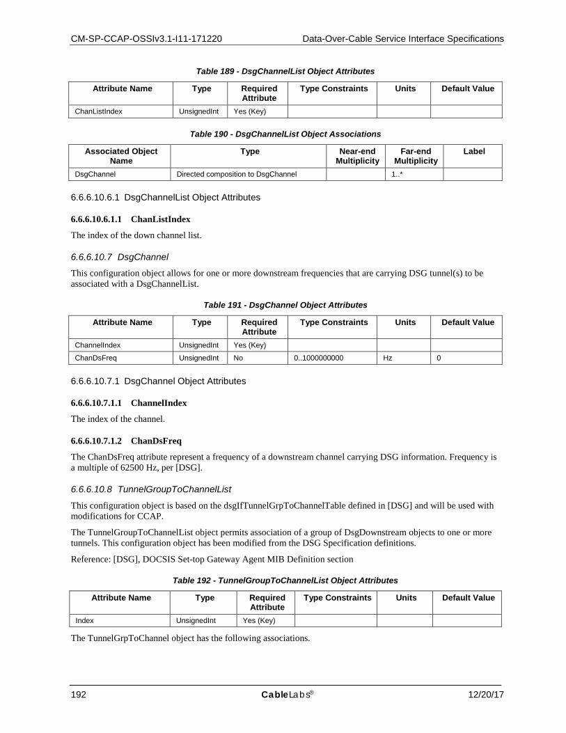
CM-SP-CCAP-OSSIv3.1-I11-171220 Data-Over-Cable Service Interface Specifications
192 CableLabs® 12/20/17
Table 189 - DsgChannelList Object Attributes
Attribute Name Type Required Attribute
Type Constraints Units Default Value
ChanListIndex UnsignedInt Yes (Key)
Table 190 - DsgChannelList Object Associations
Associated Object Name
Type Near-end Multiplicity
Far-end Multiplicity
Label
DsgChannel Directed composition to DsgChannel 1..*
6.6.6.10.6.1 DsgChannelList Object Attributes
6.6.6.10.6.1.1 ChanListIndex
The index of the down channel list.
6.6.6.10.7 DsgChannel
This configuration object allows for one or more downstream frequencies that are carrying DSG tunnel(s) to be associated with a DsgChannelList.
Table 191 - DsgChannel Object Attributes
Attribute Name Type Required Attribute
Type Constraints Units Default Value
ChannelIndex UnsignedInt Yes (Key)
ChanDsFreq UnsignedInt No 0..1000000000 Hz 0
6.6.6.10.7.1 DsgChannel Object Attributes
6.6.6.10.7.1.1 ChannelIndex
The index of the channel.
6.6.6.10.7.1.2 ChanDsFreq
The ChanDsFreq attribute represent a frequency of a downstream channel carrying DSG information. Frequency is a multiple of 62500 Hz, per [DSG].
6.6.6.10.8 TunnelGroupToChannelList
This configuration object is based on the dsgIfTunnelGrpToChannelTable defined in [DSG] and will be used with modifications for CCAP.
The TunnelGroupToChannelList object permits association of a group of DsgDownstream objects to one or more tunnels. This configuration object has been modified from the DSG Specification definitions.
Reference: [DSG], DOCSIS Set-top Gateway Agent MIB Definition section
Table 192 - TunnelGroupToChannelList Object Attributes
Attribute Name Type Required Attribute
Type Constraints Units Default Value
Index UnsignedInt Yes (Key)
The TunnelGrpToChannel object has the following associations.

CCAP™ Operations Support System Interface Specification CM-SP-CCAP-OSSIv3.1-I11-171220
12/20/17 CableLabs 193
Table 193 - TunnelGrpToChannel Object Associations
Associated Object Name
Type Near-end Multiplicity
Far-end Multiplicity
Label
TunnelGroupChannel Directed composition to TunnelGroupChannel 1..*
6.6.6.10.8.1 TunnelGroupToChannelList Object Attributes
6.6.6.10.8.1.1 Index
This attribute is the key for this object and allows a link to an instance of a TunnelCfg object be configured.
6.6.6.10.9 TunnelGroupChannel
The TunnelGroupChannel object allows DsgDownstream objects to be associated with this group.
Table 194 - TunnelGroupChannel Object Attributes
Attribute Name Type Required Attribute
Type Constraints Units Default Value
ChannelIndex UnsignedInt Yes (Key)
RulePriority UnsignedByte No 0..255 0
The TunnelGroupChannel object has the following associations.
Table 195 - TunnelGroupChannel Object Associations
Associated Object Name
Type Near-end Multiplicity
Far-end Multiplicity
Label
DsgDownstream Directed aggregation to DsgDownstream 1..* 1
VendorParametersList Directed association to VendorParametersList 0..* 0..1
6.6.6.10.9.1 TunnelGroupChannel Object Attributes
6.6.6.10.9.1.1 ChannelIndex
This attribute configures the linkage of a specific DsgDownstream instance to the TunnelCfg instance associated with the group.
6.6.6.10.9.1.2 RulePriority
The DSG rule priority determines the order in which a channel should be applied by the DSG client. The default value is 0, which is the lowest priority.
6.6.6.10.10 Classifier
This configuration object is based on the dsgIfClassifierTable defined in [DSG] and will be used with modifications for CCAP.
Reference: [DSG], DOCSIS Set-top Gateway Agent MIB Definition section
Table 196 - Classifier Object Attributes
Attribute Name Type Required Attribute
Type Constraints Units Default Value
Id UnsignedShort Yes (Key)
Priority UnsignedByte No 0
SourceIp Ipv4Prefix Yes
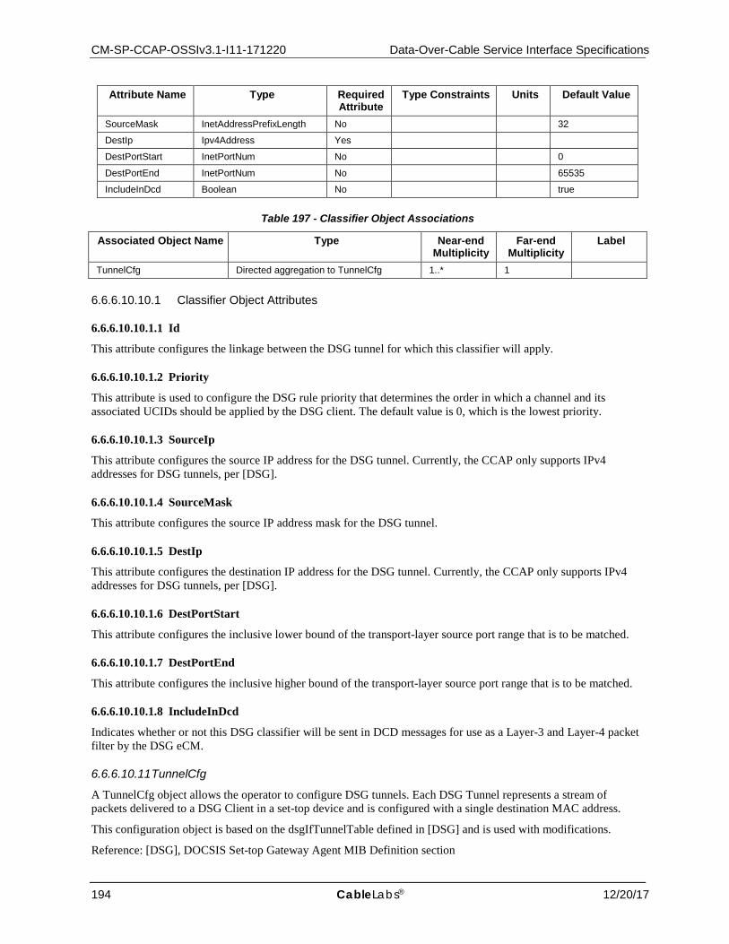
CM-SP-CCAP-OSSIv3.1-I11-171220 Data-Over-Cable Service Interface Specifications
194 CableLabs® 12/20/17
Attribute Name Type Required Attribute
Type Constraints Units Default Value
SourceMask InetAddressPrefixLength No 32
DestIp Ipv4Address Yes
DestPortStart InetPortNum No 0
DestPortEnd InetPortNum No 65535
IncludeInDcd Boolean No true
Table 197 - Classifier Object Associations
Associated Object Name Type Near-end Multiplicity
Far-end Multiplicity
Label
TunnelCfg Directed aggregation to TunnelCfg 1..* 1
6.6.6.10.10.1 Classifier Object Attributes
6.6.6.10.10.1.1 Id
This attribute configures the linkage between the DSG tunnel for which this classifier will apply.
6.6.6.10.10.1.2 Priority
This attribute is used to configure the DSG rule priority that determines the order in which a channel and its associated UCIDs should be applied by the DSG client. The default value is 0, which is the lowest priority.
6.6.6.10.10.1.3 SourceIp
This attribute configures the source IP address for the DSG tunnel. Currently, the CCAP only supports IPv4 addresses for DSG tunnels, per [DSG].
6.6.6.10.10.1.4 SourceMask
This attribute configures the source IP address mask for the DSG tunnel.
6.6.6.10.10.1.5 DestIp
This attribute configures the destination IP address for the DSG tunnel. Currently, the CCAP only supports IPv4 addresses for DSG tunnels, per [DSG].
6.6.6.10.10.1.6 DestPortStart
This attribute configures the inclusive lower bound of the transport-layer source port range that is to be matched.
6.6.6.10.10.1.7 DestPortEnd
This attribute configures the inclusive higher bound of the transport-layer source port range that is to be matched.
6.6.6.10.10.1.8 IncludeInDcd
Indicates whether or not this DSG classifier will be sent in DCD messages for use as a Layer-3 and Layer-4 packet filter by the DSG eCM.
6.6.6.10.11 TunnelCfg
A TunnelCfg object allows the operator to configure DSG tunnels. Each DSG Tunnel represents a stream of packets delivered to a DSG Client in a set-top device and is configured with a single destination MAC address.
This configuration object is based on the dsgIfTunnelTable defined in [DSG] and is used with modifications.
Reference: [DSG], DOCSIS Set-top Gateway Agent MIB Definition section
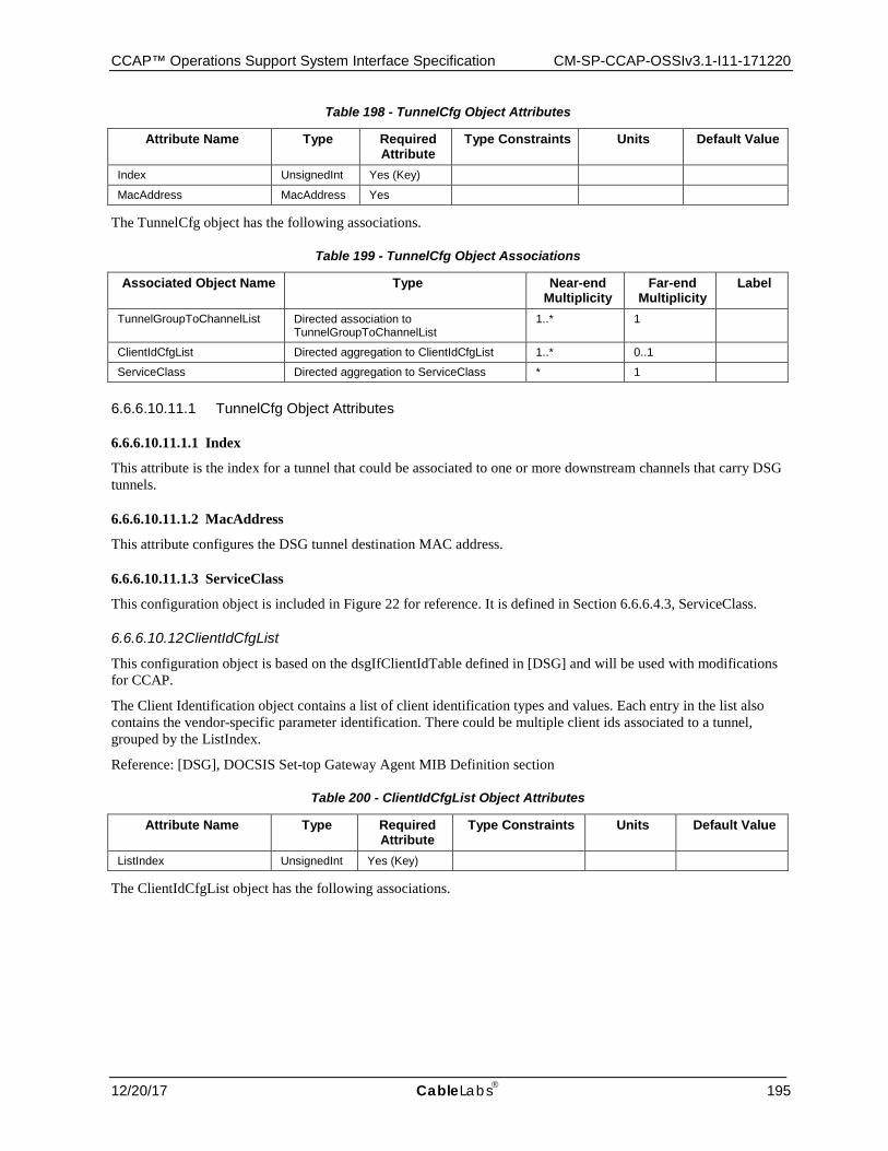
CCAP™ Operations Support System Interface Specification CM-SP-CCAP-OSSIv3.1-I11-171220
12/20/17 CableLabs 195
Table 198 - TunnelCfg Object Attributes
Attribute Name Type Required Attribute
Type Constraints Units Default Value
Index UnsignedInt Yes (Key)
MacAddress MacAddress Yes
The TunnelCfg object has the following associations.
Table 199 - TunnelCfg Object Associations
Associated Object Name Type Near-end Multiplicity
Far-end Multiplicity
Label
TunnelGroupToChannelList Directed association to TunnelGroupToChannelList
1..* 1
ClientIdCfgList Directed aggregation to ClientIdCfgList 1..* 0..1
ServiceClass Directed aggregation to ServiceClass * 1
6.6.6.10.11.1 TunnelCfg Object Attributes
6.6.6.10.11.1.1 Index
This attribute is the index for a tunnel that could be associated to one or more downstream channels that carry DSG tunnels.
6.6.6.10.11.1.2 MacAddress
This attribute configures the DSG tunnel destination MAC address.
6.6.6.10.11.1.3 ServiceClass
This configuration object is included in Figure 22 for reference. It is defined in Section 6.6.6.4.3, ServiceClass.
6.6.6.10.12 ClientIdCfgList
This configuration object is based on the dsgIfClientIdTable defined in [DSG] and will be used with modifications for CCAP.
The Client Identification object contains a list of client identification types and values. Each entry in the list also contains the vendor-specific parameter identification. There could be multiple client ids associated to a tunnel, grouped by the ListIndex.
Reference: [DSG], DOCSIS Set-top Gateway Agent MIB Definition section
Table 200 - ClientIdCfgList Object Attributes
Attribute Name Type Required Attribute
Type Constraints Units Default Value
ListIndex UnsignedInt Yes (Key)
The ClientIdCfgList object has the following associations.
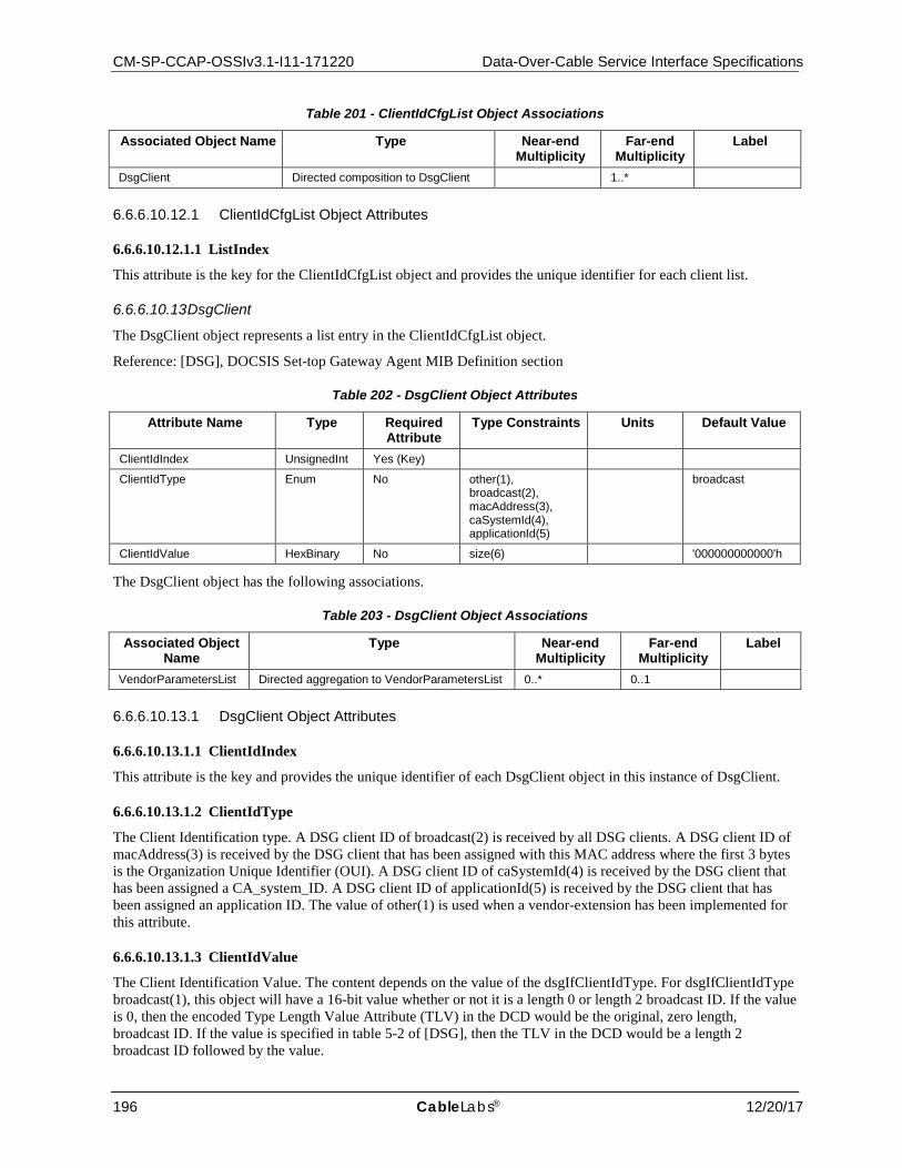
CM-SP-CCAP-OSSIv3.1-I11-171220 Data-Over-Cable Service Interface Specifications
196 CableLabs® 12/20/17
Table 201 - ClientIdCfgList Object Associations
Associated Object Name Type Near-end Multiplicity
Far-end Multiplicity
Label
DsgClient Directed composition to DsgClient 1..*
6.6.6.10.12.1 ClientIdCfgList Object Attributes
6.6.6.10.12.1.1 ListIndex
This attribute is the key for the ClientIdCfgList object and provides the unique identifier for each client list.
6.6.6.10.13 DsgClient
The DsgClient object represents a list entry in the ClientIdCfgList object.
Reference: [DSG], DOCSIS Set-top Gateway Agent MIB Definition section
Table 202 - DsgClient Object Attributes
Attribute Name Type Required Attribute
Type Constraints Units Default Value
ClientIdIndex UnsignedInt Yes (Key)
ClientIdType Enum No other(1), broadcast(2), macAddress(3), caSystemId(4), applicationId(5)
broadcast
ClientIdValue HexBinary No size(6) '000000000000'h
The DsgClient object has the following associations.
Table 203 - DsgClient Object Associations
Associated Object Name
Type Near-end Multiplicity
Far-end Multiplicity
Label
VendorParametersList Directed aggregation to VendorParametersList 0..* 0..1
6.6.6.10.13.1 DsgClient Object Attributes
6.6.6.10.13.1.1 ClientIdIndex
This attribute is the key and provides the unique identifier of each DsgClient object in this instance of DsgClient.
6.6.6.10.13.1.2 ClientIdType
The Client Identification type. A DSG client ID of broadcast(2) is received by all DSG clients. A DSG client ID of macAddress(3) is received by the DSG client that has been assigned with this MAC address where the first 3 bytes is the Organization Unique Identifier (OUI). A DSG client ID of caSystemId(4) is received by the DSG client that has been assigned a CA_system_ID. A DSG client ID of applicationId(5) is received by the DSG client that has been assigned an application ID. The value of other(1) is used when a vendor-extension has been implemented for this attribute.
6.6.6.10.13.1.3 ClientIdValue
The Client Identification Value. The content depends on the value of the dsgIfClientIdType. For dsgIfClientIdType broadcast(1), this object will have a 16-bit value whether or not it is a length 0 or length 2 broadcast ID. If the value is 0, then the encoded Type Length Value Attribute (TLV) in the DCD would be the original, zero length, broadcast ID. If the value is specified in table 5-2 of [DSG], then the TLV in the DCD would be a length 2 broadcast ID followed by the value.
CCAP™ Operations Support System Interface Specification CM-SP-CCAP-OSSIv3.1-I11-171220
12/20/17 CableLabs 197
For ClientIdType macAddress(2), this object is a well-known MAC address.
For ClientIdType caSystemId(3), this object is a CA System ID.
For ClientIdType applicationId(4), this object is an application ID.
Client IDs representing types broadcast(1), caSystemId(3) or applicationId(4) are encoded in DCD messages as unsigned integers and configured in this object as 6 octet string with the 2 LSB for the client ID value; e.g., an applicationId 2048 (0x0800) is encoded as '000000000800'h.
6.6.6.10.14 VendorParametersList
This configuration object is based on the dsgIfVendorParamTable defined in [DSG] and is used with the following modifications for CCAP: a VendorParam object has been created to allow a list of vendor parameters to be associated with this object.
The VendorParametersList object allows vendors to send specific parameters to the DSG clients within a DSG rule or within the DSG Configuration block in a DCD message.
Reference: [DSG], DOCSIS Set-top Gateway Agent MIB Definition section
Table 204 - VendorParametersList Object Associations
Associated Object Name
Type Near-end Multiplicity
Far-end Multiplicity
Label
VendorParam Directed composition to VendorParam 1..*
6.6.6.10.15 VendorParam
This configuration object is based on the dsgIfVendorParamTable defined in [DSG] and holds the attributes that define each vendor parameter.
Reference: [DSG], DOCSIS Set-top Gateway Agent MIB Definition section
6.6.6.11 PacketCable Configuration Objects This section defines the configuration objects needed for configuring PacketCable and PacketCable Multimedia (PCMM) services on the CCAP.
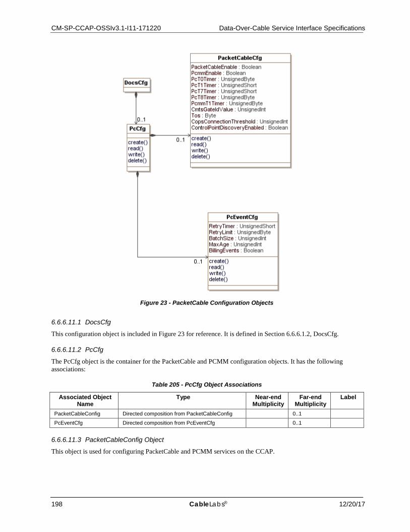
CM-SP-CCAP-OSSIv3.1-I11-171220 Data-Over-Cable Service Interface Specifications
198 CableLabs® 12/20/17
Figure 23 - PacketCable Configuration Objects
6.6.6.11.1 DocsCfg
This configuration object is included in Figure 23 for reference. It is defined in Section 6.6.6.1.2, DocsCfg.
6.6.6.11.2 PcCfg
The PcCfg object is the container for the PacketCable and PCMM configuration objects. It has the following associations:
Table 205 - PcCfg Object Associations
Associated Object Name
Type Near-end Multiplicity
Far-end Multiplicity
Label
PacketCableConfig Directed composition from PacketCableConfig 0..1
PcEventCfg Directed composition from PcEventCfg 0..1
6.6.6.11.3 PacketCableConfig Object
This object is used for configuring PacketCable and PCMM services on the CCAP.
CCAP™ Operations Support System Interface Specification CM-SP-CCAP-OSSIv3.1-I11-171220
12/20/17 CableLabs 199
Table 206 - PacketCableConfig Object Attributes
Attribute Name Type Required Attribute
Type Constraints Units Default Value
PacketCableEnable Boolean No false
PcmmEnable Boolean No false
PcT0timer UnsignedByte No seconds 30
PcT1Timer UnsignedShort No seconds 200
PcT7Timer UnsignedShort No seconds 200
PcT8Timer UnsignedByte No seconds 0
PcmmT1Timer UnsignedByte No seconds 200
CmtsGateIdValue UnsignedInt Yes 0..16383
Tos Byte Yes -1 | 0..63
CopsConnectionThreshold UnsignedInt Yes connections/15 mins
ControlPointDiscoveryEnabled Boolean No false
6.6.6.11.3.1 PacketCableConfig Object Attributes
6.6.6.11.3.1.1 PacketCableEnable
This configuration attribute allows the operator to enable PacketCable services on the CCAP.
6.6.6.11.3.1.2 PcmmEnable
This configuration attribute allows the operator to enable PacketCable Multimedia services on the CCAP.
6.6.6.11.3.1.3 PcT0Timer
This configuration attribute allows the operator to define the value in seconds for the PacketCable T0 timer.
6.6.6.11.3.1.4 PcT1Timer
This configuration attribute allows the operator to define the value in seconds for the PacketCable T1 timer.
6.6.6.11.3.1.5 PcT7Timer
This attribute allows for the setting of the Timeout for Admitted QoS Parameters for the service flow to the value specified for this timer. In the case of a flow with multiple sub-flows, the flow's Timeout for Admitted QoS Parameters is set to the value of timer T7 from the most recently received Gate-Set message for any subflow on the flow. The Timeout for Admitted QoS Parameters limits the period of time that the CMTS holds resources for a service flow's Admitted QoS Parameter Set while they are in excess of its Active QoS Parameter Set.
The recommended default value of this timer is 200 seconds.
6.6.6.11.3.1.6 PcT8Timer
This attribute configures the Timeout for Active QoS Parameters for the service flow to the value specified for this timer. In the case of a flow with multiple sub-flows, the flow's Timeout for Active QoS Parameters is set to the value of timer T8 from the most recently received Gate-Set message for any sub-flow on the flow. The Timeout for Active QoS Parameters limits the period of time resources remain unused on an active service flow.
6.6.6.11.3.1.7 PcmmT1Timer
This configuration attribute allows the operator to define the value in seconds for the PacketCable Multimedia T1 timer.
CM-SP-CCAP-OSSIv3.1-I11-171220 Data-Over-Cable Service Interface Specifications
200 CableLabs® 12/20/17
6.6.6.11.3.1.8 CmtsGateIdValue
This configuration attribute allows the operator to define the value for the CMTS ID portion of PCMM GateIds. This value is the 13 least significant bits (0-12) of the GateId.
6.6.6.11.3.1.9 Tos
This configuration attribute allows the operator to define the value for the Tos bits in outgoing COPS messages.
6.6.6.11.3.1.10 CopsConnectionThreshold
This configuration attribute allows the operator to define the threshold number of COPS connections per 15-minute interval.
6.6.6.11.3.1.11 ControlPointDiscoveryEnabled
This attribute enables or disables the Control Point Discovery functionality described in the PacketCable Specifications. The default value is false.
6.6.6.11.4 PcEventCfg Object
This object configures event messaging for PacketCable.
Table 207 - PcEventCfg Object Attributes
Attribute Name Type Required Attribute
Type Constraints Units Default Value
RetryTimer UnsignedShort No 10..10000 milliseconds 3000
RetryLimit UnsignedByte No 0..9 3
BatchSize UnsignedInt Yes
MaxAge UnsignedInt Yes seconds
BillingEvents Boolean No false
6.6.6.11.4.1 PcEventCfg Object Attributes
6.6.6.11.4.1.1 RetryTimer
This configuration attribute allows the configuration of the number of seconds the CCAP should wait before sending a message that was not acknowledged.
6.6.6.11.4.1.2 RetryLimit
This configuration attribute allows the configuration of the number of times the CCAP should retry before sending a message.
6.6.6.11.4.1.3 BatchSize
This configuration attribute allows the configuration of the number of records the CCAP should bundle in a single message to a billing or Record Keeping Server (RKS).
6.6.6.11.4.1.4 MaxAge
This object defines the max age of messages to be sent to an RKS or billing server.
6.6.6.11.4.1.5 BillingEvents
This attribute tells the CCAP if it needs to send billing events to a billing server/RKS.
CCAP™ Operations Support System Interface Specification CM-SP-CCAP-OSSIv3.1-I11-171220
12/20/17 CableLabs 201
6.6.6.12 Load Balance Configuration Objects This section defines the configuration objects needed for configuring DOCSIS load balancing on the CCAP.
The [MULPIv3.1] specification Autonomous Load Balancing section defines two modes of operation for the CMTS to load balance cable modems:
• Autonomous Load Balancing Autonomous Load Balancing refers to an algorithm implemented at the CMTS whereby the CMTS directly takes actions to manage the distribution of CMs across the available channels. The specifics of the Load Balancing algorithm is left for vendor definition. Cable modems can be provisioned (either by the CM config file, or optionally, by management objects defined here) to be assigned to Restricted Load Balancing Groups, or can be automatically assigned to General Load Balancing Groups (See [MULPIv3.1] General Load Balancing Groups and Restricted Load Balancing Groups sections). In addition to assignment to a Load Balancing Group, each CM has certain load balancing parameters. The load balancing parameters for a CM can be configured in the CM's configuration file, optionally configured directly in the CMTS, or inherited from the configuration of the Load Balancing Group to which the CM is assigned. The CM load balancing parameters help the CMTS determine which CMs are likely candidates to be balanced across the network, as well as the initialization technique to be used in the balancing operation The Load Balancing Group defines the service group or list of channels over which the CM is allowed to be balanced within a MAC Domain. The CMTS could also provide load balancing capabilities across MAC Domains. (See [MULPIv3.1] Autonomous Load Balancing section for more details.) The management objects defined here provide a global (CMTS-wide) enable/disable for Autonomous Load Balancing, as well as the ability to enable/disable Autonomous Load Balancing on a Group-by-Group basis. During Autonomous Load Balancing operations, changes to plant topology, MAC Domain structure, Channel Sets, Load Balancing Groups, etc., could produce unexpected results on those operations. Therefore, it might be advisable or even required by the CMTS implementation for the operator to disable Autonomous Load Balancing prior to making such changes. Moreover, an attempt to enable Load Balancing could be rejected if the CMTS detects configuration issues that would prevent normal Load Balancing operation.
• Externally-Directed Load Balancing The Externally-Directed Load Balancing operation is performed via a management interface where the operator directs the CMTS to move a particular CM from its current channel configuration to a new channel configuration. Since Externally-Directed Load Balancing has the potential to run at cross-purposes with Autonomous Load Balancing, the CMTS is not required to support Externally-Directed Load Balancing when the Autonomous Load Balancing operation is enabled. The process of externally directing a CM to a different set of channels is also referred to as the "change-over" operation.
There are two types of Load Balancing Groups: Restricted Load Balancing Groups and General Load Balancing Groups. The Restricted Load Balancing Groups are a list of channels where the CM is confined to be balanced by the CMTS. By definition a Restricted Load Balancing Group needs to consist of a subset of channels of a single CM-SG. The General Load Balancing Group comprises all the channels within a MD-CM-SG, and as such there is a one-to-one relationship between General Load Balancing Groups and MD-CM-SGs.
As in DOCSIS 2.0, the Externally-Directed Load Balancing functionality supports single (us & ds) change-over operations (via DCC/UCC) for CMs not operating in Multiple Receive Channel mode. For CMs operating in Multiple Receive Channel mode, the DOCSIS 3.0 CMTS also supports channel-set change-over operations (via DBC or DCC and REG-RSP-MP) (see [MULPIv3.1]).
Another difference in load balancing operation between DOCSIS 2.0 and DOCSIS 3.0 is the interpretation of General and Restricted Load Balancing Groups. In DOCSIS 2.0, General Load Balancing Groups are configured explicitly by the operator. In DOCSIS 3.0, General Load Balancing Groups are generated automatically by the CMTS based on the MD-CM-SGs described in the CMTS topology configuration. In DOCSIS 2.0, the operator configures Restricted Load Balancing Groups either to resolve ambiguous plant topologies (essentially, topologies where the MD-CM-SG cannot be uniquely determined solely by the US/DS channel pair used in Initial Ranging) or to implement service-related restrictions on the set of channels available to a particular CM (e.g., business vs. residential). In DOCSIS 3.0, the topology resolution algorithm effectively eliminates the first purpose for defining

CM-SP-CCAP-OSSIv3.1-I11-171220 Data-Over-Cable Service Interface Specifications
202 CableLabs® 12/20/17
Restricted Load Balancing Groups; operators would then only configure Restricted Load Balancing Groups to effect service-related restrictions. (See [MULPIv3.1]).
Figure 24 - Load Balance Configuration Objects
6.6.6.12.1 DocsCfg
This configuration object is included in Figure 23 for reference. It is defined in Section 6.6.6.1.2, DocsCfg.
6.6.6.12.2 LoadBalanceCfg
This object enables and disables Autonomous Load Balancing Operations. It is based on the DOSCSIS 3.0 System object and is used with the following modification: The EnableError attribute has been removed because it does not provide enough information about what aspect of the configuration has caused enabling to fail.
Reference: [OSSIv3.0], System Object
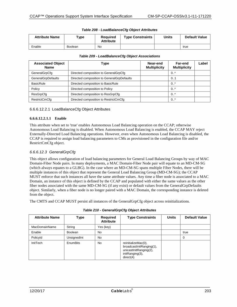
CCAP™ Operations Support System Interface Specification CM-SP-CCAP-OSSIv3.1-I11-171220
12/20/17 CableLabs 203
Table 208 - LoadBalanceCfg Object Attributes
Attribute Name Type Required Attribute
Type Constraints Units Default Value
Enable Boolean No true
Table 209 - LoadBalanceCfg Object Associations
Associated Object Name
Type Near-end Multiplicity
Far-end Multiplicity
Label
GeneralGrpCfg Directed composition to GeneralGrpCfg 0..*
GeneralGrpDefaults Directed composition to GeneralGrpDefaults 0..1
BasicRule Directed composition to BasicRule 0..*
Policy Directed composition to Policy 0..*
ResGrpCfg Directed composition to ResGrpCfg 0..*
RestrictCmCfg Directed composition to RestrictCmCfg 0..*
6.6.6.12.2.1 LoadBalanceCfg Object Attributes
6.6.6.12.2.1.1 Enable
This attribute when set to 'true' enables Autonomous Load Balancing operation on the CCAP; otherwise Autonomous Load Balancing is disabled. When Autonomous Load Balancing is enabled, the CCAP MAY reject Externally-Directed Load Balancing operations. However, even when Autonomous Load Balancing is disabled, the CCAP is required to assign load balancing parameters to CMs as provisioned in the configuration file and/or RestrictCmCfg object.
6.6.6.12.3 GeneralGrpCfg
This object allows configuration of load balancing parameters for General Load Balancing Groups by way of MAC Domain-Fiber Node pairs. In many deployments, a MAC Domain-Fiber Node pair will equate to an MD-CM-SG (which always equates to a GLBG). In the case where an MD-CM-SG spans multiple Fiber Nodes, there will be multiple instances of this object that represent the General Load Balancing Group (MD-CM-SG); the CCAP MUST enforce that such instances all have the same attribute values. Any time a fiber node is associated to a MAC Domain, an instance of this object is defined by the CCAP and populated with either the same values as the other fiber nodes associated with the same MD-CM-SG (if any exist) or default values from the GeneralGrpDefaults object. Similarly, when a fiber node is no longer paired with a MAC Domain, the corresponding instance is deleted from the object.
The CMTS and CCAP MUST persist all instances of the GeneralGrpCfg object across reinitializations.
Table 210 - GeneralGrpCfg Object Attributes
Attribute Name Type Required Attribute
Type Constraints Units Default Value
MacDomainName String Yes (key)
Enable Boolean No true
PolicyId UnsignedInt No 0
InitTech EnumBits No reinitializeMac(0), broadcastInitRanging(1), unicastInitRanging(2), initRanging(3), direct(4)
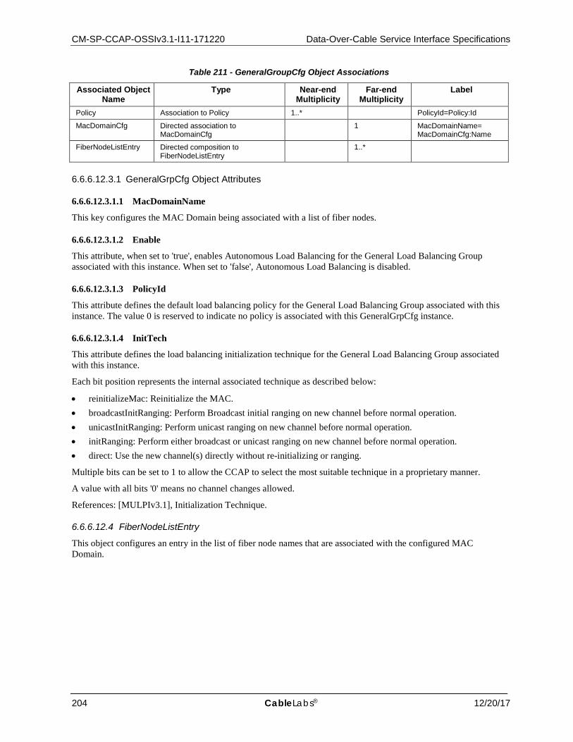
CM-SP-CCAP-OSSIv3.1-I11-171220 Data-Over-Cable Service Interface Specifications
204 CableLabs® 12/20/17
Table 211 - GeneralGroupCfg Object Associations
Associated Object Name
Type Near-end Multiplicity
Far-end Multiplicity
Label
Policy Association to Policy 1..* PolicyId=Policy:Id
MacDomainCfg Directed association to MacDomainCfg
1 MacDomainName= MacDomainCfg:Name
FiberNodeListEntry Directed composition to FiberNodeListEntry
1..*
6.6.6.12.3.1 GeneralGrpCfg Object Attributes
6.6.6.12.3.1.1 MacDomainName
This key configures the MAC Domain being associated with a list of fiber nodes.
6.6.6.12.3.1.2 Enable
This attribute, when set to 'true', enables Autonomous Load Balancing for the General Load Balancing Group associated with this instance. When set to 'false', Autonomous Load Balancing is disabled.
6.6.6.12.3.1.3 PolicyId
This attribute defines the default load balancing policy for the General Load Balancing Group associated with this instance. The value 0 is reserved to indicate no policy is associated with this GeneralGrpCfg instance.
6.6.6.12.3.1.4 InitTech
This attribute defines the load balancing initialization technique for the General Load Balancing Group associated with this instance.
Each bit position represents the internal associated technique as described below:
• reinitializeMac: Reinitialize the MAC. • broadcastInitRanging: Perform Broadcast initial ranging on new channel before normal operation. • unicastInitRanging: Perform unicast ranging on new channel before normal operation. • initRanging: Perform either broadcast or unicast ranging on new channel before normal operation. • direct: Use the new channel(s) directly without re-initializing or ranging.
Multiple bits can be set to 1 to allow the CCAP to select the most suitable technique in a proprietary manner.
A value with all bits '0' means no channel changes allowed.
References: [MULPIv3.1], Initialization Technique.
6.6.6.12.4 FiberNodeListEntry
This object configures an entry in the list of fiber node names that are associated with the configured MAC Domain.
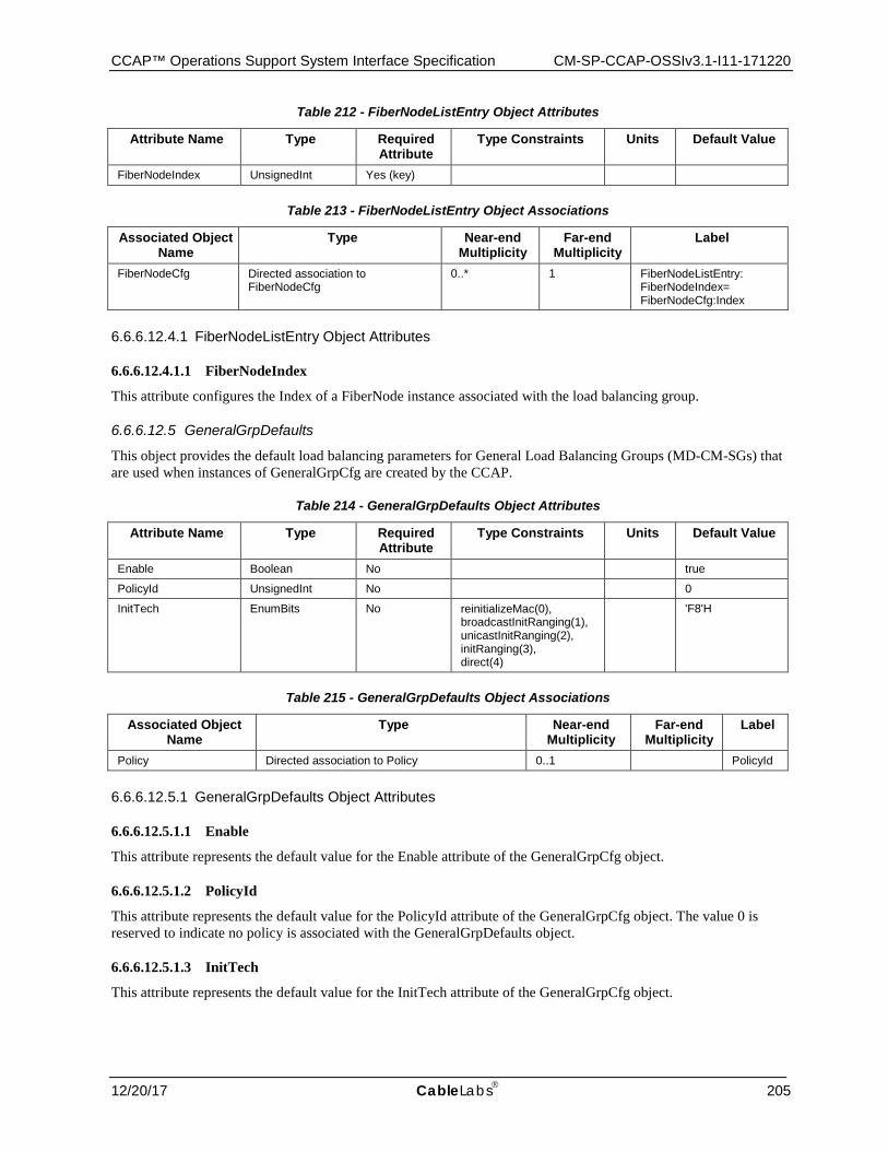
CCAP™ Operations Support System Interface Specification CM-SP-CCAP-OSSIv3.1-I11-171220
12/20/17 CableLabs 205
Table 212 - FiberNodeListEntry Object Attributes
Attribute Name Type Required Attribute
Type Constraints Units Default Value
FiberNodeIndex UnsignedInt Yes (key)
Table 213 - FiberNodeListEntry Object Associations
Associated Object Name
Type Near-end Multiplicity
Far-end Multiplicity
Label
FiberNodeCfg Directed association to FiberNodeCfg
0..* 1 FiberNodeListEntry: FiberNodeIndex= FiberNodeCfg:Index
6.6.6.12.4.1 FiberNodeListEntry Object Attributes
6.6.6.12.4.1.1 FiberNodeIndex
This attribute configures the Index of a FiberNode instance associated with the load balancing group.
6.6.6.12.5 GeneralGrpDefaults
This object provides the default load balancing parameters for General Load Balancing Groups (MD-CM-SGs) that are used when instances of GeneralGrpCfg are created by the CCAP.
Table 214 - GeneralGrpDefaults Object Attributes
Attribute Name Type Required Attribute
Type Constraints Units Default Value
Enable Boolean No true
PolicyId UnsignedInt No 0
InitTech EnumBits No reinitializeMac(0), broadcastInitRanging(1), unicastInitRanging(2), initRanging(3), direct(4)
'F8'H
Table 215 - GeneralGrpDefaults Object Associations
Associated Object Name
Type Near-end Multiplicity
Far-end Multiplicity
Label
Policy Directed association to Policy 0..1 PolicyId
6.6.6.12.5.1 GeneralGrpDefaults Object Attributes
6.6.6.12.5.1.1 Enable
This attribute represents the default value for the Enable attribute of the GeneralGrpCfg object.
6.6.6.12.5.1.2 PolicyId
This attribute represents the default value for the PolicyId attribute of the GeneralGrpCfg object. The value 0 is reserved to indicate no policy is associated with the GeneralGrpDefaults object.
6.6.6.12.5.1.3 InitTech
This attribute represents the default value for the InitTech attribute of the GeneralGrpCfg object.
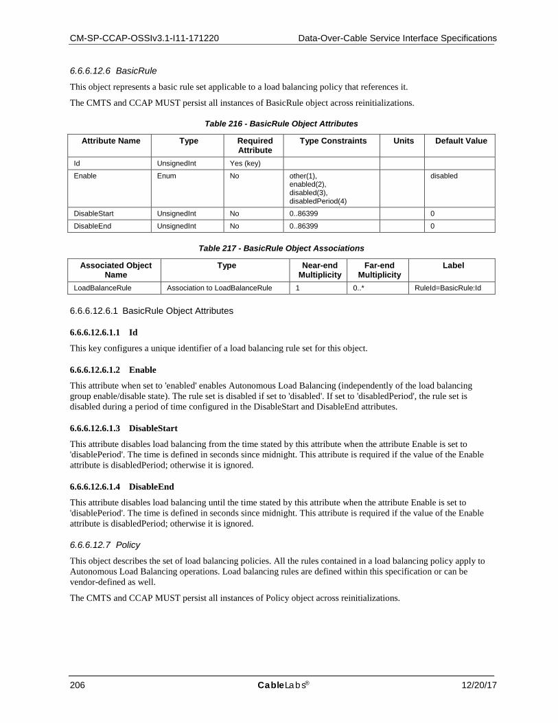
CM-SP-CCAP-OSSIv3.1-I11-171220 Data-Over-Cable Service Interface Specifications
206 CableLabs® 12/20/17
6.6.6.12.6 BasicRule
This object represents a basic rule set applicable to a load balancing policy that references it.
The CMTS and CCAP MUST persist all instances of BasicRule object across reinitializations.
Table 216 - BasicRule Object Attributes
Attribute Name Type Required Attribute
Type Constraints Units Default Value
Id UnsignedInt Yes (key)
Enable Enum No other(1), enabled(2), disabled(3), disabledPeriod(4)
disabled
DisableStart UnsignedInt No 0..86399 0
DisableEnd UnsignedInt No 0..86399 0
Table 217 - BasicRule Object Associations
Associated Object Name
Type Near-end Multiplicity
Far-end Multiplicity
Label
LoadBalanceRule Association to LoadBalanceRule 1 0..* RuleId=BasicRule:Id
6.6.6.12.6.1 BasicRule Object Attributes
6.6.6.12.6.1.1 Id
This key configures a unique identifier of a load balancing rule set for this object.
6.6.6.12.6.1.2 Enable
This attribute when set to 'enabled' enables Autonomous Load Balancing (independently of the load balancing group enable/disable state). The rule set is disabled if set to 'disabled'. If set to 'disabledPeriod', the rule set is disabled during a period of time configured in the DisableStart and DisableEnd attributes.
6.6.6.12.6.1.3 DisableStart
This attribute disables load balancing from the time stated by this attribute when the attribute Enable is set to 'disablePeriod'. The time is defined in seconds since midnight. This attribute is required if the value of the Enable attribute is disabledPeriod; otherwise it is ignored.
6.6.6.12.6.1.4 DisableEnd
This attribute disables load balancing until the time stated by this attribute when the attribute Enable is set to 'disablePeriod'. The time is defined in seconds since midnight. This attribute is required if the value of the Enable attribute is disabledPeriod; otherwise it is ignored.
6.6.6.12.7 Policy
This object describes the set of load balancing policies. All the rules contained in a load balancing policy apply to Autonomous Load Balancing operations. Load balancing rules are defined within this specification or can be vendor-defined as well.
The CMTS and CCAP MUST persist all instances of Policy object across reinitializations.
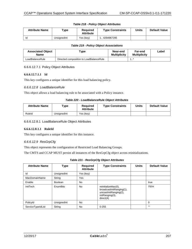
CCAP™ Operations Support System Interface Specification CM-SP-CCAP-OSSIv3.1-I11-171220
12/20/17 CableLabs 207
Table 218 - Policy Object Attributes
Attribute Name Type Required Attribute
Type Constraints Units Default Value
Id UnsignedInt Yes (key) 1.. 4294967295
Table 219 - Policy Object Associations
Associated Object Name
Type Near-end Multiplicity
Far-end Multiplicity
Label
LoadBalanceRule Directed composition to LoadBalanceRule 1..*
6.6.6.12.7.1 Policy Object Attributes
6.6.6.12.7.1.1 Id
This key configures a unique identifier for this load balancing policy.
6.6.6.12.8 LoadBalanceRule
This object allows a load balancing rule to be associated with a Policy instance.
Table 220 - LoadBalanceRule Object Attributes
Attribute Name Type Required Attribute
Type Constraints Units Default Value
RuleId UnsignedInt Yes (key)
6.6.6.12.8.1 LoadBalanceRule Object Attributes
6.6.6.12.8.1.1 RuleId
This key configures a unique identifier for this instance.
6.6.6.12.9 ResGrpCfg
This object represents the configuration of Restricted Load Balancing Groups.
The CMTS and CCAP MUST persist all instances of the ResGrpCfg object across reinitializations.
Table 221 - ResGrpCfg Object Attributes
Attribute Name Type Required Attribute
Type Constraints Units Default Value
Id UnsignedInt Yes (key)
MacDomainName String Yes
Enable Boolean No true
InitTech EnumBits No reinitializeMac(0), broadcastInitRanging(1), unicastInitRanging(2), initRanging(3), direct(4)
'F8'H
PolicyId UnsignedInt No 0
ServiceTypeIdList String No 0-255 ""
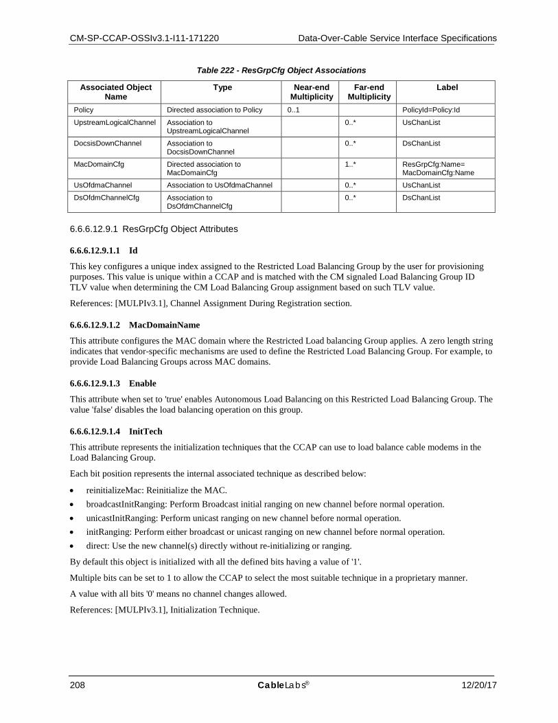
CM-SP-CCAP-OSSIv3.1-I11-171220 Data-Over-Cable Service Interface Specifications
208 CableLabs® 12/20/17
Table 222 - ResGrpCfg Object Associations
Associated Object Name
Type Near-end Multiplicity
Far-end Multiplicity
Label
Policy Directed association to Policy 0..1 PolicyId=Policy:Id
UpstreamLogicalChannel Association to UpstreamLogicalChannel
0..* UsChanList
DocsisDownChannel Association to DocsisDownChannel
0..* DsChanList
MacDomainCfg Directed association to MacDomainCfg
1..* ResGrpCfg:Name= MacDomainCfg:Name
UsOfdmaChannel Association to UsOfdmaChannel 0..* UsChanList
DsOfdmChannelCfg Association to DsOfdmChannelCfg
0..* DsChanList
6.6.6.12.9.1 ResGrpCfg Object Attributes
6.6.6.12.9.1.1 Id
This key configures a unique index assigned to the Restricted Load Balancing Group by the user for provisioning purposes. This value is unique within a CCAP and is matched with the CM signaled Load Balancing Group ID TLV value when determining the CM Load Balancing Group assignment based on such TLV value.
References: [MULPIv3.1], Channel Assignment During Registration section.
6.6.6.12.9.1.2 MacDomainName
This attribute configures the MAC domain where the Restricted Load balancing Group applies. A zero length string indicates that vendor-specific mechanisms are used to define the Restricted Load Balancing Group. For example, to provide Load Balancing Groups across MAC domains.
6.6.6.12.9.1.3 Enable
This attribute when set to 'true' enables Autonomous Load Balancing on this Restricted Load Balancing Group. The value 'false' disables the load balancing operation on this group.
6.6.6.12.9.1.4 InitTech
This attribute represents the initialization techniques that the CCAP can use to load balance cable modems in the Load Balancing Group.
Each bit position represents the internal associated technique as described below:
• reinitializeMac: Reinitialize the MAC. • broadcastInitRanging: Perform Broadcast initial ranging on new channel before normal operation. • unicastInitRanging: Perform unicast ranging on new channel before normal operation. • initRanging: Perform either broadcast or unicast ranging on new channel before normal operation. • direct: Use the new channel(s) directly without re-initializing or ranging.
By default this object is initialized with all the defined bits having a value of '1'.
Multiple bits can be set to 1 to allow the CCAP to select the most suitable technique in a proprietary manner.
A value with all bits '0' means no channel changes allowed.
References: [MULPIv3.1], Initialization Technique.
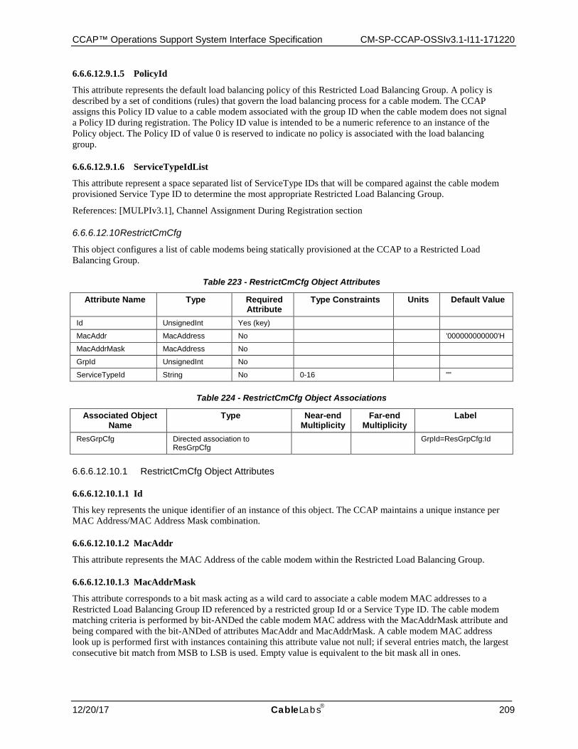
CCAP™ Operations Support System Interface Specification CM-SP-CCAP-OSSIv3.1-I11-171220
12/20/17 CableLabs 209
6.6.6.12.9.1.5 PolicyId
This attribute represents the default load balancing policy of this Restricted Load Balancing Group. A policy is described by a set of conditions (rules) that govern the load balancing process for a cable modem. The CCAP assigns this Policy ID value to a cable modem associated with the group ID when the cable modem does not signal a Policy ID during registration. The Policy ID value is intended to be a numeric reference to an instance of the Policy object. The Policy ID of value 0 is reserved to indicate no policy is associated with the load balancing group.
6.6.6.12.9.1.6 ServiceTypeIdList
This attribute represent a space separated list of ServiceType IDs that will be compared against the cable modem provisioned Service Type ID to determine the most appropriate Restricted Load Balancing Group.
References: [MULPIv3.1], Channel Assignment During Registration section
6.6.6.12.10 RestrictCmCfg
This object configures a list of cable modems being statically provisioned at the CCAP to a Restricted Load Balancing Group.
Table 223 - RestrictCmCfg Object Attributes
Attribute Name Type Required Attribute
Type Constraints Units Default Value
Id UnsignedInt Yes (key)
MacAddr MacAddress No '000000000000'H
MacAddrMask MacAddress No
GrpId UnsignedInt No
ServiceTypeId String No 0-16 ""
Table 224 - RestrictCmCfg Object Associations
Associated Object Name
Type Near-end Multiplicity
Far-end Multiplicity
Label
ResGrpCfg Directed association to ResGrpCfg
GrpId=ResGrpCfg:Id
6.6.6.12.10.1 RestrictCmCfg Object Attributes
6.6.6.12.10.1.1 Id
This key represents the unique identifier of an instance of this object. The CCAP maintains a unique instance per MAC Address/MAC Address Mask combination.
6.6.6.12.10.1.2 MacAddr
This attribute represents the MAC Address of the cable modem within the Restricted Load Balancing Group.
6.6.6.12.10.1.3 MacAddrMask
This attribute corresponds to a bit mask acting as a wild card to associate a cable modem MAC addresses to a Restricted Load Balancing Group ID referenced by a restricted group Id or a Service Type ID. The cable modem matching criteria is performed by bit-ANDed the cable modem MAC address with the MacAddrMask attribute and being compared with the bit-ANDed of attributes MacAddr and MacAddrMask. A cable modem MAC address look up is performed first with instances containing this attribute value not null; if several entries match, the largest consecutive bit match from MSB to LSB is used. Empty value is equivalent to the bit mask all in ones.
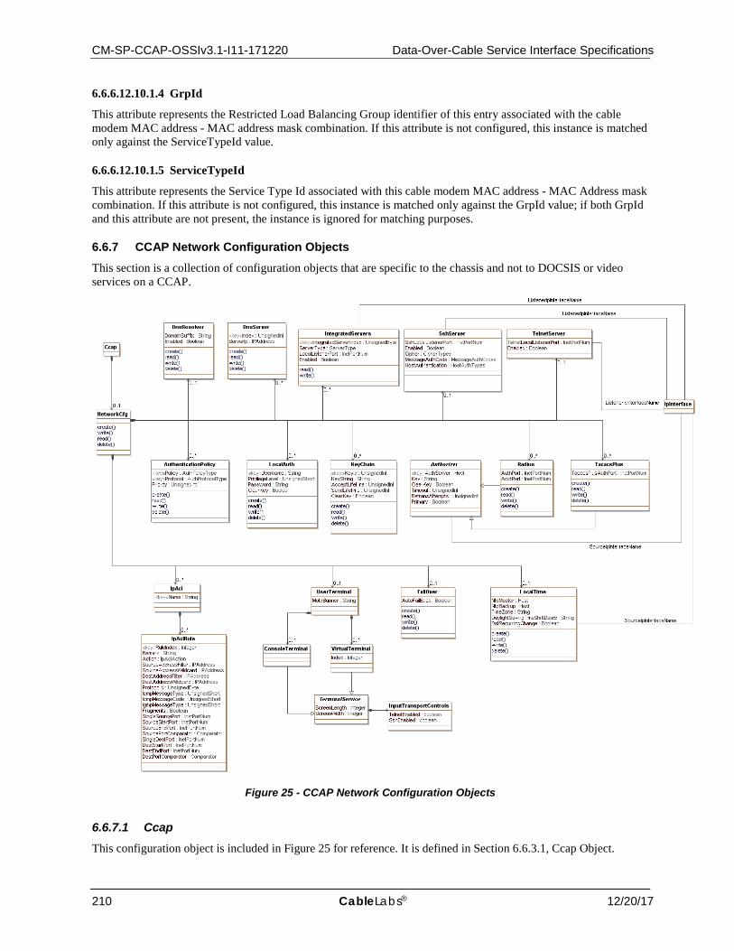
CM-SP-CCAP-OSSIv3.1-I11-171220 Data-Over-Cable Service Interface Specifications
210 CableLabs® 12/20/17
6.6.6.12.10.1.4 GrpId
This attribute represents the Restricted Load Balancing Group identifier of this entry associated with the cable modem MAC address - MAC address mask combination. If this attribute is not configured, this instance is matched only against the ServiceTypeId value.
6.6.6.12.10.1.5 ServiceTypeId
This attribute represents the Service Type Id associated with this cable modem MAC address - MAC Address mask combination. If this attribute is not configured, this instance is matched only against the GrpId value; if both GrpId and this attribute are not present, the instance is ignored for matching purposes.
6.6.7 CCAP Network Configuration Objects This section is a collection of configuration objects that are specific to the chassis and not to DOCSIS or video services on a CCAP.
Figure 25 - CCAP Network Configuration Objects
6.6.7.1 Ccap This configuration object is included in Figure 25 for reference. It is defined in Section 6.6.3.1, Ccap Object.
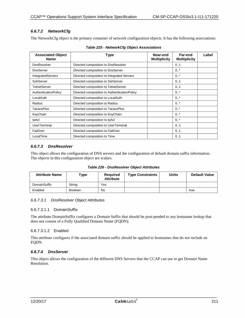
CCAP™ Operations Support System Interface Specification CM-SP-CCAP-OSSIv3.1-I11-171220
12/20/17 CableLabs 211
6.6.7.2 NetworkCfg The NetworkCfg object is the primary container of network configuration objects. It has the following associations:
Table 225 - NetworkCfg Object Associations
Associated Object Name
Type Near-end Multiplicity
Far-end Multiplicity
Label
DnsResolver Directed composition to DnsResolver 0..1
DnsServer Directed composition to DnsServer 0..*
IntegratedServers Directed composition to Integrated Servers 0..*
SshServer Directed composition to SshServer 0..1
TelnetServer Directed composition to TelnetServer 0..1
AuthenticationPolicy Directed composition to AuthenticationPolicy 0..*
LocalAuth Directed composition to LocalAuth 0..*
Radius Directed composition to Radius 0..*
TacacsPlus Directed composition to TacacsPlus 0..*
KeyChain Directed composition to KeyChain 0..*
IpAcl Directed composition to IpAcl 0..*
UserTerminal Directed composition to UserTerminal 0..1
FailOver Directed composition to FailOver 0..1
LocalTime Directed composition to Time 0..1
6.6.7.3 DnsResolver This object allows the configuration of DNS servers and the configuration of default domain suffix information. The objects in this configuration object are scalars.
Table 226 - DnsResolver Object Attributes
Attribute Name Type Required Attribute
Type Constraints Units Default Value
DomainSuffix String Yes
Enabled Boolean No true
6.6.7.3.1 DnsResolver Object Attributes
6.6.7.3.1.1 DomainSuffix
The attribute DomainSuffix configures a Domain Suffix that should be post-pended to any hostname lookup that does not consist of a Fully Qualified Domain Name (FQDN).
6.6.7.3.1.2 Enabled
This attribute configures if the associated domain suffix should be applied to hostnames that do not include an FQDN.
6.6.7.4 DnsServer This object allows the configuration of the different DNS Servers that the CCAP can use to get Domain Name Resolution.
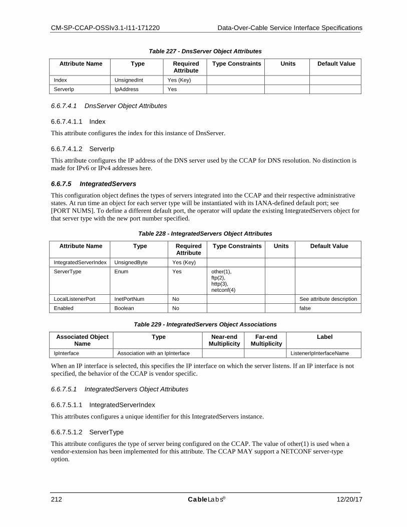
CM-SP-CCAP-OSSIv3.1-I11-171220 Data-Over-Cable Service Interface Specifications
212 CableLabs® 12/20/17
Table 227 - DnsServer Object Attributes
Attribute Name Type Required Attribute
Type Constraints Units Default Value
Index UnsignedInt Yes (Key)
ServerIp IpAddress Yes
6.6.7.4.1 DnsServer Object Attributes
6.6.7.4.1.1 Index
This attribute configures the index for this instance of DnsServer.
6.6.7.4.1.2 ServerIp
This attribute configures the IP address of the DNS server used by the CCAP for DNS resolution. No distinction is made for IPv6 or IPv4 addresses here.
6.6.7.5 IntegratedServers This configuration object defines the types of servers integrated into the CCAP and their respective administrative states. At run time an object for each server type will be instantiated with its IANA-defined default port; see [PORT NUMS]. To define a different default port, the operator will update the existing IntegratedServers object for that server type with the new port number specified.
Table 228 - IntegratedServers Object Attributes
Attribute Name Type Required Attribute
Type Constraints Units Default Value
IntegratedServerIndex UnsignedByte Yes (Key)
ServerType Enum Yes other(1), ftp(2), http(3), netconf(4)
LocalListenerPort InetPortNum No See attribute description
Enabled Boolean No false
Table 229 - IntegratedServers Object Associations
Associated Object Name
Type Near-end Multiplicity
Far-end Multiplicity
Label
IpInterface Association with an IpInterface ListenerIpInterfaceName
When an IP interface is selected, this specifies the IP interface on which the server listens. If an IP interface is not specified, the behavior of the CCAP is vendor specific.
6.6.7.5.1 IntegratedServers Object Attributes
6.6.7.5.1.1 IntegratedServerIndex
This attributes configures a unique identifier for this IntegratedServers instance.
6.6.7.5.1.2 ServerType
This attribute configures the type of server being configured on the CCAP. The value of other(1) is used when a vendor-extension has been implemented for this attribute. The CCAP MAY support a NETCONF server-type option.

CCAP™ Operations Support System Interface Specification CM-SP-CCAP-OSSIv3.1-I11-171220
12/20/17 CableLabs 213
6.6.7.5.1.3 LocalListenerPort
This attribute configures the TCP or UDP port number on which the server listens. The CCAP MUST assign the default value as the IANA-assigned port number associated with the ServerType selected, as defined in [PORT NUMS].
6.6.7.5.1.4 Enabled
This attribute configures the running state of the server. True means that the server will actively listen on the specified port. False means that the specific server is disabled.
6.6.7.6 SshServer This configuration object defines an integrated SSHv2 server in the CCAP. The CCAP SSH server MUST support SSH version 2 as defined in [RFC 4250], [RFC 4251], [RFC 4252], [RFC 4253], and [RFC 4254].
This configuration object allows different combinations of cipher, message authentication code, and host authentication code to be configured; however, a CCAP might not support all possible combinations of these three attributes.
Table 230 - SshServer Object Attributes
Attribute Name Type Required Attribute
Type Constraints
Units Default Value
SshLocalListenerPort InetPortNum No 22
Enabled Boolean No false
Cipher EnumBits No other(0), 3des(1), aes128(2), aes192(3), aes256(4), arcfour(5), blowfish(6), cast(7), twofish128(8), twofish192(9), twofish256(10)
3des
MessageAuthCode EnumBits No other(0), md5(1), md5-96(2), sha1(3), sha1-96(4), ripemd-160(5), sha2-256(6), sha2-512(7)
vendor-specific
HostAuthentication Enum No other(0), none(1), ssh-dss(2), ssh-rsa(3), pgp-sign-rsa(4), pgp-sign-dss(5)
None
Table 231 - SshServer Object Associations
Associated Object Name
Type Near-end Multiplicity
Far-end Multiplicity
Label
IpInterface Association with an IpInterface ListenerIpInterfaceName
When an IP interface is selected, this specifies the IP interface on which the server listens. If an IP interface is not specified, the behavior of the CCAP is vendor-specific.
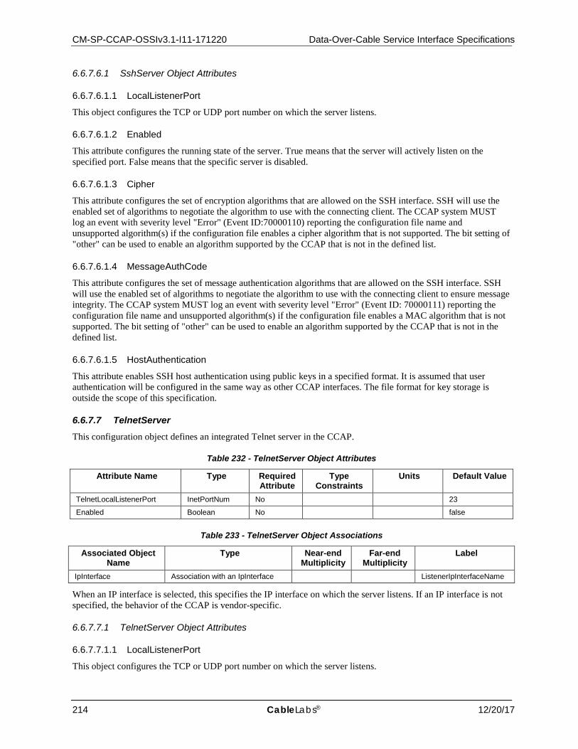
CM-SP-CCAP-OSSIv3.1-I11-171220 Data-Over-Cable Service Interface Specifications
214 CableLabs® 12/20/17
6.6.7.6.1 SshServer Object Attributes
6.6.7.6.1.1 LocalListenerPort
This object configures the TCP or UDP port number on which the server listens.
6.6.7.6.1.2 Enabled
This attribute configures the running state of the server. True means that the server will actively listen on the specified port. False means that the specific server is disabled.
6.6.7.6.1.3 Cipher
This attribute configures the set of encryption algorithms that are allowed on the SSH interface. SSH will use the enabled set of algorithms to negotiate the algorithm to use with the connecting client. The CCAP system MUST log an event with severity level "Error" (Event ID:70000110) reporting the configuration file name and unsupported algorithm(s) if the configuration file enables a cipher algorithm that is not supported. The bit setting of "other" can be used to enable an algorithm supported by the CCAP that is not in the defined list.
6.6.7.6.1.4 MessageAuthCode
This attribute configures the set of message authentication algorithms that are allowed on the SSH interface. SSH will use the enabled set of algorithms to negotiate the algorithm to use with the connecting client to ensure message integrity. The CCAP system MUST log an event with severity level "Error" (Event ID: 70000111) reporting the configuration file name and unsupported algorithm(s) if the configuration file enables a MAC algorithm that is not supported. The bit setting of "other" can be used to enable an algorithm supported by the CCAP that is not in the defined list.
6.6.7.6.1.5 HostAuthentication
This attribute enables SSH host authentication using public keys in a specified format. It is assumed that user authentication will be configured in the same way as other CCAP interfaces. The file format for key storage is outside the scope of this specification.
6.6.7.7 TelnetServer This configuration object defines an integrated Telnet server in the CCAP.
Table 232 - TelnetServer Object Attributes
Attribute Name Type Required Attribute
Type Constraints
Units Default Value
TelnetLocalListenerPort InetPortNum No 23
Enabled Boolean No false
Table 233 - TelnetServer Object Associations
Associated Object Name
Type Near-end Multiplicity
Far-end Multiplicity
Label
IpInterface Association with an IpInterface ListenerIpInterfaceName
When an IP interface is selected, this specifies the IP interface on which the server listens. If an IP interface is not specified, the behavior of the CCAP is vendor-specific.
6.6.7.7.1 TelnetServer Object Attributes
6.6.7.7.1.1 LocalListenerPort
This object configures the TCP or UDP port number on which the server listens.

CCAP™ Operations Support System Interface Specification CM-SP-CCAP-OSSIv3.1-I11-171220
12/20/17 CableLabs 215
6.6.7.7.1.2 Enabled
This attribute configures the running state of the server. True means that the server will actively listen on the specified port. False means that the specific server is disabled.
6.6.7.8 AuthenticationPolicy This configuration object allows the configuration of authentication policy. The Priority attribute controls which service is used first for authenticating users.
Table 234 - AuthenticationPolicy Object Attributes
Attribute Name Type Required Attribute
Type Constraints Units Default Value
Policy Enum Yes (Key) other(1), login(2), privilegedMode(3)
Protocol Enum Yes (Key) other(1), radius(2), tacacsPlus(3), localAuth(4), none(5)
Priority UnsignedInt Yes
6.6.7.8.1 AuthenticationPolicy Object Attributes
6.6.7.8.1.1 Policy
This attribute is the first part of the key and configures the policy type for the specified protocol. The privilegedMode(3) option is an administrative role that allows the user to execute all available commands. The value of other(1) is used when a vendor-extension has been implemented for this attribute.
6.6.7.8.1.2 Protocol
This attribute is the second part of the key and represents the protocol used for authentication. The value of other(1) is used when a vendor extension has been implemented for this attribute.
6.6.7.8.1.3 Priority
This attribute sets a priority for the protocol selected. Higher numbers are higher priority. A specified policy cannot have the same priority across multiple protocols.
6.6.7.9 LocalAuth This object configures the local user accounts and privilege levels.
Table 235 - LocalAuth Object Attributes
Attribute Name Type Required Attribute
Type Constraints
Units Default Value
Username String Yes (Key)
PrivilegeLevel UnsignedShort Yes 0..15
Password String Yes
ClearKey Boolean Yes
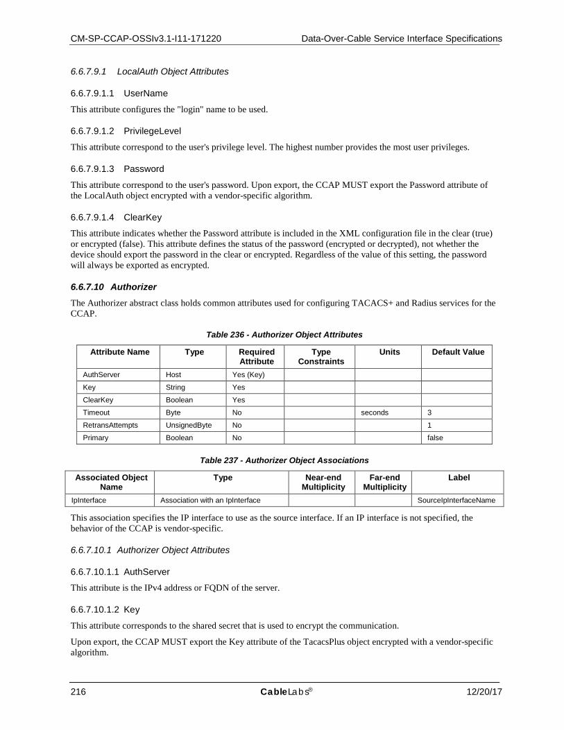
CM-SP-CCAP-OSSIv3.1-I11-171220 Data-Over-Cable Service Interface Specifications
216 CableLabs® 12/20/17
6.6.7.9.1 LocalAuth Object Attributes
6.6.7.9.1.1 UserName
This attribute configures the "login" name to be used.
6.6.7.9.1.2 PrivilegeLevel
This attribute correspond to the user's privilege level. The highest number provides the most user privileges.
6.6.7.9.1.3 Password
This attribute correspond to the user's password. Upon export, the CCAP MUST export the Password attribute of the LocalAuth object encrypted with a vendor-specific algorithm.
6.6.7.9.1.4 ClearKey
This attribute indicates whether the Password attribute is included in the XML configuration file in the clear (true) or encrypted (false). This attribute defines the status of the password (encrypted or decrypted), not whether the device should export the password in the clear or encrypted. Regardless of the value of this setting, the password will always be exported as encrypted.
6.6.7.10 Authorizer The Authorizer abstract class holds common attributes used for configuring TACACS+ and Radius services for the CCAP.
Table 236 - Authorizer Object Attributes
Attribute Name Type Required Attribute
Type Constraints
Units Default Value
AuthServer Host Yes (Key)
Key String Yes
ClearKey Boolean Yes
Timeout Byte No seconds 3
RetransAttempts UnsignedByte No 1
Primary Boolean No false
Table 237 - Authorizer Object Associations
Associated Object Name
Type Near-end Multiplicity
Far-end Multiplicity
Label
IpInterface Association with an IpInterface SourceIpInterfaceName
This association specifies the IP interface to use as the source interface. If an IP interface is not specified, the behavior of the CCAP is vendor-specific.
6.6.7.10.1 Authorizer Object Attributes
6.6.7.10.1.1 AuthServer
This attribute is the IPv4 address or FQDN of the server.
6.6.7.10.1.2 Key
This attribute corresponds to the shared secret that is used to encrypt the communication.
Upon export, the CCAP MUST export the Key attribute of the TacacsPlus object encrypted with a vendor-specific algorithm.

CCAP™ Operations Support System Interface Specification CM-SP-CCAP-OSSIv3.1-I11-171220
12/20/17 CableLabs 217
6.6.7.10.1.3 ClearKey
This attribute indicates whether the Key attribute is included in the XML configuration file in the clear (true) or encrypted (false). This attribute defines the status of the key (encrypted or decrypted), not whether the device should export the key in the clear or encrypted. Regardless of the value of this setting, the key will always be exported as encrypted.
6.6.7.10.1.4 Timeout
This attribute defines the number of seconds before a connection is declared inactive.
6.6.7.10.1.5 RetransAttempts
This attribute defines the number of retransmissions before giving up the connection.
6.6.7.10.1.6 Primary
This attribute designates whether this TACACS instance is the primary or backup server.
6.6.7.11 Radius This configuration object creates the configuration for Radius servers.
Table 238 - Radius Object Attributes
Attribute Name Type Required Attribute
Type Constraints
Units Default Value
AuthPort InetPortNum No 0..65535 1812
AcctPort InetPortNum No 0..65535 1813
Table 239 - Radius Object Associations
Associated Object Name
Type Near-end Multiplicity
Far-end Multiplicity
Label
Authorizer Specialization of Authorizer
6.6.7.11.1 Radius Object Attributes
6.6.7.11.1.1 AuthPort
This attribute defines the TCP port on which AAA authentication and authorization are performed.
6.6.7.11.1.2 AcctPort
This attribute defines the TCP port on which AAA accounting is performed.
6.6.7.12 TacacsPlus This configuration object configures TACACS+ services for the CCAP.
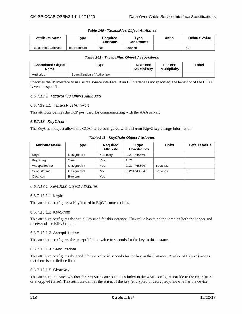
CM-SP-CCAP-OSSIv3.1-I11-171220 Data-Over-Cable Service Interface Specifications
218 CableLabs® 12/20/17
Table 240 - TacacsPlus Object Attributes
Attribute Name Type Required Attribute
Type Constraints
Units Default Value
TacacsPlusAuthPort InetPortNum No 0..65535 49
Table 241 - TacacsPlus Object Associations
Associated Object Name
Type Near-end Multiplicity
Far-end Multiplicity
Label
Authorizer Specialization of Authorizer
Specifies the IP interface to use as the source interface. If an IP interface is not specified, the behavior of the CCAP is vendor-specific.
6.6.7.12.1 TacacsPlus Object Attributes
6.6.7.12.1.1 TacacsPlusAuthPort
This attribute defines the TCP port used for communicating with the AAA server.
6.6.7.13 KeyChain The KeyChain object allows the CCAP to be configured with different Ripv2 key change information.
Table 242 - KeyChain Object Attributes
Attribute Name Type Required Attribute
Type Constraints
Units Default Value
KeyId UnsignedInt Yes (Key) 0..2147483647
KeyString String Yes 1..79
AcceptLifetime UnsignedInt Yes 0..2147483647 seconds
SendLifetime UnsignedInt No 0..2147483647 seconds 0
ClearKey Boolean Yes
6.6.7.13.1 KeyChain Object Attributes
6.6.7.13.1.1 KeyId
This attribute configures a KeyId used in RipV2 route updates.
6.6.7.13.1.2 KeyString
This attribute configures the actual key used for this instance. This value has to be the same on both the sender and receiver of the RIPv2 route.
6.6.7.13.1.3 AcceptLifetime
This attribute configures the accept lifetime value in seconds for the key in this instance.
6.6.7.13.1.4 SendLifetime
This attribute configures the send lifetime value in seconds for the key in this instance. A value of 0 (zero) means that there is no lifetime limit.
6.6.7.13.1.5 ClearKey
This attribute indicates whether the KeyString attribute is included in the XML configuration file in the clear (true) or encrypted (false). This attribute defines the status of the key (encrypted or decrypted), not whether the device
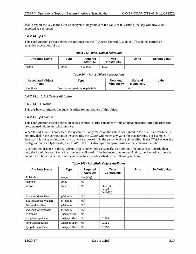
CCAP™ Operations Support System Interface Specification CM-SP-CCAP-OSSIv3.1-I11-171220
12/20/17 CableLabs 219
should export the key in the clear or encrypted. Regardless of the value of this setting, the key will always be exported as encrypted.
6.6.7.14 IpAcl This configuration object defines the attributes for the IP Access Control List object. This object defines an extended access control list.
Table 243 - IpAcl Object Attributes
Attribute Name Type Required Attribute
Type Constraints
Units Default Value
Name String Yes (Key) 1..32
Table 244 - IpAcl Object Associations
Associated Object Name
Type Near-end Multiplicity
Far-end Multiplicity
Label
IpAclRule Directed composition to IpAclRule 0..*
6.6.7.14.1 IpAcl Object Attributes
6.6.7.14.1.1 Name
This attribute configures a unique identifier for an instance of this object.
6.6.7.15 IpAclRule This configuration object defines an access control list rule contained within an IpAcl instance. Multiple rules can be contained within an IpAcl instance.
When the ACL rule is processed, the system will only match on the values configured in the rule. If an attribute is not provided in the configuration instance file, the CCAP will match any value for that attribute. For example, if ProtocolId is not specified, then any value for protocol Id in the packet will match the filter. If the CCAP rejects the configuration of an IpAclRule, the CCAP SHOULD also reject the IpAcl instance that contains the rule.
A configured instance of the IpAclRule object either holds a Remark or an Action. If it contains a Remark, then only the RuleIndex and Remark attributes are allowed. If the instance contains and Action, the Remark attribute is not allowed, but all other attributes can be included, as described in the following sections.
Table 245 - IpAclRule Object Attributes
Attribute Name Type Required Attribute
Type Constraints
Units Default Value
RuleIndex Integer Yes (Key)
Remark String No
Action Enum No other(1), deny(2), permit(3)
SourceAddressFilter IpAddress No1
SourceAddressWildcard IpAddress No2
DestAddressFilter IpAddress No1
DestAddressWildcard IpAddress No3
ProtocolId UnsignedByte No
IcmpMessageType UnsignedShort No 0..255
IcmpMessageCode UnsignedShort No 0..255
IgmpMessageType UnsignedShort No 0..255
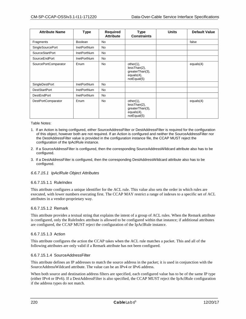
CM-SP-CCAP-OSSIv3.1-I11-171220 Data-Over-Cable Service Interface Specifications
220 CableLabs® 12/20/17
Attribute Name Type Required Attribute
Type Constraints
Units Default Value
Fragments Boolean No false
SingleSourcePort InetPortNum No
SourceStartPort InetPortNum No
SourceEndPort InetPortNum No
SourcePortComparator Enum No other(1), lessThan(2), greaterThan(3), equals(4), notEqual(5)
equals(4)
SingleDestPort InetPortNum No
DestStartPort InetPortNum No
DestEndPort InetPortNum No
DestPortComparator Enum No other(1), lessThan(2), greaterThan(3), equals(4), notEqual(5)
equals(4)
Table Notes:
1. If an Action is being configured, either SourceAddressFilter or DestAddressFilter is required for the configuration of this object, however both are not required. If an Action is configured and neither the SourceAddressFilter nor the DestAddressFilter value is provided in the configuration instance file, the CCAP MUST reject the configuration of the IpAclRule instance.
2. If a SourceAddressFilter is configured, then the corresponding SourceAddressWildcard attribute also has to be configured.
3. If a DestAddressFilter is configured, then the corresponding DestAddressWildcard attribute also has to be configured.
6.6.7.15.1 IpAclRule Object Attributes
6.6.7.15.1.1 RuleIndex
This attribute configures a unique identifier for the ACL rule. This value also sets the order in which rules are executed, with lower numbers executing first. The CCAP MAY restrict a range of indexes to a specific set of ACL attributes in a vendor-proprietary way.
6.6.7.15.1.2 Remark
This attribute provides a textual string that explains the intent of a group of ACL rules. When the Remark attribute is configured, only the RuleIndex attribute is allowed to be configured within that instance; if additional attributes are configured, the CCAP MUST reject the configuration of the IpAclRule instance.
6.6.7.15.1.3 Action
This attribute configures the action the CCAP takes when the ACL rule matches a packet. This and all of the following attributes are only valid if a Remark attribute has not been configured.
6.6.7.15.1.4 SourceAddressFilter
This attribute defines an IP addresses to match the source address in the packet; it is used in conjunction with the SourceAddressWildcard attribute. The value can be an IPv4 or IPv6 address.
When both source and destination address filters are specified, each configured value has to be of the same IP type (either IPv4 or IPv6). If a DestAddressFilter is also specified, the CCAP MUST reject the IpAclRule configuration if the address types do not match.
CCAP™ Operations Support System Interface Specification CM-SP-CCAP-OSSIv3.1-I11-171220
12/20/17 CableLabs 221
6.6.7.15.1.5 SourceAddressWildcard
The SourceAddressWildcard attribute defines which bits of the packet's source IP address are matched to the SourceAddressFilter attribute. The usage of the IP address wildcard differs from most typical applications where IP addresses are masked. Rather than restricting the defined IP address to a range of addresses by masking off the lowest significant bits of the address, the IP address mask is used as a wildcard.
Each bit in the SourceAddressWildcard set to zero indicates that the corresponding bit position in the packet's source IP address needs to exactly match the bit value in the corresponding bit position in the SourceAddressFilter. Each wildcard bit set to one indicates that both a zero bit and a one bit in the corresponding position of the packet's IP address will be considered a match to this access list entry. In other words, "ones" are places in bit positions that should be ignored. The set of "ones" does not have to start at LSB, nor has to cover consecutive bit positions. For example, a value of 0.0.255.1 is valid for an IPv4 wildcard.
For example, to configure the AclRule to match any IPv4 source address, a value of 0.0.0.0 would be configured in the SourceAddressFilter attribute and a value of 255.255.255.255 would be configured in the SourceAddressWildcard attribute.
A value of 0.0.0.0 for SourceAddressWildcard attribute signifies that the IP ACL will match packet to a specific host IP address specified in SourceAddressFilter attribute.
6.6.7.15.1.6 DestAddressFilter
This attribute defines an IP addresses to match the destination address in the packet; it is used in conjunction with the DestAddressWildcard attribute. The value can be an IPv4 or IPv6 address.
When both source and destination address filters are specified, each configured value has to be of the same IP type (either IPv4 or IPv6). If a SourceAddressFilter is also specified, the CCAP MUST reject the IpAclRule configuration if the IP address types do not match.
6.6.7.15.1.7 DestAddressWildcard
The DestAddressWildcard attribute defines which bits of the packet's source IP address are matched to the DestAddressFilter attribute. The usage of the IP address wildcard differs from most typical applications where IP addresses are masked. Rather than restricting the defined IP address to a range of addresses by masking off the lowest significant bits of the address, the IP address mask is used as a wildcard.
The rules for matching are identical to those described for SourceAddressWildcard.
6.6.7.15.1.8 ProtocolId
This attribute defines an IP protocol number for the filter to match when the protocol is not ICMP or IGMP.
If the protocol is ICMP or IGMP, one of the following attributes will be configured instead:
• IcmpMessageType • IgmpMessageType
6.6.7.15.1.9 IcmpMessageType
This attribute defines the ICMP message type for the filter to match. For the ICMP protocol, the ProtocolId attribute is not used. If both the ProtocolId and IcmpMessageType attributes are provided in an IpAclRule instance, the CCAP MUST reject the configuration of the IpAclRule instance.
6.6.7.15.1.10 IcmpMessageCode
This attribute is only applicable if an IcmpMessageType has been configured. When this attribute is defined, the CCAP will filter packets that match the configured ICMP message type and message code. If the IcmpMessageCode attribute is provided in an IpAclRule instance, but the IgmpMessageType attribute is not, the CCAP MUST reject the configuration of the IpAclRule instance.
CM-SP-CCAP-OSSIv3.1-I11-171220 Data-Over-Cable Service Interface Specifications
222 CableLabs® 12/20/17
6.6.7.15.1.11 IgmpMessageType
This attribute defines the IGMP message type for the filter to match. For the IGMP protocol, the ProtocolId attribute is not used. If both the ProtocolId and IgmpMessageType attributes are provided in an IpAclRule instance, the CCAP MUST reject the configuration of the IpAclRule instance. If both the IcmpMessageType and IgmpMessageType attributes are provided in an IpAclRule instance, the CCAP MUST reject the configuration of the IpAclRule instance.
6.6.7.15.1.12 Fragments
This attribute determines whether the ACL rule is applied to all fragments of a fragmented packet, or only to the initial fragment. A setting of false means that only the initial fragment is filtered.
6.6.7.15.1.13 SingleSourcePort
This attribute defines a single source port number for the ACL rule. The CCAP will filter a packet that comes from this source port.
For source port filtering, either the SingleSourcePort attribute, or the SourceStartPort and SourceEndPort attributes (i.e., a port range) is configured. If the SingleSourcePort and SourceStartPort attributes are provided in an IpAclRule instance, the CCAP MUST reject the configuration of the IpAclRule instance.
6.6.7.15.1.14 SourceStartPort
This attribute defines the starting source port number for a range of ports defined for the ACL rule. When the SourceStartPort attribute is configured, the SourceEndPort attribute is also required. If the SourceStartPort attribute is provided in an IpAclRule instance, but a SourceEndPort attribute is not, the CCAP MUST reject the configuration of the IpAclRule instance.
6.6.7.15.1.15 SourceEndPort
This attribute defines the ending source port number for a range of ports defined for the ACL rule. The value of this attribute has to be greater than the value in the SourceStartPort. If the SourceEndPort attribute is provided in an IpAclRule instance, but the SourceStartPort is not, the CCAP MUST reject the configuration of the IpAclRule instance.
6.6.7.15.1.16 SourcePortComparator
This attribute defines how the filter matches a specified SingleSourcePort. This attribute is not valid if a SourceStartPort and SourceEndPort are provided. The filter can match if the source port number of the packet is less than, greater than, equal to, or not equal to the defined source port number.
The CCAP MUST support the "less than", "greater than", and "not equal to" settings when a SingleSourcePort attribute is provided.
6.6.7.15.1.17 SingleDestPort
This attribute defines a single destination port number for the ACL rule. The CCAP will filter a packet that has this destination port.
For destination port filtering, either the SingleDestPort attribute, or the DestStartPort and DestEndPort attributes (i.e., a port range) are configured. If the SingleDestPort and DestStartPort attributes are provided in an IpAclRule instance, the CCAP MUST reject the configuration of the IpAclRule instance.
6.6.7.15.1.18 DestStartPort
This attribute defines the starting destination port number for a range of ports defined for the ACL rule. When the DestStartPort attribute is configured, the DestEndPort attribute is also required. If the DestStartPort attribute is provided in an IpAclRule instance, but a DestEndPort attribute is not, the CCAP MUST reject the configuration of the IpAclRule instance.
CCAP™ Operations Support System Interface Specification CM-SP-CCAP-OSSIv3.1-I11-171220
12/20/17 CableLabs 223
6.6.7.15.1.19 DestEndPort
This attribute defines the ending destination port number for a range of ports defined for the ACL rule. The value of this attribute has to be greater than the value in the DestStartPort. If the DestEndPort attribute is provided in an IpAclRule instance, but the DestStartPort is not, the CCAP MUST reject the configuration of the IpAclRule instance.
6.6.7.15.1.20 DestPortComparator
This attribute defines how the filter matches a specified SingleDestPort. The filter can match if the destination port number of the packet is less than, greater than, equal to, or not equal to the defined destination port.
The CCAP MUST support the "less than", "greater than", and "not equal to" settings when a SingleDestPort attribute is provided.
6.6.7.16 UserTerminal This container object configures the user terminal instances for the CCAP, both the ConsoleTerminal instance and VirtualTerminal instances.
Table 246 - UserTerminal Object Attributes
Attribute Name Type Required Attribute
Type Constraints
Units Default Value
MotdBanner String No ""
Table 247 - UserTerminal Object Associations
Associated Object Name
Type Near-end Multiplicity
Far-end Multiplicity
Label
TerminalService Specialization of TerminalService
6.6.7.16.1 UserTerminal Object Attributes
6.6.7.16.1.1 MotdBanner
This attribute configures the contents of a message of the day banner that displays to the user when the user logs into a virtual terminal.
6.6.7.17 VirtualTerminal This object configures a virtual terminal interface on the CCAP.
CM-SP-CCAP-OSSIv3.1-I11-171220 Data-Over-Cable Service Interface Specifications
224 CableLabs® 12/20/17
Table 248 - VirtualTerminal Object Attributes
Attribute Name Type Required Attribute
Type Constraints
Units Default Value
Index Integer Yes
Table 249 - VirtualTerminal Object Associations
Associated Object Name
Type Near-end Multiplicity
Far-end Multiplicity
Label
TerminalService Specialization of TerminalService
6.6.7.17.1 VirtualTerminal Object Attributes
6.6.7.17.1.1 Index
This attribute configures a unique index for this virtual terminal instance.
6.6.7.18 ConsoleTerminal This object configures the console terminal interface on the CCAP.
Table 250 - ConsoleTerminal Object Associations
Associated Object Name
Type Near-end Multiplicity
Far-end Multiplicity
Label
TerminalService Specialization of TerminalService
6.6.7.19 TerminalService This abstract object holds attributes used to configure the console terminal and virtual terminal instances.
Table 251 - TerminalService Object Attributes
Attribute Name Type Required Attribute
Type Constraints
Units Default Value
ScreenLength Integer No Lines 24
ScreenWidth Integer No Columns 80
Table 252 - TerminalService Object Associations
Associated Object Name
Type Near-end Multiplicity
Far-end Multiplicity
Label
InputTransportControls Directed composition to InputTransportControls
6.6.7.19.1 TerminalService Object Attributes
6.6.7.19.1.1 ScreenLength
This attribute configures the number of lines on the screen of the terminal instance.
6.6.7.19.1.2 ScreenWidth
This attribute configures the number of columns on the screen of the terminal instance.
6.6.7.20 InputTransportControls This object configures SSH and Telnet settings for a virtual terminal instance.
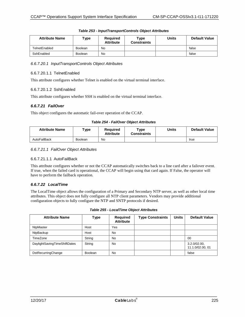
CCAP™ Operations Support System Interface Specification CM-SP-CCAP-OSSIv3.1-I11-171220
12/20/17 CableLabs 225
Table 253 - InputTransportControls Object Attributes
Attribute Name Type Required Attribute
Type Constraints
Units Default Value
TelnetEnabled Boolean No false
SshEnabled Boolean No false
6.6.7.20.1 InputTransportControls Object Attributes
6.6.7.20.1.1 TelnetEnabled
This attribute configures whether Telnet is enabled on the virtual terminal interface.
6.6.7.20.1.2 SshEnabled
This attribute configures whether SSH is enabled on the virtual terminal interface.
6.6.7.21 FailOver This object configures the automatic fail-over operation of the CCAP.
Table 254 - FailOver Object Attributes
Attribute Name Type Required Attribute
Type Constraints
Units Default Value
AutoFailBack Boolean No true
6.6.7.21.1 FailOver Object Attributes
6.6.7.21.1.1 AutoFailBack
This attribute configures whether or not the CCAP automatically switches back to a line card after a failover event. If true, when the failed card is operational, the CCAP will begin using that card again. If False, the operator will have to perform the failback operation.
6.6.7.22 LocalTime The LocalTime object allows the configuration of a Primary and Secondary NTP server, as well as other local time attributes. This object does not fully configure all NTP client parameters. Vendors may provide additional configuration objects to fully configure the NTP and SNTP protocols if desired.
Table 255 - LocalTime Object Attributes
Attribute Name Type Required Attribute
Type Constraints Units Default Value
NtpMaster Host Yes
NtpBackup Host No
TimeZone String No 00
DaylightSavingTimeShiftDates String No 3.2.0/02.00, 11.1.0/02.00, 01
DstRecurringChange Boolean No false
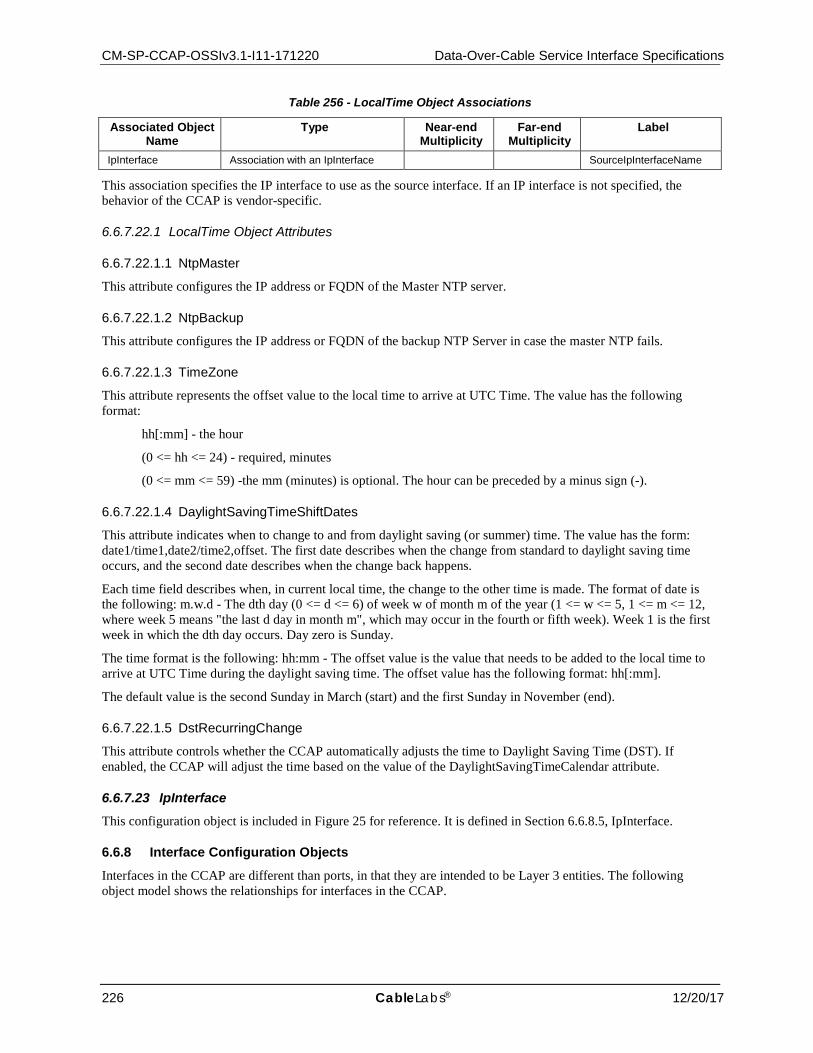
CM-SP-CCAP-OSSIv3.1-I11-171220 Data-Over-Cable Service Interface Specifications
226 CableLabs® 12/20/17
Table 256 - LocalTime Object Associations
Associated Object Name
Type Near-end Multiplicity
Far-end Multiplicity
Label
IpInterface Association with an IpInterface SourceIpInterfaceName
This association specifies the IP interface to use as the source interface. If an IP interface is not specified, the behavior of the CCAP is vendor-specific.
6.6.7.22.1 LocalTime Object Attributes
6.6.7.22.1.1 NtpMaster
This attribute configures the IP address or FQDN of the Master NTP server.
6.6.7.22.1.2 NtpBackup
This attribute configures the IP address or FQDN of the backup NTP Server in case the master NTP fails.
6.6.7.22.1.3 TimeZone
This attribute represents the offset value to the local time to arrive at UTC Time. The value has the following format:
hh[:mm] - the hour
(0 <= hh <= 24) - required, minutes
(0 <= mm <= 59) -the mm (minutes) is optional. The hour can be preceded by a minus sign (-).
6.6.7.22.1.4 DaylightSavingTimeShiftDates
This attribute indicates when to change to and from daylight saving (or summer) time. The value has the form: date1/time1,date2/time2,offset. The first date describes when the change from standard to daylight saving time occurs, and the second date describes when the change back happens.
Each time field describes when, in current local time, the change to the other time is made. The format of date is the following: m.w.d - The dth day (0 <= d <= 6) of week w of month m of the year (1 <= w <= 5, 1 <= m <= 12, where week 5 means "the last d day in month m", which may occur in the fourth or fifth week). Week 1 is the first week in which the dth day occurs. Day zero is Sunday.
The time format is the following: hh:mm - The offset value is the value that needs to be added to the local time to arrive at UTC Time during the daylight saving time. The offset value has the following format: hh[:mm].
The default value is the second Sunday in March (start) and the first Sunday in November (end).
6.6.7.22.1.5 DstRecurringChange
This attribute controls whether the CCAP automatically adjusts the time to Daylight Saving Time (DST). If enabled, the CCAP will adjust the time based on the value of the DaylightSavingTimeCalendar attribute.
6.6.7.23 IpInterface This configuration object is included in Figure 25 for reference. It is defined in Section 6.6.8.5, IpInterface.
6.6.8 Interface Configuration Objects
Interfaces in the CCAP are different than ports, in that they are intended to be Layer 3 entities. The following object model shows the relationships for interfaces in the CCAP.
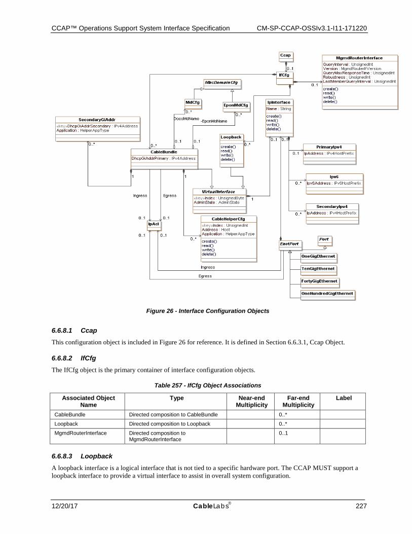
CCAP™ Operations Support System Interface Specification CM-SP-CCAP-OSSIv3.1-I11-171220
12/20/17 CableLabs 227
Figure 26 - Interface Configuration Objects
6.6.8.1 Ccap This configuration object is included in Figure 26 for reference. It is defined in Section 6.6.3.1, Ccap Object.
6.6.8.2 IfCfg The IfCfg object is the primary container of interface configuration objects.
Table 257 - IfCfg Object Associations
Associated Object Name
Type Near-end Multiplicity
Far-end Multiplicity
Label
CableBundle Directed composition to CableBundle 0..*
Loopback Directed composition to Loopback 0..*
MgmdRouterInterface Directed composition to MgmdRouterInterface
0..1
6.6.8.3 Loopback A loopback interface is a logical interface that is not tied to a specific hardware port. The CCAP MUST support a loopback interface to provide a virtual interface to assist in overall system configuration.
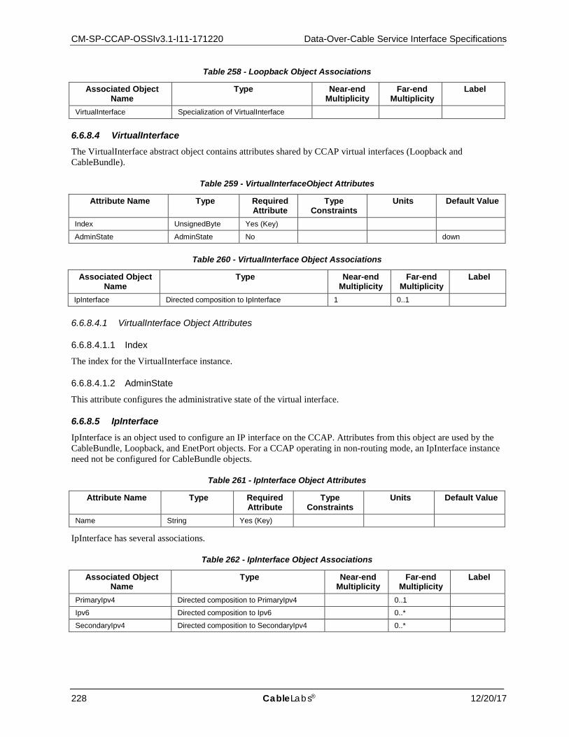
CM-SP-CCAP-OSSIv3.1-I11-171220 Data-Over-Cable Service Interface Specifications
228 CableLabs® 12/20/17
Table 258 - Loopback Object Associations
Associated Object Name
Type Near-end Multiplicity
Far-end Multiplicity
Label
VirtualInterface Specialization of VirtualInterface
6.6.8.4 VirtualInterface The VirtualInterface abstract object contains attributes shared by CCAP virtual interfaces (Loopback and CableBundle).
Table 259 - VirtualInterfaceObject Attributes
Attribute Name Type Required Attribute
Type Constraints
Units Default Value
Index UnsignedByte Yes (Key)
AdminState AdminState No down
Table 260 - VirtualInterface Object Associations
Associated Object Name
Type Near-end Multiplicity
Far-end Multiplicity
Label
IpInterface Directed composition to IpInterface 1 0..1
6.6.8.4.1 VirtualInterface Object Attributes
6.6.8.4.1.1 Index
The index for the VirtualInterface instance.
6.6.8.4.1.2 AdminState
This attribute configures the administrative state of the virtual interface.
6.6.8.5 IpInterface IpInterface is an object used to configure an IP interface on the CCAP. Attributes from this object are used by the CableBundle, Loopback, and EnetPort objects. For a CCAP operating in non-routing mode, an IpInterface instance need not be configured for CableBundle objects.
Table 261 - IpInterface Object Attributes
Attribute Name Type Required Attribute
Type Constraints
Units Default Value
Name String Yes (Key)
IpInterface has several associations.
Table 262 - IpInterface Object Associations
Associated Object Name
Type Near-end Multiplicity
Far-end Multiplicity
Label
PrimaryIpv4 Directed composition to PrimaryIpv4 0..1
Ipv6 Directed composition to Ipv6 0..*
SecondaryIpv4 Directed composition to SecondaryIpv4 0..*
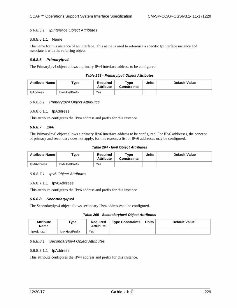
CCAP™ Operations Support System Interface Specification CM-SP-CCAP-OSSIv3.1-I11-171220
12/20/17 CableLabs 229
6.6.8.5.1 IpInterface Object Attributes
6.6.8.5.1.1 Name
The name for this instance of an interface. This name is used to reference a specific IpInterface instance and associate it with the referring object.
6.6.8.6 PrimaryIpv4 The PrimaryIpv4 object allows a primary IPv4 interface address to be configured.
Table 263 - PrimaryIpv4 Object Attributes
Attribute Name Type Required Attribute
Type Constraints
Units Default Value
IpAddress Ipv4HostPrefix Yes
6.6.8.6.1 PrimaryIpv4 Object Attributes
6.6.8.6.1.1 IpAddress
This attribute configures the IPv4 address and prefix for this instance.
6.6.8.7 Ipv6 The PrimaryIpv6 object allows a primary IPv6 interface address to be configured. For IPv6 addresses, the concept of primary and secondary does not apply; for this reason, a list of IPv6 addresses may be configured.
Table 264 - Ipv6 Object Attributes
Attribute Name Type Required Attribute
Type Constraints
Units Default Value
Ipv6Address Ipv6HostPrefix Yes
6.6.8.7.1 Ipv6 Object Attributes
6.6.8.7.1.1 Ipv6Address
This attribute configures the IPv6 address and prefix for this instance.
6.6.8.8 SecondaryIpv4 The SecondaryIpv4 object allows secondary IPv4 addresses to be configured.
Table 265 - SecondaryIpv4 Object Attributes
Attribute Name
Type Required Attribute
Type Constraints Units Default Value
IpAddress Ipv4HostPrefix Yes
6.6.8.8.1 SecondaryIpv4 Object Attributes
6.6.8.8.1.1 IpAddress
This attribute configures the IPv4 address and prefix for this instance.
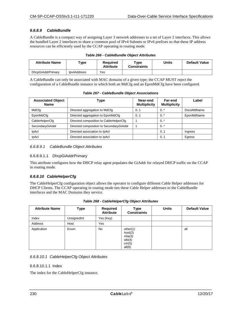
CM-SP-CCAP-OSSIv3.1-I11-171220 Data-Over-Cable Service Interface Specifications
230 CableLabs® 12/20/17
6.6.8.9 CableBundle A CableBundle is a compact way of assigning Layer 3 network addresses to a set of Layer 2 interfaces. This allows the bundled Layer 2 interfaces to share a common pool of IPv4 Subnets or IPv6 prefixes so that these IP address resources can be efficiently used by the CCAP operating in routing mode.
Table 266 - CableBundle Object Attributes
Attribute Name Type Required Attribute
Type Constraints
Units Default Value
DhcpGiAddrPrimary Ipv4Address Yes
A CableBundle can only be associated with MAC domains of a given type; the CCAP MUST reject the configuration of a CableBundle instance in which both an MdCfg and an EponMdCfg have been configured.
Table 267 - CableBundle Object Associations
Associated Object Name
Type Near-end Multiplicity
Far-end Multiplicity
Label
MdCfg Directed aggregation to MdCfg 0..1 0..* DocsMdName
EponMdCfg Directed aggregation to EponMdCfg 0..1 0..* EponMdName
CableHelperCfg Directed composition to CableHelperCfg 1 0..*
SecondaryGiAddr Directed composition to SecondaryGiAddr 1 0..*
IpAcl Directed association to IpAcl 0..1 Ingress
IpAcl Directed association to IpAcl 0..1 Egress
6.6.8.9.1 CableBundle Object Attributes
6.6.8.9.1.1 DhcpGiAddrPrimary
This attribute configures how the DHCP relay agent populates the GiAddr for relayed DHCP traffic on the CCAP in routing mode.
6.6.8.10 CableHelperCfg The CableHelperCfg configuration object allows the operator to configure different Cable Helper addresses for DHCP Clients. The CCAP operating in routing mode ties these Cable Helper addresses to the CableBundle interfaces and the MAC Domains they service.
Table 268 - CableHelperCfg Object Attributes
Attribute Name Type Required Attribute
Type Constraints
Units Default Value
Index UnsignedInt Yes (Key)
Address Host Yes
Application Enum No other(1) host(2) mta(3) stb(4) cm(5) all(6)
all
6.6.8.10.1 CableHelperCfg Object Attributes
6.6.8.10.1.1 Index
The index for the CableHelperCfg instance.
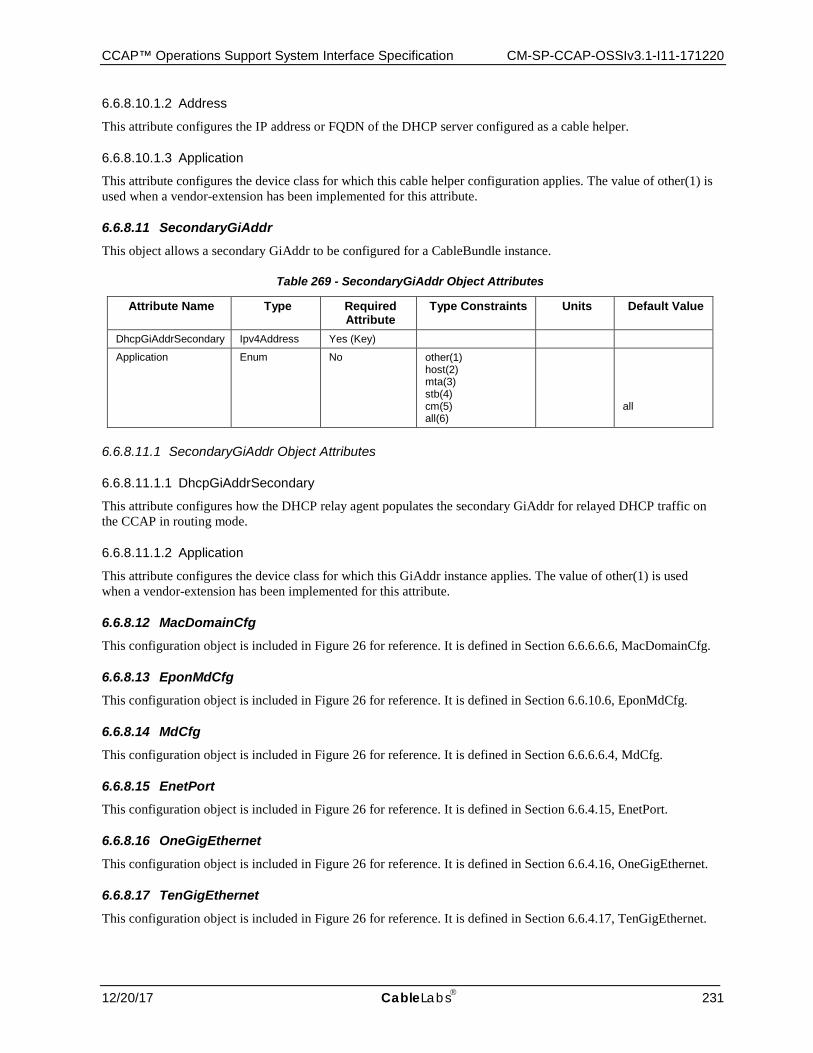
CCAP™ Operations Support System Interface Specification CM-SP-CCAP-OSSIv3.1-I11-171220
12/20/17 CableLabs 231
6.6.8.10.1.2 Address
This attribute configures the IP address or FQDN of the DHCP server configured as a cable helper.
6.6.8.10.1.3 Application
This attribute configures the device class for which this cable helper configuration applies. The value of other(1) is used when a vendor-extension has been implemented for this attribute.
6.6.8.11 SecondaryGiAddr This object allows a secondary GiAddr to be configured for a CableBundle instance.
Table 269 - SecondaryGiAddr Object Attributes
Attribute Name Type Required Attribute
Type Constraints Units Default Value
DhcpGiAddrSecondary Ipv4Address Yes (Key)
Application Enum No other(1) host(2) mta(3) stb(4) cm(5) all(6)
all
6.6.8.11.1 SecondaryGiAddr Object Attributes
6.6.8.11.1.1 DhcpGiAddrSecondary
This attribute configures how the DHCP relay agent populates the secondary GiAddr for relayed DHCP traffic on the CCAP in routing mode.
6.6.8.11.1.2 Application
This attribute configures the device class for which this GiAddr instance applies. The value of other(1) is used when a vendor-extension has been implemented for this attribute.
6.6.8.12 MacDomainCfg This configuration object is included in Figure 26 for reference. It is defined in Section 6.6.6.6.6, MacDomainCfg.
6.6.8.13 EponMdCfg This configuration object is included in Figure 26 for reference. It is defined in Section 6.6.10.6, EponMdCfg.
6.6.8.14 MdCfg This configuration object is included in Figure 26 for reference. It is defined in Section 6.6.6.6.4, MdCfg.
6.6.8.15 EnetPort This configuration object is included in Figure 26 for reference. It is defined in Section 6.6.4.15, EnetPort.
6.6.8.16 OneGigEthernet This configuration object is included in Figure 26 for reference. It is defined in Section 6.6.4.16, OneGigEthernet.
6.6.8.17 TenGigEthernet This configuration object is included in Figure 26 for reference. It is defined in Section 6.6.4.17, TenGigEthernet.
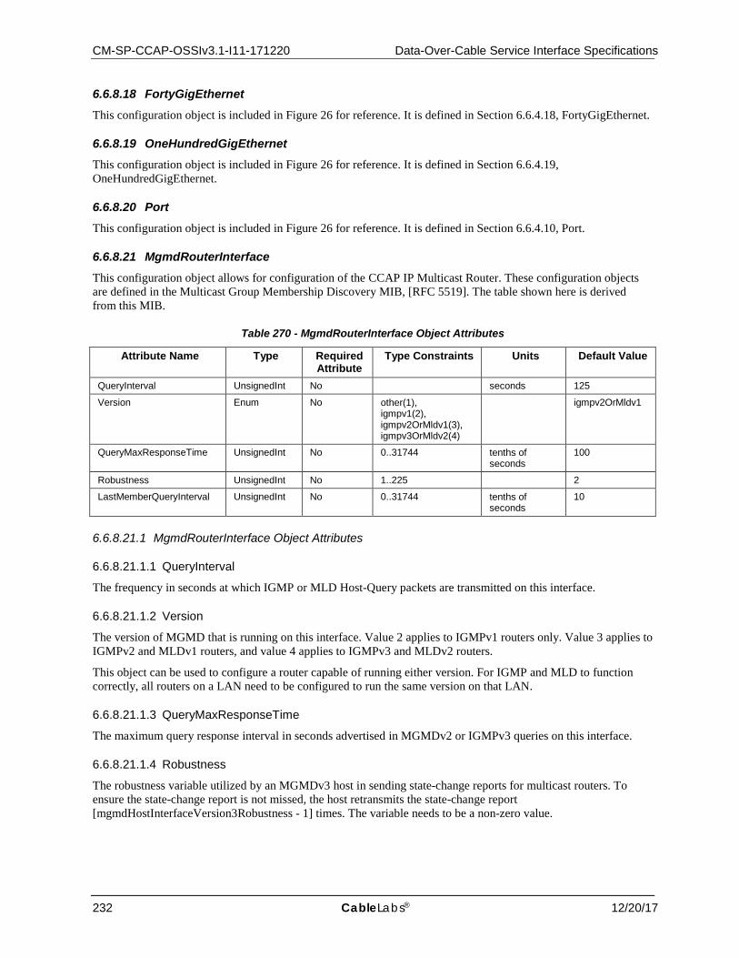
CM-SP-CCAP-OSSIv3.1-I11-171220 Data-Over-Cable Service Interface Specifications
232 CableLabs® 12/20/17
6.6.8.18 FortyGigEthernet This configuration object is included in Figure 26 for reference. It is defined in Section 6.6.4.18, FortyGigEthernet.
6.6.8.19 OneHundredGigEthernet This configuration object is included in Figure 26 for reference. It is defined in Section 6.6.4.19, OneHundredGigEthernet.
6.6.8.20 Port This configuration object is included in Figure 26 for reference. It is defined in Section 6.6.4.10, Port.
6.6.8.21 MgmdRouterInterface This configuration object allows for configuration of the CCAP IP Multicast Router. These configuration objects are defined in the Multicast Group Membership Discovery MIB, [RFC 5519]. The table shown here is derived from this MIB.
Table 270 - MgmdRouterInterface Object Attributes
Attribute Name Type Required Attribute
Type Constraints Units Default Value
QueryInterval UnsignedInt No seconds 125
Version Enum No other(1), igmpv1(2), igmpv2OrMldv1(3), igmpv3OrMldv2(4)
igmpv2OrMldv1
QueryMaxResponseTime UnsignedInt No 0..31744 tenths of seconds
100
Robustness UnsignedInt No 1..225 2
LastMemberQueryInterval UnsignedInt No 0..31744 tenths of seconds
10
6.6.8.21.1 MgmdRouterInterface Object Attributes
6.6.8.21.1.1 QueryInterval
The frequency in seconds at which IGMP or MLD Host-Query packets are transmitted on this interface.
6.6.8.21.1.2 Version
The version of MGMD that is running on this interface. Value 2 applies to IGMPv1 routers only. Value 3 applies to IGMPv2 and MLDv1 routers, and value 4 applies to IGMPv3 and MLDv2 routers.
This object can be used to configure a router capable of running either version. For IGMP and MLD to function correctly, all routers on a LAN need to be configured to run the same version on that LAN.
6.6.8.21.1.3 QueryMaxResponseTime
The maximum query response interval in seconds advertised in MGMDv2 or IGMPv3 queries on this interface.
6.6.8.21.1.4 Robustness
The robustness variable utilized by an MGMDv3 host in sending state-change reports for multicast routers. To ensure the state-change report is not missed, the host retransmits the state-change report [mgmdHostInterfaceVersion3Robustness - 1] times. The variable needs to be a non-zero value.
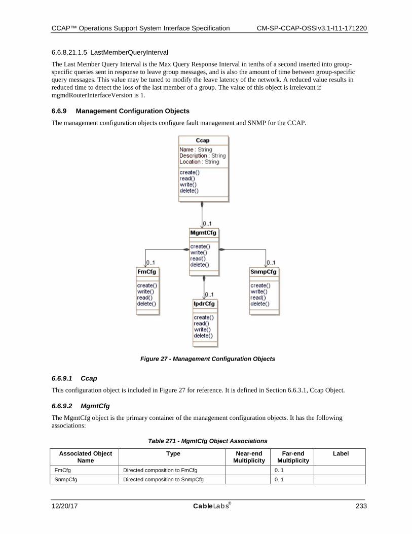
CCAP™ Operations Support System Interface Specification CM-SP-CCAP-OSSIv3.1-I11-171220
12/20/17 CableLabs 233
6.6.8.21.1.5 LastMemberQueryInterval
The Last Member Query Interval is the Max Query Response Interval in tenths of a second inserted into group-specific queries sent in response to leave group messages, and is also the amount of time between group-specific query messages. This value may be tuned to modify the leave latency of the network. A reduced value results in reduced time to detect the loss of the last member of a group. The value of this object is irrelevant if mgmdRouterInterfaceVersion is 1.
6.6.9 Management Configuration Objects
The management configuration objects configure fault management and SNMP for the CCAP.
Figure 27 - Management Configuration Objects
6.6.9.1 Ccap This configuration object is included in Figure 27 for reference. It is defined in Section 6.6.3.1, Ccap Object.
6.6.9.2 MgmtCfg The MgmtCfg object is the primary container of the management configuration objects. It has the following associations:
Table 271 - MgmtCfg Object Associations
Associated Object Name
Type Near-end Multiplicity
Far-end Multiplicity
Label
FmCfg Directed composition to FmCfg 0..1
SnmpCfg Directed composition to SnmpCfg 0..1
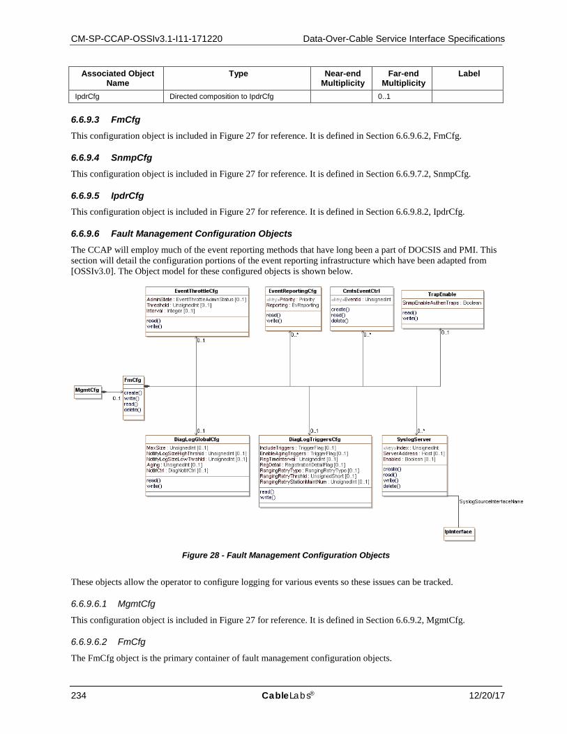
CM-SP-CCAP-OSSIv3.1-I11-171220 Data-Over-Cable Service Interface Specifications
234 CableLabs® 12/20/17
Associated Object Name
Type Near-end Multiplicity
Far-end Multiplicity
Label
IpdrCfg Directed composition to IpdrCfg 0..1
6.6.9.3 FmCfg This configuration object is included in Figure 27 for reference. It is defined in Section 6.6.9.6.2, FmCfg.
6.6.9.4 SnmpCfg This configuration object is included in Figure 27 for reference. It is defined in Section 6.6.9.7.2, SnmpCfg.
6.6.9.5 IpdrCfg This configuration object is included in Figure 27 for reference. It is defined in Section 6.6.9.8.2, IpdrCfg.
6.6.9.6 Fault Management Configuration Objects The CCAP will employ much of the event reporting methods that have long been a part of DOCSIS and PMI. This section will detail the configuration portions of the event reporting infrastructure which have been adapted from [OSSIv3.0]. The Object model for these configured objects is shown below.
Figure 28 - Fault Management Configuration Objects
These objects allow the operator to configure logging for various events so these issues can be tracked.
6.6.9.6.1 MgmtCfg
This configuration object is included in Figure 27 for reference. It is defined in Section 6.6.9.2, MgmtCfg.
6.6.9.6.2 FmCfg
The FmCfg object is the primary container of fault management configuration objects.
CCAP™ Operations Support System Interface Specification CM-SP-CCAP-OSSIv3.1-I11-171220
12/20/17 CableLabs 235
The Diagnostic Log is one of the DOCSIS Fault Management functions. The Diagnostic Log allows operators to diagnose and troubleshoot potential problems with Cable Modems (CMs), CMTS cable interfaces, or the cable plant by detecting and tracking CMs that have intermittent connectivity problems or unstable operations including:
• CM repeated registration • Station Maintenance retry
Only detected CMs are reported in the Diagnostic Log for further analysis. Diagnostic Log entries are aged out based on the configuration of the specific aging attributes. The FmCfg contains the configuration objects for the Diagnostic Log function.
The FmCfg has the following associations:
Table 272 - FmCfg Object Associations
Associated Object Name
Type Near-end Multiplicity
Far-end Multiplicity
Label
EventThrottleCfg Directed composition to EventThrottleCfg 0..1
EventReportingCfg Directed composition to EventReportingCfg 0..*
CmtsEventCtrl Directed composition to CmtsEventCtrl 0..*
TrapEnable Directed composition to TrapEnable 0..1
DiagLogGlobalCfg Directed composition to DiagLogGlobalCfg 0..1
DiagLogTriggersCfg Directed composition to DiagLogTriggersCfg 0..1
SyslogServer Directed composition to SyslogServer 0..*
6.6.9.6.3 EventThrottleCfg
This configuration object is based on the docsDevEvent group defined in [RFC 4639] and uses the following attributes without modification for CCAP:
• AdminStatus (renamed AdminState) • Threshold • Interval
Reference: [RFC 4639], docsDevEvent Group
6.6.9.6.4 EventReportingCfg
This configuration object is based on the docsDevEvControlTable object defined in [RFC 4639] and will be used without modification for CCAP.
Reference: [RFC 4639], docsDevEvControlTable
6.6.9.6.5 CmtsEventCtrl
This object represents the control mechanism to enable the dispatching of events based on the Event Id. The following rules define the event control behavior:
• If the CmtsEventCtrl object has no instances or contains an instance with Event ID 0, then all events matching the Local Log settings of docsDevEvReporting are sent to local log ONLY.
• Additionally, if the CmtsEventCtrl object contains configured instances, then Events matching the Event Ids configured in the object are sent according to the settings of the docsDevEvReporting object; i.e., Traps, Syslog, etc.
The CMTS and CCAP MUST persist all instances of CmtsEventCtrl across reinitializations.

CM-SP-CCAP-OSSIv3.1-I11-171220 Data-Over-Cable Service Interface Specifications
236 CableLabs® 12/20/17
Table 273 - CmtsEventCtrl Object
Attribute Name Type Required Attribute
Type Constraints Units Default
EventId unsignedInt key
6.6.9.6.5.1 CmtsEvent Ctrl Object Attributes
6.6.9.6.5.1.1 EventId
This key represents the Event ID of the event being enabled for delivery to a dispatch mechanism (e.g., syslog).
References: Annex D.
6.6.9.6.6 TrapEnable
This configuration object contains attributes which allow enabling or disabling of SNMP Notifications. The SnmpEnableAuthenTraps attribute is taken from [RFC 3418] and will be used without modification for the CCAP.
Reference: [RFC 3418], snmpEnableAuthenTraps
6.6.9.6.7 DiagLogGlobalCfg
The following read-only attributes have been removed:
• CurrentSize • LastResetTime • LastClearTime
This object defines the parameters to manage and control the instantiation of CMs in the Diagnostic Log object.
The CMTS and CCAP MUST persist the values of the attributes of the DiagLogGlobalCfg object across reinitializations.
Table 274 - DiagLogGlobalCfg Object Attributes
Attribute Name Type Required Attribute
Type Constraints Units Default
MaxSize unsignedInt No 1..4294967295 instances 100
NotifyLogSizeHighThrshld unsignedInt No 1..4294967295 instances 80
NotifyLogSizeLowThrshld unsignedInt No 1..4294967295 instances 60
Aging unsignedInt No 15..86400 minutes 10080
NotifCtrl EnumBits No highThresholdReached(0) lowThresholdReached(1) full(2)
''H
6.6.9.6.7.1 DiagLogGlobalCfg Object Attributes
6.6.9.6.7.1.1 MaxSize
This attribute indicates the maximum number of CM instances that can be reported in the Log.
6.6.9.6.7.1.2 NotifyLogSizeHighThrshld
This attribute is the Log high threshold value. When the number of instances in the Log exceeds this value, the CMTS will trigger a HighThreshold event.
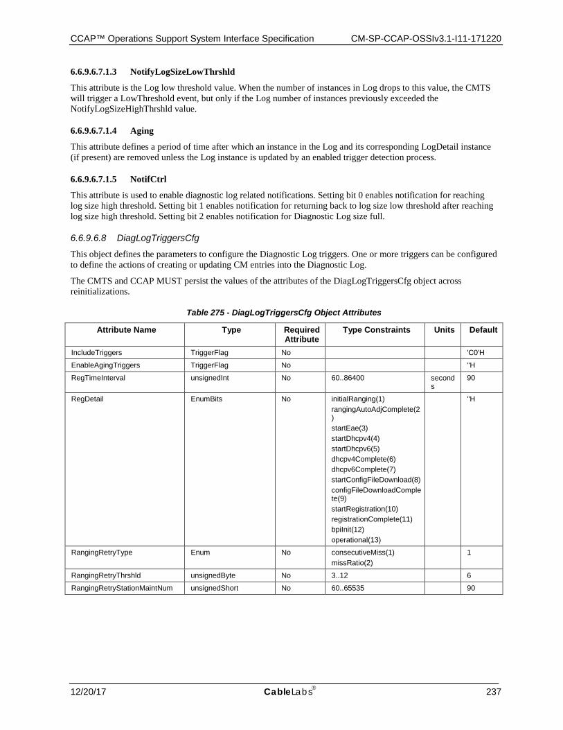
CCAP™ Operations Support System Interface Specification CM-SP-CCAP-OSSIv3.1-I11-171220
12/20/17 CableLabs 237
6.6.9.6.7.1.3 NotifyLogSizeLowThrshld
This attribute is the Log low threshold value. When the number of instances in Log drops to this value, the CMTS will trigger a LowThreshold event, but only if the Log number of instances previously exceeded the NotifyLogSizeHighThrshld value.
6.6.9.6.7.1.4 Aging
This attribute defines a period of time after which an instance in the Log and its corresponding LogDetail instance (if present) are removed unless the Log instance is updated by an enabled trigger detection process.
6.6.9.6.7.1.5 NotifCtrl
This attribute is used to enable diagnostic log related notifications. Setting bit 0 enables notification for reaching log size high threshold. Setting bit 1 enables notification for returning back to log size low threshold after reaching log size high threshold. Setting bit 2 enables notification for Diagnostic Log size full.
6.6.9.6.8 DiagLogTriggersCfg
This object defines the parameters to configure the Diagnostic Log triggers. One or more triggers can be configured to define the actions of creating or updating CM entries into the Diagnostic Log.
The CMTS and CCAP MUST persist the values of the attributes of the DiagLogTriggersCfg object across reinitializations.
Table 275 - DiagLogTriggersCfg Object Attributes
Attribute Name Type Required Attribute
Type Constraints Units Default
IncludeTriggers TriggerFlag No 'C0'H
EnableAgingTriggers TriggerFlag No ''H
RegTimeInterval unsignedInt No 60..86400 seconds
90
RegDetail EnumBits No initialRanging(1) rangingAutoAdjComplete(2) startEae(3) startDhcpv4(4) startDhcpv6(5) dhcpv4Complete(6) dhcpv6Complete(7) startConfigFileDownload(8) configFileDownloadComplete(9) startRegistration(10) registrationComplete(11) bpiInit(12) operational(13)
''H
RangingRetryType Enum No consecutiveMiss(1) missRatio(2)
1
RangingRetryThrshld unsignedByte No 3..12 6
RangingRetryStationMaintNum unsignedShort No 60..65535 90

CM-SP-CCAP-OSSIv3.1-I11-171220 Data-Over-Cable Service Interface Specifications
238 CableLabs® 12/20/17
6.6.9.6.8.1 DiagLogTriggersCfg Object Attributes
6.6.9.6.8.1.1 IncludeTriggers
This attribute turns individual diagnostic triggers on and off at a given time when each trigger is set to '1' or '0', respectively.
6.6.9.6.8.1.2 EnableAgingTriggers
This attribute enables and disables the aging of individual triggers at a given time when each trigger is set to '1' or '0' respectively. If a log entry is added by multiple triggers, and aging is disabled for one of those triggers, the CMTS MUST NOT age out such entry.
6.6.9.6.8.1.3 RegTimeInterval
This attribute is an operator empirically derived, worst-case number of seconds which the CM requires to complete registration. If the CM has not completed the registration stage within this registration time interval, the CM will be added to the Diagnostic Log.
6.6.9.6.8.1.4 RegDetail
This attribute provides for setting a bit representing a CM registration state to enable counting the number of times the CMTS determines that such CM reaches that state as the last state before failing to proceed further in the registration process and within the time interval considered for the CM registration trigger detection.
The meaning of the bit positions (left to right) are as follows:
initialRanging(1)
rangingAutoAdjComplete(2)
startEae(3)
startDhcpv4(4)
startDhcpv6(5)
dhcpv4Complete(6)
dhcpv6Complete(7)
startConfigFileDownload(8)
configFileDownloadComplete(9)
startRegistration(10)
registrationComplete(11)
bpiInit(12)
operational(13)
6.6.9.6.8.1.5 RangingRetryType
This attribute selects the type of ranging retry trigger to be enable in the Diagnostic Log. A CM failure to perform ranging when a ranging opportunity is scheduled by the CMTS is counted as ranging miss. The ranging retry trigger can be configured to either look at consecutive ranging misses or ranging miss ratio over total number of station maintenance opportunities for a certain time period. Setting this object to 'consecutiveMiss' will select consecutive ranging misses as ranging retry trigger criteria. Setting this object to 'missRatio' will select ranging miss ratio as ranging retry criteria.
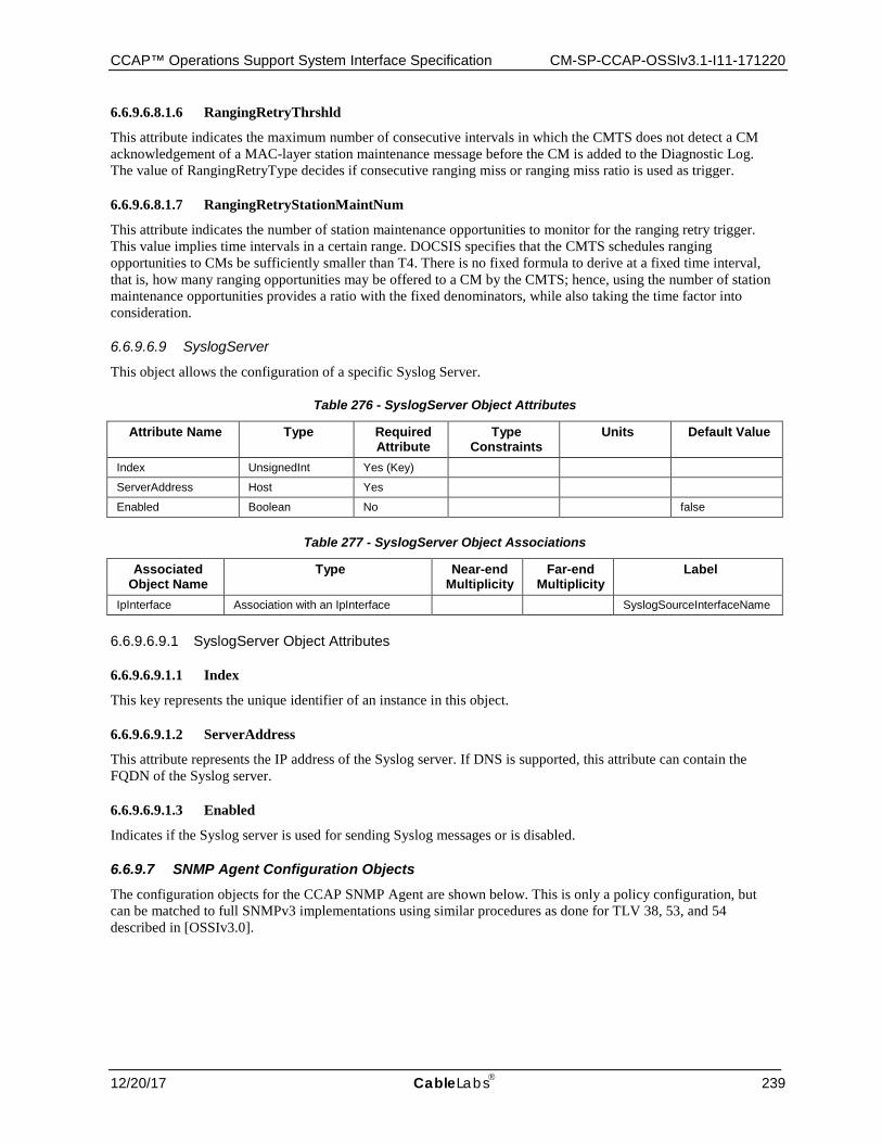
CCAP™ Operations Support System Interface Specification CM-SP-CCAP-OSSIv3.1-I11-171220
12/20/17 CableLabs 239
6.6.9.6.8.1.6 RangingRetryThrshld
This attribute indicates the maximum number of consecutive intervals in which the CMTS does not detect a CM acknowledgement of a MAC-layer station maintenance message before the CM is added to the Diagnostic Log. The value of RangingRetryType decides if consecutive ranging miss or ranging miss ratio is used as trigger.
6.6.9.6.8.1.7 RangingRetryStationMaintNum
This attribute indicates the number of station maintenance opportunities to monitor for the ranging retry trigger. This value implies time intervals in a certain range. DOCSIS specifies that the CMTS schedules ranging opportunities to CMs be sufficiently smaller than T4. There is no fixed formula to derive at a fixed time interval, that is, how many ranging opportunities may be offered to a CM by the CMTS; hence, using the number of station maintenance opportunities provides a ratio with the fixed denominators, while also taking the time factor into consideration.
6.6.9.6.9 SyslogServer
This object allows the configuration of a specific Syslog Server.
Table 276 - SyslogServer Object Attributes
Attribute Name Type Required Attribute
Type Constraints
Units Default Value
Index UnsignedInt Yes (Key)
ServerAddress Host Yes
Enabled Boolean No false
Table 277 - SyslogServer Object Associations
Associated Object Name
Type Near-end Multiplicity
Far-end Multiplicity
Label
IpInterface Association with an IpInterface SyslogSourceInterfaceName
6.6.9.6.9.1 SyslogServer Object Attributes
6.6.9.6.9.1.1 Index
This key represents the unique identifier of an instance in this object.
6.6.9.6.9.1.2 ServerAddress
This attribute represents the IP address of the Syslog server. If DNS is supported, this attribute can contain the FQDN of the Syslog server.
6.6.9.6.9.1.3 Enabled
Indicates if the Syslog server is used for sending Syslog messages or is disabled.
6.6.9.7 SNMP Agent Configuration Objects The configuration objects for the CCAP SNMP Agent are shown below. This is only a policy configuration, but can be matched to full SNMPv3 implementations using similar procedures as done for TLV 38, 53, and 54 described in [OSSIv3.0].
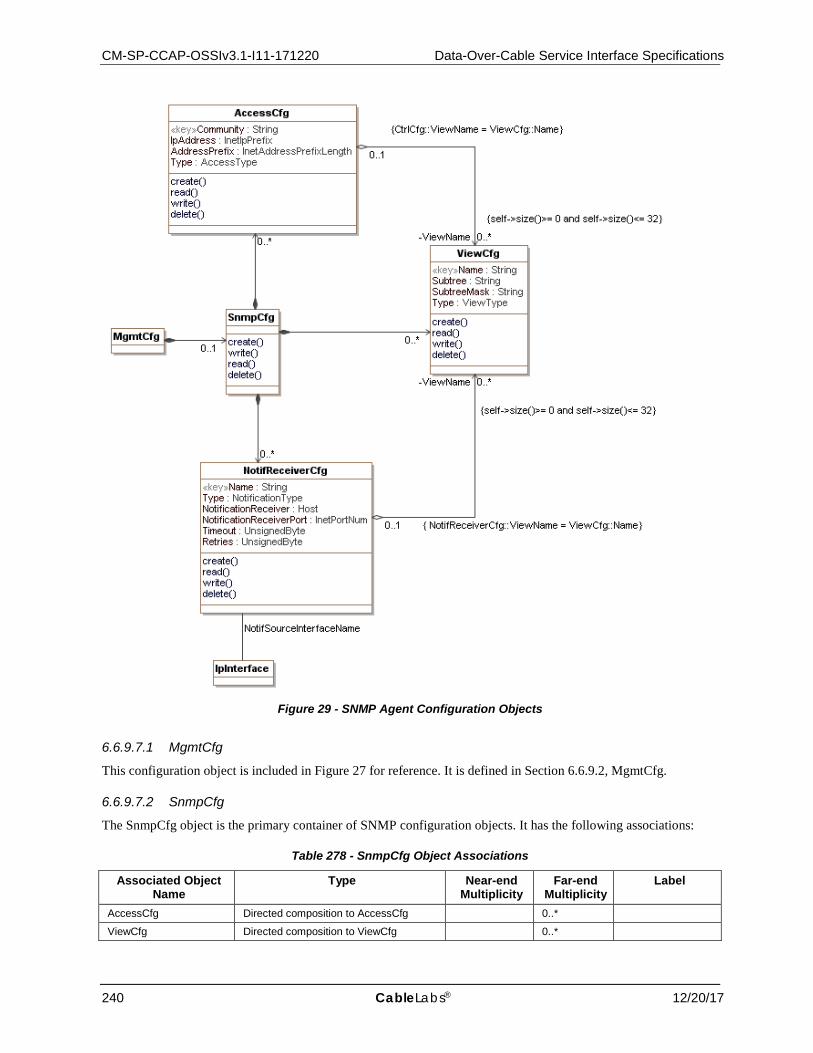
CM-SP-CCAP-OSSIv3.1-I11-171220 Data-Over-Cable Service Interface Specifications
240 CableLabs® 12/20/17
Figure 29 - SNMP Agent Configuration Objects
6.6.9.7.1 MgmtCfg
This configuration object is included in Figure 27 for reference. It is defined in Section 6.6.9.2, MgmtCfg.
6.6.9.7.2 SnmpCfg
The SnmpCfg object is the primary container of SNMP configuration objects. It has the following associations:
Table 278 - SnmpCfg Object Associations
Associated Object Name
Type Near-end Multiplicity
Far-end Multiplicity
Label
AccessCfg Directed composition to AccessCfg 0..*
ViewCfg Directed composition to ViewCfg 0..*
CCAP™ Operations Support System Interface Specification CM-SP-CCAP-OSSIv3.1-I11-171220
12/20/17 CableLabs 241
Associated Object Name
Type Near-end Multiplicity
Far-end Multiplicity
Label
NotifReceiverCfg Directed composition to NotifReceiverCfg 0..*
6.6.9.7.3 AccessCfg
This object defines the configuration of access control for SNMPv1/v2c received request messages. When an SNMP request message is received, the system checks the validity of the request by matching the community string, source (IP address, subnet), access type and view restrictions for included SNMP OIDs in the request.
Table 279 - AccessCfg Object Attributes
Attribute Name Type Required Attribute
Type Constraints
Units Default Value
Community String Yes (Key) 1..32
IpAddress InetIpPrefix Yes
AddressPrefix InetAddressPrefixLength Yes
Type Enum No readOnly(1), readWrite(2)
readOnly
Table 280 - AccessCfg Object Associations
Associated Object Name
Type Near-end Multiplicity
Far-end Multiplicity
Label
ViewCfg Directed aggregation to ViewCfg 0..1 0..* ViewName
6.6.9.7.3.1 AccessCfg Object Attributes
6.6.9.7.3.1.1 Community
The community string defined for the access control rule.
6.6.9.7.3.1.2 IpAddress
The address used in conjunction with the AddressPrefix attribute used to validate the source of an incoming SNMP request.
6.6.9.7.3.1.3 AddressPrefix
The prefix to apply to the IpAddress attribute for matching valid sources for the SNMP requests.
6.6.9.7.3.1.4 Type
Defines the type of access granted to the SNMP request. An enumeration of "other" was purposefully excluded from this enumeration.
6.6.9.7.4 ViewCfg
This object defines a View consisting of a single OID subtree matching rule for inclusion or exclusion as part of a SNMP message processing procedure such as access authorization or dispatch or notifications.
Table 281 - ViewCfg Object Attributes
Attribute Name Type Required Attribute Type Constraints
Units Default Value
Name String Yes (Key)
Subtree String Yes
SubtreeMask String Yes
CM-SP-CCAP-OSSIv3.1-I11-171220 Data-Over-Cable Service Interface Specifications
242 CableLabs® 12/20/17
Attribute Name Type Required Attribute Type Constraints
Units Default Value
Type Enum Yes other(1), included(2), excluded(3)
6.6.9.7.4.1 ViewCfg Object Attributes
6.6.9.7.4.1.1 Name
The administrative name of an instance of this object.
6.6.9.7.4.1.2 Subtree
The OID subtree to be matched for the access view. This attribute is formatted as the text representation of an ASN.1 OID following the ABNF notation below:
Subtree = empty | OID [.OID]*
OID = number; 0..128
The matching procedures are borrowed from [RFC 3414] for tree views matching with the difference that the configuration elements uses a text notation to represent OIDs and OID masks. See the SubtreeMask attribute definition for further information.
6.6.9.7.4.1.3 SubtreeMask
A mask to match OIDs for inclusion or exclusion as part of the view. This attribute definition is borrowed from [RFC 3414]. The only difference is that instead of bits per OID, a byte of value 0 or 1 is used to represent this attribute.
Each byte value 1 indicates the inclusion of the corresponding OID position in the Subtree attribute, while the value 0 indicates no need to match. See [RFC 3414] for details.
6.6.9.7.4.1.4 Type
Indicates inclusion or exclusion of the subtree for the defined view.
6.6.9.7.5 NotifReceiverCfg
This object defines where to send notifications. When an event is to be dispatched as a notification, the system checks for instances of this object that have the notification OID associated with the event as part of their Inclusion list in their ViewCfg instances. The system then sends notifications based on the matched occurrences per their configured parameters.
If an instance of NotifSourceInterfaceName is not configured, then selection of notification source interface is vendor proprietary.
Table 282 - NotifReceiverCfg Object Attributes
Attribute Name Type Required Attribute
Type Constraints
Units Default Value
Name String Yes (Key) 1..32
Type Enum No snmpV1Trap(1), snmpV2cTrap(2), snmpV2Inform(3)
snmpV2cTrap
NotificationReceiver Host Yes
NotificationReceiverPort InetPortNum No 162
Timeout UnsignedByte No seconds 1
Retries UnsignedByte No 3
CCAP™ Operations Support System Interface Specification CM-SP-CCAP-OSSIv3.1-I11-171220
12/20/17 CableLabs 243
Table 283 - NotifReceiverCfg Object Associations
Associated Object Name
Type Near-end Multiplicity
Far-end Multiplicity
Label
ViewCfg Directed aggregation to ViewCfg 0..1 0..* ViewName
IpInterface Association with IpInterface NotifSourceInterfaceName
6.6.9.7.5.1 NotifReceiverCfg Object Attributes
6.6.9.7.5.1.1 Name
The administrative name of an instance in this object.
6.6.9.7.5.1.2 Type
Indicates the type of SNMP notification being sent:
• snmpV1Trap: SNMP v1 trap • snmpV2cTrap: SNMP v2c trap • snmpV2cInform: SNMP v2c Inform
An enumeration of "other" was purposefully excluded from this enumeration.
6.6.9.7.5.1.3 NotificationReceiver
The IP address or FQDN of the notification receiver.
6.6.9.7.5.1.4 Port
The UDP port the notification receiver listen for messages.
6.6.9.7.5.1.5 Timeout
The time in seconds the sender waits for receiving confirmation for a notification being sent. This attribute is meaningful only when the attribute Type is set to snmpV2cInform(4); otherwise it is ignored.
6.6.9.7.5.1.6 Retries
The number of retries the sender will attempt in case of it has not received confirmation of inform reception. This attribute is meaningful only when the attribute Type is set to snmpV2cInform(4); otherwise it is ignored.
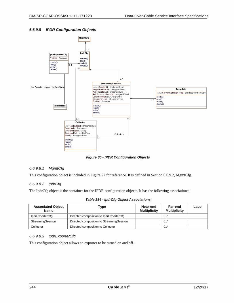
CM-SP-CCAP-OSSIv3.1-I11-171220 Data-Over-Cable Service Interface Specifications
244 CableLabs® 12/20/17
6.6.9.8 IPDR Configuration Objects
Figure 30 - IPDR Configuration Objects
6.6.9.8.1 MgmtCfg
This configuration object is included in Figure 27 for reference. It is defined in Section 6.6.9.2, MgmtCfg.
6.6.9.8.2 IpdrCfg
The IpdrCfg object is the container for the IPDR configuration objects. It has the following associations:
Table 284 - IpdrCfg Object Associations
Associated Object Name
Type Near-end Multiplicity
Far-end Multiplicity
Label
IpdrExporterCfg Directed composition to IpdrExporterCfg 0..1
StreamingSession Directed composition to StreamingSession 0..*
Collector Directed composition to Collector 0..*
6.6.9.8.3 IpdrExporterCfg
This configuration object allows an exporter to be turned on and off.
CCAP™ Operations Support System Interface Specification CM-SP-CCAP-OSSIv3.1-I11-171220
12/20/17 CableLabs 245
Table 285 - IpdrExporterCfg Object Attributes
Attribute Name Type Required Attribute
Type Constraints
Units Default Value
Enabled Boolean No true
Table 286 - IpdrExporterCfg Object Associations
Associated Object Name
Type Near-end Multiplicity
Far-end Multiplicity
Label
IpInterface Association with IpInterface IpdrExporterListenerInterfaceName
When an IP interface is selected, this specifies the IP interface on which the IPDR server listens. If an IP interface is not specified, the behavior of the CCAP is vendor-specific.
6.6.9.8.3.1 IpdrExporterCfg Object Attributes
6.6.9.8.3.1.1 Enabled
This attribute configures whether or not the IPDR exporter is enabled.
6.6.9.8.4 StreamingSession
This configuration object is used to configure global IPDR connection attributes. A typical use case is for a single Template to be associated with a StreamingSession.
Table 287 - StreamingSession Object Attributes
Attribute Name Type Required Attribute
Type Constraints
Units Default Value
SessionId UnsignedShort Yes (Key)
KeepAliveInterval UnsignedShort No seconds 20
AckTimeInterval UnsignedByte No 1..60 seconds 30
AckSequenceInterval UnsignedShort No 1..500 records 200
CollectionInterval UnsignedInt Yes 0..86400 seconds
StreamingType Enum Yes other(1), timeInterval(2), adHoc(3), event(4), timeEvent(5)
Enabled Boolean No true
Table 288 - StreamingSession Object Associations
Associated Object Name
Type Near-end Multiplicity
Far-end Multiplicity
Label
Template Directed composition to Template 1..*
Collector Directed association to Collector 0..* 0..* CollectorId
6.6.9.8.4.1 StreamingSession Object Attributes
6.6.9.8.4.1.1 SessionId
This attribute configures the ID for this session instance.
CM-SP-CCAP-OSSIv3.1-I11-171220 Data-Over-Cable Service Interface Specifications
246 CableLabs® 12/20/17
6.6.9.8.4.1.2 KeepAliveInterval
This attribute configures the interval in seconds at which IPDR "keepalives" are sent from the CCAP IPDR exporter to the collector.
6.6.9.8.4.1.3 AckTimeInterval
This attribute configures the interval in seconds in which the CCAP IPDR exporter waits for an acknowledgment.
6.6.9.8.4.1.4 AckSequenceInterval
This attribute configures the maximum number of unacknowledged records that can be sent by the CCAP IPDR exporter before receiving an acknowledgement.
6.6.9.8.4.1.5 CollectionInterval
Where streaming is of the type timeInterval, this attribute configures the interval in seconds at which IPDR information is extracted from the CCAP management objects and transmitted to the collector.
Where streaming is of the type timeEvent, this attribute identifies the interval at which the CCAP IPDR exporter will close the IPDR session to allow IPDR session processing to occur. Records created by Service Definitions supporting timeEvent are sent when the event is generated.
6.6.9.8.4.1.6 StreamingType
This attribute configures the type of IPDR streaming used for the session. See the IPDR Service Definition Schemas in Section 8 for the streaming types supported by each Service Definition. The value of other(1) is used when a vendor-extension has been implemented for this attribute.
6.6.9.8.4.1.7 Enabled
This attribute controls whether the IPDR Session is enabled or disabled.
6.6.9.8.5 Template
This configuration object allows the configuration of an individual IPDR session for a given IPDR connection.
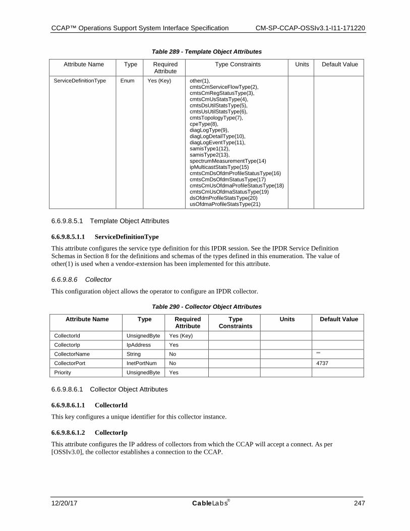
CCAP™ Operations Support System Interface Specification CM-SP-CCAP-OSSIv3.1-I11-171220
12/20/17 CableLabs 247
Table 289 - Template Object Attributes
Attribute Name Type Required Attribute
Type Constraints Units Default Value
ServiceDefinitionType Enum Yes (Key) other(1), cmtsCmServiceFlowType(2), cmtsCmRegStatusType(3), cmtsCmUsStatsType(4), cmtsDsUtilStatsType(5), cmtsUsUtilStatsType(6), cmtsTopologyType(7), cpeType(8), diagLogType(9), diagLogDetailType(10), diagLogEventType(11), samisType1(12), samisType2(13), spectrumMeasurementType(14) ipMulticastStatsType(15) cmtsCmDsOfdmProfileStatusType(16) cmtsCmDsOfdmStatusType(17) cmtsCmUsOfdmaProfileStatusType(18) cmtsCmUsOfdmaStatusType(19) dsOfdmProfileStatsType(20) usOfdmaProfileStatsType(21)
6.6.9.8.5.1 Template Object Attributes
6.6.9.8.5.1.1 ServiceDefinitionType
This attribute configures the service type definition for this IPDR session. See the IPDR Service Definition Schemas in Section 8 for the definitions and schemas of the types defined in this enumeration. The value of other(1) is used when a vendor-extension has been implemented for this attribute.
6.6.9.8.6 Collector
This configuration object allows the operator to configure an IPDR collector.
Table 290 - Collector Object Attributes
Attribute Name Type Required Attribute
Type Constraints
Units Default Value
CollectorId UnsignedByte Yes (Key)
CollectorIp IpAddress Yes
CollectorName String No ""
CollectorPort InetPortNum No 4737
Priority UnsignedByte Yes
6.6.9.8.6.1 Collector Object Attributes
6.6.9.8.6.1.1 CollectorId
This key configures a unique identifier for this collector instance.
6.6.9.8.6.1.2 CollectorIp
This attribute configures the IP address of collectors from which the CCAP will accept a connect. As per [OSSIv3.0], the collector establishes a connection to the CCAP.
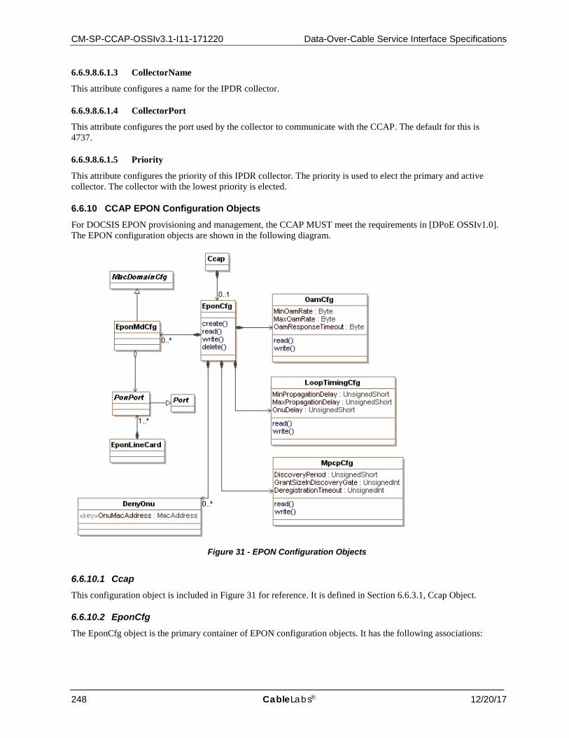
CM-SP-CCAP-OSSIv3.1-I11-171220 Data-Over-Cable Service Interface Specifications
248 CableLabs® 12/20/17
6.6.9.8.6.1.3 CollectorName
This attribute configures a name for the IPDR collector.
6.6.9.8.6.1.4 CollectorPort
This attribute configures the port used by the collector to communicate with the CCAP. The default for this is 4737.
6.6.9.8.6.1.5 Priority
This attribute configures the priority of this IPDR collector. The priority is used to elect the primary and active collector. The collector with the lowest priority is elected.
6.6.10 CCAP EPON Configuration Objects For DOCSIS EPON provisioning and management, the CCAP MUST meet the requirements in [DPoE OSSIv1.0]. The EPON configuration objects are shown in the following diagram.
Figure 31 - EPON Configuration Objects
6.6.10.1 Ccap This configuration object is included in Figure 31 for reference. It is defined in Section 6.6.3.1, Ccap Object.
6.6.10.2 EponCfg The EponCfg object is the primary container of EPON configuration objects. It has the following associations:
CCAP™ Operations Support System Interface Specification CM-SP-CCAP-OSSIv3.1-I11-171220
12/20/17 CableLabs 249
Table 291 - EponCfg Object Associations
Associated Object Name
Type Near-end Multiplicity
Far-end Multiplicity
Label
EponMdCfg Directed composition to EponMdCfg 0..*
OamCfg Directed composition to OamCfg
LoopTimingCfg Directed composition to LoopTimingCfg
MpcpCfg Directed composition to MpcpCfg
DenyOnu Directed composition to DenyOnu 0..*
6.6.10.3 OamCfg This configuration object is taken from [DPoE OSSIv1.0] and is used without modification for CCAP. This object controls the rate at which OAM messages are sent on the EPON interface.
Reference: [DPoE OSSIv1.0], EPON OAM Configuration section
6.6.10.4 LoopTimingCfg This configuration object is taken from [DPoE OSSIv1.0] and is used with the following modifications for CCAP: the OltUpDownDelayOffset and NullGrantSize attributes have been removed.
This object configures the loop timing for EPON interfaces.
Reference: [DPoE OSSIv1.0], Loop Timing section
6.6.10.5 MpcpCfg This configuration object is taken from [DPoE OSSIv1.0] and is used without modification for CCAP. It configures the Multi-Point Control Protocol for EPON interfaces.
Reference: [DPoE OSSIv1.0], MPCP Configuration section
6.6.10.6 EponMdCfg This object defines a specialization of the MacDomain object for EPON interfaces.
Table 292 - EponMdCfg Object Associations
Associated Object Name
Type Near-end Multiplicity
Far-end Multiplicity
Label
MacDomainConfig Specialization of MacDomainCfg
PonPort Directed aggregation to PonPort
6.6.10.7 DenyOnu This configuration object allows an operator to create a list of ONU MAC addresses that are not allowed to register.
Table 293 - DenyOnu Object Attributes
Attribute Name Type Required Attribute
Type Constraints Units Default Value
OnuMacAddress MacAddress Yes (Key)
6.6.10.7.1 DenyOnu Object Attributes
6.6.10.7.1.1 OnuMacAddress
The MAC address of the ONU that will be added to the deny list. This attribute is used as a key.

CM-SP-CCAP-OSSIv3.1-I11-171220 Data-Over-Cable Service Interface Specifications
250 CableLabs® 12/20/17
6.6.10.8 MacDomainCfg This configuration object is included in Figure 31 for reference. It is defined in Section 6.6.6.6.6, MacDomainCfg.
6.6.10.9 PonPort This configuration object is included in Figure 31 for reference. It is defined in Section 6.6.4.20, PonPort.
6.6.10.10 Port This configuration object is included in Figure 31 for reference. It is defined in Section 6.6.4.10, Port.
6.6.10.11 EponLineCard This configuration object is included in Figure 31 for reference. It is defined in Section 6.6.4.7, EponLineCard.
6.7 Status Monitoring and Control Requirements
6.7.1 Status Monitoring and Control UML Object Models This section defines the object models for the utilization of CCAP status and control management functions. These objects are typically not used during installation when the CCAP is brought on-line and into service. Status and control management objects are used at run time to obtain status information or command actionable control. Examples of control functions include clearing an event log or starting a packet capture on a specific MAC Domain. Examples of status functions include checking the operational state of an interface or the results of a diagnostics test. In general, configuration of these control objects would not be included in the startup-config for initial CCAP device configuration.
6.7.1.1 Fault Management Control Objects
Figure 32 - Fault Management Control Objects
6.7.1.1.1 FmCtrl
The FmCtrl object is the primary container of Fault Management Control objects. It has the following associations:
Table 294 - FmCtrl Object Associations
Associated Object Name
Type Near-end Multiplicity
Far-end Multiplicity
Label
EventLogCtrl Directed composition to EventLogCtrl 0..1
DiagLogGlobalCtrl Directed composition to DiagLogGlobalCtrl 0..1
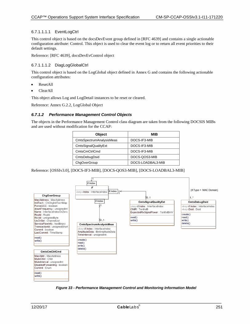
CCAP™ Operations Support System Interface Specification CM-SP-CCAP-OSSIv3.1-I11-171220
12/20/17 CableLabs 251
6.7.1.1.1.1 EventLogCtrl
This control object is based on the docsDevEvent group defined in [RFC 4639] and contains a single actionable configuration attribute: Control. This object is used to clear the event log or to return all event priorities to their default settings.
Reference: [RFC 4639], docsDevEvControl object
6.7.1.1.1.2 DiagLogGlobalCtrl
This control object is based on the LogGlobal object defined in Annex G and contains the following actionable configuration attributes:
• ResetAll • ClearAll
This object allows Log and LogDetail instances to be reset or cleared.
Reference: Annex G.2.2, LogGlobal Object
6.7.1.2 Performance Management Control Objects The objects in the Performance Management Control class diagram are taken from the following DOCSIS MIBs and are used without modification for the CCAP:
Object MIB CmtsSpectrumAnalysisMeas DOCS-IF3-MIB
CmtsSignalQualityExt DOCS-IF3-MIB
CmtsCmCtrlCmd DOCS-IF3-MIB
CmtsDebugDsid DOCS-QOS3-MIB
ChgOverGroup DOCS-LOADBAL3-MIB
Reference: [OSSIv3.0], [DOCS-IF3-MIB], [DOCS-QOS3-MIB], [DOCS-LOADBAL3-MIB]
Figure 33 - Performance Management Control and Monitoring Information Model

CM-SP-CCAP-OSSIv3.1-I11-171220 Data-Over-Cable Service Interface Specifications
252 CableLabs® 12/20/17
6.7.1.2.1 CmtsSignalQualityExt
This object provides metrics and parameters associated with received carrier, noise and interference power levels in the upstream channels of the CMTS.
Table 295 - CmtsSignalQualityExt Object
Attribute Name Type Access Type Constraints Units Default IfIndex InterfaceIndex key Interface Index of logical
upstream channel
CNIR TenthdB read-only TenthdB
ExpectedRxSignalPower TenthdBmV read-only TenthdBmV
6.7.1.2.1.1 IfIndex
This key represents the interface index of the logical upstream of the CMTS to which this instance applies.
6.7.1.2.1.2 CNIR
This attribute provides an upstream in-channel Carrier-to-Noise plus Interference Ratio (CNIR). CNIR is defined as the ratio of the expected commanded received signal power at the CMTS input, assuming QPSK0 modulation, to the noise plus interference in the channel. This measurement occurs prior to the point at which the desired CM signal, when present, is demodulated. The measurement includes the effect of the receive matched filter but does not include the effect of any ingress filtering. Both the signal power and noise/interference power are referenced to the same point, e.g., CMTS input.
6.7.1.2.1.3 ExpectedRxSignalPower
This attribute provides the power of the expected commanded received signal in the channel, referenced to the CMTS input.
6.7.1.2.2 CmtsSpectrumAnalysisMeas
The CmtsSpectrumAnalysisMeas object was defined in previous versions of the DOCSIS OSSI specification to indicate how much desired signal, noise and interference energy exists within the channel by reporting frequency content information of energy within the channel. The CmtsSpectrumAnalysisMeas object includes interface index, amplitude of noise and a time interval indicator. The CmtsSpectrumAnalysisMeas object is deprecated and replaced with the Upstream Triggered Spectrum Capture objects defined in Section 7.3.5.1.6.
6.7.1.2.3 CmtsCmCtrlCmd
The CMTS CM Control Command object allows an operator to trigger the CMTS to send a CM-CTRL-REQ message to the specified CM with specific parameters.
The CMTS is not required to persist the values of the attributes of the CmtsCmCtrlCmd object across reinitializations.
References: [MULPIv3.1] Media Access Control Specification section.
Table 296 - CmtsCmCtrlCmd Object
Attribute Name Type Access Type Constraints Units Default MacAddr MacAddress read-write '000000000000'H
MuteUsChId ChId read-write 0
MuteInterval unsignedInt read-write milliseconds 0
DisableForwarding boolean read-write false
Commit Enum read-write mute(1) cmReinit(2) disableForwarding(3)
'mute'
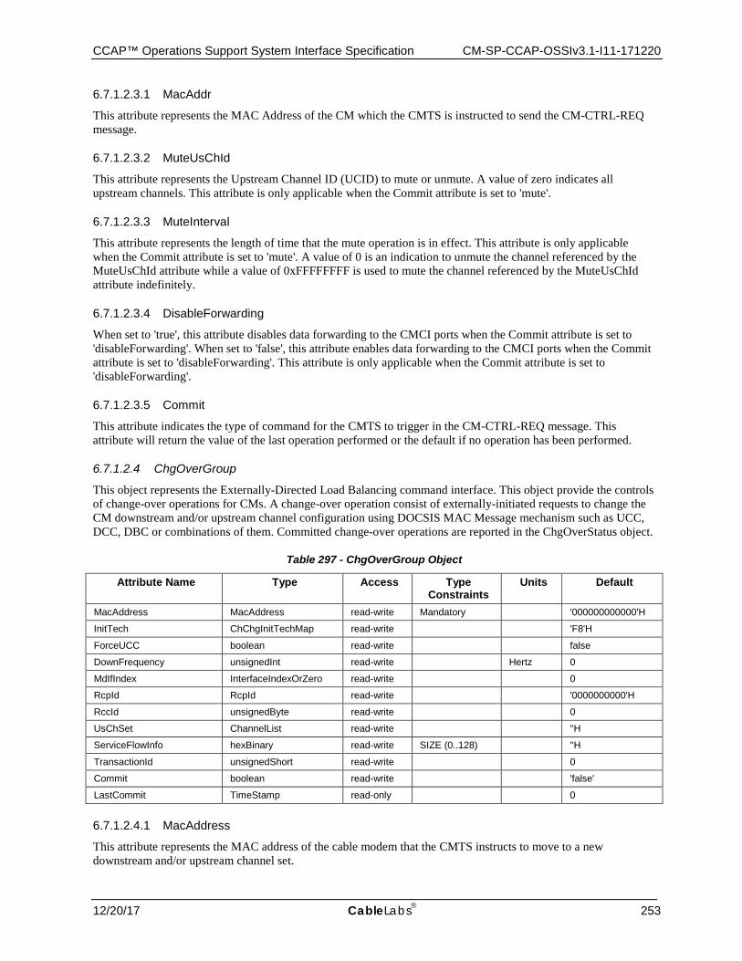
CCAP™ Operations Support System Interface Specification CM-SP-CCAP-OSSIv3.1-I11-171220
12/20/17 CableLabs 253
6.7.1.2.3.1 MacAddr
This attribute represents the MAC Address of the CM which the CMTS is instructed to send the CM-CTRL-REQ message.
6.7.1.2.3.2 MuteUsChId
This attribute represents the Upstream Channel ID (UCID) to mute or unmute. A value of zero indicates all upstream channels. This attribute is only applicable when the Commit attribute is set to 'mute'.
6.7.1.2.3.3 MuteInterval
This attribute represents the length of time that the mute operation is in effect. This attribute is only applicable when the Commit attribute is set to 'mute'. A value of 0 is an indication to unmute the channel referenced by the MuteUsChId attribute while a value of 0xFFFFFFFF is used to mute the channel referenced by the MuteUsChId attribute indefinitely.
6.7.1.2.3.4 DisableForwarding
When set to 'true', this attribute disables data forwarding to the CMCI ports when the Commit attribute is set to 'disableForwarding'. When set to 'false', this attribute enables data forwarding to the CMCI ports when the Commit attribute is set to 'disableForwarding'. This attribute is only applicable when the Commit attribute is set to 'disableForwarding'.
6.7.1.2.3.5 Commit
This attribute indicates the type of command for the CMTS to trigger in the CM-CTRL-REQ message. This attribute will return the value of the last operation performed or the default if no operation has been performed.
6.7.1.2.4 ChgOverGroup
This object represents the Externally-Directed Load Balancing command interface. This object provide the controls of change-over operations for CMs. A change-over operation consist of externally-initiated requests to change the CM downstream and/or upstream channel configuration using DOCSIS MAC Message mechanism such as UCC, DCC, DBC or combinations of them. Committed change-over operations are reported in the ChgOverStatus object.
Table 297 - ChgOverGroup Object
Attribute Name Type Access Type Constraints
Units Default
MacAddress MacAddress read-write Mandatory '000000000000'H
InitTech ChChgInitTechMap read-write 'F8'H
ForceUCC boolean read-write false
DownFrequency unsignedInt read-write Hertz 0
MdIfIndex InterfaceIndexOrZero read-write 0
RcpId RcpId read-write '0000000000'H
RccId unsignedByte read-write 0
UsChSet ChannelList read-write ''H
ServiceFlowInfo hexBinary read-write SIZE (0..128) ''H
TransactionId unsignedShort read-write 0
Commit boolean read-write 'false'
LastCommit TimeStamp read-only 0
6.7.1.2.4.1 MacAddress
This attribute represents the MAC address of the cable modem that the CMTS instructs to move to a new downstream and/or upstream channel set.
CM-SP-CCAP-OSSIv3.1-I11-171220 Data-Over-Cable Service Interface Specifications
254 CableLabs® 12/20/17
6.7.1.2.4.2 InitTech
This attribute represents the initialization technique that the cable modem is instructed to use when performing multiple-channel change-over operation. The value of this attribute applies to all upstream channels in the channel set.
6.7.1.2.4.3 ForceUCC
This attribute when set to 'true' indicates that the CMTS forces UCC messages instead of DCC messages in those scenarios that are allowed as defined in the "Upstream Channel Change Request (UCC-REQ)" section of [MULPIv3.1]. In some cases the CMTS may still use UCC commands even though this attribute value is 'false', for example in an upstream-only change-over operation directed to a CM that the CMTS is aware is only capable of UCC, but the operator is not aware of the CM capabilities. This attribute value is ignored when the target CM for the change-over operation is in MRC mode, or the UsChSet attribute is the zero-length string, or the operation includes changes for downstream channels.
6.7.1.2.4.4 DownFrequency
This attribute represents a single-downstream frequency to which the cable modem is instructed to move using a DCC request. The value zero indicates that this attribute is ignored during a commit operation.
6.7.1.2.4.5 MdIfIndex
This attribute describes the MAC Domain Interface index of the triplet: Mac Domain, RCP-ID and RCC Status Index of the RccStatus object that represents the RCC used in the change-over operation. This MAC Domain Interface Index is also used to provide context for the UsChSet and ServiceFlowInfo attributes.
6.7.1.2.4.6 RcpId
This attribute describes the RCP-ID of the triplet: Mac Domain, RCP-ID and RCC Status Index of the RccStatus object that represents the RCC used in the change-over operation. If the RCP-ID is unknown or the CM is in DOCSIS 3.1 mode, the CMTS returns a five octet long string of zeros.
6.7.1.2.4.7 RccId
This attribute describes the RCC Status Index of the triplet: Mac Domain, RCP-ID and RCC Status Index of the RccStatus object that represents the RCC used in the change-over operation. If the RCC-ID is unknown or the CM is in DOCSIS 3.1 mode, the CMTS returns a value of zero.
6.7.1.2.4.8 UsChSet
This attribute describes the Channel list (within the context of the MAC domain identified by MdIfIndex) that represents the final TCS expected from the change-over operation.
When the operation is intended for an RCC-only, this attribute is set to zero and the attribute InitTech is ignored.
6.7.1.2.4.9 ServiceFlowInfo
This attribute provides a list of Service Flow ID-Channel Set ID pairs used to control Service Flow assignment in the change-over operation. This is intended as an override to the normal assignment based on SF attributes. This attribute is encoded as a series of 32-bit pairs as follows:
• The first four bytes correspond to the value of the Service Flow ID (attribute Id of the ServiceFlow object of the DOCSIS QoS objects.
• The last four bytes correspond to the value of the attribute ChSetId of the UsChSet or DsChSet object of the CMTS Bonding Objects.
If this attribute does not include tuples for some of the CM's Service Flows, the CMTS determines the respective channels based on SF attributes. Service Flow ID-Channel Set ID pairs matching upstream service flows are ignored if the change-over operation does not affect the TCC of the CM. Similarly, Service Flow ID-Channel Set
CCAP™ Operations Support System Interface Specification CM-SP-CCAP-OSSIv3.1-I11-171220
12/20/17 CableLabs 255
ID pairs matching downstream service flows are ignored if the change-over operation does not affect the RCC of the CM.
6.7.1.2.4.10 TransactionId
This attribute represents an operator identifier for the change-over operation to be used to correlate logged information in the ChangeOver3 Status object. The CMTS uses this value as the Transaction ID in the DBC-REQ or DCC-REQ message transmitted in association with this operation. If this value is set to zero the CMTS defines its own MAC message Transaction ID value.
6.7.1.2.4.11 Commit
This attribute when set to 'true' triggers the change-over operation for Externally-Directed Load Balancing.
Setting this attribute to 'true' is known as a commit operation. A commit operation is considered successful if the CMTS considers that the entered information is valid and the transaction can be initiated. It does not imply that the channel-change operation itself (i.e., UCC, DCC, DBC transaction) reports success or completion. A commit operation is considered unsuccessful if the CMTS determines that there are invalid attributes values in the ChangeOver object such that the change-over operation cannot be initiated.
Some examples for a change-over that cannot be initiated are:
• Attempt to send a DBC for MRC that does not fit the CM RCP. • Attempt to send a DCC while a previous one is still in progress. • Attempt to send a UCC to a channel ID that is not defined.
After system initialization all ChangeOver object parameters are set to default values.
After a successful commit operation all ChangeOver object parameters are set to default values with the exception of this attribute (commit) that is set to 'true'. An unsuccessful commit operation is rejected and this attribute reports false in subsequent value queries.
After a successful commit operation, the CMTS initiates the change-over transaction using the most appropriate technique. The potential techniques are:
• UCC - For upstream-channel-only changes on CMs not operating in MRC mode. • DCC - For upstream and/or downstream channel changes on CMs not operating in MRC mode, as well as
upstream only change for CMs operating in MRC mode but with no TCS conveyed during registration. • DCC followed by channel assignment in REG-RSP-MP - For MAC Domain re-assignment on CMs operating
in MRC mode. In this case, the change-over command might only include a downstream frequency, or might include an RCC defined in the target MAC domain. The upstream channel set may or may not be provided. The only applicable Initialization Technique for this operation is 'reinitializeMAC'.
• DBC - For change in the TCS and/or RCS on CMs operating in MRC mode.
6.7.1.2.4.12 LastCommit
The value of sysUpTime when the attribute Commit was last set to true. Zero if never set.
6.7.1.2.5 CmtsDebugDsid
The CMTS Debug DSID object contains the control of DSID debug statistics reporting.
An instance in this object defines the DSID and MAC domain to which the CmtsDebugDsidStats collects statistics for the downstream channel associated with that DSID and MAC Domain. The deletion of an instance stops the reporting of statistics for the specified DSID.
This object supports instance creation and deletion.
The CMTS MUST support at least one instance of the CmtsDebugDsid object. Creation of a new instance of this object requires a valid MAC Domain and a current DSID value.
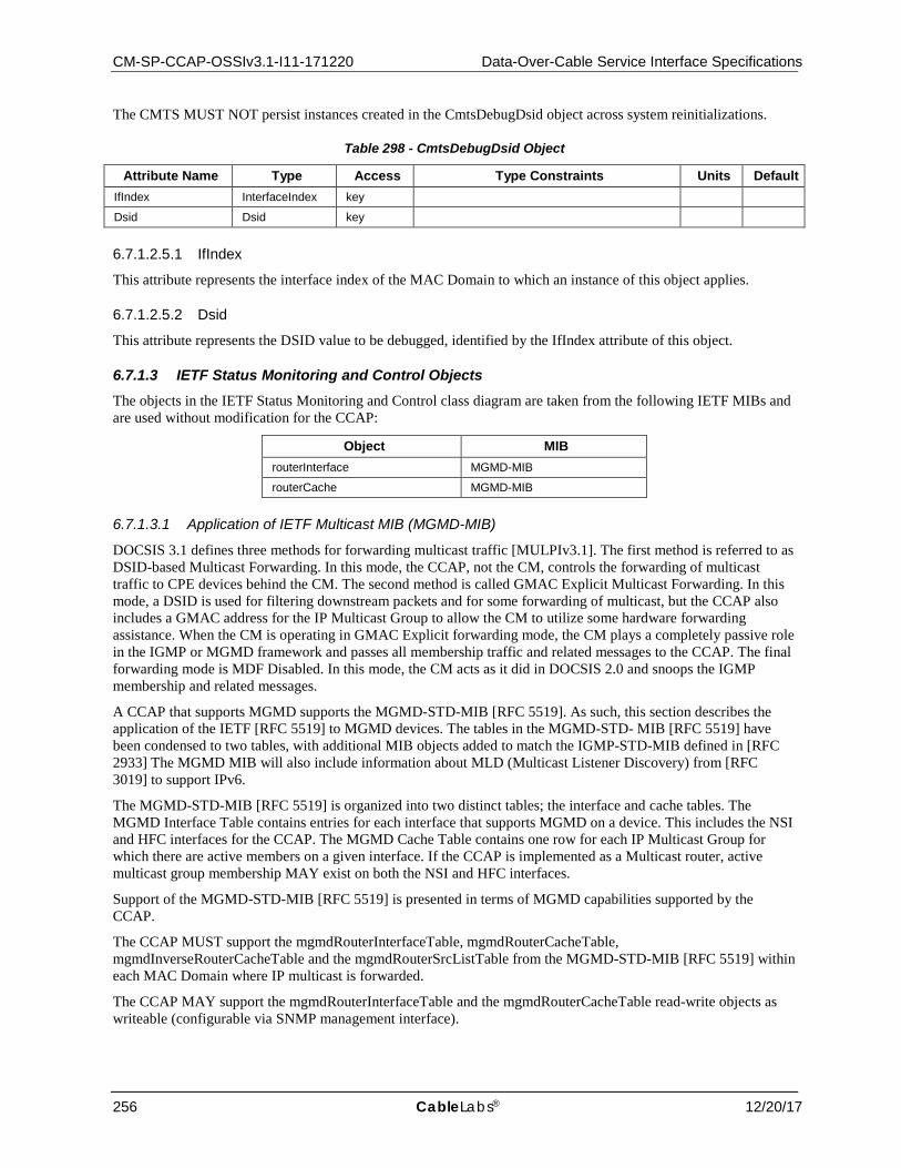
CM-SP-CCAP-OSSIv3.1-I11-171220 Data-Over-Cable Service Interface Specifications
256 CableLabs® 12/20/17
The CMTS MUST NOT persist instances created in the CmtsDebugDsid object across system reinitializations.
Table 298 - CmtsDebugDsid Object
Attribute Name Type Access Type Constraints Units Default IfIndex InterfaceIndex key
Dsid Dsid key
6.7.1.2.5.1 IfIndex
This attribute represents the interface index of the MAC Domain to which an instance of this object applies.
6.7.1.2.5.2 Dsid
This attribute represents the DSID value to be debugged, identified by the IfIndex attribute of this object.
6.7.1.3 IETF Status Monitoring and Control Objects The objects in the IETF Status Monitoring and Control class diagram are taken from the following IETF MIBs and are used without modification for the CCAP:
Object MIB routerInterface MGMD-MIB
routerCache MGMD-MIB
6.7.1.3.1 Application of IETF Multicast MIB (MGMD-MIB)
DOCSIS 3.1 defines three methods for forwarding multicast traffic [MULPIv3.1]. The first method is referred to as DSID-based Multicast Forwarding. In this mode, the CCAP, not the CM, controls the forwarding of multicast traffic to CPE devices behind the CM. The second method is called GMAC Explicit Multicast Forwarding. In this mode, a DSID is used for filtering downstream packets and for some forwarding of multicast, but the CCAP also includes a GMAC address for the IP Multicast Group to allow the CM to utilize some hardware forwarding assistance. When the CM is operating in GMAC Explicit forwarding mode, the CM plays a completely passive role in the IGMP or MGMD framework and passes all membership traffic and related messages to the CCAP. The final forwarding mode is MDF Disabled. In this mode, the CM acts as it did in DOCSIS 2.0 and snoops the IGMP membership and related messages.
A CCAP that supports MGMD supports the MGMD-STD-MIB [RFC 5519]. As such, this section describes the application of the IETF [RFC 5519] to MGMD devices. The tables in the MGMD-STD- MIB [RFC 5519] have been condensed to two tables, with additional MIB objects added to match the IGMP-STD-MIB defined in [RFC 2933] The MGMD MIB will also include information about MLD (Multicast Listener Discovery) from [RFC 3019] to support IPv6.
The MGMD-STD-MIB [RFC 5519] is organized into two distinct tables; the interface and cache tables. The MGMD Interface Table contains entries for each interface that supports MGMD on a device. This includes the NSI and HFC interfaces for the CCAP. The MGMD Cache Table contains one row for each IP Multicast Group for which there are active members on a given interface. If the CCAP is implemented as a Multicast router, active multicast group membership MAY exist on both the NSI and HFC interfaces.
Support of the MGMD-STD-MIB [RFC 5519] is presented in terms of MGMD capabilities supported by the CCAP.
The CCAP MUST support the mgmdRouterInterfaceTable, mgmdRouterCacheTable, mgmdInverseRouterCacheTable and the mgmdRouterSrcListTable from the MGMD-STD-MIB [RFC 5519] within each MAC Domain where IP multicast is forwarded.
The CCAP MAY support the mgmdRouterInterfaceTable and the mgmdRouterCacheTable read-write objects as writeable (configurable via SNMP management interface).
CCAP™ Operations Support System Interface Specification CM-SP-CCAP-OSSIv3.1-I11-171220
12/20/17 CableLabs 257
7 PERFORMANCE MANAGEMENT
7.1 Performance Management Requirements and Transport Protocols
At the CATV MAC and PHY layers, performance management focuses on the monitoring of the effectiveness of cable plant segmentation and rates of upstream traffic and collisions. Instrumentation is provided in the form of the standard interface statistics [RFC 2863] and service queue statistics (from [RFC 4546]). It is not anticipated that the CCAP upstream bandwidth allocation function will require active network management intervention and tuning.
At the LLC layer, the performance management focus is on bridge traffic management. If the CCAP implements transparent bridging, it implements the Bridge MIB [RFC 4188].
The CCAP diagnostic log capabilities, as described in Annex G, provides early detection of CM and cable plant problems.
The DOCS-IF-MIB [RFC 4546] includes variables to track PHY state such as codeword collisions and corruption, signal-to-noise ratios, transmit and receive power levels, propagation delays, micro-reflections, in channel response, and sync loss. The DOCS-IF-MIB [RFC 4546] also includes counters to track MAC state, such as collisions and excessive retries for requests, immediate data transmits, and initial ranging requests. Section 6.7.1.2 provides enhanced signal quality monitoring and diagnostic capabilities for detecting cable plant.
A final performance concern is the ability to diagnose unidirectional loss. The CCAP implements the MIB-II [RFC 1213] Interfaces Group [RFC 2863] as specified in Annex A.
7.1.1 SNMP and MIB Requirements Since CCAP configuration will be primarily accomplished via the standard XML configuration file and legacy CLI commands, SNMP is not used as a primary configuration interface on the CCAP. Based on this, most CCAP MIB objects will be used in a read-only mode for status and performance monitoring. Refer to Annex A for a detailed set of SNMP MIB object requirements.
The CCAP requires a very small set of read-create or read-write MIB objects used by operators for operational control, automation or testing tasks.
The CMTS and CCAP MAY augment the required MIBs with objects from other standard or vendor-specific MIBs where appropriate.
The CMTS and CCAP MUST implement the MIB requirements in accordance with this specification regardless of the value of an IETF MIB object's status (e.g., deprecated or optional).
If not required by this specification, deprecated objects are optional. If a CMTS or CCAP implements a deprecated MIB object, the CMTS or CCAP MUST implement the MIB object correctly according to the MIB definition.
If a CMTS does not implement a deprecated MIB object, the following conditions MUST be met:
• The CMTS or CCAP MUST NOT instantiate the deprecated MIB object. • The CMTS or CCAP MUST respond with the appropriate error/exception condition, such as noSuchObject for
SNMPv2c, when an attempt to access the deprecated MIB object is made.
If not required by this specification, additional objects are optional. If a CMTS or CCAP implements any additional MIB objects, the CMTS or CCAP MUST implement the MIB object correctly according to the MIB definition.
If a CMTS does not implement one or more additional objects, the following conditions MUST be met:
• The CMTS or CCAP MUST NOT instantiate the additional MIB object or objects. • The CMTS or CCAP MUST respond with the appropriate error/exception condition, such as noSuchObject for
SNMPv2c, when an attempt to access the non-existent additional MIB object is made.
If not required by this specification, obsolete objects are optional. If a CMTS or CCAP implements an obsolete MIB object, the CMTS or CCAP MUST implement the MIB object correctly according to the MIB definition.
If a CMTS or CCAP does not implement an obsolete MIB object, the following conditions MUST be met:
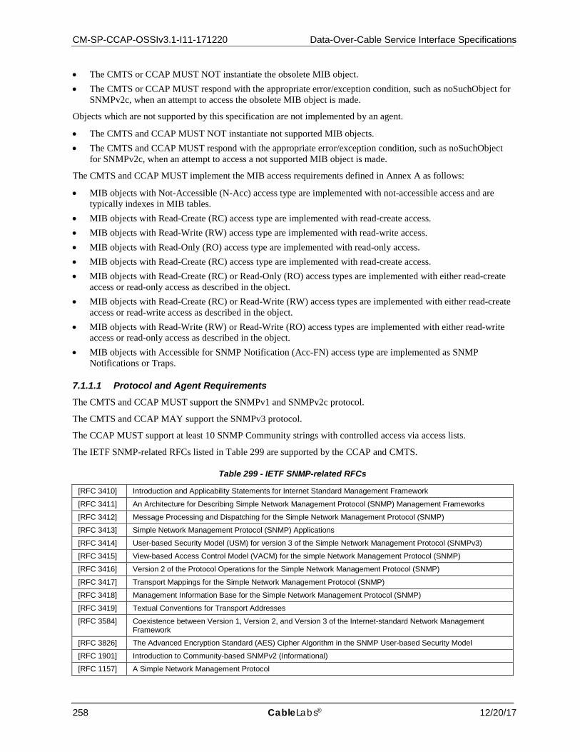
CM-SP-CCAP-OSSIv3.1-I11-171220 Data-Over-Cable Service Interface Specifications
258 CableLabs® 12/20/17
• The CMTS or CCAP MUST NOT instantiate the obsolete MIB object. • The CMTS or CCAP MUST respond with the appropriate error/exception condition, such as noSuchObject for
SNMPv2c, when an attempt to access the obsolete MIB object is made.
Objects which are not supported by this specification are not implemented by an agent.
• The CMTS and CCAP MUST NOT instantiate not supported MIB objects. • The CMTS and CCAP MUST respond with the appropriate error/exception condition, such as noSuchObject
for SNMPv2c, when an attempt to access a not supported MIB object is made.
The CMTS and CCAP MUST implement the MIB access requirements defined in Annex A as follows:
• MIB objects with Not-Accessible (N-Acc) access type are implemented with not-accessible access and are typically indexes in MIB tables.
• MIB objects with Read-Create (RC) access type are implemented with read-create access. • MIB objects with Read-Write (RW) access type are implemented with read-write access. • MIB objects with Read-Only (RO) access type are implemented with read-only access. • MIB objects with Read-Create (RC) access type are implemented with read-create access. • MIB objects with Read-Create (RC) or Read-Only (RO) access types are implemented with either read-create
access or read-only access as described in the object. • MIB objects with Read-Create (RC) or Read-Write (RW) access types are implemented with either read-create
access or read-write access as described in the object. • MIB objects with Read-Write (RW) or Read-Write (RO) access types are implemented with either read-write
access or read-only access as described in the object. • MIB objects with Accessible for SNMP Notification (Acc-FN) access type are implemented as SNMP
Notifications or Traps.
7.1.1.1 Protocol and Agent Requirements The CMTS and CCAP MUST support the SNMPv1 and SNMPv2c protocol.
The CMTS and CCAP MAY support the SNMPv3 protocol.
The CCAP MUST support at least 10 SNMP Community strings with controlled access via access lists.
The IETF SNMP-related RFCs listed in Table 299 are supported by the CCAP and CMTS.
Table 299 - IETF SNMP-related RFCs
[RFC 3410] Introduction and Applicability Statements for Internet Standard Management Framework
[RFC 3411] An Architecture for Describing Simple Network Management Protocol (SNMP) Management Frameworks
[RFC 3412] Message Processing and Dispatching for the Simple Network Management Protocol (SNMP)
[RFC 3413] Simple Network Management Protocol (SNMP) Applications
[RFC 3414] User-based Security Model (USM) for version 3 of the Simple Network Management Protocol (SNMPv3)
[RFC 3415] View-based Access Control Model (VACM) for the simple Network Management Protocol (SNMP)
[RFC 3416] Version 2 of the Protocol Operations for the Simple Network Management Protocol (SNMP)
[RFC 3417] Transport Mappings for the Simple Network Management Protocol (SNMP)
[RFC 3418] Management Information Base for the Simple Network Management Protocol (SNMP)
[RFC 3419] Textual Conventions for Transport Addresses
[RFC 3584] Coexistence between Version 1, Version 2, and Version 3 of the Internet-standard Network Management Framework
[RFC 3826] The Advanced Encryption Standard (AES) Cipher Algorithm in the SNMP User-based Security Model
[RFC 1901] Introduction to Community-based SNMPv2 (Informational)
[RFC 1157] A Simple Network Management Protocol
CCAP™ Operations Support System Interface Specification CM-SP-CCAP-OSSIv3.1-I11-171220
12/20/17 CableLabs 259
For support of SMIv2, Table 300 lists the IETF SNMP-related RFCs which are supported by the CCAP and CMTS.
Table 300 - SMIv2 IETF SNMP-related RFCs
[RFC 2578] Structure of Management Information Version 2 (SMIv2)
[RFC 2579] Textual Conventions for SMIv2
[RFC 2580] Conformance Statements for SMIv2
For support of Diffie-Helman Key exchange for the User Based Security Model, Table 301 lists the IETF SNMP-related RFC which is optionally supported by the CCAP and CMTS.
Table 301 - Diffie-Helman IETF SNMP-related RFC
[RFC 2786] Diffie-Helman USM Key Management Information Base and Textual Convention
7.1.1.1.1 CMTS and CCAP SNMP Modes of Operation
CMTS SNMP Coexistence Mode is subject to the following requirements and limitations:
• The CMTS MUST process SNMP v1/v2c Packets as described in [RFC 3411] through [RFC 3415] and [RFC 3584].
• If the CMTS supports the SNMPv3 protocol, it MUST process SNMP v3 Packets as described in [RFC 3411] through [RFC 3415] and [RFC 3584].
• SNMP Access control is determined by the SNMP-COMMUNITY-MIB [RFC 3584], and SNMP-TARGET-MIB [RFC 3413], SNMP-VIEW-BASED-ACM-MIB [RFC 3415], and SNMP-User-Based-SM-MIB [RFC 3414].
• The CMTS MUST support the SNMP-COMMUNITY-MIB [RFC 3584], which controls SNMPv1/v2c packet community string associations to a security name to select entries for access control in the SNMP-VIEW-BASED-ACM-MIB [RFC 3415].
• The CMTS SHOULD support the SNMP-USER-BASED-SM-MIB [RFC 3414] and SNMP-VIEW-BASED-ACM-MIB [RFC 3415] to control SNMPv3 packets.
• The CMTS MUST support SNMP Notification destinations as specified in the SNMP-TARGET-MIB and SNMP-NOTIFICATION-MIB [RFC 3413].
The CMTS MAY support SNMPv3 with AES encryption as defined in [RFC 3826].
7.1.1.1.2 CMTS and CCAP SNMP Access Control Configuration
The CMTS SNMP access control initial configuration is outside of the scope of this specification. If the CMTS supports SNMPv3, the CMTS MUST support the SNMPv3 key change mechanism defined in [RFC 3414].
Note that the SNMPv3 Initialization and Key Change process is based on [RFC 2786] which always configures the SNMP agent with SNMPv3 HMAC-MD5-96 as the authentication protocol and CBC-DES as the privacy protocol, both specified in [RFC 3414]. Therefore, this specification does not provide a mechanism to initialize SNMPv3 using CFB128-AES-128 for privacy key, as defined in [RFC 3826] or any other configuration defined in [RFC 3414] and are left out of scope of this specification.
[RFC 2786] provides a mechanism to kick start an SNMPv3 agent User-based Security Model [RFC 3414] and extensions to the same model for key change. [RFC 2786] does not define the mechanism to configure the initial key material for the kick start process.
7.1.1.1.3 IPv6 Transport Requirements
Several transport domains were initially defined for SNMP (see [RFC 3417]). To support IPv6, [RFC 3419] adds a new set of transport domains not only for SNMP but for any application protocol.
The CMTS and CCAP MUST support the recommendations of [RFC 3419] to support SNMP over IPv6.

CM-SP-CCAP-OSSIv3.1-I11-171220 Data-Over-Cable Service Interface Specifications
260 CableLabs® 12/20/17
7.1.1.2 CableLabs MIBs
Table 302 - CableLabs MIBs
Reference MIB Module Applicable Device [DOCS-IFEXT2-MIB] DOCSIS Interface Extension 2 MIB Module:
DOCS-IFEXT2-MIB CMTS/CCAP
[CLAB-TOPO-MIB] CableLabs Topology MIB Module: CLAB-TOPO-MIB
CMTS/CCAP
[DOCS-DIAG-MIB] DOCSIS Diagnostic Log MIB Module: DOCS-DIAG-MIB
CMTS/CCAP
[DOCS-IF3-MIB] DOCSIS Interface 3 MIB Module: DOCS-IF3-MIB
CMTS/CCAP
[DOCS-MCAST-MIB] DOCSIS Multicast MIB Module: DOCS-MCAST-MIB
CMTS/CCAP
[DOCS-MCAST-AUTH-MIB] DOCSIS Multicast Authorization MIB Module: DOCS-MCAST-AUTH-MIB
CMTS/CCAP
[DOCS-QOS3-MIB] DOCSIS Quality of Service 3 MIB Module: DOCS-QOS3-MIB
CMTS/CCAP
[DOCS-SEC-MIB] DOCSIS Security MIB Module: DOCS-SEC-MIB
CMTS/CCAP
[DOCS-SUBMGT3-MIB] DOCSIS Subscriber Management 3 MIB Module: DOCS-SUBMGT3-MIB
CMTS/CCAP
[DOCS-LOADBAL3-MIB] DOCSIS Load Balancing 3 MIB Module: DOCS-LOADBAL3-MIB
CMTS/CCAP
[CCAP-MIB] DOCSIS CCAP MIB Module: CCAP-MIB
CCAP
[M-OSSI], [DRFI] DOCSIS DRF MIB Module: DOCS-DRF-MIB
CMTS/CCAP
[DOCS-PNM-MIB] DOCSIS PNM MIB Module: DOCS-PNM-MIB
CCAP
The CCAP MUST support read-only access for all CMTS Mandatory ("M") MIB objects that have an SNMP access type of read-only ("RO") in Annex A.3 and Annex A of [L2VPN].
The CCAP MUST support read-only access for all CMTS Mandatory ("M") MIB objects that have an SNMP access type of read-write ("RW") or read-create ("RC") in Annex A.3 and Annex A of [L2VPN].
The CCAP MAY support read-write access for all CMTS Mandatory ("M") MIB objects that have an SNMP access type of read-write ("RW") in Annex Annex A.3 and Annex A of [L2VPN].
The CCAP MAY support read-create access for all CMTS Mandatory ("M") MIB objects that have an SNMP access type of read-create ("RC") in Annex Annex A.3 and Annex A of [L2VPN].
The CCAP MUST support read-only access for all Mandatory ("M") MIB objects that have an SNMP access type of read-only ("RO") in Annex A.4.
The CCAP MUST support read-write access for all Mandatory ("M") MIB objects that have an SNMP access type of read-write ("RW") or of read-create ("RC") in Annex A.4.
The CCAP-MIB defines the following:
• Objects which provide a link between an identifier of a CCAP interface used in the XML configuration file and its corresponding standard ifIndex MIB object from the ifTable and entPhysicalIndex MIB object from the Entity-MIB.
• Objects which can be used for video input program bitrate monitoring. Both the input program bitrate and input program requested bitrate can be accessed.
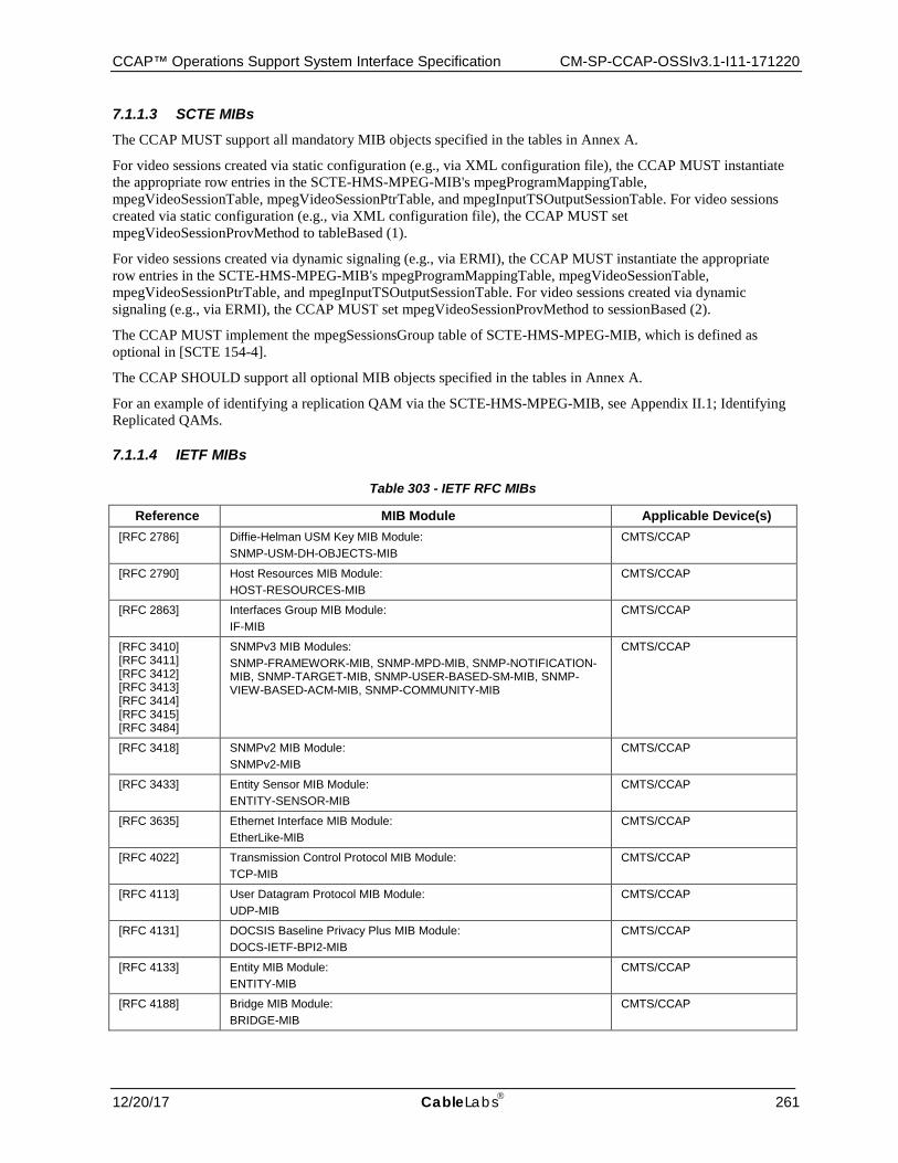
CCAP™ Operations Support System Interface Specification CM-SP-CCAP-OSSIv3.1-I11-171220
12/20/17 CableLabs 261
7.1.1.3 SCTE MIBs The CCAP MUST support all mandatory MIB objects specified in the tables in Annex A.
For video sessions created via static configuration (e.g., via XML configuration file), the CCAP MUST instantiate the appropriate row entries in the SCTE-HMS-MPEG-MIB's mpegProgramMappingTable, mpegVideoSessionTable, mpegVideoSessionPtrTable, and mpegInputTSOutputSessionTable. For video sessions created via static configuration (e.g., via XML configuration file), the CCAP MUST set mpegVideoSessionProvMethod to tableBased (1).
For video sessions created via dynamic signaling (e.g., via ERMI), the CCAP MUST instantiate the appropriate row entries in the SCTE-HMS-MPEG-MIB's mpegProgramMappingTable, mpegVideoSessionTable, mpegVideoSessionPtrTable, and mpegInputTSOutputSessionTable. For video sessions created via dynamic signaling (e.g., via ERMI), the CCAP MUST set mpegVideoSessionProvMethod to sessionBased (2).
The CCAP MUST implement the mpegSessionsGroup table of SCTE-HMS-MPEG-MIB, which is defined as optional in [SCTE 154-4].
The CCAP SHOULD support all optional MIB objects specified in the tables in Annex A.
For an example of identifying a replication QAM via the SCTE-HMS-MPEG-MIB, see Appendix II.1; Identifying Replicated QAMs.
7.1.1.4 IETF MIBs
Table 303 - IETF RFC MIBs
Reference MIB Module Applicable Device(s) [RFC 2786] Diffie-Helman USM Key MIB Module:
SNMP-USM-DH-OBJECTS-MIB CMTS/CCAP
[RFC 2790] Host Resources MIB Module: HOST-RESOURCES-MIB
CMTS/CCAP
[RFC 2863] Interfaces Group MIB Module: IF-MIB
CMTS/CCAP
[RFC 3410] [RFC 3411] [RFC 3412] [RFC 3413] [RFC 3414] [RFC 3415] [RFC 3484]
SNMPv3 MIB Modules: SNMP-FRAMEWORK-MIB, SNMP-MPD-MIB, SNMP-NOTIFICATION-MIB, SNMP-TARGET-MIB, SNMP-USER-BASED-SM-MIB, SNMP-VIEW-BASED-ACM-MIB, SNMP-COMMUNITY-MIB
CMTS/CCAP
[RFC 3418] SNMPv2 MIB Module: SNMPv2-MIB
CMTS/CCAP
[RFC 3433] Entity Sensor MIB Module: ENTITY-SENSOR-MIB
CMTS/CCAP
[RFC 3635] Ethernet Interface MIB Module: EtherLike-MIB
CMTS/CCAP
[RFC 4022] Transmission Control Protocol MIB Module: TCP-MIB
CMTS/CCAP
[RFC 4113] User Datagram Protocol MIB Module: UDP-MIB
CMTS/CCAP
[RFC 4131] DOCSIS Baseline Privacy Plus MIB Module: DOCS-IETF-BPI2-MIB
CMTS/CCAP
[RFC 4133] Entity MIB Module: ENTITY-MIB
CMTS/CCAP
[RFC 4188] Bridge MIB Module: BRIDGE-MIB
CMTS/CCAP
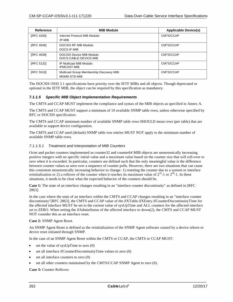
CM-SP-CCAP-OSSIv3.1-I11-171220 Data-Over-Cable Service Interface Specifications
262 CableLabs® 12/20/17
Reference MIB Module Applicable Device(s) [RFC 4293] Internet Protocol MIB Module:
IP-MIB CMTS/CCAP
[RFC 4546] DOCSIS RF MIB Module: DOCS-IF-MIB
CMTS/CCAP
[RFC 4639] DOCSIS Device MIB Module: DOCS-CABLE-DEVICE-MIB
CMTS/CCAP
[RFC 5132] IP Multicast MIB Module: IPMCAST-MIB
CMTS/CCAP
[RFC 5519] Multicast Group Membership Discovery MIB: MGMD-STD-MIB
CMTS/CCAP
The DOCSIS OSSI 3.1 specifications have priority over the IETF MIBs and all objects. Though deprecated or optional in the IETF MIB, the object can be required by this specification as mandatory.
7.1.1.5 Specific MIB Object Implementation Requirements The CMTS and CCAP MUST implement the compliance and syntax of the MIB objects as specified in Annex A.
The CMTS and CCAP MUST support a minimum of 10 available SNMP table rows, unless otherwise specified by RFC or DOCSIS specification.
The CMTS and CCAP minimum number of available SNMP table rows SHOULD mean rows (per table) that are available to support device configuration.
The CMTS and CCAP used (default) SNMP table row entries MUST NOT apply to the minimum number of available SNMP table rows.
7.1.1.5.1 Treatment and Interpretation of MIB Counters
Octet and packet counters implemented as counter32 and counter64 MIB objects are monotonically increasing positive integers with no specific initial value and a maximum value based on the counter size that will roll-over to zero when it is exceeded. In particular, counters are defined such that the only meaningful value is the difference between counter values as seen over a sequence of counter polls. However, there are two situations that can cause this consistent monotonically increasing behavior to change: 1) resetting the counter due to a system or interface reinitialization or 2) a rollover of the counter when it reaches its maximum value of 232-1 or 264-1. In these situations, it needs to be clear what the expected behavior of the counters should be.
Case 1: The state of an interface changes resulting in an "interface counter discontinuity" as defined in [RFC 2863].
In the case where the state of an interface within the CMTS and CCAP changes resulting in an "interface counter discontinuity"[RFC 2863], the CMTS and CCAP value of the ifXTable.ifXEntry.ifCounterDiscontinuityTime for the affected interface MUST be set to the current value of sysUpTime and ALL counters for the affected interface set to ZERO. When setting the ifAdminStatus of the affected interface to down(2), the CMTS and CCAP MUST NOT consider this as an interface reset.
Case 2: SNMP Agent Reset.
An SNMP Agent Reset is defined as the reinitialization of the SNMP Agent software caused by a device reboot or device reset initiated through SNMP.
In the case of an SNMP Agent Reset within the CMTS or CCAP, the CMTS or CCAP MUST:
• set the value of sysUpTime to zero (0) • set all interface ifCounterDiscontinuityTime values to zero (0) • set all interface counters to zero (0) • set all other counters maintained by the CMTS/CCAP SNMP Agent to zero (0).
Case 3: Counter Rollover.

CCAP™ Operations Support System Interface Specification CM-SP-CCAP-OSSIv3.1-I11-171220
12/20/17 CableLabs 263
When a counter32 object within the CMTS or CCAP reaches its maximum value of 4,294,967,295, the next value MUST be ZERO. When a counter64 object within the CMTS or CCAP reaches its maximum value of 18,446,744,073,709,551,615, the next value MUST be ZERO.
NOTE: Unless a CMTS or CCAP vendor provides a means outside of SNMP to preset a counter64 or counter32 object to an arbitrary value, it will not be possible to test any rollover scenarios for counter64 objects (and many counter32 objects as well). This is because it is not possible for these counters to rollover during the service life of the device (see discussion in section 3.1.6 of [RFC 2863]).
7.1.1.5.2 Requirements for DOCSIS Device MIB (RFC 4639]
The CMTS and CCAP MUST implement [RFC 4639].
NOTE: [RFC 4639] includes Compliance requirements for DIFFSERV-MIB [RFC 3289] to support IPv6 filtering as a replacement for the deprecated docsDevFilterIpTable. For backwards compatibility, this specification has requirements for docsDevFilterIpTable. IPv6 filtering requirements are specified in Annex A. This specification does not define requirements for [RFC 3289].
Additional requirements affecting [RFC 4639] are also found in [CM-OSSIv3.1], Protocol Filtering.
7.1.1.5.3 Requirements for DOCSIS RF MIB (RFC 4546)
The CCAP MUST implement [RFC 4546]. However, much of [RFC 4546] is not applicable to OFDM/OFDMA channels. Thus, this section defines separate requirements for handling both SC-QAM and OFDM/OFDMA channels.
The CCAP MUST instantiate a row entry for all SC-QAM and OFDM channels in the docsIfDownChannelTable. The CCAP MUST return appropriate values for all columns of the docsIfDownChannelTable for SC-QAM channels as described in the MIB itself and further specified in this section.
OFDM channels are defined and configured differently than SC-QAM channels. Thus, the docsIfDownChannelTable cannot properly represent OFDM channels. However, it is useful for the NMS to have some representation of OFDM channels in the docsIfDownChannelTable as an indication that the channel exists and that more information can be found in other tables. Thus, rules are defined for OFDM channels to provide standard data via the docsIfDownChannelTable.
The CCAP MUST report the following values (Table 304) for OFDM channel row entries in the docsIfDownChannelTable:
Table 304 - docsIfDownChannelTable Requirements for OFDM Channels
MIB Object Value docsIfDownChannelFrequency 0
docsIfDownChannelWidth 0
docsIfDownChannelModulation other(2)
docsIfDownChannelInterleave other(2)
docsIfDownChannelPower 0
docsIfDownChannelAnnex other(2)
docsIfDownChannelStorageType other(2)
For SC-QAM channels, the CCAP MUST implement the docsIfDownChannelWidth value based on the value of docsIf3MdCfgDownChannelAnnex. For SC-QAM channels, the CCAP MUST derive instances of the docsIfDownChannelAnnex from the values of docsIf3MdCfgDownChannelAnnex in a given MAC Domain.
For SC-QAM channels, the CCAP MUST report the value of docsIfDownChannelPower [RFC 4546] within 2 db of the actual power specified in dBmV as specified in [PHYv3.1].
The CCAP SHOULD NOT allow changes to the DS Channel Ids when modems are present on those channels, since any CMs that are already online will re-initialize and/or attempt to use a channel other than the one intended. The CCAP MUST ensure that an upstream or downstream channel ID is unique within a MAC Domain.
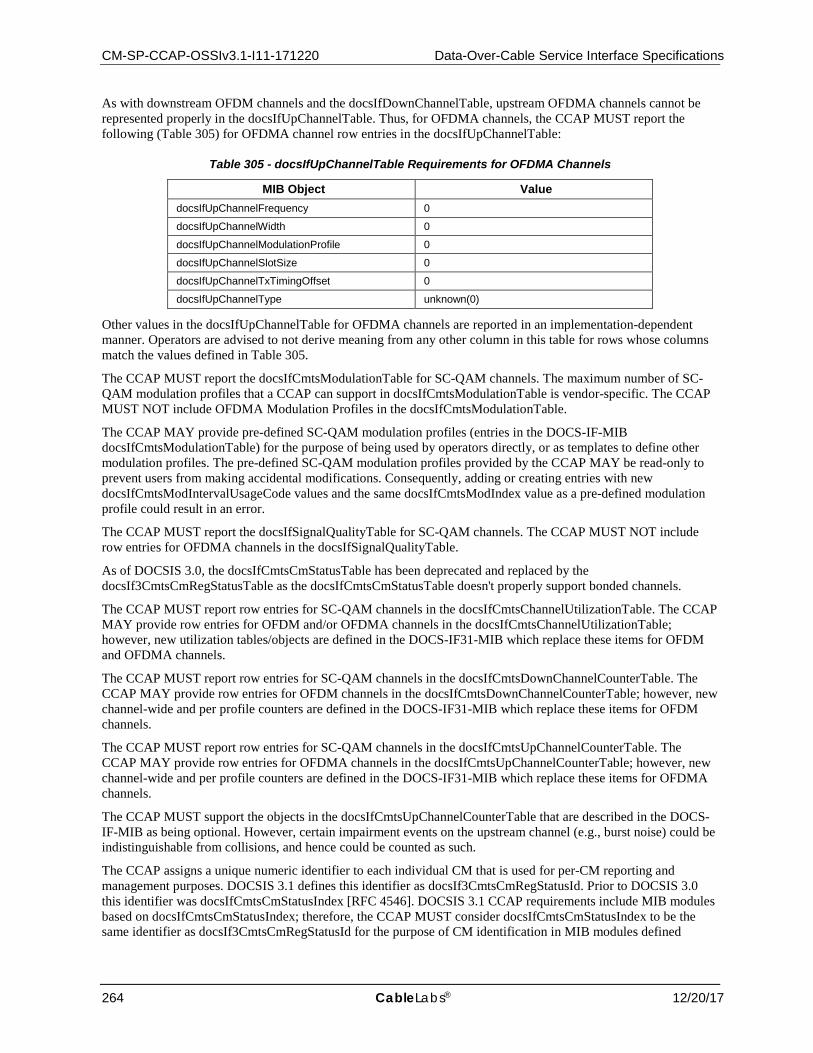
CM-SP-CCAP-OSSIv3.1-I11-171220 Data-Over-Cable Service Interface Specifications
264 CableLabs® 12/20/17
As with downstream OFDM channels and the docsIfDownChannelTable, upstream OFDMA channels cannot be represented properly in the docsIfUpChannelTable. Thus, for OFDMA channels, the CCAP MUST report the following (Table 305) for OFDMA channel row entries in the docsIfUpChannelTable:
Table 305 - docsIfUpChannelTable Requirements for OFDMA Channels
MIB Object Value docsIfUpChannelFrequency 0
docsIfUpChannelWidth 0
docsIfUpChannelModulationProfile 0
docsIfUpChannelSlotSize 0
docsIfUpChannelTxTimingOffset 0
docsIfUpChannelType unknown(0)
Other values in the docsIfUpChannelTable for OFDMA channels are reported in an implementation-dependent manner. Operators are advised to not derive meaning from any other column in this table for rows whose columns match the values defined in Table 305.
The CCAP MUST report the docsIfCmtsModulationTable for SC-QAM channels. The maximum number of SC-QAM modulation profiles that a CCAP can support in docsIfCmtsModulationTable is vendor-specific. The CCAP MUST NOT include OFDMA Modulation Profiles in the docsIfCmtsModulationTable.
The CCAP MAY provide pre-defined SC-QAM modulation profiles (entries in the DOCS-IF-MIB docsIfCmtsModulationTable) for the purpose of being used by operators directly, or as templates to define other modulation profiles. The pre-defined SC-QAM modulation profiles provided by the CCAP MAY be read-only to prevent users from making accidental modifications. Consequently, adding or creating entries with new docsIfCmtsModIntervalUsageCode values and the same docsIfCmtsModIndex value as a pre-defined modulation profile could result in an error.
The CCAP MUST report the docsIfSignalQualityTable for SC-QAM channels. The CCAP MUST NOT include row entries for OFDMA channels in the docsIfSignalQualityTable.
As of DOCSIS 3.0, the docsIfCmtsCmStatusTable has been deprecated and replaced by the docsIf3CmtsCmRegStatusTable as the docsIfCmtsCmStatusTable doesn't properly support bonded channels.
The CCAP MUST report row entries for SC-QAM channels in the docsIfCmtsChannelUtilizationTable. The CCAP MAY provide row entries for OFDM and/or OFDMA channels in the docsIfCmtsChannelUtilizationTable; however, new utilization tables/objects are defined in the DOCS-IF31-MIB which replace these items for OFDM and OFDMA channels.
The CCAP MUST report row entries for SC-QAM channels in the docsIfCmtsDownChannelCounterTable. The CCAP MAY provide row entries for OFDM channels in the docsIfCmtsDownChannelCounterTable; however, new channel-wide and per profile counters are defined in the DOCS-IF31-MIB which replace these items for OFDM channels.
The CCAP MUST report row entries for SC-QAM channels in the docsIfCmtsUpChannelCounterTable. The CCAP MAY provide row entries for OFDMA channels in the docsIfCmtsUpChannelCounterTable; however, new channel-wide and per profile counters are defined in the DOCS-IF31-MIB which replace these items for OFDMA channels.
The CCAP MUST support the objects in the docsIfCmtsUpChannelCounterTable that are described in the DOCS-IF-MIB as being optional. However, certain impairment events on the upstream channel (e.g., burst noise) could be indistinguishable from collisions, and hence could be counted as such.
The CCAP assigns a unique numeric identifier to each individual CM that is used for per-CM reporting and management purposes. DOCSIS 3.1 defines this identifier as docsIf3CmtsCmRegStatusId. Prior to DOCSIS 3.0 this identifier was docsIfCmtsCmStatusIndex [RFC 4546]. DOCSIS 3.1 CCAP requirements include MIB modules based on docsIfCmtsCmStatusIndex; therefore, the CCAP MUST consider docsIfCmtsCmStatusIndex to be the same identifier as docsIf3CmtsCmRegStatusId for the purpose of CM identification in MIB modules defined
CCAP™ Operations Support System Interface Specification CM-SP-CCAP-OSSIv3.1-I11-171220
12/20/17 CableLabs 265
through SNMP conceptual row extension, and SNMP conceptual row augmentation. See section "Relation between INDEX and AUGMENTS clauses" of [RFC 2578] for details on these concepts.
The docsIfCmtsSynchInterval object applies to Primary-Capable Downstream interfaces within the MAC Domain.
The docsIfQosProfileTable has been deprecated since the DOCSIS 1.0 Class of Service (CoS) service class definition type was deprecated and is not supported in DOCSIS 3.1.
The object docsIfDocsisBaseCapability is deprecated in DOCSIS 3.1.
7.1.1.5.4 Requirements for SNMPv2 MIB (RFC 3418)
7.1.1.5.4.1 SNMPv2-MIB System Group Requirements
The CMTS and CCAP MUST implement the System Group of [RFC 3418].
The CCAP MUST use the value of the Name attribute of the Ccap object when reporting sysName via the SNMPv2-MIB. The CCAP MUST use the value of the Location attribute of the Ccap configuration object when reporting the sysLocation via the SNMPv2-MIB.
The CMTS and CCAP MUST implement the sysDescr object. For the CMTS and CCAP, the format and content of the information in sysDescr is vendor-dependent.
7.1.1.5.4.2 SNMPv2-MIB SNMP Group Requirements
This group provides SNMP protocol statistics and protocol errors counters.
The CMTS and CCAP MUST implement The SNMP Group from [RFC 3418].
7.1.1.5.5 Requirements for Interfaces Group MIB (RFC 2863)
The CCAP MUST implement the interface MIB [RFC 2863].
The ifType object associated with a DOCSIS interface can have the following enumerated values:
• CATV MAC interface: docsCableMacLayer (127) • CATV downstream channel: docsCableDownstream (128) • CATV M-CMTS downstream channel: docsCableMCmtsDownstream (229) (See [M-OSSI]) • CATV Downstream OFDM interface: docsOfdmDownstream (277) • CATV upstream interface: docsCableUpStream (129) • CATV Upstream OFDMA interface: docsOfdmaUpstream (278) • CATV logical upstream channel: docsCableUpstreamChannel (205) • CATV upstream RF port: docsCableUpstreamRfPort (256) • CATV downstream RF port: cableDownstreamRfPort (257)
The following statements define the CCAP interface-numbering scheme requirements:
The CCAP MUST implement an instance of ifEntry for each CATV-MAC interface, downstream channel, upstream interface, logical upstream channel, and any other interface type that exists in the CMTS.
The CCAP MUST populate the ifStackTable with the associations of CATV-MAC interfaces to upstream and downstream channels as defined in the MdChCfg configuration object (refer to Section 7.2.1.1.7).
The CCAP MUST implement a row entry in the ifTable for each Downstream RF Port in the CCAP chassis. A Downstream RF Port is typically associated with a single F-connector or single MCX-75 connector on a DLC.
The CCAP MUST implement an ifType value of 257 in the ifTable row entry for each Downstream RF Port.
When an instance of VideoDownChannel is created on a given Downstream RF Port, the CCAP MUST create an ifTable entry with an ifType value of 214 (mpegTransport). For replicated QAMs, an ifTable entry will be created for every instance of a QAM on a given Downstream RF Port, regardless of whether the QAM has been replicated.
CM-SP-CCAP-OSSIv3.1-I11-171220 Data-Over-Cable Service Interface Specifications
266 CableLabs® 12/20/17
When an instance of DocsisDownChannel is created on a given Downstream RF Port, the CCAP MUST create an ifTable entry with an ifType value of 128 (docsCableDownstream).
When an instance of DOCSIS OFDMDownstreamChannel is created on a given Downstream RF Port, the CCAP MUST create an ifTable entry with an ifType value of 278 (docsOfdmDownstream).
In the absence of user configuration, the CCAP MAY automatically instantiate ifTable entries for VideoDownChannel objects and/or DocsisDownChannel objects.
The CCAP MUST implement a row entry in the ifTable for each Upstream RF Port in the CCAP chassis. An Upstream RF Port is typically associated with a single F-connector or a single MCX-75 connector on a ULC.
The CCAP MUST implement an ifType value of 256 in the ifTable row entry for each Upstream RF Port.
When an instance of DOCSIS UpstreamPhysicalChannel is created on a given Upstream RF Port, the CCAP MUST automatically create one or more corresponding instances of an UpstreamLogicalChannel.
When an instance of DOCSIS UpstreamPhysicalChannel is created on a given Upstream RF Port, the CCAP MUST create an ifTable entry with an ifType value of 129 (docsCableUpstream).
When an instance of DOCSIS OFDMAUpstreamChannel is created on a given Upstream RF Port, the CCAP MUST create an ifTable entry with an ifType value of 278 (docsOfdmaUpstream).
When an instance of DOCSIS UpstreamLogicalChannel is created, the CCAP MUST create an ifTable entry with an ifType value of 205 (docsCableUpstreamChannel).
In the absence of user configuration, the CCAP MAY automatically instantiate DOCSIS UpstreamPhysicalChannels of ifType 129 for each physical Upstream RF port on a ULC.
When an instance of DOCSIS MAC Domain is created, the CCAP MUST create an ifTable entry with an ifType value of 127 (docsCableMaclayer).
For each loopback interface that is defined in the system, the CCAP MUST represent that interface with an ifTable entry with an ifType value of 24, per [RFC 2863].
For each row entry created in the ifTable, the CCAP MUST create a corresponding row entry in the ifXTable.
The CCAP SHOULD maintain the same ifIndex value for configured interfaces across reboots if there have been no configuration changes. The interfaces to be persisted across reboots include those interfaces specified in the CCAP configuration UML object model.
7.1.1.5.5.1 ifAdminStatus
The CCAP MUST NOT accept or forward any traffic over an interface whose ifAdminStatus is 'down', (traffic includes data and MAC management traffic where applicable).
When the CCAP initializes, all Ethernet interfaces start with ifAdminStatus in the up(1) state. As a result of either explicit management or configuration information saved via other non-SNMP method (i.e., CLI commands) retained by the managed system, ifAdminStatus is then changed to either the down(2) or testing(3) states (or remains in the up(1) state). When the CCAP initializes, all DOCSIS interfaces start with ifAdminStatus in the down(2) state. As a result of either explicit management or configuration information saved via other non-SNMP method (i.e., CLI commands) retained by the managed system, ifAdminStatus is then changed to either the up(1) or testing(3) states (or remains in the down(2) state).
7.1.1.5.5.2 SNMP Notification Control Requirements
If a multi-layer interface model is present in the device, each sub-layer for which there is an entry in the ifTable can generate linkUp/Down traps. Since interface state changes would tend to propagate through the interface stack (from top to bottom, or bottom to top), it is likely that several traps would be generated for each linkUp/Down occurrence. The ifLinkUpDownTrapEnable object allows managers to control SNMP notification generation, and configure only the interface sub-layers of interest.
The CCAP MUST implement the MIB object ifLinkUpDownTrapEnable specified in [RFC 2863].
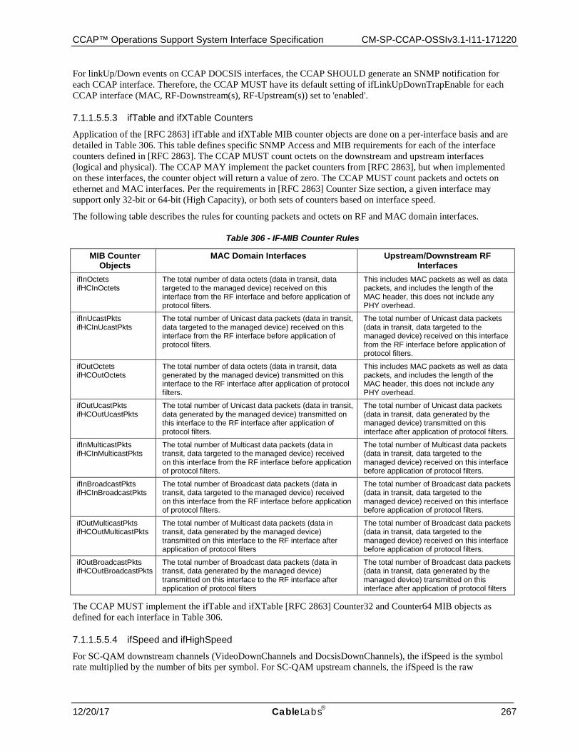
CCAP™ Operations Support System Interface Specification CM-SP-CCAP-OSSIv3.1-I11-171220
12/20/17 CableLabs 267
For linkUp/Down events on CCAP DOCSIS interfaces, the CCAP SHOULD generate an SNMP notification for each CCAP interface. Therefore, the CCAP MUST have its default setting of ifLinkUpDownTrapEnable for each CCAP interface (MAC, RF-Downstream(s), RF-Upstream(s)) set to 'enabled'.
7.1.1.5.5.3 ifTable and ifXTable Counters
Application of the [RFC 2863] ifTable and ifXTable MIB counter objects are done on a per-interface basis and are detailed in Table 306. This table defines specific SNMP Access and MIB requirements for each of the interface counters defined in [RFC 2863]. The CCAP MUST count octets on the downstream and upstream interfaces (logical and physical). The CCAP MAY implement the packet counters from [RFC 2863], but when implemented on these interfaces, the counter object will return a value of zero. The CCAP MUST count packets and octets on ethernet and MAC interfaces. Per the requirements in [RFC 2863] Counter Size section, a given interface may support only 32-bit or 64-bit (High Capacity), or both sets of counters based on interface speed.
The following table describes the rules for counting packets and octets on RF and MAC domain interfaces.
Table 306 - IF-MIB Counter Rules
MIB Counter Objects
MAC Domain Interfaces Upstream/Downstream RF Interfaces
ifInOctets ifHCInOctets
The total number of data octets (data in transit, data targeted to the managed device) received on this interface from the RF interface and before application of protocol filters.
This includes MAC packets as well as data packets, and includes the length of the MAC header, this does not include any PHY overhead.
ifInUcastPkts ifHCInUcastPkts
The total number of Unicast data packets (data in transit, data targeted to the managed device) received on this interface from the RF interface before application of protocol filters.
The total number of Unicast data packets (data in transit, data targeted to the managed device) received on this interface from the RF interface before application of protocol filters.
ifOutOctets ifHCOutOctets
The total number of data octets (data in transit, data generated by the managed device) transmitted on this interface to the RF interface after application of protocol filters.
This includes MAC packets as well as data packets, and includes the length of the MAC header, this does not include any PHY overhead.
ifOutUcastPkts ifHCOutUcastPkts
The total number of Unicast data packets (data in transit, data generated by the managed device) transmitted on this interface to the RF interface after application of protocol filters.
The total number of Unicast data packets (data in transit, data generated by the managed device) transmitted on this interface after application of protocol filters.
ifInMulticastPkts ifHCInMulticastPkts
The total number of Multicast data packets (data in transit, data targeted to the managed device) received on this interface from the RF interface before application of protocol filters.
The total number of Multicast data packets (data in transit, data targeted to the managed device) received on this interface before application of protocol filters.
ifInBroadcastPkts ifHCInBroadcastPkts
The total number of Broadcast data packets (data in transit, data targeted to the managed device) received on this interface from the RF interface before application of protocol filters.
The total number of Broadcast data packets (data in transit, data targeted to the managed device) received on this interface before application of protocol filters.
ifOutMulticastPkts ifHCOutMulticastPkts
The total number of Multicast data packets (data in transit, data generated by the managed device) transmitted on this interface to the RF interface after application of protocol filters
The total number of Broadcast data packets (data in transit, data targeted to the managed device) received on this interface before application of protocol filters.
ifOutBroadcastPkts ifHCOutBroadcastPkts
The total number of Broadcast data packets (data in transit, data generated by the managed device) transmitted on this interface to the RF interface after application of protocol filters
The total number of Broadcast data packets (data in transit, data generated by the managed device) transmitted on this interface after application of protocol filters
The CCAP MUST implement the ifTable and ifXTable [RFC 2863] Counter32 and Counter64 MIB objects as defined for each interface in Table 306.
7.1.1.5.5.4 ifSpeed and ifHighSpeed
For SC-QAM downstream channels (VideoDownChannels and DocsisDownChannels), the ifSpeed is the symbol rate multiplied by the number of bits per symbol. For SC-QAM upstream channels, the ifSpeed is the raw
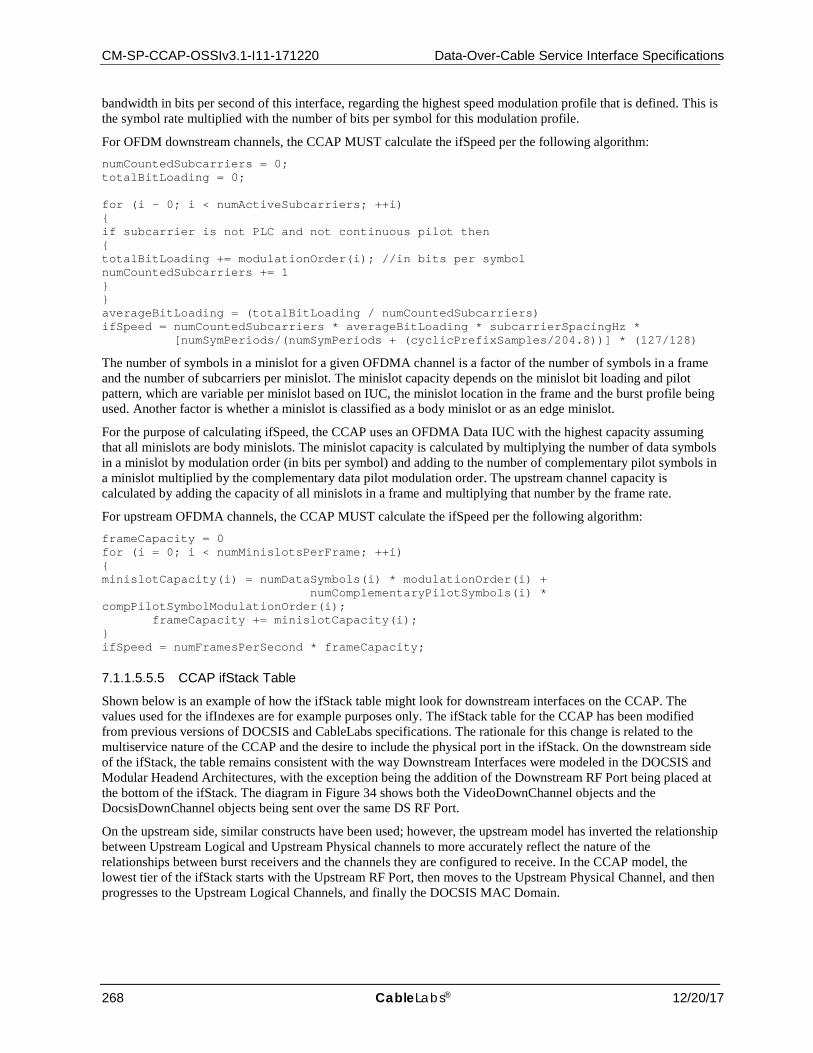
CM-SP-CCAP-OSSIv3.1-I11-171220 Data-Over-Cable Service Interface Specifications
268 CableLabs® 12/20/17
bandwidth in bits per second of this interface, regarding the highest speed modulation profile that is defined. This is the symbol rate multiplied with the number of bits per symbol for this modulation profile.
For OFDM downstream channels, the CCAP MUST calculate the ifSpeed per the following algorithm: numCountedSubcarriers = 0; totalBitLoading = 0; for (i - 0; i < numActiveSubcarriers; ++i) { if subcarrier is not PLC and not continuous pilot then { totalBitLoading += modulationOrder(i); //in bits per symbol numCountedSubcarriers += 1 } } averageBitLoading = (totalBitLoading / numCountedSubcarriers) ifSpeed = numCountedSubcarriers * averageBitLoading * subcarrierSpacingHz * [numSymPeriods/(numSymPeriods + (cyclicPrefixSamples/204.8))] * (127/128)
The number of symbols in a minislot for a given OFDMA channel is a factor of the number of symbols in a frame and the number of subcarriers per minislot. The minislot capacity depends on the minislot bit loading and pilot pattern, which are variable per minislot based on IUC, the minislot location in the frame and the burst profile being used. Another factor is whether a minislot is classified as a body minislot or as an edge minislot.
For the purpose of calculating ifSpeed, the CCAP uses an OFDMA Data IUC with the highest capacity assuming that all minislots are body minislots. The minislot capacity is calculated by multiplying the number of data symbols in a minislot by modulation order (in bits per symbol) and adding to the number of complementary pilot symbols in a minislot multiplied by the complementary data pilot modulation order. The upstream channel capacity is calculated by adding the capacity of all minislots in a frame and multiplying that number by the frame rate.
For upstream OFDMA channels, the CCAP MUST calculate the ifSpeed per the following algorithm: frameCapacity = 0 for (i = 0; i < numMinislotsPerFrame; ++i) { minislotCapacity(i) = numDataSymbols(i) * modulationOrder(i) + numComplementaryPilotSymbols(i) * compPilotSymbolModulationOrder(i); frameCapacity += minislotCapacity(i); } ifSpeed = numFramesPerSecond * frameCapacity;
7.1.1.5.5.5 CCAP ifStack Table
Shown below is an example of how the ifStack table might look for downstream interfaces on the CCAP. The values used for the ifIndexes are for example purposes only. The ifStack table for the CCAP has been modified from previous versions of DOCSIS and CableLabs specifications. The rationale for this change is related to the multiservice nature of the CCAP and the desire to include the physical port in the ifStack. On the downstream side of the ifStack, the table remains consistent with the way Downstream Interfaces were modeled in the DOCSIS and Modular Headend Architectures, with the exception being the addition of the Downstream RF Port being placed at the bottom of the ifStack. The diagram in Figure 34 shows both the VideoDownChannel objects and the DocsisDownChannel objects being sent over the same DS RF Port.
On the upstream side, similar constructs have been used; however, the upstream model has inverted the relationship between Upstream Logical and Upstream Physical channels to more accurately reflect the nature of the relationships between burst receivers and the channels they are configured to receive. In the CCAP model, the lowest tier of the ifStack starts with the Upstream RF Port, then moves to the Upstream Physical Channel, and then progresses to the Upstream Logical Channels, and finally the DOCSIS MAC Domain.
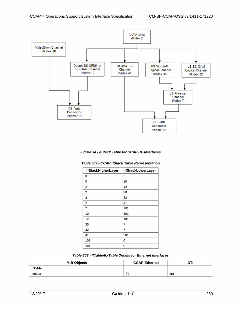
CCAP™ Operations Support System Interface Specification CM-SP-CCAP-OSSIv3.1-I11-171220
12/20/17 CableLabs 269
Figure 34 - ifStack Table for CCAP RF Interfaces
Table 307 - CCAP ifStack Table Representation
ifStackHigherLayer ifStackLowerLayer 0 2
0 10
2 12
2 30
2 32
2 41
7 201
10 101
12 101
30 7
32 7
41 201
101 0
201 0
Table 308 - IfTable/IfXTable Details for Ethernet Interfaces
MIB Objects CCAP-Ethernet DTI IfTable
ifIndex (n) (n)
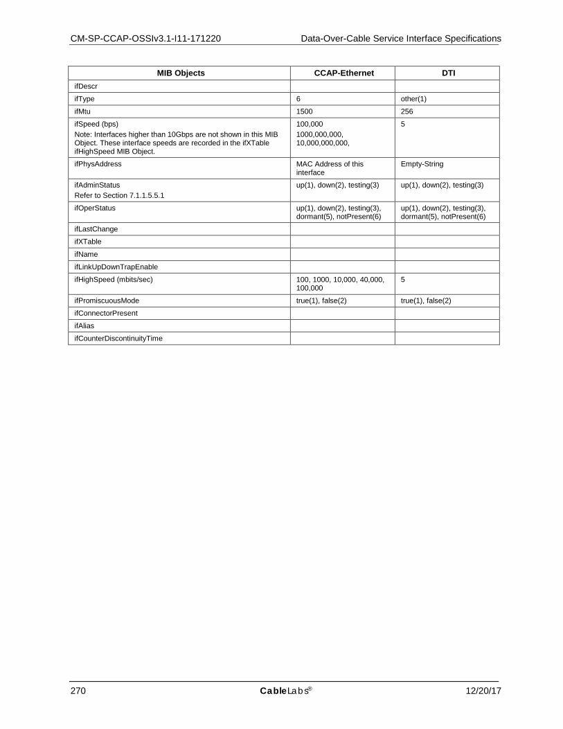
CM-SP-CCAP-OSSIv3.1-I11-171220 Data-Over-Cable Service Interface Specifications
270 CableLabs® 12/20/17
MIB Objects CCAP-Ethernet DTI ifDescr
ifType 6 other(1)
ifMtu 1500 256
ifSpeed (bps) Note: Interfaces higher than 10Gbps are not shown in this MIB Object. These interface speeds are recorded in the ifXTable ifHighSpeed MIB Object.
100,000 1000,000,000, 10,000,000,000,
5
ifPhysAddress MAC Address of this interface
Empty-String
ifAdminStatus Refer to Section 7.1.1.5.5.1
up(1), down(2), testing(3) up(1), down(2), testing(3)
ifOperStatus up(1), down(2), testing(3), dormant(5), notPresent(6)
up(1), down(2), testing(3), dormant(5), notPresent(6)
ifLastChange
ifXTable
ifName
ifLinkUpDownTrapEnable
ifHighSpeed (mbits/sec) 100, 1000, 10,000, 40,000, 100,000
5
ifPromiscuousMode true(1), false(2) true(1), false(2)
ifConnectorPresent
ifAlias
ifCounterDiscontinuityTime

CCAP™ Operations Support System Interface Specification CM-SP-CCAP-OSSIv3.1-I11-171220
12/20/17 CableLabs 271
Table 309 - IfTable/IfXTable for RF and DOCSIS Interfaces
MIB Objects CCAP-MAC CCAP VideoDown
Channel
CCAP DocsisDown
Channel
CCAP-Upstream Physical Channel
CCAP-Upstream
Logical Channel
CCAP DsRfPort
CCAP UsRfPort
CCAP DsOfdm Channel
CCAP UsOfdmaChannel
IfTable
ifIndex (n) (n) (n) (n) (n) (n) (n) (n) (n)
ifDescr t
ifType 127 214* 128 129 205 257 256 277 278
ifMtu For RF Upstream/Downstream; the value includes the length of the MAC header. Note: When a DOCSIS 3.1 CCAP enables extended MAC frame length for a CM, the CCAP-MAC MTU should reflect a value configured by the CCAP up to a maximum value of 2000. Refer to [MULPIv3.1] Extended MAC Frame Length.
2000 188 2030 2030 2030 0 0 2030 2030
ifSpeed Refer to Section 7.1.1.5.5.4
0 DVB-C ~QAM64= 41,712,000 ~QAM256= 55,616,000 J.83 Annex B ~QAM64= 30,341,646 ~QAM256= 42,884,296
DVB-C ~QAM64= 41,712,000 ~QAM256= 55,616,000 J.83 Annex B ~QAM64= 30,341,646 ~QAM256= 42,884,296
(n) (n) 0 0 Refer to Section 7.1.1.5.5.4
Refer to Section 7.1.1.5.5.4
ifPhysAddress MAC Address of interface
Empty-String Empty-String Empty-String Empty-String Empty-String
Empty-String
Empty-String
Empty-String
ifAdminStatus: up(1), down(2), testing(3)
up(1), down(2), testing(3)
up(1), down(2), testing(3)
up(1), down(2), testing(3)
up(1), down(2), testing(3)
up(1), down(2), testing(3)
up(1), down(2), testing(3)
up(1), down(2), testing(3)
up(1), down(2), testing(3)
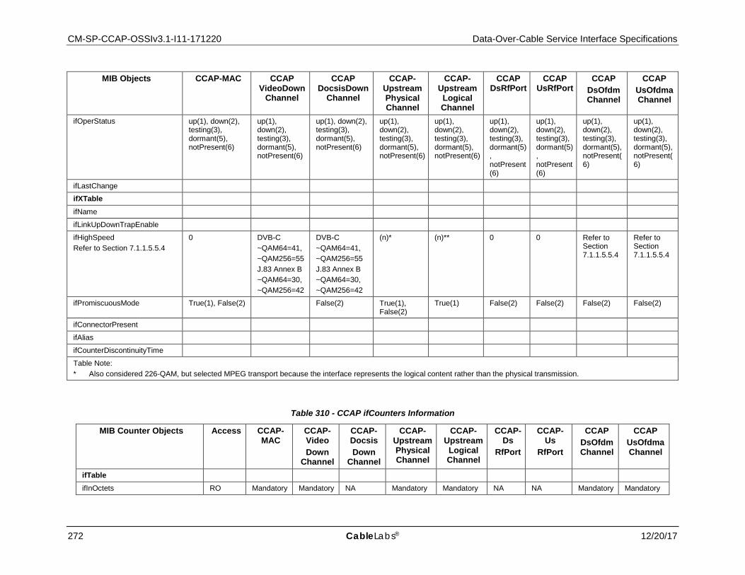
CM-SP-CCAP-OSSIv3.1-I11-171220 Data-Over-Cable Service Interface Specifications
272 CableLabs® 12/20/17
MIB Objects CCAP-MAC CCAP VideoDown
Channel
CCAP DocsisDown
Channel
CCAP-Upstream Physical Channel
CCAP-Upstream
Logical Channel
CCAP DsRfPort
CCAP UsRfPort
CCAP DsOfdm Channel
CCAP UsOfdmaChannel
ifOperStatus up(1), down(2), testing(3), dormant(5), notPresent(6)
up(1), down(2), testing(3), dormant(5), notPresent(6)
up(1), down(2), testing(3), dormant(5), notPresent(6)
up(1), down(2), testing(3), dormant(5), notPresent(6)
up(1), down(2), testing(3), dormant(5), notPresent(6)
up(1), down(2), testing(3), dormant(5), notPresent(6)
up(1), down(2), testing(3), dormant(5), notPresent(6)
up(1), down(2), testing(3), dormant(5), notPresent(6)
up(1), down(2), testing(3), dormant(5), notPresent(6)
ifLastChange
ifXTable
ifName
ifLinkUpDownTrapEnable
ifHighSpeed Refer to Section 7.1.1.5.5.4
0 DVB-C ~QAM64=41, ~QAM256=55 J.83 Annex B ~QAM64=30, ~QAM256=42
DVB-C ~QAM64=41, ~QAM256=55 J.83 Annex B ~QAM64=30, ~QAM256=42
(n)* (n)** 0 0 Refer to Section 7.1.1.5.5.4
Refer to Section 7.1.1.5.5.4
ifPromiscuousMode True(1), False(2) False(2) True(1), False(2)
True(1) False(2) False(2) False(2) False(2)
ifConnectorPresent
ifAlias
ifCounterDiscontinuityTime
Table Note: * Also considered 226-QAM, but selected MPEG transport because the interface represents the logical content rather than the physical transmission.
Table 310 - CCAP ifCounters Information
MIB Counter Objects Access CCAP-MAC
CCAP- Video Down
Channel
CCAP-Docsis Down
Channel
CCAP-Upstream Physical Channel
CCAP-Upstream
Logical Channel
CCAP- Ds
RfPort
CCAP- Us
RfPort
CCAP DsOfdmChannel
CCAP UsOfdmaChannel
ifTable
ifInOctets RO Mandatory Mandatory NA Mandatory Mandatory NA NA Mandatory Mandatory
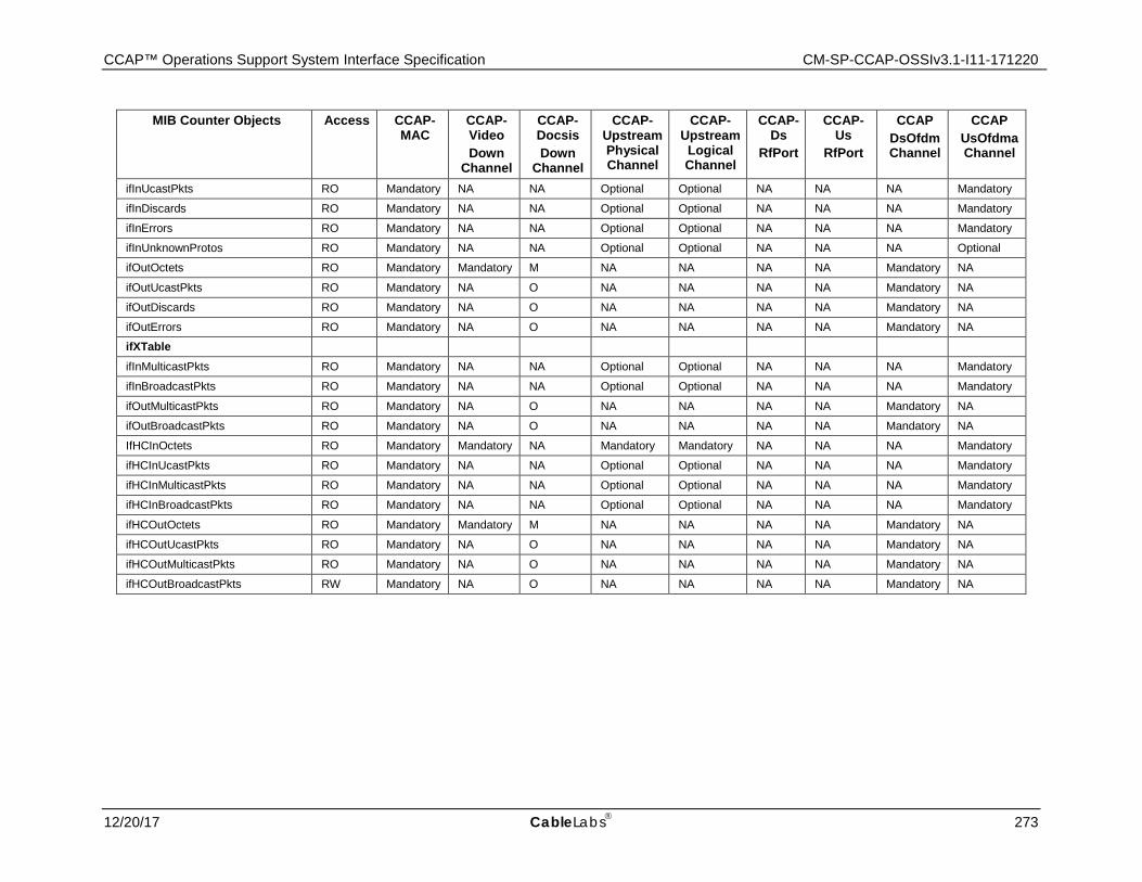
CCAP™ Operations Support System Interface Specification CM-SP-CCAP-OSSIv3.1-I11-171220
12/20/17 CableLabs 273
MIB Counter Objects Access CCAP-MAC
CCAP- Video Down
Channel
CCAP-Docsis Down
Channel
CCAP-Upstream Physical Channel
CCAP-Upstream
Logical Channel
CCAP- Ds
RfPort
CCAP- Us
RfPort
CCAP DsOfdmChannel
CCAP UsOfdmaChannel
ifInUcastPkts RO Mandatory NA NA Optional Optional NA NA NA Mandatory
ifInDiscards RO Mandatory NA NA Optional Optional NA NA NA Mandatory
ifInErrors RO Mandatory NA NA Optional Optional NA NA NA Mandatory
ifInUnknownProtos RO Mandatory NA NA Optional Optional NA NA NA Optional
ifOutOctets RO Mandatory Mandatory M NA NA NA NA Mandatory NA
ifOutUcastPkts RO Mandatory NA O NA NA NA NA Mandatory NA
ifOutDiscards RO Mandatory NA O NA NA NA NA Mandatory NA
ifOutErrors RO Mandatory NA O NA NA NA NA Mandatory NA
ifXTable
ifInMulticastPkts RO Mandatory NA NA Optional Optional NA NA NA Mandatory
ifInBroadcastPkts RO Mandatory NA NA Optional Optional NA NA NA Mandatory
ifOutMulticastPkts RO Mandatory NA O NA NA NA NA Mandatory NA
ifOutBroadcastPkts RO Mandatory NA O NA NA NA NA Mandatory NA
IfHCInOctets RO Mandatory Mandatory NA Mandatory Mandatory NA NA NA Mandatory
ifHCInUcastPkts RO Mandatory NA NA Optional Optional NA NA NA Mandatory
ifHCInMulticastPkts RO Mandatory NA NA Optional Optional NA NA NA Mandatory
ifHCInBroadcastPkts RO Mandatory NA NA Optional Optional NA NA NA Mandatory
ifHCOutOctets RO Mandatory Mandatory M NA NA NA NA Mandatory NA
ifHCOutUcastPkts RO Mandatory NA O NA NA NA NA Mandatory NA
ifHCOutMulticastPkts RO Mandatory NA O NA NA NA NA Mandatory NA
ifHCOutBroadcastPkts RW Mandatory NA O NA NA NA NA Mandatory NA
CM-SP-CCAP-OSSIv3.1-I11-171220 DOCSIS® 3.1
274 CableLabs 12/20/17
7.1.1.5.6 Requirements for Entity-MIB (RFC 4133)
The CCAP MUST implement the ENTITY-MIB [RFC 4133] as described in the following subsections and Annex A.
7.1.1.5.6.1 Entity-MIB CCAP Requirements for entPhysicalTable
The CCAP implements a row entry in the entPhysicalTable for the system chassis and each Field Replaceable Unit (FRU) installed in the CCAP chassis.
The CCAP MUST report an entry in the entPhysicalTable for the chassis component with Physical Class 'chassis'.
The CCAP MUST report entries in the entPhysicalTable of Physical Class 'container' (such as slots) that contains physical Field Removable Units (FRU) normally modeled as elements of Physical Class 'module'.
The CCAP MUST provide as much information as possible about entPhysicalTable listed in Table 311 for major components such as CCAP chassis, backplanes and containers or modules in the form or cards and/or field replaceable units (FRUs) when possible. Modules within modules (or cards) or other contained physical components need not be detailed.
The CCAP MUST provide the unique component serial number, via the entPhysicalSerialNum object, contained within the row entry in the entPhysicalTable for the system chassis and each FRU that has a serial number in the system. Example FRUs with serial numbers include, but are not limited to, fabric cards, DTI cards, SREs, DLCs, ULCs, combined Upstream & Downstream line cards, Ethernet cards, and PON line cards.
The CCAP SHOULD provide the unique component serial number, via the entPhysicalSerialNum object, contained within the row entry in the entPhysicalTable for each FRU that is a pluggable optical module such as an SFP, SFP+, QSFP, XFP, CXP.
Example FRUs that might not have serial numbers, yet are expected to be represented in the entPhysicalTable, include flash cards, fan modules, and power supply modules.
The CCAP SHOULD implement row entries in the entPhysicalTable for temperature sensors in the system with an entPhysicalClass value of "sensor".
The CCAP MAY report temperature sensors in the form of instances in the entPhysicalTable for elements of Physical Class 'sensor' with the corresponding entPhySensorType 'celsius' value in the corresponding entPhySensorTable instance of the ENTITY-SENSOR-MIB [RFC 3433].
The CCAP SHOULD provide the unique component serial number, via the entPhysicalSerialNum object, contained within the row entry in the entPhysicalTable for every FRU that is capable of causing and/or generating an event, message, log, or alarm.
The [DRFI] specification defines a multi-channel RF port capability. The set of downstream channels within the same RF port is also known as a "Channel Block" (see [DRFI]).
The [MULPIv3.1] specification does not have a concrete definition of multiple upstream interfaces being part of the same RF spigot as [DRFI] does for downstream channels, but in several diagrams (e.g., [MULPIv3.1] Downstream Convergence Layer Block Diagram) those options are discussed. For the upstream interfaces, only the physical upstream interfaces are modeled in the Entity MIB. The logical upstream interfaces are defined in the CCAP ifStackTable.
A Channel Block is defined as the set of downstream interfaces (Physical Class 'port') that share the same immediate physical component of Physical Class 'module' in the containment tree (entPhysicalContainsTable).
The Entity MIB entries below the 'chassis' container will at a minimum consist of the downstream and upstream interfaces and optionally the logical MAC Domain groupings. The goal in this reporting structure is to catalog and report those interfaces that can be combined to logically form MAC Domains.
The CCAP MUST report RF ports as Physical Class 'module' elements in the entPhysicalTable. The CCAP MUST include the text "RF port" within the description of the SNMP object entPhysicalDescr for RF ports modeled in the entPhysicalTable.
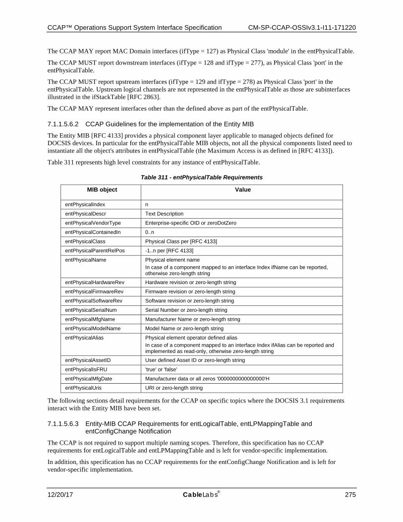
CCAP™ Operations Support System Interface Specification CM-SP-CCAP-OSSIv3.1-I11-171220
12/20/17 CableLabs 275
The CCAP MAY report MAC Domain interfaces (ifType = 127) as Physical Class 'module' in the entPhysicalTable.
The CCAP MUST report downstream interfaces (ifType = 128 and ifType = 277), as Physical Class 'port' in the entPhysicalTable.
The CCAP MUST report upstream interfaces (ifType = 129 and ifType = 278) as Physical Class 'port' in the entPhysicalTable. Upstream logical channels are not represented in the entPhysicalTable as those are subinterfaces illustrated in the ifStackTable [RFC 2863].
The CCAP MAY represent interfaces other than the defined above as part of the entPhysicalTable.
7.1.1.5.6.2 CCAP Guidelines for the implementation of the Entity MIB
The Entity MIB [RFC 4133] provides a physical component layer applicable to managed objects defined for DOCSIS devices. In particular for the entPhysicalTable MIB objects, not all the physical components listed need to instantiate all the object's attributes in entPhysicalTable (the Maximum Access is as defined in [RFC 4133]).
Table 311 represents high level constraints for any instance of entPhysicalTable.
Table 311 - entPhysicalTable Requirements
MIB object Value
entPhysicalIndex n
entPhysicalDescr Text Description
entPhysicalVendorType Enterprise-specific OID or zeroDotZero
entPhysicalContainedIn 0..n
entPhysicalClass Physical Class per [RFC 4133]
entPhysicalParentRelPos -1..n per [RFC 4133]
entPhysicalName Physical element name In case of a component mapped to an interface Index ifName can be reported, otherwise zero-length string
entPhysicalHardwareRev Hardware revision or zero-length string
entPhysicalFirmwareRev Firmware revision or zero-length string
entPhysicalSoftwareRev Software revision or zero-length string
entPhysicalSerialNum Serial Number or zero-length string
entPhysicalMfgName Manufacturer Name or zero-length string
entPhysicalModelName Model Name or zero-length string
entPhysicalAlias Physical element operator defined alias In case of a component mapped to an interface Index ifAlias can be reported and implemented as read-only, otherwise zero-length string
entPhysicalAssetID User defined Asset ID or zero-length string
entPhysicalIsFRU 'true' or 'false'
entPhysicalMfgDate Manufacturer data or all zeros '0000000000000000'H
entPhysicalUris URI or zero-length string
The following sections detail requirements for the CCAP on specific topics where the DOCSIS 3.1 requirements interact with the Entity MIB have been set.
7.1.1.5.6.3 Entity-MIB CCAP Requirements for entLogicalTable, entLPMappingTable and entConfigChange Notification
The CCAP is not required to support multiple naming scopes. Therefore, this specification has no CCAP requirements for entLogicalTable and entLPMappingTable and is left for vendor-specific implementation.
In addition, this specification has no CCAP requirements for the entConfigChange Notification and is left for vendor-specific implementation.
CM-SP-CCAP-OSSIv3.1-I11-171220 DOCSIS® 3.1
276 CableLabs 12/20/17
7.1.1.5.6.4 Entity-MIB CCAP Requirements for entPhysicalContainsTable
The purpose of the entPhysicalContainsTable in the CCAP is to represent the association of multiple downstream and upstream interfaces within the physical construction of the CCAP. These associations are already modeled in the entPhysicalTable (entPhysicalContainedIn and entPhysicalParentRelPos). The entPhysicalContainsTable provide a more direct relationship of those parent-child associations. Additionally it may provide mechanisms to indicate other associations like restrictions and configurability of downstream and upstream interfaces within a particular MAC Domain as defined below.
For the purpose of identifying downstream and upstream interfaces within an RF port as well as Channel Blocks, the CCAP MAY report in the entPhysicalContainsTable the physical component of Physical Class 'module' as the entPhysicalIndex value for each of the downstream or upstream interface Physical Indexes as the values for entPhysicalChildIndex.
For the purpose of modeling which upstream and downstream interfaces can physically and logically be configured within a MAC Domain, the CCAP MAY define logical components of Physical Class 'backplane' (in entPhysicalTable) to include (in entPhysicalContainsTable) all the MAC Domain interface resources and downstream/upstream interfaces that could potentially be added in a particular MAC Domain.
If supported, the CCAP MAY apply the following rules to indicate containment models for MAC Domain and downstream/upstream associations:
• The 'backplane' physical component entries in entPhysicalTable have a valid Physical Index for entPhysicalContainedIn (e.g., the CCAP 'chassis' or another 'backplane' Physical Class component).
• The 'backplane' physical components are not referenced by other physical components in entPhysicalTable as their entPhysicalContainedIn value.
• Physical components 'backplane' are the parent index in entPhysicalContainsTable for children indexes representing MAC Domain interfaces, downstream/upstream interfaces, and/or physical components 'modules' that represent RF ports or Channel Blocks. When this set of parent-child entries contains 'modules' (e.g., Channel Blocks) instead of individual US/DS interfaces, it indicates that the complete 'module' is configurable within a single MAC Domain, while the existence of individual 'backplane' - downstream/upstream interfaces parent-children entries in entPhysicalContainsTable indicates that individual channels (even within a Channel Block) can be associated with specific MAC Domains).
The CCAP does not need to report in the entPhysicalContainsTable the MAC Domain downstream/upstream channel hierarchy normally represented in the ifStackTable.
7.1.1.5.6.5 Entity-MIB CCAP Requirements for entAliasMappingTable
The entAliasMappingTable is used in this specification to associate the physical elements modeled in the Entity MIB with the logical components of the CCAP management model.
For each row entry created in the SNMPv2-MIB ifTable that can be mapped to an entity represented in the Entity-MIB, the CCAP MUST create a corresponding row entry in the entAliasMappingTable.
The CCAP MUST implement a row entry in the entAliasMappingTable for each UsRfPort and each DsRfPort in the chassis.
The CCAP MAY represent the mapping of MAC Domain to downstream and upstream interfaces in the entAliasMappingTable.
The CCAP MAY represent the mapping of other logical components with physical components in the entAliasMappingTable.
7.1.1.5.7 Requirements for Entity Sensor MIB (RFC 3433)
The CMTS MAY implement the Entity Sensor MIB [RFC 3433].
For ENTITY-MIB [RFC 4113] entPhysicalTable instances with entPhysicalClass of 'sensor', the CMTS and CCAP MAY implement the entPhySensorTable with the same entPhysicalIndex used in the entPhysicalTable and the entPhySensorType of 'celsius'.
CCAP™ Operations Support System Interface Specification CM-SP-CCAP-OSSIv3.1-I11-171220
12/20/17 CableLabs 277
7.1.1.5.8 Requirements for Host Resources MIB (RFC 2790)
The CMTS and CCAP MAY implement the HOST-RESOURCES-MIB [RFC 2790].
7.1.1.5.9 Requirements for Ethernet Interface MIB (RFC 3635)
The CMTS and CCAP MUST implement [RFC 3635] for each of its Ethernet interfaces.
7.1.1.5.10 Requirements for Bridge MIB (RFC 4188)
If a CMTS is a Bridging CMTS, the CMTS MUST implement the Bridge MIB [RFC 4188] to manage the bridging process and represent state information about the CMTS Forwarders using link-layer (bridging) semantics.
If STP is enabled for the CMTS, then the CMTS implements the dot1dStp scalar group [RFC 4188] and optionally the dot1dStpPortTable [RFC 4188] as specified in Annex A.
7.1.1.5.11 Requirements for Internet Protocol MIB (RFC 4293)
The CMTS and CCAP requirements for [RFC 4293] are defined in the following sections.
7.1.1.5.11.1 The IP Group
The CMTS MUST implement the ipv4GeneralGroup.
The CMTS MUST implement the ipv6GeneralGroup2.
The CMTS MUST implement the ipv4InterfaceTable.
The CMTS MUST populate the ipv4InterfaceTable with each Ethernet interface with an assigned IPv4 address. The CMTS MAY record other interfaces in the ipv4InterfaceTable which have assigned IPv4 addresses.
The CMTS MUST populate the ipv6InterfaceTable with each Ethernet interface with an assigned IPv6 address. The CMTS MAY record other interfaces in the ipv6InterfaceTable which have assigned IPv6 addresses.
The CMTS MAY implement the ipSystemStatsTable.
The Routing CMTS MUST implement the ipIfStatsTable that includes both the CATV MAC interface and any NSI interfaces. The Bridging CMTS MAY implement the ipIfStatsTable.
The Routing CMTS MUST implement the ipAddressPrefixTable. The Bridging CMTS MAY implement the ipAddressPrefixTable.
The Routing CMTS MUST implement the ipAddressTable as Read-Only. The Bridging CMTS MAY implement the ipAddressTable.
The Routing CMTS MUST implement the ipNetToPhysicalTable. The Bridging CMTS MAY implement the ipNetToPhysicalTable.
The Routing CMTS MUST implement the ipDefaultRouterTable. The Bridging CMTS MAY implement the ipDefaultRouterTable.
If the CMTS has been configured for a default route, the Routing CMTS MUST populate the default router in the ipDefaultRouterTable.
The CMTS can populate the ipDefaultRouterTable with an IPv4 and/or IPv6 statically configured default router or a default router learned through a dynamic update mechanism such as a routing protocol update or IPv6 router advertisement message.
The Routing CMTS MUST implement the ipv6RouterAdvertTable. The Bridging CMTS MUST NOT implement the ipv6RouterAdvertTable.
7.1.1.5.11.2 The ICMP Group
The CMTS MUST implement the icmpStatsTable.
The CMTS MUST implement the icmpMsgStatsTable.
CM-SP-CCAP-OSSIv3.1-I11-171220 DOCSIS® 3.1
278 CableLabs 12/20/17
7.1.1.5.12 Requirements for User Datagram Protocol (UDP) MIB (RFC 4113)
The CMTS and CCAP SHOULD implement the UDP-MIB [RFC 4113].
7.1.1.5.13 Requirements for Transmission Control Protocol (TCP) MIB (RFC 4022]
The CMTS and CCAP SHOULD implement the TCP group in [RFC 4022].
7.1.1.5.14 Requirements for Multicast Group Membership Discovery (MGMD) MIB (RFC 5519)
The CMTS MUST implement [RFC 5519].
Refer to Section 6.6.8.21 for DOCSIS 3.1 MGMD CMTS and CCAP configuration implementation details.
7.1.1.5.15 Requirements for DOCSIS Baseline Privacy Plus MIB (RFC 4131)
The CMTS MUST implement [RFC 4131].
The CMTS MUST implement the CMTS extensions to [RFC 4131] listed in Section 6.6.6.2.
The CMTS MUST report values for the MIB object docsBpi2CmtsCACertTrust of either 'trusted', 'untrusted', or 'root'. The CMTS MAY persist entries with a docsBpi2CmtsCACertTrust value of 'chained' across reboots. The CMTS MUST be capable of removing entries in the docsBpi2CmtsCACertTable via SNMP by setting the row status to 'destroy'. The CMTS MUST NOT allow new entries to be created for certificates that already exist in the docsBpi2CmtsCACertTable.
The CMTS MUST persist the entries in docsBpi2CmtsProvisionedCmCertTable across reboots. The CMTS MUST be capable of removing entries in docsBpi2CmtsProvisionedCmCertTable via SNMP by setting the row status to 'destroy'. The CMTS MUST NOT allow new entries to be created for certificates that already exist in the docsBpi2CmtsProvisionedCmCertTable.
The CMTS MUST extend the MIB object docsBpi2CmtsAuthBpkmCmCertValid enumerations as follows: docsBpi2CmtsAuthBpkmCmCertValid OBJECT-TYPE SYNTAX INTEGER { unknown (0), validCmChained (1), validCmTrusted (2), invalidCmUntrusted (3), invalidCAUntrusted (4), invalidCmOther (5), invalidCAOther (6), invalidCmRevoked(7), invalidCARevoked(8) } MAX-ACCESS read-only STATUS current DESCRIPTION "Contains the reason why a CM's certificate is deemed valid or invalid. Return unknown(0) if the CM is running BPI mode. ValidCmChained(1) means the certificate is valid because it chains to a valid certificate. ValidCmTrusted(2) means the certificate is valid because it has been provisioned (in the docsBpi2CmtsProvisionedCmCert table) to be trusted. InvalidCmUntrusted(3) means the certificate is invalid because it has been provisioned (in the docsBpi2CmtsProvisionedCmCert table) to be untrusted. InvalidCAUntrusted(4) means the certificate is invalid because it chains to an untrusted certificate. InvalidCmOther(5) and InvalidCAOther(6) refer to errors in parsing, validity periods, etc., which are attributable to the CM certificate or its chain,

CCAP™ Operations Support System Interface Specification CM-SP-CCAP-OSSIv3.1-I11-171220
12/20/17 CableLabs 279
respectively; additional information may be found in docsBpi2AuthRejectErrorString for these types of errors. invalidCmRevoked(7) means the certificate is invalid as it was marked as revoked. invalidCARevoked(8) means the CA certificate is invalid as it was marked as revoked. " REFERENCE "DOCSIS Security Specification CM-SP-SECv3.0-I08-080522, Certificate Revocation section." ::= { docsBpi2CmtsAuthEntry 19 }
A DOCSIS 3.0 CMTS uses the value of MdifIndex as the ifIndex key in the following tables:
• docsBpi2CmtsBaseTable • docsBpi2CmtsAuthTable • docsBpi2CmtsTEKTable • docsBpi2CmtsIpMulticastMapTable
Entries in the docsBpi2CmtsIpMulticastMapTable are only populated when an authorized joiner for a specific multicast group, which has been configured in the CmtsGrpCfg object for encryption (i.e., a CmtsGrpEncrypt object instance exists and is referenced by a CmtsGrpCfg instance), has successfully joined a session. Thus entries in this table are only created when active sessions have been initiated to authorized clients.
7.1.1.5.16 Requirements for Diffie-Helman USM Key MIB (RFC 2786)
The CMTS and CCAP MAY implement [RFC 2786].
7.1.1.5.17 Requirements for SNMPv3 MIB Modules
If the CMTS or CCAP supports the SNMPv3 protocol, the CMTS and CCAP MUST implement the MIBs defined in [RFC 3411] through [RFC 3415] and [RFC 3584].
The CMTS and CCAP SHOULD support a minimum of 30 available rows in the vacmViewTreeFamilyTable object.
7.1.1.5.18 Requirements for DOCSIS Interface Extension 2 MIB (Annex A)
The CMTS and CCAP MUST implement DOCS-IFEXT2-MIB, as specified in Annex A.
7.1.1.5.19 Requirements for CableLabs Topology MIB (Annex A)
The CMTS and CCAP MUST implement CLAB-TOPO-MIB, as specified in Annex A.
7.1.1.5.20 Requirements for DOCSIS Diagnostic Log MIB (Annex A)
The CMTS and CCAP MUST implement DOCS-DIAG-MIB, as specified in Annex A.
7.1.1.5.21 Requirements for DOCSIS Interface 3 MIB (Annex A)
The CMTS and CCAP MUST implement the DOCS-IF3-MIB, as specified in Annex A.
7.1.1.5.22 Requirements for DOCSIS Multicast MIB (Annex A)
The CMTS and CCAP MUST implement the DOCS-MCAST-MIB, as specified in Annex A.
7.1.1.5.23 Requirements for DOCSIS Multicast Authorization MIB (Annex A)
The CMTS and CCAP MUST implement the DOCS-MCAST-AUTH-MIB, as specified in Annex A.

CM-SP-CCAP-OSSIv3.1-I11-171220 DOCSIS® 3.1
280 CableLabs 12/20/17
7.1.1.5.24 Requirements for DOCSIS Quality of Service 3 MIB (Annex A)
The CMTS and CCAP MUST implement the DOCS-QOS3-MIB, as specified in Annex A.
A DOCSIS 3.1 CMTS and CCAP populates entries in the docsQosUpstreamStatsTable with information for Pre-3.0 DOCSIS devices. Devices operating in Multiple Transmit Channel mode will not be recorded in the docsQosUpstreamStatsTable and will instead be recorded in the docsQosServiceFlowCcfStatsTable.
7.1.1.5.25 Requirements for DOCSIS Security MIB (Annex A)
The CMTS and CCAP MUST implement the DOCS-SEC-MIB, as specified in Annex A.
7.1.1.5.26 Requirements for DOCSIS Subscriber Management 3 MIB (Annex A)
The CMTS and CCAP MUST implement the DOCS-SUBMGT3-MIB, as specified in Annex A.
7.1.1.5.27 Requirements for DOCSIS Load Balancing 3 MIB (Annex A)
The CMTS and CCAP MUST implement the DOCS-LOADBAL3-MIB, as specified in Annex A.
7.1.1.5.28 Requirements for DOCSIS DRF MIB (DRFI)
The CMTS MUST implement the managed objects from DOCS-DRF-MIB [DRFI] specified in Annex A for all the Downstream Channel interfaces that are integrated (ifType = 'docsCableDownstream').
7.1.1.5.29 Requirements for IP Multicast MIB (RFC 5132)
The CCAP MUST implement [RFC 5132].
If the CCAP has any one of the following multicast protocols enabled, PIM [RFC 4601], MLD [RFC 2710] [RFC 3810], or IGMP [RFC 1112] [RFC 2236] [RFC 3376], the CCAP MUST report a value of 'true' for ipMcastEnabled. When all three multicast protocols, PIM, MLD and IGMP are disabled in the CCAP, the value of 'false' is reported for ipMcastEnabled.
7.2 Performance Management UML Object Models
The Performance Management UML model has been divided into the following categories:
• State Data: These object are used to gather state information from the CCAP. • Statistical Data: These objects are used to gather statistical information from the CCAP.
Those models are shown in the following sections.
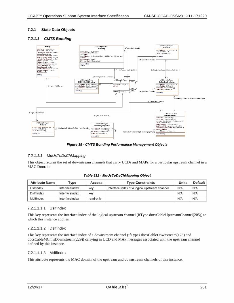
CCAP™ Operations Support System Interface Specification CM-SP-CCAP-OSSIv3.1-I11-171220
12/20/17 CableLabs 281
7.2.1 State Data Objects
7.2.1.1 CMTS Bonding
Figure 35 - CMTS Bonding Performance Management Objects
7.2.1.1.1 MdUsToDsChMapping
This object returns the set of downstream channels that carry UCDs and MAPs for a particular upstream channel in a MAC Domain.
Table 312 - MdUsToDsChMapping Object
Attribute Name Type Access Type Constraints Units Default UsIfIndex InterfaceIndex key Interface Index of a logical upstream channel N/A N/A
DsIfIIndex InterfaceIndex key N/A N/A
MdIfIndex InterfaceIndex read-only N/A N/A
7.2.1.1.1.1 UsIfIndex
This key represents the interface index of the logical upstream channel (ifType docsCableUpstreamChannel(205)) to which this instance applies.
7.2.1.1.1.2 DsIfIndex
This key represents the interface index of a downstream channel (ifTypes docsCableDownstream(128) and docsCableMCmtsDownstream(229)) carrying in UCD and MAP messages associated with the upstream channel defined by this instance.
7.2.1.1.1.3 MdIfIndex
This attribute represents the MAC domain of the upstream and downstream channels of this instance.
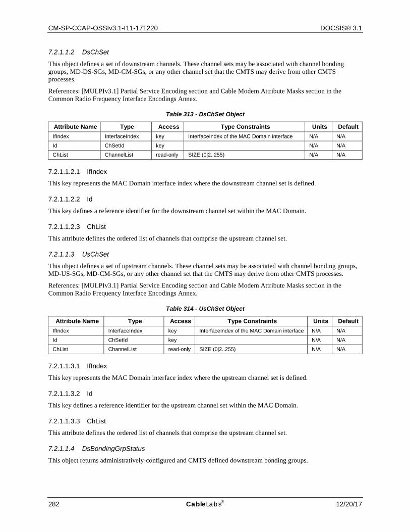
CM-SP-CCAP-OSSIv3.1-I11-171220 DOCSIS® 3.1
282 CableLabs 12/20/17
7.2.1.1.2 DsChSet
This object defines a set of downstream channels. These channel sets may be associated with channel bonding groups, MD-DS-SGs, MD-CM-SGs, or any other channel set that the CMTS may derive from other CMTS processes.
References: [MULPIv3.1] Partial Service Encoding section and Cable Modem Attribute Masks section in the Common Radio Frequency Interface Encodings Annex.
Table 313 - DsChSet Object
Attribute Name Type Access Type Constraints Units Default IfIndex InterfaceIndex key InterfaceIndex of the MAC Domain interface N/A N/A
Id ChSetId key N/A N/A
ChList ChannelList read-only SIZE (0|2..255) N/A N/A
7.2.1.1.2.1 IfIndex
This key represents the MAC Domain interface index where the downstream channel set is defined.
7.2.1.1.2.2 Id
This key defines a reference identifier for the downstream channel set within the MAC Domain.
7.2.1.1.2.3 ChList
This attribute defines the ordered list of channels that comprise the upstream channel set.
7.2.1.1.3 UsChSet
This object defines a set of upstream channels. These channel sets may be associated with channel bonding groups, MD-US-SGs, MD-CM-SGs, or any other channel set that the CMTS may derive from other CMTS processes.
References: [MULPIv3.1] Partial Service Encoding section and Cable Modem Attribute Masks section in the Common Radio Frequency Interface Encodings Annex.
Table 314 - UsChSet Object
Attribute Name Type Access Type Constraints Units Default IfIndex InterfaceIndex key InterfaceIndex of the MAC Domain interface N/A N/A
Id ChSetId key N/A N/A
ChList ChannelList read-only SIZE (0|2..255) N/A N/A
7.2.1.1.3.1 IfIndex
This key represents the MAC Domain interface index where the upstream channel set is defined.
7.2.1.1.3.2 Id
This key defines a reference identifier for the upstream channel set within the MAC Domain.
7.2.1.1.3.3 ChList
This attribute defines the ordered list of channels that comprise the upstream channel set.
7.2.1.1.4 DsBondingGrpStatus
This object returns administratively-configured and CMTS defined downstream bonding groups.

CCAP™ Operations Support System Interface Specification CM-SP-CCAP-OSSIv3.1-I11-171220
12/20/17 CableLabs 283
Table 315 - DsBondingGrpStatus Object
Attribute Name Type Access Type Constraints Units IfIndex InterfaceIndex key InterfaceIndex of MAC Domain interface N/A
ChSetId ChSetId key N/A
MdDsSgId unsignedByte read-only N/A
CfgId unsignedShort read-only N/A
7.2.1.1.4.1 IfIndex
This key represents the interface index of the MAC Domain of the bonding group of this instance.
7.2.1.1.4.2 ChSetId
This key represents the identifier for the Downstream Bonding Group or the single-downstream channel of this instance.
7.2.1.1.4.3 MdDsSgId
This attribute corresponds to the MD-DS-SG-ID that includes all the downstream channels of the Downstream Bonding Group. The value zero indicates that the bonding group does not contain channels from a single MD-DS-SG and therefore the bonding group is not valid and usable.
7.2.1.1.4.4 CfgId
This attribute provides the BondingGrpCfgId for the downstream bonding group if it was configured. Otherwise, the zero value indicates that the CMTS will define the bonding group.
7.2.1.1.5 UsBondingGrpStatus
This object returns administratively-configured and CMTS-defined upstream bonding groups.
Table 316 - UsBondingGrpStatus Object
Attribute Name Type Access Type Constraints Units ifIndex InterfaceIndex key InterfaceIndex of MAC Domain interface N/A
ChSetId ChSetId key N/A
MdUsSgId unsignedByte read-only N/A
CfgId unsignedShort read-only N/A
7.2.1.1.5.1 IfIndex
This key represents the interface index of the MAC Domain of the bonding group of this instance.
7.2.1.1.5.2 ChSetId
This key represents the identifier for the Upstream Bonding Group or the single-upstream channel of this instance.
7.2.1.1.5.3 MdUsSgId
This attribute corresponds to the MD-US-SG-ID that includes all the upstream channels of the Upstream Bonding Group. The value zero indicates that the bonding group does not contain channels from a single MD-US-SG and therefore the bonding group is not valid and usable.
7.2.1.1.5.4 CfgId
This attribute provides the BondingGrpCfgId for the upstream bonding group if it was configured. Otherwise, the zero value indicates that the CMTS defines the bonding group.
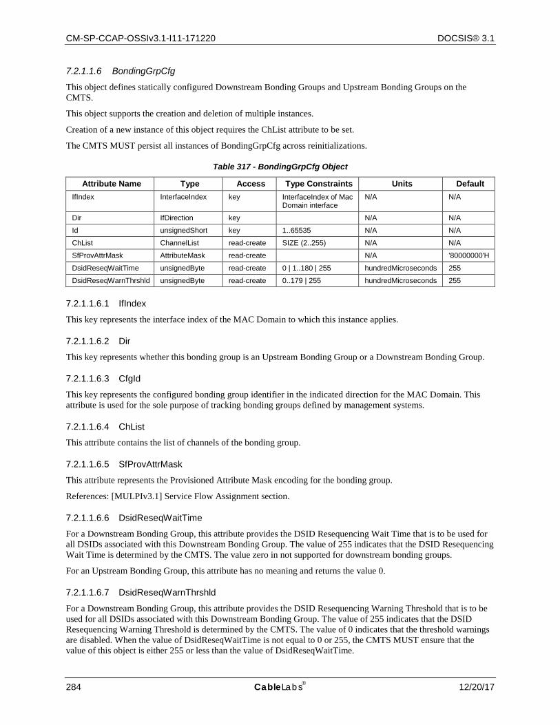
CM-SP-CCAP-OSSIv3.1-I11-171220 DOCSIS® 3.1
284 CableLabs 12/20/17
7.2.1.1.6 BondingGrpCfg
This object defines statically configured Downstream Bonding Groups and Upstream Bonding Groups on the CMTS.
This object supports the creation and deletion of multiple instances.
Creation of a new instance of this object requires the ChList attribute to be set.
The CMTS MUST persist all instances of BondingGrpCfg across reinitializations.
Table 317 - BondingGrpCfg Object
Attribute Name Type Access Type Constraints Units Default IfIndex InterfaceIndex key InterfaceIndex of Mac
Domain interface N/A N/A
Dir IfDirection key N/A N/A
Id unsignedShort key 1..65535 N/A N/A
ChList ChannelList read-create SIZE (2..255) N/A N/A
SfProvAttrMask AttributeMask read-create N/A '80000000'H
DsidReseqWaitTime unsignedByte read-create 0 | 1..180 | 255 hundredMicroseconds 255
DsidReseqWarnThrshld unsignedByte read-create 0..179 | 255 hundredMicroseconds 255
7.2.1.1.6.1 IfIndex
This key represents the interface index of the MAC Domain to which this instance applies.
7.2.1.1.6.2 Dir
This key represents whether this bonding group is an Upstream Bonding Group or a Downstream Bonding Group.
7.2.1.1.6.3 CfgId
This key represents the configured bonding group identifier in the indicated direction for the MAC Domain. This attribute is used for the sole purpose of tracking bonding groups defined by management systems.
7.2.1.1.6.4 ChList
This attribute contains the list of channels of the bonding group.
7.2.1.1.6.5 SfProvAttrMask
This attribute represents the Provisioned Attribute Mask encoding for the bonding group.
References: [MULPIv3.1] Service Flow Assignment section.
7.2.1.1.6.6 DsidReseqWaitTime
For a Downstream Bonding Group, this attribute provides the DSID Resequencing Wait Time that is to be used for all DSIDs associated with this Downstream Bonding Group. The value of 255 indicates that the DSID Resequencing Wait Time is determined by the CMTS. The value zero in not supported for downstream bonding groups.
For an Upstream Bonding Group, this attribute has no meaning and returns the value 0.
7.2.1.1.6.7 DsidReseqWarnThrshld
For a Downstream Bonding Group, this attribute provides the DSID Resequencing Warning Threshold that is to be used for all DSIDs associated with this Downstream Bonding Group. The value of 255 indicates that the DSID Resequencing Warning Threshold is determined by the CMTS. The value of 0 indicates that the threshold warnings are disabled. When the value of DsidReseqWaitTime is not equal to 0 or 255, the CMTS MUST ensure that the value of this object is either 255 or less than the value of DsidReseqWaitTime.
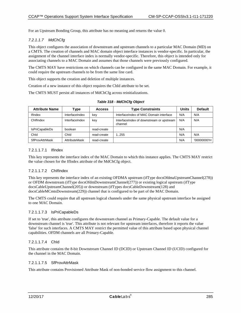
CCAP™ Operations Support System Interface Specification CM-SP-CCAP-OSSIv3.1-I11-171220
12/20/17 CableLabs 285
For an Upstream Bonding Group, this attribute has no meaning and returns the value 0.
7.2.1.1.7 MdChCfg
This object configures the association of downstream and upstream channels to a particular MAC Domain (MD) on a CMTS. The creation of channels and MAC domain object interface instances is vendor-specific. In particular, the assignment of the channel interface index is normally vendor-specific. Therefore, this object is intended only for associating channels to a MAC Domain and assumes that those channels were previously configured.
The CMTS MAY have restrictions on which channels can be configured in the same MAC Domain. For example, it could require the upstream channels to be from the same line card.
This object supports the creation and deletion of multiple instances.
Creation of a new instance of this object requires the ChId attribute to be set.
The CMTS MUST persist all instances of MdChCfg across reinitializations.
Table 318 - MdChCfg Object
Attribute Name Type Access Type Constraints Units Default IfIndex InterfaceIndex key InterfaceIndex of MAC Domain interface N/A N/A
ChIfIndex InterfaceIndex key InterfaceIndex of downstream or upstream channel
N/A N/A
IsPriCapableDs boolean read-create N/A
ChId ChId read-create 1..255 N/A N/A
SfProvAttrMask AttributeMask read-create N/A '00000000'H
7.2.1.1.7.1 IfIndex
This key represents the interface index of the MAC Domain to which this instance applies. The CMTS MAY restrict the value chosen for the IfIndex attribute of the MdChCfg object.
7.2.1.1.7.2 ChIfIndex
This key represents the interface index of an existing OFDMA upstream (ifType docsOfdmaUpstreamChannel(278)) or OFDM downstream (ifType docsOfdmDownstreamChannel(277)) or existing logical upstream (ifType docsCableUpstreamChannel(205)) or downstream (ifTypes docsCableDownstream(128) and docsCableMCmtsDownstream(229)) channel that is configured to be part of the MAC Domain.
The CMTS could require that all upstream logical channels under the same physical upstream interface be assigned to one MAC Domain.
7.2.1.1.7.3 IsPriCapableDs
If set to 'true', this attribute configures the downstream channel as Primary-Capable. The default value for a downstream channel is 'true'. This attribute is not relevant for upstream interfaces, therefore it reports the value 'false' for such interfaces. A CMTS MAY restrict the permitted value of this attribute based upon physical channel capabilities. OFDM channels are all Primary-Capable.
7.2.1.1.7.4 ChId
This attribute contains the 8-bit Downstream Channel ID (DCID) or Upstream Channel ID (UCID) configured for the channel in the MAC Domain.
7.2.1.1.7.5 SfProvAttrMask
This attribute contains Provisioned Attribute Mask of non-bonded service flow assignment to this channel.
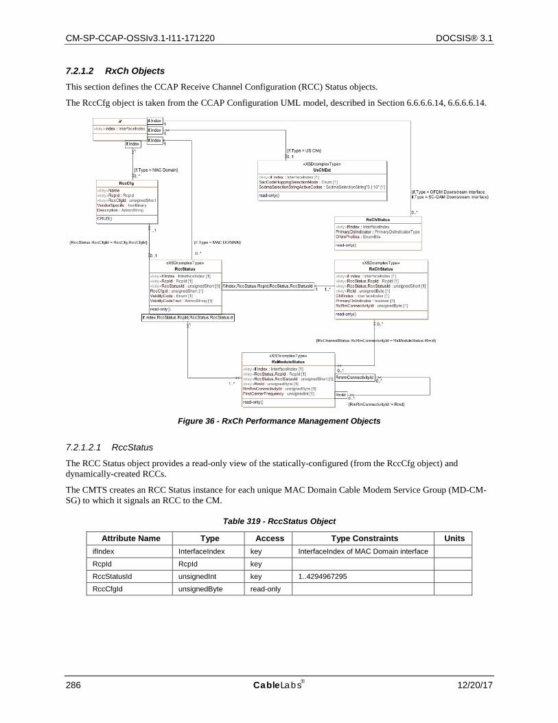
CM-SP-CCAP-OSSIv3.1-I11-171220 DOCSIS® 3.1
286 CableLabs 12/20/17
7.2.1.2 RxCh Objects This section defines the CCAP Receive Channel Configuration (RCC) Status objects.
The RccCfg object is taken from the CCAP Configuration UML model, described in Section 6.6.6.6.14, 6.6.6.6.14.
Figure 36 - RxCh Performance Management Objects
7.2.1.2.1 RccStatus
The RCC Status object provides a read-only view of the statically-configured (from the RccCfg object) and dynamically-created RCCs.
The CMTS creates an RCC Status instance for each unique MAC Domain Cable Modem Service Group (MD-CM-SG) to which it signals an RCC to the CM.
Table 319 - RccStatus Object
Attribute Name Type Access Type Constraints Units ifIndex InterfaceIndex key InterfaceIndex of MAC Domain interface
RcpId RcpId key
RccStatusId unsignedInt key 1..4294967295
RccCfgId unsignedByte read-only
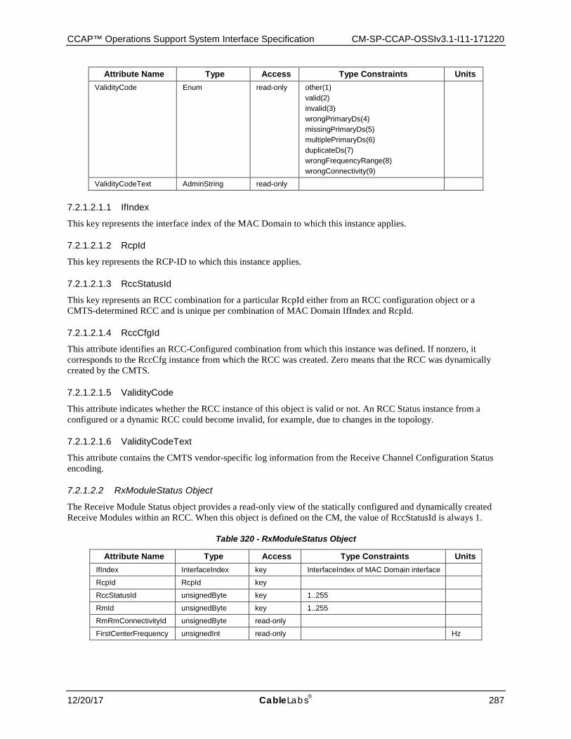
CCAP™ Operations Support System Interface Specification CM-SP-CCAP-OSSIv3.1-I11-171220
12/20/17 CableLabs 287
Attribute Name Type Access Type Constraints Units ValidityCode Enum read-only other(1)
valid(2) invalid(3) wrongPrimaryDs(4) missingPrimaryDs(5) multiplePrimaryDs(6) duplicateDs(7) wrongFrequencyRange(8) wrongConnectivity(9)
ValidityCodeText AdminString read-only
7.2.1.2.1.1 IfIndex
This key represents the interface index of the MAC Domain to which this instance applies.
7.2.1.2.1.2 RcpId
This key represents the RCP-ID to which this instance applies.
7.2.1.2.1.3 RccStatusId
This key represents an RCC combination for a particular RcpId either from an RCC configuration object or a CMTS-determined RCC and is unique per combination of MAC Domain IfIndex and RcpId.
7.2.1.2.1.4 RccCfgId
This attribute identifies an RCC-Configured combination from which this instance was defined. If nonzero, it corresponds to the RccCfg instance from which the RCC was created. Zero means that the RCC was dynamically created by the CMTS.
7.2.1.2.1.5 ValidityCode
This attribute indicates whether the RCC instance of this object is valid or not. An RCC Status instance from a configured or a dynamic RCC could become invalid, for example, due to changes in the topology.
7.2.1.2.1.6 ValidityCodeText
This attribute contains the CMTS vendor-specific log information from the Receive Channel Configuration Status encoding.
7.2.1.2.2 RxModuleStatus Object
The Receive Module Status object provides a read-only view of the statically configured and dynamically created Receive Modules within an RCC. When this object is defined on the CM, the value of RccStatusId is always 1.
Table 320 - RxModuleStatus Object
Attribute Name Type Access Type Constraints Units IfIndex InterfaceIndex key InterfaceIndex of MAC Domain interface
RcpId RcpId key
RccStatusId unsignedByte key 1..255
RmId unsignedByte key 1..255
RmRmConnectivityId unsignedByte read-only
FirstCenterFrequency unsignedInt read-only Hz

CM-SP-CCAP-OSSIv3.1-I11-171220 DOCSIS® 3.1
288 CableLabs 12/20/17
7.2.1.2.2.1 IfIndex
This key represents the interface index of the MAC Domain to which this instance applies.
7.2.1.2.2.2 RcpId
This key represents the RCP-ID to which this instance applies.
7.2.1.2.2.3 RccStatusId
This key represents an RCC combination for a particular RcpId either from an RCC configuration object or a CMTS determined RCC and is unique per combination of MAC Domain interface index and RcpId. Note that when this attribute is instantiated at the CM, its value will always be 1.
7.2.1.2.2.4 RmId
This key represents an identifier of a Receive Module instance within the Receive Channel Profile.
References: [MULPIv3.1] Receive Module Index section in the Common Radio Frequency Interface Encodings Annex.
7.2.1.2.2.5 RmRmConnectivityId
This attribute represents the Receive Module to which this Receive Module connects. Requirements for module connectivity are detailed in the RmRmConnectivityId of the RccCfg object.
7.2.1.2.2.6 FirstCenterFrequency
This attribute represents the low frequency channel of the Receive Module, or 0 if not applicable to the Receive Module.
7.2.1.2.3 Pre-DOCSIS 3.1 RxChStatus Object
The Receive Channel Status object reports the status of the statically-configured and dynamically-created Receive Channels within an RCC. When this object is defined on the CM, the value of RccStatusId is always 1.
Table 321 - RxChStatus Object
Attribute Name Type Access Type Constraints Units IfIndex InterfaceIndex key InterfaceIndex of MAC Domain interface
RcpId RcpId key
RccStatusId UnsignedByte key 1..255
RcId UnsignedByte key 1..255
ChIfIndex InterfaceIndex read-only InterfaceIndex of Downstream Channel assigned to the Receive Channel
PrimaryDsIndicator Boolean read-only
RcRmConnectivityId UnsignedByte read-only
7.2.1.2.3.1 IfIndex
This key represents the interface index of the MAC Domain to which this instance applies.
7.2.1.2.3.2 RcpId
This key represents the RCP-ID to which this instance applies.
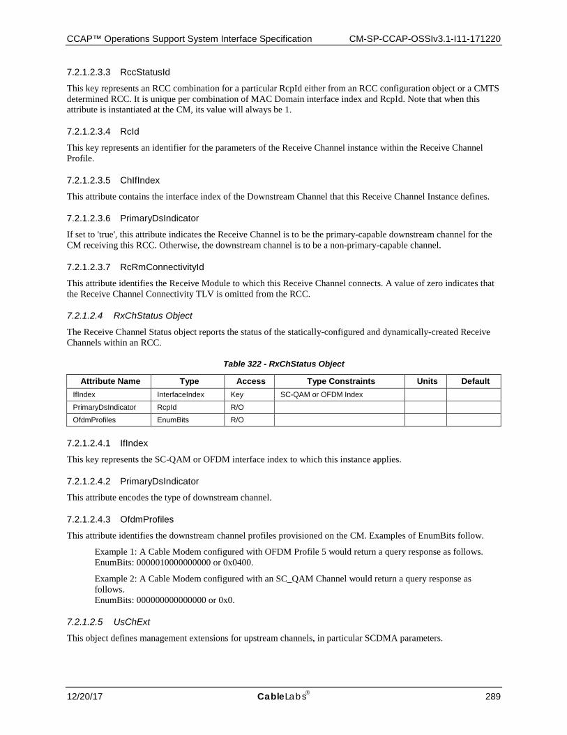
CCAP™ Operations Support System Interface Specification CM-SP-CCAP-OSSIv3.1-I11-171220
12/20/17 CableLabs 289
7.2.1.2.3.3 RccStatusId
This key represents an RCC combination for a particular RcpId either from an RCC configuration object or a CMTS determined RCC. It is unique per combination of MAC Domain interface index and RcpId. Note that when this attribute is instantiated at the CM, its value will always be 1.
7.2.1.2.3.4 RcId
This key represents an identifier for the parameters of the Receive Channel instance within the Receive Channel Profile.
7.2.1.2.3.5 ChIfIndex
This attribute contains the interface index of the Downstream Channel that this Receive Channel Instance defines.
7.2.1.2.3.6 PrimaryDsIndicator
If set to 'true', this attribute indicates the Receive Channel is to be the primary-capable downstream channel for the CM receiving this RCC. Otherwise, the downstream channel is to be a non-primary-capable channel.
7.2.1.2.3.7 RcRmConnectivityId
This attribute identifies the Receive Module to which this Receive Channel connects. A value of zero indicates that the Receive Channel Connectivity TLV is omitted from the RCC.
7.2.1.2.4 RxChStatus Object
The Receive Channel Status object reports the status of the statically-configured and dynamically-created Receive Channels within an RCC.
Table 322 - RxChStatus Object
Attribute Name Type Access Type Constraints Units Default IfIndex InterfaceIndex Key SC-QAM or OFDM Index
PrimaryDsIndicator RcpId R/O
OfdmProfiles EnumBits R/O
7.2.1.2.4.1 IfIndex
This key represents the SC-QAM or OFDM interface index to which this instance applies.
7.2.1.2.4.2 PrimaryDsIndicator
This attribute encodes the type of downstream channel.
7.2.1.2.4.3 OfdmProfiles
This attribute identifies the downstream channel profiles provisioned on the CM. Examples of EnumBits follow.
Example 1: A Cable Modem configured with OFDM Profile 5 would return a query response as follows. EnumBits: 0000010000000000 or 0x0400.
Example 2: A Cable Modem configured with an SC_QAM Channel would return a query response as follows. EnumBits: 000000000000000 or 0x0.
7.2.1.2.5 UsChExt
This object defines management extensions for upstream channels, in particular SCDMA parameters.

CM-SP-CCAP-OSSIv3.1-I11-171220 DOCSIS® 3.1
290 CableLabs 12/20/17
Table 323 - UsChExt Object Attributes
Attribute Name Type Access Type Constraints Units
Default
IfIndex InterfaceIndex key InterfaceIndex of MAC Domain interface
N/A N/A
SacCodeHoppingSelectionMode Enum read-only none(0) sac1NoCodeHopping(1) sac1CodeHoppingMode1(2) sac2CodeHoppingMode2(3) sac2NoCodeHopping(4)
N/A N/A
ScdmaSelectionStringActiveCodes HexBinary read-only SIZE (0 | 16) N/A N/A
7.2.1.2.5.1 UsChExt Object Attributes
7.2.1.2.5.1.1 IfIndex
This key represents the interface index of the logical upstream channel to which this instance applies.
7.2.1.2.5.1.2 SacCodeHoppingSelectionMode
This attribute indicates the selection mode for active codes and code hopping.
• 'none' Non-SCDMA channel
• 'sac1NoCodeHopping' Selectable active codes mode 1 and code hopping disabled
• 'sac1CodeHoppingMode1' Selectable active codes mode 1 and code hopping mode 1
• 'sac2CodeHoppingMode2' Selectable active codes mode 2 and code hopping mode 2
• 'sac2NoCodeHopping' Selectable active codes mode 2 and code hopping disabled
References: [PHYv3.1] Minislot Numbering Parameters in UCD section.
7.2.1.2.5.1.3 ScdmaSelectionStringActiveCodes
This attribute represents the active codes of the upstream channel and it is applicable only when SacCodeHoppingSelectionMode is 'sac2CodeHoppingMode2.
It is a 128-bit string indicating which codes are active. The first element in the string corresponds to code 0 (the all-ones code), and the last element in the string corresponds to code 127. A '1' in the string indicates an active code, and a '0' indicates an unused code. A zero-length string is returned for an unknown or non-applicable value.
References: [PHYv3.1] Minislot Numbering Parameters in UCD section
7.2.1.3 DOCS-L2VPN-MIB State Objects The objects in the DOCS-L2VPN-MIB: State Objects are taken from the DOCS-L2VPN-MIB specified in Annex A of [L2VPN] and are used without modification for the CCAP.
Reference: [L2VPN], DOCS-L2VPN-MIB
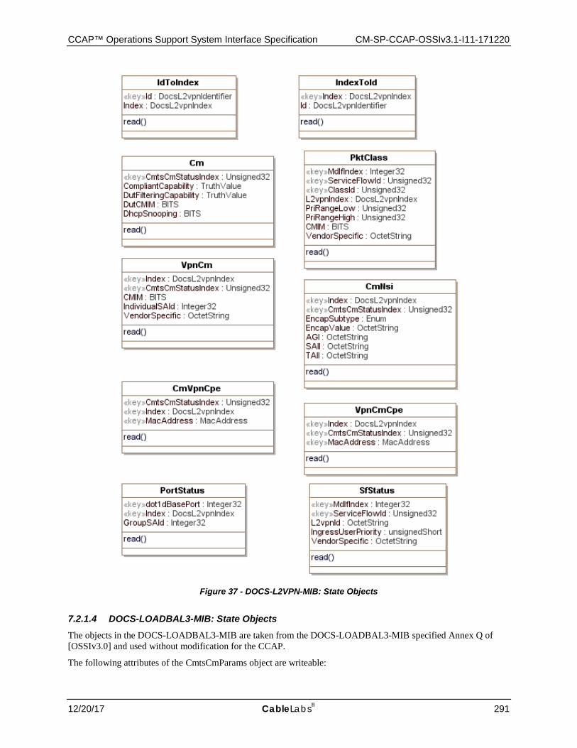
CCAP™ Operations Support System Interface Specification CM-SP-CCAP-OSSIv3.1-I11-171220
12/20/17 CableLabs 291
Figure 37 - DOCS-L2VPN-MIB: State Objects
7.2.1.4 DOCS-LOADBAL3-MIB: State Objects The objects in the DOCS-LOADBAL3-MIB are taken from the DOCS-LOADBAL3-MIB specified Annex Q of [OSSIv3.0] and used without modification for the CCAP.
The following attributes of the CmtsCmParams object are writeable:
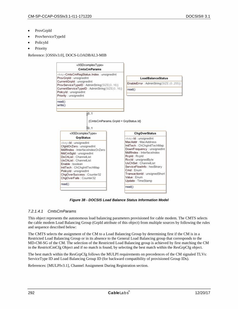
CM-SP-CCAP-OSSIv3.1-I11-171220 DOCSIS® 3.1
292 CableLabs 12/20/17
• ProvGrpId • ProvServiceTypeId • PolicyId • Priority
Reference: [OSSIv3.0], DOCS-LOADBAL3-MIB
Figure 38 - DOCSIS Load Balance Status Information Model
7.2.1.4.1 CmtsCmParams
This object represents the autonomous load balancing parameters provisioned for cable modem. The CMTS selects the cable modem Load Balancing Group (GrpId attribute of this object) from multiple sources by following the rules and sequence described below:
The CMTS selects the assignment of the CM to a Load Balancing Group by determining first if the CM is in a Restricted Load Balancing Group or in its absence to the General Load Balancing group that corresponds to the MD-CM-SG of the CM. The selection of the Restricted Load Balancing group is achieved by first matching the CM in the RestrictCmCfg Object and if no match is found, by selecting the best match within the ResGrpCfg object.
The best match within the ResGrpCfg follows the MULPI requirements on precedences of the CM signaled TLVs: ServiceType ID and Load Balancing Group ID (for backward compatibility of provisioned Group IDs).
References: [MULPIv3.1], Channel Assignment During Registration section.
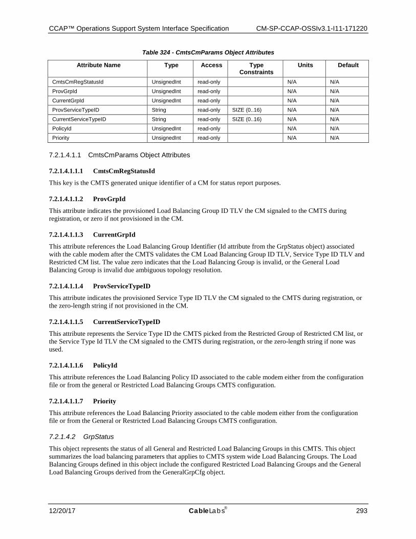
CCAP™ Operations Support System Interface Specification CM-SP-CCAP-OSSIv3.1-I11-171220
12/20/17 CableLabs 293
Table 324 - CmtsCmParams Object Attributes
Attribute Name Type Access Type Constraints
Units Default
CmtsCmRegStatusId UnsignedInt read-only N/A N/A
ProvGrpId UnsignedInt read-only N/A N/A
CurrentGrpId UnsignedInt read-only N/A N/A
ProvServiceTypeID String read-only SIZE (0..16) N/A N/A
CurrentServiceTypeID String read-only SIZE (0..16) N/A N/A
PolicyId UnsignedInt read-only N/A N/A
Priority UnsignedInt read-only N/A N/A
7.2.1.4.1.1 CmtsCmParams Object Attributes
7.2.1.4.1.1.1 CmtsCmRegStatusId
This key is the CMTS generated unique identifier of a CM for status report purposes.
7.2.1.4.1.1.2 ProvGrpId
This attribute indicates the provisioned Load Balancing Group ID TLV the CM signaled to the CMTS during registration, or zero if not provisioned in the CM.
7.2.1.4.1.1.3 CurrentGrpId
This attribute references the Load Balancing Group Identifier (Id attribute from the GrpStatus object) associated with the cable modem after the CMTS validates the CM Load Balancing Group ID TLV, Service Type ID TLV and Restricted CM list. The value zero indicates that the Load Balancing Group is invalid, or the General Load Balancing Group is invalid due ambiguous topology resolution.
7.2.1.4.1.1.4 ProvServiceTypeID
This attribute indicates the provisioned Service Type ID TLV the CM signaled to the CMTS during registration, or the zero-length string if not provisioned in the CM.
7.2.1.4.1.1.5 CurrentServiceTypeID
This attribute represents the Service Type ID the CMTS picked from the Restricted Group of Restricted CM list, or the Service Type Id TLV the CM signaled to the CMTS during registration, or the zero-length string if none was used.
7.2.1.4.1.1.6 PolicyId
This attribute references the Load Balancing Policy ID associated to the cable modem either from the configuration file or from the general or Restricted Load Balancing Groups CMTS configuration.
7.2.1.4.1.1.7 Priority
This attribute references the Load Balancing Priority associated to the cable modem either from the configuration file or from the General or Restricted Load Balancing Groups CMTS configuration.
7.2.1.4.2 GrpStatus
This object represents the status of all General and Restricted Load Balancing Groups in this CMTS. This object summarizes the load balancing parameters that applies to CMTS system wide Load Balancing Groups. The Load Balancing Groups defined in this object include the configured Restricted Load Balancing Groups and the General Load Balancing Groups derived from the GeneralGrpCfg object.
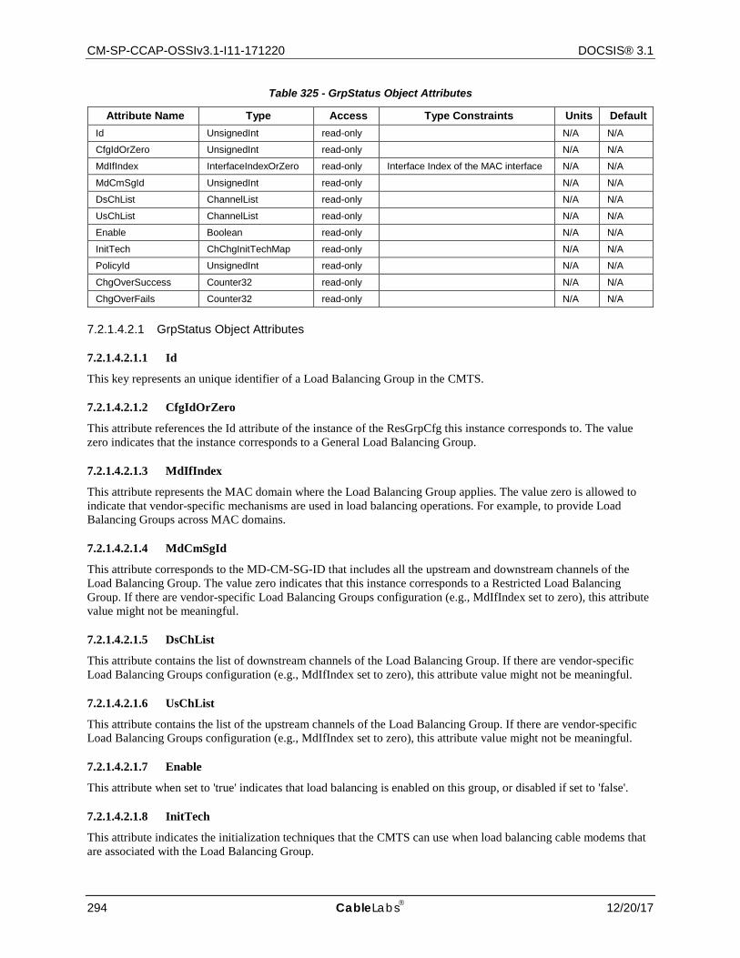
CM-SP-CCAP-OSSIv3.1-I11-171220 DOCSIS® 3.1
294 CableLabs 12/20/17
Table 325 - GrpStatus Object Attributes
Attribute Name Type Access Type Constraints Units Default Id UnsignedInt read-only N/A N/A
CfgIdOrZero UnsignedInt read-only N/A N/A
MdIfIndex InterfaceIndexOrZero read-only Interface Index of the MAC interface N/A N/A
MdCmSgId UnsignedInt read-only N/A N/A
DsChList ChannelList read-only N/A N/A
UsChList ChannelList read-only N/A N/A
Enable Boolean read-only N/A N/A
InitTech ChChgInitTechMap read-only N/A N/A
PolicyId UnsignedInt read-only N/A N/A
ChgOverSuccess Counter32 read-only N/A N/A
ChgOverFails Counter32 read-only N/A N/A
7.2.1.4.2.1 GrpStatus Object Attributes
7.2.1.4.2.1.1 Id
This key represents an unique identifier of a Load Balancing Group in the CMTS.
7.2.1.4.2.1.2 CfgIdOrZero
This attribute references the Id attribute of the instance of the ResGrpCfg this instance corresponds to. The value zero indicates that the instance corresponds to a General Load Balancing Group.
7.2.1.4.2.1.3 MdIfIndex
This attribute represents the MAC domain where the Load Balancing Group applies. The value zero is allowed to indicate that vendor-specific mechanisms are used in load balancing operations. For example, to provide Load Balancing Groups across MAC domains.
7.2.1.4.2.1.4 MdCmSgId
This attribute corresponds to the MD-CM-SG-ID that includes all the upstream and downstream channels of the Load Balancing Group. The value zero indicates that this instance corresponds to a Restricted Load Balancing Group. If there are vendor-specific Load Balancing Groups configuration (e.g., MdIfIndex set to zero), this attribute value might not be meaningful.
7.2.1.4.2.1.5 DsChList
This attribute contains the list of downstream channels of the Load Balancing Group. If there are vendor-specific Load Balancing Groups configuration (e.g., MdIfIndex set to zero), this attribute value might not be meaningful.
7.2.1.4.2.1.6 UsChList
This attribute contains the list of the upstream channels of the Load Balancing Group. If there are vendor-specific Load Balancing Groups configuration (e.g., MdIfIndex set to zero), this attribute value might not be meaningful.
7.2.1.4.2.1.7 Enable
This attribute when set to 'true' indicates that load balancing is enabled on this group, or disabled if set to 'false'.
7.2.1.4.2.1.8 InitTech
This attribute indicates the initialization techniques that the CMTS can use when load balancing cable modems that are associated with the Load Balancing Group.
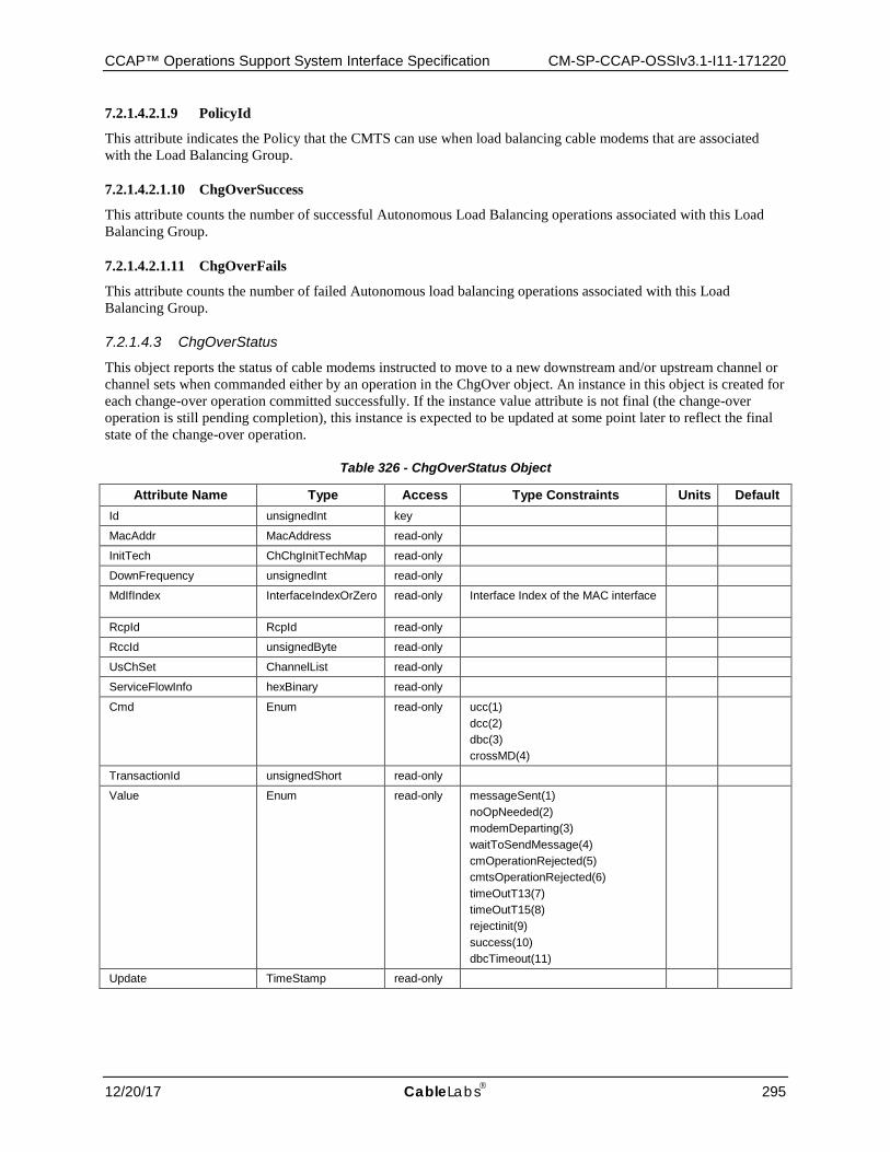
CCAP™ Operations Support System Interface Specification CM-SP-CCAP-OSSIv3.1-I11-171220
12/20/17 CableLabs 295
7.2.1.4.2.1.9 PolicyId
This attribute indicates the Policy that the CMTS can use when load balancing cable modems that are associated with the Load Balancing Group.
7.2.1.4.2.1.10 ChgOverSuccess
This attribute counts the number of successful Autonomous Load Balancing operations associated with this Load Balancing Group.
7.2.1.4.2.1.11 ChgOverFails
This attribute counts the number of failed Autonomous load balancing operations associated with this Load Balancing Group.
7.2.1.4.3 ChgOverStatus
This object reports the status of cable modems instructed to move to a new downstream and/or upstream channel or channel sets when commanded either by an operation in the ChgOver object. An instance in this object is created for each change-over operation committed successfully. If the instance value attribute is not final (the change-over operation is still pending completion), this instance is expected to be updated at some point later to reflect the final state of the change-over operation.
Table 326 - ChgOverStatus Object
Attribute Name Type Access Type Constraints Units Default Id unsignedInt key
MacAddr MacAddress read-only
InitTech ChChgInitTechMap read-only
DownFrequency unsignedInt read-only
MdIfIndex InterfaceIndexOrZero read-only Interface Index of the MAC interface
RcpId RcpId read-only
RccId unsignedByte read-only
UsChSet ChannelList read-only
ServiceFlowInfo hexBinary read-only
Cmd Enum read-only ucc(1) dcc(2) dbc(3) crossMD(4)
TransactionId unsignedShort read-only
Value Enum read-only messageSent(1) noOpNeeded(2) modemDeparting(3) waitToSendMessage(4) cmOperationRejected(5) cmtsOperationRejected(6) timeOutT13(7) timeOutT15(8) rejectinit(9) success(10) dbcTimeout(11)
Update TimeStamp read-only

CM-SP-CCAP-OSSIv3.1-I11-171220 DOCSIS® 3.1
296 CableLabs 12/20/17
7.2.1.4.3.1 Id
This key represents a monotonically increasing value for the record that stores the status of the change-over operation. When the ChOverStatus object exceeds the size limit of this object the lowest Id value instances are removed so that the total number of entries no longer exceeds the size limit allowing the CMTS to maintain the most current entries.
7.2.1.4.3.2 MacAddr
This attribute represents the Mac address set in the ChgOver object commit operation.
7.2.1.4.3.3 InitTech
The initialization technique set in change-over operation.
7.2.1.4.3.4 DownFrequency
This attribute represents the Downstream frequency set in the ChgOver object commit operation, or zero
7.2.1.4.3.5 MdIfIndex
This attribute represents the MAC Domain Interface index set in the ChgOver object commit operation, or zero.
7.2.1.4.3.6 RcpId
This attribute represents the RCP-ID set in the MultipleChChgOver object commit operation, or all zeros RCP-ID value.
7.2.1.4.3.7 RccId
This attribute represents the RCC Status Index set in the ChgOver object commit operation, or zero.
7.2.1.4.3.8 UsChSet
This attribute represents the Upstream Channel Set in the ChgOver object commit operation, or zero.
7.2.1.4.3.9 ServiceFlowInfo
This attribute represents the list of Service Flow-Channel Set ID pairs set in the ChgOver object commit operation, or zero-length string.
7.2.1.4.3.10 Cmd
The load balancing MAC Management Message exchange type used by the CMTS for the change-over operation in the ChgOver object commit operation.
• 'ucc' indicates the usage of Upstream Channel Change (UCC) messages exchange. • 'dcc' indicates the usage of Dynamic Channel Change (DCC) messages exchange. • 'dbc' indicates the usage of Dynamic Bonding Change (DCC) messages exchange • 'crossMD' although this term does not correspond to a MAC Management Message type, it indicates the
movement of a CM to a different MAC Domain that includes a sequence of different MAC Management Messages types (i.e., DCC to move the CM to the correct MAC Domain, followed by channel assignment in REG-RSP-MP).
7.2.1.4.3.11 TransactionId
This attribute represents the transaction Id value used in the change-over operation.
7.2.1.4.3.12 Value
This attribute represents the status of the specified change-over operation. The enumerations are:
CCAP™ Operations Support System Interface Specification CM-SP-CCAP-OSSIv3.1-I11-171220
12/20/17 CableLabs 297
Change-over using DCC message exchange:
• 'modemDeparting' The cable modem has responded with a change-over response of either a DCC-RSP with a confirmation code of depart(180) or a UCC-RSP.
• 'timeOutT13' Failure due to no DCC-RSP with confirmation code depart(180) received prior to expiration of the T13 timer.
• 'timeOutT15' T15 timer timed out prior to the arrival of a bandwidth request, RNG-REQ message, or DCC-RSP message with confirmation code of arrive(181) from the cable modem.
Change-over using DBC message exchange:
• 'dbcTimeout' The number of DBC-REQ retries was exceeded and no DBC-RSP was received
Change-over CMTS verifications:
• 'messageSent' The CMTS has sent a DOCSIS MAC message request to instruct the CM to do the change-over operation.
• 'noOpNeed' A change-over operation was requested in which neither the DS and US channels where the CM is operational changed.
• 'waitToSendMessage' The specified operation is active and CMTS is waiting to send the channel change message with channel info to the cable modem.
• 'cmOperationRejected' Channel Change operation was rejected by the cable modem.
• 'cmtsOperationRejected' Channel Change operation was rejected by the Cable Modem Termination System.
• 'rejectInit' Operation rejected due to unsupported initialization tech requested.
• 'success' CMTS received an indication that the CM successfully completed the change-over operation. e.g., If an initialization technique of re-initialize the MAC is used, success in indicated by the receipt of a DCC-RSP message with a confirmation code of depart(180) or DBC confirmation code ok/success. In all other DCC cases, success is indicated by: (1) the CMTS received a DCC-RSP message with confirmation code of arrive(181) or (2) the CMTS internally confirms the presence of the CM on the new channel(s).
7.2.1.4.3.13 Update
The value of sysUpTime when the attribute Value of this instance was last updated.
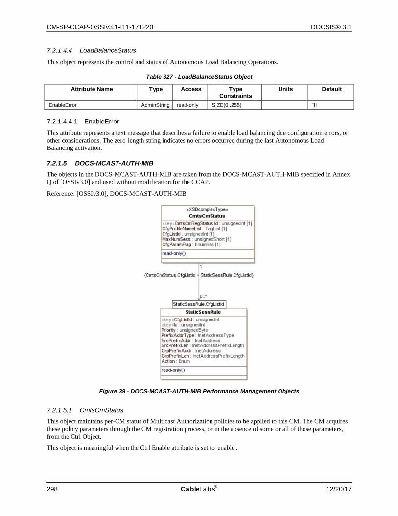
CM-SP-CCAP-OSSIv3.1-I11-171220 DOCSIS® 3.1
298 CableLabs 12/20/17
7.2.1.4.4 LoadBalanceStatus
This object represents the control and status of Autonomous Load Balancing Operations.
Table 327 - LoadBalanceStatus Object
Attribute Name Type Access Type Constraints
Units Default
EnableError AdminString read-only SIZE(0..255) ''H
7.2.1.4.4.1 EnableError
This attribute represents a text message that describes a failure to enable load balancing due configuration errors, or other considerations. The zero-length string indicates no errors occurred during the last Autonomous Load Balancing activation.
7.2.1.5 DOCS-MCAST-AUTH-MIB The objects in the DOCS-MCAST-AUTH-MIB are taken from the DOCS-MCAST-AUTH-MIB specified in Annex Q of [OSSIv3.0] and used without modification for the CCAP.
Reference: [OSSIv3.0], DOCS-MCAST-AUTH-MIB
Figure 39 - DOCS-MCAST-AUTH-MIB Performance Management Objects
7.2.1.5.1 CmtsCmStatus
This object maintains per-CM status of Multicast Authorization policies to be applied to this CM. The CM acquires these policy parameters through the CM registration process, or in the absence of some or all of those parameters, from the Ctrl Object.
This object is meaningful when the Ctrl Enable attribute is set to 'enable'.
CCAP™ Operations Support System Interface Specification CM-SP-CCAP-OSSIv3.1-I11-171220
12/20/17 CableLabs 299
In the process of authorizing a CM client's session request, the CMTS MUST check rules defined in StaticSessRule object and then rules defined in ProfileSessRule object. In the case of multiple multicast session matches, the rule priority attribute defines the final selected session rule. The selection of a session rules when multiple matches have the same priority is vendor specific.
The CMTS MAY report in the CmtsCmStatus object CMs that do not signal any IP Multicast Authorization Encodings in the registration process.
Table 328 - CmtsCmStatus Object Attributes
Attribute Name Type Access Type Constraints Units Default CmtsCmRegStatusId UnsignedInt key 1..4294967295 N/A N/A
CfgProfileNameList TagList read-only N/A N/A
CfgListId UnsignedInt read-only N/A N/A
MaxNumSess UnsignedShort read-only sessions N/A
CfgParamFlag EnumBits read-only profile(0) staticMulticast(1) maxNumSessions(2)
N/A N/A
7.2.1.5.1.1 CmtsCmStatus Object Attributes
7.2.1.5.1.1.1 CmtsCmRegStatusId
This attribute is a key which uniquely identifies the CM. This attribute matches an index value of the CMTS CM Registration Status object.
References: Section 7.2.2.2.1, CmtsCmRegStatus.
7.2.1.5.1.1.2 CfgProfileNameList
This attribute indicates the set of Profile Names associated with the CM.
This attribute indicates the CM signaled 'IP Multicast Authorization Profile Name' encodings during the CM registration process, or in the absence of instances of that config file parameter, the DefProfileNameList attribute from the Ctrl object.
References: [MULPIv3.1] IP Multicast Profile Name Subtype sections.
7.2.1.5.1.1.3 CfgListId
This attribute identifies the reference to a CMTS created Session Rule List based on the CM signaled 'IP Multicast Authorization Static Session Rule' encodings. The CMTS may reuse this attribute value to reference more than one CM that have signaled the same list of Session Rules to the CMTS.
The value zero indicates that the CM did not signal Multicast Session Rules to the CMTS or the CMTS does not support the StaticSessRule, in which case, the CMTS ignores any CM signaled Session Rule encodings during registration.
References: [MULPIv3.1] IP Multicast Join Authorization Static Session Rule Subtype section in the Common Radio Frequency Interface Encodings Annex.
7.2.1.5.1.1.4 MaxNumSess
This attribute indicates the CM signaled value in Maximum Multicast Sessions Encoding during the CM registration process. If this value is missing the DefMaxNumSess attribute of the Ctrl object is used to determine the maximum number of multicast sessions this client may forward. The value 0 indicates that no dynamic joins are permitted. The value 65535 (the largest valid value) indicates that the CMTS permits any number of sessions to be joined by clients reached through the CM.

CM-SP-CCAP-OSSIv3.1-I11-171220 DOCSIS® 3.1
300 CableLabs 12/20/17
References: [MULPIv3.1] Maximum Multicast Sessions Encoding section in the Common Radio Frequency Interface Encodings Annex.
7.2.1.5.1.1.5 CfgParamFlag
This attribute represents the functions that are activated through the registration process.
The bit 'profile' indicates whether the CM signaled 'IP Multicast Authorization Profile Name Subtype' encodings.
The bit 'staticMulticast' indicates whether the CM signaled 'IP Multicast Authorization Static Session Rule Subtype' encodings.
The bit 'maxNumSessions' indicates whether the CM signaled the 'Maximum Multicast Sessions' encoding.
7.2.1.5.2 StaticSessRule
This object defines the Session authorization Rules based on the CM or group of CMs signaled in IP Multicast Join Authorization Static Session Subtype encoding This object reflects the Static Session rules that were included in the CM registration request message.
The CMTS MAY persist all instances of the StaticSessRule object across reinitializations.
References: [MULPIv3.1] IP Multicast Join Authorization Static Session Rule Subtype section in the Common Radio Frequency Interface Encodings Annex.
Table 329 - StaticSessRule Object
Attribute Name Type Access Type Constraints Units Default CfgListId unsignedInt key 1..4294967295 N/A N/A
Id unsignedInt key 1..4294967295 N/A N/A
Priority unsignedByte read-only N/A N/A
PrefixAddrType InetAddressType read-only ipv4(1) ipv6(2)
N/A N/A
SrcPrefixAddr InetAddress read-only N/A N/A
SrcPrefixLen InetAddressPrefixLength read-only N/A N/A
GrpPrefixAddr InetAddress read-only N/A N/A
GrpPrefixLen InetAddressPrefixLength read-only N/A N/A
Action Enum read-only permit(1) deny(2)
N/A N/A
7.2.1.5.2.1 CfgListId
This attribute contains a CMTS-derived value for a set of multicast static session rules associated to one or more CMs.
7.2.1.5.2.2 Id
This attribute provides an identifier for each Multicast Authorization Static Session rule in the IP Multicast Join Authorization Static Session SubType communicated by a CM or group of CMs during registration.
7.2.1.5.2.3 Priority
This attribute defines the rule priority for the static session rule. Higher values indicate a higher priority. If more than one session rule matches a joined session, the session rule with the highest rule priority determines the authorization action.

CCAP™ Operations Support System Interface Specification CM-SP-CCAP-OSSIv3.1-I11-171220
12/20/17 CableLabs 301
7.2.1.5.2.4 PrefixAddrType
This attribute identifies the address family for the multicast session (S,G) which corresponds to the SrcPrefixAddr and GrpPrefixAddr attributes respectively.
7.2.1.5.2.5 SrcPrefixAddr
This attribute identifies a specific Multicast Source Address defined for this rule. A Source Address that is all zeros is defined as 'all source addresses (*, G)'. Source Prefix Addresses are unicast host addresses.
References: [RFC 3569] section 6; [RFC 3306] sections 5 and 6.
7.2.1.5.2.6 SrcPrefixLen
This attribute identifies the prefix length associated with a range of Source (S) IP multicast group addresses. For group or ASM-based sessions this attribute is set to 0.
7.2.1.5.2.7 GrpPrefixAddr
This attribute is the IP address corresponding to an IP multicast group.
7.2.1.5.2.8 GrpPrefixLen
This attribute identifies the prefix length associated with a range of Group Destination IP multicast addresses.
7.2.1.5.2.9 Action
This attribute specifies the authorization action for a session join attempt that matches the session rule.
The value 'accept' indicates that the rule permits a matching multicast join request is allowed. The value 'deny' indicates that a matching multicast join request is denied.
7.2.1.6 DOCSIS QoS State Information Model This section defines state performance management objects from the DOCS-QOS3-MIB.
Reference: [DOCS-QOS3-MIB]
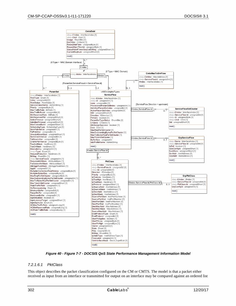
CM-SP-CCAP-OSSIv3.1-I11-171220 DOCSIS® 3.1
302 CableLabs 12/20/17
Figure 40 - Figure 7-7 - DOCSIS QoS State Performance Management Information Model
7.2.1.6.1 PktClass
This object describes the packet classification configured on the CM or CMTS. The model is that a packet either received as input from an interface or transmitted for output on an interface may be compared against an ordered list

CCAP™ Operations Support System Interface Specification CM-SP-CCAP-OSSIv3.1-I11-171220
12/20/17 CableLabs 303
of rules pertaining to the packet contents. Each rule is an instance of this object. A matching rule provides a Service Flow ID to which the packet is classified. All rules need to match for a packet to match a classifier. The attributes in this row correspond to a set of Classifier Encoding parameters in a DOCSIS MAC management message. The BitMap attribute indicates which particular parameters were present in the classifier as signaled in the DOCSIS message. If the referenced parameter was not present in the signaled Classifier, the corresponding attribute in this instance reports a value as specified by that attribute description.
References: [MULPIv3.1] Service Flows and Classifiers section.
Table 330 - PktClass Object
Attribute Name Type Access Type Constraints Units Default ifIndex InterfaceIndex Key Interface Index of MAC Domain
interface N/A N/A
ServiceFlowId Unsigned32 Key 1..4294967295 N/A N/A
Id unsignedInt Key 1..65535 N/A N/A
Direction IfDirection read-only N/A N/A
Priority unsignedByte read-only N/A N/A
IpTosLow hexBinary read-only N/A N/A
IpTosHigh hexBinary read-only N/A N/A
IpTosMask hexBinary read-only N/A N/A
IpProtocol unsignedShort read-only N/A N/A
IpSourceAddr InetAddress read-only N/A N/A
IpSourceMask InetAddress read-only N/A N/A
IpDestAddr InetAddress read-only N/A N/A
IpDestMask InetAddress read-only N/A N/A
SourcePortStart InetPortNumber read-only N/A N/A
SourcePortEnd InetPortNumber read-only N/A N/A
DestPortStart InetPortNumber read-only N/A N/A
DestPortEnd InetPortNumber read-only N/A N/A
IcmpTypeLow unsignedByte read-only N/A N/A
IcmpTypeHigh unsignedByte read-only N/A N/A
DestMacAddr MacAddress read-only N/A N/A
DestMacMask MacAddress read-only N/A N/A
SourceMacAddr MacAddress read-only N/A N/A
EnetProtocolType Enum read-only N/A N/A
EnetProtocol Integer32 read-only 0..65535 N/A N/A
UserPriLow unsignedByte read-only N/A N/A
UserPriHigh unsignedByte read-only N/A N/A
VlanId unsignedInt read-only N/A N/A
State Enum read-only active(1) inactive(2)
N/A N/A
Pkts Counter64 read-only packets
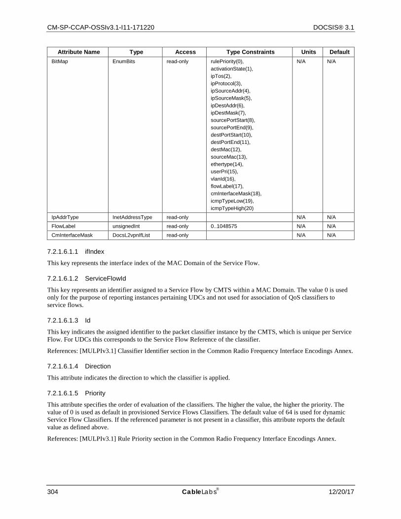
CM-SP-CCAP-OSSIv3.1-I11-171220 DOCSIS® 3.1
304 CableLabs 12/20/17
Attribute Name Type Access Type Constraints Units Default BitMap EnumBits read-only rulePriority(0),
activationState(1), ipTos(2), ipProtocol(3), ipSourceAddr(4), ipSourceMask(5), ipDestAddr(6), ipDestMask(7), sourcePortStart(8), sourcePortEnd(9), destPortStart(10), destPortEnd(11), destMac(12), sourceMac(13), ethertype(14), userPri(15), vlanId(16), flowLabel(17), cmInterfaceMask(18), icmpTypeLow(19), icmpTypeHigh(20)
N/A N/A
IpAddrType InetAddressType read-only N/A N/A
FlowLabel unsignedInt read-only 0..1048575 N/A N/A
CmInterfaceMask DocsL2vpnIfList read-only N/A N/A
7.2.1.6.1.1 ifIndex
This key represents the interface index of the MAC Domain of the Service Flow.
7.2.1.6.1.2 ServiceFlowId
This key represents an identifier assigned to a Service Flow by CMTS within a MAC Domain. The value 0 is used only for the purpose of reporting instances pertaining UDCs and not used for association of QoS classifiers to service flows.
7.2.1.6.1.3 Id
This key indicates the assigned identifier to the packet classifier instance by the CMTS, which is unique per Service Flow. For UDCs this corresponds to the Service Flow Reference of the classifier.
References: [MULPIv3.1] Classifier Identifier section in the Common Radio Frequency Interface Encodings Annex.
7.2.1.6.1.4 Direction
This attribute indicates the direction to which the classifier is applied.
7.2.1.6.1.5 Priority
This attribute specifies the order of evaluation of the classifiers. The higher the value, the higher the priority. The value of 0 is used as default in provisioned Service Flows Classifiers. The default value of 64 is used for dynamic Service Flow Classifiers. If the referenced parameter is not present in a classifier, this attribute reports the default value as defined above.
References: [MULPIv3.1] Rule Priority section in the Common Radio Frequency Interface Encodings Annex.
CCAP™ Operations Support System Interface Specification CM-SP-CCAP-OSSIv3.1-I11-171220
12/20/17 CableLabs 305
7.2.1.6.1.6 IpTosLow
This attribute indicates the low value of a range of ToS byte values. If the referenced parameter is not present in a classifier, this attribute reports the value of 0. The IP ToS octet as originally defined in [RFC 791] has been superseded by the 6-bit Differentiated Services Field (DSField, [RFC 3260]) and the 2-bit Explicit Congestion Notification Field (ECN field, [RFC 3168]). This object is defined as an 8-bit octet as defined by the DOCSIS Specification for packet classification.
References: [MULPIv3.1] IPv4 Type of Service Range and Mask and IPv6 Traffic Class Range and Mask sections in the Common Radio Frequency Interface Encodings Annex.
7.2.1.6.1.7 IpTosHigh
This attribute indicates the 8-bit high value of a range of ToS byte values. If the referenced parameter is not present in a classifier, this attribute reports the value of 0. The IP ToS octet as originally defined in [RFC 791] has been superseded by the 6-bit Differentiated Services Field (DSField, [RFC 3260]) and the 2-bit Explicit Congestion Notification Field (ECN field, [RFC 3168]). This object is defined as an 8-bit octet as defined by the DOCSIS Specification for packet classification.
References: [MULPIv3.1] IPv4 Type of Service Range and Mask and IPv6 Traffic Class Range and Mask sections in the Common Radio Frequency Interface Encodings Annex.
7.2.1.6.1.8 IpTosMask
This attribute indicates the mask value is bitwise ANDed with ToS byte in an IP packet, and this value is used for range checking of TosLow and TosHigh. If the referenced parameter is not present in a classifier, this attribute reports the value of 0. The IP ToS octet as originally defined in [RFC 791] has been superseded by the 6-bit Differentiated Services Field (DSField, [RFC 3260]) and the 2-bit Explicit Congestion Notification Field (ECN field, [RFC 3168]). This object is defined as an 8-bit octet per the DOCSIS Specification for packet classification.
References: [MULPIv3.1] IPv4 Type of Service Range and Mask and IPv6 Traffic Class Range and Mask sections in the Common Radio Frequency Interface Encodings Annex.
7.2.1.6.1.9 IpProtocol
This attribute indicates the value of the IP Protocol field required for IP packets to match this rule. The value 256 matches traffic with any IP Protocol value. The value 257 by convention matches both TCP and UDP. If the referenced parameter is not present in a classifier, this attribute reports the value of 258.
References: [MULPIv3.1] IP Protocol and IPv6 Next Header Type sections in the Common Radio Frequency Interface Encodings Annex.
7.2.1.6.1.10 IpSourceAddr
This attribute specifies the value of the IP Source Address required for packets to match this rule. An IP packet matches the rule when the packet IP Source Address bitwise ANDed with the IpSourceMask value equals the IpSourceAddr value. The address type of this object is specified by IpAddrType. If the referenced parameter is not present in a classifier, this object reports the value of '00000000'H.
References: [MULPIv3.1] IPv4 Source Address and IPv6 Source Address sections in the Common Radio Frequency Interface Encodings Annex.
7.2.1.6.1.11 IpSourceMask
This attribute specifies which bits of a packet's IP Source Address are compared to match this rule. An IP packet matches the rule when the packet source address bitwise ANDed with the IpSourceMask value equals the IpSourceAddr value. The address type of this attribute is specified by IpAddrType. If the referenced parameter is not present in a classifier, this attribute reports the value of 'FFFFFFFF'H.
References: [MULPIv3.1] IPv4 Source Mask and IPv6 Source Prefix Length (bits) sections in the Common Radio Frequency Interface Encodings Annex.

CM-SP-CCAP-OSSIv3.1-I11-171220 DOCSIS® 3.1
306 CableLabs 12/20/17
7.2.1.6.1.12 IpDestAddr
This attribute specifies the value of the IP Destination Address required for packets to match this rule. An IP packet matches the rule when the packet IP Destination Address bitwise ANDed with the IpDestMask value equals the IpDestAddr value. The address type of this attribute is specified by IpAddrType. If the referenced parameter is not present in a classifier, this attribute reports the value of '00000000'H.
References: [MULPIv3.1] IPv4 Destination Address and IPv6 Destination Address sections in the Common Radio Frequency Interface Encodings Annex.
7.2.1.6.1.13 IpDestMask
This attribute specifies which bits of a packet's IP Destination Address are compared to match this rule. An IP packet matches the rule when the packet destination address bitwise ANDed with the IpDestMask value equals the IpDestAddr value. The address type of this attribute is specified by IpAddrType. If the referenced parameter is not present in a classifier, this attribute reports the value of 'FFFFFFFF'H.
References: [MULPIv3.1] IPv4 Destination Mask and IPv6 Destination Prefix Length (bits) sections in the Common Radio Frequency Interface Encodings Annex.
7.2.1.6.1.14 SourcePortStart
This attribute specifies the low-end inclusive range of TCP/UDP source port numbers to which a packet is compared. This attribute is irrelevant for non-TCP/UDP IP packets. If the referenced parameter is not present in a classifier, this attribute reports the value of 0.
References: [MULPIv3.1] TCP/UDP Source Port Start section in the Common Radio Frequency Interface Encodings Annex.
7.2.1.6.1.15 SourcePortEnd
This attribute specifies the high-end inclusive range of TCP/UDP source port numbers to which a packet is compared. This attribute is irrelevant for non-TCP/UDP IP packets. If the referenced parameter is not present in a classifier, this attribute reports the value of 65535.
References: [MULPIv3.1] TCP/UDP Source Port End section in the Common Radio Frequency Interface Encodings Annex.
7.2.1.6.1.16 DestPortStart
This attribute specifies the low-end inclusive range of TCP/UDP destination port numbers to which a packet is compared. If the referenced parameter is not present in a classifier, this attribute reports the value of 0.
References: [MULPIv3.1] TCP/UDP Destination Port Start section in the Common Radio Frequency Interface Encodings Annex.
7.2.1.6.1.17 DestPortEnd
This attribute specifies the high-end inclusive range of TCP/UDP destination port numbers to which a packet is compared. If the referenced parameter is not present in a classifier, this attribute reports the value of 65535.
References: [MULPIv3.1] TCP/UDP Destination Port End section in the Common Radio Frequency Interface Encodings Annex.
7.2.1.6.1.18 IcmpTypeLow
This attribute specifies the low-end inclusive range of the ICMP type numbers to which a packet is compared. If the referenced parameter is not present in a classifier, this attribute reports the value of 0.
References: [MULPIv3.1] TypeLow encodings section of the Common Radio Frequency Interface Annex.
CCAP™ Operations Support System Interface Specification CM-SP-CCAP-OSSIv3.1-I11-171220
12/20/17 CableLabs 307
7.2.1.6.1.19 IcmpTypeHigh
This attribute specifies the high-end inclusive range of the ICMP type numbers to which a packet is compared. If the referenced parameter is not present in a classifier, this attribute reports the value of 255.
References: [MULPIv3.1] TypeHigh encodings section of the Common Radio Frequency Interface Annex.
7.2.1.6.1.20 DestMacAddr
An Ethernet packet matches an entry when its destination MAC address bitwise ANDed with DestMacMask equals the value of DestMacAddr. If the referenced parameter is not present in a classifier, this attribute reports the value of '000000000000'H.
References: [MULPIv3.1] Destination MAC Address section in the Common Radio Frequency Interface Encodings Annex.
7.2.1.6.1.21 DestMacMask
An Ethernet packet matches an entry when its destination MAC address bitwise ANDed with DestMacMask equals the value of DestMacAddr. If the referenced parameter is not present in a classifier, this attribute reports the value of '000000000000'H.
References: [MULPIv3.1] Destination MAC Address section in the Common Radio Frequency Interface Encodings Annex.
7.2.1.6.1.22 SourceMacAddr
An Ethernet packet matches this entry when its source MAC address equals the value of this attribute. If the referenced parameter is not present in a classifier, this attribute reports the value of 'FFFFFFFFFFFF'.
References: [MULPIv3.1] Source MAC Address section in the Common Radio Frequency Interface Encodings Annex.
7.2.1.6.1.23 EnetProtocolType
This attribute indicates the format of the layer 3 protocol ID in the Ethernet packet. A value of 'none' means that the rule does not use the layer 3 protocol type as a matching criteria. A value of 'ethertype' means that the rule applies only to frames that contain an EtherType value. Ethertype values are contained in packets using the Dec-Intel-Xerox (DIX) encapsulation or the RFC1042 Sub-Network Access Protocol (SNAP) encapsulation formats. A value of 'dsap' means that the rule applies only to frames using the IEEE802.3 encapsulation format with a Destination Service Access Point (DSAP) other than 0xAA (which is reserved for SNAP). A value of 'mac' means that the rule applies only to MAC management messages for MAC management messages. A value of 'all' means that the rule matches all Ethernet packets. If the Ethernet frame contains an 802.1P/Q Tag header (i.e., EtherType 0x8100), this attribute applies to the embedded EtherType field within the 802.1P/Q header. If the referenced parameter is not present in a classifier, this attribute reports the value of 0.
References: [MULPIv3.1] Ethertype/DSAP/MacType section in the Common Radio Frequency Interface Encodings Annex.
7.2.1.6.1.24 EnetProtocol
If EnetProtocolType is 'none', this attribute is ignored when considering whether a packet matches the current rule. If EnetProtocolType is 'ethertype', this attribute gives the 16-bit value of the EtherType that the packet needs to match in order to match the rule. If EnetProtocolType is 'dsap', the lower 8 bits of this attribute's value needs to match the DSAP byte of the packet in order to match the rule. If EnetProtocolType is 'mac', the lower 8 bits of this attribute's value represent a lower bound (inclusive) of MAC management message type codes matched, and the upper 8 bits represent the upper bound (inclusive) of matched MAC message type codes. Certain message type codes are excluded from matching, as specified in the reference. If the Ethernet frame contains an 802.1P/Q Tag header (i.e., EtherType 0x8100), this attribute applies to the embedded EtherType field within the 802.1P/Q header. If the referenced parameter is not present in the classifier, the value of this attribute is reported as 0.

CM-SP-CCAP-OSSIv3.1-I11-171220 DOCSIS® 3.1
308 CableLabs 12/20/17
References: [MULPIv3.1] Ethertype/DSAP/MacType section in the Common Radio Frequency Interface Encodings Annex.
7.2.1.6.1.25 UserPriLow
This attribute applies only to Ethernet frames using the 802.1P/Q tag header (indicated with EtherType 0x8100). Such frames include a 16-bit Tag that contains a 3-bit Priority field and a 12-bit VLAN number. Tagged Ethernet packets need to have a 3-bit Priority field within the range of PriLow to PriHigh in order to match this rule. If the referenced parameter is not present in the classifier, the value of this attribute is reported as 0.
References: [MULPIv3.1] IEEE 802.1P User_Priority section in the Common Radio Frequency Interface Encodings Annex.
7.2.1.6.1.26 UserPriHigh
This attribute applies only to Ethernet frames using the 802.1P/Qtag header (indicated with EtherType 0x8100). Such frames include a 16-bit Tag that contains a 3-bit Priority field and a 12-bit VLAN number. Tagged Ethernet packets need to have a 3-bit Priority field within the range of PriLow to PriHigh in order to match this rule. If the referenced parameter is not present in the classifier, the value of this attribute is reported as 7.
References: [MULPIv3.1] IEEE 802.1P User_Priority section in the Common Radio Frequency Interface Encodings Annex.
7.2.1.6.1.27 VlanId
This attribute applies only to Ethernet frames using the 802.1P/Q tag header. Tagged packets need to have a VLAN Identifier that matches the value in order to match the rule. If the referenced parameter is not present in the classifier, the value of this attribute is reported as 0.
References: [MULPIv3.1] IEEE 802.1Q VLAN_ID section in the Common Radio Frequency Interface Encodings Annex.
7.2.1.6.1.28 State
This attribute indicates whether or not the classifier is enabled to classify packets to a Service Flow. If the referenced parameter is not present in the classifier, the value of this attribute is reported as 'true'.
References: [MULPIv3.1] Classifier Activation State section in the Common Radio Frequency Interface Encodings Annex.
7.2.1.6.1.29 Pkts
This attribute counts the number of packets that have been classified using this entry. This includes all packets delivered to a Service Flow maximum rate policing function, whether or not that function drops the packets. This counter's last discontinuity is the ifCounterDiscontinuityTime for the same ifIndex that indexes this attribute.
7.2.1.6.1.30 BitMap
This attribute indicates which parameter encodings were actually present in the DOCSIS packet classifier encoding signaled in the DOCSIS message that created or modified the classifier. Note that Dynamic Service Change messages have replace semantics, so that all non-default parameters need to be present whether the classifier is being created or changed. A bit of this attribute is set to 1 if the parameter indicated by the comment was present in the classifier encoding, and to 0 otherwise. Note that BITS are encoded most significant bit first, so that if, for example, bits 6 and 7 are set, this attribute is encoded as the octet string '030000'H.
7.2.1.6.1.31 IpAddrType
This attribute indicates the type of the Internet address for IpSourceAddr, IpSourceMask, IpDestAddr, and IpDestMask. If the referenced parameter is not present in a classifier, this object reports the value of 'ipv4'.
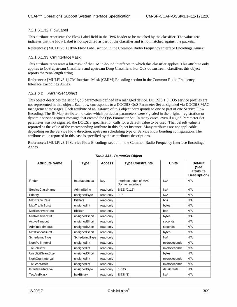
CCAP™ Operations Support System Interface Specification CM-SP-CCAP-OSSIv3.1-I11-171220
12/20/17 CableLabs 309
7.2.1.6.1.32 FlowLabel
This attribute represents the Flow Label field in the IPv6 header to be matched by the classifier. The value zero indicates that the Flow Label is not specified as part of the classifier and is not matched against the packets.
References: [MULPIv3.1] IPv6 Flow Label section in the Common Radio Frequency Interface Encodings Annex.
7.2.1.6.1.33 CmInterfaceMask
This attribute represents a bit-mask of the CM in-bound interfaces to which this classifier applies. This attribute only applies to QoS upstream Classifiers and upstream Drop Classifiers. For QoS downstream classifiers this object reports the zero-length string.
References: [MULPIv3.1] CM Interface Mask (CMIM) Encoding section in the Common Radio Frequency Interface Encodings Annex.
7.2.1.6.2 ParamSet Object
This object describes the set of QoS parameters defined in a managed device. DOCSIS 1.0 COS service profiles are not represented in this object. Each row corresponds to a DOCSIS QoS Parameter Set as signaled via DOCSIS MAC management messages. Each attribute of an instance of this object corresponds to one or part of one Service Flow Encoding. The BitMap attribute indicates which particular parameters were signaled in the original registration or dynamic service request message that created the QoS Parameter Set. In many cases, even if a QoS Parameter Set parameter was not signaled, the DOCSIS specification calls for a default value to be used. That default value is reported as the value of the corresponding attribute in this object instance. Many attributes are not applicable, depending on the Service Flow direction, upstream scheduling type or Service Flow bonding configuration. The attribute value reported in this case is specified by those attributes descriptions.
References: [MULPIv3.1] Service Flow Encodings section in the Common Radio Frequency Interface Encodings Annex.
Table 331 - ParamSet Object
Attribute Name Type Access Type Constraints Units Default (See
attribute Description)
ifIndex InterfaceIndex key Interface Index of MAC Domain interface
N/A N/A
ServiceClassName AdminString read-only SIZE (0..15) N/A N/A
Priority unsignedByte read-only 0..7 N/A N/A
MaxTrafficRate BitRate read-only bps N/A
MaxTrafficBurst unsignedInt read-only bytes N/A
MinReservedRate BitRate read-only bps N/A
MinReservedPkt unsignedShort read-only bytes N/A
ActiveTimeout unsignedShort read-only seconds N/A
AdmittedTimeout unsignedShort read-only seconds N/A
MaxConcatBurst unsignedShort read-only bytes N/A
SchedulingType SchedulingType read-only N/A N/A
NomPollInterval unsignedInt read-only microseconds N/A
TolPollJitter unsignedInt read-only microseconds N/A
UnsolicitGrantSize unsignedShort read-only bytes N/A
NomGrantInterval unsignedInt read-only microseconds N/A
TolGrantJitter unsignedInt read-only microseconds N/A
GrantsPerInterval unsignedByte read-only 0..127 dataGrants N/A
TosAndMask hexBinary read-only SIZE (1) N/A N/A
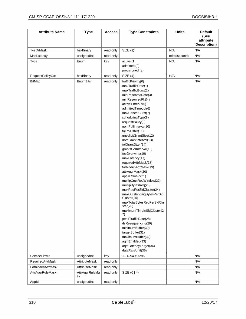
CM-SP-CCAP-OSSIv3.1-I11-171220 DOCSIS® 3.1
310 CableLabs 12/20/17
Attribute Name Type Access Type Constraints Units Default (See
attribute Description)
TosOrMask hexBinary read-only SIZE (1) N/A N/A
MaxLatency unsignedInt read-only microseconds N/A
Type Enum key active (1) admitted (2) provisioned (3)
N/A N/A
RequestPolicyOct hexBinary read-only SIZE (4) N/A N/A
BitMap EnumBits read-only trafficPriority(0) maxTrafficRate(1) maxTrafficBurst(2) minReservedRate(3) minReservedPkt(4) activeTimeout(5) admittedTimeout(6) maxConcatBurst(7) schedulingType(8) requestPolicy(9) nomPollInterval(10) tolPollJitter(11) unsolicitGrantSize(12) nomGrantInterval(13) tolGrantJitter(14) grantsPerInterval(15) tosOverwrite(16) maxLatency(17) requiredAttrMask(18) forbiddenAttrMask(19) attrAggrMask(20) applicationId(21) multipCntnReqWindow(22) multipBytesReq(23) maxReqPerSidCluster(24) maxOutstandingBytesPerSidCluster(25) maxTotalBytesReqPerSidCluster(26) maximumTimeInSidCluster(27) peakTrafficRate(28) dsResequencing(29) minimumBuffer(30) targetBuffer(31) maximumBuffer(32) aqmEnabled(33) aqmLatencyTarget(34) dataRateUnit(35)
N/A
ServiceFlowId unsignedInt key 1.. 4294967295 N/A
RequiredAttrMask AttributeMask read-only N/A
ForbiddenAttrMask AttributeMask read-only N/A
AttrAggrRuleMask AttrAggrRuleMask
read-only SIZE (0 | 4) N/A
AppId unsignedInt read-only N/A
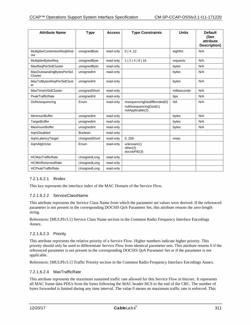
CCAP™ Operations Support System Interface Specification CM-SP-CCAP-OSSIv3.1-I11-171220
12/20/17 CableLabs 311
Attribute Name Type Access Type Constraints Units Default (See
attribute Description)
MultiplierContentionReqWindow
unsignedByte read-only 0 | 4..12 eighths N/A
MultiplierBytesReq unsignedByte read-only 1 | 2 | 4 | 8 | 16 requests N/A
MaxReqPerSidCluster unsignedByte read-only bytes N/A
MaxOutstandingBytesPerSidCluster
unsignedInt read-only bytes N/A
MaxTotBytesReqPerSidCluster
unsignedInt read-only bytes N/A
MaxTimeInSidCluster unsignedShort read-only milliseconds N/A
PeakTrafficRate unsignedInt read-only bps N/A
DsResequencing Enum read-only resequencingDsidIfBonded(0) noResequencingDsid(1) notApplicable(2)
NA N/A
MinimumBuffer unsignedInt read-only bytes N/A
TargetBuffer unsignedInt read-only bytes N/A
MaximumBuffer unsignedInt read-only bytes N/A
AqmDisabled Boolean read-only
AqmLatencyTarget UnsignedShort read-only 0..256 msec
AqmAlgInUse Enum read-only unknown(1) other(2) docsisPIE(3)
HCMaxTrafficRate UnsignedLong read-only
HCMinReservedRate UnsignedLong read-only
HCPeakTrafficRate UnsignedLong read-only
7.2.1.6.2.1 ifIndex
This key represents the interface index of the MAC Domain of the Service Flow.
7.2.1.6.2.2 ServiceClassName
This attribute represents the Service Class Name from which the parameter set values were derived. If the referenced parameter is not present in the corresponding DOCSIS QoS Parameter Set, this attribute returns the zero-length string.
References: [MULPIv3.1] Service Class Name section in the Common Radio Frequency Interface Encodings Annex.
7.2.1.6.2.3 Priority
This attribute represents the relative priority of a Service Flow. Higher numbers indicate higher priority. This priority should only be used to differentiate Service Flow from identical parameter sets. This attribute returns 0 if the referenced parameter is not present in the corresponding DOCSIS QoS Parameter Set or if the parameter is not applicable.
References: [MULPIv3.1] Traffic Priority section in the Common Radio Frequency Interface Encodings Annex.
7.2.1.6.2.4 MaxTrafficRate
This attribute represents the maximum sustained traffic rate allowed for this Service Flow in bits/sec. It represents all MAC frame data PDUs from the bytes following the MAC header HCS to the end of the CRC. The number of bytes forwarded is limited during any time interval. The value 0 means no maximum traffic rate is enforced. This
CM-SP-CCAP-OSSIv3.1-I11-171220 DOCSIS® 3.1
312 CableLabs 12/20/17
attribute applies to both upstream and downstream Service Flows. This attribute returns 0 if the referenced parameter is not present in the corresponding DOCSIS QoS Parameter Set, or if the parameter is not applicable. This attribute will also return 0 if DataRateUnitSetting is enabled and the resulting value cannot be represented in 32 bits, in which case HCMaxTrafficRate should be utilized.
References: [MULPIv3.1] Maximum Sustained Traffic Rate section in the Common Radio Frequency Interface Encodings Annex.
7.2.1.6.2.5 MaxTrafficBurst
This attribute specifies the token bucket size in bytes for this parameter set. The value is calculated from the byte following the MAC header HCS to the end of the CRC. This object is applied in conjunction with MaxTrafficRate to calculate maximum sustained traffic rate. If the referenced parameter is not present in the corresponding DOCSIS QoS Parameter Set, this attribute returns 3044 for scheduling types 'bestEffort', 'nonRealTimePollingService' and 'realTimePollingService'. If this parameter is not applicable, it is reported as 0.
References: [MULPIv3.1] Maximum Traffic Burst section in the Common Radio Frequency Interface Encodings Annex.
7.2.1.6.2.6 MinReservedRate
This attribute specifies the guaranteed minimum rate in bits/sec for this parameter set. The value is calculated from the byte following the MAC header HCS to the end of the CRC. The value of 0 indicates that no bandwidth is reserved. If the referenced parameter is not present in the corresponding DOCSIS QoS Parameter Set, this attribute returns 0. If the parameter is not applicable, it is reported as 0. This attribute will also return 0 if DataRateUnitSetting is enabled and the resulting value cannot be represented in 32 bits, in which case HCMinReservedRate should be utilized.
References: [MULPIv3.1] Minimum Reserved Traffic Rate section of the Common Radio Frequency Interface Encodings Annex.
7.2.1.6.2.7 MinReservedPkt
This attribute specifies an assumed minimum packet size in bytes for which the MinReservedRate will be provided. The value is calculated from the byte following the MAC header HCS to the end of the CRC. If the referenced parameter is omitted from a DOCSIS QoS parameter set, the used and reported value is CMTS implementation and the CM reports a value of 0. If the referenced parameter is not applicable to the direction or scheduling type of the Service Flow, both CMTS and CM report the value 0.
References: [MULPIv3.1] Assumed Minimum Reserved Rate Packet Size, in the Common Radio Frequency Interface Encodings Annex.
7.2.1.6.2.8 ActiveTimeout
This attribute specifies the maximum duration in seconds that resources remain unused on an active service flow before the CMTS signals that both the active and admitted parameter sets are null. The value 0 signifies an infinite amount of time. If the referenced parameter is not present in the corresponding DOCSIS QoS Parameter Set, this attribute returns 0.
References: [MULPIv3.1] Timeout for Active QoS Parameters section in the Common Radio Frequency Interface Encodings Annex.
7.2.1.6.2.9 AdmittedTimeout
This attribute specifies the maximum duration in seconds that resources remain in admitted state before resources need to be released. The value of 0 signifies an infinite amount of time. If the referenced parameter is not present in the corresponding DOCSIS QoS Parameter Set, this attribute returns 200.
References: [MULPIv3.1] Timeout for Admitted QoS Parameters section in the Common Radio Frequency Interface Encodings Annex.
CCAP™ Operations Support System Interface Specification CM-SP-CCAP-OSSIv3.1-I11-171220
12/20/17 CableLabs 313
7.2.1.6.2.10 MaxConcatBurst
This attribute specifies the maximum concatenated burst in bytes that an upstream Service Flow is allowed. The value is calculated from the FC byte of the Concatenation MAC Header to the last CRC byte of the last concatenated MAC frame, inclusive. The value of 0 specifies no maximum burst. If the referenced parameter is not present in the corresponding DOCSIS QoS Parameter Set, this attribute returns the value of 1522 for scheduling types 'bestEffort', 'nonRealTimePollingService', and 'realTimePollingService'. If the parameter is not applicable, it is reported as 0.
References: [MULPIv3.1] Maximum Concatenated Burst section in the Common Radio Frequency Interface Encodings Annex.
7.2.1.6.2.11 SchedulingType
This attribute specifies the upstream scheduling service used for upstream Service Flow. If the referenced parameter is not present in the corresponding DOCSIS QoS Parameter Set of an upstream Service Flow, this attribute returns the value of 'bestEffort'. For QoS parameter sets of downstream Service Flows, this attribute's value is reported as 'undefined'.
References: [MULPIv3.1] Service Flow Scheduling Type section in the Common Radio Frequency Interface Encodings Annex.
7.2.1.6.2.12 NomPollInterval
This attribute specifies the nominal interval in microseconds between successive unicast request opportunities on an upstream Service Flow. This attribute applies only to upstream Service Flows with SchedulingType of value 'nonRealTimePollingService', 'realTimePollingService', and 'unsolictedGrantServiceWithAD'. The parameter is mandatory for 'realTimePollingService'. If the parameter is omitted with 'nonRealTimePollingService', the CMTS uses an implementation-dependent value. If the parameter is omitted with 'unsolictedGrantServiceWithAD(5)' the CMTS uses the value of the Nominal Grant Interval parameter. In all cases, the CMTS reports the value it is using when the parameter is applicable. The CM reports the signaled parameter value if it was signaled. Otherwise, it returns 0. If the referenced parameter is not applicable to the direction or scheduling type of the corresponding DOCSIS QoS Parameter Set, both CMTS and CM report this attribute's value as 0.
References: [MULPIv3.1] Polling Interval section in the Common Radio Frequency Interface Encodings Annex.
7.2.1.6.2.13 TolPollJitter
This attribute specifies the maximum amount of time in microseconds that the unicast request interval may be delayed from the nominal periodic schedule on an upstream Service Flow. This parameter is applicable only to upstream Service Flows with a SchedulingType of 'realTimePollingService' or 'unsolictedGrantServiceWithAD'. If the referenced parameter is applicable but not present in the corresponding DOCSIS QoS Parameter Set, the CMTS uses an implementation-dependent value and reports the value it is using. The CM reports a value of 0 in this case. If the parameter is not applicable to the direction or upstream scheduling type of the Service Flow, both CMTS and CM report this attribute's value as 0.
References: [MULPIv3.1] Tolerated Poll Jitter section in the Common Radio Frequency Interface Encodings Annex.
7.2.1.6.2.14 UnsolicitGrantSize
This attribute specifies the unsolicited grant size in bytes. The grant size includes the entire MAC frame data PDU from the Frame Control byte to the end of the MAC frame. The referenced parameter is applicable only for upstream flows with a SchedulingType of 'unsolicitedGrantServicewithAD' or 'unsolicitedGrantService', and it is mandatory when applicable. Both CMTS and CM report the signaled value of the parameter in this case. If the referenced parameter is not applicable to the direction or scheduling type of the corresponding DOCSIS QoS Parameter Set, both CMTS and CM report this attribute's value as 0.
References: [MULPIv3.1] Unsolicited Grant Size section in the Common Radio Frequency Interface Encodings Annex.

CM-SP-CCAP-OSSIv3.1-I11-171220 DOCSIS® 3.1
314 CableLabs 12/20/17
7.2.1.6.2.15 NomGrantInterval
This attribute specifies the nominal interval in microseconds between successive data grant opportunities on an upstream Service Flow. The referenced parameter is applicable only for upstream flows with a SchedulingType of 'unsolicitedGrantServicewithAD' or 'unsolicitedGrantService(6)', and it is mandatory when applicable. Both CMTS and CM report the signaled value of the parameter in this case. If the referenced parameter is not applicable to the direction or scheduling type of the corresponding DOCSIS QoS Parameter Set, both CMTS and CM report this attribute's value as 0.
References: [MULPIv3.1] Nominal Grant Interval section in the Common Radio Frequency Interface Encodings Annex.
7.2.1.6.2.16 TolGrantJitter
This attribute specifies the maximum amount of time in microseconds that the transmission opportunities may be delayed from the nominal periodic schedule. The referenced parameter is applicable only for upstream flows with a SchedulingType of 'unsolicitedGrantServicewithAD' or 'unsolicitedGrantService(6)', and it is mandatory when applicable. Both CMTS and CM report the signaled value of the parameter in this case. If the referenced parameter is not applicable to the direction or scheduling type of the corresponding DOCSIS QoS Parameter Set, both CMTS and CM report this attribute's value as 0.
References: [MULPIv3.1] Tolerated Grant Jitter section in the Common Radio Frequency Interface Encodings Annex.
7.2.1.6.2.17 GrantsPerInterval
This attribute specifies the number of data grants per Nominal Grant Interval (NomGrantInterval). The referenced parameter is applicable only for upstream flows with a SchedulingType of 'unsolicitedGrantServicewithAD' or 'unsolicitedGrantService', and it is mandatory when applicable. Both CMTS and CM report the signaled value of the parameter in this case. If the referenced parameter is not applicable to the direction or scheduling type of the corresponding DOCSIS QoS Parameter Set, both CMTS and CM report this attribute's value as 0.
References: [MULPIv3.1] Grants per Interval section in the Common Radio Frequency Interface Encodings Annex.
7.2.1.6.2.18 TosAndMask
This attribute specifies the AND mask for the IP ToS byte for overwriting an IPv4 packet's ToS value or IPv6 packet's Traffic Class value. The IP packet ToS byte is bitwise ANDed with TosAndMask, then the result is bitwise ORed with TosORMask and the result is written to the IP packet ToS byte. A value of 'FF'H for TosAndMask and a value of '00'H for TosOrMask means that the IP Packet ToS byte is not overwritten. This combination is reported if the referenced parameter is not present in a QoS Parameter Set. The IP ToS octet as originally defined in [RFC 791] has been superseded by the 6-bit Differentiated Services Field (DSField, [RFC 3260]) and the 2-bit Explicit Congestion Notification Field (ECN field, [RFC 3168]). The IPv6 Traffic Class octet [RFC 2460] is consistent with that new definition. Network operators should avoid specifying values of TosAndMask and TosORMask that would result in the modification of the ECN bits. In particular, operators should not use values of TosAndMask that have either of the least-significant two bits set to 0. Similarly, operators should not use values of TosORMask that have either of the least-significant two bits set to 1. Even though this attribute is only enforced by the CMTS, the CM reports the value as signaled in the referenced parameter.
References: [MULPIv3.1] IP Type Of Service (DSCP) Overwrite section in the Common Radio Frequency Interface Encodings Annex; [RFC 3168]; [RFC 3260]; [RFC 2460]; [RFC 791].
7.2.1.6.2.19 TosOrMask
This attribute specifies the OR mask for the IPv4 ToS value or IPv6 Traffic Class value. See the description of TosAndMask for further details. The IP ToS octet, as originally defined in [RFC 791] has been superseded by the 6-bit Differentiated Services Field (DSField, [RFC 3260]) and the 2-bit Explicit Congestion Notification Field (ECN field, [RFC 3168]). The IPv6 Traffic Class octet [RFC 2460] is consistent with that new definition. Network operators should avoid specifying values of TosAndMask and TosORMask that would result in the modification of the ECN bits.

CCAP™ Operations Support System Interface Specification CM-SP-CCAP-OSSIv3.1-I11-171220
12/20/17 CableLabs 315
References: [MULPIv3.1] IP Type Of Service (DSCP) Overwrite section in the Common Radio Frequency Interface Encodings Annex; [RFC 3168]; [RFC 3260]; [RFC 2460]; [RFC 791].
7.2.1.6.2.20 MaxLatency
This attribute specifies the maximum latency between the reception of a packet by the CMTS on its NSI and the forwarding of the packet to the RF interface. A value of 0 signifies no maximum latency is enforced. This attribute only applies to downstream Service Flows. If the referenced parameter is not present in the corresponding downstream DOCSIS QoS Parameter Set, this attribute returns 0. This parameter is not applicable to upstream DOCSIS QoS Parameter Sets, so its value is reported as 0 in that case.
References: [MULPIv3.1] Maximum Downstream Latency section in the Common Radio Frequency Interface Encodings Annex.
7.2.1.6.2.21 Type
This key represents the QoS Parameter Set Type of the Service Flow. The following values are defined: 'active' Indicates the Active QoS parameter set, describing the service currently being provided by the DOCSIS MAC domain to the service flow. 'admitted' Indicates the Admitted QoS Parameter Set, describing services reserved by the DOCSIS MAC domain for use by the service flow. 'provisioned' Indicates the QoS Parameter Set defined in the DOCSIS CM Configuration file for the service flow.
References: [MULPIv3.1] Service Flow Scheduling Type section in the Common Radio Frequency Interface Encodings Annex.
7.2.1.6.2.22 RequestPolicyOct
This attribute specifies which transmit interval opportunities the CM omits for upstream transmission requests and packet transmissions. This object takes its default value for downstream Service Flows. Unless otherwise indicated, a bit value of 1 means that a CM is not to use that opportunity for upstream transmission. The format of this string enumerated the bits from 0 to 31 from left to right, for example bit 0 corresponds to the left most bit of the fourth octet. (octets numbered from right to left). The bit positions are defined as follows:
'broadcastReqOpp' - all CMs broadcast request opportunities
'priorityReqMulticastReq' - priority request multicast request opportunities
'reqDataForReq' - request/data opportunities for requests
'reqDataForData' - request/data opportunities for data
'piggybackReqWithData' - piggyback requests with data
'concatenateData' - concatenate data
'fragmentData' - fragment data
'suppressPayloadHeaders' - suppress payload headers
'dropPktsExceedUGSize' - A value of 1 means that the service flow will drop packets that do not fit in the Unsolicited Grant size. If the referenced parameter is not present in a QoS Parameter Set, the value of this object is reported as '00000000'H.
References: [MULPIv3.1] Request/ Transmission Policy section in the Common Radio Frequency Interface Encodings Annex.
7.2.1.6.2.23 BitMap
This attribute indicates the set of QoS Parameter Set parameters actually signaled in the DOCSIS registration or dynamic service request message that created or modified the QoS Parameter Set. A bit is set to 1 when the associated parameter is present in the original request as follows:
'trafficPriority' Traffic Priority
CM-SP-CCAP-OSSIv3.1-I11-171220 DOCSIS® 3.1
316 CableLabs 12/20/17
'maxTrafficRate' Maximum Sustained Traffic Rate
'maxTrafficBurst' Maximum Traffic Burst
'minReservedRate' Minimum Reserved Traffic Rate
'minReservedPkt' Assumed Minimum Reserved Rate Packet Size
'activeTimeout' Timeout for Active QoS Parameters
'admittedTimeout' Timeout for Admitted QoS Parameters
'maxConcatBurst' Maximum Concatenated Burst
'schedulingType' Service Flow Scheduling Type
'requestPolicy' Request/Transmission Policy
'nomPollInterval' Nominal Polling Interval
'tolPollJitter' Tolerated Poll Jitter
'unsolicitGrantSize' Unsolicited Grant Size
'nomGrantInterval' Nominal Grant Interval
'tolGrantJitter' Tolerated Grant Jitter
'grantsPerInterval' Grants per Interval
'tosOverwrite' IP Type of Service (DSCP) Overwrite
'maxLatency' Maximum Downstream Latency
'requiredAttrMask' Service Flow Required Attribute Mask
'forbiddenAttrMask Service Flow Forbidden Attribute Mask
'attrAggrMask' Service Flow Attribute Aggregation Mask
'applicationId' Application Identifier
'multipCntnReqWindow' Multiplier to Contention Request Backoff Window
'multipBytesReq' Multiplier to Number of Bytes Requested
'maxReqPerSidCluster' Maximum Requests per SID Cluster
'maxOutstandingBytesPerSidCluster' Maximum Outstanding Bytes per SID Cluster
'maxTotalBytesReqPerSidCluster' Maximum Total Bytes Requested per SID Cluster
'maximumTimeInSidCluster' Maximum Time in the SID Cluster
'peakTrafficRate' Peak Traffic Rate
'dsResequencing' - Downstream Resequencing
'minimumBuffer' Minimum Buffer
'targetBuffer' Target Buffer
'maximumBuffer' Maximum Buffer
'aqmDisabled' SF AQM Disabled
'aqmLatencyTarget' SF AQM Latency Target
'dataRateUnit' Data Rate Unit Setting
Note that when Service Class names are expanded, the registration or dynamic response message may contain parameters expanded by the CMTS based on a stored service class. These expanded parameters are not indicated by a 1 bit in this attribute. Note that even though some QoS Parameter Set parameters may not be signaled in a message

CCAP™ Operations Support System Interface Specification CM-SP-CCAP-OSSIv3.1-I11-171220
12/20/17 CableLabs 317
(so that the parameter's bit in this object is 0), the DOCSIS specification requires that default values be used. These default values are reported as the corresponding attribute.
References: [MULPIv3.1] Service Flow Encodings section in the Common Radio Frequency Interface Encodings Annex.
7.2.1.6.2.24 ServiceFlowId
This key represents the Service Flow ID for the service flow.
References: [MULPIv3.1] Service Identifier section in the Common Radio Frequency Interface Encodings Annex.
7.2.1.6.2.25 RequiredAttrMask
This attribute specifies the Required Attribute Mask to compare with the Provisioned Required Attributes when selecting the bonding groups for the service flow.
If the referenced parameter is not present in the corresponding DOCSIS QoS Parameter Set, this attribute returns '00000000'H.
References: [MULPIv3.1] Service Flow Required Attribute Mask section in the Common Radio Frequency Interface Encodings Annex.
7.2.1.6.2.26 ForbiddenAttrMask
This attribute specifies the Forbidden Attribute Mask to compare with the Provisioned Forbidden Attributes when selecting the bonding groups for the service flow.
If the referenced parameter is not present in the corresponding DOCSIS QoS Parameter Set, this attribute returns '00000000'H.
References: [MULPIv3.1] Service Flow Forbidden Attribute Mask section in the Common Radio Frequency Interface Encodings Annex.
7.2.1.6.2.27 AttrAggrRuleMask
This attribute specifies the Attribute Aggregation Mask to compare the Service Flow Required and Forbidden Attributes with the CMTS dynamically-created bonding group when selecting the bonding groups for the service flow.
If the referenced parameter is not present in the corresponding DOCSIS QoS Parameter Set, this attribute returns '00000000'H.
References: [MULPIv3.1] Service Flow Attribute Aggregation Mask section in the Common Radio Frequency Interface Encodings Annex.
7.2.1.6.2.28 AppId
This attribute represents the Application Identifier associated with the service flow for purposes beyond the scope of this specification.
If the referenced parameter is not present in the corresponding DOCSIS QoS Parameter Set, this attribute returns 0.
References: [MULPIv3.1] Application Identifier section in the Common Radio Frequency Interface Encodings Annex.
7.2.1.6.2.29 MultiplierContentionReqWindow
This attribute specifies the multiplier to be applied by a CM when performing contention request backoff for data requests. This attribute only applies to upstream Service Flows in 3.0 operation. if the referenced parameter is not present in the upstream DOCSIS QoS Parameter Set, or is not applicable, this attribute returns 8.
References: [MULPIv3.1] Multiplier to Contention Request Backoff Window section in the Common Radio Frequency Interface Encodings Annex.
CM-SP-CCAP-OSSIv3.1-I11-171220 DOCSIS® 3.1
318 CableLabs 12/20/17
7.2.1.6.2.30 MultiplierBytesReq
This attribute specifies the assumed bandwidth request multiplier. This attribute only applies to upstream Service Flows in 3.0 operation. If the referenced parameter is not present in the upstream DOCSIS QoS Parameter Set, or is not applicable, this attribute returns 4.
References: [MULPIv3.1] Multiplier to Number of Bytes Requested section in the Common Radio Frequency Interface Encodings Annex.
7.2.1.6.2.31 MaxReqPerSidCluster
This attribute specifies the maximum number of requests that a CM can make within a given SID Cluster before it needs to switch to a different SID Cluster to make further requests. A value of 0 indicates there is no limit. This attribute only applies to upstream Service Flows in 3.0 operation, in other cases it is reported as 0. If the referenced parameter is not present in the DOCSIS QoS Parameter Set, this attribute returns 0.
This attribute has been deprecated and replaced with MaxReqPerSidCluster in the ServiceFlow object.
References: [MULPIv3.1] Maximum Requests per SID Cluster section in the Common Radio Frequency Interface Encodings Annex.
7.2.1.6.2.32 MaxOutstandingBytesPerSidCluster
This attribute specifies the maximum number of bytes for which a CM can have requests outstanding on a given SID Cluster. If defined number of bytes are outstanding and further requests are required, the CM needs to switch to a different SID Cluster if one is available. A value of 0 indicates there is no limit. This attribute only applies to upstream Service Flows in 3.0 operation, in other cases it is reported as 0. If the referenced parameter is not present in the DOCSIS QoS Parameter Set, this attribute returns 0.
This attribute has been deprecated and replaced with MaxOutstandingBytesPerSidCluster in the ServiceFlow object.
References: [MULPIv3.1] Maximum Outstanding Bytes per SID Cluster section in the Common Radio Frequency Interface Encodings Annex.
7.2.1.6.2.33 MaxTotBytesReqPerSidCluster
This attribute specifies the maximum total number of bytes a CM can have requested using a given SID Cluster before it needs to switch to a different SID Cluster to make further requests. A value of 0 indicates there is no limit. This attribute only applies to upstream Service Flows in 3.0 operation, in other cases it is reported as 0. If the referenced parameter is not present in the DOCSIS QoS Parameter Set, this attribute returns 0.
This attribute has been deprecated and replaced with MaxTotBytesReqPerSidCluster in the ServiceFlow object.
References: [MULPIv3.1] Maximum Total Bytes Requested per SID Cluster section in the Common Radio Frequency Interface Encodings Annex.
7.2.1.6.2.34 MaxTimeInSidCluster
This attribute specifies the maximum time in milliseconds that a CM may use a particular SID Cluster before it has to switch to a different SID Cluster to make further requests. A value of 0 indicates there is no limit. This attribute only applies to upstream Service Flows in 3.0 operation, in other cases it is reported as 0. If the referenced parameter is not present in the DOCSIS QoS Parameter Set, this attribute returns 0.
This attribute has been deprecated and replaced with MaxTimeInSidCluster in the ServiceFlow object.
References: [MULPIv3.1] Maximum Time in the SID Cluster section in the Common Radio Frequency Interface Encodings Annex.
7.2.1.6.2.35 PeakTrafficRate
This attribute specifies the rate parameter 'P' of a token-bucket-based peak rate limiter for packets of a service flow. A value of 0 signifies no Peak Traffic Rate is enforced. If the referenced parameter is not present in the corresponding DOCSIS QoS Parameter Set, this attribute returns 0. This attribute will also return 0 if
CCAP™ Operations Support System Interface Specification CM-SP-CCAP-OSSIv3.1-I11-171220
12/20/17 CableLabs 319
DataRateUnitSetting is enabled and the resulting value cannot be represented in 32 bits, in which case HCPeakTrafficRate should be utilized.
References: [MULPIv3.1] Peak Traffic Rate section in the Common Radio Frequency Interface Encodings Annex.
7.2.1.6.2.36 DsResequencing
This attribute specifies if a resequencing DSID needs to be allocated to the service flow.
The value 'notApplicable' indicates the value of this attribute is not applicable.
The value 'resequencingDsid' indicates that a resequencing DSID is required if the service flow is assigned to a downstream bonding group
The value 'noResequencingDsid' indicates no resequencing DSID is associated with the service flow.
This attribute only applies to downstream Service Flows in 3.0 operation. If the referenced parameter is not present in the corresponding downstream DOCSIS QoS Parameter Set, this attribute returns 'notApplicable'. This parameter is not applicable to upstream DOCSIS QoS Parameter Sets, so the value 'notApplicable' is reported in that case.
References: [MULPIv3.1] Downstream Resequencing section in the Common Radio Frequency Interface Encodings Annex.
7.2.1.6.2.37 MinimumBuffer
This attribute represents the configured minimum buffer size for the service flow.
References: [MULPIv3.1] Buffer Control section in the Common Radio Frequency Interface Encodings Annex.
7.2.1.6.2.38 TargetBuffer
This attribute represents the configured target buffer size for the service flow. The value 0 indicates that no target buffer size was configured, and the device will use a vendor specific value.
References: [MULPIv3.1] Buffer Control section in the Common Radio Frequency Interface Encodings Annex.
7.2.1.6.2.39 MaximumBuffer
This attribute represents the configured maximum buffer size for the service flow. The value 4294967295 indicates that no maximum buffer size was configured, and thus there is no limit to the buffer size.
References: [MULPIv3.1] Buffer Control section in the Common Radio Frequency Interface Encodings Annex.
7.2.1.6.2.40 AqmDisabled
If this attribute is set to 'true', AQM is disabled on the upstream or downstream service flow specified by ServiceFlowId.
References: [MULPIv3.1] AQM Encodings section in the Common Radio Frequency Interface Encodings Annex.
7.2.1.6.2.41 AqmLatencyTarget
This attribute provides the latency target to be used for the AQM algorithm for the upstream or downstream Service Flow specified by ServiceFlowId. For downstream service flows, the value 256 indicates an unknown latency target. The units are in milliseconds.
References: [MULPIv3.1] AQM Encodings section in the Common Radio Frequency Interface Encodings Annex.
7.2.1.6.2.42 AqmAlgInUse
This attribute specifies the AQM algorithm in use for this service flow. If AQM is disabled on the service flow specified by ServiceFlowId, this attribute returns unknown(1).
The value unknown(1) is reported for downstream service flows or when AQM is disabled.

CM-SP-CCAP-OSSIv3.1-I11-171220 DOCSIS® 3.1
320 CableLabs 12/20/17
The value other(2) indicates a vendor proprietary algorithm for upstream queue management.
The value docsisPIE(3) indicates the upstream queue management Proportional Integral controller Enhanced (PIE) algorithm.
References: [MULPIv3.1] Proportional-Integral-Enhanced Active Queue Management Algorithm Annex.
7.2.1.6.2.43 HCMaxTrafficRate
This attribute is a 64-bit representation of the maximum sustained traffic rate allowed for this Service Flow in bits/sec. It represents all MAC frame data PDUs from the bytes following the MAC header HCS to the end of the CRC. The number of bytes forwarded is limited during any time interval. The value 0 means no maximum traffic rate is enforced. This attribute applies to both upstream and downstream Service Flows. This attribute returns 0 if the referenced parameter is not present in the corresponding DOCSIS QoS Parameter Set, or if the parameter is not applicable.
References: [MULPIv3.1] Maximum Sustained Traffic Rate section in the Common Radio Frequency Interface Encodings Annex.
7.2.1.6.2.44 HCMinReservedRate
This attribute is a 64-bit representation of the guaranteed minimum rate in bits/sec for this parameter set. The value is calculated from the byte following the MAC header HCS to the end of the CRC. The value of 0 indicates that no bandwidth is reserved. If the referenced parameter is not present in the corresponding DOCSIS QoS Parameter Set, this attribute returns 0. If the parameter is not applicable, it is reported as 0.
References: [MULPIv3.1] Minimum Reserved Traffic Rate section of the Common Radio Frequency Interface Encodings Annex.
7.2.1.6.2.45 HCPeakTrafficRate
This attribute is a 64-bit representation of the rate parameter 'P' of a token-bucket-based peak rate limiter for packets of a service flow. A value of 0 signifies no Peak Traffic Rate is enforced. If the referenced parameter is not present in the corresponding DOCSIS QoS Parameter Set, this attribute returns 0.
References: [MULPIv3.1] Peak Traffic Rate section in the Common Radio Frequency Interface Encodings Annex.
7.2.1.6.3 ServiceFlow Object
This object describes the set of DOCSIS-QoS Service Flows in a managed device.
References: [MULPIv3.1] Service Flows and Classifiers section.
Table 332 - ServiceFlow Object
Attribute Name Type Access Type Constraints Units Default ifIndex InterfaceIndex key Interface Index of MAC
Domain interface N/A N/A
Id unsignedInt key N/A N/A
SID unsignedShort read-only N/A N/A
Direction IfDirection read-only N/A N/A
Primary boolean read-only N/A N/A
ParamSetTypeStatus EnumBits read-only active(0) admitted(1) provisioned(2)
N/A N/A
ChSetId ChSetId read-only N/A N/A
AttrAssignSuccess boolean read-only N/A N/A
Dsid Dsid read-only N/A N/A
MaxReqPerSidCluster unsignedByte read-only requests N/A
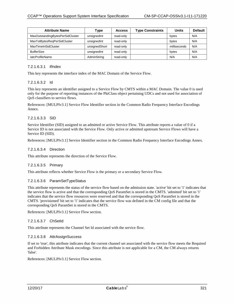
CCAP™ Operations Support System Interface Specification CM-SP-CCAP-OSSIv3.1-I11-171220
12/20/17 CableLabs 321
Attribute Name Type Access Type Constraints Units Default MaxOutstandingBytesPerSidCluster unsignedInt read-only bytes N/A
MaxTotBytesReqPerSidCluster unsignedInt read-only bytes N/A
MaxTimeInSidCluster unsignedShort read-only milliseconds N/A
BufferSize unsignedInt read-only bytes N/A
IatcProfileName AdminString read-only N/A N/A
7.2.1.6.3.1 ifIndex
This key represents the interface index of the MAC Domain of the Service Flow.
7.2.1.6.3.2 Id
This key represents an identifier assigned to a Service Flow by CMTS within a MAC Domain. The value 0 is used only for the purpose of reporting instances of the PktClass object pertaining UDCs and not used for association of QoS classifiers to service flows.
References: [MULPIv3.1] Service Flow Identifier section in the Common Radio Frequency Interface Encodings Annex.
7.2.1.6.3.3 SID
Service Identifier (SID) assigned to an admitted or active Service Flow. This attribute reports a value of 0 if a Service ID is not associated with the Service Flow. Only active or admitted upstream Service Flows will have a Service ID (SID).
References: [MULPIv3.1] Service Identifier section in the Common Radio Frequency Interface Encodings Annex.
7.2.1.6.3.4 Direction
This attribute represents the direction of the Service Flow.
7.2.1.6.3.5 Primary
This attribute reflects whether Service Flow is the primary or a secondary Service Flow.
7.2.1.6.3.6 ParamSetTypeStatus
This attribute represents the status of the service flow based on the admission state. 'active' bit set to '1' indicates that the service flow is active and that the corresponding QoS ParamSet is stored in the CMTS. 'admitted' bit set to '1' indicates that the service flow resources were reserved and that the corresponding QoS ParamSet is stored in the CMTS. 'provisioned' bit set to '1' indicates that the service flow was defined in the CM config file and that the corresponding QoS ParamSet is stored in the CMTS.
References: [MULPIv3.1] Service Flow section.
7.2.1.6.3.7 ChSetId
This attribute represents the Channel Set Id associated with the service flow.
7.2.1.6.3.8 AttrAssignSuccess
If set to 'true', this attribute indicates that the current channel set associated with the service flow meets the Required and Forbidden Attribute Mask encodings. Since this attribute is not applicable for a CM, the CM always returns 'false'.
References: [MULPIv3.1] Service Flow section.
CM-SP-CCAP-OSSIv3.1-I11-171220 DOCSIS® 3.1
322 CableLabs 12/20/17
7.2.1.6.3.9 Dsid
This attribute indicates the DSID associated with the downstream service flow. downstream service flows without a DSID or upstream Service Flows report the value zero.
7.2.1.6.3.10 MaxReqPerSidCluster
This attribute specifies the maximum number of requests that a CM can make within a given SID Cluster before it has to switch to a different SID Cluster to make further requests. A value of 0 indicates there is no limit. This attribute only applies to upstream Service Flows in 3.0 operation, in other cases it is reported as 0.
References: [MULPIv3.1] Maximum Requests per SID Cluster section in the Common Radio Frequency Interface Encodings Annex.
7.2.1.6.3.11 MaxOutstandingBytesPerSidCluster
This attribute specifies the maximum number of bytes for which a CM can have requests outstanding on a given SID Cluster. If defined number of bytes are outstanding and further requests are required, the CM needs to switch to a different SID Cluster if one is available. A value of 0 indicates there is no limit. This attribute only applies to upstream Service Flows in 3.0 operation, in other cases it is reported as 0.
References: [MULPIv3.1] Maximum Outstanding Bytes per SID Cluster section in the Common Radio Frequency Interface Encodings Annex.
7.2.1.6.3.12 MaxTotBytesReqPerSidCluster
This attribute specifies the maximum total number of bytes a CM can have requested using a given SID Cluster before it has to switch to a different SID Cluster to make further requests. A value of 0 indicates there is no limit. This attribute only applies to upstream Service Flows in 3.0 operation, in other cases it is reported as 0.
References: [MULPIv3.1] Maximum Total Bytes Requested per SID Cluster section in the Common Radio Frequency Interface Encodings Annex.
7.2.1.6.3.13 MaxTimeInSidCluster
This attribute specifies the maximum time in milliseconds that a CM may use a particular SID Cluster before it has to switch to a different SID Cluster to make further requests. A value of 0 indicates there is no limit. This attribute only applies to upstream Service Flows in 3.0 operation, in other cases it is reported as 0.
References: [MULPIv3.1] Maximum Time in the SID Cluster section in the Common Radio Frequency Interface Encodings Annex.
7.2.1.6.3.14 BufferSize
This attribute indicates the buffer size for the service flow. For the CM this attribute only applies to upstream Service Flows, for the CMTS this attribute only applies to downstream Service Flows, in other cases it is reported as 0.
References: [MULPIv3.1] Buffer Control section in the Common Radio Frequency Interface Encodings Annex.
7.2.1.6.3.15 IatcProfileName
This attribute indicates the name of the IATC Profile to which this Service Flow belongs. If this Service Flow is not part of an IATC Profile, this attribute returns an empty string.
7.2.1.6.4 CmtsMacToSrvFlow
This object provides the mapping of unicast service flows with the cable modem the service flows belongs to.
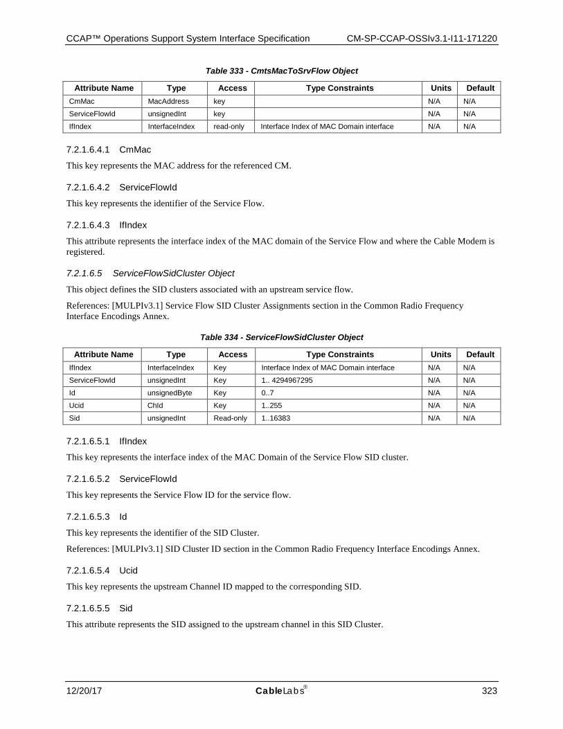
CCAP™ Operations Support System Interface Specification CM-SP-CCAP-OSSIv3.1-I11-171220
12/20/17 CableLabs 323
Table 333 - CmtsMacToSrvFlow Object
Attribute Name Type Access Type Constraints Units Default CmMac MacAddress key N/A N/A
ServiceFlowId unsignedInt key N/A N/A
IfIndex InterfaceIndex read-only Interface Index of MAC Domain interface N/A N/A
7.2.1.6.4.1 CmMac
This key represents the MAC address for the referenced CM.
7.2.1.6.4.2 ServiceFlowId
This key represents the identifier of the Service Flow.
7.2.1.6.4.3 IfIndex
This attribute represents the interface index of the MAC domain of the Service Flow and where the Cable Modem is registered.
7.2.1.6.5 ServiceFlowSidCluster Object
This object defines the SID clusters associated with an upstream service flow.
References: [MULPIv3.1] Service Flow SID Cluster Assignments section in the Common Radio Frequency Interface Encodings Annex.
Table 334 - ServiceFlowSidCluster Object
Attribute Name Type Access Type Constraints Units Default IfIndex InterfaceIndex Key Interface Index of MAC Domain interface N/A N/A
ServiceFlowId unsignedInt Key 1.. 4294967295 N/A N/A
Id unsignedByte Key 0..7 N/A N/A
Ucid ChId Key 1..255 N/A N/A
Sid unsignedInt Read-only 1..16383 N/A N/A
7.2.1.6.5.1 IfIndex
This key represents the interface index of the MAC Domain of the Service Flow SID cluster.
7.2.1.6.5.2 ServiceFlowId
This key represents the Service Flow ID for the service flow.
7.2.1.6.5.3 Id
This key represents the identifier of the SID Cluster.
References: [MULPIv3.1] SID Cluster ID section in the Common Radio Frequency Interface Encodings Annex.
7.2.1.6.5.4 Ucid
This key represents the upstream Channel ID mapped to the corresponding SID.
7.2.1.6.5.5 Sid
This attribute represents the SID assigned to the upstream channel in this SID Cluster.
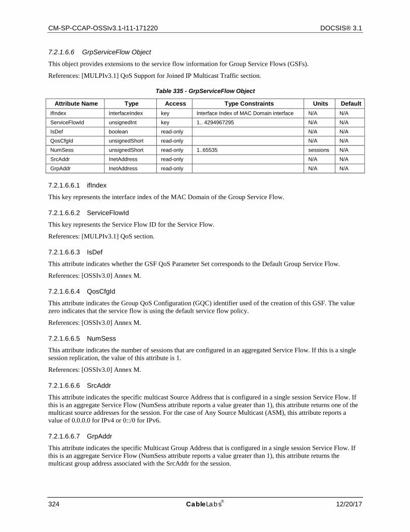
CM-SP-CCAP-OSSIv3.1-I11-171220 DOCSIS® 3.1
324 CableLabs 12/20/17
7.2.1.6.6 GrpServiceFlow Object
This object provides extensions to the service flow information for Group Service Flows (GSFs).
References: [MULPIv3.1] QoS Support for Joined IP Multicast Traffic section.
Table 335 - GrpServiceFlow Object
Attribute Name Type Access Type Constraints Units Default ifIndex InterfaceIndex key Interface Index of MAC Domain interface N/A N/A
ServiceFlowId unsignedInt key 1.. 4294967295 N/A N/A
IsDef boolean read-only N/A N/A
QosCfgId unsignedShort read-only N/A N/A
NumSess unsignedShort read-only 1..65535 sessions N/A
SrcAddr InetAddress read-only N/A N/A
GrpAddr InetAddress read-only N/A N/A
7.2.1.6.6.1 ifIndex
This key represents the interface index of the MAC Domain of the Group Service Flow.
7.2.1.6.6.2 ServiceFlowId
This key represents the Service Flow ID for the Service Flow.
References: [MULPIv3.1] QoS section.
7.2.1.6.6.3 IsDef
This attribute indicates whether the GSF QoS Parameter Set corresponds to the Default Group Service Flow.
References: [OSSIv3.0] Annex M.
7.2.1.6.6.4 QosCfgId
This attribute indicates the Group QoS Configuration (GQC) identifier used of the creation of this GSF. The value zero indicates that the service flow is using the default service flow policy.
References: [OSSIv3.0] Annex M.
7.2.1.6.6.5 NumSess
This attribute indicates the number of sessions that are configured in an aggregated Service Flow. If this is a single session replication, the value of this attribute is 1.
References: [OSSIv3.0] Annex M.
7.2.1.6.6.6 SrcAddr
This attribute indicates the specific multicast Source Address that is configured in a single session Service Flow. If this is an aggregate Service Flow (NumSess attribute reports a value greater than 1), this attribute returns one of the multicast source addresses for the session. For the case of Any Source Multicast (ASM), this attribute reports a value of 0.0.0.0 for IPv4 or 0::/0 for IPv6.
7.2.1.6.6.7 GrpAddr
This attribute indicates the specific Multicast Group Address that is configured in a single session Service Flow. If this is an aggregate Service Flow (NumSess attribute reports a value greater than 1), this attribute returns the multicast group address associated with the SrcAddr for the session.
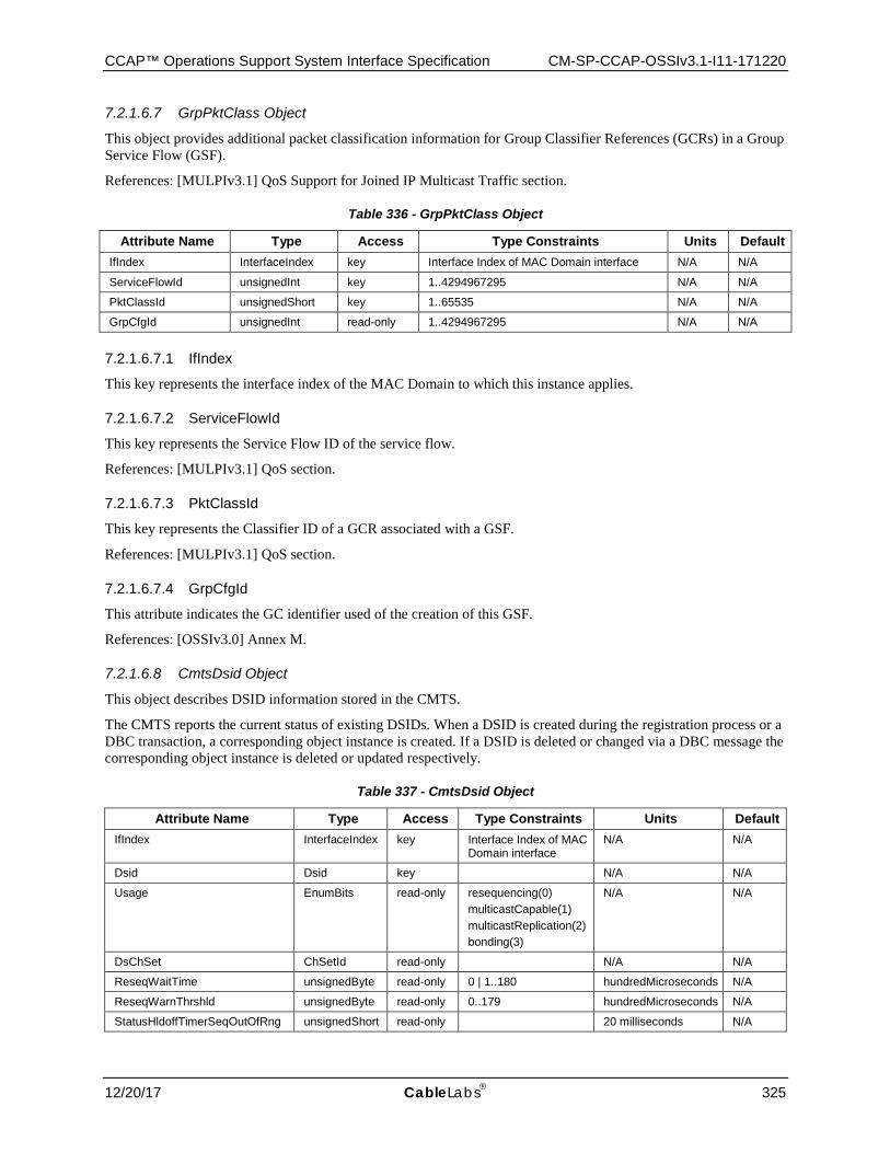
CCAP™ Operations Support System Interface Specification CM-SP-CCAP-OSSIv3.1-I11-171220
12/20/17 CableLabs 325
7.2.1.6.7 GrpPktClass Object
This object provides additional packet classification information for Group Classifier References (GCRs) in a Group Service Flow (GSF).
References: [MULPIv3.1] QoS Support for Joined IP Multicast Traffic section.
Table 336 - GrpPktClass Object
Attribute Name Type Access Type Constraints Units Default IfIndex InterfaceIndex key Interface Index of MAC Domain interface N/A N/A
ServiceFlowId unsignedInt key 1..4294967295 N/A N/A
PktClassId unsignedShort key 1..65535 N/A N/A
GrpCfgId unsignedInt read-only 1..4294967295 N/A N/A
7.2.1.6.7.1 IfIndex
This key represents the interface index of the MAC Domain to which this instance applies.
7.2.1.6.7.2 ServiceFlowId
This key represents the Service Flow ID of the service flow.
References: [MULPIv3.1] QoS section.
7.2.1.6.7.3 PktClassId
This key represents the Classifier ID of a GCR associated with a GSF.
References: [MULPIv3.1] QoS section.
7.2.1.6.7.4 GrpCfgId
This attribute indicates the GC identifier used of the creation of this GSF.
References: [OSSIv3.0] Annex M.
7.2.1.6.8 CmtsDsid Object
This object describes DSID information stored in the CMTS.
The CMTS reports the current status of existing DSIDs. When a DSID is created during the registration process or a DBC transaction, a corresponding object instance is created. If a DSID is deleted or changed via a DBC message the corresponding object instance is deleted or updated respectively.
Table 337 - CmtsDsid Object
Attribute Name Type Access Type Constraints Units Default IfIndex InterfaceIndex key Interface Index of MAC
Domain interface N/A N/A
Dsid Dsid key N/A N/A
Usage EnumBits read-only resequencing(0) multicastCapable(1) multicastReplication(2) bonding(3)
N/A N/A
DsChSet ChSetId read-only N/A N/A
ReseqWaitTime unsignedByte read-only 0 | 1..180 hundredMicroseconds N/A
ReseqWarnThrshld unsignedByte read-only 0..179 hundredMicroseconds N/A
StatusHldoffTimerSeqOutOfRng unsignedShort read-only 20 milliseconds N/A
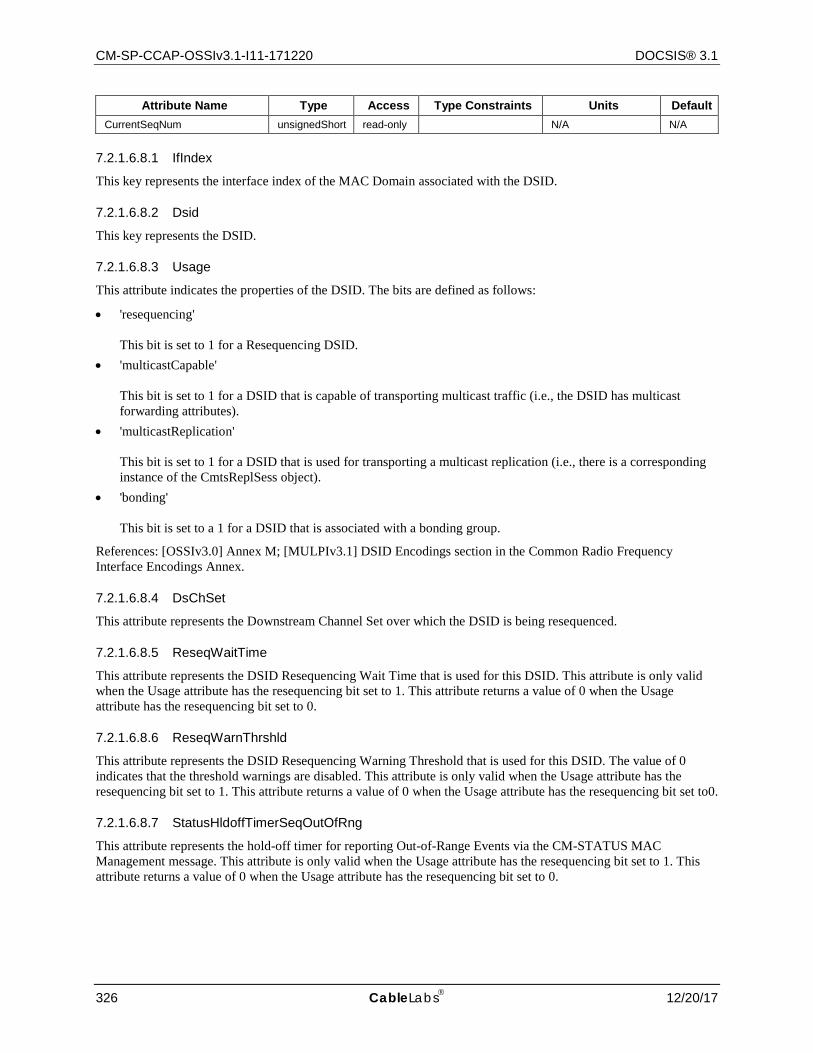
CM-SP-CCAP-OSSIv3.1-I11-171220 DOCSIS® 3.1
326 CableLabs 12/20/17
Attribute Name Type Access Type Constraints Units Default CurrentSeqNum unsignedShort read-only N/A N/A
7.2.1.6.8.1 IfIndex
This key represents the interface index of the MAC Domain associated with the DSID.
7.2.1.6.8.2 Dsid
This key represents the DSID.
7.2.1.6.8.3 Usage
This attribute indicates the properties of the DSID. The bits are defined as follows:
• 'resequencing' This bit is set to 1 for a Resequencing DSID.
• 'multicastCapable' This bit is set to 1 for a DSID that is capable of transporting multicast traffic (i.e., the DSID has multicast forwarding attributes).
• 'multicastReplication' This bit is set to 1 for a DSID that is used for transporting a multicast replication (i.e., there is a corresponding instance of the CmtsReplSess object).
• 'bonding' This bit is set to a 1 for a DSID that is associated with a bonding group.
References: [OSSIv3.0] Annex M; [MULPIv3.1] DSID Encodings section in the Common Radio Frequency Interface Encodings Annex.
7.2.1.6.8.4 DsChSet
This attribute represents the Downstream Channel Set over which the DSID is being resequenced.
7.2.1.6.8.5 ReseqWaitTime
This attribute represents the DSID Resequencing Wait Time that is used for this DSID. This attribute is only valid when the Usage attribute has the resequencing bit set to 1. This attribute returns a value of 0 when the Usage attribute has the resequencing bit set to 0.
7.2.1.6.8.6 ReseqWarnThrshld
This attribute represents the DSID Resequencing Warning Threshold that is used for this DSID. The value of 0 indicates that the threshold warnings are disabled. This attribute is only valid when the Usage attribute has the resequencing bit set to 1. This attribute returns a value of 0 when the Usage attribute has the resequencing bit set to0.
7.2.1.6.8.7 StatusHldoffTimerSeqOutOfRng
This attribute represents the hold-off timer for reporting Out-of-Range Events via the CM-STATUS MAC Management message. This attribute is only valid when the Usage attribute has the resequencing bit set to 1. This attribute returns a value of 0 when the Usage attribute has the resequencing bit set to 0.
CCAP™ Operations Support System Interface Specification CM-SP-CCAP-OSSIv3.1-I11-171220
12/20/17 CableLabs 327
7.2.1.6.8.8 LastSeqNum
This attribute reports the value of the most recent sequence number assigned by the CMTS for this DSID. This attribute is only valid when the Usage attribute has the resequencing bit set to 1. This attribute returns a value of 0 when the Usage attribute has the resequencing bit set to 0.
7.2.1.6.9 IP Multicast QoS Event Behaviors
This section defines the behavior and trigger mechanisms for several of the Multicast QoS event definitions defined in Annex D.
Event ID 89010104 reflects that a particular Group Service Flow is dropping packets as a result of a) the incoming data rate exceeding the rate-shaping bounds defined by the combination of Maximum Sustained Traffic Rate, Maximum Traffic Burst, and Peak Traffic Rate in the Group QoS Configuration, or b) the available capacity of the DCS is insufficient to support forwarding. When event reporting is administratively enabled, the CMTS MUST generate event ID 89010104 when the condition of packet loss is detected. The CMTS SHOULD detect this condition when packet loss due to AQM or buffer overflow exceeds one packet per second for each of the most recent three seconds.
Event ID 89010105 reflects that a particular Group Service Flow is no longer dropping packets as a result of a) the incoming data rate exceeding the rate-shaping bounds defined by the combination of Maximum Sustained Traffic Rate, Maximum Traffic Burst, and Peak Traffic Rate in the Group QoS Configuration, or b) the available capacity of the DCS is insufficient to support forwarding. When event reporting is administratively enabled, the CMTS MUST generate Event ID 89010105 when the condition of packet loss is no longer detected. Once a particular multicast session is in a "dropping packets" state (as indicated by the generation of event ID 89010104), the CMTS SHOULD detect this condition when packet loss due to AQM or buffer overflow equals zero packets per second for each of the most recent three seconds.
Admitted Multicast Aggregate Bandwidth is defined as the sum of the Minimum Reserved Traffic Rates of each Group Service Flow that has been admitted on a given CMTS cable interface. Note that for some vendors this CMTS cable interface will be a cable-mac interface. For others, it will be a DOCSIS Downstream Channel Set. In either case, this CMTS cable interface exists as a row entry in the ifTable (and therefore has an ifIndex which can be referenced in the defined event messages).
The IGMP and MLD protocol event messages include a threshold for determining whether ingress packet loss is occurring for IGMP/MLD protocol messages received from clients. For the IGMP/MLD protocol packet loss Event IDs 89010106 through 89010111, the configuration and logic to determine how a threshold crossing is calculated for the high and low thresholds is vendor-specific.
7.2.1.7 DOCS-SEC-MIB The objects in the DOCS-SEC-MIB are taken from the DOCS-SEC-MIB specified in Annex Q of [OSSIv3.0] ; the DocsSecCmtsCertRevocationListStatus object only includes the read-only attributes. Otherwise, these objects are used without modification for the CCAP.
Reference: [OSSIv3.0], [DOCS-SEC-MIB]
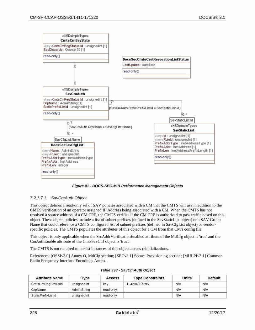
CM-SP-CCAP-OSSIv3.1-I11-171220 DOCSIS® 3.1
328 CableLabs 12/20/17
Figure 41 - DOCS-SEC-MIB Performance Management Objects
7.2.1.7.1 SavCmAuth Object
This object defines a read-only set of SAV policies associated with a CM that the CMTS will use in addition to the CMTS verification of an operator assigned IP Address being associated with a CM. When the CMTS has not resolved a source address of a CM CPE, the CMTS verifies if the CM CPE is authorized to pass traffic based on this object. These object policies include a list of subnet prefixes (defined in the SavStaticList object) or a SAV Group Name that could reference a CMTS configured list of subnet prefixes (defined in SavCfgList object) or vendor-specific policies. The CMTS populates the attributes of this object for a CM from that CM's config file.
This object is only applicable when the SrcAddrVerificationEnabled attribute of the MdCfg object is 'true' and the CmAuthEnable attribute of the CmtsSavCtrl object is 'true'.
The CMTS is not required to persist instances of this object across reinitializations.
References: [OSSIv3.0] Annex O, MdCfg section; [SECv3.1] Secure Provisioning section; [MULPIv3.1] Common Radio Frequency Interface Encodings Annex.
Table 338 - SavCmAuth Object
Attribute Name Type Access Type Constraints Units Default CmtsCmRegStatusId unsignedInt key 1..4294967295 N/A N/A
GrpName AdminString read-only N/A N/A
StaticPrefixListId unsignedInt read-only N/A N/A
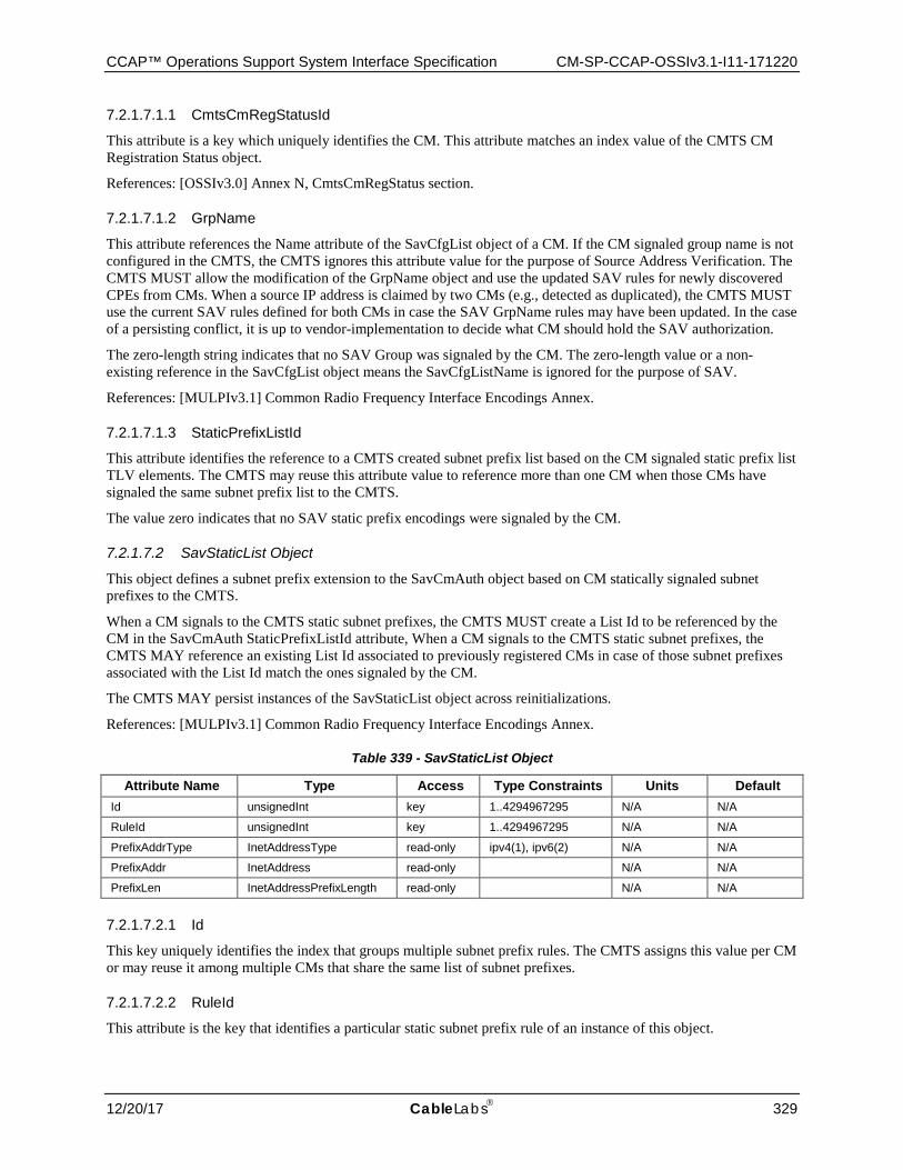
CCAP™ Operations Support System Interface Specification CM-SP-CCAP-OSSIv3.1-I11-171220
12/20/17 CableLabs 329
7.2.1.7.1.1 CmtsCmRegStatusId
This attribute is a key which uniquely identifies the CM. This attribute matches an index value of the CMTS CM Registration Status object.
References: [OSSIv3.0] Annex N, CmtsCmRegStatus section.
7.2.1.7.1.2 GrpName
This attribute references the Name attribute of the SavCfgList object of a CM. If the CM signaled group name is not configured in the CMTS, the CMTS ignores this attribute value for the purpose of Source Address Verification. The CMTS MUST allow the modification of the GrpName object and use the updated SAV rules for newly discovered CPEs from CMs. When a source IP address is claimed by two CMs (e.g., detected as duplicated), the CMTS MUST use the current SAV rules defined for both CMs in case the SAV GrpName rules may have been updated. In the case of a persisting conflict, it is up to vendor-implementation to decide what CM should hold the SAV authorization.
The zero-length string indicates that no SAV Group was signaled by the CM. The zero-length value or a non-existing reference in the SavCfgList object means the SavCfgListName is ignored for the purpose of SAV.
References: [MULPIv3.1] Common Radio Frequency Interface Encodings Annex.
7.2.1.7.1.3 StaticPrefixListId
This attribute identifies the reference to a CMTS created subnet prefix list based on the CM signaled static prefix list TLV elements. The CMTS may reuse this attribute value to reference more than one CM when those CMs have signaled the same subnet prefix list to the CMTS.
The value zero indicates that no SAV static prefix encodings were signaled by the CM.
7.2.1.7.2 SavStaticList Object
This object defines a subnet prefix extension to the SavCmAuth object based on CM statically signaled subnet prefixes to the CMTS.
When a CM signals to the CMTS static subnet prefixes, the CMTS MUST create a List Id to be referenced by the CM in the SavCmAuth StaticPrefixListId attribute, When a CM signals to the CMTS static subnet prefixes, the CMTS MAY reference an existing List Id associated to previously registered CMs in case of those subnet prefixes associated with the List Id match the ones signaled by the CM.
The CMTS MAY persist instances of the SavStaticList object across reinitializations.
References: [MULPIv3.1] Common Radio Frequency Interface Encodings Annex.
Table 339 - SavStaticList Object
Attribute Name Type Access Type Constraints Units Default Id unsignedInt key 1..4294967295 N/A N/A
RuleId unsignedInt key 1..4294967295 N/A N/A
PrefixAddrType InetAddressType read-only ipv4(1), ipv6(2) N/A N/A
PrefixAddr InetAddress read-only N/A N/A
PrefixLen InetAddressPrefixLength read-only N/A N/A
7.2.1.7.2.1 Id
This key uniquely identifies the index that groups multiple subnet prefix rules. The CMTS assigns this value per CM or may reuse it among multiple CMs that share the same list of subnet prefixes.
7.2.1.7.2.2 RuleId
This attribute is the key that identifies a particular static subnet prefix rule of an instance of this object.
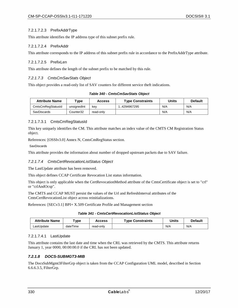
CM-SP-CCAP-OSSIv3.1-I11-171220 DOCSIS® 3.1
330 CableLabs 12/20/17
7.2.1.7.2.3 PrefixAddrType
This attribute identifies the IP address type of this subnet prefix rule.
7.2.1.7.2.4 PrefixAddr
This attribute corresponds to the IP address of this subnet prefix rule in accordance to the PrefixAddrType attribute.
7.2.1.7.2.5 PrefixLen
This attribute defines the length of the subnet prefix to be matched by this rule.
7.2.1.7.3 CmtsCmSavStats Object
This object provides a read-only list of SAV counters for different service theft indications.
Table 340 - CmtsCmSavStats Object
Attribute Name Type Access Type Constraints Units Default CmtsCmRegStatusId unsignedInt key 1..4294967295 N/A N/A
SavDiscards Counter32 read-only N/A N/A
7.2.1.7.3.1 CmtsCmRegStatusId
This key uniquely identifies the CM. This attribute matches an index value of the CMTS CM Registration Status object.
References: [OSSIv3.0] Annex N, CmtsCmRegStatus section. SavDiscards
This attribute provides the information about number of dropped upstream packets due to SAV failure.
7.2.1.7.4 CmtsCertRevocationListStatus Object
The LastUpdate attribute has been removed.
This object defines CCAP Certificate Revocation List status information.
This object is only applicable when the CertRevocationMethod attribute of the CmtsCertificate object is set to "crl" or "crlAndOcsp".
The CMTS and CCAP MUST persist the values of the Url and RefreshInterval attributes of the CmtsCertRevocationList object across reinitializations.
References: [SECv3.1] BPI+ X.509 Certificate Profile and Management section
Table 341 - CmtsCertRevocationListStatus Object
Attribute Name Type Access Type Constraints Units Default LastUpdate dateTime read-only N/A N/A
7.2.1.7.4.1 LastUpdate
This attribute contains the last date and time when the CRL was retrieved by the CMTS. This attribute returns January 1, year 0000, 00:00:00.0 if the CRL has not been updated.
7.2.1.8 DOCS-SUBMGT3-MIB The DocsSubMgmt3FilterGrp object is taken from the CCAP Configuration UML model, described in Section 6.6.6.3.5, FilterGrp.
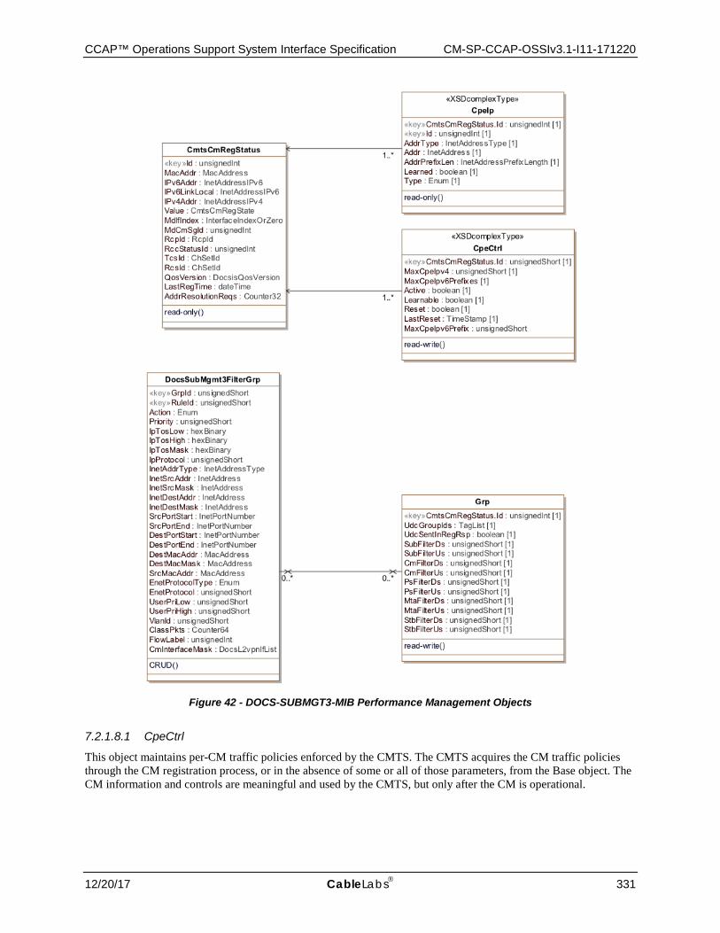
CCAP™ Operations Support System Interface Specification CM-SP-CCAP-OSSIv3.1-I11-171220
12/20/17 CableLabs 331
Figure 42 - DOCS-SUBMGT3-MIB Performance Management Objects
7.2.1.8.1 CpeCtrl
This object maintains per-CM traffic policies enforced by the CMTS. The CMTS acquires the CM traffic policies through the CM registration process, or in the absence of some or all of those parameters, from the Base object. The CM information and controls are meaningful and used by the CMTS, but only after the CM is operational.
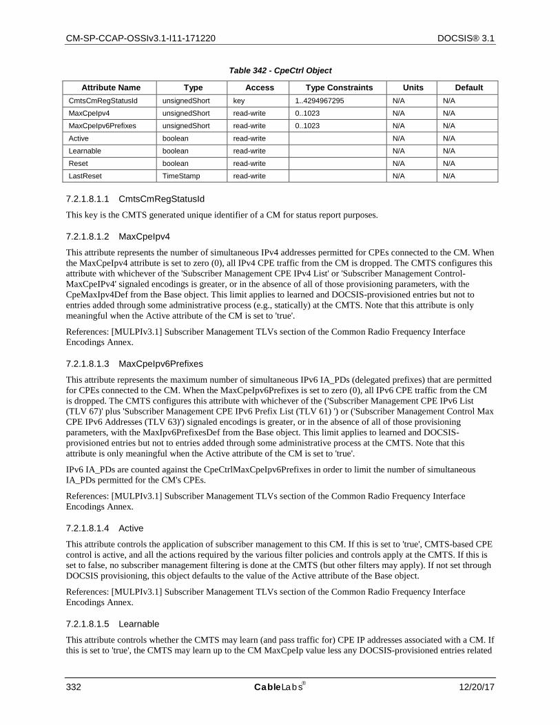
CM-SP-CCAP-OSSIv3.1-I11-171220 DOCSIS® 3.1
332 CableLabs 12/20/17
Table 342 - CpeCtrl Object
Attribute Name Type Access Type Constraints Units Default CmtsCmRegStatusId unsignedShort key 1..4294967295 N/A N/A
MaxCpeIpv4 unsignedShort read-write 0..1023 N/A N/A
MaxCpeIpv6Prefixes unsignedShort read-write 0..1023 N/A N/A
Active boolean read-write N/A N/A
Learnable boolean read-write N/A N/A
Reset boolean read-write N/A N/A
LastReset TimeStamp read-write N/A N/A
7.2.1.8.1.1 CmtsCmRegStatusId
This key is the CMTS generated unique identifier of a CM for status report purposes.
7.2.1.8.1.2 MaxCpeIpv4
This attribute represents the number of simultaneous IPv4 addresses permitted for CPEs connected to the CM. When the MaxCpeIpv4 attribute is set to zero (0), all IPv4 CPE traffic from the CM is dropped. The CMTS configures this attribute with whichever of the 'Subscriber Management CPE IPv4 List' or 'Subscriber Management Control-MaxCpeIPv4' signaled encodings is greater, or in the absence of all of those provisioning parameters, with the CpeMaxIpv4Def from the Base object. This limit applies to learned and DOCSIS-provisioned entries but not to entries added through some administrative process (e.g., statically) at the CMTS. Note that this attribute is only meaningful when the Active attribute of the CM is set to 'true'.
References: [MULPIv3.1] Subscriber Management TLVs section of the Common Radio Frequency Interface Encodings Annex.
7.2.1.8.1.3 MaxCpeIpv6Prefixes
This attribute represents the maximum number of simultaneous IPv6 IA_PDs (delegated prefixes) that are permitted for CPEs connected to the CM. When the MaxCpeIpv6Prefixes is set to zero (0), all IPv6 CPE traffic from the CM is dropped. The CMTS configures this attribute with whichever of the ('Subscriber Management CPE IPv6 List (TLV 67)' plus 'Subscriber Management CPE IPv6 Prefix List (TLV 61) ') or ('Subscriber Management Control Max CPE IPv6 Addresses (TLV 63)') signaled encodings is greater, or in the absence of all of those provisioning parameters, with the MaxIpv6PrefixesDef from the Base object. This limit applies to learned and DOCSIS-provisioned entries but not to entries added through some administrative process at the CMTS. Note that this attribute is only meaningful when the Active attribute of the CM is set to 'true'.
IPv6 IA_PDs are counted against the CpeCtrlMaxCpeIpv6Prefixes in order to limit the number of simultaneous IA_PDs permitted for the CM's CPEs.
References: [MULPIv3.1] Subscriber Management TLVs section of the Common Radio Frequency Interface Encodings Annex.
7.2.1.8.1.4 Active
This attribute controls the application of subscriber management to this CM. If this is set to 'true', CMTS-based CPE control is active, and all the actions required by the various filter policies and controls apply at the CMTS. If this is set to false, no subscriber management filtering is done at the CMTS (but other filters may apply). If not set through DOCSIS provisioning, this object defaults to the value of the Active attribute of the Base object.
References: [MULPIv3.1] Subscriber Management TLVs section of the Common Radio Frequency Interface Encodings Annex.
7.2.1.8.1.5 Learnable
This attribute controls whether the CMTS may learn (and pass traffic for) CPE IP addresses associated with a CM. If this is set to 'true', the CMTS may learn up to the CM MaxCpeIp value less any DOCSIS-provisioned entries related
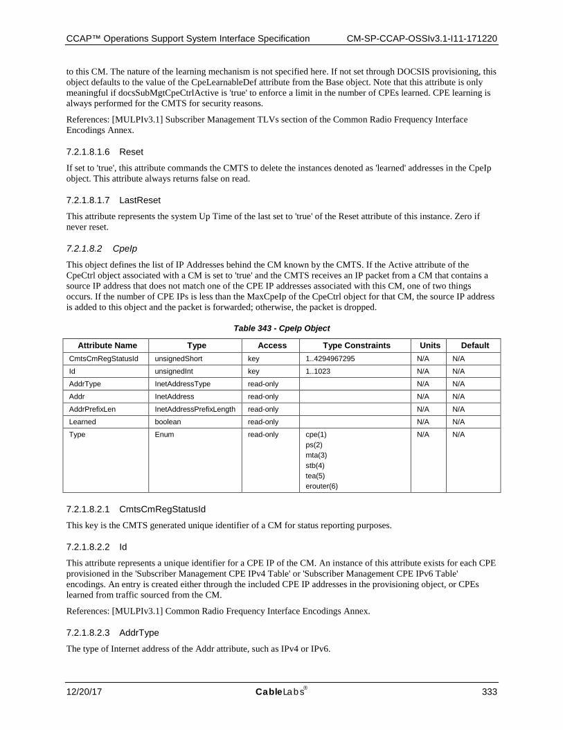
CCAP™ Operations Support System Interface Specification CM-SP-CCAP-OSSIv3.1-I11-171220
12/20/17 CableLabs 333
to this CM. The nature of the learning mechanism is not specified here. If not set through DOCSIS provisioning, this object defaults to the value of the CpeLearnableDef attribute from the Base object. Note that this attribute is only meaningful if docsSubMgtCpeCtrlActive is 'true' to enforce a limit in the number of CPEs learned. CPE learning is always performed for the CMTS for security reasons.
References: [MULPIv3.1] Subscriber Management TLVs section of the Common Radio Frequency Interface Encodings Annex.
7.2.1.8.1.6 Reset
If set to 'true', this attribute commands the CMTS to delete the instances denoted as 'learned' addresses in the CpeIp object. This attribute always returns false on read.
7.2.1.8.1.7 LastReset
This attribute represents the system Up Time of the last set to 'true' of the Reset attribute of this instance. Zero if never reset.
7.2.1.8.2 CpeIp
This object defines the list of IP Addresses behind the CM known by the CMTS. If the Active attribute of the CpeCtrl object associated with a CM is set to 'true' and the CMTS receives an IP packet from a CM that contains a source IP address that does not match one of the CPE IP addresses associated with this CM, one of two things occurs. If the number of CPE IPs is less than the MaxCpeIp of the CpeCtrl object for that CM, the source IP address is added to this object and the packet is forwarded; otherwise, the packet is dropped.
Table 343 - CpeIp Object
Attribute Name Type Access Type Constraints Units Default CmtsCmRegStatusId unsignedShort key 1..4294967295 N/A N/A
Id unsignedInt key 1..1023 N/A N/A
AddrType InetAddressType read-only N/A N/A
Addr InetAddress read-only N/A N/A
AddrPrefixLen InetAddressPrefixLength read-only N/A N/A
Learned boolean read-only N/A N/A
Type Enum read-only cpe(1) ps(2) mta(3) stb(4) tea(5) erouter(6)
N/A N/A
7.2.1.8.2.1 CmtsCmRegStatusId
This key is the CMTS generated unique identifier of a CM for status reporting purposes.
7.2.1.8.2.2 Id
This attribute represents a unique identifier for a CPE IP of the CM. An instance of this attribute exists for each CPE provisioned in the 'Subscriber Management CPE IPv4 Table' or 'Subscriber Management CPE IPv6 Table' encodings. An entry is created either through the included CPE IP addresses in the provisioning object, or CPEs learned from traffic sourced from the CM.
References: [MULPIv3.1] Common Radio Frequency Interface Encodings Annex.
7.2.1.8.2.3 AddrType
The type of Internet address of the Addr attribute, such as IPv4 or IPv6.
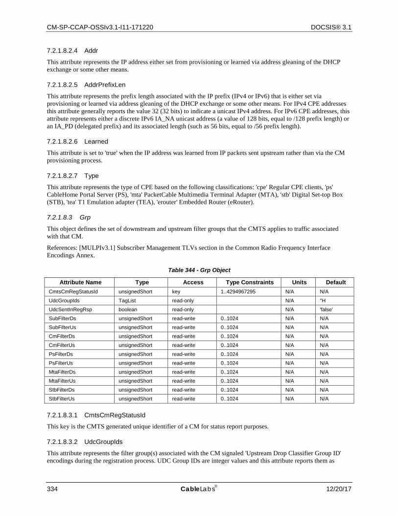
CM-SP-CCAP-OSSIv3.1-I11-171220 DOCSIS® 3.1
334 CableLabs 12/20/17
7.2.1.8.2.4 Addr
This attribute represents the IP address either set from provisioning or learned via address gleaning of the DHCP exchange or some other means.
7.2.1.8.2.5 AddrPrefixLen
This attribute represents the prefix length associated with the IP prefix (IPv4 or IPv6) that is either set via provisioning or learned via address gleaning of the DHCP exchange or some other means. For IPv4 CPE addresses this attribute generally reports the value 32 (32 bits) to indicate a unicast IPv4 address. For IPv6 CPE addresses, this attribute represents either a discrete IPv6 IA_NA unicast address (a value of 128 bits, equal to /128 prefix length) or an IA_PD (delegated prefix) and its associated length (such as 56 bits, equal to /56 prefix length).
7.2.1.8.2.6 Learned
This attribute is set to 'true' when the IP address was learned from IP packets sent upstream rather than via the CM provisioning process.
7.2.1.8.2.7 Type
This attribute represents the type of CPE based on the following classifications: 'cpe' Regular CPE clients, 'ps' CableHome Portal Server (PS), 'mta' PacketCable Multimedia Terminal Adapter (MTA), 'stb' Digital Set-top Box (STB), 'tea' T1 Emulation adapter (TEA), 'erouter' Embedded Router (eRouter).
7.2.1.8.3 Grp
This object defines the set of downstream and upstream filter groups that the CMTS applies to traffic associated with that CM.
References: [MULPIv3.1] Subscriber Management TLVs section in the Common Radio Frequency Interface Encodings Annex.
Table 344 - Grp Object
Attribute Name Type Access Type Constraints Units Default CmtsCmRegStatusId unsignedShort key 1..4294967295 N/A N/A
UdcGroupIds TagList read-only N/A ''H
UdcSentInRegRsp boolean read-only N/A 'false'
SubFilterDs unsignedShort read-write 0..1024 N/A N/A
SubFilterUs unsignedShort read-write 0..1024 N/A N/A
CmFilterDs unsignedShort read-write 0..1024 N/A N/A
CmFilterUs unsignedShort read-write 0..1024 N/A N/A
PsFilterDs unsignedShort read-write 0..1024 N/A N/A
PsFilterUs unsignedShort read-write 0..1024 N/A N/A
MtaFilterDs unsignedShort read-write 0..1024 N/A N/A
MtaFilterUs unsignedShort read-write 0..1024 N/A N/A
StbFilterDs unsignedShort read-write 0..1024 N/A N/A
StbFilterUs unsignedShort read-write 0..1024 N/A N/A
7.2.1.8.3.1 CmtsCmRegStatusId
This key is the CMTS generated unique identifier of a CM for status report purposes.
7.2.1.8.3.2 UdcGroupIds
This attribute represents the filter group(s) associated with the CM signaled 'Upstream Drop Classifier Group ID' encodings during the registration process. UDC Group IDs are integer values and this attribute reports them as
CCAP™ Operations Support System Interface Specification CM-SP-CCAP-OSSIv3.1-I11-171220
12/20/17 CableLabs 335
decimal numbers that are space-separated. The zero-length string indicates that the CM didn't signal UDC Group IDs.
This attribute provides two functions:
• Communicate the CM the configured UDC Group ID(s), irrespective of the CM being provisioned to filter upstream traffic based on IP Filters or UDCs.
• Optionally, and with regards to the CMTS, if the value of the attribute UdcSentInReqRsp is 'true', indicates that the filtering rules associated with the Subscriber Management Group ID(s) will be sent during registration to the CM. It is vendor specific whether the CMTS updates individual CM UDCs after registration when rules are changed in the Grp object.
7.2.1.8.3.3 UdcSentInRegRsp
This attribute represents the CMTS upstream filtering status for this CM. The value 'true' indicates that the CMTS has sent UDCs to the CM during registration process. In order for a CMTS to send UDCs to a CM, the CMTS MAC Domain needs to be enabled via the MAC Domain attribute SendUdcRulesEnabled and the CM had indicated the UDC capability support during the registration process. The value 'false' indicates that the CMTS was not enabled to send UDCs to the CMs in the MAC Domain, or the CM did not advertise UDC support in its capabilities encodings, or both. Since the CMTS capability to send UDCs to CMs during the registration process is optional, the CMTS is not required to instantiate this attribute.
7.2.1.8.3.4 SubFilterDs
This attribute represents the filter group applied to traffic destined for subscriber's CPE attached to the referenced CM (attached to CM CPE interfaces). This value corresponds to the 'Subscriber Downstream Group' value of the 'Subscriber Management Filter Groups' encoding signaled during the CM registration or in its absence, to the SubFilterDownDef attribute of the Base object. The value zero or a filter group ID not configured in the CMTS means no filtering is applied to traffic destined to hosts attached to this CM.
7.2.1.8.3.5 SubFilterUs
This attribute represents the filter group applied to traffic originating from subscriber's CPE attached to the referenced CM (attached to CM CPE interfaces). This value corresponds to the 'Subscriber Upstream Group' value of the 'Subscriber Management Filter Groups' encoding signaled during the CM registration or in its absence, to the SubFilterUpDef attribute of the Base object. The value zero or a filter group ID not configured in the CMTS means no filtering is applied to traffic originating from hosts attached to this CM.
7.2.1.8.3.6 CmFilterDs
This attribute represents the filter group applied to traffic destined for the CM itself. This value corresponds to the 'CM Downstream Group' value of the 'Subscriber Management Filter Groups' encoding signaled during the CM registration or in its absence, to the CmFilterDownDef attribute of the Base object. The value zero or a filter group ID not configured in the CMTS means no filtering is applied to traffic destined to this CM.
7.2.1.8.3.7 CmFilterUs
This attribute represents the filter group applied to traffic originating from the CM itself. This value corresponds to the 'Subscriber Upstream Group' value of the 'Subscriber Management Filter Groups' encoding signaled during the CM registration or in its absence, to the SubFilterUpDef attribute of the Base object. The value zero or a filter group ID not configured in the CMTS means no filtering is applied to traffic originating from this CM.
7.2.1.8.3.8 PsFilterDs
This attribute represents the filter group applied to traffic destined to the Embedded CableHome Portal Services Element or the Embedded Router on the referenced CM. This value corresponds to the 'PS Downstream Group' value of the 'Subscriber Management Filter Groups' encoding signaled during the CM registration or in its absence, to the SubFilterDownDef attribute of the Base object. The value zero or a filter group ID not configured in the
CM-SP-CCAP-OSSIv3.1-I11-171220 DOCSIS® 3.1
336 CableLabs 12/20/17
CMTS means no filtering is applied to traffic destined to the Embedded CableHome Portal Services Element or Embedded Router on this CM.
7.2.1.8.3.9 PsFilterUs
This attribute represents the filter group applied to traffic originating from the Embedded CableHome Portal Services Element or Embedded Router on the referenced CM. This value corresponds to the 'PS Upstream Group' value of the 'Subscriber Management Filter Groups' encoding signaled during the CM registration or in its absence, to the SubFilterUpDef attribute of the Base object. The value zero or a filter group ID not configured in the CMTS means no filtering is applied to traffic originating from the Embedded CableHome Portal Services Element or Embedded Router on this CM.
7.2.1.8.3.10 MtaFilterDs
This attribute represents the filter group applied to traffic destined to the Embedded Multimedia Terminal Adapter on the referenced CM. This value corresponds to the 'MTA Downstream Group' value of the 'Subscriber Management Filter Groups' encoding signaled during the CM registration or in its absence, to the SubFilterDownDef attribute of the Base object. The value zero or a filter group ID not configured in the CMTS means no filtering is applied to traffic destined to the Embedded Multimedia Terminal Adapter on this CM.
7.2.1.8.3.11 MtaFilterUs
This attribute represents the filter group applied to traffic originating from the Embedded Multimedia Terminal Adapter on the referenced CM. This value corresponds to the 'MTA Upstream Group' value of the 'Subscriber Management Filter Groups' encoding signaled during the CM registration or in its absence, to the SubFilterUpDef attribute of the Base object. The value zero or a filter group ID not configured in the CMTS means no filtering is applied to traffic originating from the Embedded Multimedia Terminal Adapter on this CM.
7.2.1.8.3.12 StbFilterDs
This attribute represents the filter group applied to traffic destined for the Embedded Set-Top Box on the referenced CM. This value corresponds to the 'STB Downstream Group' value of the 'Subscriber Management Filter Groups' encoding signaled during the CM registration or in its absence, to the SubFilterDownDef attribute of the Base object. The value zero or a filter group ID not configured in the CMTS means no filtering is applied to traffic destined to the Embedded Set-Top Box on this CM.
7.2.1.8.3.13 StbFilterUs
This attribute represents the filter group applied to traffic originating from the Embedded Set-Top Box on the referenced CM. This value corresponds to the 'STB Upstream Group' value of the 'Subscriber Management Filter Groups' encoding signaled during the CM registration or in its absence, to the SubFilterUpDef attribute of the Base object. The value zero or a filter group ID not configured in the CMTS means no filtering is applied to traffic originating from the Embedded Set-Top Box on this CM.
7.2.1.9 CCAP Topology Objects The RfPortFnCfg object is taken from the CLAB-TOPO-MIB specified in Annex Q of [OSSIv3.0] and used without modification for the CCAP.
The FiberNodeCfg object is taken from the CCAP Configuration UML model; it is defined in Section 6.6.4.12, FiberNodeCfg.
Reference: [OSSIv3.0], [DOCS-IF3-MIB], [CLAB-TOPO-MIB]
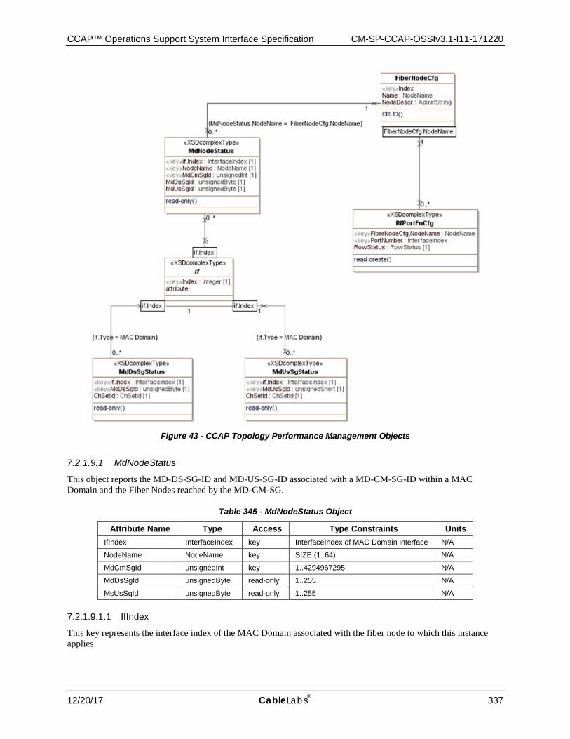
CCAP™ Operations Support System Interface Specification CM-SP-CCAP-OSSIv3.1-I11-171220
12/20/17 CableLabs 337
Figure 43 - CCAP Topology Performance Management Objects
7.2.1.9.1 MdNodeStatus
This object reports the MD-DS-SG-ID and MD-US-SG-ID associated with a MD-CM-SG-ID within a MAC Domain and the Fiber Nodes reached by the MD-CM-SG.
Table 345 - MdNodeStatus Object
Attribute Name Type Access Type Constraints Units IfIndex InterfaceIndex key InterfaceIndex of MAC Domain interface N/A
NodeName NodeName key SIZE (1..64) N/A
MdCmSgId unsignedInt key 1..4294967295 N/A
MdDsSgId unsignedByte read-only 1..255 N/A
MsUsSgId unsignedByte read-only 1..255 N/A
7.2.1.9.1.1 IfIndex
This key represents the interface index of the MAC Domain associated with the fiber node to which this instance applies.
CM-SP-CCAP-OSSIv3.1-I11-171220 DOCSIS® 3.1
338 CableLabs 12/20/17
7.2.1.9.1.2 NodeName
This key represents the name of a fiber node associated with a MD-CM-SG of a MAC Domain.
7.2.1.9.1.3 MdCmSgId
This attribute is a key and indicates the MD-CM-SG-ID of this instance. A particular MdCmSgId in a MAC Domain is associated with one or more Fiber Nodes.
7.2.1.9.1.4 MdDsSgId
This attribute corresponds to the MD-DS-SG-ID of the MD-CM-SG of this object instance. The MdDsSgId values are unique within a MAC Domain.
7.2.1.9.1.5 MdUsSgId
This attribute corresponds to the MD-US-SG-ID of the MD-CM-SG of this object instance. The MdUsSgId values are unique within a MAC Domain.
7.2.1.9.2 MdDsSgStatus
This object returns the list of downstream channel set associated with a MAC Domain MD-DS-SG-ID.
Table 346 - MdDsSgStatus Object
Attribute Name Type Access Type Constraints Units Default ifIndex InterfaceIndex key InterfaceIndex of MAC Domain interface N/A N/A
MdDsSgId unsignedByte key 1..255 N/A N/A
ChSetId ChSetId read-only N/A N/A
7.2.1.9.2.1 IfIndex
This key represents the interface index of the MAC Domain to which the MD-DS-SG-ID applies.
7.2.1.9.2.2 MdDsSgId
This key represents a MD-DS-SG-ID in a Mac Domain.
7.2.1.9.2.3 ChSetId
This attribute represents a reference to the list of downstream channels of the MD-DS-SG-ID.
7.2.1.9.3 MdUsSgStatus
This object returns the list of upstream channels associated with a MAC Domain MD-US-SG-ID.
Table 347 - MdUsSgStatus Object
Attribute Name Type Access Type Constraints Units ifIndex InterfaceIndex key InterfaceIndex of MAC Domain interface N/A
MdUsSgId unsignedByte key 1..255 N/A
ChSetId ChSetId read-only N/A
7.2.1.9.3.1 IfIndex
This key represents the interface index of the MAC Domain to which the MD-DS-SG-ID applies.
7.2.1.9.3.2 MdUsSgId
This key represents a MD-US-SG-ID in a Mac Domain.
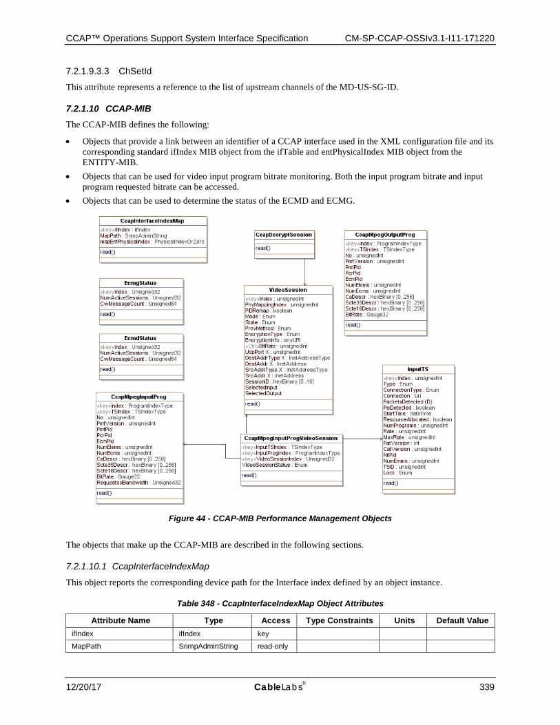
CCAP™ Operations Support System Interface Specification CM-SP-CCAP-OSSIv3.1-I11-171220
12/20/17 CableLabs 339
7.2.1.9.3.3 ChSetId
This attribute represents a reference to the list of upstream channels of the MD-US-SG-ID.
7.2.1.10 CCAP-MIB The CCAP-MIB defines the following:
• Objects that provide a link between an identifier of a CCAP interface used in the XML configuration file and its corresponding standard ifIndex MIB object from the ifTable and entPhysicalIndex MIB object from the ENTITY-MIB.
• Objects that can be used for video input program bitrate monitoring. Both the input program bitrate and input program requested bitrate can be accessed.
• Objects that can be used to determine the status of the ECMD and ECMG.
Figure 44 - CCAP-MIB Performance Management Objects
The objects that make up the CCAP-MIB are described in the following sections.
7.2.1.10.1 CcapInterfaceIndexMap
This object reports the corresponding device path for the Interface index defined by an object instance.
Table 348 - CcapInterfaceIndexMap Object Attributes
Attribute Name Type Access Type Constraints Units Default Value ifIndex ifIndex key
MapPath SnmpAdminString read-only
CM-SP-CCAP-OSSIv3.1-I11-171220 DOCSIS® 3.1
340 CableLabs 12/20/17
Attribute Name Type Access Type Constraints Units Default Value mapEntPhysicalIndex PhysicalIndexOrZero read-only
7.2.1.10.1.1 CcapInterfaceIndexMap Attributes
7.2.1.10.1.1.1 ifIndex
The index corresponds to the Interface MIB index for interfaces of IANA interface types:
• MAC Interface: docsCableMaclayer - 127 • Downstream Channel: docsCableDownstream - 128 • Upstream Interface: docsCableUpstream - 129 • Logical Upstream Channel: docsCableUpstreamChannel - 205 • Upstream RF Port: docsCableUpstreamRfPort - 256 • Downstream RF Port: cableDownstreamRfPort - 257
7.2.1.10.1.1.2 MapPath
This attribute indicates the CCAP node XPath expression that identifies the resource associated with the interface index. For example, the path value of the resource associated with an upstream logical channel with index = 5, in upstream physical channel index = 7, in an Upstream RF port number = 15, from an US RF Line Card, in slot number = 3, chassis id = 1 is represented as:
/ccap/chassis[id="1"]
/slot[number="3"]
/rf-line-card
/us-rf-port[number="15"]
/upstream-physical-channel[index="7"]
/upstream-logical-channel[index="5"]
NOTE: Line breaks in this example were added for clarity.
7.2.1.10.1.1.3 mapEntPhysicalIndex
This attribute corresponds to the entPhysicalIndex associated with the resource. The value is zero (0) if undefined.
7.2.1.10.2 EcmgStatus
This object allows for the monitoring of the interface to an Entitlement Control Message Generator (ECMG).
Table 349 - EcmgStatus Object Attributes
Attribute Name Type Access Type Constraints Units Default Value
Index UnsignedInt Key
NumActiveSessions UnsignedInt read-only
CwMessageCount UnsignedLong read-only
7.2.1.10.2.1 EcmgStatus Object Attributes
7.2.1.10.2.1.1 Index
This is an index for an instance of this object. It is a pointer to a defined Ecmg object.
CCAP™ Operations Support System Interface Specification CM-SP-CCAP-OSSIv3.1-I11-171220
12/20/17 CableLabs 341
7.2.1.10.2.1.2 NumActiveSessions
The current number of encryption sessions managed by the ECMG.
7.2.1.10.2.1.3 CwMessageCount
A running 64-bit counter that increments by one, every time the Encryptor receives one CW message from the ECMG. The counter is reset at boot time.
7.2.1.10.3 EcmdStatus
This object allows for the monitoring of the interface to an Entitlement Control Message Decoder (ECMD).
Table 350 - EcmdStatus Object Attributes
Attribute Name Type Access Type Constraints Units Default Value
Index UnsignedInt Key
NumActiveSessions UnsignedInt read-only
CwMessageCount UnsignedLong read-only
7.2.1.10.3.1 EcmdStatus Object Attributes
7.2.1.10.3.1.1 EcmdIndex
This is an index for an instance of this object. It is a pointer to a defined Ecmd object.
7.2.1.10.3.1.2 NumActiveSessions
The current number of decryption sessions managed by the ECMD.
7.2.1.10.3.1.3 CwMessageCount
A running 64-bit counter that increments by one, every time the Decryptor receives one CW message from the ECMD. The counter is reset at boot time.
7.2.1.10.4 CcapMpegInputProg
This object augments the mpegInputProgTable of the SCTE-HMS-MPEG-MIB with two additional attributes:
• BitRate • RequestedBandwidth
No further modifications have been made to this table.
Reference: [SCTE 154-4]
Table 351 - CcapMpegInputProg Object Attributes
Attribute Name Type Access Type Constraints Units Default Value BitRate Gauge32 read-only BPS
RequestedBandwidth UnsignedInt read-only
7.2.1.10.4.1 CcapMpegInputProg Object Attributes
7.2.1.10.4.1.1 BitRate
Indicates the measured MPEG input program bitrate in bits per second.
CM-SP-CCAP-OSSIv3.1-I11-171220 DOCSIS® 3.1
342 CableLabs 12/20/17
7.2.1.10.4.1.2 RequestedBandwidth
Requested bandwidth for this MPEG input program. This value is used to validate the total QAM bandwidth before allowing the creation of a new session. It is also used to validate the input program bandwidth overflow situation during the transmission. In the case of special stream without PCR, it is used to limit the output bandwidth of that special program.
A zero (0) value is returned if no bandwidth validation is done on this program.
7.2.1.10.5 CcapMpegOutputProg
This object augments the mpegOutputProgTable of the SCTE-HMS-MPEG-MIB with the addition of a BitRate attribute.
No further modifications have been made to this table.
Reference: [SCTE 154-4]
Table 352 - CcapMpegOutputProg Object Attributes
Attribute Name Type Access Type Constraints Units Default Value
BitRate Gauge32 read-only BPS
7.2.1.10.5.1 CcapMpegOutputProg Object Attributes
7.2.1.10.5.1.1 BitRate
Indicates the measured MPEG output program bitrate in bits per second.
7.2.1.10.6 VideoSession
The VideoSession object is taken from the SCTE-HMS-MPEG-MIB specified in [SCTE 154-4] and used without modification for the CCAP.
7.2.1.10.7 CcapDecryptSession
The CcapDecryptSession extends the existing VideoSession object from the SCTE-HMS-MPEG-MIB specified in [SCTE 154-4] and used without modification for the CCAP. This table is only populated with video sessions that require CCAP decryption.
Reference: [SCTE 154-4]
7.2.1.10.8 CcapMpegInputProgVideoSession
This object reports the list of video sessions that the MPEG input program are feeding.
Table 353 - CcapMpegInputProgVideoSession Object Attributes
Attribute Name Type Access Type Constraints Units Default Value
InputTSIndex TSIndexType key
InputProgIndex ProgramIndexType key
VideoSessionIndex UnsignedInt key
VideoSessionStatus Enum read-only active(1), closed(2)
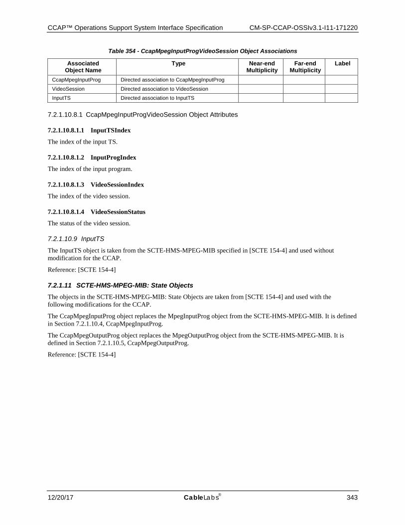
CCAP™ Operations Support System Interface Specification CM-SP-CCAP-OSSIv3.1-I11-171220
12/20/17 CableLabs 343
Table 354 - CcapMpegInputProgVideoSession Object Associations
Associated Object Name
Type Near-end Multiplicity
Far-end Multiplicity
Label
CcapMpegInputProg Directed association to CcapMpegInputProg
VideoSession Directed association to VideoSession
InputTS Directed association to InputTS
7.2.1.10.8.1 CcapMpegInputProgVideoSession Object Attributes
7.2.1.10.8.1.1 InputTSIndex
The index of the input TS.
7.2.1.10.8.1.2 InputProgIndex
The index of the input program.
7.2.1.10.8.1.3 VideoSessionIndex
The index of the video session.
7.2.1.10.8.1.4 VideoSessionStatus
The status of the video session.
7.2.1.10.9 InputTS
The InputTS object is taken from the SCTE-HMS-MPEG-MIB specified in [SCTE 154-4] and used without modification for the CCAP.
Reference: [SCTE 154-4]
7.2.1.11 SCTE-HMS-MPEG-MIB: State Objects The objects in the SCTE-HMS-MPEG-MIB: State Objects are taken from [SCTE 154-4] and used with the following modifications for the CCAP.
The CcapMpegInputProg object replaces the MpegInputProg object from the SCTE-HMS-MPEG-MIB. It is defined in Section 7.2.1.10.4, CcapMpegInputProg.
The CcapMpegOutputProg object replaces the MpegOutputProg object from the SCTE-HMS-MPEG-MIB. It is defined in Section 7.2.1.10.5, CcapMpegOutputProg.
Reference: [SCTE 154-4]
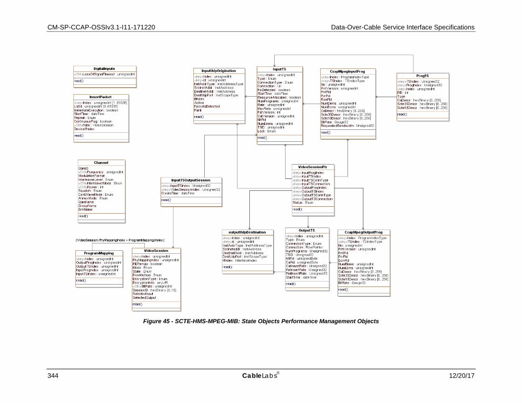
CM-SP-CCAP-OSSIv3.1-I11-171220 Data-Over-Cable Service Interface Specifications
344 CableLabs 12/20/17
Figure 45 - SCTE-HMS-MPEG-MIB: State Objects Performance Management Objects
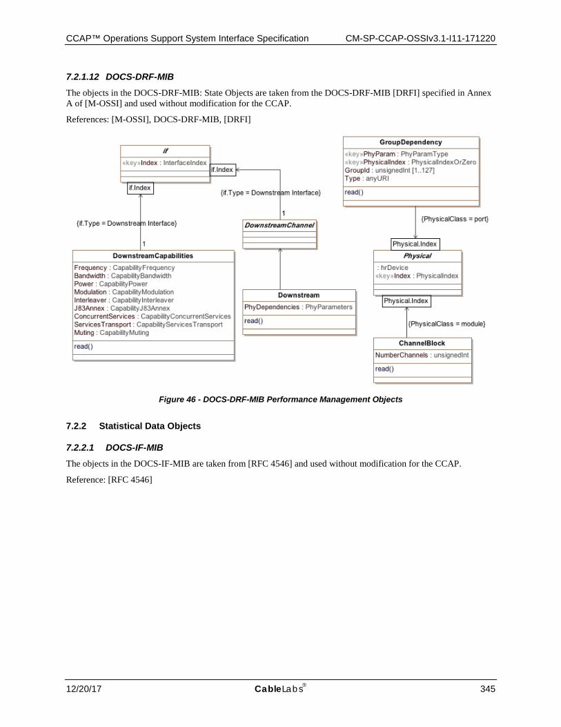
CCAP™ Operations Support System Interface Specification CM-SP-CCAP-OSSIv3.1-I11-171220
12/20/17 CableLabs 345
7.2.1.12 DOCS-DRF-MIB The objects in the DOCS-DRF-MIB: State Objects are taken from the DOCS-DRF-MIB [DRFI] specified in Annex A of [M-OSSI] and used without modification for the CCAP.
References: [M-OSSI], DOCS-DRF-MIB, [DRFI]
Figure 46 - DOCS-DRF-MIB Performance Management Objects
7.2.2 Statistical Data Objects
7.2.2.1 DOCS-IF-MIB The objects in the DOCS-IF-MIB are taken from [RFC 4546] and used without modification for the CCAP.
Reference: [RFC 4546]
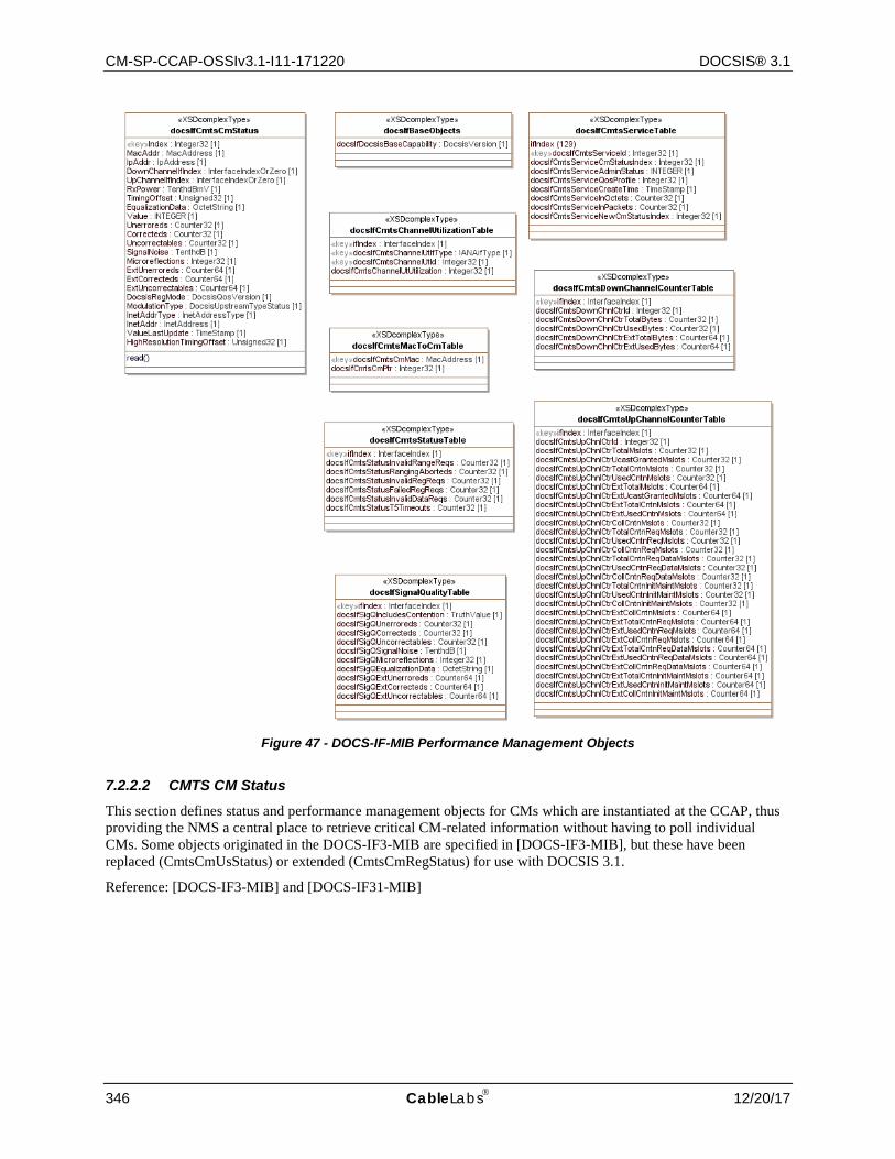
CM-SP-CCAP-OSSIv3.1-I11-171220 DOCSIS® 3.1
346 CableLabs 12/20/17
Figure 47 - DOCS-IF-MIB Performance Management Objects
7.2.2.2 CMTS CM Status This section defines status and performance management objects for CMs which are instantiated at the CCAP, thus providing the NMS a central place to retrieve critical CM-related information without having to poll individual CMs. Some objects originated in the DOCS-IF3-MIB are specified in [DOCS-IF3-MIB], but these have been replaced (CmtsCmUsStatus) or extended (CmtsCmRegStatus) for use with DOCSIS 3.1.
Reference: [DOCS-IF3-MIB] and [DOCS-IF31-MIB]
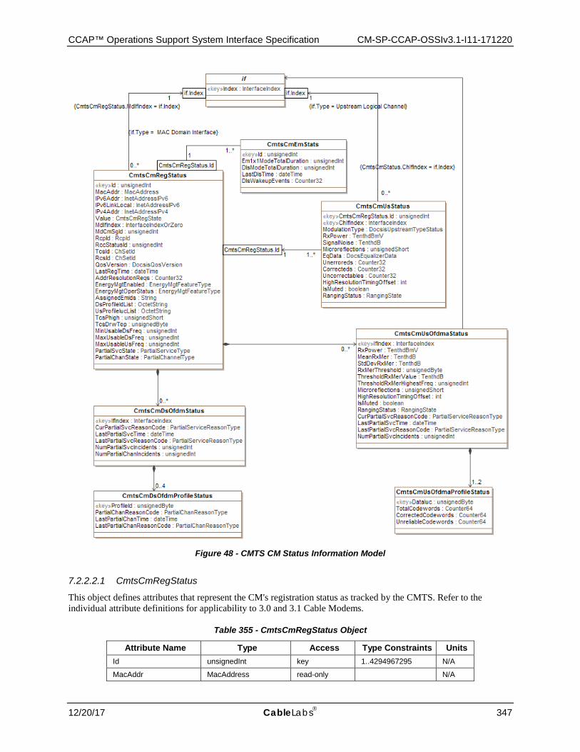
CCAP™ Operations Support System Interface Specification CM-SP-CCAP-OSSIv3.1-I11-171220
12/20/17 CableLabs 347
Figure 48 - CMTS CM Status Information Model
7.2.2.2.1 CmtsCmRegStatus
This object defines attributes that represent the CM's registration status as tracked by the CMTS. Refer to the individual attribute definitions for applicability to 3.0 and 3.1 Cable Modems.
Table 355 - CmtsCmRegStatus Object
Attribute Name Type Access Type Constraints Units Id unsignedInt key 1..4294967295 N/A
MacAddr MacAddress read-only N/A
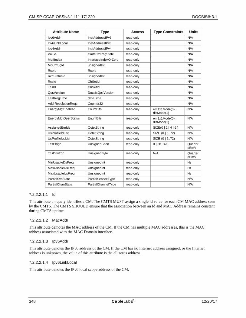
CM-SP-CCAP-OSSIv3.1-I11-171220 DOCSIS® 3.1
348 CableLabs 12/20/17
Attribute Name Type Access Type Constraints Units Ipv6Addr InetAddressIPv6 read-only N/A
Ipv6LinkLocal InetAddressIPv6 read-only N/A
Ipv4Addr InetAddressIPv4 read-only N/A
Value CmtsCmRegState read-only N/A
MdIfIndex InterfaceIndexOrZero read-only N/A
MdCmSgId unsignedInt read-only N/A
RcpId RcpId read-only N/A
RccStatusId unsignedInt read-only N/A
RcsId ChSetId read-only N/A
TcsId ChSetId read-only N/A
QosVersion DocsisQosVersion read-only N/A
LastRegTime dateTime read-only N/A
AddrResolutionReqs Counter32 read-only N/A
EnergyMgtEnabled EnumBits read-only em1x1Mode(0), dlsMode(1)
N/A
EnergyMgtOperStatus EnumBits read-only em1x1Mode(0), dlsMode(1)
N/A
AssignedEmIds OctetString read-only SIZE(0 | 2 | 4 | 6 ) N/A
DsProfileIdList OctetString read-only SIZE (0 | 6..72) N/A
UsProfileIucList OctetString read-only SIZE (0 | 6..72) N/A
TcsPhigh UnsignedShort read-only 0 | 68..320 QuarterdBmV
TcsDrwTop UnsignedByte read-only N/A QuarterdBmV
MinUsableDsFreq UnsignedInt read-only Hz
MaxUsableDsFreq UnsignedInt read-only Hz
MaxUsableUsFreq UnsignedInt read-only Hz
PartialSvcState PartialServiceType read-only N/A
PartialChanState PartialChannelType read-only N/A
7.2.2.2.1.1 Id
This attribute uniquely identifies a CM. The CMTS MUST assign a single id value for each CM MAC address seen by the CMTS. The CMTS SHOULD ensure that the association between an Id and MAC Address remains constant during CMTS uptime.
7.2.2.2.1.2 MacAddr
This attribute demotes the MAC address of the CM. If the CM has multiple MAC addresses, this is the MAC address associated with the MAC Domain interface.
7.2.2.2.1.3 Ipv6Addr
This attribute denotes the IPv6 address of the CM. If the CM has no Internet address assigned, or the Internet address is unknown, the value of this attribute is the all zeros address.
7.2.2.2.1.4 Ipv6LinkLocal
This attribute denotes the IPv6 local scope address of the CM.
CCAP™ Operations Support System Interface Specification CM-SP-CCAP-OSSIv3.1-I11-171220
12/20/17 CableLabs 349
7.2.2.2.1.5 Ipv4Addr
This attribute demotes the IPv4 address of the CM. If the CM has no IP address assigned, or the IP address is unknown, this object returns 0.0.0.0.
7.2.2.2.1.6 Value
This attribute denotes the current CM connectivity state.
References: [MULPIv3.1] Cable Modem Initialization and Reinitialization section.
7.2.2.2.1.7 MdIfIndex
This attribute denotes the interface Index of the CMTS MAC Domain where the CM is active. If the interface is unknown, the CMTS returns a value of zero.
7.2.2.2.1.8 MdCmSgId
This attribute denotes the ID of the MAC Domain CM Service Group Id (MD-CM-SG-ID) in which the CM is registered. If the ID is unknown, the CMTS returns a value of zero.
References: [MULPIv3.1] Cable Modem Service Group (CM-SG) section.
7.2.2.2.1.9 RcpId
This attribute denotes the RCP-ID associated with the CM if it is in DOCSIS 3.0 mode. If the RCP-ID is unknown or the CM is in DOCSIS 3.1 mode, the CMTS returns a five octet long string of zeros.
References: [MULPIv3.1] RCP-ID section in the Common Radio Frequency Interface Encodings Annex.
7.2.2.2.1.10 RccStatusId
This attribute denotes the RCC Id the CMTS used to configure the CM receive channel set during the registration process, if it is in DOCSIS 3.0 mode. If unknown or the CM is in DOCSIS 3.1 mode, the CMTS returns the value zero.
7.2.2.2.1.11 RcsId
This attribute denotes the Receive Channel Set (RCS) that the CM is currently using. If the RCS is unknown, the CMTS returns the value zero.
References: [MULPIv3.1] Cable Modem Physical Receive Channel Configuration section and the Receive Channels section in the Common Radio Frequency Interface Encodings Annex.
7.2.2.2.1.12 TcsId
This attribute denotes Transmit Channel Set (TCS) the CM is currently using. If the TCS is unknown, the CMTS returns the value zero.
References: [MULPIv3.1] Changes to the Transmit Channel Set section.
7.2.2.2.1.13 QosVersion
This attribute denotes the queuing services the CM registered, and will always report DOCSIS 1.1 QoS mode since DOCSIS 1.0 CoS mode has been deprecated in DOCSIS 3.1.
7.2.2.2.1.14 LastRegTime
This attribute denotes the last time the CM registered.
CM-SP-CCAP-OSSIv3.1-I11-171220 DOCSIS® 3.1
350 CableLabs 12/20/17
7.2.2.2.1.15 AddrResolutionReqs
This attribute denotes the number of upstream packets received on the SIDs assigned to a CM that are any of the following:
• Upstream IPv4 ARP Requests • Upstream IPv6 Neighbor Solicitation Requests • (For Routing CMTSs) Upstream IPv4 or IPv6 packets to unresolved destinations in locally connected
downstream in the HFC.
Discontinuities in the value of this counter can occur at re-initialization of the managed system, and at other times as indicated by the value of ifCounterDiscontinuityTime for the associated MAC Domain interface.
References: [SECv3.1] Secure Provisioning section; [RFC 2863].
7.2.2.2.1.16 EnergyMgtEnabled
This attribute indicates which, if any, of the Energy Management Features are enabled for this CM. If this attribute returns em1x1Mode(0) bit set, the CM is configured with the Energy Management 1x1 Feature enabled. If this attribute returns dlsMode(1) bit set, the CM is configured with the DLS Mode feature enabled. If this attribute returns all bits cleared, the CM will not request to operate in any Energy Management mode of operation.
NOTE: This attribute only indicates if an Energy Management Feature is enabled/disabled via the CM config file and registration request/response exchange and does not indicate whether the CM is actively operating in an Energy Management Mode.
References: [MULPIv3.1] Energy Management Features section.
7.2.2.2.1.17 EnergyMgtOperStatus
This attribute indicates whether the CM is currently operating in an Energy Management Mode. If this attribute returns em1x1Mode(0) bit set, the CM is operating in Energy Management 1x1 Mode. If this attribute returns dlsMode(1) bit set, the CM is operating in DLS Mode. If this attribute returns all bits cleared, the CM is not operating in any Energy Management Mode. This attribute always returns 0x00 (no bits set) in the case when EnergyMgtEnabled is set to 0x00 (no Energy Management Features enabled).
NOTE: dlsMode(1) and em1x1Mode(0) are mutually exclusive, thus a return value where both of these bits are 'true' is invalid.
References: [MULPIv3.1] Energy Management 1x1 Mode Indicator section.
7.2.2.2.1.18 AssignedEmIds
This attribute reports the set of CMTS-assigned EM-IDs for this CM. This attribute is encoded as an array 16-bit binary values with up to 3 elements. The broadcast EM-ID is not included in the list. This is generally displayed as a comma-delimited list of EM-IDS such as: DF13,ABAB,0002. If the EM-ID is unknown, the CMTS returns a zero length string.
This object is applicable to DOCSIS 3.1 modems but not to prior versions of DOCSIS modems. If the CM is a pre-DOCSIS 3.1 modem, the CMTS returns a zero-length string.
References: [MULPIv3.1] DOCSIS Light Sleep Feature section.
7.2.2.2.1.19 DsProfileIdList
This attribute is a variable length series of hexadecimal octets where each series entry consists of the following fields (encoded in the following order):
The ifIndex (4 octets) of the OFDM channel where the downstream Profile IDs are assigned.
The number or count of Profile IDs (1 octet with valid values of 1-4) assigned to the CM on that channel.

CCAP™ Operations Support System Interface Specification CM-SP-CCAP-OSSIv3.1-I11-171220
12/20/17 CableLabs 351
The list of Profile IDs (1 octet each with valid values of 0-15) assigned to this CM on that channel. Profile ID 0 is commonly referred to as Profile A. Likewise, Profile IDs 1, 2 and 3 are commonly referred to as Profiles B, C and D.
The CCAP MUST encode each OFDM channel in a CM's RCS as a separate n-octet entry in the DsProfileIdList.
Examples: a CM with a single OFDM channel (ifIndex 34) and four assigned profiles (Profiles IDs 0, 8, 9 and 10) would have a ProfileIdList value of 0x00000022040008090A. A CM with a 2 OFDM channel bonding group each with two assigned profiles (Profile IDs 0 and 15 on channel with ifIndex 34 and Profile IDs 0 and 14 on channel with ifIndex 35) would have a DsProfileIdList value of 0x0000002202000F0000002302000E.
The CCAP MUST NOT include the transitional profile or test profile in the DsProfileIdList.
Note that octet string lengths greater than 18 are optional.
This object is applicable to DOCSIS 3.1 modems but not to prior versions of DOCSIS modems. If the CM is a pre-DOCSIS 3.1 modem, the CMTS returns a zero-length octet string.
7.2.2.2.1.20 UsProfileIucList
This attribute is a variable length series of hexadecimal octets where each series entry consists of the following fields (encoded in the following order):
The ifIndex (4 octets) of the OFDMA channel where the Profile IUCs are assigned.
The number (or count) of Data IUCs (1 octet with valid values of 1-2) assigned to this CM on that channel.
The list of Data IUCs (1 octet each with valid values of 5, 6, 9-13) assigned to this CM on that channel.
The CCAP MUST encode each OFDMA channel in a CM's TCS as a separate n-octet entry in the UsProfileIucList.
Examples: a CM with a single OFDMA channel (ifIndex 36) and two assigned Data IUCs (5 and 6) would have a ProfileIdList value of 0x00000024020506. A CM with a 2 OFDMA channel bonding group each with one assigned Data IUC (IUC 5 on channel with ifIndex 34 and IUC 13 on channel with ifIndex 35) would have a UsProfileIucList value of 0x00000022010500000023010D.
The CCAP MUST NOT include transitional IUCs or test IUCs in the UsProfileIucList.
This object is applicable to DOCSIS 3.1 modems but not to prior versions of DOCSIS modems. If the CM is a pre-DOCSIS 3.1 modem, the CMTS returns a zero-length octet string.
7.2.2.2.1.21 TcsPhigh
This attribute reports the P1.6hi value for the CM's Transmit Channel Set [PHYv3.1]. This object is applicable to DOCSIS 3.1 modems but not to prior versions of DOCSIS modems. If the CM is a pre-DOCSIS 3.1 modem, the CMTS returns zero.
7.2.2.2.1.22 TcsDrwTop
This attribute reports the level of the top of the Dynamic Range Window. The value is expressed in dBmV and is the result of a calculation equal to P1.6hi - P1.6load_min_set [PHYv3.1]. This object is applicable to DOCSIS 3.1 modems but not to prior versions of DOCSIS modems. If the CM is a pre-DOCSIS 3.1 modem, the CMTS returns zero.
7.2.2.2.1.23 MinUsableDsFreq
This attribute is the higher of the CCAP's minimum supported downstream frequency and the CM's minimum supported downstream frequency. It indicates the lowest downstream frequency the CCAP can use to communicate with this CM taking into account the capabilities of both devices. This object is applicable to DOCSIS 3.1 modems but not to prior versions of DOCSIS modems. If the CM is a pre-DOCSIS 3.1 modem, the CMTS returns zero.
7.2.2.2.1.24 MaxUsableDsFreq
This attribute is the lower of the CCAP's maximum supported downstream frequency and the CM's maximum supported downstream frequency. It indicates the highest downstream frequency the CCAP can use to communicate
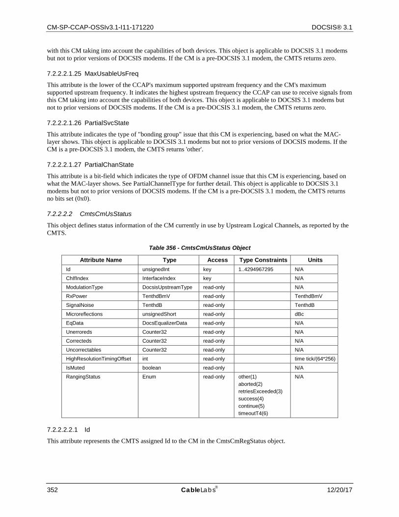
CM-SP-CCAP-OSSIv3.1-I11-171220 DOCSIS® 3.1
352 CableLabs 12/20/17
with this CM taking into account the capabilities of both devices. This object is applicable to DOCSIS 3.1 modems but not to prior versions of DOCSIS modems. If the CM is a pre-DOCSIS 3.1 modem, the CMTS returns zero.
7.2.2.2.1.25 MaxUsableUsFreq
This attribute is the lower of the CCAP's maximum supported upstream frequency and the CM's maximum supported upstream frequency. It indicates the highest upstream frequency the CCAP can use to receive signals from this CM taking into account the capabilities of both devices. This object is applicable to DOCSIS 3.1 modems but not to prior versions of DOCSIS modems. If the CM is a pre-DOCSIS 3.1 modem, the CMTS returns zero.
7.2.2.2.1.26 PartialSvcState
This attribute indicates the type of "bonding group" issue that this CM is experiencing, based on what the MAC-layer shows. This object is applicable to DOCSIS 3.1 modems but not to prior versions of DOCSIS modems. If the CM is a pre-DOCSIS 3.1 modem, the CMTS returns 'other'.
7.2.2.2.1.27 PartialChanState
This attribute is a bit-field which indicates the type of OFDM channel issue that this CM is experiencing, based on what the MAC-layer shows. See PartialChannelType for further detail. This object is applicable to DOCSIS 3.1 modems but not to prior versions of DOCSIS modems. If the CM is a pre-DOCSIS 3.1 modem, the CMTS returns no bits set (0x0).
7.2.2.2.2 CmtsCmUsStatus
This object defines status information of the CM currently in use by Upstream Logical Channels, as reported by the CMTS.
Table 356 - CmtsCmUsStatus Object
Attribute Name Type Access Type Constraints Units Id unsignedInt key 1..4294967295 N/A
ChIfIndex InterfaceIndex key N/A
ModulationType DocsisUpstreamType read-only N/A
RxPower TenthdBmV read-only TenthdBmV
SignalNoise TenthdB read-only TenthdB
Microreflections unsignedShort read-only dBc
EqData DocsEqualizerData read-only N/A
Unerroreds Counter32 read-only N/A
Correcteds Counter32 read-only N/A
Uncorrectables Counter32 read-only N/A
HighResolutionTimingOffset int read-only time tick/(64*256)
IsMuted boolean read-only N/A
RangingStatus Enum read-only other(1) aborted(2) retriesExceeded(3) success(4) continue(5) timeoutT4(6)
N/A
7.2.2.2.2.1 Id
This attribute represents the CMTS assigned Id to the CM in the CmtsCmRegStatus object.
CCAP™ Operations Support System Interface Specification CM-SP-CCAP-OSSIv3.1-I11-171220
12/20/17 CableLabs 353
7.2.2.2.2.2 ChIfIndex
This attribute represents an upstream logical interface. The CMTS instantiates each one of the channels in the current Transmit Channel Set of the CM in this object.
7.2.2.2.2.3 ModulationType
This attribute represents the modulation type currently used by this upstream channel.
7.2.2.2.2.4 RxPower
This attribute represents the receive power of this upstream channel. The reported value represents the total average power for the channel regardless of whether the CM is reporting Pr, total average power, or P1.6r, the power spectral density in an equivalent 1.6 MHz spectrum.
7.2.2.2.2.5 SignalNoise
This attribute represents Signal/Noise ratio as perceived for upstream data from the CM on this upstream channel.
7.2.2.2.2.6 Microreflections
This attribute represents microreflections received on this upstream channel.
7.2.2.2.2.7 EqData
This attribute represents the equalization data for the CM on this upstream channel.
7.2.2.2.2.8 Unerroreds
This attribute represents the codewords received without error from the CM on this upstream channel. Discontinuities in the value of this counter can occur at re-initialization of the managed system, and at other times as indicated by the value of ifCounterDiscontinuityTime for the associated upstream channel.
References: [RFC 2863].
7.2.2.2.2.9 Correcteds
This attribute represents the codewords received with correctable errors from the CM on this upstream channel. Discontinuities in the value of this counter can occur at re-initialization of the managed system, and at other times as indicated by the value of ifCounterDiscontinuityTime for the associated upstream channel.
References: [RFC 2863].
7.2.2.2.2.10 Uncorrectables
This attribute represents the codewords received with uncorrectable errors from the CM on this upstream channel. Discontinuities in the value of this counter can occur at re-initialization of the managed system, and at other times as indicated by the value of ifCounterDiscontinuityTime for the associated upstream channel.
References: [RFC 2863].
7.2.2.2.2.11 HighResolutionTimingOffset
This attribute represents the current measured round trip time on this CM's upstream channel in units of (6.25 microseconds/(64*256)). This attribute returns zero if the value is unknown.
7.2.2.2.2.12 IsMuted
This attribute has a value 'true' to indicate that the CM's upstream channel has been muted via CM-CTRL-REQ/CM-CTRL-RSP message exchange.
References: [MULPIv3.1] Media Access Control Specification section.
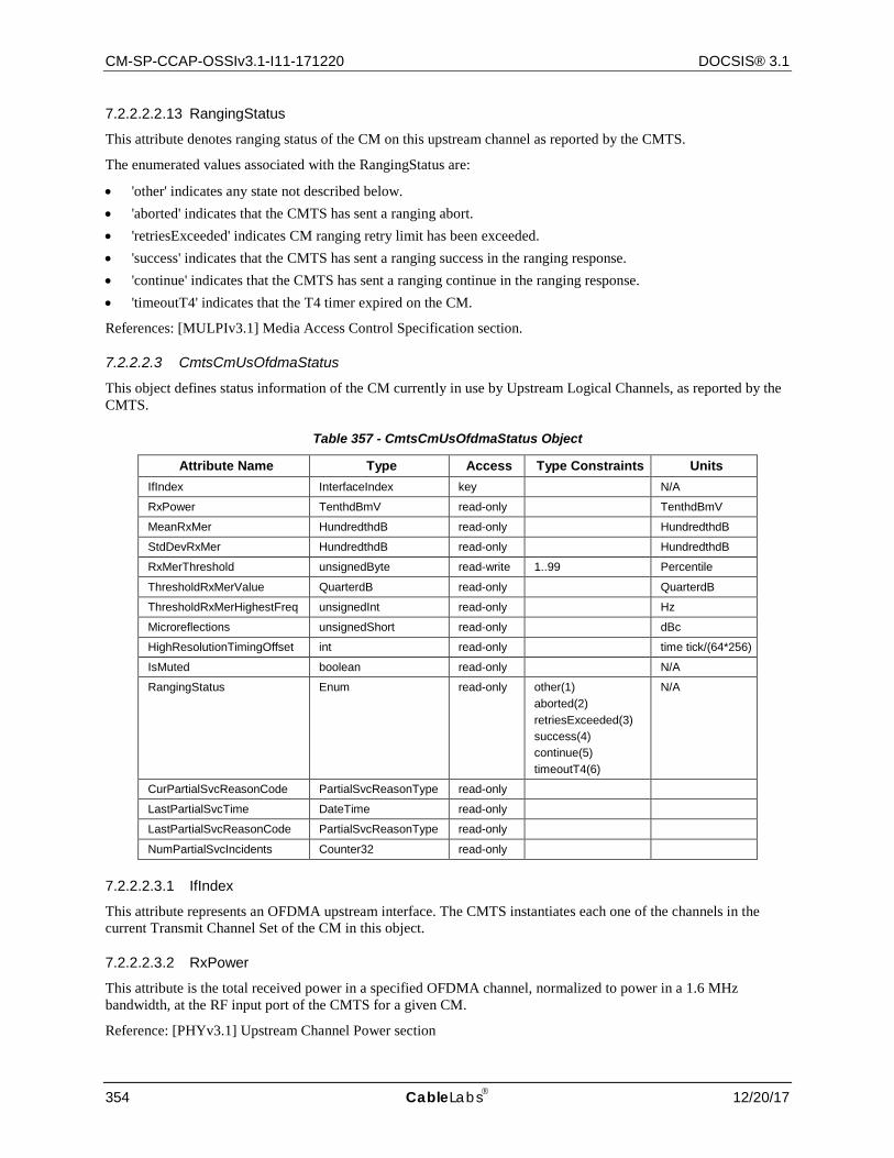
CM-SP-CCAP-OSSIv3.1-I11-171220 DOCSIS® 3.1
354 CableLabs 12/20/17
7.2.2.2.2.13 RangingStatus
This attribute denotes ranging status of the CM on this upstream channel as reported by the CMTS.
The enumerated values associated with the RangingStatus are:
• 'other' indicates any state not described below. • 'aborted' indicates that the CMTS has sent a ranging abort. • 'retriesExceeded' indicates CM ranging retry limit has been exceeded. • 'success' indicates that the CMTS has sent a ranging success in the ranging response. • 'continue' indicates that the CMTS has sent a ranging continue in the ranging response. • 'timeoutT4' indicates that the T4 timer expired on the CM.
References: [MULPIv3.1] Media Access Control Specification section.
7.2.2.2.3 CmtsCmUsOfdmaStatus
This object defines status information of the CM currently in use by Upstream Logical Channels, as reported by the CMTS.
Table 357 - CmtsCmUsOfdmaStatus Object
Attribute Name Type Access Type Constraints Units IfIndex InterfaceIndex key N/A
RxPower TenthdBmV read-only TenthdBmV
MeanRxMer HundredthdB read-only HundredthdB
StdDevRxMer HundredthdB read-only HundredthdB
RxMerThreshold unsignedByte read-write 1..99 Percentile
ThresholdRxMerValue QuarterdB read-only QuarterdB
ThresholdRxMerHighestFreq unsignedInt read-only Hz
Microreflections unsignedShort read-only dBc
HighResolutionTimingOffset int read-only time tick/(64*256)
IsMuted boolean read-only N/A
RangingStatus Enum read-only other(1) aborted(2) retriesExceeded(3) success(4) continue(5) timeoutT4(6)
N/A
CurPartialSvcReasonCode PartialSvcReasonType read-only
LastPartialSvcTime DateTime read-only
LastPartialSvcReasonCode PartialSvcReasonType read-only
NumPartialSvcIncidents Counter32 read-only
7.2.2.2.3.1 IfIndex
This attribute represents an OFDMA upstream interface. The CMTS instantiates each one of the channels in the current Transmit Channel Set of the CM in this object.
7.2.2.2.3.2 RxPower
This attribute is the total received power in a specified OFDMA channel, normalized to power in a 1.6 MHz bandwidth, at the RF input port of the CMTS for a given CM.
Reference: [PHYv3.1] Upstream Channel Power section
CCAP™ Operations Support System Interface Specification CM-SP-CCAP-OSSIv3.1-I11-171220
12/20/17 CableLabs 355
7.2.2.2.3.3 MeanRxMer
This attribute is the mean of the dB values of the RxMER measurements of all active subcarriers. The mean is computed directly on the dB values as follows:
Mean = sum of (RxMER dB values) / number of RxMER values
Reference: [PHYv3.1] Upstream Receive Modulation Error Ratio (RxMER) Per Subcarrier section
7.2.2.2.3.4 StdDevRxMer
This attribute is the standard deviation of the dB values of the RxMER measurements of all active subcarriers. The standard deviation is computed directly on the dB values as follows:
StdDev = sqrt(sum of (RxMER dB values - RxMER_mean)^2 / number of RxMER values)
7.2.2.2.3.5 RxMerThreshold
This attribute specifies the percentile (such as 2nd percentile or 5th percentile) of all active subcarriers in an OFDM channel at which the ThresholdRxMerValue occurs. That is, (Percentile) % of the subcarriers have RxMER <= ThresholdRxMerValue.
7.2.2.2.3.6 ThresholdRxMer
This attribute is the RxMER value corresponding to the specified RxMerThreshold percentile value. The CCAP sorts the subcarriers in ascending order of RxMER, resulting in a post-sorting subcarrier index ranging from 1 to the number of active subcarriers. If the percentile value corresponds to a non-integer post-sorting subcarrier index, the post-sorting index is truncated (floor function is applied); that is, the post-sorting index is selected which is the greatest integer less than or equal to the corresponding percentile value. For example, if there are 3677 active subcarriers and the 2nd percentile is specified, the CCAP computes floor(3677*0.02) = 73. That is, the RxMER value of the 73rd subcarrier in the sorted list is associated with the 2nd percentile.
7.2.2.2.3.7 ThresholdRxMerHighestFreq
This attribute is the frequency in Hz of the highest-frequency subcarrier having RxMER = ThresholdRxMer value.
7.2.2.2.3.8 Microreflections
This attribute represents microreflections received on this upstream channel.
7.2.2.2.3.9 HighResolutionTimingOffset
This attribute represents the current measured round trip time on this CM's upstream channel in units of (6.25 microseconds/(64*256)). This attribute returns zero if the value is unknown.
7.2.2.2.3.10 IsMuted
This attribute has a value 'true' to indicate that the CM's upstream channel has been muted via CM-CTRL-REQ/CM-CTRL-RSP message exchange.
References: [MULPIv3.1] Media Access Control Specification section.
7.2.2.2.3.11 RangingStatus
This attribute denotes ranging status of the CM on this upstream channel as reported by the CMTS.
The enumerated values associated with the RangingStatus are:
• Other: 'other' indicates any state not described below. • Aborted: 'aborted' indicates that the CMTS has sent a ranging abort. • retriesExceeded: 'retriesExceeded' indicates CM ranging retry limit has been exceeded. • Success: 'success' indicates that the CMTS has sent a ranging success in the ranging response.
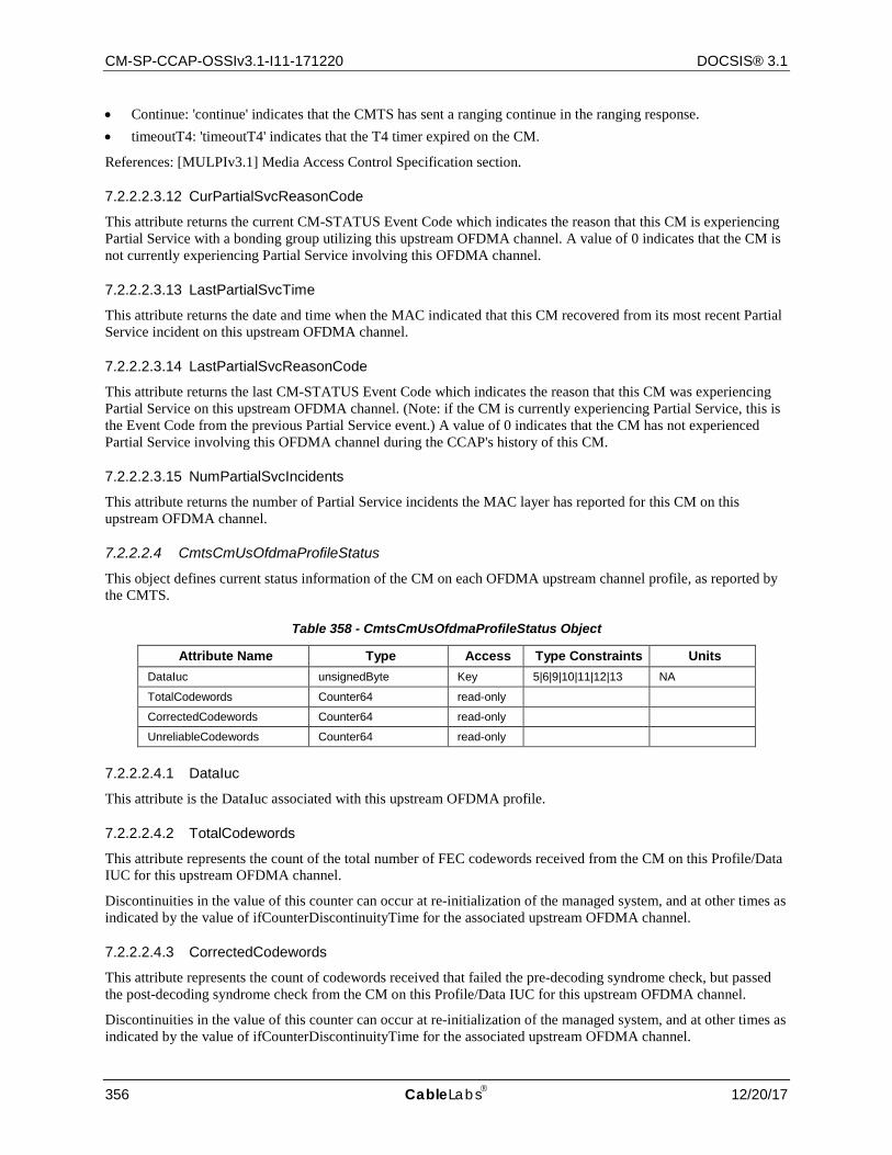
CM-SP-CCAP-OSSIv3.1-I11-171220 DOCSIS® 3.1
356 CableLabs 12/20/17
• Continue: 'continue' indicates that the CMTS has sent a ranging continue in the ranging response. • timeoutT4: 'timeoutT4' indicates that the T4 timer expired on the CM.
References: [MULPIv3.1] Media Access Control Specification section.
7.2.2.2.3.12 CurPartialSvcReasonCode
This attribute returns the current CM-STATUS Event Code which indicates the reason that this CM is experiencing Partial Service with a bonding group utilizing this upstream OFDMA channel. A value of 0 indicates that the CM is not currently experiencing Partial Service involving this OFDMA channel.
7.2.2.2.3.13 LastPartialSvcTime
This attribute returns the date and time when the MAC indicated that this CM recovered from its most recent Partial Service incident on this upstream OFDMA channel.
7.2.2.2.3.14 LastPartialSvcReasonCode
This attribute returns the last CM-STATUS Event Code which indicates the reason that this CM was experiencing Partial Service on this upstream OFDMA channel. (Note: if the CM is currently experiencing Partial Service, this is the Event Code from the previous Partial Service event.) A value of 0 indicates that the CM has not experienced Partial Service involving this OFDMA channel during the CCAP's history of this CM.
7.2.2.2.3.15 NumPartialSvcIncidents
This attribute returns the number of Partial Service incidents the MAC layer has reported for this CM on this upstream OFDMA channel.
7.2.2.2.4 CmtsCmUsOfdmaProfileStatus
This object defines current status information of the CM on each OFDMA upstream channel profile, as reported by the CMTS.
Table 358 - CmtsCmUsOfdmaProfileStatus Object
Attribute Name Type Access Type Constraints Units DataIuc unsignedByte Key 5|6|9|10|11|12|13 NA
TotalCodewords Counter64 read-only
CorrectedCodewords Counter64 read-only
UnreliableCodewords Counter64 read-only
7.2.2.2.4.1 DataIuc
This attribute is the DataIuc associated with this upstream OFDMA profile.
7.2.2.2.4.2 TotalCodewords
This attribute represents the count of the total number of FEC codewords received from the CM on this Profile/Data IUC for this upstream OFDMA channel.
Discontinuities in the value of this counter can occur at re-initialization of the managed system, and at other times as indicated by the value of ifCounterDiscontinuityTime for the associated upstream OFDMA channel.
7.2.2.2.4.3 CorrectedCodewords
This attribute represents the count of codewords received that failed the pre-decoding syndrome check, but passed the post-decoding syndrome check from the CM on this Profile/Data IUC for this upstream OFDMA channel.
Discontinuities in the value of this counter can occur at re-initialization of the managed system, and at other times as indicated by the value of ifCounterDiscontinuityTime for the associated upstream OFDMA channel.

CCAP™ Operations Support System Interface Specification CM-SP-CCAP-OSSIv3.1-I11-171220
12/20/17 CableLabs 357
7.2.2.2.4.4 UnreliableCodewords
This attribute represents the count of codewords that failed the post-decoding syndrome check received from the CM on this Profile/Data IUC for this upstream OFDMA channel.
Discontinuities in the value of this counter can occur at re-initialization of the managed system, and at other times as indicated by the value of ifCounterDiscontinuityTime for the associated upstream OFDMA channel.
7.2.2.2.5 CmtsCmDsOfdmStatus
This object defines current status information of the CM on each OFDM downstream channel, as reported by the CMTS. A separate instance exists for every OFDM channel of every CM currently assigned to an OFDMA channel. If the CM has never experienced a partial service or partial channel event with respect to this channel since the last CCAP reinitialization, no instance should exist for this object. Instances of this object should persist across CM reinitialization.
Table 359 - CmtsCmDsOfdmStatus Object
Attribute Name Type Access Type Constraints Units IfIndex InterfaceIndex Key
CurPartialSvcReasonCode PartialSvcReasonType read-only
LastPartialSvcTime dateTime read-only
LastPartialSvcReasonCode PartialSvcReasonType read-only
NumPartialSvcIncidents Counter32 read-only
NumPartialChanIncidents Counter32 read-only
7.2.2.2.5.1 IfIndex
This attribute represents an OFDM downstream interface.
7.2.2.2.5.2 CurPartialSvcReasonCode
This attribute returns the current CM-STATUS Event Code which indicates the reason that this CM is experiencing Partial Service with a bonding group utilizing this downstream OFDM channel. A value of 0 indicates that the CM is not currently experiencing Partial Service involving this OFDM channel.
7.2.2.2.5.3 LastPartialSvcTime
This attribute returns the date and time when the MAC indicated that this CM recovered from its most recent Partial Service incident on this downstream OFDM channel.
7.2.2.2.5.4 LastPartialSvcReasonCode
This attribute returns the last CM-STATUS Event Code which indicates the reason that this CM was experiencing Partial Service on this downstream OFDM channel. (Note: if the CM is currently experiencing Partial Service, this is the Event Code from the previous Partial Service event.) A value of 0 indicates that the CM has not experienced Partial Service involving this OFDM channel during the CCAP's history of this CM.
7.2.2.2.5.5 NumPartialSvcIncidents
This attribute returns the number of Partial Service incidents the MAC layer has reported for this CM on this downstream OFDM channel.
7.2.2.2.5.6 NumPartialChanIncidents
This attributes returns the number of Partial Channel incidents the MAC layer has reported for this CM on this downstream OFDM channel.
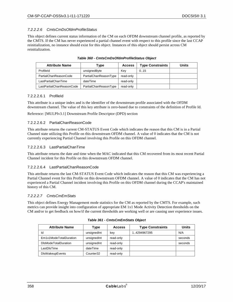
CM-SP-CCAP-OSSIv3.1-I11-171220 DOCSIS® 3.1
358 CableLabs 12/20/17
7.2.2.2.6 CmtsCmDsOfdmProfileStatus
This object defines current status information of the CM on each OFDM downstream channel profile, as reported by the CMTS. If the CM has never experienced a partial channel event with respect to this profile since the last CCAP reinitialization, no instance should exist for this object. Instances of this object should persist across CM reinitialization.
Table 360 - CmtsCmDsOfdmProfileStatus Object
Attribute Name Type Access Type Constraints Units ProfileId unsignedByte Key 0..15
PartialChanReasonCode PartialChanReasonType read-only
LastPartialChanTime dateTime read-only
LastPartialChanReasonCode PartialChanReasonType read-only
7.2.2.2.6.1 ProfileId
This attribute is a unique index and is the identifier of the downstream profile associated with the OFDM downstream channel. The value of this key attribute is zero-based due to constraints of the definition of Profile Id.
Reference: [MULPIv3.1] Downstream Profile Descriptor (DPD) section
7.2.2.2.6.2 PartialChanReasonCode
This attribute returns the current CM-STATUS Event Code which indicates the reason that this CM is in a Partial Channel state utilizing this Profile on this downstream OFDM channel. A value of 0 indicates that the CM is not currently experiencing Partial Channel involving this Profile on this OFDM channel.
7.2.2.2.6.3 LastPartialChanTime
This attribute returns the date and time when the MAC indicated that this CM recovered from its most recent Partial Channel incident for this Profile on this downstream OFDM channel.
7.2.2.2.6.4 LastPartialChanReasonCode
This attribute returns the last CM-STATUS Event Code which indicates the reason that this CM was experiencing a Partial Channel event for this Profile on this downstream OFDM channel. A value of 0 indicates that the CM has not experienced a Partial Channel incident involving this Profile on this OFDM channel during the CCAP's maintained history of this CM.
7.2.2.2.7 CmtsCmEmStats
This object defines Energy Management mode statistics for the CM as reported by the CMTS. For example, such metrics can provide insight into configuration of appropriate EM 1x1 Mode Activity Detection thresholds on the CM and/or to get feedback on how/if the current thresholds are working well or are causing user experience issues.
Table 361 - CmtsCmEmStats Object
Attribute Name Type Access Type Constraints Units Id unsignedInt key 1..4294967295 N/A
Em1x1ModeTotalDuration unsignedInt read-only seconds
DlsModeTotalDuration unsignedInt read-only seconds
LastDlsTime dateTime read-only
DlsWakeupEvents Counter32 read-only
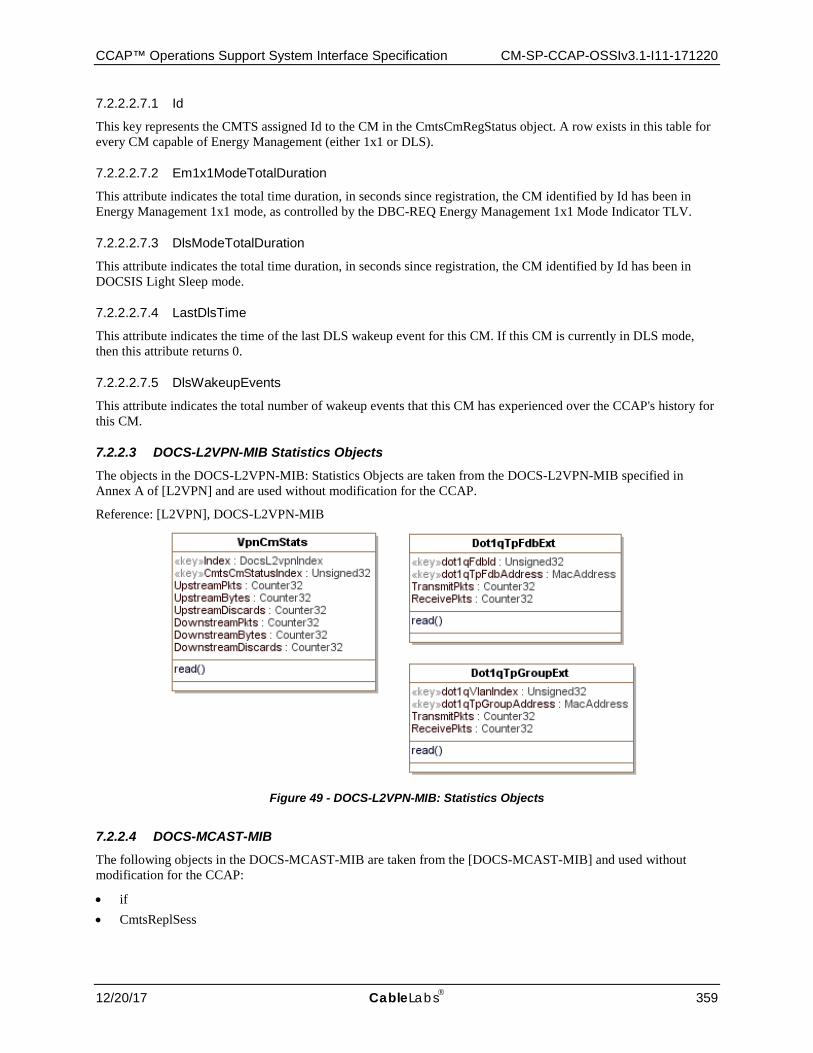
CCAP™ Operations Support System Interface Specification CM-SP-CCAP-OSSIv3.1-I11-171220
12/20/17 CableLabs 359
7.2.2.2.7.1 Id
This key represents the CMTS assigned Id to the CM in the CmtsCmRegStatus object. A row exists in this table for every CM capable of Energy Management (either 1x1 or DLS).
7.2.2.2.7.2 Em1x1ModeTotalDuration
This attribute indicates the total time duration, in seconds since registration, the CM identified by Id has been in Energy Management 1x1 mode, as controlled by the DBC-REQ Energy Management 1x1 Mode Indicator TLV.
7.2.2.2.7.3 DlsModeTotalDuration
This attribute indicates the total time duration, in seconds since registration, the CM identified by Id has been in DOCSIS Light Sleep mode.
7.2.2.2.7.4 LastDlsTime
This attribute indicates the time of the last DLS wakeup event for this CM. If this CM is currently in DLS mode, then this attribute returns 0.
7.2.2.2.7.5 DlsWakeupEvents
This attribute indicates the total number of wakeup events that this CM has experienced over the CCAP's history for this CM.
7.2.2.3 DOCS-L2VPN-MIB Statistics Objects The objects in the DOCS-L2VPN-MIB: Statistics Objects are taken from the DOCS-L2VPN-MIB specified in Annex A of [L2VPN] and are used without modification for the CCAP.
Reference: [L2VPN], DOCS-L2VPN-MIB
Figure 49 - DOCS-L2VPN-MIB: Statistics Objects
7.2.2.4 DOCS-MCAST-MIB The following objects in the DOCS-MCAST-MIB are taken from the [DOCS-MCAST-MIB] and used without modification for the CCAP:
• if • CmtsReplSess
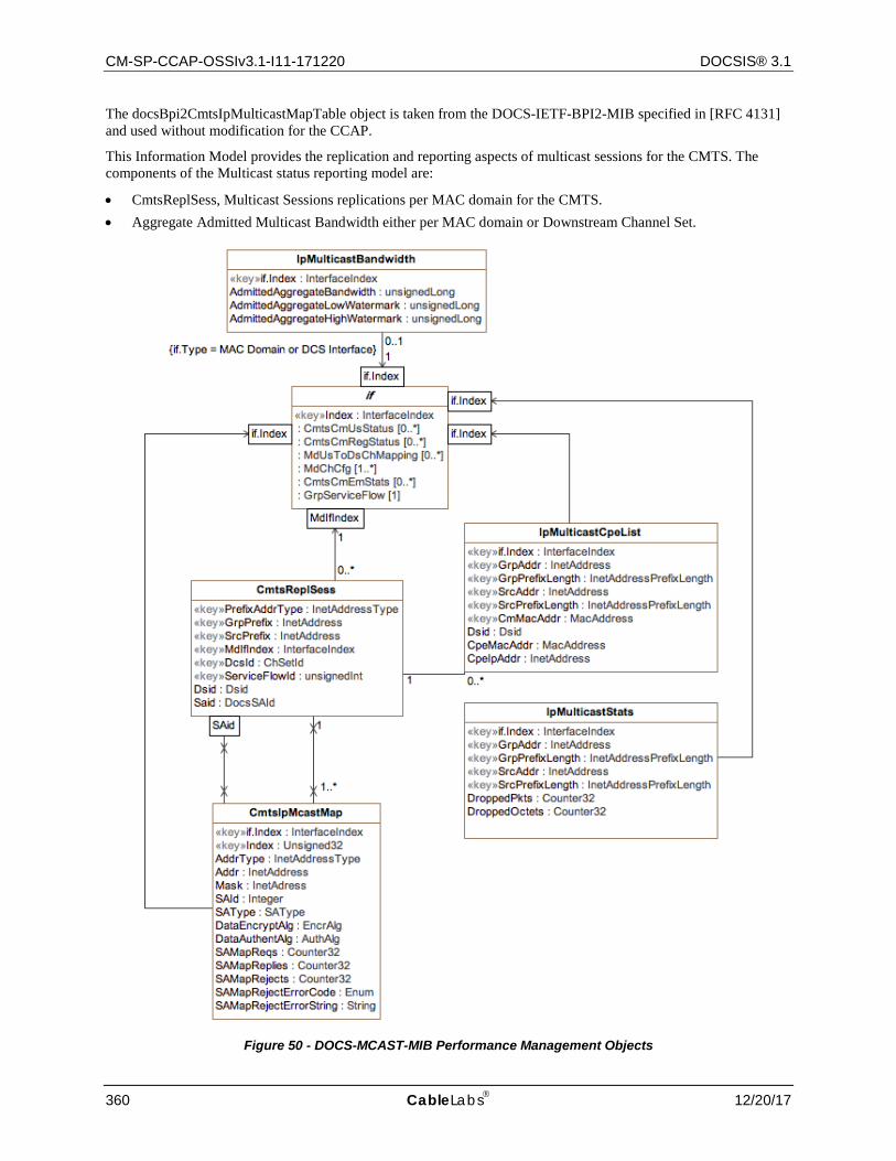
CM-SP-CCAP-OSSIv3.1-I11-171220 DOCSIS® 3.1
360 CableLabs 12/20/17
The docsBpi2CmtsIpMulticastMapTable object is taken from the DOCS-IETF-BPI2-MIB specified in [RFC 4131] and used without modification for the CCAP.
This Information Model provides the replication and reporting aspects of multicast sessions for the CMTS. The components of the Multicast status reporting model are:
• CmtsReplSess, Multicast Sessions replications per MAC domain for the CMTS. • Aggregate Admitted Multicast Bandwidth either per MAC domain or Downstream Channel Set.
Figure 50 - DOCS-MCAST-MIB Performance Management Objects
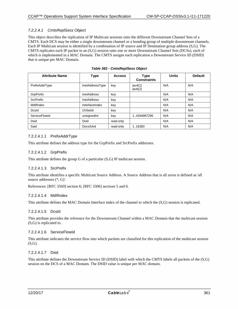
CCAP™ Operations Support System Interface Specification CM-SP-CCAP-OSSIv3.1-I11-171220
12/20/17 CableLabs 361
7.2.2.4.1 CmtsReplSess Object
This object describes the replication of IP Multicast sessions onto the different Downstream Channel Sets of a CMTS. Each DCS may be either a single downstream channel or a bonding group of multiple downstream channels. Each IP Multicast session is identified by a combination of IP source and IP Destination group address (S,G). The CMTS replicates each IP packet in an (S,G) session onto one or more Downstream Channel Sets (DCSs), each of which is implemented in a MAC Domain. The CMTS assigns each replication a Downstream Service ID (DSID) that is unique per MAC Domain.
Table 362 - CmtsReplSess Object
Attribute Name Type Access Type Constraints
Units Default
PrefixAddrType InetAddressType key ipv4(1) ipv6(2)
N/A N/A
GrpPrefix InetAddress key N/A N/A
SrcPrefix InetAddress key N/A N/A
MdIfIndex InterfaceIndex key N/A N/A
DcsId ChSetId key N/A N/A
ServiceFlowId unsignedInt key 1..4294967295 N/A N/A
Dsid Dsid read-only N/A N/A
Said DocsSAid read-only 1..16383 N/A N/A
7.2.2.4.1.1 PrefixAddrType
This attribute defines the address type for the GrpPrefix and SrcPrefix addresses.
7.2.2.4.1.2 GrpPrefix
This attribute defines the group G of a particular (S,G) IP multicast session.
7.2.2.4.1.3 SrcPrefix
This attribute identifies a specific Multicast Source Address. A Source Address that is all zeros is defined as 'all source addresses (*, G)'.
References: [RFC 3569] section 6; [RFC 3306] sections 5 and 6.
7.2.2.4.1.4 MdIfIndex
This attribute defines the MAC Domain Interface index of the channel to which the (S,G) session is replicated.
7.2.2.4.1.5 DcsId
This attribute provides the reference for the Downstream Channel within a MAC Domain that the multicast session (S,G) is replicated to.
7.2.2.4.1.6 ServiceFlowId
This attribute indicates the service flow into which packets are classified for this replication of the multicast session (S,G).
7.2.2.4.1.7 Dsid
This attribute defines the Downstream Service ID (DSID) label with which the CMTS labels all packets of the (S,G) session on the DCS of a MAC Domain. The DSID value is unique per MAC domain.
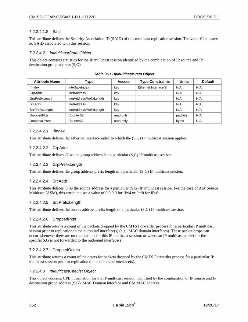
CM-SP-CCAP-OSSIv3.1-I11-171220 DOCSIS® 3.1
362 CableLabs 12/20/17
7.2.2.4.1.8 Said
This attribute defines the Security Association ID (SAID) of this multicast replication session. The value 0 indicates no SAID associated with this session.
7.2.2.4.2 IpMulticastStats Object
This object contains statistics for the IP multicast session identified by the combination of IP source and IP destination group address (S,G).
Table 363 - IpMulticastStats Object
Attribute Name Type Access Type Constraints Units Default IfIndex InterfaceIndex key Ethernet Interface(s) N/A N/A
GrpAddr InetAddress key N/A N/A
GrpPrefixLength InetAddressPrefixLength key N/A N/A
SrcAddr InetAddress key N/A N/A
SrcPrefixLength InetAddressPrefixLength key N/A N/A
DroppedPkts Counter32 read-only packets N/A
DroppedOctets Counter32 read-only bytes N/A
7.2.2.4.2.1 IfIndex
This attribute defines the Ethernet Interface index to which the (S,G) IP multicast session applies.
7.2.2.4.2.2 GrpAddr
This attribute defines 'G' as the group address for a particular (S,G) IP multicast session.
7.2.2.4.2.3 GrpPrefixLength
This attribute defines the group address prefix length of a particular (S,G) IP multicast session.
7.2.2.4.2.4 SrcAddr
This attribute defines 'S' as the source address for a particular (S,G) IP multicast session. For the case of Any Source Multicast (ASM), this attribute uses a value of 0.0.0.0 for IPv4 or 0::/0 for IPv6.
7.2.2.4.2.5 SrcPrefixLength
This attribute defines the source address prefix length of a particular (S,G) IP multicast session.
7.2.2.4.2.6 DroppedPkts
This attribute returns a count of the packets dropped by the CMTS Forwarder process for a particular IP multicast session prior to replication to the outbound interface(s) (e.g., MAC domain interfaces). These packet drops can occur whenever there are no replications for this IP multicast session, or where an IP multicast packet for the specific S,G is not forwarded to the outbound interface(s).
7.2.2.4.2.7 DroppedOctets
This attribute returns a count of the octets for packets dropped by the CMTS Forwarder process for a particular IP multicast session prior to replication to the outbound interface(s).
7.2.2.4.3 IpMulticastCpeList Object
This object contains CPE information for the IP multicast session identified by the combination of IP source and IP destination group address (S,G), MAC Domain interface and CM MAC address.

CCAP™ Operations Support System Interface Specification CM-SP-CCAP-OSSIv3.1-I11-171220
12/20/17 CableLabs 363
Table 364 - IpMulticastCpeList Object
Attribute Name Type Access Type Constraints Units Default IfIndex InterfaceIndex key MAC Domain interface(s) N/A N/A
GrpAddr InetAddress key N/A N/A
GrpPrefixLength InetAddressPrefixLength key N/A N/A
SrcAddr InetAddress key N/A N/A
SrcPrefixLength InetAddressPrefixLength key N/A N/A
CmMacAddr MacAddress key N/A N/A
Dsid Dsid read-only N/A N/A
CpeMacAddr MacAddress read-only N/A N/A
CpeIpAddr InetAddress read-only N/A N/A
7.2.2.4.3.1 IfIndex
This attribute defines the MAC Domain Interface index to which the (S,G) IP multicast session applies.
7.2.2.4.3.2 GrpAddr
This attribute defines 'G' as the group address for a particular (S,G) IP multicast session.
7.2.2.4.3.3 GrpPrefixLength
This attribute defines the group address prefix length of a particular (S,G) IP multicast session.
7.2.2.4.3.4 SrcAddr
This attribute defines 'S' as the source address for a particular (S,G) IP multicast session. For the case of Any Source Multicast (ASM), this attribute uses a value of 0.0.0.0 for IPv4 or 0::/0 for IPv6.
7.2.2.4.3.5 SrcPrefixLength
This attribute defines the source address prefix length of a particular (S,G) IP multicast session.
7.2.2.4.3.6 CmMacAddr
This attribute defines the CM MAC address of a particular (S,G) IP multicast session.
7.2.2.4.3.7 Dsid
This attribute defines the Downstream Service ID (DSID) label with which the CMTS labels all packets of a particular (S,G) IP multicast session.
7.2.2.4.3.8 CpeMacAddr
This attribute returns the CPE MAC address for the (S,G) IP multicast session.
7.2.2.4.3.9 CpeIpAddr
This attribute returns the CPE IP address for the (S,G) IP multicast session.
7.2.2.4.4 IpMulticastBandwidth Object
This object describes the admitted aggregate bandwidth of IP Multicast sessions onto the different Downstream Channel Sets or MAC Domain Interfaces of a CMTS. In addition to the current aggregate multicast bandwidth, the high and low watermarks are included as attributes.
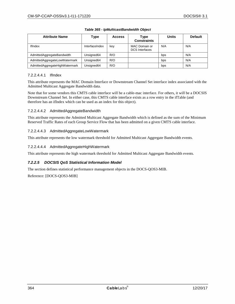
CM-SP-CCAP-OSSIv3.1-I11-171220 DOCSIS® 3.1
364 CableLabs 12/20/17
Table 365 - IpMulticastBandwidth Object
Attribute Name Type Access Type Constraints
Units Default
IfIndex InterfaceIndex key MAC Domain or DCS Interfaces
N/A N/A
AdmittedAggregateBandwidth Unsigned64 R/O bps N/A
AdmittedAggregateLowWatermark Unsigned64 R/O bps N/A
AdmittedAggregateHighWatermark Unsigned64 R/O bps N/A
7.2.2.4.4.1 IfIndex
This attribute represents the MAC Domain Interface or Downstream Channel Set interface index associated with the Admitted Multicast Aggregate Bandwidth data.
Note that for some vendors this CMTS cable interface will be a cable-mac interface. For others, it will be a DOCSIS Downstream Channel Set. In either case, this CMTS cable interface exists as a row entry in the ifTable (and therefore has an ifIndex which can be used as an index for this object).
7.2.2.4.4.2 AdmittedAggregateBandwidth
This attribute represents the Admitted Multicast Aggregate Bandwidth which is defined as the sum of the Minimum Reserved Traffic Rates of each Group Service Flow that has been admitted on a given CMTS cable interface.
7.2.2.4.4.3 AdmittedAggregateLowWatermark
This attribute represents the low watermark threshold for Admitted Multicast Aggregate Bandwidth events.
7.2.2.4.4.4 AdmittedAggregateHighWatermark
This attribute represents the high watermark threshold for Admitted Multicast Aggregate Bandwidth events.
7.2.2.5 DOCSIS QoS Statistical Information Model The section defines statistical performance management objects in the DOCS-QOS3-MIB.
Reference: [DOCS-QOS3-MIB]
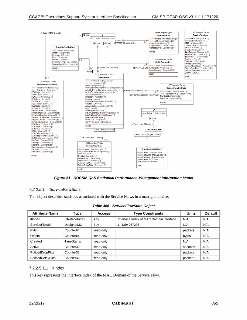
CCAP™ Operations Support System Interface Specification CM-SP-CCAP-OSSIv3.1-I11-171220
12/20/17 CableLabs 365
Figure 51 - DOCSIS QoS Statistical Performance Management Information Model
7.2.2.5.1 ServiceFlowStats
This object describes statistics associated with the Service Flows in a managed device.
Table 366 - ServiceFlowStats Object
Attribute Name Type Access Type Constraints Units Default ifIndex InterfaceIndex key Interface Index of MAC Domain interface N/A N/A
ServiceFlowId Unsigned32 key 1..4294967295 N/A N/A
Pkts Counter64 read-only packets N/A
Octets Counter64 read-only bytes N/A
Created TimeStamp read-only N/A N/A
Active Counter32 read-only seconds N/A
PolicedDropPkts Counter32 read-only packets N/A
PolicedDelayPkts Counter32 read-only packets N/A
7.2.2.5.1.1 ifIndex
This key represents the interface index of the MAC Domain of the Service Flow.
CM-SP-CCAP-OSSIv3.1-I11-171220 DOCSIS® 3.1
366 CableLabs 12/20/17
7.2.2.5.1.2 ServiceFlowId
This key represents an identifier assigned to a Service Flow by CMTS within a MAC Domain.
7.2.2.5.1.3 Pkts
For outgoing Service Flows, this attribute counts the number of Packet Data PDUs forwarded to this Service Flow. For incoming upstream CMTS service flows, this attribute counts the number of Packet Data PDUs actually received on the Service Flow identified by the SID for which the packet was scheduled. CMs not classifying downstream packets may report this attribute's value as 0 for downstream Service Flows. This attribute does not count MAC-specific management messages. Particularly for UGS flows, packets sent on the primary Service Flow in violation of the UGS grant size should be counted only by the instance of this attribute that is associated with the primary service flow. Unclassified upstream user data packets (i.e., non- MAC-management) forwarded to the primary upstream Service Flow should be counted by the instance of this attribute that is associated with the primary service flow. This attribute does include packets counted by ServiceFlowPolicedDelayPkts, but does not include packets counted by ServiceFlowPolicedDropPkts. This counter's last discontinuity is the ifCounterDiscontinuityTime for of the associated MAC Domain interface index.
7.2.2.5.1.4 Octets
This attribute indicates the count of the number of octets from the byte after the MAC header HCS to the end of the CRC for all packets counted in the ServiceFlowPkts attribute for this row. Note that this counts the octets after payload header suppression and before payload header expansion have been applied. This counter's last discontinuity is the ifCounterDiscontinuityTime for of the associated MAC Domain interface index.
7.2.2.5.1.5 Created
This attribute indicates the value of sysUpTime when the service flow was created.
7.2.2.5.1.6 Active
This attribute indicates the number of seconds that the service flow has been active. This counter's last discontinuity is the ifCounterDiscontinuityTime for of the associated MAC Domain interface index.
7.2.2.5.1.7 PolicedDropPkts
For outgoing service flows, this attribute counts the number of Packet Data PDUs classified to this service flow dropped due to: (1) exceeding the selected Buffer Size for the service flow (see the Buffer Control section in the Common Radio Frequency Interface Encodings Annex of [MULPIv3.1]); or (2) UGS packets dropped due to exceeding the Unsolicited Grant Size with a Request/Transmission policy that requires such packets to be dropped. Classified packets dropped due to other reasons needs to be counted in ifOutDiscards for the interface of this service flow. This attribute reports 0 for incoming service flows. This counter's last discontinuity is the ifCounterDiscontinuityTime for of the associated MAC Domain interface index.
7.2.2.5.1.8 PolicedDelayPkts
This attribute counts only outgoing packets delayed in order to maintain the Maximum Sustained Traffic Rate. This attribute will always report a value of 0 for UGS flows because the Maximum Sustained Traffic Rate does not apply. This attribute is 0 for incoming service flows. This counter's last discontinuity is the ifCounterDiscontinuityTime for of the associated MAC Domain interface index.
7.2.2.5.2 UpstreamStats
This object describes statistics associated with upstream service flows. All counted frames need to be received without a Frame Check Sequence (FCS) error.
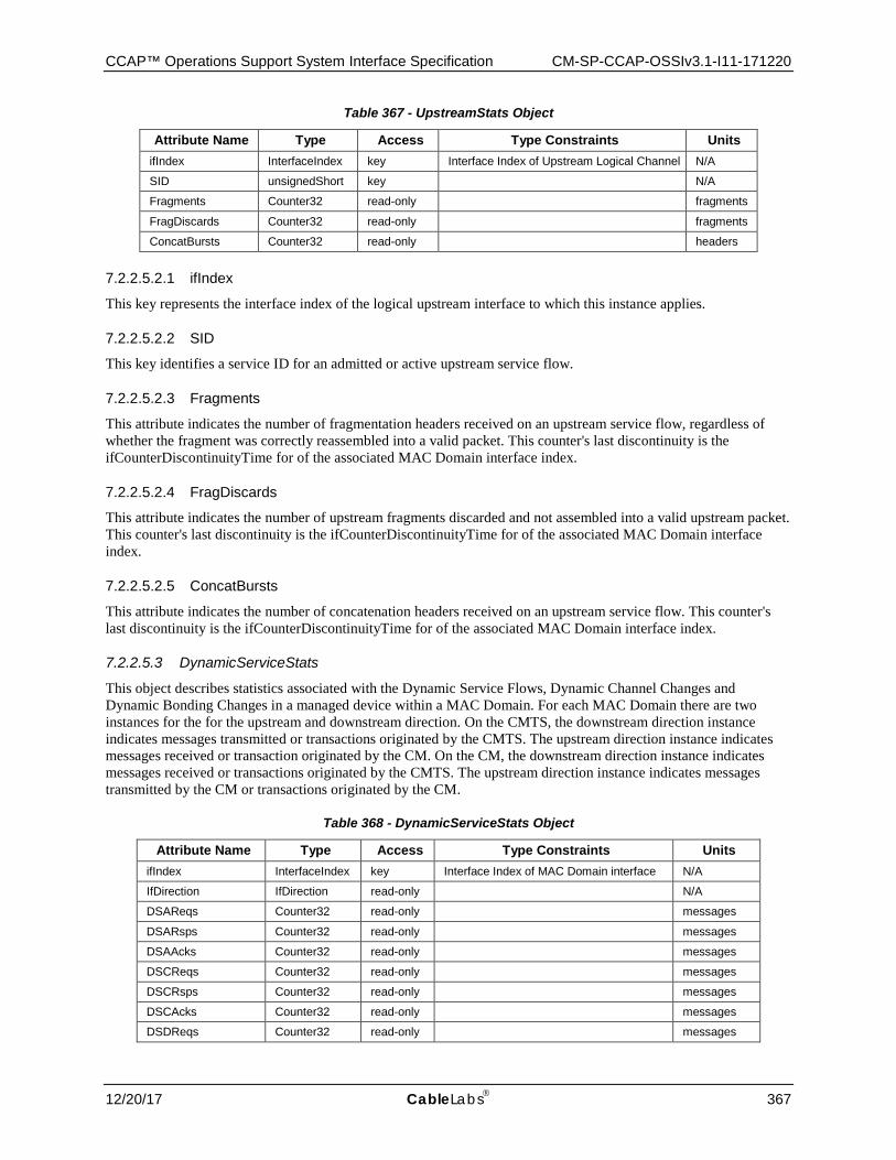
CCAP™ Operations Support System Interface Specification CM-SP-CCAP-OSSIv3.1-I11-171220
12/20/17 CableLabs 367
Table 367 - UpstreamStats Object
Attribute Name Type Access Type Constraints Units ifIndex InterfaceIndex key Interface Index of Upstream Logical Channel N/A
SID unsignedShort key N/A
Fragments Counter32 read-only fragments
FragDiscards Counter32 read-only fragments
ConcatBursts Counter32 read-only headers
7.2.2.5.2.1 ifIndex
This key represents the interface index of the logical upstream interface to which this instance applies.
7.2.2.5.2.2 SID
This key identifies a service ID for an admitted or active upstream service flow.
7.2.2.5.2.3 Fragments
This attribute indicates the number of fragmentation headers received on an upstream service flow, regardless of whether the fragment was correctly reassembled into a valid packet. This counter's last discontinuity is the ifCounterDiscontinuityTime for of the associated MAC Domain interface index.
7.2.2.5.2.4 FragDiscards
This attribute indicates the number of upstream fragments discarded and not assembled into a valid upstream packet. This counter's last discontinuity is the ifCounterDiscontinuityTime for of the associated MAC Domain interface index.
7.2.2.5.2.5 ConcatBursts
This attribute indicates the number of concatenation headers received on an upstream service flow. This counter's last discontinuity is the ifCounterDiscontinuityTime for of the associated MAC Domain interface index.
7.2.2.5.3 DynamicServiceStats
This object describes statistics associated with the Dynamic Service Flows, Dynamic Channel Changes and Dynamic Bonding Changes in a managed device within a MAC Domain. For each MAC Domain there are two instances for the for the upstream and downstream direction. On the CMTS, the downstream direction instance indicates messages transmitted or transactions originated by the CMTS. The upstream direction instance indicates messages received or transaction originated by the CM. On the CM, the downstream direction instance indicates messages received or transactions originated by the CMTS. The upstream direction instance indicates messages transmitted by the CM or transactions originated by the CM.
Table 368 - DynamicServiceStats Object
Attribute Name Type Access Type Constraints Units ifIndex InterfaceIndex key Interface Index of MAC Domain interface N/A
IfDirection IfDirection read-only N/A
DSAReqs Counter32 read-only messages
DSARsps Counter32 read-only messages
DSAAcks Counter32 read-only messages
DSCReqs Counter32 read-only messages
DSCRsps Counter32 read-only messages
DSCAcks Counter32 read-only messages
DSDReqs Counter32 read-only messages
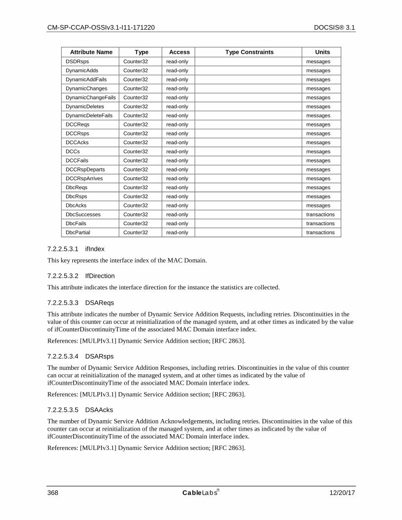
CM-SP-CCAP-OSSIv3.1-I11-171220 DOCSIS® 3.1
368 CableLabs 12/20/17
Attribute Name Type Access Type Constraints Units DSDRsps Counter32 read-only messages
DynamicAdds Counter32 read-only messages
DynamicAddFails Counter32 read-only messages
DynamicChanges Counter32 read-only messages
DynamicChangeFails Counter32 read-only messages
DynamicDeletes Counter32 read-only messages
DynamicDeleteFails Counter32 read-only messages
DCCReqs Counter32 read-only messages
DCCRsps Counter32 read-only messages
DCCAcks Counter32 read-only messages
DCCs Counter32 read-only messages
DCCFails Counter32 read-only messages
DCCRspDeparts Counter32 read-only messages
DCCRspArrives Counter32 read-only messages
DbcReqs Counter32 read-only messages
DbcRsps Counter32 read-only messages
DbcAcks Counter32 read-only messages
DbcSuccesses Counter32 read-only transactions
DbcFails Counter32 read-only transactions
DbcPartial Counter32 read-only transactions
7.2.2.5.3.1 ifIndex
This key represents the interface index of the MAC Domain.
7.2.2.5.3.2 IfDirection
This attribute indicates the interface direction for the instance the statistics are collected.
7.2.2.5.3.3 DSAReqs
This attribute indicates the number of Dynamic Service Addition Requests, including retries. Discontinuities in the value of this counter can occur at reinitialization of the managed system, and at other times as indicated by the value of ifCounterDiscontinuityTime of the associated MAC Domain interface index.
References: [MULPIv3.1] Dynamic Service Addition section; [RFC 2863].
7.2.2.5.3.4 DSARsps
The number of Dynamic Service Addition Responses, including retries. Discontinuities in the value of this counter can occur at reinitialization of the managed system, and at other times as indicated by the value of ifCounterDiscontinuityTime of the associated MAC Domain interface index.
References: [MULPIv3.1] Dynamic Service Addition section; [RFC 2863].
7.2.2.5.3.5 DSAAcks
The number of Dynamic Service Addition Acknowledgements, including retries. Discontinuities in the value of this counter can occur at reinitialization of the managed system, and at other times as indicated by the value of ifCounterDiscontinuityTime of the associated MAC Domain interface index.
References: [MULPIv3.1] Dynamic Service Addition section; [RFC 2863].
CCAP™ Operations Support System Interface Specification CM-SP-CCAP-OSSIv3.1-I11-171220
12/20/17 CableLabs 369
7.2.2.5.3.6 DSCReqs
The number of Dynamic Service Change Requests, including retries. Discontinuities in the value of this counter can occur at reinitialization of the managed system, and at other times as indicated by the value of ifCounterDiscontinuityTime of the associated MAC Domain interface index.
References: [MULPIv3.1] Dynamic Service Change section; [RFC 2863].
7.2.2.5.3.7 DSCRsps
The number of Dynamic Service Change Responses, including retries. Discontinuities in the value of this counter can occur at reinitialization of the managed system, and at other times as indicated by the value of ifCounterDiscontinuityTime of the associated MAC Domain interface index.
References: [MULPIv3.1] Dynamic Service Change section; [RFC 2863].
7.2.2.5.3.8 DSCAcks
The number of Dynamic Service Change Acknowledgements, including retries. Discontinuities in the value of this counter can occur at reinitialization of the managed system, and at other times as indicated by the value of ifCounterDiscontinuityTime of the associated MAC Domain interface index.
References: [MULPIv3.1] Dynamic Service Change section; [RFC 2863].
7.2.2.5.3.9 DSDReqs
The number of Dynamic Service Delete Requests, including retries. Discontinuities in the value of this counter can occur at reinitialization of the managed system, and at other times as indicated by the value of ifCounterDiscontinuityTime of the associated MAC Domain interface index.
References: [MULPIv3.1] Dynamic Service Deletion section; [RFC 2863].
7.2.2.5.3.10 DSDRsps
The number of Dynamic Service Delete Responses, including retries. Discontinuities in the value of this counter can occur at reinitialization of the managed system, and at other times as indicated by the value of ifCounterDiscontinuityTime of the associated MAC Domain interface index.
References: [MULPIv3.1] Dynamic Service Change section; [RFC 2863].
7.2.2.5.3.11 DynamicAdds
The number of successful Dynamic Service Addition transactions. Discontinuities in the value of this counter can occur at reinitialization of the managed system, and at other times as indicated by the value of ifCounterDiscontinuityTime of the associated MAC Domain interface index.
References: [MULPIv3.1] Dynamic Service Addition section; [RFC 2863].
7.2.2.5.3.12 DynamicAddFails
The number of failed Dynamic Service Addition transactions. Discontinuities in the value of this counter can occur at reinitialization of the managed system, and at other times as indicated by the value of ifCounterDiscontinuityTime of the associated MAC Domain interface index.
References: [MULPIv3.1] Dynamic Service Addition section; [RFC 2863].
7.2.2.5.3.13 DynamicChanges
The number of successful Dynamic Service Change transactions. Discontinuities in the value of this counter can occur at reinitialization of the managed system, and at other times as indicated by the value of ifCounterDiscontinuityTime of the associated MAC Domain interface index.
References: [MULPIv3.1] Dynamic Service Change section; [RFC 2863].
CM-SP-CCAP-OSSIv3.1-I11-171220 DOCSIS® 3.1
370 CableLabs 12/20/17
7.2.2.5.3.14 DynamicChangeFails
The number of failed Dynamic Service Change transactions. Discontinuities in the value of this counter can occur at reinitialization of the managed system, and at other times as indicated by the value of ifCounterDiscontinuityTime of the associated MAC Domain interface index.
References: [MULPIv3.1] Dynamic Service Change section; [RFC 2863].
7.2.2.5.3.15 DynamicDeletes
The number of successful Dynamic Service Delete transactions. Discontinuities in the value of this counter can occur at reinitialization of the managed system, and at other times as indicated by the value of ifCounterDiscontinuityTime of the associated MAC Domain interface index.
References: [MULPIv3.1] Dynamic Service Delete section; [RFC 2863].
7.2.2.5.3.16 DynamicDeleteFails
The number of failed Dynamic Service Delete transactions. Discontinuities in the value of this counter can occur at reinitialization of the managed system, and at other times as indicated by the value of ifCounterDiscontinuityTime of the associated MAC Domain interface index.
References: [MULPIv3.1] Dynamic Service Delete section; [RFC 2863].
7.2.2.5.3.17 DCCReqs
The number of Dynamic Channel Change Request messages traversing an interface. This count is nonzero only on downstream direction rows. This count should include the number of retries. Discontinuities in the value of this counter can occur at reinitialization of the managed system, and at other times as indicated by the value of ifCounterDiscontinuityTime of the associated MAC Domain interface index.
References: [MULPIv3.1] Dynamic Downstream and/or Upstream Channel Changes section; [RFC 2863].
7.2.2.5.3.18 DCCRsps
The number of Dynamic Channel Change Response messages traversing an interface. This count is nonzero only on upstream direction rows. This count should include the number of retries. Discontinuities in the value of this counter can occur at reinitialization of the managed system, and at other times as indicated by the value of ifCounterDiscontinuityTime of the associated MAC Domain interface index.
References: [MULPIv3.1] Dynamic Downstream and/or Upstream Channel Changes section; [RFC 2863].
7.2.2.5.3.19 DCCAcks
The number of Dynamic Channel Change Acknowledgement messages traversing an interface. This count is nonzero only on downstream direction rows. This count should include the number of retries. Discontinuities in the value of this counter can occur at reinitialization of the managed system, and at other times as indicated by the value of ifCounterDiscontinuityTime of the associated MAC Domain interface index.
References: [MULPIv3.1] Dynamic Downstream and/or Upstream Channel Changes section; [RFC 2863].
7.2.2.5.3.20 DCCs
The number of successful Dynamic Channel Change transactions. This count is nonzero only on downstream direction rows. Discontinuities in the value of this counter can occur at reinitialization of the managed system, and at other times as indicated by the value of ifCounterDiscontinuityTime of the associated MAC Domain interface index.
References: [MULPIv3.1] Dynamic Downstream and/or Upstream Channel Changes section; [RFC 2863].
CCAP™ Operations Support System Interface Specification CM-SP-CCAP-OSSIv3.1-I11-171220
12/20/17 CableLabs 371
7.2.2.5.3.21 DCCFails
The number of failed Dynamic Channel Change transactions. This count is nonzero only on downstream direction rows. Discontinuities in the value of this counter can occur at reinitialization of the managed system, and at other times as indicated by the value of ifCounterDiscontinuityTime of the associated MAC Domain interface index.
References: [MULPIv3.1] Dynamic Downstream and/or Upstream Channel Changes section; [RFC 2863].
7.2.2.5.3.22 DccRspDeparts
This attribute contains the number of Dynamic Channel Change Response (depart) messages. It only applies to upstream direction. Discontinuities in the value of this counter can occur at reinitialization of the managed system, and at other times as indicated by the value of ifCounterDiscontinuityTime of the associated MAC Domain interface index.
References: [MULPIv3.1] Dynamic Downstream and/or Upstream Channel Changes section; [RFC 2863].
7.2.2.5.3.23 DccRspArrives
This attribute contains the number of Dynamic Channel Change Response (arrive) messages and should include retries. It only applies to the upstream direction. Discontinuities in the value of this counter can occur at reinitialization of the managed system, and at other times as indicated by the value of ifCounterDiscontinuityTime of the associated MAC Domain interface index.
References: [MULPIv3.1] Dynamic Downstream and/or Upstream Channel Changes section; [RFC 2863].
7.2.2.5.3.24 DbcReqs
This attribute contains the number of Dynamic Bonding Change Requests, including retries. It only applies to the upstream direction. Discontinuities in the value of this counter can occur at reinitialization of the managed system, and at other times as indicated by the value of ifCounterDiscontinuityTime of the associated MAC Domain interface index.
References: [MULPIv3.1] Dynamic Bonding Change (DBC) section; [RFC 2863].
7.2.2.5.3.25 DbcRsps
This attribute contains the number of Dynamic Bonding Change Responses, including retries. It only applies to the upstream direction. Discontinuities in the value of this counter can occur at reinitialization of the managed system, and at other times as indicated by the value of ifCounterDiscontinuityTime of the associated MAC Domain interface index.
References: [MULPIv3.1] Dynamic Bonding Change (DBC) section; [RFC 2863].
7.2.2.5.3.26 DbcAcks
This attribute contains the number of Dynamic Bonding Change Acknowledgements, including retries. It only applies to the downstream direction. Discontinuities in the value of this counter can occur at reinitialization of the managed system, and at other times as indicated by the value of ifCounterDiscontinuityTime of the associated MAC Domain interface index.
References: [MULPIv3.1] Dynamic Bonding Change (DBC) section; [RFC 2863].
7.2.2.5.3.27 DbcSuccesses
This attribute contains the number of fully successful Dynamic Bonding Change transactions. It only applies to the downstream direction and does not include DBC transactions that result in Partial Service. Discontinuities in the value of this counter can occur at reinitialization of the managed system, and at other times as indicated by the value of ifCounterDiscontinuityTime of the associated MAC Domain interface index.
References: [MULPIv3.1] Dynamic Bonding Change (DBC) section; [RFC 2863].
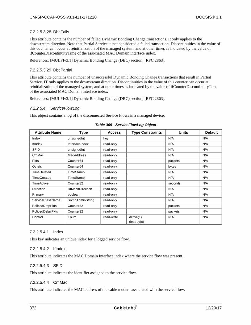
CM-SP-CCAP-OSSIv3.1-I11-171220 DOCSIS® 3.1
372 CableLabs 12/20/17
7.2.2.5.3.28 DbcFails
This attribute contains the number of failed Dynamic Bonding Change transactions. It only applies to the downstream direction. Note that Partial Service is not considered a failed transaction. Discontinuities in the value of this counter can occur at reinitialization of the managed system, and at other times as indicated by the value of ifCounterDiscontinuityTime of the associated MAC Domain interface index.
References: [MULPIv3.1] Dynamic Bonding Change (DBC) section; [RFC 2863].
7.2.2.5.3.29 DbcPartial
This attribute contains the number of unsuccessful Dynamic Bonding Change transactions that result in Partial Service. IT only applies to the downstream direction. Discontinuities in the value of this counter can occur at reinitialization of the managed system, and at other times as indicated by the value of ifCounterDiscontinuityTime of the associated MAC Domain interface index.
References: [MULPIv3.1] Dynamic Bonding Change (DBC) section; [RFC 2863].
7.2.2.5.4 ServiceFlowLog
This object contains a log of the disconnected Service Flows in a managed device.
Table 369 - ServiceFlowLog Object
Attribute Name Type Access Type Constraints Units Default Index unsignedInt key N/A N/A
IfIndex InterfaceIndex read-only N/A N/A
SFID unsignedInt read-only N/A N/A
CmMac MacAddress read-only N/A N/A
Pkts Counter64 read-only packets N/A
Octets Counter64 read-only bytes N/A
TimeDeleted TimeStamp read-only N/A N/A
TimeCreated TimeStamp read-only N/A N/A
TimeActive Counter32 read-only seconds N/A
Direction RfMacIfDirection read-only N/A N/A
Primary boolean read-only N/A N/A
ServiceClassName SnmpAdminString read-only N/A N/A
PolicedDropPkts Counter32 read-only packets N/A
PolicedDelayPkts Counter32 read-only packets N/A
Control Enum read-write active(1) destroy(6)
N/A N/A
7.2.2.5.4.1 Index
This key indicates an unique index for a logged service flow.
7.2.2.5.4.2 IfIndex
This attribute indicates the MAC Domain Interface index where the service flow was present.
7.2.2.5.4.3 SFID
This attribute indicates the identifier assigned to the service flow.
7.2.2.5.4.4 CmMac
This attribute indicates the MAC address of the cable modem associated with the service flow.
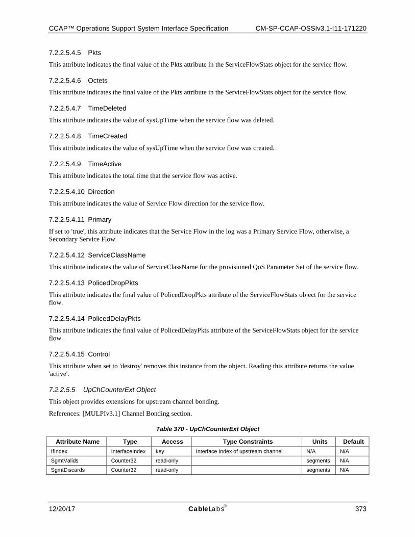
CCAP™ Operations Support System Interface Specification CM-SP-CCAP-OSSIv3.1-I11-171220
12/20/17 CableLabs 373
7.2.2.5.4.5 Pkts
This attribute indicates the final value of the Pkts attribute in the ServiceFlowStats object for the service flow.
7.2.2.5.4.6 Octets
This attribute indicates the final value of the Pkts attribute in the ServiceFlowStats object for the service flow.
7.2.2.5.4.7 TimeDeleted
This attribute indicates the value of sysUpTime when the service flow was deleted.
7.2.2.5.4.8 TimeCreated
This attribute indicates the value of sysUpTime when the service flow was created.
7.2.2.5.4.9 TimeActive
This attribute indicates the total time that the service flow was active.
7.2.2.5.4.10 Direction
This attribute indicates the value of Service Flow direction for the service flow.
7.2.2.5.4.11 Primary
If set to 'true', this attribute indicates that the Service Flow in the log was a Primary Service Flow, otherwise, a Secondary Service Flow.
7.2.2.5.4.12 ServiceClassName
This attribute indicates the value of ServiceClassName for the provisioned QoS Parameter Set of the service flow.
7.2.2.5.4.13 PolicedDropPkts
This attribute indicates the final value of PolicedDropPkts attribute of the ServiceFlowStats object for the service flow.
7.2.2.5.4.14 PolicedDelayPkts
This attribute indicates the final value of PolicedDelayPkts attribute of the ServiceFlowStats object for the service flow.
7.2.2.5.4.15 Control
This attribute when set to 'destroy' removes this instance from the object. Reading this attribute returns the value 'active'.
7.2.2.5.5 UpChCounterExt Object
This object provides extensions for upstream channel bonding.
References: [MULPIv3.1] Channel Bonding section.
Table 370 - UpChCounterExt Object
Attribute Name Type Access Type Constraints Units Default IfIndex InterfaceIndex key Interface Index of upstream channel N/A N/A
SgmtValids Counter32 read-only segments N/A
SgmtDiscards Counter32 read-only segments N/A
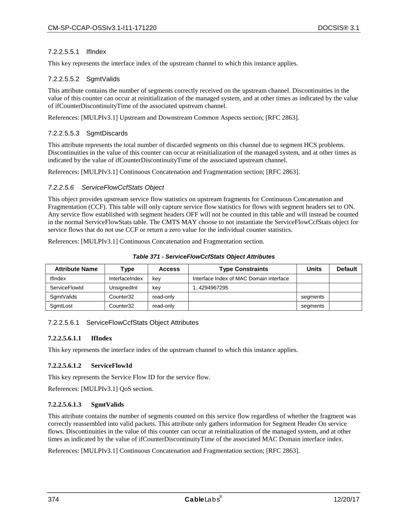
CM-SP-CCAP-OSSIv3.1-I11-171220 DOCSIS® 3.1
374 CableLabs 12/20/17
7.2.2.5.5.1 IfIndex
This key represents the interface index of the upstream channel to which this instance applies.
7.2.2.5.5.2 SgmtValids
This attribute contains the number of segments correctly received on the upstream channel. Discontinuities in the value of this counter can occur at reinitialization of the managed system, and at other times as indicated by the value of ifCounterDiscontinuityTime of the associated upstream channel.
References: [MULPIv3.1] Upstream and Downstream Common Aspects section; [RFC 2863].
7.2.2.5.5.3 SgmtDiscards
This attribute represents the total number of discarded segments on this channel due to segment HCS problems. Discontinuities in the value of this counter can occur at reinitialization of the managed system, and at other times as indicated by the value of ifCounterDiscontinuityTime of the associated upstream channel.
References: [MULPIv3.1] Continuous Concatenation and Fragmentation section; [RFC 2863].
7.2.2.5.6 ServiceFlowCcfStats Object
This object provides upstream service flow statistics on upstream fragments for Continuous Concatenation and Fragmentation (CCF). This table will only capture service flow statistics for flows with segment headers set to ON. Any service flow established with segment headers OFF will not be counted in this table and will instead be counted in the normal ServiceFlowStats table. The CMTS MAY choose to not instantiate the ServiceFlowCcfStats object for service flows that do not use CCF or return a zero value for the individual counter statistics.
References: [MULPIv3.1] Continuous Concatenation and Fragmentation section.
Table 371 - ServiceFlowCcfStats Object Attributes
Attribute Name Type Access Type Constraints Units Default IfIndex InterfaceIndex key Interface Index of MAC Domain interface
ServiceFlowId UnsignedInt key 1..4294967295
SgmtValids Counter32 read-only segments
SgmtLost Counter32 read-only segments
7.2.2.5.6.1 ServiceFlowCcfStats Object Attributes
7.2.2.5.6.1.1 IfIndex
This key represents the interface index of the upstream channel to which this instance applies.
7.2.2.5.6.1.2 ServiceFlowId
This key represents the Service Flow ID for the service flow.
References: [MULPIv3.1] QoS section.
7.2.2.5.6.1.3 SgmtValids
This attribute contains the number of segments counted on this service flow regardless of whether the fragment was correctly reassembled into valid packets. This attribute only gathers information for Segment Header On service flows. Discontinuities in the value of this counter can occur at reinitialization of the managed system, and at other times as indicated by the value of ifCounterDiscontinuityTime of the associated MAC Domain interface index.
References: [MULPIv3.1] Continuous Concatenation and Fragmentation section; [RFC 2863].
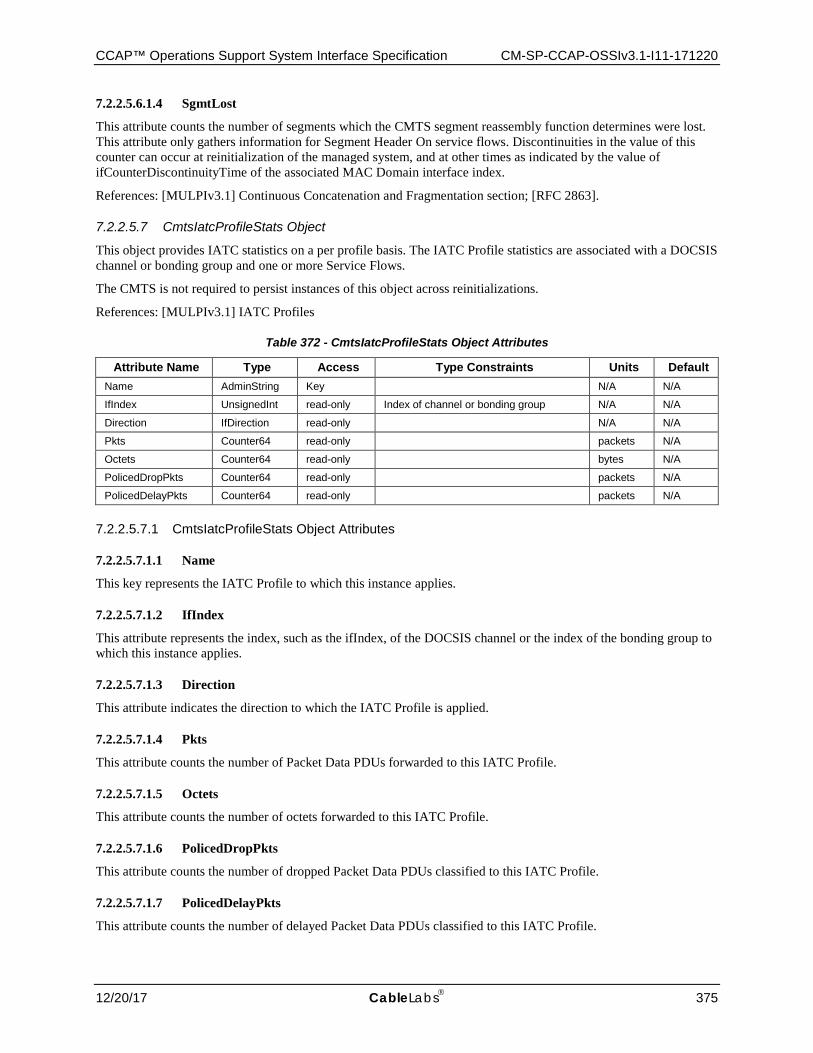
CCAP™ Operations Support System Interface Specification CM-SP-CCAP-OSSIv3.1-I11-171220
12/20/17 CableLabs 375
7.2.2.5.6.1.4 SgmtLost
This attribute counts the number of segments which the CMTS segment reassembly function determines were lost. This attribute only gathers information for Segment Header On service flows. Discontinuities in the value of this counter can occur at reinitialization of the managed system, and at other times as indicated by the value of ifCounterDiscontinuityTime of the associated MAC Domain interface index.
References: [MULPIv3.1] Continuous Concatenation and Fragmentation section; [RFC 2863].
7.2.2.5.7 CmtsIatcProfileStats Object
This object provides IATC statistics on a per profile basis. The IATC Profile statistics are associated with a DOCSIS channel or bonding group and one or more Service Flows.
The CMTS is not required to persist instances of this object across reinitializations.
References: [MULPIv3.1] IATC Profiles
Table 372 - CmtsIatcProfileStats Object Attributes
Attribute Name Type Access Type Constraints Units Default Name AdminString Key N/A N/A
IfIndex UnsignedInt read-only Index of channel or bonding group N/A N/A
Direction IfDirection read-only N/A N/A
Pkts Counter64 read-only packets N/A
Octets Counter64 read-only bytes N/A
PolicedDropPkts Counter64 read-only packets N/A
PolicedDelayPkts Counter64 read-only packets N/A
7.2.2.5.7.1 CmtsIatcProfileStats Object Attributes
7.2.2.5.7.1.1 Name
This key represents the IATC Profile to which this instance applies.
7.2.2.5.7.1.2 IfIndex
This attribute represents the index, such as the ifIndex, of the DOCSIS channel or the index of the bonding group to which this instance applies.
7.2.2.5.7.1.3 Direction
This attribute indicates the direction to which the IATC Profile is applied.
7.2.2.5.7.1.4 Pkts
This attribute counts the number of Packet Data PDUs forwarded to this IATC Profile.
7.2.2.5.7.1.5 Octets
This attribute counts the number of octets forwarded to this IATC Profile.
7.2.2.5.7.1.6 PolicedDropPkts
This attribute counts the number of dropped Packet Data PDUs classified to this IATC Profile.
7.2.2.5.7.1.7 PolicedDelayPkts
This attribute counts the number of delayed Packet Data PDUs classified to this IATC Profile.
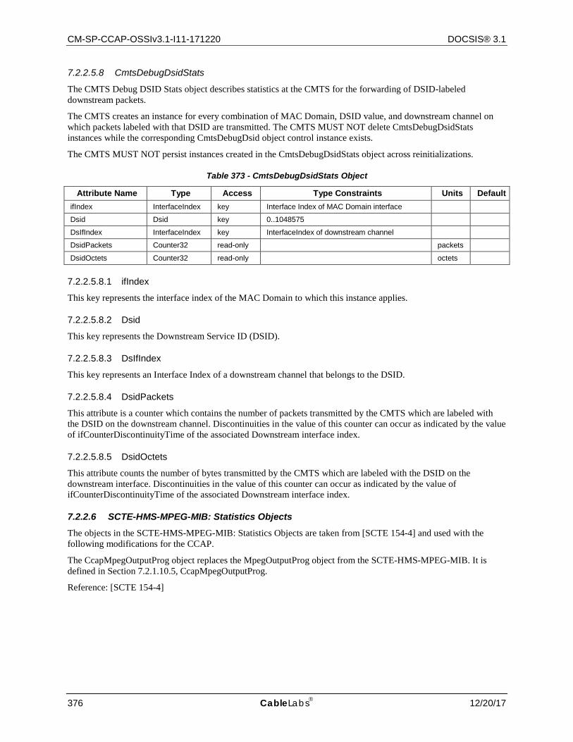
CM-SP-CCAP-OSSIv3.1-I11-171220 DOCSIS® 3.1
376 CableLabs 12/20/17
7.2.2.5.8 CmtsDebugDsidStats
The CMTS Debug DSID Stats object describes statistics at the CMTS for the forwarding of DSID-labeled downstream packets.
The CMTS creates an instance for every combination of MAC Domain, DSID value, and downstream channel on which packets labeled with that DSID are transmitted. The CMTS MUST NOT delete CmtsDebugDsidStats instances while the corresponding CmtsDebugDsid object control instance exists.
The CMTS MUST NOT persist instances created in the CmtsDebugDsidStats object across reinitializations.
Table 373 - CmtsDebugDsidStats Object
Attribute Name Type Access Type Constraints Units Default ifIndex InterfaceIndex key Interface Index of MAC Domain interface
Dsid Dsid key 0..1048575
DsIfIndex InterfaceIndex key InterfaceIndex of downstream channel
DsidPackets Counter32 read-only packets
DsidOctets Counter32 read-only octets
7.2.2.5.8.1 ifIndex
This key represents the interface index of the MAC Domain to which this instance applies.
7.2.2.5.8.2 Dsid
This key represents the Downstream Service ID (DSID).
7.2.2.5.8.3 DsIfIndex
This key represents an Interface Index of a downstream channel that belongs to the DSID.
7.2.2.5.8.4 DsidPackets
This attribute is a counter which contains the number of packets transmitted by the CMTS which are labeled with the DSID on the downstream channel. Discontinuities in the value of this counter can occur as indicated by the value of ifCounterDiscontinuityTime of the associated Downstream interface index.
7.2.2.5.8.5 DsidOctets
This attribute counts the number of bytes transmitted by the CMTS which are labeled with the DSID on the downstream interface. Discontinuities in the value of this counter can occur as indicated by the value of ifCounterDiscontinuityTime of the associated Downstream interface index.
7.2.2.6 SCTE-HMS-MPEG-MIB: Statistics Objects The objects in the SCTE-HMS-MPEG-MIB: Statistics Objects are taken from [SCTE 154-4] and used with the following modifications for the CCAP.
The CcapMpegOutputProg object replaces the MpegOutputProg object from the SCTE-HMS-MPEG-MIB. It is defined in Section 7.2.1.10.5, CcapMpegOutputProg.
Reference: [SCTE 154-4]
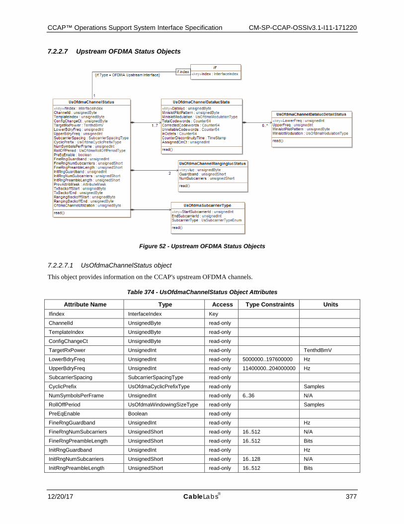
CCAP™ Operations Support System Interface Specification CM-SP-CCAP-OSSIv3.1-I11-171220
12/20/17 CableLabs 377
7.2.2.7 Upstream OFDMA Status Objects
Figure 52 - Upstream OFDMA Status Objects
7.2.2.7.1 UsOfdmaChannelStatus object
This object provides information on the CCAP's upstream OFDMA channels.
Table 374 - UsOfdmaChannelStatus Object Attributes
Attribute Name Type Access Type Constraints Units Ifindex InterfaceIndex Key
ChannelId UnsignedByte read-only
TemplateIndex UnsignedByte read-only
ConfigChangeCt UnsignedByte read-only
TargetRxPower UnsignedInt read-only TenthdBmV
LowerBdryFreq UnsignedInt read-only 5000000..197600000 Hz
UpperBdryFreq UnsignedInt read-only 11400000..204000000 Hz
SubcarrierSpacing SubcarrierSpacingType read-only
CyclicPrefix UsOfdmaCyclicPrefixType read-only Samples
NumSymbolsPerFrame UnsignedInt read-only 6..36 N/A
RollOffPeriod UsOfdmaWindowingSizeType read-only Samples
PreEqEnable Boolean read-only
FineRngGuardband UnsignedInt read-only Hz
FineRngNumSubcarriers UnsignedShort read-only 16..512 N/A
FineRngPreambleLength UnsignedShort read-only 16..512 Bits
InitRngGuardband UnsignedInt read-only Hz
InitRngNumSubcarriers UnsignedShort read-only 16..128 N/A
InitRngPreambleLength UnsignedShort read-only 16..512 Bits
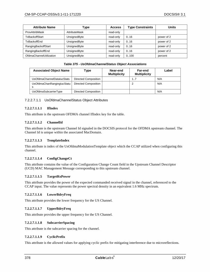
CM-SP-CCAP-OSSIv3.1-I11-171220 DOCSIS® 3.1
378 CableLabs 12/20/17
Attribute Name Type Access Type Constraints Units ProvAttribMask AttributeMask read-only
TxBackoffStart UnsignedByte read-only 0..16 power of 2
TxBackoffEnd UnsignedByte read-only 0..16 power of 2
RangingBackoffStart UnsignedByte read-only 0..16 power of 2
RangingBackoffEnd UnsignedByte read-only 0..16 power of 2
OfdmaChannelUtilization UnsignedByte read-only 0..100 percent
Table 375 - UsOfdmaChannelStatus Object Associations
Associated Object Name Type Near-end Multiplicity
Far-end Multiplicity
Label
UsOfdmaChannelDataIucStats Directed Composition 1..7 N/A
UsOfdmaChanRangingIucStatus
Directed Composition 2 N/A
UsOfdmaSubcarrierType Directed Composition N/A
7.2.2.7.1.1 UsOfdmaChannelStatus Object Attributes
7.2.2.7.1.1.1 IfIndex
This attribute is the upstream OFDMA channel IfIndex key for the table.
7.2.2.7.1.1.2 ChannelId
This attribute is the upstream Channel Id signaled in the DOCSIS protocol for the OFDMA upstream channel. The Channel Id is unique within the associated MacDomain.
7.2.2.7.1.1.3 TemplateIndex
This attribute is index of the UsOfdmaModulationTemplate object which the CCAP utilized when configuring this channel.
7.2.2.7.1.1.4 ConfigChangeCt
This attribute contains the value of the Configuration Change Count field in the Upstream Channel Descriptor (UCD) MAC Management Message corresponding to this upstream channel.
7.2.2.7.1.1.5 TargetRxPower
This attribute provides the power of the expected commanded received signal in the channel, referenced to the CCAP input. The value represents the power spectral density in an equivalent 1.6 MHz spectrum.
7.2.2.7.1.1.6 LowerBdryFreq
This attribute provides the lower frequency for the US Channel.
7.2.2.7.1.1.7 UpperBdryFreq
This attribute provides the upper frequency for the US Channel.
7.2.2.7.1.1.8 SubcarrierSpacing
This attribute is the subcarrier spacing for the channel.
7.2.2.7.1.1.9 CyclicPrefix
This attribute is the allowed values for applying cyclic prefix for mitigating interference due to microreflections.
CCAP™ Operations Support System Interface Specification CM-SP-CCAP-OSSIv3.1-I11-171220
12/20/17 CableLabs 379
7.2.2.7.1.1.10 NumSymbolsPerFrame
This attributes represents the number of symbols per frame.
7.2.2.7.1.1.11 RollOffPeriod
This attribute provides the allowed values for applying windowing to maximize the capacity of the upstream channel.
Reference: [PHYv3.1] Minislot Structure.
7.2.2.7.1.1.12 PreEqEnable
This attribute indicates pre-equalization is enabled on the OFDMA upstream Channel when its value is true, or disabled when its value is false.
7.2.2.7.1.1.13 FineRngGuardband
This attribute is the sum of the upper and lower guard bands for fine ranging in Hz.
7.2.2.7.1.1.14 FineRngNumSubcarriers
This attribute defines maximum number of subcarriers for fine ranging.
7.2.2.7.1.1.15 FineRngPreambleLength
This attribute defines the length of the OFDMA fine ranging IUC preamble.
7.2.2.7.1.1.16 InitRngGuardband
This attribute is the sum of the upper and lower guard bands for initial ranging in Hz.
7.2.2.7.1.1.17 InitRngNumSubcarriers
This attribute provides the maximum number of subcarriers for initial ranging. This is the maximum number of subcarriers for initial ranging, not including the guard band.
7.2.2.7.1.1.18 InitRngPreambleLength
This attribute provides the length of the OFDMA initial ranging IUC preamble.
7.2.2.7.1.1.19 ProvAttribMask
This attribute provides the Provisioned Attribute Mask for the OFDMA upstream Channel.
7.2.2.7.1.1.20 TxBackoffStart
This attribute provides the initial random back-off window to use when retrying transmissions. Expressed as a power of 2. A configured value of 16 indicates that a proprietary adaptive retry mechanism is to be used.
7.2.2.7.1.1.21 TxBackoffEnd
This attribute provides the final random back-off window to use when retrying transmissions. Expressed as a power of 2. A configured value of 16 indicates that a proprietary adaptive retry mechanism is to be used.
7.2.2.7.1.1.22 RangingBackoffStart
This attribute provides the initial random back-off window to use when retrying Ranging Requests. It is expressed as a power of 2. A configured value of 16 indicates that a proprietary adaptive retry mechanism is to be used.
CM-SP-CCAP-OSSIv3.1-I11-171220 DOCSIS® 3.1
380 CableLabs 12/20/17
7.2.2.7.1.1.23 RangingBackoffEnd
This attribute represents the final random back-off window to use when retrying Ranging Requests. It is expressed as a power of 2. A configured value of 16 indicates that a proprietary adaptive retry mechanism is to be used.
7.2.2.7.1.1.24 OfdmaChannelUtilization
The introduction of OFDMA channels in DOCSIS 3.1 poses a new scheduling and accounting problem for the CCAP. DOCSIS 3.1 supports simultaneous Time and Frequency Division Multiplexing (TaFDM) between SC-QAM and OFDMA channels. This implies both:
• OFDMA and SC-QAM can simultaneously operate on separate frequencies • OFDMA and SC-QAM can also operate on the same frequencies, divided in time.
TaFDM scheduling is explained in the Upstream Time and Frequency Multiplexing section of [MULPIv3.1].
When calculating utilization for OFDMA and SC-QAM channels on overlapping frequencies, the CMTS MUST uniquely account spectrum represented by minislots to either an SC-QAM channel or an OFDMA channel.
This is required to avoid a situation where available spectrum can be mistakenly accounted as available on both overlapping channels.
This attribute indicates the calculated and truncated utilization for this OFDMA upstream channel, accurate as of the most recent utilization interval.
The upstream channel utilization is expressed as a percentage of minislots utilized on the physical channel, regardless of burst type.
The utilization index calculation can be expressed by the following equation:
Utilization = MinislotsUtilized/MinislotsAllocated *100%
For an Initial Maintenance region, the minislots for the complete region are considered utilized if the CMTS received an upstream burst within the region from any CM on the physical channel. For contention REQ and REQ/DATA regions, the minislots for a transmission opportunity within the region are considered utilized if the CMTS received an upstream burst within the opportunity from any CM on the physical channel. For all other regions, utilized minislots are those in which the CMTS granted bandwidth to any unicast SID on the physical channel.
For an upstream interface that has multiple logical upstream channels enabled, the utilization index is a weighted sum of utilization indices for the logical channels. The weight for each utilization index is the percentage of upstream minislots allocated for the corresponding logical channel.
Example:
If 75% of bandwidth is allocated to the first logical channel and 25% to the second, and the utilization indices for each are 60 and 40, respectively, the utilization index for the upstream physical channel is (60 * 0.75) + (40 * 0.25) = 55. This figure applies to the most recent utilization interval.
A DOCSIS 3.1 CMTS can operate with upstream OFDMA and SC-QAM channels located on overlapping frequencies. Such scheduling mode is known as Time and Frequency Division Multiplexing (TaFDM). When operating in such mode, the CMTS uniquely allocates minislots to either an SC-QAM channel or an OFDMA channel.
The utilization index for an OFDMA channel is computed by excluding from the calculation those minislots which are effectively allocated to overlapping SC-QAM channels. OFDMA channel minislots dedicated to guard bands and for probes in OFDMA channel are considered utilized. When a SC-QAM channel overlaps in spectrum with an OFDMA channel, its minislots effectively allocated to OFDMA channels are excluded from channel utilization index calculation.
7.2.2.7.2 UsOfdmaSubcarrierType Object
This object specifies the subcarrier type for a group of subcarriers in the active spectrum of this OFDMA channel. Groups of subcarriers of the same type are presented together; non-data subcarriers in these ranges are ignored.
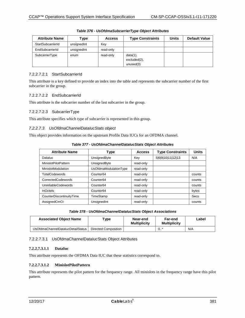
CCAP™ Operations Support System Interface Specification CM-SP-CCAP-OSSIv3.1-I11-171220
12/20/17 CableLabs 381
Table 376 - UsOfdmaSubcarrierType Object Attributes
Attribute Name Type Access Type Constraints Units Default Value StartSubcarrierId unsignedInt Key
EndSubcarrierId unsignedInt read-only
SubcarrierType enum read-only data(1), excluded(2), unused(3)
7.2.2.7.2.1 StartSubcarrierId
This attribute is a key defined to provide an index into the table and represents the subcarrier number of the first subcarrier in the group.
7.2.2.7.2.2 EndSubcarrierId
This attribute is the subcarrier number of the last subcarrier in the group.
7.2.2.7.2.3 SubcarrierType
This attribute specifies which type of subcarrier is represented in this group.
7.2.2.7.3 UsOfdmaChannelDataIucStats object
This object provides information on the upstream Profile Data IUCs for an OFDMA channel.
Table 377 - UsOfdmaChannelDataIucStats Object Attributes
Attribute Name Type Access Type Constraints Units DataIuc UnsignedByte Key 5|6|9|10|11|12|13 N/A
MinislotPilotPattern UnsignedByte read-only
MinislotModulation UsOfdmaModulationType read-only
TotalCodewords Counter64 read-only counts
CorrectedCodewords Counter64 read-only counts
UnreliableCodewords Counter64 read-only counts
InOctets Counter64 read-only bytes
CounterDiscontinuityTime TimeStamp read-only Secs
AssignedCmCt UnsignedInt read-only counts
Table 378 - UsOfdmaChannelDataIucStats Object Associations
Associated Object Name Type Near-end Multiplicity
Far-end Multiplicity
Label
UsOfdmaChannelDataIucDetailStatus Directed Composition 0..* N/A
7.2.2.7.3.1 UsOfdmaChannelDataIucStats Object Attributes
7.2.2.7.3.1.1 DataIuc
This attribute represents the OFDMA Data IUC that these statistics correspond to.
7.2.2.7.3.1.2 MinislotPilotPattern
This attribute represents the pilot pattern for the frequency range. All minislots in the frequency range have this pilot pattern.
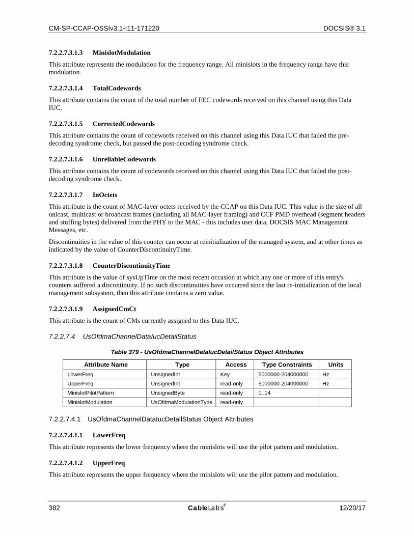
CM-SP-CCAP-OSSIv3.1-I11-171220 DOCSIS® 3.1
382 CableLabs 12/20/17
7.2.2.7.3.1.3 MinislotModulation
This attribute represents the modulation for the frequency range. All minislots in the frequency range have this modulation.
7.2.2.7.3.1.4 TotalCodewords
This attribute contains the count of the total number of FEC codewords received on this channel using this Data IUC.
7.2.2.7.3.1.5 CorrectedCodewords
This attribute contains the count of codewords received on this channel using this Data IUC that failed the pre-decoding syndrome check, but passed the post-decoding syndrome check.
7.2.2.7.3.1.6 UnreliableCodewords
This attribute contains the count of codewords received on this channel using this Data IUC that failed the post-decoding syndrome check.
7.2.2.7.3.1.7 InOctets
This attribute is the count of MAC-layer octets received by the CCAP on this Data IUC. This value is the size of all unicast, multicast or broadcast frames (including all MAC-layer framing) and CCF PMD overhead (segment headers and stuffing bytes) delivered from the PHY to the MAC - this includes user data, DOCSIS MAC Management Messages, etc.
Discontinuities in the value of this counter can occur at reinitialization of the managed system, and at other times as indicated by the value of CounterDiscontinuityTime.
7.2.2.7.3.1.8 CounterDiscontinuityTime
This attribute is the value of sysUpTime on the most recent occasion at which any one or more of this entry's counters suffered a discontinuity. If no such discontinuities have occurred since the last re-initialization of the local management subsystem, then this attribute contains a zero value.
7.2.2.7.3.1.9 AssignedCmCt
This attribute is the count of CMs currently assigned to this Data IUC.
7.2.2.7.4 UsOfdmaChannelDataIucDetailStatus
Table 379 - UsOfdmaChannelDataIucDetailStatus Object Attributes
Attribute Name Type Access Type Constraints Units LowerFreq UnsignedInt Key 5000000-204000000 Hz
UpperFreq UnsignedInt read-only 5000000-204000000 Hz
MinislotPilotPattern UnsignedByte read-only 1..14
MinislotModulation UsOfdmaModulationType read-only
7.2.2.7.4.1 UsOfdmaChannelDataIucDetailStatus Object Attributes
7.2.2.7.4.1.1 LowerFreq
This attribute represents the lower frequency where the minislots will use the pilot pattern and modulation.
7.2.2.7.4.1.2 UpperFreq
This attribute represents the upper frequency where the minislots will use the pilot pattern and modulation.
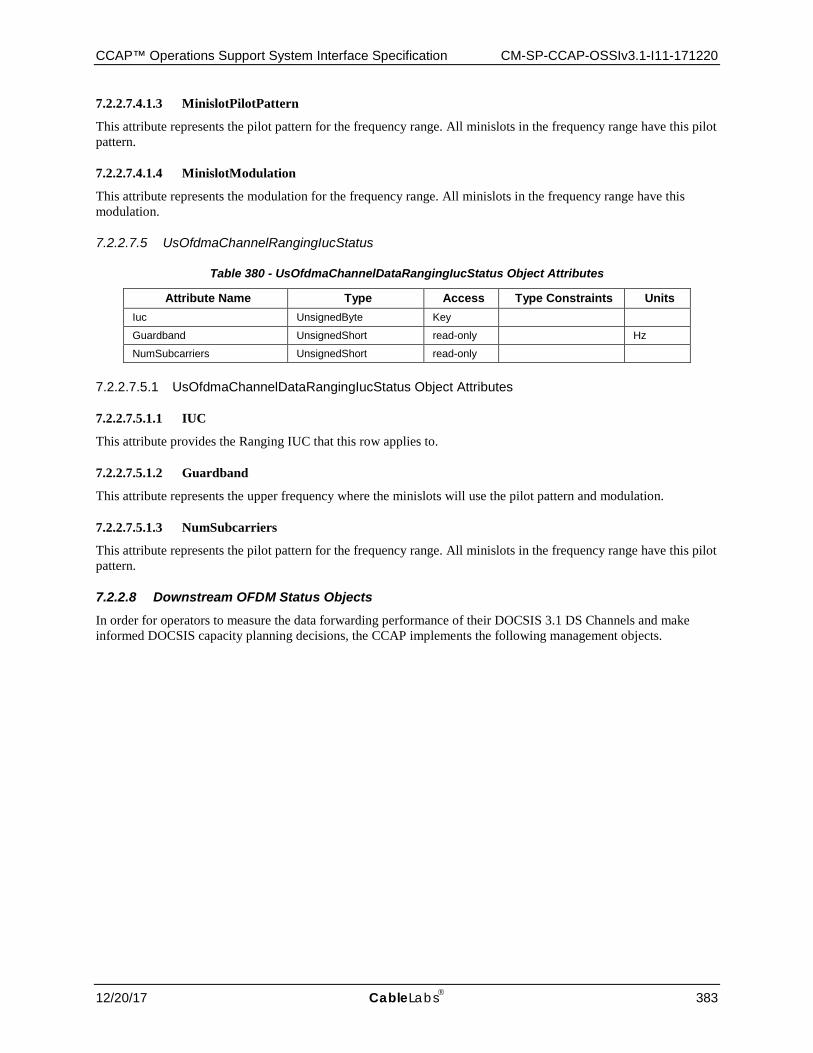
CCAP™ Operations Support System Interface Specification CM-SP-CCAP-OSSIv3.1-I11-171220
12/20/17 CableLabs 383
7.2.2.7.4.1.3 MinislotPilotPattern
This attribute represents the pilot pattern for the frequency range. All minislots in the frequency range have this pilot pattern.
7.2.2.7.4.1.4 MinislotModulation
This attribute represents the modulation for the frequency range. All minislots in the frequency range have this modulation.
7.2.2.7.5 UsOfdmaChannelRangingIucStatus
Table 380 - UsOfdmaChannelDataRangingIucStatus Object Attributes
Attribute Name Type Access Type Constraints Units Iuc UnsignedByte Key
Guardband UnsignedShort read-only Hz
NumSubcarriers UnsignedShort read-only
7.2.2.7.5.1 UsOfdmaChannelDataRangingIucStatus Object Attributes
7.2.2.7.5.1.1 IUC
This attribute provides the Ranging IUC that this row applies to.
7.2.2.7.5.1.2 Guardband
This attribute represents the upper frequency where the minislots will use the pilot pattern and modulation.
7.2.2.7.5.1.3 NumSubcarriers
This attribute represents the pilot pattern for the frequency range. All minislots in the frequency range have this pilot pattern.
7.2.2.8 Downstream OFDM Status Objects In order for operators to measure the data forwarding performance of their DOCSIS 3.1 DS Channels and make informed DOCSIS capacity planning decisions, the CCAP implements the following management objects.
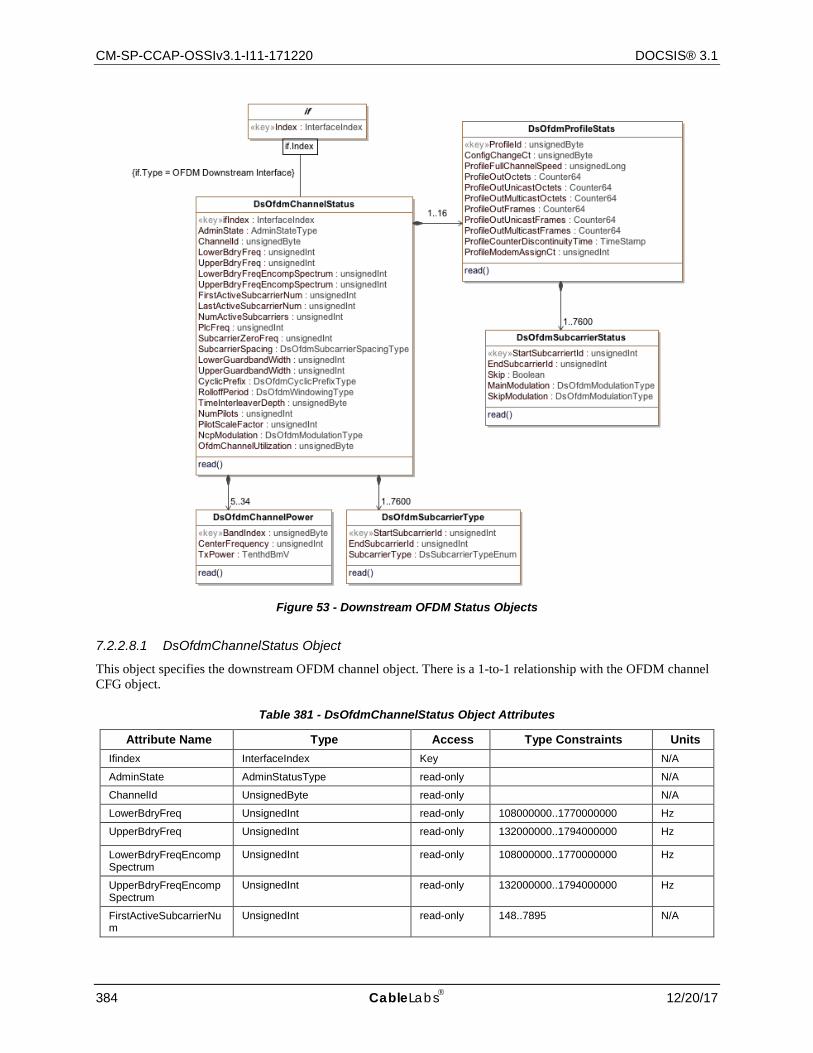
CM-SP-CCAP-OSSIv3.1-I11-171220 DOCSIS® 3.1
384 CableLabs 12/20/17
Figure 53 - Downstream OFDM Status Objects
7.2.2.8.1 DsOfdmChannelStatus Object
This object specifies the downstream OFDM channel object. There is a 1-to-1 relationship with the OFDM channel CFG object.
Table 381 - DsOfdmChannelStatus Object Attributes
Attribute Name Type Access Type Constraints Units Ifindex InterfaceIndex Key N/A
AdminState AdminStatusType read-only N/A
ChannelId UnsignedByte read-only N/A
LowerBdryFreq UnsignedInt read-only 108000000..1770000000 Hz
UpperBdryFreq UnsignedInt read-only 132000000..1794000000 Hz
LowerBdryFreqEncomp Spectrum
UnsignedInt read-only 108000000..1770000000 Hz
UpperBdryFreqEncomp Spectrum
UnsignedInt read-only 132000000..1794000000 Hz
FirstActiveSubcarrierNum
UnsignedInt read-only 148..7895 N/A
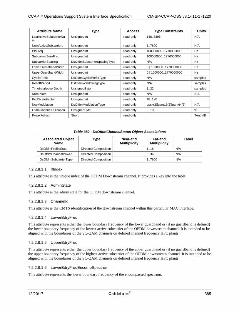
CCAP™ Operations Support System Interface Specification CM-SP-CCAP-OSSIv3.1-I11-171220
12/20/17 CableLabs 385
Attribute Name Type Access Type Constraints Units LastActiveSubcarrierNum
UnsignedInt read-only 148..7895 N/A
NumActiveSubcarriers UnsignedInt read-only 1..7600 N/A
PlcFreq UnsignedInt read-only 108000000..1770000000 Hz
SubcarrierZeroFreq UnsignedInt read-only 108000000..1770000000 Hz
SubcarrierSpacing DsOfdmSubcarrierSpacingType read-only N/A Hz
LowerGuardbandWidth UnsignedInt read-only 0 | 1000000..1770000000 Hz
UpperGuardbandWidth UnsignedInt read-only 0 | 1000000..1770000000 Hz
CyclicPrefix DsOfdmCyclicPrefixType read-only N/A samples
RolloffPeriod DsOfdmWindowingType read-only N/A samples
TimeInterleaverDepth UnsignedByte read-only 1..32 samples
NumPilots UnsignedInt read-only N/A N/A
PilotScaleFactor UnsignedInt read-only 48..120
NcpModulation DsOfdmModulationType read-only qpsk(2)|qam16(2)|qam64(3) N/A
OfdmChannelUtilization UnsignedByte read-only 0..100 %
PowerAdjust Short read-only TenthdB
Table 382 - DsOfdmChannelStatus Object Associations
Associated Object Name
Type Near-end Multiplicity
Far-end Multiplicity
Label
DsOfdmProfileStats Directed Composition 1..16 N/A
DsOfdmChannelPower Directed Composition 5..34 N/A
DsOfdmSubcarrierType Directed Composition 1..7600 N/A
7.2.2.8.1.1 IfIndex
This attribute is the unique index of the OFDM Downstream channel. It provides a key into the table.
7.2.2.8.1.2 AdminState
This attribute is the admin state for the OFDM downstream channel.
7.2.2.8.1.3 ChannelId
This attribute is the CMTS identification of the downstream channel within this particular MAC interface.
7.2.2.8.1.4 LowerBdryFreq
This attribute represents either the lower boundary frequency of the lower guardband or (if no guardband is defined) the lower boundary frequency of the lowest active subcarrier of the OFDM downstream channel. It is intended to be aligned with the boundaries of the SC-QAM channels on defined channel frequency HFC plants.
7.2.2.8.1.5 UpperBdryFreq
This attribute represents either the upper boundary frequency of the upper guardband or (if no guardband is defined) the upper boundary frequency of the highest active subcarrier of the OFDM downstream channel. It is intended to be aligned with the boundaries of the SC-QAM channels on defined channel frequency HFC plants.
7.2.2.8.1.6 LowerBdryFreqEncompSpectrum
This attribute represents the lower boundary frequency of the encompassed spectrum.
CM-SP-CCAP-OSSIv3.1-I11-171220 DOCSIS® 3.1
386 CableLabs 12/20/17
7.2.2.8.1.7 UpperBdryFreqEncompSpectrum
This attribute represents the upper boundary frequency of the encompassed spectrum.
7.2.2.8.1.8 PlcFreq
This attribute is the PHY Link Channel (PLC) frequency. It is the center frequency of the lowest subcarrier of the 6 MHz encompassed spectrum containing the PLC at its center. The frequency of this subcarrier is required to be located on a 1 MHz grid. The aim of the PLC is for the CMTS to convey to the CM the physical properties of the OFDM channel.
7.2.2.8.1.9 FirstActiveSubcarrierNum
This attribute corresponds to the number of the first non-excluded subcarrier.
7.2.2.8.1.10 LastActiveSubcarrierNum
This attribute corresponds to the number of the last non-excluded subcarrier.
7.2.2.8.1.11 NumActiveSubcarriers
This attribute defines the number of active subcarriers within the OFDM downstream channel. For 4K FFT mode, the maximum number of contiguous active subcarriers cannot exceed 3800 and for 8K FFT mode, this number cannot be greater than 7600.
Note: this excludes continuous pilots and the PLC.
7.2.2.8.1.12 SubcarrierZeroFreq
This attribute specifies the center frequency of subcarrier 0 of the OFDM channel. This is the frequency of subcarrier X(0) in the definition of the Discrete Fourier Transform.
7.2.2.8.1.13 SubcarrierSpacing
This attribute is the subcarrier spacing in use on the OFDM downstream channel.
7.2.2.8.1.14 LowerGuardbandWidth
This optional attribute defines the width in Hertz of the lower guard band of the OFDM channel. If omitted, the width of the lower guard band will be automatically configured by the CCAP.
7.2.2.8.1.15 UpperGuardbandWidth
This optional attribute defines the width in Hertz of the upper guard band of the OFDM channel. If omitted, the width of the upper guard band will be automatically configured by the CCAP.
7.2.2.8.1.16 CyclicPrefix
This attribute specifies the cyclic prefix, which enables the receiver to overcome the effects of inter-symbol-interference and intercarrier-interference caused by micro-reflections in the channel. There are five possible values for the length of the CP and the choice depends on the delay spread of the channel - a longer delay spread requires a longer cyclic prefix. The cyclic prefix (in µs) are converted into samples using the sample rate of 204.8 Msamples/s and is an integer multiple of: 1/64 * 20 µs.
7.2.2.8.1.17 RolloffPeriod
This attribute specifies the roll off period or windowing, which maximizes channel capacity by sharpening the edges of the spectrum of the OFDM signal. For windowing purposes another segment at the start of the IDFT output is appended to the end of the IDFT output -the roll-off postfix (RP). There are five possible values for the (RP), and the choice depends on the bandwidth of the channel and the number of exclusion bands within the channel. A larger RP provides sharper edges in the spectrum of the OFDM signal; however, there is a time vs. frequency trade-off.

CCAP™ Operations Support System Interface Specification CM-SP-CCAP-OSSIv3.1-I11-171220
12/20/17 CableLabs 387
Larger RP values reduce the efficiency of transmission in the time domain, but because the spectral edges are sharper, more useful subcarriers appear in the frequency domain. There is an optimum value for the RP that maximizes capacity for a given bandwidth and/or exclusion band scenario.
7.2.2.8.1.18 TimeInterleaverDepth
This attribute specifies the number of samples for the OFDM Downstream channel. This is limited to 16 samples for and 32 samples for 50 kHz and 25 kHz Subcarrier Spacing, respectively.
7.2.2.8.1.19 NumPilots
This attribute is the number of continuous pilots for the downstream channel.
7.2.2.8.1.20 PilotScaleFactor
This attribute represents the scale factor for calculating the number of continuous pilots.
7.2.2.8.1.21 NcpModulation
This attribute represents the modulation of all subcarriers in the NCP channel.
7.2.2.8.1.22 OfdmChannelUtilization
This attribute is the DS OFDM channel utilization measured by the CCAP across all profiles over the configured utilization interval.
The CCAP MUST report DS utilization metric of the channel that conforms to the following requirements:
• The CCAP MUST report a value for OfdmChannelUtilization <= 1% when no user traffic is forwarded on the channel and MMM traffic is known to be less than 1% of the channel capacity.
• The CCAP MUST report a value for OfdmChannelUtilization >= 99% when forwarded traffic completely saturates the channel.
• The CCAP MUST report a value for OfdmChannelUtilization which increases linearly with traffic volume increase and is accurate within 1% of the channel capacity for any given traffic mix (ratio of packets for a given OFDM profiles, packet size, traffic pattern, etc.) which results in nearly all full codewords as the maximum channel capacity is reached. Note: The channel capacity is defined as the largest ProfileFullChannelSpeed value for this channel.
The following algorithm is the reference algorithm for calculating OfdmChannelUtilization: chanWeightedByteTotal = 0; //ProfileFullChannelSpeed is defined in Section 7.2.2.8.4.3 mostEffProfileSpeed = max(ProfileFullChannelSpeed across all profiles); //ProfileOutOctets is the number of octets sent on a given profile during //the utilization interval. This implies a delta calc on a continuous ctr. //utilInterval is the duration of the utilization interval in seconds. for (i = 0; i < numProfiles; i++) { profileMultiplier = mostEffProfileSpeed / ProfileFullChannelSpeed[i]; chanWeightedByteTotal += profileMultiplier * ProfileOutOctets[i]; } OfdmChannelUtilization = (8 * chanWeightedByteTotal) / (mostEffProfileSpeed * utilInterval);
The reference algorithm is expected to give an excellent (within a fraction of 1%) representation of actual channel capacity and utilization under most real-world operating conditions. However, it should be recognized that the accuracy of this approach might be compromised in the event of one or more of the following:
• Large number of profiles in the system relative to total channel capacity • Aggressive latency targets

CM-SP-CCAP-OSSIv3.1-I11-171220 DOCSIS® 3.1
388 CableLabs 12/20/17
• Imbalance in traffic loading across profiles (i.e., many very-lightly-loaded profiles and few more heavily loaded profiles)
These conditions could force the codeword builder to shorten codewords in order to serve all active profiles within the limited time/bandwidth dictated by the latency targets and channel capacity. The resulting additional overhead represents a loss of total capacity not accounted for in the reference algorithm, meaning that the actual utilization will be slightly higher than the utilization reported by the reference algorithm.
The Codeword Builder Latency table of [MULPIv3.1] offers guidance regarding the relationship between number of profiles, channel bandwidth, and latency targets. In a system configured at the edges of these bounds, the error of the reference algorithm is expected to be no more than 2-3% under worst-case conditions of traffic imbalance; the effects of averaging over the utilization interval will typically reduce this error significantly.
Codeword builder algorithms, including codeword-shortening decisions, are vendor-specific. A vendor might choose to incorporate proprietary information about the codeword builder algorithm into the calculation of OfdmChannelUtilization in order to account for some or all of the capacity loss described above.
In a simplified case of a single profile with moderate-to-heavy loading, codeword builder implementations are expected to provide capacity and report utilization values which are extremely close to those given by the reference algorithm.
7.2.2.8.2 DsOfdmChannelPower Object
This object provides the attributes to measure the downstream OFDM channel power in 6 MHz-wide bands at the output of the CCAP.
Table 383 - DsOfdmChannelPower Object Attributes
Attribute Name Type Access Type Constraints Units Default Value BandIndex UnsignedByte Key 0..33
CenterFrequency UnsignedLong R/O 111000000..1215000000 Hz 0
TxPower TenthdBmV R/O dBmV
7.2.2.8.2.1 BandIndex
This attribute is a unique index used by the CCAP to identify each of the 6 MHz bands of a given OFDM downstream channel (from the lowest 6 MHz band of the Occupied Bandwidth to the highest 6 MHz band of the Occupied Bandwidth). The CCAP MUST assign indices in frequency order from the OFDM channel's lowest to highest 6 MHz frequency band for each of the 6 MHz bands of the channel, using an index of 1 to represent the lowest frequency band of the Occupied Bandwidth. Thus, an index of 33 represents the highest possible 6 MHz frequency band of the Occupied Bandwidth of an OFDM channel. The CCAP MUST also provide the power of the PLC channel and utilize a value of 0 to represent the PLC channel in this table.
7.2.2.8.2.2 CenterFrequency
This attribute corresponds to the center frequency of the 6 MHz band where the CCAP measured the average channel power. The 6 MHz measurement band is defined as any 6 MHz band with a center frequency of 111 + 6 (n-1) MHz for n = 1,2...185 (i.e., 111,117,...1215 MHz).
The CCAP MUST use a center frequency with a value of 0 for the 6 MHz encompassed spectrum containing the PLC at its center.
The CCAP MUST provide the center frequency for the 6 MHz channel, other than the one encompassing the PLC channel, per the following formula: centerfreq = 111 + 6(n-1), such that (centerfreq - 111) / 6, must be a whole number.
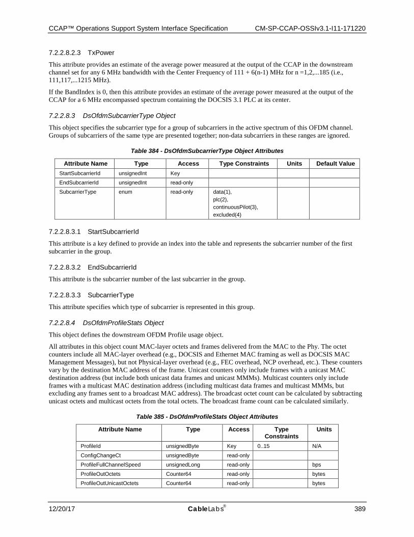
CCAP™ Operations Support System Interface Specification CM-SP-CCAP-OSSIv3.1-I11-171220
12/20/17 CableLabs 389
7.2.2.8.2.3 TxPower
This attribute provides an estimate of the average power measured at the output of the CCAP in the downstream channel set for any 6 MHz bandwidth with the Center Frequency of 111 + 6(n-1) MHz for n =1,2,...185 (i.e., 111,117,...1215 MHz).
If the BandIndex is 0, then this attribute provides an estimate of the average power measured at the output of the CCAP for a 6 MHz encompassed spectrum containing the DOCSIS 3.1 PLC at its center.
7.2.2.8.3 DsOfdmSubcarrierType Object
This object specifies the subcarrier type for a group of subcarriers in the active spectrum of this OFDM channel. Groups of subcarriers of the same type are presented together; non-data subcarriers in these ranges are ignored.
Table 384 - DsOfdmSubcarrierType Object Attributes
Attribute Name Type Access Type Constraints Units Default Value StartSubcarrierId unsignedInt Key
EndSubcarrierId unsignedInt read-only
SubcarrierType enum read-only data(1), plc(2), continuousPilot(3), excluded(4)
7.2.2.8.3.1 StartSubcarrierId
This attribute is a key defined to provide an index into the table and represents the subcarrier number of the first subcarrier in the group.
7.2.2.8.3.2 EndSubcarrierId
This attribute is the subcarrier number of the last subcarrier in the group.
7.2.2.8.3.3 SubcarrierType
This attribute specifies which type of subcarrier is represented in this group.
7.2.2.8.4 DsOfdmProfileStats Object
This object defines the downstream OFDM Profile usage object.
All attributes in this object count MAC-layer octets and frames delivered from the MAC to the Phy. The octet counters include all MAC-layer overhead (e.g., DOCSIS and Ethernet MAC framing as well as DOCSIS MAC Management Messages), but not Physical-layer overhead (e.g., FEC overhead, NCP overhead, etc.). These counters vary by the destination MAC address of the frame. Unicast counters only include frames with a unicast MAC destination address (but include both unicast data frames and unicast MMMs). Multicast counters only include frames with a multicast MAC destination address (including multicast data frames and multicast MMMs, but excluding any frames sent to a broadcast MAC address). The broadcast octet count can be calculated by subtracting unicast octets and multicast octets from the total octets. The broadcast frame count can be calculated similarly.
Table 385 - DsOfdmProfileStats Object Attributes
Attribute Name Type Access Type Constraints
Units
ProfileId unsignedByte Key 0..15 N/A
ConfigChangeCt unsignedByte read-only
ProfileFullChannelSpeed unsignedLong read-only bps
ProfileOutOctets Counter64 read-only bytes
ProfileOutUnicastOctets Counter64 read-only bytes
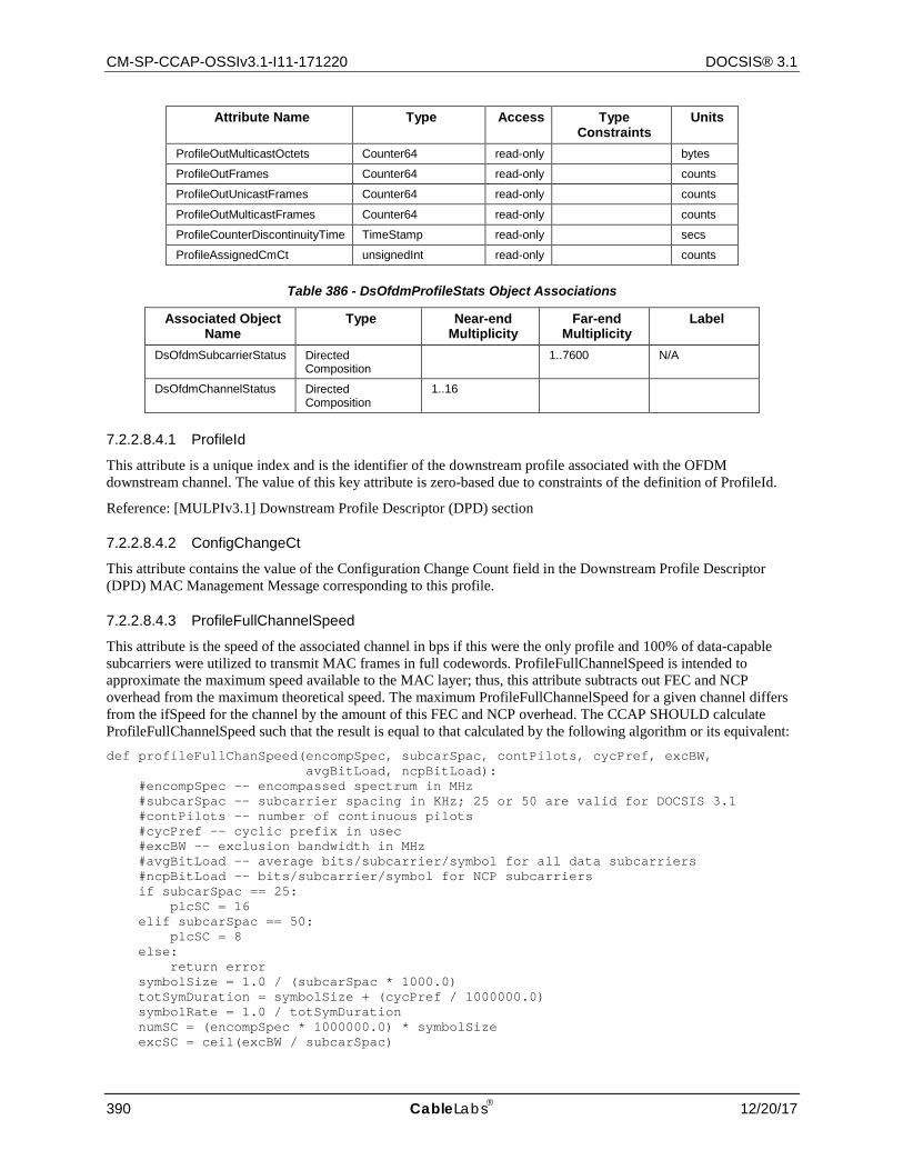
CM-SP-CCAP-OSSIv3.1-I11-171220 DOCSIS® 3.1
390 CableLabs 12/20/17
Attribute Name Type Access Type Constraints
Units
ProfileOutMulticastOctets Counter64 read-only bytes
ProfileOutFrames Counter64 read-only counts
ProfileOutUnicastFrames Counter64 read-only counts
ProfileOutMulticastFrames Counter64 read-only counts
ProfileCounterDiscontinuityTime TimeStamp read-only secs
ProfileAssignedCmCt unsignedInt read-only counts
Table 386 - DsOfdmProfileStats Object Associations
Associated Object Name
Type Near-end Multiplicity
Far-end Multiplicity
Label
DsOfdmSubcarrierStatus Directed Composition
1..7600 N/A
DsOfdmChannelStatus Directed Composition
1..16
7.2.2.8.4.1 ProfileId
This attribute is a unique index and is the identifier of the downstream profile associated with the OFDM downstream channel. The value of this key attribute is zero-based due to constraints of the definition of ProfileId.
Reference: [MULPIv3.1] Downstream Profile Descriptor (DPD) section
7.2.2.8.4.2 ConfigChangeCt
This attribute contains the value of the Configuration Change Count field in the Downstream Profile Descriptor (DPD) MAC Management Message corresponding to this profile.
7.2.2.8.4.3 ProfileFullChannelSpeed
This attribute is the speed of the associated channel in bps if this were the only profile and 100% of data-capable subcarriers were utilized to transmit MAC frames in full codewords. ProfileFullChannelSpeed is intended to approximate the maximum speed available to the MAC layer; thus, this attribute subtracts out FEC and NCP overhead from the maximum theoretical speed. The maximum ProfileFullChannelSpeed for a given channel differs from the ifSpeed for the channel by the amount of this FEC and NCP overhead. The CCAP SHOULD calculate ProfileFullChannelSpeed such that the result is equal to that calculated by the following algorithm or its equivalent: def profileFullChanSpeed(encompSpec, subcarSpac, contPilots, cycPref, excBW, avgBitLoad, ncpBitLoad): #encompSpec -- encompassed spectrum in MHz #subcarSpac -- subcarrier spacing in KHz; 25 or 50 are valid for DOCSIS 3.1 #contPilots –- number of continuous pilots #cycPref -- cyclic prefix in usec #excBW -- exclusion bandwidth in MHz #avgBitLoad -- average bits/subcarrier/symbol for all data subcarriers #ncpBitLoad -- bits/subcarrier/symbol for NCP subcarriers if subcarSpac == 25: plcSC = 16 elif subcarSpac == 50: plcSC = 8 else: return error symbolSize = 1.0 / (subcarSpac * 1000.0) totSymDuration = symbolSize + (cycPref / 1000000.0) symbolRate = 1.0 / totSymDuration numSC = (encompSpec * 1000000.0) * symbolSize excSC = ceil(excBW / subcarSpac)
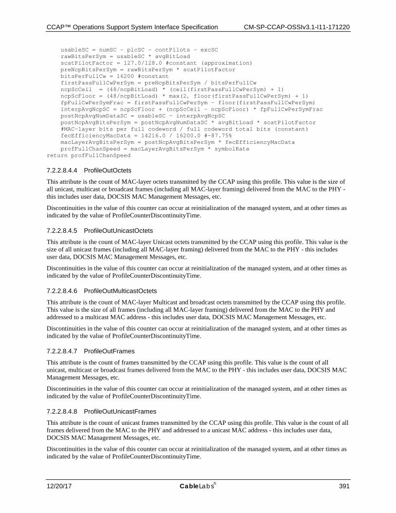
CCAP™ Operations Support System Interface Specification CM-SP-CCAP-OSSIv3.1-I11-171220
12/20/17 CableLabs 391
usableSC = numSC - plcSC - contPilots - excSC rawBitsPerSym = usableSC * avgBitLoad scatPilotFactor = 127.0/128.0 #constant (approximation) preNcpBitsPerSym = rawBitsPerSym * scatPilotFactor bitsPerFullCw = 16200 #constant firstPassFullCwPerSym = preNcpBitsPerSym / bitsPerFullCw ncpScCeil = (48/ncpBitLoad) * (ceil(firstPassFullCwPerSym) + 1) ncpScFloor = (48/ncpBitLoad) * max(2, floor(firstPassFullCwPerSym) + 1) fpFullCwPerSymFrac = firstPassFullCwPerSym - floor(firstPassFullCwPerSym) interpAvgNcpSC = ncpScFloor + (ncpScCeil - ncpScFloor) * fpFullCwPerSymFrac postNcpAvgNumDataSC = usableSC - interpAvgNcpSC postNcpAvgBitsPerSym = postNcpAvgNumDataSC * avgBitLoad * scatPilotFactor #MAC-layer bits per full codeword / full codeword total bits (constant) fecEfficiencyMacData = 14216.0 / 16200.0 #~87.75% macLayerAvgBitsPerSym = postNcpAvgBitsPerSym * fecEfficiencyMacData profFullChanSpeed = macLayerAvgBitsPerSym * symbolRate return profFullChanSpeed
7.2.2.8.4.4 ProfileOutOctets
This attribute is the count of MAC-layer octets transmitted by the CCAP using this profile. This value is the size of all unicast, multicast or broadcast frames (including all MAC-layer framing) delivered from the MAC to the PHY - this includes user data, DOCSIS MAC Management Messages, etc.
Discontinuities in the value of this counter can occur at reinitialization of the managed system, and at other times as indicated by the value of ProfileCounterDiscontinuityTime.
7.2.2.8.4.5 ProfileOutUnicastOctets
This attribute is the count of MAC-layer Unicast octets transmitted by the CCAP using this profile. This value is the size of all unicast frames (including all MAC-layer framing) delivered from the MAC to the PHY - this includes user data, DOCSIS MAC Management Messages, etc.
Discontinuities in the value of this counter can occur at reinitialization of the managed system, and at other times as indicated by the value of ProfileCounterDiscontinuityTime.
7.2.2.8.4.6 ProfileOutMulticastOctets
This attribute is the count of MAC-layer Multicast and broadcast octets transmitted by the CCAP using this profile. This value is the size of all frames (including all MAC-layer framing) delivered from the MAC to the PHY and addressed to a multicast MAC address - this includes user data, DOCSIS MAC Management Messages, etc.
Discontinuities in the value of this counter can occur at reinitialization of the managed system, and at other times as indicated by the value of ProfileCounterDiscontinuityTime.
7.2.2.8.4.7 ProfileOutFrames
This attribute is the count of frames transmitted by the CCAP using this profile. This value is the count of all unicast, multicast or broadcast frames delivered from the MAC to the PHY - this includes user data, DOCSIS MAC Management Messages, etc.
Discontinuities in the value of this counter can occur at reinitialization of the managed system, and at other times as indicated by the value of ProfileCounterDiscontinuityTime.
7.2.2.8.4.8 ProfileOutUnicastFrames
This attribute is the count of unicast frames transmitted by the CCAP using this profile. This value is the count of all frames delivered from the MAC to the PHY and addressed to a unicast MAC address - this includes user data, DOCSIS MAC Management Messages, etc.
Discontinuities in the value of this counter can occur at reinitialization of the managed system, and at other times as indicated by the value of ProfileCounterDiscontinuityTime.
CM-SP-CCAP-OSSIv3.1-I11-171220 DOCSIS® 3.1
392 CableLabs 12/20/17
7.2.2.8.4.9 ProfileOutMulticastFrames
This attribute is the count of multicast frames transmitted by the CCAP using this profile. This value is the count of all frames delivered from the MAC to the PHY and addressed to a multicast MAC address - this includes user data, DOCSIS MAC Management Messages, etc., but excludes frames sent to a broadcast address.
Discontinuities in the value of this counter can occur at reinitialization of the managed system, and at other times as indicated by the value of ProfileCounterDiscontinuityTime.
7.2.2.8.4.10 ProfileCounterDiscontinuityTime
This attribute is the value of sysUpTime on the most recent occasion at which any one or more of this entry's counters suffered a discontinuity. If no such discontinuities have occurred since the last re-initialization of the local management subsystem, then this attribute contains a zero value.
7.2.2.8.4.11 ProfileAssignedCmCt
This attribute is the count of CMs currently assigned to this profile.
7.2.2.8.5 DsOfdmSubcarrierStatus Object
This object represents a consecutive range of active subcarriers with the same modulation for the parent profile and OFDM channel.
Table 387 - DsOfdmSubcarrierStatus Object Attributes
Attribute Name Type Access Type Constraints Units StartSubcarrierId UnsignedInt Key
EndSubcarrierId UnsignedInt read-only
Skip Boolean read-only
MainModulation DsOfdmModulationType read-only
SkipModulation DsOfdmModulationType read-only
7.2.2.8.5.1 StartSubcarrierId
This attribute is a key defined to provide an index into the table and represents an identifier for the first subcarrier in the range of active subcarriers with the same modulation.
7.2.2.8.5.2 EndSubcarrierId
This attribute is the subcarrier number of the last subcarrier in the group.
7.2.2.8.5.3 Skip
This attribute indicates whether the skip modulation method is used. If true, the modulation order of the subcarriers in the range is alternating between the MainModulation and SkipModulation.
7.2.2.8.5.4 MainModulation
This attribute indicates the main modulation order of the subcarriers in the range. In case of skip modulation enabled, the MainModulation is the modulation order of the first, the third, the fifth, etc., subcarriers in the range.
7.2.2.8.5.5 SkipModulation
This attribute indicates the modulation order for every other subcarrier in the range.
7.2.2.9 DOCS-IF3-MIB: Statistical Objects The objects in the DOCS-IF3-MIB statistical performance management class diagram are taken from the following DOCSIS MIBs and are used without modification for the CCAP:
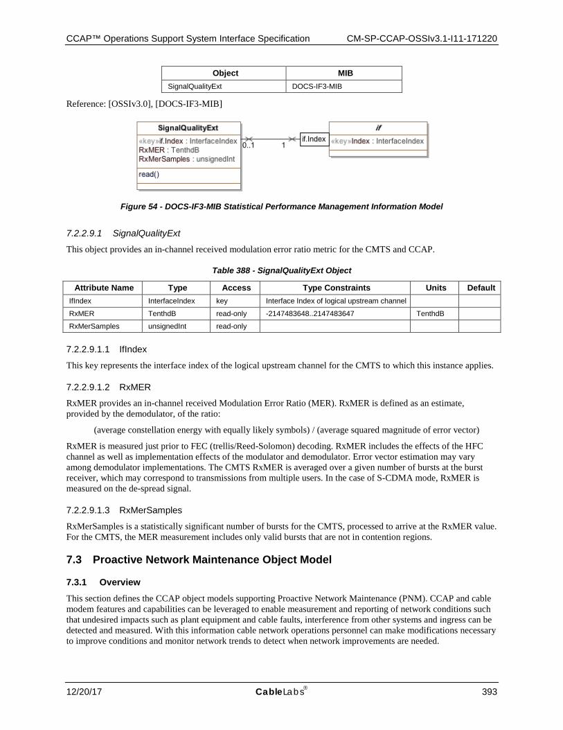
CCAP™ Operations Support System Interface Specification CM-SP-CCAP-OSSIv3.1-I11-171220
12/20/17 CableLabs 393
Object MIB SignalQualityExt DOCS-IF3-MIB
Reference: [OSSIv3.0], [DOCS-IF3-MIB]
Figure 54 - DOCS-IF3-MIB Statistical Performance Management Information Model
7.2.2.9.1 SignalQualityExt
This object provides an in-channel received modulation error ratio metric for the CMTS and CCAP.
Table 388 - SignalQualityExt Object
Attribute Name Type Access Type Constraints Units Default IfIndex InterfaceIndex key Interface Index of logical upstream channel
RxMER TenthdB read-only -2147483648..2147483647 TenthdB
RxMerSamples unsignedInt read-only
7.2.2.9.1.1 IfIndex
This key represents the interface index of the logical upstream channel for the CMTS to which this instance applies.
7.2.2.9.1.2 RxMER
RxMER provides an in-channel received Modulation Error Ratio (MER). RxMER is defined as an estimate, provided by the demodulator, of the ratio:
(average constellation energy with equally likely symbols) / (average squared magnitude of error vector)
RxMER is measured just prior to FEC (trellis/Reed-Solomon) decoding. RxMER includes the effects of the HFC channel as well as implementation effects of the modulator and demodulator. Error vector estimation may vary among demodulator implementations. The CMTS RxMER is averaged over a given number of bursts at the burst receiver, which may correspond to transmissions from multiple users. In the case of S-CDMA mode, RxMER is measured on the de-spread signal.
7.2.2.9.1.3 RxMerSamples
RxMerSamples is a statistically significant number of bursts for the CMTS, processed to arrive at the RxMER value. For the CMTS, the MER measurement includes only valid bursts that are not in contention regions.
7.3 Proactive Network Maintenance Object Model
7.3.1 Overview
This section defines the CCAP object models supporting Proactive Network Maintenance (PNM). CCAP and cable modem features and capabilities can be leveraged to enable measurement and reporting of network conditions such that undesired impacts such as plant equipment and cable faults, interference from other systems and ingress can be detected and measured. With this information cable network operations personnel can make modifications necessary to improve conditions and monitor network trends to detect when network improvements are needed.
CM-SP-CCAP-OSSIv3.1-I11-171220 DOCSIS® 3.1
394 CableLabs 12/20/17
DOCSIS 3.1 PNM capability assumes the existence of a PNM server that initiates PNM tests and receives data output from the CM and/or from the CCAP. While most tests defined in this section will complete in a short time frame, some tests will collect data over extended periods. There are also tests that can be triggered on the CM that do not require any CCAP interaction. It is possible that while a test is in progress, the CCAP could command the CM to be load balanced. In these cases, the test will abort on the CM. On the CCAP, if a test (like the DS Symbol Capture) is running for a given CM, the CCAP SHOULD prevent load balancing or other DS channel changes for that CM. Operators that wish to collect long term tests on a given modem can place the modem in the Load Balance exception table to prevent future load balance attempts on that CM which might cause the testing to abort.
Any discontinuities in the channel (channel is reset or the channel is administratively taken down or removed from service) will result in any tests associated with that interface to be concluded or aborted.
7.3.2 Data Type Definitions
This section defines the management model for the PNM Downstream Parameters Object Model. This information is contained in [PHYv3.1]: "Proactive Network Maintenance".
Table 389 - Data Types
Data Type Name Base Type Permitted Values Reference ComplexData hexBinary
MeasStatusType enum other(1) inactive(2) busy(3) sampleReady(4) error(5) resourceUnavailable(6) sampleTruncated(7)
ExclSubCarrierType hexBinary
ImpulseNoiseEventType hexBinary
RxMERData hexBinary
7.3.2.1 ComplexDataType This data type uses 16-bit fixed-point, fractional, twos-complement notation to represent each of the I (real) and Q (imaginary) components of a complex number. When viewed as a 32-bit number in a file, the I component is the most significant 16 bits and the Q component is the least significant 16 bits. Positive or negative input values exceeding the number format are clipped on I and Q independently (no rollover).
The fixed point format uses "sm.n" notation to indicate the location of the binary point in the I and Q components. Reading from left to right there is a sign bit, m integer bits, the assumed location of the binary point, and n fractional bits. If the I or Q components have less than 16 available bits of input data, the binary point of the input data is adjusted to match the sm.n specification in the 16-bit field, with the MSBs sign-filled if required, and the LSBs zero-filled if required.
Examples of sm.n notation: With s1.14 format, the numerical value "1" corresponds to hex pattern 0x4000. With s2.13 format, the numerical value "1" corresponds to 0x2000. With s3.12 format, the numerical value "1" corresponds to 0x1000.
Example of a complex number with s2.13 format on I and Q components: 0x2400F800 represents the complex number 1.125 - 0.25 j, where "j" is the square root of -1; that is, I = 1.125 and Q = -0.25.
7.3.2.2 MeasStatusType This data type is used to determine the state of a measurement. The MeasStatusTypes are interpreted as follows:
'other' - Indicates any state not described below
'inactive' - Indicates that a test is not started or in progress
CCAP™ Operations Support System Interface Specification CM-SP-CCAP-OSSIv3.1-I11-171220
12/20/17 CableLabs 395
'busy' - Indicates that a test has been started and is in progress
'sampleReady' - Indicates that a test has completed and that the measurement data is ready
'error' - Indicates that there was an error starting or during the test and any test data, if available, may not be valid
'resourceUnavailable' - Indicates that the test could not be started due to lack of test platform resources
'sampleTruncated' - Indicates that the size of the requested data exceeded file size supported
7.3.2.3 ExclSubCarrierType This data type is used to represent subcarriers which are excluded. The length in bytes of this data type is equal to the FFT size divided by 8. Each bit corresponds to a subcarrier. If a bit is set, then the subcarrier is excluded. The left most bit of the first byte corresponds to the lowest frequency subcarrier. The right most bit of the last byte corresponds to highest frequency subcarrier.
7.3.2.4 ImpulseNoiseEventType This data type is used to represent Impulse Noise events. The length in bytes of this data type is 12 bytes structured as follows:
Table 390 - Format for ImpulseNoiseEventType
Element Type Units Size TImestamp UnsignedLong 8 bytes
Event Duration UnsignedInt ns 4 bytes
EventAveragePower Short dBmV 2 bytes
7.3.2.4.1 Timestamp
Timestamp is the 64-bit Extended Timestamp. If the CMTS is not using the 64-bit Extended Timestamp, then the 8-byte value is constructed from the 32-bit DOCSIS 3.0 Timestamp as follows:
Bits 63 through 41 = 0
Bits 40 through 9 = 32-bit DOCSIS 3.0 Timestamp
Bits 8 through 0 = 0
7.3.2.4.2 EventDuration
The event duration is the period of time during which the signal level exceeded the StartTriggerLevel and until the signal level fell below the EndTriggerLevel. If the capture is done using a FreeRunDuration, then the EventDuration corresponds to the interval during which the capture was performed. The EventDuration is recorded in units of ns.
7.3.2.4.3 EventAveragePower
The EventAveragePower is the average power of the event recorded in units of dBmV using 16-bit fixed point, fractional, two's complement notation encoded using the S6.9 format.
7.3.2.5 RxMerData This data type represents a sequence of received modulation error ratio (RxMER) values for an upstream OFDMA channel at the CM. The data is expressed as a series of RxMerDataValues - one RxMerDataValue for each subcarrier (active or excluded) from the lowest-frequency active subcarrier to the highest-frequency active subcarrier with no gaps.
7.3.2.5.1 RxMerDataValue
This data type is used to express RxMER and is defined below:
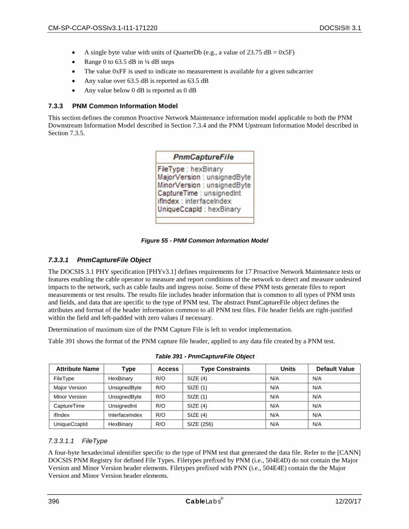
CM-SP-CCAP-OSSIv3.1-I11-171220 DOCSIS® 3.1
396 CableLabs 12/20/17
• A single byte value with units of QuarterDb (e.g., a value of 23.75 dB = 0x5F) • Range 0 to 63.5 dB in ¼ dB steps • The value 0xFF is used to indicate no measurement is available for a given subcarrier • Any value over 63.5 dB is reported as 63.5 dB • Any value below 0 dB is reported as 0 dB
7.3.3 PNM Common Information Model
This section defines the common Proactive Network Maintenance information model applicable to both the PNM Downstream Information Model described in Section 7.3.4 and the PNM Upstream Information Model described in Section 7.3.5.
Figure 55 - PNM Common Information Model
7.3.3.1 PnmCaptureFile Object The DOCSIS 3.1 PHY specification [PHYv3.1] defines requirements for 17 Proactive Network Maintenance tests or features enabling the cable operator to measure and report conditions of the network to detect and measure undesired impacts to the network, such as cable faults and ingress noise. Some of these PNM tests generate files to report measurements or test results. The results file includes header information that is common to all types of PNM tests and fields, and data that are specific to the type of PNM test. The abstract PnmCaptureFile object defines the attributes and format of the header information common to all PNM test files. File header fields are right-justified within the field and left-padded with zero values if necessary.
Determination of maximum size of the PNM Capture File is left to vendor implementation.
Table 391 shows the format of the PNM capture file header, applied to any data file created by a PNM test.
Table 391 - PnmCaptureFile Object
Attribute Name Type Access Type Constraints Units Default Value FileType HexBinary R/O SIZE (4) N/A N/A
Major Version UnsignedByte R/O SIZE (1) N/A N/A
Minor Version UnsignedByte R/O SIZE (1) N/A N/A
CaptureTime UnsignedInt R/O SIZE (4) N/A N/A
ifIndex InterfaceIndex R/O SIZE (4) N/A N/A
UniqueCcapId HexBinary R/O SIZE (256) N/A N/A
7.3.3.1.1 FileType
A four-byte hexadecimal identifier specific to the type of PNM test that generated the data file. Refer to the [CANN] DOCSIS PNM Registry for defined File Types. Filetypes prefixed by PNM (i.e., 504E4D) do not contain the Major Version and Minor Version header elements. Filetypes prefixed with PNN (i.e., 504E4E) contain the the Major Version and Minor Version header elements.
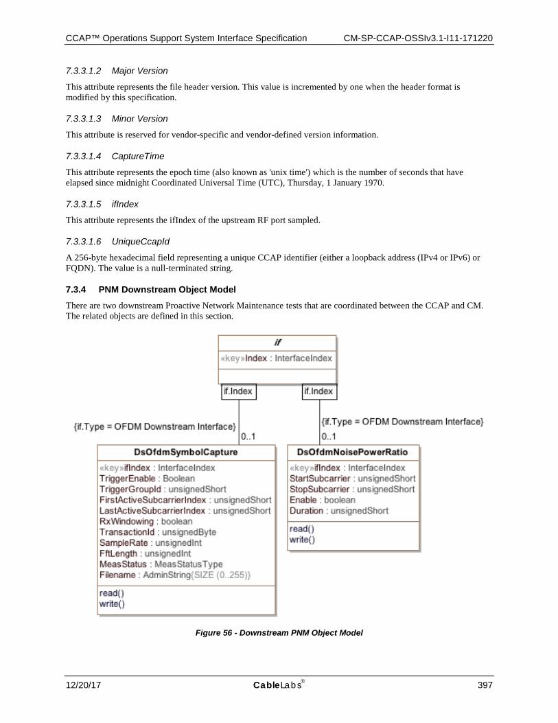
CCAP™ Operations Support System Interface Specification CM-SP-CCAP-OSSIv3.1-I11-171220
12/20/17 CableLabs 397
7.3.3.1.2 Major Version
This attribute represents the file header version. This value is incremented by one when the header format is modified by this specification.
7.3.3.1.3 Minor Version
This attribute is reserved for vendor-specific and vendor-defined version information.
7.3.3.1.4 CaptureTime
This attribute represents the epoch time (also known as 'unix time') which is the number of seconds that have elapsed since midnight Coordinated Universal Time (UTC), Thursday, 1 January 1970.
7.3.3.1.5 ifIndex
This attribute represents the ifIndex of the upstream RF port sampled.
7.3.3.1.6 UniqueCcapId
A 256-byte hexadecimal field representing a unique CCAP identifier (either a loopback address (IPv4 or IPv6) or FQDN). The value is a null-terminated string.
7.3.4 PNM Downstream Object Model
There are two downstream Proactive Network Maintenance tests that are coordinated between the CCAP and CM. The related objects are defined in this section.
Figure 56 - Downstream PNM Object Model
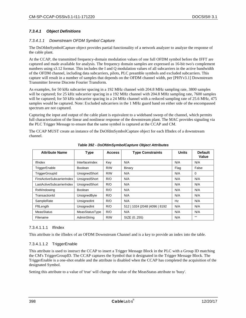
CM-SP-CCAP-OSSIv3.1-I11-171220 DOCSIS® 3.1
398 CableLabs 12/20/17
7.3.4.1 Object Definitions
7.3.4.1.1 Downstream OFDM Symbol Capture
The DsOfdmSymbolCapture object provides partial functionality of a network analyzer to analyze the response of the cable plant.
At the CCAP, the transmitted frequency-domain modulation values of one full OFDM symbol before the IFFT are captured and made available for analysis. The frequency domain samples are expressed as 16-bit two's complement numbers using s3.12 format. This includes the I and Q modulation values of all subcarriers in the active bandwidth of the OFDM channel, including data subcarriers, pilots, PLC preamble symbols and excluded subcarriers. This capture will result in a number of samples that depends on the OFDM channel width, per [PHYv3.1] Downstream Transmitter Inverse Discrete Fourier Transform.
As examples, for 50 kHz subcarrier spacing in a 192 MHz channel with 204.8 MHz sampling rate, 3800 samples will be captured; for 25 kHz subcarrier spacing in a 192 MHz channel with 204.8 MHz sampling rate, 7600 samples will be captured; for 50 kHz subcarrier spacing in a 24 MHz channel with a reduced sampling rate of 25.6 MHz, 475 samples would be captured. Note: Excluded subcarriers in the 1 MHz guard band on either side of the encompassed spectrum are not captured.
Capturing the input and output of the cable plant is equivalent to a wideband sweep of the channel, which permits full characterization of the linear and nonlinear response of the downstream plant. The MAC provides signaling via the PLC Trigger Message to ensure that the same symbol is captured at the CCAP and CM.
The CCAP MUST create an instance of the DsOfdmSymbolCapture object for each IfIndex of a downstream channel.
Table 392 - DsOfdmSymbolCapture Object Attributes
Attribute Name Type Access Type Constraints Units Default Value
IfIndex InterfaceIndex Key N/A N/A N/A
TriggerEnable Boolean R/W Binary Flag False
TriggerGroupId UnsignedShort R/W N/A N/A 0
FirstActiveSubcarrierIndex UnsignedShort R/O N/A N/A N/A
LastActiveSubcarrierIndex UnsignedShort R/O N/A N/A N/A
RxWindowing Boolean R/O N/A N/A N/A
TransactionId UnsignedByte R/O N/A N/A N/A
SampleRate UnsignedInt R/O N/A Hz N/A
FftLength UnsignedInt R/O 512 | 1024 |2048 |4096 | 8192 N/A N/A
MeasStatus MeasStatusType R/O N/A N/A N/A
Filename AdminString R/W SIZE (0..255) N/A ""
7.3.4.1.1.1 IfIndex
This attribute is the ifIndex of an OFDM Downstream Channel and is a key to provide an index into the table.
7.3.4.1.1.2 TriggerEnable
This attribute is used to instruct the CCAP to insert a Trigger Message Block in the PLC with a Group ID matching the CM's TriggerGroupID. The CCAP captures the Symbol that it designated in the Trigger Message Block. The TriggerEnable is a one-shot enable and the attribute is disabled when the CCAP has completed the acquisition of the designated Symbol.
Setting this attribute to a value of 'true' will change the value of the MeasStatus attribute to 'busy'.
CCAP™ Operations Support System Interface Specification CM-SP-CCAP-OSSIv3.1-I11-171220
12/20/17 CableLabs 399
7.3.4.1.1.3 TriggerGroupId
This attribute is used by the CCAP to be inserted in the PLC Trigger MB to identify a CM or a group of CMs expected to perform Symbol Capture measurements for the designated symbol.
7.3.4.1.1.4 FirstActiveSubcarrierIndex
This attribute is used to denote the subcarrier index of the lowest frequency of the Encompassed Spectrum for the OFDM channel.
7.3.4.1.1.5 LastActiveSubcarrierIndex
This attribute is used to denote the subcarrier index of the highest frequency of the Encompassed Spectrum for the OFDM channel.
7.3.4.1.1.6 RxWindowing
This attribute is a flag indicating if vendor proprietary Windowing was enabled during the capture.
7.3.4.1.1.7 TransactionId
This attribute is the Transaction ID sent by the CCAP in the Trigger MB. Prior to completion of a measurement this attribute has no meaning.
7.3.4.1.1.8 SampleRate
This attribute is the FFT sample rate in use by the CM for the channel; typically the sample rate for the downstream channel will be 204.8 MHz.
7.3.4.1.1.9 FftLength
This attribute is the FFT length in use by the CM for the channel; typically this value is 4096 or 8192 for the Downstream Channel.
7.3.4.1.1.10 MeasStatus
This attribute is used to determine the status of the measurement. The PNM server will query the Status value to determine when the measurement is complete.
7.3.4.1.1.11 Filename
This attribute contains the name of the file with the captured symbol data at the CCAP that is to be downloaded using TFTP to the PNM server.
This value can only be changed while a test is not in progress. An attempt to set this value while the value of MeasStatus is 'busy' will return 'inconsistentValue'.
If the value of this object is an empty string, then a default filename value will be used. Otherwise, the value set will be used as the filename. If a default filename is generated, then that value will be returned in this object and will represent the filename that was used for the test. All subsequent tests should set this object to a meaningful value or to an 'empty string' value (to generate a new default filename) before starting a new test.
If a default filename value is used, it is generated as the test name, plus a unique CCAP identifier (either a loopback address (IPv4 or IPv6) or FQDN), plus the 'epoch time'. The epoch time (also known as 'unix time') is defined as the number of seconds that have elapsed since midnight Coordinated Universal Time (UTC),Thursday, 1 January 1970.
Hence, the format would be:
PNMCcapSymCap_<Unique CCAP Identifier>_<epoch>
For example: PNMCcapSymCap_ccap1.boulder.cablelabs.com_1403405123
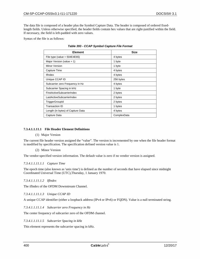
CM-SP-CCAP-OSSIv3.1-I11-171220 DOCSIS® 3.1
400 CableLabs 12/20/17
The data file is composed of a header plus the Symbol Capture Data. The header is composed of ordered fixed-length fields. Unless otherwise specified, the header fields contain hex values that are right-justified within the field. If necessary, the field is left-padded with zero values.
Syntax of the file is as follows:
Table 393 - CCAP Symbol Capture File Format
Element Size File type (value = 504E4E65) 4 bytes
Major Version (value = 1) 1 byte
Minor Version 1 byte
Capture Time 4 bytes
IfIndex 4 bytes
Unique CCAP ID 256 bytes
Subcarrier zero Frequency in Hz 4 bytes
Subcarrier Spacing in kHz 1 byte
FirstActiveSubcarrierIndex 2 bytes
LastActiveSubcarrierIndex 2 bytes
TriggerGroupId 2 bytes
Transaction ID 1 bytes
Length (in bytes) of Capture Data 4 bytes
Capture Data ComplexData
7.3.4.1.1.11.1 File Header Element Definitions
(1) Major Version
The current file header version assigned the “value”. The version is incremented by one when the file header format is modified by specification. The specification defined version value is 1.
(2) Minor Version
The vendor-specified version information. The default value is zero if no vendor version is assigned.
7.3.4.1.1.11.1.1 Capture Time
The epoch time (also known as 'unix time') is defined as the number of seconds that have elapsed since midnight Coordinated Universal Time (UTC),Thursday, 1 January 1970.
7.3.4.1.1.11.1.2 IfIndex
The ifIndex of the OFDM Downstream Channel.
7.3.4.1.1.11.1.3 Unique CCAP ID
A unique CCAP identifier (either a loopback address (IPv4 or IPv6) or FQDN). Value is a null terminated string.
7.3.4.1.1.11.1.4 Subcarrier zero Frequency in Hz
The center frequency of subcarrier zero of the OFDM channel.
7.3.4.1.1.11.1.5 Subcarrier Spacing in kHz
This element represents the subcarrier spacing in kHz.
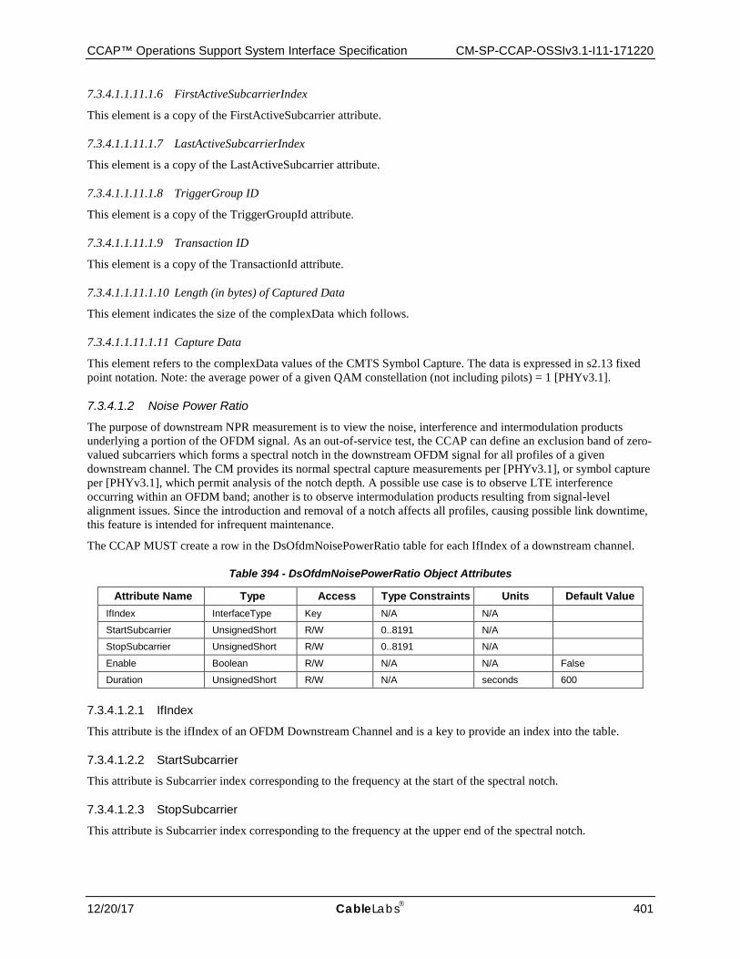
CCAP™ Operations Support System Interface Specification CM-SP-CCAP-OSSIv3.1-I11-171220
12/20/17 CableLabs 401
7.3.4.1.1.11.1.6 FirstActiveSubcarrierIndex
This element is a copy of the FirstActiveSubcarrier attribute.
7.3.4.1.1.11.1.7 LastActiveSubcarrierIndex
This element is a copy of the LastActiveSubcarrier attribute.
7.3.4.1.1.11.1.8 TriggerGroup ID
This element is a copy of the TriggerGroupId attribute.
7.3.4.1.1.11.1.9 Transaction ID
This element is a copy of the TransactionId attribute.
7.3.4.1.1.11.1.10 Length (in bytes) of Captured Data
This element indicates the size of the complexData which follows.
7.3.4.1.1.11.1.11 Capture Data
This element refers to the complexData values of the CMTS Symbol Capture. The data is expressed in s2.13 fixed point notation. Note: the average power of a given QAM constellation (not including pilots) = 1 [PHYv3.1].
7.3.4.1.2 Noise Power Ratio
The purpose of downstream NPR measurement is to view the noise, interference and intermodulation products underlying a portion of the OFDM signal. As an out-of-service test, the CCAP can define an exclusion band of zero-valued subcarriers which forms a spectral notch in the downstream OFDM signal for all profiles of a given downstream channel. The CM provides its normal spectral capture measurements per [PHYv3.1], or symbol capture per [PHYv3.1], which permit analysis of the notch depth. A possible use case is to observe LTE interference occurring within an OFDM band; another is to observe intermodulation products resulting from signal-level alignment issues. Since the introduction and removal of a notch affects all profiles, causing possible link downtime, this feature is intended for infrequent maintenance.
The CCAP MUST create a row in the DsOfdmNoisePowerRatio table for each IfIndex of a downstream channel.
Table 394 - DsOfdmNoisePowerRatio Object Attributes
Attribute Name Type Access Type Constraints Units Default Value IfIndex InterfaceType Key N/A N/A
StartSubcarrier UnsignedShort R/W 0..8191 N/A
StopSubcarrier UnsignedShort R/W 0..8191 N/A
Enable Boolean R/W N/A N/A False
Duration UnsignedShort R/W N/A seconds 600
7.3.4.1.2.1 IfIndex
This attribute is the ifIndex of an OFDM Downstream Channel and is a key to provide an index into the table.
7.3.4.1.2.2 StartSubcarrier
This attribute is Subcarrier index corresponding to the frequency at the start of the spectral notch.
7.3.4.1.2.3 StopSubcarrier
This attribute is Subcarrier index corresponding to the frequency at the upper end of the spectral notch.
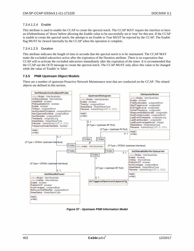
CM-SP-CCAP-OSSIv3.1-I11-171220 DOCSIS® 3.1
402 CableLabs 12/20/17
7.3.4.1.2.4 Enable
This attribute is used to enable the CCAP to create the spectral notch. The CCAP MAY require the interface to have an ifAdminStatus of 'down' before allowing the Enable value to be successfully set to 'true' for this test. If the CCAP is unable to create the spectral notch, the attempt to set Enable to True MUST be rejected by the CCAP. The Enable flag MUST be cleared internally by the CCAP when the operation is complete.
7.3.4.1.2.5 Duration
This attribute indicates the length of time in seconds that the spectral notch is to be maintained. The CCAP MAY make the excluded subcarriers active after the expiration of the Duration attribute. There is no expectation that CCAP will re-activate the excluded subcarriers immediately after the expiration of the timer. It is recommended that the CCAP use the OCD message to create the spectral notch. The CCAP MUST only allow this value to be changed while the value of 'Enable' is 'false'.
7.3.5 PNM Upstream Object Models
There are a number of upstream Proactive Network Maintenance tests that are conducted on the CCAP. The related objects are defined in this section.
Figure 57 - Upstream PNM Information Model
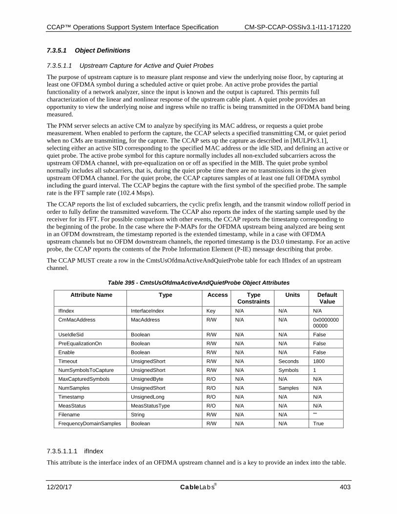
CCAP™ Operations Support System Interface Specification CM-SP-CCAP-OSSIv3.1-I11-171220
12/20/17 CableLabs 403
7.3.5.1 Object Definitions
7.3.5.1.1 Upstream Capture for Active and Quiet Probes
The purpose of upstream capture is to measure plant response and view the underlying noise floor, by capturing at least one OFDMA symbol during a scheduled active or quiet probe. An active probe provides the partial functionality of a network analyzer, since the input is known and the output is captured. This permits full characterization of the linear and nonlinear response of the upstream cable plant. A quiet probe provides an opportunity to view the underlying noise and ingress while no traffic is being transmitted in the OFDMA band being measured.
The PNM server selects an active CM to analyze by specifying its MAC address, or requests a quiet probe measurement. When enabled to perform the capture, the CCAP selects a specified transmitting CM, or quiet period when no CMs are transmitting, for the capture. The CCAP sets up the capture as described in [MULPIv3.1], selecting either an active SID corresponding to the specified MAC address or the idle SID, and defining an active or quiet probe. The active probe symbol for this capture normally includes all non-excluded subcarriers across the upstream OFDMA channel, with pre-equalization on or off as specified in the MIB. The quiet probe symbol normally includes all subcarriers, that is, during the quiet probe time there are no transmissions in the given upstream OFDMA channel. For the quiet probe, the CCAP captures samples of at least one full OFDMA symbol including the guard interval. The CCAP begins the capture with the first symbol of the specified probe. The sample rate is the FFT sample rate (102.4 Msps).
The CCAP reports the list of excluded subcarriers, the cyclic prefix length, and the transmit window rolloff period in order to fully define the transmitted waveform. The CCAP also reports the index of the starting sample used by the receiver for its FFT. For possible comparison with other events, the CCAP reports the timestamp corresponding to the beginning of the probe. In the case where the P-MAPs for the OFDMA upstream being analyzed are being sent in an OFDM downstream, the timestamp reported is the extended timestamp, while in a case with OFDMA upstream channels but no OFDM downstream channels, the reported timestamp is the D3.0 timestamp. For an active probe, the CCAP reports the contents of the Probe Information Element (P-IE) message describing that probe.
The CCAP MUST create a row in the CmtsUsOfdmaActiveAndQuietProbe table for each IfIndex of an upstream channel.
Table 395 - CmtsUsOfdmaActiveAndQuietProbe Object Attributes
Attribute Name Type Access Type Constraints
Units Default Value
IfIndex InterfaceIndex Key N/A N/A N/A
CmMacAddress MacAddress R/W N/A N/A 0x000000000000
UseIdleSid Boolean R/W N/A N/A False
PreEqualizationOn Boolean R/W N/A N/A False
Enable Boolean R/W N/A N/A False
Timeout UnsignedShort R/W N/A Seconds 1800
NumSymbolsToCapture UnsignedShort R/W N/A Symbols 1
MaxCapturedSymbols UnsignedByte R/O N/A N/A N/A
NumSamples UnsignedShort R/O N/A Samples N/A
Timestamp UnsignedLong R/O N/A N/A N/A
MeasStatus MeasStatusType R/O N/A N/A N/A
Filename String R/W N/A N/A ""
FrequencyDomainSamples Boolean R/W N/A N/A True
7.3.5.1.1.1 ifIndex
This attribute is the interface index of an OFDMA upstream channel and is a key to provide an index into the table.
CM-SP-CCAP-OSSIv3.1-I11-171220 DOCSIS® 3.1
404 CableLabs 12/20/17
7.3.5.1.1.2 CmMacAddress
This attribute represents the MAC address of the CM transmitting the probe to be measured.
7.3.5.1.1.3 UseIdleSid
This attribute when enabled causes the CCAP to measure the channel during a quiet period when no CM is transmitting.
7.3.5.1.1.4 PreEqualizationOn
This attribute when enabled causes the CCAP to enable pre-equalization in the Probe Information Element for the CM transmitting the probe to be measured.
7.3.5.1.1.5 Enable
This attribute causes the CCAP to begin the measurement of a probe for the selected CM or for a quiet period if the UseIdleSid attribute is enabled. The Enable attribute is cleared internally by the CCAP when the measurement has been completed.
7.3.5.1.1.6 Timeout
This attribute provides a timeout for the measurement if the CCAP is unable to perform the measurement for some reason. A value of zero for the Timeout attribute means that the measurement continues to be active until the measurement is complete or until the Enable attribute is cleared.
7.3.5.1.1.7 NumSymbolsToCapture
This attribute represents the number of symbols the CCAP is to capture for the modem whose probe is being measured or the number of symbol times to measure for the idle Sid.
7.3.5.1.1.8 MaxCapturedSymbols
This attribute represents the number of symbols the CCAP can capture for one measurement. Typically, for 50 kHz Subcarrier Spacing, the CCAP can capture two symbols, and for 25 kHz, the CCAP can capture one symbol. In order to capture more than one symbol, the CCAP would need to schedule multiple probe opportunities for the CM whose probe is being measured.
7.3.5.1.1.9 NumSamples
This attribute represents the number of FFT samples used for the measurement.
7.3.5.1.1.10 Timestamp
This attribute represents the timestamp corresponding to the time when measurement was performed. In the case in which the Primary Downstream is an OFDM channel this is the 64 bit timestamp. In the case in which the Primary Downstream is an SC-QAM channel this is the 32 bit timestamp. If the 32 bit timestamp is used, the 32 most significant bits of the timestamp are set to zero.
7.3.5.1.1.11 MeasStatus
This attribute is used to determine the status of the command. When the Status = SampleReady, the CCAP has completed the measurement and the Enable attribute has been cleared.
7.3.5.1.1.12 Filename
This attribute is the name of the file with the captured probe data at the CCAP that is to be downloaded using TFTP to the PNM server.
This value can only be changed while a test is not in progress. An attempt to set this value while the value of 'MeasStatus' is 'busy' will return 'inconsistentValue'.
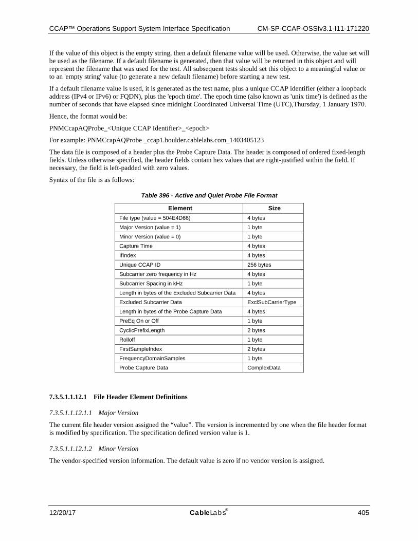
CCAP™ Operations Support System Interface Specification CM-SP-CCAP-OSSIv3.1-I11-171220
12/20/17 CableLabs 405
If the value of this object is the empty string, then a default filename value will be used. Otherwise, the value set will be used as the filename. If a default filename is generated, then that value will be returned in this object and will represent the filename that was used for the test. All subsequent tests should set this object to a meaningful value or to an 'empty string' value (to generate a new default filename) before starting a new test.
If a default filename value is used, it is generated as the test name, plus a unique CCAP identifier (either a loopback address (IPv4 or IPv6) or FQDN), plus the 'epoch time'. The epoch time (also known as 'unix time') is defined as the number of seconds that have elapsed since midnight Coordinated Universal Time (UTC),Thursday, 1 January 1970.
Hence, the format would be:
PNMCcapAQProbe_<Unique CCAP Identifier>_<epoch>
For example: PNMCcapAQProbe _ccap1.boulder.cablelabs.com_1403405123
The data file is composed of a header plus the Probe Capture Data. The header is composed of ordered fixed-length fields. Unless otherwise specified, the header fields contain hex values that are right-justified within the field. If necessary, the field is left-padded with zero values.
Syntax of the file is as follows:
Table 396 - Active and Quiet Probe File Format
Element Size File type (value = 504E4D66) 4 bytes
Major Version (value = 1) 1 byte
Minor Version (value = 0) 1 byte
Capture Time 4 bytes
IfIndex 4 bytes
Unique CCAP ID 256 bytes
Subcarrier zero frequency in Hz 4 bytes
Subcarrier Spacing in kHz 1 byte
Length in bytes of the Excluded Subcarrier Data 4 bytes
Excluded Subcarrier Data ExclSubCarrierType
Length in bytes of the Probe Capture Data 4 bytes
PreEq On or Off 1 byte
CyclicPrefixLength 2 bytes
Rolloff 1 byte
FirstSampleIndex 2 bytes
FrequencyDomainSamples 1 byte
Probe Capture Data ComplexData
7.3.5.1.1.12.1 File Header Element Definitions
7.3.5.1.1.12.1.1 Major Version
The current file header version assigned the “value”. The version is incremented by one when the file header format is modified by specification. The specification defined version value is 1.
7.3.5.1.1.12.1.2 Minor Version
The vendor-specified version information. The default value is zero if no vendor version is assigned.

CM-SP-CCAP-OSSIv3.1-I11-171220 DOCSIS® 3.1
406 CableLabs 12/20/17
7.3.5.1.1.12.1.3 Capture Time
The epoch time (also known as 'unix time') is defined as the number of seconds that have elapsed since midnight Coordinated Universal Time (UTC),Thursday, 1 January 1970.
7.3.5.1.1.12.1.4 IfIndex
The ifIndex of the OFDMA Upstream Channel.
7.3.5.1.1.12.1.5 Unique CCAP ID
A unique CCAP identifier (either a loopback address (IPv4 or IPv6) or FQDN). Value is a null terminated string.
7.3.5.1.1.12.1.6 Subcarrier zero frequency in Hz
The center frequency of subcarrier zero of the OFDM channel.
7.3.5.1.1.12.1.7 Subcarrier spacing in kHz
This element represents the subcarrier spacing for the OFDM channel.
7.3.5.1.1.12.1.8 Length in bytes of the Excluded Subcarrier Data
This element represents the length of the excluded subcarrier data which follows.
7.3.5.1.1.12.1.9 Excluded Subcarrier Data
This element contains the excluded subcarrier data as ExclSubCarType.
7.3.5.1.1.12.1.10 Length in bytes of the Probe Capture Data
This element represents the length of the probe capture data which follows.
7.3.5.1.1.12.1.11 PreEq On or Off
This file header attribute indicates if the test was conducted with pre-equalization enabled or disabled. It is included in the header of the file to fully define the transmitted waveform.
7.3.5.1.1.12.1.12 CyclicPrefixLength
This attribute provides the currently configured cyclic prefix length configured for this OFDMA channel. It is included in the header of the file to fully define the transmitted waveform.
7.3.5.1.1.12.1.13 Rolloff
This attribute provides the currently configured rolloff period configured for this OFDMA channel. It is included in the header of the file to fully define the transmitted waveform.
7.3.5.1.1.12.1.14 FirstSampleIndex
This attribute represents the first active subcarrier used in the probe capture.
7.3.5.1.1.12.1.15 FrequencyDomainSamples
This attribute indicates if the output samples are to be in the time domain or in the frequency domain. True means the samples are in the frequency domain. False means they are in the time domain.
7.3.5.1.1.12.1.16 Probe Capture Data
This element refers to the complexData values of the Probe Capture Data. The data is expressed in s3.12 Fixed Point notation. The CMTS SHOULD adjust the scaling such that the average power of the samples is approximately 1, in order to avoid excessive clipping and quantization noise.
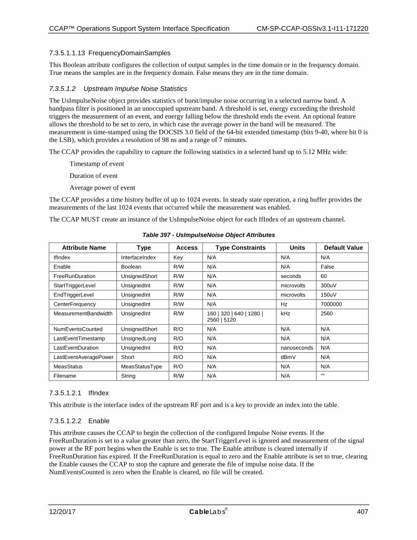
CCAP™ Operations Support System Interface Specification CM-SP-CCAP-OSSIv3.1-I11-171220
12/20/17 CableLabs 407
7.3.5.1.1.13 FrequencyDomainSamples
This Boolean attribute configures the collection of output samples in the time domain or in the frequency domain. True means the samples are in the frequency domain. False means they are in the time domain.
7.3.5.1.2 Upstream Impulse Noise Statistics
The UsImpulseNoise object provides statistics of burst/impulse noise occurring in a selected narrow band. A bandpass filter is positioned in an unoccupied upstream band. A threshold is set, energy exceeding the threshold triggers the measurement of an event, and energy falling below the threshold ends the event. An optional feature allows the threshold to be set to zero, in which case the average power in the band will be measured. The measurement is time-stamped using the DOCSIS 3.0 field of the 64-bit extended timestamp (bits 9-40, where bit 0 is the LSB), which provides a resolution of 98 ns and a range of 7 minutes.
The CCAP provides the capability to capture the following statistics in a selected band up to 5.12 MHz wide:
Timestamp of event
Duration of event
Average power of event
The CCAP provides a time history buffer of up to 1024 events. In steady state operation, a ring buffer provides the measurements of the last 1024 events that occurred while the measurement was enabled.
The CCAP MUST create an instance of the UsImpulseNoise object for each IfIndex of an upstream channel.
Table 397 - UsImpulseNoise Object Attributes
Attribute Name Type Access Type Constraints Units Default Value IfIndex InterfaceIndex Key N/A N/A N/A
Enable Boolean R/W N/A N/A False
FreeRunDuration UnsignedShort R/W N/A seconds 60
StartTriggerLevel UnsignedInt R/W N/A microvolts 300uV
EndTriggerLevel UnsignedInt R/W N/A microvolts 150uV
CenterFrequency UnsignedInt R/W N/A Hz 7000000
MeasurementBandwidth UnsignedInt R/W 160 | 320 | 640 | 1280 | 2560 | 5120
kHz 2560
NumEventsCounted UnsignedShort R/O N/A N/A N/A
LastEventTimestamp UnsignedLong R/O N/A N/A N/A
LastEventDuration UnsignedInt R/O N/A nanoseconds N/A
LastEventAveragePower Short R/O N/A dBmV N/A
MeasStatus MeasStatusType R/O N/A N/A N/A
Filename String R/W N/A N/A ""
7.3.5.1.2.1 IfIndex
This attribute is the interface index of the upstream RF port and is a key to provide an index into the table.
7.3.5.1.2.2 Enable
This attribute causes the CCAP to begin the collection of the configured Impulse Noise events. If the FreeRunDuration is set to a value greater than zero, the StartTriggerLevel is ignored and measurement of the signal power at the RF port begins when the Enable is set to true. The Enable attribute is cleared internally if FreeRunDuration has expired. If the FreeRunDuration is equal to zero and the Enable attribute is set to true, clearing the Enable causes the CCAP to stop the capture and generate the file of impulse noise data. If the NumEventsCounted is zero when the Enable is cleared, no file will be created.

CM-SP-CCAP-OSSIv3.1-I11-171220 DOCSIS® 3.1
408 CableLabs 12/20/17
7.3.5.1.2.3 FreeRunDuration
This attribute provides length of time to perform the measurement when the Enable attribute is set to true.
7.3.5.1.2.4 StartTriggerLevel
If the FreeRunDuration is set to zero and the Enable attribute is set to true, an individual burst event starts when the burst noise exceeds the StartTriggerLevel.
7.3.5.1.2.5 EndTriggerLevel
The measurement of an individual burst event ends when the burst noise falls below the EndTriggerLevel. It is worth noting that if the EndTriggerLevel is set to zero, the FreeRunDuration is set to zero and the Enable attribute is set to true, that at most a single Impulse Noise Event will be recorded when triggered by a burst event exceeding the StartTriggerLevel.
7.3.5.1.2.6 CenterFrequency
This attribute defines the center frequency for the noise power measurement.
7.3.5.1.2.7 MeasurementBandwidth
This attribute defines the bandwidth for the noise power measurement. The MeasurementBandwidth is the -3 dB bandwidth; the occupied bandwidth is typically 1.25 times the measurement bandwidth.
7.3.5.1.2.8 NumEventsCounted
This attribute is used to indicate how many impulse noise events have been recorded since the Enable was set to true. This value will be 1024 in steady state, after the ring buffer has filled with measurements. If the StartTriggerLevel is set to zero, then the NumEventsCounted will be set to 1 when the FreeRunDuration has expired and the Enable has been internally cleared.
7.3.5.1.2.9 LastEventTimestamp
This attribute provides represents the timestamp corresponding to the start of the last recorded event. The measurement is time-stamped using the 64-bit extended timestamp. If the CMTS is not using the 64-bit Extended Timestamp, then the 8 byte value is constructed from the 32-bit DOCSIS 3.0 Timestamp as follows:
Bits 63 through 41 = 0
Bits 40 through 9 = 32-bit DOCSIS 3.0 Timestamp
Bits 8 through 0 = 0
7.3.5.1.2.10 LastEventDuration
This attribute provides represents the time corresponding to the duration of the last recorded event. The EventDuration is expressed in ns.
7.3.5.1.2.11 LastEventAveragePower
This attribute represents the average power measured during the last recorded event. The LastEventAveragePower is expressed in units of dBmV with 16-bit fixed point, fractional, two's complement notation encoded using the S6.9 format.
7.3.5.1.2.12 MeasStatus
This attribute is used to determine the status of the command. When the Status is sampleReady, the CCAP has completed the measurement and the Enable attribute has been cleared. If the StartTriggerLevel is set to a non zero value and the Enable attribute is set to true, then collection of Impulse Noise events is in progress and the MeasStatus attribute will return a value of 'busy'. If the Enable attribute is cleared while collection of Impulse Noise events is active, the MeasStatus attribute will be set to 'sampleReady'.
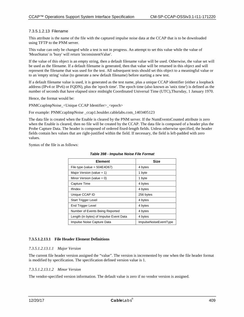
CCAP™ Operations Support System Interface Specification CM-SP-CCAP-OSSIv3.1-I11-171220
12/20/17 CableLabs 409
7.3.5.1.2.13 Filename
This attribute is the name of the file with the captured impulse noise data at the CCAP that is to be downloaded using TFTP to the PNM server.
This value can only be changed while a test is not in progress. An attempt to set this value while the value of 'MeasStatus' is 'busy' will return 'inconsistentValue'.
If the value of this object is an empty string, then a default filename value will be used. Otherwise, the value set will be used as the filename. If a default filename is generated, then that value will be returned in this object and will represent the filename that was used for the test. All subsequent tests should set this object to a meaningful value or to an 'empty string' value (to generate a new default filename) before starting a new test.
If a default filename value is used, it is generated as the test name, plus a unique CCAP identifier (either a loopback address (IPv4 or IPv6) or FQDN), plus the 'epoch time'. The epoch time (also known as 'unix time') is defined as the number of seconds that have elapsed since midnight Coordinated Universal Time (UTC),Thursday, 1 January 1970.
Hence, the format would be:
PNMCcapImpNoise_<Unique CCAP Identifier>_<epoch>
For example: PNMCcapImpNoise _ccap1.boulder.cablelabs.com_1403405123
The data file is created when the Enable is cleared by the PNM server. If the NumEventsCounted attribute is zero when the Enable is cleared, then no file will be created by the CCAP. The data file is composed of a header plus the Probe Capture Data. The header is composed of ordered fixed-length fields. Unless otherwise specified, the header fields contain hex values that are right-justified within the field. If necessary, the field is left-padded with zero values.
Syntax of the file is as follows:
Table 398 - Impulse Noise File Format
Element Size File type (value = 504E4D67) 4 bytes
Major Version (value = 1) 1 byte
Minor Version (value = 0) 1 byte
Capture Time 4 bytes
IfIndex 4 bytes
Unique CCAP ID 256 bytes
Start Trigger Level 4 bytes
End Trigger Level 4 bytes
Number of Events Being Reported 4 bytes
Length (in bytes) of Impulse Event Data 4 bytes
Impulse Noise Capture Data ImpulseNoiseEventType
7.3.5.1.2.13.1 File Header Element Definitions
7.3.5.1.2.13.1.1 Major Version
The current file header version assigned the “value”. The version is incremented by one when the file header format is modified by specification. The specification defined version value is 1.
7.3.5.1.2.13.1.2 Minor Version
The vendor-specified version information. The default value is zero if no vendor version is assigned.
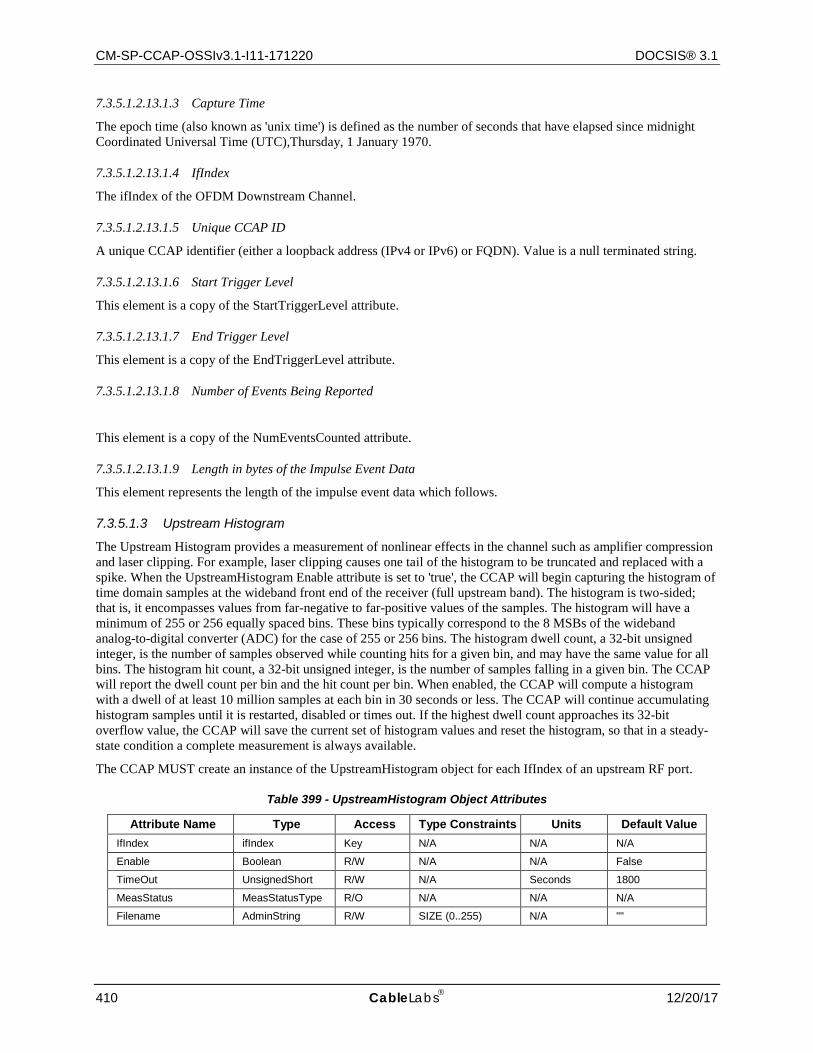
CM-SP-CCAP-OSSIv3.1-I11-171220 DOCSIS® 3.1
410 CableLabs 12/20/17
7.3.5.1.2.13.1.3 Capture Time
The epoch time (also known as 'unix time') is defined as the number of seconds that have elapsed since midnight Coordinated Universal Time (UTC),Thursday, 1 January 1970.
7.3.5.1.2.13.1.4 IfIndex
The ifIndex of the OFDM Downstream Channel.
7.3.5.1.2.13.1.5 Unique CCAP ID
A unique CCAP identifier (either a loopback address (IPv4 or IPv6) or FQDN). Value is a null terminated string.
7.3.5.1.2.13.1.6 Start Trigger Level
This element is a copy of the StartTriggerLevel attribute.
7.3.5.1.2.13.1.7 End Trigger Level
This element is a copy of the EndTriggerLevel attribute.
7.3.5.1.2.13.1.8 Number of Events Being Reported
This element is a copy of the NumEventsCounted attribute.
7.3.5.1.2.13.1.9 Length in bytes of the Impulse Event Data
This element represents the length of the impulse event data which follows.
7.3.5.1.3 Upstream Histogram
The Upstream Histogram provides a measurement of nonlinear effects in the channel such as amplifier compression and laser clipping. For example, laser clipping causes one tail of the histogram to be truncated and replaced with a spike. When the UpstreamHistogram Enable attribute is set to 'true', the CCAP will begin capturing the histogram of time domain samples at the wideband front end of the receiver (full upstream band). The histogram is two-sided; that is, it encompasses values from far-negative to far-positive values of the samples. The histogram will have a minimum of 255 or 256 equally spaced bins. These bins typically correspond to the 8 MSBs of the wideband analog-to-digital converter (ADC) for the case of 255 or 256 bins. The histogram dwell count, a 32-bit unsigned integer, is the number of samples observed while counting hits for a given bin, and may have the same value for all bins. The histogram hit count, a 32-bit unsigned integer, is the number of samples falling in a given bin. The CCAP will report the dwell count per bin and the hit count per bin. When enabled, the CCAP will compute a histogram with a dwell of at least 10 million samples at each bin in 30 seconds or less. The CCAP will continue accumulating histogram samples until it is restarted, disabled or times out. If the highest dwell count approaches its 32-bit overflow value, the CCAP will save the current set of histogram values and reset the histogram, so that in a steady-state condition a complete measurement is always available.
The CCAP MUST create an instance of the UpstreamHistogram object for each IfIndex of an upstream RF port.
Table 399 - UpstreamHistogram Object Attributes
Attribute Name Type Access Type Constraints Units Default Value IfIndex ifIndex Key N/A N/A N/A
Enable Boolean R/W N/A N/A False
TimeOut UnsignedShort R/W N/A Seconds 1800
MeasStatus MeasStatusType R/O N/A N/A N/A
Filename AdminString R/W SIZE (0..255) N/A ""
CCAP™ Operations Support System Interface Specification CM-SP-CCAP-OSSIv3.1-I11-171220
12/20/17 CableLabs 411
7.3.5.1.3.1 IfIndex
This attribute is the interface index of an upstream RF Port and is a key to provide an index into the table.
7.3.5.1.3.2 Enable
Setting this attribute to a value of 'true' instructs the CCAP to begin collection of histogram data and when enabled, the CCAP continues producing new data at its own rate.
This value is only allowed to be set to 'true' if the value of 'MeasStatus' is a value other than 'busy'. Setting this value to 'true' will change the value of the 'MeasStatus' attribute to 'busy'.
Setting this attribute to a value of 'false' instructs the CCAP to stop the collection of histogram data and to generate the file.
This attribute returns 'true' if the CCAP is actively collecting histogram data. Otherwise it returns 'false'.
A restart may be accomplished by setting this attribute to 'false' and then back to 'true'.
7.3.5.1.3.3 Timeout
This attribute sets a seconds time-out timer for capturing histogram data. This attribute is used to automatically clear the Enable attribute when the timeout expires. If the value of Timeout is zero, the CCAP MUST collect data until the value is changed, stopped, or until any dwell counter approaches its 32-bit rollover value. If the Timeout attribute is re-written while Enable is 'true', the CCAP MUST restart the timeout timer with the new Timeout value and continue collecting data.
When the timeout expires, the 'Enable' object will be set to 'false' and the capture will stop. When this happens, the data collected up to this point will be saved in the file defined by the 'FileName', and the value of 'MeasStatus' will be set to 'sampleReady'.
Setting this value does not start a capture. Captures can only be started by setting the 'Enable' attribute.
If this attribute is written while the 'Enable' attribute is 'true', the timer is restarted.
This object returns the value with which it was last set.
7.3.5.1.3.4 MeasStatus
This attribute is used to determine the status of the command. When the Status is 'sampleReady', the CCAP is ready for the Histogram data to be read.
7.3.5.1.3.5 Filename
This attribute is the name of the file at the CCAP which is to be transferred to the PNM server. The data is stored as 32-bit integers for the hit and dwell count values.
This value can only be changed while a test is not in progress. An attempt to set this value while the value of MeasStatus is 'busy' will return 'inconsistentValue'.
If the value of this object is an empty string, then a default filename value will be used. Otherwise, the value set will be used as the filename. If a default filename is generated, then that value will be returned in this object and will represent the filename that was used for the test. All subsequent tests should set this object to a meaningful value or to an 'empty string' value (to generate a new default filename) before starting a new test.
If a default filename value is used, it is generated as the test name, plus a unique CCAP identifier (either a loopback address (IPv4 or IPv6) or FQDN), plus the 'epoch time'. The epoch time (also known as 'unix time') is defined as the number of seconds that have elapsed since midnight Coordinated Universal Time (UTC),Thursday, 1 January 1970.
Hence, the format would be:
PNMCcapHist_<Unique CCAP Identifier>_<epoch>
For example: PNMCcapHist_ccap1.boulder.cablelabs.com_1403405123
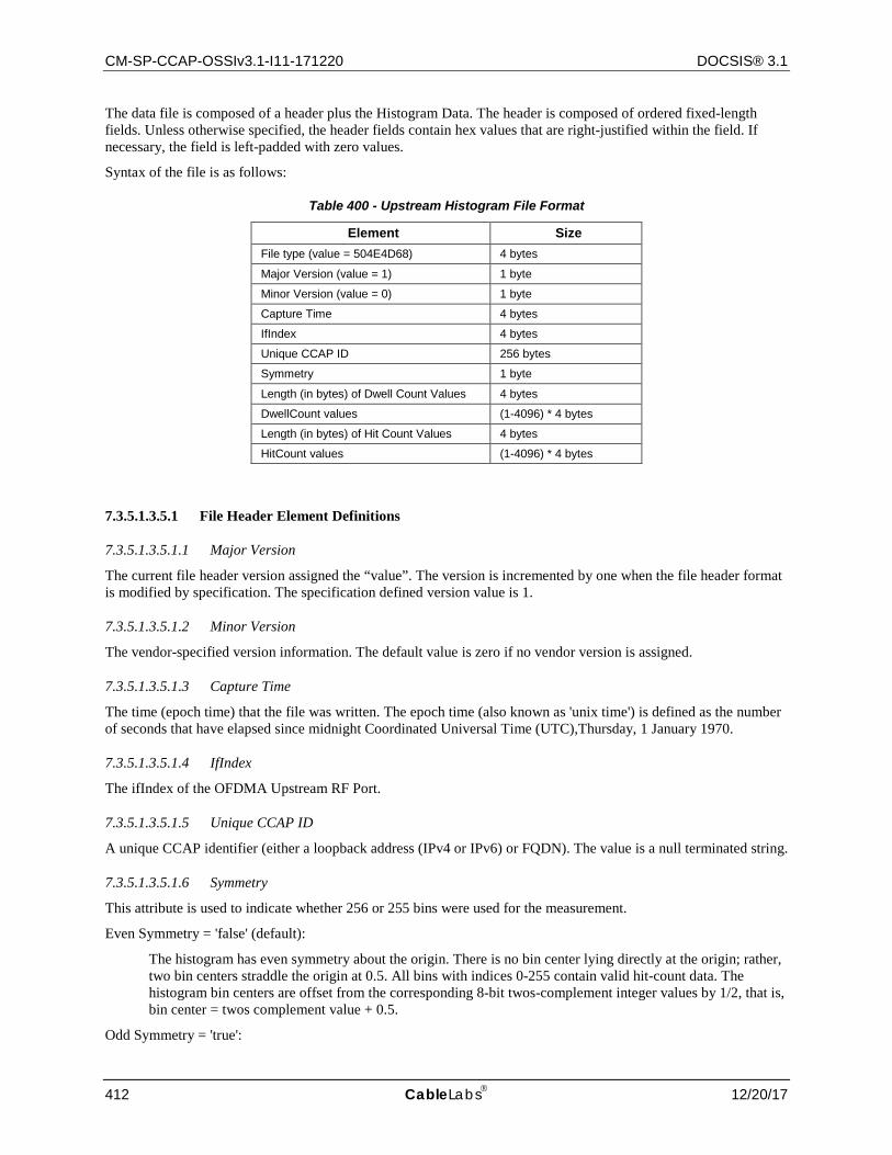
CM-SP-CCAP-OSSIv3.1-I11-171220 DOCSIS® 3.1
412 CableLabs 12/20/17
The data file is composed of a header plus the Histogram Data. The header is composed of ordered fixed-length fields. Unless otherwise specified, the header fields contain hex values that are right-justified within the field. If necessary, the field is left-padded with zero values.
Syntax of the file is as follows:
Table 400 - Upstream Histogram File Format
Element Size File type (value = 504E4D68) 4 bytes
Major Version (value = 1) 1 byte
Minor Version (value = 0) 1 byte
Capture Time 4 bytes
IfIndex 4 bytes
Unique CCAP ID 256 bytes
Symmetry 1 byte
Length (in bytes) of Dwell Count Values 4 bytes
DwellCount values (1-4096) * 4 bytes
Length (in bytes) of Hit Count Values 4 bytes
HitCount values (1-4096) * 4 bytes
7.3.5.1.3.5.1 File Header Element Definitions
7.3.5.1.3.5.1.1 Major Version
The current file header version assigned the “value”. The version is incremented by one when the file header format is modified by specification. The specification defined version value is 1.
7.3.5.1.3.5.1.2 Minor Version
The vendor-specified version information. The default value is zero if no vendor version is assigned.
7.3.5.1.3.5.1.3 Capture Time
The time (epoch time) that the file was written. The epoch time (also known as 'unix time') is defined as the number of seconds that have elapsed since midnight Coordinated Universal Time (UTC),Thursday, 1 January 1970.
7.3.5.1.3.5.1.4 IfIndex
The ifIndex of the OFDMA Upstream RF Port.
7.3.5.1.3.5.1.5 Unique CCAP ID
A unique CCAP identifier (either a loopback address (IPv4 or IPv6) or FQDN). The value is a null terminated string.
7.3.5.1.3.5.1.6 Symmetry
This attribute is used to indicate whether 256 or 255 bins were used for the measurement.
Even Symmetry = 'false' (default):
The histogram has even symmetry about the origin. There is no bin center lying directly at the origin; rather, two bin centers straddle the origin at 0.5. All bins with indices 0-255 contain valid hit-count data. The histogram bin centers are offset from the corresponding 8-bit twos-complement integer values by 1/2, that is, bin center = twos complement value + 0.5.
Odd Symmetry = 'true':
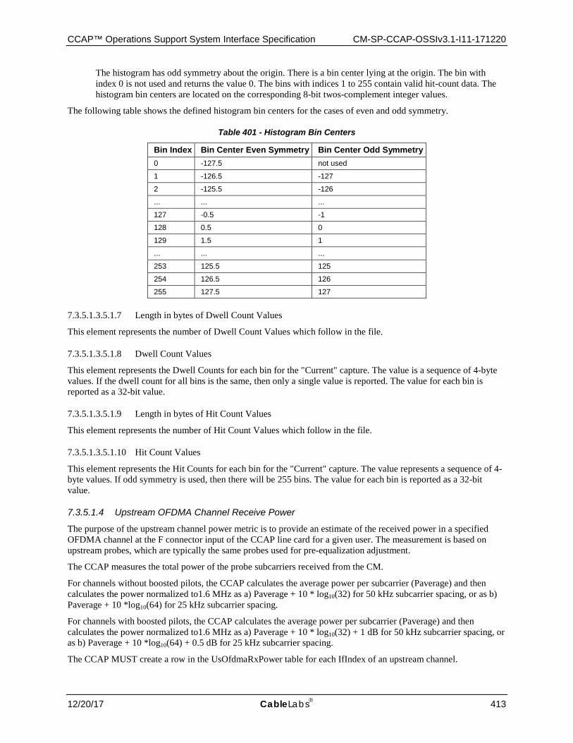
CCAP™ Operations Support System Interface Specification CM-SP-CCAP-OSSIv3.1-I11-171220
12/20/17 CableLabs 413
The histogram has odd symmetry about the origin. There is a bin center lying at the origin. The bin with index 0 is not used and returns the value 0. The bins with indices 1 to 255 contain valid hit-count data. The histogram bin centers are located on the corresponding 8-bit twos-complement integer values.
The following table shows the defined histogram bin centers for the cases of even and odd symmetry.
Table 401 - Histogram Bin Centers
Bin Index Bin Center Even Symmetry Bin Center Odd Symmetry 0 -127.5 not used
1 -126.5 -127
2 -125.5 -126
... ... ...
127 -0.5 -1
128 0.5 0
129 1.5 1
... ... ...
253 125.5 125
254 126.5 126
255 127.5 127
7.3.5.1.3.5.1.7 Length in bytes of Dwell Count Values
This element represents the number of Dwell Count Values which follow in the file.
7.3.5.1.3.5.1.8 Dwell Count Values
This element represents the Dwell Counts for each bin for the "Current" capture. The value is a sequence of 4-byte values. If the dwell count for all bins is the same, then only a single value is reported. The value for each bin is reported as a 32-bit value.
7.3.5.1.3.5.1.9 Length in bytes of Hit Count Values
This element represents the number of Hit Count Values which follow in the file.
7.3.5.1.3.5.1.10 Hit Count Values
This element represents the Hit Counts for each bin for the "Current" capture. The value represents a sequence of 4-byte values. If odd symmetry is used, then there will be 255 bins. The value for each bin is reported as a 32-bit value.
7.3.5.1.4 Upstream OFDMA Channel Receive Power
The purpose of the upstream channel power metric is to provide an estimate of the received power in a specified OFDMA channel at the F connector input of the CCAP line card for a given user. The measurement is based on upstream probes, which are typically the same probes used for pre-equalization adjustment.
The CCAP measures the total power of the probe subcarriers received from the CM.
For channels without boosted pilots, the CCAP calculates the average power per subcarrier (Paverage) and then calculates the power normalized to1.6 MHz as a) Paverage + 10 * log10(32) for 50 kHz subcarrier spacing, or as b) Paverage + 10 *log10(64) for 25 kHz subcarrier spacing.
For channels with boosted pilots, the CCAP calculates the average power per subcarrier (Paverage) and then calculates the power normalized to1.6 MHz as a) Paverage + 10 * log10(32) + 1 dB for 50 kHz subcarrier spacing, or as b) Paverage + 10 *log10(64) + 0.5 dB for 25 kHz subcarrier spacing.
The CCAP MUST create a row in the UsOfdmaRxPower table for each IfIndex of an upstream channel.
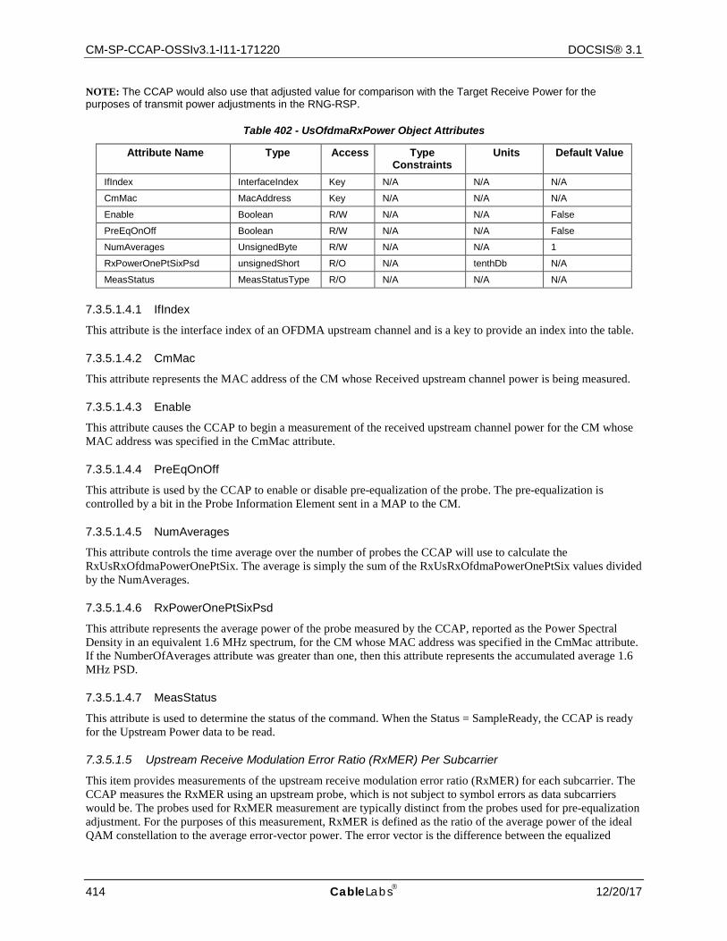
CM-SP-CCAP-OSSIv3.1-I11-171220 DOCSIS® 3.1
414 CableLabs 12/20/17
NOTE: The CCAP would also use that adjusted value for comparison with the Target Receive Power for the purposes of transmit power adjustments in the RNG-RSP.
Table 402 - UsOfdmaRxPower Object Attributes
Attribute Name Type Access Type Constraints
Units Default Value
IfIndex InterfaceIndex Key N/A N/A N/A
CmMac MacAddress Key N/A N/A N/A
Enable Boolean R/W N/A N/A False
PreEqOnOff Boolean R/W N/A N/A False
NumAverages UnsignedByte R/W N/A N/A 1
RxPowerOnePtSixPsd unsignedShort R/O N/A tenthDb N/A
MeasStatus MeasStatusType R/O N/A N/A N/A
7.3.5.1.4.1 IfIndex
This attribute is the interface index of an OFDMA upstream channel and is a key to provide an index into the table.
7.3.5.1.4.2 CmMac
This attribute represents the MAC address of the CM whose Received upstream channel power is being measured.
7.3.5.1.4.3 Enable
This attribute causes the CCAP to begin a measurement of the received upstream channel power for the CM whose MAC address was specified in the CmMac attribute.
7.3.5.1.4.4 PreEqOnOff
This attribute is used by the CCAP to enable or disable pre-equalization of the probe. The pre-equalization is controlled by a bit in the Probe Information Element sent in a MAP to the CM.
7.3.5.1.4.5 NumAverages
This attribute controls the time average over the number of probes the CCAP will use to calculate the RxUsRxOfdmaPowerOnePtSix. The average is simply the sum of the RxUsRxOfdmaPowerOnePtSix values divided by the NumAverages.
7.3.5.1.4.6 RxPowerOnePtSixPsd
This attribute represents the average power of the probe measured by the CCAP, reported as the Power Spectral Density in an equivalent 1.6 MHz spectrum, for the CM whose MAC address was specified in the CmMac attribute. If the NumberOfAverages attribute was greater than one, then this attribute represents the accumulated average 1.6 MHz PSD.
7.3.5.1.4.7 MeasStatus
This attribute is used to determine the status of the command. When the Status = SampleReady, the CCAP is ready for the Upstream Power data to be read.
7.3.5.1.5 Upstream Receive Modulation Error Ratio (RxMER) Per Subcarrier
This item provides measurements of the upstream receive modulation error ratio (RxMER) for each subcarrier. The CCAP measures the RxMER using an upstream probe, which is not subject to symbol errors as data subcarriers would be. The probes used for RxMER measurement are typically distinct from the probes used for pre-equalization adjustment. For the purposes of this measurement, RxMER is defined as the ratio of the average power of the ideal QAM constellation to the average error-vector power. The error vector is the difference between the equalized
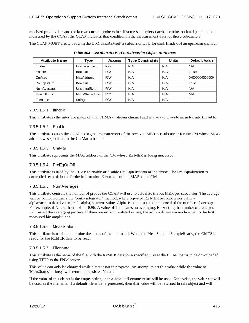
CCAP™ Operations Support System Interface Specification CM-SP-CCAP-OSSIv3.1-I11-171220
12/20/17 CableLabs 415
received probe value and the known correct probe value. If some subcarriers (such as exclusion bands) cannot be measured by the CCAP, the CCAP indicates that condition in the measurement data for those subcarriers.
The CCAP MUST create a row in the UsOfdmaRxMerPerSubcarrier table for each IfIndex of an upstream channel.
Table 403 - UsOfdmaRxMerPerSubcarrier Object Attributes
Attribute Name Type Access Type Constraints Units Default Value IfIndex InterfaceIndex Key N/A N/A N/A
Enable Boolean R/W N/A N/A False
CmMac MacAddress R/W N/A N/A 0x000000000000
PreEqOnOff Boolean R/W N/A N/A False
NumAverages UnsignedByte R/W N/A N/A N/A
MeasStatus MeasStatusType R/O N/A N/A N/A
Filename String R/W N/A N/A ""
7.3.5.1.5.1 IfIndex
This attribute is the interface index of an OFDMA upstream channel and is a key to provide an index into the table.
7.3.5.1.5.2 Enable
This attribute causes the CCAP to begin a measurement of the received MER per subcarrier for the CM whose MAC address was specified in the CmMac attribute.
7.3.5.1.5.3 CmMac
This attribute represents the MAC address of the CM whose Rx MER is being measured.
7.3.5.1.5.4 PreEqOnOff
This attribute is used by the CCAP to enable or disable Pre Equalization of the probe. The Pre Equalization is controlled by a bit in the Probe Information Element sent in a MAP to the CM.
7.3.5.1.5.5 NumAverages
This attribute controls the number of probes the CCAP will use to calculate the Rx MER per subcarrier. The average will be computed using the "leaky integrator" method, where reported Rx MER per subcarrier value = alpha*accumulated values + (1-alpha)*current value. Alpha is one minus the reciprocal of the number of averages. For example, if N=25, then alpha = 0.96. A value of 1 indicates no averaging. Re-writing the number of averages will restart the averaging process. If there are no accumulated values, the accumulators are made equal to the first measured bin amplitudes.
7.3.5.1.5.6 MeasStatus
This attribute is used to determine the status of the command. When the MeasStatus = SampleReady, the CMTS is ready for the RxMER data to be read.
7.3.5.1.5.7 Filename
This attribute is the name of the file with the RxMER data for a specified CM at the CCAP that is to be downloaded using TFTP to the PNM server.
This value can only be changed while a test is not in progress. An attempt to set this value while the value of 'MeasStatus' is 'busy' will return 'inconsistentValue'.
If the value of this object is the empty string, then a default filename value will be used. Otherwise, the value set will be used as the filename. If a default filename is generated, then that value will be returned in this object and will
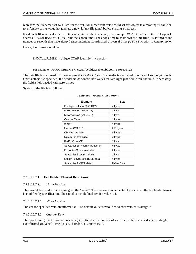
CM-SP-CCAP-OSSIv3.1-I11-171220 DOCSIS® 3.1
416 CableLabs 12/20/17
represent the filename that was used for the test. All subsequent tests should set this object to a meaningful value or to an 'empty string' value (to generate a new default filename) before starting a new test.
If a default filename value is used, it is generated as the test name, plus a unique CCAP identifier (either a loopback address (IPv4 or IPv6) or FQDN), plus the 'epoch time'. The epoch time (also known as 'unix time') is defined as the number of seconds that have elapsed since midnight Coordinated Universal Time (UTC),Thursday, 1 January 1970.
Hence, the format would be:
PNMCcapRxMER_<Unique CCAP Identifier>_<epoch>
For example: PNMCcapRxMER_ccap1.boulder.cablelabs.com_1403405123
The data file is composed of a header plus the RxMER Data. The header is composed of ordered fixed-length fields. Unless otherwise specified, the header fields contain hex values that are right-justified within the field. If necessary, the field is left-padded with zero values.
Syntax of the file is as follows:
Table 404 - RxMER File Format
Element Size File type (value = 504E4D69) 4 bytes
Major Version (value = 1) 1 byte
Minor Version (value = 0) 1 byte
Capture Time 4 bytes
IfIndex 4 bytes
Unique CCAP ID 256 bytes
CM MAC Address 6 bytes
Number of averages 2 bytes
PreEq On or Off 1 byte
Subcarrier zero center frequency 4 bytes
FirstActiveSubcarrierIndex 2 bytes
Subcarrier Spacing in kHz 1 byte
Length in bytes of RxMER data 4 bytes
Subcarrier RxMER data RxMerData
7.3.5.1.5.7.1 File Header Element Definitions
7.3.5.1.5.7.1.1 Major Version
The current file header version assigned the “value”. The version is incremented by one when the file header format is modified by specification. The specification defined version value is 1.
7.3.5.1.5.7.1.2 Minor Version
The vendor-specified version information. The default value is zero if no vendor version is assigned.
7.3.5.1.5.7.1.3 Capture Time
The epoch time (also known as 'unix time') is defined as the number of seconds that have elapsed since midnight Coordinated Universal Time (UTC),Thursday, 1 January 1970.
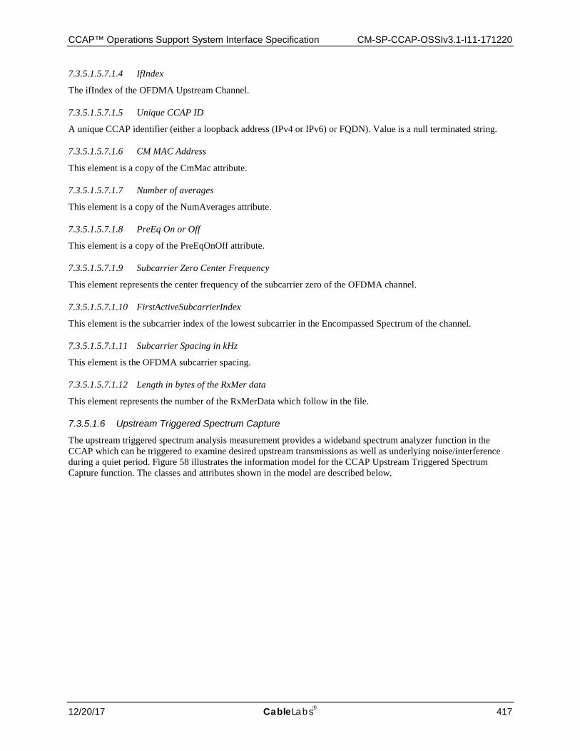
CCAP™ Operations Support System Interface Specification CM-SP-CCAP-OSSIv3.1-I11-171220
12/20/17 CableLabs 417
7.3.5.1.5.7.1.4 IfIndex
The ifIndex of the OFDMA Upstream Channel.
7.3.5.1.5.7.1.5 Unique CCAP ID
A unique CCAP identifier (either a loopback address (IPv4 or IPv6) or FQDN). Value is a null terminated string.
7.3.5.1.5.7.1.6 CM MAC Address
This element is a copy of the CmMac attribute.
7.3.5.1.5.7.1.7 Number of averages
This element is a copy of the NumAverages attribute.
7.3.5.1.5.7.1.8 PreEq On or Off
This element is a copy of the PreEqOnOff attribute.
7.3.5.1.5.7.1.9 Subcarrier Zero Center Frequency
This element represents the center frequency of the subcarrier zero of the OFDMA channel.
7.3.5.1.5.7.1.10 FirstActiveSubcarrierIndex
This element is the subcarrier index of the lowest subcarrier in the Encompassed Spectrum of the channel.
7.3.5.1.5.7.1.11 Subcarrier Spacing in kHz
This element is the OFDMA subcarrier spacing.
7.3.5.1.5.7.1.12 Length in bytes of the RxMer data
This element represents the number of the RxMerData which follow in the file.
7.3.5.1.6 Upstream Triggered Spectrum Capture
The upstream triggered spectrum analysis measurement provides a wideband spectrum analyzer function in the CCAP which can be triggered to examine desired upstream transmissions as well as underlying noise/interference during a quiet period. Figure 58 illustrates the information model for the CCAP Upstream Triggered Spectrum Capture function. The classes and attributes shown in the model are described below.
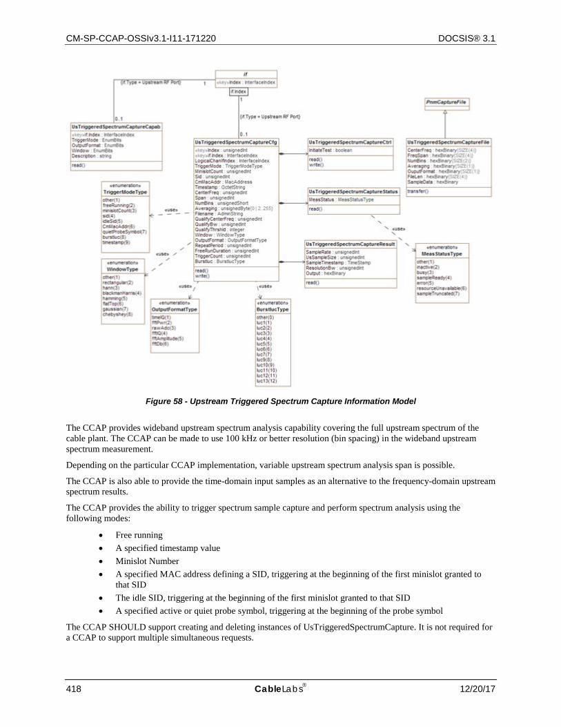
CM-SP-CCAP-OSSIv3.1-I11-171220 DOCSIS® 3.1
418 CableLabs 12/20/17
Figure 58 - Upstream Triggered Spectrum Capture Information Model
The CCAP provides wideband upstream spectrum analysis capability covering the full upstream spectrum of the cable plant. The CCAP can be made to use 100 kHz or better resolution (bin spacing) in the wideband upstream spectrum measurement.
Depending on the particular CCAP implementation, variable upstream spectrum analysis span is possible.
The CCAP is also able to provide the time-domain input samples as an alternative to the frequency-domain upstream spectrum results.
The CCAP provides the ability to trigger spectrum sample capture and perform spectrum analysis using the following modes:
• Free running • A specified timestamp value • Minislot Number • A specified MAC address defining a SID, triggering at the beginning of the first minislot granted to
that SID • The idle SID, triggering at the beginning of the first minislot granted to that SID • A specified active or quiet probe symbol, triggering at the beginning of the probe symbol
The CCAP SHOULD support creating and deleting instances of UsTriggeredSpectrumCapture. It is not required for a CCAP to support multiple simultaneous requests.
CCAP™ Operations Support System Interface Specification CM-SP-CCAP-OSSIv3.1-I11-171220
12/20/17 CableLabs 419
Note that upstream triggered spectrum analysis measures the power vs frequency of any input signal, including TDMA/A-TDMA, OFDMA, OOB upstream, ingress, and noise.
The Upstream Triggered Spectrum Capture function is described in four objects associated with the four fundamental functions listed below:
• Test configuration (Cfg) • Test control (Ctrl) • Test monitoring (Status) • Test result reporting (Result)
The same pair of indexes are defined for the four (Cfg, Ctrl, Status and Result) Upstream Triggered Spectrum Capture objects. This links the four objects such that the same values for the pair of indexes accesses the same instance of each of the objects. Therefore, the attributes in one object indexed with Index = x and ifIndex = y correspond to the attributes in each of the other three objects indexed with Index = x and ifIndex = y. An entry created in one object with Index = x and ifIndex = y also automatically creates an entry in the other three objects with Index = x and ifIndex = y.
The CCAP is not required to retain the RF port capture configuration when the CCAP is reset.
If the CCAP supports line card failover protections, the CCAP is not required to retain the RF port capture configuration when a failover occurs.
A CCAP PNM Upstream Triggered Spectrum Capture Capabilities object is provided to allow a CCAP to advertise its US Spectrum Capture capabilities.
The Upstream Triggered Spectrum Capture feature supports eight trigger modes, and for each mode a set of attributes need to be configured to provide the CCAP with the information it needs to perform the capture. Table 405 identifies the attributes that are required to be configured for each trigger mode.
The CCAP MUST NOT initiate an Upstream Triggered Spectrum Capture test if required attributes listed in Table 405 for the configured trigger mode are not configured with a value. It is not required to configure Filename each time Upstream Triggered Spectrum Capture test is initiated, but this is recommended.
For each trigger mode, the operator can optionally configure Averaging, Filename, QualifyCenterFreq, QualifyBw, QualifyThrshld, Window, OutputFormat, RepeatPeriod, or TriggerCount. Default values are used for these attributes if they are not configured.
Table 405 - Attributes Required to be Configured for Each Trigger Mode
Trigger Mode Attributes Required to be Configured Free Running CenterFreq, Span, NumBins
Minislot Count MinislotCount, CenterFreq, Span
SID Sid, CenterFreq, Span
Idle SID CenterFreq, Span
CM MAC Address CmMacAddr, CenterFreq, Span
Quiet Probe Symbol CenterFreq, Span
Burst IUC CmMacAddr, ifIndex, BurstIuc
Timestamp Timestamp, CenterFreq, Span
7.3.5.1.6.1 UsTriggeredSpectrumCaptureCapab Object
The Upstream Triggered Spectrum Capture Capabilities object exposes capabilities supported by the CCAP for Upstream Triggered Spectrum Capture trigger modes, data output formats, and windowing function used when performing the discrete Fourier transform.
CM-SP-CCAP-OSSIv3.1-I11-171220 DOCSIS® 3.1
420 CableLabs 12/20/17
Table 406 - UsTriggeredSpectrumCaptureCapab Object
Attribute Name Type Access Type Constraints Units Default Value TriggerMode EnumBits R/O other(0),
freeRunning(1), miniSlotCount(2), sid(3), idleSid(4), cmMac(5), quietProbeSymbol(6), burstIuc(7), timestamp(8)
N/A
OutputFormat EnumBits R/O other(0) timeIQ(1), fftPower(2), rawAdc(3), fftIQ(4), fftAmplitude(5), fftDb(6)
N/A
Window EnumBits R/O other(0), rectangular(1), hann(2), blackmanHarris(3), hamming(4), flatTop(5), gaussian(6), chebyshev(7)
N/A
Description string R/O N/A
7.3.5.1.6.1.1 TriggerMode
This attribute indicates which of the upstream triggered spectrum capture function trigger modes is supported by the CCAP. TriggerMode attribute is reported in BITS format, with value 0 for each bit definition indicating the CCAP does not support the corresponding TriggerMode, and value 1 for each bit definition indicating the CCAP supports the corresponding trigger mode. See the description of the UsTriggeredSpectrumCaptureCfg object TriggerMode attribute for more information about CCAP upstream triggered spectrum capture trigger modes. The value other(0) is provided for vendor-proprietary and future extensions.
7.3.5.1.6.1.2 OutputFormat
This attribute indicates which of the upstream triggered spectrum capture function data output formats are supported by the CCAP. OutputFormat attribute is reported in BITS format, with value 0 for each bit definition indicating the CCAP does not support the corresponding OutputFormat, and value 1 for each bit definition indicating the CCAP supports the corresponding output data format. See the description of the UsTriggeredSpectrumCaptureCfg object OutputFormat attribute for more information about CCAP upstream triggered spectrum capture output formats. The value other(0) is provided for vendor-proprietary and future extensions.
7.3.5.1.6.1.3 Window
This attribute indicates which of the upstream triggered spectrum capture function window formats are supported by the CCAP. The Window attribute is reported in BITS format, with value for each bit definition 0 indicating the CCAP does not support the corresponding Window option and value 1 for each bit definition indicating the CCAP supports the corresponding Window option. See the description of the UsTriggeredSpectrumCaptureCfg object Window attribute for more information about CCAP upstream triggered spectrum capture window options. The value other(0) is provided for vendor-proprietary and future extensions.
CCAP™ Operations Support System Interface Specification CM-SP-CCAP-OSSIv3.1-I11-171220
12/20/17 CableLabs 421
7.3.5.1.6.1.4 Description
This attribute reports a textual description of a CCAP's upstream triggered spectrum capture capabilities. The format is vendor-specific. Example content can include, but is not limited to:
• Center Frequency range and resolution • Frequency Span range and resolution • Sampling rate each frequency span • Averaging range and resolution • Averaging method • Number of time domain IQ samples • Number of FFT bins
7.3.5.1.6.2 UsTriggeredSpectrumCaptureFile Object
The Upstream Triggered Spectrum Capture File object defines the format for the Upstream Triggered Spectrum Capture test-specific information in the data capture file created by the CCAP when an Upstream Triggered Spectrum Capture test is executed.
When the CCAP runs an Upstream Triggered Spectrum Capture test, it MUST create a results file composed of the PnmCaptureFile header fields as defined in Section 7.3.3.1 followed by the UsTriggeredSpectrumCaptureFile fields described in this section. The FileType for the capture file is 504E4E6A. Capture file fields are right-justified within the field and left-padded with zero values if necessary. The implemented values of various parameters may be different from the requested values, as the spectrum analysis function will provide the implementation value closest to the requested value.
The content of the Upstream Triggered Spectrum Capture file can be retrieved via SNMP or bulk file transfer. Refer to the UsTriggeredSpectrumCaptureResult object and the CCAP Bulk Data Transfer section, respectively.
In the event of insufficient memory resources to create a new capture file, the CCAP MUST overwrite the oldest stored capture file with the new capture file being created.
Table 407 - UsTriggeredSpectrumCaptureFile Object
Attribute Name Type Access Type Constraints Units Default Value
CenterFreq HexBinary R/O SIZE (4) Hz
FreqSpan HexBinary R/O SIZE (4) Hz
NumBins HexBinary R/O SIZE (2) N/A
Averaging HexBinary R/O SIZE (1) N/A
SamplingRate HexBinary R/O SIZE (4) Hz
OutputFormat HexBinary R/O SIZE (1) N/A
FileLen HexBinary R/O SIZE (4) Bytes
FFTSampleSize HexBinary R/O SIZE (4) Bytes
CalibrationConstantP0 Short R/O SIZE (2) HundredthsdBmV
Window Enum R/O other(1), rectangular(2), hann(3), blackmanHarris(4), hamming(5), flatTop(6), gaussian(7), chebyshev(8)
N/A N/A
SampleData HexBinary R/O N/A
CM-SP-CCAP-OSSIv3.1-I11-171220 DOCSIS® 3.1
422 CableLabs 12/20/17
7.3.5.1.6.2.1 CenterFreq
A four-byte hexadecimal field containing the implemented value of the CenterFreq attribute as specified in the UsTriggeredSpectrumCaptureCfg object.
7.3.5.1.6.2.2 FreqSpan
A four-byte hexadecimal field containing the implemented value of the Span attribute as specified in the UsTriggeredSpectrumCaptureCfg object.
7.3.5.1.6.2.3 NumBins
A two-byte hexadecimal field containing the implemented value of the NumBins attribute as specified in the UsTriggeredSpectrumCaptureCfg object.
7.3.5.1.6.2.4 Averaging
A one-byte hexadecimal field containing the implemented value of the Averaging attribute as specified in the UsTriggeredSpectrumCaptureCfg object.
7.3.5.1.6.2.5 SamplingRate
A four-byte hexadecimal field containing the sampling rate in Hertz for time IQ data. The Sampling rate in Hz is 100 times the encoded value, which allows up to 100 seconds between samples.
7.3.5.1.6.2.6 OutputFormat
A one-byte hexadecimal field containing the value of the OutputFormat attribute as specified in the UsTriggeredSpectrumCaptureCfg object.
7.3.5.1.6.2.7 FileLen
A four-byte hexadecimal field representing the length in bytes of the upstream spectrum sample capture data which follow in the file.
7.3.5.1.6.2.8 FftSampleSize
The FftSampleSize attribute is included in the output file to provide information about the size of the FFT being captured when the Upstream Capture Mode is configured to fftPower(2), fftIQ(4), fftAmplitude(5), or fftDb(6). This attribute is included in the header portion of the output file.
7.3.5.1.6.2.9 CalibrationConstantP0
This attribute is intended to communicate the calculated calibration constant value that is applied to all BINs in an upstream Spectrum Capture. This value is used by an external entity to obtain the US spectrum capture estimate in dBmV at an agreed calibration point, such as the RF connector of the line card. The goal is to select the calibration constant such that after calibration, the sum of the linear power (not dB) values of all FFT bins in the 6.4 MHz occupied band of the above 0 dBmV test signal = 1 (i.e., 0 dB). This property will hold regardless of which resolution bandwidth or FFT window is selected. With this calibration, integrated power measurements (sum of linear power over a given spectral bandwidth) will give correctly calibrated results in dBmV for any collection of signals in the spectrum.
7.3.5.1.6.2.10 Windowing
This attribute specifies the windowing function that was configured when performing the discrete Fourier transform for the upstream spectrum analysis.
7.3.5.1.6.2.11 SampleData
The upstream spectrum sample capture data formatted according to the configured OutputFormat.
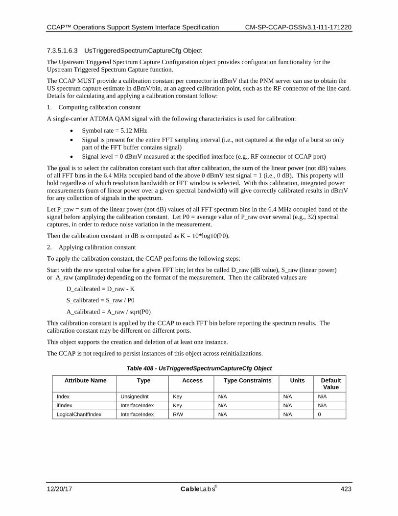
CCAP™ Operations Support System Interface Specification CM-SP-CCAP-OSSIv3.1-I11-171220
12/20/17 CableLabs 423
7.3.5.1.6.3 UsTriggeredSpectrumCaptureCfg Object
The Upstream Triggered Spectrum Capture Configuration object provides configuration functionality for the Upstream Triggered Spectrum Capture function.
The CCAP MUST provide a calibration constant per connector in dBmV that the PNM server can use to obtain the US spectrum capture estimate in dBmV/bin, at an agreed calibration point, such as the RF connector of the line card. Details for calculating and applying a calibration constant follow:
1. Computing calibration constant
A single-carrier ATDMA QAM signal with the following characteristics is used for calibration:
• Symbol rate = 5.12 MHz • Signal is present for the entire FFT sampling interval (i.e., not captured at the edge of a burst so only
part of the FFT buffer contains signal) • Signal level = 0 dBmV measured at the specified interface (e.g., RF connector of CCAP port)
The goal is to select the calibration constant such that after calibration, the sum of the linear power (not dB) values of all FFT bins in the 6.4 MHz occupied band of the above 0 dBmV test signal = 1 (i.e., 0 dB). This property will hold regardless of which resolution bandwidth or FFT window is selected. With this calibration, integrated power measurements (sum of linear power over a given spectral bandwidth) will give correctly calibrated results in dBmV for any collection of signals in the spectrum.
Let P_raw = sum of the linear power (not dB) values of all FFT spectrum bins in the 6.4 MHz occupied band of the signal before applying the calibration constant. Let P0 = average value of P_raw over several (e.g., 32) spectral captures, in order to reduce noise variation in the measurement.
Then the calibration constant in dB is computed as K = 10*log10(P0).
2. Applying calibration constant
To apply the calibration constant, the CCAP performs the following steps:
Start with the raw spectral value for a given FFT bin; let this be called D_raw (dB value), S_raw (linear power) or A_raw (amplitude) depending on the format of the measurement. Then the calibrated values are
D_calibrated = D_raw - K
S_calibrated = S_raw / P0
A_calibrated = A_raw / sqrt(P0)
This calibration constant is applied by the CCAP to each FFT bin before reporting the spectrum results. The calibration constant may be different on different ports.
This object supports the creation and deletion of at least one instance.
The CCAP is not required to persist instances of this object across reinitializations.
Table 408 - UsTriggeredSpectrumCaptureCfg Object
Attribute Name Type Access Type Constraints Units Default Value
Index UnsignedInt Key N/A N/A N/A
ifIndex InterfaceIndex Key N/A N/A N/A
LogicalChanIfIndex InterfaceIndex R/W N/A N/A 0
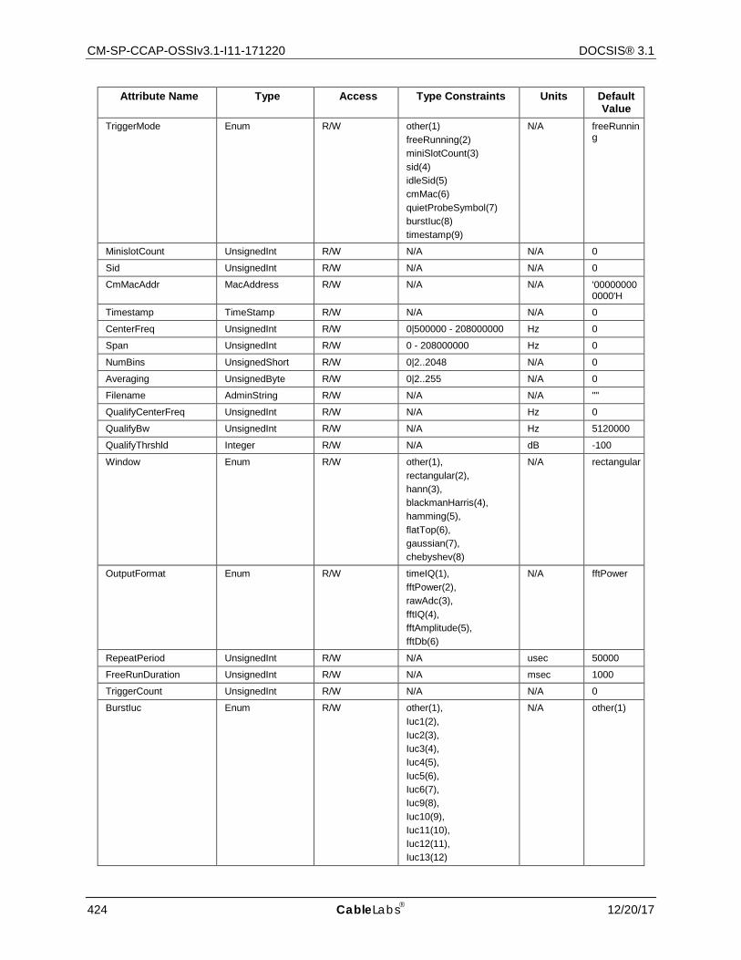
CM-SP-CCAP-OSSIv3.1-I11-171220 DOCSIS® 3.1
424 CableLabs 12/20/17
Attribute Name Type Access Type Constraints Units Default Value
TriggerMode Enum R/W other(1) freeRunning(2) miniSlotCount(3) sid(4) idleSid(5) cmMac(6) quietProbeSymbol(7) burstIuc(8) timestamp(9)
N/A freeRunning
MinislotCount UnsignedInt R/W N/A N/A 0
Sid UnsignedInt R/W N/A N/A 0
CmMacAddr MacAddress R/W N/A N/A '000000000000'H
Timestamp TimeStamp R/W N/A N/A 0
CenterFreq UnsignedInt R/W 0|500000 - 208000000 Hz 0
Span UnsignedInt R/W 0 - 208000000 Hz 0
NumBins UnsignedShort R/W 0|2..2048 N/A 0
Averaging UnsignedByte R/W 0|2..255 N/A 0
Filename AdminString R/W N/A N/A ""
QualifyCenterFreq UnsignedInt R/W N/A Hz 0
QualifyBw UnsignedInt R/W N/A Hz 5120000
QualifyThrshld Integer R/W N/A dB -100
Window Enum R/W other(1), rectangular(2), hann(3), blackmanHarris(4), hamming(5), flatTop(6), gaussian(7), chebyshev(8)
N/A rectangular
OutputFormat Enum R/W timeIQ(1), fftPower(2), rawAdc(3), fftIQ(4), fftAmplitude(5), fftDb(6)
N/A fftPower
RepeatPeriod UnsignedInt R/W N/A usec 50000
FreeRunDuration UnsignedInt R/W N/A msec 1000
TriggerCount UnsignedInt R/W N/A N/A 0
BurstIuc Enum R/W other(1), Iuc1(2), Iuc2(3), Iuc3(4), Iuc4(5), Iuc5(6), Iuc6(7), Iuc9(8), Iuc10(9), Iuc11(10), Iuc12(11), Iuc13(12)
N/A other(1)
CCAP™ Operations Support System Interface Specification CM-SP-CCAP-OSSIv3.1-I11-171220
12/20/17 CableLabs 425
7.3.5.1.6.3.1 Index
This key attribute is a unique identifier for a particular set of configuration settings. If the CCAP does not support multiple Upstream Triggered Spectrum Sample Capture configuration settings, the CCAP MUST only support a value of 1 for this attribute and reject any attempt to configure it to a value other than 1.
7.3.5.1.6.3.2 ifIndex
This key attribute is the interface index of an upstream RF port.
The CCAP MAY provide simultaneous measurements of logical upstream channels within a single upstream physical interface.
7.3.5.1.6.3.3 LogicalChannelIfIndex
This attribute is the interface index of the logical channel to which the sample capture trigger applies, when TriggerMode is miniSlotCount, sid, idleSid, quietProbeSymbol, and burstIuc.
The value 0 means the CCAP is triggering on something specific to the upstream RF port, not a specific channel.
When the value of LogicalChannelIndex is the ifIndex of a physical or logical channel and upstream triggered spectrum sample capture is initiated, the CCAP MUST trigger on the assigned trigger mode event for the physical or logical channel indicated by the value of LogicalChannelIndex.
7.3.5.1.6.3.4 TriggerMode
This attribute is used to control the trigger mode for the Upstream Triggered Spectrum Analysis sample capture. Values allowed for this attribute are listed and described below. Each trigger mode requires the Enable attribute to be set to true as well as the proper configuration settings applied that are applicable to the specific trigger mode.
other: The CCAP initiates sampling the upstream spectrum as the result of a trigger condition not defined in this specification.
freeRunning: The CCAP immediately initiates sampling and continues sampling until the length of time configured in attribute FreeRunDuration has transpired. Sampling terminates when the length of time configured in FreeRunDuration has elapsed or when FFT is disabled. The interval between captures is RepeatPeriod, or the minimum period supported by the CCAP, whichever is greater.
miniSlotCount: The CCAP initiates sampling when the minislot number equals the value configured for attribute MinislotCount.
sid: The CCAP immediately initiates capturing samples corresponding to the Service Flow identified with the Service Identifier (SID) numbered with the value of attribute Sid. The CCAP continues to sample the configured upstream spectrum after being triggered on transmissions corresponding to the specified SID until FFT is disabled or a new configuration is applied.
idleSid: The CCAP immediately initiates capturing samples during an idle period selected by the CCAP. The CCAP will continue to sample the configured upstream spectrum during transmissions corresponding to the idle SID until FFT is disabled or a new configuration is applied.
cmMacAddr: The CCAP immediately initiates sampling data on a grant for any SID assigned to the cable modem whose MAC address is the value of attribute CmMac. The CCAP continues to sample the configured upstream spectrum during transmissions corresponding to the configured CM MAC until FFT is disabled or a new configuration is applied.
quietProbeSymbol: The CCAP immediately initiates sampling data when a configured OFDMA Quiet Probe Symbol occurs. The CCAP will continue to sample the configured upstream spectrum during Quiet Probe Symbols until FFT is disabled or a new configuration is applied.
The Upstream Triggered Spectrum Capture test with quietProbeSymbol trigger is different from the Upstream Capture for Active and Quiet Probes PNM feature in that the Upstream Triggered Spectrum Capture test is more general than the Upstream Capture for Active and Quiet Probes test. Upstream
CM-SP-CCAP-OSSIv3.1-I11-171220 DOCSIS® 3.1
426 CableLabs 12/20/17
Triggered Spectrum Capture test can be done in any band, while the Upstream Capture for Active and Quiet Probes test is specifically for an OFDMA channel.
burstIuc: The CCAP immediately initiates sampling when the CCAP issues the grant for the configured burst Interval Usage Code. The CCAP will continue to sample the configured upstream spectrum during transmissions corresponding to the configured IUC until FFT is disabled or a new configuration is applied.
timestamp: The CCAP initiates sampling when the configured timestamp occurs. The CCAP will continue to sample the configured upstream spectrum until FFT is disabled or a new configuration is applied; however, a single capture typically is made in this mode. This is the DOCSIS 3.1 timestamp defined in [MULPIv3.1].
Note that if the CCAP supports only one set of Upstream Triggered Spectrum Capture configuration, then if a test is configured with timestamp trigger, it effectively blocks any other test setup and execution until it completes, since setting up the other test will overwrite the timestamp test configuration.
7.3.5.1.6.3.5 MinislotCount
This attribute specifies the minislot number at the beginning of which the CCAP starts the upstream spectrum sample capture. This attribute is applicable only when the TriggerMode attribute is set to MiniSlotCount and is ignored if TriggerMode is set to any other value.
7.3.5.1.6.3.6 Sid
This attribute specifies the SID corresponding to the CM which is granted a burst opportunity for the purpose of Upstream Triggered Spectrum Analysis.
This attribute is applicable only when the TriggerMode attribute is set to Sid and is ignored if TriggerMode is set to any other value.
7.3.5.1.6.3.7 CmMacAddr
This attribute specifies from which cable modem the CCAP will capture upstream transmissions.
The CCAP MUST trigger upstream spectrum sample capture on a grant for any SID assigned to the CM whose MAC address is configured in CmMacAddr, and capture upstream spectrum samples when the burst corresponding to that grant is received by the CCAP. This attribute is used when the TriggerMode is CmMac and is an alternative to using Sid for the TriggerMode. This attribute is ignored if TriggerMode is set to any value other than CmMac.
7.3.5.1.6.3.8 Timestamp
This attribute specifies the specific time in the future when upstream spectrum sample capture is required to be initiated. If Enable is true, TriggerMode is set to timestamp, configuration settings have been applied, and InitiateTest is true, the CCAP MUST initiate sampling when the configured timestamp occurs. The CCAP will continue to sample the configured upstream spectrum until FFT is disabled or a new configuration is applied; however, a single capture typically is made in this mode.
7.3.5.1.6.3.9 CenterFreq
This attribute specifies the center frequency of the upstream spectrum to be sampled for analysis. When this attribute is read, it provides the actual center frequency, which may be different from the requested (configured) center frequency due to implementation effects.
7.3.5.1.6.3.10 Span
This attribute determines the frequency span of the upstream spectrum sample capture. When this attribute is read, it provides the actual span, which may be different from the requested (configured) span due to implementation effects.
CCAP™ Operations Support System Interface Specification CM-SP-CCAP-OSSIv3.1-I11-171220
12/20/17 CableLabs 427
7.3.5.1.6.3.11 NumBins`
This attribute determines the number of frequency bins or samples per span when sampling the upstream spectrum. When this attribute is read, it provides the actual number of bins, which may be different from the requested (configured) number of bins due to implementation effects. The number of bins is typically less than the FFT length in use, due to filter rolloff at the edges of the analysis band. A larger number of frequency bins will result in better frequency resolution for a given frequency span.
7.3.5.1.6.3.12 Averaging
This attribute specifies whether the CCAP is to average spectral frequency domain sample power to remove spurious spectral peaks and troughs, and the number of samples to use to calculate the average power.
The CCAP MUST NOT calculate the average of the upstream spectrum samples when the value of Averaging is zero.
The CCAP MUST calculate the average power of upstream spectrum samples, over the number of samples specified, when the value of the Averaging attribute is non-zero.
The CCAP MUST use quantities in the linear power domain when performing time averaging over multiple spectra. Time averaging provides for a smoother resulting spectrum. In time averaging, the spectrum is captured multiple times, and each FFT bin is averaged over the successive values in that bin to provide the final spectrum value for that bin. A leaky integrator may be used to perform the averaging. Let x = x_I + j*x_Q be the vector of time domain input samples to the FFT and y = y_I + j*y_Q be the vector of complex output frequency bin values of the FFT. Then p = |y|^2 = y_I^2 + y_Q^2 is the power or squared magnitude of the bin values and r = |y| = sqrt(y_I^2 + y_Q^2) is the magnitude of the bin values. The values may be converted to dB using s = 10*log10(p) = 20*log10(r). Only values of p are used for time averaging. Magnitude values need to be squared before averaging. dB values need to be converted into linear power using p = 10^(s/10) before averaging; after averaging, the smoothed bin values may be converted back to dB.
7.3.5.1.6.3.13 Filename
This attribute specifies the name of the file with the upstream triggered spectrum capture data at the CCAP that is to be transferred from the CCAP using TFTP to the PNM server or other TFTP client. The content of the sample data file transferred from the CCAP using TFTP is the same as the content returned in attribute Output of the corresponding Result object.
If the value of this attribute is an empty string, then a default filename value will be used. Otherwise, the value set will be used as the filename. If a default filename is generated, then that value will be returned in this attribute and will represent the filename that was used for the test. All subsequent tests should set this attribute to a meaningful value or to an 'empty string' value (to generate a new default filename) before starting a new test.
If a default filename value is used, it is generated as the test name, plus a unique CCAP identifier (either a loopback address (IPv4 or IPv6) or FQDN), plus the 'epoch time'. The epoch time (also known as 'unix time') is defined as the number of seconds that have elapsed since midnight Coordinated Universal Time (UTC),Thursday, 1 January 1970.
Hence, the format would be:
PNMCcapUsSpecAn_<Unique CCAP Identifier>_<epoch>, where
Hence, the upstream spectrum sample capture filename format would be as shown in the following example:
PNMCcapUsSpecAn_ccap1.boulder.cablelabs.com_1403405123
Format of upstream triggered spectrum capture file is described in Section 7.3.5.1.6.2.
7.3.5.1.6.3.14 QualifyCenterFreq
This attribute specifies the center frequency of a band that is used to qualify a spectrum for upload. The average of the FFT linear power values in this band is computed and compared to a threshold. If the average power in the band is below the threshold, the spectrum is discarded. If the power average is greater than or equal to the threshold, the spectrum is considered qualified.
CM-SP-CCAP-OSSIv3.1-I11-171220 DOCSIS® 3.1
428 CableLabs 12/20/17
7.3.5.1.6.3.15 QualifyBw
This attribute specifies the bandwidth of a band that is used to qualify a spectrum for upload. The average of the FFT linear power values in this band is computed and compared to a threshold. If the average power in the band is below the threshold, the spectrum is discarded. If the power average is greater than or equal to the threshold, the spectrum is considered qualified.
7.3.5.1.6.3.16 QualifyThrshld
This attribute specifies the threshold applied to qualify a spectrum for upload. The average of the FFT linear power values in the specified band is computed and compared to this threshold. If the average power in the band is below the threshold, the spectrum is discarded. If the power average is greater than or equal to the threshold, the spectrum is considered qualified. If this threshold is set to -100 dB or lower, the threshold qualification feature is disabled (all spectra are then considered qualified).
7.3.5.1.6.3.17 Window
This attribute specifies the windowing function that will be used when performing the discrete Fourier transform for the upstream spectrum analysis. Use of "modern" windowing functions not yet defined will likely be specified as 'other'.
The CCAP MUST be capable of implementing rectangular windowing and at least one of the following other window types when performing discrete Fourier transform on upstream spectrum sample data:
• Hann windowing • Blackman Harris windowing.
The CCAP SHOULD implement Hamming windowing for performing discrete Fourier transform on upstream spectrum sample data.
The CCAP MAY implement Flat Top windowing for performing discrete Fourier transform on upstream spectrum sample data.
The CCAP MAY implement Gaussian windowing for performing discrete Fourier transform on upstream spectrum sample data.
The CCAP MAY implement Chebyshev windowing for performing discrete Fourier transform on upstream spectrum sample data.
7.3.5.1.6.3.18 OutputFormat
This attribute specifies the format of the data returned in the upstream spectrum sample capture file and in the Output attribute of the Results object.
The CCAP MUST be capable of reporting upstream spectrum sample FFT input data in complex time-domain in-phase and quadrature (I/Q) format. The enumeration value for complex time-domain I/Q format is timeIQ.
The CCAP MUST use 4 bytes per upstream spectrum sample to represent the data when reporting in complex time-domain I/Q format.
The CCAP MUST be capable of reporting upstream spectrum sample FFT output data in power format. The enumeration value for power format is fftPower.
The CCAP MUST use 4 bytes per bin to represent upstream spectrum sample FFT output data when reporting upstream spectrum sample data in power format.
The CCAP MAY be capable of reporting upstream spectrum sample real FFT input data in raw analog-to-digital converter (ADC) output format. The enumeration value for raw ADC output format is rawAdc.
The CCAP MUST use 2 bytes per upstream spectrum sample to represent the data when reporting in raw ADC output format.
The CCAP MAY support reporting of upstream spectrum sample FFT output data in I/Q format. The enumeration value for I/Q format is fftIQ.
CCAP™ Operations Support System Interface Specification CM-SP-CCAP-OSSIv3.1-I11-171220
12/20/17 CableLabs 429
The CCAP MUST use 4 bytes per bin to represent FFT output data when reporting upstream spectrum sample data in I/Q format.
The CCAP MAY support reporting of upstream spectrum sample FFT output data in amplitude format. The enumeration value for amplitude format is fftAmplitude.
The CCAP MUST use 2 bytes per bin to represent upstream spectrum sample FFT output data when reporting upstream spectrum sample data in amplitude format.
The CCAP MAY support reporting of upstream spectrum sample FFT data in dB format using units of hundredths dB. The enumeration value for spectrum amplitude format is fftDb.
The CCAP MUST use 2 bytes per bin to represent upstream spectrum sample FFT output data when reporting in dB format.
The CCAP MUST reject any attempt to set OutputFormat to an optional value not supported by the CCAP.
7.3.5.1.6.3.19 RepeatPeriod
This attribute specifies the interval in microseconds between consecutive triggers for FFT sample capture. The CCAP is permitted to trigger at larger intervals if unable to support the requested interval.Configuring a zero value indicates the test is to run once only.
The CCAP MUST reject an attempt to set RepeatPeriod to a value greater than the current value of FreeRunDuration.
7.3.5.1.6.3.20 FreeRunDuration
This attribute specifies the length of time in milliseconds for which the CCAP continues to capture and return FFT results when in free running mode.
Sample captures are expected to take a few microseconds, so if FreeRunDuration is set for longer than a sample capture duration, the CCAP could potentially capture more sample data than it can store.
The CCAP MUST reject an attempt to set FreeRunDuration to a value less than the current value of RepeatPeriod.
7.3.5.1.6.3.21 TriggerCount
This attribute determines the number of times to trigger upstream spectrum sample capture when Enable and InitiateTest are set to true and configured trigger conditions are met.
The CCAP MUST trigger upstream spectrum sample capture continuously when the value of TriggerCount is zero.
This attribute is applicable to FreeRun trigger modes as well as other trigger modes.
7.3.5.1.6.3.22 BurstIuc
This attribute configures the desired BurstIuc when the TriggerMode attribute is configured for burstIuc(8). IUCs that can be used include any request, station maintenance, initial maintenance, or data grant defined in [MULPI3.1].
7.3.5.1.6.4 UsTriggeredSpectrumCaptureCtrl Object
The Upstream Triggered Spectrum Capture Control object provides command and control functionality for the Upstream Triggered Spectrum Capture function.
This object supports the creation and deletion of multiple instances. Instances are created and/or deleted when the corresponding UsTriggeredSpectrumCaptureCfg object instances are instantiated. The CCAP is not required to persist instances of this object across reinitializations.
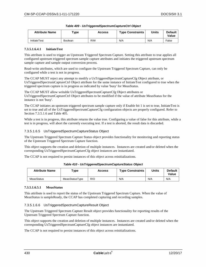
CM-SP-CCAP-OSSIv3.1-I11-171220 DOCSIS® 3.1
430 CableLabs 12/20/17
Table 409 - UsTriggeredSpectrumCaptureCtrl Object
Attribute Name Type Access Type Constraints Units Default Value
InitiateTest Boolean R/W N/A N/A False
7.3.5.1.6.4.1 InitiateTest
This attribute is used to trigger an Upstream Triggered Spectrum Capture. Setting this attribute to true applies all configured upstream triggered spectrum sample capture attributes and initiates the triggered upstream spectrum sample capture and sample output conversion process.
Read-write attributes, which are used to configure the Upstream Triggered Spectrum Capture, can only be configured while a test is not in progress.
The CCAP MUST reject any attempt to modify a UsTriggeredSpectrumCaptureCfg Object attribute, or UsTriggeredSpectrumCaptureCtrl Object attribute for the same instance of InitiateTest configured to true when the triggered spectrum capture is in progress as indicated by value 'busy' for MeasStatus.
The CCAP MUST allow writable UsTriggeredSpectrumCaptureCfg Object attributes or UsTriggeredSpectrumCaptureCtrl Object attributes to be modified if the value of attribute MeasStatus for the instance is not 'busy'.
The CCAP initiates an upstream triggered spectrum sample capture only if Enable bit 1 is set to true, InitiateTest is set to true and all of the UsTriggeredSpectrumCaptureCfg configuration objects are properly configured. Refer to Section 7.3.5.1.6 and Table 405.
While a test is in progress, this attribute returns the value true. Configuring a value of false for this attribute, while a test is in progress, will abort the currently executing test. If a test is aborted, the result data is discarded.
7.3.5.1.6.5 UsTriggeredSpectrumCaptureStatus Object
The Upstream Triggered Spectrum Capture Status object provides functionality for monitoring and reporting status of the Upstream Triggered Spectrum Capture function.
This object supports the creation and deletion of multiple instances. Instances are created and/or deleted when the corresponding UsTriggeredSpectrumCaptureCfg object instances are instantiated.
The CCAP is not required to persist instances of this object across reinitializations.
Table 410 - UsTriggeredSpectrumCaptureStatus Object
Attribute Name Type Access Type Constraints Units Default Value
MeasStatus MeasStatusType R/O N/A N/A N/A
7.3.5.1.6.5.1 MeasStatus
This attribute is used to report the status of the Upstream Triggered Spectrum Capture. When the value of MeasStatus is sampleReady, the CCAP has completed capturing and recording samples.
7.3.5.1.6.6 UsTriggeredSpectrumCaptureResult Object
The Upstream Triggered Spectrum Capture Result object provides functionality for reporting results of the Upstream Triggered Spectrum Capture function.
This object supports the creation and deletion of multiple instances. Instances are created and/or deleted when the corresponding UsTriggeredSpectrumCaptureCfg object instances are instantiated.
The CCAP is not required to persist instances of this object across reinitializations.
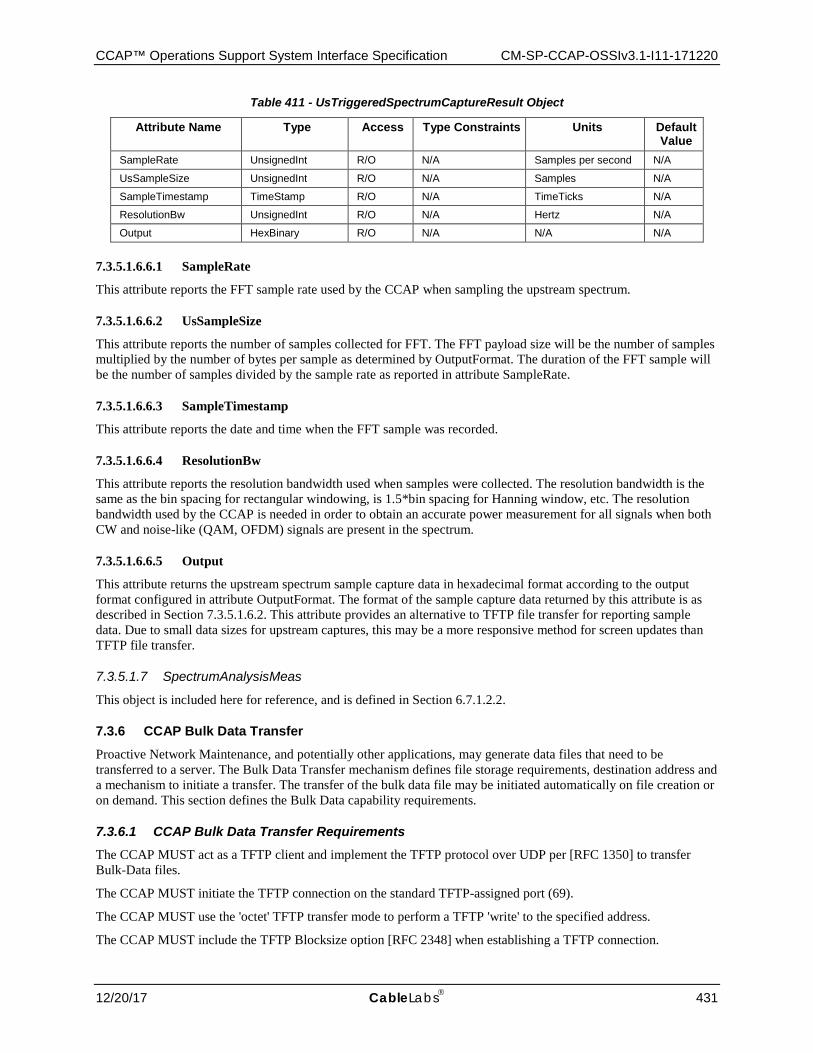
CCAP™ Operations Support System Interface Specification CM-SP-CCAP-OSSIv3.1-I11-171220
12/20/17 CableLabs 431
Table 411 - UsTriggeredSpectrumCaptureResult Object
Attribute Name Type Access Type Constraints Units Default Value
SampleRate UnsignedInt R/O N/A Samples per second N/A
UsSampleSize UnsignedInt R/O N/A Samples N/A
SampleTimestamp TimeStamp R/O N/A TimeTicks N/A
ResolutionBw UnsignedInt R/O N/A Hertz N/A
Output HexBinary R/O N/A N/A N/A
7.3.5.1.6.6.1 SampleRate
This attribute reports the FFT sample rate used by the CCAP when sampling the upstream spectrum.
7.3.5.1.6.6.2 UsSampleSize
This attribute reports the number of samples collected for FFT. The FFT payload size will be the number of samples multiplied by the number of bytes per sample as determined by OutputFormat. The duration of the FFT sample will be the number of samples divided by the sample rate as reported in attribute SampleRate.
7.3.5.1.6.6.3 SampleTimestamp
This attribute reports the date and time when the FFT sample was recorded.
7.3.5.1.6.6.4 ResolutionBw
This attribute reports the resolution bandwidth used when samples were collected. The resolution bandwidth is the same as the bin spacing for rectangular windowing, is 1.5*bin spacing for Hanning window, etc. The resolution bandwidth used by the CCAP is needed in order to obtain an accurate power measurement for all signals when both CW and noise-like (QAM, OFDM) signals are present in the spectrum.
7.3.5.1.6.6.5 Output
This attribute returns the upstream spectrum sample capture data in hexadecimal format according to the output format configured in attribute OutputFormat. The format of the sample capture data returned by this attribute is as described in Section 7.3.5.1.6.2. This attribute provides an alternative to TFTP file transfer for reporting sample data. Due to small data sizes for upstream captures, this may be a more responsive method for screen updates than TFTP file transfer.
7.3.5.1.7 SpectrumAnalysisMeas
This object is included here for reference, and is defined in Section 6.7.1.2.2.
7.3.6 CCAP Bulk Data Transfer Proactive Network Maintenance, and potentially other applications, may generate data files that need to be transferred to a server. The Bulk Data Transfer mechanism defines file storage requirements, destination address and a mechanism to initiate a transfer. The transfer of the bulk data file may be initiated automatically on file creation or on demand. This section defines the Bulk Data capability requirements.
7.3.6.1 CCAP Bulk Data Transfer Requirements The CCAP MUST act as a TFTP client and implement the TFTP protocol over UDP per [RFC 1350] to transfer Bulk-Data files.
The CCAP MUST initiate the TFTP connection on the standard TFTP-assigned port (69).
The CCAP MUST use the 'octet' TFTP transfer mode to perform a TFTP 'write' to the specified address.
The CCAP MUST include the TFTP Blocksize option [RFC 2348] when establishing a TFTP connection.
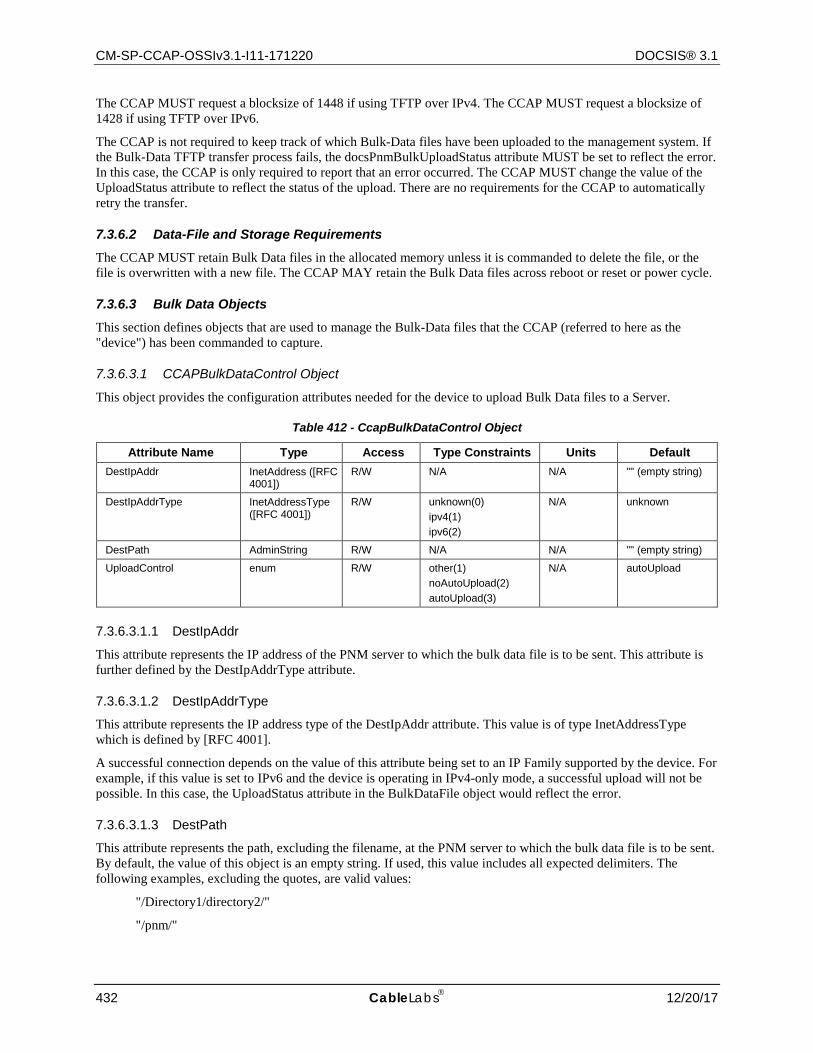
CM-SP-CCAP-OSSIv3.1-I11-171220 DOCSIS® 3.1
432 CableLabs 12/20/17
The CCAP MUST request a blocksize of 1448 if using TFTP over IPv4. The CCAP MUST request a blocksize of 1428 if using TFTP over IPv6.
The CCAP is not required to keep track of which Bulk-Data files have been uploaded to the management system. If the Bulk-Data TFTP transfer process fails, the docsPnmBulkUploadStatus attribute MUST be set to reflect the error. In this case, the CCAP is only required to report that an error occurred. The CCAP MUST change the value of the UploadStatus attribute to reflect the status of the upload. There are no requirements for the CCAP to automatically retry the transfer.
7.3.6.2 Data-File and Storage Requirements The CCAP MUST retain Bulk Data files in the allocated memory unless it is commanded to delete the file, or the file is overwritten with a new file. The CCAP MAY retain the Bulk Data files across reboot or reset or power cycle.
7.3.6.3 Bulk Data Objects This section defines objects that are used to manage the Bulk-Data files that the CCAP (referred to here as the "device") has been commanded to capture.
7.3.6.3.1 CCAPBulkDataControl Object
This object provides the configuration attributes needed for the device to upload Bulk Data files to a Server.
Table 412 - CcapBulkDataControl Object
Attribute Name Type Access Type Constraints Units Default DestIpAddr InetAddress ([RFC
4001]) R/W N/A N/A "" (empty string)
DestIpAddrType InetAddressType ([RFC 4001])
R/W unknown(0) ipv4(1) ipv6(2)
N/A unknown
DestPath AdminString R/W N/A N/A "" (empty string)
UploadControl enum R/W other(1) noAutoUpload(2) autoUpload(3)
N/A autoUpload
7.3.6.3.1.1 DestIpAddr
This attribute represents the IP address of the PNM server to which the bulk data file is to be sent. This attribute is further defined by the DestIpAddrType attribute.
7.3.6.3.1.2 DestIpAddrType
This attribute represents the IP address type of the DestIpAddr attribute. This value is of type InetAddressType which is defined by [RFC 4001].
A successful connection depends on the value of this attribute being set to an IP Family supported by the device. For example, if this value is set to IPv6 and the device is operating in IPv4-only mode, a successful upload will not be possible. In this case, the UploadStatus attribute in the BulkDataFile object would reflect the error.
7.3.6.3.1.3 DestPath
This attribute represents the path, excluding the filename, at the PNM server to which the bulk data file is to be sent. By default, the value of this object is an empty string. If used, this value includes all expected delimiters. The following examples, excluding the quotes, are valid values:
"/Directory1/directory2/"
"/pnm/"
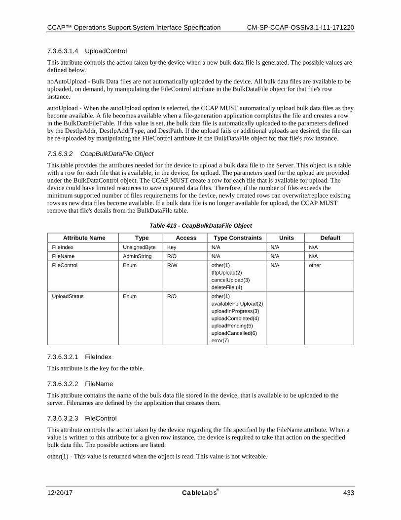
CCAP™ Operations Support System Interface Specification CM-SP-CCAP-OSSIv3.1-I11-171220
12/20/17 CableLabs 433
7.3.6.3.1.4 UploadControl
This attribute controls the action taken by the device when a new bulk data file is generated. The possible values are defined below.
noAutoUpload - Bulk Data files are not automatically uploaded by the device. All bulk data files are available to be uploaded, on demand, by manipulating the FileControl attribute in the BulkDataFile object for that file's row instance.
autoUpload - When the autoUpload option is selected, the CCAP MUST automatically upload bulk data files as they become available. A file becomes available when a file-generation application completes the file and creates a row in the BulkDataFileTable. If this value is set, the bulk data file is automatically uploaded to the parameters defined by the DestIpAddr, DestIpAddrType, and DestPath. If the upload fails or additional uploads are desired, the file can be re-uploaded by manipulating the FileControl attribute in the BulkDataFile object for that file's row instance.
7.3.6.3.2 CcapBulkDataFile Object
This table provides the attributes needed for the device to upload a bulk data file to the Server. This object is a table with a row for each file that is available, in the device, for upload. The parameters used for the upload are provided under the BulkDataControl object. The CCAP MUST create a row for each file that is available for upload. The device could have limited resources to save captured data files. Therefore, if the number of files exceeds the minimum supported number of files requirements for the device, newly created rows can overwrite/replace existing rows as new data files become available. If a bulk data file is no longer available for upload, the CCAP MUST remove that file's details from the BulkDataFile table.
Table 413 - CcapBulkDataFile Object
Attribute Name Type Access Type Constraints Units Default FileIndex UnsignedByte Key N/A N/A N/A
FileName AdminString R/O N/A N/A N/A
FileControl Enum R/W other(1) tftpUpload(2) cancelUpload(3) deleteFile (4)
N/A other
UploadStatus Enum R/O other(1) availableForUpload(2) uploadInProgress(3) uploadCompleted(4) uploadPending(5) uploadCancelled(6) error(7)
7.3.6.3.2.1 FileIndex
This attribute is the key for the table.
7.3.6.3.2.2 FileName
This attribute contains the name of the bulk data file stored in the device, that is available to be uploaded to the server. Filenames are defined by the application that creates them.
7.3.6.3.2.3 FileControl
This attribute controls the action taken by the device regarding the file specified by the FileName attribute. When a value is written to this attribute for a given row instance, the device is required to take that action on the specified bulk data file. The possible actions are listed:
other(1) - This value is returned when the object is read. This value is not writeable.
CM-SP-CCAP-OSSIv3.1-I11-171220 DOCSIS® 3.1
434 CableLabs 12/20/17
tftpUpload(2) - The CCAP MUST initiate a TFTP-Write to the server with the parameters specified in the 'DestIpAddr', 'DestIpAddrType', and 'DestPath' attributes. This action will change the value of the UploadStatus attribute to 'uploadInProgress' while the transfer is ongoing. This object can only be set to 'tftpUpload' when the value of the 'UploadStatus' attribute is not set to a value of 'uploadInProgress' for this row OR for any row in the table. This limits the upload process to one upload at a time. This object will return 'inconsistentValue' for this case.
cancelUpload(3) - The CCAP MUST cancel a pending upload or an upload currently in progress on this bulk data file. The value of the UploadStatus attribute will be changed to 'uploadCancelled'.
deleteFile (4) - The CCAP MUST delete the file from its memory and from this table. This object cannot be set to deleteFile(4) while an upload is in progress.
7.3.6.3.2.4 UploadStatus
This attribute reflects the status of the bulk data file. The possible values are listed below.
other(1) - Any condition not covered by the other defined values.
availableForUpload(2) - The file is available to be uploaded.
uploadInProgress(3) - The file is currently being uploaded.
uploadCompleted(4) - The file was successfully uploaded.
uploadPending(5) - The file has been selected for upload but a condition does not allow the upload to take place. The upload will start when the condition blocking uploads has been removed. For example, another upload that is currently in progress could cause this value to be returned.
uploadCancelled(6) - An upload was cancelled before it completed.
error(7) - An error occurred and the file was not successfully uploaded.
7.3.7 Triggering OPT Messages
To support the requirements of an external application managing DOCSIS OFDM channel profiles, a capability is needed for triggering the DOCSIS OPT message to retrieve various channel and profile related metrics and perform various tests as defined in [MULPIv3.1]. A triggering mechanism is defined to trigger the CMTS to send an OPT Request (OPT-REQ) message and then return CM metric information from the OPT Response (OPT-RSP) message. Note that the tests that return a given profile's MER per subcarrier data will be larger than a single SNMP PDU can transport in a single Ethernet frame.
The OFDM Profile Test (OPT) is performed using MAC Management Message (MMM) provided to evaluate several different parameters associated with a Downstream OFDM profile that is not currently being used by a target CM.
An OPT is requested by the CMTS through the generation of a OPT-REQ message to the CM required to perform the test. The CM performs the OPT using the parameters described in the OPT-REQ message. Upon successful completion of the test, the CM returns the OPT results in the OPT-RSP message.
The OPT message exchange is designed to support the following:
• Retrieval of the per-subcarrier MER values from the CM, which is a channel level measurement • Compilation by the CM for codeword statistics including codeword counts, uncorrectable codeword
counts, and the ability to enable codeword tagging • Execution of NCP Profile tests, which include the NCP Field counts and NCP CRC failure counts
When the CM receives an OPT Request message it may contain one or more of the aforementioned tests. The CM will use the OPT Response message to return the tested values to the CMTS.
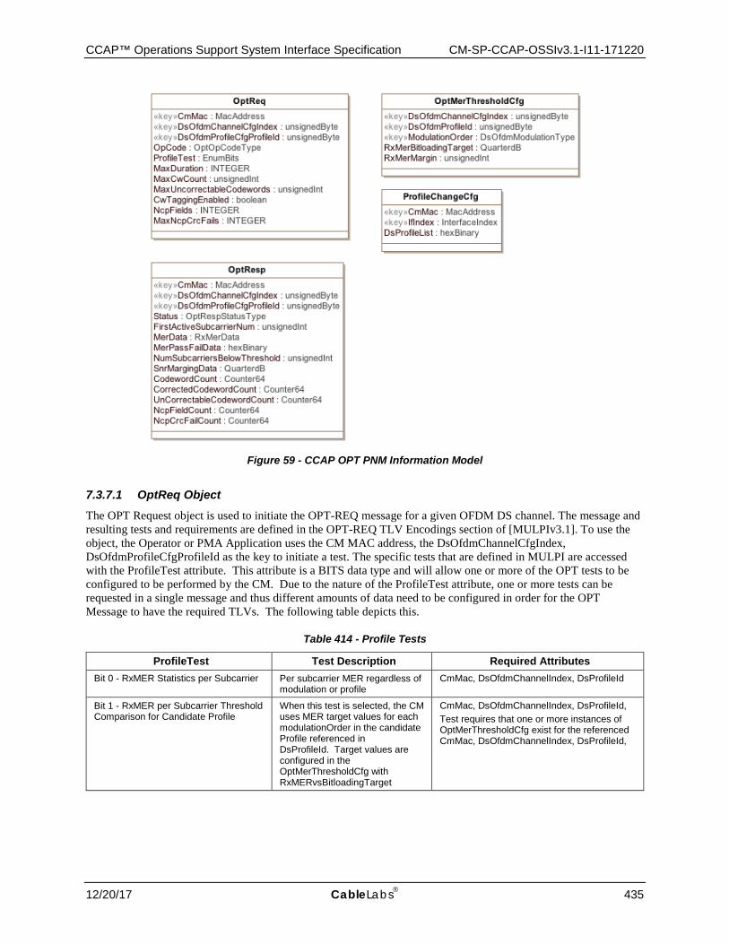
CCAP™ Operations Support System Interface Specification CM-SP-CCAP-OSSIv3.1-I11-171220
12/20/17 CableLabs 435
Figure 59 - CCAP OPT PNM Information Model
7.3.7.1 OptReq Object The OPT Request object is used to initiate the OPT-REQ message for a given OFDM DS channel. The message and resulting tests and requirements are defined in the OPT-REQ TLV Encodings section of [MULPIv3.1]. To use the object, the Operator or PMA Application uses the CM MAC address, the DsOfdmChannelCfgIndex, DsOfdmProfileCfgProfileId as the key to initiate a test. The specific tests that are defined in MULPI are accessed with the ProfileTest attribute. This attribute is a BITS data type and will allow one or more of the OPT tests to be configured to be performed by the CM. Due to the nature of the ProfileTest attribute, one or more tests can be requested in a single message and thus different amounts of data need to be configured in order for the OPT Message to have the required TLVs. The following table depicts this.
Table 414 - Profile Tests
ProfileTest Test Description Required Attributes Bit 0 - RxMER Statistics per Subcarrier Per subcarrier MER regardless of
modulation or profile CmMac, DsOfdmChannelIndex, DsProfileId
Bit 1 - RxMER per Subcarrier Threshold Comparison for Candidate Profile
When this test is selected, the CM uses MER target values for each modulationOrder in the candidate Profile referenced in DsProfileId. Target values are configured in the OptMerThresholdCfg with RxMERvsBitloadingTarget
CmMac, DsOfdmChannelIndex, DsProfileId, Test requires that one or more instances of OptMerThresholdCfg exist for the referenced CmMac, DsOfdmChannelIndex, DsProfileId,
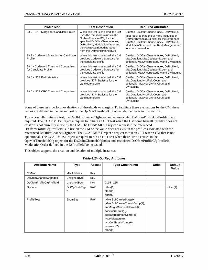
CM-SP-CCAP-OSSIv3.1-I11-171220 DOCSIS® 3.1
436 CableLabs 12/20/17
ProfileTest Test Description Required Attributes Bit 2 - SNR Margin for Candidate Profile When this test is selected, the CM
uses the threshold values in the OptMerThresholdCfg for the specified DsOfdmChannelIndex, DsProfileId, ModulationOrder and the RxMERvsBitloadingTarget from the OptMerThresholdCfg
CmMac, DsOfdmChannelIndex, DsProfileId, Test requires that one or more instances of OptMerThresholdCfg exist for the referenced CmMac, DsOfdmChannelIndex, DsProfileId, ModulationOrder and that RxMerMargin is set to a non-zero value
Bit 3 - Codeword Statistics for Candidate Profile
When this test is selected, the CM provides Codeword Statistics for the candidate profile
CmMac, DsOfdmChannelIndex, DsProfileId, MaxDuration, MaxCodewordCount and optionally MaxUncorrectedCw and CwTagging
Bit 4 - Codeword Threshold Comparison for Candidate Profile
When this test is selected, the CM provides Codeword Statistics for the candidate profile
CmMac, DsOfdmChannelIndex, DsProfileId, MaxDuration, MaxCodewordCount and optionally MaxUncorrectedCw and CwTagging
Bit 5 - NCP Field statistics When this test is selected, the CM provides NCP Statistics for the candidate profile
CmMac, DsOfdmChannelIndex, DsProfileId, MaxDuration, NcpFieldCount, and optionally MaxNcpCrcFailCount and CwTagging
Bit 6 - NCP CRC Threshold Comparison When this test is selected, the CM provides NCP Statistics for the candidate profile
CmMac, DsOfdmChannelIndex, DsProfileId, MaxDuration, NcpFieldCount, and optionally MaxNcpCrcFailCount and CwTagging
Some of these tests perform evaluations of thresholds or margins. To facilitate these evaluations by the CM, these values are defined in the test request or the OptMerThresholdCfg object defined later in this section.
To successfully initiate a test, the DsOfdmChannelCfgIndex and an associated DsOfdmProfileCfgProfileId are required. The CCAP MUST reject a request to initiate an OPT test when the DsOfdmChannelCfgIndex does not exist or is not currently in use by the CM. The CCAP MUST reject a request if the referenced DsOfdmProfileCfgProfileId is in use on the CM or the value does not exist in the profiles associated with the referenced DsOfdmChannelCfgIndex. The CCAP MUST reject a request to run an OPT test on CM that is not operational. The CCAP MUST reject a request to run an OPT test when there are no entries in the OptMerThresholdCfg object for the DsOfdmChannelCfgIndex and associated DsOfdmProfileCfgProfileId, ModulationOrder defined in the DsProfileId being tested.
This object supports the creation and deletion of multiple instances.
Table 415 - OptReq Attributes
Attribute Name Type Access Type Constraints Units Default Value
CmMac MacAddress Key
DsOfdmChannelCfgIndex UnsignedByte Key
DsOfdmProfileCfgProfileId UnsignedByte Key 0..15 | 255
OpCode OptOpCodeType
R/W other(1), start(2), abort(3)
other(1)
ProfileTest EnumBits R/W rxMerSubCarrierStats(0), rxMerSubCarrierThreshComp(1), snrMarginCandidateProfile(2), codewordStats(3), codewordThreshComp(4), ncpFieldStats(5), ncpCrcThreshComp(6), reserved(7), other(8)

CCAP™ Operations Support System Interface Specification CM-SP-CCAP-OSSIv3.1-I11-171220
12/20/17 CableLabs 437
Attribute Name Type Access Type Constraints Units Default Value
MaxDuration Integer R/W 4 Bytes milliseconds Need a smart default for this
MaxCodewords unsignedInt R/W 4 Bytes Number of codewords
Need a smart default for this
MaxUncorrectableCodewords unsignedInt R/W 4 Bytes Number of codewords
CodewordTaggingEnabled Boolean R/W false(0)
NcpFields Integer R/W 4 Bytes
MaxNcpCrcFails Integer R/W 4 Bytes
7.3.7.1.1 CmMac
This key represents the MAC address for the referenced CM.
Reference: [MULPIv3.1] OPT-REQ TLV Encodings
7.3.7.1.2 DsOfdmChannelCfgIndex
This key represents an instance of the DsOfdmChannelCfg of the Downstream OFDM channel that is currently assigned to a CM.
Reference: [MULPIv3.1] OPT-REQ TLV Encodings
7.3.7.1.3 DsOfdmProfileCfgProfileId
This key is the targeted profile being tested with OPT for the instance of DsOfdmChannelCfgIndex. For Data Profile testing, the ID of the profile that is being tested is used. The value 254 is used for RxMER statistics only. The value 255 is used for NCP Profile Testing.
Reference: [MULPIv3.1] OPT-REQ TLV Encodings
7.3.7.1.4 OpCode
This attribute controls the testing to be performed by the CM receiving the OPT-REQ message. This attribute is defined to mirror the OpCode field in the OPT-REQ message defined in the MULPI Spec.
Reference: [MULPIv3.1] OPT-REQ TLV Encodings
7.3.7.1.5 ProfileTest
This attribute defines which of the OPT tests are to be run by the CM. The tests are encoded as individual bits:
rxMerSubCarrierStats(0),
rxMerSubCarrierThreshComp(1),
snrMarginCandidateProfile(2),
codewordStats(3),
codewordThreshComp(4),
ncpFieldStats(5),
ncpCrcThreshComp(6),
reserved(7),
CM-SP-CCAP-OSSIv3.1-I11-171220 DOCSIS® 3.1
438 CableLabs 12/20/17
other(8)
When a given bit is set, then that test will be performed by the CM. Note that the tests rxMerSubCarrierThreshComp(1), snrMarginCandidateProfile(2) require entries in the OptMerThreshold object for these tests to be performed.
This attribute corresponds to TLV 1 in the OPT Request message.
Reference: [MULPIv3.1] OPT-REQ TLV Encodings
7.3.7.1.6 MaxDuration
This attribute allows the tester to determine how long a test may run before returning results or aborting.
This attribute corresponds to TLV 4 in the OPT Request message.
Reference: [MULPIv3.1] OPT-REQ TLV Encodings
7.3.7.1.7 MaxCodewords
This attribute defines the maximum number of codewords that the CM should examine before the test is complete. When either Nc or more codewords have been received, or Ne or more codeword errors have occurred, since the start of the test, the CM will send an OPT-RSP with a Complete status.
This attribute is only present in the OPT-REQ message for Codeword tests: codewordStats(3), codewordThreshComp(4).
This attribute corresponds to TLV 5.1 in the OPT Request message.
Reference: [MULPIv3.1] OPT-REQ TLV Encodings
7.3.7.1.8 MaxUncorrectableCodewords
This attribute defines the maximum number of uncorrectable codewords that the CM should allow before the test is complete. When either Nc or more codewords have been received, or Ne or more codeword errors have occurred, since the start of the test, the CM will send an OPT-RSP with a Complete status.
This attribute is only present in the OPT-REQ message for Codeword tests: codewordStats(3), codewordThreshComp(4).
This attribute corresponds to TLV 5.2 in the OPT Request message.
Reference: [MULPIv3.1] OPT-REQ TLV Encodings
7.3.7.1.9 CodewordTaggingEnabled
This attribute indicates whether Codeword Tagging is in use for this test. This attribute is defined as a Boolean with the value 'false' meaning that codeword tagging is disabled and a value of 'true meaning that codeword tagging is enabled. When codeword tagging is enabled, The CM will report codeword counts that include only codewords received on the profile in question for the duration of the test for which the 'T' bit is set to 1 in the NCP pointing to the codeword. The location of the 'T' bit is specified in [PHYv3.1].
If codeword tagging is disabled, the CM only reports codeword counts that include all codewords received on the profile in question for the duration of the test.
This attribute is only present in the OPT-REQ message for Codeword tests: codewordStats(3), codewordThreshComp(4).
This attribute corresponds to TLV 5.3 in the OPT Request message.
Reference: [MULPIv3.1] OPT-REQ TLV Encodings
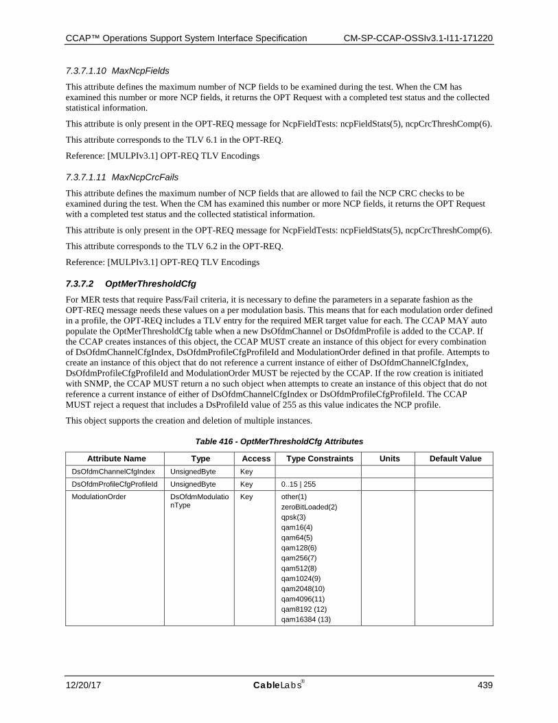
CCAP™ Operations Support System Interface Specification CM-SP-CCAP-OSSIv3.1-I11-171220
12/20/17 CableLabs 439
7.3.7.1.10 MaxNcpFields
This attribute defines the maximum number of NCP fields to be examined during the test. When the CM has examined this number or more NCP fields, it returns the OPT Request with a completed test status and the collected statistical information.
This attribute is only present in the OPT-REQ message for NcpFieldTests: ncpFieldStats(5), ncpCrcThreshComp(6).
This attribute corresponds to the TLV 6.1 in the OPT-REQ.
Reference: [MULPIv3.1] OPT-REQ TLV Encodings
7.3.7.1.11 MaxNcpCrcFails
This attribute defines the maximum number of NCP fields that are allowed to fail the NCP CRC checks to be examined during the test. When the CM has examined this number or more NCP fields, it returns the OPT Request with a completed test status and the collected statistical information.
This attribute is only present in the OPT-REQ message for NcpFieldTests: ncpFieldStats(5), ncpCrcThreshComp(6).
This attribute corresponds to the TLV 6.2 in the OPT-REQ.
Reference: [MULPIv3.1] OPT-REQ TLV Encodings
7.3.7.2 OptMerThresholdCfg For MER tests that require Pass/Fail criteria, it is necessary to define the parameters in a separate fashion as the OPT-REQ message needs these values on a per modulation basis. This means that for each modulation order defined in a profile, the OPT-REQ includes a TLV entry for the required MER target value for each. The CCAP MAY auto populate the OptMerThresholdCfg table when a new DsOfdmChannel or DsOfdmProfile is added to the CCAP. If the CCAP creates instances of this object, the CCAP MUST create an instance of this object for every combination of DsOfdmChannelCfgIndex, DsOfdmProfileCfgProfileId and ModulationOrder defined in that profile. Attempts to create an instance of this object that do not reference a current instance of either of DsOfdmChannelCfgIndex, DsOfdmProfileCfgProfileId and ModulationOrder MUST be rejected by the CCAP. If the row creation is initiated with SNMP, the CCAP MUST return a no such object when attempts to create an instance of this object that do not reference a current instance of either of DsOfdmChannelCfgIndex or DsOfdmProfileCfgProfileId. The CCAP MUST reject a request that includes a DsProfileId value of 255 as this value indicates the NCP profile.
This object supports the creation and deletion of multiple instances.
Table 416 - OptMerThresholdCfg Attributes
Attribute Name Type Access Type Constraints Units Default Value DsOfdmChannelCfgIndex UnsignedByte Key
DsOfdmProfileCfgProfileId UnsignedByte Key 0..15 | 255
ModulationOrder DsOfdmModulationType
Key other(1) zeroBitLoaded(2) qpsk(3) qam16(4) qam64(5) qam128(6) qam256(7) qam512(8) qam1024(9) qam2048(10) qam4096(11) qam8192 (12) qam16384 (13)
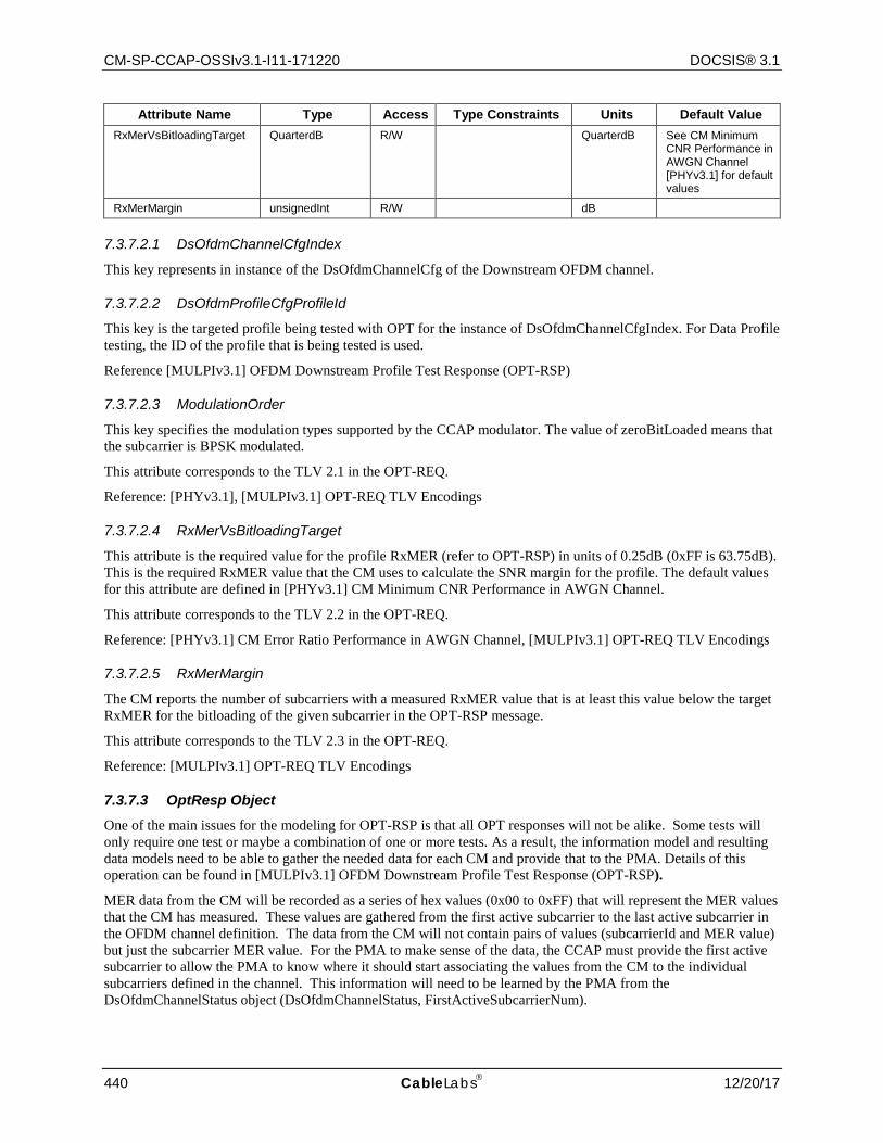
CM-SP-CCAP-OSSIv3.1-I11-171220 DOCSIS® 3.1
440 CableLabs 12/20/17
Attribute Name Type Access Type Constraints Units Default Value RxMerVsBitloadingTarget QuarterdB R/W QuarterdB See CM Minimum
CNR Performance in AWGN Channel [PHYv3.1] for default values
RxMerMargin unsignedInt R/W dB
7.3.7.2.1 DsOfdmChannelCfgIndex
This key represents in instance of the DsOfdmChannelCfg of the Downstream OFDM channel.
7.3.7.2.2 DsOfdmProfileCfgProfileId
This key is the targeted profile being tested with OPT for the instance of DsOfdmChannelCfgIndex. For Data Profile testing, the ID of the profile that is being tested is used.
Reference [MULPIv3.1] OFDM Downstream Profile Test Response (OPT-RSP)
7.3.7.2.3 ModulationOrder
This key specifies the modulation types supported by the CCAP modulator. The value of zeroBitLoaded means that the subcarrier is BPSK modulated.
This attribute corresponds to the TLV 2.1 in the OPT-REQ.
Reference: [PHYv3.1], [MULPIv3.1] OPT-REQ TLV Encodings
7.3.7.2.4 RxMerVsBitloadingTarget
This attribute is the required value for the profile RxMER (refer to OPT-RSP) in units of 0.25dB (0xFF is 63.75dB). This is the required RxMER value that the CM uses to calculate the SNR margin for the profile. The default values for this attribute are defined in [PHYv3.1] CM Minimum CNR Performance in AWGN Channel.
This attribute corresponds to the TLV 2.2 in the OPT-REQ.
Reference: [PHYv3.1] CM Error Ratio Performance in AWGN Channel, [MULPIv3.1] OPT-REQ TLV Encodings
7.3.7.2.5 RxMerMargin
The CM reports the number of subcarriers with a measured RxMER value that is at least this value below the target RxMER for the bitloading of the given subcarrier in the OPT-RSP message.
This attribute corresponds to the TLV 2.3 in the OPT-REQ.
Reference: [MULPIv3.1] OPT-REQ TLV Encodings
7.3.7.3 OptResp Object One of the main issues for the modeling for OPT-RSP is that all OPT responses will not be alike. Some tests will only require one test or maybe a combination of one or more tests. As a result, the information model and resulting data models need to be able to gather the needed data for each CM and provide that to the PMA. Details of this operation can be found in [MULPIv3.1] OFDM Downstream Profile Test Response (OPT-RSP).
MER data from the CM will be recorded as a series of hex values (0x00 to 0xFF) that will represent the MER values that the CM has measured. These values are gathered from the first active subcarrier to the last active subcarrier in the OFDM channel definition. The data from the CM will not contain pairs of values (subcarrierId and MER value) but just the subcarrier MER value. For the PMA to make sense of the data, the CCAP must provide the first active subcarrier to allow the PMA to know where it should start associating the values from the CM to the individual subcarriers defined in the channel. This information will need to be learned by the PMA from the DsOfdmChannelStatus object (DsOfdmChannelStatus, FirstActiveSubcarrierNum).
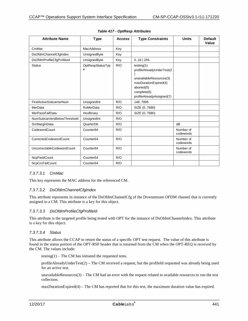
CCAP™ Operations Support System Interface Specification CM-SP-CCAP-OSSIv3.1-I11-171220
12/20/17 CableLabs 441
Table 417 - OptResp Attributes
Attribute Name Type Access Type Constraints Units Default Value
CmMac MacAddress Key
DsOfdmChannelCfgIndex UnsignedByte Key
DsOfdmProfileCfgProfileId UnsignedByte Key 0..16 | 255
Status OptRespStatusType
R/O testing(1) profileAlreadyUnderTest(2) unavailableResources(3) maxDurationExpired(4) aborted(5) complete(6) profileAlreadyAssigned(7)
FirstActiveSubcarrierNum UnsignedInt R/O 148..7895
MerData RxMerData R/O SIZE (0..7680)
MerPassFailData HexBinary R/O SIZE (0..7680)
NumSubcarriersBelowThreshold UnsignedInt R/O
SnrMarginData QuarterDb R/O dB
CodewordCount Counter64 R/O Number of codewords
CorrectedCodewordCount Counter64 R/O Number of codewords
UncorrectableCodewordCount Counter64 R/O Number of codewords
NcpFieldCount Counter64 R/O
NcpCrcFailCount Counter64 R/O
7.3.7.3.1 CmMac
This key represents the MAC address for the referenced CM.
7.3.7.3.2 DsOfdmChannelCfgIndex
This attribute represents in instance of the DsOfdmChannelCfg of the Downstream OFDM channel that is currently assigned to a CM. This attribute is a key for this object.
7.3.7.3.3 DsOfdmProfileCfgProfileId
This attribute is the targeted profile being tested with OPT for the instance of DsOfdmChannelindex. This attribute is a key for this object.
7.3.7.3.4 Status
This attribute allows the CCAP to return the status of a specific OPT test request. The value of this attribute is found in the status portion of the OPT-RSP header that is returned from the CM when the OPT-REQ is received by the CM. The values include:
testing(1) – The CM has initiated the requested tests.
profileAlreadyUnderTest(2) – The CM received a request, but the profileId requested was already being used for an active test.
unavailableResources(3) – The CM had an error with the request related to available resources to run the test collection.
maxDurationExpired(4) – The CM has reported that for this test, the maximum duration value has expired.
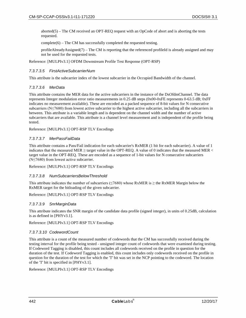
CM-SP-CCAP-OSSIv3.1-I11-171220 DOCSIS® 3.1
442 CableLabs 12/20/17
aborted(5) – The CM received an OPT-REQ request with an OpCode of abort and is aborting the tests requested.
complete(6) – The CM has successfully completed the requested testing.
profileAlreadyAssigned(7) – The CM is reporting that the referenced profileId is already assigned and may not be used for the requested tests.
Reference: [MULPIv3.1] OFDM Downstream Profile Test Response (OPT-RSP)
7.3.7.3.5 FirstActiveSubcarrierNum
This attribute is the subcarrier index of the lowest subcarrier in the Occupied Bandwidth of the channel.
7.3.7.3.6 MerData
This attribute contains the MER data for the active subcarriers in the instance of the DsOfdmChannel. The data represents Integer modulation error ratio measurements in 0.25 dB steps (0x00-0xFE represents 0-63.5 dB; 0xFF indicates no measurement available). These are encoded as a packed sequence of 8-bit values for N consecutive subcarriers (N≤7680) from lowest active subcarrier to the highest active subcarrier, including all the subcarriers in between. This attribute is a variable length and is dependent on the channel width and the number of active subcarriers that are available. This attribute is a channel level measurement and is independent of the profile being tested.
Reference: [MULPIv3.1] OPT-RSP TLV Encodings
7.3.7.3.7 MerPassFailData
This attribute contains a Pass/Fail indication for each subcarrier's RxMER (1 bit for each subcarrier). A value of 1 indicates that the measured MER ≥ target value in the OPT-REQ. A value of 0 indicates that the measured MER < target value in the OPT-REQ. These are encoded as a sequence of 1-bit values for N consecutive subcarriers (N≤7680) from lowest active subcarrier.
Reference: [MULPIv3.1] OPT-RSP TLV Encodings
7.3.7.3.8 NumSubcarriersBelowThreshold
This attribute indicates the number of subcarriers (≤7680) whose RxMER is ≥ the RxMER Margin below the RxMER target for the bitloading of the given subcarrier.
Reference: [MULPIv3.1] OPT-RSP TLV Encodings
7.3.7.3.9 SnrMarginData
This attribute indicates the SNR margin of the candidate data profile (signed integer), in units of 0.25dB, calculation is as defined in [PHYv3.1].
Reference: [MULPIv3.1] OPT-RSP TLV Encodings
7.3.7.3.10 CodewordCount
This attribute is a count of the measured number of codewords that the CM has successfully received during the testing interval for the profile being tested - unsigned integer count of codewords that were examined during testing. If Codeword Tagging is disabled, this count includes all codewords received on the profile in question for the duration of the test. If Codeword Tagging is enabled, this count includes only codewords received on the profile in question for the duration of the test for which the 'T' bit was set in the NCP pointing to the codeword. The location of the 'T' bit is specified in [PHYv3.1].
Reference: [MULPIv3.1] OPT-RSP TLV Encodings
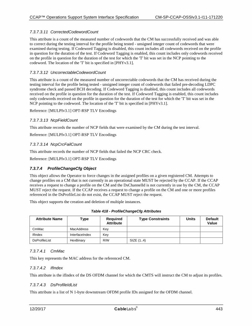
CCAP™ Operations Support System Interface Specification CM-SP-CCAP-OSSIv3.1-I11-171220
12/20/17 CableLabs 443
7.3.7.3.11 CorrectedCodewordCount
This attribute is a count of the measured number of codewords that the CM has successfully received and was able to correct during the testing interval for the profile being tested - unsigned integer count of codewords that were examined during testing. If Codeword Tagging is disabled, this count includes all codewords received on the profile in question for the duration of the test. If Codeword Tagging is enabled, this count includes only codewords received on the profile in question for the duration of the test for which the 'T' bit was set in the NCP pointing to the codeword. The location of the 'T' bit is specified in [PHYv3.1].
7.3.7.3.12 UncorrectableCodewordCount
This attribute is a count of the measured number of uncorrectable codewords that the CM has received during the testing interval for the profile being tested - unsigned integer count of codewords that failed pre-decoding LDPC syndrome check and passed BCH decoding. If Codeword Tagging is disabled, this count includes all codewords received on the profile in question for the duration of the test. If Codeword Tagging is enabled, this count includes only codewords received on the profile in question for the duration of the test for which the 'T' bit was set in the NCP pointing to the codeword. The location of the 'T' bit is specified in [PHYv3.1].
Reference: [MULPIv3.1] OPT-RSP TLV Encodings
7.3.7.3.13 NcpFieldCount
This attribute records the number of NCP fields that were examined by the CM during the test interval.
Reference: [MULPIv3.1] OPT-RSP TLV Encodings
7.3.7.3.14 NcpCrcFailCount
This attribute records the number of NCP fields that failed the NCP CRC check.
Reference: [MULPIv3.1] OPT-RSP TLV Encodings
7.3.7.4 ProfileChangeCfg Object This object allows the Operator to force changes in the assigned profiles on a given registered CM. Attempts to change profiles on a CM that is not currently in an operational state MUST be rejected by the CCAP. If the CCAP receives a request to change a profile on the CM and the DsChannelId is not currently in use by the CM, the CCAP MUST reject the request. If the CCAP receives a request to change a profile on the CM and one or more profiles referenced in the DsProfileList do not exist, the CCAP MUST reject the request.
This object supports the creation and deletion of multiple instances.
Table 418 - ProfileChangeCfg Attributes
Attribute Name Type Required Attribute
Type Constraints Units Default Value
CmMac MacAddress Key
IfIndex InterfaceIndex Key
DsProfileList HexBinary R/W SIZE (1..4)
7.3.7.4.1 CmMac
This key represents the MAC address for the referenced CM.
7.3.7.4.2 IfIndex
This attribute is the ifIndex of the DS OFDM channel for which the CMTS will instruct the CM to adjust its profiles.
7.3.7.4.3 DsProfileIdList
This attribute is a list of N 1-byte downstream OFDM profile IDs assigned for the OFDM channel.
CM-SP-CCAP-OSSIv3.1-I11-171220 DOCSIS® 3.1
444 CableLabs 12/20/17
7.4 IPDR
The CCAP MUST implement IPDR/SP as described in Section 8.
The CCAP MUST support IPDR reporting on all of its access network interfaces (QAM, PON, etc.).
7.4.1 IPDR Service Definitions The CCAP MUST support all IPDR service definitions defined as mandatory in Section 8, including SAMIS. Refer to DOCSIS IPDR Service Definitions figure in Section 8 for the IPDR service definition object diagram.
If the CCAP supports PON interfaces, the CCAP MUST support all IPDR service definitions defined as mandatory in [DPoE OSSIv2.0].

CCAP™ Operations Support System Interface Specification CM-SP-CCAP-OSSIv3.1-I11-171220
12/20/17 CableLabs 445
8 ACCOUNTING MANAGEMENT
8.1 SAMIS
This specification defines an accounting management interface for subscriber usage-based applications denominated Subscriber Account Management Interface Specification (SAMIS). SAMIS is defined to enable prospective vendors of cable modems and cable modem termination systems to address the operational requirements of subscriber account management in a uniform and consistent manner. It is the intention that this would enable operators and other interested parties to define, design and develop Operations and Business Support Systems necessary for the commercial deployment of different class of services over cable networks, with accompanying usage-based billing of services for each individual subscriber.
Subscriber Account Management described here refers to the following business processes and terms:
Class of Service Provisioning Processes, which are involved in the automatic and dynamic provisioning and enforcement of subscribed class of policy-based service level agreements (SLAs).
Usage-Based Billing Processes, which are involved in the processing of bills based on services rendered to and consumed by paying subscribers. This Specification focuses primarily on bandwidth-centric usage-based billing scenarios. It complements the PacketCable Event Messages Specification [PKT EM].
The business processes defined above are aligned with the scenarios for Subscriber Account Management described in Appendix I of [OSSIv3.0]. In order to develop the DOCSIS-OSS Subscriber Account Management Specification, it is necessary to consider high-level business processes common to cable operators and the associated operational scenarios. These issues are discussed in Annex B.
The CCAP MUST support collection of usage information, for use by the billing system, via an interface known as the Subscriber Accounting Management Interface Specification (SAMIS).
8.1.1 Subscriber Usage Billing and class of services
The [MULPIv3.1] specification uses the concept of class of service, as the term to indicate the type of data services a CM requests and receives from the CCAP. From a high level perspective class of services are observed as subscriber types (e.g., residential or business) and the DOCSIS RFI MAC layer parameters fulfill the subscriber service needs.
The [MULPIv3.1] specification supports a DOCSIS 1.1 QoS service class definition type that offers queuing and scheduling services. The DOCSIS 1.0 Class of Service (CoS) service class definition type has been deprecated and is not supported in DOCSIS 3.1.
8.1.1.1 DOCSIS 1.1 Quality of Service (QoS) The [MULPIv3.1] specification provides a mechanism for a CM to register with its CCAP and to configure itself based on external QoS parameters when it is powered up or reset.
To quote (in part) from the Theory of Operation section of [MULPIv3.1]:
The principal mechanism for providing enhanced QoS is to classify packets traversing the RF MAC interface into a Service Flow. A Service Flow is a unidirectional flow of packets that provide a particular Quality of Service. The CM and the CMTS provide this QoS by shaping, policing, and prioritizing traffic according to the QoS Parameter Set defined for the Service Flow.
The requirements for Quality of Service include:
• A configuration and registration function for pre-configuring CM-based QoS Service Flows and traffic parameters.
• Utilization of QoS traffic parameters for downstream Service Flows. • Classification of packets arriving from the upper layer service interface to a specific active Service Flow
CM-SP-CCAP-OSSIv3.1-I11-171220 DOCSIS® 3.1
446 CableLabs 12/20/17
• Grouping of Service Flow properties into named Service Classes, so upper layer entities and external applications (at both the CM and the CCAP) can request Service Flows with desired QoS parameters in a globally consistent way.
A Service Class Name (SCN) is defined in the CCAP by provisioning (see [OSSIv3.0] Annex O). An SCN provides an association to a QoS Parameter Set. Service Flows that are created using an SCN are considered to be "named" Service Flows. The SCN identifies the service characteristics of a Service Flow to external systems such as a billing system or customer service system. For consistency in billing, operators should ensure that SCNs are unique within an area serviced by the same BSS that utilizes this interface. A descriptive SCN might be something like PrimaryUp, GoldUp, VoiceDn, or BronzeDn to indicate the nature and direction of the Service Flow to the external system.
A Service Package implements a Service Level Agreement (SLA) between the MSO and its Subscribers on the RFI interface. A Service Package might be known by a name such as Gold, Silver, or Bronze. A Service Package is itself implemented by the set of named Service Flows (using SCNs) that are placed into a CM Configuration File that is stored on a Config File server. Note: The CM Configuration File contains several kinds of information needed to properly configure the CM and its relationship with the CMTS, but for the sake of this discussion only the Service Flow and Quality of Service components are of interest. The set of Service Flows defined in the CM Config File are used to create active Service Flows when the CM registers with the CCAP. Note that many Subscribers are assigned to the same Service Package and, therefore, many CMs use the same CM Config File to establish their active Service Flows.
A Service Package has to define at least two Service Flows known as Primary Service Flows that are used by default when a packet matches none of the classifiers for the other Service Flows. A CM Config File that implements a Service Package, therefore, needs to define the two primary Service Flows using SCNs (e.g., PrimaryUp and PrimaryDn) that are known to the CCAP if these Service Flows are to be visible to external systems by this billing interface. Note that it is often the practice in a usage sensitive billing environment to segregate the operator's own maintenance traffic, to and from the CM, into the primary service flows so that this traffic is not reflected in the traffic counters associated the subscriber's SLA service flows.
The [MULPIv3.1] specification also provides for dynamically created Service Flows. An example could be a set of dynamic Service Flows created by an embedded PacketCable Multimedia Terminal Adapter (eMTA) to manage VoIP signaling and media flows. All dynamic Service Flows need to be created using an SCN known to the CCAP if they are to be visible to the billing system. These dynamic SCNs do not need to appear in the CM Config File but the MTA may refer to them directly during its own initialization and operation.
During initialization, a CM communicates with a DHCP Server that provides the CM with its assigned IP address and, in addition, receives a pointer to the Config File server that stores the assigned CM Config File for that CM. The CM reads the CM Config File and forwards the set of Service Flow definitions (using SCNs) up to the CCAP. The CCAP then performs a macro-expansion on the SCNs (using its provisioned SCN templates) into QoS Parameter Sets sent in the Registration Response for the CM. Internally, each active Service Flow is identified by a 32-bit SFID assigned by the CCAP to a specific CM (relative to the RFI interface). For billing purposes, however, the SFID is not sufficient as the only identifier of a Service Flow because the billing system cannot distinguish the class of service being delivered by one SFID from another. Therefore, the SCN is necessary, in addition to the SFID, to identify the Service Flow's class of service characteristics to the billing system.
The billing system can then rate the charges differently for each of the Service Flow traffic counts based on its Service Class (e.g., Gold octet counts are likely to be charged more than Bronze octet counts). Thus, the billing system obtains, from the CCAP, the traffic counts for each named Service Flow (identified by SFID and SCN) that a subscriber's CM uses during the billing data collection interval. This is true even if multiple active Service Flows (i.e., SFIDs) are created using the same SCN for a given CM over time. This will result in multiple billing records for the CM for Service Flows that have the same SCN (but different SFIDs). Note that the SFID is the primary key to the Service Flow. When an active Service Flow exists across multiple sequential billing files, the SFID allows the sequence of recorded counter values to be correlated to the same Service Flow instance.
8.1.1.2 High-Level Requirements for Subscriber Usage Billing Records This section provides the high-level, functional requirements of the Subscriber Usage Billing interface.
The CCAP provides formatted Subscriber Usage Billing Records for all subscribers attached to the CCAP, on demand, to mediation or billing systems.
CCAP™ Operations Support System Interface Specification CM-SP-CCAP-OSSIv3.1-I11-171220
12/20/17 CableLabs 447
The transfer of these Usage Billing Records from the CCAP to the mediation/billing system uses the streaming model defined in [IPDR/SP]. This is a mechanism for transmission of Usage Billing Records in near "real-time" from the CCAP to the mediation system.
The CCAP needs to support a minimum billing record transfer interval of 15 minutes.
The CCAP MUST support the processing and transmitting of Subscriber Usage Billing Records as follows:
• A Subscriber Usage Billing Record identifies the CCAP by host name and IP address and the date and time record is sent. The sysUpTime value for the CCAP is recorded, as well as the MAC domain, downstream and upstream information, the CM is registered on to facilitate the characterization of cable interfaces usage.
• A Subscriber Usage Billing Record is identified by CM MAC address (but not necessarily sorted). The Subscriber's current CM IP address is also present in the billing record for the Subscriber. If the CCAP is tracking CPE addresses behind the Subscriber's CM, then these CPE MAC and IP addresses are also be present in the billing record as well. CPE FQDNs (Fully Qualified Domain Name) are be present in the billing record only if gleaned from DHCP relay agent transactions (reverse DNS queries are not required).
• A Subscriber Usage Billing Record has entries for each active Service Flow (identified by SFID and Service Class Name) used by all CMs operating in DOCSIS 1.1 (or higher) registration mode during the collection interval. This includes all currently running Service Flows, as well as all terminated Service Flows that were deleted and logged during the collection interval. A provisioned or admitted state SF that was deleted before it became active, is not recorded in the billing document, even though it was logged by the CCAP.
• A Subscriber Usage Billing Record identifies a running Service Flows or a terminated Service Flow, as well as a de-registered CM. A terminated Service Flow is reported into a Subscriber Usage Billing Record once.
• A Subscriber Usage Billing Record identifies the Service Flow direction as upstream or downstream. It collects the number of packets and octets passed for each upstream and downstream Service Flow. The number of packets dropped and the number of packets delayed due to enforcement of QoS maximum throughput parameters (SLA) are also collected for each Service Flow. In the case of an upstream Service Flow, the reported SLA drop and delay counters represent only the QoS policing performed by the CCAP. Note that since it is possible for a Subscriber to switch back and forth from one service package to another, or to have dynamic service flows occur multiple times, it is possible that there will be multiple Subscriber Usage Records for a given SCN during the collection period. This could also occur if a CM re-registers for any reason (such as CM power failure).
• All traffic counters within a Subscriber Usage Billing Record are absolute 32-bit or 64-bit counters. These traffic counters need to be reset to zero by the CCAP if it re-initializes its management interface. The CCAP sysUpTime value is used to determine if the management interface has been reset between adjacent collection intervals. It is expected that the 64-bit counters will not roll over within the service lifetime of the CCAP.
8.1.1.3 Subscriber Usage Billing Records Mapping to Existing DOCSIS Data model In Section 8.1.1.2 the High-level requirements for Subscriber Usage Billing includes counters for consumption-based billing. Part of that section deals with the collection of counters associated with DOCSIS 1.1 Quality of Service. The mapping described below is required to consistently define the Subscriber Usage Billing service specification based on mandatory and well-defined counter requirements as much as possible.
The [MULPIv3.1] specification does not define MAC layer primitives for usage counters associated to SFIDs to be mapped to Management models like SNMP or this Subscriber Usage Billing service specification.
DOCSIS mandatory QoS counter requirements are contained in this specification. They are defined as UML Information models in Section 7.2 of this specification; see Section 7.1 for details on the corresponding SNMP SMI data models.
Table 419 describes the Subscriber Usage Billing model mapping to this specification standard management object base and other requirements not defined in this specification. See Table Notes immediately following Table 419.
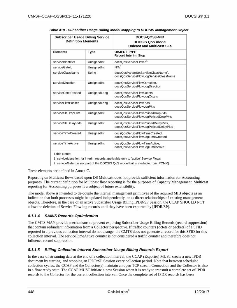
CM-SP-CCAP-OSSIv3.1-I11-171220 DOCSIS® 3.1
448 CableLabs 12/20/17
Table 419 - Subscriber Usage Billing Model Mapping to DOCSIS Management Object
Subscriber Usage Billing Service Definition Elements
DOCS-QOS3-MIB DOCSIS QoS model
Unicast and Multicast SFs Elements Type OBJECT-TYPE
Record Interim, Stop
serviceIdentifier UnsignedInt docsQosServiceFlowId1,
serviceGateId UnsignedInt N/A2
serviceClassName String docsQosParamSetServiceClassName1, docsQosServiceFlowLogServiceClassName
serviceDirection UnsignedInt docsQosServiceFlowDirection, docsQosServiceFlowLogDirection
serviceOctetPassed UnsignedLong docsQosServiceFlowOctets, docsQosServiceFlowLogOctets
servicePktsPassed UnsignedLong docsQosServiceFlowPkts, docsQosServiceFlowLogPkts
serviceSlaDropPkts UnsignedInt docsQosServiceFlowPolicedDropPkts, docsQosServiceFlowLogPolicedDropPkts
serviceSlaDelayPkts UnsignedInt docsQosServiceFlowPolicedDelayPkts, docsQosServiceFlowLogPolicedDelayPkts
serviceTimeCreated UnsignedInt docsQosServiceFlowTimeCreated, docsQosServiceFlowLogTimeCreated
serviceTimeActive UnsignedInt docsQosServiceFlowTimeActive, docsQosServiceFlowLogTimeActive
Table Notes: 1 serviceIdentifier: for interim records applicable only to 'active' Service Flows 2 serviceGateId is not part of the DOCSIS QoS model but is available from [PCMM]
These elements are defined in Annex C.
Reporting on Multicast flows based upon DS Multicast does not provide sufficient information for Accounting purposes. The current definition for Multicast flow reporting is for the purposes of Capacity Management. Multicast reporting for Accounting purposes is a subject of future extensibility.
The model above is intended to de-couple the internal management primitives of the required MIB objects as an indication that both processes might be updated independently, or as direct relationships of existing management objects. Therefore, in the case of an active Subscriber Usage Billing IPDR/SP Session, the CCAP SHOULD NOT allow the deletion of Service Flow log records until they have been exported by [IPDR/SP].
8.1.1.4 SAMIS Records Optimization The CMTS MAY provide mechanisms to prevent exporting Subscriber Usage Billing Records (record suppression) that contain redundant information from a Collector perspective. If traffic counters (octets or packets) of a SFID reported in a previous collection interval do not change, the CMTS does not generate a record for this SFID for this collection interval. The serviceTimeActive counter is not considered a traffic counter and therefore does not influence record suppression.
8.1.1.5 Billing Collection Interval Subscriber Usage Billing Records Export In the case of streaming data at the end of a collection interval, the CCAP (Exporter) MUST create a new IPDR document by starting, and stopping an IPDR/SP Session every collection period. Note that between scheduled collection cycles, the CCAP and the Collector(s) maintain an open TCP stream Connection and the Collector is also in a flow ready state. The CCAP MUST initiate a new Session when it is ready to transmit a complete set of IPDR records to the Collector for the current collection interval. Once the complete set of IPDR records has been
CCAP™ Operations Support System Interface Specification CM-SP-CCAP-OSSIv3.1-I11-171220
12/20/17 CableLabs 449
transmitted, the CCAP MUST stop the session immediately or stop the session at the end of the collection interval, thereby closing the IPDR document for the current collection interval. When the session is stopped immediately, all subsequent terminated SF's MUST be buffered by the Exporter until they can be transmitted in the next scheduled collection interval. The CCAP MAY also leave the session open until the next collection interval. In addition to the scheduled collection cycles, the CCAP MAY also initiate an unscheduled Session with a Collector whenever it needs to transmit IPDR records for terminated SFs because it is in danger of losing data (e.g., its SF log buffer is about to overflow). This unscheduled Session will only contain RecType = Stop IPDR records for the terminated SFs in the log buffer, thereby clearing the buffer. It is imperative that logged SFs are only reported once into an IPDR document. If no connection is available (e.g., for an unscheduled Session or existing open Session) with a Collector, then the CCAP MUST delete the oldest SF log entries first.
Other Management strategies may provide Collector control over the streaming data by executing FlowStop and FlowStart at its convenience (for example to perform load balancing or force the termination of streaming from an Exporter).
8.1.2 DOCSIS Subscriber Usage Billing Requirements
The CCAP MUST support Subscriber Usage Billing by implementing this Subscriber Accounting Management Interface Specification (SAMIS) based on [IPDR/BSR].
8.2 IPDR Protocol
8.2.1 Introduction
This section defines the IPDR Streaming Protocol [IPDR/SP] requirements for the CCAP. Unless otherwise indicated, the term "IPDR Exporter" refers to the CCAP. A collector system is often referred to as an "IPDR Collector" and conforms to [IPDR/BSR] and in particular to [IPDR/SP] specification. IPDR collector management requirements are outside the scope of this specification. See Section 8.2.2 for a brief overview of the IPDR Standard.
[IPDR/SP] provides scalable solutions for the collection of high volume management data related to performance, usage, and operational status of the cable networks. The [IPDR/SP] scalability benefits are for both the CCAP and the data collection systems. The CCAP gains in reduced computing resources, compared with other management protocols, such as SNMP, when generating comparable data sets. The collector systems benefit from [IPDR/SP] by reducing the costs associated with reliable data collection, scalable growth in number of records, and multiple types of data sets over the same collection platform. See [IPDR/SP] for additional information about the streaming protocol design considerations.
The IPDR-related standards listed in Table 420 are supported by CCAP.
Table 420 - IPDR-related Standards
[IPDR/SP] IPDR/SP Protocol Specification
[IPDR/BSR] IPDR Business Solution Requirements - Network Data Management Usage (NDM-U)
[IPDR/SSDG] IPDR Service Specification Design Guide
[IPDR/XDR] IPDR/XDR Encoding Format
[IPDR/CAPAB] IPDR/Capability File Format
8.2.2 IP Detail Record (IPDR) Standard
[IPDR/SSDG] defines a generic model for using XML Schema in IP Detail Recording applications. [IPDR/XDR] defines the compact binary representation of corresponding IP Detail Records. The following subsections describe the IPDR standard and its application in DOCSIS networks.
8.2.2.1 IPDR Network Model The IPDR Network Model is given in the [IPDR/BSR] specification and is portrayed in Figure 60. In this network model, the Service Consumer (SC) is the Cable Data Service Subscriber identified by their Cable Modem MAC address, current CM IP address, and current CPE IP addresses. The Service Element (SE) is the CCAP identified by
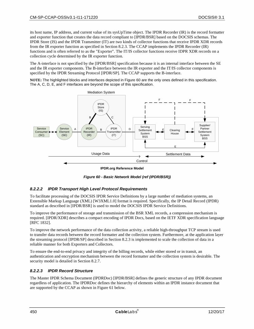
CM-SP-CCAP-OSSIv3.1-I11-171220 DOCSIS® 3.1
450 CableLabs 12/20/17
its host name, IP address, and current value of its sysUpTime object. The IPDR Recorder (IR) is the record formatter and exporter function that creates the data record compliant to [IPDR/BSR] based on the DOCSIS schemas. The IPDR Store (IS) and the IPDR Transmitter (IT) are two kinds of collector functions that receive IPDR XDR records from the IR exporter function as specified in Section 8.2.3. The CCAP implements the IPDR Recorder (IR) functions and is often referred to as the "Exporter". The IT/IS collector functions receive IDPR XDR records on a collection cycle determined by the IR exporter function.
The A-interface is not specified by the [IPDR/BSR] specification because it is an internal interface between the SE and the IR exporter components. The B-interface between the IR exporter and the IT/IS collector components is specified by the IPDR Streaming Protocol [IPDR/SP]. The CCAP supports the B-interface.
NOTE: The highlighted blocks and interfaces depicted in Figure 60 are the only ones defined in this specification. The A, C, D, E, and F interfaces are beyond the scope of this specification.
Figure 60 - Basic Network Model (ref (IPDR/BSR))
8.2.2.2 IPDR Transport High Level Protocol Requirements To facilitate processing of the DOCSIS IPDR Service Definitions by a large number of mediation systems, an Extensible Markup Language (XML) [W3XML1.0] format is required. Specifically, the IP Detail Record (IPDR) standard as described in [IPDR/BSR] is used to model the DOCSIS IPDR Service Definitions.
To improve the performance of storage and transmission of the BSR XML records, a compression mechanism is required. [IPDR/XDR] describes a compact encoding of IPDR Docs, based on the IETF XDR specification language [RFC 1832].
To improve the network performance of the data collection activity, a reliable high-throughput TCP stream is used to transfer data records between the record formatter and the collection system. Furthermore, at the application layer the streaming protocol [IPDR/SP] described in Section 8.2.3 is implemented to scale the collection of data in a reliable manner for both Exporters and Collectors.
To ensure the end-to-end privacy and integrity of the billing records, while either stored or in transit, an authentication and encryption mechanism between the record formatter and the collection system is desirable. The security model is detailed in Section 8.2.7.
8.2.2.3 IPDR Record Structure The Master IPDR Schema Document (IPDRDoc) [IPDR/BSR] defines the generic structure of any IPDR document regardless of application. The IPDRDoc defines the hierarchy of elements within an IPDR instance document that are supported by the CCAP as shown in Figure 61 below.
ServiceConsumer
(SC)
ServiceElement
(SE)
IPDRTransmitter
(IT)
IPDRRecorder
(IR)
IPDRStore(IS)
ServingSettlement
SystemBSS
ClearingHouse
Supplier/Partner
SettlementSystem
BSS
Settlement Data
Control
Usage Data
Mediation System
A
B
B
C
D
F F
E E
E
IPDR.org Reference Model
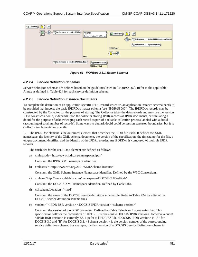
CCAP™ Operations Support System Interface Specification CM-SP-CCAP-OSSIv3.1-I11-171220
12/20/17 CableLabs 451
Figure 61 - IPDRDoc 3.5.1 Master Schema
8.2.2.4 Service Definition Schemas Service definition schemas are defined based on the guidelines listed in [IPDR/SSDG]. Refer to the applicable Annex as defined in Table 424 for each service definition schema.
8.2.2.5 Service Definition Instance Documents To complete the definition of an application-specific IPDR record structure, an application instance schema needs to be provided that imports the basic IPDRDoc master schema (see [IPDR/SSDG]). The IPDRDoc records may be constructed by the Collector for the purpose of storing. The Collector takes the data records and may use the session ID to construct a docId, it depends upon the collector storing IPDR records as IPDR documents, or simulating a docId for the purpose of acknowledging each record as part of a reliable collection process labeled with a docId (accounting of total number of records). Some ways to demark docId could be session start/stop boundaries, but it is Collector implementation specific.
1. The IPDRDoc element is the outermost element that describes the IPDR file itself. It defines the XML namespace, the identity of the XML schema document, the version of the specification, the timestamp for the file, a unique document identifier, and the identity of the IPDR recorder. An IPDRDoc is composed of multiple IPDR records.
The attributes for the IPDRDoc element are defined as follows:
a) xmlns:ipdr="http://www.ipdr.org/namespaces/ipdr"
Constant: the IPDR XML namespace identifier.
b) xmlns:xsi="http://www.w3.org/2001/XMLSchema-instance"
Constant: the XML Schema Instance Namespace identifier. Defined by the W3C Consortium.
c) xmlns= "http://www.cablelabs.com/namespaces/DOCSIS/3.0/xsd/ipdr"
Constant: the DOCSIS XML namespace identifier. Defined by CableLabs.
d) xsi:schemaLocation="*.xsd"
Constant: the name of the DOCSIS service definition schema file. Refer to Table 424 for a list of the DOCSIS service definition schema files.
e) version="<IPDR BSR version>-<DOCSIS IPDR version>.<schema version>"
Constant: the version of the IPDR document. Defined by Cable Television Laboratories, Inc. This specification follows the convention of <IPDR BSR version>-<DOCSIS IPDR version>.<schema version>. <IPDR BSR version> is currently 3.5.1 (refer to [IPDR/BSR]). <DOCSIS IPDR version> is "A" for DOCSIS 3.0 and "B" for DOCSIS 3.1. <Schema version> is the version number of the corresponding service definition schema. For example, the first version of a DOCSIS Service Definition schema in
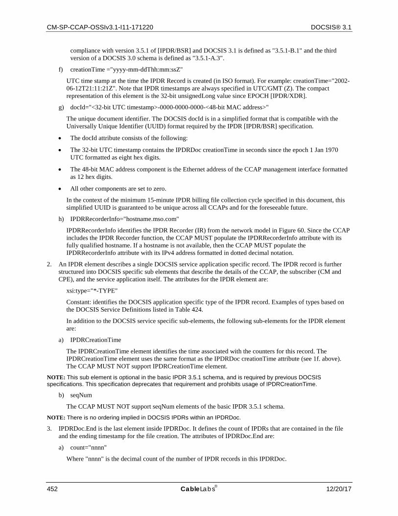
CM-SP-CCAP-OSSIv3.1-I11-171220 DOCSIS® 3.1
452 CableLabs 12/20/17
compliance with version 3.5.1 of [IPDR/BSR] and DOCSIS 3.1 is defined as "3.5.1-B.1" and the third version of a DOCSIS 3.0 schema is defined as "3.5.1-A.3".
f) creationTime ="yyyy-mm-ddThh:mm:ssZ"
UTC time stamp at the time the IPDR Record is created (in ISO format). For example: creationTime="2002-06-12T21:11:21Z". Note that IPDR timestamps are always specified in UTC/GMT (Z). The compact representation of this element is the 32-bit unsignedLong value since EPOCH [IPDR/XDR].
g) docId="<32-bit UTC timestamp>-0000-0000-0000-<48-bit MAC address>"
The unique document identifier. The DOCSIS docId is in a simplified format that is compatible with the Universally Unique Identifier (UUID) format required by the IPDR [IPDR/BSR] specification.
• The docId attribute consists of the following:
• The 32-bit UTC timestamp contains the IPDRDoc creationTime in seconds since the epoch 1 Jan 1970 UTC formatted as eight hex digits.
• The 48-bit MAC address component is the Ethernet address of the CCAP management interface formatted as 12 hex digits.
• All other components are set to zero.
In the context of the minimum 15-minute IPDR billing file collection cycle specified in this document, this simplified UUID is guaranteed to be unique across all CCAPs and for the foreseeable future.
h) IPDRRecorderInfo="hostname.mso.com"
IPDRRecorderInfo identifies the IPDR Recorder (IR) from the network model in Figure 60. Since the CCAP includes the IPDR Recorder function, the CCAP MUST populate the IPDRRecorderInfo attribute with its fully qualified hostname. If a hostname is not available, then the CCAP MUST populate the IPDRRecorderInfo attribute with its IPv4 address formatted in dotted decimal notation.
2. An IPDR element describes a single DOCSIS service application specific record. The IPDR record is further structured into DOCSIS specific sub elements that describe the details of the CCAP, the subscriber (CM and CPE), and the service application itself. The attributes for the IPDR element are:
xsi:type="*-TYPE"
Constant: identifies the DOCSIS application specific type of the IPDR record. Examples of types based on the DOCSIS Service Definitions listed in Table 424.
In addition to the DOCSIS service specific sub-elements, the following sub-elements for the IPDR element are:
a) IPDRCreationTime
The IPDRCreationTime element identifies the time associated with the counters for this record. The IPDRCreationTime element uses the same format as the IPDRDoc creationTime attribute (see 1f. above). The CCAP MUST NOT support IPDRCreationTime element.
NOTE: This sub element is optional in the basic IPDR 3.5.1 schema, and is required by previous DOCSIS specifications. This specification deprecates that requirement and prohibits usage of IPDRCreationTime.
b) seqNum
The CCAP MUST NOT support seqNum elements of the basic IPDR 3.5.1 schema.
NOTE: There is no ordering implied in DOCSIS IPDRs within an IPDRDoc.
3. IPDRDoc.End is the last element inside IPDRDoc. It defines the count of IPDRs that are contained in the file and the ending timestamp for the file creation. The attributes of IPDRDoc.End are:
a) count="nnnn"
Where "nnnn" is the decimal count of the number of IPDR records in this IPDRDoc.
CCAP™ Operations Support System Interface Specification CM-SP-CCAP-OSSIv3.1-I11-171220
12/20/17 CableLabs 453
b) endTime ="yyyy-mm-ddThh:mm:ssZ"
Where endTime is the UTC time stamp at the time the file is completed (see 1f. above).
For [IPDR/SP] protocol, it is left to the collector to generate IPDRDoc.End based on SessionStop message for a specific docId, see Section 8.2.4. In addition, IPDRDoc.End is an [IPDR/BSR] optional field and it is included in this section for information purposes with no requirements for CCAPS Exporter.
8.2.3 IPDR Streaming Model
DOCSIS IPDR Service records are built by the record formatter on the CCAP and are then transmitted to the collection system using the IPDR Streaming Protocol [IPDR/SP].
The [IPDR/SP] Protocol is an application running over a reliable, connection oriented transport layer protocol such as TCP. It allows exporting high volume of Data Records from a Service Element with an efficient use of network, storage, and processing resources. There are also bi-directional control message exchanges, though they only comprise a small portion of the traffic.
The [IPDR/SP] was built upon two existing specifications, namely IPDR's [IPDR/BSR] [IPDR/XDR] file format and Common Reliable Accounting for Network Elements (CRANE) [RFC 3423].
It enables efficient and reliable delivery of any data, mainly Data Records from Service Elements (the record formatters that are denoted as the "Exporters") to any collection systems (that are denoted as the "Collectors"), such as mediation systems and BSS/OSS.
NOTE: The term "Exporter" corresponds to the CCAP, unless otherwise specified.
Since the IPDR Streaming Protocol could run over different transport layers in future versions, a transport neutral version negotiation is needed. [IPDR/SP] supports a negotiation mechanism running over UDP. Either the Exporter or the Collector could inquire about the Streaming Protocol version and transport layer support by sending a UDP packet on a configured UDP port.
8.2.3.1 Sessions and Collector Priorities A Session is a logical connection between an Exporter and one or more Collectors for the purpose of delivering Data Records. For any given Session, a single active Collector will be targeted with those Data Records. Multiple Sessions may be maintained concurrently in an Exporter or Collector, in which case they are distinguished by Session IDs. For a complete specification of the Sessions, see [IPDR/SP].
A Collector is assigned a Priority value. Data Records need to be delivered to the Collector with the highest Priority value (the primary Collector) within a Session. The Collector Priority reflects the Exporter's preference regarding which Collector will receive Data Records. The assignment of the Collector Priority needs to consider factors such as geographical distance, communication cost, and Collector loading, etc. It is also possible for several Collectors to have the same priority. In this case, the selection method is vendor-specific.
8.2.3.2 Documents and Collection Methodologies The IPDR/SP Protocol provides for open-ended streaming of data records as they are created, or as an option, logical boundaries may also be placed between groups of data records as well. A logical range of data records is called a document. For more information on this topic see [IPDR/SP]. Even though [IPDR/SP] supports the IPDRDoc instance documents requirements, the IPDRDoc is handled by the collector and not by the exporter. The collector can, for example, create IPDRDoc based on sessions start/stop sequence sent by the exporter, or based on number of records received.
In this specification, an IPDR document is defined as a series of records that were generated during the interval an IPDR session lasted or during a time interval called collection interval. Each DOCSIS IPDR Service Definition has its own requirements in terms of how IPDR documents are generated. For example, [IPDR/SP] sessions are created on a schedule basis, an open-ended session or a per-request session. Below is a list of collection methodologies:
Time Interval Session: The exporter follows a schedule based session to stream data on a periodic time interval. The collector creates the IPDRDoc within those demarcation points. Note that the Time Interval Session is managed by the exporter as being delimited by session start/stop messages. A collector initiated flow operation is possible as

CM-SP-CCAP-OSSIv3.1-I11-171220 DOCSIS® 3.1
454 CableLabs 12/20/17
well; the collector issues Flow Stop messages to stop the exporter streaming. Finally, it is possible to control the Time Interval Session at either end-points. A Time Interval Session may close immediately after the exporter streams the records or remain open until the end of the time interval in which case, the exporter stops the session and starts a new session for the next time interval.
Event Based Session: It consists of an open-ended session or a Time Interval Session. During the time the IPDR session is open the exporter can stream records at any time, thus the name "Event Based Session". In the case of an open-ended session, the collector could create documents based on size, number of records received, timestamps (to simulate Time Interval Sessions), or never creates an IPDRDoc.
Ad-hoc Session: Per request (from a Collector), the Exporter creates a session and closes it when either the data is streamed or a closing command is generated. Once Collector starts flow, CCAP Exporter SHOULD start session, stream data and stop session. The CCAP Exporter can optionally support additional management interface triggers for starting the session.
Some variations of the collection methodologies above include the possibility that an open-ended session demarcated by the collector as IPDR document by time where the records are received.
In cases where periodic records exporting applies (Time Interval Session), the DOCSIS IPDR Service Definition needs to specify the handling of records deleted in the exporter before the scheduled time for data streaming. That is accomplished either with an immediate record if exporter does not want to retain such record in memory, or wait until the next periodic interval to report that data. It is also required to distinguish between the record being a periodically exported record or a final record. This specification defines a periodic record as an "interim" record and a final record as a "stop" record.
8.2.3.3 Data Types and Message Format [IPDR/SP] describes its message format using an augmented form of [RFC 1832], External Data Representation (XDR) [IPDR/XDR]. Two augmentations of XDR used by [IPDR/XDR] that enable a more concise and formal C style syntax for describing protocol message formats, are as follows:
• Support for indefinite length specification. This allows for stream based encoding of information without knowing or calculating the entire length of a message or document in advance. The value of -1 in a length field indicates that, based on Template information, a decoder be able to determine where a message completes.
• No 32-bit alignment padding. Beginning in IPDR 3.5.1, both [IPDR/XDR] and [IPDR/SP] remove the padding constraint specified by XDR. This allows for specification to the byte level of structures. This augmentation is described in [RFC 1832], "Areas for Future Enhancement".
For a complete specification of the [IPDR/SP] message format see the Message Format section of that specification.
The type IDs for the base types and the derived types used in the protocol, the data structure as well as the data representation are described in the Data Types section of [IPDR/SP] specification.
8.2.3.4 Templates and Service Definitions The IPDR/SP Protocol utilizes the concept of Templates in order to eliminate the transmission of redundant information such as field identifiers and typing information on a per data record basis.
A Template is an ordered list of Field Identifiers. A Field Identifier is the specification of a Field in the Template. A Template references an IPDR Service Definition. It specifies a data item that a Service Element (e.g., CCAP) may export. Each Field specifies the Type of the Field. [IPDR/SP] specifies that Templates may be optionally negotiated upon setup of the communication between the Exporter and the Collector. This allows the Exporter to avoid sending Fields that the Collector is not interested in. Several Templates can be used concurrently (for different types of records). Fields contained in a Template could be enabled or disabled. An enabled Field implies that the outgoing data record will contain the data item specified by the key. A disabled Field implies that the outgoing record will omit the specified data item. The enabling/disabling mechanism further reduces bandwidth requirements; it could also reduce processing in Service Elements, as only needed data items are produced. For a complete specification of the IPDR streaming Templates, refer to the Templates section of [IPDR/SP].
The IPDR/SP Protocol incorporates IPDR/Service Definitions [IPDR/SSDG], based on XML-Schema, by reference.

CCAP™ Operations Support System Interface Specification CM-SP-CCAP-OSSIv3.1-I11-171220
12/20/17 CableLabs 455
A Template references an IPDR Service Definition document, where a more complete definition of the Template is included. IPDR Service Definitions describe in detail the properties of the various data records and their fields (see Service Specification Design Guide 3.5.1 [IPDR/SSDG].)
8.2.3.5 Flow Control and Data Reliability Flow control mechanisms are employed to ensure that data is sent from an Exporter to a Collector only if it is ready to receive data. Four messages are employed to support flow control:
• FlowStart and FlowStop are sent by the Collector to indicate whether it is ready or not ready to receive data. • SessionStart and SessionStop messages are sent by the Exporter to designate the associated Collector the
active/inactive Collector and to provide information about the IPDR document being transmitted within the Session.
Flow control mechanisms are likewise used to indicate to the Collector whether the Exporter considers the Collector to be a primary or backup Collector. The Flow control also provides information on the data sequence numbers and document Id so that the Collectors can collectively guarantee that no Data Records are lost. For the complete specification of the IPDR flow control mechanism refer to the Flow Control section of [IPDR/SP].
To further reduce the likelihood of data loss IPDR/SP Messages are acknowledged after they have been processed and the record information has been placed in persistent storage. Refer to the Data Transfer section of [IPDR/SP].
8.2.3.5.1 DOCSIS IPDR/SP Flow Diagrams
Figure 62 illustrates the Streaming Protocol flow diagram based on the DOCSIS default Streaming Flow (the Time Interval based Session Streaming) set of requirements.
Figure 63 illustrates the Streaming Protocol flow for Event Based Session.
Figure 64 illustrates the Streaming Protocol flow for the ad-hoc Session. The Ad-hoc Streaming flow diagram shown is one of the types. The Time Interval based Session Streaming can also be treated as on Ad-hoc streaming flow. Neither these diagrams nor the explanations provided in limit the ability of a Collector or Exporter (CCAP) to be fully compliant with the IPDR Streaming Protocol flow diagram [IPDR/SP]. Note that these figure models a DocId boundary (established by the IPDR Streaming Session Start/Stop messages) that is used to identify the records created during a collection interval (see Section 8.2.3.2). A single continuously open session/document will span a single collection interval and will be closed at the end of the interval. Figure 62 represents a complete IPDR session/document and assumes the model of periodic data streaming with interim and stop records. Each entity instance of the DOCSIS IPDR Service will include one or more Interim records and one Stop record when the entity in the DOCSIS IPDR service is deleted. If a Service entity instance is both created and deleted within the same collection interval, then only a single Stop record is exported.
Since the collection interval may be up to 24 hours long, it is likely that Keep-Alive messages will be sent periodically to indicate that the session/document is still open but there are no Stop records to export at the moment. Later, at the end of the collection interval, the current session/document is terminated with a SessionStop message, a new DocId is created, and the next session/document is started with a SessionStart message.
NOTE: The sequence diagram shown in Figure 62, Figure 63 and Figure 64 does not include optional Template Negotiation and the mandatory KeepAlive messages.

CM-SP-CCAP-OSSIv3.1-I11-171220 DOCSIS® 3.1
456 CableLabs 12/20/17
Figure 62 - Sequence Diagram for DOCSIS Time Interval Session Streaming Requirements
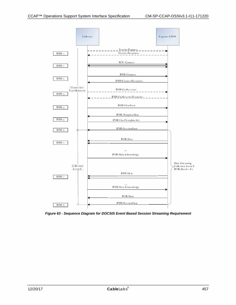
CCAP™ Operations Support System Interface Specification CM-SP-CCAP-OSSIv3.1-I11-171220
12/20/17 CableLabs 457
Figure 63 - Sequence Diagram for DOCSIS Event Based Session Streaming Requirement
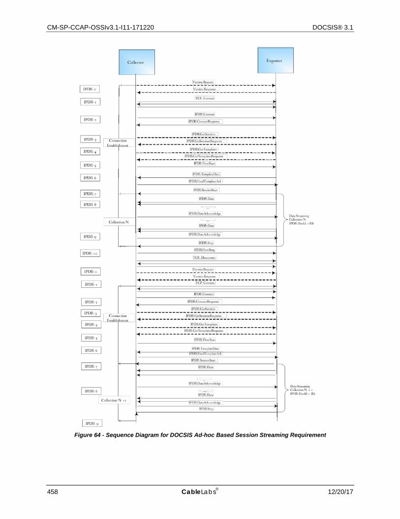
CM-SP-CCAP-OSSIv3.1-I11-171220 DOCSIS® 3.1
458 CableLabs 12/20/17
Figure 64 - Sequence Diagram for DOCSIS Ad-hoc Based Session Streaming Requirement

CCAP™ Operations Support System Interface Specification CM-SP-CCAP-OSSIv3.1-I11-171220
12/20/17 CableLabs 459
Table 421 - DOCSIS IPDR Collection Methodologies Sequence Diagram Details
Identifier Streaming Sequence Diagram Description IPDR-0 Prior to Streaming Connection, Collector may query Exporter for version request (discovery).
IPDR-1 Collector initiates the TCP connection: Port 4737
IPDR-2 Collector sends IPDR Connect message, sets capabilities flags and KeepAlive value Exporter (CCAP) replies with IPDR ConnectResponse message.
IPDR-3 Collector may request Sessions description to know what session ID and associated templates to use for streaming by GetSessions message request. Exporter (CCAP) reply with the GetSessionsResponse message.
IPDR-4 Following the GetSessionsResponse message the Collector may request template descriptions for the Session ID of interest by sending a GetTemplates message Exporter (CCAP) replies with the GetTemplatesResponse message.
IPDR-5 Collector is ready to start receiving data. Sends IPDR FlowStart message.
IPDR-6 Exporter (CCAP) sends a TemplateData message. Collector responds with FinalTemplateData message.
IPDR-7 Exporter (CCAP) starts the Session by sending IPDR SessionStart message.
IPDR-8 Data is streamed by Exporter (CCAP) and acknowledged by Collector IPDR DataAcknowledge messages.
IPDR-9 Exporter (CCAP) closes the IPDR Session with a SessionStop.
IPDR-10 Collector sends a IPDR FlowStop message to indicate that it is no longer able to participate in a particular session.
Repeat Steps IPDR-6 through IPDR-9 based on the provisioned collection interval.
Figure 65 shows typical interaction between Collector and Exporter when multiple sessions are used. In this particular example Collector uses ad-hoc and event based session ("Session 1" and "Session 3" respectively) to retrieve initial state and subsequent changes of CMTS-TOPOLOGY. Another time interval based session ("Session 2") is used for SAMIS-TYPE-2 service. This example has the following assumptions:
• The event session is a time interval session • The CCAP time interval is in sync with the wall clock. Sessions 2 and 3 have the same time interval t. • Keep Alive, Data Ack and other messages are omitted for clarity the example. • Each IPDR session is carried in a separated IPDR connection.
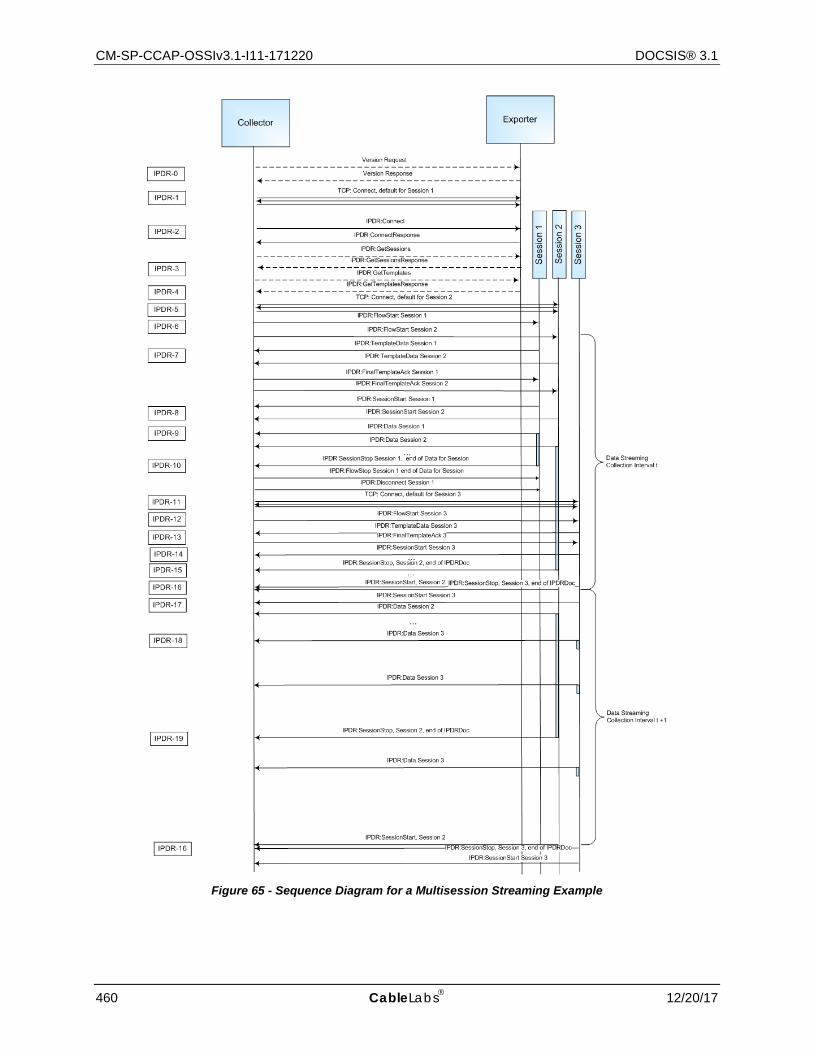
CM-SP-CCAP-OSSIv3.1-I11-171220 DOCSIS® 3.1
460 CableLabs 12/20/17
Figure 65 - Sequence Diagram for a Multisession Streaming Example
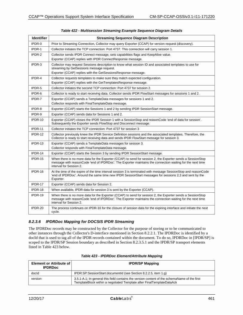
CCAP™ Operations Support System Interface Specification CM-SP-CCAP-OSSIv3.1-I11-171220
12/20/17 CableLabs 461
Table 422 - Multisession Streaming Example Sequence Diagram Details
Identifier Streaming Sequence Diagram Description IPDR-0 Prior to Streaming Connection, Collector may query Exporter (CCAP) for version request (discovery).
IPDR-1 Collector initiates the TCP connection: Port 4737. This connection will carry session 1.
IPDR-2 Collector sends IPDR Connect message, sets capabilities flags and KeepAlive value. Exporter (CCAP) replies with IPDR ConnectResponse message.
IPDR-3 Collector may request Sessions description to know what session ID and associated templates to use for streaming by GetSessions message request. Exporter (CCAP) replies with the GetSessionsResponse message.
IPDR-4 Collector requests templates to make sure they match expected configuration. Exporter (CCAP) replies with the GetTemplatesResponse message.
IPDR-5 Collector initiates the second TCP connection: Port 4737 for session 2.
IPDR-6 Collector is ready to start receiving data. Collector sends IPDR FlowStart messages for sessions 1 and 2.
IPDR-7 Exporter (CCAP) sends a TemplateData messages for sessions 1 and 2. Collector responds with FinalTemplateData message.
IPDR-8 Exporter (CCAP) starts the Sessions 1 and 2 by sending IPDR SessionStart message.
IPDR-9 Exporter (CCAP) sends data for Sessions 1 and 2.
IPDR-10 Exporter (CCAP) closes the IPDR Session 1 with a SessionStop and reasonCode 'end of data for session'. Subsequently the Exporter sends FlowStop and Disconnect message.
IPDR-11 Collector initiates the TCP connection: Port 4737 for session 3
IPDR-12 Collector previously knew the IPDR Service Definition sessions and the associated templates. Therefore, the Collector is ready to start receiving data and sends IPDR FlowStart message for session 3.
IPDR-13 Exporter (CCAP) sends a TemplateData messages for session 3. Collector responds with FinalTemplateData message.
IPDR-14 Exporter (CCAP) starts the Session 3 by sending IPDR SessionStart message.
IPDR-15 When there is no more data for the Exporter (CCAP) to send for session 2, the Exporter sends a SessionStop message with reasonCode 'end of IPDRDoc'. The Exporter maintains the connection waiting for the next time interval for Session 2.
IPDR-16 At the time of the expire of the time interval session 3 is terminated with message SessionStop and reasonCode 'end of IPDRDoc'. Around the same time new IPDR SessionStart messages for sessions 2,3 and sent by the Exporter.
IPDR-17 Exporter (CCAP) sends data for Session 2.
IPDR-18 When available, IPDR data for session 3 is sent by the Exporter (CCAP).
IPDR-19 When there is no more data for the Exporter (CCAP) to send for session 2, the Exporter sends a SessionStop message with reasonCode 'end of IPDRDoc'. The Exporter maintains the connection waiting for the next time interval for Session 2.
IPDR-20 The process continues on IPDR-16 for the closure of session data for the expiring interface and initiate the next cycle.
8.2.3.6 IPDRDoc Mapping for DOCSIS IPDR Streaming The IPDRDoc records may be constructed by the Collector for the purpose of storing or to be communicated to other instances through the Collector's D-interface mentioned in Section 8.2.2.1. The IPDRDoc is identified by a docId that is used to tag all of the IPDR records contained within the document. To do so, IPDRDoc in [IPDR/SP] is scoped to the IPDR/SP Session boundary as described in Section 8.2.3.5.1 and the IPDR/SP transport elements listed in Table 423 below.
Table 423 - IPDRDoc Element/Attribute Mapping
Element or Attribute of IPDRDoc
IPDR/SP Mapping
docId IPDR:SP:SessionStart:documentId (see Section 8.2.2.5, item 1.g)
version 3.5.1-A.1; In general this field contains the version content of the schemaName of the first TemplateBlock within a negotiated Template after FinalTemplateDataAck
CM-SP-CCAP-OSSIv3.1-I11-171220 DOCSIS® 3.1
462 CableLabs 12/20/17
Element or Attribute of IPDRDoc
IPDR/SP Mapping
creationTime IPDR:SP:SessionStartExporterBootTime
IPDRRecorderInfo reverse DNS lookup of Exporter IP
IPDRType Refer to the Data Type section of [IPDR/SP]
ipdr:IPDRCreationTime Not supported (see Section 8.2.2.5)
ipdr:seqNum Not supported (see Section 8.2.2.5) IPDR reliable transport is handled via IPDR:SP:DataSequenceNum
IPDRDoc.End (optional)
Count reflect number of records After closing the Session (Session Stop): IPDR:SP:DataAcknowledge:SequenceNumber - IPDR:SP:SessionStart:FirstRecordSequenceNumber
endTime Time since epoch time when SessionStop was received
8.2.3.7 Message Detail and IDL Definition The complete message set defined for IPDR/SP and the normative IDL specification for constructing IPDR/SP messages are defined in [IPDR/SP].
8.2.4 CCAP IPDR Specifications Support The CCAP MUST support [IPDR/SP] as the transport mechanism for all DOCSIS Service Definitions.
The CCAP MUST support data records encoded in IPDR/XDR Encoding Format, per the [IPDR/XDR] specification.
The CCAP MAY support the UDP-based Service Discovery Protocol described in the IPDR Streaming Protocol section in [IPDR/SP].
The CCAP MAY support the advertisement upon request of IPDR capabilities as described in [IPDR/CAPAB]. The retrieval of this file is vendor-dependent. The same information is available by the Service Discovery described above.
8.2.4.1 IPDR Streaming Protocol The CCAP MUST support the minimum conformance feature set for the IPDR Streaming Protocol as follows:
8.2.4.1.1 IPDR/SP Transport Protocol
The CCAP MUST support IPDR Streaming Protocol [IPDR/SP] over TCP.
8.2.4.1.2 Streaming Flow Control and Messaging
[IPDR/SP] defines three main states in its model: 1) Connection, 2) Flow and 3) Session. Connections are initiated by either Collectors or Exporters. Flows are initiated by Collectors only and Sessions are initiated by Exporters (CCAPs) only. See table 1 of [IPDR/SP] for details.
8.2.4.1.2.1 Streaming Flow Connection and Messaging
The CCAP MUST support a minimum of two IPDR streaming connections.
IPDR streaming includes Template Negotiation allowing Collectors to adjust the data streams to include only the information that is relevant to their systems. The CCAP SHOULD support Template Negotiation for any supported Service Definition; the support of the IPDR/SP message MODIFY TEMPLATE RESPONSE is recommended.
If the CCAP implements Template Negotiation capability, then all messages within the Template Negotiation phase MUST be supported as described in the Protocol Sequence section of [IPDR/SP].
CCAP™ Operations Support System Interface Specification CM-SP-CCAP-OSSIv3.1-I11-171220
12/20/17 CableLabs 463
If the CCAP does not implement Template Negotiation, a Collector MODIFY TEMPLATE message MUST be replied to with a MODIFY TEMPLATE RESPONSE having a preconfigured Template Set as described in [IPDR/SP].
The CCAP MAY support IPDR Capability File Negotiation.
If the CCAP supports IPDR Capability File Negotiation, then Communication Negotiation MUST be supported. Communication Negotiation allows the Exporter and the Collector to negotiate communication parameters. The Communication Negotiation allows both the Collector and the Exporter to acknowledge that they are capable of participating in the exchange of records via IPDR Streaming as and identify their ability to support optional protocol capabilities.
8.2.4.1.2.2 Streaming Flow Sessions
The CCAP MUST support a minimum of one Data Streaming Session per connection.
The CCAP MUST handle a minimum of one Template per Session, which is transmitted to the Collector via the TEMPLATE DATA message as described in [IPDR/SP].
See Section 8.2.3 for the definition of the relationship between IPDR/SP Sessions, [IPDR/XDR] documents, and collection intervals.
8.2.4.1.2.3 Records Collection
A particular Service Definition supports ad-hoc, and event or time interval based data collection in order for the Collector to retrieve initial state through the ad-hoc session followed by subsequent updates through the event or time interval based session.
A typical scenario is for example the IPDR Service Definition CMTS-TOPOLOGY-TYPE that supports ad-hoc and event based sessions. The ad-hoc session allows the Collector to obtain initial topology, and the event based session to obtain subsequent topology updates. To allow a Collector to perform timely synchronous processing of SAMIS flow records (e.g., SAMIS-TYPE-2) along with corresponding topology records, the CCAP SHOULD use the same time base and interval for both a topology event session and a SAMIS interval session. The only difference to open ended event sessions is that Exporter inserts start/stop session messages at regular time intervals while the content of data records is the same. This allows Collector to easily detect when Exporter is done sending flow information and topology (e.g., CMTS-TOPOLOGY-TYPE, CMTS-CM-REG-STATUS-TYPE and CPE-TYPE) for specific interval.
Unless otherwise specified, for an IPDR Service Definition that supports ad-hoc, and time interval and/or event based collection mechanisms, the CCAP MUST support the streaming of the ad-hoc session along with an event based or time interval session of that IPDR Service Definition at the same time where each session could be within the same connection or in separate connections.
Due to the nature of the record streaming at the Exporter, it is up to the Collector to detect duplicate records along simultaneous collection methodologies. Possible scenarios are the following:
• Collector starts ad-hoc session first and doesn't start event session for the same service until ad-hoc session finishes and it gets initial state.
• Collector starts both ad-hoc and corresponding event sessions with the same service at the same time. Exporter doesn't send any events (changes) until is done with sending initial state and stops ad-hoc session.
• Exporter can start sending event records while the ad-hoc session has not terminated. In this case Collector will have to figure out based on the recreation time that event record it has already received is newer than ad-hoc record which represents initial state so it could discard obsolete ad-hoc record.
In the case when adHoc session is established while event session is not for the same service, the CCAP Exporter SHOULD send any events that occur while sending an adHoc "snapshot" within the adHoc session.
The CCAP Exporter SHOULD use record type interim(1) for snapshot records and record type stop(2), start(3) or event(4) for event records (record is created, destroyed or changed, respectively). Event records are sent as events occur or are detected. AdHoc session lasts as long as it is necessary to send a snapshot. If in the meantime corresponding event session is established, the CCAP Exporter SHOULD send any subsequent events using that
CM-SP-CCAP-OSSIv3.1-I11-171220 DOCSIS® 3.1
464 CableLabs 12/20/17
session as it would normally do. It is up to the Collector to make sure there is always either adHoc or event session open for sending events in order to make sure no events are lost.
Refer to Table 422 and Figure 65 for a multisession streaming example.
8.2.5 Requirements for IPv6
The CCAP MUST support IPDR/SP transport for Collectors that have IPv4 addresses [IPDR/SP]. The CCAP SHOULD support an interoperable IPDR/SP transport mechanism for both IPv4 and IPv6 addresses [IPDR/SP].
8.2.6 Data Collection Methodologies for DOCSIS IPDR Service Definitions
This specification, as well as [IPDR/SP], defines a mechanism for the Collector and Exporter to coordinate the state control of DOCSIS IPDR Service Definitions that support multiple collection methodologies. In this case the session message provides information about the streaming methodology used for that session id. In other words, an additional session ID of the same service template is associated with a specific collection methodology (e.g., ad-hoc). This is achieved by placing special requirements in the SessionBlock.reserved attribute of the IPDR/SP GET SESSIONS RESPONSE message as follows:
The CCAP MUST define a sessionID for each collection mechanism supported for each IPDR Service Definition.
The CCAP MUST define the SessionBlock.sessionType attribute of the IPDR/SP GET SESSIONS RESPONSE as defined in [IPDR/SP]. The SessionBlock.sessionType attribution is shown below:
struct SessionBlock {
char sessionId;
char sessionType;
UTF8String sessionName;
UTF8String sessionDescription;
int ackTimeInterval;
int ackSequenceInterval;
};
The field description for sessionType:
Type of Session: Integer values of first three least significant bits of this field identify the following session types:
0 - Equivalent of sessionType Information Not Available
1 - Time Interval
2 - Adhoc
3 - Event
4 - Time Based Event
8.2.7 IPDR Streaming Protocol Security Model Refer to [IPDR/SP] for the IPDR/SP Security recommendations. The IPDR/SP Security Model is out of the scope of this specification.
8.3 IPDR Service Definition Schemas
This section defines the IPDR Service Definitions required for DOCSIS 3.1. Table 424 lists the DOCSIS 3.0 IPDR Service Definitions, corresponding schemas, applicable device and object model specification reference. Refer to Section 8.2 for an overview of the IPDR/SP protocol and Annex B for an overview of the SAMIS IPDR Service
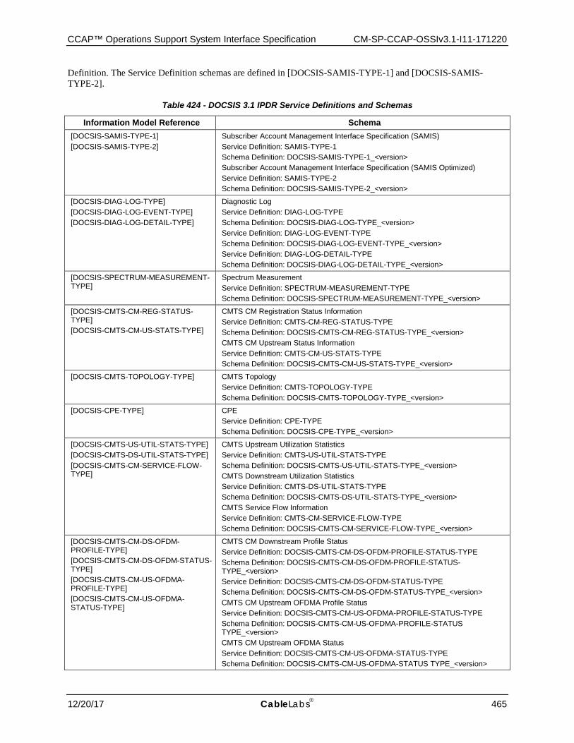
CCAP™ Operations Support System Interface Specification CM-SP-CCAP-OSSIv3.1-I11-171220
12/20/17 CableLabs 465
Definition. The Service Definition schemas are defined in [DOCSIS-SAMIS-TYPE-1] and [DOCSIS-SAMIS-TYPE-2].
Table 424 - DOCSIS 3.1 IPDR Service Definitions and Schemas
Information Model Reference Schema [DOCSIS-SAMIS-TYPE-1] [DOCSIS-SAMIS-TYPE-2]
Subscriber Account Management Interface Specification (SAMIS) Service Definition: SAMIS-TYPE-1 Schema Definition: DOCSIS-SAMIS-TYPE-1_<version> Subscriber Account Management Interface Specification (SAMIS Optimized) Service Definition: SAMIS-TYPE-2 Schema Definition: DOCSIS-SAMIS-TYPE-2_<version>
[DOCSIS-DIAG-LOG-TYPE] [DOCSIS-DIAG-LOG-EVENT-TYPE] [DOCSIS-DIAG-LOG-DETAIL-TYPE]
Diagnostic Log Service Definition: DIAG-LOG-TYPE Schema Definition: DOCSIS-DIAG-LOG-TYPE_<version> Service Definition: DIAG-LOG-EVENT-TYPE Schema Definition: DOCSIS-DIAG-LOG-EVENT-TYPE_<version> Service Definition: DIAG-LOG-DETAIL-TYPE Schema Definition: DOCSIS-DIAG-LOG-DETAIL-TYPE_<version>
[DOCSIS-SPECTRUM-MEASUREMENT-TYPE]
Spectrum Measurement Service Definition: SPECTRUM-MEASUREMENT-TYPE Schema Definition: DOCSIS-SPECTRUM-MEASUREMENT-TYPE_<version>
[DOCSIS-CMTS-CM-REG-STATUS-TYPE] [DOCSIS-CMTS-CM-US-STATS-TYPE]
CMTS CM Registration Status Information Service Definition: CMTS-CM-REG-STATUS-TYPE Schema Definition: DOCSIS-CMTS-CM-REG-STATUS-TYPE_<version> CMTS CM Upstream Status Information Service Definition: CMTS-CM-US-STATS-TYPE Schema Definition: DOCSIS-CMTS-CM-US-STATS-TYPE_<version>
[DOCSIS-CMTS-TOPOLOGY-TYPE] CMTS Topology Service Definition: CMTS-TOPOLOGY-TYPE Schema Definition: DOCSIS-CMTS-TOPOLOGY-TYPE_<version>
[DOCSIS-CPE-TYPE] CPE Service Definition: CPE-TYPE Schema Definition: DOCSIS-CPE-TYPE_<version>
[DOCSIS-CMTS-US-UTIL-STATS-TYPE] [DOCSIS-CMTS-DS-UTIL-STATS-TYPE] [DOCSIS-CMTS-CM-SERVICE-FLOW-TYPE]
CMTS Upstream Utilization Statistics Service Definition: CMTS-US-UTIL-STATS-TYPE Schema Definition: DOCSIS-CMTS-US-UTIL-STATS-TYPE_<version> CMTS Downstream Utilization Statistics Service Definition: CMTS-DS-UTIL-STATS-TYPE Schema Definition: DOCSIS-CMTS-DS-UTIL-STATS-TYPE_<version> CMTS Service Flow Information Service Definition: CMTS-CM-SERVICE-FLOW-TYPE Schema Definition: DOCSIS-CMTS-CM-SERVICE-FLOW-TYPE_<version>
[DOCSIS-CMTS-CM-DS-OFDM-PROFILE-TYPE] [DOCSIS-CMTS-CM-DS-OFDM-STATUS-TYPE] [DOCSIS-CMTS-CM-US-OFDMA-PROFILE-TYPE] [DOCSIS-CMTS-CM-US-OFDMA-STATUS-TYPE]
CMTS CM Downstream Profile Status Service Definition: DOCSIS-CMTS-CM-DS-OFDM-PROFILE-STATUS-TYPE Schema Definition: DOCSIS-CMTS-CM-DS-OFDM-PROFILE-STATUS-TYPE_<version> Service Definition: DOCSIS-CMTS-CM-DS-OFDM-STATUS-TYPE Schema Definition: DOCSIS-CMTS-CM-DS-OFDM-STATUS-TYPE_<version> CMTS CM Upstream OFDMA Profile Status Service Definition: DOCSIS-CMTS-CM-US-OFDMA-PROFILE-STATUS-TYPE Schema Definition: DOCSIS-CMTS-CM-US-OFDMA-PROFILE-STATUS TYPE_<version> CMTS CM Upstream OFDMA Status Service Definition: DOCSIS-CMTS-CM-US-OFDMA-STATUS-TYPE Schema Definition: DOCSIS-CMTS-CM-US-OFDMA-STATUS TYPE_<version>
CM-SP-CCAP-OSSIv3.1-I11-171220 DOCSIS® 3.1
466 CableLabs 12/20/17
Information Model Reference Schema [DOCSIS-DS-OFDM-PROFILE-STATS-TYPE] [DOCSIS-US-OFDMA-PROFILE-STATS-TYPE]
Downstream OFDM Profile Statistics Service Definition: DOCSIS-DS-OFDM-PROFILE-STATS-TYPE Schema Definition: DOCSIS-DS-OFDM-PROFILE-STATS-TYPE_<version> Upstream OFDMA Profile Statistics Service Definition: DOCSIS-US-OFDMA-PROFILE-STATS-TYPE Schema Definition: DOCSIS-US-OFDMA-PROFILE-STATS-TYPE_<version>
The DOCSIS IPDR Service Definitions are XML schemas derived from the IPDR Master Schema document (IPDRDoc). See Section 8.2.2.3 for details of the IPDR Master Schema. This specification names DOCSIS IPDR Service Definitions in the form of DOCSIS-<SERVICE-NAME>-TYPE (e.g., DOCSIS-SAMIS-TYPE-1, DOCSIS-DIAG-LOG-TYPE).
In addition to the conventional IPDR Service Definition models, this specification defines Object Model Schemas (Auxiliary Schemas) to represent network components being referenced by the Service Definitions themselves. For example, the DOCSIS-CMTS-INFO Auxiliary Schema offers Topology information at the Physical and MAC layer of the CMTS-CM arrangements. For the same example, a DOCSIS Service Definition (service aware) can include the object schema DOCSIS-CMTS-INFO to complete the CM-CMTS identification and to offer context for the statistics and parameters reported in the document records. This modular abstraction allows the definition of different schema documents for the same Service Definition at different elements of the collection infrastructure. Refer to Annex C for a list of Auxiliary Schemas defined for DOCSIS 3.1.
One example is the SAMIS model that supports two different models (see detailed SAMIS requirements in Annex B):
• The Service Definition Schema DOCSIS-SAMIS-TYPE-1 Each document record contains the information modeled by the Service Definition DOCSIS-CMTS-INFO. CMTS-CM related information is duplicated for each SAMIS record.
• The Service Definition Schema DOCSIS-SAMIS-TYPE-2 Each document record contains a reference to the last updated DOCSIS-CMTS-INFO, reducing the amount of data sent over the network. DOCSIS-CMTS-INFO information is sent periodically (e.g., any time an update to the CMTS-CM Status is performed). The collector system is in charge of correlating the information received from records of DOCSIS-SAMIS-TYPE-2 and DOCSIS-CMTS-INFO to re-create the equivalent record obtained when using the DOCSIS-SAMIS-TYPE-1 Service Definition schema.
This section defines the minimum set of objects required to support the DOCSIS 3.0 IPDR Service Definitions. The CCAP MAY define IPDR Service Definitions which extend the DOCSIS requirements to include vendor-specific features.
8.3.1 Requirements for DOCSIS SAMIS Service Definitions
The CCAP MUST implement SAMIS-TYPE-1 as specified in Annex B.
The CCAP MUST implement SAMIS-TYPE-2 as specified in Annex B.
8.3.1.1 Records Collection Subscriber Usage Billing Records report the absolute traffic counter values for each Service Flow that has become active during the billing collection interval as seen at the end of the interval. Normal Service Flows used by a Cable Modem or Class or Service (Subscriber) are reported. Group Service Flows are reported by Service Flow without CM association. The collection interval is defined as the time between:
• The creation of the previous billing document denoted as Tprev. • The creation of the current billing document denoted as Tnow.
In reference to Figure 66 below, there are two kinds of records reported for a SFID/SID in the current billing document: 1) SFIDs/SIDs that are still running at the time the billing document is created (called 'Interim' records)
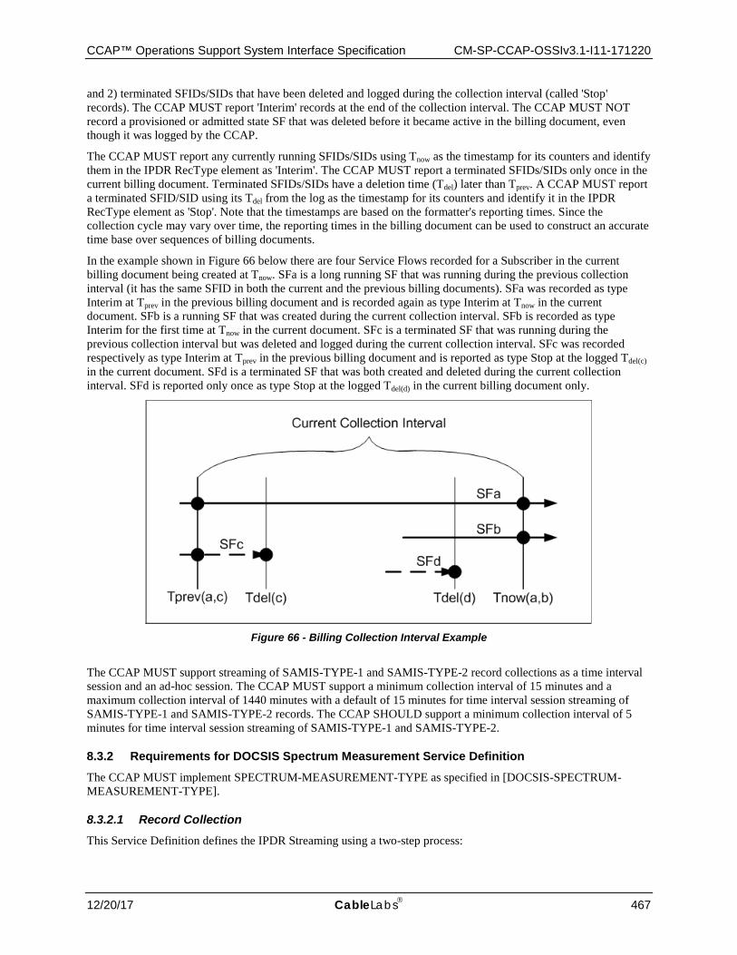
CCAP™ Operations Support System Interface Specification CM-SP-CCAP-OSSIv3.1-I11-171220
12/20/17 CableLabs 467
and 2) terminated SFIDs/SIDs that have been deleted and logged during the collection interval (called 'Stop' records). The CCAP MUST report 'Interim' records at the end of the collection interval. The CCAP MUST NOT record a provisioned or admitted state SF that was deleted before it became active in the billing document, even though it was logged by the CCAP.
The CCAP MUST report any currently running SFIDs/SIDs using Tnow as the timestamp for its counters and identify them in the IPDR RecType element as 'Interim'. The CCAP MUST report a terminated SFIDs/SIDs only once in the current billing document. Terminated SFIDs/SIDs have a deletion time (Tdel) later than Tprev. A CCAP MUST report a terminated SFID/SID using its Tdel from the log as the timestamp for its counters and identify it in the IPDR RecType element as 'Stop'. Note that the timestamps are based on the formatter's reporting times. Since the collection cycle may vary over time, the reporting times in the billing document can be used to construct an accurate time base over sequences of billing documents.
In the example shown in Figure 66 below there are four Service Flows recorded for a Subscriber in the current billing document being created at Tnow. SFa is a long running SF that was running during the previous collection interval (it has the same SFID in both the current and the previous billing documents). SFa was recorded as type Interim at Tprev in the previous billing document and is recorded again as type Interim at Tnow in the current document. SFb is a running SF that was created during the current collection interval. SFb is recorded as type Interim for the first time at Tnow in the current document. SFc is a terminated SF that was running during the previous collection interval but was deleted and logged during the current collection interval. SFc was recorded respectively as type Interim at Tprev in the previous billing document and is reported as type Stop at the logged Tdel(c) in the current document. SFd is a terminated SF that was both created and deleted during the current collection interval. SFd is reported only once as type Stop at the logged Tdel(d) in the current billing document only.
Figure 66 - Billing Collection Interval Example
The CCAP MUST support streaming of SAMIS-TYPE-1 and SAMIS-TYPE-2 record collections as a time interval session and an ad-hoc session. The CCAP MUST support a minimum collection interval of 15 minutes and a maximum collection interval of 1440 minutes with a default of 15 minutes for time interval session streaming of SAMIS-TYPE-1 and SAMIS-TYPE-2 records. The CCAP SHOULD support a minimum collection interval of 5 minutes for time interval session streaming of SAMIS-TYPE-1 and SAMIS-TYPE-2.
8.3.2 Requirements for DOCSIS Spectrum Measurement Service Definition
The CCAP MUST implement SPECTRUM-MEASUREMENT-TYPE as specified in [DOCSIS-SPECTRUM-MEASUREMENT-TYPE].
8.3.2.1 Record Collection This Service Definition defines the IPDR Streaming using a two-step process:
CM-SP-CCAP-OSSIv3.1-I11-171220 DOCSIS® 3.1
468 CableLabs 12/20/17
• SNMP or other configuration management interface such as CLI is used to configure the diagnostic (i.e., create the interface and attributes; destroy the interface).
• IPDR/SP is used to stream the measurement statistics (large data set).
Spectrum Measurement records report the spectrum measurement statistics for all the pre-configured interfaces and their attributes as specified in [DOCSIS-SPECTRUM-MEASUREMENT-TYPE].
The CCAP MUST support streaming of SPECTRUM-MEASUREMENT-TYPE record collections as a time interval session and an ad-hoc session. The rate at which records are streamed when only one interface is configured will not exceed the estimated time interval defined in [DOCSIS-SPECTRUM-MEASUREMENT-TYPE]. If more than one interface is configured, that rate can be lower than the estimated time interval defined in [DOCSIS-SPECTRUM-MEASUREMENT-TYPE].
8.3.3 Requirements for DOCSIS Diagnostic Log Service Definitions
The CCAP MUST implement DIAG-LOG-TYPE as specified in [DOCSIS-DIAG-LOG-TYPE].
The CCAP MUST implement DIAG-LOG-EVENT-TYPE as specified in [DOCSIS-DIAG-LOG-EVENT-TYPE].
The CCAP MUST implement DIAG-LOG-DETAIL-TYPE as specified in [DOCSIS-DIAG-LOG-DETAIL-TYPE].
8.3.3.1 Record Collection This Service Definition defines the IPDR Streaming using a two-step process:
• SNMP or other configuration management interface such as CLI is used to configure the Diagnostic Log. • IPDR/SP is used to stream the Diagnostic Log instances.
The CCAP MUST support streaming of DIAG-LOG-TYPE record collections as an ad-hoc session.
The CCAP MUST support streaming of DIAG-LOG-EVENT-TYPE record collections as an event session.
The CCAP MUST support streaming of DIAG-LOG-DETAIL-TYPE record collections as a time interval session, an ad-hoc session and an event session.
For event-based Diagnostic Log records, the CCAP streams the record when the event is logged in the Diagnostic Log. For time interval based Diagnostic Log records, the CCAP streams a snapshot of the Diagnostic Log. The CCAP MUST support a minimum collection interval of 5 minutes and a maximum collection interval of 1440 minutes with a default of 15 minutes for time interval session streaming of the Diagnostic Log records.
8.3.4 Requirements for DOCSIS CMTS CM Registration Status Service Definition
The CCAP MUST implement CMTS-CM-REG-STATUS-TYPE as specified in [DOCSIS-CMTS-CM-REG-STATUS-TYPE].
8.3.4.1 Record Collection This Service Definition defines the IPDR Streaming using a two-step process:
• SNMP or other configuration management interface such as CLI is used to configure CMTS CM Registration Status service definition.
• IPDR/SP is used to stream CMTS CM Registration Status instances.
The CCAP MUST support streaming of CMTS-CM-REG-STATUS-TYPE record collections as a time interval session, an ad-hoc session and an event session. The CCAP MUST support a minimum collection interval of 5 minutes and a maximum collection interval of 1440 minutes with a default of 15 minutes for time interval session streaming of the CMTS-CM-REG-STATUS-TYPE records.
8.3.5 Requirements for DOCSIS CMTS CM Upstream Status Service Definition
The CCAP MUST implement CMTS-CM-US-STATS-TYPE as specified in [DOCSIS-CMTS-CM-US-STATS-TYPE].
CCAP™ Operations Support System Interface Specification CM-SP-CCAP-OSSIv3.1-I11-171220
12/20/17 CableLabs 469
8.3.5.1 Record Collection This Service Definition defines the IPDR Streaming using a two-step process:
• SNMP or other configuration management interface such as CLI is used to configure CMTS CM Upstream Status service definition.
• IPDR/SP is used to stream CMTS CM Upstream Status instances.
The CCAP MUST support streaming of CMTS-CM-US-STATS-TYPE record collections as a time interval session and an ad-hoc session. The CCAP MUST support a minimum collection interval of 5 minutes and a maximum collection interval of 1440 minutes with a default of 15 minutes for time interval session streaming of the CMTS-CM-US-STATS-TYPE records.
8.3.6 Requirements for DOCSIS CMTS Topology Service Definition
The CCAP MUST implement CMTS-TOPOLOGY-TYPE as specified in [DOCSIS-CMTS-TOPOLOGY-TYPE].
8.3.6.1 Record Collection This Service Definition defines the IPDR Streaming using a two-step process:
• SNMP or other configuration management interface such as CLI is used to configure the topology. • IPDR/SP is used to stream the topology information.
The CCAP MUST support streaming of CMTS-TOPOLOGY-TYPE record collections as an ad-hoc session and event session.
8.3.7 Requirements for DOCSIS CPE Service Definition
The CCAP MUST implement CPE-TYPE as specified in [DOCSIS-CPE-TYPE].
8.3.7.1 Record Collection This Service Definition defines the IPDR Streaming using a two-step process:
• SNMP or other configuration management interface such as CLI is used to configure DOCSIS CPE service definition.
• IPDR/SP is used to stream DOCSIS CPE instances.
The CCAP MUST support streaming of CPE-TYPE record collections as an ad-hoc session and event session.
8.3.8 Requirements for DOCSIS CMTS Upstream Utilization Statistics Service Definition The CCAP MUST implement CMTS-US-UTIL-STATS-TYPE as specified in [DOCSIS-CMTS-US-UTIL-STATS-TYPE].
8.3.8.1 Record Collection This Service Definition defines the IPDR Streaming using a two-step process:
• SNMP or other configuration management interface such as CLI is used to configure CMTS Upstream Utilization Statistics service definition.
• IPDR/SP is used to stream CMTS Upstream Utilization Statistics instances.
The CCAP MUST create CMTS-US-UTIL-STATS-TYPE records using the configured utilization interval. The CCAP MUST support streaming of CMTS-US-UTIL-STATS-TYPE record collections as an event based session.
8.3.9 Requirements for DOCSIS CMTS Downstream Utilization Statistics Service Definition
The CCAP MUST implement CMTS-DS-UTIL-STATS-TYPE as specified in [DOCSIS-CMTS-DS-UTIL-STATS-TYPE].
CM-SP-CCAP-OSSIv3.1-I11-171220 DOCSIS® 3.1
470 CableLabs 12/20/17
8.3.9.1 Record Collection This Service Definition defines the IPDR Streaming using a two-step process:
• SNMP or other configuration management interface such as CLI is used to configure CMTS Downstream Utilization Statistics service definition.
• IPDR/SP is used to stream CMTS Downstream Utilization Statistics instances.
The CCAP MUST create CMTS-DS-UTIL-STATS-TYPE records using the configured utilization interval. The CCAP MUST support streaming of CMTS-DS-UTIL-STATS-TYPE record collections as an event based session.
8.3.10 Requirements for DOCSIS CMTS CM Service Flow Service Definition
The CCAP MUST implement CMTS-CM-SERVICE-FLOW-TYPE as specified in [DOCSIS-CMTS-CM-SERVICE-FLOW-TYPE].
8.3.10.1 Record Collection This Service Definition defines the IPDR Streaming using a two-step process:
• SNMP or other configuration management interface such as CLI is used to configure the CMTS CM SERVICE FLOW Service Definition.
• IPDR/SP is used to stream the CMTS CM SERVICE FLOW instances.
The CCAP MUST support streaming of CMTS-CM-SERVICE-FLOW-TYPE record collections as an ad-hoc session and event session. The CCAP MUST report all Active service flows on an ad-hoc session. The CCAP MUST report all new service flows that become active on an event session.
8.3.11 Requirements for IP Multicast Statistics Service Definition
The CCAP MUST implement IP-MULTICAST-STATS-TYPE as specified in [DOCSIS-IP-MULTICAST-STATS-TYPE].
8.3.11.1 Record Collection This Service Definition defines the IPDR Streaming using a two-step process:
• SNMP or other configuration management interface such as CLI is used to configure the IP Multicast Statistics Service Definition.
• IPDR/SP is used to stream the IP-MULTICAST-STATS-TYPE record instances.
The CCAP MUST support streaming of IP-MULTICAST-STATS-TYPE record collections as a time interval session. The CCAP MUST support a minimum collection interval of 5 minutes and a maximum collection interval of 1440 minutes with a default of 15 minutes for time interval session streaming of the IP-MULTICAST-STATS-TYPE records.
8.3.12 Requirements for DOCSIS CMTS CM Downstream OFDM Service Definition The CCAP MUST implement CMTS-CM-DS-OFDM-STATUS-TYPE as specified in [DOCSIS-CMTS-CM-DS-OFDM-STATUS-TYPE].
8.3.12.1 Record Collection This Service Definition defines the IPDR Streaming using a two-step process:
• SNMP or other configuration management interface such as CLI is used to configure the CMTS CM Downstream OFDM Service Definition.
• IPDR/SP is used to stream the CMTS-CM-DS-OFDM-STATUS-TYPE record instances.
The CCAP MUST support streaming of CMTS-CM-DS-OFDM-STATUS-TYPE record collections as a time interval and session. The CCAP MUST support a minimum collection interval of 5 minutes and a maximum
CCAP™ Operations Support System Interface Specification CM-SP-CCAP-OSSIv3.1-I11-171220
12/20/17 CableLabs 471
collection interval of 1440 minutes with a default of 15 minutes for time interval session streaming of the CMTS-CM-DS-OFDM-STATUS-TYPE records. The CCAP MUST report all new partial service events on an event session.
8.3.13 Requirements for DOCSIS CMTS CM Downstream OFDM Profile Service Definition
The CCAP MUST implement CMTS-CM-DS-OFDM-PROFILE-STATUS-TYPE as specified in [DOCSIS-CMTS-CM-DS-OFDM-PROFILE-TYPE].
8.3.13.1 Record Collection This Service Definition defines the IPDR Streaming using a two-step process:
• SNMP or other configuration management interface such as CLI is used to configure the CMTS CM Downstream OFDM Profile Service Definition.
• IPDR/SP is used to stream the CMTS-CM-DS-OFDM-PROFILE-STATUS-TYPE record instances.
The CCAP MUST support streaming of CMTS-CM-DS-OFDM-PROFILE-STATUS-TYPE record collections as a time interval and session. The CCAP MUST support a minimum collection interval of 5 minutes and a maximum collection interval of 1440 minutes with a default of 15 minutes for time interval session streaming of the CMTS-CM-DS-OFDM-PROFILE-STATUS-TYPE records. The CCAP MUST report all new partial channel events on an event session.
8.3.14 Requirements for DOCSIS CMTS CM Upstream OFDMA Service Definition
The CCAP MUST implement CMTS-CM-US-OFDMA-STATUS-TYPE as specified in [DOCSIS-CMTS-CM-US-OFDMA-STATUS-TYPE].
8.3.14.1 Record Collection This Service Definition defines the IPDR Streaming using a two-step process:
• SNMP or other configuration management interface such as CLI is used to configure the CMTS CM Upstream OFDMA Service Definition.
• IPDR/SP is used to stream the CMTS-CM-US-OFDMA-STATUS-TYPE record instances.
The CCAP MUST support streaming of CMTS-CM-US-OFDMA-STATUS-TYPE record collections as a time interval and session. The CCAP MUST support a minimum collection interval of 5 minutes and a maximum collection interval of 1440 minutes with a default of 15 minutes for time interval session streaming of the CMTS-CM-US-OFDMA-STATUS-TYPE records. The CCAP MUST report all new partial service events on an event session.
8.3.15 Requirements for DOCSIS CMTS CM Upstream OFDMA Profile Service Definition
The CCAP MUST implement CMTS-CM-US-OFDMA-PROFILE-STATUS-TYPE as specified in [DOCSIS-CMTS-CM-US-OFDMA-PROFILE-TYPE].
8.3.15.1 Record Collection This Service Definition defines the IPDR Streaming using a two-step process:
• SNMP or other configuration management interface such as CLI is used to configure the CMTS CM Upstream OFDMA Profile Service Definition.
• IPDR/SP is used to stream the CMTS-CM-US-OFDMA-PROFILE-STATUS-TYPE record instances.
The CCAP MUST support streaming of CMTS-CM-US-OFDMA-PROFILE-STATUS-TYPE record collections as a time interval and session. The CCAP MUST support a minimum collection interval of 5 minutes and a maximum collection interval of 1440 minutes with a default of 15 minutes for time interval session streaming of the CMTS-CM-US-OFDMA-PROFILE-STATUS-TYPE records. The CCAP MUST report all new partial channel events on an event session.
CM-SP-CCAP-OSSIv3.1-I11-171220 DOCSIS® 3.1
472 CableLabs 12/20/17
8.3.16 Requirements for DOCSIS Downstream OFDM Profile Statistics Service Definition
The CMTS MUST implement DS-OFDM-PROFILE-STATS-TYPE as specified in [DOCSIS-DS-OFDM-PROFILE-STATS-TYPE].
8.3.16.1 Record Collection This Service Definition defines the IPDR Streaming using a two-step process:
• SNMP or other configuration management interface such as CLI is used to configure the Downstream OFDM Profile Statistics Service Definition.
• IPDR/SP is used to stream the DS-OFDM-PROFILE-STATS-TYPE record instances.
The CMTS MUST support streaming of DS-OFDM-PROFILE-STATS-TYPE record collections as a time interval session. The CMTS MUST support a minimum collection interval of 1 minute and a maximum collection interval of 60 minutes with a default of 5 minutes for time interval session streaming of the DS-OFDM-PROFILE-STATS-TYPE records.
8.3.17 Requirements for DOCSIS Upstream OFDMA Profile Statistics Service Definition
The CMTS MUST implement US-OFDMA-PROFILE-STATS-TYPE as specified in [DOCSIS-US-OFDMA-PROFILE-STATS-TYPE].
8.3.17.1 Record Collection This Service Definition defines the IPDR Streaming using a two-step process:
• SNMP or other configuration management interface such as CLI is used to configure the DOCSIS Upstream OFDMA Profile Statistics Service Definition.
• IPDR/SP is used to stream the US-OFDMA-PROFILE-STATS-TYPE record instances.
The CMTS MUST support streaming of US-OFDMA-PROFILE-STATS-TYPE record collections as a time interval session. The CMTS MUST support a minimum collection interval of 1 minute and a maximum collection interval of 60 minutes with a default of 5 minutes for time interval session streaming of the US-OFDMA-PROFILE-STATS-TYPE records.
8.3.18 Requirements for Auxiliary Schemas
The CCAP MUST implement the auxiliary schemas as specified in Auxiliary Schemas for DOCSIS IPDR Service Definitions (Normative).
CCAP™ Operations Support System Interface Specification CM-SP-CCAP-OSSIv3.1-I11-171220
12/20/17 CableLabs 473
9 FAULT MANAGEMENT AND REPORTING REQUIREMENTS
9.1 Fault Management Requirements and Transport Protocols
This section defines requirements for remote monitoring/detection, diagnosis, reporting, and correction of problems.
9.2 Event Reporting
The CCAP MUST log events using standard mechanisms defined in section 8 of [CM-OSSIv3.1].
The CCAP MUST support all Mandatory ("M") CMTS MIB objects that have an SNMP access type of accessible for SNMP Notifications ("Acc-FN") in Annex A and in Annex A of [L2VPN].
The CCAP MUST log events when loss of fan, loss of power supply, and temperature issues are detected. These events are specified in Annex A. The CCAP is expected to implement additional physical and environmental events beyond the three basic ones listed here.
9.2.1 SNMP Usage
In the DOCSIS environment, SNMP is one method is used to achieve the goals of fault management: remote detection, diagnosis, reporting, and correction of CMTS/CCAP network faults.
The CMTS/CCAP sends SNMP notifications to one or more NMSs (subject to operator imposed policy). CMTS/CCAP requirements for SNMP notifications are detailed in Section 9.2.2.1.2. The CMTS/CCAP sends events to a syslog server. The CMTS/CCAP requirements for syslog events are detailed in Section 9.2.2.1.3.
9.2.2 Event Notification
The CMTS/CCAP generates asynchronous events that indicate malfunction situations and notify the operator about important events. The methods for reporting events are defined below:
1. Stored in Local Log (docsDevEventTable from [RFC 4639]).
2. Reported to SNMP entities as an SNMP notification.
3. Sent as a message to a Syslog server.
4. Optionally reported to NETCONF clients as a NETCONF notification.
This specification defines the support of DOCSIS specific events (see Annex D) and IETF events. The former are normally in the form of SNMP notifications. The delivery of IETF Notifications to local log and syslog server is optional.
Event Notifications are enabled and disabled via configuration settings.
Events can be reported to Local Log, Syslog, and/or SNMP notifications based on the configuration settings defined in the EventReportingCfg object (see Section 6.6.9.6.4).
The CMTS and CCAP MUST support event notifications via local event logging.
The CMTS and CCAP MUST support event notifications via Syslog, including limiting/throttling, as specified in [RFC 4639].
The CMTS and CCAP MUST support event notification via SNMP traps, including limiting/throttling, as specified in [RFC 4639].
9.2.2.1 Format of Events The subsections which follow explain in detail how the CMTS and CCAP reports standard events by any of the following three mechanisms: local event logging, SNMP notification, and Syslog.
Annex D lists all DOCSIS event definitions.
CM-SP-CCAP-OSSIv3.1-I11-171220 DOCSIS® 3.1
474 CableLabs 12/20/17
9.2.2.1.1 Local Event Logging
The CCAP MUST maintain Local Log events, defined in [RFC 4639], in local non-volatile storage.
The CMTS and CCAP MAY retain events designated for local volatile storage in local non-volatile storage.
The CCAP Local Log non-volatile storage events MUST persist across reboots.
Events are identical if their EventIds are identical. For identical events occurring consecutively, the CMTS and CCAP MAY choose to store only a single event.
If the CCAP stores as a single event multiple identical events that occur consecutively, the CCAP MUST reflect the most recent event in the event description.
A CMTS MUST maintain Local Log events, defined in Annex D, in local-volatile storage or local non-volatile storage or both. A CMTS MAY retain in local non-volatile storage events designated for local volatile storage.
A CMTS MUST implement its Local Log as a cyclic buffer. The number of entries supported by the CMTS for the Local Log is vendor specific with a minimum of ten entries. The CMTS Local Log MAY persist across reboots. The CMTS MUST provide access to the Local Log events through the docsDevEventTable [RFC 4639].
Aside from the procedures defined in this document, event recording conforms to the requirements of [RFC 4639]. Event descriptions are defined in English. A CMTS MUST implement event descriptors such that no event descriptor is longer than 255 characters, which is the maximum defined for SnmpAdminString [RFC 3411].
The EventId digit is a 32-bit unsigned integer. EventIds ranging [RFC 4639] from 0 to (231 - 1) are reserved by DOCSIS. The CMTS MUST report in the docsDevEvTable [RFC 4639] the EventId as a 32-bit unsigned integer and convert the EventId from the error codes defined in Annex D to be consistent with this number format.
The CMTS MUST implement EventIds ranging from 231 to (232 - 1) as vendor-specific EventIds using the following format:
Bit 31 is set to indicate vendor-specific event
Bits 30-16 contain the lower 15 bits of the vendor's SNMP enterprise number
Bits 15-0 are used by the vendor to number events
Section 9.2.2.1.3 describes rules to generate unique EventIds from the error code.
The [RFC 4639] docsDevEvIndex object provides relative ordering of events in the log. The creation of local-volatile and local non-volatile logs necessitates a method for synchronizing docsDevEvIndex values between the two Local Logs after reboot. A CMTS which supports local non-volatile storage MUST adhere to the rules listed below for creating local volatile and local non-volatile logs following a re-boot:
Renumber the values of docsDevEvIndex maintained in the local non-volatile log beginning with 1.
Initialize the local volatile log with the contents of the local non-volatile log.
Use the value of the last restored non-volatile docsDevEvIndex plus one as the docsDevEvIndex for the first event recorded in the new active session's local volatile log.
The CMTS MUST clear both the local volatile and local non-volatile event logs when an event log reset is initiated through an SNMP SET of the docsDevEvControl object [RFC 4639].
9.2.2.1.2 SNMP Notifications
The CCAP MUST implement the generic SNMP notifications according to Annex A.
When any event causes a generic SNMP notification occurrence in a CMTS, the CMTS MUST send notifications if throttling/limiting mechanism [RFC 4639] and other limitations [RFC 3413] do not restrict notification sending.
The CCAP MUST implement SNMP notifications defined in [DOCS-DIAG-MIB] and [DOCS-IF3-MIB].
The CCAP MUST support at least 4 SNMP trap destinations.
The CCAP MUST support the ability to filter traps individually and filter traps by priority level.
CCAP™ Operations Support System Interface Specification CM-SP-CCAP-OSSIv3.1-I11-171220
12/20/17 CableLabs 475
A CMTS operating in SNMP v1/v2c NmAccess mode MUST support SNMPv1 and SNMPv2c Traps as defined in [RFC 3416].
A CMTS operating in SNMP Coexistence mode MUST support SNMP notification type 'trap' and 'inform' as defined in [RFC 3416] and [RFC 3413].
The CMTS MUST send notifications for any event, if docsDevEvControl object [RFC 4639], throttling/limiting mechanism [RFC 4639] and [RFC 3413] limitations applied later do not restrict notification sending.
The CMTS MUST NOT report via SNMP notifications vendor-specific events that are not described in instructions submitted with certification testing application documentation.
9.2.2.1.3 Syslog
The CCAP MUST support at least 4 Syslog servers as recipients.
The CMTS and CCAP MUST support Syslog messages that communicate interface up/down events, user login/logout events, configuration changes, and access failures.
When the CCAP sends a Syslog message for a DOCSIS-defined event, the CCAP MUST send it in the following format: <level>TIMESTAMP HOSTNAME CCAP[vendor]: <eventId> text vendor-specific-text
When the CMTS sends a syslog message for a DOCSIS-defined event, the CMTS MUST send it in the following format:<level>TIMESTAMP HOSTNAME CMTS[vendor]: <eventId> text vendor-specific-text
Where:
• level is an ASCII representation of the event priority, enclosed in angle brackets, which is constructed as an OR of the default Facility (128) and event priority (0-7). The resulting level ranges between 128 and 135.
• TIMESTAMP and HOSTNAME follow the format of [RFC 3164]. The single space after TIMESTAMP is part of the TIMESTAMP field. The single space after HOSTNAME is part of the HOSTNAME field.
• vendor is the vendor name for the vendor-specific syslog messages or DOCSIS for the standard DOCSIS messages.
• s an ASCII representation of the INTEGER number in decimal format, enclosed in angle brackets, which uniquely identifies the type of event. The CMTS and CCAP MUST equate the eventId with the value stored in the docsDevEvId object in docsDevEventTable. For the standard DOCSIS events this number is converted from the error code using the following rules:
• The number is an eight-digit decimal number. • The first two digits (left-most) are the ASCII code for the letter in the Error code. • The next four digits are filled by 2 or 3 digits between the letter and the dot in the Error code with zero
filling in the gap in the left side. • The last two digits are filled by the number after the dot in the Error code with zero filling in the gap in
the left side.
For example, event D04.2 is converted into 68000402, and Event I114.1 is converted into 73011401. This convention only uses a small portion of available number space reserved for DOCSIS (0 to 231-1). The first letter of an error code is always in upper-case. See Annex D for event definitions.
• text contains the textual description for the standard DOCSIS event message, as defined in Annex D. • vendor-specific-text contains vendor specific information. This field is optional.
For example, the syslog event for the event F001.9, "XML Configuration File - Fatal operation Value Error - Configuration Aborted: <P1>, <P2>", is as follows: <132>CCAP[DOCSIS]: <70000109> XML Configuration File - Fatal Operation Value Error - Configuration Aborted: ccap1.xml, syntax error
CM-SP-CCAP-OSSIv3.1-I11-171220 DOCSIS® 3.1
476 CableLabs 12/20/17
The number 70000109 in the example is the number assigned by DOCSIS to this particular event.
The CMTS and CCAP MAY report non-DOCSIS events in the standard syslog message format [RFC 3164] rather than the DOCSIS syslog message format defined above.
When the CMTS or CCAP sends a syslog message for an event not defined in this specification, the CMTS or CCAP MAY send it according to the format and semantics of the elements defined above.
9.2.2.2 BIT Values for docsDevEvReporting (RFC 4639) Permissible BIT values for [RFC 4639] docsDevEvReporting objects include:
1: local(0)
2: traps(1)
3: syslog(2)
4: localVolatile(8)
5: stdInterface(9)
Bit-0 means non-volatile Local Log storage and bit-8 is used for volatile Local Log storage (see Section 9.2.2.1). Bit-1 means SNMP Notifications which correspond to both SNMP Trap and SNMP Inform.
For backward compatibility with Pre-3.0 DOCSIS devices, the CMTS MUST support bit-3 in docsDevEvReporting BITS encoding for volatile Local Log storage.
DOCSIS 3.0 devices need to support bit override mechanisms during SNMP SET operations with either one-byte or two-byte BITS encoding for docsDevEvReporting for backward compatibility with Pre-3.0 DOCSIS behavior.
The CMTS MUST use the bit-3 value to set both bit-3 and bit-8 for SNMP SET operations on docsDevEvReporting using a one-byte BITS encoded value; therefore, the CMTS reports bit-3 and bit-8 with identical values for SNMP GET operations.
The CMTS MUST use the bit-8 value to set bit-3 and bit-8 for SNMP SET operations, irrespective of the bit-3 value, on docsDevEvReporting using a two or more byte BITS encoded value.
The CMTS MAY support bit-9 in docsDevEvReporting BITS encoding in accordance with [RFC 4639] definition.
A CMTS that reports an event by SNMP Notification or syslog MUST also report the event by a Local Log (volatile or non-volatile).
Combinations of docsDevEvReporting with traps(1) and/or syslog(2) bits with no Local Log bits (bit-0, bit-3 or bit-8) set are known as unacceptable combinations.
The CMTS MUST reject and report a 'Wrong Value' error for SNMPv2c/v3 PDUs or a 'Bad Value' error for SNMPv1 PDUs for any attempt to set docsDevEvReporting with unacceptable combinations.
The CMTS MUST accept any SNMP SET operation to docsDevEvReporting different than the unacceptable combinations.
The CMTS MUST ignore any undefined bits in docsDevEvReporting on SNMP SET operations and report a zero value for those bits.
Refer to Section 9.2.2.1.1 for details on Local Log requirements for the CMTS.
If CMTS supports both volatile and non-volatile storage, the CMTS MUST maintain the non-volatile storage when both non-volatile Local Log and volatile Local Log bits are set for a specific docsDevEvReporting event priority. If CMTS supports both volatile and non-volatile storage, the CMTS MAY maintain the volatile storage when both non-volatile Local Log and volatile Local Log bits are set for a specific docsDevEvReporting event priority. When both non-volatile Local Log and volatile Local Log bits are set for a specific docsDevEvReporting event priority, the CMTS MUST NOT report duplicate events in the docsDevEventTable.
CCAP™ Operations Support System Interface Specification CM-SP-CCAP-OSSIv3.1-I11-171220
12/20/17 CableLabs 477
9.2.2.3 Standard Events for CCAP The CCAP MUST maintain the non-volatile storage when both non-volatile Local Log and volatile Local Log bits are set for a specific event priority, configured in the Reporting attribute of the 6.6.9.6.4 object (see Section 6.6.9.6.4).
The CCAP MAY maintain the volatile storage when both non-volatile Local Log and volatile Local Log bits are set for a specific event priority.
When both non-volatile Local Log and volatile Local Log bits are set for a specific event priority, the CCAP MUST report the event as a single event in the docsDevEventTable.
Event priority levels for the CCAP will use the following categories:
Emergency(1) events indicate fatal hardware or software failure that prevent normal system operation (all service are affected).
Alert(2) events indicate a major hardware or software failure that causes some service interruption (no redundancy available).
Critical(3) events indicate a major hardware or software failure that does not cause an interrupt of the normal data flow. This level of event may be also used when some redundant device was automatically activated to replace the defective device.
Error(4) events indicate that an incorrect input signal (external system error) is causing temporary or permanent interruption of the normal data flow.
Warning(5) events indicate a minor failure that does not cause any interrupt of the data flow.
Notice(6) events indicate that a specified alarm condition has been removed.
Information(7) events indicate a milestone or checkpoint in normal operation that could be of particular importance for troubleshooting.
Debug(8) events are reserved for vendor-specific events.
The reporting mechanism for each priority can be changed from the default reporting mechanism via the EventReportingCfg object defined in this specification (see Section 6.6.9.6.4).
9.2.2.4 Standard DOCSIS Events for CMTS CMTSs use the same levels of the event priorities as a CM (see [CM-OSSIv3.1]); however, the priority definition of the events is different. Events with the priority level of 'Warning' and less, specify problems that could affect the individual user (for example, individual CM registration problem).
Every CMTS vendor may define their own set of 'Alert' events.
Priority level of 'Error' indicates problems with a group of CMs (for example CMs that share same upstream channel).
Priority level of 'Critical' indicates a problem that affects the whole cable system operation, but is not a faulty condition of the CMTS device.
Priority level of 'Emergency' is vendor-specific and indicates problems with the CMTS hardware or software, which prevents CMTS operation.
During CMTS initialization or reinitialization, the CMTS MUST support, as a minimum, the default event reporting mechanism shown in Table 425 or Table 426 or Table 427.
The CMTS MAY implement default reporting mechanisms above the minimum requirements listed in Table 425 or or Table 426 or Table 427 with the exception of the 'Debug' priority level.
The reporting mechanism for each priority could be changed from the default reporting mechanism by using docsDevEvReporting object of DOCS-CABLE-DEVICE-MIB [RFC 4639].
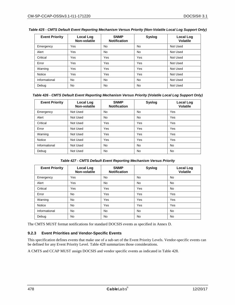
CM-SP-CCAP-OSSIv3.1-I11-171220 DOCSIS® 3.1
478 CableLabs 12/20/17
Table 425 - CMTS Default Event Reporting Mechanism Versus Priority (Non-Volatile Local Log Support Only)
Event Priority Local Log Non-volatile
SNMP Notification
Syslog Local Log Volatile
Emergency Yes No No Not Used
Alert Yes No No Not Used
Critical Yes Yes Yes Not Used
Error Yes Yes Yes Not Used
Warning Yes Yes Yes Not Used
Notice Yes Yes Yes Not Used
Informational No No No Not Used
Debug No No No Not Used
Table 426 - CMTS Default Event Reporting Mechanism Versus Priority (Volatile Local Log Support Only)
Event Priority Local Log Non-volatile
SNMP Notification
Syslog Local Log Volatile
Emergency Not Used No No Yes
Alert Not Used No No Yes
Critical Not Used Yes Yes Yes
Error Not Used Yes Yes Yes
Warning Not Used Yes Yes Yes
Notice Not Used Yes Yes Yes
Informational Not Used No No No
Debug Not Used No No No
Table 427 - CMTS Default Event Reporting Mechanism Versus Priority
Event Priority Local Log Non-volatile
SNMP Notification
Syslog Local Log Volatile
Emergency Yes No No No
Alert Yes No No No
Critical Yes Yes Yes No
Error No Yes Yes Yes
Warning No Yes Yes Yes
Notice No Yes Yes Yes
Informational No No No No
Debug No No No No
The CMTS MUST format notifications for standard DOCSIS events as specified in Annex D.
9.2.3 Event Priorities and Vendor-Specific Events
This specification defines events that make use of a sub-set of the Event Priority Levels. Vendor-specific events can be defined for any Event Priority Level. Table 428 summarizes those considerations.
A CMTS and CCAP MUST assign DOCSIS and vendor specific events as indicated in Table 428.
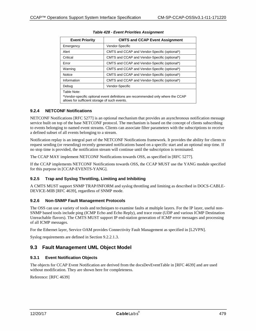
CCAP™ Operations Support System Interface Specification CM-SP-CCAP-OSSIv3.1-I11-171220
12/20/17 CableLabs 479
Table 428 - Event Priorities Assignment
Event Priority CMTS and CCAP Event Assignment Emergency Vendor-Specific
Alert CMTS and CCAP and Vendor-Specific (optional*)
Critical CMTS and CCAP and Vendor-Specific (optional*)
Error CMTS and CCAP and Vendor-Specific (optional*)
Warning CMTS and CCAP and Vendor-Specific (optional*)
Notice CMTS and CCAP and Vendor-Specific (optional*)
Information CMTS and CCAP and Vendor-Specific (optional*)
Debug Vendor-Specific
Table Note: *Vendor-specific optional event definitions are recommended only where the CCAP allows for sufficient storage of such events.
9.2.4 NETCONF Notifications NETCONF Notifications [RFC 5277] is an optional mechanism that provides an asynchronous notification message service built on top of the base NETCONF protocol. The mechanism is based on the concept of clients subscribing to events belonging to named event streams. Clients can associate filter parameters with the subscriptions to receive a defined subset of all events belonging to a stream.
Notification replay is an integral part of the NETCONF Notifications framework. It provides the ability for clients to request sending (or resending) recently generated notifications based on a specific start and an optional stop time. If no stop time is provided, the notification stream will continue until the subscription is terminated.
The CCAP MAY implement NETCONF Notifications towards OSS, as specified in [RFC 5277].
If the CCAP implements NETCONF Notifications towards OSS, the CCAP MUST use the YANG module specified for this purpose in [CCAP-EVENTS-YANG].
9.2.5 Trap and Syslog Throttling, Limiting and Inhibiting A CMTS MUST support SNMP TRAP/INFORM and syslog throttling and limiting as described in DOCS-CABLE-DEVICE-MIB [RFC 4639], regardless of SNMP mode.
9.2.6 Non-SNMP Fault Management Protocols
The OSS can use a variety of tools and techniques to examine faults at multiple layers. For the IP layer, useful non-SNMP based tools include ping (ICMP Echo and Echo Reply), and trace route (UDP and various ICMP Destination Unreachable flavors). The CMTS MUST support IP end-station generation of ICMP error messages and processing of all ICMP messages.
For the Ethernet layer, Service OAM provides Connectivity Fault Management as specified in [L2VPN].
Syslog requirements are defined in Section 9.2.2.1.3.
9.3 Fault Management UML Object Model
9.3.1 Event Notification Objects
The objects for CCAP Event Notification are derived from the docsDevEventTable in [RFC 4639] and are used without modification. They are shown here for completeness.
Reference: [RFC 4639]
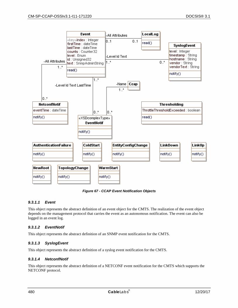
CM-SP-CCAP-OSSIv3.1-I11-171220 DOCSIS® 3.1
480 CableLabs 12/20/17
Figure 67 - CCAP Event Notification Objects
9.3.1.1 Event This object represents the abstract definition of an event object for the CMTS. The realization of the event object depends on the management protocol that carries the event as an autonomous notification. The event can also be logged in an event log.
9.3.1.2 EventNotif This object represents the abstract definition of an SNMP event notification for the CMTS.
9.3.1.3 SyslogEvent This object represents the abstract definition of a syslog event notification for the CMTS.
9.3.1.4 NetconfNotif This object represents the abstract definition of a NETCONF event notification for the CMTS which supports the NETCONF protocol.

CCAP™ Operations Support System Interface Specification CM-SP-CCAP-OSSIv3.1-I11-171220
12/20/17 CableLabs 481
9.3.1.5 LocalLog This object represent the abstract definition of an event stored in the CMTS volatile and/or non-volatile local log.
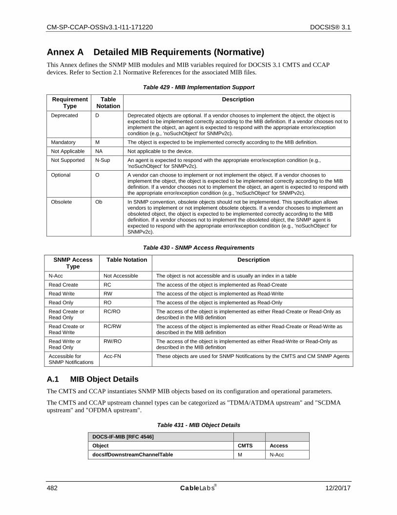
CM-SP-CCAP-OSSIv3.1-I11-171220 DOCSIS® 3.1
482 CableLabs 12/20/17
Annex A Detailed MIB Requirements (Normative) This Annex defines the SNMP MIB modules and MIB variables required for DOCSIS 3.1 CMTS and CCAP devices. Refer to Section 2.1 Normative References for the associated MIB files.
Table 429 - MIB Implementation Support
Requirement Type
Table Notation
Description
Deprecated D Deprecated objects are optional. If a vendor chooses to implement the object, the object is expected to be implemented correctly according to the MIB definition. If a vendor chooses not to implement the object, an agent is expected to respond with the appropriate error/exception condition (e.g., 'noSuchObject' for SNMPv2c).
Mandatory M The object is expected to be implemented correctly according to the MIB definition.
Not Applicable NA Not applicable to the device.
Not Supported N-Sup An agent is expected to respond with the appropriate error/exception condition (e.g., 'noSuchObject' for SNMPv2c).
Optional O A vendor can choose to implement or not implement the object. If a vendor chooses to implement the object, the object is expected to be implemented correctly according to the MIB definition. If a vendor chooses not to implement the object, an agent is expected to respond with the appropriate error/exception condition (e.g., 'noSuchObject' for SNMPv2c).
Obsolete Ob In SNMP convention, obsolete objects should not be implemented. This specification allows vendors to implement or not implement obsolete objects. If a vendor chooses to implement an obsoleted object, the object is expected to be implemented correctly according to the MIB definition. If a vendor chooses not to implement the obsoleted object, the SNMP agent is expected to respond with the appropriate error/exception condition (e.g., 'noSuchObject' for SNMPv2c).
Table 430 - SNMP Access Requirements
SNMP Access Type
Table Notation Description
N-Acc Not Accessible The object is not accessible and is usually an index in a table
Read Create RC The access of the object is implemented as Read-Create
Read Write RW The access of the object is implemented as Read-Write
Read Only RO The access of the object is implemented as Read-Only
Read Create or Read Only
RC/RO The access of the object is implemented as either Read-Create or Read-Only as described in the MIB definition
Read Create or Read Write
RC/RW The access of the object is implemented as either Read-Create or Read-Write as described in the MIB definition
Read Write or Read Only
RW/RO The access of the object is implemented as either Read-Write or Read-Only as described in the MIB definition
Accessible for SNMP Notifications
Acc-FN These objects are used for SNMP Notifications by the CMTS and CM SNMP Agents
A.1 MIB Object Details The CMTS and CCAP instantiates SNMP MIB objects based on its configuration and operational parameters.
The CMTS and CCAP upstream channel types can be categorized as "TDMA/ATDMA upstream" and "SCDMA upstream" and "OFDMA upstream".
Table 431 - MIB Object Details
DOCS-IF-MIB [RFC 4546]
Object CMTS Access docsIfDownstreamChannelTable M N-Acc
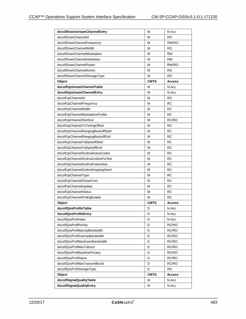
CCAP™ Operations Support System Interface Specification CM-SP-CCAP-OSSIv3.1-I11-171220
12/20/17 CableLabs 483
docsIfDownstreamChannelEntry M N-Acc
docsIfDownChannelId M RO
docsIfDownChannelFrequency M RW/RO
docsIfDownChannelWidth M RO
docsIfDownChannelModulation M RW
docsIfDownChannelInterleave M RW
docsIfDownChannelPower M RW/RO
docsIfDownChannelAnnex M RO
docsIfDownChannelStorageType M RO
Object CMTS Access docsIfUpstreamChannelTable M N-Acc
docsIfUpstreamChannelEntry M N-Acc
docsIfUpChannelId M RO
docsIfUpChannelFrequency M RC
docsIfUpChannelWidth M RC
docsIfUpChannelModulationProfile M RC
docsIfUpChannelSlotSize M RC/RO
docsIfUpChannelTxTimingOffset M RO
docsIfUpChannelRangingBackoffStart M RC
docsIfUpChannelRangingBackoffEnd M RC
docsIfUpChannelTxBackoffStart M RC
docsIfUpChannelTxBackoffEnd M RC
docsIfUpChannelScdmaActiveCodes M RC
docsIfUpChannelScdmaCodesPerSlot M RC
docsIfUpChannelScdmaFrameSize M RC
docsIfUpChannelScdmaHoppingSeed M RC
docsIfUpChannelType M RC
docsIfUpChannelCloneFrom M RC
docsIfUpChannelUpdate M RC
docsIfUpChannelStatus M RC
docsIfUpChannelPreEqEnable M RC
Object CMTS Access docsIfQosProfileTable D N-Acc
docsIfQosProfileEntry D N-Acc
docsIfQosProfIndex D N-Acc
docsIfQosProfPriority D RC/RO
docsIfQosProfMaxUpBandwidth D RC/RO
docsIfQosProfGuarUpBandwidth D RC/RO
docsIfQosProfMaxDownBandwidth D RC/RO
docsIfQosProfMaxTxBurst D RC/RO
docsIfQosProfBaselinePrivacy D RC/RO
docsIfQosProfStatus D RC/RO
docsIfQosProfMaxTransmitBurst D RC/RO
docsIfQosProfStorageType D RO
Object CMTS Access docsIfSignalQualityTable M N-Acc
docsIfSignalQualityEntry M N-Acc
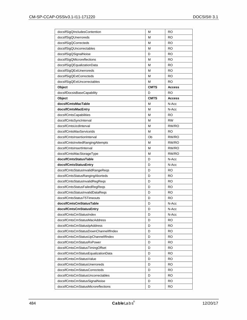
CM-SP-CCAP-OSSIv3.1-I11-171220 DOCSIS® 3.1
484 CableLabs 12/20/17
docsIfSigQIncludesContention M RO
docsIfSigQUnerroreds M RO
docsIfSigQCorrecteds M RO
docsIfSigQUncorrectables M RO
docsIfSigQSignalNoise D RO
docsIfSigQMicroreflections M RO
docsIfSigQEqualizationData M RO
docsIfSigQExtUnerroreds M RO
docsIfSigQExtCorrecteds M RO
docsIfSigQExtUncorrectables M RO
Object CMTS Access docsIfDocsisBaseCapability D RO
Object CMTS Access docsIfCmtsMacTable M N-Acc
docsIfCmtsMacEntry M N-Acc
docsIfCmtsCapabilities M RO
docsIfCmtsSyncInterval M RW
docsIfCmtsUcdInterval M RW/RO
docsIfCmtsMaxServiceIds M RO
docsIfCmtsInsertionInterval Ob RW/RO
docsIfCmtsInvitedRangingAttempts M RW/RO
docsIfCmtsInsertInterval M RW/RO
docsIfCmtsMacStorageType M RW/RO
docsIfCmtsStatusTable D N-Acc
docsIfCmtsStatusEntry D N-Acc
docsIfCmtsStatusInvalidRangeReqs D RO
docsIfCmtsStatusRangingAborteds D RO
docsIfCmtsStatusInvalidRegReqs D RO
docsIfCmtsStatusFailedRegReqs D RO
docsIfCmtsStatusInvalidDataReqs D RO
docsIfCmtsStatusT5Timeouts D RO
docsIfCmtsCmStatusTable D N-Acc
docsIfCmtsCmStatusEntry D N-Acc
docsIfCmtsCmStatusIndex D N-Acc
docsIfCmtsCmStatusMacAddress D RO
docsIfCmtsCmStatusIpAddress D RO
docsIfCmtsCmStatusDownChannelIfIndex D RO
docsIfCmtsCmStatusUpChannelIfIndex D RO
docsIfCmtsCmStatusRxPower D RO
docsIfCmtsCmStatusTimingOffset D RO
docsIfCmtsCmStatusEqualizationData D RO
docsIfCmtsCmStatusValue D RO
docsIfCmtsCmStatusUnerroreds D RO
docsIfCmtsCmStatusCorrecteds D RO
docsIfCmtsCmStatusUncorrectables D RO
docsIfCmtsCmStatusSignalNoise D RO
docsIfCmtsCmStatusMicroreflections D RO
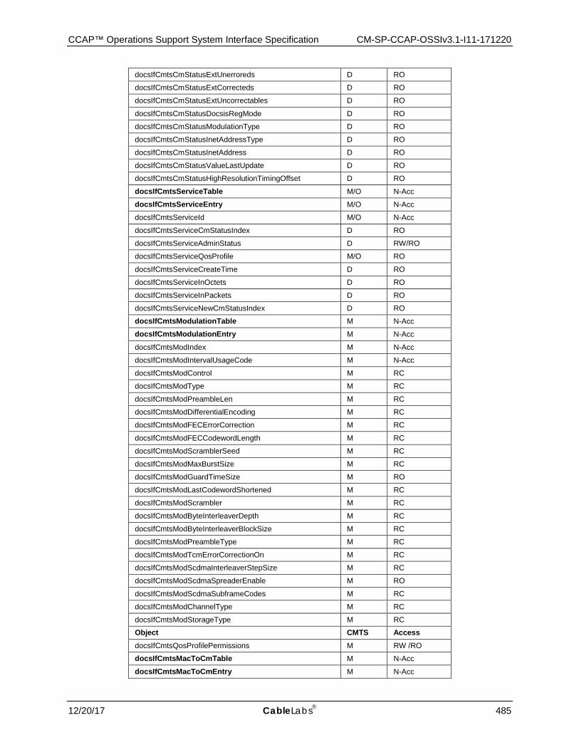
CCAP™ Operations Support System Interface Specification CM-SP-CCAP-OSSIv3.1-I11-171220
12/20/17 CableLabs 485
docsIfCmtsCmStatusExtUnerroreds D RO
docsIfCmtsCmStatusExtCorrecteds D RO
docsIfCmtsCmStatusExtUncorrectables D RO
docsIfCmtsCmStatusDocsisRegMode D RO
docsIfCmtsCmStatusModulationType D RO
docsIfCmtsCmStatusInetAddressType D RO
docsIfCmtsCmStatusInetAddress D RO
docsIfCmtsCmStatusValueLastUpdate D RO
docsIfCmtsCmStatusHighResolutionTimingOffset D RO
docsIfCmtsServiceTable M/O N-Acc
docsIfCmtsServiceEntry M/O N-Acc
docsIfCmtsServiceId M/O N-Acc
docsIfCmtsServiceCmStatusIndex D RO
docsIfCmtsServiceAdminStatus D RW/RO
docsIfCmtsServiceQosProfile M/O RO
docsIfCmtsServiceCreateTime D RO
docsIfCmtsServiceInOctets D RO
docsIfCmtsServiceInPackets D RO
docsIfCmtsServiceNewCmStatusIndex D RO
docsIfCmtsModulationTable M N-Acc
docsIfCmtsModulationEntry M N-Acc
docsIfCmtsModIndex M N-Acc
docsIfCmtsModIntervalUsageCode M N-Acc
docsIfCmtsModControl M RC
docsIfCmtsModType M RC
docsIfCmtsModPreambleLen M RC
docsIfCmtsModDifferentialEncoding M RC
docsIfCmtsModFECErrorCorrection M RC
docsIfCmtsModFECCodewordLength M RC
docsIfCmtsModScramblerSeed M RC
docsIfCmtsModMaxBurstSize M RC
docsIfCmtsModGuardTimeSize M RO
docsIfCmtsModLastCodewordShortened M RC
docsIfCmtsModScrambler M RC
docsIfCmtsModByteInterleaverDepth M RC
docsIfCmtsModByteInterleaverBlockSize M RC
docsIfCmtsModPreambleType M RC
docsIfCmtsModTcmErrorCorrectionOn M RC
docsIfCmtsModScdmaInterleaverStepSize M RC
docsIfCmtsModScdmaSpreaderEnable M RO
docsIfCmtsModScdmaSubframeCodes M RC
docsIfCmtsModChannelType M RC
docsIfCmtsModStorageType M RC
Object CMTS Access docsIfCmtsQosProfilePermissions M RW /RO
docsIfCmtsMacToCmTable M N-Acc
docsIfCmtsMacToCmEntry M N-Acc
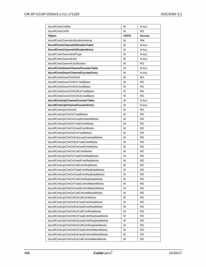
CM-SP-CCAP-OSSIv3.1-I11-171220 DOCSIS® 3.1
486 CableLabs 12/20/17
docsIfCmtsCmMac M N-Acc
docsIfCmtsCmPtr M RO
Object CMTS Access docsIfCmtsChannelUtilizationInterval M RW
DocsIfCmtsChannelUtilizationTable M N-Acc
DocsIfCmtsChannelUtilizationEntry M N-Acc
docsIfCmtsChannelUtIfType M N-Acc
docsIfCmtsChannelUtId M N-Acc
docsIfCmtsChannelUtUtilization M RO
docsIfCmtsDownChannelCounterTable M N-Acc
docsIfCmtsDownChannelCounterEntry M N-Acc
docsIfCmtsDownChnlCtrId M RO
docsIfCmtsDownChnlCtrTotalBytes M RO
docsIfCmtsDownChnlCtrUsedBytes M RO
docsIfCmtsDownChnlCtrExtTotalBytes M RO
docsIfCmtsDownChnlCtrExtUsedBytes M RO
docsIfCmtsUpChannelCounterTable M N-Acc
docsIfCmtsUpChannelCounterEntry M N-Acc
docsIfCmtsUpChnlCtrId M RO
docsIfCmtsUpChnlCtrTotalMslots M RO
docsIfCmtsUpChnlCtrUcastGrantedMslots M RO
docsIfCmtsUpChnlCtrTotalCntnMslots M RO
docsIfCmtsUpChnlCtrUsedCntnMslots M RO
docsIfCmtsUpChnlCtrExtTotalMslots M RO
docsIfCmtsUpChnlCtrExtUcastGrantedMslots M RO
docsIfCmtsUpChnlCtrExtTotalCntnMslots M RO
docsIfCmtsUpChnlCtrExtUsedCntnMslots M RO
docsIfCmtsUpChnlCtrCollCntnMslots M RO
docsIfCmtsUpChnlCtrTotalCntnReqMslots M RO
docsIfCmtsUpChnlCtrUsedCntnReqMslots M RO
docsIfCmtsUpChnlCtrCollCntnReqMslots M RO
docsIfCmtsUpChnlCtrTotalCntnReqDataMslots M RO
docsIfCmtsUpChnlCtrUsedCntnReqDataMslots M RO
docsIfCmtsUpChnlCtrCollCntnReqDataMslots M RO
docsIfCmtsUpChnlCtrTotalCntnInitMaintMslots M RO
docsIfCmtsUpChnlCtrUsedCntnInitMaintMslots M RO
docsIfCmtsUpChnlCtrCollCntnInitMaintMslots M RO
docsIfCmtsUpChnlCtrExtCollCntnMslots M RO
docsIfCmtsUpChnlCtrExtTotalCntnReqMslots M RO
docsIfCmtsUpChnlCtrExtUsedCntnReqMslots M RO
docsIfCmtsUpChnlCtrExtCollCntnReqMslots M RO
docsIfCmtsUpChnlCtrExtTotalCntnReqDataMslots M RO
docsIfCmtsUpChnlCtrExtUsedCntnReqDataMslots M RO
docsIfCmtsUpChnlCtrExtCollCntnReqDataMslots M RO
docsIfCmtsUpChnlCtrExtTotalCntnInitMaintMslots M RO
docsIfCmtsUpChnlCtrExtUsedCntnInitMaintMslots M RO
docsIfCmtsUpChnlCtrExtCollCntnInitMaintMslots M RO
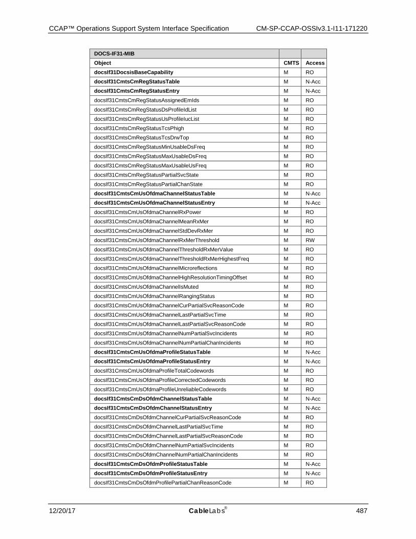
CCAP™ Operations Support System Interface Specification CM-SP-CCAP-OSSIv3.1-I11-171220
12/20/17 CableLabs 487
DOCS-IF31-MIB
Object CMTS Access docsIf31DocsisBaseCapability M RO
docsIf31CmtsCmRegStatusTable M N-Acc
docsIf31CmtsCmRegStatusEntry M N-Acc
docsIf31CmtsCmRegStatusAssignedEmIds M RO
docsIf31CmtsCmRegStatusDsProfileIdList M RO
docsIf31CmtsCmRegStatusUsProfileIucList M RO
docsIf31CmtsCmRegStatusTcsPhigh M RO
docsIf31CmtsCmRegStatusTcsDrwTop M RO
docsIf31CmtsCmRegStatusMinUsableDsFreq M RO
docsIf31CmtsCmRegStatusMaxUsableDsFreq M RO
docsIf31CmtsCmRegStatusMaxUsableUsFreq M RO
docsIf31CmtsCmRegStatusPartialSvcState M RO
docsIf31CmtsCmRegStatusPartialChanState M RO
docsIf31CmtsCmUsOfdmaChannelStatusTable M N-Acc
docsIf31CmtsCmUsOfdmaChannelStatusEntry M N-Acc
docsIf31CmtsCmUsOfdmaChannelRxPower M RO
docsIf31CmtsCmUsOfdmaChannelMeanRxMer M RO
docsIf31CmtsCmUsOfdmaChannelStdDevRxMer M RO
docsIf31CmtsCmUsOfdmaChannelRxMerThreshold M RW
docsIf31CmtsCmUsOfdmaChannelThresholdRxMerValue M RO
docsIf31CmtsCmUsOfdmaChannelThresholdRxMerHighestFreq M RO
docsIf31CmtsCmUsOfdmaChannelMicroreflections M RO
docsIf31CmtsCmUsOfdmaChannelHighResolutionTimingOffset M RO
docsIf31CmtsCmUsOfdmaChannelIsMuted M RO
docsIf31CmtsCmUsOfdmaChannelRangingStatus M RO
docsIf31CmtsCmUsOfdmaChannelCurPartialSvcReasonCode M RO
docsIf31CmtsCmUsOfdmaChannelLastPartialSvcTime M RO
docsIf31CmtsCmUsOfdmaChannelLastPartialSvcReasonCode M RO
docsIf31CmtsCmUsOfdmaChannelNumPartialSvcIncidents M RO
docsIf31CmtsCmUsOfdmaChannelNumPartialChanIncidents M RO
docsIf31CmtsCmUsOfdmaProfileStatusTable M N-Acc
docsIf31CmtsCmUsOfdmaProfileStatusEntry M N-Acc
docsIf31CmtsCmUsOfdmaProfileTotalCodewords M RO
docsIf31CmtsCmUsOfdmaProfileCorrectedCodewords M RO
docsIf31CmtsCmUsOfdmaProfileUnreliableCodewords M RO
docsIf31CmtsCmDsOfdmChannelStatusTable M N-Acc
docsIf31CmtsCmDsOfdmChannelStatusEntry M N-Acc
docsIf31CmtsCmDsOfdmChannelCurPartialSvcReasonCode M RO
docsIf31CmtsCmDsOfdmChannelLastPartialSvcTime M RO
docsIf31CmtsCmDsOfdmChannelLastPartialSvcReasonCode M RO
docsIf31CmtsCmDsOfdmChannelNumPartialSvcIncidents M RO
docsIf31CmtsCmDsOfdmChannelNumPartialChanIncidents M RO
docsIf31CmtsCmDsOfdmProfileStatusTable M N-Acc
docsIf31CmtsCmDsOfdmProfileStatusEntry M N-Acc
docsIf31CmtsCmDsOfdmProfilePartialChanReasonCode M RO
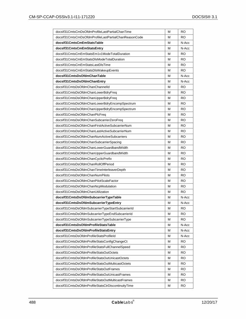
CM-SP-CCAP-OSSIv3.1-I11-171220 DOCSIS® 3.1
488 CableLabs 12/20/17
docsIf31CmtsCmDsOfdmProfileLastPartialChanTime M RO
docsIf31CmtsCmDsOfdmProfileLastPartialChanReasonCode M RO
docsIf31CmtsCmEmStatsTable M N-Acc
docsIf31CmtsCmEmStatsEntry M N-Acc
docsIf31CmtsCmEmStatsEm1x1ModeTotalDuration M RO
docsIf31CmtsCmEmStatsDlsModeTotalDuration M RO
docsIf31CmtsCmEmStatsLastDlsTime M RO
docsIf31CmtsCmEmStatsDlsWakeupEvents M RO
docsIf31CmtsDsOfdmChanTable M N-Acc
docsIf31CmtsDsOfdmChanEntry M N-Acc
docsIf31CmtsDsOfdmChanChannelId M RO
docsIf31CmtsDsOfdmChanLowerBdryFreq M RO
docsIf31CmtsDsOfdmChanUpperBdryFreq M RO
docsIf31CmtsDsOfdmChanLowerBdryEncompSpectrum M RO
docsIf31CmtsDsOfdmChanUpperBdryEncompSpectrum M RO
docsIf31CmtsDsOfdmChanPlcFreq M RO
docsIf31CmtsDsOfdmChanSubcarrierZeroFreq M RO
docsIf31CmtsDsOfdmChanFirstActiveSubcarrierNum M RO
docsIf31CmtsDsOfdmChanLastActiveSubcarrierNum M RO
docsIf31CmtsDsOfdmChanNumActiveSubcarriers M RO
docsIf31CmtsDsOfdmChanSubcarrierSpacing M RO
docsIf31CmtsDsOfdmChanLowerGuardbandWidth M RO
docsIf31CmtsDsOfdmChanUpperGuardbandWidth M RO
docsIf31CmtsDsOfdmChanCyclicPrefix M RO
docsIf31CmtsDsOfdmChanRollOffPeriod M RO
docsIf31CmtsDsOfdmChanTimeInterleaverDepth M RO
docsIf31CmtsDsOfdmChanNumPilots M RO
docsIf31CmtsDsOfdmChanPilotScaleFactor M RO
docsIf31CmtsDsOfdmChanNcpModulation M RO
docsIf31CmtsDsOfdmChanUtilization M RO
docsIf31CmtsDsOfdmSubcarrierTypeTable M N-Acc
docsIf31CmtsDsOfdmSubcarrierTypeEntry M N-Acc
docsIf31CmtsDsOfdmSubcarrierTypeStartSubcarrierId M RO
docsIf31CmtsDsOfdmSubcarrierTypeEndSubcarrierId M RO
docsIf31CmtsDsOfdmSubcarrierTypeSubcarrierType M RO
docsIf31CmtsDsOfdmProfileStatsTable M N-Acc
docsIf31CmtsDsOfdmProfileStatsEntry M N-Acc
docsIf31CmtsDsOfdmProfileStatsProfileId M N-Acc
docsIf31CmtsDsOfdmProfileStatsConfigChangeCt M RO
docsIf31CmtsDsOfdmProfileStatsFullChannelSpeed M RO
docsIf31CmtsDsOfdmProfileStatsOutOctets M RO
docsIf31CmtsDsOfdmProfileStatsOutUnicastOctets M RO
docsIf31CmtsDsOfdmProfileStatsOutMulticastOctets M RO
docsIf31CmtsDsOfdmProfileStatsOutFrames M RO
docsIf31CmtsDsOfdmProfileStatsOutUnicastFrames M RO
docsIf31CmtsDsOfdmProfileStatsOutMulticastFrames M RO
docsIf31CmtsDsOfdmProfileStatsCtrDiscontinuityTime M RO
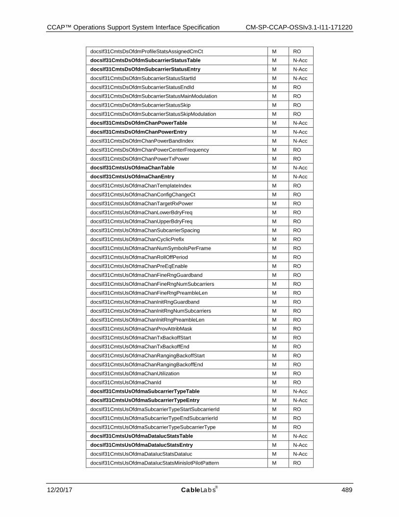
CCAP™ Operations Support System Interface Specification CM-SP-CCAP-OSSIv3.1-I11-171220
12/20/17 CableLabs 489
docsIf31CmtsDsOfdmProfileStatsAssignedCmCt M RO
docsIf31CmtsDsOfdmSubcarrierStatusTable M N-Acc
docsIf31CmtsDsOfdmSubcarrierStatusEntry M N-Acc
docsIf31CmtsDsOfdmSubcarrierStatusStartId M N-Acc
docsIf31CmtsDsOfdmSubcarrierStatusEndId M RO
docsIf31CmtsDsOfdmSubcarrierStatusMainModulation M RO
docsIf31CmtsDsOfdmSubcarrierStatusSkip M RO
docsIf31CmtsDsOfdmSubcarrierStatusSkipModulation M RO
docsIf31CmtsDsOfdmChanPowerTable M N-Acc
docsIf31CmtsDsOfdmChanPowerEntry M N-Acc
docsIf31CmtsDsOfdmChanPowerBandIndex M N-Acc
docsIf31CmtsDsOfdmChanPowerCenterFrequency M RO
docsIf31CmtsDsOfdmChanPowerTxPower M RO
docsIf31CmtsUsOfdmaChanTable M N-Acc
docsIf31CmtsUsOfdmaChanEntry M N-Acc
docsIf31CmtsUsOfdmaChanTemplateIndex M RO
docsIf31CmtsUsOfdmaChanConfigChangeCt M RO
docsIf31CmtsUsOfdmaChanTargetRxPower M RO
docsIf31CmtsUsOfdmaChanLowerBdryFreq M RO
docsIf31CmtsUsOfdmaChanUpperBdryFreq M RO
docsIf31CmtsUsOfdmaChanSubcarrierSpacing M RO
docsIf31CmtsUsOfdmaChanCyclicPrefix M RO
docsIf31CmtsUsOfdmaChanNumSymbolsPerFrame M RO
docsIf31CmtsUsOfdmaChanRollOffPeriod M RO
docsIf31CmtsUsOfdmaChanPreEqEnable M RO
docsIf31CmtsUsOfdmaChanFineRngGuardband M RO
docsIf31CmtsUsOfdmaChanFineRngNumSubcarriers M RO
docsIf31CmtsUsOfdmaChanFineRngPreambleLen M RO
docsIf31CmtsUsOfdmaChanInitRngGuardband M RO
docsIf31CmtsUsOfdmaChanInitRngNumSubcarriers M RO
docsIf31CmtsUsOfdmaChanInitRngPreambleLen M RO
docsIf31CmtsUsOfdmaChanProvAttribMask M RO
docsIf31CmtsUsOfdmaChanTxBackoffStart M RO
docsIf31CmtsUsOfdmaChanTxBackoffEnd M RO
docsIf31CmtsUsOfdmaChanRangingBackoffStart M RO
docsIf31CmtsUsOfdmaChanRangingBackoffEnd M RO
docsIf31CmtsUsOfdmaChanUtilization M RO
docsIf31CmtsUsOfdmaChanId M RO
docsIf31CmtsUsOfdmaSubcarrierTypeTable M N-Acc
docsIf31CmtsUsOfdmaSubcarrierTypeEntry M N-Acc
docsIf31CmtsUsOfdmaSubcarrierTypeStartSubcarrierId M RO
docsIf31CmtsUsOfdmaSubcarrierTypeEndSubcarrierId M RO
docsIf31CmtsUsOfdmaSubcarrierTypeSubcarrierType M RO
docsIf31CmtsUsOfdmaDataIucStatsTable M N-Acc
docsIf31CmtsUsOfdmaDataIucStatsEntry M N-Acc
docsIf31CmtsUsOfdmaDataIucStatsDataIuc M N-Acc
docsIf31CmtsUsOfdmaDataIucStatsMinislotPilotPattern M RO
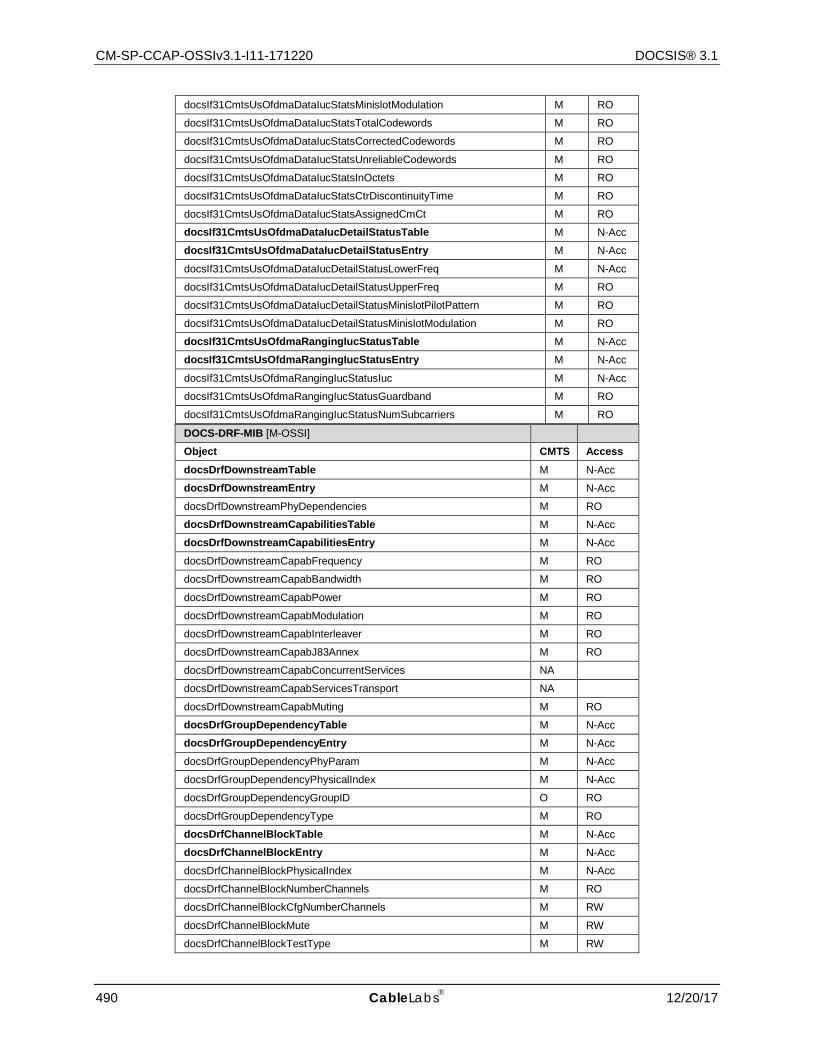
CM-SP-CCAP-OSSIv3.1-I11-171220 DOCSIS® 3.1
490 CableLabs 12/20/17
DOCS-DRF-MIB [M-OSSI]
Object CMTS Access docsDrfDownstreamTable M N-Acc
docsDrfDownstreamEntry M N-Acc
docsDrfDownstreamPhyDependencies M RO
docsDrfDownstreamCapabilitiesTable M N-Acc
docsDrfDownstreamCapabilitiesEntry M N-Acc
docsDrfDownstreamCapabFrequency M RO
docsDrfDownstreamCapabBandwidth M RO
docsDrfDownstreamCapabPower M RO
docsDrfDownstreamCapabModulation M RO
docsDrfDownstreamCapabInterleaver M RO
docsDrfDownstreamCapabJ83Annex M RO
docsDrfDownstreamCapabConcurrentServices NA
docsDrfDownstreamCapabServicesTransport NA
docsDrfDownstreamCapabMuting M RO
docsDrfGroupDependencyTable M N-Acc
docsDrfGroupDependencyEntry M N-Acc
docsDrfGroupDependencyPhyParam M N-Acc
docsDrfGroupDependencyPhysicalIndex M N-Acc
docsDrfGroupDependencyGroupID O RO
docsDrfGroupDependencyType M RO
docsDrfChannelBlockTable M N-Acc
docsDrfChannelBlockEntry M N-Acc
docsDrfChannelBlockPhysicalIndex M N-Acc
docsDrfChannelBlockNumberChannels M RO
docsDrfChannelBlockCfgNumberChannels M RW
docsDrfChannelBlockMute M RW
docsDrfChannelBlockTestType M RW
docsIf31CmtsUsOfdmaDataIucStatsMinislotModulation M RO
docsIf31CmtsUsOfdmaDataIucStatsTotalCodewords M RO
docsIf31CmtsUsOfdmaDataIucStatsCorrectedCodewords M RO
docsIf31CmtsUsOfdmaDataIucStatsUnreliableCodewords M RO
docsIf31CmtsUsOfdmaDataIucStatsInOctets M RO
docsIf31CmtsUsOfdmaDataIucStatsCtrDiscontinuityTime M RO
docsIf31CmtsUsOfdmaDataIucStatsAssignedCmCt M RO
docsIf31CmtsUsOfdmaDataIucDetailStatusTable M N-Acc
docsIf31CmtsUsOfdmaDataIucDetailStatusEntry M N-Acc
docsIf31CmtsUsOfdmaDataIucDetailStatusLowerFreq M N-Acc
docsIf31CmtsUsOfdmaDataIucDetailStatusUpperFreq M RO
docsIf31CmtsUsOfdmaDataIucDetailStatusMinislotPilotPattern M RO
docsIf31CmtsUsOfdmaDataIucDetailStatusMinislotModulation M RO
docsIf31CmtsUsOfdmaRangingIucStatusTable M N-Acc
docsIf31CmtsUsOfdmaRangingIucStatusEntry M N-Acc
docsIf31CmtsUsOfdmaRangingIucStatusIuc M N-Acc
docsIf31CmtsUsOfdmaRangingIucStatusGuardband M RO
docsIf31CmtsUsOfdmaRangingIucStatusNumSubcarriers M RO

CCAP™ Operations Support System Interface Specification CM-SP-CCAP-OSSIv3.1-I11-171220
12/20/17 CableLabs 491
docsDrfChannelBlockTestIfIndex M RW
IF-MIB [RFC 2863]
Object CMTS Access ifNumber M RO
ifTableLastChange M RO
ifTable Note: The ifTable Counter32 objects are not reflected here; refer to [RFC 2863] for details on these objects.
M N-Acc
ifEntry M N-Acc
ifIndex M RO
ifDescr M RO
ifType M RO
ifMtu M RO
ifSpeed M RO
ifPhysAddress M RO
ifAdminStatus M RW
ifOperStatus M RO
ifLastChange M RO
ifOutQLen D RO
ifSpecific D RO
ifXTable Note: The ifXTable Counter32 and Counter64 objects are not reflected here; refer to Table 310 for details on these objects.
M N-Acc
ifXEntry M N-Acc
ifName M RO
ifLinkUpDownTrapEnable M RW
ifHighSpeed M RO
ifPromiscuousMode M RW/RO
ifConnectorPresent M RO
ifAlias M RW/RO
ifCounterDiscontinuityTime M RO
ifStackTable M N-Acc
ifStackEntry M N-Acc
ifStackHigherLayer M N-Acc
ifStackLowerLayer M N-Acc
ifStackStatus M RC/RO
Object CMTS Access ifStackLastChange M RC/RO
ifRcvAddressTable O N-Acc
ifRcvAddressEntry O N-Acc
ifRcvAddressAddress O N-Acc
ifRcvAddressStatus O RC
IfRcvAddressType O RC
Notification
linkUp M Acc-FN
linkDown M Acc-FN
ifTestTable D N-Acc
ifTestEntry D N-Acc

CM-SP-CCAP-OSSIv3.1-I11-171220 DOCSIS® 3.1
492 CableLabs 12/20/17
ifTestId D RW
ifTestStatus D RW
ifTestType D RW
ifTestResult D RO
ifTestCode D RO
ifTestOwner D RW
BRIDGE-MIB [RFC 4188] Note: Implementation of BRIDGE-MIB is required ONLY if device is a bridging device.
Object CMTS Access dot1dBase
dot1dBaseBridgeAddress M RO
dot1dBaseNumPorts M RO
dot1dBaseType M RO
dot1dBasePortTable M N-Acc
dot1dBasePortEntry M N-Acc
dot1dBasePort M RO
dot1dBasePortIfIndex M RO
dot1dBasePortCircuit M RO
dot1dBasePortDelayExceededDiscards M RO
dot1dBasePortMtuExceededDiscards M RO
dot1dStp
dot1dStpProtocolSpecification M RO
dot1dStpPriority M RW
dot1dStpTimeSinceTopologyChange M RO
dot1dStpTopChanges M RO
dot1dStpDesignatedRoot M RO
dot1dStpRootCost M RO
dot1dStpRootPort M RO
dot1dStpMaxAge M RO
dot1dStpHelloTime M RO
dot1dStpHoldTime M RO
dot1dStpForwardDelay M RO
dot1dStpBridgeMaxAge M RW
dot1dStpBridgeHelloTime M RW
dot1dStpBridgeForwardDelay M RW
dot1dStpPortTable Note: This table is required ONLY if STP is implemented.
O N-Acc
dot1dStpPortEntry O N-Acc
dot1dStpPort O RO
dot1dStpPortPriority O RW
dot1dStpPortState O RO
dot1dStpPortEnable O RW
dot1dStpPortPathCost O RW
dot1dStpPortDesignatedRoot O RO
dot1dStpPortDesignatedCost O RO
dot1dStpPortDesignatedBridge O RO
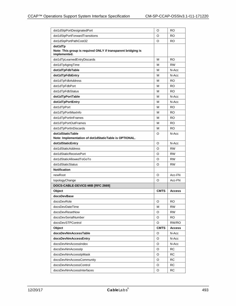
CCAP™ Operations Support System Interface Specification CM-SP-CCAP-OSSIv3.1-I11-171220
12/20/17 CableLabs 493
dot1dStpPortDesignatedPort O RO
dot1dStpPortForwardTransitions O RO
dot1dStpPortPathCost32 O RO
dot1dTp Note: This group is required ONLY if transparent bridging is implemented.
dot1dTpLearnedEntryDiscards M RO
dot1dTpAgingTime M RW
dot1dTpFdbTable M N-Acc
dot1dTpFdbEntry M N-Acc
dot1dTpFdbAddress M RO
dot1dTpFdbPort M RO
dot1dTpFdbStatus M RO
dot1dTpPortTable M N-Acc
dot1dTpPortEntry M N-Acc
dot1dTpPort M RO
dot1dTpPortMaxInfo M RO
dot1dTpPortInFrames M RO
dot1dTpPortOutFrames M RO
dot1dTpPortInDiscards M RO
dot1dStaticTable Note: Implementation of dot1dStaticTable is OPTIONAL.
O N-Acc
dot1dStaticEntry O N-Acc
dot1dStaticAddress O RW
dot1dStaticReceivePort O RW
dot1dStaticAllowedToGoTo O RW
dot1dStaticStatus O RW
Notification
newRoot O Acc-FN
topologyChange O Acc-FN
DOCS-CABLE-DEVICE-MIB [RFC 2669]
Object CMTS Access docsDevBase
docsDevRole O RO
docsDevDateTime M RW
docsDevResetNow O RW
docsDevSerialNumber O RO
docsDevSTPControl O RW/RO
Object CMTS Access docsDevNmAccessTable O N-Acc
docsDevNmAccessEntry O N-Acc
docsDevNmAccessIndex O N-Acc
docsDevNmAccessIp O RC
docsDevNmAccessIpMask O RC
docsDevNmAccessCommunity O RC
docsDevNmAccessControl O RC
docsDevNmAccessInterfaces O RC
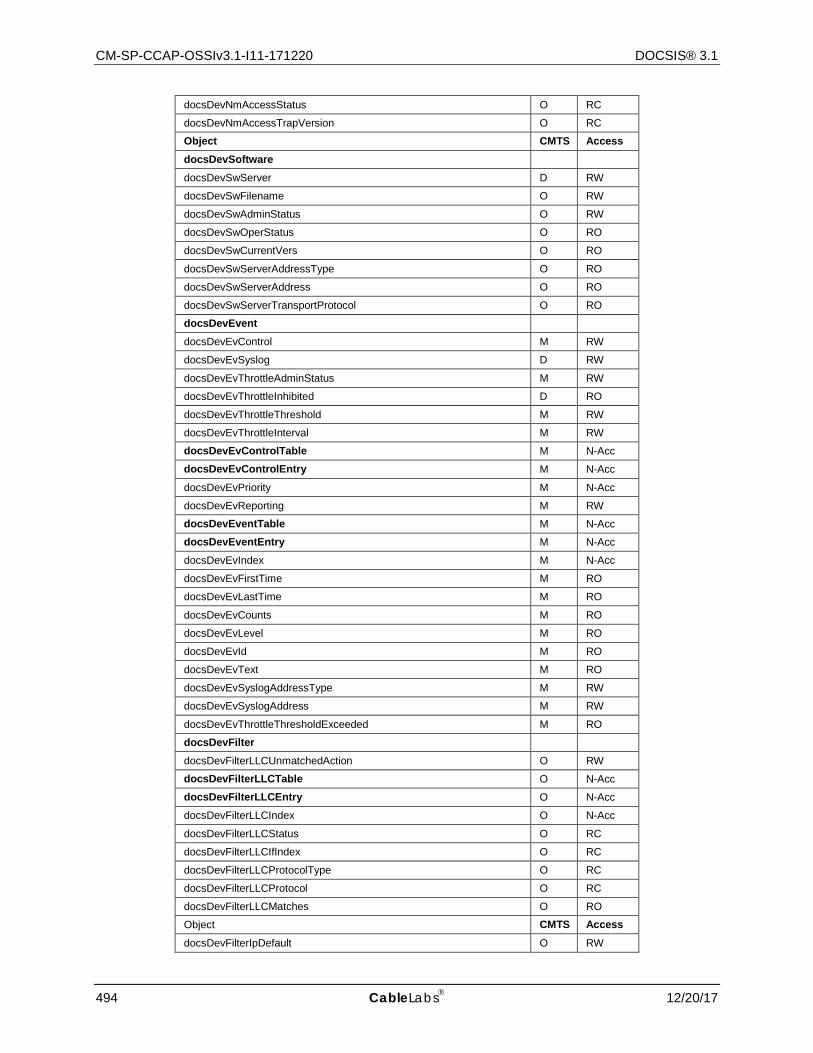
CM-SP-CCAP-OSSIv3.1-I11-171220 DOCSIS® 3.1
494 CableLabs 12/20/17
docsDevNmAccessStatus O RC
docsDevNmAccessTrapVersion O RC
Object CMTS Access docsDevSoftware
docsDevSwServer D RW
docsDevSwFilename O RW
docsDevSwAdminStatus O RW
docsDevSwOperStatus O RO
docsDevSwCurrentVers O RO
docsDevSwServerAddressType O RO
docsDevSwServerAddress O RO
docsDevSwServerTransportProtocol O RO
docsDevEvent
docsDevEvControl M RW
docsDevEvSyslog D RW
docsDevEvThrottleAdminStatus M RW
docsDevEvThrottleInhibited D RO
docsDevEvThrottleThreshold M RW
docsDevEvThrottleInterval M RW
docsDevEvControlTable M N-Acc
docsDevEvControlEntry M N-Acc
docsDevEvPriority M N-Acc
docsDevEvReporting M RW
docsDevEventTable M N-Acc
docsDevEventEntry M N-Acc
docsDevEvIndex M N-Acc
docsDevEvFirstTime M RO
docsDevEvLastTime M RO
docsDevEvCounts M RO
docsDevEvLevel M RO
docsDevEvId M RO
docsDevEvText M RO
docsDevEvSyslogAddressType M RW
docsDevEvSyslogAddress M RW
docsDevEvThrottleThresholdExceeded M RO
docsDevFilter
docsDevFilterLLCUnmatchedAction O RW
docsDevFilterLLCTable O N-Acc
docsDevFilterLLCEntry O N-Acc
docsDevFilterLLCIndex O N-Acc
docsDevFilterLLCStatus O RC
docsDevFilterLLCIfIndex O RC
docsDevFilterLLCProtocolType O RC
docsDevFilterLLCProtocol O RC
docsDevFilterLLCMatches O RO
Object CMTS Access docsDevFilterIpDefault O RW

CCAP™ Operations Support System Interface Specification CM-SP-CCAP-OSSIv3.1-I11-171220
12/20/17 CableLabs 495
docsDevFilterIpTable D N-Acc
docsDevFilterIpEntry D N-Acc
docsDevFilterIpIndex D N-Acc
docsDevFilterIpStatus D RC
docsDevFilterIpControl D RC
docsDevFilterIpIfIndex D RC
docsDevFilterIpDirection D RC
docsDevFilterIpBroadcast D RC
docsDevFilterIpSaddr D RC
docsDevFilterIpSmask D RC
docsDevFilterIpDaddr D RC
docsDevFilterIpDmask D RC
docsDevFilterIpProtocol D RC
docsDevFilterIpSourcePortLow D RC
docsDevFilterIpSourcePortHigh D RC
docsDevFilterIpDestPortLow D RC
docsDevFilterIpDestPortHigh D RC
docsDevFilterIpMatches D RO
docsDevFilterIpTos D RC
docsDevFilterIpTosMask D RC
docsDevFilterIpContinue D RC
docsDevFilterIpPolicyId D RC
docsDevFilterPolicyTable D N-Acc
docsDevFilterPolicyEntry D N-Acc
docsDevFilterPolicyIndex D N-Acc
docsDevFilterPolicyId D RC
docsDevFilterPolicyStatus D RC
docsDevFilterPolicyPtr D RC
docsDevFilterTosTable D N-Acc
docsDevFilterTosEntry D N-Acc
docsDevFilterTosIndex D N-Acc
docsDevFilterTosStatus D RC
docsDevFilterTosAndMask D RC
docsDevFilterTosOrMask D RC
IP-MIB [RFC 4293]
Object CMTS Access ipv4GeneralGroup
ipForwarding M RW
ipDefaultTTL M RW
ipReasmTimeout M RW
ipv6GeneralGroup2
ipv6IpForwarding M RW
ipv6IpDefaultHopLimit M RW
ipv4InterfaceTableLastChange M RO
ipv4InterfaceTable M N-Acc
ipv4InterfaceEntry M N-Acc
ipv4InterfaceIfIndex M N-Acc
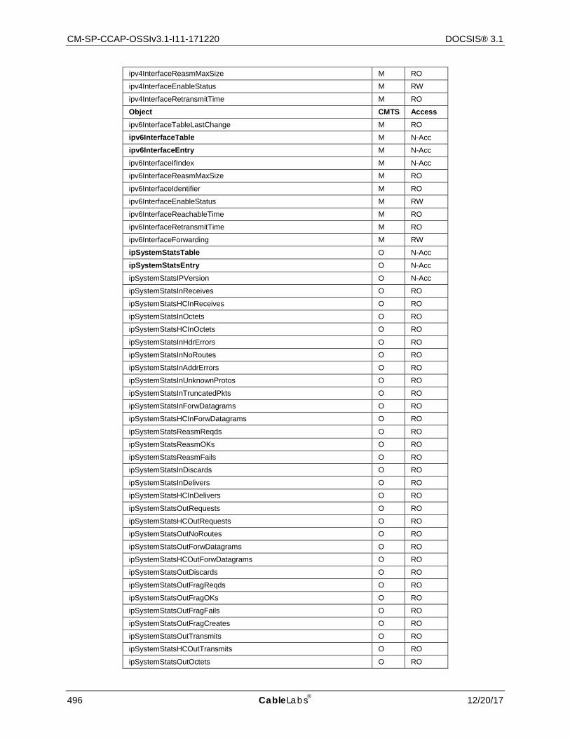
CM-SP-CCAP-OSSIv3.1-I11-171220 DOCSIS® 3.1
496 CableLabs 12/20/17
ipv4InterfaceReasmMaxSize M RO
ipv4InterfaceEnableStatus M RW
ipv4InterfaceRetransmitTime M RO
Object CMTS Access ipv6InterfaceTableLastChange M RO
ipv6InterfaceTable M N-Acc
ipv6InterfaceEntry M N-Acc
ipv6InterfaceIfIndex M N-Acc
ipv6InterfaceReasmMaxSize M RO
ipv6InterfaceIdentifier M RO
ipv6InterfaceEnableStatus M RW
ipv6InterfaceReachableTime M RO
ipv6InterfaceRetransmitTime M RO
ipv6InterfaceForwarding M RW
ipSystemStatsTable O N-Acc
ipSystemStatsEntry O N-Acc
ipSystemStatsIPVersion O N-Acc
ipSystemStatsInReceives O RO
ipSystemStatsHCInReceives O RO
ipSystemStatsInOctets O RO
ipSystemStatsHCInOctets O RO
ipSystemStatsInHdrErrors O RO
ipSystemStatsInNoRoutes O RO
ipSystemStatsInAddrErrors O RO
ipSystemStatsInUnknownProtos O RO
ipSystemStatsInTruncatedPkts O RO
ipSystemStatsInForwDatagrams O RO
ipSystemStatsHCInForwDatagrams O RO
ipSystemStatsReasmReqds O RO
ipSystemStatsReasmOKs O RO
ipSystemStatsReasmFails O RO
ipSystemStatsInDiscards O RO
ipSystemStatsInDelivers O RO
ipSystemStatsHCInDelivers O RO
ipSystemStatsOutRequests O RO
ipSystemStatsHCOutRequests O RO
ipSystemStatsOutNoRoutes O RO
ipSystemStatsOutForwDatagrams O RO
ipSystemStatsHCOutForwDatagrams O RO
ipSystemStatsOutDiscards O RO
ipSystemStatsOutFragReqds O RO
ipSystemStatsOutFragOKs O RO
ipSystemStatsOutFragFails O RO
ipSystemStatsOutFragCreates O RO
ipSystemStatsOutTransmits O RO
ipSystemStatsHCOutTransmits O RO
ipSystemStatsOutOctets O RO
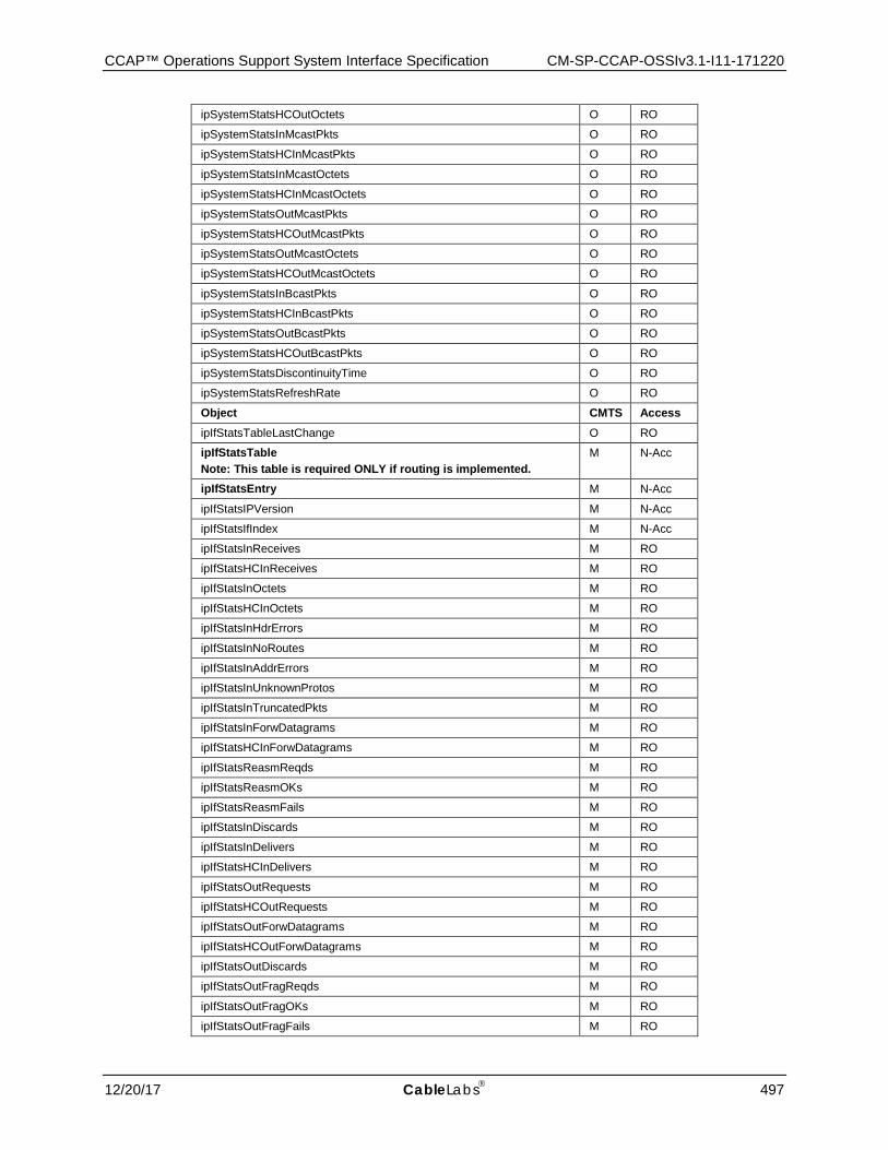
CCAP™ Operations Support System Interface Specification CM-SP-CCAP-OSSIv3.1-I11-171220
12/20/17 CableLabs 497
ipSystemStatsHCOutOctets O RO
ipSystemStatsInMcastPkts O RO
ipSystemStatsHCInMcastPkts O RO
ipSystemStatsInMcastOctets O RO
ipSystemStatsHCInMcastOctets O RO
ipSystemStatsOutMcastPkts O RO
ipSystemStatsHCOutMcastPkts O RO
ipSystemStatsOutMcastOctets O RO
ipSystemStatsHCOutMcastOctets O RO
ipSystemStatsInBcastPkts O RO
ipSystemStatsHCInBcastPkts O RO
ipSystemStatsOutBcastPkts O RO
ipSystemStatsHCOutBcastPkts O RO
ipSystemStatsDiscontinuityTime O RO
ipSystemStatsRefreshRate O RO
Object CMTS Access ipIfStatsTableLastChange O RO
ipIfStatsTable Note: This table is required ONLY if routing is implemented.
M N-Acc
ipIfStatsEntry M N-Acc
ipIfStatsIPVersion M N-Acc
ipIfStatsIfIndex M N-Acc
ipIfStatsInReceives M RO
ipIfStatsHCInReceives M RO
ipIfStatsInOctets M RO
ipIfStatsHCInOctets M RO
ipIfStatsInHdrErrors M RO
ipIfStatsInNoRoutes M RO
ipIfStatsInAddrErrors M RO
ipIfStatsInUnknownProtos M RO
ipIfStatsInTruncatedPkts M RO
ipIfStatsInForwDatagrams M RO
ipIfStatsHCInForwDatagrams M RO
ipIfStatsReasmReqds M RO
ipIfStatsReasmOKs M RO
ipIfStatsReasmFails M RO
ipIfStatsInDiscards M RO
ipIfStatsInDelivers M RO
ipIfStatsHCInDelivers M RO
ipIfStatsOutRequests M RO
ipIfStatsHCOutRequests M RO
ipIfStatsOutForwDatagrams M RO
ipIfStatsHCOutForwDatagrams M RO
ipIfStatsOutDiscards M RO
ipIfStatsOutFragReqds M RO
ipIfStatsOutFragOKs M RO
ipIfStatsOutFragFails M RO
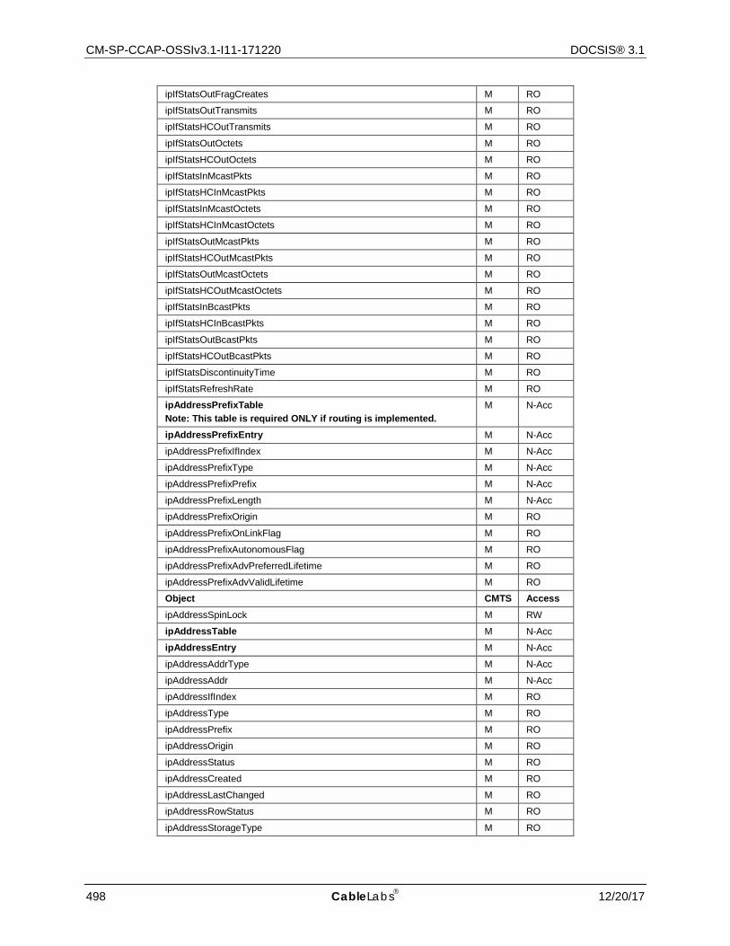
CM-SP-CCAP-OSSIv3.1-I11-171220 DOCSIS® 3.1
498 CableLabs 12/20/17
ipIfStatsOutFragCreates M RO
ipIfStatsOutTransmits M RO
ipIfStatsHCOutTransmits M RO
ipIfStatsOutOctets M RO
ipIfStatsHCOutOctets M RO
ipIfStatsInMcastPkts M RO
ipIfStatsHCInMcastPkts M RO
ipIfStatsInMcastOctets M RO
ipIfStatsHCInMcastOctets M RO
ipIfStatsOutMcastPkts M RO
ipIfStatsHCOutMcastPkts M RO
ipIfStatsOutMcastOctets M RO
ipIfStatsHCOutMcastOctets M RO
ipIfStatsInBcastPkts M RO
ipIfStatsHCInBcastPkts M RO
ipIfStatsOutBcastPkts M RO
ipIfStatsHCOutBcastPkts M RO
ipIfStatsDiscontinuityTime M RO
ipIfStatsRefreshRate M RO
ipAddressPrefixTable Note: This table is required ONLY if routing is implemented.
M N-Acc
ipAddressPrefixEntry M N-Acc
ipAddressPrefixIfIndex M N-Acc
ipAddressPrefixType M N-Acc
ipAddressPrefixPrefix M N-Acc
ipAddressPrefixLength M N-Acc
ipAddressPrefixOrigin M RO
ipAddressPrefixOnLinkFlag M RO
ipAddressPrefixAutonomousFlag M RO
ipAddressPrefixAdvPreferredLifetime M RO
ipAddressPrefixAdvValidLifetime M RO
Object CMTS Access ipAddressSpinLock M RW
ipAddressTable M N-Acc
ipAddressEntry M N-Acc
ipAddressAddrType M N-Acc
ipAddressAddr M N-Acc
ipAddressIfIndex M RO
ipAddressType M RO
ipAddressPrefix M RO
ipAddressOrigin M RO
ipAddressStatus M RO
ipAddressCreated M RO
ipAddressLastChanged M RO
ipAddressRowStatus M RO
ipAddressStorageType M RO

CCAP™ Operations Support System Interface Specification CM-SP-CCAP-OSSIv3.1-I11-171220
12/20/17 CableLabs 499
ipNetToPhysicalTable Note: This table is required ONLY if routing is implemented.
M N-Acc
ipNetToPhysicalEntry M N-Acc
ipNetToPhysicalIfIndex M N-Acc
ipNetToPhysicalNetAddressType M N-Acc
ipNetToPhysicalNetAddress M N-Acc
ipNetToPhysicalPhysAddress M RC
ipNetToPhysicalLastUpdated M RO
ipNetToPhysicalType M RC
ipNetToPhysicalState M RO
ipNetToPhysicalRowStatus M RC
ipDefaultRouterTable Note: This table is required ONLY if routing is implemented.
M N-Acc
ipDefaultRouterEntry M N-Acc
ipDefaultRouterAddressType M N-Acc
ipDefaultRouterAddress M N-Acc
ipDefaultRouterIfIndex M N-Acc
ipDefaultRouterLifetime M RC
ipDefaultRouterPreference M RO
ipv6RouterAdvertGroup
ipv6RouterAdvertSpinLock O RW
ipv6RouterAdvertTable Note: This table is required ONLY if routing is implemented.
M N-Acc
ipv6RouterAdvertEntry M N-Acc
ipv6RouterAdvertIfIndex M N-Acc
ipv6RouterAdvertSendAdverts M RC
ipv6RouterAdvertMaxInterval M RC
ipv6RouterAdvertMinInterval M RC
ipv6RouterAdvertManagedFlag M RC
ipv6RouterAdvertOtherConfigFlag M RC
ipv6RouterAdvertLinkMTU M RC
ipv6RouterAdvertReachableTime M RC
ipv6RouterAdvertRetransmitTime M RC
ipv6RouterAdvertCurHopLimit M RC
ipv6RouterAdvertDefaultLifetime M RC
ipv6RouterAdvertRowStatus M RC
icmpStatsTable M N-Acc
icmpStatsEntry M N-Acc
icmpStatsIPVersion M N-Acc
icmpStatsInMsgs M RO
icmpStatsInErrors M RO
icmpStatsOutMsgs M RO
icmpStatsOutErrors M RO
icmpMsgStatsTable M N-Acc
icmpMsgStatsEntry M N-Acc
icmpMsgStatsIPVersion M N-Acc
icmpMsgStatsType M N-Acc

CM-SP-CCAP-OSSIv3.1-I11-171220 DOCSIS® 3.1
500 CableLabs 12/20/17
icmpMsgStatsInPkts M RO
icmpMsgStatsOutPkts M RO
UDP-MIB [RFC 4113]
Object CMTS Access UDPGroup
udpInDatagrams O RO
udpNoPorts O RO
udpInErrors O RO
udpOutDatagrams O RO
udpEndpointTable O N-Acc
udpEndpointEntry O N-Acc
udpEndpointLocalAddressType O N-Acc
udpEndpointLocalAddress O N-Acc
udpEndpointLocalPort O N-Acc
udpEndpointRemoteAddressType O N-Acc
udpEndpointRemoteAddress O N-Acc
udpEndpointRemotePort O N-Acc
udpEndpointInstance O N-Acc
udpEndpointProcess O RO
TCP-MIB [RFC 4022]
Object CMTS Access tcpBaseGroup
tcpRtoAlgorithm O RO
tcpRtoMin O RO
tcpRtoMax O RO
tcpMaxConn O RO
tcpActiveOpens O RO
tcpPassiveOpens O RO
tcpAttemptFails O RO
tcpEstabResets O RO
tcpCurrEstab O RO
tcpInSegs O RO
tcpOutSegs O RO
tcpRetransSegs O RO
tcpInErrs O RO
tcpOutRsts O RO
tcpHCGroup
tcpHCInSegs O RO
tcpHCOutSegs O RO
tcpConnectionTable O N-Acc
tcpConnectionEntry O N-Acc
tcpConnectionLocalAddressType O N-Acc
tcpConnectionLocalAddress O N-Acc
tcpConnectionLocalPort O N-Acc
tcpConnectionRemAddressType O N-Acc
tcpConnectionRemAddress O N-Acc
tcpConnectionRemPort O N-Acc
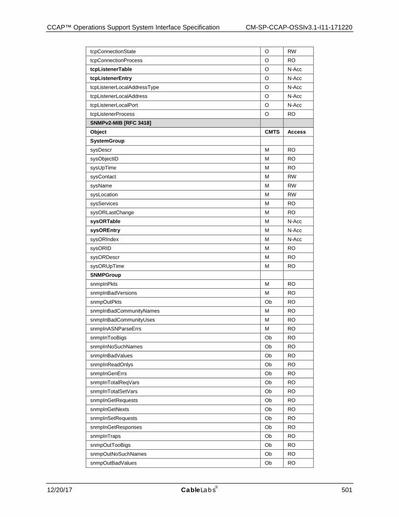
CCAP™ Operations Support System Interface Specification CM-SP-CCAP-OSSIv3.1-I11-171220
12/20/17 CableLabs 501
tcpConnectionState O RW
tcpConnectionProcess O RO
tcpListenerTable O N-Acc
tcpListenerEntry O N-Acc
tcpListenerLocalAddressType O N-Acc
tcpListenerLocalAddress O N-Acc
tcpListenerLocalPort O N-Acc
tcpListenerProcess O RO
SNMPv2-MIB [RFC 3418]
Object CMTS Access SystemGroup
sysDescr M RO
sysObjectID M RO
sysUpTime M RO
sysContact M RW
sysName M RW
sysLocation M RW
sysServices M RO
sysORLastChange M RO
sysORTable M N-Acc
sysOREntry M N-Acc
sysORIndex M N-Acc
sysORID M RO
sysORDescr M RO
sysORUpTime M RO
SNMPGroup
snmpInPkts M RO
snmpInBadVersions M RO
snmpOutPkts Ob RO
snmpInBadCommunityNames M RO
snmpInBadCommunityUses M RO
snmpInASNParseErrs M RO
snmpInTooBigs Ob RO
snmpInNoSuchNames Ob RO
snmpInBadValues Ob RO
snmpInReadOnlys Ob RO
snmpInGenErrs Ob RO
snmpInTotalReqVars Ob RO
snmpInTotalSetVars Ob RO
snmpInGetRequests Ob RO
snmpInGetNexts Ob RO
snmpInSetRequests Ob RO
snmpInGetResponses Ob RO
snmpInTraps Ob RO
snmpOutTooBigs Ob RO
snmpOutNoSuchNames Ob RO
snmpOutBadValues Ob RO
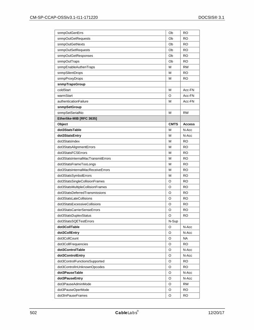
CM-SP-CCAP-OSSIv3.1-I11-171220 DOCSIS® 3.1
502 CableLabs 12/20/17
snmpOutGenErrs Ob RO
snmpOutGetRequests Ob RO
snmpOutGetNexts Ob RO
snmpOutSetRequests Ob RO
snmpOutGetResponses Ob RO
snmpOutTraps Ob RO
snmpEnableAuthenTraps M RW
snmpSilentDrops M RO
snmpProxyDrops M RO
snmpTrapsGroup
coldStart M Acc-FN
warmStart O Acc-FN
authenticationFailure M Acc-FN
snmpSetGroup
snmpSetSerialNo M RW
Etherlike-MIB [RFC 3635]
Object CMTS Access dot3StatsTable M N-Acc
dot3StatsEntry M N-Acc
dot3StatsIndex M RO
dot3StatsAlignmentErrors M RO
dot3StatsFCSErrors M RO
dot3StatsInternalMacTransmitErrors M RO
dot3StatsFrameTooLongs M RO
dot3StatsInternalMacReceiveErrors M RO
dot3StatsSymbolErrors M RO
dot3StatsSingleCollisionFrames O RO
dot3StatsMultipleCollisionFrames O RO
dot3StatsDeferredTransmissions O RO
dot3StatsLateCollisions O RO
dot3StatsExcessiveCollisions O RO
dot3StatsCarrierSenseErrors O RO
dot3StatsDuplexStatus O RO
dot3StatsSQETestErrors N-Sup
dot3CollTable O N-Acc
dot3CollEntry O N-Acc
dot3CollCount O NA
dot3CollFrequencies O RO
dot3ControlTable O N-Acc
dot3ControlEntry O N-Acc
dot3ControlFunctionsSupported O RO
dot3ControlInUnknownOpcodes O RO
dot3PauseTable O N-Acc
dot3PauseEntry O N-Acc
dot3PauseAdminMode O RW
dot3PauseOperMode O RO
dot3InPauseFrames O RO
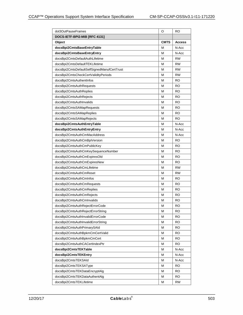
CCAP™ Operations Support System Interface Specification CM-SP-CCAP-OSSIv3.1-I11-171220
12/20/17 CableLabs 503
dot3OutPauseFrames O RO
DOCS-IETF-BPI2-MIB [RFC 4131]
Object CMTS Access docsBpi2CmtsBaseEntryTable M N-Acc
docsBpi2CmtsBaseEntryEntry M N-Acc
docsBpi2CmtsDefaultAuthLifetime M RW
docsBpi2CmtsDefaultTEKLifetime M RW
docsBpi2CmtsDefaultSelfSignedManufCertTrust M RW
docsBpi2CmtsCheckCertValidityPeriods M RW
docsBpi2CmtsAuthentInfos M RO
docsBpi2CmtsAuthRequests M RO
docsBpi2CmtsAuthReplies M RO
docsBpi2CmtsAuthRejects M RO
docsBpi2CmtsAuthInvalids M RO
docsBpi2CmtsSAMapRequests M RO
docsBpi2CmtsSAMapReplies M RO
docsBpi2CmtsSAMapRejects M RO
docsBpi2CmtsAuthEntryTable M N-Acc
docsBpi2CmtsAuthEntryEntry M N-Acc
docsBpi2CmtsAuthCmMacAddress M N-Acc
docsBpi2CmtsAuthCmBpiVersion M RO
docsBpi2CmtsAuthCmPublicKey M RO
docsBpi2CmtsAuthCmKeySequenceNumber M RO
docsBpi2CmtsAuthCmExpiresOld M RO
docsBpi2CmtsAuthCmExpiresNew M RO
docsBpi2CmtsAuthCmLifetime M RW
docsBpi2CmtsAuthCmReset M RW
docsBpi2CmtsAuthCmInfos M RO
docsBpi2CmtsAuthCmRequests M RO
docsBpi2CmtsAuthCmReplies M RO
docsBpi2CmtsAuthCmRejects M RO
docsBpi2CmtsAuthCmInvalids M RO
docsBpi2CmtsAuthRejectErrorCode M RO
docsBpi2CmtsAuthRejectErrorString M RO
docsBpi2CmtsAuthInvalidErrorCode M RO
docsBpi2CmtsAuthInvalidErrorString M RO
docsBpi2CmtsAuthPrimarySAId M RO
docsBpi2CmtsAuthBpkmCmCertValid M RO
docsBpi2CmtsAuthBpkmCmCert M RO
docsBpi2CmtsAuthCACertIndexPtr M RO
docsBpi2CmtsTEKTable M N-Acc
docsBpi2CmtsTEKEntry M N-Acc
docsBpi2CmtsTEKSAId M N-Acc
docsBpi2CmtsTEKSAType M RO
docsBpi2CmtsTEKDataEncryptAlg M RO
docsBpi2CmtsTEKDataAuthentAlg M RO
docsBpi2CmtsTEKLifetime M RW
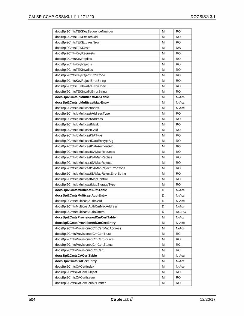
CM-SP-CCAP-OSSIv3.1-I11-171220 DOCSIS® 3.1
504 CableLabs 12/20/17
docsBpi2CmtsTEKKeySequenceNumber M RO
docsBpi2CmtsTEKExpiresOld M RO
docsBpi2CmtsTEKExpiresNew M RO
docsBpi2CmtsTEKReset M RW
docsBpi2CmtsKeyRequests M RO
docsBpi2CmtsKeyReplies M RO
docsBpi2CmtsKeyRejects M RO
docsBpi2CmtsTEKInvalids M RO
docsBpi2CmtsKeyRejectErrorCode M RO
docsBpi2CmtsKeyRejectErrorString M RO
docsBpi2CmtsTEKInvalidErrorCode M RO
docsBpi2CmtsTEKInvalidErrorString M RO
docsBpi2CmtsIpMulticastMapTable M N-Acc
docsBpi2CmtsIpMulticastMapEntry M N-Acc
docsBpi2CmtsIpMulticastIndex M N-Acc
docsBpi2CmtsIpMulticastAddressType M RO
docsBpi2CmtsIpMulticastAddress M RO
docsBpi2CmtsIpMulticastMask M RO
docsBpi2CmtsIpMulticastSAId M RO
docsBpi2CmtsIpMulticastSAType M RO
docsBpi2CmtsIpMulticastDataEncryptAlg M RO
docsBpi2CmtsIpMulticastDataAuthentAlg M RO
docsBpi2CmtsIpMulticastSAMapRequests M RO
docsBpi2CmtsIpMulticastSAMapReplies M RO
docsBpi2CmtsIpMulticastSAMapRejects M RO
docsBpi2CmtsIpMulticastSAMapRejectErrorCode M RO
docsBpi2CmtsIpMulticastSAMapRejectErrorString M RO
docsBpi2CmtsIpMulticastMapControl M RO
docsBpi2CmtsIpMulticastMapStorageType M RO
docsBpi2CmtsMulticastAuthTable D N-Acc
docsBpi2CmtsMulticastAuthEntry D N-Acc
docsBpi2CmtsMulticastAuthSAId D N-Acc
docsBpi2CmtsMulticastAuthCmMacAddress D N-Acc
docsBpi2CmtsMulticastAuthControl D RC/RO
docsBpi2CmtsProvisionedCmCertTable M N-Acc
docsBpi2CmtsProvisionedCmCertEntry M N-Acc
docsBpi2CmtsProvisionedCmCertMacAddress M N-Acc
docsBpi2CmtsProvisionedCmCertTrust M RC
docsBpi2CmtsProvisionedCmCertSource M RO
docsBpi2CmtsProvisionedCmCertStatus M RC
docsBpi2CmtsProvisionedCmCert M RC
docsBpi2CmtsCACertTable M N-Acc
docsBpi2CmtsCACertEntry M N-Acc
docsBpi2CmtsCACertIndex M N-Acc
docsBpi2CmtsCACertSubject M RO
docsBpi2CmtsCACertIssuer M RO
docsBpi2CmtsCACertSerialNumber M RO
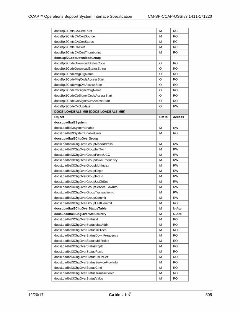
CCAP™ Operations Support System Interface Specification CM-SP-CCAP-OSSIv3.1-I11-171220
12/20/17 CableLabs 505
docsBpi2CmtsCACertTrust M RC
docsBpi2CmtsCACertSource M RO
docsBpi2CmtsCACertStatus M RC
docsBpi2CmtsCACert M RC
docsBpi2CmtsCACertThumbprint M RO
docsBpi2CodeDownloadGroup
docsBpi2CodeDownloadStatusCode O RO
docsBpi2CodeDownloadStatusString O RO
docsBpi2CodeMfgOrgName O RO
docsBpi2CodeMfgCodeAccessStart O RO
docsBpi2CodeMfgCvcAccessStart O RO
docsBpi2CodeCoSignerOrgName O RO
docsBpi2CodeCoSignerCodeAccessStart O RO
docsBpi2CodeCoSignerCvcAccessStart O RO
docsBpi2CodeCvcUpdate O RW
DOCS-LOADBAL3-MIB [DOCS-LOADBAL3-MIB]
Object CMTS Access docsLoadbal3System
docsLoadbal3SystemEnable M RW
docsLoadbal3SystemEnableError M RO
docsLoadbal3ChgOverGroup
docsLoadbal3ChgOverGroupMacAddress M RW
docsLoadbal3ChgOverGroupInitTech M RW
docsLoadbal3ChgOverGroupForceUCC M RW
docsLoadbal3ChgOverGroupdownFrequency M RW
docsLoadbal3ChgOverGroupMdIfIndex M RW
docsLoadbal3ChgOverGroupRcpId M RW
docsLoadbal3ChgOverGroupRccId M RW
docsLoadbal3ChgOverGroupUsChSet M RW
docsLoadbal3ChgOverGroupServiceFlowInfo M RW
docsLoadbal3ChgOverGroupTransactionId M RW
docsLoadbal3ChgOverGroupCommit M RW
docsLoadbal3ChgOverGroupLastCommit M RO
docsLoadbal3ChgOverStatusTable M N-Acc
docsLoadbal3ChgOverStatusEntry M N-Acc
docsLoadbal3ChgOverStatusId M RO
docsLoadbal3ChgOverStatusMacAddr M RO
docsLoadbal3ChgOverStatusInitTech M RO
docsLoadbal3ChgOverStatusDownFrequency M RO
docsLoadbal3ChgOverStatusMdIfIndex M RO
docsLoadbal3ChgOverStatusRcpId M RO
docsLoadbal3ChgOverStatusRccId M RO
docsLoadbal3ChgOverStatusUsChSet M RO
docsLoadbal3ChgOverStatusServiceFlowInfo M RO
docsLoadbal3ChgOverStatusCmd M RO
docsLoadbal3ChgOverStatusTransactionId M RO
docsLoadbal3ChgOverStatusValue M RO
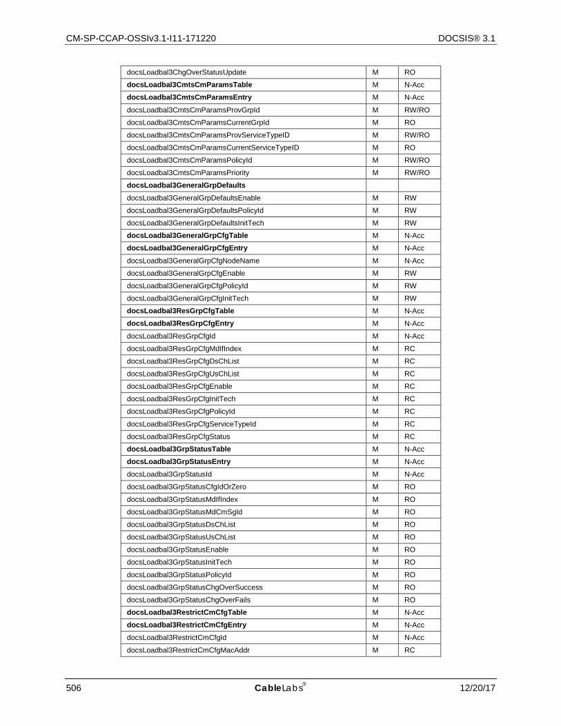
CM-SP-CCAP-OSSIv3.1-I11-171220 DOCSIS® 3.1
506 CableLabs 12/20/17
docsLoadbal3ChgOverStatusUpdate M RO
docsLoadbal3CmtsCmParamsTable M N-Acc
docsLoadbal3CmtsCmParamsEntry M N-Acc
docsLoadbal3CmtsCmParamsProvGrpId M RW/RO
docsLoadbal3CmtsCmParamsCurrentGrpId M RO
docsLoadbal3CmtsCmParamsProvServiceTypeID M RW/RO
docsLoadbal3CmtsCmParamsCurrentServiceTypeID M RO
docsLoadbal3CmtsCmParamsPolicyId M RW/RO
docsLoadbal3CmtsCmParamsPriority M RW/RO
docsLoadbal3GeneralGrpDefaults
docsLoadbal3GeneralGrpDefaultsEnable M RW
docsLoadbal3GeneralGrpDefaultsPolicyId M RW
docsLoadbal3GeneralGrpDefaultsInitTech M RW
docsLoadbal3GeneralGrpCfgTable M N-Acc
docsLoadbal3GeneralGrpCfgEntry M N-Acc
docsLoadbal3GeneralGrpCfgNodeName M N-Acc
docsLoadbal3GeneralGrpCfgEnable M RW
docsLoadbal3GeneralGrpCfgPolicyId M RW
docsLoadbal3GeneralGrpCfgInitTech M RW
docsLoadbal3ResGrpCfgTable M N-Acc
docsLoadbal3ResGrpCfgEntry M N-Acc
docsLoadbal3ResGrpCfgId M N-Acc
docsLoadbal3ResGrpCfgMdIfIndex M RC
docsLoadbal3ResGrpCfgDsChList M RC
docsLoadbal3ResGrpCfgUsChList M RC
docsLoadbal3ResGrpCfgEnable M RC
docsLoadbal3ResGrpCfgInitTech M RC
docsLoadbal3ResGrpCfgPolicyId M RC
docsLoadbal3ResGrpCfgServiceTypeId M RC
docsLoadbal3ResGrpCfgStatus M RC
docsLoadbal3GrpStatusTable M N-Acc
docsLoadbal3GrpStatusEntry M N-Acc
docsLoadbal3GrpStatusId M N-Acc
docsLoadbal3GrpStatusCfgIdOrZero M RO
docsLoadbal3GrpStatusMdIfIndex M RO
docsLoadbal3GrpStatusMdCmSgId M RO
docsLoadbal3GrpStatusDsChList M RO
docsLoadbal3GrpStatusUsChList M RO
docsLoadbal3GrpStatusEnable M RO
docsLoadbal3GrpStatusInitTech M RO
docsLoadbal3GrpStatusPolicyId M RO
docsLoadbal3GrpStatusChgOverSuccess M RO
docsLoadbal3GrpStatusChgOverFails M RO
docsLoadbal3RestrictCmCfgTable M N-Acc
docsLoadbal3RestrictCmCfgEntry M N-Acc
docsLoadbal3RestrictCmCfgId M N-Acc
docsLoadbal3RestrictCmCfgMacAddr M RC
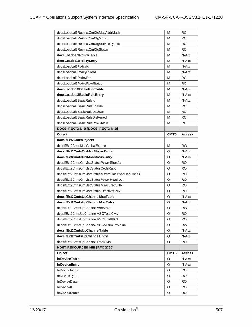
CCAP™ Operations Support System Interface Specification CM-SP-CCAP-OSSIv3.1-I11-171220
12/20/17 CableLabs 507
docsLoadbal3RestrictCmCfgMacAddrMask M RC
docsLoadbal3RestrictCmCfgGrpId M RC
docsLoadbal3RestrictCmCfgServiceTypeId M RC
docsLoadbal3RestrictCmCfgStatus M RC
docsLoadbal3PolicyTable M N-Acc
docsLoadbal3PolicyEntry M N-Acc
docsLoadbal3PolicyId M N-Acc
docsLoadbal3PolicyRuleId M N-Acc
docsLoadbal3PolicyPtr M RC
docsLoadbal3PolicyRowStatus M RC
docsLoadbal3BasicRuleTable M N-Acc
docsLoadbal3BasicRuleEntry M N-Acc
docsLoadbal3BasicRuleId M N-Acc
docsLoadbal3BasicRuleEnable M RC
docsLoadbal3BasicRuleDisStart M RC
docsLoadbal3BasicRuleDisPeriod M RC
docsLoadbal3BasicRuleRowStatus M RC
DOCS-IFEXT2-MIB [DOCS-IFEXT2-MIB]
Object CMTS Access docsIfExt2CmtsObjects
docsIfExt2CmtsMscGlobalEnable M RW
docsIfExt2CmtsCmMscStatusTable O N-Acc
docsIfExt2CmtsCmMscStatusEntry O N-Acc
docsIfExt2CmtsCmMscStatusPowerShortfall O RO
docsIfExt2CmtsCmMscStatusCodeRatio O RO
docsIfExt2CmtsCmMscStatusMaximumScheduledCodes O RO
docsIfExt2CmtsCmMscStatusPowerHeadroom O RO
docsIfExt2CmtsCmMscStatusMeasuredSNR O RO
docsIfExt2CmtsCmMscStatusEffectiveSNR O RO
docsIfExt2CmtsUpChannelMscTable O N-Acc
docsIfExt2CmtsUpChannelMscEntry O N-Acc
docsIfExt2CmtsUpChannelMscState O RW
docsIfExt2CmtsUpChannelMSCTotalCMs O RO
docsIfExt2CmtsUpChannelMSCLimitIUC1 O RO
docsIfExt2CmtsUpChannelMSCMinimumValue O RW
docsIfExt2CmtsUpChannelTable O N-Acc
docsIfExt2CmtsUpChannelEntry O N-Acc
docsIfExt2CmtsUpChannelTotalCMs O RO
HOST-RESOURCES-MIB [RFC 2790]
Object CMTS Access hrDeviceTable O N-Acc
hrDeviceEntry O N-Acc
hrDeviceIndex O RO
hrDeviceType O RO
hrDeviceDescr O RO
hrDeviceID O RO
hrDeviceStatus O RO
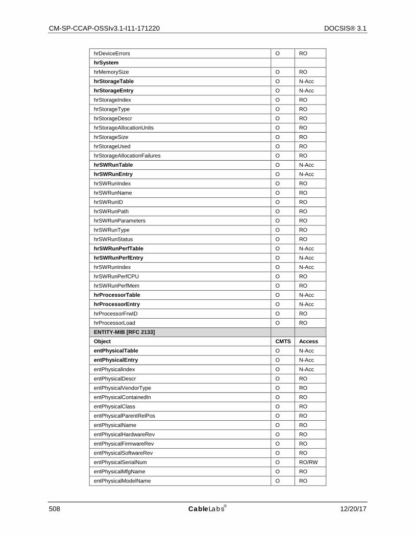
CM-SP-CCAP-OSSIv3.1-I11-171220 DOCSIS® 3.1
508 CableLabs 12/20/17
hrDeviceErrors O RO
hrSystem
hrMemorySize O RO
hrStorageTable O N-Acc
hrStorageEntry O N-Acc
hrStorageIndex O RO
hrStorageType O RO
hrStorageDescr O RO
hrStorageAllocationUnits O RO
hrStorageSize O RO
hrStorageUsed O RO
hrStorageAllocationFailures O RO
hrSWRunTable O N-Acc
hrSWRunEntry O N-Acc
hrSWRunIndex O RO
hrSWRunName O RO
hrSWRunID O RO
hrSWRunPath O RO
hrSWRunParameters O RO
hrSWRunType O RO
hrSWRunStatus O RO
hrSWRunPerfTable O N-Acc
hrSWRunPerfEntry O N-Acc
hrSWRunIndex O N-Acc
hrSWRunPerfCPU O RO
hrSWRunPerfMem O RO
hrProcessorTable O N-Acc
hrProcessorEntry O N-Acc
hrProcessorFrwID O RO
hrProcessorLoad O RO
ENTITY-MIB [RFC 2133]
Object CMTS Access entPhysicalTable O N-Acc
entPhysicalEntry O N-Acc
entPhysicalIndex O N-Acc
entPhysicalDescr O RO
entPhysicalVendorType O RO
entPhysicalContainedIn O RO
entPhysicalClass O RO
entPhysicalParentRelPos O RO
entPhysicalName O RO
entPhysicalHardwareRev O RO
entPhysicalFirmwareRev O RO
entPhysicalSoftwareRev O RO
entPhysicalSerialNum O RO/RW
entPhysicalMfgName O RO
entPhysicalModelName O RO
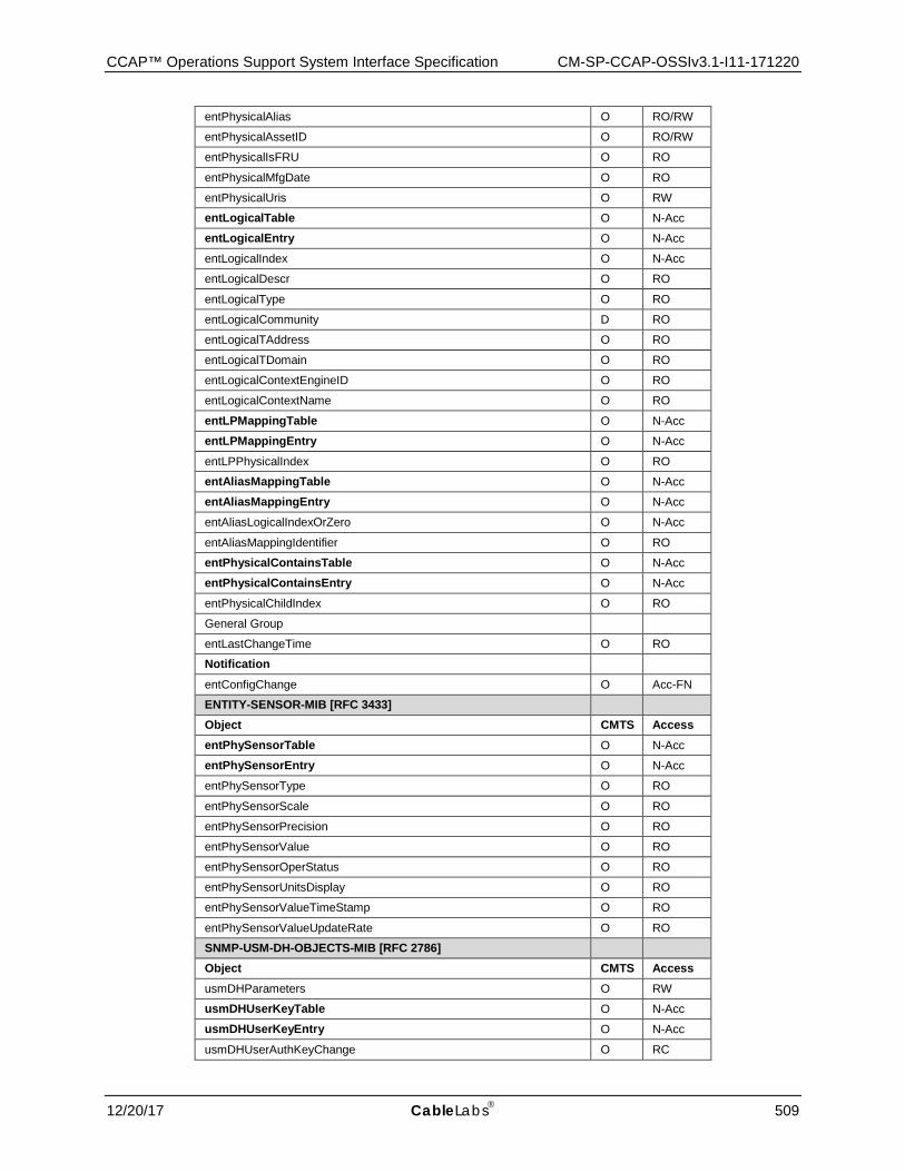
CCAP™ Operations Support System Interface Specification CM-SP-CCAP-OSSIv3.1-I11-171220
12/20/17 CableLabs 509
entPhysicalAlias O RO/RW
entPhysicalAssetID O RO/RW
entPhysicalIsFRU O RO
entPhysicalMfgDate O RO
entPhysicalUris O RW
entLogicalTable O N-Acc
entLogicalEntry O N-Acc
entLogicalIndex O N-Acc
entLogicalDescr O RO
entLogicalType O RO
entLogicalCommunity D RO
entLogicalTAddress O RO
entLogicalTDomain O RO
entLogicalContextEngineID O RO
entLogicalContextName O RO
entLPMappingTable O N-Acc
entLPMappingEntry O N-Acc
entLPPhysicalIndex O RO
entAliasMappingTable O N-Acc
entAliasMappingEntry O N-Acc
entAliasLogicalIndexOrZero O N-Acc
entAliasMappingIdentifier O RO
entPhysicalContainsTable O N-Acc
entPhysicalContainsEntry O N-Acc
entPhysicalChildIndex O RO
General Group
entLastChangeTime O RO
Notification
entConfigChange O Acc-FN
ENTITY-SENSOR-MIB [RFC 3433]
Object CMTS Access entPhySensorTable O N-Acc
entPhySensorEntry O N-Acc
entPhySensorType O RO
entPhySensorScale O RO
entPhySensorPrecision O RO
entPhySensorValue O RO
entPhySensorOperStatus O RO
entPhySensorUnitsDisplay O RO
entPhySensorValueTimeStamp O RO
entPhySensorValueUpdateRate O RO
SNMP-USM-DH-OBJECTS-MIB [RFC 2786]
Object CMTS Access usmDHParameters O RW
usmDHUserKeyTable O N-Acc
usmDHUserKeyEntry O N-Acc
usmDHUserAuthKeyChange O RC
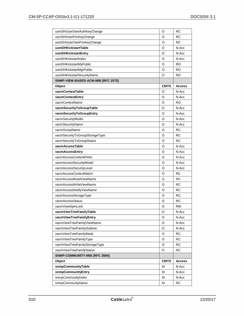
CM-SP-CCAP-OSSIv3.1-I11-171220 DOCSIS® 3.1
510 CableLabs 12/20/17
usmDHUserOwnAuthKeyChange O RC
usmDHUserPrivKeyChange O RC
usmDHUserOwnPrivKeyChange O RC
usmDHKickstartTable O N-Acc
usmDHKickstartEntry O N-Acc
usmDHKickstartIndex O N-Acc
usmDHKickstartMyPublic O RO
usmDHKickstartMgrPublic O RO
usmDHKickstartSecurityName O RO
SNMP-VIEW-BASED-ACM-MIB [RFC 2575]
Object CMTS Access vacmContextTable O N-Acc
vacmContextEntry O N-Acc
vacmContextName O RO
vacmSecurityToGroupTable O N-Acc
vacmSecurityToGroupEntry O N-Acc
vacmSecurityModel O N-Acc
vacmSecurityName O N-Acc
vacmGroupName O RC
vacmSecurityToGroupStorageType O RC
vacmSecurityToGroupStatus O RC
vacmAccessTable O N-Acc
vacmAccessEntry O N-Acc
vacmAccessContextPrefix O N-Acc
vacmAccessSecurityModel O N-Acc
vacmAccessSecurityLevel O N-Acc
vacmAccessContextMatch O RC
vacmAccessReadViewName O RC
vacmAccessWriteViewName O RC
vacmAccessNotifyViewName O RC
vacmAccessStorageType O RC
vacmAccessStatus O RC
vacmViewSpinLock O RW
vacmViewTreeFamilyTable O N-Acc
vacmViewTreeFamilyEntry O N-Acc
vacmViewTreeFamilyViewName O N-Acc
vacmViewTreeFamilySubtree O N-Acc
vacmViewTreeFamilyMask O RC
vacmViewTreeFamilyType O RC
vacmViewTreeFamilyStorageType O RC
vacmViewTreeFamilyStatus O RC
SNMP-COMMUNITY-MIB [RFC 3584]
Object CMTS Access snmpCommunityTable M N-Acc
snmpCommunityEntry M N-Acc
snmpCommunityIndex M N-Acc
snmpCommunityName M RC

CCAP™ Operations Support System Interface Specification CM-SP-CCAP-OSSIv3.1-I11-171220
12/20/17 CableLabs 511
snmpCommunitySecurityName M RC
snmpCommunityContextEngineID M RC
snmpCommunityContextName M RC
snmpCommunityTransportTag M RC
snmpCommunityStorageType M RC
snmpCommunityStatus M RC
snmpTargetAddrExtTable M N-Acc
snmpTargetAddrExtEntry M N-Acc
snmpTargetAddrTMask M RC
snmpTargetAddrMMS M RC
snmpTrapAddress O ACC-FN
snmpTrapCommunity O ACC-FN
SNMP-FRAMEWORK-MIB [RFC 3411]
Object CMTS Access snmpEngineGroup
snmpEngineID M RO
snmpEngineBoots M RO
snmpEngineTime M RO
snmpEngineMaxMessageSize M RO
SNMP-MPD-MIB [RFC 3412]
Object CMTS Access snmpMPDStats
snmpUnknownSecurityModels M RO
snmpInvalidMsgs M RO
snmpUnknownPDUHandlers M RO
SNMP Applications [RFC 2573]
Object CMTS Access snmpTargetSpinLock M RW
snmpTargetAddrTable M N-Acc
snmpTargetAddrEntry M N-Acc
snmpTargetAddrName M N-Acc
snmpTargetAddrTDomain M RC
snmpTargetAddrTAddress M RC
snmpTargetAddrTimeout M RC
snmpTargetAddrRetryCount M RC
snmpTargetAddrTagList M RC
snmpTargetAddrParams M RC
snmpTargetAddrStorageType M RC
snmpTargetAddrRowStatus M RC
snmpTargetParamsTable M N-Acc
snmpTargetParamsEntry M N-Acc
snmpTargetParamsName M N-Acc
snmpTargetParamsMPModel M RC
snmpTargetParamsSecurityModel M RC
snmpTargetParamsSecurityName M RC
snmpTargetParamsSecurityLevel M RC
snmpTargetParamsStorageType M RC
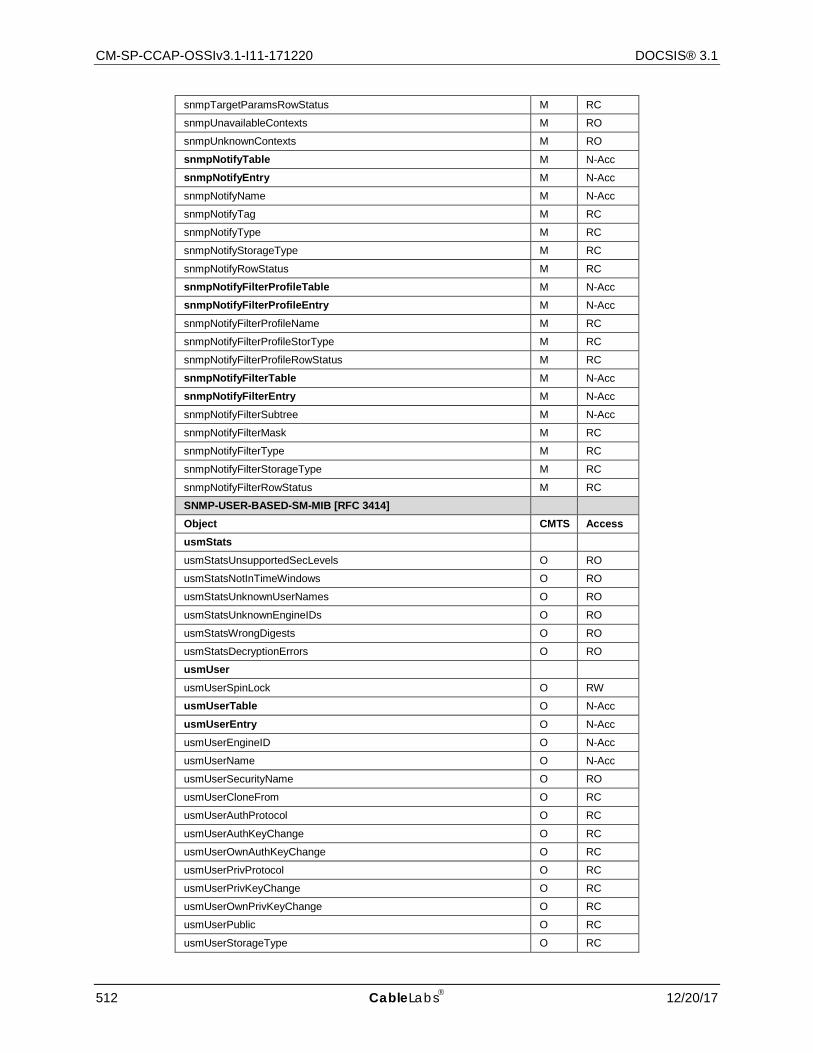
CM-SP-CCAP-OSSIv3.1-I11-171220 DOCSIS® 3.1
512 CableLabs 12/20/17
snmpTargetParamsRowStatus M RC
snmpUnavailableContexts M RO
snmpUnknownContexts M RO
snmpNotifyTable M N-Acc
snmpNotifyEntry M N-Acc
snmpNotifyName M N-Acc
snmpNotifyTag M RC
snmpNotifyType M RC
snmpNotifyStorageType M RC
snmpNotifyRowStatus M RC
snmpNotifyFilterProfileTable M N-Acc
snmpNotifyFilterProfileEntry M N-Acc
snmpNotifyFilterProfileName M RC
snmpNotifyFilterProfileStorType M RC
snmpNotifyFilterProfileRowStatus M RC
snmpNotifyFilterTable M N-Acc
snmpNotifyFilterEntry M N-Acc
snmpNotifyFilterSubtree M N-Acc
snmpNotifyFilterMask M RC
snmpNotifyFilterType M RC
snmpNotifyFilterStorageType M RC
snmpNotifyFilterRowStatus M RC
SNMP-USER-BASED-SM-MIB [RFC 3414]
Object CMTS Access usmStats
usmStatsUnsupportedSecLevels O RO
usmStatsNotInTimeWindows O RO
usmStatsUnknownUserNames O RO
usmStatsUnknownEngineIDs O RO
usmStatsWrongDigests O RO
usmStatsDecryptionErrors O RO
usmUser
usmUserSpinLock O RW
usmUserTable O N-Acc
usmUserEntry O N-Acc
usmUserEngineID O N-Acc
usmUserName O N-Acc
usmUserSecurityName O RO
usmUserCloneFrom O RC
usmUserAuthProtocol O RC
usmUserAuthKeyChange O RC
usmUserOwnAuthKeyChange O RC
usmUserPrivProtocol O RC
usmUserPrivKeyChange O RC
usmUserOwnPrivKeyChange O RC
usmUserPublic O RC
usmUserStorageType O RC
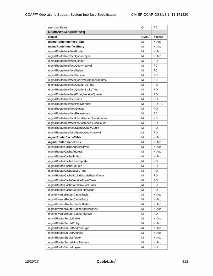
CCAP™ Operations Support System Interface Specification CM-SP-CCAP-OSSIv3.1-I11-171220
12/20/17 CableLabs 513
usmUserStatus O RC
MGMD-STD-MIB [RFC 5519]
Object CMTS Access mgmdRouterInterfaceTable M N-Acc
mgmdRouterInterfaceEntry M N-Acc
mgmdRouterInterfaceIfIndex M N-Acc
mgmdRouterInterfaceQuerierType M N-Acc
mgmdRouterInterfaceQuerier M RO
mgmdRouterInterfaceQueryInterval M RC
mgmdRouterInterfaceStatus M RC
mgmdRouterInterfaceVersion M RC
mgmdRouterInterfaceQueryMaxResponseTime M RC
mgmdRouterInterfaceQuerierUpTime M RO
mgmdRouterInterfaceQuerierExpiryTime M RO
mgmdRouterInterfaceWrongVersionQueries M RO
mgmdRouterInterfaceJoins M RO
mgmdRouterInterfaceProxyIfIndex M RO/RC
mgmdRouterInterfaceGroups M RO
mgmdRouterInterfaceRobustness M RC
mgmdRouterInterfaceLastMemberQueryInterval M RC
mgmdRouterInterfaceLastMemberQueryCount M RO
mgmdRouterInterfaceStartupQueryCount M RO
mgmdRouterInterfaceStartupQueryInterval M RO
mgmdRouterCacheTable M N-Acc
mgmdRouterCacheEntry M N-Acc
mgmdRouterCacheAddressType M N-Acc
mgmdRouterCacheAddress M N-Acc
mgmdRouterCacheIfIndex M N-Acc
mgmdRouterCacheLastReporter M RO
mgmdRouterCacheUpTime M RO
mgmdRouterCacheExpiryTime M RO
mgmdRouterCacheExcludeModeExpiryTimer M RO
mgmdRouterCacheVersion1HostTimer M RO
mgmdRouterCacheVersion2HostTimer M RO
mgmdRouterCacheSourceFilterMode M RO
mgmdInverseRouterCacheTable M N-Acc
mgmdInverseRouterCacheEntry M N-Acc
mgmdInverseRouterCacheIfIndex M N-Acc
mgmdInverseRouterCacheAddressType M N-Acc
mgmdInverseRouterCacheAddress M RO
mgmdRouterSrcListTable M N-Acc
mgmdRouterSrcListEntry M N-Acc
mgmdRouterSrcListAddressType M N-Acc
mgmdRouterSrcListAddress M N-Acc
mgmdRouterSrcListIfIndex M N-Acc
mgmdRouterSrcListHostAddress M N-Acc
mgmdRouterSrcListExpire M RO
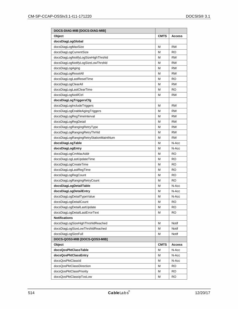
CM-SP-CCAP-OSSIv3.1-I11-171220 DOCSIS® 3.1
514 CableLabs 12/20/17
DOCS-DIAG-MIB [DOCS-DIAG-MIB]
Object CMTS Access docsDiagLogGlobal
docsDiagLogMaxSize M RW
docsDiagLogCurrentSize M RO
docsDiagLogNotifyLogSizeHighThrshld M RW
docsDiagLogNotifyLogSizeLowThrshld M RW
docsDiagLogAging M RW
docsDiagLogResetAll M RW
docsDiagLogLastResetTime M RO
docsDiagLogClearAll M RW
docsDiagLogLastClearTime M RO
docsDiagLogNotifCtrl M RW
docsDiagLogTriggersCfg
docsDiagLogIncludeTriggers M RW
docsDiagLogEnableAgingTriggers M RW
docsDiagLogRegTimeInterval M RW
docsDiagLogRegDetail M RW
docsDiagLogRangingRetryType M RW
docsDiagLogRangingRetryThrhld M RW
docsDiagLogRangingRetryStationMaintNum M RW
docsDiagLogTable M N-Acc
docsDiagLogEntry M N-Acc
docsDiagLogCmMacAddr M RO
docsDiagLogLastUpdateTime M RO
docsDiagLogCreateTime M RO
docsDiagLogLastRegTime M RO
docsDiagLogRegCount M RO
docsDiagLogRangingRetryCount M RO
docsDiagLogDetailTable M N-Acc
docsDiagLogDetailEntry M N-Acc
docsDiagLogDetailTypeValue M N-Acc
docsDiagLogDetailCount M RO
docsDiagLogDetailLastUpdate M RO
docsDiagLogDetailLastErrorText M RO
Notifications
docsDiagLogSizeHighThrshldReached M Notif
docsDiagLogSizeLowThrshldReached M Notif
docsDiagLogSizeFull M Notif
DOCS-QOS3-MIB [DOCS-QOS3-MIB]
Object CMTS Access docsQosPktClassTable M N-Acc
docsQosPktClassEntry M N-Acc
docsQosPktClassId M N-Acc
docsQosPktClassDirection M RO
docsQosPktClassPriority M RO
docsQosPktClassIpTosLow M RO

CCAP™ Operations Support System Interface Specification CM-SP-CCAP-OSSIv3.1-I11-171220
12/20/17 CableLabs 515
docsQosPktClassIpTosHigh M RO
docsQosPktClassIpTosMask M RO
docsQosPktClassIpProtocol M RO
docsQosPktClassIpSourceAddr M RO
docsQosPktClassIpSourceMask M RO
docsQosPktClassIpDestAddr M RO
docsQosPktClassIpDestMask M RO
docsQosPktClassSourcePortStart M RO
docsQosPktClassSourcePortEnd M RO
docsQosPktClassDestPortStart M RO
docsQosPktClassDestPortEnd M RO
docsQosPktClassDestMacAddr M RO
docsQosPktClassDestMacMask M RO
docsQosPktClassSourceMacAddr M RO
docsQosPktClassEnetProtocolType M RO
docsQosPktClassEnetProtocol M RO
docsQosPktClassUserPriLow M RO
docsQosPktClassUserPriHigh M RO
docsQosPktClassVlanId M RO
docsQosPktClassState M RO
docsQosPktClassPkts M RO
docsQosPktClassBitMap M RO
docsQosPktClassIpAddrType M RO
docsQosPktClassFlowLabel M RO
docsQosPktClassIcmpTypeHigh M RO
docsQosPktClassIcmpTypeLow M RO
docsQosPktClassCmInterfaceMask M RO
docsQosParamSetTable M N-Acc
docsQosParamSetEntry M N-Acc
docsQosParamSetServiceClassName M RO
docsQosParamSetPriority M RO
docsQosParamSetMaxTrafficRate M RO
docsQosParamSetMaxTrafficBurst M RO
docsQosParamSetMinReservedRate M RO
docsQosParamSetMinReservedPkt M RO
docsQosParamSetActiveTimeout M RO
docsQosParamSetAdmittedTimeout M RO
docsQosParamSetMaxConcatBurst M RO
docsQosParamSetSchedulingType M RO
docsQosParamSetNomPollInterval M RO
docsQosParamSetTolPollJitter M RO
docsQosParamSetUnsolicitGrantSize M RO
docsQosParamSetNomGrantInterval M RO
docsQosParamSetTolGrantJitter M RO
docsQosParamSetGrantsPerInterval M RO
docsQosParamSetTosAndMask M RO
docsQosParamSetTosOrMask M RO
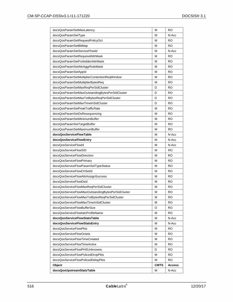
CM-SP-CCAP-OSSIv3.1-I11-171220 DOCSIS® 3.1
516 CableLabs 12/20/17
docsQosParamSetMaxLatency M RO
docsQosParamSetType M N-Acc
docsQosParamSetRequestPolicyOct M RO
docsQosParamSetBitMap M RO
docsQosParamSetServiceFlowId M N-Acc
docsQosParamSetRequiredAttrMask M RO
docsQosParamSetForbiddenAttrMask M RO
docsQosParamSetAttrAggrRuleMask M RO
docsQosParamSetAppId M RO
docsQosParamSetMultiplierContentionReqWindow M RO
docsQosParamSetMultiplierBytesReq M RO
docsQosParamSetMaxReqPerSidCluster D RO
docsQosParamSetMaxOutstandingBytesPerSidCluster D RO
docsQosParamSetMaxTotBytesReqPerSidCluster D RO
docsQosParamSetMaxTimeInSidCluster D RO
docsQosParamSetPeakTrafficRate M RO
docsQosParamSetDsResequencing M RO
docsQosParamSetMinimumBuffer M RO
docsQosParamSetTargetBuffer M RO
docsQosParamSetMaximumBuffer M RO
docsQosServiceFlowTable M N-Acc
docsQosServiceFlowEntry M N-Acc
docsQosServiceFlowId M N-Acc
docsQosServiceFlowSID M RO
docsQosServiceFlowDirection M RO
docsQosServiceFlowPrimary M RO
docsQosServiceFlowParamSetTypeStatus M RO
docsQosServiceFlowChSetId M RO
docsQosServiceFlowAttrAssignSuccess M RO
docsQosServiceFlowDsid M RO
docsQosServiceFlowMaxReqPerSidCluster M RO
docsQosServiceFlowMaxOutstandingBytesPerSidCluster M RO
docsQosServiceFlowMaxTotBytesReqPerSidCluster M RO
docsQosServiceFlowMaxTimeInSidCluster M RO
docsQosServiceFlowBufferSize O RO
docsQosServiceFlowIatcProfileName M RO
docsQosServiceFlowStatsTable M N-Acc
docsQosServiceFlowStatsEntry M N-Acc
docsQosServiceFlowPkts M RO
docsQosServiceFlowOctets M RO
docsQosServiceFlowTimeCreated M RO
docsQosServiceFlowTimeActive M RO
docsQosServiceFlowPHSUnknowns D RO
docsQosServiceFlowPolicedDropPkts M RO
docsQosServiceFlowPolicedDelayPkts M RO
Object CMTS Access docsQosUpstreamStatsTable M N-Acc
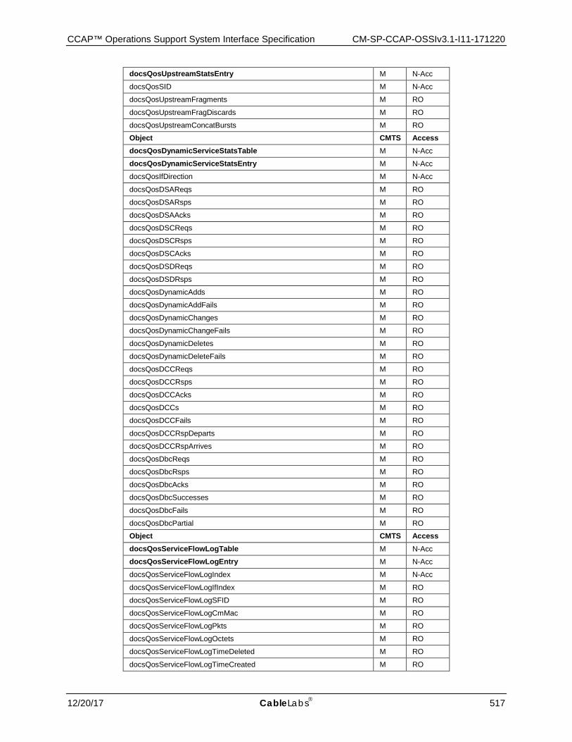
CCAP™ Operations Support System Interface Specification CM-SP-CCAP-OSSIv3.1-I11-171220
12/20/17 CableLabs 517
docsQosUpstreamStatsEntry M N-Acc
docsQosSID M N-Acc
docsQosUpstreamFragments M RO
docsQosUpstreamFragDiscards M RO
docsQosUpstreamConcatBursts M RO
Object CMTS Access docsQosDynamicServiceStatsTable M N-Acc
docsQosDynamicServiceStatsEntry M N-Acc
docsQosIfDirection M N-Acc
docsQosDSAReqs M RO
docsQosDSARsps M RO
docsQosDSAAcks M RO
docsQosDSCReqs M RO
docsQosDSCRsps M RO
docsQosDSCAcks M RO
docsQosDSDReqs M RO
docsQosDSDRsps M RO
docsQosDynamicAdds M RO
docsQosDynamicAddFails M RO
docsQosDynamicChanges M RO
docsQosDynamicChangeFails M RO
docsQosDynamicDeletes M RO
docsQosDynamicDeleteFails M RO
docsQosDCCReqs M RO
docsQosDCCRsps M RO
docsQosDCCAcks M RO
docsQosDCCs M RO
docsQosDCCFails M RO
docsQosDCCRspDeparts M RO
docsQosDCCRspArrives M RO
docsQosDbcReqs M RO
docsQosDbcRsps M RO
docsQosDbcAcks M RO
docsQosDbcSuccesses M RO
docsQosDbcFails M RO
docsQosDbcPartial M RO
Object CMTS Access docsQosServiceFlowLogTable M N-Acc
docsQosServiceFlowLogEntry M N-Acc
docsQosServiceFlowLogIndex M N-Acc
docsQosServiceFlowLogIfIndex M RO
docsQosServiceFlowLogSFID M RO
docsQosServiceFlowLogCmMac M RO
docsQosServiceFlowLogPkts M RO
docsQosServiceFlowLogOctets M RO
docsQosServiceFlowLogTimeDeleted M RO
docsQosServiceFlowLogTimeCreated M RO
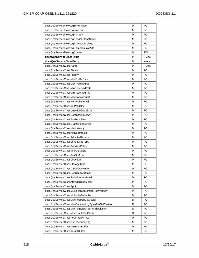
CM-SP-CCAP-OSSIv3.1-I11-171220 DOCSIS® 3.1
518 CableLabs 12/20/17
docsQosServiceFlowLogTimeActive M RO
docsQosServiceFlowLogDirection M RO
docsQosServiceFlowLogPrimary M RO
docsQosServiceFlowLogServiceClassName M RO
docsQosServiceFlowLogPolicedDropPkts M RO
docsQosServiceFlowLogPolicedDelayPkts M RO
docsQosServiceFlowLogControl M RW
docsQosServiceClassTable M N-Acc
docsQosServiceClassEntry M N-Acc
docsQosServiceClassName M N-Acc
docsQosServiceClassStatus M RC
docsQosServiceClassPriority M RC
docsQosServiceClassMaxTrafficRate M RC
docsQosServiceClassMaxTrafficBurst M RC
docsQosServiceClassMinReservedRate M RC
docsQosServiceClassMinReservedPkt M RC
docsQosServiceClassMaxConcatBurst M RC
docsQosServiceClassNomPollInterval M RC
docsQosServiceClassTolPollJitter M RC
docsQosServiceClassUnsolicitGrantSize M RC
docsQosServiceClassNomGrantInterval M RC
docsQosServiceClassTolGrantJitter M RC
docsQosServiceClassGrantsPerInterval M RC
docsQosServiceClassMaxLatency M RC
docsQosServiceClassActiveTimeout M RC
docsQosServiceClassAdmittedTimeout M RC
docsQosServiceClassSchedulingType M RC
docsQosServiceClassRequestPolicy M RC
docsQosServiceClassTosAndMask M RC
docsQosServiceClassTosOrMask M RC
docsQosServiceClassDirection M RC
docsQosServiceClassStorageType M RC
docsQosServiceClassDSCPOverwrite M RC
docsQosServiceClassRequiredAttrMask M RC
docsQosServiceClassForbiddenAttrMask M RC
docsQosServiceClassAttrAggrRuleMask M RC
docsQosServiceClassAppId M RC
docsQosServiceClassMultiplierContentionReqWindow M RC
docsQosServiceClassMultiplierBytesReq M RC
docsQosServiceClassMaxReqPerSidCluster D RC
docsQosServiceClassMaxOutstandingBytesPerSidCluster D RC
docsQosServiceClassMaxTotBytesReqPerSidCluster D RC
docsQosServiceClassMaxTimeInSidCluster D RC
docsQosServiceClassPeakTrafficRate M RC
docsQosServiceClassDsResequencing M RC
docsQosServiceClassMinimumBuffer M RC
docsQosServiceClassTargetBuffer M RC

CCAP™ Operations Support System Interface Specification CM-SP-CCAP-OSSIv3.1-I11-171220
12/20/17 CableLabs 519
docsQosServiceClassMaximumBuffer M RC
Object CMTS Access docsQosPHSTable D N-Acc
docsQosPHSEntry D N-Acc
docsQosPHSField D RO
docsQosPHSMask D RO
docsQosPHSSize D RO
docsQosPHSVerify D RO
docsQosPHSIndex D RO
Object CMTS Access docsQosCmtsMacToSrvFlowTable M N-Acc
docsQosCmtsMacToSrvFlowEntry M N-Acc
docsQosCmtsCmMac M N-Acc
docsQosCmtsServiceFlowId M N-Acc
docsQosCmtsIfIndex M RO
Object CMTS Access docsQosServiceFlowSidClusterTable M N-Acc
docsQosServiceFlowSidClusterEntry M N-Acc
docsQosServiceFlowSidClusterId M N-Acc
docsQosServiceFlowSidClusterUcid M N-Acc
docsQosServiceFlowSidClusterSid M RO
Object CMTS Access docsQosGrpServiceFlowTable M N-Acc
docsQosGrpServiceFlowEntry M N-Acc
docsQosGrpServiceFlowIsDef M RO
docsQosGrpServiceFlowQosConfigId M RO
docsQosGrpServiceFlowNumSess M RO
docsQosGrpServiceFlowSrcAddr M RO
docsQosGrpServiceFlowGrpAddr M RO
docsQosGrpPktClassTable M N-Acc
docsQosGrpPktClassEntry M N-Acc
docsQosGrpPktClassGrpConfigId M RO
docsQosUpChCounterExtTable M N-Acc
docsQosUpChCounterExtEntry M N-Acc
docsQosUpChCounterExtSgmtValids M RO
docsQosUpChCounterExtSgmtDiscards M RO
docsQosServiceFlowCcfStatsTable M N-Acc
docsQosServiceFlowCcfStatsEntry M N-Acc
docsQosServiceFlowCcfStatsSgmtValids M RO
docsQosServiceFlowCcfStatsSgmtLost M RO
Object CMTS Access docsQosCmtsDsidTable M N-Acc
docsQosCmtsDsidEntry M N-Acc
docsQosCmtsDsidDsid M N-Acc
docsQosCmtsDsidUsage M RO
docsQosCmtsDsidDsChSet M RO
docsQosCmtsDsidReseqWaitTime M RO
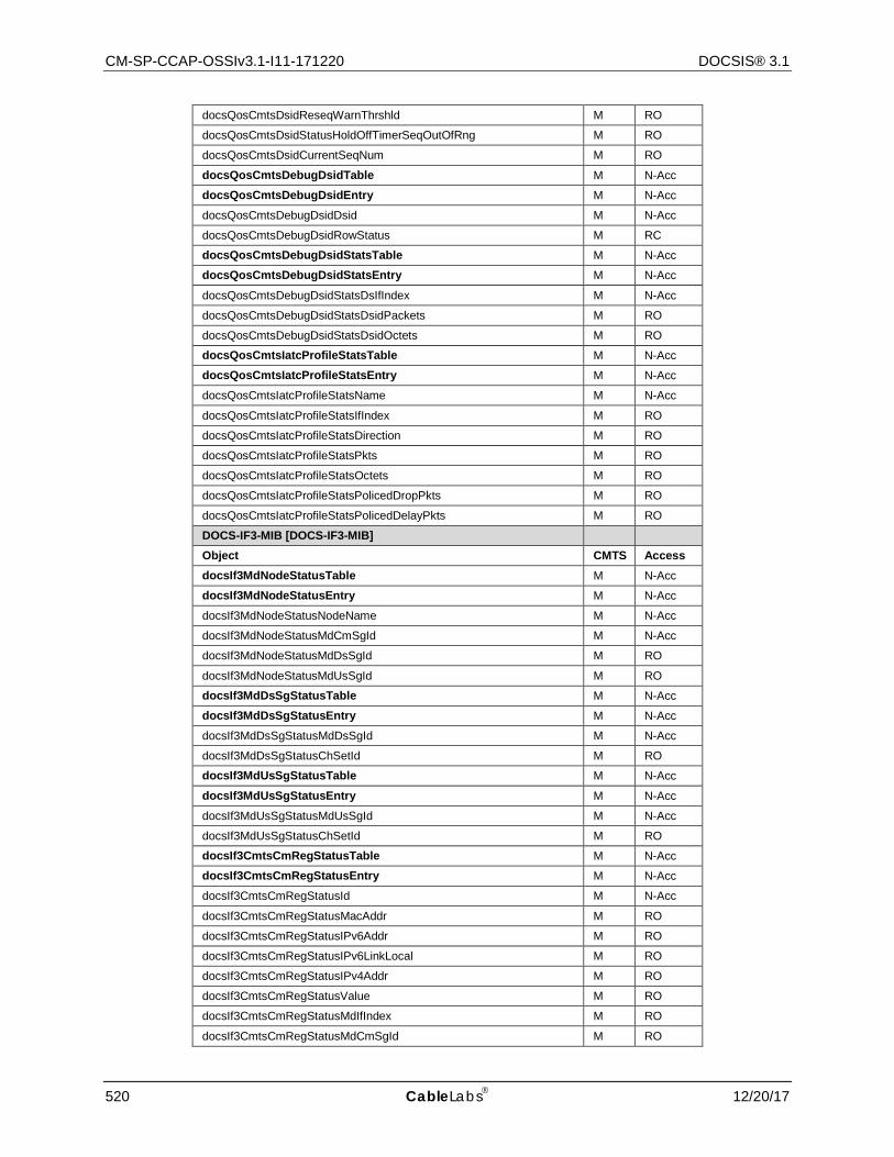
CM-SP-CCAP-OSSIv3.1-I11-171220 DOCSIS® 3.1
520 CableLabs 12/20/17
docsQosCmtsDsidReseqWarnThrshld M RO
docsQosCmtsDsidStatusHoldOffTimerSeqOutOfRng M RO
docsQosCmtsDsidCurrentSeqNum M RO
docsQosCmtsDebugDsidTable M N-Acc
docsQosCmtsDebugDsidEntry M N-Acc
docsQosCmtsDebugDsidDsid M N-Acc
docsQosCmtsDebugDsidRowStatus M RC
docsQosCmtsDebugDsidStatsTable M N-Acc
docsQosCmtsDebugDsidStatsEntry M N-Acc
docsQosCmtsDebugDsidStatsDsIfIndex M N-Acc
docsQosCmtsDebugDsidStatsDsidPackets M RO
docsQosCmtsDebugDsidStatsDsidOctets M RO
docsQosCmtsIatcProfileStatsTable M N-Acc
docsQosCmtsIatcProfileStatsEntry M N-Acc
docsQosCmtsIatcProfileStatsName M N-Acc
docsQosCmtsIatcProfileStatsIfIndex M RO
docsQosCmtsIatcProfileStatsDirection M RO
docsQosCmtsIatcProfileStatsPkts M RO
docsQosCmtsIatcProfileStatsOctets M RO
docsQosCmtsIatcProfileStatsPolicedDropPkts M RO
docsQosCmtsIatcProfileStatsPolicedDelayPkts M RO
DOCS-IF3-MIB [DOCS-IF3-MIB]
Object CMTS Access docsIf3MdNodeStatusTable M N-Acc
docsIf3MdNodeStatusEntry M N-Acc
docsIf3MdNodeStatusNodeName M N-Acc
docsIf3MdNodeStatusMdCmSgId M N-Acc
docsIf3MdNodeStatusMdDsSgId M RO
docsIf3MdNodeStatusMdUsSgId M RO
docsIf3MdDsSgStatusTable M N-Acc
docsIf3MdDsSgStatusEntry M N-Acc
docsIf3MdDsSgStatusMdDsSgId M N-Acc
docsIf3MdDsSgStatusChSetId M RO
docsIf3MdUsSgStatusTable M N-Acc
docsIf3MdUsSgStatusEntry M N-Acc
docsIf3MdUsSgStatusMdUsSgId M N-Acc
docsIf3MdUsSgStatusChSetId M RO
docsIf3CmtsCmRegStatusTable M N-Acc
docsIf3CmtsCmRegStatusEntry M N-Acc
docsIf3CmtsCmRegStatusId M N-Acc
docsIf3CmtsCmRegStatusMacAddr M RO
docsIf3CmtsCmRegStatusIPv6Addr M RO
docsIf3CmtsCmRegStatusIPv6LinkLocal M RO
docsIf3CmtsCmRegStatusIPv4Addr M RO
docsIf3CmtsCmRegStatusValue M RO
docsIf3CmtsCmRegStatusMdIfIndex M RO
docsIf3CmtsCmRegStatusMdCmSgId M RO
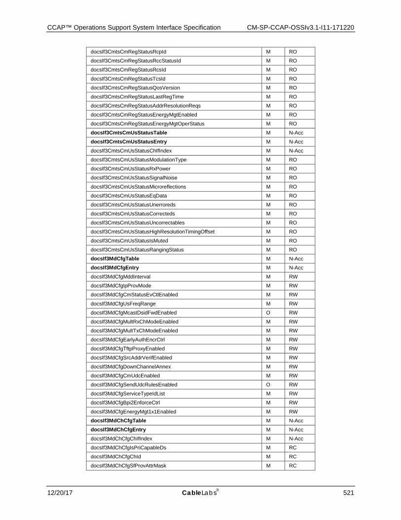
CCAP™ Operations Support System Interface Specification CM-SP-CCAP-OSSIv3.1-I11-171220
12/20/17 CableLabs 521
docsIf3CmtsCmRegStatusRcpId M RO
docsIf3CmtsCmRegStatusRccStatusId M RO
docsIf3CmtsCmRegStatusRcsId M RO
docsIf3CmtsCmRegStatusTcsId M RO
docsIf3CmtsCmRegStatusQosVersion M RO
docsIf3CmtsCmRegStatusLastRegTime M RO
docsIf3CmtsCmRegStatusAddrResolutionReqs M RO
docsIf3CmtsCmRegStatusEnergyMgtEnabled M RO
docsIf3CmtsCmRegStatusEnergyMgtOperStatus M RO
docsIf3CmtsCmUsStatusTable M N-Acc
docsIf3CmtsCmUsStatusEntry M N-Acc
docsIf3CmtsCmUsStatusChIfIndex M N-Acc
docsIf3CmtsCmUsStatusModulationType M RO
docsIf3CmtsCmUsStatusRxPower M RO
docsIf3CmtsCmUsStatusSignalNoise M RO
docsIf3CmtsCmUsStatusMicroreflections M RO
docsIf3CmtsCmUsStatusEqData M RO
docsIf3CmtsCmUsStatusUnerroreds M RO
docsIf3CmtsCmUsStatusCorrecteds M RO
docsIf3CmtsCmUsStatusUncorrectables M RO
docsIf3CmtsCmUsStatusHighResolutionTimingOffset M RO
docsIf3CmtsCmUsStatusIsMuted M RO
docsIf3CmtsCmUsStatusRangingStatus M RO
docsIf3MdCfgTable M N-Acc
docsIf3MdCfgEntry M N-Acc
docsIf3MdCfgMddInterval M RW
docsIf3MdCfgIpProvMode M RW
docsIf3MdCfgCmStatusEvCtlEnabled M RW
docsIf3MdCfgUsFreqRange M RW
docsIf3MdCfgMcastDsidFwdEnabled O RW
docsIf3MdCfgMultRxChModeEnabled M RW
docsIf3MdCfgMultTxChModeEnabled M RW
docsIf3MdCfgEarlyAuthEncrCtrl M RW
docsIf3MdCfgTftpProxyEnabled M RW
docsIf3MdCfgSrcAddrVerifEnabled M RW
docsIf3MdCfgDownChannelAnnex M RW
docsIf3MdCfgCmUdcEnabled M RW
docsIf3MdCfgSendUdcRulesEnabled O RW
docsIf3MdCfgServiceTypeIdList M RW
docsIf3MdCfgBpi2EnforceCtrl M RW
docsIf3MdCfgEnergyMgt1x1Enabled M RW
docsIf3MdChCfgTable M N-Acc
docsIf3MdChCfgEntry M N-Acc
docsIf3MdChCfgChIfIndex M N-Acc
docsIf3MdChCfgIsPriCapableDs M RC
docsIf3MdChCfgChId M RC
docsIf3MdChCfgSfProvAttrMask M RC
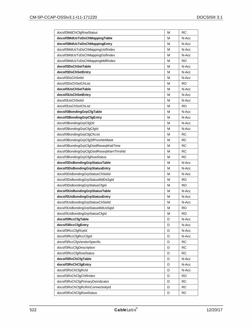
CM-SP-CCAP-OSSIv3.1-I11-171220 DOCSIS® 3.1
522 CableLabs 12/20/17
docsIf3MdChCfgRowStatus M RC
docsIf3MdUsToDsChMappingTable M N-Acc
docsIf3MdUsToDsChMappingEntry M N-Acc
docsIf3MdUsToDsChMappingUsIfIndex M N-Acc
docsIf3MdUsToDsChMappingDsIfIndex M N-Acc
docsIf3MdUsToDsChMappingMdIfIndex M RO
docsIf3DsChSetTable M N-Acc
docsIf3DsChSetEntry M N-Acc
docsIf3DsChSetId M N-Acc
docsIf3DsChSetChList M RO
docsIf3UsChSetTable M N-Acc
docsIf3UsChSetEntry M N-Acc
docsIf3UsChSetId M N-Acc
docsIf3UsChSetChList M RO
docsIf3BondingGrpCfgTable M N-Acc
docsIf3BondingGrpCfgEntry M N-Acc
docsIf3BondingGrpCfgDir M N-Acc
docsIf3BondingGrpCfgCfgId M N-Acc
docsIf3BondingGrpCfgChList M RC
docsIf3BondingGrpCfgSfProvAttrMask M RC
docsIf3BondingGrpCfgDsidReseqWaitTime M RC
docsIf3BondingGrpCfgDsidReseqWarnThrshld M RC
docsIf3BondingGrpCfgRowStatus M RC
docsIf3DsBondingGrpStatusTable M N-Acc
docsIf3DsBondingGrpStatusEntry M N-Acc
docsIf3DsBondingGrpStatusChSetId M N-Acc
docsIf3DsBondingGrpStatusMdDsSgId M RO
docsIf3DsBondingGrpStatusCfgId M RO
docsIf3UsBondingGrpStatusTable M N-Acc
docsIf3UsBondingGrpStatusEntry M N-Acc
docsIf3UsBondingGrpStatusChSetId M N-Acc
docsIf3UsBondingGrpStatusMdUsSgId M RO
docsIf3UsBondingGrpStatusCfgId M RO
docsIf3RccCfgTable D N-Acc
docsIf3RccCfgEntry D N-Acc
docsIf3RccCfgRcpId D N-Acc
docsIf3RccCfgRccCfgId D N-Acc
docsIf3RccCfgVendorSpecific D RC
docsIf3RccCfgDescription D RC
docsIf3RccCfgRowStatus D RC
docsIf3RxChCfgTable D N-Acc
docsIf3RxChCfgEntry D N-Acc
docsIf3RxChCfgRcId D N-Acc
docsIf3RxChCfgChIfIndex D RO
docsIf3RxChCfgPrimaryDsIndicator D RC
docsIf3RxChCfgRcRmConnectivityId D RC
docsIf3RxChCfgRowStatus D RC
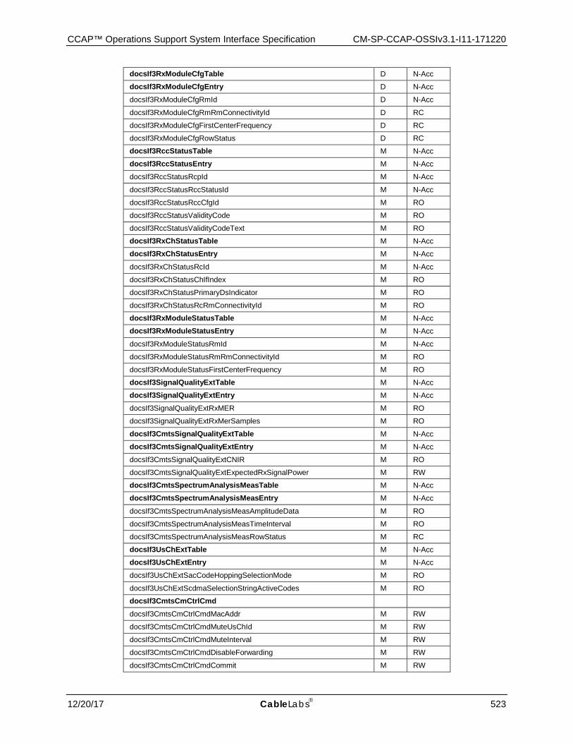
CCAP™ Operations Support System Interface Specification CM-SP-CCAP-OSSIv3.1-I11-171220
12/20/17 CableLabs 523
docsIf3RxModuleCfgTable D N-Acc
docsIf3RxModuleCfgEntry D N-Acc
docsIf3RxModuleCfgRmId D N-Acc
docsIf3RxModuleCfgRmRmConnectivityId D RC
docsIf3RxModuleCfgFirstCenterFrequency D RC
docsIf3RxModuleCfgRowStatus D RC
docsIf3RccStatusTable M N-Acc
docsIf3RccStatusEntry M N-Acc
docsIf3RccStatusRcpId M N-Acc
docsIf3RccStatusRccStatusId M N-Acc
docsIf3RccStatusRccCfgId M RO
docsIf3RccStatusValidityCode M RO
docsIf3RccStatusValidityCodeText M RO
docsIf3RxChStatusTable M N-Acc
docsIf3RxChStatusEntry M N-Acc
docsIf3RxChStatusRcId M N-Acc
docsIf3RxChStatusChIfIndex M RO
docsIf3RxChStatusPrimaryDsIndicator M RO
docsIf3RxChStatusRcRmConnectivityId M RO
docsIf3RxModuleStatusTable M N-Acc
docsIf3RxModuleStatusEntry M N-Acc
docsIf3RxModuleStatusRmId M N-Acc
docsIf3RxModuleStatusRmRmConnectivityId M RO
docsIf3RxModuleStatusFirstCenterFrequency M RO
docsIf3SignalQualityExtTable M N-Acc
docsIf3SignalQualityExtEntry M N-Acc
docsIf3SignalQualityExtRxMER M RO
docsIf3SignalQualityExtRxMerSamples M RO
docsIf3CmtsSignalQualityExtTable M N-Acc
docsIf3CmtsSignalQualityExtEntry M N-Acc
docsIf3CmtsSignalQualityExtCNIR M RO
docsIf3CmtsSignalQualityExtExpectedRxSignalPower M RW
docsIf3CmtsSpectrumAnalysisMeasTable M N-Acc
docsIf3CmtsSpectrumAnalysisMeasEntry M N-Acc
docsIf3CmtsSpectrumAnalysisMeasAmplitudeData M RO
docsIf3CmtsSpectrumAnalysisMeasTimeInterval M RO
docsIf3CmtsSpectrumAnalysisMeasRowStatus M RC
docsIf3UsChExtTable M N-Acc
docsIf3UsChExtEntry M N-Acc
docsIf3UsChExtSacCodeHoppingSelectionMode M RO
docsIf3UsChExtScdmaSelectionStringActiveCodes M RO
docsIf3CmtsCmCtrlCmd
docsIf3CmtsCmCtrlCmdMacAddr M RW
docsIf3CmtsCmCtrlCmdMuteUsChId M RW
docsIf3CmtsCmCtrlCmdMuteInterval M RW
docsIf3CmtsCmCtrlCmdDisableForwarding M RW
docsIf3CmtsCmCtrlCmdCommit M RW
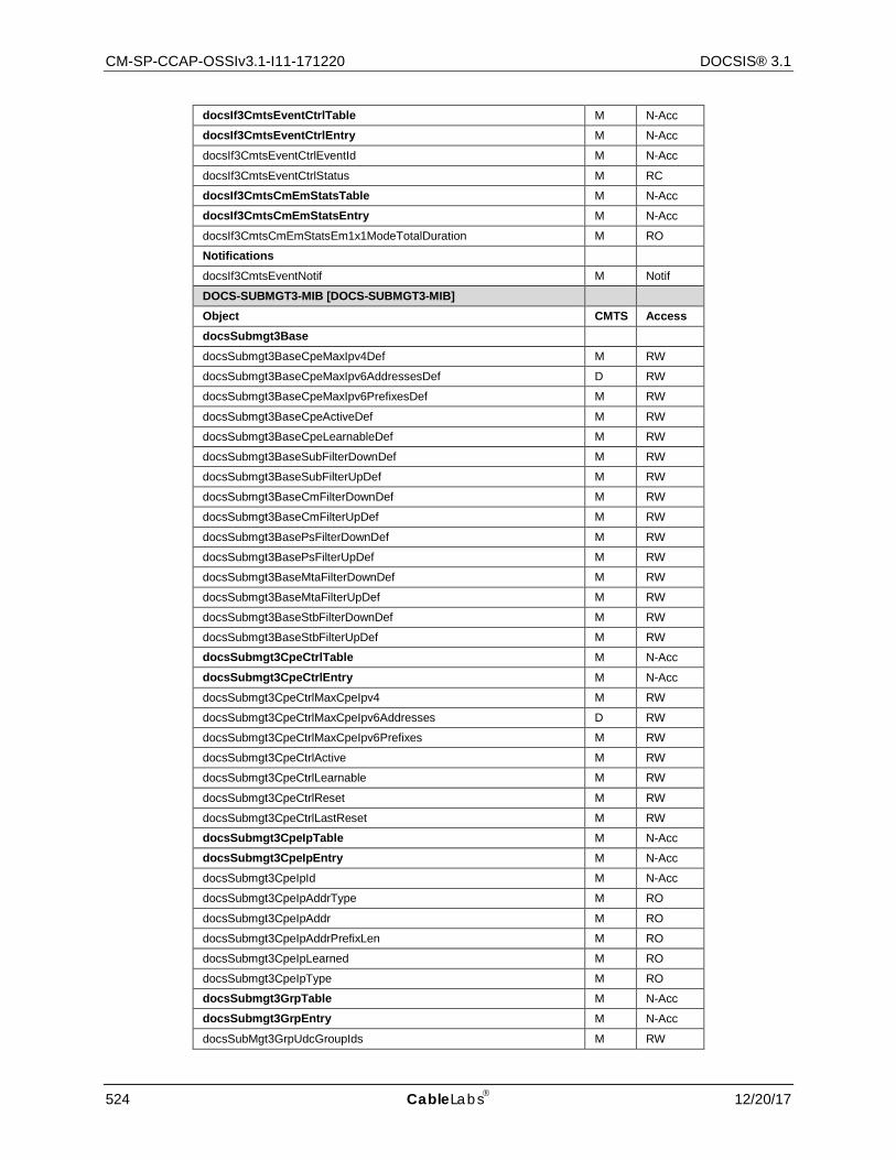
CM-SP-CCAP-OSSIv3.1-I11-171220 DOCSIS® 3.1
524 CableLabs 12/20/17
docsIf3CmtsEventCtrlTable M N-Acc
docsIf3CmtsEventCtrlEntry M N-Acc
docsIf3CmtsEventCtrlEventId M N-Acc
docsIf3CmtsEventCtrlStatus M RC
docsIf3CmtsCmEmStatsTable M N-Acc
docsIf3CmtsCmEmStatsEntry M N-Acc
docsIf3CmtsCmEmStatsEm1x1ModeTotalDuration M RO
Notifications
docsIf3CmtsEventNotif M Notif
DOCS-SUBMGT3-MIB [DOCS-SUBMGT3-MIB]
Object CMTS Access docsSubmgt3Base
docsSubmgt3BaseCpeMaxIpv4Def M RW
docsSubmgt3BaseCpeMaxIpv6AddressesDef D RW
docsSubmgt3BaseCpeMaxIpv6PrefixesDef M RW
docsSubmgt3BaseCpeActiveDef M RW
docsSubmgt3BaseCpeLearnableDef M RW
docsSubmgt3BaseSubFilterDownDef M RW
docsSubmgt3BaseSubFilterUpDef M RW
docsSubmgt3BaseCmFilterDownDef M RW
docsSubmgt3BaseCmFilterUpDef M RW
docsSubmgt3BasePsFilterDownDef M RW
docsSubmgt3BasePsFilterUpDef M RW
docsSubmgt3BaseMtaFilterDownDef M RW
docsSubmgt3BaseMtaFilterUpDef M RW
docsSubmgt3BaseStbFilterDownDef M RW
docsSubmgt3BaseStbFilterUpDef M RW
docsSubmgt3CpeCtrlTable M N-Acc
docsSubmgt3CpeCtrlEntry M N-Acc
docsSubmgt3CpeCtrlMaxCpeIpv4 M RW
docsSubmgt3CpeCtrlMaxCpeIpv6Addresses D RW
docsSubmgt3CpeCtrlMaxCpeIpv6Prefixes M RW
docsSubmgt3CpeCtrlActive M RW
docsSubmgt3CpeCtrlLearnable M RW
docsSubmgt3CpeCtrlReset M RW
docsSubmgt3CpeCtrlLastReset M RW
docsSubmgt3CpeIpTable M N-Acc
docsSubmgt3CpeIpEntry M N-Acc
docsSubmgt3CpeIpId M N-Acc
docsSubmgt3CpeIpAddrType M RO
docsSubmgt3CpeIpAddr M RO
docsSubmgt3CpeIpAddrPrefixLen M RO
docsSubmgt3CpeIpLearned M RO
docsSubmgt3CpeIpType M RO
docsSubmgt3GrpTable M N-Acc
docsSubmgt3GrpEntry M N-Acc
docsSubMgt3GrpUdcGroupIds M RW
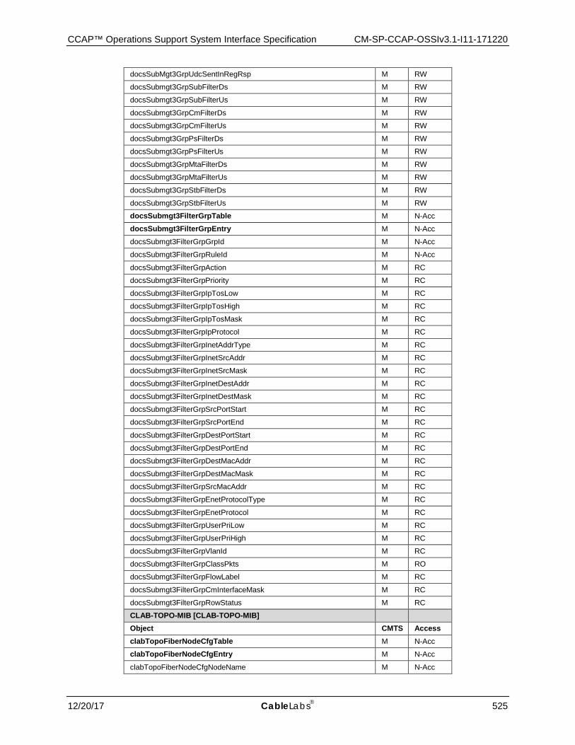
CCAP™ Operations Support System Interface Specification CM-SP-CCAP-OSSIv3.1-I11-171220
12/20/17 CableLabs 525
docsSubMgt3GrpUdcSentInRegRsp M RW
docsSubmgt3GrpSubFilterDs M RW
docsSubmgt3GrpSubFilterUs M RW
docsSubmgt3GrpCmFilterDs M RW
docsSubmgt3GrpCmFilterUs M RW
docsSubmgt3GrpPsFilterDs M RW
docsSubmgt3GrpPsFilterUs M RW
docsSubmgt3GrpMtaFilterDs M RW
docsSubmgt3GrpMtaFilterUs M RW
docsSubmgt3GrpStbFilterDs M RW
docsSubmgt3GrpStbFilterUs M RW
docsSubmgt3FilterGrpTable M N-Acc
docsSubmgt3FilterGrpEntry M N-Acc
docsSubmgt3FilterGrpGrpId M N-Acc
docsSubmgt3FilterGrpRuleId M N-Acc
docsSubmgt3FilterGrpAction M RC
docsSubmgt3FilterGrpPriority M RC
docsSubmgt3FilterGrpIpTosLow M RC
docsSubmgt3FilterGrpIpTosHigh M RC
docsSubmgt3FilterGrpIpTosMask M RC
docsSubmgt3FilterGrpIpProtocol M RC
docsSubmgt3FilterGrpInetAddrType M RC
docsSubmgt3FilterGrpInetSrcAddr M RC
docsSubmgt3FilterGrpInetSrcMask M RC
docsSubmgt3FilterGrpInetDestAddr M RC
docsSubmgt3FilterGrpInetDestMask M RC
docsSubmgt3FilterGrpSrcPortStart M RC
docsSubmgt3FilterGrpSrcPortEnd M RC
docsSubmgt3FilterGrpDestPortStart M RC
docsSubmgt3FilterGrpDestPortEnd M RC
docsSubmgt3FilterGrpDestMacAddr M RC
docsSubmgt3FilterGrpDestMacMask M RC
docsSubmgt3FilterGrpSrcMacAddr M RC
docsSubmgt3FilterGrpEnetProtocolType M RC
docsSubmgt3FilterGrpEnetProtocol M RC
docsSubmgt3FilterGrpUserPriLow M RC
docsSubmgt3FilterGrpUserPriHigh M RC
docsSubmgt3FilterGrpVlanId M RC
docsSubmgt3FilterGrpClassPkts M RO
docsSubmgt3FilterGrpFlowLabel M RC
docsSubmgt3FilterGrpCmInterfaceMask M RC
docsSubmgt3FilterGrpRowStatus M RC
CLAB-TOPO-MIB [CLAB-TOPO-MIB]
Object CMTS Access clabTopoFiberNodeCfgTable M N-Acc
clabTopoFiberNodeCfgEntry M N-Acc
clabTopoFiberNodeCfgNodeName M N-Acc
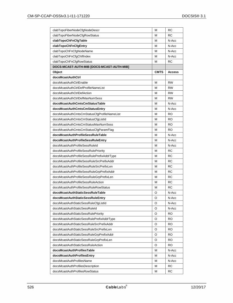
CM-SP-CCAP-OSSIv3.1-I11-171220 DOCSIS® 3.1
526 CableLabs 12/20/17
clabTopoFiberNodeCfgNodeDescr M RC
clabTopoFiberNodeCfgRowStatus M RC
clabTopoChFnCfgTable M N-Acc
clabTopoChFnCfgEntry M N-Acc
clabTopoChFnCfgNodeName M N-Acc
clabTopoChFnCfgChIfIndex M N-Acc
clabTopoChFnCfgRowStatus M RC
DOCS-MCAST-AUTH-MIB [DOCS-MCAST-AUTH-MIB]
Object CMTS Access docsMcastAuthCtrl
docsMcastAuthCtrlEnable M RW
docsMcastAuthCtrlDefProfileNameList M RW
docsMcastAuthCtrlDefAction M RW
docsMcastAuthCtrlDefMaxNumSess M RW
docsMcastAuthCmtsCmStatusTable M N-Acc
docsMcastAuthCmtsCmStatusEntry M N-Acc
docsMcastAuthCmtsCmStatusCfgProfileNameList M RO
docsMcastAuthCmtsCmStatusCfgListId M RO
docsMcastAuthCmtsCmStatusMaxNumSess M RO
docsMcastAuthCmtsCmStatusCfgParamFlag M RO
docsMcastAuthProfileSessRuleTable M N-Acc
docsMcastAuthProfileSessRuleEntry M N-Acc
docsMcastAuthProfileSessRuleId M N-Acc
docsMcastAuthProfileSessRulePriority M RC
docsMcastAuthProfileSessRulePrefixAddrType M RC
docsMcastAuthProfileSessRuleSrcPrefixAddr M RC
docsMcastAuthProfileSessRuleSrcPrefixLen M RC
docsMcastAuthProfileSessRuleGrpPrefixAddr M RC
docsMcastAuthProfileSessRuleGrpPrefixLen M RC
docsMcastAuthProfileSessRuleAction M RC
docsMcastAuthProfileSessRuleRowStatus M RC
docsMcastAuthStaticSessRuleTable O N-Acc
docsMcastAuthStaticSessRuleEntry O N-Acc
docsMcastAuthStaticSessRuleCfgListId O N-Acc
docsMcastAuthStaticSessRuleId O N-Acc
docsMcastAuthStaticSessRulePriority O RO
docsMcastAuthStaticSessRulePrefixAddrType O RO
docsMcastAuthStaticSessRuleSrcPrefixAddr O RO
docsMcastAuthStaticSessRuleSrcPrefixLen O RO
docsMcastAuthStaticSessRuleGrpPrefixAddr O RO
docsMcastAuthStaticSessRuleGrpPrefixLen O RO
docsMcastAuthStaticSessRuleAction O RO
docsMcastAuthProfilesTable M N-Acc
docsMcastAuthProfilesEntry M N-Acc
docsMcastAuthProfilesName M N-Acc
docsMcastAuthProfilesDescription M RC
docsMcastAuthProfilesRowStatus M RC
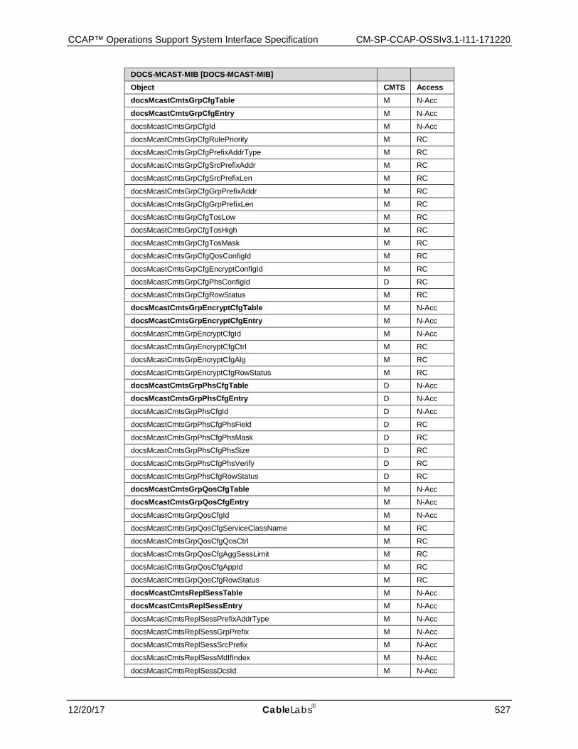
CCAP™ Operations Support System Interface Specification CM-SP-CCAP-OSSIv3.1-I11-171220
12/20/17 CableLabs 527
DOCS-MCAST-MIB [DOCS-MCAST-MIB]
Object CMTS Access docsMcastCmtsGrpCfgTable M N-Acc
docsMcastCmtsGrpCfgEntry M N-Acc
docsMcastCmtsGrpCfgId M N-Acc
docsMcastCmtsGrpCfgRulePriority M RC
docsMcastCmtsGrpCfgPrefixAddrType M RC
docsMcastCmtsGrpCfgSrcPrefixAddr M RC
docsMcastCmtsGrpCfgSrcPrefixLen M RC
docsMcastCmtsGrpCfgGrpPrefixAddr M RC
docsMcastCmtsGrpCfgGrpPrefixLen M RC
docsMcastCmtsGrpCfgTosLow M RC
docsMcastCmtsGrpCfgTosHigh M RC
docsMcastCmtsGrpCfgTosMask M RC
docsMcastCmtsGrpCfgQosConfigId M RC
docsMcastCmtsGrpCfgEncryptConfigId M RC
docsMcastCmtsGrpCfgPhsConfigId D RC
docsMcastCmtsGrpCfgRowStatus M RC
docsMcastCmtsGrpEncryptCfgTable M N-Acc
docsMcastCmtsGrpEncryptCfgEntry M N-Acc
docsMcastCmtsGrpEncryptCfgId M N-Acc
docsMcastCmtsGrpEncryptCfgCtrl M RC
docsMcastCmtsGrpEncryptCfgAlg M RC
docsMcastCmtsGrpEncryptCfgRowStatus M RC
docsMcastCmtsGrpPhsCfgTable D N-Acc
docsMcastCmtsGrpPhsCfgEntry D N-Acc
docsMcastCmtsGrpPhsCfgId D N-Acc
docsMcastCmtsGrpPhsCfgPhsField D RC
docsMcastCmtsGrpPhsCfgPhsMask D RC
docsMcastCmtsGrpPhsCfgPhsSize D RC
docsMcastCmtsGrpPhsCfgPhsVerify D RC
docsMcastCmtsGrpPhsCfgRowStatus D RC
docsMcastCmtsGrpQosCfgTable M N-Acc
docsMcastCmtsGrpQosCfgEntry M N-Acc
docsMcastCmtsGrpQosCfgId M N-Acc
docsMcastCmtsGrpQosCfgServiceClassName M RC
docsMcastCmtsGrpQosCfgQosCtrl M RC
docsMcastCmtsGrpQosCfgAggSessLimit M RC
docsMcastCmtsGrpQosCfgAppId M RC
docsMcastCmtsGrpQosCfgRowStatus M RC
docsMcastCmtsReplSessTable M N-Acc
docsMcastCmtsReplSessEntry M N-Acc
docsMcastCmtsReplSessPrefixAddrType M N-Acc
docsMcastCmtsReplSessGrpPrefix M N-Acc
docsMcastCmtsReplSessSrcPrefix M N-Acc
docsMcastCmtsReplSessMdIfIndex M N-Acc
docsMcastCmtsReplSessDcsId M N-Acc
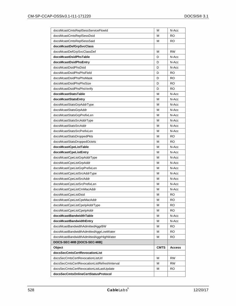
CM-SP-CCAP-OSSIv3.1-I11-171220 DOCSIS® 3.1
528 CableLabs 12/20/17
docsMcastCmtsReplSessServiceFlowId M N-Acc
docsMcastCmtsReplSessDsid M RO
docsMcastCmtsReplSessSaid M RO
docsMcastDefGrpSvcClass
docsMcastDefGrpSvcClassDef M RW
docsMcastDsidPhsTable D N-Acc
docsMcastDsidPhsEntry D N-Acc
docsMcastDsidPhsDsid D N-Acc
docsMcastDsidPhsPhsField D RO
docsMcastDsidPhsPhsMask D RO
docsMcastDsidPhsPhsSize D RO
docsMcastDsidPhsPhsVerify D RO
docsMcastStatsTable M N-Acc
docsMcastStatsEntry M N-Acc
docsMcastStatsGrpAddrType M N-Acc
docsMcastStatsGrpAddr M N-Acc
docsMcastStatsGrpPrefixLen M N-Acc
docsMcastStatsSrcAddrType M N-Acc
docsMcastStatsSrcAddr M N-Acc
docsMcastStatsSrcPrefixLen M N-Acc
docsMcastStatsDroppedPkts M RO
docsMcastStatsDroppedOctets M RO
docsMcastCpeListTable M N-Acc
docsMcastCpeListEntry M N-Acc
docsMcastCpeListGrpAddrType M N-Acc
docsMcastCpeListGrpAddr M N-Acc
docsMcastCpeListGrpPrefixLen M N-Acc
docsMcastCpeListSrcAddrType M N-Acc
docsMcastCpeListSrcAddr M N-Acc
docsMcastCpeListSrcPrefixLen M N-Acc
docsMcastCpeListCmMacAddr M N-Acc
docsMcastCpeListDsid M RO
docsMcastCpeListCpeMacAddr M RO
docsMcastCpeListCpeIpAddrType M RO
docsMcastCpeListCpeIpAddr M RO
docsMcastBandwidthTable M N-Acc
docsMcastBandwidthEntry M N-Acc
docsMcastBandwidthAdmittedAggrBW M RO
docsMcastBandwidthAdmittedAggrLowWater M RO
docsMcastBandwidthAdmittedAggrHighWater M RO
DOCS-SEC-MIB [DOCS-SEC-MIB]
Object CMTS Access docsSecCmtsCertRevocationList
docsSecCmtsCertRevocationListUrl M RW
docsSecCmtsCertRevocationListRefreshInterval M RW
docsSecCmtsCertRevocationListLastUpdate M RO
docsSecCmtsOnlineCertStatusProtocol
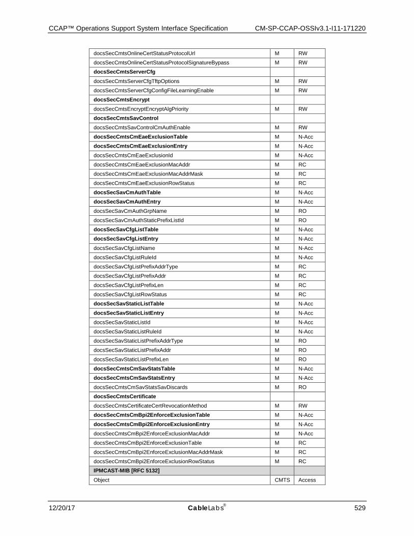
CCAP™ Operations Support System Interface Specification CM-SP-CCAP-OSSIv3.1-I11-171220
12/20/17 CableLabs 529
docsSecCmtsOnlineCertStatusProtocolUrl M RW
docsSecCmtsOnlineCertStatusProtocolSignatureBypass M RW
docsSecCmtsServerCfg
docsSecCmtsServerCfgTftpOptions M RW
docsSecCmtsServerCfgConfigFileLearningEnable M RW
docsSecCmtsEncrypt
docsSecCmtsEncryptEncryptAlgPriority M RW
docsSecCmtsSavControl
docsSecCmtsSavControlCmAuthEnable M RW
docsSecCmtsCmEaeExclusionTable M N-Acc
docsSecCmtsCmEaeExclusionEntry M N-Acc
docsSecCmtsCmEaeExclusionId M N-Acc
docsSecCmtsCmEaeExclusionMacAddr M RC
docsSecCmtsCmEaeExclusionMacAddrMask M RC
docsSecCmtsCmEaeExclusionRowStatus M RC
docsSecSavCmAuthTable M N-Acc
docsSecSavCmAuthEntry M N-Acc
docsSecSavCmAuthGrpName M RO
docsSecSavCmAuthStaticPrefixListId M RO
docsSecSavCfgListTable M N-Acc
docsSecSavCfgListEntry M N-Acc
docsSecSavCfgListName M N-Acc
docsSecSavCfgListRuleId M N-Acc
docsSecSavCfgListPrefixAddrType M RC
docsSecSavCfgListPrefixAddr M RC
docsSecSavCfgListPrefixLen M RC
docsSecSavCfgListRowStatus M RC
docsSecSavStaticListTable M N-Acc
docsSecSavStaticListEntry M N-Acc
docsSecSavStaticListId M N-Acc
docsSecSavStaticListRuleId M N-Acc
docsSecSavStaticListPrefixAddrType M RO
docsSecSavStaticListPrefixAddr M RO
docsSecSavStaticListPrefixLen M RO
docsSecCmtsCmSavStatsTable M N-Acc
docsSecCmtsCmSavStatsEntry M N-Acc
docsSecCmtsCmSavStatsSavDiscards M RO
docsSecCmtsCertificate
docsSecCmtsCertificateCertRevocationMethod M RW
docsSecCmtsCmBpi2EnforceExclusionTable M N-Acc
docsSecCmtsCmBpi2EnforceExclusionEntry M N-Acc
docsSecCmtsCmBpi2EnforceExclusionMacAddr M N-Acc
docsSecCmtsCmBpi2EnforceExclusionTable M RC
docsSecCmtsCmBpi2EnforceExclusionMacAddrMask M RC
docsSecCmtsCmBpi2EnforceExclusionRowStatus M RC
IPMCAST-MIB [RFC 5132]
Object CMTS Access
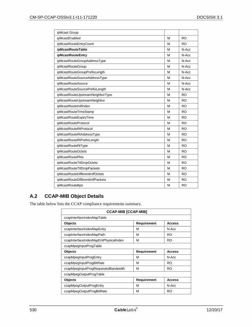
CM-SP-CCAP-OSSIv3.1-I11-171220 DOCSIS® 3.1
530 CableLabs 12/20/17
ipMcast Group
ipMcastEnabled M RO
ipMcastRouteEntryCount M RO
ipMcastRouteTable M N-Acc
ipMcastRouteEntry M N-Acc
ipMcastRouteGroupAddressType M N-Acc
ipMcastRouteGroup M N-Acc
ipMcastRouteGroupPrefixLength M N-Acc
ipMcastRouteSourceAddressType M N-Acc
ipMcastRouteSource M N-Acc
ipMcastRouteSourcePrefixLength M N-Acc
ipMcastRouteUpstreamNeighborType M RO
ipMcastRouteUpstreamNeighbor M RO
ipMcastRouteInIfIndex M RO
ipMcastRouteTimeStamp M RO
ipMcastRouteExpiryTime M RO
ipMcastRouteProtocol M RO
ipMcastRouteRtProtocol M RO
ipMcastRouteRtAddressType M RO
ipMcastRouteRtPrefixLength M RO
ipMcastRouteRtType M RO
ipMcastRouteOctets M RO
ipMcastRoutePkts M RO
ipMcastRouteTtlDropOctets M RO
ipMcastRouteTtlDropPackets M RO
ipMcastRouteDifferentInIfOctets M RO
ipMcastRouteDifferentInIfPackets M RO
ipMcastRouteBps M RO
A.2 CCAP-MIB Object Details The table below lists the CCAP compliance requirements summary.
CCAP-MIB [CCAP-MIB] ccapInterfaceIndexMapTable
Objects Requirement Access ccapInterfaceIndexMapEntry M N-Acc
ccapInterfaceIndexMapPath M RO
ccapInterfaceIndexMapEntPhysicalIndex M RO
ccapMpegInputProgTable
Objects Requirement Access ccapMpegInputProgEntry M N-Acc
ccapMpegInputProgBitRate M RO
ccapMpegInputProgRequestedBandwidth M RO
ccapMpegOutputProgTable
Objects Requirement Access ccapMpegOutputProgEntry M N-Acc
ccapMpegOutputProgBitRate M RO
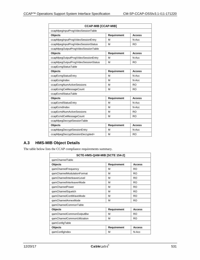
CCAP™ Operations Support System Interface Specification CM-SP-CCAP-OSSIv3.1-I11-171220
12/20/17 CableLabs 531
CCAP-MIB [CCAP-MIB] ccapMpegInputProgVideoSessionTable
Objects Requirement Access ccapMpegInputProgVideoSessionEntry M N-Acc
ccapMpegInputProgVideoSessionStatus M RO
ccapMpegOutputProgVideoSessionTable
Objects Requirement Access ccapMpegOutputProgVideoSessionEntry M N-Acc
ccapMpegOutputProgVideoSessionStatus M RO
ccapEcmgStatusTable
Objects Requirement Access ccapEcmgStatusEntry M N-Acc
ccapEcmgIndex M N-Acc
ccapEcmgNumActiveSessions M RO
ccapEcmgCwMessageCount M RO
ccapEcmdStatusTable
Objects Requirement Access ccapEcmdStatusEntry M N-Acc
ccapEcmdIndex M N-Acc
ccapEcmdNumActiveSessions M RO
ccapEcmdCwMessageCount M RO
ccapMpegDecryptSessionTable
Objects Requirement Access ccapMpegDecryptSessionEntry M N-Acc
ccapMpegDecryptSessionDecrypted= M RO
A.3 HMS-MIB Object Details The table below lists the CCAP compliance requirements summary.
SCTE-HMS-QAM-MIB [SCTE 154-2] qamChannelTable
Objects Requirement Access qamChannelFrequency M RO
qamChannelModulationFormat M RO
qamChannelInterleaverLevel M RO
qamChannelInterleaverMode M RO
qamChannelPower M RO
qamChannelSquelch M RO
qamChannelContWaveMode M RO
qamChannelAnnexMode M RO
qamChannelCommonTable
Objects Requirement Access qamChannelCommonOutputBw M RO
qamChannelCommonUtilization M RO
qamConfigTable
Objects Requirement Access qamConfigIndex M N-Acc
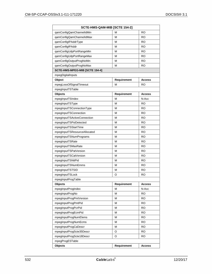
CM-SP-CCAP-OSSIv3.1-I11-171220 DOCSIS® 3.1
532 CableLabs 12/20/17
SCTE-HMS-QAM-MIB [SCTE 154-2] qamConfigQamChannelIdMin M RO
qamConfigQamChannelIdMax M RO
qamConfigIPAddrType M RO
qamConfigIPAddr M RO
qamConfigUdpPortRangeMin M RO
qamConfigUdpPortRangeMax M RO
qamConfigOutputProgNoMin M RO
qamConfigOutputProgNoMax M RO
SCTE-HMS-MPEG-MIB [SCTE 154-4] mpegDigitalInputs
Object Requirement Access mpegLossOfSignalTimeout M RO
mpegInputTSTable
Objects Requirement Access mpegInputTSIndex M N-Acc
mpegInputTSType M RO
mpegInputTSConnectionType M RO
mpegInputTSConnection M RO
mpegInputTSActiveConnection M RO
mpegInputTSPsiDetected M RO
mpegInputTSStartTime M RO
mpegInputTSResourceAllocated M RO
mpegInputTSNumPrograms M RO
mpegInputTSRate M RO
mpegInputTSMaxRate M RO
mpegInputTSPatVersion M RO
mpegInputTSCatVersion M RO
mpegInputTSNitPid M RO
mpegInputTSNumEmms M RO
mpegInputTSTSID M RO
mpegInputTSLock O RO
mpegInputProgTable
Objects Requirement Access mpegInputProgIndex M N-Acc
mpegInputProgNo M RO
mpegInputProgPmtVersion M RO
mpegInputProgPmtPid M RO
mpegInputProgPcrPid M RO
mpegInputProgEcmPid M RO
mpegInputProgNumElems M RO
mpegInputProgNumEcms M RO
mpegInputProgCaDescr M RO
mpegInputProgScte35Descr O RO
mpegInputProgScte18Descr O RO
mpegProgESTable
Objects Requirement Access
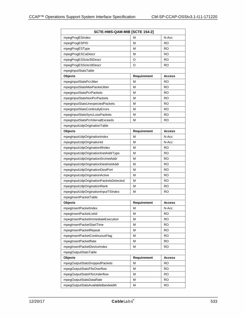
CCAP™ Operations Support System Interface Specification CM-SP-CCAP-OSSIv3.1-I11-171220
12/20/17 CableLabs 533
SCTE-HMS-QAM-MIB [SCTE 154-2] mpegProgESIndex M N-Acc
mpegProgESPID M RO
mpegProgESType M RO
mpegProgESCaDescr M RO
mpegProgESScte35Descr O RO
mpegProgESScte18Descr O RO
mpegInputStatsTable
Objects Requirement Access mpegInputStatsPcrJitter M RO
mpegInputStatsMaxPacketJitter M RO
mpegInputStatsPcrPackets M RO
mpegInputStatsNonPcrPackets M RO
mpegInputStatsUnexpectedPackets M RO
mpegInputStatsContinuityErrors M RO
mpegInputStatsSyncLossPackets M RO
mpegInputStatsPcrIntervalExceeds M RO
mpegInputUdpOriginationTable
Objects Requirement Access mpegInputUdpOriginationIndex M N-Acc
mpegInputUdpOriginationId M N-Acc
mpegInputUdpOriginationIfIndex M RO
mpegInputUdpOriginationInetAddrType M RO
mpegInputUdpOriginationSrcInetAddr M RO
mpegInputUdpOriginationDestInetAddr M RO
mpegInputUdpOriginationDestPort M RO
mpegInputUdpOriginationActive M RO
mpegInputUdpOriginationPacketsDetected M RO
mpegInputUdpOriginationRank M RO
mpegInputUdpOriginationInputTSIndex M RO
mpegInsertPacketTable
Objects Requirement Access mpegInsertPacketIndex M N-Acc
mpegInsertPacketListId M RO
mpegInsertPacketImmediateExecution M RO
mpegInsertPacketStartTime M RO
mpegInsertPacketRepeat M RO
mpegInsertPacketContinuousFlag M RO
mpegInsertPacketRate M RO
mpegInsertPacketDeviceIndex M RO
mpegOutputStatsTable
Objects Requirement Access mpegOutputStatsDroppedPackets M RO
mpegOutputStatsFifoOverflow M RO
mpegOutputStatsFifoUnderflow M RO
mpegOutputStatsDataRate M RO
mpegOutputStatsAvailableBandwidth M RO
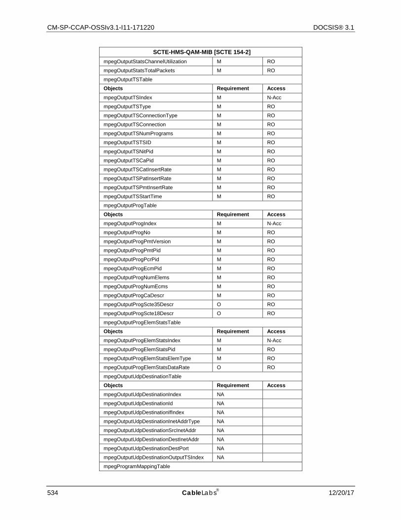
CM-SP-CCAP-OSSIv3.1-I11-171220 DOCSIS® 3.1
534 CableLabs 12/20/17
SCTE-HMS-QAM-MIB [SCTE 154-2] mpegOutputStatsChannelUtilization M RO
mpegOutputStatsTotalPackets M RO
mpegOutputTSTable
Objects Requirement Access mpegOutputTSIndex M N-Acc
mpegOutputTSType M RO
mpegOutputTSConnectionType M RO
mpegOutputTSConnection M RO
mpegOutputTSNumPrograms M RO
mpegOutputTSTSID M RO
mpegOutputTSNitPid M RO
mpegOutputTSCaPid M RO
mpegOutputTSCatInsertRate M RO
mpegOutputTSPatInsertRate M RO
mpegOutputTSPmtInsertRate M RO
mpegOutputTSStartTime M RO
mpegOutputProgTable
Objects Requirement Access mpegOutputProgIndex M N-Acc
mpegOutputProgNo M RO
mpegOutputProgPmtVersion M RO
mpegOutputProgPmtPid M RO
mpegOutputProgPcrPid M RO
mpegOutputProgEcmPid M RO
mpegOutputProgNumElems M RO
mpegOutputProgNumEcms M RO
mpegOutputProgCaDescr M RO
mpegOutputProgScte35Descr O RO
mpegOutputProgScte18Descr O RO
mpegOutputProgElemStatsTable
Objects Requirement Access mpegOutputProgElemStatsIndex M N-Acc
mpegOutputProgElemStatsPid M RO
mpegOutputProgElemStatsElemType M RO
mpegOutputProgElemStatsDataRate O RO
mpegOutputUdpDestinationTable
Objects Requirement Access mpegOutputUdpDestinationIndex NA
mpegOutputUdpDestinationId NA
mpegOutputUdpDestinationIfIndex NA
mpegOutputUdpDestinationInetAddrType NA
mpegOutputUdpDestinationSrcInetAddr NA
mpegOutputUdpDestinationDestInetAddr NA
mpegOutputUdpDestinationDestPort NA
mpegOutputUdpDestinationOutputTSIndex NA
mpegProgramMappingTable

CCAP™ Operations Support System Interface Specification CM-SP-CCAP-OSSIv3.1-I11-171220
12/20/17 CableLabs 535
SCTE-HMS-QAM-MIB [SCTE 154-2] Objects Requirement Access mpegProgramMappingIndex M N-Acc
mpegProgramMappingOutputProgIndex M RO
mpegProgramMappingOutputTSIndex M RO
mpegProgramMappingInputProgIndex M RO
mpegProgramMappingInputTSIndex M RO
mpegVideoSessionTable
Objects Requirement Access mpegVideoSessionIndex M N-Acc
mpegVideoSessionPhyMappingIndex M RO
mpegVideoSessionPIDRemap M RO
mpegVideoSessionMode M RO
mpegVideoSessionState M RO
mpegVideoSessionProvMethod M RO
mpegVideoSessionEncryptionType M RO
mpegVideoSessionEncryptionInfo M RO
mpegVideoSessionBitRate M RO
mpegVideoSessionID M RO
mpegVideoSessionSelectedInput M RO
mpegVideoSessionSelectedOutput M RO
mpegVideoSessionPtrTable
Objects Requirement Access mpegVideoSessionPtrInputProgIndex M N-Acc
mpegVideoSessionPtrInputTSIndex M RO
mpegVideoSessionPtrInputTSConnType M RO
mpegVideoSessionPtrInputTSConnection M RO
mpegVideoSessionPtrOutputProgIndex M RO
mpegVideoSessionPtrOutputTSIndex M RO
mpegVideoSessionPtrOutputTSConnType M RO
mpegVideoSessionPtrOutputTSConnection M RO
mpegVideoSessionPtrStatus M RO
mpegInputTSOutputSessionTable
Objects Requirement Access mpegInputTSOutputSessionCreateTime M RO
A.4 PNM MIB Object Details The table below lists the CCAP compliance requirements summary.
DOCS-PNM-MIB
Object CMTS Access
docsPnmBulkCtl Group
docsPnmBulkDestIpAddrType M RW
docsPnmBulkDestIpAddr M RW
docsPnmBulkDestPath M RW
docsPnmBulkUploadControl M RW
docsPnmBulkFileTable M N-Acc
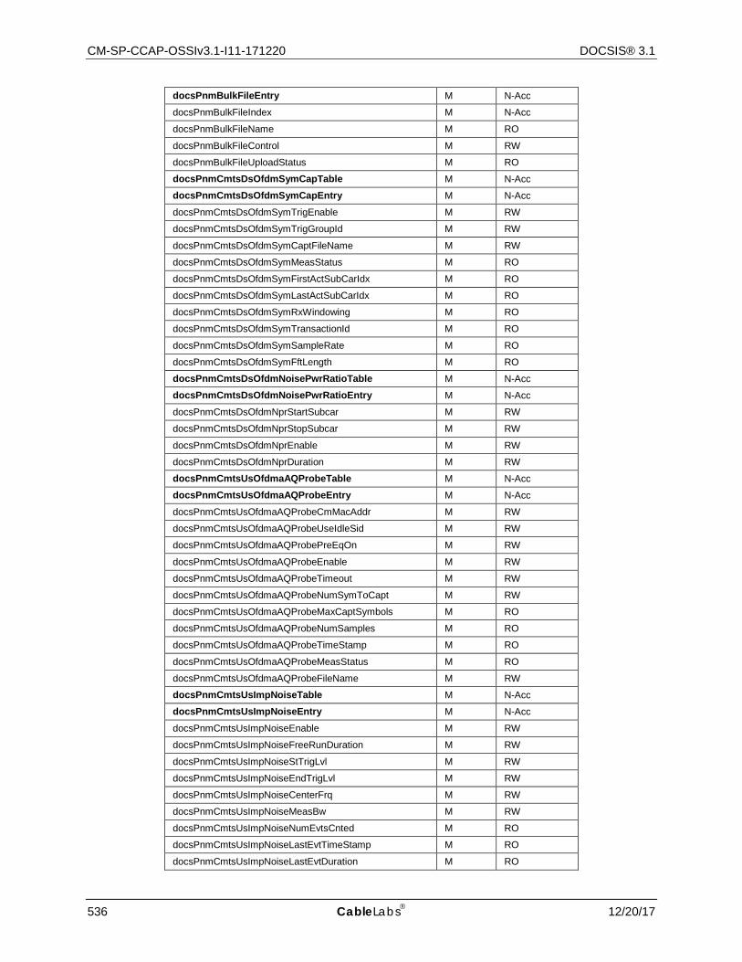
CM-SP-CCAP-OSSIv3.1-I11-171220 DOCSIS® 3.1
536 CableLabs 12/20/17
docsPnmBulkFileEntry M N-Acc
docsPnmBulkFileIndex M N-Acc
docsPnmBulkFileName M RO
docsPnmBulkFileControl M RW
docsPnmBulkFileUploadStatus M RO
docsPnmCmtsDsOfdmSymCapTable M N-Acc
docsPnmCmtsDsOfdmSymCapEntry M N-Acc
docsPnmCmtsDsOfdmSymTrigEnable M RW
docsPnmCmtsDsOfdmSymTrigGroupId M RW
docsPnmCmtsDsOfdmSymCaptFileName M RW
docsPnmCmtsDsOfdmSymMeasStatus M RO
docsPnmCmtsDsOfdmSymFirstActSubCarIdx M RO
docsPnmCmtsDsOfdmSymLastActSubCarIdx M RO
docsPnmCmtsDsOfdmSymRxWindowing M RO
docsPnmCmtsDsOfdmSymTransactionId M RO
docsPnmCmtsDsOfdmSymSampleRate M RO
docsPnmCmtsDsOfdmSymFftLength M RO
docsPnmCmtsDsOfdmNoisePwrRatioTable M N-Acc
docsPnmCmtsDsOfdmNoisePwrRatioEntry M N-Acc
docsPnmCmtsDsOfdmNprStartSubcar M RW
docsPnmCmtsDsOfdmNprStopSubcar M RW
docsPnmCmtsDsOfdmNprEnable M RW
docsPnmCmtsDsOfdmNprDuration M RW
docsPnmCmtsUsOfdmaAQProbeTable M N-Acc
docsPnmCmtsUsOfdmaAQProbeEntry M N-Acc
docsPnmCmtsUsOfdmaAQProbeCmMacAddr M RW
docsPnmCmtsUsOfdmaAQProbeUseIdleSid M RW
docsPnmCmtsUsOfdmaAQProbePreEqOn M RW
docsPnmCmtsUsOfdmaAQProbeEnable M RW
docsPnmCmtsUsOfdmaAQProbeTimeout M RW
docsPnmCmtsUsOfdmaAQProbeNumSymToCapt M RW
docsPnmCmtsUsOfdmaAQProbeMaxCaptSymbols M RO
docsPnmCmtsUsOfdmaAQProbeNumSamples M RO
docsPnmCmtsUsOfdmaAQProbeTimeStamp M RO
docsPnmCmtsUsOfdmaAQProbeMeasStatus M RO
docsPnmCmtsUsOfdmaAQProbeFileName M RW
docsPnmCmtsUsImpNoiseTable M N-Acc
docsPnmCmtsUsImpNoiseEntry M N-Acc
docsPnmCmtsUsImpNoiseEnable M RW
docsPnmCmtsUsImpNoiseFreeRunDuration M RW
docsPnmCmtsUsImpNoiseStTrigLvl M RW
docsPnmCmtsUsImpNoiseEndTrigLvl M RW
docsPnmCmtsUsImpNoiseCenterFrq M RW
docsPnmCmtsUsImpNoiseMeasBw M RW
docsPnmCmtsUsImpNoiseNumEvtsCnted M RO
docsPnmCmtsUsImpNoiseLastEvtTimeStamp M RO
docsPnmCmtsUsImpNoiseLastEvtDuration M RO
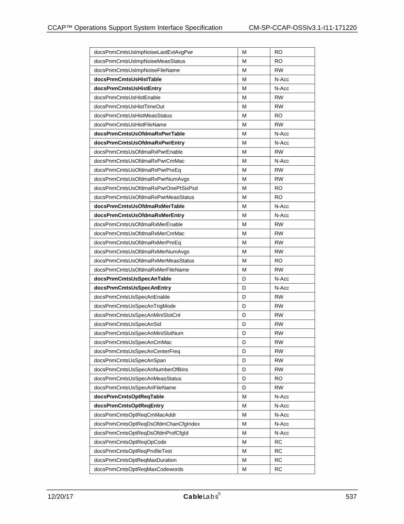
CCAP™ Operations Support System Interface Specification CM-SP-CCAP-OSSIv3.1-I11-171220
12/20/17 CableLabs 537
docsPnmCmtsUsImpNoiseLastEvtAvgPwr M RO
docsPnmCmtsUsImpNoiseMeasStatus M RO
docsPnmCmtsUsImpNoiseFileName M RW
docsPnmCmtsUsHistTable M N-Acc
docsPnmCmtsUsHistEntry M N-Acc
docsPnmCmtsUsHistEnable M RW
docsPnmCmtsUsHistTimeOut M RW
docsPnmCmtsUsHistMeasStatus M RO
docsPnmCmtsUsHistFileName M RW
docsPnmCmtsUsOfdmaRxPwrTable M N-Acc
docsPnmCmtsUsOfdmaRxPwrEntry M N-Acc
docsPnmCmtsUsOfdmaRxPwrEnable M RW
docsPnmCmtsUsOfdmaRxPwrCmMac M N-Acc
docsPnmCmtsUsOfdmaRxPwrPreEq M RW
docsPnmCmtsUsOfdmaRxPwrNumAvgs M RW
docsPnmCmtsUsOfdmaRxPwrOnePtSixPsd M RO
docsPnmCmtsUsOfdmaRxPwrMeasStatus M RO
docsPnmCmtsUsOfdmaRxMerTable M N-Acc
docsPnmCmtsUsOfdmaRxMerEntry M N-Acc
docsPnmCmtsUsOfdmaRxMerEnable M RW
docsPnmCmtsUsOfdmaRxMerCmMac M RW
docsPnmCmtsUsOfdmaRxMerPreEq M RW
docsPnmCmtsUsOfdmaRxMerNumAvgs M RW
docsPnmCmtsUsOfdmaRxMerMeasStatus M RO
docsPnmCmtsUsOfdmaRxMerFileName M RW
docsPnmCmtsUsSpecAnTable D N-Acc
docsPnmCmtsUsSpecAnEntry D N-Acc
docsPnmCmtsUsSpecAnEnable D RW
docsPnmCmtsUsSpecAnTrigMode D RW
docsPnmCmtsUsSpecAnMiniSlotCnt D RW
docsPnmCmtsUsSpecAnSid D RW
docsPnmCmtsUsSpecAnMiniSlotNum D RW
docsPnmCmtsUsSpecAnCmMac D RW
docsPnmCmtsUsSpecAnCenterFreq D RW
docsPnmCmtsUsSpecAnSpan D RW
docsPnmCmtsUsSpecAnNumberOfBins D RW
docsPnmCmtsUsSpecAnMeasStatus D RO
docsPnmCmtsUsSpecAnFileName D RW
docsPnmCmtsOptReqTable M N-Acc
docsPnmCmtsOptReqEntry M N-Acc
docsPnmCmtsOptReqCmMacAddr M N-Acc
docsPnmCmtsOptReqDsOfdmChanCfgIndex M N-Acc
docsPnmCmtsOptReqDsOfdmProfCfgId M N-Acc
docsPnmCmtsOptReqOpCode M RC
docsPnmCmtsOptReqProfileTest M RC
docsPnmCmtsOptReqMaxDuration M RC
docsPnmCmtsOptReqMaxCodewords M RC
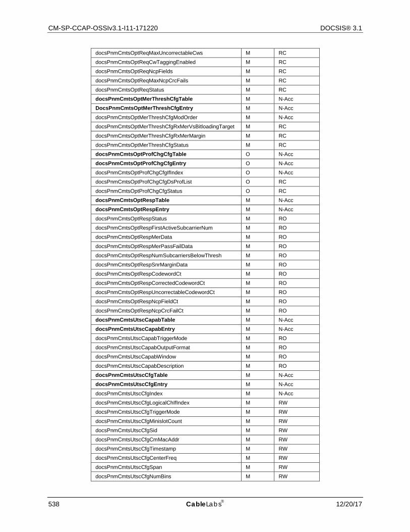
CM-SP-CCAP-OSSIv3.1-I11-171220 DOCSIS® 3.1
538 CableLabs 12/20/17
docsPnmCmtsOptReqMaxUncorrectableCws M RC
docsPnmCmtsOptReqCwTaggingEnabled M RC
docsPnmCmtsOptReqNcpFields M RC
docsPnmCmtsOptReqMaxNcpCrcFails M RC
docsPnmCmtsOptReqStatus M RC
docsPnmCmtsOptMerThreshCfgTable M N-Acc
DocsPnmCmtsOptMerThreshCfgEntry M N-Acc
docsPnmCmtsOptMerThreshCfgModOrder M N-Acc
docsPnmCmtsOptMerThreshCfgRxMerVsBitloadingTarget M RC
docsPnmCmtsOptMerThreshCfgRxMerMargin M RC
docsPnmCmtsOptMerThreshCfgStatus M RC
docsPnmCmtsOptProfChgCfgTable O N-Acc
docsPnmCmtsOptProfChgCfgEntry O N-Acc
docsPnmCmtsOptProfChgCfgIfIndex O N-Acc
docsPnmCmtsOptProfChgCfgDsProfList O RC
docsPnmCmtsOptProfChgCfgStatus O RC
docsPnmCmtsOptRespTable M N-Acc
docsPnmCmtsOptRespEntry M N-Acc
docsPnmCmtsOptRespStatus M RO
docsPnmCmtsOptRespFirstActiveSubcarrierNum M RO
docsPnmCmtsOptRespMerData M RO
docsPnmCmtsOptRespMerPassFailData M RO
docsPnmCmtsOptRespNumSubcarriersBelowThresh M RO
docsPnmCmtsOptRespSnrMarginData M RO
docsPnmCmtsOptRespCodewordCt M RO
docsPnmCmtsOptRespCorrectedCodewordCt M RO
docsPnmCmtsOptRespUncorrectableCodewordCt M RO
docsPnmCmtsOptRespNcpFieldCt M RO
docsPnmCmtsOptRespNcpCrcFailCt M RO
docsPnmCmtsUtscCapabTable M N-Acc
docsPnmCmtsUtscCapabEntry M N-Acc
docsPnmCmtsUtscCapabTriggerMode M RO
docsPnmCmtsUtscCapabOutputFormat M RO
docsPnmCmtsUtscCapabWindow M RO
docsPnmCmtsUtscCapabDescription M RO
docsPnmCmtsUtscCfgTable M N-Acc
docsPnmCmtsUtscCfgEntry M N-Acc
docsPnmCmtsUtscCfgIndex M N-Acc
docsPnmCmtsUtscCfgLogicalChIfIndex M RW
docsPnmCmtsUtscCfgTriggerMode M RW
docsPnmCmtsUtscCfgMinislotCount M RW
docsPnmCmtsUtscCfgSid M RW
docsPnmCmtsUtscCfgCmMacAddr M RW
docsPnmCmtsUtscCfgTimestamp M RW
docsPnmCmtsUtscCfgCenterFreq M RW
docsPnmCmtsUtscCfgSpan M RW
docsPnmCmtsUtscCfgNumBins M RW
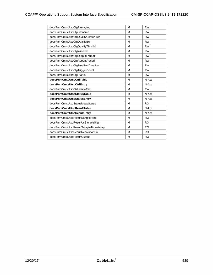
CCAP™ Operations Support System Interface Specification CM-SP-CCAP-OSSIv3.1-I11-171220
12/20/17 CableLabs 539
docsPnmCmtsUtscCfgAveraging M RW
docsPnmCmtsUtscCfgFilename M RW
docsPnmCmtsUtscCfgQualifyCenterFreq M RW
docsPnmCmtsUtscCfgQualifyBw M RW
docsPnmCmtsUtscCfgQualifyThrshld M RW
docsPnmCmtsUtscCfgWindow M RW
docsPnmCmtsUtscCfgOutputFormat M RW
docsPnmCmtsUtscCfgRepeatPeriod M RW
docsPnmCmtsUtscCfgFreeRunDuration M RW
docsPnmCmtsUtscCfgTriggerCount M RW
docsPnmCmtsUtscCfgStatus M RW
docsPnmCmtsUtscCtrlTable M N-Acc
docsPnmCmtsUtscCtrlEntry M N-Acc
docsPnmCmtsUtscCtrlInitiateTest M RW
docsPnmCmtsUtscStatusTable M N-Acc
docsPnmCmtsUtscStatusEntry M N-Acc
docsPnmCmtsUtscStatusMeasStatus M RO
docsPnmCmtsUtscResultTable M N-Acc
docsPnmCmtsUtscResultEntry M N-Acc
docsPnmCmtsUtscResultSampleRate M RO
docsPnmCmtsUtscResultUsSampleSize M RO
docsPnmCmtsUtscResultSampleTimestamp M RO
docsPnmCmtsUtscResultResolutionBw M RO
docsPnmCmtsUtscResultOutput M RO
CM-SP-CCAP-OSSIv3.1-I11-171220 DOCSIS® 3.1
540 CableLabs 12/20/17
Annex B IPDR for DOCSIS Cable Data Systems Subscriber Usage Billing Records (Normative)
B.1 Service Definition Cable Data Systems consist of Cable Modem Termination Systems (CMTSs), located at a Multiple Service Operator's (MSO's) head-end office, that provide broadband Internet access to subscribers connected via Cable Modems (CMs), through the Hybrid Fiber/Coax (HFC) cable plant. These Cable Data Systems comply with the Data-Over-Cable Service Interface Specifications (DOCSIS) sponsored by Cable Television Laboratories, Inc. The IPDR format for Cable Data Systems Subscriber Usage Billing Records specified herein, support the DOCSIS 1.1, 2.0 and 3.0 Operations Support System Interface Specification (OSSI). The DOCSIS 1.1, 2.0 and 3.0 OSSI specifications require the CMTS to provide usage-billing records for all bandwidth consumed by the subscribers connected to it by their Cable Modems, when polled by the MSO's billing or mediation system.
B.1.1 DOCSIS Service Requirements
1. Cable Data Service is "always on". Thus, from the CMTS perspective, there are no subscriber log-on events to track, but rather, in a manner similar to electric power utilities, there are only data traffic flows to meter and police.
2. Cable Data Subscribers are uniquely identified by their Cable Modem MAC addresses (i.e., Ethernet addresses). Note that a CM is usually assigned a dynamic IP address via DHCP, so the IP address of a subscriber may change over time. Since the CM MAC address is constant, it is used to identify the subscriber's usage billing records. All Internet traffic generated by the subscriber's CPE is bridged by the CM to and from the CMTS. The subscriber's packet and byte (octet) traffic counts are recorded by the CMTS in Service Flow counters associated with the CM MAC address. A CM may have two or more Service Flows active during a collection interval. Note that the current IP addresses of the CM and all the CPE in use during the collection interval are recorded for auditing purposes.
3. Cable Data Service is metered and enforced against a Service Level Agreement (SLA) that specifies the Quality of Service (QoS) that an MSO provides to a subscriber. An MSO typically has several Service Packages to offer to their subscribers, such as "Gold", "Silver", or "Bronze". Each of the Service Packages implements a specific SLA and is available for a specific price. A Service Package is implemented by a set of Service Flows that are known to the billing system by their Service Flow IDs (SFIDs) and Service Class Names (SCNs). Service Flows are the unit of billing data collection for a Cable Data Subscriber. In addition, since a subscriber may change their Service Package over time, it is very likely that a given subscriber will have several IPDRs, one for each Service Flow they have used during the collection interval.
4. Bandwidth in a Cable Data System is measured separately in both the downstream and upstream directions (relative to the CMTS). Each Service Flow is unidirectional and may be associated with packet traffic of a specific type (e.g., TCP or UDP). Since most SLAs provide for asymmetric bandwidth guarantees, it is necessary to separate the downstream and upstream traffic flows in the billing usage records. Bandwidth used is measured in both packets and octets.
5. The bandwidth guarantee component of the SLA is enforced and metered by the CMTS with the assistance of the CM. However, the CM is not considered a trusted device because of its location on the Customer's Premises, so the CMTS is expected to provide all of the usage billing information for each subscriber connected to it.
6. Since an SLA may require the CMTS to enforce bandwidth limits by dropping or delaying packets that exceed the maximum throughput bandwidth for a Service Flow, the SLA dropped packets counters and delayed packets counters are also included in the usage records for each Service Flow. These counters are not intended to compute billable subscriber usage but rather are available to the billing and customer care systems to enable "up-selling" to subscribers who consistently exceed their subscribed service level. Thus, subscribers whose usage patterns indicate a large number of dropped octets are probably candidates for an upgrade to a higher SLA that supports their true application bandwidth demands which, in turn, generates more revenue for the MSO.
7. The packet and octet values in the usage billing records are based on absolute 64-bit counters maintained in the CMTS. These counters may be reset when the CMTS system resets, therefore the CMTS system up time (see
CCAP™ Operations Support System Interface Specification CM-SP-CCAP-OSSIv3.1-I11-171220
12/20/17 CableLabs 541
CmtsSysUpTime in Annex C) is included in the IPDRDoc so that the billing or mediation system can correlate counters that appear to regress.
8. Group Service Flows are Service Flows received by one or more Cable Modems. A single record is created for a Group Service flow.
B.1.2 SAMIS Usage Attribute List
A DOCSIS SAMIS IPDR record is constructed from a number of attributes that describe the IPDR itself, the CMTS that is serving the subscriber, the subscriber's CM, and the QoS attributes and counters.
B.1.2.1 CMTS Information A DOCSIS SAMIS IPDR record contains attributes that identify the CMTS that is serving the subscriber. The CMTS attributes are defined in the CMTS Information section of Annex C. Note that the CMTS information attributes defined in Annex C can be streamed independently (i.e., in other IPDR record types) from the SAMIS IPDR and then correlated at the Collector using the CmtsHostName attribute.
DOCSIS SAMIS Type 1 IPDR records contain the following CMTS attributes:
• CmtsHostName • CmtsSysUpTime • CmtsIpv4Addr • CmtsIpv6Addr • CmtsMdIfName • CmtsMdIfIndex
DOCSIS SAMIS Type 2 IPDR records contain the following CMTS attributes:
• CmtsHostName • CmtsSysUpTime • CmtsMdIfName • CmtsMdIfIndex
B.1.2.2 CM Information A DOCSIS SAMIS IPDR record contains attributes that uniquely identify the CM or Group Service Flow. Each SAMIS IPDR for a given CM or Group Service Flow within the IPDRDoc will contain identical values for these attributes. The CM attributes are defined in the CM or Group Service Flow Information section of Annex C. Note that the CM information attributes defined in Annex C can be streamed independently (i.e., in other IPDR record types) from the SAMIS IPDR and then correlated at the Collector.
DOCSIS SAMIS Type 1 IPDR records contain the following CM attributes:
• CmMacAddr • CmIpv4Addr • CmIpv6Addr • CmIpv6LinkLocalAddr • CmQosVersion • CmRegStatusValue • CmLastRegTime
DOCSIS SAMIS Type 2 IPDR records contain the following CM attribute:
• CmMacAddr
CM-SP-CCAP-OSSIv3.1-I11-171220 DOCSIS® 3.1
542 CableLabs 12/20/17
B.1.2.3 Record Information A DOCSIS SAMIS IPDR record contains attributes that identify the type of record and creation time. The Record attributes are defined in the Record Information section of Annex C.
DOCSIS SAMIS Type 1 and Type 2 IPDR records contain the following CM attributes:
• RecType • RecCreationTime
B.1.2.4 QoS Information A DOCSIS SAMIS IPDR record contains the following attributes that identify the service flow and contain the counters maintained by the CMTS for that service flow (i.e., QoS attributes). The QoS attributes are defined in the QoS Information section of Annex C.
DOCSIS SAMIS Type 1 and Type 2 IPDR records contain the following CM attributes:
• ServiceFlowChSet • ServiceAppId • ServiceDsMulticast • ServiceIdentifier • ServiceGateId • ServiceClassName • ServiceDirection • ServiceOctetsPassed • ServicePktsPassed • ServiceSlaDropPkts • ServiceSlaDelayPkts • ServiceTimeCreated • ServiceTimeActive
B.2 IPDR Service Definition Schemas Refer to [DOCSIS-SAMIS-TYPE-1] and [DOCSIS-SAMIS-TYPE-2] for the IPDR Service Definition XML schemas for the SAMIS feature.
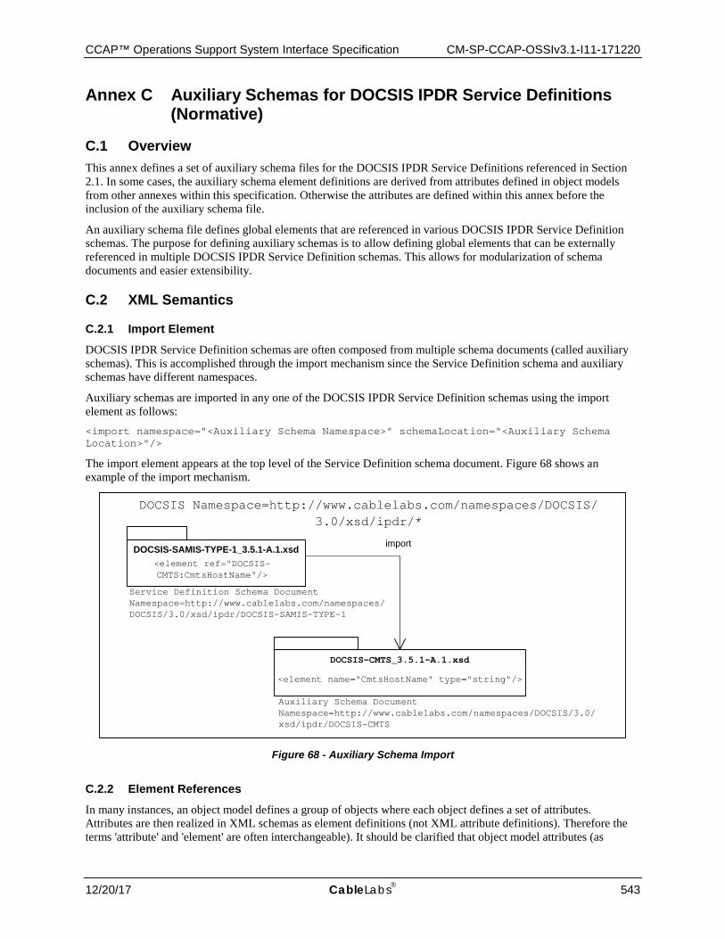
CCAP™ Operations Support System Interface Specification CM-SP-CCAP-OSSIv3.1-I11-171220
12/20/17 CableLabs 543
Annex C Auxiliary Schemas for DOCSIS IPDR Service Definitions (Normative)
C.1 Overview This annex defines a set of auxiliary schema files for the DOCSIS IPDR Service Definitions referenced in Section 2.1. In some cases, the auxiliary schema element definitions are derived from attributes defined in object models from other annexes within this specification. Otherwise the attributes are defined within this annex before the inclusion of the auxiliary schema file.
An auxiliary schema file defines global elements that are referenced in various DOCSIS IPDR Service Definition schemas. The purpose for defining auxiliary schemas is to allow defining global elements that can be externally referenced in multiple DOCSIS IPDR Service Definition schemas. This allows for modularization of schema documents and easier extensibility.
C.2 XML Semantics
C.2.1 Import Element
DOCSIS IPDR Service Definition schemas are often composed from multiple schema documents (called auxiliary schemas). This is accomplished through the import mechanism since the Service Definition schema and auxiliary schemas have different namespaces.
Auxiliary schemas are imported in any one of the DOCSIS IPDR Service Definition schemas using the import element as follows: <import namespace="<Auxiliary Schema Namespace>" schemaLocation="<Auxiliary Schema Location>"/>
The import element appears at the top level of the Service Definition schema document. Figure 68 shows an example of the import mechanism.
DOCSIS-SAMIS-TYPE-1_3.5.1-A.1.xsd
DOCSIS-CMTS_3.5.1-A.1.xsd
DOCSIS Namespace=http://www.cablelabs.com/namespaces/DOCSIS/3.0/xsd/ipdr/*
import
<element name="CmtsHostName" type="string"/>
<element ref="DOCSIS-CMTS:CmtsHostName"/>
Auxiliary Schema DocumentNamespace=http://www.cablelabs.com/namespaces/DOCSIS/3.0/xsd/ipdr/DOCSIS-CMTS
Service Definition Schema DocumentNamespace=http://www.cablelabs.com/namespaces/DOCSIS/3.0/xsd/ipdr/DOCSIS-SAMIS-TYPE-1
Figure 68 - Auxiliary Schema Import
C.2.2 Element References
In many instances, an object model defines a group of objects where each object defines a set of attributes. Attributes are then realized in XML schemas as element definitions (not XML attribute definitions). Therefore the terms 'attribute' and 'element' are often interchangeable). It should be clarified that object model attributes (as
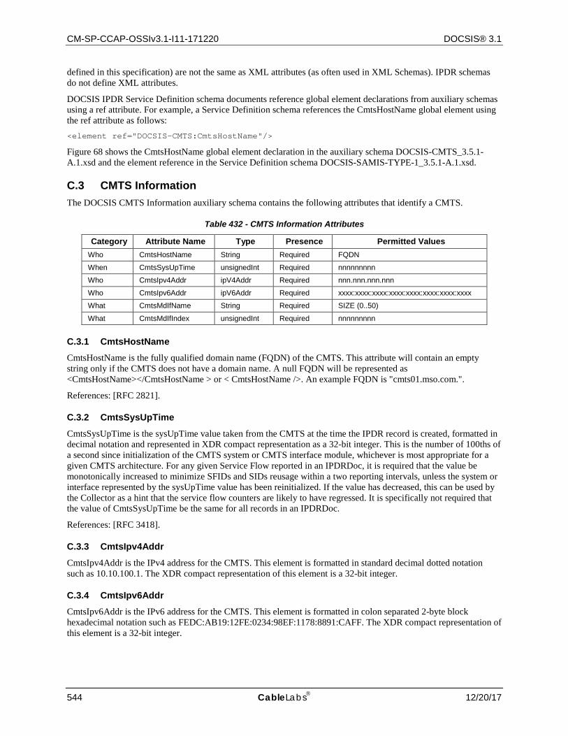
CM-SP-CCAP-OSSIv3.1-I11-171220 DOCSIS® 3.1
544 CableLabs 12/20/17
defined in this specification) are not the same as XML attributes (as often used in XML Schemas). IPDR schemas do not define XML attributes.
DOCSIS IPDR Service Definition schema documents reference global element declarations from auxiliary schemas using a ref attribute. For example, a Service Definition schema references the CmtsHostName global element using the ref attribute as follows: <element ref="DOCSIS-CMTS:CmtsHostName"/>
Figure 68 shows the CmtsHostName global element declaration in the auxiliary schema DOCSIS-CMTS_3.5.1-A.1.xsd and the element reference in the Service Definition schema DOCSIS-SAMIS-TYPE-1_3.5.1-A.1.xsd.
C.3 CMTS Information The DOCSIS CMTS Information auxiliary schema contains the following attributes that identify a CMTS.
Table 432 - CMTS Information Attributes
Category Attribute Name Type Presence Permitted Values Who CmtsHostName String Required FQDN
When CmtsSysUpTime unsignedInt Required nnnnnnnnn
Who CmtsIpv4Addr ipV4Addr Required nnn.nnn.nnn.nnn
Who CmtsIpv6Addr ipV6Addr Required xxxx:xxxx:xxxx:xxxx:xxxx:xxxx:xxxx:xxxx
What CmtsMdIfName String Required SIZE (0..50)
What CmtsMdIfIndex unsignedInt Required nnnnnnnnn
C.3.1 CmtsHostName CmtsHostName is the fully qualified domain name (FQDN) of the CMTS. This attribute will contain an empty string only if the CMTS does not have a domain name. A null FQDN will be represented as <CmtsHostName></CmtsHostName > or < CmtsHostName />. An example FQDN is "cmts01.mso.com.".
References: [RFC 2821].
C.3.2 CmtsSysUpTime
CmtsSysUpTime is the sysUpTime value taken from the CMTS at the time the IPDR record is created, formatted in decimal notation and represented in XDR compact representation as a 32-bit integer. This is the number of 100ths of a second since initialization of the CMTS system or CMTS interface module, whichever is most appropriate for a given CMTS architecture. For any given Service Flow reported in an IPDRDoc, it is required that the value be monotonically increased to minimize SFIDs and SIDs reusage within a two reporting intervals, unless the system or interface represented by the sysUpTime value has been reinitialized. If the value has decreased, this can be used by the Collector as a hint that the service flow counters are likely to have regressed. It is specifically not required that the value of CmtsSysUpTime be the same for all records in an IPDRDoc.
References: [RFC 3418].
C.3.3 CmtsIpv4Addr
CmtsIpv4Addr is the IPv4 address for the CMTS. This element is formatted in standard decimal dotted notation such as 10.10.100.1. The XDR compact representation of this element is a 32-bit integer.
C.3.4 CmtsIpv6Addr CmtsIpv6Addr is the IPv6 address for the CMTS. This element is formatted in colon separated 2-byte block hexadecimal notation such as FEDC:AB19:12FE:0234:98EF:1178:8891:CAFF. The XDR compact representation of this element is a 32-bit integer.

CCAP™ Operations Support System Interface Specification CM-SP-CCAP-OSSIv3.1-I11-171220
12/20/17 CableLabs 545
C.3.5 CmtsMdIfName
CmtsMdIfName contains the first 50 characters of the ifName from the Interfaces Group MIB for the row entry corresponding to the CMTS MAC Domain interface (ifType = 127) for this CM. The ifName is defined as: "The textual name of the interface. The value of this object should be the name of the interface as assigned by the local device and should be suitable for use in commands entered at the device's 'console'. This might be a text name, such as 'le0' or a simple port number, such as '1', depending on the interface naming syntax of the device. If several entries in the ifTable together represent a single interface as named by the device, then each will have the same value of ifName. Note that for an agent which responds to SNMP queries concerning an interface on some other (proxied) device, then the value of ifName for such an interface is the proxied device's local name for it. If there is no local name, or this attribute is otherwise not applicable, then this attribute contains a zero-length string.
References: [RFC 2863].
C.3.6 CmtsMdIfIndex
CmtsMdIfIndex is the ifIndex from the Interfaces Group MIB for the CMTS MAC Domain interface (described in CmtsMdIfName). This value makes the ServiceIdentifier unique.
References: [RFC 2863].
C.4 CM Information Schema Refer to Section 2.1 Normative References for this service definition XML schema.
C.5 Record Information The DOCSIS Record Information auxiliary schema contains the following attributes which define information about an IPDR record. Refer to Section 2.1 Normative References for this service definition XML schema.
Table 433 - Record Information Attributes
Category Attribute Name Type Presence Permitted Values What RecType Integer Required Interim(1)
Stop(2) Start(3) Event(4)
When RecCreationTime dateTimeMsec Required yyyy-mm-ddThh:mm:ss.mmmZ
C.5.1 RecType
The service flow type may be either Interim or Stop. An Interim type indicates a running service flow. A Stop type indicates a terminated service flow. A terminated service flow is only reported once in the IPDRDoc that is created on the cycle after the service flow is deleted. An Interim service flow is reported in each IPDRDoc that is created while it is running.
The CMTS MUST include in the IPDR record the current sample of the active counters for a running service flow.
The CMTS MUST include in the IPDR record the final, logged counter values for a terminated service flow.
C.5.2 RecCreationTime
The RecCreationTime ="yyyy-mm-ddThh:mm:ssZ" UTC time stamp at the time the data for the record was acquired based on CmtsSysUpTime (see CMTS Information section) value. The compact representation of this attribute is the 64-bit Long value since Epoch Time.
The CMTS MUST NOT delete the internal logged SF counters until after the terminated service flow has been recorded into an IPDR record that has been transmitted to a collector and acknowledged or stored in non-volatile memory, regardless of any other capability to manage them via SNMP through the DOCS-QOS3-MIB.
The time zone is always GMT for DOCSIS IPDRs.
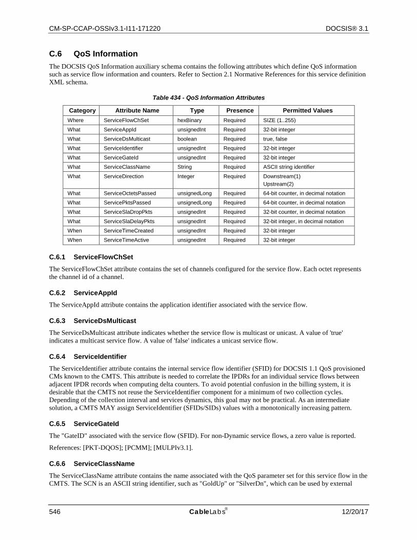
CM-SP-CCAP-OSSIv3.1-I11-171220 DOCSIS® 3.1
546 CableLabs 12/20/17
C.6 QoS Information The DOCSIS QoS Information auxiliary schema contains the following attributes which define QoS information such as service flow information and counters. Refer to Section 2.1 Normative References for this service definition XML schema.
Table 434 - QoS Information Attributes
Category Attribute Name Type Presence Permitted Values Where ServiceFlowChSet hexBinary Required SIZE (1..255)
What ServiceAppId unsignedInt Required 32-bit integer
What ServiceDsMulticast boolean Required true, false
What ServiceIdentifier unsignedInt Required 32-bit integer
What ServiceGateId unsignedInt Required 32-bit integer
What ServiceClassName String Required ASCII string identifier
What ServiceDirection Integer Required Downstream(1) Upstream(2)
What ServiceOctetsPassed unsignedLong Required 64-bit counter, in decimal notation
What ServicePktsPassed unsignedLong Required 64-bit counter, in decimal notation
What ServiceSlaDropPkts unsignedInt Required 32-bit counter, in decimal notation
What ServiceSlaDelayPkts unsignedInt Required 32-bit integer, in decimal notation
When ServiceTimeCreated unsignedInt Required 32-bit integer
When ServiceTimeActive unsignedInt Required 32-bit integer
C.6.1 ServiceFlowChSet
The ServiceFlowChSet attribute contains the set of channels configured for the service flow. Each octet represents the channel id of a channel.
C.6.2 ServiceAppId The ServiceAppId attribute contains the application identifier associated with the service flow.
C.6.3 ServiceDsMulticast
The ServiceDsMulticast attribute indicates whether the service flow is multicast or unicast. A value of 'true' indicates a multicast service flow. A value of 'false' indicates a unicast service flow.
C.6.4 ServiceIdentifier The ServiceIdentifier attribute contains the internal service flow identifier (SFID) for DOCSIS 1.1 QoS provisioned CMs known to the CMTS. This attribute is needed to correlate the IPDRs for an individual service flows between adjacent IPDR records when computing delta counters. To avoid potential confusion in the billing system, it is desirable that the CMTS not reuse the ServiceIdentifier component for a minimum of two collection cycles. Depending of the collection interval and services dynamics, this goal may not be practical. As an intermediate solution, a CMTS MAY assign ServiceIdentifier (SFIDs/SIDs) values with a monotonically increasing pattern.
C.6.5 ServiceGateId
The "GateID" associated with the service flow (SFID). For non-Dynamic service flows, a zero value is reported.
References: [PKT-DQOS]; [PCMM]; [MULPIv3.1].
C.6.6 ServiceClassName
The ServiceClassName attribute contains the name associated with the QoS parameter set for this service flow in the CMTS. The SCN is an ASCII string identifier, such as "GoldUp" or "SilverDn", which can be used by external

CCAP™ Operations Support System Interface Specification CM-SP-CCAP-OSSIv3.1-I11-171220
12/20/17 CableLabs 547
operations systems to assign, monitor, and bill for different levels of bandwidth service without having to interpret the details of the QoS parameter set itself. A service flow is associated with an SCN whenever a cable modem configuration file uses the SCN to define an active service flow. A dynamic service flow application such as PacketCable may also assign an SCN to a service flow as a parameter during the dynamic creation of the service flow. Note that the use of SCNs is optional within the context of the DOCSIS 3.1 MAC and Upper Layer Protocols Interface Specification, however, for operational purposes, especially when billing for tiered data services per this specification, their use often becomes mandatory. Since this policy is within the control of the operator, the use of SCNs is not mandatory in this specification, but rather highly recommended.
The CMTS MUST include the ServiceClassName attribute in the IPDR record. The CMTS MUST encode this attribute as a zero length string if no SCN is used to identify the service flow.
References: [PKT-DQOS]; [MULPIv3.1].
C.6.7 ServiceDirection
The CMTS MUST include the ServiceDirection attribute, which identifies the service flow direction relative to the CMTS RFI interface, as follows:
• Identifies DOCSIS 1.1 downstream service flows passing packets from the CMTS to the CM. • Identifies upstream DOCSIS 1.1 service flows passing packets from the cable modem to the CMTS.
C.6.8 ServiceOctetsPassed
The CMTS MUST include the ServiceOctetsPassed attribute as follows:
• For DOCSIS QoS service flows, ServiceOctetsPassed contains the current (or final) 64-bit count of the number of octets passed, formatted in decimal notation.
If the RecType is Interim, then this is the current value of the running counter. If the RecType is Stop, then this is the final value of the terminated counter. The 64-bit counter value will not wrap around within the service lifetime of the CMTS.
C.6.9 ServicePktsPassed
The CMTS MUST include the ServicePktsPassed attribute as follows:
• For DOCSIS QoS service flows, ServicePktsPassed contains the current (or final) 64-bit count of the number of packets passed, formatted in decimal notation.
If the RecType is Interim, then this is the current value of the running counter. If the RecType is Stop, then this is the final value of the terminated counter. The 64-bit counter value will not wrap around within the service lifetime of the CMTS.
C.6.10 ServiceSlaDropPkts
The CMTS MUST include the ServiceSlaDropPkts attribute as follows:
• For DOCSIS QoS service flows, ServiceSlaDropPkts contains the current (or final) count of packets dropped by this service flow.
This is based on a 32-bit counter value maintained in the CMTS where it is unlikely to overflow within the service lifetime of the DOCSIS QoS service. Note that this value is the count of packets dropped by the CMTS for upstream service flows. Upstream packets dropped by the CM are not counted here.
C.6.11 ServiceSlaDelayPkts
The CMTS MUST include the ServiceSlaDelayPkts attribute as follows:
• For DOCSIS QoS service flows, ServiceSlaDelayPkts contains the current (or final) count of packets delayed by this service flow.
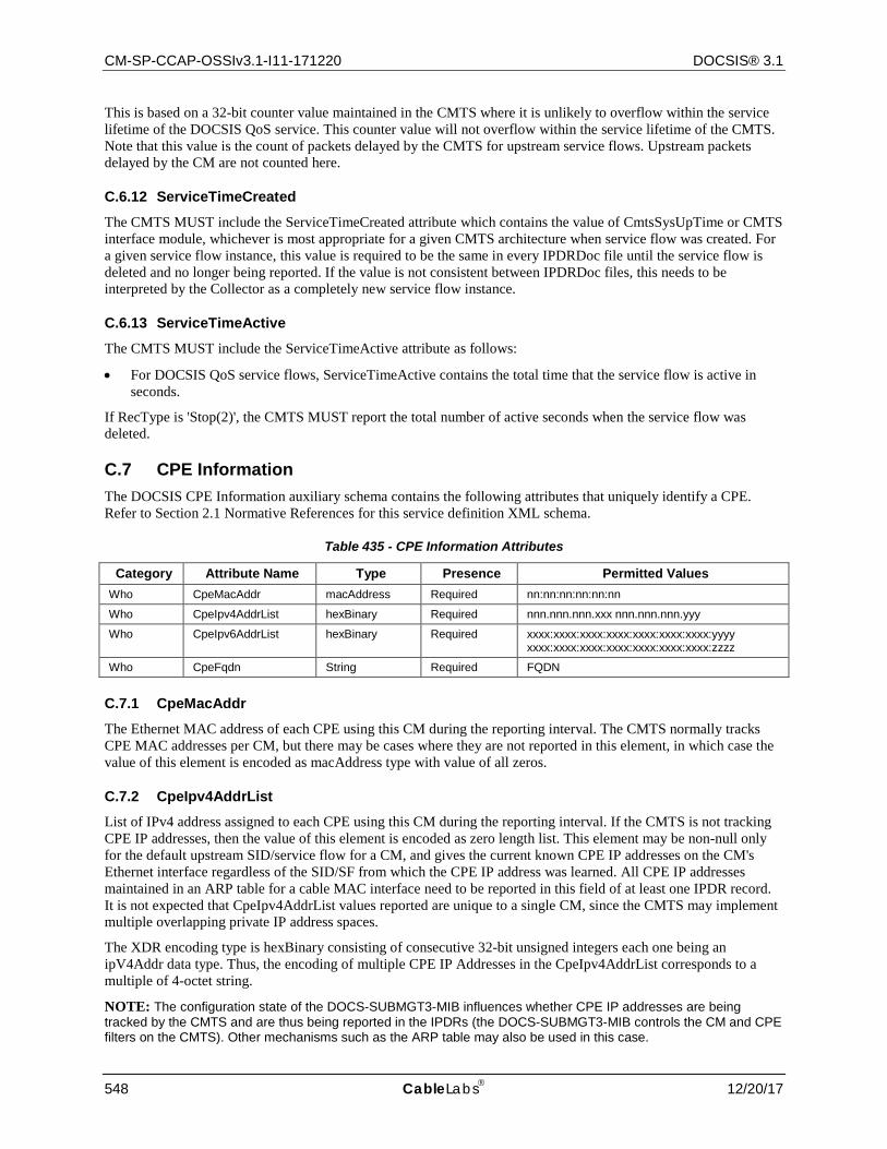
CM-SP-CCAP-OSSIv3.1-I11-171220 DOCSIS® 3.1
548 CableLabs 12/20/17
This is based on a 32-bit counter value maintained in the CMTS where it is unlikely to overflow within the service lifetime of the DOCSIS QoS service. This counter value will not overflow within the service lifetime of the CMTS. Note that this value is the count of packets delayed by the CMTS for upstream service flows. Upstream packets delayed by the CM are not counted here.
C.6.12 ServiceTimeCreated
The CMTS MUST include the ServiceTimeCreated attribute which contains the value of CmtsSysUpTime or CMTS interface module, whichever is most appropriate for a given CMTS architecture when service flow was created. For a given service flow instance, this value is required to be the same in every IPDRDoc file until the service flow is deleted and no longer being reported. If the value is not consistent between IPDRDoc files, this needs to be interpreted by the Collector as a completely new service flow instance.
C.6.13 ServiceTimeActive
The CMTS MUST include the ServiceTimeActive attribute as follows:
• For DOCSIS QoS service flows, ServiceTimeActive contains the total time that the service flow is active in seconds.
If RecType is 'Stop(2)', the CMTS MUST report the total number of active seconds when the service flow was deleted.
C.7 CPE Information The DOCSIS CPE Information auxiliary schema contains the following attributes that uniquely identify a CPE. Refer to Section 2.1 Normative References for this service definition XML schema.
Table 435 - CPE Information Attributes
Category Attribute Name Type Presence Permitted Values Who CpeMacAddr macAddress Required nn:nn:nn:nn:nn:nn
Who CpeIpv4AddrList hexBinary Required nnn.nnn.nnn.xxx nnn.nnn.nnn.yyy
Who CpeIpv6AddrList hexBinary Required xxxx:xxxx:xxxx:xxxx:xxxx:xxxx:xxxx:yyyy xxxx:xxxx:xxxx:xxxx:xxxx:xxxx:xxxx:zzzz
Who CpeFqdn String Required FQDN
C.7.1 CpeMacAddr
The Ethernet MAC address of each CPE using this CM during the reporting interval. The CMTS normally tracks CPE MAC addresses per CM, but there may be cases where they are not reported in this element, in which case the value of this element is encoded as macAddress type with value of all zeros.
C.7.2 CpeIpv4AddrList List of IPv4 address assigned to each CPE using this CM during the reporting interval. If the CMTS is not tracking CPE IP addresses, then the value of this element is encoded as zero length list. This element may be non-null only for the default upstream SID/service flow for a CM, and gives the current known CPE IP addresses on the CM's Ethernet interface regardless of the SID/SF from which the CPE IP address was learned. All CPE IP addresses maintained in an ARP table for a cable MAC interface need to be reported in this field of at least one IPDR record. It is not expected that CpeIpv4AddrList values reported are unique to a single CM, since the CMTS may implement multiple overlapping private IP address spaces.
The XDR encoding type is hexBinary consisting of consecutive 32-bit unsigned integers each one being an ipV4Addr data type. Thus, the encoding of multiple CPE IP Addresses in the CpeIpv4AddrList corresponds to a multiple of 4-octet string.
NOTE: The configuration state of the DOCS-SUBMGT3-MIB influences whether CPE IP addresses are being tracked by the CMTS and are thus being reported in the IPDRs (the DOCS-SUBMGT3-MIB controls the CM and CPE filters on the CMTS). Other mechanisms such as the ARP table may also be used in this case.
CCAP™ Operations Support System Interface Specification CM-SP-CCAP-OSSIv3.1-I11-171220
12/20/17 CableLabs 549
C.7.3 CpeIpv6AddrList
List of IPv6 address assigned to each CPE using this CM during the reporting interval. If the CMTS is not tracking CPE IP addresses, then the value of this element is encoded as zero length list. This element may be non-null only for the default upstream SID/service flow for a CM, and gives the current known CPE IP addresses on the CM's Ethernet interface regardless of the SID/SF from which the CPE IP address was learned. All CPE IP addresses maintained in an ARP table for a cable MAC interface need to be reported in this field of at least one IPDR record. It is not expected that CpeIpv6AddrList values reported are unique to a single CM, since the CMTS may implement multiple overlapping private IP address spaces.
The XDR encoding type is hexBinary consisting of consecutive ipV6Addr data types (4 byte length + 16 byte address encoding). Thus, the encoding of multiple CPE IP Addresses in the CpeIpv6AddrList corresponds to a multiple of 20-octet string.
C.7.4 CpeFqdn
The Fully Qualified Domain Name (FQDN) assigned to each CPE using this CM during the reporting interval. If the CMTS is not tracking CPE FQDNs, then this element will be the zero-length string. This element includes only CPE FQDNs gleaned by the CMTS, such as from DHCP relay, and otherwise stored in the CMTS for reporting or other purposes. It is not required for the CMTS to query perform reverse DNS query to obtain the FQDN of a CPE IP address otherwise reported in the CpeIpv4AddrList or CpeIpv6AddrList field. An example FQDN is "[email protected].".
References: [RFC 2821].
Refer to Section 2.1 Normative References for this service definition XML schema.
C.8 Spectrum Measurement Information Refer to the CmtsSpectrumAnalysisMeas object of Section 6.7.1.2 for the definition of the Spectrum Measurement attributes.
Refer to Section 2.1 Normative References for this service definition XML schema.
C.9 Diagnostic Log Information Refer to the DiagLog and DiagLogDetail objects of Annex A for the definition of the Diagnostic Log attributes.
Refer to Section 2.1 Normative References for this service definition XML schema.
C.10 CMTS CM Upstream Status Information Refer to the CmtsCmUsStatus object of Section 7.2.2.2.2 for the definition of the CMTS CM Upstream Status attributes.
Refer to Section 2.1 Normative References for this service definition XML schema.
C.11 CMTS CM Node Channel Information Refer to the CmtsCmRegStatus object in Section 7 for the definition of the CMTS CM Node Channel attributes.
C.12 CMTS MAC Domain Node Information Refer to the MdNodeStatus, MdDsSgStatus and MdUsSgStatus objects in Section 7 for the definition of the MAC Domain (MD) Node attributes.
Refer to Section 2.1 Normative References for this service definition XML schema.
C.13 CMTS Upstream Utilization Information Refer to Section 2.1 Normative References for this service definition XML schema.
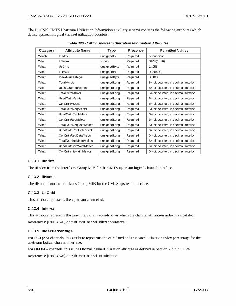
CM-SP-CCAP-OSSIv3.1-I11-171220 DOCSIS® 3.1
550 CableLabs 12/20/17
The DOCSIS CMTS Upstream Utilization Information auxiliary schema contains the following attributes which define upstream logical channel utilization counters.
Table 436 - CMTS Upstream Utilization Information Attributes
Category Attribute Name Type Presence Permitted Values Which IfIndex unsignedInt Required nnnnnnnnn
What IfName String Required SIZE(0..50)
What UsChId unsignedByte Required 1..255
What Interval unsignedInt Required 0..86400
What IndexPercentage unsignedByte Required 0..100
What TotalMslots unsignedLong Required 64-bit counter, in decimal notation
What UcastGrantedMslots unsignedLong Required 64-bit counter, in decimal notation
What TotalCntnMslots unsignedLong Required 64-bit counter, in decimal notation
What UsedCntnMslots unsignedLong Required 64-bit counter, in decimal notation
What CollCntnMslots unsignedLong Required 64-bit counter, in decimal notation
What TotalCntnReqMslots unsignedLong Required 64-bit counter, in decimal notation
What UsedCntnReqMslots unsignedLong Required 64-bit counter, in decimal notation
What CollCntnReqMslots unsignedLong Required 64-bit counter, in decimal notation
What TotalCntnReqDataMslots unsignedLong Required 64-bit counter, in decimal notation
What UsedCntnReqDataMslots unsignedLong Required 64-bit counter, in decimal notation
What CollCntnReqDataMslots unsignedLong Required 64-bit counter, in decimal notation
What TotalCntnInitMaintMslots unsignedLong Required 64-bit counter, in decimal notation
What UsedCntnInitMaintMslots unsignedLong Required 64-bit counter, in decimal notation
What CollCntnInitMaintMslots unsignedLong Required 64-bit counter, in decimal notation
C.13.1 IfIndex
The ifIndex from the Interfaces Group MIB for the CMTS upstream logical channel interface.
C.13.2 ifName
The ifName from the Interfaces Group MIB for the CMTS upstream interface.
C.13.3 UsChId
This attribute represents the upstream channel id.
C.13.4 Interval
This attribute represents the time interval, in seconds, over which the channel utilization index is calculated.
References: [RFC 4546] docsIfCmtsChannelUtilizationInterval.
C.13.5 IndexPercentage
For SC-QAM channels, this attribute represents the calculated and truncated utilization index percentage for the upstream logical channel interface.
For OFDMA channels, this is the OfdmaChannelUtilization attribute as defined in Section 7.2.2.7.1.1.24.
References: [RFC 4546] docsIfCmtsChannelUtUtilization.
CCAP™ Operations Support System Interface Specification CM-SP-CCAP-OSSIv3.1-I11-171220
12/20/17 CableLabs 551
C.13.6 TotalMslots
This attribute represents the current count, from CMTS initialization, of all minislots defined for this upstream logical channel interface. This count includes all IUCs and SIDs, even those allocated to the NULL SID for a logical channel that is inactive.
Reference: [RFC 4546] docsIfCmtsUpChnlCtrExtTotalMslots.
C.13.7 UcastGrantedMslots
This attribute represents the current count, from CMTS initialization, of unicast granted minislots on the upstream logical channel regardless of burst type. Unicast granted minislots are those in which the CMTS assigned bandwidth to any unicast SID on the logical channel. However, this object does not include minislots for reserved IUCs, or grants to SIDs designated as meaning 'no CM'.
References: [RFC 4546] docsIfCmtsUpChnlCtrExtUcastGrantedMslots.
C.13.8 TotalCntnMslots
This attribute represents the current count, from CMTS initialization, of contention minislots defined for this upstream logical channel. This count includes all minislots assigned to a broadcast or multicast SID on the logical channel.
References: [RFC 4546] docsIfCmtsUpChnlCtrExtTotalCntnMslots.
C.13.9 UsedCntnMslots
This attribute represents the current count, from CMTS initialization, of contention minislots utilized on the upstream logical channel. For contention regions, utilized minislots are those in which the CMTS correctly received an upstream burst from any CM on the upstream logical channel.
References: [RFC 4546] docsIfCmtsUpChnlCtrExtUsedCntnMslots.
C.13.10 CollCntnMslots
This attribute represents the current count, from CMTS initialization, of collision contention minislots on the upstream logical channel. For contention regions, these are the minislots applicable to burst that the CMTS detected but could not correctly receive.
References: [RFC 4546] docsIfCmtsUpChnlCtrExtCollCntnMslots.
C.13.11 TotalCntnReqMslots
This attribute represents the current count, from CMTS initialization, of contention request minislots defined for this upstream logical channel. This count includes all minislots for IUC1 assigned to a broadcast or multicast SID on the logical channel.
References: [RFC 4546] docsIfCmtsUpChnlCtrExtTotalCntnReqMslots.
C.13.12 UsedCntnReqMslots This attribute represents the current count, from CMTS initialization, of contention request minislots utilized on this upstream logical channel. This count includes all contention minislots for UIC1 applicable to bursts that the CMTS correctly received.
References: [RFC 4546] docsIfCmtsUpChnlCtrExtUsedCntnReqMslots.
C.13.13 CollCntnReqMslots
This attribute represents the current count, from CMTS initialization, of contention request minislots subjected to collisions on this upstream logical channel. This includes all contention minislots for IUC1 applicable to bursts that the CMTS detected but could not correctly receive.
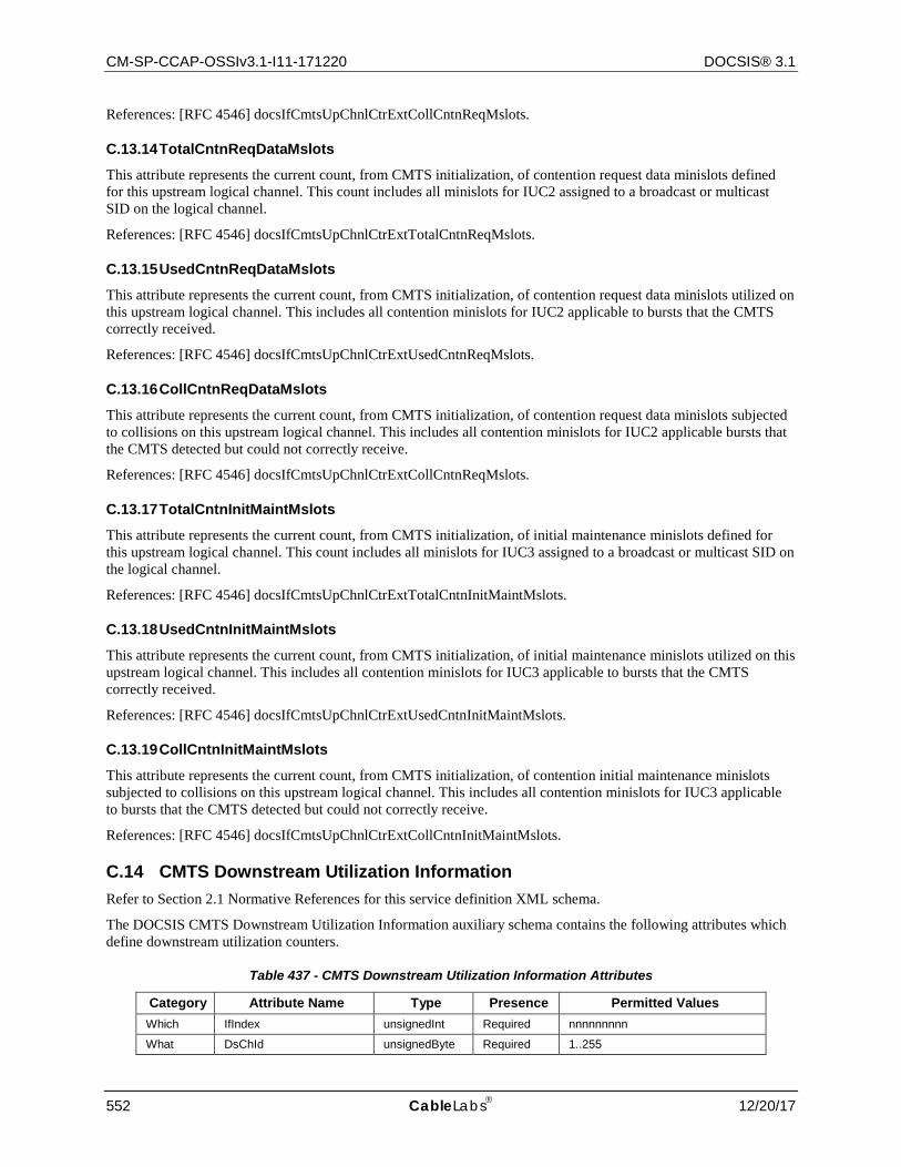
CM-SP-CCAP-OSSIv3.1-I11-171220 DOCSIS® 3.1
552 CableLabs 12/20/17
References: [RFC 4546] docsIfCmtsUpChnlCtrExtCollCntnReqMslots.
C.13.14 TotalCntnReqDataMslots
This attribute represents the current count, from CMTS initialization, of contention request data minislots defined for this upstream logical channel. This count includes all minislots for IUC2 assigned to a broadcast or multicast SID on the logical channel.
References: [RFC 4546] docsIfCmtsUpChnlCtrExtTotalCntnReqMslots.
C.13.15 UsedCntnReqDataMslots
This attribute represents the current count, from CMTS initialization, of contention request data minislots utilized on this upstream logical channel. This includes all contention minislots for IUC2 applicable to bursts that the CMTS correctly received.
References: [RFC 4546] docsIfCmtsUpChnlCtrExtUsedCntnReqMslots.
C.13.16 CollCntnReqDataMslots
This attribute represents the current count, from CMTS initialization, of contention request data minislots subjected to collisions on this upstream logical channel. This includes all contention minislots for IUC2 applicable bursts that the CMTS detected but could not correctly receive.
References: [RFC 4546] docsIfCmtsUpChnlCtrExtCollCntnReqMslots.
C.13.17 TotalCntnInitMaintMslots
This attribute represents the current count, from CMTS initialization, of initial maintenance minislots defined for this upstream logical channel. This count includes all minislots for IUC3 assigned to a broadcast or multicast SID on the logical channel.
References: [RFC 4546] docsIfCmtsUpChnlCtrExtTotalCntnInitMaintMslots.
C.13.18 UsedCntnInitMaintMslots
This attribute represents the current count, from CMTS initialization, of initial maintenance minislots utilized on this upstream logical channel. This includes all contention minislots for IUC3 applicable to bursts that the CMTS correctly received.
References: [RFC 4546] docsIfCmtsUpChnlCtrExtUsedCntnInitMaintMslots.
C.13.19 CollCntnInitMaintMslots
This attribute represents the current count, from CMTS initialization, of contention initial maintenance minislots subjected to collisions on this upstream logical channel. This includes all contention minislots for IUC3 applicable to bursts that the CMTS detected but could not correctly receive.
References: [RFC 4546] docsIfCmtsUpChnlCtrExtCollCntnInitMaintMslots.
C.14 CMTS Downstream Utilization Information Refer to Section 2.1 Normative References for this service definition XML schema.
The DOCSIS CMTS Downstream Utilization Information auxiliary schema contains the following attributes which define downstream utilization counters.
Table 437 - CMTS Downstream Utilization Information Attributes
Category Attribute Name Type Presence Permitted Values Which IfIndex unsignedInt Required nnnnnnnnn
What DsChId unsignedByte Required 1..255

CCAP™ Operations Support System Interface Specification CM-SP-CCAP-OSSIv3.1-I11-171220
12/20/17 CableLabs 553
Category Attribute Name Type Presence Permitted Values What IfName String Required SIZE(0..50)
What Interval unsignedInt Required 0..86400
What IndexPercentage unsignedByte Required 0..100
What TotalBytes unsignedLong Required 64-bit counter, in decimal notation
What UsedBytes unsignedLong Required 64-bit counter, in decimal notation
C.14.1 IfIndex
The ifIndex from the Interfaces Group MIB for the CMTS downstream interface.
C.14.2 IfName
The ifName from the Interfaces Group MIB for the CMTS downstream interface.
C.14.3 DsChId
This attribute represents the downstream channel id.
C.14.4 Interval This attribute represents the time interval, in seconds, over which the channel utilization index is calculated.
References: [RFC 4546] docsIfCmtsChannelUtilizationInterval.
C.14.5 IndexPercentage
For SC-QAM channels, this attribute represents the calculated and truncated utilization index percentage for the downstream interface.
For OFDM channels, this is the OfdmChannelUtilization attribute as defined in Section 7.2.2.8.1.22.
References: [RFC 4546] docsIfCmtsChannelUtUtilization.
C.14.6 TotalBytes
For SC-QAM channels, this attribute represents the total number of bytes in the payload portion of MPEG Packets, not including MPEG header or pointer_field, transported by the downstream interface.
For OFDM channels, this is the largest ProfileFullChanSpeed assigned to this channel * the DsUtilInterval *8. Refer to Section 7.2.2.8.4.3.
Reference: [RFC 4546] docsIfCmtsDownChnlCtrExtTotalBytes.
C.14.7 UsedBytes
For SC-QAM channels, this attribute represents the total number of DOCSIS data bytes transported by the downstream interface. The number of data bytes is defined as the total number of bytes transported in DOCSIS payloads minus the number of stuff bytes transported in DOCSIS payloads.
For OFDM channels, this is DsUtilTotalBytes * DsUtilIndexPercentage.
References: [RFC 4546] docsIfCmtsDownChnlCtrExtUsedBytes.
C.15 Service Flow Information Refer to Section 2.1 Normative References for this service definition XML schema.
The DOCSIS Service Flow Information auxiliary schema contain the following attributes that describe the configured QoS parameters.
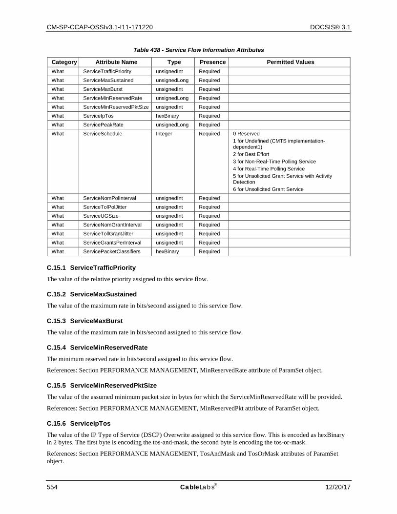
CM-SP-CCAP-OSSIv3.1-I11-171220 DOCSIS® 3.1
554 CableLabs 12/20/17
Table 438 - Service Flow Information Attributes
Category Attribute Name Type Presence Permitted Values What ServiceTrafficPriority unsignedInt Required
What ServiceMaxSustained unsignedLong Required
What ServiceMaxBurst unsignedInt Required
What ServiceMinReservedRate unsignedLong Required
What ServiceMinReservedPktSize unsignedInt Required
What ServiceIpTos hexBinary Required
What ServicePeakRate unsignedLong Required
What ServiceSchedule Integer Required 0 Reserved 1 for Undefined (CMTS implementation-dependent1) 2 for Best Effort 3 for Non-Real-Time Polling Service 4 for Real-Time Polling Service 5 for Unsolicited Grant Service with Activity Detection 6 for Unsolicited Grant Service
What ServiceNomPolInterval unsignedInt Required
What ServiceTolPolJitter unsignedInt Required
What ServiceUGSize unsignedInt Required
What ServiceNomGrantInterval unsignedInt Required
What ServiceTollGrantJitter unsignedInt Required
What ServiceGrantsPerInterval unsignedInt Required
What ServicePacketClassifiers hexBinary Required
C.15.1 ServiceTrafficPriority
The value of the relative priority assigned to this service flow.
C.15.2 ServiceMaxSustained
The value of the maximum rate in bits/second assigned to this service flow.
C.15.3 ServiceMaxBurst
The value of the maximum rate in bits/second assigned to this service flow.
C.15.4 ServiceMinReservedRate
The minimum reserved rate in bits/second assigned to this service flow.
References: Section PERFORMANCE MANAGEMENT, MinReservedRate attribute of ParamSet object.
C.15.5 ServiceMinReservedPktSize
The value of the assumed minimum packet size in bytes for which the ServiceMinReservedRate will be provided.
References: Section PERFORMANCE MANAGEMENT, MinReservedPkt attribute of ParamSet object.
C.15.6 ServiceIpTos
The value of the IP Type of Service (DSCP) Overwrite assigned to this service flow. This is encoded as hexBinary in 2 bytes. The first byte is encoding the tos-and-mask, the second byte is encoding the tos-or-mask.
References: Section PERFORMANCE MANAGEMENT, TosAndMask and TosOrMask attributes of ParamSet object.
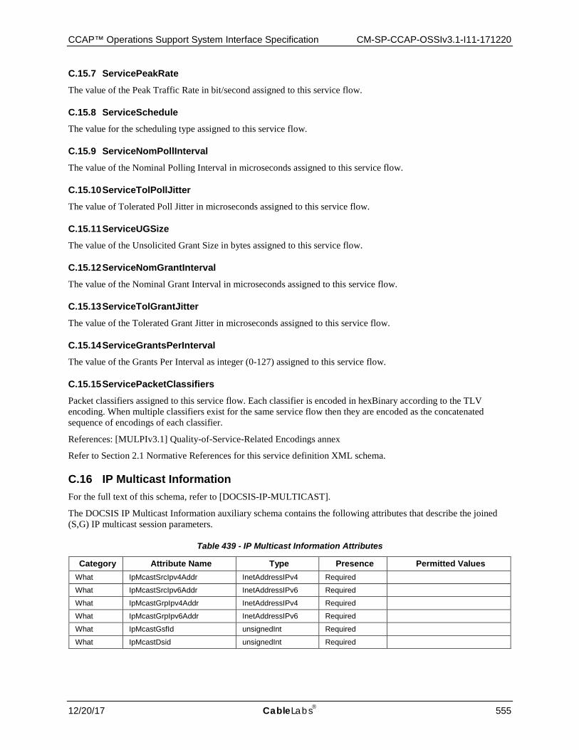
CCAP™ Operations Support System Interface Specification CM-SP-CCAP-OSSIv3.1-I11-171220
12/20/17 CableLabs 555
C.15.7 ServicePeakRate
The value of the Peak Traffic Rate in bit/second assigned to this service flow.
C.15.8 ServiceSchedule The value for the scheduling type assigned to this service flow.
C.15.9 ServiceNomPollInterval
The value of the Nominal Polling Interval in microseconds assigned to this service flow.
C.15.10 ServiceTolPollJitter
The value of Tolerated Poll Jitter in microseconds assigned to this service flow.
C.15.11 ServiceUGSize The value of the Unsolicited Grant Size in bytes assigned to this service flow.
C.15.12 ServiceNomGrantInterval
The value of the Nominal Grant Interval in microseconds assigned to this service flow.
C.15.13 ServiceTolGrantJitter
The value of the Tolerated Grant Jitter in microseconds assigned to this service flow.
C.15.14 ServiceGrantsPerInterval The value of the Grants Per Interval as integer (0-127) assigned to this service flow.
C.15.15 ServicePacketClassifiers
Packet classifiers assigned to this service flow. Each classifier is encoded in hexBinary according to the TLV encoding. When multiple classifiers exist for the same service flow then they are encoded as the concatenated sequence of encodings of each classifier.
References: [MULPIv3.1] Quality-of-Service-Related Encodings annex
Refer to Section 2.1 Normative References for this service definition XML schema.
C.16 IP Multicast Information For the full text of this schema, refer to [DOCSIS-IP-MULTICAST].
The DOCSIS IP Multicast Information auxiliary schema contains the following attributes that describe the joined (S,G) IP multicast session parameters.
Table 439 - IP Multicast Information Attributes
Category Attribute Name Type Presence Permitted Values What IpMcastSrcIpv4Addr InetAddressIPv4 Required
What IpMcastSrcIpv6Addr InetAddressIPv6 Required
What IpMcastGrpIpv4Addr InetAddressIPv4 Required
What IpMcastGrpIpv6Addr InetAddressIPv6 Required
What IpMcastGsfId unsignedInt Required
What IpMcastDsid unsignedInt Required
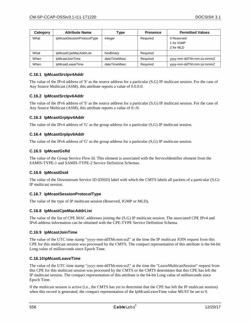
CM-SP-CCAP-OSSIv3.1-I11-171220 DOCSIS® 3.1
556 CableLabs 12/20/17
Category Attribute Name Type Presence Permitted Values What IpMcastSessionProtocolType Integer Required 0 Reserved
1 for IGMP 2 for MLD
What IpMcastCpeMacAddrList hexBinary Required
When IpMcastJoinTime dateTimeMsec Required yyyy-mm-ddThh:mm:ss:mmmZ
When IpMcastLeaveTime dateTimeMsec Required yyyy-mm-ddThh:mm:ss:mmmZ
C.16.1 IpMcastSrcIpv4Addr
The value of the IPv4 address of 'S' as the source address for a particular (S,G) IP multicast session. For the case of Any Source Multicast (ASM), this attribute reports a value of 0.0.0.0.
C.16.2 IpMcastSrcIpv6Addr
The value of the IPv6 address of 'S' as the source address for a particular (S,G) IP multicast session. For the case of Any Source Multicast (ASM), this attribute reports a value of 0::/0.
C.16.3 IpMcastGrpIpv4Addr
The value of the IPv4 address of 'G' as the group address for a particular (S,G) IP multicast session.
C.16.4 IpMcastGrpIpv6Addr
The value of the IPv6 address of 'G' as the group address for a particular (S,G) IP multicast session.
C.16.5 IpMcastGsfId
The value of the Group Service Flow Id. This element is associated with the ServiceIdentifier element from the SAMIS-TYPE-1 and SAMIS-TYPE-2 Service Definition Schemas.
C.16.6 IpMcastDsid
The value of the Downstream Service ID (DSID) label with which the CMTS labels all packets of a particular (S,G) IP multicast session.
C.16.7 IpMcastSessionProtocolType
The value of the type of IP multicast session (Reserved, IGMP or MLD).
C.16.8 IpMcastCpeMacAddrList
The value of the list of CPE MAC addresses joining the (S,G) IP multicast session. The associated CPE IPv4 and IPv6 address information can be obtained with the CPE-TYPE Service Definition Schema.
C.16.9 IpMcastJoinTime The value of the UTC time stamp "yyyy-mm-ddThh:mm:ssZ" at the time the IP multicast JOIN request from this CPE for this multicast session was processed by the CMTS. The compact representation of this attribute is the 64-bit Long value of milliseconds since Epoch Time.
C.16.10 IpMcastLeaveTime
The value of the UTC time stamp "yyyy-mm-ddThh:mm:ssZ" at the time the "LeaveMulticastSession" request from this CPE for this multicast session was processed by the CMTS or the CMTS determines that this CPE has left the IP multicast session. The compact representation of this attribute is the 64-bit Long value of milliseconds since Epoch Time.
If the multicast session is active (i.e., the CMTS has yet to determine that the CPE has left the IP multicast session) when this record is generated, the compact representation of the IpMcastLeaveTime value MUST be set to 0.

CCAP™ Operations Support System Interface Specification CM-SP-CCAP-OSSIv3.1-I11-171220
12/20/17 CableLabs 557
Reference: [MULPIv3.0] Downstream Multicast Forwarding section.
C.17 CMTS CM Downstream OFDM Information Refer to the CmtsCmRegStatus object of Section 7.2.2.2.1 for the definition of the attributes found in the CMTS CM Downstream OFDM Information Schema.
Refer to Section 2.1 Normative References for this service definition XML schema.
C.18 CMTS CM Partial Channel/Service Information Refer to the attributes related to Partial Channel and Partial Service conditions in the CmtsCmRegStatus, CmtsCmDsOfdmStatus, CmtsCmDsOfdmProfileStatus, CmtsCmUsOfdmaStatus and CmtsCmUsOfdmaProfile objects of Section 7.2.2 for the definition of the attributes found in the CMTS CM Partial Channel/Service Information Schema.
Refer to Section 2.1 Normative References for this service definition XML schema.
C.19 CMTS CM Upstream OFDMA Information Refer to the CmtsCmUsOfdmaStatus object of Section 7.2.2.2.3 for the definition of the attributes found in the CMTS CM Upstream OFDMA Information Schema.
Refer to Section 2.1 Normative References for this service definition XML schema.
C.20 OFDM Profile Status Information Refer to the CmtsCmRegStatus, CmtsCmDsOfdmProfileStatus and CmtsCmUsOfdmaProfile objects of Section 7.2.2 as well as the UsOfdmaChannelDataIucStats object of Section 7.2.2.7.3 and the DsOfdmProfileStats object of Section 7.2.2.8.4 for the definition of the OFDM Profile Status attributes. Note: in this case the term "OFDM Profile" is used generically to apply to either a downstream OFDM profile or an upstream OFDMA profile/data IUC.
Refer to Section 2.1 Normative References for this service definition XML schema.
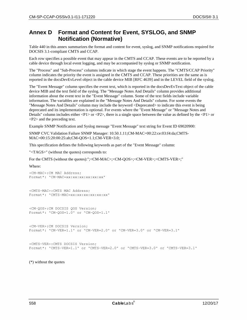
CM-SP-CCAP-OSSIv3.1-I11-171220 DOCSIS® 3.1
558 CableLabs 12/20/17
Annex D Format and Content for Event, SYSLOG, and SNMP Notification (Normative)
Table 440 in this annex summarizes the format and content for event, syslog, and SNMP notifications required for DOCSIS 3.1-compliant CMTS and CCAP.
Each row specifies a possible event that may appear in the CMTS and CCAP. These events are to be reported by a cable device through local event logging, and may be accompanied by syslog or SNMP notification.
The "Process" and "Sub-Process" columns indicate in which stage the event happens. The "CMTS/CCAP Priority" column indicates the priority the event is assigned in the CMTS and CCAP. These priorities are the same as is reported in the docsDevEvLevel object in the cable device MIB [RFC 4639] and in the LEVEL field of the syslog.
The "Event Message" column specifies the event text, which is reported in the docsDevEvText object of the cable device MIB and the text field of the syslog. The "Message Notes And Details" column provides additional information about the event text in the "Event Message" column. Some of the text fields include variable information. The variables are explained in the "Message Notes And Details" column. For some events the "Message Notes And Details" column may include the keyword <Deprecated> to indicate this event is being deprecated and its implementation is optional. For events where the "Event Message" or "Message Notes and Details" column includes either <P1> or <P2>, there is a single space between the value as defined by the <P1> or <P2> and the preceding text.
Example SNMP Notification and Syslog message "Event Message" text string for Event ID 69020900:
SNMP CVC Validation Failure SNMP Manager: 10.50.1.11;CM-MAC=00:22:ce:03:f4:da;CMTS-MAC=00:15:20:00:25:ab;CM-QOS=1.1;CM-VER=3.0;
This specification defines the following keywords as part of the "Event Message" column:
"<TAGS>" (without the quotes) corresponds to:
For the CMTS (without the quotes):";<CM-MAC>;<CM-QOS>;<CM-VER>;<CMTS-VER>;"
Where: <CM-MAC>:CM MAC Address; Format*: "CM-MAC=xx:xx:xx:xx:xx:xx"
<CMTS-MAC>:CMTS MAC Address; Format*: "CMTS-MAC=xx:xx:xx:xx:xx:xx"
<CM-QOS>:CM DOCSIS QOS Version; Format*: "CM-QOS=1.0" or "CM-QOS=1.1"
<CM-VER>:CM DOCSIS Version; Format*: "CM-VER=1.1" or "CM-VER=2.0" or "CM-VER=3.0" or "CM-VER=3.1"
<CMTS-VER>:CMTS DOCSIS Version; Format*: "CMTS-VER=1.1" or "CMTS-VER=2.0" or "CMTS-VER=3.0" or "CMTS-VER=3.1"
(*) without the quotes

CCAP™ Operations Support System Interface Specification CM-SP-CCAP-OSSIv3.1-I11-171220
12/20/17 CableLabs 559
The CCAP MUST support all mandatory events as defined in Table 440, as well as the list of events defined in Table 441. The CMTS MUST support all mandatory events defined in Table 441.
Example SNMP Notification and Syslog message "Event Message" text string for Event ID 69010100: SW Download INIT - Via NMS SW file: junk.bin - SW server: 10.50.1.11;CM-MAC=00:22:ce:03:f4:da;CMTS-MAC=00:15:20:00:25:ab;CM-QOS=1.1;CM-VER=3.0;
The CMTS and CCAP MAY append additional vendor-specific text to the end of the event text reported in the docsDevEvText object and the syslog text field.
The "Error Code Set" column specifies the error code. The "Event ID" column indicates a unique identification number for the event, which is assigned to the docsDevEvId object in the cable device MIB and the <eventId> field of the syslog. The "Notification Name" column specifies the SNMP notification, which notifies this event to an SNMP notification receiver.
The syslog format, as well as the rules to uniquely generate an event ID from the error code, are described in Section 9.2.2.1.3 of this specification.
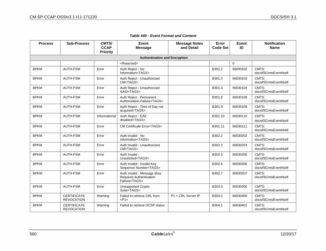
CM-SP-CCAP-OSSIv3.1-I11-171220 DOCSIS® 3.1
560 CableLabs 12/20/17
Table 440 - Event Format and Content
Process Sub-Process CMTS/ CCAP
Priority
Event Message
Message Notes and Detail
Error Code Set
Event ID
Notification Name
Authentication and Encryption <Reserved> 0
BPKM AUTH-FSM Error Auth Reject - No Information<TAGS> B301.2 66030102 CMTS:
docsIf3CmtsEventNotif
BPKM AUTH-FSM Error Auth Reject - Unauthorized CM<TAGS> B301.3 66030103 CMTS:
docsIf3CmtsEventNotif
BPKM AUTH-FSM Error Auth Reject - Unauthorized SAID<TAGS> B301.4 66030104 CMTS:
docsIf3CmtsEventNotif
BPKM AUTH-FSM Error Auth Reject - Permanent Authorization Failure<TAGS> B301.8 66030108 CMTS:
docsIf3CmtsEventNotif
BPKM AUTH-FSM Error Auth Reject - Time of Day not acquired<TAGS> B301.9 66030109 CMTS:
docsIf3CmtsEventNotif
BPKM AUTH-FSM Informational Auth Reject - EAE disabled<TAGS> B301.10 66030110 CMTS:
docsIf3CmtsEventNotif
BPKM AUTH-FSM Error CM Certificate Error<TAGS> B301.11 66030111 CMTS: docsIf3CmtsEventNotif
BPKM AUTH-FSM Error Auth Invalid - No Information<TAGS> B302.2 66030202 CMTS:
docsIf3CmtsEventNotif
BPKM AUTH-FSM Error Auth Invalid - Unauthorized CM<TAGS> B302.3 66030203 CMTS:
docsIf3CmtsEventNotif
BPKM AUTH-FSM Error Auth Invalid - Unsolicited<TAGS> B302.5 66030205 CMTS:
docsIf3CmtsEventNotif
BPKM AUTH-FSM Error Auth Invalid - Invalid Key Sequence Number<TAGS> B302.6 66030206 CMTS:
docsIf3CmtsEventNotif
BPKM AUTH-FSM Error Auth Invalid - Message (Key Request) Authentication Failure<TAGS>
B302.7 66030207 CMTS: docsIf3CmtsEventNotif
BPKM AUTH-FSM Error Unsupported Crypto Suite<TAGS> B303.0 66030300 CMTS:
docsIf3CmtsEventNotif
BPKM CERTIFICATE REVOCATION
Warning Failed to retrieve CRL from <P1>
P1 = CRL Server IP B304.0 66030400 CMTS: docsIf3CmtsEventNotif
BPKM CERTIFICATE REVOCATION
Warning Failed to retrieve OCSP status B304.1 66030401 CMTS: docsIf3CmtsEventNotif
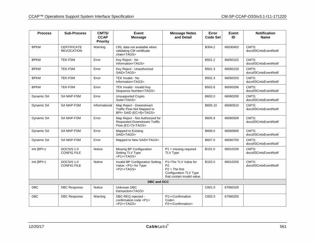
CCAP™ Operations Support System Interface Specification CM-SP-CCAP-OSSIv3.1-I11-171220
12/20/17 CableLabs 561
Process Sub-Process CMTS/ CCAP
Priority
Event Message
Message Notes and Detail
Error Code Set
Event ID
Notification Name
BPKM CERTIFICATE REVOCATION
Warning CRL data not available when validating CM certificate chain<TAGS>
B304.2 66030402 CMTS: docsIf3CmtsEventNotif
BPKM TEK-FSM Error Key Reject - No Information<TAGS> B501.2 66050102 CMTS:
docsIf3CmtsEventNotif
BPKM TEK-FSM Error Key Reject - Unauthorized SAID<TAGS> B501.3 66050103 CMTS:
docsIf3CmtsEventNotif
BPKM TEK-FSM Error TEK Invalid - No Information<TAGS> B502.3 66050203 CMTS:
docsIf3CmtsEventNotif
BPKM TEK-FSM Error TEK Invalid - Invalid Key Sequence Number<TAGS> B502.6 66050206 CMTS:
docsIf3CmtsEventNotif
Dynamic SA SA MAP-FSM Error Unsupported Crypto Suite<TAGS> B602.0 66060200 CMTS:
docsIf3CmtsEventNotif
Dynamic SA SA MAP-FSM Informational Map Reject - Downstream Traffic Flow Not Mapped to BPI+ SAID (EC=8)<TAGS>
B605.10 66060510 CMTS: docsIf3CmtsEventNotif
Dynamic SA SA MAP-FSM Error Map Reject - Not Authorized for Requested Downstream Traffic Flow (EC=7)<TAGS>
B605.9 66060509 CMTS: docsIf3CmtsEventNotif
Dynamic SA SA MAP-FSM Error Mapped to Existing SAID<TAGS> B606.0 66060600 CMTS:
docsIf3CmtsEventNotif
Dynamic SA SA MAP-FSM Error Mapped to New SAID<TAGS> B607.0 66060700 CMTS: docsIf3CmtsEventNotif
Init (BPI+) DOCSIS 1.0 CONFIG FILE
Notice Missing BP Configuration Setting TLV Type: <P1><TAGS>
P1 = missing required TLV Type
B101.0 66010100 CMTS: docsIf3CmtsEventNotif
Init (BPI+) DOCSIS 1.0 CONFIG FILE
Notice Invalid BP Configuration Setting Value: <P1> for Type: <P2><TAGS>
P1=The TLV Value for P2. P2 = The first Configuration TLV Type that contain invalid value.
B102.0 66010200 CMTS: docsIf3CmtsEventNotif
DBC and DCC DBC DBC Response Notice Unknown DBC
transaction<TAGS> C601.0 67060100
DBC DBC Response Warning DBC-REQ rejected - confirmation code <P1>: <P2><TAGS>
P1=<Confirmation Code> P2=<Confirmation>
C602.0 67060200
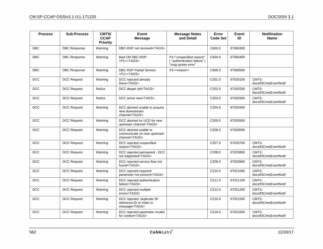
CM-SP-CCAP-OSSIv3.1-I11-171220 DOCSIS® 3.1
562 CableLabs 12/20/17
Process Sub-Process CMTS/ CCAP
Priority
Event Message
Message Notes and Detail
Error Code Set
Event ID
Notification Name
DBC DBC Response Warning DBC-RSP not received<TAGS> C603.0 67060300
DBC DBC Response Warning Bad CM DBC-RSP: <P1><TAGS>
P1="unspecified reason" | "authentication failure" | "msg syntax error"
C604.0 67060400
DBC DBC Response Warning DBC-RSP Partial Service <P1><TAGS>
P1=<reason> C605.0 67060500
DCC DCC Request Warning DCC rejected already there<TAGS> C201.0 67020100 CMTS:
docsIf3CmtsEventNotif
DCC DCC Request Notice DCC depart old<TAGS> C202.0 67020200 CMTS: docsIf3CmtsEventNotif
DCC DCC Request Notice DCC arrive new<TAGS> C203.0 67020300 CMTS: docsIf3CmtsEventNotif
DCC DCC Request Warning DCC aborted unable to acquire new downstream channel<TAGS>
C204.0 67020400
DCC DCC Request Warning DCC aborted no UCD for new upstream channel<TAGS> C205.0 67020500
DCC DCC Request Warning DCC aborted unable to communicate on new upstream channel<TAGS>
C206.0 67020600
DCC DCC Request Warning DCC rejected unspecified reason<TAGS> C207.0 67020700 CMTS:
docsIf3CmtsEventNotif
DCC DCC Request Warning DCC rejected permanent - DCC not supported<TAGS> C208.0 67020800 CMTS:
docsIf3CmtsEventNotif
DCC DCC Request Warning DCC rejected service flow not found<TAGS> C209.0 67020900 CMTS:
docsIf3CmtsEventNotif
DCC DCC Request Warning DCC rejected required parameter not present<TAGS> C210.0 67021000 CMTS:
docsIf3CmtsEventNotif
DCC DCC Request Warning DCC rejected authentication failure<TAGS> C211.0 67021100 CMTS:
docsIf3CmtsEventNotif
DCC DCC Request Warning DCC rejected multiple errors<TAGS> C212.0 67021200 CMTS:
docsIf3CmtsEventNotif
DCC DCC Request Warning DCC rejected, duplicate SF reference-ID or index in message<TAGS>
C215.0 67021500 CMTS: docsIf3CmtsEventNotif
DCC DCC Request Warning DCC rejected parameter invalid for context<TAGS> C216.0 67021600 CMTS:
docsIf3CmtsEventNotif
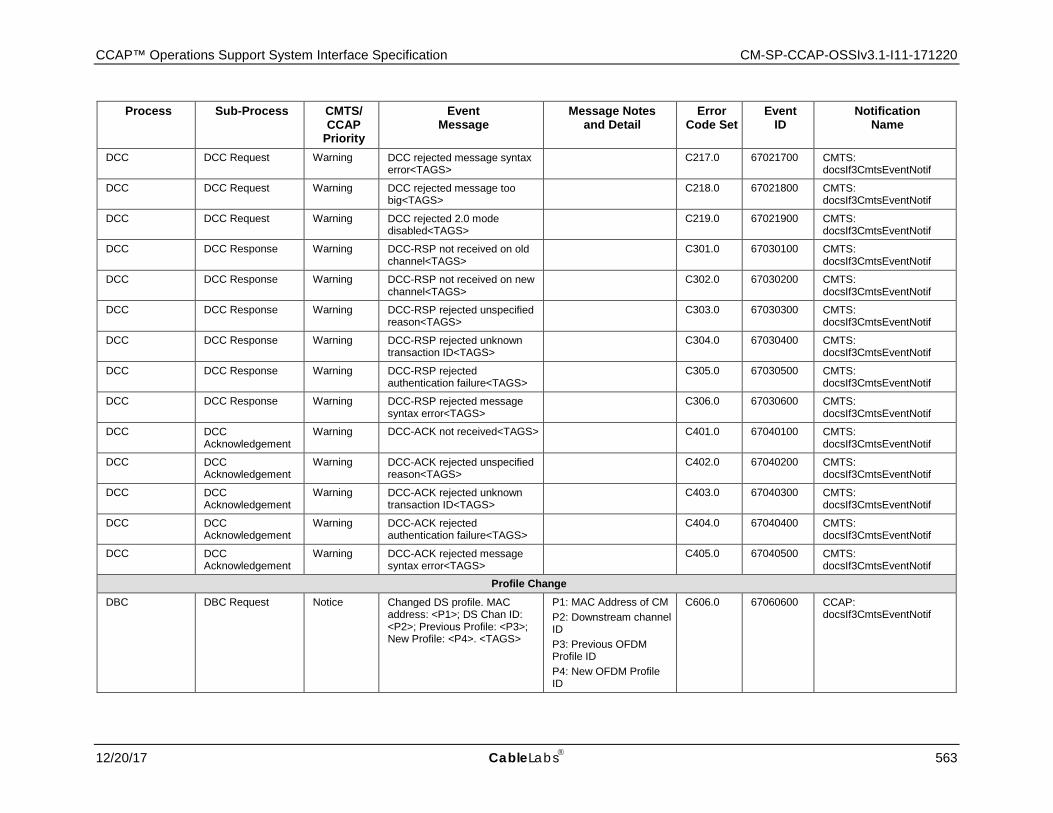
CCAP™ Operations Support System Interface Specification CM-SP-CCAP-OSSIv3.1-I11-171220
12/20/17 CableLabs 563
Process Sub-Process CMTS/ CCAP
Priority
Event Message
Message Notes and Detail
Error Code Set
Event ID
Notification Name
DCC DCC Request Warning DCC rejected message syntax error<TAGS> C217.0 67021700 CMTS:
docsIf3CmtsEventNotif
DCC DCC Request Warning DCC rejected message too big<TAGS> C218.0 67021800 CMTS:
docsIf3CmtsEventNotif
DCC DCC Request Warning DCC rejected 2.0 mode disabled<TAGS> C219.0 67021900 CMTS:
docsIf3CmtsEventNotif
DCC DCC Response Warning DCC-RSP not received on old channel<TAGS> C301.0 67030100 CMTS:
docsIf3CmtsEventNotif
DCC DCC Response Warning DCC-RSP not received on new channel<TAGS> C302.0 67030200 CMTS:
docsIf3CmtsEventNotif
DCC DCC Response Warning DCC-RSP rejected unspecified reason<TAGS> C303.0 67030300 CMTS:
docsIf3CmtsEventNotif
DCC DCC Response Warning DCC-RSP rejected unknown transaction ID<TAGS> C304.0 67030400 CMTS:
docsIf3CmtsEventNotif
DCC DCC Response Warning DCC-RSP rejected authentication failure<TAGS> C305.0 67030500 CMTS:
docsIf3CmtsEventNotif
DCC DCC Response Warning DCC-RSP rejected message syntax error<TAGS> C306.0 67030600 CMTS:
docsIf3CmtsEventNotif
DCC DCC Acknowledgement
Warning DCC-ACK not received<TAGS> C401.0 67040100 CMTS: docsIf3CmtsEventNotif
DCC DCC Acknowledgement
Warning DCC-ACK rejected unspecified reason<TAGS> C402.0 67040200 CMTS:
docsIf3CmtsEventNotif
DCC DCC Acknowledgement
Warning DCC-ACK rejected unknown transaction ID<TAGS> C403.0 67040300 CMTS:
docsIf3CmtsEventNotif
DCC DCC Acknowledgement
Warning DCC-ACK rejected authentication failure<TAGS> C404.0 67040400 CMTS:
docsIf3CmtsEventNotif
DCC DCC Acknowledgement
Warning DCC-ACK rejected message syntax error<TAGS> C405.0 67040500 CMTS:
docsIf3CmtsEventNotif
Profile Change DBC DBC Request Notice Changed DS profile. MAC
address: <P1>; DS Chan ID: <P2>; Previous Profile: <P3>; New Profile: <P4>. <TAGS>
P1: MAC Address of CM P2: Downstream channel ID P3: Previous OFDM Profile ID P4: New OFDM Profile ID
C606.0 67060600 CCAP: docsIf3CmtsEventNotif
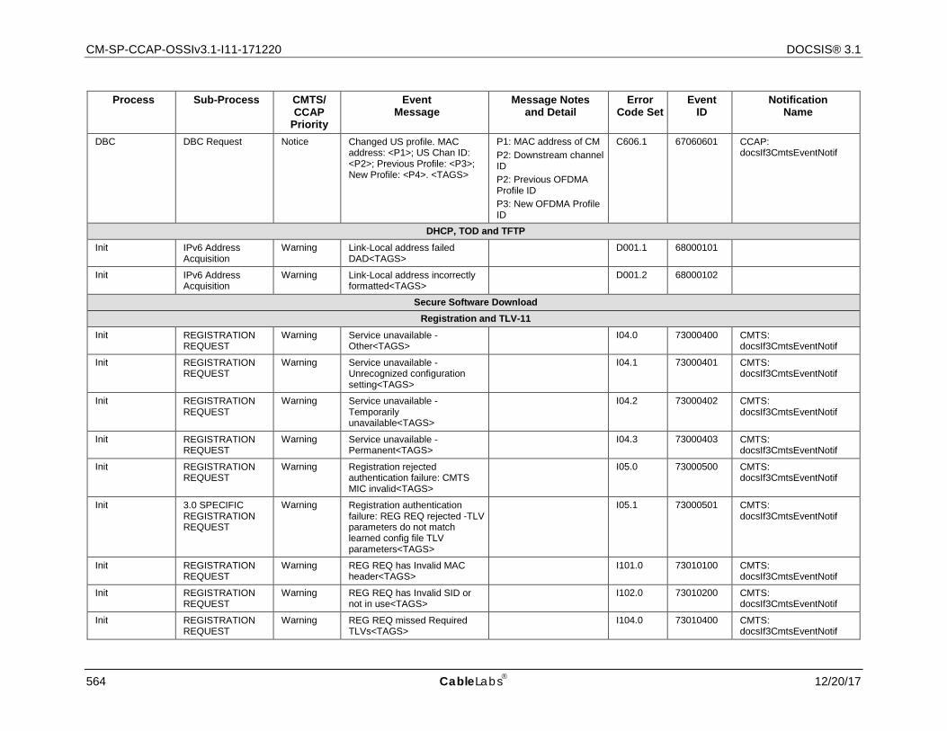
CM-SP-CCAP-OSSIv3.1-I11-171220 DOCSIS® 3.1
564 CableLabs 12/20/17
Process Sub-Process CMTS/ CCAP
Priority
Event Message
Message Notes and Detail
Error Code Set
Event ID
Notification Name
DBC DBC Request Notice Changed US profile. MAC address: <P1>; US Chan ID: <P2>; Previous Profile: <P3>; New Profile: <P4>. <TAGS>
P1: MAC address of CM P2: Downstream channel ID P2: Previous OFDMA Profile ID P3: New OFDMA Profile ID
C606.1 67060601 CCAP: docsIf3CmtsEventNotif
DHCP, TOD and TFTP Init IPv6 Address
Acquisition Warning Link-Local address failed
DAD<TAGS> D001.1 68000101
Init IPv6 Address Acquisition
Warning Link-Local address incorrectly formatted<TAGS> D001.2 68000102
Secure Software Download Registration and TLV-11
Init REGISTRATION REQUEST
Warning Service unavailable - Other<TAGS> I04.0 73000400 CMTS:
docsIf3CmtsEventNotif
Init REGISTRATION REQUEST
Warning Service unavailable - Unrecognized configuration setting<TAGS>
I04.1 73000401 CMTS: docsIf3CmtsEventNotif
Init REGISTRATION REQUEST
Warning Service unavailable - Temporarily unavailable<TAGS>
I04.2 73000402 CMTS: docsIf3CmtsEventNotif
Init REGISTRATION REQUEST
Warning Service unavailable - Permanent<TAGS> I04.3 73000403 CMTS:
docsIf3CmtsEventNotif
Init REGISTRATION REQUEST
Warning Registration rejected authentication failure: CMTS MIC invalid<TAGS>
I05.0 73000500 CMTS: docsIf3CmtsEventNotif
Init 3.0 SPECIFIC REGISTRATION REQUEST
Warning Registration authentication failure: REG REQ rejected -TLV parameters do not match learned config file TLV parameters<TAGS>
I05.1 73000501 CMTS: docsIf3CmtsEventNotif
Init REGISTRATION REQUEST
Warning REG REQ has Invalid MAC header<TAGS> I101.0 73010100 CMTS:
docsIf3CmtsEventNotif
Init REGISTRATION REQUEST
Warning REG REQ has Invalid SID or not in use<TAGS> I102.0 73010200 CMTS:
docsIf3CmtsEventNotif
Init REGISTRATION REQUEST
Warning REG REQ missed Required TLVs<TAGS> I104.0 73010400 CMTS:
docsIf3CmtsEventNotif
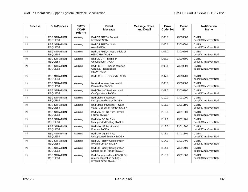
CCAP™ Operations Support System Interface Specification CM-SP-CCAP-OSSIv3.1-I11-171220
12/20/17 CableLabs 565
Process Sub-Process CMTS/ CCAP
Priority
Event Message
Message Notes and Detail
Error Code Set
Event ID
Notification Name
Init REGISTRATION REQUEST
Warning Bad DS FREQ - Format Invalid<TAGS> I105.0 73010500 CMTS:
docsIf3CmtsEventNotif
Init REGISTRATION REQUEST
Warning Bad DS FREQ - Not in use<TAGS> I105.1 73010501 CMTS:
docsIf3CmtsEventNotif
Init REGISTRATION REQUEST
Warning Bad DS FREQ - Not Multiple of 62500 Hz<TAGS> I105.2 73010502 CMTS:
docsIf3CmtsEventNotif
Init REGISTRATION REQUEST
Warning Bad US CH - Invalid or Unassigned<TAGS> I106.0 73010600 CMTS:
docsIf3CmtsEventNotif
Init REGISTRATION REQUEST
Warning Bad US CH - Change followed with (RE-) Registration REQ<TAGS>
I106.1 73010601 CMTS: docsIf3CmtsEventNotif
Init REGISTRATION REQUEST
Warning Bad US CH - Overload<TAGS> I107.0 73010700 CMTS: docsIf3CmtsEventNotif
Init REGISTRATION REQUEST
Warning Network Access has Invalid Parameter<TAGS> I108.0 73010800 CMTS:
docsIf3CmtsEventNotif
Init REGISTRATION REQUEST
Warning Bad Class of Service - Invalid Configuration<TAGS> I109.0 73010900 CMTS:
docsIf3CmtsEventNotif
Init REGISTRATION REQUEST
Warning Bad Class of Service - Unsupported class<TAGS> I110.0 73011000 CMTS:
docsIf3CmtsEventNotif
Init REGISTRATION REQUEST
Warning Bad Class of Service - Invalid class ID or out of range<TAGS> I111.0 73011100 CMTS:
docsIf3CmtsEventNotif
Init REGISTRATION REQUEST
Warning Bad Max DS Bit Rate - Invalid Format<TAGS> I112.0 73011200 CMTS:
docsIf3CmtsEventNotif
Init REGISTRATION REQUEST
Warning Bad Max DS Bit Rate Unsupported Setting<TAGS> I112.1 73011201 CMTS:
docsIf3CmtsEventNotif
Init REGISTRATION REQUEST
Warning Bad Max US Bit - Invalid Format<TAGS> I113.0 73011300 CMTS:
docsIf3CmtsEventNotif
Init REGISTRATION REQUEST
Warning Bad Max US Bit Rate - Unsupported Setting<TAGS> I113.1 73011301 CMTS:
docsIf3CmtsEventNotif
Init REGISTRATION REQUEST
Warning Bad US Priority Configuration - Invalid Format<TAGS> I114.0 73011400 CMTS:
docsIf3CmtsEventNotif
Init REGISTRATION REQUEST
Warning Bad US Priority Configuration - Setting out of Range<TAGS> I114.1 73011401 CMTS:
docsIf3CmtsEventNotif
Init REGISTRATION REQUEST
Warning Bad Guaranteed Min US CH Bit rate Configuration setting - Invalid Format<TAGS>
I115.0 73011500 CMTS: docsIf3CmtsEventNotif
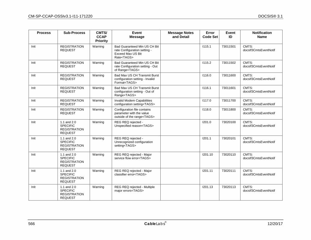
CM-SP-CCAP-OSSIv3.1-I11-171220 DOCSIS® 3.1
566 CableLabs 12/20/17
Process Sub-Process CMTS/ CCAP
Priority
Event Message
Message Notes and Detail
Error Code Set
Event ID
Notification Name
Init REGISTRATION REQUEST
Warning Bad Guaranteed Min US CH Bit rate Configuration setting - Exceed Max US Bit Rate<TAGS>
I115.1 73011501 CMTS: docsIf3CmtsEventNotif
Init REGISTRATION REQUEST
Warning Bad Guaranteed Min US CH Bit rate Configuration setting - Out of Range<TAGS>
I115.2 73011502 CMTS: docsIf3CmtsEventNotif
Init REGISTRATION REQUEST
Warning Bad Max US CH Transmit Burst configuration setting - Invalid Format<TAGS>
I116.0 73011600 CMTS: docsIf3CmtsEventNotif
Init REGISTRATION REQUEST
Warning Bad Max US CH Transmit Burst configuration setting - Out of Range<TAGS>
I116.1 73011601 CMTS: docsIf3CmtsEventNotif
Init REGISTRATION REQUEST
Warning Invalid Modem Capabilities configuration setting<TAGS> I117.0 73011700 CMTS:
docsIf3CmtsEventNotif
Init REGISTRATION REQUEST
Warning Configuration file contains parameter with the value outside of the range<TAGS>
I118.0 73011800 CMTS: docsIf3CmtsEventNotif
Init 1.1 and 2.0 SPECIFIC REGISTRATION REQUEST
Warning REG REQ rejected - Unspecified reason<TAGS> I201.0 73020100 CMTS:
docsIf3CmtsEventNotif
Init 1.1 and 2.0 SPECIFIC REGISTRATION REQUEST
Warning REG REQ rejected - Unrecognized configuration setting<TAGS>
I201.1 73020101 CMTS: docsIf3CmtsEventNotif
Init 1.1 and 2.0 SPECIFIC REGISTRATION REQUEST
Warning REG REQ rejected - Major service flow error<TAGS> I201.10 73020110 CMTS:
docsIf3CmtsEventNotif
Init 1.1 and 2.0 SPECIFIC REGISTRATION REQUEST
Warning REG REQ rejected - Major classifier error<TAGS> I201.11 73020111 CMTS:
docsIf3CmtsEventNotif
Init 1.1 and 2.0 SPECIFIC REGISTRATION REQUEST
Warning REG REQ rejected - Multiple major errors<TAGS> I201.13 73020113 CMTS:
docsIf3CmtsEventNotif
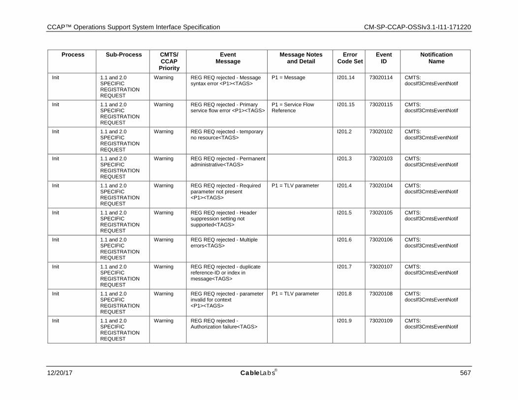
CCAP™ Operations Support System Interface Specification CM-SP-CCAP-OSSIv3.1-I11-171220
12/20/17 CableLabs 567
Process Sub-Process CMTS/ CCAP
Priority
Event Message
Message Notes and Detail
Error Code Set
Event ID
Notification Name
Init 1.1 and 2.0 SPECIFIC REGISTRATION REQUEST
Warning REG REQ rejected - Message syntax error <P1><TAGS>
P1 = Message I201.14 73020114 CMTS: docsIf3CmtsEventNotif
Init 1.1 and 2.0 SPECIFIC REGISTRATION REQUEST
Warning REG REQ rejected - Primary service flow error <P1><TAGS>
P1 = Service Flow Reference
I201.15 73020115 CMTS: docsIf3CmtsEventNotif
Init 1.1 and 2.0 SPECIFIC REGISTRATION REQUEST
Warning REG REQ rejected - temporary no resource<TAGS> I201.2 73020102 CMTS:
docsIf3CmtsEventNotif
Init 1.1 and 2.0 SPECIFIC REGISTRATION REQUEST
Warning REG REQ rejected - Permanent administrative<TAGS> I201.3 73020103 CMTS:
docsIf3CmtsEventNotif
Init 1.1 and 2.0 SPECIFIC REGISTRATION REQUEST
Warning REG REQ rejected - Required parameter not present <P1><TAGS>
P1 = TLV parameter I201.4 73020104 CMTS: docsIf3CmtsEventNotif
Init 1.1 and 2.0 SPECIFIC REGISTRATION REQUEST
Warning REG REQ rejected - Header suppression setting not supported<TAGS>
I201.5 73020105 CMTS: docsIf3CmtsEventNotif
Init 1.1 and 2.0 SPECIFIC REGISTRATION REQUEST
Warning REG REQ rejected - Multiple errors<TAGS> I201.6 73020106 CMTS:
docsIf3CmtsEventNotif
Init 1.1 and 2.0 SPECIFIC REGISTRATION REQUEST
Warning REG REQ rejected - duplicate reference-ID or index in message<TAGS>
I201.7 73020107 CMTS: docsIf3CmtsEventNotif
Init 1.1 and 2.0 SPECIFIC REGISTRATION REQUEST
Warning REG REQ rejected - parameter invalid for context <P1><TAGS>
P1 = TLV parameter I201.8 73020108 CMTS: docsIf3CmtsEventNotif
Init 1.1 and 2.0 SPECIFIC REGISTRATION REQUEST
Warning REG REQ rejected - Authorization failure<TAGS> I201.9 73020109 CMTS:
docsIf3CmtsEventNotif
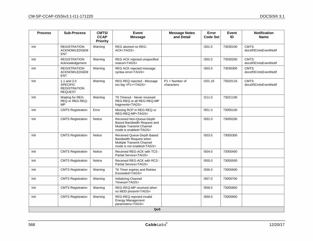
CM-SP-CCAP-OSSIv3.1-I11-171220 DOCSIS® 3.1
568 CableLabs 12/20/17
Process Sub-Process CMTS/ CCAP
Priority
Event Message
Message Notes and Detail
Error Code Set
Event ID
Notification Name
Init REGISTRATION ACKNOWLEDGEMENT
Warning REG aborted no REG-ACK<TAGS> I301.0 73030100 CMTS:
docsIf3CmtsEventNotif
Init REGISTRATION Acknowledgement
Warning REG ACK rejected unspecified reason<TAGS> I302.0 73030200 CMTS:
docsIf3CmtsEventNotif
Init REGISTRATION ACKNOWLEDGEMENT
Warning REG ACK rejected message syntax error<TAGS> I303.0 73030300 CMTS:
docsIf3CmtsEventNotif
Init 1.1 and 2.0 SPECIFIC REGISTRATION REQUEST
Warning REG REQ rejected - Message too big <P1><TAGS>
P1 = Number of characters
I201.16 73020116 CMTS: docsIf3CmtsEventNotif
Init Waiting for REG-REQ or REG-REQ-MP
Warning T9 Timeout - Never received REG-REQ or all REG-REQ-MP fragments<TAGS>
I211.0 73021100
Init CMTS Registration Error Missing RCP in REG-REQ or REG-REQ-MP<TAGS> I551.0 73055100
Init CMTS Registration Notice Received Non-Queue-Depth Based Bandwidth Request and Multiple Transmit Channel mode is enabled<TAGS>
I552.0 73055200
Init CMTS Registration Notice Received Queue-Depth Based Bandwidth Request when Multiple Transmit Channel mode is not enabled<TAGS>
I553.0 73055300
Init CMTS Registration Notice Received REG-ACK with TCS - Partial Service<TAGS> I554.0 73055400
Init CMTS Registration Notice Received REG-ACK with RCS - Partial Service<TAGS> I555.0 73055500
Init CMTS Registration Warning T6 Timer expires and Retries Exceeded<TAGS> I556.0 73055600
Init CMTS Registration Warning Initializing Channel Timeout<TAGS> I557.0 73055700
Init CMTS Registration Warning REG-REQ-MP received when no MDD present<TAGS> I558.0 73055800
Init CMTS Registration Warning REG-REQ rejected invalid Energy Management parameters<TAGS>
I559.0 73055900
QoS
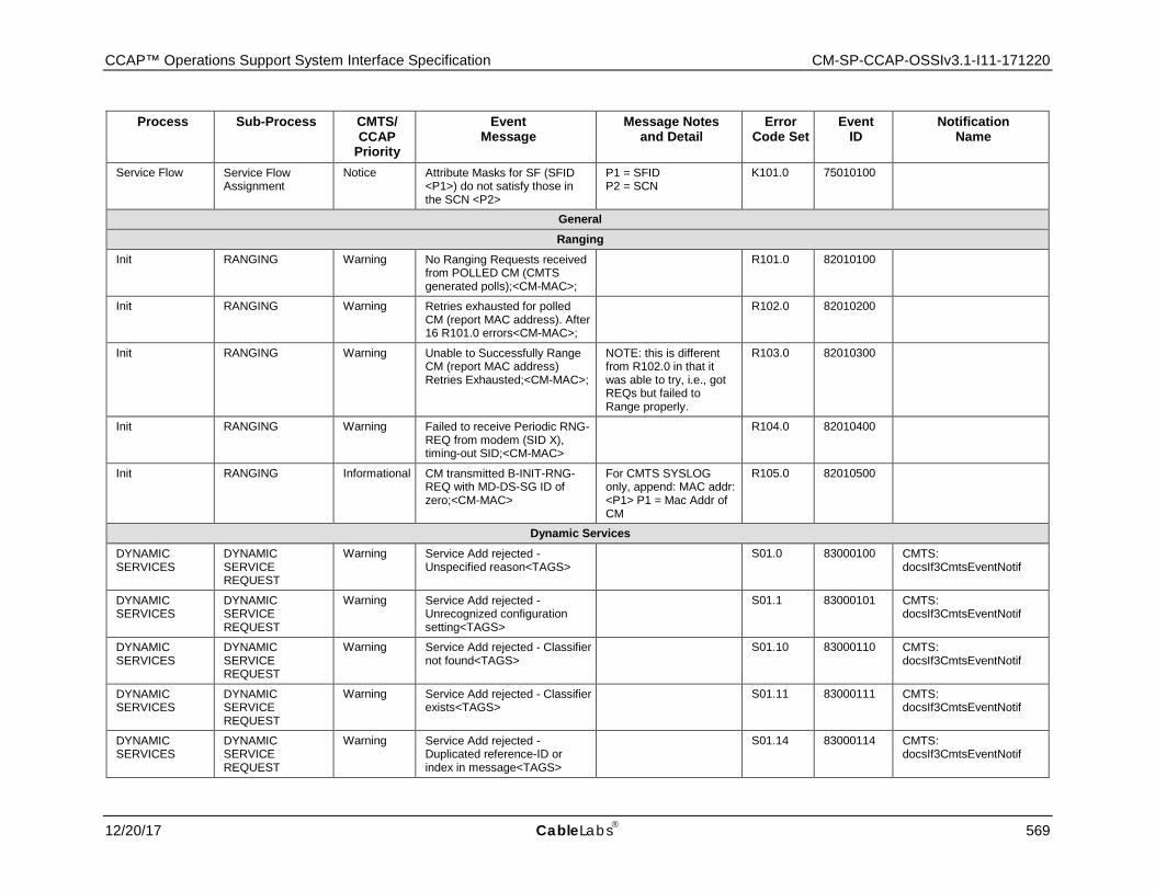
CCAP™ Operations Support System Interface Specification CM-SP-CCAP-OSSIv3.1-I11-171220
12/20/17 CableLabs 569
Process Sub-Process CMTS/ CCAP
Priority
Event Message
Message Notes and Detail
Error Code Set
Event ID
Notification Name
Service Flow Service Flow Assignment
Notice Attribute Masks for SF (SFID <P1>) do not satisfy those in the SCN <P2>
P1 = SFID P2 = SCN
K101.0 75010100
General Ranging
Init RANGING Warning No Ranging Requests received from POLLED CM (CMTS generated polls);<CM-MAC>;
R101.0 82010100
Init RANGING Warning Retries exhausted for polled CM (report MAC address). After 16 R101.0 errors<CM-MAC>;
R102.0 82010200
Init RANGING Warning Unable to Successfully Range CM (report MAC address) Retries Exhausted;<CM-MAC>;
NOTE: this is different from R102.0 in that it was able to try, i.e., got REQs but failed to Range properly.
R103.0 82010300
Init RANGING Warning Failed to receive Periodic RNG-REQ from modem (SID X), timing-out SID;<CM-MAC>
R104.0 82010400
Init RANGING Informational CM transmitted B-INIT-RNG-REQ with MD-DS-SG ID of zero;<CM-MAC>
For CMTS SYSLOG only, append: MAC addr: <P1> P1 = Mac Addr of CM
R105.0 82010500
Dynamic Services DYNAMIC SERVICES
DYNAMIC SERVICE REQUEST
Warning Service Add rejected - Unspecified reason<TAGS> S01.0 83000100 CMTS:
docsIf3CmtsEventNotif
DYNAMIC SERVICES
DYNAMIC SERVICE REQUEST
Warning Service Add rejected - Unrecognized configuration setting<TAGS>
S01.1 83000101 CMTS: docsIf3CmtsEventNotif
DYNAMIC SERVICES
DYNAMIC SERVICE REQUEST
Warning Service Add rejected - Classifier not found<TAGS> S01.10 83000110 CMTS:
docsIf3CmtsEventNotif
DYNAMIC SERVICES
DYNAMIC SERVICE REQUEST
Warning Service Add rejected - Classifier exists<TAGS> S01.11 83000111 CMTS:
docsIf3CmtsEventNotif
DYNAMIC SERVICES
DYNAMIC SERVICE REQUEST
Warning Service Add rejected - Duplicated reference-ID or index in message<TAGS>
S01.14 83000114 CMTS: docsIf3CmtsEventNotif
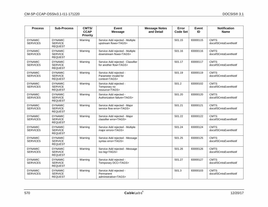
CM-SP-CCAP-OSSIv3.1-I11-171220 DOCSIS® 3.1
570 CableLabs 12/20/17
Process Sub-Process CMTS/ CCAP
Priority
Event Message
Message Notes and Detail
Error Code Set
Event ID
Notification Name
DYNAMIC SERVICES
DYNAMIC SERVICE REQUEST
Warning Service Add rejected - Multiple upstream flows<TAGS> S01.15 83000115 CMTS:
docsIf3CmtsEventNotif
DYNAMIC SERVICES
DYNAMIC SERVICE REQUEST
Warning Service Add rejected - Multiple downstream flows<TAGS> S01.16 83000116 CMTS:
docsIf3CmtsEventNotif
DYNAMIC SERVICES
DYNAMIC SERVICE REQUEST
Warning Service Add rejected - Classifier for another flow<TAGS> S01.17 83000117 CMTS:
docsIf3CmtsEventNotif
DYNAMIC SERVICES
DYNAMIC SERVICE REQUEST
Warning Service Add rejected - Parameter invalid for context<TAGS>
S01.19 83000119 CMTS: docsIf3CmtsEventNotif
DYNAMIC SERVICES
DYNAMIC SERVICE REQUEST
Warning Service Add rejected - Temporary no resource<TAGS>
S01.2 83000102 CMTS: docsIf3CmtsEventNotif
DYNAMIC SERVICES
DYNAMIC SERVICE REQUEST
Warning Service Add rejected - Authorization failure<TAGS> S01.20 83000120 CMTS:
docsIf3CmtsEventNotif
DYNAMIC SERVICES
DYNAMIC SERVICE REQUEST
Warning Service Add rejected - Major service flow error<TAGS> S01.21 83000121 CMTS:
docsIf3CmtsEventNotif
DYNAMIC SERVICES
DYNAMIC SERVICE REQUEST
Warning Service Add rejected - Major classifier error<TAGS> S01.22 83000122 CMTS:
docsIf3CmtsEventNotif
DYNAMIC SERVICES
DYNAMIC SERVICE REQUEST
Warning Service Add rejected - Multiple major errors<TAGS> S01.24 83000124 CMTS:
docsIf3CmtsEventNotif
DYNAMIC SERVICES
DYNAMIC SERVICE REQUEST
Warning Service Add rejected - Message syntax error<TAGS> S01.25 83000125 CMTS:
docsIf3CmtsEventNotif
DYNAMIC SERVICES
DYNAMIC SERVICE REQUEST
Warning Service Add rejected - Message too big<TAGS> S01.26 83000126 CMTS:
docsIf3CmtsEventNotif
DYNAMIC SERVICES
DYNAMIC SERVICE REQUEST
Warning Service Add rejected - Temporary DCC<TAGS> S01.27 83000127 CMTS:
docsIf3CmtsEventNotif
DYNAMIC SERVICES
DYNAMIC SERVICE REQUEST
Warning Service Add rejected - Permanent administrative<TAGS>
S01.3 83000103 CMTS: docsIf3CmtsEventNotif
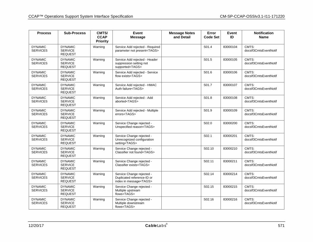
CCAP™ Operations Support System Interface Specification CM-SP-CCAP-OSSIv3.1-I11-171220
12/20/17 CableLabs 571
Process Sub-Process CMTS/ CCAP
Priority
Event Message
Message Notes and Detail
Error Code Set
Event ID
Notification Name
DYNAMIC SERVICES
DYNAMIC SERVICE REQUEST
Warning Service Add rejected - Required parameter not present<TAGS> S01.4 83000104 CMTS:
docsIf3CmtsEventNotif
DYNAMIC SERVICES
DYNAMIC SERVICE REQUEST
Warning Service Add rejected - Header suppression setting not supported<TAGS>
S01.5 83000105 CMTS: docsIf3CmtsEventNotif
DYNAMIC SERVICES
DYNAMIC SERVICE REQUEST
Warning Service Add rejected - Service flow exists<TAGS> S01.6 83000106 CMTS:
docsIf3CmtsEventNotif
DYNAMIC SERVICES
DYNAMIC SERVICE REQUEST
Warning Service Add rejected - HMAC Auth failure<TAGS> S01.7 83000107 CMTS:
docsIf3CmtsEventNotif
DYNAMIC SERVICES
DYNAMIC SERVICE REQUEST
Warning Service Add rejected - Add aborted<TAGS> S01.8 83000108 CMTS:
docsIf3CmtsEventNotif
DYNAMIC SERVICES
DYNAMIC SERVICE REQUEST
Warning Service Add rejected - Multiple errors<TAGS> S01.9 83000109 CMTS:
docsIf3CmtsEventNotif
DYNAMIC SERVICES
DYNAMIC SERVICE REQUEST
Warning Service Change rejected - Unspecified reason<TAGS> S02.0 83000200 CMTS:
docsIf3CmtsEventNotif
DYNAMIC SERVICES
DYNAMIC SERVICE REQUEST
Warning Service Change rejected - Unrecognized configuration setting<TAGS>
S02.1 83000201 CMTS: docsIf3CmtsEventNotif
DYNAMIC SERVICES
DYNAMIC SERVICE REQUEST
Warning Service Change rejected - Classifier not found<TAGS> S02.10 83000210 CMTS:
docsIf3CmtsEventNotif
DYNAMIC SERVICES
DYNAMIC SERVICE REQUEST
Warning Service Change rejected - Classifier exists<TAGS> S02.11 83000211 CMTS:
docsIf3CmtsEventNotif
DYNAMIC SERVICES
DYNAMIC SERVICE REQUEST
Warning Service Change rejected - Duplicated reference-ID or index in message<TAGS>
S02.14 83000214 CMTS: docsIf3CmtsEventNotif
DYNAMIC SERVICES
DYNAMIC SERVICE REQUEST
Warning Service Change rejected - Multiple upstream flows<TAGS>
S02.15 83000215 CMTS: docsIf3CmtsEventNotif
DYNAMIC SERVICES
DYNAMIC SERVICE REQUEST
Warning Service Change rejected - Multiple downstream flows<TAGS>
S02.16 83000216 CMTS: docsIf3CmtsEventNotif
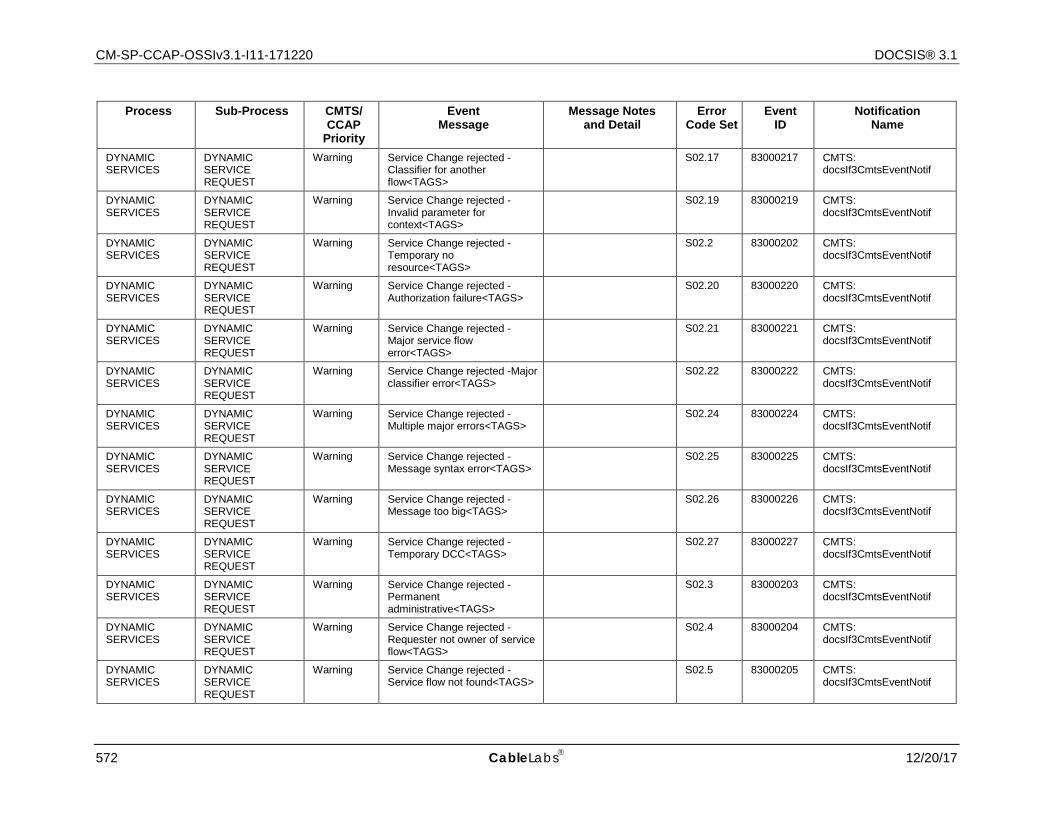
CM-SP-CCAP-OSSIv3.1-I11-171220 DOCSIS® 3.1
572 CableLabs 12/20/17
Process Sub-Process CMTS/ CCAP
Priority
Event Message
Message Notes and Detail
Error Code Set
Event ID
Notification Name
DYNAMIC SERVICES
DYNAMIC SERVICE REQUEST
Warning Service Change rejected - Classifier for another flow<TAGS>
S02.17 83000217 CMTS: docsIf3CmtsEventNotif
DYNAMIC SERVICES
DYNAMIC SERVICE REQUEST
Warning Service Change rejected - Invalid parameter for context<TAGS>
S02.19 83000219 CMTS: docsIf3CmtsEventNotif
DYNAMIC SERVICES
DYNAMIC SERVICE REQUEST
Warning Service Change rejected - Temporary no resource<TAGS>
S02.2 83000202 CMTS: docsIf3CmtsEventNotif
DYNAMIC SERVICES
DYNAMIC SERVICE REQUEST
Warning Service Change rejected - Authorization failure<TAGS> S02.20 83000220 CMTS:
docsIf3CmtsEventNotif
DYNAMIC SERVICES
DYNAMIC SERVICE REQUEST
Warning Service Change rejected - Major service flow error<TAGS>
S02.21 83000221 CMTS: docsIf3CmtsEventNotif
DYNAMIC SERVICES
DYNAMIC SERVICE REQUEST
Warning Service Change rejected -Major classifier error<TAGS> S02.22 83000222 CMTS:
docsIf3CmtsEventNotif
DYNAMIC SERVICES
DYNAMIC SERVICE REQUEST
Warning Service Change rejected - Multiple major errors<TAGS> S02.24 83000224 CMTS:
docsIf3CmtsEventNotif
DYNAMIC SERVICES
DYNAMIC SERVICE REQUEST
Warning Service Change rejected - Message syntax error<TAGS> S02.25 83000225 CMTS:
docsIf3CmtsEventNotif
DYNAMIC SERVICES
DYNAMIC SERVICE REQUEST
Warning Service Change rejected - Message too big<TAGS> S02.26 83000226 CMTS:
docsIf3CmtsEventNotif
DYNAMIC SERVICES
DYNAMIC SERVICE REQUEST
Warning Service Change rejected - Temporary DCC<TAGS> S02.27 83000227 CMTS:
docsIf3CmtsEventNotif
DYNAMIC SERVICES
DYNAMIC SERVICE REQUEST
Warning Service Change rejected - Permanent administrative<TAGS>
S02.3 83000203 CMTS: docsIf3CmtsEventNotif
DYNAMIC SERVICES
DYNAMIC SERVICE REQUEST
Warning Service Change rejected - Requester not owner of service flow<TAGS>
S02.4 83000204 CMTS: docsIf3CmtsEventNotif
DYNAMIC SERVICES
DYNAMIC SERVICE REQUEST
Warning Service Change rejected - Service flow not found<TAGS> S02.5 83000205 CMTS:
docsIf3CmtsEventNotif

CCAP™ Operations Support System Interface Specification CM-SP-CCAP-OSSIv3.1-I11-171220
12/20/17 CableLabs 573
Process Sub-Process CMTS/ CCAP
Priority
Event Message
Message Notes and Detail
Error Code Set
Event ID
Notification Name
DYNAMIC SERVICES
DYNAMIC SERVICE REQUEST
Warning Service Change rejected - Required parameter not present<TAGS>
S02.6 83000206 CMTS: docsIf3CmtsEventNotif
DYNAMIC SERVICES
DYNAMIC SERVICE REQUEST
Warning Service Change rejected - Header suppression setting not supported<TAGS>
S02.7 83000207 CMTS: docsIf3CmtsEventNotif
DYNAMIC SERVICES
DYNAMIC SERVICE REQUEST
Warning Service Change rejected - HMAC Auth failure<TAGS> S02.8 83000208 CMTS:
docsIf3CmtsEventNotif
DYNAMIC SERVICES
DYNAMIC SERVICE REQUEST
Warning Service Change rejected - Multiple errors<TAGS> S02.9 83000209 CMTS:
docsIf3CmtsEventNotif
DYNAMIC SERVICES
DYNAMIC SERVICE REQUEST
Warning Service Delete rejected - Unspecified reason<TAGS> S03.0 83000300 CMTS:
docsIf3CmtsEventNotif
DYNAMIC SERVICES
DYNAMIC SERVICE REQUEST
Warning Service Delete rejected -Requester not owner of service flow<TAGS>
S03.1 83000301 CMTS: docsIf3CmtsEventNotif
DYNAMIC SERVICES
DYNAMIC SERVICE REQUEST
Warning Service Delete rejected - Service flow not found<TAGS> S03.2 83000302 CMTS:
docsIf3CmtsEventNotif
DYNAMIC SERVICES
DYNAMIC SERVICE REQUEST
Warning Service Delete rejected - HMAC Auth failure<TAGS> S03.3 83000303 CMTS:
docsIf3CmtsEventNotif
DYNAMIC SERVICES
DYNAMIC SERVICE REQUEST
Warning Service Delete rejected - Message syntax error<TAGS> S03.4 83000304 CMTS:
docsIf3CmtsEventNotif
DYNAMIC SERVICES
DYNAMIC SERVICE RESPONSE
Warning Service Add Response rejected - Invalid transaction ID<TAGS> S101.0 83010100 CMTS:
docsIf3CmtsEventNotif
DYNAMIC SERVICES
DYNAMIC SERVICE RESPONSE
Warning Service Add aborted - No RSP<TAGS> S101.1 83010101 CMTS:
docsIf3CmtsEventNotif
DYNAMIC SERVICES
DYNAMIC SERVICE RESPONSE
Warning Service Add Response rejected - Duplicate reference_ID or index in message<TAGS>
S101.11 83010111 CMTS: docsIf3CmtsEventNotif
DYNAMIC SERVICES
DYNAMIC SERVICE RESPONSE
Warning Service Add Response rejected - Classifier for another flow<TAGS>
S101.12 83010112 CMTS: docsIf3CmtsEventNotif
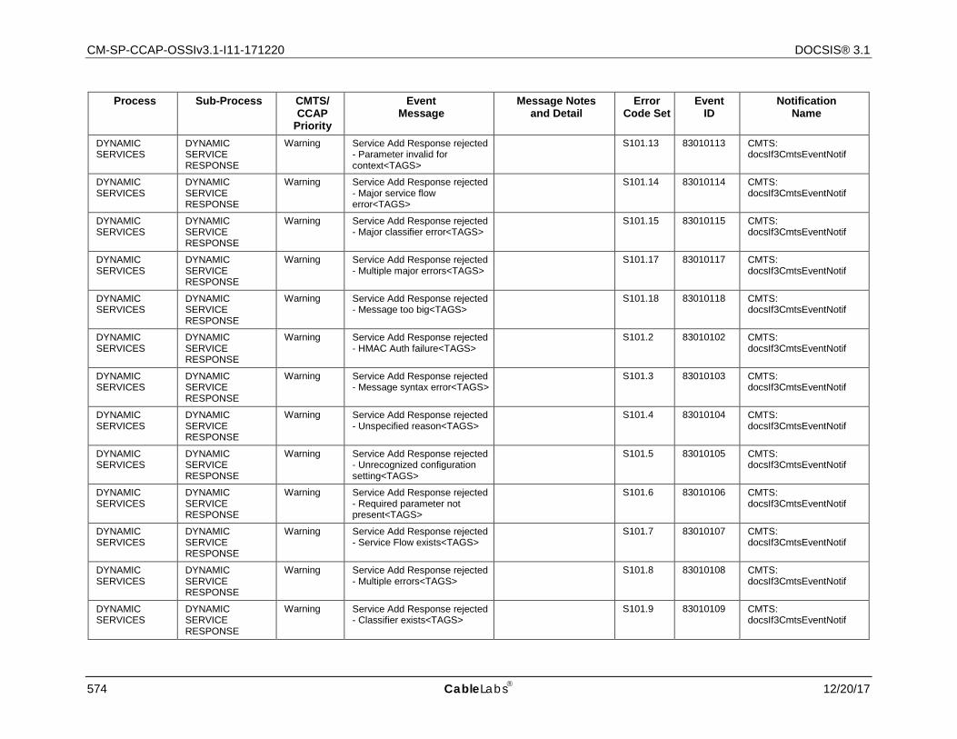
CM-SP-CCAP-OSSIv3.1-I11-171220 DOCSIS® 3.1
574 CableLabs 12/20/17
Process Sub-Process CMTS/ CCAP
Priority
Event Message
Message Notes and Detail
Error Code Set
Event ID
Notification Name
DYNAMIC SERVICES
DYNAMIC SERVICE RESPONSE
Warning Service Add Response rejected - Parameter invalid for context<TAGS>
S101.13 83010113 CMTS: docsIf3CmtsEventNotif
DYNAMIC SERVICES
DYNAMIC SERVICE RESPONSE
Warning Service Add Response rejected - Major service flow error<TAGS>
S101.14 83010114 CMTS: docsIf3CmtsEventNotif
DYNAMIC SERVICES
DYNAMIC SERVICE RESPONSE
Warning Service Add Response rejected - Major classifier error<TAGS> S101.15 83010115 CMTS:
docsIf3CmtsEventNotif
DYNAMIC SERVICES
DYNAMIC SERVICE RESPONSE
Warning Service Add Response rejected - Multiple major errors<TAGS> S101.17 83010117 CMTS:
docsIf3CmtsEventNotif
DYNAMIC SERVICES
DYNAMIC SERVICE RESPONSE
Warning Service Add Response rejected - Message too big<TAGS> S101.18 83010118 CMTS:
docsIf3CmtsEventNotif
DYNAMIC SERVICES
DYNAMIC SERVICE RESPONSE
Warning Service Add Response rejected - HMAC Auth failure<TAGS> S101.2 83010102 CMTS:
docsIf3CmtsEventNotif
DYNAMIC SERVICES
DYNAMIC SERVICE RESPONSE
Warning Service Add Response rejected - Message syntax error<TAGS> S101.3 83010103 CMTS:
docsIf3CmtsEventNotif
DYNAMIC SERVICES
DYNAMIC SERVICE RESPONSE
Warning Service Add Response rejected - Unspecified reason<TAGS> S101.4 83010104 CMTS:
docsIf3CmtsEventNotif
DYNAMIC SERVICES
DYNAMIC SERVICE RESPONSE
Warning Service Add Response rejected - Unrecognized configuration setting<TAGS>
S101.5 83010105 CMTS: docsIf3CmtsEventNotif
DYNAMIC SERVICES
DYNAMIC SERVICE RESPONSE
Warning Service Add Response rejected - Required parameter not present<TAGS>
S101.6 83010106 CMTS: docsIf3CmtsEventNotif
DYNAMIC SERVICES
DYNAMIC SERVICE RESPONSE
Warning Service Add Response rejected - Service Flow exists<TAGS> S101.7 83010107 CMTS:
docsIf3CmtsEventNotif
DYNAMIC SERVICES
DYNAMIC SERVICE RESPONSE
Warning Service Add Response rejected - Multiple errors<TAGS> S101.8 83010108 CMTS:
docsIf3CmtsEventNotif
DYNAMIC SERVICES
DYNAMIC SERVICE RESPONSE
Warning Service Add Response rejected - Classifier exists<TAGS> S101.9 83010109 CMTS:
docsIf3CmtsEventNotif
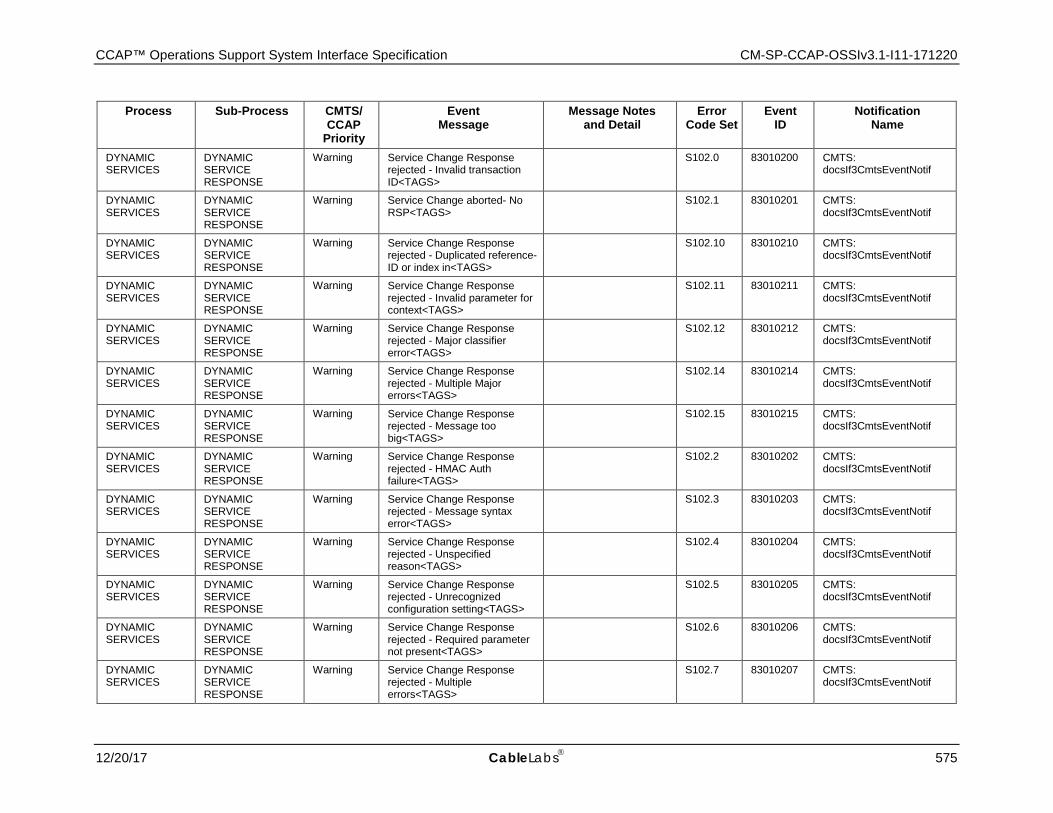
CCAP™ Operations Support System Interface Specification CM-SP-CCAP-OSSIv3.1-I11-171220
12/20/17 CableLabs 575
Process Sub-Process CMTS/ CCAP
Priority
Event Message
Message Notes and Detail
Error Code Set
Event ID
Notification Name
DYNAMIC SERVICES
DYNAMIC SERVICE RESPONSE
Warning Service Change Response rejected - Invalid transaction ID<TAGS>
S102.0 83010200 CMTS: docsIf3CmtsEventNotif
DYNAMIC SERVICES
DYNAMIC SERVICE RESPONSE
Warning Service Change aborted- No RSP<TAGS> S102.1 83010201 CMTS:
docsIf3CmtsEventNotif
DYNAMIC SERVICES
DYNAMIC SERVICE RESPONSE
Warning Service Change Response rejected - Duplicated reference-ID or index in<TAGS>
S102.10 83010210 CMTS: docsIf3CmtsEventNotif
DYNAMIC SERVICES
DYNAMIC SERVICE RESPONSE
Warning Service Change Response rejected - Invalid parameter for context<TAGS>
S102.11 83010211 CMTS: docsIf3CmtsEventNotif
DYNAMIC SERVICES
DYNAMIC SERVICE RESPONSE
Warning Service Change Response rejected - Major classifier error<TAGS>
S102.12 83010212 CMTS: docsIf3CmtsEventNotif
DYNAMIC SERVICES
DYNAMIC SERVICE RESPONSE
Warning Service Change Response rejected - Multiple Major errors<TAGS>
S102.14 83010214 CMTS: docsIf3CmtsEventNotif
DYNAMIC SERVICES
DYNAMIC SERVICE RESPONSE
Warning Service Change Response rejected - Message too big<TAGS>
S102.15 83010215 CMTS: docsIf3CmtsEventNotif
DYNAMIC SERVICES
DYNAMIC SERVICE RESPONSE
Warning Service Change Response rejected - HMAC Auth failure<TAGS>
S102.2 83010202 CMTS: docsIf3CmtsEventNotif
DYNAMIC SERVICES
DYNAMIC SERVICE RESPONSE
Warning Service Change Response rejected - Message syntax error<TAGS>
S102.3 83010203 CMTS: docsIf3CmtsEventNotif
DYNAMIC SERVICES
DYNAMIC SERVICE RESPONSE
Warning Service Change Response rejected - Unspecified reason<TAGS>
S102.4 83010204 CMTS: docsIf3CmtsEventNotif
DYNAMIC SERVICES
DYNAMIC SERVICE RESPONSE
Warning Service Change Response rejected - Unrecognized configuration setting<TAGS>
S102.5 83010205 CMTS: docsIf3CmtsEventNotif
DYNAMIC SERVICES
DYNAMIC SERVICE RESPONSE
Warning Service Change Response rejected - Required parameter not present<TAGS>
S102.6 83010206 CMTS: docsIf3CmtsEventNotif
DYNAMIC SERVICES
DYNAMIC SERVICE RESPONSE
Warning Service Change Response rejected - Multiple errors<TAGS>
S102.7 83010207 CMTS: docsIf3CmtsEventNotif
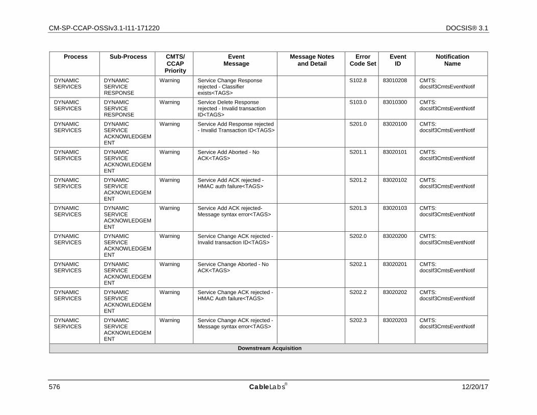
CM-SP-CCAP-OSSIv3.1-I11-171220 DOCSIS® 3.1
576 CableLabs 12/20/17
Process Sub-Process CMTS/ CCAP
Priority
Event Message
Message Notes and Detail
Error Code Set
Event ID
Notification Name
DYNAMIC SERVICES
DYNAMIC SERVICE RESPONSE
Warning Service Change Response rejected - Classifier exists<TAGS>
S102.8 83010208 CMTS: docsIf3CmtsEventNotif
DYNAMIC SERVICES
DYNAMIC SERVICE RESPONSE
Warning Service Delete Response rejected - Invalid transaction ID<TAGS>
S103.0 83010300 CMTS: docsIf3CmtsEventNotif
DYNAMIC SERVICES
DYNAMIC SERVICE ACKNOWLEDGEMENT
Warning Service Add Response rejected - Invalid Transaction ID<TAGS> S201.0 83020100 CMTS:
docsIf3CmtsEventNotif
DYNAMIC SERVICES
DYNAMIC SERVICE ACKNOWLEDGEMENT
Warning Service Add Aborted - No ACK<TAGS> S201.1 83020101 CMTS:
docsIf3CmtsEventNotif
DYNAMIC SERVICES
DYNAMIC SERVICE ACKNOWLEDGEMENT
Warning Service Add ACK rejected - HMAC auth failure<TAGS> S201.2 83020102 CMTS:
docsIf3CmtsEventNotif
DYNAMIC SERVICES
DYNAMIC SERVICE ACKNOWLEDGEMENT
Warning Service Add ACK rejected- Message syntax error<TAGS> S201.3 83020103 CMTS:
docsIf3CmtsEventNotif
DYNAMIC SERVICES
DYNAMIC SERVICE ACKNOWLEDGEMENT
Warning Service Change ACK rejected - Invalid transaction ID<TAGS> S202.0 83020200 CMTS:
docsIf3CmtsEventNotif
DYNAMIC SERVICES
DYNAMIC SERVICE ACKNOWLEDGEMENT
Warning Service Change Aborted - No ACK<TAGS> S202.1 83020201 CMTS:
docsIf3CmtsEventNotif
DYNAMIC SERVICES
DYNAMIC SERVICE ACKNOWLEDGEMENT
Warning Service Change ACK rejected - HMAC Auth failure<TAGS> S202.2 83020202 CMTS:
docsIf3CmtsEventNotif
DYNAMIC SERVICES
DYNAMIC SERVICE ACKNOWLEDGEMENT
Warning Service Change ACK rejected - Message syntax error<TAGS> S202.3 83020203 CMTS:
docsIf3CmtsEventNotif
Downstream Acquisition
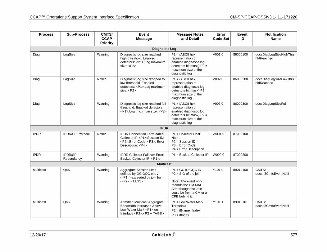
CCAP™ Operations Support System Interface Specification CM-SP-CCAP-OSSIv3.1-I11-171220
12/20/17 CableLabs 577
Process Sub-Process CMTS/ CCAP
Priority
Event Message
Message Notes and Detail
Error Code Set
Event ID
Notification Name
Diagnostic Log Diag LogSize Warning Diagnostic log size reached
high threshold. Enabled detectors: <P1>;Log maximum size: <P2>
P1 = (ASCII hex representation of enabled diagnostic log detectors bit mask) P2 = maximum size of the diagnostic log
V001.0 86000100 docsDiagLogSizeHighThrshldReached
Diag LogSize Notice Diagnostic log size dropped to low threshold. Enabled detectors: <P1>;Log maximum size: <P2>
P1 = (ASCII hex representation of enabled diagnostic log detectors bit mask) P2 = maximum size of the diagnostic log
V002.0 86000200 docsDiagLogSizeLowThrshldReached
Diag LogSize Warning Diagnostic log size reached full threshold. Enabled detectors: <P1>;Log maximum size: <P2>
P1 = (ASCII hex representation of enabled diagnostic log detectors bit mask) P2 = maximum size of the diagnostic log
V003.0 86000300 docsDiagLogSizeFull
IPDR IPDR IPDR/SP Protocol Notice IPDR Connection Terminated.
Collector IP:<P1>;Session ID: <P2>;Error Code: <P3>; Error Description: <P4>
P1 = Collector Host Name P2 = Session ID P3 = Error Code P4 = Error Description
W001.0 87000100
IPDR IPDR/SP Redundancy
Warning IPDR Collector Failover Error: Backup Collector IP: <P1>;
P1 = Backup Collector IP W002.0 87000200
Multicast Multicast QoS Warning Aggregate Session Limit
defined by GC,GQC entry (<P1>) exceeded by join for (<P2>)<TAGS>
P1 = GC ID,GQC ID P2 = S,G of the join Note: The event only records the CM MAC Addr though the Join could be from a CM or a CPE behind it.
Y101.0 89010100 CMTS: docsIf3CmtsEventNotif
Multicast QoS Warning Admitted Multicast Aggregate Bandwidth Increased Above Low Water Mark <P1> on Interface <P2>:<P3><TAGS>
P1 = Low Water Mark Threshold P2 = ifName.ifIndex P3 = ifIndex
Y101.1 89010101 CMTS: docsIf3CmtsEventNotif
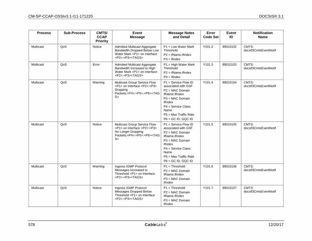
CM-SP-CCAP-OSSIv3.1-I11-171220 DOCSIS® 3.1
578 CableLabs 12/20/17
Process Sub-Process CMTS/ CCAP
Priority
Event Message
Message Notes and Detail
Error Code Set
Event ID
Notification Name
Multicast QoS Notice Admitted Multicast Aggregate Bandwidth Dropped Below Low Water Mark <P1> on Interface <P2>:<P3><TAGS>
P1 = Low Water Mark Threshold P2 = ifName.ifIndex P3 = ifIndex
Y101.2 89010102 CMTS: docsIf3CmtsEventNotif
Multicast QoS Error Admitted Multicast Aggregate Bandwidth Increased to High Water Mark <P1> on Interface <P2>:<P3><TAGS>
P1 = High Water Mark Threshold P2 = ifName.ifIndex P3 = ifIndex
Y101.3 89010103 CMTS: docsIf3CmtsEventNotif
Multicast QoS Warning Multicast Group Service Flow <P1> on Interface <P2>:<P3> Dropping Packets;<P4>:<P5>:<P6><TAGS>
P1 = Service Flow ID associated with GSF P2 = MAC Domain ifName.ifIndex P3 = MAC Domain ifIndex P4 = Service Class Name P5 = Max Traffic Rate P6 = GC ID, GQC ID
Y101.4 89010104 CMTS: docsIf3CmtsEventNotif
Multicast QoS Notice Multicast Group Service Flow <P1> on Interface <P2>:<P3> No Longer Dropping Packets;<P4>:<P5>:<P6><TAGS>
P1 = Service Flow ID associated with GSF P2 = MAC Domain ifName.ifIndex P3 = MAC Domain ifIndex P4 = Service Class Name P5 = Max Traffic Rate P6 = GC ID, GQC ID
Y101.5 89010105 CMTS: docsIf3CmtsEventNotif
Multicast QoS Warning Ingress IGMP Protocol Messages Increased to Threshold <P1> on Interface <P2>:<P3><TAGS>
P1 = Threshold P2 = MAC Domain ifName.ifIndex P3 = MAC Domain ifIndex
Y101.6 89010106 CMTS: docsIf3CmtsEventNotif
Multicast QoS Notice Ingress IGMP Protocol Messages Dropped Below Threshold <P1> on Interface <P2>:<P3><TAGS>
P1 = Threshold P2 = MAC Domain ifName.ifIndex P3 = MAC Domain ifIndex
Y101.7 89010107 CMTS: docsIf3CmtsEventNotif

CCAP™ Operations Support System Interface Specification CM-SP-CCAP-OSSIv3.1-I11-171220
12/20/17 CableLabs 579
Process Sub-Process CMTS/ CCAP
Priority
Event Message
Message Notes and Detail
Error Code Set
Event ID
Notification Name
Multicast QoS Warning Ingress MLD Protocol Messages Increased to Threshold <P1> on Interface <P2>:<P3><TAGS>
P1 = Threshold P2 = MAC Domain ifName.ifIndex P3 = MAC Domain ifIndex
Y101.8 89010108 CMTS: docsIf3CmtsEventNotif
Multicast QoS Notice Ingress MLD Protocol Messages Dropped Below Threshold <P1> on Interface <P2>:<P3><TAGS>
P1 = Threshold P2 = MAC Domain ifName.ifIndex P3 = MAC Domain ifIndex
Y101.9 89010109 CMTS: docsIf3CmtsEventNotif
Multicast Authorization Notice Multicast session <P1> not authorized for Client <P2> behind CM <P3><TAGS>
P1 = S,G of the join P2 = IPv4 or IPv6 Address of Client P3 = CM MAC Addr
Y102.0 89010200 CMTS: docsIf3CmtsEventNotif
Multicast Authorization Warning Maximum Multicast Session <P1> Threshold <P2> Reached for CM <P3><TAGS>
P1 = S,G of the join P2 = Multicast Session Limit P3 = CM MAC Addr
Y102.1 89010201 CMTS: docsIf3CmtsEventNotif
Multicast Authorization Informational Multicast Profile <P1> created for CM <P2><TAGS>
P1 = Profile Name P2 = CM MAC Addr
Y103.0 89010300 CMTS: docsIf3CmtsEventNotif
CM-STATUS CM-STATUS CM-STATUS Notice CM-STATUS received prior to
REG-ACK<TAGS> J01.0 74000100 CMTS: docsIf3CmtsEventNotif
CM-STATUS CM-STATUS Notice CM-STATUS received while enable bit cleared<TAGS> J02.0 74000200 CMTS:
docsIf3CmtsEventNotif
CM-STATUS CM-STATUS Notice CM-STATUS received - secondary channel MDD timeout<TAGS>
J03.0 74000300 CMTS: docsIf3CmtsEventNotif
CM-STATUS CM-STATUS Notice CM-STATUS received - QAM/FEC lock failure<TAGS> J04.0 74000400 CMTS:
docsIf3CmtsEventNotif
CM-STATUS CM-STATUS Notice CM-STATUS received - sequence out-of-range<TAGS> J05.0 74000500 CMTS:
docsIf3CmtsEventNotif
CM-STATUS CM-STATUS Notice CM-STATUS received - MDD recovery<TAGS> J06.0 74000600 CMTS:
docsIf3CmtsEventNotif
CM-STATUS CM-STATUS Notice CM-STATUS received - QAM/FEC recovery<TAGS> J07.0 74000700 CMTS:
docsIf3CmtsEventNotif
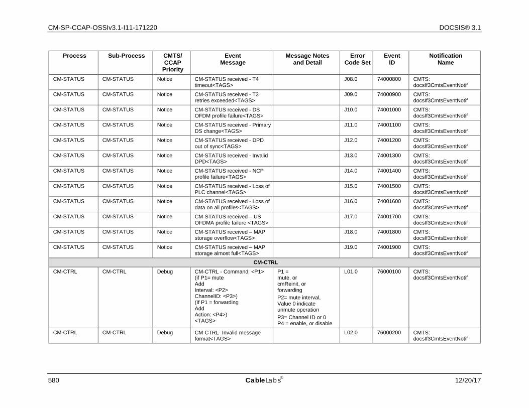
CM-SP-CCAP-OSSIv3.1-I11-171220 DOCSIS® 3.1
580 CableLabs 12/20/17
Process Sub-Process CMTS/ CCAP
Priority
Event Message
Message Notes and Detail
Error Code Set
Event ID
Notification Name
CM-STATUS CM-STATUS Notice CM-STATUS received - T4 timeout<TAGS> J08.0 74000800 CMTS:
docsIf3CmtsEventNotif
CM-STATUS CM-STATUS Notice CM-STATUS received - T3 retries exceeded<TAGS> J09.0 74000900 CMTS:
docsIf3CmtsEventNotif
CM-STATUS CM-STATUS Notice CM-STATUS received - DS OFDM profile failure<TAGS> J10.0 74001000 CMTS:
docsIf3CmtsEventNotif
CM-STATUS CM-STATUS Notice CM-STATUS received - Primary DS change<TAGS> J11.0 74001100 CMTS:
docsIf3CmtsEventNotif
CM-STATUS CM-STATUS Notice CM-STATUS received - DPD out of sync<TAGS> J12.0 74001200 CMTS:
docsIf3CmtsEventNotif
CM-STATUS CM-STATUS Notice CM-STATUS received - Invalid DPD<TAGS> J13.0 74001300 CMTS:
docsIf3CmtsEventNotif
CM-STATUS CM-STATUS Notice CM-STATUS received - NCP profile failure<TAGS> J14.0 74001400 CMTS:
docsIf3CmtsEventNotif
CM-STATUS CM-STATUS Notice CM-STATUS received - Loss of PLC channel<TAGS> J15.0 74001500 CMTS:
docsIf3CmtsEventNotif
CM-STATUS CM-STATUS Notice CM-STATUS received - Loss of data on all profiles<TAGS> J16.0 74001600 CMTS:
docsIf3CmtsEventNotif
CM-STATUS CM-STATUS Notice CM-STATUS received – US OFDMA profile failure <TAGS> J17.0 74001700 CMTS:
docsIf3CmtsEventNotif
CM-STATUS CM-STATUS Notice CM-STATUS received – MAP storage overflow<TAGS> J18.0 74001800 CMTS:
docsIf3CmtsEventNotif
CM-STATUS CM-STATUS Notice CM-STATUS received – MAP storage almost full<TAGS> J19.0 74001900 CMTS:
docsIf3CmtsEventNotif
CM-CTRL CM-CTRL CM-CTRL Debug CM-CTRL - Command: <P1>
(if P1= mute Add Interval: <P2> ChannelID: <P3>) (If P1 = forwarding Add Action: <P4>) <TAGS>
P1 = mute, or cmReinit, or forwarding P2= mute interval, Value 0 indicate unmute operation P3= Channel ID or 0 P4 = enable, or disable
L01.0 76000100 CMTS: docsIf3CmtsEventNotif
CM-CTRL CM-CTRL Debug CM-CTRL- Invalid message format<TAGS> L02.0 76000200 CMTS:
docsIf3CmtsEventNotif
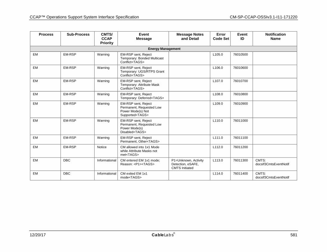
CCAP™ Operations Support System Interface Specification CM-SP-CCAP-OSSIv3.1-I11-171220
12/20/17 CableLabs 581
Process Sub-Process CMTS/ CCAP
Priority
Event Message
Message Notes and Detail
Error Code Set
Event ID
Notification Name
Energy Management EM EM-RSP Warning EM-RSP sent, Reject
Temporary: Bonded Multicast Conflict<TAGS>
L105.0 76010500
EM EM-RSP Warning EM-RSP sent, Reject Temporary: UGS/RTPS Grant Conflict<TAGS>
L106.0 76010600
EM EM-RSP Warning EM-RSP sent, Reject Temporary: Attribute Mask Conflict<TAGS>
L107.0 76010700
EM EM-RSP Warning EM-RSP sent, Reject Temporary: Deferred<TAGS> L108.0 76010800
EM EM-RSP Warning EM-RSP sent, Reject Permanent, Requested Low Power Mode(s) Not Supported<TAGS>
L109.0 76010900
EM EM-RSP Warning EM-RSP sent, Reject Permanent, Requested Low Power Mode(s) Disabled<TAGS>
L110.0 76011000
EM EM-RSP Warning EM-RSP sent, Reject Permanent, Other<TAGS> L111.0 76011100
EM EM-RSP Notice CM allowed into 1x1 Mode while Attribute Masks not met<TAGS>
L112.0 76011200
EM DBC Informational CM entered EM 1x1 mode; Reason: <P1><TAGS>
P1=Unknown, Activity Detection, eSAFE, CMTS Initiated
L113.0 76011300 CMTS: docsIf3CmtsEventNotif
EM DBC Informational CM exited EM 1x1 mode<TAGS> L114.0 76011400 CMTS:
docsIf3CmtsEventNotif
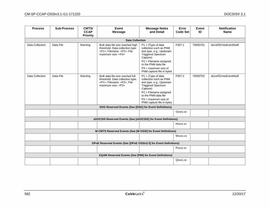
CM-SP-CCAP-OSSIv3.1-I11-171220 DOCSIS® 3.1
582 CableLabs 12/20/17
Process Sub-Process CMTS/ CCAP
Priority
Event Message
Message Notes and Detail
Error Code Set
Event ID
Notification Name
Data Collection Data Collection Data File Warning Bulk data file size reached high
threshold. Data collection type: <P1>; Filename: <P2>; File maximum size: <P3>
P1 = (Type of data collection such as PNM test type, e.g., Upstream Triggered Spectrum Capture) P2 = Filename assigned to the PNM data file P3 = maximum size of PNM capture file in bytes
F007.1 70000701 docsIf3CmtsEventNotif
Data Collection Data File Warning Bulk data file size reached full threshold. Data collection type: <P1>; Filename: <P2>; File maximum size: <P3>
P1 = (Type of data collection such as PNM test type, e.g., Upstream Triggered Spectrum Capture) P2 = Filename assigned to the PNM data file P3 = maximum size of PNM capture file in bytes
F007.2 70000702 docsIf3CmtsEventNotif
DSG Reserved Events (See [DSG] for Event Definitions)
Gxxxx.xx
eDOCSIS Reserved Events (See [eDOCSIS] for Event Definitions)
Hxxxx.xx
M-CMTS Reserved Events (See [M-OSSI] for Event Definitions)
Mxxxx.xx
DPoE Reserved Events (See [DPoE OSSIv2.0] for Event Definitions)
Pxxxx.xx
EQAM Reserved Events (See [PMI] for Event Definitions)
Qxxxx.xx
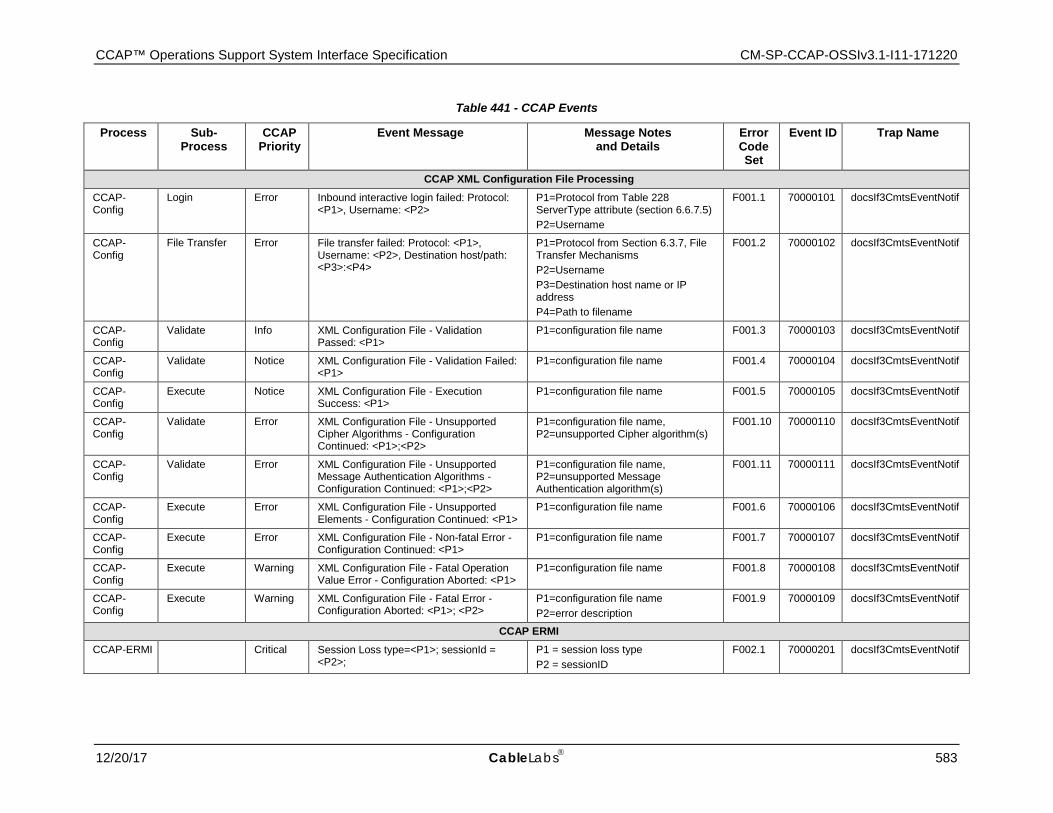
CCAP™ Operations Support System Interface Specification CM-SP-CCAP-OSSIv3.1-I11-171220
12/20/17 CableLabs 583
Table 441 - CCAP Events
Process Sub- Process
CCAP Priority
Event Message Message Notes and Details
Error Code Set
Event ID Trap Name
CCAP XML Configuration File Processing CCAP-Config
Login Error Inbound interactive login failed: Protocol: <P1>, Username: <P2>
P1=Protocol from Table 228 ServerType attribute (section 6.6.7.5) P2=Username
F001.1 70000101 docsIf3CmtsEventNotif
CCAP-Config
File Transfer Error File transfer failed: Protocol: <P1>, Username: <P2>, Destination host/path: <P3>:<P4>
P1=Protocol from Section 6.3.7, File Transfer Mechanisms P2=Username P3=Destination host name or IP address P4=Path to filename
F001.2 70000102 docsIf3CmtsEventNotif
CCAP-Config
Validate Info XML Configuration File - Validation Passed: <P1>
P1=configuration file name F001.3 70000103 docsIf3CmtsEventNotif
CCAP-Config
Validate Notice XML Configuration File - Validation Failed: <P1>
P1=configuration file name F001.4 70000104 docsIf3CmtsEventNotif
CCAP-Config
Execute Notice XML Configuration File - Execution Success: <P1>
P1=configuration file name F001.5 70000105 docsIf3CmtsEventNotif
CCAP-Config
Validate Error XML Configuration File - Unsupported Cipher Algorithms - Configuration Continued: <P1>;<P2>
P1=configuration file name, P2=unsupported Cipher algorithm(s)
F001.10 70000110 docsIf3CmtsEventNotif
CCAP-Config
Validate Error XML Configuration File - Unsupported Message Authentication Algorithms - Configuration Continued: <P1>;<P2>
P1=configuration file name, P2=unsupported Message Authentication algorithm(s)
F001.11 70000111 docsIf3CmtsEventNotif
CCAP-Config
Execute Error XML Configuration File - Unsupported Elements - Configuration Continued: <P1>
P1=configuration file name F001.6 70000106 docsIf3CmtsEventNotif
CCAP-Config
Execute Error XML Configuration File - Non-fatal Error - Configuration Continued: <P1>
P1=configuration file name F001.7 70000107 docsIf3CmtsEventNotif
CCAP-Config
Execute Warning XML Configuration File - Fatal Operation Value Error - Configuration Aborted: <P1>
P1=configuration file name F001.8 70000108 docsIf3CmtsEventNotif
CCAP-Config
Execute Warning XML Configuration File - Fatal Error - Configuration Aborted: <P1>; <P2>
P1=configuration file name P2=error description
F001.9 70000109 docsIf3CmtsEventNotif
CCAP ERMI CCAP-ERMI Critical Session Loss type=<P1>; sessionId =
<P2>; P1 = session loss type P2 = sessionID
F002.1 70000201 docsIf3CmtsEventNotif
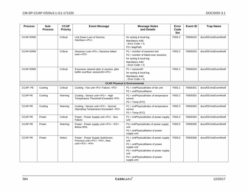
CM-SP-CCAP-OSSIv3.1-I11-171220 DOCSIS® 3.1
584 CableLabs 12/20/17
Process Sub- Process
CCAP Priority
Event Message Message Notes and Details
Error Code Set
Event ID Trap Name
CCAP-ERMI Critical Link Down Loss of Service; Interface=<P1>;
for syslog & local-log Mandatory Add: ; Error Code = 0; P1= MapPath
F002.2 70000202 docsIf3CmtsEventNotif
CCAP-ERMI Critical Sessions Lost=<P1>; Sessions failed-over=<P2>
P1 = number of sessions lost P2 = number of failed-over sessions for syslog & local-log Mandatory Add: ; Error Code = 0;
F002.3 70000203 docsIf3CmtsEventNotif
CCAP-ERMI Critical Excessive network jitter in session, jitter buffer overflow; sessionID=<P1>
P1 = sessionID for syslog & local-log Mandatory Add: ; Error Code = 0;
F002.4 70000204 docsIf3CmtsEventNotif
CCAP Physical & Environmental CCAP- PE Cooling Critical Cooling - Fan unit <P1> Failure; <P2> P1 = entPhysicalIndex of fan unit
P2 = entPhysicalName F003.1 70000301 docsIf3CmtsEventNotif
CCAP-PE Cooling Warning Cooling - Sensor unit=<P1> - High Temperature Threshold Exceeded <P2>
P1 = entPhysicalIndex of temperature sensor P2 = Temp (F/C)
F003.2 70000302 docsIf3CmtsEventNotif
CCAP-PE Cooling Warning Cooling - Sensor unit=<P1> - Normal Operating Temperature Exceeded: <P2>
P1 = entPhysicalIndex of temperature sensor P2 = Temp (F/C)
F003.3 70000303 docsIf3CmtsEventNotif
CCAP-PE Power Critical Power - Power Supply unit-<P1> - Bus Failure
P1 = entPhysicalIndex of power supply unit
F003.4 70000304 docsIf3CmtsEventNotif
CCAP-PE Power Warning Power - Power supply unit=<P1>: <P2> - Below 95%
P1= entPhysicalIndex of power supply unit P2 = entPhysicalName of power supply unit
F003.5 70000305 docsIf3CmtsEventNotif
CCAP-PE Power Notice Power - Power Supply Switchover, Previous unit=<P1>: <P2>, New unit=<P2>: <P4>
P1 = entPhysicalIndex of power supply unit P2 = entPhysicalName of power supply unit P3 = entPhysicalIndex of power supply unit P4 = entPhysicalName of power supply unit
F003.6 70000306 docsIf3CmtsEventNotif
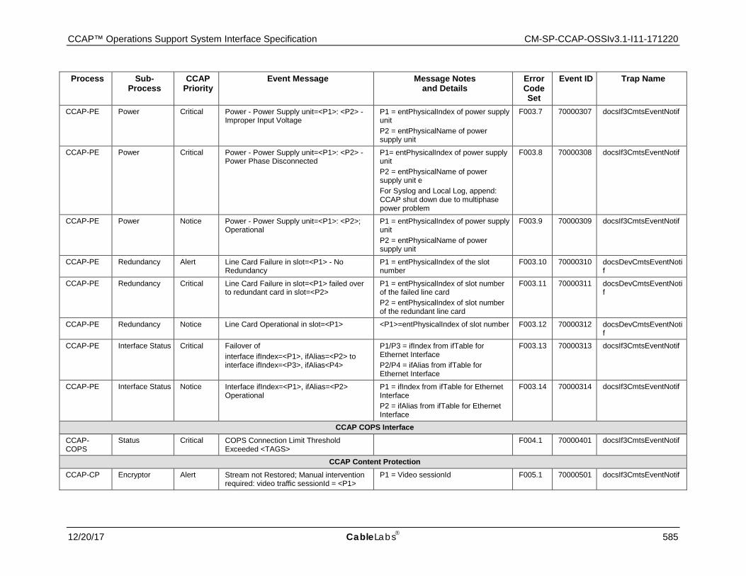
CCAP™ Operations Support System Interface Specification CM-SP-CCAP-OSSIv3.1-I11-171220
12/20/17 CableLabs 585
Process Sub- Process
CCAP Priority
Event Message Message Notes and Details
Error Code Set
Event ID Trap Name
CCAP-PE Power Critical Power - Power Supply unit=<P1>: <P2> - Improper Input Voltage
P1 = entPhysicalIndex of power supply unit P2 = entPhysicalName of power supply unit
F003.7 70000307 docsIf3CmtsEventNotif
CCAP-PE Power Critical Power - Power Supply unit=<P1>: <P2> - Power Phase Disconnected
P1= entPhysicalIndex of power supply unit P2 = entPhysicalName of power supply unit e For Syslog and Local Log, append: CCAP shut down due to multiphase power problem
F003.8 70000308 docsIf3CmtsEventNotif
CCAP-PE Power Notice Power - Power Supply unit=<P1>: <P2>; Operational
P1 = entPhysicalIndex of power supply unit P2 = entPhysicalName of power supply unit
F003.9 70000309 docsIf3CmtsEventNotif
CCAP-PE Redundancy Alert Line Card Failure in slot=<P1> - No Redundancy
P1 = entPhysicalIndex of the slot number
F003.10 70000310 docsDevCmtsEventNotif
CCAP-PE Redundancy Critical Line Card Failure in slot=<P1> failed over to redundant card in slot=<P2>
P1 = entPhysicalIndex of slot number of the failed line card P2 = entPhysicalIndex of slot number of the redundant line card
F003.11 70000311 docsDevCmtsEventNotif
CCAP-PE Redundancy Notice Line Card Operational in slot=<P1> <P1>=entPhysicalIndex of slot number F003.12 70000312 docsDevCmtsEventNotif
CCAP-PE Interface Status Critical Failover of interface ifIndex=<P1>, ifAlias=<P2> to interface ifIndex=<P3>, ifAlias<P4>
P1/P3 = ifIndex from ifTable for Ethernet Interface P2/P4 = ifAlias from ifTable for Ethernet Interface
F003.13 70000313 docsIf3CmtsEventNotif
CCAP-PE Interface Status Notice Interface ifIndex=<P1>, ifAlias=<P2> Operational
P1 = ifIndex from ifTable for Ethernet Interface P2 = ifAlias from ifTable for Ethernet Interface
F003.14 70000314 docsIf3CmtsEventNotif
CCAP COPS Interface CCAP-COPS
Status Critical COPS Connection Limit Threshold Exceeded <TAGS> F004.1 70000401 docsIf3CmtsEventNotif
CCAP Content Protection CCAP-CP Encryptor Alert Stream not Restored; Manual intervention
required: video traffic sessionId = <P1> P1 = Video sessionId F005.1 70000501 docsIf3CmtsEventNotif
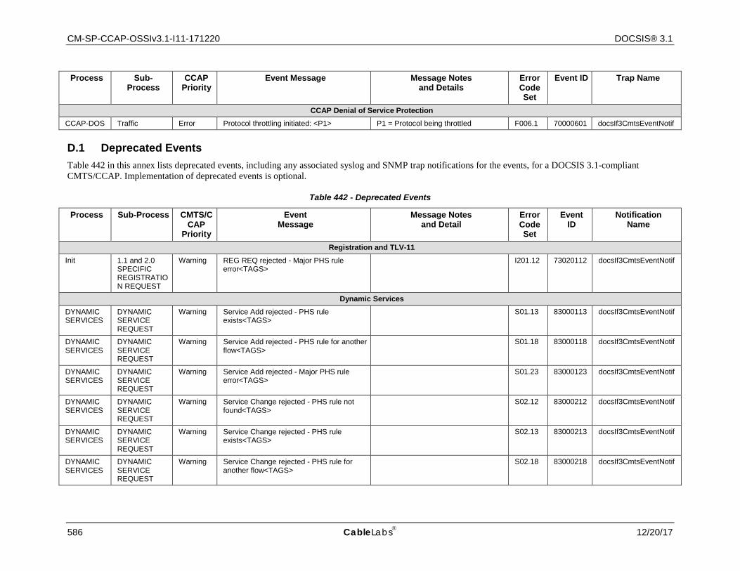
CM-SP-CCAP-OSSIv3.1-I11-171220 DOCSIS® 3.1
586 CableLabs 12/20/17
Process Sub- Process
CCAP Priority
Event Message Message Notes and Details
Error Code Set
Event ID Trap Name
CCAP Denial of Service Protection CCAP-DOS Traffic Error Protocol throttling initiated: <P1> P1 = Protocol being throttled F006.1 70000601 docsIf3CmtsEventNotif
D.1 Deprecated Events Table 442 in this annex lists deprecated events, including any associated syslog and SNMP trap notifications for the events, for a DOCSIS 3.1-compliant CMTS/CCAP. Implementation of deprecated events is optional.
Table 442 - Deprecated Events
Process Sub-Process CMTS/CCAP
Priority
Event Message
Message Notes and Detail
Error Code Set
Event ID
Notification Name
Registration and TLV-11 Init 1.1 and 2.0
SPECIFIC REGISTRATION REQUEST
Warning REG REQ rejected - Major PHS rule error<TAGS> I201.12 73020112 docsIf3CmtsEventNotif
Dynamic Services DYNAMIC SERVICES
DYNAMIC SERVICE REQUEST
Warning Service Add rejected - PHS rule exists<TAGS> S01.13 83000113 docsIf3CmtsEventNotif
DYNAMIC SERVICES
DYNAMIC SERVICE REQUEST
Warning Service Add rejected - PHS rule for another flow<TAGS> S01.18 83000118 docsIf3CmtsEventNotif
DYNAMIC SERVICES
DYNAMIC SERVICE REQUEST
Warning Service Add rejected - Major PHS rule error<TAGS> S01.23 83000123 docsIf3CmtsEventNotif
DYNAMIC SERVICES
DYNAMIC SERVICE REQUEST
Warning Service Change rejected - PHS rule not found<TAGS> S02.12 83000212 docsIf3CmtsEventNotif
DYNAMIC SERVICES
DYNAMIC SERVICE REQUEST
Warning Service Change rejected - PHS rule exists<TAGS> S02.13 83000213 docsIf3CmtsEventNotif
DYNAMIC SERVICES
DYNAMIC SERVICE REQUEST
Warning Service Change rejected - PHS rule for another flow<TAGS> S02.18 83000218 docsIf3CmtsEventNotif
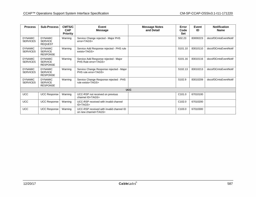
CCAP™ Operations Support System Interface Specification CM-SP-CCAP-OSSIv3.1-I11-171220
12/20/17 CableLabs 587
Process Sub-Process CMTS/CCAP
Priority
Event Message
Message Notes and Detail
Error Code Set
Event ID
Notification Name
DYNAMIC SERVICES
DYNAMIC SERVICE REQUEST
Warning Service Change rejected - Major PHS error<TAGS> S02.23 83000223 docsIf3CmtsEventNotif
DYNAMIC SERVICES
DYNAMIC SERVICE RESPONSE
Warning Service Add Response rejected - PHS rule exists<TAGS> S101.10 83010110 docsIf3CmtsEventNotif
DYNAMIC SERVICES
DYNAMIC SERVICE RESPONSE
Warning Service Add Response rejected - Major PHS Rule error<TAGS> S101.16 83010116 docsIf3CmtsEventNotif
DYNAMIC SERVICES
DYNAMIC SERVICE RESPONSE
Warning Service Change Response rejected - Major PHS rule error<TAGS> S102.13 83010213 docsIf3CmtsEventNotif
DYNAMIC SERVICES
DYNAMIC SERVICE RESPONSE
Warning Service Change Response rejected - PHS rule exists<TAGS> S102.9 83010209 docsIf3CmtsEventNotif
UCC UCC UCC Response Warning UCC-RSP not received on previous
channel ID<TAGS> C101.0 67010100
UCC UCC Response Warning UCC-RSP received with invalid channel ID<TAGS> C102.0 67010200
UCC UCC Response Warning UCC-RSP received with invalid channel ID on new channel<TAGS> C103.0 67010300

CM-SP-CCAP-OSSIv3.1-I11-171220 DOCSIS® 3.1
588 CableLabs 12/20/17
D.2 Example SNMP Notification and Syslog Event Message The following is an example SNMP Notification and Syslog message "Event Message" text string for Event ID 70000304: Power - Power Supply Bus Failure; unit=pw/1/1/;
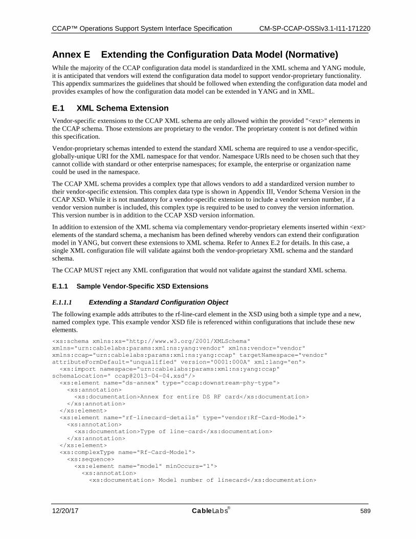
CCAP™ Operations Support System Interface Specification CM-SP-CCAP-OSSIv3.1-I11-171220
12/20/17 CableLabs 589
Annex E Extending the Configuration Data Model (Normative) While the majority of the CCAP configuration data model is standardized in the XML schema and YANG module, it is anticipated that vendors will extend the configuration data model to support vendor-proprietary functionality. This appendix summarizes the guidelines that should be followed when extending the configuration data model and provides examples of how the configuration data model can be extended in YANG and in XML.
E.1 XML Schema Extension Vendor-specific extensions to the CCAP XML schema are only allowed within the provided "<ext>" elements in the CCAP schema. Those extensions are proprietary to the vendor. The proprietary content is not defined within this specification.
Vendor-proprietary schemas intended to extend the standard XML schema are required to use a vendor-specific, globally-unique URI for the XML namespace for that vendor. Namespace URIs need to be chosen such that they cannot collide with standard or other enterprise namespaces; for example, the enterprise or organization name could be used in the namespace.
The CCAP XML schema provides a complex type that allows vendors to add a standardized version number to their vendor-specific extension. This complex data type is shown in Appendix III, Vendor Schema Version in the CCAP XSD. While it is not mandatory for a vendor-specific extension to include a vendor version number, if a vendor version number is included, this complex type is required to be used to convey the version information. This version number is in addition to the CCAP XSD version information.
In addition to extension of the XML schema via complementary vendor-proprietary elements inserted within <ext> elements of the standard schema, a mechanism has been defined whereby vendors can extend their configuration model in YANG, but convert these extensions to XML schema. Refer to Annex E.2 for details. In this case, a single XML configuration file will validate against both the vendor-proprietary XML schema and the standard schema.
The CCAP MUST reject any XML configuration that would not validate against the standard XML schema.
E.1.1 Sample Vendor-Specific XSD Extensions
E.1.1.1 Extending a Standard Configuration Object The following example adds attributes to the rf-line-card element in the XSD using both a simple type and a new, named complex type. This example vendor XSD file is referenced within configurations that include these new elements. <xs:schema xmlns:xs="http://www.w3.org/2001/XMLSchema" xmlns="urn:cablelabs:params:xml:ns:yang:vendor" xmlns:vendor="vendor" xmlns:ccap="urn:cablelabs:params:xml:ns:yang:ccap" targetNamespace="vendor" attributeFormDefault="unqualified" version="0001:000A" xml:lang="en"> <xs:import namespace="urn:cablelabs:params:xml:ns:yang:ccap" schemaLocation=" [email protected]"/> <xs:element name="ds-annex" type="ccap:downstream-phy-type"> <xs:annotation> <xs:documentation>Annex for entire DS RF card</xs:documentation> </xs:annotation> </xs:element> <xs:element name="rf-linecard-details" type="vendor:Rf-Card-Model"> <xs:annotation> <xs:documentation>Type of line-card</xs:documentation> </xs:annotation> </xs:element> <xs:complexType name="Rf-Card-Model"> <xs:sequence> <xs:element name="model" minOccurs="1"> <xs:annotation> <xs:documentation> Model number of linecard</xs:documentation>
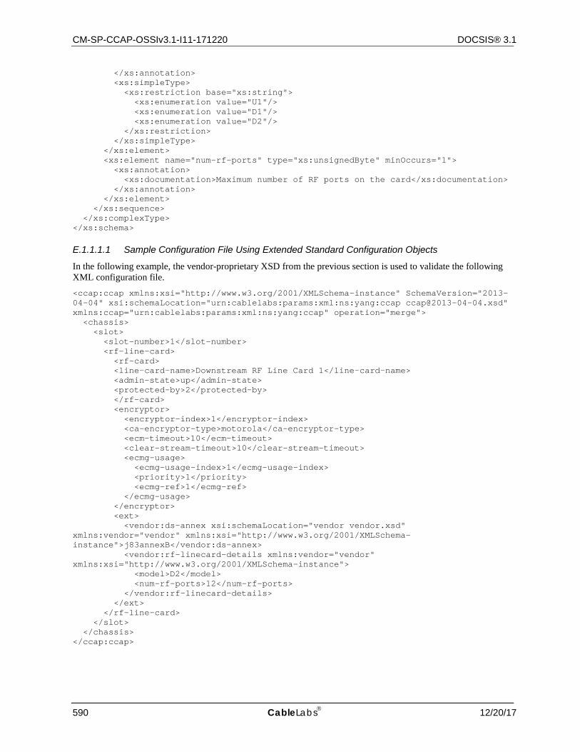
CM-SP-CCAP-OSSIv3.1-I11-171220 DOCSIS® 3.1
590 CableLabs 12/20/17
</xs:annotation> <xs:simpleType> <xs:restriction base="xs:string"> <xs:enumeration value="U1"/> <xs:enumeration value="D1"/> <xs:enumeration value="D2"/> </xs:restriction> </xs:simpleType> </xs:element> <xs:element name="num-rf-ports" type="xs:unsignedByte" minOccurs="1"> <xs:annotation> <xs:documentation>Maximum number of RF ports on the card</xs:documentation> </xs:annotation> </xs:element> </xs:sequence> </xs:complexType> </xs:schema>
E.1.1.1.1 Sample Configuration File Using Extended Standard Configuration Objects
In the following example, the vendor-proprietary XSD from the previous section is used to validate the following XML configuration file. <ccap:ccap xmlns:xsi="http://www.w3.org/2001/XMLSchema-instance" SchemaVersion="2013-04-04" xsi:schemaLocation="urn:cablelabs:params:xml:ns:yang:ccap [email protected]" xmlns:ccap="urn:cablelabs:params:xml:ns:yang:ccap" operation="merge"> <chassis> <slot> <slot-number>1</slot-number> <rf-line-card> <rf-card> <line-card-name>Downstream RF Line Card 1</line-card-name> <admin-state>up</admin-state> <protected-by>2</protected-by> </rf-card> <encryptor> <encryptor-index>1</encryptor-index> <ca-encryptor-type>motorola</ca-encryptor-type> <ecm-timeout>10</ecm-timeout> <clear-stream-timeout>10</clear-stream-timeout> <ecmg-usage> <ecmg-usage-index>1</ecmg-usage-index> <priority>1</priority> <ecmg-ref>1</ecmg-ref> </ecmg-usage> </encryptor> <ext> <vendor:ds-annex xsi:schemaLocation="vendor vendor.xsd" xmlns:vendor="vendor" xmlns:xsi="http://www.w3.org/2001/XMLSchema-instance">j83annexB</vendor:ds-annex> <vendor:rf-linecard-details xmlns:vendor="vendor" xmlns:xsi="http://www.w3.org/2001/XMLSchema-instance"> <model>D2</model> <num-rf-ports>12</num-rf-ports> </vendor:rf-linecard-details> </ext> </rf-line-card> </slot> </chassis> </ccap:ccap>
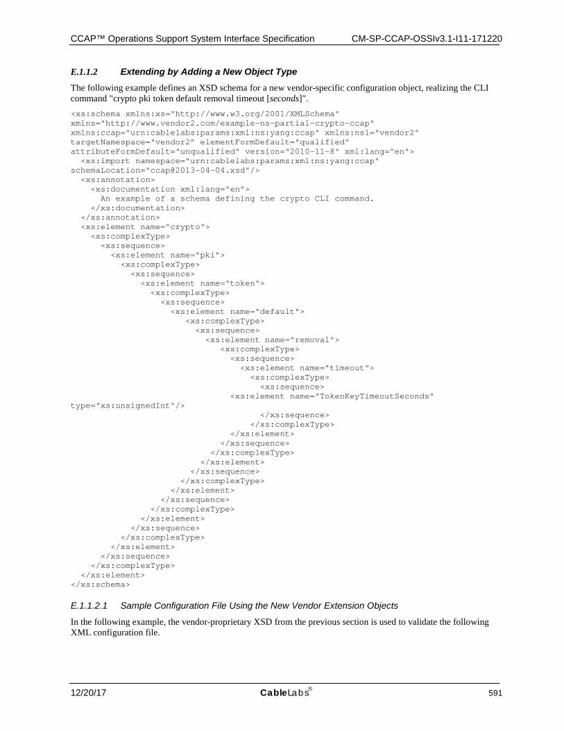
CCAP™ Operations Support System Interface Specification CM-SP-CCAP-OSSIv3.1-I11-171220
12/20/17 CableLabs 591
E.1.1.2 Extending by Adding a New Object Type The following example defines an XSD schema for a new vendor-specific configuration object, realizing the CLI command "crypto pki token default removal timeout [seconds]". <xs:schema xmlns:xs="http://www.w3.org/2001/XMLSchema" xmlns="http://www.vendor2.com/example-ns-partial-crypto-ccap" xmlns:ccap="urn:cablelabs:params:xml:ns:yang:ccap" xmlns:ns1="vendor2" targetNamespace="vendor2" elementFormDefault="qualified" attributeFormDefault="unqualified" version="2010-11-8" xml:lang="en"> <xs:import namespace="urn:cablelabs:params:xml:ns:yang:ccap" schemaLocation="[email protected]"/> <xs:annotation> <xs:documentation xml:lang="en"> An example of a schema defining the crypto CLI command. </xs:documentation> </xs:annotation> <xs:element name="crypto"> <xs:complexType> <xs:sequence> <xs:element name="pki"> <xs:complexType> <xs:sequence> <xs:element name="token"> <xs:complexType> <xs:sequence> <xs:element name="default"> <xs:complexType> <xs:sequence> <xs:element name="removal"> <xs:complexType> <xs:sequence> <xs:element name="timeout"> <xs:complexType> <xs:sequence> <xs:element name="TokenKeyTimeoutSeconds" type="xs:unsignedInt"/> </xs:sequence> </xs:complexType> </xs:element> </xs:sequence> </xs:complexType> </xs:element> </xs:sequence> </xs:complexType> </xs:element> </xs:sequence> </xs:complexType> </xs:element> </xs:sequence> </xs:complexType> </xs:element> </xs:sequence> </xs:complexType> </xs:element> </xs:schema>
E.1.1.2.1 Sample Configuration File Using the New Vendor Extension Objects
In the following example, the vendor-proprietary XSD from the previous section is used to validate the following XML configuration file.
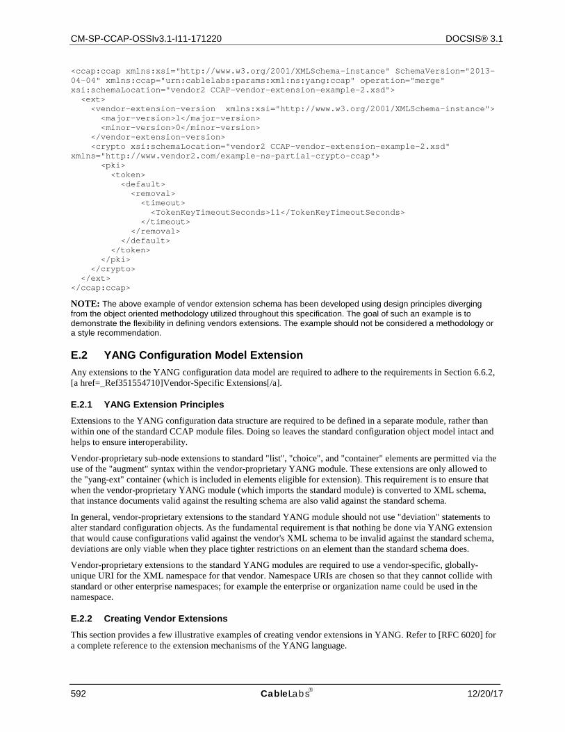
CM-SP-CCAP-OSSIv3.1-I11-171220 DOCSIS® 3.1
592 CableLabs 12/20/17
<ccap:ccap xmlns:xsi="http://www.w3.org/2001/XMLSchema-instance" SchemaVersion="2013-04-04" xmlns:ccap="urn:cablelabs:params:xml:ns:yang:ccap" operation="merge" xsi:schemaLocation="vendor2 CCAP-vendor-extension-example-2.xsd"> <ext> <vendor-extension-version xmlns:xsi="http://www.w3.org/2001/XMLSchema-instance"> <major-version>1</major-version> <minor-version>0</minor-version> </vendor-extension-version> <crypto xsi:schemaLocation="vendor2 CCAP-vendor-extension-example-2.xsd" xmlns="http://www.vendor2.com/example-ns-partial-crypto-ccap"> <pki> <token> <default> <removal> <timeout> <TokenKeyTimeoutSeconds>11</TokenKeyTimeoutSeconds> </timeout> </removal> </default> </token> </pki> </crypto> </ext> </ccap:ccap>
NOTE: The above example of vendor extension schema has been developed using design principles diverging from the object oriented methodology utilized throughout this specification. The goal of such an example is to demonstrate the flexibility in defining vendors extensions. The example should not be considered a methodology or a style recommendation.
E.2 YANG Configuration Model Extension Any extensions to the YANG configuration data model are required to adhere to the requirements in Section 6.6.2, [a href=_Ref351554710]Vendor-Specific Extensions[/a].
E.2.1 YANG Extension Principles
Extensions to the YANG configuration data structure are required to be defined in a separate module, rather than within one of the standard CCAP module files. Doing so leaves the standard configuration object model intact and helps to ensure interoperability.
Vendor-proprietary sub-node extensions to standard "list", "choice", and "container" elements are permitted via the use of the "augment" syntax within the vendor-proprietary YANG module. These extensions are only allowed to the "yang-ext" container (which is included in elements eligible for extension). This requirement is to ensure that when the vendor-proprietary YANG module (which imports the standard module) is converted to XML schema, that instance documents valid against the resulting schema are also valid against the standard schema.
In general, vendor-proprietary extensions to the standard YANG module should not use "deviation" statements to alter standard configuration objects. As the fundamental requirement is that nothing be done via YANG extension that would cause configurations valid against the vendor's XML schema to be invalid against the standard schema, deviations are only viable when they place tighter restrictions on an element than the standard schema does.
Vendor-proprietary extensions to the standard YANG modules are required to use a vendor-specific, globally-unique URI for the XML namespace for that vendor. Namespace URIs are chosen so that they cannot collide with standard or other enterprise namespaces; for example the enterprise or organization name could be used in the namespace.
E.2.2 Creating Vendor Extensions
This section provides a few illustrative examples of creating vendor extensions in YANG. Refer to [RFC 6020] for a complete reference to the extension mechanisms of the YANG language.
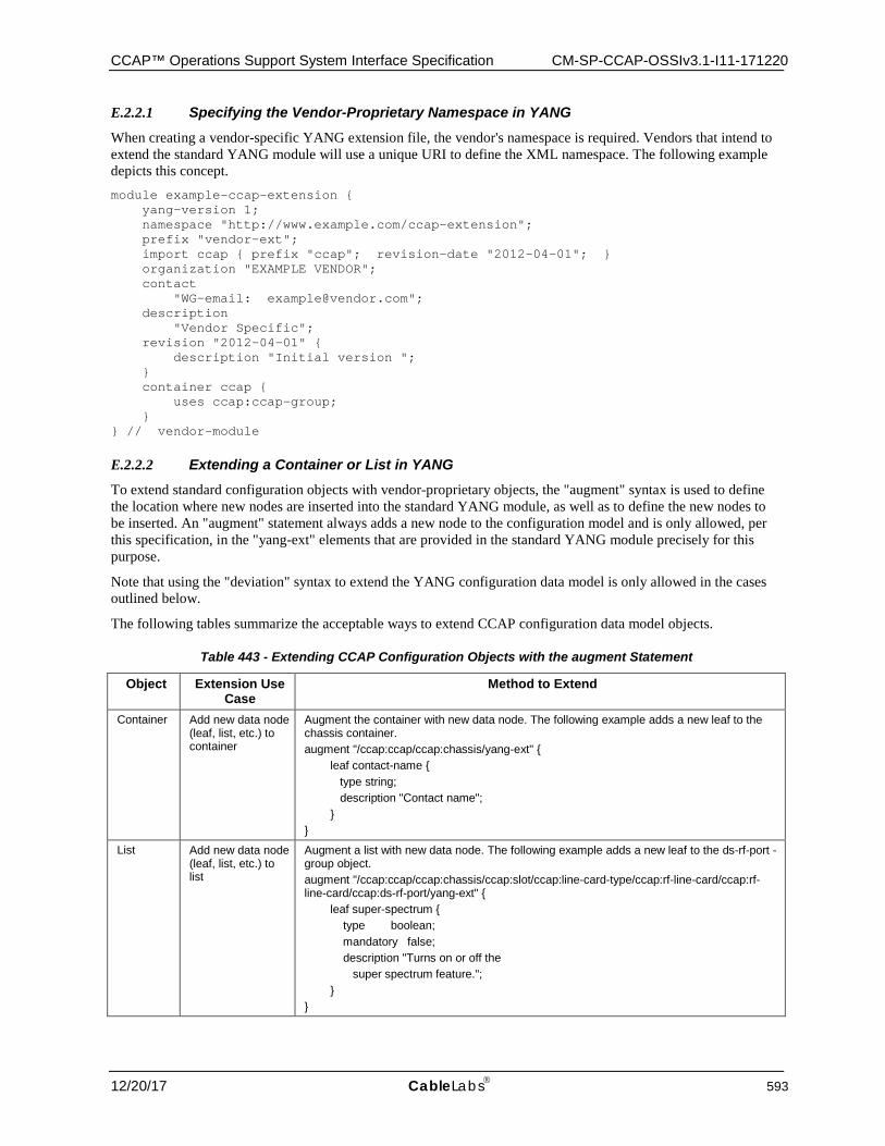
CCAP™ Operations Support System Interface Specification CM-SP-CCAP-OSSIv3.1-I11-171220
12/20/17 CableLabs 593
E.2.2.1 Specifying the Vendor-Proprietary Namespace in YANG When creating a vendor-specific YANG extension file, the vendor's namespace is required. Vendors that intend to extend the standard YANG module will use a unique URI to define the XML namespace. The following example depicts this concept. module example-ccap-extension { yang-version 1; namespace "http://www.example.com/ccap-extension"; prefix "vendor-ext"; import ccap { prefix "ccap"; revision-date "2012-04-01"; } organization "EXAMPLE VENDOR"; contact "WG-email: [email protected]"; description "Vendor Specific"; revision "2012-04-01" { description "Initial version "; } container ccap { uses ccap:ccap-group; } } // vendor-module
E.2.2.2 Extending a Container or List in YANG To extend standard configuration objects with vendor-proprietary objects, the "augment" syntax is used to define the location where new nodes are inserted into the standard YANG module, as well as to define the new nodes to be inserted. An "augment" statement always adds a new node to the configuration model and is only allowed, per this specification, in the "yang-ext" elements that are provided in the standard YANG module precisely for this purpose.
Note that using the "deviation" syntax to extend the YANG configuration data model is only allowed in the cases outlined below.
The following tables summarize the acceptable ways to extend CCAP configuration data model objects.
Table 443 - Extending CCAP Configuration Objects with the augment Statement
Object Extension Use Case
Method to Extend
Container Add new data node (leaf, list, etc.) to container
Augment the container with new data node. The following example adds a new leaf to the chassis container. augment "/ccap:ccap/ccap:chassis/yang-ext" { leaf contact-name { type string; description "Contact name"; } }
List Add new data node (leaf, list, etc.) to list
Augment a list with new data node. The following example adds a new leaf to the ds-rf-port -group object. augment "/ccap:ccap/ccap:chassis/ccap:slot/ccap:line-card-type/ccap:rf-line-card/ccap:rf-line-card/ccap:ds-rf-port/yang-ext" { leaf super-spectrum { type boolean; mandatory false; description "Turns on or off the super spectrum feature."; } }
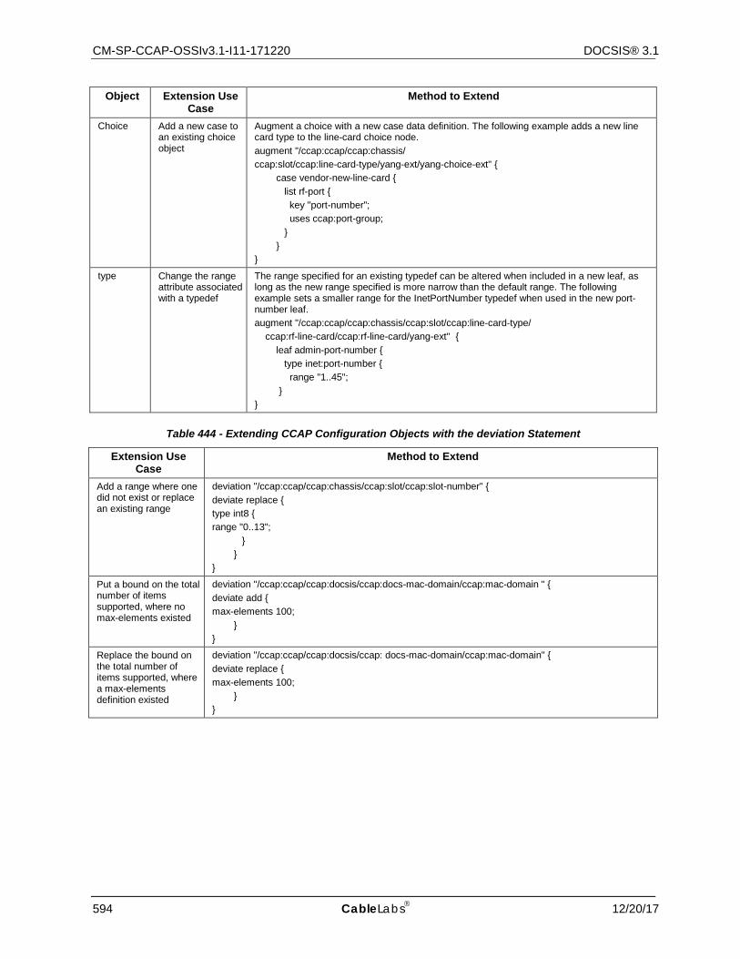
CM-SP-CCAP-OSSIv3.1-I11-171220 DOCSIS® 3.1
594 CableLabs 12/20/17
Object Extension Use Case
Method to Extend
Choice Add a new case to an existing choice object
Augment a choice with a new case data definition. The following example adds a new line card type to the line-card choice node. augment "/ccap:ccap/ccap:chassis/ ccap:slot/ccap:line-card-type/yang-ext/yang-choice-ext" { case vendor-new-line-card { list rf-port { key "port-number"; uses ccap:port-group; } } }
type Change the range attribute associated with a typedef
The range specified for an existing typedef can be altered when included in a new leaf, as long as the new range specified is more narrow than the default range. The following example sets a smaller range for the InetPortNumber typedef when used in the new port-number leaf. augment "/ccap:ccap/ccap:chassis/ccap:slot/ccap:line-card-type/ ccap:rf-line-card/ccap:rf-line-card/yang-ext" { leaf admin-port-number { type inet:port-number { range "1..45"; } }
Table 444 - Extending CCAP Configuration Objects with the deviation Statement
Extension Use Case
Method to Extend
Add a range where one did not exist or replace an existing range
deviation "/ccap:ccap/ccap:chassis/ccap:slot/ccap:slot-number" { deviate replace { type int8 { range "0..13"; } } }
Put a bound on the total number of items supported, where no max-elements existed
deviation "/ccap:ccap/ccap:docsis/ccap:docs-mac-domain/ccap:mac-domain " { deviate add { max-elements 100; } }
Replace the bound on the total number of items supported, where a max-elements definition existed
deviation "/ccap:ccap/ccap:docsis/ccap: docs-mac-domain/ccap:mac-domain" { deviate replace { max-elements 100; } }

CCAP™ Operations Support System Interface Specification CM-SP-CCAP-OSSIv3.1-I11-171220
12/20/17 CableLabs 595
Extension Use Case
Method to Extend
Remove a default value and make the item mandatory
// First remove the default deviation "/ccap:ccap/ccap:docsis/ccap:docs-mac-domain/ccap:mac-domain/ccap:mdd-interval" { deviate delete { default "2000"; } } //Now add the mandatory true property deviation "/ccap:ccap/ccap:docsis/ccap:docs-mac-domain/ccap:mac-domain/ccap:mdd-interval" { deviate add { mandatory "true"; } }
E.2.3 Example Vendor-Proprietary Extensions in YANG Configuration Messages
The following examples show a vendor-extension YANG module and a partial CCAP configuration that uses those vendor extensions.
E.2.3.1 Sample Vendor-Extension YANG Module In this example, the following elements are extended:
• A contact-name leaf is added to the chassis container • The InetPortNumber typedef has its range narrowed in the port-number leaf • A new case is added to the card-type choice definition module example-ccap-extension { yang-version 1; namespace "http://www.example.com/ccap-extension"; prefix "ccap-extension"; import ccap { prefix "ccap"; } organization "Example Vendor"; contact "WG-email: [email protected]"; description "Vendor Specific"; revision "2013-04-04" { description "Initial version "; } augment "/ccap/chassis/slot/line-card-type/rf-line-card/yang-ext1" { leaf admin-port-number { type inet:port-number { range "1..45"; } } } augment "/ccap/chassis/slot/line-card-type/yang-choice-ext" { choice vendor-line-card { case vendor-turbo-card { list rf-port { key "port-number"; uses ccap:port-group; } } } }
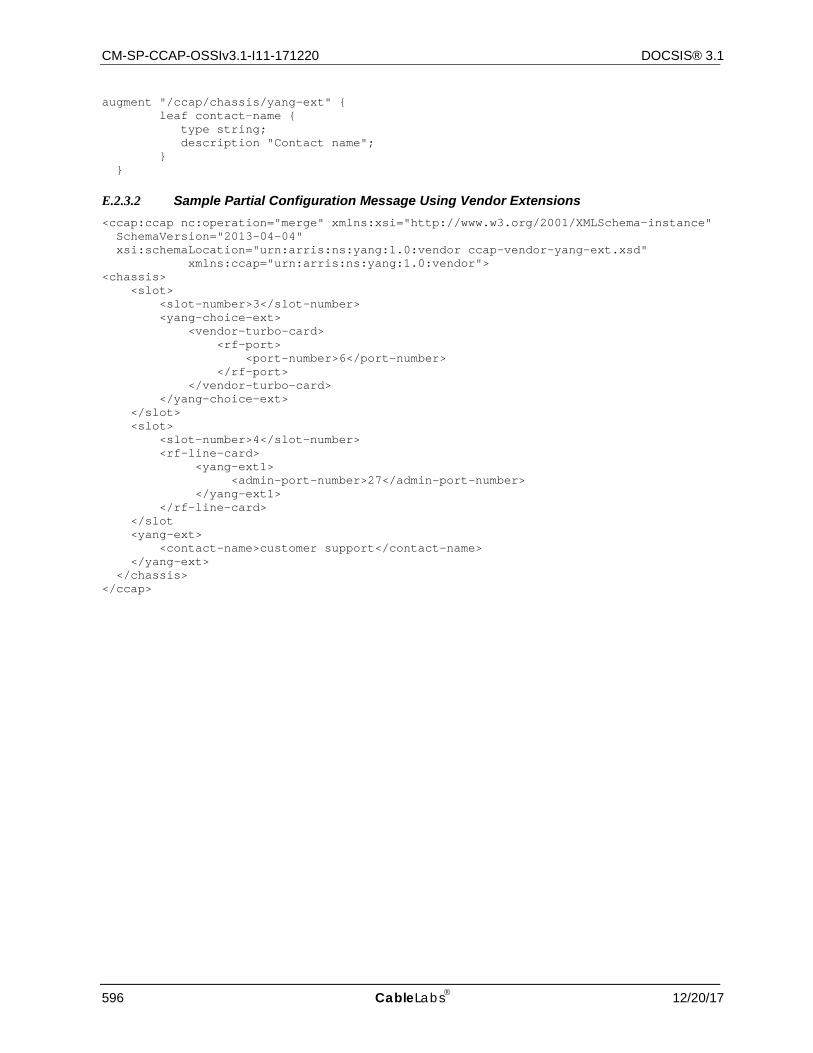
CM-SP-CCAP-OSSIv3.1-I11-171220 DOCSIS® 3.1
596 CableLabs 12/20/17
augment "/ccap/chassis/yang-ext" { leaf contact-name { type string; description "Contact name"; } }
E.2.3.2 Sample Partial Configuration Message Using Vendor Extensions <ccap:ccap nc:operation="merge" xmlns:xsi="http://www.w3.org/2001/XMLSchema-instance" SchemaVersion="2013-04-04" xsi:schemaLocation="urn:arris:ns:yang:1.0:vendor ccap-vendor-yang-ext.xsd" xmlns:ccap="urn:arris:ns:yang:1.0:vendor"> <chassis> <slot> <slot-number>3</slot-number> <yang-choice-ext> <vendor-turbo-card> <rf-port> <port-number>6</port-number> </rf-port> </vendor-turbo-card> </yang-choice-ext> </slot> <slot> <slot-number>4</slot-number> <rf-line-card> <yang-ext1> <admin-port-number>27</admin-port-number> </yang-ext1> </rf-line-card> </slot <yang-ext> <contact-name>customer support</contact-name> </yang-ext> </chassis> </ccap>
CCAP™ Operations Support System Interface Specification CM-SP-CCAP-OSSIv3.1-I11-171220
12/20/17 CableLabs 597
Annex F CCAP Data Type Definitions (Normative)
F.1 Overview This annex includes the data type definitions for the Information Models defined for use in the CCAP. The Unified Modeling Language (UML) is used for modeling the management requirements. The data types defined in this annex are mapped for use with YANG data types.
The data types defined in this Annex are mapped for use with SNMP MIBs, IPDR XML schemas, YANG modules and XSD Schemas.
Basic UML notation used in this specification is explained in Appendix VII.
F.2 Data Types Mapping XML is becoming the standard for data definition models. With XML data transformations can be done with or without a model (DTD or Schema definition). DTDs and XML schemas provides additional data validation layer to the applications exchanging XML data. There are several models to map formal notation constructs like ASN.1 to XML [ITU-T X.692], UML to XML, YANG to XML, or XML by itself can be used for modeling purposes.
Each area of data information interest approaches XML and defines data models and/or data containment structures and data types. Similarly, SNMP took and modified a subset of ASN.1 for defining the Structured Management Information SMIv1 and SMIv2.
Due to the lack of a unified data model and data types for Network Management a neutral model would be appropriated to allow capturing specific requirements and methodologies from existing protocols and allow forward or reverse engineering of those standards like SNMP to the general object model and vice versa.
F.3 Data Types Requirements and Classification The Information Model has to provide seamless translation for SMIv2 requirements, in particular when creating MIB modules based on the Information Model, this specification needs to provide full support of [RFC 2578], [RFC 2579], and the clarifications and recommendations of [RFC 4181].
The Information Model has to provide seamless translation for IPDR modeling requirements which is by itself a subset of XML representations with some IPDR extensions.
The Information Model has to provide seamless translation for YANG modeling requirements, in particular when creating YANG modules based on the Information Model.
Thus, there are two data type groups defined for modeling purposes and mapping to protocol data notation roundtrip.
• General data types
Required data types to cover all the management syntax and semantic requirement for all OSSI supported data models. In this category are data types defined in SNMP SMIv2 [RFC 2578], IPDR data types [IPDR/XDR] and [IPDR/SSDG], and YANG common data types [RFC 6991].
• Extended data types
Management protocols specialization based on frequent usage or special semantics. Required data types to cover all the syntax requirement for all OSSI supported data models. In this category are SNMP TEXTUAL-CONVENTION clauses [RFC 2579] of mandatory or recommended usage by [RFC 2579] and [RFC 4181] when modeling for SNMP MIB modules.
F.4 Data Type Mapping Methodology The specification "XML Schema Part 2: Data types Second Edition" is based on [ISO 11404] which provides a language-independent data types (see XML Schema reference). The mapping proposed below uses a subset of the XML schema data types to cover both SNMP forward and reverse engineering and as well IPDR types. Any additional protocol being added should be feasible to provide the particular mappings.
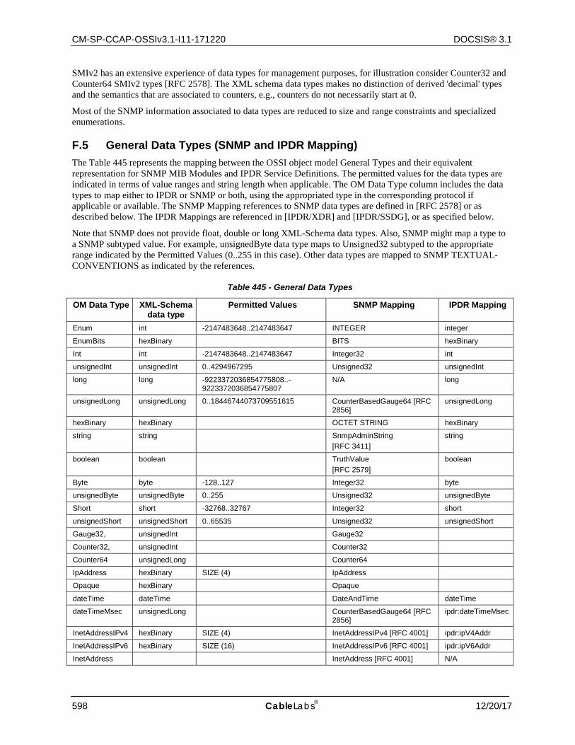
CM-SP-CCAP-OSSIv3.1-I11-171220 DOCSIS® 3.1
598 CableLabs 12/20/17
SMIv2 has an extensive experience of data types for management purposes, for illustration consider Counter32 and Counter64 SMIv2 types [RFC 2578]. The XML schema data types makes no distinction of derived 'decimal' types and the semantics that are associated to counters, e.g., counters do not necessarily start at 0.
Most of the SNMP information associated to data types are reduced to size and range constraints and specialized enumerations.
F.5 General Data Types (SNMP and IPDR Mapping) The Table 445 represents the mapping between the OSSI object model General Types and their equivalent representation for SNMP MIB Modules and IPDR Service Definitions. The permitted values for the data types are indicated in terms of value ranges and string length when applicable. The OM Data Type column includes the data types to map either to IPDR or SNMP or both, using the appropriated type in the corresponding protocol if applicable or available. The SNMP Mapping references to SNMP data types are defined in [RFC 2578] or as described below. The IPDR Mappings are referenced in [IPDR/XDR] and [IPDR/SSDG], or as specified below.
Note that SNMP does not provide float, double or long XML-Schema data types. Also, SNMP might map a type to a SNMP subtyped value. For example, unsignedByte data type maps to Unsigned32 subtyped to the appropriate range indicated by the Permitted Values (0..255 in this case). Other data types are mapped to SNMP TEXTUAL-CONVENTIONS as indicated by the references.
Table 445 - General Data Types
OM Data Type XML-Schema data type
Permitted Values SNMP Mapping IPDR Mapping
Enum int -2147483648..2147483647 INTEGER integer
EnumBits hexBinary BITS hexBinary
Int int -2147483648..2147483647 Integer32 int
unsignedInt unsignedInt 0..4294967295 Unsigned32 unsignedInt
long long -9223372036854775808..-9223372036854775807
N/A long
unsignedLong unsignedLong 0..18446744073709551615 CounterBasedGauge64 [RFC 2856]
unsignedLong
hexBinary hexBinary OCTET STRING hexBinary
string string SnmpAdminString [RFC 3411]
string
boolean boolean TruthValue [RFC 2579]
boolean
Byte byte -128..127 Integer32 byte
unsignedByte unsignedByte 0..255 Unsigned32 unsignedByte
Short short -32768..32767 Integer32 short
unsignedShort unsignedShort 0..65535 Unsigned32 unsignedShort
Gauge32, unsignedInt Gauge32
Counter32, unsignedInt Counter32
Counter64 unsignedLong Counter64
IpAddress hexBinary SIZE (4) IpAddress
Opaque hexBinary Opaque
dateTime dateTime DateAndTime dateTime
dateTimeMsec unsignedLong CounterBasedGauge64 [RFC 2856]
ipdr:dateTimeMsec
InetAddressIPv4 hexBinary SIZE (4) InetAddressIPv4 [RFC 4001] ipdr:ipV4Addr
InetAddressIPv6 hexBinary SIZE (16) InetAddressIPv6 [RFC 4001] ipdr:ipV6Addr
InetAddress InetAddress [RFC 4001] N/A
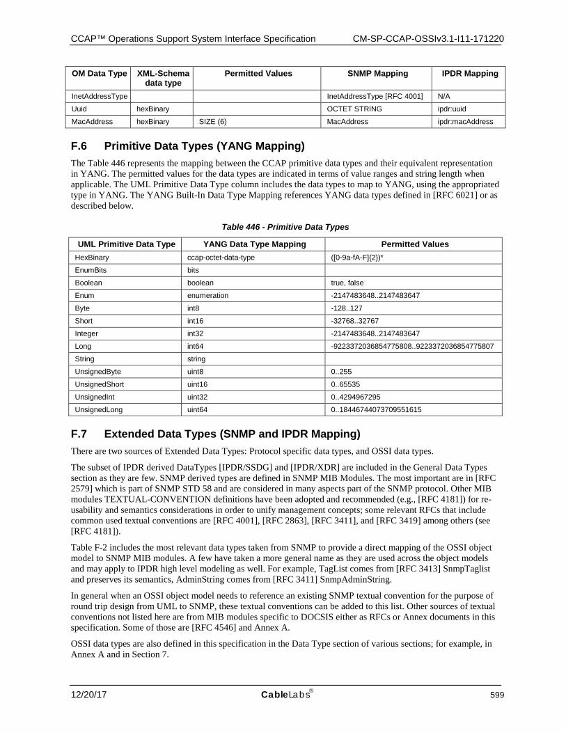
CCAP™ Operations Support System Interface Specification CM-SP-CCAP-OSSIv3.1-I11-171220
12/20/17 CableLabs 599
OM Data Type XML-Schema data type
Permitted Values SNMP Mapping IPDR Mapping
InetAddressType InetAddressType [RFC 4001] N/A
Uuid hexBinary OCTET STRING ipdr:uuid
MacAddress hexBinary SIZE (6) MacAddress ipdr:macAddress
F.6 Primitive Data Types (YANG Mapping) The Table 446 represents the mapping between the CCAP primitive data types and their equivalent representation in YANG. The permitted values for the data types are indicated in terms of value ranges and string length when applicable. The UML Primitive Data Type column includes the data types to map to YANG, using the appropriated type in YANG. The YANG Built-In Data Type Mapping references YANG data types defined in [RFC 6021] or as described below.
Table 446 - Primitive Data Types
UML Primitive Data Type YANG Data Type Mapping Permitted Values HexBinary ccap-octet-data-type ([0-9a-fA-F]{2})*
EnumBits bits
Boolean boolean true, false
Enum enumeration -2147483648..2147483647
Byte int8 -128..127
Short int16 -32768..32767
Integer int32 -2147483648..2147483647
Long int64 -9223372036854775808..9223372036854775807
String string
UnsignedByte uint8 0..255
UnsignedShort uint16 0..65535
UnsignedInt uint32 0..4294967295
UnsignedLong uint64 0..18446744073709551615
F.7 Extended Data Types (SNMP and IPDR Mapping) There are two sources of Extended Data Types: Protocol specific data types, and OSSI data types.
The subset of IPDR derived DataTypes [IPDR/SSDG] and [IPDR/XDR] are included in the General Data Types section as they are few. SNMP derived types are defined in SNMP MIB Modules. The most important are in [RFC 2579] which is part of SNMP STD 58 and are considered in many aspects part of the SNMP protocol. Other MIB modules TEXTUAL-CONVENTION definitions have been adopted and recommended (e.g., [RFC 4181]) for re-usability and semantics considerations in order to unify management concepts; some relevant RFCs that include common used textual conventions are [RFC 4001], [RFC 2863], [RFC 3411], and [RFC 3419] among others (see [RFC 4181]).
Table F-2 includes the most relevant data types taken from SNMP to provide a direct mapping of the OSSI object model to SNMP MIB modules. A few have taken a more general name as they are used across the object models and may apply to IPDR high level modeling as well. For example, TagList comes from [RFC 3413] SnmpTaglist and preserves its semantics, AdminString comes from [RFC 3411] SnmpAdminString.
In general when an OSSI object model needs to reference an existing SNMP textual convention for the purpose of round trip design from UML to SNMP, these textual conventions can be added to this list. Other sources of textual conventions not listed here are from MIB modules specific to DOCSIS either as RFCs or Annex documents in this specification. Some of those are [RFC 4546] and Annex A.
OSSI data types are also defined in this specification in the Data Type section of various sections; for example, in Annex A and in Section 7.
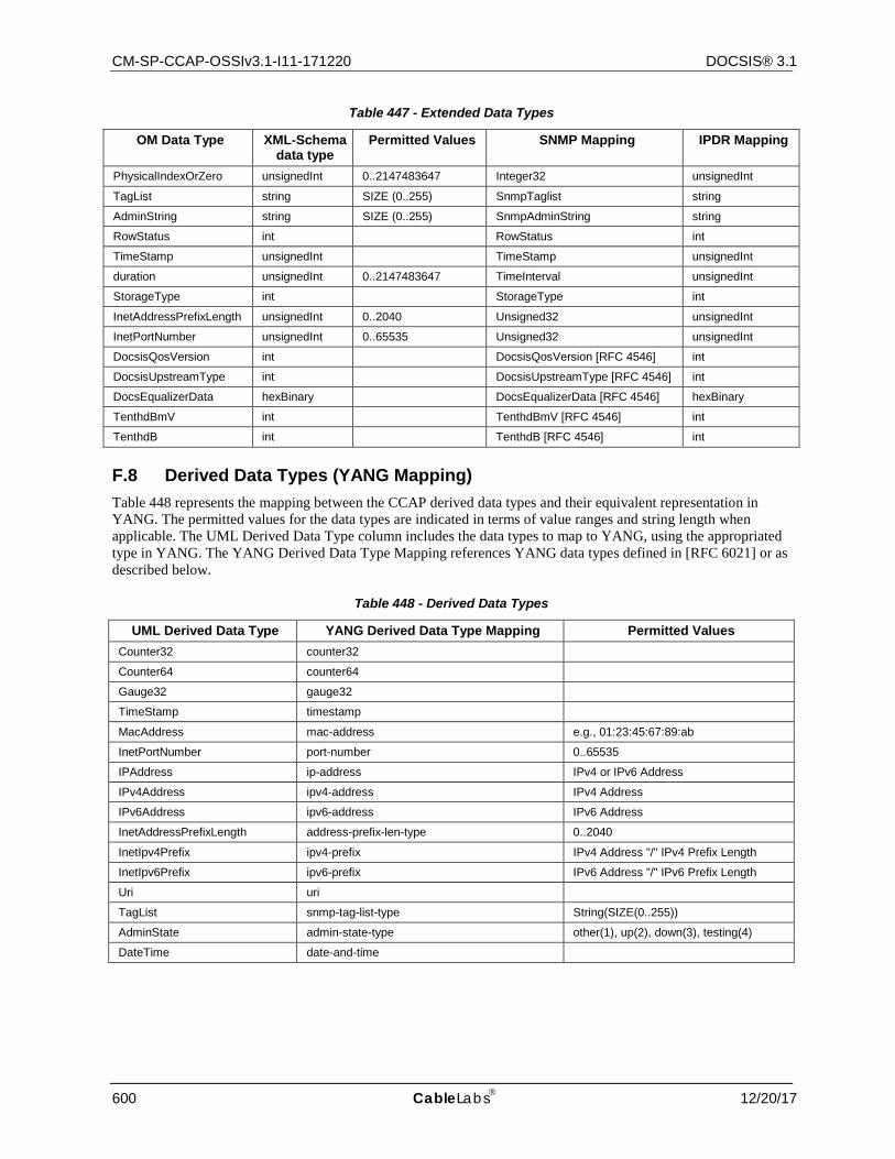
CM-SP-CCAP-OSSIv3.1-I11-171220 DOCSIS® 3.1
600 CableLabs 12/20/17
Table 447 - Extended Data Types
OM Data Type XML-Schema data type
Permitted Values SNMP Mapping IPDR Mapping
PhysicalIndexOrZero unsignedInt 0..2147483647 Integer32 unsignedInt
TagList string SIZE (0..255) SnmpTaglist string
AdminString string SIZE (0..255) SnmpAdminString string
RowStatus int RowStatus int
TimeStamp unsignedInt TimeStamp unsignedInt
duration unsignedInt 0..2147483647 TimeInterval unsignedInt
StorageType int StorageType int
InetAddressPrefixLength unsignedInt 0..2040 Unsigned32 unsignedInt
InetPortNumber unsignedInt 0..65535 Unsigned32 unsignedInt
DocsisQosVersion int DocsisQosVersion [RFC 4546] int
DocsisUpstreamType int DocsisUpstreamType [RFC 4546] int
DocsEqualizerData hexBinary DocsEqualizerData [RFC 4546] hexBinary
TenthdBmV int TenthdBmV [RFC 4546] int
TenthdB int TenthdB [RFC 4546] int
F.8 Derived Data Types (YANG Mapping) Table 448 represents the mapping between the CCAP derived data types and their equivalent representation in YANG. The permitted values for the data types are indicated in terms of value ranges and string length when applicable. The UML Derived Data Type column includes the data types to map to YANG, using the appropriated type in YANG. The YANG Derived Data Type Mapping references YANG data types defined in [RFC 6021] or as described below.
Table 448 - Derived Data Types
UML Derived Data Type YANG Derived Data Type Mapping Permitted Values Counter32 counter32
Counter64 counter64
Gauge32 gauge32
TimeStamp timestamp
MacAddress mac-address e.g., 01:23:45:67:89:ab
InetPortNumber port-number 0..65535
IPAddress ip-address IPv4 or IPv6 Address
IPv4Address ipv4-address IPv4 Address
IPv6Address ipv6-address IPv6 Address
InetAddressPrefixLength address-prefix-len-type 0..2040
InetIpv4Prefix ipv4-prefix IPv4 Address "/" IPv4 Prefix Length
InetIpv6Prefix ipv6-prefix IPv6 Address "/" IPv6 Prefix Length
Uri uri
TagList snmp-tag-list-type String(SIZE(0..255))
AdminState admin-state-type other(1), up(2), down(3), testing(4)
DateTime date-and-time

CCAP™ Operations Support System Interface Specification CM-SP-CCAP-OSSIv3.1-I11-171220
12/20/17 CableLabs 601
Annex G Diagnostic Log (Normative)
G.1 Overview The Diagnostic Log allows operators to diagnose and troubleshoot potential problems with CCAP/CMTS cable interfaces, Cable Modems (CMs), or the cable plant by detecting and tracking CMs that have intermittent connectivity problems or unstable operations including:
• CM repeated registration • Station Maintenance retry
Only detected CMs are reported in the Diagnostic Log for further analysis. Diagnostic Log entries are aged out based on the configuration of the specific aging attributes.
G.2 Object Definitions This section describes the object definitions for the Diagnostic Log object model.
The DOCSIS Diagnostic Log object model is depicted in Figure 69. This diagram graphically presents the individual DOCSIS Diagnostic Log objects and their attributes. The DOCSIS Diagnostic Log MIB and the DOCSIS Diagnostic Log IPDR Service Definition schema are derived from the object model.
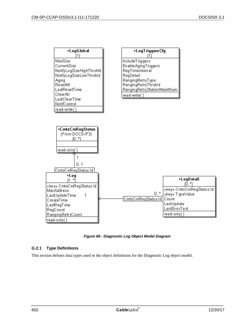
CM-SP-CCAP-OSSIv3.1-I11-171220 DOCSIS® 3.1
602 CableLabs 12/20/17
Figure 69 - Diagnostic Log Object Model Diagram
G.2.1 Type Definitions
This section defines data types used in the object definitions for the Diagnostic Log object model.
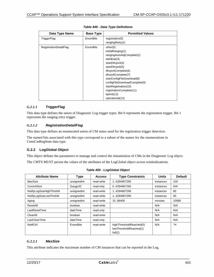
CCAP™ Operations Support System Interface Specification CM-SP-CCAP-OSSIv3.1-I11-171220
12/20/17 CableLabs 603
Table 449 - Data Type Definitions
Data Type Name Base Type Permitted Values TriggerFlag EnumBits registration(0)
rangingRetry(1)
RegistrationDetailFlag EnumBits other(0) initialRanging(1) rangingAutoAdjComplete(2) startEae(3) startDhcpv4(4) startDhcpv6(5) dhcpv4Complete(6) dhcpv6Complete(7) startConfigFileDownload(8) configFileDownloadComplete(9) startRegistration(10) registrationComplete(11) bpiInit(12) operational(13)
G.2.1.1 TriggerFlag This data type defines the union of Diagnostic Log trigger types. Bit 0 represents the registration trigger, Bit 1 represents the ranging retry trigger.
G.2.1.2 RegistrationDetailFlag This data type defines an enumerated union of CM states used for the registration trigger detection.
The named bits associated with this type correspond to a subset of the names for the enumerations in CmtsCmRegState data type.
G.2.2 LogGlobal Object
This object defines the parameters to manage and control the instantiation of CMs in the Diagnostic Log object.
The CMTS MUST persist the values of the attributes of the LogGlobal object across reinitializations.
Table 450 - LogGlobal Object
Attribute Name Type Access Type Constraints Units Default MaxSize unsignedInt read-write 1..4294967295 instances 100
CurrentSize Gauge32 read-only 0..4294967295 instances N/A
NotifyLogSizeHighThrshld unsignedInt read-write 1..4294967295 instances 80
NotifyLogSizeLowThrshld unsignedInt read-write 1..4294967295 instances 60
Aging unsignedInt read-write 15..86400 minutes 10080
ResetAll boolean read-write N/A N/A
LastResetTime dateTime read-only N/A N/A
ClearAll boolean read-write N/A N/A
LastClearTime dateTime read-only N/A N/A
NotifCtrl EnumBits read-write highThresholdReached(0) lowThresholdReached(1) full(2)
N/A ''H
G.2.2.1 MaxSize This attribute indicates the maximum number of CM instances that can be reported in the Log.
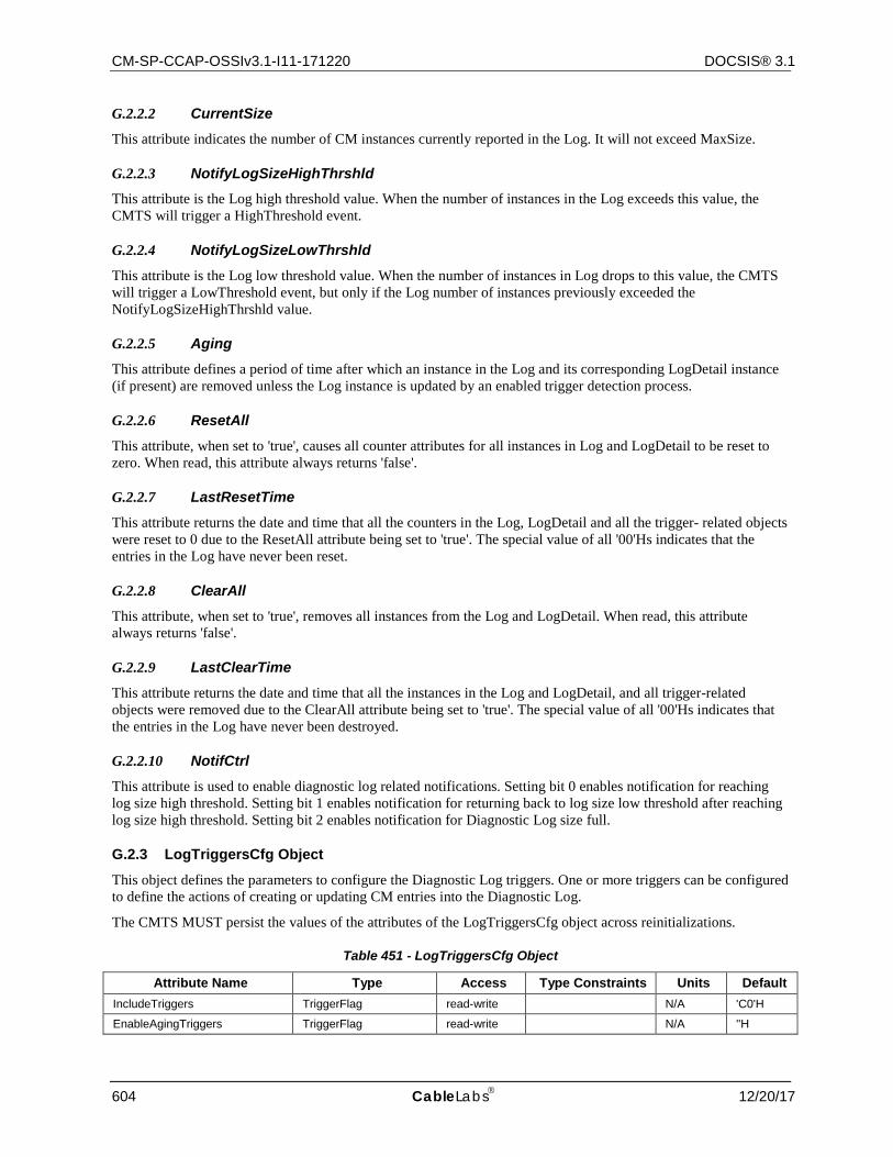
CM-SP-CCAP-OSSIv3.1-I11-171220 DOCSIS® 3.1
604 CableLabs 12/20/17
G.2.2.2 CurrentSize This attribute indicates the number of CM instances currently reported in the Log. It will not exceed MaxSize.
G.2.2.3 NotifyLogSizeHighThrshld This attribute is the Log high threshold value. When the number of instances in the Log exceeds this value, the CMTS will trigger a HighThreshold event.
G.2.2.4 NotifyLogSizeLowThrshld This attribute is the Log low threshold value. When the number of instances in Log drops to this value, the CMTS will trigger a LowThreshold event, but only if the Log number of instances previously exceeded the NotifyLogSizeHighThrshld value.
G.2.2.5 Aging This attribute defines a period of time after which an instance in the Log and its corresponding LogDetail instance (if present) are removed unless the Log instance is updated by an enabled trigger detection process.
G.2.2.6 ResetAll This attribute, when set to 'true', causes all counter attributes for all instances in Log and LogDetail to be reset to zero. When read, this attribute always returns 'false'.
G.2.2.7 LastResetTime This attribute returns the date and time that all the counters in the Log, LogDetail and all the trigger- related objects were reset to 0 due to the ResetAll attribute being set to 'true'. The special value of all '00'Hs indicates that the entries in the Log have never been reset.
G.2.2.8 ClearAll This attribute, when set to 'true', removes all instances from the Log and LogDetail. When read, this attribute always returns 'false'.
G.2.2.9 LastClearTime This attribute returns the date and time that all the instances in the Log and LogDetail, and all trigger-related objects were removed due to the ClearAll attribute being set to 'true'. The special value of all '00'Hs indicates that the entries in the Log have never been destroyed.
G.2.2.10 NotifCtrl This attribute is used to enable diagnostic log related notifications. Setting bit 0 enables notification for reaching log size high threshold. Setting bit 1 enables notification for returning back to log size low threshold after reaching log size high threshold. Setting bit 2 enables notification for Diagnostic Log size full.
G.2.3 LogTriggersCfg Object
This object defines the parameters to configure the Diagnostic Log triggers. One or more triggers can be configured to define the actions of creating or updating CM entries into the Diagnostic Log.
The CMTS MUST persist the values of the attributes of the LogTriggersCfg object across reinitializations.
Table 451 - LogTriggersCfg Object
Attribute Name Type Access Type Constraints Units Default IncludeTriggers TriggerFlag read-write N/A 'C0'H
EnableAgingTriggers TriggerFlag read-write N/A ''H
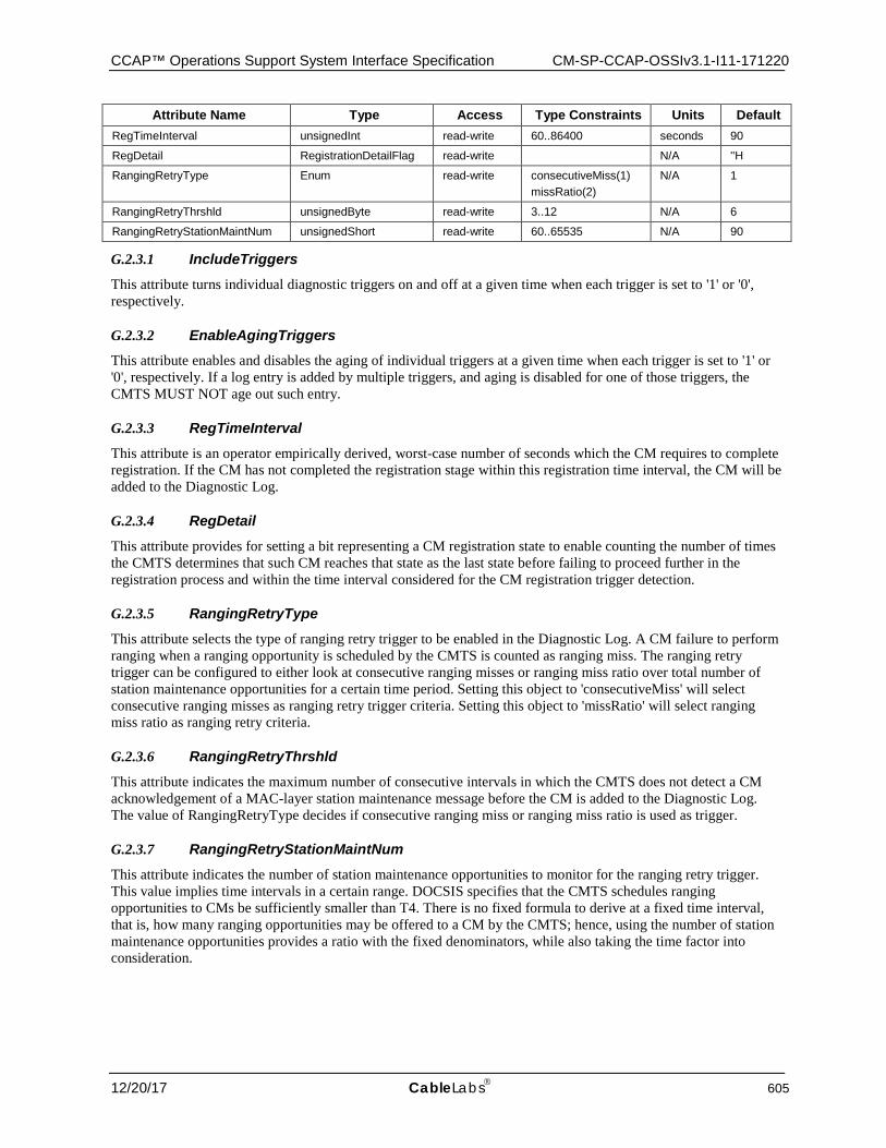
CCAP™ Operations Support System Interface Specification CM-SP-CCAP-OSSIv3.1-I11-171220
12/20/17 CableLabs 605
Attribute Name Type Access Type Constraints Units Default RegTimeInterval unsignedInt read-write 60..86400 seconds 90
RegDetail RegistrationDetailFlag read-write N/A ''H
RangingRetryType Enum read-write consecutiveMiss(1) missRatio(2)
N/A 1
RangingRetryThrshld unsignedByte read-write 3..12 N/A 6
RangingRetryStationMaintNum unsignedShort read-write 60..65535 N/A 90
G.2.3.1 IncludeTriggers This attribute turns individual diagnostic triggers on and off at a given time when each trigger is set to '1' or '0', respectively.
G.2.3.2 EnableAgingTriggers This attribute enables and disables the aging of individual triggers at a given time when each trigger is set to '1' or '0', respectively. If a log entry is added by multiple triggers, and aging is disabled for one of those triggers, the CMTS MUST NOT age out such entry.
G.2.3.3 RegTimeInterval This attribute is an operator empirically derived, worst-case number of seconds which the CM requires to complete registration. If the CM has not completed the registration stage within this registration time interval, the CM will be added to the Diagnostic Log.
G.2.3.4 RegDetail This attribute provides for setting a bit representing a CM registration state to enable counting the number of times the CMTS determines that such CM reaches that state as the last state before failing to proceed further in the registration process and within the time interval considered for the CM registration trigger detection.
G.2.3.5 RangingRetryType This attribute selects the type of ranging retry trigger to be enabled in the Diagnostic Log. A CM failure to perform ranging when a ranging opportunity is scheduled by the CMTS is counted as ranging miss. The ranging retry trigger can be configured to either look at consecutive ranging misses or ranging miss ratio over total number of station maintenance opportunities for a certain time period. Setting this object to 'consecutiveMiss' will select consecutive ranging misses as ranging retry trigger criteria. Setting this object to 'missRatio' will select ranging miss ratio as ranging retry criteria.
G.2.3.6 RangingRetryThrshld This attribute indicates the maximum number of consecutive intervals in which the CMTS does not detect a CM acknowledgement of a MAC-layer station maintenance message before the CM is added to the Diagnostic Log. The value of RangingRetryType decides if consecutive ranging miss or ranging miss ratio is used as trigger.
G.2.3.7 RangingRetryStationMaintNum This attribute indicates the number of station maintenance opportunities to monitor for the ranging retry trigger. This value implies time intervals in a certain range. DOCSIS specifies that the CMTS schedules ranging opportunities to CMs be sufficiently smaller than T4. There is no fixed formula to derive at a fixed time interval, that is, how many ranging opportunities may be offered to a CM by the CMTS; hence, using the number of station maintenance opportunities provides a ratio with the fixed denominators, while also taking the time factor into consideration.
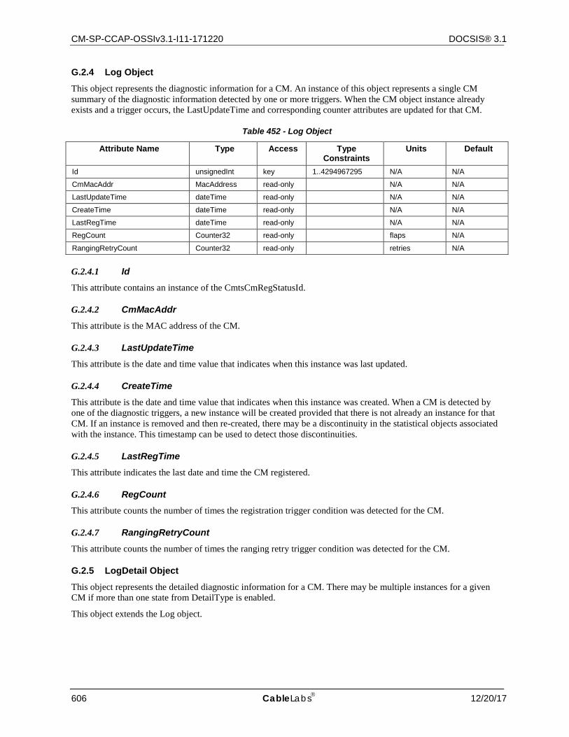
CM-SP-CCAP-OSSIv3.1-I11-171220 DOCSIS® 3.1
606 CableLabs 12/20/17
G.2.4 Log Object
This object represents the diagnostic information for a CM. An instance of this object represents a single CM summary of the diagnostic information detected by one or more triggers. When the CM object instance already exists and a trigger occurs, the LastUpdateTime and corresponding counter attributes are updated for that CM.
Table 452 - Log Object
Attribute Name Type Access Type Constraints
Units Default
Id unsignedInt key 1..4294967295 N/A N/A
CmMacAddr MacAddress read-only N/A N/A
LastUpdateTime dateTime read-only N/A N/A
CreateTime dateTime read-only N/A N/A
LastRegTime dateTime read-only N/A N/A
RegCount Counter32 read-only flaps N/A
RangingRetryCount Counter32 read-only retries N/A
G.2.4.1 Id This attribute contains an instance of the CmtsCmRegStatusId.
G.2.4.2 CmMacAddr This attribute is the MAC address of the CM.
G.2.4.3 LastUpdateTime This attribute is the date and time value that indicates when this instance was last updated.
G.2.4.4 CreateTime This attribute is the date and time value that indicates when this instance was created. When a CM is detected by one of the diagnostic triggers, a new instance will be created provided that there is not already an instance for that CM. If an instance is removed and then re-created, there may be a discontinuity in the statistical objects associated with the instance. This timestamp can be used to detect those discontinuities.
G.2.4.5 LastRegTime This attribute indicates the last date and time the CM registered.
G.2.4.6 RegCount This attribute counts the number of times the registration trigger condition was detected for the CM.
G.2.4.7 RangingRetryCount This attribute counts the number of times the ranging retry trigger condition was detected for the CM.
G.2.5 LogDetail Object
This object represents the detailed diagnostic information for a CM. There may be multiple instances for a given CM if more than one state from DetailType is enabled.
This object extends the Log object.
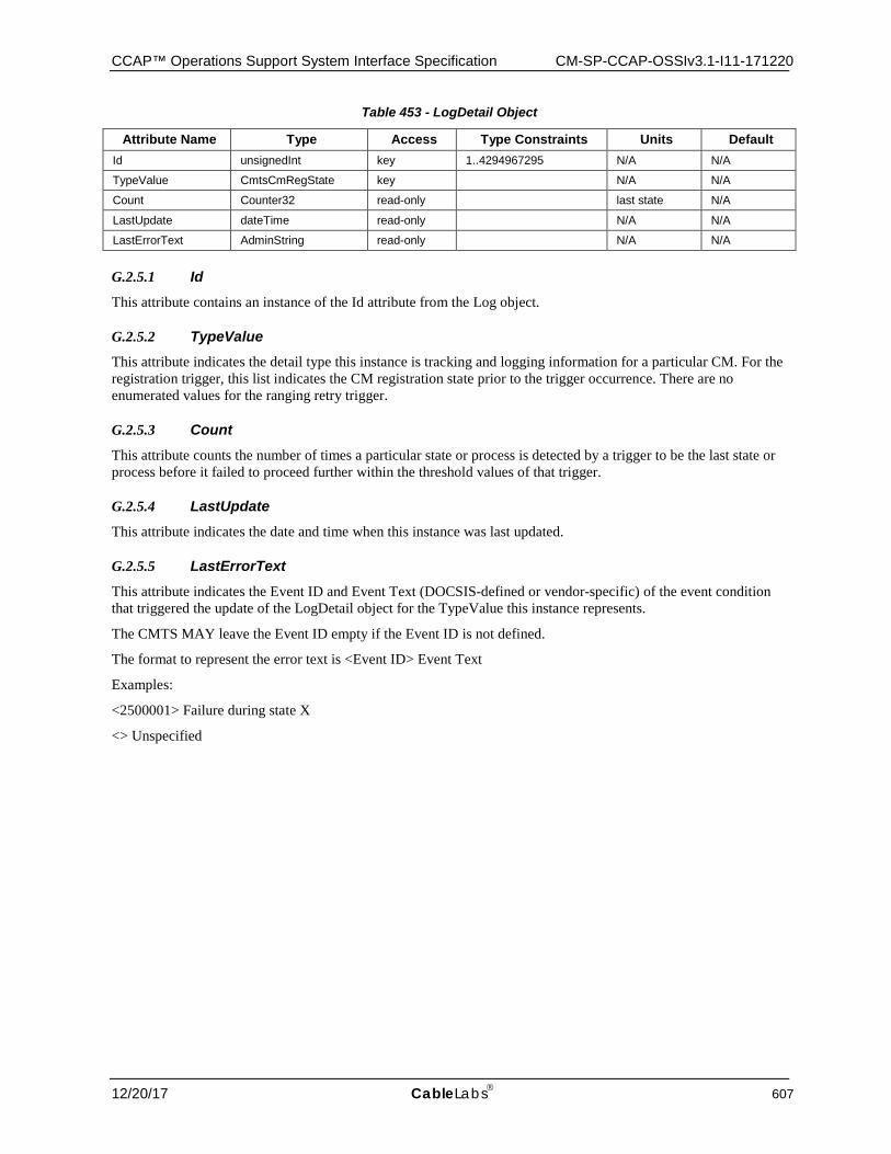
CCAP™ Operations Support System Interface Specification CM-SP-CCAP-OSSIv3.1-I11-171220
12/20/17 CableLabs 607
Table 453 - LogDetail Object
Attribute Name Type Access Type Constraints Units Default Id unsignedInt key 1..4294967295 N/A N/A
TypeValue CmtsCmRegState key N/A N/A
Count Counter32 read-only last state N/A
LastUpdate dateTime read-only N/A N/A
LastErrorText AdminString read-only N/A N/A
G.2.5.1 Id This attribute contains an instance of the Id attribute from the Log object.
G.2.5.2 TypeValue This attribute indicates the detail type this instance is tracking and logging information for a particular CM. For the registration trigger, this list indicates the CM registration state prior to the trigger occurrence. There are no enumerated values for the ranging retry trigger.
G.2.5.3 Count This attribute counts the number of times a particular state or process is detected by a trigger to be the last state or process before it failed to proceed further within the threshold values of that trigger.
G.2.5.4 LastUpdate This attribute indicates the date and time when this instance was last updated.
G.2.5.5 LastErrorText This attribute indicates the Event ID and Event Text (DOCSIS-defined or vendor-specific) of the event condition that triggered the update of the LogDetail object for the TypeValue this instance represents.
The CMTS MAY leave the Event ID empty if the Event ID is not defined.
The format to represent the error text is <Event ID> Event Text
Examples:
<2500001> Failure during state X
<> Unspecified
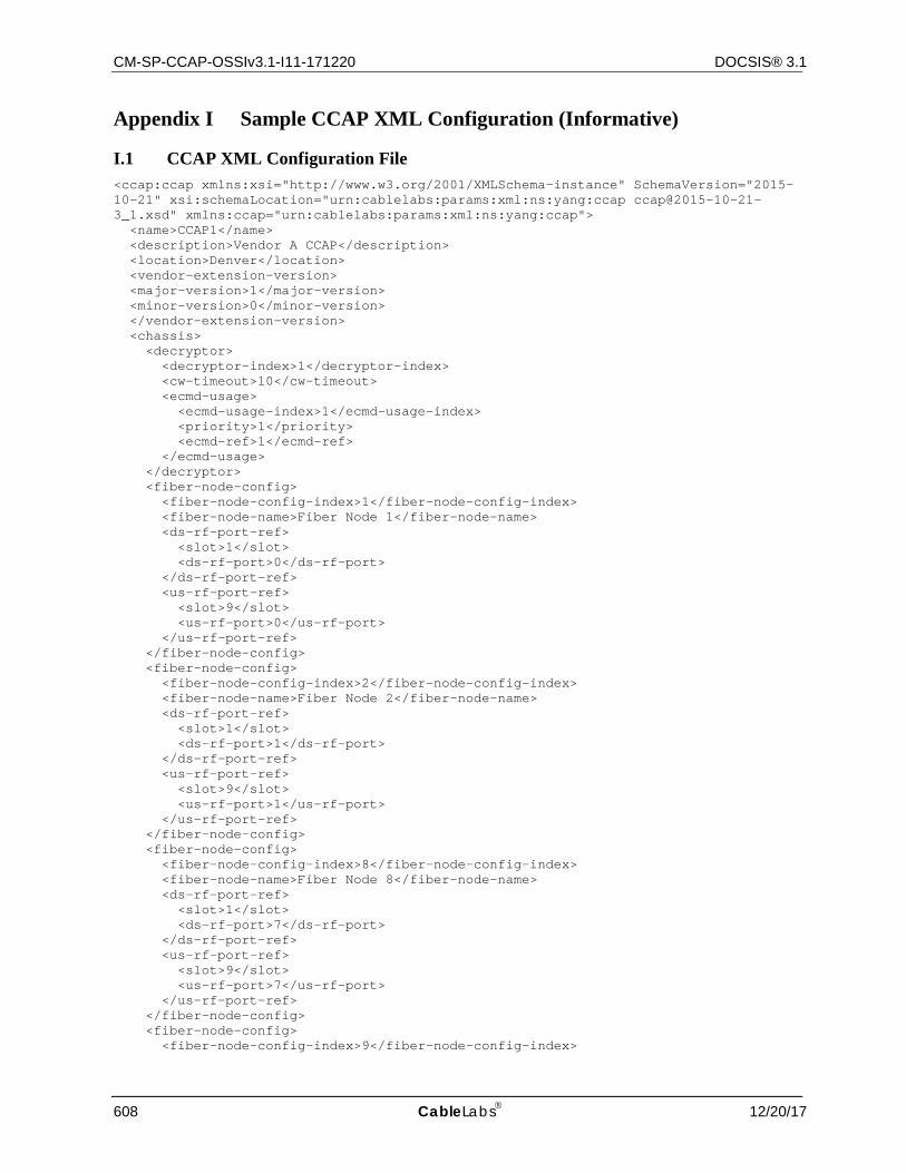
CM-SP-CCAP-OSSIv3.1-I11-171220 DOCSIS® 3.1
608 CableLabs 12/20/17
Appendix I Sample CCAP XML Configuration (Informative)
I.1 CCAP XML Configuration File <ccap:ccap xmlns:xsi="http://www.w3.org/2001/XMLSchema-instance" SchemaVersion="2015-10-21" xsi:schemaLocation="urn:cablelabs:params:xml:ns:yang:ccap ccap@2015-10-21-3_1.xsd" xmlns:ccap="urn:cablelabs:params:xml:ns:yang:ccap"> <name>CCAP1</name> <description>Vendor A CCAP</description> <location>Denver</location> <vendor-extension-version> <major-version>1</major-version> <minor-version>0</minor-version> </vendor-extension-version> <chassis> <decryptor> <decryptor-index>1</decryptor-index> <cw-timeout>10</cw-timeout> <ecmd-usage> <ecmd-usage-index>1</ecmd-usage-index> <priority>1</priority> <ecmd-ref>1</ecmd-ref> </ecmd-usage> </decryptor> <fiber-node-config> <fiber-node-config-index>1</fiber-node-config-index> <fiber-node-name>Fiber Node 1</fiber-node-name> <ds-rf-port-ref> <slot>1</slot> <ds-rf-port>0</ds-rf-port> </ds-rf-port-ref> <us-rf-port-ref> <slot>9</slot> <us-rf-port>0</us-rf-port> </us-rf-port-ref> </fiber-node-config> <fiber-node-config> <fiber-node-config-index>2</fiber-node-config-index> <fiber-node-name>Fiber Node 2</fiber-node-name> <ds-rf-port-ref> <slot>1</slot> <ds-rf-port>1</ds-rf-port> </ds-rf-port-ref> <us-rf-port-ref> <slot>9</slot> <us-rf-port>1</us-rf-port> </us-rf-port-ref> </fiber-node-config> <fiber-node-config> <fiber-node-config-index>8</fiber-node-config-index> <fiber-node-name>Fiber Node 8</fiber-node-name> <ds-rf-port-ref> <slot>1</slot> <ds-rf-port>7</ds-rf-port> </ds-rf-port-ref> <us-rf-port-ref> <slot>9</slot> <us-rf-port>7</us-rf-port> </us-rf-port-ref> </fiber-node-config> <fiber-node-config> <fiber-node-config-index>9</fiber-node-config-index>
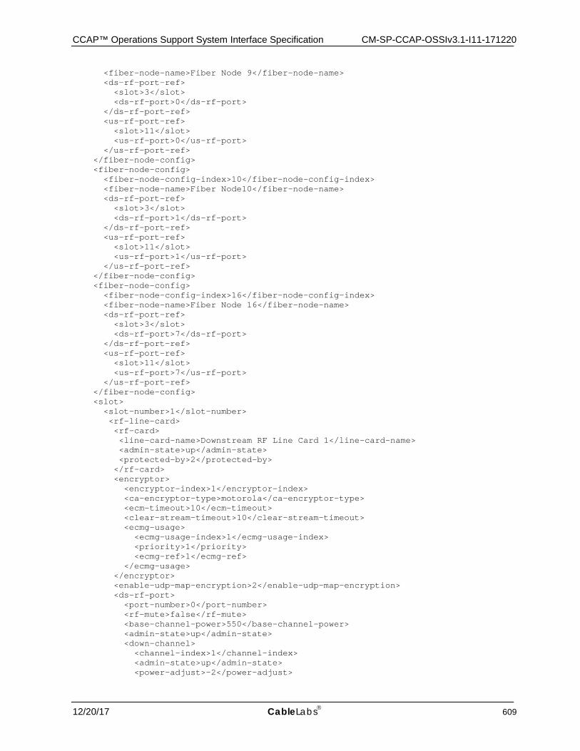
CCAP™ Operations Support System Interface Specification CM-SP-CCAP-OSSIv3.1-I11-171220
12/20/17 CableLabs 609
<fiber-node-name>Fiber Node 9</fiber-node-name> <ds-rf-port-ref> <slot>3</slot> <ds-rf-port>0</ds-rf-port> </ds-rf-port-ref> <us-rf-port-ref> <slot>11</slot> <us-rf-port>0</us-rf-port> </us-rf-port-ref> </fiber-node-config> <fiber-node-config> <fiber-node-config-index>10</fiber-node-config-index> <fiber-node-name>Fiber Node10</fiber-node-name> <ds-rf-port-ref> <slot>3</slot> <ds-rf-port>1</ds-rf-port> </ds-rf-port-ref> <us-rf-port-ref> <slot>11</slot> <us-rf-port>1</us-rf-port> </us-rf-port-ref> </fiber-node-config> <fiber-node-config> <fiber-node-config-index>16</fiber-node-config-index> <fiber-node-name>Fiber Node 16</fiber-node-name> <ds-rf-port-ref> <slot>3</slot> <ds-rf-port>7</ds-rf-port> </ds-rf-port-ref> <us-rf-port-ref> <slot>11</slot> <us-rf-port>7</us-rf-port> </us-rf-port-ref> </fiber-node-config> <slot> <slot-number>1</slot-number> <rf-line-card> <rf-card> <line-card-name>Downstream RF Line Card 1</line-card-name> <admin-state>up</admin-state> <protected-by>2</protected-by> </rf-card> <encryptor> <encryptor-index>1</encryptor-index> <ca-encryptor-type>motorola</ca-encryptor-type> <ecm-timeout>10</ecm-timeout> <clear-stream-timeout>10</clear-stream-timeout> <ecmg-usage> <ecmg-usage-index>1</ecmg-usage-index> <priority>1</priority> <ecmg-ref>1</ecmg-ref> </ecmg-usage> </encryptor> <enable-udp-map-encryption>2</enable-udp-map-encryption> <ds-rf-port> <port-number>0</port-number> <rf-mute>false</rf-mute> <base-channel-power>550</base-channel-power> <admin-state>up</admin-state> <down-channel> <channel-index>1</channel-index> <admin-state>up</admin-state> <power-adjust>-2</power-adjust>

CM-SP-CCAP-OSSIv3.1-I11-171220 DOCSIS® 3.1
610 CableLabs 12/20/17
<frequency>555000000</frequency> <rf-mute>false</rf-mute> <qam-alias>FN1_VOD1</qam-alias> <erm-advertising>true</erm-advertising> <erm-managed> <input-map-group-name>Group1</input-map-group-name> <phy-lock-parameters>interleaver</phy-lock-parameters> <allocation-type>linear vod sdv</allocation-type> <encryption-capability> <encryption-capability-index>1</encryption-capability-index> <ca-encryptor>motorola</ca-encryptor> <encryption-scheme>aes</encryption-scheme> <key-length>56</key-length> </encryption-capability> <erm-name>ERM-1</erm-name> </erm-managed> <video> <video-output-tsid>1</video-output-tsid> <video-phy-profile-index>1</video-phy-profile-index> </video> </down-channel> <down-channel> <channel-index>2</channel-index> <admin-state>up</admin-state> <power-adjust>-2</power-adjust> <frequency>561000000</frequency> <rf-mute>false</rf-mute> <qam-alias>FN1_VOD2</qam-alias> <erm-advertising>true</erm-advertising> <erm-managed> <input-map-group-name>Group2</input-map-group-name> <phy-lock-parameters>interleaver</phy-lock-parameters> <allocation-type>linear vod sdv</allocation-type> <encryption-capability> <encryption-capability-index>1</encryption-capability-index> <ca-encryptor>motorola</ca-encryptor> <encryption-scheme>aes</encryption-scheme> <key-length>56</key-length> </encryption-capability> <erm-name>ERM-1</erm-name> </erm-managed> <video> <video-output-tsid>2</video-output-tsid> </video> </down-channel> <down-channel> <channel-index>16</channel-index> <admin-state>up</admin-state> <power-adjust>0</power-adjust> <frequency>645000000</frequency> <rf-mute>false</rf-mute> <qam-alias>FN1_VOD16</qam-alias> <erm-advertising>true</erm-advertising> <erm-managed> <input-map-group-name>Group3</input-map-group-name> <phy-lock-parameters>interleaver</phy-lock-parameters> <allocation-type>vod sdv</allocation-type> <encryption-capability> <encryption-capability-index>1</encryption-capability-index> <ca-encryptor>motorola</ca-encryptor> <encryption-scheme>aes</encryption-scheme> <key-length>56</key-length> </encryption-capability>
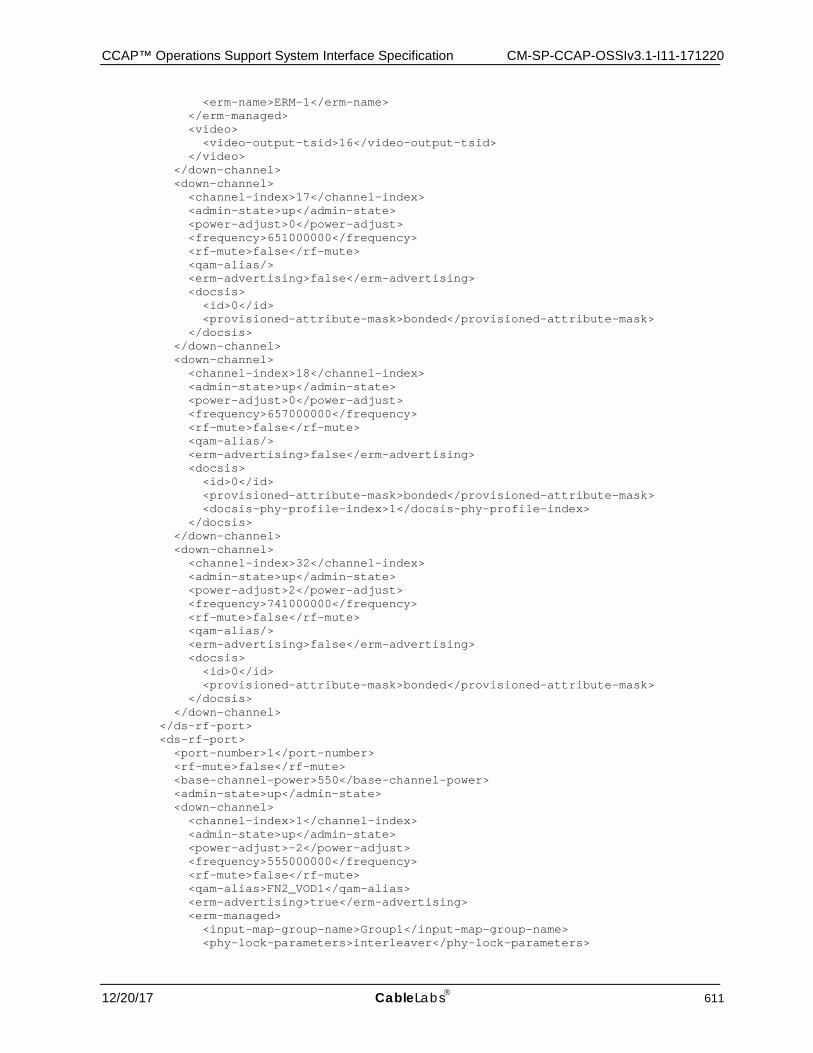
CCAP™ Operations Support System Interface Specification CM-SP-CCAP-OSSIv3.1-I11-171220
12/20/17 CableLabs 611
<erm-name>ERM-1</erm-name> </erm-managed> <video> <video-output-tsid>16</video-output-tsid> </video> </down-channel> <down-channel> <channel-index>17</channel-index> <admin-state>up</admin-state> <power-adjust>0</power-adjust> <frequency>651000000</frequency> <rf-mute>false</rf-mute> <qam-alias/> <erm-advertising>false</erm-advertising> <docsis> <id>0</id> <provisioned-attribute-mask>bonded</provisioned-attribute-mask> </docsis> </down-channel> <down-channel> <channel-index>18</channel-index> <admin-state>up</admin-state> <power-adjust>0</power-adjust> <frequency>657000000</frequency> <rf-mute>false</rf-mute> <qam-alias/> <erm-advertising>false</erm-advertising> <docsis> <id>0</id> <provisioned-attribute-mask>bonded</provisioned-attribute-mask> <docsis-phy-profile-index>1</docsis-phy-profile-index> </docsis> </down-channel> <down-channel> <channel-index>32</channel-index> <admin-state>up</admin-state> <power-adjust>2</power-adjust> <frequency>741000000</frequency> <rf-mute>false</rf-mute> <qam-alias/> <erm-advertising>false</erm-advertising> <docsis> <id>0</id> <provisioned-attribute-mask>bonded</provisioned-attribute-mask> </docsis> </down-channel> </ds-rf-port> <ds-rf-port> <port-number>1</port-number> <rf-mute>false</rf-mute> <base-channel-power>550</base-channel-power> <admin-state>up</admin-state> <down-channel> <channel-index>1</channel-index> <admin-state>up</admin-state> <power-adjust>-2</power-adjust> <frequency>555000000</frequency> <rf-mute>false</rf-mute> <qam-alias>FN2_VOD1</qam-alias> <erm-advertising>true</erm-advertising> <erm-managed> <input-map-group-name>Group1</input-map-group-name> <phy-lock-parameters>interleaver</phy-lock-parameters>

CM-SP-CCAP-OSSIv3.1-I11-171220 DOCSIS® 3.1
612 CableLabs 12/20/17
<allocation-type>linear</allocation-type> <encryption-capability> <encryption-capability-index>1</encryption-capability-index> <ca-encryptor>motorola</ca-encryptor> <encryption-scheme>aes</encryption-scheme> <key-length>56</key-length> </encryption-capability> <erm-name>ERM-2</erm-name> </erm-managed> <video> <video-output-tsid>65</video-output-tsid> </video> </down-channel> <down-channel> <channel-index>2</channel-index> <admin-state>up</admin-state> <power-adjust>-2</power-adjust> <frequency>561000000</frequency> <rf-mute>false</rf-mute> <qam-alias>FN2_VOD2</qam-alias> <erm-advertising>true</erm-advertising> <erm-managed> <input-map-group-name>Group2</input-map-group-name> <phy-lock-parameters>interleaver</phy-lock-parameters> <allocation-type>vod</allocation-type> <encryption-capability> <encryption-capability-index>1</encryption-capability-index> <ca-encryptor>motorola</ca-encryptor> <encryption-scheme>aes</encryption-scheme> <key-length>56</key-length> </encryption-capability> <erm-name>ERM-2</erm-name> </erm-managed> <video> <video-output-tsid>66</video-output-tsid> </video> </down-channel> <down-channel> <channel-index>16</channel-index> <admin-state>up</admin-state> <power-adjust>0</power-adjust> <frequency>645000000</frequency> <rf-mute>false</rf-mute> <qam-alias>FN2_VOD16</qam-alias> <erm-advertising>true</erm-advertising> <erm-managed> <input-map-group-name>Group3</input-map-group-name> <phy-lock-parameters>interleaver</phy-lock-parameters> <allocation-type>vod sdv</allocation-type> <encryption-capability> <encryption-capability-index>1</encryption-capability-index> <ca-encryptor>motorola</ca-encryptor> <encryption-scheme>aes</encryption-scheme> <key-length>56</key-length> </encryption-capability> <erm-name>ERM-2</erm-name> </erm-managed> <video> <video-output-tsid>80</video-output-tsid> </video> </down-channel> <down-channel> <channel-index>17</channel-index>
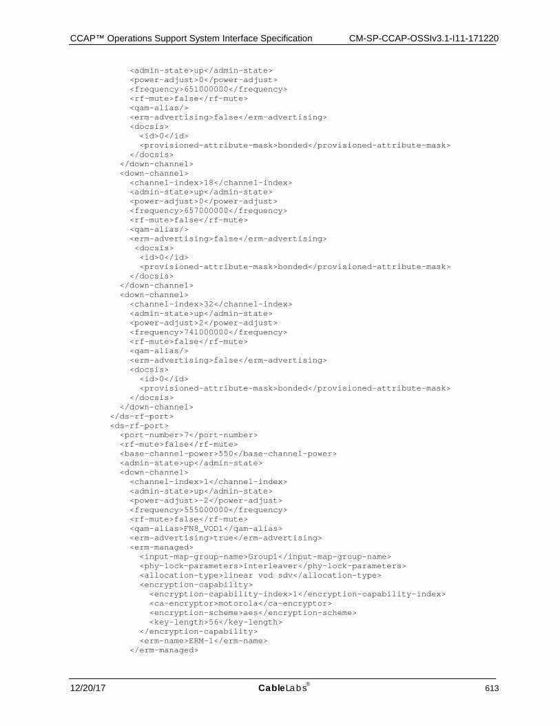
CCAP™ Operations Support System Interface Specification CM-SP-CCAP-OSSIv3.1-I11-171220
12/20/17 CableLabs 613
<admin-state>up</admin-state> <power-adjust>0</power-adjust> <frequency>651000000</frequency> <rf-mute>false</rf-mute> <qam-alias/> <erm-advertising>false</erm-advertising> <docsis> <id>0</id> <provisioned-attribute-mask>bonded</provisioned-attribute-mask> </docsis> </down-channel> <down-channel> <channel-index>18</channel-index> <admin-state>up</admin-state> <power-adjust>0</power-adjust> <frequency>657000000</frequency> <rf-mute>false</rf-mute> <qam-alias/> <erm-advertising>false</erm-advertising> <docsis> <id>0</id> <provisioned-attribute-mask>bonded</provisioned-attribute-mask> </docsis> </down-channel> <down-channel> <channel-index>32</channel-index> <admin-state>up</admin-state> <power-adjust>2</power-adjust> <frequency>741000000</frequency> <rf-mute>false</rf-mute> <qam-alias/> <erm-advertising>false</erm-advertising> <docsis> <id>0</id> <provisioned-attribute-mask>bonded</provisioned-attribute-mask> </docsis> </down-channel> </ds-rf-port> <ds-rf-port> <port-number>7</port-number> <rf-mute>false</rf-mute> <base-channel-power>550</base-channel-power> <admin-state>up</admin-state> <down-channel> <channel-index>1</channel-index> <admin-state>up</admin-state> <power-adjust>-2</power-adjust> <frequency>555000000</frequency> <rf-mute>false</rf-mute> <qam-alias>FN8_VOD1</qam-alias> <erm-advertising>true</erm-advertising> <erm-managed> <input-map-group-name>Group1</input-map-group-name> <phy-lock-parameters>interleaver</phy-lock-parameters> <allocation-type>linear vod sdv</allocation-type> <encryption-capability> <encryption-capability-index>1</encryption-capability-index> <ca-encryptor>motorola</ca-encryptor> <encryption-scheme>aes</encryption-scheme> <key-length>56</key-length> </encryption-capability> <erm-name>ERM-1</erm-name> </erm-managed>
CM-SP-CCAP-OSSIv3.1-I11-171220 DOCSIS® 3.1
614 CableLabs 12/20/17
<video> <video-output-tsid>449</video-output-tsid> </video> </down-channel> <down-channel> <channel-index>2</channel-index> <admin-state>up</admin-state> <power-adjust>-2</power-adjust> <frequency>561000000</frequency> <rf-mute>false</rf-mute> <qam-alias>FN8_VOD2</qam-alias> <erm-advertising>true</erm-advertising> <erm-managed> <input-map-group-name>Group2</input-map-group-name> <phy-lock-parameters>interleaver</phy-lock-parameters> <allocation-type>linear vod sdv</allocation-type> <encryption-capability> <encryption-capability-index>1</encryption-capability-index> <ca-encryptor>motorola</ca-encryptor> <encryption-scheme>aes</encryption-scheme> <key-length>56</key-length> </encryption-capability> <erm-name>ERM-1</erm-name> </erm-managed> <video> <video-output-tsid>450</video-output-tsid> </video> </down-channel> <down-channel> <channel-index>16</channel-index> <admin-state>up</admin-state> <power-adjust>0</power-adjust> <frequency>645000000</frequency> <rf-mute>false</rf-mute> <qam-alias>FN8_VOD16</qam-alias> <erm-advertising>true</erm-advertising> <erm-managed> <input-map-group-name>Group3</input-map-group-name> <phy-lock-parameters>interleaver</phy-lock-parameters> <allocation-type>linear vod sdv</allocation-type> <encryption-capability> <encryption-capability-index>1</encryption-capability-index> <ca-encryptor>motorola</ca-encryptor> <encryption-scheme>aes</encryption-scheme> <key-length>56</key-length> </encryption-capability> <erm-name>ERM-1</erm-name> </erm-managed> <video> <video-output-tsid>464</video-output-tsid> </video> </down-channel> <down-channel> <channel-index>17</channel-index> <admin-state>up</admin-state> <power-adjust>0</power-adjust> <frequency>651000000</frequency> <rf-mute>false</rf-mute> <qam-alias/> <erm-advertising>false</erm-advertising> <docsis> <id>0</id> <provisioned-attribute-mask>bonded</provisioned-attribute-mask>
CCAP™ Operations Support System Interface Specification CM-SP-CCAP-OSSIv3.1-I11-171220
12/20/17 CableLabs 615
</docsis> </down-channel> <down-channel> <channel-index>18</channel-index> <admin-state>up</admin-state> <power-adjust>0</power-adjust> <frequency>657000000</frequency> <rf-mute>false</rf-mute> <qam-alias/> <erm-advertising>false</erm-advertising> <docsis> <id>0</id> <provisioned-attribute-mask>bonded</provisioned-attribute-mask> </docsis> </down-channel> <down-channel> <channel-index>32</channel-index> <admin-state>up</admin-state> <power-adjust>2</power-adjust> <frequency>741000000</frequency> <rf-mute>false</rf-mute> <qam-alias/> <erm-advertising>false</erm-advertising> <docsis> <id>0</id> <provisioned-attribute-mask>bonded</provisioned-attribute-mask> </docsis> </down-channel> </ds-rf-port> </rf-line-card> </slot> <slot> <slot-number>2</slot-number> <rf-line-card> <rf-card> <line-card-name>Downstream RF Line Card Spare</line-card-name> <admin-state>up</admin-state> </rf-card> </rf-line-card> </slot> <slot> <slot-number>3</slot-number> <rf-line-card> <rf-card> <line-card-name>Downstream RF Line Card 3</line-card-name> <admin-state>up</admin-state> <protected-by>2</protected-by> </rf-card> <encryptor> <encryptor-index>1</encryptor-index> <ca-encryptor-type>motorola</ca-encryptor-type> <ecm-timeout>10</ecm-timeout> <clear-stream-timeout>10</clear-stream-timeout> <ecmg-usage> <ecmg-usage-index>1</ecmg-usage-index> <priority>1</priority> <ecmg-ref>1</ecmg-ref> </ecmg-usage> </encryptor> <ds-rf-port> <port-number>0</port-number> <rf-mute>false</rf-mute> <base-channel-power>550</base-channel-power>
CM-SP-CCAP-OSSIv3.1-I11-171220 DOCSIS® 3.1
616 CableLabs 12/20/17
<admin-state>up</admin-state> <down-channel> <channel-index>1</channel-index> <admin-state>up</admin-state> <power-adjust>-2</power-adjust> <frequency>555000000</frequency> <rf-mute>false</rf-mute> <qam-alias>FN9_VOD1</qam-alias> <erm-advertising>true</erm-advertising> <erm-managed> <input-map-group-name>Group1</input-map-group-name> <phy-lock-parameters>interleaver</phy-lock-parameters> <allocation-type>linear vod sdv</allocation-type> <encryption-capability> <encryption-capability-index>1</encryption-capability-index> <ca-encryptor>motorola</ca-encryptor> <encryption-scheme>aes</encryption-scheme> <key-length>56</key-length> </encryption-capability> <erm-name>ERM-1</erm-name> </erm-managed> <video> <video-output-tsid>513</video-output-tsid> </video> </down-channel> <down-channel> <channel-index>2</channel-index> <admin-state>up</admin-state> <power-adjust>-2</power-adjust> <frequency>561000000</frequency> <rf-mute>false</rf-mute> <qam-alias>FN9_VOD2</qam-alias> <erm-advertising>true</erm-advertising> <erm-managed> <input-map-group-name>Group2</input-map-group-name> <phy-lock-parameters>interleaver</phy-lock-parameters> <allocation-type>linear vod sdv</allocation-type> <encryption-capability> <encryption-capability-index>1</encryption-capability-index> <ca-encryptor>motorola</ca-encryptor> <encryption-scheme>aes</encryption-scheme> <key-length>56</key-length> </encryption-capability> <erm-name>ERM-1</erm-name> </erm-managed> <video> <video-output-tsid>514</video-output-tsid> </video> </down-channel> <down-channel> <channel-index>16</channel-index> <admin-state>up</admin-state> <power-adjust>0</power-adjust> <frequency>645000000</frequency> <rf-mute>false</rf-mute> <qam-alias>FN9_VOD16</qam-alias> <erm-advertising>true</erm-advertising> <erm-managed> <input-map-group-name>Group3</input-map-group-name> <phy-lock-parameters>interleaver</phy-lock-parameters> <allocation-type>linear vod sdv</allocation-type> <encryption-capability> <encryption-capability-index>1</encryption-capability-index>
CCAP™ Operations Support System Interface Specification CM-SP-CCAP-OSSIv3.1-I11-171220
12/20/17 CableLabs 617
<ca-encryptor>motorola</ca-encryptor> <encryption-scheme>aes</encryption-scheme> <key-length>56</key-length> </encryption-capability> <erm-name>ERM-1</erm-name> </erm-managed> <video> <video-output-tsid>528</video-output-tsid> </video> </down-channel> <down-channel> <channel-index>17</channel-index> <admin-state>up</admin-state> <power-adjust>0</power-adjust> <frequency>651000000</frequency> <rf-mute>false</rf-mute> <qam-alias/> <erm-advertising>false</erm-advertising> <docsis> <id>0</id> <provisioned-attribute-mask>bonded</provisioned-attribute-mask> </docsis> </down-channel> <down-channel> <channel-index>18</channel-index> <admin-state>up</admin-state> <power-adjust>0</power-adjust> <frequency>657000000</frequency> <rf-mute>false</rf-mute> <qam-alias/> <erm-advertising>false</erm-advertising> <docsis> <id>0</id> <provisioned-attribute-mask>bonded</provisioned-attribute-mask> </docsis> </down-channel> <down-channel> <channel-index>32</channel-index> <admin-state>up</admin-state> <power-adjust>2</power-adjust> <frequency>741000000</frequency> <rf-mute>false</rf-mute> <qam-alias/> <erm-advertising>false</erm-advertising> <docsis> <id>0</id> <provisioned-attribute-mask>bonded</provisioned-attribute-mask> </docsis> </down-channel> </ds-rf-port> <ds-rf-port> <port-number>1</port-number> <rf-mute>false</rf-mute> <base-channel-power>550</base-channel-power> <admin-state>up</admin-state> <down-channel> <channel-index>1</channel-index> <admin-state>up</admin-state> <power-adjust>-2</power-adjust> <frequency>555000000</frequency> <rf-mute>false</rf-mute> <qam-alias>FN10_VOD1</qam-alias> <erm-advertising>true</erm-advertising>

CM-SP-CCAP-OSSIv3.1-I11-171220 DOCSIS® 3.1
618 CableLabs 12/20/17
<erm-managed> <input-map-group-name>Group1</input-map-group-name> <phy-lock-parameters>interleaver</phy-lock-parameters> <allocation-type>linear vod sdv</allocation-type> <encryption-capability> <encryption-capability-index>1</encryption-capability-index> <ca-encryptor>motorola</ca-encryptor> <encryption-scheme>aes</encryption-scheme> <key-length>56</key-length> </encryption-capability> <erm-name>ERM-1</erm-name> </erm-managed> <video> <video-output-tsid>577</video-output-tsid> </video> </down-channel> <down-channel> <channel-index>2</channel-index> <admin-state>up</admin-state> <power-adjust>-2</power-adjust> <frequency>561000000</frequency> <rf-mute>false</rf-mute> <qam-alias>FN10_VOD2</qam-alias> <erm-advertising>true</erm-advertising> <erm-managed> <input-map-group-name>Group2</input-map-group-name> <phy-lock-parameters>interleaver</phy-lock-parameters> <allocation-type>linear vod sdv</allocation-type> <encryption-capability> <encryption-capability-index>1</encryption-capability-index> <ca-encryptor>motorola</ca-encryptor> <encryption-scheme>aes</encryption-scheme> <key-length>56</key-length> </encryption-capability> <erm-name>ERM-1</erm-name> </erm-managed> <video> <video-output-tsid>578</video-output-tsid> </video> </down-channel> <down-channel> <channel-index>16</channel-index> <admin-state>up</admin-state> <power-adjust>0</power-adjust> <frequency>645000000</frequency> <rf-mute>false</rf-mute> <qam-alias>FN10_VOD16</qam-alias> <erm-advertising>true</erm-advertising> <erm-managed> <input-map-group-name>Group3</input-map-group-name> <phy-lock-parameters>interleaver</phy-lock-parameters> <allocation-type>linear vod sdv</allocation-type> <encryption-capability> <encryption-capability-index>1</encryption-capability-index> <ca-encryptor>motorola</ca-encryptor> <encryption-scheme>aes</encryption-scheme> <key-length>56</key-length> </encryption-capability> <erm-name>ERM-1</erm-name> </erm-managed> <video> <video-output-tsid>598</video-output-tsid> </video>
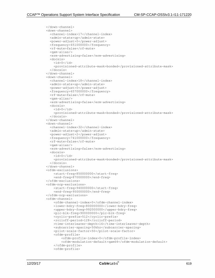
CCAP™ Operations Support System Interface Specification CM-SP-CCAP-OSSIv3.1-I11-171220
12/20/17 CableLabs 619
</down-channel> <down-channel> <channel-index>17</channel-index> <admin-state>up</admin-state> <power-adjust>0</power-adjust> <frequency>651000000</frequency> <rf-mute>false</rf-mute> <qam-alias/> <erm-advertising>false</erm-advertising> <docsis> <id>0</id> <provisioned-attribute-mask>bonded</provisioned-attribute-mask> </docsis> </down-channel> <down-channel> <channel-index>18</channel-index> <admin-state>up</admin-state> <power-adjust>0</power-adjust> <frequency>657000000</frequency> <rf-mute>false</rf-mute> <qam-alias/> <erm-advertising>false</erm-advertising> <docsis> <id>0</id> <provisioned-attribute-mask>bonded</provisioned-attribute-mask> </docsis> </down-channel> <down-channel> <channel-index>32</channel-index> <admin-state>up</admin-state> <power-adjust>2</power-adjust> <frequency>741000000</frequency> <rf-mute>false</rf-mute> <qam-alias/> <erm-advertising>false</erm-advertising> <docsis> <id>0</id> <provisioned-attribute-mask>bonded</provisioned-attribute-mask> </docsis> </down-channel> <ofdm-exclusions> <start-freq>850000000</start-freq> <end-freq>870000000</end-freq> </ofdm-exclusions> <ofdm-ncp-exclusions> <start-freq>940000000</start-freq> <end-freq>950000000</end-freq> </ofdm-ncp-exclusions> <ofdm-channel> <ofdm-channel-index>0</ofdm-channel-index> <lower-bdry-freq>800000000</lower-bdry-freq> <upper-bdry-freq>992000000</upper-bdry-freq> <plc-blk-freq>900000000</plc-blk-freq> <cyclic-prefix>512</cyclic-prefix> <rolloff-period>128</rolloff-period> <time-interleaver-depth>16</time-interleaver-depth> <subcarrier-spacing>50khz</subcarrier-spacing> <pilot-scale-factor>50</pilot-scale-factor> <ofdm-profile> <ofdm-profile-index>0</ofdm-profile-index> <ofdm-modulation-default>qam64</ofdm-modulation-default> </ofdm-profile> <ofdm-profile>

CM-SP-CCAP-OSSIv3.1-I11-171220 DOCSIS® 3.1
620 CableLabs 12/20/17
<ofdm-profile-index>1</ofdm-profile-index> <ofdm-modulation-default>qam4096</ofdm-modulation-default> <ofdm-subcarrier> <start-frequency>820000000</start-frequency> <end-frequency>840000000</end-frequency> <ofdm-main-modulation>qam1024</ofdm-main-modulation> </ofdm-subcarrier> <ofdm-subcarrier> <start-frequency>941000000</start-frequency> <end-frequency>944000000</end-frequency> <ofdm-main-modulation>qam512</ofdm-main-modulation> </ofdm-subcarrier> </ofdm-profile> <ofdm-profile> <ofdm-profile-index>2</ofdm-profile-index> <ofdm-modulation-default>qam1024</ofdm-modulation-default> <ofdm-subcarrier> <start-frequency>820000000</start-frequency> <end-frequency>840000000</end-frequency> <skip>true</skip> <ofdm-main-modulation>qam1024</ofdm-main-modulation> <ofdm-skip-modulation>qam512</ofdm-skip-modulation> </ofdm-subcarrier> </ofdm-profile> <ofdm-profile> <ofdm-profile-index>3</ofdm-profile-index> <ofdm-modulation-default>qam256</ofdm-modulation-default> </ofdm-profile> <ofdm-profile> <ofdm-profile-index>255</ofdm-profile-index> <ofdm-modulation-default>qam64</ofdm-modulation-default> <ofdm-subcarrier> <start-frequency>820000000</start-frequency> <end-frequency>840000000</end-frequency> <ofdm-main-modulation>zero-bit-load</ofdm-main-modulation> </ofdm-subcarrier> </ofdm-profile> </ofdm-channel> </ds-rf-port> <ds-rf-port> <port-number>7</port-number> <rf-mute>false</rf-mute> <base-channel-power>550</base-channel-power> <admin-state>up</admin-state> <down-channel> <channel-index>1</channel-index> <admin-state>up</admin-state> <power-adjust>-2</power-adjust> <frequency>555000000</frequency> <rf-mute>false</rf-mute> <qam-alias>FN16_VOD1</qam-alias> <erm-advertising>true</erm-advertising> <erm-managed> <input-map-group-name>Group1</input-map-group-name> <phy-lock-parameters>interleaver</phy-lock-parameters> <allocation-type>linear vod sdv</allocation-type> <encryption-capability> <encryption-capability-index>1</encryption-capability-index> <ca-encryptor>motorola</ca-encryptor> <encryption-scheme>aes</encryption-scheme> <key-length>56</key-length> </encryption-capability> <erm-name>ERM-1</erm-name>

CCAP™ Operations Support System Interface Specification CM-SP-CCAP-OSSIv3.1-I11-171220
12/20/17 CableLabs 621
</erm-managed> <video> <video-output-tsid>961</video-output-tsid> </video> </down-channel> <down-channel> <channel-index>2</channel-index> <admin-state>up</admin-state> <power-adjust>-2</power-adjust> <frequency>561000000</frequency> <rf-mute>false</rf-mute> <qam-alias>FN16_VOD2</qam-alias> <erm-advertising>true</erm-advertising> <erm-managed> <input-map-group-name>Group2</input-map-group-name> <phy-lock-parameters>interleaver</phy-lock-parameters> <allocation-type>linear vod sdv</allocation-type> <encryption-capability> <encryption-capability-index>1</encryption-capability-index> <ca-encryptor>motorola</ca-encryptor> <encryption-scheme>aes</encryption-scheme> <key-length>56</key-length> </encryption-capability> <erm-name>ERM-1</erm-name> </erm-managed> <video> <video-output-tsid>962</video-output-tsid> </video> </down-channel> <down-channel> <channel-index>16</channel-index> <admin-state>up</admin-state> <power-adjust>0</power-adjust> <frequency>645000000</frequency> <rf-mute>false</rf-mute> <qam-alias>FN16_VOD16</qam-alias> <erm-advertising>true</erm-advertising> <erm-managed> <input-map-group-name>Group3</input-map-group-name> <phy-lock-parameters>interleaver</phy-lock-parameters> <allocation-type>linear vod sdv</allocation-type> <encryption-capability> <encryption-capability-index>1</encryption-capability-index> <ca-encryptor>motorola</ca-encryptor> <encryption-scheme>aes</encryption-scheme> <key-length>56</key-length> </encryption-capability> <erm-name>ERM-1</erm-name> </erm-managed> <video> <video-output-tsid>976</video-output-tsid> </video> </down-channel> <down-channel> <channel-index>17</channel-index> <admin-state>up</admin-state> <power-adjust>0</power-adjust> <frequency>651000000</frequency> <rf-mute>false</rf-mute> <qam-alias/> <erm-advertising>false</erm-advertising> <docsis> <id>0</id>
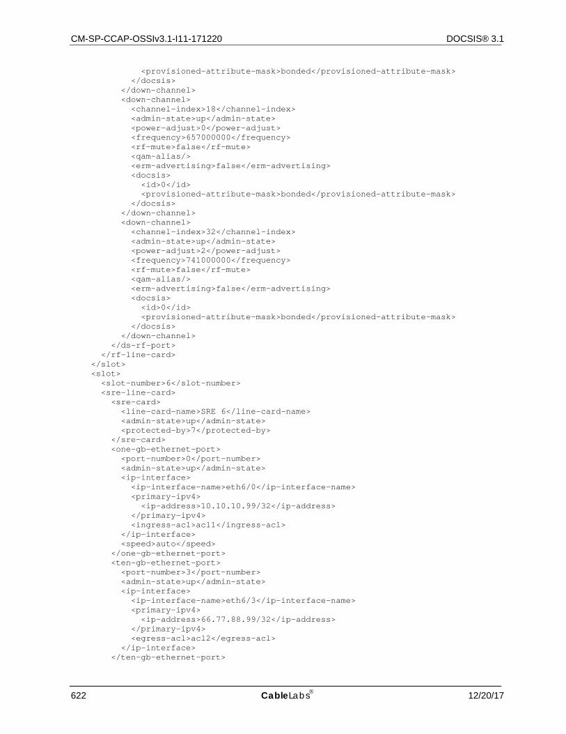
CM-SP-CCAP-OSSIv3.1-I11-171220 DOCSIS® 3.1
622 CableLabs 12/20/17
<provisioned-attribute-mask>bonded</provisioned-attribute-mask> </docsis> </down-channel> <down-channel> <channel-index>18</channel-index> <admin-state>up</admin-state> <power-adjust>0</power-adjust> <frequency>657000000</frequency> <rf-mute>false</rf-mute> <qam-alias/> <erm-advertising>false</erm-advertising> <docsis> <id>0</id> <provisioned-attribute-mask>bonded</provisioned-attribute-mask> </docsis> </down-channel> <down-channel> <channel-index>32</channel-index> <admin-state>up</admin-state> <power-adjust>2</power-adjust> <frequency>741000000</frequency> <rf-mute>false</rf-mute> <qam-alias/> <erm-advertising>false</erm-advertising> <docsis> <id>0</id> <provisioned-attribute-mask>bonded</provisioned-attribute-mask> </docsis> </down-channel> </ds-rf-port> </rf-line-card> </slot> <slot> <slot-number>6</slot-number> <sre-line-card> <sre-card> <line-card-name>SRE 6</line-card-name> <admin-state>up</admin-state> <protected-by>7</protected-by> </sre-card> <one-gb-ethernet-port> <port-number>0</port-number> <admin-state>up</admin-state> <ip-interface> <ip-interface-name>eth6/0</ip-interface-name> <primary-ipv4> <ip-address>10.10.10.99/32</ip-address> </primary-ipv4> <ingress-acl>acl1</ingress-acl> </ip-interface> <speed>auto</speed> </one-gb-ethernet-port> <ten-gb-ethernet-port> <port-number>3</port-number> <admin-state>up</admin-state> <ip-interface> <ip-interface-name>eth6/3</ip-interface-name> <primary-ipv4> <ip-address>66.77.88.99/32</ip-address> </primary-ipv4> <egress-acl>acl2</egress-acl> </ip-interface> </ten-gb-ethernet-port>
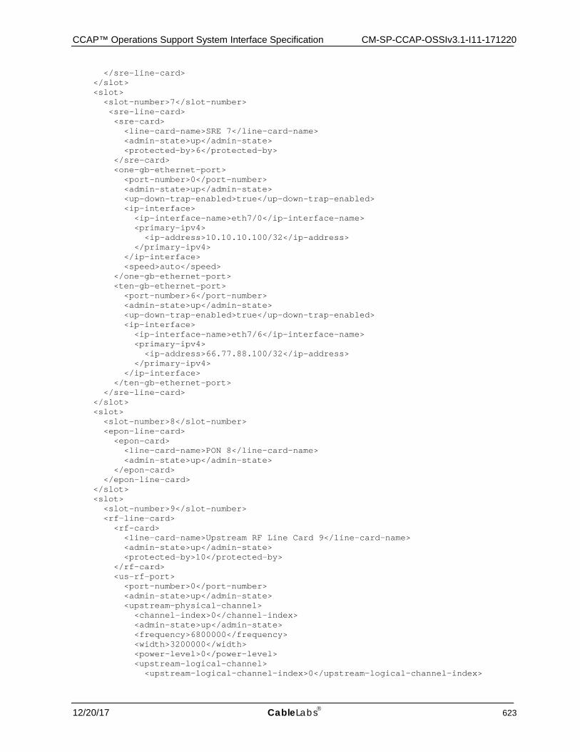
CCAP™ Operations Support System Interface Specification CM-SP-CCAP-OSSIv3.1-I11-171220
12/20/17 CableLabs 623
</sre-line-card> </slot> <slot> <slot-number>7</slot-number> <sre-line-card> <sre-card> <line-card-name>SRE 7</line-card-name> <admin-state>up</admin-state> <protected-by>6</protected-by> </sre-card> <one-gb-ethernet-port> <port-number>0</port-number> <admin-state>up</admin-state> <up-down-trap-enabled>true</up-down-trap-enabled> <ip-interface> <ip-interface-name>eth7/0</ip-interface-name> <primary-ipv4> <ip-address>10.10.10.100/32</ip-address> </primary-ipv4> </ip-interface> <speed>auto</speed> </one-gb-ethernet-port> <ten-gb-ethernet-port> <port-number>6</port-number> <admin-state>up</admin-state> <up-down-trap-enabled>true</up-down-trap-enabled> <ip-interface> <ip-interface-name>eth7/6</ip-interface-name> <primary-ipv4> <ip-address>66.77.88.100/32</ip-address> </primary-ipv4> </ip-interface> </ten-gb-ethernet-port> </sre-line-card> </slot> <slot> <slot-number>8</slot-number> <epon-line-card> <epon-card> <line-card-name>PON 8</line-card-name> <admin-state>up</admin-state> </epon-card> </epon-line-card> </slot> <slot> <slot-number>9</slot-number> <rf-line-card> <rf-card> <line-card-name>Upstream RF Line Card 9</line-card-name> <admin-state>up</admin-state> <protected-by>10</protected-by> </rf-card> <us-rf-port> <port-number>0</port-number> <admin-state>up</admin-state> <upstream-physical-channel> <channel-index>0</channel-index> <admin-state>up</admin-state> <frequency>6800000</frequency> <width>3200000</width> <power-level>0</power-level> <upstream-logical-channel> <upstream-logical-channel-index>0</upstream-logical-channel-index>
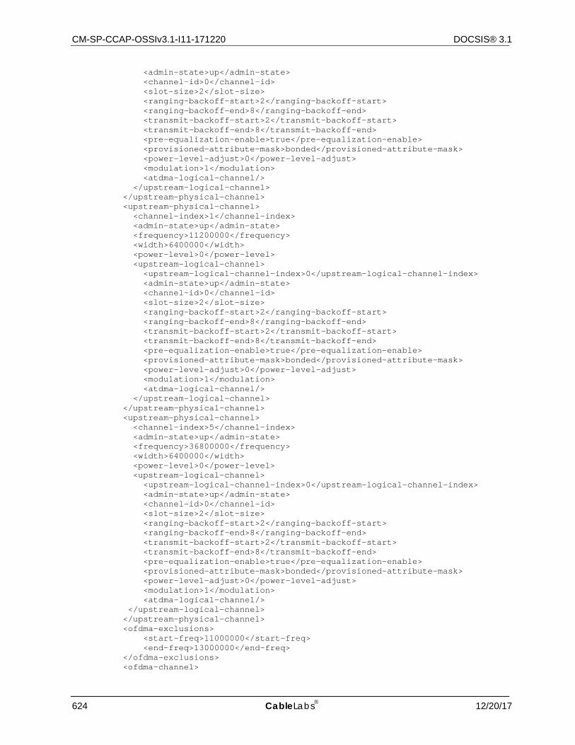
CM-SP-CCAP-OSSIv3.1-I11-171220 DOCSIS® 3.1
624 CableLabs 12/20/17
<admin-state>up</admin-state> <channel-id>0</channel-id> <slot-size>2</slot-size> <ranging-backoff-start>2</ranging-backoff-start> <ranging-backoff-end>8</ranging-backoff-end> <transmit-backoff-start>2</transmit-backoff-start> <transmit-backoff-end>8</transmit-backoff-end> <pre-equalization-enable>true</pre-equalization-enable> <provisioned-attribute-mask>bonded</provisioned-attribute-mask> <power-level-adjust>0</power-level-adjust> <modulation>1</modulation> <atdma-logical-channel/> </upstream-logical-channel> </upstream-physical-channel> <upstream-physical-channel> <channel-index>1</channel-index> <admin-state>up</admin-state> <frequency>11200000</frequency> <width>6400000</width> <power-level>0</power-level> <upstream-logical-channel> <upstream-logical-channel-index>0</upstream-logical-channel-index> <admin-state>up</admin-state> <channel-id>0</channel-id> <slot-size>2</slot-size> <ranging-backoff-start>2</ranging-backoff-start> <ranging-backoff-end>8</ranging-backoff-end> <transmit-backoff-start>2</transmit-backoff-start> <transmit-backoff-end>8</transmit-backoff-end> <pre-equalization-enable>true</pre-equalization-enable> <provisioned-attribute-mask>bonded</provisioned-attribute-mask> <power-level-adjust>0</power-level-adjust> <modulation>1</modulation> <atdma-logical-channel/> </upstream-logical-channel> </upstream-physical-channel> <upstream-physical-channel> <channel-index>5</channel-index> <admin-state>up</admin-state> <frequency>36800000</frequency> <width>6400000</width> <power-level>0</power-level> <upstream-logical-channel> <upstream-logical-channel-index>0</upstream-logical-channel-index> <admin-state>up</admin-state> <channel-id>0</channel-id> <slot-size>2</slot-size> <ranging-backoff-start>2</ranging-backoff-start> <ranging-backoff-end>8</ranging-backoff-end> <transmit-backoff-start>2</transmit-backoff-start> <transmit-backoff-end>8</transmit-backoff-end> <pre-equalization-enable>true</pre-equalization-enable> <provisioned-attribute-mask>bonded</provisioned-attribute-mask> <power-level-adjust>0</power-level-adjust> <modulation>1</modulation> <atdma-logical-channel/> </upstream-logical-channel> </upstream-physical-channel> <ofdma-exclusions> <start-freq>11000000</start-freq> <end-freq>13000000</end-freq> </ofdma-exclusions> <ofdma-channel>
CCAP™ Operations Support System Interface Specification CM-SP-CCAP-OSSIv3.1-I11-171220
12/20/17 CableLabs 625
<ofdma-channel-index>0</ofdma-channel-index> <lower-bdry-freq>10000000</lower-bdry-freq> <upper-bdry-freq>34000000</upper-bdry-freq> <provisioned-attribute-mask>bonded</provisioned-attribute-mask> <ranging-backoff-start>2</ranging-backoff-start> <ranging-backoff-end>8</ranging-backoff-end> <transmit-backoff-start>2</transmit-backoff-start> <transmit-backoff-end>8</transmit-backoff-end> <ofdma-chan-template>0</ofdma-chan-template> </ofdma-channel> </us-rf-port> <us-rf-port> <port-number>1</port-number> <admin-state>up</admin-state> <upstream-physical-channel> <channel-index>0</channel-index> <admin-state>up</admin-state> <frequency>6800000</frequency> <width>3200000</width> <power-level>0</power-level> <upstream-logical-channel> <upstream-logical-channel-index>0</upstream-logical-channel-index> <admin-state>up</admin-state> <channel-id>0</channel-id> <slot-size>2</slot-size> <ranging-backoff-start>2</ranging-backoff-start> <ranging-backoff-end>8</ranging-backoff-end> <transmit-backoff-start>2</transmit-backoff-start> <transmit-backoff-end>8</transmit-backoff-end> <pre-equalization-enable>true</pre-equalization-enable> <provisioned-attribute-mask>bonded</provisioned-attribute-mask> <power-level-adjust>0</power-level-adjust> <modulation>1</modulation> <atdma-logical-channel/> </upstream-logical-channel> </upstream-physical-channel> <upstream-physical-channel> <channel-index>1</channel-index> <admin-state>up</admin-state> <frequency>11200000</frequency> <width>6400000</width> <power-level>0</power-level> <upstream-logical-channel> <upstream-logical-channel-index>0</upstream-logical-channel-index> <admin-state>up</admin-state> <channel-id>0</channel-id> <slot-size>2</slot-size> <ranging-backoff-start>2</ranging-backoff-start> <ranging-backoff-end>8</ranging-backoff-end> <transmit-backoff-start>2</transmit-backoff-start> <transmit-backoff-end>8</transmit-backoff-end> <pre-equalization-enable>true</pre-equalization-enable> <provisioned-attribute-mask>bonded</provisioned-attribute-mask> <power-level-adjust>0</power-level-adjust> <modulation>1</modulation> <atdma-logical-channel/> </upstream-logical-channel> </upstream-physical-channel> <upstream-physical-channel> <channel-index>5</channel-index> <admin-state>up</admin-state> <frequency>36800000</frequency> <width>6400000</width>
CM-SP-CCAP-OSSIv3.1-I11-171220 DOCSIS® 3.1
626 CableLabs 12/20/17
<power-level>0</power-level> <upstream-logical-channel> <upstream-logical-channel-index>0</upstream-logical-channel-index> <admin-state>up</admin-state> <channel-id>0</channel-id> <slot-size>2</slot-size> <ranging-backoff-start>2</ranging-backoff-start> <ranging-backoff-end>8</ranging-backoff-end> <transmit-backoff-start>2</transmit-backoff-start> <transmit-backoff-end>8</transmit-backoff-end> <pre-equalization-enable>true</pre-equalization-enable> <provisioned-attribute-mask>bonded</provisioned-attribute-mask> <power-level-adjust>0</power-level-adjust> <modulation>1</modulation> <atdma-logical-channel/> </upstream-logical-channel> </upstream-physical-channel> </us-rf-port> <us-rf-port> <port-number>7</port-number> <admin-state>up</admin-state> <upstream-physical-channel> <channel-index>0</channel-index> <admin-state>up</admin-state> <frequency>6800000</frequency> <width>3200000</width> <power-level>0</power-level> <upstream-logical-channel> <upstream-logical-channel-index>0</upstream-logical-channel-index> <admin-state>up</admin-state> <channel-id>0</channel-id> <slot-size>2</slot-size> <ranging-backoff-start>2</ranging-backoff-start> <ranging-backoff-end>8</ranging-backoff-end> <transmit-backoff-start>2</transmit-backoff-start> <transmit-backoff-end>8</transmit-backoff-end> <pre-equalization-enable>true</pre-equalization-enable> <provisioned-attribute-mask>bonded</provisioned-attribute-mask> <power-level-adjust>0</power-level-adjust> <modulation>1</modulation> <atdma-logical-channel/> </upstream-logical-channel> </upstream-physical-channel> <upstream-physical-channel> <channel-index>1</channel-index> <admin-state>up</admin-state> <frequency>11200000</frequency> <width>6400000</width> <power-level>0</power-level> <upstream-logical-channel> <upstream-logical-channel-index>0</upstream-logical-channel-index> <admin-state>up</admin-state> <channel-id>0</channel-id> <slot-size>2</slot-size> <ranging-backoff-start>2</ranging-backoff-start> <ranging-backoff-end>8</ranging-backoff-end> <transmit-backoff-start>2</transmit-backoff-start> <transmit-backoff-end>8</transmit-backoff-end> <pre-equalization-enable>true</pre-equalization-enable> <provisioned-attribute-mask>bonded</provisioned-attribute-mask> <power-level-adjust>0</power-level-adjust> <modulation>1</modulation> <atdma-logical-channel/>
CCAP™ Operations Support System Interface Specification CM-SP-CCAP-OSSIv3.1-I11-171220
12/20/17 CableLabs 627
</upstream-logical-channel> </upstream-physical-channel> <upstream-physical-channel> <channel-index>5</channel-index> <admin-state>up</admin-state> <frequency>36800000</frequency> <width>6400000</width> <power-level>0</power-level> <upstream-logical-channel> <upstream-logical-channel-index>0</upstream-logical-channel-index> <admin-state>up</admin-state> <channel-id>0</channel-id> <slot-size>2</slot-size> <ranging-backoff-start>2</ranging-backoff-start> <ranging-backoff-end>8</ranging-backoff-end> <transmit-backoff-start>2</transmit-backoff-start> <transmit-backoff-end>8</transmit-backoff-end> <pre-equalization-enable>true</pre-equalization-enable> <provisioned-attribute-mask>bonded</provisioned-attribute-mask> <power-level-adjust>0</power-level-adjust> <modulation>1</modulation> <atdma-logical-channel/> </upstream-logical-channel> </upstream-physical-channel> </us-rf-port> </rf-line-card> </slot> <slot> <slot-number>10</slot-number> <rf-line-card> <rf-card> <line-card-name>Upstream RF Line Card Spare</line-card-name> <admin-state>up</admin-state> </rf-card> </rf-line-card> </slot> <slot> <slot-number>11</slot-number> <rf-line-card> <rf-card> <line-card-name>Upstream RF Line Card 11</line-card-name> <admin-state>up</admin-state> <protected-by>10</protected-by> </rf-card> <us-rf-port> <port-number>0</port-number> <admin-state>up</admin-state> <upstream-physical-channel> <channel-index>0</channel-index> <admin-state>up</admin-state> <frequency>6800000</frequency> <width>3200000</width> <power-level>0</power-level> <upstream-logical-channel> <upstream-logical-channel-index>0</upstream-logical-channel-index> <admin-state>up</admin-state> <channel-id>1</channel-id> <slot-size>2</slot-size> <ranging-backoff-start>12</ranging-backoff-start> <ranging-backoff-end>16</ranging-backoff-end> <transmit-backoff-start>12</transmit-backoff-start> <transmit-backoff-end>16</transmit-backoff-end> <pre-equalization-enable>true</pre-equalization-enable>
CM-SP-CCAP-OSSIv3.1-I11-171220 DOCSIS® 3.1
628 CableLabs 12/20/17
<provisioned-attribute-mask>bonded</provisioned-attribute-mask> <power-level-adjust>0</power-level-adjust> <modulation>1</modulation> <atdma-logical-channel/> </upstream-logical-channel> </upstream-physical-channel> <upstream-physical-channel> <channel-index>1</channel-index> <admin-state>up</admin-state> <frequency>11200000</frequency> <width>6400000</width> <power-level>0</power-level> <upstream-logical-channel> <upstream-logical-channel-index>0</upstream-logical-channel-index> <admin-state>up</admin-state> <channel-id>2</channel-id> <slot-size>4</slot-size> <ranging-backoff-start>2</ranging-backoff-start> <ranging-backoff-end>8</ranging-backoff-end> <transmit-backoff-start>5</transmit-backoff-start> <transmit-backoff-end>8</transmit-backoff-end> <pre-equalization-enable>true</pre-equalization-enable> <provisioned-attribute-mask>bonded</provisioned-attribute-mask> <power-level-adjust>0</power-level-adjust> <modulation>1</modulation> <atdma-logical-channel/> </upstream-logical-channel> </upstream-physical-channel> <upstream-physical-channel> <channel-index>5</channel-index> <admin-state>up</admin-state> <frequency>36800000</frequency> <width>6400000</width> <power-level>0</power-level> <upstream-logical-channel> <upstream-logical-channel-index>0</upstream-logical-channel-index> <admin-state>up</admin-state> <channel-id>2</channel-id> <slot-size>4</slot-size> <ranging-backoff-start>2</ranging-backoff-start> <ranging-backoff-end>8</ranging-backoff-end> <transmit-backoff-start>5</transmit-backoff-start> <transmit-backoff-end>8</transmit-backoff-end> <pre-equalization-enable>true</pre-equalization-enable> <provisioned-attribute-mask>bonded</provisioned-attribute-mask> <power-level-adjust>0</power-level-adjust> <modulation>1</modulation> <atdma-logical-channel/> </upstream-logical-channel> </upstream-physical-channel> </us-rf-port> <us-rf-port> <port-number>1</port-number> <admin-state>up</admin-state> <upstream-physical-channel> <channel-index>0</channel-index> <admin-state>up</admin-state> <frequency>6800000</frequency> <width>3200000</width> <power-level>0</power-level> <upstream-logical-channel> <upstream-logical-channel-index>0</upstream-logical-channel-index> <admin-state>up</admin-state>
CCAP™ Operations Support System Interface Specification CM-SP-CCAP-OSSIv3.1-I11-171220
12/20/17 CableLabs 629
<channel-id>0</channel-id> <slot-size>2</slot-size> <ranging-backoff-start>2</ranging-backoff-start> <ranging-backoff-end>8</ranging-backoff-end> <transmit-backoff-start>2</transmit-backoff-start> <transmit-backoff-end>8</transmit-backoff-end> <pre-equalization-enable>true</pre-equalization-enable> <provisioned-attribute-mask>bonded</provisioned-attribute-mask> <power-level-adjust>0</power-level-adjust> <modulation>1</modulation> <atdma-logical-channel/> </upstream-logical-channel> </upstream-physical-channel> <upstream-physical-channel> <channel-index>1</channel-index> <admin-state>up</admin-state> <frequency>11200000</frequency> <width>6400000</width> <power-level>0</power-level> <upstream-logical-channel> <upstream-logical-channel-index>0</upstream-logical-channel-index> <admin-state>up</admin-state> <channel-id>0</channel-id> <slot-size>2</slot-size> <ranging-backoff-start>2</ranging-backoff-start> <ranging-backoff-end>8</ranging-backoff-end> <transmit-backoff-start>2</transmit-backoff-start> <transmit-backoff-end>8</transmit-backoff-end> <pre-equalization-enable>true</pre-equalization-enable> <provisioned-attribute-mask>bonded</provisioned-attribute-mask> <power-level-adjust>0</power-level-adjust> <modulation>1</modulation> <atdma-logical-channel/> </upstream-logical-channel> </upstream-physical-channel> <upstream-physical-channel> <channel-index>5</channel-index> <admin-state>up</admin-state> <frequency>36800000</frequency> <width>6400000</width> <power-level>0</power-level> <upstream-logical-channel> <upstream-logical-channel-index>0</upstream-logical-channel-index> <admin-state>up</admin-state> <channel-id>0</channel-id> <slot-size>2</slot-size> <ranging-backoff-start>2</ranging-backoff-start> <ranging-backoff-end>8</ranging-backoff-end> <transmit-backoff-start>2</transmit-backoff-start> <transmit-backoff-end>8</transmit-backoff-end> <pre-equalization-enable>true</pre-equalization-enable> <provisioned-attribute-mask>bonded</provisioned-attribute-mask> <power-level-adjust>0</power-level-adjust> <modulation>2</modulation> <atdma-logical-channel/> </upstream-logical-channel> </upstream-physical-channel> </us-rf-port> <us-rf-port> <port-number>7</port-number> <admin-state>up</admin-state> <upstream-physical-channel> <channel-index>0</channel-index>
CM-SP-CCAP-OSSIv3.1-I11-171220 DOCSIS® 3.1
630 CableLabs 12/20/17
<admin-state>up</admin-state> <frequency>6800000</frequency> <width>3200000</width> <power-level>0</power-level> <upstream-logical-channel> <upstream-logical-channel-index>0</upstream-logical-channel-index> <admin-state>up</admin-state> <channel-id>0</channel-id> <slot-size>2</slot-size> <ranging-backoff-start>2</ranging-backoff-start> <ranging-backoff-end>8</ranging-backoff-end> <transmit-backoff-start>2</transmit-backoff-start> <transmit-backoff-end>8</transmit-backoff-end> <pre-equalization-enable>true</pre-equalization-enable> <provisioned-attribute-mask>bonded</provisioned-attribute-mask> <power-level-adjust>0</power-level-adjust> <modulation>1</modulation> <atdma-logical-channel/> </upstream-logical-channel> </upstream-physical-channel> <upstream-physical-channel> <channel-index>1</channel-index> <admin-state>up</admin-state> <frequency>11200000</frequency> <width>6400000</width> <power-level>0</power-level> <upstream-logical-channel> <upstream-logical-channel-index>0</upstream-logical-channel-index> <admin-state>up</admin-state> <channel-id>0</channel-id> <slot-size>2</slot-size> <ranging-backoff-start>2</ranging-backoff-start> <ranging-backoff-end>8</ranging-backoff-end> <transmit-backoff-start>2</transmit-backoff-start> <transmit-backoff-end>8</transmit-backoff-end> <pre-equalization-enable>true</pre-equalization-enable> <provisioned-attribute-mask>bonded</provisioned-attribute-mask> <power-level-adjust>0</power-level-adjust> <modulation>1</modulation> <atdma-logical-channel/> </upstream-logical-channel> </upstream-physical-channel> <upstream-physical-channel> <channel-index>5</channel-index> <admin-state>up</admin-state> <frequency>36800000</frequency> <width>6400000</width> <power-level>0</power-level> <upstream-logical-channel> <upstream-logical-channel-index>0</upstream-logical-channel-index> <admin-state>up</admin-state> <channel-id>0</channel-id> <slot-size>2</slot-size> <ranging-backoff-start>2</ranging-backoff-start> <ranging-backoff-end>8</ranging-backoff-end> <transmit-backoff-start>2</transmit-backoff-start> <transmit-backoff-end>8</transmit-backoff-end> <pre-equalization-enable>true</pre-equalization-enable> <provisioned-attribute-mask>bonded</provisioned-attribute-mask> <power-level-adjust>0</power-level-adjust> <modulation>1</modulation> <atdma-logical-channel/> </upstream-logical-channel>
CCAP™ Operations Support System Interface Specification CM-SP-CCAP-OSSIv3.1-I11-171220
12/20/17 CableLabs 631
</upstream-physical-channel> </us-rf-port> </rf-line-card> </slot> <video-phy-profile> <phy-index>0</phy-index> <modulation>qam256</modulation> <interleaver-depth>fecI128J1</interleaver-depth> <downstream-phy-standard>j83annexB</downstream-phy-standard> <spectrum-inversion>false</spectrum-inversion> </video-phy-profile> <video-phy-profile> <phy-index>1</phy-index> <modulation>qam64</modulation> <interleaver-depth>fecI128J4</interleaver-depth> <spectrum-inversion>true</spectrum-inversion> <symbol-rate-override>40000000</symbol-rate-override> </video-phy-profile> <docsis-phy-profile> <phy-index>0</phy-index> <modulation>qam256</modulation> <interleaver-depth>fecI32J4</interleaver-depth> <downstream-phy-standard>j83annexB</downstream-phy-standard> </docsis-phy-profile> <docsis-phy-profile> <phy-index>1</phy-index> <modulation>qam64</modulation> <interleaver-depth>fecI8J16</interleaver-depth> </docsis-phy-profile> </chassis> <docsis> <docs-global> <maximum-scheduled-codes-enabled>false</maximum-scheduled-codes-enabled> <l2-vpn-global-enabled>false</l2-vpn-global-enabled> </docs-global> <cm-vendor-oui> <cm-oui>FFFFFF</cm-oui> <cm-vendor-name>CableLabs</cm-vendor-name> </cm-vendor-oui> <ofdm-guard-band> <guard-band-index>1</guard-band-index> <guard-band-width>1000000</guard-band-width> </ofdm-guard-band> <ofdm-guard-band> <guard-band-index>0</guard-band-index> <guard-band-width>0</guard-band-width> </ofdm-guard-band> <docs-security> <sav-config-list> <sav-config-list-name>SecCfgSavList1</sav-config-list-name> <sav-rule> <rule-id>1</rule-id> <prefix-address>10.193.1.1/32</prefix-address> </sav-rule> </sav-config-list> <sav-config-list> <sav-config-list-name>SecCfgSavList2</sav-config-list-name> <sav-rule> <rule-id>1</rule-id> <prefix-address>10.194.1.1/32</prefix-address> </sav-rule> <sav-rule> <rule-id>2</rule-id>
CM-SP-CCAP-OSSIv3.1-I11-171220 DOCSIS® 3.1
632 CableLabs 12/20/17
<prefix-address>10.194.2.1/32</prefix-address> </sav-rule> </sav-config-list> <cmts-sav-control> <cm-authentication-enable>true</cm-authentication-enable> </cmts-sav-control> <cmts-server-config> <tftp-options>net-addr</tftp-options> <config-file-learning-enabled>true</config-file-learning-enabled> </cmts-server-config> <cmts-encrypt> <encrypt-alg-priority>aes128CbcMode des56CbcMode des40CbcMode</encrypt-alg-priority> </cmts-encrypt> <cmts-certificate> <cert-revocation-method>crl-and-ocsp</cert-revocation-method> </cmts-certificate> <cmts-cert-revocation-list> <url>crl.verisign.net</url> <refresh-interval>10080</refresh-interval> </cmts-cert-revocation-list> <cmts-cm-eae-exclusion> <cmts-cm-eae-exclusion-id>1</cmts-cm-eae-exclusion-id> <mac-address>59:94:6B:7C:2A:CC</mac-address> <mac-address-mask>FF:FF:FF:FF:FF:FF</mac-address-mask> </cmts-cm-eae-exclusion> <cmts-online-cert-status-protocol> <url>ocsp.verisign.net</url> <signature-bypass>false</signature-bypass> </cmts-online-cert-status-protocol> <sys-bpi-config> <sys-default-authentication-lifetime>5</sys-default-authentication-lifetime> <sys-default-tek-lifetime>5</sys-default-tek-lifetime> </sys-bpi-config> </docs-security> <docs-subscriber-management> <base> <cpe-max-ipv4>16</cpe-max-ipv4> <cpe-max-ipv6>16</cpe-max-ipv6> <cpe-active>true</cpe-active> <cpe-learnable>true</cpe-learnable> <subscriber-downstream-filter>1</subscriber-downstream-filter> <subscriber-upstream-filter>0</subscriber-upstream-filter> <cm-downstream-filter>0</cm-downstream-filter> <cm-upstream-filter>0</cm-upstream-filter> <ps-downstream-filter>0</ps-downstream-filter> <ps-upstream-filter>0</ps-upstream-filter> <mta-downstream-filter>0</mta-downstream-filter> <mta-upstream-filter>0</mta-upstream-filter> <stb-downstream-filter>0</stb-downstream-filter> <stb-upstream-filter>0</stb-upstream-filter> </base> <filter-group> <group-id>1</group-id> <rule-id>1</rule-id> <filter-action>permit</filter-action> <priority>1</priority> <ip-tos-low>00</ip-tos-low> <ip-tos-high>FF</ip-tos-high> <ip-tos-mask>FF</ip-tos-mask> <ip-protocol>257</ip-protocol> <source-address>10.10.10.0/10</source-address> <destination-address>192.168.8.1/10</destination-address>
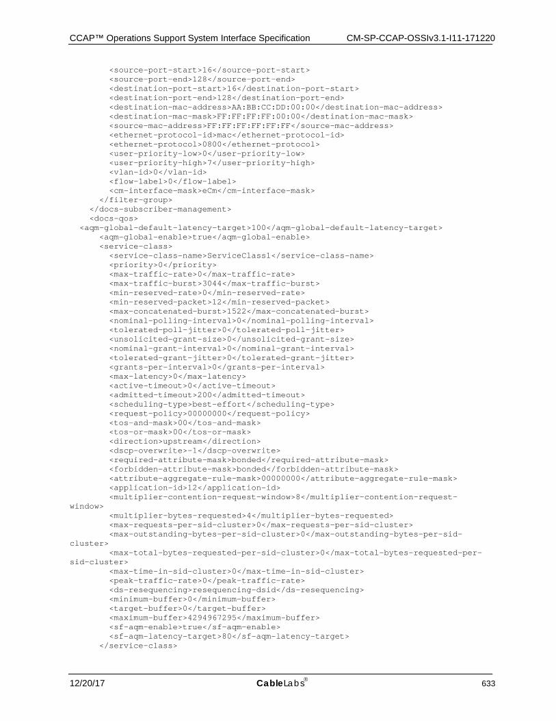
CCAP™ Operations Support System Interface Specification CM-SP-CCAP-OSSIv3.1-I11-171220
12/20/17 CableLabs 633
<source-port-start>16</source-port-start> <source-port-end>128</source-port-end> <destination-port-start>16</destination-port-start> <destination-port-end>128</destination-port-end> <destination-mac-address>AA:BB:CC:DD:00:00</destination-mac-address> <destination-mac-mask>FF:FF:FF:FF:00:00</destination-mac-mask> <source-mac-address>FF:FF:FF:FF:FF:FF</source-mac-address> <ethernet-protocol-id>mac</ethernet-protocol-id> <ethernet-protocol>0800</ethernet-protocol> <user-priority-low>0</user-priority-low> <user-priority-high>7</user-priority-high> <vlan-id>0</vlan-id> <flow-label>0</flow-label> <cm-interface-mask>eCm</cm-interface-mask> </filter-group> </docs-subscriber-management> <docs-qos> <aqm-global-default-latency-target>100</aqm-global-default-latency-target> <aqm-global-enable>true</aqm-global-enable> <service-class> <service-class-name>ServiceClass1</service-class-name> <priority>0</priority> <max-traffic-rate>0</max-traffic-rate> <max-traffic-burst>3044</max-traffic-burst> <min-reserved-rate>0</min-reserved-rate> <min-reserved-packet>12</min-reserved-packet> <max-concatenated-burst>1522</max-concatenated-burst> <nominal-polling-interval>0</nominal-polling-interval> <tolerated-poll-jitter>0</tolerated-poll-jitter> <unsolicited-grant-size>0</unsolicited-grant-size> <nominal-grant-interval>0</nominal-grant-interval> <tolerated-grant-jitter>0</tolerated-grant-jitter> <grants-per-interval>0</grants-per-interval> <max-latency>0</max-latency> <active-timeout>0</active-timeout> <admitted-timeout>200</admitted-timeout> <scheduling-type>best-effort</scheduling-type> <request-policy>00000000</request-policy> <tos-and-mask>00</tos-and-mask> <tos-or-mask>00</tos-or-mask> <direction>upstream</direction> <dscp-overwrite>-1</dscp-overwrite> <required-attribute-mask>bonded</required-attribute-mask> <forbidden-attribute-mask>bonded</forbidden-attribute-mask> <attribute-aggregate-rule-mask>00000000</attribute-aggregate-rule-mask> <application-id>12</application-id> <multiplier-contention-request-window>8</multiplier-contention-request-window> <multiplier-bytes-requested>4</multiplier-bytes-requested> <max-requests-per-sid-cluster>0</max-requests-per-sid-cluster> <max-outstanding-bytes-per-sid-cluster>0</max-outstanding-bytes-per-sid-cluster> <max-total-bytes-requested-per-sid-cluster>0</max-total-bytes-requested-per-sid-cluster> <max-time-in-sid-cluster>0</max-time-in-sid-cluster> <peak-traffic-rate>0</peak-traffic-rate> <ds-resequencing>resequencing-dsid</ds-resequencing> <minimum-buffer>0</minimum-buffer> <target-buffer>0</target-buffer> <maximum-buffer>4294967295</maximum-buffer> <sf-aqm-enable>true</sf-aqm-enable> <sf-aqm-latency-target>80</sf-aqm-latency-target> </service-class>
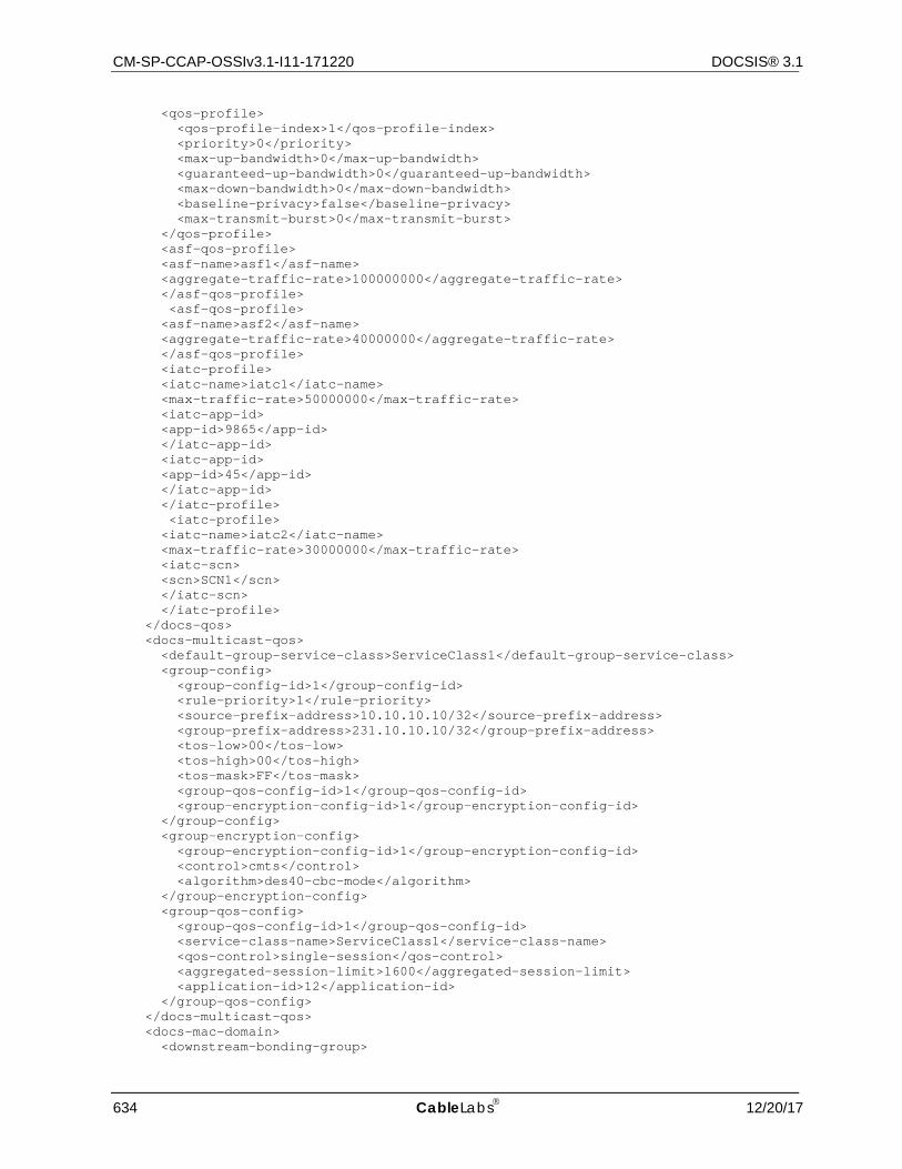
CM-SP-CCAP-OSSIv3.1-I11-171220 DOCSIS® 3.1
634 CableLabs 12/20/17
<qos-profile> <qos-profile-index>1</qos-profile-index> <priority>0</priority> <max-up-bandwidth>0</max-up-bandwidth> <guaranteed-up-bandwidth>0</guaranteed-up-bandwidth> <max-down-bandwidth>0</max-down-bandwidth> <baseline-privacy>false</baseline-privacy> <max-transmit-burst>0</max-transmit-burst> </qos-profile> <asf-qos-profile> <asf-name>asf1</asf-name> <aggregate-traffic-rate>100000000</aggregate-traffic-rate> </asf-qos-profile> <asf-qos-profile> <asf-name>asf2</asf-name> <aggregate-traffic-rate>40000000</aggregate-traffic-rate> </asf-qos-profile> <iatc-profile> <iatc-name>iatc1</iatc-name> <max-traffic-rate>50000000</max-traffic-rate> <iatc-app-id> <app-id>9865</app-id> </iatc-app-id> <iatc-app-id> <app-id>45</app-id> </iatc-app-id> </iatc-profile> <iatc-profile> <iatc-name>iatc2</iatc-name> <max-traffic-rate>30000000</max-traffic-rate> <iatc-scn> <scn>SCN1</scn> </iatc-scn> </iatc-profile> </docs-qos> <docs-multicast-qos> <default-group-service-class>ServiceClass1</default-group-service-class> <group-config> <group-config-id>1</group-config-id> <rule-priority>1</rule-priority> <source-prefix-address>10.10.10.10/32</source-prefix-address> <group-prefix-address>231.10.10.10/32</group-prefix-address> <tos-low>00</tos-low> <tos-high>00</tos-high> <tos-mask>FF</tos-mask> <group-qos-config-id>1</group-qos-config-id> <group-encryption-config-id>1</group-encryption-config-id> </group-config> <group-encryption-config> <group-encryption-config-id>1</group-encryption-config-id> <control>cmts</control> <algorithm>des40-cbc-mode</algorithm> </group-encryption-config> <group-qos-config> <group-qos-config-id>1</group-qos-config-id> <service-class-name>ServiceClass1</service-class-name> <qos-control>single-session</qos-control> <aggregated-session-limit>1600</aggregated-session-limit> <application-id>12</application-id> </group-qos-config> </docs-multicast-qos> <docs-mac-domain> <downstream-bonding-group>
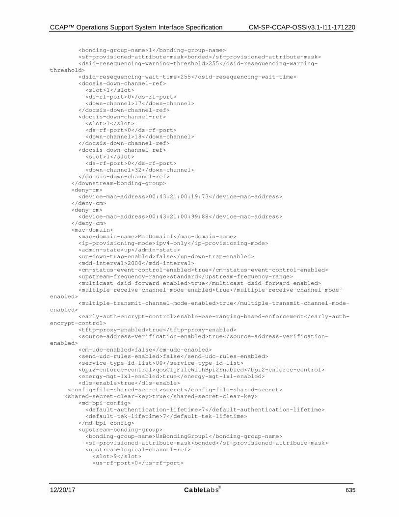
CCAP™ Operations Support System Interface Specification CM-SP-CCAP-OSSIv3.1-I11-171220
12/20/17 CableLabs 635
<bonding-group-name>1</bonding-group-name> <sf-provisioned-attribute-mask>bonded</sf-provisioned-attribute-mask> <dsid-resequencing-warning-threshold>255</dsid-resequencing-warning-threshold> <dsid-resequencing-wait-time>255</dsid-resequencing-wait-time> <docsis-down-channel-ref> <slot>1</slot> <ds-rf-port>0</ds-rf-port> <down-channel>17</down-channel> </docsis-down-channel-ref> <docsis-down-channel-ref> <slot>1</slot> <ds-rf-port>0</ds-rf-port> <down-channel>18</down-channel> </docsis-down-channel-ref> <docsis-down-channel-ref> <slot>1</slot> <ds-rf-port>0</ds-rf-port> <down-channel>32</down-channel> </docsis-down-channel-ref> </downstream-bonding-group> <deny-cm> <device-mac-address>00:43:21:00:19:73</device-mac-address> </deny-cm> <deny-cm> <device-mac-address>00:43:21:00:99:88</device-mac-address> </deny-cm> <mac-domain> <mac-domain-name>MacDomain1</mac-domain-name> <ip-provisioning-mode>ipv4-only</ip-provisioning-mode> <admin-state>up</admin-state> <up-down-trap-enabled>false</up-down-trap-enabled> <mdd-interval>2000</mdd-interval> <cm-status-event-control-enabled>true</cm-status-event-control-enabled> <upstream-frequency-range>standard</upstream-frequency-range> <multicast-dsid-forward-enabled>true</multicast-dsid-forward-enabled> <multiple-receive-channel-mode-enabled>true</multiple-receive-channel-mode-enabled> <multiple-transmit-channel-mode-enabled>true</multiple-transmit-channel-mode-enabled> <early-auth-encrypt-control>enable-eae-ranging-based-enforcement</early-auth-encrypt-control> <tftp-proxy-enabled>true</tftp-proxy-enabled> <source-address-verification-enabled>true</source-address-verification-enabled> <cm-udc-enabled>false</cm-udc-enabled> <send-udc-rules-enabled>false</send-udc-rules-enabled> <service-type-id-list>00</service-type-id-list> <bpi2-enforce-control>qosCfgFileWithBpi2Enabled</bpi2-enforce-control> <energy-mgt-1x1-enabled>true</energy-mgt-1x1-enabled> <dls-enable>true</dls-enable> <config-file-shared-secret>secret</config-file-shared-secret> <shared-secret-clear-key>true</shared-secret-clear-key> <md-bpi-config> <default-authentication-lifetime>7</default-authentication-lifetime> <default-tek-lifetime>7</default-tek-lifetime> </md-bpi-config> <upstream-bonding-group> <bonding-group-name>UsBondingGroup1</bonding-group-name> <sf-provisioned-attribute-mask>bonded</sf-provisioned-attribute-mask> <upstream-logical-channel-ref> <slot>9</slot> <us-rf-port>0</us-rf-port>
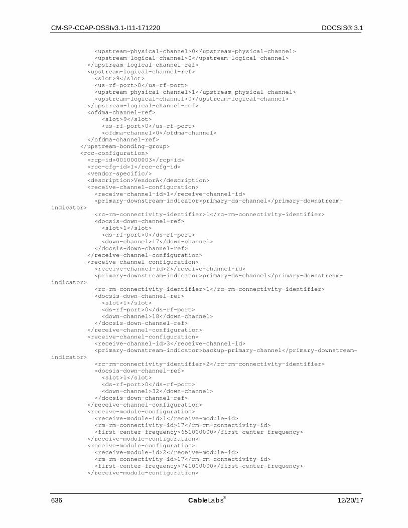
CM-SP-CCAP-OSSIv3.1-I11-171220 DOCSIS® 3.1
636 CableLabs 12/20/17
<upstream-physical-channel>0</upstream-physical-channel> <upstream-logical-channel>0</upstream-logical-channel> </upstream-logical-channel-ref> <upstream-logical-channel-ref> <slot>9</slot> <us-rf-port>0</us-rf-port> <upstream-physical-channel>1</upstream-physical-channel> <upstream-logical-channel>0</upstream-logical-channel> </upstream-logical-channel-ref> <ofdma-channel-ref> <slot>9</slot> <us-rf-port>0</us-rf-port> <ofdma-channel>0</ofdma-channel> </ofdma-channel-ref> </upstream-bonding-group> <rcc-configuration> <rcp-id>0010000003</rcp-id> <rcc-cfg-id>1</rcc-cfg-id> <vendor-specific/> <description>VendorA</description> <receive-channel-configuration> <receive-channel-id>1</receive-channel-id> <primary-downstream-indicator>primary-ds-channel</primary-downstream-indicator> <rc-rm-connectivity-identifier>1</rc-rm-connectivity-identifier> <docsis-down-channel-ref> <slot>1</slot> <ds-rf-port>0</ds-rf-port> <down-channel>17</down-channel> </docsis-down-channel-ref> </receive-channel-configuration> <receive-channel-configuration> <receive-channel-id>2</receive-channel-id> <primary-downstream-indicator>primary-ds-channel</primary-downstream-indicator> <rc-rm-connectivity-identifier>1</rc-rm-connectivity-identifier> <docsis-down-channel-ref> <slot>1</slot> <ds-rf-port>0</ds-rf-port> <down-channel>18</down-channel> </docsis-down-channel-ref> </receive-channel-configuration> <receive-channel-configuration> <receive-channel-id>3</receive-channel-id> <primary-downstream-indicator>backup-primary-channel</primary-downstream-indicator> <rc-rm-connectivity-identifier>2</rc-rm-connectivity-identifier> <docsis-down-channel-ref> <slot>1</slot> <ds-rf-port>0</ds-rf-port> <down-channel>32</down-channel> </docsis-down-channel-ref> </receive-channel-configuration> <receive-module-configuration> <receive-module-id>1</receive-module-id> <rm-rm-connectivity-id>17</rm-rm-connectivity-id> <first-center-frequency>651000000</first-center-frequency> </receive-module-configuration> <receive-module-configuration> <receive-module-id>2</receive-module-id> <rm-rm-connectivity-id>17</rm-rm-connectivity-id> <first-center-frequency>741000000</first-center-frequency> </receive-module-configuration>
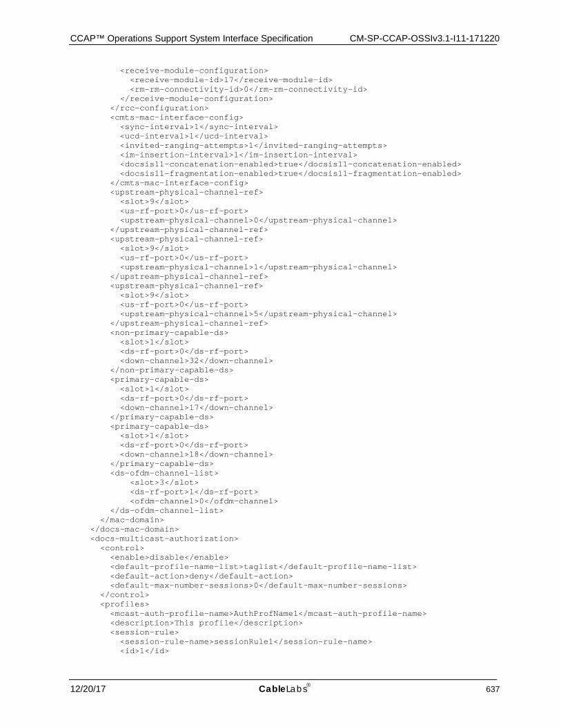
CCAP™ Operations Support System Interface Specification CM-SP-CCAP-OSSIv3.1-I11-171220
12/20/17 CableLabs 637
<receive-module-configuration> <receive-module-id>17</receive-module-id> <rm-rm-connectivity-id>0</rm-rm-connectivity-id> </receive-module-configuration> </rcc-configuration> <cmts-mac-interface-config> <sync-interval>1</sync-interval> <ucd-interval>1</ucd-interval> <invited-ranging-attempts>1</invited-ranging-attempts> <im-insertion-interval>1</im-insertion-interval> <docsis11-concatenation-enabled>true</docsis11-concatenation-enabled> <docsis11-fragmentation-enabled>true</docsis11-fragmentation-enabled> </cmts-mac-interface-config> <upstream-physical-channel-ref> <slot>9</slot> <us-rf-port>0</us-rf-port> <upstream-physical-channel>0</upstream-physical-channel> </upstream-physical-channel-ref> <upstream-physical-channel-ref> <slot>9</slot> <us-rf-port>0</us-rf-port> <upstream-physical-channel>1</upstream-physical-channel> </upstream-physical-channel-ref> <upstream-physical-channel-ref> <slot>9</slot> <us-rf-port>0</us-rf-port> <upstream-physical-channel>5</upstream-physical-channel> </upstream-physical-channel-ref> <non-primary-capable-ds> <slot>1</slot> <ds-rf-port>0</ds-rf-port> <down-channel>32</down-channel> </non-primary-capable-ds> <primary-capable-ds> <slot>1</slot> <ds-rf-port>0</ds-rf-port> <down-channel>17</down-channel> </primary-capable-ds> <primary-capable-ds> <slot>1</slot> <ds-rf-port>0</ds-rf-port> <down-channel>18</down-channel> </primary-capable-ds> <ds-ofdm-channel-list> <slot>3</slot> <ds-rf-port>1</ds-rf-port> <ofdm-channel>0</ofdm-channel> </ds-ofdm-channel-list> </mac-domain> </docs-mac-domain> <docs-multicast-authorization> <control> <enable>disable</enable> <default-profile-name-list>taglist</default-profile-name-list> <default-action>deny</default-action> <default-max-number-sessions>0</default-max-number-sessions> </control> <profiles> <mcast-auth-profile-name>AuthProfName1</mcast-auth-profile-name> <description>This profile</description> <session-rule> <session-rule-name>sessionRule1</session-rule-name> <id>1</id>
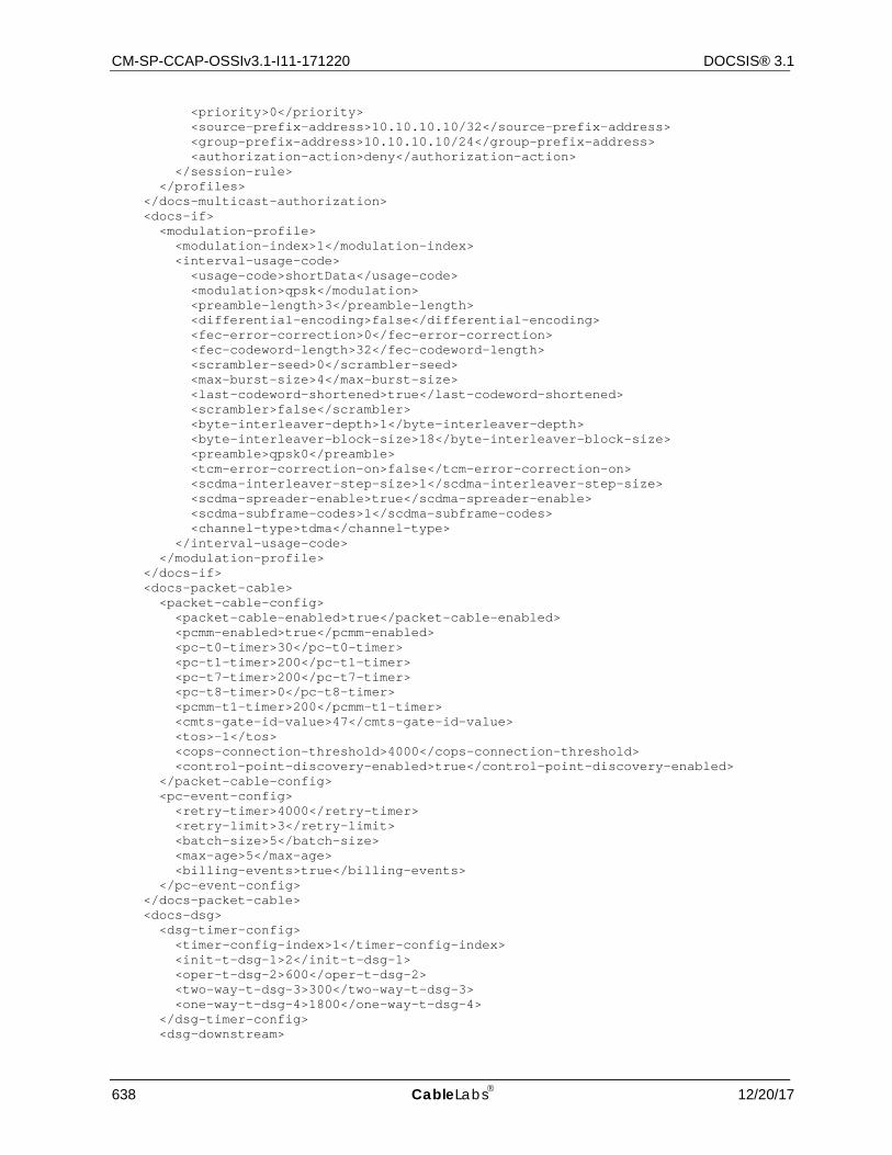
CM-SP-CCAP-OSSIv3.1-I11-171220 DOCSIS® 3.1
638 CableLabs 12/20/17
<priority>0</priority> <source-prefix-address>10.10.10.10/32</source-prefix-address> <group-prefix-address>10.10.10.10/24</group-prefix-address> <authorization-action>deny</authorization-action> </session-rule> </profiles> </docs-multicast-authorization> <docs-if> <modulation-profile> <modulation-index>1</modulation-index> <interval-usage-code> <usage-code>shortData</usage-code> <modulation>qpsk</modulation> <preamble-length>3</preamble-length> <differential-encoding>false</differential-encoding> <fec-error-correction>0</fec-error-correction> <fec-codeword-length>32</fec-codeword-length> <scrambler-seed>0</scrambler-seed> <max-burst-size>4</max-burst-size> <last-codeword-shortened>true</last-codeword-shortened> <scrambler>false</scrambler> <byte-interleaver-depth>1</byte-interleaver-depth> <byte-interleaver-block-size>18</byte-interleaver-block-size> <preamble>qpsk0</preamble> <tcm-error-correction-on>false</tcm-error-correction-on> <scdma-interleaver-step-size>1</scdma-interleaver-step-size> <scdma-spreader-enable>true</scdma-spreader-enable> <scdma-subframe-codes>1</scdma-subframe-codes> <channel-type>tdma</channel-type> </interval-usage-code> </modulation-profile> </docs-if> <docs-packet-cable> <packet-cable-config> <packet-cable-enabled>true</packet-cable-enabled> <pcmm-enabled>true</pcmm-enabled> <pc-t0-timer>30</pc-t0-timer> <pc-t1-timer>200</pc-t1-timer> <pc-t7-timer>200</pc-t7-timer> <pc-t8-timer>0</pc-t8-timer> <pcmm-t1-timer>200</pcmm-t1-timer> <cmts-gate-id-value>47</cmts-gate-id-value> <tos>-1</tos> <cops-connection-threshold>4000</cops-connection-threshold> <control-point-discovery-enabled>true</control-point-discovery-enabled> </packet-cable-config> <pc-event-config> <retry-timer>4000</retry-timer> <retry-limit>3</retry-limit> <batch-size>5</batch-size> <max-age>5</max-age> <billing-events>true</billing-events> </pc-event-config> </docs-packet-cable> <docs-dsg> <dsg-timer-config> <timer-config-index>1</timer-config-index> <init-t-dsg-1>2</init-t-dsg-1> <oper-t-dsg-2>600</oper-t-dsg-2> <two-way-t-dsg-3>300</two-way-t-dsg-3> <one-way-t-dsg-4>1800</one-way-t-dsg-4> </dsg-timer-config> <dsg-downstream>
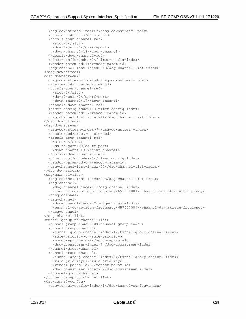
CCAP™ Operations Support System Interface Specification CM-SP-CCAP-OSSIv3.1-I11-171220
12/20/17 CableLabs 639
<dsg-downstream-index>7</dsg-downstream-index> <enable-dcd>true</enable-dcd> <docsis-down-channel-ref> <slot>1</slot> <ds-rf-port>0</ds-rf-port> <down-channel>18</down-channel> </docsis-down-channel-ref> <timer-config-index>1</timer-config-index> <vendor-param-id>1</vendor-param-id> <dsg-channel-list-index>44</dsg-channel-list-index> </dsg-downstream> <dsg-downstream> <dsg-downstream-index>8</dsg-downstream-index> <enable-dcd>true</enable-dcd> <docsis-down-channel-ref> <slot>1</slot> <ds-rf-port>0</ds-rf-port> <down-channel>17</down-channel> </docsis-down-channel-ref> <timer-config-index>1</timer-config-index> <vendor-param-id>2</vendor-param-id> <dsg-channel-list-index>44</dsg-channel-list-index> </dsg-downstream> <dsg-downstream> <dsg-downstream-index>9</dsg-downstream-index> <enable-dcd>true</enable-dcd> <docsis-down-channel-ref> <slot>1</slot> <ds-rf-port>0</ds-rf-port> <down-channel>32</down-channel> </docsis-down-channel-ref> <timer-config-index>0</timer-config-index> <vendor-param-id>0</vendor-param-id> <dsg-channel-list-index>44</dsg-channel-list-index> </dsg-downstream> <dsg-channel-list> <dsg-channel-list-index>44</dsg-channel-list-index> <dsg-channel> <dsg-channel-index>1</dsg-channel-index> <channel-downstream-frequency>651000000</channel-downstream-frequency> </dsg-channel> <dsg-channel> <dsg-channel-index>2</dsg-channel-index> <channel-downstream-frequency>657000000</channel-downstream-frequency> </dsg-channel> </dsg-channel-list> <tunnel-group-to-channel-list> <tunnel-group-index>100</tunnel-group-index> <tunnel-group-channel> <tunnel-group-channel-index>1</tunnel-group-channel-index> <rule-priority>0</rule-priority> <vendor-param-id>2</vendor-param-id> <dsg-downstream-index>7</dsg-downstream-index> </tunnel-group-channel> <tunnel-group-channel> <tunnel-group-channel-index>2</tunnel-group-channel-index> <rule-priority>1</rule-priority> <vendor-param-id>2</vendor-param-id> <dsg-downstream-index>8</dsg-downstream-index> </tunnel-group-channel> </tunnel-group-to-channel-list> <dsg-tunnel-config> <dsg-tunnel-config-index>1</dsg-tunnel-config-index>
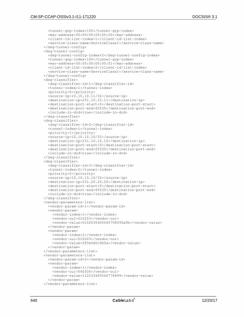
CM-SP-CCAP-OSSIv3.1-I11-171220 DOCSIS® 3.1
640 CableLabs 12/20/17
<tunnel-grp-index>100</tunnel-grp-index> <mac-address>00:00:00:00:00:00</mac-address> <client-id-list-index>1</client-id-list-index> <service-class-name>ServiceClass1</service-class-name> </dsg-tunnel-config> <dsg-tunnel-config> <dsg-tunnel-config-index>2</dsg-tunnel-config-index> <tunnel-grp-index>100</tunnel-grp-index> <mac-address>00:00:00:00:00:01</mac-address> <client-id-list-index>2</client-id-list-index> <service-class-name>ServiceClass1</service-class-name> </dsg-tunnel-config> <dsg-classifier> <dsg-classifier-id>1</dsg-classifier-id> <tunnel-index>1</tunnel-index> <priority>0</priority> <source-ip>10.10.10.11/32</source-ip> <destination-ip>231.10.10.11</destination-ip> <destination-port-start>0</destination-port-start> <destination-port-end>65535</destination-port-end> <include-in-dcd>true</include-in-dcd> </dsg-classifier> <dsg-classifier> <dsg-classifier-id>2</dsg-classifier-id> <tunnel-index>1</tunnel-index> <priority>1</priority> <source-ip>10.10.10.10/32</source-ip> <destination-ip>231.10.10.10</destination-ip> <destination-port-start>0</destination-port-start> <destination-port-end>65535</destination-port-end> <include-in-dcd>true</include-in-dcd> </dsg-classifier> <dsg-classifier> <dsg-classifier-id>3</dsg-classifier-id> <tunnel-index>2</tunnel-index> <priority>0</priority> <source-ip>10.10.10.10/32</source-ip> <destination-ip>231.20.20.20</destination-ip> <destination-port-start>0</destination-port-start> <destination-port-end>65535</destination-port-end> <include-in-dcd>true</include-in-dcd> </dsg-classifier> <vendor-parameters-list> <vendor-param-id>1</vendor-param-id> <vendor-param> <vendor-index>1</vendor-index> <vendor-oui>010203</vendor-oui> <vendor-value>0102030405060708090a0b</vendor-value> </vendor-param> <vendor-param> <vendor-index>2</vendor-index> <vendor-oui>010203</vendor-oui> <vendor-value>0f0e0d0c0b0a</vendor-value> </vendor-param> </vendor-parameters-list> <vendor-parameters-list> <vendor-param-id>2</vendor-param-id> <vendor-param> <vendor-index>1</vendor-index> <vendor-oui>040506</vendor-oui> <vendor-value>112233445566778899</vendor-value> </vendor-param> </vendor-parameters-list>
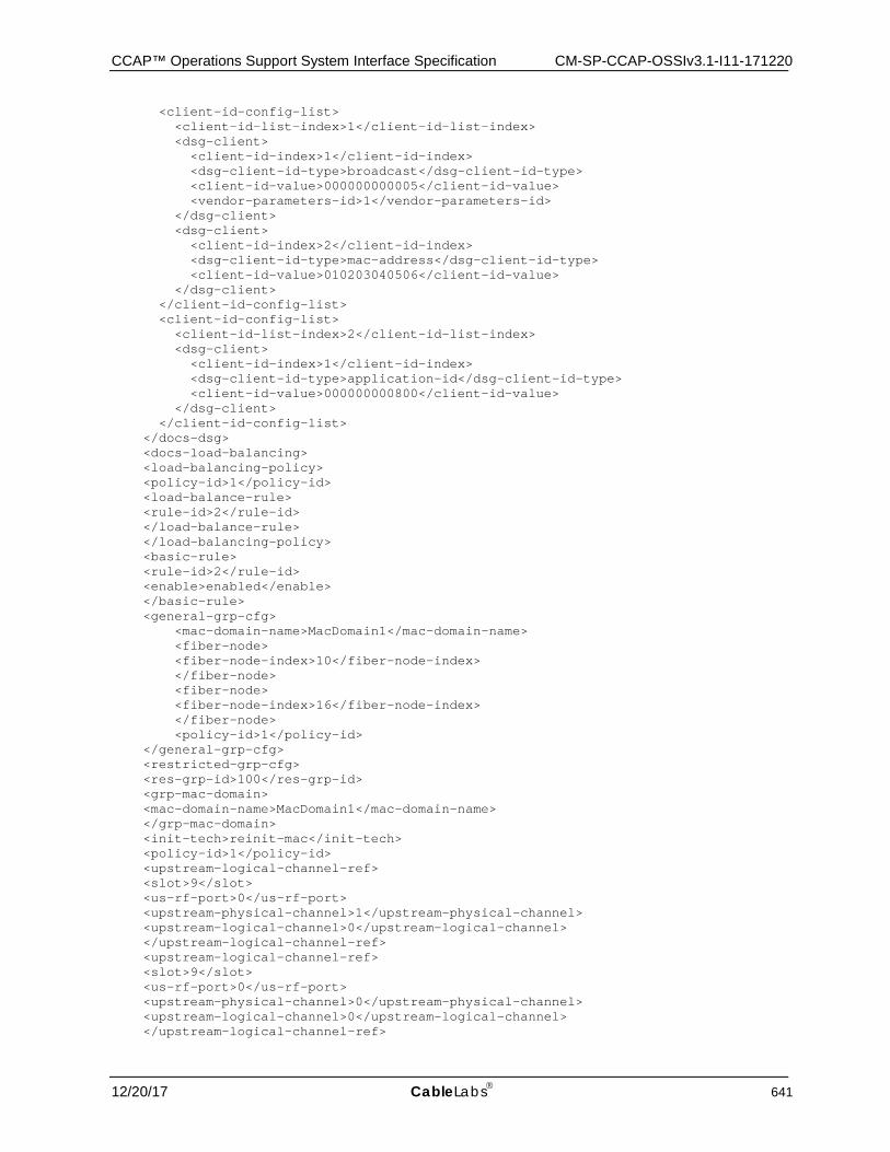
CCAP™ Operations Support System Interface Specification CM-SP-CCAP-OSSIv3.1-I11-171220
12/20/17 CableLabs 641
<client-id-config-list> <client-id-list-index>1</client-id-list-index> <dsg-client> <client-id-index>1</client-id-index> <dsg-client-id-type>broadcast</dsg-client-id-type> <client-id-value>000000000005</client-id-value> <vendor-parameters-id>1</vendor-parameters-id> </dsg-client> <dsg-client> <client-id-index>2</client-id-index> <dsg-client-id-type>mac-address</dsg-client-id-type> <client-id-value>010203040506</client-id-value> </dsg-client> </client-id-config-list> <client-id-config-list> <client-id-list-index>2</client-id-list-index> <dsg-client> <client-id-index>1</client-id-index> <dsg-client-id-type>application-id</dsg-client-id-type> <client-id-value>000000000800</client-id-value> </dsg-client> </client-id-config-list> </docs-dsg> <docs-load-balancing> <load-balancing-policy> <policy-id>1</policy-id> <load-balance-rule> <rule-id>2</rule-id> </load-balance-rule> </load-balancing-policy> <basic-rule> <rule-id>2</rule-id> <enable>enabled</enable> </basic-rule> <general-grp-cfg> <mac-domain-name>MacDomain1</mac-domain-name> <fiber-node> <fiber-node-index>10</fiber-node-index> </fiber-node> <fiber-node> <fiber-node-index>16</fiber-node-index> </fiber-node> <policy-id>1</policy-id> </general-grp-cfg> <restricted-grp-cfg> <res-grp-id>100</res-grp-id> <grp-mac-domain> <mac-domain-name>MacDomain1</mac-domain-name> </grp-mac-domain> <init-tech>reinit-mac</init-tech> <policy-id>1</policy-id> <upstream-logical-channel-ref> <slot>9</slot> <us-rf-port>0</us-rf-port> <upstream-physical-channel>1</upstream-physical-channel> <upstream-logical-channel>0</upstream-logical-channel> </upstream-logical-channel-ref> <upstream-logical-channel-ref> <slot>9</slot> <us-rf-port>0</us-rf-port> <upstream-physical-channel>0</upstream-physical-channel> <upstream-logical-channel>0</upstream-logical-channel> </upstream-logical-channel-ref>
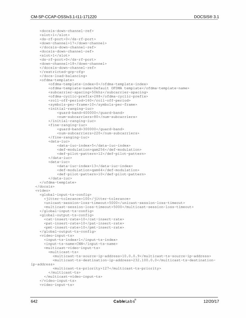
CM-SP-CCAP-OSSIv3.1-I11-171220 DOCSIS® 3.1
642 CableLabs 12/20/17
<docsis-down-channel-ref> <slot>1</slot> <ds-rf-port>0</ds-rf-port> <down-channel>17</down-channel> </docsis-down-channel-ref> <docsis-down-channel-ref> <slot>1</slot> <ds-rf-port>0</ds-rf-port> <down-channel>18</down-channel> </docsis-down-channel-ref> </restricted-grp-cfg> </docs-load-balancing> <ofdma-template> <ofdma-template-index>0</ofdma-template-index> <ofdma-template-name>Default OFDMA template</ofdma-template-name> <subcarrier-spacing>50khz</subcarrier-spacing> <ofdma-cyclic-prefix>288</ofdma-cyclic-prefix> <roll-off-period>160</roll-off-period> <symbols-per-frame>10</symbols-per-frame> <initial-ranging-iuc> <guard-band>400000</guard-band> <num-subcarriers>80</num-subcarriers> </initial-ranging-iuc> <fine-ranging-iuc> <guard-band>300000</guard-band> <num-subcarriers>220</num-subcarriers> </fine-ranging-iuc> <data-iuc> <data-iuc-index>5</data-iuc-index> <def-modulation>qam256</def-modulation> <def-pilot-pattern>12</def-pilot-pattern> </data-iuc> <data-iuc> <data-iuc-index>13</data-iuc-index> <def-modulation>qam64</def-modulation> <def-pilot-pattern>10</def-pilot-pattern> </data-iuc> </ofdma-template> </docsis> <video> <global-input-ts-config> <jitter-tolerance>100</jitter-tolerance> <unicast-session-loss-timeout>5000</unicast-session-loss-timeout> <multicast-session-loss-timeout>5000</multicast-session-loss-timeout> </global-input-ts-config> <global-output-ts-config> <cat-insert-rate>10</cat-insert-rate> <pat-insert-rate>10</pat-insert-rate> <pmt-insert-rate>10</pmt-insert-rate> </global-output-ts-config> <video-input-ts> <input-ts-index>1</input-ts-index> <input-ts-name>CNN</input-ts-name> <multicast-video-input-ts> <multicast-ts> <multicast-ts-source-ip-address>10.0.0.9</multicast-ts-source-ip-address> <multicast-ts-destination-ip-address>232.100.0.0</multicast-ts-destination-ip-address> <multicast-ts-priority>127</multicast-ts-priority> </multicast-ts> </multicast-video-input-ts> </video-input-ts> <video-input-ts>
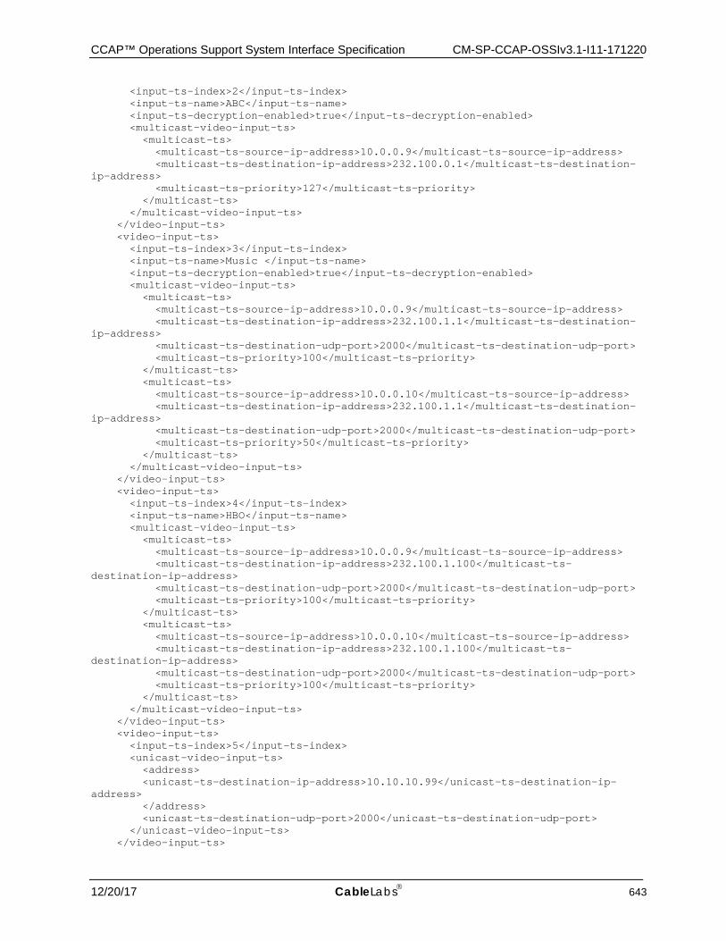
CCAP™ Operations Support System Interface Specification CM-SP-CCAP-OSSIv3.1-I11-171220
12/20/17 CableLabs 643
<input-ts-index>2</input-ts-index> <input-ts-name>ABC</input-ts-name> <input-ts-decryption-enabled>true</input-ts-decryption-enabled> <multicast-video-input-ts> <multicast-ts> <multicast-ts-source-ip-address>10.0.0.9</multicast-ts-source-ip-address> <multicast-ts-destination-ip-address>232.100.0.1</multicast-ts-destination-ip-address> <multicast-ts-priority>127</multicast-ts-priority> </multicast-ts> </multicast-video-input-ts> </video-input-ts> <video-input-ts> <input-ts-index>3</input-ts-index> <input-ts-name>Music </input-ts-name> <input-ts-decryption-enabled>true</input-ts-decryption-enabled> <multicast-video-input-ts> <multicast-ts> <multicast-ts-source-ip-address>10.0.0.9</multicast-ts-source-ip-address> <multicast-ts-destination-ip-address>232.100.1.1</multicast-ts-destination-ip-address> <multicast-ts-destination-udp-port>2000</multicast-ts-destination-udp-port> <multicast-ts-priority>100</multicast-ts-priority> </multicast-ts> <multicast-ts> <multicast-ts-source-ip-address>10.0.0.10</multicast-ts-source-ip-address> <multicast-ts-destination-ip-address>232.100.1.1</multicast-ts-destination-ip-address> <multicast-ts-destination-udp-port>2000</multicast-ts-destination-udp-port> <multicast-ts-priority>50</multicast-ts-priority> </multicast-ts> </multicast-video-input-ts> </video-input-ts> <video-input-ts> <input-ts-index>4</input-ts-index> <input-ts-name>HBO</input-ts-name> <multicast-video-input-ts> <multicast-ts> <multicast-ts-source-ip-address>10.0.0.9</multicast-ts-source-ip-address> <multicast-ts-destination-ip-address>232.100.1.100</multicast-ts-destination-ip-address> <multicast-ts-destination-udp-port>2000</multicast-ts-destination-udp-port> <multicast-ts-priority>100</multicast-ts-priority> </multicast-ts> <multicast-ts> <multicast-ts-source-ip-address>10.0.0.10</multicast-ts-source-ip-address> <multicast-ts-destination-ip-address>232.100.1.100</multicast-ts-destination-ip-address> <multicast-ts-destination-udp-port>2000</multicast-ts-destination-udp-port> <multicast-ts-priority>100</multicast-ts-priority> </multicast-ts> </multicast-video-input-ts> </video-input-ts> <video-input-ts> <input-ts-index>5</input-ts-index> <unicast-video-input-ts> <address> <unicast-ts-destination-ip-address>10.10.10.99</unicast-ts-destination-ip-address> </address> <unicast-ts-destination-udp-port>2000</unicast-ts-destination-udp-port> </unicast-video-input-ts> </video-input-ts>
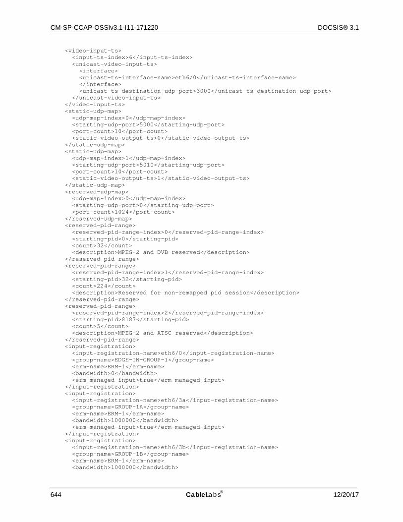
CM-SP-CCAP-OSSIv3.1-I11-171220 DOCSIS® 3.1
644 CableLabs 12/20/17
<video-input-ts> <input-ts-index>6</input-ts-index> <unicast-video-input-ts> <interface> <unicast-ts-interface-name>eth6/0</unicast-ts-interface-name> </interface> <unicast-ts-destination-udp-port>3000</unicast-ts-destination-udp-port> </unicast-video-input-ts> </video-input-ts> <static-udp-map> <udp-map-index>0</udp-map-index> <starting-udp-port>5000</starting-udp-port> <port-count>10</port-count> <static-video-output-ts>0</static-video-output-ts> </static-udp-map> <static-udp-map> <udp-map-index>1</udp-map-index> <starting-udp-port>5010</starting-udp-port> <port-count>10</port-count> <static-video-output-ts>1</static-video-output-ts> </static-udp-map> <reserved-udp-map> <udp-map-index>0</udp-map-index> <starting-udp-port>0</starting-udp-port> <port-count>1024</port-count> </reserved-udp-map> <reserved-pid-range> <reserved-pid-range-index>0</reserved-pid-range-index> <starting-pid>0</starting-pid> <count>32</count> <description>MPEG-2 and DVB reserved</description> </reserved-pid-range> <reserved-pid-range> <reserved-pid-range-index>1</reserved-pid-range-index> <starting-pid>32</starting-pid> <count>224</count> <description>Reserved for non-remapped pid session</description> </reserved-pid-range> <reserved-pid-range> <reserved-pid-range-index>2</reserved-pid-range-index> <starting-pid>8187</starting-pid> <count>5</count> <description>MPEG-2 and ATSC reserved</description> </reserved-pid-range> <input-registration> <input-registration-name>eth6/0</input-registration-name> <group-name>EDGE-IN-GROUP-1</group-name> <erm-name>ERM-1</erm-name> <bandwidth>0</bandwidth> <erm-managed-input>true</erm-managed-input> </input-registration> <input-registration> <input-registration-name>eth6/3a</input-registration-name> <group-name>GROUP-1A</group-name> <erm-name>ERM-1</erm-name> <bandwidth>1000000</bandwidth> <erm-managed-input>true</erm-managed-input> </input-registration> <input-registration> <input-registration-name>eth6/3b</input-registration-name> <group-name>GROUP-1B</group-name> <erm-name>ERM-1</erm-name> <bandwidth>1000000</bandwidth>
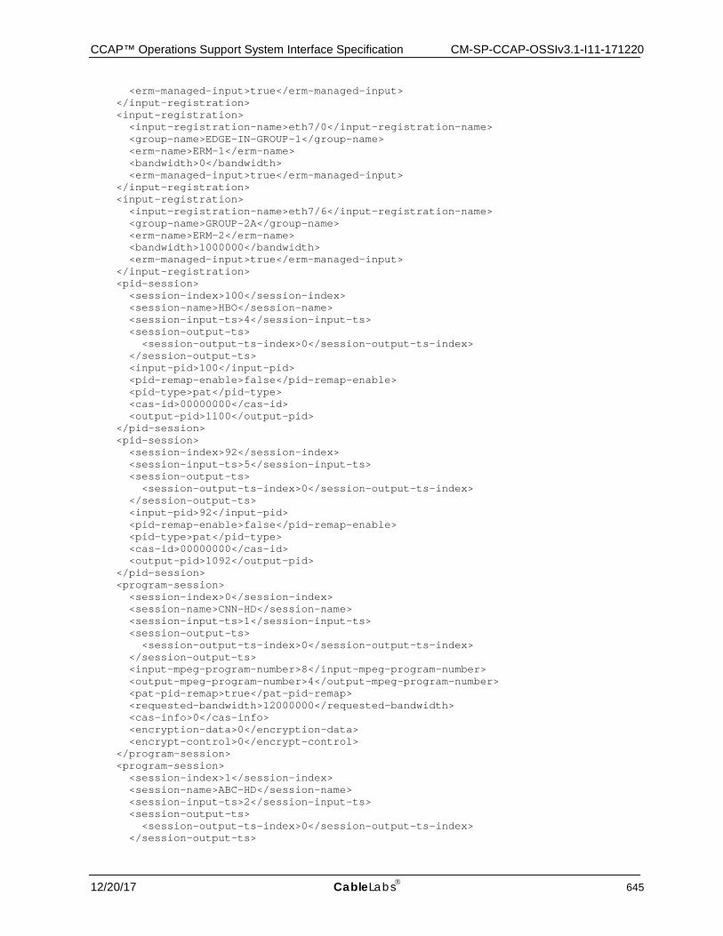
CCAP™ Operations Support System Interface Specification CM-SP-CCAP-OSSIv3.1-I11-171220
12/20/17 CableLabs 645
<erm-managed-input>true</erm-managed-input> </input-registration> <input-registration> <input-registration-name>eth7/0</input-registration-name> <group-name>EDGE-IN-GROUP-1</group-name> <erm-name>ERM-1</erm-name> <bandwidth>0</bandwidth> <erm-managed-input>true</erm-managed-input> </input-registration> <input-registration> <input-registration-name>eth7/6</input-registration-name> <group-name>GROUP-2A</group-name> <erm-name>ERM-2</erm-name> <bandwidth>1000000</bandwidth> <erm-managed-input>true</erm-managed-input> </input-registration> <pid-session> <session-index>100</session-index> <session-name>HBO</session-name> <session-input-ts>4</session-input-ts> <session-output-ts> <session-output-ts-index>0</session-output-ts-index> </session-output-ts> <input-pid>100</input-pid> <pid-remap-enable>false</pid-remap-enable> <pid-type>pat</pid-type> <cas-id>00000000</cas-id> <output-pid>1100</output-pid> </pid-session> <pid-session> <session-index>92</session-index> <session-input-ts>5</session-input-ts> <session-output-ts> <session-output-ts-index>0</session-output-ts-index> </session-output-ts> <input-pid>92</input-pid> <pid-remap-enable>false</pid-remap-enable> <pid-type>pat</pid-type> <cas-id>00000000</cas-id> <output-pid>1092</output-pid> </pid-session> <program-session> <session-index>0</session-index> <session-name>CNN-HD</session-name> <session-input-ts>1</session-input-ts> <session-output-ts> <session-output-ts-index>0</session-output-ts-index> </session-output-ts> <input-mpeg-program-number>8</input-mpeg-program-number> <output-mpeg-program-number>4</output-mpeg-program-number> <pat-pid-remap>true</pat-pid-remap> <requested-bandwidth>12000000</requested-bandwidth> <cas-info>0</cas-info> <encryption-data>0</encryption-data> <encrypt-control>0</encrypt-control> </program-session> <program-session> <session-index>1</session-index> <session-name>ABC-HD</session-name> <session-input-ts>2</session-input-ts> <session-output-ts> <session-output-ts-index>0</session-output-ts-index> </session-output-ts>
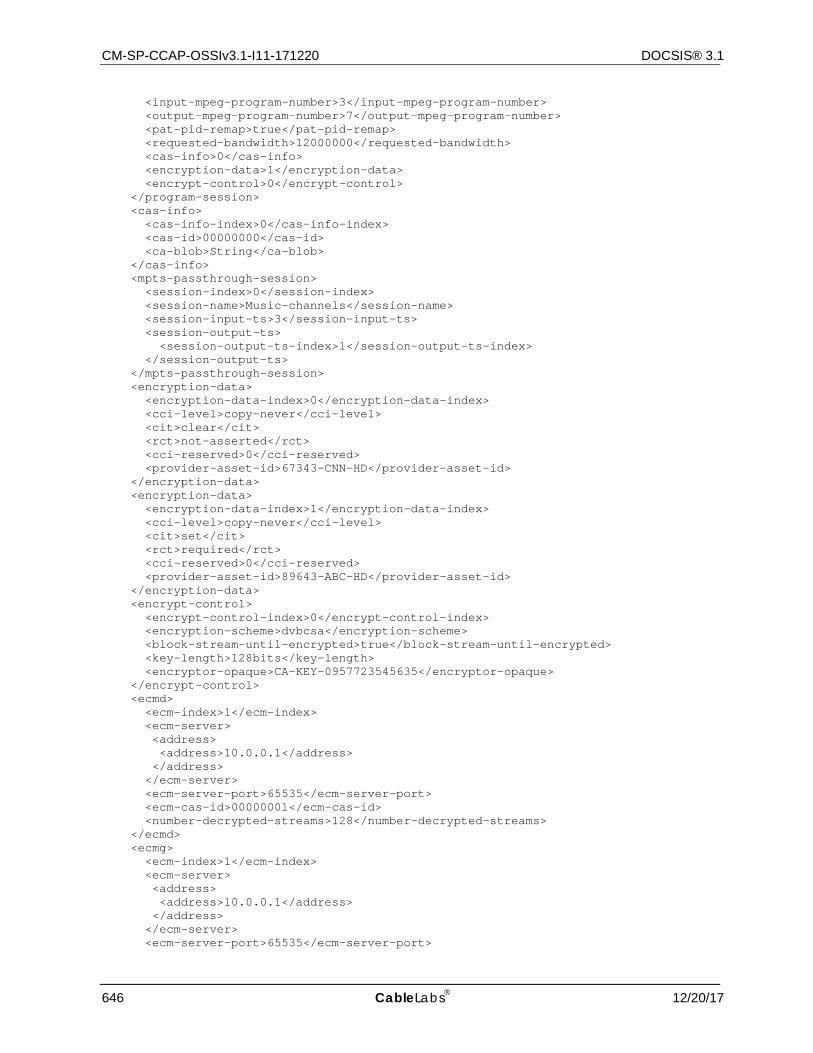
CM-SP-CCAP-OSSIv3.1-I11-171220 DOCSIS® 3.1
646 CableLabs 12/20/17
<input-mpeg-program-number>3</input-mpeg-program-number> <output-mpeg-program-number>7</output-mpeg-program-number> <pat-pid-remap>true</pat-pid-remap> <requested-bandwidth>12000000</requested-bandwidth> <cas-info>0</cas-info> <encryption-data>1</encryption-data> <encrypt-control>0</encrypt-control> </program-session> <cas-info> <cas-info-index>0</cas-info-index> <cas-id>00000000</cas-id> <ca-blob>String</ca-blob> </cas-info> <mpts-passthrough-session> <session-index>0</session-index> <session-name>Music-channels</session-name> <session-input-ts>3</session-input-ts> <session-output-ts> <session-output-ts-index>1</session-output-ts-index> </session-output-ts> </mpts-passthrough-session> <encryption-data> <encryption-data-index>0</encryption-data-index> <cci-level>copy-never</cci-level> <cit>clear</cit> <rct>not-asserted</rct> <cci-reserved>0</cci-reserved> <provider-asset-id>67343-CNN-HD</provider-asset-id> </encryption-data> <encryption-data> <encryption-data-index>1</encryption-data-index> <cci-level>copy-never</cci-level> <cit>set</cit> <rct>required</rct> <cci-reserved>0</cci-reserved> <provider-asset-id>89643-ABC-HD</provider-asset-id> </encryption-data> <encrypt-control> <encrypt-control-index>0</encrypt-control-index> <encryption-scheme>dvbcsa</encryption-scheme> <block-stream-until-encrypted>true</block-stream-until-encrypted> <key-length>128bits</key-length> <encryptor-opaque>CA-KEY-0957723545635</encryptor-opaque> </encrypt-control> <ecmd> <ecm-index>1</ecm-index> <ecm-server> <address> <address>10.0.0.1</address> </address> </ecm-server> <ecm-server-port>65535</ecm-server-port> <ecm-cas-id>00000001</ecm-cas-id> <number-decrypted-streams>128</number-decrypted-streams> </ecmd> <ecmg> <ecm-index>1</ecm-index> <ecm-server> <address> <address>10.0.0.1</address> </address> </ecm-server> <ecm-server-port>65535</ecm-server-port>
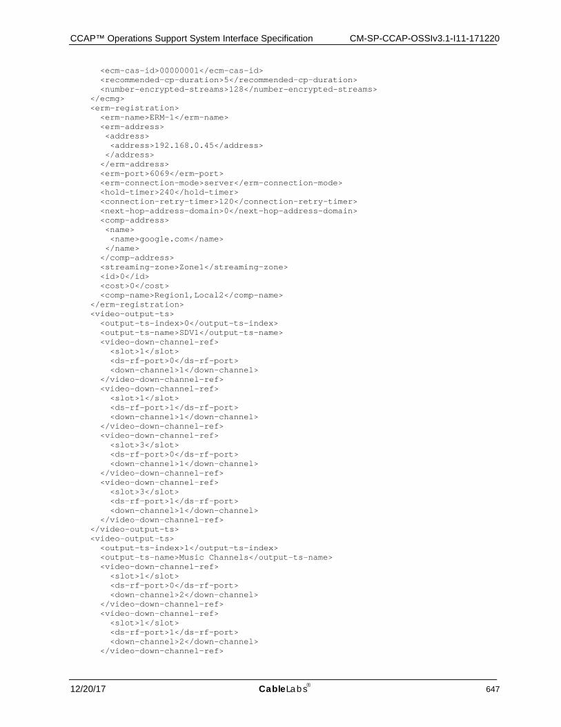
CCAP™ Operations Support System Interface Specification CM-SP-CCAP-OSSIv3.1-I11-171220
12/20/17 CableLabs 647
<ecm-cas-id>00000001</ecm-cas-id> <recommended-cp-duration>5</recommended-cp-duration> <number-encrypted-streams>128</number-encrypted-streams> </ecmg> <erm-registration> <erm-name>ERM-1</erm-name> <erm-address> <address> <address>192.168.0.45</address> </address> </erm-address> <erm-port>6069</erm-port> <erm-connection-mode>server</erm-connection-mode> <hold-timer>240</hold-timer> <connection-retry-timer>120</connection-retry-timer> <next-hop-address-domain>0</next-hop-address-domain> <comp-address> <name> <name>google.com</name> </name> </comp-address> <streaming-zone>Zone1</streaming-zone> <id>0</id> <cost>0</cost> <comp-name>Region1,Local2</comp-name> </erm-registration> <video-output-ts> <output-ts-index>0</output-ts-index> <output-ts-name>SDV1</output-ts-name> <video-down-channel-ref> <slot>1</slot> <ds-rf-port>0</ds-rf-port> <down-channel>1</down-channel> </video-down-channel-ref> <video-down-channel-ref> <slot>1</slot> <ds-rf-port>1</ds-rf-port> <down-channel>1</down-channel> </video-down-channel-ref> <video-down-channel-ref> <slot>3</slot> <ds-rf-port>0</ds-rf-port> <down-channel>1</down-channel> </video-down-channel-ref> <video-down-channel-ref> <slot>3</slot> <ds-rf-port>1</ds-rf-port> <down-channel>1</down-channel> </video-down-channel-ref> </video-output-ts> <video-output-ts> <output-ts-index>1</output-ts-index> <output-ts-name>Music Channels</output-ts-name> <video-down-channel-ref> <slot>1</slot> <ds-rf-port>0</ds-rf-port> <down-channel>2</down-channel> </video-down-channel-ref> <video-down-channel-ref> <slot>1</slot> <ds-rf-port>1</ds-rf-port> <down-channel>2</down-channel> </video-down-channel-ref>
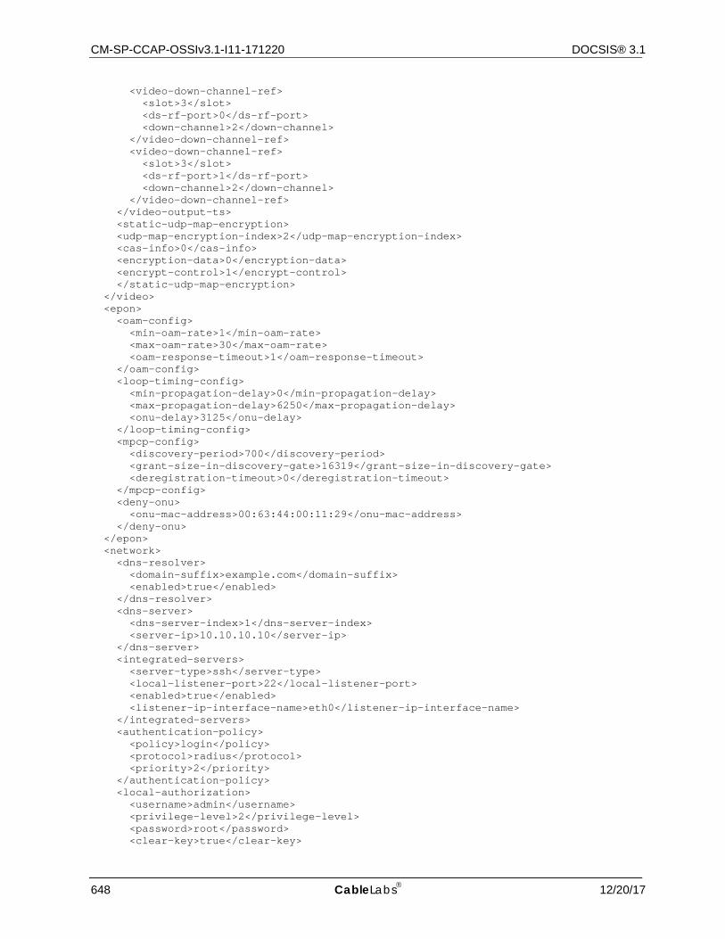
CM-SP-CCAP-OSSIv3.1-I11-171220 DOCSIS® 3.1
648 CableLabs 12/20/17
<video-down-channel-ref> <slot>3</slot> <ds-rf-port>0</ds-rf-port> <down-channel>2</down-channel> </video-down-channel-ref> <video-down-channel-ref> <slot>3</slot> <ds-rf-port>1</ds-rf-port> <down-channel>2</down-channel> </video-down-channel-ref> </video-output-ts> <static-udp-map-encryption> <udp-map-encryption-index>2</udp-map-encryption-index> <cas-info>0</cas-info> <encryption-data>0</encryption-data> <encrypt-control>1</encrypt-control> </static-udp-map-encryption> </video> <epon> <oam-config> <min-oam-rate>1</min-oam-rate> <max-oam-rate>30</max-oam-rate> <oam-response-timeout>1</oam-response-timeout> </oam-config> <loop-timing-config> <min-propagation-delay>0</min-propagation-delay> <max-propagation-delay>6250</max-propagation-delay> <onu-delay>3125</onu-delay> </loop-timing-config> <mpcp-config> <discovery-period>700</discovery-period> <grant-size-in-discovery-gate>16319</grant-size-in-discovery-gate> <deregistration-timeout>0</deregistration-timeout> </mpcp-config> <deny-onu> <onu-mac-address>00:63:44:00:11:29</onu-mac-address> </deny-onu> </epon> <network> <dns-resolver> <domain-suffix>example.com</domain-suffix> <enabled>true</enabled> </dns-resolver> <dns-server> <dns-server-index>1</dns-server-index> <server-ip>10.10.10.10</server-ip> </dns-server> <integrated-servers> <server-type>ssh</server-type> <local-listener-port>22</local-listener-port> <enabled>true</enabled> <listener-ip-interface-name>eth0</listener-ip-interface-name> </integrated-servers> <authentication-policy> <policy>login</policy> <protocol>radius</protocol> <priority>2</priority> </authentication-policy> <local-authorization> <username>admin</username> <privilege-level>2</privilege-level> <password>root</password> <clear-key>true</clear-key>
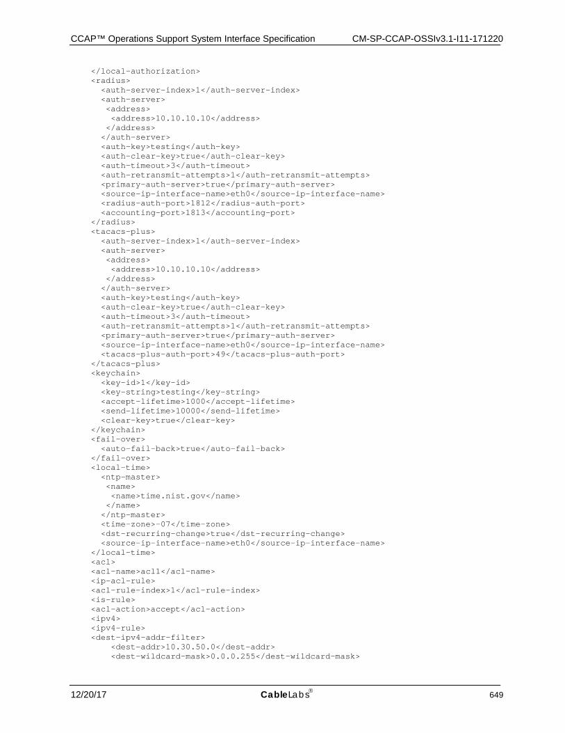
CCAP™ Operations Support System Interface Specification CM-SP-CCAP-OSSIv3.1-I11-171220
12/20/17 CableLabs 649
</local-authorization> <radius> <auth-server-index>1</auth-server-index> <auth-server> <address> <address>10.10.10.10</address> </address> </auth-server> <auth-key>testing</auth-key> <auth-clear-key>true</auth-clear-key> <auth-timeout>3</auth-timeout> <auth-retransmit-attempts>1</auth-retransmit-attempts> <primary-auth-server>true</primary-auth-server> <source-ip-interface-name>eth0</source-ip-interface-name> <radius-auth-port>1812</radius-auth-port> <accounting-port>1813</accounting-port> </radius> <tacacs-plus> <auth-server-index>1</auth-server-index> <auth-server> <address> <address>10.10.10.10</address> </address> </auth-server> <auth-key>testing</auth-key> <auth-clear-key>true</auth-clear-key> <auth-timeout>3</auth-timeout> <auth-retransmit-attempts>1</auth-retransmit-attempts> <primary-auth-server>true</primary-auth-server> <source-ip-interface-name>eth0</source-ip-interface-name> <tacacs-plus-auth-port>49</tacacs-plus-auth-port> </tacacs-plus> <keychain> <key-id>1</key-id> <key-string>testing</key-string> <accept-lifetime>1000</accept-lifetime> <send-lifetime>10000</send-lifetime> <clear-key>true</clear-key> </keychain> <fail-over> <auto-fail-back>true</auto-fail-back> </fail-over> <local-time> <ntp-master> <name> <name>time.nist.gov</name> </name> </ntp-master> <time-zone>-07</time-zone> <dst-recurring-change>true</dst-recurring-change> <source-ip-interface-name>eth0</source-ip-interface-name> </local-time> <acl> <acl-name>acl1</acl-name> <ip-acl-rule> <acl-rule-index>1</acl-rule-index> <is-rule> <acl-action>accept</acl-action> <ipv4> <ipv4-rule> <dest-ipv4-addr-filter> <dest-addr>10.30.50.0</dest-addr> <dest-wildcard-mask>0.0.0.255</dest-wildcard-mask>
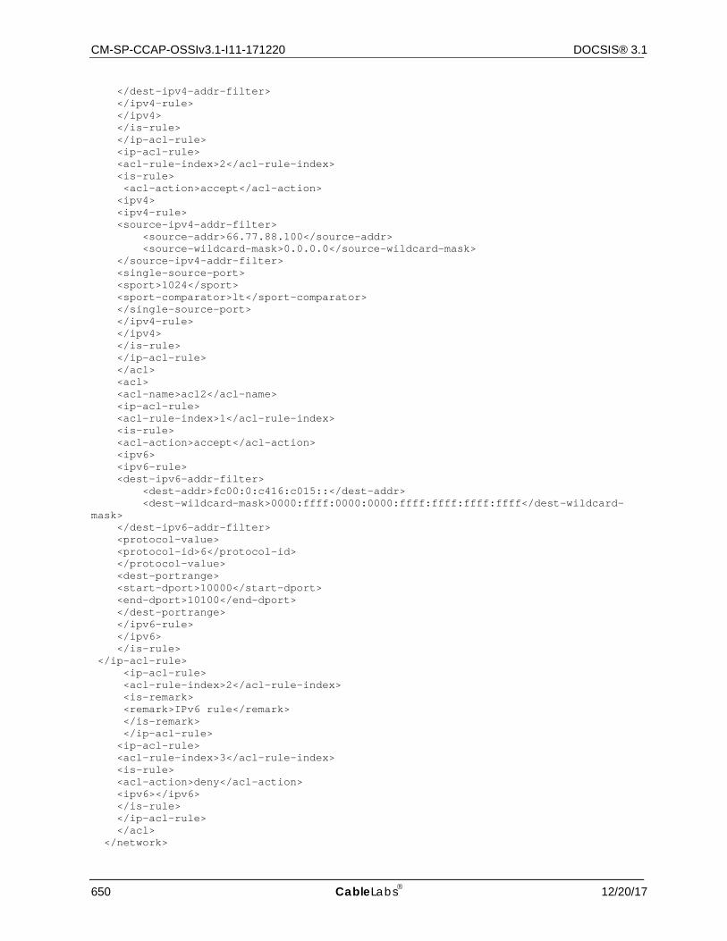
CM-SP-CCAP-OSSIv3.1-I11-171220 DOCSIS® 3.1
650 CableLabs 12/20/17
</dest-ipv4-addr-filter> </ipv4-rule> </ipv4> </is-rule> </ip-acl-rule> <ip-acl-rule> <acl-rule-index>2</acl-rule-index> <is-rule> <acl-action>accept</acl-action> <ipv4> <ipv4-rule> <source-ipv4-addr-filter> <source-addr>66.77.88.100</source-addr> <source-wildcard-mask>0.0.0.0</source-wildcard-mask> </source-ipv4-addr-filter> <single-source-port> <sport>1024</sport> <sport-comparator>lt</sport-comparator> </single-source-port> </ipv4-rule> </ipv4> </is-rule> </ip-acl-rule> </acl> <acl> <acl-name>acl2</acl-name> <ip-acl-rule> <acl-rule-index>1</acl-rule-index> <is-rule> <acl-action>accept</acl-action> <ipv6> <ipv6-rule> <dest-ipv6-addr-filter> <dest-addr>fc00:0:c416:c015::</dest-addr> <dest-wildcard-mask>0000:ffff:0000:0000:ffff:ffff:ffff:ffff</dest-wildcard-mask> </dest-ipv6-addr-filter> <protocol-value> <protocol-id>6</protocol-id> </protocol-value> <dest-portrange> <start-dport>10000</start-dport> <end-dport>10100</end-dport> </dest-portrange> </ipv6-rule> </ipv6> </is-rule> </ip-acl-rule> <ip-acl-rule> <acl-rule-index>2</acl-rule-index> <is-remark> <remark>IPv6 rule</remark> </is-remark> </ip-acl-rule> <ip-acl-rule> <acl-rule-index>3</acl-rule-index> <is-rule> <acl-action>deny</acl-action> <ipv6></ipv6> </is-rule> </ip-acl-rule> </acl> </network>
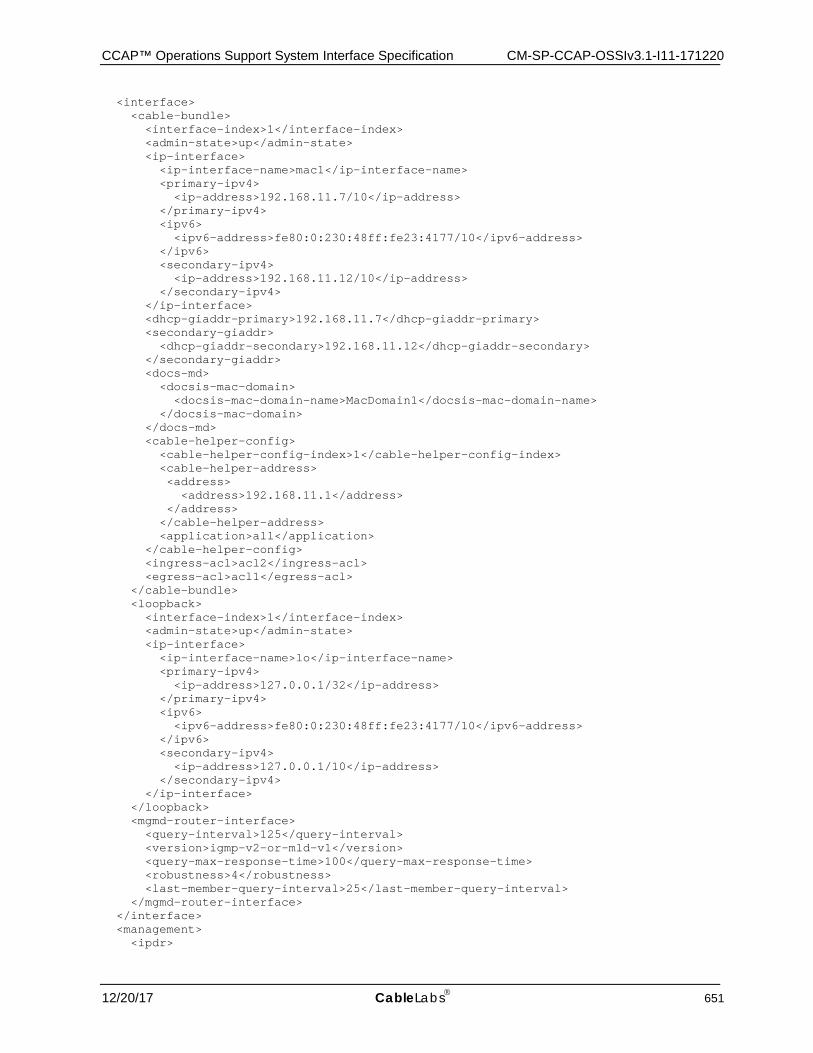
CCAP™ Operations Support System Interface Specification CM-SP-CCAP-OSSIv3.1-I11-171220
12/20/17 CableLabs 651
<interface> <cable-bundle> <interface-index>1</interface-index> <admin-state>up</admin-state> <ip-interface> <ip-interface-name>mac1</ip-interface-name> <primary-ipv4> <ip-address>192.168.11.7/10</ip-address> </primary-ipv4> <ipv6> <ipv6-address>fe80:0:230:48ff:fe23:4177/10</ipv6-address> </ipv6> <secondary-ipv4> <ip-address>192.168.11.12/10</ip-address> </secondary-ipv4> </ip-interface> <dhcp-giaddr-primary>192.168.11.7</dhcp-giaddr-primary> <secondary-giaddr> <dhcp-giaddr-secondary>192.168.11.12</dhcp-giaddr-secondary> </secondary-giaddr> <docs-md> <docsis-mac-domain> <docsis-mac-domain-name>MacDomain1</docsis-mac-domain-name> </docsis-mac-domain> </docs-md> <cable-helper-config> <cable-helper-config-index>1</cable-helper-config-index> <cable-helper-address> <address> <address>192.168.11.1</address> </address> </cable-helper-address> <application>all</application> </cable-helper-config> <ingress-acl>acl2</ingress-acl> <egress-acl>acl1</egress-acl> </cable-bundle> <loopback> <interface-index>1</interface-index> <admin-state>up</admin-state> <ip-interface> <ip-interface-name>lo</ip-interface-name> <primary-ipv4> <ip-address>127.0.0.1/32</ip-address> </primary-ipv4> <ipv6> <ipv6-address>fe80:0:230:48ff:fe23:4177/10</ipv6-address> </ipv6> <secondary-ipv4> <ip-address>127.0.0.1/10</ip-address> </secondary-ipv4> </ip-interface> </loopback> <mgmd-router-interface> <query-interval>125</query-interval> <version>igmp-v2-or-mld-v1</version> <query-max-response-time>100</query-max-response-time> <robustness>4</robustness> <last-member-query-interval>25</last-member-query-interval> </mgmd-router-interface> </interface> <management> <ipdr>
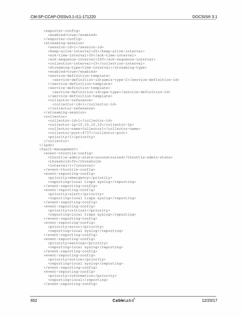
CM-SP-CCAP-OSSIv3.1-I11-171220 DOCSIS® 3.1
652 CableLabs 12/20/17
<exporter-config> <enabled>true</enabled> </exporter-config> <streaming-session> <session-id>1</session-id> <keep-alive-interval>20</keep-alive-interval> <ack-time-interval>30</ack-time-interval> <ack-sequence-interval>200</ack-sequence-interval> <collection-interval>15</collection-interval> <streaming-type>time-interval</streaming-type> <enabled>true</enabled> <service-definition-template> <service-definition-id>samis-type-2</service-definition-id> </service-definition-template> <service-definition-template> <service-definition-id>cpe-type</service-definition-id> </service-definition-template> <collector-reference> <collector-id>1</collector-id> </collector-reference> </streaming-session> <collector> <collector-id>1</collector-id> <collector-ip>10.10.10.10</collector-ip> <collector-name>Collector1</collector-name> <collector-port>4737</collector-port> <priority>1</priority> </collector> </ipdr> <fault-management> <event-throttle-config> <throttle-admin-state>unconstrained</throttle-admin-state> <threshold>50</threshold> <interval>1</interval> </event-throttle-config> <event-reporting-config> <priority>emergency</priority> <reporting>local traps syslog</reporting> </event-reporting-config> <event-reporting-config> <priority>alert</priority> <reporting>local traps syslog</reporting> </event-reporting-config> <event-reporting-config> <priority>critical</priority> <reporting>local traps syslog</reporting> </event-reporting-config> <event-reporting-config> <priority>error</priority> <reporting>local syslog</reporting> </event-reporting-config> <event-reporting-config> <priority>warning</priority> <reporting>local syslog</reporting> </event-reporting-config> <event-reporting-config> <priority>notice</priority> <reporting>local syslog</reporting> </event-reporting-config> <event-reporting-config> <priority>information</priority> <reporting>local</reporting> </event-reporting-config>
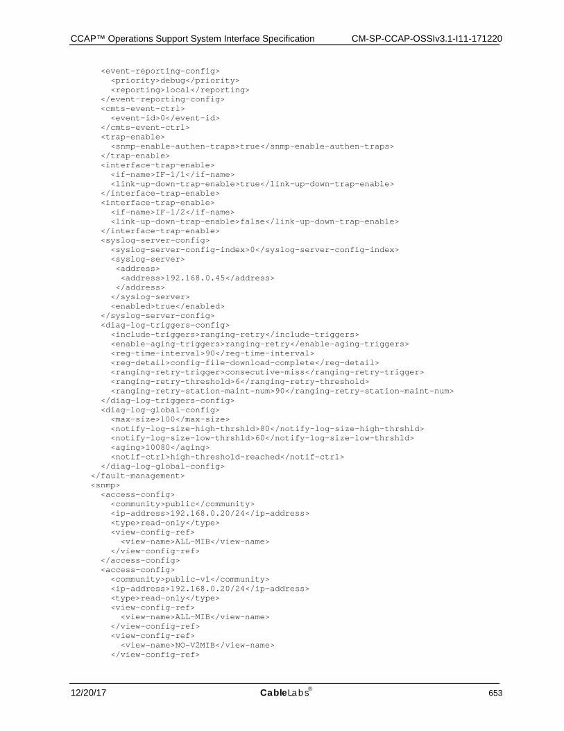
CCAP™ Operations Support System Interface Specification CM-SP-CCAP-OSSIv3.1-I11-171220
12/20/17 CableLabs 653
<event-reporting-config> <priority>debug</priority> <reporting>local</reporting> </event-reporting-config> <cmts-event-ctrl> <event-id>0</event-id> </cmts-event-ctrl> <trap-enable> <snmp-enable-authen-traps>true</snmp-enable-authen-traps> </trap-enable> <interface-trap-enable> <if-name>IF-1/1</if-name> <link-up-down-trap-enable>true</link-up-down-trap-enable> </interface-trap-enable> <interface-trap-enable> <if-name>IF-1/2</if-name> <link-up-down-trap-enable>false</link-up-down-trap-enable> </interface-trap-enable> <syslog-server-config> <syslog-server-config-index>0</syslog-server-config-index> <syslog-server> <address> <address>192.168.0.45</address> </address> </syslog-server> <enabled>true</enabled> </syslog-server-config> <diag-log-triggers-config> <include-triggers>ranging-retry</include-triggers> <enable-aging-triggers>ranging-retry</enable-aging-triggers> <reg-time-interval>90</reg-time-interval> <reg-detail>config-file-download-complete</reg-detail> <ranging-retry-trigger>consecutive-miss</ranging-retry-trigger> <ranging-retry-threshold>6</ranging-retry-threshold> <ranging-retry-station-maint-num>90</ranging-retry-station-maint-num> </diag-log-triggers-config> <diag-log-global-config> <max-size>100</max-size> <notify-log-size-high-thrshld>80</notify-log-size-high-thrshld> <notify-log-size-low-thrshld>60</notify-log-size-low-thrshld> <aging>10080</aging> <notif-ctrl>high-threshold-reached</notif-ctrl> </diag-log-global-config> </fault-management> <snmp> <access-config> <community>public</community> <ip-address>192.168.0.20/24</ip-address> <type>read-only</type> <view-config-ref> <view-name>ALL-MIB</view-name> </view-config-ref> </access-config> <access-config> <community>public-v1</community> <ip-address>192.168.0.20/24</ip-address> <type>read-only</type> <view-config-ref> <view-name>ALL-MIB</view-name> </view-config-ref> <view-config-ref> <view-name>NO-V2MIB</view-name> </view-config-ref>
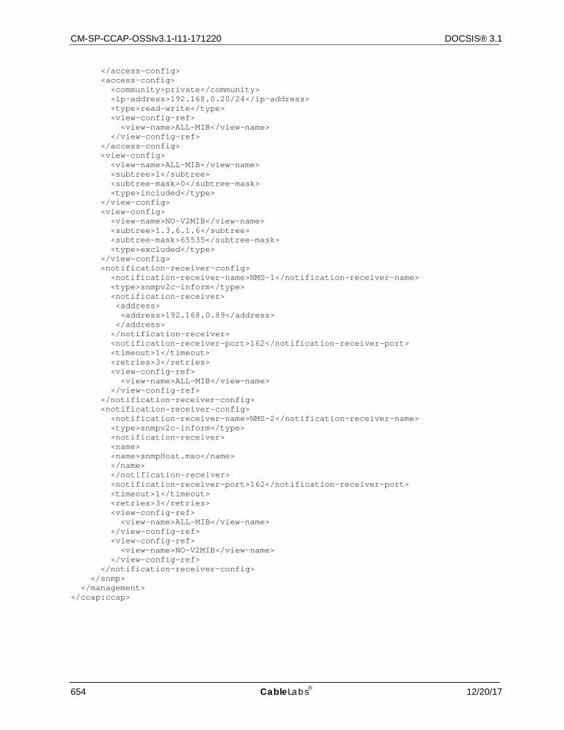
CM-SP-CCAP-OSSIv3.1-I11-171220 DOCSIS® 3.1
654 CableLabs 12/20/17
</access-config> <access-config> <community>private</community> <ip-address>192.168.0.20/24</ip-address> <type>read-write</type> <view-config-ref> <view-name>ALL-MIB</view-name> </view-config-ref> </access-config> <view-config> <view-name>ALL-MIB</view-name> <subtree>1</subtree> <subtree-mask>0</subtree-mask> <type>included</type> </view-config> <view-config> <view-name>NO-V2MIB</view-name> <subtree>1.3.6.1.6</subtree> <subtree-mask>65535</subtree-mask> <type>excluded</type> </view-config> <notification-receiver-config> <notification-receiver-name>NMS-1</notification-receiver-name> <type>snmpv2c-inform</type> <notification-receiver> <address> <address>192.168.0.89</address> </address> </notification-receiver> <notification-receiver-port>162</notification-receiver-port> <timeout>1</timeout> <retries>3</retries> <view-config-ref> <view-name>ALL-MIB</view-name> </view-config-ref> </notification-receiver-config> <notification-receiver-config> <notification-receiver-name>NMS-2</notification-receiver-name> <type>snmpv2c-inform</type> <notification-receiver> <name> <name>snmpHost.mso</name> </name> </notification-receiver> <notification-receiver-port>162</notification-receiver-port> <timeout>1</timeout> <retries>3</retries> <view-config-ref> <view-name>ALL-MIB</view-name> </view-config-ref> <view-config-ref> <view-name>NO-V2MIB</view-name> </view-config-ref> </notification-receiver-config> </snmp> </management> </ccap:ccap>
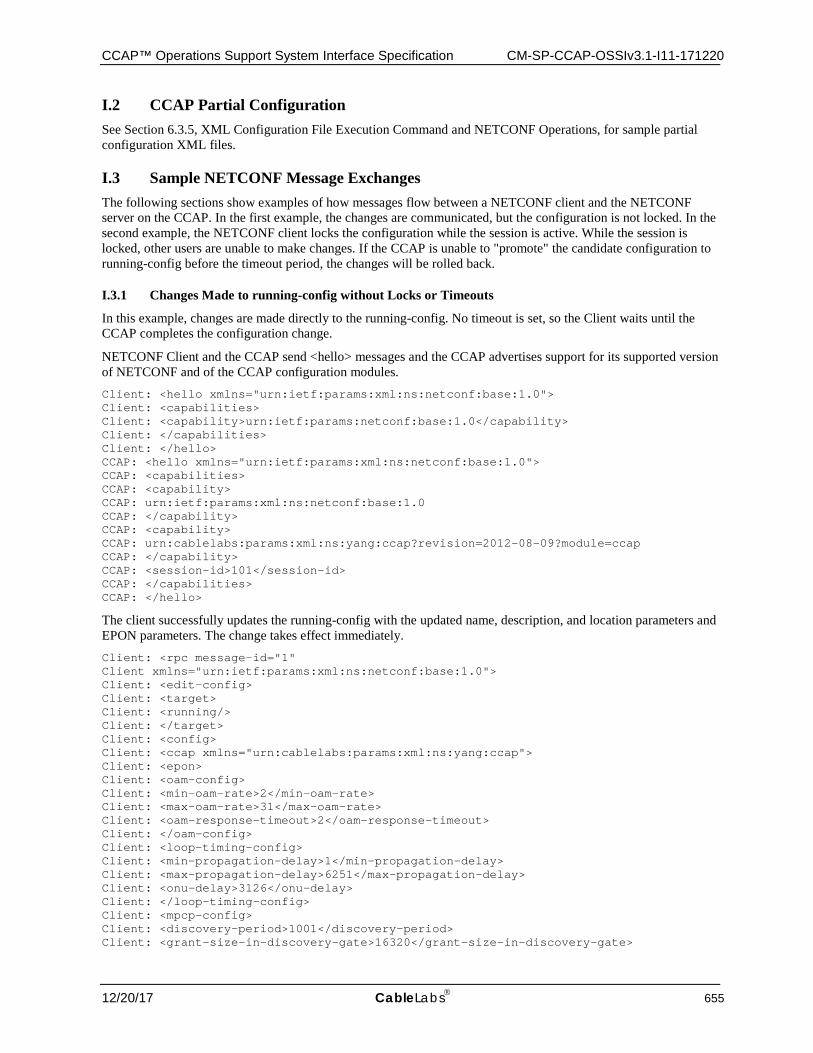
CCAP™ Operations Support System Interface Specification CM-SP-CCAP-OSSIv3.1-I11-171220
12/20/17 CableLabs 655
I.2 CCAP Partial Configuration See Section 6.3.5, XML Configuration File Execution Command and NETCONF Operations, for sample partial configuration XML files.
I.3 Sample NETCONF Message Exchanges The following sections show examples of how messages flow between a NETCONF client and the NETCONF server on the CCAP. In the first example, the changes are communicated, but the configuration is not locked. In the second example, the NETCONF client locks the configuration while the session is active. While the session is locked, other users are unable to make changes. If the CCAP is unable to "promote" the candidate configuration to running-config before the timeout period, the changes will be rolled back.
I.3.1 Changes Made to running-config without Locks or Timeouts
In this example, changes are made directly to the running-config. No timeout is set, so the Client waits until the CCAP completes the configuration change.
NETCONF Client and the CCAP send <hello> messages and the CCAP advertises support for its supported version of NETCONF and of the CCAP configuration modules. Client: <hello xmlns="urn:ietf:params:xml:ns:netconf:base:1.0"> Client: <capabilities> Client: <capability>urn:ietf:params:netconf:base:1.0</capability> Client: </capabilities> Client: </hello> CCAP: <hello xmlns="urn:ietf:params:xml:ns:netconf:base:1.0"> CCAP: <capabilities> CCAP: <capability> CCAP: urn:ietf:params:xml:ns:netconf:base:1.0 CCAP: </capability> CCAP: <capability> CCAP: urn:cablelabs:params:xml:ns:yang:ccap?revision=2012-08-09?module=ccap CCAP: </capability> CCAP: <session-id>101</session-id> CCAP: </capabilities> CCAP: </hello>
The client successfully updates the running-config with the updated name, description, and location parameters and EPON parameters. The change takes effect immediately. Client: <rpc message-id="1" Client xmlns="urn:ietf:params:xml:ns:netconf:base:1.0"> Client: <edit-config> Client: <target> Client: <running/> Client: </target> Client: <config> Client: <ccap xmlns="urn:cablelabs:params:xml:ns:yang:ccap"> Client: <epon> Client: <oam-config> Client: <min-oam-rate>2</min-oam-rate> Client: <max-oam-rate>31</max-oam-rate> Client: <oam-response-timeout>2</oam-response-timeout> Client: </oam-config> Client: <loop-timing-config> Client: <min-propagation-delay>1</min-propagation-delay> Client: <max-propagation-delay>6251</max-propagation-delay> Client: <onu-delay>3126</onu-delay> Client: </loop-timing-config> Client: <mpcp-config> Client: <discovery-period>1001</discovery-period> Client: <grant-size-in-discovery-gate>16320</grant-size-in-discovery-gate>
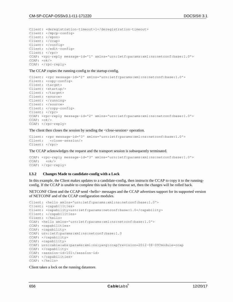
CM-SP-CCAP-OSSIv3.1-I11-171220 DOCSIS® 3.1
656 CableLabs 12/20/17
Client: <deregistration-timeout>1</deregistration-timeout> Client: </mpcp-config> Client: </epon> Client: </ccap> Client: </config> Client: </edit-config> Client: </rpc> CCAP: <rpc-reply message-id="1" xmlns="urn:ietf:params:xml:ns:netconf:base:1.0"> CCAP: <ok/> CCAP: </rpc-reply>
The CCAP copies the running-config to the startup-config. Client: <rpc message-id="2" xmlns="urn:ietf:params:xml:ns:netconf:base:1.0"> Client: <copy-config> Client: <target> Client: <startup/> Client: </target> Client: <source> Client: </running> Client: </source> Client: </copy-config> Client: </rpc> CCAP: <rpc-reply message-id="2" xmlns="urn:ietf:params:xml:ns:netconf:base:1.0"> CCAP: <ok/> CCAP: </rpc-reply>
The client then closes the session by sending the <close-session> operation. Client: <rpc message-id="3" xmlns="urn:ietf:params:xml:ns:netconf:base:1.0"> Client: <close-session/> Client: </rpc>
The CCAP acknowledges the request and the transport session is subsequently terminated. CCAP: <rpc-reply message-id="3" xmlns="urn:ietf:params:xml:ns:netconf:base:1.0"> CCAP: <ok/> CCAP: </rpc-reply>
I.3.2 Changes Made to candidate-config with a Lock
In this example, the Client makes updates to a candidate-config, then instructs the CCAP to copy it to the running-config. If the CCAP is unable to complete this task by the timeout set, then the changes will be rolled back.
NETCONF Client and the CCAP send <hello> messages and the CCAP advertises support for its supported version of NETCONF and of the CCAP configuration modules. Client: <hello xmlns="urn:ietf:params:xml:ns:netconf:base:1.0"> Client: <capabilities> Client: <capability>urn:ietf:params:netconf:base:1.0</capability> Client: </capabilities> Client: </hello> CCAP: <hello xmlns="urn:ietf:params:xml:ns:netconf:base:1.0"> CCAP: <capabilities> CCAP: <capability> CCAP: urn:ietf:params:xml:ns:netconf:base:1.0 CCAP: </capability> CCAP: <capability> CCAP: urn:cablelabs:params:xml:ns:yang:ccap?revision=2012-08-09?module=ccap CCAP: </capability> CCAP: <session-id>101</session-id> CCAP: </capabilities> CCAP: </hello>
Client takes a lock on the running datastore.
CCAP™ Operations Support System Interface Specification CM-SP-CCAP-OSSIv3.1-I11-171220
12/20/17 CableLabs 657
Client: <rpc xmlns="urn:ietf:params:xml:ns:netconf:base:1.0" message-id="1"> Client: <lock> Client: <target> Client: <running/> Client: </target> Client: </lock> Client: </rpc> CCAP: <rpc-reply xmlns="urn:ietf:params:xml:ns:netconf:base:1.0" message-id="1"> CCAP: <ok/> CCAP: </rpc-reply>
The Client successfully updates the candidate-config with the changes to the CCAP parameters and EPON parameters. Client: <rpc message-id="2" xmlns="urn:ietf:params:xml:ns:netconf:base:1.0"> Client: <edit-config> Client: <target> Client: <candidate/> Client: </target> Client: <config> Client: <ccap xmlns="urn:cablelabs:params:xml:ns:yang:ccap"> Client: <epon> Client: <oam-config> Client: <min-oam-rate>2</min-oam-rate> Client: <max-oam-rate>31</max-oam-rate> Client: <oam-response-timeout>2</oam-response-timeout> Client: </oam-config> Client: <loop-timing-config> Client: <min-propagation-delay>1</min-propagation-delay> Client: <max-propagation-delay>6251</max-propagation-delay> Client: <onu-delay>3126</onu-delay> Client: </loop-timing-config> Client: <mpcp-config> Client: <discovery-period>1001</discovery-period> Client: <grant-size-in-discovery-gate>16320</grant-size-in-discovery-gate> Client: <deregistration-timeout>1</deregistration-timeout> Client: </mpcp-config> Client: </epon> Client: </ccap> Client: </config> Client: </edit-config> Client: </rpc> CCAP: <rpc-reply xmlns="urn:ietf:params:xml:ns:netconf:base:1.0" message-id="2"> CCAP: <ok/> CCAP: </rpc-reply>
The Client commits the configuration in the candidate-config to the running-config. This is done with a timeout of 120 seconds. The CCAP is expected to come back with a confirming commit before the timeout expires, otherwise the configuration change will roll back. Client: <rpc message-id="3" xmlns="urn:ietf:params:xml:ns:netconf:base:1.0"> Client: <commit> Client: <confirmed/> Client: <confirm-timeout>120</confirm-timeout> Client: </commit> Client: </rpc> CCAP: <rpc-reply message-id="3" xmlns="urn:ietf:params:xml:ns:netconf:base:1.0"> CCAP: <ok/> CCAP: </rpc-reply>
The Client does any external tests required and then comes back with a confirming commit. Client: <rpc message-id="4" xmlns="urn:ietf:params:xml:ns:netconf:base:1.0"> Client: <commit/> Client: </rpc>
CM-SP-CCAP-OSSIv3.1-I11-171220 DOCSIS® 3.1
658 CableLabs 12/20/17
CCAP: <rpc-reply message-id="4" xmlns="urn:ietf:params:xml:ns:netconf:base:1.0"> CCAP: <ok/> CCAP: </rpc-reply>
The Client releases the lock on the running data store allowing other applications to access the configuration. Client: <rpc message-id="5" xmlns="urn:ietf:params:xml:ns:netconf:base:1.0"> Client: <unlock> Client: <target> Client: <running/> Client: </target> Client: </unlock> Client: </rpc> CCAP: <rpc-reply message-id="5" xmlns="urn:ietf:params:xml:ns:netconf:base:1.0"> CCAP: <ok/> CCAP: </rpc-reply>
The Client then closes the session by sending the <close-session> operation. Client: <rpc message-id="6" xmlns="urn:ietf:params:xml:ns:netconf:base:1.0"> Client: <close-session/> Client: </rpc>
The CCAP acknowledges the request and the transport session is subsequently terminated. CCAP: <rpc-reply message-id="6" xmlns="urn:ietf:params:xml:ns:netconf:base:1.0"> CCAP: <ok/> CCAP: </rpc-reply>
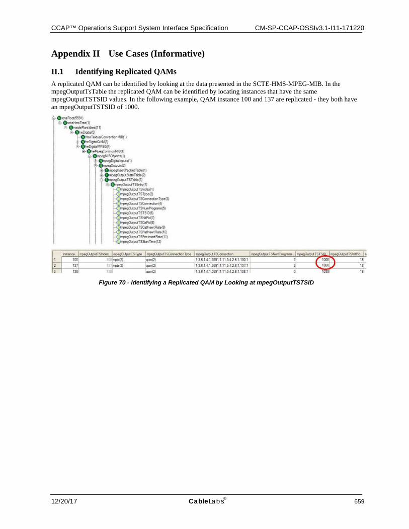
CCAP™ Operations Support System Interface Specification CM-SP-CCAP-OSSIv3.1-I11-171220
12/20/17 CableLabs 659
Appendix II Use Cases (Informative)
II.1 Identifying Replicated QAMs A replicated QAM can be identified by looking at the data presented in the SCTE-HMS-MPEG-MIB. In the mpegOutputTsTable the replicated QAM can be identified by locating instances that have the same mpegOutputTSTSID values. In the following example, QAM instance 100 and 137 are replicated - they both have an mpegOutputTSTSID of 1000.
Figure 70 - Identifying a Replicated QAM by Looking at mpegOutputTSTSID
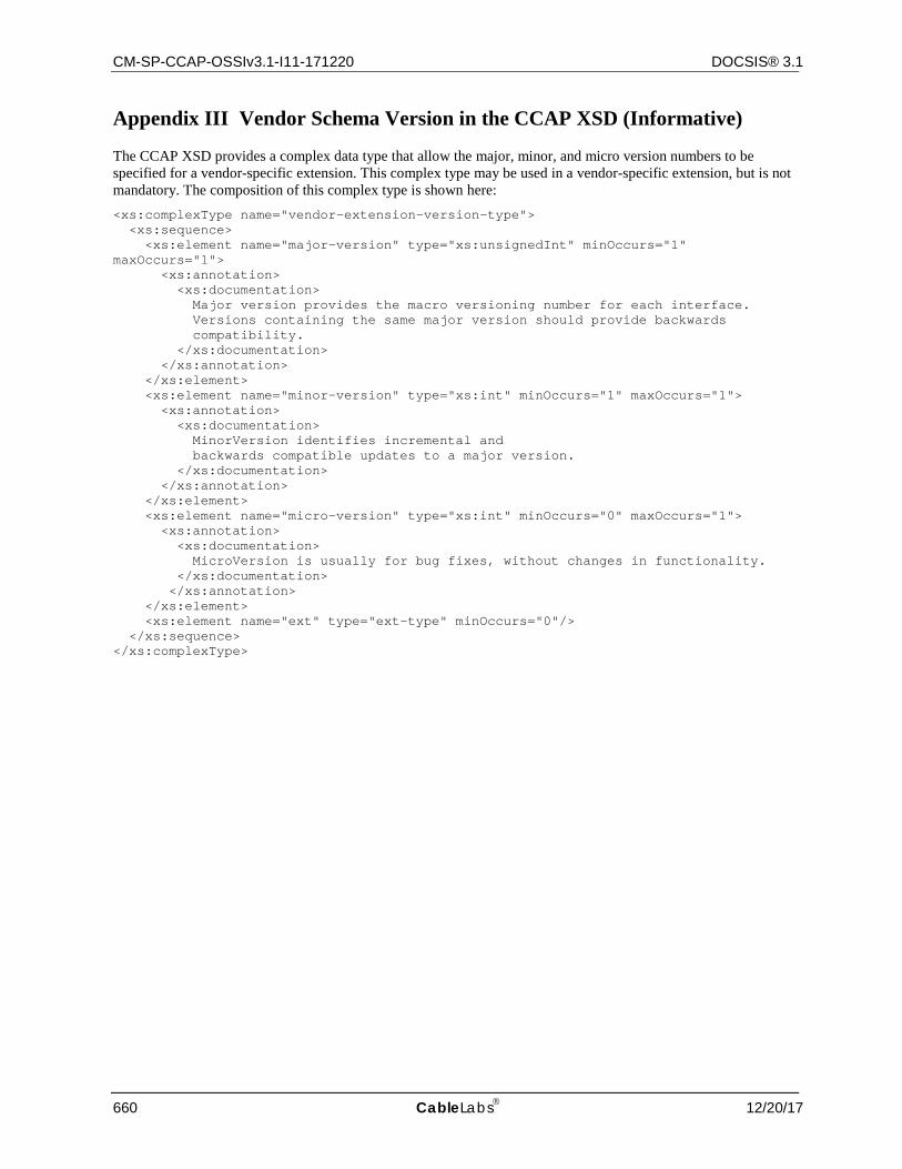
CM-SP-CCAP-OSSIv3.1-I11-171220 DOCSIS® 3.1
660 CableLabs 12/20/17
Appendix III Vendor Schema Version in the CCAP XSD (Informative)
The CCAP XSD provides a complex data type that allow the major, minor, and micro version numbers to be specified for a vendor-specific extension. This complex type may be used in a vendor-specific extension, but is not mandatory. The composition of this complex type is shown here: <xs:complexType name="vendor-extension-version-type"> <xs:sequence> <xs:element name="major-version" type="xs:unsignedInt" minOccurs="1" maxOccurs="1"> <xs:annotation> <xs:documentation> Major version provides the macro versioning number for each interface. Versions containing the same major version should provide backwards compatibility. </xs:documentation> </xs:annotation> </xs:element> <xs:element name="minor-version" type="xs:int" minOccurs="1" maxOccurs="1"> <xs:annotation> <xs:documentation> MinorVersion identifies incremental and backwards compatible updates to a major version. </xs:documentation> </xs:annotation> </xs:element> <xs:element name="micro-version" type="xs:int" minOccurs="0" maxOccurs="1"> <xs:annotation> <xs:documentation> MicroVersion is usually for bug fixes, without changes in functionality. </xs:documentation> </xs:annotation> </xs:element> <xs:element name="ext" type="ext-type" minOccurs="0"/> </xs:sequence> </xs:complexType>
CCAP™ Operations Support System Interface Specification CM-SP-CCAP-OSSIv3.1-I11-171220
12/20/17 CableLabs 661
Appendix IV Converting YANG to XSD (Informative)
IV.1 Using PYANG to Generate an XSD from the CCAP YANG Modules The CCAP XML Schema is derived by an automated process that converts the standard CCAP YANG modules specified in [CCAP-CONFIG-YANG] into a valid schema file. The conversion of the YANG to XSD is performed by pyang-a YANG validator, transformer, and code generator, written in Python. While CableLabs manages the conversion of the CCAP YANG file into the CCAP schema file (XSD), pyang can be used by anyone to convert the CCAP YANG modules into a valid XSD.
Note that pyang requires Python to run; installing Python is beyond the scope of this specification.
To run pyang on the CCAP YANG module file to produce a valid instance of the CCAP XSD, complete the following steps:
1. Download the most recent version of pyang from the Google Code repository located at: http://code.google.com/p/pyang/downloads/
2. Install pyang according to the installation instructions found on this site.
3. Download the most recent version of the CCAP XSD translator plugin (ccapxsd.py) from the following location: http://www.cablelabs.com/YANG/DOCSIS
4. Place the ccapxsd.py file in the pyang/plugins directory; this directory will be located within the site local Python library directory.
5. Ensure that the following files are present in the local directory:
• ietf-inet-types.yang (2010-09-24)
• ietf-yang-types.yang (2010-09-24)
• [email protected] (the most recent version of the CCAP YANG module file)
These files can be obtained from the following location: http://www.cablelabs.com/YANG/DOCSIS
6. Run the pyang tool with the following command line options: pyang -f ccapxsd --ccapxsd-global-complex-types --inline-type -o [email protected] [email protected]
where yyyy-mm-dd represents the date on which the most recent version of the YANG module file was published.
This will produce an XML Schema file in the local directory.
It should be noted that pyang currently does not support creating a valid CCAP schema when vendor extensions to the standard CCAP YANG module file are included in a separate file.
IV.2 Creating In-Line Data Types in the CCAP.XSD During the conversion process, pyang converts containers and lists that have the same name to a complex type that can be reused throughout the model. While this conversion increases the extensibility of the configuration object model, there are cases in which these definitions should not be converted to a complex type; there is value in allowing them to be unique and extended on an individual basis.
To allow for these containers and lists to be extended on an individual basis, the YANG extension "inlineType" has been created. This extension, when placed in a container or list, inhibits the generation of a named complex type, leaving the type definition in-line. This allows the desired separate extension points for each occurrence.
One example of where this is useful is the ip-interface list in the virtual-interface-group. This grouping is included for both cable-bundle and loopback interfaces. Given that these interface types are very different, it is likely that a vendor would want to extend them differently, which is now allowed by the inlineType extension.
The following example shows this usage: grouping virtual-interface-group {
CM-SP-CCAP-OSSIv3.1-I11-171220 DOCSIS® 3.1
662 CableLabs 12/20/17
leaf interface-index { type uint8; mandatory true; description "The index for this virtual ip-interface"; } leaf admin-state { type admin-state-type; default down; description "This attribute configures the administrative state of the virtual interface."; } list ip-interface { key ip-interface-name; max-elements 1; ccap:inlineType; description "An ip-interface object."; uses ip-interface-group; container yang-ext { ccap:extensionPoint; //different pyang flags impact use of this hint description "node for vendor YANG extensions"; } } }
The extension is enabled on the pyang command line: pyang -o [email protected] -f ccapxsd --ccapxsd-global-complex-types --inline-type [email protected]

CCAP™ Operations Support System Interface Specification CM-SP-CCAP-OSSIv3.1-I11-171220
12/20/17 CableLabs 663
Appendix V DOCSIS IPDR Sample Instance Documents (Informative)
This appendix provides a sampling of the XML Instance Documents which conform to the corresponding DOCSIS IPDR Service Definition schemas defined in Section 8.
V.1 Collector Aggregation IPDRDoc is expected to be aggregated by the Collector with the IPDR/SP data streamed within the session start stop boundary.
V.2 Schema Location The schemaLocation attribute [W3XSD1.0] is used to associate a XML Instance Document to a published schema XSD document.
The DOCSIS XML Schema location is defined and maintained by CableLabs as:
http://www.cablelabs.com/namespaces/DOCSIS/3.0/xsd/ipdr/<Service-Definition-Schema>_3.5.1-A.1.xsd
NOTE: The schema location is a Uniform Resource Locator (URL) which points to the actual schema file.
V.3 DIAG-LOG-TYPE This section provides a sample XML Instance Document for the Diagnostic Log Service Definition, DIAG-LOG-TYPE and corresponding XML Schema DOCSIS-DIAG-LOG-TYPE_3.5.1-A.2.xsd.
V.3.1 Use Case
The CMTS "cmts01.mso.com" logs an entry in its diagnostic log for the CM with MAC Address 00-09-36-A7-70-89 when the CM fails to register. The CM last registered at 9:15 on 06/04/2006. The registration trigger count has reached 3. The CM was originally added to the diagnostic log at 9:30 on 06/04/2006. The latest trigger occurred at 6:30 on 06/05/2006. The CMTS streams this information to a Collector as shown in the following instance document.
V.3.2 Instance Document <?xml version="1.0"?> <ipdr:IPDRDoc xmlns:ipdr="http://www.ipdr.org/namespaces/ipdr" xmlns:xsi="http://www.w3.org/2001/XMLSchema-instance" xmlns="http://www.cablelabs.com/namespaces/DOCSIS/3.0/xsd/ipdr/DOCSIS-DIAG-LOG-TYPE" xmlns:DOCSIS-DIAG-LOG="http://www.cablelabs.com/namespaces/DOCSIS/3.0/xsd/ipdr/DOCSIS-DIAG-LOG" xmlns:DOCSIS-REC="http://www.cablelabs.com/namespaces/DOCSIS/3.0/xsd/ipdr/DOCSIS-REC" xmlns:DOCSIS-CM="http://www.cablelabs.com/namespaces/DOCSIS/3.0/xsd/ipdr/DOCSIS-CM" xsi:schemaLocation="http://www.cablelabs.com/namespaces/DOCSIS/3.0/xsd/ipdr/DOCSIS-DIAG-LOG-TYPE http://www.cablelabs.com/namespaces/DOCSIS/3.0/xsd/ipdr/DOCSIS-DIAG-LOG-TYPE/DOCSIS-DIAG-LOG-TYPE_3.5.1-A.2.xsd" docId="3d07ba27-0000-0000-0000-1a2b3c4d5e6f" creationTime="2006-06-05T07:11:00Z" IPDRRecorderInfo="cmts01.mso.com" version="3.5.1-A.2"> <ipdr:IPDR xsi:type="DIAG-LOG-TYPE"> <DOCSIS-CMTS:CmtsHostName>cmts01.mso.com.</DOCSIS-CMTS:CmtsHostName> <DOCSIS-CM:CmMacAddr>00-09-36-A7-70-89</DOCSIS-CM:CmMacAddr> <DOCSIS-DIAG-LOG:LastUpdateTime>2006-06-05T06:30:00Z</DOCSIS-DIAG-LOG:LastUpdateTime> <DOCSIS-DIAG-LOG:CreateTime>2006-06-04T09:30:00Z</DOCSIS-DIAG-LOG:CreateTime> <DOCSIS-DIAG-LOG:LastRegTime>2006-06-04T09:15:00Z</DOCSIS-DIAG-LOG:LastRegTime> <DOCSIS-DIAG-LOG:RegCount>3</DOCSIS-DIAG-LOG:RegCount> <DOCSIS-DIAG-LOG:RangingRetryCount>0</DOCSIS-DIAG-LOG:RangingRetryCount> <DOCSIS-REC:RecType>1</DOCSIS-REC:RecType>
CM-SP-CCAP-OSSIv3.1-I11-171220 DOCSIS® 3.1
664 CableLabs 12/20/17
</ipdr:IPDR> <ipdr:IPDRDoc.End count="1" endTime="2006-06-05T07:15:00Z"/> </ipdr:IPDRDoc>
V.4 DIAG-LOG-DETAIL-TYPE This section provides a sample XML Instance Document for the Diagnostic Log Service Definition, DIAG-LOG-DETAIL-TYPE and corresponding XML Schema DOCSIS-DIAG-LOG-DETAIL-TYPE_3.5.1-A.2.xsd.
V.4.1 Use Case
The CMTS "cmts01.mso.com" logs an entry in its diagnostic log for the CM with MAC Address 00-09-36-A7-70-89 when the CM fails to register. The CM last triggered a registration diagnostic log entry at 6:30 on 06/05/2006. The detail Count of 1 represents the total number of times the CM had reached the startRegistration (TypeValue=11) state before failing the registration process. The corresponding event is:
<73000401> Service Unavailable - Unrecognized configuration setting
The CMTS streams this information to a Collector as shown in the following instance document.
V.4.2 Instance Document <?xml version="1.0"?> <ipdr:IPDRDoc xmlns:ipdr="http://www.ipdr.org/namespaces/ipdr" xmlns:xsi="http://www.w3.org/2001/XMLSchema-instance" xmlns="http://www.cablelabs.com/namespaces/DOCSIS/3.0/xsd/ipdr/DOCSIS-DIAG-LOG-DETAIL-TYPE" xmlns:DOCSIS-DIAG-LOG-DETAIL="http://www.cablelabs.com/namespaces/DOCSIS/3.0/xsd/ipdr/DOCSIS-DIAG-LOG-DETAIL" xmlns:DOCSIS-REC="http://www.cablelabs.com/namespaces/DOCSIS/3.0/xsd/ipdr/DOCSIS-REC" xmlns:DOCSIS-CM="http://www.cablelabs.com/namespaces/DOCSIS/3.0/xsd/ipdr/DOCSIS-CM" xsi:schemaLocation="http://www.cablelabs.com/namespaces/DOCSIS/3.0/xsd/ipdr/DOCSIS-DIAG-LOG-DETAIL-TYPE http://www.cablelabs.com/namespaces/DOCSIS/3.0/xsd/ipdr/DOCSIS-DIAG-LOG-DETAIL-TYPE/DOCSIS-DIAG-LOG-DETAIL-TYPE_3.5.1-A.2.xsd" docId="3d07ba27-0000-0000-0000-1a2b3c4d5e6f" creationTime="2006-06-05T07:11:00Z" IPDRRecorderInfo="cmts01.mso.com" version="3.5.1-A.2"> <ipdr:IPDR xsi:type="DIAG-LOG-DETAIL-TYPE"> <DOCSIS-CMTS:CmtsHostName>cmts01.mso.com.</DOCSIS-CMTS:CmtsHostName> <DOCSIS-CM:CmMacAddr>00-09-36-A7-70-89</DOCSIS-CM:CmMacAddr> <DOCSIS-DIAG-LOG-DETAIL:TypeValue>11</DOCSIS-DIAG-LOG-DETAIL:TypeValue> <DOCSIS-DIAG-LOG-DETAIL:Count>1</DOCSIS-DIAG-LOG-DETAIL:Count> <DOCSIS-DIAG-LOG-DETAIL:LastUpdate>2006-06-05T06:30:00Z</DOCSIS-DIAG-LOG-DETAIL:LastUpdate> <DOCSIS-DIAG-LOG-DETAIL:LastErrorText> <73000401> Service Unavailable - Unrecognized configuration setting </DOCSIS-DIAG-LOG-DETAIL:LastErrorText> <DOCSIS-REC:RecType>1</DOCSIS-REC:RecType> </ipdr:IPDR> <ipdr:IPDRDoc.End count="1" endTime="2006-06-05T07:15:00Z"/> </ipdr:IPDRDoc>
V.5 DIAG-LOG-EVENT-TYPE This section provides a sample XML Instance Document for the Diagnostic Log Service Definition, DIAG-LOG-EVENT-TYPE and corresponding XML Schema DOCSIS-DIAG-LOG-EVENT-TYPE_3.5.1-A.2.xsd.
CCAP™ Operations Support System Interface Specification CM-SP-CCAP-OSSIv3.1-I11-171220
12/20/17 CableLabs 665
V.5.1 Use Case
At the CMTS sysUpTime "2226878", the CMTS "cmts01.mso.com" detects a diagnostic log trigger for the CM with MAC Address 00-09-36-A7-70-89 when the CM fails to register (TriggerFlagValue of 1 indicates a registration trigger). The CM had reached the startRegistration (TypeValue=11) state before failing the registration process. The corresponding event is:
<73000401> Service Unavailable - Unrecognized configuration setting
Since the RecType value of 4 indicates an event based record, the CMTS autonomously streams this information to a Collector as shown in the following instance document.
V.5.2 Instance Document <?xml version="1.0"?> <ipdr:IPDRDoc xmlns:ipdr="http://www.ipdr.org/namespaces/ipdr" xmlns:xsi="http://www.w3.org/2001/XMLSchema-instance" xmlns="http://www.cablelabs.com/namespaces/DOCSIS/3.0/xsd/ipdr/DOCSIS-DIAG-LOG-EVENT-TYPE" xmlns:DOCSIS-DIAG-LOG="http://www.cablelabs.com/namespaces/DOCSIS/3.0/xsd/ipdr/DOCSIS-DIAG-LOG" xmlns:DOCSIS-DIAG-LOG-DETAIL="http://www.cablelabs.com/namespaces/DOCSIS/3.0/xsd/ipdr/DOCSIS-DIAG-LOG-DETAIL" xmlns:DOCSIS-CMTS="http://www.cablelabs.com/namespaces/DOCSIS/3.0/xsd/ipdr/DOCSIS-CMTS" xmlns:DOCSIS-REC="http://www.cablelabs.com/namespaces/DOCSIS/3.0/xsd/ipdr/DOCSIS-REC" xmlns:DOCSIS-CM="http://www.cablelabs.com/namespaces/DOCSIS/3.0/xsd/ipdr/DOCSIS-CM" xsi:schemaLocation="http://www.cablelabs.com/namespaces/DOCSIS/3.0/xsd/ipdr/DOCSIS-DIAG-LOG-EVENT-TYPE http://www.cablelabs.com/namespaces/DOCSIS/3.0/xsd/ipdr/DOCSIS-DIAG-LOG-EVENT-TYPE/DOCSIS-DIAG-LOG-EVENT-TYPE_3.5.1-A.2.xsd" docId="3d07ba27-0000-0000-0000-1a2b3c4d5e6f" creationTime="2006-06-05T07:11:00Z" IPDRRecorderInfo="cmts01.mso.com" version="3.5.1-A.2"> <ipdr:IPDR xsi:type="DIAG-LOG-EVENT-TYPE"> <DOCSIS-CMTS:CmtsHostName>cmts01.mso.com.</DOCSIS-CMTS:CmtsHostName> <DOCSIS-CM:CmMacAddr>00-09-36-A7-70-89</DOCSIS-CM:CmMacAddr> <DOCSIS-CMTS:CmtsSysUpTime>2226878</DOCSIS-CMTS:CmtsSysUpTime> <DOCSIS-DIAG-LOG:TriggerFlagValue>1</DOCSIS-DIAG-LOG:TriggerFlagValue> <DOCSIS-DIAG-LOG-DETAIL:TypeValue>11</DOCSIS-DIAG-LOG-DETAIL:TypeValue> <DOCSIS-DIAG-LOG-DETAIL:LastErrorText> <73000401> Service Unavailable - Unrecognized configuration setting </DOCSIS-DIAG-LOG-DETAIL:LastErrorText> <DOCSIS-REC:RecType>4</DOCSIS-REC:RecType> </ipdr:IPDR> <ipdr:IPDRDoc.End count="1" endTime="2006-06-05T07:15:00Z"/> </ipdr:IPDRDoc>
V.6 SPECTRUM-MEASUREMENT-TYPE This section provides a sample XML Instance Document for the Spectrum Measurement Service Definition, SPECTRUM-MEASUREMENT-TYPE and corresponding XML Schema DOCSIS-SPECTRUM-MEASUREMENT-TYPE_3.5.1-A.2.xsd.
V.6.1 Use Case
Refer to "Use Case 3 Data Analysis" in Appendix VI.2.2.3 for the Use Case defining the following XML Instance Document.
This instance document includes the "current" data plot from the Use Case mentioned above. For clarity, each eight data points in the element SpectrumAnalysisMeasAmplitude of the XML Instance Document are shown per line
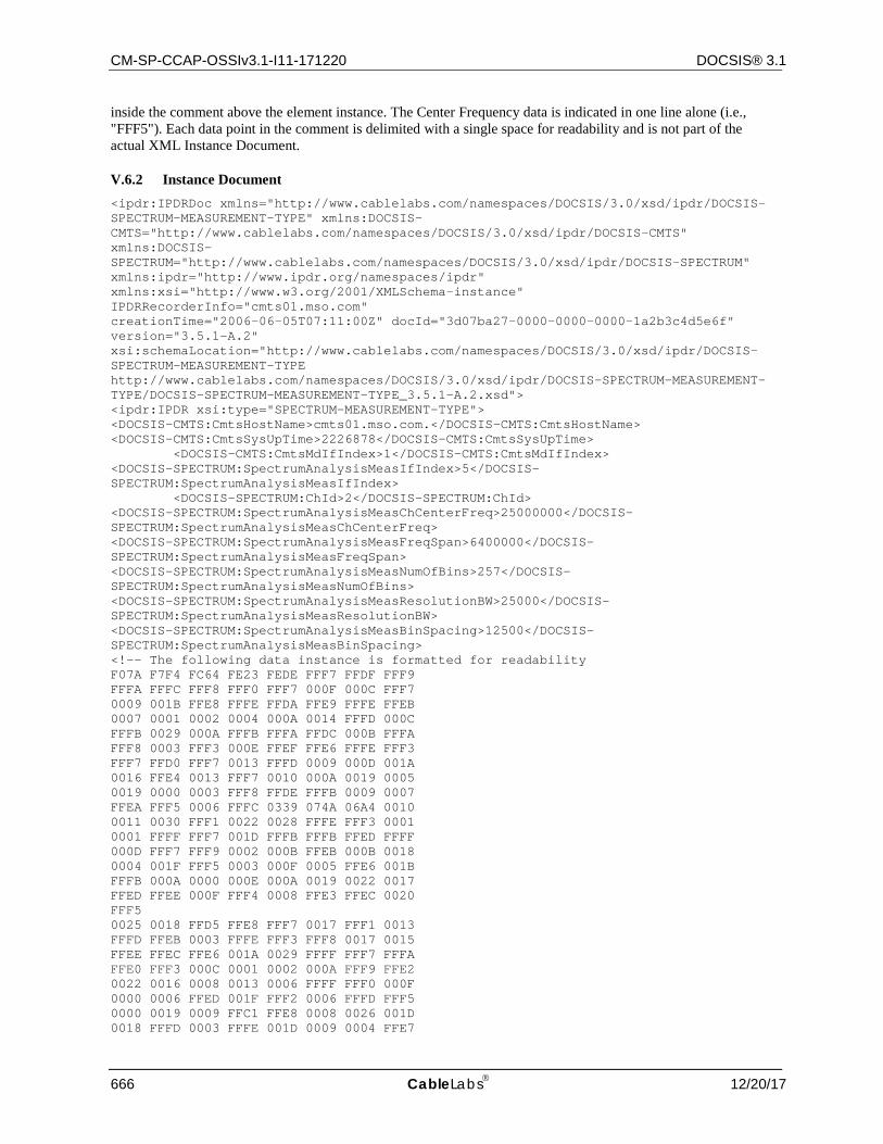
CM-SP-CCAP-OSSIv3.1-I11-171220 DOCSIS® 3.1
666 CableLabs 12/20/17
inside the comment above the element instance. The Center Frequency data is indicated in one line alone (i.e., "FFF5"). Each data point in the comment is delimited with a single space for readability and is not part of the actual XML Instance Document.
V.6.2 Instance Document <ipdr:IPDRDoc xmlns="http://www.cablelabs.com/namespaces/DOCSIS/3.0/xsd/ipdr/DOCSIS-SPECTRUM-MEASUREMENT-TYPE" xmlns:DOCSIS-CMTS="http://www.cablelabs.com/namespaces/DOCSIS/3.0/xsd/ipdr/DOCSIS-CMTS" xmlns:DOCSIS-SPECTRUM="http://www.cablelabs.com/namespaces/DOCSIS/3.0/xsd/ipdr/DOCSIS-SPECTRUM" xmlns:ipdr="http://www.ipdr.org/namespaces/ipdr" xmlns:xsi="http://www.w3.org/2001/XMLSchema-instance" IPDRRecorderInfo="cmts01.mso.com" creationTime="2006-06-05T07:11:00Z" docId="3d07ba27-0000-0000-0000-1a2b3c4d5e6f" version="3.5.1-A.2" xsi:schemaLocation="http://www.cablelabs.com/namespaces/DOCSIS/3.0/xsd/ipdr/DOCSIS-SPECTRUM-MEASUREMENT-TYPE http://www.cablelabs.com/namespaces/DOCSIS/3.0/xsd/ipdr/DOCSIS-SPECTRUM-MEASUREMENT-TYPE/DOCSIS-SPECTRUM-MEASUREMENT-TYPE_3.5.1-A.2.xsd"> <ipdr:IPDR xsi:type="SPECTRUM-MEASUREMENT-TYPE"> <DOCSIS-CMTS:CmtsHostName>cmts01.mso.com.</DOCSIS-CMTS:CmtsHostName> <DOCSIS-CMTS:CmtsSysUpTime>2226878</DOCSIS-CMTS:CmtsSysUpTime> <DOCSIS-CMTS:CmtsMdIfIndex>1</DOCSIS-CMTS:CmtsMdIfIndex> <DOCSIS-SPECTRUM:SpectrumAnalysisMeasIfIndex>5</DOCSIS-SPECTRUM:SpectrumAnalysisMeasIfIndex> <DOCSIS-SPECTRUM:ChId>2</DOCSIS-SPECTRUM:ChId> <DOCSIS-SPECTRUM:SpectrumAnalysisMeasChCenterFreq>25000000</DOCSIS-SPECTRUM:SpectrumAnalysisMeasChCenterFreq> <DOCSIS-SPECTRUM:SpectrumAnalysisMeasFreqSpan>6400000</DOCSIS-SPECTRUM:SpectrumAnalysisMeasFreqSpan> <DOCSIS-SPECTRUM:SpectrumAnalysisMeasNumOfBins>257</DOCSIS-SPECTRUM:SpectrumAnalysisMeasNumOfBins> <DOCSIS-SPECTRUM:SpectrumAnalysisMeasResolutionBW>25000</DOCSIS-SPECTRUM:SpectrumAnalysisMeasResolutionBW> <DOCSIS-SPECTRUM:SpectrumAnalysisMeasBinSpacing>12500</DOCSIS-SPECTRUM:SpectrumAnalysisMeasBinSpacing> <!-- The following data instance is formatted for readability F07A F7F4 FC64 FE23 FEDE FFF7 FFDF FFF9 FFFA FFFC FFF8 FFF0 FFF7 000F 000C FFF7 0009 001B FFE8 FFFE FFDA FFE9 FFFE FFEB 0007 0001 0002 0004 000A 0014 FFFD 000C FFFB 0029 000A FFFB FFFA FFDC 000B FFFA FFF8 0003 FFF3 000E FFEF FFE6 FFFE FFF3 FFF7 FFD0 FFF7 0013 FFFD 0009 000D 001A 0016 FFE4 0013 FFF7 0010 000A 0019 0005 0019 0000 0003 FFF8 FFDE FFFB 0009 0007 FFEA FFF5 0006 FFFC 0339 074A 06A4 0010 0011 0030 FFF1 0022 0028 FFFE FFF3 0001 0001 FFFF FFF7 001D FFFB FFFB FFED FFFF 000D FFF7 FFF9 0002 000B FFEB 000B 0018 0004 001F FFF5 0003 000F 0005 FFE6 001B FFFB 000A 0000 000E 000A 0019 0022 0017 FFED FFEE 000F FFF4 0008 FFE3 FFEC 0020 FFF5 0025 0018 FFD5 FFE8 FFF7 0017 FFF1 0013 FFFD FFEB 0003 FFFE FFF3 FFF8 0017 0015 FFEE FFEC FFE6 001A 0029 FFFF FFF7 FFFA FFE0 FFF3 000C 0001 0002 000A FFF9 FFE2 0022 0016 0008 0013 0006 FFFF FFF0 000F 0000 0006 FFED 001F FFF2 0006 FFFD FFF5 0000 0019 0009 FFC1 FFE8 0008 0026 001D 0018 FFFD 0003 FFFE 001D 0009 0004 FFE7
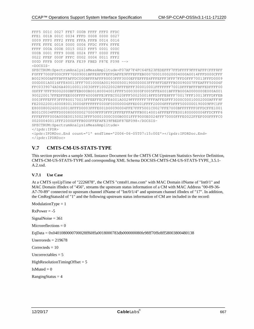
CCAP™ Operations Support System Interface Specification CM-SP-CCAP-OSSIv3.1-I11-171220
12/20/17 CableLabs 667
FFF5 001C 0027 FFE7 000B FFFF FFF0 FFDC FFE1 001B 001C 0034 FFFD 0008 0000 0027 0009 FFF0 FFF2 FFFE FFFA FFFB 0014 0016 FFFE FFFE 0018 0000 0006 FFDC FFF6 FFFE FFFF 000A 000E 0015 0023 FFF5 0001 000C 000B 0001 FFF9 000E 0024 FFF7 0000 FFFE 0022 FFEF 000F FFFC 0002 0004 0011 FFF2 000D FFFB 000F FEFA FE39 FBED F87E F098 --> <DOCSIS-SPECTRUM:SpectrumAnalysisMeasAmplitude>F07AF7F4FC64FE23FEDEFFF7FFDFFFF9FFFAFFFCFFF8FFF0FFF7000F000CFFF70009001BFFE8FFFEFFDAFFE9FFFEFFEB0007000100020004000A0014FFFD000CFFFB0029000AFFFBFFFAFFDC000BFFFAFFF80003FFF3000EFFEFFFE6FFFEFFF3FFF7FFD0FFF70013FFFD0009000D001A0016FFE40013FFF70010000A00190005001900000003FFF8FFDEFFFB00090007FFEAFFF50006FFFC0339074A06A4001000110030FFF100220028FFFEFFF300010001FFFFFFF7001DFFFBFFFBFFEDFFFF000DFFF7FFF90002000BFFEB000B00180004001FFFF50003000F0005FFE6001BFFFB000A0000000E000A001900220017FFEDFFEE000FFFF40008FFE3FFEC0020FFF500250018FFD5FFE8FFF70017FFF10013FFFDFFEB0003FFFEFFF3FFF800170015FFEEFFECFFE6001A0029FFFFFFF7FFFAFFE0FFF3000C00010002000AFFF9FFE200220016000800130006FFFFFFF0000F00000006FFED001FFFF20006FFFDFFF5000000190009FFC1FFE800080026001D0018FFFD0003FFFE001D00090004FFE7FFF5001C0027FFE7000BFFFFFFF0FFDCFFE1001B001C0034FFFD0008000000270009FFF0FFF2FFFEFFFAFFFB00140016FFFEFFFE001800000006FFDCFFF6FFFEFFFF000A000E00150023FFF50001000C000B0001FFF9000E0024FFF70000FFFE0022FFEF000FFFFC000200040011FFF2000DFFFB000FFEFAFE39FBEDF87EF098</DOCSIS-SPECTRUM:SpectrumAnalysisMeasAmplitude> </ipdr:IPDR> <ipdr:IPDRDoc.End count="1" endTime="2006-06-05T07:15:00Z"></ipdr:IPDRDoc.End> </ipdr:IPDRDoc>
V.7 CMTS-CM-US-STATS-TYPE This section provides a sample XML Instance Document for the CMTS CM Upstream Statistics Service Definition, CMTS-CM-US-STATS-TYPE and corresponding XML Schema DOCSIS-CMTS-CM-US-STATS-TYPE_3.5.1-A.2.xsd.
V.7.1 Use Case
At a CMTS sysUpTime of "2226878", the CMTS "cmts01.mso.com" with MAC Domain ifName of "Int0/1" and MAC Domain ifIndex of "456", streams the upstream status information of a CM with MAC Address "00-09-36-A7-70-89" connected to upstream channel ifName of "Int/0/1/4" and upstream channel ifIndex of "17". In addition, the CmRegStatusId of "1" and the following upstream status information of CM are included in the record:
ModulationType = 1
RxPower = -5
SignalNoise = 361
Microreflections = 0
EqData = 0x0401080000700028ff60ffa0018000783db000000080fe98ff70ffe8ff58003800480138
Unerroreds = 219678
Correcteds = 10
Uncorrectables = 5
HighResolutionTimingOffset = 5
IsMuted = 0
RangingStatus = 4
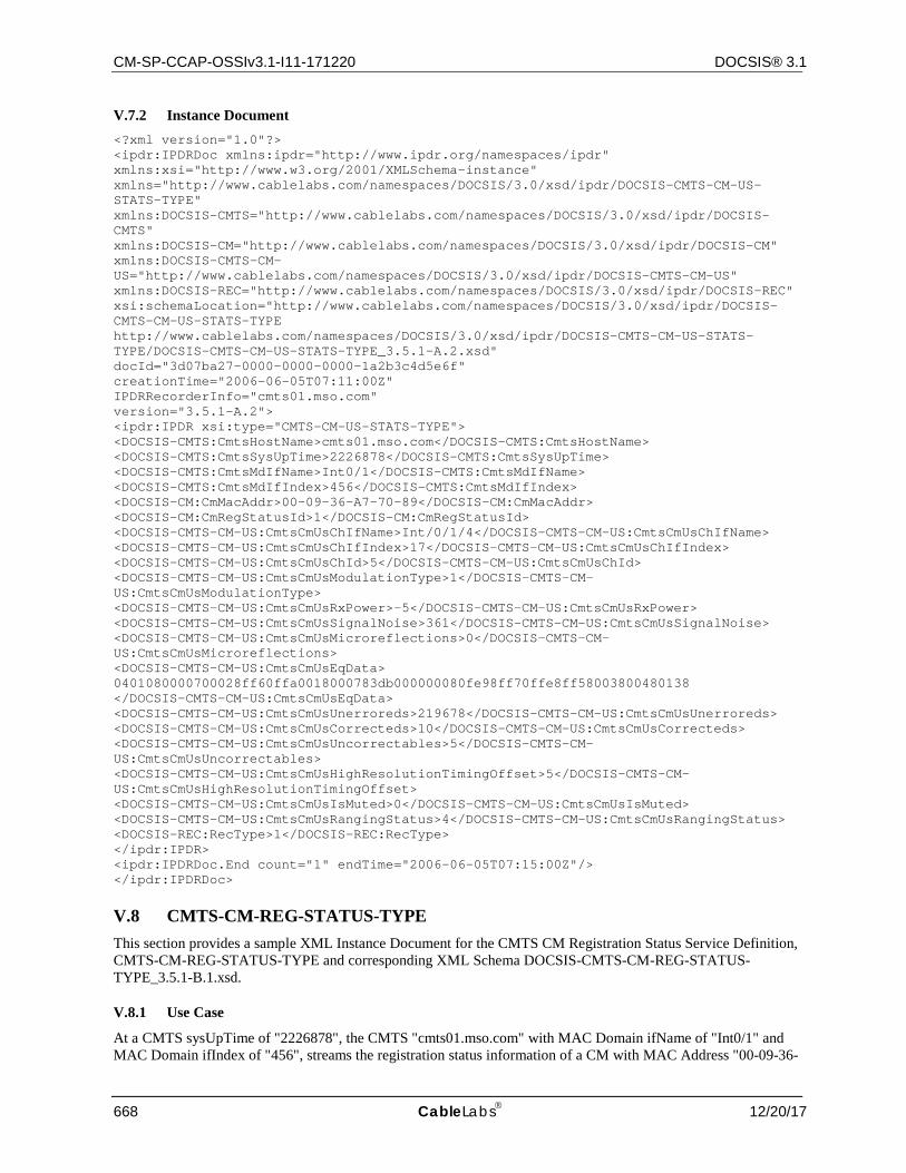
CM-SP-CCAP-OSSIv3.1-I11-171220 DOCSIS® 3.1
668 CableLabs 12/20/17
V.7.2 Instance Document <?xml version="1.0"?> <ipdr:IPDRDoc xmlns:ipdr="http://www.ipdr.org/namespaces/ipdr" xmlns:xsi="http://www.w3.org/2001/XMLSchema-instance" xmlns="http://www.cablelabs.com/namespaces/DOCSIS/3.0/xsd/ipdr/DOCSIS-CMTS-CM-US-STATS-TYPE" xmlns:DOCSIS-CMTS="http://www.cablelabs.com/namespaces/DOCSIS/3.0/xsd/ipdr/DOCSIS-CMTS" xmlns:DOCSIS-CM="http://www.cablelabs.com/namespaces/DOCSIS/3.0/xsd/ipdr/DOCSIS-CM" xmlns:DOCSIS-CMTS-CM-US="http://www.cablelabs.com/namespaces/DOCSIS/3.0/xsd/ipdr/DOCSIS-CMTS-CM-US" xmlns:DOCSIS-REC="http://www.cablelabs.com/namespaces/DOCSIS/3.0/xsd/ipdr/DOCSIS-REC" xsi:schemaLocation="http://www.cablelabs.com/namespaces/DOCSIS/3.0/xsd/ipdr/DOCSIS-CMTS-CM-US-STATS-TYPE http://www.cablelabs.com/namespaces/DOCSIS/3.0/xsd/ipdr/DOCSIS-CMTS-CM-US-STATS-TYPE/DOCSIS-CMTS-CM-US-STATS-TYPE_3.5.1-A.2.xsd" docId="3d07ba27-0000-0000-0000-1a2b3c4d5e6f" creationTime="2006-06-05T07:11:00Z" IPDRRecorderInfo="cmts01.mso.com" version="3.5.1-A.2"> <ipdr:IPDR xsi:type="CMTS-CM-US-STATS-TYPE"> <DOCSIS-CMTS:CmtsHostName>cmts01.mso.com</DOCSIS-CMTS:CmtsHostName> <DOCSIS-CMTS:CmtsSysUpTime>2226878</DOCSIS-CMTS:CmtsSysUpTime> <DOCSIS-CMTS:CmtsMdIfName>Int0/1</DOCSIS-CMTS:CmtsMdIfName> <DOCSIS-CMTS:CmtsMdIfIndex>456</DOCSIS-CMTS:CmtsMdIfIndex> <DOCSIS-CM:CmMacAddr>00-09-36-A7-70-89</DOCSIS-CM:CmMacAddr> <DOCSIS-CM:CmRegStatusId>1</DOCSIS-CM:CmRegStatusId> <DOCSIS-CMTS-CM-US:CmtsCmUsChIfName>Int/0/1/4</DOCSIS-CMTS-CM-US:CmtsCmUsChIfName> <DOCSIS-CMTS-CM-US:CmtsCmUsChIfIndex>17</DOCSIS-CMTS-CM-US:CmtsCmUsChIfIndex> <DOCSIS-CMTS-CM-US:CmtsCmUsChId>5</DOCSIS-CMTS-CM-US:CmtsCmUsChId> <DOCSIS-CMTS-CM-US:CmtsCmUsModulationType>1</DOCSIS-CMTS-CM-US:CmtsCmUsModulationType> <DOCSIS-CMTS-CM-US:CmtsCmUsRxPower>-5</DOCSIS-CMTS-CM-US:CmtsCmUsRxPower> <DOCSIS-CMTS-CM-US:CmtsCmUsSignalNoise>361</DOCSIS-CMTS-CM-US:CmtsCmUsSignalNoise> <DOCSIS-CMTS-CM-US:CmtsCmUsMicroreflections>0</DOCSIS-CMTS-CM-US:CmtsCmUsMicroreflections> <DOCSIS-CMTS-CM-US:CmtsCmUsEqData> 0401080000700028ff60ffa0018000783db000000080fe98ff70ffe8ff58003800480138 </DOCSIS-CMTS-CM-US:CmtsCmUsEqData> <DOCSIS-CMTS-CM-US:CmtsCmUsUnerroreds>219678</DOCSIS-CMTS-CM-US:CmtsCmUsUnerroreds> <DOCSIS-CMTS-CM-US:CmtsCmUsCorrecteds>10</DOCSIS-CMTS-CM-US:CmtsCmUsCorrecteds> <DOCSIS-CMTS-CM-US:CmtsCmUsUncorrectables>5</DOCSIS-CMTS-CM-US:CmtsCmUsUncorrectables> <DOCSIS-CMTS-CM-US:CmtsCmUsHighResolutionTimingOffset>5</DOCSIS-CMTS-CM-US:CmtsCmUsHighResolutionTimingOffset> <DOCSIS-CMTS-CM-US:CmtsCmUsIsMuted>0</DOCSIS-CMTS-CM-US:CmtsCmUsIsMuted> <DOCSIS-CMTS-CM-US:CmtsCmUsRangingStatus>4</DOCSIS-CMTS-CM-US:CmtsCmUsRangingStatus> <DOCSIS-REC:RecType>1</DOCSIS-REC:RecType> </ipdr:IPDR> <ipdr:IPDRDoc.End count="1" endTime="2006-06-05T07:15:00Z"/> </ipdr:IPDRDoc>
V.8 CMTS-CM-REG-STATUS-TYPE This section provides a sample XML Instance Document for the CMTS CM Registration Status Service Definition, CMTS-CM-REG-STATUS-TYPE and corresponding XML Schema DOCSIS-CMTS-CM-REG-STATUS-TYPE_3.5.1-B.1.xsd.
V.8.1 Use Case
At a CMTS sysUpTime of "2226878", the CMTS "cmts01.mso.com" with MAC Domain ifName of "Int0/1" and MAC Domain ifIndex of "456", streams the registration status information of a CM with MAC Address "00-09-36-
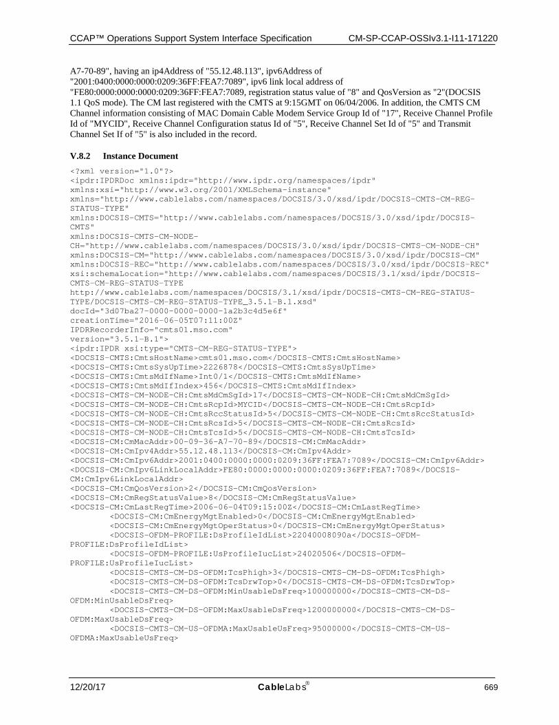
CCAP™ Operations Support System Interface Specification CM-SP-CCAP-OSSIv3.1-I11-171220
12/20/17 CableLabs 669
A7-70-89", having an ip4Address of "55.12.48.113", ipv6Address of "2001:0400:0000:0000:0209:36FF:FEA7:7089", ipv6 link local address of "FE80:0000:0000:0000:0209:36FF:FEA7:7089, registration status value of "8" and QosVersion as "2"(DOCSIS 1.1 QoS mode). The CM last registered with the CMTS at 9:15GMT on 06/04/2006. In addition, the CMTS CM Channel information consisting of MAC Domain Cable Modem Service Group Id of "17", Receive Channel Profile Id of "MYCID", Receive Channel Configuration status Id of "5", Receive Channel Set Id of "5" and Transmit Channel Set If of "5" is also included in the record.
V.8.2 Instance Document <?xml version="1.0"?> <ipdr:IPDRDoc xmlns:ipdr="http://www.ipdr.org/namespaces/ipdr" xmlns:xsi="http://www.w3.org/2001/XMLSchema-instance" xmlns="http://www.cablelabs.com/namespaces/DOCSIS/3.0/xsd/ipdr/DOCSIS-CMTS-CM-REG-STATUS-TYPE" xmlns:DOCSIS-CMTS="http://www.cablelabs.com/namespaces/DOCSIS/3.0/xsd/ipdr/DOCSIS-CMTS" xmlns:DOCSIS-CMTS-CM-NODE-CH="http://www.cablelabs.com/namespaces/DOCSIS/3.0/xsd/ipdr/DOCSIS-CMTS-CM-NODE-CH" xmlns:DOCSIS-CM="http://www.cablelabs.com/namespaces/DOCSIS/3.0/xsd/ipdr/DOCSIS-CM" xmlns:DOCSIS-REC="http://www.cablelabs.com/namespaces/DOCSIS/3.0/xsd/ipdr/DOCSIS-REC" xsi:schemaLocation="http://www.cablelabs.com/namespaces/DOCSIS/3.1/xsd/ipdr/DOCSIS-CMTS-CM-REG-STATUS-TYPE http://www.cablelabs.com/namespaces/DOCSIS/3.1/xsd/ipdr/DOCSIS-CMTS-CM-REG-STATUS-TYPE/DOCSIS-CMTS-CM-REG-STATUS-TYPE_3.5.1-B.1.xsd" docId="3d07ba27-0000-0000-0000-1a2b3c4d5e6f" creationTime="2016-06-05T07:11:00Z" IPDRRecorderInfo="cmts01.mso.com" version="3.5.1-B.1"> <ipdr:IPDR xsi:type="CMTS-CM-REG-STATUS-TYPE"> <DOCSIS-CMTS:CmtsHostName>cmts01.mso.com</DOCSIS-CMTS:CmtsHostName> <DOCSIS-CMTS:CmtsSysUpTime>2226878</DOCSIS-CMTS:CmtsSysUpTime> <DOCSIS-CMTS:CmtsMdIfName>Int0/1</DOCSIS-CMTS:CmtsMdIfName> <DOCSIS-CMTS:CmtsMdIfIndex>456</DOCSIS-CMTS:CmtsMdIfIndex> <DOCSIS-CMTS-CM-NODE-CH:CmtsMdCmSgId>17</DOCSIS-CMTS-CM-NODE-CH:CmtsMdCmSgId> <DOCSIS-CMTS-CM-NODE-CH:CmtsRcpId>MYCID</DOCSIS-CMTS-CM-NODE-CH:CmtsRcpId> <DOCSIS-CMTS-CM-NODE-CH:CmtsRccStatusId>5</DOCSIS-CMTS-CM-NODE-CH:CmtsRccStatusId> <DOCSIS-CMTS-CM-NODE-CH:CmtsRcsId>5</DOCSIS-CMTS-CM-NODE-CH:CmtsRcsId> <DOCSIS-CMTS-CM-NODE-CH:CmtsTcsId>5</DOCSIS-CMTS-CM-NODE-CH:CmtsTcsId> <DOCSIS-CM:CmMacAddr>00-09-36-A7-70-89</DOCSIS-CM:CmMacAddr> <DOCSIS-CM:CmIpv4Addr>55.12.48.113</DOCSIS-CM:CmIpv4Addr> <DOCSIS-CM:CmIpv6Addr>2001:0400:0000:0000:0209:36FF:FEA7:7089</DOCSIS-CM:CmIpv6Addr> <DOCSIS-CM:CmIpv6LinkLocalAddr>FE80:0000:0000:0000:0209:36FF:FEA7:7089</DOCSIS-CM:CmIpv6LinkLocalAddr> <DOCSIS-CM:CmQosVersion>2</DOCSIS-CM:CmQosVersion> <DOCSIS-CM:CmRegStatusValue>8</DOCSIS-CM:CmRegStatusValue> <DOCSIS-CM:CmLastRegTime>2006-06-04T09:15:00Z</DOCSIS-CM:CmLastRegTime> <DOCSIS-CM:CmEnergyMgtEnabled>0</DOCSIS-CM:CmEnergyMgtEnabled> <DOCSIS-CM:CmEnergyMgtOperStatus>0</DOCSIS-CM:CmEnergyMgtOperStatus> <DOCSIS-OFDM-PROFILE:DsProfileIdList>22040008090a</DOCSIS-OFDM-PROFILE:DsProfileIdList> <DOCSIS-OFDM-PROFILE:UsProfileIucList>24020506</DOCSIS-OFDM-PROFILE:UsProfileIucList> <DOCSIS-CMTS-CM-DS-OFDM:TcsPhigh>3</DOCSIS-CMTS-CM-DS-OFDM:TcsPhigh> <DOCSIS-CMTS-CM-DS-OFDM:TcsDrwTop>0</DOCSIS-CMTS-CM-DS-OFDM:TcsDrwTop> <DOCSIS-CMTS-CM-DS-OFDM:MinUsableDsFreq>100000000</DOCSIS-CMTS-CM-DS-OFDM:MinUsableDsFreq> <DOCSIS-CMTS-CM-DS-OFDM:MaxUsableDsFreq>1200000000</DOCSIS-CMTS-CM-DS-OFDM:MaxUsableDsFreq> <DOCSIS-CMTS-CM-US-OFDMA:MaxUsableUsFreq>95000000</DOCSIS-CMTS-CM-US-OFDMA:MaxUsableUsFreq>
CM-SP-CCAP-OSSIv3.1-I11-171220 DOCSIS® 3.1
670 CableLabs 12/20/17
<DOCSIS-CMTS-CM-PARTIAL:PartialSvcState>0</DOCSIS-CMTS-CM-PARTIAL:PartialSvcState> <DOCSIS-CMTS-CM-PARTIAL:PartialChanState>0</DOCSIS-CMTS-CM-PARTIAL:PartialChanState> <DOCSIS-REC:RecType>1</DOCSIS-REC:RecType> <DOCSIS-REC:RecCreationTime>2006-06-05T07:11:00Z</DOCSIS-REC:RecCreationTime> </ipdr:IPDR> <ipdr:IPDRDoc.End count="1" endTime="2006-06-05T07:15:00Z"/> </ipdr:IPDRDoc>
V.9 CMTS-TOPOLOGY-TYPE This section provides a sample XML Instance Document for the CMTS Topology Service Definition, CMTS-TOPOLOGY-TYPE and corresponding XML Schema DOCSIS-CMTS-TOPOLOGY-TYPE_3.5.1-A.2.xsd.
V.9.1 Use Case
At a CMTS sysUpTime of "2226878", the CMTS "cmts01.mso.com" with ipv4Address of "10.40.57.11", ipv6Address of "2001:0400:0000:0000:0000:FF00:FE00:0000", MAC Domain ifName of "Int0/1" and MAC Domain ifIndex of "456", streams the topology information consisting of Node Name as "DENVER288", MAC Domain Cable Modem Service Group Id of "1010", MAC Domain Downstream Service Group Id of "2", MAC Domain Upstream Service Group Id "5", MAC Domain Downstream Service Group Channel List of "01020304" and MAC Domain Upstream Service Group Channel List of "0A0B0C3D".
V.9.2 Instance Document <?xml version="1.0"?> <ipdr:IPDRDoc xmlns:ipdr="http://www.ipdr.org/namespaces/ipdr" xmlns:xsi="http://www.w3.org/2001/XMLSchema-instance" xmlns="http://www.cablelabs.com/namespaces/DOCSIS/3.0/xsd/ipdr/DOCSIS-CMTS-TOPOLOGY-TYPE" xmlns:DOCSIS-CMTS="http://www.cablelabs.com/namespaces/DOCSIS/3.0/xsd/ipdr/DOCSIS-CMTS" xmlns:DOCSIS-MD-NODE="http://www.cablelabs.com/namespaces/DOCSIS/3.0/xsd/ipdr/DOCSIS-MD-NODE" xmlns:DOCSIS-REC="http://www.cablelabs.com/namespaces/DOCSIS/3.0/xsd/ipdr/DOCSIS-REC" xsi:schemaLocation="http://www.cablelabs.com/namespaces/DOCSIS/3.0/xsd/ipdr/DOCSIS-CMTS-TOPOLOGY-TYPE http://www.cablelabs.com/namespaces/DOCSIS/3.0/xsd/ipdr/DOCSIS-CMTS-TOPOLOGY-TYPE/DOCSIS-CMTS-TOPOLOGY-TYPE_3.5.1-A.2.xsd" docId="3d07ba27-0000-0000-0000-1a2b3c4d5e6f" creationTime="2006-06-05T07:11:00Z" IPDRRecorderInfo="cmts01.mso.com" version="3.5.1-A.2"> <ipdr:IPDR xsi:type="CMTS-TOPOLOGY-TYPE"> <DOCSIS-CMTS:CmtsHostName>cmts01.mso.com</DOCSIS-CMTS:CmtsHostName> <DOCSIS-CMTS:CmtsSysUpTime>2226878</DOCSIS-CMTS:CmtsSysUpTime> <DOCSIS-CMTS:CmtsIpv4Addr>10.40.57.11</DOCSIS-CMTS:CmtsIpv4Addr> <DOCSIS-CMTS:CmtsIpv6Addr>2001:0400:0000:0000:0000:FF00:FE00:0000</DOCSIS-CMTS:CmtsIpv6Addr> <DOCSIS-CMTS:CmtsMdIfName>Int0/1</DOCSIS-CMTS:CmtsMdIfName> <DOCSIS-CMTS:CmtsMdIfIndex>456</DOCSIS-CMTS:CmtsMdIfIndex> <DOCSIS-MD-NODE:CmtsNodeName>DENVER2881</DOCSIS-MD-NODE:CmtsNodeName> <DOCSIS-MD-NODE:CmtsMdCmSgId>1010</DOCSIS-MD-NODE:CmtsMdCmSgId> <DOCSIS-MD-NODE:CmtsMdDsSgId>2</DOCSIS-MD-NODE:CmtsMdDsSgId> <DOCSIS-MD-NODE:CmtsMdUsSgId>5</DOCSIS-MD-NODE:CmtsMdUsSgId> <DOCSIS-MD-NODE:CmtsMdDsSgChList>01020304</DOCSIS-MD-NODE:CmtsMdDsSgChList> <DOCSIS-MD-NODE:CmtsMdUsSgChList>0A0B0C3D</DOCSIS-MD-NODE:CmtsMdUsSgChList> <DOCSIS-REC:RecType>1</DOCSIS-REC:RecType> </ipdr:IPDR> <ipdr:IPDRDoc.End count="1" endTime="2006-06-05T07:15:00Z"/> </ipdr:IPDRDoc>
CCAP™ Operations Support System Interface Specification CM-SP-CCAP-OSSIv3.1-I11-171220
12/20/17 CableLabs 671
V.10 CPE-TYPE This section provides a sample XML Instance Document for the CPE Service Definition, CPE-TYPE and corresponding XML Schema DOCSIS-CPE-TYPE_3.5.1-A.2.xsd.
V.10.1 Use Case
At a CMTS sysUpTime of "2226878", the CMTS "cmts01.mso.com" streams the CPE record for a CPE with MAC Address 00-08-22-B4-66-90 corresponding to a CM with MAC Address 00-09-36-A7-70-89 and a CMTS MAC Domain ifName of "Int0/1" and ifIndex of 456. In addition, the CPE IPv4 address of 192.168.0.11, IPv6 address of 2001:0400:0000:0000:0000:1000:FFFF:0000 and FQDN of "somehost.example.com." are included in the record.
V.10.2 Instance Document <?xml version="1.0"?> <ipdr:IPDRDoc xmlns:xsi="http://www.w3.org/2001/XMLSchema-instance" xmlns:ipdr="http://www.ipdr.org/namespaces/ipdr" xmlns="http://www.cablelabs.com/namespaces/DOCSIS/3.0/xsd/ipdr/DOCSIS-CPE-TYPE" xmlns:DOCSIS-CPE="http://www.cablelabs.com/namespaces/DOCSIS/3.0/xsd/ipdr/DOCSIS-CPE" xmlns:DOCSIS-CMTS="http://www.cablelabs.com/namespaces/DOCSIS/3.0/xsd/ipdr/DOCSIS-CMTS" xmlns:DOCSIS-CM="http://www.cablelabs.com/namespaces/DOCSIS/3.0/xsd/ipdr/DOCSIS-CM" xmlns:DOCSIS-REC="http://www.cablelabs.com/namespaces/DOCSIS/3.0/xsd/ipdr/DOCSIS-REC" xsi:schemaLocation="http://www.cablelabs.com/namespaces/DOCSIS/3.0/xsd/ipdr/DOCSIS-CPE-TYPE http://www.cablelabs.com/namespaces/DOCSIS/3.0/xsd/ipdr/DOCSIS-CPE-TYPE/DOCSIS-CPE-TYPE_3.5.1-A.2.xsd" docId="3d07ba27-0000-0000-0000-1a2b3c4d5e6f" version="3.5.1-A.2" creationTime="2006-06-05T07:11:00Z" IPDRRecorderInfo="cmts01.mso.com"> <ipdr:IPDR xsi:type="CPE-TYPE"> <DOCSIS-CMTS:CmtsHostName>cmts01.mso.com.</DOCSIS-CMTS:CmtsHostName> <DOCSIS-CMTS:CmtsSysUpTime>2226878</DOCSIS-CMTS:CmtsSysUpTime> <DOCSIS-CMTS:CmtsMdIfName>Int0/1</DOCSIS-CMTS:CmtsMdIfName> <DOCSIS-CMTS:CmtsMdIfIndex>456</DOCSIS-CMTS:CmtsMdIfIndex> <DOCSIS-CM:CmMacAddr>00-09-36-A7-70-89</DOCSIS-CM:CmMacAddr> <DOCSIS-REC:RecType>1</DOCSIS-REC:RecType> <DOCSIS-CPE:CpeMacAddr>00-08-22-B4-66-90</DOCSIS-CPE:CpeMacAddr> <DOCSIS-CPE:CpeIpv4AddrList>192.168.0.11</DOCSIS-CPE:CpeIpv4AddrList> <DOCSIS-CPE:CpeIpv6AddrList>2001:0400:0000:0000:0000:1000:FFFF:0000</DOCSIS-CPE:CpeIpv6AddrList> <DOCSIS-CPE:CpeFqdn>somehost.example.com.</DOCSIS-CPE:CpeFqdn> </ipdr:IPDR> <ipdr:IPDRDoc.End count="1" endTime="2006-06-05T07:15:00Z"/> </ipdr:IPDRDoc>
V.11 SAMIS-TYPE-1 and SAMIS-TYPE-2
V.11.1 Use Case
The Type 1 and Type 2 XML Instance Documents defined in the following sections represent the same use case, but differ in the amount of data which is streamed. Type 1 streams the full record containing all CMTS, CM and service statistics counters. The optimized record, Type 2, only streams those elements that are needed in each record instance such that correlation can be performed at the collector.
NOTE: The instance documents presented below represent one streaming record for illustrative purposes only. The full set of streaming records for the defined use case are not included.
The use case represented in this section is defined in the following section.
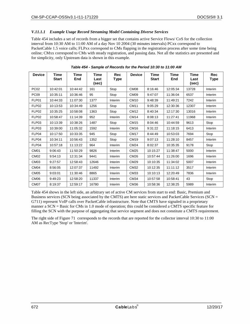
CM-SP-CCAP-OSSIv3.1-I11-171220 DOCSIS® 3.1
672 CableLabs 12/20/17
V.11.1.1 Example Usage Record Streaming Model Containing Diverse Services
Table 454 includes a set of records from a bigger set that contains active Service Flows/ CoS for the collection interval from 10:30 AM to 11:00 AM of a day Nov 10 2004 (30 minutes intervals) PCxx correspond to PacketCable 1.5 voice calls; FLPxx correspond to CMs flapping in the registration process after some time being online; CMxx correspond to CMs with steady registration, and passing data. Not all the statistics are presented and for simplicity, only Upstream data is shown in this example.
Table 454 - Sample of Records for the Period 10:30 to 11:00 AM
Device Time Start
Time End
Time Last (sec)
Rec Type
Device Time Start
Time End
Time Last (sec)
Rec Type
PC02 10:42:01 10:44:42 161 Stop CM08 8:16:46 12:05:34 13728 Interim
PC09 10:35:11 10:36:46 95 Stop CM09 9:47:07 11:36:04 6537 Interim
FLP01 10:44:33 11:07:30 1377 Interim CM10 9:48:39 11:49:21 7242 Interim
FLP02 10:13:53 10:34:49 1256 Stop CM11 9:05:29 12:30:36 12307 Interim
FLP02 10:35:25 10:58:08 1363 Stop CM12 8:40:34 12:17:30 13016 Interim
FLP02 10:58:47 11:14:39 952 Interim CM14 8:08:13 11:27:41 11968 Interim
FLP03 10:13:39 10:38:26 1487 Stop CM15 8:04:46 10:44:59 9613 Stop
FLP03 10:39:00 11:05:32 1592 Interim CM16 9:31:22 11:18:15 6413 Interim
FLP04 10:17:50 10:33:35 945 Stop CM17 8:44:49 10:53:03 7694 Stop
FLP04 10:34:11 10:56:43 1352 Stop CM19 9:07:13 11:28:10 8457 Interim
FLP04 10:57:18 11:13:22 964 Interim CM24 8:02:37 10:35:35 9178 Stop
CM01 9:06:43 11:50:29 9826 Interim CM25 10:15:27 11:38:47 5000 Interim
CM02 9:54:13 12:31:34 9441 Interim CM26 10:57:44 11:26:00 1696 Interim
CM03 9:27:57 12:58:43 12646 Interim CM29 10:10:35 11:34:02 5007 Interim
CM04 8:56:05 12:07:37 11492 Interim CM32 10:12:35 11:11:12 3517 Interim
CM05 9:03:01 11:30:46 8865 Interim CM33 10:10:13 12:20:49 7836 Interim
CM06 9:49:23 12:58:20 11337 Interim CM34 10:57:58 10:58:41 43 Stop
CM07 8:19:37 12:59:17 16780 Interim CM36 10:58:36 12:38:25 5989 Interim
Table 454 shows in the left side, an arbitrary set of active CM services from start to end: Basic, Premium and Business services (SCN being associated by the CMTS) are here static services and PacketCable Services (SCN = G711) represent VoIP calls over PacketCable infrastructure. Note that CMTS have signaled in a proprietary manner a SCN = Basic for CMs in 1.0 mode of operation; this could be considered a CMTS specific feature for filling the SCN with the purpose of aggregating that service segment and does not constitute a CMTS requirement.
The right side of Figure 71 corresponds to the records that are reported for the collector interval 10:30 to 11:00 AM as RecType 'Stop' or 'Interim'.
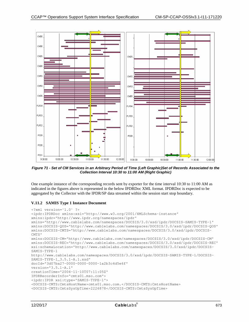
CCAP™ Operations Support System Interface Specification CM-SP-CCAP-OSSIv3.1-I11-171220
12/20/17 CableLabs 673
Figure 71 - Set of CM Services in an Arbitrary Period of Time (Left Graphic)Set of Records Associated to the
Collection Interval 10:30 to 11:00 AM (Right Graphic)
One example instance of the corresponding records sent by exporter for the time interval 10:30 to 11:00 AM as indicated in the figures above is represented in the below IPDRDoc XML format. IPDRDoc is expected to be aggregated by the Collector with the IPDR/SP data streamed within the session start stop boundary.
V.11.2 SAMIS Type 1 Instance Document <?xml version='1.0' ?> <ipdr:IPDRDoc xmlns:xsi="http://www.w3.org/2001/XMLSchema-instance" xmlns:ipdr="http://www.ipdr.org/namespaces/ipdr" xmlns="http://www.cablelabs.com/namespaces/DOCSIS/3.0/xsd/ipdr/DOCSIS-SAMIS-TYPE-1" xmlns:DOCSIS-QOS="http://www.cablelabs.com/namespaces/DOCSIS/3.0/xsd/ipdr/DOCSIS-QOS" xmlns:DOCSIS-CMTS="http://www.cablelabs.com/namespaces/DOCSIS/3.0/xsd/ipdr/DOCSIS-CMTS" xmlns:DOCSIS-CM="http://www.cablelabs.com/namespaces/DOCSIS/3.0/xsd/ipdr/DOCSIS-CM" xmlns:DOCSIS-REC="http://www.cablelabs.com/namespaces/DOCSIS/3.0/xsd/ipdr/DOCSIS-REC" xsi:schemaLocation="http://www.cablelabs.com/namespaces/DOCSIS/3.0/xsd/ipdr/DOCSIS-SAMIS-TYPE-1 http://www.cablelabs.com/namespaces/DOCSIS/3.0/xsd/ipdr/DOCSIS-SAMIS-TYPE-1/DOCSIS-SAMIS-TYPE-1_3.5.1-A.1.xsd" docId="3d07ba27-0000-0000-0000-1a2b3c4d5e6f" version="3.5.1-A.1" creationTime="2004-11-10T07:11:05Z" IPDRRecorderInfo="cmts01.mso.com"> <ipdr:IPDR xsi:type="SAMIS-TYPE-1"> <DOCSIS-CMTS:CmtsHostName>cmts01.mso.com.</DOCSIS-CMTS:CmtsHostName> <DOCSIS-CMTS:CmtsSysUpTime>2226878</DOCSIS-CMTS:CmtsSysUpTime>
CM-SP-CCAP-OSSIv3.1-I11-171220 DOCSIS® 3.1
674 CableLabs 12/20/17
<DOCSIS-CMTS:CmtsIpv4Addr>10.40.57.11</DOCSIS-CMTS:CmtsIpv4Addr> <DOCSIS-CMTS:CmtsIpv6Addr>2001:0400:0000:0000:0000:FF00:FE00:0000</DOCSIS-CMTS:CmtsIpv6Addr> <DOCSIS-CMTS:CmtsMdIfName>Int0/1</DOCSIS-CMTS:CmtsMdIfName> <DOCSIS-CMTS:CmtsMdIfIndex>456</DOCSIS-CMTS:CmtsMdIfIndex> <DOCSIS-CM:CmMacAddr>00-09-36-A7-70-89</DOCSIS-CM:CmMacAddr> <DOCSIS-CM:CmIpv4Addr>55.12.48.113</DOCSIS-CM:CmIpv4Addr> <DOCSIS-CM:CmIpv6Addr>2001:0400:0000:0000:0000:1000:FF00:0000</DOCSIS-CM:CmIpv6Addr> <DOCSIS-CM:CmIpv6LinkLocalAddr>FE80:0000:0000:0000:0209:36FF:FEA7:7089</DOCSIS-CM:CmIpv6LinkLocalAddr> <DOCSIS-CM:CmQosVersion>2</DOCSIS-CM:CmQosVersion> <DOCSIS-CM:CmRegStatusValue>8</DOCSIS-CM:CmRegStatusValue> <DOCSIS-CM:CmLastRegTime>2006-06-04T09:15:00Z</DOCSIS-CM:CmLastRegTime> <DOCSIS-REC:RecType>1</DOCSIS-REC:RecType> <DOCSIS-REC:RecCreationTime>2004-11-10T07:11:05Z</DOCSIS-REC:RecCreationTime> <DOCSIS-QOS:ServiceFlowChSet>01020304</DOCSIS-QOS:ServiceFlowChSet> <DOCSIS-QOS:ServiceAppId>10000</DOCSIS-QOS:ServiceAppId> <DOCSIS-QOS:ServiceDsMulticast>false</DOCSIS-QOS:ServiceDsMulticast> <DOCSIS-QOS:ServiceIdentifier>361</DOCSIS-QOS:ServiceIdentifier> <DOCSIS-QOS:ServiceGateId>500</DOCSIS-QOS:ServiceGateId> <DOCSIS-QOS:ServiceClassName>Premium</DOCSIS-QOS:ServiceClassName> <DOCSIS-QOS:ServiceDirection>2</DOCSIS-QOS:ServiceDirection> <DOCSIS-QOS:ServiceOctetsPassed>16486400</DOCSIS-QOS:ServiceOctetsPassed> <DOCSIS-QOS:ServicePktsPassed>82431</DOCSIS-QOS:ServicePktsPassed> <DOCSIS-QOS:ServiceSlaDropPkts>412</DOCSIS-QOS:ServiceSlaDropPkts> <DOCSIS-QOS:ServiceSlaDelayPkts>8</DOCSIS-QOS:ServiceSlaDelayPkts> <DOCSIS-QOS:ServiceTimeCreated>2210822</DOCSIS-QOS:ServiceTimeCreated> <DOCSIS-QOS:ServiceTimeActive>161</DOCSIS-QOS:ServiceTimeActive> </ipdr:IPDR> <ipdr:IPDRDoc.End count="1" endTime="2004-11-10T07:11:08Z"/> </ipdr:IPDRDoc>
V.11.3 SAMIS Type 2 Instance Document <?xml version='1.0' ?> <ipdr:IPDRDoc xmlns:xsi="http://www.w3.org/2001/XMLSchema-instance" xmlns:ipdr="http://www.ipdr.org/namespaces/ipdr" xmlns="http://www.cablelabs.com/namespaces/DOCSIS/3.0/xsd/ipdr/DOCSIS-SAMIS-TYPE-2" xmlns:DOCSIS-QOS="http://www.cablelabs.com/namespaces/DOCSIS/3.0/xsd/ipdr/DOCSIS-QOS" xmlns:DOCSIS-CMTS="http://www.cablelabs.com/namespaces/DOCSIS/3.0/xsd/ipdr/DOCSIS-CMTS" xmlns:DOCSIS-CM="http://www.cablelabs.com/namespaces/DOCSIS/3.0/xsd/ipdr/DOCSIS-CM" xmlns:DOCSIS-REC="http://www.cablelabs.com/namespaces/DOCSIS/3.0/xsd/ipdr/DOCSIS-REC" xsi:schemaLocation="http://www.cablelabs.com/namespaces/DOCSIS/3.0/xsd/ipdr/DOCSIS-SAMIS-TYPE-2 http://www.cablelabs.com/namespaces/DOCSIS/3.0/xsd/ipdr/DOCSIS-SAMIS-TYPE-2/DOCSIS-SAMIS-TYPE-2_3.5.1-A.1.xsd" docId="3d07ba27-0000-0000-0000-1a2b3c4d5e6f" version="3.5.1-A.1" creationTime="2004-11-10T07:11:05Z" IPDRRecorderInfo="cmts01.mso.com"> <ipdr:IPDR xsi:type="SAMIS-TYPE-2"> <DOCSIS-CMTS:CmtsHostName>cmts01.mso.com.</DOCSIS-CMTS:CmtsHostName> <DOCSIS-CMTS:CmtsSysUpTime>2226878</DOCSIS-CMTS:CmtsSysUpTime> <DOCSIS-CMTS:CmtsMdIfName>Int0/1</DOCSIS-CMTS:CmtsMdIfName> <DOCSIS-CMTS:CmtsMdIfIndex>456</DOCSIS-CMTS:CmtsMdIfIndex> <DOCSIS-CM:CmMacAddr>00-09-36-A7-70-89</DOCSIS-CM:CmMacAddr> <DOCSIS-REC:RecType>1</DOCSIS-REC:RecType> <DOCSIS-REC:RecCreationTime>2004-11-10T07:11:05Z</DOCSIS-REC:RecCreationTime> <DOCSIS-QOS:ServiceFlowChSet>01020304</DOCSIS-QOS:ServiceFlowChSet> <DOCSIS-QOS:ServiceAppId>10000</DOCSIS-QOS:ServiceAppId> <DOCSIS-QOS:ServiceDsMulticast>false</DOCSIS-QOS:ServiceDsMulticast> <DOCSIS-QOS:ServiceIdentifier>361</DOCSIS-QOS:ServiceIdentifier>
CCAP™ Operations Support System Interface Specification CM-SP-CCAP-OSSIv3.1-I11-171220
12/20/17 CableLabs 675
<DOCSIS-QOS:ServiceGateId>500</DOCSIS-QOS:ServiceGateId> <DOCSIS-QOS:ServiceClassName>Premium</DOCSIS-QOS:ServiceClassName> <DOCSIS-QOS:ServiceDirection>2</DOCSIS-QOS:ServiceDirection> <DOCSIS-QOS:ServiceOctetsPassed>16486400</DOCSIS-QOS:ServiceOctetsPassed> <DOCSIS-QOS:ServicePktsPassed>82431</DOCSIS-QOS:ServicePktsPassed> <DOCSIS-QOS:ServiceSlaDropPkts>412</DOCSIS-QOS:ServiceSlaDropPkts> <DOCSIS-QOS:ServiceSlaDelayPkts>8</DOCSIS-QOS:ServiceSlaDelayPkts> <DOCSIS-QOS:ServiceTimeCreated>2210822</DOCSIS-QOS:ServiceTimeCreated> <DOCSIS-QOS:ServiceTimeActive>161</DOCSIS-QOS:ServiceTimeActive> </ipdr:IPDR> <ipdr:IPDRDoc.End count="1" endTime="2004-11-10T07:11:08Z"/> </ipdr:IPDRDoc>
V.12 CMTS-US-UTIL-STATS-TYPE This section provides a sample XML Instance Document for the CMTS Upstream Utilization Statistics Service Definition, CMTS-US-UTIL-STATS-TYPE and corresponding XML Schema DOCSIS-CMTS-US-UTIL-STATS-TYPE_3.5.1-A.4.xsd.
V.12.1 Use Case
At a CMTS sysUpTime of "2226878", the CMTS "cmts01.mso.com" with MAC Domain ifIndex of "456", streams (using an event based session) the upstream utilization statistics information for the upstream logical channel with ifIndex of "17". In addition, the UsUtilInterval of "900" (15 minutes) and the following utilization information is included in the record:
IndexPercentage = 80
TotalMslots = 1403854841
UcastGrantedMslots = 33281121
TotalCntnMslots = 1370280369
UsedCntnMslots = 815830
CollCntnMslots = 1332
TotalCntnReqMslots = 311083615
UsedCntnReqMslots = 574833
CollCntnReqMslots = 1332
TotalCntnReqDataMslots = 0
UsedCntnReqDataMslots = 0
CollCntnReqDataMslots = 0
TotalCntnInitMaintMslots = 1059212846
UsedCntnInitMaintMslots = 240997
CollCntnInitMaintMslots = 0
V.12.2 Instance Document <?xml version="1.0"?> <ipdr:IPDRDoc xmlns:ipdr="http://www.ipdr.org/namespaces/ipdr" xmlns:xsi="http://www.w3.org/2001/XMLSchema-instance" xmlns="http://www.cablelabs.com/namespaces/DOCSIS/3.0/xsd/ipdr/DOCSIS-CMTS-US-UTIL-STATS-TYPE" xmlns:DOCSIS-CMTS="http://www.cablelabs.com/namespaces/DOCSIS/3.0/xsd/ipdr/DOCSIS-CMTS" xmlns: DOCSIS-CMTS-US-UTIL="http://www.cablelabs.com/namespaces/DOCSIS/3.0/xsd/ipdr/DOCSIS-CMTS-US-UTIL"
CM-SP-CCAP-OSSIv3.1-I11-171220 DOCSIS® 3.1
676 CableLabs 12/20/17
xmlns:DOCSIS-REC="http://www.cablelabs.com/namespaces/DOCSIS/3.0/xsd/ipdr/DOCSIS-REC" xsi:schemaLocation="http://www.cablelabs.com/namespaces/DOCSIS/3.0/xsd/ipdr/DOCSIS-CMTS-US-UTIL-STATS-TYPE http://www.cablelabs.com/namespaces/DOCSIS/3.0/xsd/ipdr/DOCSIS-CMTS-US-UTIL-STATS-TYPE/DOCSIS-CMTS-US-UTIL-STATS-TYPE_3.5.1-A.4.xsd" docId="3d07ba27-0000-0000-0000-1a2b3c4d5e6f" creationTime="2006-06-05T07:11:00Z" IPDRRecorderInfo="cmts01.mso.com" version="3.5.1-A.4"> <ipdr:IPDR xsi:type="CMTS-US-UTIL-STATS-TYPE"> <DOCSIS-CMTS:CmtsHostName>cmts01.mso.com</DOCSIS-CMTS:CmtsHostName> <DOCSIS-CMTS:CmtsSysUpTime>2226878</DOCSIS-CMTS:CmtsSysUpTime> <DOCSIS-CMTS:CmtsMdIfIndex>456</DOCSIS-CMTS:CmtsMdIfIndex> <DOCSIS-CMTS-US-UTIL:UsIfIndex>17</DOCSIS-CMTS-US-UTIL:UsIfIndex> <DOCSIS-CMTS-US-UTIL:UsIfName> Int/0/1/4</DOCSIS-CMTS-US-UTIL:UsIfName> <DOCSIS-CMTS-US-UTIL:UsChId>2</DOCSIS-CMTS-US-UTIL:UsChId> <DOCSIS-CMTS-US-UTIL:UsUtilInterval>900</DOCSIS-CMTS-US-UTIL:UsUtilInterval> <DOCSIS-CMTS-US-UTIL:UsUtilIndexPercentage>80</DOCSIS-CMTS-US-UTIL:UsUtilIndexPercentage> <DOCSIS-CMTS-US-UTIL:UsUtilTotalMslots >1403854841</DOCSIS-CMTS-US-UTIL:UsUtilTotalMslots> <DOCSIS-CMTS-US-UTIL:UsUtilUcastGrantedMslots>33281121</DOCSIS-CMTS-US-UTIL:UsUtilUcastGrantedMslots> <DOCSIS-CMTS-US-UTIL:UsUtilTotalCntnMslots>1370280369</DOCSIS-CMTS-US-UTIL:UsUtilTotalCntnMslots> <DOCSIS-CMTS-US-UTIL:UsUtilUsedCntnMslots>815830</DOCSIS-CMTS-US-UTIL:UsUtilUsedCntnMslots> <DOCSIS-CMTS-US-UTIL:UsUtilCollCntnMslots>1332</DOCSIS-CMTS-US-UTIL:UsUtilCollCntnMslots> <DOCSIS-CMTS-US-UTIL:UsUtilTotalCntnReqMslots>311083615</DOCSIS-CMTS-US-UTIL:UsUtilTotalCntnReqMslots> <DOCSIS-CMTS-US-UTIL:UsUtilUsedCntnReqMslots>574833</DOCSIS-CMTS-US-UTIL:UsUtilUsedCntnReqMslots> <DOCSIS-CMTS-US-UTIL:UsUtilCollCntnReqMslots>1332</DOCSIS-CMTS-US-UTIL:UsUtilCollCntnReqMslots> <DOCSIS-CMTS-US-UTIL:UsUtilTotalCntnReqDataMslots>0</DOCSIS-CMTS-US-UTIL:UsUtilTotalCntnReqDataMslots> <DOCSIS-CMTS-US-UTIL:UsUtilUsedCntnReqDataMslots>0</DOCSIS-CMTS-US-UTIL:UsUtilUsedCntnReqDataMslots> <DOCSIS-CMTS-US-UTIL:UsUtilCollCntnReqDataMslots>0</DOCSIS-CMTS-US-UTIL:UsUtilCollCntnReqDataMslots> <DOCSIS-CMTS-US-UTIL:UsUtilTotalCntnInitMaintMslots>1059212846</DOCSIS-CMTS-US-UTIL:UsUtilTotalCntnInitMaintMslots> <DOCSIS-CMTS-US-UTIL:UsUtilUsedCntnInitMaintMslots>240997</DOCSIS-CMTS-US-UTIL:UsUtilUsedCntnInitMaintMslots> <DOCSIS-CMTS-US-UTIL:UsUtilCollCntnInitMaintMslots>0</DOCSIS-CMTS-US-UTIL:UsUtilCollCntnInitMaintMslots> <DOCSIS-REC:RecType>4</DOCSIS-REC:RecType> </ipdr:IPDR> <ipdr:IPDRDoc.End count="1" endTime="2006-06-05T07:15:00Z"/> </ipdr:IPDRDoc>
V.13 CMTS-DS-UTIL-STATS-TYPE This section provides a sample XML Instance Document for the CMTS Downstream Utilization Statistics Service Definition, CMTS-DS-UTIL-STATS-TYPE and corresponding XML Schema DOCSIS-CMTS-DS-UTIL-STATS-TYPE_3.5.1-A.3.xsd.
V.13.1 Use Case
At a CMTS sysUpTime of "2226888", the CMTS "cmts01.mso.com" with MAC Domain ifIndex of "456", streams (using an event based session) the downstream utilization statistics information for the downstream channel with
CCAP™ Operations Support System Interface Specification CM-SP-CCAP-OSSIv3.1-I11-171220
12/20/17 CableLabs 677
ifIndex of "18". In addition, the DsUtilInterval of "900" (15 minutes) and the following utilization information is included in the record:
IndexPercentage = 70
TotalBytes = 2668756233
UsedBytes = 3323829507
V.13.2 Instance Document <?xml version="1.0"?> <ipdr:IPDRDoc xmlns:ipdr="http://www.ipdr.org/namespaces/ipdr" xmlns:xsi="http://www.w3.org/2001/XMLSchema-instance" xmlns="http://www.cablelabs.com/namespaces/DOCSIS/3.0/xsd/ipdr/DOCSIS-CMTS-DS-UTIL-STATS-TYPE" xmlns:DOCSIS-CMTS="http://www.cablelabs.com/namespaces/DOCSIS/3.0/xsd/ipdr/DOCSIS-CMTS" xmlns: DOCSIS-CMTS-DS-UTIL="http://www.cablelabs.com/namespaces/DOCSIS/3.0/xsd/ipdr/DOCSIS-CMTS-DS-UTIL" xmlns:DOCSIS-REC="http://www.cablelabs.com/namespaces/DOCSIS/3.0/xsd/ipdr/DOCSIS-REC" xsi:schemaLocation="http://www.cablelabs.com/namespaces/DOCSIS/3.0/xsd/ipdr/DOCSIS-CMTS-DS-UTIL-STATS-TYPE http://www.cablelabs.com/namespaces/DOCSIS/3.0/xsd/ipdr/DOCSIS-CMTS-DS-UTIL-STATS-TYPE/DOCSIS-CMTS-DS-UTIL-STATS-TYPE_3.5.1-A.3.xsd" docId="3d07ba27-0000-0000-0000-1a2b3c4d5e6f" creationTime="2006-06-05T07:11:00Z" IPDRRecorderInfo="cmts01.mso.com" version="3.5.1-A.3"> <ipdr:IPDR xsi:type="CMTS-DS-UTIL-STATS-TYPE"> <DOCSIS-CMTS:CmtsHostName>cmts01.mso.com</DOCSIS-CMTS:CmtsHostName> <DOCSIS-CMTS:CmtsSysUpTime>2226888</DOCSIS-CMTS:CmtsSysUpTime> <DOCSIS-CMTS:CmtsMdIfIndex>456</DOCSIS-CMTS:CmtsMdIfIndex> <DOCSIS-CMTS-DS-UTIL:DsIfIndex>18</DOCSIS-CMTS-DS-UTIL:DsIfIndex> <DOCSIS-CMTS-DS-UTIL:DsIfName> Int/0/1/1</DOCSIS-CMTS-DS-UTIL:DsIfName> <DOCSIS-CMTS-DS-UTIL:DsChId>1</DOCSIS-CMTS-DS-UTIL:DsChId> <DOCSIS-CMTS-DS-UTIL:DsUtilInterval>900</DOCSIS-CMTS-DS-UTIL:DsUtilInterval> <DOCSIS-CMTS-DS-UTIL:DsUtilIndexPercentage>70</DOCSIS-CMTS-DS-UTIL:DsUtilIndexPercentage> <DOCSIS-CMTS-DS-UTIL:DsUtilTotalBytes >2668756233</DOCSIS-CMTS-DS-UTIL:DsUtilTotalBytes> <DOCSIS-CMTS-DS-UTIL:DsUtilUsedBytes>3323829507</DOCSIS-CMTS-DS-UTIL:DsUtilUsedBytes> <DOCSIS-REC:RecType>4</DOCSIS-REC:RecType> </ipdr:IPDR> <ipdr:IPDRDoc.End count="1" endTime="2006-06-05T07:15:00Z"/> </ipdr:IPDRDoc>
V.14 CMTS-CM-SERVICE-FLOW-TYPE This section provides a sample XML Instance Document for the CMTS CM Service Flow Service Definition, CMTS-CM-SERVICE-FLOW-TYPE and corresponding XML Schema DOCSIS-CMTS-CM-SERVICE-FLOW-TYPE_3.5.1-B.1.xsd.
V.14.1 Use Case
At a CMTS sysUpTime of "2226888", the CMTS "cmts01.mso.com" with MAC Domain ifIndex of "456"and Service Identifier 361, streams (using an event based session) the Service Flow information. The Service Flow is a statically provisioned Best Effort Service Flow. The Service Flow has the following characteristics:
Service Flow Channel Set = 01020304
MaxRate = 1000000
MaxBurst = 2000000
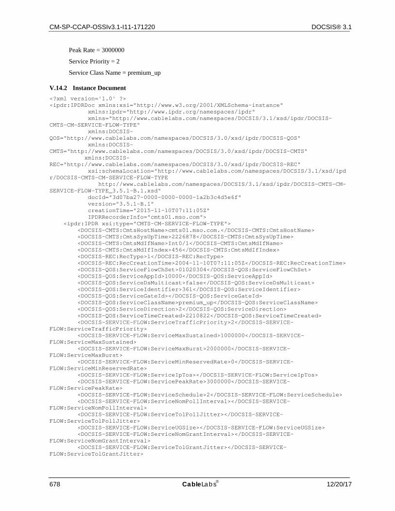
CM-SP-CCAP-OSSIv3.1-I11-171220 DOCSIS® 3.1
678 CableLabs 12/20/17
Peak Rate = 3000000
Service Priority = 2
Service Class Name = premium_up
V.14.2 Instance Document <?xml version='1.0' ?> <ipdr:IPDRDoc xmlns:xsi="http://www.w3.org/2001/XMLSchema-instance" xmlns:ipdr="http://www.ipdr.org/namespaces/ipdr" xmlns="http://www.cablelabs.com/namespaces/DOCSIS/3.1/xsd/ipdr/DOCSIS-CMTS-CM-SERVICE-FLOW-TYPE" xmlns:DOCSIS-QOS="http://www.cablelabs.com/namespaces/DOCSIS/3.0/xsd/ipdr/DOCSIS-QOS" xmlns:DOCSIS-CMTS="http://www.cablelabs.com/namespaces/DOCSIS/3.0/xsd/ipdr/DOCSIS-CMTS" xmlns:DOCSIS-REC="http://www.cablelabs.com/namespaces/DOCSIS/3.0/xsd/ipdr/DOCSIS-REC" xsi:schemaLocation="http://www.cablelabs.com/namespaces/DOCSIS/3.1/xsd/ipdr/DOCSIS-CMTS-CM-SERVICE-FLOW-TYPE http://www.cablelabs.com/namespaces/DOCSIS/3.1/xsd/ipdr/DOCSIS-CMTS-CM-SERVICE-FLOW-TYPE_3.5.1-B.1.xsd" docId="3d07ba27-0000-0000-0000-1a2b3c4d5e6f" version="3.5.1-B.1" creationTime="2015-11-10T07:11:05Z" IPDRRecorderInfo="cmts01.mso.com"> <ipdr:IPDR xsi:type="CMTS-CM-SERVICE-FLOW-TYPE"> <DOCSIS-CMTS:CmtsHostName>cmts01.mso.com.</DOCSIS-CMTS:CmtsHostName> <DOCSIS-CMTS:CmtsSysUpTime>2226878</DOCSIS-CMTS:CmtsSysUpTime> <DOCSIS-CMTS:CmtsMdIfName>Int0/1</DOCSIS-CMTS:CmtsMdIfName> <DOCSIS-CMTS:CmtsMdIfIndex>456</DOCSIS-CMTS:CmtsMdIfIndex> <DOCSIS-REC:RecType>1</DOCSIS-REC:RecType> <DOCSIS-REC:RecCreationTime>2004-11-10T07:11:05Z</DOCSIS-REC:RecCreationTime> <DOCSIS-QOS:ServiceFlowChSet>01020304</DOCSIS-QOS:ServiceFlowChSet> <DOCSIS-QOS:ServiceAppId>10000</DOCSIS-QOS:ServiceAppId> <DOCSIS-QOS:ServiceDsMulticast>false</DOCSIS-QOS:ServiceDsMulticast> <DOCSIS-QOS:ServiceIdentifier>361</DOCSIS-QOS:ServiceIdentifier> <DOCSIS-QOS:ServiceGateId></DOCSIS-QOS:ServiceGateId> <DOCSIS-QOS:ServiceClassName>premium_up</DOCSIS-QOS:ServiceClassName> <DOCSIS-QOS:ServiceDirection>2</DOCSIS-QOS:ServiceDirection> <DOCSIS-QOS:ServiceTimeCreated>2210822</DOCSIS-QOS:ServiceTimeCreated> <DOCSIS-SERVICE-FLOW:ServiceTrafficPriority>2</DOCSIS-SERVICE-FLOW:ServiceTrafficPriority> <DOCSIS-SERVICE-FLOW:ServiceMaxSustained>1000000</DOCSIS-SERVICE-FLOW:ServiceMaxSustained> <DOCSIS-SERVICE-FLOW:ServiceMaxBurst>2000000</DOCSIS-SERVICE-FLOW:ServiceMaxBurst> <DOCSIS-SERVICE-FLOW:ServiceMinReservedRate>0</DOCSIS-SERVICE-FLOW:ServiceMinReservedRate> <DOCSIS-SERVICE-FLOW:ServiceIpTos></DOCSIS-SERVICE-FLOW:ServiceIpTos> <DOCSIS-SERVICE-FLOW:ServicePeakRate>3000000</DOCSIS-SERVICE-FLOW:ServicePeakRate> <DOCSIS-SERVICE-FLOW:ServiceSchedule>2</DOCSIS-SERVICE-FLOW:ServiceSchedule> <DOCSIS-SERVICE-FLOW:ServiceNomPollInterval></DOCSIS-SERVICE-FLOW:ServiceNomPollInterval> <DOCSIS-SERVICE-FLOW:ServiceTolPollJitter></DOCSIS-SERVICE-FLOW:ServiceTolPollJitter> <DOCSIS-SERVICE-FLOW:ServiceUGSize></DOCSIS-SERVICE-FLOW:ServiceUGSize> <DOCSIS-SERVICE-FLOW:ServiceNomGrantInterval></DOCSIS-SERVICE-FLOW:ServiceNomGrantInterval> <DOCSIS-SERVICE-FLOW:ServiceTolGrantJitter></DOCSIS-SERVICE-FLOW:ServiceTolGrantJitter>

CCAP™ Operations Support System Interface Specification CM-SP-CCAP-OSSIv3.1-I11-171220
12/20/17 CableLabs 679
<DOCSIS-SERVICE-FLOW:ServiceGrantsPerInterval></DOCSIS-SERVICE-FLOW:ServiceGrantsPerInterval> <DOCSIS-SERVICE-FLOW:ServicePacketClassifier></DOCSIS-SERVICE-FLOW:ServicePacketClassifier> </ipdr:IPDR> <ipdr:IPDRDoc.End count="1" endTime="2015-11-10T07:11:08Z"/> </ipdr:IPDRDoc>
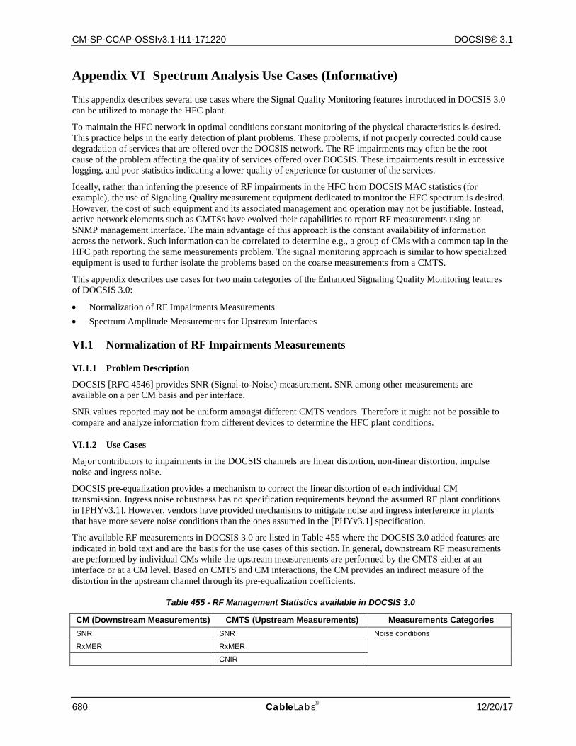
CM-SP-CCAP-OSSIv3.1-I11-171220 DOCSIS® 3.1
680 CableLabs 12/20/17
Appendix VI Spectrum Analysis Use Cases (Informative)
This appendix describes several use cases where the Signal Quality Monitoring features introduced in DOCSIS 3.0 can be utilized to manage the HFC plant.
To maintain the HFC network in optimal conditions constant monitoring of the physical characteristics is desired. This practice helps in the early detection of plant problems. These problems, if not properly corrected could cause degradation of services that are offered over the DOCSIS network. The RF impairments may often be the root cause of the problem affecting the quality of services offered over DOCSIS. These impairments result in excessive logging, and poor statistics indicating a lower quality of experience for customer of the services.
Ideally, rather than inferring the presence of RF impairments in the HFC from DOCSIS MAC statistics (for example), the use of Signaling Quality measurement equipment dedicated to monitor the HFC spectrum is desired. However, the cost of such equipment and its associated management and operation may not be justifiable. Instead, active network elements such as CMTSs have evolved their capabilities to report RF measurements using an SNMP management interface. The main advantage of this approach is the constant availability of information across the network. Such information can be correlated to determine e.g., a group of CMs with a common tap in the HFC path reporting the same measurements problem. The signal monitoring approach is similar to how specialized equipment is used to further isolate the problems based on the coarse measurements from a CMTS.
This appendix describes use cases for two main categories of the Enhanced Signaling Quality Monitoring features of DOCSIS 3.0:
• Normalization of RF Impairments Measurements • Spectrum Amplitude Measurements for Upstream Interfaces
VI.1 Normalization of RF Impairments Measurements
VI.1.1 Problem Description
DOCSIS [RFC 4546] provides SNR (Signal-to-Noise) measurement. SNR among other measurements are available on a per CM basis and per interface.
SNR values reported may not be uniform amongst different CMTS vendors. Therefore it might not be possible to compare and analyze information from different devices to determine the HFC plant conditions.
VI.1.2 Use Cases
Major contributors to impairments in the DOCSIS channels are linear distortion, non-linear distortion, impulse noise and ingress noise.
DOCSIS pre-equalization provides a mechanism to correct the linear distortion of each individual CM transmission. Ingress noise robustness has no specification requirements beyond the assumed RF plant conditions in [PHYv3.1]. However, vendors have provided mechanisms to mitigate noise and ingress interference in plants that have more severe noise conditions than the ones assumed in the [PHYv3.1] specification.
The available RF measurements in DOCSIS 3.0 are listed in Table 455 where the DOCSIS 3.0 added features are indicated in bold text and are the basis for the use cases of this section. In general, downstream RF measurements are performed by individual CMs while the upstream measurements are performed by the CMTS either at an interface or at a CM level. Based on CMTS and CM interactions, the CM provides an indirect measure of the distortion in the upstream channel through its pre-equalization coefficients.
Table 455 - RF Management Statistics available in DOCSIS 3.0
CM (Downstream Measurements) CMTS (Upstream Measurements) Measurements Categories SNR SNR Noise conditions
RxMER RxMER
CNIR
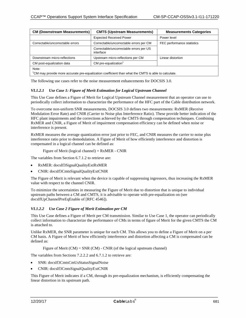
CCAP™ Operations Support System Interface Specification CM-SP-CCAP-OSSIv3.1-I11-171220
12/20/17 CableLabs 681
CM (Downstream Measurements) CMTS (Upstream Measurements) Measurements Categories Expected Received Power Power level
Correctable/uncorrectable errors Correctable/uncorrectable errors per CM FEC performance statistics
Correctable/uncorrectable errors per US interface
Downstream micro-reflections Upstream micro-reflections per CM Linear distortion
CM post-equalization data CM pre-equalization1
Note: 1CM may provide more accurate pre-equalization coefficient than what the CMTS is able to calculate.
The following use cases refer to the noise measurement enhancements for DOCSIS 3.0.
VI.1.2.1 Use Case 1: Figure of Merit Estimation for Logical Upstream Channel
This Use Case defines a Figure of Merit for Logical Upstream Channel measurement that an operator can use to periodically collect information to characterize the performance of the HFC part of the Cable distribution network.
To overcome non-uniform SNR measurements, DOCSIS 3.0 defines two measurements: RxMER (Receive Modulation Error Rate) and CNIR (Carrier to Noise plus Interference Ratio). These provide better indication of the HFC plant impairments and the corrections achieved by the CMTS through compensation techniques. Combining RxMER and CNIR, a Figure of Merit of impairment compensation efficiency can be defined when noise or interference is present.
RxMER measures the average quantization error just prior to FEC, and CNIR measures the carrier to noise plus interference ratio prior to demodulation. A Figure of Merit of how efficiently interference and distortion is compensated in a logical channel can be defined as:
Figure of Merit (logical channel) = RxMER - CNIR
The variables from Section 6.7.1.2 to retrieve are:
• RxMER: docsIf3SignalQualityExtRxMER • CNIR: docsIf3CmtsSignalQualityExtCNIR
The Figure of Merit is relevant when the device is capable of suppressing ingressors, thus increasing the RxMER value with respect to the channel CNIR.
To minimize the uncertainties in measuring the Figure of Merit due to distortion that is unique to individual upstream paths between a CM and CMTS, it is advisable to operate with pre-equalization on (see docsIfUpChannelPreEqEnable of [RFC 4546]).
VI.1.2.2 Use Case 2 Figure of Merit Estimation per CM
This Use Case defines a Figure of Merit per CM transmission. Similar to Use Case 1, the operator can periodically collect information to characterize the performance of CMs in terms of figure of Merit for the given CMTS the CM is attached to.
Unlike RxMER, the SNR parameter is unique for each CM. This allows you to define a Figure of Merit on a per CM basis. A Figure of Merit of how efficiently interference and distortion affecting a CM is compensated can be defined as:
Figure of Merit (CM) = SNR (CM) - CNIR (of the logical upstream channel)
The variables from Sections 7.2.2.2 and 6.7.1.2 to retrieve are:
• SNR: docsIf3CmtsCmUsStatusSignalNoise • CNIR: docsIf3CmtsSignalQualityExtCNIR
This Figure of Merit indicates if a CM, through its pre-equalization mechanism, is efficiently compensating the linear distortion in its upstream path.
CM-SP-CCAP-OSSIv3.1-I11-171220 DOCSIS® 3.1
682 CableLabs 12/20/17
VI.1.2.3 Use Case 3 Absolute Noise and Interference Estimation
Traditionally CMTSs are expected to command the CMs' power transmission so that the CMTS received power is close to 0 dBmV across all CMs.
This Use Case defines how an operator may derive the absolute value of the noise plus interference (in dBmV) from the reported value (CNIR in dB) which is a relative measure.
For example, CNIR and ExpectedRxSignalPower can be used to estimate noise and interference levels (N+I) across the operator's network in dBmV as:
N + I = CNIR - ExpectedRxSignalPower (CMs of the logical upstream channel)
Operators may determine the difference between the target and the actual received power at the CMTS using the following equation:
CM Offset Power = CM Rx Power - ExpectedRxSignalPower
The variables from Sections 7.2.2.2 and 6.7.1.2 to retrieve are:
• CM Rx Power: docsIf3CmtsCmUsStatusRxPower • ExpectedRxSignalPower: docsIf3CmtsSignalQualityExtExpectedRxSignalPower
VI.1.2.3.1 CM Estimated CNIR
Operators may estimate individual CM CNIR by combining the CNIR obtained for the logical channel and the CM offset power as follows:
CM Estimated CNIR = CM Offset Power + CNIR
CM Offset Power: The difference between the actual received CM power level and the expected commanded received signal power at the CMTS.
The variables from Sections 7.2.2.2 and 6.7.1.2 to retrieve are:
• CNIR: docsIf3CmtsSignalQualityExtCNIR • CM Rx Power: docsIf3CmtsCmUsStatusRxPower • Expected Commanded Received Signal Power: docsIf3CmtsSignalQualityExtExpectedRxSignalPower
VI.2 Upstream Spectrum Measurement Monitoring
VI.2.1 Problem Description
Placing spectrum analyzers to obtain granular spectrum monitoring to achieve extensive coverage of the number of nodes, the number of channels, increased frequency of samples, and with increased frequency resolution is cost prohibitive and cumbersome. Such limited coverage complicates agile troubleshooting of plant spectrum.
VI.2.2 Use Cases
DOCSIS 3.0 adds the spectrum monitoring feature where the management system requests CMTSs to perform spectrum measurement over an upstream channel.
VI.2.2.1 Use Case 1 Spectrum Analysis Measurement Setup
This Use Case describes the operator configuration procedure to start the measurements of spectrum amplitude values for a specific channel.
The operator only needs to select the logical upstream channel for which the upstream receiver will capture the spectrum amplitude. SNMP is used to trigger the test using a read-create RowStatus object set to 'CreateAndGo'.
The CMTS reports the following pre-configured parameters (refer to [OSSIv3.0] Annex J for object details):
• The NumberOfBins is the number of data points that compose the spectral data.
CCAP™ Operations Support System Interface Specification CM-SP-CCAP-OSSIv3.1-I11-171220
12/20/17 CableLabs 683
• The FrequencySpan is the width of the band across which the spectral amplitudes characterizing the channel are measured.
• The ResolutionBW is the equivalent noise bandwidth for each bin. • The TimeInterval is the estimated average repetition period of measurements defining the average rate at
which new spectra can be retrieved. An SNMP manager should not attempt to collect the data at a higher rate than the value specified.
• The BinSpacing is the frequency separation between adjacent bin centers.
VI.2.2.2 Use Case 2 Data Retrieval
This Use Case describes a typical procedure for the retrieval of spectrum amplitude data from the CMTS. The data can be retrieved via SNMP or streamed by the CMTS using the Spectrum Amplitude IPDR Service Definition defined in Section 8.
Section 8 illustrates the detailed steps for the IPDR connection establishment and data retrieval. The following process briefly defines the data retrieval process. Refer to Section 8.2 for details on the IPDR Streaming Protocol.
The collector opens a connection with the CMTS. If a reliable collection mechanism is not required, there is no need to have a backup collector.
The CMTS is configured to generate data for a given interface.
When the CMTS setup is complete, it starts the transfer of information to the collector.
The operator can then use an application to plot the information collected as shown in Figure 72 and Figure 73.
When the operator no longer wishes to continue retrieving information, the operator can remove the measurement point in the CMTS which suspends the data generation and export. The operator can then tear down the previously established IPDR/SP connection.
The Figure 72 shows the sequence diagram for streaming of spectrum analysis measurement data. The operator selects the logical upstream channel of interest. The CMTS starts the data streaming to the collector. After the data is captured, the streaming may be terminated.
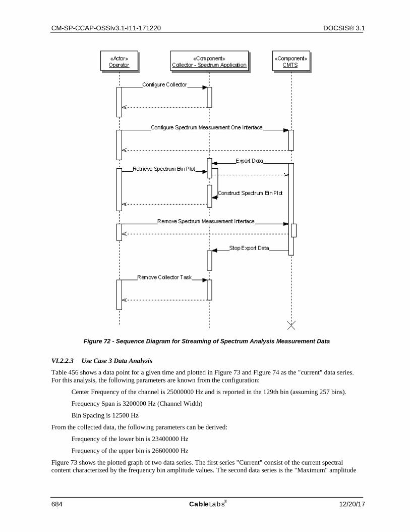
CM-SP-CCAP-OSSIv3.1-I11-171220 DOCSIS® 3.1
684 CableLabs 12/20/17
Figure 72 - Sequence Diagram for Streaming of Spectrum Analysis Measurement Data
VI.2.2.3 Use Case 3 Data Analysis
Table 456 shows a data point for a given time and plotted in Figure 73 and Figure 74 as the "current" data series. For this analysis, the following parameters are known from the configuration:
Center Frequency of the channel is 25000000 Hz and is reported in the 129th bin (assuming 257 bins).
Frequency Span is 3200000 Hz (Channel Width)
Bin Spacing is 12500 Hz
From the collected data, the following parameters can be derived:
Frequency of the lower bin is 23400000 Hz
Frequency of the upper bin is 26600000 Hz
Figure 73 shows the plotted graph of two data series. The first series "Current" consist of the current spectral content characterized by the frequency bin amplitude values. The second data series is the "Maximum" amplitude
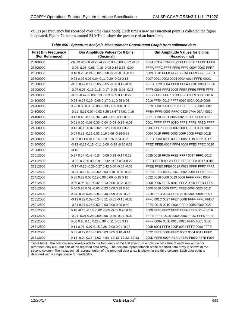
CCAP™ Operations Support System Interface Specification CM-SP-CCAP-OSSIv3.1-I11-171220
12/20/17 CableLabs 685
values per frequency bin recorded over time (max hold). Each time a new measurement point is collected the figure is updated. Figure 74 zooms around 24 MHz to show the presence of an interferer.
Table 456 - Spectrum Analysis Measurement Constructed Graph from collected data
First Bin Frequency (For Reference)
Bin Amplitude Values for 8 bins (Decimal)
Bin Amplitude Values for 8 bins (Hexadecimal)
23400000 -39.73 -20.60 -9.23 -4.77 -2.90 -0.08 -0.32 -0.07 F07A F7F4 FC64 FE23 FEDE FFF7 FFDF FFF9
23500000 -0.06 -0.03 -0.08 -0.16 -0.08 0.16 0.13 -0.09 FFFA FFFC FFF8 FFF0 FFF7 000F 000C FFF7
23600000 0.10 0.28 -0.24 -0.02 -0.38 -0.23 -0.01 -0.20 0009 001B FFE8 FFFE FFDA FFE9 FFFE FFEB
23700000 0.08 0.02 0.03 0.04 0.11 0.20 -0.03 0.13 0007 0001 0002 0004 000A 0014 FFFD 000C
23800000 -0.05 0.42 0.11 -0.05 -0.05 -0.36 0.12 -0.06 FFFB 0029 000A FFFB FFFA FFDC 000B FFFA
23900000 -0.07 0.03 -0.13 0.15 -0.17 -0.25 -0.01 -0.13 FFF8 0003 FFF3 000E FFEF FFE6 FFFE FFF3
24000000 -0.09 -0.47 -0.08 0.19 -0.03 0.09 0.13 0.27 FFF7 FFD0 FFF7 0013 FFFD 0009 000D 001A
24100000 0.23 -0.27 0.19 -0.08 0.17 0.11 0.25 0.06 0016 FFE4 0013 FFF7 0010 000A 0019 0005
24200000 0.26 0.00 0.03 -0.08 -0.33 -0.05 0.10 0.08 0019 0000 0003 FFF8 FFDE FFFB 0009 0007
24300000 -0.21 -0.11 0.07 -0.03 8.25 18.67 17.01 0.16 FFEA FFF5 0006 FFFC 0339 074A 06A4 0010
24400000 0.17 0.48 -0.15 0.34 0.40 -0.01 -0.12 0.02 0011 0030 FFF1 0022 0028 FFFE FFF3 0001
24500000 0.01 0.00 -0.08 0.30 -0.04 -0.04 -0.19 -0.01 0001 FFFF FFF7 001D FFFB FFFB FFED FFFF
24600000 0.13 -0.08 -0.07 0.02 0.12 -0.20 0.11 0.25 000D FFF7 FFF9 0002 000B FFEB 000B 0018
24700000 0.04 0.32 -0.11 0.03 0.16 0.06 -0.26 0.28 0004 001F FFF5 0003 000F 0005 FFE6 001B
24800000 -0.05 0.11 0.01 0.14 0.10 0.26 0.34 0.23 FFFB 000A 0000 000E 000A 0019 0022 0017
24900000 -0.18 -0.17 0.15 -0.11 0.08 -0.29 -0.20 0.32 FFED FFEE 000F FFF4 0008 FFE3 FFEC 0020
25000000 -0.10 FFF5
25012500 0.37 0.24 -0.43 -0.24 -0.09 0.23 -0.14 0.19 0025 0018 FFD5 FFE8 FFF7 0017 FFF1 0013
25112500 -0.02 -0.20 0.03 -0.01 -0.12 -0.07 0.24 0.22 FFFD FFEB 0003 FFFE FFF3 FFF8 0017 0015
25212500 -0.17 -0.20 -0.26 0.27 0.42 0.00 -0.08 -0.06 FFEE FFEC FFE6 001A 0029 FFFF FFF7 FFFA
25312500 -0.31 -0.12 0.13 0.02 0.03 0.10 -0.06 -0.30 FFE0 FFF3 000C 0001 0002 000A FFF9 FFE2
25412500 0.35 0.23 0.08 0.19 0.06 0.00 -0.15 0.16 0022 0016 0008 0013 0006 FFFF FFF0 000F
25512500 0.00 0.06 -0.19 0.32 -0.13 0.06 -0.03 -0.10 0000 0006 FFED 001F FFF2 0006 FFFD FFF5
25612500 0.00 0.26 0.09 -0.63 -0.23 0.09 0.38 0.30 0000 0019 0009 FFC1 FFE8 0008 0026 001D
25712500 0.24 -0.03 0.03 -0.01 0.30 0.09 0.05 -0.25 0018 FFFD 0003 FFFE 001D 0009 0004 FFE7
25812500 -0.11 0.29 0.39 -0.24 0.11 -0.01 -0.16 -0.36 FFF5 001C 0027 FFE7 000B FFFF FFF0 FFDC
25912500 -0.31 0.27 0.28 0.53 -0.03 0.08 0.00 0.40 FFE1 001B 001C 0034 FFFD 0008 0000 0027
26012500 0.10 -0.16 -0.13 -0.02 -0.05 -0.05 0.20 0.23 0009 FFF0 FFF2 FFFE FFFA FFFB 0014 0016
26112500 -0.01 -0.01 0.24 0.00 0.06 -0.36 -0.09 -0.02 FFFE FFFE 0018 0000 0006 FFDC FFF6 FFFE
26212500 0.00 0.10 0.15 0.21 0.36 -0.11 0.01 0.13 FFFF 000A 000E 0015 0023 FFF5 0001 000C
26312500 0.11 0.01 -0.07 0.15 0.36 -0.08 0.01 -0.02 000B 0001 FFF9 000E 0024 FFF7 0000 FFFE
26412500 0.35 -0.17 0.16 -0.03 0.03 0.05 0.18 -0.14 0022 FFEF 000F FFFC 0002 0004 0011 FFF2
26512500 0.13 -0.04 0.15 -2.62 -4.54 -10.43 -19.22 -39.43 000D FFFB 000F FEFA FE39 FBED F87E F098
Table Note: This first column corresponds to the frequency of the first spectrum amplitude bin value of each row and is for reference only (i.e., not part of the reported data array). The decimal representation of the reported data array is shown in the second column. The hexadecimal representation of the reported data array is shown in the third column. Each data point is delimited with a single space for readability.
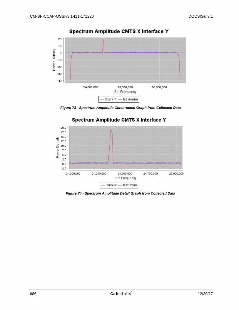
CM-SP-CCAP-OSSIv3.1-I11-171220 DOCSIS® 3.1
686 CableLabs 12/20/17
Figure 73 - Spectrum Amplitude Constructed Graph from Collected Data
Figure 74 - Spectrum Amplitude Detail Graph from Collected Data

CCAP™ Operations Support System Interface Specification CM-SP-CCAP-OSSIv3.1-I11-171220
12/20/17 CableLabs 687
Appendix VII Information Model Notation (Informative)
This appendix illustrates the UML notation used throughout this specification to define Information Models.
VII.1 Overview The Unified Modeling Language (UML) is a unified model for object oriented analysis and design (OOA&D). UML is an OMG standard and is an accepted ISO specification [ISO 19501].
UML defines a general-purpose, graphical modeling language that can be applied to any application domain (e.g., communications) and implementation platforms (e.g., J2EE).
VII.2 Information Model Diagram The OSSI Information Model diagram is represented by the UML Class Diagram. The class diagram describes the types of objects existing in a system and their static relationship or association.
VII.2.1 Classes
Classes are generally represented by a square box with three compartments. The top compartment contains the class name (used here as the object name) with the first letter capitalized. The middle compartment contains the list of attributes with the first letter of each attribute in lower case. The bottom compartment contains the list of operations. For the purposes of this specification, the methods section of the class box is not used (suppressed) and the implementation level details of the attributes are omitted.
Attributes also include a visibility notation which precedes the attribute name and is one of the following:
• '+' public (default) • '-' private • '#' protected
If the above notation is omitted from the attribute, the default of public is implied. For the purposes of this specification, the protected visibility generally refers to indexes of MIB tables, schema instances, etc.
An interface is represented in the class diagram as an object with the keyword <<interface>> preceding the object name. In general, an interface is a declaration of a set of public features and obligations (such as get methods).
VII.2.2 Associations
A class diagram also contains associations which represent relationships between instances of classes. An association has two ends with each end attached to one of the classes. The association end also has a multiplicity indicator which defines how many objects may participate in the relationship. Multiplicity notation is as follows:
• '1' exactly one • '*' zero or more (default) • '0..1' zero or one (optional) • 'm..n' numerically specified
If the above notation is omitted from the association end, the default of '*' is implied.
If one end of the association contains an open arrowhead, this implies navigability in the direction indicated by the arrow.
VII.2.3 Generalization
Generalization is the concept of creating subclasses from superclasses and is also known as inheritance within programming languages. Subclasses include (or inherit) all the elements of the superclass and may override inherited methods. Subclasses are more specific classes while superclasses are generalized classes.
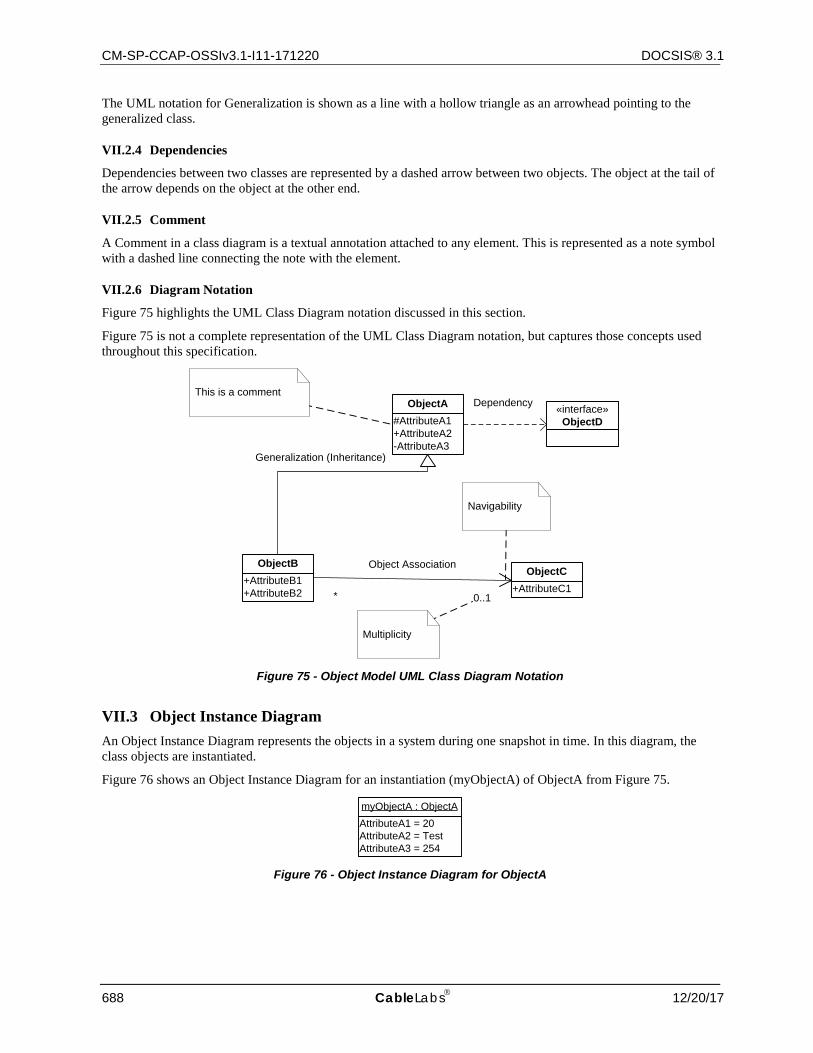
CM-SP-CCAP-OSSIv3.1-I11-171220 DOCSIS® 3.1
688 CableLabs 12/20/17
The UML notation for Generalization is shown as a line with a hollow triangle as an arrowhead pointing to the generalized class.
VII.2.4 Dependencies
Dependencies between two classes are represented by a dashed arrow between two objects. The object at the tail of the arrow depends on the object at the other end.
VII.2.5 Comment
A Comment in a class diagram is a textual annotation attached to any element. This is represented as a note symbol with a dashed line connecting the note with the element.
VII.2.6 Diagram Notation
Figure 75 highlights the UML Class Diagram notation discussed in this section.
Figure 75 is not a complete representation of the UML Class Diagram notation, but captures those concepts used throughout this specification.
#AttributeA1+AttributeA2-AttributeA3
ObjectAThis is a comment
+AttributeB1+AttributeB2
ObjectB
+AttributeC1ObjectC
Generalization (Inheritance)
* 0..1
Object Association
Navigability
Multiplicity
«interface»ObjectD
Dependency
Figure 75 - Object Model UML Class Diagram Notation
VII.3 Object Instance Diagram An Object Instance Diagram represents the objects in a system during one snapshot in time. In this diagram, the class objects are instantiated.
Figure 76 shows an Object Instance Diagram for an instantiation (myObjectA) of ObjectA from Figure 75.
AttributeA1 = 20AttributeA2 = TestAttributeA3 = 254
myObjectA : ObjectA
Figure 76 - Object Instance Diagram for ObjectA

CCAP™ Operations Support System Interface Specification CM-SP-CCAP-OSSIv3.1-I11-171220
12/20/17 CableLabs 689
VII.4 ObjectA Definition Example This section defines the details of the object and its associated attributes as defined in the object model diagram. The description of the object includes behavior, persistence requirements (if any), object creation and deletion behavior (if any), etc.
Table 457 lists the attributes the object defined in the object model. The object table is derived from the object model diagram where each row in the table represents an attribute of the object.
The "Attribute Name" column contains each defined attribute of the object. The naming convention for attributes is to capitalize the first letter and each letter of successive words within the name. Also, attribute names typically do not include any of the object name elements since this would cause duplication when the object and attributes are realized in SNMP.
The "Type" column contains the data type for the attribute. The data type can be a simple type such as unsignedInt or a defined data type such as EnumBits. DOCSIS 3.0 data types are defined in Annex F.
The "Access" column indicates the attributes accessibility (as mapped to an SNMP object for example). Example values include "key", "read-only", "read-write", and "read-create".
The "Type Constraints" column lists constraints on the normal data type specified in the "Type" column. If there are no defined constraints for the attribute, this column is empty. The example below for AttributeA1 lists a constraint on the unsignedInt Type where the range starts from 1 instead of normally starting from 0 for an unsignedInt.
The "Units" column lists units for the attribute or "N/A" if the attribute does not have units.
The "Default" column contains the default value for the attribute or "N/A" if the attribute does not have a default value or in cases where the attribute's description defines rules for the initialization value.
The sections following the table are attribute descriptions which might include behavioral requirements or references.
Table 457 - ObjectA Example Table Layout
Attribute Name Type Access Type Constraints Units Default AttributeA1 unsignedInt key 1..4294967295 N/A N/A
AttributeA2 AdminString read-write SIZE (1..15) N/A N/A
AttributeA3 unsignedByte read-create seconds 60
VII.4.1.1 AttributeA1
AttributeA1 is a key defined for...
NOTE: Objects which represent a table (in an SNMP MIB realization) and have N number of instances need to include at least one "key" attribute which is used to denote the instance or id. Key attributes are typically denoted with a protected visibility whereas all other attributes are denoted with a public visibility.
VII.4.1.2 AttributeA2
AttributeA2 is ...
NOTE: Persistence requirements are documented at the object level, not at the attribute level.
VII.4.1.3 AttributeA3
AttributeA3 is ...
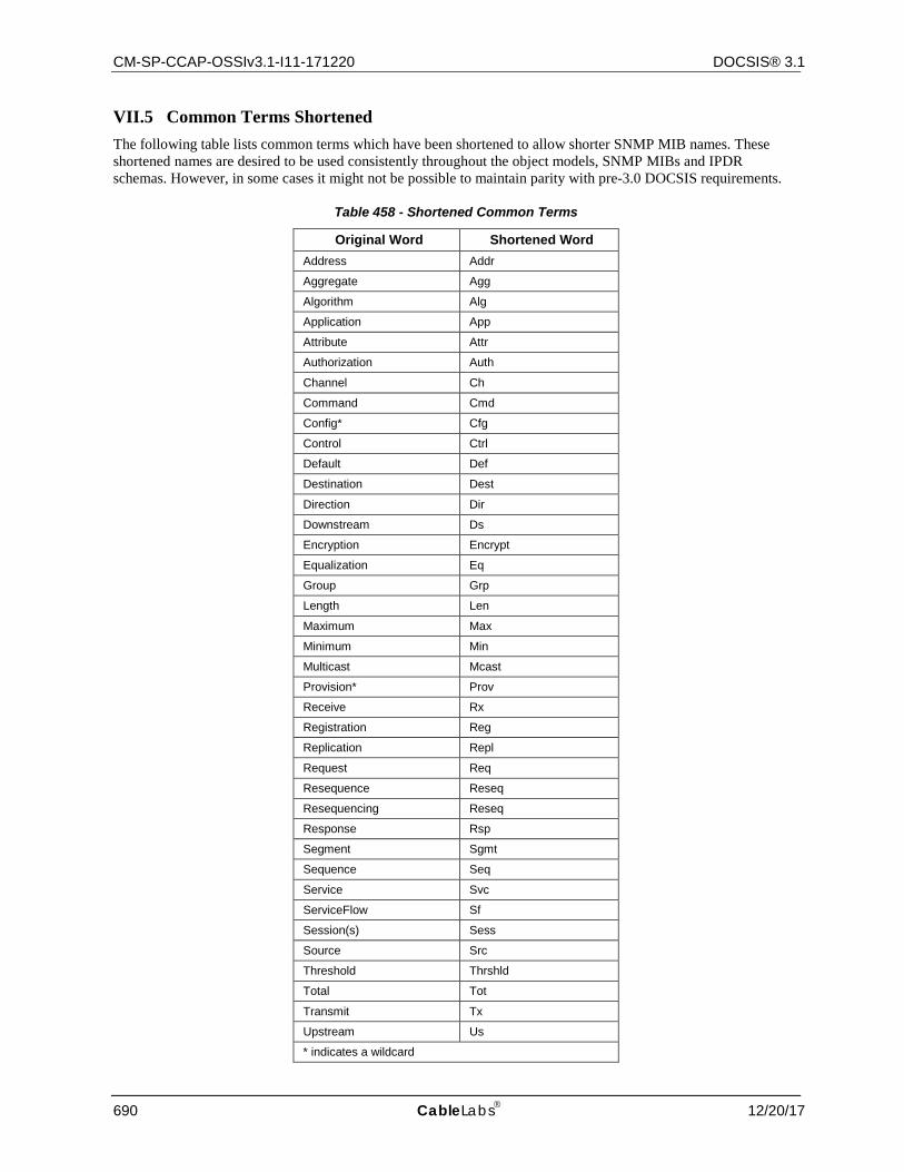
CM-SP-CCAP-OSSIv3.1-I11-171220 DOCSIS® 3.1
690 CableLabs 12/20/17
VII.5 Common Terms Shortened The following table lists common terms which have been shortened to allow shorter SNMP MIB names. These shortened names are desired to be used consistently throughout the object models, SNMP MIBs and IPDR schemas. However, in some cases it might not be possible to maintain parity with pre-3.0 DOCSIS requirements.
Table 458 - Shortened Common Terms
Original Word Shortened Word Address Addr
Aggregate Agg
Algorithm Alg
Application App
Attribute Attr
Authorization Auth
Channel Ch
Command Cmd
Config* Cfg
Control Ctrl
Default Def
Destination Dest
Direction Dir
Downstream Ds
Encryption Encrypt
Equalization Eq
Group Grp
Length Len
Maximum Max
Minimum Min
Multicast Mcast
Provision* Prov
Receive Rx
Registration Reg
Replication Repl
Request Req
Resequence Reseq
Resequencing Reseq
Response Rsp
Segment Sgmt
Sequence Seq
Service Svc
ServiceFlow Sf
Session(s) Sess
Source Src
Threshold Thrshld
Total Tot
Transmit Tx
Upstream Us
* indicates a wildcard

CCAP™ Operations Support System Interface Specification CM-SP-CCAP-OSSIv3.1-I11-171220
12/20/17 CableLabs 691
VII.5.1 Exceptions
Data types and managed objects do not consistently use the shortened names. Also, the term ServiceFlowId remains unchanged. Service and ServiceFlow are often not shortened to retain backward compatibility with QoS managed objects.
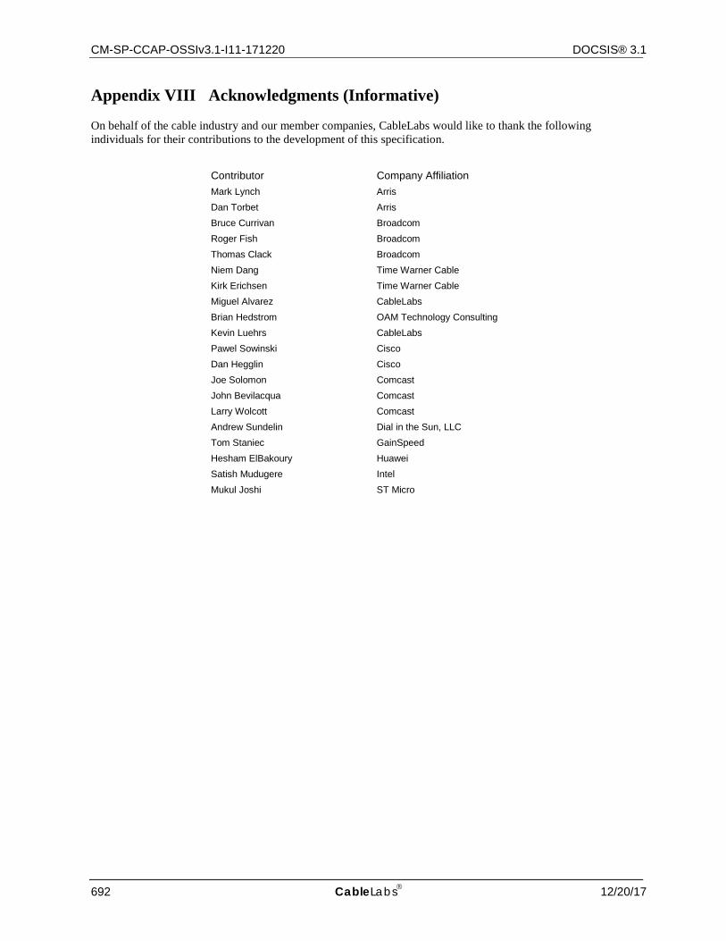
CM-SP-CCAP-OSSIv3.1-I11-171220 DOCSIS® 3.1
692 CableLabs 12/20/17
Appendix VIII Acknowledgments (Informative)
On behalf of the cable industry and our member companies, CableLabs would like to thank the following individuals for their contributions to the development of this specification.
Contributor Company Affiliation Mark Lynch Arris Dan Torbet Arris Bruce Currivan Broadcom Roger Fish Broadcom Thomas Clack Broadcom Niem Dang Time Warner Cable Kirk Erichsen Time Warner Cable Miguel Alvarez CableLabs Brian Hedstrom OAM Technology Consulting Kevin Luehrs CableLabs Pawel Sowinski Cisco Dan Hegglin Cisco Joe Solomon Comcast John Bevilacqua Comcast Larry Wolcott Comcast Andrew Sundelin Dial in the Sun, LLC Tom Staniec GainSpeed Hesham ElBakoury Huawei Satish Mudugere Intel Mukul Joshi ST Micro
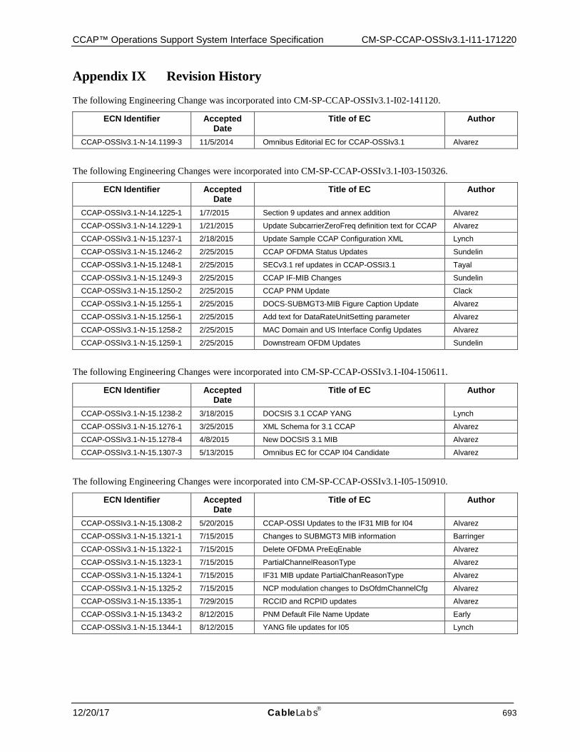
CCAP™ Operations Support System Interface Specification CM-SP-CCAP-OSSIv3.1-I11-171220
12/20/17 CableLabs 693
Appendix IX Revision History
The following Engineering Change was incorporated into CM-SP-CCAP-OSSIv3.1-I02-141120.
ECN Identifier Accepted Date
Title of EC Author
CCAP-OSSIv3.1-N-14.1199-3 11/5/2014 Omnibus Editorial EC for CCAP-OSSIv3.1 Alvarez
The following Engineering Changes were incorporated into CM-SP-CCAP-OSSIv3.1-I03-150326.
ECN Identifier Accepted Date
Title of EC Author
CCAP-OSSIv3.1-N-14.1225-1 1/7/2015 Section 9 updates and annex addition Alvarez
CCAP-OSSIv3.1-N-14.1229-1 1/21/2015 Update SubcarrierZeroFreq definition text for CCAP Alvarez
CCAP-OSSIv3.1-N-15.1237-1 2/18/2015 Update Sample CCAP Configuration XML Lynch
CCAP-OSSIv3.1-N-15.1246-2 2/25/2015 CCAP OFDMA Status Updates Sundelin
CCAP-OSSIv3.1-N-15.1248-1 2/25/2015 SECv3.1 ref updates in CCAP-OSSI3.1 Tayal
CCAP-OSSIv3.1-N-15.1249-3 2/25/2015 CCAP IF-MIB Changes Sundelin
CCAP-OSSIv3.1-N-15.1250-2 2/25/2015 CCAP PNM Update Clack
CCAP-OSSIv3.1-N-15.1255-1 2/25/2015 DOCS-SUBMGT3-MIB Figure Caption Update Alvarez
CCAP-OSSIv3.1-N-15.1256-1 2/25/2015 Add text for DataRateUnitSetting parameter Alvarez
CCAP-OSSIv3.1-N-15.1258-2 2/25/2015 MAC Domain and US Interface Config Updates Alvarez
CCAP-OSSIv3.1-N-15.1259-1 2/25/2015 Downstream OFDM Updates Sundelin
The following Engineering Changes were incorporated into CM-SP-CCAP-OSSIv3.1-I04-150611.
ECN Identifier Accepted Date
Title of EC Author
CCAP-OSSIv3.1-N-15.1238-2 3/18/2015 DOCSIS 3.1 CCAP YANG Lynch
CCAP-OSSIv3.1-N-15.1276-1 3/25/2015 XML Schema for 3.1 CCAP Alvarez
CCAP-OSSIv3.1-N-15.1278-4 4/8/2015 New DOCSIS 3.1 MIB Alvarez
CCAP-OSSIv3.1-N-15.1307-3 5/13/2015 Omnibus EC for CCAP I04 Candidate Alvarez
The following Engineering Changes were incorporated into CM-SP-CCAP-OSSIv3.1-I05-150910.
ECN Identifier Accepted Date
Title of EC Author
CCAP-OSSIv3.1-N-15.1308-2 5/20/2015 CCAP-OSSI Updates to the IF31 MIB for I04 Alvarez
CCAP-OSSIv3.1-N-15.1321-1 7/15/2015 Changes to SUBMGT3 MIB information Barringer
CCAP-OSSIv3.1-N-15.1322-1 7/15/2015 Delete OFDMA PreEqEnable Alvarez
CCAP-OSSIv3.1-N-15.1323-1 7/15/2015 PartialChannelReasonType Alvarez
CCAP-OSSIv3.1-N-15.1324-1 7/15/2015 IF31 MIB update PartialChanReasonType Alvarez
CCAP-OSSIv3.1-N-15.1325-2 7/15/2015 NCP modulation changes to DsOfdmChannelCfg Alvarez
CCAP-OSSIv3.1-N-15.1335-1 7/29/2015 RCCID and RCPID updates Alvarez
CCAP-OSSIv3.1-N-15.1343-2 8/12/2015 PNM Default File Name Update Early
CCAP-OSSIv3.1-N-15.1344-1 8/12/2015 YANG file updates for I05 Lynch
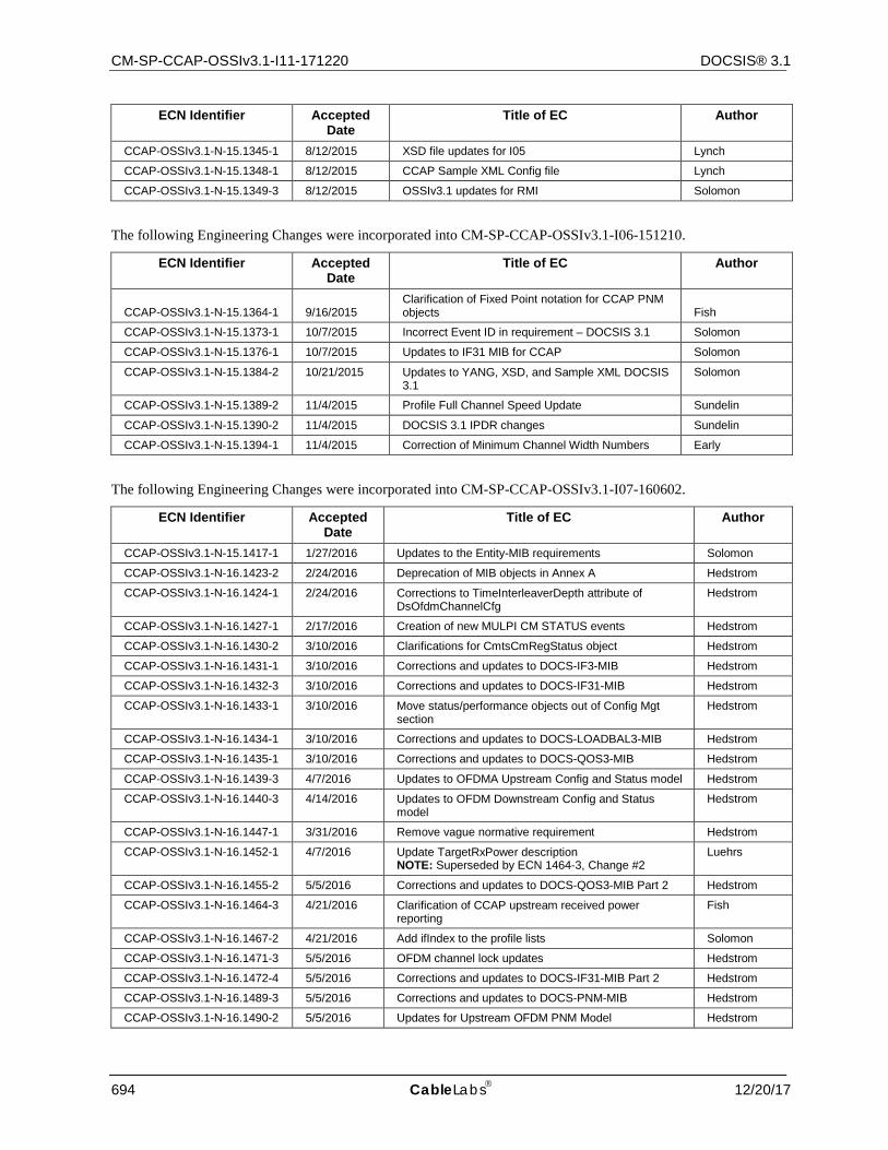
CM-SP-CCAP-OSSIv3.1-I11-171220 DOCSIS® 3.1
694 CableLabs 12/20/17
ECN Identifier Accepted Date
Title of EC Author
CCAP-OSSIv3.1-N-15.1345-1 8/12/2015 XSD file updates for I05 Lynch
CCAP-OSSIv3.1-N-15.1348-1 8/12/2015 CCAP Sample XML Config file Lynch
CCAP-OSSIv3.1-N-15.1349-3 8/12/2015 OSSIv3.1 updates for RMI Solomon
The following Engineering Changes were incorporated into CM-SP-CCAP-OSSIv3.1-I06-151210.
ECN Identifier Accepted Date
Title of EC Author
CCAP-OSSIv3.1-N-15.1364-1 9/16/2015 Clarification of Fixed Point notation for CCAP PNM objects Fish
CCAP-OSSIv3.1-N-15.1373-1 10/7/2015 Incorrect Event ID in requirement – DOCSIS 3.1 Solomon
CCAP-OSSIv3.1-N-15.1376-1 10/7/2015 Updates to IF31 MIB for CCAP Solomon
CCAP-OSSIv3.1-N-15.1384-2 10/21/2015 Updates to YANG, XSD, and Sample XML DOCSIS 3.1
Solomon
CCAP-OSSIv3.1-N-15.1389-2 11/4/2015 Profile Full Channel Speed Update Sundelin
CCAP-OSSIv3.1-N-15.1390-2 11/4/2015 DOCSIS 3.1 IPDR changes Sundelin
CCAP-OSSIv3.1-N-15.1394-1 11/4/2015 Correction of Minimum Channel Width Numbers Early
The following Engineering Changes were incorporated into CM-SP-CCAP-OSSIv3.1-I07-160602.
ECN Identifier Accepted Date
Title of EC Author
CCAP-OSSIv3.1-N-15.1417-1 1/27/2016 Updates to the Entity-MIB requirements Solomon
CCAP-OSSIv3.1-N-16.1423-2 2/24/2016 Deprecation of MIB objects in Annex A Hedstrom
CCAP-OSSIv3.1-N-16.1424-1 2/24/2016 Corrections to TimeInterleaverDepth attribute of DsOfdmChannelCfg
Hedstrom
CCAP-OSSIv3.1-N-16.1427-1 2/17/2016 Creation of new MULPI CM STATUS events Hedstrom
CCAP-OSSIv3.1-N-16.1430-2 3/10/2016 Clarifications for CmtsCmRegStatus object Hedstrom
CCAP-OSSIv3.1-N-16.1431-1 3/10/2016 Corrections and updates to DOCS-IF3-MIB Hedstrom
CCAP-OSSIv3.1-N-16.1432-3 3/10/2016 Corrections and updates to DOCS-IF31-MIB Hedstrom
CCAP-OSSIv3.1-N-16.1433-1 3/10/2016 Move status/performance objects out of Config Mgt section
Hedstrom
CCAP-OSSIv3.1-N-16.1434-1 3/10/2016 Corrections and updates to DOCS-LOADBAL3-MIB Hedstrom
CCAP-OSSIv3.1-N-16.1435-1 3/10/2016 Corrections and updates to DOCS-QOS3-MIB Hedstrom
CCAP-OSSIv3.1-N-16.1439-3 4/7/2016 Updates to OFDMA Upstream Config and Status model Hedstrom
CCAP-OSSIv3.1-N-16.1440-3 4/14/2016 Updates to OFDM Downstream Config and Status model
Hedstrom
CCAP-OSSIv3.1-N-16.1447-1 3/31/2016 Remove vague normative requirement Hedstrom
CCAP-OSSIv3.1-N-16.1452-1 4/7/2016 Update TargetRxPower description NOTE: Superseded by ECN 1464-3, Change #2
Luehrs
CCAP-OSSIv3.1-N-16.1455-2 5/5/2016 Corrections and updates to DOCS-QOS3-MIB Part 2 Hedstrom
CCAP-OSSIv3.1-N-16.1464-3 4/21/2016 Clarification of CCAP upstream received power reporting
Fish
CCAP-OSSIv3.1-N-16.1467-2 4/21/2016 Add ifIndex to the profile lists Solomon
CCAP-OSSIv3.1-N-16.1471-3 5/5/2016 OFDM channel lock updates Hedstrom
CCAP-OSSIv3.1-N-16.1472-4 5/5/2016 Corrections and updates to DOCS-IF31-MIB Part 2 Hedstrom
CCAP-OSSIv3.1-N-16.1489-3 5/5/2016 Corrections and updates to DOCS-PNM-MIB Hedstrom
CCAP-OSSIv3.1-N-16.1490-2 5/5/2016 Updates for Upstream OFDM PNM Model Hedstrom
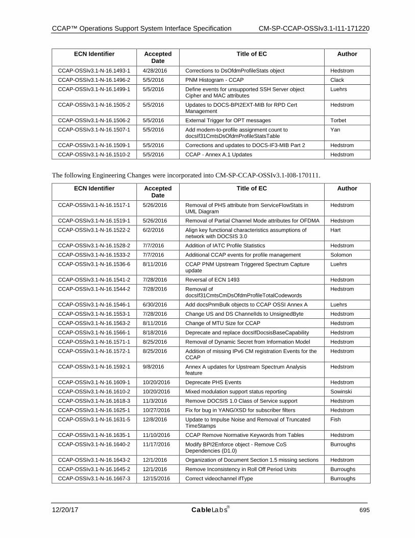
CCAP™ Operations Support System Interface Specification CM-SP-CCAP-OSSIv3.1-I11-171220
12/20/17 CableLabs 695
ECN Identifier Accepted Date
Title of EC Author
CCAP-OSSIv3.1-N-16.1493-1 4/28/2016 Corrections to DsOfdmProfileStats object Hedstrom
CCAP-OSSIv3.1-N-16.1496-2 5/5/2016 PNM Histogram - CCAP Clack
CCAP-OSSIv3.1-N-16.1499-1 5/5/2016 Define events for unsupported SSH Server object Cipher and MAC attributes
Luehrs
CCAP-OSSIv3.1-N-16.1505-2 5/5/2016 Updates to DOCS-BPI2EXT-MIB for RPD Cert Management
Hedstrom
CCAP-OSSIv3.1-N-16.1506-2 5/5/2016 External Trigger for OPT messages Torbet
CCAP-OSSIv3.1-N-16.1507-1 5/5/2016 Add modem-to-profile assignment count to docsIf31CmtsDsOfdmProfileStatsTable
Yan
CCAP-OSSIv3.1-N-16.1509-1 5/5/2016 Corrections and updates to DOCS-IF3-MIB Part 2 Hedstrom
CCAP-OSSIv3.1-N-16.1510-2 5/5/2016 CCAP - Annex A.1 Updates Hedstrom
The following Engineering Changes were incorporated into CM-SP-CCAP-OSSIv3.1-I08-170111.
ECN Identifier Accepted Date
Title of EC Author
CCAP-OSSIv3.1-N-16.1517-1 5/26/2016 Removal of PHS attribute from ServiceFlowStats in UML Diagram
Hedstrom
CCAP-OSSIv3.1-N-16.1519-1 5/26/2016 Removal of Partial Channel Mode attributes for OFDMA Hedstrom
CCAP-OSSIv3.1-N-16.1522-2 6/2/2016 Align key functional characteristics assumptions of network with DOCSIS 3.0
Hart
CCAP-OSSIv3.1-N-16.1528-2 7/7/2016 Addition of IATC Profile Statistics Hedstrom
CCAP-OSSIv3.1-N-16.1533-2 7/7/2016 Additional CCAP events for profile management Solomon
CCAP-OSSIv3.1-N-16.1536-6 8/11/2016 CCAP PNM Upstream Triggered Spectrum Capture update
Luehrs
CCAP-OSSIv3.1-N-16.1541-2 7/28/2016 Reversal of ECN 1493 Hedstrom
CCAP-OSSIv3.1-N-16.1544-2 7/28/2016 Removal of docsIf31CmtsCmDsOfdmProfileTotalCodewords
Hedstrom
CCAP-OSSIv3.1-N-16.1546-1 6/30/2016 Add docsPnmBulk objects to CCAP OSSI Annex A Luehrs
CCAP-OSSIv3.1-N-16.1553-1 7/28/2016 Change US and DS ChannelIds to UnsignedByte Hedstrom
CCAP-OSSIv3.1-N-16.1563-2 8/11/2016 Change of MTU Size for CCAP Hedstrom
CCAP-OSSIv3.1-N-16.1566-1 8/18/2016 Deprecate and replace docsIfDocsisBaseCapability Hedstrom
CCAP-OSSIv3.1-N-16.1571-1 8/25/2016 Removal of Dynamic Secret from Information Model Hedstrom
CCAP-OSSIv3.1-N-16.1572-1 8/25/2016 Addition of missing IPv6 CM registration Events for the CCAP
Hedstrom
CCAP-OSSIv3.1-N-16.1592-1 9/8/2016 Annex A updates for Upstream Spectrum Analysis feature
Hedstrom
CCAP-OSSIv3.1-N-16.1609-1 10/20/2016 Deprecate PHS Events Hedstrom
CCAP-OSSIv3.1-N-16.1610-2 10/20/2016 Mixed modulation support status reporting Sowinski
CCAP-OSSIv3.1-N-16.1618-3 11/3/2016 Remove DOCSIS 1.0 Class of Service support Hedstrom
CCAP-OSSIv3.1-N-16.1625-1 10/27/2016 Fix for bug in YANG/XSD for subscriber filters Hedstrom
CCAP-OSSIv3.1-N-16.1631-5 12/8/2016 Update to Impulse Noise and Removal of Truncated TimeStamps
Fish
CCAP-OSSIv3.1-N-16.1635-1 11/10/2016 CCAP Remove Normative Keywords from Tables Hedstrom
CCAP-OSSIv3.1-N-16.1640-2 11/17/2016 Modify BPI2Enforce object - Remove CoS Dependencies (D1.0)
Burroughs
CCAP-OSSIv3.1-N-16.1643-2 12/1/2016 Organization of Document Section 1.5 missing sections Hedstrom
CCAP-OSSIv3.1-N-16.1645-2 12/1/2016 Remove Inconsistency in Roll Off Period Units Burroughs
CCAP-OSSIv3.1-N-16.1667-3 12/15/2016 Correct videochannel ifType Burroughs
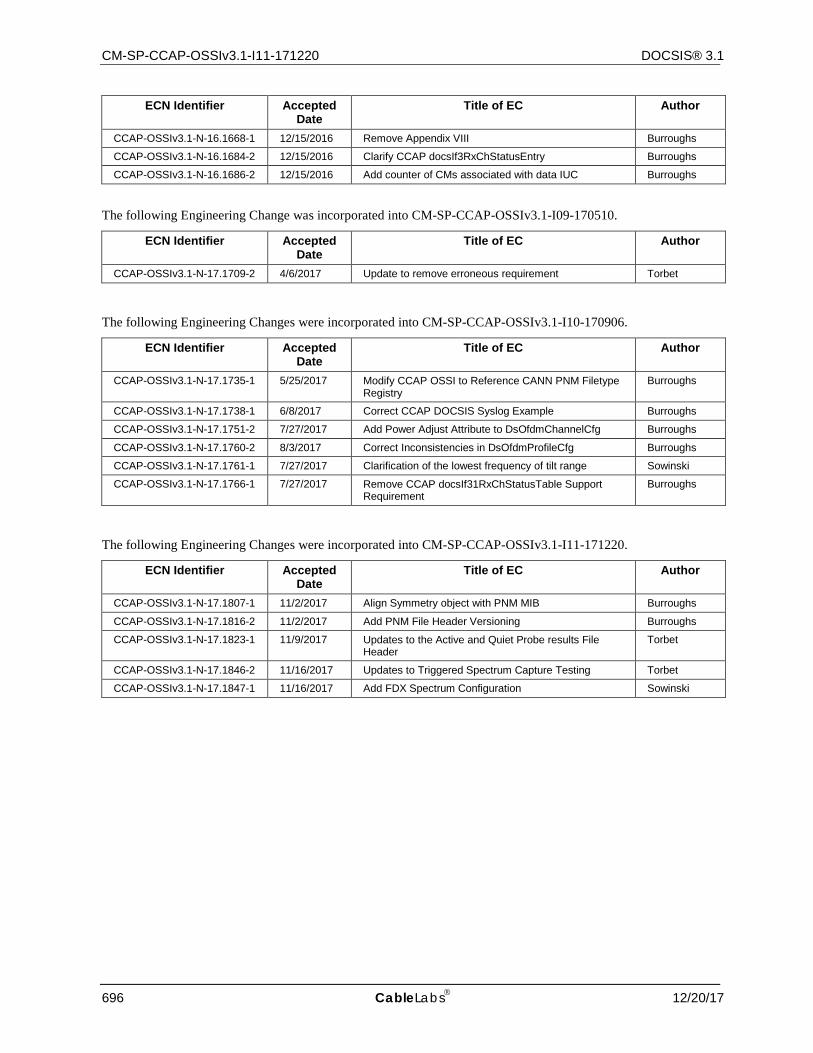
CM-SP-CCAP-OSSIv3.1-I11-171220 DOCSIS® 3.1
696 CableLabs 12/20/17
ECN Identifier Accepted Date
Title of EC Author
CCAP-OSSIv3.1-N-16.1668-1 12/15/2016 Remove Appendix VIII Burroughs
CCAP-OSSIv3.1-N-16.1684-2 12/15/2016 Clarify CCAP docsIf3RxChStatusEntry Burroughs
CCAP-OSSIv3.1-N-16.1686-2 12/15/2016 Add counter of CMs associated with data IUC Burroughs
The following Engineering Change was incorporated into CM-SP-CCAP-OSSIv3.1-I09-170510.
ECN Identifier Accepted Date
Title of EC Author
CCAP-OSSIv3.1-N-17.1709-2 4/6/2017 Update to remove erroneous requirement Torbet
The following Engineering Changes were incorporated into CM-SP-CCAP-OSSIv3.1-I10-170906.
ECN Identifier Accepted Date
Title of EC Author
CCAP-OSSIv3.1-N-17.1735-1 5/25/2017 Modify CCAP OSSI to Reference CANN PNM Filetype Registry
Burroughs
CCAP-OSSIv3.1-N-17.1738-1 6/8/2017 Correct CCAP DOCSIS Syslog Example Burroughs
CCAP-OSSIv3.1-N-17.1751-2 7/27/2017 Add Power Adjust Attribute to DsOfdmChannelCfg Burroughs
CCAP-OSSIv3.1-N-17.1760-2 8/3/2017 Correct Inconsistencies in DsOfdmProfileCfg Burroughs
CCAP-OSSIv3.1-N-17.1761-1 7/27/2017 Clarification of the lowest frequency of tilt range Sowinski
CCAP-OSSIv3.1-N-17.1766-1 7/27/2017 Remove CCAP docsIf31RxChStatusTable Support Requirement
Burroughs
The following Engineering Changes were incorporated into CM-SP-CCAP-OSSIv3.1-I11-171220.
ECN Identifier Accepted Date
Title of EC Author
CCAP-OSSIv3.1-N-17.1807-1 11/2/2017 Align Symmetry object with PNM MIB Burroughs
CCAP-OSSIv3.1-N-17.1816-2 11/2/2017 Add PNM File Header Versioning Burroughs
CCAP-OSSIv3.1-N-17.1823-1 11/9/2017 Updates to the Active and Quiet Probe results File Header
Torbet
CCAP-OSSIv3.1-N-17.1846-2 11/16/2017 Updates to Triggered Spectrum Capture Testing Torbet
CCAP-OSSIv3.1-N-17.1847-1 11/16/2017 Add FDX Spectrum Configuration Sowinski