data modeling - sap
TRANSCRIPT

Data Modeling
Sybase® PowerDesigner®
15.0Windows

Part number: DC38058-01-1500-01Last modified: September 2008
Copyright © 2008 Sybase, Inc. and its subsidiaries. All rights reserved.
Information in this manual may change without notice and does not represent a commitment on the part of Sybase, Inc. and its subsidiaries.
Sybase, Inc. provides the software described in this manual under a Sybase License Agreement. The software may be used only in accordance withthe terms of the agreement.
No part of this publication may be reproduced, transmitted, or translated in any form or by any means, electronic, mechanical, manual, optical, orotherwise, without the prior written permission of Sybase, Inc. and its subsidiaries.
Use, duplication, or disclosure by the government is subject to the restrictions set forth in subparagraph (c)(1)(ii) of DFARS 52.227-7013 for theDOD and as set forth in FAR 52.227-19(a)-(d) for civilian agencies.
Sybase, SYBASE (logo), ADA Workbench, Adaptable Windowing Environment, Adaptive Component Architecture, Adaptive Server, AdaptiveServer Anywhere, Adaptive Server Enterprise, Adaptive Server Enterprise Monitor, Adaptive Server Enterprise Replication, Adaptive ServerEverywhere, Advantage Database Server, Afaria, Answers 365, Answers Anywhere, AppModeler, APT Workbench, APT-Build, APT-Edit,APT-Execute, APT-Translator, APT-Library, ASEP, Avaki, Avaki (Arrow Design), Avaki Data Grid, AvantGo, Bit-Wise, BizTracker, CertifiedPowerBuilder Developer, Certified SYBASE Professional, Certified SYBASE Professional Logo, CodeBank, Column Design, ComponentPack,Convoy/DM, Copernicus, CSP, Data Pipeline, DataArchitect, Database Analyzer, DataExpress, DataServer, DataWindow, DataWindow .NET,DB-Library, dbQueue, Dejima, Dejima Direct, Developers Workbench, DirectConnect Anywhere, DirectConnect, Distribution Director, DynamicMobility Model, e-ADK, e-Biz Integrator, EC Gateway, ECMAP, ECRTP, eFulfillment Accelerator, EII Plus, Embedded SQL, EMS, EnterpriseClient/Server, Enterprise Connect, Enterprise Data Studio, Enterprise Manager, Enterprise Work Architecture, Enterprise Work Designer, EnterpriseWork Modeler, eProcurement Accelerator, eremote, Everything Works Better When Everything Works Together, EWA, Extended Systems,ExtendedView, Financial Fusion, Financial Fusion (and design), Financial Fusion Server, Formula One, Fusion Powered e-Finance, Fusion PoweredFinancial Destinations, Fusion Powered STP, GeoPoint, GlobalFIX, iAnywhere, iAnywhere Solutions, ImpactNow, Industry Warehouse Studio,InfoMaker, Information Anywhere, InformationConnect, InphoMatch, InstaHelp, Intelligent Self-Care, InternetBuilder, iremote, iScript, JaguarCTS, jConnect for JDBC, KnowledgeBase, Logical Memory Manager, M2M Anywhere, Mach Desktop, Mail Anywhere Studio, MainframeConnect, Maintenance Express, Manage Anywhere Studio, MAP, M-Business Anywhere, MDI Access Server, MDI Database Gateway,media.splash, Message Anywhere Server, MetaWorks, MethodSet, mFolio, Mirror Activator, ML Query, MMS 365, Mobile 365 (and design),MobiLink, MySupport, New Era of Networks, Next Generation Learning, Next Generation Learning Studio, O DEVICE, OASiS, OASiS logo,ObjectConnect, ObjectCycle, OmniConnect, OmniQ, OmniSQL Access Module, OmniSQL Toolkit, OneBridge, Open Biz, Open BusinessInterchange, Open Client, Open ClientConnect, Open Client/Server, Open Client/Server Interfaces, Open Gateway, Open Server, OpenServerConnect, Open Solutions, OpenSwitch, Partnerships that Work, PB-Gen, PC APT Execute, PC DB-Net, PC Net Library, Pharma Anywhere,PhysicalArchitect, PocketBuilder, Power Through Knowledge, power.stop, PowerAMC, PowerBuilder, PowerBuilder Foundation Class Library,PowerDesigner, PowerDimensions, Powering the New Economy, PowerScript, PowerSite, PowerSocket, Powersoft, PowerStage, PowerTips,Powersoft Portfolio, Powersoft Professional, PowerWare Desktop, PowerWare Enterprise, ProcessAnalyst, Pylon, Pylon Anywhere, PylonApplication Server, Pylon Conduit, Pylon Pro, QAnywhere, RAP - The Trading Edition, Rapport, Relational Beans, RepConnector, ReportWorkbench, Report-Execute, Replication Agent, Replication Driver, Replication Server, Replication Server Manager, Replication Toolkit, ResourceManager, RFID Anywhere, RW-DisplayLib, RW-Library, SAFE, SAFE/PRO, Sales Anywhere, Search Anywhere, SDF, Search Anywhere, SecureSQL Toolset, Security Guardian, ShareSpool, Sharelink SKILS, smart.partners, smart.parts, smart.script, SOA Anywhere Trademark,SQLAdvantage, SQL Anywhere, SQL Anywhere Studio, SQL Code Checker, SQL Edit, SQL Edit/TPU, SQL Modeler, SQL Remote, SQL SMART,SQL Toolset, SQL Station, SQLJ, Stage III Engineering, STEP, SupportNow, S.W.I.F.T. Message Format Libraries, Sybase 365, Sybase Central,Sybase IQ, Sybase Learning Connection, Sybase MPP, SyberLearning LIVE, SyberLearning OnDemand, Sybase SQL Desktop, Sybase SQLLifecycle, Sybase SQL Workgroup, Sybase Synergy Program, Sybase Virtual Server Architecture, Sybase User Workbench, SybaseWare, SyberFinancial, SyberAssist, SybFlex, SybMD, SyBooks, System 10, System 11, System XI (logo), SystemTools, Tabular Data Stream, The EnterpriseClient/Server Company, The Extensible Software Platform, The Future Is Wide Open, The Learning Connection, The Model For Client/ServerSolutions, The Online Information Center, The Power of One, TotalFix, TradeForce, Transact-SQL, Translation Toolkit, Turning Imagination IntoReality, UltraLite, UltraLiteJ, UltraLite.NET, UNIBOM, Unilib, Uninull, Unisep, Unistring, Unwired Accelerator, Unwired Orchestrator, URKRuntime Kit for UniCode, Unwired Accelerator, Unwired Orchestrator, Viafone, Virtualized Resource Management, VisualWriter,WarehouseArchitect, Warehouse Studio, Warehouse WORKS, Watcom, Watcom SQL, Web Deployment Kit, Web.PB, Web.SQL, WebSights,WebViewer, XA-Library, XA-Server, XcelleNet, XP Server, XTNDAccess, and XTNDConnect are trademarks of Sybase, Inc. or its subsidiaries.
All other trademarks are the property of their respective owners.
ii
Contents
I Building Data Models vii
About This Manual ix
1 Getting Started with Data Modeling 1Data Modeling with PowerDesigner . . . . . . . . . . . . . . . 2Creating a Data Model . . . . . . . . . . . . . . . . . . . . . . 5
2 Building Conceptual and Logical Diagrams 11Introducing Conceptual and Logical Diagrams . . . . . . . . . 12Conceptual Diagram Basics . . . . . . . . . . . . . . . . . . . 13Logical Diagram Basics . . . . . . . . . . . . . . . . . . . . . 17Data Items (CDM) . . . . . . . . . . . . . . . . . . . . . . . . 21Entities (CDM/LDM) . . . . . . . . . . . . . . . . . . . . . . . 24Attributes (CDM/LDM) . . . . . . . . . . . . . . . . . . . . . . 27Identifiers (CDM/LDM) . . . . . . . . . . . . . . . . . . . . . . 30Relationships (CDM/LDM) . . . . . . . . . . . . . . . . . . . . 32Associations and Association Links (CDM) . . . . . . . . . . 44Inheritances (CDM/LDM) . . . . . . . . . . . . . . . . . . . . 51
3 Building Physical Diagrams 57Physical Diagram Basics . . . . . . . . . . . . . . . . . . . . 58Tables (PDM) . . . . . . . . . . . . . . . . . . . . . . . . . . . 62Columns (PDM) . . . . . . . . . . . . . . . . . . . . . . . . . 86Keys (PDM) . . . . . . . . . . . . . . . . . . . . . . . . . . . . 95Indexes (PDM) . . . . . . . . . . . . . . . . . . . . . . . . . . 103Defaults (PDM) . . . . . . . . . . . . . . . . . . . . . . . . . . 111Domains (CDM/LDM/PDM) . . . . . . . . . . . . . . . . . . . 115Sequences (PDM) . . . . . . . . . . . . . . . . . . . . . . . . 124Abstract Data Types (PDM) . . . . . . . . . . . . . . . . . . . 129References (PDM) . . . . . . . . . . . . . . . . . . . . . . . . 138Views (PDM) . . . . . . . . . . . . . . . . . . . . . . . . . . . 152View References (PDM) . . . . . . . . . . . . . . . . . . . . . 169Check Parameters (CDM/LDM/PDM) . . . . . . . . . . . . . . 174Business Rules (CDM/LDM/PDM) . . . . . . . . . . . . . . . 179Physical Options . . . . . . . . . . . . . . . . . . . . . . . . . 188
iii

4 Building Multidimensional Diagrams 193Multidimensional Diagram Basics . . . . . . . . . . . . . . . . 194Cubes (PDM) . . . . . . . . . . . . . . . . . . . . . . . . . . . 198Dimensions (PDM) . . . . . . . . . . . . . . . . . . . . . . . . 209Attributes (PDM) . . . . . . . . . . . . . . . . . . . . . . . . . 211Facts (PDM) . . . . . . . . . . . . . . . . . . . . . . . . . . . 214Measures (PDM) . . . . . . . . . . . . . . . . . . . . . . . . . 216Hierarchies (PDM) . . . . . . . . . . . . . . . . . . . . . . . . 218Associations (PDM) . . . . . . . . . . . . . . . . . . . . . . . 220
5 Building Triggers and Procedures 223Triggers (PDM) . . . . . . . . . . . . . . . . . . . . . . . . . . 224Trigger Templates (PDM) . . . . . . . . . . . . . . . . . . . . 240Trigger Template Items (PDM) . . . . . . . . . . . . . . . . . . 248Stored Procedures and Functions (PDM) . . . . . . . . . . . 255Procedure Templates (PDM) . . . . . . . . . . . . . . . . . . 266SQL Code Definition Toolbars . . . . . . . . . . . . . . . . . . 270Creating SQL/XML Queries with the Wizard . . . . . . . . . . 271Generating Triggers and Procedures . . . . . . . . . . . . . . 275
6 Building a Database Access Structure 281Introducing database access . . . . . . . . . . . . . . . . . . 282Users (PDM) . . . . . . . . . . . . . . . . . . . . . . . . . . . 283Roles (PDM) . . . . . . . . . . . . . . . . . . . . . . . . . . . 298Groups (PDM) . . . . . . . . . . . . . . . . . . . . . . . . . . 300Synonyms (PDM) . . . . . . . . . . . . . . . . . . . . . . . . . 302
7 Building Web Services 309Introducing Web Services . . . . . . . . . . . . . . . . . . . . 310Web Services (PDM) . . . . . . . . . . . . . . . . . . . . . . . 311Web Operations (PDM) . . . . . . . . . . . . . . . . . . . . . 316Web Parameters (PDM) . . . . . . . . . . . . . . . . . . . . . 321Testing Web Services . . . . . . . . . . . . . . . . . . . . . . 323Generating Web Services . . . . . . . . . . . . . . . . . . . . 324Reverse Engineering Web Services . . . . . . . . . . . . . . 328
8 Working with Data Models 331Customizing the Data Modeling Environment . . . . . . . . . 332Generating Other Models from a Data Model . . . . . . . . . 370Checking a Data Model . . . . . . . . . . . . . . . . . . . . . 381Working with SQL . . . . . . . . . . . . . . . . . . . . . . . . 426
iv

II Working with Databases 433
9 Generating a Database from a PDM 435Connecting to a Database . . . . . . . . . . . . . . . . . . . . 436Generating a Database . . . . . . . . . . . . . . . . . . . . . 438Using Test Data . . . . . . . . . . . . . . . . . . . . . . . . . . 472Estimating Database Size . . . . . . . . . . . . . . . . . . . . 500Modifying a Database . . . . . . . . . . . . . . . . . . . . . . 506Accessing a Database . . . . . . . . . . . . . . . . . . . . . . 513
10 Reverse Engineering a Database into a PDM 515Getting Started with Reverse Engineering . . . . . . . . . . . 516Reverse Engineering from Scripts . . . . . . . . . . . . . . . 517Reverse Engineering from a Live Database . . . . . . . . . . 520Reverse Engineering Options . . . . . . . . . . . . . . . . . . 524Reverse Engineering Database Statistics . . . . . . . . . . . 532
11 DBMS-Specific Features 535Working with PowerDesigner’s DBMS-Specific Features . . . 536IBM DB2 for z/OS (formerly OS/390) . . . . . . . . . . . . . . 537IBM DB2 for Common Server . . . . . . . . . . . . . . . . . . 542Informix SQL . . . . . . . . . . . . . . . . . . . . . . . . . . . 549Ingres . . . . . . . . . . . . . . . . . . . . . . . . . . . . . . . 550Interbase . . . . . . . . . . . . . . . . . . . . . . . . . . . . . 551Microsoft Access . . . . . . . . . . . . . . . . . . . . . . . . . 552Microsoft SQL Server . . . . . . . . . . . . . . . . . . . . . . 553MySQL . . . . . . . . . . . . . . . . . . . . . . . . . . . . . . 617NonStop SQL . . . . . . . . . . . . . . . . . . . . . . . . . . . 619Oracle . . . . . . . . . . . . . . . . . . . . . . . . . . . . . . . 620PostgreSQL . . . . . . . . . . . . . . . . . . . . . . . . . . . . 643Red Brick Warehouse . . . . . . . . . . . . . . . . . . . . . . 648Sybase AS Anywhere . . . . . . . . . . . . . . . . . . . . . . 649Sybase AS Enterprise . . . . . . . . . . . . . . . . . . . . . . 655Sybase AS IQ . . . . . . . . . . . . . . . . . . . . . . . . . . 659Sybase SQL Anywhere . . . . . . . . . . . . . . . . . . . . . 674Teradata . . . . . . . . . . . . . . . . . . . . . . . . . . . . . . 678
12 Writing SQL Statements in PowerDesigner 687Introduction . . . . . . . . . . . . . . . . . . . . . . . . . . . . 688Writing SQL with the PowerDesigner GTL . . . . . . . . . . . 689Writing SQL with the PDM Variables and Macros . . . . . . . 691PDM Macros . . . . . . . . . . . . . . . . . . . . . . . . . . . 693PDM Variables . . . . . . . . . . . . . . . . . . . . . . . . . . 704PowerDesigner Formatting Variables . . . . . . . . . . . . . . 716
v

13 Migrating from ERwin to PowerDesigner 717Introducing the ERwin Import Process . . . . . . . . . . . . . 718Preparing to Import your ERwin models . . . . . . . . . . . . 720The Import Process . . . . . . . . . . . . . . . . . . . . . . . 721After Importing . . . . . . . . . . . . . . . . . . . . . . . . . . 723Getting Started Using PowerDesigner . . . . . . . . . . . . . 728
Index 731
vi

PART I
BUILDING DATA MODELS
This part explains how to use PowerDesigner to build Data Models.

viii

About This Manual
Subject
This book describes the PowerDesigner Conceptual, Logical, and PhysicalData Models, including how to create a CDM, LDM, and PDM, build eachof the available diagrams, and generate and reverse engineer databases.
Audience
This book assumes that you are an experienced Windows user with someexperience with relational databases and SQL.
Documentation primer
For information about the complete documentation set provided withPowerDesigner, see the “Getting Started with PowerDesigner” chapter of theCore Features Guide .
Typographic conventions
PowerDesigner documentation uses special typefaces to help you readilyidentify specific items:
♦ monospace text (normal and bold)
Used for: Code samples, commands, compiled functions and files,references to variables.
Example: declare user_defined..., the BeforeInsertTriggertemplate.
♦ bold textUsed for: New terms.
Example: A shortcut has a target object.
♦ SMALL CAPS
Used for: Key names.
Example: Press the ENTER key.
Bibliography
Data Modeling Essentials
Graeme Simsion, Van Nostrand Reinhold, 1994, 310 pages; paperbound;ISBN 1850328773
ix

Information engineering
James Martin, Prentice Hall, 1990, three volumes of 178, 497, and 625pages respectively; clothbound, ISBN 0-13-464462-X (vol. 1),0-13-464885-4 (vol. 2), and 0-13-465501-X (vol. 3).
Celko95
Joe Celko, Joe Celko’s SQL for Smarties (Morgan Kaufmann Publishers,Inc., 1995), 467 pages; paperbound; ISBN 1-55860-323-9.
x

CHAPTER 1
Getting Started with Data Modeling
About this chapter This chapter presents the Conceptual, Logical, and Physical Data Modelsand provides guidance for data modeling with PowerDesigner.
Contents Topic: page
Data Modeling with PowerDesigner 2
Creating a Data Model 5
1

Data Modeling with PowerDesigner
Data Modeling with PowerDesignerA data model is a representation of the information consumed and producedby a system. Data modeling involves analyzing the data objects present in asystem and the relationships between them. PowerDesigner providesconceptual, logical, and physical data models to allow you to analyze andmodel your system at all levels of abstraction.
Conceptual Data Models
A Conceptual Data Model (CDM) represents the logical structure of a datasystem independent of any software or data storage structure. It gives aformal representation of the data needed to run an enterprise or a businessactivity, and may contain data objects not yet implemented in a physicaldatabase.
A CDM allows you to:
♦ Represent the organization of data in a graphic format to create EntityRelationship Diagrams (ERD).
♦ Verify the validity of data design.
♦ Generate a Logical Data Model (LDM), a Physical Data Model (PDM) oran Object-Oriented Model (OOM), which specifies an objectrepresentation of the CDM using the UML standard.
+ To create a CDM, see “Creating a Data Model” on page 5. For detailedinformation about conceptual diagrams, see “Conceptual Diagram Basics”in the Building Conceptual and Logical Diagrams chapter.
Logical Data Models
A Logical Data Model helps you design a database structure and performsome database denormalization actions independent of any specific DBMSphysical requirements.
You can use a logical model as an intermediary step in the database designprocess between the conceptual and physical designs:
♦ Start with a CDM containing entities, attributes, relationships, domains,data items and business rules. If need be, you may develop the CDM inseveral design steps starting from a high level model to a low level CDM
♦ Generate an LDM. Create indexes and specify FK column names andother common features
2

Chapter 1. Getting Started with Data Modeling
♦ Generate one or more PDMs, each targeted to a specific DBMSimplementation
This design process allows you to keep everything consistent in a largedevelopment effort.
+ To create an LDM, see “Creating a Data Model” on page 5. For detailedinformation about logical diagrams, see “Logical Diagram Basics” in theBuilding Conceptual and Logical Diagrams chapter.
Physical Data Models
A Physical Data Model (PDM) is a database design tool suitable formodeling the implementation of physical structures and data queries in adatabase.
Depending on the type of database you want to design, you will use differenttypes of diagrams in the PDM:
♦ Operational PDM - You use PDM to design the structure of anoperational database. Usually, in data modeling, the physical analysisfollows the conceptual and/or logical analysis, and addresses the detailsof the actual physical implementation of data in a database, to suit yourperformance and physical constraints.
♦ Business intelligence PDM - You can use a PDM to design the structureof a data environment, which consists of:• Data warehouse or data mart database – are populated with data
transferred from operational databases, and gather together all theinformation that may be needed in an OLAP database, where queriesfor business analysis and decision making are performed. The datawarehouse database gathers all the data manipulated in a company for
3

Data Modeling with PowerDesigner
example, whereas the data mart focuses on smaller entities in thecompany.You use physical diagrams to design a data warehouse or data martdatabase. Since these databases usually contain very large amounts ofdata for storage, you do not need to design them for performance. Youmay assign types (fact and dimension) to the database tables to have apreview of the multidimensional structure in an OLAP database.
• A multidimensional OLAP database - which is generally populatedwith data that has first been aggregated in a data warehouse or datamart (though sometimes it is transferred directly from operationaldatabases), and in which information is organized to facilitate queriesperformed by different tools. Business analysts use OLAP databases tosend queries and retrieve business information from the differentdimensions existing in the database.You use PDM multidimensional diagrams to design the differentdimensions and cubes within the OLAP database.
+ To create Physical Diagrams, see the “Building Physical Diagrams”chapter. To create Multidimensional Diagrams, see the “BuildingMultidimensional Diagrams” chapter.
4

Chapter 1. Getting Started with Data Modeling
Creating a Data ModelYou can create a new CDM from scratch, by importing a Process AnalystModel (.PAM) or an ERwin model (.ERX), or by generating it from a CDM,PDM, or OOM.
You can create a new PDM from scratch, or reverse engineer the model froman existing database.
+ For information about reverse engineering, see the “ReverseEngineering a Database into a PDM” chapter.
v To create a new CDM, LDM, or PDM
1. Select File ä New to open the New dialog box.
2. Select one of the following model types:♦ Conceptual Data Model
♦ Logical Data Model
♦ Physical Data Model
3. Select one of the following radio buttons:♦ New model – Creates a new, empty, model.
♦ New model from template – Creates a model from a model template,which can contain pre-configured options, preferences, extensions, andobjects. For more information, see “Model Templates” in the Modelschapter of the Core Features Guide .
4. Enter a model name. The code of the model, which is used for script orcode generation, is derived from this name according to the modelnaming conventions.
5

Creating a Data Model
5. [PDM only] Select a DBMS, and specify whether to:♦ Share the DBMS definition – use the original DBMS file in the
“Resource Files\DBMS” directory. Changes made to the DBMS areshared by all PDMs that share it.
♦ Copy the DBMS definition in model – make a copy of the DBMS file.The copied DBMS is saved with the PDM and changes made to it donot impact any other PDMs.+ For more information on DBMS properties and customizing aDBMS, see the DBMS Resource File Reference chapter of theCustomizing and Extending PowerDesigner manual.
6. [PDM only] Select the type of the first diagram. The diagram chosenbecomes the default for the next time you create a new PDM. You cancreate as many diagrams as you need in a CDM, LDM, or PDM.
7. [optional] Click the Extended Model Definitions tab, and select one ormore extended model definitions to attach to your model.
+ For more information on using extended model definitions, see“Extended Model Definitions” in the Resource Files and the PublicMetamodel chapter of the Customizing and Extending PowerDesignermanual.
8. Click OK to create the new data model in the current Workspace.
Demo exampleSample data models are available in the Examples directory.
Model properties
To open a model property sheet, double-click its Browser entry.
The General tab contains the following properties:
Property Description
Name Specifies the name of the model, which should be clear andmeaningful, and should convey its purpose to non-technicalusers.
Code Specifies the technical name of the item used for generatingcode or scripts, which may be abbreviated, and should notinclude spaces.
Comment Provides descriptive information about the model.
6

Chapter 1. Getting Started with Data Modeling
Property Description
Filename Specifies the location of the model file. This field is empty if themodel has never been saved.
Author Specifies the author of the model. If you enter nothing, theAuthor field in diagram title boxes displays the user name fromthe model property sheet Version Info tab. If you enter a space,the Author field displays nothing.
Version Specifies the version of the model. You can use this box todisplay the repository version or a user defined version of themodel. This parameter is defined in the Title page of the modeldisplay preferences
DBMS [PDM only] Specifies the DBMS attached to the model. Click-ing the Properties tool to the right of this field to open the DBMSfile in the Resource Editor.
Database [PDM only] Specifies the database that is the target for themodel. You can create a database in the model by clicking theCreate tool to the right of this field.
If your DBMS supports multiple databases in a single model(enabled by the EnableManyDatabases entry in the Databasecategory of the DBMS), this field is not present, and is replacedby a list of databases in the Model menu. A Database category isalso displayed in the physical options of your database objects.
Defaultdiagram
Specifies the diagram displayed by default when you open themodel.
Database properties (PDM)
You can create a database from the General tab of the model property sheetor, if your DBMS supports multiple databases in a single model, from thelist of databases in the Model menu.
A database has the following properties:
Property Description
Name Name for the database
Code Code for the database. This code is generated in databasescripts
Comment Descriptive label for the database
7

Creating a Data Model
Property Description
Stereotype Sub-classification used to extend the semantics of an objectwithout changing its structure; it can be predefined or user-defined
DBMS DBMS for the database
Options Physical options available in the DBMS
Script Begin and end scripts that are inserted at the start and end ofa database creation script
Rules Business rules for the database
v To use a database in a physical option
1. Open the property sheet of an object with physical options.
2. Click the Options tab, select the in database (. . . ) option and click the>> button.
3. Select a database from the list below the right pane.
4. Click OK.
When you use the in [<tablespace>] physical option, you associate apredefined tablespace with a database using the following syntax:
DBname.TBSPCname
For example, tablespace CUST_DATA belongs to database myBase. In thefollowing example, table Customer will be created in tablespaceCUST_DATA:
8

Chapter 1. Getting Started with Data Modeling
You should not define a database together with a tablespace physical optionon the same object, this will raise an error during check model.
The database Dependencies tab displays the list of objects that use thecurrent database in their physical options.
Archiving a PDM
Archived models store all constraint names without making a differencebetween user defined and calculated constraints. These models are used withthe modify database feature.
You can archive a PDM with the .apm file extension, using the followingmethods:
♦ Save a PDM as an archived model
♦ Automatically archive PDM after database creation
v To archive a PDM
1. Select File ä Save As, select Archived PDM (bin) or Archived PDM(xml) in the Save As Type list, and click Save.
or
9

Creating a Data Model
Select Database ä Generate Database, click the Options tab, select theAutomatic Archive check box in the After Generation groupbox, andclick OK.
10

CHAPTER 2
Building Conceptual and LogicalDiagrams
About this chapter This chapter describes how to build conceptual and logical diagrams, andhow to create and modify the associated objects.
Contents Topic: page
Introducing Conceptual and Logical Diagrams 12
Conceptual Diagram Basics 13
Logical Diagram Basics 17
Data Items (CDM) 21
Entities (CDM/LDM) 24
Attributes (CDM/LDM) 27
Identifiers (CDM/LDM) 30
Relationships (CDM/LDM) 32
Associations and Association Links (CDM) 44
Inheritances (CDM/LDM) 51
11

Introducing Conceptual and Logical Diagrams
Introducing Conceptual and Logical DiagramsThe data models in this chapter allow you to model the semantic and logicalstructure of your system.
PowerDesigner provides you with a highly flexible environment in which tomodel your data systems. You can begin with either a CDM (see“Conceptual Diagram Basics” on page 13) or an LDM (see “LogicalDiagram Basics” on page 17) to analyze your system and then generate aPDM (see the Building Physical Diagrams chapter) to work out the details ofyour implementation. Full support for database reverse-engineering allowsyou to take existing data structures and analyze them at any level ofabstraction.
For more information about intermodel generation, see “Generating OtherModels from a Data Model” in the Working with Data Models chapter.
12

Chapter 2. Building Conceptual and Logical Diagrams
Conceptual Diagram BasicsA Conceptual Data Model (CDM) represents the structure of your database,independent of any software or data storage structure. It describes entities(things of significance to a organization) and their identifiers and otherattributes, along with the relationships and inheritances that connect them.
In the following conceptual diagram, the Teacher and Student entities inheritattributes from the Person parent entity. The two child entities are linkedwith a one-to-many relationship (a teacher has several students but eachstudent has only one main teacher).
In addition:
♦ a teacher can teach several subjects and a subject can be taught by severalteachers (many-to-many).
♦ a teacher can teach several lessons and a lesson is taught by only oneteacher (one-to-many).
♦ a student attends multiple lessons and a lesson is followed by multiplestudents (many-to-many).
♦ a student studies multiple subjects and a subject can be studied bymultiple students (many-to-many).
13

Conceptual Diagram Basics
Conceptual diagram objects
You can create the following objects in a conceptual diagram:
Object Tool Symbol Description
Domain [none] [none] Set of values for which a dataitem is valid. See “Domains(CDM/LDM/PDM)” in theBuilding Physical Diagramschapter.
Data Item [none] [none] Elementary piece of infor-mation. See “Data Items(CDM)” on page 21.
Entity Person, place, thing, or con-cept that is of interest tothe enterprise. See “Entities(CDM/LDM)” on page 24.
Entity At-tribute
[none] [none] Elementary piece of informa-tion attached to an entity. See“Attributes (CDM/LDM)” onpage 27.
Identifier [none] [none] One or many entity attributes,whose values uniquely iden-tify each occurrence ofthe entity. See “Identifiers(CDM/LDM)” on page 30.
Relationship Named connection or rela-tion between entities (ERmodeling methodology). See“Relationships (CDM/LDM)”on page 32.
Inheritance Relationship that defines anentity as a special case ofa more general entity. See“Inheritances (CDM/LDM)”on page 51.
14

Chapter 2. Building Conceptual and Logical Diagrams
Object Tool Symbol Description
Association Named connection or as-sociation between entities(Merise modeling methodol-ogy). See “Associations andAssociation Links (CDM)”on page 44.
AssociationLink
Link that connects an associa-tion to an entity. See “Associ-ations and Association Links(CDM)” on page 44.
Creating a conceptual diagram
You can create a conceptual diagram in an existing CDM in any of thefollowing ways:
♦ Right-click the model in the Browser and select New ä ConceptualDiagram from the contextual menu
♦ Right-click the background of any diagram and select Diagram ä NewDiagram from the contextual menu.
To create a new CDM with a conceptual diagram, select File ä New, chooseConceptual Data Model from the Model type list, and click OK.
Opening a v6 PAM into a CDM
You can open a v6 process analyst model (PAM) into a CDM, to recoverprocess modeling information, as follows:
PAM object CDM object
Business rule Business rule
Domain Domain
Data store Entity
Data item Data item
You can recover processes from a PAM by opening it into a BPM (see theBusiness Process Modeling guide).
15

Conceptual Diagram Basics
v To open a PAM into a CDM
1. Select File ä Open and select the PAM file.
2. Click Open to display the Formats for ProcessAnalyst Model window.
3. Select PowerDesigner Conceptual Data Model and click OK to begin theimport.
The recovered objects are imported into the CDM and appear in a defaultdiagram.
16

Chapter 2. Building Conceptual and Logical Diagrams
Logical Diagram BasicsA Logical Data Model (LDM) allows you to validate the relationshipsidentified in your CDM. The objects are similar to those in the CDM, butprimary identifiers migrate along one-to-many relationships to becomeforeign identifiers, and many-to-many relationships, which are not permittedin an LDM, are replaced by intermediate entities.
The following logical diagram represent the same system as that in ourCDM example (see “Conceptual Diagram Basics” on page 13).
Primary identifiers have migrated along one-to-many relationships tobecome foreign identifiers, and many-to-many relationships are replacedwith an intermediary entity linked with one-to-many relationships to theextremities.
Logical diagram objects
You can create the following objects in a logical diagram:
17

Logical Diagram Basics
Object Tool Symbol Description
Domain [none] [none] Set of values for which a dataitem is valid. See “Domains(CDM/LDM/PDM)” in theBuilding Physical Diagramschapter.
Entity Person, place, thing, or con-cept that is of interest tothe enterprise. See “Entities(CDM/LDM)” on page 24.
Entity At-tribute
[none] [none] Elementary piece of informa-tion attached to an entity. See“Attributes (CDM/LDM)” onpage 27.
Identifier [none] [none] One or many entity attributes,whose values uniquely iden-tify each occurrence ofthe entity. See “Identifiers(CDM/LDM)” on page 30.
Relationship Named connection or rela-tion between entities (ERmodeling methodology). See“Relationships (CDM/LDM)”on page 32.
n-n Rela-tionship
[LDM only] Named cardi-nality represented with anintermediary entity. See “Re-lationships (CDM/LDM)” onpage 32.
Inheritance Relationship that defines anentity as a special case ofa more general entity. See“Inheritances (CDM/LDM)”on page 51.
Creating a logical diagram
You can create a logical diagram in an existing LDM in any of the followingways:
18

Chapter 2. Building Conceptual and Logical Diagrams
♦ Right-click the model in the Browser and select New ä Logical Diagramfrom the contextual menu.
♦ Right-click the background of any diagram and select Diagram ä NewDiagram from the contextual menu.
To create a new LDM with a logical diagram, select File ä New, chooseLogical Data Model from the Model type list, and click OK.
Importing a deprecated PDM logical model
If you have previously created a PDM with the logical model DBMS, youwill be invited to migrate to an LDM when you open it.
v To open a deprecated PDM logical model
1. Select File ä Open and browse to the PDM logical model to open.
2. Click Open to display the Import Logical Data Model dialog:
3. Choose one of the following options:♦ Convert the model to a logical data model – Note that only tables,
columns, keys and references are preserved
♦ Change the DBMS target to “ANSI Level 2” and open it as a PDM
4. Click OK to open the model.
Restoring generation links to a converted LDMA PDM with the logical model DBMS that had been generated from a CDMwill retain its links to the source CDM when you convert it to an LDM.However, for any PDM generated from the old LDM, you will need torestore the generation links by regenerating the PDM from the new LDM,using the Update existing PDM option (see Linking and SynchronizingModels in the Core Features Guide ).
19

Logical Diagram Basics
Importing multiple interconnected PDM logical models
If you have previously created multiple PDMs with the logical modelDBMS, and these models are connected by shortcuts and generation or otherlinks, you can convert them en masse to logical data models and preservetheir interconnections.
v To open multiple deprecated PDM logical models
1. Select File ä Import ä Legacy Logical Data Models to open the ImportLogical Data Models dialog:
2. Click Open, browse to the legacy PDMs you want to import, select them,and then click OK to add them to the list. You can, if necessary, addmultiple PDMs from multiple directories by repeating this step.
3. When you have added all the necessary PDMs to the list, click OK toimport them into interconnected LDMs.
20

Chapter 2. Building Conceptual and Logical Diagrams
Data Items (CDM)A data item is an elementary piece of information, which represents a factor a definition in an information system, and which may or may not have anyeventual existence as a modeled object.
You can attach a data item to an entity (see “Entities (CDM/LDM)” onpage 24 ) in order to create an entity attribute (see “Attributes (CDM/LDM)”on page 27), which is associated with the data item.
There is no requirement to attach a data item to an entity. It remains definedin the model and can be attached to an entity at any time.
Data items are not generated when you generate an LDM or PDM.
Example In the information system for a publishing company, the last names forauthors and customers are both important pieces of business information.The data item LAST NAME is created to represent this information. It isattached to the entities AUTHOR and CUSTOMER, and becomes entityattributes of those entities.
Another piece of information is the date of birth of each author. The dataitem BIRTH DATE is created but, as there is no immediate need for thisinformation in the model, it is not attached to any entity.
Creating a data item
You can create a data item in any of the following ways:
♦ Select Model ä Data Items to access the List of Data Items, and click theAdd a Row tool.
♦ Create an entity attribute (see “Attributes (CDM/LDM)” on page 27). Adata item will be automatically created.
♦ Right-click the model or package in the Browser, and select New ä DataItem.
+ For general information about creating objects, see the Objects chapterin the Core Features Guide .
Data item properties
You can modify an object’s properties from its property sheet. To open a dataitem property sheet, double-click its Browser entry in the Data Items folder.
The General tab contains the following properties:
21

Data Items (CDM)
Property Description
Name Specifies the name of the item, which should be clear andmeaningful, and should convey the item’s purpose to non-technical users.
Code Specifies the technical name of the object, which is used forgenerating code or scripts, which may be abbreviated, andshould not generally include spaces.
Comment Specifies a descriptive label for the data item.
Stereotype Sub-classification used to extend the semantics of an objectwithout changing its structure; it can be predefined or user-defined.
Data type Specifies the code indicating the data format, such as N fornumeric or A for alphanumeric, followed by the number ofcharacters.
Length Specifies the maximum number of characters.
Precision Specifies the number of places after the decimal point, for datavalues that can take a decimal point.
Domain Specifies the name of the associated domain (See “Domains(CDM/LDM/PDM)” in the Building Physical Diagrams chap-ter). If you attach a data item to a domain, the domain suppliesa data type to the data item, and can also apply length, decimalprecision, and check parameters.
The following tabs are also commonly used:
♦ Standard Checks - contains checks which control the values permitted forthe data item (see “Check parameters (CDM/LDM/PDM)” in theBuilding Physical Diagrams chapter).
♦ Additional Checks - allows you to specify additional constraints (notdefined by standard check parameters) for the data item.
♦ Rules - lists the business rules associated with the data item (see“Business Rules (CDM/LDM/PDM)” in the Building Physical Diagramschapter).
Controlling uniqueness and reuse of data items
The following model options allow you to control naming restraints andreuse for data items:
22

Chapter 2. Building Conceptual and Logical Diagrams
Option When selected When cleared
Uniquecode
Each data item must have aunique code.
Multiple data items can have thesame code.
Allowreuse
One data item can be an entityattribute for multiple entities.
Each data item can be an entityattribute for only one entity
If you do not select Unique Code, two data items can have the same code,and you differentiate them by the entities that use them. The entities arelisted in the Used By column of the list of data items.
Item not visible in listTo make an item visible in a list, click the Customize Columns and Filtertool in the list toolbar, select the appropriate check box from the list of filteroptions that is displayed, and click OK.
v To define code and reuse options for data items
1. Select Tools ä Model Options to open the Model Options dialog box:
2. Select or clear the Unique Code and Allow Reuse check boxes in theData Item groupbox, and then click OK to return to the model.
Error message The following error message is displayed if you select the Unique Codeoption, when data items are already sharing a name in the CDM:
Error message Solution
Unique Code option could not beselected because two data items havethe same code: data_item_code.
Assign unique codes to all dataitems
23

Entities (CDM/LDM)
Entities (CDM/LDM)An entity represents an object about which you want to store information.For example, in a model of a major corporation, the entities created mayinclude Employee and Division.
When you generate a PDM from a CDM or LDM, entities are generated astables.
Creating an entity
You can create an entity in any of the following ways:
♦ Use the Entity tool in the diagram Palette.
♦ Select Model ä Entities to access the List of Entities, and click the Add aRow tool.
♦ Right-click the model or package in the Browser, and select New ä
Entity.
+ For general information about creating objects, see the Objects chapterin the Core Features Guide .
Entity properties
You can modify an object’s properties from its property sheet. To open anentity property sheet, double-click its diagram symbol or its Browser entryin the Entities folder.
The General tab contains the following properties:
24

Chapter 2. Building Conceptual and Logical Diagrams
Property Description
Name Specifies the name of the item, which should be clear andmeaningful, and should convey the item’s purpose to non-technical users.
Code Specifies the technical name of the object, which is used forgenerating code or scripts, which may be abbreviated, andshould not generally include spaces.
Comment Specifies a descriptive label for the entity.
Stereotype Sub-classification used to extend the semantics of an objectwithout changing its structure; it can be predefined or user-defined.
Number Specifies the estimated number of occurrences in the physicaldatabase for the entity (the number of records).
Generate Specifies that the entity will generate a table in a PDM.
Parent En-tity
[read-only] Specifies the parent entity. Click the Properties toolat the right of the field to open the parent property sheet.
The following tabs are also available:
♦ Attributes - lists the attributes associated with the entity (see “Attributes(CDM/LDM)” on page 27).
♦ Identifiers - lists the attributes associated with the entity (see “Identifiers(CDM/LDM)” on page 30).
♦ Rules - lists the business rules associated with the entity (see “BusinessRules (CDM/LDM/PDM)” in the Building Physical Diagrams chapter).
♦ Subtypes – [Barker only] lists the subtypes that inherit from the entity.
Copying an entity
You can make a copy of an entity within the same model or between models.
The following rules apply to copied entities. The indicated selections forUnique code and Allow reuse apply to the model that receives the copiedentity:
25

Entities (CDM/LDM)
Data item optionsselected
Result of copying an entity
Unique Code
Allow Reuse
New entity with new name and code
New identifier with new name code
Reuses other entity attributes
Unique Code only New entity with new name and code
New identifier with new name and code
New attributes with new names and codes
Allow Reuse only New entity with new name and code
New identifier with same name and code
Reuses other entity attributes
None New entity with new name and code
New identifier with same name code
New entity attributes with same names and codes
v To copy an entity within a model
1. Select an entity in the CDM/LDM, and then select Edit ä Copy and Editä Paste.
2. [alternatively] Press CTRL and drag the entity to a new position in thediagram.
The entity is copied and the new entity is displayed in the Browser anddiagram.
v To copy an entity to a different model
1. Select an entity in the CDM/LDM, and then select Edit ä Copy
2. Select the new diagram or model and then select Edit ä Paste.
The entity is copied and the new entity is displayed in the Browser anddiagram.
26

Chapter 2. Building Conceptual and Logical Diagrams
Attributes (CDM/LDM)In a CDM, attributes are data items attached to an entity, association, orinheritance. In an LDM, there are no data items, and so attributes exist inentities without a conceptual origin.
When you generate a PDM from a CDM or LDM, entity attributes aregenerated as table columns.
Creating an attribute
You can create an entity attribute using the following tools, available on theAttributes tab in the property sheet of an entity, association, or inheritance:
Tool Description
Add a Row – Creates a new attribute and associated data item (withthe same name and code).
If you have enabled the Allow Reuse model option, the new dataitem can be used as an attribute for other objects.
If you have enabled the Allow Reuse and Unique Code modeloptions and you type the name of an existing data item, it will beautomatically reused.
Add Data Item (CDM)/Add Attributes (LDM) - Opens a Selectionwindow listing all the data items/attributes available in the model.Select one or more data items/attributes in the list and then click OKto make them attributes to the object.
If the data item/attribute has not yet been used, it will be linked tothe object.
If the data item/attribute has already been used, it will be copied(with a modified name if you have enabled the Unique code modeloption) and the copy attached to the object.
+ For general information about creating objects, see the Objects chapterin the Core Features Guide .
Attribute properties
You can modify an object’s properties from its property sheet. To open anattribute property sheet, double-click its Browser entry in the Attributesfolder within an entity, association, or inheritance.
The General tab contains the following properties:
27

Attributes (CDM/LDM)
Property Description
Name Specifies the name of the item, which should be clear andmeaningful, and should convey the item’s purpose to non-technical users.
Code Specifies the technical name of the object, which is used forgenerating code or scripts, which may be abbreviated, andshould not generally include spaces.
Comment Specifies a descriptive label for the attribute.
Stereotype Sub-classification used to extend the semantics of an objectwithout changing its structure; it can be predefined or user-defined.
Entity/ As-sociation/Inheritance
[read-only] Specifies the parent object. Click the tool to theright of the field to open its property sheet.
Data Item [CDM only, read-only] Specifies the related data item. Clickthe tool to the right of the field to open its property sheet.
Inheritedfrom
[LDM only, read-only] Specifies the parent entity from whichthe attribute is migrated through an inheritance.
Data type Specifies the data type of the attribute, such as numeric,alphanumeric, boolean, or others. Click the questionmark button to open the list of data types (see “Domains(CDM/LDM/PDM)” in the Building Physical Diagrams chap-ter).
Length Specifies the maximum length of the data type.
Precision Specifies the maximum number of places after the decimalpoint.
Domain Specifies the name of the associated domain (See “Domains(CDM/LDM/PDM)” in the Building Physical Diagrams chap-ter). If you attach an attribute to a domain, the domain suppliesa data type to the attribute, and can also apply length, decimalprecision, and check parameters.
PrimaryIdentifier
[entity attributes only] Indicates whether or not the attribute isthe primary identifier of the entity.
Displayed [entity and association attributes only] Displays the attribute inthe object symbol.
28

Chapter 2. Building Conceptual and Logical Diagrams
Property Description
Mandatory Specifies that every object occurrence must assign a value tothe attribute. Identifiers (see “Identifiers (CDM/LDM)” onpage 30) are always mandatory.
Foreignidentifier
[LDM only, read-only] Indicates whether or not the attribute isthe foreign identifier of the entity.
The following tabs are also available:
♦ Standard Checks - contains checks which control the values permitted forthe attribute (see “Check parameters (CDM/LDM/PDM) in the BuildingPhysical Diagrams chapter).
♦ Additional Checks - allows you to specify additional constraints (notdefined by standard check parameters) for the attribute.
♦ Rules - lists the business rules associated with the attribute (see “BusinessRules (CDM/LDM/PDM)” in the Building Physical Diagrams chapter).
Deleting attributes (CDM)
When you delete an attribute, model options determine whether or not thecorresponding data items are also deleted:
Model options selected Result of deleting an attribute
Unique Code and AllowReuse
Does not delete corresponding data item
Unique Code only Does not delete corresponding data item
Allow Reuse only Deletes corresponding data item if it is not usedby another entity
None Deletes corresponding data item
29

Identifiers (CDM/LDM)
Identifiers (CDM/LDM)An identifier is one or many entity attributes, whose values uniquelyidentify each occurrence of the entity.
Each entity must have at least one identifier. If an entity has only oneidentifier, it is designated by default as the primary identifier.
When you generate a PDM from a CDM or LDM, identifiers are generatedas primary or alternate keys.
Creating an identifier
You can create an entity in any of the following ways:
♦ Open the Attributes tab in the property sheet of an entity, select one ormore attributes, and click the Create Identifier tool. The selectedattributes are associated with the identifier and are listed on the attributestab of its property sheet.
♦ Open the Identifiers tab in the property sheet of an entity, and click theAdd a Row tool.
+ For general information about creating objects, see the Objects chapterin the Core Features Guide .
Identifier properties
You can modify an object’s properties from its property sheet. To open anidentifier property sheet, double-click its Browser entry in the Identifiersfolder beneath an entity.
The General tab contains the following properties:
30

Chapter 2. Building Conceptual and Logical Diagrams
Property Description
Name The name of the identifier which should be clear and meaning-ful, and should convey its purpose to non-technical users.
Code The technical name of the identifier used for generating codeor scripts, which may be abbreviated, and should not generallyinclude spaces.
Comment Specifies a descriptive label for the identifier.
Stereotype Sub-classification used to extend the semantics of an objectwithout changing its structure; it can be predefined or user-defined.
Entity Specifies the name of the entity to which the identifier belongs.
Primaryidentifier
Specifies that the identifier is a primary identifier.
The following tabs are also available:
♦ Attributes - lists the attributes (see “Attributes (CDM/LDM)” on page 27)associated with the identifier: Click the Add Attributes tool to add anattribute.
31
Relationships (CDM/LDM)
Relationships (CDM/LDM)A relationship is a link between entities. For example, in a model thatmanages human resources, the “Member” relationship links the entitiesEmployee and Team and expresses that each employee works in a team, andeach team has employees.
An occurrence of a relationship corresponds to one instance of each of thetwo entities involved in the relationship. For example, the employee Martinworking in the Marketing team is one occurrence of the relationshipMember.
When you generate a PDM from a CDM or LDM, relationships aregenerated as references.
Relationships andassociations
Relationships are used in the Entity Relationship (ER), Barker, and IDEF1Xmodeling methodologies. In the Merise methodology associations (see“Associations and Association Links (CDM)” on page 44) are used to linkentities. PowerDesigner lets you use either relationships or associationsexclusively, or combine the two methodologies in the same model.
This section analyzes relationships in the Entity Relationship methodology,for more information on IDEF1X, see “Setting CDM/LDM Model Options”in the Working with Data Models chapter.
Creating a relationship
You can create a relationship in any of the following ways:
♦ Use the Relationship tool in the diagram Palette. Click inside the firstentity to be linked and, while continuing to hold down the mouse button,drag the cursor to the second entity. Release the mouse button inside thesecond entity.
♦ Select Model ä Relationships to access the List of Relationships, andclick the Add a Row tool.
♦ Right-click the model or package in the Browser, and select New ä
Relationship.
+ For general information about creating objects, see the Objects chapterin the Core Features Guide .
Relationship properties
You can modify an object’s properties from its property sheet. To open arelationship property sheet, double-click its diagram symbol or its Browserentry in the Relationships folder.
32

Chapter 2. Building Conceptual and Logical Diagrams
The General tab contains the following properties:
Property Description
Name Specifies the name of the item, which should be clear andmeaningful, and should convey the item’s purpose to non-technical users.
Code Specifies the technical name of the object, which is used forgenerating code or scripts, which may be abbreviated, andshould not generally include spaces.
Comment Specifies a descriptive label for the relationship.
Stereotype Sub-classification used to extend the semantics of an objectwithout changing its structure; it can be predefined or user-defined.
Entity1
Entity2
Specifies the two entities linked by the relationship. You canuse the tools to the right of the lists to create an object, browsethe complete tree of available objects or view the propertiesof the currently selected object.
Generate Specifies that the relationship should be generated as areference when you generate a PDM.
Cardinalities Contains data about cardinality as the number of instances ofone entity in relation to another entity.
33

Relationships (CDM/LDM)
Relationship property sheet Cardinalities tab
The Cardinalities tab contains the following properties:
Property Description
Cardinality Specifies the number of instances (none, one, or many) of anentity in relation to another entity. You can choose from thefollowing values:♦ One-to-one (symbol: <1..1>) - One instance of entity A
can correspond to only one instance of entity B.
♦ One-to-many (symbol: <1..n>) - One instance of entity Acan correspond to more than one instance of entity B.
♦ Many-to-one (symbol: <n..1>) - More than one instance ofentity A can correspond to the same one instance of entityB.
♦ Many-to-many (symbol: <n..n>) - More than one instanceof entity A can correspond to more than one instance of en-tity B. To use n..n relationships in an LDM, see “Enablingmany-to-many relationships in an LDM” on page 38.
+ For information about the termination points of the relationships in eachof the supported notations, see “Supported CDM/LDM notations” in theWorking with Data Models chapter.
In addition, this tab contains a groupbox for both directions of therelationship, each of which contains the following properties:
34

Chapter 2. Building Conceptual and Logical Diagrams
Property Description
Dominantrole
In a one-to-one relationship, you can define one direction of therelationship as dominant. If you define a dominant direction,the one-to-one relationship generates one reference in thePDM. The dominant entity becomes the parent table. If youdo not define a dominant direction, the one-to-one relationshipgenerates two references.
The relationship pictured here shows the one-to-one
relationship.
In a PDM, this relationship generates the followingreference: Author is the parent table, and its pri-mary key migrates to the Picture table as foreign
key.
Role name Text that describes the relationship of EntityA to EntityB.
35

Relationships (CDM/LDM)
Property Description
Dependent In a dependent relationship, one entity is partially identified byanother. Each entity must have an identifier. In some cases,however, the attributes of an entity are not sufficient to identifyan occurrence of the entity. For these entities, their identifiersincorporate the identifier of another entity with which they havea dependent relationship.
For example, an entity named Task has two entity attributes,TASK NAME and TASK COST. A task may be performed inmany different projects and the task cost will vary with eachproject. To identify each occurrence of TASK COST the uniqueTask entity identifier is the compound of its Task name entityattribute and the Project number identifier from the Projectentity.
A many-to-many relationship cannot be a dependent relation-ship.
The relationship pictured here expresses this
dependency.
The circle at the top of the triangle indicates that occurrencesof the Project entity do not require an occurrence of theTask entity. But an occurrence of the Task entity requires anoccurrence of the Project entity on which it depends.
Mandatory Indicates that the relationship between entities is mandatory.You define options from the point of view of the both entitiesin the relationship.
For example, the subcontract relationship is optional fromcustomer to project, but mandatory from project to customer.Each project must have a customer, but each customer does nothave to have a project.
Cardinality Specifies the maximum and minimum number of instances ofEntityA in relation to EntityB (if mandatory, at least 1). Youcan choose from the following values:♦ 0..1 – Zero to one instances
♦ 0..n – Zero to many instances
♦ 1..1 – Exactly one instance
♦ 1..n – one to many instances
36

Chapter 2. Building Conceptual and Logical Diagrams
Relationship property sheet Joins tab (LDM)
A join is a link between an attribute in a parent entity and an attribute in achild entity (attribute pair) that is defined within a relationship.
A join can link primary, alternate or foreign identifiers, or user-specifiedattributes in the parent and child entities that are independent of identifierattributes.
v To define joins in a relationship
1. Double-click a relationship in the diagram to open its property sheet andthen click the Joins tab.
2. Select a key in the Parent Identifier list to create joins on its attributes. Ifyou select <NONE>, the attribute lists are empty and you must specifyyour own attributes to join.
The attributes linked by the joins are listed in the Parent Attribute andChild Attribute columns.
37

Relationships (CDM/LDM)
Changing a foreign identifier attribute linked by a joinYou can change the foreign identifier attribute linked by a join byclicking the attribute in the Child Entity list, and selecting anotherattribute from the list.
3. [optional] If you selected <NONE> from the Parent Identifier list, clickthe Parent Attribute column and select an attribute from the list, thenclick the Child Attribute column and select a child attribute.
4. [optional] Select the Auto arrange join order check box to sort the list bythe identifier attribute order. If this option is not selected, you canre-arrange the attributes using the arrow buttons.
5. Click OK.
Linking attributes in aprimary or alternateidentifier
For any relationship you can choose to link a primary or alternate identifier,to a corresponding foreign identifier. When you select an identifier from theJoins tab of the relationship property sheet, all the identifier attributes arelinked to matching foreign identifier attributes in the child entity.
Changing a foreign identifier attribute linkA foreign identifier attribute can be changed to link to another parent entityattribute, either within the identifier relationship, or independent of it.
Reuse and Migrationoption for a selectedrelationship
You can use the following buttons on the Joins tab to reuse or migrateattributes linked by joins.
Tool Description
Reuse Attributes - Reuse existing child attributes with same codeas parent entity attributes.
Migrate Attributes - Migrate identifier attributes to foreign identi-fier attributes. If attributes do not exist they are created.
Cancel Migration - Delete any migrated attributes in child entity.
Enabling many-to-many relationships in an LDM
In an LDM, many-to-many relationships are, by default, not permitted andare represented with an intermediary entity. If you allow many-to-manyrelationships, you can select the many-to-many value in the cardinalities tab.
38

Chapter 2. Building Conceptual and Logical Diagrams
v To display the many-to-many value in a LDM cardinalities tab
1. Select Tools ä Model Options to open the Model Options dialog box.
2. Select the Allow n-n relationships check box in the Relationshipgroupbox, and then click OK to return to the model.
Creating a reflexive relationship
A reflexive relationship is a relationship between an entity and itself.
In the following example, the reflexive relationship Supervise expresses thatan employee (Manager) can supervise other employees.
Getting neat relationship linesTo obtain clean lines with rounded corners when you create a reflexiverelationship, select Display Preferences ä Format ä Relationship andmodify the Line Style with the appropriate type from the Corners list.
v To create a reflexive relationship
1. Click the Relationship tool in the Palette.
2. Click inside the entity symbol and, while continuing to hold down themouse button, drag the cursor a short distance within the symbol, beforereleasing the button.
A relationship symbol loops back to the same entity.
Entity dependenciesIn the Dependencies page of the entity, you can see two identical occur-rences of the relationship, this is to indicate that the relationship is reflexiveand serves as origin and destination for the link
39

Relationships (CDM/LDM)
Defining a code option for relationships
You can control naming restraints for relationships so that each relationshipmust have a unique code.
If you do not select Unique Code, two relationships can have the same code,and you differentiate them by the entities they link.
v To define the Unique Code model option for relationships
1. Select Tools ä Model Options to open the Model Options dialog box:
2. Select or clear the Unique Code check box in the Relationship groupbox,and then click OK to return to the model.
Error message The following error message is displayed when the option you choose isincompatible with the current CDM:
Error message Solution
Unique Code option could not beselected because at least two re-lationships have the same code:relationship_code.
Change the code of one relationship
Changing a relationship into an associative entity
You can transform a relationship into an associative entity (see “Associationsand Association Links (CDM)” on page 44) linked by two relationships, andthen attach entity attributes to the associative entity, that you could not attachto the relationship.
The associative entity retains the name and code of the relationship, and thetwo new relationships handle cardinality properties.
v To change a relationship directly into an associative entity
1. Right-click a relationship symbol and select Change to Entity ä Standardfrom the contextual menu.
An associative entity with two relationships replaces the relationship.The associative entity takes the name of the original relationship.
40
Chapter 2. Building Conceptual and Logical Diagrams
v To change a relationship into an associative entity using theChange to Entity Wizard
1. Right-click a relationship symbol and select Change to Entity ä Wizardfrom the contextual menu to open the Change to Entity Wizard.
2. On the Customizing Entity page, type an entity name and code, and thenclick Next.
3. On the first Customizing Relationship page, complete the details for therelationship that will be created between the first entity and the newentity, and then click Next.
4. On the second Customizing Relationship page, complete the details forthe relationship that will be created between the new entity and thesecond entity, and then click Finish.
The associative entity with two relationships replaces the relationship.
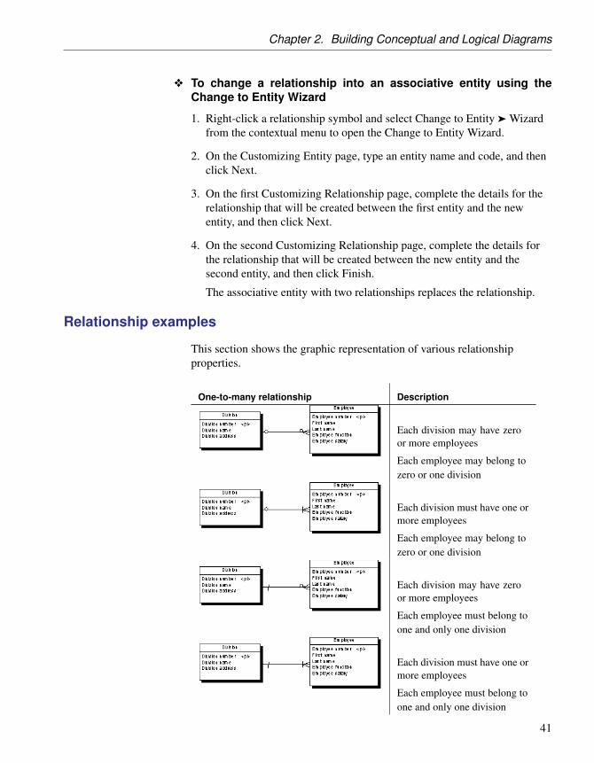
Relationship examples
This section shows the graphic representation of various relationshipproperties.
One-to-many relationship Description
Each division may have zeroor more employees
Each employee may belong tozero or one division
Each division must have one ormore employees
Each employee may belong tozero or one division
Each division may have zeroor more employees
Each employee must belong toone and only one division
Each division must have one ormore employees
Each employee must belong toone and only one division
41

Relationships (CDM/LDM)
One-to-many relationship Description
Each division may have zeroor more employees
Each employee must belong toone and only one division
Each employee is identifieduniquely by division numberand employee number
Each division must have one ormore employees
Each employee must belong toone and only one division
Each employee is identifieduniquely by division numberand employee number
One-to-one relationship Description
Each team works on zero orone project
Each project is managed byzero or one team
Each team works on one andone project only
Each project is managed byzero or one team
Each team works on zero orone project
Each project is managed byone and one team only
42

Chapter 2. Building Conceptual and Logical Diagrams
Many-to-many relationship Description
Each division may have zeroor more employees
Each employee may belong tozero or more divisions
Each division must have one ormore employees
Each employee may belong tozero or more divisions
Each division may have zeroor more employees
Each employee must belong toone or more divisions
Each division must have one ormore employees
Each employee must belong toone or more divisions
Identifier Migration along Relationships
Migrations are made instantaneously in an LDM or during generation if yougenerate a PDM from a CDM.
Relationship type Migration
Dependent one-to-many
Foreign identifiers become attributes of the primaryidentifier of the child entity.
Many-to-many No attributes are migrated.
Dominant one-to-one Primary identifier migrate from the dominant at-tribute.
Mandatory one-to-many
If the child to parent role is mandatory, migratedattributes are mandatory.
43

Associations and Association Links (CDM)
Associations and Association Links (CDM)In the Merise modeling methodology an association is used to connectseveral entities that each represents clearly defined objects, but are linked byan event, which may not be so clearly represented by another entity.
Each instance of an association corresponds to an instance of each entitylinked to the association.
When you generate a PDM from a CDM, associations are generated astables or references.
In the following example, three entities VIDEOK7, CLIENT, and STOREcontain video cassette, client, and store information. They are linked by anassociation which represents a video cassette rental (K7RENTAL). TheK7RENTAL association also contains the attributes DATE and STAFF_ID,which give the date of the rental, and the identity of the staff member whorented out the video cassette.
When you generate a PDM, K7RENTED is generated as a table with fivecolumns, STORE_ID,K7_ID, CLIENT_ID, DATE, and STAFF_ID.
44

Chapter 2. Building Conceptual and Logical Diagrams
You can use associations exclusively in your CDM, or use both associationsand relationships.
Association links An association is connected to an entity by an association link, whichsymbolizes the role and the cardinality between an association and an entity.
Creating an association with links
The easiest way to create an association between entities is to use theAssociation Link tool, which will create the association and the necessarylinks as well.
v To create an association with links
1. Click the Association Link tool in the Palette.
2. Click inside the first entity and while continuing to hold down the mousebutton, drag the cursor to a second entity. Release the mouse button.
An association symbol is created between the two entities.
Creating an association without links
You can create an association without links in any of the following ways:
♦ Use the Association tool in the diagram Palette.
♦ Select Model ä Associations to access the List of Associations, and clickthe Add a Row tool.
45

Associations and Association Links (CDM)
♦ Right-click the model or package in the Browser, and select New ä
Association.
Once you have created the association, you can link it to the relevant entitiesby using the Association Link tool.
+ For general information about creating objects, see the Objects chapterin the Core Features Guide .
Association properties
You can modify an object’s properties from its property sheet. To open anassociation property sheet, double-click its diagram symbol or its Browserentry in the Associations folder.
The General tab contains the following properties:
Property Description
Name Specifies the name of the item, which should be clear andmeaningful, and should convey the item’s purpose to non-technical users.
Code Specifies the technical name of the object, which is used forgenerating code or scripts, which may be abbreviated, andshould not generally include spaces.
Comment Specifies a descriptive label for the association.
Stereotype Sub-classification used to extend the semantics of an objectwithout changing its structure; it can be predefined or user-defined.
Number Specifies the estimated number of occurrences in the physicaldatabase for the association (the number of records).
Generate Specifies that the association will generate a table in a PDM.
Attributes Specifies the data item attached to an association.
Rules Specifies the business rules associated with the association.
Association link properties
You can modify an object’s properties from its property sheet. To open anassociation link property sheet, double-click its diagram symbol or itsBrowser entry in the Association Links folder.
46

Chapter 2. Building Conceptual and Logical Diagrams
The General tab contains the following properties:
Property Description
Entity Specifies the entity connected by the association link. You canuse the tools to the right of the list to create an object, browsethe complete tree of available objects or view the properties ofthe currently selected object.
Associa-tion
Specifies the association connected by the association link.
Role Specifies the label indicating the role of the association link.
Identifier Indicates if the entity is dependent on the other entity.
Cardinality Specifies the number of occurrences (one or many) that oneentity has relative to another. You define the cardinality foreach association link between the association and the entity.You can choose between:♦ 0,1 - There can be zero or one occurrence of the association
in relation to one instance of the entity. The association isnot mandatory
♦ 0,n - There can be zero or many occurrences of the associa-tion in relation to one instance of the entity. The associationis not mandatory
♦ 1,1 - One occurrence of the entity can be related to only oneoccurrence of the association. The association is mandatory
♦ 1,n - One occurrence of the entity can be related to oneor many occurrences of the association. The association ismandatory
You can change the default format of cardinalities from theregistry:
HKEY_CURRENT_USER\Software\Sybase\PowerDesigner <version>\ModelOptions\Conceptual Options
CardinalityNotation=1 (0..1) or 2(0,1)
Stereotype Sub-classification used to extend the semantics of an objectwithout changing its structure; it can be predefined or user-defined.
Creating a reflexive association
A reflexive association is a relationship between an entity and itself.
47

Associations and Association Links (CDM)
v To create a reflexive association
1. Click the Association Link tool in the Palette.
2. Click inside the entity symbol and, while continuing to hold down themouse button, drag the cursor a short distance within the symbol, beforereleasing the button.
3. Drag the resulting association symbol away from entity to make clear itstwo links to the entity:
In the example above, the reflexive association Manager expresses that anemployee (Manager) can manage other employees.
Defining a dependent association
In a dependent association, one entity is partially identified by another. Eachentity must have an identifier. In some cases, however, the attributes of anentity are not sufficient to identify an occurrence of the entity. For theseentities, their identifiers incorporate the identifier of another entity withwhich they have a dependent association.
Example An entity named Task has two entity attributes, TASK NAME and TASKCOST. A task may be performed in many different projects and the task costwill vary with each project. To identify each occurrence of TASK COST theunique Task entity identifier is the compound of its Task name entityattribute and the Project number identifier from the Project entity.
When you generate a PDM, the TASK table contains the PROJECTNUMBER column as a foreign key, which is also a primary key column.The primary key therefore consists of both PROJECT NUMBER and TASKNAME columns.
48

Chapter 2. Building Conceptual and Logical Diagrams
Association link identifiers and associationsThe same association can not have two identifier association links.
v To define a dependent association
1. Double-click an association link symbol to display the association linkproperty sheet.
2. Select the Identifier check box and then click OK to return to the model..
The cardinality of the association link is enclosed in parenthesis toindicate that the association link is an identifier.
Changing an association into an associative entity
You can transform an association into an associative entity linked by twoassociations. The associative entity gets the name and code of theassociation. The two new associations handle cardinality properties.
Example Two entities PROJECT MANAGER and CONTRACTOR are linked by theassociation WORKS ON PROJECT WITH:
You can represent this association with an associative entity:
The two new associations can be represented as follows:
49

Associations and Association Links (CDM)
v To change an association into an associative entity
1. Right-click an association symbol, and select Change to Entity from thecontextual menu.
An associative entity that is linked to two associations replaces theoriginal association. The associative entity takes the name of the originalassociation.
Creating an association attribute
The tools used for creating association attributes on this tab are the same asthose for creating entity attributes. For more information, see “Creating anattribute” on page 27.
50

Chapter 2. Building Conceptual and Logical Diagrams
Inheritances (CDM/LDM)An inheritance allows you to define an entity as a special case of a moregeneral entity. The general, or supertype (or parent) entity contains all of thecommon characteristics, and the subtype (or child) entity contains only theparticular characteristics.
In the example below, the Account entity represents all the bank accounts inthe information system. There are two subtypes: checking accounts andsavings accounts.
The inheritance symbol displays the inheritance status:
IDEF1X E/R and Merise Description
Standard
— Mutually exclusive inheritance
Complete inheritance
— Mutually exclusive and complete inheri-tance
Inheritances in the Barker notationThere is no separate inheritance object in the Barker notation. You representan inheritance by placing one entity symbol on top of another. Barkerinheritances are always complete and mutually exclusive. The supertypelists its subtypes on the Subtypes tab (see “Entity properties” on page 24).
Creating an inheritance
You can create an inheritance in any of the following ways:
51

Inheritances (CDM/LDM)
♦ Use the Inheritance tool in the diagram Palette (see “Creating aninheritance with the Inheritance tool” on page 52).
♦ Select Model ä Inheritances to access the List of Inheritances, and clickthe Add a Row tool. You will be required to specify a parent entity.
♦ Right-click the model or package in the Browser, and select New ä
Inheritance. You will be required to specify a parent entity.
+ For general information about creating objects, see the Objects chapterin the Core Features Guide .
Creating an inheritance with the Inheritance tool
You can use the inheritance tool to create inheritances between entities andto join additional children to an inheritance.
v To create an inheritance link using the Inheritance tool
1. Select the Inheritance tool in the Palette.
2. Click the child entity and, while continuing to hold down the mousebutton, drag the cursor to the parent entity. Release the mouse buttoninside the child entity.
The link is displayed between the two entities and has a half-circle in themiddle and an arrowhead that points to the parent entity.
3. [optional] To create additional child entities for the same link, drag anddrop an inheritance link from the half-circle to the additional child entity.
The symbol links all the child entities to the parent.
52

Chapter 2. Building Conceptual and Logical Diagrams
Dragging an inheritance link to a different child entityYou can change the child entity at the end of an inheritance link byclicking the inheritance link and drag one of its attach points to adifferent entity.
4. [optional] Double-click the new link in the diagram to open theinheritance property sheet, and enter any appropriate properties.
Inheritance properties
You can modify an object’s properties from its property sheet. To open aninheritance property sheet, double-click its diagram symbol or its Browserentry in the Inheritances folder.
The General tab contains the following properties:
Property Description
Name Specifies the name of the item, which should be clear andmeaningful, and should convey the item’s purpose to non-technical users.
Code Specifies the technical name of the object, which is used forgenerating code or scripts, which may be abbreviated, andshould not generally include spaces.
Comment Specifies a descriptive label for the inheritance link.
Stereotype Sub-classification used to extend the semantics of an objectwithout changing its structure; it can be predefined or user-defined.
Parent Specifies the name of the parent entity. You can use the toolsto the right of the list to create an object, browse the completetree of available objects or view the properties of the currentlyselected object.
Mutuallyexclusivechildren
Specifies that only one child can exist for one occurrence of theparent entity.
Complete Specifies that all instances of the parent entity (surtype) mustbelong to one of the children (subtypes). For example, entityPerson has 2 sub-types Male and Female; each instance ofentity Person is either a male or a female.
53

Inheritances (CDM/LDM)
Inheritance property sheet Generation tab
The generation mode defines the physical implementation of an inheritancestructure by specifying which entities in an inheritance structure should begenerated as tables in the PDM.
The Generation tab contains the following properties:
Property Description
GenerationMode
Specifies which parts of the inheritance will be generated. Youcan specify one or both of the following:♦ Generate parent - Generates a table corresponding to the
parent entity, which:• Inherits entity attributes of each child entity
• Is affected by child entity relationships
• Contains reference to any table which has a many-to-onerelationship with child entity
♦ Generate children - Generates a table corresponding to eachchild entity. The primary key of each child table is the con-catenation of the child entity identifier and the parent entityidentifier. When this option is selected, you must choosebetween:• Inherit all attributes – Each table inherits all the entity
attributes of the parent entity
• Inherit only primary attributes - Each table inherits onlythe identifier of the parent entity
Note that, if you do not select Generate Children, you cancontrol the generation of individual child tables using theoption Generate in the property sheet of each child entity.
54

Chapter 2. Building Conceptual and Logical Diagrams
Property Description
Specifyingattributes
In the case of parent-only generation, you can choose to definea specifying attribute, an entity attribute that is defined for aparent entity which differentiates occurrences of each child.
In the example below, the TITLE entity has two children,NONPERIODICAL and PERIODICAL.
As only the parent table TITLE will be generated in a PDM,a specifying entity attribute PERIODICAL is defined for theinheritance link to differentiate between the two child entities.
In the PDM, each of the child entity attributes willgenerate columns in the table TITLE, and the spec-ifying entity attribute PERIODICAL will generate acorresponding column PERIODICAL. The values of thiscolumn indicate whether an instance of TITLE is a periodical or
not.
The tools available on this tab for creating specifying attributesare the same as those for creating entity attributes. For moreinformation, see “Creating an attribute” on page 27.
Inheritance property sheet Children tab
The Children tab list the child entities attached to the inheritance.
v To add a child entity to an inheritance link
1. Open an inheritance property sheet and click the Children tab:
2. Click the Add Children tool to open a selection window listing all theentities available in the model.
3. Select one or more entities, and then click OK to return to the inheritanceproperty sheet.
The new entity is added to the list of child entities.
55

Inheritances (CDM/LDM)
4. Click OK to return to the diagram.
The new child entity is linked to the inheritance symbol in the diagram.
Making inheritance links mutually exclusive
When an inheritance link is mutually exclusive, one occurrence of the parententity cannot be matched to more than one child entity. This information isfor documentation only and has no impact in generating the PDM.
To make an inheritance link mutually exclusive, open the inheritanceproperty sheet and select the Mutually Exclusive Children check box. Thenclick OK to return to the diagram.
The mutually exclusive inheritance link displays an X on its half-circlesymbol.
In the diagram below, the inheritance link is mutually exclusive, meaningthat an account is either checking or savings, but never both.
Identifier Migration through an Inheritance (LDM)
In an LDM, primary identifiers of a parent entity always migrate to the childentity. The migration of other attributes of the parent entity depends onwhich inheritance option is selected.
If a child entity is not generated, its attributes migrate to its parent entity.
56

CHAPTER 3
Building Physical Diagrams
About this chapter This chapter describes how to build physical diagrams, and how to createand modify the associated objects.
Contents Topic: page
Physical Diagram Basics 58
Tables (PDM) 62
Columns (PDM) 86
Keys (PDM) 95
Indexes (PDM) 103
Defaults (PDM) 111
Domains (CDM/LDM/PDM) 115
Sequences (PDM) 124
Abstract Data Types (PDM) 129
References (PDM) 138
Views (PDM) 152
View References (PDM) 169
Check Parameters (CDM/LDM/PDM) 174
Business Rules (CDM/LDM/PDM) 179
Physical Options 188
57

Physical Diagram Basics
Physical Diagram BasicsA physical diagram allows you to define a database structure from thephysical implementation point of view. It takes into account the physicalresources: DBMS, data storage structures and software, to describe thestructure of the database.
You build a physical diagram at the end of the data analysis process, beforeyou start the software programming. The physical diagram allows you todefine how data from conceptual model are implemented in the database.
Physical diagram objects
You can create the following objects in a physical diagram:
Object Tool Symbol Description
Table Collection of rows (records) that haveassociated columns (fields). See “Tables(PDM)” on page 62.
Column [none] [none] Data structure that contains an individ-ual data item within a row (record),model equivalent of a database field. See“Columns (PDM)” on page 86.
Primary key [none] [none] Column or columns whose valuesuniquely identify each row in a table,and are designated as the primary identi-fier of each row in the table. See “Keys(PDM)” on page 95.
Alternatekey
[none] [none] Column or columns whose valuesuniquely identify each row in a table,and which is not a primary key. See“Keys (PDM)” on page 95.
Foreign key [none] [none] Column or columns whose values de-pend on and migrate from a primary oralternate key in another table. See “Keys(PDM)” on page 95.
Index [none] [none] Data structure associated with one ormore columns in a table, in which thecolumn values are ordered in such away as to speed up access to data. See“Indexes (PDM)” on page 103.
58

Chapter 3. Building Physical Diagrams
Object Tool Symbol Description
Default [none] [none] [certain DBMSs] A default value fora column. See “Defaults (PDM)” onpage 111.
Domain [none] [none] Defines valid values for a column.See “Domains (CDM/LDM/PDM)” onpage 115.
Sequence [none] [none] [certain DBMSs] Defines the form ofincrementation for a column. See “Se-quences (PDM)” on page 124.
Abstractdata type
[none] [none] [certain DBMSs] User-defined data type.See “Abstract Data Types (PDM)” onpage 129.
Reference Link between a primary or an alternatekey in a parent table, and a foreignkey of a child table. Depending on itsselected properties, a reference can alsolink columns that are independent ofprimary or alternate key columns. See“References (PDM)” on page 138.
View Data structure that results from a SQLquery and that is built from data in oneor more tables. See “Views (PDM)” onpage 152.
View Refer-ence
Link between a table and a view. See“View References (PDM)” on page 169.
Trigger [none] [none] A segment of SQL code associated witha table or a view. See “Trigger Overviewin the Building Triggers and Procedureschapter.
Procedure Precompiled collection of SQL state-ments stored under a name in the databaseand processed as a unit. See “Stored Pro-cedures and Functions” in the BuildingTriggers and Procedures chapter.
59

Physical Diagram Basics
Object Tool Symbol Description
Database [none] [none] The database of which the PDM is a rep-resentation. See “Creating a Database” inthe Getting Started with Data Modelingchapter.
Storage [none] [none] A partition on a storage device. See“Tables spaces and Storages” in theGenerating a Database from a PDMchapter.
Tablespace [none] [none] A partition in a database. See “Tablesspaces and Storages” in the Generating aDatabase from a PDM chapter.
User [none] [none] A person who can log in or connect tothe database. See “Users (PDM)” in theBuilding a Database Access Structurechapter.
Role [none] [none] A predefined user profile. See “Roles(PDM)” in the Building a DatabaseAccess Structure chapter.
Group [none] [none] Defines privileges and permissions fora set of users. See “Groups (PDM)” inthe Building a Database Access Structurechapter.
Synonym [none] [none] An alternative name for various types ofobjects. See “Synonyms (PDM)” in theBuilding a Database Access Structurechapter.
Web service [none] [none] Collection of SQL statements stored ina database to retrieve relational data inHTML, XML, WSDL or plain text for-mat, through HTTP or SOAP requests.See “Web Services (PDM)” in the Build-ing Web Services chapter.
Web opera-tion
[none] [none] Sub-object of a Web service containinga SQL statement and displaying Webparameters and result columns. See“Web Service Operations (PDM)” in theBuilding Web Services chapter.
60

Chapter 3. Building Physical Diagrams
Creating a physical diagram
You can create a physical diagram in an existing PDM in any of thefollowing ways:
♦ Right-click the model in the Browser and select New ä Physical Diagramfrom the contextual menu
♦ Right-click the background of any diagram and select Diagram ä NewDiagram ä Physical Diagram from the contextual menu.
To create a new PDM with a physical diagram, select File ä New, choosePhysical Data Model from the Model type list, choose Physical Diagram asthe first diagram, and click OK.
61

Tables (PDM)
Tables (PDM)A table represents a collection of data arranged in columns and rows. Tablesmay contain any of the following objects:
♦ Columns are named properties of a table that describe its characteristics(see “Columns (PDM)” on page 86).
♦ Indexes are data structures associated with a table that are logicallyordered by key values (see “Indexes (PDM)” on page 103).
♦ Keys are columns, or combinations of columns, that uniquely identifyrows in a table. Each key can generate a unique index or a uniqueconstraint in a target database (see “Keys (PDM)” on page 95).
♦ Triggers are segments of SQL code associated with tables, and stored in adatabase. They are invoked automatically whenever there is an attempt tomodify data in associated tables (see the Building Triggers andProcedures chapter).
You can use database-specific physical options to specify physicalparameters for tables and many other objects (see “Physical Options” onpage 188).
Creating a table
You can create a table in any of the following ways:
♦ Use the Table tool in the diagram Palette
♦ Select Model ä Tables to access the List of Tables, and click the Add aRow tool
♦ Right-click the model or package in the Browser, and select New ä Table
+ For general information about creating objects, see the Objects chapterin the Core Features Guide .
Table properties
You can modify an object’s properties from its property sheet. To open atable property sheet, double-click its diagram symbol or its Browser entry inthe Tables folder. The following sections detail the property sheet tabs thatcontain the properties most commonly entered for tables.
The General tab contains the following properties:
62

Chapter 3. Building Physical Diagrams
Property Description
Name Specifies the name of the item which should be clear andmeaningful, and should convey the item’s purpose to non-technical users
Code Specifies the technical name of the item used for generatingcode or scripts, which may be abbreviated, and should notgenerally include spaces
Comment Specifies a descriptive label for the table
Stereotype Sub-classification used to extend the semantics of an objectwithout changing its structure; it can be predefined or user-defined
Owner Specifies the name of the table owner. You choose an ownerfrom a list of users. A table can only have one owner at atime. This is normally the table creator
Number Specifies the estimated number of records in the table in thephysical database, which is used to estimate database size.This box is automatically populated during reverse engi-neering if you select the Statistics check box in the ReverseEngineering dialog box (see “Reverse Engineering from aLive Database” in the “Reverse Engineering a Database intoa PDM” chapter).
You can enter your own value in this field, or refresh itsstatistics (along with those for all of the table’s columns)at any time by right-clicking the table symbol or its entryin the Browser and selecting Update Statistics from thecontextual menu. You can also update the statistics for alltables by selecting Tools ä Update Statistics (see “ReverseEngineering Database Statistics” in the “Reverse Engineeringa Database into a PDM” chapter).
Generate Specifies that the table is generated in the database
Dimensionaltype
Specifies the multidimensional type of the table. You canchoose between:♦ Dimension - see “Dimensions (PDM)” in the Building
Multidimensional Diagrams chapter
♦ Fact - see “Facts (PDM)” in the Building Multidimen-sional Diagrams chapter
63

Tables (PDM)
Property Description
Type Specifies the type of the table. You can choose between:♦ Relational
♦ Object - for abstract data types
♦ XML - for storing and retrieving data using an XML for-mat. For more information, see “Creating an XML tableor view” on page 65
The following tabs are also available:
♦ Columns - lists the columns associated with the table (see “Columns(PDM)” on page 86).
♦ Indexes - lists the indexes associated with the table (see “Indexes (PDM)”on page 103).
♦ Keys - lists the keys associated with the table (see “Keys (PDM)” onpage 95).
♦ Triggers - lists the triggers associated with the table (see The BuildingTriggers and Procedures chapter).
♦ Procedures - lists the procedures associated with the table (see theBuilding Triggers and Procedures chapter).
♦ Physical Options - list the physical options associated with the table (see“Physical Options” on page 188).
♦ Preview - displays the SQL code associated with the table (see“Previewing SQL statements” in the Working with Data Models chapter).
Linking a table to an abstract data type
Some DBMS like Oracle or DB2 Common Server support tables based onabstract data types (ADT). A table based on an ADT uses the properties ofthe ADT and the ADT attributes become table columns.
To link a table to an ADT you have to use the Based On list to select anabstract data type. Not all ADT can be used, only ADT of type Object inOracle, or Structured in DB2 Common Server appear in the Based On list.
64

Chapter 3. Building Physical Diagrams
+ For more information on abstract data types, see “Abstract Data Types(PDM)” on page 129.
Creating an XML table or view
Some DBMS support tables and views of XML type.
An XML table is used to store an XML document, it does not containcolumns. It is possible to associate this table with an XML schemaregistered in a relational database, in this case the schema is used to validatethe XML document stored in the table.
If you select the XML type in the Type list, the Column tab disappears andthe following additional properties appear in the table property sheet:
65

Tables (PDM)
Property Description
Schema Allows you to enter the target namespace or the name of anXML model. The schema must be registered in the database tobe used for validating XML documents. You can:♦ type a user-defined schema name
♦ click the Select a registered schema button to connect to adatabase and select a registered schema
If you select an element from an XML model open in the Pow-erDesigner workspace, the Schema property is automaticallyinitialized with the XML model target namespace. Note thatthis schema must also be registered in the database to be usedfor validating XML documents
Element Allows you to select a root element in the XML document. Youcan:♦ type a user-defined element name
♦ click the Select an element button to select an element fromthe XML models open in the workspace or from the schemaregistered in the database
v To create an XML table
1. Right-click the Table category in the Browser and select New.
The property sheet of a new table is displayed.
2. Type a table name and a table code.
3. In the Type list, select XML.
The Columns tab disappears and the Schema and Element boxes appearin the lower part of the General tab.
4. In the Schema box, type the target namespace or name of an XML modelor use the Select a registered schema button to select among theregistered schema in a selected database.
5. In the Element box, type the name of the root element of the selectedschema.
66

Chapter 3. Building Physical Diagrams
6. Click OK.
Naming a table constraint
A table constraint is a named check that enforces data requirements of checkparameters.
Whenever you place a data restriction on a table, a constraint is createdautomatically. You have the option of specifying a name for the constraint.If you do not, the database creates a default constraint name automatically.
This name helps you to identify and customize a table constraint in scriptsfor database creation and modification.
v To name a table constraint
1. Double-click a table in the diagram to display its property sheet, and clickthe Check tab.
2. Click the User Defined button to the right of the Constraint Name box,and type changes to the constraint name in the Constraint Name box.
Undo changes to a constraint nameYou can always return to the default constraint name by re-clicking theUser-Defined button.
3. Click OK.
67

Tables (PDM)
+ For more information, see “Check Parameters (CDM/LDM/PDM)” onpage 174.
Creating external tables
You can create external tables when you need to access data in a remotetable. The external table has all the properties of the remote table but it doesnot contain any data locally.
External tables are metamodel extensions defined in the profile category ofan extended model definition attached to a PDM. For example, in SybaseASA, external tables are called proxy tables and a specific extended modeldefinition is delivered to let you design these tables.
+ For more information on designing proxy tables in Sybase ASA, seesection Working with proxy tables in Sybase ASA in chapter DBMS-specificFeatures.
+ For more information on designing proxy tables in Sybase ASE, seesection Working with proxy tables in Sybase ASE in chapter DBMS-specificFeatures.
Denormalizing Tables and Columns
Database normalization consists in eliminating redundancy and inconsistentdependencies between tables. While normalization is generally consideredthe goal of database design, denormalization, the deliberate duplication ofcertain data in order to speed data retrieval, may be appropriate in certaincases:
♦ Critical queries rely upon data from more than one table
♦ Many calculations need to be applied to one or many columns beforequeries can be successfully answered
♦ Tables need to be accessed in different ways by different users during thesame timeframe
♦ Certain columns are queried a large percentage of the time
When deciding whether to denormalize, you need to analyze the data accessrequirements of the applications in your environment and their actualperformance characteristics. Often, good indexing and other solutions solvemany performance problems rather than denormalization.
Denormalization may be accomplished in several ways:
♦ Horizontal partitioning is used to divide a table into multiple tablescontaining the same columns but fewer rows
68

Chapter 3. Building Physical Diagrams
♦ Vertical partitioning is used to divide a table into multiple tablescontaining the same number of rows but fewer columns
♦ Table collapsing is used to merge tables in order to eliminate the joinbetween them
♦ Column denormalization is used to repeat a column in tables in order toavoid creating a join between tables
The following sections explain how to implement these denormalizationtechniques in PowerDesigner.
Creating horizontal partitions
Horizontal partitioning consists in segmenting a table into multiple tableseach containing a subset of rows and the same columns as the partitionedtable in order to optimize data retrieval. You can use any column, includingprimary keys, as partitioning criteria.
Example In this example, the table Annual_Sales contains the following columns:
This table may contain a very large amount of data. You could optimize dataretrieval by creating horizontal partitions by year. The result is as follows:
Horizontal partitioning has the following pros and cons:
69

Tables (PDM)
Pros Cons
Improve the query response time Requires additional joins and unions toretrieve data from multiple tables
Accelerate incremental databackup and recovery
Requires more intelligent queries todetermine which table contains therequested data
Decrease time required to loadinto indexed tables
Requires additional metadata to describethe partitioned table
Horizontal PartitioningWizard
You can partition tables horizontally using the Horizontal PartitioningWizard.
v To partition a table with the Horizontal Partitioning Wizard
1. Select Tools ä Denormalization ä Horizontal Partitioning, or right-clicka table in the diagram and select Horizontal Partitioning from thecontextual menu, in order to open the Horizontal Partitioning Wizard:
2. Select the table to partition and select the check box if you want to keepthe original table after partitioning. Then click Next to go to the PartitionDefinition page.
3. The Partition Definition page allows you to create as many partitions asyou need with the Insert and Add a row tools. The name of each partitionmust be unique in the model. A table will be created for each partition
70

Chapter 3. Building Physical Diagrams
you specify, and will take the name of the relevant partition. Then clickNext to go to the Discriminant Column Selection page.
4. The Discriminant Column Selection page allows you to specify thecolumns that will be used as partition criteria using the Add Columnstool. These columns will not be included in the partitions. Then clickNext to go to the Partitioning Information page.
5. The Partitioning Information page allows you to specify a name and codefor the transformation object that will be created together with thepartitions. Then click Finish.
The table is partitioned, a horizontal partitioning object is created, and allreferences to the original table are created on each partition table.
Creating vertical partitions
Vertical partitioning consists in segmenting a table into multiple tables eachcontaining a subset of columns and the same number of rows as thepartitioned table. The partition tables share the same primary key.
Example The table Customer contains the following columns:
This table can be divided in two tables corresponding to different aspects ofthe table. You can use the Vertical Partitioning Wizard to split the table asfollows:
Vertical partitioning has the following pros and cons:
71

Tables (PDM)
Pros Cons
Improve the query response time Requires additional joins and unions toretrieve data from multiple tables
Allows you to split data requiringdifferent levels of protection, youcan store confidential informationin a special partition
Requires more intelligent queries todetermine which table contains therequested data
Requires additional metadata to describethe partitioned table
Vertical PartitioningWizard
You can partition tables vertically using the Vertical Partitioning Wizard.The key columns of the partitioned table are duplicated whereas the othercolumns are distributed among the partition tables. PowerDesigner verifiesthat all the columns of the partitioned table are used in the partition tables.
v To partition a table with the Vertical Partitioning Wizard
1. Select Tools ä Denormalization ä Vertical Partitioning, or right-click atable in the diagram and select Vertical Partitioning from the contextualmenu, in order to open the Vertical Partitioning Wizard:
2. Select the table to partition and select the check box if you want to keepthe original table after partitioning. Then click Next to go to the PartitionDefinition page.
3. The Partition Definition page allows you to create as many partitions as
72

Chapter 3. Building Physical Diagrams
you need with the Insert and Add a row tools. The name of each partitionmust be unique in the model. A table will be created for each partitionyou specify, and will take the name of the relevant partition. Then clickNext to go to the Discriminant Column Selection page.
4. The Discriminant Column Selection page allows you to specify whichcolumns will be included in each partition table. Drag columns from theAvailable columns pane, and drop them onto the appropriate partitiontable in the Columns distribution pane, or use the Add and Removebuttons at the bottom of each pane. When all your columns are allocated,click Next to go to the Partitioning Information page.
5. The Partitioning Information page allows you to specify a name and codefor the transformation object that will be created together with thepartitions. Then click Finish.
The table is partitioned, a vertical partitioning object is created, and allreferences to the original table are created on each partition table.
Creating table collapsings
Table collapsing consists in merging tables into a single table in order toeliminate joins and to improve query performance.
The generated table gathers the columns of the merged tables. All incomingand outgoing references to the input tables are preserved in the resultingtable. When the collapsed tables are related by references, the followingoccurs:
♦ The parent column of the join is no longer needed, thus removed
♦ The columns of the parent table are duplicated
♦ The foreign keys of the children are removed, but their columns arepreserved in the resulting table
Example Tables Customer and Order are linked together.
73

Tables (PDM)
To optimize data retrieval in the database, you collapse both tables into asingle table to eliminate the join. The result is a single table (with 2synonym symbols) with the primary key of the child table:
Table Collapsing Wizard The Table Collapsing Wizard lets you merge multiple tables into a singletable. You can collapse tables related to each other with a reference or tableswith identical primary keys.
v To combine multiple tables with the Table Collapsing Wizard
1. Select Tools ä Denormalization ä Table Collapsing, or right-click areference between the tables to collapse and select Table Collapsing fromthe contextual menu, in order to open the Table Collapsing Wizard:
74

Chapter 3. Building Physical Diagrams
2. Specify a name and code for the target table to be created, and then clickNext to go to the Input Table Selection page.
3. The Input Table Selection page allows you to select the tables to collapsewith the Add Tables tool. Select the check box if you want to keep theoriginal tables after collapsing, and then click Next to go to the TableCollapsing Information page.
4. The Table Collapsing Information page allows you to specify a name andcode for the transformation object that will be created together with thetable collapsing. Then click Finish.
The selected tables are collapsed, and a table collapsing object is created.
Denormalizing columns
You can denormalize columns to eliminate frequent joins using columndenormalization.
Example
In this example, you want to have the division name printed on the pay slipof each employee, however, you do not want to create a join between thosetables. You can denormalize columns in order to have column Div_Name intable PaySlip:
Column denormalization eliminates joins for many queries, however itrequires more maintenance and disk space.
Column DenormalizationWizard
The Column Denormalization Wizard lets you duplicate columns in aselected table. The result is a replica of the original column in the targettable.
75

Tables (PDM)
+ For more information about object replicas, see the Shortcuts and ObjectReplications chapter in the Core Features Guide .
v To denormalize a column with the Column Denormalization Wiz-ard1. Select Tools ä Denormalization ä Column Denormalization, or
right-click a table and select Column Denormalization from thecontextual menu, in order to open the Column Denormalization Wizard:
2. Select the table in which you want the denormalized columns to beadded, and then click Next to go to the Column Selection page.
3. The Column Selection page allows you to select the columns to replicate.Select one or more columns to replicate, and then click Finish.
A replication is created for each selected column. You can display the listof replicas from the menu command Model ä Replications. Each replicahas its own property sheet. For more information about object replicas,see the Shortcuts and Object Replications chapter in the Core FeaturesGuide .
Removing adenormalized column
You can move and paste a denormalized column into another model orpackage in the standard way.
Reverting adenormalized column
You can revert a column denormalization by deleting the duplicated columnfrom the target table property sheet. This automatically removes the columnreplica. Note that you cannot revert a column denormalization by deleting acolumn replica from the list of replications.
76

Chapter 3. Building Physical Diagrams
Denormalization object properties
A denormalization transformation object is automatically created when youpartition a table using the Horizontal or Vertical Partitioning Wizard orcollapse tables with the Table Collapsing Wizard.
To access this object, select Model ä Transformations to open the List ofTransformations, select the appropriate object, and then click the Propertiestool.
The following properties are available on the General tab:
Property Description
Name Specifies the name of the partitioning object. It is rec-ommended to provide a clear name in the PartitioningWizard
Code Specifies the code of the partitioning object
Comment Specifies additional information about the partitioningobject.
Partitioned table [partitionings only] Specifies the name of the table usedto create the table partitions.
DiscriminantColumns
[horizontal partitionings only] Specifies the name andcode of the columns used as partition criteria
Target table [table collapsings only] Specifies the name of the tableresulting from the collapsing of selected tables
Partitions tab The Partitions tab is only available for partitionings, and lists the tablesassociated with the partitioning. The following actions can be performed onthis tab:
♦ Open the property sheets of the partition tables.
♦ Add more partitions and edit the properties of the corresponding tables.
♦ Add comments to identify the different partitions
♦ Delete partitions and their corresponding tables. When you delete apartition, you are prompted to specify whether you want to delete thecorresponding table. You can delete a partition and keep its table, but youcannot delete a table and keep an empty partition
Partition Columns tab The Partition Columns tab is only available for vertical partitionings, anddisplays the distribution of columns between the partition tables. You candrag and drop columns to reallocate them between tables.
77

Tables (PDM)
Source Tables tab The Source Tables tab is only available for table collapsings, and displaysthe tables that were collapsed. These tables will no longer exist unless youselected to keep the original tables in the Table Collapsing Wizard.
Example: Intermodel generation and horizontal partitions
When you update a PDM generated from another model, any horizontalpartitioning is preserved.
For example, the Sales CDM contains the entity Customer:
You generate the Sales PDM from the CDM, and the Customer entity isgenerated to the Customer table:
You partition this table using City as the criterion. The City column isexcluded from the partition tables:
You modify the CDM by adding an Activity attribute to the Customer entity,and regenerate the PDM in update mode. The partitions are taken intoaccount in the merge dialog box: The new Activity attributes are selected bydefault, while the City criteria columns are not selected.
78

Chapter 3. Building Physical Diagrams
Example: Intermodel generation and vertical partitions
When you generate in update mode a PDM from a PDM, a CDM or anOOM, vertical partitioning is preserved.
For example, you build a CDM to design the project management process,this model contains entity Task:
The CDM is generated in a PDM, entity Task becomes table Task:
79

Tables (PDM)
You decide to split the table in two table partitions: one table contains thedetails about the task, the other table contains the task schedule:
You modify the CDM and regenerate the PDM in update mode. Thepartitions are taken into account in the merge dialog box as you can see inthe following dialog box: CDM changes (creation of the Task_Managerattribute) are selected by default, and column modifications related topartition creation are not selected.
80

Chapter 3. Building Physical Diagrams
Removing partitionings and table collapsings
You can remove partitionings or table collapsings and either keep or removethe associated tables.
v To remove a denormalization and keep the associated tables
1. Select Model ä Transformations to open the List of Transformations.
2. Select the denormalization object, and then click the Delete tool.
The denormalization object (and, for partitionings, its partitions) aredeleted, but the corresponding tables are retained, and becomeindependent from each other.
81

Tables (PDM)
v To remove a denormalization as well as the associated tables
1. Select Model ä Transformations to open the List of Transformations.
2. Select the denormalization object, and then click the Cancel tool.
Cancel Transformation toolThe Cancel Transformation tool is only available if the selected denor-malization object is based upon a table generated from another model.You can recover the original table by regenerating it from the sourcemodel.
The denormalization object (and, for partitionings, its partitions) aredeleted, as well as the corresponding tables.
Moving denormalizationsYou cannot move or paste a denormalization object to another model orpackage.
Using PowerBuilder Extended Attributes
When designing tables to be used in a PowerBuilder DataWindow, you canmanage the extended attributes which PowerBuilder uses to storeapplication-based information, such as label and heading text for columns,validation rules, display formats, and edit styles.
PowerDesigner supports certain columns for two PowerBuilder systemtables, PBCatTbl (for tables) and PBCatCol (for columns), on theExtended Attributes tab of tables and columns available in a model to whichthe PowerBuilder extended model definition is attached:
82
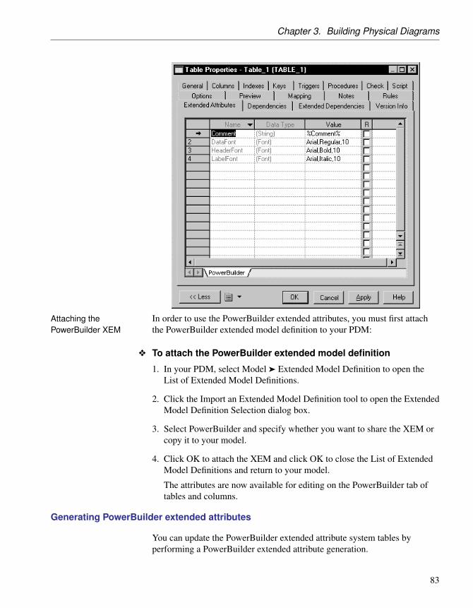
Chapter 3. Building Physical Diagrams
Attaching thePowerBuilder XEM
In order to use the PowerBuilder extended attributes, you must first attachthe PowerBuilder extended model definition to your PDM:
v To attach the PowerBuilder extended model definition
1. In your PDM, select Model ä Extended Model Definition to open theList of Extended Model Definitions.
2. Click the Import an Extended Model Definition tool to open the ExtendedModel Definition Selection dialog box.
3. Select PowerBuilder and specify whether you want to share the XEM orcopy it to your model.
4. Click OK to attach the XEM and click OK to close the List of ExtendedModel Definitions and return to your model.
The attributes are now available for editing on the PowerBuilder tab oftables and columns.
Generating PowerBuilder extended attributes
You can update the PowerBuilder extended attribute system tables byperforming a PowerBuilder extended attribute generation.
83

Tables (PDM)
During generation, certain extended attributes may contain variables in theirvalues, which are translated during generation, for example to access objectproperties. The following object properties are translated during generation:
Object Property
Table Comment
Column Comment
Label
Header
Initial value
This automated process uses the PowerDesigner generation templatelanguage (see the Customizing Generation with GTL chapter in Customizingand Extending PowerDesigner ).
v To generate PowerBuilder extended attributes
1. Select Tools ä PowerBuilder ä Generate Extended Attributes to open thePowerBuilder Extended Attributes Generation dialog box.
2. Click the Connect to a Data Source tool to open the Connect to a DataSource window.
3. Select a machine or file data source and click Connect.
The selected data source is displayed in the Data Source box in the upperpart of the PowerBuilder Extended Attributes Generation dialog box.
4. Select the tables you want to generate.
5. Click OK to start generation.
The Output window displays the generation messages.
Reverse engineering PowerBuilder extended attributes
The reverse engineering feature reads the PowerBuilder extended attributescontained in a database and writes them into the appropriate tables andcolumns in a PDM.
During reverse engineering, certain reversed extended attributes arecompared with the translated default values in the PowerBuilder extendedmodel definition. It these attributes match, the reversed value is replaced bythe default value from the extended model definition.
+ For more information about objects translated during reverseengineering, see “Generating PowerBuilder extended attributes” on page 83.
84
Chapter 3. Building Physical Diagrams
This automated process uses the PowerDesigner generation templatelanguage (see the Customizing Generation with GTL chapter in Customizingand Extending PowerDesigner ).
v To reverse engineer PowerBuilder extended attributes
1. Select Tools ä PowerBuilder ä Reverse Extended Attributes.
The PowerBuilder Extended Attributes Reverse Engineering dialog boxis displayed.
2. Click the Connect to a Data Source tool to open the Connect to a DataSource dialog box.
3. Select a machine or file data source and click Connect.
The selected data source is displayed in the Data Source box in the upperpart of the PowerBuilder Extended Attributes Reverse Engineering dialogbox.
4. Select the tables you want to reverse engineer.
5. Click OK to start reverse engineering.
The Output window displays the reverse engineering messages.
85

Columns (PDM)
Columns (PDM)A column contains an individual data item within a row. It is the modelequivalent of a database column. A column is always defined for a table.When you create a column, it must be assigned a name and code. You canalso select a data type for the column. This can be done directly from a listof available data types, or by attaching the column to a domain.
Creating a column
You can create a column in any of the following ways:
♦ Open the Columns tab in the property sheet of a table, and click the Adda Row tool
♦ Right-click a table in the Browser, and select New ä Column
+ For general information about creating objects, see the Objects chapterin the Core Features Guide .
Column properties
You can modify an object’s properties from its property sheet. To open acolumn property sheet, double-click its row in the Columns tab of a table orits Browser entry. The following sections detail the property sheet tabs thatcontain the properties most commonly entered for columns.
The General tab contains the following properties:
Property Description
Name Specifies the name of the item, which should be clear andmeaningful, and should convey the item’s purpose to non-technical users
Code Specifies the technical name of the object, which is used forgenerating code or scripts, which may be abbreviated, andshould not generally include spaces
Comment Specifies a descriptive label for the column
Stereotype Sub-classification used to extend the semantics of an objectwithout changing its structure; it can be predefined or user-defined
Table Specifies the table which contains column
Data type Specifies the form of the data corresponding to the column,such as numeric, alphanumeric, boolean, or others
86

Chapter 3. Building Physical Diagrams
Property Description
Displayed When selected, allows the display of the selected column inthe table symbol
Length Specifies the maximum length of the data type
Precision Specifies the maximum number of places after the decimalpoint
Identity When selected, indicates that the data is auto-incremented(not available for all DBMS)
Domain Specifies the name of the associated domain. You can use thetools to the right of the list to create an object, browse thecomplete tree of available objects or view the properties ofthe currently selected object
Computed When selected, designates that the column is computed froman expression using values from other columns in the table(not available for all DBMS)
Primary key When selected, designates a column whose values uniquelyidentify a row in the table
Foreign key When selected, designates a column that depends on andmigrates from a primary key column in another table
Mandatory When selected, indicates a column that must be assigned anot null value
With default When selected, indicates if a default value is assigned to thecolumn when a Null value is inserted (not available for allDBMS)
Column property sheet Detail tab
The Detail tab contains the following properties:
Property Description
Null Values Specifies the number (or percentage) of column entries whichcontain null values. You can enter a number or percentagein this field or derive its value from database statistics (see“Updating Column Statistics” on page 88).
87

Columns (PDM)
Property Description
Distinct Val-ues
Specifies the number (or percentage) of column entries whichcontain distinct values. You can enter a number or percentagein this field or derive its value from database statistics (see“Updating Column Statistics” on page 88).
For example, you generate a table with 2 columns and 10rows. You set the percentage of distinct values to 100 % forColumn 1 and to 80% for Column 2. This implies that 10rows will have distinct values in Column 1, and 8 rows inColumn 2.
When you apply a test data profile with a list generationsource to a column with a given percentage of distinct values,PowerDesigner uses the values from the test data profile list.If there are not enough values declared in the list, a warningmessage is displayed in the Output window to inform you thatthe distinct value parameter cannot be enforced due to lack ofdistinct values in the list of values.
AverageLength
Specifies the average length of a value. You can enter anumber in this field or derive its value from database statistics(see “Updating Column Statistics” on page 88).
Profile Test data profile selected from the list. Profiles can usecharacters, numbers or date/time data types.
+ For more information, see “Using test data” section inthe Generating a Database from a PDM chapter.
ComputedExpression
Computed expression typed directly in the Computed Expres-sion pane or defined with the SQL Editor (accessed with theEdit tool) which helps you define more complex expressions.
+ For more information, see “Creating a computed column”on page 89.
Updating Column Statistics
You can enter values in the Null Values, Distinct Values and Average Lengthfields. Alternatively, you can automatically populate them during reverseengineering by selecting the Statistics check box in the Reverse Engineeringdialog box (see “Reverse Engineering from a Live Database” in the “ReverseEngineering a Database into a PDM” chapter).
You can refresh the value of these fields (along with those for all of thetable’s columns) at any time by right-clicking the table symbol or its entry inthe Browser and selecting Update Statistics from the contextual menu. You
88

Chapter 3. Building Physical Diagrams
can also update the statistics for all tables by selecting Tools ä UpdateStatistics (see “Reverse Engineering Database Statistics” in the “ReverseEngineering a Database into a PDM” chapter).
Creating a computed column
A computed column is a column whose content is computed from anexpression using values from other columns in the table. The computedcolumn is then filled with the results.
Simple computed expressions can be entered directly in the ComputedExpression pane on the Detail tab of the column property sheet. For morecomplex expressions, use the SQL Editor available through the Edit toolfound on the same tab.
Computed columns are not available in all DBMS.
Example Assume that you want to automatically fill a column with the total sales ofwidgets. To do this, you can create a computed column that will use thenumber of widgets multiplied by the widget price:
Column name Contents Action on data
Number of widgets Number of widgets sold —
Widget price Price of widgets when sold —
Widget sales Total widget sales Computed by multiplyingthe first two columns
While our example is very simple, the SQL Editor allows you to define verycomplex computed column expressions.
+ For more information on the SQL Editor, see Using SQL tools in theWorking with Data Models chapter.
v To create a computed column
1. Double-click a table to open its property sheet, and click the Columns tab.
2. Click the Add a Row tool, and then click the Properties tool to open theproperty sheet for the new column.
3. On the General tab, select the Computed checkbox, and then click theDetail tab.
4. Enter an expression in the Computed Expression box to define thecomputed column. Alternatively,you can click the Edit with SQL Editortool to use the SQL Editor.
89

Columns (PDM)
In our example, we use the asterisk (*) as an arithmetic operator tomultiply the number of widgets by their price.
5. Click OK to return to the column property sheet.
The expression is displayed in the Computed Expression pane.
6. Click OK in each of the dialog boxes.
Selecting a data type for a column
There are two ways to select a data type for a column:
♦ Attach the column to a domain - The domain dictates a data type, alength, and a level of precision, as well as optional check parameters
♦ Manually select a data type - You select a data type along with alength, a level of precision, and optional check parameters
About check parametersCheck parameters indicate data ranges and validation rules. You can setcheck parameters for domains, tables, and columns.
v To select a data type for a column
1. Double-click a table to open its property sheet, and click the Columns tab.
2. Click the required column entry and then click the Properties tool to openits property sheet.
90

Chapter 3. Building Physical Diagrams
3. Select a data type from the Data Type list or click the Question markbutton to open and choose a data type from the Standard Data Typesdialog box.
4. If required, enter a data type length and precision.
Undefined data typeIf you do not want to select a data type immediately, you can choose the<undefined> data type. When you generate the database, this data typeis replaced by the default data type for your database, as defined in theDBMS.
5. Click OK in each of the dialog boxes.
Attaching a column to a domain
If you attach a column to a domain, the domain supplies the data type andrelated data characteristics. It may also indicate check parameters, andbusiness rules.
v To attach a column to a domain
1. Double-click a table to open its property sheet, and click the Columns tab.
2. Click the required column entry and then click the Properties tool to openits property sheet.
91

Columns (PDM)
3. Select a domain from the Domain list and then click OK.
Copying a column to another table
You can copy a column from one table and add it to another table. If thetable already contains a column with the same name or code as the copiedcolumn, the copied column is renamed. For example, the column PUB_ID isrenamed PUB_ID2 when it is copied to a table which already contains acolumn PUB_ID.
92

Chapter 3. Building Physical Diagrams
v To copy a column to another table
1. Double-click a table to open its property sheet, and click the Columns tab.
2. Click the Add Columns tool to open a selection box listing the columnsattached to all other tables in the model.
3. Select one or more columns in the list and then click OK.
The copied columns appear in the list of columns for the current table.
4. Click OK.
Naming a column constraint
A column constraint is a named check that enforces data requirements ofcheck parameters.
Whenever you place a data restriction on a column, it generates a constraintautomatically. You have the option of specifying a name for the constraint.If you do not specify a name for the constraint, PowerDesigner creates adefault constraint name automatically.
This name helps you to identify and customize a column constraint in scriptsfor database creation and modification.
v To name a column constraint
1. Open the property sheet of a column and click the Additional Checks tab.
2. Type changes to the constraint name in the Constraint Name box.
93
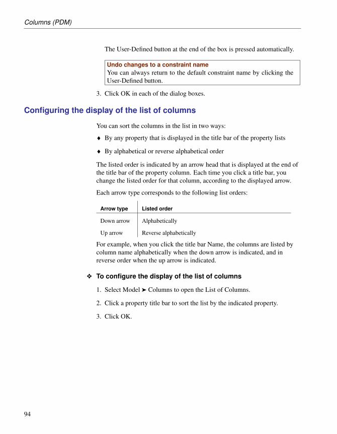
Columns (PDM)
The User-Defined button at the end of the box is pressed automatically.
Undo changes to a constraint nameYou can always return to the default constraint name by clicking theUser-Defined button.
3. Click OK in each of the dialog boxes.
Configuring the display of the list of columns
You can sort the columns in the list in two ways:
♦ By any property that is displayed in the title bar of the property lists
♦ By alphabetical or reverse alphabetical order
The listed order is indicated by an arrow head that is displayed at the end ofthe title bar of the property column. Each time you click a title bar, youchange the listed order for that column, according to the displayed arrow.
Each arrow type corresponds to the following list orders:
Arrow type Listed order
Down arrow Alphabetically
Up arrow Reverse alphabetically
For example, when you click the title bar Name, the columns are listed bycolumn name alphabetically when the down arrow is indicated, and inreverse order when the up arrow is indicated.
v To configure the display of the list of columns
1. Select Model ä Columns to open the List of Columns.
2. Click a property title bar to sort the list by the indicated property.
3. Click OK.
94

Chapter 3. Building Physical Diagrams
Keys (PDM)A key is a column, or a combination of columns, that uniquely identifies arow in a table. Each key can generate a unique index or a unique constraintin a target database.
The physical diagram supports the following types of keys:
♦ Primary - Column or combination of columns whose values uniquelyidentify every row in a table. A table can have only one primary key
♦ Alternate - Column or combination of columns (not the same column orcombination of columns as for a primary key) whose values uniquelyidentify every row in a table
♦ Foreign - Column or combination of columns whose values are requiredto match a primary key, or alternate key, in some other table
Example The TITLE table shown below has a primary, alternate and foreign key:
♦ TITLE_ID is the primary key and consists of the column TITLE ISBNwhich identifies each book title in the table
♦ TITLE_NAME is an alternate key containing the columns TITLE NAMEand TITLE TYPE. It allows each title to be identified by its name andtype, The fact that it is an alternate key indicates that there is a constraintthat no two titles of the same type can have the same name
The TITLE table also contains the foreign key column PUBLISHER ID.This column references the primary key column in the Publisher table.
Creating a Key
The method for creating a key depends on the type of key. See theappropriate section:
♦ “Primary keys” on page 96
♦ “Alternate keys” on page 98
♦ “Foreign keys” on page 99
95

Keys (PDM)
Key properties
You can modify an object’s properties from its property sheet. To open a keyproperty sheet, go to the Keys tab of its parent table, or double-click itsBrowser entry.
The General tab contains the following properties:
Property Description
Name Specifies the name of the item, which should be clearand meaningful, and should convey the item’s purpose tonon-technical users
Code Specifies the technical name of the object, which is usedfor generating code or scripts, which may be abbreviated,and should not generally include spaces
Comment Specifies the descriptive comment for the key
Stereotype Sub-classification used to extend the semantics of an objectwithout changing its structure; it can be predefined oruser-defined
Table Specifies the name of the table where the key is defined
Constraintname
Specifies the name of the key constraint. PowerDesignerautomatically creates a constraint name for a key, it is usedduring database creation and modification. You can modifythe default name, you can also cancel these changes and goback to the default name
Primary key Indicates if the key is the primary key of the current table.There must be only one primary key in a table, if youselect the Primary Key check box in a key property sheet, itreplaces an already existing primary key
Cluster Indicates whether the key constraint is a clustered constraint(for those DBMS that support clustered indexes)
Primary keys
A primary key is the primary identifier for a table, and is attached to one ormore columns whose values uniquely identify every row in the table.
Every table must have a primary key, composed of one or more of itscolumns.
96

Chapter 3. Building Physical Diagrams
Example Employee number is the primary key for the table Employee. This meansthat each employee must have one unique employee number.
You can define one or more columns as the primary key of a table from thelist of columns.
v To designate a primary key
1. Double-click a table in the diagram to open its property sheet.
2. Click the Columns tab, and select the check box in the P column for oneor more columns in the list.
3. [optional] Click the Keys tab and rename the key or select it and click theProperties tool to access its property sheet.
4. Click OK.
Rebuilding primary keys
Rebuilding primary keys in a physical diagram updates primary keys fortables.
Rebuilding primary keys is useful following the reverse engineering of adatabase in which all of the primary keys could not be reverse engineered, orif you did not select the rebuild option for primary keys when you reverseengineered the database. The rebuild option for primary keys createsprimary keys for tables that have no key and a single unique index.
You can choose to rebuild all primary keys in your model, or select thetables for which you want to rebuild the primary keys.
97

Keys (PDM)
v To rebuild primary keys
1. Select Tools ä Rebuild Objects ä Rebuild Primary Keys to open theRebuild Primary Keys dialog box, which lists all the tables in the currentmodel.
Rebuilding primary keys in a packageTo rebuild the primary keys in package, select the package from the listat the top of the tab.
To rebuild the primary keys in a sub-package, select the Include Sub-Packages icon next to the list, and then select a sub-package from thedropdown list.
2. Select the tables containing the primary keys that you want to rebuild.
Selecting or clearing all check boxesYou can select all check boxes, or clear all check boxes, by selecting theSelect All tool, or Clear All tool, from the toolbar at the top of the tab.
3. Click OK.
Alternate keys
An alternate key is a key attached to one or more columns whose valuesuniquely identify every row in the table, but which is not a primary key. Analternate key can also be a foreign key. Each alternate key can generate aunique index or a unique constraint in a target database.
98

Chapter 3. Building Physical Diagrams
Create key tool You can also select one or several columns and use the Create Key tool inthe Columns tab of the table property sheet.
v To designate an alternate key
1. Double-click a table in the diagram to open its property sheet.
2. Click the Keys tab, which lists all the keys defined for the table.
3. Click the Add a Row tool, and type a name for the newly created key.
Alternate key naming conventionThe naming convention for an alternate key is AK followed by thenumber of the key column code; for example AK1_CUSNAME.
4. [optional] Type a constraint name in the Constraint Name column.If youdo not specify a constraint name, PowerDesigner creates a defaultconstraint name automatically.
Displaying additional property columnsIf you do not see the Constraint Name column, display it with theCustomize Columns and Filter tool. For more information, see “Cus-tomizing object list columns and filtering lists” section in the Objetschapter of the Core Features Guide .
5. Click the property tool and confirm the object creation in order to openthe property sheet for the new key.
6. Click the columns tab, which lists all the columns to which the key isattached. At key creation, the list is empty.
7. Click the Add Columns tool to open a selection box listing all thecolumns in the table (except those attached to the primary key).
8. Select one or more columns and click OK in each of the dialog boxes.
Foreign keys
A foreign key is a primary key, or an alternate key, that migrates fromanother table. Depending on selected model options, a primary key can beautomatically migrated to a child table as a foreign key at reference creation.
The columns that are defined in a foreign key can also be user-specified atcreation and changed at any time from the Joins tab of the reference propertysheet.
+ For information about the auto-migration of a foreign key, see“Automatic reuse and migration of columns ” on page 139.
99

Keys (PDM)
+ For more information on defining references, see “References (PDM)”on page 138.
Adding parent table columns to a key
You can add additional columns from the parent table to a primary key or analternate key.
v To add parent table columns to a key
1. Open the key’s property sheet and click the Columns tab.
2. Click the Add Columns tool to open a selection box listing all thecolumns in the table (except those already attached to the primary key).
3. Select one or more columns and click OK in each of the dialog boxes.
Naming key constraints
Naming key constraints helps you to identify and customize key constraintsin scripts for database creation and modification. The constraint name givesyou greater flexibility for modifying keys in subsequent databasegenerations.
If you do not specify a constraint name, PowerDesigner creates a defaultconstraint name automatically.
Naming a primary key constraint
A primary key constraint is a named check that enforces the uniqueness andthe presence of values in a primary key column.
You can use the following variable in the name of a primary key constraint:
Variable Description
%TABLE% Code of the table
+ For a full list of all variables that you can use in PowerDesigner, see theappendix Variables in PowerDesigner.
v To name a primary key constraint
1. Double-click a table in the diagram to open its property sheet.
2. Click the Keys tab, select the primary key, and click the Properties tool toopen its property sheet.
100

Chapter 3. Building Physical Diagrams
3. Enter the required name in the Constraint Name box.
The User-Defined button to the right of the Constraint box is pressedautomatically. You can return to the default constraint name byre-clicking the User-Defined button.
4. Click OK in each of the dialog boxes.
Naming an alternate key constraint
You can use the following variable in the name of a alternate key constraint:
Variable Description
%AK% Code of the alternate key
%AKNAME% Name of the alternate key
%TABLE% Code of the table
+ For a full list of all variables that you can use in PowerDesigner, see theappendix Variables in PowerDesigner.
v To name an alternate key constraint
1. Double-click a table in the diagram to open its property sheet.
2. Click the Keys tab, select an alternate key, and click the Properties tool toopen its property sheet.
3. Enter the required name in the Constraint Name box.
The User-Defined button to the right of the Constraint box is pressedautomatically. You can return to the default constraint name byre-clicking the User-Defined button.
4. Click OK in each of the dialog boxes.
Naming a foreign key constraint
You can use the following variable in the name of a foreign key constraint:
101

Keys (PDM)
Variable Description
%REFR-NAME%
Name of the reference
%REFR-CODE%
Code of the reference
%PARENT% Code of the parent table
%CHILD% Code of the child table
+ For a full list of all variables that you can use in PowerDesigner, see theappendix Variables in PowerDesigner.
v To name a foreign key constraint
1. Double-click a reference in the diagram to open its property sheet.
2. Click the Integrity tab and enter the required name in the ConstraintName box.
The User-Defined button to the right of the Constraint box is pressedautomatically. You can return to the default constraint name byre-clicking the User-Defined button.
3. Click OK in each of the dialog boxes.
102

Chapter 3. Building Physical Diagrams
Indexes (PDM)An index is a data structure associated with a table that is logically orderedby the values of a key. It improves database performance and access speed.
You normally create indexes for columns that you access regularly, andwhere response time is important. Indexes are most effective when they areused on columns that contain mostly unique values.
Example In a table called Author, you create indexes for the primary key Author IDand the column Author name, but not for the column City. The values forcity, are not likely to be unique, nor searched regularly, and do not helpreduce query time.
Creating an index
You can create the following types of index:
♦ A user-defined index - Associated with one or more columns
♦ An index linked to a key - Automatically updated when the key columnor columns are modified. An index linked to a key is unique because ituses the same unique set of columns as the key.
♦ A function-based index - [if supported by the DBMS] Precomputes thevalue of a function or expression based on one or more columns andstores it in the index. The function or the expression will replace theindex column in the index definition. Function-based indexes provide anefficient mechanism for evaluating statements that contain functions intheir WHERE clauses.
Index namingconventions
Use the following naming conventions for indexes:
Index Naming convention
Primary key Table code followed by PK; for example EMPLOYEE _PK
Foreign key Table code followed by FK; for example PROJECT _ FK
Alternate key Table code followed by AK; for example EMPLOYEE _ AK
Example A table contains a compound primary key. This is a primary key designatedto more than one column in a table. You create an index and link it to theprimary key. If one of the primary key columns is deleted, the correspondingindex associated with the column is also deleted.
103

Indexes (PDM)
v To create an index
1. Double-click a table symbol to display its property sheet and click theIndexes tab.
2. Click the Add a Row tool and enter an index name and an index code.
3. Click the Properties tool to open the property sheet of the new index.
4. Type or select any appropriate index properties, and then click theColumns tab.
5. To create a user defined index: click the Add Columns tool, selectone or more columns from the list, and then click OK
To create an index linked to a key: select the primary key, analternate key, or foreign key from the Columns definition list
To create a function-based index [if supported by the DBMS]: clickthe Add a Row tool, then click in the Expression column and select theellipsis button to open the SQL Editor. Enter an expression in the editorand then click OK
104

Chapter 3. Building Physical Diagrams
6. Select Ascending or Descending in the Sort column.
7. Click OK in each of the dialog boxes.
Reverse engineeringfunction-based index
An index column with an expression has a LONG data type that cannot beconcatenated in a string statement during reverse engineering. The only wayto bypass this limitation and concatenate this value is to use variables in thequery executed to retrieve the adequate information.
In the Oracle 8i and Oracle 8i2 DBMS, the query SqlListQuery defined inthe Index category contains the following variable used to recover the indexexpression in a column with the LONG data type.
’%SqlExpression.Xpr’||i.table_name||i.index_name||c.column_position||’%’
+ For more information on the use of variables in reverse engineeringqueries, see section Extension mechanism for live database reverseengineering queries, in the DBMS Resource File Reference chapter of theCustomizing and Extending PowerDesigner manual.
Example Function-based indexes defined on UPPER(column_name) orLOWER(column_name) can facilitate case-insensitive searches.
You want to define an index that will put all names in lowercase on the tableEMPLOYEE in order to ease search. You can define the following index
105

Indexes (PDM)
(syntax for Oracle 8i):
CREATE INDEX low_name_idx ON EMPLOYEE (LOWER(EMPLNAM))
Then the DBMS can use it when processing queries such as:
SELECT * FROM EMPLOYEE WHERE LOWER(EMPLNAM)="brown"
+ For general information about creating objects, see the Objects chapterin the Core Features Guide .
Index properties
You can modify an object’s properties from its property sheet. To open anindex property sheet, double-click its diagram symbol or its Browser entry.The following sections detail the property sheet tabs that contain theproperties most commonly entered for indexes.
The General tab contains the following properties:
Property Description
Name Specifies the name of the item, which should be clear andmeaningful, and should convey the item’s purpose to non-technical users
Code Specifies the technical name of the object, which is used forgenerating code or scripts, which may be abbreviated, andshould not generally include spaces
Comment Specifies a descriptive label for the index
Stereotype Sub-classification used to extend the semantics of an objectwithout changing its structure; it can be predefined or user-defined
Owner Specifies the name of index owner. You choose an ownerfrom a list of users, the index and table owners can beidentical or different. An index can only have one owner at atime. This is normally the index creator.
Some DBMS allow you to define an index owner, eitheridentical or different from the table owner. If the DBMSof the current model does not support index owners, thetable owner will be automatically assigned to the index afterswitching to a DBMS that supports index owners.
Table Specifies the table to index
106

Chapter 3. Building Physical Diagrams
Property Description
Type [Sybase IQ, and Oracle only] Specifies the type of index.You can choose between:♦ Bitmap – [Oracle] In a bitmap index, a bitmap for each
key value is used instead of a list of row Ids
♦ HG – [Sybase IQ] HighGroup indexes are used forGROUP BY, COUNT(DISTINCT) and SELECT DIS-TINCT statements when data has more than 1000 uniquevalues
♦ HNG – [Sybase IQ] HighNonGroup indexes make equal-ity comparisons, SUM and AVG calculations very fastwhen data has more than 1000 unique values. Nonequal-ity comparisons can also be done
♦ LF – [Sybase IQ] LowFast indexes are used for columnsthat have a very low number of unique values. This indexalso facilitates join index processing. It is one of the twoindexes allowed for columns used in join relationships
♦ CMP – [Sybase IQ] Compare indexes are used forcolumns that store the binary comparison (<, >, or =) ofany two distinct columns with identical data types, preci-sion, and scale
♦ WD – [Sybase IQ] Is used to index keywords by treat-ing the contents of a CHAR or VARCHAR column as adelimited list
Unique Specifies whether an index is a unique index
Cluster Specifies that the index is a clustered index. A table cannothave more than one clustered index.
Note that clusters in Oracle 11 and higher are modeled asextended objects with a <<Cluster>> stereotype. For moreinformation, see the DBMS-Specific Features chapter.
The following tabs are also available:
♦ Columns - lists the columns with which the index is associated (see“Creating an index” on page 103).
Rebuilding indexes
Rebuilding indexes in a physical diagram automatically updates any changesthat you have made to primary keys, foreign keys, or alternate keys in your
107

Indexes (PDM)
model.
v To rebuild indexes
1. Select Tools ä Rebuild Objects ä Rebuild Indexes to open the RebuildIndexes dialog box.
2. Set the appropriate options.
3. [optional] Click the Selection tab to specify which tables you want torebuild indexes for.
4. Click OK. If you selected the Delete and Rebuild mode, a confirmationbox asks you to confirm your choice. Click Yes to confirm the deletionand rebuild of the selected references.
Rebuilding index options The following options are available when rebuilding indexes:
Option Description
Primary key Rebuilds primary key indexes. The text box shows thenaming convention for primary keys. By default this is%TABLE%_PK
Other keys Rebuilds alternate key indexes. The text box shows thenaming convention for alternate keys. By default this is%AKEY%_AK
Foreign keyindexes
Rebuilds foreign key indexes. The text box shows the namingconvention for foreign keys. By default this is %REFR%_FK
108
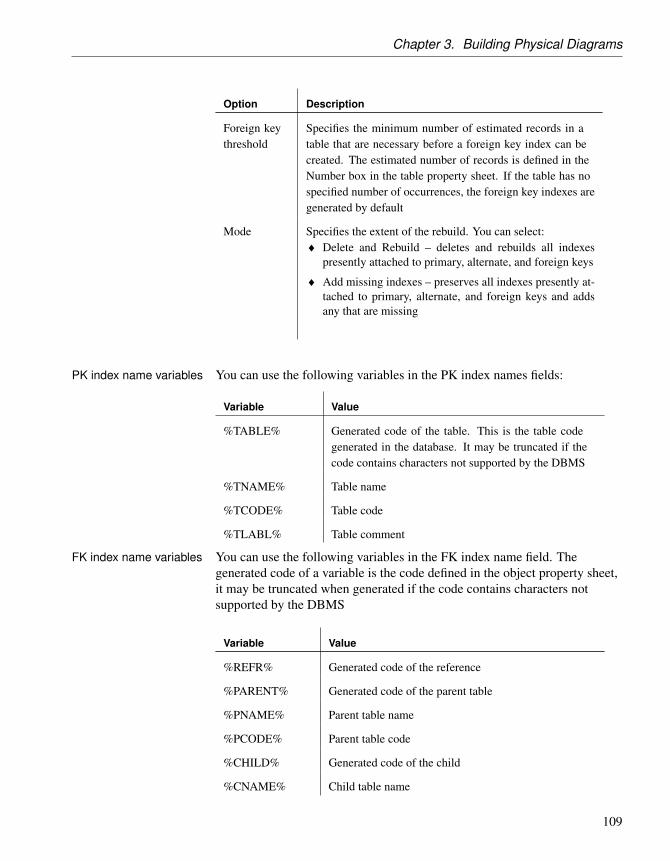
Chapter 3. Building Physical Diagrams
Option Description
Foreign keythreshold
Specifies the minimum number of estimated records in atable that are necessary before a foreign key index can becreated. The estimated number of records is defined in theNumber box in the table property sheet. If the table has nospecified number of occurrences, the foreign key indexes aregenerated by default
Mode Specifies the extent of the rebuild. You can select:♦ Delete and Rebuild – deletes and rebuilds all indexes
presently attached to primary, alternate, and foreign keys
♦ Add missing indexes – preserves all indexes presently at-tached to primary, alternate, and foreign keys and addsany that are missing
PK index name variables You can use the following variables in the PK index names fields:
Variable Value
%TABLE% Generated code of the table. This is the table codegenerated in the database. It may be truncated if thecode contains characters not supported by the DBMS
%TNAME% Table name
%TCODE% Table code
%TLABL% Table comment
FK index name variables You can use the following variables in the FK index name field. Thegenerated code of a variable is the code defined in the object property sheet,it may be truncated when generated if the code contains characters notsupported by the DBMS
Variable Value
%REFR% Generated code of the reference
%PARENT% Generated code of the parent table
%PNAME% Parent table name
%PCODE% Parent table code
%CHILD% Generated code of the child
%CNAME% Child table name
109

Indexes (PDM)
Variable Value
%CCODE% Child table code
%PQUALI-FIER%
Parent table qualifier
%CQUALI-FIER%
Child table qualifier
%REFRNAME% Reference name
%REFRCODE% Reference code
Indexes in query tables
You can create an index associated with the columns of a query table, whichis a special type of view available in Oracle and DB2. These indexes arecalled view indexes. Query table indexes behave like indexes defined ontables, they are data structures that improve database performance andaccess speed. You normally create indexes for columns that you accessregularly, and where response time is important.
For more information about query tables, see “Creating a query table” onpage 163.
110

Chapter 3. Building Physical Diagrams
Defaults (PDM)A default is a value that can be assigned to a column or a domain in theDBMS of the Sybase Adaptive Server Enterprise and Microsoft SQL Serverfamilies.
You select a default from the Default list in the Check Parameters tab of acolumn or domain property sheet.
Example The default object citydflt is used to assign the same default value to allcolumns of type city.
Creating a default
You can create a default in any of the following ways:
♦ Select Model ä Defaults to access the List of Defaults, and click the Adda Row tool.
♦ Right-click the model or package in the Browser, and select New ä
Default.
+ For general information about creating objects, see the Objects chapterin the Core Features Guide .
Default properties
You can modify an object’s properties from its property sheet. To open adefault property sheet, double-click its diagram symbol or its Browser entryin the Defaults folder. The following sections detail the property sheet tabsthat contain the properties most commonly entered for defaults.
The General tab contains the following properties:
111

Defaults (PDM)
Property Description
Name Specifies the name of the item, which should be clear andmeaningful, and should convey the item’s purpose to non-technical users
Code Specifies the technical name of the object, which is used forgenerating code or scripts, which may be abbreviated, andshould not generally include spaces
Comment Specifies the descriptive label
Stereotype Sub-classification used to extend the semantics of an objectwithout changing its structure; it can be predefined or user-defined
Owner Specifies the name of default owner. You choose an owner froma list of users
Value Specifies the value of default object that will be generated
Default property sheet Preview tab
You can view the default creation order in the Preview tab of the defaultproperty sheet.
create default CITYDFLTas ’Dublin’
Assigning a default to a column or a domain
You can select a default from the list of defaults and assign it to a column ora domain from the Standard Checks tab of the column or domain propertysheet.
+ For more information on check parameters, see “Check Parameters(CDM/LDM/PDM)” on page 174.
If you only type a value in the Default list of a domain property sheet, it willnot be generated as a default object in the database. It is highlyrecommended to use the Rebuild Default feature to create the default objectcorresponding to this value.
+ For more information, see section “Rebuilding defaults” on page 113.
v To assign a default to a column or a domain
1. Open the property sheet of a column or a domain, and click the StandardChecks tab.
112

Chapter 3. Building Physical Diagrams
2. Select a default in the Default list in the Value groupbox.
Alternatively, you can type a default value in the listbox; this does notcreate a default object in the model, it only assigns a default value for thecurrent column or domain. If you type a name that already exists in thelist, the default object is attached to the column or domain.
3. Click OK in each of the dialog boxes.
Rebuilding defaults
You can generate defaults from domains and columns having default values.The Default Rebuild feature uses the default values to create default objectsand attaches them to the appropriate domains and/or columns.
Upgrading modelsWhen you open a model containing domains with default values and savedin a previous version of PowerDesigner, default objects corresponding tothe default values are created in the model.
Default objects are also created when you change the DBMS of a modelcontaining domains with default values, to a DBMS that supports defaultobjects. The opposite process occurs when you switch to a DBMS that doesnot support default objects: default objects are converted into default values.
Default name template You can define a template for the generated default names. This template hasthe D_%.U:VALUE% value and supports the following variables:
♦ DOMAIN for the code of the domain using the default
♦ COLUMN for the code of the column using the default
♦ TABLE for the code of the table that contains the column with a default
You can define one template for domain defaults and one for columndefaults.
v To rebuild defaults
1. Select Tools ä Rebuild Objects ä Rebuild Defaults to open the DefaultRebuild dialog box.
2. Specify a default name template in the Domain and Column boxes.
3. [optional] Select the Reuse default with identical value check box – thisoption will reuse default objects with identical value among columns anddomains. If you do not select this option, rebuild creates one default perobject.
113

Defaults (PDM)
4. [optional] Select the Delete and rebuild check box – this option detachesthe default objects attached to selected objects and deletes them if theyare not used. If you select all objects, this option allows you to clean upthe model from all existing defaults and recreate new default objects.
5. [optional] Click the Selection tab to specify domains and tables fordefault generation.
6. Click OK.
The defaults are automatically created and attached to the domains and/orcolumns.
114

Chapter 3. Building Physical Diagrams
Domains (CDM/LDM/PDM)Domains help you identify the types of information in your model. Theydefine the set of values for which a column/entity attribute is valid. Applyingdomains to columns/entity attributes makes it easier to standardize datacharacteristics for columns/entity attributes in different tables/entities.
In a diagram, you can associate the following information with a domain:
♦ Data type, length, and precision
♦ Check parameters
♦ Business rules
♦ Mandatory property
Creating a domain
You can create a domain as follows:
♦ Select Model ä Domains to access the List of Domains, and click theAdd a Row tool
♦ Right-click the model or package in the Browser, and select New ä
Domain
+ For general information about creating objects, see the Objects chapterin the Core Features Guide .
Domain properties
You can modify an object’s properties from its property sheet. To open adomain property sheet, double-click its Browser entry in the Domains folder.
The General tab contains the following properties:
Property Description
Name Specifies the name of the item, which should be clear andmeaningful, and should convey the item’s purpose to non-technical users
Code Specifies the technical name of the object, which is used forgenerating code or scripts, which may be abbreviated, andshould not generally include spaces
Comment Specifies a descriptive label for the domain
115

Domains (CDM/LDM/PDM)
Property Description
Stereotype Sub-classification used to extend the semantics of an objectwithout changing its structure; it can be predefined or user-defined
Owner [PDM only] Specifies the name of domain owner. Youchoose an owner from a list of users. A domain can onlyhave one owner at a time. This is normally the domaincreator
Data type Specifies the form of the data corresponding to the domain,such as numeric, alphanumeric, Boolean, or others. The<undefined> data type indicates a domain without a datatype. If an <undefined> data type is present when yougenerate your database, it is replaced by the default data typefor your database
Length [where appropriate] Specifies the maximum number ofcharacters. In the PhysDataType list of available datatypes (select Database ä Edit current database ä Script ä
DataType ä PhysDataType), a variable indicates where youhave to type a length or precision, as follows:♦ %n - length
♦ %s - length with precision
♦ %p - decimal precisionFor example, if you are using Sybase Adaptive ServerAnywhere and you choose the data type char(%n), youcan choose a length of ten by typing char(10).
Precision [where appropriate] Specifies the number of places after thedecimal point, for data values that can take a decimal point
Mandatory Specifies that domain values are mandatory for allcolumns/entity attributes using that domain
Identity (For Adaptive Server Enterprise, MS SQL Server and thoseDBMS that support it). When selected, indicates that thedata is auto-incremented for columns using that domain
With default [PDM only] (For those DBMS that support it). Whenselected, indicates if a default value is assigned to a columnusing the domain, when a Null value is inserted
Profile [PDM only] Specifies the test Data profile assigned to thedomain
116

Chapter 3. Building Physical Diagrams
The following tabs are also available:
♦ Standard Checks - contains checks which control the values permitted forthe column/entity attribute (see “Check Parameters (CDM/LDM/PDM)”on page 174)
♦ Additional Checks - allows you to specify additional constraints (notdefined by standard check parameters) for the column/entity attribute.
♦ Rules - lists the business rules associated with the column/entity attribute(see “Business Rules (CDM/LDM/PDM)” on page 179).
List of standard data types
You can open the list of Standard Data Types by clicking the question markbutton to the left of the list of Data Types on the General Tab of a domainproperty sheet.
Numeric data types The following numeric data types are available:
Standarddata type
DBMS-specificphysical data type
Content Length
Integer int / INTEGER 32-bit integer —
Short Integer smallint / SMALL-INT
16-bit integer —
117

Domains (CDM/LDM/PDM)
Standarddata type
DBMS-specificphysical data type
Content Length
Long Integer int / INTEGER 32-bit integer —
Byte tinyint / SMALL-INT
256 values —
Number numeric / NUM-BER
Numbers with a fixeddecimal point
Fixed
Decimal decimal / NUM-BER
Numbers with a fixeddecimal point
Fixed
Float float / FLOAT 32-bit floating point num-bers
Fixed
Short Float real / FLOAT Less than 32-bit pointdecimal number
—
Long Float double precision /BINARY DOUBLE
64-bit floating point num-bers
—
Money money / NUMBER Numbers with a fixeddecimal point
Fixed
Serial numeric / NUM-BER
Automatically incre-mented numbers
Fixed
Boolean bit / SMALLINT Two opposing values(true/false; yes/no; 1/0)
—
Character data types The following character data types are available:
118

Chapter 3. Building Physical Diagrams
Standarddata type
DBMS-specificphysical data type
Content Length
Characters char / CHAR Character strings Fixed
VariableCharacters
varchar / VAR-CHAR2
Character strings Maximum
Long Charac-ters
varchar / CLOB Character strings Maximum
Long VarCharacters
text / CLOB Character strings Maximum
Text text / CLOB Character strings Maximum
Multibyte nchar / NCHAR Multibyte characterstrings
Fixed
VariableMultibyte
nvarchar / NVAR-CHAR2
Multibyte characterstrings
Maximum
Time data types The following time data types are available:
Standarddata type
DBMS-specificphysical data type
Content Length
Date date / DATE Day, month, year —
Time time / DATE Hour, minute, and second —
Date & Time datetime / DATE Date and time —
Timestamp timestamp /TIMESTAMP
System date and time —
Other data types The following other data types are available:
119

Domains (CDM/LDM/PDM)
Standarddata type
DBMS-specificphysical data type
Content Length
Binary binary / RAW Binary strings Maximum
Long Binary image / BLOB Binary strings Maximum
Bitmap image / BLOB Images in bitmap format(BMP)
Maximum
Image image / BLOB Images Maximum
OLE image / BLOB OLE links Maximum
Other — User-defined data type —
Undefined undefined Undefined. Replaced bythe default data type atgeneration.
—
Cascading updates to columns/entity attributes associated with thedomain
When you modify data types associated with a domain, an updateconfirmation box is displayed asking if you want to modify thecolumns/entity attributes currently using the domain.
v To modify domain properties in a data model
1. Open the property sheet of a domain and edit its properties as required.
2. Click OK.
If the domain is used by one or more columns/entity attributes, an updateconfirmation box is displayed asking if you want to modify domainproperties for the columns/entity attributes using the domain.
120

Chapter 3. Building Physical Diagrams
The Data Type check box is selected or not according to the options set toenforce non-divergence from a domain (see “Enforcing non-divergencefrom a domain in a data model” on page 121).
3. Select any other properties that you want to update (Check, Rules,Mandatory, Profile) for all columns/entity attributes using the domain.
4. Click one of the following buttons:♦ Yes - The columns/entity attributes currently using the domain are
modified according to the update
♦ No - The columns/entity attributes currently using the domain are notmodified according to the update but the current modification isaccepted if domain divergence is allowed in the model options (see“Enforcing non-divergence from a domain in a data model” onpage 121).
♦ Cancel - The update is cancelled and nothing is changed
Enforcing non-divergence from a domain in a data model
You can enforce non-divergence between a domain and the columns/entityattributes that use the domain.
121

Domains (CDM/LDM/PDM)
v To enforce domain non-divergence in a data model
1. Select Tools ä Model Options to open the Model Options dialog box. Ina PDM, you have to click the Column and Domain sub-category in theleft-hand Category pane to display the Enforce non-divergence option:
2. Select the check boxes of the column/entity attribute properties that arenot permitted to diverge from the domain definition. You can specify anyor all of:
♦ Data type - data type, length, and precision
♦ Check - check parameters such as minimum and maximum values
♦ Rules – business rules
♦ Mandatory – mandatory property of the column
♦ [PDM only] Profile - test data profileIf you subsequently modify in your domain any of the propertiesspecified as non-divergent here, then the corresponding properties of thecolumns/entity attributes attached to that domain are automaticallyupdated.
Column/entity attribute properties specified as non-divergent appeardimmed and are non-editable in the List of Columns/Entity attributes andColumn/Entity attribute property sheets. If you want to modify anon-divergent column/entity attribute property, you must detach thecolumn/entity attribute from its domain.
3. Click OK to close the Model Options dialog box.
122

Chapter 3. Building Physical Diagrams
4. When you set the Enforce non-divergence options, you are asked if youwant to apply domain properties to columns/entity attributes currentlyattached to the domain. If you click OK, the column/entity attributeproperties are modified in order to be consistent with the properties of thedomain to which they belong.
123

Sequences (PDM)
Sequences (PDM)If your DBMS supports sequences, then you can create a sequence for acolumn.
A sequence is like an advanced form of an auto-incremented column. Wherethe latter is a column whose values automatically increment by 1, sequencesallow you to define a more complex list of numbers. For example, you coulddefine a list of numbers ranging between two values with an increment byany number (integer) you want.
Once you define a sequence, you can apply and enable it to a column. Thedata type for the column receiving the sequence must be a numeric datatype. Such auto-incremented columns can be used in a key for a PDM table.
+ For more information on data types, see “Selecting a data type for acolumn” on page 90.
Example Assume that you want to create a column listing the months of the yearwhen quarterly reports are published: March, June, September, andDecember. The first report is published on the third month, the second on thesixth, the third on the ninth and the last on the twelfth.
You can define the proper sequence by typing the following values forsequence option parameters:
Parameter name Description Value
Start with March is the third month of the year 3
Increment by Look three months ahead to identify thenext month in the list
3
Maxvalue Stop when you have reached the lastmonth of the year
12
The sequence created with these parameter settings allows you toautomatically create the list of months in a year when quarterly reports arepublished.
Creating a Sequence
There are two steps to using sequences:
♦ Create a sequence (including defining sequence options)
♦ Apply and enable a sequence to a column
124

Chapter 3. Building Physical Diagrams
v To create a sequence
1. Select Model ä Sequences to open the List of Sequences.
2. Click the Add a Row tool and type a name for the new sequence.
3. Double-click the arrow to the left of the new sequence to display itsproperty sheet.
4. Click the Physical Options tab and enter any appropriate parameters.These options are DBMS-specific. For more information on using thistab, see “Physical Options” on page 188.
The above example shows the options and values to create a sequence ofmonths in a year when quarterly reports are published.
5. [optional] Click the Apply To button to open a selection list and specifyother sequences to which these same options will apply.
125

Sequences (PDM)
6. Click OK in each of the dialog boxes.
v To apply and enable a sequence on a column
1. Open the property sheet of the column to which you want to apply thesequence.
2. On the General tab, select a sequence from the Sequence list.
3. Click OK to close the property sheet.
4. Select Tools ä Rebuild Objects ä Rebuild Triggers to open the RebuildTriggers dialog box.
5. Click the Selection tab and select the table or tables containing thecolumn to which you want to attach a sequence.
6. Click OK.
The triggers are rebuilt and the sequence is enabled on the column.
+ For more information on rebuilding triggers, see the Building Triggersand Procedures chapter.
Sequence properties
You can modify an object’s properties from its property sheet. To open asequence property sheet, double-click its Browser entry in the Sequencesfolder or its line in the List of Sequences. The following sections detail theproperty sheet tabs that contain the properties most commonly entered forsequences.
126

Chapter 3. Building Physical Diagrams
The General tab contains the following properties:
Property Description
Name Specifies the name of the item, which should be clear andmeaningful, and should convey the item’s purpose to non-technical users
Code Specifies the technical name of the object, which is used forgenerating code or scripts, which may be abbreviated, andshould not generally include spaces
Comment Specifies a descriptive label for the sequence
Stereotype Sub-classification used to extend the semantics of an objectwithout changing its structure; it can be predefined or user-defined
Owner Specifies the name of sequence owner. You choose an ownerfrom a list of users. A column can only have one owner at atime. This is normally the column creator
The following tabs are also available:
♦ Physical Options - lists the physical options associated with the sequence(see “Physical Options” on page 188). For information about theseoptions, see your DBMS documentation.
Changing the DBMS of a model which contains sequences andauto-incremented columns
If you create a sequence attached to a column in a DBMS supportingsequences, such as Oracle 8 and higher, Interbase or PostgreSQL, or createan auto-incremented column in a DBMS supporting this feature, and thendecide to change the target DBMS, the following effects occur:
127

Sequences (PDM)
DBMS change Defined in origi-nal DBMS
Effect on sequence objects andauto-incremented columns
DBMS supportingsequences to aDBMS supportingauto-incrementedcolumns
Sequence at-tached to a col-umn
The sequence disappears and thecolumn to which it was attached be-comes an auto-incremented columnin the DBMS
DBMS supportingauto-incrementedcolumns to aDBMS support-ing sequences
Auto-incremented col-umn
The auto-incremented column isdeleted and replaced by a sequenceobject called S_TABLENAMEwhich is attached to the originalcolumn
Sequences and intermodel generation
When a CDM or an OOM is generated from a PDM, the data type of a tablecolumn attached to a sequence is translated to a numeric data type in the newmodel:
PDM gener-ated to
Sequence is converted to
CDM A serial data type for an entity property. The data typehas the format NO%n where %n is a number indicating thelength of the data type
OOM A serial data type for a class attribute. The data type has theformat NO%n, where %n is a number indicating the lengthof the data type
128

Chapter 3. Building Physical Diagrams
Abstract Data Types (PDM)An abstract data type (ADT) is a user-defined data type which canencapsulate a range of data values and functions. The functions can be bothdefined on, and operate on the set of values.
Abstract data types can be used in the following ways in a Physical diagram:
Abstractdata typeis
Description
Created You can create an abstract data type of any kind supportedby your DBMS.
If you create an abstract data type of type JAVA, you canlink it to a Java class in an OOM to access the Java classproperties (see “Linking an abstract data type to a Java class”on page 133).
Reverse engi-neered
An abstract data type in a database can be reverse engineeredinto a PDM.
If you also reverse engineer the JAVA classes into an OOM,then the abstract data types of the type JAVA in the PDMare automatically linked to the Java classes in the OOM(see “Reverse-engineering a PDM linked to an OOM” onpage 137)
+ For more information on reverse engineering a database into a PDM, seechapter Reverse Engineering.
+ For more information on creating and reverse engineering Java classesinto a PowerDesigner Object-Oriented Model, see the Object-OrientedModeling guide.
Depending on the current DBMS, the following kinds of abstract data typescan be created in PowerDesigner:
129

Abstract Data Types (PDM)
Type Description Example
Array Fixed length collection ofelements
VARRAY (Oracle 8 and higher)
List Unfixed length collectionof objects
TABLE (Oracle 8 and higher)
Java Java class JAVA (Adaptive Server Any-where, and Adaptive Server En-terprise)
Object Contains a list of at-tributes and a list of pro-cedures
OBJECT (Oracle 8 and higher)
SQLJ Object Contains a list of at-tributes and a list of pro-cedures
SQLJ OBJECT (Oracle 9i andhigher)
Structured Contains a list of at-tributes
NAMED ROW TYPE (Informix9.x, and IBM DB2 5.2)
Example An abstract data type for the Gregorian calendar which has functions definedto do the following:
♦ Read and write roman numerals
♦ Convert dates from the Julian calendar to the Gregorian calendar
♦ Convert dates from the Gregorian calendar to the Julian calendar
Creating an abstract data type
You can create an abstract data type in any of the following ways:
♦ Select Model ä Abstract Data Types to access the List of Abstract DataTypes, and click the Add a Row tool.
♦ Right-click the model or package in the Browser, and select New ä
Abstract Data Type.
+ See also “Creating object and SQLJ object abstract data types” onpage 132.
+ For general information about creating objects, see the Objects chapterin the Core Features Guide .
Abstract data type properties
You can modify an object’s properties from its property sheet. To open an
130
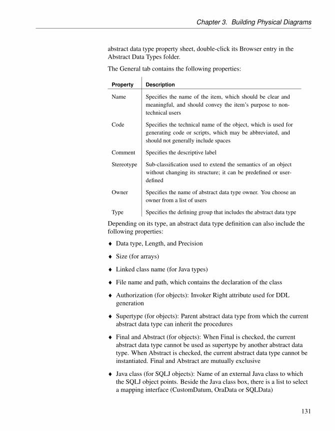
Chapter 3. Building Physical Diagrams
abstract data type property sheet, double-click its Browser entry in theAbstract Data Types folder.
The General tab contains the following properties:
Property Description
Name Specifies the name of the item, which should be clear andmeaningful, and should convey the item’s purpose to non-technical users
Code Specifies the technical name of the object, which is used forgenerating code or scripts, which may be abbreviated, andshould not generally include spaces
Comment Specifies the descriptive label
Stereotype Sub-classification used to extend the semantics of an objectwithout changing its structure; it can be predefined or user-defined
Owner Specifies the name of abstract data type owner. You choose anowner from a list of users
Type Specifies the defining group that includes the abstract data type
Depending on its type, an abstract data type definition can also include thefollowing properties:
♦ Data type, Length, and Precision
♦ Size (for arrays)
♦ Linked class name (for Java types)
♦ File name and path, which contains the declaration of the class
♦ Authorization (for objects): Invoker Right attribute used for DDLgeneration
♦ Supertype (for objects): Parent abstract data type from which the currentabstract data type can inherit the procedures
♦ Final and Abstract (for objects): When Final is checked, the currentabstract data type cannot be used as supertype by another abstract datatype. When Abstract is checked, the current abstract data type cannot beinstantiated. Final and Abstract are mutually exclusive
♦ Java class (for SQLJ objects): Name of an external Java class to whichthe SQLJ object points. Beside the Java class box, there is a list to selecta mapping interface (CustomDatum, OraData or SQLData)
131

Abstract Data Types (PDM)
Creating object and SQLJ object abstract data types
If you select the OBJECT (or SQLJ OBJECT) type for an abstract data type,two additional tabs are displayed in the property sheet:
♦ The Attributes tab allows you to specify an object (or SQLJ object) with anumber of attributes to which are assigned appropriate data types
♦ The Procedures tab allows you to specify an object (or SQLJ object) witha number of procedures to which are assigned appropriate parameters
Procedure inheritance An object abstract data type with a supertype can inherit non-finalprocedures. You can use the Inherit Procedure tool in the Procedures tab ofthe abstract data type to select a non-final procedure from a parent abstractdata type. Inheritance only applies to non-finale procedures.
Object example For example, you want to create an Address object with Street, City, andZipCode attributes, and a Location procedure.
v To specify attributes and procedures for an object (or SQLJ ob-ject) abstract data type1. Open the property sheet of the abstract data type and select either
OBJECT or SQLJ_OBJECT from the type list.
The Attributes and Procedures tabs are displayed.
2. Click the Attributes tab.
132

Chapter 3. Building Physical Diagrams
3. For each attribute, click the Add a Row tool, and:♦ enter a Name and Code
♦ select a data type class from the Data Type list
♦ [optional] Select the Mandatory (M) checkbox
4. Click the Procedures tab:
5. For each procedure, click the Add a Row tool, and:♦ enter a Name and Code
♦ [optional] Select the Final (F), Static (S) and/or Abstract (A) columns
6. Click OK in each of the dialog boxes.
Linking an abstract data type to a Java class
You can specify a Java class in the PDM, and then link it to a Java class in anOOM. The OOM must be open in the current Workspace to be available forlinking.
When you link an abstract data type to a Java class, a shortcut is createdwhich allows you to access the properties of the Java class from within thePDM.
133

Abstract Data Types (PDM)
v To link an abstract data type to a Java class
1. Create an abstract data type and select Java from the Type list on theGeneral tab of its property sheet.
2. Click the Ellipsis button to the right of the Class box to open a Java classselection box, which lists all the Java classes that are available in theOOMs currently open in the Workspace.
134

Chapter 3. Building Physical Diagrams
3. Select a Java class and click OK.
The abstract data type is now linked to the Java class, and the class nameis displayed in the Class box.
4. Click the Properties button at the end of the Class box to open theproperty sheet of the Java class.
If the related OOM is closed, then a shortcut property sheet for the Javaclass is displayed, and you must click the Properties button to the right ofthe Name box to display its actual property sheet..
135

Abstract Data Types (PDM)
If the related OOM is open, then the class property sheet is openeddirectly:
5. Click OK in each of the dialog boxes.
136

Chapter 3. Building Physical Diagrams
Reverse-engineering a PDM linked to an OOM
You can reverse engineer a PDM from a database that contains Java classesand also reverse the Java classes into an OOM. The Java abstract data typesin the PDM are automatically linked to the Java classes in the OOM asfollows:
♦ You should reverse engineer the Java classes in the database that are usedas data types for the columns and domains in an OOM
♦ Then reverse engineer the database into a PDM
♦ PowerDesigner automatically searches the open OOM for the Javaclasses that correspond to the JAVA abstract data types in the PDM andmakes the corresponding links
The Java classes that are reverse engineered into the PDM are createdautomatically as abstract data types of type JAVA.
You can access the properties of these Java classes from the property sheetsof the corresponding abstract data types in the PDM. For more information,see “Linking an abstract data type to a Java class” on page 133.
137

References (PDM)
References (PDM)A reference is a link between a parent table and a child table. It defines areferential integrity constraint between column pairs for a primary key, oralternate key, and a foreign key, or between user specified columns in bothtables.
When column pairs are linked by a reference, each value in the child tablecolumn refers to an equivalent value in the parent table column.
Within a reference, each column pair is linked by a join. Depending on thenumber of columns in the primary key, or alternate key, or the number ofspecified columns, a reference can contain one or more joins.
A reference normally links primary key, or alternate key, columns to foreignkey columns.
Example The two tables SALE and STORE are linked by a reference. STORE is theparent table and SALE is the child table. The reference contains a join whichlinks the primary key column STORE ID (the referenced column) to theforeign key column STORE ID (the referencing column).
Creating a reference
You can create a reference that links a primary key, or alternate key, to aforeign key, or user-specified columns in both parent and child tables.
Depending on its properties, a reference can link a parent table and a childtable in one of two ways:
Reference links Description
Primary key, alternatekey and foreign keys
Primary or alternate key in the parent table is linkedto a foreign key in the child table
User specifiedcolumns
One or more columns in the parent table are linked tocorresponding columns in the child table. The linkedcolumns in both tables are specified by the user, andare linked independently of primary key, alternatekey, and foreign key columns
138

Chapter 3. Building Physical Diagrams
You can create a reference in any of the following ways:
♦ Use the Reference tool in the diagram Palette.
♦ Select Model ä References to access the List of References, and click theAdd a Row tool.
♦ Right-click the model or package in the Browser, and select New ä
Reference.
+ For general information about creating objects, see the Objects chapterin the Core Features Guide .
Automatic reuse and migration of columns
When you create a reference, PowerDesigner can automatically:
♦ Reuse an appropriate existing column in the child table as the foreign keycolumn
♦ Migrate the primary key column in the parent table to create a foreign keycolumn in the child table
v To auto-reuse and/or auto-migrate columns
1. Select Tools ä Model Options to open the Model Options dialog box.
2. Select the Reference sub-category in the left-hand Category pane todisplay the Reference tab.
139

References (PDM)
3. Specify your choices for column reuse and migration as follows:♦ To auto-reuse existing columns in child tables as foreign key
columns when creating references - select the Auto-reuse columnscheck box. Note that the column in the child table must have the samecode as the migrating primary key column, and cannot already be aforeign key column for it to be suitable for reuse. If you want to reusea child table column that is already a foreign key column, you must dothis manually from the Joins tab of the reference property sheet.
♦ To auto-migrate primary key columns in parent tables for use asforeign key columns in child tables - select the Auto-migratecolumns check box. This will also enable the column properties checkboxes, allowing you to specify which of the parent column propertiesto migrate.
♦ To auto-migrate the properties of parent table primary keycolumns - select the appropriate check boxes:
• Domains• Check (check parameters)• Rules (business rules)• Last position (migrated columns should be added at the end of the
table column list. If the Last position option is not selected, migratedcolumns are inserted between key columns and other columns whichimplies that a child table must be dropped and recreated each timeyou add a reference and modify an existing database.)
Note that, during intermodel generation, whether or not the Auto-migratecolumns check box is selected, any selected column property is migratedfrom the PK to the FK.
4. Ensure that the Default link on creation option is set to Primary key.
5. Click OK to close the Model Options dialog box.
Examples
The following examples illustrate how using the auto-reuse columns andauto-migrate columns options affects the creation of references.
Matching child tablecolumn exists
The following table shows the results of migrating primary key columns to achild table that contains a matching column for one of the primary keycolumns. The original two tables are also shown below:
140

Chapter 3. Building Physical Diagrams
Auto-reuse Auto-migrate
Result Description ofchild table
Selected Selected Col_1 is reusedand Col_2 is cre-ated
Not selected Selected T1_Col_1 is cre-ated and Col_2 iscreated
Selected Not selected Col_1 is reusedand Col_2 is notcreated
Not selected Not selected No column isreused and nocolumn is created
Matching child tablecolumn is already a FKcolumn
The following table shows the results of migrating primary key columns to achild table that contains a matching child table column that is already aforeign key column for another table. The original two tables are also shownbelow:
Auto-reuse Auto-migrate
Result Description ofchild table
Selected Selected T1_Col_1 is cre-ated and Col_2 iscreated
Not selected Selected T1_Col_1 is cre-ated and Col_2 iscreated
Selected Not selected No columns arereused or created
Not selected Not selected No columns arereused or created
Notes:
141

References (PDM)
♦ By default, only the properties of the primary key column are migrated tothe foreign key. If the primary key column is attached to a domain, thedomain will not be migrated to the new foreign key column unless theEnforce non-divergence option model option is selected (see “Enforcingnon-divergence from a domain in a data model” on page 121).
♦ The following table shows the results of changing references when youhave selected the auto-migrate columns option:
Action Result
Modify referenceattach point
Migrate primary key in parent table to foreign keyin child table
Delete unused foreign key columns
Modify reference join
Delete primary key Delete corresponding foreign key and referencejoin
Migrate primary key in parent table to foreign key in child table
Delete unused foreign key columns
Modify reference join
Action Result
Modify referenceattach point
Migrate primary key in parent table to foreign key inchild table
Delete unused foreign key columns
Modify reference join
Delete primary key Delete corresponding foreign key and reference join
+ For more information on other model options for references, see“Setting PDM Model Options” section in the “Customizing the PDMEnvironment” chapter.
Reference properties
You can modify an object’s properties from its property sheet. To open areference property sheet, double-click its diagram symbol or its Browserentry in the References folder. The following sections detail the propertysheet tabs that contain the properties most commonly entered for references.
The General tab contains the following properties:
142

Chapter 3. Building Physical Diagrams
Property Description
Name Specifies the name of the item, which should be clear andmeaningful, and should convey the item’s purpose to non-technical users
Code Specifies the technical name of the object, which is used forgenerating code or scripts, which may be abbreviated, andshould not generally include spaces
Comment Specifies a descriptive label for the reference
Stereotype Sub-classification used to extend the semantics of an objectwithout changing its structure; it can be predefined or user-defined
Parent table Specifies the parent table of the reference. This table containsthe primary key, or alternate key, linked by the reference.You can use the tools to the right of the list to create anobject, browse the complete tree of available objects or viewthe properties of the currently selected object
Parent role Specifies the role of the parent table in the reference. Thetext is displayed in the diagram, near the parent table
Child table Specifies the child table of the reference. This table containsthe foreign key linked by the reference
Child role Specifies the role of the child table in the reference. The textis displayed in the diagram, near the child table
Generate When selected, indicates to generate the reference in thedatabase
Reference property sheet Joins tab
A join is a link between a column in a parent table and a column in a childtable (column pair) that is defined within a reference.
A join can link primary, alternate or foreign key, or user-specified columnsin the parent and child tables that are independent of key columns.
v To define joins in a reference
1. Double-click a reference in the diagram to open its property sheet, andthen click the Joins tab.
2. Select a key in the Parent Key list to create joins on its columns. If you
143

References (PDM)
select <NONE>, the column lists are empty and you must specify yourown columns to join.
The columns linked by the joins are listed in the Parent Table and ChildTable columns.
Changing a foreign key column linked by a joinYou can change the foreign key column linked by a join by clicking thecolumn in the Child Table list, and selecting another column from thelist.
3. [optional] If you selected <NONE> from the Parent Key list, click theParent Table Column and select a column from the list, then click theChild Table Column and select a child column.
4. [optional] Select the Auto arrange join order check box to sort the list bythe key column order. If this option is not selected, you can re-arrange thecolumns using the arrow buttons.
5. Click OK.
144

Chapter 3. Building Physical Diagrams
Enabling the Auto arrange join order check boxTo enable this check box, add an EnableChangeJoinOrder item to theReference category in the DBMS definition file and set the value to YES.See the DBMS Resource File Reference chapter of the Customizing andExtending PowerDesigner manual.
Default joins at referencecreation
Join creation is determined by the following Model Options:
Default Link onCreation
Auto-migrateColumns
Result
Primary Key Selected Joins created between primary andforeign key columns.
Not selected Joins created and linked to primarykey columns, but are incomplete. For-eign key columns must be specifiedmanually.
User-defined Selected No joins created. Parent and childtable column pairs must be specifiedmanually.
Not selected No joins created. Parent and childtable column pairs must be specifiedmanually.
Linking columns in aprimary or alternate key
For any reference you can choose to link a primary key, or alternate key, to acorresponding foreign key. When you select a key from the Joins tab of thereference property sheet, all the key columns are linked to matching foreignkey columns in the child table.
Changing a foreign key column linkA foreign key column can be changed to link to another parent tablecolumn, either within the key relationship, or independent of it.
Reuse and Migrationoption for a selectedreference
You can use the following buttons on the Joins tab to reuse or migratecolumns linked by joins.
145

References (PDM)
Tool Description
Reuse Columns - Reuse existing child columns with same code asparent table columns
Migrate Columns - Migrate key columns to foreign key columns.If columns do not exist they are created
Cancel Migration - Delete any migrated columns in child table
Reference property sheet Integrity tab
Referential integrity is a collection of rules that govern data consistencybetween primary keys, alternate keys and foreign keys. It dictates whathappens when you update or delete a value in a referenced column in theparent table, and when you delete a row containing a referenced columnfrom the parent table.
The Integrity tab contains the following properties:
Property Description
Constraintname
Name of the referential integrity constraint. Maximumlength is 254 characters
Implementation Specifies how referential integrity will be implemented.You can choose between:♦ Declarative- Referential integrity constraints are de-
fined for particular references. When the reference isgenerated the target DBMS evaluates the reference va-lidity and generates appropriate error messages
♦ Trigger - Referential integrity constraints are imple-mented by triggers based on the integrity constraintsdefined in the reference property sheet. The triggerevaluates reference validity and generates appropriateuser-defined error messages
146

Chapter 3. Building Physical Diagrams
Property Description
Cardinality Indicates the minimum and maximum number of instancesin a child table permitted for each corresponding instancein the parent table. The following values are available bydefault:♦ 0..* - A parent can have zero or more children. There
is no maximum.
♦ 0..1 - A parent can have zero or one children.
♦ 1..* - A parent can have one or more children. There isno maximum.
♦ 1..1 – A parent must have exactly one childAlternately, you can enter your own integer values in oneof the following formats:♦ x..y - A parent can have between x and y children.
♦ x - A parent can have exactly x children.
♦ x..y, a..b - A parent can have between x and y or be-tween a and b children.
You can use * or n to represent no limit.
Examples:♦ 2..n – There must be at least 2 children.
♦ 10 - There must be exactly 10 children.
♦ 1..2, 4..n – There must be one, two, four or more chil-dren.
User-defined Indicates a user-defined constraint name
147

References (PDM)
Property Description
Update con-straint
How updating a key value, in the parent table affects theforeign key value in the child table. Depending on theimplementation and DBMS, you can choose between:♦ None - Update or deletion of a value in the parent table
has no effect on the child table.
♦ Restrict - A value in the parent table cannot be updatedor deleted if one or more matching child values exists
♦ Cascade - Update or deletion of a value in the parenttable causes an update or delete of matching values inthe child table
♦ Set null - Update or deletion of a value in the parenttable sets matching values in the child table to NULL
♦ Set default - Update or deletion of a value in the par-ent table sets matching values in the child table to thedefault value
Delete con-straint
How deleting a row in the parent table affects the childtable
Mandatory par-ent
Each foreign key value in the child table must have acorresponding key value, in the parent table
Change parentallowed
A foreign key value can change to select another value inthe referenced key in the parent table
Check on com-mit
[Sybase SQL Anywhere 5.0 and 5.5 only] Verifies refer-ential integrity only on the commit, instead of verifyingit after row insertion. You can use this feature to controlcircular dependencies
Cluster Indicates whether the reference constraint is a clusteredconstraint (for those DBMS that support clustered indexes)
Rebuilding references
You can rebuild references to create default references between PK columnsin one table and columns with identical code and data type in another table.Note that rebuilding is not possible between two tables with PK columns.
Rebuilding references is useful following the reverse engineering of adatabase in which all of the references could not be reverse engineered.
148

Chapter 3. Building Physical Diagrams
v To rebuild references
1. Select Tools ä Rebuild Objects ä Rebuild References to open theRebuild References dialog box.
2. Select a mode:♦ Delete and Rebuild - All existing references are deleted, and new
references built based on matching key columns
♦ Preserve - All existing references are kept, and new references are builtbased on new matching key columns
3. [optional] Click the Selection tab and specify the tables for which youwant to rebuild references. By default, all tables are selected.
Rebuilding references in a packageTo rebuild references between tables in a package, select the packagefrom the list at the top of the tab.
To rebuild references between tables in a sub-package, select the IncludeSub-Packages icon next to the list, and then select a sub-package fromthe dropdown list.
4. Click OK. If you selected the Delete and Rebuild mode, a confirmationbox asks you to confirm your choice. Click Yes to confirm the deletionand rebuild of the selected references.
149

References (PDM)
Changing a table at either end of a reference
After reference creation you can change one table, or both of the tables,linked by a reference, using one of the following methods:
♦ Click the reference and hold down CTRL as you drag one of its attachpoints to a different table.
♦ Double-click a reference in the diagram to display its property sheet andchoose a different parent or child table from the lists.
♦ Select Model ä References to open the list of references, and choose adifferent parent or child table from the lists.
Modifying a reference graphically
You can modify a reference symbol as follows:
v To bend a reference symbol
1. Select Symbol ä Format to open the Symbol Format dialog box.
2. Click the Line Style tab and select the jagged line symbol from theCorners list.
3. Click OK to return to the diagram.
4. Press and hold CTRL while clicking the point on the reference where youwant to insert an angle.
A handle is added to the reference at the point clicked.
5. Release CTRL. You can now drag the handle to create the desired angle.
v To straighten a reference symbol
1. Click a reference symbol that has one or more angles to make its handlesappear.
2. Press and hold CTRL while clicking a handle to remove the handle andangle.
150

Chapter 3. Building Physical Diagrams
v To drag a reference to a different table
1. Click a reference symbol.
2. Press and hold CTRL while dragging one of the symbol ends to a newtable.
You can set the global display mode for references by clicking Tools ä
Model Options and selecting a notation from the list. PowerDesignersupports Relational, CODASYL, Conceptual and IDEF1X notations.
151

Views (PDM)
Views (PDM)A view is an alternative way of looking at the data in one or more tables. It ismade up of a subset of columns from one or more tables.
You define a SQL query for each view.
Creating a view
You can create a view in any of the following ways:
♦ Use the View tool in the diagram Palette.
♦ Select Model ä Views to access the List of Views, and click the Add aRow tool.
♦ Right-click the model or package in the Browser, and select New ä View.
♦ Select Tools ä Create View. For more details, see “Creating a view fromthe Tools menu” on page 156. You can, optionally, pre-select one or moretables and views in the diagram to create a view automatically populatedwith their columns.
+ For general information about creating objects, see the Objects chapterin the Core Features Guide .
View properties
You can modify an object’s properties from its property sheet. To open aview property sheet, double-click its diagram symbol or its Browser entry inthe Views folder. The following sections detail the property sheet tabs thatcontain the properties most commonly entered for views.
The General tab contains the following properties:
Property Description
Name Specifies the name of the item, which should be clear andmeaningful, and should convey the item’s purpose to non-technical users
Code Specifies the technical name of the object, which is used forgenerating code or scripts, which may be abbreviated, andshould not generally include spaces
Comment Specifies a descriptive label for the view
152

Chapter 3. Building Physical Diagrams
Property Description
Stereotype Sub-classification used to extend the semantics of an objectwithout changing its structure; it can be predefined or user-defined
Owner Specifies the name of view owner. You choose an ownerfrom a list of users. A view can only have one owner at atime. This is normally the view creator
Usage Specifies the use of the view: Query only defines a viewfor consultation only, view cannot update tables; Updatabledefines a view for consultation and update, view can updatetables; and With Check options implements controls on viewinsertions
Dimensionaltype
Specifies the multidimensional type of the view, that isDimension or Fact
Type For those DBMS that support it, allows you to define thetype of a view. You can select materialized query table,materialized view, summary table, or XML
Generate Includes view generation as part of database generationscript
User-defined When selected, makes sure the view query is not parsed byPowerDesigner internal parser. This protects the view queryfrom any update using model objects and keeps its syntaxas defined by user. Otherwise, the view query is parsed andmodified according to model values
+ For more information on materialized views, materialized query tables,and summary tables, see “Creating a query table” on page 163.
+ For more information on XML views, see “Creating an XML table orview” on page 65.
View property sheet Columns tab
The Columns tab in a view property sheet displays the list of columns in theview. This list of columns reflects the SELECT orders from the queries ofthe current view. The only way to add or remove columns from this list is tomodify the query of the view.
+ For more information on how to define the query of a view, see“Creating, editing, and deleting queries associated with views” on page 157.
153

Views (PDM)
If the view was created from one or several tables or views The name,code, description and data type of the view column are those of thecorresponding column in the linked table or view.
If the view is user-defined It implies the view is not linked to anotherobject. The name and code of the view column comes from the columnname in the first query in the view definition. For example, MyView isdefined by the following queries:
select Name, Commentfrom Propertyunionselect Signature, Bodyfrom Method
Only the two columns of the first query are used to create the correspondingview columns:
In this case, if you modify the view column code, the view creation scriptwill reflect the change. In our example, if you rename Name in ClientName,the view creation script is the following:
create view MYVIEW (ClientName, "Comment") asselect Name, Commentfrom Property
View column properties When you select a column in the list of view columns and click theProperties tool in the toolbar, the view column property sheet is displayed.You can define the following properties from the view column propertysheet:
154

Chapter 3. Building Physical Diagrams
Property Description
Name Specifies the name of the view column. This name is automat-ically calculated. If you choose to modify the default name,the User-defined button is selected and the Custom Namecolumn displays the user-defined name. You can recover thedefault name by clicking again the User-defined button
Code Specifies the code of the view column. The code is automati-cally calculated. If you choose to modify the default code, theUser-defined button is selected and the Custom Code columndisplays the user-defined code. You can recover the defaultcode by clicking again the User-defined button
Comment Specifies the comment of the view column. This commentis automatically calculated from the column comment inthe original table or view. If you choose to modify thedefault comment, the User-defined button is selected. Youcan recover the default comment by clicking again the User-defined button
Stereotype View column stereotype
Data Type View column data type. This data type is automaticallycalculated from the column data type in the original tableor view. If you choose to modify the default data type, theUser-defined button is selected. You can recover the defaultdata type by clicking again the User-defined button
Length Maximum length of the data type
Precision Maximum number of places after the decimal point
You can also define notes and business rules on a view column.
User-defined name orcode
You can modify the name and the code of a view column from the list. Ifyou need to recover the name or code default value, you have to clear thecorresponding cell in the list, the default name or code is automaticallyrestored.
View property sheet SQL Query tab
The SQL Query tab displays the SQL code for all the queries associatedwith the view. You can edit this code directly in this tab or access theproperty sheets of individual queries. For more information, see “Creating,editing, and deleting queries associated with views” on page 157.
155

Views (PDM)
View property sheet Triggers tab
The Triggers tab is only displayed if your DBMS supports triggers on views.
View triggers can make the view behave like a table. You can define a triggerto fire when one or more attributes of a table view column are modified.
v To create a trigger on a view
1. Open the view property sheet and click the Triggers tab.
2. Click the Add a Row tool, and then click the Properties tool to open theproperty sheet of the newly-created trigger.
3. Click the Definition tab. The trigger time type will be set to “instead of”.
4. Write a trigger from scratch or select a trigger template. For more detailsabout writing triggers, see the chapter “Building Triggers andProcedures”
View property sheet Preview tab
The Preview tab displays the SQL code associated with the view. For moreinformation, see “Previewing SQL statements” in the Working with DataModels chapter.
Creating a view from the Tools menu
You can create a view from the Tools menu. This method allows you toautomatically populate the view with columns from tables and other views
v To create a view from the Tools menu
1. [optional] Select one or more tables and views in the diagram. You canselect multiple objects by holding down the SHIFT key while you selectthem.
2. Select Tools ä Create View.
If you have not selected any tables or views, then a selection box opens,allowing you to select the objects to be included in the view.
156

Chapter 3. Building Physical Diagrams
Select the appropriate objects and then click OK.
A view symbol is displayed in the diagram. It displays all the columns ineach of the tables and views selected for the view. The names for thetables and views appear at the bottom of the view symbol.
Creating, editing, and deleting queries associated with views
You can edit queries associated with a view from the SQL Query tab of theview property sheet.
157

Views (PDM)
Any number of queries may be associated with a view, and the totality oftheir SQL statements is shown in this tab, linked by any of the standard SQLconstructs, such as Union, etc.
Editing query code in the SQL Query tab
You can edit the code shown in the SQL Query tab in any of the followingways:
♦ Edit the code directly in the tab
♦ Click the Edit with SQL Editor tool to open the code in PowerDesigner’sbuilt-in SQL Editor. The SQL Editor provides a more complete querydefinition environment than the SQL query tab, including access tostandard SQL constructs and syntax tools for functions and operators (see“Defining queries with the SQL Editor” in the Working with Data Modelschapter).
♦ Click the Edit with tool (CTRL+E) to open the code in your favoriteeditor
Any edits you make in the SQL Query tab will propagate to the propertysheets of the associated individual queries (see “Opening the property sheetof a query” on page 159).
Query list The individual queries associated with the view are available from the Query
158

Chapter 3. Building Physical Diagrams
list at the bottom of the SQL Query tab. You can create and delete queriesusing the tools at the bottom of the tab.
v To create a new query in the Query list
1. Click the Add a query tool to the right of the Query list (you can specifythe way in which the new query will be linked with the other queries byclicking the arrow to the right of the tool and selecting one of theconstructs listed below).
The new query’s property sheet opens.
2. Enter the query code and click OK.
The new query is added to the Query list in the View property sheet SQLQuery tab, and its code is added to the tab.
The following SQL constructs are available for linking queries inPowerDesigner (depending on your DBMS):
Construct Result Example
Union [de-fault]
Displays all the data retrieved by both thequeries, except where results are repeated.
SELECT 1: ABCSELECT 2: BCDResult: ABCD
Union All Displays all the data retrieved by both thequeries, including repeated results.
SELECT 1: ABCSELECT 2: BCDResult: ABCBCD
Intersect Displays only the data retrieved by boththe queries.
SELECT 1: ABCSELECT 2: BCDResult: BC
Minus Displays only the data retrieved by one orother of the queries, but not by both.
SELECT 1: ABCSELECT 2: BCDResult: AD
v To delete a query from the Query list
1. Select the query in the Query list.
2. Click the Delete tool to the right of the Query list.
The query is removed from the Query list and its code deleted from thetab.
Opening the property sheet of a query
Each query associated with a view has its own property sheet, whichcontains the following tabs:
159

Views (PDM)
♦ SQL (see “Query property sheet SQL tab” on page 160)
♦ Tables (see “Query property sheet Tables tab” on page 160)
♦ Columns (see “Query property sheet Columns tab” on page 161)
♦ Where (see “Query property sheet Where tab” on page 161)
♦ Group By (see “Query property sheet Group By tab” on page 162)
♦ Having (see “Query property sheet Having tab” on page 162)
♦ Order By (see “Query property sheet Order By tab” on page 163)
You can manipulate each of these clauses using the lists in these tabs, andany changes you make will propagate to the other tabs and the SQL Querytab of the parent view (see “Editing query code in the SQL Query tab” onpage 158).
v To open a query’s property sheet from the Query list
1. Select the query in the Query list.
2. Click the Properties tool to the right of the Query list.
Query property sheet SQL tab
This tab displays the SQL code for the query.
You can edit the code of an individual query in its SQL tab in any of thefollowing ways:
♦ Edit the code directly in the tab
♦ Click the Edit with SQL Editor tool to open the code in PowerDesigner’sbuilt-in SQL Editor (see “Defining queries with the SQL Editor” in theWorking with Data Models chapter).
♦ Click the Edit with tool (CTRL+E) to open the code in your favoriteeditor
Any edits you make in the SQL tab will propagate to the query’s “clause”tabs and the SQL Query tab of the parent view (see “Editing query code inthe SQL Query tab” on page 158).
Query property sheet Tables tab
This tab lists the tables in the FROM clause, which specify where the querydata will be drawn from.
160

Chapter 3. Building Physical Diagrams
You can add or delete tables as appropriate, and reorder the tables in the listusing the arrows at the bottom of the tab.Any changes you make willpropagate to the query’s SQL tab and to the SQL Query tab of the parentview.
v To add a table
1. Click in the first empty row in the list.
2. Select a table from the list. To enter a more complex expression via theSQL Editor, click the ellipsis button to the right of the list.
3. [optional] Enter an alias for the table in the Alias column.
Query property sheet Columns tab
This tab lists the columns in the SELECT clause, which specify what datawill be displayed in the query.
You can add or delete columns as appropriate, and reorder the columns inthe list using the arrows at the bottom of the tab. Any changes you make willpropagate to the query’s SQL tab and to the SQL Query tab of the parentview.
v To add a column
1. Click in the first empty row in the list.
2. Select a column from the list. You can add all the columns in a table byselecting a list entry with the table name followed by an asterisk. To entera more complex expression via the SQL Editor, click the ellipsis button tothe right of the list.
3. [optional] Enter an alias for the column in the Alias column.
Query property sheet Where tab
This tab lists the expressions in the WHERE clause, which restrict the dataretrieved by the query.
You can add or delete expressions as appropriate, and reorder theexpressions in the list using the arrows at the bottom of the tab. Any changesyou make will propagate to the query’s SQL tab and to the SQL Query tab ofthe parent view.
161

Views (PDM)
v To add an expression
1. Click in the first empty row in the list.
2. [optional] Enter a prefix in the Prefix column.
3. In the first Expression column, select a column from the list. To enter amore complex expression via the SQL Editor, click the ellipsis button tothe right of the list.
4. In the Operator column, select an operator from the list.
5. In the second Expression column, select a column from the list. To entera more complex expression via the SQL Editor, click the ellipsis button tothe right of the list.
6. [optional] Enter a suffix in the Suffix column.
Query property sheet Group By tab
This tab lists the columns in the GROUP BY clause, which control how thedata retrieved by the query will be grouped.
You can add or delete columns as appropriate, and reorder the columns inthe list using the arrows at the bottom of the tab. Any changes you make willpropagate to the query’s SQL tab and to the SQL Query tab of the parentview.
v To add a column
1. Click in the first empty row in the list.
2. Select a column from the list. To enter a more complex expression via theSQL Editor, click the ellipsis button to the right of the list.
Query property sheet Having tab
This tab lists the expressions in the HAVING clause, which restrict the datareturned by a query with a GROUP BY clause.
You can add or delete expressions as appropriate, and reorder theexpressions in the list using the arrows at the bottom of the tab. Any changesyou make will propagate to the query’s SQL tab and to the SQL Query tab ofthe parent view.
162

Chapter 3. Building Physical Diagrams
v To add an expression
1. Click in the first empty row in the list.
2. [optional] Enter a prefix in the Prefix column.
3. In the first Expression column, select a column from the list. To enter amore complex expression via the SQL Editor, click the ellipsis button tothe right of the list.
4. In the Operator column, select an operator from the list.
5. In the second Expression column, select a column from the list. To entera more complex expression via the SQL Editor, click the ellipsis button tothe right of the list.
6. [optional] Enter a suffix in the Suffix column.
Query property sheet Order By tab
This tab lists the columns in the ORDER BY clause, which control the wayin which the data retrieved by the query will be sorted.
You can add or delete columns as appropriate, and reorder the columns inthe list using the arrows at the bottom of the tab. Any changes you make willpropagate to the query’s SQL tab and to the SQL Query tab of the parentview.
v To add a column
1. Click in the first empty row in the list.
2. In the Column column, select a column from the list. To enter a morecomplex expression via the SQL Editor, click the ellipsis button to theright of the list.
3. In the Sort Direction column, select either ASC or DESC.
Creating a query table
A query table is a table whose data proceeds from the result of a query. InPowerDesigner, you design a query table using a view with a specific type,depending on the DBMS.
DB2 In DB2 CS7, you design a query table using a view with the summary tabletype. In later versions of DB2, you should use the materialized query tabletype.
163

Views (PDM)
+ For more information on summary tables and materialized views, seeDB2 documentation.
Oracle In Oracle, you design a query table using a view with the materialized viewtype. Materialized view is the new recommended name for snapshots thatwere used before version 8i.
+ For more information on materialized views and snapshots, see Oracledocumentation.
You define a view as a query table by selecting the query table ormaterialized view type in the view property sheet.
The query creation order of DB2 summary table is of type:
create summary table VIEW_1 as...
The query creation order of DB2 materialized query table is of type:
create table VIEW_1 as...
The query creation order of Oracle materialized view is of type:
create materialized view VIEW_1 as...
164

Chapter 3. Building Physical Diagrams
The query creation order of an Oracle snapshot is of type:
create snapshot VIEW_1 as...
If you change the DBMS of a model containing query tables, these areconverted into regular views.
Physical options Query tables support physical options. When you select a query table type inthe view property sheet, the Options tab automatically is displayed to let youdefine physical options for view generation.
Using extended dependencies for views
Extended dependencies are links between physical diagram objects. Theselinks help to make object relationships clearer between model objects but arenot interpreted and checked by PowerDesigner as they are meant to be usedfor documentation purposes only.
You can complement these links by applying stereotypes.
You can type stereotypes directly in the Stereotype column of the objectproperty sheet or select a value from the list if you have previously definedstereotypes in an embedded or imported extended model definition (.XEM).
You can use extended dependencies between a view and tables links in themodel.
Example A view identified as Book Sales can have two extended dependenciesindicating that the view depends on the Title and Sale tables. The diagramdisplays their extended dependencies and stereotypes.
165

Views (PDM)
For more information on extended model definitions, see Extended ModelDefinitions in the Working with Data Models chapter.
+ For more information on extended dependencies, see “Using extendeddependencies”, in the Objects chapter of the Core Features Guide.
Defining a generation order for views
You can use extended dependencies to define an order in the generation ofviews.
Extended dependencies are free links between PDM objects. These linkshelp to make object relationships clearer between model objects. Usually,these links are not interpreted and checked by PowerDesigner as they aremeant to be used for documentation purposes only. However, if you assignthe <<DBCreateAfter>> stereotype to an extended dependency betweenviews, it will be analyzed during generation.
The view from which you start the extended dependency is the dependentview and the view at the other end of the link is the influent view. Theinfluent view will be generated before the dependent view.
Circular extendeddependencies
If you create a reflexive and/or circular set of extended dependencies withthe <<DBCreateAfter>> stereotype, an error message is displayed
166

Chapter 3. Building Physical Diagrams
during the check model. If you choose to ignore this error, the views will begenerated in alphabetical order, without taking into account the generationorder, which could cause errors in the creation of views in the database.
Example You create the view DEPARTMENT STORE from the table STORE. Theview retrieves information from the table as you can check in the SQL Querytab of the view property sheet:
You decide to create another view called COMPUTER COUNTER to showonly part of the department store offer. This view is created from the viewDEPARTMENT STORE, and retrieves information from it.
By default views are generated in alphabetical order, so the generation ofCOMPUTER COUNTER will fail since the view DEPARTMENT STOREfrom which it depends is not generated. To bypass this problem, you cancreate a extended dependency with the <<DBCreateAfter>> stereotypefrom COMPUTER COUNTER to DEPARTMENT STORE.
This allows you to set an order in the generation of views: DEPARTMENTSTORE will be generated before COMPUTER COUNTER.
167

Views (PDM)
You can create an extended dependency between views from the list ofviews or from the diagram.
+ For more information on how to create views from a list, see “Defining ageneration order for stored procedures” section in the Building Triggers andProcedures chapter.
v To define a generation order for views from the diagram
1. Select the Extended Dependencies tool in the palette.
2. Click inside the dependent view and while holding down the mousebutton, drag the cursor into the influent view. Release the mouse button.
3. Double-click the extended dependency link.
The dependent view property sheet opens to the Extended Dependenciestab. you can check that the influent view is displayed in the InfluentObject column of the list of extended dependencies.
4. Click inside the Stereotype column, click the down arrow and select<<DBCreateAfter>> in the list.
5. Click OK.
+ For more information on extended dependencies, see “Using extendeddependencies”, in the Objects chapter of the Core Features Guide .
168

Chapter 3. Building Physical Diagrams
View References (PDM)A view reference is a link between a parent table or view and a child tableor view. It is used to define a set of predefined joins between the columns ofthe parent and the child table or view.
View references are not generated in the database.
Example Table Orders is the parent of view Customer_Order.
Creating a view reference
You can create a view reference between two views or between a table and aview. A view reference cannot link two tables.
You can create a view reference in any of the following ways:
♦ Use the Reference tool in the diagram Palette.
♦ Select Model ä View References to access the List of View References,and click the Add a Row tool.
♦ Right-click the model or package in the Browser, and select New ä ViewReference.
+ For general information about creating objects, see the Objects chapterin the Core Features Guide .
+ For more information about manipulating view references, see“Changing a table at either end of a reference” on page 150 and “Modifyinga reference graphically” on page 150.
View reference properties
You can modify an object’s properties from its property sheet. To open aview reference property sheet, double-click its diagram symbol or itsBrowser entry in the View References folder.
169

View References (PDM)
The General tab contains the following properties:
170

Chapter 3. Building Physical Diagrams
Property Description
Name Specifies the name of the item, which should be clear andmeaningful, and should convey the item’s purpose to non-technical users
Code Specifies the technical name of the object, which is used forgenerating code or scripts, which may be abbreviated, andshould not generally include spaces
Comment Specifies a descriptive label for the view reference
Stereotype Sub-classification used to extend the semantics of an objectwithout changing its structure; it can be predefined or user-defined
Parent Specifies the parent table or view of the view reference. Youcan use the tools to the right of the list to create an object,browse the complete tree of available objects or view theproperties of the currently selected object
Parent role Specifies the role of the parent table or view in the viewreference. The text is displayed in the diagram, near theparent table or view
Child Specifies the child table or view of the view reference. Youcan use the tools to the right of the list to create an object,browse the complete tree of available objects or view theproperties of the currently selected object
Child role Specifies the role of the child table or view in the viewreference. The text is displayed in the diagram, near thechild table or view
A view reference also includes joins, that are links between parent columnsand child columns.
Defining view reference joins
A join is a link between a column in a parent table or view and a column in achild table or view that is defined within a view reference.
If you create a new view from existing views, the joins defined on theseviews influence the WHERE statement in the SQL query of the new view.
171

View References (PDM)
Example
French_Store is a view of table Store. You define a join between Store_ID inthe table and STORE_STORE_ID in the view.
Customer_Orders is a view of table Orders. You define a join betweenOrder_No in the table and ORDER_ORDER_N in the view.
You create a view reference between French_Store and Customer_Order inwhich you define a join between ORDER_ORDER_STORE andSTORE_STORE_ID. This is to establish a correspondence between the storeID and the store where the order is sent.
If you create a view from French_Store and Customer_Orders, you cancheck in the SQL query tab of the view that the SELECT order takes intoaccount the join defined between the views. The SELECT statement willretrieve orders sent to French stores only.
In the Joins tab of a view reference property sheet, you can use the ReuseColumns tool to reuse existing child columns with same code as parentcolumns.
172

Chapter 3. Building Physical Diagrams
v To define joins in a view reference
1. Double-click a view reference in the diagram to display the viewreference property sheet.
2. Click the Joins tab to display the Joins tab.
3. Click the Reuse Columns tool to reuse existing child columns with samecode as parent columns.
or
Click the Add a Row tool.
A join is created but you have to define the parent and child columns.
4. Click in the Parent Column column and select a column in the list.
5. Click in the Child Column column and select a column in the list.
6. Click OK.
173

Check Parameters (CDM/LDM/PDM)
Check Parameters (CDM/LDM/PDM)Check parameters are set of conditions which data must satisfy to remainvalid.
There are three types of check parameters:
Parametertype
Description Can be attachedto
Standardcheck pa-rameters
Common data constraints which definea data range. For example minimum andmaximum values for a column
Columns/Entityattributes
Domains
Additionalcheck param-eters
SQL expression defining a data con-straint using the %MINMAX%, %LIST-VAL%, and %RULES% variables thatare instantiated with standard parametervalues
Columns/Entityattributes
Domains
Validationrule
Business rule that is defined as a serverexpression, and is attached to one of thefollowing listed objects
Tables/Entities
Columns/Entityattributes
Domains
Setting standard check parameters for objects in a data model
Standard parameters indicate common data constraints. The following tablelists standard parameters:
Parameter Description
Minimum Lowest acceptable numeric value
Maximum Highest acceptable numeric value
Default Value selected from a list of default values or typedin the listbox. The list of values is defined in theScript\Keywords\ReservedDefault entry of the DBMSdefinition file
Format Data format (for example, 9999.99)
Unit Standard measure
Lowercase Forces all alphabetical characters to lowercase
Uppercase Forces all alphabetical characters to uppercase
174

Chapter 3. Building Physical Diagrams
Parameter Description
Cannot Modify Protects from changes, results in a non-modifiable col-umn/entity attribute in the table when generated in thedatabase
List of Values Authorized values
Label String that identifies an authorized value in the list
+ For more information on defaults, see “Defaults (PDM)” on page 111.
v To set standard parameters
1. Open the property sheet of a domain or column/entity attribute and clickthe Standard Checks tab.
2. Enter the appropriate standard parameters, and then click OK.
+ See also “Managing quotation marks around values (PDM)” onpage 178.
Defining additional check parameters for objects in a data model
You define additional check parameters for data constraints where standardcheck parameters are not sufficient.
175

Check Parameters (CDM/LDM/PDM)
Example A table/entity in a data model for a clothing shop may contain checkparameters defined for a column/entity attribute SIZE, which depend on thecheck parameters defined on another column/entity attribute CLOTHINGTYPE, as clothing size for a skirt in one country may be different from thesame size in another country.
In this case an expression is required to create a constraint which uses checkparameters defined for both columns/entity attributes.
v To define additional check parameters
1. Open the property sheet of a domain or column/entity attribute and clickthe Additional Checks tab.
2. Type a SQL expression, which may include any of the followingvariables:
♦ %MINMAX% - Minimum and maximum values defined in Valuesgroupbox on Standard Checks tab
♦ %LISTVAL% - Customized values defined in List Values groupbox onStandard Checks tab
♦ %RULES% - Validation rule expression defined on Expression tab ofthe Rules property sheet
3. Click OK to return to the model diagram.
176

Chapter 3. Building Physical Diagrams
Using a validation rule in check parameters in a data model
A validation rule is a rule that validates data based on a correspondingbusiness rule. A validation rule can be generated as a check parameter whenthe following conditions apply:
♦ Validation rule is attached to a table/entity, column/entity attribute, ordomain
♦ Validation rule is defined as a server expression
At generation, validation rule variables are instantiated with the followingvalues:
Variable Value
%COLUMN% Code of the column to which the business rule applies
%DOMAIN% Code of the domain to which the business rule applies
%TABLE% Code of the table to which the business rule applies
%MINMAX% Minimum and maximum values for the column ordomain
%LISTVAL% List values for the column or domain
%RULES% Server validation rules for the column or domain
+ For more information on defining business rules, see “Business Rules(CDM/LDM/PDM)” on page 179.
v To use a validation rule in check parameters
1. Open the property sheet of a table, domain, or column, and click theRules tab.
2. Click the Add Objects button to open a selection box, and select abusiness rule in the list.
3. Click OK in each of the dialog boxes.
Validation rule expressionsYou must click the Rules button to modify the expression attached to avalidation rule. You can also modify validation rule expressions fromthe list of business rules, by clicking the Define button.
177

Check Parameters (CDM/LDM/PDM)
Managing quotation marks around values (PDM)
For a domain or a column, standard parameters can indicate minimum,maximum, and default values as well as a list of values.
In general, if the data type of domain or column is a string data type,quotation marks surround its values in the generated script. The generationof single or double quotation marks depends on the target DBMS.
However, quotation marks are not generated in the following cases:
♦ You define a data type that is not recognized as a string data type byPowerDesigner
♦ Value is surrounded by tilde characters
♦ Value is a keyword defined in the DBMS (for example, NULL)
In addition, if the value is already surrounded by quotation marks additionalquotation marks are not generated.
The following table shows the way a value for a string data type is generatedin a script:
Value for string data type Result in script
Active ‘Active’
‘Active’ ‘Active’
”Active” ‘”Active”’
~Active~ Active
NULL NULL
178

Chapter 3. Building Physical Diagrams
Business Rules (CDM/LDM/PDM)A business rule is a rule that your business follows. This can be agovernment-imposed law, a customer requirement, or an internal guideline.
Business rules often start as simple observations. For example, “customerscall toll-free numbers to place orders”. During the design process theydevelop into more detailed expressions. For example, what information acustomer supplies when placing an order or how much a customer can spendbased on a credit limit.
Business rules guide and document the creation of a model. For example,the rule “an employee belongs to only one division” can help yougraphically build the link between an employee and a division.
Business rules complement model graphics with information that is noteasily represented graphically. For example, some rules specify physicalconcerns in the form of formulas and validation rules. These technicalexpressions do not have a graphical representation.
During intermodel generation the business rules transfer directly into thegenerated model where you can further specify them.
There are three ways to use business rules in a PDM:
♦ You can apply a business rule to an object in the PDM
♦ You can create a server expression for a business rule which can begenerated to a database
♦ A business rule expression can also be inserted in a trigger or storedprocedure (see the Building Triggers and Procedures chapter)
Before you create business rules, formulate your rules by asking yourself thefollowing questions:
♦ What business problems do I want to address?
♦ Are there any mandatory procedures for my system?
♦ Do any specifications set the scope of my project?
♦ Do any constraints limit my options?
♦ How do I describe each of these procedures, specifications, andconstraints?
♦ How do I classify these descriptions: as definitions, facts, formulas, orvalidation rules?
179
Business Rules (CDM/LDM/PDM)
Creating a business rule
You can create a business rule in any of the following ways:
♦ Select Model ä Business Rules to access the List of Business Rules, andclick the Add a Row tool
♦ Right-click the model or package in the Browser, and select New ä
Business Rule
♦ Open the property sheet of the object to which you want to apply the rule,click the Rules tab, and click the Create an Object tool
For general information about creating objects, see the “Creating Objects”chapter in the Core Features Guide .
Business rule properties
You can modify an object’s properties from its property sheet. To open abusiness rule property sheet, double-click its Browser entry in the BusinessRules folder.
The General tab contains the following properties:
Property Description
Name The name of the item which should be clear and meaningful,and should convey the item’s purpose to non-technical users
Code The technical name of the item used for generating code orscripts, which may be abbreviated, and should not generallyinclude spaces
Comment Descriptive label for the rule
Stereotype Sub-classification used to extend the semantics of an object.
180

Chapter 3. Building Physical Diagrams
Property Description
Type Specifies the nature of the business rule. You can choosebetween:♦ Constraint – a check constraint on a value. In a PDM,
constraint business rules can be generated in the database.For example, “The start date should be inferior to the enddate of a project.”
♦ Definition – a property of the element in the system. Forexample; “A customer is a person identified by a name andan address”.
♦ Fact – a certainty in the system. For example, “A clientmay place one or more orders”.
♦ Formula – a calculation. For example, “The total order isthe sum of all the order line costs”.
♦ Requirement – a functional specification. For example,“The model is designed so that total losses do not exceed10% of total sales”.
♦ Validation – a constraint on a value. For example, “Thesum of all orders for a client must not be greater than thatclient’s allowance”.
Attaching an expression to a business rule in a PDM
A business rule typically starts out as a description. As you develop yourmodel and analyze your business problem, you can complete a rule byadding a technical expression. The syntax of expressions depends on thetarget database.
Each business rule can include two types of expression:
♦ Server - can be generated to a database. You can generate serverexpressions as check parameters if they are attached to tables, domains,or columns
♦ Client - used mainly for documentation purposes. However, you caninsert both types of expression into a trigger or a stored procedure
v To attach an expression to a business rule in a PDM
1. Open the business rule property sheet and click the Expression tab.
2. Enter a server or client expression on the appropriate sub-tab.
181

Business Rules (CDM/LDM/PDM)
3. Click OK in each of the dialog boxes.
Applying a business rule to a model object
You can apply a business rule to a model object from the object’s propertysheet.
v To apply a business rule to a model object
1. Open the model object’s property sheet and click the Rules tab.
2. Click the Add Objects tool to open a list of available business rules.
3. Select one or more business rules and click OK.
The business rules are added to the object and appear in the list ofbusiness rules for the object.
4. Click OK to return to the model diagram.
U Column in the List of business rulesWhen you apply a business rule to an object, the U (Used) columnbeside this business rule is automatically checked in the List of businessrules to indicate that the business rule is used by at least one object inthe model. The U column allows you to visualize unused business rules,you can then delete them if necessary.
Constraint business rules
A constraint business rule is used to manage multiple constraints on tables
182

Chapter 3. Building Physical Diagrams
and columns in a database for the DBMS that support this feature.
During generation, the variable %RULES% is evaluated in order to generatea single constraint in the SQL script. This constraint is a concatenation of allcheck parameters defined in the Check tab of a table property sheet, and allvalidation business rules applied to the current table. You can preview theresult of the concatenation of checks and validation business rules in thePreview page of a table property sheet.
+ For more information on the check parameters of a table, see “Naming atable constraint” on page 67.
If you want to define distinct check constraints on tables and columns, youhave to define constraint business rules and attach them to objects. This typeof business rule allows to generate multiple check constraints on an object inthe database.
This feature is only available for DBMS supporting multiple checkconstraints, and provided the EnableMultiCheck entry in the Generalcategory of the DBMS is set to Yes.
+ For more information on DBMS entries, see the DBMS Resource FileReference chapter in the Customizing and Extending PowerDesignermanual.
Example Let’s consider the table Project:
+ The following checks are defined for this table:
Check Description
Check parameter (inthe Check page of thetable)
This check verifies that the customer number isdifferent from the employee number
Validation business rule PROJ_NUM to check that the column projectnumber is not null
EMP_NUM to check that the employee number isnot null
Constraint business rule DATE_CONSTY to check that the start date of theproject is inferior to the end date of the project
183

Business Rules (CDM/LDM/PDM)
+ When you display the table code preview, you can verify that the checkparameters and validation business rules are concatenated into a singleconstraint, whereas the constraint business rule is displayed as a differentconstraint in the script.
Creating a constraint business rule
v To create a constraint business rule in a PDM
1. Select Model ä Business Rules to open the List of Business Rules, andclick the Add a Row tool to create a new rule.
2. Enter a name and a code for the new rule, and click the Properties tool toopen its property sheet:
3. Select Constraint in the Type list, and then click the Expression tab.
4. Enter an expression in the Server page.
184

Chapter 3. Building Physical Diagrams
5. Click OK to save your changes and return to the model diagram.
Applying a constraint business rule to a table or a column
You can attach a constraint business rule to a table or a column. You cannotreuse a constraint business rule between different objects, so you must createas many as needed for your model objects.
When you attach a constraint business rule to an object, the code of thebusiness rule will be used as the constraint name. If you wish to enforcecode uniqueness for constraints in your model, you have to set theUniqueConstName entry in the General category of the DBMS to Yes. Insuch case, the code of the constraint generated from validation business rulesand the code of the constraint business rules must be unique in the model.
+ For more information on DBMS entries, see the DBMS Resource FileReference chapter in the Customizing and Extending PowerDesignermanual.
v To attach a constraint business rule to a table or column
1. Open the table or column’s property sheet and click the Rules tab.
2. Click the Add Objects tool to open a list of available business rules.
185

Business Rules (CDM/LDM/PDM)
3. Select a constraint business rule from the selection list and click OK toattach it to the object.
4. [optional] Click Apply to confirm the attachment of the rule and thenclick the Preview tab to verify that the constraint has been created in thescript:
5. Click OK to return to the diagram.
Generating a constraint business rule
Depending on the type of DBMS, the following is generated regarding checkconstraints:
186

Chapter 3. Building Physical Diagrams
Database type Generation result
Database does not sup-port any check con-straints
No constraint is generated
Database does not sup-port multiple check con-straints
Constraint business rules, check parameters, andvalidation business rules are concatenated into asingle constraint expression
Database supports multi-ple check constraints
First, the check parameters and validation busi-ness rules are generated into a single constraint,then the constraint business rules are generatedinto different constraints. Constraints are thusordered
Reverse engineering a constraint business rule
During reverse engineering, the constraint order is taken into account:
♦ The first constraint is retrieved as check parameters (in the Check page ofthe table property sheet)
♦ Each constraint following the initial constraint is retrieved as a constraintbusiness rule
187

Physical Options
Physical OptionsA physical option is a parameter (included at the end of a Create statement)that defines how an object is optimized or stored in a database. Physicaloptions are not supported by all databases, and vary by DBMS. In ASA 6,for example, you can define physical options for tables, columns, indexes,tablespaces, and databases. Other DBMSs provide options for keys,storages, and sequences.
The syntax for a physical option depends on the DBMS. For example:
DBMS Tablespace option syntax
Oracle 6.0 or higher Tablespace
Sybase Adaptive Server Any-where
In
+ For more information about the syntax of physical options and how theyare controlled in the DBMS resource file, see “Physical Options” in theDBMS Resource File Reference chapter of the Customizing and ExtendingPowerDesigner manual.
When you change DBMS, the physical option settings are applied as far aspossible to the new DBMS. If a specific physical option was selected in themodel, the default value is preserved for the option in the new DBMS.Unselected physical options are reset with the new DBMS default values.
PowerDesigner allows you to set:
♦ Default physical options for all the objects in the model (see “Definingdefault physical options” on page 188)
♦ Physical options for a specific object, which override the default physicaloption values (see “Defining physical options for individual objects” onpage 191)
Defining default physical options
Default physical options define physical options for all the objects of aparticular type in the model. The default physical options are stored in theDBMS definition file (see the Working with Data Models chapter).
The values you assign for default physical options can be included in adatabase creation script that you generate from a PDM, or can be directlygenerated in the target database. You select the appropriate default physicaloptions from the Selection tab of the Database Generation dialog box.
188

Chapter 3. Building Physical Diagrams
Physical option default values can also be reverse engineered from adatabase into a PDM.
You can view the script for a physical option in the Preview tab for theobject for which it is defined.
v To define default physical options
1. Select Database ä Default Physical Options to display the DefaultPhysical Options dialog box. There is a tab for each kind of object thatsupports physical options. The Table tab opens by default:
2. The Syntax tab in the left pane lists the physical options available in theDBMS, and the right pane contains the physical options that have beenselected for the object.
3. To add an option for the object, select it in the list in the Syntax pane andclick the Add tool between the panes to copy it to the Items pane. To addonly a sub-parameter for the option, expand the option in the Syntaxpane, select the required parameter and then click the Add tool.
4. To set a value for a physical option parameter, select the parameter in thelist in Items pane and enter or select the appropriate value in the field thatis displayed below the pane. The entered value will then be displayedagainst the parameter in the Items list.
189

Physical Options
5. Repeat the above steps as many times as necessary to specified all yourrequired physical options. By default, these options will be applied to alltables in the model. To specify that the options should apply to onlycertain of the existing tables, click the Apply to button to display aselection dialog. Select the tables that you want to apply the options tofrom the list and then click OK.
6. Select the other tabs to specify physical options for other option types.(Note that the Apply to button is not available on the Database tab).
7. Click OK to close the Default Physical Options dialog box.
The following tools are available for adding and removing physical optionsto an object:
Tool Action when clicked
Adds physical option selected in Syntax tab (left pane) to Items tab(right pane)
Aligns a selected physical option in the Items tab with the corre-sponding physical option in the Syntax tab
Removes physical option selected in Items tab
190

Chapter 3. Building Physical Diagrams
Defining physical options for individual objects
+ You can set physical options for selected objects to override the defaultphysical options (see “Defining default physical options” on page 188).
+ There are two different interfaces for specifying physical options forindividual objects, both of which are accessible through tabs on the object’sproperty sheet:
♦ Physical Options (Common) – this tab is displayed by default (alongwith the Partition tab, if applicable), and lists the most commonly-usedphysical options in the format of a standard property sheet tab. You canenter values for the necessary option parameters and click OK
♦ Physical Options (All) – this tab is hidden by default, and lists all theavailable physical options for the object in a tree format. To display thistab, click the Property Sheet Menu button and select Customize FavoriteTabs ä Physical Options (All). You should follow the procedure in“Defining default physical options” on page 188, to modify theappropriate options.
+ Changes made on either of these tabs will be reflected on the other.
Tablespace and storage optionsYou can choose a tablespace or storage already defined in the model asa value for a tablespace or storage that you define for a table. These arelisted in a list below the right pane in the Options tab. In DB2 OS/390,tablespaces are, by default, prefixed by the name of the database attached tothe model (see the DBMS-Specific Features chapter). For more informationon defining tablespaces and storages, see the Generating a Database from aPDM chapter.
DBMS-specific information
The following table lists the objects for which physical options are availablewhen working with a particular DBMS:
191

Physical Options
Database Objects supporting physical options
Sybase AS Anywhere Table, Index, Database, Tablespace
Sybase AS Enterprise Table, Index, Key, Database
IBM DB2 for CommonServer
Table, Column, Index, View, Storage, Tablespace
IBM DB2 for OS/390 Table, Column, Index, Database, Storage, Ta-blespace
Microsoft SQL Server Table, Index, Key, Database
Oracle Table, Key, Index, View, Join Index, Sequence,Database, Tablespace, Storage
For information about these options, see your database documentation.
192

CHAPTER 4
Building Multidimensional Diagrams
About this chapter This chapter describes how to build multidimensional diagrams, and how tocreate and modify the associated objects.
.
Contents Topic: page
Multidimensional Diagram Basics 194
Cubes (PDM) 198
Dimensions (PDM) 209
Attributes (PDM) 211
Facts (PDM) 214
Measures (PDM) 216
Hierarchies (PDM) 218
Associations (PDM) 220
193

Multidimensional Diagram Basics
Multidimensional Diagram BasicsA multidimensional diagram is a model of business activities in terms ofcubes and dimensions. It organizes business data into one or other of thesecategories. Numeric values or measures such as sales total, budget limits, arethe facts of the business. The area covered by a business, in terms ofgeography, time, or products are the dimensions of the business.
The multidimensional diagram is used to design the cubes in an OLAPengine, together with the different analysis dimensions.
Business analysts use OLAP databases to send queries and retrieve businessinformation from the different dimensions existing in the database.
OLAP databases are populated with data from a data warehouse or data martdatabase. This data transfer is implemented via a relational tomultidimensional mapping, the data warehouse or data mart database beingthe data source of the OLAP database. The OLAP cube is designed tosupport multidimensional analysis queries, it is organized according touser-defined dimensions.
Multidimensional analysis queries usually involve calculated lists, such asgrowth and decline rates and time-based comparisons. They aim at detectingtrends and relationships. These types of queries are supported by an OLAPdatabase, but not by an operational database.
+ For more information on the relational to multidimensional mapping,see “Defining a relational to relational mapping” section in the Working withData Models chapter.
Example Sales data can have the dimensions product, region, customer, and store.Facts, for example, the sales totals, are viewed through the user-defineddimensions. When you retrieve the sales total of a particular product for aparticular region, you are viewing the sales total through the product andregion dimensions. The most common dimension is time because thepurpose of multidimensional analytical queries is to find trends.
194

Chapter 4. Building Multidimensional Diagrams
195

Multidimensional Diagram Basics
Multidimensional diagram objects
You can create the following objects in a multidimensional diagram:
Object Tool Symbol Description
Cube Collection of measures related to as-pects of the business and used to carryout a decision support investigation.See “Cubes (PDM)” on page 198.
Dimension Axis of investigation of a cube (time,product, geography). See “Dimen-sions (PDM)” on page 209.
Attribute [none] [none] Used to qualify a dimension. For ex-ample, attribute Year qualifies the Datedimension. See “Attributes (PDM)”on page 211.
Fact [none] [none] Group of measures used among cubes.See “Facts (PDM)” on page 214.
Measure [none] [none] Variable linked to a fact, used as thefocus of a decision support investi-gation. See “Measures (PDM)” onpage 216.
Hierarchy [none] [none] Organizational structure that describesa traversal pattern though a dimen-sion. See “Hierarchies (PDM)” onpage 218.
Association Association that relates a cube to adimension. See “Associations (PDM)”on page 220.
Creating a multidimensional diagram
You can create a multidimensional diagram in an existing PDM in any of thefollowing ways:
♦ Right-click the model in the Browser and select New ä MultidimensionalDiagram from the contextual menu
♦ Right-click the background of any diagram and select Diagram ä NewDiagram ä Multidimensional Diagram from the contextual menu.
196

Chapter 4. Building Multidimensional Diagrams
To create a new PDM with a multidimensional diagram, select File ä New,choose Physical Data Model from the Model type list, chooseMultidimensional Diagram as the first diagram, and click OK.
197

Cubes (PDM)
Cubes (PDM)A cube is a collection of measures (see “Measures (PDM)” on page 216)corresponding to values stored into each of its data cells. The measures areorganized into dimensions (see “Dimensions (PDM)” on page 209) toprovide for faster retrieval and drill-down.
Usually a cube is associated with a fact that allows to define and sharemeasures among cubes.
In a multidimensional diagram, the cube represents an OLAP cube. Cubesneed to be created and populated via a text file in the OLAP engine. Thistext file contains a query used to extract data from a data warehouse oroperational database to fill the cubes in the OLAP engine, and is defined inthe Query tab of the cube’s property sheet.
Creating a cube
You can create a cube in any of the following ways:
♦ Use the Cube tool in the diagram Palette.
♦ Select Model ä Cubes to access the List of Cubes, and click the Add aRow tool.
♦ Right-click the model or package in the Browser, and select New ä Cube.
♦ Rebuild a cube from a fact table or view defined in a physical diagram(see “Retrieving Multidimensional Objects” on page 199).
+ For general information about creating objects, see the Objects chapterin the Core Features Guide .
Cube properties
You can modify an object’s properties from its property sheet. To open acube property sheet, double-click its diagram symbol or its Browser entry inthe Cubes folder. The following sections detail the property sheet tabs thatcontain the properties most commonly entered for cubes.
The General tab contains the following properties:
198

Chapter 4. Building Multidimensional Diagrams
Property Description
Name Specifies the name of the item, which should be clear andmeaningful, and should convey the item’s purpose to non-technical users
Code Specifies the technical name of the object, which is used forgenerating code or scripts, which may be abbreviated, andshould not generally include spaces
Comment Specifies a descriptive label for the cube
Stereotype Sub-classification used to extend the semantics of an objectwithout changing its structure; it can be predefined or user-defined
Fact Specifies the fact used by the cube. You can use the tools tothe right of the list to create an object, browse the completetree of available objects or view the properties of the currentlyselected object
The following tabs are also available:
♦ Fact Measures - lists the Measures linked to the fact used by the cube (see“Measures (PDM)” on page 216).
♦ Queries - displays the SQL statement required to generate the cube datatext file that is used to populate the OLAP cube.
Retrieving Multidimensional Objects
During the design of a data warehouse, you will need to identify which ofyour tables and views will represent facts, and which dimensions. In thissection, we will refer to both tables and views as being either:
♦ A fact table – which stores variable numerical values related to aspectsof a business (for example, sales, revenue, budget). These are usually thevalues you want to obtain when you carry out a decision supportinvestigation.
♦ A dimension table – which stores data related to the axis of investigationof a fact (for example, geography, time, product). A dimension tableshould be connected to a central fact table.
You can specify your tables and views individually as facts or dimensions, oryou can use Multidimensional Objects Retrieval Wizard to perform this taskautomatically, based on the references connecting them:
♦ Child tables or views become Fact tables or views
199

Cubes (PDM)
♦ Parent tables or views become Dimension tables or views
The new type is indicated in the Dimensional Type field in the object’sproperty sheet, and a type icon is displayed in the upper left corner of itssymbol:
Fact table Dimension table
v To retrieve multidimensional objects
1. Select Tools ä Multidimension ä Retrieve Multidimensional Objects toopen the Multidimensional Objects Retrieval Wizard.
2. Specify the objects to be retrieved. By default both Facts and Dimensionswill be retrieved.
Sybase AS IQ v12.0 and higherIf you are working with Sybase AS IQ v12.0 or higher, you can alsoselect to automatically rebuild join indexes after retrieving multidi-mensional objects. For more information, see “IQ join indexes” in theDBMS-Specific Features chapter.
3. [optional] Click the Selection tab to specify which tables to retrievemultidimensional objects from..
4. Click OK to retrieve the multidimensional objects..
The selected tables are assigned a multidimensional type.
Rebuilding Cubes
Once the fact and dimension tables of the data warehouse schema aredesigned, you can use this information to build the multidimensional cubes.The Rebuild Cubes Wizard transforms fact tables or views into cubes, anddimension tables or views into dimensions. You can then design the cubestaking into account the different analysis axes of the dimensions. Thesecubes will serve to generate the text files used to create and populate theOLAP engine.
The Rebuild Cubes feature works only if there are tables in the physicaldiagram with a multidimensional type (Fact or Dimension). You can assigntypes either manually (see “Table property sheet General tab” in theBuilding Physical Diagrams chapter) or via the Multidimensional ObjectsRetrieval Wizard (see “Retrieving Multidimensional Objects” on page 199).
200

Chapter 4. Building Multidimensional Diagrams
The Rebuild Cubes Wizard creates multidimensional objects in a new orexisting multidimensional diagram as follows:
Physical object After rebuild cubes, creates
Fact table A fact with the name of the fact table.
A cube with the name of the fact table.
Column in a Facttable (except foreignkeys)
A measure with the name of the column.
Dimensions tablesattached to the facttable
A dimension, named through the concatenation ofthe dimension tables along the path to the child table,from the furthest to the closest.
A hierarchy that becomes the default hierarchy,and which contains attributes corresponding to theprimary key columns of the tables converted into adimension
Column in a Dimen-sion table (exceptforeign keys)
An attribute, named through the concatenation ofthe dimension table name and column name if col-umn names are ambiguous. Otherwise the name isidentical to the name of the column.
Reference between afact and a dimensiontable
A cube dimension association
201

Cubes (PDM)
v To rebuild cubes
1. Select Tools ä Multidimension ä Rebuild Cubes to open the CubeRebuild Wizard:
2. Specify a rebuild mode. You can choose between the following options:♦ Delete and Rebuild – all cubes are deleted and rebuilt, including those
to which you have made modifications.
♦ Preserve – only those cubes that have not been modified are deletedand rebuilt. Any cubes that you have modified are preserved.
3. [optional] Click the Selection tab to specify which tables or views will beused to rebuild cubes. Only those tables and views that have amultidimensional type are available for rebuilding.
4. Click OK to rebuild cubes.
A message in the Output window informs you that the rebuild issuccessful. The cube and dimension are created and displayed in amultidimensional diagram.
Generating Extraction Scripts
The Generate Extraction Script feature allows you to generate script filesthat will be used to fill and update tables in a data warehouse or data martdatabase.
202

Chapter 4. Building Multidimensional Diagrams
The link between the operational database and the data warehouse or datamart database is a relational to relational mapping.
+ For more information about relational to relational mapping, see“Relational to relational mapping” in the “Creating Mappings” chapter ofthe Core Features Guide .
You can generate a script file for each data source, you can also select thetables in the data source which select orders will be generated in the scriptfile. The extraction scripts list all the select orders defined in the tablemappings.
203

Cubes (PDM)
v To generate an extraction script
1. In the Physical Diagram, select Database ä Generate Extraction Script toopen the Extraction Script Generation dialog box.
2. Specify a destination directory for the generated file, and select the CheckModel check box if you want to verify the PDM syntax before generation.The name of the script is identical to the name of the data source.
3. [optional] Click the Options tab and specify any appropriate options. Formore information, see “Extraction Script Generation Options tab” onpage 204.
4. [optional] Click the Selection tab, and select the tables that you want touse in the script generation.
5. Click OK to generate the script files in the specified directory.
Extraction Script Generation Options tab
The Options tab allows you to specify the format for the script.
204
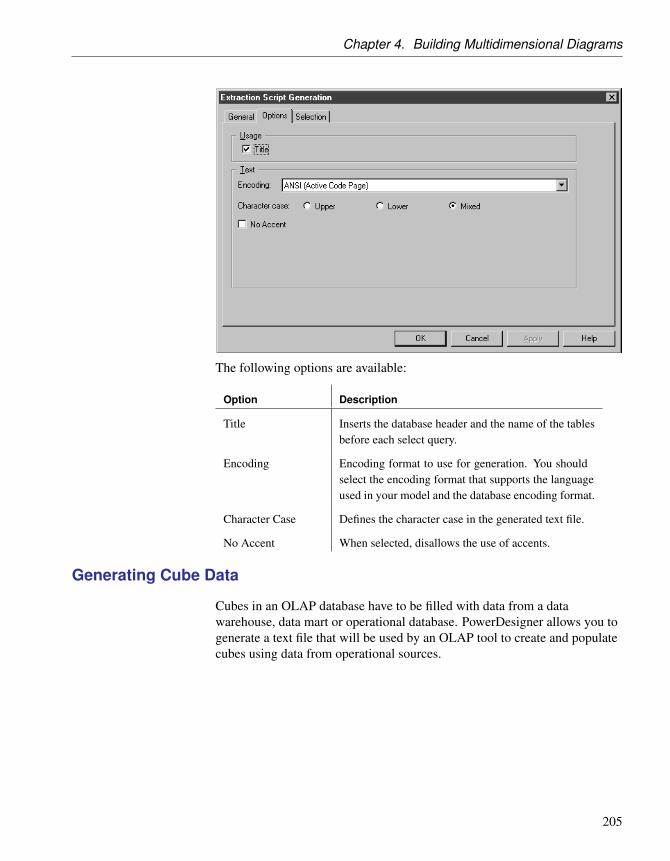
Chapter 4. Building Multidimensional Diagrams
The following options are available:
Option Description
Title Inserts the database header and the name of the tablesbefore each select query.
Encoding Encoding format to use for generation. You shouldselect the encoding format that supports the languageused in your model and the database encoding format.
Character Case Defines the character case in the generated text file.
No Accent When selected, disallows the use of accents.
Generating Cube Data
Cubes in an OLAP database have to be filled with data from a datawarehouse, data mart or operational database. PowerDesigner allows you togenerate a text file that will be used by an OLAP tool to create and populatecubes using data from operational sources.
205

Cubes (PDM)
In a PDM multidimensional diagram, each cube is associated with a query.There is one cube per mapping and per data source. The query defined on acube is used to extract data from a data warehouse or operational database topopulate the cubes in the OLAP database. The link between the datawarehouse database and the OLAP database is a relational tomultidimensional mapping.
+ For more information about relational to multidimensional mapping, see“Relational to multidimensional mapping” section in the Creating Mappingschapter of the Core Features Guide .
When you generate cube data, PowerDesigner produces one text file for eachselected cube and each selected data source. The name of the generated fileis a concatenation of the name of the cube and the name of the data source.
Each file contains the following fields:
Field Details
Dimension Lists the attributes of the cube
Member Lists the attribute values
Data fields Contains the values stored in the fact measures
206

Chapter 4. Building Multidimensional Diagrams
v To generate cube data
1. In the multidimensional diagram, select Tools ä Generate Cube Data.
The Generate Cube Data dialog box is displayed.
2. Define a destination directory for the generated file in the Directory box.
3. Select the generation options in the Options tab.
4. Select the cubes and data sources for which you want to generate a filefrom the sub- tabs in the Selection tab.
5. Click OK.
The generated files are stored in the destination directory you havedefined.
Cube data generationoptions
You can customize the format of the generated text files from the GenerateCube Data dialog box.
207
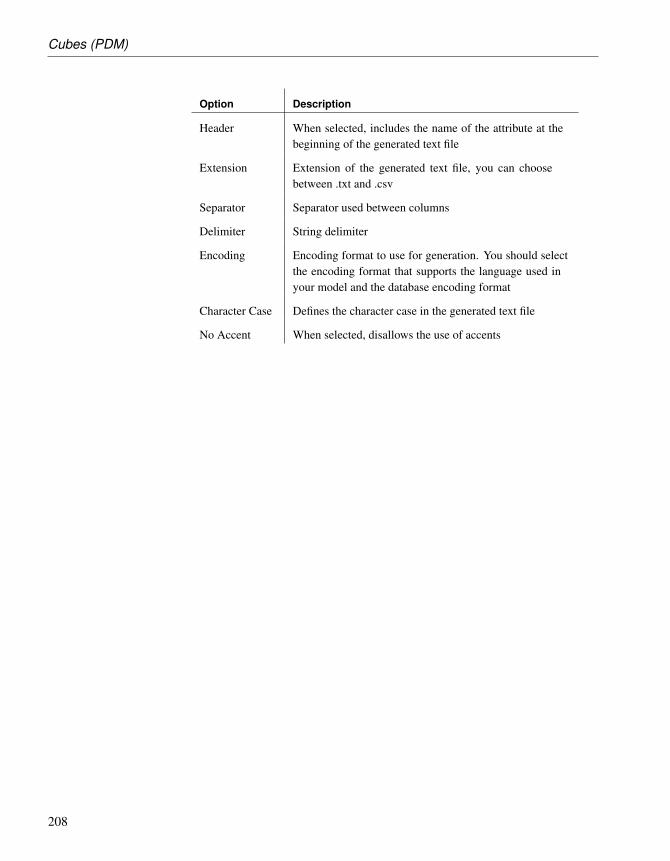
Cubes (PDM)
Option Description
Header When selected, includes the name of the attribute at thebeginning of the generated text file
Extension Extension of the generated text file, you can choosebetween .txt and .csv
Separator Separator used between columns
Delimiter String delimiter
Encoding Encoding format to use for generation. You should selectthe encoding format that supports the language used inyour model and the database encoding format
Character Case Defines the character case in the generated text file
No Accent When selected, disallows the use of accents
208

Chapter 4. Building Multidimensional Diagrams
Dimensions (PDM)A dimension is an axis of analysis in a multidimensional structure.
The dimension is made of an ordered list of attributes that share a commonsemantic meaning in the domain being modeled. Each attribute designates aunique position along the axis.
The dimension can be mapped to tables or views: this mapping allows totransfer operational data to the dimension.
+ For more information on object mapping, see “Mapping objects in aPDM” in the Working with Data Models chapter.
A dimension may have one or more hierarchies representing attribute sets.
Creating a dimension
You can create a dimension in any of the following ways:
♦ Use the Dimension tool in the diagram Palette.
♦ Select Model ä Dimensions to access the List of Dimensions, and clickthe Add a Row tool.
♦ Right-click the model or package in the Browser, and select New ä
Dimension.
+ For general information about creating objects, see the Objects chapterin the Core Features Guide .
Dimension properties
You can modify an object’s properties from its property sheet. To open adimension property sheet, double-click its diagram symbol or its Browserentry in the Dimensions folder. The following sections detail the propertysheet tabs that contain the properties most commonly entered fordimensions.
The General tab contains the following properties:
209

Dimensions (PDM)
Property Description
Name Specifies the name of the item, which should be clearand meaningful, and should convey the item’s purpose tonon-technical users
Code Specifies the technical name of the object, which is usedfor generating code or scripts, which may be abbreviated,and should not generally include spaces
Comment Specifies a descriptive label for the dimension
Stereotype Sub-classification used to extend the semantics of an objectwithout changing its structure; it can be predefined oruser-defined
Default Hierar-chy
Specifies the dimension hierarchy used by default fora cube to perform its consolidation calculations. Thehierarchy used by the cube is defined on the cube dimensionassociation
The following tabs are also available:
♦ Attributes - lists the attributes that qualify the dimension (see “Attributes(PDM)” on page 211).
♦ Hierarchies - lists the hierarchies used to organize the dimensionattributes (see “Hierarchies (PDM)” on page 218).
♦ Mapping - defines the mapping between the current dimension and atable or a view in a data source.
210

Chapter 4. Building Multidimensional Diagrams
Attributes (PDM)An attribute is used to qualify dimensions (see “Dimensions (PDM)” onpage 209) used in queries. For example, the Time dimension can containattributes Year, Quarter, Month, and Week.
Attributes can be organized in hierarchies (see “Hierarchies (PDM)” onpage 218).
Creating an attribute
You can create an attribute in any of the following ways:
♦ Open the Attributes tab in the property sheet of a dimension, and click theAdd a Row tool.
♦ Right-click a dimension in the Browser, and select New ä Attribute.
+ For general information about creating objects, see the Objects chapterin the Core Features Guide .
Attribute properties
You can modify an object’s properties from its property sheet. To open anattribute property sheet, double-click its Browser entry. The followingsections detail the property sheet tabs that contain the properties mostcommonly entered for attributes.
The General tab contains the following properties:
211

Attributes (PDM)
Property Description
Name Specifies the name of the item, which should be clearand meaningful, and should convey the item’s purpose tonon-technical users
Code Specifies the technical name of the object, which is usedfor generating code or scripts, which may be abbreviated,and should not generally include spaces
Comment Specifies a descriptive label for the attribute
Stereotype Sub-classification used to extend the semantics of an objectwithout changing its structure; it can be predefined oruser-defined
Dimension Parent dimension of the attribute
Attribute property sheet Detail Attributes tab
A detail attribute participates in the definition of an attribute.
Detail attributes appear in the list of dimension attributes, but you can usethem to further define a given attribute. For example, attributes Cust_Nameand Cust_Address appear in the list of dimension attributes, however theyare used as detail attributes of attribute Cust_ID.
212

Chapter 4. Building Multidimensional Diagrams
v To define a detail attribute
1. Open the property sheet of a dimension, and click the Attributes tab.
2. Select an attribute in the list, click the Properties tool to open its propertysheet, and then click the Detail Attributes tab.
3. Click the Add Detail Attributes tool to open a Selection dialog listing theattributes available in the model, select one or more, and then click OK.
4. Click Apply.
213

Facts (PDM)
Facts (PDM)A fact corresponds to the focus of a decision support investigation. It is a setof measures (see “Measures (PDM)” on page 216) manipulated by a cube(see “Cubes (PDM)” on page 198). For example, Sale, Revenue, Budgetcould be facts.
Facts can be reused among different cubes.
Creating a fact
You can create a fact in any of the following ways:
♦ Select Model ä Facts to access the List of Facts, and click the Add a Rowtool.
♦ Right-click the model or package in the Browser, and select New ä Fact.
+ For general information about creating objects, see the Objects chapterin the Core Features Guide .
Fact properties
You can modify an object’s properties from its property sheet. To open a factproperty sheet, double-click its Browser entry in the Facts folder. Thefollowing sections detail the property sheet tabs that contain the propertiesmost commonly entered for facts.
The General tab contains the following properties:
214

Chapter 4. Building Multidimensional Diagrams
Property Description
Name Specifies the name of the item, which should be clearand meaningful, and should convey the item’s purpose tonon-technical users
Code Specifies the technical name of the object, which is usedfor generating code or scripts, which may be abbreviated,and should not generally include spaces
Comment Specifies a descriptive label for the fact
Stereotype Sub-classification used to extend the semantics of an objectwithout changing its structure; it can be predefined oruser-defined
The following tabs are also available:
♦ Measures - lists the measures manipulated by the cube with which thefact is associated (see “Measures (PDM)” on page 216).
♦ Mapping - contains the mapping between the fact and a table or a view ina data source.
215

Measures (PDM)
Measures (PDM)A measure is a variable that corresponds to the focus of an investigation.Measures describe the meaning of the analytical values stored in each datacell of a cube (see “Cubes (PDM)” on page 198).
Measures are most of the time numeric values like for example Price orTotal.
Measures can also be the result of an operation or calculation as indicated inthe formula box of the measure property sheet.
Creating a measure
You can create a measure in any of the following ways:
♦ Open the Measures tab in the property sheet of a fact, and click the Add aRow tool.
♦ Right-click a fact in the Browser, and select New ä Measure.
+ For general information about creating objects, see the Objects chapterin the Core Features Guide .
Measure properties
You can modify an object’s properties from its property sheet. To open ameasure property sheet, double-click its diagram symbol or its Browserentry. The following sections detail the property sheet tabs that contain theproperties most commonly entered for measures.
The General tab contains the following properties:
216

Chapter 4. Building Multidimensional Diagrams
Property Description
Name Specifies the name of the item, which should be clear andmeaningful, and should convey the item’s purpose to non-technical users
Code Specifies the technical name of the object, which is used forgenerating code or scripts, which may be abbreviated, andshould not generally include spaces
Comment Specifies a descriptive label for the measure
Stereotype Sub-classification used to extend the semantics of an objectwithout changing its structure; it can be predefined or user-defined
Fact Specifies the parent fact of the measure
Formula Indicates if the measure is a computed expression and allowsto define this expression
217

Hierarchies (PDM)
Hierarchies (PDM)A hierarchy defines one of two paths through a dimension (see“Dimensions (PDM)” on page 209):
♦ an organizational path - describes a traversal pattern through adimension, from the most general to the most specific attribute of thedimension. It is an ordered subset of the attributes.
♦ a consolidation path - represents a consolidation of attributes. Forexample, a Time dimension with a base periodicity of days might have ahierarchy specifying the consolidation of days into weeks, weeks intomonths, months into quarters, and quarters into years.
Creating a hierarchy
You can create a hierarchy in any of the following ways:
♦ Open the Hierarchies tab in the property sheet of a dimension, and clickthe Add a Row tool.
♦ Open the Attributes tab in the property sheet of a dimension, and click theCreate Hierarchy tool.
♦ Right-click a dimension in the Browser, and select New ä Hierarchy.
+ For general information about creating objects, see the Objects chapterin the Core Features Guide .
Hierarchy properties
You can modify an object’s properties from its property sheet. To open ahierarchy property sheet, double-click its Browser entry. The followingsections detail the property sheet tabs that contain the properties mostcommonly entered for hierarchies.
The General tab contains the following properties:
218

Chapter 4. Building Multidimensional Diagrams
Property Description
Name Specifies the name of the item, which should be clearand meaningful, and should convey the item’s purpose tonon-technical users
Code Specifies the technical name of the object, which is usedfor generating code or scripts, which may be abbreviated,and should not generally include spaces
Comment Specifies a descriptive label for the hierarchy
Stereotype Sub-classification used to extend the semantics of an objectwithout changing its structure; it can be predefined oruser-defined
Dimension Specifies the parent dimension of the hierarchy
The following tabs are also available:
♦ Attributes - lists the attributes associated with the hierarchy (see“Attributes (PDM)” on page 211).
219
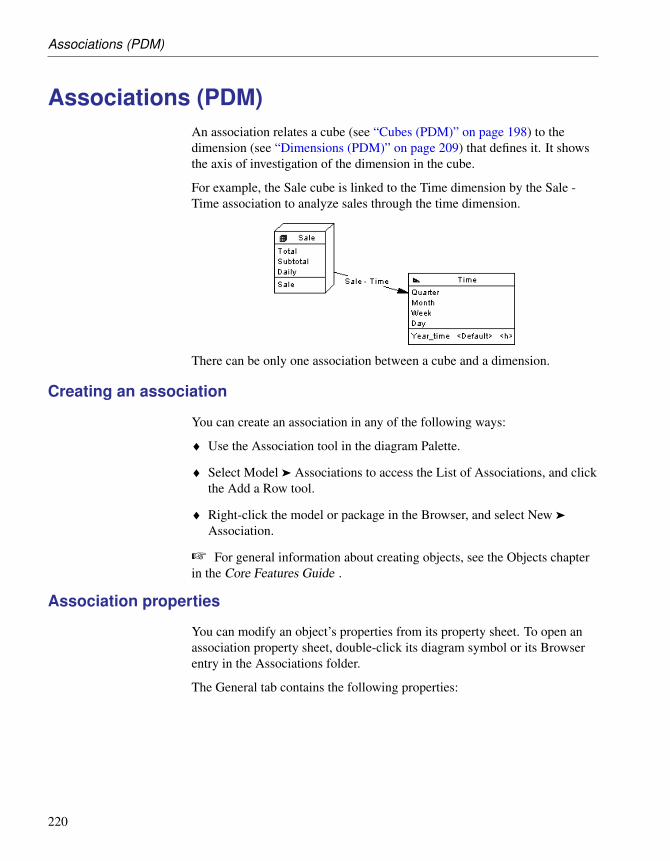
Associations (PDM)
Associations (PDM)An association relates a cube (see “Cubes (PDM)” on page 198) to thedimension (see “Dimensions (PDM)” on page 209) that defines it. It showsthe axis of investigation of the dimension in the cube.
For example, the Sale cube is linked to the Time dimension by the Sale -Time association to analyze sales through the time dimension.
There can be only one association between a cube and a dimension.
Creating an association
You can create an association in any of the following ways:
♦ Use the Association tool in the diagram Palette.
♦ Select Model ä Associations to access the List of Associations, and clickthe Add a Row tool.
♦ Right-click the model or package in the Browser, and select New ä
Association.
+ For general information about creating objects, see the Objects chapterin the Core Features Guide .
Association properties
You can modify an object’s properties from its property sheet. To open anassociation property sheet, double-click its diagram symbol or its Browserentry in the Associations folder.
The General tab contains the following properties:
220

Chapter 4. Building Multidimensional Diagrams
Property Description
Cube Specifies the cube origin of the association. You can click theProperties tool to view the properties of the currently selectedobject
Dimension Specifies the destination dimension of the association. Youcan use the tools to the right of the list to create an object,browse the complete tree of available objects or view theproperties of the currently selected object
Stereotype Sub-classification used to extend the semantics of an objectwithout changing its structure; it can be predefined or user-defined
Hierarchy Specifies the hierarchy used by the cube for the consolidationcalculation. You can click the Properties tool to view theproperties of the currently selected object
221


CHAPTER 5
Building Triggers and Procedures
About this chapter This chapter presents triggers and procedures used to generate databaseconstraints.
Contents Topic: page
Triggers (PDM) 224
Trigger Templates (PDM) 240
Trigger Template Items (PDM) 248
Stored Procedures and Functions (PDM) 255
Procedure Templates (PDM) 266
SQL Code Definition Toolbars 270
Creating SQL/XML Queries with the Wizard 271
Generating Triggers and Procedures 275
223

Triggers (PDM)
Triggers (PDM)A trigger is a segment of SQL code associated with a table or a view, andstored in a database. It is invoked automatically whenever there is an attemptto modify data in the associated table with an insert, delete, or updatecommand.
Triggers enhance the security, efficiency, and standardization of databases.
You can use triggers to enforce referential integrity, where declarativeconstraints are not sufficient. You can also use triggers to implementsequences for columns.
Trigger templates andtemplate items
A trigger template is a pre-defined form for creating triggers.PowerDesigner ships templates for each supported DBMS. Depending onthe current DBMS, there are pre-defined templates for insert, update, anddelete trigger types.
A template item is a reusable block of SQL script that can implementreferential integrity, or do any other work on database tables. PowerDesignerships template items for each supported DBMS. A template item is insertedinto a trigger template script, or a trigger script. The template item calls acorresponding SQL macro which can implement an insert, update, delete, orerror message constraint on one or more tables in the database.
You can use the PowerDesigner templates and template items, copy and editthem, or create your own from scratch. For more information, see “TriggerTemplates (PDM)” on page 240.
Creating Triggers for Referential Integrity
You can create triggers automatically for one or more tables in a model,when you specify that triggers are to be used to implement referentialintegrity and for columns where the values depend on a sequence.
v To implement referential integrity between tables by triggers
1. Create a reference between two tables, and then double click thereference symbol to open its property sheet.
2. Click the Integrity tab, and then select Trigger from the Implementationlist.
3. Specify the form of Update and Delete constraints using the radiobuttons, and then click OK to return to the diagram.
4. If you have set the Automatically rebuild triggers model option, thentriggers will have been created automatically in the parent and child
224

Chapter 5. Building Triggers and Procedures
tables. To verify this, double-click the table symbol to open its propertysheet, and then click the Triggers tab. If the triggers are not present„ youwill need to rebuild your triggers manually.
+ For more information about the Automatically rebuild triggers modeloption and rebuilding triggers manually, see “Rebuilding Triggers” onpage 229.
+ For more information about selecting referential integrity optionsfrom the Reference property sheet, see section Defining referentialintegrity in chapter Building Physical Diagrams.
You can instruct PowerDesigner to implement referential integrity betweentables using triggers by default.
v To implement referential integrity between tables by triggers bydefault
1. Select Tools Model Options and click Reference under Model Settings inthe Category list.
2. Select Trigger from the Default implementation list, and then click OK.
From now, when you create a reference between tables, referentialintegrity will be implemented using triggers by default.
Creating Other Triggers
You can create your own triggers from the property sheet of a table (or view,if supported by your DBMS).
You can write a trigger from scratch directly in its property sheet, but werecommend that you use a trigger template and/or trigger template items todefine the trigger code. These allow you to create triggers in a modularfashion, to make re-use of your trigger code easier and give your triggersmore portability.
+ For more information, see “Trigger Templates (PDM)” on page 240.
Creating a trigger from a template
You can create a trigger based on one of the PowerDesigner templates or ona template of your own.
v To create a trigger from a template
1. Double-click a table symbol to open its property sheet, and then click theTriggers tab.
225

Triggers (PDM)
2. Click the Add a Row tool to create a new trigger, and type a name andcode.
3. Click Apply to commit the creation of the new trigger, and then click theProperties tool to open its property sheet.
4. Click the Definition tab, and select a trigger template from the Templatelist.
The time and event fields will be set and the template code copied intothe definition box.
5. [optional] Modify the trigger definition code. You can add triggertemplate items, use PDM variables and macros and various other toolsavailable from the toolbar (see “SQL Code Definition Toolbars” onpage 270).
If you edit the code, then the trigger will be marked as user-defined andwill be excluded from most forms of rebuilding (see “RebuildingTriggers” on page 229).
6. You can also modify the trigger’s other properties. For a full list of theproperties available, see “Trigger properties” on page 228.
7. Click OK in each of the dialog boxes.
Creating a trigger from scratch
You can create a trigger without basing it on a template. However, werecommend that you use a template as this will simplify reuse of your codeand make your triggers more portable.
226

Chapter 5. Building Triggers and Procedures
v To create a trigger from scratch
1. Double-click a table symbol to open its property sheet, and then click theTriggers tab.
2. Click the Add a Row tool to create a new trigger, and type a name andcode.
3. Click Apply to commit the creation of the new trigger, and then click theProperties tool to open its property sheet.
4. Click the Definition tab.
5. Enter the trigger definition code. You can add trigger template items, usePDM variables and macros and various other tools available from thetoolbar (see “SQL Code Definition Toolbars” on page 270).
The trigger will be marked as user-defined and will be excluded frommost forms of rebuilding (see “Rebuilding Triggers” on page 229).
6. You can also modify the trigger’s other properties. For a full list of theproperties available, see “Trigger properties” on page 228.
7. Click OK in each of the dialog boxes.
Editing triggers in EclipseWhen using the PowerDesigner Eclipse plug-in, you can right-click atrigger in the Browser and select Edit in SQL Editor from the contextualmenu to open it in the Eclipse SQL Editor. You can optionally connectto your database in order to obtain auto-completion for table names. Thetrigger definition is added as a .SQL file to the Generated SQL Files list inthe Workspace Navigator.
227

Triggers (PDM)
Trigger properties
You can modify an object’s properties from its property sheet. To open atrigger property sheet, double-click its Browser entry in the Triggers folder.The following sections detail the property sheet tabs that contain theproperties most commonly entered for triggers.
The General tab contains the following properties:
Property Description
Name The name of the item which should be clear and meaningful,and should convey the item’s purpose to non-technical users
Code The technical name of the item used for generating code orscripts, which may be abbreviated, and should not generallyinclude spaces
Comment Descriptive label for the trigger
Stereotype Sub-classification used to extend the semantics of an objectwithout changing its structure; it can be predefined or user-defined
Owner Name of trigger owner. You choose an owner from a list ofusers. A trigger can only have one owner at a time. This isnormally the trigger creator
Table Table attached to trigger
Generate Indicates to generate trigger
User-defined [Read-only] Indicates that the trigger definition is modifiedby user. You modify a trigger definition when you change thetrigger template script in the Definition tab of the trigger
Trigger property sheet Definition tab
The Definition tab allows you to enter code for the trigger. It contains thefollowing properties:
228

Chapter 5. Building Triggers and Procedures
Property Description
Template Template on which the trigger is based
User-defined This button is automatically depressed when you modify thedefinition of a trigger, that is to say the trigger template code.You can click the User-Defined button to restore the triggerdefinition as it is provided in the template
Time Time attribute of the template. The content of the list dependson the DBMS
Event Event attribute of the template. The content of the list dependson the DBMS
Order Firing order of trigger
Time and event You can customize the trigger time and event, and you can also handlemultiple events on a single trigger.
The time and event lists are filled with the values defined in the triggertemplate and the values defined in the Time and Event entries in the Triggercategory of the DBMS editor. For example, if you define Select as an eventin the DBMS definition file, it will appear in the list of events.
For more information about triggers with multiple event, see “Definingtriggers with multiple events” on page 239.
For information about the Definition tab toolbar, see “SQL Code DefinitionToolbars” on page 270.
Trigger property sheet Preview tab
The Preview tab displays the SQL code associated with the trigger. For moreinformation, see “Previewing SQL statements” in the Working with DataModels chapter.
Trigger property sheet Template Items tab
The Template Items tab lists the trigger template items available for use inthe trigger definition. For more information, see “Trigger Template Items(PDM)” on page 248.
Rebuilding Triggers
You rebuild triggers in order to ensure that:
♦ They are attached to all tables joined by a reference where referentialintegrity is implemented by a trigger
229

Triggers (PDM)
♦ Any changes to a trigger template or trigger template item are cascadeddown to all associated triggers
PowerDesigner can rebuild triggers either:
♦ Automatically, whenever a relevant change is made, if you have enabledthe Automatically rebuild triggers model option
♦ Manually, when you select Tools ä Rebuild Objects ä Rebuild Triggers
The Rebuild Triggers function creates new triggers based on template itemsthat correspond to trigger referential integrity defined for references andsequence implementation for columns.
The Rebuild Triggers function does not use pre-defined template itemswhich are not applicable to trigger referential integrity or sequenceimplementation.
+ For information about rebuilding dependencies between triggers andother objects, see “Tracing Trigger and Procedure Dependencies” onpage 257.
Rebuilding triggers automatically
PowerDesigner can automatically rebuild your triggers whenever a relevantchange is made.
v To enable the automatically rebuild triggers option
1. Select Tools ä Model Options to open the Model Options window.
2. In the Category pane, click on Trigger under the Model Settings node togo to the Trigger model options
3. Select the Automatically rebuild triggers checkbox, and click OK.
PowerDesigner will rebuild all triggers and will, from now on, rebuildtriggers whenever you make a relevant change in the model.
Rebuilding triggers manually
You can rebuild triggers manually at any time.
v To rebuild triggers manually
1. Select Tools ä Rebuild Objects ä Rebuild Triggers to open the TriggerRebuild window.
2. Specify a rebuild mode. You can choose between the following options:
230

Chapter 5. Building Triggers and Procedures
♦ Delete and Rebuild – all triggers attached to templates are deleted andrebuilt, including those to which you have made modifications
♦ Preserve – only those triggers attached to templates that have not beenmodified are deleted and rebuilt. Any triggers that you have modifiedare preserved.
3. The Trigger selection box shows an expandable tree view of trigger types.There are three levels in this tree:
♦ All trigger types supported by the current DBMS
♦ All trigger templates corresponding to the trigger types
♦ All template items defined for each trigger templateFor example, in the list below, the two template itemsInsertChildParentExist and InsertTooManyChildren are usedin the BeforeInsertTrigger template that is, in turn, used in alltriggers with a time of Before and an event type of Insert:
You can select which trigger types, trigger templates, and template itemswill be rebuilt by expanding the appropriate nodes and selecting orclearing the check boxes as required.
4. [optional] Click the Error Messages tab to define the types of errormessages to generate. For more information about this tab, see the“Creating and generating user-defined error messages” on page 278section.
231

Triggers (PDM)
5. [optional] Click the Selection tab. to specify which tables to rebuild thetriggers for.
6. Click OK to begin the rebuild process.
Progress is shown in the Output window. You can view the triggers thathave been created from the Triggers tab of the table property sheet, orfrom the List of Triggers.
Which Triggers are Rebuilt?
Whether you use the automatic model option or rebuild triggers manually,all triggers that are based on a trigger template are rebuilt. These include:
♦ The default PowerDesigner triggers that are used to maintain referentialintegrity between tables
♦ Any other triggers that you have created via a user-defined triggertemplate
Triggers are rebuilt when a change in the DBMS family is madeIf you change the target DBMS family, for example from Sybase to Oracleor IBM DB2, triggers are automatically rebuilt.
User-defined triggers When a trigger based on a trigger template is modified, it becomesuser-defined. The Rebuild Triggers function does not create a triggercorresponding to a trigger template attached to a user-defined trigger if youselect the “Preserve” mode.
If you wish to recreate a trigger based on the same trigger template you can:
♦ Click the User-defined button in the Definition tab of the trigger propertysheet to reset your edits. This removes the changes performed on thetrigger and reapplies the trigger template
♦ Select <None> in the trigger template list in the Definition tab of thetrigger property sheet. This detaches the trigger template from theuser-defined trigger. The next time you will rebuild triggers, a new triggerbased on the previously mentioned trigger template will be created
For example, Trigger1 is based on template TrigTpl1. You modify Trigger1so PowerDesigner turns it into a user-defined trigger. If you want to recreatea trigger based on TrigTpl1 you can click the User-defined button in theDefinition tab of the Trigger1 property sheet: you restore the triggertemplate code, but you lose the modifications on the trigger. You can alsokeep the changes performed on the trigger by selecting <None> in thetrigger template list in the Definition tab of the trigger property sheet. The
232
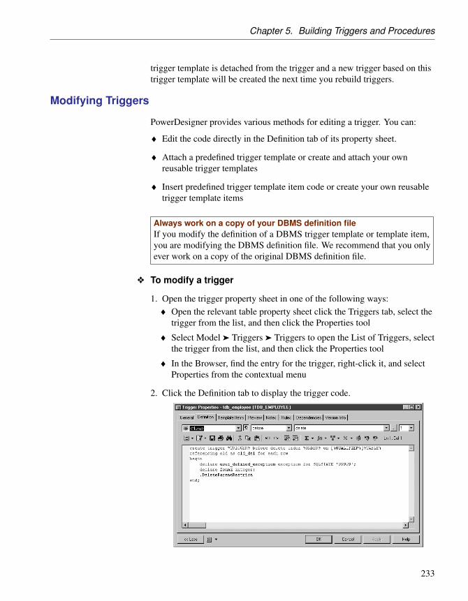
Chapter 5. Building Triggers and Procedures
trigger template is detached from the trigger and a new trigger based on thistrigger template will be created the next time you rebuild triggers.
Modifying Triggers
PowerDesigner provides various methods for editing a trigger. You can:
♦ Edit the code directly in the Definition tab of its property sheet.
♦ Attach a predefined trigger template or create and attach your ownreusable trigger templates
♦ Insert predefined trigger template item code or create your own reusabletrigger template items
Always work on a copy of your DBMS definition fileIf you modify the definition of a DBMS trigger template or template item,you are modifying the DBMS definition file. We recommend that you onlyever work on a copy of the original DBMS definition file.
v To modify a trigger
1. Open the trigger property sheet in one of the following ways:♦ Open the relevant table property sheet click the Triggers tab, select the
trigger from the list, and then click the Properties tool
♦ Select Model ä Triggers ä Triggers to open the List of Triggers, selectthe trigger from the list, and then click the Properties tool
♦ In the Browser, find the entry for the trigger, right-click it, and selectProperties from the contextual menu
2. Click the Definition tab to display the trigger code.
233

Triggers (PDM)
3. Enter the trigger definition code. You can attach a trigger template, addtemplate items, use PDM variables and macros and various other toolsavailable from the toolbar (see “SQL Code Definition Toolbars” onpage 270).
The trigger will be marked as user-defined and will be excluded frommost forms of rebuilding (see “Rebuilding Triggers” on page 229), if youselect the “Preserve” mode.
4. You can also modify the trigger’s other properties. For a full list of theproperties available, see “Trigger properties” on page 228.
5. Click OK in each of the dialog boxes.
Inserting a template item into a trigger or trigger template
Template items are inserted in a trigger or trigger template definition using adot followed by the template item name. For example, the following scriptcontains two template items InsertChildParentExist andInsertTooManyChildren:
/* Before insert trigger "%TRIGGER%" for table"[%QUALIFIER%]%TABLE%" */
create trigger %TRIGGER% before insert order %ORDER% on[%QUALIFIER%]%TABLE%
referencing new as new_ins for each rowbegin
declare user_defined_exception exception for SQLSTATE’99999’;
declare found integer;.InsertChildParentExist.InsertTooManyChildren
end/
v To add a template item to a trigger or trigger template
1. Open the property sheet of the trigger or trigger template that you want tomodify, and then click the Definition tab.
2. Click at the point in the code where you want to insert the triggertemplate item, and then click one of the following tools:
♦ Add Trigger Item From DBMS – to open a selection box containing alist of trigger template items defined in the DBMS definition file
♦ Add Trigger Item From Model – to open a selection box containing alist of trigger template items defined in the model
234

Chapter 5. Building Triggers and Procedures
3. Select the item to insert and then click OK to return to the definition tab.
The trigger template item will be inserted in your code. It will alsoappear in the list on the Template Items tab.
Declaring a template item in a trigger definition
Certain DBMS require that a cursor and variables are declared for eachtemplate item before the template item name is used in the script. This canbe a statement that calls a corresponding procedure. You can use thefollowing format to declare a template item: Decl template item name.
235

Triggers (PDM)
For example, the trigger definition for Oracle 8 contains the.DeclInsertChildParentExist statement which declares the following.InsertChildParentExist template item:
-- Before insert trigger "[%QUALIFIER%]%TRIGGER%" for table"[%QUALIFIER%]%TABLE%"
create trigger [%QUALIFIER%]%TRIGGER% before inserton [%QUALIFIER%]%TABLE% for each rowdeclare
integrity_error exception;errno integer;errmsg char(200);dummy integer;found boolean;.DeclInsertChildParentExist
begin.InsertChildParentExist
-- Errors handlingexception
when integrity_error thenraise_application_error(errno, errmsg);
end;/
In a generated trigger script, .DeclInsertChildExist corresponds to thefollowing definition:
.FOREACH_PARENT()-- Declaration of InsertChildParentExist constraint for the
parent "[%PQUALIFIER%]%PARENT%".DEFINE "CURSOR" "cpk%REFNO%_%.25L:TABLE%"cursor %CURSOR%(.JOIN("var_%.L26:FK% %.L:COLTYPE%", "", ",", ")
is")select 1from [%PQUALIFIER%]%PARENT%where .JOIN("%PK% = var_%.L26:FK%", "and ")and .JOIN("var_%.L26:FK% is not null", "and ", "", ";")
.ENDFOR
Trigger naming conventions
The pre-defined trigger templates that ship with PowerDesigner indicatenaming conventions for the trigger scripts that it generates. The namingconvention consists of a prefix indicating the trigger type followed by thetable code.
The default naming conventions include a variable (%L:TABLE). The nameof the resulting trigger script replaces this variable with a lower-case tablecode. For example, a resulting trigger script may have the name ti_employee.
You can change the trigger naming convention in PowerDesigner
236

Chapter 5. Building Triggers and Procedures
pre-defined DBMS trigger templates from the Trigger Templates tab of theDBMS property sheet.
v To change trigger naming conventions in a DBMS trigger tem-plate
1. Select Database ä Edit Current DBMS to open the DBMS definition filein the Resource Editor, and then click the Trigger Template tab.
2. Click a trigger template in the list, and then click the Properties tool toopen its property sheet .
3. Type a new trigger name in the Trigger Name text box at the bottom ofthe tab.
For example, mytempl_%TABLE%
4. Click OK in each of the dialog boxes.
Calling a related procedure in a trigger template
Some target databases do not accept code within a trigger statement. Forthese databases, a trigger template can call a related procedure as aparameter, which is defined in a procedure template. In these cases,procedure templates are listed in the list of trigger templates.
Example Informix does not accept code in trigger templates. The templateInsertTrigger calls the procedure in the form of the variable %PROC%, asfollows:
-- Insert trigger "[%QUALIFIER%]%TRIGGER%" for table"[%QUALIFIER%]%TABLE%"
create trigger [%QUALIFIER%]%TRIGGER% insert on[%QUALIFIER%]%TABLE%
referencing new as new_insfor each row (execute procedure %PROC%(.FKCOLN("new_
ins.%COLUMN%", "", ",", "));")/
The template InsertProc defines the procedure, as follows:
237

Triggers (PDM)
-- Insert procedure "%PROC%" for table "[%QUALIFIER%]%TABLE%"create procedure %PROC%(.FKCOLN("new_%.14L:COLUMN% %COLTYPE%",
"", ",", ")").DeclInsertChildParentExist.DeclInsertTooManyChildrendefine errno integer;define errmsg char(255);define numrows integer;
.InsertChildParentExist
.InsertTooManyChildren
end procedure;/
Multiple triggers
Some DBMSs allow you to have multiple triggers of the same type (timeand event) defined for any given table. Triggers of the same type are triggersthat are invoked for the same insert, update, or delete event.
Example A company is considering large numbers of candidates for new positions invarious posts. You want to ensure that all new employees will have a salarythat is within the range of others working in the same field, and less than hisor her prospective manager.
On an EMPLOYEE table, you create two BeforeInsert triggers ,tibTestSalry1_EMPLOYEE to verify that a proposed salary falls withinthe correct range, and tibTestSalry2_EMPLOYEE to verify that theproposed salary is less than that of the prospective manager.
create trigger tibTestSalry1 before insert order 1 on EMPLOYEEreferencing new as new_ins for each rowbegin
[Trigger code]
end
create trigger tibTestSalry2 before insert order 2 on EMPLOYEEbegin
[Trigger code]
end
For a specified table, you can indicate the order that a trigger executes, orfires, within a group of triggers of the same type.
238

Chapter 5. Building Triggers and Procedures
v To indicate trigger order
1. Click the Definition tab from the trigger property sheet.
2. Select a number from the Order dropdown list box to indicates theposition in the firing order that the trigger fires.
3. Click OK in each of the dialog boxes.
Defining triggers with multiple events
Some DBMSs support multiple events on triggers. If such is the case, theEllipsis button to the right of the Event box on the trigger definition tab isavailable.
You can click the Ellipsis button to open the Multiple Events Selection box.If you select several events and click OK, the different events will bedisplayed in the Event box, separated by the appropriate delimiter.
239

Trigger Templates (PDM)
Trigger Templates (PDM)PowerDesigner trigger templates and template items allow you to createtriggers in a modular reusable fashion.
PowerDesigner uses pre-defined trigger templates to create triggers toimplement referential integrity between tables. Trigger templates exist foreach type of trigger supported by the DBMS. Each template specifies:
♦ a Time – relevant to an event. One of:• After
• Before
♦ an Event – that can occur to a table row. One of:• Delete
• Insert
• Update
♦ Code – that performs the trigger action. The code may contain referencesto trigger template items, which are re-usable blocks of script.
You can create trigger templates and trigger template items in your DBMSdefinition file or in your model. These elements will be available as follows:
Trigger template or templateitem created in:
Available to
DBMS (shared definitionfile)
All models sharing the DBMS
DBMS (copied definition file Current model only
Model Current model only
+ For more information on the DBMS share and copied definition files,see the “Generating a Database from a PDM” chapter.
Modifying DBMS template itemsBy modifying a DBMS template item, you modify the template itemdefinition in the current DBMS. You should only modify a DBMS that is acopy of the DBMS shipped with PowerDesigner.
+ For more information on working with DBMS resource files, see theDBMS Resource File Reference chapter of the Customizing and ExtendingPowerDesigner manual.
240

Chapter 5. Building Triggers and Procedures
Creating a trigger template
You can create a new trigger template in your DBMS definition file or aspart of your model. You can begin by copying an existing template or writeone from scratch.two types of trigger templates:
v To create a trigger template
1. To create a DBMS trigger template: select Database ä Edit CurrentDBMS to open the DBMS definition file in the resource editor, and thenclick the Trigger Templates tab:
or
To create a model trigger template: select Model ä Triggers ä TriggerTemplates to open the List of User-Defined Trigger Templates:
241

Trigger Templates (PDM)
2. Click on one of the following tools:♦ Create from DBMS trigger template – opens a selection box listing
all the trigger templates available in the current DBMS. Select a checkbox for the type of trigger template that you want to use as the basis foryour new template and click OK to return to the trigger template list.The duplicate DBMS template has been added to the list.
♦ Add a Row – adds a new blank template to the list.
3. Type a new name and code for the new template and click Apply tocommit its creation.
4. Click the Properties tool to open the property sheet of the new triggertemplate:
242

Chapter 5. Building Triggers and Procedures
5. Click the Definition tab and enter or modify the definition code. You canadd trigger template items, use PDM variables and macros and variousother tools available from the toolbar. For more information, see “SQLCode Definition Toolbars” on page 270.
6. You can also modify other of the trigger template’s properties. For a fulllist of the properties available, see “Trigger template properties” onpage 245.
7. Click OK in each of the dialog boxes.
If you have created DBMS trigger template, a confirmation box willappear, asking if you want to save the changes to the DBMS.
Click Yes to confirm the template creation.
PowerDesigner pre-defined trigger templates
The pre-defined DBMS templates provided with PowerDesigner controlreferential integrity constraints for insert, update, and delete events.Depending on the current DBMS, there is a before and after event templatefor each trigger type.
You can modify the code of these pre-defined trigger templates, but theycannot be deleted or renamed.
The following templates types exist, but may vary by DBMS:
Insert templates
243

Trigger Templates (PDM)
Template type Generates trigger/procedure executing. . .
InsertTrigger With insert
BeforeInsertTrigger
Before insert
AfterInsertTrigger After insert
InsertProc When called by InsertTrigger
BeforeInsertProc When called by BeforeInsertTrigger
AfterInsertProc When called by AfterInsertTrigger
Update templates
Template type Generates trigger/procedure executing. . .
UpdateTrigger With update
BeforeUpdateTrigger
Before update
AfterUpdateTrigger After update
UpdateProc When called by UpdateTrigger
BeforeUpdateProc When called by BeforeUpdateTrigger
AfterUpdateProc When called by AfterUpdateTrigger
Delete templates
Template type Generates trigger/procedure executing. . .
DeleteTrigger With delete
BeforeDeleteTrigger
Before delete
AfterDeleteTrigger After delete
DeleteProc When called by DeleteTrigger
BeforeDeleteProc When called by BeforeDeleteTrigger
AfterDeleteProc When called by AfterDeleteTrigger
Modifying a trigger template
You can modify both your templates and those that are provided withPowerDesigner.
244
Chapter 5. Building Triggers and Procedures
v To modify a trigger template
1. Open the trigger template property sheet in one of the following ways:
2. To modify a DBMS trigger template: select Database ä Edit CurrentDBMS to open the DBMS definition file in the resource editor, and thenclick the Trigger Templates tab.
3. To modify a model trigger template: select Model ä Triggers ä TriggerTemplates to open the List of User-Defined Trigger Templates.
4. Click a trigger template in the list, and then click the Properties tool toopen its property sheet.
5. Click the Definition tab and modify the trigger definition code. You canadd trigger template items, use PDM variables and macros and variousother tools available from the toolbar. For more information, see “SQLCode Definition Toolbars” on page 270.
6. You can also modify other of the trigger template’s properties. For a fulllist of the properties available, see “Trigger template properties” onpage 245.
7. Click OK in each of the dialog boxes.
If you have created DBMS trigger template, a confirmation box willappear, asking if you want to save the changes to the DBMS.
Click Yes to confirm the template creation.
Trigger template properties
You can modify a trigger templates properties from its property sheet. Thefollowing sections detail the property sheet tabs that contain the propertiesmost commonly entered for trigger templates.
The General tab contains the following properties:
Property Description
Name The name of the item which should be clear and meaning-ful, and should convey the item’s purpose to non-technicalusers
Code The technical name of the item used for generating code orscripts, which may be abbreviated, and should not generallyinclude spaces
Comment Descriptive label for the trigger template
245

Trigger Templates (PDM)
Property Description
DBMS Current DBMS
Trigger time Time attribute of the trigger template. The list displays thevalues defined in the trigger templates and template itemsof the current DBMS
Trigger event Event attribute of the trigger template. The list displays thevalues defined in the trigger templates and template itemsof the current DBMS
Trigger name Name of trigger associated with template
Applies to ta-ble triggers orview triggers
For those DBMS that support view triggers, it allows youto define if the trigger template applies to table or viewtriggers
Trigger template property sheet Definition tab
The Definition tab contains a field for entering its definition code. Forinformation about editing this code, see “Modifying Triggers” on page 233.
Trigger template property sheet Template Items tab
The Template Items tab list the template items that are defined in the triggertemplate and that will be generated when a trigger is generated from thetemplate.
A template item that is deleted from the Template Items tab is not deletedfrom the trigger template definition. You can therefore limit the templateitems available for generation by removing template items from theTemplate Item tab, without having to remove them from the trigger templatedefinition.
Rebuild triggers When you use Rebuild Triggers to automatically create triggers for selectedtables, the template items that are listed on this tab are those available forgeneration. Whether they are generated or not depends on the following:
♦ Template items are generated in a trigger if they match the triggerimplemented referential integrity defined for a reference attached to thetable
♦ Template items are generated in a trigger if they are user-defined,regardless of trigger referential integrity constraints
Adding template items totrigger template definition
You can add any template item from the model or DBMS to the Triggertemplate definition by clicking an Add Trigger Item tool from the Definition
246

Chapter 5. Building Triggers and Procedures
tab of the trigger template property sheet, and selecting a trigger item. It isautomatically added to the Template Items tab.
247

Trigger Template Items (PDM)
Trigger Template Items (PDM)Trigger template items are named reusable blocks of script that can beinserted into trigger templates or triggers.
In a generated trigger script, a template item calls a macro that implements atrigger referential integrity constraint or does any other updating work ontables in the database.
Example A trigger template for Sybase Adaptive Server Anywhere 6 contains the.InsertChildParentExist template item, which corresponds to thefollowing definition:
.FOREACH_PARENT()/* Parent "[%PQUALIFIER%]%PARENT%" must exist when inserting a
child in "[%CQUALIFIER%]%CHILD%" */if (.JOIN("new_ins.%FK% is not null", "", " and", ") then")begin
set found = 0;select 1into foundfrom dummywhere exists (select 1
from [%PQUALIFIER%]%PARENT%where .JOIN("%PK% = new_ins.%FK%", "and ",
"", ");")if found <> 1 then
message ’Error: Trigger(%TRIGGER%) of table[%QUALIFIER%]%TABLE%’;
message ’ Parent code must exist when inserting achild!’;
signal user_defined_exception;end if;
endend if;.ENDFOR
Creating a trigger template item
You usually create a template item when an existing template item is notsuitable, or to create a repeatable block of code to do updating work ontables in the database.
You can create a new trigger template in your DBMS definition file or aspart of your model. You can begin by copying an existing template or writeone from scratch.
248

Chapter 5. Building Triggers and Procedures
v To create a trigger template item
1. To create a DBMS trigger template item: select Database ä Edit CurrentDBMS to open the DBMS definition file in the resource editor, and thenclick the Trigger Template Items tab:
or
To create a model trigger template item: select Model ä Triggers ä
Trigger Template Items to open the List of User-Defined TriggerTemplate Items:
2. Click on one of the following tools:♦ Create from DBMS trigger item – opens a selection box listing all
the trigger template items available in the current DBMS. Select a
249

Trigger Template Items (PDM)
check box for the type of item that you want to use as the basis foryour new item and click OK to return to the trigger template item list.The duplicate DBMS template item has been added to the list.
♦ Add a Row – adds a new blank template item to the list.
3. Type a new name and code for the new template item and click Apply tocommit its creation.
4. Click the Properties tool to open the property sheet of the new templateitem:
5. Click the Definition tab and enter or modify the definition code. You canuse PDM variables and macros and various other tools available from thetoolbar. For more information, see “SQL Code Definition Toolbars” onpage 270.
6. You can also modify other of the trigger template item’s properties. For afull list of the properties available, see “Trigger template properties” onpage 245.
7. Click OK in each of the dialog boxes.
If you have created DBMS trigger template item, a confirmation box willappear, asking if you want to save the changes to the DBMS.
Click Yes to confirm the template creation.
250

Chapter 5. Building Triggers and Procedures
PowerDesigner pre-defined trigger template items
PowerDesigner ships pre-defined template items for each pre-defined triggertemplate defined in the supported DBMS. The Rebuild Triggers functionuses both pre-defined and user-defined trigger templates to automaticallycreate triggers for selected tables.
In the pre-defined trigger templates, each pre-defined template itemcorresponds to a referential integrity constraint. Although a pre-definedtemplate item is defined in a trigger template, it is only generated in a triggerscript if it implements the trigger referential integrity defined for a reference.
Template items have the following generation conditions:
Template item is listed in. . . Template item is. . .
Template Items tab of triggerproperty sheet
Available for generation
Template Items tab of triggertemplate property sheet
Generated
You can modify the code for these pre-defined template items, but theycannot be deleted or renamed.
The PowerDesigner pre-defined template items that are available depend onthe current DBMS.
Insert constraints The template items below implement referential integrity in insert triggertemplates.
Template item Integrity con-straint
Description
DeclInsertChildParentExistInsertChildParentExist
Mandatory parent Parent must existwhen inserting achild
DeclInsertTooManyChildrenInsertTooManyChildren
Cannot exceedmaximum cardi-nality constraint
Cannot insert achild if maximumcardinality hasbeen reached
DeclInsertSequenceColumnInsertSequenceColumn
Select value insequence list forcolumn
Select a value forthe column from alist of sequences
251

Trigger Template Items (PDM)
Update constraints The template items below implement referential integrity in update triggertemplates.
Template item Integrity con-straint
Description
DeclUpdateChildParentExist
UpdateChildParentExist
Mandatory par-ent
Parent must existwhen updating achild
DeclUpdateChildChangeParent
UpdateChildChangeParent
Change parentnot allowed
Cannot modifyparent code inchild
DeclUpdateParentRestrict
UpdateParentRestrict
Restrict on up-date
Cannot modifyparent if childexists
DeclUpdateParentCascade
UpdateParentCascade
Cascade on up-date
Modify parentcode in all chil-dren
DeclUpdateChangeColumn
UpdateChangeColumn
Non-modifiablecolumn
Cannot modifycolumn
DeclUpdateParentSetNull
UpdateParentSetNull
Set null on up-date
Set parent code tonull in all children
DeclUpdateParentSetDefault
UpdateParentSetDefault
Set default onupdate
Set parent codeto default in allchildren
DeclUpdateTooManyChildren
UpdateTooManyChildren
Cannot exceedmaximum car-dinality con-straint
Cannot update achild if maximumcardinality hasbeen reached
Delete constraints The template items below implement referential integrity in delete triggertemplates.
Template item Integrity con-straint
Description
DeclDeleteParentRestrict
DeleteParentRestrict
Restrict ondelete
Cannot deleteparent if childexists
252

Chapter 5. Building Triggers and Procedures
Template item Integrity con-straint
Description
DeclDeleteParentCascade
DeleteParentCascade
Cascade ondelete
Delete parentcode in all chil-dren
DeclDeleteParentSetNull
DeleteParentSetNull
Set null ondelete
Delete in parentsets child to null
DeclDeleteParentSetDefault
DeleteParentSetDefault
Set default ondelete
Delete in parentsets child to de-fault
Constraint messages You can insert the following template items in any trigger template. Theygenerate error messages that indicate the violation of an integrity constraint.
Template item Description
UseErrorMsgText Error handling without a message table
UseErrorMsgTable Error handling with a message table
Modifying a trigger template item
You can modify both your template items and those that are provided withPowerDesigner.
v To modify a trigger template item
1. Open the trigger template item property sheet in one of the followingways:
2. To modify a DBMS trigger template item: select Database ä Edit CurrentDBMS to open the DBMS definition file in the resource editor, and thenclick the Trigger Template Items tab.
3. To modify a model trigger template item: select Model ä Triggers ä
Trigger Templates Items to open the List of User-Defined TriggerTemplate Items.
4. Click a trigger template item in the list, and then click the Properties toolto open its property sheet.
5. Click the Definition tab and modify the trigger definition code. You canuse PDM variables and macros and various other tools available from the
253

Trigger Template Items (PDM)
toolbar. For more information, see “SQL Code Definition Toolbars” onpage 270.
6. You can also modify other of the trigger template item’s properties. For afull list of the properties available, see “Trigger template properties” onpage 245.
7. Click OK in each of the dialog boxes.
If you have created DBMS trigger template item, a confirmation box willappear, asking if you want to save the changes to the DBMS.
Click Yes to confirm the template creation.
Trigger template item properties
You can modify an object’s properties from its property sheet. To open atrigger template item property sheet, access it via the List of User-DefinedTrigger Template Items List or the DBMS Properties window. The followingsections detail the property sheet tabs that contain the properties mostcommonly entered for trigger template items.
The General tab contains the following properties:
Property Description
Name The name of the item which should be clear and meaningful,and should convey the item’s purpose to non-technical users
Code The technical name of the item used for generating code orscripts, which may be abbreviated, and should not generallyinclude spaces
Comment Descriptive label for the template item
DBMS Current DBMS
The following tabs are also available:
♦ Definition - allows you to enter the SQL code for the template item. Forinformation about the tools available, see “SQL Code DefinitionToolbars” on page 270.
♦ Declaration - contains the declaration for the template item in triggerscripts. For information about the tools available, see “SQL CodeDefinition Toolbars” on page 270.
254

Chapter 5. Building Triggers and Procedures
Stored Procedures and Functions (PDM)You can define stored procedures and functions for any DBMS that supportsthem.
A stored procedure is a precompiled collection of SQL statements storedunder a name and processed as a unit. Stored procedures are stored within adatabase; can be executed with one call from an application; and allowuser-declared variables, conditional execution, and other programmingfeatures.
The use of stored procedures can be helpful in controlling access to data(end-users may enter or change data but do not write procedures), preservingdata integrity (information is entered in a consistent manner), and improvingproductivity (statements in a stored procedure only need to be written onetime).
A user-defined function is a form of procedure that returns a value to thecalling environment for use in queries and other SQL statements.
Creating a stored procedure or function
You can create a stored procedure or function in any of the following ways:
♦ Use the Procedure tool in the diagram Palette
♦ Open the Procedures tab in the property sheet of a table, and click theAdd a Row tool
♦ Select Model ä Procedures to access the List of Procedures, and click theAdd a Row tool
♦ Right-click the model or package in the Browser, and select New ä
Procedure
+ For general information about creating objects, see the Objects chapterin the Core Features Guide .
You can create a procedure based on one of the PowerDesigner templates oron a template of your own.
v To create a procedure
1. Double-click a table symbol to open its property sheet, and then click theProcedures tab.
2. Click the Add a Row tool to create a new procedure, and type a name andcode.
255

Stored Procedures and Functions (PDM)
3. Click Apply to commit the creation of the new procedure, and then clickthe Properties tool to open its property sheet.
4. Click the Definition tab:
5. [optional] Select a procedure template from the Template list (see“Procedure Templates (PDM)” on page 266).
6. Modify the procedure definition code. You can use PDM variables andmacros and various other tools available from the toolbar (see “SQLCode Definition Toolbars” on page 270).
7. You can also modify the procedure’s other properties. For a full list of theproperties available, see “Procedure properties” on page 256.
8. Click OK in each of the dialog boxes.
Editing procedures in EclipseWhen using the PowerDesigner Eclipse plug-in, you can right-click aprocedure in the Browser or diagram and select Edit in SQL Editor fromthe contextual menu to open it in the Eclipse SQL Editor. You canoptionally connect to your database in order to obtain auto-completion fortable names. The procedure definition is added to the Generated SQL Fileslist in the Workspace Navigator.
Procedure properties
You can modify an object’s properties from its property sheet. To open aprocedure property sheet, double-click its diagram symbol or its Browserentry in the Procedures folder. The following sections detail the propertysheet tabs that contain the properties most commonly entered for procedures.
256

Chapter 5. Building Triggers and Procedures
The General tab contains the following properties:
Property Description
Name Specifies the name of the item which should be clear andmeaningful, and should convey the item’s purpose to non-technical users.
Code Specifies the technical name of the item used for generatingcode or scripts, which may be abbreviated, and should notgenerally include spaces.
Comment Specifies a descriptive label for the procedure.
Stereotype Sub-classification used to extend the semantics of an objectwithout changing its structure; it can be predefined or user-defined.
Owner Specifies the name of the procedure owner.
Table Specifies the table to which the procedure is attached. Youcan use the tools to the right of the list to create an object,browse the complete tree of available objects or view theproperties of the currently selected object.
The following tabs are also available:
♦ Definition - allows you to enter the SQL code for the procedure. Forinformation about the tools available, see “SQL Code DefinitionToolbars” on page 270.
Tracing Trigger and Procedure Dependencies
When you write a trigger or procedure, PowerDesigner automatically createsdependencies to any table, view, procedure, or database package referencedin the code. These dependencies are taken into account when performing animpact analysis prior to deleting the trigger or procedure or objects on whichthey depend. For procedures, if the procedure has a symbol in your diagram,then any dependencies will be shown graphically by way of arrows linkingthe procedure to these objects.
The diagram below shows a procedure, ProcChangeLocation, which isdependent on a number of other objects:
257

Stored Procedures and Functions (PDM)
The Extended Dependencies tab of the trigger or procedure property sheetlists the objects upon which it depends. The stereotype <<DBCreateAfter(computed)>> specifies that PowerDesigner has determined that the triggeror procedure can only be created after these objects.
The Dependencies tab of the Employee table property sheet shows thatProcChangeLocation is dependent upon it.
258

Chapter 5. Building Triggers and Procedures
If you were to perform an impact analysis prior to deleting the Employeetable, you would be warned of the dependency of the procedure upon it.
259

Stored Procedures and Functions (PDM)
Creating procedure dependencies manually
Since procedures have diagram symbols, you can manually adddependencies for them. To do this, use the Link/Extended Dependency toolin the palette. In the diagram below, I have added a dependency fromProcChangeLocation to a new procedure, ProcOccupancy:
260

Chapter 5. Building Triggers and Procedures
Since ProcOccupancy is not directly referenced in ProcChangeLocation, Ineeded to manually add the stereotype <<DBCreateAfter>> to thedependency in the ProcChangeLocation property sheet ExtendedDependencies tab:
Rebuilding trigger and procedure dependencies
Trigger and procedure dependencies are rebuilt automatically after thefollowing actions:
261

Stored Procedures and Functions (PDM)
♦ Importing a PDM created with a former version of PowerDesigner
♦ Reverse engineering a database into a PDM
♦ Merging PDMs
You can also manually rebuild trigger and procedure dependencies at anytime.
v To rebuild trigger and procedure dependencies
1. Select Tools ä Rebuild Objects ä Rebuild Triggers and ProceduresDependencies to open the Procedures Dependencies window.
2. Specify a rebuild mode for each of Procedures and Triggers. You canchoose between the following options:
♦ Delete and Rebuild – all triggers and/or procedures attached totemplates are deleted and rebuilt, including those to which you havemade modifications
♦ Preserve – only those triggers and/or procedures attached to templatesthat have not been modified are deleted and rebuilt. Any triggersand/or procedures that you have modified are preserved.
3. [optional] Click the Selection tab and specify the tables, views,procedures, and (for Oracle only) database packages for which you wantto rebuild dependencies. By default all are selected.
4. Click OK to begin the rebuild process.
262

Chapter 5. Building Triggers and Procedures
Attaching a stored procedure to a table
You can attach a stored procedure to a table when your current DBMSsupports stored procedures. This feature lets you update the table or retrieveinformation from this table.
For example, the stored procedure TABLE_ADDROW can be attached to atable in which you need to insert rows.
Intermodel generation When you generate an OOM from a PDM, the procedures attached to a tablebecome operations with the <<procedure>> stereotype in the generatedclass. By attaching procedures to tables, you are able to define classoperations in the generated OOM.
When you generate a PDM from an OOM, class operations with the<<procedure>> stereotype become stored procedures attached to thegenerated table. The operation body is generated as a comment in theprocedure definition.
You can attach a table to a procedure from the property sheet of a procedureor the property sheet of a table.
v To attach a stored procedure to a table
1. Open the table property sheet and click the Procedures.
2. Click the Add Objects tool to open a selection box, choose the the storedprocedure you want to attach to the table and click OK.
The stored procedure is displayed in the list of stored procedures.
263

Stored Procedures and Functions (PDM)
3. Click OK.
Rebuilding procedures attached to tables
You can rebuild procedures attached to tables at any time.
264

Chapter 5. Building Triggers and Procedures
v To rebuild procedures attached to tables manually
1. Select Tools ä Rebuild Objects ä Rebuild Table Stored Procedures toopen the Rebuild Table Stored Procedures window.
2. Specify a rebuild mode. You can choose between the following options:♦ Delete and Rebuild – all procedures attached to tables are deleted and
rebuilt
♦ Add missing table stored procedures – adds procedures to any selectedtables that do not presently have them.
3. [optional] Click the Selection tab to specify for which tables you want torebuild stored procedures.
4. Click OK to begin the rebuild process.
265

Procedure Templates (PDM)
Procedure Templates (PDM)PowerDesigner procedure templates allow you to create procedures in amodular reusable fashion.
PowerDesigner provides certain basic procedure templates and also allowsyou to write your own. You can create procedure templates in your DBMSdefinition file or in your model. These elements will be available as follows:
Procedure template created in: Available to
DBMS (shared definition file) All models sharing the DBMS
DBMS (copied definition file) Current model only
+ For more information on the DBMS share and copied definition files,see the “Generating a Database from a PDM” chapter.
Modifying DBMS template itemsBy modifying a DBMS template, you modify its definition in the currentDBMS. You should only modify a DBMS if you have already made a copyof the DBMS definition file provided with PowerDesigner.
+ For more information on working with DBMS resource files, see theDBMS Resource File Reference chapter of the Customizing and ExtendingPowerDesigner manual.
Creating a procedure template
You can create a new procedure template in your DBMS definition file or aspart of your model. You can begin by copying an existing template or writeone from scratch:
266

Chapter 5. Building Triggers and Procedures
v To create a procedure template
1. Select Database ä Edit Current DBMS to open the DBMS definition filein the resource editor, and then click the Procedure Templates tab:
2. Click the Add a Row tool to add a new blank template to the list.
3. Type a new name and code for the new template and click Apply tocommit its creation.
4. Click the Properties tool to open the property sheet of the new proceduretemplate:
5. Click the Definition tab and enter or modify the definition code. You can
267

Procedure Templates (PDM)
use PDM variables and macros and various other tools available from thetoolbar (see “SQL Code Definition Toolbars” on page 270).
6. You can also modify other of the procedure template’s properties. For afull list of the properties available, see “Procedure template properties”on page 269.
7. Click OK in each of the dialog boxes.
A confirmation box will appear, asking if you want to save the changes tothe DBMS.
Click Yes to confirm the template creation.
PowerDesigner pre-defined procedure templates
The pre-defined DBMS templates provided with PowerDesigner generateSQL insert, delete, update, and select statement procedures.
You can modify the code of these pre-defined procedure templates, but theycannot be deleted or renamed.
The following templates, which create procedures linked to tables, areprovided for those databases that support them:
Template type Generates procedure executing. . .
DeleteProcedure a SQL Delete statement
InsertProcedure a SQL Insert statement
SelectProcedure a SQL Select statement
UpdateProcedure a SQL Update statement
Modifying a procedure template
You can modify both your templates and those that are provided withPowerDesigner.
v To modify a procedure template
1. Select Database ä Edit Current DBMS to open the DBMS definition filein the resource editor, and then click the Procedure Templates tab.
2. Click a procedure template in the list, and then click the Properties tool toopen its property sheet.
3. Click the Definition tab and modify the procedure definition code. Youcan use PDM variables and macros and various other tools available from
268

Chapter 5. Building Triggers and Procedures
the toolbar. For more information, see “SQL Code Definition Toolbars”on page 270.
4. You can also modify other of the procedure template’s properties. For afull list of the properties available, see “Procedure template properties”on page 269.
5. Click OK in each of the dialog boxes.
A confirmation box will appear, asking if you want to save the changes tothe DBMS.
Click Yes to confirm the template creation.
Procedure template properties
You can modify a procedure template’s properties from its property sheet.The following sections detail the property sheet tabs that contain theproperties most commonly entered for procedure templates.
The General tab contains the following properties:
Property Description
Name The name of the item which should be clear and meaning-ful, and should convey the item’s purpose to non-technicalusers.
Code The technical name of the item used for generating code orscripts, which may be abbreviated, and should not generallyinclude spaces.
Comment Descriptive label for the procedure template.
DBMS Current DBMS.
Function Specifies whether the template defines procedures or func-tions.
ProcedureName
Specifies the format of the resulting procedure names.
Linked to table Specifies whether the resulting procedure will be linked toa table.
The following tabs are also available:
♦ Definition - contains a field for entering its definition code. Forinformation about editing this code, see “Modifying a proceduretemplate” on page 268.
269

SQL Code Definition Toolbars
SQL Code Definition ToolbarsThe following tools are available on the Definition tabs of trigger, procedureand template property sheets:
Tool Description
Add Trigger Item From Model - [Triggers and trigger templatesonly] Opens a dialog box to select a trigger template item defined inthe model for insertion in the trigger definition.
Add Trigger Item From DBMS - [Triggers and trigger templatesonly] Opens a dialog box to select a trigger template item defined inthe DBMS definition file for insertion in the trigger definition.
Operators - Lists logical operators for insertion in the triggerdefinition.
Functions - Lists group, number, string, date, conversion and otherfunctions for insertion in the trigger definition.
Macros - Lists macros for insertion in the trigger definition. Formore information on macros, see the “Writing SQL Statements inPowerDesigner” appendix.
Variables - Lists variables for use with operators and functionsfor insertion in the trigger definition. You can also use formattingvariables that have a syntax that can force a format on their values,as follows:♦ Force values to lower-case or upper-case characters
♦ Truncate the length of valuesFor more information on variables, see “PDM variables” in theWriting SQL Statements in PowerDesigner chapter.
Edit with SQL Editor - Opens the SQL Editor dialog box. Pro-vides object types and available objects for insertion in the triggerdefinition.
SQL/XML Wizard - Opens the SQL/XML Wizard to build aSQL/XML query from a table or a view and insert it in the triggerdefinition (see “Creating SQL/XML Queries with the Wizard” onpage 271).
Insert SQL/XML Macro - Opens a dialog box to select a global ele-ment in an XML model open in the workspace with the SQL/XMLextended model definition. Inserts a SQL/XML macro referencingthe selected element in the trigger definition.
270

Chapter 5. Building Triggers and Procedures
Creating SQL/XML Queries with the WizardYou can use the SQL/XML Wizard to insert a SQL/XML query in thedefinition of a trigger, stored procedure, or function to store or retrieve data,in an XML format, from relational databases supporting SQL/XML. Thewizard, allows you to select tables and views from a PDM to build a mappedXML model. This XML model (which does not appear in the workspace) isused to generate SQL/XML queries from global elements.
v To insert a SQL/XML query in the definition of a trigger
1. Open the trigger property sheet, click the Definition tab and position thecursor in the trigger definition where you want to insert the SQL/XMLquery:
2. Click the SQL/XML Wizard tool to launch the wizard at the Tables andViews Selection page:
271

Creating SQL/XML Queries with the Wizard
3. Select the tables and views that you want to include in your query andclick Next to go to the XML Hierarchy Design page:
On this tab, you construct the XML hierarchy that you want to generate:♦ The left-hand pane lists the tables and views that you have selected
272

Chapter 5. Building Triggers and Procedures
♦ The right-hand pane displays the XML hierarchy to be generated,containing a default root element.
4. You can build your XML hierarchy using the following techniques:♦ Specify whether columns will be generated as elements or attributes by
using the radio buttons above the panes.♦ Drag and drop a table, view, or column onto a node in the XML
hierarchy. You must respect the PDM hierarchy: You cannot create anXML hierarchy between two elements if there is no reference betweentheir corresponding tables, and a parent table cannot be placedbeneath one of its children.
♦ Right-click a table, view, or column and select Add from the contextualmenu to add it to the last selected node in the XML hierarchy.
♦ Rename an element or attribute by clicking its node and typing a newname.
♦ Create new elements and attributes not in the PDM, and Sequence,Choice and All group particles, by right-clicking an XML node andselecting New ä object from the contextual menu.
♦ Delete an XML node by right-clicking it and selecting Delete from thecontextual menu.
5. When you have finished building your hierarchy, click Next to go to theQuery tab:
6. Review your query and click Back, if necessary, to make revisions inyour hierarchy. When you are satisfied, click Finish to close the wizardand insert the SQL/XML query in the trigger definition
273

Creating SQL/XML Queries with the Wizard
7. [optional] Add code to complete the SQL/XML query:
8. Click OK to close the trigger property sheet:
274

Chapter 5. Building Triggers and Procedures
Generating Triggers and ProceduresYou can create or modify database triggers to a script or to a live databaseconnection.
v To generate triggers and procedures
1. Select Database ä Generate Database to open the Database Generationwindow, and specify the standard options, including whether you want togenerate to a script or to a live database connection.
+ For detailed information about using this window, see the“Generating a Database” section in the “Generating a Database from aPDM” chapter.
2. Select “Triggers & Procedures (with Permissions)” from the Settings setlist in the Quick Launch groupbox at the bottom of the window. Thissettings set specifies standard options for generating triggers andprocedures.
or:
Click the Options tab and click on Trigger in the left-hand pane to displaythe trigger generation options. Change the default options as appropriate.
+ For detailed information about settings sets, see “Quick launchselection and settings sets” section in the “Generating a Database from aPDM” chapter.
3. [optional] Click the Selection tab and select the Table or Proceduresubtab at the bottom of the tab. Select the tables or procedures that youwant to generate for. Note that if you want to generate a trigger script fortables owned by a particular owner, you can select an owner from theOwner list.
4. Click OK to begin the generation.
Defining a generation order for stored procedures
You can use extended dependencies to define an order in the generation ofstored procedures.
Extended dependencies are free links between PDM objects. These linkshelp to make object relationships clearer between model objects. Usually,these links are not interpreted and checked by PowerDesigner as they aremeant to be used for documentation purposes only. However, if you assignthe <<DBCreateAfter>> stereotype to an extended dependency betweenstored procedures, it will be analyzed during generation.
275

Generating Triggers and Procedures
The procedure from which you start the extended dependency is thedependent procedure and the procedure at the other end of the link is theinfluent procedure. The influent procedure will be generated before thedependent procedure.
Circular extendeddependencies
If you create a reflexive and/or circular set of extended dependencies withthe <<DBCreateAfter>> stereotype, an error message is displayed duringthe check model. If you choose to ignore this error, the stored procedureswill be generated in alphabetical order, without taking into account thegeneration order, which could cause errors in the creation of storedprocedures in the database.
Example A publisher may decide to sell certain books at a reduced rate (15%) when acustomer’s order is above 10 000$.
In this model, one stored procedure GENERAL CHECK globally verifiesorders: check books availability, check the order amount, check if discountrate is calculated, and applies discount rate to order bill. During theexecution of this stored procedure, the procedure DISCOUNT CALC iscalled to calculate the 15% discount rate. It is important to generateGENERAL CHECK before DISCOUNT CALC; you can define an extendeddependency to set the generation order between these two objects. To do so,you have to open the property sheet of the dependent stored procedure, clickthe Extended Dependencies tab and create an extended dependency with the<<DBCreateAfter>> stereotype with the influent stored procedure.
276

Chapter 5. Building Triggers and Procedures
v To define a generation order for stored procedures
1. Select Model ä Procedures to display the List of Stored Procedures.
2. Select a dependent stored procedure in the list and click the Propertiestool.
The property sheet of the stored procedure is displayed.
3. Click the Extended Dependencies tab to display the ExtendedDependencies tab.
4. Click the Add Objects tool.
5. Select the Procedure tab in the Add Object selection dialog box.
6. Select the influent stored procedure check box and click OK.
7. Select the <<DBCreateAfter>> stereotype in the Stereotype list.
8. Click OK.
The influent stored procedure is displayed in the Influent Object columnof the list of extended dependencies of the dependent stored procedure.
+ For more information on extended dependencies, see “Using extendeddependencies”, in the Objects chapter of the Core Features Guide.
277

Generating Triggers and Procedures
Creating and generating user-defined error messages
You can create user-defined error messages. The error messages are stored ina message table which you need to create in your database. When you selecttrigger generation parameters, you can choose to generate an error messagefrom this table.
In the generated trigger script, the message table is called in a SELECTcommand. If an error number in the script corresponds to an error numbervalue in the table column, then the standard error message is replaced by themessage defined in the table.
Creating a message table
You create a message table which stores error message information.
v To create a message table
1. Create a table with columns to store the following information:
Column to store. . . Description
Error number Number of the error message that is referencedin the trigger script
Message text Text of message
2. Generate the table in your database.
3. Select Database ä Execute SQL.
A dialog box asks you to identify a data source and connectionparameters.
4. Select a data source and fill in connection parameters.
5. Click Connect.
An SQL query editor box is displayed.
6. Type an SQL statement to insert a message number and text in theappropriate columns. You can use the following format for example:
insert into table values (error number,’error message’)
insert into ERR_MSG values (1004,’The value that you are
trying to insert does not exist in the referenced
table’)
278

Chapter 5. Building Triggers and Procedures
7. Click Execute.
A message box tells you that the command has been successfullyexecuted.
8. Click OK.
You return to the SQL query box.
9. Click Close.
Generating a user-defined error message
You can choose to generate a user-defined error message from the triggergeneration parameters box.
v To generate a user-defined error message
1. Select Tools ä Rebuild Objects ä Rebuild Triggers.
The Rebuild Triggers dialog box is displayed.
2. Click the Error Messages tab.
The Error Messages tab is displayed.
3. Select the User-defined radio button.
4. Type the name of the table that contains the error message in the MessageTable Name box.
5. Type the name of the column that contains the error number in theMessage Number box.
6. Type the name of the column that contains the error message text in theMessage Text column.
Below is an example of the details for a table called ERR_MSG.
279

Generating Triggers and Procedures
7. Click the General tab and select the mode and triggers to create.
8. Click the Selection tab and select the tables for which you want to createtriggers.
+ For more information on rebuilding triggers, see section “RebuildingTriggers” on page 229.
9. Click OK.
The trigger rebuilding process is shown in the Output window.
Select Database ä Generate Database to open the Database Generationwindow.
10. Select generation parameters as required.
11. Click OK.
+ For information on selecting trigger generation parameters, seesection “Generating Triggers and Procedures” on page 275.
280

CHAPTER 6
Building a Database Access Structure
About this chapter This chapter explains how to manage access to the database using privilegesand permissions, and defining users, groups, roles, and object synonyms.
Contents Topic: page
Introducing database access 282
Users (PDM) 283
Roles (PDM) 298
Groups (PDM) 300
Synonyms (PDM) 302
281

Introducing database access
Introducing database accessIn this manual, we group within the concept of database access, the objectsthat are used to let database users carry out their jobs while preserving theprivacy and integrity of the information within the database.
Depending on the target DBMS, the setting up of a secure databaseenvironment implies the following tasks:
♦ Creation of users (see “Users (PDM)” on page 283)
♦ Creation of groups (see “Groups (PDM)” on page 300)
♦ Creation of roles (see “Roles (PDM)” on page 298)
♦ Definition of system privileges (see “Granting system privileges” onpage 286)
♦ Definition of object permissions (see “Granting object permissions” onpage 290)
Reverse engineering During reverse engineering by script, the permission and privilege grantorders are reverse engineered only if the user, group, or role already exist inthe model or, in the case of a new model, if the user, group, or role creationorders are in the same script.
These restrictions do not apply to reverse engineering from a live databaseconnection.
282

Chapter 6. Building a Database Access Structure
Users (PDM)A user is a database object that identifies a person who can login or connectto the database. Users may have:
♦ a role that specifies their responsibilities (see “Roles (PDM)” onpage 298)
♦ membership in a group that specifies their rights (see “Groups (PDM)”on page 300)
♦ privileges that control their level of access (see “Granting systemprivileges” on page 286)
♦ permissions that allow them to perform actions on objects (see “Grantingobject permissions” on page 290)
NoteNot all DBMSs support the concepts of user, role and group.
Creating a user
You can create a user in any of the following ways:
♦ Select Model ä Users and Roles ä Users to access the List of Users, andclick the Add a Row tool.
♦ Right-click the model or package in the Browser, and select New ä User.
+ For general information about creating objects, see the Objects CoreFeatures Guide .
User properties
You can modify an object’s properties from its property sheet. To open auser property sheet, double-click its Browser entry in the Users folder. Thefollowing sections detail the property sheet tabs that contain the propertiesmost commonly entered for users.
The General tab contains the following properties:
283

Users (PDM)
Property Description
Name Name of the user
Code Code of the user used as identifier in the database
Comment Descriptive label for the user
Stereotype Sub-classification used to extend the semantics of an objectwithout changing its structure; it can be predefined or user-defined
Password Password that may be used for database connection
The following tabs are also available:
♦ Privileges - lists the system privileges granted to the user (see “Grantingsystem privileges” on page 286).
♦ Permissions - lists the operations that the user is permitted to perform onvarious database objects (see “Granting object permissions” onpage 290).
Assigning an owner to an object
In a database, the user who creates an object (tables, views, storedprocedures, etc) is the owner of the object and is automatically granted allpermissions on it.
When building a PDM, you must attach the user to the object in order tomake it the owner. Each object can have only one owner. In a model wheremany users have access to the same objects, you can restrict objectmodifications to the owner and define permissions for the other users.
Owners can also be used during generation: when you select to generate fora selected owner, only the tables belonging to this owner are generated,whereas when you generate as ADMIN, you generate all the tables on behalfof all their owners.
284

Chapter 6. Building a Database Access Structure
v To attach an object to a user
1. Open the property sheet of the object.
2. Select a user in the Owner list. You can create a new user by clicking theellipsis button to the right of the Owner list.
3. Click OK.
Specifying default owners for object types
You can specify a default owner for each type of object that supports theconcept of ownership. The default owner will automatically be linked to allthe objects of this type that you create after making this change.
v To specify a default owner for tables
1. Select Tools ä Model Options and then select Table and View in theleft-hand pane.
2. Select a user in the Default owner list in the Table groupbox. You cancreate a new user by clicking the ellipsis button to the right of the Defaultowner list.
3. Click OK.
285

Users (PDM)
For more information, see “Setting PDM Model Options” in theCustomizing the PDM Environment chapter.
Granting system privileges
A system privilege is a set of rights assigned to a database user, group, orrole. You use system privileges to create user profiles with different levels ofinfluence over the database content.
System privileges are used in association with object permissions (see“Granting object permissions” on page 290) to evaluate the rights of a user,group, or role. For example, if a user has the modify privilege, he cannotmodify an object on which he has no update permission.
TerminologyIn some DBMS, system privileges are called permissions. In this manual,the term privilege is used for any right granted to a user, a group, or a role.Permissions are defined for objects.
System privileges vary according to the DBMS you are using. The list ofprivileges also includes predefined roles (like connect, or resource) for aneasier use.
System privileges are granted to a user. A user with administrative profile isalso allowed to revoke a privilege in order to prevent a user from performingcertain actions over the database content.
The list of predefined system privileges allowed in the current DBMS isavailable in the System entry under Script\Object\Privileges in the DBMSresource file. The Privileges category also contains entries used to providethe syntax for the different order corresponding to the DBMS privileges.
Granting system privileges to a user, role, or group
The procedure for defining privileges is identical for users, groups, and roles.
Adding a system privilegeYou can add a system privilege to the list of available privileges from theDBMS editor. To do so, select Database ä Edit Current DBMS, expandcategories Script\Objects\Privileges and type each new system privilege ona new line at the end of the list of privileges in the Value box
Inherited privileges By default, a user belonging to a group or having a role inherits the group orrole privileges. Inherited privileges appear in the Privileges tab of the userproperty sheet.
286

Chapter 6. Building a Database Access Structure
When you select specific privileges for the user, the list of privilegesdisplays the user privilege above the group privilege. The following tablesummarizes the different privilege combinations:
Privilege com-bination
Description
Privilege granted to user
Privilege inherited from group
Privilege inherited from group and revoked to user
Privilege inherited from group overloaded by “with adminoption”
v To grant system privileges to a user, role, or group
1. Open the property sheet of a user, role, or group, and click the Privilegestab.
2. Click the Add Objects tool to open a selection box listing all theprivileges available in the DBMS.
3. Select one or more privileges and click OK to add them to the list ofprivileges of the user, role, or group. By default, privileges are granted.
287

Users (PDM)
In the example below, the privileges in red are granted to the group towhich the user belongs.
4. [optional] To change the state of a privilege, click in the State columnuntil the desired state is displayed, or select one of the Privilege statetools at the bottom of the tab:
♦ Grant – [default] Assigns the privilege to the user.
♦ Grant with admin option - Assigns the privilege to the user, and allowsthe recipient to pass on the privilege to other users; groups, or roles.For example, you assign the CREATE TABLE privilege for userDesigner_1 and then click the Grant With Admin Option button topermit Designer_1 to grant this privilege to other users.
♦ Revoke – Revokes the privilege inherited from a group or role for thecurrent user or group. This option is only available when the user hasinherited a privilege from a group or a role.
♦ None - Cancels any state and cleans up the current cell.
288

Chapter 6. Building a Database Access Structure
5. Click OK.
Generating privileges
You can generate privileges to a script or to a live database connection.
v To generate privileges
1. Select Database ä Generate Database to open the Database Generationwindow, and specify the standard options, including whether you want togenerate to a script or to a live database connection.
+ For detailed information about using this window, see “Generating aDatabase” section in the “Generating a Database from a PDM” chapter.
2. Select “Users & Groups (with privileges)” from the Settings set list in theQuick Launch groupbox at the bottom of the window. This settings setspecifies standard options for generating privileges.
or:
Click the Options tab and click on User in the left-hand pane to displaythe user generation options. Change the default options as appropriate.
+ For detailed information about settings sets, see “Quick launchselection and settings sets” section in the “Generating a Database from aPDM” chapter.
289
Users (PDM)
3. [optional] Click the Selection tab and select the Users sub-tab at thebottom of the tab. Select the users that you want to generate for.
4. Click OK to begin the generation.
Granting object permissions
Object permissions are operations attached to particular database objects.
PowerDesigner allows you to define permissions on tables, views, columns,procedures, packages, and other objects depending on your DBMS. Some orall of the following may be available
Permission Description
Select To observe information contained in object
Insert To insert rows into object
Alter To alter table with ALTER TABLE command
Delete To delete rows from object
References To create indexes in tables and foreign key referencingtables
Update To update row in object
Index To create an index with the CREATE INDEX command
Execute To execute procedure or function
+ For more information on the permissions allowed in your DBMS, seeyour DBMS documentation.
Object owner The owner of an object (see “Assigning an owner to an object” on page 284)automatically has permission to carry out any operation on that object. Thesepermissions do not appear in the Permissions tab of the object property sheetbut they are implemented during generation and reverse engineering.
Granting permissions to a user, role, or group
The procedure for defining privileges is identical for users, groups, and roles.
Inherited permissions A user belonging to a group or having a role with permissions inherits thesepermissions. You can display or hide users with inherited permissions usingthe following tools in the upper part of the Permissions tab:
290

Chapter 6. Building a Database Access Structure
Tool Action
Adds users that inherit permissions
Hides users that do not inherit permissions
When you select specific permissions for the user, the list of permissionsdisplays the user permission above the group permission. The followingtable summarizes the different permission combinations:
Permissioncombination
Description
Permission granted to user
Permission inherited from group
Permission granted to group and revoked to user
Permission granted to group and overloaded by “withadmin option”
Permission granted to group and revoked with cascade touser
v To grant permissions to a user, role, or group
1. Open the property sheet of a user, role, or group, and click thePermissions tab. The columns in the list show the permissions availablefor a given type of object in the current DBMS. A sub-tab is displayed foreach type of object supporting permissions in the current DBMS.
2. Click the Add Objects tool to open a selection box listing all the objectsof the present type in the model.
3. Select one or more objects and click OK to add them to the list ofpermissions of the user, role, or group. If the current user belongs to agroup with permissions on the selected objects, these permissions appearin red in the list.
291

Users (PDM)
4. [optional] To change the state of a permission, click in the appropriatecolumn until the desired state is displayed, or select one of the Permissionstate tools at the bottom of the tab:
♦ Grant – Assigns the permission to the user.
♦ Grant with admin option - Assigns the permission to the user, andallows the recipient to pass on the permission to other users; groups, orroles.
♦ Revoke – Revokes the permission inherited from a group or role for thecurrent user or group. This option is only available when the user hasinherited a permission from a group or a role.
♦ Revoke with cascade – Revokes the permission inherited from a groupor role for the current user or group and revokes any permissiongranted by the user.
♦ None - Cancels any state and cleans up the current cell.
292

Chapter 6. Building a Database Access Structure
5. [optional] For tables, you can specify permissions on individual columns(see “Defining column permissions” on page 295).
6. Click OK.
Granting permissions for an object from its property sheet
You can also grant permissions for an object directly in its property sheet.
v To define permissions from the object property sheet
1. Open the property sheet of the object and click the Permissions tab. Thecolumns in the list show the permissions available for the object in thecurrent DBMS. Sub-tabs allow you to grant permissions to Users, Roles,and Groups.
2. Click the Add Objects tool to open a selection box listing all the users (orroles or groups) in the model.
3. Select one or more users and click OK to add them to the list of userswith permissions on the object. If the user belongs to a group withpermissions on the object, these permissions appear in red in the list.
293
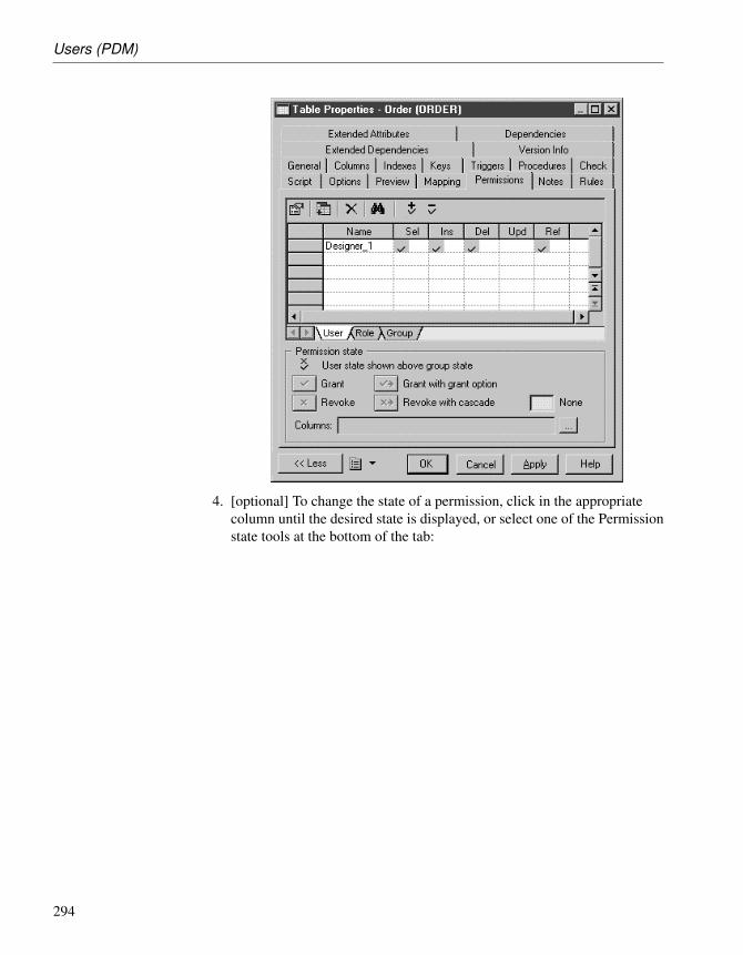
Users (PDM)
4. [optional] To change the state of a permission, click in the appropriatecolumn until the desired state is displayed, or select one of the Permissionstate tools at the bottom of the tab:
294

Chapter 6. Building a Database Access Structure
5. [optional] For tables, you can specify permissions on individual columns(see “Defining column permissions” on page 295).
6. Click OK.
Defining column permissions
You can fine tune the permissions on a table by specifying permissions on acolumn-by-column basis. The available column permissions are specified inthe DBMS resource file. Note that any new or modified permission may notbe supported during generation or reverse-engineering.
295

Users (PDM)
v To define column permissions
1. Open the property sheet of a table, click the Permissions tab, and select auser, group or role:
2. Click the Ellipsis button beside the Columns box to open the ColumnPermissions dialog box. The columns in the list show the permissionsavailable for each of the table’s columns.
296

Chapter 6. Building a Database Access Structure
3. Click inside a column cell until the desired state is displayed, or selectone of the Permission state tools at the bottom of the tab.
4. Click OK to close the Column Permissions dialog box and return to theproperty sheet. The cells corresponding to selected column permissionscontain ellipsis symbols. Click on one of these symbols to display theassociated column permissions information in the Columns box.
5. Click OK.
297

Roles (PDM)
Roles (PDM)A role is a predefined profile that can be assigned to users, or roles in thoseDBMS that support this concept. Roles are reverse engineered in your modeland you can also create user-defined roles.
Roles may have:
♦ privileges that control their level of access (see “Granting systemprivileges” on page 286)
♦ permissions that allow them to perform actions on objects (see “Grantingobject permissions” on page 290)
Creating a role
You can create a role in any of the following ways:
♦ Select Model ä Users and Roles ä Roles to access the List of Roles, andclick the Add a Row tool.
♦ Right-click the model or package in the Browser, and select New ä Role.
+ For general information about creating objects, see the Objects CoreFeatures Guide .
Role properties
You can modify an object’s properties from its property sheet. To open a roleproperty sheet, double-click its Browser entry in the Roles folder. Thefollowing sections detail the property sheet tabs that contain the propertiesmost commonly entered for roles.
The General tab contains the following properties:
Property Description
Name Name of the role
Code Code of the role used as identifier in the database
Comment Descriptive label for the role
Stereotype Sub-classification used to extend the semantics of an objectwithout changing its structure; it can be predefined or user-defined
The following tabs are also available:
♦ Privileges - lists the system privileges granted to the role (see “Grantingsystem privileges” on page 286).
298

Chapter 6. Building a Database Access Structure
♦ Permissions - lists the operations that the role is permitted to perform onvarious database objects (see “Granting object permissions” onpage 290).
Assigning a user to a role
Once you have created a role, you can assign users to it.
v To assign a role to a user
1. Select Model ä Users and Roles ä Roles to open the List of Roles.
2. Select a role in the list, click the Properties tool to open its property sheetand then click the Users tab.
3. Click the Add Objects tool to open a selection box listing the usersavailable in the model.
4. Select one or more users and click OK to assign these users to the role.
5. Click OK.
299
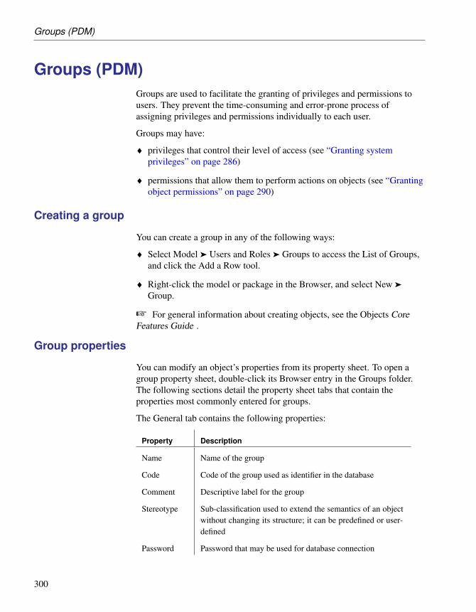
Groups (PDM)
Groups (PDM)Groups are used to facilitate the granting of privileges and permissions tousers. They prevent the time-consuming and error-prone process ofassigning privileges and permissions individually to each user.
Groups may have:
♦ privileges that control their level of access (see “Granting systemprivileges” on page 286)
♦ permissions that allow them to perform actions on objects (see “Grantingobject permissions” on page 290)
Creating a group
You can create a group in any of the following ways:
♦ Select Model ä Users and Roles ä Groups to access the List of Groups,and click the Add a Row tool.
♦ Right-click the model or package in the Browser, and select New ä
Group.
+ For general information about creating objects, see the Objects CoreFeatures Guide .
Group properties
You can modify an object’s properties from its property sheet. To open agroup property sheet, double-click its Browser entry in the Groups folder.The following sections detail the property sheet tabs that contain theproperties most commonly entered for groups.
The General tab contains the following properties:
Property Description
Name Name of the group
Code Code of the group used as identifier in the database
Comment Descriptive label for the group
Stereotype Sub-classification used to extend the semantics of an objectwithout changing its structure; it can be predefined or user-defined
Password Password that may be used for database connection
300

Chapter 6. Building a Database Access Structure
The following tabs are also available:
♦ Privileges - lists the system privileges granted to the group (see “Grantingsystem privileges” on page 286).
♦ Permissions - lists the operations that the group is permitted to performon various database objects (see “Granting object permissions” onpage 290).
Inserting a user into a group
Once you have created a group, you can insert users into it.
v To insert a user into a group
1. Select Model ä Users and Roles ä Groups to open the List of Groups.
2. Select a group in the list, click the Properties tool to open its propertysheet and then click the Users tab.
3. Click the Add Objects tool to open a selection box listing the usersavailable in the model.
4. Select one or more users and click OK to insert these users into the group.
5. Click OK.
301

Synonyms (PDM)
Synonyms (PDM)A synonym is an alternative name for various types of objects (table, view,sequence, procedure, function, synonym or database package). Synonymsare created to:
♦ Mask the name and owner of an object
♦ Provide location transparency for remote objects of a distributed database
♦ Simplify SQL statements for database users
Example For example, table SALES_DATA is owned by user JWARD. A standardselect statement on this table would be:
SELECT * FROM jward.sales_data
The database administrator can create a synonym for this table and ownerand call it SALES. In this case, the SQL statement is simplified in thefollowing way:
SELECT * FROM sales
In PowerDesigner synonyms are created for base objects. The base object isthe object used to create a synonym. Base objects support multiplesynonyms while each synonym must have only one base object. You canview the synonyms depending on a base object in the Dependencies tab ofthe base object property sheet.
If you delete the base object of a synonym, the synonym is deleted as well.
Creating a synonym
You can create a synonym as follows:
302

Chapter 6. Building a Database Access Structure
v To create a synonym
1. Select Model ä Synonyms to open the List of Synonyms.
2. Click the Create Synonyms tool to open a selection box listing all theavailable objects in the model on various sub-tabs.
3. Select one or more objects and click OK.
Synonyms for each of the selected objects are created in the List ofSynonyms. By default, a synonym has the same name as its base object.If the Base Object column is not shown in the list, click the CustomizeColumns and Filter tool, select Base Object in the list of availablecolumns, and click OK.
303

Synonyms (PDM)
4. Click in the Name column of one of the rows and enter a new name forthe synonym. Alternatively, you can click the Properties tool to open theproperty sheet of the synonym and edit its name and other propertiesthere.
5. Click OK in each of the dialog boxes.
+ For general information about creating objects, see the Objects CoreFeatures Guide .
Synonym properties
You can modify an object’s properties from its property sheet. To open asynonym property sheet, double-click its Browser entry in the Synonymsfolder.
The General tab contains the following properties:
Property Description
Name Name of the synonym (usually corresponding to a simplifiedname of the base object)
Code Code of the synonym
Comment Additional information about the synonym
304

Chapter 6. Building a Database Access Structure
Property Description
Stereotype Sub-classification used to extend the semantics of an objectwithout changing its structure; it can be predefined or user-defined
Owner Name of the synonym owner. You choose an owner from alist of users. A synonym can only have one owner at a time
Base Object Name of the object origin of the synonym. The Ellipsis but-ton displays a selection dialog box that lets you select objectsamong all the models opened in the current workspace andbelonging to the same DBMS family as the current DBMS
Visibility Allows to define a synonym as public (accessible to alldatabase users) or private (available to a specific user)
Type For those DBMS that support it (for example DB2) you cancreate an alias instead of a synonym. In PowerDesignersynonyms and aliases are managed in the same way whereastheir behavior in the database may be different
+ For more information on aliases, see the DB2 documentation.
Creating a view for a synonym
You can create views for synonyms in the same way as you create views fortables. The view query displays the content of the object used for thesynonym. For example, the ORDERS_PROD_DEPT table has a synonymORDERS:
If you create a view for the ORDERS synonym, the view query displays theselect order of the table content:
305

Synonyms (PDM)
v To create a view from a synonym
1. Ensure that no objects are selected in the diagram and select Tools ä
Create View to open a selection box listing all the available objects in themodel.
2. Click the Synonyms tab and select one or more synonyms to add to theview.
3. Click OK. The view is created in the diagram.
+ For more information about creating views, see “Views (PDM)” in theBuilding Physical Diagrams chapter.
Generating synonyms
You can generate synonyms from the Database Generation dialog box. Formore information, see “Generating a Database” section in the “Generating aDatabase from a PDM” chapter.
Reverse engineering synonyms
PowerDesigner supports the reverse engineering of synonyms.
When you reverse engineer synonyms, the link with the base object ispreserved if both objects are reverse engineered and if the base object isdisplayed before the synonym in the script.
You can reverse a synonym without its base object; in this case you shouldnot forget to define a base object for the synonym.
306

Chapter 6. Building a Database Access Structure
For more information about reverse engineering, see the ReverseEngineering a Database into a PDM chapter.
307


CHAPTER 7
Building Web Services
About this chapter This chapter describes how to create, generate and reverse engineer webservices in the following databases:
♦ Sybase Adaptive Server Anywhere 9 and over
♦ Sybase Adaptive Server Enterprise 15 and over
♦ Sybase IQ12.6 and over
♦ IBM DB2 v8.1 and over
Contents Topic: page
Introducing Web Services 310
Web Services (PDM) 311
Web Operations (PDM) 316
Web Parameters (PDM) 321
Testing Web Services 323
Generating Web Services 324
Reverse Engineering Web Services 328
309

Introducing Web Services
Introducing Web ServicesWeb services are applications stored on web servers that you can accessremotely through standard web protocols (HTTP, SOAP) and data formats(HTML, XML. . . ), whatever the systems and programming languages.
In SOAP requests, queries are encapsulated into services, whereas in HTTPrequests, operations are invoked directly. In PowerDesigner, you can designweb services for both protocols.
PowerDesigner supports web services for the following databases:
♦ Sybase Adaptive Server Anywhere 9 and over
♦ Sybase Adaptive Server Enterprise 15 and over
♦ Sybase IQ12.6 and over
♦ IBM DB2 v8.1 and over
Web services can be used to simplify access to databases. If you use webservices to query databases, you no longer need drivers to communicate withthose databases.
In the following example, you can see the result of an HTTP request for adatabase web service:
Web services are made of a set of operations. Each operation contains a SQLquery for retrieving data from a database.
310

Chapter 7. Building Web Services
Web Services (PDM)In PowerDesigner, web services are made of web operations whichthemselves contain web parameters and result columns:
♦ Web operations specify the SQL statements used to retrieve data fromdatabases
♦ Web parameters are the parameters which appear in the SQL statements
♦ Result columns are the columns in which the results are displayed
These objects have no symbols, but they appear in the Browser tree view.
This structure is compatible with the definition of web services in thesupported databases.
Import Web service asservice provider
You can import a web service as a service provider into a Business ProcessModel (BPM) to define the links between a concrete implementation ofservice interfaces and operations and their abstract definition.
+ For more information, see “Importing a service provider from an OOMor a PDM” in the Building Business Process Diagrams chapter of theBusiness Processs Modeling guide.
Web services in Sybase ASA, ASE, and IQ
PowerDesigner supports web services for ASA 9 and over, ASE 15 and overand IQ 12.6 and over. You must specify the type of the web service in theService type list on the General tab of its property sheet (see “Web serviceproperties” on page 313).
Web services can be invoked by either of two protocols:
♦ A web service invoked via an HTTP request can have a RAW, HTML orXML type.
When several web services concern the same table in a database, theirname usually starts with the name of the table, followed by a slash and a
311

Web Services (PDM)
specific name identifying the query (e.g. Customer/List,Customer/Name). In that case, the name of the table is called the localpath (which is defined on the General tab of the web service propertysheet).
PowerDesigner treats HTTP web operations which share a local path asbelonging to the web service with that local path name.
♦ [ASA and IQ only] A web service invoked in a SOAP request can have aSOAP or a DISH type.
PowerDesigner treats SOAP web services for these databases as weboperations belonging to a DISH web service.
Implementation (SQLstatement)
When you create a web service, you must type a SQL statement to selectwhich data you want to retrieve from the database in the Implementationtab of the property sheet of its web operation(s). For DISH web services,SQL statements are defined in the SOAP web services bearing their prefixname.
Web services in IBM DB2
PowerDesigner supports web services for IBM DB2 v8.1 and over.
In IBM DB2, web services are defined by Document Access DefinitionExtension (DADX) files.
+ For more information about generating DADX files, see “Generatingweb services for IBM DB2 v8.1” on page 324.
A DADX file specifies a web service through a set of operations defined bySQL statements or Document Access Definition (DAD) files, which specifythe mapping between XML elements and DB2 tables.
+ For more information on DAD files, see “Generating a DAD file forIBM DB2”, in the Exchanging Data with Databases Supporting XML”chapter of the XML Modeling guide.
Creating a web service
You can create a web service in any of the following ways:
♦ Select Model ä Web Services to access the List of Web Services, andclick the Add a Row tool.
♦ Right-click the model or package in the Browser, and select New ä WebService.
+ For general information about creating objects, see the Objects CoreFeatures Guide .
312

Chapter 7. Building Web Services
Web service properties
You can modify an object’s properties from its property sheet. To open aweb service property sheet, double-click its Browser entry in the WebServices folder. The following sections detail the property sheet tabs thatcontain the properties most commonly entered for web services.
The General tab contains the following properties:
Property Description
Name Name of the web service. Used in URIs to access the webservice. It can neither start with a slash nor contain twoconsecutive slashes
Code Code of the web service
Comment Descriptive label for the web service
Stereotype Sub-classification used to extend the semantics of an objectwithout changing its structure; it can be predefined oruser-defined
Local path Name prefixing the web service. If you type a path, theUser-Defined tool (beside the Local path box) is pushed-in.Click the User-Defined tool to recover the original path.The default value is the name of the web service
313

Web Services (PDM)
Property Description
Service type [ASA, ASE, and IQ only] Specifies the type of web service.You can choose from:♦ DISH - [ASA and IQ only] acts as a proxy for a group
of SOAP services and generates a WSDL (Web Ser-vices Description Language) file for each of its SOAPservices. When you create a DISH service, you mustspecify a prefix name (on the Extended Attributes tab)for all the SOAP services to which the DISH service ap-plies. PowerDesigner treats SOAP web services as Weboperations (see “Web Operations (PDM)” on page 316)of DISH web services.
♦ HTML – [ASA and IQ only] the result of the SQL state-ment or procedure is formatted as an HTML document(with a table containing rows and columns).
♦ RAW - the result of the SQL statement or procedure issent without any additional formatting.
♦ SOAP - [ASE only] generates a WSDL (Web ServicesDescription Language) file.
♦ XML - the result of the SQL statement or procedureis sent in XML. By default, the result is converted intoXML RAW format.
Web service property sheet Operations tab
This tab lists the web operations associated with the web service (see “WebOperations (PDM)” on page 316).
Web service property sheet Sybase tab
Only available with ASA, ASE, and IQ.
This tab displays the following properties:
314

Chapter 7. Building Web Services
Property Description
Port number Specifies the port number for the test URL.
Server name Specifies the server name for the test URL.
Name prefix(dish servicesonly)
[ASA and IQ only] Specifies the name prefix for DISHservices.
Database name [ASE only] Specifies the database name for the test URL.
Web service property sheet Security tab
Only available with ASA and IQ.
This tab displays the following properties:
Property Description
Secured con-nection
If selected, only HTTPS connections are accepted. Ifcleared, both HTTP and HTTPS connections are accepted
Required au-thorization
If selected, all users must provide a name and a password.When cleared, a single user must be identified
ConnectionUser
When authorization is required, you can select <None> ora list of user names. When authorization is not required,you must select a user name. Default value is <None>,which means all users are granted access
Web service property sheet Namespaces tab
Only available with IBM DB2.
This tab displays a list of namespaces with their prefix, URI and comment.
An XML Schema can be specified where elements and data types used inweb parameters and result columns are defined.
315

Web Operations (PDM)
Web Operations (PDM)A web operation is a child object of a web service. It allows you to definethe SQL statement of a web service and to display its parameters and resultcolumns.
Creating a web operation
You can create a web operation as follows:
♦ Open the Operations tab in the property sheet of a web service, and clickthe Add a Row tool.
+ For general information about creating objects, see the Objects CoreFeatures Guide .
Web operation properties
You can modify an object’s properties from its property sheet. To open aweb operation property sheet, double-click its Browser entry in theOperations folder beneath the parent web service. The following sectionsdetail the property sheet tabs that contain the properties most commonlyentered for web operations.
The General tab contains the following properties:
Property Description
Name Name of the web operation. In URIs, it comes after the nameof the web service followed by a slash. It can neither start witha slash nor contain two consecutive slashes
Code Code of the web operation
Comment Descriptive label for the web operation
Stereotype Sub-classification used to extend the semantics of an objectwithout changing its structure; it can be predefined or user-defined
Web Ser-vice
Code of the web service containing the web operation. Youcan click the Properties tool (beside the web Service box) todisplay the web service property sheet
Owner [ASE 15 only] Specifies the owner of the operation.
316

Chapter 7. Building Web Services
Property Description
OperationType
[IBM DB2 only] Specifies the type of operation. You canchoose from the following:♦ call - invokes a stored procedure with parameters and result
columns for the web operation
♦ query - retrieves relational data using the SQL select state-ment in the Implementation tab
♦ retrieveXML - retrieves an XML document from relationaldata. The mapping of relational data to XML data is definedby a DAD file with SQL or RDB as MappingType
♦ storeXML - stores an XML document as relational data.The mapping of XML data to relational data is defined by aDAD file, with RDB as MappingType
♦ update - executes the SQL update statement with optionalparameters. Parameters can be created from the Parameterstab in the web operation property sheet
Web operation property sheet Parameters tab
This tab lists the web parameters associated with the web operation. Theseparameters are part of the SQL statement defined on the Implementation tab.They can be created on this tab, before generating a web service, or reverseengineered from a web service (ASA, ASE, and IQ only).
You can use the following tools to add parameters on this tab:
Tool Name Description
Add a Row Adds a parameter to the end of the list.
Insert a Row Inserts a parameter above the current line inthe list.
Add Parametersfrom SQL Imple-mentation
[ASA, ASE, and IQ only] Display the param-eters resulting from the reverse engineering ofthe web service .
Web operation property sheet Implementation tab
This tab displays the SQL statement for the web service. You can use thefollowing tools to type the SQL statement:
317

Web Operations (PDM)
Tool Name Description
Operators Provides logical operators
Functions Provides group, number, string, date, conversionand other functions
Macros Provides macros to accelerate the creation of a SQLstatement
Variables Provides variables for use with operators andfunctions
Edit withSQL Editor
Opens the SQL Editor dialog box. Provides objecttypes and available objects to insert in the SQLstatement
SQL/XMLWizard
Opens the SQL/XML Wizard to build a SQL/XMLquery from a table or a view, and insert it in theSQL statement
InsertSQL/XMLMacro
Opens a dialog box to select a global element inan XML model open in the workspace with theSQL/XML extended model definition. Inserts aSQLXML macro referencing the selected elementin the SQL statement
For example:
318

Chapter 7. Building Web Services
Web operation property sheet Result Columns tab
This tab lists the result columns associated with the web operation (see“Web Operation Result Columns” on page 320).
You can use the following tools to add result columns on this tab:
Tool Name Description
Add a Row Adds a result column to the end of the list.
Insert a Row Inserts a result column above the current linein the list.
Add Result Columnsfrom Executing SQLStatement
Display the result columns resulting fromthe execution of the SQL statement in thedatabase.
Web operation property sheet Security tab
Only available with ASA, and IQ.
This tab displays the following properties:
Property Description
Secured con-nection
If selected, only HTTPS connections are accepted. If cleared,both HTTP and HTTPS connections are accepted
Required au-thorization
If selected, all users must provide a name and a password.When cleared, a single user must be identified
ConnectionUser
When authorization is required, you can select <None> or alist of user names. When authorization is not required, youmust select a user name. Default value is <None>, whichmeans all users are granted access
Web operation property sheet Sybase tab
Only available with ASE.
This tab displays the following properties:
319

Web Operations (PDM)
Property Description
Alias Specifies the user-defined database alias.
Secure Specifies the form of security. You can choose between:♦ Clear – Use standard HTTP
♦ SSL – Use HTTPS
Web Operation Result Columns
Result columns are sub-objects of web operations. They are part of the SQLstatement defined in the Implementation tab of a web operation propertysheet, and belong to a table in the target database. They are listed in theResult Columns tab of a web operation property sheet.
The General tab of a result column property sheet displays the followingproperties:
Property Description
Name Name of the result column
Code Code of the result column
Comment Descriptive label for the result column
Data Type [IBM DB2 only] Select an XML schema data type from thelist, or click the Select Object tool to open a selection dialogbox where you select a global element in an XML model openin the workspace
Is element [IBM DB2 only] Checked and greyed when a global element isattached to a result column
320

Chapter 7. Building Web Services
Web Parameters (PDM)Web parameters are child objects of web operations. They are part of theSQL statement defined in the Implementation tab of a web operationproperty sheet. They are listed in the Parameters tab of a web operationproperty sheet.
Creating a web parameter
You can create a web parameter in any of the following ways:
♦ Open the Parameters tab in the property sheet of a web operation, andclick the Add a Row tool.
♦ Right-click a web operation in the Browser, and select New ä WebParameter.
+ For general information about creating objects, see the Objects CoreFeatures Guide .
Web parameter properties
You can modify an object’s properties from its property sheet. To open aweb parameter property sheet, double-click its Browser entry in theParameters folder beneath its parent web operation.
The General tab contains the following properties:
Property Description
Name Name of the web parameter.
Code Code of the web parameter.
Comment Descriptive label for the web parameter.
Stereotype Sub-classification used to extend the semantics of an objectwithout changing its structure; it can be predefined or user-defined.
Web Oper-ation
Name of the web operation containing the web parameter.
ParameterType
Select in if you want the web parameter to be an input param-eter. Select in/out if you want the web parameter to be bothan input and output parameter. Select out if you want the webparameter to be an output parameter.
321

Web Parameters (PDM)
Property Description
DefaultValue
[ASE only] Specifies a default value for the parameter.
Data Type [For IBM DB2] Select an XML schema data type from the list,or click the Select Object tool to open a selection dialog boxwhere you select a global element in an XML model open inthe workspace.
[For ASE] Select a datatype from the list.
Is element [IBM DB2 only] Checked and greyed when a global element isattached to a web parameter.
322

Chapter 7. Building Web Services
Testing Web ServicesPowerDesigner provides a method for testing web services within the modelenvironment. You must be connected to the appropriate database.
v To test a web service
1. Right-click the browser entry for a web service of type DISH or SOAPand select Show WSDL
or
Right-click the browser entry for a web service operation belonging to aweb service of another type and select Test Web Service Operation fromthe contextual menu.
2. Review the generated URL and then click OK.
For a web service of type SOAP, the WSDL file will be displayed in yourbrowser
or
For a web service of type RAW, the result will be displayed in yourbrowser
323

Generating Web Services
Generating Web ServicesYou generate web services in order to implement them on target databases.
Generating web services for Sybase ASA, ASE, and IQ
You can generate database web services to a script or to a live databaseconnection.
v To generate web services for Sybase ASA, ASE, and IQ
1. Select Database ä Generate Database to open the Database Generationwindow, and specify the standard options, including whether you want togenerate to a script or to a live database connection.
+ For detailed information about using this window, see “Generating aDatabase” section in the “Generating a Database from a PDM” chapter.
2. [optional] Click the Options tab and click on Web Service in the left-handpane to display the web service generation options. Change the defaultoptions as appropriate.
3. [optional] Click the Selection tab and select the Web Services subtab atthe bottom of the tab. Select the web services that you want to generate.
4. Click OK to begin the generation.
Note that for web services generated to a live database connection, you mayhave to refresh the Web Services folder before they appear.
Generating web services for IBM DB2 v8.1
In IBM DB2, web services are defined by Document Access DefinitionExtension (DADX) files.
A PDM with the appropriate extended model definition allows you togenerate a DADX file for each web service defined for IBM DB2.
You can attach the DADX extended model definition at model creation. Inthe New dialog box, once you have selected Physical Data Model in theModel type list, and IBM DB2 UDB 8.x Common Server in the DBMS list,click the Extended Model Definitions tab and select DADX.
v To generate DADX files for IBM DB2
1. Select Model ä Extended Model Definitions to open the List of ExtendedModel Definitions.
324

Chapter 7. Building Web Services
2. Click the Import an Extended Model Definition tool to open theExtended Model Definition Selection dialog box, select DADX in the listof extended model definitions and click OK.
DADX is displayed in the List of Extended Model Definitions.
3. Click OK to return to the main window.
4. Select Tools ä Extended Generation to open the Generation dialog boxwith DADX selected in the Targets tab.
5. Click the Select a Path button, to the right of the Directory box, andspecify a path for the DADX files.
6. Click the Selection tab, and select the web services for which you want togenerate a DADX file.
325

Generating Web Services
7. Click OK to begin generation.
When generation is complete, the Result dialog box will be displayedwith the paths of the DADX files.
8. Select the path of a DADX file and click Edit.
The DADX file is displayed in the editor window.
326

Chapter 7. Building Web Services
9. Click Close in the Result dialog box.
You can now use the DADX files for SOAP requests in IBM DB2 UDB webservices Object Runtime Framework (WORF).
327

Reverse Engineering Web Services
Reverse Engineering Web ServicesYou reverse engineer web services from a database to a PDM, when youwant to reuse these web services in the PDM. Once reverse engineered, youcan modify and generate them in the database.
You can only reverse engineer web services from Sybase ASA, ASE, and IQ.
You can reverse engineer web services into a new or existing PDM from ascript or live database connection via the Database Reverse Engineeringdialog box.
+ For information about using the Database Reverse Engineering dialogbox, see the “Reverse Engineering a Database into a PDM” chapter.
The following list shows how web service objects in these databases aretreated in PowerDesigner:
♦ Database HTTP web services with a common local path are grouped asPowerDesigner web operations of an HTTP web service with thespecified local path:
Software Web servicename
Type Web operationname
Database Customers/Name HTML —
PowerDesigner Customers HTML Name
♦ Database HTTP web services without a common local path are groupedas PowerDesigner web operations of an HTTP web service named raw,xml or html:
Software Web servicename
Type Web operationname
Database Customers HTML —
PowerDesigner html HTML Customers
♦ Database SOAP web services with a prefix name are considered asPowerDesigner web operations of a DISH web service with the prefixname:
328

Chapter 7. Building Web Services
Software Web servicename
Type Web operationname
Database DishPrefix/Name SOAP —
PowerDesigner Customers (withDishPrefix as pre-fix)
DISH Name
♦ Database SOAP web services without a prefix name are considered asPowerDesigner web operations of a DISH web service without a prefixname:
Software Web servicename
Type Web operationname
Database Customers SOAP —
PowerDesigner WEBSERVICE_1 DISH Customers
♦ Database DISH web services with or without a prefix name areconsidered identically in PowerDesigner:
Software Web servicename
Type Web operationname
Database Customers DISH —
PowerDesigner Customers (withor without Dish-Prefix as prefix)
DISH —
329


CHAPTER 8
Working with Data Models
About this chapter This chapter describes how to work with data models.
Contents Topic: page
Customizing the Data Modeling Environment 332
Generating Other Models from a Data Model 370
Checking a Data Model 381
Working with SQL 426
331

Customizing the Data Modeling Environment
Customizing the Data Modeling EnvironmentThe PowerDesigner data modeling environment includes a set of parametersand configuration options that define various aspects of the model contentand behavior. You can set these parameters:
♦ At model creation
♦ After creating a model with default options and parameters
♦ When creating a model template
Setting CDM/LDM model options
This section explains how to set global options for the objects in yourCDM/LDM. These options apply only to the current CDM/LDM.
For information about controlling the naming conventions of your models,see “Naming Conventions” section in the Models chapter of the CoreFeatures Guide .
Setting Model Settings
To set Model Settings, select Tools ä Model Options or right-click thediagram background and select Model Options from the contextual menu.
332

Chapter 8. Working with Data Models
The options on this tab affect all the objects in the model, including thosealready created, while changes to the object-specific options on thesub-category tabs only affect objects created subsequently.
You can set the following options on this tab:
Option Description
Name/Codecase sensi-tive
Specifies that the names and codes for all objects are casesensitive, allowing you to have two objects with identicalnames or codes but different cases in the same model.
If you change case sensitivity during the design process,we recommend that you check your model (Tools ä CheckModel) to verify that your model does not contain anyduplicate objects.
Enable linksto require-ments
Displays a Requirements tab in the property sheet of everyobject in the model, which allows you to attach requirementsto objects in your model. These attached requirements arekept synchronized with your requirements model.
For more information, see the Requirements Modeling guide.
Enforce non-divergence
Enforces non-divergence between a domain definition and theattributes using the domain. You can select any or all of thefollowing attribute properties:♦ Data type - Data type, length, and precision
♦ Check - Check parameters, such as minimum and maxi-mum
♦ Rules - Business rules
♦ Mandatory - Attribute mandatory propertyWhen you apply these options, you are asked if you want toapply domain properties to attributes currently attached to thedomain. If you click OK, the attribute properties are modifiedfor consistency with the domain.
When you modify the properties of a domain, the propertiesof the attributes attached to it are updated provided they areselected here.
When you select an attribute property under Enforce non-divergence, that property cannot be modified in the lists ofattributes and the property sheets of attributes.
If you want to modify an attribute property that is defined asnon-divergent, you must detach the attribute from its domain,or clear the appropriate Enforce non-divergence model option.
333

Customizing the Data Modeling Environment
Option Description
Use datatype fullname
Specifies that the complete data type is displayed in entitysymbols.
Default datatype
Specifies a default data type to apply to domains and attributesif none is selected for them.
Notation You can choose between the following notations:♦ Entity / Relationship [Default – used throughout this man-
ual] Entity/relationship notation connects entities withlinks representing one of four relationships between them.These relationships have properties that apply to both en-tities involved in the relationship
♦ Merise - uses associations instead of relationships
♦ E/R + Merise - both entity/relationship and Merise areused in the same model
♦ IDEF1X - data modeling notation for relationships and en-tities. In this notation, each set of relationship symbols de-scribes a combination of the optionality and cardinality ofthe entity next to it
♦ Barker – inheritances are represented by placing the childentities inside the parent entity symbol, and relationshipsare drawn in two parts, each reflecting the multiplicity ofthe associated entity role.
For more information about these notations, see “SupportedCDM/LDM notations” on page 361
Unique code Requires that data items or relationships have unique codes
Allow n-nrelationships
[LDM only] Allows n-n relationships to be displayed.
334

Chapter 8. Working with Data Models
Option Description
Allow reuse Allows the reuse of one data item as an attribute for morethan one entity provided the attributes have same name anddata type and do not belong to a primary key.
When deselected or when the attribute belongs to a primarykey, the data item cannot be reused. In this case, if the Uniquecode check box is selected, a new data item with identicalname but different code is created, otherwise a new data itemwith identical name and code is created.
When you delete an entity or entity attributes, these optionsdetermine whether or not the corresponding data items arealso deleted, as follows:♦ Both – deletes the entity attribute.
♦ Unique Code only – deletes the entity attribute.
♦ Allow Reuse only – deletes the entity attribute and the cor-responding data item (if it is not used by another entity).
♦ None – deletes the entity attribute and the correspondingdata item.
Setting Migration Settings (LDM only)
To set migration settings, select Tools ä Model Options, and select theMigration settings sub-category in the left-hand Category pane.
Option Description
Migrate at-tribute prop-erties
Enables the domain, the checks or the rules to be kept whenan attribute is migrated.
335

Customizing the Data Modeling Environment
Option Description
Foreign at-tribute name
Specifies the naming convention for migrated foreign iden-tifiers. You can select one of the default templates from thelist or enter your own using the following variables:♦ %PARENT% - Name/Code of the parent entity
♦ %ATTRIBUTE% - Name/Code of the parent attribute
♦ %IDENTIFIER% - Name/Code of the identifier con-straint attached to the relationship
♦ %RELATIONSHIP% - Name/Code of the relationship
♦ %PARENTROLE% - Role of the entity that generated theparent entity, this variable proceeds from the conceptualenvironment. If no role is defined on the relationship,%PARENTROLE% takes the content of %PARENT% toavoid generating an attribute with no name
The following example checks the %PARENTROLE%value; if it is equal to the parent name (which isthe replacement value) then the template “%.3:PAR-ENT%_%ATTRIBUTE%” will be used, otherwise template“%PARENTROLE% will be used because the user hasentered a parent role for the relationship:
Note that customized naming templates reappear in thegeneration dialog box the next time you open it, but are notsaved to the list of predefined templates.
Use template Controls when the primary identifier attribute name templatewill be used. You can choose between the following radiobuttons:♦ Always use template.
♦ Only use template in case of conflict.
These options are available for relationships and automatic for inheritances,except the Only use template in case of conflict option, which is alwaystriggered.
Setting PDM Model Options
This section explains how to set global options for the objects in your PDM.For information about controlling the naming conventions of your models,see “Naming Conventions” in the Models chapter of the Core FeaturesGuide .
336

Chapter 8. Working with Data Models
Setting Model Settings
To set Model Settings, select Tools ä Model Options or right-click thediagram background and select Model Options from the contextual menu.
The options on this tab affect all the objects in the model, including thosealready created, while changes to the object-specific options on thesub-category tabs only affect objects created subsequently.
You can set the following options on this tab:
Option Function
Name/Codecase sensitive
Specifies that the names and codes for all objects are casesensitive, allowing you to have two objects with identicalnames or codes but different cases in the same model.
If you change case sensitivity during the design process,we recommend that you check your model (Tools ä CheckModel) to verify that your model does not contain anyduplicate objects.
337

Customizing the Data Modeling Environment
Option Function
Enable links torequirements
Displays a Requirements tab in the property sheet ofevery object in the model, which allows you to attachrequirements to objects in your model. These attachedrequirements are kept synchronized with your requirementsmodel.
For more information about requirements, see the Require-ments Modeling guide.
Notation Specifies the use of one of the following notation types forthe model. You can choose between:♦ Relational - Arrow pointing to primary key. This option
is the default, and is used in this manual.
♦ CODASYL - Arrow pointing to foreign key.
♦ Conceptual - Cardinality displayed in IE format (crow’sfeet).
♦ IDEF1X - Cardinality and mandatory status displayedon reference, primary columns in separate containersand dependent tables with rounded rectangles.
When you change notation, all symbols in all diagramsare updated accordingly. If you switch from Merise toIDEF1X, all associations are converted to relationships.
Table and view model options
To set model options for tables and views, select Tools ä Model Options,and select the Table & View sub-category in the left-hand Category pane.
338

Chapter 8. Working with Data Models
339
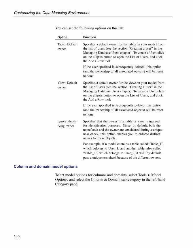
Customizing the Data Modeling Environment
You can set the following options on this tab:
Option Function
Table: Defaultowner
Specifies a default owner for the tables in your model fromthe list of users (see the section “Creating a user” in theManaging Database Users chapter). To create a User, clickon the ellipsis button to open the List of Users, and clickthe Add a Row tool.
If the user specified is subsequently deleted, this option(and the ownership of all associated objects) will be resetto none.
View: Defaultowner
Specifies a default owner for the views in your model fromthe list of users (see the section “Creating a user” in theManaging Database Users chapter). To create a User, clickon the ellipsis button to open the List of Users, and clickthe Add a Row tool.
If the user specified is subsequently deleted, this option(and the ownership of all associated objects) will be resetto none.
Ignore identi-fying owner
Specifies that the owner of a table or view is ignoredfor identification purposes. Since, by default, both thename/code and the owner are considered during a unique-ness check, this option enables you to enforce distinctnames for these objects.
For example, if a model contains a table called “Table_1”,which belongs to User_1, and another table, also called“Table_1”, which belongs to User_2, it will, by default,pass a uniqueness check because of the different owners.
Column and domain model options
To set model options for columns and domains, select Tools ä ModelOptions, and select the Column & Domain sub-category in the left-handCategory pane.
340

Chapter 8. Working with Data Models
You can set the following options on this tab:
Option Function
Enforce non-divergence
Specifies that columns attached to a domain must remainsynchronized with the selected properties, any or all of:Data type, Check, Rules, Mandatory, and Profile.
Default datatype
Specifies a default data type to be applied to columns anddomains.
Column:Mandatory bydefault
Specifies that columns are created, by default, as manda-tory.
Domain:Mandatory bydefault
Specifies that domains are created, by default, as manda-tory.
Reference model options
To set model options for references, select Tools ä Model Options, andselect the Reference sub-category in the left-hand Category pane.
341

Customizing the Data Modeling Environment
You can set the following options on this tab:
Option Function
Unique code Requires that references have unique codes. If this optionis not selected then different references can have the samecode (except when two references share the same childtable).
Auto-reusecolumns
Enables the reuse of columns in a child table as foreign keycolumns if the following conditions are satisfied:♦ Child column has same code as migrating primary key
column
♦ Child column is not already a foreign key column
♦ Data types are compatibleFor more information, see “Automatic reuse and migrationof columns” in the Building Physical Diagrams chapter.
342

Chapter 8. Working with Data Models
Option Function
Auto-migratecolumns
Enables the automatic migration of primary key columnsfrom the parent table as foreign key columns to the childtable. If you select both Auto-migrate columns and anyof the following sub-options, then the relevant columnproperty of the PK will also be migrated to the FK atreference creation:♦ Domain
♦ Check
♦ Rules
♦ Last positionFor more information, see “Automatic reuse and migrationof columns” in the Building Physical Diagrams chapter.
Mandatoryparent
Specifies that the relationship between child and parenttables is, by default, mandatory, i.e., each foreign key valuein the child table must have a corresponding key value, inthe parent table.
Change parentallowed
Specifies that a foreign key value can change to selectanother value in the referenced key in the parent table.
Check on com-mit
Specifies that referential integrity is checked only on com-mit, rather than immediately after row insertion. Thisfeature can be useful when working with circular depen-dencies. Not available with all DBMSs.
Propagate col-umn properties
Propagates changes made to the name, code, stereotype,or data type of a parent table column to the correspondingchild column.
Default link oncreation
Specifies how reference links are created. You can selecteither:♦ Primary key – automatically create links from primary
key to foreign key columns at creation
♦ User-defined – manually create your own links
343

Customizing the Data Modeling Environment
Option Function
Default imple-mentation
Specifies how referential integrity is implemented in thereference. You can select either:♦ Declarative – referential integrity is defined by con-
straint in foreign declarations
♦ Trigger – referential integrity is implemented by triggersFor more information on referential integrity, see “Refer-ence property sheet Integrity tab” in the Building PhysicalDiagrams chapter.
Default Con-straints: Up-date
Controls how updating a key value in the parent table will,by default, affect the foreign key value in the child table.Depending on your DBMS, you can choose from some orall of the following settings:♦ None – no effect
♦ Restrict – cannot update parent value if one or morematching child values exist (no effect)
♦ Cascade - update matching child values
♦ Set null - set matching child values to NULL
♦ Set default – set matching child values to default value
Default Con-straints: Delete
Controls how deleting a key value in the parent table will,by default, affect the foreign key value in the child table.Depending on your DBMS, you can choose from some orall of the following settings:♦ None – no effect
♦ Restrict – cannot delete parent value if one or morematching child values exist (no effect)
♦ Cascade - delete matching child values
♦ Set null - set matching child values to NULL
♦ Set default – set matching child values to default value
Sequence model options
To set model options for sequences, select Tools ä Model Options, andselect the Sequence sub-category in the left-hand Category pane.
344

Chapter 8. Working with Data Models
You can set the following options on this tab:
Option Function
DefaultOwner
Specifies a default owner for the sequences in your modelfrom the list of users (see the section “Creating a user” in theManaging Database Users chapter). To create a User, clickon the ellipsis button to open the List of Users, and click theAdd a Row tool.
If the user specified is subsequently deleted, this option (andthe ownership of all associated objects) will be reset to none.
Index model options
To set model options for indexes, select Tools ä Model Options, and selectthe Index sub-category in the left-hand Category pane.
You can set the following options on this tab:
Option Function
Table: De-fault Owner
Specifies a default owner for the table indexes in your modelfrom the list of users (see the section “Creating a user” in theManaging Database Users chapter). To create a User, clickon the ellipsis button to open the List of Users, and click theAdd a Row tool.
If no default user is specified here, then the owner of theparent table is used by default.
If the user specified is subsequently deleted, this option (andthe ownership of all associated objects) will be reset to none.
View: De-fault Owner
Specifies a default owner for the view indexes in your modelfrom the list of users (see the section “Creating a user” in theManaging Database Users chapter). To create a User, clickon the ellipsis button to open the List of Users, and click theAdd a Row tool.
If no default user is specified here, then the owner of theparent view is used by default.
If the user specified is subsequently deleted, this option (andthe ownership of all associated objects) will be reset to none.
Join index model options
To set model options for join indexes, select Tools ä Model Options, andselect the Join Index sub-category in the left-hand Category pane.
345

Customizing the Data Modeling Environment
You can set the following options on this tab:
Option Function
Defaultowner
Specifies a default owner for the join indexes in your modelfrom the list of users (see the section “Creating a user” in theManaging Database Users chapter). To create a User, clickon the ellipsis button to open the List of Users, and click theAdd a Row tool.
If the user specified is subsequently deleted, this option (andthe ownership of all associated objects) will be reset to none.
Procedure model options
To set model options for procedures, select Tools ä Model Options, andselect the Procedure sub-category in the left-hand Category pane.
You can set the following options on this tab:
Option Function
Defaultowner
Specifies a default owner for the procedures in your modelfrom the list of users (see the section “Creating a user” in theManaging Database Users chapter). To create a User, clickon the ellipsis button to open the List of Users, and click theAdd a Row tool.
If the user specified is subsequently deleted, this option (andthe ownership of all associated objects) will be reset to none.
Trigger model options
To set model options for triggers, select Tools ä Model Options, and selectthe Trigger sub-category in the left-hand Category pane.
You can set the following options on this tab:
346

Chapter 8. Working with Data Models
Option Function
Option Function
Table: De-fault Owner
Specifies a default owner for the table triggers in your modelfrom the list of users (see the section “Creating a user” in theManaging Database Users chapter). To create a User, clickon the ellipsis button to open the List of Users, and click theAdd a Row tool.
If no default user is specified here, then the owner of theparent table is used by default.
If the user specified is subsequently deleted, this option (andthe ownership of all associated objects) will be reset to none.
View: De-fault Owner
Specifies a default owner for the view triggers in your modelfrom the list of users (see the section “Creating a user” in theManaging Database Users chapter). To create a User, clickon the ellipsis button to open the List of Users, and click theAdd a Row tool.
If no default user is specified here, then the owner of theparent view is used by default.
If the user specified is subsequently deleted, this option (andthe ownership of all associated objects) will be reset to none.
Rebuild au-tomaticallytriggers
Automatically rebuilds the triggers on the child and parenttables of a reference when you:♦ change the implementation of a reference
♦ change the referential integrity rules of a reference imple-mented by a trigger
♦ change the child or parent table of a reference imple-mented by a trigger (new and old)
♦ create or delete a reference implemented by a trigger
♦ change the maximum cardinality of the referencesNote: If this option is not selected, you can manually instructPowerDesigner to rebuild triggers at any time by selectingTools ä Rebuild Objects ä Rebuild Triggers.
Database package model options
To set model options for database packages, select Tools ä Model Options,and select the Database Package sub-category in the left-hand Categorypane.
347

Customizing the Data Modeling Environment
You can set the following options on this tab:
Option Function
Defaultowner
Specifies a default owner for the database packages in yourmodel from the list of users (see the section “Creating auser” in the Managing Database Users chapter). To create aUser, click on the ellipsis button to open the List of Users,and click the Add a Row tool.
If the user specified is subsequently deleted, this option (andthe ownership of all associated objects) will be reset to none.
Setting Data Model Display Preferences
PowerDesigner display preferences allow you to customize the format ofobject symbols, and the information that is displayed on them.
To set a data model display preferences, select Tools ä Display Preferencesor right-click the diagram background and select Display Preferences fromthe contextual menu.
For information about changing the format of symbols, see “Format displaypreferences” in the Customizing your Modeling Environment chapter of theCore Features Guide . The following sections list the options available tocustomize the information displayed on a data model object symbols. Notethat the objects available to be customized in the Display Preferences
348

Chapter 8. Working with Data Models
window are dependant upon the current diagram type.
Default optionsClick the Default button to display default display preferences. Clickthe Set As Default button to set current display preferences as defaultselections.
Association display preferences (CDM)
To set display preferences for associations in a CDM, select Tools ä DisplayPreferences, and select the Association sub-category in the left-handCategory pane.
Association
Preference Display description
Attributes Displays the name of the association.
Display Limit Controls the maximum number of attributes displayed insymbol.
Stereotype Displays the stereotype of the association.
Comment Displays the comment of the association. When selected,all other check boxes are deselected, except for Stereotype.
Association attributes
Preference Display description
Data types Displays the data types of association attributes.
Replace bydomains
Displays the domains of association attributes. You canonly display domains when the Data types check box isselected.
Domains Displays the domain of association attributes. For detailsof how this and the Data types preferences interact, see“Entity display preferences (CDM/LDM)” on page 351.
Mandatory Displays the letter M beside mandatory association at-tributes.
Stereotype Displays the stereotype of association attributes.
Association display preferences (PDM)
To set display preferences for associations in a PDM, select Tools ä DisplayPreferences, and select the Association sub-category in the left-hand
349

Customizing the Data Modeling Environment
Category pane.
Preference Description
Name Displays the name of the association.
Hierarchy Displays the name of the hierarchy used to compute the cube
Stereotype Displays the stereotype of the association.
Association Link display preferences (CDM)
To set display preferences for association links, select Tools ä DisplayPreferences, and select the Association Link sub-category in the left-handCategory pane.
Preference Description
Role Displays the role of the association link
Cardinality Displays the cardinality of the association link
Stereotype Displays the stereotype of the association link
Cube display preferences (PDM)
To set display preferences for cubes, select Tools ä Display Preferences, andselect the Cube sub-category in the left-hand Category pane.
Preference Description
Fact Mea-sures
Displays fact measures. When selected, you can additionallyspecify whether to display all fact measures, or to limit themto a given number.
Fact Displays cube facts.
Stereotype Displays the stereotype of the cub. You can also display thestereotype of the cube measures and facts.
Dimension display preferences (PDM)
To set display preferences for dimensions, select Tools ä DisplayPreferences, and select the Dimension sub-category in the left-handCategory pane.
350

Chapter 8. Working with Data Models
Preference Description
Attributes Displays the dimension attributes. When selected, you canadditionally specify whether to display all attributes, or tolimit them to a given number.
Hierarchies Displays dimension hierarchies. When selected, you canalso specify whether to display <Default> beside the defaulthierarchy in dimension symbols.
Stereotype Displays the stereotypes of dimensions. You can also displaythe stereotype of the dimension attributes and hierarchies.
Dimension Attributes The following display preferences are available for dimension attributes:
Preference Description
Indicators ofHierarchy
Displays the hierarchies indicators of dimension attributes.When selected, you can also specify whether to display thehierarchy level of dimension attributes.
Entity display preferences (CDM/LDM)
To set display preferences for entities, select Tools ä Display Preferences,and select the Entity sub-category in the left-hand Category pane.
Entity
351

Customizing the Data Modeling Environment
Preference Display description
Attributes Specifies whether Attributes are displayed on entity symbols.If selected, you can choose between displaying:♦ All attributes - All attributes:
♦ Primary attributes - Only primary identifier attributes:
♦ Identifying attributes - All identifier attributes:
♦ Display limit - Number of attributes shown depends ondefined value. For example, if set to 5:
Identifiers All identifier attributes for the entityare listed at the bottom of the entity
symbol:
Stereotype Stereotype of the entity.
Comment Comment of the entity. When selected, allother check boxes are deselected, except for
Stereotype:
Entity attributes
352

Chapter 8. Working with Data Models
Preference Display description
Data types Data type for each entity
attribute:
Replace byDomains
Domain for each entity attribute. You can only displaydomains when the Data type check box is selected.
Domains Domain of an attribute in an entity. This display optioninteracts with the selection for Data types. As a result, thereare four display options:♦ Data types - Displays only the data type, if any:
♦ Domains - Displays only the domain, if any:
♦ Data types and Domain - Displays both data type and do-main, if any:
♦ Data types and Replace by domains - Displays either datatype or domain, if any, and domain if both are present:
Mandatory <M> indicators are displayed next to each mandatory
attribute:
353

Customizing the Data Modeling Environment
Preference Display description
Identifierindicators
<pi> indicators are displayed next to primary iden-tifiers and <ai> indicators next to non-primary
identifiers:
Stereotype Displays the stereotype of the entity attributes
Entity identifiers
Preference Display description
Stereotype Displays the stereotype of the entity identifiers
Inheritance display preferences (CDM/LDM)
To set display preferences for inheritances, select Tools ä DisplayPreferences, and select the Inheritance sub-category in the left-handCategory pane.
Preference Description
Name Displays the name of the inheritance
Stereotype Displays the stereotype of the inheritance
Package display preferences (CDM/LDM/PDM)
To set display preferences for packages, select Tools ä Display Preferences,and select the Package sub-category in the left-hand Category pane.
Preference Description
Stereotype Displays the stereotype of the package
Comment Displays the comment of the package
Procedure display preferences (PDM)
To set display preferences for procedures, select Tools ä DisplayPreferences, and select the Procedure sub-category in the left-hand Categorypane.
354

Chapter 8. Working with Data Models
Preference Description
Owner Displays the names of procedure owners
Stereotype Displays the stereotypes of procedures
Reference display preferences (PDM)
To set display preferences for dimensions, select Tools ä DisplayPreferences, and select the Reference sub-category in the left-hand Categorypane.
Preference Description
Name Displays the name or code of the reference depending onwhether the Name or Code radio button is selected
Constraintname
Displays the referential integrity constraint name
Join Displays the statement of linked columns between the twotables
Referentialintegrity
Displays the update and delete referential integrity con-straints as follows:♦ upd() - Update
♦ del() - Delete
♦ cpa - Change Parent AllowedA letter between the parentheses indicates the type of con-straint, as follows:♦ ( ) - None
♦ (R) - Restrict
♦ (C) - Cascade
♦ (N) - Set null
♦ (D) - Set defaultThe referential integrity label shown below indicates thefollowing:♦ Cascade on update
♦ Set null on delete
♦ Cardinality is 0..n (any number of children is accept-able).
355

Customizing the Data Modeling Environment
Preference Description
Stereotype Displays the stereotypes of references
Role names Displays the role names for parent and child tables ofreferences
Cardinality Displays the minimum and maximum number of instances ina child table that can appear for each corresponding instancein the parent table.
The default cardinality labels for PowerDesigner indicate theminimum and maximum number of children as follows:
[minimum ..maximum]
For example, the cardinality label [0..n] indicates thatany number of children is acceptable.
Implementa-tion
Displays the implementation mode of referential integrity,declarative or by triggers
Reference display mode + For information about changing the notation of references, see “SettingModel Settings” on page 337.
Moving text on a reference symbolWhen a reference symbol displays text, the text position is based on theposition of handles. You can add a handle on the reference symbol bypressing CTRL while you click the symbol.
Relationship display preferences (CDM/LDM)
To set display preferences for relationships, select Tools ä DisplayPreferences, and select the Relationship sub-category in the left-handCategory pane.
356

Chapter 8. Working with Data Models
Preference Display description
Name Displays the name of the relationship*
Role Displays the role of each direction in the relationship
Join [LDM only] Displays the statement of linked attributesbetween the two entities
Cardinality Displays the minimum and maximum number of instancesthat the first entity can have relative to the second entity
Dominance Displays the letter D on the dominant entity side of therelationship
Stereotype Displays the stereotype of the relationship
Table display preferences (PDM)
To set display preferences for tables, select Tools ä Display Preferences, andselect the Table sub-category in the left-hand Category pane.
Preference Description
Columns Displays table columns. When selected, you can choosebetween displaying all columns, only primary key columns,only key columns, or limit the number of columns displayedto a given number.
Indexes Displays all indexes defined for table columns
Keys Displays all keys defined on table
Triggers Displays all triggers defined for table
Owner Displays name of table owner
Stereotype Displays stereotype of the table. You can also display thestereotype of columns, keys, indexes, and triggers
Comment Displays comment of the table. When selected, all othercheck boxes are deselected, except for Stereotype
Table Columns display You can display information about columns in each table.
Keys and indexes are represented by indicators in the table symbol. Eachkey and index indicator is assigned a number. You can use these numbers tokeep track of the different groups of alternate keys, foreign keys, and indexesin your model.
You can display the following column information in a table symbol:
357

Customizing the Data Modeling Environment
Preference Displays Example
Data types Data type for each column
Replace bydomains
Domain codes for each columnattached to a domain
Domains Domain of an attribute in the table.This display option interacts withthe selection for Data types. Asa result, there are four displayoptions
See Display domainand data type for op-tions and examples
Key Indica-tors
<pk>, <fk>, and <ak> indica-tors next to primary key, foreignkey, and alternate key columnsrespectively. When the Keys pref-erence is also selected, the keynames are listed at the bottom ofthe table symbol
Index indica-tors
<i(n )> indicator next to indexedcolumns. When the Indexes pref-erence is also selected, the indexnames and corresponding numbersare listed at the bottom of the tablesymbol
NULL/NOTNULL
Column indicator: null, not null,identity, or with default (DBMS-dependent)
358

Chapter 8. Working with Data Models
Displaying foreign key indicator numbersYou can display foreign key numbers next to their corresponding foreignkey names on the references links between the appropriate parent and childtables.
+ For information on displaying text with a reference symbol, see section“Reference display preferences (PDM)” on page 355.
Display domain and datatype
You can display the domain of an attribute in the symbol of a table. Thereare four display options available:
Preference Displays Example
Data types Only the data type, if itexists
Domains Only the domain, if it exists
Data typesand Domains
Both data type and domain,if they exist
Data typesand Replaceby domains
If domain exists and datatype does not exist, thendisplays domain.
If domain does not existand data type exists, thendisplays data type.
Default optionsClick the Default button to display default table display preferences. Clickthe Set As Default button to set current display preferences as defaultselections.
Table notation + For information about changing the notation of tables, see “SettingModel Settings” on page 337.
View display preferences (PDM)
To set display preferences for views, select Tools ä Display Preferences, andselect the View sub-category in the left-hand Category pane.
359

Customizing the Data Modeling Environment
Preference Description
Columns Displays the columns in the view. When selected, you canchoose between displaying all the columns, or to limit themto a given number.
Tables Displays the tables in the view.
Indexes For those DBMS that support query tables, displays theindexes in the views of type materialized view, summarytable or snapshot.
Owner Displays the names of view owners.
Stereotype Displays the stereotypes of views.
Comment Displays the comments associated with views. When se-lected, all other check boxes except for Stereotype aredeselected.
View column displaypreferences
The following display preferences are available for view columns:
Preference Description
Name Displays the view column names.
Expression Displays the SQL expressions for view columns.
Data types Displays the data type for view columns.
Index indica-tor
For those DBMS that support query tables, displays theindicator next to indexed columns.
View reference display preferences (PDM)
To set display preferences for views, select Tools ä Display Preferences, andselect the View reference sub-category in the left-hand Category pane.
Preference Description
Name Displays the name or code of view references.
Join Displays the statement of linked columns between the twotables or views.
Stereotype Displays the stereotype of view references
Role names Displays the role names for parent and child tables or viewsof view references.
View reference displaymode
+ For information about changing the notation of view references, see
360

Chapter 8. Working with Data Models
“Setting Model Settings” on page 337.
Supported CDM/LDM notations
PowerDesigner supports the most popular data modeling notations in theCDM and LDM via the notation model option (see “Setting Model Settings”on page 332).
Entity/relationshipnotation
In the Entity/relationship notation, entities are represented as rectangles anddivided in three compartments: name, attributes, and identifiers.
The termination points of relationships indicate the cardinality as follows:
361

Customizing the Data Modeling Environment
(Note that the Merise notation uses associations instead of relationships):
Inheritance symbols indicate if they are complete and if they have mutuallyexclusive children:
Complete Mutually exclusive Symbol
No No
Yes No
No Yes
Yes Yes
IDEF1X notation In the Idef1x notation, entity names are displayed outside the symbol, anddependent entities are drawn with round corners.
Relationship symbols indicate the cardinality as follows:
362

Chapter 8. Working with Data Models
Inheritance symbols indicate if the inheritance is complete:
Complete Symbol
Yes
No
Barker notation In the Barker notation, entities are drawn with round corners, andinheritances are displayed by placing children inside the parent entity.
363

Customizing the Data Modeling Environment
Only attributes are listed and a symbol specifies whether each attribute is akey, a mandatory or an optional attribute as follows:
Relationship symbols indicate the cardinality as follows:
The line style specifies if a relationship is mandatory:
Specifying the PDM DBMS
PowerDesigner can be used with many different DBMSs. Each supportedDBMS has its own DBMS definition file, which provides PowerDesignerwith the syntax for generating databases, triggers, and stored procedures fora that DBMS.
+ For more information on the DBMS definition file, see the DBMSResource File Reference chapter in the Customizing and ExtendingPowerDesigner manual.
Not certified resource fileSome resource files are delivered with “Not Certified” in their names.Sybase will perform all possible validation checks, however Sybase doesnot maintain specific environments to fully certify these resource files.Sybase will support the definition by accepting bug reports and willprovide fixes as per standard policy, with the exception that there will beno final environmental validation of the fix. Users are invited to assistSybase by testing fixes of the definition provided by Sybase and report anycontinuing inconsistencies.
364

Chapter 8. Working with Data Models
Changing the target DBMS
When you create a PDM, you select a target DBMS (see “Creating a PDM”in the Building Physical Diagrams chapter). You can change the DBMS of amodel at any time.
You may be required to change the DBMS if you open a PDM and theassociated DBMS file has been deprecated, or is otherwise unavailable. Inthis case the Choose DBMS dialog box will open, inviting you to select aDBMS from the list.
If you change the target DBMS, the model may be altered to conform withthe new DBMS as follows:
♦ All data types specified in your model will be converted to theirequivalents in the new DBMS. For more information about data types,see Script/Data Type Category in the DBMS Resource File Referencechapter of the Customizing and Extending PowerDesigner manual.
♦ Any objects not supported by the new DBMS will be deleted
♦ Certain objects, whose behavior is heavily DBMS-dependent may losetheir values. You can choose to preserve the values associated with thefollowing database objects, if they are supported by the new DBMS:• Triggers and stored procedures – note that triggers are always rebuilt
when you change DBMS.
• Physical options - if the syntax of an option is incompatible with thenew DBMS, the values will be lost, even if you have selected topreserve the physical option. For example, the physical option in usedby ASA is not supported by Oracle and any values associated with thatoption will be lost.
• Database objects: databases, storages, tablespaces, abstract data types,sequences
• Extended attributes
365

Customizing the Data Modeling Environment
v To change the target database for a PDM
1. Select Database ä Change Current DBMS to open the Change the TargetDBMS dialog box:
2. Select a target DBMS from the list.
3. Select one of the following radio buttons:♦ Share the DBMS definition – use the original DBMS file in the
“Resource Files\DBMS” directory. Any changes made to the DBMSare shared by all linked PDMs.
♦ Copy the DBMS definition in model – make a copy of the originalDBMS file in the “Resource Files\DBMS” directory. The currentDBMS is independent of the original DBMS, so modifications made tothe DBMS in the DBMS directory are not available to the PDM. Thecopied object language is saved with the PDM and cannot be usedwithout it.+ For more information on DBMS properties and customizing aDBMS, see the DBMS Resource File Reference chapter in theCustomizing and Extending PowerDesigner manual.
4. [optional] Click the DBMS Preserve Options tab, which displays optionsfor database objects that can be preserved or lost when the target DBMSis changed:
366

Chapter 8. Working with Data Models
5. Select check boxes for the objects and options that you want to preserve.
Preserve options selected by defaultIf you are changing target database within a database family, for examplebetween Sybase ASE 12.5 and 15, all preserve options available areselected by default. The database objects not supported by the old andnew target databases are disabled.
6. Click OK.
A message box opens to tell you that the target database has beenchanged.
7. Click OK to return to the model with the new DBMS.
Working with data model extended model definitions
Extended model definitions (.XEM files) provide means for customizing andextending PowerDesigner metaclasses, parameters and generation. Extendedmodel definitions are typed like models in PowerDesigner. You create anextended model definition for a specific type of model and you cannot sharethese files between heterogeneous models.
Extended model definitions may contain:
♦ Extended attributes for applicable objects in order to further define theirproperties
367

Customizing the Data Modeling Environment
♦ Stereotypes to define extended dependencies established between modelobjects
+ For more information on extended dependencies, see “Working withdata model extended dependencies” on page 369.
♦ Generation targets and commands to complement the generation of anobject model, or to perform an extended generation
When you create a new data model, or when you reverse engineer into a newdata model, you can select one or several extended model definitions andattach them to the model from the Extended Model Definitions tab of theNew dialog box.
You can choose one of the following options:
Option Definition
Share Current extended model definition constantly refers to the ex-tended model definition stored in the Resource Files\ExtendedModel Definitions directory. Any changes made to the extendedmodel definition are shared by all linked XEM
Copy Current extended model definition is a unique copy of the ex-tended model definition stored in the Resource Files\ExtendedModel Definitions directory. The current extended model defi-nition is independent of the original one, so modifications madeto the extended model definition in the Resource Files\ExtendedModel Definitions directory are not available to the copied XEM.This one is saved with the PDM and cannot be used without it
+ For more information on extended model definitions, see “Extended
368

Chapter 8. Working with Data Models
Model Definitions” in the Resource Files and the Public Metamodel chapterof the Customizing and Extending PowerDesigner manual.
Working with data model extended dependencies
Extended dependencies are links between PDM objects. These links help tomake object relationships clearer but are not interpreted and checked byPowerDesigner as they are meant to be used for documentation purposesonly.
You can complement these links by applying stereotypes. Stereotypes areused to define extended dependencies between objects in the PDM.
You can type stereotypes directly in the Stereotype column of the objectproperty sheet or select a value from the list if you have previously definedstereotypes in an embedded or imported extended model definition (.XEM).
+ For more information on extended model definitions, see “ExtendedModel Definitions” in the Resource Files and the Public Metamodel chapterof the Customizing and Extending PowerDesigner manual.
369

Generating Other Models from a Data Model
Generating Other Models from a Data ModelYou can generate the following types of models from CDMs, LDMs, andPDMs:
Data Model CDM LDM PDM OOM XSM
CDM X X X X
LDM X X X
PDM X X X X X
v To generate a model from a CDM, LDM, or PDM
1. Select Tools, and then one of the following to open the appropriate ModelGeneration Options Window:
♦ Generate Conceptual Data Model. . . Ctrl+Shift+C
♦ Generate Logical Data Model. . . Ctrl+Shift+L
♦ Generate Physical Data Model. . . Ctrl+Shift+P
♦ Generate Object-Oriented Model. . . Ctrl+Shift+O
♦ Generate XML Model. . . Ctrl+Shift+M
2. On the General tab, select a radio button to generate a new or update anexisting model, and complete the appropriate options.
3. [optional – PDM-PDM generation only] Click the DBMS PreserveOptions tab and set any appropriate options.
4. [optional] Click the Detail tab and set any appropriate options. Werecommend that you select the Check model checkbox to check themodel for errors and warnings before generation.
5. [optional] Click the Target Models tab and specify the target models forany generated shortcuts.
6. [optional] Click the Selection tab and select or deselect objects togenerate.
7. Click OK to begin generation.
Generation optionsFor detailed information about the options available on the various tabs ofthe Generation window, see the Linking and Synchronizing Models chapterof the Core Features Guide .
370

Chapter 8. Working with Data Models
Generating other models from a CDM
The following table details how CDM objects are generated to other models:
CDM OOM PDM
Entity Class Table
Entity attribute Attribute Table column
Primary identifier - Primary or foreign key de-pending on independent ordependent relationship
Identifier - Alternate key
Association Relationship or associa-tion
-
Binary associationwith attributes
Association class -
Inheritance Generalization -
Relationship - Reference
Persistent entities (OOM) All entities are generated as persistent classes with the “Generate table”persistence mode.
When the Generate check box of an entity is not selected, the generated classhas the “Migrate columns” persistence mode.
Changing the name of a column automaticallyTwo columns in the same table cannot have the same name. If columnnames conflict due to foreign key migration, PowerDesigner automaticallyrenames the migrated columns. The new name is composed of the firstthree letters of the original entity name followed by the code of the attribute.
Generating PDM table keys from CDM entity identifiers
The type of key that is generated in the PDM depends on the cardinality andtype of dependency defined for a relationship in the CDM. Primaryidentifiers generate primary and foreign keys. Other identifiers that are notprimary identifiers generate alternate keys:
♦ A primary key is a column or columns whose values uniquely identify arow in a table.
371

Generating Other Models from a Data Model
♦ A foreign key is a column or columns that depend on and migrate from aprimary key column in another table.
♦ An alternate key is a column or columns whose values uniquely identifya row in a table, and is not a primary key.
Independentone-to-manyrelationships
In independent one-to-many relationships, the primary identifier of the entityon the one side of the relationship is generated as a:
♦ Primary key in the table generated by the entity on the one side of therelationship
♦ Foreign key in the table generated by the entity on the many side of therelationship
The following CDM shows an independent relationship. Each divisioncontains one or more employees:
The following PDM will be generated:
Table Primary key Foreign key
Division Division number —
Employee Employee number Division number
Dependent one-to-manyrelationships
In dependent relationships, the primary identifier of the nondependent entityis generated as a primary/foreign key in the table generated by the dependententity. The migrated column is integrated into the primary key if it alreadyexists.
The following CDM shows a dependent relationship. Each task must have aproject number.
372

Chapter 8. Working with Data Models
The following PDM will be generated:
Table Primary key Foreign key
Project Project number —
Task Project number/Task num-ber
Project number
Independentmany-to-manyrelationships
In independent many-to-many relationships, the primary identifiers of bothentities migrate to a join table as primary/foreign keys. The CDM belowshows an independent relationship. Each employee can be a member of oneor more teams, and each team can have one or more employees as members.
The following PDM will be generated:
Table Primary key Foreign key
Team Team number —
Employee Employee number —
Member Team number/Employee num-ber
Team number/Employee num-ber
Independent one-to-onerelationships
In independent one-to-one relationships, the primary identifier of one entitymigrates to the other generated table as a foreign key.
Generating tables from entities with inheritance links
Two properties influence the generation of tables from entities withinheritance links.
373

Generating Other Models from a Data Model
Object Property When selected generates
Entity Generate table Table for the entity (parent or child)
Inheritance Generation mode Parent and/or children as indicated
Generating Other Models from an LDM
The following table details how LDM objects are generated to other models:
LDM CDM PDM
Business rule Business rule Business rule
Domain Domain Domain
Entity Entity Table
Identifier Identifier Key
Entity attribute Entity attribute Column table
Inheritance Inheritance References
Relationship Relationship Reference
Generating Other Models from a PDM
The following table details how PDM objects are generated to other models:
PDM CDM LDM OOM XSM
Domain Domain Domain Simple Type
Table Entity Class Element
Table column Entity attribute Attribute Attribute or ele-ment
Primary key Primary identifier Primary identifier -
Alternate key Identifier Identifier -
Foreign key - - Keyref constraint
Stored-Procedures
- Operation -
View - - Element
View column - - Attribute
374

Chapter 8. Working with Data Models
PDM CDM LDM OOM XSM
Index - - Unique
Abstract data type - - Complex type
Reference Relationship Association -
XML model naming conventionsIf the code of the generated XML model objects does not correspond tothe target language naming conventions, you can define a code namingconvention script to convert object names into codes. For more informationon conversion scripts, see “.convert_name & .convert_code macros” in theModels chapter.
XML Specifics Generation of column as attribute or element is controlled by generationoption
Foreign keys - When a foreign key is not a composition, it is generated as aKeyRef constraint
Oracle 8 and Interbasesequence translation
When a CDM is generated from a PDM, the data type of a table columnattached to a sequence is translated to a serial data type in the new model.
The resulting CDM serial data type for an entity property has the formatNO%n, where %n is a number indicating the length of the data type.
+ For more information on sequences, see sections on Oracle andInterbase in chapter DBMS-specific Features.
OOM Specifics All tables are generated as persistent classes with the “Generate table”persistence mode.
All abstract data types are generated as persistent classes with the “GenerateADT” persistence mode.
Table - Class. The cardinality of a class is translated from the number ofestimated records in a table
Table with migrated keys from only two other tables - Class linked with anassociation class between the two classes generated by the two parent tables
Stored-Procedures and stored functions attached to selected table - If theparent table is generated as a class, the stored procedure or the storedfunction is generated as an operation attached to the class
375

Generating Other Models from a Data Model
OOM naming conventionsIf the code of the generated OOM objects does not correspond to the targetlanguage naming conventions, you can define a code naming conventionscript to convert object names into codes. For more information onconversion scripts, see “.convert_name & .convert_code macros” in theModels chapter.
Configuring the generated model options
When you configure the options of a CDM to generate, you may defineoptions diverging from the PDM options.
To avoid conflicts, PowerDesigner applies the following rule for defaultvalues of CDM options: an option defined for the generated CDM shouldrespect the equivalent option of the PDM.
Equivalent Enforce non-divergence model options are available in both thePDM and CDM.
PDM option CDM option Result in generated CDM
4 En-force non-divergence
— Enforce non-divergence in model accordingto PDM options. Data items and attributesattached to the domain cannot have divergentdefinitions
— 4 En-force non-divergence
Enforce non-divergence in model accordingto CDM options defined using the ConfigureModel Options feature
Relationships uniquecode
(CDM) Unique Code for relationships is not selected by default in the CDMoptions. However, if you select Unique Code for relationships in the CDMoptions, relationships are renamed during the generation of a PDM to aCDM.
Options with no equivalent, like Enforce Profile in the PDM without anycorresponding option in a CDM, are generated using default values found inthe registry.
Options with noequivalent in the models
(OOM) Options with no equivalent, like Enforce Profile in the PDM withoutany corresponding option in an OOM, are generated using default valuesfound in the registry.
Generating an XSM from a PDM via the XML Builder Wizard
The XML Builder Wizard helps you build an XML model (XSM) that willbe used to generate SQL/XML queries for retrieving data from databases. It
376

Chapter 8. Working with Data Models
is more powerful than the standard PDM-XSM generation, as it helps you tocustomize the XML hierarchy to be built, and sets up the XSM to retrievedata from relational databases supporting SQL/XML, and for generation ofan annotated schema (see the Working with XML and Databases chapter inthe XML Modeling guide).
v To generate an XSM from a PDM via the XML Builder Wizard
1. In your PDM, select Tools ä XML Builder Wizard to open the XMLBuilder Wizard to the Model Selection page:
Select whether you want to create a new XML model or update anexisting XML model currently open in your workspace.
2. Click Next to go to the Tables and Views Selection tab:
377

Generating Other Models from a Data Model
Select the tables and views you want to generate. By default, all tablesand views are selected.
3. Click Next to go to the XML Hierarchy Design tab:
On this tab, you construct the XML hierarchy that you want to generate:♦ The left-hand pane lists the tables and views that you have selected
378

Chapter 8. Working with Data Models
♦ The right-hand pane displays the XML hierarchy to be generated,containing a default root element.
4. You can build your XML hierarchy using the following techniques:♦ Specify whether columns will be generated as elements or attributes by
using the radio buttons above the panes.
♦ Drag and drop a table, view, or column onto a node in the XMLhierarchy. You must respect the PDM hierarchy: You cannot create anXML hierarchy between two elements if there is no reference betweentheir corresponding tables, and a parent table cannot be placedbeneath one of its children.
♦ Right-click a table, view, or column and select Add from the contextualmenu to add it to the last selected node in the XML hierarchy.
♦ Rename an element or attribute by clicking its node and typing a newname.
♦ Create new elements and attributes not in the PDM, and Sequence,Choice and All group particles, by right-clicking an XML node andselecting New ä object from the contextual menu.
♦ Delete an XML node by right-clicking it and selecting Delete from thecontextual menu.
5. Click Finish to generate the XSM.
In the case of an update to an existing XSM, your hierarchy will becreated as a new root in the model.
The SQL/XML extended model definition is automatically attached tothe XML model to enable you to generate SQL/XML queries from globalelements. For more information, see the Exchanging Data with Databasessupporting XML chapter in the XML Modeling guide.
XML Builder Wizard tools The following tools are available to help you build your hierarchy:
379

Generating Other Models from a Data Model
Tool Description
Properties – Opens the property sheet for the selected table, view, orcolumn.
Add Object - Adds the selected PDM object to the XML hierarchy.
Create Default Hierarchy for Selected Objects - Adds the selectedPDM objects to the XML hierarchy.
380

Chapter 8. Working with Data Models
Checking a Data ModelYou can check the validity of your data model at any time. A valid datamodel conforms to the following kinds of rules:
♦ Each object name in a data model must be unique
♦ Each entity in a CDM must have at least one attribute
♦ Each relationship in a LDM must be attached to at least one entity
♦ Each index in a PDM must have a column
Check your data model before generationWe recommend that you check your data model before generating anothermodel or a database from it. If the check encounters errors, generationwill be stopped. The Check model option is enabled by default in theGeneration dialog box.
You can check a data model in any of the following ways:
♦ Press F4, or
♦ Select Tools ä Check Model, or
♦ Right-click the diagram background and select Check Model from thecontextual menu
The Check Model Parameters window opens, which allows you to specifythe kinds of checks to perform, and the objects to apply them to. For detailedinformation about this window and correcting problems reported, see“Checking a Model” in the Models chapter of the Core Features Guide .
The following sections document the data model-specific checks availableby default. For information about checks made on generic objects availablein all model types, see “Checking a Model” in the Models chapter of theCore Features Guide .
Abstract data type checks (PDM)
The following PDM model checks are made on abstract data types:
381

Checking a Data Model
Check Description and Correction
Abstract datatype name andcode uniqueness
Abstract data type names and codes must be unique inthe model.
Manual correction: Modify the duplicate name/code
Automatic correction: Appends a number to the dupli-cate name/code
Abstract DataType code maxi-mum length
The code of the ADT is longer than the maximumallowed by the DBMS.
Manual correction: Reduce the length of the code
Automatic correction: Reduces the code to a permissiblelength
Instantiable ob-ject type musthave attributesand no abstractprocedures
If an abstract data type of type Object (or SQLJ Object)is instantiable (Abstract option not checked), then it musthave attributes and no abstract procedure.
Manual correction: Define at least one attribute in theADT Attributes tab and clear the Abstract option in theprocedures property sheet
Automatic correction: None
Abstract objecttype must nothave tables basedon it
If an abstract data type of type Object (or SQLJ Object)is not instantiable (Abstract option checked), then it mustnot have tables based on it.
Manual correction: Set the Based on property to<None> in the tables property sheet
Automatic correction: None
Abstract data type procedure checks (PDM)
The following PDM model checks are made on abstract data typeprocedures:
Check Description and Correction
Abstract datatype procedurename and codeuniqueness
Abstract data type procedure names and codes must beunique in the abstract data type.
Manual correction: Modify the duplicate name/code
Automatic correction: Appends a number to the dupli-cate name/code
382

Chapter 8. Working with Data Models
Check Description and Correction
Abstract DataType procedurecode maximumlength
The code of the ADT procedure is longer than themaximum allowed by the DBMS.
Manual correction: Reduce the length of the code
Automatic correction: Reduces the code to a permissiblelength
Procedure cannothave the samename as an at-tribute
An abstract data type procedure cannot have the samename as an attribute.
Manual correction: Change the name of the ADT proce-dure
Automatic correction: None
Abstract datatype proceduredefinition empty
An abstract data type procedure must have a definition.
Manual correction: Create an ADT procedure definitionin the Definition tab of the ADT procedure propertysheet
Automatic correction: None
Inconsistent re-turn type
If the abstract data type procedure is a function, a mapor an order, you should define a return data type for thefunction, map or order.
Manual correction: Select a return data type in the Returndata type list
Automatic correction: None
Association checks (CDM)
The following CDM model checks are made on associations:
Check Description and Correction
Association nameand code unique-ness
Association names and codes must be unique in thenamespace.
Manual correction: Modify the duplicate name/code
Automatic correction: Appends a number to the dupli-cate name/code.
Number of links>= 2
An association is isolated and therefore does not define arelationship between entities.
Manual correction: Define at least two links between theisolated association and one or several entities.
Automatic correction: None.
383

Checking a Data Model
Check Description and Correction
Number of links= 2 with an iden-tifier link
An identifier link introduces a dependency between twoentities. An association with this type of link must bebinary.
Manual correction: Delete the unnecessary links or clearthe Identifier check box for a link.
Automatic correction: None.
Number of iden-tifier links <=1
An identifier link introduces a dependency between twoentities. There can only be one identifier link betweentwo entities otherwise a circular dependency is created.
Manual correction: Clear the Identifier check box forone of the links.
Automatic correction: None.
Absence of prop-erties with identi-fier links
An association with an identifier link cannot have anyproperties.
Manual correction: Move the association properties intothe dependent entity (the one linked to the associationwith an identifier link).
Automatic correction: None.
Bijective associa-tion between twoentities
There are bijective associations between two entitieswhen a two-way one to one association between theentities exist. This is equivalent to a merge of twoentities.
Manual correction: Merge the entities or modify thecardinality links.
Automatic correction: None.
Maximal cardi-nality links
An association with more than two links can only havelinks with a maximum cardinality greater than one.
Manual correction: Change the maximum cardinality ofsuch links to be greater than 1.
Automatic correction: None.
Reflexive identi-fier links
An identifier link introduces a dependency between twoentities. An association with this type of link cannottherefore be reflexive.
Manual correction: Change the relationship between theentities or clear the Identifier check box for a link.
Automatic correction: None.
384

Chapter 8. Working with Data Models
Check Description and Correction
Name unique-ness constraintbetween many-to-many associa-tions and entities
A many-to-many association and an entity cannot havethe same name or code.
Manual correction: Change the name or code of themany-to-many association or the name or code of theentity. If you do not, PDM generation will rename thegenerated table.
Automatic correction: None.
Association checks (PDM)
The following PDM model checks are made on associations:
Check Description and Correction
Existence of hier-archy
Association names and codes must be unique in themodel.
Manual correction: Select a hierarchy in the Hierarchylist in the association property sheet
Automatic correction: None
Attribute checks (PDM)
The following PDM model checks are made on attributes:
Check Description and Correction
Attribute nameand code unique-ness
Attribute names and codes must be unique in the model.
Manual correction: Modify the duplicate name/code
Automatic correction: Appends a number to the dupli-cate name/code
Column checks (PDM)
The following PDM model checks are made on columns:
Check Description and Correction
Column nameand code unique-ness
Column names and codes must be unique in a table.
Manual correction: Modify the duplicate name/code
Automatic correction: Appends a number to the dupli-cate name/code
385

Checking a Data Model
Check Description and Correction
Column codemaximum length
The column code length is limited by the maximumlength specified in the DBMS definition (MaxLen entry,in the Objects ä Column category) or in the namingconventions of the model options.
Manual correction: Modify the column code length tomeet this requirement
Automatic correction: Truncates the code length to themaximum length specified in the DBMS definition
Domain diver-gence
Divergence is verified between columns, domains, anddata types. Various checks and attributes are also exam-ined. One or more of the Enforce non divergence modeloptions must be selected.
Manual correction: Select one or more of the Enforcenon divergence model options to enforce non divergence
Automatic correction: Restores divergent attributes fromdomain to column (domain values overwrite columnvalues)
Column manda-tory
In some DBMS, the columns included in a key or aunique index should be mandatory.
Manual correction: Select the Mandatory check box inthe column property sheet
Automatic correction: Makes the column mandatory
Detect inconsis-tencies betweencheck parameters
The values entered in the check parameters tab areinconsistent for numeric and string data types: defaultdoes not respect minimum and maximum values, ordefault does not belong to list of values, or values inlist are not included in minimum and maximum values,or minimum is greater than maximum value. Checkparameters must be defined consistently.
Manual correction: Modify default, minimum, maximumor list of values in the check parameters tab
Automatic correction: None
Precision > Max-imum length
The data type precision should not be greater than thelength. Note that some DBMS accept a precision higherthan the length.
Manual correction: Make the data type length greaterthan the precision
Automatic correction: None
386
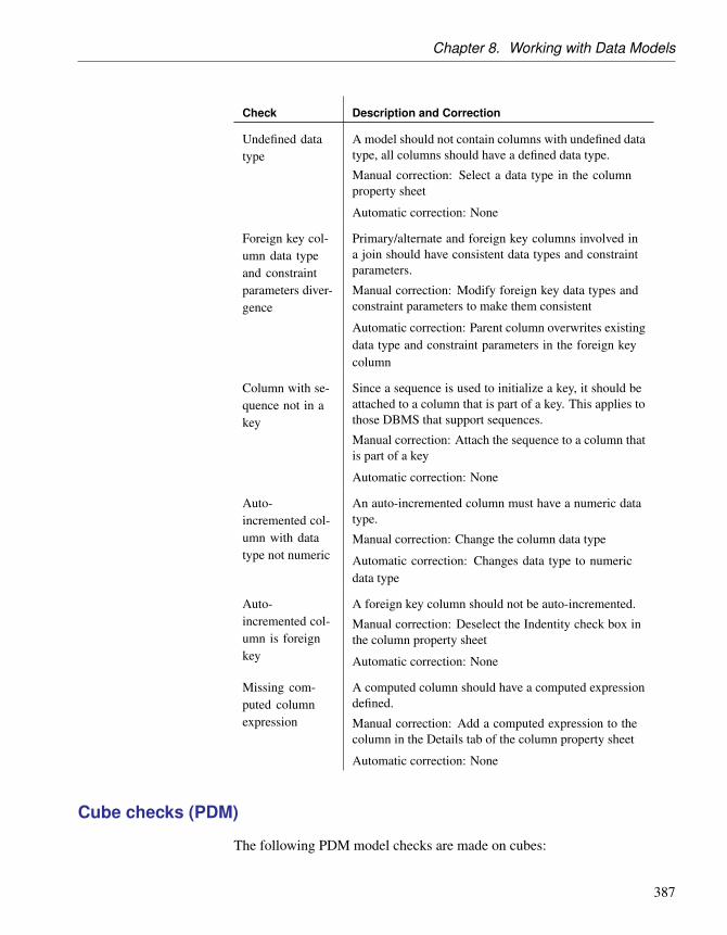
Chapter 8. Working with Data Models
Check Description and Correction
Undefined datatype
A model should not contain columns with undefined datatype, all columns should have a defined data type.
Manual correction: Select a data type in the columnproperty sheet
Automatic correction: None
Foreign key col-umn data typeand constraintparameters diver-gence
Primary/alternate and foreign key columns involved ina join should have consistent data types and constraintparameters.
Manual correction: Modify foreign key data types andconstraint parameters to make them consistent
Automatic correction: Parent column overwrites existingdata type and constraint parameters in the foreign keycolumn
Column with se-quence not in akey
Since a sequence is used to initialize a key, it should beattached to a column that is part of a key. This applies tothose DBMS that support sequences.
Manual correction: Attach the sequence to a column thatis part of a key
Automatic correction: None
Auto-incremented col-umn with datatype not numeric
An auto-incremented column must have a numeric datatype.
Manual correction: Change the column data type
Automatic correction: Changes data type to numericdata type
Auto-incremented col-umn is foreignkey
A foreign key column should not be auto-incremented.
Manual correction: Deselect the Indentity check box inthe column property sheet
Automatic correction: None
Missing com-puted columnexpression
A computed column should have a computed expressiondefined.
Manual correction: Add a computed expression to thecolumn in the Details tab of the column property sheet
Automatic correction: None
Cube checks (PDM)
The following PDM model checks are made on cubes:
387

Checking a Data Model
Check Description and Correction
Cube name andcode uniqueness
Cubes names and codes must be unique in the model.
Manual correction: Modify the duplicate name/code
Automatic correction: Appends a number to the dupli-cate name/code
Existence of as-sociation
A cube must have at least one association with a dimen-sion.
Manual correction: Create an association between thecube and a dimension
Automatic correction: None
Existence of fact A cube must be associated to a fact.
Manual correction: Click the Ellipsis button beside theFact box in the cube property sheet, and select a factfrom the List of Facts
Automatic correction: None
Duplicated asso-ciation with thesame dimension
A cube cannot have more than one association with thesame dimension.
Manual correction: Delete one of the associations
Automatic correction: None
Database checks (PDM)
The following PDM model checks are made on databases:
Check Description and Correction
Database nameand code unique-ness
Database names and codes must be unique in the model.
Manual correction: Modify the duplicate name/code
Automatic correction: Appends a number to the dupli-cate name/code
Database codemaximum length
The code of the database is longer than the maximumallowed by the DBMS.
Manual correction: Reduce the length of the code
Automatic correction: Reduces the code to a permissiblelength
388

Chapter 8. Working with Data Models
Check Description and Correction
Database notused
The database you have created is not used in the model.
Manual correction: Delete the database or apply thedatabase as a physical option to a table, an index, a key,a column, a storage, a tablespace or a view (Options tabof the object property sheet)
Automatic correction: None
Database package checks (PDM)
The following PDM model checks are made on database packages:
Check Description and Correction
Database pack-age name andcode uniqueness
Database package names and codes must be unique inthe model.
Manual correction: Modify the duplicate name/code
Automatic correction: Appends a number to the dupli-cate name/code
Database pack-age name andcode maximumlength
The database package name and code length is limited bythe maximum length specified in the DBMS definition(MaxLen entry, in the Objects ä DB Package category)and in the naming conventions of the model options.
Manual correction: Modify the name/code length tomeet this requirement
Automatic correction: Truncates the name/code lengthto the maximum length specified in the DBMS definition
Existence ofpackage proce-dure
A database package is an encapsulated collection ofrelated procedures. It should contain at least one proce-dure.
Manual correction: Create one or several procedures inthe database package or use existing stored proceduresand duplicate them in the database package
Automatic correction: None
Existence ofpackage cursor
This check is to suggest that a database package cancontain cursors to define a work area and access itsstored information.
Manual correction: Create one or several cursors in theCursors tab of the database package property sheet
Automatic correction: None
389

Checking a Data Model
Check Description and Correction
Existence ofpackage variable
This check is to suggest that a database package cancontain variables to capture or provide a value when oneis needed.
Manual correction: Create one or several variables in theVariables tab of the database package property sheet
Automatic correction: None
Existence ofpackage type
This check is to suggest that a database package cancontain user-defined data types called types.
Manual correction: Create one or several types in theTypes tab of the database package property sheet
Automatic correction: None
Existence ofpackage excep-tion
This check is to suggest that a database package cancontain exceptions to handle internal and user-definederror conditions.
Manual correction: Create one or several exceptionsin the Exceptions tab of the database package propertysheet
Automatic correction: None
Database package cursor checks (PDM)
The following PDM model checks are made on package cursors:
Check Description and Correction
Package cursorname and codeuniqueness
Database package cursor names and codes must beunique in the database package.
Manual correction: Modify the duplicate name/code
Automatic correction: Appends a number to the dupli-cate name/code
Package cursordefinition empty
A package cursor must have a definition.
Manual correction: Create the cursor definition in theDefinition tab of the cursor property sheet
Automatic correction: None
Check for unde-fined return types
You should define a return data type for a cursor.
Manual correction: Select a return data type in the cursorproperty sheet
Automatic correction: None
390

Chapter 8. Working with Data Models
Check Description and Correction
Existence of pa-rameter
A cursor must contain parameters for input values.
Manual correction: Create one or several parameters inthe Parameters tab of the cursor property sheet
Automatic correction: None
Database package exception checks (PDM)
The following PDM model checks are made on exceptions:
Check Description and Correction
Package excep-tion name andcode uniqueness
Exception names and codes must be unique in thedatabase package.
Manual correction: Modify the duplicate name/code
Automatic correction: Appends a number to the dupli-cate name/code
Database package procedure checks (PDM)
The following PDM model checks are made on package procedures:
Check Description and Correction
Package proce-dure name andcode uniqueness
Database package procedure names and codes must beunique in the database package.
Manual correction: Modify the duplicate name/code
Automatic correction: Appends a number to the dupli-cate name/code
Package proce-dure definitionempty
A package procedure must have a definition.
Manual correction: Create the package procedure def-inition in the Definition tab of the package procedureproperty sheet
Automatic correction: None
Existence of pa-rameter
A package procedure must contain parameters for inputand output values.
Manual correction: Create one or several parameters inthe Parameters tab of the package procedure propertysheet
Automatic correction: None
391
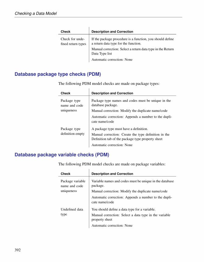
Checking a Data Model
Check Description and Correction
Check for unde-fined return types
If the package procedure is a function, you should definea return data type for the function.
Manual correction: Select a return data type in the ReturnData Type list
Automatic correction: None
Database package type checks (PDM)
The following PDM model checks are made on package types:
Check Description and Correction
Package typename and codeuniqueness
Package type names and codes must be unique in thedatabase package.
Manual correction: Modify the duplicate name/code
Automatic correction: Appends a number to the dupli-cate name/code
Package typedefinition empty
A package type must have a definition.
Manual correction: Create the type definition in theDefinition tab of the package type property sheet
Automatic correction: None
Database package variable checks (PDM)
The following PDM model checks are made on package variables:
Check Description and Correction
Package variablename and codeuniqueness
Variable names and codes must be unique in the databasepackage.
Manual correction: Modify the duplicate name/code
Automatic correction: Appends a number to the dupli-cate name/code
Undefined datatype
You should define a data type for a variable.
Manual correction: Select a data type in the variableproperty sheet
Automatic correction: None
392

Chapter 8. Working with Data Models
Data item checks (CDM)
The following CDM model checks are made on data items:
Check Description and Correction
Data item nameand code unique-ness
Data item names and codes must be unique in the model.
Manual correction: Modify the duplicate name/code
Automatic correction: Appends a number to the dupli-cate name/code.
Data item notused
There are unused data items. These are useless for PDMgeneration.
Manual correction: To use a data item, add it to an entity.If you do not need an unused data item, delete it to allowPDM generation.
Automatic correction: None.
Data item usedmultiple times
There are entities using the same data items. This can betolerated if you defined this check as a warning.
Manual correction: Take care to ensure consistencywhen defining data item properties.
Automatic correction: None.
Detect differ-ences betweendata item and as-sociated domain
There is a divergence between data items and associateddomains. This can be tolerated if you defined this checkas a warning.
Manual correction: Ensure consistency when definingdata item properties
Automatic correction: Restores divergent attributes fromdomain to data items (domain values overwrite data itemvalues).
Detect inconsis-tencies betweencheck parameters
The values entered in the check parameters page areinconsistent for numeric and string data types: defaultdoes not respect minimum and maximum values, ordefault does not belong to list of values, or values inlist are not included in minimum and maximum values,or minimum is greater than maximum value. Checkparameters must be defined consistently.
Manual correction: Modify default, minimum, maximumor list of values in the check parameters page
Automatic correction: None.
393

Checking a Data Model
Check Description and Correction
Precision > max-imum length
The data type precision should not be greater than orequal to the length.
Manual correction: Make the data type length greaterthan or equal to the precision.
Automatic correction: None.
Undefined datatype
Undefined data types for data items exist. To be com-plete, a model should have all its data items data typesdefined.
Manual correction: While undefined data types are toler-ated, you must select data types for currently undefineddata types before you can generate a PDM.
Automatic correction: None.
Invalid data type Invalid data types for data items exist. To be complete,a model should have all its data types for data itemscorrectly defined.
Manual correction: While tolerated, you must selectvalid data types for currently non-valid data types togenerate the PDM.
Automatic correction: None.
Data source checks (PDM)
The following PDM model checks are made on data sources:
Check Description and Correction
Data source nameand code unique-ness
Data source names and codes must be unique in themodel.
Manual correction: Modify the duplicate name/code
Automatic correction: Appends a number to the dupli-cate name/code
Existence ofphysical datamodel
A data source must contain at least one physical datamodel in its definition.
Manual correction: Add a physical data model from theModels tab of the property sheet of the data source
Automatic correction: Deletes data source withoutphysical data model
394

Chapter 8. Working with Data Models
Check Description and Correction
Data source con-taining modelsdiffering DBMStypes
The models in a data source should share the sameDBMS since they represent a single database.
Manual correction: Delete models with different DBMSor modify the DBMS of models in the data source
Automatic correction: None
Default checks (PDM)
The following PDM model checks are made on defaults:
Check Description and Correction
Default name andcode uniqueness
Default names and codes must be unique in the model.
Manual correction: Modify the duplicate name/code
Automatic correction: Appends a number to the dupli-cate name/code
Default codemaximum length
The default code length is limited by the maximumlength specified in the DBMS definition (MaxLen entry,in the Objects ä Default category).
Manual correction: Modify the default code length tomeet this requirement
Automatic correction: Truncates the default code lengthto the maximum length specified in the DBMS definition
Default valueempty
You must type a value for the default, this value is usedduring generation.
Manual correction: Type a value in the Value box of thedefault property sheet
Automatic correction: None
Several defaultswith same value
A model should not contain several defaults with identi-cal value.
Manual correction: Modify default value or deletedefaults with identical value
Automatic correction: None
Dimension checks (PDM)
The following PDM model checks are made on dimensions:
395

Checking a Data Model
Check Description and Correction
Dimension nameand code unique-ness
Dimension names and codes must be unique in themodel.
Manual correction: Modify the duplicate name/code
Automatic correction: Appends a number to the dupli-cate name/code
Existence of at-tribute
A dimension must have at least one attribute.
Manual correction: Create an attribute in the Attributestab of the dimension property sheet
Automatic correction: None
Existence of hier-archy
A dimension must use at least one hierarchy.
Manual correction: Create a hierarchy in the Hierarchiestab of the dimension property sheet
Automatic correction: None
Dimension haveduplicated hierar-chies
Dimensions should not have duplicated hierarchies, thatis to say hierarchies organizing identical attributes.
Manual correction: Remove one of the duplicated hier-archies
Automatic correction: None
Dimension with-out a default hier-archy
A dimension should have a default hierarchy.
Manual correction: Select a hierarchy in the DefaultHierarchy list of the dimension property sheet
Automatic correction: None
Dimension map-ping not defined
A dimension should be mapped to tables or views in anoperational model in order to be populated by data fromthis model.
Manual correction: Map the dimension to a table or aview. You may need to create a data source before youcan create the mapping
Automatic correction: Destroys the mapping for thedimension. This removes the data source from theMapping list in the dimension Mapping tab
Attribute map-ping not defined
Attributes must be mapped to columns in the data sourcetables or views.
Manual correction: Map the attributes to columns in thedata source
Automatic correction: None
396

Chapter 8. Working with Data Models
Check Description and Correction
Incomplete di-mension mappingfor multidimen-sional generation
All attributes, detail attributes and hierarchies of thedimension must be mapped to tables and columns. Youmust map the dimension objects before generation.
Manual correction: Map dimension objects to tables andcolumns
Automatic correction: None
Dimension hierarchy checks (PDM)
The following PDM model checks are made on dimension hierarchies:
Check Description and Correction
Dimension hier-archy name andcode uniqueness
Dimension hierarchy names and codes must be unique inthe model.
Manual correction: Modify the duplicate name/code
Automatic correction: Appends a number to the dupli-cate name/code
Existence of at-tribute
A dimension hierarchy must have at least one attribute.
Manual correction: Add an attribute to the hierarchyfrom the Attributes tab of the hierarchy property sheet
Automatic correction: None
Domain checks (CDM/LDM/PDM)
The following model checks are made on domains:
Check Description and Correction
Domain nameand code unique-ness
Domain names and codes must be unique in the model.
Manual correction: Modify the duplicate name/code
Automatic correction: Appends a number to the dupli-cate name/code
397

Checking a Data Model
Check Description and Correction
Domain codemaximum length
[PDM only] The domain code length is limited bythe maximum length specified in the DBMS definition(MaxLen entry, in the Objects ä Domain category) or inthe naming conventions of the model options.
Manual correction: Modify the domain code length tomeet this requirement
Automatic correction: Truncates the domain code lengthto the maximum length specified in the DBMS definition
Detect Inconsis-tencies betweencheck parameters
The values entered in the Check Parameters tab areinconsistent for numeric and string data types. Defaultdoes not respect minimum and maximum values, ordefault does not belong to list of values, or values inlist are not included in minimum and maximum values,or minimum is greater than maximum value. Checkparameters must be defined consistently.
Manual correction: Modify default, minimum, maximumor list of values in the check parameters tab
Automatic correction: None
Precision > max-imum length
The data type precision should not be greater than thelength.
Manual correction: Make the data type length greaterthan the precision
Automatic correction: None
Undefined datatype
A model should not contain domains with undefined datatype, all domains should have a defined data type.
Manual correction: Select a data type from the domainproperty sheet
Automatic correction: None
Invalid data type [CDM/LDM only] Invalid data types for domains exist.To be complete, a model should have all its domain datatypes correctly defined.
Manual correction: While tolerated, you must selectvalid data types for currently non-valid data types togenerate the PDM.
Automatic correction: None.
398

Chapter 8. Working with Data Models
Check Description and Correction
Domain missingdefault object
[PDM only] A domain cannot have a default valuewithout being attached to a default object.
Manual correction: Create a default object for the domainor use the rebuild default feature
Automatic correction: Creates a default object for do-main
Entity attribute checks (CDM)
The following CDM model checks are made on entity attributes:
Check Description and Correction
Entity attributename and codeuniqueness
Attribute names and codes must be unique in the entity.
Manual correction: Modify the duplicate name/code
Automatic correction: Appends a number to the dupli-cate name/code.
Entity attribute checks (LDM)
The following LDM model checks are made on entity attributes:
Check Description and Correction
Entity attributename and codeuniqueness
Attribute names and codes must be unique in the entity.
Manual correction: Modify the duplicate name/code
Automatic correction: Appends a number to the dupli-cate name/code.
Detect differ-ences betweenattribute and as-sociated domain
There is a divergence between attributes and associateddomains. This can be tolerated if you defined this checkas a warning.
Manual correction: Ensure consistency when definingattribute properties
Automatic correction: Restores divergent attributes fromdomain to attributes (domain values overwrite attributevalues).
399

Checking a Data Model
Check Description and Correction
Detect inconsis-tencies betweencheck parameters
The values entered in the Check Parameters page areinconsistent for numeric and string data types. Defaultdoes not respect minimum and maximum values, ordefault does not belong to list of values, or values inlist are not included in minimum and maximum values,or minimum is greater than maximum value. Checkparameters must be defined consistently.
Manual correction: Modify default, minimum, maximumor list of values in the check parameters page
Automatic correction: None.
Precision > max-imum length
The data type precision should not be greater than orequal to the length.
Manual correction: Make the data type length greaterthan or equal to the precision.
Automatic correction: None.
Undefined datatype
Undefined data types for attributes exist. To be complete,a model should have all its attributes data types defined.
Manual correction: While undefined data types are toler-ated, you must select data types for currently undefineddata types before you can generate a PDM.
Automatic correction: None.
Invalid data type Invalid data types for attributes exist. To be complete,a model should have all its data types for attributescorrectly defined.
Manual correction: While tolerated, you must selectvalid data types for currently non-valid data types togenerate the PDM.
Automatic correction: None.
Entity identifier checks (CDM/LDM)
The following CDM/LDM model checks are made on entity identifiers:
400

Chapter 8. Working with Data Models
Check Description and Correction
Entity identifiername and codeuniqueness
Entity identifier names and codes must be unique in thenamespace.
Manual correction: Modify the duplicate name/code
Automatic correction: Appends a number to the dupli-cate name/code.
Existence of en-tity attribute
At least one attribute must exist for an entity identifier.
Manual correction: Add an attribute to the entity identi-fier or delete the identifier.
Automatic correction: None.
Identifier inclu-sion
An identifier cannot include another one.
Manual correction: Delete the identifier that includes anexisting identifier.
Automatic correction: None.
Entity checks (CDM/LDM)
The following CDM/LDM model checks are made on entities:
Check Description and Correction
Entity name andcode uniqueness
Entity names and codes must be unique in the names-pace.
Manual correction: Modify the duplicate name/code
Automatic correction: Appends a number to the dupli-cate name/code.
Entity name andcode maximumlength
The entity name and code length is limited to a maxi-mum length of 254 characters specified in the namingconventions of the model options.
Manual correction: Modify the entity name/code lengthto meet this requirement.
Automatic correction: Truncates the entity name/codelength to the maximum length specified in the namingconventions.
Existence of at-tributes
An entity must always contain at least one attribute.
Manual correction: Add an attribute to the entity ordelete the entity.
Automatic correction: None.
401

Checking a Data Model
Check Description and Correction
Number of serialtypes > 1
An entity cannot have more than one serial type attribute.Serial types are automatically calculated values.
Manual correction: Change the types of the appropriateentity attributes to have only one serial type attribute.
Automatic correction: None.
Existence ofidentifiers
An entity must contain at least one identifier.
Manual correction: Add an identifier to the entity ordelete the entity.
Automatic correction: None.
Existence of rela-tionship or asso-ciation link
An entity must have at least one relationship or associa-tion link.
Manual correction: Add a relationship or an associationlink to the entity or delete the entity.
Automatic correction: None.
Redundant inher-itance
An entity inherits from another entity more than once.This is redundant and adds nothing to the model.
Manual correction: Delete redundant inheritances
Automatic correction: None.
Multiple inheri-tance
An entity has multiple inheritance. This is unusual butcan be tolerated if you defined this check as a warning.
Manual correction: Make sure that the multiple inheri-tance is necessary in your model.
Automatic correction: None.
Parent of severalinheritances
An entity is the parent of multiple inheritances. This isunusual but can be tolerated if you defined this check asa warning.
Manual correction: Verify if the multiple inheritancescould not be merged.
Automatic correction: None.
Redefined pri-mary identifier
Primary identifiers in child entities must be the same asthose in their parents.
Manual correction: Delete those primary identifiers inthe child entities that are not in the parent entity.
Automatic correction: None.
402

Chapter 8. Working with Data Models
Fact checks (PDM)
The following PDM model checks are made on facts:
Check Description and Correction
Fact name andcode uniqueness
Fact names and codes must be unique in the model.
Manual correction: Modify the duplicate name/code
Automatic correction: Appends a number to the dupli-cate name/code
Existence of mea-sure
A fact must have at least one measure.
Manual correction: Create a measure in the Measurestab of the fact property sheet
Automatic correction: None
Fact mapping notdefined
A fact must be mapped to tables or views in an opera-tional model in order to be populated by data from thismodel.
Manual correction: Map the fact to tables or views. Youmay need to create a data source before you can createthe mapping
Automatic correction: Destroys the mapping for the fact.This removes the data source from the Mapping list inthe fact Mapping tab
Measure map-ping not defined
Fact measures must be mapped to columns in the datasource tables or views.
Manual correction: Map the fact measure to columns inthe data source
Automatic correction: Destroys the mapping for themeasure. This removes the measures that are not mappedto any object in the Measures Mapping tab of the factMapping tab
Fact measure checks (PDM)
The following PDM model checks are made on fact measures:
403

Checking a Data Model
Check Description and Correction
Fact measurename and codeuniqueness
Fact measure names and codes must be unique in themodel.
Manual correction: Modify the duplicate name/code
Automatic correction: Appends a number to the dupli-cate name/code
Group checks (PDM)
The following PDM model checks are made on groups:
Check Description and Correction
Group name andcode uniqueness
Group names and codes must be unique in the model.
Manual correction: Modify the duplicate name/code
Automatic correction: Appends a number to the dupli-cate name/code
Group code max-imum length
The group code length is limited by the maximum lengthspecified in the DBMS definition (MaxLen entry, in theObjects ä Group category) or in the naming conventionsof the model options.
Manual correction: Modify the group code length tomeet this requirement
Automatic correction: Truncates the group code lengthto the maximum length specified in the DBMS definition
Existence of user A group is created to factorize privilege and permissiongranting to users. A group without user members isuseless.
Manual correction: Add users to group or delete group
Automatic correction: Deletes unassigned group
Group passwordempty
Groups must have a password to be able to connect tothe database (for those DBMS that support passwordsfor groups.)
Manual correction: Define a password for the group
Automatic correction: None
Horizontal partitioning checks (PDM)
The following PDM model checks are made on horizontal partitioning
404

Chapter 8. Working with Data Models
objects:
Check Description and Correction
Horizontal parti-tioning name andcode uniqueness
Horizontal partitioning names and codes must be uniquein the model.
Manual correction: Modify the duplicate name/code
Automatic correction: Appends a number to the dupli-cate name/code
Existence of par-tition
A horizontal partitioning object cannot be empty, it mustcontain at least one partition.
Manual correction: Delete the horizontal partitioningobject or create at least one partition in the horizontalpartitioning object property sheet
Automatic correction: Deletes empty horizontal parti-tioning object
Unavailable tar-get table
A partition should have a corresponding table. You coulddelete a table that actually corresponds to a partition, thischeck verifies that each partition has a correspondingtable.
Manual correction: Delete the partition with no corre-sponding table
Automatic correction: Deletes the partition with nocorresponding table
Index checks (PDM)
The following PDM model checks are made on indexes:
Check Description and Correction
Index name andcode uniqueness
Depending on the DBMS, a model or a table cannotcontain two indexes with identical name and/or code.
Manual correction: Modify the duplicate name/code
Automatic correction: Appends a number to the dupli-cate name/code
405

Checking a Data Model
Check Description and Correction
Index code maxi-mum length
The index code length is limited by the maximum lengthspecified in the DBMS definition (MaxLen entry, in theObjects ä Index category) or in the naming conventionsof the model options.
Manual correction: Modify the index code length tomeet this requirement
Automatic correction: Truncates the index code lengthto the maximum length specified in the DBMS definition
Existence of in-dex column
An index must have at least one index column.
Manual correction: Add an index column from theColumn tab of the index property sheet or delete theindex
Automatic correction: Deletes the index without column
Undefined indextype
An index type must be specified.
Manual correction: Specify a type in the index propertysheet or delete the index with no type
Automatic correction: None
Index columncount
The current DBMS does not support more than thenumber of index columns specified in the MaxColIndexentry of the current DBMS.
Manual correction: Delete one or more columns in theindex property sheet. You can create additional indexesfor these columns
Automatic correction: None
Uniqueness for-bidden for HNGindex type
An index of HNG (HighNonGroup) type cannot beunique.
Manual correction: Change the index type or set theindex as non unique
Automatic correction: None
Index inclusion An index should not include another index.
Manual correction: Delete the index that includes anexisting index
Automatic correction: None
Inheritance checks (CDM/LDM)
The following CDM/LDM model checks are made on inheritances:
406

Chapter 8. Working with Data Models
Check Description and Correction
Inheritance nameand code unique-ness
Inheritance names and codes must be unique in themodel.
Manual correction: Modify the duplicate name/code
Automatic correction: Appends a number to the dupli-cate name/code.
Existence of in-heritance link
An inheritance must have at least one inheritance link,from the inheritance to the parent entity.
Manual correction: Define the inheritance link or deletethe inheritance.
Automatic correction: None.
Incomplete in-heritance withungenerated an-cestor
[LDM only] If an inheritance is incomplete, the parentshould be generated because you can lose information.
Manual correction: Generate parent entity or define theinheritance as complete.
Automatic correction: None.
Join index checks (PDM)
The following PDM model checks are made on join indexes and bitmap joinindexes:
Check Description and Correction
Join index nameand code unique-ness
Join index names and codes must be unique in the model.
Manual correction: Modify the duplicate name/code
Automatic correction: Appends a number to the dupli-cate name/code
Existence of basetable
Join index must have a base table.
Manual correction: Select a base table in the join indexproperty sheet
Automatic correction: None
Join Index tablesowners
The tables associated to a join index must have the sameowner.
Manual correction: Modify the join index owner or thetable owner
Automatic correction: None
407

Checking a Data Model
Check Description and Correction
Join index refer-ences connection
Join index references must be connected to selected tableon a linear axis.
Manual correction: Delete or replace references in thejoin index
Automatic correction: None
Duplicated joinindexes
Join indexes cannot have the same set of references.
Manual correction: Delete one of the duplicated joinindexes
Automatic correction: None
Key checks (PDM)
The following PDM model checks are made on keys:
Check Description and Correction
Key name andcode uniqueness
Key names and codes must be unique in the model.
Manual correction: Modify the duplicate name/code
Automatic correction: Appends a number to the dupli-cate name/code
Key code length The key code length is limited by the maximum lengthspecified in the DBMS definition (MaxConstLen entry,in the Object ä Key category).
Manual correction: Modify the key code length to meetthis requirement
Automatic correction: Truncates the key code length tothe maximum length specified in the DBMS definition
Key column ex-ists
Each key must have at least one column.
Manual correction: Add a column to the key from theColumn tab of the key property sheet
Automatic correction: Deletes key without column
Key inclusion A key cannot include another key (on some columns,regardless of their order).
Manual correction: Delete the key that includes anexisting key
Automatic correction: None
408

Chapter 8. Working with Data Models
Check Description and Correction
Multi-columnkey has sequencecolumn
Since the column initialized by a sequence is already akey, it should not be included in a multi-column key.
Manual correction: Detach the sequence from a columnthat is already part of a multi-column key
Automatic correction: None
Package checks (CDM/LDM/PDM)
The following model checks are made on packages:
Check Description and Correction
Circular refer-ences
[PDM only] A circular reference occurs when a tablerefers to another table, and so on until a loop is createdbetween tables. A package cannot contain circularreferences.
Manual correction: Resolve the circular reference bycorrecting the reference, deleting its source, or clearingthe Mandatory parent or Check on commit option
Automatic correction: None
Constraint nameuniqueness
[PDM only] A constraint name is a unique identifier forthe constraint definition of tables, columns, primary andforeign keys in the database. You define the constraintname in the following tabs:
Check tab of the table property sheet
Additional Check tab of the column property sheet
General tab of the key property sheet
A constraint name must be unique in a model.
Manual correction: Modify the duplicated constraintname in the corresponding tab
Automatic correction: Modifies the duplicated constraintname of a selected object by appending a number to itscurrent name
409

Checking a Data Model
Check Description and Correction
Constraint namemaximum length
[PDM only] The constraint name length cannot be longerthan the length specified in the DBMS definition: eitherin the MaxConstLen entry, in the Object category, or ineach object category.
Manual correction: Modify the constraint name to meetthis requirement
Automatic correction: Truncates the constraint name tothe maximum length specified in the DBMS definition
Circular depen-dencies
[PDM only] Extended dependencies with the stereo-type <<DBCreateAfter>> can be used between storedprocedures to define a generation order for stored pro-cedures. An extended dependency with the stereotype<<DBCreateAfter>> should not introduce a circulardependency in the model.
Manual correction: Remove the <<DBCreateAfter>>extended dependency
Automatic correction: None
Circular depen-dency
[CDM/LDM only] A circular dependency occurs whenan entity depends on another and so on until a depen-dency loop is created between entities. A package cannotcontain circular dependencies.
Manual correction: Clear the Dependent check box forthe link or delete an inheritance link.
Automatic correction: None.
Circularity withmandatory links
[CDM/LDM only] A circular dependency occurs whenan entity depends on another and so on until a depen-dency loop is created between entities through mandatorylinks.
Manual correction: Clear the Mandatory parent checkbox or delete a dependency on a relationship.
Automatic correction: None.
Shortcut codeuniqueness
Shortcuts codes must be unique in a namespace.
Manual correction: Change the code of one of theshortcuts
Automatic correction: None
410

Chapter 8. Working with Data Models
Check Description and Correction
Shortcut poten-tially generatedas child table of areference
[CDM/LDM only] The package should not containassociations or relationships with an external shortcut aschild entity. Although this can be tolerated in the CDM,the association or relationship will not be generated in aPDM if the external shortcut is generated as a shortcut.
Manual correction: Modify the design of your modelin order to create the association or relationship in thepackage where the child entity is defined.
Automatic correction: None.
Procedure checks (PDM)
The following PDM model checks are made on procedures:
Check Description and Correction
Procedure nameand code unique-ness
Procedure names and codes must be unique in the model.
Manual correction: Modify the duplicate name/code
Automatic correction: Appends a number to the dupli-cate name/code
Procedure codemaximum length
The procedure code length is limited by the maximumlength specified in the DBMS definition (MaxLen entry,in the Objects ä Procedure category).
Manual correction: Modify the procedure code length tomeet this requirement
Automatic correction: Truncates the procedure codelength to the maximum length specified in the DBMSdefinition
Procedure defini-tion body empty
A procedure definition should have a body to specify itsfunctionality.
Manual correction: Specify a procedure body from theDefinition tab of the procedure property sheet
Automatic correction: None
Existence of per-mission
Permissions are usage restrictions set on a procedure fora particular user, group or role.
Manual correction: Define permissions on the procedurefor users, groups and roles
Automatic correction: None
411

Checking a Data Model
Reference checks (PDM)
The following PDM model checks are made on references:
Check Description and Correction
Reference nameand code unique-ness
Reference names and codes must be unique in the model.
Manual correction: Modify the duplicate name/code
Automatic correction: Appends a number to the dupli-cate name/code
Reflexive andmandatory refer-ence
A reflexive reference exists should not have a mandatoryparent which could lead to inconsistent joins.
Manual correction: Correct the reference by clearing theMandatory parent check box
Automatic correction: None
Existence of ref-erence join
A reference must have at least one reference join.
Manual correction: Create a reference join for thereference or delete the reference
Automatic correction: Deletes reference without join
Reference codemaximum length
The reference code length is limited by the maximumlength specified in the DBMS definition (MaxConstLenentry, in the Object ä Reference category) or in thenaming conventions of the model options.
Manual correction: Modify the reference code length tomeet this requirement
Automatic correction: Truncates the reference codelength to the maximum length specified in the DBMSdefinition
Incomplete join Joins must be complete.
Manual correction: Select a foreign key column oractivate the primary key column migration
Automatic correction: None
412

Chapter 8. Working with Data Models
Check Description and Correction
Join order The join order must be the same as the key column orderfor some DBMS.
Manual correction: If required, change the join order toreflect the key column order
Automatic correction: The join order is changed tomatch the key column order
During a reference check, the following object controlsare made.
Relationship checks (CDM/LDM)
The following CDM/LDM model checks are made on relationships:
Check Description and Correction
Relationshipname and codeuniqueness
Relationship names and codes must be unique in themodel.
Manual correction: Modify the duplicate name/code
Automatic correction: Appends a number to the dupli-cate name/code.
Reflexive depen-dency
A dependency means that one entity is defined througha relationship with another. A dependent relationshipcannot therefore be reflexive.
Manual correction: Change or delete the reflexive de-pendency.
Automatic correction: None.
Reflexive manda-tory
A reflexive mandatory relationship exists.
Manual correction: Deselect the Mandatory check boxesfor the relationship to be non-mandatory.
Automatic correction: None.
Bijective rela-tionship betweentwo entities
There is a bijective relationship between two entitieswhen there is a two-way one to one relationship betweenthe entities. This is equivalent to a merge of two entities.
Manual correction: Merge the entities or modify therelationship.
Automatic correction: None.
413

Checking a Data Model
Check Description and Correction
Name uniquenessconstraint formany to manyrelationships andentities
A many-to-many relationship and an entity cannot havethe same name or code.
Manual correction: Change the name or code of themany-to-many relationship or the name or code of theentity. If you do not, PDM generation will rename thegenerated table.
Automatic correction: None.
Consistency be-tween dominantand dependentrelationships
A dependent relationship between entities cannot also bea dominant relationship.
Manual correction: Select the Dominant check box onthe other (correct) side of the relationship.
Automatic correction: None.
Relationship withchild shortcut
External shortcut could be generated as child table.An entity that is at the “many” end of a one-to-manyrelationship or which is non-dominant should not be anexternal shortcut as the reference will not be generatedduring the generation of a PDM.
Manual correction: Change the cardinality of the rela-tionship cardinality or the entity, which should not be anexternal shortcut.
Automatic correction: None.
‘Many-many’relationships
[LDM only] ‘Many-to-many’ relationships are not per-mitted.
Manual correction: Create an intermediary entity, whichcontains the primary identifiers of the previous ‘many-to-many’ entities.
Automatic correction: None.
Role checks (PDM)
The following PDM model checks are made on roles:
Check Description and Correction
Role name andcode uniqueness
Role names and codes must be unique in the model.
Manual correction: Modify the duplicate name/code
Automatic correction: Appends a number to the dupli-cate name/code
414

Chapter 8. Working with Data Models
Check Description and Correction
Role code maxi-mum length
The role code length is limited by the maximum lengthspecified in the DBMS definition (MaxLen entry, in theObjects ä Role category) or in the naming conventionsof the model options.
Manual correction: Modify the role code length to meetthis requirement
Automatic correction: Truncates the role code length tothe maximum length specified in the DBMS definition
Existence of user A role is used to create predefined profile that can beassigned to users or roles. A role that is not assigned toany user or role is useless.
Manual correction: Assign role to users or delete role
Automatic correction: Deletes unassigned role
Sequence checks (PDM)
The following PDM model checks are made on sequences:
Check Description and Correction
Sequence nameand code unique-ness
Default names and codes must be unique in the model.
Manual correction: Modify the duplicate name/code
Automatic correction: Appends a number to the dupli-cate name/code
Sequence codemaximum length
The code of the sequence is longer than the maximumallowed by the DBMS.
Manual correction: Reduce the length of the code
Automatic correction: Reduces the code to a permissiblelength
Storage checks (PDM)
The following PDM model checks are made on storages:
415

Checking a Data Model
Check Description and Correction
Storage name andcode uniqueness
Storage names and codes must be unique in the model.
Manual correction: Modify the duplicate name/code
Automatic correction: Appends a number to the dupli-cate name/code
Storage codemaximum length
The code of the storage is longer than the maximumallowed by the DBMS.
Manual correction: Reduce the length of the code
Automatic correction: Reduces the code to a permissiblelength
Storage not used The storage you have created is not used in the model.
Manual correction: Delete the storage or apply thestorage as a physical option to a table, an index, a key, acolumn, a tablespace or a view (Options tab of the objectproperty sheet)
Automatic correction: None
Synonym checks (PDM)
The following PDM model checks are made on synonyms:
Check Description and Correction
Synonym nameand code unique-ness
Synonym names and codes must be unique in the model.
Manual correction: Modify the duplicate name/code
Automatic correction: Appends a number to the dupli-cate name/code
Synonym nameand code maxi-mum length
The synonym name and code length is limited by themaximum length specified in the DBMS definition(MaxLen entry, in the Objects ä Synonym category) andin the naming conventions of the model options.
Manual correction: Modify the name/code length tomeet this requirement
Automatic correction: Truncates the name/code lengthto the maximum length specified in the DBMS definition
416

Chapter 8. Working with Data Models
Check Description and Correction
Existence of thebase object
A synonym must correspond to a model object. Bydefault, when you create synonyms from the List ofSynonyms using the Add a Row tool, they are notattached to any base object.
Manual correction: Select a base object from the syn-onym property sheet
Automatic correction: Deletes the synonym
Table checks (PDM)
The following PDM model checks are made on tables:
Check Description and Correction
Table name andcode uniqueness
Tables names and codes must be unique in the model.
Manual correction: Modify the duplicate name/code
Automatic correction: Appends a number to the dupli-cate name/code
Table name andcode length
The table name and code length is limited by the maxi-mum length specified in the DBMS definition (MaxLenentry, in the Objects ä Table category) and in the namingconventions of the model options.
Manual correction: Modify the name/code length tomeet this requirement
Automatic correction: Truncates the name/code lengthto the maximum length specified in the DBMS definition
Constraint nameconflict with in-dex name
A constraint name of the table cannot be the same as anindex name.
Manual correction: Change the name of the table con-straint
Automatic correction: None
Existence of col-umn, reference,index, key
A table should contain at least one column, one index,one key, and one reference.
Manual correction: Add missing item to the definition ofthe table
Automatic correction: None
417

Checking a Data Model
Check Description and Correction
Number of auto-incrementedcolumns
Auto-incremented columns contain automatically cal-culated values. A table cannot contain more than oneauto-incremented column.
Manual correction: Delete all but one auto-incrementedcolumn
Automatic correction: None
Table index defi-nition uniqueness
Identical indexes are indexes with the same columns,order and type. A table cannot have identical indexes.
Manual correction: Delete index or change its properties
Automatic correction: None
Table mappingnot defined
When a table belongs to a model containing one orseveral data sources, it must be mapped to tables orviews in the data source in order to establish a relationalto relational mapping.
Manual correction: Map the current table to one orseveral tables or views in the model belonging to the datasource
Automatic correction: Destroys the mapping for thetable. This removes the data source from the Mappinglist in the table Mapping tab
Column mappingnot defined
When a column belong to a table in a model contain-ing one or several data sources, it should be mappedto columns in the data source in order to establish arelational to relational mapping.
Manual correction: Map the current column to one orseveral columns in the models belonging to the datasource
Automatic correction: Destroys the mapping for thecolumn. This removes the columns that are not mappedto any object in the Columns Mapping tab of the tableMapping tab
Existence of per-mission
Permissions are usage restrictions set on a table for aparticular user, group or role.
Manual correction: Define permissions on the table forusers, groups and roles
Automatic correction: None
418

Chapter 8. Working with Data Models
Table collapsing checks (PDM)
The following PDM model checks are made on table collapsing:
Check Description and Correction
Table collapsingname and codeuniqueness
Table collapsing names and codes must be unique in themodel.
Manual correction: Modify the duplicate name/code
Automatic correction: Appends a number to the dupli-cate name/code
Existence of tar-get table
A table collapsing must have a table as result of thecollapsing.
Manual correction: Delete the table collapsing object
Automatic correction: None
Unavailable tar-get table
The table resulting from the collapsing should be avail-able.
Manual correction: Delete the table collapsing object
Automatic correction: Deletes the table collapsing object
Tablespace checks (PDM)
The following PDM model checks are made on tablespaces:
Check Description and Correction
Tablespace nameand code unique-ness
Tablespace names and codes must be unique in themodel.
Manual correction: Modify the duplicate name/code
Automatic correction: Appends a number to the dupli-cate name/code
Tablespace codemaximum length
The code of the tablespace is longer than the maximumallowed by the DBMS.
Manual correction: Reduce the length of the code
Automatic correction: Reduces the code to a permissiblelength
419

Checking a Data Model
Check Description and Correction
Tablespace notused
The tablespace you have created is not used in the model.
Manual correction: Delete the tablespace or apply thetablespace as a physical option to a table, an index, a key,a column, a storage or a view (Options tab of the objectproperty sheet)
Automatic correction: None
Trigger checks (PDM)
The following PDM model checks are made on triggers:
Check Description and Correction
Trigger name andcode uniqueness
Trigger names and codes must be unique in the model.
Manual correction: Modify the duplicate name/code
Automatic correction: Appends a number to the dupli-cate name/code
Trigger codelength
The trigger code length is limited by the maximumlength specified in the DBMS definition (MaxLen entry,in the Objects ä Trigger category).
Manual correction: Modify the trigger code length tomeet this requirement
Automatic correction: Truncates the trigger code lengthto the maximum length specified in the DBMS definition
User checks (PDM)
The following PDM model checks are made on users:
Check Description and Correction
User name andcode uniqueness
User names and codes must be unique in the model.
Manual correction: Modify the duplicate name/code
Automatic correction: Appends a number to the dupli-cate name/code
420

Chapter 8. Working with Data Models
Check Description and Correction
User code maxi-mum length
The user code length is limited by the maximum lengthspecified in the DBMS definition (MaxLen entry, in theObjects ä User category).
Manual correction: Modify the user code length to meetthis requirement
Automatic correction: Truncates the user code length tothe maximum length specified in the DBMS definition
User passwordempty
Users must have a password to be able to connect to thedatabase.
Manual correction: Define a password for the user
Automatic correction: None
Vertical partitioning checks (PDM)
The following PDM model checks are made on partitions:
Check Description and Correction
Vertical parti-tioning name andcode uniqueness
Vertical partitioning names and codes must be unique inthe model.
Manual correction: Modify the duplicate name/code
Automatic correction: Appends a number to the dupli-cate name/code
Existence of par-tition
A vertical partitioning object cannot be empty, it mustcontain at least one partition.
Manual correction: Delete the vertical partitioning objector create at least one partition in the vertical partitioningobject property sheet
Automatic correction: Deletes empty vertical partition-ing object
Unavailable tar-get table
A partition should have a corresponding table. You coulddelete a table that actually corresponds to a partition, thischeck verifies that each partition has a correspondingtable.
Manual correction: Delete the partition with no corre-sponding table
Automatic correction: Deletes the partition with nocorresponding table
421

Checking a Data Model
View checks (PDM)
The following PDM model checks are made on views:
Check Description and Correction
View name andcode uniqueness
View names and codes must be unique in the model.
Manual correction: Modify the duplicate name/code
Automatic correction: Appends a number to the dupli-cate name/code
View code maxi-mum length
The view code length is limited by the maximum lengthspecified for the table code length.
Manual correction: Modify the view code length to meetthis requirement
Automatic correction: Truncates the view code length tothe maximum length specified in the DBMS definition
Existence of per-mission
Permissions are usage restrictions set on a view for aparticular user, group or role.
Manual correction: Define permissions on the view forusers, groups and roles
Automatic correction: None
View index checks (PDM)
The following PDM model checks are made on view indexes:
Check Description and Correction
Index name andcode uniqueness
Depending on the DBMS, a model or a view cannotcontain two view indexes with identical name and/orcode.
Manual correction: Modify the duplicate name/code
Automatic correction: Appends a number to the dupli-cate name/code
422

Chapter 8. Working with Data Models
Check Description and Correction
Index code maxi-mum length
The view index code length is limited by the maximumlength specified in the DBMS definition (MaxLen entry,in the Objects ä Index category) or in the namingconventions of the model options.
Manual correction: Modify the view index code lengthto meet this requirement
Automatic correction: Truncates the view index codelength to the maximum length specified in the DBMSdefinition
Existence of in-dex column
A view index must have at least one index column.
Manual correction: Add an index column from theColumn tab of the view index property sheet or deletethe index
Automatic correction: Deletes the view index withoutcolumn
Index columncount
The current DBMS does not support more than thenumber of index columns specified in the MaxColIndexentry in the Index category of the current DBMS.
Manual correction: Delete one or more columns in theview index property sheet. You can create additionalview indexes for these columns
Automatic correction: None
View index inclu-sion
A view index should not include another index.
Manual correction: Delete the view index that includesan existing index
Automatic correction: None
View reference checks (PDM)
The following PDM model checks are made on view references:
423

Checking a Data Model
Check Description and Correction
View referencename and codeuniqueness
View reference names and codes must be unique in themodel.
Manual correction: Modify the duplicate name/code
Automatic correction: Appends a number to the dupli-cate name/code
Existence of viewreference join
A view reference must have at least one view referencejoin.
Manual correction: Create a view reference join for theview reference or delete the reference
Automatic correction: Deletes view reference withoutjoin
Web operation checks (PDM)
The following PDM model checks are made on Web operations:
Check Description and Correction
Web operationname and codeuniqueness
Web operation names and codes must be unique in themodel.
Manual correction: Modify the duplicate name/code
Automatic correction: Appends a number to the dupli-cate name/code
Web operationcode maximumlength
The Web operation code length is limited by the maxi-mum length specified in the DBMS definition (Maxlenentry, in the Objects ä Web Operation category).
Manual correction: Modify the Web operation codelength to meet this requirement
Automatic correction: Truncates the Web operation codelength to the maximum length specified in the DBMSdefinition
Web service checks (PDM)
The following PDM model checks are made on Web services:
424

Chapter 8. Working with Data Models
Check Description and Correction
Web servicename and codeuniqueness
Web service names and codes must be unique in themodel.
Manual correction: Modify the duplicate name/code
Automatic correction: Appends a number to the dupli-cate name/code
Web service codemaximum length
The Web service code length is limited by the maximumlength specified in the DBMS definition (Maxlen entry,in the Objects ä Web Service category).
Manual correction: Modify the Web service code lengthto meet this requirement
Automatic correction: Truncates the Web service codelength to the maximum length specified in the DBMSdefinition
425

Working with SQL
Working with SQLGenerating a PDM produces SQL code for your target DBMS.PowerDesigner provides tools to change and preview SQL code during PDMdevelopment. These tools are:
♦ The SQL editor
♦ The SQL preview
The SQL editor allows you to define queries and the SQL preview allowsyou to see a SQL query script before it is generated.
Defining queries with the SQL Editor
You can use the editing features of the SQL Editor to define a query. TheSQL Editor dialog box is divided into specific panes containing theinformation shown below:
Information Pane location
Objects types Upper left part of the dialog box
Available objects Upper right part of the dialog box
Query script textbox Lower part of the dialog box
The list of available objects depends on the selected object type. You canselect individual objects from the list of available objects for insertion in thequery script textbox.
You can also define expressions by entering basic arithmetic operators suchas add, subtract, multiply, divide (+, -, *, /) and with the syntax tools shownbelow:
Syntax tool Content
Functions Provides group, number, string, date, conversion and otherfunctions
Operators Provides logical operators
Variables Provides variables for use with operators and functions
Macros Provides macros to accelerate the creation of a templateitem definition
These syntax tools allow greater flexibility in defining complex expressions.
The SQL Editor can be used for the following tasks:
426

Chapter 8. Working with Data Models
♦ Defining a query for a view, a procedure, a trigger
♦ Defining a computed column
+ For more information on defining views, see Defining a query for a viewin chapter Building Physical Diagrams.
+ For more information on defining computed columns, see Creating acomputed column in chapter Building Physical Diagrams.
v To define a query with the SQL Editor
1. Click the query script textbox where you want to insert the SQL script.
2. Select an object type from the upper left part of the dialog box.
For example, select Tables to display the list of available tables. The listof available objects of this type is displayed in the upper right part of thedialog box.
3. Double-click the available object that you want to add to the script.
The item is added to the query script.
4. Select a function or an operator to add to the script from the Function orOperator lists.
The item is added to the query script.
5. Click OK.
427

Working with SQL
Previewing SQL statements
The Preview tab shows an SQL query script before it is generated. Thedisplayed script reflects the options selected in the Database Generationdialog box. This script cannot be modified.
+ For more information on database generation options, see theGenerating a Database from a PDM chapter.
The text in the script preview is color coded as follows:
Text color Represents
Blue SQL reserved word
Black Statement body
Red Variable
Green Comment
You can use the following tools and keyboard shortcuts from the Previewtoolbar:
428

Chapter 8. Working with Data Models
Tool Description Keyboard shortcut
Editor contextual menu SHIFT + F11
Refresh F5
This tool is available when at least oneextended model definition flagged forgeneration is linked to the model andwhen it contains GeneratedFiles entriesfor the current object. When available,it displays the list of targets for thecurrent object. If you add a generationtarget, the corresponding tab is addedto the Preview tab. If you deselect ageneration target, the corresponding tabdisappears from the Preview tab
CTRL + F6
Show generation options CTRL + W
Ignore generation options CTRL + D
+ For more information on extended model definitions used forgeneration, see “Extended Model Definitions” in the Resource Files and thePublic Metamodel chapter of the Customizing and ExtendingPowerDesigner manual.
Changing generationoptions
If you click the Change Generation Options tool, the Generation Optionsdialog box is displayed. You can change generation options and previewtheir effect on the code.
Ignore generationoptions
If you click the Ignore Generation Options tool, the preview ignoresgeneration options selected by using the Change generation options tool butuses a predefined set of options.
429

Working with SQL
Selected tool Effect on generationoptions
Effect on preview
Change generation options You can select genera-tion options
Visible in Preview ifoptions are applicable
Ignore generation options Generation optionscurrently selected areoverridden by prede-fined set of options
Only predefined op-tions are visible inPreview
Change generation options+ Ignore generation options
You can select genera-tion options
Changes ignored inPreview
The predefined set of generation options selects these items:
Generation Option Tab Selected items
Tables and Views All items except drop options
Keys and Indexes All items except options represented dif-ferently in some DBMS. For example, if adatabase is auto indexed, the index optionscorresponding to the keys are not selected
Database All items except drop options
Options All user-defined options are used
SQL script bookmarks In the SQL Editor or SQL Preview tab, you can add and remove bookmarksat specific points in the SQL script and then navigate forwards or backwardsfrom bookmark to bookmark:
Keyboardshortcut
Description
CTRL + F2 Adds a new bookmark. A blue bookmark box is displayed.If you repeat this action from the same position, thebookmark is deleted and the blue marker disappears
F2 Jumps to next bookmark
SHIFT + F2 Jumps to the previous bookmark
Note that bookmarks are not printable and are lost if you use the Refresh,Change Generation or Ignore Generation options.
430

Chapter 8. Working with Data Models
v To preview the code of a table
1. Double-click a table in the diagram to display the table property sheet.
2. Click the Preview tab to display the Preview tab.
3. Click OK.
431

Working with SQL
432

PART II
WORKING WITHDATABASES
This part explains how to link your Physical Data Models to your databases,including how to generate a database from a PDM, and reverse-engineer a
PDM from a database.


CHAPTER 9
Generating a Database from a PDM
About this chapter This chapter explains how to connect to a database, and to generate andmodify databases via scripts or a live database connection.
Contents Topic: page
Connecting to a Database 436
Generating a Database 438
Using Test Data 472
Estimating Database Size 500
Modifying a Database 506
Accessing a Database 513
435

Connecting to a Database
Connecting to a DatabasePowerDesigner provides various methods for connecting to your database.
Before connecting to your database for the first time, you will have toconfigure a PowerDesigner connection profile. Your choice will depend onthe interface that you have installed:
You have Configure a connection of type:
ODBC driver ODBC machine or file data source
DBMS client Native connection profile
JDBC driver JDBC connection profile
ADO.NET driver ADO.NET connection profile
OLE DB driver OLE DB connection profile
DirectConnect driver DirectConnect connection profile
+ For detailed information about creating, configuring, and usingconnection profiles, see “Connecting to a Database” section in the ModelsChapter of the Core Features Guide .
v To connect to a database
1. Select Database ä Connect to open the Connect to a Data Sourcewindow:
2. Select one of the following radio buttons, depending on your chosen
436

Chapter 9. Generating a Database from a PDM
method for connecting to your database:♦ ODBC machine data source
♦ ODBC file data source
♦ Connection profile (for native, JDBC, ADO.NET, OLE DB orDirectConnect connections)
You can use the tools to the right of the data source field to browse to anew connection profile file or directory, and the Modify and Configurebuttons to modify or configure your data source connection.
3. Enter your user ID and password, and then click Connect. If prompted byyour database, you may need to enter additional connection parameters.
Connection timeYou stay connected until you disconnect or terminate the shell session.
Displaying information about a connected database
The extent of information available about a database depends on the DBMSand the connection profile in use.
v To display information about a connected database
1. Connect to a data source.
2. Select Database ä Connection Information.
Disconnecting from a data source
v To disconnect from a data source
1. Select Database ä Disconnect.
437

Generating a Database
Generating a DatabaseThis section explains how to generate a database from a PDM.
PowerDesigner can generate a database creation script that you can run inyour DBMS environment or generate a database structure directly to a livedatabase connection.
v To generate a database
1. Select Database ä Generate Database to open the Database Generationdialog box (for more information, see “Database Generation dialogGeneral tab” on page 440).
2. Type a destination directory and a filename for the script file in theDirectory and File Name boxes.
3. Select the Script generation or Direct Generation radio button.
4. [optional] Click the Options tab, and specify creation options for yourdatabase objects (for more information, see “Database Generation dialogOptions tab” on page 443).
5. [optional] Click the Format tab, and specify format options for yourdatabase objects (for more information, see “Database Generation dialogFormat tab” on page 456).
6. [optional] Click the Selection tab, and specify the database objects to becreated (for more information, see “Database Generation dialog Selectiontab” on page 458).
438

Chapter 9. Generating a Database from a PDM
7. [optional] Click the Summary tab to view the summary of your settingsand selections (for more information, see “Database Generation dialogSummary tab” on page 459).
8. [optional] Click the Preview tab to preview the database script to be used(for more information, see “Database Generation dialog Preview tab” onpage 459).
9. Click OK to begin the generation.
If you are creating a database script: The output window shows theprogress of the generation process, and indicates the syntax for runningthe script. At the end of script generation, a Result box is displayed. Itlists the file path of the generated script file. Click Edit to open the scriptin a text editor or Close to close the Result box.
If you are generating a database directly: If you are not currentlyconnected to a database, a dialog box asks you to identify a data sourceand connection parameters.
Select a machine data source or file data source, type your user ID andpassword and then click Connect. You may be prompted for additionalconnection parameters.
Advanced generation topicsAdvanced users may want to further customize database generation by,for example, customizing the order in which objects are generated, addingscripts to run before or after generation, and generating their own ex-tended objects. For information on these and other advanced topics, theDBMS Resource File Reference chapter in the Customizing and ExtendingPowerDesigner manual.
439

Generating a Database
Database Generation dialog General tab
The General tab is the main tab for controlling database generation.
You can set the following options
Parameter Description
Directory [required] Specifies the destination directory for the scriptfile.
File name [required] Specifies the destination filename for the script file.
One file only Specifies that the generation script is created as a single file.By default, a separate script file is created for each table.
Generationtype
Specifies the type of generation to perform. You can choosebetween:♦ Script generation - generate a script to be executed on a
DBMS at a later time
♦ Direct generation – generate a script and execute it on alive database connection
Edit genera-tion script
[available only when Direct generation is selected] Opens thegeneration script in a text editor for review or editing beforeexecution on the database.
440

Chapter 9. Generating a Database from a PDM
Parameter Description
Checkmodel
Specifies that a model check is performed before scriptgeneration.
Automaticarchive
Creates an archive version of the PDM after generation.
Quick launch selection and settings sets
The Quick Launch groupbox at the bottom of the General tab allows you toload pre-configured selections and settings sets for use when generating thedatabase.
Selection A selection comprises:
♦ a set of selections of database objects made on the Selection tab (see“Database Generation dialog Selection tab” on page 458)
To save a selection, enter a name in the Selection bar at the bottom of theGeneral or Selection tab and then click Save. The selection is saved as partof the model file.
Settings set A settings set comprises:
♦ a set of options selected on the Options tab (see “Database Generationdialog Options tab” on page 443) and
♦ the format options specified on the Format tab (see “Database Generationdialog Format tab” on page 456)
v To save a settings set
1. Enter a name in the Settings set bar at the bottom of the General, Options,or Format tab and then click the Save tool.
2. When the Settings location dialog box opens, specify whether you wantto save the settings set as either:
♦ Inside the model
♦ As an external file
441

Generating a Database
3. Click OK.
Managing settings sets You can review your settings sets at any time by clicking on the Settings SetManager tool to launch the Settings Set Manager:
The following tools are available:
Icon Use
Browse to the settings set directory.
Delete the selected settings set. Only available when an internally-saved settings set is selected. You can only delete a settings setsaved to an external file through Windows Explorer.
Export the selected settings sets to an external file. Only availablewhen an internally-saved settings set is selected.
Import the selected settings sets to inside the model. Only availablewhen an externally-saved settings set is selected.
Note that settings sets should not be copied and renamed outside ofPowerDesigner. If you want to create a variant of an existing settings set,then you should load it, make the necessary changes, and then save it under adifferent name.
442

Chapter 9. Generating a Database from a PDM
Database Generation dialog Options tab
The Options tab allows you to specify what script elements to generate foreach object type.
By default, there is an entry in the left-hand pane under the meta-category“All Objects” for each object type present in your model, and all the possibleoptions are displayed in the right-hand pane. If you click on an object typein the left-hand pane, then the options are restricted to that object type.
Depending on the objects present in your model, some or all of the followingoptions will be available.
You can save your option settings via the Settings set bar at the bottom of thetab. For more information, see “Quick launch selection and settings sets” onpage 441.
443

Generating a Database
Database options
These options control the generation of the database.
Parameter Result of selection
Createdatabase
Generates database
Physical op-tions
Generates physical options for database
Begin script Inserts customized script before database creation
End script Inserts customized script after database creation
Opendatabase
Opens database
Closedatabase
Closes database
Dropdatabase
Deletes an existing database, before creating new database
Tablespace options
These options control the generation of tablespaces.
Parameter Result of selection
Create ta-blespace
Generates tablespaces
Begin script Inserts customized script before tablespace creation
End script Inserts customized script after tablespace creation
Comment Generates tablespace comments
Drop ta-blespace
Deletes an existing tablespace, before creating a new ta-blespace
444

Chapter 9. Generating a Database from a PDM
Storage options
These options control the generation of storages.
Parameter Result of selection
Create stor-age
Generates storages
Comment Generates storage comments
Drop storage Deletes an existing storage, before creating a new storage
User options
These options control the generation of users.
Option Result of selection
Create user Generates users.
Physical op-tions
Generates physical options for users
Drop user Deletes the existing user before creating the new user.
Privilege Generates privileges for users.
Group options
These options control the generation of groups.
Option Result of selection
Create group Generates groups.
Drop group Deletes the existing group before creating the new group.
Privilege Generates privileges for groups.
Role options
These options control the generation of roles.
445

Generating a Database
Option Result of selection
Create group Generates roles.
Drop group Deletes the existing role before creating the new role.
Privilege Generates privileges for roles.
Domain options
These options control the generation of domains/user-defined data types.
Parameter Result of selection
Create datatype
Generates user-defined data types
Default value Default value for user-defined data type
Check Generates check parameters and validation rules for user-defined data types
Comment Generates user-defined data type comments
Drop datatype
Deletes an existing user-defined data type, before creatingnew user-defined data type
Business rule options
These options control the generation of business rules.
Parameter Result of selection
Create rule Generates rules
Comment Generates rule comments
Drop rule Deletes an existing rule, before creating a new rule
446

Chapter 9. Generating a Database from a PDM
Default options
These options control the generation of defaults.
Parameter Result of selection
Create de-fault
Generates default object
Comment Generates default comments
Drop default Deletes an existing default before creating a new defaultobject
If the Create and Drop check boxes are selected, the default objects will becreated/dropped before domains and tables.
+ For more information on the default generation statement, see sectionDefault in the DBMS Resource File Reference chapter in the Customizingand Extending PowerDesigner manual.
Abstract data type options
These options control the generation of abstract data types.
Parameter Result of selection
Create datatype
Defines an abstract data type which is stored on a server
Begin script Inserts customized script before data type creation
End script Inserts customized script after data type creation
Comment Generates data type comments
Drop datatype
Deletes an existing abstract data type, before defining aabstract data type
Install JAVAclass
Installs a Java class which is stored on a server
RemoveJAVA class
Deletes an existing Java class, before installing a new Javaclass
Permission Generates the permission statement for a given user duringdata type creation
447

Generating a Database
Sequence options
These options control the generation of sequences.
Parameter Result of selection
Create se-quence
Generates sequence
Comment Generates sequence comments
Drop se-quence
Deletes an existing sequence, before creating a new sequence
Permission Generates the permission statement for a given user duringsequence creation
Creation parameters for tables & columns
These options control the generation of tables, columns, indexes, and keys.
Table options These options control the generation of tables.
Parameter Result of selection
Create table Generates tables.
Check Generates check parameters and validation rules for tables.If selected you can choose between:♦ Inside Table - checks are generated during table creation
♦ Outside - checks are generated with a separate SQL com-mand, generally using an ALTER command after the cre-ation of the table
The generation of checks outside the table is possible if theAddTableCheck entry exists in the Table category of thecurrent DBMS.
Physical op-tions
Generates physical options for tables.
Begin script Inserts customized script before table creation.
End script Inserts customized script after table creation.
Comment Generates table comments.
Permission Generates the permission statement for a given user duringtable creation.
448

Chapter 9. Generating a Database from a PDM
Parameter Result of selection
Drop table Deletes the existing table before creating the new table.
Column options These options control the generation of columns.
Parameter Result of selection
User-definedtype
Generates user-defined data type for column
Default value Assigns default value to column at creation
Check Generates check parameters and validation rules for columns.If selected you can choose between:♦ Inside Table - checks are generated during table creation
♦ Outside - checks are generated with a separate SQL com-mand, generally using an ALTER command after the cre-ation of the table
The generation of checks outside the table is possible if theAddTableCheck entry exists in the Table category of thecurrent DBMS.
Comment Generates column comments
Physical op-tions
Generates physical options for column
Permission Generates the permission statement for the column duringcreation
Primary key options These options control the generation of primary keys.
Parameter Result of the selection
Create pri-mary key
Generates primary keys. If selected you can choose between:♦ Inside Table - primary keys are generated during table
creation
♦ Outside - primary keys are generated with a separate SQLcommand, generally using an ALTER command after thecreation of the table
The generation of primary keys outside the table is possibleif the Create entry exists in the PKey category of the currentDBMS.
449

Generating a Database
Parameter Result of the selection
Physical op-tions
Generates physical options for primary keys
Comment Generates key comments
Drop primarykey
Deletes an existing primary key, before creating a newprimary key
Alternate key options These options control the generation of alternate keys.
Parameter Result of the selection
Create alter-nate key
Generates alternate keys. If selected you can choose be-tween:♦ Inside Table - alternate keys are generated during table
creation
♦ Outside - alternate keys are generated with a separateSQL command, generally using an ALTER command af-ter the creation of the table
The generation of alternate keys outside the table is possibleif the Create entry exists in the Key category of the currentDBMS.
Physical op-tions
Generates physical options for alternate keys
Comment Generates alternate key comments
Drop alter-nate key
Deletes an existing alternate key, before creating a newalternate key
Foreign keys options These options control the generation of foreign keys.
450

Chapter 9. Generating a Database from a PDM
Parameter Result of selection
Create for-eign key
Generates foreign keys. If selected you can choose between:♦ Inside Table - foreign keys are generated during table cre-
ation
♦ Outside - foreign keys are generated with a separate SQLcommand, generally using an ALTER command after thecreation of the table
The generation of foreign keys outside the table is possibleif the Create entry exists in the Reference category of thecurrent DBMS.
Decl. In-tegrity
Generates declarative referential integrity for references thathave Declarative selected for referential integrity implemen-tation in the reference property sheet. You can specify anyor all of the following:♦ Update constraint restrict
♦ Update constraint cascade
♦ Update constraint set null
♦ Update constraint set default
♦ Delete constraint restrict
♦ Delete constraint cascade
♦ Delete constraint set null
♦ Delete constraint set default
Comment Generates foreign key comments
Drop foreignkey
Deletes an existing foreign key , before creating a newforeign key
Index options These options control the generation of indexes.
451

Generating a Database
Parameter Result of selection
Create index Generates indexes. If selected you can choose between:♦ Inside Table - indexes are generated during table creationcreate table customer (
customer_id int not null,customer_name varchar(50)
)unique index CustomerIdx (customer_
id);
♦ Outside - indexes are generated with a separate SQL com-mand, generally using an ALTER command after the cre-ation of the table
create table customer (customer_id int not null,customer_name varchar(50)
);
create unique index CustomerIdx onCustomer(customer_id);
The generation of indexes outside the table is possible ifthe Create entry exists in the Index category of the currentDBMS.
Physical op-tions
Generates physical options for indexes
Comment Generates index comments
Drop index Deletes an existing index before creating a new index
Index Filter You can specify from none to all of:♦ Primary key - Generates primary key indexes
♦ Foreign key - Generates foreign key indexes
♦ Alternate key - Generates alternate key indexes
♦ Cluster - Generates cluster indexes
♦ Others - Generates indexes for all key columns with a de-fined index
Trigger options These options control the generation of triggers.
Parameter Result of selection
Create trigger Generates triggers
Drop trigger Deletes an existing trigger, before creating a new trigger
452

Chapter 9. Generating a Database from a PDM
Parameter Result of selection
Comment Generates trigger comments
Trigger Filter You can specify the creation of triggers:♦ For insert
♦ For update
♦ For delete
View options
These options control the generation of views.
Parameter Result of selection
Create view Generates views
Force columnlist
Generates a view with a list of columns, even if this list isidentical to the corresponding columns in the SQL order.Allows you to generate the list of view columns with theview creation order. By default, the list of view columns isgenerated only if it is different from the list of columns ofthe view query. For example, in the following view query:select a, b from Table1
columns a and b are view columns by default. The defaultgeneration statement is:create view V1 as select a, b from
Table1
If you select the Force column list option, the generationstatement will become:create view V1(a,b) as select a, b
from Table1
Physical op-tions
Generates physical options for view
Begin script Inserts customized script before view creation
End script Inserts customized script after view creation
Drop view Deletes an existing view before creating a new view
Comment Generates view comments
453

Generating a Database
Parameter Result of selection
Permission Generates the permission statement for the user during viewcreation
Synonym options
These options control the generation of synonyms.
Option Result of selection
Create syn-onym
Generates synonyms.
Drop syn-onym
Deletes the existing synonym before creating the new syn-onym.
Synonym Fil-ter
You can specify from none to all of:♦ Table - Generates table synonyms
♦ View - Generates view synonyms
♦ Procedure - Generates procedure synonyms
♦ Synonym - Generates synonym synonyms
♦ Database Package - Generates database package syn-onyms
♦ Sequence - Generates sequence synonyms
454

Chapter 9. Generating a Database from a PDM
Join index options
These options control the generation of join indexes.
Parameter Result of selection
Create joinindex
Generates join indexes
Physical op-tions
Generates physical options for join indexes for those DBMSthat support it
Begin script Inserts customized script before join index creation
End script Inserts customized script after join index creation
Drop joinindex
Deletes an existing join index, before creating a new joinindex
Comment Generates join index comments
Procedure options
These options control the generation of procedures.
Option Result of selection
Create proce-dure
Generates procedures.
Begin script Inserts customized script before procedure creation
End script Inserts customized script after procedure creation
Drop proce-dure
Deletes the existing procedure before creating the newprocedure.
Comment Generates procedure comments
Permission Generates the permission statement for the procedure duringcreation
Database package options
These options control the generation of database packages.
455

Generating a Database
Option Result of selection
Createdatabasepackage
Generates database packages.
Dropdatabasepackage
Deletes the existing database package before creating thenew database package.
Permission Generates the permission statement for the database packageduring creation.
Web service options
These options control the generation of web services.
Option Result of selection
Create webservice
Generates web services.
Drop webservice
Deletes the existing web service before creating the new webservice.
Permission Generates the permission statement for the web serviceduring creation.
Dimension options
These options control the generation of dimensions.
Option Result of selection
Create di-mension
Generates dimensions.
Drop dimen-sion
Deletes the existing dimension before creating the newdimension.
Permission Generates the permission statement for the dimension duringcreation.
Database Generation dialog Format tab
The options on the Format tab allow you to control the format of databasegeneration scripts.
456

Chapter 9. Generating a Database from a PDM
Some of the following options may not be available, depending on yourtarget database.
You can save your format settings via the Settings set bar at the bottom ofthe tab. For more information, see “Quick launch selection and settings sets”on page 441.
Option Result of selection
Database pre-fix
Table and view names in the script are prefixed by thedatabase name.
Identifier de-limiter
Specifies the characters used to delimit identifiers (forexample, table and view names). Most DBMSs require adouble-quote character (“), but some permit other forms ofdelimiter.
Owner prefix Table and view names in the script are prefixed by theirowner names. For those DBMSs that support sequenceowners, this option will also prefix sequence names by theirowner names.
Title Each section of the script includes commentary in the formof titles (for example, Database Name: TUTORIAL).
457

Generating a Database
Option Result of selection
Generatename inempty com-ment
For those DBMSs that support comments, this option allowsto generate the name in the comment when the commentbox is empty. This option applies to tables, columns, andviews. The comment generated using the object name willbe reversed as a comment.
Encoding Specifies an encoding format. You should select a format thatsupports the language used in your model and the databaseencoding format.
Charactercase
Specifies the case to use in the script. You can choosebetween:♦ Upper - all uppercase characters
♦ Lower - all lowercase characters
♦ Mixed - lowercase and uppercase characters
No accent Non-accented characters replace accented characters inscript
Database Generation dialog Selection tab
The Selection tab allows you to specify individual objects to generate.
By default, all the objects in the model except for those that belong to a
458

Chapter 9. Generating a Database from a PDM
package, or that are shortcuts from another model are listed and selected forgeneration.
You can save your selection via the Selection bar at the bottom of the tab.For more information, see “Quick launch selection and settings sets” onpage 441.
For more information about Selection windows, see “Adding an item from aselection list” section in the Objects chapter of the Core Features Guide .
Database Generation dialog Summary tab
The Summary tab allows you to view a summary of your generation options.The option summary is not editable, but you can search, save, print, andcopy its contents.
Database Generation dialog Preview tab
The Preview tab allows you to view the SQL script. The script is noteditable, but you can search, save, print, and copy its contents.
459

Generating a Database
Generating a Microsoft Access 97 database
PowerDesigner and MS Access 97 use .DAT files to exchange information.These files are created from the PDM files via the script generation. Theaccess.mdb database uses or creates .DAT files to generate or reverse Accessdatabases.
You can define the database generation parameters from the access.mdbdatabase window.
v To generate an MS Access database from a PowerDesigner PDM
1. Generate the database script from PowerDesigner.
2. Double-click access.mdb in the PowerDesigner \tools directory.
3. Select Generate Access Database from PowerDesigner Script File.
4. Type the destination database in the Select Database box.
5. Type the file created by PowerDesigner in the PowerDesigner File.
6. Click on the Create button.
Configuring tablespaces and storages
Tablespaces and storages are generic objects used to represent the physicallocation (in a named partition) of tables and indexes in a database or storagedevice:
460

Chapter 9. Generating a Database from a PDM
♦ a tablespace is a partition in a database
♦ a storage is a partition on a storage device
For some DBMSs, a tablespace can use a specified storage in its definition.
The following table lists the DBMSs that support tablespaces and storages,explains which concept they represent and indicates the commands thatimplement PowerDesigner tablespace and storage options:
DBMS Tablespace represents. . . Storage represents. . .
ADABAS NA NA
IBM DB2 UDBCommon Server
tablespacecreate tablespace
buffer poolcreate bufferpool
IBM DB2 UDBfor OS/390
table spacecreate tablespace
storage groupcreate stogroup
Informix NA NA
Ingres NA NA
InterBase NA NA
Microsoft Access NA NA
Microsoft SQLServer
NA filegroupalter database add filegroup...
MySQL NA NA
Oracle tablespacecreate tablespace
storage structure (notphysical storage)
PostgreSQL NA NA
Sybase ASA database spacecreate dbspace
NA
Sybase ASE NA segmentsp-addsegment
Sybase AS IQ database spacecreate dbspace
NA
461

Generating a Database
DBMS Tablespace represents. . . Storage represents. . .
Teradata NA NA
Tablespace or storage not applicableWhen tablespace or storage options are not applicable for a DBMS, thecorresponding model menu item is grayed.
Creating a tablespace or storage
The lists of tablespace and storage options offer pre-defined parameters foreach DBMS where applicable. The lists show default values and value listsfor certain parameters which correspond to the recommended values for theDBMS.
+ For more information on tablespace and storage options for a particularDBMS, see its reference manual.
v To create a tablespace or storage
1. Select Model ä Tablespaces or Model ä Storages to open the List ofTablespaces or List of Storages.
2. Click the Add a Row tool to create a tablespace or storage and then clickthe Properties tool to open its property sheet.
3. Click the Physical Options tab, and select and set the necessary physicaloptions:
462

Chapter 9. Generating a Database from a PDM
Simplified Physical Option tabsPowerDesigner offers simplified physical option tabs for some DBMSs.Consequently you may have the option of choosing between the PhysicalOptions (Common) and Physical Options (All) tabs.
For more information, see “Physical Options” in the Building PhysicalDiagrams chapter.
4. [optional] Click the Preview tab to review the SQL code to be generatedfor the tablespace or storage.
463

Generating a Database
5. Click OK.
The selected options appear in Options column of the List of Tablespacesor List of Storages.
Customizing scripts
You can customize scripts as follows:
♦ Insert scripts at the beginning and end of database creation script
♦ Insert scripts before and after a table creation command
Customizing a creation script allows you to add descriptive informationabout a generated script, or manipulate the script in such a way that is notprovided by PowerDesigner.
Examples If a development project archives all the database creation scripts that aregenerated, a header script can be inserted before each creation script, whichmay indicate the date, time, and any other information specific to thegenerated script.
If an organization requires that generated scripts are filed using a namingsystem which may be independent from a script name, a header script coulddirect a generated script to be filed under a different name than the nameindicated in the creation script.
464

Chapter 9. Generating a Database from a PDM
Access rights can be added as a footer to a table creation script.
Script toolbar properties
You can use the following tools and keyboard shortcut from the scripttoolbar:
Tool Description Keyboard shortcut
Editor context menu SHIFT + F11
Edit With. Opens the default editor youpreviously defined
CTRL + E
+ For more information on defining a default editor, see section“Specifying text editors” in the Models chapter of the Core Features Guide .
Inserting begin and end scripts for database creation
In a database creation script, you can insert the following scripts:
Script Where it is inserted
Begin script Before the command that creates the database
End script After the last command in the database creation script
You can use the following variables in these scripts:
Variable Description
%DATABASE% Name of the current PDM
%DATE% Date of script generation
%DBMSNAME% Name of the DBMS for the target database
%NAMESCRIPT% Filename of script file
%PATHSCRIPT% Filename and path of script file
%STARTCMD% Command that runs the script
%AUTHOR% Author of the current model
465

Generating a Database
v To insert begin and end scripts for database creation
1. Select Model ä Model Properties.
or
Right click the diagram background.
Select Properties from the contextual menu.
The model property sheet is displayed.
2. Click the Create tool next to the Database box.
A confirmation box is displayed asking you to commit the creation of thedatabase script object.
3. Click Yes.
The database property sheet is displayed.
466

Chapter 9. Generating a Database from a PDM
4. Type a name and code for the database.
5. Click the Script tab.
The Script tab opens to the Begin tab.
6. Type the DBMS-specific commands to insert in the beginning of thescript.
7. Click the End tab at the bottom of the tab.
8. Type the DBMS-specific commands to insert at the end of the script.
9. Click OK in each of the dialog boxes.
Inserting begin and end scripts for table creation
For each table, you have the option to insert the following scripts:
Script Where it is inserted
Begin script Immediately before the table creation command (after thetable title)
End script Immediately after the table creation command
These scripts can appear in database creation scripts and databasemodification scripts.
467

Generating a Database
You can use the following variables in these scripts:
Variable Description
%COLNLIST% Column list
%DATABASE% Code of the current PDM
%DATE% Date of script generation
%DBMSNAME% Code of the DBMS for the target database
%NAMESCRIPT% Filename of script file
%OWNER% Table owner
%OWNERPREFIX% Owner prefix of table owner
%PATHSCRIPT% Filename and path of script file
%STARTCMD% Command that runs the script
%TABLE% Name or code of current table (based on displaypreferences)
%TCODE% Code of the current table
%TLABL% Label of the current table
%TNAME% Name of the current table
%AUTHOR% Author of the current model
v To insert begin and end scripts for table creation
1. Double-click a table symbol.
The table property sheet is displayed.
2. Click the Script tab.
The Script tab opens to the Begin tab.
3. Type the DBMS-specific commands to insert in the beginning of thescript.
4. Click the End tab at the bottom of the tab.
5. Type the DBMS-specific commands to insert at the end of the script.
6. Click OK.
468

Chapter 9. Generating a Database from a PDM
Inserting begin and end script for tablespace creation
For each tablespace, you have the option to insert the following scripts:
Script Where it is inserted
Begin script Immediately before the tablespace creation command (afterthe table title)
End script Immediately after the tablespace creation command
These scripts can appear in database creation scripts and databasemodification scripts.
You can use the following variables in these scripts:
Variable Description
%DATABASE% Code of the current PDM
%DATE% Date of script generation
%DBMSNAME% Code of the DBMS for the target database
%NAMESCRIPT% Filename of script file
%PATHSCRIPT% Filename and path of script file
%STARTCMD% Command that runs the script
%TABLESPACE% Code of the tablespace
%OPTIONS% Physical options of the tablespace
%AUTHOR% Author of the current model
v To insert begin and end scripts for tablespace creation
1. Double-click a tablespace in the list of tablespace.
The tablespace property sheet is displayed.
2. Click the Script tab.
The Script tab opens to the Begin tab.
3. Type the DBMS-specific commands to insert in the beginning of thescript.
4. Click the End tab at the bottom of the tab.
469

Generating a Database
5. Type the DBMS-specific commands to insert at the end of the script.
6. Click OK.
Formatting variables in customized scripts
Variables have a syntax that can force a format on their values. Typical usesare as follows:
♦ Force values to lowercase or uppercase characters
♦ Truncate the length of values
♦ Enquote text
You embed formatting options in variable syntax as follows:
%[[?][-][width][.[-]precision][c][H][F][U|L][T][M][q][Q]:]<varname>%
The variable formatting options are the following:
Format option Description
? Mandatory field, if a null value is returned the translatecall fails
n (where n is aninteger)
Blanks or zeros added to the left to fill the width andjustify the output to the right
-n Blanks or zeros added to the right to fill the width andjustify the output to the left
width Copies the specified minimum number of characters tothe output buffer
.[-]precision Copies the specified maximum number of characters tothe output buffer
.L Lower-case characters
.U Upper-case characters
.F Combined with L and U, applies conversion to firstcharacter
.T Leading and trailing white space trimmed from thevariable
.H Converts number to hexadecimal
.c Upper-case first letter and lower-case next letters
470

Chapter 9. Generating a Database from a PDM
Format option Description
.n Truncates to n first characters
.-n Truncates to n last characters
M Extracts a portion of the variable name, this option usesthe width and precision parameters to identify the portionto extract
q Enquotes the variable (single quotes)
Q Enquotes the variable (double quotes)
+ For more examples on variable formatting, see section Defining variableformatting options in the DBMS Resource File Reference chapter in theCustomizing and Extending PowerDesigner manual.
471

Using Test Data
Using Test DataTest data is sample data that you can define and generate for one or moretables in a PDM. When you generate test data, PowerDesigner automaticallygenerates rows of data in database tables.
You normally use test data to verify the performance of a database that isbeing developed. You can use test data to do the following:
♦ Verify the performance of the database when it is filled with largeamounts of data
♦ Verify the performance of the database when it is accessed by differentapplications or users
♦ Verify the operational performance of the database when it is accessed bydifferent applications or users
♦ Estimate the amount of memory space the database will take up
♦ Examine data formatting in the database
You can generate test data for selected tables in a PDM, or for all the tablesin a PDM.
You can add test data to an empty database or to a database that alreadycontains data.
Test Data profile You generate test data for a table based on test data profiles. A test dataprofile is a named class of data types that has a defined data generationsource. A test data profile can be assigned to one or more columns.
When you assign a test data profile to a column, it acts as a representative forthe data type of that column. Test data for the column is then generatedusing the data profile and its defined data source.
You can also select a test data profile to apply to a domain. You can thenchoose to have the profile automatically assigned to all columns that use thatdomain.
A test data profile can use one of the following:
♦ Number
♦ Character
♦ Date/Time
Example For a column named Employee Location, you create a test data profilenamed Address using the Character class. You then define a test data source
472

Chapter 9. Generating a Database from a PDM
for Address. You can also assign it to other columns, such as Store Location,and Client Address.
Default test data profiles If you do not assign a test data profile for a column, a default test data profileis assigned to the column when you generate test data for the table. Youdefine default test data profiles for each class used to generate test data.
Test data restrictions The following objects are not taken into account when you generate test data:
♦ Alternate keys
♦ Foreign keys
♦ Business and validation rules
♦ Binary, sequential, OLE, text or image data types
♦ Trigger contents
v To set up a test data profile
1. Create a test data profile for one or more columns.
2. Define a test data generation source for each data profile.
3. Define column fill parameters for columns that need to be populated withdata in a particular way.
4. Assign test data profiles to all relevant columns.
5. Use the test data profiles to generate test data.
Creating a test data profile
When you create a test data profile you need to define the followingproperties:
Property Description
Name Name of the profile
Code Code of the data profile
Profile class You can assign one of the following data type classes:
Number
Character
Date/Time
473

Using Test Data
When you define the profile class, make sure it reflects the DBMSlimitations, for example, someDBMS do not support dates prior to a certaindate.
Generation source You define a test data generation source for each data profile. You can usethe following test data generation sources:
Generation source Test data values are generated
Automatic By PowerDesigner
List From a list of test data values
Direct From a live database connection
File From a source file
Each data generation source has its own set of options for defininggeneration parameters.
v To create a test data profile
1. Select Model ä Test Data Profiles.
The List of Test Data Profiles is displayed.
2. Click a blank line in the list.
3. Type a test data Profile name and a profile code.
4. Select a data type class from the Profile Class list.
474

Chapter 9. Generating a Database from a PDM
Display the column you needIf you do not see the column you need, display it with the CustomizeColumns and Filter tool. For details, see “Customizing object listcolumns and filtering lists” section in the Objets chapter of the CoreFeatures Guide .
5. Click Apply.
6. Double-click the new profile to display its property sheet.
7. Define generation source parameters.
8. Click OK in each of the dialog boxes.
Automatic test data generation source parameters
There are different automatic test data generation source parameters for eachprofile class.
Defining an automatic test data generation source for numbers
You have the following options to define generation source parameters forthe profile class Number:
Option Description
Random Indicates to generate random data
Sequential Indicates to generate sequential data
From/To Indicates the range for random or sequential data
Step Indicates interval between each sequential number step
Generate deci-mal numbers
Generates decimal numbers
Decimal digitsnumber
Indicates the maximum number of decimal places to begenerated
475

Using Test Data
v To define an automatic data generation source
1. Select Model ä Test Data Profiles.
The List of Test Data Profiles is displayed.
2. Double-click a test data profile using numbers.
The Profile properties sheet opens to the General tab.
3. Select the Automatic radio button.
4. Click the Detail tab.
476

Chapter 9. Generating a Database from a PDM
The Detail tab is displayed.
5. Specify test data generation parameters.
6. Click OK in each of the dialog boxes.
Defining an automatic test data generation source for characters
You have the following options to define generation source parameters forthe profile class Character:
Option Parameter Description
Verify Valid characters List of authorized characters
All Accepts all characters
Invalid characters List of unauthorized characters
No accents Replaces accents with unaccented char-acters
Mask String of mask characters.
Case Upper
First uppercase
Lower
Mixed
Indicates authorized letter cases
477

Using Test Data
Option Parameter Description
Length Exact You indicate exact character length
From/To You indicate character length range
Character selection You can specify valid characters to accept and invalid characters to refuse.You use a comma ( , ) to separate each single character, character interval, orstring.
The following syntax applies to valid and invalid characters.
Character set Syntax Example
Interval of charac-ters
Characters in single quotationmarks separated by a dash ’a’-’z’
Single character orCharacter string
Characters in quotation marks
"a" | "xyz"
Mask characters A mask character is a pre-defined character that indicates to users that theyneed to type a particular piece of information. The test data that is generatedrespects the following mask characters:
Maskcharacter
Prompts to type
A Letter
9 Number
? Any character
478

Chapter 9. Generating a Database from a PDM
v To define an automatic data generation source
1. Select Model ä Test Data Profiles.
The List of Test Data Profiles is displayed.
2. Double-click a test data profile using characters.
The Profile properties sheet opens to the General tab.
3. Select the Automatic radio button.
4. Click the Detail tab.
479

Using Test Data
The Detail tab is displayed.
5. Specify test data generation parameters.
6. Click OK in each of the dialog boxes.
Defining an automatic test data generation source for date and time
You can define the following generation source parameters for the profileclass Date/Time:
Value Parameter Description
Date range From/To Indicates range of date values
Time range From/To Indicates range of time values
Step Date/Time step Indicates date and time intervals for sequen-tial data values.
Values Random Indicates to generate random data
Sequential Indicates to generate sequential data
480

Chapter 9. Generating a Database from a PDM
v To define an automatic data generation source
1. Select Model ä Test Data Profiles.
The List of Test Data Profiles is displayed.
2. Double-click a data profile using date and time.
The Profile properties sheet opens to the General tab.
3. Select the Automatic radio button.
4. Click the Detail tab.
481
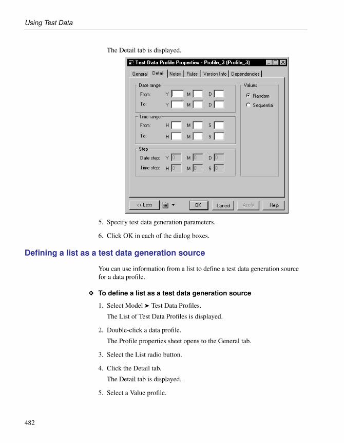
Using Test Data
The Detail tab is displayed.
5. Specify test data generation parameters.
6. Click OK in each of the dialog boxes.
Defining a list as a test data generation source
You can use information from a list to define a test data generation sourcefor a data profile.
v To define a list as a test data generation source
1. Select Model ä Test Data Profiles.
The List of Test Data Profiles is displayed.
2. Double-click a data profile.
The Profile properties sheet opens to the General tab.
3. Select the List radio button.
4. Click the Detail tab.
The Detail tab is displayed.
5. Select a Value profile.
482

Chapter 9. Generating a Database from a PDM
6. Type a value and label.
7. Click OK in each of the dialog boxes.
Defining a live database connection as a test data generation source
You can use information from a live database connection to define a test datageneration source for a data profile.
v To define a database as a test data generation source
1. Select Model ä Test Data Profiles to open the List of Test Data Profiles.
2. Double-click a data profile to open its property sheet.
3. Select the Database Generation radio button, and then click the Detail tab.
4. Click the Select a data source tool beside the Data source box and select amachine or file data source. For more information, see “Connecting to aDatabase” section in the Models chapter of the Core Features Guide .
5. Type the login and password corresponding to your data source.
6. Type the name of the table and column to query in the data source.
The variables in the default query are replaced by the table and columnvalues.
483

Using Test Data
You can also type a user-defined query in the Query box. Theuser-defined button indicates when the default query has been modified.You can click this button to recover the default query.
7. Click OK.
You return to the List of Test Data Profiles.
8. Click OK.
Defining a file as a test data generation source
You can import a CSV file to define a data generation source for a dataprofile. You can define the following generation source parameters for theCSV file:
Value Parameter Description
Values Random Indicates to import file lines in random order
Sequential Indicates to import file lines sequentially
CSV import restriction Each CSV file that you import for each data profile must come from thesame directory. If you have not previously used this directory as a CSV filetest data source, you will need to select the correct directory to define the filepath.
484

Chapter 9. Generating a Database from a PDM
Example test data filesPowerDesigner provides example test data files in the \TESTDATA direc-tory.
v To define a file as a test data generation source
1. Select Model ä Test Data Profiles.
The List of Test Data Profiles is displayed.
2. Double-click a data profile.
The Profile properties sheet opens to the General tab.
3. Select the File radio button.
4. Click the Detail tab.
The Detail tab is displayed.
A dialog box asks you to select a file.
Specifying the CSV directoryIf you are importing a CSV file for the first time from a specificdirectory, you need to select the appropriate directory.
5. Select a file and click Open.
You return to the Detail tab.
485

Using Test Data
6. Specify test generation parameters.
7. Click OK.
You return to the List of Test Data Profiles.
8. Click OK.
Defining column fill parameters
Fill parameters determine how a column is filled or populated with testdata. You can define column fill parameters when you assign a data profile tothe column, or as an independent procedure.
You can define the following fill parameters:
Value Description
Null values Percentage of column entries containing a null value
Distinct values Indication of the percentage of column rows that containunique entries. This is a maximum value, and can changeautomatically depending on the referential integrity param-eters of primary key columns. Alternately, a specific valuecan be entered, without a percentage sign, to indicate theexact number of column rows that contain unique entries.
Average LengthThe Average Length box is only used for the Estimate data base sizefunction. The value that is displayed by default, is the maximum length forthe data type defined for a selected column.
Indicated columnproperties
The following column properties are indicated on the Columns sheet:
Indicator Property When selected, indicates that. . .
M Mandatory Column must be assigned a value. The fillparameter Null value is automatically defined as0%
U Unique col-umn
Column is the only column in a primary key, al-ternate key, or unique index. The fill parametersNull Values and Distinct Values are automati-cally defined as 0% and 100% respectively
F Foreign Column is a foreign key column. You cannotassign a data profile to this column. It automati-cally takes the data profile of the correspondingprimary key column in the parent table
486

Chapter 9. Generating a Database from a PDM
v To define column fill parameters
1. Select Model ä Tables.
The List of tables is displayed.
2. Double-click a table from the list.
The Profile properties sheet opens to the General tab.
3. Select the Columns tab.
The Columns tab is displayed.
487

Using Test Data
4. Double-click a column name.
The Column properties dialog box is displayed.
5. Select the Detail tab.
The Detail tab is displayed.
6. Select or type Column fill parameters.
7. Select a profile from the test data parameters dropdown list box.
8. Click OK in each dialog box.
You return to the Columns tab.
9. Click OK.
Assigning a data profile
When you assign a data profile to a column, the data profile defines the typeof test data that you generate for that column.
You can assign a data profile to each column in a table, except for the foreignkey columns. The data profiles for foreign keys are assigned by default.
When you assign a data profile to a column that contains check parameters,the generated test data respects the column constraints.
488

Chapter 9. Generating a Database from a PDM
There are three approaches to assigning data profiles:
♦ Assign a data profile from the list of tables
♦ Assign a data profile from the list of columns
♦ Select a data profile for a domain, so that all columns attached to thatdomain are automatically assigned the data profile.
+ For more information on how to select a data profile for a domain, seechapter Building Physical Diagrams.
Assigning a data profile from the list of tables
v To assign a data profile from the list of tables
1. Select Model ä Tables.
The List of tables is displayed.
2. Double-click a table in the list.
The table property sheet opens to the General tab.
3. Select the Columns tab.
The Columns tab is displayed.
489

Using Test Data
4. Select a column in the list.
5. Select a test data profile from the dropdown list box.
Display the column you needIf you do not see the column you need, display it with the CustomizeColumns and Filter tool. For details, see “Customizing object listcolumns and filtering lists” section in the Objets chapter of the CoreFeatures Guide .
6. Click OK.
Assigning a data profile from the list of columns
490

Chapter 9. Generating a Database from a PDM
v To assign a data profile from the list of columns
1. Select Model ä Columns.
The List of Columns is displayed.
2. Select a column in the list.
3. Select a test data profile from the dropdown list box.
Display the column you needIf you do not see the column you need, display it with the CustomizeColumns and Filter tool. For details, see “Customizing object listcolumns and filtering lists” section in the Objets chapter of the CoreFeatures Guide .
4. Click OK.
Importing a data profile
You can import data profiles in XPF format from another PDM. Theimported profiles appear in the list of profiles.
v To import a data profile
1. Select Tools ä Test Data Profiles ä Import.
A standard Open dialog box is displayed.
2. Browse to the EXAMPLES/TUTORIAL directory.
491
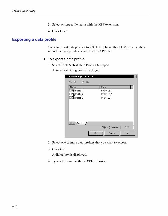
Using Test Data
3. Select or type a file name with the XPF extension.
4. Click Open.
Exporting a data profile
You can export data profiles to a XPF file. In another PDM, you can thenimport the data profiles defined in this XPF file.
v To export a data profile
1. Select Tools ä Test Data Profiles ä Export.
A Selection dialog box is displayed.
2. Select one or more data profiles that you want to export.
3. Click OK.
A dialog box is displayed.
4. Type a file name with the XPF extension.
492

Chapter 9. Generating a Database from a PDM
5. Click Save.
Generating test data
You can generate test data for all the tables in a PDM, or for selected tables.
You can generate data for either an empty database or for an existingdatabase.
Avoid generating triggersDo not implement triggers if you generate a new database. It is alsorecommended that you remove triggers from an existing test database.Triggers can considerably increase the time required to generate thedatabase and can block insertions. In addition, they are not needed for thetype of test we are performing.
v To generate test data
1. Assign data profiles to the columns in each table for which you want togenerate test data (see “Assigning a data profile” on page 488).
Default values for data profilesTest data generation is typically based on user-defined data profiles.If you have no data profile definitions, you are automatically providedwith default values. The default number of rows is set to 20 and thevalue <default> is displayed in each of the following three defaultprofile boxes.
2. Select Database ä Generate Test Data to open the Test Data Generationdialog box.
493

Using Test Data
3. Specify a directory and filename for your test data file, and then choosebetween Script and Direct generation. For more information, see “TestData Generation General tab” on page 494.
4. [optional] To change the number of rows to be generated for specifictables, click the Number of Rows tab. For more information, see “TestData Generation Number of Rows tab” on page 496.
5. [optional] To modify script formatting options, click the Format tab. Formore information, see “Test Data Generation Format tab” on page 497.
6. [optional] To control which tables will have test data generated, click theSelection tab. For more information, see “Test Data Generation Selectiontab” on page 499.
7. Click OK to start the generation.
If you are generating a test data script : then a Result dialog box asksyou if you want to Edit or Close the newly generated file.
If you are generating test data to a live database connection , then aConnect to a Data Source dialog box opens.
Select a data source, and then click Connect.
A message in the Output window indicates that the test data generation iscompleted.
Test Data Generation General tab
The General tab allows you to set general generation options.
494

Chapter 9. Generating a Database from a PDM
The following options are available on this tab:
Option Result of selection
Directory Specifies the directory in which the file will besaved.
File name Specifies the name of the file.
Select the One file only checkbox to specify thatonly a single file can be generated.
Generation type Specifies how the test data will be generated. Thefollowing settings are available:♦ Script generation - in DBMS-specific syntax
♦ Direct generation – to a live database connec-tion
♦ Data file – as a set of values in a file
495

Using Test Data
Option Result of selection
Commit mode Specifies when the data will be committed. Thefollowing settings are available:♦ Auto - automatically during script generation
♦ At end - at end of script generation
♦ By packet - at defined intervals during scriptgeneration
Data file format For use with the data file option. The followingsettings are available:♦ CSV – comma-separated values
♦ Custom delimiter – specify a custom delimiter
Delete old data Deletes existing data before generating new data..
Check model Checks the PDM before generating the testdatabase or script, and stops generation if anerror is found.
Automatic archive Creates an archive of any previous test data.
Default number of rows Specifies the default number of rows for table
Default number profile Specifies the default number profile for table
Default character profile Specifies the default character profile for table
Default date profile Specifies the default date profile for table
Test Data Generation Number of Rows tab
The Number of Rows tab allows you to specify the number of rows of testdata to generate. Enter the required number in the Test Number column.
496

Chapter 9. Generating a Database from a PDM
Test Data Generation Format tab
The Format tab allows you to set script format options.
497

Using Test Data
The following options are available on this tab:
Option Result of selection
Owner prefix Specifies that an owner prefix is added.
Titles Specifies that each section of the script includes commen-tary in the form of titles.
Encoding Specifies the encoding format to use for test data genera-tion. You should select the encoding format that supportsthe language used in your model and the database encod-ing format.
Character case Specifies the character case to use. The following settingsare available:♦ Upper - all uppercase characters
♦ Lower - all lowercase characters
♦ Mixed - both uppercase and lowercase characters
No accent Non-accented characters replace accented characters inscript.
498

Chapter 9. Generating a Database from a PDM
Test Data Generation Selection tab
The Selection tab allows you to specify tables for which test data will begenerated.
+ For more information on selection windows, see “Adding an item from aselection list” section in the Objects chapter of the Core Features Guide .
499

Estimating Database Size
Estimating Database SizeYou can estimate the size of a database for all the tables in the model or foronly selected tables throughout the model.
Basis of calculation You obtain an estimate based on the following elements:
♦ Estimated number of records in tables
♦ Columns in each table
♦ Indexes in the model
♦ Tablespaces in the model
♦ Database storage options
Estimation depends on parameters like DBMS type, physical options,column data types, indexes and keys. The estimation formula used in thisfeature proceeds from the DBMS documentation.
Records in tablesYou indicate a number of records in each table in your model.
Columns The estimated database size for a column is based on the following:
♦ Size of fixed length data types
♦ Average size of variable length data types
Indexes The estimate of the database size includes all indexes including primary keyindexes, foreign key indexes, alternate key indexes and database-specificindexes such as IQ join indexes.
Automatic index constraintsThe automatic indexing of keys is DBMS specific. If the target databasesupports the automatic indexing of keys, the resulting database size estima-tion includes these indexes.
Tablespace size The size of a tablespace associated with a table is estimated by default, andis displayed as a total of the following:
♦ All tables in the tablespace
♦ All indexes in the tablespace
+ For more information on how to associate a tablespace with an index ortable, see section Creating an Index in chapter Building Physical Diagrams.
500

Chapter 9. Generating a Database from a PDM
Storage options Data storage options are DBMS specific. You define data storage optionssupported by the target database. These are included in the estimate ofdatabase size.
Indicating the number of records in a table
Before you estimate database size, you indicate the number of records ineach table that you generate.
v To indicate the number of records in a table
1. Select Model ä Tables.
The List of Tables is displayed.
2. Display the Test Number column.
Display the column you needIf you do not see the column you need, display it with the CustomizeColumns and Filter tool. For details, see “Customizing object listcolumns and filtering lists” section in the Objets chapter of the CoreFeatures Guide .
3. Type a value in the Test Number column for the table that requires anindication of the number of records.
501

Estimating Database Size
4. Click OK.
Indicating average data type length
You can indicate the estimated average data type length for variable lengthdata types. This average length value is then used instead of the maximumdata type length when you estimate database size.
Average size must be carefully selectedThe average length value is particularly important for strings or long binarydata types. A Binary Long OBject (BLOB) such as a picture can representthe largest portion of the space actually taken by a table.
v To indicate average data type length
1. Select Model ä Tables.
The List of Tables is displayed.
2. Double-click a table name.
The Table Properties sheet opens to the General tab.
3. Click the Columns tab.
The Columns tab is displayed.
4. Double-click a column that uses a data type with variable length.
The Column Properties sheet opens to the General tab.
5. Click the Detail tab.
The Detail tab is displayed.
502

Chapter 9. Generating a Database from a PDM
6. Type a value in the Average length box.
7. Click OK in each of the dialog boxes.
Estimating the database size of a model
You can estimate the database size of all the tables in the model.
503

Estimating Database Size
v To estimate the database size of all the tables in the model
1. Select Database ä Estimate Database Size.
The Database Size Estimation dialog box is displayed.
2. Click the Include Sub-Packages button.
3. Select all the tables from the list.
4. Click OK.
The output list displays the estimated database size.
Estimating the database size of selected tables
You can estimate the database size of selected tables in the model.
v To estimate the database size of selected tables in the model
1. Select Database ä Estimate Database Size.
The Database Size Estimation dialog box is displayed.
2. Select a package from the list.
The list of tables in the currently selected package is displayed.
3. Select one or more tables from the list.
504

Chapter 9. Generating a Database from a PDM
4. If required, repeat steps 2 and 3 until all the tables of interest have beenselected throughout the model.
5. Click OK.
A confirmation box is displayed asking if you want to keep all previouslyselected objects in the database size estimate.
6. Click OK.
The output list displays the estimated database size.
505

Modifying a Database
Modifying a DatabaseYou can modify an existing database schema by synchronizing it with yourmodel. The existing schema can be in the form of:
♦ an archive model
♦ a live database connection
♦ a script file
♦ a model from the repository
The PDM (source model) and the existing database schema (target model)are merged using a database synchronization window, which allows you tochoose which objects are added, deleted, or updated in the target.
v To modify a database
1. Select Database ä Apply Model Changes to Database to open the ApplyModel Changes to Database dialog box.
2. Type a destination directory and filename for the script file in theDirectory and File Name boxes.
3. Specify the type of generation to perform. You can choose between ascript and a live database connection.
4. Specify how PowerDesigner will obtain the database schema to modify.You can choose between:
♦ Using an archive model – Click the button to the right to browse to thearchived model.
♦ Using a data source – Click the button to the right to connect to yourdata source.
♦ Using a script file – Select a script from the list or click the button tothe right to browse to the script.
♦ Using a model from repository – Click the Change Model Version toolto the right to browse to a version of the currently selected model.
5. If you want to retain your existing data, select the Backup Tables option.If this option is not selected, then all existing data will be erased. Fordetails of this and other options on this tab, see “Apply Model Changes toDatabase dialog General tab” on page 508.
6. [optional] If you want to change the default generation options, then clickthe Options tab. For more information about these options, see “ApplyModel Changes to Database dialog Options tab” on page 510.
506

Chapter 9. Generating a Database from a PDM
7. [optional] If you want to change the format of your script, then click theFormat tab. This tab has the same functionality as in the DatabaseGeneration window (see “Database Generation dialog Format tab” onpage 456).
8. [optional] If you want to control which database objects will be modified,then click the Selection tab. This tab has the same functionality as in theDatabase Generation window (see “Database Generation dialog Selectiontab” on page 458)
9. Click OK. If you are using a live database connection, then the ReverseEngineering window will open, allowing you to select or clear checkboxes in the target model for objects that you want to include or removefrom the source model. Make your selections and then click OK tocontinue.
10. The Database Synchronization window will open. Select or clear checkboxes in the target model for objects that you want to include or removefrom the model.
+ For more information on comparing and merging models, see theComparing and Merging Models chapter in the Core Features Guide .
11. Click OK.♦ If you are generating a script, at the end of generation a result box
opens listing the file path of the generated file. To open the script in atext editor, click the file in the result box and click the Edit button. Toclose the Result box, click the Close button.
507

Modifying a Database
♦ If you are generating a database directly, a Data Source connection boxis displayed. Type your connection details and click the Connectbutton. A message box shows the progress of the generation process.At the end of generation click OK to close the box.
Modify Database options
The following sections give detailed information about the various optionsthat you can use to control database modification.
Apply Model Changes to Database dialog General tab
This tab controls the main options for database modification.
You can set the following options:
Option Description
Directory [required] Specifies the destination directory for thescript file.
508

Chapter 9. Generating a Database from a PDM
Option Description
File name [required] Specifies the destination filename for thescript file.
One file only Specifies that the generation script is created as a singlefile. By default, a separate script file is created for eachtable.
Generation Type Specifies the type of generation to perform. You canchoose between:♦ Script generation - generate a script to be executed
on a DBMS at a later time
♦ Direct generation – generate a script and execute iton a live database connection
Edit generationscript
[available only when direct generation is selected]Opens the generation script in a text editor for review orediting before execution on a live database connection.
Obtains databaseschema
Select the kind of schema that the model will modify.You can choose between:♦ Using an archive model - Modified PDM is merged
with an archived PDM.
♦ Using a data source - Modified PDM is mergedwith a reverse engineered database schema for a livedatabase connection.
♦ Using a script file - Modified PDM script file ismerged with an existing database script file.
♦ Using a model from repository - Modified PDM ismerged with a selected version of a PDM consoli-dated in the repository.
Backup tables Specifies that any existing table will be copied totemporary backup tables during the modification, andthen restored to the updated tables. If this option is notselected, then all existing data will be erased.
Always use createstatements/
Use alter state-ments when possi-ble
Select a radio button to specify whether create state-ments should always be used to modify database tables,or whether alter statements should be used where pos-sible
509

Modifying a Database
Option Description
Drop temporarytables
[available only when Backup Tables is selected] Speci-fies that the temporary backup tables are removed afterscript execution.
Use physical op-tions for temporarytables
[available only when Backup Tables is selected] Spec-ifies that the temporary backup tables are generatedwith their physical options.
Check model Specifies that a model check is performed before scriptgeneration.
Automatic archive Creates an archive version of the PDM after generation.
You can load option settings previously used for database generation via theSettings set bar at the bottom of the tab. For more information, see “Quicklaunch selection and settings sets” on page 441.
Apply Model Changes to Database dialog Options tab
This tab controls certain script options.
510

Chapter 9. Generating a Database from a PDM
These options are dependent on the selected DBMS and certain of them maybe unavailable.
Option Result of selection
Inside/
Outside
Specifies whether and where various constraints will be gen-erated. Note that if alter statements are used to modify tables,then constraints may be generated outside the table even if theinside radio button is selected here.
Index Fil-ter
Specifies which kinds of indexes to generate.
Comment Specifies whether comments are generated.
You can load option settings previously used for database generation via theSettings set bar at the bottom of the tab. For more information, see “Quicklaunch selection and settings sets” on page 441.
Apply Model Changes to Database dialog Format tab
This tab controls the format of your modification script. It has the same
511

Modifying a Database
functionality as the equivalent tab in Database Generation (see “DatabaseGeneration dialog Format tab” on page 456).
Apply Model Changes to Database dialog Selection tab
The Selection tab allows you to specify individual objects to generate. It hasthe same functionality as the equivalent tab in Database Generation (see“Database Generation dialog Selection tab” on page 458).
512

Chapter 9. Generating a Database from a PDM
Accessing a DatabasePowerDesigner allows you to display data from the database thatcorresponds to your model, and to send SQL queries to a connected datasource.
Displaying data from a database
If the database corresponding to the PDM already exists, you can display thedata that corresponds to a table, view, or reference in the PDM.
v To display data from a connected database
1. Right-click a table, view, or reference.
A contextual menu is displayed.
2. Select View Data from the contextual menu.
A dialog box asks you to identify a data source and connectionparameters.
3. Select the Machine data source radio button.
Select a data source from the list.
or
Select the File data source radio button.
Browse to the directory containing the .DSN file.
Select the .DSN file.
513

Accessing a Database
4. Type your user ID and password.
5. Click Connect and, if prompted by your data source, type additionalconnection parameters.
A Query Results windows list all the database records corresponding tothe selected table, view, or reference.
6. Click the Close button.
Executing SQL queries
You can send SQL queries to a database and display the results.
v To execute a SQL query
1. Select Database ä Execute SQL. If you are not already connected to adatabase, the Connect to Data Source window will open. Choose yourconnection profile and click Connect to proceed to the Execute SQLQuery dialog.
2. Type one or more SQL statements in the window, and click Run to applythem to the database.
The query results are displayed in the Results window.
514

CHAPTER 10
Reverse Engineering a Database into aPDM
About this chapter This chapter describes how to reverse engineer database objects into a PDM.
Contents Topic: page
Getting Started with Reverse Engineering 516
Reverse Engineering from Scripts 517
Reverse Engineering from a Live Database 520
Reverse Engineering Options 524
Reverse Engineering Database Statistics 532
515

Getting Started with Reverse Engineering
Getting Started with Reverse EngineeringReverse engineering is the process of generating a PDM (or certain PDMobjects) from an existing database schema. You can reverse engineer anexisting database schema into a new PDM or into an existing PDM.
There are two ways to reverse engineer a PDM from a database schema:
Generateusing
Description
Script file The script will normally be the script used to generate thedatabase but can also include other scripts.
If you use more than one script files, make sure that the orderof the files respects dependencies among objects (for example,trigger creation scripts must come after table creation scripts;and grant permission scripts must come after both table anduser creation scripts.
For more information, see the “Reverse Engineering fromScripts” on page 517 section.
Datasource
You reverse engineer the schema for an existing database,specifying an data source, and connection information.You canselect to use administrator permissions in order to be able toselect the system tables that are reserved to a database admin.
For more information, see the “Reverse Engineering from aLive Database” on page 520 section.
Set options appropriatelyWhen you reverse engineer a database, whether from a script or a datasource, make sure that you set the rebuild options appropriately. Click theOptions tab and select or clear the checkboxes to rebuild references and/orprimary keys according to your needs. By default, no rebuild options areselected.
516
Chapter 10. Reverse Engineering a Database into a PDM
Reverse Engineering from ScriptsPowerDesigner can reverse engineer a PDM for one or more SQL script files.
Reversing from SQL files in EclipseWhen working with the PowerDesigner Eclipse plug-in you can, in additionto the procedure below, select any SQL file in the Navigator, right-click itand select Reverse Engineer from SQL File. You will be given the optionto reverse into an existing or new PDM.
v To reverse engineer objects one or more script files
1. To reverse engineer a script into an existing PDM, select Database ä
Update Model from Database.
or
To reverse engineer a script and create a new PDM, select File ä ReverseEngineer ä Database to open the New Physical Data Model dialog box.Specify a model name, choose a DBMS from the list, and then click OK.
2. When the Database Reverse Engineering Options dialog box opens, clickthe Using script files radio button.
Always place trigger script files after table script filesYou can add as many script files as necessary to the list. The reverseengineering process handles files sequentially. Trigger scripts mustalways be executed after table scripts. This is the only constraint forordering your files in the list, but it is essential for a successful reverseengineering of triggers. Use the Move tools to position the files correctlyin the list.
517

Reverse Engineering from Scripts
3. Click the Options tab to specify any reverse engineering options. Formore details, see “Reverse engineering Options tab” on page 524.
4. Click the Target Models tab to specify any external shortcuts. For moredetails, see “Reverse engineering Target Models tab” on page 527.
5. Click OK to begin the process of reverse engineering. When the processis complete, a confirmation message is given in the Output window. Ifyou are reverse engineering to an existing PDM, then the Merge Modelsdialog box opens to help you merge the new objects into your PDM.
+ For more information on comparing and merging two models, see theComparing and Merging Models chapter in the Core Features Guide .
Script file tools
The following tools are available to help you to select script files:
518

Chapter 10. Reverse Engineering a Database into a PDM
Tool Description
Add Files – Opens a dialog box to allow you to browse for scriptsfiles. You can add as many files as necessary.
Move Up – Moves the selected file(s) up one row. This tool isgrayed if the selected file(s) are at the top of the list.
Move Down - Moves the selected file(s) down one row. This tool isgrayed if the selected file(s) are at the bottom of the list.
Clear All - Deletes all files from the list.
519

Reverse Engineering from a Live Database
Reverse Engineering from a Live DatabasePowerDesigner can reverse engineer a PDM from a live database connection.
v To reverse engineer database objects from a live database con-nection1. To reverse engineer from a live database connection into an existing
PDM, select Database ä Update Model from Database to open theDatabase Reverse Engineering Options dialog box.
or
To reverse engineer from a live database connection and create a newPDM, select File ä Reverse Engineer ä Database to open the NewPhysical Data Model dialog box. Specify a model name, choose a DBMSfrom the list, and then click OK.
2. When the Database Reverse Engineering Options dialog box opens, clickthe Using a data source radio button.
520

Chapter 10. Reverse Engineering a Database into a PDM
Data sourceA data source might be predefined, or you can type the name of anexisting data source. In both cases, when you click OK, a databaseconnection dialog box opens, if you need to specify additional connec-tion parameters. Click Connect and the Database Reverse Engineeringdialog box is displayed. (Go to step 9)
3. Click the Connect to a Data Source tool to open the Connect to anODBC Data Source dialog box.
4. Select the appropriate source, type a user ID and a password, and thenclick Connect to return to the Database Reverse Engineering Optionsdialog box.
5. If you want to select tables reserved to the database administrator, thenyou must select the Reverse using administrator’s permissions checkbox.
6. Click the Options tab to specify any reverse engineering options. Formore details, see “Reverse engineering Options tab” on page 524.
521

Reverse Engineering from a Live Database
7. Click the Target Models tab to specify any external shortcuts. For moredetails, see “Reverse engineering Target Models tab” on page 527.
8. Click OK to open the ODBC Reverse Engineering dialog box. This boxallows you to specify a selection of objects to reverse engineer. Onlytables and triggers are selected by default.
For more information about selecting objects, see “Database Reverse
522
Chapter 10. Reverse Engineering a Database into a PDM
Engineering Selection window” on page 528.
9. Click OK to begin the process of reverse engineering. When the processis complete, a confirmation message is given in the Output window. Ifyou are reverse engineering to an existing PDM, then the Merge Modelsdialog box opens to help you merge the new objects into your PDM.
+ For more information on comparing and merging two models, see theComparing and Merging Models chapter in the Core Features Guide .
523

Reverse Engineering Options
Reverse Engineering OptionsThe following sections give detailed information about the various optionsthat you can use to control reverse engineering.
Reverse engineering Options tab
When you reverse engineer a database schema using script files or a datasource, you can define rebuild options after reverse engineering.
The rebuild options automatically perform the following tasks after reverseengineering:
Reverse options Description
Automatically re-build referenceswhen no reference isreversed
Rebuilds references when no references are reverseengineered. The rebuild references feature starts bydetecting columns with identical name and data typein different tables. A reference is created betweeneach column belonging to a primary key and a col-umn, with identical name and data type, that does notbelong to a primary or a foreign key in another table.
Automatically re-build primary keysfrom unique indexeswhen tables have nokey and only oneunique index
Rebuilds primary keys using unique indexes whentables have no key and only one unique index.
Automatically re-verse tables refer-enced by selectedtables
Reverse engineers the parents of the selected childtables in order to complement the definition of thesechild tables.
524

Chapter 10. Reverse Engineering a Database into a PDM
Reverse options Description
Create symbols Creates a symbol for each reversed object in thediagram. Otherwise, reversed objects are visible onlyin the browser.
The layout of the symbols in the diagram will beautomatically arranged. In cases where there are alarge number of objects with complex interactions,the auto-layout feature is likely to create synonymsof objects to improve the diagram readability. Forexample, if a table has a large number of references,the auto-layout feature will create a synonym of thistable in another location of the diagram in order toimprove the diagram presentation.
File encoding Specifies the default file encoding of the files toreverse engineer. Click the ellipsis to the right ofthe option to change the encoding (see “Reverseengineering encoding format” on page 525).
Block terminator Specifies the end of block character for the reversedscript. By default, displays the value defined in theDBMS, under Script\SQL\Syntax. You can modifythis value, in which case it will be saved in theRegistry for reuse in other models. You can restorethe DBMS value using the Restore from DBMS tool.
Command termina-tor
Specifies the end of command character for thereversed script. By default, displays the value definedin the DBMS, under Script\SQL\Syntax. You canmodify this value, in which case it will be saved in theRegistry for reuse in other models. You can restorethe DBMS value using the Restore from DBMS tool.
Case sensitivedatabase
Specifies that the database is case sensitive andenables the case sensitive option in the model.
+ For more information on indexes, rebuilding references and rebuildingprimary keys, see chapter Building Physical Diagrams.
Reverse engineering encoding format
If the code you want to reverse engineer is written with Unicode or MBCS(Multibyte character set), you should use the encoding parameters providedto you in the File Encoding box.
525

Reverse Engineering Options
If you want to change these parameters because you know which encoding isused within the sources, you can select the appropriate encoding parameterby clicking the Ellipsis button beside the File Encoding box. This opens theText Input Encoding Format dialog box in which you can select theencoding format of your choice.
The Text Input Encoding Format dialog box includes the following options:
Option Description
Encoding hint Encoding format to be used as hint when reversing thefile.
Detection mode Indicates whether text encoding detection is to be at-tempted and specifies how much of each file should beanalyzed. When enabled, PowerDesigner analyzes a por-tion of the text, and uses an heuristic based on illegal bytessequences and/or the presence of encoding-specific tagsin order to detect the appropriate encoding that should beused for reading the text.
The following settings are available:♦ No detection - for use when you know what the encod-
ing format is
♦ Quick detection - analyzes a small part of the file. Foruse when you think that the encoding format will beeasy to detect
♦ Full detection – analyzes the whole file. For use whenyou think that the number of characters that determinethe encoding format is very small
526

Chapter 10. Reverse Engineering a Database into a PDM
Option Description
On ambiguousdetection
Specifies what action should be taken in case of ambigu-ity. The following settings are available:♦ Use encoding hint and display warning - the encod-
ing hint format is used and a warning message is dis-played.
♦ Use encoding hint - the encoding hint format is usedbut no warning message is displayed.
♦ Use detected encoding - the encoding format detectedby PowerDesigner is used
Abort on charac-ter loss
Allows you to stop reverse engineering if characterscannot be identified and are to be lost in current encoding
Here is an example on how to read encoding formats from the list:
Reverse engineering Target Models tab
External shortcuts depend on their corresponding target objects located indifferent models. When you need several models to design a single database,you can use shortcuts to share objects between models.
During reverse engineering, PowerDesigner allows you to create externalshortcuts from target objects in target models. In the Database ReverseEngineering Options dialog box, the Target Models tab displays the list ofdetected target models containing target objects for shortcuts in the currentmodel to reverse.
This tab is always visible in the Database Reverse Engineering Optionsdialog box, even if the model does not contain shortcuts.
This tab is empty when you reverse engineer into a new model. This is to letyou add target models and create shortcuts instead of duplicating objects.
You can use the Target Models tab in the Database Reverse EngineeringOptions dialog box to manage target models using the following tools:
527

Reverse Engineering Options
Tool Tooltip Description
Change TargetModel
Displays a standard Open dialog box to let youselect another file as target model
Open Model Opens selected target model in current workspace
Add Models Opens a selection list with the models opened inthe current workspace. This tool is particularlyuseful when you reverse engineer into a newmodel where the target models are not defined
Delete Deletes the target model and the shortcuts in thecurrent model that reference the deleted targetmodel
When you reverse engineer a model, any target models should be open inyour workspace. If not, the following confirmation dialog box is displayedto let you open the target models:
Reverse engineeringfrom script
All the create statements in the script create objects, provided the scriptcontains a full definition of the object.
When the script only uses an object and does not define it, this object issought among the target objects in the target models and an external shortcutis created in the reversed model.
Reverse engineeringfrom data source
When you reverse engineer from a live database connection, externalshortcuts are created for all selected objects already existing in another targetmodel. These existing objects are deselected by default in the Selection tabof the Reverse Engineering dialog box, except the target objectscorresponding to shortcuts already existing in the reversed model.
Database Reverse Engineering Selection window
When you reverse engineer a database from a live database connection, youcan choose to generate a PDM for all, or just selected objects. You make thisselection in the Database Reverse Engineering Selection window:
528

Chapter 10. Reverse Engineering a Database into a PDM
The object types that you can reverse engineer are DBMS-dependent.Unavailable object types do not appear for selection.
Filters You can restrict database objects to reverse engineer by selecting an owneror a database qualifier in the top area of the window:
Filter Description
Qualifier A qualifier is a database, or a partition in a database, thatcontains one or more tables. When a qualifier is selected as afilter, it restricts the objects available for reverse engineering tothe objects contained within the selected qualifier. For example,the DB2 DBMS authorizes the use of the qualifier field to selectwhich databases are to be reverse engineered from a list.
Owner Normally the creator of a database object is its owner. When anowner is selected as a filter; it restricts the objects available forreverse engineering to the objects owned by the selected owner.
You can filter on a qualifier and/or owner in either of the following ways:
♦ Select a qualifier in the Filter on object qualifier list and/or select a userID in the Filter on object owner list.
♦ Click the Select Qualifier and Owner tool, and type a qualifier and/orowner in the dialog box. This method is recommended if the selectedqualifier contains a large number of table owners, as opening the Ownerlist may take a very long time.
529

Reverse Engineering Options
Note that only users that have creation rights are reverse engineered.
Selecting objects from multiple ownersTo reverse engineer objects from multiple owners, you can select All usersas a filter from the owner list. All the objects belonging to all ownersappear in the list, and you can select the objects for reverse engineeringregardless of their owner.
Objects and options You access different object types to select by clicking on the appropriatesub-tabs.
Tables and triggersWhen you select tables containing triggers from the Table tab, the corre-sponding triggers are automatically selected in the Trigger tab.
Certain object types have attributes, or options, that appear below the objectlists. These options depend on the selected object type and on the currentDBMS. Unavailable options appear grayed.
User-defined and abstract data typesYou can reverse engineer user-defined and abstract data types. In thegenerated PDM, the names of these data types appear in the List ofAbstract Data Types.
Selection list You can save your selections for re-use by entering a selection name in thelist at the bottom of the window and clicking the save tool to the right of thelist. Selections are saved with a .sel file extension, and are added to the listfor subsequent use. You can change the folder in which the files are saved byclicking the folder tool to the right of the list.
+ For more information on selection windows, see “Adding an item from aselection list” section in the Objects chapter of the Core Features Guide .
Reverse engineering a Microsoft Access 97 database
PowerDesigner and MS Access 97 use .DAT files to exchange information.These files are reversed into the PDM. The access.mdb database uses orcreates .DAT files to reverse Access databases.
530

Chapter 10. Reverse Engineering a Database into a PDM
You can define the database reverse parameters from the access.mdbdatabase window.
v To reverse an MS Access database into a PowerDesigner PDM
1. Double-click ACCESS.MDB in the PowerDesigner \tools directory.
2. Select Reverse Engineer Access Database File to PowerDesigner Script.
3. Type the Access database name in the Select Database box.
4. Type the .DAT file to create in the PowerDesigner File.
5. Click the Create button.
6. Select DBMS ä Reverse Engineering Databases in PowerDesigner.
7. Select the newly generated script file to reverse.
8. Click OK.
Optimizing live database reverse engineering queries
Live database reverse engineering has been optimized in order to improveperformance. All queries run according to an optimization process rule. Thisprocess uses the following registry keys:
♦ RevOdbcMinCount defines a number of selected objects for reverseengineering. The default number is 100
♦ RevOdbcMinPerct defines a percentage of selected objects for reverseengineering. The default percentage is 10
These keys do not exist by default, you have to create and edit them in theRegistry under:
Current User \Software\Sybase\PowerDesigner <version>\FolderOptions\Physical Objects
During reverse engineering, PowerDesigner compares the total number ofcurrent objects for reverse engineering to the value of RevOdbcMinCount.
If the total number of listed items is lower than the value ofRevOdbcMinCount A global reverse query is executed.
If the total number of listed items is higher than the value ofRevOdbcMinCount The process uses key RevOdbcMinPerct.♦ If the percentage of reversed items is lower than the percentage defined in
RevOdbcMinPerct, then the same query is executed for each object.
♦ If the percentage of reversed items is higher than the percentage definedin RevOdbcMinPerct, then a global query is executed.
531

Reverse Engineering Database Statistics
Reverse Engineering Database StatisticsYou can reverse engineer statistics for an existing database, such as thenumber of distinct or null values in a column or the average length of acharacter field. These can provide helpful information when optimizing adesign.
You can reverse engineer the statistics as part of the general reverseengineering process by selecting the Statistics checkbox in the DatabaseReverse Engineering window (see “Reverse Engineering from a LiveDatabase” on page 520), or update them at any other time, using thededicated Update Statistics window.
v To update database statistics
1. Select Tools ä Update Statistics to open the Update Statistics window (ifPowerDesigner is not presently connected to a database via a livedatabase connection, you will be required to connect):
2. On the General tab, select or clear the checkboxes to specify whether youwant to update statistics for tables and/or columns.
3. [optional] Click the Selection tab and select or clear checkboxes tospecify for which tables you want to update statistics:
532

Chapter 10. Reverse Engineering a Database into a PDM
4. Click OK to begin the update. Progress appears in the Output window.For large updates, a progress dialog box opens, allowing you to cancelthe update at any time.
When the process is complete, you can view the updated statistics in theproperty sheets of your tables and columns.
533


CHAPTER 11
DBMS-Specific Features
About this chapter PowerDesigner can be used with a number of DBMS with specific featuresoften requiring special procedures for certain tasks. This chapter describesthese DBMS-specific features and associated tasks.
+ For more information on DBMS definition file contents, see the DBMSResource File Reference chapter in the Customizing and ExtendingPowerDesigner manual.
Contents Topic: page
Working with PowerDesigner’s DBMS-Specific Features 536
IBM DB2 for z/OS (formerly OS/390) 537
IBM DB2 for Common Server 542
Informix SQL 549
Ingres 550
Interbase 551
Microsoft Access 552
Microsoft SQL Server 553
MySQL 617
NonStop SQL 619
Oracle 620
PostgreSQL 643
Red Brick Warehouse 648
Sybase AS Anywhere 649
Sybase AS Enterprise 655
Sybase AS IQ 659
Sybase SQL Anywhere 674
Teradata 678
535

Working with PowerDesigner’s DBMS-Specific Features
Working with PowerDesigner’s DBMS-SpecificFeatures
This chapter provides information about the DBMS-specific features inPowerDesigner.
PowerDesigner provides customized support for a wide range of databasefamilies through DBMS-specific resource files. These files have a .xdbextension, and are located in the “Resource Files\DBMS” directory insideyour PowerDesigner installation directory.
Resource files support, among others, three kinds of customization forPowerDesigner model objects:
♦ Assignment of standard objects to the specific syntax of a DBMS
♦ Definition of Extended Attributes for certain objects to allow forDBMS-specific object properties
♦ Definition of additional DBMS-specific model objects.
You can view and edit the resource file for your selected DBMS in theResource Editor by selecting Database ä Edit Current DBMS.
+ For more information about working with resource files and theResource File Editor, see the following chapters in the Customizing andExtending PowerDesigner manual:
♦ Resource Files and the Public Metamodel
♦ DBMS Resource File Reference
♦ Extending your models with Profiles
536

Chapter 11. DBMS-Specific Features
IBM DB2 for z/OS (formerly OS/390)This section describes features specific to the IBM DB2 for z/OS family ofdatabases.
Deprecated versionsThe DBMSs for IBM DB2 v5.x are deprecated.
The following table lists DB2 objects and their equivalents inPowerDesigner:
DB2 PowerDesigner
Bufferpool Storage
Database Partition Group Extended Object<<DatabasePartitionGroup>>
Distinct Type Domain
Function Procedure of “Function” type
Index Extension Extended Object <<IndexExtension>>
Method Abstract Data Type Procedure
Type Abstract Data Type
SuperView SubView of a View
Trusted contexts
Using a trusted context in an application can improve security by placingaccountability at the middle-tier, reducing over granting of privileges, andauditing of end-user’s activities.
Trusted contexts are supported for DB2 v9.x and higher for z/OS.PowerDesigner models trusted contexts as extended objects with astereotype of <<TrustedContext>>.
Creating a trustedcontext
You can create a trusted context in any of the following ways:
♦ Select Model ä Trusted Contexts to access the List of Trusted Contexts,and click the Add a Row tool.
♦ Right-click the model or package in the Browser, and select New ä
Trusted Context.
Trusted contextproperties
You can modify an object’s properties from its property sheet. To open a
537

IBM DB2 for z/OS (formerly OS/390)
trusted context property sheet, double-click its Browser entry in the TrustedContexts folder.
The following extended attributes are available on the DB2 tab:
Name Description
Enable Specifies that the trusted context is created in the enabledstate.
Scripting name: Enable
Authorization Specifies that the context is a connection that is establishedby the authorization ID that is specified by authorization-name.
Scripting name: Authorization
Default role Specifies the default role that is assigned to a user in a trustedconnection when the user does not have a role in the trustedcontext.
If empty, then a No Default Role is assumed.
Scripting name: DefaultRole
As objectowner
Specifies that the role is treated as the owner of the objectsthat are created using a trusted connection based on thetrusted context.
Scripting name: WithRoleAsObjectOwner
Default secu-rity label
Specifies the default security label for a trusted connectionbased on the trusted context.
Scripting name: DefaultSecurityLabel
Attributes Specifies one or more connection trust attributes that areused to define the trusted context.
Scripting name: Attributes
With use for Specifies who can use a trusted connection that is based onthe trusted context.
Scripting name: WithUseFor
Auxiliary tables
Auxiliary tables are used to store large object (LOB) data, such as graphics,video, etc, or to store rarely-accessed data in order to improve theperformance of the base table.
Auxiliary tables are supported for IBM DB2 v9.x and higher for z/OS.
538

Chapter 11. DBMS-Specific Features
PowerDesigner models auxiliary tables as extended objects with a stereotypeof <<Auxiliary Table>>.
Creating an auxiliarytable
You can create an auxiliary table in any of the following ways:
♦ Select Model ä Auxiliary Table to access the List of Auxiliary Tables,and click the Add a Row tool.
♦ Right-click the model or package in the Browser, and select New ä
Auxiliary Table.
Auxiliary table properties You can modify an object’s properties from its property sheet. To open anauxiliary table property sheet, double-click its Browser entry in theAuxiliary Tables folder.
The following extended attributes are available on the DB2 tab:
Name Description
Database Specifies the database in which the LOB data will be stored.
Scripting name: Database
Tablespace Specifies the table space in which the auxiliary table iscreated.
Scripting name: Tablespace
Table Specifies the table that owns the LOB column.
Scripting name: Table
Column Specifies the name of the LOB column in the auxiliary table.
Scripting name: Column
Partition Specifies the partition of the base table for which the auxiliarytable is to store the specified column.
Scripting name: Partition
Tablespace prefix
In IBM databases for OS/390, the physical options for a table can specify thetablespace in which a table resides, as well as the database name.
You declare a tablespace in a database and assign a table to a tablespace onthe Physical Options (Common) tabs of their property sheets.
If the tablespace is not declared in any database, then the tablespace is notprefixed by any database name.
539

IBM DB2 for z/OS (formerly OS/390)
When you preview your table creation code, you can verify that thetablespace is prefixed by the name of the database.
IBM DB2 extended attributes
The following extended attributes are defined by default in the IBM DB2DBMS.
Column The following extended attributes are available on the DB2 tab:
Name Description
Field pro-cedurename
Defines the procedure that will be used as generator/cryptor ofvalues.
Scripting name: ExtFieldProcName
Charactersubtype
[up to v6.x] Specifies a subtype for a character string column(column with a CHAR,VARCHAR,or LONG VARCHARdata type). The subtype can proceed from the list defined inextended attribute type T_ForData.
Scripting name: ExtData
540

Chapter 11. DBMS-Specific Features
Name Description
Generatedvalue
[v7.x and higher] Indicates that DB2 generates values for thecolumn using the computed column function. If you selectAlways, the server will send an error message if you try to typea value in the column. If you select By Default, the server usesthe computed column value or the value typed for the column.
Scripting name: ExtGeneratedAs
Charactersubtype
[v7.x and higher] Specifies a subtype for a character stringcolumn.
Scripting name: ExtSubtypeData
Domain The following extended attributes are available on the DB2 tab:
Name Description
CharacterSubtype
[v6.x and higher] Specifies a subtype for a character stringcolumn.
Scripting name: ExtSubtypeData
541

IBM DB2 for Common Server
IBM DB2 for Common ServerThis section describes features specific to the IBM DB2 for Common Serverfamily of databases.
Deprecated versionsThe DBMSs for IBM DB2 v5.x are deprecated.
To see the comparison table between DB2 objects and their equivalents inPowerDesigner, see “IBM DB2 for z/OS (formerly OS/390)” on page 537.
Database partition groups
Database partition groups are supported for DB2 v9.x and higher forCommon Server.
A partition group is a logical layer that provides for the grouping of one ormore database partitions. A partition can belong to more than one partitiongroup. When a database is created, DB2 creates three default partitiongroups, which cannot be dropped.
Creating a databasepartition group
You can create a database partition group in any of the following ways:
♦ Select Model ä Database Partition Groups to access the List of DatabasePartition Groups, and click the Add a Row tool.
♦ Right-click the model or package in the Browser, and select New ä
Database Partition Group.
Database partition groupproperties
You can modify an object’s properties from its property sheet. To open adatabase partition group property sheet, double-click its diagram symbol orits Browser entry in the Database Partition Groups folder.
The following extended attributes are available on the DB2 tab:
Property Description
Databasepartitions
Specifies the database partitions that are in the partition group.
When empty, the group includes all database partitions definedin the database at the time of its creation.
Scripting name: DBPartitionNumList
Index extensions
Index extensions are supported for DB2 v9.x and higher, and are used withindexes on tables that have columns of a structured or distinct type.
The following options are available on the DB2 tab:
542

Chapter 11. DBMS-Specific Features
Property Description
Owner Specifies the index extension schema.
Scripting name: Owner
Parameters Specifies a list of parameters (with data types) that is passedto the index extension at CREATE INDEX time to define theactual behavior of this index extension.
Scripting name: IndexExtensionParameters
Key gener-ation func-tion
Specifies how the index key is generated using a user-definedtable function. Multiple index entries may be generated for asingle source key data value.
Scripting name: KeyGenerationFunction
Parameter Specifies parameters for the key generation function.
Scripting name: KeyGenerationFunctionParameters
Searchmethods
Specifies the list of method details of the index search. Eachdetail consists of a method name, the search arguments, a rangeproducing function, and an optional index filter function.
Scripting name: SearchMethods
Source keyparameters
Specifies the parameter (and its data type) that is associatedwith the source key column.
Scripting name: SourceKeyParameters
Target keyparameters
Specifies the target key parameters that are the output of thekey generation function specified on the GENERATE KEYUSING clause.
Scripting name: TargetKeyParameters
IBM DB2 extended attributes
The following extended attributes are defined by default in the IBM DB2DBMS.
Abstract Data Types The following extended attributes are available on the DB2 tab (v9.x andhigher):
543

IBM DB2 for Common Server
Name Description
Inlinelength
Indicates the maximum size (in bytes) of a structured typecolumn instance to store inline with the rest of the valuesin the row of a table. Instances of a structured type or itssubtypes, that are larger than the specified inline length, arestored separately from the base table row, similar to the waythat LOB values are handled.
Scripting name: InlineLength
Withoutcompari-son
Indicates that there are no comparison functions supported forinstances of the structured type.
Scripting name: WithoutComparison
Cast (refas source)function
Defines the name of the system-generated function that castsa reference type value for this structured type to the data typerepresentation type. A schema name must not be specified aspart of function name (SQLSTATE 42601). The cast functionis created in the same schema as the structured type. If theclause is not specified, the default value for function name isthe name of the representation type.
Scripting name: RefAsSourceCastFunction
Cast(source asref) func-tion
Defines the name of the system-generated function that castsa value with the data type representation type to the referencetype of this structured type. A schema name must not be speci-fied as part of the function name (SQLSTATE 42601). The castfunction is created in the same schema as the structured type. Ifthe clause is not specified, the default value for function name isthe structured type name. A matching function signature mustnot already exist in the same schema (SQLSTATE 42710).
Scripting name: SourceAsRefCastFunction
With func-tion access
Indicates that all methods of this type and its subtypes, in-cluding methods created in the future, can be accessed usingfunctional notation. This clause can be specified only for theroot type of a structured type hierarchy (the UNDER clause isnot specified) (SQLSTATE 42613). This clause is provided toallow the use of functional notation for those applications thatprefer this form of notation over method invocation notation.
Scripting name: WithFunctionAccess
544

Chapter 11. DBMS-Specific Features
Name Description
Ref using Defines the built-in data type used as the representation (un-derlying data type) for the reference type of this structuredtype and all its subtypes. This clause can only be specified forthe root type of a structured type hierarchy (UNDER clauseis not specified) (SQLSTATE 42613). The type cannot be aLONG VARCHAR, LONG VARGRAPHIC, BLOB, CLOB,DBCLOB, DATALINK, or structured type, and must have alength less than or equal to 32 672 bytes (SQLSTATE 42613).If this clause is not specified for the root type of a structuredtype hierarchy, then REF USING VARCHAR(16) FOR BITDATA is assumed.
Scripting name: RepType
Length/precision
Specifies the precision for representation type.
Scripting name: RepPrecision
Abstract Data TypeAttributes
The following extended attributes are available on the DB2 tab (v9.x andhigher) with the LOB data type:
Name Description
Compact Specifies COMPACT options for LOB data type columns.
Scripting name: Compact
Logged Specifies LOGGED options for LOB data type columns.
Scripting name: Logged
Abstract Data TypeProcedures
The following extended attributes are available on the DB2 tab (v9.x andhigher):
Name Description
Inherit iso-lation level
Specifies whether or not a lock request can be associated withthe isolation-clause of the statement when the method inheritsthe isolation level of the statement that invokes the method. Thedefault is INHERIT ISOLATION LEVEL WITHOUT LOCKREQUEST.
Scripting name: IsolationLevel
Method isexternal
Indicates that the CREATE METHOD statement is being usedto register a method, based on code written in an externalprogramming language.
Scripting name: ExternalMethod
545

IBM DB2 for Common Server
Name Description
Externalname
Identifies the name of the user-written code which implementsthe method being defined.
Scripting name: ExternalName
Transformgroup
Indicates the transform group that is used for user-definedstructured type transformations when invoking the method. Atransform is required since the method definition includes auser-defined structured type.
Scripting name: TransformGroup
Columns The following extended attributes are available on the DB2 tab:
Name Description
Lob option [up to v8.x] Specifies options for LOB data type columns.
Scripting name: ExtLobOption
For bit data Specifies that the content of the column is to be treated asbit (binary) data. This is only applicable on columns with acharacter datatype.
Scripting name: ExtForBitData
Expression [v7.x and higher] Specifies that the definition of the column isbased on an expression.
Scripting name: ExtGenExpr
AlwaysGeneratevalue
[v7.x and higher] When set to True (generated always), indi-cates that DB2 will always generate a value for the columnwhen a row is inserted into the table or whenever the resultvalue of the generation expression may change.
When set to False (generated by default), indicates that DB2will generate a value for the column when a row is inserted intothe table, unless a value is specified.
Scripting name: ExtGenAlways
Compact Specifies COMPACT options for LOB data type columns.
Scripting name: Compact
Logged Specifies LOGGED options for LOB data type columns.
Scripting name: Logged
Tables The following extended attributes are available on the DB2 tab:
546

Chapter 11. DBMS-Specific Features
Name Description
Ptcfree Indicates what percentage of each tab to leave as free spaceduring load or reorganization.
Scripting name: ExtTablePctFree
Tablespaces The following extended attributes are available on the DB2 tab:
Name Description
Type Specifies the tablespace type, as defined in the extendedattribute type ExtTablespaceTypeList.
Scripting name: ExtTablespaceType
Views The following extended attributes are available on the DB2 tab (v9.x andhigher):
Name Description
View isbased on atype
Specifies that the columns of the view are based on the attributesof the structured type identified by type-name.
Scripting name: ADTView
Structuredtype
Specifies the abstract data type that the view is based on.
Scripting name: ViewType
Super view Specifies the view that the current view is a subview of. Thesuperview must be an existing view and must be defined usinga structured type that is the immediate supertype of the currentview type.
Scripting name: SuperView
Identifiercolumn
Defines the object identifier column for the typed view.
Scripting name: OIDColumn
Unchecked Defines the object identifier column of the typed view definitionto assume uniqueness even though the system cannot prove thisuniqueness.
Scripting name: Unchecked
Additionaloptions
Defines additional options that apply to columns of a typedview.
Scripting name: RootViewOptions
547

IBM DB2 for Common Server
Name Description
With rowmovement
Specifies that an updated row is to be moved to the appropriateunderlying table, even if it violates a check constraint on thattable.
Scripting name: WithRowMovement
Check op-tion
Specifies the constraint that every row that is inserted orupdated through the view must conform to the definition of theview.
Scripting name: CheckOption
548

Chapter 11. DBMS-Specific Features
Informix SQLThis section describes features specific to the Informix SQL family ofdatabases.
Informix SQL extended attributes
The following extended attributes are defined by default in the InformixSQL DBMS.
Columns The following extended attributes are available on the Informix tab:
Name Description
Serial Start Defines the initial value of the column with a SERIALdatatype.
Scripting name: ExtSerialStart
549

Ingres
IngresThis section describes features specific to the Ingres family of databases.
Ingres extended attributes
The following extended attributes are defined by default in the IngresDBMS.
Columns The following extended attributes are available on the Extended Attributestab:
Name Description
NotDefault Indicates the column needs a value. This generates the “notdefault” clause in the sql statement.
Scripting name: NotDefault
Users The following extended attributes are available on the Ingres tab:
Name Description
Defaultgroup
Specifies the default group the user belongs to.
Scripting name: DefaultGroup
Expirationdate
Specifies an optional expiration date associated with each user.Any valid date can be used. Once the expiration date is reached,the user is no longer able to log on. If the expire_date clause isomitted, the default is noexpire_date.
Scripting name: ExpireDate
Externalpassword
Allows a user’s password to be authenticated externally toIngres. The password is passed to an external authenticationserver for authentication.
Scripting name: ExternalPassword
Limitingsecuritylabel
Allows a security administrator to restrict the highest securitylabel with which users can connect to Ingres when enforcingmandatory access control (MAC).
Scripting name: LimitingSecurityLabel
Profile Allows a profile to be specified for a particular user. If theprofile clause is omitted, the default is noprofile.
Scripting name: Profile
550

Chapter 11. DBMS-Specific Features
InterbaseThis section describes features specific to the Interbase family of databases.
Interbase extended attributes
The following extended attributes are defined by default in the InterbaseDBMS.
Indexes The following extended attributes are available on the Interbase tab:
Name Description
Row sort Defines that the default value of the index (ascendingor descending) is defined on the index and not on thecolumn.
Scripting name: ExtAscDesc
Sequences The following extended attributes are available on the Interbase tab:
Name Description
First value Specifies the sequence first value for Interbase generator.
Scripting name: ExtStartWith
Increment value Specifies the sequence increment value for Interbasegenerator.
Scripting name: ExtIncrement
551

Microsoft Access
Microsoft AccessThis section describes features specific to the MS Access family ofdatabases.
Deprecated versionsThe DBMS for Microsoft Access 95 & 97 is deprecated.
MS Access extended attributes
The following extended attributes are defined by default in the MicrosoftAccess DBMS.
Columns The following extended attributes are available on the Access 2000 tab:
Name Description
Allow ZeroLength
Specifies whether a zero-length string (“”) is a valid entry ina table column.
Applies only to Text, Memo, and Hyperlink table fields.
Scripting name: ExtAllowZeroLength
552

Chapter 11. DBMS-Specific Features
Microsoft SQL ServerThis section describes features specific to the Microsoft SQL Server familyof databases.
Horizontal partitioning
Horizontal positioning in MS SQL Server 2005 is a method for making largetables and indexes more manageable by dividing them horizontally andspreading them across more than one filegroup in a database.
PowerDesigner supports horizontal partitioning through the partitionfunction and partition scheme objects.
Partition functions
A partition function specifies how a table or index can be partitioned.PowerDesigner models partition functions as extended objects with astereotype of <<PartitionFunction>>.
Creating a partitionfunction
You can create a partition function in any of the following ways:
♦ Select Model ä Partition Functions to access the List of PartitionFunctions, and click the Add a Row tool.
♦ Right-click the model or package in the Browser, and select New ä
Partition Function.
Partition functionproperties
You can modify an object’s properties from its property sheet. To open apartition function property sheet, double-click its diagram symbol or itsBrowser entry in the Partition Functions folder.
The following extended attributes are available on the Microsoft tab:
Name Description
Input ParameterType
Specifies the data type of the column used for parti-tioning. All data types are valid, except text, ntext,image, xml, timestamp, varchar(max), nvarchar(max),varbinary(max), alias data types, or CLR user-defineddata types.
Scripting name: InputParameterType
553

Microsoft SQL Server
Name Description
Interval Side Specifies to which side of each boundary value intervalthe boundary_value [,. . . n ] belongs. You can choosebetween:♦ left [default]
♦ rightInterval values are sorted by the Database Engine inascending order from left to right.
Scripting name: IntervalSide
Boundary Values Specifies the boundary values for each partition of apartitioned table or index. All values must be separatedby commas.
Scripting name: BoundaryValues
Partition schemes
A partition scheme maps the partitions produced by a partition function to aset of user-defined filegroups. PowerDesigner models partition schemes asextended objects with a stereotype of <<PartitionScheme>>.
Creating a partitionscheme
You can create a partition scheme in any of the following ways:
♦ Select Model ä Partition Schemes to access the List of PartitionSchemes, and click the Add a Row tool.
♦ Right-click the model or package in the Browser, and select New ä
Partition Scheme.
Partition schemeproperties
You can modify an object’s properties from its property sheet. To open apartition scheme property sheet, double-click its diagram symbol or itsBrowser entry in the Partition Schemes folder.
The following extended attributes are available on the Microsoft tab:
554

Chapter 11. DBMS-Specific Features
Name Description
Partition Func-tion
Specifies the partition function using the scheme. Parti-tions created by the partition function are mapped to thefilegroups specified in the partition scheme.
Scripting name: PartitionFunction
All Partitions Specifies that all partitions map to the filegroup specifiedby the File Groups property.
Scripting name: AllPartitions
File Groups Specifies the names of the filegroups to hold the parti-tions specified by the partition function. If [PRIMARY]is specified, the partition is stored on the primary file-group. If ALL is specified, only one filegroup name canbe specified.
Scripting name: Filegroups
Partitioning a table or an index
To partition a table or an index, specify a partition scheme and column onthe Microsoft tab of its property sheet.
Common Language Runtime (CLR) integration
CLR integration means that stored procedures, triggers, and user-definedtypes, functions, and aggregate functions can be written for SQL Server inany .NET language, such as VB .NET or C#.
PowerDesigner supports CLR integration with assemblies, aggregatefunctions, CLR types, procedures, functions, and triggers.
CLR assemblies
An assembly is a DLL file used to deploy functions, stored procedures,triggers, user-defined aggregates, and user-defined types that are written inone of the managed code languages hosted by the Microsoft .NETFramework common language runtime (CLR), instead of in Transact-SQL.PowerDesigner models assemblies as extended objects with a stereotype of<<Assembly>>.
Creating an assembly You can create an assembly in any of the following ways:
♦ Select Model ä Assemblies to access the List of Assemblies, and clickthe Add a Row tool.
♦ Right-click the model or package in the Browser, and select New ä
555

Microsoft SQL Server
Assembly.
Assembly properties You can modify an object’s properties from its property sheet. To open anassembly property sheet, double-click its diagram symbol or its Browserentry in the Assemblies folder.
The following extended attributes are available on the Microsoft tab:
Name Description
Authorization Specifies the name of a user or role as the owner of theassembly.
Scripting name: Authorization
File name Specifies the local path or network location where theassembly that is being uploaded is located, and also themanifest file name that corresponds to the assembly. Canbe entered as a fixed string or an expression evaluatingto a fixed string.
Scripting name: FileName
Permission set Specifies a set of code access permissions that aregranted to the assembly when it is accessed by SQLServer. You can choose between:♦ SAFE
♦ UNSAFE
♦ EXTERNAL_ACCESSScripting name: PermissionSet
Visibility Specifies that the assembly is visible for creating com-mon language runtime (CLR) functions, stored pro-cedures, triggers, user-defined types, and user-definedaggregate functions against it. You can choose between:♦ On
♦ OffScripting name: Visibility
Unchecked data By default, ALTER ASSEMBLY fails if it must verifythe consistency of individual table rows. This optionallows postponing the checks until a later time by usingDBCC CHECKTABLE.
Scripting name: UncheckedData
556

Chapter 11. DBMS-Specific Features
CLR aggregate functions
An aggregate function performs a calculation on a set of values and returns asingle value. Traditionally, Microsoft SQL Server has supported onlybuilt-in aggregate functions, such as SUM or MAX, that operate on a set ofinput scalar values and generate a single aggregate value from that set. SQLServer integration with the Microsoft .NET Framework common languageruntime (CLR) now allows developers to create custom aggregate functionsin managed code, and to make these functions accessible to Transact-SQL orother managed code. PowerDesigner models aggregate functions asextended objects with a stereotype of <<Aggregate>>.
Creating an aggregatefunction
You can create an aggregate function in any of the following ways:
♦ Select Model ä Aggregates to access the List of Aggregates, and clickthe Add a Row tool.
♦ Right-click the model or package in the Browser, and select New ä
Aggregate.
Aggregate functionproperties
You can modify an object’s properties from its property sheet. To open anaggregate function property sheet, double-click its diagram symbol or itsBrowser entry in the Aggregates folder.
The following extended attributes are available on the Microsoft tab:
Name Description
Owner Specifies the name of a schema as the owner of theaggregate function.
Scripting name: Owner
Assembly Specifies the assembly to bind with the aggregatefunction.
Scripting name: Assembly
Class name Specifies the name of the class in the assembly thatimplements the aggregate function.
If the class name is not specified, SQL Server assumesit is the same as the aggregate name.
Scripting name: Class
Parameter name Specifies the name of the input parameter.
Scripting name: InputParameterName
557

Microsoft SQL Server
Name Description
Type Specifies the type of the input parameter. All scalar datatypes or CLR user-defined types can be used, excepttext, ntext, and image.
Scripting name: InputParameterType
Return type Specifies the return type of the aggregate function. Allscalar data types or CLR user-defined types can be usedas return type, except text, ntext, and image.
Scripting name: ReturnType
CLR user-defined types
The introduction of user-defined types (UDTs) in SQL Server 2005 allowsyou to extend the scalar type system of the server, enabling storage of CLRobjects in a SQL Server database. UDTs can contain multiple elements andcan have behaviors, differentiating them from the traditional alias data typeswhich consist of a single SQL Server system data type.
Because UDTs are accessed by the system as a whole, their use for complexdata types may negatively impact performance. Complex data is generallybest modeled using traditional rows and tables. UDTs in SQL Server 2005are well suited to the following:
♦ Date, time, currency, and extended numeric types
♦ Geospatial applications
♦ Encoded or encrypted data
PowerDesigner models user-defined types as abstract data types.
Creating a user-definedtype
To create a user-defined type, you must have already created an assembly(see “CLR assemblies” on page 555) and have an OOM containing anappropriate class open in the workspace, in order to specify the supertype.
v To create a user-defined type
1. Create an abstract data type by:♦ Select Model ä Abstract Data Types to access the List of Abstract
Data Types, and click the Add a Row tool.♦ Right-click the model or package in the Browser, and select New ä
Abstract Data Type.
2. On the General Tab of its property sheet, select CLR from the list ofTypes.
558

Chapter 11. DBMS-Specific Features
3. Click the Select Object tool to the right of the Class field, in order tospecify a supertype.
4. Click the Microsoft tab and select an assembly from the list to bind to thetype.
5. Click OK to close the property sheet.
User-defined typeproperties
You can modify an object’s properties from its property sheet. To open auser-defined type property sheet, double-click its diagram symbol or itsBrowser entry in the Abstract Data Types folder.
In addition to the standard abstract data type properties, a user-defined typehas the following additional properties available on the Microsoft tab:
Name Description
Assembly Specifies the assembly to bind with the abstract datatype.
Scripting name: Assembly
Mandatory Specifies whether the type can hold a null value.
Scripting name: Mandatory
CLR procedures and functions
In Microsoft SQL Server 2005, you can write user-defined functions in anyMicrosoft .NET Framework programming language, such as MicrosoftVisual Basic .NET or Microsoft Visual C#. PowerDesigner models CLRprocedures and functions as standard procedures that use a CLR template,and are linked to a method from an associated OOM.
Creating a CLRprocedure or function
To create a CLR procedure or function, you must have already created anassembly (see “CLR assemblies” on page 555) and you must have an OOMopen in the workspace, in order to specify an associated class method.
v To create a CLR procedure or function
1. Create a standard procedure or function.
2. On the Definition Tab of its property sheet, select CLR Procedure or CLRFunction from the template list. A Class method field will be displayed tothe right of the template list.
3. Click the Select Method tool to the right of the Class method field, inorder to specify the associated method.
4. Click the Microsoft tab and select an assembly from the list to bind to theprocedure or function.
559

Microsoft SQL Server
5. Click OK to close the property sheet.
CLR procedure orfunction properties
You can modify an object’s properties from its property sheet. To open aCLR procedure or function property sheet, double-click its diagram symbolor its Browser entry in the Procedures folder.
The following extended attributes are available on the Microsoft tab:
Name Description
Assembly Specifies the assembly where the class method is de-fined.
Scripting name: Assembly
CLR triggers
The Microsoft SQL Server integration with the .NET Framework commonlanguage runtime (CLR), allows you to use any .NET Framework languageto create CLR triggers. PowerDesigner CLR triggers as standard triggers thatuse a CLR template, and are linked to a method from an associated OOM.
Creating a CLR trigger To create a CLR trigger, you must have already created an assembly (see“CLR assemblies” on page 555) and you must have an OOM open in theworkspace, in order to specify an associated class method.
v To create a CLR trigger
1. Create a standard trigger.
2. On the Definition Tab of its property sheet, select CLR Trigger from thetemplate list. A Class method field will be displayed to the right of thetemplate list.
3. Click the Select Method tool to the right of the Class method field, inorder to specify the associated method.
4. Click the Microsoft tab and select an assembly from the list to bind to thetrigger.
5. Click OK to close the property sheet.
CLR trigger properties You can modify an object’s properties from its property sheet. To open aCLR trigger property sheet, double-click its Browser entry.
The following extended attributes are available on the SQL Server tab:
560

Chapter 11. DBMS-Specific Features
Name Description
Assembly Specifies the assembly where the class method is de-fined.
Scripting name: Assembly
Encryption
SQL Server 2005 uses a new security infrastructure that supportshierarchical encryption and key management.
PowerDesigner supports encryption with certificates and asymmetric andsymmetric keys.
Certificates
A public key certificate, usually just called a certificate, is a digitally-signedstatement that binds the value of a public key to the identity of the person,device, or service that holds the corresponding private key. Certificates areissued and signed by a certification authority (CA). The entity that receives acertificate from a CA is the subject of that certificate. PowerDesigner modelscertificates as extended objects with a stereotype of <<Certificate>>.
Creating a certificate You can create a certificate in any of the following ways:
♦ Select Model ä Certificates to access the List of Certificates, and clickthe Add a Row tool.
♦ Right-click the model or package in the Browser, and select New ä
Certificate.
Certificate properties You can modify an object’s properties from its property sheet. To open acertificate property sheet, double-click its diagram symbol or its Browserentry in the Certificates folder.
The following extended attributes are available on the Microsoft tab:
Name Description
Authorization Specifies the name of a user as the owner of the certifi-cate.
Scripting name: Authorization
Assembly Specifies a signed assembly that has already been loadedinto the database.
Scripting name: Assembly
561

Microsoft SQL Server
Name Description
Assembly File Specifies the complete path, including file name, to aDER encoded file that contains the certificate. The pathname can be a local path or a UNC path to a networklocation. The file will be accessed in the security contextof the SQL Server service account. This account musthave the required file system permissions.
Scripting name: AssemblyFile
Executable If the EXECUTABLE option is used, the file is a DLLthat has been signed by the certificate.
Scripting name: Executable
File Specifies the complete path, including file name, to theprivate key. The private key path name can be a localpath or a UNC path to a network location. The file willbe accessed in the security context of the SQL Serverservice account. This account must have the necessaryfile system permissions.
Scripting name: PrivateKeyFile
Encryption pass-word (private key)
Specifies the password that will be used to encrypt theprivate key.
Scripting name: PrivateKeyEncryptionPassword
Decryption pass-word
Specifies the password required to decrypt a private keythat is retrieved from a file.
Scripting name: PrivateKeyDecryptionPassword
Subject Specifies the value of the subject field in the metadata ofthe certificate as defined in the X.509 standard.
Scripting name: Subject
Encryption pass-word
Use this option only if you want to encrypt the certificatewith a password.
Scripting name: EncryptionPassword
Star date Specifies the date on which the certificate becomesvalid. If not specified, StartDate will be set equal to thecurrent date.
Scripting name: StartDate
Expiry date Specifies the date on which the certificate expires. If notspecified, ExpiryDate will be set to a date one year afterStartDate.
Scripting name: ExpiryDate
562

Chapter 11. DBMS-Specific Features
Name Description
Active for begindialog
Specifies that the certificate is available to the initiatorof a Service Broker dialog conversation.
Scripting name: ActiveForBeginDialog
Asymmetric keys
An asymmetric key is made up of a private key and the corresponding publickey. Each key can decrypt data encrypted by the other. Asymmetricencryption and decryption are relatively resource-intensive, but they providea higher level of security than symmetric encryption. An asymmetric keycan be used to encrypt a symmetric key for storage in a database.PowerDesigner models OBJECTS as extended objects with a stereotype of<<AsymmetricKey>>.
Creating an asymmetrickey
You can create an asymmetric key in any of the following ways:
♦ Select Model ä Asymmetric Keys to access the List of AsymmetricKeys, and click the Add a Row tool.
♦ Right-click the model or package in the Browser, and select New ä
Asymmetric Key.
Asymmetric keyproperties
You can modify an object’s properties from its property sheet. To open anasymmetric key property sheet, double-click its diagram symbol or itsBrowser entry in the Asymmetric Keys folder.
The following extended attributes are available on the Microsoft tab:
Name Description
Authorization Specifies the name of a user as the owner of the asymmetrickey.
Scripting name: Authorization
Assembly Specifies the name of an assembly from which to load thepublic key.
Scripting name: Assembly
Assembly file Specifies the path of a file from which to load the key.
Scripting name: AssemblyFile
563

Microsoft SQL Server
Name Description
Executable If the EXECUTABLE option is used, the file attributespecifies an assembly file from which to load the public key,otherwise the file attribute specifies the path of a strong namefile from which to load the key pair.
Scripting name: Executable
Algorithm Specifies the algorithm used to encrypt the key.
Scripting name: Algorithm
Encryptionpassword
Specifies the password with which to encrypt the private key.If this clause is not present, the private key will be encryptedwith the database master key.
Scripting name: EncryptionPassword
Symmetric keys
A symmetric key is one key that is used for both encryption and decryption.Encryption and decryption by using a symmetric key is fast, and suitable forroutine use with sensitive data in the database. PowerDesigner modelssymmetric keys as extended objects with a stereotype of<<SymmetricKey>>.
Creating a symmetric key You can create a symmetric key in any of the following ways:
♦ Select Model ä Symmetric Keys to access the List of Symmetric Keys,and click the Add a Row tool.
♦ Right-click the model or package in the Browser, and select New ä
Symmetric Key.
Symmetric keyproperties
You can modify an object’s properties from its property sheet. To open asymmetric key property sheet, double-click its diagram symbol or itsBrowser entry in the Symmetric Keys folder.
The following extended attributes are available on the Microsoft tab:
Name Description
Authorization Specifies the name of a user or role as the owner of thekey.
Scripting name: Authorization
Certificate Specifies the name of the certificate that will be used toencrypt the symmetric key.
Scripting name: Certificate
564

Chapter 11. DBMS-Specific Features
Name Description
Password Specifies a password from which to derive a TRIPLE_DESkey with which to secure the symmetric key. Passwordcomplexity will be checked. You should always use strongpasswords.
Scripting name: Password
Symmetric key Specifies a symmetric key to be used to encrypt the keythat is being created.
Scripting name: SymmetricKey
Asymmetrickey
Specifies an asymmetric key to be used to encrypt the keythat is being created.
Scripting name: AsymmetricKey
Key source Specifies a pass phrase from which to derive the key.
Scripting name: KeySource
Algorithm Specifies the algorithm used to encrypt the key
Scripting name: Algorithm
Identity value Specifies an identity phrase from which to generate aGUID for tagging data that is encrypted with a temporarykey.
Scripting name: IdentityValue
Full text search
SQL Server 2005 supports full-text queries against a table’s plain characterdata. PowerDesigner supports this feature through the full text catalog andfull text index objects.
Full-text catalogs
A full-text catalog contains zero or more full-text indexes. PowerDesignermodels full-text catalogs as extended objects with a stereotype of<<FullTextCatalog>>.
Creating a full-textcatalog
You can create a full-text catalog in any of the following ways:
♦ Select Model ä Full-Text Catalogs to access the List of Full TextCatalogs, and click the Add a Row tool.
♦ Right-click the model or package in the Browser, and select New ä FullText Catalog.
565

Microsoft SQL Server
Full-text catalogproperties
You can modify an object’s properties from its property sheet. To open afull-text catalog property sheet, double-click its diagram symbol or itsBrowser entry in the Full Text Catalogs folder.
The following extended attributes are available on the Microsoft tab:
Name Description
Authorization Specifies the name of a user or role as the owner of the fulltext catalog.
Scripting name: Authorization
File group Specifies the name of the SQL Server filegroup (or storage)of which the new catalog will be part.
Scripting name: FileGroup
Path Specifies the root directory for the catalog.
Scripting name: Path
Accent sensi-tivity
Specifies whether the catalog is accent sensitive for full textindexing.
Scripting name: AccentSensitivity
Default Specifies that the catalog is the default catalog.
Scripting name: Default
Full-text indexes
A full-text index stores information about significant words and theirlocation within a given column. This information is used to quickly computefull-text queries that search for rows with particular words or combinationsof words. PowerDesigner models full-text indexes as table indexes with anindex type set to “Full Text”.
Creating a full-text index
v To create a full-text index
1. Create an index by opening the property sheet of a table, clicking theIndexes tab and clicking the Add a Row tool.
2. Open the property sheet of the new index by clicking the properties tool,and then select FULLTEXT from the list of Types on the General tab.
3. Click the Select Class tool to the right of the Class field, in order tospecify a supertype.
566

Chapter 11. DBMS-Specific Features
4. Click the Microsoft tab and select a catalog from the list and then specifythe type of change tracking required.
5. Click OK to confirm your changes and close the property sheet.
Full-text index properties You can modify an object’s properties from its property sheet. To open afull-text index property sheet, double-click its Browser entry.
In addition to the standard index properties, a full-text index has thefollowing additional properties available on the Microsoft tab:
Name Description
Catalog Specifies the full text catalog where the full text index isdefined.
Scripting name: FullTextCatalog
Changetracking
Specifies whether or not SQL Server maintains a list of allchanges to the indexed data. You can choose between:♦ manual
♦ auto
♦ off
♦ off, no populationScripting name: ChangeTracking
XML indexing
SQL Server 2005 provides improvements in indexing XML data.PowerDesigner supports these new features through the XML index object.
XML indexes
PowerDesigner models XML indexes as table indexes with an index type setto “XML”.
Creating an XML index
v To create an XML index
1. Create an index by opening the property sheet of a table, clicking theIndexes tab and clicking the Add a Row tool.
2. Open the property sheet of the new index by clicking the properties tool,and then select XML from the list of Types on the General tab.
3. Click the Microsoft tab and specify any additional options.
567

Microsoft SQL Server
4. Click OK to confirm your changes and close the property sheet.
XML index properties You can modify an object’s properties from its property sheet. To open anXML index property sheet, double-click its Browser entry.
The following extended attributes are available on the Microsoft tab:
Name Description
Primary Specifies that this is the primary xml index.
Scripting name: XMLPrimary
Primary index Specifies the primary XML index to use in creating asecondary XML index.
Scripting name: PrimaryXMLIndex
SecondaryXML indextype
Specifies the type of the secondary XML index.
Scripting name: SecondaryXMLIndexType
Fill factor Specifies a percentage that indicates how full the DatabaseEngine should make the leaf level of each index pageduring index creation or rebuild.
Scripting name: FillFactor
Max degree ofparallelism
Overrides the max degree of parallelism configurationoption for the duration of the index operation. UseMAXDOP to limit the number of processors used in aparallel plan execution. The maximum is 64 processors.
Scripting name: MaxDop
Pad index Specifies index padding.
Scripting name: PadIndex
Statistics norecompute
Specifies whether distribution statistics are recomputed.
Scripting name: StatisticsNoRecompute
Drop existing Specifies that the named, preexisting clustered, nonclus-tered, or XML index is dropped and rebuilt.
Scripting name: DropExisting
Sort in tempo-rary database
Specifies whether to store temporary sort results in tempdb.
Scripting name: SortInTempDB
Allow rowlocks
Specifies whether row locks are allowed.
Scripting name: AllowRowLocks
568

Chapter 11. DBMS-Specific Features
Name Description
Allow pagelocks
Specifies whether page locks are allowed.
Scripting name: AllowPageLocks
XML data types
The new XML data type allows you to store XML documents and fragmentsin a SQL Server 2005 database. PowerDesigner supports this through newcolumn properties and the XML schema collection object.
XML schema collections
An XML schema collection provides the following:
♦ Validation constraints - Whenever a typed XML instance is assigned to ormodified, SQL Server validates the instance.
♦ Data type information about the instance data - Schemas provideinformation about the types of attributes and elements in the XML datatype instance. The type information provides more precise operationalsemantics to the values. For example, decimal arithmetic operations canbe performed on a decimal value, but not on a string value. Because ofthis, typed XML storage can be made significantly more compact thanuntyped XML.
PowerDesigner models XML schema collections as extended objects with astereotype of <<XMLSchemaCollection>>.
Creating an XMLschema collection
You can create a XML schema collection in any of the following ways:
♦ Select Model ä XML Schema Collections to access the List of XMLSchema Collections, and click the Add a Row tool.
♦ Right-click the model or package in the Browser, and select New ä XMLSchema Collection.
XML schema collectionproperties
You can modify an object’s properties from its property sheet. To open aXML schema collection property sheet, double-click its diagram symbol orits Browser entry in the XML Schema Collections folder.
The following extended attributes are available on the Microsoft tab:
569
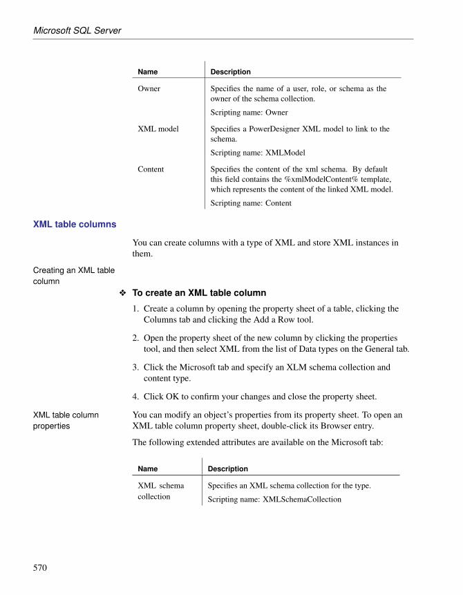
Microsoft SQL Server
Name Description
Owner Specifies the name of a user, role, or schema as theowner of the schema collection.
Scripting name: Owner
XML model Specifies a PowerDesigner XML model to link to theschema.
Scripting name: XMLModel
Content Specifies the content of the xml schema. By defaultthis field contains the %xmlModelContent% template,which represents the content of the linked XML model.
Scripting name: Content
XML table columns
You can create columns with a type of XML and store XML instances inthem.
Creating an XML tablecolumn
v To create an XML table column
1. Create a column by opening the property sheet of a table, clicking theColumns tab and clicking the Add a Row tool.
2. Open the property sheet of the new column by clicking the propertiestool, and then select XML from the list of Data types on the General tab.
3. Click the Microsoft tab and specify an XLM schema collection andcontent type.
4. Click OK to confirm your changes and close the property sheet.
XML table columnproperties
You can modify an object’s properties from its property sheet. To open anXML table column property sheet, double-click its Browser entry.
The following extended attributes are available on the Microsoft tab:
Name Description
XML schemacollection
Specifies an XML schema collection for the type.
Scripting name: XMLSchemaCollection
570

Chapter 11. DBMS-Specific Features
Name Description
Content type Specifies the nature of the content to be stored in thecolumn. You can choose between:♦ CONTENT – [default] the data can contain multiple
top-level elements.
♦ DOCUMENT – the data can contain only one top-level element.
Scripting name: ContentType
Database mirroring
SQL Server 2005 supports database mirroring, in which the principal serversends, in real-time, blocks of its database log records to the mirror instancewhich, in the event of failover, can be made available within a few seconds.
PowerDesigner supports database mirroring with the following modelobjects:
♦ Databases (Mirroring tab)
♦ Endpoints
Databases
For information about creating a database object, see “Creating a database”section in the Getting Started with Data Modeling chapter.
The following extended attributes are available on the Mirroring tab:
Name Description
Enable mirroring Enables mirroring for the database.
Scripting name: EnableMirroring
Partner/ Witness Specifies the role that the database will play in themirroring relationship. You can choose between:♦ Partner – the database is either a principal or mirror
database.
♦ Witness – the database acts as a witness to a mirroringrelationship. A SET WITNESS clause affects bothcopies of the database, but can only be specified onthe principal server. If a witness is set for a session,a quorum is required to serve the database, regardlessof the SAFETY setting.
Scripting names: Partner, Witness
571

Microsoft SQL Server
Name Description
Options Specifies mirroring options for the database. You canchoose between:♦ <None>
♦ server
♦ off
♦ failover
♦ force_service_allow_data_loss
♦ resume
♦ safety full
♦ safety off
♦ suspend
♦ timeoutScripting name: MirrorOptions
Server For partner mirroring, specifies the server networkaddress of an instance of SQL Server to act as a failoverpartner in a new database mirroring session.
For witness mirroring, specifies an instance of theDatabase Engine to act as the witness server for adatabase mirroring session.
Scripting name: MirrorServer
Time-out [if partner is selected] Specifies the time-out period inseconds. The time-out period is the maximum timethat a server instance waits to receive a PING messagefrom another instance in the mirroring session beforeconsidering that other instance to be disconnected.
Scripting name: TimeOut
End points
An end point encapsulates a transport protocol and a port number, andenables SQL Server to communicate over the network. PowerDesignermodels end points as extended objects with a stereotype of <<EndPoint>>.
Creating an end point You can create an end point in any of the following ways:
♦ Select Model ä End Points to access the List of End Points, and click theAdd a Row tool.
♦ Right-click the model or package in the Browser, and select New ä End
572

Chapter 11. DBMS-Specific Features
Point.
End point properties You can modify an object’s properties from its property sheet. To open anend point property sheet, double-click its Browser entry.
The following extended attributes are available on the Microsoft tab:
Name Description
Owner Specifies the owner of the endpoint.
Scripting name: Owner
State Specifies the state of the endpoint at creation. You canchoose between:♦ started
♦ stopped
♦ disabledScripting name: State
Protocol: Name Specifies the transport protocol to be used by the end-point. You can choose between:♦ http
♦ tcpScripting name: Protocol
Protocol: Argu-ment
Allows you to enter arguments for the chosen protocol.
Scripting name: ProtocolArgument
Language: Name Specifies the type of content to be sent. You can choosebetween:♦ soap
♦ tsql
♦ service_broker
♦ database_mirroringScripting name: Language
Language: Argu-ment
Allows you to enter arguments for the chosen language.
Scripting name: LanguageArgument
Service Broker
The service broker manages a queue of services. Applications that useService Broker communicate by sending messages to one another as part ofa conversation. The participants in a conversation must agree on the name
573

Microsoft SQL Server
and content of each message. PowerDesigner supports service brokerthrough the following objects:
♦ Message types - define the type of data that a message can contain.
♦ Contracts - define which message types an application uses to accomplisha particular task.
♦ Queues - store messages.
♦ Event notifications - execute in response to a DDL statements and SQLTrace events by sending information about these events to a ServiceBroker service.
♦ Services - are specific tasks or sets of tasks.
Message types
Message types define the type of data that a message can contain. You createidentical message types in each database that participates in a conversation.
Message types specify the type of XML validation that SQL Server performsfor messages of that type. For arbitrary or binary data, the message type canspecify that SQL Server performs no validation. PowerDesigner modelsmessage types as extended objects with a stereotype of<<MessageType>>.
Creating a message type You can create a message type in any of the following ways:
♦ Select Model ä Message Types to access the List of Message Types, andclick the Add a Row tool.
♦ Right-click the model or package in the Browser, and select New ä
Message Type.
Message type properties You can modify an object’s properties from its property sheet. To open amessage type property sheet, double-click its Browser entry.
The following extended attributes are available on the Microsoft tab:
574

Chapter 11. DBMS-Specific Features
Name Description
Authorization Specifies a database user or role as the owner of themessage type. If the current user is dbo or sa, this may bethe name of any valid user or role. Otherwise, it must bethe name of the current user, a user that the current userhas IMPERSONATE permission for, or a role to whichthe current user belongs. By default, the message typebelongs to the current user.
Scripting name: Owner
Validation Specifies how the Service Broker validates the messagebody for messages of this type. You can choose between:♦ none [default] – no validation performed
♦ empty – message must contain no data
♦ well_formed_xml – message must contain well-formed XML
♦ valid_xml with schema collection – message mustconform to the specified XML schema
Scripting name: Validation
Schema Specifies the name of the schema to be used for validatingthe message contents.
Scripting name: SchemaCollectionName
Contracts
Contracts define the message types used in a Service Broker conversationand also determine which side of the conversation can send messages of thattype. Each conversation follows a contract. The initiating service specifiesthe contract for the conversation when the conversation begins. The targetservice specifies the contracts that the target service accepts conversationsfor. PowerDesigner models contracts as extended objects with a stereotypeof <<Contract>>.
You create an identical contract in each database that participates in aconversation.
Creating a contract You can create a contract in any of the following ways:
♦ Select Model ä Contracts to access the List of Contracts, and click theAdd a Row tool.
♦ Right-click the model or package in the Browser, and select New ä
Contract.
575
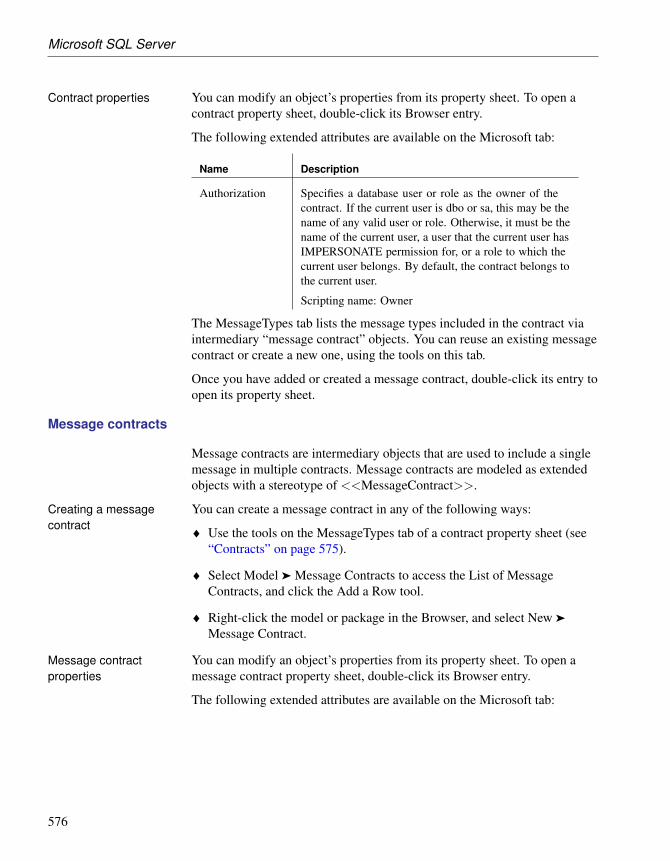
Microsoft SQL Server
Contract properties You can modify an object’s properties from its property sheet. To open acontract property sheet, double-click its Browser entry.
The following extended attributes are available on the Microsoft tab:
Name Description
Authorization Specifies a database user or role as the owner of thecontract. If the current user is dbo or sa, this may be thename of any valid user or role. Otherwise, it must be thename of the current user, a user that the current user hasIMPERSONATE permission for, or a role to which thecurrent user belongs. By default, the contract belongs tothe current user.
Scripting name: Owner
The MessageTypes tab lists the message types included in the contract viaintermediary “message contract” objects. You can reuse an existing messagecontract or create a new one, using the tools on this tab.
Once you have added or created a message contract, double-click its entry toopen its property sheet.
Message contracts
Message contracts are intermediary objects that are used to include a singlemessage in multiple contracts. Message contracts are modeled as extendedobjects with a stereotype of <<MessageContract>>.
Creating a messagecontract
You can create a message contract in any of the following ways:
♦ Use the tools on the MessageTypes tab of a contract property sheet (see“Contracts” on page 575).
♦ Select Model ä Message Contracts to access the List of MessageContracts, and click the Add a Row tool.
♦ Right-click the model or package in the Browser, and select New ä
Message Contract.
Message contractproperties
You can modify an object’s properties from its property sheet. To open amessage contract property sheet, double-click its Browser entry.
The following extended attributes are available on the Microsoft tab:
576

Chapter 11. DBMS-Specific Features
Name Description
Sent by Specifies which endpoint can send a message of the in-dicated message type. Contracts document the messagesthat services can use to have specific conversations. Eachconversation has two endpoints: the initiator endpoint,the service that started the conversation, and the targetendpoint, the service that the initiator is contacting.
Scripting name: Sender
Message type Specifies the message type of the contract.
Scripting name: MessageType
Queues
When a message arrives for a service, Service Broker places the message onthe queue associated with the service. PowerDesigner models queues asextended objects with a stereotype of <<Queue>>.
Creating a queue You can create a queue in any of the following ways:
♦ Select Model ä Queues to access the List of Queues, and click the Add aRow tool.
♦ Right-click the model or package in the Browser, and select New ä
Queue.
Queue properties You can modify an object’s properties from its property sheet. To open aqueue property sheet, double-click its Browser entry.
The following extended attributes are available on the Microsoft tab:
Name Description
Owner Specifies the owner of the queue.
Scripting name: Owner
Status Specifies that the queue is available. This is the default.
If a queue is unavailable, no messages can be added toor removed from it. If you create a queue as unavailable,then no messages can be added to it until it is madeavailable with an ALTER QUEUE statement.
Scripting name: Status
577

Microsoft SQL Server
Name Description
Retention Specifies that all messages sent or received on con-versations using this queue are retained in the queueuntil the conversations have ended. This allows you toretain messages for auditing purposes, or to performcompensating transactions if an error occurs.
The default is to not retain messages in the queue in thisway.
Scripting name: Retention
Activation Specifies that a stored procedure is required to activatemessage processing for the queue.
Scripting name: Activation
Status (activation) Specifies that Service Broker activates the associatedstored procedure when the number of procedures cur-rently running is less than MAX_QUEUE_READERSand when messages arrive on the queue faster than thestored procedures receive messages.
This is the default.
Scripting name: ActivationStatus
Procedure Specifies the name of the stored procedure to activate toprocess messages in this queue.
Scripting name: ActivationProcedureName
MaxQueueRead-ers
Specifies the maximum number of instances of theactivation stored procedure that the queue can start atthe same time. Must be set to between 0 and 32767.
Scripting name: ActivationMaxQueueReaders
Execute as Specifies the user under which the activation storedprocedure runs. SQL Server must be able to checkthe permissions for this user at the time that the queueactivates the stored procedure. You can choose between:♦ SELF - the stored procedure executes as the current
user. (The database principal executing this CRE-ATE QUEUE statement.)
♦ OWNER - the stored procedure executes as theowner of the queue.
Scripting name: ActivationExecuteAs
File group Specifies the SQL Server filegroup on which to createthe queue.
Scripting name: FileGroup
578

Chapter 11. DBMS-Specific Features
Event Notifications
An event notification sends information about a database or server event to aservice broker service. Event notifications are created only by usingTransact-SQL statements. PowerDesigner models event notifications asextended objects with a stereotype of <<EventNotification>>.
Creating an eventnotification
You can create an event notification in any of the following ways:
♦ Select Model ä Event Notifications to access the List of EventNotifications, and click the Add a Row tool.
♦ Right-click the model or package in the Browser, and select New ä EventNotification.
Event notificationproperties
You can modify an object’s properties from its property sheet. To open anevent notification property sheet, double-click its Browser entry.
The following extended attributes are available on the Microsoft tab:
Name Description
Applies on Specifies the scope of the event notification. You canchoose between:♦ database – the notification fires whenever the speci-
fied event in the FOR clause occurs anywhere in theinstance of SQL Server.
♦ server - the notification fires whenever the speci-fied event in the FOR clause occurs in the currentdatabase.
♦ queue - the notification fires whenever the spec-ified event in the FOR clause occurs in thecurrent queue. Can be specified only if FORQUEUE_ACTIVATION or FOR BROKER_-QUEUE_DISABLED is also specified.
Scripting name: AppliesOn
Queue Specifies the queue to which the event notificationapplies. Available only if Applies on is set to “queue”.
Scripting name: Queue
579

Microsoft SQL Server
Name Description
With fan in Instructs SQL Server to send only one message per eventto any specified service for all event notifications that:♦ are created on the same event.
♦ are created by the same principal (as identified bySID).
♦ specify the same service and broker_instance_-specifier.
♦ specify WITH FAN_IN.Scripting name: WithFanIn
Events Specifies the name of the event type that causes the eventnotification to execute. Can be a Transact-SQL DDL,SQL Trace, or Service Broker event type.
Scripting name: Events
Service Specifies the target service that receives the event in-stance data. SQL Server opens one or more conversa-tions to the target service for the event notification. Thisservice must honor the same SQL Server Events messagetype and contract that is used to send the message. See“Services” on page 580.
Scripting name: Service
Instance Specifies a service broker instance against whichbroker_service is resolved. Use ‘current database’to specify the service broker instance in the currentdatabase.
Scripting name: Instance
Services
Services are specific tasks or set of tasks. Service Broker uses the name ofthe service to route messages, deliver messages to the correct queue within adatabase, and enforce the contract for a conversation. PowerDesignermodels services as extended objects with a stereotype of <<Service>>.
Creating a service You can create a service in any of the following ways:
♦ Select Model ä Services to access the List of Services, and click the Adda Row tool.
♦ Right-click the model or package in the Browser, and select New ä
Service.
580

Chapter 11. DBMS-Specific Features
Service properties You can modify an object’s properties from its property sheet. To open aservice property sheet, double-click its Browser entry.
The following extended attributes are available on the Microsoft tab:
Name Description
Authorization Specifies the owner of the service.
Scripting name: Owner
Queue Specifies the queue that receives messages for the ser-vice. The queue must exist in the same database as theservice.
Scripting name: Queue
The Contracts tab lists the contracts with which the service is associated.
Routes
Routes appear in the routing table for the database. For outgoing messages,Service Broker determines routing by checking the routing table in the localdatabase. For messages on conversations that originate in another instance,including messages to be forwarded, Service Broker checks the routes inmsdb. PowerDesigner models routes as extended objects with a stereotypeof <<Route>>.
Creating a route You can create a route in any of the following ways:
♦ Select Model ä Routes to access the List of Routes, and click the Add aRow tool.
♦ Right-click the model or package in the Browser, and select New ä
Route.
Route properties You can modify an object’s properties from its property sheet. To open aroute property sheet, double-click its Browser entry.
The following extended attributes are available on the Microsoft tab:
Name Description
Owner Specifies the owner of the route.
Scripting name: Owner
Remote service Specifies the name of the remote service to which theroute points.
Scripting name: Service
581

Microsoft SQL Server
Name Description
Broker instance Specifies the database that hosts the target service.
Scripting name: BrokerInstance
Lifetime Specifies the amount of time, in seconds, that SQLServer retains the route in the routing table.
Scripting name: Lifetime
Address Specifies the network address for the route. The next_-hop_address specifies a TCP/IP address in the followingformat:
TCP://{ dns_name | netbios_name | ip_address } : port_-number
Scripting name: Address
Mirror address Specifies the network address for a mirrored databasewith one mirrored database hosted at the next_hop_-address. The next_hop_mirror_address specifies aTCP/IP address in the following format:
TCP://{ dns_name | netbios_name | ip_address } : port_-number
Scripting name: MirrorAddress
Remote service bindings
Remote service bindings create a binding that defines the securitycredentials to use to initiate a conversation with a remote service.PowerDesigner models remote service bindings as extended objects with astereotype of <<RemoteServiceBinding>>.
Creating a remoteservice binding
You can create a remote service binding in any of the following ways:
♦ Select Model ä Remote Service Bindings to access the List of RemoteService Bindings, and click the Add a Row tool.
♦ Right-click the model or package in the Browser, and select New ä
Remote Service Binding.
Remote service bindingproperties
You can modify an object’s properties from its property sheet. To open aremote service binding property sheet, double-click its Browser entry.
The following extended attributes are available on the Microsoft tab:
582

Chapter 11. DBMS-Specific Features
Name Description
Owner Specifies the owner of the binding.
Scripting name: Owner
Remote service Specifies the remote service to bind to the user identifiedin the WITH USER clause.
Scripting name: RemoteService
User Specifies the database principal that owns the certificateassociated with the remote service identified by the TOSERVICE clause.
Scripting name: User
Anonymous Specifies that anonymous authentication is used whencommunicating with the remote service.
Scripting name: Anonymous
Resource Governor
Resource Governor, available in SQL Server 2008, lets you limit resourcerequests by workloads for CPU time and memory to optimize theirallocation. PowerDesigner supports Resource Governor through thefollowing objects:
♦ Workload groups – are containers for sets of similar session requests.
♦ Resource pools – represent the physical resources of the server.
Workload groups
A workload group serves as a container for session requests that are similar,to allow the aggregate monitoring of resource consumption and theapplication of a uniform policy to all the requests in the group. A groupdefines the policies for its members. PowerDesigner models workload groupsas extended objects with a stereotype of <<WorkloadGroup>>.
Creating a workloadgroup
You can create a workload group binding in any of the following ways:
♦ Select Model ä Workload groups to access the List of Workload Groups,and click the Add a Row tool.
♦ Right-click the model or package in the Browser, and select New ä
Workload Group.
Workload groupproperties
You can modify an object’s properties from its property sheet. To open aworkload group property sheet, double-click its Browser entry.
583

Microsoft SQL Server
The following extended attributes are available on the Microsoft tab:
Name Description
Importance Specifies the relative importance of a request in theworkload group.
Scripting name: Importance
Request maxi-mum memory
Specifies the maximum amount of memory that a singlerequest can take from the pool.
Scripting name: RequestMaxMemoryGrantPercent
Request maxi-mum CPU
Specifies the maximum amount of CPU time, in seconds,that a request can use.
Scripting name: RequestMaxCpuTimeSec
Memory grantrequest timeout
Specifies the maximum time, in seconds, that a querycan wait for a memory grant (work buffer memory) tobecome available.
Scripting name: RequestMemoryGrantTimeoutSec
Maximum degreeof parallelism
Specifies the maximum degree of parallelism (DOP) forparallel requests.
Scripting name: MaxDop
Maximum re-quests
Specifies the maximum number of simultaneous requeststhat are allowed to execute in the workload group.
Scripting name: GroupMaxRequests
Resource pool Associates the workload group with the specified re-source pool.
Scripting name: ResourcePool
Resource pools
A resource pool represents the physical resources of the server.PowerDesigner models resource pools as extended objects with a stereotypeof <<ResourcePool>>.
Creating a resource pool You can create a resource pool in any of the following ways:
♦ Select Model ä Resource Pools to access the List of Resource pools, andclick the Add a Row tool.
♦ Right-click the model or package in the Browser, and select New ä
Resource Pool.
584

Chapter 11. DBMS-Specific Features
Resource pool properties You can modify an object’s properties from its property sheet. To open aresource pool property sheet, double-click its Browser entry.
The following extended attributes are available on the Microsoft tab:
Name Description
CPU percent Min Specifies the guaranteed average CPU bandwidth forall requests in the resource pool when there is CPUcontention. The value is an integer, with a default settingof 0.
Scripting name: MinCpuPercent
CPU percent Max Specifies the maximum average CPU bandwidth that allrequests in resource pool will receive when there is CPUcontention. The value is an integer, with a default settingof 100.
Scripting name: MaxCpuPercent
Memory percentMin
Specifies the minimum amount of memory reserved forthis resource pool that can not be shared with otherresource pools. The value is an integer, with a defaultsetting of 0.
Scripting name: MinMemoryPercent
Memory percentMax
Specifies the total server memory that can be used byrequests in this resource pool. The value is an integer,with a default setting of 100.
Scripting name: MaxMemoryPercent
Synonyms
PowerDesigner supports SQL Server 2005 synonyms through the standardsynonym object.
Synonyms can be created for the following types of objects:
♦ Assembly (CLR) Stored Procedure
♦ Assembly (CLR) Table-valued Function
♦ Assembly (CLR) Scalar Function
♦ Assembly Aggregate (CLR) Aggregate Functions
♦ Replication-filter-procedure
♦ Extended Stored Procedure
585

Microsoft SQL Server
♦ SQL Scalar Function
♦ SQL Table-valued Function
♦ SQL Inline-table-valued Function
♦ SQL Stored Procedure
♦ View
♦ Table
For more information about synonyms, see the “Building PhysicalDiagrams” chapter.
SQL Server 2000 Analysis Services
The OLAP Services feature from SQL Server v7.0 is called AnalysisServices in SQL Server 2000. PowerDesigner supports analysis servicesthrough an add-in.
For information about analysis services in SQL Server 2005, see “MicrosoftSQL Server 2005 Analysis Services” on page 592.
Analysis Services provide the following capabilities:
♦ The Analysis server that manages, stores multidimensional informationand serves client application requests for OLAP data. The server storescube metadata (cube definition specifications) in a repository. Completedcubes can be stored in a variety of storage modes: multidimensionaldatabase files (MOLAP), tables in a relational database (ROLAP), or ahybrid of multidimensional database files and relational tables (HOLAP).
♦ A metadata repository that contains definitions of OLAP data objectssuch as cubes and their elements.
♦ The PivotTable Service, which is an OLE DB for OLAP provider thatconnects client applications to the Analysis server and manages offlinecubes.
♦ An object model called Decision Support Objects (DSO), that providessupport for the Analysis Manager user interface and for customapplications that manage OLAP metadata and control the server. DSOuses hierarchically arranged groups of objects to define basic elements ofOLAP data. PowerDesigner creates and manipulates DSO objects tomanage metadata for OLAP data.
586
Chapter 11. DBMS-Specific Features
Source data for multidimensional cubes resides in relational databases wherethe data has been transformed into a star or snowflake schema typically usedin OLAP data warehouse systems. Analysis Services can work with manyrelational databases that support connections using ODBC or OLE DB.
+ For more information on SQL Server Analysis Services, see yourDBMS documentation.
v To enable PowerDesigner support for Analysis Services
1. Select Tools ä General Options, and select the Add-ins category in theleft-hand pane.
2. Select the Microsoft Analysis Services add-in (PdMsOlap.dll) and thenclick OK to install it and return to the model.
+ For more information, see “Managing add-ins” in the Models chapter ofthe Core Features Guide .
PowerDesigner and the DSO metamodel
DSO uses hierarchically arranged groups of objects to define basic elementsof Analysis Services data storage, as implemented by the Analysis server.
587

Microsoft SQL Server
The following table lists the mappings between the objects contained withinthe DSO and PowerDesigner PDM metamodels:
DSO Object PowerDesigner PDM Object
clsDatabase Model
(Each model corresponds to a DSO Database.)
clsDataSource Data source
ClsDatabaseDimen-sion
Dimension
(As in the DSO model, PowerDesigner dimensionsare shared among cubes.)
clsCube Cube
(Cubes managed by PowerDesigner are only localcubes.)
588

Chapter 11. DBMS-Specific Features
DSO Object PowerDesigner PDM Object
clsCube Fact
(A Fact corresponds to a DSO cube in order to storemeasures.)
clsCubeMeasure Measure
clsDatabaseDimen-sion
Dimension hierarchy
(Each dimension hierarchy is generated as a DSODatabase Dimension. Attributes of a dimension hier-archy define levels of the corresponding DatabaseD-imension.)
clsDatabaseLevelclsCubeLevel
Dimension attribute
(Attributes of a dimension or dimension hierarchydefine levels in a database dimension.)
clsCubeDimension Cube dimension association
(In DSO, when the name of a Cube Dimensioncorresponds to the name of a Database Dimension,the Cube Dimension is automatically associatedwith the Database Dimension to be shared betweencubes.)
Generating cubes
The Microsoft Analysis Services add-in lets you generate cubes.
v To generate cubes
1. Select Tools ä Microsoft Analysis Services ä Generate Cubes to openthe connection dialog box.
2. Enter a name for the server and database, and then click OK to open theCube Selection dialog box, which lists all the available cubes. The statecolumn indicates if the cube has already been generated. Cubes alreadygenerated are deselected by default.
589

Microsoft SQL Server
3. Select the cubes you want to generate, and then click OK.
The selected cubes are generated. If a cube already exists in the database,it is dropped before being recreated. If a dimension already exists, theselected cube reuses it. To be fully generated, a cube must have acomplete mapping to a table before being generated.
Reverse Engineering cubes
The Microsoft Analysis Services add-in lets you reverse engineer cubes.
v To reverse engineer cubes
1. Select Tools ä Microsoft Analysis Services ä Reverse Engineer Cubes toopen the connection dialog box.
2. Enter a name for the server and database, and then click OK to open theSource Model Selection dialog box, which lists the models linked to theselected data source.
590

Chapter 11. DBMS-Specific Features
3. Select the appropriate source models and then click OK to open the CubeSelection dialog box, which lists all the available cubes. The state columnindicates if the cube already exists in the current model. Cubes alreadyexisting are deselected by default.
4. Select the cubes you want to reverse engineer, and then click OK.
591

Microsoft SQL Server
The selected cubes are created or updated in the current model. If adimension or a cube already exists, it is updated.
Microsoft SQL Server 2005 Analysis Services
PowerDesigner allows you to retrieve multiple dimension objects in a PDMin order to build cubes, and to create a new multiple-dimension diagram.From this diagram, you can generate cubes to a Microsoft SQL Server 2005Analysis Server (SSAS).
SQL Server 2005 Management Tools requiredIn order to use the analysis services add-in to generate and reverse-engineercubes, you must have installed the SQL Server 2005 Management Toolsclient component.
v To enable PowerDesigner support for Analysis Services
1. Select Tools ä General Options, and select the Add-ins category in theleft-hand pane.
2. Select the Microsoft SQL Server 2005 Analysis Services add-in(PowerDesigner.AddIn.Pdm.SQLServer.dll) and then click OK to installit and return to the model.
+ For more information, see “Managing add-ins” in the Models chapter ofthe Core Features Guide .
Generating cubes
The Microsoft SQL Server 2005 Analysis Services add-in enables thegeneration of cubes.
Before generating cubes, you must define a data source with an OLE DBconnection that will specify from where the cubes will be populated.
592

Chapter 11. DBMS-Specific Features
v To specify a data source for a cube
1. Create a data source in your PDM from the List of data sources or byright-clicking the model in the browser and selecting New ä Data Sourcefrom the contextual menu.
2. Select the OLE DB tab and specify the kind of data provider.
3. Click the ellipsis tool to the right of the connection string field to openthe provider-specific configuration dialog.
593

Microsoft SQL Server
4. Complete the parameters appropriately, click Apply to Connection String,and then Test Connection. Then click Ok to return to the data sourceproperty sheet.
5. Click OK to return to your model.
When you have created the appropriate data sources, you can proceed withgenerating your cubes.
594

Chapter 11. DBMS-Specific Features
v To generate cubes
1. Select Tools ä Microsoft SQL Server 2005 Analysis Services ä GenerateCubes to open the wizard.
Click Next to continue.
2. Enter a server name, and select the database you want to generate to:
595
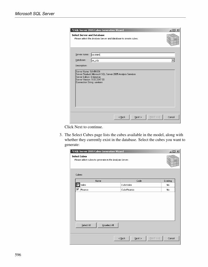
Microsoft SQL Server
Click Next to continue.
3. The Select Cubes page lists the cubes available in the model, along withwhether they currently exist in the database. Select the cubes you want togenerate:
596

Chapter 11. DBMS-Specific Features
Click Next to continue.
4. The Generate Cubes page lists the cubes to be generated:
Click Finish to begin generation. Progress is displayed in the wizard,which will close automatically after successful completion.
If a cube already exists in the database, it is dropped and recreated. If arelated dimension already exists, it is reused. To fully generate a cube,your model must include a complete mapping to a table.
Reverse engineering Microsoft SQL Server 2005 cubes
The Microsoft SQL Server 2005 Analysis Services add-in enables thereverse engineering of cubes.
Before reverse-engineering cubes, you should create one or more PDMs tomodel the tables which provide its data. As part of the reverse-engineeringprocess, PowerDesigner will create links from the reversed cubes to thesetables.
597

Microsoft SQL Server
v To reverse engineer cubes
1. Select Tools ä Microsoft SQL Server 2005 Analysis Services ä ReverseEngineer Cubes to open the wizard.
Click Next to continue.
2. Enter a server name, and select the database you want to reverse from:
598

Chapter 11. DBMS-Specific Features
Click Next to continue.
3. The Select Cubes page lists the available cubes. Select the cubes youwant to reverse engineer and then click Next to continue:
599

Microsoft SQL Server
4. The Configure Data Sources page lists the data sources that are requiredto populate the selected cubes. For each source, select the Physical DataModel in which the tables are modeled, and then click Next to continue:
5. The Reverse Engineer Cubes page lists the cubes to be reversed:
600

Chapter 11. DBMS-Specific Features
Click Finish to begin reverse-engineering. Progress is displayed in thewizard, which will close automatically after successful completion.
Miscellaneous additional features
The following additional features are also available for SQL Server 2005:
♦ User Schemas – Use the schema stereotype to specify that a user isactually a schema, belonging to another user (the “principal”).
♦ WithOption – Use the withoptions type to enable access to additionalphysical options when working with views.
♦ Support for multiple databases during live database reverse engineering.
MS SQL Server extended attributes
The following extended attributes are defined by default in the MS SQLServer DBMS.
Columns The following extended attributes are available on the Microsoft tab:
Name Description
Do not val-idate checkconstraintsduring repli-cation
Specifies that “NOT FOR REPLICATION” keywords areused to prevent the CHECK constraint from being enforcedduring the distribution process used by replication.
Scripting name: ExtCkcNotForReplication
Default con-straint name
Contains the name of the constraint that is used to applya default value to the column. If empty, the “constraint”keyword is not generated.
Scripting name: ExtDeftConstName
Identity seedand incre-ment
Is a string composed of two integer values separated by acomma.
First value is the seed value of the identity column, meaningthe value to be assigned to the first row in the table.
Second value is the increment to add to the seed value forsuccessive rows in the table.
Scripting name: ExtIdentitySeedInc
Identity valuenot replicated
Indicates that the IDENTITY property should not be en-forced when a replication login inserts data into the table.
Scripting name: ExtIdtNotForReplication
601

Microsoft SQL Server
Name Description
Not null con-straint name
Contains the name of the constraint that is used to apply amandatory property of the column. If empty, the “constraint”keyword is not generated.
Scripting name: ExtNullConstName
Row globalunique iden-tifier
[v2000 and higher] Indicates that the new column is a rowglobal unique identifier column. Only one unique identifiercolumn per table can be designated as the ROWGUIDCOLcolumn.
Scripting name: ExtRowGuidCol
Collationname
[v2005 and higher] A single string that specifies the collationname for a SQL collation.
Scripting name: ExtCollation
XML schemacollection
[v2000 and higher] Applies only to the XML data type forassociating an XML schema collection with the type.
Scripting name: XMLSchemaCollection
Content type [v2005 and higher] - CONTENT:
Specifies that each instance of the XML data type incolumn_name can contain multiple top-level elements.CONTENT applies only to the XML data type and can bespecified only if xml_schema_collection is also specified. Ifnot specified, CONTENT is the default behavior.
- DOCUMENT:
Specifies that each instance of the XML data type incolumn_name can contain only one top-level element. DOC-UMENT applies only to the XML data type and can bespecified only if xml_schema_collection is also specified.
Scripting name: ContentType
Cubes The following extended attributes are available on the Microsoft tab:
602

Chapter 11. DBMS-Specific Features
Name Description
Options [v2000] You can choose between the following:♦ PASSTHROUGH: causes the SELECT clause to be passed di-
rectly to the source database without modification by Pivot-Table Service. If PASSTHROUGH is not specified, PivotTableService parses the query and formulates a set of queries equiv-alent to the original that is optimized for the source databaseand index structures. This set of queries is often more efficientthan the specified.
♦ DEFER_DATA: causes the query to be parsed locally and ex-ecuted only when necessary to retrieve data to satisfy a userrequest. DEFER_DATA is used to specify that a local cube hasto be defined in the ROLAP storage mode.
♦ ATTEMPT_DEFER: causes PivotTable Service to attempt toparse the query and defer data loading if successful, or, if thequery cannot be parsed, to process the specified query immedi-ately as if PASSTHROUGH had been specified.
♦ ATTEMPT_ANALYSIS: causes PivotTable Service to attemptto parse the query and formulate an optimized set of queries. Ifthe query cannot be parsed, PivotTable Services processes thequery immediately as if PASSTHROUGH had been specified.
Scripting name: Options
Storagemode
[v2005 and higher] Specifies the storage mode for the cube.
Scripting name: StorageMode
Visible [v2005 and higher] Determines the visibility of the Cube.
Scripting name: Visible
Dimensions The following extended attributes are available on the Microsoft tab:
Name Description
Hidden [v2000] Indicates whether the dimension is hidden from clients.
Scripting name: IsHidden
603

Microsoft SQL Server
Name Description
Options [v2000] Dimension options to manage member uniqueness andspecify their storage. You can choose between:♦ UNIQUE_NAME: Member names are unique within the di-
mension.
♦ UNIQUE_KEY: Member keys are unique within the dimen-sion.
♦ NOTRELATEDTOFACTTABLE: Indicates that non-leafmembers cannot be associated with fact table data.
♦ ALLOWSIBLINGSWITHSAMENAME: Determineswhether children of a single member in a hierarchy can haveidentical names.
Scripting name: Options
Subtype [v2000] Indicates the subtype of a dimension. You can choosebetween:♦ PARENT_CHILD:Indicates that the dimension is a parent-
child dimension.
♦ LINKED: Indicates that the cube is linked to another cube ona remote Analysis server.
♦ MINING: Indicates that the dimension is based on the contentof an OLAP data-mining model that has been processed for acube.
Scripting name: SubType
Template [v2000] Contains a template string that is used to generatecaptions for system-generated data members.
Scripting name: Template
604

Chapter 11. DBMS-Specific Features
Name Description
Time [v2000] Indicates that a dimension refers to time (year, month,week, day, and so on). You can choose between:♦ TIME: Year, month, week, day, and so on. The only valid
levels in a time dimension are those defined in the LevelTypesenumeration.
The following values post-fixed by an asterisk (*) are additionalvalues that can be used by the add-in but do not exist in the MDXsyntax. You can choose between a dimension that contains:♦ ACCOUNT: (*) an account structure with parent-child rela-
tionships.
♦ BILLOFMATERIALS (*): a material/component break-down. The parent-child relationship implies a parent com-posed of its children.
♦ CHANNEL (*): a distribution channel.
♦ CURRENCY (*): currency information.
♦ CUSTOMERS (*): customer information. The lowest levelrepresents individual customers.
♦ GEOGRAPHY (*): a geographic hierarchy.
♦ ORGANIZATION (*): the reporting structure of an organiza-tion.
♦ PRODUCTS (*): product information. The lowest level rep-resents individual products.
♦ PROMOTION (*): marketing and advertising promotions.
♦ QUANTITATIVE (*): quantitative elements (such as exam-ple, income level, number of children, and so on).
♦ RATES (*): different types of rates (for example, buy, sell,discounted. and so on).
♦ SCENARIO (*): different business scenarios.Scripting name: TimeDef
Type [v2005 and higher] Provides information about the contents ofthe dimension.
Scripting name: Type
Storagemode
[v2005 and higher] Determines the storage mode for the parentelement.
Scripting name: StorageMode
At-tributeAllMem-berName
[v2005 and higher] Contains the caption, in the default language,for the All member of the dimension.
Scripting name: AttributeAllMemberName
605

Microsoft SQL Server
Name Description
WriteEn-abled
[v2005 and higher] Indicates whether dimension writebacks areavailable (subject to security permissions).
Scripting name: WriteEnabled
Dimension Attributes The following extended attributes are available on the Microsoft tab:
Name Description
Rollupexpres-sion
[v2000] Contains a Multidimensional Expressions (MDX) ex-pression used to override the default roll-up mode.
Scripting name: CustomRollupExpr
Formatkey
[v2000] Name of the column or expression that contains memberkeys.
Scripting name: FormatKey
Formatname
[v2000] Name of the column or expression that contains membernames.
Scripting name: FormatName
Hide val-ues
[v2000] Options to hide level members. You can choose between:♦ BLANK_NAME: Hides a level member with an empty name.
♦ PARENT_NAME: Hides a level member when the membername is identical to the name of its parent.
♦ ONLY_CHILD_AND_BLANK_NAME: Hides a level mem-ber when it is the only child of its parent and its name is nullor an empty string.
♦ ONLY_CHILD_AND_PARENT_NAME: Hides a levelmember when it is the only child of its parent and is identicalto the name of its parent.
Scripting name: HideValues
Hidden [v2000] Indicates whether the level is hidden from client appli-cations.
Scripting name: IsHidden
606

Chapter 11. DBMS-Specific Features
Name Description
Options [v2000] Options about member uniqueness, ordering and datasource. You can choose between:♦ UNIQUE: Indicates that the members of a level are unique.
♦ UNIQUE_NAME: Indicates that their member name columnsuniquely identify the level members.
♦ UNIQUE_KEY: Indicates that their member key columnsuniquely identify the level members.
♦ NOTRELATEDTOFACTTABLE: Indicates that the levelmembers cannot be associated with fact table data.
♦ SORTBYNAME: Indicates that level members are ordered bytheir names.
♦ SORTBYKEY: Indicates that level members are ordered bytheir keys.
♦ SORTBYPROPERTY <property names>: Indicates thatmembers are ordered by their property <property names>.
Scripting name: Options
Root val-ues
[v2000] Determines how the root member or members of aparent-child hierarchy are identified. You can choose between:♦ ROOT_IF_PARENT_IS_BLANK: Only members with a
null, a zero, or an empty string in their parent key columnare treated as root members.
♦ ROOT_IF_PARENT_IS_MISSING: Only members with par-ents that cannot be found are treated as root members.
♦ ROOT_IF_PARENT_IS_SELF: Only members having them-selves as parents are treated as root members.
♦ ROOT_IF_PARENT_IS_BLANK _OR_SELF_OR_-MISSING: Members are treated as root members if theymeet one or more of the conditions specified by ROOT_IF_-PARENT_IS_BLANK, ROOT_IF_PARENT_IS_SELF, orROOT_IF_PARENT_IS_MISSING.
Scripting name: RootValues
607

Microsoft SQL Server
Name Description
Type [v2000 and higher] Identifies the specific type of level. You canchoose between:♦ ALL: Indicates the top (All) level of a dimension (the one that
precalculates all the members of all lower levels).
♦ YEAR: a level that refers to years (Time dimension only).
♦ QUARTER: a level that refers to (calendar) quarters (Timedimension only).
♦ MONTH: a level that refers to months (Time dimension only).
♦ WEEK: a level that refers to weeks (Time dimension only).
♦ DAY: a level that refers to days (Time dimension only).
♦ DAYOFWEEK: a level that refers to days of the week (Timedimension only).
♦ DATE: a level that refers to dates (Time dimension only).
♦ HOUR: a level that refers to hours (Time dimension only).
♦ MINUTE: a level that refers to minutes (Time dimensiononly).
♦ SECOND: Indicates that a level refers to seconds (Time di-mension only).
Scripting name: Type
Member-sWith-Data
[v2005 and higher] Determines whether to display data membersfor non-leaf members in the parent attribute.
Scripting name: MembersWithData
OrderBy [v2005 and higher] Describes how to order the members con-tained in the attribute.
Scripting name: OrderBy
Member-Name-sUnique
[v2005 and higher] Determines whether member names underthe parent element must be unique.
Scripting name: MemberNamesUnique
IsAggre-gatable
[v2005 and higher] Specifies whether the values of the Dimen-sionAttribute element can be aggregated.
Scripting name: IsAggregatable
Attribute-Hierar-chyEn-abled
[v2005 and higher] Determines whether an attribute hierarchy isenabled for the attribute.
Scripting name: AttributeHierarchyEnabled
608

Chapter 11. DBMS-Specific Features
Name Description
Attribute-Hierar-chyVisi-ble
[v2005 and higher] Determines whether the attribute hierarchy isvisible to client applications.
Scripting name: AttributeHierarchyVisible
Databases The following extended attributes are available on the Microsoft tab:
Name Description
Primary Specifies that the associated file specification list defines theprimary file.
Scripting name: Primary
File Gets or sets the file specification.
Scripting name: FileListFileSpec
Filegroup Gets or sets the first filegroup name.
Scripting name: FilelistFilegroup
File (file-group)
Gets or sets the Filegroup specification.
Scripting name: FileGroupFileSpec
Log on Gets or sets the log file specification.
Scripting name: LogOnFileSpec
Collationname
[v2000 and higher] Specifies the default collation for thedatabase. Collation name can be either a Windows collationname or a SQL collation name.
Scripting name: Collate
Attach Specifies that a database is attached from an existing set ofoperating system files.
Scripting name: ForAttach
609

Microsoft SQL Server
Name Description
With [v2005 and higher] Controls Service Broker options on thedatabase.
Service Broker options can only be specified when the FORATTACH clause is used.♦ ENABLE_BROKER: Specifies that Service Broker is en-
abled for the specified database.
♦ NEW_BROKER: Creates a new service_broker_guidvalue in both sys.databases and the restored database andends all conversation endpoints with clean up. The brokeris enabled, but no message is sent to the remote conversa-tion endpoints.
♦ ERROR_BROKER_CONVERSATIONS: Ends all con-versations with an error stating that the database is at-tached or restored. The broker is disabled until this op-eration is completed and then enabled.
Scripting name: ForAttachWith
Attach re-build log
[v2005 and higher] Specifies that the database is created byattaching an existing set of operating system files.
Scripting name: ForAttachRebuildLog
Databasechaining
[v2005 and higher] When ON is specified, the database canbe the source or target of a cross database ownership chain.
When OFF, the database cannot participate in cross databaseownership chaining. The default is OFF.
Scripting name: WithDbChaining
Trust worthy [v2005 and higher] When ON is specified, database modules(for example, views, user-defined functions, or stored proce-dures) that use an impersonation context can access resourcesoutside the database.
When OFF, database modules in an impersonation contextcannot access resources outside the database. The default isOFF.
Scripting name: WithTrustworthy
Snapshot of [v2005 and higher] Specifies the name of the new databasesnapshot.
Scripting name: AsSnapshotOf
610

Chapter 11. DBMS-Specific Features
Name Description
Load [up to v2000] Indicates that the database is created with the“dbo use only” database option turned on, and the status is setto loading.
Scripting name: ForLoad
For information about the extended attributes available on the Mirroring tab,see “Database mirroring” on page 571.
Data Sources The following extended attributes are available on the OLE DB tab:
Name Description
Dataprovider
Specifies the data provider. You can choose between:♦ .NET Framework Data Provider for Microsoft SQL Server
♦ .NET Framework Data Provider for Oracle
♦ Native Data Provider for OLE DBScripting name: DataProvider
Connectionstring
Specifies the connection string.
Scripting name: ConnectionString
The following extended attributes are available on the configuration:
Name Description
Server name Specifies the server name.
Scripting name: ServerName
Authentica-tion
[only for SQL Server] Specifies the Windows Authenticationand SQL Server Authentication types.
Scripting name: AuthenticationType
User name Specifies the User name.
Scripting name: UserName
Password Specifies the password.
Scripting name: Password
Initial cata-log
[only for SQL Server and OLE DB] Specifies the Initialcatalog.
Scripting name: InitialCatalog
611

Microsoft SQL Server
Name Description
DatabaseFile
[only for SQL Server] Specifies a Microsoft SQL Serverdatabase file if you select an MSSQL connection.
Scripting name: MSSQLDatabaseFile
Logicalname
[only for SQL Server] Specifies the logical name of theselected database file.
Scripting name: LogicalName
Dataproviders
[only for OLE DB] Specifies the data provider.
Scripting name: DataProvider
Location [only for OLE DB] Specifies the location for OLEDB.
Scripting name: Location
Persist secu-rity info
[only for OLE DB] Specifies that security information bepersistent.
Scripting name: PersistSecurityInfo
Use Win-dows NTIntegratedSecurity
[only for OLE DB] Specifies whether to use windows NTIntegrated Security or not.
Scripting name: UseNTIntegratedSecurity
Dimension Hierarchies The following extended attributes are available on the Microsoft tab:
Name Description
Hidden [v2000] Indicates whether the hierarchy is hidden from clientapplications.
Scripting name: IsHidden
AllMember-Name
[v2005 and higher] Contains the caption in the default lan-guage for the All member of a Hierarchy element.
Scripting name: AllMemberName
Member-Name-sUnique
[v2005 and higher] Determines whether member names underthe parent element must be unique.
Scripting name: MemberNamesUnique
AllowDupli-cateNames
[v2005 and higher] Determines whether duplicate names areallowed in a Hierarchy element.
Scripting name: AllowDuplicateNames
612

Chapter 11. DBMS-Specific Features
Fact Measures The following extended attributes are available on the Microsoft tab:
Name Description
Format [v2000] Format used to display the values of the cubemeasure.
Scripting name: Format
Cube measurefunction type
[v2000] A value corresponding to the type of aggregatefunction used by the cube measure.
Scripting name: Function
Hidden [v2000] Indicates whether the measure is visible to theclient.
Scripting name: IsHidden
Member calcu-lating order
[v2000] Order in which the calculated member will besolved when calculated members intersect each other.
Scripting name: SolveOrder
Source columndata type
[v2000] Returns an OLE DB enumeration constant thatidentifies the SourceColumn (in the fact table) data type.
Scripting name: Type
Aggregate-Function
[v2005 and higher] Defines the common prefix to be usedfor aggregation names throughout the associated parentelement.
Scripting name: AggregateFunction
BindingType [v2005 and higher] Defines the binding type for the mea-sure.
Scripting name: BindingType
Visible [v2005 and higher] Determines the visibility of the FactMeasure.
Scripting name: Visible
FormatString [v2005 and higher] Describes the display format for aCalculationProperty or a Measure element.
Scripting name: FormatString
Indexes The following extended attributes are available on the Microsoft tab:
613

Microsoft SQL Server
Name Description
Filegroup Specifies the name of the filegroup.
Scripting name: FileGroup
Partitionscheme
[v2005 and higher] Specifies the name of the partitionscheme.
Scripting name: PartitionScheme
Column [v2005 and higher] Specifies the partitioned column.
Scripting name: PartitionSchemeColumn
Fill factor Specifies a percentage that indicates how full the DatabaseEngine should make the leaf level of each index pageduring index creation or rebuild.
Scripting name: FillFactor
Max degree ofparallelism
[v2005 and higher] Overrides the max degree of parallelismconfiguration option for the duration of the index operation.Use MAXDOP to limit the number of processors used in aparallel plan execution. The maximum is 64 processors.
Scripting name: MaxDop
Pad index Specifies index padding.
Scripting name: PadIndex
Statistics norecompute
Specifies whether distribution statistics are recomputed.
Scripting name: StatisticsNoRecompute
Drop existing Specifies that the named, preexisting clustered, nonclus-tered, or XML index is dropped and rebuilt.
Scripting name: DropExisting
Online [v2005 and higher] Specifies whether underlying tablesand associated indexes are available for queries and datamodification during the index operation.
Scripting name: Online
Sort in tempo-rary database
[v2005 and higher] Specifies whether to store temporarysort results in tempdb.
Scripting name: SortInTempDB
Allow rowlocks
[v2005 and higher] Specifies whether row locks are al-lowed.
Scripting name: AllowRowLocks
614

Chapter 11. DBMS-Specific Features
Name Description
Allow pagelocks
[v2005 and higher] Specifies whether page locks areallowed.
Scripting name: AllowPageLocks
Ignore dup key Specifies the error response to duplicate key values in amultiple row insert operation on a unique clustered orunique nonclustered index.
Scripting name: IgnoreDupKey
If the index is not a cluster index, then the Include tab is displayed, allowingyou to specify the columns with which it is associated.
Keys The following extended attributes are available on the Microsoft tab:
Name Description
Filegroup Specifies the name of the filegroup.
Scripting name: FileGroup
Fill Factor Specifies how full SQL Server should make each indexpage used to store the index data.
Scripting name: FillFactor
References The following extended attributes are available on the Microsoft tab:
Name Description
Do not validateforeign keyconstraint dur-ing replication
Specifies that “NOT FOR REPLICATION” keywords areused to prevent the FOREIGN KEY constraint from beingenforced during the distribution process used by replication.
Scripting name: ExtFkNotForReplication
Tables The following extended attributes are available on the Microsoft tab:
Name Description
File group Specifies the name of the filegroup.
Scripting name: FileGroup
Partitionscheme
[v2005 and higher] Specifies the name of the partitionscheme.
Scripting name: PartitionScheme
615

Microsoft SQL Server
Name Description
Column [v2005 and higher] Specifies the name of the partitionedcolumn.
Scripting name: PartitionSchemeColumn
Text/Image on Specifies the name of the filegroup where text and imageare stored.
Scripting name: TextImageOn
Do not validatecheck con-straints duringreplication
Specifies that “NOT FOR REPLICATION” keywords areused to prevent the TABLE CHECK constraint from beingenforced during the distribution process used by replication.
Scripting name: ExtCktNotForReplication
Users The following extended attributes are available on the Microsoft tab with thestereotype <<schema>> (v2005 and higher):
Name Description
Schema owner Specifies the name of the database-level principal userthat will own the schema. This principal may own otherschemas, and may not use the current schema as its defaultschema.
Scripting name: SchemaOwner
Views The following extended attributes are available on the Microsoft tab:
Name Description
Encryptionoption
Defines the encryption option of the view, respecting theview creation syntax.
Scripting name: WithOption
616

Chapter 11. DBMS-Specific Features
MySQLThis section describes features specific to the MySQL family of databases.
Deprecated versionsThe DBMSs for MySQL v3.22 and 3.23 are deprecated.
Note that when developing for MySQL and using double quotes as adelimiter, it is necessary to set the sql_mode to ANSI_QUOTES:
SET sql_mode=’ANSI_QUOTES’
MySQL extended attributes
The following extended attributes are defined by default in the MySQLDBMS.
Columns The following extended attributes are available on the MySQL tab:
Name Description
Character set Set of symbols and encodings.
Scripting name: CharSet
Collation Set of rules for comparing characters in a character set.
Scripting name: Collate
National A way to indicate that a CHAR column should use UTF8character set.
Scripting name: National
Unsigned Indicates negative values are not allowed for the column.
Scripting name: Unsigned
Retrievewith lead-ing zeros
When displayed, the default padding of spaces is replacedwith zeros. For example, for a column declared as INT(5)ZEROFILL, a value of 4 is retrieved as 00004.
If you specify ZEROFILL for a numeric column, MySQLautomatically adds the UNSIGNED attribute to the column.
Scripting name: ZeroFill
Indexes The following extended attributes are available on the MySQL tab:
617

MySQL
Name Description
Full text in-dex
Indicates that the index is a full text index.
Scripting name: FullText
Keys The following extended attributes are available on the MySQL tab:
Name Description
Unique key When set to True, indicates that the key is unique. Falseimplies that the key allows duplicate values.
Scripting name: ExtUnique
Models The following extended attributes are available on the MySQL tab:
Name Description
Databasetype
Indicates the type of the database, as specified in the extendedattribute type DatabaseType.
Scripting name: DatabaseType
References The following extended attributes are available on the MySQL tab:
Name Description
Referencematch type
Indicates the reference match type, as specified in the ex-tended attribute type ReferenceMatchType.
Scripting name: ReferenceMatch
618

Chapter 11. DBMS-Specific Features
NonStop SQLThis section describes features specific to the NonStop SQL family ofdatabases.
NonStop SQL extended attributes
The following extended attributes are defined by default in the NonStopSQL DBMS.
Columns The following extended attributes are available on the Extended Attributestab:
Name Description
[none] Specifies an extended type for columns, listed in extendedattribute type TExtType.
Scripting name: ExtType
619

Oracle
OracleThis section describes features specific to the Oracle family of databases:
Deprecated versionsThe DBMSs for Oracle v8 and v8i (8.1.5) are deprecated.
Special variables for triggers
You can use the following variables with Oracle:
♦ TRGBODY
♦ TRGDESC
Object and SQLJ object data types
Oracle v8 and higher allows you to specify a table type of “Object”, and tobase the table on an object or SQLJ object abstract data type, so that thetable uses the properties of the ADT and the ADT attributes become tablecolumns.
+ For more information on ADTs, see your Oracle documentation.
v To create an object (or SQLJ object) data type
1. Select Model ä Abstract Data Types to open the List of Abstract DataTypes, and click the Add a Row tool. Enter a name for the new ADT, andclick the Properties tool to open its property sheet.
2. Select OBJECT or SQLJ_OBJECT from the Type list.
Additional Attributes and Procedures tabs are displayed in the ADTproperty sheet.
3. Click the Attributes tab, and create as many attributes, specifying a name,a code, and a data type for each.
4. Click OK to close the property sheet and return to your model.
Now that you have created your new data type, you can base tables on it.
v To base a table on an object (or SQLJ object) data type
1. Open a table property sheet, and select Object in the Type list.
2. Select the new object (or SQLJ object) data type in the Based on list.
3. Click OK to close the property sheet and return to your model.
620

Chapter 11. DBMS-Specific Features
Bitmap join indexes
A bitmap join index is a bitmap index described through a join query. It isdefined on a base table, and stores the row ids from the base table along withthe indexed columns from the joined tables.
+ For more information about bitmap join indexes, see your Oracledocumentation.
You can design a bitmap join index either automatically or manually.
Automatically creating bitmap join indexes through rebuilding
You can automatically generate a bitmap join index for each fact table andthe dimension tables that it references. Each generated bitmap join indexconsists of the references that link a fact table to all the dimension tableslocated on a single axis proceeding from the fact table.
A reference between two fact tables does not generate any bitmap join index.A bitmap join index is constrained and can only be defined for tables that areorganized in a connected tree.
v To rebuild bitmap join indexes for all references linked to a facttable1. Select Tools ä Rebuild Objects ä Rebuild Join Indexes to open the
Rebuild Join Indexes dialog box, and select one of the following modes:♦ Delete and Rebuild - all existing indexes are deleted before join index
rebuild.
♦ Preserve - preserves all existing join indexes in the PDM.
2. Click the Selection tab, select one or more fact tables in the list, and thenclick OK.
A confirmation box asks if you want to continue.
3. Click Yes to generate a bitmap join index for each fact table.
Displaying automatically generated bitmap join indexesAutomatically generated bitmap join indexes appear in the list of joinindexes. To display the list, select Model ä Join Indexes.
Manually creating bitmap join indexes
You can manually create bitmap join indexes from the list of join indexes orvia the base table property sheet.
621

Oracle
v To create a bitmap join index in the list of join indexes
1. Select Model ä Join Indexes to open the List of Join Indexes.
2. Click the Add a Row tool and enter a bitmap join index name in theName column.
3. Click the Properties tool to open the new bitmap join index propertysheet.
4. Select a base table on the General tab, and then click the References tab.
5. Click the Add References tool to open a selection window, which lists theavailable references depending on the selected base table. Select one ormore references in the list, and then click OK.
The selected reference is displayed in the References list.
6. Click the Columns tab, and then click the Add Columns tool to open aselection window, which lists the available columns depending on theselected references. Select one or more columns in the list, and then clickOK.
The selected columns are displayed in the Columns list.
7. Click OK to complete the creation of the bitmap join index and return tothe model.
You can create a join index or a bitmap join index from the Join Index tab ofa table property sheet. The bitmap join index will be based on the table.
v To create a bitmap join index from the table property sheet
1. Open the property sheet of a table and click the Join Index tab.
2. Click the Insert a Row or the Add a Row tool to create a new bitmap joinindex associated with the table.
3. Click the Properties tool to display the new bitmap join index propertysheet. The Base table box is initialized with the selected table.
Bitmap join index properties
A bitmap join index has the following properties:
622

Chapter 11. DBMS-Specific Features
Property Description
Name The name of the item which should be clear and meaningful,and should convey the item’s purpose to non-technical users.
Code The technical name of the item used for generating code orscripts, which may be abbreviated, and should not generallyinclude spaces.
Comment Additional information about the bitmap join index.
Stereotype Sub-classification among bitmap join indexes.
Owner Name of the user who created the bitmap join index.
Base table Name of the table that stores the bitmap join index.
The following tabs are also available:
♦ Columns tab - The bitmap join index stores information about thecolumns used for the index. These columns are displayed in the Columnstab of the bitmap join index property sheet.
♦ Options tab - You can define physical options for bitmap join indexesgeneration. These options override the default physical options defined inthe model. You can choose to generate these options by selecting thePhysical Options check box in the Join Index groupbox in the Keys andIndexes tab of the Generation dialog box.
Adding a column to a bitmap join index
You can define the list of columns involved in the bitmap join index. Thesecolumns proceed from the different dimension tables linked to the base table.
When you create a bitmap join index manually, you have to select columnsusing the list of columns in the bitmap index property sheet.
When you create a bitmap join index using the rebuild join index feature, thelist of columns is initialized with all columns of the tables involved in thejoin except foreign keys.
v To add a column to a bitmap join index
1. Open the bitmap join index property sheet and make sure the bitmap joinindex has a base table.
2. Click the Columns tab and then click the Add Columns tool.
A selection dialog box is displayed, which lists columns to include in thejoin depending on the selected references.
623

Oracle
3. Select one or more columns in the list and click OK.
The columns appear in the list of bitmap join index columns.
4. Click OK.
Adding a reference to a bitmap join index
You can add a reference to any bitmap join index. You do this, for example,when you create a new reference that you want to include in an existingbitmap join index.
v To add a reference to a bitmap join index
1. Select Model ä Join Indexes to open the List of Join Indexes.
2. Select a bitmap join index in the list and then click the Properties tool toopen its property sheet.
3. Click the References tab, and then click the Add References tool.
A selection dialog box is displayed. It displays available referencesdepending on the selected base table.
4. Select one or several references in the list.
5. Click OK to add the new reference to the References list:
6. Click OK to close the bitmap join index property sheet.
Database packages
In Oracle, packages encapsulate related procedures, functions, andassociated cursors and variables together as a unit in the database. Packagesusually have two parts, a specification and a body. The specification is theinterface with your applications; it declares the types, variables, constants,exceptions, cursors, and subprograms available for use. The body fullydefines cursors and subprograms, and so implements the specification.
Packages provide advantages in the following areas:
♦ Encapsulation of related procedures and variables in a single named,stored unit in the database. This provides for better organization duringthe development process and makes privilege management easier.
♦ Separation of public and private procedures, variables, constants, andcursors.
♦ Better performance since entire package is loaded into memory when anobject from the package is called for the first time.
624

Chapter 11. DBMS-Specific Features
Creating a database package
v To create a database package
1. Select Model ä Database Packages to open the List of DatabasePackages.
2. Click the Add a Row tool to add a database package to the list, and thenclick the Properties tool to display its property sheet.
3. Type a name and a code for the database package.
4. [optional] Select an Owner and/or Privilege for the database package.
5. Click OK to complete the creation of the database package.
A database package has the following properties:
Property Description
Name The name of the item which should be clear and meaningful,and should convey the item’s purpose to non-technical users.
Code The technical name of the item used for generating code orscripts, which may be abbreviated, and should not generallyinclude spaces.
Comment Additional information about the database package.
Stereotype Sub-classification used to extend the semantics of an objectwithout changing its structure; it can be predefined or user-defined.
Owner Name of database package owner. You choose an ownerfrom a list of users. A database package can only have oneowner at a time.
Privilege Lets you specify whether the functions and procedures inthe database package execute with the privileges and inthe schema of the user who owns it (definer), or with theprivileges and in the schema of CURRENT_USER (invoker).
The following tabs are also available:
♦ Procedures tab – Lists the procedures associated with the databasepackage (see “Database package procedures” on page 627).
♦ Variables tab - Lists the variables associated with the database package(see “Database package variables” on page 628).
625

Oracle
♦ Cursors tab - Lists the cursors associated with the database package (see“Database package cursors” on page 629).
♦ Exceptions tab – Lists the exceptions associated with the databasepackage (see “Database package exceptions” on page 630).
♦ Types tab - Lists the types associated with the database package (see“Database package types” on page 630).
♦ Initialization tab - Lets you define initialization code for the databasepackage body. Typically initialization holds statements that initializedatabase package variables. Initialization takes place after databasepackage creation and compilation in the server.
Inserting procedures in a database package
A database package is a set of related procedures. When you create adatabase package, you have to declare the procedures it contains.
PowerDesigner differentiates between:
♦ A procedure created in the model.
♦ A procedure created in a database package. This procedure only exists inthe database package and disappears when you delete the package. In thissection, we call it package procedure. You can create a packageprocedure from a model procedure using the copy feature.
v To insert procedures in a database package
1. Open the property sheet of the database package and click the Procedurestab.
2. Click the Insert a Row tool if you want to create procedures in thedatabase package.
or
Click the Create from Procedure tool if you want to duplicate existingprocedures in the database package. Select the procedures and click OK.
The procedures appear in the list.
3. Select a procedure in the list and click the Properties button to open itsproperty sheet.
4. Specify any appropriate properties.
5. Click OK to close the property sheet and return to your model.
626
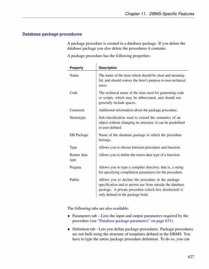
Chapter 11. DBMS-Specific Features
Database package procedures
A package procedure is created in a database package. If you delete thedatabase package you also delete the procedures it contains.
A package procedure has the following properties:
Property Description
Name The name of the item which should be clear and meaning-ful, and should convey the item’s purpose to non-technicalusers.
Code The technical name of the item used for generating codeor scripts, which may be abbreviated, and should notgenerally include spaces.
Comment Additional information about the package procedure.
Stereotype Sub-classification used to extend the semantics of anobject without changing its structure; it can be predefinedor user-defined.
DB Package Name of the database package to which the procedurebelongs.
Type Allows you to choose between procedure and function.
Return datatype
Allows you to define the return data type of a function.
Pragma Allows you to type a compiler directive, that is, a stringfor specifying compilation parameters for the procedure.
Public Allows you to declare the procedure in the packagespecification and to permit use from outside the databasepackage. A private procedure (check box deselected) isonly defined in the package body.
The following tabs are also available:
♦ Parameters tab – Lists the input and output parameters required by theprocedure (see “Database package parameters” on page 631).
♦ Definition tab - Lets you define package procedures. Package proceduresare not built using the structure of templates defined in the DBMS. Youhave to type the entire package procedure definition. To do so, you can
627

Oracle
use operators and functions to insert script items into the cursordefinition.
For example, the definition of the CREDIT package procedure is thefollowing:
CREATE PROCEDURE credit (Account_number NUMBER, Amount INNUMBER) AS
BEGINUPDATE accountsSET balance = balance + amountWHERE account_id = acc_no;END;
Database package variables
Variables can be declared within a package. A variable can be used in a SQLor PL/SQL statement to capture or provide a value when one is needed.
For example, you can define the variable in_stock with a boolean data typeto verify if a product is available or not.
Variables have the following properties:
Property Description
Name The name of the item which should be clear and meaning-ful, and should convey the item’s purpose to non-technicalusers.
Code The technical name of the item used for generating code orscripts, which may be abbreviated, and should not generallyinclude spaces.
Comment Additional information about the variable.
DB Package Name of the database package to which the variablebelongs.
Data Type Data type of the variable. You can use the Question Markbutton to display the list of Standard Data Types.
Mandatory If selected, indicates that the not null clause is set on thevariable, thus making it mandatory.
Length Allows you to define the variable length.
Precision Number of places after the decimal point, for data valuesthat can take a decimal point.
Default value Default value of the variable.
628

Chapter 11. DBMS-Specific Features
Property Description
Constant Indicates that the variable is a constant. A constant has avalue assigned. For example: Credit_Limit constant REAL:= 500 000;
Public Allows you to declare the variable in the package specifica-tion and to permit use from outside the database package.A private variable (check box deselected) is only defined inthe package body.
Database package cursors
A cursor is a multi-row query, which lets you name a work area and accessits stored information.
Cursors have the following properties:
Property Description
Name The name of the item which should be clear and meaningful,and should convey the item’s purpose to non-technical users.
Code The technical name of the item used for generating code orscripts, which may be abbreviated, and should not generallyinclude spaces.
Comment Additional information about the cursor.
DB Package Name of the database package to which the cursor belongs.
Return DataType
Allows you to define the data type of a cursor result value.
Public Allows you to declare the cursor in the package specificationand to permit use from outside the database package. Aprivate cursor (check box deselected) is only defined in thepackage body.
The following tabs are also available:
♦ Parameters tab – Lists the input and output parameters required by thecursor (see “Database package parameters” on page 631).
♦ Definition tab - lets you define the cursor. You can use operators andfunctions to insert script items into the cursor definition.
For example, the following cursor allows locating in table emp, theemployee number, name, and function in a given department and for a given
629

Oracle
employee number:
Select empno, empname, job FROM emp WHERE deptno=20 and empno =num ;
Database package exceptions
PL/SQL allows you to explicitly handle internal and user-defined errorconditions, called exceptions, that arise during processing of PL/SQL code.
Exceptions have the following properties:
Properties Description
Name The name of the item which should be clear and meaningful,and should convey the item’s purpose to non-technical users.
Code The technical name of the item used for generating code orscripts, which may be abbreviated, and should not generallyinclude spaces.
Comment Additional information about the exceptions.
DB Package Name of the database package to which the exceptionbelongs.
Pragma Allows you to type a compiler directive, that is, a string forspecifying compilation parameters for the exception.
Database package types
A type is a user-defined composite datatype that encapsulates a data
630

Chapter 11. DBMS-Specific Features
structure along with the functions and procedures needed to manipulate thedata. You can also define subtypes of object types: a subtype contains all theattributes and methods of the parent type, it can contain additional attributesand can override methods from the type.
Types have the following properties:
Property Description
Name The name of the item which should be clear and meaningful,and should convey the item’s purpose to non-technical users.
Code The technical name of the item used for generating code orscripts, which may be abbreviated, and should not generallyinclude spaces.
Comment Additional information about the type.
DB Package Name of the database package to which the type belongs.
Type Allows you to declare the type as type or subtype.
Public Allows you to declare the type in the package specificationand to permit use from outside the database package. Aprivate type (check box deselected) is only defined in thepackage body.
The following tabs are also available:
♦ Definition - Used to declare the type contents.
The following example defines the type bank_account:
CREATE TYPE Bank_Account AS OBJECT (acct_number INTEGER(5),balance REAL,status VARCHAR2(10),);
Database package parameters
Database package procedures (see “Database package procedures” onpage 627) and cursors (see “Database package cursors” on page 629) can useinput and output parameters.
For example, in a CREDIT procedure, you could define the parametersAccount Number and Amount.
Parameters have the following properties:
631

Oracle
Property Description
Name The name of the item which should be clear and meaningful,and should convey the item’s purpose to non-technical users.
Code The technical name of the item used for generating code orscripts, which may be abbreviated, and should not generallyinclude spaces.
Comment Additional information about the parameter.
Parent Specifies the database package parent of the parameter. Youcan see the database package property sheet by clicking theProperties tool at the right of the field.
Data type Data type of the parameter. You can use the Question Markbutton to display the list of Standard Data Types.
Default Value Default value of the parameter.
Parametertype
Type of the parameter.
Rebuilding database package procedures
You can rebuild database package procedure dependencies (along with otherprocedure dependencies) by selecting Tools ä Rebuild Objects ä RebuildProcedures Dependencies. For more information, see “Rebuilding proceduredependencies” in the Building Triggers and Procedures chapter.
Generating database packages
You can define generation parameters for database packages in the DatabasePackage tab of the Triggers and Procedures Generation dialog box.
The following parameters are available:
632

Chapter 11. DBMS-Specific Features
Parameter Resulting generation command
Createdatabase pack-age
Create database package, as defined in the Oracle DBMS:create package %DBPACKAGE% [authid
%DBPACKAGEPRIV%][[%R%?[is][as]:as]
%DBPACKAGESPEC%
end [%DBPACKAGE%]/
[create package body %DBPACKAGE% AS
%DBPACKAGEBODY%
[BEGIN
%DBPACKAGEINIT%] ]
end [%DBPACKAGE%]
]
Drop databasepackage
Drop database package, as defined in the Oracle DBMS:drop package %DBPACKAGE%
Permission Generate the permission statement for a given user duringdatabase package creation.
+ For more information on the create and drop statements for databasepackages, see the DBMS Resource File Reference chapter in theCustomizing and Extending PowerDesigner manual.
Reverse engineering database packages
You can select database packages to reverse engineer from the DatabasePackage tab of the Database Reverse Engineering dialog box.
When you reverse engineer a database package, the sub-objects (variable,procedure, cursor, exception, and type) are created from the specificationand the body of the database package.
Reverse engineering tablespace physical options
In Oracle, you cannot reverse engineer tablespace physical options via a livedatabase connection without a login “System”.
If you do not have a login “System”, the list of tablespaces is reversedwithout the physical options of the objects.
If you want to cancel the reverse engineering of tablespace physical options,
633

Oracle
you have to clear the query SqlAttrQuery in the Tablespace category inthe Oracle DBMS.
Oracle dimensions
In Oracle, the columns of the dimension table are called levels of thedimension hierarchy. These levels can have dependent columns. Forexample, in the dimension Time, the level Quarter has a dependent columncalled Number of business days.
The following mapping is established between dimensions in Oracle andPowerDesigner:
Oracle object PowerDesigner object
Dimension Dimension
Hierarchy Dimension hierarchy
Level Dimension attribute used in a hierarchy
Attribute Dimension attribute used as detail attribute
Oracle dimension creation and deletion orders can be generated and reverseengineered in PowerDesigner. Both generation and reverse engineering canbe done by script or through a live database connection. For moreinformation, see the Generating a Database from a PDM and the ReverseEngineering a Database into a PDM chapters.
+ For more information on dimensions, see the Building MultidimensionalDiagrams chapter.
Transparent Data Encryption (TDE)
Oracle 10gR2 provides Transparent Data Encryption (TDE), encryption thatis transparent for the user.
When encrypting a column, Oracle creates an encryption key for the parenttable and encrypts text data in the column with a user-specified encryptionalgorithm. The table key is encrypted using a master key and placed in thedata dictionary. The master key is stored in a secure location called a wallet,which can be a file on the database server. When a user enters data into anencrypted column, Oracle retrieves the master key from the wallet, decryptsthe table key from the data dictionary, and uses it to encrypt the new data.
Creating a wallet password
In order to access the master key used to encrypt the table keys, you must
634

Chapter 11. DBMS-Specific Features
create a master password to open the wallet.
v To create a wallet password
1. Right-click the model in the Browser, and select Properties from thecontextual menu to open its property sheet.
2. Click the Oracle tab, and enter your wallet password in the PasswordEncryption field.
3. Click OK to close the model property sheet. The password will be usedto create alter statements for opening and closing the wallet.
Creating an encrypted table column
You can create one or more encrypted column in one or more tables. Youcan specify the encryption algorithm to be used, but all columns in aparticular table must use the same algorithm. If you create a secondencrypted column in a table, and specify a different algorithm, the lastspecified algorithm will be used for all columns in the table.
v To encrypt a table column
1. Create a column and open its property sheet.
2. On the General tab, specify any of the following types, which supportencryption:
♦ CHAR, NCHAR, VARCHAR2, and NVARCHAR2
♦ DATE and TIMESTAMP
♦ INTERVAL DAY TO SECOND and YEAR TO MONTH
♦ NUMBER
♦ RAW
3. Click the Oracle tab and select the Encryption checkbox.
4. Select an encryption algorithm from the list particular
5. [optional] Select the With salt checkbox in order to add some random bitsto the encryption key.
6. Click OK to complete the column definition.
Clusters
A cluster is a schema object that contains data from one or more tables,which have one or more columns in common. Oracle Database storestogether all the rows from all the tables that share the same cluster key.
635

Oracle
PowerDesigner models clusters as extended objects with a stereotype of<<Cluster>>.
Upgrading clusters from v10gR2 and earlierClusters in Oracle v10gR2 and earlier are modeled as indexes with theCluster check box selected. To upgrade such clusters to v11 or higher, youmust generate a new PDM with the appropriate DBMS target from youroriginal model. Simply changing the target DBMS will result in the loss ofany existing clusters
Creating a cluster You can create a cluster in any of the following ways:
♦ Select Model ä Clusters to access the List of Clusters, and click the Adda Row tool
♦ Right-click the model or package in the Browser, and select New ä
Cluster
Cluster properties You can modify an object’s properties from its property sheet. To open acluster property sheet, double-click its Browser in the Clusters folder.
The following extended attributes are available on the General tab:
Name Description
Owner Specifies the owner of the cluster
In addition, the following tabs are available:
♦ Columns – lists the columns associated with the cluster
♦ Indexes – lists the indexes defined for the cluster
Database Links
A database link is a schema object in one database that enables you to accessobjects on another database.
Database links are supported for Oracle 11g and higher. PowerDesignermodels database links as extended objects with a stereotype of <<DatabaseLink>>.
Creating a database link You can create a database link in any of the following ways:
♦ Select Model ä Database links to access the List of Database links, andclick the Add a Row tool.
♦ Right-click the model or package in the Browser, and select New ä
Database link.
636

Chapter 11. DBMS-Specific Features
Database link properties You can modify an object’s properties from its property sheet. To open adatabase link property sheet, double-click its Browser in the Database linksfolder.
The following extended attributes are available on the Oracle tab:
Name Description
Shared Specifies the use of a single network connection to create apublic database link that can be shared among multiple users.If selected, you must also specify a user name and passwordfor the target instance on the remote server.
Scripting names: Shared, AuthenticatedBy, Authentication-Password
Connect to Specifies the user name and password used to connect to theremote database using a fixed user database link.You need tospecify CURRENT_USER to create a current user databaselink. The current user must be a global user with a validaccount on the remote database. If you do not specify a value,then the database link uses the user name and password ofeach user who is connected to the database.
Scripting names: Username, Password
Servicename
Specifies the service name of a remote database. If you spec-ify only the database name, then Oracle Database implicitlyappends the database domain to the connect string to create acomplete service name.
Scripting name: ServiceName
Physicaldata model
Specifies the PowerDesigner model that contains the objectsof the remote database. Use the buttons to the right of thefield to create, delete, select, or view the property sheet of themodel.
Scripting name: LinkModel
Materialized view logs
When DML changes are made to master table data, Oracle Database storesrows describing those changes in the materialized view log and then uses thematerialized view log to refresh materialized views based on the mastertable.
Materialized view logs are supported for Oracle 11g and higher.PowerDesigner models materialized view logs as extended objects with astereotype of <<Materialized view log>>.
637

Oracle
Creating a materializedview log
You can create a materialized view log as follows:
♦ Open the property sheet of the table to which you want to attach the log,select the Oracle tab, and click the Create button in the Materialized viewlog groupbox.
Materialized view logproperties
You can modify an object’s properties from its property sheet. To open amaterialized view log property sheet, double-click its Browser entry or clickthe Properties button on its parent table Oracle tab.
The General tab displays the master table name and the comment. Thefollowing properties are available on the Partitions tab:
Name Description
Type Specifies the method for paritioning the table. You can choosebetween:♦ Range/Composite - Partitions the table on ranges of values
from the column list.
♦ Hash - Partitions the table using the hash method.
♦ List - Partitions the table on lists of literal values from col-umn.
♦ Reference - Equipartitions the table being created (thechild table) by a referential constraint to an existing par-titioned table (the parent table).
♦ System - Partitions the table by the partitions specified.When you select a type, additional options are displayed, toallow you to specify the appropriate parameters.
Oracle extended attributes
The following extended attributes are defined by default in the OracleDBMS.
Abstract Data TypesAttributes
The following extended attributes are available for attributes of abstract datatypes of type OBJECT or SQLJ_OBJECT on the Oracle tab:
Name Description
Declare REF Generates a REF modifier on attribute to declare references,which hold pointers to objects.
Scripting name: RefAttribute
Columns The following extended attributes are available on the Oracle tab:
638

Chapter 11. DBMS-Specific Features
Name Description
Deferred op-tion of checkconstraint
Defines the deferred option of a column constraint check. Itis used in the definition or create and add items statements.
Scripting name: ExtColumnDeferOption
Name of notnull con-straint
[v8i and higher] Defines the name of the not null constraintfor a column.
Scripting name: ExtNotNullConstraintName
Deferred op-tion of notnull con-straint
[v8i and higher] Defines the deferred option of a column notnull constraint. It is used in “create” and “add” statementitems definition.
An empty value means “Not deferrable”.
Scripting name: ExtNotNullDeferOption
Encrypted [v10gR2 and higher] Specifies if column is encrypted.
Scripting name: Encrypted
Algorithm [v10gR2 and higher] Specifies the algorithm used for en-cryption.
Scripting name: Algorithm
With salt [v10gR2 and higher] Specifies if encryption adds salt toencoded data.
Scripting name: EncryptionWithSalt
Identified byPassword
[v10gR2 and higher] Identifies by password.
Scripting name: IdentifiedByPassword
Database Packages The following extended attributes are available on the Oracle tab:
Name Description
Add serially_-reusable pragmaon package specifi-cation
[v9i and higher] When set to True, defines that thepragma serially_reusable clause must be applied onthe database package specification.
Scripting name: IsSpecPragma
Add serially_-reusable pragmaon package body
[v9i and higher] When set to True, defines that thepragma serially_reusable clause must be applied onthe database package body declaration.
Scripting name: IsPragma
References The following extended attributes are available on the Oracle tab:
639

Oracle
Name Description
Deferred option offoreign key con-straint
Defines the deferred option of a reference. It is usedin the definition of create and add items statements.
Scripting name: ExtReferenceDeferOption
Exceptions into Specifies a table into which Oracle places theROWIDs of all rows violating the constraint.
Scripting name: ExceptionsInto
Rely [v8i and higher] Specifies whether an enabled con-straint is to be enforced.
Specify RELY to enable an existing constraint withoutenforcement.
Specify NORELY to enable and enforce an existingconstraint.
Scripting name: Rely
Disable Disables the integrity constraint.
Scripting name: Disable
Validate Checks that all old data also obeys the constraint.
Scripting name: Validate
Tables The following extended attributes are available on the Oracle tab:
Name Description
Type Defines if the table is of type global temporary or not.
Scripting name: ExtTableType
The following extended attributes are available (for v11g and higher) on theXML properties tab when the table type is set to XML:
Name Description
Object prop-erties
Specifies that the properties of object tables are essentiallythe same as those of relational tables.
However, instead of specifying columns, you specify at-tributes of the object.
Scripting name: XmlTypeObjProperty
Storage type Specifies that XMLType columns can be stored in LOB,object-relational, or binary XML columns.
Scripting name: XMLTypeStorage
640

Chapter 11. DBMS-Specific Features
Name Description
Basic file Use this clause to specify the traditional LOB storage.
Scripting name: BasicFile
Secure file Use this clause to specify high-performance LOB.
Scripting name: SecureFile
LOB segmentname
Specify the name of the LOB data segment. You cannot useLOB_segname if you specify more than one LOB_item.
Scripting name: LOBSegname
LOB parame-ters
Use this clause to specify various elements of LOB parame-ters.
Scripting name: LOBParameters
Tablespaces The following extended attributes are available on the Oracle tab:
Name Description
Size specifi-cation
[v10g and higher] Specifies whether the tablespace is abigfile or smallfile tablespace. This clause overrides anydefault tablespace type setting for the database. You canchoose from the following settings:♦ bigfile - contains only one datafile or tempfile. The maxi-
mum size of the single datafile or tempfile is 128 terabytes(TB) for a tablespace with 32K blocks and 32TB for a ta-blespace with 8K blocks.
♦ smallfile - a traditional Oracle tablespace.Scripting name: SizeSpecification
Temporarytablespace
Use this option to create a locally managed temporarytablespace, which is an allocation of space in the databasethat can contain transient data that persists only for theduration of a session. This transient data cannot be recoveredafter process or instance failure.
Scripting name: Temporary
Undo ta-blespace
Use this option to create an undo tablespace. When you runthe database in automatic undo management mode, OracleDatabase manages undo space using the undo tablespaceinstead of rollback segments. This clause is useful if you arenow running in automatic undo management mode but yourdatabase was not created in automatic undo managementmode.
Scripting name: Undo
641

Oracle
Views The following extended attributes are available on the Oracle tab:
Name Description
Super viewobject
[v9i and higher] Used in the UNDER clause to specify thesuperview the current object view is based on.
Scripting name: ExtObjSuperView
Object viewkey
[v8i and higher] Specifies the attributes of the object typethat will be used as a key to identify each row in the objectview.
Scripting name: ExtObjOIDList
Object viewtype
[v8i and higher] Defines the type of the object view.
Scripting name: ExtObjViewType
Force When set to TRUE, allows you to create the view regardlessof the existence of the base tables or the owner privileges onthese tables.
Scripting name: ExtViewForce
642

Chapter 11. DBMS-Specific Features
PostgreSQLThis section describes features specific to the PostgreSQL family ofdatabases.
PostgreSQL base and composite type domains
PowerDesigner supports the following special PostgreSQL data types:
♦ Base Type
♦ Composite Type
v To create a base or composite type
1. Select Model ä Domains to open the List of Domains.
2. Click the Add a Row tool to create a new domain, and then click theProperties tool to open its property sheet.
3. Select either BaseType or CompositeType from the Stereotype list andclick Apply .
4. An additional tab called either Base Type or Composite Type will bedisplayed, allowing you to specify type-specific extended attributes. Seethe relevant section in the “PostgreSQL extended attributes” on page 643section, for details of these properties.
PostgreSQL extended attributes
The following extended attributes are defined by default in the PostgreSQLDBMS.
Database The following extended attributes are available on the PostgreSQL tab:
Name Description
Template The name of the template from which to create the newdatabase, or DEFAULT to use the default template.
Scripting name: Template
Encoding Character set encoding to use in the new database. Specify astring constant (e.g., ‘SQL_ASCII’), or an integer encodingnumber, or DEFAULT to use the default encoding.
Scripting name: Encoding
Domain (Base Type) The following extended attributes are available on the PostgreSQL tab:
643

PostgreSQL
Name Description
Array delim-iter
Delimiter character for the array.
Scripting name: ExtTypeDelimiter
Array Ele-ment type
Specifies the type of the array elements.
Scripting name: ExtTypeElement
Input func-tion
Name of a function, created by CREATE FUNCTION,which converts data from its external form to the internalform of the type.
Scripting name: ExtTypeInput
Length Literal value which specifies the internal length of the newtype.
Scripting name: ExtTypeLength
Output func-tion
Name of a function, created by CREATE FUNCTION,which converts data from its internal form to a form suitablefor display.
Scripting name: ExtTypeOutput
By Value Indicates that operators and functions which use this datatype should be passed an argument by value rather than byreference.
Scripting name: ExtTypePassedByValue
Receive func-tion
Name of a function, created by CREATE FUNCTION,which converts data of this type from a form suitable fortransmission from another machine to internal form.
Scripting name: ExtTypeReceive
Send function Name of a function, created by CREATE FUNCTION,which converts data of this type into a form suitable fortransmission to another machine.
Scripting name: ExtTypeSend
Domain (CompositeType)
The following extended attributes are available on the PostgreSQL tab:
644

Chapter 11. DBMS-Specific Features
Name Description
Definition The composite type is specified by a list of attribute namesand data types. This is essentially the same as the row type ofa table, but using CREATE TYPE avoids the need to createan actual table when all that is wanted is to define a type. Astand-alone composite type is useful as the argument or returntype of a function.
Scripting name: CompositeDefinition
Groups The following extended attributes are available on the PostgreSQL tab (v8and higher):
Name Description
Group iden-tifier (id)
The SYSID clause can be used to choose the PostgreSQLgroup ID of the new group. This is normally not necessary,but may be useful if you need to recreate a group referencedin the permissions of some object.
Scripting name: SysId
Procedures The following extended attributes are available on the PostgreSQL tab:
Name Description
Language The name of the language that the function is implementedin. May be SQL, C, internal, or the name of a user-definedprocedural language. (See also extended attribute typeProcLanguageList.)
Scripting name: ProcLanguage
References The following extended attributes are available on the PostgreSQL tab (v8and higher):
645

PostgreSQL
Name Description
Deferrable Controls whether the constraint can be deferred. A constraintthat is not deferrable will be checked immediately after everycommand. Checking of constraints that are deferrable may bepostponed until the end of the transaction.
Only foreign key constraints currently accept this clause. Allother constraint types are not deferrable.
Scripting name: Deferrable
Foreign keyconstraint
If a constraint is deferrable, this clause specifies the defaulttime to check the constraint.
False means the constraint is INITIALLY IMMEDIATE, it ischecked after each statement. This is the default.
True means the constraint is INITIALLY DEFERRED, it ischecked only at the end of the transaction.
Scripting name: ForeignKeyConstraintDeferred
Tables The following extended attributes are available on the PostgreSQL tab (v8and higher):
Name Description
Temporarystate
If specified, the table is created as a temporary table. Tempo-rary tables are automatically dropped at the end of a session,or optionally at the end of the current transaction.
Scripting name: Temporary
Tablespaces The following extended attributes are available on the PostgreSQL tab (v8and higher):
Name Description
Location Specifies the directory that will be used for the tablespace.The directory must be specified by an absolute path name.
Scripting name: TbspLocation
Owner Specifies the name of the user who will own the tablespace.If omitted, defaults to the user executing the command.Only superusers may create tablespaces, but they can assignownership of tablespaces to non-superusers.
Scripting name: TbspOwner
Users The following extended attributes are available on the PostgreSQL tab (v8and higher):
646

Chapter 11. DBMS-Specific Features
Name Description
Createdatabase
Defines a user’s ability to create databases.
If TRUE, the user is allowed to create databases.
Scripting name: CreateDB
Create user If TRUE, the user is allowed to create new users.
This option also turns the user into a superuser who canoverride all access restrictions.
Scripting name: CreateUser
Encryptedpassword
Controls whether the password is stored encrypted in thesystem catalogs.
Scripting name: EncryptedPassword
User identi-fier (id)
The SYSID clause can be used to choose the PostgreSQL userID of the new user. This is normally not necessary, but maybe useful if you need to recreate the owner of an orphanedobject.
Scripting name: SysId
Validity This clause sets an absolute time after which the user’spassword is no longer valid. If this clause is omitted thepassword will be valid for all time.
Scripting name: Validity
647

Red Brick Warehouse
Red Brick WarehouseThis section describes features specific to the Red Brick Warehouse familyof databases.
Red Brick Warehouse extended attributes
The following extended attributes are defined by default in the Red BrickWarehouse DBMS.
Columns The following extended attributes are available on the Red Brick tab:
Name Description
Unique Declares that duplicate values are not allowed in the column.
Declaring a column UNIQUE does not enforce uniquenesson the column; to enforce uniqueness, you must also build aBTREE index on the column.
Scripting name: IsUnique
Procedures The following extended attributes are available on the Red Brick tab:
Name Description
Macro Type A macro can be temporary, public, or private: see MacroType-List for details.
If neither temporary nor public is specified, a private macro iscreated by default.
Scripting name: MacroType
648

Chapter 11. DBMS-Specific Features
Sybase AS AnywhereThis section describes features specific to the Sybase AS Anywhere familyof databases
Deprecated versionsThe DBMSs for Sybase AS Anywhere v7 and v8 are deprecated.
Note that from version 10, AS Anywhere is known as Sybase SQLAnywhere (see “Sybase SQL Anywhere” on page 674).
Auto-increment columns
Auto-increment columns are equivalent to identity columns in those DBMSthat support identity columns.
If you switch from Sybase ASA to a DBMS that supports identity columns,the Identity checkbox will be selected for each auto-increment column. Onthe other hand, if you switch to Sybase ASA, identity columns will beassigned the autoincrement default value.
When you reverse engineer a script containing identity columns (usingSybase ASE-compatible syntax), these are automatically converted intoauto-increment columns in Sybase ASA.
Working with proxy tables in Sybase ASA and ASE
A proxy table is used to access data in a remote table, it has all the attributesof the remote table, but it does not contain any data locally.
PowerDesigner can generate the script for a proxy table in order to run it in aSybase ASA or ASE database. To do so, you need to attach the ProxyTablesextended model definition to your model and then design proxy tables usingexternal shortcuts or replications.
After designing the proxy tables, you can use the build data source featurethat will create a data source for each target model of the current model.Target models are models containing the target tables of the replica orexternal shortcuts, they are also called remote servers.
Once the data sources are properly defined, you can use the extendedgeneration feature to generate the proxy table and remote server creationscripts.
Understanding the ProxyTables extended model definition
For an external shortcut or replica to be used as a proxy table you need to
649

Sybase AS Anywhere
attach the ProxyTable extended model definition to the model.
v To attach the ProxyTables extended model definition to an exist-ing model
1. Select Model ä Extended Model Definitions.
2. Click the Import an Extended Model Definition tool.
A selection dialog box is displayed.
3. Select the ASA Proxy Tables or ASE Proxy Tables extended modeldefinition and click OK.
The extended model definition is displayed in the list.
4. Click OK.
Select ProxyTables XEM at model creationYou can also select the relevant Proxy Tables XEM in the Extended ModelDefinitions tab of the New dialog box
The ProxyTables extended model definition contains generation templates,extended attributes, custom checks and custom methods to support thedefinition of external proxy tables.
You can double-click the ProxyTables extended model definition in theBrowser to display its properties in the resource editor. The followingextensions must be defined in the Profile category to fully support proxytables:
♦ BasePackage:• Generation template - for generating proxy tables.
♦ DataSource:• Connection information custom check - verifies that the connection
information is sufficient to connect to the database. You must specifythe data source name, user login and password in the DatabaseConnection tab of the data source property sheet.
• GenerateAsProxyServer extended attribute - when set to true, definesthe data source model as the proxy remote server.
• [various templates] - used for proxy table generation.
♦ Model:• Proxy Servers and Tables generated files - to generate proxy server and
table script files.
650

Chapter 11. DBMS-Specific Features
• Menu – provides a contextual menu for building data sources andcommands in the Tools menu for rebuilding data sources andgenerating proxy tables.
• BuildProxyTableDataSourcesand GenerateProxyTables methods - usedin the menu.
• [various templates] - required for proxy server and proxy table scriptgeneration.
♦ Shortcut:• Data source existence custom check - verifies that data sources are
defined for the shortcuts.
♦ Table:• Proxy table is child of reference custom check - verifies that the model
replica is not the child of another table via a reference link.
• [various templates] - required for proxy table, remote server and accessdefinition creation syntax.
Creating a proxy table
You use external shortcuts and/or replica to design proxy tables in yourmodel.
An external shortcut is a non-modifiable reference to an object in anothermodel. For more information on shortcuts, see “Shortcuts”in the Shortcutsand Object Replications chapter of the Core Features Guide .
A replica is an exact copy of an object that can be updated when the originalobject is modified. For more information on replications, see“Replications”in the Shortcuts and Object Replications chapter of the CoreFeatures Guide .
One interesting aspect of using replica, is that you can modify the replicacode in order to make it different from the target table. A custom checkverifies that replica are not used as child tables of a reference.
v To create a proxy table in a PDM
1. Select a table in a target model and drag it to the model where you wantto create proxy tables using the appropriate key combination to createeither an external shortcut or a replica.
2. Repeat this operation for each proxy table.
651

Sybase AS Anywhere
Defining the remote server of a proxy table
The remote server is the model containing the target tables of the externalshortcut or replica. The remote server is defined using a data source in theproxy tables model; this data source provides access to the remote data onthe server.
Note: the same data source can contain information for several models thatshare the same remote servers.
When you attach the ProxyTables extended model definition to the modelcontaining proxy tables, a specific contextual menu is displayed on thephysical data model item, this menu command is used for building the datasource of the proxy tables.
Note: This command does not build data sources for target models that areclosed in the workspace.
v To define the remote server of a proxy table
1. Create a new data source and set the GenerateAsProxyServer extendedattribute to True.
2. Add the target models in the Models tab of the data source property sheet.
You can also right-click the model that contains replica and/or shortcutsin the Browser and select the Build Proxy Tables Data Sources command.A data source is automatically created for each target model.
3. Double-click a data source in the Browser to display its property sheet.
4. Click the Database Connection tab, and define the data source name,login and password.
5. Click OK.
6. Repeat steps 2 to 5 for each data source.
Generating the remote server and proxy tables creation scripts
You can generate the remote server and proxy tables creation scripts in orderto run them in the database. Generation must be started from the modelcontaining proxy tables.
The ProxyTables extended model definition contains the creation scriptsyntax for ASA or ASE.
652

Chapter 11. DBMS-Specific Features
v To generate the remote server and proxy tables creation scripts
1. Select Tools ä Proxy Tables ä Generate Proxy Tables to open theGeneration dialog box, and click the Options tab.
2. Set a value for the UserReplica and UserShorcut options to allow you togenerate the proxy tables corresponding to replica and/or externalshortcuts.
3. Set the Generate proxy servers option to one of the following values:♦ True – to generate proxy servers. You can deselect any proxy servers
you do not want to generate.
♦ False – to not generate proxy servers
4. Click OK to begin generation.
The generated script is displayed in the Result dialog box.
5. [optional] Double-click the generated SQL file or click the Edit button toopen the script in a text editor.
6. Run the script on your database in order to create the proxy tables.
Sybase AS Anywhere extended attributes
The following extended attributes are defined by default in the Sybase ASAnywhere DBMS.
Table The following extended attributes are available on the Sybase tab:
Name Description
Global tem-porary table
Defines if table is a global temporary table or not.
Scripting name: ExtGlobalTemporaryTable
Web Services The following extended attributes are available on the Sybase tab (v9 andhigher):
Name Description
Port number Specifies the web service port number.
Scripting name: PortNumber
Server name Specifies the web service server name.
Scripting name: ServerName
Name prefix(dish servicesonly)
Specifies the web service name prefix (dish services only).
Scripting name: Prefix
653

Sybase AS Anywhere
Web Operations The following extended attributes are available on the Sybase tab (v9 andhigher) when the service type is not dish:
Name Description
URL Determines whether URI paths are accepted and, if so, howthey are processed.
Scripting name: Url
654

Chapter 11. DBMS-Specific Features
Sybase AS EnterpriseThis section describes features specific to the Sybase AS Enterprise familyof databases.
Deprecated versionsThe DBMSs for Sybase AS Enterprise v11.0 and v11.5-11.9 are deprecated.
Proxy tables
For information about using proxy tables, see “Working with proxy tables inSybase ASA and ASE” on page 649.
Encryption Keys
Encryption keys are supported for ASE v12.5.3a and higher. PowerDesignermodels encryption keys as extended objects with a stereotype of<<EncryptionKey>>.
Adaptive Server authentication and access control mechanisms ensure thatonly properly identified and authorized users can access data. You canencrypt data at the column level, thus restricting your security measures toonly sensitive data, and minimizing processing overhead.
Encrypting columns in Adaptive Server is more straightforward than usingencryption in the middle tier, or in the client application. You use SQLstatements to create the encryption keys and specify columns for encryption.Adaptive Server handles key generation and storage. Encryption anddecryption of data occurs automatically and transparently as you write andread the data in encrypted columns. No application changes are required,and there is no need to purchase third-party software.
Creating an encryptionkey
You can create an encryption key in any of the following ways:
♦ Select Model ä Encryption Keys to access the List of Encryption Keys,and click the Add a Row tool.
♦ Right-click the model or package in the Browser, and select New ä
Encryption Key.
Encryption keyproperties
You can modify an object’s properties from its property sheet. To open anencryption key property sheet, double-click its Browser entry in theEncryption Keys folder.
The following extended attributes are available on the Sybase tab:
655

Sybase AS Enterprise
Name Description
Owner [v12.5.3a and higher] Specifies the owner of the encryptionkey.
Scripting name: Owner
Key length [v12.5.3a and higher] Specifies the size in bits of the key tobe created. Valid key lengths for AES are 128, 192 and 256bits.
Scripting name: KeyLength
Algorithm [v12.5.3a and higher] Specifies the algorithm used to generatethe encryption key. Currently, Advanced Encryption Standard(AES) is the only algorithm supported.
Scripting name: Algorithm
Initializationvector
[v12.5.3a and higher] Controls the use of an initializationvector when encrypting. When an initialization vector is usedby the encryption algorithm, the ciphertext of two identicalpieces of plaintext will be different, which would prevent thecryptanalyst from detecting patterns of data but would renderthe data on disk useless for indexing or matching withoutdecryption.
Scripting name: InitVector
Padding ofdatatypes
[v12.5.3a and higher] Specifies the use of padding ofdatatypes whose length is less than one block. Paddingcan be used instead of an initialization vector to randomizethe ciphertext. It is only suitable for columns whose plaintextlength is less than half the block length. For the default AESalgorithm the block length is 16 bytes.
Scripting name: Pad
Passwordphrase
[v15.0.2 and higher] Specifies a default key for use on allencrypted columns which do not have a keyname specified increate table or alter table. This is a database specific defaultkey for use with tables in the same database. The default keyis stored in the database sysencryptkeys table, the same asnon-default keys.
Scripting name: PasswordPhrase
656

Chapter 11. DBMS-Specific Features
Name Description
Default en-cryption key
[v12.5.3a and higher] Allows the System Security Officer tocreate a default key for use on all encrypted columns whichdo not have a keyname specified in create table or alter table.This is a database specific default key for use with tables inthe same database. The default key is stored in the databasesysencryptkeys table, the same as non-default keys.
Scripting name: Default
Sybase AS Enterprise extended attributes
The following extended attributes are defined by default in the Sybase ASEnterprise DBMS.
Columns The following extended attributes are available on the Sybase tab:
Name Description
Store Java-SQL columnin row
[v12.0 and higher] Specifies whether a Java-SQL columnis stored separate from the row (set to False) or in storageallocated directly in the row (set to True).
Scripting name: InRow
Computedcolumn ismaterialized
Specifies that the computed column is materialized.
Scripting name: Materialized
Encrypted [v12.5.3a and higher] Specifies that the column is encrypted.
Scripting name: Encrypted
EncryptionKey
[v12.5.3a and higher] Specifies an encryption key name.
Scripting name: EncryptionKey
Keys The following extended attributes are available on the Sybase tab:
Name Description
Key index isdescending
Specifies if the index created for a constraint is to be createdin descending order for each column.
Scripting name: DescKey
Model The following extended attributes are available on the Encryption tab(v12.5.3a and higher):
657

Sybase AS Enterprise
Name Description
Encryptionpassword
Global encryption password.
Scripting name: EncryptionPassword
Web Services The following extended attributes are available on the Sybase tab (v15.0 andhigher):
Name Description
Port number Specifies the web service port number.
Scripting name: PortNumber
Server name Specifies the web service server name.
Scripting name: ServerName
Databasename
Specifies the database name used in the URL to access theweb service.
Scripting name: DatabaseName
Web Operations The following extended attributes are available on the Sybase tab (v15.0 andhigher):
Name Description
Alias Specifies the name of the user-defined database alias.
Scripting name: Alias
Secure Security option. clear indicates that HTTP is used to accessthis Web service. ssl indicates HTTPS is used to access thisWeb service
Scripting name: Secure
658

Chapter 11. DBMS-Specific Features
Sybase AS IQThis section describes features specific to the Sybase AS IQ family ofdatabases.
Deprecated versionsThe DBMSs for Sybase AS IQ v12.0 and v12.4.3 are deprecated.
Sybase Adaptive Server IQ (AS IQ) is a high-performance decision supportserver designed specifically for data warehousing.
Sybase AS IQ provides benefits that allow an interactive approach todecision support including:
♦ Intelligent query processing using index-only access plans to processonly the data needed to satisfy any type of query
♦ Truly interactive, ad hoc query performance on a uniprocessor as well ason parallel systems. An ad hoc query is a query about which the systemhas no prior knowledge and for which no explicit tuning is required. Adhoc queries are distinguished from standard or production reports, whereonly pre-defined variables, such as dates, are used to generate pre-definedreports on a regular basis.
♦ Fully-flexible schema support
♦ Efficient query execution without query-specific tuning by the SystemAdministrator (under most circumstances)
♦ Fast aggregations, counts, comparisons of data
♦ Stored procedures
♦ Entire database and indexing stored in less space than raw data
♦ Numerous index types
♦ Join indexes to improve overall query performance. Join indexesrepresent links between columns in different tables. They enable muchfaster query processing on multiple indexes in a very large database, andare usually applied instead of ad hoc queries.
IQ indexes
Before creating IQ indexes, you should consider the implications of varioustypes of indexes on the database server memory and disk space.
659

Sybase AS IQ
The set of indexes you define for any given column can have dramaticimpact on the speed of query processing. There are four main criteria forchoosing indexes:
♦ Number of unique values
♦ Types of queries
♦ Disk space usage
♦ Data types
It is best to consider all criteria in combination, rather than individually. Todecide on indexes, look closely at the data in each column.
Try to anticipate the number of unique and total values, the query resultsusers will want from it, and whether the data will be used in ad hoc joins orjoin indexes.
+ For more information about choosing index types, see chapter AdaptiveServer IQ Indexes in the Adaptive Server IQ Administration andPerformance Guide.
Rebuilding IQ indexes
As you develop a PDM or modify an existing one, you may change datatypes, alter the percentage of distinct values or change the number of valuesin tables. You must then rebuild the IQ indexes to reflect these changes.
660

Chapter 11. DBMS-Specific Features
v To rebuild IQ indexes
1. Select Tools ä Rebuild Objects ä Rebuild Indexes to open the RebuildIndexes dialog box:
2. Select a default name to generates IQ indexes. You can use the followingvariables:
♦ %COLUMN% - Column name
♦ %INDEXTYPE% - Type of index to be rebuilt
♦ %TABLE% - Name or code of table (based on display preferences)
3. Specify a mode to use. You can choose between:♦ Delete and Rebuild - All existing indexes are deleted before index
rebuild
♦ Preserve Indexes - Preserves all existing indexes
4. [optional] Select the Update statistics before rebuild checkbox to updatesuch statistics as the number of records in a table and the number ofdistinct values in a column before performing the rebuild. Selecting thisoption can help with optimizing the rebuild.
5. [optional] Click the Selection tab and select or clear checkboxes tospecify for which tables you want to rebuild indexes.
661
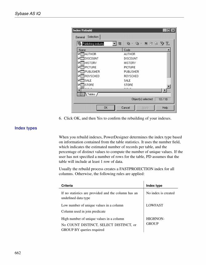
Sybase AS IQ
6. Click OK, and then Yes to confirm the rebuilding of your indexes.
Index types
When you rebuild indexes, PowerDesigner determines the index type basedon information contained from the table statistics. It uses the number field,which indicates the estimated number of records per table, and thepercentage of distinct values to compute the number of unique values. If theuser has not specified a number of rows for the table, PD assumes that thetable will include at least 1 row of data.
Usually the rebuild process creates a FASTPROJECTION index for allcolumns. Otherwise, the following rules are applied:
Criteria Index type
If no statistics are provided and the column has anundefined data type
No index is created
Low number of unique values in a column
Column used in join predicate
LOWFAST
High number of unique values in a column
No COUNT DISTINCT, SELECT DISTINCT, orGROUP BY queries required
HIGHNON-GROUP
662

Chapter 11. DBMS-Specific Features
Criteria Index type
Column used in join predicate
High number of unique values in a column (more that1000)
Anticipate COUNT DISTINCT, SELECT DISTINCT,or GROUP BY queries
Column must enforce uniqueness
HIGHGROUP
Column without numeric datatype No index is created
Column with date type DATE
Column with time type TIME
Column with datetime or smalldatetime type DTTM
For example (IQ v12.5, Table A contains 1500 rows
Column % Distinct
values
Unique
values
Rebuild indexes gen-erates
Col_1 integer 100 1500 HG index
Col_2 integer 50 750 LF index
Col_3 integer 0 0 no index
Col_4 char (10) 100 1500 no index
Col_5 char (10) 50 750 LF index
IQ join indexes
A join index is a special type of index used in Sybase AS IQ, whichrepresents a full outer join of two or more tables. The query engine may usethis full outer join as a starting point for queries that include left outer, rightouter, and inner joins. A full outer join is one where all rows from both theleft and right specified tables are included in the result, with NULL returnedfor any column with no matching value in the corresponding column.
Join indexes are defined from references. You can create a join index for anyset of columns that your users commonly join to resolve queries.
While some references are based on keys, Sybase AS IQ allows you tocreate user-defined references to include the exact join required by yourforeseen queries.
663

Sybase AS IQ
You can define a join index:
♦ Automatically, by creating join indexes from all references linked to afact table
♦ Manually, by creating a join index in the list of join indexes
Facts and Dimensions A fact corresponds to the focus of a decision support investigation. Forexample, Sales, Revenue, and Budget are facts. A table containing facts isset as a fact table in the table property sheet.
A dimension defines the axis of the investigation of a fact. For example,Product, Region, and Time are the axes of investigation of the Sales fact. Atable containing dimensions is linked to a fact table and is set as a dimensiontable in the table property sheet.
+ For more information about setting table properties, see the BuildingPhysical Diagrams chapter.
Creating a join index from the table property sheet
You can create a join index or a bitmap join index from the Join Index tab ofthe table property sheet. The join index is automatically based on the currenttable.
v To create a join index from the table property sheet
1. Open the property sheet of a table and click the Join Index tab.
2. Click the Insert a Row or the Add a Row tool to add a join index.
3. [optional] Click the Properties tool to open the join index property sheetand check that the Base table box is initialized with the selected table.
Creating a join index in the list of join indexes
If you need to create more join indexes than those automatically created bythe rebuild process, you can use the list of join indexes.
Several references can be made at onceThe following procedure shows how to create a join index in its simplestform: using one reference at a time. Once you become familiar with joinindex creation, you can select several references at once to reflect a morecomplex query plan.
664

Chapter 11. DBMS-Specific Features
v To create a join index in the list of join indexes
1. Select Model ä Join Indexes to open the List of Join Indexes.
2. Click the Add a Row tool, type a name in the Name column, and thenclick the Properties tool to open the property sheet of the new join index.
3. Click the References tab to display the list of references of the join index.The list is empty when you create a new join index.
4. Click the Add References tool to open a selection box listing all theavailable references in the PDM, select a reference, and then click OK toadd it to the Join Index references list:
5. Click OK in each of the dialog boxes to complete the creation of the joinindex.
Join index properties
A join index has the following properties:
665

Sybase AS IQ
Property Description
Name The name of the item which should be clear and meaningful,and should convey the item’s purpose to non-technical users.
Code The technical name of the item used for generating code orscripts, which may be abbreviated, and should not generallyinclude spaces.
Stereo-type
Sub-classification used to extend the semantics of an objectwithout changing its structure; it can be predefined or user-defined.
Comment Descriptive label for the join index.
Base table Name of the table that stores the join index. You can use thetools to the right of the list to create an object, browse thecomplete tree of available objects or view the properties of thecurrently selected object.
Rebuilding join indexes for all references linked to a fact table
You can automatically generate a join index for each selected fact table andthe dimension tables that it references. The rebuild process only applies tofact tables selected in the Selection tab of the Join Index Rebuild tab.
Each automatically generated join index consists of the references that link afact table to all the dimension tables located on a single axis proceedingfrom the fact table.
666

Chapter 11. DBMS-Specific Features
A reference between two fact tables does not generate any join index.
A join index is constrained and can only be defined for tables that areorganized in a connected tree.
Parameter Result of selection
Delete andRebuild
When selected all existing indexes are deleted before joinindex rebuild.
Preserve When selected, preserves all existing join indexes in thePDM.
The same feature applies to Oracle bitmap join indexes.
+ For more information on Oracle bitmap join indexes, see section“Automatically creating bitmap join indexes through rebuilding” onpage 621.
v To rebuild join indexes for all references linked to a fact table
1. Select Tools ä Rebuild Objects ä Rebuild Join Indexes to open theRebuild Join Indexes dialog:
2. Click the Selection tab, and select one or more fact tables from the list:
3. Click OK, and then Yes to confirm rebuilding of the join indexes.
A join index is automatically generated for each fact table.
667

Sybase AS IQ
Displaying automatically generated join indexesAutomatically generated join indexes appear in the list of join indexes.To display the list, select Model ä Join Indexes.
Adding references to a join index
You can add a reference to any join index. You do this, for example, whenyou create a new reference that you want to include in an existing join index.
v To add a reference to a join index
1. Select Model ä Join Indexes to open the List of Join Indexes.
2. Select a join index in the list, and then click the Properties tool to open itsproperty sheet.
3. Select the References tab, and click the Add References tool to open aselection box listing all the available references in the PDM. Select theappropriate reference in the list and click OK to add it to the join index:
4. Click OK in each of the dialog boxes to complete the addition of thereference to the join index.
Generating IQ data movement scripts
PowerDesigner provides the capability to generate data movement scripts topopulate your AS IQ data warehouse from your other databases. The scriptcan be used to:
668

Chapter 11. DBMS-Specific Features
♦ Generate a flat file for loading to the AS IQ data warehouse
♦ Create Insert Location statements for use with a proxy data base (for ASEand ASA only)
To create a data movement script, you must:
♦ Add the Data Movement IQ XEM to your AS IQ model
♦ Specify your data movement options
♦ [optional] Create a data source linked to a model of the database fromwhich you want to draw the data to be moved
♦ [optional] Specify mappings between the tables in your data source andyour AS IQ database
♦ Generate the data movement script
v To add the Data Movement IQ XEM to your AS IQ model
1. Select Model ä Extended Model Definitions to open the List of ExtendedModel Definitions.
2. Click the Import an Extended Model Definition tool, select the DataMovement IQ and click OK to add this XEM to the model.
3. Click OK to close the List of Extended Model Definitions and return tothe model.
v To create a data source to populate your IQ data warehouse
1. Create a PDM to model your source database, and ensure that it is openin your workspace.
2. In your AS IQ PDM, right-click the model name in the Browser andselect New ä Data Source.
3. Enter a name for the source and then click the Models tab.
4. Click the Add Models tool, and select your source model.
5. Click the Database Connection tab, and complete the fields to enable aconnection to your source database.
6. Complete the fields on the Data Movement tab and click OK.
669
Sybase AS IQ
Data Source propertiesData Movement tab
The following fields are available on the Data Source properties sheet DataMovement tab:
Property Description
RemoteServer Name
Specifies the name of the remote server used in the interfacefile for IQ server.
RemoteDatabaseName
Specifies the name of the remote database.
Data SourceName
Specifies the label given to the data source in the sql.ini file.
Dump filedirectory
Specifies the directory where the ‘dump’ file (external flatfile), that contains the data to be imported, will be created.
Local username
Specifies the database user name.
v To specify data movement options
1. Right-click the model item in the Browser and select Properties from thecontextual menu.
2. Click the Data Movement tab and enter the appropriate values for themodel as a whole.
3. [optional] To override these global data movement options for a specifictable, open its property sheet and enter table-specific values on the DataMovement tab. This tab also allows you to specify a table-specific dumpfile for importing into the table
Model properties DataMovement tab
The following fields are available on the Model properties sheet DataMovement tab:
Property Description
Field Delim-iter
Specifies the delimiter to be used between fields in the dumpfile.
Row Delim-iter
Specifies the delimiter to be used between rows in the dumpfile.
MaximumImage orText Size
Specifies the maximum length of an image (or text) record, towhich it will be truncated if necessary.
Load filedirectory
Specifies the directory where the load file is located.
670

Chapter 11. DBMS-Specific Features
Table properties DataMovement tab
If the Data Movement Method generation option is set to Insert Location, aData Movement tab is available on each Table properties sheet, containingthe following fields:
Property Description
Dump filename
Specifies the name of the ‘dump’ file (external flat file) thatcontains the data to be imported.
Field Delim-iter
Specifies the delimiter to be used between fields in the dumpfile.
Row Delim-iter
Specifies the delimiter to be used between rows in the dumpfile.
MaximumImage orText Size
Specifies the maximum length of an image (or text) record, towhich it will be truncated if necessary.
v To specify mappings between the tables in your data source andyour AS IQ database
1. Select Tools ä Mapping Editor to open the Mapping Editor.
2. Create the necessary mappings and then click OK. For detailedinformation about using the Mapping Editor, see the Creating Mappingschapter in the Core Features Guide .
v To generate the data movement script
1. Select Tools ä Extended Generation to open the Generation window.
2. Specify a directory in which to generate your data movement files.
3. [optional] Click the Selection tab and specify for which Tables and/orData Sources you want to generate a data movement script.
4. Click the Options tab and specify your data movement script generationoptions. You can set the following options:
♦ Use Mappings – specifies whether any previously-created mappingsshould be used for the data movement
♦ Data Movement Method – specifies which kind of script to generate.You can choose between:
• Insert Location – [IQ or ASE only] PowerDesigner will create aloadscript for connecting the source database to the IQ server. Notethat if the data source is not an IQ or ASE database, then noloadscript will be generated.
671

Sybase AS IQ
• External File – PowerDesigner will create a dump file from thesource database together with a loadscript to upload it to the IQserver.
5. [optional] Click the Generated Files tab to review the names andlocations of the files to be generated.
6. Click OK to begin the generation of the data movement script.
Sybase AS IQ events
PowerDesigner supports Sybase AS IQ events for v12.7 and higher. Fordetails, see “SQL Anywhere events” on page 674.
Sybase AS IQ extended attributes
The following extended attributes are defined by default in the Sybase AS IQDBMS.
Columns The following extended attributes are available on the Sybase tab (v12.4.3and higher):
Name Description
Number ofdistinct value(Iq unique)
Defines the cardinality of the column (to optimize theindexes internally).
Scripting name: ExtIqUnicity
Tables The following extended attributes are available on the Sybase tab (v12.4.3and higher):
Name Description
Global tempo-rary table
Specifies that the table is a global temporary table.
Scripting name: ExtGlobalTemporaryTable
Web Services The following extended attributes are available on the Sybase tab (v12.6 andhigher):
672

Chapter 11. DBMS-Specific Features
Name Description
Port number Specifies the web service port number.
Scripting name: PortNumber
Server name Specifies the web service server name.
Scripting name: ServerName
Name prefix [DISH service type] Specifies a name prefix. Only SOAPservices whose names begin with this prefix are handled.
Scripting name: Prefix
Web Operations The following extended attributes are available on the Sybase tab (v12.6 andhigher) when the service type is not dish:
Name Description
URL Determines whether URI paths are accepted and, if so, howthey are processed.
Scripting name: Url
673

Sybase SQL Anywhere
Sybase SQL AnywhereThis section describes features specific to the Sybase SQL Anywhere familyof databases.
Note that Sybase SQL Anywhere is the new name for Sybase AS Anywhere(see “Sybase AS Anywhere” on page 649).
SQL Anywhere events
This section also applies to Sybase AS IQ events.
Events allow you to automate and schedule actions. PowerDesigner modelsevents as extended objects with a stereotype of <<Event>>.
You can create an event in any of the following ways:
♦ Select Model ä Events to access the List of Events, and click the Add aRow tool.
♦ Right-click the model or package in the Browser, and select New ä
Event.
You can modify an object’s properties from its property sheet. To open anevent property sheet, double-click its diagram symbol or its Browser entry inthe Events folder.
The following extended attributes are available on the Sybase tab:
Name Description
Event isscheduled
Specifies that the server carries out a set of actions according toa schedule of times.
If selected, this option disables the “Event is triggered” option.
Scripting name: ScheduledEvent
Scheduledefinition
Enter the schedule of event trigger times here. Click the Newbutton to launch a dedicated editor window.
Scripting name: SchedulesText
Event istriggered
Specifies that the server carries out a set of actions when apredefined type of system event occurs.
This option is the default and, if selected, disables the “Eventis scheduled” option.
Scripting name: TypedEvent
674

Chapter 11. DBMS-Specific Features
Name Description
Event type The event-type is one of the listed set of system-defined eventtypes. The event types are case insensitive. To specify theconditions under which this event-type triggers the event, usethe WHERE clause.
Scripting name: EventType
Triggercondition
Determines the condition under which an event is fired. Forexample, to take an action when the disk containing thetransaction log becomes more than 80% full, use the followingtriggering condition:
WHERE event_condition( ‘LogDiskSpacePercentFree’ ) < 20
The argument to the event_condition function must be valid forthe event type.
You can use multiple AND conditions to make up the WHEREclause, but you cannot use OR conditions or other conditions.
Scripting name: TriggerCondition
Handler Each event has one handler.
The actions of an event handler are committed if no erroris detected during execution, and rolled back if errors aredetected.
Scripting name: Handler
Enable By default, event handlers are enabled. When DISABLE isspecified, the event handler does not execute even when thescheduled time or triggering condition occurs. A TRIGGEREVENT statement does not cause a disabled event handler tobe executed.
Scripting name: Enable
At(databases)
If you want to execute events at remote or consolidateddatabases in a SQL Remote setup, you can use this clauseto restrict the databases at which the event is handled. Bydefault, all databases execute the event.
Scripting name: Database
Sybase SQL Anywhere extended attributes
The following extended attributes are defined by default in the Sybase SQLAnywhere DBMS.
Columns The following extended attributes are available on the Sybase tab:
675

Sybase SQL Anywhere
Name Description
Column iscompressed
Specifies whether this column is stored in a compressedformat.
Scripting name: Compressed
Tables The following extended attributes are available on the Sybase tab:
Name Description
PCTFREE Specifies the percentage of free space you want to reservefor each table page. The free space is used if rows increasein size when the data is updated. If there is no free spacein a table page, every increase in the size of a row onthat page requires the row to be split across multiple tablepages, causing row fragmentation and possible performancedegradation.
The value percent-free-space is an integer between 0 and100. The former specifies that no free space is to be lefton each page (each page is to be fully packed). A highvalue causes each row to be inserted into a page by itself. IfPCTFREE is not set, 200 bytes are reserved in each page.
Scripting name: PctFree
Temporary ta-ble
Specifies either temporary table is a global or a localtemporary table.
Scripting name: TemporaryTable
Indexes The following extended attributes are available on the Sybase tab:
Name Description
Virtual index The VIRTUAL keyword is primarily for use by the IndexConsultant. A virtual index mimics the properties of areal physical index during the evaluation of query plansby the Index Consultant and when the PLAN function isused. You can use virtual indexes together with the PLANfunction to explore the performance impact of an index,without the often time consuming and resource consumingeffects of creating a real index.
Scripting name: Virtual
Web Services The following extended attributes are available on the Sybase tab:
676

Chapter 11. DBMS-Specific Features
Name Description
Port number Specifies the web service port number.
Scripting name: PortNumber
Server name Specifies the web service server name.
Scripting name: ServerName
Name prefix [DISH service type] Specifies a name prefix. Only SOAPservices whose names begin with this prefix are handled.
Scripting name: Prefix
Web Operations The following extended attributes are available on the Sybase tab when theservice type is not dish:
Name Description
URL Determines whether URI paths are accepted and, if so, howthey are processed.
Scripting name: Url
677

Teradata
TeradataThis section describes features specific to the Teradata family of databases.
Transform groups
A transform is a mechanism for creating an external representation of theUDT that is used when exporting and importing data between the client andthe Teradata server. This mechanism allows most Teradata client utilities andopen APIs to transparently move data to and from a UDT without the needfor special logic or metadata.
Transforms usually appear as a named pair of functions or methods (usuallyreferred to as To-SQL and From-SQL to indicate the direction of data flowto and from the database) called a transform group. A transform group isrequired if the type is to be used in a table.
Transform groups are supported for Teradata v2r6 and higher.PowerDesigner models transform groups as extended objects with astereotype of <<TransformGroup>>.
Creating a transformgroup
You can create a transform group in any of the following ways:
♦ Select Model ä Transform Groups to access the List of TransformGroups, and click the Add a Row tool.
♦ Right-click the model or package in the Browser, and select New ä
Transform Group.
Transform groupproperties
You can modify an object’s properties from its property sheet. To open atransform group property sheet, double-click its Browser entry in theTransform Groups folder.
The following extended attributes are available on the Teradata tab (vV2R6and higher):
678

Chapter 11. DBMS-Specific Features
Name Description
UDT Specifies the name of the user-defined type associated withthe transform group.
Scripting name: UDT
To sql with Specifies the function name and parameters to be used as thetosql routine for this transform group, and whether or not it isspecific.
Scripting names: ToName, ToParms, ToSpecific
From sqlwith
Specifies the method or function name and parameters tobe used as the fromsql routine for this transform group, andwhether or not it is specific and/or instantiable.
Scripting names: FromType, FromName, FromParms, From-Specific, FromInstance, FromUDT
Teradata database permissions
You can define multiple databases in a PDM for Teradata, and also definepermissions on the database object.
+ For more information on permissions, see the “Building a DatabaseAccess Structure” chapter.
Primary indexes in Teradata
In Teradata, users tend to use indexes rather than key constraints.
v To create a primary index
1. Open the property sheet of an index from the Indexes tab of a table, orfrom the List of Indexes available by selecting Model ä Indexes.
2. Click the Teradata tab and select the Primary Index checkbox.
3. Click OK to close the index property sheet.
When a primary index is based on a key, it is automatically unique. Youcan make this primary index non-unique by detaching the index from thekey. To do so, select <None> in the Columns Definition list in theColumns tab of the index property sheet, and set the PrimaryIndexextended attribute of the index to True.
Once defined, you can decide to generate indexes or keys in the SQLscript, and you can also decide to generate them inside or outside thetable creation script.
679

Teradata
Teradata extended attributes
The following extended attributes are defined by default in the TeradataDBMS.
Abstract data types The following extended attributes are available on the Teradata tab if thetype is distinct (vV2R6 and higher):
Name Description
Predefineddata type
Indicates that character column comparison uses charactercase (upper and lower) to raise differences.
Scripting name: PredefinedDataType
Abstract data typeprocedures
The following extended attributes are available on the Teradata tab if thetype is distinct (vV2R6 and higher):
Name Description
Return datatype
Specifies the name of the data type returned by the method,which can be either a predefined data type or a UDT.
Scripting name: ReturnDataType
Self as result Specifies that the method is type-preserving. If so, then thedata type specified in the RETURNS clause for the methodmust have the same name as UDT_name.
Scripting name: SelfAsResult
As locator Specifies that BLOB and CLOB types must be represented bya locator. The Teradata Database does not support in-memoryLOB parameters: an AS LOCATOR phrase must be specifiedfor each LOB parameter and return value.
Scripting name: ReturnAsLocator
Character set Specifies the CHARACTER SET clause for character datatype.
Scripting name: ReturnCharSet
Cast datatype
Specifies a computed attribute that show the datatype and itslength and precision.
Scripting name: CastDataTypeDisplay
As locator Specifies that BLOB and CLOB types must be represented bya locator.
Scripting name: CastAsLocator
680

Chapter 11. DBMS-Specific Features
Name Description
Specificmethodname
Specifies the specific name of the method whose signature isbeing added to the type definition for UDT_name.
Scripting name: SpecificMethodName
Parameterstyle
Specifies the parameter style for the method defined by thissignature.
Scripting name: ParameterStyle
Returns nullon null input
Specifies that the method defined by this signature is notcalled if any of the arguments passed to it is null. Instead, itreturns a null.
Scripting name: ReturnsNullOnNullInput
Determinis-tic
Specifies that the result of invoking the method defined bythis signature is deterministic.
Scripting name: Deterministic
Language Specifies the language (either C or C++) used to write thesource code for the method defined by this signature.
Scripting name: Language
Columns The following extended attributes are available on the Teradata tab (vV2R6and higher):
Name Description
Case specific Specifies that character column comparison is case-sensitive.
Scripting name: CaseSpecific
Character set Specifies the character set to be used.
Scripting name: CharacterSet
System gen-erated only
Specifies that identity column values are always system-generated. You cannot insert values into, nor update, anidentity column defined as GENERATED ALWAYS.
If not selected, identity column values are system-generatedunless the user does not enter a non-null value.
Scripting name: ExtGenAlways
681

Teradata
Name Description
Compressedvalues
Compresses specified values and nulls in one or more columnsof a table to zero space. When the data in a column matches avalue specified in the COMPRESS phrase, then that value isstored only once in the table header regardless of how manytimes it occurs as a field value for the column, thus savingdisk storage space.
Attribute must be enclosed in parenthesis when it is composedof multiple values.
Scripting name: Compress
Databases The following extended attributes are available on the Teradata tab (vV2R6and higher):
Name Description
Account Specifies the account ID identifiers.
Scripting name: Account
After journal Specifies the type of image to be maintained by default fordata tables created in the new database.
Scripting name: AfterJournal
Default journaltable
Specifies the default table that is to receive the journalimages of data tables created in the new database.
Scripting name: DefaultJournalTable
Fallback Specifies whether to create and store a duplicate copy ofeach table created in the new database.
Scripting name: Fallback
Owningdatabase
Specifies the name of the immediate owning user ordatabase. The default is the user name associated withthe current session.
Scripting name: FromDatabaseName
Journal Specifies the number of before change images to be main-tained by default for each data table created in the newdatabase.
Scripting name: Journal
Permanentspace
Specifies the number of bytes to be reserved for permanentstorage of the new user database. The space is taken fromunallocated space in the database of the immediate owner.
Scripting name: PermanentSpace
682

Chapter 11. DBMS-Specific Features
Name Description
Spool space Specifies the number of bytes (n) to be allocated for spoolfiles. The default is the largest value that is not greater thenthe owner spool space, and that is a multiple of the numberof AMPs on the system.
Scripting name: SpoolSpace
Temporaryspace
Specifies how much space (in bytes) is to be allocated forcreating temporary tables by this user. Note that temporaryspace is reserved prior to spool space for any user definedwith this characteristic.
Scripting name: TemporarySpace
Indexes The following extended attributes are available on the Teradata tab:
Name Description
Primary In-dex
Specifies that the index is the primary index.
Scripting name: PrimaryIndex
All Specifies that a NUSI should retain row ID pointers foreach logical row of a join index (as opposed to only thecompressed physical rows).
Scripting name: AllIndex
Index hasname
Specifies that the index will be generated with its name (asTeradata allows index with no name).
Scripting name: NamedIndex
Tables The following extended attributes are available on the Teradata tab (vV2R6and higher):
Name Description
On commitaction
Specifies the action to take with the contents of a globaltemporary table when a transaction ends:♦ DELETE ROWS - clears the temporary table of all rows.
♦ PRESERVE ROWS - retains the rows in the table after thetransaction is committed.
Scripting name: CommitRowAction
683

Teradata
Name Description
Type Specifies whether the table to be created is a global temporarytable or a volatile table:♦ GLOBAL TEMPORARY - a temporary table definition is
created and stored in the data dictionary for future materi-alization. You can create global temporary tables by copy-ing a table WITH NO DATA, but not by copying a tableWITH DATA.
♦ VOLATILE - specifies that a volatile table be created, withits definition retained in memory only for the course of thesession in which it is defined.
Scripting name: GlobalTemporary
Duplicaterow control
Controls the treatment of duplicate rows. If there are unique-ness constraints on any column or set of columns in the tabledefinition, then the table cannot have duplicate rows evenif it is declared as MULTISET. Some client utilities haverestrictions with respect to MULTISET tables.
Scripting name: SetOrMultiset
Users The following extended attributes are available on the Teradata tab :
Name Description
Owner Specifies the database (or user) that owns the current user.
Scripting name: DBOwner
Permanent Specifies the number of bytes to be reserved for permanentstorage of the new user database. The space is taken fromunallocated space in the database of the immediate owner.
Scripting name: PermanentSpace
Spool Specifies the number of bytes (n) to be allocated for spoolfiles. The default is the largest value that is not greater thenthe owner spool space, and that is a multiple of the numberof AMPs on the system.
Scripting name: SpoolSpace
Temporary Specifies how much space (in bytes) is to be allocated forcreating temporary tables by this user. Note that temporaryspace is reserved prior to spool space for any user definedwith this characteristic.
Scripting name: TemporarySpace
684

Chapter 11. DBMS-Specific Features
Name Description
Account Specifies the account ID identifiers.
Scripting name: Account
Fallback Specifies whether to create and store a duplicate copy ofeach table created in the new database.
Scripting name: Fallback
Journal Specifies the number of before change images to be main-tained by default for each data table created in the newdatabase.
Scripting name: Journal
After journal Specifies the type of image to be maintained by default fordata tables created in the new database.
Scripting name: AfterJournal
Default table Specifies the default table that is to receive the journalimages of data tables created in the new database.
Scripting name: DefaultJournalTable
Database Specifies the default database name.
Scripting name: DefaultDatabase
Role Specifies the default role for the user.
Scripting name: DefaultRole
Character set Specifies the default character data type.
Scripting name: DefaultCharacterSet
Collation Specifies the default collation for this user.
Scripting name: Collation
Time zone Specifies the default time zone displacement for the user.
Scripting name: TimeZone
Date format Specifies the default format for importing and exportingDATE values for the user.
Scripting name: DateForm
Profile name Specifies a profile to the user.
Scripting name: Profile
Startup string Specifies a startup string.
Scripting name: Startup
685

Teradata
Views The following extended attributes are available on the Teradata tab (vV2R6and higher):
Name Description
Lock type Specifies the type of lock to be placed.
Scripting name: LockType
Locked objectclass
Specifies the type (class) of the object to be locked.
Scripting name: LockedClass
Locked object Specifies the name of the object to be locked.
Scripting name: LockedObjt
No wait Specifies that if the indicated lock cannot be obtained, thestatement should be aborted.
Scripting name: NoWait
686

CHAPTER 12
Writing SQL Statements in PowerDesigner
About this appendix This appendix provides a short introduction to writing SQL scripts inPowerDesigner and lists the variables and macros available for use in suchscripts.
Contents Topic: page
Introduction 688
Writing SQL with the PowerDesigner GTL 689
Writing SQL with the PDM Variables and Macros 691
PDM Macros 693
PDM Variables 704
PowerDesigner Formatting Variables 716
687

Introduction
IntroductionPowerDesigner allows you to associate your own custom SQL statementswith many database objects.
You can write triggers and procedures, and also add begin and end scripts tomany database objects.
+ For more information, see:
♦ The “Building Triggers and Procedures” chapter
♦ The “Customizing scripts” section in the “Generating a Database from aPDM” chapter
Instead of hard coding the names of tables, columns, and other objects inyour SQL statements, you can use the PowerDesigner Generation TemplateLanguage (GTL) or the PDM variables and macros to obtain these valuesfrom the model.
While you can perform many tasks using the PDM variables and macros, theGTL is more powerful, as it allows you to access any information about anyobject in the model.
+ For more detailed information about the GTL, see the CustomizingGeneration with GTL chapter of the Customizing and ExtendingPowerDesigner manual.
688

Chapter 12. Writing SQL Statements in PowerDesigner
Writing SQL with the PowerDesigner GTLYou can use the PowerDesigner Generation Template Language (GTL) towrite SQL statements.
In the following example, a trigger written using GTL is attached to theExample table, and writes the contents of any insertion to HistoryTable.
See “Writing SQL with the PDM Variables and Macros” on page 691 for anexample of the same trigger written using the PowerDesigner macros andvariables:
The actual trigger code can be viewed on the Preview tab:
689

Writing SQL with the PowerDesigner GTL
+ For more information, see the Customizing Generation with GTLchapter of the Customizing and Extending PowerDesigner manual.
690

Chapter 12. Writing SQL Statements in PowerDesigner
Writing SQL with the PDM Variables and MacrosYou can use the PDM Variables and Macros to write SQL statements.
In the following example, a trigger written using the PDM variables andmacros is attached to the Example table, and writes the contents of anyinsertion to HistoryTable.
See “Writing SQL with the PowerDesigner GTL” on page 689 for anexample of the same trigger written using the PowerDesigner GTL:
The actual trigger code can be viewed on the Preview tab:
691

Writing SQL with the PDM Variables and Macros
+ For lists of the available variables and macros, see “PDM Macros” onpage 693, “PDM Variables” on page 704, and “PowerDesigner FormattingVariables” on page 716.
692

Chapter 12. Writing SQL Statements in PowerDesigner
PDM MacrosYou can use predefined macros in trigger templates, template items, triggers,and procedures. Macros perform specific functions.
AKCOLN
Description Repeats a statement for each alternate key in a table
Syntax
.AKCOLN("statement","prefix","suffix","last_suffix", "condition")
Argument Description
statement Statement to repeat for each column
prefix Prefix for each new line
suffix Suffix for each new line
last suffix Suffix for the last line
condition Alternate key code (if condition argument is left empty themacro returns a statement for each alternate key in the table)
Example In a trigger for the table TITLEAUTHOR, the following macro:
message .AKCOLN("’%COLUMN% is an alternate key column’","", "","", "AKEY1")
generates the following trigger script:
message ’TA_ORDER is an alternate key column’,
Column variable onlyFor columns, the macro AKCOLN only accepts the variable %COL-UMN%.
ALLCOL
Description Repeats a statement for each column in a table
Syntax
.ALLCOL("statement","prefix","suffix","last_suffix")
693

PDM Macros
Argument Description
statement Statement to repeat for each column
prefix Prefix for each new line
suffix Suffix for each new line
last suffix Suffix for the last line
Example In a trigger for the table AUTHOR, the following macro:
.ALLCOL("%COLUMN% %COLTYPE%","",",",";")
generates the following trigger script:
AU_ID char(12),AU_LNAME varchar(40),AU_FNAME varchar(40),AU_BIOGRAPH long varchar,AU_ADVANCE numeric(8,2),AU_ADDRESS varchar(80),CITY varchar(20),STATE char(2),POSTALCODE char(5),AU_PHONE char(12);
DEFINE
Description Defines a variable and initializes its value.
Syntax
.DEFINE "variable" "value"
Argument Description
variable Variable name (without % signs)
value Variable value (may include another variable surrounded by %signs)
Example In a trigger for the table AUTHOR, the following macro:
.DEFINE "TRIGGER" "T_%TABLE%"message ’Error: Trigger(%TRIGGER%) of table %TABLE%’
generates the following trigger script:
message ’Error: Trigger(T_AUTHOR) of table AUTHOR’;
694

Chapter 12. Writing SQL Statements in PowerDesigner
DEFINEIF
Description Defines a variable and initializes its value if the test value is not null
Syntax
.DEFINEIF "test_value" "variable" "value"
Argument Description
test_value Value to test
variable Variable name (without % signs)
value Variable value (may include another variable surrounded by %signs)
Example For example, to define a variable for a default data type:
%DEFAULT%.DEFINEIF "%DEFAULT%" "_DEFLT"" "%DEFAULT%"Add %COLUMN% %DATATYPE% %_DEFLT%
ERROR
Description Handles errors
Syntax
.ERROR (errno, "errmsg")
Argument Description
errno Error number
errmsg Error message
Example
.ERROR(-20001, "Parent does not exist, cannot insert child")
FKCOLN
Description Repeats a statement for each foreign key column in a table
Syntax
.FKCOLN("statement","prefix","suffix","last_suffix")
695

PDM Macros
Argument Description
statement Statement to repeat for each column
prefix Prefix for each new line
suffix Suffix for each new line
last suffix Suffix for the last line
Example In a trigger for the table TITLEAUTHOR, the following macro:
message .FKCOLN("’%COLUMN% is a foreign key column’","",",",";")
generates the following trigger script:
message ’AU_ID is a foreign key column,TITLE_ISBN is a foreign key column;’
Column variable onlyFor columns, the macro FKCOLN only accepts the variable %COLUMN%.
FOREACH_CHILD
Description Repeats a statement for each parent-to-child reference in the current tablefulfilling a condition
Syntax
.FOREACH_CHILD ("condition")
"statement"
.ENDFOR
Argument Description
condition Reference condition (see below)
statement Statement to repeat
Condition Selects
UPDATE RESTRICT Restrict on update
UPDATE CASCADE Cascade on update
UPDATE SETNULL Set null on update
UPDATE SETDEFAULT Set default on update
696

Chapter 12. Writing SQL Statements in PowerDesigner
Condition Selects
DELETE RESTRICT Restrict on delete
DELETE CASCADE Cascade on delete
DELETE SETNULL Set null on delete
DELETE SETDEFAULT Set default on delete
Example In a trigger for the table TITLE, the following macro:
.FOREACH_CHILD("DELETE RESTRICT")-- Cannot delete parent "%PARENT%" if children still exist in
"%CHILD%".ENDFOR
generates the following trigger script:
-- Cannot delete parent "TITLE" if children still exist in"ROYSCHED"
-- Cannot delete parent "TITLE" if children still exist in"SALE"
-- Cannot delete parent "TITLE" if children still exist in"TITLEAUTHOR"
FOREACH_COLUMN
Description Repeats a statement for each column in the current table fulfilling a condition
Syntax
.FOREACH_COLUMN ("condition")
"statement"
.ENDFOR
Argument Description
condition Column condition (see below)
statement Statement to repeat
697

PDM Macros
Condition Selects
empty All columns
PKCOLN Primary key columns
FKCOLN Foreign key columns
AKCOLN Alternate key columns
NMFCOL Non-modifiable columns (columns that have Cannot Modifyselected as a check parameter)
INCOLN Triggering columns (primary key columns, foreign keycolumns; and non-modifiable columns)
Example In a trigger for the table TITLE, the following macro:
.FOREACH_COLUMN("NMFCOL")-- "%COLUMN%" cannot be modified.ENDFOR
generates the following trigger script:
-- "TITLE_ISBN" cannot be modified-- "PUB_ID" cannot be modified
FOREACH_PARENT
Description Repeats a statement for each child-to-parent reference in the current tablefulfilling a condition
Syntax
.FOREACH_PARENT ("condition")
"statement"
.ENDFOR
Argument Description
condition Reference condition (see below)
statement Statement to repeat
698

Chapter 12. Writing SQL Statements in PowerDesigner
Condition Selects references defined with . . .
empty All references
FKNULL Non-mandatory foreign keys
FKNOTNULL Mandatory foreign keys
FKCANTCHG Non-modifiable foreign keys
Example In a trigger for the table SALE, the following macro:
.FOREACH_PARENT("FKCANTCHG")-- Cannot modify parent code of "%PARENT%" in child "%CHILD%".ENDFOR
generates the following trigger script:
-- Cannot modify parent code of "STORE" in child "SALE"-- Cannot modify parent code of "TITLE" in child "SALE"
INCOLN
Description Repeats a statement for each primary key column, foreign key column,alternate key column, or non-modifiable column in a table.
Syntax
.INCOLN("statement","prefix","suffix","last_suffix")
Argument Description
statement Statement to repeat for each column
prefix Prefix for each new line
suffix Suffix for each new line
last suffix Suffix for the last line
Example In a trigger for the table TITLE, the following macro:
.INCOLN("%COLUMN% %COLTYPE%","",",",";")
generates the following trigger script:
TITLE_ISBN char(12),PUB_ID char(12);
JOIN
Description Repeats a statement for column couple in a join.
699

PDM Macros
Syntax
.JOIN("statement","prefix","suffix","last_suffix")
Argument Description
statement Statement to repeat for each column
prefix Prefix for each new line
suffix Suffix for each new line
last suffix Suffix for the last line
Example In a trigger for the table TITLE, the following macro:
.FOREACH_PARENT()where .JOIN("%PK%=%FK%", " and", "", ";")message ’Reference %REFR% links table %PARENT% to %CHILD%’.ENDFOR
generates the following trigger script:
message ’Reference TITLE_PUB links table PUBLISHER to TITLE
Primary key, alternate key, and foreign keys variables onlyFor columns, the macro JOIN only accepts the variables %PK%, %AK%,and %FK%.
NMFCOL
Description Repeats a statement for each non-modifiable column in a table.Non-modifiable columns have Cannot Modify selected as a check parameter.
Syntax
.NMFCOL("statement","prefix","suffix","last_suffix")
Argument Description
statement Statement to repeat for each column
prefix Prefix for each new line
suffix Suffix for each new line
last suffix Suffix for the last line
Example In a trigger for the table TITLE, the following macro:
.NMFCOL("%COLUMN% %COLTYPE%","",",",";")
700

Chapter 12. Writing SQL Statements in PowerDesigner
generates the following trigger script:
TITLE_ISBN char(12),PUB_ID char(12);
PKCOLN
Description Repeats a statement for each primary key column in a table
Syntax
.PKCOLN("statement","prefix","suffix","last_suffix")
Argument Description
statement Statement to repeat for each column
prefix Prefix for each new line
suffix Suffix for each new line
last suffix Suffix for the last line
Example In a trigger for the table TITLEAUTHOR, the following macro:
message .PKCOLN("’%COLUMN% is a primary key column’","",",",";")
generates the following trigger script:
message ’AU_ID is a primary key column’,’TITLE_ISBN is a primary key column’;
Column variable onlyFor columns, the macro PKCOLN only accepts the variable %COLUMN%.
CLIENTEXPRESSION and SERVEREXPRESSION
Description Uses the client and/or server expression of a business rule in the triggertemplate, template item, trigger, and procedure script.
Syntax
.CLIENTEXPRESSION(code of the business rule)
.SERVEREXPRESSION(code of the business rule)
Example The business rule ACTIVITY_DATE_CONTROL has the following serverexpression:
activity.begindate < activity.enddate
701

PDM Macros
In a trigger based on template AfterDeleteTrigger, you type the followingmacro in the Definition tab of the trigger:
.SERVEREXPRESSION(ACTIVITY_DATE_CONTROL)
This generates the following trigger script:
activity.begindate < activity.enddateend
SQLXML
Description Avoids typing a SQL/XML query in the definition of a trigger, a procedureor a function. Use one of the following tools:
♦ The Insert SQL/XML Macro tool opens a selection dialog box whereyou choose a global element from an XML model open in the workspace,mapped to a PDM, and linked with the SQL/XML extended modeldefinition. Click OK in the dialog box and the SQLXML macro isdisplayed in the definition code, with the code of the XML model(optional) and the code of the global element
♦ The Macros tool, where you select .SQLXML( ) in the list. TheSQLXML macro is displayed empty in the definition code. You must fillthe parentheses with the code of an XML model (optional), followed by ::and the code of a global element. The XML model, from which youchoose a global element, must be open in the workspace, mapped to aPDM, and linked with the SQL/XML extended model definition
702

Chapter 12. Writing SQL Statements in PowerDesigner
After generation, the SQLXML macro is replaced by the SQL/XML queryof the global element.
Syntax
.SQLXML(code of an XML model::code of a global element)
Note: the code of an XML model is optional.
Example In a trigger for the table EMPLOYEE, the following macro:
.SQLXML(CorporateMembership::DEPARTMENT)
generates the following trigger script:
select XMLELEMENT( NAME "Department", XMLATTRIBUTES(DEPNUM,DEPNAME),
(select XMLAGG ( XMLELEMENT( NAME "Employee",XMLATTRIBUTES (DEPNUM,EMPID,FIRSTNAME,LASTNAME)) )
from EMPLOYEEwhere DEPNUM = DEPNUM))
from DEPARTMENT
703

PDM Variables
PDM VariablesMany objects have both a code variable and a generated code variable.
The code variable is the attribute code that is defined in the object propertysheet.
The generated code variable is computed from the attribute code accordingto available generation options. The values for the code and generated codevariables can be different in the following situations:
♦ When the Code is a reserved word or it contains invalid characters, thegenerated code is quoted
♦ When the code is longer than authorized by the database, the generatedcode is truncated
Note:
To access variables of sub-objects (columns in a table for example) you haveto use loop macros or GTL macros to browse the list of sub-objects. Forexample, in a trigger the following macro loops on table columns and foreach column with the CannotModify attribute outputs the code of thecolumn followed by “cannot be modified”:
.foreach_item(Table.Columns)
.if(%CannotModify%)-- "%Code%" cannot be modified
.endif
.next
+ For more information, see “Using macros” in the chapter “BuildingTriggers and Procedures”.
Common variables for allnamed objects
The following variables can be used for all named object definitions:
Variable name Comment
@OBJTNAME Object name
@OBJTCODE Object code
@OBJTLABL Object comment
@OBJTDESC Object description
Common variables forobjects
The following variables can be used in all object definitions:
704

Chapter 12. Writing SQL Statements in PowerDesigner
Variable name Comment
COMMENT Object comment. If no comment is defined the objectname is used
OWNER Generated code of the object owner, or the object parent
DBPREFIX Database prefix of object (name of database + ‘.’ ifdatabase defined)
QUALIFIER Whole object qualifier (database prefix + owner prefix)
OPTIONS SQL text defining physical options for object
CONSTNAME Object constraint name
CONSTRAINT Object constraint SQL body. For example(A <= 0) AND(A >= 10)
RULES Concatenation of server expression for business ruleassociated with object
Table variables The following variables can used in a table definition:
Variable name Comment
TABLE Generated code of the table
TNAME Table name
TCODE Table code
TLABL Table comment
PKEYCOLUMNS List of primary key columns. For example: A, B
TABLDEFN Complete body of the table definition. It containsdefinition of columns, checks and keys
CLASS Abstract data type name
CLUSTERCOLUMNS List of columns used for the cluster
Variables for domain andcolumn checks
The following variables can be used in domain check parameter and columncheck parameter definitions:
Variable name Comment
UNIT Standard check unit attribute
705

PDM Variables
Variable name Comment
FORMAT Standard check format attribute
DATATYPE Data type. For example int, char(10) or numeric(8, 2)
DTTPCODE Data type code. For example int, char or numeric
LENGTH Data type length. For example 0, 10 or 8
PREC Data type precision. For example 0, 0 or 2
ISRDONLY TRUE if the read-only attribute of standard check isselected
DEFAULT Default value
MINVAL Minimum value
MAXVAL Maximum value
VALUES List of values. For example(0, 1, 2, 3, 4, 5)
LISTVAL SQL constraint associated with a list of values. Forexample C1 in (0, 1, 2, 3, 4, 5)
MINMAX SQL constraint associated with minimum and maximumvalues. For example(C1 <= 0) AND (C1 >= 5)
ISMAND TRUE if the domain or column is mandatory
MAND Contains the keywords “null” or “not null” depending onif the attribute is mandatory or not mandatory
NULL Contains keyword “null” if the domain or column is notmandatory
NOTNULL Contains Keyword “not null” if the domain or column ismandatory
IDENTITY Keyword “identity” if the domain or column is identity(Sybase specific)
WITHDEFAULT Keyword “with default” if the domain or column is withdefault
ISUPPERVAL TRUE if the upper-case attribute of standard check isselected
ISLOWERVAL TRUE if the lower-case attribute of standard check isselected
706

Chapter 12. Writing SQL Statements in PowerDesigner
Column variables The following variables can be used in a column definition:
Variable name Comment
COLUMN Generated code of the column
COLNNO Position of Column in List of columns of Table
COLNNAME Column name
COLNCODE Column code
PRIMARY Contains Keyword “primary” if the column is a primarykey column
ISPKEY TRUE if the column is part of a primary key
FOREIGN TRUE if the column is part of a foreign key
COMPUTE Compute constraint text
Abstract data typevariables
The following variables can be used in an abstract data type definition:
Variable name Comment
ADT Generated code of the abstract data type
TYPE Type of Abstract data type. For example “array”, or “list”
SIZE Abstract data type size
ISARRAY TRUE if the abstract data type is of type array
ISLIST TRUE if the abstract data type is of type list
ISSTRUCT TRUE if the abstract data type is of type structure
ISOBJECT TRUE if the abstract data type is of type object
ISJAVA TRUE if the abstract data type is of type JAVA class
ADTDEF Contains definition of the abstract data type
Abstract data typeattribute variables
The following variable can be used in an abstract data type attributedefinition:
Variable name Comment
ADTATTR Generated code of an abstract data type attribute
Domain variables The following variable can be used in a domain definition:
707

PDM Variables
Variable name Comment
DOMAIN Generated code of a domain (also available for columns)
Business rule variables The following variables can be used in a business rule definition:
Variable name Comment
RULE Generated code of a business rule
RULENAME Rule name
RULECODE Rule code
RULECEXPR Rule client expression
RULESEXPR Rule server expression
Index variables The following variables can be used in an index definition:
Variable name Comment
TABLE Generated code of the parent of an index, can be a tableor a query table (view)
INDEX Generated code of the index
INDEXNAME Index name
INDEXCODE Index code
UNIQUE Contains keyword “unique” when an index is unique
INDEXTYPE Contains the index type (DBMS dependant)
CIDXLIST List of index columns. For example A asc, B desc, C asc
INDEXKEY Contains keywords “primary”, “unique” or “foreign”depending on an index origin
CLUSTER Contains keyword “cluster” when an index is a clusteredindex
INDXDEFN Used for defining an index within a table definition
Index column variables The following variables can be used in index column definitions:
708

Chapter 12. Writing SQL Statements in PowerDesigner
Variable name Comment
ASC Contains keywords “ASC” or “DESC” depending on thesort order
ISASC TRUE if the index column sort is ascending
Reference variables The following variables can be used in a reference definition:
Variable name Comment
REFR Generated code of the reference
PARENT Generated code of the parent table
PNAME Parent table name
PCODE Parent table name
PQUALIFIER Parent table qualifier. See also QUALIFIER
CHILD Generated code of a child table
CNAME Child table name
CCODE Child table code
CQUALIFIER Child table qualifier. See also QUALIFIER
REFRNAME Reference name
REFRCODE Reference code
FKCON-STRAINT
Foreign key (reference) constraint name
PKCON-STRAINT
Constraint name of the primary key used to referencethe object
CKEY-COLUMNS
List of parent key columns. For example: C1, C2, C3
FKEY-COLUMNS
List of child foreign key columns. For example: C1, C2,C3
UPDCONST Update declarative constraint. This can be any of thefollowing keywords
Restrict
Cascade
Set null
Set default
709

PDM Variables
Variable name Comment
DELCONST Delete declarative constraint. This can be any of thefollowing keywords
Restrict
Cascade
Set null
Set default
MINCARD Minimum cardinality
MAXCARD Maximum cardinality
POWNER Parent table owner name
COWNER Child table owner name
CHCKONCMMT TRUE when check on commit is selected on a reference(ASA 6.0 specific)
JOINS Reference joins
REFRNO Reference number in the child table collection of refer-ences
Reference columnvariables
The following variables can be used in reference column definitions:
Variable name Comment
CKEYCOLUMN Generated code of the parent table column (primary key)
FKEYCOLUMN Generated code of a child table column (foreign key)
PK Generated code of a primary key column
PKNAME Primary key column name
FK Generated code of a foreign key column
FKNAME Foreign key column name
AK Alternate key column code (same as PK)
AKNAME Alternate key column name (same as PKNAME)
COLTYPE Primary key column data type
DEFAULT Foreign key column default value
HOSTCOLTYPE Primary key column data type used in procedure decla-ration. For example: without length
710

Chapter 12. Writing SQL Statements in PowerDesigner
Key variables The following variables can be used in a key definition:
Variable name Comment
COLUMNSCOLNLIST
List of key columns. For example”A, B, C”
ISPKEY TRUE when a key is the primary key for the table
PKEY Primary key constraint name
AKEY Alternate key constraint name
KEY Key constraint name
ISMULTICOLN True if the key has more than one column
CLUSTER Cluster keyword
Variables for views The following variables can be used in a view definition:
Variable name Comment
VIEW Generated code of the view
VIEWNAME View name
VIEWCODE View code
VIEWCOLN List of columns of a view. For example: “A, B, C”
SQL SQL text of a view. For example Select * from T1
VIEWCHECK Contains the keyword “with check option” if this optionis selected in the view property sheet
SCRIPT Complete view creation order. For example create viewV1 as select * from T1
Trigger variables The variables listed below can be used in a trigger definition. You can alsouse owning table variables in a trigger definition.
Variable name Comment
ORDER Order number of Trigger (where the current DBMSsupports more than one trigger of one type)
TRIGGER Generated code of the trigger
REFNO Reference order number in the list of references for thetable
ERRNO Error number for standard error
711

PDM Variables
Variable name Comment
ERRMSG Error message for standard error
MSGTAB Name of a table containing user-defined error messages
MSGNO Name of a column containing error numbers in a user-defined error table
MSGTXT Name of a column containing error messages in auser-defined error table
SCRIPT SQL script of trigger or procedure.
TRGBODY Trigger body (only for Oracle live database reverseengineering)
TRGDESC Trigger description (only for Oracle live databasereverse engineering)
TRGDEFN Trigger definition
Database, trigger, andprocedure generationvariables
The following variables can be used for database, procedure, and triggergeneration:
Variable name Comment
DATE Generation date & time
USER Login name of the user executing the generation
PATHSCRIPT Path where the file script will be generated
NAMESCRIPT Name of the file script where SQL orders will be written
STARTCMD Description explaining how to execute a generated script
ISUPPER TRUE if upper case generation option is set
ISLOWER TRUE if lower case generation option is set
DBMSNAME Name of the DBMS associated with the generated model
DATABASE Code of the database associated with the generated model
Reverse engineeringvariables
The following variables can be used when reverse engineering a databaseinto a PDM:
712

Chapter 12. Writing SQL Statements in PowerDesigner
Variable name Comment
R Set to TRUE during reverse engineering
S Allows to skip a word. The string is parsed for reverseengineering but is not generated
D Allows to skip a numeric value. The numeric value isparsed for reverse engineering but is not generated
A Allows to skip all text. The text is parsed for reverseengineering but is not generated
ISODBCUSER True if the current user is the connected user
CATALOG Catalog name that will be used in live database reverseengineering queries
SCHEMA Schema that will be used in live database reverse engi-neering queries
SIZE Data type size of a column or a domain. Used for livedatabase reverse engineering, when a data type length isnot defined in the system tables
VALUE One value from the list of values in a column or domain
TRGTYPE Variable used in the Create order of a trigger. Triggertype uses keywords for each trigger type, for example“BeforeInsert”, or “AfterUpdate”
TRGEVENT Variable used in the Create order of a trigger. Triggerevent uses keywords for each trigger event, for example”Insert”, “Update”, and “Delete”
TRGTIME Variable used in the Create order of a trigger. Timing oftrigger uses the keywords “Null”, “Before”, and “After”
Databasesynchronization variables
The following variables can be used for database generation whensynchronizing a modified PDM with an existing database:
Variable name Comment
OLDOWNER Old owner name of the object. See also OWNER
NEWOWNER New owner name of the object. See also OWNER
OLDQUALIFIER Old qualifier of the object. See also QUALIFIER
NEWQUALIFIER New qualifier for the object. See also QUALIFIER
713

PDM Variables
Variable name Comment
OLDTABL Old code of the table
NEWTABL New code of the table
OLDCOLN Old code of the column
NEWCOLN New code of the column
Database securityvariables
The following database security variables are available:
Variable name Comment
PRIVLIST List of privileges for a grant/revoke order
PERMLIST List of permissions for a grant/revoke order
GRANTEE Name of the user, group, or role for a grant/revokeorder
ID Name of the user
GROUP Name of the group
ROLE Name of the role
OBJECT Database objects (table, view, column, and so on)
PERMISSION SQL grant/revoke order for a database object
PRIVILEGE SQL grant/revoke order for an ID (user, group, orrole)
GRANTOPTION Option for grant: with grant option / with adminoption
REVOKEOPTION Option for revoke: with cascade
Metadata variables The following metadata variables are available:
Variable name Comment
@CLSSNAME Localized name for an object class. For example: Table,View, Column, Index
@CLSSCODE Object class code. For example: TABL, VIEW, COLN,INDX
DBMS, database optionsvariables
The following DBMS and database options variables are available:
714

Chapter 12. Writing SQL Statements in PowerDesigner
Variable name Comment
TABLESPACE Generated code of a tablespace
STORAGE Generated code of a storage
Variables for ASE & SQLServer
The following DBMS specific variables are available for Sybase AdaptiveServer Anywhere and Microsoft SQL Server:
Variable name Comment
RULENAME Name of a business rule object associated with adomain
DEFAULTNAME Name of a default object associated with a domain
USE_SP_PKEY Use sp_primary key to create primary keys (SQLServer)
USE_SP_FKEY Use sp_foreign key to create foreign keys (SQLServer)
Sequence variable The following variable can be used in a sequence definition:
Variable name Comment
SQNC Name of sequence
Procedure variables The following variables can be used in a procedure definition:
Variable name Comment
PROC Generated code of a procedure (also available for triggerwhen a trigger is implemented with a procedure)
FUNC Generated code of a procedure where the procedure is afunction (with a return value)
Join index variables (IQ) The following variables can be used in a join index definition:
Variable name Comment
JIDX Generated code for join index
JIDXDEFN Complete body of join index definition
REFRLIST List of references (for live database connection)
RFJNLIST List of reference joins (for live database connection)
715

PowerDesigner Formatting Variables
PowerDesigner Formatting VariablesVariables have a syntax that can force a format on their values, as follows:
♦ Force values to lower-case or upper-case characters
♦ Truncate the length of values
When a variable does not specify formatting, its values have the same formatas in the PDM.
Format code Format of variable value in script
.L Lower-case characters
.T Removes blank spaces
.U Upper-case characters
.c Upper-case first letter and lower-case next letters
.n Maximum length where n is the number of characters
n Justifies to fixed length where n is the number of characters
-n Right justify variable text to fixed length where n is thenumber of characters
You embed formatting options in variable syntax as follows:
%.format:variable%
For example:
%.L:TABLE%
The table below shows formatted variables and their results in a script for thetable EMPLOYEE.
Template statement with variable Resulting script statement
create trigger %TABLE% create trigger EMPLOYEE
create trigger %.L:TABLE% create trigger employee
create trigger %.U:TABLE% create trigger EMPLOYEE
create trigger %.4:TABLE% create trigger EMPL
create trigger %.4L:TABLE% create trigger empl
716

CHAPTER 13
Migrating from ERwin to PowerDesigner
About this appendix This appendix explains how to migrate from ERwin to PowerDesigner. Youwill learn about the differences between the two design environments andhow to import your models into PowerDesigner.
Contents Topic: page
Introducing the ERwin Import Process 718
Preparing to Import your ERwin models 720
The Import Process 721
After Importing 723
Getting Started Using PowerDesigner 728
717

Introducing the ERwin Import Process
Introducing the ERwin Import ProcessYou can easily import a model built with ERwin into PowerDesigner with noloss of metadata. PowerDesigner allows complete flexibility through reliablelinking and synchronization between conceptual, physical andobject-oriented model approaches, providing outstanding model clarity andflexibility.
File types
PowerDesigner supports the import of the following ERwin file types:
♦ ERwin v3.x (.erx)
♦ ERwin v4.x (.xml)
♦ ERwin v7.x (.xml) – the ERwin model must be saved as “Standard XMLFormat”, and you must uncheck the “Only save minimum amount ofinformation” check box in the ERwin Save as XML File dialog box.
Versions 4.x or 7.x are recommended, as they contain more metadata.
ERwin and PowerDesigner implement database design in different ways.
♦ An ERwin logical model can be imported into either:• a PowerDesigner conceptual data model (CDM), or
• a PowerDesigner logical data model
♦ An ERwin Physical Model is imported into a PowerDesigner physicaldata model (PDM)
In the PowerDesigner Physical Data Model you can use two design levels:the logical model allows you to design the database structure and performsome database denormalization actions without taking into account anyDBMS physical requirement. The physical model allows you to design thedatabase taking into account the physical requirements of a given DBMS
718

Chapter 13. Migrating from ERwin to PowerDesigner
Limitations
You cannot import the following ERwin objects:
♦ ERwin triggers and stored procedures (not directly possible, but see theprocess in “Post-import checklist” on page 725)
♦ ERwin reports
♦ ER1 files
♦ ERwin data sources
♦ ERwin target clients
While PowerDesigner can import all your object display preferences andwill retain color and font information, it does not support multiple colors forcolumns in a single table. The default column color will be used during theimport.
719

Preparing to Import your ERwin models
Preparing to Import your ERwin modelsThis section provides a list of suggestions for how to prepare your ERwinfiles and set up your PowerDesigner environment:
♦ We recommend that you import from an ERwin 4.x file (.xml) rather thana 3.x file (.erx), due to the greater amount of metadata available in thenewer ERwin files.
♦ Review your ERwin model to see if any model object names areduplicated. It is good practice to avoid using duplicate names, andPowerDesigner will automatically attach a suffix to any duplicate objectsthat it encounters during the import process.
720

Chapter 13. Migrating from ERwin to PowerDesigner
The Import ProcessPowerDesigner provides a wizard to automatically import your ERwin files.
v To import an ERwin model into PowerDesigner
1. Select File ä Import ä ERwin File.
2. Select or browse to the directory that contains the ERwin file, select it,and then click Open.
3. If the ERwin file contains only a physical model, you will be prompted tochoose whether to import references as triggers. Select Yes or No tobegin the import.
Alternatively, if the ERwin file contains a logical model or a combinedlogical and physical model, the ERwin model import dialog box opens:
The options available depend on the type of ERwin model that you areimporting. The traditional approach to data modeling in PowerDesigneris to create a Conceptual Data Model synchronized with a Physical DataModel. The full set of options is as follows:
♦ A Conceptual Data Model can be created when you are importing anERwin Logical Model. It provides a platform-independentrepresentation of a system, giving an abstract view of its static datastructures, and permitting real normalized data structures withmany-to-many and inheritance relationships.
♦ A Logical Data Model can be created when you are importing anERwin Logical Model. It allows you to resolve many-to-many andsuper/sub-type relationships, de-normalize your data structures, anddefine indexes, without specifying a particular RDBMS. InPowerDesigner, a Logical Data Model is an RDBMS-independentversion of a Physical Data Model.
721
The Import Process
♦ A Physical Data Model can be created when you are importing anERwin Physical Model. It is a representation of a real database andassociated objects running on a server with complete information onthe structure of the physical objects, such as tables, columns,references, triggers, stored procedures, views, and indexes.
Select the checkbox for each type of models that you want to create.
4. If your ERwin model contains a logical model, and you want to create aconceptual data model, then you can choose to merge identical dataitems. This is a powerful metadata management technique that is notavailable in the ERwin environment.
For example, your ERwin logical model may contain multiple entitiesthat contain an attribute “address”. By default, PowerDesigner will createa separate data item for each of these entity attributes. However if youselect the Merge identical data items checkbox, then a single data itemwill be created, and adjustments to it will automatically cascade down toall the associated entity attributes.
5. If your ERwin model contains a physical model, then you can choosewhether to implement referential integrity using triggers.
6. Click OK to begin the import. When the process is complete, theimported models will appear in the Browser.
722

Chapter 13. Migrating from ERwin to PowerDesigner
After ImportingThis section describes what you should expect in your newly-importedmodels.
PowerDesigner object terminology
PowerDesigner and ERwin use a different terminology to speak about manyof their model objects. The following sections compare how these two toolsrefer to model objects.
General PowerDesigner model objects
The import process converts general ERwin model objects intoPowerDesigner objects as follows:
ERwin PowerDesigner
Model Model
Stored display and subjectarea
Diagram
Business rule Business rule
Domain Domain
Symbols ( including symbolsize and position)
Symbols ( including symbol size and posi-tion)
Description Description
Notes Annotation
Text block Text symbol
IE notation Entity/Relationship notation
IDEF1X notation IDEF1X notation
User-defined properties Imported as extended attributes stored into aspecific extended model definition embeddedin the model. The name of this extendedmodel definition is Imported Attributes, youcan manage it from the resource editor. Formore information, see “Extended Model Def-initions” in the Resource Files and the PublicMetamodel chapter of the Customizing andExtending PowerDesigner manual.
723

After Importing
PowerDesigner conceptual data model objects
The import process converts ERwin logical model objects into conceptualdata model (CDM) objects as follows:
ERwin logical model PowerDesigner CDM
Attribute Data item, entity attribute
Key group Identifier
Entity Entity
Relationship Relationship
Subtype relationship Inheritance link
Subtype category Inheritance
PowerDesigner physical data model objects
The import process translates ERwin physical model objects into physicaldata model (PDM) objects as follows:
ERwin physical model PowerDesigner PDM
Column Column
Key Key
Table Table
Relationship Reference
Index Index
View table View
Fact, dimension, outrigger Table
Target database Current DBMS
Valid value Check parameter
Tablespace Tablespace
Segment Storage
724

Chapter 13. Migrating from ERwin to PowerDesigner
Post-import checklist
This section lists a series of recommended post-import checks and processes.
Import triggers: Triggers cannot be directly imported from ERwin. Thereare, however, two methods for transferring your constraint triggerinformation to PowerDesigner:
♦ Automatically generate triggers: To do this, select Tools ä RebuildObjects ä Rebuild Triggers. Creating triggers in this way ensures thatthey will be synchronized automatically by PowerDesigner, but the actualcode may be different from that which you are used to in ERwin.
♦ Reverse engineer triggers: To do this, generate the triggers from ERwin,and then reverse engineer them into PowerDesigner. Creating triggers inthis way ensures that they use exactly the same code as before, but theywill not be automatically synchronized by PowerDesigner.
Import procedures: Procedures cannot be directly imported from ERwin.You can, however transfer them by generating the triggers from ERwin, andthen reverse engineering them into PowerDesigner.
Set up your object naming conventions and other model options: Tocontrol the naming conventions of model objects in PowerDesigner, selectTools ä Model Options, and then click on the object entry in the NamingConvention category in the Category pane:
725

After Importing
You can control other object creation defaults by clicking on the object entryin the Model Settings category:
726

Chapter 13. Migrating from ERwin to PowerDesigner
Differences to Expect
This section lists certain differences that you may encounter when workingwith your imported ERwin model in PowerDesigner.
Why do I see errors in Check Model when my ERwin model was clean?PowerDesigner performs stricter checks than ERwin. For example, duplicateobjects are not permitted in PowerDesigner, and the existence of orphaneditems will generate a warning.
Why do some of my object symbols appear with numeric suffixes? If anobject is required to appear more than once in a diagram (for, example, toimprove readability), PowerDesigner will create a graphical synonym torepresent it. Thus, if the table “Purchase” is displayed twice in a diagram,the two symbols will be labeled as “Purchase: 1” and “Purchase: 2”.
727

Getting Started Using PowerDesigner
Getting Started Using PowerDesignerThis section lists some common tasks that former ERwin users will want toperform with PowerDesigner:
Objects How do I find objects? All the objects in the model are listed, organized bytype, in the Browser. PowerDesigner provides various methods for locatingyour objects:
♦ To find the symbol for an object in the Browser: Right-click the objectin the Browser and select Find in Diagram from the contextual menu.
♦ To find the browser entry for an object symbol: Right-click the symbolin the diagram and select Find in Browser from the contextual menu.
♦ To search for an object: Type CTRL+F to open the Find Objects dialogbox. Enter the text to search for (you can use the asterisk as a wild card)and click Find Now. Right-click any of the results choose whether to findit in the Browser or Diagram.
How do I edit objects? You can edit the name of an object by selecting itssymbol in the diagram and typing F2. To edit other object properties,double-click the symbol or the object entry in the Browser and enter thenecessary information in its property sheet.
How do I share objects? You can share objects between packages andmodels using shortcuts and replications. For more information, see theShortcuts and Object Replications chapter in the Core Features Guide .
Packages/Subject Areas How do I create subject areas? In PowerDesigner, you can create multipleviews of your model by adding additional diagrams. You can also divideyour model into smaller subdivisions using packages.
♦ To add a diagram to your model: Right-click the diagram backgroundand select Diagram ä New Diagram ä [Diagram Type] from thecontextual menu.
♦ To convert a diagram into a package: Right-click the diagrambackground and select Diagram ä Convert to Package. The ConvertDiagram to Package wizard will open, permitting you to name thepackage and select objects to move into it. The package will appear in theBrowser with its own diagram and associated objects. For moreinformation about packages, see “Packages” in the Models chapter of theCore Features Guide .
Reports How do I create a report? PowerDesigner provides wizards to create twodifferent types of report:
728

Chapter 13. Migrating from ERwin to PowerDesigner
♦ To create a report about a specific type of object: Select Report ä ListReport Wizard and follow the wizard instructions.
♦ To create a report about multiple object types or the whole model:Select Report ä Report Wizard and follow the wizard instructions.
For more information about PowerDesigner reports, see the Reports chapterin the Core Features Guide .
Databases How do I create a model from a database? Select File ä Reverse Engineerä Database and complete the dialog box. For more information, see the“Reverse Engineering a Database into a PDM” chapter.
How do I update my model from a database? Select Database ä ReverseEngineer ä Database and complete the dialog box. A Merge window willopen to allow you to verify the changes to be made before committing them.For more information, see the “Reverse Engineering a Database into aPDM” chapter.
How do I generate a database from my model? Select Database ä
Generate Database and complete the dialog box. For more information, seethe “Generating a Database from a PDM” chapter.
How do I update a database from my model? Select Database ä ApplyModel Changes to Database and complete the dialog box. A DatabaseSynchronization window will open to allow you to verify the changes to bemade before committing them. For more information, see the “Generating aDatabase from a PDM” chapter.
Models How do I compare two models? Select Tools ä Compare Models andcomplete the dialog box. For more information, see the Comparing andMerging Models chapter in the Core Features Guide .
How do I merge two models? Select Tools ä Merge Model and completethe dialog box. For more information, see the Comparing and MergingModels chapter in the Core Features Guide .
729

Getting Started Using PowerDesigner
730

Index
Aabstract data type 64, 129
abstract object 381attribute variable 707categories 129check model 381create 130, 447drop 447instantiable object 381link to Java class 133properties 130use in PowerDesigner 129variable 707
abstract data type procedurecheck model 382definition 382name conflict with attribute 382return type 382
Access 97 460, 530access.mdb 460add-in MS SQL Server 586administrator permission 516AKCOLN 693alias 302ALLCOL 693Alter (permission) 290alter (script) 506alternate key 58
column 98constraint 100, 101define 95designate 98generate 448, 450generate index 107index 103, 106, 451name 99number 101physical option 450variable 101
ambiguous detection in Java reverse engineering 525Analysis server (MS SQL Server) 586Analysis services (MS SQL Server) 586
apm 9archive 9ASK column default 86association 44, 196, 220
cardinality 47change to entity 49check model 383, 385create 45, 220define 49dependent 48display preferences 349entity 49entity attribute 49properties 46, 220reflexive 47
association attribute 50association link
cardinality 47define 45display preferences 350properties 46
asymmetric key 563attribute 27, 196, 211
association 50create 27, 211delete 29enforce coherence 332identifier 29link to identifier 38migrate 38properties 27, 211reuse 29
attribute (multidimensional diagram) 385auto-increment column in Sybase ASA 649auto-layout during reverse engineering 524auto-migrate 139
check parameter 139column 140columns (model option) 342default join 37, 143domain 139validation rule 139
731

Index
auto-reuse columns 140, 342auxiliary table
IBM DB2 538
BBarker notation 363base object 302bend
reference 150bend a reference 150bibliography ixbinary (data type) 119bitmap
index 106bitmap (data type 119bitmap join index 621
add reference 624check model 407column 623create 621options in Oracle 622properties 622rebuild 621table 622
BLOB 502block terminator 524boolean data type 117buffer pool 460build
index 107reference 148
business rule 179apply 182create 180expression 181
business rule (PDM)apply 177constraint 182domain 121expression 177properties 180validation 177, 446, 448, 449variable 708
byte (data type) 117
Ccandidate key 95
cardinalityassociation 47define 34define for an association link 47format 146maximum 146minimum 146reference 146, 355referential integrity 146relationship 34, 41
case sensitivity (model option) 337CDM
association 44association link 44attribute 27check model 381create 5data item 21define environment 332description 2display preferences 348domain 115enforce domain 332entity 24Entity Relationship Diagram 2ERD 2error 23, 40identifier 30import 718inheritance 51logical model 2model options 332notation 361open PAM 15option 22, 40, 332relationship 32role 2validation 381
CDM/PDM pair 721certificate 561Change to Entity Wizard 40character
data profile 478format 457, 510mask 478script 457, 510
check model
732

Index
abstract data type 381abstract data type procedure 382association (CDM) 383association (PDM) 385attribute (multidimensional diagram) 385bitmap join index 407CDM 381column 385cube 387cursor 390data item 393data source object 394database package 389default 395dimension 395dimension hierarchy 397domain 397entity 401entity attribute 399entity identifier 400exception 391fact 403fact measure 403group 404horizontal partitioning 404index 405inheritance 406join index 407key 408LDM 381package 409package procedure 391package type 392PDM 381procedure 411reference 412relationship 413role 414sequence 415storage 415synonym 416table 417table collapsing 419tablespace 419trigger 420user 420variable 392
vertical partitioning 421view 422view index 422view reference 423Web operation 424Web service 424
check parameteradditional 175auto-migrate 139column 93, 174, 177, 449constraint 67, 93data profile 488data type 90define 174domain 121, 174, 177entity attribute 174generate 446, 448, 449properties 174standard 174table 67, 448type 174validation 177validation rule 174, 179
child table 101, 150circular extended dependency 166, 275client
expression 177CLIENTEXPRESSION 701CLR
aggregate function 557assembly 555function 559integration 555procedure 559trigger 560user-defined type 558
clusterkey 96Oracle 635referential integrity 146
clustered index 103, 106CODASYL 151code
data item 22option 40relationship 40unique 22, 40
733

Index
collapse tables 73column 58, 86
alternate key 98bitmap join index 623check model 385check parameter 174, 177, 449check parameter variable 705comment 449computed 86, 89constraint business rule 185create 86, 448, 449data type 90default 86details 87domain 91, 121duplicate 92fill parameter 486foreign key 86, 99generate 448, 449identity 86indicated property 486link to key 145migrate 145non-divergence from domain 121permission 293, 295primary key 86, 96properties 86, 154sort 94statistics 532validation rule 177, 449variable 177, 696, 706view 153
column denormalization 75delete replica 76duplicate columns 75replication 75revert 76select column 75wizard 75
column mandatory by default (model option) 341command
storage 462tablespace 462
commentcolumn 449generate name for empty comment 457script 457, 510
table 448view 453
computed column 86, 89conceptual data type 117, 365conceptual diagram
association 44attribute 27create 15data item 21entity 24identifier 30inheritance 51relationship 32
connect database 437, 513, 514connection profile 436constraint
alternate key 100, 101business rule 182column 93delete 146, 252foreign key 100, 101generate 98insert 251link index 103name 67, 93, 100, 101primary key 100table 67unique 98update 146, 252
constraint business rule 182apply to table or column 185create 184generate 186reverse engineer 187
constraint namedefault 101, 102display 355label 355
contract 575CSV file 484cube 196, 198
check model 387create 198display preferences 350duplicated association 387existence of association 387existence of fact 387
734

Index
generate cube data 205generate in MS SQL Server 589generate in MS SQL Server 2005 592properties 198rebuild 200reverse engineer in MS SQL Server 590reverse engineer in MS SQL Server 2005 597
cube data generation 205data fields 206dimension 206member 206text file 206
cursorcheck model 390database package 389definition 390, 629in database package 629parameters 390, 629public 629return data type 629return type 390
customizefunction 255procedure 255script 444, 448, 464, 465, 467, 469
Ddata access 68data fields 206data item 21
association 50check model 393code 22copy 25create 21delete 29error 23option 25properties 21reuse 22, 29, 332unique 332unique code 22
data movement script (Sybase IQ) 668data profile
assign 488assign from table 489, 490check parameter 488
data source 474date/time 475define 472export 492foreign key 488import 491
data source in a PDMautomatic 475check model 394CSV file 484database 483differing DBMS 394disconnect 437existence of PDM 394list 482test data 474
data type 117average length 502binary 119bitmap 119BLOB 502boolean 117byte 117character 118column 90convert to conceptual 365create 446date 119decimal 117default 332domain 115, 121drop 446float 117image 119integer 117length 117money 117number 117OLE 119precision 117select 90serial 117show full name 332time 119translate 365undefined 90, 115, 119
database 7
735

Index
access 282, 513add user to group 301change 365checks 388close 444connect 437, 513, 514create 8, 438, 444, 464define 7denormalization 68display 437, 513, 514drop 444estimate size 500generate 438, 464, 506generate PDM 528generate privileges 289group 283, 300information 437modify 506MS Access 97 460, 530open 444optimize reverse engineering 531options variable 714owner 284parameter 508permission 290physical option 444prefix tablespace in DB2 OS/390 191, 539preserve object 365privilege 286properties 7quick launch 441reverse engineer 516reverse engineer tablespace physical options in
Oracle 633role 283, 298script 438, 506select 365settings sets 441size 500statistics 532synchronization variable 713target 365test data 483user 283variable 712
database linkOracle 636
database mirroring 571database package 624
body 624check model 389create during generation 632default owner 348define 625define cursors 629define exceptions 630define procedure 627define types 630define variables 628drop during generation 632generate 632insert procedure 626owner 625privilege 625reverse engineer 633specification 624
database package cursor 629database package exception 630database package procedure 626
check model 391definition 391, 627parameters 391, 627public 627replication of stored procedure 626return data type 627type 627
database package procedure dependencies 261database package type 630
check model 392definition 392
database partition group 542database space 460DATE 662date
data profile 475data type 119
DB2 537column default 86reverse engineer 528
DBCreateAfter 166, 275DBMS 364
editor 364non supported object 365physical option 188
736

Index
trigger template 240decimal (data type) 117decision support object 586default 111
assign 112automatic rebuild 113check model 395column 86constraint name 101, 102create 111, 447delete and rebuild 113drop 447generate 447physical option 188physical options objects 188properties 111rebuild 113reuse 113same value 395test data profile 473value empty 395
DEFINE 694DEFINEIF 695Delete (permission) 290delete data item 29denormalization 68
column denormalization 75horizontal partitioning 69table collapsing 73vertical partitioning 71
dependencyprocedure 257trigger 257
dependent association 48detail attribute 212detail column 87dimension 196, 206, 209
check model 395create 209detail attribute 212display preferences 350generate for Oracle 634Oracle 634properties 209
dimension attribute (display preferences) 351dimension hierarchy
check model 397
existence of attribute 397disconnect data source 437discriminant column 70display preference
association 349association link 350cube 350dimension 350dimension attribute 351entity 351hierarchy 351inheritance 354procedure 354reference 355relationship 356table 357view 359view reference 360
display preferencespackage 354
diverge from domain 332domain
CDM 115check model 397create 115data type 115define 115diverge from 332enforce coherence 332LDM 115modify 120PDM 115properties 115
domain (CDM)non-divergence 121
domain (LDM)non-divergence 121
domain (PDM)assign default 112attach column 91auto-migrate 139business rule 121check parameter 121, 174, 177check parameter variable 705coherence 121column 121data type 117, 121
737

Index
define 115enforce 121length 117mandatory 121non-divergence 121precision 117use 121validation rule 177variable 177, 707
Domain and Attribute option 332domain mandatory by default (model option) 341dominant relationship 34drag a reference reference 150drop
abstract data type 447data type 446database 444default 447foreign key 450, 452index 451join index 455primary key 449, 450sequence 448storage 445synonym 454table 448tablespace 444view 453
DSO metamodel 587DTTM 662duplicate columns 75
EE/R + Merise 332edit
script 465, 467, 469trigger 233
enabledbprefix 539EnableMultiCheck 182encoding for reverse engineering 525encryption 561encryption key
Sybase ASE 655end point 572enforce
domain 121non-divergence 121, 341
entity 24add to inheritance 55association 49associative 40attribute 29change from association 49change from relationship 40check model 401copy 25create 24delete 29display preferences 351entity attribute 25generate table 373identifier 25, 29inheritance 373properties 24wizard 40
entity attributeadd to identifier 30association 49check model 399copy 25identifier 25inheritance 54properties 54relationship 40specifying entity attribute 54
entity identifier 400entity/relationship 332entity/relationship notation 332ERD
CDM 2Entity Relationship Diagram 2
ERROR 695error message 695
data item 23relationship 40unique code 23, 40user-defined 278, 279
ERwinembedded extended model definition 718import 718migrate CDM/PDM pair 721migrating from 721user-defined properties 718
estimate
738

Index
database size 500model database size 503tables database size 504
event 229EventDelimiter 239multiple 239trigger 229
event notification 579EventDelimiter 239events
Sybase Anywhere 674Sybase IQ 672
exceptioncheck model 391database package 389
exception (database package) 630Execute (permission) 290execute query 514export data profile 492expression
business rule 177client 177server 177
extended attributeDB2 537IBM DB2 543import PowerBuilder extended model definition
83Informix 549Interbase 551MS Access 552MySQL 617NonStop SQL 619Oracle 638PostgreSQL 643PowerBuilder 82Sybase ASA 653Sybase ASE 657Sybase IQ 672Sybase SQL Anywhere 675Teradata 680
extended dependenciescircular 166, 275PDM 369stored procedures 275view 165, 166
extended model definition 649
new PDM 367PowerBuilder 83
external table 68extraction script 202
Ffact 196, 214
check model 403create 214existence of measure 403mapping not defined 403properties 214
fact measure 403FASTPROJECTION 662file encoding in reverse engineering 525filegroup 460fill parameter
define value 486indicated column property 486
FKCOLN 695float (data type)
PDM 117force column list 453FOREACH_CHILD 696FOREACH_COLUMN 697FOREACH_PARENT 698foreign identifier
change attribute 38foreign key 58
auto-migrate 139change column 144column 86, 99constraint 100, 101data profile 488define 95designate 99drop 450, 452generate 448, 450, 452generate from identifier 371generate index 107index 103, 106, 451name 103number 359referential integrity 146variable 101, 700
formatcardinality 146
739

Index
character 457, 510script 457, 510variable 470, 716
full-textcatalog 565index 566search 565
functioncreate 255custom 255define 255edit with SQL editor 270insert SQL/XML macro 270permission 293SQL code 270SQL/XML wizard 270
function-based index 103Oracle 8i 103Oracle 8i2 103reverse engineer 103SqlListQuery 103use variables 103
Ggeneral option 22, 40generate
alternate key 448, 450alternate key index 107automatic archive 9automatic test data source 475, 478, 480CDM 376check parameter 446, 448, 449column 448, 449configure CDM options 376constraint 98constraint business rule 186cube data 205cubes in MS SQL Server 589data source 83database 438, 464, 506database package 632default 447error message 278, 279extraction script 202for MS Access 97 460foreign key 371, 448, 450, 452foreign key index 107
index 98, 107, 448, 451inheritance 373inside table 448join index 455, 666name for empty comment 457options 428options for test data 493outside table 448PDM from database 528physical option 444, 448, 451PowerBuilder extended attribute 83primary key 371, 448, 449primary key index 107privileges 289procedure 275proxy table script 652public names 83quick launch 441quotation marks 178reference 148referential integrity 146, 448rule 446script 438, 444, 448, 457, 506, 510select object 458sequence 448settings sets 441storage 445stored procedures order 275synonym 454synonyms 306table 373, 448tablespace 444test data 472, 482–484, 493trigger 275validation rule 177, 446, 448, 449view 448, 453views order 166XML model via XML Builder Wizard 376
generated code variables 704Grant
permission 290privilege 286
Grant with admin option (privilege) 286Grant with grant option (permission) 290group 283, 300
add user 301assign role 299
740

Index
check model 404create 300privilege 286properties 300
HHG index 106hierarchy 196, 218
create 218display preferences 351properties 218
HIGHGROUP 662HIGHNONGROUP 662HNG (index) 106horizontal partitioning
check model 404create 69MS SQL Server 2005 553object 77preserve during generation 78properties 77remove 81wizard 70
IIBM DB2
auxiliary table 538database partition group 542extended attributes 543index extension 542trusted context 537web services 312
IDEF1X 151, 332identifier 30
attribute 29child 54copy 25create 30delete 29entity attribute 25, 30generate key 371link attribute 38parent 54properties 30
identifier delimiter script 457identity
column 86
column in Sybase ASE 649column in Sybase ASE 11, 12 655Sybase 86
image (data type) 119import
CDM 718CSV file 484data profile 491deprecated PDM logical model 19ERwin 718interconnected PDM logical models 20model 718web service as service provider 311XPF file 491
INCOLN 699index 58, 103
alternate key 103, 106, 451bitmap 106change DBMS 106check model 405clear 107clustered 103, 106column variable 708create 103, 448drop 451drop join 455estimate database size 500foreign key 103, 106, 451function-based 103generate 98, 107, 448, 451HG 106HNG 106key constraint 103LF 106link to key/reference 103owner 106primary key 103, 106, 451properties 106query table 110rebuild 107rebuild option 107table 103type 662types 106unique 98, 103, 106user define 103variable 708
741

Index
Index (permission) 290index extension 542Informix 549inheritance 51
add child entity 55check model 406child 54create 51display preferences 354entity attribute 54generate 54generation mode 54mutually exclusive 56parent 54primary key 54properties 53, 54
insertconstraint 251procedure in template 237trigger template 237, 243
Insert (permission) 290inside table 449, 450, 452install java class 447instead of (trigger) 156integer (data type) 117Interbase
extended attribute 551sequences 124
IQ index rebuild 659, 660
JJava class
link 133remove 447reverse engineer 137
JOIN 699join
change child attribute 38change child column 144create 37, 143default 37, 143define 37, 38, 143, 145index 455index generate 455migrate attribute 38migrate column 145primary identifier 37
primary key 143reference 355reuse attribute 38reuse column 145, 172table collapsing 73view reference 171
join indexcheck model 407create 664define 663generate 666properties 665Sybase AS IQ 663table 664variable 715
Kkey 95
add column 100alternate 95check model 408cluster 96code 96create 95define 95foreign 95link column 145name 96primary 95properties 96variable 711
key number (foreign key) 359
Llabel
constraint name 355referential integrity 355
LDMattribute 27check model 381define environment 332display preferences 348domain 115entity 24identifier 30inheritance 51logical diagram 17
742

Index
migration settings 335model options 332notation 361relationship 32validation 381
LF (index) 106link
Java class 129, 137OOM 133reverse Java class 129
listcolumn 94test data 482
LISTVAL check parameter 175logical diagram
attribute 27create 18entity 24identifier 30inheritance 51objects 17relationship 32
logical model 2loop macro 704LOWFAST 662
Mmacro
CLIENTEXPRESSION 701SERVEREXPRESSION 701SQLXML 702trigger 693trigger template 693
manual creation of triggers 225mask character 478materialized query table 164materialized view 164materialized view (index) 110materialized view log
Oracle 637measure 196, 216
create 216properties 216
member 206Merise 332Merise notation 332message
contract 576type 574
metadata variables 714migrate
ERwin model into CDM/PDM pair 721migrate from ERwin 721migration settings
LDM 335MINMAX check parameter 175model
copy DBMS 5create 5ERwin 718import 718open 15option 22, 40properties 6share DBMS 5
model optionauto-migrate columns 342auto-reuse columns 342change parent allowed 342check on commit 342CODASYL 337column mandatory by default 341conceptual 337data item 332data type full name 332database package default owner 348default constraints delete 342default constraints update 342default data type 332, 341default implementation 342default link on creation 342domain and attribute 332domain mandatory by default 341enable links to requirements 337enforce non-divergence 341IDEF1X 337ignore identifying owner 340join index default owner 346mandatory parent 342name/code case sensitive 337notation 332, 337procedure default owner 346propagate column properties 342rebuild automatically triggers 340
743

Index
relational 337relationship 332sequence default owner 345table default owner 340, 345table trigger default owner 346unique code 342view default owner 340, 345view trigger default owner 346
money (data type) 117move reference to table 150MS Access 552MS Access extended attributes 552MS SQL Server 553
ActiveX 586Analysis server 586Analysis Services 586cube extended attributes 602customize attributes 606customize cubes 602customize dimensions 603customize hierarchy 612customize multi-dimensional objects 601data source 611data source extended attributes 611database 609database extended attributes 609decision support object 586dimension extended attributes 603DSO metamodel 587enable add-in 586extended attributes 601, 606generate cubes 589hierarchy extended attributes 612repository 586reverse engineer cubes 590
MS SQL Server 2000 553MS SQL Server 2005 553
asymmetric key 563certificate 561CLR aggregate function 557CLR assembly 555CLR function 559CLR integration 555CLR procedure 559CLR trigger 560CLR user-defined type 558contract 575
database mirroring 571encryption 561end point 572event notification 579full-text catalog 565full-text index 566full-text search 565generate cubes 592horizontal partitioning 553message contract 576message type 574partition function 553partition scheme 554queue 577remote service binding 582reverse engineer cubes 597route 581service 580service broker 573symmetric key 564synonym 585user schema 601WithOption 601XML data type 569XML index 567XML indexing 567XML schema collection 569XML table column 570
MS SQL Server 2008 553Resource Governor 583resource pool 584workload group 583
MS SQL Server 7.x 553multidimensional diagram
association 220attribute 211basics 194create 196cube 198dimension 209fact 214hierarchy 218measure 216retrieve objects 199user 283
multiple databasechecks 388
744

Index
IBM DB2 7multiple triggers 238MySQL extended attributes 617
NNMFCOL 700non supported object 365non-divergence 121NonStop SQL extended attributes 619non-unique primary index 679normalization 68notation
Barker 363CODASYL 151, 337conceptual 151, 337Entity/Relationship 332IDEF1X 151, 337Merise 332model option (PDM) 337model options 359reference 151, 356relational 151, 337
Notation option 332number
alternate key 101data type 117reference 101rows for test data 493
Oobject
attach to user 284owner 284PDM 58
object abstract data type 132inherit procedure 132
object data type in Oracle 620, 659OLE data type 119OOM
link 133link Java class 129
operation procedure 263option
CDM 22, 40code 40configure for generated CDM 376data item 25
for reverse engineering 530general 22, 40model 22, 40physical 444, 448, 451relationship 40script 457, 510
Oracleadd reference to bitmap join index 624bitmap join index 621bitmap join index properties 622cluster 635create bitmap join index 621database link 636database package 624dimensions 634extended attribute 638generate dimensions 634materialized view log 637object data type 620, 659rebuild bitmap join index 621reverse engineer tablespace physical options 633sequences 124special variables 620SQLJ object data type 620transparent data encryption (TDE) 634
order trigger 238outside table 449, 450, 452owner 106, 284
database object 290index 106
Ppackage
check model 409display preferences 354
PAM opened into CDM 15parameter
generate test data 474modify database 508test data source 475, 478, 480
parent table 101, 150, 524partition
add 77corresponding table 77delete 77horizontal 70manage 77
745

Index
vertical 72partition function 553partition scheme 554PBCatCol 83PBCatTbl 83PDM
archive 9check model 381create 5database 7DBMS overview 364define environment 332display preferences 348domain 115extended dependencies 369generate from database 528object 58role 3save as 9select extended model definition 367validation 381
permissionAlter 290column 295database objects 290define for user 290define from object property sheet 293Delete 290Execute 290Grant 290Grant with grant option 290Index 290Insert 290object owner 290References 290reverse engineer 282Revoke 290Revoke with cascade 290Select 290Update 290
physical data type 365physical diagram
abstract data type 129column 86create 61default 111define 58
group 300index 103key 95reference 138role 298synonym 302table 62user 283view 152view reference 169web operation 316web parameter 321web service 311
physical optionalternate key 450default 188define 188, 191primary key 449query table 165storage 191tablespace 191
PKCOLN 701PostgreSQL extended attributes 643PowerBuilder
extended attribute 82extended model definition 83generate extended attributes 83PBCatCol 83PBCatTbl 83reverse extended attributes 84
pragmadatabase package exception 630database package procedure 627
precision 117preview
bookmark 428change generation options 428keyboard shortcuts 428predefined set of options 428refresh 428SQL tools 428storage command 462table 428tablespace command 462
primary identifierjoin 37
primary index
746

Index
non-unique 679Teradata 679unique 679
primary key 58child 54column 86, 96constraint 100define 95designate 96drop 449, 450generate 448, 449generate from identifier 371generate index 107index 103, 106, 451inheritance 54join 143name 103physical option 449rebuild 97, 524referential integrity 146variable 100, 700
privilege 286create in DBMS editor 286define 286define for group 286define for role 286define for user 286generate 289Grant 286Grant with admin option 286reverse engineer 282Revoke 286
procedureattach to table 263check model 411custom 255database package 389define 255dependency 257display preferences 354edit with SQL editor 270example 237function insert 270generate 275inherit in abstract data type 132insert SQL/XML macro 270macro insert 270
OOM operation 263operator insert 270permission 293properties 256SQL/XML wizard 270stored 255trigger template 237variable 712, 715variable insert 270
procedure (database package) 626, 627procedure dependencies 261procedure template 266
create 266identify 268model 268modify DBMS 268modify model 268properties 269type 268user-defined 268
propertieshorizontal partitioning 77vertical partitioning 77
proxy tablecreate 651define remote server 652extended model definition 649generate script 652Sybase ASA 649Sybase ASE 649, 655
Qquery
execute 514performance 68SQL 514
query tabledefine 163index 110materialized view 163physical options 165snapshot 163summary table 163view type 164
queue 577quick launch 441quotation mark to generate 178
747

Index
Rrebuild
bitmap join index 621cube 200database package procedure dependencies 261defaults 113index 107IQ index 659, 660primary key 97, 524procedure dependencies 261reference 148, 524trigger dependencies 261
rebuild triggerscreate trigger automatically 224delete and rebuild 232delete trigger 232insert trigger 232select trigger template 232template item 232, 246trigger template 232, 246update trigger 232user-defined trigger 232
reference 58, 138add to bitmap join index 624add to join index 668auto-migration 140bend 150cardinality 146, 355change table 150check model 412child table 146CODASYL 151column variable 710conceptual 151create 138delete 148display 150, 151display preferences 355drag 150generate 148join 355mode 150model options 356modify 150move to table 150name 355notation 151, 356
number 101number of children 146preference 150, 151, 355properties 142rebuild 148, 524relational 151reuse column 140straighten 150text 355variable 101, 709view 157
References (permission) 290referential integrity 146, 224
cardinality 146cluster 146delete 146display 355generate 146, 448label 355properties 146update 146
reflexive association 47relational notation 151relational to multidimensional mapping 205relational to relational mapping 202relationship 32
associative entity 40cardinality 34, 41change to entity 40check model 413code 40create 32, 39define 34, 40dependent 34dominant 34entity attribute 40error 40example 41mandatory 34option 40optional 34properties 32reflexive 39unique code 40
relationship display preferences 356remote server 652remote service binding 582
748
Index
replication (PDM) 75repository in MS SQL Server 586requirements (model option) 337Resource Governor 583resource pool 584result column
data type 320definition 320is element 320
retrievemultidimensional objects 199WarehouseArchitect object 199
reverse engineer 282Access 97 530administrator permissions 516auto-layout 524block terminator 524constraint business rule 187cubes in MS SQL Server 590database package 633DB2 528from a data source 520from database 516from script files 516from scripts 517generate PDM from database 528Java class 137link Java class 129optimization 531options 524, 530owner filter 528parent tables 524permission 282PowerBuilder extended attributes 84privilege 282public names 84qualifier filter 528rebuild primary key 524rebuild reference 524retrieve number of rows in tables 524script 282script files order 516shortcuts 527synonym creation 524synonyms 306system login in Oracle 633table with triggers 528
tablespace physical options in Oracle 633terminator 524trigger script files 530user-defined and abstract data types 528variable 712
reverse engineeringencoding 525file encoding 525statistics 532
Revokepermission 290privilege 286
Revoke with cascade (permission) 290role 283, 298
assign role 299assign to a group 299assign to a user 299check model 414create 298privilege 286properties 298
route 581RULES check parameter 175
Sscript
alter 506begin 444, 448, 455, 465, 467, 469comment 457, 510create database 438, 464create table 464customize 444, 448, 464, 465, 467, 469database create 444, 465edit 465, 467, 469end 444, 448, 455, 465, 467, 469extraction 202format 457, 510generate 438, 444, 448, 457, 506, 510identifier delimiter 457model 444, 465modify database 506option 457, 510preview 428table 448, 467text color code 428title 457, 510variable 465, 467
749

Index
security variables 714segment 460Select (permission) 290sequence 124, 224
check model 415create 124, 448drop 448generate 448Interbase 124properties 126variable 715
serial (data type)PDM 117
serverexpression 177
SERVEREXPRESSION 701service 580service broker 573service provider in web service import 311settings sets 441shortcuts
reverse engineering in PDM 527size
database 500snapshot 164snapshot (index) 110SOAP 311sort columns 94source (test data generation) 475, 478, 480special variables in Oracle 620specifying entity attribute 54SQL query 514SQL Server variable 715SQL tools
editor 426preview 428
SQL/XML wizard 271SQLBase column default 86SQLJ object abstract data type 132SQLJ object data type in Oracle 620SqlListQuery 103SQLXML macro 702storage
check model 415command 462configure 460create 445
define 191, 462drop 445generate 445not used 415preview 462select 191
storage group 460stored procedure
create 255extended dependencies 275generation order 275
straighten reference 150subtype in database package 630summary table 110, 164Sybase AS Anywhere events 674Sybase AS IQ
add reference to join index 668create join index 664data movement script 668define join index 663events 672extended attribute 672features 659generate join index 666index type 662join index in table 664join index properties 663rebuild IQ indexes 659, 660
Sybase ASAauto-increment columns 649define remote server of proxy 652extended attribute 653generate script for proxy tables 652proxy tables 649web services 311
Sybase ASEdefine remote server of proxy 652encryption key 655extended attribute 657generate script for proxy tables 652identity columns 649, 655proxy table 655proxy tables 649web services 311
Sybase IQ web services 311Sybase SQL Anywhere
extended attribute 675
750

Index
symmetric key 564synonym 302, 585
alias 302base object 302check model 416code 302create 302, 454create view 305define 302drop 454filter 454generate 306, 454name 302owner 302properties 304reverse engineer 306, 524type 302visibility 302
syntax (variables) 470, 716System Administrator 298system login in database reverse for Oracle 633system privilege 286system role 298System Security Officer 298
Ttable 58, 62
alternate key 98attach procedure 263based on abstract data type 64bitmap join index 622check model 417check parameter 448comment 448constraint 67constraint business rule 185create 62, 448, 464create trigger 225data profile 489, 490display preferences 357drop 448estimate database size 500external 68foreign key 99, 139generate 448index 103indicate record 501
join index 664message 278modify trigger 233multidimensional type 199notation 359permission 293physical option 448, 451preview code 428primary key 96properties 62reverse engineer table triggers 528script 448, 467statistics 532validation rule 448variable 705XML type 65
table collapsing 73check model 419eliminate joins 73input tables 74object 74references 74remove 81target table 74wizard 74
table generation 373tablespace
begin script 469check model 419command 462configure 460create 444database prefix in DB2 OS/390 191, 539define 191, 462drop 444enabledbprefix 539end script 469generate 444not used 419preview 462reverse physical options in Oracle 633select 191
TDE 634template item 248
add to trigger template 246create from existing template item 248create new 248
751

Index
declare in trigger 235define 224, 248identify 251insert in trigger 234insert in trigger template 234modify DBMS 253properties 254rebuild triggers 246
Teradataextended attributes 680primary index 679primary key 679transform group 678
terminator 524test data 472
assign data profile 488automatic generation 475, 478, 480column fill parameter 486data source 474distinct values 87export data profile 492generate 472, 493generate from database 483generate from file 484generate from list 482generate option 493generation parameter 474, 493import data profile 491number of rows 493restriction 473triggers 493use 472
test data profileassign 472create 473default 473define 472
textreference 355
TIME 662time
data profile 475data type 119
title script 457, 510transform group
Teradata 678transformation
column denormalization 75horizontal partitioning 69table collapsing 73vertical partitioning 71
translate data types 365transparent data encryption (TDE) 634trigger
check model 420create 224create automatically 224create manually 225declare template item 235define 224dependency 257edit 233edit with SQL editor 228event 229function insert 228, 233generate 275insert SQL/XML macro 228insert template item 234instead of 156macro 693macro insert 228, 233modify 233modify from table 233multiple 238multiple events 239name convention 236operator insert 228, 233order 238overview 224properties 228referential integrity 224reverse engineer script files 530reverse engineer table with triggers 528same type 238sequence 224SQL/XML wizard 228test data 493time 229user-defined 225variable 711, 712variable insert 228, 233view 156
trigger dependencies 261trigger template 240
752

Index
add template item 246create 241DBMS 240, 241declare template item 235define 224delete 244duplicate 241example 237identify 243insert 237, 243insert template item 234macro 693model 243modify DBMS 244modify model 244, 253name 236procedure 237properties 245rebuild triggers 246type 243update 244user-defined 243
trusted contextIBM DB2 537
typedatabase package 389
type (database package)definition 630public 630subtype 630
typographic conventions ix
Uundefined data type 90, 115unique
code (model option) 342constraint 98index 98, 103, 106primary index 679
UniqueConstName 185update
constraint 146, 252trigger template 244
Update (permission) 290user 283
add to group 301assign role 299
attach object 284check model 420create 283define 284permission 290privilege 286properties 283role 298vs owner 284
user schema 601user-defined
error message 278generate 279index 103
Vvalidation
CDM 381LDM 381PDM 381
validation rule 174apply 177auto-migrate 139business rule 177check parameter 177column 177, 449define 177domain 177generate 177, 446, 449table 448
variableabstract data type 707abstract data type attribute 707Adaptive Server Anywhere 715all named objects 704all objects 704business rule (PDM) 708check model 392code 704column 177, 696, 706column check parameter 705common 704constraint name 100, 101data type 392database 712database options 714database package 389
753

Index
database synchronization 713domain 177domain (PDM) 707domain check parameter 705foreign key 700format 470, 716generated code 704index 708index column 708join index 715justify 470, 716key 711list 704loop macro 704metadata 714primary key 700procedure 715reference 101, 709reference column 710reverse engineer 712script 465, 467security 714sequence 715SQL Server 715syntax 470, 716table 100, 101, 705trigger 711, 712view 711
variable (database package) 628vertical partitioning 71
check model 421preserve during generation 79properties 77remove 81wizard 72
view 58, 152check model 422column 154columns 153comment 453create 152, 448, 453create from synonym 305define query 157display preferences 359drop 453extended dependencies 165, 166force column list 453
generate 448, 453generation order 166materialized query table 164modify column properties 154multidimensional type 199permission 293properties 152reference 157select table 156select view 156snapshot 164summary table 164table 157trigger 156type 164variable 711XML type 65
view index 422view reference 169
check model 423create 169display preferences 360join 171properties 169
WWarehouseArchitect retrieve object 199Web operation 58
check model 424web operation 316
create 316properties 316security properties 319
web parameter 321create 321properties 321
Web service 58check model 424in PowerDesigner 311local path 311
web service 311create 312DADX extended model definition 324DADX files 312general definition 310generate web services for IBM DB2 324import as service provider 311
754

Index
prefix name 311properties 313reverse engineer web services 328types 311
with default (column properties) 86WithOption 601workload group 583WSDL 311
XXML
data type 569index 567indexing 567table 65table column 570view 65XML schema collection 569
XML Builder Wizard 376XPF import 491
755