data link and physical layers cpsc 363 computer networks ellen walker hiram college (includes...
TRANSCRIPT

Data Link and Physical Layers
CPSC 363 Computer Networks
Ellen Walker
Hiram College
(Includes figures from Computer Networking by Kurose & Ross, © Addison Wesley 2002)

Internet Layers
• Application• Transport • Network• Data Link
– Delivers data from one node (host or router) to another over a physical link
• Physical

Data Link Layer“link”
• Node: – a host or router
• Link: – wired or wireless
connection between nodes
• Frame:– Layer 2 packet

Link Layer Protocols
• Ethernet• 802.11 wireless LAN• Token Ring• PPP
• A single datagram can travel across all of these in its path from one host to another!

Travel Analogy
• Plan a trip– Car to Akron Airport– Plane to Munich Airport– Subway to Munich center city
• Each mode of transportation is a link layer protocol
• The routing protocol from the network layer is like the travel agent who set up the whole trip.

Network Interface Card (NIC)
• Specialized hardware, sits on the host bus• Connects between CPU and physical network
link– Implements link layer protocols in hardware– Looks like an I/O device– “Where software meets hardware”
• One NIC per connection– Switches have many– Desktops, laptops often have 2 (wired, wireless)

Services of the link layer
• Framing– Encapsulate the message (again!) within a link-layer frame
(new headers…)– “MAC” address in frames is different from IP address
• Link Access– Coordinate transmission of frames
• Reliable delivery (optional)– Acknowledgement & retransmission (same as TCP)
• Flow control

More Services
• Error detection– Drop error frames now; don’t wait for Transport
Layer
• Error correction– Even better! Not only detect the error, but correct
it. This will require more “check bits”
• Half- or full-duplex– Nodes at both ends can transmit at the same time
(full duplex) or must take turns (half-duplex)

Adapters
• Link level protocols implemented by adapters– Network Interface Cards (inside the box)– PCMCIA cards for laptops
• Adapters contain– Physical connection to the physical link
(termination if needed)– Antenna for wireless– Processor chip(s) that implements protocols– Memory chip(s) for buffering

Error Detection & Correction
• Add extra bits (EDC) to the message (D) before sending– EDC bits depend on the message bits, e.g. checksums
• At the other end, check to make sure received EDC bits (EDC’) are correct for received message bits (D’)– If not, report or correct the error
• Correction needs more EDC bits than detection• Both detection and correction are limited. For each
algorithm, there is some number N where N “lucky” bit flips will not be seen as an error. (Bigger EDC -> bigger N)

Parity Check for Error Detection
• Add 1 extra bit to each d bits so that the total number of 1’s in (d+1) bits is odd (or even)– E.g. 1110 1101 1 (8 bits + 1, odd parity)
• Problem: even # of bit flips won’t be recognized– This can approach 50% in practice!
• Generalization: 2D Parity check– Make a rectangle; 1 bit for each row, 1 for each
column

2D Parity can correct an error
• A one-bit error will cause 2 parity bits to be wrong– Row of the error– Column of the error
• Therefore, to correct the error, flip the bit at the row, column intersection
• 2-bit errors can be detected but not correct• More power takes more bits
– Detect a 1-bit error: 1 bit– Correct a 1-bit error: R+C+1 bits, where R=#rows, C=
#columns– For a 16-bit (4x4) 2d scheme, you need 9 parity bits.

Advantage of Error Correction
• Save time– Don’t have to wait for packet to be retransmitted
• Save bandwidth– No extra NAK packets or retransmitted packets
• Avoid loss– Fewer packets sit in buffers that might become full

Checksumming
• Group data bits, add them up, take 1’s complement to get EDC bits.
• If data + EDC != 1111111111111111 , error!• Recall: used for UDP, TCP (entire packet); IP
(header only)• Can detect any pattern without even # flips in
same column• Simple and fast, not as powerful as CRC
(next slide)

Cyclic Redundancy Check
• AKA “polynomial codes” - each bit string is viewed as a polynomial– Coefficients are the 0 and 1 values– Operations on bit string interpreted as polynomial
arithmetic
Cyclic Redundancy Check
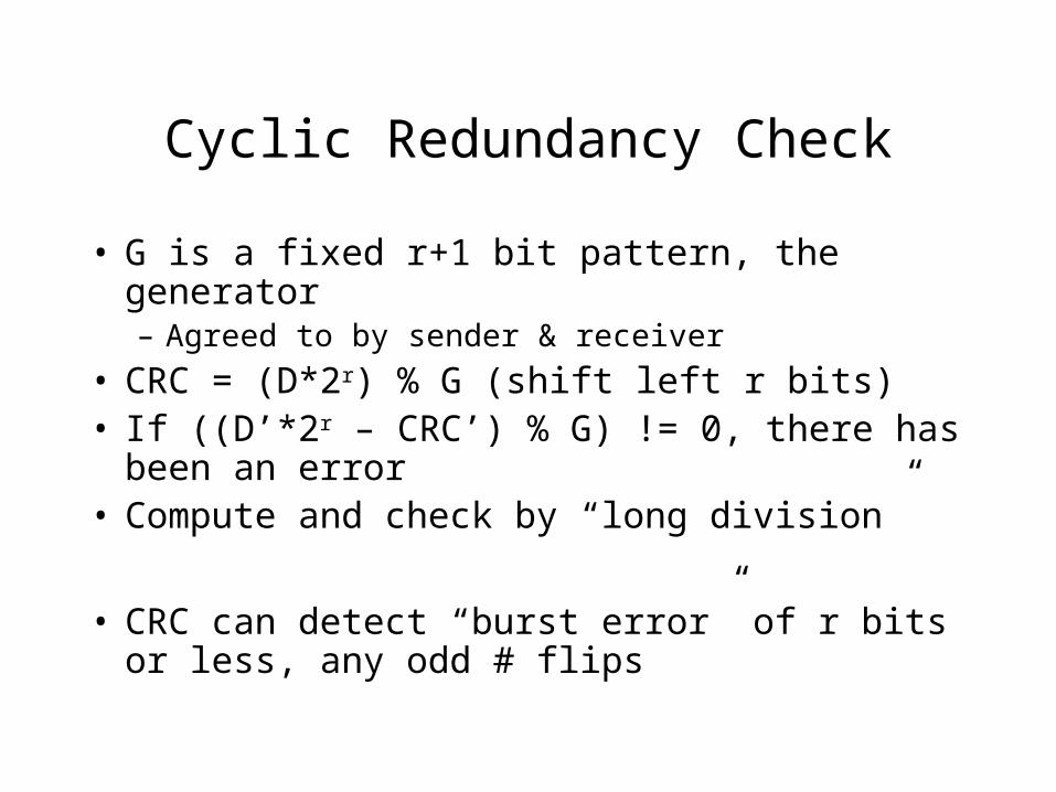
• G is a fixed r+1 bit pattern, the generator – Agreed to by sender & receiver
• CRC = (D*2r) % G (shift left r bits)• If ((D’*2r – CRC’) % G) != 0, there has been
an error • Compute and check by “long division”
• CRC can detect “burst error” of r bits or less, any odd # flips

Computing a CRC
• Data = 110101, G = 1001, r = 3• Long division without carries or borrows (XOR for –)1001|110101000 <-- append 3 0’s to data 1001 1000 1001 1100 1001 1010 1001 011 <-- 3 CRC bits

Using CRC to verify correct
• Received data: 110101, CRC 011, G 1001 1001|110101011 <-- append CRC to data 1001 1000 1001 1101 1001 1001 1001 0 <-- remainder is 0, valid
Using CRC to detect error
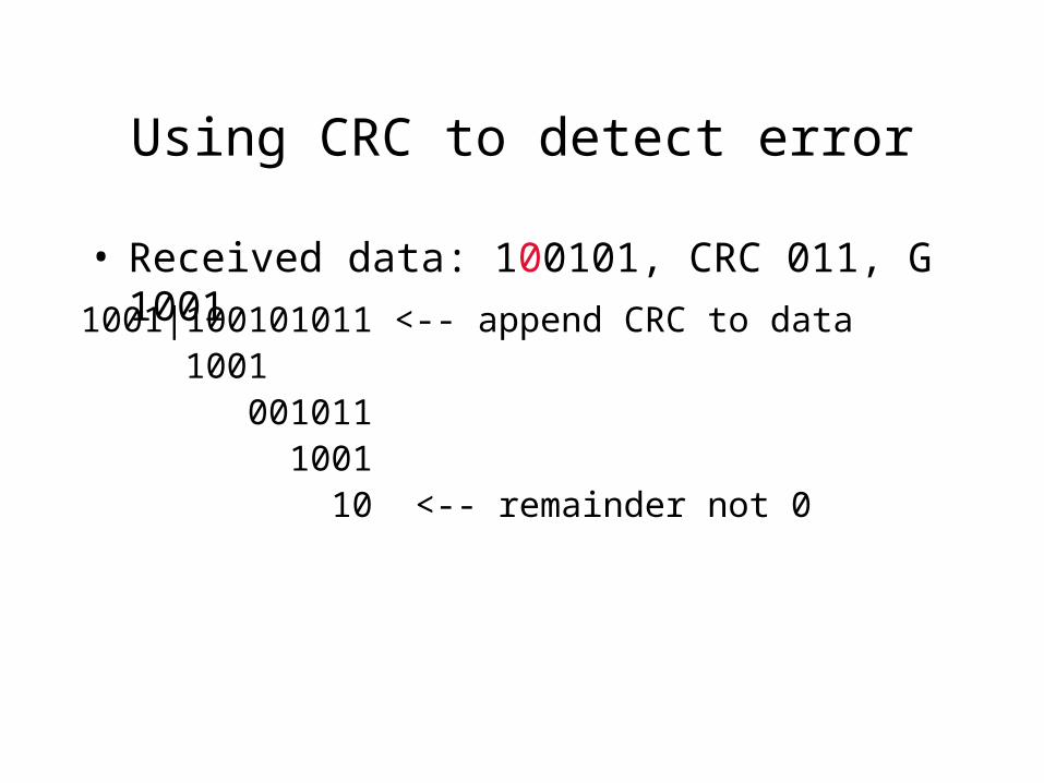
• Received data: 100101, CRC 011, G 1001
1001|100101011 <-- append CRC to data 1001 001011 1001 10 <-- remainder not 0

Summary: error detection & correction methods
• Parity bit– Detects odd # flips, cost = 1 bit per N
• 2D Parity– Corrects one flip, R+C+1 bits (per N = RC)
• Checksum– Detects odd # flips per column, uses k bits, where k is the
number of columns
• CRC– Detects “burst error” of r+1 bits or less, uses r bits, where r is
the size of the generator

Multiple Access Protocols
• Many sending and receiving nodes• One broadcast channel• Problem: how to effectively share the
broadcast channel
• Example: you and 25 friends you haven’t seen in a while, all trying to talk at once…

Human Multiple Access protocols
• Take turns to talk• Raise your hand if you have something to say• Don’t interrupt someone who is talking• Give everyone a chance

Computer Multiple Access Protocols
• Channel partitioning protocols– Share bandwidth according to time slots,
frequencies, or code division
• Random access protocols– Always transmit at full bandwidth, if there is a
conflict, retransmit the frame (after a random delay)
• Taking-turns protocols– Master node or “token” determines whose turn it is
to broadcast

Channel Partitioning Protocols (review)
• Frequency Division Multiplexing (FDM)– Each message travels in a unique Frequency
Band (like an FM radio station)
• Time Division Multiplexing (TDM)– Time is divided into Frames, and Frames are
divided into Slots. Each message gets one slot.
Freq
Time

Code Division Multiplexing
• Each sender uses a different code, receiver knows sender’s code to reconstruct message from sum of all broadcasts– Code is a sequence of +1,-1 that change faster
than data bits; get multiplied by (1,-1) data bits– Receiver gets sum of what all senders send
• Analogy: cocktail party, but everyone is speaking a different language (and you only understand one of them)

CDM Example (Senders) [5.12]

CDM Example (Receiver 1) [5.12]

Random Access Protocols
• Sender sends a message…• Sender listens for a collision
– If what the sender receives isn’t its own message, there must be a collision
• If there is a collision, all messages must be resent– If resent immediately, there will be another collision– Therefore, each host waits a random amount of time before
resending– If the collision rate gets too high, then it gets driven to 100%
by messages being resent over and over and over …

Slotted ALOHA (assumptions)
• All frames the same size, L• Time divided into slots of L/R (one-frame
time)• Nodes transmit only at beginning of slots
(synchronized)• If 2 or more transmit, collision detected before
end of frame

Slotted ALOHA (algorithm)
• If node has frame to send, wait until next slot and send it
• If no collision, node is done (can prepare to send next frame)
• Otherwise, retransmit with probability p in each subsequent slot until successful

Slotted ALOHA: Evaluation
• If only one node needs to transmit, it can use the full channel
• Protocol is decentralized; each node makes its own (re)transmission decisions– But, nodes are synchronized
• Protocol is extremely simple• But, maximum efficiency at p= 0.37, so on
average, only 37% of bandwidth is available in the long run (p. 437)

Pure ALOHA
• No slots; nodes immediately transmit as soon as frame received from Network layer
• If collision– With probability p, immediately retransmit– Else, wait 1 frame time, then with probability p,
retransmit… (etc)
• Maximum efficiency is half of slotted ALOHA (tradeoff with synchronization)

CSMA / CD
• Carrier Sense– Wait for “quiet” before sending a message
• Multiple Access– All share a broadcast channel (wired or wireless)
• Collision Detection– When a message is sent, check for collision, and if
so, wait a random time and resend

Why both Carrier Sensing and Collision Detection?
• Messages take time to propagate. – Dark blue message
from B has not yet arrived at D by t1, so D broadcasts
– Before message is over, they collide (stripes)

Taking Turns
• Polling– One master node repeatedly asks (polls) each
node in turn, asking whether it wants to send– Also called “round robin”
• Token passing– A special frame called a “token” circulates around
the network. In order to broadcast, a node must hold the token
– When the message is done (or if no message to send), pass the token to the next node

Local Area Networks
• Concentrated in a physical area, e.g. company site, campus
• LAN provides access to the Internet through a router (LAN = AS)
• Typical setup (Ethernet)– Host to router across broadcast channel, 1 “link”– CSMA / CD protocol– 10Mbps, 100Mbps, 1Gbps or 10Gbps

Local Addresses
• Address belongs to network card (not the computer)– Media Access Control (MAC) address, also called
physical or hardware address– Unique value assigned at network card
manufacture, e.g. 00:03:93:51:5e:34– IEEE manages the address space; each
manufacturer has a range
• Address is permanent; must be mapped to Internet address (e.g. mobile laptop)
Addressing on LAN
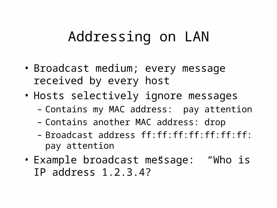
• Broadcast medium; every message received by every host
• Hosts selectively ignore messages– Contains my MAC address: pay attention– Contains another MAC address: drop– Broadcast address ff:ff:ff:ff:ff:ff:ff: pay attention
• Example broadcast message: “Who is IP address 1.2.3.4?”

Address Resolution Protocol
• ARP module keeps a table of MAC and IP addresses of hosts on the LAN
• To find a new mapping– ARP broadcasts ARP packet (sending IP and LAN
addresses, receiving IP address)– Host with matching address responds with its own ARP
packet (its own IP and LAN addresses as sender)– ARP module receives the packet and updates its table.
• Each line in the table has limited lifetime (TTL) - if a node is disconnected, its address mapping will eventually disappear.

What about Routers?
• Router responds to any ARP request for an external (out of the LAN) address.– It can tell by the high order bits (class or CIDR)
• Off-network packet is encapsulated as frame and sent to router
• Router collects frames, uses network layer routing table to determine outgoing interface
• Packets re-encapsulated as frames for the other LAN, using a different ARP table and hardware address.

Dynamic Host Configuration Protocol (DHCP)
• Dynamically assigns IP address to hosts– Each address has a limited lifetime (lease); must
be renewed after that
• Client/Server protocol– Client is new host attaching to network, needs IP
address and other configuration information (e.g. CIDR bits)
– Server allocates (and tracks) IP addresses

Four Steps to IP via DHCP
1. DHCP Discover message (UDP to port 67)• Sent as broadcast (via IP, then via LAN)• Ignored by all but DHCP server(s)
2. DHCP server offer message(s) (UDP)• Still a broadcast, as client is not yet configured• Contains transaction ID, IP address, lease time
3. DHCP request message• Echoes parameters, back to chosen server
4. DHCP ACK• From server back to (now-configured) client

Ethernet
• Different rates (10Mbps to 10Gbps)• Different physical setups
– 1 long coax cable with connections to hosts– Long optical fiber– Stars of twisted pair (CAT 5) connections with hubs in the
center
• Unreliable and connectionless transmission– If an error is detected, the packet is dropped…– …but the sender doesn’t know it!– It’s up to higher level protocols (TCP) to arrange for
retransmission

Ethernet Frame Structure
• Data field: 46 to 1500 bytes (MTU is 1500)• Src & Dest (MAC) address: 6 bytes each• Type field: 2 bytes
– IP vs. AppleTalk vs. Novell IPX…
• CRC: 4 bytes– For error detection
• Preamble: 8 bytes– 10101010 (x7) 10101011 , for synchronization

Manchester Encoding• Every bit has a transition (falling for 1, rising for 0)• Allows for self-synchronization (transition in middle of
bit)• Used in many Ethernet technologies, e.g. 10BaseT
(Physical layer!)

Ethernet-Specific CSMA/CD
• Before sending, put frame in a buffer• Wait until channel is idle, then begin transmitting
frame• While transmitting, monitor for signal energy from
other nodes (collision)– If none, the frame is done– If collision detected,
• stop transmitting and transmit 48-bit jam signal (abort)
• Wait a random amount of time and retransmit
• Each time a retransmission fails wait approximately twice as long the next time (exponential backoff)

Exponential Backoff
• After each collision, choose K at random, from {0 to 2m-1} where m is the number of prior collisions– Up to double, each time– Value for m maxes out at 10 (never more than
1023)
• Wait K*512 bit times, then retransmit• Distance limit chosen so that host with the
shortest retransmit time after a collision won’t have another collision
Efficiency of Ethernet
• Efficiency is measured as fraction of time during which frames are transmitted without collisions when the network is “loaded”
• Efficiency increases as propagation time decreases
• Efficiency increases as transmission time increases– Once a frame grabs the channel, it keeps it going
at full rate for a longer time.

LAN Topology
• Bus (10Base2) - max 185m between nodes
• Star (10BaseT, 100BaseT) - max 100m to hub
HUB

Multi-segment LANs
• Connect multiple “segments” of LAN with hub, bridge and/or switch– Avoid distance limitations – Mix standards
• Example: “Backbone” + sub-LANs

Gigabit and 10 Gigabit Ethernet
• Backward compatible with 10BaseT and 100BaseT• Point-to-Point (switches) or shared broadcast (hubs)
– CSMA/CD for shared; distance severely restricted (512 bit times?)
• Often used as backbone (next slide) for interconnecting slower (10baseT and 100baseT) LANs
• Runs on optical fiber, or (1G, now) CAT 5 cable

Hubs and Switches
• Hub– Many interfaces; every input bit is broadcast on all interfaces
– One collision domain
• Switch (“layer 2 switch”)– Each “side” of a switch is an isolated collision domain
– Forward and filter frames based on packet addresses (like router, but at LAN level)
– May include extra features (such as full duplex, cut-through, more interfaces)

Interconnecting with Hubs
• Total length extended• One big collision domain• Cannot interconnect 10BaseT with 100BaseT
hub
hubhub
hub

Ethernet Limits
• Maximum bandwidth in collision domain is fixed (e.g. 10Mbps for 10BaseT)
• Cannot connect 10BaseT to 100BaseT with hub (or to Gigabit Ethernet)
• Restriction on – Maximum hosts per collision domain– Maximum distance between hosts per collision
domain– Maximum # tiers in multi-tier design

Switch Routing
• Like Routers, bridges need to choose an outgoing interface for each message, based on address (in this case LAN, not IP)
• Because hosts come and go (or move), switches must be self-learning– No preconfiguration by administrator– No specialized routing protocol packets!– Messages themselves help to update the tables

Switch Operation
• Routing table is initially empty• For every frame, store source LAN address,
incoming interface, and current time in table• If destination LAN address isn’t in table,
forward to all interfaces, but if it is in the table, forward to only the correct interface
• If an address in the table is too old, delete it.• Spanning tree: make sure no bridge receives
the same host’s packet on multiple interfaces!

Switch vs. Router
• Switch is level-2 (Link), router is level-3 (Network)
• Advantages of switch over router:– Plug-and-play (do not need to be configured)– Faster (less processing per packet)
• Advantages of router over switch:– Packets can take more direct (lower cost) paths;
not limited to spanning tree– Provide firewall protection against broadcast
storms; isolation of traffic

Switches: A compromise
• Plug and play like bridges• Generally more interfaces than bridges
– High performance design– Mix of 10, 100, and Gb interfaces on one switch– Not unreasonable to connect host directly to
switch, rather than using the bus medium
• If no waiting packets, “cut through” switching - start before prior packet is complete