data flow diagrams bca sem iv k.i.r.a.s. what is a dfd? data flow diagrams (dfds) are used to depict...
TRANSCRIPT
Data Flow Diagrams
BCA Sem IV
K.I.R.A.S

What is A DFD?
Data flow diagrams (DFDs) are used to depict the flow and transformation of data in an information processing system.
DFDs give an overview to an analyst specifying where data originates, how it is processed and where the results go.
DFDs act as a graphical communication aid between a user and an analyst. It is also useful as a communication aid between an analyst and a system designer.
The procedure to develop a DFD starts with one DFD giving an overview of the system to be designed. This is called a context diagram.
The context diagram is expanded into a series of DFDs, each describing a specific function. This method of top down analysis and breaking down DFDs to give more and more detail is known as levelling.

What is A DFD? The main merit of DFD is that it provides an
overview of what data flows in a system, what transformations are done on the data, what files are used and where results flow.
It is a good documentation aid which is understood by both programmers and non-programmers (i.e., laypersons). As DFD specifies only what processes are performed and not how they are performed it is easily understood by a non-programming user.
A DFD allows you to identify the transformations that take place on data as it moves from input to output in the system.

Types of Diagrams
Context Diagram A data flow diagram (DFD) of the scope of an
organizational system that shows the system boundaries, external entities that interact with the system and the major information flows between the entities and the system
Level-O Diagram A data flow diagram (DFD) that represents a
system’s major processes, data flows and data stores at a high level of detail
Context diagram
A diagram giving an entire system’s data flows and processing with a single Process (circle) is called a context diagram.
A context diagram is expanded into a number of inter-related processes. Each process may be further expanded into a set of inter-connected sub processes. This procedure of expanding a DFD is known as levelling.
Elements of data-flow diagrams
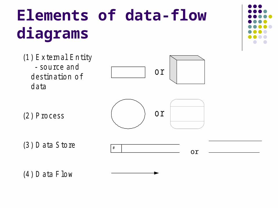
(1 ) E x te rn a l E n ti ty - s o u rce an d
d es t in a t io n o fd a ta
(2 ) P ro ces s
(3 ) D a ta S to re
(4 ) D a ta F lo w
o r
#
o r
or

Show all processes data flows must start or end in a process beware of black holes - every process and data
store must produce data
Elements of data-flow diagrams
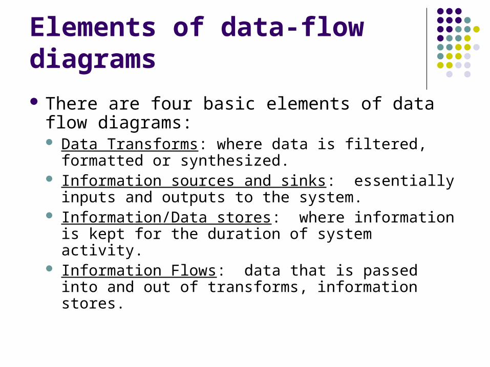
There are four basic elements of data flow diagrams: Data Transforms: where data is filtered, formatted
or synthesized. Information sources and sinks: essentially inputs
and outputs to the system. Information/Data stores: where information is
kept for the duration of system activity. Information Flows: data that is passed into and
out of transforms, information stores.

Source
Source represent persons, processes which produce data to be used by the system or receive data that is output by the system
Reside outside the system, but interact with system Either
a) receive info from system,
b) trigger system into motion,
c) provide new information to system
Examples: Student, Customer, Client
Data Stores
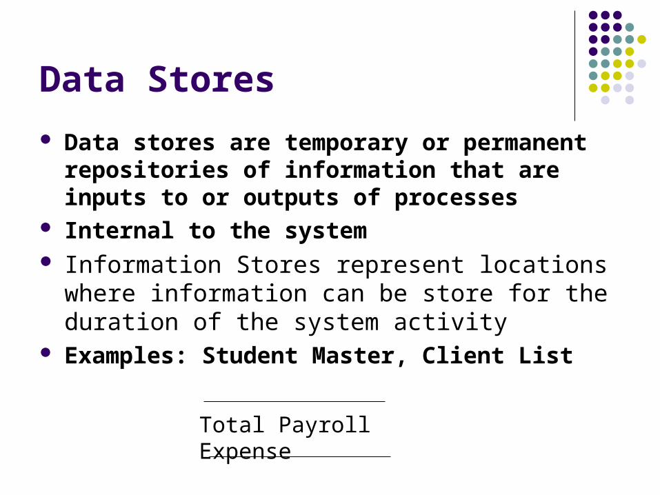
Data stores are temporary or permanent repositories of information that are inputs to or outputs of processes
Internal to the system Information Stores represent locations where
information can be store for the duration of the system activity
Examples: Student Master, Client List
Total Payroll Expense
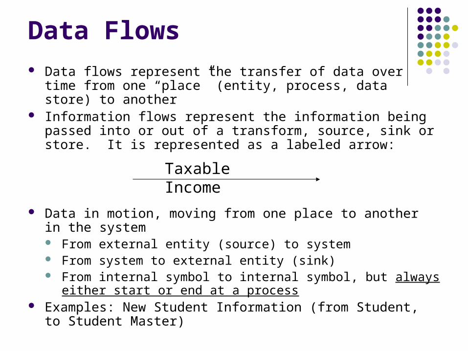
Data Flows Data flows represent the transfer of data over time from one
“place” (entity, process, data store) to another Information flows represent the information being passed into or
out of a transform, source, sink or store. It is represented as a labeled arrow:
Data in motion, moving from one place to another in the system From external entity (source) to system From system to external entity (sink) From internal symbol to internal symbol, but always either start or
end at a process Examples: New Student Information (from Student, to Student
Master)
Taxable Income
Data transforms
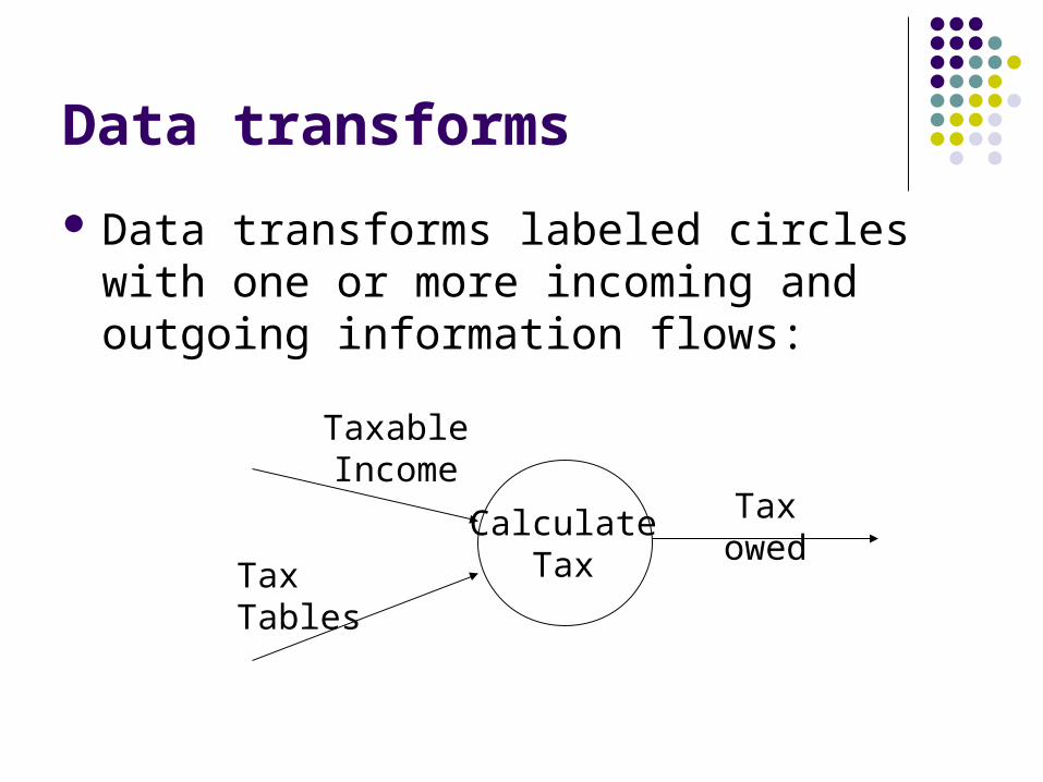
Data transforms labeled circles with one or more incoming and outgoing information flows:
CalculateTax
Taxable Income
Tax Tables
Tax owed

Processes Processes are discrete actions that transform input data to
output data Examples: Create Student Record, Calculate Purchase Cost,
Register Client
Always internal to system Law of conservation of data:#1: Data stays at rest unless
moved by a process.#2: Processes cannot consume or create data
Must have at least 1 input data flow Must have at least 1 output data flow (to avoid black holes) Should have sufficient inputs to create outputs

Define the System• A system is the collection of all business processes which
perform tasks or produce outputs we care about. It is “what happens.”
• The system is a single process, connected to external entities
• Represented in a “Context Diagram”
Define Subsystems• A subsystem gives a more detailed view individual
processes contained in the context diagram• Includes data stores, more elementary processes

Creating Data Flow Diagrams
Creating DFDs is a highly iterative process of gradual refinement.
General steps:1. Create a preliminary Context Diagram2. Identify the ways in which users most commonly
use the system3. Create a Level 0 diagram from fragments4. Decompose to Level 1,2,…5. Go to step 1 and revise as necessary6. Validate DFDs with users.
DFD Rules
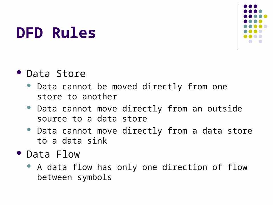
Data Store Data cannot be moved directly from one store to another Data cannot move directly from an outside source to a data
store Data cannot move directly from a data store to a data sink
Data Flow A data flow has only one direction of flow between symbols

DFD Rules—Context Diagram
One process, numbered 0. Sources (external entities) as squares Main data flows depicted No internal data stores are shown
They are inside the system
DFD ExampleA mail-order company distributes CDs and tapes at
discount price to record-club members. When an order processing clerk receives an order form, he or she verifies that the sender is a club member by checking the Member file. If the sender is not a member, the clerk returns the order along with a membership application form. If the customer is a member, the clerk verifies the order item data by checking the Item file. Then the clerk enters the order data and saves it to the Daily Orders file. The clerk also prints an invoice and shipping list for each order, which are forwarded to Order Fulfillment.

DFD Example - Step 1
SECOND SENTENCE:When an order processing clerk receives an order form, he or she
verifies that the sender is a club member by checking the Member file.
RESULT:Order Processing System
Record Club
Member
Customer (Non
Member)
order
Verify Member status
Member dataMembers
DFD Example - Step 2 continued
SECOND SENTENCE:
When an order processing clerk receives an order form, he or she verifies that the sender is a club member by checking the Member file.
RULES FOLLOWED: data flows start or end in a process

DFD Example - Step 3
THIRD SENTENCE:If the sender is not a member, the clerk returns the
order along with a membership application form.RESULT: Order Processing System
Record Club
Member
Customer (Non
Member)
Verify Member status
order
application form
Member dataMembers
DFD Example - Step 3 continued
THIRD SENTENCE:
If the sender is not a member, the clerk returns the order along with a membership application form.
RULES FOLLOWED: shows all processes without conditions

DFD Example - Step 4
FOURTH SENTENCE:If the customer is a member, the clerk verifies the order item data by
checking the Item file.
RESULT:Order Processing System
Record Club
Member
Customer (Non
Member)
order
application form
Verify Member status
Verify Order item
data
Member dataMembers
Items
Item details
DFD Example - Step 4 continued
FOURTH SENTENCE:
If the customer is a member, the clerk verifies the order item data by checking the Item file.
RULES FOLLOWED: data flows start or end in a process shows all processes without conditions

DFD Example - Step 5
FIFTH SENTENCE:
Then the clerk enters the order data and saves it to the Daily Orders file.
Record Club
Member
Customer (Non
Member)
Verify Member status
Verify Order item
data
Daily Orders
application
form
order Member dataMembers
Item detailsItems
Verified member order
orderDaily Orders
Member order

DFD Example - Step 5 continued
FIFTH SENTENCE:
Then the clerk enters the order data and saves it to the Daily Orders file.
RULES FOLLOWED: data flows start or end in a process
DFD Example - Step 6
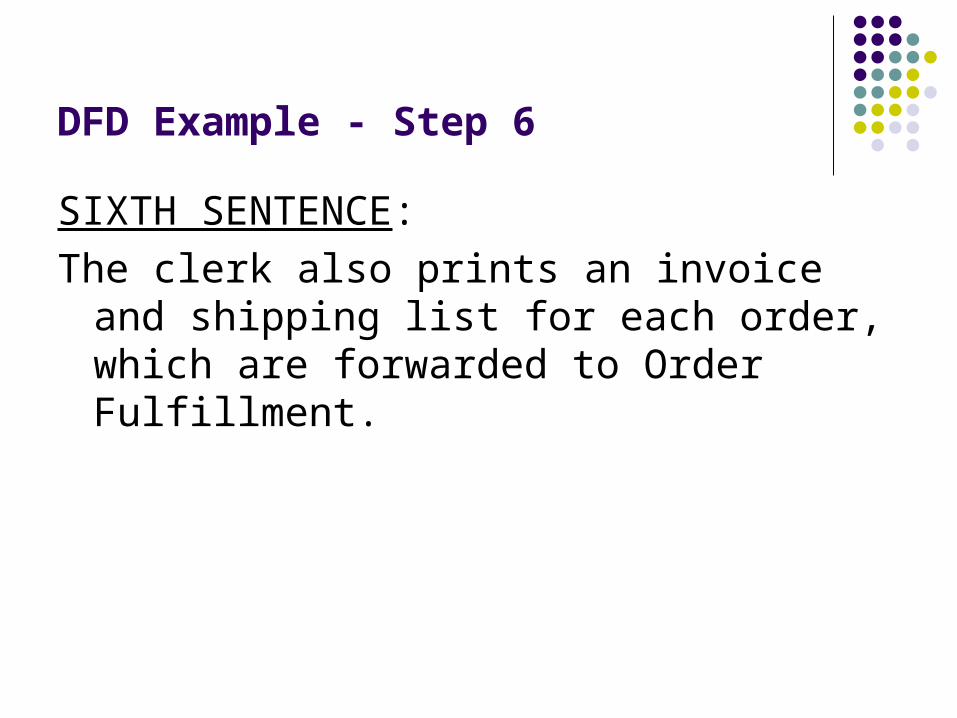
SIXTH SENTENCE:
The clerk also prints an invoice and shipping list for each order, which are forwarded to Order Fulfillment.
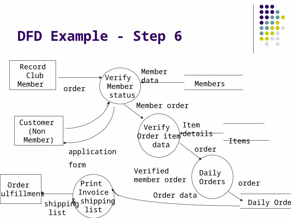
DFD Example - Step 6
Record Club
Member
Customer (Non
Member)
Verify Member status
application
form
Verify Order item
data
Member order
Member data
Members
Item details Items
Verified member order
Daily Orders
order
order
Daily Orders
orderPrint Invoice
& shipping list
Order data
Order Fulfillment
shipping list
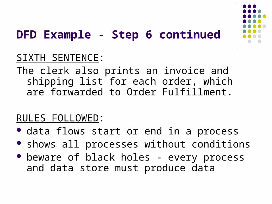
DFD Example - Step 6 continued
SIXTH SENTENCE:The clerk also prints an invoice and shipping list for
each order, which are forwarded to Order Fulfillment.
RULES FOLLOWED: data flows start or end in a process shows all processes without conditions beware of black holes - every process and data
store must produce data

University Course Registration System
University Registration
Student
Course detailsStudent
details, marks details
University Administration
Course details
Student details
Level 0 (Context Model)
Acceptance / Denial note

University Course Registration
Validate inputted details
Student details, marks details
Course details Denial
note
Course details
Student details
Process Application University Administration
Student
Level 1
Student database
Acceptancenote
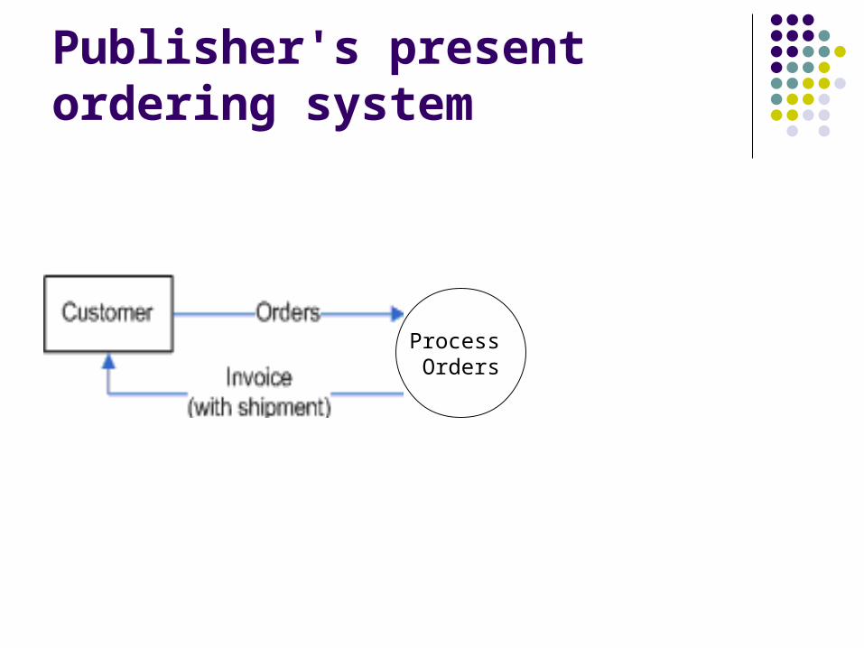
Publisher's present ordering system
Process Orders

Publisher's present ordering system
Level 1

Level 2: Showing Order Verification & credit check
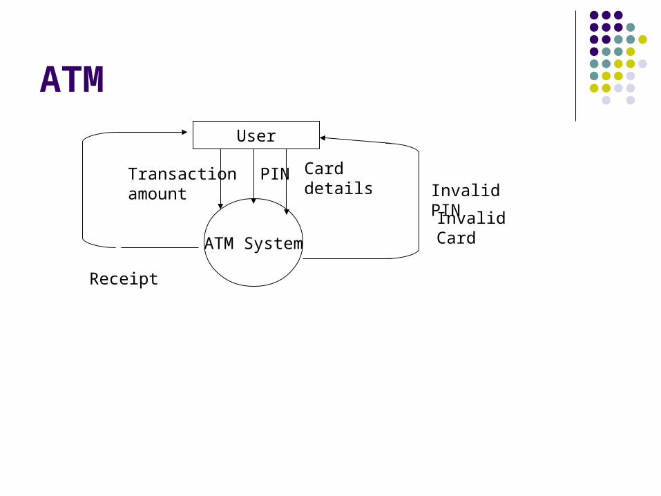
ATM
ATM System
User
PINTransaction amount Invalid PIN
Invalid Card
Receipt
Card details

ATM
User Verify CardPIN
Card details
Invalid Card
Valid Card Details
Verify PIN
Cards
Card Num, PIN
Card status
Validate Amount
Card status
Accounts
Account balance
Daily Balance
Invalid PIN
amount
Overdraw
Transact Withdrawal
Transaction details
Receipt
Validated Transaction details
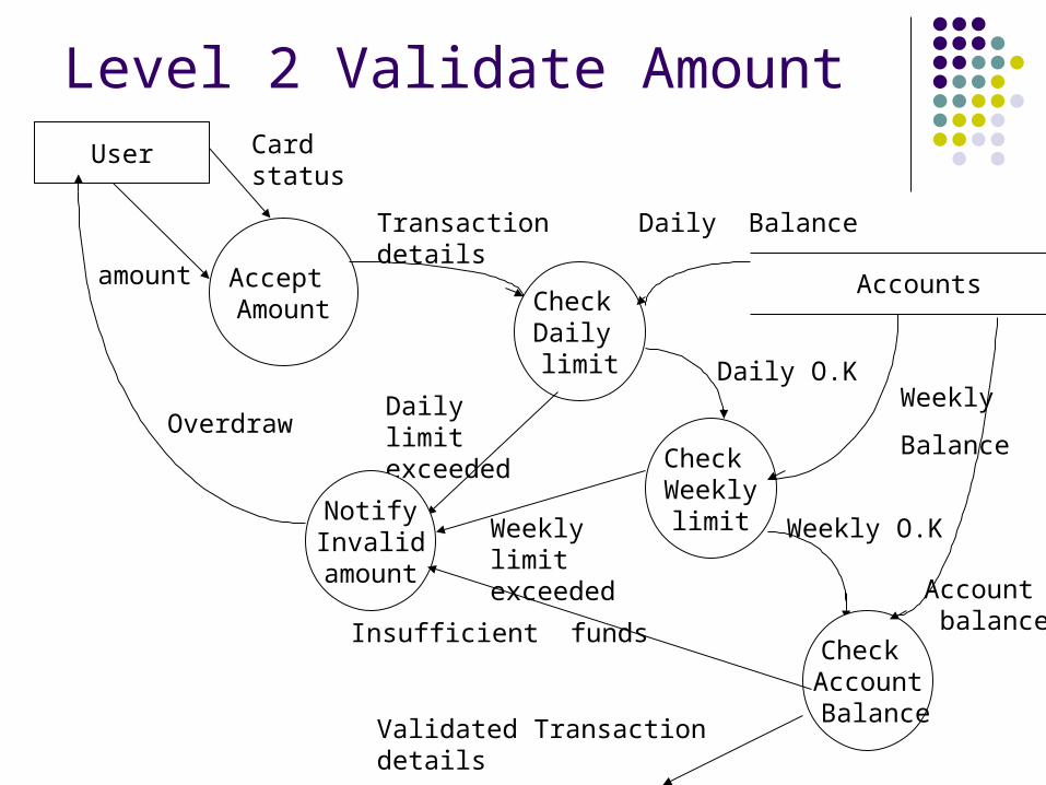
Level 2 Validate Amount
Accept Amount
Transaction details
Check Daily limit
Accounts
Daily Balance
Daily limit exceeded
Notify Invalid amount
User Card status
amount
OverdrawCheck Weekly
limit
Daily O.K
Weekly limit exceeded
Weekly O.K
Check Account Balance
Insufficient funds
Validated Transaction details
Weekly
Balance
Account balance
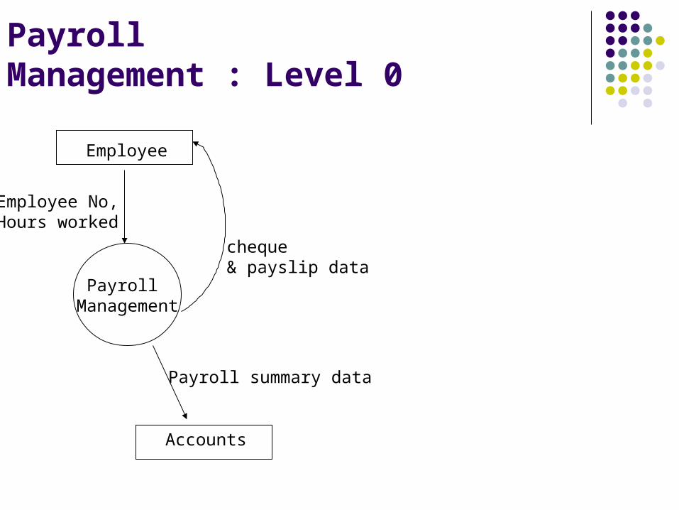
Payroll Management : Level 0
Employee
Employee No, Hours worked
Payroll Management
cheque & payslip data
Accounts
Payroll summary data
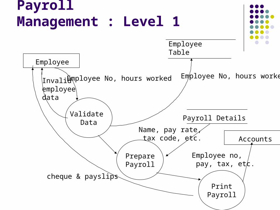
Payroll Management : Level 1
Employee
Employee No, hours worked
Validate Data
Employee Table
Employee No, hours workedInvalid employee data
PreparePayroll
Name, pay rate, tax code, etc.
Payroll Details
PrintPayroll
Accounts
Employee no, pay, tax, etc.
cheque & payslips
Decomposition of DFDs
Functional decomposition Act of going from one single system to many
component processes This is a repetitive procedure allowing us to
provide more and more detail as necessary The lowest level is called a primitive DFD
Level-N Diagrams A DFD that is the result of n nested
decompositions of a series of sub-processes from a process on a level-0 diagram

Uses of DFD
Used to analyze the system to ensure that the
design is complete
Used to partition the system into programs
Used for system documentation
Better communication with users
Better understanding of the business by analysts