data ducting infrastructure for new homes - gov.uk2.3.6 building ducts 30 2.3.7 multi-dwelling...
TRANSCRIPT

Data Ducting Infrastructure for New HomesGuidance Note
www.communities.gov.ukcommunity, opportunity, prosperity

Data Ducting Infrastructure for New HomesGuidance Note
Bill Guile, English Partnerships
John Barrow, Axsis consultants
March 2008Department for Communities and Local Government

Communities and Local GovernmentEland HouseBressenden PlaceLondon SW1E 5DUTelephone: 020 7944 4400Website: www.communities.gov.uk
© Crown Copyright, 2008
Copyright in the typographical arrangement rests with the Crown.
This publication, excluding logos, may be reproduced free of charge in any format or medium for research, private study or for internal circulation within an organisation. This is subject to it being reproduced accurately and not used in a misleading context. The material must be acknowledged as Crown copyright and the title of the publication specified.
Any other use of the contents of this publication would require a copyright licence. Please apply for a Click-Use Licence for core material at www.opsi.gov.uk/click-use/system/online/pLogin.asp, or by writing to the Office of Public Sector Information, Information Policy Team, St Clements House, 2-16 Colegate, Norwich, NR3 1BQ. Fax: 01603 723000 or email: [email protected]
If you require this publication in an alternative format please email [email protected]
Communities and Local Government PublicationsPO Box 236WetherbyWest YorkshireLS23 7NBTel: 08701 226 236Fax: 08701 226 237Textphone: 08701 207 405Email: [email protected] online via the Communities and Local Government website: www.communities.gov.uk
75%March 2008
Product Code: 07BD04608

3
AcknowledgementsMany thanks to those whose input during the development and consultation on this guidance has helped to design and refine the document.
Special thanks to:
Mark Graveston, Ofsoptics for supplying clipart for the document Kathleen De Smedt, FTTH (European) for permission to reference text from the FTTH paper issued in Barcelona 2007.
If you have any comments or queries on the guidance you should address them to Bill Guile by email at: [email protected].
DisclaimerPlease note that this document has been produced to assist readers by providing guidance on practical and technical issues concerned with laying ducting for data service delivery. The document does not purport to provide guidance on the law, and if readers have any queries about any legal issues relating to the document they are advised to seek their own legal advice. In addition, where the document refers to an interpretation of the law, readers should not rely on that interpretation without seeking advice from an appropriate source.

Preface 5
Preface
This document is designed and written as a guidance note to housing developers who intend or who wish to consider the laying of ducting on development sites, and within dwellings, for the delivery of data services.
Data services today are becoming important to the house buyer and are increasingly being taken into consideration when purchasing a new home. The buyer will want flexible data services that will positively impact their quality of life.
Data services come in many guises offering not just broadband services such as email and internet access, but pure entertainment from all over the world. Digital television, video on-demand and international radio are just a few of the services that are possible and are currently available. These services will grow as a result of changes such as Digital Television Switchover taking place between 2008 and 2012. As services grow and the demand increases, services will evolve to give the consumer greater choice and flexibility. Personal communication is seen as the leader, no longer limited by distance and cost, with new services offering low cost or free communication between people from any country.
Further, as more people work from home there is an increasing demand for data services to enable them to conduct business as if they were in an office. People are now taking this into account when buying a home, looking for space for an ‘office’ and the availability of broadband connectivity. Furthermore, Intelligent Homes can exploit data service connectivity and deliver new services to residents, manage heating and energy usage automatically to help reduce carbon emissions and wasted energy.
This document is not intended to promote a particular technology and it needs to be recognised that with new technologies parts of the document may become irrelevant. Although this document refers to ducting, cabled and fibre technologies data service delivery is by no means limited to wiring and wireless technologies offer an alternative. It is expected that the demand for such services will increase and it is felt that doing nothing is becoming less of an option.
To conclude, this document has undergone extensive consultation with government and industry to understand their requirements to make this document as practical and user-friendly as possible. However, we would recommend that you seek professional guidance from the relevant field of expertise to complement this document.
Communities and Local Government English Partnerships

Contents 7
Contents
Section 1: Introduction 9
1.1 Background 9
1.2 Objective 10
1.3 Scope 10
1.4 Structure of Document 11
Section 2: Infrastructure guidance 12
2.1 Introduction 12
2.2 External Infrastructure 12
2.2.1 Understanding the needs 12
2.2.2 What is required 13
2.2.3 Topology and layout 14
2.2.4 Trenching 17
2.2.5 Ducts 17
2.2.6 Chambers 19
2.2.7 Terminal chambers 22
2.2.8 Street cabinets 23
2.2.9 Support for wireless technology 24
2.2.10 Duct signage and layout recording 24
2.2.11 Boundaries 25
2.2.12 Termination and capping 25
2.3 Internal Infrastructure 25
2.3.1 Understanding the needs 25
2.3.2 What is required 26
2.3.3 Topology and layout 27
2.3.4 Terminal box 28
2.3.5 Equipment cabinet 29
2.3.6 Building ducts 30
2.3.7 Multi-dwelling buildings 33
2.3.8 Boundaries 34
2.4 Duct Conditions 34
2.5 Sub Ducting 36

8 Data Ducting Infrastructure for New Homes
Appendix A: Ownership and stewardship 37
A.1 Introduction To Options 37
A.2 Options 37
A.2.1 Option 1: Local authority adoption 37
A.2.2 Option 2: Management company ownership 38
A.2.3 Option 3: Lease of infrastructure 38
A.2.4 Option 4: Sale of infrastructure 38
A.2.5 Option 5: Lease or resell of network provision 38
A.2.6 Option 6: Shared Ownership 39
A.2.7 Option 7: S.106 and Tariff 39
Appendix B: Standards and regulations 40
B.1 Standards, Regulations and Guidance 40
B.2 Cabling, Data Socket and Technology Requirements 41
B.3 Communications Act 41
B.3.1 Introduction 41
B.3.2 Electronic Communications Network 41
B.3.3 Electronic Communications Services 42
B.3.4 General Conditions 42
B.3.5 Universal Service Obligation 42
B.4 Ex-Ante Regulation And Competition Policy 43
Appendix C: Potential application of infrastructure 44
C.1 Use of External Infrastructure 44
C.2 Use of Internal Infrastructure 46
Appendix D. Cable sizing assumptions 49
D.1 External Infrastructure Cables 49
D.1.1 Multi-pair cables for external infrastructure 49
D.1.2 Fibre optic cables for external infrastructure 49
D.1.3 Coax cable for external infrastructure 50
D.2 Internal Infrastructure Cables 50
Appendix E: Glossary 51
Appendix F: Definitions 54

Section 1 Introduction 9
Section 1
Introduction
1.1 Background
Technology is allowing for greater freedom and choice than ever before, giving people more free time. People today use technology in a variety of ways that benefits them and their local community. Many local groups are formed in the digital world and distant communications are no longer associated with high costs and long delays.
Data services to homes are now more popular than ever before offering greater choice and competitive prices to the consumer. These services come in many guises offering television, radio, internet access, security, etc. As the demand for such services increase so will the need for new dwellings to include these services as the norm.
Currently data services are delivered in a variety of ways including using:
• Theinfrastructurethatdeliversstandardtelephonyservices
• Acabletelevisionnetwork
• Adedicated‘multi-services’broadbandnetwork
• Mobiletelephony,wirelessandsatellitetoofferflexibilityanddeliverservicestoareas that cannot access other services.
As the take up of broadband and associated data services has increased it has become apparent that people will demand a data service with a home as a matter of course, considering it as important as other utilities.
It is envisaged that in the near future developers will be looking to use data services within their new dwellings as selling points these may include broadband ready homes, central security services, intelligent heat and power management.
Wireless technologies offer flexibility for the delivery of data services and arguably a simpler implementation. However, it is understood that wired based services will still be required to deliver high data demanding services. Indeed, even wireless based services still require some form of cabling for connection to the larger service provision.

10 Data Ducting Infrastructure for New Homes
1.2 Objective
The practical guidance in this document aims to:
• Givedeveloperstheopportunitytoconsidertheinstallationofinfrastructureswithin new developments and dwellings to support the later provision of data services by third parties
• Reducetheriskof‘non-standardinfrastructures’(forexampleusingadhocducting types and topologies) leading to future incompatibility issues within different developments.
The guidance gives developers the opportunity to add benefits to new developments and add to the marketability of their dwellings.
The guidance is not technology or service specific neither is it intended to promote any particular cabling type, wireless solution and network technology or data service. Rather it aims to be generic to enable developers to make their own informed choice of the infrastructure model that is best suited to their development.
1.3 Scope
This document enables developers, perhaps initially with specialist support, to be able to understand and implement an infrastructure to allow the later delivery of data services to and within dwellings.
This document aims only to provide guidance to developers with respect to an infrastructure that will include elements such as ducting and chambers.
The guidance should not be treated as prescriptive. It is recognised that the layout and size of developments and dwellings will vary widely. Within the framework provided, developers will need to make a judgement on a case by case basis.
It is assumed within the guidance that the majority of developers will not install any data network cabling or associated network equipment. However, it is recognised that the detailed design of some elements of infrastructures may be clarified if developers have a rapport with potential data service providers who may wish to utilise the infrastructure.
This document is not intended to provide developers with any guidance on investment decisions. Likewise, although it refers to some regulations, developers should seek advice from the relevant government body and/or appropriate specialists.

Section 1 Introduction 11
Although wireless solutions are noted within this document as an example of how ducting could be used to provide an infrastructure for the delivery of service to wireless transceivers, the use of wireless is outside the scope of this guidance.
Developers should ensure that any use or development of the guidance in this document is compliant with all Health and Safety requirements.
1.4 Structure of Document
The main body is contained in Section 2 which provides guidance for the design and implementation of an infrastructure to support the later provision of data services:
• Section2.2considersthe‘externalinfrastructure’thatwilltypicallybeinstalledbeneath carriageways and footways
• Section2.3considersthe‘internalinfrastructure’withindwellinghousesandmulti-dwelling buildings.
Appendices A and B provide supporting information for developers:
• AppendixAconsiderssomepossibleoptionsfortheownershipandmanagement of the external infrastructure described in Section 2.2
• AppendixBreferencesstandardsandregulationsthatarerelevanttothedesignand implementation of the infrastructure described in Section 2.
Appendices C and D provide technical information that supports the guidance given in Section 2. It is not essential that developers understand these appendices but an awareness of the terminology and issues involved may assist in providing context. It would however be expected that any specialist engaged to apply the guidance to a development would understand their content.
• AppendixCdetailsthecablingandnetworktechnologiesthatcouldpotentiallyutilise the installed infrastructure
• AppendixDprovidesdimensionsfortypicalcablesthatmaybeinstalled.Thisdata has been used as a basis for the duct and chamber sizing given in Section 2.
Appendix E provides a glossary of terms used in Section 2.
Appendix F provides definitions of terms used within the IT and telecommunications industry.

12 Data Ducting Infrastructure for New Homes
Section 2
Infrastructure guidance
2.1 Introduction
This section provides guidance on an infrastructure to facilitate the later installation of cabling and associated network equipment to support the delivery of broadband and other data services.
Much of the guidance is provided at a high level since many aspects of the infrastructure will depend on the size and layout of the development and the design and number of dwellings. It is assumed that developers will engage a specialist to ‘flesh-out’ the guidance for a given development and consider issues such as design to secure network reliability.
This section refers to the infrastructure needs in basic Information and Communications Technology (ICT) terms. These terms and some of the technical options are considered further in Appendix C. This should enable developers to ‘speak the same language’ as their specialist. Indeed, going forward it is recommended that developers should acquire some ICT awareness such that they can discuss and implement the provision of a data service infrastructure with the same confidence as they do with other utilities.
The guidance is split into two parts:
• External Infrastructure – considers the infrastructure for the cabling and network equipment that delivers data services from a data service provider to individual dwellings. The external infrastructure will typically be installed beneath carriageways and footways
• Internal Infrastructure – considers the infrastructure for the cabling and network equipment that distributes data services within houses and multi-occupancy buildings.
2.2 External Infrastructure
2.2.1 Understanding the needsThe external infrastructure is required to facilitate the installation of cabling and possibly network equipment to support the provision of data services to dwellings. The cabling and network equipment is likely to be installed by a data service provider once a development is underway, for example when there is a revenue stream from residents. However, it may not be installed until after a development has been completed.

Section 2 Infrastructure guidance 13
Ideally one or more data service providers should have been identified at the outset of a development as they may assist in the detailed design of the external infrastructure. However, it is important that the external infrastructure is not restricted by design to a given data service provider or a particular network technology. It also needs to be recognised that the external infrastructure should be available to other data service providers.
2.2.2 What is requiredThe following elements, as shown in Figure 2.1, need to be considered in the design and implementation of the external infrastructure:
• Accessnode–toprovideaninterfacebetweentheexternalinfrastructureandthe data service provider’s network. Depending on the network technology and the data service provider’s requirement the access node may be implemented in a street cabinet or a chamber. The access node may be required to accommodate active (powered) network equipment
• Streetcabinets(notshowninthefigure)–mayberequiredforcablejoints,cabledistribution points and possibly to house active (powered) network equipment. Cabinets should be of sufficient size for additional ducting, at least one additional duct, for future requirements
• Chambers–forcableinstallation,cablerouting,cablejointingandsomepassive distribution points. Chambers may also be required to accommodate active (powered) network equipment that is designed specifically for such an environment although most data service providers are likely to favour street cabinets
• Terminalchambers–chambersthatmayberequiredtoconnectthewiderexternal infrastructure with dwellings or groups of dwellings. Terminal chambers should be located outside the dwelling plot as stated in paragraph 2.2.7 and illustrated in Figure 2.1
• Ducts–pipestofacilitatetheinstallationandlaterreplacementofcables.Thismay also include micro or inner ducts.

14 Data Ducting Infrastructure for New Homes
Figure 2.1: Elements forming external infrastructure
Terminal Chambers (if required)
Service Providers Network
Access Node
Note: this diagram is for illustrative purposes only.
Chambers
Terminal Ducts linking to Terminal Chambers
Primary Duct – linking access node to distribution ducts
Ducts to dw
ellings
Distribution Ducts – serving road or group of dwelling
2.2.3 Topology and layoutThe cabling installed by data service providers will typically consist of one or more of the following types:
• Copperpairsasusedtodeliverstandardtelephonyandsomebroadbandservices
• Coaxasusedonsomecabletelevisionsystems–somesystemsalsosupportthedelivery of telephony and broadband services
• Acombinationofcoaxandfibreopticsasusedonsomenewercabletelevisionsystems
• Fibreopticcablingthatcansupport‘nextgeneration’broadbandservices,telephony, television and video.
The cabling requirement and the associated network equipment that needs to be accommodated by the external infrastructure will largely be determined by the network technology to be installed. This in turn could lead to essentially three different cable/ network topologies: star, tree and multi-drop as shown in Figure 2.2.
Ducting to support wireless base technologies should be considered. This would include ducting and termination points near to posts that will allow for cabling to connect to a wireless based technology, which could be located at the top of a structure.

Section 2 Infrastructure guidance 15
Figure 2.2: Possible cable/network topologies
Access Node
Service Providers Network
Dw
ellings a) Star Network Configuration
Note: this diagram is for illustrative purposes only.
Service Providers Network Chambers
Access Node
c) Multi-drop Network configuration
Dwellings
Access Node
Service Providers Network
Chambers
b) Tree Network configuration
In addition to meeting the requirements of the network technology, the topology and layout of the external infrastructure will be impacted by the size, layout and phasing of the development, the routing of carriageways and footways, and the installation of other utilities.
From the above it would appear impossible to provide an external infrastructure that is optimal for all potential network technologies. It is however important to consider how a network topology can map onto a duct layout given that footways and carriageways are rarely in a star or tree configuration. Considering Figure 2.2, it can be seen that ducting that supports configuration c) can also support cabling in the other configurations. The resulting generic configuration maybe adopted for most developments as shown in Figure 2.3.

16 Data Ducting Infrastructure for New Homes
Figure 2.3: Generic duct configuration
Note: this diagram is for illustrative purposes only.
Wireless Mast
Service Providers Network
Ducts to dwellings
Terminal Ducts linking to Terminal Chambers
Ducts to dwellings
Access Node
Chambers
Terminal Chambers
Terminal Ducts linking to Terminal Chambers
Terminal Chambers
Primary Ducts – linking access node to distribution ducts
Distribution Ducts – serving road or group of dwellings
In designing an external infrastructure based on the above generic configuration the following issues need be considered:
• Accesstopotentialdataserviceproviderinfrastructures.Theaccessnodeshould be located near to the likely point of connection to wider network infrastructures. This will require a dialogue with potential data service providers. In some larger developments the pragmatic approach may be to have two or more access nodes
• Thelocationofanysharedaerials/dishesthatmaybeconnectedviatheexternalinfrastructure
• Thecableinstallationrequirements(whicharelikelytobeunknownatthetimeof infrastructure design and construction) including:
– the number of cables per duct which will depend on the number of dwellings to be served and on the network technology and cable sizing
– the length of cable runs determined by electrical and/or mechanical constraints
– cable jointing requirements both within the external infrastructure and at the interface with the internal infrastructures
– cable bending radius both during installation and long term.

Section 2 Infrastructure guidance 17
These issues will have an impact on the size and layout of the ducts and chambers.
• Thepossibleplacementofactivecomponentsandtheirenvironmental,power and maintenance access requirements. This will have an impact on the requirement for street cabinets.
• Ductingtoallowcablingforwirelessservicesshouldalsobeconsidered.Thismayinclude ducting and termination points near to poles or masts that would allow for cabling to connect to a wireless technology located on the structure.
2.2.4 TrenchingThis document does not provide detailed guidance in respect of the trenching. The most appropriate method will depend on the nature of the development, other trenching requirements, the existing utilities and the impact of work on carriageways and footways.
It is expected that developers will wish to keep excavations to a minimum. This can be achieved in a new development by trench sharing with the data service and utilities sharing a common route, for example, under a footway. This approach requires early consultation with all parties concerned. An alternative is to use narrow trenching for each utilities pipes and cables but this requires the location of all pre-existing services to be located prior to any work.
Trenchless solutions include installing a duct for communications services within an existing pipe or using a shared services duct or tunnel for all utilities. Whilst outside the scope of this document it is noted that such solutions may have maintenance and access implications that need be fully considered before any decision is taken.
2.2.5 DuctsCyan coloured ducts should be used for the delivery of data services. In any installation, consideration should also be given to the existing and likely telephony utility provision and the possibility of confusion over duct use.1
The diameter and number of communication ducts required will depend on the network topology and the type and number of cables to be installed. Table 2.1 provides duct guidance based on the cable sizing given in Appendix D.1.2 Since these are minimum duct sizes developers may employ larger ducts to reduce the number of sizes employed.
1 Reference: National Joint Utilities Group guidelines. White ducts should be used for telecommunications applications. Since ‘telecommunications’ services may include broadband the distinction from ‘communications’ is somewhat arbitrary.
2 This sizing is to allow for the installation of both fibre optic cable and multi-pair cabling with some spare capacity.

18 Data Ducting Infrastructure for New Homes
Table 2.1: Minimum duct sizing and number
Total number of dwellings connected via duct
Ductinternal diameter (mm)
Number of ducts
1 to 3 30 1
4 to 15 50 1
16 to 30 90 1
31 to 300 90 2
301 to 600 90 3
The duct material should be rigid and suitable for purpose. The duct should be capable of withstanding a reasonable superimposed load and reinforced where appropriate.
The trench into which the duct is laid should ideally be parallel with the finished ground level.
The base of the trench should generally be covered with at least 25mm of well-compacted fine fill material but this should be increased to 65mm in rocky ground. Ducts should also be surrounded by a well-compacted fine fill material, to a minimum depth of 50mm above the duct.
Ducts should be installed such that there is a minimum depth from finished ground level to the crown of the duct over the entire length of the duct of:
• 250mmwhenunderafootway
• 450mmwhenunderacarriageway
• 900mmwhenbeneathagriculturalland.
Consideration should be given for ducting depths when using couplers to join ducting together, this may require slightly deeper trenching at coupler points.
Site conditions may cause a duct to be laid shallower or deeper than the above. A structural protection layer using, for example, suitable protection strips, tiles or concrete pipes, should protect shallow ducting.
For easements of ducting that may pass through private land, it is envisaged that this ducting would follow the same trench path and depth used for the delivery of other utilities.
Ducting passing through agricultural land should be avoided if possible. However, where required, the depth of the ducting should be sufficient to remove the risk of damage from farming equipment having regard to land use. The above depth of 900mm should therefore be considered as an absolute minimum. It is not envisaged that chambers would generally be located on agricultural land; therefore duct lengths and the means of cable installation should be considered.

Section 2 Infrastructure guidance 19
Duct routing should be as straight as practicable and located wherever possible under a 2m footway or a 2m wide service strip. Duct runs between chambers need not be straight but the radius of curves should not be less than 12 times the diameter of the duct as shown in Figure 2.4. Developers should also ensure the integrity of the ducting and the ‘easy flow’ of the infrastructure. They should confirm that their duct routing allows for the constraints of the selected ducting.
For new developments it is considered that where a dedicated communications duct route is required that it should be positioned centrally, under a footway or service strip.
Ducts should be installed to each dwelling to allow the later installation of cables.
If cables are installed at the time of construction (along with gas, electricity and water services) the use of armoured cables, that can be directly buried, may appear attractive. However, the cost saving needs to be considered against the loss of flexibility and the disruption that would be caused if cables need to be supplemented or replaced. The use of directly buried communication cabling is not recommended.
Ducts should be clean and free from obstruction.
2.2.6 ChambersChambers must be of sufficient size having regard to the ease of cable installation and maintenance. However, they must also be sized having regard to the routing and requirements of other utilities.
Chambers should be placed (as shown in Figures 2.3 and 2.5):
• Atductdistributionpoints,iewherethreeormoreductsarejoined
• Atpointswheretheradiusofcurvatureoftheductwouldbelessthan12timesthe diameter of the duct (or as otherwise constrained by the duct specification)
• Amaximumofevery70monaprimaryduct
• Amaximumofevery50monadistributionduct
• Onaterminalducttoadwellingifrequired–theterminalchamberisdetailedinSection 2.2.7
• InapublicspacethatwilllatersupportawirelessaccesspointasdetailedinSection 2.2.9
• Ataccessnodelocation.
20 Data Ducting Infrastructure for New Homes
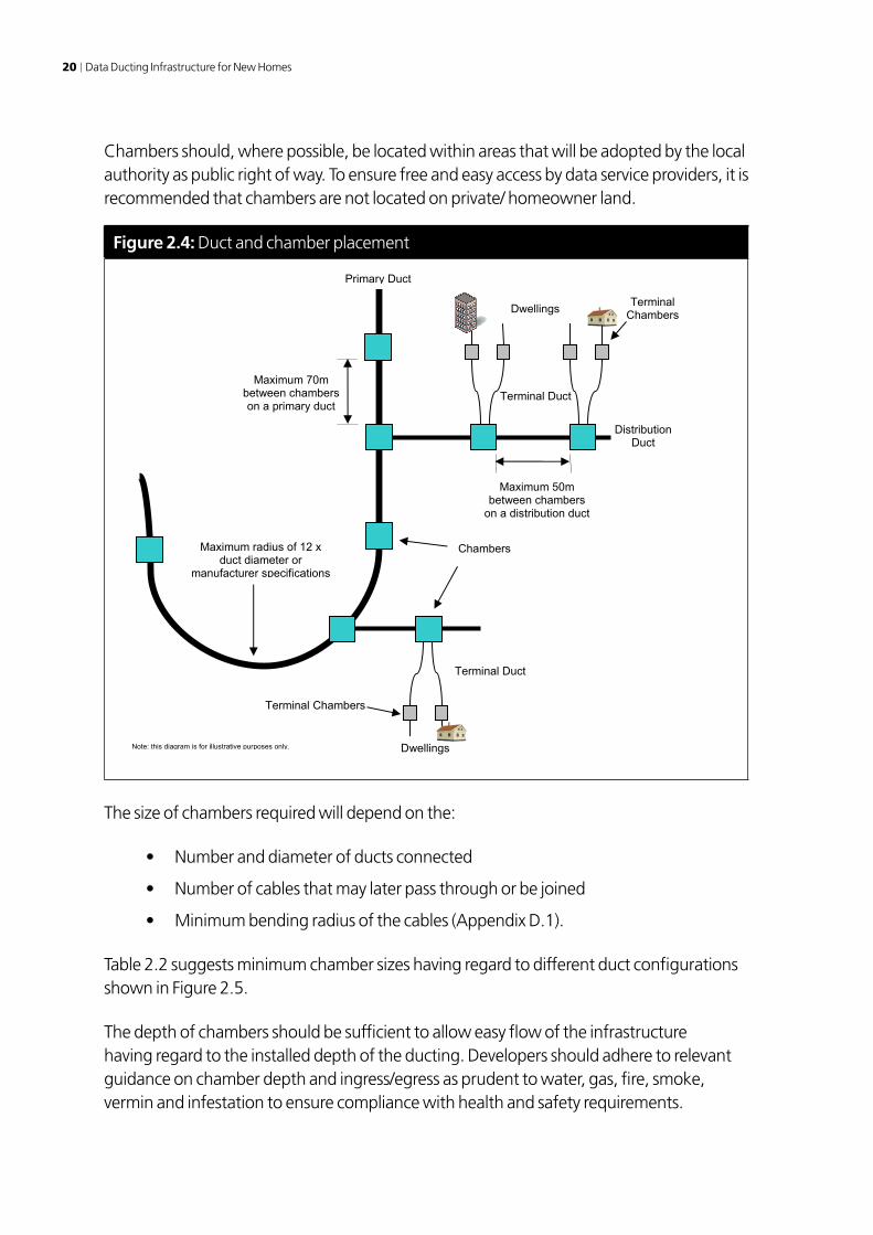
Chambers should, where possible, be located within areas that will be adopted by the local authority as public right of way. To ensure free and easy access by data service providers, it is recommended that chambers are not located on private/ homeowner land.
Figure 2.4: Duct and chamber placement
Terminal Duct
Distribution Duct
Maximum 70m between chambers on a primary duct
Maximum 50m between chambers
on a distribution duct
Chambers
Note: this diagram is for illustrative purposes only.
Primary Duct
Maximum radius of 12 x duct diameter or
manufacturer specifications
Terminal Duct
Terminal Chambers
Terminal Chambers
Dwellings
Dwellings
The size of chambers required will depend on the:
• Numberanddiameterofductsconnected
• Numberofcablesthatmaylaterpassthroughorbejoined
• Minimumbendingradiusofthecables(AppendixD.1).
Table 2.2 suggests minimum chamber sizes having regard to different duct configurations shown in Figure 2.5.
The depth of chambers should be sufficient to allow easy flow of the infrastructure having regard to the installed depth of the ducting. Developers should adhere to relevant guidance on chamber depth and ingress/egress as prudent to water, gas, fire, smoke, vermin and infestation to ensure compliance with health and safety requirements.

Section 2 Infrastructure guidance 21
Table 2.2: Minimum chamber sizing
Total number of dwellings connected via chamber
Chamber lengthmm
Chamber width(duct config. a)
mm
Chamber width(duct config. b)
mm
1 to 3 300 300 300
4 to 15 450 300 300
16 to 30 600 300 450
31 to 60 750 300 600
61 to 300 900 450 900
301 to 600 1800 450 1800
Figure 2.5: Chamber duct configuration
Duct Configuration a)
Duct Configuration b)
Duct
Possible Cable Routes
Duct
Possible Cable Routes
Chamber
Chamber
Duct
Ducts
Duct
Developers should also consider the use of smaller chambers that can be used to pull cables on long duct runs (but under the maximum chamber spacing advised above).
An access node chamber should be constructed based on the sizing in Table 2.2.
Ducts should enter chambers at right angles to their wall and be finished flush with the inside surface of the wall. There should be a minimum of 50mm between ducts and the chamber walls.

22 Data Ducting Infrastructure for New Homes
Ducts should be de-burred where they enter chambers to prevent any later damage to cables.
Chambers and connected ducts should be clean and free of debris.
Chambers should have water drainage/ soakage to ensure that they do not fill with water.
Frames and covers and other surface mounted apparatus should be rigid and suitable for purpose. They should be capable of withstanding a reasonable superimposed load and should, where practicable, be located to reduce the possibility of damage from heavy vehicles.
Frames and covers should be flush with firm surrounding ground or 25mm below if in a grassed or soil area such that they do not present a trip hazard.
Covers should be secure using an Allen key screw lock with a standard key that professionals and organisations would have access to.
Where a chamber may be required to house active equipment, the environmental and power requirements of the equipment should ideally be considered in the design of the chamber. Such information is however unlikely to be available at the time of design and build and if such a requirement arises some later work may therefore be required. However it is likely that active equipment will be housed in above ground cabinets as regular servicing of active components is not uncommon. Where a data service provider proposes to install equipment in a chamber the servicing implications need be considered.
2.2.7 Terminal chambersSubject to the layout of a development a terminal chamber should be located at a suitable location outside each dwelling house or multi-dwelling building plot as shown in Figure 2.6. The purpose of the terminal chamber is to enable cables from the external infrastructure ducts to be routed to dwelling houses or other buildings. It is not recommended that the external ducting is routed into the dwelling but is terminated at the terminal box. Variance may arise where:
• Houses/buildingsareclosetothefootwayorcarriagewayandthuscablescanberouted directly from the distribution duct without the use of terminal chambers. Indeed, in some developments there may not be sufficient space to reasonably install terminal chambers
• Insomedevelopmentsitmaybemoreappropriateforasingleterminalchamberto route ducts for more that one building
• Terminalchambersshouldnotbelocatedwithinbuildingplotsunlessabsolutelynecessary.
Terminal chambers should follow the above chamber guidance (Section 2.2.6).

Section 2 Infrastructure guidance 23
If the external duct needs to enter a building the relevant provisions of the Building Regulations/Standards should be followed notably with respect to preventing:
• Thespreadoffireandsmoke
• Gases,dangeroussubstancesanddampfromenteringthebuilding.
Figure 2.6: Terminal chamber and duct configuration
Terminal Box Equipment Cabinet
Duct Diameter as Table 2.1
Terminal Duct
Chamber linking distribution duct Terminal Chamber
(if required)
Note: this diagram is for illustrative purposes only.
Plot Boundary
150mm minimum radius
Duct leading from terminal box to equipment cabinet. Not connected to the terminal duct.
The terminal box and equipment cabinet shown in Figure 2.6 are part of the internal infrastructure and are therefore considered in Section 2.3.
2.2.8 Street cabinetsStreet cabinets may be required to house some cabling jointing systems and some network equipment. Given that the use of street cabinets is likely to be data service provider and solution specific, it is not anticipated that developers will install street cabinets. However, developers should endeavour to allow space in their site layout. Also note that:
• Streetcabinetsshouldonlybeusedwherenecessaryandwillbedeterminedbythe systems design and specification. Consideration on size, visual impact and vandalism should be considered
• Streetcabinetsshouldbesuitableforpurpose,capableofwithstandingareasonable superimposed load

24 Data Ducting Infrastructure for New Homes
• Cabinetsshouldbelockabletoreducetheriskoftheftandvandalismtotheequipment they hold. This may also be required to address health and safety concerns
• Streetcabinetsshouldbelocatedinsuchapositionthatwillalloweasyaccessfor equipment installation and maintenance. The location of the street cabinets should be suited to minimise possible impact to pedestrians and vehicles
• Equipmentinstreetcabinetsmayrequiretobepowered.Ductingtofacilitateapower feed should be considered during the design stage if applicable
• Itisunlikelythatstreetcabinetlocations,size,mountingandpowerrequirementswill be available at the time of infrastructure design and build and some later work may therefore be required. Therefore it is considered that street cabinets should be reasonably future proof for additional ducting or equipment.
2.2.9 Support for wireless technologyWireless technologies may be required on the development. Wireless technologies would normally be installed on a pole or mast to give a wider coverage of service. Poles or masts would normally have ducting to support cabling to allow for the easy connection to the wireless hardware.
Ducting leading to the pole/ mast may be of the same type as the ducting to dwellings. A terminal chamber located near to the pole/mast is likely to be required to allow for cabling to be pulled through to the pole/ mast.
Figure 2.7: Terminal chamber and wireless pole/mast
Chamber linking Distribution Duct
Duct
Terminal Chamber (if required)
Terminal Duct
Wireless Mast or Pole
Note: this diagram is for illustrative purposes only.
2.2.10 Duct signage and layout recordingDuring backfilling of the trench a suitable identification marker tape should be placed approximately 100mm above the top of the duct. Marker tape should be white with a blue legend.

Section 2 Infrastructure guidance 25
The cover to chambers should be marked ‘Comms’. Covers should not identify a data service provider unless installed by or dedicated to a particular provider such as at the access node.
The layout of the external infrastructure should be recorded using an ‘industry standard’ CAD package. This should be made available to the appropriate local authority in a media/format agreed with that authority.
2.2.11 BoundariesThe boundaries of the external infrastructure (prior to the installation of any cabling or network equipment) should be:
• Withintheaccessnodeadjacenttotheducttothedataserviceprovider’sownnetwork infrastructure
• Ateachdwellinghouseormulti-dwellingbuilding(suchasflatsormaisonettes)adjacent to the place where the data service providers’ cable could later enter the building. This is considered further in Section 2.3
• Theductingwithinthepoleormastifitisownedbyathirdparty.
2.2.12 Termination and cappingDuring construction all open ends of ducts should be plugged or capped to prevent the ingress of vermin, water or dirt. Likewise chambers should not be left uncovered.
Measures should also be taken to ensure that the completed infrastructure does not suffer from the ingress of vermin, water or dirt. Ducts to dwellings must remain capped until a data service provider installs a cable. Resealing caps maybe appropriate to ensure sealing after the cable is installed.
2.3 Internal Infrastructure
2.3.1 Understanding the needsAlthough this document is intended to provide guidance with respect to data services it is important that the support of such services within the dwelling be considered in the wider context of other cable distribution requirements. Appendix C.2 identifies some of the equipment that may require cabling within a typical dwelling. In summary these may be considered as:
• Communications,entertainmentandotherequipmentthatrequirebroadbandor at least basic internet connectivity. The connection of such equipment is the prime focus of this guidance

26 Data Ducting Infrastructure for New Homes
• Otherequipmentthatmayrequireanexternalnetworkconnectionotherthanthe internet
• Systemsandequipmentthatrequirecablingwithinthedwellingbutmayormaynot have any need for external connectivity.
Equipment within the dwelling may employ a wide range of cabling of both a standard and proprietary type. Some may also connect using a wireless technology. Both cabling and wireless solutions are evolving and any internal infrastructure will need to offer sufficient capacity and flexibility to meet future requirements.
It should be noted that some of the data connectivity requirements within a dwelling may be met using a wireless rather than cabled solution. The use of wireless technologies is outside the scope of this document. However, ducting is still required to support cabling to wireless hardware.
It is clearly impossible to pre-cable a dwelling to support all possible applications. Indeed, the current provision of telephone and television sockets in homes is often inadequate and lacking in flexibility. The result is that many dwelling have extensive cabling that is often surface mounted or trailed across floors.
2.3.2 What is requiredOccupants of dwellings are likely to require:
• Datasocketsat‘usefullocations’throughoutthedwelling
• A‘readilyaccessible’locationwherenetworkequipmentcanbeinstalledwithasimple ‘user-friendly’ method of connecting the network equipment to ‘live’ data sockets
• Mainselectricitysocketsthatarelocatednearthedatasockets.
The possibility of installing data sockets at ‘useful locations’ will depend on the nature of the dwellings and the type of occupancy. However, diverse user needs can only be met by a flexible infrastructure that will allow sockets to be readily installed as and where required. Such a flexible infrastructure would also offer the potential for supporting other cabling distribution requirements.
It is not envisaged that developers install data sockets, data cabling or the associated network equipment although some may chose to do so. Rather developers should install internal ducting that enable the later installation of data cabling, faceplates and sockets, and network equipment with minimal disturbance to either previously installed cables or the fabric of the building. The aim should be to facilitate cable installation by an electrician or a qualified competent person.

Section 2 Infrastructure guidance 27
The internal infrastructure should be limited to the supporting faceplates and sockets at ‘normal height’ but consideration should be given for sockets and faceplates that maybe located at a higher location within the dwelling to facilitate a wireless solution or wall mounted media systems such as a flat screen television.
The internal infrastructure should also be designed to support the installation of devices at ceiling level such as sensors for home security and telecare and ceiling mounted loudspeakers.
2.3.3 Topology and layoutThe following issues need be considered in determining the topology and layout of the internal infrastructure for a dwelling:
• Accesstotheexternalinfrastructureviaanexternalterminalbox
• Thepossiblerequirementtolateraccommodateajointbetweenexternalandinternal grade cabling
• Thelocationofanequipmentcabinetthatmaylateraccommodateequipmenttosupport the distribution of data services within the dwelling (see Appendix C.2)
• Thelikelylocationofanytelevisionaerials/dishes,coaxandprimarysocketsofthetype often installed by developers. Such consideration should include the needs of digital television and the possible use of a shared television reception system (see Appendix C.2)
• Thelikelylocationofanystandardtelephonesocketsandwiringofthetypeofteninstalled by developers
• Locationswhereusersmayrealisticallybeexpectedtorequireadataconnection.This needs to be considered in determining the size of the ducting to the areas within a dwelling
• Thecableinstallationrequirements(whicharelikelytobenotfullyknownatthetime of infrastructure design and construction) including:
– the number of cables per duct (can be estimated as noted in previous point)
– the length of cable runs – a maximum of 90m from the equipment cabinet is recommended for ‘standard’ data cables (reference Appendix B.2)
– cable installation requirements including the minimum bending radius (see guidance based on cabling in Appendix D.2) will impact of duct sizing, types of bends and access requirements.
From the above it can be seen that ducts should be routed from an equipment cabinet (located near to the external infrastructure) to at least the main living areas, kitchen and the bedrooms.

28 Data Ducting Infrastructure for New Homes
The ducts should not be restricted to data network use and suitable access points should be included to enable the ducts to be used for other cabling applications (excluding power).
2.3.4 Terminal boxAn external terminal box should be installed at each dwelling house or multi occupancy dwelling to facilitate cable entry as shown in Figure 2.8. The terminal box may also be required to accommodate joints between internal and external grade cables.
The terminal box should be located such that cables can readily pass through the wall to the equipment cabinet.
The terminal box should have minimum dimensions of 300mm height by 300mm width by 150mm depth.
The terminal box should have a full size door (ie 300mm by 300mm) that should be lockable, ideally with a standard service key.
The terminal box should be designed for external mounting and constructed to withstand minor impacts.
In some developments, depending on the location, ‘terminal boxes’ may be installed as a matter of course to aid in the delivery of local telecommunications and TV-based services. They may be installed by service providers or developers. This document does not rule out the use of these ‘terminal boxes’ for the above use, but it is recommended that minimum specifications in this guidance be adhered to and ownership and access rights considered.

Section 2 Infrastructure guidance 29
Figure 2.8: Terminal box and equipment cabinet location
Equipment Cabinet
Note: this diagram is for illustrative purposes only.
Terminal Box
Terminal Duct Diameter as Table 2.1
150mm minimum radius
Height above finished floor level as per building regulations or standards
Duct leading from terminal box to equipment cabinet. Not connected to the terminal duct.
2.3.5 Equipment cabinetAn equipment cabinet should be installed in each dwelling. The equipment cabinet may be required to later accommodate network termination and network distribution equipment installed by a data service provider and/or resident. This is considered further in Appendix C.2.
The equipment cabinet should be located in a dry area that will not be subject to environmental extremes. This essentially dictates a location within the dwelling. Ideally the equipment cabinet should be located to align with the entry into the dwelling of the duct from the terminal box.
The equipment cabinet should also be easily accessible by residents including those with disabilities (in accordance with the appropriate Building Regulations/ Standards).
The equipment cabinet should have minimum dimensions of 300mm height by 300mm width by 150mm depth. However, a larger size equipment cabinet would be preferable and may indeed be essential to support the cable patching requirements in larger dwellings.

30 Data Ducting Infrastructure for New Homes
The equipment cabinet should have a full size door (ie 300mm by 300mm) that allows easy access for residents or suppliers to draw cables from.
The equipment cabinet should be lockable using a manual locking mechanism that is easy to use by residents. It is not recommended that the equipment cabinet is locked using a key that can be removed.
The equipment cabinet should be specifically designed to accommodate network equipment, patch panels and a mains power strip. It should be constructed to facilitate the connection of the ducting detailed above and should be ventilated. Any mains distribution strip must be installed by a qualified competent person in compliance with the appropriate regulation/standard.
The equipment cabinet should be constructed to withstand minor impacts.
The equipment cabinet may be required to house wireless network equipment and therefore should not be constructed from a material that will impact the performance of the wireless network.
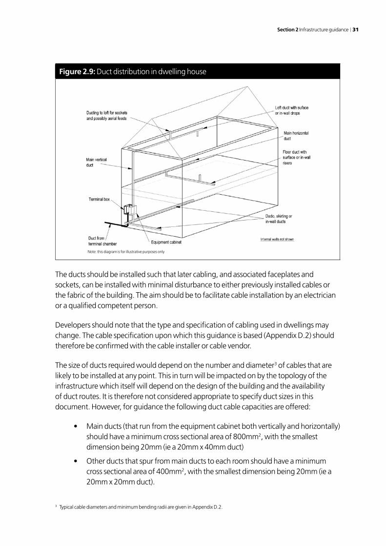
2.3.6 Building ductsThis document is not intended to provide guidance on specific types of ducts in new and existing buildings. There is likely to be a compromise between cost, aesthetics, flexibility and ease of access. Options that developers may consider, as shown in Figure 2.9, include:
• Verticalductconcealedwithotherservicesinriser
• Ductsin-wallwithpossiblypredefinedaccessandsocketpositions
• Dadoducting
• Skirtingducting(ifnotintendedforsockets)
• Simplesurfacemountedducting.
Section 2 Infrastructure guidance 31
Figure 2.9: Duct distribution in dwelling house
The ducts should be installed such that later cabling, and associated faceplates and sockets, can be installed with minimal disturbance to either previously installed cables or the fabric of the building. The aim should be to facilitate cable installation by an electrician or a qualified competent person.
Developers should note that the type and specification of cabling used in dwellings may change. The cable specification upon which this guidance is based (Appendix D.2) should therefore be confirmed with the cable installer or cable vendor.
The size of ducts required would depend on the number and diameter3 of cables that are likely to be installed at any point. This in turn will be impacted on by the topology of the infrastructure which itself will depend on the design of the building and the availability of duct routes. It is therefore not considered appropriate to specify duct sizes in this document. However, for guidance the following duct cable capacities are offered:
• Mainducts(thatrunfromtheequipmentcabinetbothverticallyandhorizontally)should have a minimum cross sectional area of 800mm2, with the smallest dimension being 20mm (ie a 20mm x 40mm duct)
• Otherductsthatspurfrommainductstoeachroomshouldhaveaminimumcross sectional area of 400mm2, with the smallest dimension being 20mm (ie a 20mm x 20mm duct).
3 Typical cable diameters and minimum bending radii are given in Appendix D.2.
Note: this diagram is for illustrative purposes only

32 Data Ducting Infrastructure for New Homes
Developers are advised to employ larger ducts than specified above where space and/ or dwelling construction permits giving consideration to the maximum number of sockets that may be wired in each area/room served.
The ducts should enable cables to be installed with a minimum (long term) bending radius of 60mm.
Bends in the ducts should be kept to a minimum. Access points should be provided where there are multiple bends or bends greater than 45 degrees.
Access points to under floor horizontal ducting should remain available through floorboards or other floor components.
The ducts for data services should be separate from main electricity cables and comply with cable separation and routing standards.
Where a vertical duct runs between floors the relevant provisions of the Building Regulations/ Standards should be followed, notably with respect to fire safety, resistance to moisture and resistance to sound.
Ducts should be positioned is such away that damage from ‘DIY’ is minimised. A similar approach to the best practice installation of electrical cables and sockets should be considered.
The ducts should enable ‘standard size’ face plates and data sockets to be readily installed for example:
• Byremoving/cuttingasectionofductingtodirectlyinsertafaceplate–usingducting that has ideally been designed for the purpose
• Locatingfaceplates(withappropriatebackboxes)adjacenttoaccessibleducting.
Data sockets (and other sockets supported by the internal infrastructure) must be located at a height above finished level floor that is in accordance with Building Regulations/Standards.
Any data sockets located in the loft area should be located in such a position as not to put the resident at risk from trailing cables etc.
This document does not provide any guidance on the installation of mains electricity cabling and sockets. However, developers need to recognise that the quantity and location of power sockets may be an issue given the provision of a flexible data services infrastructure. Developers should therefore consider options for a more flexible power provision in accordance with Building Regulations/ Standards.

Section 2 Infrastructure guidance 33
2.3.7 Multi-dwelling buildingsThe above guidance for a dwelling house also applies to multi-dwelling buildings such as flats or maisonettes with the following exceptions.
Each dwelling within the building could have a separate equipment cabinet or a cabinet per floor in a public area as shown in Figure 2.10.
The dwelling ducting from the equipment cabinet should not be routed outside of the dwelling served.
The duct(s) from the terminal chamber should be routed to the equipment cabinets in a common duct with controlled access and restrictions allowing only authorised person’s access. The common duct may be routed vertically and/ or horizontally.
The common duct should have a minimum cross-sectional area of 2000mm2, with the smallest dimension being 40mm (ie a 40mm x 50mm duct). This size should serve up to 15 dwellings but larger duct should be employed if space permits. The common duct cross sectional area should be increased by 2000mm2 for each additional 15 dwellings.
Figure 2.10: Duct distribution in multi-occupancy building
Where a common duct runs between floors, or horizontally between dwellings, the relevant provisions of the Building Regulations/ Standards should be followed.
This is especially important with respect to fire safety, resistance to moisture, gas leaks, air tightness and resistance to sound.
Note: this diagram is for illustrative purposes only

34 Data Ducting Infrastructure for New Homes
2.3.8 BoundariesAt each dwelling the boundary between the external and internal infrastructure should be adjacent to the place where the data service providers’ cable may later enter the building. The resident would remain the owner of the ducting that houses the data cable from the service provider.
In a multi-dwelling building the boundary between the external and internal infrastructure should be adjacent to the place where the data service providers’ cable may later enter the building. The landlord shall therefore have responsibility for a part of the internal infrastructure (including the terminal box and common duct) that may accommodate cables and network equipment that is owned by a data service provider.
Subject to the terms of the lease of multi-dwelling buildings, the landlord may also be responsible for the equipment cabinet and ducting within each dwelling.
Boundaries for ducting between two premises start and end at the dividing wall as shown in Figure 2.11. The ownership of the infrastructure within the ducting may remain with the service provider or the original infrastructure owner.
Figure 2.11: Duct Boundary multi-occupancy building
Note: this diagram is for illustrative purposes only
Internal Ducting
Dwelling 1 Dwelling 2
Boundary Dwelling 1
Boundary Dwelling 2
Terminal Box
Equipment Cabinet
2.4 Duct Conditions
Ducts between the external infrastructure (usually the terminal chamber) and the dwelling house must be capable of accommodating differential movements between the dwelling structure and the surrounding ground. Such differential movements may be caused by:

Section 2 Infrastructure guidance 35
• Seasonalandlongertermmovementsofductslaidinoraboveplasticsoilsofmedium or high shrinkage/swelling potential, and within the zone of climatic or vegetation-induced moisture content changes (respectively around 1.0m and up to 6.0+m below ground level)
• Groundsettlementbeneathandaroundadwellingsupportedonpiledfoundations where the soils which the piles pass through (above the stratum in which the piles are founded) are susceptible to compression/consolidation. Such compression/consolidation can be caused by placing fill material over soft/weak soils (such as alluvium or older inadequately compacted fill/made ground) or by removing groundwater (by installing land drains or abstraction wells, etc).
These differential movements have been known to reach 250mm or occasionally more.
Tolerance to such differential movements could be achieved by various measures, including:
• Short‘rocker’pipesimmediatelyadjacenttothebuilding(morethanonemayberequired)
• Telescopicductsmountedverticallyonthewallofthedwelling,beneaththeterminal box
• Flexibleductslaidwithsufficientsurpluslengthtoaccommodatethemaximumfeasible movements.
Although outside the scope of this document it is important to note that cabling/ fibre should have sufficient slack to support the movement of ducting during shrinkage and soil movement.
When using High Density Polypropylene (HDPE) ducting, storage should be a consideration to ensure the integrity of the ducting. Considerations are:
• Extremesurfacetemperaturesofupto80ºCarepossiblewhenexposedtosunlight. This may cause localised damage or distortions
• Longtermexposureofductingtosunlightupto12monthsmayhaveasignificant effect on impact resistance and physical properties of the duct
• Over12monthsexposuretodirectsunlightwilldamagetheduct,thisshouldbeavoided.
It is recommended the HDPE ducting and polypropylene couplers are stored away from direct sunlight.
It is unlikely that data cables will exceed a surface temperature that would have a significant impact on the ducting.

36 Data Ducting Infrastructure for New Homes
Ducting should be sufficient to withstand chemicals that are likely to occur in the soils or groundwater.
2.5 Sub Ducting
Consideration may need to be given to the provision of sub-ducting. Sub ducting or inner ducts are ducts within the primary ducts or distribution ducts.
Sub ducts or inner ducts may allow for easement of installing a cable or fibre infrastructure and may reduce the risk of damage to an already installed infrastructure within the primary or distribution duct.
In most cases inner ducts or sub-ducts are pre-installed within the ducting pipe by the ducting manufacturer as shown in Figure 2.12.
Sub-ducts or inner ducts may reduce the flexibility of the duct. This should be considered when designing the trench layouts.
Figure 2.12: Inner or Micro Ducts
Duct
Inner Ducts or Micro Ducts
Cabling Infrastructure

Appendix A Ownership and stewardship 37
Appendix A
Ownership and stewardship
A.1 Introduction to Options
This appendix considers the management and ownership of the external ducting. Seven options are considered here but developers may wish to consider others. It is envisaged that a commercial decision would be made to determine the best approach to ownership or stewardship to ensure value for money and sustainability.
It is assumed in the first four options that the developer lays the external infrastructure but has no involvement in the later service provision.
In the fifth option the developer may employ a business model that includes either:
• Pre-installedcablingthatisofferedonacommercialbasistodataserviceproviders
• Cablingandnetworkequipmenttoofferawholesaleservicetodataserviceproviders
• Cablingandnetworkequipmenttoofferaretailservicetoresidents.
The sixth option considers the options of shared ownerships allowing the developer and third-party share the cost of capital expenditure and profit share.
The final option considers the cost integration of the capital cost and operational cost within section 106 or other tariff options.
A.2 Options
A.2.1 Option 1: Local authority adoptionThere is currently no legislation for a local authority to adopt ducting for data services. Any adoption would be subject to a bespoke agreement between a developer and an authority. This could be similar to Section 38 of the Highways Act but further consultation between the parties would be needed regarding the viability of this approach.
The authority may require a commuted sum for a given number of years for the management and support of the ducting. Boundaries are an important issue using this approach since they would need to be clearly defined to ensure that the authority would not have any responsibility for any ducting in private building.

38 Data Ducting Infrastructure for New Homes
A.2.2 Option 2: Management company ownership
A developer could engage a management company that could potentially own and manage the external infrastructure, possibly together with responsibility for other aspects of a development. The management company could then lease the infrastructure to one or more data service providers.
The management company may require additional funding to manage the infrastructure, the following should be considered:
• Acapitalsum/commutedsumfromthedevelopertoensureasustainablemodelduring the initial phase of the development
• Acovenantcouldbesetupforaresidents’‘servicecharge’thatincludesthemanagement of the infrastructure. Gap funding from the developer may be required in the early years until there are enough residents.
A.2.3 Option 3: Lease of infrastructure
The developer may wish to continue to own the external infrastructure and obtain revenue by subleasing to one or more data service providers.
A.2.4 Option 4: Sale of infrastructure
Selling the infrastructure possibly offers the more attractive approach, quickly gaining a return and reducing the risk. There are currently very few companies that specialise in managing such infrastructures however the number is expected to increase. Such companies attract revenue from the rental of space within the ducting or bandwidth services over the cabling.
Alternatively the developer may sell the infrastructure directly to a data service provider. This option may risk competition issues arising. Developers should seek appropriate guidance.
A.2.5 Option 5: Lease or resell of network provision
The developer could install the data network cabling and possibly the associated networking equipment (as considered in Appendix C). Possible models are:
• Install and offer cabling – provision of external ducting and laying of cabling within ducting possibly using copper or fibre optic4 cables. This cabling would
4 Often referred to as ‘dark fibre’.

Appendix A Ownership and stewardship 39
then be offered on a commercial basis to data service providers. This option carries both technical and commercial risks and it is therefore unlikely to be undertaken on a speculative basis. However, it may be possible to agree commercial terms and confirm the cabling required with prospective service providers prior to any investment.
• Whole service offering – provision of external ducting and cabling (as in above point) with additional electronic equipment to provide a ‘live access data service’ to data service providers.
• Retail service offering – (as in previous point) but with live data service offered by developer directly to residents. A variation on this model may be to offer the service via a management company.
This option offers the benefit that residents moving into their new homes could immediately avail of data services. Of course these advantages may be obtained independently of the external infrastructure ownership issue if a data service provider installs their own cabling and network equipment in the infrastructure at the outset.
If a developer owns and operates the cabling and network equipment then it may be considered as a provider of electronic communications services under the Communications Act as explained in Appendix B.3. A developer may also be affected by ex ante regulation and competition policy as noted in Appendix B.4.
A.2.6 Option 6: Shared Ownership
The developer, land owner and possibly the local authority contribute to the installation of the ducting.
The local authority could take public control of the ducting and operate it to best suit the community by renting space for service providers, see option 1 on adoption.
The developer would attract revenue from an agreed rental of the ducting, possibly back to the local authority, or the developer may decide to sell their stake in the ducting to the community or local authority.
A.2.7 Option 7: S.106 and Tariff
The cost of the ducting could be agreed within the S.106 tariff and if the land is publicly owned could be deducted from land value.
The local authority may wish to add the costing of the ducting and subsequent ownership costs to the planning tariff. Adoption would be similar to that stated in Option 1.

40 Data Ducting Infrastructure for New Homes
Appendix B
Standards and regulations
This appendix references some of the standards and regulations that are relevant to the design and implementation of the infrastructure described in Section 2. It is not intended to be exhaustive and it does not include standards and regulations that apply to building development in areas such as planning, health and safety, environmental protection and construction management.
This appendix also outlines the implications of the Communications Act and then considers network access and competition issues that may have been of concern to some developers installing network infrastructures.
B.1 Standards, Regulations and Guidance
Duct guidance (for external infrastructure): National Joint Utilities Group – Guidelines on the Positioning and Colour Coding of Utilities’ Apparatus – April 2003.
The Building Regulations (in England, Wales and Northern Ireland) or the Building Standards (in Scotland) as appropriate.
British Standards as appropriate notably with respect to Electrical Installations and Telecommunications Systems.
Refer to the Highways Agency (or the Scottish Executive in Scotland) standards for man hole covers, man hole frames and ducting under roads for England, Wales and Northern Ireland or the Scottish Executive in Scotland.
CP 312-1: 1973 Code of practice for plastics pipe works (thermoplastics material) – General principles and choice of material.
Reference to the appropriate guidance for the specifications of conduit systems for cable management. BS EN 50086-2.4 is a particular requirement for conduit systems underground.

Appendix B Standards and regulations 41
B.2 Cabling, Data Socket and Technology Requirements
There are various guides and standards on cabling and technology requirements (of which the developer’s specialist should be aware).
In addition to the guidance and standards produced by national standards bodies (such as BSi) there are European (CEN/CENELEC (EN)) standards and international (ISO, IEEE, TIA and EIA) standards.
B.3 Communications Act
B.3.1 IntroductionAlthough the Communications Act 2003 may not have a direct impact on developers unless they operate a data service (network) the following is provided to ensure awareness. This section considers the regulatory status of a developer that offers a service as noted in Appendix A.2.5 and in particular whether they could be classified as a provider of an electronic communications network (ECN) or electronic communications services (ECS) under the Communications Act.
The ECN and ECS remain subject to regulatory and industry interpretation and debate. The information in this appendix is therefore based on an interpretation of the regulatory position and developers should obtain advice to confirm if and how the regulations may apply.
This appendix also notes:
• TheresponsibilitiesinanydevelopmentofprovidersthataresubjecttotheUniversal Service Obligation (USO)
• PowersthosedevelopersinstallinganetworkinfrastructuremayseekundertheCommunications Act.
B.3.2 Electronic Communications NetworkAn ECN is a transmission system for conveying messages of any kind. Data cabling and associated network equipment could therefore be considered as an ECN.
A developer would not qualify as a provider of an ECN if it merely implements the internal and external ducting as described in Section 2 of this document. Neither should a developer be considered to provide an ECN if it leases the external ducting to a data service provider.

42 Data Ducting Infrastructure for New Homes
A developer may be considered to provide an ECN if they install cabling and network equipment (in the external ducting) and then operate and maintain the network.
B.3.3 Electronic Communications ServicesAn ECS is a service for the conveyance of messages by means of an ECN. It is thus concerned with the conveyance of signals rather than the provision of content. The provider of an ECS is normally the body with a contractual relationship with the end user. A developer is thus unlikely to be considered as a provider of ECS.
B.3.4 General Conditions The General Conditions of Entitlement apply to providers of ECN or ECS and, for most providers, these are the only relevant communications regulatory conditions. The General Conditions are thus unlikely to apply to developers.
B.3.5 Universal Service ObligationThere has been uncertainty regarding the Universal Service Obligation (USO). Ofcom has stated that “BT does not have a right to require developers to build out copper5 as part of new housing projects in order to fulfil its USO but BT has to meet reasonable requests if made by customers on these developments.”
The developer, in most cases, is not subjected to the USO on its infrastructure similar to BT or Kingston Communications. However you should seek guidance from Ofcom if you plan to impose a covenant on the land that gives difficultly to USO providers in supplying a service.
Developers who intend to install their own network infrastructure (ie cabling and network equipment) may seek powers under the Communications Act, as this grants them certain rights to carry out works that they would not otherwise benefit from. These rights include:
• CertainexemptionsundertheTownandCountryPlanningregimeintheformofpermitted development
• Thepowertocarryoutworksinconnectionwiththeinstallationofapparatusinthe streets without the need to obtain a specific street works licence
• TherighttoapplytotheCourtconferringaright,whereagreementcouldnotbereached with the owner of private land, to execute works on private land.
5 As used for the standard telephone network (often referred to as the PSTN).

Appendix B Standards and regulations 43
B.4 Ex-Ante Regulation and Competition Policy
A developer may be affected by ex-ante regulation and competition policy, which flow from certain European Directives. In a case where a provider is found to have a position of dominance it is then required to meet certain remedies in order to foster competition. These remedies could include a requirement to provide access to other providers.
Ex-ante regulation is only imposed after conducting a thorough market review under the EU Framework Directive to assess competition in each defined market and in particular to assess whether any firms in that market have Significant Market Power (SMP).
Ofcom’s wholesale local access market review covering copper and cable local access services resulted in a number of obligations being applied to communications providers with SMP in the wholesale local access market. Currently, Ofcom has not defined any markets that include fibre access (with the exception of fibre based leased line products), dark fibre or ducting, and is not obliged to under the current EU Framework.
Even in the absence of ex ante regulation, operators of a fibre access network to new build premises would still be subject to ex-post competition law. A competition law investigation might be triggered by complaints from consumers or operators.
Developers requiring additional information should refer to the Ofcom and OFT websites.

44 Data Ducting Infrastructure for New Homes
Appendix C
Potential application of infrastructure
C.1 Use of external infrastructure
This appendix provides a high level overview of some of the cabling and network technology options that could potentially be installed in the external infrastructure. It is intended to provide a context for the infrastructure guidance in Section 2.2 and should give developers an awareness of some of the terms that may be used by data service providers.
Bandwidth or other network performance indications have not been provided as these can be misleading and often have no relationship to the actual user experience.
The main cabling and related network technologies that could be used to implement a broadband connection to dwellings are:
• Copperpairs–astraditionallyusedforstandardtelephony.Canalsosupportbroadband using ADSL (Asymmetric Digital Subscriber Lines) and other variants of DSL with the effective data throughput being dependent on the distance from the serving exchange.
• Acopper‘localloop’ispassive(iedoesnothaveanyactivecomponents)andthusany chambers or street cabinets used to terminate/ distribute copper pairs may not require power. Indeed, since power for a standard telephone is provided from the local exchange, calls can be made without any mains electricity (or battery backup) at the dwelling: this does not apply to technologies that use active components.
• CoaxorHybridFibreCoax(HFC)–usedforcabletelevisionbothbycableserviceproviders and for the local distribution of broadcast services in some flats and similar developments including IRS, shared antenna and shared satellite dish. Can also support broadband and telephony services. Note that there are various cable, IRS and Satellite service implementations and some are entirely based on coaxial cabling whereas others use a combination of fibre and coax.
An HFC network, as shown in Figure C.1, requires street cabinets with active components to allow the fibre optic cabling to link to the local coaxial cabling for onward distribution to dwellings. Depending on the size and layout of the development an additional level of ‘distribution’ street cabinets may be required.

Appendix B Standards and regulations 45
Figure C1: Hybrid Fibre Coax Network Schematic
Coax Cable
Coax Cable
Coax Cable
Service Provider
Local aerial/dishes and head end equipment
Access Node
Fibre Optic Cables
Coax Cable
Street Cabinets
Dw
ellings
Terminal Cabinets (may not be required on small developments)
Note: this diagram is for illustrative purposes only
• FibreOptics–fibreopticcablingcanbeusedtosupport‘nextgeneration’IPbased broadband networks that support data, telephony (using Voice over IP) and television (in IP packets rather than radio frequency). This technology is currently perceived by the industry as the way forward.
A fibre optic infrastructure may use an Ethernet technology, as used in most office data networks, or a Passive Optical Network (PON) as favoured by some public network providers for fibre ‘local loops’. The choice of technology could impact on the external infrastructure shown in Figure C.2:
– An Ethernet implementation in a small development may have a star configuration with a point-to-point cable between each dwelling and the access node
– A larger development with an Ethernet implementation may require distribution points to allow multi-fibre bundles from the access node to splice to smaller cables
– A PON may require distribution points to accommodate passive optical couplers that ‘fan out’ the fibre cabling to dwellings.

46 Data Ducting Infrastructure for New Homes
Figure C.2: Fibre Network Schematic
Service Provider Network
Note: this diagram is for illustrative purposes only.
Local aerial/dishes and head end equipment
Access Node
Fibre Optic Cables
Dw
ellings
Terminal Cabinets (may not be required on small developments)
C.2 Use of Internal Infrastructure
This appendix provides a high level overview of some of the potential apparatus and applications that could employ the internal infrastructure. It is intended to provide a context for the infrastructure guidance in Section 2.3.
Dwellings may contain a wide range of communications, entertainment and other equipment that require a broadband (internet) connection including:
• Personalcomputers
• Gamesconsoles
• Televisionsettopboxesandsimilarproductsthathaveaninternetconnectionforreceiving IP-TV and video on-demand
• Internetradio
• Internettelephones
• Securitysystems
• Homeautomationproducts
• Advancedtelecareandtelehealthservices.

Appendix C Potential application of infrastructure 47
Dwellings may contain other equipment that requires an external network connection including:
• Standardtelephonehandsets–connecteddirectlyoncopperpairsoronbroadband via an IP converter
• Modemsin,forexample,apersonalcomputerorsettopbox–connecteddirectlyon copper pairs or on broadband via an IP converter
• Cabletelevision(usingtraditionalRF/IFratherthanIPpackets)–connectedviadedicated cabling infrastructure
• TelevisiondeliveredviaasharedinfrastructuresuchasanIntegratedReceptionSystem (IRS). An IRS is essentially a master antenna TV system that can carry analogue and digital terrestrial television, FM and DAB radio, and both free to air and subscription satellite services. However digital satellite services may require more than one dish for multi-dwelling units and may require two connections to the satellite dish per dwelling for SKY+ services.
In addition to the equipment noted in C2.2, dwellings may contain other systems and equipment that use a wide range of cabling types that could avail of an internal infrastructure including:
• Terrestrialandsatellitetelevision
• Audiosystems
• Homecinemasystems
• PCperipheralssuchasprintersandscanners.
A typical dwelling is likely to have devices that have wireless connectivity. Whilst such connectivity is likely to supplement the cabled internal infrastructure emerging technologies may offer the possibility of a totally wireless solution. However it is envisaged that ducting would still be required to enable wireless access points to connect to the wider network/ internet.
The equipment cabinet detailed in Section 2.3.5 may be required to accommodate the following types of equipment:
• Externalnetworkterminationequipmentgenerallyinstalledbythedataservice provider and likely to remain the property of the provider. Some types of termination equipment may also include the network distribution function detailed below

48 Data Ducting Infrastructure for New Homes
• Dwellingnetworkdistributionequipmentenablingdataserviceconnectivitywithin the dwelling (likely to be based on Ethernet and twisted pair data cabling) that may be installed by the data service provider, the resident or a third party. Is likely to be owned by the resident but may be provided as part of a service rental. Some network distribution equipment may also provide a wireless network capability
• Apatchingpanelonwhichthecablingisterminated–thisislikelytobeinstalledas the same time as the first fit cabling
• Anuninterruptiblepowersupplymayberequiredifitisdesiredtoensurevoiceover IP (VoIP) service availability in the event of a mains electricity failure at the dwelling.

Appendix D Cable sizing assumptions 49
Appendix D
Cable sizing assumptionsThe following cabling information has been used to inform the guidance provided in Section 2.
D.1 External Infrastructure Cables
D1.1 Multi-pair cables for external infrastructureThe diameter of external grade multi-pair cables depends on the type of construction and the conductor size. The minimum bending radius of cables varies but is generally in the region of 10 to 15 times the cable’s external diameter.
Number of pairs Core diameterMm
Typical external diameter
mm
Minimum bending radius –
at 15 times dia. mm
10 0.5 10 150
20 0.5 14 210
50 0.5 18 270
100 0.5 24 360
200 0.5 37 555
1000 0.4 56 840
2000 0.4 70 1050
D1.2 Fibre optic cables for external infrastructureThe diameter of fibre optic cables depends on the type of construction. The minimum bending radius (long term) is typically 15 times the external diameter.

50 Data Ducting Infrastructure for New Homes
Number of fibres Typical external diameter
Mm
Minimum bending radius –
at 15 times dia. mm
6, 12, 24, 36 10 150
48, 72 12 180
96 14 210
144 18 270
216 19 285
D1.3 Coax cable for external infrastructureThe diameter of external grade cables depends on the type of construction, screening and core size. The minimum bending radius varies but is generally in the region of 10 times the cable’s external diameter.
Number of cores Type Typical external diameter
mm
Minimum bending radius –
at 10 times dia. mm
1 Low loss for cable or satellite television
10 100
D.2 Internal Infrastructure Cables
Cable application Type of cable Typical diameter
mm
Typical minimum bending
radiusmm
Data services(also telephony)
4 pair UTP 7 42
Data backbone(not applicable to most dwellings)
4 core fibre 5 50
Television/radio(terrestrial, cable TV and satellite)
coaxial 8 48

Appendix E Glossary 51
APPENDIX E
Glossary
This glossary contains the technical terms used in this document. It does not include any of the Information Communication Technology terms but only acronyms that appear in the Appendices. Appendix F gives terms and acronyms for ICT.
Access node Chamber or street cabinet that would provide the interface between the external infrastructure and a data service provider’s wider network
Broadband A generic term used by data service providers to describe a network service that provides a ‘relatively high’ bandwidth
Cable The term cable in this document refers to cables used to deliver data services (with associated apparatus) unless otherwise noted
Chamber Required for cable joints, cable distribution points and possibly active (powered) equipment. May also be required to facilitate a cable installation
Data service Service that provides broadband network connectivity to the internet and potentially to other networked services such as email, web hosting, video on-demand, etc. Connection can be used to deliver ‘IP data’ which can also include telephony, television and radio.
Such services are sometimes referred to in the ITC industry as ‘multi-services’ or ‘triple-play’
Data service provider Supplier of data service. This is a generic term for a provider that may be a ‘traditional’ telecommunications company, a content provider that has its own network infrastructure or a service provider that employs another’s network
Data sockets Sockets in dwellings to allow occupants to connect devices to a broadband service or other devices within the dwelling
Distribution duct Duct that provides ‘street level’ distribution linking connecting primary duct and terminal duct

52 Data Ducting Infrastructure for New Homes
Duct In the external infrastructure pipes to facilitate the installation and later replacement of cables.
In the internal infrastructure ‘building duct’ of a shape and type as determined by the developer to be appropriate for a given dwelling
Dwelling A house (generally for a single group of occupants), flat or maisonette
Dwelling house A building that contains a single dwelling. Connected houses are considered as separate building in this guidance
Equipment cabinet Cabinet within dwelling to later house network termination equipment and/or network distribution equipment
External Ducting, chambers and other apparatus in a development infrastructure (excluding dwellings) to enable the later installation and
replacement of data cabling and associated network equipment
First fit Cabling (for data services) and data sockets that a developer may install in a dwelling as part of their standard build
Internal Ducting and other apparatus within a dwelling house or infrastructure multi-dwelling building to enable both a ‘first fit’ and a later
installation of data cabling and associated sockets. The internal infrastructure will also provide for the housing of network termination and network distribution equipment
Multi-dwelling A building that contains multiple dwellings such as flats, building maisonettes or apartments
Network equipment Equipment installed at access node, chambers and/or in street cabinets to deliver data services to dwellings
Network distribution Equipment installed in equipment cabinet to deliver data services equipment within a dwelling
Network termination Equipment installed in equipment cabinet to terminate external equipment cabling at a dwelling
Street cabinet A cabinet that may be required to house cable joints, cable distribution points and possibly active (powered) equipment. Although essentially part of the external infrastructure, street cabinets may be installed by data service providers

Appendix E Glossary 53
Primary duct Duct that connects access node to distribution ducts
Primary sockets Sockets for television and radio often installed by developers as part of their standard build
Terminal box Used to describe the end point of an external infrastructure that enters a dwelling. The terminal box may also contain equipment to facilitate the end point termination of a cable infrastructure
Terminal chamber A chamber, generally within a plot, that is used to connect the wider external infrastructure with dwellings or groups of dwellings
Terminal duct Duct to one or more dwellings from a chamber on distribution duct. The terminal duct may therefore run within a building plot
Wireless Used in this document as a generic term for wireless data technologies that could potentially be employed for wide area service distribution or within a dwelling. The use of wireless solutions is outside the scope of this document

54 Data Ducting Infrastructure for New Homes
APPENDIX F
Definitions
The definitions contained within this appendix aim to give the developer an understanding of some of the terminology used within the IT and telecommunications industry. It is by no means an exhaustive list.
ADSL/ SDSL/ DSL/ IDSL Used to describe a digital data communication over standard telephone line. Digital Subscriber Loop or Line (DSL), ‘A’ meaning Asymmetrical (Bandwidth varies for download and upload), ‘S’ meaning Symmetrical (Bandwidth the same for both download and upload), ‘I’ meaning ISDN
Bandwidth Used to describe the limit that data can be transmitted or received. Telecommunications measure bandwidth in frequencies eg Mhz, Ghz. The ICT industry tend to use Kilobits/ Megabits or Gigabits
Bits Generally used in conjunction with Kilobits/ Megabits and Gigabits. In this term meaning the make up of information. An example is the letter ‘A’ on a computer is made up of 8 bits
CAT5e,6,7/ UTP/ A term used to describe a physical copper wire that connects Twisted Pair/ one device to another device. CAT is an abbreviation for Category Patch Cable usually followed by a number, eg CAT5. The difference between
each CAT cable is the ability to transmitted data at greater speeds
CATV Community Access cable Television Systems or Community Antenna Television, sometimes referred to as Cable. Cable TV mainly uses Coax to deliver its services
CCTV Closed Circuit Television, mainly used for security and are increasingly connecting to networks using IP
Coax Coaxial cable mainly used for the reception of TV based services. Can also be used within a computer network for broadband services or network services. Offers good bandwidth at high frequencies
Dark Fibre Same as Fibre Optic but has no light therefore not being used

Appendix E Glossary 55
DNS Domain Name Servers, used on a network to traverse plain text names to IP addresses, eg www.------.co.uk = 012.345.678.90
DSLAM Digital Subscriber Lines Access Multiplexer allows the standard telephone line in the home or business to transmit and receive data more quickly. The DSLAM is usually located in an exchange and is only available to dwellings and business close to the exchange. ADSL2+ uses this service
email Electronic mail, delivered via a network of devices to a particular address. The address is normally plain text but is traversed into an IP address by Domain Name Servers (DNS) for delivery
Fibre Optic A medium for transmitting data using light offering tremendous speeds for transmission. Perceived by both industries as the most future proof infrastructure
Firewall A term used to describe a security feature that protects a network from external threats, eg hacking
FTTH Fibre To The Home. Describes fibre from the service point to the home
Hiperman Same standard as IEEE 802.16 used in Europe
IEEE Institute of Electrical and Electronics Engineers, a none profit international organisation, setting standards for technology related to electricity
Interconnect/ Term used to describe a device or location where third parties can meet me rooms connect their infrastructure to a community network to deliver
services
Internet A connection of devices over a WAN delivering services and information
Intranet A web based service delivered to a select number of devices on a private network
IP Internet Protocol, used to describe the method in which data in transmitted over a network or internet. Each device connected to a network has an IP Address which is made up of four segments, each segment ranging from 0-255, eg 192.168.0.255. An IP address is the address that data is transmitted from and received by

56 Data Ducting Infrastructure for New Homes
Kilobits/ Megabits Kilo meaning a thousand bits (103) and Gigabits Mega meaning a million bits (106) (Kbps/ Mbps Giga meaning a thousand million bits (109) and Gbps)
LAN Local Area Network used to describe a network contained within the same building
Last Mile The final part of delivering services to the dwelling or business. In most cases this is the point that data moves from one medium to another, eg Fibre Optic onto copper wiring
WAN Wide Area Network used to describe a network which extends to multiple buildings
ONT Optical Network Translator is a device used to convert information received via Fibre Optic (Light) and converts it to be transmitted over another media eg copper cable
OPLAN Open Public Local Area Network, term used to describe a network that the public can connect to, to gain access to services
Patch Panel Network points within the home or office would normally terminate at a patch panel. By using a patch cable you are able to make the network points live allowing devices connected to the network point access to other services on the network
POP3/ SMTP/ IMAP4 Protocols used for the transmission and reception of e-mails.
POP3, Post Office Protocol version 3
SMTP, Simple Mail Transfer Protocol
IMAP4, Internet Message Access Protocol ver 4
Ports As with IP, ports are addressed for the delivery and receiving of data. Ports are not physical but are numbers ranging from 0-65535. Sometimes referred to as software ports. Web browsing is usually done on Port 80 and email on port 25 or 110. Different software/applications use various ports but all use the same IP address for external communications
POTS Plain Old Telephone System, used to describe a standard analogue phone that connects to the PSTN network and draws its power from the PSTN system

Appendix F Definitions 57
Protocol A set of rules governing communication between devices
PSTN Public Switched Telephone Network, used to describe the UK’s telephone network. Currently managed by BT and is available to almost every home/ business in the UK
RJ11/ RJ14 Connector found at the end of telephone wire. RJ11 and RJ14 are similar except for the wiring within the modular connector
RJ45 Used to describe a connector at the end of a cable, mainly used for connecting devices to a network or patch panel. In the telecommunications industry this could be described as an 8P8C, slightly different from the RJ45 but does the same thing
Router A device used to manage data transmissions and reception over a data network. Some routers also sport a WiFi (802.11) connection
Server A computer based device used as a central point for a number of network devices. Can be used for collecting emails for users, storing documents/ data, security etc
VoIP Voice Over Internet Protocol, a way of communicating using voice similar to a telephone but using the internet via IP rather than a normal telephone connected to the PSTN
VPN Virtual Private Network, a network created using encryption and tunneling over the Internet to a private network
WiFi/ Wireless/ A trademark of the WiFi alliance. Used to describe a Wireless WLAN/ IEEE 802.11 Connection that devices can connect too wirelessly to gain access
to services.
WLAN refers to a Wireless Local Area Network (see LAN)
WiMAX/ IEEE 802.16 Worldwide Interoperability for Microwave Access. A licensed spectrum for the transmission of wireless data over longer distances than WiFi and at greater speeds