data communication andd networking unit i
TRANSCRIPT
DATA COMMUNICATION ANDD NETWORKING
UNIT I
1. Define data communication.
a. Data communication is the exchange of data between two devices via some form
of transmission medium.
2. Data communication system components
a. Sender
b. Receiver
c. Message
d. Medium
e. Protocol
3. What are the types of transmission modes?
a. Simplex
b. Half-duplex
c. Full-duplex
4. Define simplex.
a. Simplex is a fixed one-way transmission mode.
b. Data may flow only one direction
5. Define half-duplex.
a. Half duplex is a two-way transmission, but only one way at a time.
b. Data may travel n-either direction, but only one unit can send at any one time.
6. Define full-duplex.
a. Full duplex is a simultaneous two-way transmission.
b. A full duplex transmission involves a link that allows simultaneously sending
and receiving of data in both directions.
7. Define topology.
a. Topology is a layout of a network.
8. Define LAN.
a. Local Area Network
b. LAN is a group of computers located in the same room, on the same floor, or in
the same building that are connected to form a single network.
9. Define WAN.
a. Wide Area Network
b. The networks spread across countries are known as WANs.
10. Define MAN.
a. Metropolitan Area Network
b. It is a collection of multiple networks that are connected within the same city to
form a citywide network for a specific government or industry.
TEN MARK AND FIVE MARK
11. Data communications system components
a. Sender- the sender is the device that sends the data message. It can be a
computer, workstation, telephone handset, video camera, and so on.
b. Receiver - the receiver is the device that sends the data message. It can be a
computer, workstation, telephone handset, video camera, and so on.
c. Message – the message is the information to be communicated. It can consist of
text, numbers, pictures, sound, Video or any combination of these.
d. Medium – the transmission medium is the physical path by which a message
travels from sender to receiver. It consists of twisted pair wire, coaxial cable, etc.
e. Protocol – a protocol is a set of rules that govern data communication.
12. Network Protocols and Standards
a. Protocols - a protocol is a set of rules that govern data communication, protocol
defines what is communicated, how it is communicated and when it is
communicated.
i. Key elements,
1. Syntax
2. Semantics
3. Timing
ii. Syntax – syntax refers to the structure of the data.
iii. Semantics – it refers to the meaning of each section of bit
iv. Timing – it refers of two characteristics : when data should be sent and
how fast they can be sent.
v. Example of Network Protocols
1. HTTP- Hyper Text Transfer Protocol – set of rules for exchanging
files of all types on the WWW.
2. FTP – File Transfer Protocol, to exchange files between computers
on the internet.
3. SMTP- Simple Mail Transfer Protocol, is the internet protocol used
to send mail to server.
4. POP- Post Office Protocol, the client to retrieve mail from an
internet server.
5. Types of protocols are
a. Data-link protocols
b. Network Protocols
c. Transport Protocols
d. Application layer protocols
iii. STANDARD – a standard provides a model for development that makes it
possible for a product to work regardless of individual manufacture.
Types of standards
De facto – it divided into two classes
Proprietary
Non – proprietary
De jure – de jure standards are those that have been legislated by an officially
recognized body.
13. Types of network topologies
Network Topology is the schematic description of a network arrangement,
connecting various nodes (sender and receiver) through lines of connection.
BUS Topology
Bus topology is a network type in which every computer and network device is
connected to single cable. When it has exactly two endpoints, then it is
called Linear Bus topology.
Features of Bus Topology
1. It transmits data only in one direction.
2. Every device is connected to a single cable
Advantages of Bus Topology
1. It is cost effective.
2. Cable required is least compared to other network topology.
3. Used in small networks.
4. It is easy to understand.
5. Easy to expand joining two cables together.
Disadvantages of Bus Topology
1. Cables fails then whole network fails.
2. If network traffic is heavy or nodes are more the performance of the
network decreases.
3. Cable has a limited length.
4. It is slower than the ring topology.
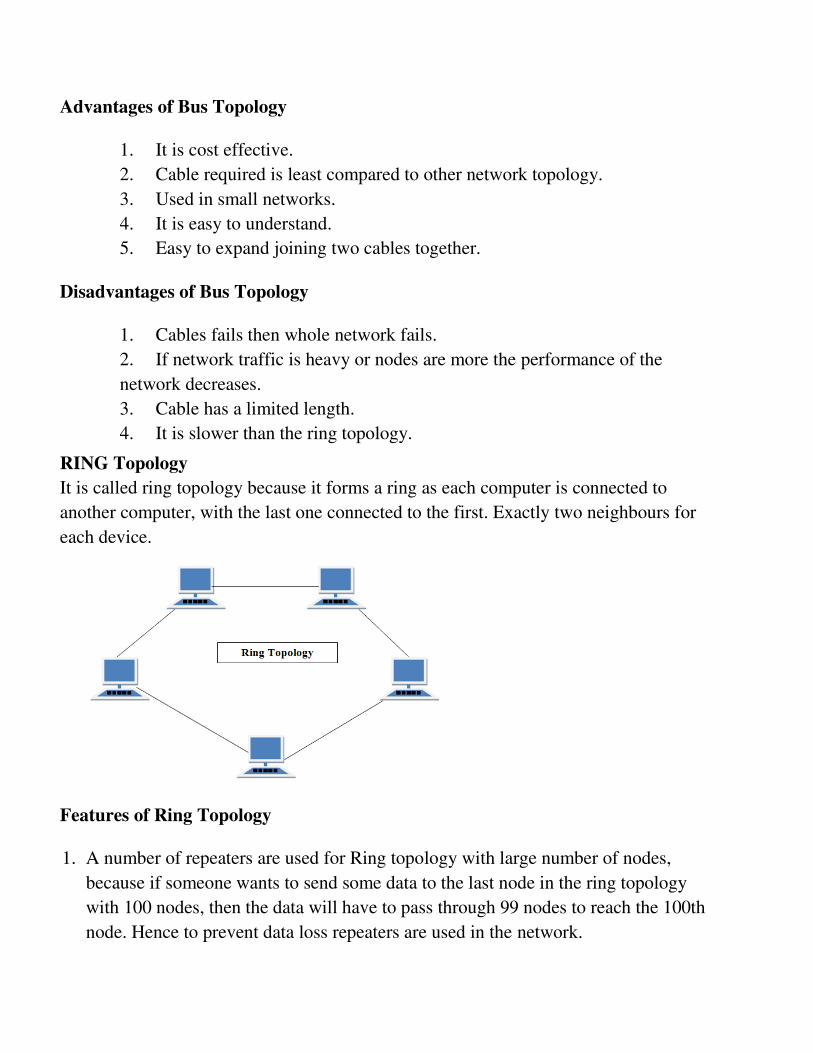
RING Topology
It is called ring topology because it forms a ring as each computer is connected to
another computer, with the last one connected to the first. Exactly two neighbours for
each device.
Features of Ring Topology
1. A number of repeaters are used for Ring topology with large number of nodes,
because if someone wants to send some data to the last node in the ring topology
with 100 nodes, then the data will have to pass through 99 nodes to reach the 100th
node. Hence to prevent data loss repeaters are used in the network.
2. The transmission is unidirectional, but it can be made bidirectional by having 2
connections between each Network Node, it is called Dual Ring Topology.
3. In Dual Ring Topology, two ring networks are formed, and data flow is in opposite
direction in them. Also, if one ring fails, the second ring can act as a backup, to keep
the network up.
4. Data is transferred in a sequential manner that is bit by bit. Data transmitted, has to
pass through each node of the network, till the destination node.
Advantages of Ring Topology
1. Transmitting network is not affected by high traffic or by adding more nodes, as
only the nodes having tokens can transmit data.
2. Cheap to install and expand
Disadvantages of Ring Topology
1. Troubleshooting is difficult in ring topology.
2. Adding or deleting the computers disturbs the network activity.
3. Failure of one computer disturbs the whole network.
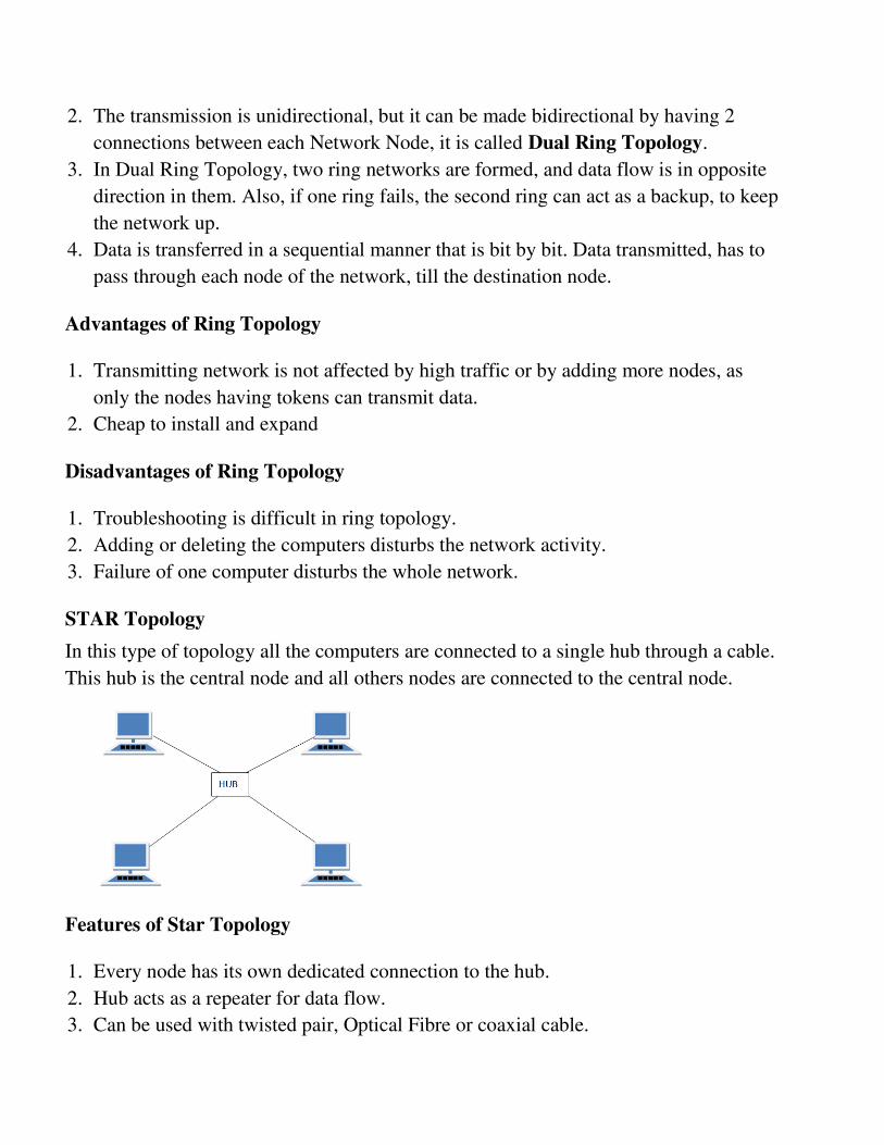
STAR Topology
In this type of topology all the computers are connected to a single hub through a cable.
This hub is the central node and all others nodes are connected to the central node.
Features of Star Topology
1. Every node has its own dedicated connection to the hub.
2. Hub acts as a repeater for data flow.
3. Can be used with twisted pair, Optical Fibre or coaxial cable.
Advantages of Star Topology
1. Fast performance with few nodes and low network traffic.
2. Hub can be upgraded easily.
3. Easy to troubleshoot.
4. Easy to setup and modify.
5. Only that node is affected which has failed, rest of the nodes can work smoothly.
Disadvantages of Star Topology
1. Cost of installation is high.
2. Expensive to use.
3. If the hub fails then the whole network is stopped because all the nodes depend on
the hub.
4. Performance is based on the hub that is it depends on its capacity
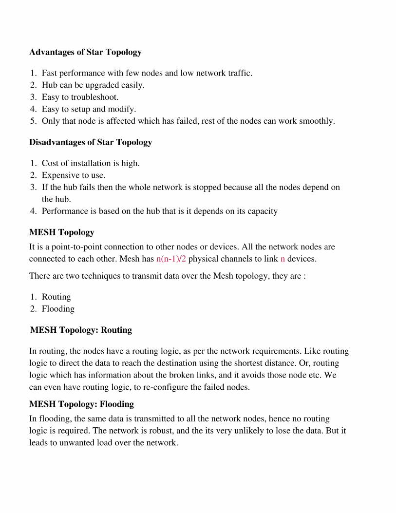
MESH Topology
It is a point-to-point connection to other nodes or devices. All the network nodes are
connected to each other. Mesh has n(n-1)/2 physical channels to link n devices.
There are two techniques to transmit data over the Mesh topology, they are :
1. Routing
2. Flooding
MESH Topology: Routing
In routing, the nodes have a routing logic, as per the network requirements. Like routing
logic to direct the data to reach the destination using the shortest distance. Or, routing
logic which has information about the broken links, and it avoids those node etc. We
can even have routing logic, to re-configure the failed nodes.
MESH Topology: Flooding
In flooding, the same data is transmitted to all the network nodes, hence no routing
logic is required. The network is robust, and the its very unlikely to lose the data. But it
leads to unwanted load over the network.
Types of Mesh Topology
1. Partial Mesh Topology : In this topology some of the systems are connected in the
same fashion as mesh topology but some devices are only connected to two or three
devices.
2. Full Mesh Topology : Each and every nodes or devices are connected to each other.
Features of Mesh Topology
1. Fully connected.
2. Robust.
3. Not flexible.
Advantages of Mesh Topology
1. Each connection can carry its own data load.
2. It is robust.
3. Fault is diagnosed easily.
4. Provides security and privacy.
Disadvantages of Mesh Topology
1. Installation and configuration is difficult.
2. Cabling cost is more.
3. Bulk wiring is required.
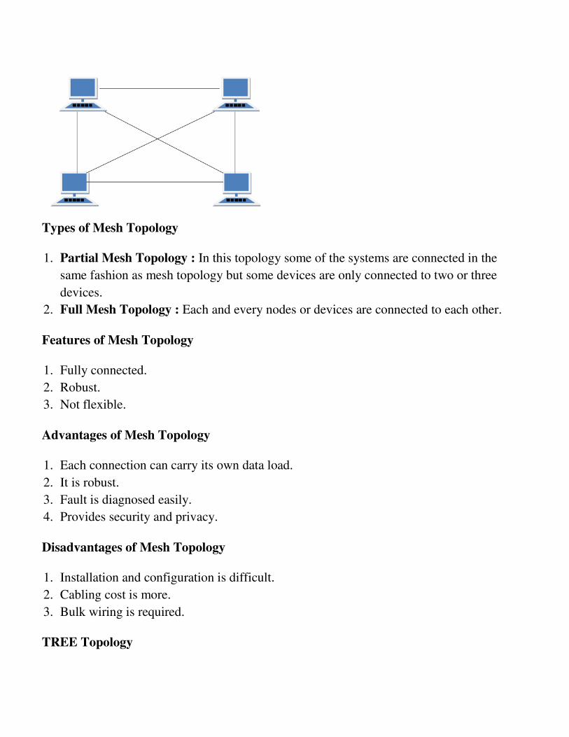
TREE Topology
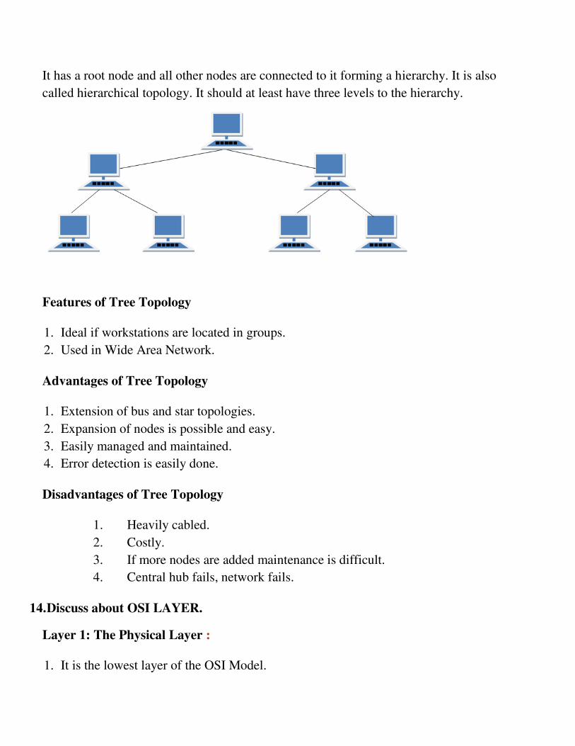
It has a root node and all other nodes are connected to it forming a hierarchy. It is also
called hierarchical topology. It should at least have three levels to the hierarchy.
Features of Tree Topology
1. Ideal if workstations are located in groups.
2. Used in Wide Area Network.
Advantages of Tree Topology
1. Extension of bus and star topologies.
2. Expansion of nodes is possible and easy.
3. Easily managed and maintained.
4. Error detection is easily done.
Disadvantages of Tree Topology
1. Heavily cabled.
2. Costly.
3. If more nodes are added maintenance is difficult.
4. Central hub fails, network fails.
14. Discuss about OSI LAYER.
Layer 1: The Physical Layer :
1. It is the lowest layer of the OSI Model.
2. It activates, maintains and deactivates the physical connection.
3. It is responsible for transmission and reception of the unstructured raw data over
network.
4. Voltages and data rates needed for transmission is defined in the physical layer.
5. It converts the digital/analog bits into electrical signal or optical signals.
6. Data encoding is also done in this layer.
Layer 2: Data Link Layer :
1. Data link layer synchronizes the information which is to be transmitted over the
physical layer.
2. The main function of this layer is to make sure data transfer is error free from one
node to another, over the physical layer.
3. Transmitting and receiving data frames sequentially is managed by this layer.
4. This layer sends and expects acknowledgements for frames received and sent
respectively. Resending of non-acknowledgement received frames is also handled
by this layer.
5. This layer establishes a logical layer between two nodes and also manages the
Frame traffic control over the network. It signals the transmitting node to stop, when
the frame buffers are full.
Layer 3: The Network Layer :
1. It routes the signal through different channels from one node to other.
2. It acts as a network controller. It manages the Subnet traffic.
3. It decides by which route data should take.
4. It divides the outgoing messages into packets and assembles the incoming packets
into messages for higher levels.
Layer 4: Transport Layer :
1. It decides if data transmission should be on parallel path or single path.
2. Functions such as Multiplexing, Segmenting or Splitting on the data are done by this
layer
3. It receives messages from the Session layer above it, convert the message into
smaller units and passes it on to the Network layer.
4. Transport layer can be very complex, depending upon the network requirements.
Transport layer breaks the message (data) into small units so that they are handled more
efficiently by the network layer.
Layer 5: The Session Layer :
1. Session layer manages and synchronize the conversation between two different
applications.
2. Transfer of data from source to destination session layer streams of data are marked
and are resynchronized properly, so that the ends of the messages are not cut
prematurely and data loss is avoided.
Layer 6: The Presentation Layer :
1. Presentation layer takes care that the data is sent in such a way that the receiver will
understand the information (data) and will be able to use the data.
2. While receiving the data, presentation layer transforms the data to be ready for the
application layer.
3. Languages(syntax) can be different of the two communicating systems. Under this
condition presentation layer plays a role of translator.
4. It perfroms Data compression, Data encryption, Data conversion etc.
Layer 7: Application Layer :
1. It is the topmost layer.
2. Transferring of files disturbing the results to the user is also done in this layer. Mail
services, directory services, network resource etc are services provided by
application layer.
3. This layer mainly holds application programs to act upon the received and to be sent
data.
Merits of OSI reference model:
1. OSI model distinguishes well between the services, interfaces and protocols.
2. Protocols of OSI model are very well hidden.
3. Protocols can be replaced by new protocols as technology changes.
4. Supports connection oriented services as well as connectionless service.
Demerits of OSI reference model:
1. Model was devised before the invention of protocols.
2. Fitting of protocols is tedious task.
3. It is just used as a reference model.
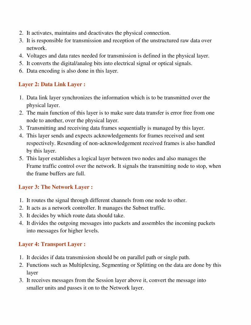
15. What are the Transmission Modes used in Computer Networks?
Transmission mode refers to the mechanism of transferring of data between two devices
connected over a network. It is also called Communication Mode. These modes direct
the direction of flow of information. There are three types of transmission modes. They
are:
1. Simplex Mode
2. Half duplex Mode
3. Full duplex Mode
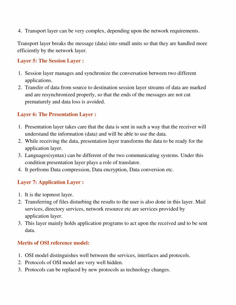
SIMPLEX Mode
In this type of transmission mode, data can be sent only in one direction i.e.
communication is unidirectional. We cannot send a message back to the sender.
Unidirectional communication is done in Simplex Systems where we just need to send a
command/signal, and do not expect any response back.
Examples of simplex Mode are loudspeakers, television broadcasting, television and
remote, keyboard and monitor etc.
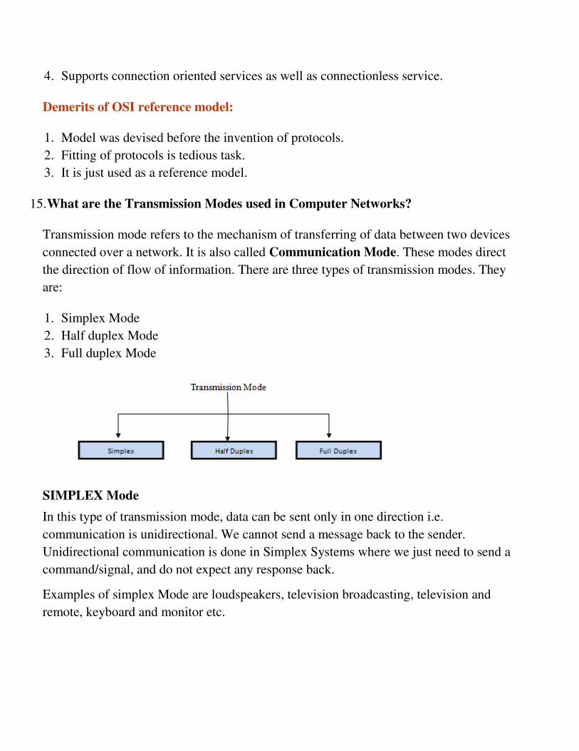
HALF DUPLEX Mode
Half-duplex data transmission means that data can be transmitted in both directions on a
signal carrier, but not at the same time.
For example, on a local area network using a technology that has half-duplex
transmission, one workstation can send data on the line and then immediately receive
data on the line from the same direction in which data was just transmitted. Hence half-
duplex transmission implies a bidirectional line (one that can carry data in both
directions) but data can be sent in only one direction at a time.
Example of half duplex is a walkie- talkie in which message is sent one at a time but
messages are sent in both the directions.
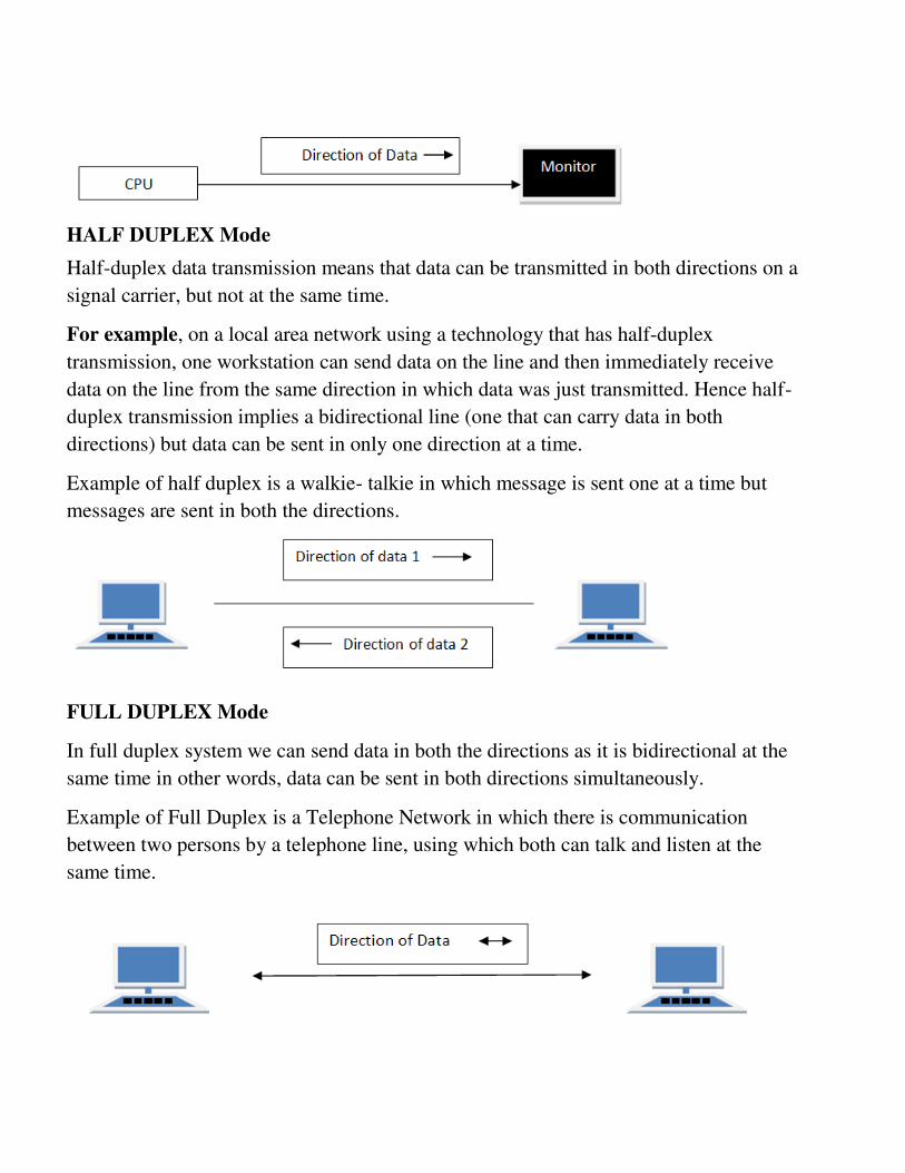
FULL DUPLEX Mode
In full duplex system we can send data in both the directions as it is bidirectional at the
same time in other words, data can be sent in both directions simultaneously.
Example of Full Duplex is a Telephone Network in which there is communication
between two persons by a telephone line, using which both can talk and listen at the
same time.

In full duplex system there can be two lines one for sending the data and the other for
receiving data.
16. Explain about Line Configuration.
A Network is nothing but a connection made through connection links between two or
more devices. Devices can be a computer, printer or any other device that is capable to
send and receive data. There are two ways to connect the devices :
1. Point-to-Point connection
2. Multipoint connection
Point-To-Point Connection
It is a protocol which is used as a communication link between two devices. It is simple
to establish. The most common example for Point-to-Point connection (PPP) is a
computer connected by telephone line. We can connect the two devices by means of a
pair of wires or using a microwave or satellite link.
Example: Point-to-Point connection between remote control and Television for
changing the channels.
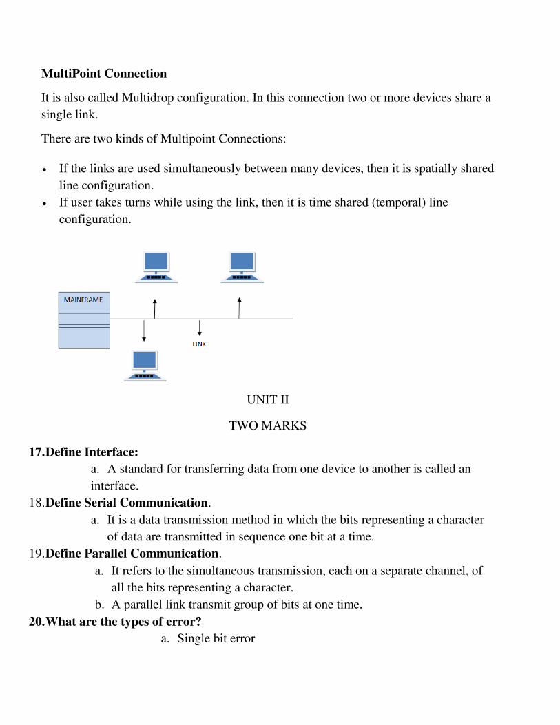
MultiPoint Connection
It is also called Multidrop configuration. In this connection two or more devices share a
single link.
There are two kinds of Multipoint Connections:
If the links are used simultaneously between many devices, then it is spatially shared
line configuration.
If user takes turns while using the link, then it is time shared (temporal) line
configuration.
UNIT II
TWO MARKS
17. Define Interface:
a. A standard for transferring data from one device to another is called an
interface.
18. Define Serial Communication.
a. It is a data transmission method in which the bits representing a character
of data are transmitted in sequence one bit at a time.
19. Define Parallel Communication.
a. It refers to the simultaneous transmission, each on a separate channel, of
all the bits representing a character.
b. A parallel link transmit group of bits at one time.
20. What are the types of error?
a. Single bit error
b. Burst error
21. Define Checksum.
a. The error detection method used by the higher layer protocol is
called checksum.
22. Define Single bit error.
a. It means only one bit of a given data unit is changed from 1 to 0 or from 0 to 1.
23. Define burst error.
a. The term burst error means that two or more bits in the data unit have changed
from 1 to 0 or from 0 to 1.
FIVE MARKS AND TEN MARKS
24. Explain about DTE/DCE.
a. Most digital data processing devices have limited data transmission capability. It
rare for the device to attach directly to transmission or net working facility.
b. The device includes terminals and computers are referred to as Data Terminal
Equipment (DTE). A DTE make use of the transmission system through the
mediation of Data Circuit terminating Equipment.
c. Example : Modem
d. DTE is responsible for transmitting and receiving bits, one at a time, over a
transmission medium or network .
e. DCE must also interact with DTE.
f. The two DCE’s that exchange signals over the transmission line or network must
understand each other.
g. Characteristics
i. Mechanical
ii. Electrical
iii. Functional
25. Discuss about MODEM.
a. A modem is an electronic device that converts computer’s digital information
into analog carrier signals and vice versa. Computers use modems to
communicate with each other over a network.
b. The word modem is derived from “modulator – demodulator “that defines the
functions it performs.
c. Modulation is the process of changing the form of the signal carrying the
information.
d. The demodulation process does the task of extracting information from the
signals that are modulated.
e. Modems are classified on the basis of two criteria
i. Data sent per unit time
ii. Change in the state of the signal per unit time
f. Functions of modem:
i. Error Correction
ii. Compression of Data
iii. Flow Control
g. Types of modems
i. Internal and External Modem
ii. Intelligent and Standard modems
iii. Wireless and short – haul modems
26. Discuss about guided transmission media.
Guided media, which are those that provide a conduit from one device to another,
include Twisted-Pair Cable, Coaxial Cable, and Fibre-Optic Cable.
A signal travelling along any of these media is directed and contained by the physical
limits of the medium. Twisted-pair and coaxial cable use metallic (copper) conductors
that accept and transport signals in the form of electric current. Optical fibre is a cable
that accepts and transports signals in the form of light.
Twisted Pair Cable
This cable is the most commonly used and is cheaper than others. It is lightweight,
cheap, can be installed easily, and they support many different types of network.
A twisted pair consists of two conductors(normally copper), each with its own plastic
insulation, twisted together. One of these wires is used to carry signals to the receiver,
and the other is used only as ground reference. The receiver uses the difference between
the two. In addition to the signal sent by the sender on one of the wires,
interference(noise) and crosstalk may affect both wires and create unwanted signals. If
the two wires are parallel, the effect of these unwanted signals is not the same in both
wires because they are at different locations relative to the noise or crosstalk sources.
This results in a difference at the receiver.
Twisted Pair is of two types:

Unshielded Twisted Pair (UTP)
Shielded Twisted Pair (STP)
Unshielded Twisted Pair Cable
It is the most common type of telecommunication when compared with Shielded
Twisted Pair Cable which consists of two conductors usually copper, each with its own
color plastic insulator. Identification is the reason behind coloured plastic insulation.
Advantages
Installation is easy
Flexible
Cheap
It has high speed capacity,
100 meter limit
Higher grades of UTP are used in LAN technologies like Ethernet.
It consists of two insulating copper wires (1mm thick). The wires are twisted together in
a helical form to reduce electrical interference from similar pair.
Disadvantages
Bandwidth is low when compared with Coaxial Cable
Provides less protection from interference.
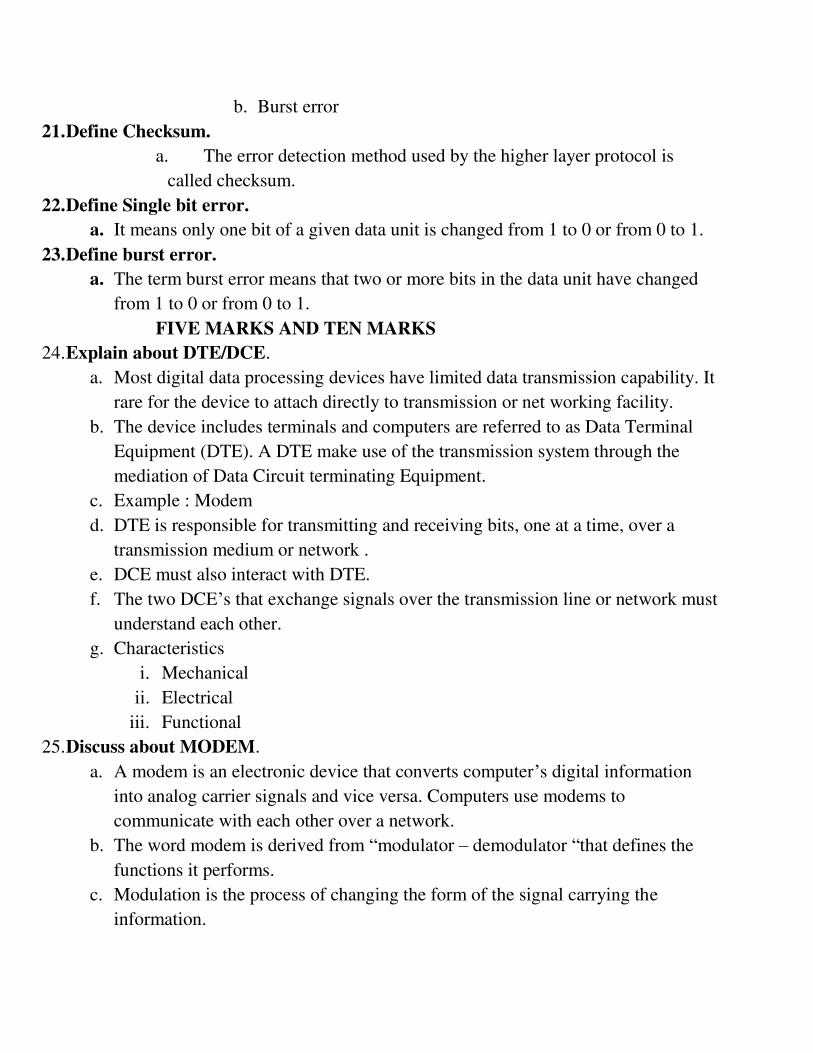
Shielded Twisted Pair Cable
This cable has a metal foil or braided-mesh covering which encases each pair of
insulated conductors. Electromagnetic noise penetration is prevented by metal casing.
Shielding also eliminates crosstalk (explained in KEY TERMS Chapter).
It has same attenuation as unshielded twisted pair. It is faster the unshielded and coaxial
cable. It is more expensive than coaxial and unshielded twisted pair.
Advantages
Easy to install
Performance is adequate
Can be used for Analog or Digital transmission
Increases the signalling rate
Higher capacity than unshielded twisted pair
Eliminates crosstalk
Disadvantages
Difficult to manufacture
Heavy
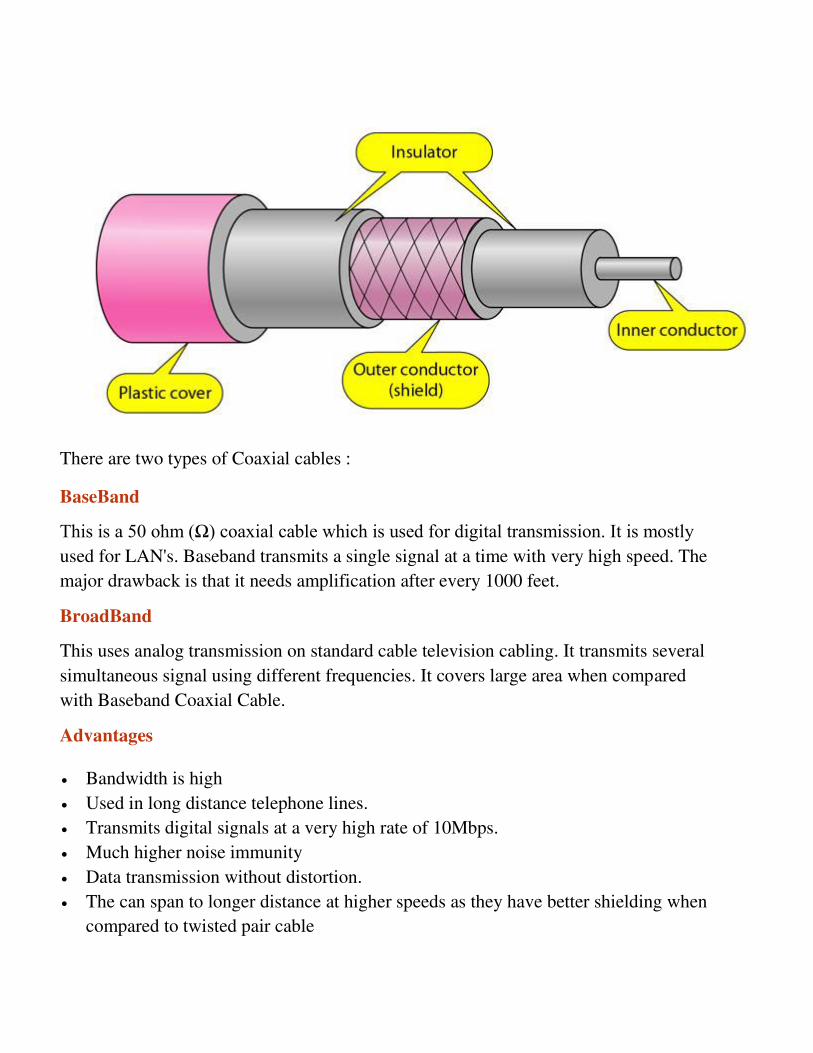
Coaxial Cable
Coaxial is called by this name because it contains two conductors that are parallel to
each other. Copper is used in this as centre conductor which can be a solid wire or a
standard one. It is surrounded by PVC installation, a sheath which is encased in an outer
conductor of metal foil, barid or both.
Outer metallic wrapping is used as a shield against noise and as the second conductor
which completes the circuit. The outer conductor is also encased in an insulating sheath.
The outermost part is the plastic cover which protects the whole cable.
There are two types of Coaxial cables :
BaseBand
This is a 50 ohm (Ω) coaxial cable which is used for digital transmission. It is mostly used for LAN's. Baseband transmits a single signal at a time with very high speed. The
major drawback is that it needs amplification after every 1000 feet.
BroadBand
This uses analog transmission on standard cable television cabling. It transmits several
simultaneous signal using different frequencies. It covers large area when compared
with Baseband Coaxial Cable.
Advantages
Bandwidth is high
Used in long distance telephone lines.
Transmits digital signals at a very high rate of 10Mbps.
Much higher noise immunity
Data transmission without distortion.
The can span to longer distance at higher speeds as they have better shielding when
compared to twisted pair cable
Disadvantages
Single cable failure can fail the entire network.
Difficult to install and expensive when compared with twisted pair.
If the shield is imperfect, it can lead to grounded loop.
Fiber Optic Cable
A fibre-optic cable is made of glass or plastic and transmits signals in the form of light.
For better understanding we first need to explore several aspects of the nature of light.
Light travels in a straight line as long as it is mobbing through a single uniform
substance. If ray of light travelling through one substance suddenly enters another
substance (of a different density), the ray changes direction.
The below figure shows how a ray of light changes direction when going from a more
dense to a less dense substance.
Advantages
Fibre optic has several advantages over metallic cable:
Higher bandwidth
Less signal attenuation
Immunity to electromagnetic interference
Resistance to corrosive materials
Light weight
Greater immunity to tapping
Disadvantages
There are some disadvantages in the use of optical fibre:
Installation and maintenance
Unidirectional light propagation
High cost
27. Explain about Unguided media.
We can divide wireless transmission into three broad groups:
1. Radio waves
2. Micro waves
3. Infrared waves
Radio Waves
Electromagnetic waves ranging in frequencies between 3 KHz and 1 GHz are normally
called radio waves.
Radio waves are omnidirectional. When an antenna transmits radio waves, they are
propagated in all directions. This means that the sending and receiving antennas do not
have to be aligned. A sending antenna send waves that can be received by any receiving
antenna. The omnidirectional property has disadvantage, too. The radio waves
transmitted by one antenna are susceptible to interference by another antenna that may
send signal suing the same frequency or band.
Radio waves, particularly with those of low and medium frequencies, can penetrate
walls. This characteristic can be both an advantage and a disadvantage. It is an
advantage because, an AM radio can receive signals inside a building. It is a
disadvantage because we cannot isolate a communication to just inside or outside a
building.
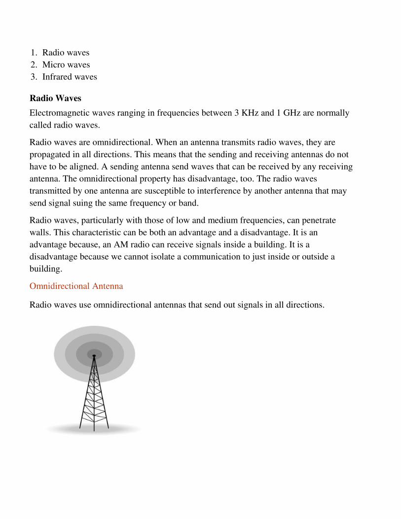
Omnidirectional Antenna
Radio waves use omnidirectional antennas that send out signals in all directions.
Applications
The omnidirectional characteristics of radio waves make them useful for
multicasting in which there is one sender but many receivers.
AM and FM radio, television, maritime radio, cordless phones, and paging are
examples of multicasting.
Micro Waves
Electromagnetic waves having frequencies between 1 and 300 GHz are called micro
waves. Micro waves are unidirectional. When an antenna transmits microwaves, they
can be narrowly focused. This means that the sending and receiving antennas need to be
aligned. The unidirectional property has an obvious advantage. A pair of antennas can
be aligned without interfering with another pair of aligned antennas.
The following describes some characteristics of microwaves propagation:
Microwave propagation is line-of-sight. Since the towers with the mounted antennas
need to be in direct sight of each other, towers that are far apart need to be very tall.
Very high-frequency microwaves cannot penetrate walls. This characteristic can be
a disadvantage if receivers are inside the buildings.
The microwave band is relatively wide, almost 299 GHz. Therefore, wider sub-
bands can be assigned and a high date rate is possible.
Use of certain portions of the band requires permission from authorities.
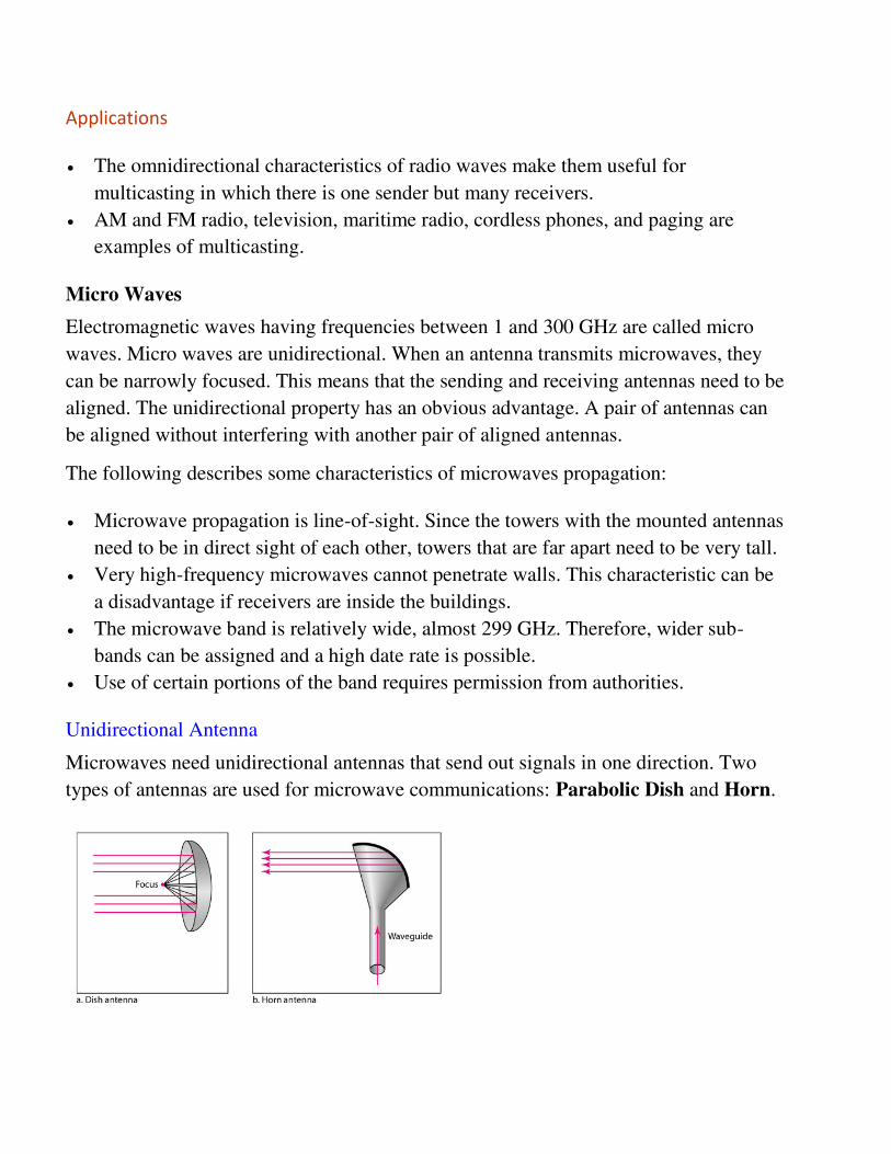
Unidirectional Antenna
Microwaves need unidirectional antennas that send out signals in one direction. Two
types of antennas are used for microwave communications: Parabolic Dish and Horn.

A parabolic antenna works as a funnel, catching a wide range of waves and directing
them to a common point. In this way, more of the signal is recovered than would be
possible with a single-point receiver.
A horn antenna looks like a gigantic scoop. Outgoing transmissions are broadcast up a
stem and deflected outward in a series of narrow parallel beams by the curved head.
Received transmissions are collected by the scooped shape of the horn, in a manner
similar to the parabolic dish, and are deflected down into the stem.
Applications
Microwaves, due to their unidirectional properties, are very useful when unicast(one-to-
one) communication is needed between the sender and the receiver. They are used in
cellular phones, satellite networks and wireless LANs.
There are 2 types of Microwave Transmission :
1. Terrestrial Microwave
2. Satellite Microwave
Advantages of Microwave Transmission
Used for long distance telephone communication
Carries 1000's of voice channels at the same time
Disadvantages of Microwave Transmission
It is Very costly
Satellite Microwave
This is a microwave relay station which is placed in outer space. The satellites are
launched either by rockets or space shuttles carry them.
These are positioned 36000KM above the equator with an orbit speed that exactly
matches the rotation speed of the earth. As the satellite is positioned in a geo-
synchronous orbit, it is stationery relative to earth and always stays over the same point

on the ground. This is usually done to allow ground stations to aim antenna at a fixed
point in the sky.
Features of Satellite Microwave :
Bandwidth capacity depends on the frequency used.
Satellite microwave deployment for orbiting satellite is difficult.
Advantages of Satellite Microwave :
Transmitting station can receive back its own transmission and check whether the
satellite has transmitted information correctly.
A single microwave relay station which is visible from any point.
Disadvantages of Satellite Microwave :
Satellite manufacturing cost is very high
Cost of launching satellite is very expensive
Transmission highly depends on whether conditions, it can go down in bad weather
Infrared Waves
Infrared waves, with frequencies from 300 GHz to 400 THz, can be used for short-
range communication. Infrared waves, having high frequencies, cannot penetrate walls.
This advantageous characteristic prevents interference between one system and another,
a short-range communication system in on room cannot be affected by another system
in the next room.
When we use infrared remote control, we do not interfere with the use of the remote by
our neighbours. However, this same characteristic makes infrared signals useless for
long-range communication. In addition, we cannot use infrared waves outside a
building because the sun's rays contain infrared waves that can interfere with the
communication.
Applications
The infrared band, almost 400 THz, has an excellent potential for data transmission.
Such a wide bandwidth can be used to transmit digital data with a very high data
rate.
The Infrared Data Association(IrDA), an association for sponsoring the use of
infrared waves, has established standards for using these signals for communication
between devices such as keyboards, mouse, PCs and printers.
28. Discuss about Flow Control.
a. Flow control is a set of procedures that tells the sender how much data it can
transmit before it must wait for an acknowledgement from the receiver.
b. It may have limiting storage buffer and processing power.
c. Stop and Wait
i. The sender transmits a frame
ii. It waits for an acknowledgement from the other side. It will not send the
next frame till it receives an acknowledgement from the receiver
iii. The receiver sends the acknowledgement when it receives an error-free
frame.
d. Sliding window
i. Station A maintains a list of sequence number that is allowed to send, and
Station B maintains a list of sequence numbers that is prepared to receive.
ii. Each of these lists is considered as window of frames.
iii. This operation is referred to as sliding – window flow control.
e. The initial condition
i. After the first frame has been sent
ii. After the first frame has been received
iii. After the first acknowledgement has been received
29. Discuss about error control
a. Error control mechanism that detects errors and requests retransmission.
b. Flow control an error control are both implemented together.
c. When error is detected in the received frame a negative acknowledgement
(NAK) is sent to the sender and the specified frame is retransmitted.
d. This process is called automatic Repeat Request.
e. Three techniques perform reliable transmission. they are
i. Stop-and-Wait ARQ
ii. Sliding Window
iii. Selective Objective
f. The sender transmits a frame, waits for acknowledgement if the frame received
is error free. Otherwise, negative acknowledgement if the frame is corrupted.
g. If the sender receives a NAK, it retransmits the last frame
h. It notifies the sender that the previously sent frame is received error-free.
30. Explain about Error detection method
a. All frames are eventually delivered to the network layer at the destination, and in
proper order.
b. Types of redundancy
i. Vertical Redundancy Check
ii. Longituinal Redundancy Check
iii. Cycle Redundancy Check
iv. Check sum
c. Vertical Redundancy Check
i. Least expansive mechanism for error detection is the vertical redundancy
check often called a pairty check.
d. Longituinal Redundancy Check
i. A block of bits is divided into rows and a redundant row of bits is added
to the whole block
e. Cycle Redundancy Check
i. The most powerful of the redundancy checking techniques is the Cyclic
Redundancy Check
ii. CRC is based on binary division
f. Checksum
i. The error detection method used by the higher-layer protocol is called
checksum.
31. Explain about error correction method.

a. Error correction can be handled in two ways. When an error is discovered, the
receiver can have the sender to retransmit the entire data unit.
b. A receiver can use an error-correcting code, which automatically corrects certain
errors.
c. The error-detection codes and require more redundancy bits.
d. Most error correction is limited to one, two, three-bit errors.
e. Code Word
i. The error-detecting and error-correcting properties of a code depend on
its Hamming distance
ii. Te detect d errors, a distance of d+1 code is needed
iii. To correct d errors, a distance 2+1 code is needed
f. Hamming Code
i. Detect single-bit and double-bit errors
ii. Otherwise, correct a single bit error
UNIT III
TWO MARKS
32. Define Multiplexing.
a. Multiplexing is the method of dividing a communication channel into many
logical channels so that a number of independent signals may be simultaneously
transmitted on it.
33. What are the types of multiplexing?
a. Frequency division multiplexing
b. Time division multiplexing
c. Wave length division multiplexing
34. Difference between multicast and broadcast
a. Multicast – sending group of station is called multicast
b. Broadcast – sending to all stations on the network is called broadcast.
35. Define Demultiplexing.
a. Delivering received segments at receiver side to the correct app layer processes
is called as demultiplexing.
36. Define Switch.
a. A switched network consists of a series of interlinked nodes, called switches.
37. What are the types of switching?
a. Circuit Switching
b. Message Switching
c. Packet switching
38. What is FDDI?
a. Fibre Distributed Data Interface is a high performance fibre optic token ring
LAN running at 100mbps over distance upto 200km with up to 1000 stations
connected.
FIVE AND TEN MARKS
39. Explain about Mutiplexing and types.
a. Multiplexing is the method of dividing a communication channel into many
logical channels so that a number of independent signals may be simultaneously
transmitted on it.
Types of Multiplexing
Different type of multiplexing is used in communication. In this article, the following
three major multiplexing techniques are discussed:
Frequency division multiplexing
Wavelength division multiplexing
Time division multiplexing
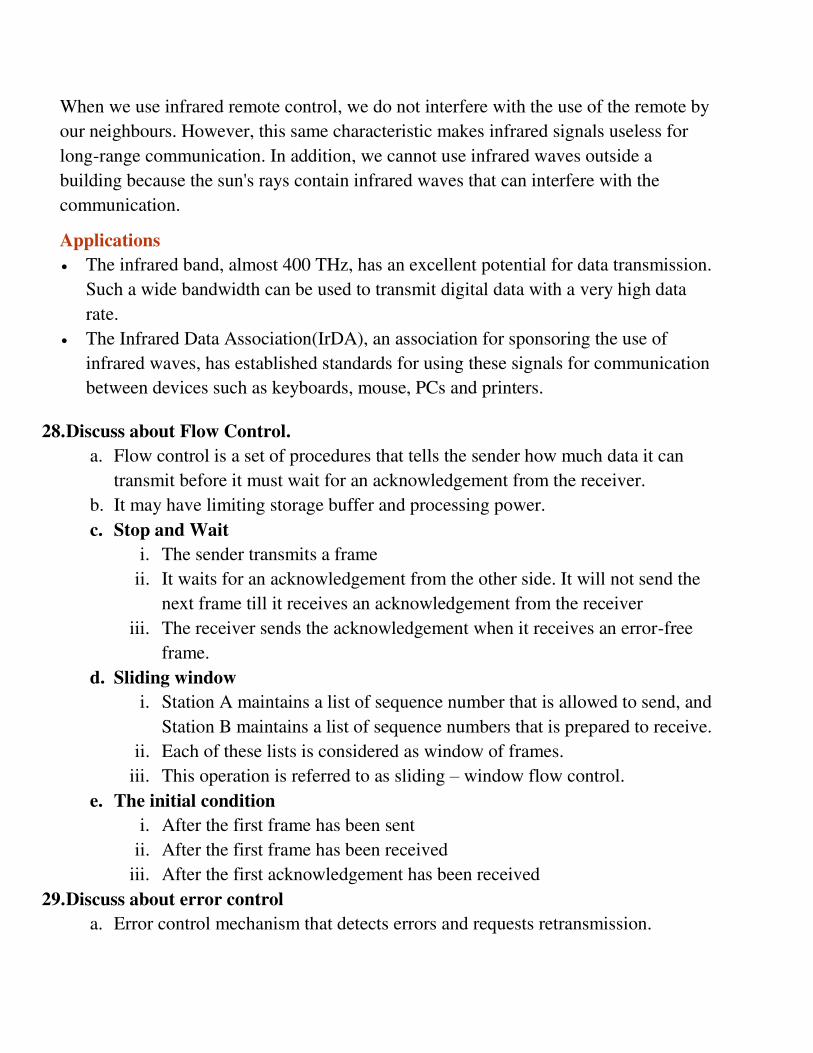
1. Frequency Division Multiplexing
In the 20th century, many telephone companies used frequency-division multiplexing
for long distance connections to multiplex thousands of voice signals through a coaxial
cable system. For shorter distances, cheaper balanced cables were used for various
systems like bell systems K-and N-carrier, but they didn’t allow large bandwidths. The
FDM is an analog multiplexing that combines analog signals. Frequency division
multiplexing is applied when the bandwidth of the link is greater than the combined
bandwidth of the signals to be transmitted.
Frequency Division Multiplexing
In this type of multiplexing, signals are generated by sending different device-
modulated carrier frequencies, and these modulated signals are then combined into a
single signal that can be transported by the link. To accommodate the modulated signal,
the carrier frequencies are separated with enough bandwidth, and these bandwidth
ranges are the channels through which different signals travel. These channels can be
separated by unused bandwidth. Some of the examples for the time division
multiplexing include radio and television signal transmission.
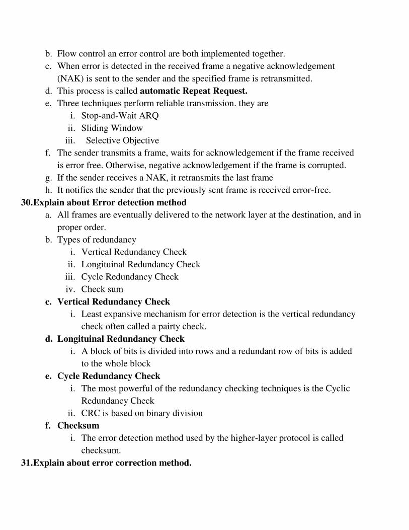
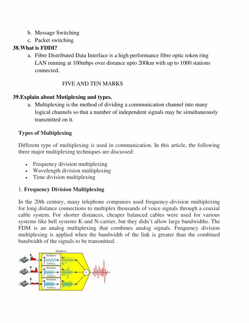
2. Wavelength Division Multiplexing
Wavelength division multiplexing (WDM) is a technology in fiber optic
communications; and, for the high capacity communication systems, wavelength
division multiplexing is the most promising concept. This system uses multiplexer at
transmitter to join signals and demultiplexer to split the signals apart, at the receiver
end. The purpose of WDM is to combine multiple light sources into a single light
source at the multiplexer; and, at the demultiplexer the single light is converted into
multiple light sources.
WDM is designed to use the high data rate capability of the fiber optic cable. The data
rate of this cable is higher than the metallic transmission cable’s data rate.
Conceptually, the wavelength division multiplexing is same as the frequency division
multiplexing, except for the transmission through the fiber optic channels wherein the
multiplexing and demultiplexing involves optical signals.
Wavelength Division Multiplexing
3. Time-Division Multiplexing
Time division multiplexing is a technique used to transmit a signal over a single
communication channel by dividing the time frame into slots – one slot for each
message signal. Time-division multiplexing is primarily applied to digital signals as
well as analog signals, wherein several low speed channels are multiplexed into high-
speed channels for transmission. Based on the time, each low-speed channel is allocated
to a specific position, where it works in synchronized mode. At both the ends,
40. Explain Project 802.
a. In 1985, IEEE developed project 802. The IEEE has subdivided the data link
layer into two sub layers.
i. Logical Link Control
ii. Medium Access Control
b. The strength of project 802 is modularity.
c. 802.1 – internetworking
d. 802.2 – LLC and MAC
e. 802.3 – CSMA/CD
f. 802.4 – Token Bus
g. 802.5 – Token Ring and others
h. LLC – Logical Link Control upper sublayer of data link layer. The LLC
sublayer acts as an interface between the medium access control sublayer and
the network layer.
i. MAC – MAC is responsible for the transmission of data packets to and from the
network-interface card, and to and from another remotely shared channel.
Multicast – sending group of station is called multicast
j. Broadcast – sending to all stations on the network is called broadcast.
k. CSMA/CD – carrier sense multiple access/ collision detection is a MAC method
used Ethernet technology for LAN.
l. This is used in combination with collision detection in which transmitting station
detects collisions by sensing transmissions from other stations while it is
transmitting a frame.
m. Token BUS - Token bus is the name given to a linear or tree shaped cable onto
which the nodes are attached.
n. The token is passed from one idle station to another until station with a pending
message receives. After the message is sent, the token is passed to the next
station
o. TOKEN RING – token ring works very differently from Ethernet. A token ring
network is a local area network (LAN) in which all computers are connected in a
ring or star topology and a binary digit- or token-passing scheme is used in order
to prevent the collision of data between two computers that want to send
messages at the same time
41. Write short notes on: Ethernet.
a. Ethernet is the most popular network architecture for LAN.
b. Ethernet is a LAN, connecting computer together with cable to share
information.
c. Ethernet can connect upto 1024 personal computer workstation.
d. Most landlines are solid with an installed network adapter.
e. Reliability throughput are superior than WIFI.
f. Types of Ethernet
Types Standard Topology Intermediate
device
Thick ethernet 10base5 Bus Repeater
Thin ethernet 10base2 Bus Repeater
Twisted pair
ethernet
10baseT Star Hub
42. Explain about FDDI.
a. Fibre Distributed Data Interface is a high performance fibre optic token ring
LAN running at 100mbps over distance upto 200km with up to 1000 stations
connected.
b. The FDDI cabling consists of two fibre rings, one transmitting clockwise and the
other transmitting counterclockwise.
c. If either one breaks, the other can be used as a backup. If both break at the same
point the two rings can be joined into a single ring approximately.
d. FDDI uses multimode fibres because the additional expenses of single mode
fibre is not needed for networks running at only 100 Mbps.
43. Explain about switching techniques.
a. A switched network consists of a series of interlinked nodes, called switches.
types of switching
i. Circuit Switching
ii. Message Switching
iii. Packet switching
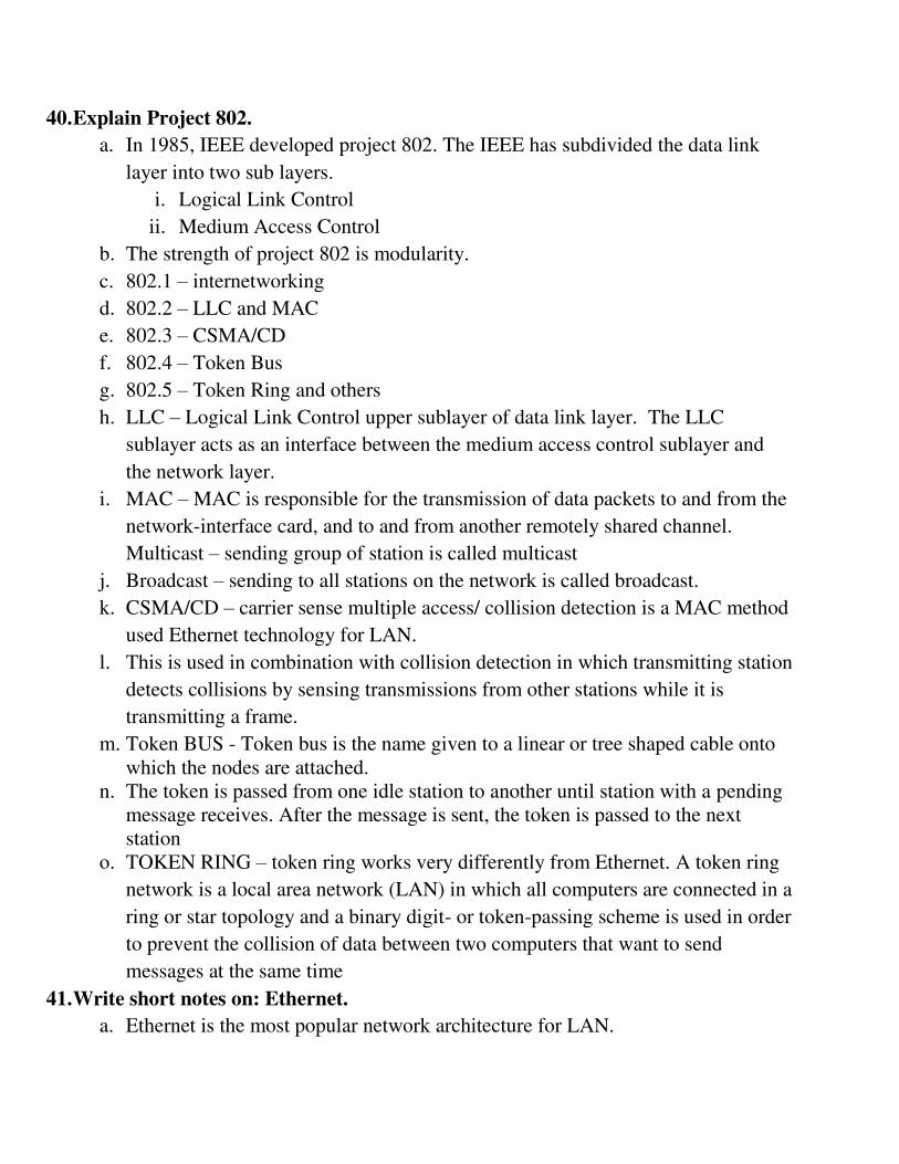
Circuit Switching
Circuit Switching is generally used in the public networks. It comes into existence for
handling voice traffic in addition to digital data. However digital data handling by the
use of circuit switching methods are proved to be inefficient. The network for Circuit
Switching is shown in figure.
Circuit Switching Network
Here the network connection allows the electrical current and the associated voice with
it to flow in between the two respective users. The end to end communication was
established during the duration of call.
In circuit switching the routing decision is made when the path is set up across the
given network. After the link has been sets in between the sender and the receiver then
the information is forwarded continuously over the provided link.
In Circuit Switching a dedicated link/path is established across the sender and the
receiver which is maintained for the entire duration of conversation.
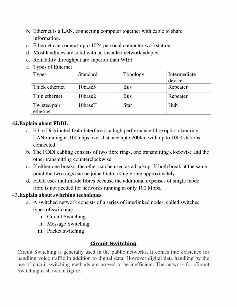
Packet Switching
In packet switching, messages are broken up into packets and each of which includes a
header with source, destination and intermediate node address information. Individual
packets in packet switching technique take different routes to reach their respective
destination. Independent routing of packets is done in this case for following reasons:
1. Bandwidth is reduces by the splitting of data onto different routes for a
busy circuit.
2. For a certain link in a network, the link goes down during transmission the
remaining packets can be send through the another route.
Packet Switching Network
The major advantage of packet switching id that they are used for performing data rate
conversion.
In cases where traffic fees are charged, for example in cellular communication, packet
switching is characterized by a fee per unit of information transmitted
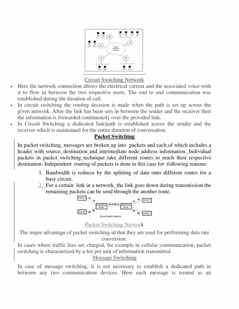
Message Switching
In case of message switching, it is not necessary to establish a dedicated path in
between any two communication devices. Here each message is treated as an
independent unit and includes its own destination source address by its own. Each
complete message is then transmitted from one device to another through internetwork.
Message Switching Data Network
Each intermediate device receive the message and store it until the nest device is ready
to receive it and then this message switching network is sometimes called as store and
forward switching
The storing and Forwarding introduces the concept f delay. For this reasons this
switching is not recommended for real time applications like voice and video..
44. Difference between connection oriented and connectionless service.
Connection-Oriented Connectionless
Transfer is slower Transfer is faster
Send error free data transfer Does not guarantee for delivering data
Resource allocation is needed Does not need resource allocation
More Reliability Reliability
Stream Based Message Based
UNIT IV
45. Explain about ISDN.
a. Integrated Services Digital Network (ISDN) was developed ITU-T in 1976. It is
a set of protocols that combines telephone and data transport services.
b. The goal ISDN is to form a WAN that provides universal end-to-end
connectivity over digital media.
c. ISDN Layers:
i. ISDN specifies two different channels (B and D) with different
functionalities. Channels are for user-to-user communications. The
subscriber uses the D channel to connect to the network, then the B
channel to send information to another user.
ii. ISDN is defined in three separate planes:
1. User plane
2. Control plane
3. Management plane
iii. ISDN architecture for the user and control planes (B and D channels)
iv. Services of ISDN:
1. Bearer services
2. Teleservices
3. Supplementary services
v. Bearer Services:
1. It provides to transfer information among the users without the
network manipulating the content of that information.
vi. Teleservices
1. The network may change or process the contents of the data.
Teleservices include telephony, teletex, telefax, videotext etc.
vii. Supplementary services
1. It provide additional functionality to the bearer services and
teleservices.
2. Services are reverse charging, call waiting, and message hadling.
viii. Access to ISDN:
1. Bearer channel(B)
2. Data channel (D)
3. Hybrid channel(H)
ix. Bearer channel – it defined at rate 64kbps. Used to carry digital data,
digitized voice, or other low data-rate transmission.
x. Data channel – it defined at rate 64kbps. The primary function of a D
channel is to carry control signaling for the B channel.
xi. Hybrid Channel – data rate 384kpbs. Used video, teleconferencing and so
on.
xii. Broadband ISDN services – two types of services
1. Interactive
2. Distributive
46. Explain about x.25 Layers.
a. One of the most widely used protocol standards is x.25. the standard specifies an
interface between a host system and a packet switching network in ISDN.
b. Three Layer

i. Physical level
ii. Link level
iii. Packet level
c. Physical Layer deals with the physical interface between an attached station. The
link that attaches the station to the packet switching node.
d. The link layer provides for the reliable transfer of data across the physical link
by transmitting the data as a sequence of frames.
e. The packet layer provides an external virtual circuit services.
f. Virtual circuit service
i. X.25 provides two types of virtual circuit
1. Virtual call
2. Permanent virtual circuit
g. Packet switching:
i. X.25 provides the capability to identify a contiguous sequence of data
packets, which is called a complete packet sequence.
47. Discuss ATM protocol.
a. Asynchronous Transfer Mode
b. ITU-T International Telecommunications Union- Telecommunications
Standards was developed.
c. A private ATM network and public ATM network carrying voice, video and
data traffic. ATM is the connection oriented services.
d. ATM is more efficient than Synchronous technologies.
e. ATM transfers information in fixed size units called cells.
f. Each cell consists of 53 bytes. The first 5 bytes contain cell-header information,
and the remaining 48 bytes contain user information.
g. ATM cell header Fields
i. Generic flow control
ii. Virtual path identifiers
iii. Virtual channel identifier
iv. Header error control
h. ATM topology
i. Point-to-point
ii. Point-to-multipoint
iii. Point-to-point- is the unidirectional process
iv. Point –to-multipoint – data transmit source to destination
v. Source node is called the root node
vi. Destination node is called the leaves
vii. Root node transmits data to the leaves but leaves does not transmit to root
node.
TWO MARKS
48. What are types of planes?
ISDN is defined in three separate planes:
1. User plane
2. Control plane
3. Management plane
49. What are services provide in ISDN?
i. Services of ISDN:
1. Bearer services
2. Teleservices
3. Supplementary services
50. Define Packet switching.
a. X.25 provides the capability to identify a contiguous sequence of data packets,
which is called a complete packet sequence
51. Write a note on: Broadband ISDN.
i. Broadband ISDN services – two types of services
1. Interactive
2. Distributive
UNIT V
TWO MARKS
52. Define Repeater.
a. A network device used to generate or replicate a signal. Repeaters are used in
transmissions systems to regenerate analog or digital signal distorted by
transmission loss.
53. Define Hub.
a. Hub is a device that splits a network connection into multiple computers. When
a computer requests information from a network or a specific computer, it sends
the request to the hub through a cable.
54. Define Switches.
a. Switch is a telecommunication device grouped as one of computer network
components.
55. Define Router.
a. Used to connect a LAN with an internet connection is called router.
56. What is WWW?
a. World wide Web an information system on the internet which allows documents
to be connected to other documents by hypertext links, enabling the user to
search for information by moving from one document to another.
TEN AND FIVE MARKS
57. Write short notes on: Bridges and Gateway
a. Bridges
i. A device used to connect two separate Ethernet networks into one
extended Ethernet. Bridges only forward packets between networks that
are destined for the other network.
ii. Types of bridges
1. Transparent basic bridge
2. Source routing bridge
3. Transparent learning bridge
4. Transparent spanning bridge
b. Gateway
i. A gateway is a node in a computer network, a key stopping point for data
on its way to or from other networks.
ii. The gateway is the computer that routes traffic from a workstation to the
outside network that is serving up the webpages.
iii. The gateway is the internet service provider that gives you access to the
entire internet.
58. Discuss in detail, any ONE routing algorithms.
a. Routing is the process of selecting paths in a network along which to network
along which to send network traffic.
b. Goals of routing are correctness, simplicity, robustness, stability , fairness and
optimality.
c. Routing is performed for many kinds of network, including the telephone
network, electronic data networks and transportation networks
d. Non – adaptive Routing
i. Once the pathway to destination has been selected , the router sends all
packets for that destination along that one route.
ii. The routing decisions are not made based on the condition or topology of
the network.
e. Adaptive Routing
i. A router may select a new route for each packet in response to changes in
condition and topology of the networks.
f. Shortest path Routing
i. Links between routers have a cost associated with them. In general it
could be a function of distance, bandwidth, average traffic,
communication cost, mean queue length,measured delay, router
processing speed etc…
ii. The shortest path algorithm just finds the least expensive path through the
network, based on the cost function.
iii. Example: Dijkstra’s algorithm.
59. Write a short note on: TCP/IP Layers.
a. The TCP/IP model is a concise version of the OSI model.
i. Application layer
ii. Transport layer
iii. Internet layer
iv. Network access layer
b. Network access layer
i. The layer corresponds to the combination of data link layer and physical
layer of the OSI layer. It looks out for hardware addressing and the
protocols present in this layer allows for physical transmission of data.
c. Internet layer
i. This layer parallels the function of OSI’s network layer. It defines the
protocols which are responsible for logical transmission of data over the
entire network.
d. Transport layer
i. This layer is analogous to the transport layer of the OSI noel. It is
responsible for end-to-end communication and error-free delivery of data.
e. Application layer
i. This layer performs the functions of top three layers of the OSI model:
application, presentation and session layer. It is responsible for node-to-
node communication and controls user-interface specifications.