data and procedures for the design of floating tire ... · data and procedures for the design of...
TRANSCRIPT

NYSGi-T-79-00l C, 3
0
Data and Procedures for the Design ofFloating Tire Breakwaters
byVolker W. Harms
WATER RESOURCES AND ENVIRONMENTAL
ENGINEERING RESEARCH REPORT NO. 79-l
DEPARTMENT OF CIVIL ENGINEERING
STATE UNIVERSITY OF NEW YORK AT BUFFALO
NATiONAL SEA GRANT OEPQSITORYPELL L>BRARY BU LOiNG
URi, NARRAGANSETT BAY CAViPUSNARRAGANSETT, Ri 02882
r'nfl
~g�posit,bt! ~V~Yg
SUNY/Buffalo � WREE � 79P]
January l979

DATA AND PROCEDURES FOR THE DESIGN OF
FLOATING TIRE BREAKWATERS
by
Volker W. Harms
NATIONAL SQ GRANT DEPOStTDRYPELL LIBRARY BUILD>NG
URt, NARRAGANSEtT BAY CAMPUS5ARRAGAN$97, R I 02882
Research Project Progress Report 1979Sea Grant Project No. 150-S019D"Development of Design Criteriafor Floating Tire Bre >kwaters"
September 1, 1977 � March 31, 1979
This research was sponsored by New York Sea GrantInstitute under a grant from the Office of Sea Grant,National Oceanic and Atmo. pheric Administration NOAA!,U.S. Department of Corrmerce. It was performed incooperation with the Hydraulics Research Division ofthe Canada Centre for Inland Waters, Burlington,Ontario.
January 1.979

Table of Contents
Page
Introducti on
I I. Estimated Construction Costs
III. Design Curves
15
20
A. Goodyear FTBB. Wa;e-Guard FTBC. Wave-Maze FTB
IV. Design Procedure
V. References 43
Appendix I - Hydraulic Model Tests and Data
84Appendix II - Full Scale Verification i!f Model Data
88Appendix III � Generation of Wind Waves � Wave Period Tx
Appendix IV � Construction Details
95105
A. Construction Details for the Wave-Guard FTBB. How to Construct s Goodyear! FTB
Acknowledgement
Conversion Table
List of Symbols
A.B.
C.D.E.
F.
Laboratory Facili Lies and ExperimentalData for Goodyear FTBData for Wave-Gua "d FTBData for Wave-Mazi FTBData for Multi-1a er-Goodyear FTBInfluence of Tire Mooring Damper
Procedures 4556667175
79
Acknowledgement
The author would like to thank Dr. John Judd and Or. Donald
Squires of the New York Sea Grant Institute for providing the
flexibility necessary for an early completion of the laboratory
tests. I would also like to express my appreciation to Dr. T.M.
Dick, Head of the Hydraulics Research Division of the Canada Centre
for Inland Waters CCIW!, for his cooperation in this research
effort, and for making the performance of laboratory tests at CCIW
possible. The kind assistance of CCIW staff members Dr. M. Skafel,
C. Dezeeuw, T. Nudds, W. Stage and G. Bokos, and that of T. Bender
and S. Kam of the State University of N.Y., Buffalo is greatly
appreciated. Permission of the University of Maine/New Hampshire
Sea Grant Program to reproduce the report entitled "How to Build a
Floating Tire Breakwater" is gratefully a=knowledged.
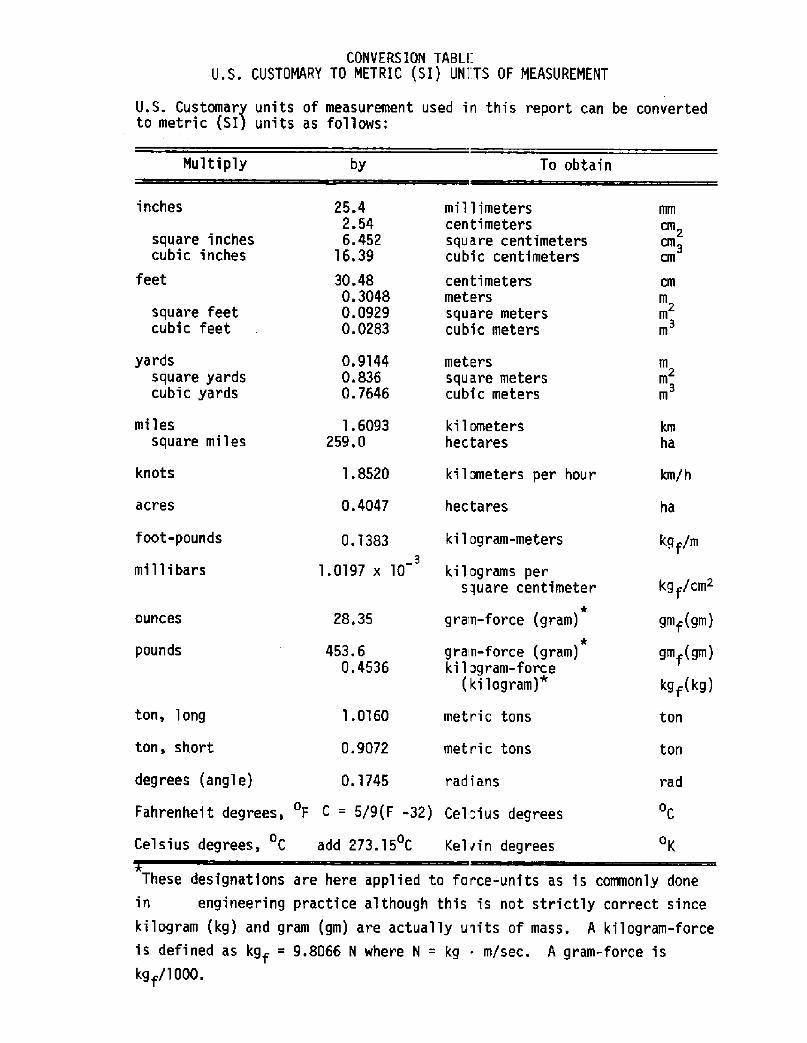
CONVERS ION TABLEU.S. CUSTOMARY TO METRIC SI! UNj:TS OF MEASUREMENT
U.S. Customary units of measurement used in this report can be convertedto metric SI! units as follows:
Multiply To obtainby
inches millimeterscentimeterssquare centimeterscubic centimeters
25.42.546.452
16.39square inchescubic inches
30.480.30480.09290.0283
centimetersmeters
square meterscubic meters
feet cm
m2
m
m
square feetcubic feet
0.91440.8360.7646
yardssquare yardscubic yards
meterssquare meterscubic meters
m
m m
mi1 essquare miles
ki 1 ometershectares
km
ha
knots
ha
kg f/m0.1383
31.0197 x 10
kgf/cm2
28. 35
453.6
0.4536
ounces
pounds
ton
ton
rad
CFahrenheit degrees, F C = 5/9 F -32! Cel=ius degrees
Cel sius degrees, C add 273.15 C OKKelvirl degrees
These designations are here applied to force-units as is commonly done
in engineering practice although this is not strictly correct since
kilogram kg! and gram gm! are actually usits of mass. A kilogram-forceis defined as kgf = 9.8066 N where N = kg m/sec. A gram-force iskgf/1000.
acres
foot-pounds
millibars
ton, long
ton, short
degrees angle!
1.6093259.0
1.8520
0.4047
1.0160
0.9072
0.1745
kilometers per hour
hectares
kilogram-meters
kil ograms persquare centimeter
grain-force gram!*gram-force gram!*ki 1 og ram-force
kilogram!*
metric tons
metric tons
radians
gmf gm!
gmf gm!
kgf kg!

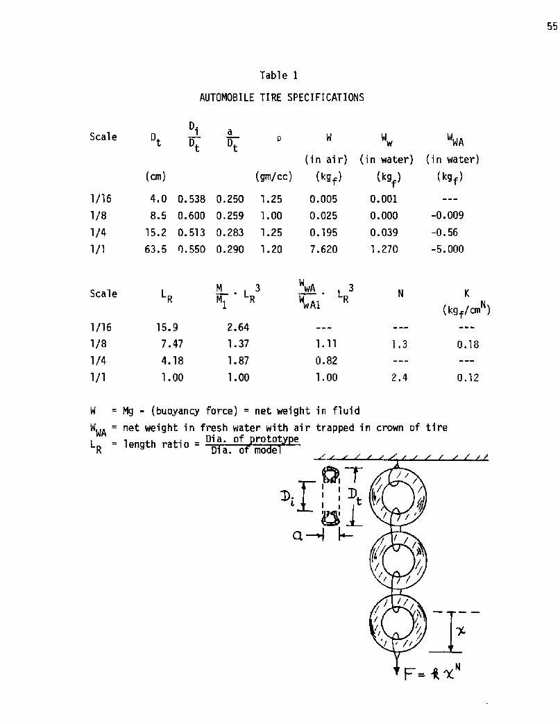
breakwater draft generally D = 0.85 D !
tire di~ ~eterD Fmaximum peak! horizontal mooring Force on seaward mooring line per unit length y of breakwater!
FTB floating tire breakwater
gravitational acceleration
string-spacing in Wave-Guard FTB
H, Ht wave height seaward, and shoreward of the breakwater
incident wave length
wave period
beam period
beam direction
length of breakwater dimension pa~ allel to wave crest line!
vertical direction
specific weight of fluid
density of fluid
kinematic viscosity of fluid
fetch length used in wave-generation calculations
wind speed used in wave-generation calculations
F0
U
List of Symbol..
b log-spacing in Wave-Guard FTB
8 breakwater beam size dimension in direction of wave progress!
Cd effective drag coefficient of autorsobile tires
C wave-height transmission ratio, equal to H�/H
d water depth

DATA AND PROCEDURES FOR THE DESIGN OF Fl OATING TIRE BREAKWATERS
by Volker W. Harms
I . Introducti on
Floating structures have been utilized as wave-attenuation devices
for some time: Reid's floating breakwater goes back to 1842 and the con-
cept is probably as old as the need for protected ship moorings. Ni'li-
tary needs provided an early incentive for the deployment of floating
breakwaters: the Bombardon breakwater Lochner, 1948! used for the pro-
tection of amphibious naval operations during the invasion of Normandy in
World War II represents the first major utilization of such structures.
Presently the largest demand for floating breakwaters is generated by the
pleasure boat market Richey and Nece, 1974!: an increasing demand for
mooring space, and the simultaneous depletion of suitable construction
sites with natural protection, creates a n ed for artificial, low-cost
protection of marinas and harbors. The floating tire breakwater FTB! is
a recent innovation Stitt, '1963; Kowalski, 1974! evolving out of this
increasing demand for low-cost wave-protection structures. It is a flexi-
ble breakwater constructed almost entirely of scrap automobile tires, and
is intended for short-fetch say less than 15 km! or semi-protected loca-
tions. The utilization of scrap automobi le tires as basic building
components, and a modular design for ease of construction, makes it
possible to keep the installed cost below,'[50 per linear foot, as re-
ported by Candle �977! and Shaw and Ross ',1977!. Some fundamental
advantages of floating breakwaters include the following:

they may be effectively employed in water prohibitively deep for conven-
tional bottom-resting structures; they continue to be effective during
large seasonal water level fluctuations in lakes and reservoirs; they
generally do not interfere with natural water circulation patterns,
sediment transport, life of benthic organisms and fish migrations to
the extent that conventional bottom-resting structures do; they may be
towed to different locations as the need for wave protection changes.
Although the technical feasibility of many floating-breakwater
designs can be established, e.g., that of the tethered-sphere breakwater
Seymour, 1974!, and it is certainly possible with today's technology to
develop floating structures to protect from any sea state, it is the
consideration of econanic-feasi bi lity that is frequent'ly neglected
Griffin, 'l972! and this can, when finally addressed, lead to sobering
results Moffatt and Nichol, I977!. In this regard the evolution of the
FTB is perhaps an exception, with economi c feasibility a primary concern
from the beginning: to the extent that the technical and economic feasi-
bilityy had been demonstrated in the prototype Wave-Naze FTB, Sti tts,
1963! long before a laboratory evaluation of its effectiveness was ini-
tiated Kamel, 1968!. Even to the present time a similar trend can be
detected, with the construction and installation of FTB's proceeding
without the support of adequate engineering design criteria. This
report is intended as a contribution towards the establishment of such
needed design criteria for floating tire breakwaters.
Three configurations are here considered under the generic name of
floating tire breakwater: the Wave-Naze FTB Noble, 1969!, the Goodyear
FTB Kowalski and Ross, 1975! and the Wave-Guard FTB Harms and Bender,
1978!. They differ principally in terms af tire arrangement, and

therefore spatial tire-density i.e., number of tires per unit volume of
breakwater!, and binding material used. Laboratory tests on the more
recent FTB-versions, the Goodyear and Wave-Guard configurations, were
performed on 1/4-scale and 1/8-scale models and results for the Goodyear
FTB compared to some full-scale measurements performed at the U.S. Army
Coastal Engineering Research Center Gi les, 1978!. A description of the
hydraulic model tests performed in the Hydraulic Laboratory of the Canada
Centre for Inland Waters in Burlington, Ontario may be found in Appendix
I.A the data itself in Appendix I.B - I. F! . Figure 1 depi cts the drained
wave tank and some of the breakwater modelc that were tested. The full-
scale data is contained in Appendix II, where it is also compared to
small-scale measurements. Laboratory test~ on the pioneer in the FTB-
field, the Wave-maze FTB, were not undertaken. Instead, existing 1/4-
scale laboratory data from the U.S. Army Engineer Waterways Experiment
Station was analyzed and is here included f' or completeness in Appendix
I.D.
The Goodyear FTB consists of bundles cf automobile tires that are
interconnected as shown in the breakwater models of Fig. 1 and 2. The
installed breakwater floats near the water surface with only the crown
of the vertically-floating tires exposed, as shown in the Dunkirk-Harbor
field installation of Fig. 3. The bundles have, in the past, been held
together and interconnected with rope, cable and chain, but for state-
of-the-art construction the use of conveyor-belt edging and nylon bolts
is presently recoenended Davis, 1977!. Detailed construction procedures
incorporating the most ~ecent improvements are contained in a report by
Shaw and Ross 'l977! entitled, "How to Construct a Goodyear! Floating
Tire Breakwater." This report has here been included, for the

CU'D 0
CY!
U- MI
D S-I
D W0 W0 S
CD OJs- tt5 OU
CO r
~ O
CCQ CJ
ClW 3
rOJ
O S-QJS-O
S-Q!
Ql lSS
3 C!
SS-
C Sr 4C CLS- <nD I
C CU~ ~
GPv7 ~
CQ U

Figure 3. Prototype installation of Goodye~.r FTB at Dunkirk,New York photo courtesy of Goodyear Tire 5 Rubber Co.!

Figure 4. Two views of 1/8-scale Wave-Guard FT8 with reconmendedtire spacing.

t~
Ilg
OJ
N IOl
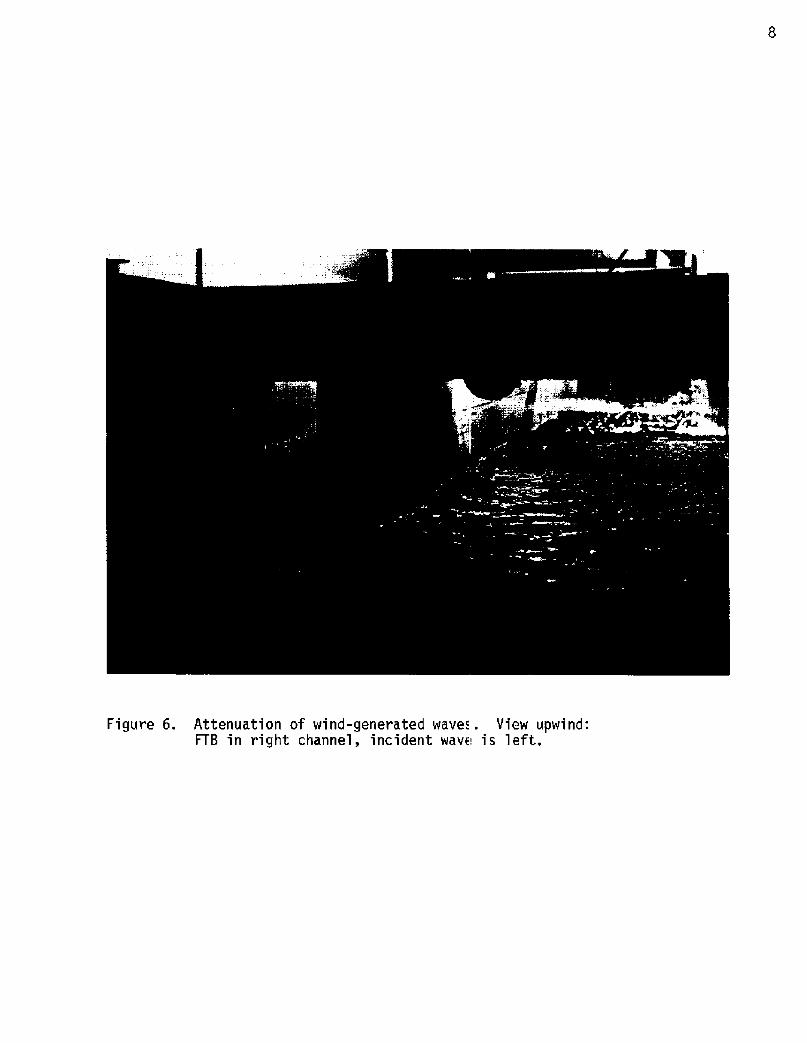
Figure 6. Attenuation of wind-generated wavec. View upwind:FTB in right channel, incident wav» is left.

x+Lix
B
Figure 7. Definition Sketch
convenience of the user, as Appendix IV.B. For additional information
on the construction of a Goodyear FTB the reader is also referred to
reports by R.D. Candle 1977! and Giles an! Sorensen �978!.
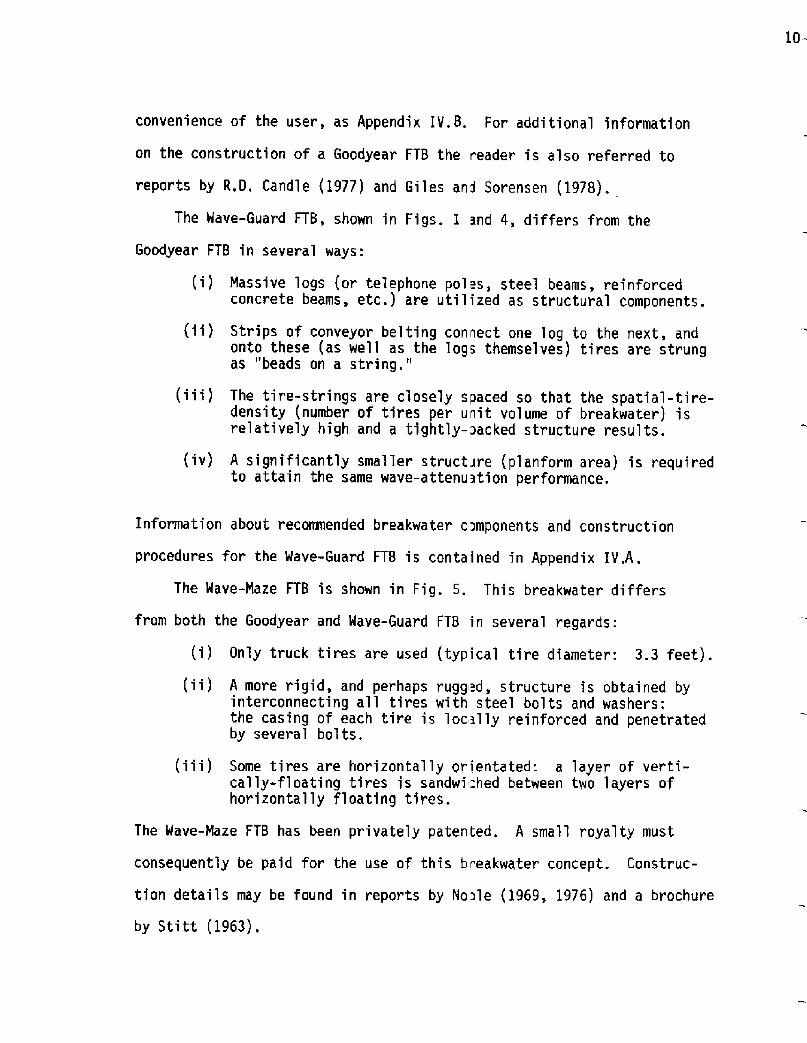
The Wave-Guard FTB, shown in Figs. I and 4, differs from the
Goodyear FTB in several ways:
i! Massive logs or telephone pol s, stee'i beams, reinforcedconcrete beams, etc.! are utilized as structural components.
ii! Strips of conveyor belting convect one log to the next, andonto these as well as the logs themselves! tires are strungas "beads on a string."
iii! The tire-strings are closely spaced so that the spatial-tire-density number of tires per unit volume of breakwater! isrelatively high and a tightly-~acked structure results.
iv! A significantly smai1er structure planform area! is requiredto attain the same wave-attenustion performance.
Information about recommended breakwater components and construction
procedures for the Wave-Guard FTB is contained in Appendix IV.A .
The Wave-Maze FTB is shown in Fig. 5. This breakwater differs
from both the Goodyear and Wave-Guard FTB in several regards:
i! Only truck tires are used typical tire diameter: 3.3 feet!.
ii! A more rigid, and perhaps rugg d, structure is obtained byinterconnecting all tires with steel bolts and washers:the casing of each tire is locally reinforced and penetratedby several bolts.
iii! Some tires are horizontally orientated a layer of verti-cally-floating tires is sandwi =hed between two layers ofhorizontally floating tires.
The Wave-Naze FTB has been privately patented. A small royalty must
consequently be paid for the use of this breakwater concept. Construc-
tion details may be found in reports by No~le 1969, 1976! and a brochure
by Stitt �963!.
This report focuses on two design parameters that are generally most
difficult to evaluate and are, at the same time, among the most important:
the beam size B needed for effective wave protection i.e., the horizontal
d1mension in the d1rection of wave progres;, as shown in Fig. 7!, and the
associated maximum mooring force required to restrain the breakwater.
These parameters are considered in detail .n Sections III and IV of this
report. The length y of the breakwater . s here not considered since
this dimension will generally be chosen equal to the particular shore-
line distance to be protected: the influence of wave diffract1on around
the extremities of structure actually demands that the structure be some-
what larger than this perhaps one additional wave-length! but a detailed,
site-specific analysis of this is presently not considered practically
worthwhile for FTB's. Only 2-dimensional ',aboratory tests were performed:
each model extended across the full width of the channel in which it was
located, so that diffraction-affects are p> ecluded. This is shown in the
attenuation of wind waves in Fig. 6 .
Before discussing specific characteri. ties of a particular type of
FTB wave-transm1ssion and mooring-force response!, it is perhaps helpful
to consider some general features of these structures. A floating tire
breakwater is essentia'lly a mat composed of a large number of intercon-
nected, flexible elements floating near th» surface so as to provide a
sheltered region of reduced wave activity. A FTB differs not only struc-
turally from most other floating impermeabie breakwaters but also,
because of this, exhibits fundamentally di ferent functional characteris-
t1cs as a "break-water,"i.e., the manner 1n which it intercepts and
alters the incident wave motion to create a sheltered zone. Host break-
waters function primarily as wave reflectors: although some of the

intercepted wave energy is indeed dissipated upon the structure, the
larger portion is generally redirected seaward again. The converse is
true for the typical FTB: it is principal y a wave-energy dissipator.
Most of the incident wave energy is transformed into turbulence within
aid around the many components of this structure eventually being con-
verted to thermal energy}, while only a small portion of the wave energy
is reflected. This fundamental characteristic of the FTB is exhibited
in Fig. 8, where the ratio of energy-dissipated to energy-reflected is
shown: the reflected energy is only between 7-20% as large as that dis-
sipated, depending upon the relative wave length L/B. This relationship
was extracted from laboratory measurements of Kamel �968! using regular
waves and 1/4-scale models of the Wave-Haze FTB, and should apply as well
to the Goodyear and Wave-Guard FTB.
It is instructive to compare the wave-transmission characteristics
of FTB's to some other breakwaters that behave dominantly as wave reflec-
tors for very steep waves, of course, significant energy dissipation
occurs even on vertical-walled, smooth, impermeable structures!. For
this purpose the experimentally-determined wave-transmission curve for a
"dissipative" FTB type: Goodyear! is compared to two simple examples
of "reflective" structures: in Fig. 9 a fixed, vertical plate simulating
a wave barrier constructed of siding mounted on a pile structure Wiegel,
1960! is considered, and in Fig. 10 a rigid horizontal plate fixed, and
also floating at the still-water level. Comparison of the experimental
data for the Goodyear FTB Figs.I.IO-I.II in Appendix I.B! to that for
the vertical plate indicates that a Goodyear FTB with beam size B = 12D
offers approximately the same level of wave attenuation as a fixed ver-
tical plate of equal draft D. Comparison to the theoretical wave-

�
Figure 8. Ratio of Energy Dissipated to EnergyReftected by FT3.
20
Figure 9. Wave Transmission Past Vertical Plate.
c, 0. 0.2 0.5 2 5 10Lg
Figure 10. Wave Transmission Past Horizontal Plate.

transmission characteristics of the horizortal plates in Fig. 10 indi-
cates that the performance of the Goodyear FTB lies approximately midway
between that of the fixed and floating plate, i.e., for the same beam
size B, the FTB is less effective than the fixed plate but more effec-
tive than the floating one. The large improvement in wave-attenuation
performance that may be realized by fixing the plate should be noted,
although it must be recognized that this generally also implies a large
increase in wave-induced structural loads. among other things.

II. Estimated Construction Costs
It is our intention in this section to provide the potential FTB-
user with adequate cost information for a first assessment of the relative
economic merits of the Goodyear, Wave-Guard and Wave-Naze FTB's. The
figure of merit used for this purpose is the cost per unit-length-of-
breakwater e.g., f per foot of length in the y-direction, see Fig. 7!.
The cost of a structure is obviously very dependent upon the beam size B.
Since the wave-attenuation performance of the three types of breakwaters
under consideration are quite different even for the same beam size, a
proper cost comparison cannot be based upon equal beam size but must
account for differences in their effectiveness. The calculations in this
section do just that ~ They are based upon the principle of "equal-wave-
protection": the cost of each structure »as only evaluated after having
first "sized" each of the three breakwaters so as to provide the same
degree of wave protection C = 0.5!. The cost of the mooring system
has not been included in these figures because it is so inherently site-
dependent and variable and would, furthermore, not vary greatly from one
type of breakwater to another. It should he noted. that the cost-estimates
are just that, "estimates," and that price.' will vary with time and locality.
Nevertheless. the figures used are the best that could be obtained from
a variety of sometimes conflicting! source s engaged in the construction,
research or promotion of FTB's or FTB-components as of June 1978!.
A potential FTB-user clearly needs to know how large an initial
capital investment wi'll be required for th» construction and installation
of a particular FTB. Beyond this, he should certainly know how much wave
protection he is buying with this structur» this information is largely
contained in this report!, and he should also be able to estimate the
useful life-span of the structure and associated maintenance costs!.

The last consideration is probably the most difficult to address because
the FEB itself is a relatively recent innovation with little historic
field data upon which to base life-span estimates:
i! The oldest field installation of a Goodyear FEB isthat on a small lake in Ohio Wingfoot 1ake:miles in length!, having been in the water continuouslyfor four years. The history of this installation as well as others! would suggest that the usefullife of a properly-constructed Goodyear FT6 is wellin excess of four years if the structure is locatedon a small lake, or otherwise subjected only to rela-tively benign wave conditions.
ii! The Wave-Maze FTB is the only FTB wi th long-term saltwater exposure: the field installation in TomalesBay, California has been in continuous operation f' or15 years little information exists on the repairhistory and local wave conditions!.
iii! The Wave-Guard FTB has only been tested in thelaboratory.
The construction-cost estimates on thE following pages apply to
three different types of FEB's that were each designed to provide the
same level of wave protection, i.e., to reduce waves 1.6 feet in height
and 40 feet in length down to a transmitted height of 0.8 feet i.e.,
C = 0.50 with H/L = 0.04!. The absolute cost figures that were arrived
at are certainly of interest: they indicate that it is indeed possible
to obtain the cited level of wave protection for less than $50 per foot
installed! by using a Goodyear or Wave-Guard FTB. But a comparison
of construction costs for the three structures is perhaps equally re-
vealing, indicating that:
i! The Wave-Guard FTB is somewhat 'less costly than theGoodyear FEB and is, at the sam» time, significantlysmaller for the same degree of wave protection.
ii! The Wave-Maze FTB is far more costly than either theGoodyear or Wave-Guard FTB, but perhaps also has alonger useful life and greater ~ xtreme-event survivalcapabi li ti es.

Cost Estimate
wave length L = 40 ft
breakwater length y = 504 fi. �2 modules 9 7.0 ft!
beam size
tire diameter
I tern
ScrapAuto Tires 3.CO 1,512.00 3.0010,080 .15
FlotationUrethane Foam if used! 5.040 lbs .70 7.00 3, 528. 00 7.00
15,120 .20 6.00 3,024.00 6.00
Nylon Bolts9 8 bolts/mod
Laborla 2 hrs/mod
4,032 .50 4.00 2,016.00 4.00
12 F 001,008 hrs 6.00 6,048.00 12. 00
ConveyorBel ting8 30 ft/mod
B = 46 ft � modules 9 6.5 ft!
C = 05t:
D = 2,1 ft �4" automobile tires!
Quantity Unit Cost Cost/tlodule Total Cost Cost/ft of BW$ $ $ $/ft
Total Cost = $16,128.00
Cost per foot of BW without floatation! = $25.00
Cost per foot of BW with floatation! = $32.00 without mooring system!

Cost Estimate
Wave-Guard FTB
40
504 ft �2 sections 8 12 ft!
28.6 ft
0. 50
12.0 ft
2.4 ft
2.1 ft 'l4" automobile tires!
wave length
breakwater 'length
beam size B =
C b =pole spacing
tire spacing
tire diameter Dt =
I tern
ScrapAuto Tires 12,600 .15 1,890.004! l. 00 3.75
FlotationUrethane Foam if used! 6,300 lbs 4,410.00l0! .00 8. 75.70
ConveyorBelting9 228 ft/section 9,576 ft .20 1,915.20
2,'100.00
3.804! .60
50. 00Telephone poles 42or Wooden piles
4.2050.00 850% ofnew cost
Nylon Bolts9 40/secti on 1.680 20.00 1.67.50 840
Labor 912 hrs/section 504 hrs 3,024.00
250.00
7c',. 00 6. 006.00
Miscellaneous 6.00 .50
Tota'I Cost = $14,430.00
Cost per foot of BW without floatation! = $ '19.88
Cost per foot of BW with floatation! = $ without mooring sys' tem!
28.63
Costguantity Unit Cost 12 ft sections Total Cost Cost/ft of BW
$ $ $

Cost Estimate
Wave-Maze FTB
wave length L= 40 ft
breakwater length y = 504 ft
B= 43 ftbeam size
c, = o.5o
Dt = 3.3 ft �0" truck tires!tire d.i ameter
The construction of a large Wave-Haze FTB is presently in progress
on the West Coast San Francisco Chronicle, 8. August: 1978!. This
wou'Id indicate that the cost per square foot of breakwater planform
area! is somewhat in excess of $6. From personal communications with
H. Noble the designer of this structure and co-developer of the Wave-
the 504' x 43' Wave-Maze FTB:
Total Cost = $108,000
Cost per foot of BW = $215 including rrooring system!
Haze concept! it was determined that the ii~stalled cost generally varies
between $4 - $6 per square foot. Using 5 3/ft in the cost estimate for2

I I I. Oesign Curves
Two important FTB design parameters ai e considered in this report,
these are:
A. The wave-attenuation erformance of thi structure as given in terms
of the wave-transmission coefficient C.� which represents the ratio
of the transmitted wave height to the incident wave height for
irregular waves the average wave height of the wave train has been
used to assign values to both Ct and tl>e wave steepness, H/L!. The
parameter Ct is a measure of the wave-sheltering effectiveness of
the breakwater: for a wave of unit height impinging upon the struc-
ture the value of Ct is a direct measure of the transmitted wave
height, e.g., a value of Ct = 0.3 implies that a wave 1.0 ft in
height will be reduced to 0.3 ft as it passes through the breakwater.
The transmission of regular monochromatic! waves through a Goodyear
FTB is depicted in Fig. 1'I, a photograph taken through the glass wall
of the wave tank. The attenuation of irregular wind-generated waves
by a Goodyear FTB located in the right channel, Channel I! is shown
in the photograph-sequence of Fig. 12 .
B. The eak moorin force that the breakwater will exert on the seaward
mooring line. It should be noted that the force magnitudes here listed
only apply to mooring lines that provi 9e predeoinantly a horizontal
restraining force, i.e., when the length of mooring 'line is at least
equal to, say, seven times the local water depth. In the case of the
Wave-Guard FTB a 3-tire mooring damper was inserted between pole-
connection and anchor line see Appendix I. A. for details!. In proto-
types of the Wave-Guard FTB such mooring dampers shou'td also be
installed in order to avoid higher peak mooring loads.

O
O MChI
c S-I
EcQ 0
S-U 4-
S- oln5Q 'r
U O0 40 0Cg S-
CL V Ck
WO CE I IQ
LD 3

22
Figure 12. Attenuation of wind-generated waves by FTBfor two different wind speeds view upwind;FTB 1ocated in right channel, left channelunobstructed!

Although the use of the design curves s perhaps adequate'ly described
in the examples of Section IV, the fo'llowing information will assist
in making the design data more readily accessible:
A. Several parameters that are repeatedly used will be once more defined,
wave-heighttransmission ratio
t transmi ttt k ~lnc1 ent
force er unit len th of breakwaterIht o f uid beam size earn size
F~yBforce parameter
re'Iative wave length F
wave steepness
D breakwater draftd tt'ttrelative draft
B. Both the wave-height transmission ratio Ct and the force parameter
are considered to be functions of L./B, H/L and D/d only.F
Y
C. The draft 0 of both the Goodyear and Wave-Guard FTB is related to
the tire diameter D used, and may be «pproximated by D = 0.85 Dt.
For the Wave-Maze FTB the equivalent relationship is typically
0 = 1.3 Dt.
D. In tests performed by Giles and Sorenson �978! the peak mooring
force on the shoreward mooring lines did not exceed 10$ of the
seaward-peak-mooring-force. It is therefore suggested that a figure
of 20K be used for design purposes if no significant waves can
approach from the shoreward side!.
E. The values obtained from the vertical «xis of the force di agrams
represent 100,000 times the value of F/yB . Using ~ = 62.4 lb/ft3 �000 kgf/m3!

for fresh water ~ = specific gravity of fluid! one finds that
~ x 10s = 1600 ~F F
Y 8if the English System of units with
8 in feet and F in pounds per foot is used,
and
x 10 = 100~>y8
i f the Intern stional System of units with
B in meters and F in kgf per meter is used.
also increases with increasing wave steepness.
C. Laboratory experiments performed at th» Canada Centre for Inland
Maters were restri cted to 1/4-scale and 1/8-scale models of FTB's.
Oesign curves for both wave-transmissi >n and peak-mooring-force
were generated from this relatively extensive data base and compared
to some measurements performed on full-scale breakwaters at the U.S.
Army Coastal Engineering Center. The model data and existing full-
scale data are canpared in Appendix II: the agreement is very good.
The use of hydraulic-model data in the design of FTB's is therefore
well justified, and the many advantages of model tests over proto-
type tests can thus be realized. Bifficulties certainly exist in
The peak mooring force F is therefore «asily obtained from the
diagrams once the beam size B is speci Fied.
The following very general, but useful, observations can be made
about the FTB-design-curves:
A. The effectiveness of the structure as a wave barrier! decreases
with increasing wave length, and increases with increasing wave
steepness.
B. The peak mooring force increases with increasing wave length and

modelling the mooring system but, to a large extent, even these can
be overcome by innovative modelling techniques.D. Although wave-transmission design curves have only been drawn for
a wave steepness of approximately 4l, it is possible to estimate
values of Ct for higher or lower values of wave steepness by referring
to the actual data-point distributions upon which these curves are
based Appendix I and II!. The value of Ct generally decreases asthe wave steepness H/L increases. For the Goodyear FTH two additional
wave-transmission performance curves for an est~mated wave steepness
of 1X and 8X are given in Fig. I. 16 of Appendix I.H.
E. In tests with the Wave-Guard FTB a mooring line with a 3-tire
mooring damper was used see Appendix ISA for a description!.
With this damper installed the mooring connection at the breakwater
end can be made directly to the massiv wooden poles, as opposed
to the more flexible but weaker tire-strings, without incurring
excessively high peak mooring loads. [n prototype structures such
mooring dampers should also be installi d. Since full-scale ti res
are "stiffer" than the 1/8-sca'le mode'I tires tested, it is recommended
that at least five tires be used in th~ fu'll-scale mooring Damper.
It is here relevant to note that struc-.ura'I failures in Goodyear
FTB's are frequently related to stress concentrations in the vicinity
of the mooring connection.
F. Multi-layer-Goodyear FTB's shown in Appendix I.E.! were tested but
are presently not considered worthwhil» alternatives except, perhaps,
in very special applications. The fami liar, single-layer-Goodyear
FTH provides more wave protection than a multi -layer-Goodyear FTH
constructed of the same number of modules. Design curves for 2-layer
and 3-layer Goodyear FTH's are, nevertheless, included in Appendix I.E.

DES I GN CURVI:S
GOODYERR FTB

27
O

28
� xg!SF
liP
Figure 14. Force Design Curves for Goodyear FTB

DESIGN CURV=S
WAVE-GUARD FTB
30

F
L!8Figure 16. Force Design Curves for Wave-Guard FTB

DESIGN CURVES
WAVE-NAZE F1 8

331,0 LgB
� xiOF s
'fB 2 Figure 17. Wave-Transmission and Fo~ ce Design Curves forWave-Naze 'FTB

I V. Design Procedure
The design procedure here presented has been deve'loped with the
potential user in mind: experience has shown that he is generally a
person with, at best, a limited technical-engineering background, and
frequently none at a'll. It would consequently be inappropriate to
develop a sophisticated design procedure demanding a data-base that will,
in practice, never be acquired and a level of technical expertise that
cannot normally be counted upon. It is our aim instead to present a
simple design procedure that represents a',i a significant improvement
over the present state of affai rs i.e. existing "rules of thumb"!
while at the same time, b} keeping the design-effort or design
cost! associated with a FTB small compared to the construction effort
or total capita1 investment!. Although wave refraction and diffraction
are neglected in the basic procedure here outlined, their influence can
readily be incorporated after having been separately analyzed. This
should be done whenever practically feasible. An outline of the design
procedure with reference to the Goodyear FTB follows:
l. Specify site and tire characteristics
A. Average ti re diameter, 0t
B. Average water depth at FTB locati or, d
C. Fetch length for prevailing storm ci rection, F
2. Define Wave Conditions
A. Beam-design-wave i.e. prevalent wave condition to be mitigated!:perform measurements to obtain representative local wave periodT and height H
8. Force-design-wave i.e. extreme event!: use graphs of AppendixIII to obtain extreme wave period T for specified wind velocityU, average water depth d and fetch 'fength F associated withprevailing storm direction if possible, account for refractionand diffraction!
35
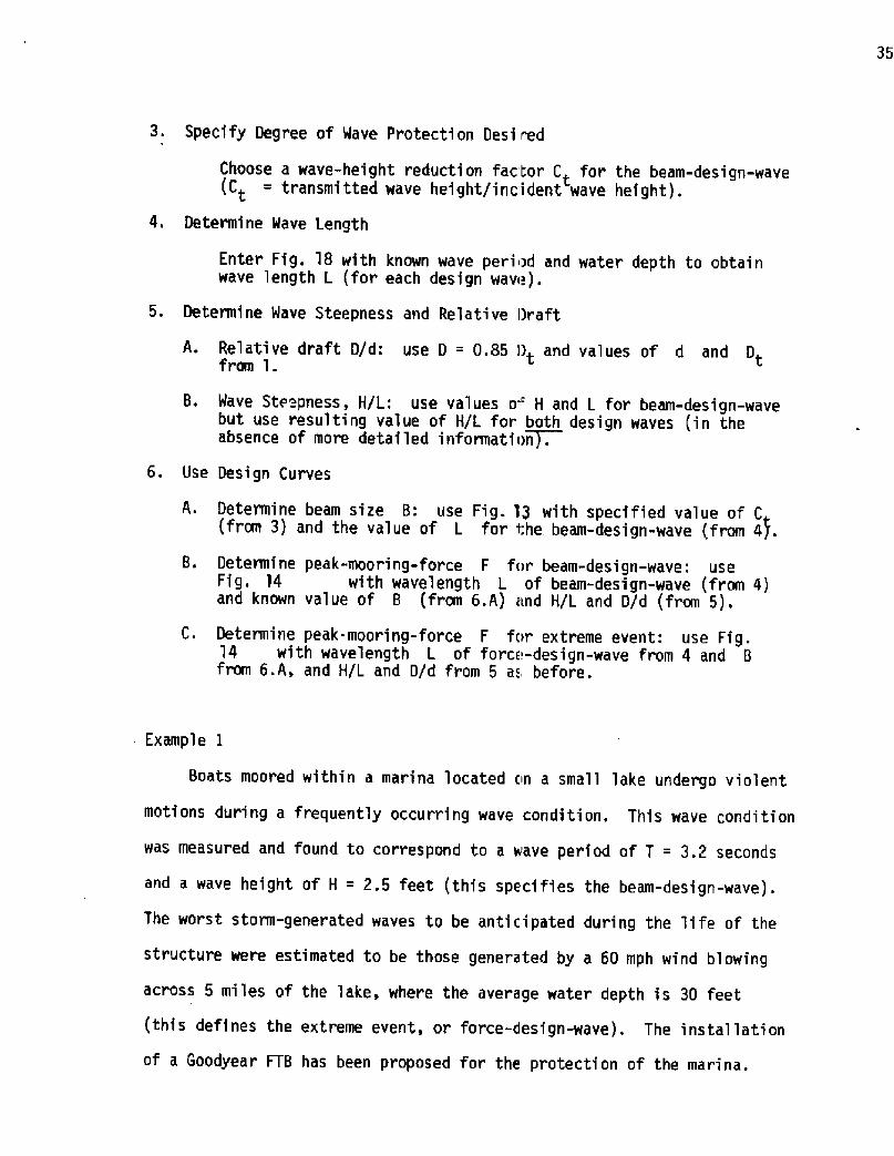
3. Specify Degree of Wave Protecti on Desi f ed
Choose a wave-height reduction factor C for the beam-design-wave Ct = transmitted wave height/incident wave height!.
4. Determine Wave Length
Enter Fig. 18 with known wave period and water depth to obtai nwave length L for each design wave!.
5. Determine Wave Steepness and Relative Draft
A. Relative draft D/d: use D = 0.85 Dt and values of d and Dtfrom 1.
8. Wave Ste pness, H/L: use values o' H and L for beam-design-wavebut use resulting value of H/L for both design waves in theabsence of more detailed informati !~n .
6. Use Design Curves
A. Determine beam size B: use Fig. 13 with specified value of C from 3! and the value of L for i;he beam-design-wave from ai.
8. Determine peak-mooring-force F for beam-design-wave: useFig. 14 with wavelength L of beam-design-wave from 4!and known value of 8 from 6.A! and H/L and D/d from 5!.
C. Determine peak-mooring-force F for extreme event: use Fig.14 with wavelength L of force-design-wave from 4 and 8from 6.A, and H/L and D/d from 5 as before.
Example 1
Boats moored within a marina located on a small lake undergo violent
motions during a frequently occurring wave condition. This wave condition
was measured and found to correspond to a wave per iod of T = 3.2 seconds
and a wave height of H = 2.5 feet this specifies the beam-design-wave!.
The worst storm-generated waves to be anticipated during the life of the
structure were estimated to be those generated by a 60 mph wind blowing
across 5 miles of the lake, where the average water depth is 30 feet
this defines the extreme event, or force-design-wave!. The installation
of a Goodyear FTB has been proposed for the protection of the marina.

52
C3LD
10 ~ 0.0 2e0 8.04iO 6 ' 0
PERIOD SEC.!
UJ
Ld!
C!
CV
FigUre lB. Relationship Between Wavelength, Wave Period and Water Oepth 1 i near theory!

37
The average water depth at the proposed site is 6 feet, and the local
supply of scrap ti res indicates that an out.side di ameter of D = 2. 1 feet
is typical. If the beam-design-wave is to be reduced to a height of
Ht = 1.4 feet, determine the beam-size B requi red for the Goodyear FTBto accomplish this, as well as the peak mo iring force F to be antici-
pated for a structure of this size. Assum that waves approach the break-
water normally, as shown on page 39. When this is not the case, it is
suggested that the dimension of the structure along the direction of wave
approach be used instead of B e.g., for a wave incidence angle of 45 use
1.4 B instead of simply B!, at least until more specific data becomes
available.
Solution:
1. Site and Tire Characteristics
A. Dt = 21 ft
B. d = 6 ft
C. F = 5 miles with I = 30 ft0
2. Wave Conditions
A. Beam-design-wave: T = 3.2 sec, H � 2.5 ft measured at site!
B. Force-design-wave:from Fig.111.6 with U = 60 mph, F = 5 miles
and d = 30 ft, obtain T = 4 ~ 5 secX
3. Protection Desired
Reduction of wave height to 1.4 feet implies that the wave-
transmission ratio is C = ' = 0..56t 2.5
4. Wave Lengths
A. Beam-Design-Wave:
With T = 3.2 sec, d = 6' ~ L = 40 ft from Fig. 18
B. Force-Design Wave:
With T = 4.5 sec, d = 6'~ L = 60 ft from Fig. 18

5. Wave Steepness and Relative Draft
A. Relative draft, D/d: with D = �.85!�a 1! = 1.8' and
d = 6' ~ D/d = 0.30
2.5B. Wave steepness H/L from 4A!: H/L 40 0 0636. Design Curves
A. Beam size B: with Ct = 0.56 and H/L ~ 0.04 ~ L/B = 1..0
since L = 40 ft -+ B = 40 ft which is somewhat
conservative because actually H/L = 0.063
B. Peak mooring force F for beam-de;ign-wave:
with L/B = 1 0, H/L = 0 063, 0/d = 0 30 in Fig. 14
have x 10 = 1600 � .; ~ 45 Fig. i. 19 is her e alsoF
yB B' helpful!
F -45. �t~~2
16 !G
C. Peak mooring force F for force-design-wave: with L/B =� 6040
= 1.5 and H/L, D/d as before, from Fig.14 have
1600 F " 100, so that F = 100 401600B2
F = 100~lb/ft
~Sureaar: In order to reduce the wave heigl t of the beam-design-wave to
approximately 1/2 requires a Goodyear FTB with B = 40 feet i.ea e a
6-module beam!, and in order to remain moored during the extreme event a
restraining force of 100 lbs per foot of breakwater length must be pro-
vided for this structure. Most frequently the so-called force-design-
wave extreme event! yields the highest mooring-force demand, as was here
the case, but exceptions to this ru'le may be encountered.

Example 2
4 floating tire breakwater is proposed for the protection of a river
marina that periodically suffers wave damage from the passage of large
fishing vesse1s. It was determined that a representative large fishing
boat moving at 14 knots generated 3.6 seccnd waves 2.0 ft in height the
beam-design-wave!. These waves are to be reduced by the breakwater to a
height of 8 inches. The most severe storrr-generated waves to be antici-
pated during the life of the structure were estimated to be those gener-
ated by a 90 mph wind blowing across 3 miles of water wi th average depth

of 20 ft!. Under a'll conditions it may be assumed that waves approach
the breakwater at right angles as shown in the sketch. The water depth
at the location of the proposed FTB is 12 i't. Truck tires with average
outside diameter of Dt = 3.2 ft are available and will be used. Deter-
mine the beam-size B of an appropriate FlB either Goodyear or Wave-
Guard type! and the associated maximum mooring force F for the above
regular design waves.
Solution:
1. Site and Tire Characteristics
A. D = 32ft
B. d = 12 ft
C. F = 3 miles with 3 = 20 ft0
2. Wave Condi ti ons
A. Beam-design-wave: T = 3.6 sec, H = 2.0 ft measured at site!
B. Force-design-wave: From Fig. III.4 with U = 90 mph, F = 3 miles0
and d = 20 ft, obtain T�= 4.5 sec3. Protection Desired
Reduction of wave height to 0.67 feet implies that the wave-
transmission ratio is Ct = 2'0 = 0.330. 67
4. Wave Lengths
A. Seam-Design-Wave:
T = 3 6 sec, d = 12 ft ~L = 56 ft
B. Force-Design-Wave:
T = 4.5 sec, d = 12 ft ~L 80 ft

5. Wave Steepness, and Relative Draft
A. Relative draft, D/d: with 0 = �.85!�.2! = 2.7'
and d = 12' ~ D/d = 0.23
B. Wave steepness H/L from 4A!: H/L = � ' = 0.0362.056
6. Design Curves Goodyear FTB!
A. Beam size B: with Ct = 0.33 and H/L ~ 0.04 ~L/B = 0.56,
since L = 56 ft ~ B = 100 ft
B. Peak mooring force F for beam-design-wave:
with L/B = 0.56, H/L = 0.036, D/d = 0.23 in Fig. 14 and
interpolating!, obtain
1600�B2
$1~001600
F=311b ft
1600�B 2
7. Design Curves Wave-Guard FTB!
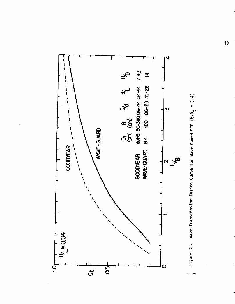
A. Beam size B Fig. 15 !: with Ct = 033 and
H/L � 0.04 ~ L/B = 0.96
since L = 56 ft ~B = 58 ft
B. Peak mooring force F for beam-design-wave:
with L/B = 0.96, H/L = 0.036, 0/d = 0,23 in
C. Peak mooring force
80with L/8 = 100Fig. 14 and
F for force-design-wave:
= 0.80, H/L = 0.036, D/d = 0.23 in
interpolatingj, obtain

42
Fig. 16 interpol ating! obtain
1600 � � 22
82 » ~�82
160 i
C. Peak mooring force F for force-design-wave:
with L/B = ~ = 1.4, k/L = O.C36, 0/d = 0.23 in80
Fig. 16 interpolating!, obtain
1600 2 41B
~Sunnnar: For equal wave-attenuation performance the Mave-Guard FTB is
significantly smaller than the Goodyear FTB �8 ft-beam as compared to
100 ft-beam!, but requires somewhat higher mooring-restraining-farces for
the case considered 86 lb/ft as compared to 69 lb/ft!.
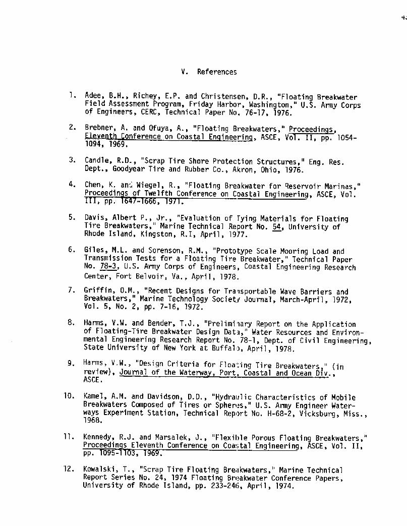
V. References
Adee, B.H., Richey, E.P. and Christensen, D.R., "Floating BreakwaterField Assessment Program, Friday Harbor, Washington," UPS. Army Corpsof Engineers, CERC, Technical Paper No. 76-'l7, 1976.
II I .A. d9f .," t t ."~fdicC nference on Coastal En inee~rin, ASCE, Vol. II, pp. 1054-
1094, 1969.
Candle, R.D., "Scrap Ti re Shore Protecti on Structures," Eng. Res.Dept., Goodyear Tire and Rubber Co., Akron, Ohio, 1976.
Chen, K. an Wiegel, R.. "Floating Breakwater for Reservoir Marinas,"Proceedin s of Twelfth Conference on Coastal Engineering, ASCE, Vol.
~ pp ~
Davis, Albert P., Jr., "Evaluation of Tying Materials for FloatingTire Breakwaters," Marine Technical Report No. 54, University ofRhode Island, Kingston, R. I, April, 1977.
Giles, M.L. and Sorenson, R.M., "Prototype Scale Mooring Load andTransmission Tests for a Floating Tire Breakwater," Technical PaperNo. 78-3, U.S. Army Corps of Engineers, Coastal Engineering ResearchCenter, Fort Belvoir, Va., April, 1978,
Griffin, O.M., "Recent Designs for Transportable Wave Barriers andBreakwaters," Marine Technology Society Journa'I, March-April, 1972,Vol. 5, No. 2, pp. 7-16, 1972.
Harms. V.W. and Bender, T.J., "Preliminary Report on the Applicationof Floating-Tire Breakwater Design Data," Water Resources and Environ-mental Engineering Research Report No. 78-1, Dept. of Civil Engineering,State University of New York at Buffalo, April, 1978.
Harms, V.W., "Design Criteria for Floa".ing Tire Breakwaters," inreview!, Journal of the Waterwa, Port, Coastal and Ocean Di v.,ASCE.
Kame1, A.M. and Davidson, D.D., "Hydraulic Characteristics of MobileBreakwaters Composed of Tires or Spheres," U.S. Army Engineer Water-ways Experiment Station, Technical Report No. H-68-2, Vicksburg, Miss.,1968.
Kennedy, R.J. and Marsalek, J., "Flexible Porous Floating Breakwaters,"Proceedin s Eleventh Conference on Coastal Engineering, ASCE, Vol. II,pp. 095-
Kowalski, T., "Scrap Tire Floating Bre>kwaters," Marine TechnicalReport Series No. 24, 1974 F1oating Bri akwater Conference Papers,University of Rhode Island, pp. 233-246, April, 1974.

44
13. Lochner, R., Faber, O., and Penny, W.,Vol. 2, Docks and Harbors, The Insti tutLondon, pp. 256-290, 1948.
Miller, D.S., "Practical Applications of Floating Breakwaters forSmall Craft Harbors," Marine Technical Report Series No. 24, 1974Floating Breakwater Conference Papers, University of Rhode Island,pp. 263-277, April, 1974.
14.
Moffatt and Nichol Engineers, "Feasibility Study to Evaluate theColmerciai Market for a Tethered Float Breakwater," Report No. MA-RD-970-77077, Maritime Adm., Washington, D.C., pp. 88-90, March, 1977.
15.
Noble, H.M., "Wave-Maze Floating Breakwater," Proceedin s CivilEn ineerin in the Oceans II, ASCE Conference, ami eac , a.,
ec.
16.
Noble, H.M., "Use of Wave-Naze Flexible Floating Breakwater toProtect Offshore Structures and Landings," presented at the May 3-6,1976 Eighth Annual Offshore Technology Conference, Houston, Texas.
17,
Richey, E.P. and Nece, R.E., "Floating Breakwaters - State of the Art,"Marine Technical Report Series No. 24, Floating Breakwater ConferencePapers, University of Rhode Island, pp. 1-19, 1974.
18.
Shaw, G. and Ross, N., "How to Build a Floating Tire Breakwater,"Information Bulletin No. 1, Sea Grant Publications, Ira C. DarlingCenter, Walpole, Maine, 1977.
19 '
Seymour, Richard J., "Tethered Float Breakwaters," Proceedin sof the Floatin Breakwater Conference, Newport, Rho e s an , April,1
20.
Stitt, R.L., "Wave-Maze Floating Breakwaterj" 10732 E. Freer Street,Temple City, California.
21.
Sutko, A.A. and Haden, E.L., "The Effect of Surge, Heave and Pitchon the Performance of a Floating Breakwater," Marine Technical ReportSeries No. 24, 1974 Floating Breakwater Conference Papers, pp. 4'1-53,University Wo Rhode Island, 1974.
22.
Wiegel, R.L ~, "Transmission of Waves Past a Rigid Vertical ThinBarrier," J. Waterwa s Harbor Div., Prcc., ASCE. 86, WWI Paper 2413,March, 196 .
23.

Appendix I.A. Laboratory Facilities and Experimental Procedures
Tests were conducted in the large wind wave tank of the Hydraulics
Laboratory at the Canada Centre for Inland Waters in Burlington, Ontario.
The tank, shown in Fig. I.l is l09 meters in length, 4.5 meters wide and
can be operated at a water depth of up to 1.2 meters. Waves can be
generated by a hydraulically-driven piston-type wave machine or by operat-
ing the tank as a wind tunnel at speeds up to 64 km/h. Multiple reflec-
tions from fibrous beaches withi n the harbor-like basin at the end of the
tank are uti lized for wave-energy di ssi pati on. Wave heights were measured
with capacitance wave probes and mooring forces were obtained from the
strain-gauge canti'1ever-force-transducers shown in Fig. I.2 and 1.9,
Analog signals from wave gauges and force transducers were monitored on a
6-channel Brush osci llographi c recorder and simultaneously stored on
magnetic tape. A sample data trace from the recorder is shown in Fig.
I.3. Time-series analysis of the wave and force data was performed on
the wave tank mini -computer shown in Fig. I.4! using programs available
at the Canada Centre for Inland Waters. The test section, consisti ng
of three sub-channels 8.5 m in length l m, l m and 2.5 m wide! located
approximately 55 m from the wave generator and 45 m fram the beach, is
depicted in Fig. I.5 ~ This position normally permi tted individual runs to
be completed before waves reflected from the beach or generator could
influence measurements. Two breakwaters were generally tested simultane-
ously, in Channels I and II as shown in Fig. I. l, while the incident-wave
characteristics were measured in the remaining unobstructed Channel III.
The mooring system and position of the breakwater within the test section
are shown in Fig. I.2 for the two water levels tested. The mooring lines,
consisting of 0.37 mm stainless steel wire, provided essenti ally a

46
horizontal restraining force since the slope was always less than IV:30H.
A 6 mm plastic rod was fastened to the breakwater along its horizontal
leading edge. In the case of the Wave-Gua "d FTB, a 3-tire mooring damper
shown in Fig. I.B on a preliminary Wave-Guard FTB model!, was installed
at the end of this rod where the plastic od connects directly to the
massive log!, between the plastic rod and Lhe 2-wire bridle leading to the
force cantilever. Tire mooring dampers we'"e generally not used on the
Goodyear FTB because that structure is alri ady so very flexible throughout,
so that the 3-tire damper would have littli effect. But from separate tests
it was found that a 20-tire mooring damper did reduce peak mooring forces
significantly on the Goodyear FTB. The installation of tire-mooring-
dampers therefore appears to be a practical way to reduce peak mooring
forces without reducing the effectiveness of the structure but more exten-
sive tests will be required to establish this. The plastic rod was used
on all breakwaters: it prevented the structures from contracting latera'lly
and made model changes easier. Mooring foi ces were only measured on the
seaward mooring line, and only peak values are here reported. A 100 gram
counterweight provided a constant restoring force to the breakwater via
the rear shoreward! wire, as shown in Fig, I.2. The rear cable and
small restoring force prevented the breakwater from drifting between
runs and also made possible the measurement of sma] 1 seaward forces
using only a single force cantilever per bi eakwater. In Fig. I.6 models
of the Goodyear and Wave-Guard FTB are shore resting on the bottom of the
drained wind wave tank a tethered sphere lireakwater is shown in the
background!. Models of the Goodyear FTB were fabricated according to
construction guidelines by Candle �977! arid Shaw and Ross �977!:
the standard 18-tire module used in existirig field installations can be
seen in Fig. I.6. The Wave-Guard FTB incoi porates wooden logs te'lephone

poles, etc.! that are aligned with the direction of wave progress.
Several strips of conveyor belting connect one log to the next, and onto
these as well as the logs themselves! tires are strung as "beads on a
string." The result is a tightly-packed structure with many more ti res
per unit surface area not a significant cost factor!, as shown in the
models on page 6 .
The use of regular waves had been envisioned in the laboratory test
program with subsequent investigations to be performed using wave
spectra!. But it was not possible to obtain regular waves less than 1.3 m
in length at the location of the test section, approximately 60 m from
the wave generator, even though the writer has himself performed tests with
regular waves under similar conditions in other tanks at a distance of
up to 30 m from the wave generator. It was not determined whether
Benjamin-Feir wave instabilities were incurred due to the increased dis-
tance of travel, or if the wave generator itself was the source of the
problem. Since these shorter waves with periods of 1 sec or less were
required to adequately define the wave-attenuation performance of the
model breakwaters, and yet were irregular at the test section, i t became
necessary to combine this irregular-wave narrow-spectra! data with that
from other tests with regular waves. The equi valent-monochrmati c wave
height and length needed for this purpose were defined as the average
wave hei ght and peak-energy wave length, respectively, obtained from
time-series analysis of the water surface elevation. The number appear-
ing next to each data symbol in this report represents the wave steepness
in percent, and the letters r, m, w designate regular waves, machine-
generated wave-spectra and wind-generated waves, respectively. The
generation of wind waves is shown in Fig. I.7 and their attenuation by a

Goodyear FTB on page 8 . The letter x ind cates that the value of Ctwas obtained directly from the analog trac» of the 6-channel Brush
recorder, not from time-series analysis. An absence of the letter x
indi cates that the value of C was obtained from time series analysis
mooring forces were always obtained directly from the analog wave
record!. By applying dimensional analysis to a particular type of FTB
and mooring system it can be shown that th» wave-height transmission
ratio Ct and the force parameter F/yB are functions of the relative2
wave length L/B, wave steepness H/L, relative draft 0/d and beam-to-draft
ratio B/D. These will be the governing parameters in model and prototype
if it can be ensured that i! geometric scaling exists and the same
fluids are used, ii! scaling of elastic arid inertia properties of tires,
binding material and mooring system has berlin accomplished, and iii! only
small motions of the structure are allowed. Although strict compliance
with these demands cannot be assured e.g., inertia and elasticity
properties of model and prototype tires ar» not precisely scaled, see
1able j. on page 55 as well as Figs. I.37 arid 3,38!, the above nondimen-
sional parameters were used as the framewo> k for this engineering
investigation.

O UJUJ

ELEVATION- SHALLOW WATER N07 70 S CALE!
ELEVATION-OEEP WATER lNO7 70 SCAl E!
Figure I.2. Diagram of Test Section and Breakwater Instal!ation

+ +SISS/SSQ SISSSIII S It I ttalUUd OI4Q PUPIBASQ

Figure I.4. Control Room for Nave Tank at Canada Centre for Inland Waters
Figure I.5. Wave Tank with 3-channel Test Section view towards wave generator!

53
Figure I.7. Wind-generated Waves lOOking u!lWind, U = 16 m/SeC! CD CD0 lClX 3CO fd
CD
CDrdO S~DlruI CLC:
CO VlI OD S-CJ C7l
CJ Ofg X
ct' CD
CD
ChI

Figure I.B. 3-Tire Mooring Dampers on Preliminary Model of Wave-Guard FTB
Figure I.g. Cantilever Force Transducer with Strain Gauge

Appendix I. B
Laboratory Data for the Goodyear FTB

1.0
20
"/o
Fig. I.10 Transmission Data for Goodyear FTB�2-modul e beam!

IO
CI OS
1.0
Ci 05 10 y 200
1.0
CI OS Fig. I.ll Transmission Data for Goodyear FTB�, 4, and 8-module beam sizes!

1.0
0.S
2010 IOO
L/
Fig. 1.12 Transmission Curves from Fig. ! .10 and I.ll,Ct f L/0

1.0
0.5 Q1 Q2G5 1 2 5
Figure I.13. Transmission Curves from Fig. I.lg, Ct = f L/B! now.1.0
Q 05 01 0.210
Figure I.14. Single Averaged Transmission Curve from Fig. I.13!

i.o
0.5
0 0 i 2 3~e
Figure I.l5. Summary of all data curve from Fig. I.14!
f,0 0 0 1 2 3Lg
Figure I. l6. 4>-Design-Curve and Limits of Data

62
2Lg
Figure I.17. Force Data for D/d 3.065 H/L 3Ã and O'X!

F~X
Fx X 2'e
Figvre I.18. Force Data for D/d = 0.12 H/L = 3X and 6C!

64
Lg
Figure I.19. Force Data for D/d = 0.,'? - 0.4 H/E = 3% and 5%!

300
200
100
F �s> x>P 20 5 /L IN Vofigure ?.20. Influence of' Wave steepness Upon Mooring Force

66
APPENDIX I. C.
LABORATORY DATA FOR THE NAVE-GUARD FTB

1.0
100
Lg
Figure ?.21. Transmission Data for Wave-Guard FTB normal floatation!
1.0
Ct 05
20 50 100
Figure j:.22. Transmission Data 'or Wave-Guard FTB submerged case!

68
i.O
Figure ?.23. Transmission Data Plotted as Fijnetion of L/8 from Fig. I.21!

69
2Lj
2Lgs
F1gure I.24. Force Data for Wave-Guard FTB D/d = 0.065 and 0.23!

O 0 O 0 OO

APPENDIX I.D.
LABORATORY DATA FOR WAVE-MAZE FTB[Data Source: Kamel �968!]

72i.O
Cg 0.5
50
Figure I.26. Transmission Data for Wa~e-Naze FTB B/D = 10 and 11!
Figure I.27. Transmission Data for Wave-Maze FTB B/D = 4.1!

73
1.0
C, 05
Figure I.28. Comparison of Wave-Maze «nd Goodyear Transmission Curves
1.0
C, 0.5
ae0.2
Figure I.29. Comparison of Wave- Haze, Goodyear and Have-GuardTransmission Curves


75
APPENDIX I. E,
LABORATORY DATA FOR MULTI-LAYER-GOODYEAR FTB

76
Figure I.31. Two-Layer-Goodyear FTB el evati on! S-Cl
O O IQ IO 3 0

77
Figure I.33. Transmission Data for Two-Layer-Goodyear FTB
2
Ye
Figure [.3g. Approximate Design Curves for 2-Layer and 3-I ayerGoodyear FTB's

78
Figure I.35. Comparison of Transmission Curves of Single-Layerand Nu'Iti-Layer Goodyear FT8's all assembled froman equal number of tire modules!

79
APPENDIX I. F.
INFLUENCE OF TIRE MOORI'NG DAMPER

80
F
18~
'<e
F
fB
'>e
Figure I.36. Inf]uence of 2G-Tire Mooring Damper on Goodyear and Wave-Guard FTB

10201C'
X crn!50 !OQ
Figure I.37. Force-Displacement Relationship for Prototype 3-TireMooring Damper

82
~ qf!
0.110 20
X cm!
Figure 1.38. Force-Displ acescent Relationship for 1/8-Scale Tire Mooring Dampers

83
APPENDIX II
FULL-SCALE VERIFICATION OF MODEL DATA

84
0.6
0.2
2
L/
Cr
0.6
0.2
'I 2 4L/
Comparison of Full-S=ale Have-Transmission Data D/d = 0.3 and O.l5! With 1/4 and 1/8-Scale Model Data
Figure I I. 1.

"e~ieu e II.2. F ill-Seal. Force Data Compared to Model Data ',D d = 0.3!

86
F > xfQ 2 10 2L B
F' s~~ x� LgS
Figure II.3. Full-Scale Force Oata Compared to Model Oata D/d = 0.15!

87
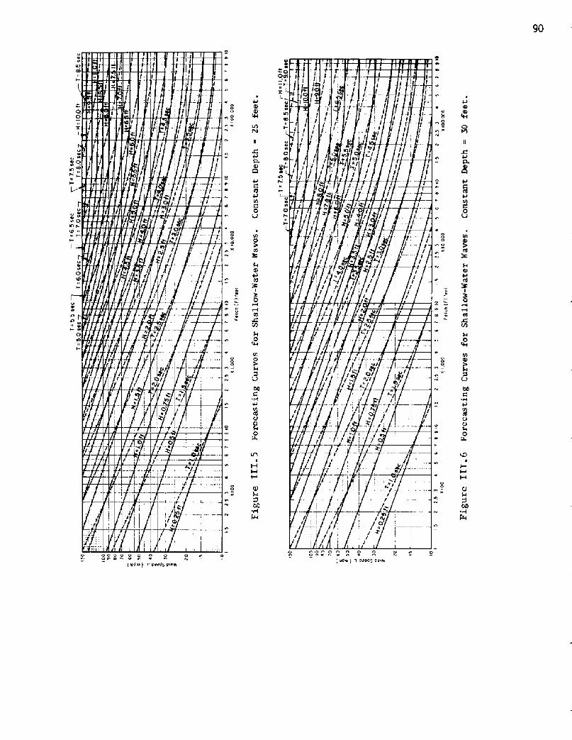
Appendix I II Generati on of Wind Waves - Wave Period Tx
The figures in this section have been reproduced from the Shore Pro-
tection Manual SPA! of the U.S. Army Coastal Engineering Research Center,
Second Edition, 1975. Figures III. I - III.LO are used for estimating
heights and periods of waves generated by winds blowing over relatively
shal'low bodies of water from 5 to 50 feet in depth!. For depths in
excess of 50 feet, it is suggested that Fig. III. 11, "Deepwater Wave
Forecasting Curves," be used. The extreme-i vent wave period, T , thatX
is needed in the design procedure of Section IV, is obtained from these
graphs: this parameter is simply labelled "T" in Fig. III.1 - III.10,
and referred to as "significant period" in =ig. III.ll.

88
I
I l.I Q Q
'QQo o
CP
l U/pd
0 C OU
o o o Q o Q Q Q
o
Q 4-o
Q
L�
o o Q Q QQ
/- ',rI
H HQ QQ Q
QQQ Q Q Q Q Q8QQ4'I li d u I I P l l 0 5 P o ll
@go o o o o dp g ado! d Pdddg dllk
V 4
Q a $V
O P
cd
0
pd
0
T N
Iz
I op
I/ l ld
/» CdI
0 CdCh
O
H I � I
8
00~ R

89
IA«hIIT.
8C O o
ufo aCfo o«I
g lg u
'OulO 4 I0 4 I-4I�
0
o iflIAfoI-
O O O OO oO 4
fu
4 4o
C~ I ~
o ~ I
IQ 4o O ul
4I-
Oa
u
u«4O
«l I«I~ 4
o
«4«lO C
iC
oooaaooo O Ooaa o v o Vdo ! h Puudf« Pufd!
p!
pd
pd
3 0 ddV!
0
o«oaaOOgOo 4 a a Vdo! h Puudd puffd
cd!
3 0 r5U!
4 0
90
O00'II� ~�
Iz'
j 'I
0 00I/IOttlP
I
u Du
O ISVP /~ I IA
/ I
t I
/0 -0
Ia0
o tl
0 C 0 0 0 o
V
I Vo u-d
7I/ / /
/u ou
///
/r
/u 0 Ct
u
0I
h
Pj
bO~ I-
CI0
/'/ l I // ' /
//
0 ~ 0 0 0 0 0 0 D 0Du 0 u atI IIIII'| II Itaalltt Ilu III
r5
4>Cl
0
C6
0
I /
/I//
i' i'/
/ I/
/
000 0 0 D 0 0 D 00 u I oI uuo! ~ aaauS au at
td
8
I/i
0

I I
I;I<o Ogt- tpi
Uvt-0 C3tt
00oD0
800DUIAI
t l
I I- I I,'
I
IOOto
IZ
/ ' I 7I I
I 1 /'I
oowaIltto>~ ID
0 IIUI0
A I
O
U 0Xttaj /
ItT.
D00
I/ '1
I0a cV
Itz
C>C!I
z
Lc
/
/
b ~ addL
M M M0 0 D III
i/, ' /
ooO 0 0 0 0 0 a0 cl ~ 4 0 al d do l 0 Paadg rUINI
oooo 0 o 0 0 0 0oa 0i Udw l ~ paad5 paltti
4 pl
rdI
0 3 CdiC6 0
I1
II
.// t
/
A
a V0
C
0 Ut

92
D O O OO
nO O
O O O Oc
8O
l
O
O p
OO
C vCl
O O O O
O OO O
O O O OO O C O lt lt O ! ft ~ &alt 5 0 ~ l ItlO O O O O O
ttt
4J
I
0 3 Itl
O O O O O O C O OO OIvttu I It ea~lIS Oui+
4 I0 3 ttlCh
CO
Q

93
'4 I 0 At Alcc Al
0 0IE
0 40 0I8
48 IE
F8 05
Al0 o0
08N
E8 IA
000E0
4
V
ul0
0 000N E0 E0~ Vch004
00 00 Ito
0It
0 Z
0 0?:vt 0
Cl
CA D4
0L AlVllI
IV
0 Al
0 LCIII
00 e 0 0
C0OI 0
Q44
0 ~ tIA
0Alh.
0 0 CVI
Al C0ltN C0'
I/I
AI
D 0 0o e e D o eD
IAAH Iud 4 ~ lip ul puau5 puty0 8 e o 0 0 0 0 o 0 o 0 o D e 0 44 0 0 0Al ll 0 IA I- 0 0 rt et t t Ac let 0 0 Al N N
De oeoeeoeeeeoeeecvoe e0 0 e e 0 0 IO 0 0 0 0 0 At N cvEUEUE Ui PEEU5 PUIEE
4 O
O C3>zLo
mN
v! ~'LJJ O
~OZ
<O � "-Zz~cL' 0m O
oebJ C90 ZQW cn
~z-! 0
~Oc[ LJJQ UJ
QCL COLJJ~OOZ

94-
Appendix IV.A. Construction Details for the Wave-Guard FTB
Materials
Scrap tires can be obtained in significant quantities in almost any
area from tire dealers, garages and landfill sites. In many areas it is
now necessary to circumferentially slit tires before thay can be land-
fi lied: this makes uncut tires even more readily available since many
owners of used tires would prefer to avoid the added disposal cost and
instead deliver che uncut tires to a breakwater construction site with-
out charge. Even if this is not the case, a delivery charge of not more
than $0. l5 per tire is generally encountered Candle, 1977!.
A sketch of the Wave-Guard FTB, including mooring system and
recommended pole-spacing, is shown in Fig . IV. l. The term "pole" i s
here only intended to be descriptive: wooden piles or buoyant reinforced-
concrete or steel beams could be used as well. Used telephone poles
appear to be the most economical and readily avai lable source and can
often be procured for less than $50 per pole. These are generally avai 1-
able from telephone companies. The price will vary according to size,
condition and hauling distance. On'ly poles that are structurally sound
should be used, and additional creosoting may be advisable for increased
wood-preservation. A 50 ft telephone pole, class 1, douglas fir!,
weighs approximately 1900 lbs and costs about $200 new, including treat-
ment Koppers Co., Shortville, N.Y.!: the pole diameter at the top is
typi cally about 9" and near the bottom approximately l5" for a 50 ft pole.
Only tested and proven binding materials should be used in FTB-construc-
tion since it has been found that it is this structural component that
generally fails first. In-situ salt water tests were performed at the

University of Rhode Island in 1976 on 12 different binding materials
Davis, 1977!. Conveyor-belt edging material was found to possess the
most suitable properties, but heavy galvanized steel chain minimum wire
diameter '1/2"! has also been successfully used. Tests performed on 3"
wide strips of belting that were joined together with two 1/2" nylon
bolts gave an average tensile strength of 2150 lbs. The belting itself
displays an ultimate tensile strength of approximately 9500 psi. The
main advantages of conveyor belting are that it is:
1! Relatively inexpensive from $0.25 - $1.00 per sq ft!
2! Lightweight and easy to handle
3! Non-corrosi ve
4! Non-abrasive in conjunction with other breakwater components
generally used
It is recommended that the belting for the Wave Guard FTB be 4" wide and
1/2" thi ck. Davis �977! found that nylon bolts, nuts, and washers are
a good way to fasten conveyor belting: the tying system then being inert
in the marine environment, easy to assemble and of acceptable strength.
Since nylon is degraded by sunlight it is recommended that the nylon
fasteners be dyed black. At least four 1/3" bolts with flat washers
should be used to fasten the belting at each connection. A sketch of
the recommended connection is shown in Fig. IV.2. This pattern should
provide well over 3000 lbs of tensi le strergth. Galvanized 1/2" open-
link steel chain could also be used in place of the belting but this is
more expensive approx. $0.80/ft! and necessitates additional buoyancy.
Each tire floating in an upright position will trap air and provide
about ll lbs of reserve buoyancy see pg.55 for tire characteristics!.
After a period of time the air will escape if the tires are not
96
periodically recharged with air either manually or by wave action.
Experience with the Goodyear FTB in fresh water has shown that supple-
mental floatation is not needed if the stru:ture is regularly cleaned
and the accumulation of sand within the tir s is minimal. The passage
of waves allows the tires to periodically retrap new air and therefore
will keep the breakwater afloat indefinitel r. Salt water is more of a
problem because tires are an excellent habi tat for the growth of seaweed,
muscles, barnacles and the like. This added weight reduces the effective
buoyancy of the tires and, without regular maintenance, this may cause
parts of the structure to becane submerged, and eventually all of it.
If it has been decided to construct the Wave-Guard FTB without supple-
mental floatation, then it is recawnended that the structure be regularly
monitored for local submergence and be cleaned at least annually. It
has recently been found that compressed air can be effectively used to
refloat portions of FTB's that have lost their buoyancy, and that ccjm-
pressed air can also be employed to clean the tires of trapped sediments
and some marine growth. The use of supplemental floatation becomes
necessary if this periodic maintenance and cleaning cannot be provided.
In this case i t is recommended that the top., of every tire be foamed with
1/2 lb of urethane foam kits are available for mixing and injecting the
foam!. This should support any added marin» growth or sediment accumula-
tions. Supplemental floatation increases the cost of FTB's substantially.
The recommended mooring line consists of' a tire-mooring-damper located
at the breakwater end of the mooring line plus an anchor chain near the
bott', as shown in Fig. IV. l. For the chain porti on the use of 1/2" open-
1ink low-carbon chain appears to be most econani cal. The chain has an
average tensile strength of 2200 lbs and is heavy enough to withstand years

ELEVATION
Figure IV.1. Schematic of Wave-GuarC FTB and Mooring System

POLE
PIVOT
II
4 LOCKING RODS
PLAN -VIEW
8 -~lLOCKING- ROD
BELTING BELTINGELEVATION
II
~p NYLON BOLTS
Figure IV.2. Construction DetailsShowing 8elt Connection,Locking Rods and Pole Pivot
Figure I V.3. Interconnection of Tire-Strings and Poles

99
Figure IV.4. Tires may be Interconnected wi'h Steel Chain or,Preferably, Conveyor Be1ting. Photo courtesy ofGoodyear Tire 4m Rubber Co. j

of abrasion and corrosion. Careful consideration must, however, be
given to the mooring loads to be antici pated, and the number of mooring
lines to be used, before actually selecting the chain.
Construction
The Wave-Guard concept was developed wi th the following goals in mind:
i ! It should be an effecti ve wave attenuator
ii! It should be simple to construct and at a low cost
minimum construction effort!.
iii! It should be a rugged structure that can resist years
of wave action.
The Wave-Guard FTB should be built as near as possible to the water' s
edge. The structure may even be assembled in shallow water and then
towed to the site of deployment. A beach near the site would be an i deal
location for the construction of a FTB. If the breakwater is to be
built complete on a beach, the poles should be placed perpendicular to
the water's edge to facilitate the subsequent transport into the water
push-pull!. A farm tractor or some comparable machinery is the heaviest
equipment needed to maneuver poles and transport the structure into the
water.
Since the log spacing b should not exceed 6Dt where Dt is the diame-
ter of the ti res used! and the string spacing G should be approximately
equal to 1.2 D , it follows that b = 12 ft and 6 = 2.4 ft when typical
14" automobile tires with Dt 2.1 ft are used. The tires should be
distributed along the construction site to minimize the amount of handling.
The poles are moved into position and then lifted and balanced on a pivot
point approximately 18" off the ground as shown in Fig. IV.2. Tires can

then be easily placed over the entire pole. Once the pole is armoured
with tires, steel bars � ft in length! are pushed through the end-tires
and through the pole, in order to lock the tires onto the pole. It is
suggested that this also be done at 15 ft intervals along the pole. The
holes in the poles should be large enough for a 3/4" steel rod. Two
holes should be punched in the tire so that the rod can be inserted
through the tire and pole as shown in Fig. IV.2, and after locally heating
the rod the ends should be bent over to lock the rod in place. The log
is now armoured with tires.
With poles arranged parallel to one another at the proper distance,
the tire-strings can be constructed and connected to the poles. Each
string of tires will consist of approximately 20 � 25 tires depending
upon the compression desired in the strings and will be placed about
6" apart tread to tread!. The belting or binding material is strung
through the tires as shown in Fig. IY.3: each loop is approximately 30
ft in length. Each loop of belting will fasten two tire-strings to the
pole members by threading the belting through five tires on each pole,
as shown. The belting can be joined anywhere along the loop but prefer-
ably not near the pole. The belting should be overlapped at least 8"
and fastened with four 1/2" nylon bolts. A mechani cal punch is used
to make bolt holes in the belting. Before bolting and punching . the
belting should be pulled as tight as practi =ally possible to remove any
unwanted slack, and the excess belting trimmed as needed. Tire spacers
are used between adjacent tire-strings as shown in Fig. IV.3. The belt-
ing is guided through two tires on the tire-strings and comes back through
the spacers. The belting connections are tie same as those described
for the strings. Oepending upon the availaliiiity of machinery, it may

be advantageous to perform sane of the final assembly in 2 - 3 ft ofwater. This would avoid the final land-to-water transport phase whichis frequently the most demanding. The armoured logs and tire-.stringswould be rolled into the water individually after having been completedon the beach, and subsequently connected. The FTB would then be towedto its final destination. This procedure requires that a sheltered,accessible beach be found, but would e'Iiminate the use of heavy machinery.
The use of tire mooring dampers with at least five tires in seriesis recommended. Belting may be used to tie the tires together usingthe techniques discussed. The mooring line is fastened to the polethrough two tires about 10 tires from the end. The opposite end ofthe mooring line is connected to the anchor with chain or belting ofsuitable length and size. Tire-to-tire connections, Using steel chainand conveyor belting are shown in Fig. lY.4,.

103
APPENDIX IV.B
HOW TO BUILD A FLOATING TIRE BREAKWATER
George ShawNeil Ross
September, 197'.~
University of Raine/University of New HampshireCooperative Institutional Sea Grant Program


The Great Bay Marina floating tire breakwater in action on a brisk and breezyNovember day.
dominant direction of the waves is known, a shorter breakwater facing the wavesmight be sufficient. Its length and shape would then depend on the physicalcharacteristics of the area to be protected as well as wave refraction around theends of the unit. To control refracted waves, a longer breakwater or an L-shapedone may be needed.
Beam: Width is determined by the predominant w~ve length in the area to be pro-tected. Increasing the width increases the wave length that will be suppressed.The general rule is that the beam must be greater than half of the significantwave length.
To determine the significant wave length, first determine the period T! ofthe oncoming waves by measuring the average time in seconds between successivewave crests passing a given point {such as a piling or buoy! in the space ofabout five minutes. Then, calculate the significant wave length {L! using thisformula:
L = 5T
This formula applies to deep-water waves or those where the depth of water isgreater than half of the wave length L!.

Most of the early FTBs were three bundles wide., or about 20 feet. Many full-scale field tests have been performed by Sea Grant at the University of RhodeIsland to substantiate the performance of the brealcwater. Automobile tire struc-ture widths of 20 and 26 feet were found to be 80 percent effective in suppressingthree-to-four-foot waves. Therefore, it is recommended that a structure 26 feet,or four bundles, wide by one unit deep be consider d for suppressing three-foothigh waves.
Draft: Immersed depth is determined by the height of significant waves occurringin the area. Again, a general rule: draft should be greater than one-half theheight of the significant wave. Breakwaters built of standard automobile tiresare effective in seas up to five feet. Such breakwaters will suppress about 70to 8S percent of the incoming wave height. Larger truck or tractor tires willincrease the depth of the breakwater and control higher waves.
First Steps
The breakwater should be situated with its leading edge parallel to the on-coming waves. It should be moored as close as possible to the area to be protectedso that the wind will not have sufficient fetch to rebuild the waves behind the
breakwater.
Since the breakwater is very mobile, the best location can be found byexperimentation. In fact, the FTB can be sh'fted with the seasona1 variations inwave direction. The breakwater should be placed in water of sufficient depth toprevent it from touching bottom at low tide or in low water. Doing this willalso prevent it from sinking. The returning tide might fill the tires with sandand sink them. For this reason, this type of breakwater should not be instalIedwithout supplemental flotation in highly silted rivers. In high silt transportareas, the breakwater might continue to float if 2" x 3" holes were cut in thebottom of each tire to allow the sediment to wash through. This has not yet beentested.
Permits must be obtained from the appropriate agencies before a floatingbreakwater can be installed in the navigable waters of New Hampshire, Maine andmost other states. Briefly stated, approval or acceptance must be received fromlocal abutters, planning and zoning boards, State Fish and Game Departments, andall other state regulatory agencies involved in matters such as these. Inaddition, the U.S. Army Corps of Engineers must give its approval. Anyoneplanning a breakwater should alIow six to eight months for the permit procedure.To speed up the process all local, state and federal permit requests should befiled at the same time.
Materials
Tires: With an estimated existing stockpile of more than two billion scraptires in the United States, marinas should not have much difficulty obtainingthem. Large quantities are usua1ly available from tire dealers, recapping centers,truck stops, highway departments and town dumps. Most of these places are eager

107
to dispose of them and many will even deliver them to the marina free of charge.
Air trapped in the tire crowns will provide sufficient buoyancy to keep theFTB afloat a while. The tires float approximatel v six inches above the waterlevel and two feet below the surface, providing about ten pounds of reservebuoyancy per tire, or 200 pounds per unit of 20 standard �4-15 inch! tires.
It is recommended, however, that supplemental flotation be provided in everytire. Any one of several types of closed cell rigid urethane foam, set into thetops of the tires, is suitable for this purpose.
~gindin Materials; The binding material can represent as much as one-thirdof the total cost of the breakwater, with labor and the mooring system accountingfor the remainder. The temptation is to economize on binding materials as muchas possible, but this kind of economizing should be avoided.
The ideal binding material must be able to hold together for ten years inan aerated-seawater condition where it is subject to corrosion, crevassing,fatiguing and abrasion. To be ideal, it must do this at a reasonable cost. Infresh water, corrosion and crevassing will be les of a problem.
In situ salt water tests were conducted at UI',I's Narragansett Bay Campusfrom January through November, 1976 to evaluate tkie reliability of 12 differentmaterials that were thought suitable for connecting FTB units.» The bindingmaterial recommended above al1 others tested is conveyor belt edging material,a scrap product resulting from the trimming of new conveyor belts. Because ofits fabric plies, this material demonstrates ultimate tensile strength on theorder of 9,500 p.s.i. when no stress risers, such as bolt holes or cuts arepresent. The belt material is available from several tire manufacturers in thiscountry, including Goodyear.
Minimum recommended belt dimensions are 2" wide by .37S" thick with threeor more nylon plies. Dimensions of this scrap material can vary widely, so priorarrangements should be made with the rubber company supplying the belting toavoid shipment of unuseable sized material.
Conveyor belt edging demonstrates several other desirable characteristics.It can be easily cut on a band saw or with a hand hack saw or axe. Holes forbolts can be punched singly or with a multipIe gang punch. The materia1 isvirtually inert in the marine environment. It is pliable enough to be handledeasily by one man during its fabrication and assembly into the tire modules.
As a means of fastening the belting together, the use of nylon bolts, nutsand washers was conceived. This makes a binding system that is totally inertin the marine environment. The nylon fasteners sh>uld be dyed black beforethey are used. Doing this wiIl provide a screen to prevent ultra-violet raysfrom degrading the nylon over a Iong period of tim . Several minutes of immersionin household dye in boiling water is sufficient for this purpose.
«Complete test results are avaiIable upon request:From the University of RhodeIsland Marine Advisory Service.

108
The size and number of fas-teners that are employed on eachbelt section is important foroverall strength and fatigueconsiderations. Two basic sys-terns that have been employed todate are:
Voids in the center of these3/8-16 injection molded boltscause the strength of these boltsto vary substantially, by severalhundred pounds. For this reason,the second system, explainedbelow, is reconnnended over the3/8-16 bolts. Several break-waters which employ this systemare in use at present and havebeen in the water for more thansix months. One of these, at theGreat Bay Marina in Newington,New Hampshire, is 150 feet inlength and is positioned perpen-dicular to a daily tidal flow inexcess of three knots. It has
also withstood the onslaught of winter ice movement with no damage to the bindingsystem to date.
2. The use of two �!, I/2-13 bolts per belt Fastening. The belt used withthis pattern should be no less than two inches, and preferably three inches wideto prevent belt tearing, An average strength of thi s pattern is 2,150 pounds.In this system, the bolts do not fail. Either the bolts pull through the rubberbelting or the belting tears.
These bolts differ from the 3/8-16 bolts in that they are manufactured Fromcast nylon bar stock on a screw machine and do not liave the voids that are presentin the 3/8-16 bolts. This system tends to be more predictable as far as re-peatable strength limits.
1. The use of three �!,3/8-16 bolts per belt fastening. See photo on this page.! Thebelt width used with this patternshould be no less than two incheswide in the bolt zone to preventthe belting from being tomthrough to the edges. This pat-tern can support an average loadof 2,100 pounds before the boltsfail. Washers must be employedunder the bolt head and nut toprevent the head or nut frompulling through the rubber.
The floating ti,-e breakwater installed at theGreat Bay Marin i. in Newington, New Hampshire,in September, 1076, was bound together withconveyor belt edging material. Three 3/8-16bolts per fastening were used to secure thebonds.

JV7
Hints for Use of Nylon Fasteners:
When tightening the nuts, torque limitations should be maintained. Thesewill vary with the size of the bolt being used. Watch the nylon washer only flat washers are recommended, i.e., no lock washers! for cuppingas the nut is tightened. A very s1ight cupping indicates that the nutis tight enough.
a!
Bolts should be long enough to permit a minimum of '4" of threads to pro-trude through the nut. Allowance for varying belt thicknesses and twoflat washers should be made accordingly. This 4" of threads allows apropane soldering tip to melt and distort a sufficient number of threadsto prevent the nut from "backing off." Also the growth of marine plantsin the exposed threads severely hampers the nut from working loose.
b!
The fallowing information is a result of the in situ test employing rubberconveyor belting and nylon fasteners as the binding system for a floating tirebreakwater:
The belting and nylon fasteners are inert in the sea water environment.
The belting has excellent abrasion resistance to chafing against tirecasings, other binding materials and marine growth, such as barnaclesand mussels.
The belting shows no signs of delamination separation along fabric plies!after nine months of immersion.
A slight increase in tensile strength of the belting approximately 2-3%!was noticed after six months of immersion. This could be due to a betterdissipation of heat, generated by the internal tensile straining, throughthe wet fiber plies.
The material is easily handled by one or two persons during fabricationand assembly.
The system allows localized loads to be distributed readily throughoutthe tire matrix.
The system can withstand low water temperatures including ice, highloading conditions caused by currents, wave action and cyclic fatigueloading. It can be towed without undergoing excessive strain.
7.
The materials do not pollute the environment.
The system has a negligible negative buoymcy effect upon the breakwatermodules.
The system can be unfastened readily for,addition of tires, repairs orfor other purposes.
10.
At this time, these materials and fastening m'thods are the most economicaland, probably, the most dependable. Estimated 1if. is ten years.

Second to this system would be chain with a minimum wire diameter of V',preferably galvanized. In third position relative to reliability would be poly-propylene, either braided for use in splicing! or regular lay. If polypropyleneis employed in this capacity it should have an ultra-violet screen shield toretard degradation. All other materials are not recommended as binding materialfor floating breakwater applications.
Materials not recommended for FTB use are:
l. ~N lon lines. They demonstrate poor abrasion resistance, knot looseningand ultra-violet degradation.
2. "Kevlar" line. Internal fiber friction during flexing of rope severelyimpairs strength characteristics of this aaterial.
3. Any metallic wire rope, such as plain steel, galvanized steel or stainlesssteel because of inherent corrosive problems particularly around theclamped or swedged ends!, metal fatigue, caused by constant flexing, andthe cutting action of the rope on the tire bodies.
Coosiruction
Side View
Top View
The design of thebreakwater is based on a
modular concept, in whichrelatively few tires aresecured together to forman easily assembled, port-able building unit. Thisunit then serves as the
basic building block forlarge structures.
The construction pro-cedure is very simple.First, assemble the modularunit. This is done by se-curing 18 tires togetherto form a 7' x 6~<' x 24'bundle. The basic method
used to construct the
bundles is to stack thetires flat in a 3-2-3-2-3-
2-3 configuration, as shownin Figure 1 and in thephoto on page 8. Weavethe binding materialthrough as the tires arestacked, The increasingweight of the tire stackand compression of the
FIGURE 1
Modular Building Unit Shown as Constructed

tires by hand will allow easy fastening of the binding material, and will form atightly secured bundle.
The bundles should be constructed near the installation site, if practical.However, they are relatively easy to transport from the assembly site to wherethe breakwater will be installed. Be sure to ins' all supplemental flotation ineach tire before assembling the tires into bundle; .
Connecting the tire units into a long chain i o form the breakwater requiresonly a slight alteration of tire position and the addition of two tires per bundle.
Tire bundles are constructed by stacking the tire flat in a 3-2-3-2-3-2-3 config-uration. Binding material--in this case, conveyor belt edging--is woven throughthe tires as they are stacked to secure the bundle.

112
First, the four cornertires of each bundle arerotated about 100 , as shownin Figures 2 and 3. Next,the two additional tiresare inserted at each end ofthe module to serve as con-nectors, interlocking toform the desired shape ofthe protective structure. See Figure 3!
The resulting mat,shown in Figure 4, hasexcellent strength charac-teristics as high as55,000 lbs. breakingstrength on a Q' spacedlongitudinal and transversegrid!. It also has theability to absorb greatamounts of enery by yield-ing and deforming whenover-loaded. Elongationof more than 30 percent ispossible in both directions. FIGURE 2
These elongations occuronly under extremely highloading conditions, and the tire bundles returr, to their normal shape under no-loadconditions without permanent deformation resulting.
The Bridle. To prevent any individual bundles from separating and driftingaway, a bridle line should be threaded through the outside tires around theperimeter of the breakwater. See Figure 4.! Secure the line to the two outsidetires in each bundle to prevent chafing. The material can be one or more linesof synthetic rope or chain providing the weight is not excessive!.
~Moorin s. The size of the moorings and anchoring system will vary dependingon the type of bottom sand, rock or mud! and local tides and currents as well asthe amount of exposure to wind and waves. Anchors, mushroom moorings, concreteand/or granite blocks heavy enough to resist drag are satisfactory.
Design the mooring system as you would for boats over 30 feet long. Localexperience with moorings will be the best guide. Wooden pilings with the break-water built around them may be used in place of moorings. It is recommendedthat moorings be placed a maximum of 50 feet apart on the wave side and every100 feet on the lee side. Mooring lines should be attached to the breakwaterin such a way that the load is distributed between two or more bundles.
~Markin . The FTB could be a navigational hazard unless properly marked andlighted.

The modular units may be positioned ineither the eros wise or lengthwise direction.
Connec
FIGURE 3
Modular Units Connected to Form Mat

114Bridle n bet10n.
FIGURE 4
Shore Protect i on Mat and C connect in g Bri die