data acquisition and processing report€¦ · data acquisition and processing report spot (s3004)...
TRANSCRIPT
DATA ACQUISITION AND PROCESSING REPORT
SPOT (s3004) Team Leader: Lieutenant Junior Grade Briana Welton, NOAA
Applicable Surveys
M-H910-NRT7-07
H11658
WESTERN SAMBOS, KEY WEST, FL
OPR-E300-BH/NRT7-07
H11693
POTOMAC RIVER INVESTIGATIONS, POTOMAC RIVER, VA & MD
S-E923-TJ-07
F00547
MAERSK TERMINAL, PORTSMOUTH, VA

A. EQUIPMENT All survey data acquired by the Special Projects Operation Team (SPOT) were acquired with Survey Vessel s3004. Vessel s3004 has one sonar mounting arm on the starboard side of the vessel from which only one of the Unit’s three sonar systems- Reson 8125 multibeam echosounder (MBES), Klein Light Weight 5000 side scan sonar (SSS), or Benthos C3D phase-differencing bathymetric sonar (C3D)- are mounted at a given time. The dry hardware (Klein TPU, Reson 8P, and Benthos Server) are mounted in the cabin rack with all cables run such that changing sonar requires only exchange and connection of the transducer heads. The Odom CV vertical beam echosounder (VBES) is hull mounted near the center of rotation of the vessel. The methods and systems described in this report are used to meet complete coverage and object detection coverage requirements and are in accordance with the OCS Hydrographic Surveys Specifications and Deliverables Manual (3/2007), Hydrographic Survey Directives, and the OCS Field Procedures Manual for Hydrographic Surveying (3/2007, v 2.1).
A.1. ECHOSOUNDING EQUIPMENT ODOM ECHOTRAC CV VERTICAL-BEAM ECHOSOUNDER The Odom Echotrac CV2 VBES is used as a single-frequency digital recording echosounder system with a digital recorder. The frequency settings range from 100 kHz to 1 MHz, though the normal operating frequency is 200 kHz. The manufacturer specifications of this sonar are included in Appendix I of this report. The data is digitally recorded in meters as .bin files and Hypack files. The .bin files replace paper-trace records and can be viewed in Pydro Post Acquisition Tools. The Hypack files are converted to Caris HDCS data for processing. The Odom CV is primarily used simultaneously with either the Klein 5000 SSS or the Benthos C3D sonar. The ODOM Echotrac CV2 is inappropriate for sole use in situations requiring complete coverage or object detection coverage. However, combined with SSS data, the ODOM Echotrac CV can be used to meet NOAA specifications for complete and object detection coverage. RESON SEABAT 8125 MULTIBEAM ECHOSOUNDER The Reson SeaBat 8125 MBES is a single-frequency, digital-recording MBES with an operating frequency of 455 kHz. The RESON 8125 transducer consists of a flat transmitter array and solid cylindrical receiver array installed on a manually deployable arm off the starboard side of vessel s3004.

The Reson 8125 forms 240 beams each of which has a 0.5° across-track beam footprint for a maximum total swath width of 120°. Each beam has an along-track resolution of 1°. The ping rate is nominally 20-40 Hz, but may vary according to operating conditions. The Reson 8125 sonar is capable of bottom detection in depths from 3-120m. Specifications for this sonar are included in Appendix I of this report. The Reson 8125 performs active beam steering to correct for sound speed at the transducer head using a surface sound speed sensor. This sensor is discussed in the Sound Speed Equipment section of this report1. Real-time attitude data from the vessel’s Applanix POS-MV attitude sensor is also input to the Reson 8125 to aid beam steering, though attitude correction is performed post-acquisition in Caris HIPS. The Applanix POS-MV attitude sensor is discussed in the Positioning and Orientation Equipment section of this report. Reson 8125 data are acquired in meters using Isis XTF format. In addition to bathymetry, Reson “Snippets” and side scan data are also recorded in the XTF file. Reson “Snippets” and side scan data are not routinely used to generate charting products and are archived for second party scientific purposes such as sea bottom characterization, fish habit studies, or geological studies. Reson 8125 user parameters and surface sound speed are also recorded within the XTF file. BENTHOS LIGHT WEIGHT C3D SIDE SCAN/ BATHYMETRY SYSTEM The Benthos C3D is a phase-differencing bathymetric sonar that uses the CAATI (Computed Angle of Arrival Transient Imaging) Algorithm patented by Simon Frasier University to solve for multiple angles of arrival to achieve a wide swath of high resolution bathymetry and imagery. The system consists of a C3D light weight towfish, a processor and a computer for a user interface. The specifications of the Benthos C3D are included in Appendix I of this report.
1 An Odom Digibar is used aboard vessel s3004 for this purpose.

The C3D acquires both SSS imagery and bathymetric data, both of which are recorded in a single Isis XTF file. A real-time surface sound speed input from the Odom Digibar is used during acquisition. The Benthos C3D is under evaluation by the NOAA Office of Coast Survey; the bathymetry is not currently used for charting purposes. However, gridded surfaces are created to analyze generalized bathymetry. Odom CV VBES data is acquired in conjunction with Benthos C3D bathymetric and imagery data and used as the sole source of bathymetry for charting purposes.
A.2. ACOUSTIC IMAGING EQUIPMENT KLEIN 5000 HIGH-SPEED SIDE SCAN SONAR The light weight Klein 5000 high-resolution side-scan sonar system is a digital-recording, beam-forming acoustic imagery device with an operating frequency of 455 kHz and
vertical beam angle of 40°. The Klein 5000 system consists of a Klein towfish, a Transceiver/Processing Unit (TPU), and a computer for user interface. The Klein 5000 system is distinct from other commercially-available SSS in that it forms five simultaneous, dynamically-focused receiver beams per transducer face to improve along-track resolution. The along-track resolution is approximately 30cm at the 100m range scale, even when acquiring data at speeds up to 10 knots. Across-track resolution is typically 7.5cm at the 100m range scale. The achievable 0.3m resolution meets the OCS Hydrographic Surveys Specifications and Deliverables Manual for object detection. Triton Isis is used to acquire data with the Klein 5000 SSS.
A.3. MANUAL SOUNDING EQUIPMENT Vessel s3004 does not possess manual sounding equipment such as a sounding pole or a lead line.
A.4. POSITIONING AND ORIENTATION EQUIPMENT Vessel s3004 uses an Applanix POS-MV 320 Version 4 inertial positioning and orientation system along with U.S. Coast Guard Differential GPS (DGPS) for a highly accurate blended position and orientation solution.

Vessel s3004 is equipped with a Trimble DSM132 DGPS receiver. The DSM132 includes a GPS receiver capable of receiving external RTCM correctors from a shore-based reference station. The system outputs position information once per second. Best expected position accuracy with the DSM132 system is less than one meter with 5 or more space vehicle vectors in the solution. The POS/MV 320 includes dual GPS antennas, an inertial measurement unit (IMU), and data processor (PCS). The IMU measures linear and angular accelerations corresponding to the major motions of the vessel (heave, pitch, roll) and inputs this data to the PCS, where it is combined with a GPS position determined by carrier-phase differential measurements to give the final position solution. Heading is calculated using a GPS-azimuthal measurement system (GAMS); two offset GPS receivers mounted on the cabin of the vessel input to the PCS. The blended DGPS and inertial position/orientation solution has typical values of 0.02° true roll and pitch accuracy, 0.02° heading accuracy, 2m position accuracy, and 0.03 ms-1 speed accuracy. These parameters are monitored in real time during acquisition using the POS/MV user interface software, PosView. These values meet the position accuracy standard for an IHO Order 1 survey. Vessel s3004 is set up according to the “Precise Timing” method, a sonar acquisition configuration which applies a time stamp at the point of acquisition to all incoming sonar, attitude, and positioning data2. The timing message is generated by the POS/MV and synchronizes the sonar system time with the POS/MV UTC time. Although “Precise Timing” reduces the effect of time latency on MBES data, corrections for residual time latency biases must still be made via a patch test. POS-MV True Heave files (.000) are also recorded during bathymetric data acquisition and applied in Caris HIPS/SIPS during post processing.
A.5. SOUND SPEED PROFILERS SEA-BIRD SBE19+ CTD PROFILER Vessel s3004 acquires water column sound speed data using a Sea-Bird Electronics SeaCat SBE19+ Conductivity-Temperature-Depth (CTD) profiler. Temperature is measured directly. Salinity is calculated from measured electrical conductivity. Depth is calculated from strain gauge pressure. The SBE19+ is capable of CTD profiling at depths from 0-350m. The SBE19+ is deployed by hand over the side of vessel s3004. 2 Further documentation on Precise Timing may be found in Appendix III of the 2007 Field Procedures Manual.

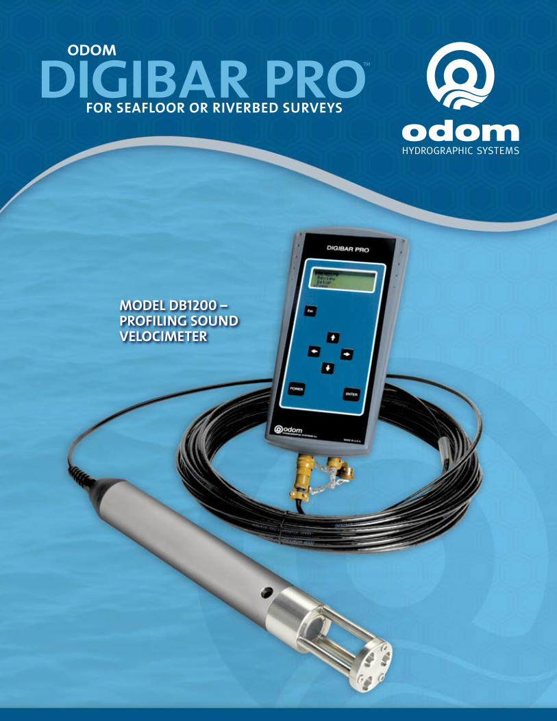
The CTD was returned to the manufacturer for calibration January 2007. Calibration documents are contained in Appendix IV of this report. SEA SURFACE SOUND VELOCIMETERS Vessel s3004 uses an Odom Digibar Pro for surface sound speed input to the Reson 8125 and C3D. Unlike the CTD profiler, sea surface sound speed is calculated using two-way travel time. A pulse of known frequency is emitted and reflected off a surface. The two-way travel time is measured over the known distance between the transmitter and reflective surface, from which the sound speed is then calculated. ODOM HYDROGRAPHIC SYSTEMS DIGIBAR PRO The Digibar Pro is a real-time time-of-flight sea surface sound velocimeter. The manufacturer specified sound speed accuracy is 0.3 ms-1. Aboard vessel s3004 the
Digibar probe is mounted to top of the deployable sonar arm plate, below which the Reson 8125 or the C3D are mounted. Data are sent in real time to the Reson 8P or Benthos C3D server. The Digibar Pro has not been calibrated since it was purchased in 2005.
B. SOFTWARE SYSTEMS B.1 ACQUISITION SOFTWARE HYPACK MAX Hypack Max is a multi-function marine survey software package. Hypack Max is used for vessel navigation and for acquisition of VBES data and detached positions. Survey lines, vessel position with respect to lines, and various navigation parameters are displayed for the helmsman. Hypack also controls Isis data logging on the acquisition computer through the NOAA Delph string, allowing XTF files to be named by their Hypack line file name.
TRITON IMAGING ISIS Isis is a Windows-based acquisition software package that provides real-time data display and sonar control. Isis is used to acquire Klein 5000, Reson 8125 and Benthos C3D data in XTF format. The Isis setup is configurable for each type of sonar and allows the user to save the configuration files so that they are automatically launched during start-up.

The same computer is used for SSS and MBES acquisition. A separate computer is used for C3D data acquisition, which was provided with the C3D system. Data acquisition is monitored real-time by a qualified sonar operator. The primary user settings that are adjustable during SSS acquisition are the range scale and the resolution. Typically, the range scale and resolution are set prior to logging data and not changed again until the surveyed depth area changes. The primary adjustable user settings during MBES acquisition are transmit power, range, gain, pulse length, ping rate, spreading, and absorption. Typically, power, range, and gain are the only settings that are adjusted dynamically during the logging of a line file (power and gain sparingly). The pulse length, spreading, and absorption are set for the survey depth area and are rarely adjusted. The ping rate is set to its maximum because the Reson 8125 will only use the highest possible ping rate for the vessel speed and depth at any given time.
B.2. PROCESSING SOFTWARE CARIS HIPS/SIPS V 6.1 Caris HIPS/SIPS (Hydrographic Information Processing System/ Side-scan Information Processing System) is used for processing, correcting, and analyzing all bathymetric, side scan, and phase-differencing bathymetric sonar data. Caris HIPS is used for converting, correcting, cleaning, and analyzing gridded bathymetric data. Caris SIPS is used for converting and correcting side-scan sonar imagery and for contact selection and mosaic generation. Phase-differencing bathymetric sonar XTF files are processed in Caris as both bathymetric and side scan data files. HSTP PYDRO Pydro is a proprietary program developed and maintained by NOAA’s Hydrographic Systems and Technology Program (HSTP), and is used primarily for feature management. Multibeam contacts (designated soundings), SSS contacts, and detached position are analyzed, grouped, and assigned S-57 classifications. Weighted grids (Caris surfaces) are imported into Pydro and excessed at survey scale for chart comparison. The Pydro Preliminary Smooth Sheet file (.pss) is delivered to the Atlantic Hydrographic Branch as part of the final submission package. With the newest release of Pydro (v.7.x) the ability to process Tidal Constituents and Residual Interpolator (TCARI) tides has been implemented. If provided in the project instructions, the TCARI file for the area is loaded into Pydro along with the predicted, observed, or verified tide files for the corresponding stations. With this implementation,

tides are no longer processed within Caris HIPS. Further discussion of TCARI is found in the Water Level Corrections section of this report. HSTP VELOCWIN HSTP Velocwin is a proprietary program for the processing of sound speed casts. This program uses Sea-Bird Electronics SeaTerm and SBE Data Processing software to convert hexadecimal SeaCat data into ASCII conductivity-temperature-depth data, and then converts the ASCII data into a depth-binned sound speed file. The resulting SVP files are applied in Caris HIPS during post-processing to correct for sound speed variation within the water column. These sound speed files are applied to the data in Caris HIPS. Velocwin is also used to compare sound speed casts with its DQA function and to archive sound speed information for the National Oceanographic Data Center. MAPINFO PROFESSIONAL 8.5 MapInfo Professional is the Geographic Information System (GIS) software package used by SPOT. MapInfo is used for sheet management, line planning, final data analysis and creating end-user products such as chartlets and survey plots.
C. ACQUISITION METHODS The project instructions assigned to SPOT call either for 200% C3D, or Complete or Object Detection Coverage as defined in the FPM. Where 200% C3D coverage is required, survey lines are planned such that outer beams cover the nadir beams of adjacent lines at set range scales, according to depth (generally 4 times the water depth for 200% coverage). Vertical beam echo sounder data is acquired simultaneously with C3D data acquisition and used as the sole source of bathymetric data for charting purposes. Where 200% SSS with VBES is used to comply with object detection requirements, the C3D is used as the source of SSS data. Two SSS line plans (100% coverage and 200% coverage) are created using the range scales appropriate for the survey area. Line spacing for the first 100% coverage is 120m at the 75 meter range scale and 160m at the 100 meter range scale. The line spacing for the second 100% coverage line plan is identical to the spacing for the first 100%, and the first line of the second 100% coverage is offset by half the line spacing. Vertical beam echo sounder data is acquired simultaneously with C3D data acquisition and used as the sole source of bathymetric data for charting purposes. When the project instructions require complete coverage, MBES lines are planned at a spacing of two to three times the water depth and acquired at a speed of three to four knots. The design of the sonar pole mount is the speed limiting factor for all other modes

of acquisition. The maximum survey speed is around eight knots; otherwise water wake from the pole is forced over the gunwale of the vessel. All lines are run parallel to each other except cross lines. CROSS LINES Cross lines are acquired in accordance with the OCS Field Procedures Manual as a confidence check of the survey data. Survey lines are planned such that ten percent of the total linear nautical miles are cross lines. Cross lines are planned perpendicular to main scheme lines when survey area allows. Cross lines are compared to the product navigation surface in Caris HIPS 6.1. The results of the Cross line QC test are submitted in Separate V of the Descriptive Report of each project.
D. CORRECTIONS TO ECHO SOUNDING AND QUALITY CONTROL
D.1. SOUND SPEED SBE19+ CONDUCTIVITY, TEMPERATURE AND DEPTH (CTD) PROFILER Sound speed profiles acquired with the Sea-Bird Electronics SeaCat SBE19+ CTD profiler are processed using the HSTP program Velocwin, which generates sound speed profile (SVP) files that are used to correct bathymetric HDCS data in Caris HIPS. Sound speed correctors are applied to MBES and VBES soundings during post processing.
The interval at which CTD casts are conducted depends on the data acquisition type, survey area and prevailing conditions. At a minimum, one CTD cast per week for VBES sound speed correction and one CTD cast every three to four hours for MBES acquisition is conducted. Casts are conducted more frequently when changing survey areas, or when survey conditions such as weather, tide, or current change sufficiently.
D.2. WATER LEVEL CORRECTORS
Soundings are initially reduced to Mean Lower-Low Water (MLLW) using predicted tides or preliminary (observed) zoned water level data. Data are obtained from the local, primary tide gauges through the Center for Operational Oceanographic Products and Services (CO-OPS) website (http://tidesandcurrents.noaa.gov/olddata). Predicted or observed water level files are converted to Caris tide files (.tid) and applied to all sounding data using either discrete tide zoning in Caris HIPS (.zdf files) or the TCARI module in Pydro if provided by CO-OPS. After data acquisition is complete, a request for final, approved water levels is submitted to CO-OPS. Once final approved water levels are received, sounding data are re-corrected to MLLW using either the verified zones or the verified TCARI files.

D.3. TCARI Starting with the 2007 field season, some projects require the use of the TCARI model for water level correction. Tidal Constituents and Residual Interpolator is a gridded interpolation algorithm that assigns appropriate water level time and phase offsets to echosounder data at each grid node. If the use of TCARI files for water level correction is directed by the Project Instructions, then the Pydro TCARI tools found in Pydro 7.xx , are used to overwrite tide file in the HDCS line folder. D.4. HEAVE, PITCH, ROLL AND HEADING, INCLUDING BIASES AND NAVIGATION TIMING ERRORS Heave, pitch, roll, and timing bias values for vessel s3004 are determined during a patch test after a system is newly mounted on the sonar arm. Vessel offsets, dynamic draft correctors, and system bias values are entered in the sonar’s Caris Hydrographic Vessel Files (.hvf) and applied during Caris’ merge process. D.5. VESSEL OFFSETS AND DYNAMIC DRAFT CORRECTORS The vessel offsets were measured with a total station by the NOAA National Geodetic Service in Norfolk, VA, in the fall of 2005. The offsets are found in Appendix III of this report, and are also entered in the HVFs submitted with each survey. The dynamic draft values used for s3004 are those measured on s3002 (NRT5), an identical vessel. The dynamic draft values are entered in the HVFs submitted with each survey.
E. DATA PROCESSING AND QUALITY CONTROL
E.1. BATHYMETRY Raw bathymetry data (XTF and Hypack) are converted into Caris HDCS data format upon completion of daily acquisition. Conversion parameters vary for each data format, and are stored in the LogFile of each HDCS processed line folder. After conversion, data are corrected with true heave, tides, and sound speed and then merged. Following merge, Total Propagated Error (TPE) is calculated. For further explanation of TPE calculations refer to Section 4.2.1.1 of the 2007 OCS Field Procedures Manual (v. 2.2, March 2007).

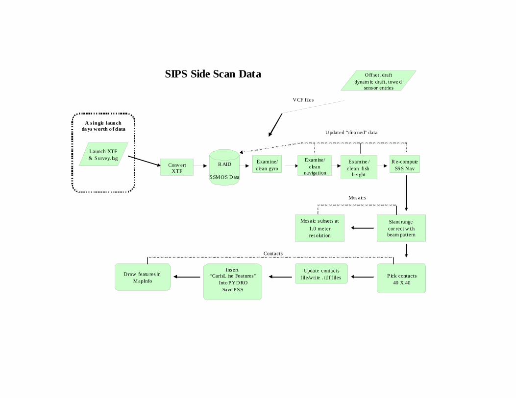
VERTICAL BEAM BATHYMETRY When VBES is the sole source of bathymetry (e.g. 200% SSS/C3D + VBES survey), VBES is converted to Caris HDCS and processed as described in the previous paragraph. The data is then examined and cleaned in Caris Singlebeam Editor. Digital records (.bin files) are used to provide extra information during data cleaning. The .bin files are viewed in Pydro Post Acquisition Tools. After the data has been processed and cleaned, an uncertainty-weighted BASE Surface is computed (usually at a resolution of five meters). MULTIBEAM BATHYMETRY Depending on acquisition type, MBES bathymetry is analyzed using Caris BASE surface layers. Caris BASE surfaces are described in detail in the 2007 OCS Field Procedures Manual and the Caris HIPS/SIPS 6.1 Users Manual. When the primary source of bathymetry for a survey area is a combination of VBES and MBES, a collection of finalized CUBE surfaces is generated as the depth product of the survey. The data is examined and cleaned as necessary to reject gross fliers and to identify systematic data errors. Systematic errors are corrected or removed from the project, documentation of which is found in the survey processing notes or descriptive report. The surface names contain the resolution at which they were created, which is based on depth and data density. When Complete or Object Detection MBES is the primary source of bathymetry, data are processed using CUBE. After computation of TPE, MBES lines are either used to create a new surface or are added to an existing surface. The resulting layers are analyzed by the data processor to identify fliers and/or systematic errors, and to identify significant bottom features. Fliers are rejected by the data processor in Caris Subset Editor (multi-line spatial view) or Caris Swath Editor (single-line time-series view). Systematic errors are identified and documented by the data processor. Least depths of navigationally significant features are flagged as “designated soundings,” which both identifies the object as a navigationally significant object for import into Pydro and forces the depth of the grid to match the least depth of the feature. After data editing is complete, grids are finalized and combined for delivery to the Atlantic Hydrographic Branch. Surface resolution depends on depth and survey type (see OCS Hydrographic Specifications and Deliverables Manual for further information), and is specified in the name of the surface. E.2. IMAGERY After acquisition, SSS data are converted from XTF format to Caris HDCS format. Fish height, vessel heading (gyro), and vessel navigation records are then reviewed and corrected and recalculated. Data are then slant-range corrected to 0.1m with beam pattern correction. The slant-range corrected SSS imagery data are closely examined for

contacts. Imaged objects are evaluated for significance based upon apparent shadow length and appearance. Contacts are selected3 and saved to a contact file within the respective Caris HDCS line file and inserted into Pydro for feature management. Two mosaics are created after SSS data have been processed; one of the first 100% of coverage and one of the second 100% of coverage (200%). If any deficiencies in the SSS coverage are found, a holiday line file is created from the mosaics, and additional lines of SSS are acquired. E.3. BATHYMETRY ANALYSIS AND FEATURE CLASSIFICATION Following data cleaning in Caris HIPS and SIPS, the following items are inserted into Pydro and saved in a Preliminary Smooth Sheet (PSS) file: finalized weighted bathymetry grids, SSS (C3D) contacts, MBES designated soundings, detached positions (DPs), Geographic Positions (GP), bottom samples (Hypack DPs), and AWOIS items. The Pydro .pss is used for survey analysis and feature management. Images of contacts exported from Caris are displayed in the Image Notebook Editor in Pydro. Contacts are arranged by day and line and can be selected in the data “Tree” window. Information concerning a specific contact is reviewed in the Editor Notebook Window in Pydro. This information includes position, surrounding depths, contact cross references, and charting recommendations. Each contact is reviewed, and information flags are set accordingly as described in the Pydro Data Flagging Decision Tree (Figure 4-22 in the OCS Field Procedures Manual). Contacts appearing significant4 are further investigated with MBES or VBES. Multiple representations of one distinct feature (e.g. contacts from two or more SSS lines on a wreck) may be correlated together. For a group of correlated features, one representation is selected as the primary contact, and all others are selected as secondary contacts with respect to the primary contact. After a feature is fully classified, primary features are flagged as “Resolved.” If a primary feature is flagged “Resolved,” then the secondary features correlated to that primary feature are automatically flagged “Resolved” and are given the same full classification as the primary feature. After all items within the PSS have been resolved, three reports are generated for submission to the Atlantic Hydrographic Branch: Feature Report, AWOIS Report, and DTON report5.
3 Contact selection includes measuring apparent height, selecting contact position, and creating a contact snapshot (*.tif) image. 4 Significant features are defined by the Hydrographic Survey Specifications and Deliverables as an object rising more than one meter above the seafloor in water depths of 0-20 meters, and an object rising 10% of depth above the seafloor in water depths greater than 20 meters.

E.4. SURVEY DELIVERABLES AND ANCILLARY PRODUCT GENERATION All data are submitted digitally in close-keeping with section 5.1.2.2 the OCS Hydrographic Field Procedures Manuel; including raw and processed sonar data, ancillary correction data (tides, sound speed, true heave, hydrographic vessel files, etc), supporting products (Pydro PSS files, Caris sessions and field sheets); and all supporting reports and documentation. The final bathymetric deliverable is a collection of gridded surfaces. Side scan sonar mosaics are also submitted as evidence of appropriate imagery coverage. These mosaics are also used to identify contacts, as well as general bottom type. Bathymetric surfaces and SSS mosaics are submitted in their respective Caris field sheets. In addition, the Pydro Preliminary Smooth Sheet (PSS) file is submitted as the record of survey feature management.
5 Danger to Navigation (DTON) reports are generated immediately after discovery and are so submitted to the Marine Chart Division of the NOAA Office of Coast Survey. Multiple DTON reports during the course of a survey are possible. If no dangers are found during the course of a survey, no report is generated.

E. APPROVAL SHEET As Team Leader, I have ensured that standard field surveying and processing procedures were utilized in accordance with the NOS Hydrographic Manual, Fourth Edition; Field Procedures Manual, and the NOS Hydrographic Surveys Specifications and Deliverables.
I acknowledge that all of the information contained in this report is complete and accurate to the best of my knowledge. LT(jg) Briana Welton, NOAA

Appendix I

Equipment Type Manufacturer Model Serial Number Firmware and/or Software Version
Version Install Date
Date of last Calibration
Date of last Service
Multibeam Echosounder Reson 8125 31546 unknown unknown unknown unknown
Side Scan Sonar Klein System 5000 Towfish 317, TPU 157 unknown unknown new new
Interferometric Sonar Benthos C3D 40364 unknown unknown new new
Equipment Type Manufacturer Model Serial Number Firmware and/or Software Version
Version Install Date
Date of last Calibration
Date of last Service
GPS Aided Inertial Naviation Applanix POS/MV 320 V4 2233 3.3.2.2 Nov-06 3/22/2007 none (new)
DGPS Reciever Trimble DSM132 224090080
Attitude Sensor Applanix 320 2233 3/22/2007
Equipment Type Manufacturer Model Serial Number Firmware and/or Software Version
Version Install Date
Date of last Calibration
Date of last Service
Sound Speed Profiler Sea-Bird SeaCat Plus Profiler 19P36399-4634 Mar-05 Mar-05
Surface Sound Velocimeter Odom Digibar Pro 98350 new n/a
SONAR & SOUNDING EQUIPMENT
POSITIONING & ATTITUDE EQUIPMENT
SOUND SPEED MEASUREMENT EQUIPMENT
Field Unit: SPOT (s3004)
Effective Date: MARCH 2007
Updated Through: MARCH 2007
Hydrographic Hardware Inventory

Equipment Type Manufacturer Model Serial Number Firmware and/or Software Version
Version Install Date
Date of last Calibration
Date of last Service
none
Equipment Type Manufacturer Model Serial Number Firmware and/or Software Version
Version Install Date
Date of last Calibration
Date of last Service
GPS Backpack Trimble TSCe 31462Terrasync Ver????Pathfinder???? 7-Jan none none
Equipment Type Manufacturer Model Serial Number Firmware and/or Software Version
Version Install Date
Date of last Calibration
Date of last Service
HORIZONTAL AND VERTICAL CONTROL EQUIPMENT
OTHER EQUIPMENT
TIDES & LEVELING EQUIPMENT

Additional Information
240 Beams1° x 0.5° Resolution
Additional Information
Roll/Pitch Accuracy: 0.05°Heave Accuracy: the greater of 5cm or 5% for periods of 20s or less
Additional Information
Additional Information
Additional Information
Additional Information

• Focused0.5°beams
• 240beams
• 2.5cm near field resolution
• 6mm depth resolution
• 120° swath
The SeaBat 8125 is the first wide-sector, wide-band, focused multibeamsonar ever to be deployed. Utilizing 240 dynamically focused receivebeams, the system measures a 120° swath across the seafloor, detectsthe bottom, and delivers the measured ranges at a depth resolution of6mm. The backscatter intensity image is displayed in real time on thesonar display.
The 8125 can be controlled through its native graphical user interface, orthrough an external control data collection and navigation software package.
The system can be mounted on a survey vessel or deployed on an ROVat depths down to 1500m. The high-speed data uplink is carried on astandard SeaBat copper cable for surface installation. A fiber-opticalinterface is available for ROV deployment.
SeaBat 8125
SeaBat 8125ULTRAHIGHRESOLUTIONFOCUSEDMULTIBEAMECHOSOUNDERSYSTEM

SYSTEM PERFORMANCEFrequency: 455kHzDepth Resolution: 6mmSwath Coverage: 120°Max Range: 120mNumber of Beams: 240Along-Track Beamwidth: 1°Across-Track Beamwidth: 0.5° (at nadir)Accuracy: • IHO Special Order • U.S. Army Corps of Engineers Special OrderOperational Speed: Up to 12 knotsMax. Update Rate: 40Transducer Depth Rating: 600m (Standard) 1500m (Optional)
INTERFACE
Version: B
023 051103 / US
System Supply: 115V/230V 50/60Hz, 350W maxVideo Display: SVGA, 800 x 600, 72HzSystem Control: TrackballData Output: 10MB Ethernet or serial RS232CData Uplink: High-speed digital coax with fiber-optic optionSonar Head Supply: 24VDC, 5.6A Peak, 2A Average (May be supplied from sonar processor)Temperature: Operating: 0° to +40°C Storage: -30° to +55°C
MECHANICAL INTERFACE
Power Requirements: 24VDC, 5.6A Peak, 2A Average (May be supplied from sonar processor)Operating Depth: 600m/1500mDimensions: 266 x 320mm (W / D) excluding projectorTemperature: Operating: -5° to +40°C Storage -30° to +55°CWeight (aluminum): Dry: 26.8kg (59lbs.) Wet: 4.8kg (10.6lbs.)Weight (titanium): Dry: 40kg (88lbs.) Wet: 18kg (39.6lbs.)
Dimensions are in mm
SeaBat 8125ULTRAHIGHRESOLUTIONFOCUSEDMULTIBEAMECHOSOUNDERSYSTEM
RESON A/S RESON GmbH RESON-Telenav ElectronicsDenmark Germany Pte. Ltd.Tel:+4547380022 Tel:+494317207180 SingaporeE-mail:[email protected] E-mail:[email protected] Tel:+65-6-872-0836 E-mail:[email protected] Inc. RESON B.V.USA TheNetherlands RESON SA (PTY) LTD.Tel:+1805964-6260 Tel:+31(0)102451500 SouthAfricaE-mail:[email protected] E-mail:[email protected] Tel:+2721701-1720 E-mail:[email protected] OFFSHORE LTD. RESON Mediterranean SRLScotland,U.K. ItalyTel:+441224709900 Tel:+39-051-572-643E-mail:[email protected] E-mail:[email protected]
RESON reserves the right to change specifications without notice. © 2006 RESON A/SFor Acoustical Measurement Accuracy please refer to www.reson.com or contact sales.

Multi-beam Sonar System 5500 Specifications
Towfish Number of beams: 10 (5 per side) Frequency: 455 kHz Pulse length: 50 to 200usec user selectable Resolution (along track): 20 cm to 75 m, increasing to 36 cm at 150 m max. range Resolution (across track): Deturmined by selected pulse length.
Operating Speed Envelope: 2 to 10 knots @150 m Sonar Range Sonar Digitization: 12 bits per channel Maximum Operating Range: 150 m (300 m Swath) Array Length: 120 cm (47.2 in) Body length: 194 centimeters (76.4 in) Body Diameter: 15.2 centimeters (6 in.) Weight in air : 70 kg (155 lbs.) nominal Heading sensor: Standard Equipment Pressure sensor: Standard Equipment Pitch and roll sensor: Standard Equipment Altimeter sensor: Standard Equipment
Towfish Options Yaw Rate & High Resolution Roll Sensors: Optional Temperature Sensor: Optional Responder: Optional
Tranceiver Processor Unit Width: 19 in. rack mount Height: 13.2 cm (5.2 in) Depth: 54.6 cm (21.5 in) Weight: 12.7 kg (28 lbs.) Voltage: 115 / 240 VAC
50 / 60 Hz Power: 120 watts Navigation Input: NEMA 0183

Data Output: 100 Base-Tx Ethernet LAN PC Display / Control Unit: Klein Ruggedized or Customer Supplied PC Display Software: SonarPro Software suite
Towcable Type: Coaxial or Fiber-optic double armored steel.
Contact Klein for specifications
nn

C3D-LPM TransceiverThe C3D-LPM transceiver houses the DSP, power supply and all the circuitry necessary for signal processing. The transceiver module interfaces to a standard PC (either supplied by Teledyne Benthos or customer supplied) via Ethernet. The DSP runs on 110/220 VAC power auto sensing.
Lightweight pole mount for small vessel, shallow water applications
C3D-LPM SONAR IMAGING SYSTEM
C3D-PC All-in-One ComputerThe C3D-PC is an all-in-one computer installed with third party acquisition software to display and store C3D data. The small footprint allows for easy installation on most small vessels. The PC operates on 110/220 VAC auto sensing.
T E L E D Y N E B E N T H O S G E O P H Y S I C A L

C3D SystemSonarFrequency: 200 kHz
SideScanRange: 25 to 300 meters per side
BathymetricRange: 10 to 12 times water depth
Resolution(acrosstrack)SideScanSonar: 4.5 cm
Bathymetry: 5.5 cm
BeamWidth: 1 degree (one-way)
PulseLength: 25 usec to 1 msec
(depending on range)
RepetitionRate: Up to 30 pings/sec
DepressionAngle: 20, 30, 40 degrees
TransmitSourceLevel: Max. 224dB re: 1uPa@1M
C3D-LPMConstruction: Stainless steel imbedded in
glass filled polyurethane
Length: 99.3 cm (39.1 inches)
Diameter: 17.3 cm (6.8 inches)
Weight(inair): 20.4 kg (45 lbs)
C3D-LPM TransceiverTopsideInterfacePowerSupply: Input 110/220 VAC auto sensingNetworkinterface: Ethernet
Dimensions: 2U Rack mount 48.3 cm (19 inches)
Weight: 9.5 kg (21 lbs)
TransducerCables: 10 meters standard
C3D-PCOperatingSystem: Windows XP
Processor: Pentium processor
Storage: Large capacity hard drive, writable
CD/DVD
NetworkInterface: 100base T Ethernet (compatible
with ADSL high-speed
communications interface)
Serial: RS232
DisplayMonitor: 17” flat panel (built into processor)
Specifications subject to change without notice. 3/2007. ©2007 TELEDYNE BENTHOS, Inc.Other products and company names mentioned herein may be trademarks and/or registered trademarks.
Teledyne Benthos49 Edgerton Drive, North Falmouth, MA 02556 USATel 508-563-1000 • Fax 508-563-6444 • E-mail: [email protected]
C3D-LPM Sonar Imaging System
System Specifications
www.benthos.com


DIGIBAR PROODOM
FOR SEAFLOOR OR RIVERBED SURVEYS
HYDROGRAPHIC SYSTEMS

The Digibar Pro™ is the most cost-efficient and accurate means of determining water column sound velocities. It quickly calibrates acoustic systems regardless of sea state or current, and is
faster and safer than the traditional bar check method. Digibar Pro™ uses “sing-around” technology, which automatically compensates for all factors influencing sound velocity, including salinity, depth and temperature.
P R O B ESing-Around Frequency• 11 kHz
Communications• RS485, 19.2 kBaud
Temperature Range• 39° F - 104° (4° C – 40° C) Typical
Sample Rate• 10 Hz
Depth Sensor Accuracy• 1.0 ft (31.0 cm)
Dimensions• 14.7 l x 2.0 d in (37.3 l x 5.0 d cm)
Topside UnitVelocity range• 4595 – 5250 ft/sec (1400 – 1600 m/sec)
Resolution• 0.1 ft/sec (0.1 m/sec)
Accuracy• +/- 1 ft/sec (+/- 0.3 m/sec)
Power Requirement • Three “C” cell batteries
Communications• RS232, selectable baud rate
Dimensions• 11.4 l x 5.5 w x 3.7 d inches
(29.0 l x 14.0 w x 9.4 d cm)
Weight• 2.6 lbs (1.2 kg)
C A B L E • 4-conductor, Polyethelene-jacketed with
Kevlar strength member
Breaking Strength• 400 lbs (182 kg)
• Velocity pro�les downloaded to a computer
• Handheld display/logger with computer interface
• Battery operated
• RS232/RS485
• Detachable cable (in lengths up to 100 meters)
• Sampling by depth or time
• Stainless steel probe
• Waterproof
• Lightweight
• Portable
• Optional transit cases
HYDROGRAPHIC SYSTEMS
1450 Seaboard Avenue
Baton Rouge, Louisiana 70810-6261 USA
E-mail: [email protected]
www.odomhydrographic.com
O D O M H Y D R O G R A P H I C S Y S T E M S , I N C . ( 2 2 5 ) 7 6 9 - 3 0 5 1 · ( 2 2 5 ) 7 6 6 - 5 1 2 2 F A X
G E N E R A L S P E C I F I C A T I O N S
F E A T U R E S
DIGIBAR PROODOM
FOR SEAFLOOR OR RIVERBED SURVEYS
Buy Odom – invest in your peace of mind.


APPENDIX II

V BES & DPH YP ACK data
preProcessP /V /D /Ls
Con vertX TF
H D CSP/V /D /Ls
Tide, SVP,V CF Clean N AV
(3 kt speed jum ps)
Cleandepths
CleanH RP
Load tides& SVP data
SEACATsound speedprofile casts
V elocW in N O D CFiles
Project Rela tedD ata Subm ission
D aily “R aw” D ataSou rces
Line-by-line, time series-based data c leaning
Sensor offse ts,draught , biases
Tides data
SV P files
TID files
V CF files
SV Pcorrect
CleanO bsD epths
M ergeD ata
Cus
tom
erPr
oduc
ts
PSS Pydro
Area-based cleaning; m ultip le lines a t-a-time
CARIS Tools- HD CS Subset Cleaning- H IP S v5.2 + v5.3
-- Field Sheet Editor
O ther Tools: V ESA, Geozui, … ?
SW M BX TF data
+ Survey.log
Con vertTGT
ZonedTides
Bathym etry Data C leaning to PSS
VBES & DP HYPACK data
preProcessP/V/D/Ls
ConvertXTF
HDCSP/V/D/Ls
Tide, SVP,VCF
Cleandepths
CleanHRP
Load tides & SVP data
SEACAT sound speed profile casts
VelocWin NODCFiles
Project Related Data Submission Daily “Raw” Data
Sources from Boat Sensor offsets,draught , biases
Tides data
SVP files
TID files
HVF files
SVPcorrect
Merge & Compute TPE
Customer
Products
PSS Pydro
CARIS Tools-Surface Creation -Field Sheet Editor
SWMB XTF data
+ Survey.log
ConvertTGT
ZonedTides
Bathymetry Data Cleaning to PSS
POS-MV True Heave

Data Flow Diagram -- Data Integration with Pydro
PSS Bathymetry Features
Hypack
HydroMI*(MapInfo)
HIPS DepthsBathymetry & Features-----------------------------SIPS Side Scan Contacts
Features
Data
Conversion
Isis
PSS
Compilation
Caris HIPS/SIPS
Bathymetry & Side Scan Rasters
Raster Coverage from Observed/ProcessedDepths SSS<Processed>SideScan
Pydro
PydroCoverage Tool
GIS & Plots
Launch XTF& Survey.log
Conv ertXTF
R AID
SSMOS Data
Examine/clean gyro
Slant range cor rect withbeam pattern
Pick contacts40 X 40
Update contactsf ile/write .tif f f iles
SIPS Side Scan Data
A s ingle launchda ys worth o f data
Updated “clea ned” data
Off set, draftdynam ic draft, towe d
sensor entries
VCF files
Examine/clean
navigation
Examine /clean fish
height
Mosaic subsets at1.0 meter resolution
Mosaics
Contacts
Insert “CarisL ine Features”
Into PYDROSave PSS
Draw featu res inMapInfo
R e-computeSSS Nav
file:///K|/NOAA/NRT-7/Survey/DAPRs/2007/Appendix%202-Processing/NRT7_s3004_C3D_100_HVF_REPORT.txt
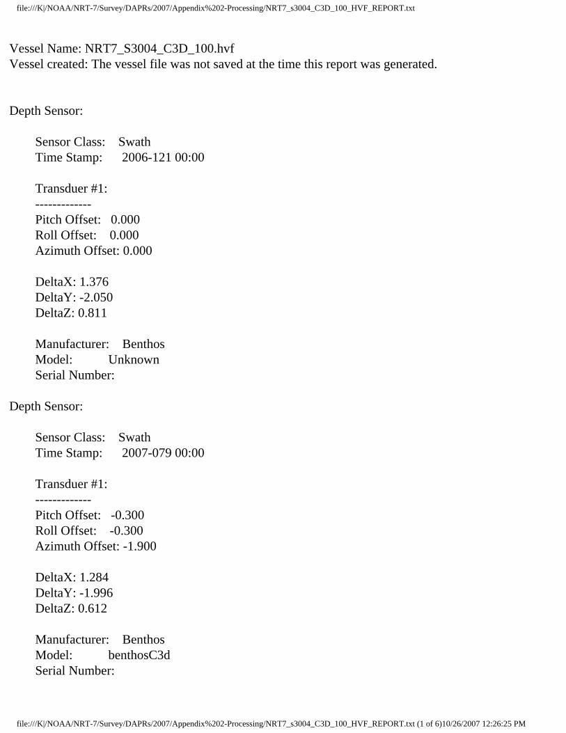
Vessel Name: NRT7_S3004_C3D_100.hvfVessel created: The vessel file was not saved at the time this report was generated.
Depth Sensor:
Sensor Class: Swath Time Stamp: 2006-121 00:00
Transduer #1: ------------- Pitch Offset: 0.000 Roll Offset: 0.000 Azimuth Offset: 0.000
DeltaX: 1.376 DeltaY: -2.050 DeltaZ: 0.811
Manufacturer: Benthos Model: Unknown Serial Number:
Depth Sensor:
Sensor Class: Swath Time Stamp: 2007-079 00:00
Transduer #1: ------------- Pitch Offset: -0.300 Roll Offset: -0.300 Azimuth Offset: -1.900
DeltaX: 1.284 DeltaY: -1.996 DeltaZ: 0.612
Manufacturer: Benthos Model: benthosC3d Serial Number:
file:///K|/NOAA/NRT-7/Survey/DAPRs/2007/Appendix%202-Processing/NRT7_s3004_C3D_100_HVF_REPORT.txt (1 of 6)10/26/2007 12:26:25 PM

file:///K|/NOAA/NRT-7/Survey/DAPRs/2007/Appendix%202-Processing/NRT7_s3004_C3D_100_HVF_REPORT.txt
_________________________________________________________Navigation Sensor:
Time Stamp: 2005-299 00:00
Comments Offset applied in POS Latency 0.000 DeltaX: 0.000 DeltaY: 0.000 DeltaZ: 0.000
Manufacturer: Applanix Model: POSMV v4 Serial Number: (null)
_________________________________________________________Gyro Sensor:
Time Stamp: 2005-299 00:00
Comments (null) Latency 0.000
_________________________________________________________Heave Sensor:
Time Stamp: 2005-299 00:00
Comments RP to IMU Apply Yes Latency 0.000 DeltaX: 0.000 DeltaY: 0.000 DeltaZ: 0.000 Offset: 0.000
Manufacturer: (null) Model: (null) Serial Number: (null)
_________________________________________________________Pitch Sensor:
file:///K|/NOAA/NRT-7/Survey/DAPRs/2007/Appendix%202-Processing/NRT7_s3004_C3D_100_HVF_REPORT.txt (2 of 6)10/26/2007 12:26:25 PM
file:///K|/NOAA/NRT-7/Survey/DAPRs/2007/Appendix%202-Processing/NRT7_s3004_C3D_100_HVF_REPORT.txt
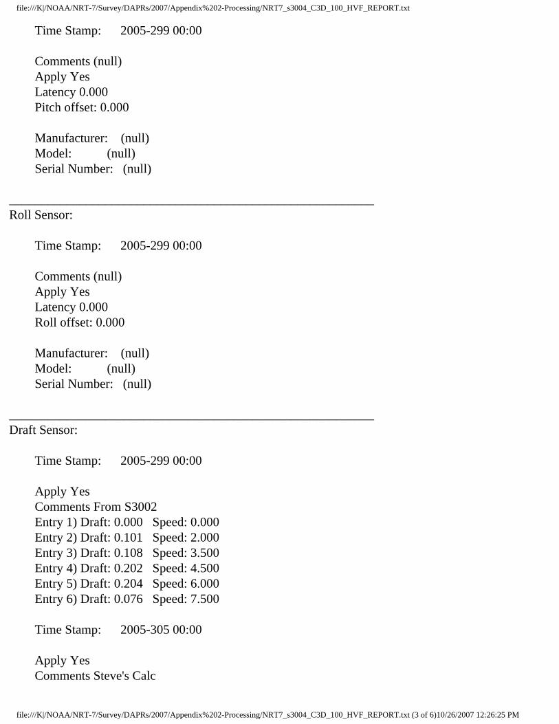
Time Stamp: 2005-299 00:00
Comments (null) Apply Yes Latency 0.000 Pitch offset: 0.000
Manufacturer: (null) Model: (null) Serial Number: (null)
_________________________________________________________Roll Sensor:
Time Stamp: 2005-299 00:00
Comments (null) Apply Yes Latency 0.000 Roll offset: 0.000
Manufacturer: (null) Model: (null) Serial Number: (null)
_________________________________________________________Draft Sensor:
Time Stamp: 2005-299 00:00
Apply Yes Comments From S3002 Entry 1) Draft: 0.000 Speed: 0.000 Entry 2) Draft: 0.101 Speed: 2.000 Entry 3) Draft: 0.108 Speed: 3.500 Entry 4) Draft: 0.202 Speed: 4.500 Entry 5) Draft: 0.204 Speed: 6.000 Entry 6) Draft: 0.076 Speed: 7.500
Time Stamp: 2005-305 00:00
Apply Yes Comments Steve's Calc
file:///K|/NOAA/NRT-7/Survey/DAPRs/2007/Appendix%202-Processing/NRT7_s3004_C3D_100_HVF_REPORT.txt (3 of 6)10/26/2007 12:26:25 PM

file:///K|/NOAA/NRT-7/Survey/DAPRs/2007/Appendix%202-Processing/NRT7_s3004_C3D_100_HVF_REPORT.txt
Entry 1) Draft: 0.000 Speed: 1.800 Entry 2) Draft: -0.020 Speed: 4.200 Entry 3) Draft: -0.020 Speed: 5.000 Entry 4) Draft: -0.060 Speed: 6.400 Entry 5) Draft: -0.020 Speed: 7.300 Entry 6) Draft: 0.000 Speed: 8.200_________________________________________________________TPE
Time Stamp: 2007-079 00:00
Comments Offsets corrected in POS, SDs from HSTD2007_2 Offsets
Motion sensing unit to the transducer 1 X Head 1 0.000 Y Head 1 0.000 Z Head 1 0.000 Motion sensing unit to the transducer 2 X Head 2 0.000 Y Head 2 0.000 Z Head 2 0.000 Navigation antenna to the transducer 1 X Head 1 0.000 Y Head 1 0.000 Z Head 1 0.000 Navigation antenna to the transducer 2 X Head 2 0.000 Y Head 2 0.000 Z Head 2 0.000
Roll offset of transducer number 1 0.000 Roll offset of transducer number 2 0.000
Heave Error: 0.050 or 5.000'' of heave amplitude. Measurement errors: 0.050 Motion sensing unit alignment errors Gyro:1.000 Pitch:1.000 Roll:1.000 Gyro measurement error: 0.020 Roll measurement error: 0.020 Pitch measurement error: 0.020 Navigation measurement error: 1.000 Transducer timing error: 0.010
file:///K|/NOAA/NRT-7/Survey/DAPRs/2007/Appendix%202-Processing/NRT7_s3004_C3D_100_HVF_REPORT.txt (4 of 6)10/26/2007 12:26:25 PM

file:///K|/NOAA/NRT-7/Survey/DAPRs/2007/Appendix%202-Processing/NRT7_s3004_C3D_100_HVF_REPORT.txt
Navigation timing error: 0.010 Gyro timing error: 0.010 Heave timing error: 0.010 PitchTimingStdDev: 0.010 Roll timing error: 0.010 Sound Velocity speed measurement error: 0.000 Surface sound speed measurement error: 0.000 Tide measurement error: 0.000 Tide zoning error: 0.000 Speed over ground measurement error: 0.030 Dynamic loading measurement error: 0.150 Static draft measurement error: 0.100 Delta draft measurement error: 0.020 StDev Comment: `éƒJ Ï…J`õ…JPõ…J°ð…J €…J@í…J°k€JàZ€J€Ó…Ja_________________________________________________________Svp Sensor:
Time Stamp: 2006-121 00:00
Comments Svp #1: ------------- Pitch Offset: 0.000 Roll Offset: 0.000 Azimuth Offset: 0.000
DeltaX: 1.376 DeltaY: -2.050 DeltaZ: 0.811
SVP #2: ------------- Pitch Offset: 0.000 Roll Offset: 0.000 Azimuth Offset: 0.000
DeltaX: 0.000 DeltaY: 0.000 DeltaZ: 0.000
Time Stamp: 2007-079 00:00
file:///K|/NOAA/NRT-7/Survey/DAPRs/2007/Appendix%202-Processing/NRT7_s3004_C3D_100_HVF_REPORT.txt (5 of 6)10/26/2007 12:26:25 PM

file:///K|/NOAA/NRT-7/Survey/DAPRs/2007/Appendix%202-Processing/NRT7_s3004_C3D_100_HVF_REPORT.txt
Comments (null) Svp #1: ------------- Pitch Offset: 0.000 Roll Offset: 0.000 Azimuth Offset: 0.000
DeltaX: 1.284 DeltaY: -1.996 DeltaZ: 0.612
SVP #2: ------------- Pitch Offset: 0.000 Roll Offset: 0.000 Azimuth Offset: 0.000
DeltaX: 0.000 DeltaY: 0.000 DeltaZ: 0.000
_________________________________________________________WaterLine:
Time Stamp: 2005-300 00:00
Comments RP to WL Apply Yes WaterLine -0.080_________________________________________________________
file:///K|/NOAA/NRT-7/Survey/DAPRs/2007/Appendix%202-Processing/NRT7_s3004_C3D_100_HVF_REPORT.txt (6 of 6)10/26/2007 12:26:25 PM

file:///K|/NOAA/NRT-7/Survey/DAPRs/2007/Appendix%202-Processing/NRT7_s3004_C3D_200_HVF_REPORT.txt
Vessel Name: NRT7_S3004_C3D_200.hvfVessel created: The vessel file was not saved at the time this report was generated.
Depth Sensor:
Sensor Class: Swath Time Stamp: 2006-121 00:00
Transduer #1: ------------- Pitch Offset: 0.000 Roll Offset: 0.000 Azimuth Offset: 0.000
DeltaX: 1.376 DeltaY: -2.050 DeltaZ: 0.811
Manufacturer: Benthos Model: Unknown Serial Number:
Depth Sensor:
Sensor Class: Swath Time Stamp: 2007-079 00:00
Transduer #1: ------------- Pitch Offset: -0.300 Roll Offset: -0.300 Azimuth Offset: -1.900
DeltaX: 1.284 DeltaY: -1.996 DeltaZ: 0.612
Manufacturer: Benthos Model: benthosC3d Serial Number:
file:///K|/NOAA/NRT-7/Survey/DAPRs/2007/Appendix%202-Processing/NRT7_s3004_C3D_200_HVF_REPORT.txt (1 of 6)10/26/2007 12:26:25 PM

file:///K|/NOAA/NRT-7/Survey/DAPRs/2007/Appendix%202-Processing/NRT7_s3004_C3D_200_HVF_REPORT.txt
_________________________________________________________Navigation Sensor:
Time Stamp: 2005-299 00:00
Comments Offset applied in POS Latency 0.000 DeltaX: 0.000 DeltaY: 0.000 DeltaZ: 0.000
Manufacturer: Applanix Model: POSMV v4 Serial Number: (null)
_________________________________________________________Gyro Sensor:
Time Stamp: 2005-299 00:00
Comments (null) Latency 0.000
_________________________________________________________Heave Sensor:
Time Stamp: 2005-299 00:00
Comments RP to IMU Apply Yes Latency 0.000 DeltaX: 0.000 DeltaY: 0.000 DeltaZ: 0.000 Offset: 0.000
Manufacturer: (null) Model: (null) Serial Number: (null)
_________________________________________________________Pitch Sensor:
file:///K|/NOAA/NRT-7/Survey/DAPRs/2007/Appendix%202-Processing/NRT7_s3004_C3D_200_HVF_REPORT.txt (2 of 6)10/26/2007 12:26:25 PM

file:///K|/NOAA/NRT-7/Survey/DAPRs/2007/Appendix%202-Processing/NRT7_s3004_C3D_200_HVF_REPORT.txt
Time Stamp: 2005-299 00:00
Comments (null) Apply Yes Latency 0.000 Pitch offset: 0.000
Manufacturer: (null) Model: (null) Serial Number: (null)
_________________________________________________________Roll Sensor:
Time Stamp: 2005-299 00:00
Comments (null) Apply Yes Latency 0.000 Roll offset: 0.000
Manufacturer: (null) Model: (null) Serial Number: (null)
_________________________________________________________Draft Sensor:
Time Stamp: 2005-299 00:00
Apply Yes Comments From S3002 Entry 1) Draft: 0.000 Speed: 0.000 Entry 2) Draft: 0.101 Speed: 2.000 Entry 3) Draft: 0.108 Speed: 3.500 Entry 4) Draft: 0.202 Speed: 4.500 Entry 5) Draft: 0.204 Speed: 6.000 Entry 6) Draft: 0.076 Speed: 7.500
Time Stamp: 2005-305 00:00
Apply Yes Comments Steve's Calc
file:///K|/NOAA/NRT-7/Survey/DAPRs/2007/Appendix%202-Processing/NRT7_s3004_C3D_200_HVF_REPORT.txt (3 of 6)10/26/2007 12:26:25 PM

file:///K|/NOAA/NRT-7/Survey/DAPRs/2007/Appendix%202-Processing/NRT7_s3004_C3D_200_HVF_REPORT.txt
Entry 1) Draft: 0.000 Speed: 1.800 Entry 2) Draft: -0.020 Speed: 4.200 Entry 3) Draft: -0.020 Speed: 5.000 Entry 4) Draft: -0.060 Speed: 6.400 Entry 5) Draft: -0.020 Speed: 7.300 Entry 6) Draft: 0.000 Speed: 8.200_________________________________________________________TPE
Time Stamp: 2007-079 00:00
Comments Offsets corrected in POS, SDs from HSTD2007_2 Offsets
Motion sensing unit to the transducer 1 X Head 1 0.000 Y Head 1 0.000 Z Head 1 0.000 Motion sensing unit to the transducer 2 X Head 2 0.000 Y Head 2 0.000 Z Head 2 0.000 Navigation antenna to the transducer 1 X Head 1 0.000 Y Head 1 0.000 Z Head 1 0.000 Navigation antenna to the transducer 2 X Head 2 0.000 Y Head 2 0.000 Z Head 2 0.000
Roll offset of transducer number 1 0.000 Roll offset of transducer number 2 0.000
Heave Error: 0.050 or 5.000'' of heave amplitude. Measurement errors: 0.050 Motion sensing unit alignment errors Gyro:1.000 Pitch:1.000 Roll:1.000 Gyro measurement error: 0.020 Roll measurement error: 0.020 Pitch measurement error: 0.020 Navigation measurement error: 1.000 Transducer timing error: 0.010
file:///K|/NOAA/NRT-7/Survey/DAPRs/2007/Appendix%202-Processing/NRT7_s3004_C3D_200_HVF_REPORT.txt (4 of 6)10/26/2007 12:26:25 PM

file:///K|/NOAA/NRT-7/Survey/DAPRs/2007/Appendix%202-Processing/NRT7_s3004_C3D_200_HVF_REPORT.txt
Navigation timing error: 0.010 Gyro timing error: 0.010 Heave timing error: 0.010 PitchTimingStdDev: 0.010 Roll timing error: 0.010 Sound Velocity speed measurement error: 0.000 Surface sound speed measurement error: 0.000 Tide measurement error: 0.000 Tide zoning error: 0.000 Speed over ground measurement error: 0.030 Dynamic loading measurement error: 0.150 Static draft measurement error: 0.100 Delta draft measurement error: 0.020 StDev Comment: `éƒJ Ï…J`õ…JPõ…J°ð…J €…J@í…J°k€JàZ€J€Ó…Ja_________________________________________________________Svp Sensor:
Time Stamp: 2006-121 00:00
Comments Svp #1: ------------- Pitch Offset: 0.000 Roll Offset: 0.000 Azimuth Offset: 0.000
DeltaX: 1.376 DeltaY: -2.050 DeltaZ: 0.811
SVP #2: ------------- Pitch Offset: 0.000 Roll Offset: 0.000 Azimuth Offset: 0.000
DeltaX: 0.000 DeltaY: 0.000 DeltaZ: 0.000
Time Stamp: 2007-079 00:00
file:///K|/NOAA/NRT-7/Survey/DAPRs/2007/Appendix%202-Processing/NRT7_s3004_C3D_200_HVF_REPORT.txt (5 of 6)10/26/2007 12:26:25 PM

file:///K|/NOAA/NRT-7/Survey/DAPRs/2007/Appendix%202-Processing/NRT7_s3004_C3D_200_HVF_REPORT.txt
Comments (null) Svp #1: ------------- Pitch Offset: 0.000 Roll Offset: 0.000 Azimuth Offset: 0.000
DeltaX: 1.284 DeltaY: -1.996 DeltaZ: 0.612
SVP #2: ------------- Pitch Offset: 0.000 Roll Offset: 0.000 Azimuth Offset: 0.000
DeltaX: 0.000 DeltaY: 0.000 DeltaZ: 0.000
_________________________________________________________WaterLine:
Time Stamp: 2005-300 00:00
Comments RP to WL Apply Yes WaterLine -0.080_________________________________________________________
file:///K|/NOAA/NRT-7/Survey/DAPRs/2007/Appendix%202-Processing/NRT7_s3004_C3D_200_HVF_REPORT.txt (6 of 6)10/26/2007 12:26:25 PM

file:///K|/NOAA/NRT-7/Survey/DAPRs/2007/Appendix%202-Processing/NRT7_s3004_C3D_HVF_REPORT.txt
Vessel Name: NRT7_S3004_C3D.hvfVessel created: The vessel file was not saved at the time this report was generated.
Depth Sensor:
Sensor Class: Swath Time Stamp: 2006-121 00:00
Transduer #1: ------------- Pitch Offset: 0.000 Roll Offset: 0.000 Azimuth Offset: 0.000
DeltaX: 1.376 DeltaY: -2.050 DeltaZ: 0.811
Manufacturer: Benthos Model: Unknown Serial Number:
Depth Sensor:
Sensor Class: Swath Time Stamp: 2007-079 00:00
Transduer #1: ------------- Pitch Offset: -0.300 Roll Offset: -0.300 Azimuth Offset: -1.900
DeltaX: 1.284 DeltaY: -1.996 DeltaZ: 0.612
Manufacturer: Benthos Model: benthosC3d Serial Number:
file:///K|/NOAA/NRT-7/Survey/DAPRs/2007/Appendix%202-Processing/NRT7_s3004_C3D_HVF_REPORT.txt (1 of 6)10/26/2007 12:26:25 PM

file:///K|/NOAA/NRT-7/Survey/DAPRs/2007/Appendix%202-Processing/NRT7_s3004_C3D_HVF_REPORT.txt
_________________________________________________________Navigation Sensor:
Time Stamp: 2005-299 00:00
Comments Offset applied in POS Latency 0.000 DeltaX: 0.000 DeltaY: 0.000 DeltaZ: 0.000
Manufacturer: Applanix Model: POSMV v4 Serial Number: (null)
_________________________________________________________Gyro Sensor:
Time Stamp: 2005-299 00:00
Comments (null) Latency 0.000
_________________________________________________________Heave Sensor:
Time Stamp: 2005-299 00:00
Comments RP to IMU Apply Yes Latency 0.000 DeltaX: 0.000 DeltaY: 0.000 DeltaZ: 0.000 Offset: 0.000
Manufacturer: (null) Model: (null) Serial Number: (null)
_________________________________________________________Pitch Sensor:
file:///K|/NOAA/NRT-7/Survey/DAPRs/2007/Appendix%202-Processing/NRT7_s3004_C3D_HVF_REPORT.txt (2 of 6)10/26/2007 12:26:25 PM

file:///K|/NOAA/NRT-7/Survey/DAPRs/2007/Appendix%202-Processing/NRT7_s3004_C3D_HVF_REPORT.txt
Time Stamp: 2005-299 00:00
Comments (null) Apply Yes Latency 0.000 Pitch offset: 0.000
Manufacturer: (null) Model: (null) Serial Number: (null)
_________________________________________________________Roll Sensor:
Time Stamp: 2005-299 00:00
Comments (null) Apply Yes Latency 0.000 Roll offset: 0.000
Manufacturer: (null) Model: (null) Serial Number: (null)
_________________________________________________________Draft Sensor:
Time Stamp: 2005-299 00:00
Apply Yes Comments From S3002 Entry 1) Draft: 0.000 Speed: 0.000 Entry 2) Draft: 0.101 Speed: 2.000 Entry 3) Draft: 0.108 Speed: 3.500 Entry 4) Draft: 0.202 Speed: 4.500 Entry 5) Draft: 0.204 Speed: 6.000 Entry 6) Draft: 0.076 Speed: 7.500
Time Stamp: 2005-305 00:00
Apply Yes Comments Steve's Calc
file:///K|/NOAA/NRT-7/Survey/DAPRs/2007/Appendix%202-Processing/NRT7_s3004_C3D_HVF_REPORT.txt (3 of 6)10/26/2007 12:26:25 PM

file:///K|/NOAA/NRT-7/Survey/DAPRs/2007/Appendix%202-Processing/NRT7_s3004_C3D_HVF_REPORT.txt
Entry 1) Draft: 0.000 Speed: 1.800 Entry 2) Draft: -0.020 Speed: 4.200 Entry 3) Draft: -0.020 Speed: 5.000 Entry 4) Draft: -0.060 Speed: 6.400 Entry 5) Draft: -0.020 Speed: 7.300 Entry 6) Draft: 0.000 Speed: 8.200_________________________________________________________TPE
Time Stamp: 2007-079 00:00
Comments Offsets corrected in POS, SDs from HSTD2007_2 Offsets
Motion sensing unit to the transducer 1 X Head 1 0.000 Y Head 1 0.000 Z Head 1 0.000 Motion sensing unit to the transducer 2 X Head 2 0.000 Y Head 2 0.000 Z Head 2 0.000 Navigation antenna to the transducer 1 X Head 1 0.000 Y Head 1 0.000 Z Head 1 0.000 Navigation antenna to the transducer 2 X Head 2 0.000 Y Head 2 0.000 Z Head 2 0.000
Roll offset of transducer number 1 0.000 Roll offset of transducer number 2 0.000
Heave Error: 0.050 or 5.000'' of heave amplitude. Measurement errors: 0.050 Motion sensing unit alignment errors Gyro:1.000 Pitch:1.000 Roll:1.000 Gyro measurement error: 0.020 Roll measurement error: 0.020 Pitch measurement error: 0.020 Navigation measurement error: 1.000 Transducer timing error: 0.010
file:///K|/NOAA/NRT-7/Survey/DAPRs/2007/Appendix%202-Processing/NRT7_s3004_C3D_HVF_REPORT.txt (4 of 6)10/26/2007 12:26:25 PM

file:///K|/NOAA/NRT-7/Survey/DAPRs/2007/Appendix%202-Processing/NRT7_s3004_C3D_HVF_REPORT.txt
Navigation timing error: 0.010 Gyro timing error: 0.010 Heave timing error: 0.010 PitchTimingStdDev: 0.010 Roll timing error: 0.010 Sound Velocity speed measurement error: 0.000 Surface sound speed measurement error: 0.000 Tide measurement error: 0.000 Tide zoning error: 0.000 Speed over ground measurement error: 0.030 Dynamic loading measurement error: 0.150 Static draft measurement error: 0.100 Delta draft measurement error: 0.020 StDev Comment: `éƒJ Ï…J`õ…JPõ…J°ð…J €…J@í…J°k€JàZ€J€Ó…Ja_________________________________________________________Svp Sensor:
Time Stamp: 2006-121 00:00
Comments Svp #1: ------------- Pitch Offset: 0.000 Roll Offset: 0.000 Azimuth Offset: 0.000
DeltaX: 1.376 DeltaY: -2.050 DeltaZ: 0.811
SVP #2: ------------- Pitch Offset: 0.000 Roll Offset: 0.000 Azimuth Offset: 0.000
DeltaX: 0.000 DeltaY: 0.000 DeltaZ: 0.000
Time Stamp: 2007-079 00:00
file:///K|/NOAA/NRT-7/Survey/DAPRs/2007/Appendix%202-Processing/NRT7_s3004_C3D_HVF_REPORT.txt (5 of 6)10/26/2007 12:26:25 PM

file:///K|/NOAA/NRT-7/Survey/DAPRs/2007/Appendix%202-Processing/NRT7_s3004_C3D_HVF_REPORT.txt
Comments (null) Svp #1: ------------- Pitch Offset: 0.000 Roll Offset: 0.000 Azimuth Offset: 0.000
DeltaX: 1.284 DeltaY: -1.996 DeltaZ: 0.612
SVP #2: ------------- Pitch Offset: 0.000 Roll Offset: 0.000 Azimuth Offset: 0.000
DeltaX: 0.000 DeltaY: 0.000 DeltaZ: 0.000
_________________________________________________________WaterLine:
Time Stamp: 2005-300 00:00
Comments RP to WL Apply Yes WaterLine -0.080_________________________________________________________
file:///K|/NOAA/NRT-7/Survey/DAPRs/2007/Appendix%202-Processing/NRT7_s3004_C3D_HVF_REPORT.txt (6 of 6)10/26/2007 12:26:25 PM
file:///K|/NOAA/NRT-7/Survey/DAPRs/2007/Appendix%202-Processing/NRT7_S3004_Reson8125_HVF_REPORT.txt
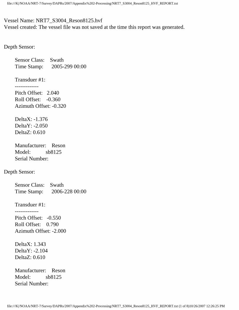
Vessel Name: NRT7_S3004_Reson8125.hvfVessel created: The vessel file was not saved at the time this report was generated.
Depth Sensor:
Sensor Class: Swath Time Stamp: 2005-299 00:00
Transduer #1: ------------- Pitch Offset: 2.040 Roll Offset: -0.360 Azimuth Offset: -0.320
DeltaX: -1.376 DeltaY: -2.050 DeltaZ: 0.610
Manufacturer: Reson Model: sb8125 Serial Number:
Depth Sensor:
Sensor Class: Swath Time Stamp: 2006-228 00:00
Transduer #1: ------------- Pitch Offset: -0.550 Roll Offset: 0.790 Azimuth Offset: -2.000
DeltaX: 1.343 DeltaY: -2.104 DeltaZ: 0.610
Manufacturer: Reson Model: sb8125 Serial Number:
file:///K|/NOAA/NRT-7/Survey/DAPRs/2007/Appendix%202-Processing/NRT7_S3004_Reson8125_HVF_REPORT.txt (1 of 8)10/26/2007 12:26:25 PM

file:///K|/NOAA/NRT-7/Survey/DAPRs/2007/Appendix%202-Processing/NRT7_S3004_Reson8125_HVF_REPORT.txt
Depth Sensor:
Sensor Class: Swath Time Stamp: 2006-310 00:00
Transduer #1: ------------- Pitch Offset: -1.250 Roll Offset: 0.650 Azimuth Offset: 0.790
DeltaX: 1.343 DeltaY: -2.104 DeltaZ: 0.610
Manufacturer: Reson Model: sb8125 Serial Number:
Depth Sensor:
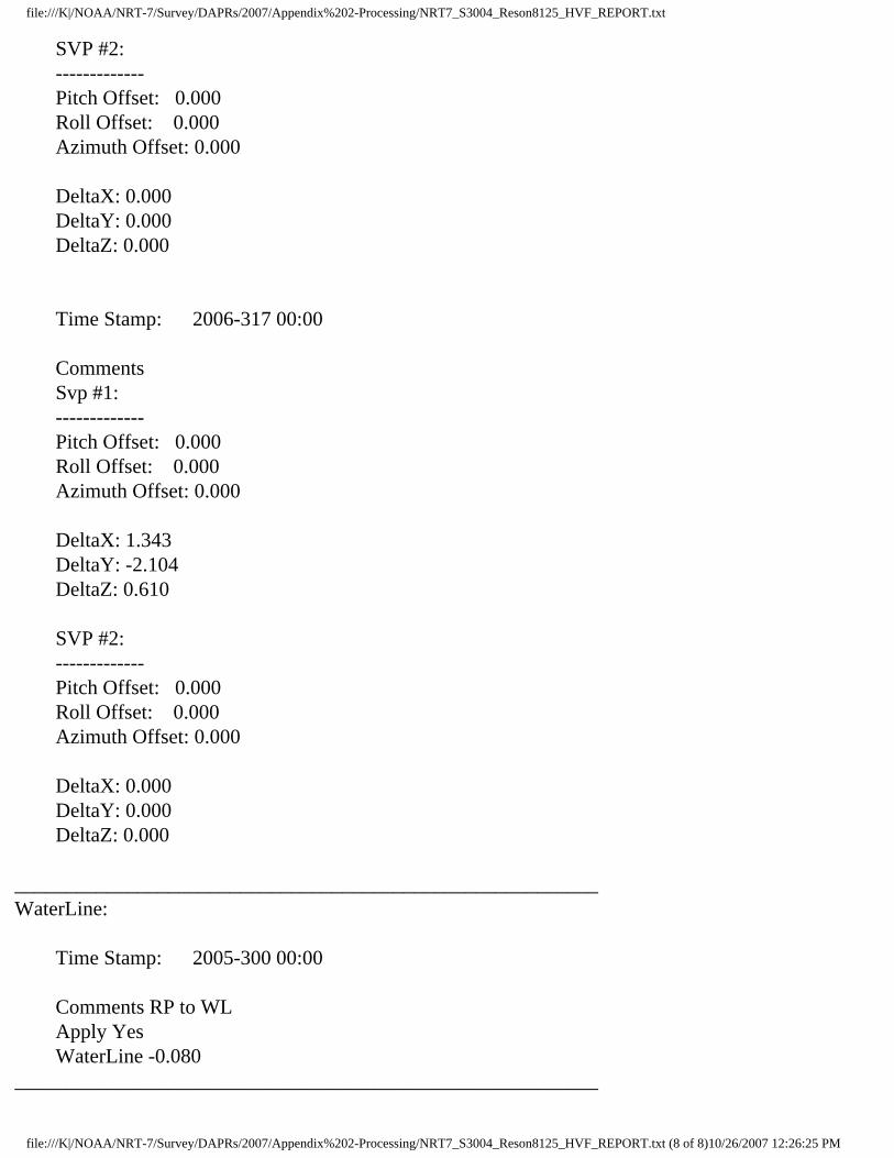
Sensor Class: Swath Time Stamp: 2006-317 00:00
Transduer #1: ------------- Pitch Offset: -1.600 Roll Offset: 0.850 Azimuth Offset: 0.800
DeltaX: 1.343 DeltaY: -2.104 DeltaZ: 0.610
Manufacturer: Reson Model: sb8125 Serial Number:
_________________________________________________________Navigation Sensor:
Time Stamp: 2005-299 00:00
file:///K|/NOAA/NRT-7/Survey/DAPRs/2007/Appendix%202-Processing/NRT7_S3004_Reson8125_HVF_REPORT.txt (2 of 8)10/26/2007 12:26:25 PM

file:///K|/NOAA/NRT-7/Survey/DAPRs/2007/Appendix%202-Processing/NRT7_S3004_Reson8125_HVF_REPORT.txt
Comments Offset applied in POS Latency 0.000 DeltaX: 0.000 DeltaY: 0.000 DeltaZ: 0.000
Manufacturer: Applanix Model: POSMV v4 Serial Number: (null)
_________________________________________________________Gyro Sensor:
Time Stamp: 2005-299 00:00
Comments (null) Latency 0.000
_________________________________________________________Heave Sensor:
Time Stamp: 2005-299 00:00
Comments RP to IMU Apply Yes Latency -0.300 DeltaX: 0.000 DeltaY: 0.000 DeltaZ: 0.000 Offset: 0.000
Manufacturer: (null) Model: (null) Serial Number: (null)
_________________________________________________________Pitch Sensor:
Time Stamp: 2005-299 00:00
Comments (null) Apply Yes Latency 0.000
file:///K|/NOAA/NRT-7/Survey/DAPRs/2007/Appendix%202-Processing/NRT7_S3004_Reson8125_HVF_REPORT.txt (3 of 8)10/26/2007 12:26:25 PM

file:///K|/NOAA/NRT-7/Survey/DAPRs/2007/Appendix%202-Processing/NRT7_S3004_Reson8125_HVF_REPORT.txt
Pitch offset: 0.000
Manufacturer: (null) Model: (null) Serial Number: (null)
_________________________________________________________Roll Sensor:
Time Stamp: 2005-299 00:00
Comments (null) Apply Yes Latency 0.000 Roll offset: 0.000
Manufacturer: (null) Model: (null) Serial Number: (null)
_________________________________________________________Draft Sensor:
Time Stamp: 2005-299 00:00
Apply Yes Comments From S3002 Entry 1) Draft: 0.000 Speed: 0.000 Entry 2) Draft: 0.101 Speed: 2.000 Entry 3) Draft: 0.108 Speed: 3.500 Entry 4) Draft: 0.202 Speed: 4.500 Entry 5) Draft: 0.204 Speed: 6.000 Entry 6) Draft: 0.076 Speed: 7.500_________________________________________________________TPE
Time Stamp: 2006-310 00:00
Comments Offsets
Motion sensing unit to the transducer 1 X Head 1 1.343
file:///K|/NOAA/NRT-7/Survey/DAPRs/2007/Appendix%202-Processing/NRT7_S3004_Reson8125_HVF_REPORT.txt (4 of 8)10/26/2007 12:26:25 PM

file:///K|/NOAA/NRT-7/Survey/DAPRs/2007/Appendix%202-Processing/NRT7_S3004_Reson8125_HVF_REPORT.txt
Y Head 1 -2.104 Z Head 1 0.610 Motion sensing unit to the transducer 2 X Head 2 0.000 Y Head 2 0.000 Z Head 2 0.000 Navigation antenna to the transducer 1 X Head 1 0.000 Y Head 1 0.000 Z Head 1 0.000 Navigation antenna to the transducer 2 X Head 2 0.000 Y Head 2 0.000 Z Head 2 0.000
Roll offset of transducer number 1 0.000 Roll offset of transducer number 2 0.000
Heave Error: 0.050 or 5.000'' of heave amplitude. Measurement errors: 0.001 Motion sensing unit alignment errors Gyro:1.000 Pitch:1.000 Roll:1.000 Gyro measurement error: 0.020 Roll measurement error: 0.020 Pitch measurement error: 0.020 Navigation measurement error: 1.000 Transducer timing error: 0.010 Navigation timing error: 0.010 Gyro timing error: 0.010 Heave timing error: 0.010 PitchTimingStdDev: 0.010 Roll timing error: 0.010 Sound Velocity speed measurement error: 4.000 Surface sound speed measurement error: 0.500 Tide measurement error: 0.020 Tide zoning error: 0.020 Speed over ground measurement error: 0.030 Dynamic loading measurement error: 0.150 Static draft measurement error: 0.100 Delta draft measurement error: 0.100 StDev Comment: `éƒJ Ï…J`õ…JPõ…J°ð…J €…J@í…J°k€JàZ€J€Ó…Ja_________________________________________________________Svp Sensor:
file:///K|/NOAA/NRT-7/Survey/DAPRs/2007/Appendix%202-Processing/NRT7_S3004_Reson8125_HVF_REPORT.txt (5 of 8)10/26/2007 12:26:25 PM
file:///K|/NOAA/NRT-7/Survey/DAPRs/2007/Appendix%202-Processing/NRT7_S3004_Reson8125_HVF_REPORT.txt
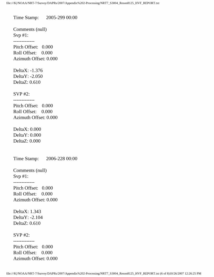
Time Stamp: 2005-299 00:00
Comments (null) Svp #1: ------------- Pitch Offset: 0.000 Roll Offset: 0.000 Azimuth Offset: 0.000
DeltaX: -1.376 DeltaY: -2.050 DeltaZ: 0.610
SVP #2: ------------- Pitch Offset: 0.000 Roll Offset: 0.000 Azimuth Offset: 0.000
DeltaX: 0.000 DeltaY: 0.000 DeltaZ: 0.000
Time Stamp: 2006-228 00:00
Comments (null) Svp #1: ------------- Pitch Offset: 0.000 Roll Offset: 0.000 Azimuth Offset: 0.000
DeltaX: 1.343 DeltaY: -2.104 DeltaZ: 0.610
SVP #2: ------------- Pitch Offset: 0.000 Roll Offset: 0.000 Azimuth Offset: 0.000
file:///K|/NOAA/NRT-7/Survey/DAPRs/2007/Appendix%202-Processing/NRT7_S3004_Reson8125_HVF_REPORT.txt (6 of 8)10/26/2007 12:26:25 PM

file:///K|/NOAA/NRT-7/Survey/DAPRs/2007/Appendix%202-Processing/NRT7_S3004_Reson8125_HVF_REPORT.txt
DeltaX: 0.000 DeltaY: 0.000 DeltaZ: 0.000
Time Stamp: 2006-307 00:00
Comments Svp #1: ------------- Pitch Offset: 0.000 Roll Offset: 0.000 Azimuth Offset: 0.000
DeltaX: 0.000 DeltaY: 0.000 DeltaZ: 0.000
SVP #2: ------------- Pitch Offset: 0.000 Roll Offset: 0.000 Azimuth Offset: 0.000
DeltaX: 0.000 DeltaY: 0.000 DeltaZ: 0.000
Time Stamp: 2006-310 00:00
Comments Svp #1: ------------- Pitch Offset: 0.000 Roll Offset: 0.000 Azimuth Offset: 0.000
DeltaX: 1.343 DeltaY: -2.104 DeltaZ: 0.610
file:///K|/NOAA/NRT-7/Survey/DAPRs/2007/Appendix%202-Processing/NRT7_S3004_Reson8125_HVF_REPORT.txt (7 of 8)10/26/2007 12:26:25 PM
file:///K|/NOAA/NRT-7/Survey/DAPRs/2007/Appendix%202-Processing/NRT7_S3004_Reson8125_HVF_REPORT.txt
SVP #2: ------------- Pitch Offset: 0.000 Roll Offset: 0.000 Azimuth Offset: 0.000
DeltaX: 0.000 DeltaY: 0.000 DeltaZ: 0.000
Time Stamp: 2006-317 00:00
Comments Svp #1: ------------- Pitch Offset: 0.000 Roll Offset: 0.000 Azimuth Offset: 0.000
DeltaX: 1.343 DeltaY: -2.104 DeltaZ: 0.610
SVP #2: ------------- Pitch Offset: 0.000 Roll Offset: 0.000 Azimuth Offset: 0.000
DeltaX: 0.000 DeltaY: 0.000 DeltaZ: 0.000
_________________________________________________________WaterLine:
Time Stamp: 2005-300 00:00
Comments RP to WL Apply Yes WaterLine -0.080_________________________________________________________
file:///K|/NOAA/NRT-7/Survey/DAPRs/2007/Appendix%202-Processing/NRT7_S3004_Reson8125_HVF_REPORT.txt (8 of 8)10/26/2007 12:26:25 PM

file:///K|/NOAA/NRT-7/Survey/DAPRs/2007/Appendix%202-Processing/NRT7_S3004_SB_HVF_REPORT.txt
Vessel Name: NRT7_S3004_SB.hvfVessel created: The vessel file was not saved at the time this report was generated.
Depth Sensor:
Sensor Class: Swath Time Stamp: 2006-274 00:00
Transduer #1: ------------- Pitch Offset: 0.000 Roll Offset: 0.000 Azimuth Offset: 0.000
DeltaX: -0.276 DeltaY: 0.040 DeltaZ: 0.255
Manufacturer: Odom Model: oecv Serial Number:
_________________________________________________________Navigation Sensor:
Time Stamp: 2005-299 00:00
Comments Offset applied in POS Latency 0.040 DeltaX: 0.000 DeltaY: 0.000 DeltaZ: 0.000
Manufacturer: Applanix Model: POSMV v4 Serial Number: (null)
_________________________________________________________Gyro Sensor:
Time Stamp: 2005-299 00:00
file:///K|/NOAA/NRT-7/Survey/DAPRs/2007/Appendix%202-Processing/NRT7_S3004_SB_HVF_REPORT.txt (1 of 6)10/26/2007 12:26:25 PM

file:///K|/NOAA/NRT-7/Survey/DAPRs/2007/Appendix%202-Processing/NRT7_S3004_SB_HVF_REPORT.txt
Comments (null) Latency 0.000
_________________________________________________________Heave Sensor:
Time Stamp: 2005-299 00:00
Comments RP to IMU Apply Yes Latency 0.000 DeltaX: 0.000 DeltaY: 0.000 DeltaZ: 0.000 Offset: 0.000
Manufacturer: (null) Model: (null) Serial Number: (null)
_________________________________________________________Pitch Sensor:
Time Stamp: 2005-299 00:00
Comments (null) Apply Yes Latency 0.000 Pitch offset: 0.000
Manufacturer: (null) Model: (null) Serial Number: (null)
_________________________________________________________Roll Sensor:
Time Stamp: 2005-299 00:00
Comments (null) Apply Yes Latency 0.000
file:///K|/NOAA/NRT-7/Survey/DAPRs/2007/Appendix%202-Processing/NRT7_S3004_SB_HVF_REPORT.txt (2 of 6)10/26/2007 12:26:25 PM

file:///K|/NOAA/NRT-7/Survey/DAPRs/2007/Appendix%202-Processing/NRT7_S3004_SB_HVF_REPORT.txt
Roll offset: 0.000
Manufacturer: (null) Model: (null) Serial Number: (null)
_________________________________________________________Draft Sensor:
Time Stamp: 2005-299 00:00
Apply Yes Comments From S3002 Entry 1) Draft: 0.000 Speed: 0.000 Entry 2) Draft: 0.101 Speed: 2.000 Entry 3) Draft: 0.108 Speed: 3.500 Entry 4) Draft: 0.202 Speed: 4.500 Entry 5) Draft: 0.204 Speed: 6.000 Entry 6) Draft: 0.076 Speed: 7.500
Time Stamp: 2005-305 00:00
Apply Yes Comments Steve's Calc Entry 1) Draft: 0.000 Speed: 1.800 Entry 2) Draft: -0.020 Speed: 4.200 Entry 3) Draft: -0.020 Speed: 5.000 Entry 4) Draft: -0.060 Speed: 6.400 Entry 5) Draft: -0.020 Speed: 7.300 Entry 6) Draft: 0.000 Speed: 8.200_________________________________________________________Svp Sensor:
Time Stamp: 2006-121 00:00
Comments Svp #1: ------------- Pitch Offset: 0.000 Roll Offset: 0.000 Azimuth Offset: 0.000
DeltaX: 1.376
file:///K|/NOAA/NRT-7/Survey/DAPRs/2007/Appendix%202-Processing/NRT7_S3004_SB_HVF_REPORT.txt (3 of 6)10/26/2007 12:26:25 PM

file:///K|/NOAA/NRT-7/Survey/DAPRs/2007/Appendix%202-Processing/NRT7_S3004_SB_HVF_REPORT.txt
DeltaY: -2.050 DeltaZ: 0.811
SVP #2: ------------- Pitch Offset: 0.000 Roll Offset: 0.000 Azimuth Offset: 0.000
DeltaX: 0.000 DeltaY: 0.000 DeltaZ: 0.000
Time Stamp: 2006-253 00:00
Comments Svp #1: ------------- Pitch Offset: 0.000 Roll Offset: 0.000 Azimuth Offset: 0.000
DeltaX: -0.276 DeltaY: 0.040 DeltaZ: 0.255
SVP #2: ------------- Pitch Offset: 0.000 Roll Offset: 0.000 Azimuth Offset: 0.000
DeltaX: 0.000 DeltaY: 0.000 DeltaZ: 0.000
Time Stamp: 2006-273 00:00
Comments Svp #1: -------------
file:///K|/NOAA/NRT-7/Survey/DAPRs/2007/Appendix%202-Processing/NRT7_S3004_SB_HVF_REPORT.txt (4 of 6)10/26/2007 12:26:25 PM

file:///K|/NOAA/NRT-7/Survey/DAPRs/2007/Appendix%202-Processing/NRT7_S3004_SB_HVF_REPORT.txt
Pitch Offset: 0.000 Roll Offset: 0.000 Azimuth Offset: 0.000
DeltaX: 0.000 DeltaY: 0.000 DeltaZ: 0.000
SVP #2: ------------- Pitch Offset: 0.000 Roll Offset: 0.000 Azimuth Offset: 0.000
DeltaX: 0.000 DeltaY: 0.000 DeltaZ: 0.000
Time Stamp: 2006-274 00:00
Comments Svp #1: ------------- Pitch Offset: 0.000 Roll Offset: 0.000 Azimuth Offset: 0.000
DeltaX: -0.276 DeltaY: 0.040 DeltaZ: 0.255
SVP #2: ------------- Pitch Offset: 0.000 Roll Offset: 0.000 Azimuth Offset: 0.000
DeltaX: 0.000 DeltaY: 0.000 DeltaZ: 0.000
_________________________________________________________
file:///K|/NOAA/NRT-7/Survey/DAPRs/2007/Appendix%202-Processing/NRT7_S3004_SB_HVF_REPORT.txt (5 of 6)10/26/2007 12:26:25 PM

file:///K|/NOAA/NRT-7/Survey/DAPRs/2007/Appendix%202-Processing/NRT7_S3004_SB_HVF_REPORT.txt
WaterLine:
Time Stamp: 2005-300 00:00
Comments RP to WL Apply Yes WaterLine -0.080_________________________________________________________
file:///K|/NOAA/NRT-7/Survey/DAPRs/2007/Appendix%202-Processing/NRT7_S3004_SB_HVF_REPORT.txt (6 of 6)10/26/2007 12:26:25 PM

APPENDIX III

“1” (bit on bow)
“3” (stbd POS M/V antenna)
“2” (port POS M/V antenna)
“5” (IMU)
“00” Top-aft-inside coming of hatch in cabin
“7” Punch mark on forward side of mounting plate
“9” Punch mark on top of arm
“11” Punch mark on aft side of mounting plate
“13” Center of J-arm up-right
“15” stbd-stern bit
“4” Punch on forward lower plate
“6” Punch on top of arm
“8” Punch on aft lower plate
“10” port-stern bit
“Stern” bottom of V-hull
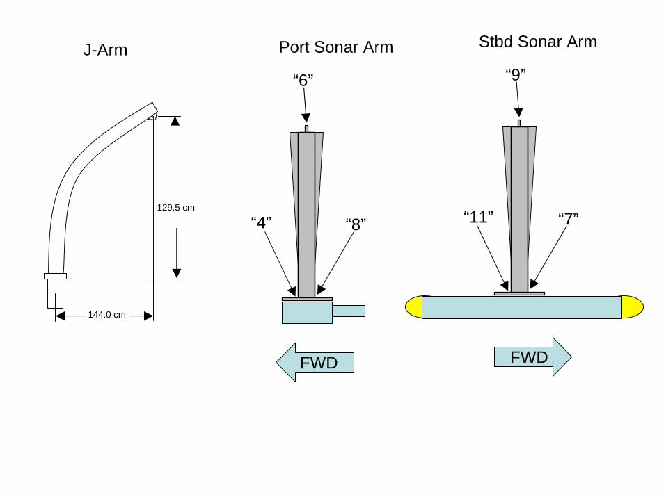
144.0 cm
129.5 cm
FWD
“4”
“6”
“8”
FWD
“11”
“9”
“7”
J-Arm Port Sonar Arm Stbd Sonar Arm

Point Name Northing Easting Elevationfore/aft port/stb up/down
AMC 16.3631 -11.4689 0.67BOWKEEL 4.2287 -0.0188 0.21IMU 0.097 0.1113 -0.09RP 0 0 0STERNKEEL -4.0363 -0.0188 -0.35TP1 -0.9354 6.0829 0.521 4.632 0.001 1.292 1.256 -0.7956 2.473 1.2496 0.7606 2.4711 -2.1143 1.3752 -0.429 -2.0498 1.3755 0.987 -1.8818 1.3729 -0.4410 -2.9992 -1.1347 0.9813 -2.548 0.5653 1.4915 -2.9967 1.1135 1
fwd (+) stb (+) up (+)
8=76=94=11
for/aft port/stbd up/down7 to LW3D -0.1143 -0.0889 -0.17145RP to LWC3D P -1.9961 1.284 -0.61145
The surveyed point were treated as the following in the new diagram and the signs and values adjusted accordinly:
Note: Mounting arm was modified in summer/fall 2006. The port side arm became the stbd-side arm after the modifcation. We assume the position of the deployed pole did not change. BJW

Gigabit Switch
DataCable
Klein 5000LWTowfish
Odom DigibarPro
XTF Data Output
MBES Data
UNISIPS Data
Side Scan Sonar
Ethernet X-Over192.168.0.85
ResonDownlink1
Port
Motion DataReson port 3
Klein Hub
Ethernet192.168.0.XXX
Multiple DisplaysAdded for Nav, Multi-type data collection
TSWG BoatConnection Diagram
DRAFTSonar-Pro Version
8/26/05
Position Data
Multiple DisplaysAdded for Nav, Multi-type data collection
192.168.0.82
129.100.1.232
129.100.1.233
PPS to Serial
Odom CV2Echosounder
Trimble DGPSRTCM
9600,N,8,1
If ISIS used for SSS192.168.1.224
Port 2 from ResonIsis Commands
UTCReson Port 1
DelphSurvey Control
XTF or SDF DataOutput
SSS Data
RAW Hypack Data
SBES Data
NMEA
IP 192.168.0.81Klein TPU
POS IP129.100.1.231
Reson IP192.168.0.83
SonarPro SSSHypack SBES
Navigation
Triton ISISDelphNavBathyPro
DHARMAUnisips
ENet2
ENet1
Com3
Com4
Com5
Com6
Com7
ENet2
ENet1
Enet3
Com3
Com4
Com5
Com6
Com7
Telemout
XXXXXXiXXXXXX7XXXXX
9600
,N,8
,1
9600
,N,8
,1
9600
,N,8
,1
19200,N,8,1
4800,N,8,1
5Hz,19200,N
,8,1
Groups 3,7,10,102,111

Benthos C3D Wiring Diagram Aboard s3004
Towfish
POS-MV
Odom Digibar
SSV
Benthos C3D Server
Isis Acquisition Computer
Network Switch
Ethernet Ethernet
Star
boar
d So
nar C
able
Serial- 9600, n,8,1
Port
Sona
r Cab
le
Cro
ssov
er C
able

APPENDIX IV

SEA-BIRD ELECTRONICS, INC.1808 - 136th Place Northeast, Bellevue, Washington 98005 USA
Phone: (425) 643-9866 Fax: (425) 643-9954 www.seabird.com
Conductivity Calibration Report
Conductivity sensors are normally calibrated 'as received', without cleaning or adjustments, allowing a determination of
sensor drift. If the calibration identifies a problem or indicates cell cleaning is necessary, then a second calibration is
performed after work is completed. The 'as received' calibration is not performed if the sensor is damaged or non-
functional, or by customer request.
Customer: NOAA - NRT-1
Job Number: 44256
Model Number SBE 19Plus
Date of Report: 1/9/2007
Serial Number: 19P37217-4677
An 'as received' calibration certificate is provided, listing the coefficients used to convert sensor frequency to
conductivity. Users must choose whether the 'as received' calibration or the previous calibration better represents the
sensor condition during deployment. In SEASOFT enter the chosen coefficients using the program SEACON. The
coefficient 'slope' allows small corrections for drift between calibrations (consult the SEASOFT manual). Calibration
coefficients obtained after a repair or cleaning apply only to subsequent data.
'AS RECEIVED CALIBRATION' PerformedPerformedPerformedPerformed Not PerformedNot PerformedNot PerformedNot Performed
Date:Date:Date:Date: 1/9/2007 Drift since last cal:Drift since last cal:Drift since last cal:Drift since last cal: +.00050 PSU/month*PSU/month*PSU/month*PSU/month*
Comments:Comments:Comments:Comments:
'CALIBRATION AFTER CLEANING & REPLATINIZING' PerformedPerformedPerformedPerformed Not PerformedNot PerformedNot PerformedNot Performed
Date:Date:Date:Date: Drift sinceDrift sinceDrift sinceDrift since PSU/month*PSU/month*PSU/month*PSU/month*
Comments:Comments:Comments:Comments:
Cell cleaning and electrode replatinizing tend to 'reset' the conductivity sensor to its original condition. Lack of drift in
post-cleaning-calibration indicates geometric stability of the cell and electrical stability of the sensor circuit.
*Measured at 3.0 S/m
Last cal:Last cal:Last cal:Last cal:

SEA-BIRD ELECTRONICS, INC.1808 136th Place N.E., Bellevue, Washington, 98005 USA
Phone: (425) 643 - 9866 Fax (425) 643 - 9954 Email: [email protected]
SENSOR SERIAL NUMBER: 4677
CALIBRATION DATE: 09-Jan-07
SBE19plus CONDUCTIVITY CALIBRATION DATA
PSS 1978: C(35,15,0) = 4.2914 Siemens/meter
COEFFICIENTS:
g = -1.054221e+000
h = 1.391571e-001
i = -2.948637e-004
j = 3.995315e-005
CPcor = -9.5700e-008
CTcor = 3.2500e-006
BATH TEMP BATH SAL BATH COND INST FREQ INST COND RESIDUAL
(ITS-90) (PSU) (Siemens/m) (Hz) (Siemens/m) (Siemens/m)
22.0000 0.0000 0.00000 2757.46 0.0000 0.00000
1.0000 34.6447 2.96269 5381.02 2.9627 -0.00001
4.5000 34.6250 3.26845 5581.53 3.2685 0.00001
14.9999 34.5835 4.24606 6178.31 4.2461 0.00003
18.5000 34.5748 4.58978 6374.58 4.5898 0.00000
24.0000 34.5653 5.14540 6679.36 5.1454 -0.00003
29.0000 34.5601 5.66506 6952.02 5.6650 -0.00002
32.5001 34.5572 6.03591 7140.05 6.0359 0.00002
f = INST FREQ / 1000.0
Conductivity = (g + hf2
+ if3
+ jf4
) / (1 + δt + εp) Siemens/meter
t = temperature[°C)]; p = pressure[decibars]; δ = CTcor; ε = CPcor;
Residual = instrument conductivity - bath conductivity
Date, Slope Correction
-0.004
-0.002
0.000
0.002
0.004
0 1 2 3 4 5 6 7
Resid
ual, (
S/m
)
Conductivity (Siemens/m)
02-Aug-05 1.0003127
09-Jan-07 1.0000000

SEA-BIRD ELECTRONICS, INC.1808 136th Place N.E., Bellevue, Washington, 98005 USA
Phone: (425) 643 - 9866 Fax (425) 643 - 9954 Email: [email protected]
SENSOR SERIAL NUMBER: 4677CALIBRATION DATE: 04-Jan-07
SBE19plus PRESSURE CALIBRATION DATA 508 psia S/N 6135
COEFFICIENTS:PA0 = 1.741331e-001
PA1 = 1.549722e-003
PA2 = 9.222321e-012
PTEMPA0 = -7.930081e+001
PTEMPA1 = 4.829264e+001
PTEMPA2 = -3.740742e-001
PTCA0 = 5.152023e+005
PTCA1 = 9.012761e+000
PTCA2 = -1.728316e-001
PTCB0 = 2.429287e+001
PTCB1 = -6.250000e-004
PTCB2 = 0.000000e+000
PRESSURE SPAN CALIBRATION THERMAL CORRECTION PRESSURE INST THERMISTOR COMPUTED ERROR TEMP THERMISTOR INST PSIA OUTPUT OUTPUT PRESSURE %FSR ITS90 OUTPUT OUTPUT 14.67 524663.0 2.1 14.67 -0.00 32.50 2.36 524972.58 104.95 582845.0 2.1 104.93 -0.01 29.00 2.28 524966.94 204.98 647223.0 2.1 204.86 -0.02 24.00 2.18 524974.66 304.92 711614.0 2.1 304.90 -0.00 18.50 2.06 524966.99 404.93 775925.0 2.1 404.89 -0.01 15.00 1.98 524954.54 504.92 840208.0 2.1 504.91 -0.00 4.50 1.76 524895.24 404.90 775962.0 2.1 404.95 0.01 1.00 1.69 524865.65 304.89 711660.0 2.1 304.97 0.02 204.93 647285.0 2.1 204.96 0.01 TEMP(ITS90) SPAN(mV) 104.93 582887.0 2.1 104.99 0.01 -5.00 24.30 14.67 524664.0 2.1 14.67 -0.00 35.00 24.27
y = thermistor output; t = PTEMPA0 + PTEMPA1 * y + PTEMPA2 * y2
x = pressure output - PTCA0 - PTCA1 * t - PTCA2 * t2
n = x * PTCB0 / (PTCB0 + PTCB1 * t + PTCB2 * t2)
pressure (psia) = PA0 + PA1 * n + PA2 * n2
Date, Avg Delta P %FS
-0.50
-0.25
0.00
0.25
0.50
0 50 100 150 200 250 300 350 400 450 500 550
Res
idua
l, (%
FS
R)
Pressure (PSIA)
04-Jan-07 0.00

SEA-BIRD ELECTRONICS, INC.1808 136th Place N.E., Bellevue, Washington, 98005 USA
Phone: (425) 643 - 9866 Fax (425) 643 - 9954 Email: [email protected]
SENSOR SERIAL NUMBER: 4677
CALIBRATION DATE: 09-Jan-07
SBE19plus TEMPERATURE CALIBRATION DATA
ITS-90 TEMPERATURE SCALE
ITS-90 COEFFICIENTS
a0 = 1.162054e-003
a1 = 2.738619e-004
a2 = -9.432152e-007
a3 = 1.791934e-007
BATH TEMP INSTRUMENT INST TEMP RESIDUAL
(ITS-90) OUTPUT(n) (ITS-90) (ITS-90)
1.0000 693723.056 1.0001 0.0001
4.5000 620453.352 4.4998 -0.0002
14.9999 435193.141 15.0002 0.0003
18.5000 384587.141 18.4998 -0.0002
24.0000 315243.225 24.0000 0.0000
29.0000 261952.225 28.9998 -0.0002
32.5001 229534.817 32.5002 0.0001
MV = (n - 524288) / 1.6e+007
R = (MV * 2.900e+009 + 1.024e+008) / (2.048e+004 - MV * 2.0e+005)
Temperature ITS-90 = 1/{a0 + a1[ln(R)] + a2[ln2
(R)] + a3[ln3
(R)]} - 273.15 (°C)
Residual = instrument temperature - bath temperature
Date, Delta T (mdeg C)
-0.02
-0.01
0.00
0.01
0.02
-5 0 5 10 15 20 25 30 35
Re
sid
ua
l, (
De
gre
es C
)
Temperature, Degrees C
02-Aug-05 1.42
09-Jan-07 0.00

Service
Customer Information:
Report
Company NOAA - NRT-1 Date 1/23/2007
Contact Steve Brodet
PO Number TBD
RMA Number 44256
SEA-BIRD ELECTRONICS, INC.1808 - 136th Place Northeast, Bellevue, Washington 98005 USAPhone: (425) 643-9866 Fax: (425) 643-9954 www.seabird.com
Serial Number 05M0684Model Number SBE 05T
Services Requested:1. Evaluate/Repair Instrumentation.
Problems Found:
Services Performed:1. Performed initial diagnostic evaluation.
Special Notes:
Tuesday, January 23, 2007 Page 1 of 2

Service
Customer Information:
Report
Company NOAA - NRT-1 Date 1/23/2007
Contact Steve Brodet
PO Number TBD
RMA Number 44256
SEA-BIRD ELECTRONICS, INC.1808 - 136th Place Northeast, Bellevue, Washington 98005 USAPhone: (425) 643-9866 Fax: (425) 643-9954 www.seabird.com
Serial Number 19P37217-4677Model Number SBE 19Plus
Services Requested:1. Evaluate/Repair Instrumentation.2. Perform Routine Calibration Service.
Problems Found:
Services Performed:1. Performed initial diagnostic evaluation.2. Upgraded firmware to most current revision (see special notes).*3. Calibrated the pressure sensor.4. Performed "Post Cruise" calibration of the temperature & conductivity sensors.5. Performed complete system check and full diagnostic evaluation.
Special Notes:* Updated the EPROM to version 1.6b.
Tuesday, January 23, 2007 Page 2 of 2

SEA-BIRD ELECTRONICS, INC.1808 - 136th Place Northeast, Bellevue, Washington 98005 USA
Phone: (425) 643-9866 Fax: (425) 643-9954 www.seabird.com
Temperature Calibration Report
Customer: NOAA - NRT-1
Job Number: 44256
Model Number SBE 19Plus
Date of Report: 1/9/2007
Serial Number: 19P37217-4677
'AS RECEIVED CALIBRATION' PerformedPerformedPerformedPerformed Not PerformedNot PerformedNot PerformedNot Performed
Date:Date:Date:Date: 1/9/2007 Drift since last cal:Drift since last cal:Drift since last cal:Drift since last cal: -.00099 Degrees Celsius/yearDegrees Celsius/yearDegrees Celsius/yearDegrees Celsius/year
Comments:Comments:Comments:Comments:
'CALIBRATION AFTER REPAIR' PerformedPerformedPerformedPerformed Not PerformedNot PerformedNot PerformedNot Performed
Date:Date:Date:Date: Drift sinceDrift sinceDrift sinceDrift since Degrees Celsius/yearDegrees Celsius/yearDegrees Celsius/yearDegrees Celsius/year
Comments:Comments:Comments:Comments:
Last cal:Last cal:Last cal:Last cal:
Temperature sensors are normally calibrated 'as received', without adjustments, allowing a determination sensor drift. If
the calibration identifies a problem, then a second calibration is performed after work is completed. The 'as received'
calibration is not performed if the sensor is damaged or non-functional, or by customer request.
An 'as received' calibration certificate is provided, listing coefficients to convert sensor frequency to temperature. Users
must choose whether the 'as received' calibration or the previous calibration better represents the sensor condition
during deployment. In SEASOFT enter the chosen coefficients using the program SEACON. The coefficient 'offset'
allows a small correction for drift between calibrations (consult the SEASOFT manual). Calibration coefficients
obtained after a repair apply only to subsequent data.


Vessel:
Date: 3/22/2007 Dn: 81Personnel:
PCS Serial # 2233
IP Address:
POS controller Version (Use Menu Help > About) POSView 3.3.2.2
POS Version (Use Menu View > Statistics) MV320 Ver4GPS Receivers
Primary ReceiverSecondary Receiver
Location: D M SApproximate Position: Lat 38 18 50
Lon 76 26 42DGPS Beacon Station:Frequency: 301 kHZ
Satellite Constellation (Use View> GPS Data)Primary GPS (Port Antenna) N
HDOP: 0..862VDOP: 1.188
Sattelites in Use: 9
PDOP 1.736 (Use View> GAMS Solution)
Note: Secondary GPS satellite constellation and number of satellites were exactly the same as the Primary GPS
CALIBRATION AREAPatuxant River, MD (Solomons)
Annapolis, MD
2, 4, 5, 9, 12, 17, 20, 23, 28
LTJG Welton, PS Brodet, PS Gostnell, PS Turner
129.100.1.231
SN 60008125SN 60001853
POS/MV Calibration ReportField Unit: NRT7 s3004
SYSTEM INFORMATIONNRT7 (s3004)

SettingsGams Parameter Setup (Use Settings > Installation > GAMS Intallation)
User Entries, Pre-Calibration Baseline Vector1.559 Two Antenna Separation (m) -0.008 X Component (m)0.50 Heading Calibration Threshold 1.559 YComponent (m)
0 Heading Correction 0.017 Z Component (m)
Calibration Procedure:
Start time: 13:21 UTCEnd time: 13:26 UTCHeading accuracy achieved for calibration: 0.031
Calibration Results:Gams Parameter Setup (Use Settings > Installation > GAMS Intallation)
POS/MV Post-Calibration Values Baseline Vector3.27 Two Antenna Separation (m) -0.042 X Component (m)
0.500 Heading Calibration Threshold 3.27 YComponent (m)0 Heading Correction 0.011 Z Component (m)
yesyes
Save POS Settings on PC (Use File > Store POS Settings on PC)File Name:
GAMS Status Online?Save Settings?
Calibration Notes:
2.22.2007.nvm
POS/MV CONFIGURATION
Configuration Notes:
POS/MV CALIBRATION
(Refer to POS MV V3 Installation and Operation Guide, 4-25)

The POS/MV uses a Right-Hand Orthogonal Reference SystemThe right-hand orthogonal system defines the following:• The x-axis is in the fore-aft direction in the appropriate reference frame.• The y-axis is perpendicular to the x-axis and points towards the
right (starboard) side in the appropriate reference frame.• The z-axis points downwards in the appropriate reference frame.
The POS/MV uses a Tate-Bryant Rotation SequenceApply the rotation in the following order to bring the two frames of reference
into complete alignment:a) Heading rotation - apply a right-hand screw rotation θz about the
z-axis to align one frame with the other.b) Pitch rotation - apply a right-hand screw rotation θy about the
once-rotated y-axis to align one frame with the other.c) Roll rotation - apply a right-hand screw rotation θx about the
twice-rotated x-axis to align one frame with the other.
NOTE:
GENERAL GUIDANCE
SETTINGS (insert screen grabs)Input/Output Ports (Use Settings > Input/Output Ports)

Installation (Use Settings > Installation)
Heave Filter (Use Settings > Heave) Events (Use Settings > Events)
Heave Filter (Use Settings > Heave)Time Sync (Use Settings > Time Sync)

Sensor Mounting (Use Settings > Installation > Sensor Mounting)
Tags, Multipath and Auto Start (Use Settings > Installation > Tags, Multipath and Auto Start)

Primary GPS Receiver
Secondary GPS Receiver
Frame Control (Use Tools > Config)
GPS Receiver Configuration (Use Settings> Installation> GPS Receiver Configuration)
User Parameter Accuracy (Use Settings > Installation > User Accuracy)

Appendix V
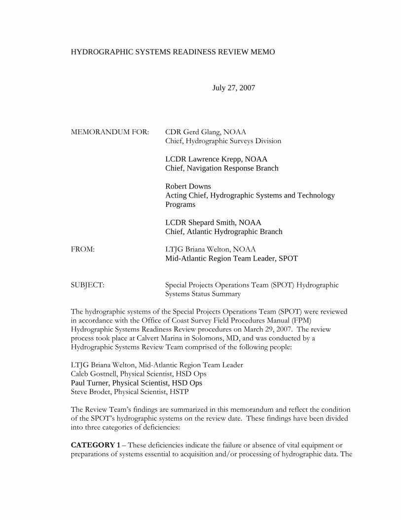
HYDROGRAPHIC SYSTEMS READINESS REVIEW MEMO
July 27, 2007
MEMORANDUM FOR: CDR Gerd Glang, NOAA Chief, Hydrographic Surveys Division LCDR Lawrence Krepp, NOAA Chief, Navigation Response Branch Robert Downs
Acting Chief, Hydrographic Systems and Technology Programs
LCDR Shepard Smith, NOAA Chief, Atlantic Hydrographic Branch FROM: LTJG Briana Welton, NOAA Mid-Atlantic Region Team Leader, SPOT SUBJECT: Special Projects Operations Team (SPOT) Hydrographic
Systems Status Summary The hydrographic systems of the Special Projects Operations Team (SPOT) were reviewed in accordance with the Office of Coast Survey Field Procedures Manual (FPM) Hydrographic Systems Readiness Review procedures on March 29, 2007. The review process took place at Calvert Marina in Solomons, MD, and was conducted by a Hydrographic Systems Review Team comprised of the following people: LTJG Briana Welton, Mid-Atlantic Region Team Leader Caleb Gostnell, Physical Scientist, HSD Ops Paul Turner, Physical Scientist, HSD Ops Steve Brodet, Physical Scientist, HSTP The Review Team’s findings are summarized in this memorandum and reflect the condition of the SPOT’s hydrographic systems on the review date. These findings have been divided into three categories of deficiencies: CATEGORY 1 – These deficiencies indicate the failure or absence of vital equipment or preparations of systems essential to acquisition and/or processing of hydrographic data. The

HYDROGRAPHIC SYSTEMS READINESS REVIEW MEMO
vessel will be required to cease or limit hydrographic survey operations due to the following deficiencies:
1. The Special Projects Operations Team has a requirement for portable office space
and at least two data processing computers with accompanying software. The office trailer is unequipped for mobile assignments and the unit has no processing machines. Currently the Team Leader is using Atlantic Hydrographic Branch office space and a laptop to process existing data, but the lack of dedicated processing machines makes efficient data manipulation and delivery nearly impossible.
CATEGORY 2 – These deficiencies indicate noncompliance with established policies, directives, instructions, or accepted hydrographic practice not addressed under Category 1. The following deficiencies shall be corrected in as timely a manner as funding, time, and/or professional assistance permit:
1. The vessel has only one mounting arm from which to deploy any one of the vessel’s three sonar systems: Reson 8125 multibeam echosounder (MBES), Light Weight Klein 5000 side scan sonar (SSS), and Benthos C3D interferometric sonar. A patch test must be performed each time one of these sonar systems is newly mounted before conducting hydrographic survey operations.
2. The port-side mounting arm was removed and the starboard side mounting arm was
modified since the last NGS static offset survey. Since neither the length of the starboard arm or position of the cupped receptacle for the arm were altered, the surveyed benchmark stamp on the top of the arm is assumed to be the same as it was prior to modification. The offsets within the vessel frame of reference between the acoustic phase center of each sonar system and the benchmark on the top of the mounting arm have been manually measured with a steel tape. These manually measured offsets are used in the respective Caris HIPS/SIPS hydrographic vessel files (HVF). Resurvey of the mounting arm will be performed when possible.
3. A lead line comparison between the Reson 8125 multibeam, the Odom CV
singlebeam, and the Benthos C3D interferometric sonar has never been performed. This comparison will be performed as soon as time and staffing allows.
4. Settlement and squat measurements have never been performed on this vessel.
The current dynamic draft tables used in the system HVFs are from NRT 5 (s3002), a vessel of the same make and model. Settlement and squat measurements will be determined for this vessel as soon as time and staffing allows.

HYDROGRAPHIC SYSTEMS READINESS REVIEW MEMO
5. Isis 6.0 is currently being used for Reson 8125 and light weight Klein 5000 data acquisition. The software will be updated to the most recent version of Isis 7.0 when time and staffing allows.
CATEGORY 3 – items are associated with observations during the course of the review which merit consideration for corrective actions. These observations are included for review and dialogue related to potential problem areas and hydrographic operational efficiency. It is important to assure that resources (funds, skills, and time) are available at the operating level in order to meet the needs identified in this report and to sustain the efficient operation, upkeep, and repair of the field unit’s hydrographic systems.
1. The computer on which Hypack Max is used for navigation and singlebeam data acquisition exhibited serious boot errors on the date of review. The computer was sent to the Office of Coast Survey’s Hydrographic Support and Technology Program for analysis. A new hard drive and an updated operating system were installed to remedy the operating system boot problem. Since the update, the computer operates slower than expected for unidentified reasons.
2. The Digibar surface sound-velocimeter operates on battery power only, requiring
weekly and/or daily battery renewal. Until a 12-volt power supply can be added to the Digibar, spare batteries must be carried aboard the vessel.
3. The vessel does not have a bottom-sampler, preventing the acquisition of bottom
samples. Acquisition of a bottom-sampler should be considered.